KR102473781B1 - Semiconductor device, display module, and electronic device - Google Patents
Semiconductor device, display module, and electronic device Download PDFInfo
- Publication number
- KR102473781B1 KR102473781B1 KR1020160095144A KR20160095144A KR102473781B1 KR 102473781 B1 KR102473781 B1 KR 102473781B1 KR 1020160095144 A KR1020160095144 A KR 1020160095144A KR 20160095144 A KR20160095144 A KR 20160095144A KR 102473781 B1 KR102473781 B1 KR 102473781B1
- Authority
- KR
- South Korea
- Prior art keywords
- transistor
- film
- oxide
- oxide semiconductor
- gate
- Prior art date
Links
- 239000004065 semiconductor Substances 0.000 title claims abstract description 341
- 230000008859 change Effects 0.000 claims description 7
- 239000010410 layer Substances 0.000 description 311
- 239000000758 substrate Substances 0.000 description 124
- 239000011701 zinc Substances 0.000 description 85
- 239000004973 liquid crystal related substance Substances 0.000 description 63
- 239000013078 crystal Substances 0.000 description 62
- 238000000034 method Methods 0.000 description 54
- 229910052760 oxygen Inorganic materials 0.000 description 48
- 230000006870 function Effects 0.000 description 46
- 239000001301 oxygen Substances 0.000 description 44
- QVGXLLKOCUKJST-UHFFFAOYSA-N atomic oxygen Chemical compound [O] QVGXLLKOCUKJST-UHFFFAOYSA-N 0.000 description 43
- 239000000523 sample Substances 0.000 description 40
- 238000001514 detection method Methods 0.000 description 38
- 230000015572 biosynthetic process Effects 0.000 description 35
- 229910052782 aluminium Inorganic materials 0.000 description 31
- 229910052751 metal Inorganic materials 0.000 description 31
- 239000007789 gas Substances 0.000 description 30
- XAGFODPZIPBFFR-UHFFFAOYSA-N aluminium Chemical compound [Al] XAGFODPZIPBFFR-UHFFFAOYSA-N 0.000 description 29
- 239000000203 mixture Substances 0.000 description 29
- XUIMIQQOPSSXEZ-UHFFFAOYSA-N Silicon Chemical compound [Si] XUIMIQQOPSSXEZ-UHFFFAOYSA-N 0.000 description 28
- 125000004429 atom Chemical group 0.000 description 28
- 229910052710 silicon Inorganic materials 0.000 description 28
- 239000010703 silicon Substances 0.000 description 28
- 238000010586 diagram Methods 0.000 description 26
- 238000010894 electron beam technology Methods 0.000 description 25
- 239000002184 metal Substances 0.000 description 25
- 229910052719 titanium Inorganic materials 0.000 description 24
- 239000010936 titanium Substances 0.000 description 24
- 239000000463 material Substances 0.000 description 23
- MYMOFIZGZYHOMD-UHFFFAOYSA-N Dioxygen Chemical compound O=O MYMOFIZGZYHOMD-UHFFFAOYSA-N 0.000 description 22
- RTAQQCXQSZGOHL-UHFFFAOYSA-N Titanium Chemical compound [Ti] RTAQQCXQSZGOHL-UHFFFAOYSA-N 0.000 description 22
- 229910001882 dioxygen Inorganic materials 0.000 description 22
- IJGRMHOSHXDMSA-UHFFFAOYSA-N Atomic nitrogen Chemical compound N#N IJGRMHOSHXDMSA-UHFFFAOYSA-N 0.000 description 20
- 229910052721 tungsten Inorganic materials 0.000 description 19
- 239000001257 hydrogen Substances 0.000 description 18
- 229910052739 hydrogen Inorganic materials 0.000 description 18
- 239000010937 tungsten Substances 0.000 description 18
- 239000004020 conductor Substances 0.000 description 17
- XLOMVQKBTHCTTD-UHFFFAOYSA-N Zinc monoxide Chemical compound [Zn]=O XLOMVQKBTHCTTD-UHFFFAOYSA-N 0.000 description 16
- WFKWXMTUELFFGS-UHFFFAOYSA-N tungsten Chemical compound [W] WFKWXMTUELFFGS-UHFFFAOYSA-N 0.000 description 16
- 230000009977 dual effect Effects 0.000 description 15
- 238000002149 energy-dispersive X-ray emission spectroscopy Methods 0.000 description 15
- PXHVJJICTQNCMI-UHFFFAOYSA-N Nickel Chemical compound [Ni] PXHVJJICTQNCMI-UHFFFAOYSA-N 0.000 description 14
- 229910052581 Si3N4 Inorganic materials 0.000 description 14
- HQVNEWCFYHHQES-UHFFFAOYSA-N silicon nitride Chemical compound N12[Si]34N5[Si]62N3[Si]51N64 HQVNEWCFYHHQES-UHFFFAOYSA-N 0.000 description 14
- RYGMFSIKBFXOCR-UHFFFAOYSA-N Copper Chemical compound [Cu] RYGMFSIKBFXOCR-UHFFFAOYSA-N 0.000 description 13
- UFHFLCQGNIYNRP-UHFFFAOYSA-N Hydrogen Chemical compound [H][H] UFHFLCQGNIYNRP-UHFFFAOYSA-N 0.000 description 13
- 229910052802 copper Inorganic materials 0.000 description 13
- 239000010949 copper Substances 0.000 description 13
- 230000000694 effects Effects 0.000 description 13
- 229910044991 metal oxide Inorganic materials 0.000 description 13
- 150000004706 metal oxides Chemical class 0.000 description 13
- ZOKXTWBITQBERF-UHFFFAOYSA-N Molybdenum Chemical compound [Mo] ZOKXTWBITQBERF-UHFFFAOYSA-N 0.000 description 12
- 238000005259 measurement Methods 0.000 description 12
- 229910052750 molybdenum Inorganic materials 0.000 description 12
- 239000011733 molybdenum Substances 0.000 description 12
- 230000008569 process Effects 0.000 description 12
- 238000004458 analytical method Methods 0.000 description 11
- 238000002173 high-resolution transmission electron microscopy Methods 0.000 description 11
- 239000012535 impurity Substances 0.000 description 11
- 238000013507 mapping Methods 0.000 description 11
- 239000011347 resin Substances 0.000 description 11
- 229920005989 resin Polymers 0.000 description 11
- VYPSYNLAJGMNEJ-UHFFFAOYSA-N silicon dioxide Inorganic materials O=[Si]=O VYPSYNLAJGMNEJ-UHFFFAOYSA-N 0.000 description 11
- 238000003917 TEM image Methods 0.000 description 10
- 238000002441 X-ray diffraction Methods 0.000 description 10
- 239000000956 alloy Substances 0.000 description 10
- 239000011521 glass Substances 0.000 description 10
- 229910052757 nitrogen Inorganic materials 0.000 description 10
- 229910045601 alloy Inorganic materials 0.000 description 9
- 230000007547 defect Effects 0.000 description 9
- 229910052814 silicon oxide Inorganic materials 0.000 description 9
- 229910052715 tantalum Inorganic materials 0.000 description 9
- GUVRBAGPIYLISA-UHFFFAOYSA-N tantalum atom Chemical compound [Ta] GUVRBAGPIYLISA-UHFFFAOYSA-N 0.000 description 9
- 238000003079 width control Methods 0.000 description 9
- VYZAMTAEIAYCRO-UHFFFAOYSA-N Chromium Chemical compound [Cr] VYZAMTAEIAYCRO-UHFFFAOYSA-N 0.000 description 8
- XEEYBQQBJWHFJM-UHFFFAOYSA-N Iron Chemical compound [Fe] XEEYBQQBJWHFJM-UHFFFAOYSA-N 0.000 description 8
- GQPLMRYTRLFLPF-UHFFFAOYSA-N Nitrous Oxide Chemical compound [O-][N+]#N GQPLMRYTRLFLPF-UHFFFAOYSA-N 0.000 description 8
- 230000000903 blocking effect Effects 0.000 description 8
- 229910052804 chromium Inorganic materials 0.000 description 8
- 239000011651 chromium Substances 0.000 description 8
- 238000002003 electron diffraction Methods 0.000 description 8
- 229910052733 gallium Inorganic materials 0.000 description 8
- 229910052735 hafnium Inorganic materials 0.000 description 8
- 238000010438 heat treatment Methods 0.000 description 8
- 229910052738 indium Inorganic materials 0.000 description 8
- 238000009413 insulation Methods 0.000 description 8
- 238000004519 manufacturing process Methods 0.000 description 8
- 230000001590 oxidative effect Effects 0.000 description 8
- 239000011787 zinc oxide Substances 0.000 description 8
- 101100341026 Caenorhabditis elegans inx-2 gene Proteins 0.000 description 7
- OKTJSMMVPCPJKN-UHFFFAOYSA-N Carbon Chemical compound [C] OKTJSMMVPCPJKN-UHFFFAOYSA-N 0.000 description 7
- 206010027146 Melanoderma Diseases 0.000 description 7
- 229910052779 Neodymium Inorganic materials 0.000 description 7
- BQCADISMDOOEFD-UHFFFAOYSA-N Silver Chemical compound [Ag] BQCADISMDOOEFD-UHFFFAOYSA-N 0.000 description 7
- 239000003086 colorant Substances 0.000 description 7
- 150000001875 compounds Chemical class 0.000 description 7
- 238000005530 etching Methods 0.000 description 7
- 229910003437 indium oxide Inorganic materials 0.000 description 7
- PJXISJQVUVHSOJ-UHFFFAOYSA-N indium(iii) oxide Chemical compound [O-2].[O-2].[O-2].[In+3].[In+3] PJXISJQVUVHSOJ-UHFFFAOYSA-N 0.000 description 7
- 229910052759 nickel Inorganic materials 0.000 description 7
- 238000012545 processing Methods 0.000 description 7
- 229910052709 silver Inorganic materials 0.000 description 7
- 239000004332 silver Substances 0.000 description 7
- 238000004544 sputter deposition Methods 0.000 description 7
- 229910052727 yttrium Inorganic materials 0.000 description 7
- 229910052726 zirconium Inorganic materials 0.000 description 7
- 229910001316 Ag alloy Inorganic materials 0.000 description 6
- 102100040862 Dual specificity protein kinase CLK1 Human genes 0.000 description 6
- 102100040858 Dual specificity protein kinase CLK4 Human genes 0.000 description 6
- 101000749294 Homo sapiens Dual specificity protein kinase CLK1 Proteins 0.000 description 6
- 101000749298 Homo sapiens Dual specificity protein kinase CLK4 Proteins 0.000 description 6
- BLRPTPMANUNPDV-UHFFFAOYSA-N Silane Chemical compound [SiH4] BLRPTPMANUNPDV-UHFFFAOYSA-N 0.000 description 6
- NRTOMJZYCJJWKI-UHFFFAOYSA-N Titanium nitride Chemical compound [Ti]#N NRTOMJZYCJJWKI-UHFFFAOYSA-N 0.000 description 6
- 238000004040 coloring Methods 0.000 description 6
- 238000007599 discharging Methods 0.000 description 6
- VBJZVLUMGGDVMO-UHFFFAOYSA-N hafnium atom Chemical compound [Hf] VBJZVLUMGGDVMO-UHFFFAOYSA-N 0.000 description 6
- 239000011159 matrix material Substances 0.000 description 6
- 230000004048 modification Effects 0.000 description 6
- 238000012986 modification Methods 0.000 description 6
- 238000000623 plasma-assisted chemical vapour deposition Methods 0.000 description 6
- 229910000077 silane Inorganic materials 0.000 description 6
- 239000003381 stabilizer Substances 0.000 description 6
- 230000007704 transition Effects 0.000 description 6
- -1 tungsten nitride Chemical class 0.000 description 6
- VWQVUPCCIRVNHF-UHFFFAOYSA-N yttrium atom Chemical compound [Y] VWQVUPCCIRVNHF-UHFFFAOYSA-N 0.000 description 6
- 229910052725 zinc Inorganic materials 0.000 description 6
- GYHNNYVSQQEPJS-UHFFFAOYSA-N Gallium Chemical compound [Ga] GYHNNYVSQQEPJS-UHFFFAOYSA-N 0.000 description 5
- QCWXUUIWCKQGHC-UHFFFAOYSA-N Zirconium Chemical compound [Zr] QCWXUUIWCKQGHC-UHFFFAOYSA-N 0.000 description 5
- 230000005540 biological transmission Effects 0.000 description 5
- 239000000919 ceramic Substances 0.000 description 5
- 239000005262 ferroelectric liquid crystals (FLCs) Substances 0.000 description 5
- 150000002431 hydrogen Chemical class 0.000 description 5
- 229910052746 lanthanum Inorganic materials 0.000 description 5
- QEFYFXOXNSNQGX-UHFFFAOYSA-N neodymium atom Chemical compound [Nd] QEFYFXOXNSNQGX-UHFFFAOYSA-N 0.000 description 5
- 239000002356 single layer Substances 0.000 description 5
- XLYOFNOQVPJJNP-UHFFFAOYSA-N water Substances O XLYOFNOQVPJJNP-UHFFFAOYSA-N 0.000 description 5
- 229910001868 water Inorganic materials 0.000 description 5
- MGWGWNFMUOTEHG-UHFFFAOYSA-N 4-(3,5-dimethylphenyl)-1,3-thiazol-2-amine Chemical compound CC1=CC(C)=CC(C=2N=C(N)SC=2)=C1 MGWGWNFMUOTEHG-UHFFFAOYSA-N 0.000 description 4
- QGZKDVFQNNGYKY-UHFFFAOYSA-N Ammonia Chemical compound N QGZKDVFQNNGYKY-UHFFFAOYSA-N 0.000 description 4
- 229910052684 Cerium Inorganic materials 0.000 description 4
- 208000005156 Dehydration Diseases 0.000 description 4
- CBENFWSGALASAD-UHFFFAOYSA-N Ozone Chemical compound [O-][O+]=O CBENFWSGALASAD-UHFFFAOYSA-N 0.000 description 4
- KDLHZDBZIXYQEI-UHFFFAOYSA-N Palladium Chemical compound [Pd] KDLHZDBZIXYQEI-UHFFFAOYSA-N 0.000 description 4
- 239000002131 composite material Substances 0.000 description 4
- 230000018044 dehydration Effects 0.000 description 4
- 238000006297 dehydration reaction Methods 0.000 description 4
- 238000006356 dehydrogenation reaction Methods 0.000 description 4
- 238000000151 deposition Methods 0.000 description 4
- 230000008021 deposition Effects 0.000 description 4
- AJNVQOSZGJRYEI-UHFFFAOYSA-N digallium;oxygen(2-) Chemical compound [O-2].[O-2].[O-2].[Ga+3].[Ga+3] AJNVQOSZGJRYEI-UHFFFAOYSA-N 0.000 description 4
- PZPGRFITIJYNEJ-UHFFFAOYSA-N disilane Chemical compound [SiH3][SiH3] PZPGRFITIJYNEJ-UHFFFAOYSA-N 0.000 description 4
- 230000005684 electric field Effects 0.000 description 4
- 230000005669 field effect Effects 0.000 description 4
- 229910001195 gallium oxide Inorganic materials 0.000 description 4
- 125000005843 halogen group Chemical group 0.000 description 4
- APFVFJFRJDLVQX-UHFFFAOYSA-N indium atom Chemical compound [In] APFVFJFRJDLVQX-UHFFFAOYSA-N 0.000 description 4
- AMGQUBHHOARCQH-UHFFFAOYSA-N indium;oxotin Chemical compound [In].[Sn]=O AMGQUBHHOARCQH-UHFFFAOYSA-N 0.000 description 4
- 239000012212 insulator Substances 0.000 description 4
- 229910052742 iron Inorganic materials 0.000 description 4
- 150000002739 metals Chemical class 0.000 description 4
- JCXJVPUVTGWSNB-UHFFFAOYSA-N nitrogen dioxide Inorganic materials O=[N]=O JCXJVPUVTGWSNB-UHFFFAOYSA-N 0.000 description 4
- 229960001730 nitrous oxide Drugs 0.000 description 4
- 235000013842 nitrous oxide Nutrition 0.000 description 4
- 230000003287 optical effect Effects 0.000 description 4
- 238000000206 photolithography Methods 0.000 description 4
- 230000001681 protective effect Effects 0.000 description 4
- 239000011241 protective layer Substances 0.000 description 4
- 150000004756 silanes Chemical class 0.000 description 4
- 238000001228 spectrum Methods 0.000 description 4
- VEDJZFSRVVQBIL-UHFFFAOYSA-N trisilane Chemical compound [SiH3][SiH2][SiH3] VEDJZFSRVVQBIL-UHFFFAOYSA-N 0.000 description 4
- YVTHLONGBIQYBO-UHFFFAOYSA-N zinc indium(3+) oxygen(2-) Chemical compound [O--].[Zn++].[In+3] YVTHLONGBIQYBO-UHFFFAOYSA-N 0.000 description 4
- 229920000178 Acrylic resin Polymers 0.000 description 3
- 239000004925 Acrylic resin Substances 0.000 description 3
- 229910018137 Al-Zn Inorganic materials 0.000 description 3
- 229910018573 Al—Zn Inorganic materials 0.000 description 3
- 229910052796 boron Inorganic materials 0.000 description 3
- 238000004364 calculation method Methods 0.000 description 3
- 239000003990 capacitor Substances 0.000 description 3
- GWXLDORMOJMVQZ-UHFFFAOYSA-N cerium Chemical compound [Ce] GWXLDORMOJMVQZ-UHFFFAOYSA-N 0.000 description 3
- 238000009826 distribution Methods 0.000 description 3
- 230000001747 exhibiting effect Effects 0.000 description 3
- 229910021389 graphene Inorganic materials 0.000 description 3
- 229910000449 hafnium oxide Inorganic materials 0.000 description 3
- WIHZLLGSGQNAGK-UHFFFAOYSA-N hafnium(4+);oxygen(2-) Chemical compound [O-2].[O-2].[Hf+4] WIHZLLGSGQNAGK-UHFFFAOYSA-N 0.000 description 3
- 238000000731 high angular annular dark-field scanning transmission electron microscopy Methods 0.000 description 3
- 230000001678 irradiating effect Effects 0.000 description 3
- FZLIPJUXYLNCLC-UHFFFAOYSA-N lanthanum atom Chemical compound [La] FZLIPJUXYLNCLC-UHFFFAOYSA-N 0.000 description 3
- 239000011777 magnesium Substances 0.000 description 3
- 239000007769 metal material Substances 0.000 description 3
- 239000002159 nanocrystal Substances 0.000 description 3
- 150000004767 nitrides Chemical class 0.000 description 3
- 230000001151 other effect Effects 0.000 description 3
- TWNQGVIAIRXVLR-UHFFFAOYSA-N oxo(oxoalumanyloxy)alumane Chemical compound O=[Al]O[Al]=O TWNQGVIAIRXVLR-UHFFFAOYSA-N 0.000 description 3
- 230000000704 physical effect Effects 0.000 description 3
- 229920006122 polyamide resin Polymers 0.000 description 3
- 229920001721 polyimide Polymers 0.000 description 3
- 239000009719 polyimide resin Substances 0.000 description 3
- 239000000126 substance Substances 0.000 description 3
- XOLBLPGZBRYERU-UHFFFAOYSA-N tin dioxide Chemical compound O=[Sn]=O XOLBLPGZBRYERU-UHFFFAOYSA-N 0.000 description 3
- 229910001887 tin oxide Inorganic materials 0.000 description 3
- UWCWUCKPEYNDNV-LBPRGKRZSA-N 2,6-dimethyl-n-[[(2s)-pyrrolidin-2-yl]methyl]aniline Chemical compound CC1=CC=CC(C)=C1NC[C@H]1NCCC1 UWCWUCKPEYNDNV-LBPRGKRZSA-N 0.000 description 2
- 229910018120 Al-Ga-Zn Inorganic materials 0.000 description 2
- XKRFYHLGVUSROY-UHFFFAOYSA-N Argon Chemical compound [Ar] XKRFYHLGVUSROY-UHFFFAOYSA-N 0.000 description 2
- ZOXJGFHDIHLPTG-UHFFFAOYSA-N Boron Chemical group [B] ZOXJGFHDIHLPTG-UHFFFAOYSA-N 0.000 description 2
- CURLTUGMZLYLDI-UHFFFAOYSA-N Carbon dioxide Chemical compound O=C=O CURLTUGMZLYLDI-UHFFFAOYSA-N 0.000 description 2
- FYYHWMGAXLPEAU-UHFFFAOYSA-N Magnesium Chemical compound [Mg] FYYHWMGAXLPEAU-UHFFFAOYSA-N 0.000 description 2
- PWHULOQIROXLJO-UHFFFAOYSA-N Manganese Chemical compound [Mn] PWHULOQIROXLJO-UHFFFAOYSA-N 0.000 description 2
- BPQQTUXANYXVAA-UHFFFAOYSA-N Orthosilicate Chemical compound [O-][Si]([O-])([O-])[O-] BPQQTUXANYXVAA-UHFFFAOYSA-N 0.000 description 2
- 239000004952 Polyamide Substances 0.000 description 2
- 229910020833 Sn-Al-Zn Inorganic materials 0.000 description 2
- 229910020868 Sn-Ga-Zn Inorganic materials 0.000 description 2
- 229910020994 Sn-Zn Inorganic materials 0.000 description 2
- 229910009069 Sn—Zn Inorganic materials 0.000 description 2
- ATJFFYVFTNAWJD-UHFFFAOYSA-N Tin Chemical compound [Sn] ATJFFYVFTNAWJD-UHFFFAOYSA-N 0.000 description 2
- GWEVSGVZZGPLCZ-UHFFFAOYSA-N Titan oxide Chemical compound O=[Ti]=O GWEVSGVZZGPLCZ-UHFFFAOYSA-N 0.000 description 2
- HCHKCACWOHOZIP-UHFFFAOYSA-N Zinc Chemical compound [Zn] HCHKCACWOHOZIP-UHFFFAOYSA-N 0.000 description 2
- 229910007541 Zn O Inorganic materials 0.000 description 2
- 230000009471 action Effects 0.000 description 2
- 229910021529 ammonia Inorganic materials 0.000 description 2
- 238000013459 approach Methods 0.000 description 2
- 239000012298 atmosphere Substances 0.000 description 2
- GPBUGPUPKAGMDK-UHFFFAOYSA-N azanylidynemolybdenum Chemical compound [Mo]#N GPBUGPUPKAGMDK-UHFFFAOYSA-N 0.000 description 2
- 229910052790 beryllium Inorganic materials 0.000 description 2
- ATBAMAFKBVZNFJ-UHFFFAOYSA-N beryllium atom Chemical group [Be] ATBAMAFKBVZNFJ-UHFFFAOYSA-N 0.000 description 2
- 229910052799 carbon Inorganic materials 0.000 description 2
- 239000000969 carrier Substances 0.000 description 2
- 238000005229 chemical vapour deposition Methods 0.000 description 2
- 230000003098 cholesteric effect Effects 0.000 description 2
- 230000000295 complement effect Effects 0.000 description 2
- 238000002425 crystallisation Methods 0.000 description 2
- 230000008025 crystallization Effects 0.000 description 2
- 238000009792 diffusion process Methods 0.000 description 2
- 238000009713 electroplating Methods 0.000 description 2
- 238000000724 energy-dispersive X-ray spectrum Methods 0.000 description 2
- 230000008020 evaporation Effects 0.000 description 2
- 238000001704 evaporation Methods 0.000 description 2
- 229910052732 germanium Inorganic materials 0.000 description 2
- GNPVGFCGXDBREM-UHFFFAOYSA-N germanium atom Chemical group [Ge] GNPVGFCGXDBREM-UHFFFAOYSA-N 0.000 description 2
- 229910052749 magnesium Inorganic materials 0.000 description 2
- 239000011572 manganese Substances 0.000 description 2
- WPBNNNQJVZRUHP-UHFFFAOYSA-L manganese(2+);methyl n-[[2-(methoxycarbonylcarbamothioylamino)phenyl]carbamothioyl]carbamate;n-[2-(sulfidocarbothioylamino)ethyl]carbamodithioate Chemical compound [Mn+2].[S-]C(=S)NCCNC([S-])=S.COC(=O)NC(=S)NC1=CC=CC=C1NC(=S)NC(=O)OC WPBNNNQJVZRUHP-UHFFFAOYSA-L 0.000 description 2
- QGLKJKCYBOYXKC-UHFFFAOYSA-N nonaoxidotritungsten Chemical compound O=[W]1(=O)O[W](=O)(=O)O[W](=O)(=O)O1 QGLKJKCYBOYXKC-UHFFFAOYSA-N 0.000 description 2
- SIWVEOZUMHYXCS-UHFFFAOYSA-N oxo(oxoyttriooxy)yttrium Chemical compound O=[Y]O[Y]=O SIWVEOZUMHYXCS-UHFFFAOYSA-N 0.000 description 2
- 125000004430 oxygen atom Chemical group O* 0.000 description 2
- 229910052763 palladium Inorganic materials 0.000 description 2
- 230000003071 parasitic effect Effects 0.000 description 2
- 238000005268 plasma chemical vapour deposition Methods 0.000 description 2
- 239000004033 plastic Substances 0.000 description 2
- BASFCYQUMIYNBI-UHFFFAOYSA-N platinum Chemical compound [Pt] BASFCYQUMIYNBI-UHFFFAOYSA-N 0.000 description 2
- 229920005668 polycarbonate resin Polymers 0.000 description 2
- 239000004431 polycarbonate resin Substances 0.000 description 2
- 229920001225 polyester resin Polymers 0.000 description 2
- 229920005672 polyolefin resin Polymers 0.000 description 2
- 238000007639 printing Methods 0.000 description 2
- 239000010453 quartz Substances 0.000 description 2
- 229910052706 scandium Inorganic materials 0.000 description 2
- SIXSYDAISGFNSX-UHFFFAOYSA-N scandium atom Chemical compound [Sc] SIXSYDAISGFNSX-UHFFFAOYSA-N 0.000 description 2
- 239000000243 solution Substances 0.000 description 2
- 125000006850 spacer group Chemical group 0.000 description 2
- 238000003860 storage Methods 0.000 description 2
- MZLGASXMSKOWSE-UHFFFAOYSA-N tantalum nitride Chemical compound [Ta]#N MZLGASXMSKOWSE-UHFFFAOYSA-N 0.000 description 2
- JBQYATWDVHIOAR-UHFFFAOYSA-N tellanylidenegermanium Chemical compound [Te]=[Ge] JBQYATWDVHIOAR-UHFFFAOYSA-N 0.000 description 2
- OGIDPMRJRNCKJF-UHFFFAOYSA-N titanium oxide Inorganic materials [Ti]=O OGIDPMRJRNCKJF-UHFFFAOYSA-N 0.000 description 2
- 229910001930 tungsten oxide Inorganic materials 0.000 description 2
- 229910052720 vanadium Inorganic materials 0.000 description 2
- GPPXJZIENCGNKB-UHFFFAOYSA-N vanadium Chemical group [V]#[V] GPPXJZIENCGNKB-UHFFFAOYSA-N 0.000 description 2
- 238000007740 vapor deposition Methods 0.000 description 2
- 229910000838 Al alloy Inorganic materials 0.000 description 1
- 239000004986 Cholesteric liquid crystals (ChLC) Substances 0.000 description 1
- 229910000881 Cu alloy Inorganic materials 0.000 description 1
- 102100040844 Dual specificity protein kinase CLK2 Human genes 0.000 description 1
- 102100040856 Dual specificity protein kinase CLK3 Human genes 0.000 description 1
- 229910052692 Dysprosium Inorganic materials 0.000 description 1
- 229910052691 Erbium Inorganic materials 0.000 description 1
- 229910052693 Europium Inorganic materials 0.000 description 1
- 229910052688 Gadolinium Inorganic materials 0.000 description 1
- 229910004129 HfSiO Inorganic materials 0.000 description 1
- 239000005264 High molar mass liquid crystal Substances 0.000 description 1
- 229910052689 Holmium Inorganic materials 0.000 description 1
- 101000749291 Homo sapiens Dual specificity protein kinase CLK2 Proteins 0.000 description 1
- 101000749304 Homo sapiens Dual specificity protein kinase CLK3 Proteins 0.000 description 1
- 229910052765 Lutetium Inorganic materials 0.000 description 1
- 229910000914 Mn alloy Inorganic materials 0.000 description 1
- 239000004983 Polymer Dispersed Liquid Crystal Substances 0.000 description 1
- KWYUFKZDYYNOTN-UHFFFAOYSA-M Potassium hydroxide Chemical compound [OH-].[K+] KWYUFKZDYYNOTN-UHFFFAOYSA-M 0.000 description 1
- 229910052777 Praseodymium Inorganic materials 0.000 description 1
- 229910052772 Samarium Inorganic materials 0.000 description 1
- 229910000577 Silicon-germanium Inorganic materials 0.000 description 1
- 239000004990 Smectic liquid crystal Substances 0.000 description 1
- 229910020944 Sn-Mg Inorganic materials 0.000 description 1
- 229910052771 Terbium Inorganic materials 0.000 description 1
- 239000004974 Thermotropic liquid crystal Substances 0.000 description 1
- 229910052775 Thulium Inorganic materials 0.000 description 1
- 229910052769 Ytterbium Inorganic materials 0.000 description 1
- 229910009369 Zn Mg Inorganic materials 0.000 description 1
- 229910007573 Zn-Mg Inorganic materials 0.000 description 1
- LEVVHYCKPQWKOP-UHFFFAOYSA-N [Si].[Ge] Chemical compound [Si].[Ge] LEVVHYCKPQWKOP-UHFFFAOYSA-N 0.000 description 1
- 230000004075 alteration Effects 0.000 description 1
- 229910052786 argon Inorganic materials 0.000 description 1
- 230000008901 benefit Effects 0.000 description 1
- UMIVXZPTRXBADB-UHFFFAOYSA-N benzocyclobutene Chemical compound C1=CC=C2CCC2=C1 UMIVXZPTRXBADB-UHFFFAOYSA-N 0.000 description 1
- 239000006229 carbon black Substances 0.000 description 1
- 229910002092 carbon dioxide Inorganic materials 0.000 description 1
- 239000001569 carbon dioxide Substances 0.000 description 1
- 239000002041 carbon nanotube Substances 0.000 description 1
- 229910021393 carbon nanotube Inorganic materials 0.000 description 1
- 239000003638 chemical reducing agent Substances 0.000 description 1
- 238000005352 clarification Methods 0.000 description 1
- 229910017052 cobalt Inorganic materials 0.000 description 1
- 239000010941 cobalt Substances 0.000 description 1
- GUTLYIVDDKVIGB-UHFFFAOYSA-N cobalt atom Chemical compound [Co] GUTLYIVDDKVIGB-UHFFFAOYSA-N 0.000 description 1
- 229920001940 conductive polymer Polymers 0.000 description 1
- 238000012937 correction Methods 0.000 description 1
- 230000008878 coupling Effects 0.000 description 1
- 238000010168 coupling process Methods 0.000 description 1
- 238000005859 coupling reaction Methods 0.000 description 1
- 238000000354 decomposition reaction Methods 0.000 description 1
- 238000013461 design Methods 0.000 description 1
- 238000003795 desorption Methods 0.000 description 1
- 239000003989 dielectric material Substances 0.000 description 1
- 239000000975 dye Substances 0.000 description 1
- KBQHZAAAGSGFKK-UHFFFAOYSA-N dysprosium atom Chemical compound [Dy] KBQHZAAAGSGFKK-UHFFFAOYSA-N 0.000 description 1
- 238000005401 electroluminescence Methods 0.000 description 1
- 238000000921 elemental analysis Methods 0.000 description 1
- 238000005516 engineering process Methods 0.000 description 1
- 239000003822 epoxy resin Substances 0.000 description 1
- UYAHIZSMUZPPFV-UHFFFAOYSA-N erbium Chemical compound [Er] UYAHIZSMUZPPFV-UHFFFAOYSA-N 0.000 description 1
- OGPBJKLSAFTDLK-UHFFFAOYSA-N europium atom Chemical compound [Eu] OGPBJKLSAFTDLK-UHFFFAOYSA-N 0.000 description 1
- 238000004299 exfoliation Methods 0.000 description 1
- 239000000284 extract Substances 0.000 description 1
- UIWYJDYFSGRHKR-UHFFFAOYSA-N gadolinium atom Chemical compound [Gd] UIWYJDYFSGRHKR-UHFFFAOYSA-N 0.000 description 1
- PCHJSUWPFVWCPO-UHFFFAOYSA-N gold Chemical compound [Au] PCHJSUWPFVWCPO-UHFFFAOYSA-N 0.000 description 1
- 229910052737 gold Inorganic materials 0.000 description 1
- 239000010931 gold Substances 0.000 description 1
- 229910002804 graphite Inorganic materials 0.000 description 1
- 239000010439 graphite Substances 0.000 description 1
- 229910001385 heavy metal Inorganic materials 0.000 description 1
- KJZYNXUDTRRSPN-UHFFFAOYSA-N holmium atom Chemical compound [Ho] KJZYNXUDTRRSPN-UHFFFAOYSA-N 0.000 description 1
- 238000012905 input function Methods 0.000 description 1
- 230000001788 irregular Effects 0.000 description 1
- 238000010030 laminating Methods 0.000 description 1
- 238000003475 lamination Methods 0.000 description 1
- 229910052747 lanthanoid Inorganic materials 0.000 description 1
- 150000002602 lanthanoids Chemical class 0.000 description 1
- 239000005355 lead glass Substances 0.000 description 1
- OHSVLFRHMCKCQY-UHFFFAOYSA-N lutetium atom Chemical compound [Lu] OHSVLFRHMCKCQY-UHFFFAOYSA-N 0.000 description 1
- 229910052748 manganese Inorganic materials 0.000 description 1
- 239000011156 metal matrix composite Substances 0.000 description 1
- 239000013081 microcrystal Substances 0.000 description 1
- 230000000116 mitigating effect Effects 0.000 description 1
- 238000002156 mixing Methods 0.000 description 1
- 229910052755 nonmetal Inorganic materials 0.000 description 1
- 239000011368 organic material Substances 0.000 description 1
- 230000003647 oxidation Effects 0.000 description 1
- 238000007254 oxidation reaction Methods 0.000 description 1
- 238000006213 oxygenation reaction Methods 0.000 description 1
- 230000035515 penetration Effects 0.000 description 1
- 239000000049 pigment Substances 0.000 description 1
- 239000002985 plastic film Substances 0.000 description 1
- 229920006255 plastic film Polymers 0.000 description 1
- 229910052697 platinum Inorganic materials 0.000 description 1
- 230000010287 polarization Effects 0.000 description 1
- 229920003217 poly(methylsilsesquioxane) Polymers 0.000 description 1
- 229920000647 polyepoxide Polymers 0.000 description 1
- 229940072033 potash Drugs 0.000 description 1
- BWHMMNNQKKPAPP-UHFFFAOYSA-L potassium carbonate Substances [K+].[K+].[O-]C([O-])=O BWHMMNNQKKPAPP-UHFFFAOYSA-L 0.000 description 1
- 235000015320 potassium carbonate Nutrition 0.000 description 1
- PUDIUYLPXJFUGB-UHFFFAOYSA-N praseodymium atom Chemical compound [Pr] PUDIUYLPXJFUGB-UHFFFAOYSA-N 0.000 description 1
- 230000000750 progressive effect Effects 0.000 description 1
- 230000009467 reduction Effects 0.000 description 1
- 230000004044 response Effects 0.000 description 1
- 230000000630 rising effect Effects 0.000 description 1
- KZUNJOHGWZRPMI-UHFFFAOYSA-N samarium atom Chemical compound [Sm] KZUNJOHGWZRPMI-UHFFFAOYSA-N 0.000 description 1
- 229910052594 sapphire Inorganic materials 0.000 description 1
- 239000010980 sapphire Substances 0.000 description 1
- 239000003566 sealing material Substances 0.000 description 1
- VSZWPYCFIRKVQL-UHFFFAOYSA-N selanylidenegallium;selenium Chemical compound [Se].[Se]=[Ga].[Se]=[Ga] VSZWPYCFIRKVQL-UHFFFAOYSA-N 0.000 description 1
- 238000000926 separation method Methods 0.000 description 1
- HBMJWWWQQXIZIP-UHFFFAOYSA-N silicon carbide Chemical compound [Si+]#[C-] HBMJWWWQQXIZIP-UHFFFAOYSA-N 0.000 description 1
- 229910010271 silicon carbide Inorganic materials 0.000 description 1
- 239000005361 soda-lime glass Substances 0.000 description 1
- 239000006104 solid solution Substances 0.000 description 1
- 238000004611 spectroscopical analysis Methods 0.000 description 1
- 229910002076 stabilized zirconia Inorganic materials 0.000 description 1
- GZCRRIHWUXGPOV-UHFFFAOYSA-N terbium atom Chemical compound [Tb] GZCRRIHWUXGPOV-UHFFFAOYSA-N 0.000 description 1
- FRNOGLGSGLTDKL-UHFFFAOYSA-N thulium atom Chemical compound [Tm] FRNOGLGSGLTDKL-UHFFFAOYSA-N 0.000 description 1
- 238000012546 transfer Methods 0.000 description 1
- 229910052723 transition metal Inorganic materials 0.000 description 1
- 238000002834 transmittance Methods 0.000 description 1
- 238000001039 wet etching Methods 0.000 description 1
- NAWDYIZEMPQZHO-UHFFFAOYSA-N ytterbium Chemical compound [Yb] NAWDYIZEMPQZHO-UHFFFAOYSA-N 0.000 description 1
Images


Classifications
-
- H—ELECTRICITY
- H01—ELECTRIC ELEMENTS
- H01L—SEMICONDUCTOR DEVICES NOT COVERED BY CLASS H10
- H01L29/00—Semiconductor devices specially adapted for rectifying, amplifying, oscillating or switching and having potential barriers; Capacitors or resistors having potential barriers, e.g. a PN-junction depletion layer or carrier concentration layer; Details of semiconductor bodies or of electrodes thereof ; Multistep manufacturing processes therefor
- H01L29/66—Types of semiconductor device ; Multistep manufacturing processes therefor
- H01L29/68—Types of semiconductor device ; Multistep manufacturing processes therefor controllable by only the electric current supplied, or only the electric potential applied, to an electrode which does not carry the current to be rectified, amplified or switched
- H01L29/76—Unipolar devices, e.g. field effect transistors
- H01L29/772—Field effect transistors
- H01L29/78—Field effect transistors with field effect produced by an insulated gate
- H01L29/786—Thin film transistors, i.e. transistors with a channel being at least partly a thin film
- H01L29/78645—Thin film transistors, i.e. transistors with a channel being at least partly a thin film with multiple gate
- H01L29/78648—Thin film transistors, i.e. transistors with a channel being at least partly a thin film with multiple gate arranged on opposing sides of the channel
-
- G—PHYSICS
- G02—OPTICS
- G02F—OPTICAL DEVICES OR ARRANGEMENTS FOR THE CONTROL OF LIGHT BY MODIFICATION OF THE OPTICAL PROPERTIES OF THE MEDIA OF THE ELEMENTS INVOLVED THEREIN; NON-LINEAR OPTICS; FREQUENCY-CHANGING OF LIGHT; OPTICAL LOGIC ELEMENTS; OPTICAL ANALOGUE/DIGITAL CONVERTERS
- G02F1/00—Devices or arrangements for the control of the intensity, colour, phase, polarisation or direction of light arriving from an independent light source, e.g. switching, gating or modulating; Non-linear optics
- G02F1/01—Devices or arrangements for the control of the intensity, colour, phase, polarisation or direction of light arriving from an independent light source, e.g. switching, gating or modulating; Non-linear optics for the control of the intensity, phase, polarisation or colour
- G02F1/13—Devices or arrangements for the control of the intensity, colour, phase, polarisation or direction of light arriving from an independent light source, e.g. switching, gating or modulating; Non-linear optics for the control of the intensity, phase, polarisation or colour based on liquid crystals, e.g. single liquid crystal display cells
- G02F1/133—Constructional arrangements; Operation of liquid crystal cells; Circuit arrangements
- G02F1/136—Liquid crystal cells structurally associated with a semi-conducting layer or substrate, e.g. cells forming part of an integrated circuit
- G02F1/1362—Active matrix addressed cells
- G02F1/1368—Active matrix addressed cells in which the switching element is a three-electrode device
-
- H—ELECTRICITY
- H01—ELECTRIC ELEMENTS
- H01L—SEMICONDUCTOR DEVICES NOT COVERED BY CLASS H10
- H01L27/00—Devices consisting of a plurality of semiconductor or other solid-state components formed in or on a common substrate
- H01L27/02—Devices consisting of a plurality of semiconductor or other solid-state components formed in or on a common substrate including semiconductor components specially adapted for rectifying, oscillating, amplifying or switching and having potential barriers; including integrated passive circuit elements having potential barriers
- H01L27/12—Devices consisting of a plurality of semiconductor or other solid-state components formed in or on a common substrate including semiconductor components specially adapted for rectifying, oscillating, amplifying or switching and having potential barriers; including integrated passive circuit elements having potential barriers the substrate being other than a semiconductor body, e.g. an insulating body
- H01L27/1214—Devices consisting of a plurality of semiconductor or other solid-state components formed in or on a common substrate including semiconductor components specially adapted for rectifying, oscillating, amplifying or switching and having potential barriers; including integrated passive circuit elements having potential barriers the substrate being other than a semiconductor body, e.g. an insulating body comprising a plurality of TFTs formed on a non-semiconducting substrate, e.g. driving circuits for AMLCDs
- H01L27/1222—Devices consisting of a plurality of semiconductor or other solid-state components formed in or on a common substrate including semiconductor components specially adapted for rectifying, oscillating, amplifying or switching and having potential barriers; including integrated passive circuit elements having potential barriers the substrate being other than a semiconductor body, e.g. an insulating body comprising a plurality of TFTs formed on a non-semiconducting substrate, e.g. driving circuits for AMLCDs with a particular composition, shape or crystalline structure of the active layer
- H01L27/1225—Devices consisting of a plurality of semiconductor or other solid-state components formed in or on a common substrate including semiconductor components specially adapted for rectifying, oscillating, amplifying or switching and having potential barriers; including integrated passive circuit elements having potential barriers the substrate being other than a semiconductor body, e.g. an insulating body comprising a plurality of TFTs formed on a non-semiconducting substrate, e.g. driving circuits for AMLCDs with a particular composition, shape or crystalline structure of the active layer with semiconductor materials not belonging to the group IV of the periodic table, e.g. InGaZnO
-
- H—ELECTRICITY
- H01—ELECTRIC ELEMENTS
- H01L—SEMICONDUCTOR DEVICES NOT COVERED BY CLASS H10
- H01L27/00—Devices consisting of a plurality of semiconductor or other solid-state components formed in or on a common substrate
- H01L27/02—Devices consisting of a plurality of semiconductor or other solid-state components formed in or on a common substrate including semiconductor components specially adapted for rectifying, oscillating, amplifying or switching and having potential barriers; including integrated passive circuit elements having potential barriers
- H01L27/12—Devices consisting of a plurality of semiconductor or other solid-state components formed in or on a common substrate including semiconductor components specially adapted for rectifying, oscillating, amplifying or switching and having potential barriers; including integrated passive circuit elements having potential barriers the substrate being other than a semiconductor body, e.g. an insulating body
- H01L27/1214—Devices consisting of a plurality of semiconductor or other solid-state components formed in or on a common substrate including semiconductor components specially adapted for rectifying, oscillating, amplifying or switching and having potential barriers; including integrated passive circuit elements having potential barriers the substrate being other than a semiconductor body, e.g. an insulating body comprising a plurality of TFTs formed on a non-semiconducting substrate, e.g. driving circuits for AMLCDs
- H01L27/124—Devices consisting of a plurality of semiconductor or other solid-state components formed in or on a common substrate including semiconductor components specially adapted for rectifying, oscillating, amplifying or switching and having potential barriers; including integrated passive circuit elements having potential barriers the substrate being other than a semiconductor body, e.g. an insulating body comprising a plurality of TFTs formed on a non-semiconducting substrate, e.g. driving circuits for AMLCDs with a particular composition, shape or layout of the wiring layers specially adapted to the circuit arrangement, e.g. scanning lines in LCD pixel circuits
-
- H—ELECTRICITY
- H01—ELECTRIC ELEMENTS
- H01L—SEMICONDUCTOR DEVICES NOT COVERED BY CLASS H10
- H01L27/00—Devices consisting of a plurality of semiconductor or other solid-state components formed in or on a common substrate
- H01L27/02—Devices consisting of a plurality of semiconductor or other solid-state components formed in or on a common substrate including semiconductor components specially adapted for rectifying, oscillating, amplifying or switching and having potential barriers; including integrated passive circuit elements having potential barriers
- H01L27/12—Devices consisting of a plurality of semiconductor or other solid-state components formed in or on a common substrate including semiconductor components specially adapted for rectifying, oscillating, amplifying or switching and having potential barriers; including integrated passive circuit elements having potential barriers the substrate being other than a semiconductor body, e.g. an insulating body
- H01L27/1214—Devices consisting of a plurality of semiconductor or other solid-state components formed in or on a common substrate including semiconductor components specially adapted for rectifying, oscillating, amplifying or switching and having potential barriers; including integrated passive circuit elements having potential barriers the substrate being other than a semiconductor body, e.g. an insulating body comprising a plurality of TFTs formed on a non-semiconducting substrate, e.g. driving circuits for AMLCDs
- H01L27/1251—Devices consisting of a plurality of semiconductor or other solid-state components formed in or on a common substrate including semiconductor components specially adapted for rectifying, oscillating, amplifying or switching and having potential barriers; including integrated passive circuit elements having potential barriers the substrate being other than a semiconductor body, e.g. an insulating body comprising a plurality of TFTs formed on a non-semiconducting substrate, e.g. driving circuits for AMLCDs comprising TFTs having a different architecture, e.g. top- and bottom gate TFTs
-
- H—ELECTRICITY
- H01—ELECTRIC ELEMENTS
- H01L—SEMICONDUCTOR DEVICES NOT COVERED BY CLASS H10
- H01L29/00—Semiconductor devices specially adapted for rectifying, amplifying, oscillating or switching and having potential barriers; Capacitors or resistors having potential barriers, e.g. a PN-junction depletion layer or carrier concentration layer; Details of semiconductor bodies or of electrodes thereof ; Multistep manufacturing processes therefor
- H01L29/66—Types of semiconductor device ; Multistep manufacturing processes therefor
- H01L29/68—Types of semiconductor device ; Multistep manufacturing processes therefor controllable by only the electric current supplied, or only the electric potential applied, to an electrode which does not carry the current to be rectified, amplified or switched
- H01L29/76—Unipolar devices, e.g. field effect transistors
- H01L29/772—Field effect transistors
- H01L29/78—Field effect transistors with field effect produced by an insulated gate
- H01L29/786—Thin film transistors, i.e. transistors with a channel being at least partly a thin film
- H01L29/7869—Thin film transistors, i.e. transistors with a channel being at least partly a thin film having a semiconductor body comprising an oxide semiconductor material, e.g. zinc oxide, copper aluminium oxide, cadmium stannate
-
- H—ELECTRICITY
- H03—ELECTRONIC CIRCUITRY
- H03K—PULSE TECHNIQUE
- H03K19/00—Logic circuits, i.e. having at least two inputs acting on one output; Inverting circuits
- H03K19/0021—Modifications of threshold
-
- G—PHYSICS
- G02—OPTICS
- G02F—OPTICAL DEVICES OR ARRANGEMENTS FOR THE CONTROL OF LIGHT BY MODIFICATION OF THE OPTICAL PROPERTIES OF THE MEDIA OF THE ELEMENTS INVOLVED THEREIN; NON-LINEAR OPTICS; FREQUENCY-CHANGING OF LIGHT; OPTICAL LOGIC ELEMENTS; OPTICAL ANALOGUE/DIGITAL CONVERTERS
- G02F1/00—Devices or arrangements for the control of the intensity, colour, phase, polarisation or direction of light arriving from an independent light source, e.g. switching, gating or modulating; Non-linear optics
- G02F1/01—Devices or arrangements for the control of the intensity, colour, phase, polarisation or direction of light arriving from an independent light source, e.g. switching, gating or modulating; Non-linear optics for the control of the intensity, phase, polarisation or colour
- G02F1/13—Devices or arrangements for the control of the intensity, colour, phase, polarisation or direction of light arriving from an independent light source, e.g. switching, gating or modulating; Non-linear optics for the control of the intensity, phase, polarisation or colour based on liquid crystals, e.g. single liquid crystal display cells
- G02F1/133—Constructional arrangements; Operation of liquid crystal cells; Circuit arrangements
- G02F1/1333—Constructional arrangements; Manufacturing methods
- G02F1/133345—Insulating layers
-
- G—PHYSICS
- G02—OPTICS
- G02F—OPTICAL DEVICES OR ARRANGEMENTS FOR THE CONTROL OF LIGHT BY MODIFICATION OF THE OPTICAL PROPERTIES OF THE MEDIA OF THE ELEMENTS INVOLVED THEREIN; NON-LINEAR OPTICS; FREQUENCY-CHANGING OF LIGHT; OPTICAL LOGIC ELEMENTS; OPTICAL ANALOGUE/DIGITAL CONVERTERS
- G02F1/00—Devices or arrangements for the control of the intensity, colour, phase, polarisation or direction of light arriving from an independent light source, e.g. switching, gating or modulating; Non-linear optics
- G02F1/01—Devices or arrangements for the control of the intensity, colour, phase, polarisation or direction of light arriving from an independent light source, e.g. switching, gating or modulating; Non-linear optics for the control of the intensity, phase, polarisation or colour
- G02F1/13—Devices or arrangements for the control of the intensity, colour, phase, polarisation or direction of light arriving from an independent light source, e.g. switching, gating or modulating; Non-linear optics for the control of the intensity, phase, polarisation or colour based on liquid crystals, e.g. single liquid crystal display cells
- G02F1/133—Constructional arrangements; Operation of liquid crystal cells; Circuit arrangements
- G02F1/1333—Constructional arrangements; Manufacturing methods
- G02F1/1335—Structural association of cells with optical devices, e.g. polarisers or reflectors
- G02F1/133509—Filters, e.g. light shielding masks
- G02F1/133512—Light shielding layers, e.g. black matrix
-
- G—PHYSICS
- G02—OPTICS
- G02F—OPTICAL DEVICES OR ARRANGEMENTS FOR THE CONTROL OF LIGHT BY MODIFICATION OF THE OPTICAL PROPERTIES OF THE MEDIA OF THE ELEMENTS INVOLVED THEREIN; NON-LINEAR OPTICS; FREQUENCY-CHANGING OF LIGHT; OPTICAL LOGIC ELEMENTS; OPTICAL ANALOGUE/DIGITAL CONVERTERS
- G02F1/00—Devices or arrangements for the control of the intensity, colour, phase, polarisation or direction of light arriving from an independent light source, e.g. switching, gating or modulating; Non-linear optics
- G02F1/01—Devices or arrangements for the control of the intensity, colour, phase, polarisation or direction of light arriving from an independent light source, e.g. switching, gating or modulating; Non-linear optics for the control of the intensity, phase, polarisation or colour
- G02F1/13—Devices or arrangements for the control of the intensity, colour, phase, polarisation or direction of light arriving from an independent light source, e.g. switching, gating or modulating; Non-linear optics for the control of the intensity, phase, polarisation or colour based on liquid crystals, e.g. single liquid crystal display cells
- G02F1/133—Constructional arrangements; Operation of liquid crystal cells; Circuit arrangements
- G02F1/1333—Constructional arrangements; Manufacturing methods
- G02F1/1343—Electrodes
- G02F1/134309—Electrodes characterised by their geometrical arrangement
-
- G—PHYSICS
- G02—OPTICS
- G02F—OPTICAL DEVICES OR ARRANGEMENTS FOR THE CONTROL OF LIGHT BY MODIFICATION OF THE OPTICAL PROPERTIES OF THE MEDIA OF THE ELEMENTS INVOLVED THEREIN; NON-LINEAR OPTICS; FREQUENCY-CHANGING OF LIGHT; OPTICAL LOGIC ELEMENTS; OPTICAL ANALOGUE/DIGITAL CONVERTERS
- G02F1/00—Devices or arrangements for the control of the intensity, colour, phase, polarisation or direction of light arriving from an independent light source, e.g. switching, gating or modulating; Non-linear optics
- G02F1/01—Devices or arrangements for the control of the intensity, colour, phase, polarisation or direction of light arriving from an independent light source, e.g. switching, gating or modulating; Non-linear optics for the control of the intensity, phase, polarisation or colour
- G02F1/13—Devices or arrangements for the control of the intensity, colour, phase, polarisation or direction of light arriving from an independent light source, e.g. switching, gating or modulating; Non-linear optics for the control of the intensity, phase, polarisation or colour based on liquid crystals, e.g. single liquid crystal display cells
- G02F1/133—Constructional arrangements; Operation of liquid crystal cells; Circuit arrangements
- G02F1/136—Liquid crystal cells structurally associated with a semi-conducting layer or substrate, e.g. cells forming part of an integrated circuit
- G02F1/1362—Active matrix addressed cells
- G02F1/136286—Wiring, e.g. gate line, drain line
-
- G—PHYSICS
- G02—OPTICS
- G02F—OPTICAL DEVICES OR ARRANGEMENTS FOR THE CONTROL OF LIGHT BY MODIFICATION OF THE OPTICAL PROPERTIES OF THE MEDIA OF THE ELEMENTS INVOLVED THEREIN; NON-LINEAR OPTICS; FREQUENCY-CHANGING OF LIGHT; OPTICAL LOGIC ELEMENTS; OPTICAL ANALOGUE/DIGITAL CONVERTERS
- G02F2201/00—Constructional arrangements not provided for in groups G02F1/00 - G02F7/00
- G02F2201/12—Constructional arrangements not provided for in groups G02F1/00 - G02F7/00 electrode
- G02F2201/121—Constructional arrangements not provided for in groups G02F1/00 - G02F7/00 electrode common or background
-
- G—PHYSICS
- G02—OPTICS
- G02F—OPTICAL DEVICES OR ARRANGEMENTS FOR THE CONTROL OF LIGHT BY MODIFICATION OF THE OPTICAL PROPERTIES OF THE MEDIA OF THE ELEMENTS INVOLVED THEREIN; NON-LINEAR OPTICS; FREQUENCY-CHANGING OF LIGHT; OPTICAL LOGIC ELEMENTS; OPTICAL ANALOGUE/DIGITAL CONVERTERS
- G02F2201/00—Constructional arrangements not provided for in groups G02F1/00 - G02F7/00
- G02F2201/12—Constructional arrangements not provided for in groups G02F1/00 - G02F7/00 electrode
- G02F2201/123—Constructional arrangements not provided for in groups G02F1/00 - G02F7/00 electrode pixel
-
- G—PHYSICS
- G06—COMPUTING; CALCULATING OR COUNTING
- G06F—ELECTRIC DIGITAL DATA PROCESSING
- G06F3/00—Input arrangements for transferring data to be processed into a form capable of being handled by the computer; Output arrangements for transferring data from processing unit to output unit, e.g. interface arrangements
- G06F3/01—Input arrangements or combined input and output arrangements for interaction between user and computer
- G06F3/03—Arrangements for converting the position or the displacement of a member into a coded form
- G06F3/041—Digitisers, e.g. for touch screens or touch pads, characterised by the transducing means
-
- H—ELECTRICITY
- H03—ELECTRONIC CIRCUITRY
- H03K—PULSE TECHNIQUE
- H03K2217/00—Indexing scheme related to electronic switching or gating, i.e. not by contact-making or -breaking covered by H03K17/00
- H03K2217/0036—Means reducing energy consumption
Landscapes
- Engineering & Computer Science (AREA)
- Power Engineering (AREA)
- Physics & Mathematics (AREA)
- Microelectronics & Electronic Packaging (AREA)
- Computer Hardware Design (AREA)
- General Physics & Mathematics (AREA)
- Condensed Matter Physics & Semiconductors (AREA)
- Chemical & Material Sciences (AREA)
- Crystallography & Structural Chemistry (AREA)
- Ceramic Engineering (AREA)
- Mathematical Physics (AREA)
- Nonlinear Science (AREA)
- Computing Systems (AREA)
- General Engineering & Computer Science (AREA)
- Optics & Photonics (AREA)
- Thin Film Transistor (AREA)
- Control Of Indicators Other Than Cathode Ray Tubes (AREA)
- Liquid Crystal Display Device Control (AREA)
- Control Of El Displays (AREA)
- Electronic Switches (AREA)
- Logic Circuits (AREA)
- Liquid Crystal (AREA)
- Electroluminescent Light Sources (AREA)
Abstract
본 발명은 신규 구성의 반도체 장치를 제공한다. 소비 전력이 저감된 반도체 장치를 제공한다.
게이트와 백 게이트를 갖는 트랜지스터에서 제 1 상태에서는 입력 단자로부터의 신호를 게이트와 백 게이트의 양쪽 모두에 공급하고, 제 2 상태에서는 입력 단자로부터의 신호를 게이트에만 공급하기 위한 회로가 제공되는 구성으로 한다. 이 구성으로 함으로써, 트랜지스터의 전류 공급 능력을 동작에 따라 전환할 수 있어 백 게이트에 전하를 충전하는 데 소비되는 전력을 저감할 수 있다.The present invention provides a semiconductor device having a novel structure. A semiconductor device with reduced power consumption is provided.
In a transistor having a gate and a back gate, a circuit for supplying a signal from an input terminal to both the gate and a back gate in a first state and supplying a signal from an input terminal only to the gate in a second state is provided. do. With this configuration, the current supply capability of the transistor can be switched according to the operation, and the power consumed for charging the back gate can be reduced.
Description
본 발명의 일 형태는 반도체 장치, 표시 모듈, 및 전자 기기에 관한 것이다.One embodiment of the present invention relates to a semiconductor device, a display module, and an electronic device.
다만, 본 발명의 일 형태는 상술한 기술 분야에 한정되지 않는다. 본 명세서 등에서 개시(開示)하는 발명의 기술 분야는 물건, 방법, 또는 제조 방법에 관한 것이다. 또는, 본 발명의 일 형태는 공정(process), 기계(machine), 제품(manufacture), 또는 조성물(composition of matter)에 관한 것이다. 그러므로, 본 명세서에 개시되는 본 발명의 일 형태에 따른 기술 분야의 일례를 더 구체적으로 말하면, 반도체 장치, 표시 장치, 발광 장치, 축전 장치, 기억 장치, 이들의 구동 방법, 또는 이들의 제조 방법을 들 수 있다.However, one embodiment of the present invention is not limited to the above technical fields. The technical field of the invention disclosed in this specification and the like relates to an object, method, or manufacturing method. Alternatively, one form of the invention relates to a process, machine, manufacture, or composition of matter. Therefore, to speak more specifically about an example of the technical field according to one embodiment of the present invention disclosed herein, a semiconductor device, a display device, a light emitting device, a power storage device, a memory device, a driving method thereof, or a manufacturing method thereof can be heard
또한, 본 명세서 등에서 반도체 장치는 반도체 특성을 이용하여 기능할 수 있는 소자, 회로, 또는 장치 등을 가리킨다. 일례로서 트랜지스터나 다이오드 등의 반도체 소자는 반도체 장치다. 또 다른 일례로서 반도체 소자를 갖는 회로는 반도체 장치다. 또 다른 일례로서 반도체 소자를 갖는 회로를 구비한 장치는 반도체 장치다.Also, in this specification and the like, a semiconductor device refers to an element, circuit, or device that can function by using semiconductor characteristics. As an example, semiconductor elements such as transistors and diodes are semiconductor devices. As another example, a circuit having a semiconductor element is a semiconductor device. As another example, a device having a circuit having a semiconductor element is a semiconductor device.
표시 장치는 고성능화(예를 들어 슬림 베젤화, 다계조화, 및 고정세(高精細)화 등)되고 있다. 이러한 고성능화를 실현하기 위한 구동 회로는 높은 동특성(온 특성이나 주파수 특성(f특성이라고 불림))이 요구된다.BACKGROUND OF THE INVENTION [0002] Display devices are becoming higher in performance (for example, slim bezel, multi-gradation, and high definition). A drive circuit for realizing such high performance is required to have high dynamic characteristics (on characteristics and frequency characteristics (called f characteristics)).
예를 들어, 특허문헌 1~3에서는 동특성을 올리기 위하여 구동 회로의 일부의 트랜지스터로서 반도체층 상하에 게이트 전극을 제공한 트랜지스터(아래에서 듀얼 게이트 트랜지스터라고 함)를 채용하는 반도체 장치가 개시되어 있다.For example,
상술한 바와 같이, 반도체 장치의 구성으로서는 다양한 종류의 구성이 있다. 각 구성은 장점과 단점을 가지므로 상황에 따라 적당한 구성이 선택될 수 있다. 따라서, 신규 구성의 반도체 장치를 제안할 수 있으면, 선택의 자유도를 높이는 데 기여한다.As described above, there are various types of configurations of semiconductor devices. Since each configuration has advantages and disadvantages, an appropriate configuration can be selected according to the situation. Therefore, if a semiconductor device with a novel configuration can be proposed, it contributes to increasing the degree of freedom of selection.
그래서 본 발명의 일 형태는 기존의 반도체 장치와 다른 구성을 갖는, 신규 반도체 장치, 신규 표시 모듈, 신규 전자 기기 등을 제공하는 것을 과제 중 하나로 한다.Therefore, one aspect of the present invention makes it one of the tasks to provide a novel semiconductor device, a novel display module, a novel electronic device, etc. having a configuration different from those of existing semiconductor devices.
또한, 듀얼 게이트 트랜지스터에서는 하나의 게이트 전극(아래에서 게이트라고 함)과 다른 하나의 게이트 전극(아래에서 백 게이트라고 함)의 양쪽 모두에 전압을 인가하여 동특성을 높인다. 그러나, 동특성을 높일 필요가 없는 표시를 할 때는 반도체층의 한쪽에 게이트가 제공된 트랜지스터(아래에서 싱글 게이트 트랜지스터라고 함)를 사용하는 것이 소비 전력의 관점에서 보면 좋은 경우가 있다. 즉, 듀얼 게이트 트랜지스터를 사용하면 동특성 능력이 과잉 상태가 되므로 동작시키는 데에 있어서 전력이 불필요하게 소비된다.Further, in a dual gate transistor, dynamic characteristics are improved by applying a voltage to both of one gate electrode (hereinafter referred to as a gate) and the other gate electrode (hereinafter referred to as a back gate). However, there are cases in which, from the viewpoint of power consumption, it is better to use a transistor provided with a gate on one side of the semiconductor layer (hereinafter referred to as a single-gate transistor) for display that does not require high dynamic characteristics. That is, when a dual-gate transistor is used, the dynamic characteristic capability becomes excessive, so power is unnecessarily consumed in operation.
그래서 본 발명의 일 형태는 듀얼 게이트 트랜지스터로서 동작시키는 상태와 싱글 게이트 트랜지스터로서 동작시키는 상태를 전환할 수 있는, 신규 구성을 갖는 반도체 장치 등을 제공하는 것을 과제 중 하나로 한다. 또한, 본 발명의 일 형태는 상태에 따라 백 게이트의 충방전에 소비되는 전력을 삭감할 수 있는, 신규 구성을 갖는 반도체 장치 등을 제공하는 것을 과제 중 하나로 한다.One of the problems of one embodiment of the present invention is to provide a semiconductor device or the like having a novel configuration capable of switching between a dual-gate transistor operating state and a single-gate transistor operating state. Furthermore, one of the objects of one embodiment of the present invention is to provide a semiconductor device or the like having a novel configuration capable of reducing the power consumed for charging and discharging of the back gate depending on the state.
또한, 본 발명의 일 형태의 과제는 상술한 것에 한정되지 않는다. 상술한 과제는 다른 과제의 존재를 방해하는 것은 아니다. 또한, 다른 과제는 여기서는 언급되지 않으며 아래에 기재되어 있다. 당업자라면 여기서 언급되지 않은 과제를 명세서 또는 도면 등의 기재로부터 도출할 수 있고 적절히 추출할 수 있다. 또한, 본 발명의 일 형태는 상술한 과제 및/또는 다른 과제 중 적어도 하나의 과제를 해결하는 것이다.In addition, the subject of one aspect of this invention is not limited to what was mentioned above. The above-mentioned task does not prevent the existence of other tasks. In addition, other tasks are not mentioned here and are described below. Those skilled in the art can derive subjects not mentioned here from descriptions such as specifications or drawings, and can extract them appropriately. In addition, one aspect of the present invention is to solve at least one of the above-described problems and/or other problems.
본 발명의 일 형태는 제 1 트랜지스터, 제 2 트랜지스터, 및 회로를 포함하고, 제 1 트랜지스터의 게이트는 제 1 입력 단자에 전기적으로 접속되고, 제 1 트랜지스터의 소스 및 드레인 중 하나는 제 1 배선에 전기적으로 접속되고, 제 1 트랜지스터의 소스 및 드레인 중 다른 하나는 출력 단자에 전기적으로 접속되고, 제 2 트랜지스터의 게이트는 제 2 입력 단자에 전기적으로 접속되고, 제 2 트랜지스터의 소스 및 드레인 중 하나는 제 2 배선에 전기적으로 접속되고, 제 2 트랜지스터의 소스 및 드레인 중 다른 하나는 출력 단자에 전기적으로 접속되고, 회로는 제 1 입력 단자와 제 1 트랜지스터의 백 게이트를 전기적으로 접속시키는 제 1 상태와, 출력 단자와 제 1 트랜지스터의 백 게이트를 전기적으로 접속시키는 제 2 상태를 제어 신호에 따라 전환하는 기능을 갖는, 반도체 장치다.One aspect of the present invention includes a first transistor, a second transistor, and a circuit, wherein a gate of the first transistor is electrically connected to a first input terminal, and one of a source and a drain of the first transistor is connected to a first wiring. electrically connected, the other one of the source and the drain of the first transistor is electrically connected to the output terminal, the gate of the second transistor is electrically connected to the second input terminal, and one of the source and the drain of the second transistor is electrically connected a first state electrically connected to the second wire, the other one of the source and the drain of the second transistor electrically connected to the output terminal, and the circuit electrically connecting the first input terminal and the back gate of the first transistor; , a semiconductor device having a function of switching a second state in which the output terminal and the back gate of the first transistor are electrically connected according to a control signal.
본 발명의 일 형태에서 회로는 제 1 스위치 및 제 2 스위치를 포함하고, 제어 신호는 제 1 스위치와 제 2 스위치를 교대로 온오프함에 따라 제 1 상태와 제 2 상태를 전환하는 신호인 반도체 장치가 바람직하다.In one embodiment of the present invention, a semiconductor device in which a circuit includes a first switch and a second switch, and the control signal is a signal for switching between the first state and the second state by alternately turning on and off the first switch and the second switch. is preferable
본 발명의 일 형태에서 제 1 스위치 및 제 2 스위치는 트랜지스터인 반도체 장치가 바람직하다.In one aspect of the present invention, a semiconductor device in which the first switch and the second switch are transistors is preferable.
본 발명의 일 형태에서 제 2 트랜지스터는 제 2 입력 단자에 전기적으로 접속된 백 게이트를 포함한 반도체 장치가 바람직하다.In one aspect of the present invention, the second transistor is preferably a semiconductor device including a back gate electrically connected to the second input terminal.
본 발명의 일 형태에서 제 3 트랜지스터를 포함하고, 제 3 트랜지스터는 입력 단자와 제 1 트랜지스터의 게이트 사이에 제공되고, 제 3 트랜지스터의 게이트는 고전위가 공급되는 배선에 전기적으로 접속되는 반도체 장치가 바람직하다.In one aspect of the present invention, a semiconductor device includes a third transistor, the third transistor is provided between an input terminal and a gate of the first transistor, and the gate of the third transistor is electrically connected to a wiring to which a high potential is supplied. desirable.
또한, 이 외의 본 발명의 일 형태는 아래의 실시형태의 설명 및 도면에 기재되어 있다.In addition, one aspect of this invention other than this is described in the following description of embodiment and drawing.
본 발명의 일 형태는 신규 반도체 장치, 신규 표시 모듈, 신규 전자 기기 등을 제공할 수 있다.One embodiment of the present invention can provide a novel semiconductor device, a novel display module, a novel electronic device, and the like.
또는, 본 발명의 일 형태는 듀얼 게이트 트랜지스터로서 동작시키는 상태와 싱글 게이트 트랜지스터로서 동작시키는 상태를 전환할 수 있는, 신규 구성을 갖는 반도체 장치 등을 제공할 수 있다. 또한, 본 발명의 일 형태는 상태에 따라 백 게이트의 충방전에 소비되는 전력을 삭감할 수 있는, 신규 구성을 갖는 반도체 장치 등을 제공할 수 있다.Alternatively, one embodiment of the present invention can provide a semiconductor device or the like having a novel configuration capable of switching between a dual-gate transistor operating state and a single-gate transistor operating state. Furthermore, one embodiment of the present invention can provide a semiconductor device or the like having a novel configuration capable of reducing the power consumed for charging and discharging of the back gate depending on the state.
또한, 본 발명의 일 형태의 효과는 상술한 것에 한정되지 않는다. 상술한 효과는 다른 효과의 존재를 방해하는 것은 아니다. 또한, 다른 효과는 이 항목에서 언급되지 않은 효과이며, 아래에 기재되어 있다. 이 항목에서 언급되지 않은 효과는 당업자라면 명세서 또는 도면 등의 기재로부터 도출할 수 있고 적절히 추출할 수 있다. 또한, 본 발명의 일 형태는 상술한 효과 및/또는 다른 효과 중 적어도 하나의 효과를 갖는다. 따라서, 본 발명의 일 형태는 경우에 따라서는 상술한 효과를 갖지 않는 경우도 있다.In addition, the effects of one embodiment of the present invention are not limited to those described above. The above effects do not prevent the existence of other effects. Also, other effects are effects not mentioned in this section, and are described below. Effects not mentioned in this item can be derived from descriptions such as specifications or drawings by those skilled in the art and can be extracted appropriately. In addition, one embodiment of the present invention has at least one of the above effects and/or other effects. Therefore, one embodiment of the present invention may not have the above-mentioned effect depending on the case.
도 1의 (A), (C), 및 (D)는 본 발명의 일 형태를 설명하기 위한 회로도이고, 도 1의 (B)는 본 발명의 일 형태를 설명하기 위한 타이밍 차트.
도 2의 (A)~(D)는 본 발명의 일 형태를 설명하기 위한 회로도.
도 3의 (A)~(C)는 본 발명의 일 형태를 설명하기 위한 회로도.
도 4의 (A)는 본 발명의 일 형태를 설명하기 위한 회로도이고, 도 4의 (B)는 본 발명의 일 형태를 설명하기 위한 타이밍 차트.
도 5의 (A) 및 (B)는 본 발명의 일 형태를 설명하기 위한 회로도.
도 6은 본 발명의 일 형태를 설명하기 위한 상면도.
도 7은 본 발명의 일 형태를 설명하기 위한 상면도.
도 8은 본 발명의 일 형태를 설명하기 위한 회로도.
도 9의 (A)~(C)는 본 발명의 일 형태를 설명하기 위한 회로도.
도 10의 (A) 및 (B)는 본 발명의 일 형태를 설명하기 위한 회로도.
도 11은 본 발명의 일 형태를 설명하기 위한 타이밍 차트.
도 12의 (A)~(C)는 본 발명의 일 형태를 설명하기 위한 회로도.
도 13의 (A)는 본 발명의 일 형태를 설명하기 위한 상면도이고, 도 13의 (B)는 본 발명의 일 형태를 설명하기 위한 단면도.
도 14의 (A)~(D)는 본 발명의 일 형태를 설명하기 위한 단면도.
도 15의 (A) 및 (B)는 본 발명의 일 형태를 설명하기 위한 단면도.
도 16의 (A)~(C)는 본 발명의 일 형태를 설명하기 위한 단면도.
도 17은 본 발명의 일 형태를 설명하기 위한 상면도.
도 18은 본 발명의 일 형태를 설명하기 위한 단면도.
도 19의 (A)~(C)는 본 발명의 일 형태를 설명하기 위한 투영도.
도 20은 본 발명의 일 형태를 설명하기 위한 단면도.
도 21의 (A)~(C)는 본 발명의 일 형태에 따른 전자 기기를 설명하기 위한 도면.
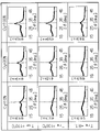
도 22는 시료의 XRD 스펙트럼의 측정 결과를 설명하기 위한 도면.
도 23의 (A)~(L)은 시료의 TEM 이미지 및 전자 빔 회절 패턴을 설명하기 위한 도면.
도 24의 (A)~(C)는 시료의 EDX 매핑을 나타낸 도면.1(A), (C), and (D) are circuit diagrams for explaining one embodiment of the present invention, and FIG. 1 (B) is a timing chart for explaining one embodiment of the present invention.
2(A) to (D) are circuit diagrams for explaining one embodiment of the present invention.
3(A) to (C) are circuit diagrams for explaining one embodiment of the present invention.
Fig. 4(A) is a circuit diagram for explaining one embodiment of the present invention, and Fig. 4(B) is a timing chart for explaining one embodiment of the present invention.
5(A) and (B) are circuit diagrams for explaining one embodiment of the present invention.
Fig. 6 is a top view for explaining one embodiment of the present invention;
Fig. 7 is a top view for explaining one embodiment of the present invention;
8 is a circuit diagram for explaining one embodiment of the present invention.
9(A) to (C) are circuit diagrams for explaining one embodiment of the present invention.
10(A) and (B) are circuit diagrams for explaining one embodiment of the present invention.
11 is a timing chart for explaining one embodiment of the present invention.
12(A) to (C) are circuit diagrams for explaining one embodiment of the present invention.
Fig. 13(A) is a top view for explaining one embodiment of the present invention, and Fig. 13(B) is a cross-sectional view for explaining one embodiment of the present invention.
14(A) to (D) are cross-sectional views for explaining one embodiment of the present invention.
15(A) and (B) are sectional views for explaining one embodiment of the present invention.
16(A) to (C) are sectional views for explaining one embodiment of the present invention.
Fig. 17 is a top view for explaining one embodiment of the present invention;
Fig. 18 is a cross-sectional view for explaining one embodiment of the present invention.
19(A) to (C) are projection views for explaining one embodiment of the present invention.
Fig. 20 is a cross-sectional view for explaining one embodiment of the present invention.
21(A) to (C) are diagrams for explaining an electronic device according to one embodiment of the present invention.
22 is a diagram for explaining measurement results of XRD spectrum of a sample.
23(A) to (L) are views for explaining TEM images and electron beam diffraction patterns of samples.
24 (A) to (C) are diagrams showing EDX mapping of samples.
실시형태에 대하여 도면을 참조하면서 자세히 설명한다. 다만, 실시형태는 많은 다른 양태로 실시할 수 있고, 본 발명의 취지 및 범위로부터 벗어남이 없이 그 형태 및 자세한 사항을 다양하게 변경할 수 있다는 것은 당업자라면 용이하게 이해할 수 있다. 따라서, 본 발명은 아래에 기재된 실시형태의 내용에 한정하여 해석되는 것은 아니다.An embodiment will be described in detail referring to the drawings. However, those skilled in the art can easily understand that the embodiments can be implemented in many different ways, and that the form and details can be changed in various ways without departing from the spirit and scope of the present invention. Therefore, the present invention should not be construed as being limited to the contents of the embodiments described below.
또한, 본 명세서 등에서 "제 1", "제 2", 및 "제 3" 등의 서수사는 구성 요소의 혼동을 피하기 위하여 붙여진 것이다. 따라서, 구성 요소의 개수를 한정하는 것은 아니다. 또한, 구성 요소의 순서를 한정하는 것은 아니다.In addition, in this specification and the like, ordinal numbers such as “first,” “second,” and “third” are added to avoid confusion among components. Therefore, the number of components is not limited. Also, the order of components is not limited.
또한, 도면에서, 동일한 요소 또는 같은 기능을 갖는 요소, 동일한 재질의 요소, 또는 동시에 형성되는 요소 등에는 동일한 부호를 붙이는 경우가 있고, 그것에 대한 반복 설명은 생략하는 경우가 있다.Note that in the drawings, the same reference numerals may be given to the same elements, elements having the same function, elements made of the same material, or elements formed at the same time, and repeated explanation thereof may be omitted in some cases.
(실시형태 1)(Embodiment 1)
본 실시형태에서는 반도체 장치의 일례에 관하여 설명한다.In this embodiment, an example of a semiconductor device will be described.
도 1의 (A)는 반도체 장치(100)를 설명하기 위한 회로도다. 반도체 장치(100)는 표시 장치의 구동 회로의 일부에 사용될 수 있다.1(A) is a circuit diagram for explaining the
도 1의 (A)에 도시된 반도체 장치(100)는 트랜지스터(101), 트랜지스터(102), 및 전환 회로(103)를 포함한다. 또한, 입력 단자 IN, 입력 단자 INB, 출력 단자 OUT, 배선(104), 및 배선(105)을 도 1의 (A)에 도시하였다.The
트랜지스터(101)는 소스와 드레인 사이의 도통 상태 즉 배선(104)과 출력 단자 OUT 사이의 도통 상태를 제어한다. 트랜지스터(101)는 게이트와 백 게이트를 포함한 듀얼 게이트 트랜지스터다. 트랜지스터(101)의 도통 상태는 게이트에 인가되는 입력 단자 IN의 전압, 및 백 게이트에 인가되는 전압에 따라 제어된다. 아래에서 트랜지스터(101)가 n채널형 트랜지스터인 예를 설명한다.The
트랜지스터(102)는 소스와 드레인 사이의 도통 상태 즉 배선(105)과 출력 단자 OUT 사이의 도통 상태를 제어한다. 트랜지스터(102)는 게이트를 포함한 싱글 게이트 트랜지스터다. 트랜지스터(102)의 도통 상태는 게이트에 인가되는 입력 단자 INB의 전압에 따라 제어된다. 아래에서 트랜지스터(102)가 n채널형 트랜지스터인 예를 설명한다.The
전환 회로(103)는 트랜지스터(101)의 백 게이트와 입력 단자 IN을 접속시키는지 또는 트랜지스터(101)의 백 게이트와 출력 단자 OUT를 접속시키는지를 제어 신호 φ에 따라 전환할 수 있다. 전환 회로(103)는 단순히 "회로"라고 기재할 경우도 있다.The
입력 단자 INB에 공급되는 입력 신호는 예를 들어 입력 단자 IN에 공급되는 입력 신호를 반전시킨 신호에 상당한다. 배선(104)에는 예를 들어 고전위에 상당하는 정전위(VDD)가 공급된다. 배선(105)에는 예를 들어 저전위에 상당하는 정전위(VSS, GND 등)가 공급된다. 배선(104) 또는 배선(105)에 클록 신호 또는 리셋 신호 등이 공급되는 구성이라도 좋다.The input signal supplied to the input terminal INB corresponds to a signal obtained by inverting the input signal supplied to the input terminal IN, for example. For example, a constant potential (V DD ) corresponding to a high potential is supplied to the
도 1의 (B)는 도 1의 (A)에 도시된 반도체 장치(100)의 동작을 설명하기 위한 타이밍 차트다. 도 1의 (B)에는 입력 단자 IN의 파형, 입력 단자 INB의 파형, 제어 신호 φ의 파형, 및 출력 단자 OUT의 파형을 도시하였다. 도 1의 (B)는 신호의 파형에 따라 제 1 기간 P1과 제 2 기간 P2로 나누어 설명될 수 있다.FIG. 1(B) is a timing chart for explaining the operation of the
도 1의 (B)에 도시된 바와 같이, 입력 단자 IN의 파형과 입력 단자 INB의 파형은 반전된 관계가 된다. 제 1 기간 P1에는 제어 신호 φ가 H 레벨이 된다. 제 2 기간 P2에는 제어 신호 φ가 L 레벨이 된다. 출력 단자 OUT의 파형은 배선(104) 및 배선(105)에 공급되는 전위 또는 신호에 따라 달라지지만, 예를 들어 배선(104)에 고전위에 상당하는 정전위가 공급되고, 배선(105)에 저전위에 상당하는 정전위가 공급되면, 입력 단자 IN의 파형에 따른 파형이 된다.As shown in Fig. 1(B), the waveform of the input terminal IN and the waveform of the input terminal INB have an inverted relationship. During the first period P1, the control signal φ becomes H level. In the second period P2, the control signal φ becomes L level. The waveform of the output terminal OUT varies depending on the potential or signal supplied to the
상술한 바와 같이, 전환 회로(103)는 제어 신호 φ에 따라 접속의 상태를 전환한다. 제 1 기간 P1에는 트랜지스터(101)의 백 게이트와 입력 단자 IN을 접속시킨다. 즉, 도 1의 (C)의 회로도의 상태가 된다. 또한, 제 2 기간 P2에는 트랜지스터(101)의 백 게이트와 출력 단자 OUT를 접속시킨다. 즉, 도 1의 (D)의 회로도의 상태가 된다.As described above, the
도 1의 (C)의 회로도의 경우, 트랜지스터(101)가 듀얼 게이트 트랜지스터로서 동작하기 때문에, 높은 동특성(온 특성이나 주파수 특성(f특성이라고 불림))을 갖는 동작을 실시할 수 있다. 따라서, 도 1의 (B)의 제 1 기간 P1에 도시된 바와 같이, 출력 단자 OUT의 파형은 입력 단자 IN의 파형에 비슷하게 할 수 있다. 한편, 도 1의 (D)의 회로도의 경우, 트랜지스터(101)가 싱글 게이트 트랜지스터로서 동작하기 때문에, 동특성이 억제된 동작이 가능하다. 따라서, 도 1의 (B)의 제 2 기간 P2에 도시된 바와 같이, 출력 단자 OUT의 파형은 입력 단자 IN의 파형(점선으로 도시됨)보다 일그러진 파형(실선으로 도시됨)으로 할 수 있다.In the case of the circuit diagram of FIG. 1(C), since the
도 1의 (C)에서의 동작과 도 1의 (D)에서의 동작의 차이점은 도 2의 (A)~(D)의 회로도를 사용하여 설명할 수 있다. 도 2의 (A)~(D)에서는 입력 단자 IN, INB, 및 출력 단자 OUT에 공급되는 신호가 하이 레벨 전위일 때 'H'로 표기하고, 로 레벨 전위일 때 'L'로 표기하였다. 또한, 도 2의 (A)~(D)에는 하이 레벨 전위 또는 로 레벨 전위를 트랜지스터에 인가함으로써 게이트 및 백 게이트에 축적되는 양 전하 및 음 전하를 모식적으로 도시하였다. 또한, 도 2의 (A)~(D)에서 배선(104)은 VDD로 하고, 배선(105)은 VSS로 하였다.The difference between the operation in (C) of FIG. 1 and the operation in (D) of FIG. 1 can be explained using circuit diagrams in (A) to (D) of FIG. 2 . In (A) to (D) of FIG. 2 , signals supplied to the input terminals IN, INB, and the output terminal OUT are marked with 'H' when the signal is at a high level potential, and marked with 'L' when the signal is at a low level potential. 2(A) to (D) schematically show positive and negative charges accumulated in the gate and back gate by applying a high level potential or a low level potential to the transistor. In (A) to (D) of FIG. 2 , the
도 2의 (A) 및 (B)는 듀얼 게이트 트랜지스터로서 동작시키는 경우를 모식적으로 도시한 것이다.2(A) and (B) schematically show a case of operating as a dual gate transistor.
도 2의 (A)는 입력 단자 IN의 전위를 하이 레벨로 하고 입력 단자 INB의 전위를 로 레벨로 한 경우에 게이트 및 백 게이트에 축적되는 양 전하 및 음 전하를 모식적으로 도시한 것이다. 입력 단자 IN의 전위에 의거하여 트랜지스터(101)에 양 전하가 충전된다. 트랜지스터(101)가 도통 상태가 되어 전류 ID1이 흐른다. 입력 단자 INB의 전위에 의거하여 트랜지스터(102)에 음 전하가 충전된다. 트랜지스터(102)가 비도통 상태가 된다. 출력 단자 OUT의 전위는 하이 레벨이 된다.2(A) schematically shows positive and negative charges accumulated in the gate and back gate when the potential of the input terminal IN is set to a high level and the potential of the input terminal INB is set to a low level. Positive charge is charged in the
도 2의 (B)는 입력 단자 IN의 전위를 로 레벨로 하고, 입력 단자 INB의 전위를 하이 레벨로 한 경우에 게이트 및 백 게이트에 축적되는 양 전하 및 음 전하를 모식적으로 도시한 것이다. 입력 단자 IN의 전위에 의거하여 트랜지스터(101)에 음 전하가 충전된다. 트랜지스터(101)가 비도통 상태가 된다. 입력 단자 INB의 전위에 의거하여 트랜지스터(102)에 양 전하가 충전된다. 트랜지스터(102)가 도통 상태가 된다. 출력 단자 OUT의 전위는 로 레벨이 된다.2(B) schematically shows positive and negative charges accumulated in the gate and back gate when the potential of the input terminal IN is set to a low level and the potential of the input terminal INB is set to a high level. A negative charge is charged in the
도 2의 (A) 및 (B)에 도시된 바와 같이, 듀얼 게이트 트랜지스터의 동작시에는, 트랜지스터(101)에서 게이트 및 백 게이트의 양쪽 모두에 양 전하 또는 음 전하가 충전되기 때문에 채널 형성 영역에 전계가 인가되기 쉽고, 전류 ID1을 크게 할 수 있다. 결과적으로, 높은 동특성을 갖는 동작을 실시할 수 있다.As shown in (A) and (B) of FIG. 2 , during operation of the dual gate transistor, positive or negative charges are charged in both the gate and the back gate of the
한편, 도 2의 (C) 및 (D)에는 싱글 게이트 트랜지스터로서 동작하는 경우를 모식적으로 도시하였다.On the other hand, (C) and (D) of FIG. 2 schematically shows the case of operating as a single gate transistor.
도 2의 (C)는 입력 단자 IN의 전위를 하이 레벨로 하고, 입력 단자 INB의 전위를 로 레벨로 한 경우에 게이트에 축적되는 양 전하 및 음 전하를 모식적으로 도시한 것이다. 입력 단자 IN의 전위에 의거하여 트랜지스터(101)에 양 전하가 충전된다. 트랜지스터(101)가 도통 상태가 되어 전류 ID2이 흐른다. 입력 단자 INB의 전위에 의거하여 트랜지스터(102)에 음 전하가 충전된다. 트랜지스터(102)가 비도통 상태가 된다. 출력 단자 OUT의 전위는 하이 레벨이 된다.2(C) schematically shows positive and negative charges accumulated in the gate when the potential of the input terminal IN is set to a high level and the potential of the input terminal INB is set to a low level. Positive charge is charged in the
도 2의 (D)는 입력 단자 IN의 전위를 로 레벨로 하고, 입력 단자 INB의 전위를 하이 레벨로 한 경우에 게이트에 축적되는 양 전하 및 음 전하를 모식적으로 도시한 것이다. 입력 단자 IN의 전위에 의거하여 트랜지스터(101)에 음 전하가 충전된다. 트랜지스터(101)가 비도통 상태가 된다. 입력 단자 INB의 전위에 의거하여 트랜지스터(102)에 양 전하가 충전된다. 트랜지스터(102)가 도통 상태가 된다. 출력 단자 OUT의 전위는 로 레벨이 된다.2(D) schematically shows positive and negative charges accumulated in the gate when the potential of the input terminal IN is set to a low level and the potential of the input terminal INB is set to a high level. A negative charge is charged in the
도 2의 (C) 및 (D)에 도시된 바와 같이, 싱글 게이트 트랜지스터의 동작에서는 트랜지스터(101)의 게이트의 한쪽에 입력 단자 IN으로부터 양 전하 또는 음 전하가 충전되기 때문에 듀얼 게이트 트랜지스터의 경우와 비교하여 채널 형성 영역에 전계가 가해지기 어려워 전류 ID2를 전류 ID1보다 작게 할 수 있다. 결과적으로, 동특성이 억제된 동작을 실시할 수 있다.As shown in (C) and (D) of FIG. 2, in the operation of a single gate transistor, since positive or negative charges are charged from the input terminal IN to one side of the gate of the
상술한 본 발명의 일 형태의 반도체 장치에서는 듀얼 게이트 트랜지스터로서 동작시키는 상태와 싱글 게이트 트랜지스터로서 동작시키는 상태를 전환할 수 있다. 그래서, 높은 동특성이 불필요한 표시를 할 때는 싱글 게이트 트랜지스터로서 동작시키고, 높은 동특성이 필요한 표시를 할 때는 듀얼 게이트 트랜지스터로서 동작시킬 수 있다. 싱글 게이트 트랜지스터를 사용하면, 듀얼 게이트 트랜지스터를 사용하는 경우와 비교하여 백 게이트의 충방전에 소비되는 전력을 삭감할 수 있다.In the semiconductor device of one embodiment of the present invention described above, it is possible to switch between operating as a dual-gate transistor and operating as a single-gate transistor. Therefore, it can be operated as a single-gate transistor for display requiring high dynamic characteristics, and as a dual-gate transistor for display requiring high dynamic characteristics. When a single gate transistor is used, power consumed for charging and discharging of the back gate can be reduced compared to the case of using a dual gate transistor.
또한, 높은 동특성이 불필요한 표시를 할 때는, 표시 장치의 프레임 주파수를 등속(60Hz) 이하로 하여 동작시키는 경우 등이 있다. 또한, 높은 동특성이 필요한 표시를 할 때는, 배속(120Hz) 구동이나 4배속(240Hz) 구동 등으로 동작시키는 경우 등이 있다. 예를 들어 스포츠 시청과 홈 페이지 열람 등의 표시를 전환하는 경우에는, 프레임 주파수를 전환하는 것이 소비 전력 삭감에 유효적이다. 이 프레임 주파수의 전환에 따라 본 발명의 일 형태와 같이 백 게이트의 충방전을 전환하는 것은 소비 전력을 더 삭감하는 데 유효적이다.In addition, when performing a display where high dynamic characteristics are unnecessary, there is a case where the frame frequency of the display device is operated at a constant speed (60 Hz or less). In addition, when displaying requiring high dynamic characteristics, there are cases where the display is operated by double speed (120 Hz) drive or quad speed (240 Hz) drive. For example, when switching displays such as watching sports and viewing a home page, switching the frame frequency is effective for reducing power consumption. Switching the charging and discharging of the back gate as in one embodiment of the present invention by switching the frame frequency is effective for further reducing power consumption.
도 1의 (A)에 도시된 반도체 장치(100)는 다양한 변형예를 가질 수 있다. 도 3의 (A)~(C)에 변형예의 일례를 도시하였다.The
도 3의 (A)의 반도체 장치(100A)는 입력 단자 IN과 트랜지스터(101)의 게이트 사이에 트랜지스터(106)를 배치한 변형예다. 트랜지스터(106)의 게이트에는 배선(107)이 접속된다. 배선(107)은 고전위에 상당하는 정전위로 하는 것이 바람직하다. 도 3의 (A)의 구성으로 함으로써, 트랜지스터(106)의 게이트에 입력 단자 IN의 신호를 공급할 수 있으면서, 출력 단자 OUT와 트랜지스터(101)의 게이트 사이의 기생 용량 등으로 용량 결합이 생겨 트랜지스터(101)의 게이트의 전위가 상승된 경우에 입력 단자 IN의 전위가 상승되는 것을 억제할 수 있다.The
또한, 도 3의 (B)의 반도체 장치(100B)는 트랜지스터(102)를 듀얼 게이트 트랜지스터(108)로 한 변형예다. 이 구성으로 함으로써 트랜지스터(108)의 동특성을 높일 수 있다.The
도 3의 (A)와 도 3의 (B)의 변형예를 조합할 수도 있다. 이것이 도 3의 (C)의 반도체 장치(100C)와 같다. 도 3의 (C)에서는 도 3의 (A)의 트랜지스터(106)를 듀얼 게이트 트랜지스터(109)로 하고, 트랜지스터(102)를 듀얼 게이트 트랜지스터(108)로 한 변형예다. 이 구성으로 함으로써 트랜지스터(109) 및 트랜지스터(108)의 동특성을 높일 수 있다.Modifications of FIG. 3(A) and FIG. 3(B) may be combined. This is the same as the
도 4의 (A)에서는 도 3의 (C)의 반도체 장치(100C)에 의거하여 전환 회로(103)의 구체적인 회로 구성의 일례를 설명한다.In FIG. 4(A), an example of a specific circuit configuration of the
전환 회로(103)는 트랜지스터(110) 및 트랜지스터(111)를 갖는다. 트랜지스터(110) 및 트랜지스터(111)는 양쪽 모두 듀얼 게이트 트랜지스터로서 도시되어 있다. 트랜지스터(110)는 소스와 드레인 사이의 도통 상태, 즉 트랜지스터(101)의 백 게이트와 입력 단자 IN 사이의 도통 상태를 제어한다. 트랜지스터(111)는 소스와 드레인 사이의 도통 상태 즉 트랜지스터(101)의 백 게이트와 출력 단자 OUT 사이의 도통 상태를 제어한다. 트랜지스터(110)는 제어 신호 φ에 따라 도통 상태가 제어된다. 트랜지스터(111)는 제어 신호 φ의 반전 신호에 상당하는 제어 신호 φB에 따라 도통 상태가 제어된다. 또한, 트랜지스터(110) 및 트랜지스터(111)는 양쪽 모두 n채널형 트랜지스터인 예를 설명한다.The
도 4의 (B)는 도 4의 (A)에 도시된 반도체 장치(100C)의 전환 회로(103)의 동작을 설명하기 위한 타이밍 차트다. 도 4의 (B)에는 입력 단자 IN의 파형, 입력 단자 INB의 파형, 제어 신호 φ의 파형, 제어 신호 φB의 파형, 및 출력 단자 OUT의 파형을 도시하였다. 도 4의 (B)는 도 1의 (B)와 마찬가지로 제 1 기간 P1과 제 2 기간 P2로 나누어 설명될 수 있다.FIG. 4B is a timing chart for explaining the operation of the
도 4의 (B)에 도시된 바와 같이, 제어 신호 φ의 파형과 제어 신호 φB의 파형은 서로 반전된 관계가 된다. 제 1 기간 P1에서 제어 신호 φ를 H 레벨로 하고, 제어 신호 φB를 L 레벨로 한다. 제 2 기간 P2에서 제어 신호 φ를 L 레벨로 하고, 제어 신호 φB를 H 레벨로 한다.As shown in (B) of FIG. 4 , the waveform of the control signal φ and the waveform of the control signal φB have a mutually inverted relationship. In the first period P1, the control signal φ is set to H level and the control signal φB is set to L level. In the second period P2, the control signal φ is set to L level and the control signal φB is set to H level.
도 4의 (B)에 도시된 바와 같이, 제어 신호 φ 및 제어 신호 φB를 제어함으로써 전환 회로(103)는 접속 상태를 전환한다. 제 1 기간 P1에서는 트랜지스터(101)의 백 게이트와 입력 단자 IN을 접속시킬 수 있다. 즉, 트랜지스터(101)를 듀얼 게이트 트랜지스터로서 동작시킬 수 있다. 또한, 제 2 기간 P2에서는 트랜지스터(101)의 백 게이트와 출력 단자 OUT를 접속시킬 수 있다. 즉, 트랜지스터(101)를 싱글 게이트 트랜지스터로서 동작시킬 수 있다. 따라서, 트랜지스터(101)의 동특성을 전환할 수 있으므로, 도 4의 (B)의 제 2 기간 P2에 도시된 바와 같이, 출력 단자 OUT의 파형은 입력 단자 IN의 파형(점선으로 도시됨)보다 일그러진 파형(실선으로 도시됨)으로 할 수 있다.As shown in Fig. 4(B), the
도 4의 (A)에 도시된 전환 회로(103)는 다양한 변형예를 가질 수 있다. 그 변형예의 일례를 도 5의 (A) 및 (B)에 도시하였다.The
도 5의 (A)의 반도체 장치(100C)가 갖는 전환 회로(103A)는 트랜지스터(110)를 스위치 110SW로 하고, 트랜지스터(111)를 스위치 111SW로 한 변형예다. 즉, 트랜지스터(110) 및 트랜지스터(111)는 교대로 도통 상태가 될 수 있는 소자로 변경할 수 있다.The
또한, 도 5의 (B)의 반도체 장치(100C)가 갖는 전환 회로(103B)는 트랜지스터(111)를 싱글 게이트 트랜지스터(111S)로 한 변형예다. 즉, 트랜지스터(110) 및 트랜지스터(111)는 듀얼 게이트 트랜지스터와 싱글 게이트 트랜지스터의 어느 쪽으로나 변경할 수 있다.The
도 6에서는 도 4의 (A)에 도시된 반도체 장치(100C)에 의거한 반도체 장치(100C)의 상면도의 일례를 설명한다. 도 6은 도전층(121), 도전층(122), 반도체층(123), 개구(124), 및 도전층(125)을 순차적으로 형성하여 트랜지스터나 배선을 제공한 것이다. 또한, 설명을 용이하게 하기 위하여 도전층들 사이의 절연층 등은 생략하였다.In FIG. 6, an example of a top view of a
도 4의 (A)에 도시된 트랜지스터(101), 트랜지스터(108), 트랜지스터(109), 트랜지스터(110), 및 트랜지스터(111)를 도 6에 도시하였다. 모든 트랜지스터가 듀얼 게이트 트랜지스터다. 또한, 도 4의 (A)에 도시된 배선(104), 배선(105), 배선(107), 입력 단자 IN, 입력 단자 INB, 출력 단자 OUT, 제어 신호 φ, 및 제어 신호 φB가 공급되는 배선을 도 6에 도시하였다.
도 6의 트랜지스터(101)에서 백 게이트에 상당하는 도전층은 도전층(121)이고, 게이트에 상당하는 도전층은 도전층(125)이다. 백 게이트에 상당하는 도전층이 게이트에 상당하는 도전층보다 채널 길이 방향으로 폭이 넓다. 이 구성으로 함으로써 싱글 게이트와 듀얼 게이트 구조를 전환하였을 때의 전하의 충방전에 의한 효과를 높일 수 있다. 또한, 전환 회로(103)를 구성하는 트랜지스터(110, 111)는 트랜지스터(101, 108)보다 트랜지스터의 크기를 작게 하는 것이 바람직하다. 트랜지스터(110, 111)는 스위치로서 기능하면 좋으므로 이 구성으로 함으로써 반도체 장치(100C)의 트랜지스터가 차지하는 회로 면적을 소형화시킬 수 있다.In the
또한, 도 6에서는 백 게이트에 상당하는 도전층으로서 게이트에 상당하는 도전층인 도전층(125)의 아래층에 위치하는 도전층(121)을 설명하였지만, 상하를 바꿔도 좋다. 예를 들어, 도 7에 도시된 바와 같이, 백 게이트에 상당하는 도전층은 도전층(125)으로 하고, 게이트에 상당하는 도전층은 도전층(121)으로 하여도 좋다. 이 구성으로 함으로써 백 게이트에 상당하는 도전층이 게이트에 상당하는 도전층보다 채널 길이 방향으로 폭을 작게 할 수 있어 싱글 게이트 트랜지스터로 한 경우의 동특성의 저하를 억제할 수 있다.In addition, in FIG. 6, as the conductive layer corresponding to the back gate, the
다음에, 도 8~도 11에서는 도 4의 (A)에 도시된 반도체 장치(100C)에 의거하여 입력 단자 IN 및 입력 단자 INB에 신호를 공급하는 회로(200)를 도시하였고, 반도체 장치를 표시 장치의 구동 회로에 적용하는 경우의 구성예에 관하여 설명한다.Next, FIGS. 8 to 11 show a
도 8의 (A)에 도시된 회로(200)는 입력 단자 IN 및 입력 단자 INB에 접속된다. 반도체 장치(100C)는 입력 단자 IN 및 입력 단자 INB에 공급하는 신호를 증폭하여 출력하는 버퍼로서 기능할 수 있다.The
또한, 버퍼로서 기능하는 반도체 장치(100C)는 회로(200)에 하나 있는 것에 한정되지 않는다. 도 8의 (B)에 도시된 바와 같이 복수개 제공하여도 좋다. 이 경우에는, 출력 단자 OUT는 출력 단자 SROUT 및 출력 단자 OUT로 하고, 접속되는 회로에 따라 나누어 제공하는 것이 바람직하다. 이러한 구성으로 함으로써, 접속되는 회로의 부하에 따라 버퍼를 구성하는 트랜지스터의 크기를 변경할 수 있으므로 크기를 축소하거나 또는 부하에 맞춘 크기를 설계할 수 있다.Also, the
다음에, 도 8의 (A) 및 (B)의 회로(200)의 구체적인 예에 관하여 설명한다. 입력 단자 IN 및 입력 단자 INB에 공급하는 신호의 타이밍을 제어하는 회로(200)와, 버퍼로서 기능하는 반도체 장치(100C)를 조합함으로써, 시프트 레지스터의 1단을 구성하는 회로로서 기능시킬 수 있다.Next, a specific example of the
도 9의 (A)에는 n+2단의 펄스를 출력할 수 있는 시프트 레지스터의 회로 구성의 일례를 도시하였다. 회로 SR 및 회로 SRDUM은 회로(200)와 반도체 장치(100C)를 조합한 회로에 상당한다. 도 9의 (A)의 시프트 레지스터는 외부로부터 스타트 펄스, 클록 신호 CLK1~CLK4, 펄스 폭 제어 신호 PWC1~PWC4, 리셋 신호 RES, 제어 신호 φ, 및 제어 신호 φB에 따라 출력 단자 OUT_1~OUT_n+2(n은 자연수)에 펄스를 출력할 수 있다. 또한, 도면에서 생략하였지만, 리셋 신호 RES, 제어 신호 φ, 및 제어 신호 φB는 서로 다른 배선에 공급되는 신호다.9(A) shows an example of a circuit configuration of a shift register capable of outputting pulses of n+2 stages. Circuit SR and circuit SR DUM correspond to a circuit in which the
회로 SR에는 도 9의 (B)에 도시된 각 신호가 공급된다. 회로 SRDUM에는 도 9의 (C)에 도시된 각 신호가 공급된다. 회로 SR 및 회로 SRDUM에 공급되는 클록 신호 CLK1~CLK4, 펄스 폭 제어 신호 PWC1~PWC4는 단마다 다르다. 또한, LIN은 시프트 레지스터의 시프트 방향의 위쪽 단 측에서 공급되는 신호다. 또한, RIN은 시프트 레지스터의 시프트 방향의 아래쪽 단 측에서 공급되는 신호다. 또한, SROUT는 다음 단의 시프트 레지스터에 공급되는 신호다. OUT는 부하가 되는 배선에 공급되는 신호다.Each signal shown in (B) of FIG. 9 is supplied to the circuit SR. Each signal shown in (C) of FIG. 9 is supplied to the circuit SR DUM . Clock signals CLK1 to CLK4 and pulse width control signals PWC1 to PWC4 supplied to circuit SR and circuit SR DUM are different for each stage. Also, LIN is a signal supplied from the upper end side of the shift register in the shift direction. Also, RIN is a signal supplied from the lower end side of the shift register in the shift direction. Also, SROUT is a signal supplied to the shift register of the next stage. OUT is the signal supplied to the wiring that becomes the load.
회로 SR의 회로 구성의 일례를 도 10의 (A)에 도시하였다. 도 10의 (A)의 회로(200)는 트랜지스터(201~209)를 갖는다. 트랜지스터(201~209)는 듀얼 게이트 트랜지스터로서 도시하였지만, 싱글 게이트 트랜지스터라도 좋다. 마찬가지로, 회로 SRDUM의 회로 구성의 일례를 도 10의 (B)에 도시하였다.An example of the circuit configuration of the circuit SR is shown in FIG. 10(A). The
또한, 도 11에는 펄스 폭 제어 신호 PWC1~PWC4, 클록 신호 CLK1~CLK4, 제어 신호 φ, 제어 신호 φB, 스타트 펄스 SP, 및 출력 단자 OUT_1~OUT_n+2의 파형을 나타내는 타이밍 차트를 도시하였다. 도 11의 타이밍 차트는 제어 신호 φ 및 제어 신호 φB의 파형으로 알 수 있는 바와 같이, 전반의 기간이 도 1의 (B)에서 설명한 제 1 기간 P1에 상당하고, 후반의 기간이 도 1의 (B)에서 설명한 제 2 기간 P2에 상당한다.11 shows a timing chart showing waveforms of pulse width control signals PWC1 to PWC4, clock signals CLK1 to CLK4, control signals φ, control signals φB, start pulse SP, and output terminals OUT_1 to
제 1 기간 P1에서는 펄스 폭 제어 신호 PWC1~PWC4, 클록 신호 CLK1~CLK4의 주파수가 크고, 시프트 레지스터의 버퍼에서는 높은 동특성이 요구된다. 따라서, 버퍼 회로에서는 트랜지스터가 듀얼 게이트 트랜지스터로서 기능하도록 제어 신호 φ 및 제어 신호 φB가 공급된다. 한편, 제 2 기간 P2에서는 펄스 폭 제어 신호 PWC1 내지 PWC4, 클록 신호 CLK1 내지 CLK4의 주파수가 작고, 시프트 레지스터의 버퍼에서는 높은 동특성이 요구되지 않고, 능력이 과잉이다. 따라서, 버퍼 회로에서는 트랜지스터가 싱글 게이트 트랜지스터로서 기능하도록 제어 신호 φ 및 제어 신호 φB가 공급된다.In the first period P1, the frequencies of the pulse width control signals PWC1 to PWC4 and the clock signals CLK1 to CLK4 are high, and high dynamic characteristics are required for the buffer of the shift register. Therefore, in the buffer circuit, the control signal φ and the control signal φB are supplied so that the transistor functions as a dual gate transistor. On the other hand, in the second period P2, the frequencies of the pulse width control signals PWC1 to PWC4 and the clock signals CLK1 to CLK4 are small, high dynamic characteristics are not required for the buffer of the shift register, and the capacity is excessive. Therefore, in the buffer circuit, the control signal φ and the control signal φB are supplied so that the transistor functions as a single gate transistor.
상술한 바와 같이, 프레임 주파수의 변화에 한정되지 않고, 클록 신호 등의 주파수에 따라, 버퍼를 구성하는 트랜지스터에서 듀얼 게이트의 기능과 싱글 게이트의 기능을 전환함으로써 백 게이트를 충방전하기 위한 전력의 소비를 삭감할 수 있다.As described above, power consumption for charging and discharging the back gate is not limited to the change in the frame frequency, but by switching between the dual gate function and the single gate function in the transistor constituting the buffer according to the frequency of the clock signal or the like. can be reduced
(실시형태 2)(Embodiment 2)
본 실시형태에서는 본 발명의 일 형태에 따른 반도체 장치를 적용 가능한 표시 장치에 관하여 설명한다.In this embodiment, a display device to which the semiconductor device according to one embodiment of the present invention can be applied will be described.
도 12의 (A)에 예시된 표시 장치는 회로(300) 및 화소부(130)를 갖는다. 화소부(130)에는 N개(N은 3 이상의 자연수)의 배선 GL(GL[1]~GL[N]이라고도 기재함) 및 M(M은 자연수)개의 배선 SL(배선 SL[1]~SL[M]이라고도 기재함)이 제공된다. 그리고, N개의 배선 GL 및 M개의 배선 SL에 대응하여 화소(131)가 제공된다. 회로(300)는 게이트 드라이버(게이트선 구동 회로, 게이트 신호선 구동 회로, 주사선 구동 회로라고도 함)로서의 기능을 갖는다. N개의 배선 GL은 게이트선(게이트 신호선, 주사선이라고도 함)으로서의 기능을 갖는다. M개의 배선 SL은 비디오 신호를 전달하는 기능을 갖는다. 즉, M개의 배선 SL은 소스선(소스 신호선, 신호선이라고도 함)으로서의 기능을 갖는다. 또한, M개의 배선 SL은 소스 드라이버(소스선 구동 회로, 소스 신호선 구동 회로, 또는 신호선 구동 회로라고도 함)로서의 기능을 갖는 회로와 접속된다.The display device illustrated in FIG. 12A includes a
또한, 회로(300)로서는 실시형태 1에서 설명한 도 9의 시프트 레지스터를 사용할 수 있다. 이 경우, N개의 배선 GL은 출력 단자 OUT_1~OUT_n에 상당한다. 또한, 회로(300)가 갖는 N개의 회로(301)(회로(301)[1]~301[N]이라고도 기재함)로서는 실시형태 1에서 설명한 회로 SR 및 회로 SRDUM을 사용할 수 있다.As the
화소(131)의 선택 상태 또는 비선택 상태는 배선 GL의 전위에 따라 제어된다. 즉, 화소(131)의 선택 또는 비선택은 회로(300)에 의하여 제어된다. 화소(131)가 선택되면, 배선 SL의 비디오 신호가 화소(131)에 기록된다. 그리고, 비디오 신호가 화소(131)에 유지되는 동시에, 화소(131)가 비디오 신호에 따른 표시를 한다. 이 후, 화소(131)가 비선택 상태가 되면, 화소(131)는 유지한 비디오 신호에 따른 표시를 계속한다.The selected state or non-selected state of the
다음에, 화소(131)의 구체적인 구성예에 관하여 설명한다.Next, a specific configuration example of the
도 12의 (B)에 예시한 화소(131)는 트랜지스터(132), 액정 소자(133), 및 용량 소자(134)를 갖는다. 트랜지스터(132)는 제 1 단자가 배선 SL과 접속되고, 제 2 단자가 액정 소자(133)의 제 1 전극(화소 전극이라고도 함) 및 용량 소자(134)의 제 1 전극과 접속되고, 게이트가 배선 GL과 접속된다. 액정 소자(133)의 제 2 전극(공통 전극이라고도 함)은 복수의 화소(131) 모두 또는 2개 이상에서 공통된다. 즉, 제 1 화소(131)의 액정 소자(133)의 제 2 전극이 되는 영역을 갖는 도전체는 제 2 화소(131)의 액정 소자(133)의 제 2 전극이 되는 영역을 갖는다. 용량 소자(134)의 제 2 전극은 용량선으로서의 기능을 갖는 배선과 접속된다. 용량 소자(134)의 제 2 전극은 복수의 화소(131) 모두 또는 2개 이상에서 동일 배선과 접속된다. 다만, 용량 소자(134)의 제 2 전극은 액정 소자(133)의 제 2 전극과 접속되어도 좋다. 트랜지스터(132)는 배선 GL의 전위에 따라 온 상태 또는 오프 상태가 제어된다. 트랜지스터(132)가 온 상태가 되면, 배선 SL의 비디오 신호가 화소(131)에 입력된다. 액정 소자(133)는 액정 재료를 갖는다. 액정 재료의 배향은 액정 소자(133)의 제 1 전극과 액정 소자(133)의 제 2 전극의 전위차에 의하여 제어된다. 용량 소자(134)는 비디오 신호에 따른 전하를 축적하는 기능을 갖는다. 즉, 용량 소자(134)는 액정 소자(133)의 제 1 전극의 전위를 비디오 신호에 따른 값으로 유지하는 기능을 갖는다.The
도 12의 (C)에 예시한 화소(131)는 트랜지스터(135), 트랜지스터(136), 및 EL 소자(137)를 갖는다. 트랜지스터(135)는 제 1 단자가 배선 SL과 접속되고, 제 2 단자가 트랜지스터(136)의 게이트와 접속되고, 게이트가 배선 GL과 접속된다. 트랜지스터(136)는 제 1 단자가 EL 소자(137)에 흐르는 전류를 공급하는 기능을 갖는 배선과 접속되고, 제 2 단자가 EL 소자(137)의 제 1 전극(화소 전극이라고도 함)과 접속된다. EL 소자(137)의 제 2 전극(공통 전극이라고도 함)은 복수의 화소(131) 모두 또는 2개 이상에서 공통된다. 즉, 제 1 화소(131)의 EL 소자(137)의 제 2 전극이 되는 영역을 갖는 도전체는 제 2 화소(131)의 EL 소자(137)의 제 2 전극이 되는 영역을 갖는다. 트랜지스터(135)는 배선 GL의 전위에 따라 온 상태 또는 오프 상태가 제어된다. 트랜지스터(135)가 온 상태가 되면, 배선 SL의 비디오 신호가 화소(131)에 입력된다. 트랜지스터(136)는 EL 소자(137)에 전류를 공급하는 기능을 갖는다. 트랜지스터(136)가 EL 소자(137)에 공급하는 전류는 비디오 신호에 따른 값이 된다. EL 소자(137)는 트랜지스터(136)로부터 공급되는 전류에 따라 발광하는 기능을 갖는다.The
화소(131)의 구성은 도 12의 (B) 및 도 12의 (C)로 한정되지 않는다. 화소(131)는 게이트가 배선 GL과 접속되고, 제 1 단자가 배선 SL과 접속되는 트랜지스터와, 이 트랜지스터를 통하여 입력되는 비디오 신호에 따라 표시를 하는 표시 소자를 가지면 좋다. 또는, 화소(131)는 게이트가 배선 GL과 접속되고, 제 1 단자가 배선 SL과 접속되는 트랜지스터와, 이 트랜지스터를 통하여 입력되는 비디오 신호에 따른 전위 또는 전류가 공급되는 화소 전극을 가지면 좋다. 또는, 화소(131)는 게이트가 배선 GL과 접속되고, 제 1 단자가 배선 SL과 접속되는 트랜지스터와, 이 트랜지스터를 통하여 입력되는 비디오 신호에 따른 전류를 표시 소자 또는 화소 전극에 공급하는 트랜지스터를 가지면 좋다. 또한, 화소가 갖는 트랜지스터는 싱글 게이트 트랜지스터와 듀얼 게이트 트랜지스터의 어느 쪽이라도 좋다.The configuration of the
(실시형태 3)(Embodiment 3)
본 실시형태에서는 실시형태 1에서 설명한 각 반도체 장치가 갖는 트랜지스터에 적용 가능한 트랜지스터의 구성예에 관하여 도면을 참조하여 설명한다.In the present embodiment, configuration examples of transistors applicable to the transistors included in each semiconductor device described in
<트랜지스터의 구성예><Example of configuration of transistor>
도 13의 (A)는 아래에 예시한 트랜지스터(600)의 상면 개략도다. 또한, 도 13의 (A)의 절단선 A-B에 따른 트랜지스터(600)의 단면 개략도를 도 13의 (B)에 도시하였다.13(A) is a top plan schematic diagram of a
트랜지스터(600)는 기판(601) 위에 제공되는 게이트(602)와, 기판(601) 및 게이트(602) 위에 제공되는 절연층(603)과, 절연층(603) 위에 게이트(602)와 중첩되도록 제공되는 산화물 반도체층(604)과, 산화물 반도체층(604) 상면에 접촉되는 한 쌍의 전극(605a, 605b)을 갖는다. 또한, 절연층(603), 산화물 반도체층(604), 및 한 쌍의 전극(605a, 605b)을 덮는 절연층(606)이 제공되고, 절연층(606) 위에 절연층(607)이 제공된다. 또한, 절연층(607) 위에 백 게이트(608)가 제공된다.The
기판(601)의 재질 등에 큰 제한은 없지만, 적어도 나중에 실시되는 가열 처리에 견딜 수 있을 정도의 내열성을 갖는 재료를 사용한다. 기판(601)으로서 예를 들어 유리 기판, 세라믹 기판, 석영 기판, 사파이어 기판, YSZ(산화이트륨 안정화 지르코니아) 기판 등을 사용하여도 좋다. 또한, 실리콘이나 탄소화 실리콘을 재료로 한 단결정 반도체 기판이나 다결정 반도체 기판, 실리콘 저마늄을 재료로 한 화합물 반도체 기판, SOI 기판 등을 적용할 수도 있다. 또한, 이러한 기판 위에 반도체 소자가 제공된 것을 기판(601)으로서 사용하여도 좋다.There is no particular restriction on the material of the
또한, 기판(601)으로서 플라스틱 등의 가요성 기판을 사용하고, 이 가요성 기판 위에 직접 트랜지스터(600)를 형성하여도 좋다. 또는, 기판(601)과 트랜지스터(600) 사이에 박리층을 제공하여도 좋다. 박리층은 그 상층에 트랜지스터의 일부 또는 모두를 형성한 후, 기판(601)으로부터 분리하여 다른 기판으로 전치하는 데 사용할 수 있다. 결과적으로, 트랜지스터(600)는 내열성이 떨어지는 기판이나 가요성 기판으로도 전치할 수 있다.Alternatively, a flexible substrate such as plastic may be used as the
게이트(602)는 알루미늄, 크로뮴, 구리, 탄탈럼, 타이타늄, 몰리브데넘, 및 텅스텐 중에서 선택된 금속, 또는 상술한 금속을 성분으로 하는 합금이나, 상술한 금속을 조합한 합금 등을 사용하여 형성할 수 있다. 또한, 망가니즈 및 지르코늄 중에서 선택된 어느 하나 또는 복수의 금속을 사용하여도 좋다. 또한, 게이트(602)는 단층 구조와 2층 이상의 적층 구조의 어느 쪽이라도 좋다. 예를 들어 실리콘을 함유한 알루미늄막의 단층 구조, 알루미늄막 위에 타이타늄막이 적층된 2층 구조, 질화 타이타늄막 위에 타이타늄막이 적층된 2층 구조, 질화 타이타늄막 위에 텅스텐막이 적층된 2층 구조, 질화 탄탈럼막 또는 질화 텅스텐막 위에 텅스텐막이 적층된 2층 구조, 타이타늄막과 알루미늄막과 타이타늄막이 순차적으로 적층된 3층 구조 등이 있다. 또한, 알루미늄에, 타이타늄, 탄탈럼, 텅스텐, 몰리브데넘, 크로뮴, 네오디뮴, 스칸듐 중에서 선택된 하나 또는 복수의 금속을 조합한 합금막, 또는 질화막을 사용하여도 좋다.The
또한, 게이트(602) 및 백 게이트(608)는 인듐 주석 산화물, 산화 텅스텐을 포함한 인듐 산화물, 산화 텅스텐을 포함한 인듐 아연 산화물, 산화 타이타늄을 포함한 인듐 산화물, 산화 타이타늄을 포함한 인듐 주석 산화물, 인듐 아연 산화물, 산화실리콘이 첨가된 인듐 주석 산화물 등의 투광성을 갖는 도전성 재료를 적용할 수도 있다. 또한, 이 투광성을 갖는 도전성 재료와 상술한 금속의 적층 구조로 할 수도 있다.In addition, the
또한, 게이트(602)와 절연층(603) 사이에 In-Ga-Zn계 산질화물 반도체막, In-Sn계 산질화물 반도체막, In-Ga계 산질화물 반도체막, In-Zn계 산질화물 반도체막, Sn계 산질화물 반도체막, In계 산질화물 반도체막, 금속 질화막(InN, ZnN 등) 등을 제공하여도 좋다. 이들 재료는 일함수가 5eV 이상, 바람직하게는 5.5eV 이상이며, 트랜지스터의 문턱 전압을 양으로 할 수 있어, 소위 노멀리 오프의 스위칭 소자를 실현할 수 있다. 예를 들어 In-Ga-Zn계 산질화물 반도체막을 사용하는 경우, 적어도 산화물 반도체층(604)보다 높은 질소 농도, 구체적으로는 7at.% 이상의 In-Ga-Zn계 산질화물 반도체막을 사용한다.In addition, an In-Ga-Zn oxynitride semiconductor film, an In-Sn oxynitride semiconductor film, an In-Ga oxynitride semiconductor film, and an In-Zn oxynitride semiconductor film are interposed between the
절연층(603)은 게이트 절연막으로서 기능한다. 산화물 반도체층(604)의 하면과 접촉되는 절연층(603)은 산화물 절연막인 것이 바람직하다.The insulating
절연층(603)으로서는 예를 들어 산화 실리콘, 산화 질화 실리콘, 질화 산화 실리콘, 질화 실리콘, 산화 알루미늄, 산화 하프늄, 산화 갈륨 또는 Ga-Zn계 금속 산화물 등을 사용하면 좋고, 적층 또는 단층으로 제공된다.As the insulating
또한, 절연층(603)으로서 하프늄 실리케이트(HfSiOx), 질소가 첨가된 하프늄 실리케이트(HfSixOyNz), 질소가 첨가된 하프늄 알루미네이트(HfAlxOyNz), 산화 하프늄, 산화 이트륨 등의 high-k 재료를 사용함으로써 트랜지스터의 게이트 리크를 저감시킬 수 있다.In addition, as the insulating
한 쌍의 전극(605a 및 605b)은 트랜지스터의 소스 전극 또는 드레인 전극으로서 기능한다.A pair of
한 쌍의 전극(605a, 605b)은 도전성 재료로서 알루미늄, 타이타늄, 크로뮴, 니켈, 구리, 이트륨, 지르코늄, 몰리브데넘, 은, 탄탈럼, 또는 텅스텐 등의 금속, 또는 이것을 주성분으로 하는 합금의 단층 또는 적층을 사용할 수 있다. 예를 들어 실리콘을 포함한 알루미늄막의 단층 구조, 알루미늄막 위에 타이타늄막을 적층시킨 2층 구조, 텅스텐막 위에 타이타늄막을 적층시킨 2층 구조, 구리-마그네슘-알루미늄 합금막 위에 구리막을 적층시킨 2층 구조, 타이타늄막 또는 질화 타이타늄막과, 알루미늄막 또는 구리막과, 타이타늄막 또는 질화 타이타늄막을 순차적으로 적층시킨 3층 구조, 몰리브데넘막 또는 질화 몰리브데넘막과, 알루미늄막 또는 구리막과, 몰리브데넘막 또는 질화 몰리브데넘막을 순차적으로 적층시킨 3층 구조 등이 있다. 또한, 산화 인듐, 산화 주석, 또는 산화 아연을 포함한 투명 도전성 재료를 사용하여도 좋다.The pair of
절연층(606)은 화학량론적 조성을 충족시키는 산소보다 많은 산소를 포함한 산화물 절연막을 사용하는 것이 바람직하다. 화학량론적 조성을 충족시키는 산소보다 많은 산소를 포함한 산화물 절연막은 가열에 의하여 일부의 산소가 이탈된다. 화학량론적 조성을 충족시키는 산소보다 많은 산소를 함유하는 산화물 절연막은 승온 이탈 가스 분광법(TDS: Thermal Desorption Spectroscopy) 분석에서 산소 원자로 환산하였을 때의 산소의 이탈량이 1.0×10¹⁸atoms/cm3 이상, 바람직하게는 3.0×10²⁰atoms/cm3 이상인 산화물 절연막이다. 또한, TDS 분석시의 막의 표면 온도는 100℃ 이상 700℃ 이하, 또는 100℃ 이상 500℃ 이하가 바람직하다.For the insulating
절연층(606)으로서는 산화 실리콘, 산화 질화실리콘 등을 사용할 수 있다.As the insulating
또한, 절연층(606)은 나중에 절연층(607)을 형성할 때 산화물 반도체층(604)이 받는 대미지를 완화하는 막으로서도 기능한다.In addition, the insulating
또한, 절연층(606)과 산화물 반도체층(604) 사이에 산소를 투과시키는 산화물막을 제공하여도 좋다.An oxide film permeable to oxygen may also be provided between the insulating
산소를 투과시키는 산화물막으로서는 산화 실리콘, 산화 질화 실리콘 등을 사용할 수 있다. 또한, 본 명세서에서 산화 질화 실리콘막이란 질소보다 산소의 함유량이 많은 막을 가리키고, 질화 산화 실리콘막이란 산소보다 질소의 함유량이 많은 막을 가리킨다.As the oxide film through which oxygen is transmitted, silicon oxide, silicon oxynitride, or the like can be used. In this specification, a silicon oxynitride film refers to a film containing more oxygen than nitrogen, and a silicon nitride oxide film refers to a film containing more nitrogen than oxygen.
절연층(607)은 산소, 수소, 물 등에 대한 블로킹 효과를 갖는 절연막을 사용할 수 있다. 절연층(606) 위에 절연층(607)을 제공함으로써, 산화물 반도체층(604)으로부터 외부로 산소가 확산되는 것과, 외부로부터 산화물 반도체층(604)으로 수소나 물 등이 침입하는 것을 방지할 수 있다. 산소, 수소, 물 등의 블로킹 효과를 갖는 절연막으로서는 질화 실리콘, 질화 산화 실리콘, 산화 알루미늄, 산화 질화 알루미늄, 산화 갈륨, 산화 질화 갈륨, 산화 이트륨, 산화 질화 이트륨, 산화 하프늄, 산화 질화 하프늄 등이 있다.As the insulating
<트랜지스터의 제작 방법예><Example of manufacturing method of transistor>
다음에, 도 13에 예시한 트랜지스터(600)의 제작 방법의 일례에 관하여 설명한다.Next, an example of a manufacturing method of the
우선, 도 14의 (A)에 도시된 바와 같이, 기판(601) 위에 게이트(602)를 형성하고, 게이트(602) 위에 절연층(603)을 형성한다.First, as shown in (A) of FIG. 14 , a
여기서는, 기판(601)으로서 유리 기판을 사용한다.Here, a glass substrate is used as the
게이트(602)의 형성 방법은 아래와 같다. 처음에, 스퍼터링법, CVD법, 증착법 등에 의하여 도전막을 형성하고, 도전막 위에 제 1 포토마스크를 사용하여 포토리소그래피 공정에 의하여 레지스트 마스크를 형성한다. 다음에, 이 레지스트 마스크를 사용하여 도전막의 일부분을 에칭하여 게이트(602)를 형성한다. 이 후, 레지스트 마스크를 제거한다.A method of forming the
또한, 게이트(602)는 상술한 형성 방법 대신에 전해 도금법, 인쇄법, 잉크젯법 등으로 형성하여도 좋다.Alternatively, the
절연층(603)은 스퍼터링법, PECVD법, 증착법 등으로 형성한다.The insulating
절연층(603)으로서 산화 실리콘막, 산화 질화 실리콘막, 또는 질화 산화 실리콘막을 형성하는 경우, 원료 가스로서는 실리콘을 포함한 퇴적성 가스 및 산화성 가스를 사용하는 것이 바람직하다. 실리콘을 포함한 퇴적성 가스의 대표예로서는 실레인, 다이실레인, 트라이실레인, 불화실레인 등이 있다. 산화성 가스로서는 산소, 오존, 일산화 이질소, 이산화 질소 등이 있다.In the case of forming a silicon oxide film, a silicon oxynitride film, or a silicon nitride oxide film as the insulating
또한, 절연층(603)으로서 질화 실리콘막을 형성하는 경우, 2단계의 형성 방법을 사용하는 것이 바람직하다. 우선, 실레인, 질소, 및 암모니아의 혼합 가스를 원료 가스로서 사용한 플라스마 CVD법에 의하여 결함이 적은 제 1 질화 실리콘막을 형성한다. 다음에, 원료 가스를 실레인 및 질소의 혼합 가스로 전환하여 수소 농도가 적고 수소를 블로킹할 수 있는 제 2 질화 실리콘막을 형성한다. 이러한 형성 방법에 의하여 절연층(603)으로서 결함이 적고 수소를 블로킹할 수 있는 질화 실리콘막을 형성할 수 있다.In the case of forming a silicon nitride film as the insulating
또한, 절연층(603)으로서 산화 갈륨막을 형성하는 경우, MOCVD(Metal Organic Chemical Vapor Deposition)법을 사용하여 형성할 수 있다.In the case of forming a gallium oxide film as the insulating
다음에, 도 14의 (B)에 도시된 바와 같이, 절연층(603) 위에 산화물 반도체층(604)을 형성한다.Next, as shown in FIG. 14(B), an
산화물 반도체층(604)의 형성 방법은 아래와 같다. 우선, 산화물 반도체막을 형성한다. 그리고, 산화물 반도체막 위에 제 2 포토마스크를 사용하여 포토리소그래피 공정에 의하여 레지스트 마스크를 형성한다. 다음에, 이 레지스트 마스크를 사용하여 산화물 반도체막의 일부분을 에칭하여 산화물 반도체층(604)을 형성한다. 이 후, 레지스트 마스크를 제거한다.A method of forming the
이후, 가열 처리를 실시하여도 좋다. 가열 처리는 산소를 포함한 분위기하에서 실시하는 것이 바람직하다. 또한, 이 가열 처리의 온도는 예를 들어 150℃ 이상 600℃ 이하, 바람직하게는 200℃ 이상 500℃ 이하로 하면 좋다.Thereafter, heat treatment may be performed. Heat treatment is preferably performed in an oxygen-containing atmosphere. The temperature of this heat treatment may be, for example, 150°C or more and 600°C or less, preferably 200°C or more and 500°C or less.
다음에, 도 14의 (C)에 도시된 바와 같이, 한 쌍의 전극(605a, 605b)을 형성한다.Next, as shown in FIG. 14(C), a pair of
한 쌍의 전극(605a, 605b)의 형성 방법은 아래와 같다. 우선, 스퍼터링법, PECVD법, 증착법 등으로 도전막을 형성한다. 다음에, 이 도전막 위에 제 3 포토마스크를 사용하여 포토리소그래피 공정에 의하여 레지스트 마스크를 형성한다. 다음에, 이 레지스트 마스크를 사용하여 도전막의 일부분을 에칭하여 한 쌍의 전극(605a, 605b)을 형성한다. 이 후, 레지스트 마스크를 제거한다.A method of forming the pair of
또한, 도 14의 (C)에 도시된 바와 같이, 도전막의 에칭시에 산화물 반도체층(604) 상부의 일부분이 에칭되어 박막화되는 경우가 있다. 그러므로, 산화물 반도체층(604)을 형성할 때 산화물 반도체막의 두께를 미리 두껍게 설정해 두는 것이 바람직하다.In addition, as shown in FIG. 14(C), during the etching of the conductive film, a part of the upper portion of the
다음에, 도 14의 (D)에 도시된 바와 같이, 산화물 반도체층(604) 및 한 쌍의 전극(605a, 605b) 위에 절연층(606)을 형성하고, 그리고 절연층(606) 위에 절연층(607)을 형성하고, 그리고 절연층(607) 위에 백 게이트(608)를 형성한다.Next, as shown in FIG. 14(D), an insulating
절연층(606)으로서 산화 실리콘막 또는 산화 질화 실리콘막을 형성하는 경우에는, 원료 가스로서 실리콘을 포함한 퇴적성 가스 및 산화성 가스를 사용하는 것이 바람직하다. 실리콘을 포함한 퇴적성 가스의 대표예로서는 실레인, 다이실레인, 트라이실레인, 불화 실레인 등이다. 산화성 가스로서는 산소, 오존, 일산화 이질소, 이산화 질소 등이 있다.In the case of forming a silicon oxide film or a silicon oxynitride film as the insulating
예를 들어 플라스마 CVD 장치의 진공 배기된 처리실 내에 재치(載置)된 기판을 180℃ 이상 260℃ 이하, 더 바람직하게는 200℃ 이상 240℃ 이하로 유지하고, 처리실에 원료 가스를 도입하여 처리실 내의 압력을 100Pa 이상 250Pa 이하, 더 바람직하게는 100Pa 이상 200Pa 이하로 하고, 처리실 내에 제공되는 전극에 0.17W/cm2 이상 0.5W/cm2 이하, 더욱 바람직하게는 0.25W/cm2 이상 0.35W/cm2 이하의 고주파 전력을 공급하는 조건에 의하여 산화 실리콘막 또는 산화 질화 실리콘막을 형성한다.For example, a substrate placed in a vacuum-exhausted processing chamber of a plasma CVD device is maintained at a temperature of 180° C. or higher and 260° C. or lower, more preferably 200° C. or higher and 240° C. or lower, and source gas is introduced into the processing chamber to cool the inside of the processing chamber. The pressure is 100Pa or more and 250Pa or less, more preferably 100Pa or more and 200Pa or less, and the electrode provided in the treatment chamber is 0.17W/cm 2 or more and 0.5W/cm 2 or less, more preferably 0.25W/cm 2 or more 0.35W/cm 2 A silicon oxide film or a silicon oxynitride film is formed under the condition of supplying high frequency power of cm 2 or less.
성막 조건으로서 상기 압력의 처리실에서 상기 파워 밀도의 고주파 전력을 공급함으로써 플라스마 중에서 원료 가스의 분해 효율이 높아지고 산소 라디칼이 증가하고 원료 가스의 산화가 진행되기 때문에 산화물 절연막의 산소 함유량이 화학량론비보다 많게 된다. 그러나, 기판 온도가 상기 온도이면, 실리콘과 산소의 결합력이 약하기 때문에 가열에 의하여 산소의 일부가 이탈된다. 결과적으로, 화학량론적 조성을 충족시키는 산소보다 많은 산소를 함유하고, 가열에 의하여 산소의 일부가 이탈되는 산화물 절연막을 형성할 수 있다.As a film formation condition, by supplying high-frequency power of the power density in the processing chamber at the pressure, the decomposition efficiency of the source gas in the plasma increases, oxygen radicals increase, and oxidation of the source gas proceeds, so that the oxygen content of the oxide insulating film is higher than the stoichiometric ratio. . However, when the substrate temperature is the above temperature, a part of oxygen is released by heating because the bonding force between silicon and oxygen is weak. As a result, it is possible to form an oxide insulating film containing more oxygen than oxygen satisfying the stoichiometric composition and from which part of the oxygen is released by heating.
또한, 산화물 반도체층(604)과 절연층(606) 사이에 산화물 절연막을 제공하는 경우에는, 이 산화물 절연막이 절연층(606)의 형성 공정에서 산화물 반도체층(604)의 보호막이 된다. 결과적으로, 산화물 반도체층(604)이 받는 대미지를 저감시키면서, 파워 밀도가 높은 고주파 전력을 사용하여 절연층(606)을 형성할 수 있다.In the case where an oxide insulating film is provided between the
예를 들어 PECVD 장치의 진공 배기된 처리실 내에 재치된 기판을 180℃ 이상 400℃ 이하, 더 바람직하게는 200℃ 이상 370℃ 이하로 유지하고, 처리실에 원료 가스를 도입하여 처리실 내의 압력을 20Pa 이상 250Pa 이하, 더 바람직하게는 100Pa 이상 250Pa 이하로 하고, 처리실 내에 제공된 전극에 고주파 전력을 공급하는 조건에 의하여, 산화물 절연막으로서 산화 실리콘막 또는 산화 질화 실리콘막을 형성할 수 있다. 또한, 처리실의 압력을 100Pa 이상 250Pa 이하로 함으로써, 상기 산화물 절연막을 형성할 때, 산화물 반도체층(604)이 받는 대미지를 저감시킬 수 있다.For example, a substrate placed in an evacuated processing chamber of a PECVD apparatus is maintained at a temperature of 180° C. to 400° C., more preferably 200° C. to 370° C. Below, more preferably 100 Pa or more and 250 Pa or less, and under the conditions of supplying high-frequency power to electrodes provided in the processing chamber, a silicon oxide film or a silicon oxynitride film can be formed as an oxide insulating film. In addition, by setting the pressure in the processing chamber to 100 Pa or more and 250 Pa or less, damage to the
산화물 절연막의 원료 가스로서는 실리콘을 포함한 퇴적성 가스 및 산화성 가스를 사용하는 것이 바람직하다. 실리콘을 포함한 퇴적성 가스의 대표예로서는 실레인, 다이실레인, 트라이실레인, 불화 실레인 등이 있다. 산화성 가스로서는 산소, 오존, 일산화 이질소, 이산화 질소 등이 있다.As the source gas for the oxide insulating film, it is preferable to use a deposition gas containing silicon and an oxidizing gas. Representative examples of the depositional gas containing silicon include silane, disilane, trisilane, and fluorinated silane. Examples of the oxidizing gas include oxygen, ozone, dinitrogen monoxide, and nitrogen dioxide.
절연층(607)은 스퍼터링법, PECVD법 등으로 형성할 수 있다.The insulating
절연층(607)으로서 질화 실리콘막 또는 질화 산화 실리콘막을 형성하는 경우, 원료 가스로서는 실리콘을 포함한 퇴적성 가스, 산화성 가스, 및 질소를 포함한 가스를 사용하는 것이 바람직하다. 실리콘을 포함한 퇴적성 가스의 대표예로서는 실레인, 다이실레인, 트라이실레인, 불화 실레인 등이 있다. 산화성 가스로서는 산소, 오존, 일산화 이질소, 이산화 질소 등이 있다. 질소를 포함한 가스로서는 질소, 암모니아 등이 있다.When forming a silicon nitride film or a silicon nitride oxide film as the insulating
백 게이트(608)의 형성 방법은 아래와 같다. 우선, 스퍼터링법, CVD법, 증착법 등에 의하여 도전막을 형성하고, 도전막 위에 제 4 포토마스크를 사용하여 포토리소그래피 공정에 의하여 레지스트 마스크를 형성한다. 다음에, 이 레지스트 마스크를 사용하여 도전막의 일부분을 에칭하여 백 게이트(608)를 형성한다. 이 후, 레지스트 마스크는 제거한다.A method of forming the
또한, 백 게이트(608)는 상술한 형성 방법 대신에 전해 도금법, 인쇄법, 잉크젯법 등으로 형성하여도 좋다.Alternatively, the
상술한 공정을 거쳐 트랜지스터(600)를 형성할 수 있다.The
<트랜지스터의 변형예><Modified example of transistor>
아래에서는 트랜지스터(600)와 부분적으로 상이한 트랜지스터의 구성예에 관하여 설명한다.A configuration example of a transistor partially different from the
아래에 예시한 트랜지스터(610)의 단면 개략도를 도 15의 (A)에 도시하였다. 트랜지스터(610)는 트랜지스터(600)와 산화물 반도체층의 구성이 다르다.A cross-sectional schematic diagram of the
트랜지스터(610)가 갖는 산화물 반도체층(614)은 산화물 반도체층(614a)과 산화물 반도체층(614b)이 적층되어 구성된다.The
또한, 산화물 반도체층(614a)과 산화물 반도체층(614b) 사이의 경계는 불명확한 경우가 있기 때문에, 도 15의 (A) 등의 도면에는 이들 사이의 경계를 파선으로 도시하였다.In addition, since the boundary between the
산화물 반도체층(614a)에는 대표적으로는 In-Ga 산화물, In-Zn 산화물, In-M-Zn 산화물(M은 Al, Ti, Ga, Y, Zr, La, Ce, Nd, 또는 Hf)을 사용한다. 또한, 산화물 반도체층(614a)이 In-M-Zn 산화물일 때, Zn 및 O를 제외한 In 및 M의 원자수비는 바람직하게는 In이 50atomic% 미만, M이 50atomic% 이상, 더 바람직하게는 In이 25atomic% 미만, M이 75atomic% 이상으로 한다. 또한, 예를 들어 산화물 반도체층(614a)은 에너지 갭이 2eV 이상, 바람직하게는 2.5eV 이상, 더 바람직하게는 3eV 이상인 재료를 사용하다.In-Ga oxide, In-Zn oxide, or In-M-Zn oxide (M is Al, Ti, Ga, Y, Zr, La, Ce, Nd, or Hf) is typically used for the
산화물 반도체층(614b)으로서는 In 또는 Ga를 포함하고, 대표적으로는, In-Ga 산화물, In-Zn 산화물, In-M-Zn 산화물(M은 Al, Ti, Ga, Y, Zr, La, Ce, Nd 또는 Hf)이며, 또한 산화물 반도체층(614a)보다 전도대 하단의 에너지가 진공 준위에 가까우며, 대표적으로는 산화물 반도체층(614b)의 전도대 하단의 에너지와, 산화물 반도체층(614a)의 전도대 하단의 에너지의 차이가 0.05eV 이상, 0.07eV 이상, 0.1eV 이상, 또는 0.15eV 이상, 또한 2eV 이하, 1eV 이하, 0.5eV 이하, 또는 0.4eV 이하로 하는 것이 바람직하다.The
또한, 산화물 반도체층(614b)이 In-M-Zn 산화물일 때, Zn 및 O를 제외한 In과 M의 원자수비는 바람직하게는 In이 25atomic% 이상, M이 75atomic% 미만, 더 바람직하게는 In이 34atomic% 이상, M이 66atomic% 미만으로 한다.In addition, when the
예를 들어 산화물 반도체층(614a)으로서 원자수비가 In:Ga:Zn=1:1:1, In:Ga:Zn=1:1:1.2, 또는 In:Ga:Zn=3:1:2인 In-Ga-Zn 산화물을 사용할 수 있다. 또한, 산화물 반도체층(614b)으로서 원자수비가 In:Ga:Zn=1:3:2, 1:6:4, 또는 1:9:6인 In-Ga-Zn 산화물을 사용할 수 있다. 또한, 산화물 반도체층(614a) 및 산화물 반도체층(614b)의 원자수비는 각각 상술한 원자수비의 플러스마이너스 20%의 오차 변동을 포함한다.For example, the
위쪽 층에 제공되는 산화물 반도체층(614b)에 스태빌라이저로서 기능하는 Ga의 함유량이 많은 산화물을 사용함으로써, 산화물 반도체층(614a) 및 산화물 반도체층(614b)으로부터 산소가 방출되는 것을 억제할 수 있다.Oxygen release from the
또한, 상술한 것에 한정되지 않으며, 필요로 하는 트랜지스터의 반도체 특성 및 전기적 특성(전계 효과 이동도, 문턱 전압 등)에 따라 적절한 조성의 것을 사용하면 좋다. 또한, 필요로 하는 트랜지스터의 반도체 특성을 얻기 위하여 산화물 반도체층(614a) 및 산화물 반도체층(614b)의 캐리어 밀도나 불순물 농도, 결함 밀도, 금속 원소와 산소의 원자수비, 원자간 거리, 밀도 등을 적절한 것으로 하는 것이 바람직하다.In addition, it is not limited to the above-mentioned ones, and those having an appropriate composition may be used according to the required semiconductor characteristics and electrical characteristics (field effect mobility, threshold voltage, etc.) of the transistor. In addition, in order to obtain required semiconductor characteristics of the transistor, carrier density, impurity concentration, defect density, atomic number ratio of metal elements and oxygen, distance between atoms, density, etc. of the
또한, 상기에서는 산화물 반도체층(614)으로서 2개의 산화물 반도체층이 적층된 구성을 예시하였지만, 3개 이상의 산화물 반도체층이 적층된 구성으로 하여도 좋다.In the above, a structure in which two oxide semiconductor layers are stacked as the
아래에 예시한 트랜지스터(620)의 단면 개략도를 도 15의 (B)에 도시하였다. 트랜지스터(620)는 트랜지스터(600) 및 트랜지스터(610)와 산화물 반도체층의 구성이 다르다.A cross-sectional schematic diagram of the
트랜지스터(620)가 갖는 산화물 반도체층(624)은 산화물 반도체층(624a), 산화물 반도체층(624b), 및 산화물 반도체층(624c)이 순차적으로 적층되어 구성된다.The
산화물 반도체층(624a) 및 산화물 반도체층(624b)은 절연층(603) 위에 적층된다. 또한, 산화물 반도체층(624c)은 산화물 반도체층(624b)의 상면, 및 한 쌍의 전극(605a, 605b)의 상면 및 측면에 접촉되어 제공된다.An
예를 들어 산화물 반도체층(624b)으로서 상술한 <트랜지스터의 변형예>에 예시한 산화물 반도체층(614a)과 같은 구성을 사용할 수 있다. 또한, 예를 들어 산화물 반도체층(624a, 624c)으로서, 상술한 <트랜지스터의 변형예>에 예시한 산화물 반도체층(614b)과 같은 구성을 사용할 수 있다.For example, as the
예를 들어 산화물 반도체층(624b)의 아래쪽 층에 제공되는 산화물 반도체층(624a), 및 위쪽 층에 제공되는 산화물 반도체층(624c)에 스태빌라이저로서 기능하는 Ga의 함유량이 많은 산화물을 사용함으로써, 산화물 반도체층(624a), 산화물 반도체층(624b), 및 산화물 반도체층(624c)으로부터 산소가 방출되는 것을 억제할 수 있다.For example, by using an oxide having a high content of Ga that functions as a stabilizer in the
또한, 예를 들어 주로 산화물 반도체층(624b)에 채널이 형성되는 경우에, 산화물 반도체층(624b)에 In의 함유량이 많은 산화물을 사용하고, 산화물 반도체층(624b)과 접촉시켜 한 쌍의 전극(605a, 605b)을 제공함으로써 트랜지스터(620)의 온 전류를 증대시킬 수 있다.Further, for example, when a channel is mainly formed in the
<트랜지스터의 다른 구성예><Another configuration example of a transistor>
아래에서는 산화물 반도체막을 적용할 수 있는 다른 구성예에 관하여 설명한다.Below, other structural examples to which an oxide semiconductor film can be applied will be described.
또한, 아래에서는 상술한 기재와 같은 구성 또는 같은 기능을 갖는 구성 요소에는 동일한 부호를 붙이고 중복 설명은 생략한다.In addition, in the following, the same reference numerals are given to components having the same structure or function as those described above, and redundant descriptions are omitted.
아래에 예시한 트랜지스터(650)의 단면 개략도를 도 16의 (A)에 도시하였다.A cross-sectional schematic diagram of the
트랜지스터(650)는 기판(601) 위에 제공된 백 게이트(608)와, 절연층(651) 위에 제공된 산화물 반도체층(604)과, 산화물 반도체층(604) 상면에 접촉되는 한 쌍의 전극(605a, 605b)과, 산화물 반도체층(604) 및 한 쌍의 전극(605a, 605b) 위에 제공된 절연층(603)과, 절연층(603) 위에 산화물 반도체층(604)과 중첩되도록 제공된 게이트(602)를 갖는다. 또한, 절연층(603) 및 게이트(602)를 덮어 절연층(652)이 제공되어 있다.The
절연층(651)은 기판(601)으로부터 산화물 반도체층(604)으로 불순물이 확산되는 것을 억제하는 기능을 갖는다. 예를 들어 상술한 절연층(607)과 같은 구성을 사용할 수 있다. 또한, 절연층(651)은 불필요하면 제공하지 않아도 된다.The insulating
절연층(652)에는 상술한 절연층(607)과 마찬자지로 산소, 수소, 물 등의 블로킹 효과를 갖는 절연막을 적용할 수 있다. 또한, 절연층(607)은 불필요하면 제공하지 않아도 된다.An insulating film having an effect of blocking oxygen, hydrogen, water, or the like can be applied to the insulating
아래에서는 트랜지스터(650)와 부분적으로 상이한 트랜지스터의 구성예에 관하여 설명한다.A configuration example of a transistor partially different from the
아래에 예시한 트랜지스터(660)의 단면 개략도를 도 16의 (B)에 도시하였다. 트랜지스터(660)는 트랜지스터(650)와 산화물 반도체층의 구성이 다르다.A cross-sectional schematic diagram of the
트랜지스터(660)가 갖는 산화물 반도체층(664)은 산화물 반도체층(664a), 산화물 반도체층(664b), 및 산화물 반도체층(664c)이 순차적으로 적층되어 구성되어 있다.The
산화물 반도체층(664a), 산화물 반도체층(664b), 및 산화물 반도체층(664c) 중에서 어느 하나, 또는 어느 2개, 또는 모두에 상술한 산화물 반도체막을 적용할 수 있다.The oxide semiconductor film described above can be applied to any one of the
예를 들어 산화물 반도체층(664b)으로서 상술한 <트랜지스터의 변형예>에 예시한 산화물 반도체층(614a)과 같은 구성을 사용할 수 있다. 또한, 예를 들어 산화물 반도체층(664a, 664c)으로서 상술한 <트랜지스터의 변형예>에 예시한 산화물 반도체층(614b)과 같은 구성을 사용할 수 있다.For example, as the
또한, 산화물 반도체층(664b)의 아래쪽 층에 제공되는 산화물 반도체층(664a), 및 위쪽 층에 제공되는 산화물 반도체층(664c)에 스태빌라이저로서 기능하는 Ga의 함유량이 많은 산화물을 사용함으로써, 산화물 반도체층(664a), 산화물 반도체층(664b), 및 산화물 반도체층(664c)으로부터 산소가 방출되는 것을 억제할 수 있다.Further, by using an oxide having a high content of Ga that functions as a stabilizer in the
아래에서는 트랜지스터(650)와 부분적으로 상이한 트랜지스터의 구성예에 관하여 설명한다.A configuration example of a transistor partially different from the
아래에 예시한 트랜지스터(670)의 단면 개략도를 도 16의 (C)에 도시하였다. 트랜지스터(670)는 산화물 반도체층(604)에 접촉된 한 쌍의 전극(605a, 605b)의 형상 및 게이트(602)의 형상 등이 트랜지스터(650)와 다르다.A cross-sectional schematic diagram of the
트랜지스터(670)는 기판(601) 위에 제공된 백 게이트(608)와, 절연층(651) 위에 제공된 산화물 반도체층(604)과, 산화물 반도체층(604) 위의 절연층(603)과, 절연층(603) 위의 게이트(602)와, 절연층(651) 및 산화물 반도체층(604) 위의 절연층(654)과, 절연층(654) 위의 절연층(656)과, 절연층(654, 656)에 형성된 개구부를 통하여 산화물 반도체층(604)에 전기적으로 접속된 한 쌍의 전극(605a, 605b)과, 절연층(656) 및 한 쌍의 전극(605a, 605b) 위의 절연층(652)을 갖는다.The
절연층(654)은 예를 들어 수소를 포함한 절연막으로 형성된다. 이 수소를 포함한 절연막으로서는 질화 실리콘막 등을 들 수 있다. 절연층(654)에 포함되는 수소는 산화물 반도체층(604) 내의 산소 결손과 결합함으로써, 산화물 반도체층(604) 내에서 캐리어가 된다. 따라서, 도 16의 (C)에 도시된 구성에서는 산화물 반도체층(604)과 절연층(654)이 접촉되는 영역을 n형 영역(604b) 및 n형 영역(604c)으로 하였다. 또한, n형 영역(604b)과 n형 영역(604c) 사이에 개재(介在)되는 영역은 채널 영역(604a)으로서 기능한다.The insulating
산화물 반도체층(604) 내에 n형 영역(604b, 604c)을 제공함으로써, 한 쌍의 전극(605a, 605b)과의 접촉 저항을 저감시킬 수 있다. 또한, n형 영역(604b, 604c)으로서는 게이트(602)를 형성할 때 게이트(602)를 피복하는 절연층(654)을 사용하여 자기 정합적으로 형성할 수 있다. 도 16의 (C)에 도시된 트랜지스터(670)는 소위 셀프 얼라인형 톱 게이트 트랜지스터다. 셀프 얼라인형 톱 게이트 트랜지스터 구조로 함으로써, 게이트(602)와 소스 전극 및 드레인 전극으로서 기능하는 한 쌍의 전극(605a, 605b)이 중첩되지 않기 때문에, 전극들 사이에 생기는 기생 용량을 저감시킬 수 있다.By providing the n-
또한, 트랜지스터(670)가 갖는 절연층(656)은 예를 들어 산화 질화 실리콘막 등으로 형성할 수 있다.In addition, the insulating
(실시형태 4)(Embodiment 4)
본 실시형태에서는 채널 형성 영역에 산화물 반도체를 갖는 트랜지스터(OS 트랜지스터)에 관하여 설명한다. OS 트랜지스터는 상술한 실시형태에서 설명한 반도체 장치가 갖는 트랜지스터에 적용할 수 있다.In this embodiment, a transistor (OS transistor) having an oxide semiconductor in a channel formation region will be described. The OS transistor can be applied to the transistor included in the semiconductor device described in the above-described embodiments.
<OS 트랜지스터의 특성><Characteristics of OS transistor>
OS 트랜지스터의 오프 전류는 산화물 반도체 내의 불순물 농도를 저감시켜 산화물 반도체를 진성 또는 실질적으로 진성으로 함으로써 낮게 할 수 있다. 여기서, 실질적으로 진성이란 산화물 반도체 내의 캐리어 밀도가 1×10¹⁷/cm3 미만인 것, 1×10¹⁵/cm3 미만인 것, 또는 1×10¹³/cm3 미만인 것을 가리킨다. 산화물 반도체에서 수소, 질소, 탄소, 실리콘, 및 주성분 이외의 금속 원소는 불순물이 된다. 예를 들어 수소 및 질소는 도너 준위의 형성에 기여하여 캐리어 밀도를 증대시킨다.The off-state current of the OS transistor can be lowered by reducing the impurity concentration in the oxide semiconductor to make the oxide semiconductor intrinsic or substantially intrinsic. Here, substantially intrinsic means that the carrier density in the oxide semiconductor is less than 1×10 17 /cm 3 , less than 1×10 15 /cm 3 , or less than 1×10 13 /cm 3 . In the oxide semiconductor, metal elements other than hydrogen, nitrogen, carbon, silicon, and main components become impurities. For example, hydrogen and nitrogen increase the carrier density by contributing to the formation of donor levels.
진성 또는 실질적으로 진성으로 한 산화물 반도체를 사용한 트랜지스터는 캐리어 밀도가 낮기 때문에, 문턱 전압이 음이 되는 경우가 적다. 또한, 상기 산화물 반도체를 사용한 트랜지스터는 산화물 반도체의 캐리어 트랩이 적기 때문에, 전기적 특성의 변동이 작고, 신뢰성이 높은 트랜지스터가 된다. 또한, 상기 산화물 반도체를 사용한 트랜지스터는 오프 전류를 매우 낮게 할 수 있다.Since a transistor using an intrinsic or substantially intrinsic oxide semiconductor has a low carrier density, the threshold voltage rarely becomes negative. Further, since the oxide semiconductor has few carrier traps, the transistor using the oxide semiconductor has little variation in electrical characteristics and is highly reliable. Also, a transistor using the oxide semiconductor can have very low off-state current.
또한, 오프 전류를 낮게 한 OS 트랜지스터에서는 실온(25℃ 정도)에서 채널 폭 1μm당의 오프 전류가 1×10-18A 이하, 1×10-21A 이하, 또는 1×10-24A 이하, 또는 85℃에서 1×10-15A 이하, 1×10-18A 이하, 또는 1×10-21A 이하로 할 수 있다.Further, in the OS transistor with low off-state current, the off-state current per 1 μm of channel width at room temperature (about 25° C.) is 1 × 10 -18 A or less, 1 × 10 -21 A or less, or 1 × 10 -24 A or less, or At 85°C, it may be 1×10 -15 A or less, 1×10 -18 A or less, or 1×10 -21 A or less.
<오프 전류><off current>
본 명세서에서는 특별히 언급이 없는 한 오프 전류란 트랜지스터가 오프 상태(비도통 상태, 차단 상태라고도 함)일 때의 드레인 전류를 말한다. 또한, 특별히 언급이 없는 한 오프 상태란 n채널형 트랜지스터의 경우에는 게이트와 소스 사이의 전압(Vgs)이 문턱 전압(Vth)보다 낮은 상태를 말하고, p채널형 트랜지스터의 경우에는 게이트와 소스 사이의 전압(Vgs)이 문턱 전압(Vth)보다 높은 상태를 말한다. 예를 들어 n채널형 트랜지스터의 오프 전류란 게이트와 소스 사이의 전압(Vgs)이 문턱 전압(Vth)보다 낮은 상태일 때의 드레인 전류를 말하는 경우가 있다.In this specification, unless otherwise specified, an off current refers to a drain current when a transistor is in an off state (also referred to as a non-conducting state or a cut-off state). In addition, unless otherwise specified, the off state refers to a state in which the voltage (Vgs) between the gate and the source is lower than the threshold voltage (Vth) in the case of an n-channel type transistor, and in the case of a p-channel type transistor, the state between the gate and the source It refers to a state in which the voltage (Vgs) is higher than the threshold voltage (Vth). For example, the off current of an n-channel transistor may refer to a drain current when the gate-source voltage (Vgs) is lower than the threshold voltage (Vth).
트랜지스터의 오프 전류는 Vgs에 의존하는 경우가 있다. 따라서, 트랜지스터의 오프 전류가 I 이하가 되는 Vgs의 값이 존재하는 것을 오프 전류는 I 이하라고 하는 경우가 있다. 트랜지스터의 오프 전류란 Vgs가 소정의 값일 때의 오프 상태, Vgs가 소정의 범위 내의 값일 때의 오프 상태, 또는 Vgs가 충분히 저감된 오프 전류가 얻어지는 값일 때의 오프 상태 등에서의 오프 전류를 말하는 경우가 있다.The off-state current of a transistor may depend on Vgs. Therefore, there are cases in which the off-state current of the transistor is I or less when there exists a value of Vgs at which the off-state current of the transistor is I or less. The off-state of a transistor refers to the off-state when Vgs is a predetermined value, the off-state when Vgs is a value within a predetermined range, or the off-state when Vgs is a sufficiently reduced off-state current. have.
예를 들어, 문턱 전압(Vth)이 0.5V이며 Vgs가 0.5V일 때의 드레인 전류가 1×10⁻⁹A이고, Vgs가 0.1V일 때의 드레인 전류가 1×10-13A이고, Vgs가 -0.5V일 때의 드레인 전류가 1×10-19A이고, Vgs가 -0.8V일 때의 드레인 전류가 1×10-22A인 n채널형 트랜지스터를 생각한다. 상기 트랜지스터의 드레인 전류는 Vgs가 -0.5V일 때 또는 Vgs가 -0.5V~-0.8V의 범위 내에 있을 때 1×10-19A 이하이므로, 상기 트랜지스터의 오프 전류는 1×10-19A 이하라고 하는 경우가 있다. 상기 트랜지스터의 드레인 전류가 1×10-22A 이하가 되는 Vgs가 존재하기 때문에 상기 트랜지스터의 오프 전류는 1×10-22A 이하라고 하는 경우가 있다.For example, the threshold voltage (Vth) is 0.5V, the drain current when Vgs is 0.5V is 1×10 -9 A, the drain current when Vgs is 0.1V is 1×10 -13 A, and Vgs is 0.1V. Consider an n-channel transistor with a drain current of 1×10 -19 A when Vgs is -0.5V and a drain current of 1×10 -22 A when Vgs is -0.8V. Since the drain current of the transistor is 1×10 -19 A or less when Vgs is -0.5V or when Vgs is in the range of -0.5V to -0.8V, the off current of the transistor is 1x10 -19 A or less It is sometimes said. Since Vgs at which the drain current of the transistor is 1×10 -22 A or less exists, the off current of the transistor may be 1×10 -22 A or less.
본 명세서에서는 채널 폭(W)을 갖는 트랜지스터의 오프 전류를 채널 폭(W)당 전류값으로 나타내는 경우가 있다. 또한, 소정의 채널 폭(예를 들어 1μm)당 전류값으로 나타내는 경우가 있다. 후자의 경우, 오프 전류의 단위는 전류/길이의 차원을 갖는 단위(예를 들어 A/μm)로 나타내어지는 경우가 있다.In this specification, the off current of a transistor having a channel width (W) may be expressed as a current value per channel width (W). In some cases, it is expressed as a current value per predetermined channel width (for example, 1 μm). In the latter case, the unit of the off current may be represented by a unit having a dimension of current/length (for example, A/μm).
트랜지스터의 오프 전류는 온도에 의존하는 경우가 있다. 특별히 언급이 없는 한, 본 명세서에서 오프 전류란 실온, 60℃, 85℃, 95℃, 또는 125℃에서의 오프 전류를 말하는 경우가 있다. 또는, 상기 트랜지스터가 포함되는 반도체 장치 등의 신뢰성이 보증되는 온도, 또는 상기 트랜지스터가 포함되는 반도체 장치 등이 사용되는 온도(예를 들어 5℃~35℃ 중 어느 하나의 온도)에서의 오프 전류를 말하는 경우가 있다. 실온, 60℃, 85℃, 95℃, 125℃, 상기 트랜지스터가 포함되는 반도체 장치 등의 신뢰성이 보증되는 온도, 또는 상기 트랜지스터가 포함되는 반도체 장치 등이 사용되는 온도(예를 들어, 5℃~35℃ 중 어느 하나의 온도)에서 트랜지스터의 오프 전류가 I 이하가 되는 Vgs가 존재하는 것을 트랜지스터의 오프 전류는 I 이하라고 하는 경우가 있다.The off-state current of a transistor may depend on temperature. Unless otherwise specified, the off current in this specification may refer to an off current at room temperature, 60°C, 85°C, 95°C, or 125°C. Alternatively, the off current at a temperature at which the reliability of the semiconductor device including the transistor is guaranteed or at a temperature at which the semiconductor device including the transistor is used (for example, any one of 5°C to 35°C) sometimes say room temperature, 60°C, 85°C, 95°C, 125°C, a temperature at which the reliability of the semiconductor device including the transistor is guaranteed, or a temperature at which the semiconductor device including the transistor is used (e.g., 5°C to In some cases, the presence of Vgs at which the off-state current of the transistor becomes I or less at a temperature of 35° C. or less means that the off-state current of the transistor is I or less.
트랜지스터의 오프 전류는 드레인과 소스 사이의 전압(Vds)에 의존하는 경우가 있다. 특별히 언급이 없는 한, 본 명세서에서 오프 전류란 Vds가 0.1V, 0.8V, 1V, 1.2V, 1.8V, 2.5V, 3V, 3.3V, 10V, 12V, 16V, 또는 20V일 때의 오프 전류를 말하는 경우가 있다. 또는, 상기 트랜지스터가 포함되는 반도체 장치 등의 신뢰성이 보증되는 Vds 또는 상기 트랜지스터가 포함되는 반도체 장치 등에서 사용되는 Vds에서의 오프 전류를 말하는 경우가 있다. 트랜지스터의 오프 전류가 I 이하라는 것은 Vds가 0.1V, 0.8V, 1V, 1.2V, 1.8V, 2.5V, 3V, 3.3V, 10V, 12V, 16V, 20V, 상기 트랜지스터가 포함되는 반도체 장치의 신뢰성이 보증되는 Vds, 또는 상기 트랜지스터가 포함되는 반도체 장치 등에서 사용되는 Vds에서의 트랜지스터의 오프 전류가 I 이하가 되는 Vgs의 값이 존재하는 것을 말하는 경우가 있다.The off current of a transistor sometimes depends on the voltage (Vds) between the drain and the source. Unless otherwise specified, the off current in this specification is the off current when Vds is 0.1V, 0.8V, 1V, 1.2V, 1.8V, 2.5V, 3V, 3.3V, 10V, 12V, 16V, or 20V. sometimes say Alternatively, in some cases, it refers to off-state current at Vds for which reliability of the semiconductor device including the transistor is guaranteed or Vds used for the semiconductor device including the transistor. The fact that the off current of the transistor is I or less means that Vds is 0.1V, 0.8V, 1V, 1.2V, 1.8V, 2.5V, 3V, 3.3V, 10V, 12V, 16V, 20V, the reliability of the semiconductor device including the transistor. In some cases, this guaranteed Vds or a Vgs value at which the off-state current of a transistor at Vds used in a semiconductor device or the like including the transistor is I or less exists.
상술한 오프 전류에 대한 설명에서 드레인을 소스로 바꿔 읽어도 좋다. 즉, 오프 전류란 트랜지스터가 오프 상태일 때 소스를 흐르는 전류를 말하는 경우도 있다.In the description of the off current described above, the drain may be replaced with the source. That is, in some cases, the off current refers to the current flowing through the source when the transistor is in an off state.
본 명세서에서는 오프 전류와 같은 뜻으로 리크 전류라고 기재하는 경우가 있다.In this specification, there are cases where it is described as a leakage current with the same meaning as an off current.
본 명세서에서 오프 전류란 예를 들어 트랜지스터가 오프 상태일 때 소스와 드레인 사이를 흐르는 전류를 말하는 경우가 있다.In this specification, an off current may refer to a current flowing between a source and a drain when a transistor is in an off state, for example.
<산화물 반도체의 조성><Composition of Oxide Semiconductor>
OS 트랜지스터의 반도체층에 사용하는 산화물 반도체로서는, 적어도 인듐(In) 또는 아연(Zn)을 포함하는 것이 바람직하다. 특히 In 및 Zn을 포함하는 것이 바람직하다. 또한, 이들에 더하여 산소를 강하게 결합시키는 스태빌라이저를 포함하는 것이 바람직하다. 스태빌라이저로서는, 갈륨(Ga), 주석(Sn), 지르코늄(Zr), 하프늄(Hf) 및 알루미늄(Al) 중 적어도 어느 하나를 포함하면 좋다.As the oxide semiconductor used for the semiconductor layer of the OS transistor, it is preferable to contain at least indium (In) or zinc (Zn). In particular, those containing In and Zn are preferred. In addition to these, it is preferable to include a stabilizer that strongly binds oxygen. As the stabilizer, at least one of gallium (Ga), tin (Sn), zirconium (Zr), hafnium (Hf), and aluminum (Al) may be included.
또한, 기타 스태빌라이저로서, 란타노이드인 란타넘(La), 세륨(Ce), 프라세오디뮴(Pr), 네오디뮴(Nd), 사마륨(Sm), 유로퓸(Eu), 가돌리늄(Gd), 터븀(Tb), 디스프로슘(Dy), 홀뮴(Ho), 어븀(Er), 툴륨(Tm), 이터븀(Yb), 루테튬(Lu) 중 어느 한 종류 또는 여러 종류를 포함하여도 좋다.In addition, as other stabilizers, lanthanoids such as lanthanum (La), cerium (Ce), praseodymium (Pr), neodymium (Nd), samarium (Sm), europium (Eu), gadolinium (Gd), terbium (Tb), Any one type or several types of dysprosium (Dy), holmium (Ho), erbium (Er), thulium (Tm), ytterbium (Yb), and lutetium (Lu) may be included.
트랜지스터의 반도체층에 사용하는 산화물 반도체로서는, 예를 들어 산화 인듐, 산화 주석, 산화 아연, In-Zn계 산화물, Sn-Zn계 산화물, Al-Zn계 산화물, Zn-Mg계 산화물, Sn-Mg계 산화물, In-Mg계 산화물, In-Ga계 산화물, In-Ga-Zn계 산화물(IGZO라고도 표기함), In-Al-Zn계 산화물, In-Sn-Zn계 산화물, Sn-Ga-Zn계 산화물, Al-Ga-Zn계 산화물, Sn-Al-Zn계 산화물, In-Hf-Zn계 산화물, In-Zr-Zn계 산화물, In-Ti-Zn계 산화물, In-Sc-Zn계 산화물, In-Y-Zn계 산화물, In-La-Zn계 산화물, In-Ce-Zn계 산화물, In-Pr-Zn계 산화물, In-Nd-Zn계 산화물, In-Sm-Zn계 산화물, In-Eu-Zn계 산화물, In-Gd-Zn계 산화물, In-Tb-Zn계 산화물, In-Dy-Zn계 산화물, In-Ho-Zn계 산화물, In-Er-Zn계 산화물, In-Tm-Zn계 산화물, In-Yb-Zn계 산화물, In-Lu-Zn계 산화물, In-Sn-Ga-Zn계 산화물, In-Hf-Ga-Zn계 산화물, In-Al-Ga-Zn계 산화물, In-Sn-Al-Zn계 산화물, In-Sn-Hf-Zn계 산화물, In-Hf-Al-Zn계 산화물 등이 있다.Examples of the oxide semiconductor used for the semiconductor layer of the transistor include indium oxide, tin oxide, zinc oxide, In-Zn oxide, Sn-Zn oxide, Al-Zn oxide, Zn-Mg oxide, and Sn-Mg. oxide, In-Mg oxide, In-Ga oxide, In-Ga-Zn oxide (also referred to as IGZO), In-Al-Zn oxide, In-Sn-Zn oxide, Sn-Ga-Zn oxide, Al-Ga-Zn oxide, Sn-Al-Zn oxide, In-Hf-Zn oxide, In-Zr-Zn oxide, In-Ti-Zn oxide, In-Sc-Zn oxide , In-Y-Zn oxide, In-La-Zn oxide, In-Ce-Zn oxide, In-Pr-Zn oxide, In-Nd-Zn oxide, In-Sm-Zn oxide, In -Eu-Zn oxide, In-Gd-Zn oxide, In-Tb-Zn oxide, In-Dy-Zn oxide, In-Ho-Zn oxide, In-Er-Zn oxide, In-Tm -Zn-based oxide, In-Yb-Zn-based oxide, In-Lu-Zn-based oxide, In-Sn-Ga-Zn-based oxide, In-Hf-Ga-Zn-based oxide, In-Al-Ga-Zn-based oxide , In-Sn-Al-Zn-based oxide, In-Sn-Hf-Zn-based oxide, In-Hf-Al-Zn-based oxide, and the like.
예를 들어 원자수비가 In:Ga:Zn=1:1:1, In:Ga:Zn=3:1:2, 또는 In:Ga:Zn=2:1:3인 In-Ga-Zn계 산화물이나 이 조성 근방의 조성을 갖는 산화물을 사용하면 좋다. 특히, 원자수비가 In:Ga:Zn=4:2:3인 In-Ga-Zn계 산화물 또는 이 조성 근방의 조성을 갖는 In-Ga-Zn계 산화물을 사용하면 좋다. 원자수비가 In:Ga:Zn=4:2:3인 In-Ga-Zn계 산화물 또는 이 조성 근방의 조성을 갖는 In-Ga-Zn계 산화물을 얻기 위하여는 원자수비가 In:Ga:Zn=4:2:4.1인 타깃을 사용하여 산화물 반도체를 성막한다.For example, an In-Ga-Zn-based oxide having an atomic number ratio of In:Ga:Zn=1:1:1, In:Ga:Zn=3:1:2, or In:Ga:Zn=2:1:3 However, an oxide having a composition close to this composition may be used. In particular, an In—Ga—Zn oxide having an atomic number ratio of In:Ga:Zn=4:2:3 or an In—Ga—Zn oxide having a composition close to this composition may be used. In order to obtain an In-Ga-Zn-based oxide having an atomic number ratio of In:Ga:Zn=4:2:3 or an In-Ga-Zn-based oxide having a composition close to this composition, the atomic number ratio is In:Ga:Zn=4 : An oxide semiconductor film is formed using a target of 2:4.1.
<산화물 반도체 내의 불순물><Impurities in Oxide Semiconductor>
반도체층을 구성하는 산화물 반도체막에 수소가 함유되면, 산화물 반도체와 결합함으로써 수소의 일부가 도너가 되고 캐리어인 전자가 발생된다. 이로 인하여 트랜지스터의 문턱 전압이 음 방향으로 변동된다. 따라서, 산화물 반도체막을 형성한 후에, 탈수화 처리(탈수소화 처리)를 실시하여 산화물 반도체막으로부터 수소 또는 수분을 제거하여 불순물이 가능한 한 함유되지 않도록 고순도화시키는 것이 바람직하다.When hydrogen is contained in the oxide semiconductor film constituting the semiconductor layer, part of the hydrogen becomes a donor by bonding with the oxide semiconductor, and electrons serving as carriers are generated. As a result, the threshold voltage of the transistor varies in a negative direction. Therefore, after forming the oxide semiconductor film, it is preferable to perform a dehydration treatment (dehydrogenation treatment) to remove hydrogen or water from the oxide semiconductor film so that the oxide semiconductor film is highly purified so as not to contain impurities as much as possible.
또한, 산화물 반도체막에 탈수화 처리(탈수소화 처리)를 실시함으로써 산화물 반도체막의 산소가 감소되는 경우가 있다. 따라서, 산화물 반도체막에 탈수화 처리(탈수소화 처리)를 실시함으로써 증가한 산소 결손을 보충하기 위하여 산화물 반도체막에 산소를 가하는 처리를 실시하는 것이 바람직하다.In some cases, oxygen in the oxide semiconductor film is reduced by subjecting the oxide semiconductor film to dehydration treatment (dehydrogenation treatment). Therefore, it is preferable to carry out a treatment of adding oxygen to the oxide semiconductor film in order to compensate for the increased oxygen vacancies by subjecting the oxide semiconductor film to dehydration treatment (dehydrogenation treatment).
이와 같이, 산화물 반도체막은 탈수화 처리(탈수소화 처리)에 의하여 수소 또는 수분이 제거되고, 가산소화 처리에 의하여 산소 결손을 보충함으로써, i형(진성) 산화물 반도체막 또는 i형에 한없이 가깝고 실질적으로 i형(진성)인 산화물 반도체막으로 할 수 있다.In this way, hydrogen or moisture is removed from the oxide semiconductor film by dehydration treatment (dehydrogenation treatment), and oxygen vacancies are compensated by additional oxygenation treatment, so that an i-type (intrinsic) oxide semiconductor film or an i-type oxide semiconductor film is infinitely close to and substantially An i-type (intrinsic) oxide semiconductor film can be used.
<산화물 반도체의 구조><Structure of Oxide Semiconductor>
산화물 반도체의 구조에 관하여 설명한다.The structure of an oxide semiconductor is explained.
또한, 본 명세서에서 "평행"이란, 2개의 직선이 -10° 이상 10° 이하의 각도로 배치된 상태를 말한다. 따라서, -5° 이상 5° 이하의 경우도 포함된다. 또한, "실질적으로 평행"이란, 2개의 직선이 -30° 이상 30° 이하의 각도로 배치된 상태를 말한다. 또한, "수직"이란, 2개의 직선이 80° 이상 100° 이하의 각도로 배치된 상태를 말한다. 따라서, 85° 이상 95° 이하의 경우도 포함된다. 또한, "실질적으로 수직"이란, 2개의 직선이 60° 이상 120° 이하의 각도로 배치된 상태를 말한다.In this specification, "parallel" refers to a state in which two straight lines are arranged at an angle of -10° or more and 10° or less. Therefore, the case of -5° or more and 5° or less is included. Further, "substantially parallel" refers to a state in which two straight lines are arranged at an angle of -30° or more and 30° or less. Also, "perpendicular" refers to a state in which two straight lines are arranged at an angle of 80° or more and 100° or less. Therefore, cases of 85° or more and 95° or less are included. Further, "substantially perpendicular" refers to a state in which two straight lines are arranged at an angle of 60° or more and 120° or less.
또한, 본 명세서에서 결정이 삼방정계 및 능면체정계는 육방정계에 포함된다.In addition, in this specification, crystals are included in the trigonal system and the rhombohedral system in the hexagonal system.
산화물 반도체막은 비단결정 산화물 반도체막과 단결정 산화물 반도체막으로 나뉘어진다. 또는, 산화물 반도체는 예를 들어 결정성 산화물 반도체와 비정질 산화물 반도체로 나뉘어진다.Oxide semiconductor films are divided into non-single-crystal oxide semiconductor films and single-crystal oxide semiconductor films. Alternatively, oxide semiconductors are divided into, for example, crystalline oxide semiconductors and amorphous oxide semiconductors.
또한, 비단결정 산화물 반도체로서는, CAAC-OS(C Axis Aligned Crystalline Oxide Semiconductor), 다결정 산화물 반도체, 미결정 산화물 반도체, 및 비정질 산화물 반도체 등이 있다. 또한, 결정성 산화물 반도체로서는, 단결정 산화물 반도체, CAAC-OS, 다결정 산화물 반도체, 및 미결정 산화물 반도체 등이 있다.Further, non-single crystal oxide semiconductors include CAAC-OS (CAxis Aligned Crystalline Oxide Semiconductor), polycrystalline oxide semiconductors, microcrystalline oxide semiconductors, and amorphous oxide semiconductors. Incidentally, examples of crystalline oxide semiconductors include single crystal oxide semiconductors, CAAC-OS, polycrystalline oxide semiconductors, and microcrystalline oxide semiconductors.
우선, CAAC-OS막에 관하여 설명한다.First, the CAAC-OS film will be described.
CAAC-OS막은 c축 배향된 복수의 결정부를 갖는 산화물 반도체막 중 하나다.The CAAC-OS film is one of oxide semiconductor films having a plurality of c-axis oriented crystal parts.
투과 전자 현미경(TEM: Transmission Electron Microscope)을 사용하여 CAAC-OS막의 명시야상 및 회절 패턴의 복합 해석상(고분해능 TEM 이미지이라고도 함)을 관찰하면 복수의 결정부를 확인할 수 있다. 한편, 고분해능 TEM 이미지를 관찰하여도 명확한 결정부들 사이의 경계 즉 결정립계(그레인 바운더리라고도 함)를 확인할 수 없다. 따라서, CAAC-OS막은 결정립계에 기인하는 전자 이동도의 저하가 일어나기 어렵다고 할 수 있다.A plurality of crystal parts can be confirmed by observing a composite analysis image (also referred to as a high-resolution TEM image) of a bright field image and a diffraction pattern of the CAAC-OS film using a transmission electron microscope (TEM). On the other hand, even when observing a high-resolution TEM image, it is not possible to clearly identify boundaries between crystal parts, that is, crystal grain boundaries (also referred to as grain boundaries). Therefore, it can be said that the CAAC-OS film is less prone to decrease in electron mobility due to grain boundaries.
시료면과 실질적으로 평행한 방향에서 CAAC-OS막의 단면의 고분해능 TEM 이미지를 관찰하면, 결정부에서 금속 원자가 층상으로 배열되어 있는 것을 확인할 수 있다. 금속 원자의 각 층은 CAAC-OS막의 막을 형성하는 면(피형성면이라고도 함) 또는 상면의 요철을 반영한 형상이며, CAAC-OS막의 피형성면 또는 상면과 평행하게 배열된다.When a high-resolution TEM image of a cross-section of the CAAC-OS film is observed in a direction substantially parallel to the sample surface, it can be confirmed that metal atoms are arranged in layers in the crystal part. Each layer of metal atoms has a shape reflecting concavities and convexities of the film forming surface (also referred to as formation surface) or upper surface of the CAAC-OS film, and is arranged parallel to the formation surface or upper surface of the CAAC-OS film.
한편, 시료면과 실질적으로 수직인 방향에서 CAAC-OS막의 평면의 고분해능 TEM 이미지를 관찰하면, 결정부에서 금속 원자가 삼각형상 또는 육각형상으로 배열되어 있는 것을 확인할 수 있다. 그러나, 상이한 결정부들 사이에서 금속 원자의 배열에 규칙성을 찾을 수 없다.On the other hand, when a planar high-resolution TEM image of the CAAC-OS film is observed in a direction substantially perpendicular to the sample surface, it can be confirmed that metal atoms are arranged in a triangular or hexagonal shape in the crystal part. However, no regularity can be found in the arrangement of metal atoms between different crystal parts.
X선 회절(XRD: X-Ray Diffraction) 장치를 사용하여 CAAC-OS막의 구조를 해석하면, 예를 들어 out-of-plane법에 의하여 InGaZnO4의 결정을 갖는 CAAC-OS막을 해석하면, 회절각(2θ)이 31° 근방일 때 피크가 나타나는 경우가 있다. 이 피크는 InGaZnO4의 결정의 (009)면에서 유래되기 때문에, CAAC-OS막의 결정이 c축 배향성을 갖고, c축이 CAAC-OS막의 피형성면 또는 상면에 실질적으로 수직인 방향을 향하는 것을 확인할 수 있다.If the structure of a CAAC-OS film is analyzed using an X-ray diffraction (XRD) device, for example, a CAAC-OS film having an InGaZnO 4 crystal is analyzed by an out-of-plane method, the diffraction angle A peak may appear when (2θ) is around 31°. Since this peak is derived from the (009) plane of the crystal of InGaZnO 4 , the crystal of the CAAC-OS film has c-axis orientation, and the c-axis is directed in a direction substantially perpendicular to the formed surface or upper surface of the CAAC-OS film. You can check.
또한, out-of-plane법에 의하여 InGaZnO4의 결정을 갖는 CAAC-OS막을 해석하면, 2θ가 31° 근방일 때의 피크 외에 2θ가 36° 근방일 때도 피크가 나타나는 경우가 있다. 2θ가 36° 근방일 때의 피크는 CAAC-OS막 내의 일부에 c축 배향성을 갖지 않는 결정이 포함되는 것을 나타낸다. CAAC-OS막은 2θ가 31° 근방일 때 피크를 나타내고, 2θ가 36° 근방일 때 피크를 나타내지 않는 것이 바람직하다.In addition, when analyzing a CAAC-OS film having InGaZnO 4 crystals by the out-of-plane method, a peak may appear when 2θ is around 36° in addition to a peak when 2θ is around 31°. The peak when 2θ is around 36° indicates that a part of the CAAC-OS film contains crystals having no c-axis orientation. It is preferable that the CAAC-OS film exhibits a peak when 2θ is around 31° and does not show a peak when 2θ is around 36°.
CAAC-OS막은 불순물 농도가 낮은 산화물 반도체막이다. 불순물은 수소, 탄소, 실리콘, 전이금속 원소 등의 산화물 반도체막의 주성분 이외의 원소다. 특히, 실리콘 등 산화물 반도체막을 구성하는 금속 원소보다 산소와의 결합력이 강한 원소는 산화물 반도체막으로부터 산소를 빼앗음으로써 산화물 반도체막의 원자 배열을 흩뜨려 결정성을 저하시키는 요인이 된다. 또한, 철이나 니켈 등의 중금속, 아르곤, 이산화 탄소 등은 원자 반경(또는 분자 반경)이 크기 때문에, 산화물 반도체막 내부에 포함되면, 산화물 반도체막의 원자 배열을 흩뜨려 결정성을 저하시키는 요인이 된다. 또한, 산화물 반도체막에 포함되는 불순물은 캐리어 트랩이나 캐리어 발생원이 되는 경우가 있다.The CAAC-OS film is an oxide semiconductor film with a low impurity concentration. The impurity is an element other than the main component of the oxide semiconductor film, such as hydrogen, carbon, silicon, or a transition metal element. In particular, an element having a stronger bonding force with oxygen than a metal element constituting the oxide semiconductor film, such as silicon, deprives oxygen from the oxide semiconductor film, thereby disturbing the atomic arrangement of the oxide semiconductor film and reducing crystallinity. In addition, since heavy metals such as iron and nickel, argon, and carbon dioxide have large atomic radii (or molecular radii), when included in the oxide semiconductor film, the atomic arrangement of the oxide semiconductor film is disturbed and crystallinity is reduced. . Also, impurities contained in the oxide semiconductor film may serve as carrier traps or carrier generation sources.
또한, CAAC-OS막은 결함 준위 밀도가 낮은 산화물 반도체막이다. 예를 들어 산화물 반도체막 내의 산소 결손은 캐리어 트랩이 되거나, 수소가 포획되면 캐리어 발생원이 되는 경우가 있다.Also, the CAAC-OS film is an oxide semiconductor film with a low density of defect states. For example, oxygen vacancies in the oxide semiconductor film serve as carrier traps, or when hydrogen is trapped, become carrier generation sources in some cases.
불순물 농도가 낮고 결함 준위 밀도가 낮은(산소 결손이 적은) 것을 고순도 진성 또는 실질적으로 고순도 진성이라고 부른다. 고순도 진성 또는 실질적으로 고순도 진성인 산화물 반도체막은 캐리어 발생원이 적기 때문에, 캐리어 밀도를 낮게 할 수 있다. 따라서, 이 산화물 반도체막을 사용한 트랜지스터는 문턱 전압이 음이 되는(노멀리 온이라고도 함) 경우가 적다. 또한, 고순도 진성 또는 실질적으로 고순도 진성인 산화물 반도체막은 캐리어 트랩이 적다. 따라서, 이 산화물 반도체막을 사용한 트랜지스터는 전기적 특성의 변동이 작고, 신뢰성이 높은 트랜지스터가 된다. 또한, 산화물 반도체막의 캐리어 트랩에 포획된 전하는 방출될 때까지 시간이 오래 걸려 마치 고정 전하처럼 작용하는 경우가 있다. 그래서, 불순물 농도가 높고 결함 준위 밀도가 높은 산화물 반도체막을 사용한 트랜지스터는 전기적 특성이 불안정해지는 경우가 있다.A state in which the impurity concentration is low and the density of defect states is low (oxygen vacancies are small) is called highly purified intrinsic or substantially highly purified intrinsic. Since the highly purified intrinsic or substantially highly purified intrinsic oxide semiconductor film has few carrier generation sources, the carrier density can be reduced. Therefore, a transistor using this oxide semiconductor film rarely has a negative threshold voltage (also referred to as normally-on). Further, a highly purified intrinsic or substantially highly purified intrinsic oxide semiconductor film has few carrier traps. Accordingly, a transistor using this oxide semiconductor film has little variation in electrical characteristics and is highly reliable. In addition, there are cases in which the charges trapped in the carrier traps of the oxide semiconductor film take a long time to be discharged and act like fixed charges. Accordingly, a transistor using an oxide semiconductor film having a high impurity concentration and a high density of defect states may have unstable electrical characteristics.
또한, CAAC-OS막을 사용한 트랜지스터는 가시광이나 자외광의 조사에 의한 전기적 특성의 변동이 작다.Further, a transistor using a CAAC-OS film has little change in electrical characteristics due to irradiation with visible light or ultraviolet light.
다음에, 미결정 산화물 반도체막에 관하여 설명한다.Next, the microcrystalline oxide semiconductor film will be described.
미결정 산화물 반도체막은 고분해능 TEM 이미지에서 결정부를 확인할 수 있는 영역과, 명확한 결정부를 확인할 수 없는 영역을 갖는다. 미결정 산화물 반도체막에 포함되는 결정부는 1nm 이상 100nm 이하, 또는 1nm 이상 10nm 이하의 크기인 경우가 많다. 특히, 1nm 이상 10nm 이하, 또는 1nm 이상 3nm 이하의 미결정인 나노 결정(nc: nanocrystal)을 갖는 산화물 반도체막을 nc-OS(nanocrystalline Oxide Semiconductor)막이라고 부른다. 또한, nc-OS막은 예를 들어 고분해능 TEM 이미지에서는 결정립계를 명확히 확인할 수 없는 경우가 있다.The microcrystalline oxide semiconductor film has a region in which a crystal part can be confirmed in a high-resolution TEM image and a region in which a clear crystal part cannot be confirmed. The crystal part included in the microcrystalline oxide semiconductor film has a size of 1 nm or more and 100 nm or less, or 1 nm or more and 10 nm or less in many cases. In particular, an oxide semiconductor film having microcrystalline nanocrystals (nc: nanocrystal) of 1 nm or more and 10 nm or less, or 1 nm or more and 3 nm or less is called a nanocrystalline oxide semiconductor (nc-OS) film. In addition, in the nc-OS film, for example, in a high-resolution TEM image, crystal grain boundaries may not be clearly confirmed.
nc-OS막은 미소한 영역(예를 들어 1nm 이상 10nm 이하의 영역, 특히 1nm 이상 3nm 이하의 영역)에서 원자 배열에 주기성을 갖는다. 또한, nc-OS막은 상이한 결정부들 사이에서 결정 방위에 규칙성을 찾을 수 없다. 그래서, 막 전체에서 배향성이 관측되지 않는다. 따라서, nc-OS막은 분석 방법에 따라서는 비정질 산화물 반도체막과 구별하지 못하는 경우가 있다. 예를 들어 결정부보다 큰 직경의 X선을 사용하는 XRD 장치를 사용하여 nc-OS막의 구조를 out-of-plane법에 의하여 해석하면, 결정면을 나타내는 피크가 검출되지 않는다. 또한, 프로브 직경이 결정부보다 큰(예를 들어 50nm 이상) 전자 빔을 사용하는 전자 회절(제한 시야 전자 회절이라고도 함)에 의하여 nc-OS막의 구조를 해석하면, 헤일로 패턴과 같은 회절 패턴이 관측된다. 한편, 프로브 직경이 결정부의 크기에 가깝거나 결정부보다 작은 전자 빔을 사용하는 나노 빔 전자 회절에 의하여 nc-OS막의 구조를 해석하면, 스폿이 관측된다. 또한, 나노 빔 전자 회절에 의하여 nc-OS막의 구조를 해석하면, 원을 그리듯이(링상으로) 휘도가 높은 영역이 관측되는 경우가 있다. 또한, 나노 빔 전자 회절에 의하여 nc-OS막의 구조를 해석하면, 링상의 영역 내에 복수의 스폿이 관측되는 경우가 있다.The nc-OS film has periodicity in atomic arrangement in a minute region (for example, a region of 1 nm or more and 10 nm or less, particularly a region of 1 nm or more and 3 nm or less). Also, the nc-OS film cannot find regularity in crystal orientation between different crystal parts. Therefore, orientation is not observed in the entire film. Therefore, in some cases, the nc-OS film cannot be distinguished from an amorphous oxide semiconductor film depending on the analysis method. For example, when the structure of the nc-OS film is analyzed by the out-of-plane method using an XRD apparatus using X-rays with a diameter larger than that of the crystal part, no peak representing the crystal plane is detected. In addition, when the structure of the nc-OS film is analyzed by electron diffraction (also called limited-field electron diffraction) using an electron beam having a probe diameter larger than the crystal portion (eg, 50 nm or more), a diffraction pattern like a halo pattern is observed. do. On the other hand, when the structure of the nc-OS film is analyzed by nanobeam electron diffraction using an electron beam having a probe diameter close to or smaller than the size of the crystal part, a spot is observed. Further, when the structure of the nc-OS film is analyzed by nanobeam electron diffraction, a region with high luminance may be observed in a circular (ring) manner. Further, when the structure of the nc-OS film is analyzed by nanobeam electron diffraction, a plurality of spots may be observed within the ring-shaped region.
nc-OS막은 비정질 산화물 반도체막보다 규칙성이 높은 산화물 반도체막이다. 이로 인해, nc-OS막은 비정질 산화물 반도체막보다 결함 준위 밀도가 낮아진다. 다만, nc-OS막은 상이한 결정부간에 결정 방위에 규칙성이 나타나지 않는다. 이로 인해, nc-OS막은 CAAC-OS막과 비교하여 결함 준위 밀도가 높아진다.The nc-OS film is an oxide semiconductor film with higher regularity than an amorphous oxide semiconductor film. For this reason, the density of defect states of the nc-OS film is lower than that of the amorphous oxide semiconductor film. However, in the nc-OS film, there is no regularity in crystal orientation between different crystal parts. For this reason, the nc-OS film has a higher density of defect states than the CAAC-OS film.
다음에, 비정질 산화물 반도체막에 관하여 설명한다.Next, an amorphous oxide semiconductor film will be described.
비정질 산화물 반도체막은 막 내의 원자 배열이 불규칙하고 결정부를 갖지 않는 산화물 반도체막이다. 석영과 같은 무정형 상태를 갖는 산화물 반도체막이 그 일례다.An amorphous oxide semiconductor film is an oxide semiconductor film in which the arrangement of atoms in the film is irregular and has no crystal parts. An example is an oxide semiconductor film having an amorphous state such as quartz.
비정질 산화물 반도체막의 고분해능 TEM 이미지에서는 결정부를 확인할 수 없다.In the high-resolution TEM image of the amorphous oxide semiconductor film, crystal parts cannot be identified.
XRD 장치를 사용하여 out-of-plane법에 의하여 비정질 산화물 반도체막의 구조를 해석하면, 결정면을 나타내는 피크가 검출되지 않는다. 또한, 전자 회절에 의하여 비정질 산화물 반도체막의 구조를 해석하면, 헤일로 패턴이 관측된다. 또한, 나노 빔 전자 회절에 의하여 비정질 산화물 반도체막의 구조를 해석하면, 스폿이 관측되지 않고 헤일로 패턴이 관측된다.When the structure of the amorphous oxide semiconductor film is analyzed by the out-of-plane method using an XRD device, no peak indicating a crystal plane is detected. Further, when the structure of the amorphous oxide semiconductor film is analyzed by electron diffraction, a halo pattern is observed. Further, when the structure of the amorphous oxide semiconductor film is analyzed by nanobeam electron diffraction, no spot is observed but a halo pattern is observed.
또한, 산화물 반도체막은 nc-OS막과 비정질 산화물 반도체막 사이의 물성을 나타내는 구조를 갖는 경우가 있다. 이러한 구조를 갖는 산화물 반도체막을 특히 a-like OS(amorphous-like Oxide Semiconductor)막이라고 부른다.Also, the oxide semiconductor film may have a structure exhibiting physical properties between the nc-OS film and the amorphous oxide semiconductor film. An oxide semiconductor film having such a structure is particularly called an a-like OS (amorphous-like oxide semiconductor) film.
a-like OS막은 고분해능 TEM 이미지에서 공동(보이드라고도 함)이 관찰되는 경우가 있다. 또한, 고분해능 TEM 이미지에서 결정부를 명확히 확인할 수 있는 영역과, 결정부를 확인할 수 없는 영역이 있다. a-like OS막은 TEM 관찰에 사용되는 미량의 전자 빔에 의하여 결정화가 일어나 결정부의 성장이 관찰되는 경우가 있다. 한편, 양질의 nc-OS막은 TEM 관찰에 사용되는 미량의 전자 빔에 의한 결정화는 거의 관찰되지 않는다.In the a-like OS film, cavities (also referred to as voids) may be observed in high-resolution TEM images. In addition, in the high-resolution TEM image, there are areas where crystal parts can be clearly identified and areas where crystal parts cannot be identified. In the a-like OS film, crystallization occurs due to a small amount of electron beam used for TEM observation, and growth of crystal parts may be observed. On the other hand, in the nc-OS film of good quality, crystallization by a small amount of electron beam used for TEM observation is hardly observed.
또한, a-like OS막 및 nc-OS막의 결정부의 크기는 고분해능 TEM 이미지를 사용하여 계측할 수 있다. 예를 들어 InGaZnO4의 결정은 층상 구조를 갖고, In-O층 사이에 2개의 Ga-Zn-O층을 갖는다. InGaZnO4의 결정의 단위 격자는 3개의 In-O층과 6개의 Ga-Zn-O층의 총 9개의 층이 c축 방향으로 층상으로 중첩된 구조를 갖는다. 따라서, 이들 근접한 층들 사이의 간격은 (009)면의 격자면 간격(d값이라고도 함)과 같은 정도이며, 결정 구조 해석으로부터 그 값은 0.29nm로 구해진다. 그래서 고분해능 TEM 이미지에서 격자 줄무늬에 착안하여 격자 줄무늬의 간격이 0.28nm 이상 0.30nm 이하인 개소에서는 각 격자 줄무늬가 InGaZnO4의 결정의 a-b면에 대응하는 것으로 간주한다.In addition, the sizes of the crystal parts of the a-like OS film and the nc-OS film can be measured using high-resolution TEM images. For example, a crystal of InGaZnO 4 has a layered structure, and has two Ga-Zn-O layers between In-O layers. The crystal unit cell of InGaZnO 4 has a structure in which a total of 9 layers of 3 In-O layers and 6 Ga-Zn-O layers are layered in the c-axis direction. Therefore, the spacing between these adjacent layers is about the same as the lattice spacing (also referred to as d value) of the (009) plane, and the value is found to be 0.29 nm from crystal structure analysis. Therefore, focusing on the lattice fringes in the high-resolution TEM image, each lattice fringe is regarded as corresponding to the ab plane of the InGaZnO 4 crystal at a location where the spacing of the lattice fringes is 0.28 nm or more and 0.30 nm or less.
또한, 산화물 반도체막은 구조에 따라 밀도가 달라지는 경우가 있다. 예를 들어 어떤 산화물 반도체막의 조성을 알면, 이 조성과 동일한 조성의 단결정 산화물 반도체막의 밀도와 비교함으로써 이 산화물 반도체막의 구조를 추정할 수 있다. 예를 들어 단결정 산화물 반도체막의 밀도에 대하여 a-like OS막의 밀도는 78.6% 이상 92.3% 미만이다. 또한, 예를 들어 단결정 산화물 반도체막의 밀도에 대하여 nc-OS막의 밀도 및 CAAC-OS막의 밀도는 92.3% 이상 100% 미만이다. 또한, 단결정 산화물 반도체막의 밀도에 대하여 밀도가 78% 미만인 산화물 반도체막은 성막하는 것 자체가 어렵다.Also, the density of the oxide semiconductor film may vary depending on the structure. For example, if the composition of a certain oxide semiconductor film is known, the structure of this oxide semiconductor film can be estimated by comparing it with the density of a single crystal oxide semiconductor film having the same composition as this composition. For example, the density of the a-like OS film is 78.6% or more and less than 92.3% with respect to the density of the single crystal oxide semiconductor film. Further, for example, the density of the nc-OS film and the density of the CAAC-OS film are 92.3% or more and less than 100% with respect to the density of the single crystal oxide semiconductor film. In addition, it is difficult to form an oxide semiconductor film whose density is less than 78% of that of a single crystal oxide semiconductor film.
상술한 기재에 관하여 구체적인 예를 사용하여 설명한다. 예를 들어 In:Ga:Zn=1:1:1[원자수비]을 충족시키는 산화물 반도체막에서 능면체정 구조를 갖는 단결정 InGaZnO4의 밀도는 6.357g/cm3이다. 따라서, 예를 들어 In:Ga:Zn=1:1:1[원자수비]을 충족시키는 산화물 반도체막에서 a-like OS막의 밀도는 5.0g/cm3이상 5.9g/cm3 미만이다. 또한, 예를 들어 In:Ga:Zn=1:1:1[원자수비]을 충족시키는 산화물 반도체막에서 nc-OS막의 밀도 및 CAAC-OS막의 밀도는 5.9g/cm3 이상 6.3g/cm3 미만이다.The above description will be described using specific examples. For example, in an oxide semiconductor film satisfying In:Ga:Zn=1:1:1 [atomic number ratio], the density of single crystal InGaZnO 4 having a rhombohedral structure is 6.357 g/cm 3 . Therefore, in an oxide semiconductor film satisfying, for example, In:Ga:Zn=1:1:1 [atomic number ratio], the density of the a-like OS film is 5.0 g/cm 3 or more and less than 5.9 g/cm 3 . Further, for example, in an oxide semiconductor film satisfying In:Ga:Zn=1:1:1 [atomic number ratio], the density of the nc-OS film and the density of the CAAC-OS film are 5.9 g/cm 3 or more and 6.3 g/cm 3 is less than
또한, 동일한 조성을 갖는 단결정이 존재하지 않는 경우가 있다. 이 경우에는, 조성이 상이한 단결정을 임의의 비율로 조합함으로써, 원하는 조성의 단결정에 상당하는 밀도를 산출할 수 있다. 원하는 조성의 단결정의 밀도는 조성이 상이한 단결정을 조합하는 비율에 따라 가중 평균하여 산출하면 좋다. 다만, 밀도는 가능한 한 적은 종류의 단결정을 조합하여 산출하는 것이 바람직하다.In addition, single crystals having the same composition do not exist in some cases. In this case, by combining single crystals having different compositions in an arbitrary ratio, a density corresponding to a single crystal having a desired composition can be calculated. What is necessary is just to calculate the density of the single crystal of a desired composition by carrying out the weighted average according to the ratio of combining single crystals of different compositions. However, it is preferable to calculate the density by combining as few types of single crystals as possible.
또한, 산화물 반도체막은 예를 들어 비정질 산화물 반도체막, a-like OS막, 미결정 산화물 반도체막, 및 CAAC-OS막 중 2종류 이상을 갖는 적층막이라도 좋다.Further, the oxide semiconductor film may be a laminated film including, for example, two or more types of an amorphous oxide semiconductor film, an a-like OS film, a microcrystalline oxide semiconductor film, and a CAAC-OS film.
상술한 바와 같이 OS 트랜지스터는 매우 우수한 오프 전류 특성을 실현할 수 있다.As described above, the OS transistor can realize very good off-current characteristics.
(실시형태 5)(Embodiment 5)
<CAC-OS의 구성><Configuration of CAC-OS>
아래에서는 본 발명의 일 형태에 개시되는 트랜지스터에 사용할 수 있는 CAC-OS(cloud aligned complementary oxide semiconductor)의 구성에 대하여 설명한다.A configuration of a cloud aligned complementary oxide semiconductor (CAC-OS) that can be used for a transistor disclosed in one embodiment of the present invention will be described below.
본 명세서 등에서 금속 산화물(metal oxide)이란 넓은 의미로 금속의 산화물이다. 금속 산화물은 산화물 절연체, 산화물 도전체(투명 산화물 도전체를 포함함), 산화물 반도체(Oxide Semiconductor 또는 단순히 OS라고도 함) 등으로 분류된다. 예를 들어, 트랜지스터의 활성층에 금속 산화물을 사용한 경우, 상기 금속 산화물을 산화물 반도체라고 부르는 경우가 있다. 즉, OS FET라고 기재한 경우에는, 금속 산화물 또는 산화물 반도체를 갖는 트랜지스터라고 바꿔 말할 수 있다.In this specification and the like, a metal oxide is an oxide of a metal in a broad sense. Metal oxides are classified into oxide insulators, oxide conductors (including transparent oxide conductors), oxide semiconductors (also referred to as oxide semiconductors or simply OSs), and the like. For example, when a metal oxide is used for an active layer of a transistor, the metal oxide is sometimes referred to as an oxide semiconductor. That is, when described as an OS FET, it can be rephrased as a transistor having a metal oxide or an oxide semiconductor.
본 명세서에서는 금속 산화물이 도전체의 기능을 갖는 영역과 유전체의 기능을 갖는 영역이 혼합되어 금속 산화물 전체가 반도체로서 기능하는 경우, CAC-OS(cloud aligned complementary oxide semiconductor), 또는 CAC-metal oxide로 정의한다.In this specification, when a region having a function of a conductor and a region having a function of a dielectric are mixed with a metal oxide and the entire metal oxide functions as a semiconductor, CAC-OS (cloud aligned complementary oxide semiconductor) or CAC-metal oxide define.
즉 CAC-OS란 예를 들어 산화물 반도체를 구성하는 원소가 0.5nm 이상 10nm 이하, 바람직하게는 0.5nm 이상 3nm 이하, 또는 이것과 근방의 크기로 편재(偏在)한 재료 중 하나의 구성을 말한다. 또한, 아래에서는 산화물 반도체에서 하나 또는 그 이상의 원소가 편재하고, 상기 원소를 포함한 영역이 0.5nm 이상 10nm 이하, 바람직하게는 0.5nm 이상 3nm 이하, 또는 그것과 근방의 크기로 혼재한 상태를 모자이크 패턴 또는 패치 패턴이라고도 한다.That is, the CAC-OS refers to, for example, a configuration of one of materials in which the elements constituting the oxide semiconductor are unevenly distributed in a size of 0.5 nm or more and 10 nm or less, preferably 0.5 nm or more and 3 nm or less, or in the vicinity thereof. Further, below, one or more elements are unevenly distributed in the oxide semiconductor, and the region containing the elements is mixed in a size of 0.5 nm or more and 10 nm or less, preferably 0.5 nm or more and 3 nm or less, or in the vicinity thereof, in a mosaic pattern. Also called patch pattern.
특정한 원소가 편재한 영역은 상기 원소가 갖는 성질에 따라 물리 특성이 결정된다. 예를 들어, 금속 산화물을 구성하는 원소 중에서 비교적 절연체가 되는 경향이 있는 원소가 편재한 영역은 유전체 영역이 된다. 한편, 금속 산화물을 구성하는 원소 중에서 비교적 도체가 되는 경향이 있는 원소가 편재한 영역은 도전체 영역이 된다. 또한, 도전체 영역과 유전체 영역이 모자이크 패턴으로 혼합됨으로써, 재료는 반도체로서 기능한다.The physical properties of a region in which a specific element is ubiquitous are determined according to the properties of the element. For example, a region in which an element that tends to be a relatively insulator among elements constituting a metal oxide is unevenly distributed becomes a dielectric region. On the other hand, a region in which elements that tend to be relatively conductors among the elements constituting the metal oxide are unevenly distributed becomes a conductor region. Further, the material functions as a semiconductor by mixing the conductive region and the dielectric region in a mosaic pattern.
즉, 본 발명의 일 형태에 따른 금속 산화물은 물리 특성이 상이한 재료가 혼합된 매트릭스 복합재(matrix composite) 또는 금속 매트릭스 복합재(metal matrix composite)의 일종이다.That is, the metal oxide according to one embodiment of the present invention is a kind of matrix composite or metal matrix composite in which materials having different physical properties are mixed.
또한, 산화물 반도체는 적어도 인듐을 포함하는 것이 바람직하다. 특히, 인듐 및 아연을 포함하는 것이 바람직하다. 또한, 이들에 더하여 원소 M(M은 갈륨, 알루미늄, 실리콘, 붕소, 이트륨, 구리, 바나듐, 베릴륨, 타이타늄, 철, 니켈, 저마늄, 지르코늄, 몰리브데넘, 란타넘, 세륨, 네오디뮴, 하프늄, 탄탈럼, 텅스텐, 및 마그네슘 등 중에서 선택된 한 종류 또는 여러 종류)이 포함되어도 좋다.Also, the oxide semiconductor preferably contains at least indium. In particular, those containing indium and zinc are preferred. In addition to these elements M (M is gallium, aluminum, silicon, boron, yttrium, copper, vanadium, beryllium, titanium, iron, nickel, germanium, zirconium, molybdenum, lanthanum, cerium, neodymium, hafnium, one kind or several kinds selected from tantalum, tungsten, magnesium, etc.) may be included.
예를 들어, In-Ga-Zn 산화물에서의 CAC-OS(CAC-OS 중에서 In-Ga-Zn 산화물을 특히 CAC-IGZO라고 불러도 좋음)란 인듐 산화물(아래에서 InOX1(X1은 0보다 큰 실수(實數))로 함) 또는 인듐 아연 산화물(아래에서 InX2ZnY2OZ2(X2, Y2, 및 Z2는 0보다 큰 실수)로 함)과, 갈륨 산화물(아래에서 GaOX3(X3은 0보다 큰 실수)으로 함) 또는 갈륨 아연 산화물(아래에서 GaX4ZnY4OZ4(X4, Y4, 및 Z4는 0보다 큰 실수)로 함) 등으로 재료가 분리함으로써 모자이크 패턴이 되고, 모자이크 패턴의 InOX1 또는 InX2ZnY2OZ2가 막 내에 균일하게 분포된 구성(아래에서 클라우드상(cloud-like)이라고도 함)을 말한다.For example, CAC-OS on In-Ga-Zn oxide (among CAC-OS, In-Ga-Zn oxide can be called especially CAC-IGZO) means indium oxide (InO X1 (X1 is a real number greater than zero). (real number)) or indium zinc oxide (herein referred to as In X2 Zn Y2 O Z2 (where X2, Y2, and Z2 are real numbers greater than zero)), gallium oxide (herein referred to as GaO X3 (where X3 is greater than zero)) large real number) or gallium zinc oxide (hereafter referred to as Ga X4 Zn Y4 O Z4 (X4, Y4, and Z4 are real numbers greater than 0)), etc. to form a mosaic pattern, and the mosaic pattern of InO It refers to a configuration in which X1 or In X2 Zn Y2 O Z2 is uniformly distributed in the film (hereinafter also referred to as cloud-like).
즉, CAC-OS는 GaOX3이 주성분인 영역과, InX2ZnY2OZ2 또는 InOX1이 주성분인 영역이 혼재한 구성을 갖는 복합 산화물 반도체다. 또한, 본 명세서에서 예를 들어 제 1 영역의 원소 M에 대한 In의 원자수비가, 제 2 영역의 원소 M에 대한 In의 원자수비보다 큰 것을 "제 1 영역은 제 2 영역에 비하여 In의 농도가 높다"라고 한다.That is, the CAC-OS is a composite oxide semiconductor having a structure in which a region mainly composed of GaO X3 and a region mainly composed of In X2 Zn Y2 O Z2 or InO X1 are mixed. In addition, in the present specification, for example, the atomic number ratio of In to element M in the first region is greater than the atomic number ratio of In to element M in the second region as “concentration of In in the first region compared to that in the second region” is high".
또한, IGZO는 통칭이며, In, Ga, Zn, 및 O로 이루어지는 하나의 화합물을 말하는 경우가 있다. 대표적인 예로서, InGaO3(ZnO)m1(m1은 자연수), 또는 In(1+x0)Ga(1-x0)O3(ZnO)m0(-1≤x0≤1, m0은 임의의 수)으로 나타내어지는 결정성 화합물을 들 수 있다.In addition, IGZO is a common name and may say one compound which consists of In, Ga, Zn, and O. As a representative example, InGaO 3 (ZnO) m1 (m1 is a natural number) or In (1+x0) Ga (1-x0) O 3 (ZnO) m0 (-1≤x0≤1, m0 is an arbitrary number). The crystalline compounds shown are mentioned.
상기 결정성 화합물은 단결정 구조, 다결정 구조, 또는 CAAC 구조를 갖는다. 또한, CAAC 구조란 복수의 IGZO의 나노 결정이 c축 배향을 갖고, 또한 a-b면에서는 배향되지 않고 연결된 결정 구조를 말한다.The crystalline compound has a single crystal structure, a polycrystal structure, or a CAAC structure. In addition, a CAAC structure refers to a crystal structure in which a plurality of nanocrystals of IGZO have a c-axis orientation and are connected without being oriented in the a-b plane.
한편, CAC-OS는 산화물 반도체의 재료 구성에 관한 것이다. CAC-OS란 In, Ga, Zn, 및 O를 포함하는 재료 구성에서, Ga를 주성분으로 하는 나노 입자상 영역이 부분적으로 관찰되고, In을 주성분으로 하는 나노 입자상 영역이 부분적으로 관찰되고, 이 영역들이 각각 모자이크 패턴으로 무작위로 분산되어 있는 구성을 말한다. 따라서, CAC-OS에서 결정 구조는 부차적인 요소다.On the other hand, CAC-OS relates to the material composition of an oxide semiconductor. In CAC-OS, in a material composition containing In, Ga, Zn, and O, a nanoparticle-like region mainly composed of Ga is partially observed, and a nanoparticle-like region mainly composed of In is partially observed, and these regions are A composition that is randomly distributed in a mosaic pattern. Therefore, crystal structure is a secondary factor in CAC-OS.
또한, CAC-OS는 조성이 다른 2종류 이상의 막의 적층 구조를 포함하지 않는 것으로 한다. 예를 들어 In을 주성분으로 하는 막과 Ga를 주성분으로 하는 막의 2층으로 이루어지는 구조를 포함하지 않는다.In addition, the CAC-OS shall not contain a laminated structure of two or more types of films having different compositions. For example, a two-layered structure of a film containing In as a main component and a film containing Ga as a main component is not included.
또한, GaOX3이 주성분인 영역과, InX2ZnY2OZ2 또는 InOX1이 주성분인 영역 사이의 경계는 명확히 관찰되지 않는 경우가 있다.In addition, the boundary between a region mainly composed of GaO X3 and a region containing In X2 Zn Y2 O Z2 or InO X1 as a main component may not be observed clearly in some cases.
또한, 갈륨 대신에, 알루미늄, 실리콘, 붕소, 이트륨, 구리, 바나듐, 베릴륨, 타이타늄, 철, 니켈, 저마늄, 지르코늄, 몰리브데넘, 란타넘, 세륨, 네오디뮴, 하프늄, 탄탈럼, 텅스텐, 및 마그네슘 등 중에서 선택된 한 종류 또는 여러 종류가 포함되는 경우, CAC-OS는 상기 원소를 주성분으로 하는 나노 입자상 영역이 부분적으로 관찰되고, In을 주성분으로 하는 나노 입자상 영역이 부분적으로 관찰되고, 이 영역들이 각각 모자이크 패턴으로 무작위로 분산되어 있는 구성을 말한다.Also, instead of gallium, aluminum, silicon, boron, yttrium, copper, vanadium, beryllium, titanium, iron, nickel, germanium, zirconium, molybdenum, lanthanum, cerium, neodymium, hafnium, tantalum, tungsten, and When one type or several types selected from magnesium or the like are included, in the CAC-OS, a nanoparticulate area mainly composed of the above element is partially observed, and a nanoparticulate area mainly composed of In is partially observed, and these areas are A composition that is randomly distributed in a mosaic pattern.
<CAC-OS의 해석><Interpretation of CAC-OS>
이어서, 각종 측정 방법에 의하여, 기판 위에 성막한 산화물 반도체를 측정한 결과에 대하여 설명한다.Next, the results of measuring the oxide semiconductor film formed on the substrate by various measuring methods will be described.
≪시료의 구성과 제작 방법≫≪Sample composition and production method≫
아래에서는, 본 발명의 일 형태에 따른 9개의 시료에 대하여 설명한다. 각 시료는 산화물 반도체 성막 시의 기판 온도 및 산소 가스 유량비가 서로 다른 조건으로 제작된다. 또한, 시료는 기판 및 기판 위의 산화물 반도체를 갖는 구조다.Below, nine samples according to one embodiment of the present invention will be described. Each sample is produced under different conditions of substrate temperature and oxygen gas flow rate during oxide semiconductor film formation. Also, the sample is a structure having a substrate and an oxide semiconductor on the substrate.
각 시료의 제작 방법에 대하여 설명한다.The manufacturing method of each sample is demonstrated.
우선, 기판에는 유리 기판을 사용한다. 이어서, 스퍼터링 장치를 사용하여 유리 기판 위에 산화물 반도체로서 두께가 100nm인 In-Ga-Zn 산화물을 형성한다. 성막 조건은 체임버 내의 압력이 0.6Pa이며, 타깃으로 산화물 타깃(In:Ga:Zn=4:2:4.1[원자수비])을 사용한다. 또한, 스퍼터링 장치 내에 설치된 산화물 타깃에 2500W의 AC 전력을 공급한다.First, a glass substrate is used as the substrate. Subsequently, an In—Ga—Zn oxide having a thickness of 100 nm is formed as an oxide semiconductor on the glass substrate using a sputtering device. The film formation condition is that the pressure in the chamber is 0.6 Pa, and an oxide target (In:Ga:Zn = 4:2:4.1 [atomic number ratio]) is used as a target. In addition, AC power of 2500 W is supplied to the oxide target installed in the sputtering device.
또한, 산화물의 성막 조건으로서, 기판의 온도를 의도적으로 가열하지 않는 온도(아래에서 실온 또는 R.T.라고도 함), 130℃, 또는 170℃로 하였다. 또한, Ar과 산소의 혼합 가스에 대한 산소 가스의 유량비(아래에서 산소 가스 유량비라고도 함)를 10%, 30%, 또는 100%로 함으로써, 9개의 시료를 제작한다.Further, as the oxide film formation conditions, the temperature of the substrate was set to a temperature at which the substrate was not intentionally heated (hereinafter also referred to as room temperature or R.T.), 130°C, or 170°C. In addition, nine samples are produced by setting the flow rate ratio of oxygen gas to the mixed gas of Ar and oxygen (also referred to as oxygen gas flow rate ratio below) to 10%, 30%, or 100%.
≪X선 회절에 의한 해석≫≪Analysis by X-ray diffraction≫
본 항목에서는 9개의 시료에 대하여 X선 회절(XRD: X-ray diffraction) 측정을 수행한 결과에 대하여 설명한다. 또한, XRD 장치로서 D8 ADVANCE(Bruker AXS사 제조)를 사용하였다. 또한, 조건은 out-of-plane법에 의한 θ/2θ 스캔에서, 주사 범위를 15deg.~50deg.로 하고, 스텝 폭을 0.02deg.로 하고, 주사 속도를 3.0deg./min으로 하였다.This section describes the results of X-ray diffraction (XRD) measurements on 9 samples. In addition, as an XRD device, D8 ADVANCE (manufactured by Bruker AXS) was used. Further, the conditions were θ/2θ scan by the out-of-plane method, the scanning range was 15 deg. to 50 deg., the step width was 0.02 deg., and the scanning speed was 3.0 deg./min.
도 22에 out-of-plane법에 의하여 XRD 스펙트럼을 측정한 결과를 나타내었다. 또한, 도 22에서 상단에는 성막 시의 기판 온도의 조건이 170℃인 시료에서의 측정 결과를 나타내고, 중단에는 성막 시의 기판 온도의 조건이 130℃인 시료에서의 측정 결과를 나타내고, 하단에는 성막 시의 기판 온도의 조건이 R.T.인 시료에서의 측정 결과를 나타내었다. 또한, 왼쪽 열에는 산소 가스 유량비의 조건이 10%인 시료에서의 측정 결과를 나타내고, 중앙 열에는 산소 가스 유량비의 조건이 30%인 시료에서의 측정 결과를 나타내고, 오른쪽 열에는 산소 가스 유량비의 조건이 100%인 시료에서의 측정 결과를 나타내었다.22 shows the results of measuring the XRD spectrum by the out-of-plane method. In addition, in FIG. 22, the upper part shows the measurement result of a sample having a substrate temperature condition of 170°C during film formation, the middle part shows the measurement result of a sample having a substrate temperature condition of 130°C during film formation, and the lower part shows the result of film formation. The measurement results of the sample in which the condition of the substrate temperature at the time is R.T. are shown. In addition, the left column shows the measurement results for the sample with the oxygen gas flow rate condition of 10%, the center column shows the measurement result for the sample with the oxygen gas flow rate condition of 30%, and the right column shows the oxygen gas flow rate condition. The measurement results for the sample with 100% are shown.
도 22에 도시된 XRD 스펙트럼에서는 성막 시의 기판 온도를 높게 하거나, 또는 성막 시의 산소 가스 유량비의 비율을 크게 함으로써, 2θ=31° 부근의 피크 강도가 높게 된다. 또한, 2θ=31° 부근의 피크는 피형성면 또는 상면에 실질적으로 수직인 방향에 대하여 c축 배향된 결정성 IGZO 화합물(CAAC(c-axis aligned crystalline)-IGZO라고도 함)인 것에서 유래하는 것이 알려져 있다.In the XRD spectrum shown in FIG. 22, the peak intensity around 2θ = 31° becomes high by increasing the substrate temperature during film formation or increasing the oxygen gas flow rate ratio during film formation. In addition, the peak around 2θ = 31 ° is derived from a c-axis aligned crystalline IGZO compound (also called c-axis aligned crystalline (CAAC) -IGZO) with respect to the direction substantially perpendicular to the formed surface or upper surface. It is known.
또한, 도 22에 도시된 XRD 스펙트럼은 성막 시의 기판 온도가 낮을수록 또는 산소 가스 유량비가 작을수록 명확한 피크가 나타나지 않았다. 따라서, 성막 시의 기판 온도가 낮거나 또는 산소 가스 유량비가 작은 시료는 측정 영역의 a-b면 방향 및 c축 방향의 배향은 보이지 않는다는 것을 알 수 있다.In addition, in the XRD spectrum shown in FIG. 22, no clear peak appeared as the substrate temperature at the time of film formation was lowered or the oxygen gas flow rate was smaller. Therefore, it can be seen that the orientation of the measurement region in the a-b plane direction and the c-axis direction is not observed in the sample where the substrate temperature during film formation is low or the oxygen gas flow rate is low.
≪전자 현미경에 의한 해석≫≪Analysis by electron microscope≫
본 항목에서는 성막 시의 기판 온도 R.T., 산소 가스 유량비 10%로 제작한 시료를 HAADF(high-angle annular dark field)-STEM(scanning transmission electron microscope)에 의하여 관찰 및 해석한 결과에 대하여 설명한다(아래에서 HAADF-STEM에 의하여 취득한 이미지는 TEM 이미지라고도 함).In this section, the results of observation and analysis of a sample fabricated with a substrate temperature R.T. at the time of film formation and an oxygen gas flow rate of 10% by HAADF (high-angle annular dark field)-STEM (scanning transmission electron microscope) are described (below Images acquired by HAADF-STEM are also referred to as TEM images).
HAADF-STEM에 의하여 취득한 평면 이미지(아래에서 평면 TEM 이미지라고도 함) 및 단면 이미지(아래에서 단면 TEM 이미지라고도 함)를 해석한 결과에 대하여 설명한다. 또한, TEM 이미지는 구면 수차 보정 기능을 사용하여 관찰하였다. 또한, HAADF-STEM 이미지는 원자 분해능 분석 전자 현미경(일본전자 주식회사 제조, JEM-ARM200F)을 사용하여, 가속 전압 200kV, 빔 직경 약 0.1nmφ의 전자 빔을 조사하여 촬영하였다.Results of analyzing planar images (hereinafter referred to as planar TEM images) and cross-sectional images (hereinafter referred to as cross-sectional TEM images) obtained by HAADF-STEM will be described. In addition, TEM images were observed using a spherical aberration correction function. In addition, the HAADF-STEM image was taken by irradiating an electron beam with an accelerating voltage of 200 kV and a beam diameter of about 0.1 nmφ using an atomic resolution analytical electron microscope (JEM-ARM200F manufactured by Nippon Electronics Co., Ltd.).
도 23의 (A)는 성막 시의 기판 온도 R.T., 산소 가스 유량비 10%로 제작한 시료의 평면 TEM 이미지다. 도 23의 (B)는 성막 시의 기판 온도 R.T., 산소 가스 유량비 10%로 제작한 시료의 단면 TEM 이미지다.23(A) is a planar TEM image of a sample fabricated at a substrate temperature R.T. during film formation and an oxygen gas flow rate ratio of 10%. 23(B) is a cross-sectional TEM image of a sample fabricated at a substrate temperature R.T. at the time of film formation and an oxygen gas flow rate ratio of 10%.
≪전자 빔 회절 패턴의 해석≫≪Analysis of electron beam diffraction pattern≫
본 항목에서는 성막 시의 기판 온도 R.T., 산소 가스 유량비 10%로 제작한 시료에 프로브 직경이 1nm인 전자 빔(나노 빔 전자 빔이라고도 함)을 조사함으로써, 전자 빔 회절 패턴을 얻은 결과에 대하여 설명한다.In this section, the result of obtaining an electron beam diffraction pattern by irradiating an electron beam with a probe diameter of 1 nm (also referred to as a nanobeam electron beam) to a sample fabricated at a substrate temperature R.T. at the time of film formation and an oxygen gas flow rate of 10% is explained. .
도 23의 (A)에 도시된 바와 같이, 성막 시의 기판 온도 R.T, 산소 가스 유량비 10%로 제작한 시료의 평면 TEM 이미지에서 흑점 a1, 흑점 a2, 흑점 a3, 흑점 a4, 및 흑점 a5로 나타낸 전자 빔 회절 패턴을 관찰한다. 또한, 전자 빔 회절 패턴은 전자 빔을 조사하면서 0초의 위치에서 35초의 위치까지 일정한 속도로 이동시키면서 관찰한다. 흑점 a1의 결과를 도 23의 (C)에, 흑점 a2의 결과를 도 23의 (D)에, 흑점 a3의 결과를 도 23의 (E)에, 흑점 a4의 결과를 도 23의 (F)에, 및 흑점 a5의 결과를 도 23의 (G)에 나타내었다.As shown in (A) of FIG. 23, in the planar TEM image of the sample fabricated at the substrate temperature R.T during film formation and the oxygen gas flow rate ratio of 10%, black dots a1, black dots a2, black dots a3, black dots a4, and black dots a5 are shown. Observe the electron beam diffraction pattern. In addition, the electron beam diffraction pattern is observed while moving the electron beam from a position of 0 second to a position of 35 seconds at a constant speed while irradiating the electron beam. The result of black point a1 is in FIG. 23(C), the result of black point a2 is in FIG. 23(D), the result of black point a3 is in FIG. 23(E), the result of black point a4 is in FIG. 23(F) , and the results of black spot a5 are shown in FIG. 23(G).
도 23의 (C), (D), (E), (F), 및 (G)에서 원을 그리듯이(링상으로) 휘도가 높은 영역이 관측된다. 또한, 링상 영역에 복수의 스폿이 관측된다.In (C), (D), (E), (F), and (G) of FIG. 23, regions with high luminance are observed in a circular manner (in a ring shape). Also, a plurality of spots are observed in the ring-shaped region.
또한, 도 23의 (B)에 도시된 바와 같이, 성막 시의 기판 온도 R.T., 산소 가스 유량비 10%로 제작한 시료의 단면 TEM 이미지에서 흑점 b1, 흑점 b2, 흑점 b3, 흑점 b4, 및 흑점 b5로 나타낸 전자 빔 회절 패턴을 관찰한다. 흑점 b1의 결과를 도 23의 (H)에, 흑점 b2의 결과를 도 23의 (I)에, 흑점 b3의 결과를 도 23의 (J)에, 흑점 b4의 결과를 도 23의 (K)에, 및 흑점 b5의 결과를 도 23의 (L)에 나타내었다.In addition, as shown in (B) of FIG. 23 , black spot b1, black spot b2, black spot b3, black spot b4, and black spot b5 in the cross-sectional TEM image of the sample fabricated at the substrate temperature R.T. at the time of film formation and the oxygen gas flow rate ratio of 10% Observe the electron beam diffraction pattern represented by The result of black point b1 is in FIG. 23(H), the result of black point b2 is in FIG. 23(I), the result of black point b3 is in FIG. 23(J), the result of black point b4 is in FIG. 23(K) , and the results of black spot b5 are shown in FIG. 23(L).
도 23의 (H), (I), (J), (K), 및 (L)에서 링상으로 휘도가 높은 영역이 관측된다. 또한, 링상 영역에 복수의 스폿이 관측된다.In (H), (I), (J), (K), and (L) of FIG. 23, ring-shaped regions with high luminance are observed. Also, a plurality of spots are observed in the ring-shaped region.
여기서, 예를 들어, InGaZnO4의 결정을 갖는 CAAC-OS에 대하여 프로브 직경 300nm의 전자 빔을 시료면에 평행하게 입사시키면, InGaZnO4의 결정의 (009)면에 기인하는 스폿이 포함되는 회절 패턴이 확인된다. 즉, CAAC-OS는 c축 배향성을 갖고, c축이 피형성면 또는 상면에 실질적으로 수직인 방향을 향하고 있다는 것을 알 수 있다. 한편, 같은 시료에 대하여 프로브 직경이 300nm인 전자 빔을 시료면에 수직으로 입사시키면, 링상 회절 패턴이 확인된다. 즉, CAAC-OS에서 a축 및 b축은 배향성을 갖지 않는다는 것을 알 수 있다.Here, for example, for a CAAC-OS having an InGaZnO 4 crystal, when an electron beam having a probe diameter of 300 nm is incident parallel to the sample surface, a diffraction pattern including a spot resulting from the (009) plane of the InGaZnO 4 crystal this is confirmed That is, it can be seen that the CAAC-OS has c-axis orientation, and the c-axis is directed in a direction substantially perpendicular to the formed surface or upper surface. On the other hand, when an electron beam having a probe diameter of 300 nm is perpendicularly incident on the sample surface for the same sample, a ring-shaped diffraction pattern is confirmed. That is, it can be seen that in the CAAC-OS, the a-axis and the b-axis do not have orientation.
또한, 프로브 직경이 큰(예를 들어 50nm 이상) 전자 빔을 사용하는 전자 빔 회절에 의하여, 미결정을 갖는 산화물 반도체(nano crystalline oxide semiconductor, 아래에서 nc-OS라고 함)의 구조를 해석하면, 헤일로 패턴과 같은 회절 패턴이 관측된다. 또한, 프로브 직경이 작은(예를 들어, 50nm 미만) 전자 빔을 사용하는 나노 빔 전자 빔 회절에 의하여, nc-OS의 구조를 해석하면, 휘점(스폿)이 관측된다. 또한, 나노 빔 전자 회절에 의하여 nc-OS막의 구조를 해석하면, 원을 그리듯이(링상으로) 휘도가 높은 영역이 관측되는 경우가 있다. 또한, 링상 영역에 복수의 휘점이 관측되는 경우가 있다.In addition, if the structure of a nano crystalline oxide semiconductor (hereinafter referred to as nc-OS) having a microcrystal is analyzed by electron beam diffraction using an electron beam having a large probe diameter (eg, 50 nm or more), halo A diffraction pattern like the pattern is observed. Further, when the structure of the nc-OS is analyzed by nanobeam electron beam diffraction using an electron beam having a small probe diameter (eg, less than 50 nm), bright spots (spots) are observed. Further, when the structure of the nc-OS film is analyzed by nanobeam electron diffraction, a region with high luminance may be observed in a circular (ring) manner. In addition, there are cases where a plurality of bright spots are observed in the ring-shaped area.
성막 시의 기판 온도 R.T., 산소 가스 유량비 10%로 제작한 시료의 전자 빔 회절 패턴은 링상으로 휘도가 높은 영역과, 이 링 영역에 복수의 휘점을 갖는다. 따라서, 성막 시의 기판 온도 R.T., 산소 가스 유량비 10%로 제작한 시료는 전자 빔 회절 패턴이 nc-OS의 전자 빔 회절 패턴과 같게 되고, 평면 방향 및 단면 방향에서 배향성을 갖지 않는다.The electron beam diffraction pattern of the sample produced at the substrate temperature R.T. at the time of film formation and the oxygen gas flow rate ratio of 10% has a ring-shaped region with high luminance and a plurality of bright spots in the ring region. Therefore, the sample fabricated at the substrate temperature R.T. at the time of film formation and the oxygen gas flow rate ratio of 10% has an electron beam diffraction pattern identical to that of the nc-OS, and has no orientation in the planar and cross-sectional directions.
상술한 바와 같이, 성막 시의 기판 온도가 낮거나 또는 산소 가스 유량비가 작은 산화물 반도체는 비정질 구조의 산화물 반도체막 및 단결정 구조의 산화물 반도체막의 양쪽 모두와 명확히 다른 성질을 갖는다고 추정할 수 있다.As described above, it can be assumed that an oxide semiconductor having a low substrate temperature or a small oxygen gas flow rate during film formation has properties distinctly different from both an amorphous structure oxide semiconductor film and a single crystal structure oxide semiconductor film.
≪원소 분석≫≪Elemental Analysis≫
본 항목에서는 에너지 분산형 X선 분광법(EDX: energy dispersive X-ray spectroscopy)을 사용하여 얻은 EDX 매핑(mapping)을 평가함으로써, 성막 시의 기판 온도 R.T., 산소 가스 유량비 10%로 제작한 시료의 원소를 분석한 결과에 대하여 설명한다. 또한, EDX 측정에는 원소 분석 장치로서 에너지 분산형 X선 분석 장치(일본전자 주식회사 제조, JED-2300T)를 사용한다. 또한, 시료로부터 방출된 X선의 검출에는 Si 드리프트 검출기를 사용한다.In this section, by evaluating the EDX mapping obtained using energy dispersive X-ray spectroscopy (EDX), the elements of the sample produced at the substrate temperature R.T. during film formation and the oxygen gas flow rate ratio of 10% The analysis results are explained. In the EDX measurement, an energy dispersive X-ray analyzer (manufactured by Nippon Electronics Co., Ltd., JED-2300T) is used as an elemental analyzer. In addition, a Si drift detector is used to detect X-rays emitted from the sample.
EDX 측정에서는, 시료의 분석 대상 영역의 각 점에 전자 빔을 조사함으로써 발생되는 시료의 특성 X선 에너지와 발생 횟수를 측정하고, 각 점에 대응하는 EDX 스펙트럼을 얻는다. 본 실시형태에서는 각 점의 EDX 스펙트럼의 피크를 In 원자의 L껍질로의 전자 전이(electron transition), Ga 원자의 K껍질로의 전자 전이, Zn 원자의 K껍질로의 전자 전이, 및 O 원자의 K껍질로의 전자 전이에 귀속시켜, 각 점에서의 각 원자의 비율을 산출한다. 이를 시료의 분석 대상 영역에 대하여 실시함으로써, 각 원자의 비율의 분포가 나타내어진 EDX 매핑을 얻을 수 있다.In the EDX measurement, an electron beam is irradiated to each point of the region to be analyzed of the sample, and the characteristic X-ray energy and number of occurrences of the sample generated are measured, and an EDX spectrum corresponding to each point is obtained. In the present embodiment, the peak of the EDX spectrum at each point is determined by the electron transition of In atoms to the L shell, the electron transition of Ga atoms to the K shell, the electron transition of Zn atoms to the K shell, and the electron transition of O atoms to the K shell. Attributing to the electron transition to the K shell, the ratio of each atom at each point is calculated. By performing this on the analysis target region of the sample, EDX mapping representing the distribution of the ratio of each atom can be obtained.
성막 시의 기판 온도 R.T., 산소 가스 유량비 10%로 제작한 시료의 단면에서의 EDX 매핑을 도 24에 나타내었다. 도 24의 (A)는 Ga 원자의 EDX 매핑(모든 원자에 대한 Ga 원자의 비율은 1.18~18.64[atomic%]의 범위로 함)이다. 도 24의 (B)는 In 원자의 EDX 매핑(모든 원자에 대한 In 원자의 비율은 9.28~33.74[atomic%]의 범위로 함)이다. 도 24의 (C)는 Zn 원자의 EDX 매핑(모든 원자에 대한 Zn 원자의 비율은 6.69~24.99[atomic%]의 범위로 함)이다. 또한, 도 24의 (A), (B), 및 (C)는 성막 시의 기판 온도 R.T., 산소 가스 유량비 10%로 제작한 시료의 단면에서 서로 같은 범위의 영역을 나타낸 것이다. 또한, EDX 매핑은 범위당 측정 원소가 많을수록 밝게 되고 범위당 측정 원소가 적을수록 어둡게 되도록 명암으로 원소의 비율을 나타낸다. 또한, 도 24에 나타낸 EDX 매핑의 배율은 720만배다.EDX mapping of a cross section of a sample fabricated at a substrate temperature R.T. at the time of film formation and an oxygen gas flow rate of 10% is shown in FIG. 24 . 24(A) is an EDX mapping of Ga atoms (the ratio of Ga atoms to all atoms is in the range of 1.18 to 18.64 [atomic%]). 24(B) is an EDX mapping of In atoms (the ratio of In atoms to all atoms is in the range of 9.28 to 33.74 [atomic%]). 24(C) is an EDX mapping of Zn atoms (the ratio of Zn atoms to all atoms is in the range of 6.69 to 24.99 [atomic%]). 24 (A), (B), and (C) show areas within the same ranges in the cross section of a sample fabricated at a substrate temperature R.T. during film formation and an oxygen gas flow rate ratio of 10%. In addition, EDX mapping represents the ratio of elements in terms of contrast so that the brighter the number of measured elements per range is, the darker the smaller the number of measured elements per range is. In addition, the magnification of EDX mapping shown in Fig. 24 is 7.2 million times.
도 24의 (A), (B), 및 (C)에 나타낸 EDX 매핑에서는 화상에 상대적인 명암의 분포가 확인되고, 성막 시의 기판 온도 R.T., 산소 가스 유량비 10%로 제작한 시료에서 각 원자가 분포를 갖도록 존재하는 것을 확인할 수 있다. 여기서, 도 24의 (A), (B), 및 (C)에서 실선으로 둘러싸인 범위와 파선으로 둘러싸인 범위에 주목한다.In the EDX mapping shown in (A), (B), and (C) of FIG. 24, the distribution of brightness and darkness relative to the image is confirmed, and each valence distribution in the sample fabricated at the substrate temperature R.T. during film formation and the oxygen gas flow rate ratio of 10% It can be confirmed that it exists to have . Here, attention is paid to the ranges enclosed by solid lines and the ranges enclosed by broken lines in Figs. 24 (A), (B) and (C).
도 24의 (A)에서, 실선으로 둘러싸인 범위는 상대적으로 어두운 영역을 많이 포함하고, 파선으로 둘러싸인 범위는 상대적으로 밝은 영역을 많이 포함한다. 또한, 도 24의 (B)에서, 실선으로 둘러싸인 범위는 상대적으로 밝은 영역을 많이 포함하고, 파선으로 둘러싸인 범위는 상대적으로 어두운 영역을 많이 포함한다.In (A) of FIG. 24 , a range surrounded by a solid line includes a relatively large number of dark areas, and a range surrounded by a broken line includes a relatively large number of bright areas. Also, in FIG. 24(B) , the range enclosed by the solid line includes a relatively large number of bright areas, and the range surrounded by a broken line includes a relatively large number of dark areas.
즉, 실선으로 둘러싸인 범위는 In 원자가 상대적으로 많은 영역이고, 파선으로 둘러싸인 범위는 In 원자가 상대적으로 적은 영역이다. 여기서, 도 24의 (C)에서, 실선으로 둘러싸인 범위에서 오른쪽은 상대적으로 밝은 영역이고, 왼쪽은 상대적으로 어두운 영역이다. 따라서, 실선으로 둘러싸인 범위는 InX2ZnY2OZ2 또는 InOX1 등이 주성분인 영역이다.That is, a region surrounded by a solid line is a region with relatively many In atoms, and a region surrounded by a broken line is a region with relatively few In atoms. Here, in FIG. 24(C), the right side is a relatively bright area and the left side is a relatively dark area in the range enclosed by the solid line. Therefore, the range enclosed by the solid line is a region in which In X2 Zn Y2 O Z2 or InO X1 is the main component.
또한, 실선으로 둘러싸인 범위는 Ga 원자가 상대적으로 적은 영역이고, 파선으로 둘러싸인 범위는 Ga 원자가 상대적으로 많은 영역이다. 도 24의 (C)에서, 파선으로 둘러싸인 범위에서 왼쪽 위의 영역은 상대적으로 밝은 영역이고, 오른쪽 아래의 영역은 상대적으로 어두운 영역이다. 따라서, 파선으로 둘러싸인 범위는 GaOX3 또는GaX4ZnY4OZ4 등이 주성분인 영역이다.Further, a region surrounded by a solid line is a region with relatively few Ga atoms, and a region surrounded by a broken line is a region with relatively many Ga atoms. In (C) of FIG. 24 , the upper left area is a relatively bright area and the lower right area is a relatively dark area in the range enclosed by the broken line. Therefore, the range enclosed by the broken line is a region in which GaO X3 or Ga X4 Zn Y4 O Z4 or the like is the main component.
또한, 도 24의 (A), (B), 및 (C)에서, In 원자는 Ga 원자보다 비교적 균일하게 분포되고, InOX1이 주성분인 영역은 InX2ZnY2OZ2가 주성분이 되는 영역을 개재하여 서로 연결되도록 형성되는 것과 같이 보인다. 이와 같이, InX2ZnY2OZ2 또는 InOX1이 주성분인 영역은 클라우드상으로 퍼져 형성되어 있다.24 (A), (B), and (C), In atoms are distributed relatively more uniformly than Ga atoms, and the region where InO X1 is the main component is the region where In X2 Zn Y2 O Z2 is the main component. It appears to be formed so as to be interposed and connected to each other. In this way, the region in which InX2 Zn Y2 O Z2 or InO X1 is the main component is spread in the form of a cloud.
이와 같이, GaOX3 등이 주성분인 영역과, InX2ZnY2OZ2 또는 InOX1이 주성분인 영역이 편재하여 혼재되는 구조를 갖는 In-Ga-Zn 산화물을 CAC-OS라고 부를 수 있다.In this way, an In-Ga-Zn oxide having a structure in which a region mainly composed of GaO X3 and the like and a region mainly composed of InX2 Zn Y2 O Z2 or InO X1 are unevenly distributed and mixed can be referred to as a CAC-OS.
또한, CAC-OS에서의 결정 구조는 nc 구조를 갖는다. nc 구조를 갖는 CAC-OS의 전자 빔 회절 이미지에서 단결정, 다결정, 또는 CAAC 구조를 포함하는 IGZO에 기인하는 휘점(스폿) 외에도 몇 군데 이상의 휘점(스폿)이 나타난다. 또는, 몇 군데 이상의 휘점(스폿)에 더하여 링상으로 휘도가 높은 영역이 나타나는 것으로 결정 구조가 정의된다.In addition, the crystal structure in CAC-OS has an nc structure. In the electron beam diffraction image of the CAC-OS having the nc structure, several or more bright spots (spots) appear in addition to the bright spots (spots) due to single crystal, polycrystal, or IGZO including the CAAC structure. Alternatively, the crystal structure is defined as a ring-shaped region with high luminance appearing in addition to several or more bright points (spots).
또한, 도 24의 (A), (B), 및 (C)에서 GaOX3 등이 주성분인 영역, 및 InX2ZnY2OZ2 또는 InOX1이 주성분인 영역의 크기는 0.5nm 이상 10nm 이하, 또는 1nm 이상 3nm 이하로 관찰된다. 또한, EDX 매핑에서, 각 원소에서 주성분인 영역의 직경은 바람직하게는 1nm 이상 2nm 이하로 한다.In addition, in (A), (B), and (C) of FIG. 24, GaO X3 The size of a region mainly composed of etc. and a region mainly composed of InX2 Zn Y2 O Z2 or InO X1 is observed to be 0.5 nm or more and 10 nm or less, or 1 nm or more and 3 nm or less. Further, in EDX mapping, the diameter of a region that is a main component of each element is preferably set to 1 nm or more and 2 nm or less.
상술한 바와 같이, CAC-OS는 금속 원소가 균일하게 분포된 IGZO 화합물과 다른 구조이고, IGZO 화합물과 다른 성질을 갖는다. 즉, CAC-OS는 GaOX3 등이 주성분인 영역과, InX2ZnY2OZ2 또는 InOX1이 주성분인 영역으로 서로 상분리(相分離)되어, 각 원소를 주성분으로 하는 영역이 모자이크 패턴인 구조를 갖는다.As described above, the CAC-OS has a structure different from that of the IGZO compound in which metal elements are uniformly distributed, and has properties different from those of the IGZO compound. That is, the CAC-OS has a structure in which a region mainly composed of GaO X3 and the like and a region mainly composed of In X2 Zn Y2 O Z2 or InO X1 are phase-separated from each other, and the region containing each element as a main component is a mosaic pattern. have
여기서, InX2ZnY2OZ2 또는 InOX1이 주성분인 영역은 GaOX3 등이 주성분인 영역에 비하여 도전성이 높은 영역이다. 즉, InX2ZnY2OZ2 또는 InOX1이 주성분인 영역을 캐리어가 흐름으로써, 산화물 반도체로서의 도전성이 나타난다. 따라서, InX2ZnY2OZ2 또는 InOX1이 주성분인 영역이 산화물 반도체 내에 클라우드상으로 분포됨으로써, 높은 전계 효과 이동도(μ)를 구현할 수 있다.Here, a region in which InX2 Zn Y2 O Z2 or InO X1 is the main component has higher conductivity than a region in which GaO X3 or the like is the main component. That is, when carriers flow through a region in which InX2 Zn Y2 O Z2 or InO X1 is the main component, conductivity as an oxide semiconductor appears. Accordingly, a region in which InX2 Zn Y2 O Z2 or InO X1 is the main component is distributed in a cloud shape in the oxide semiconductor, thereby realizing high field effect mobility (μ).
한편, GaOX3 등이 주성분인 영역은 InX2ZnY2OZ2 또는 InOX1이 주성분인 영역에 비하여 절연성이 높은 영역이다. 즉, GaOX3 등이 주성분인 영역이 산화물 반도체 내에 분포됨으로써, 누설 전류가 억제되어, 양호한 스위칭 동작을 구현할 수 있다.On the other hand, a region mainly composed of GaO X3 is a region having higher insulation than a region mainly composed of InX2 Zn Y2 O Z2 or InO X1 . That is, by distributing a region in which GaO X3 or the like is the main component, leakage current is suppressed, and a good switching operation can be realized.
따라서, CAC-OS를 반도체 소자에 사용한 경우, GaOX3 등에 기인하는 절연성과, InX2ZnY2OZ2 또는 InOX1에 기인하는 도전성이 상보적으로 작용함으로써, 높은 온 전류(Ion) 및 높은 전계 효과 이동도(μ)를 구현할 수 있다.Therefore, when the CAC-OS is used in a semiconductor device, the insulation due to GaO X3 and the conductivity due to In X2 Zn Y2 O Z2 or InO X1 act complementaryly, resulting in high on-current (I on ) and high electric field. The effect mobility (μ) can be realized.
또한, CAC-OS를 사용한 반도체 소자는 신뢰성이 높다. 따라서, CAC-OS는 디스플레이를 비롯한 다양한 반도체 장치에 최적이다.In addition, a semiconductor device using a CAC-OS has high reliability. Therefore, CAC-OS is optimal for various semiconductor devices including displays.
본 실시형태는 적어도 그 일부가 본 명세서에 기재된 다른 실시형태와 적절히 조합하여 실시할 수 있다.At least a part of this embodiment can be implemented in appropriate combination with other embodiments described in this specification.
(실시형태 6)(Embodiment 6)
본 실시형태에서는 상술한 실시형태에서 설명한 반도체 장치를 적용한 표시 장치를 포함한 표시 모듈에 관하여 설명한다. 반도체 장치는 일례로서 게이트 드라이버 회로부, 소스 드라이버 회로부, 또는 화소부의 일부에 적용할 수 있다. 표시 모듈의 일례에 관하여 아래에서 도 17 및 도 18을 사용하여 설명한다.In this embodiment, a display module including a display device to which the semiconductor device described in the above-described embodiment is applied will be described. As an example, the semiconductor device can be applied to a gate driver circuit unit, a source driver circuit unit, or a part of a pixel unit. An example of the display module will be described using FIGS. 17 and 18 below.
<표시 모듈의 상면도><Top view of display module>
도 17은 표시 모듈의 일례를 도시한 상면도다. 도 17에 도시된 표시 모듈(700)은 제 1 기판(701) 위에 제공된 화소부(702)와, 제 1 기판(701)에 제공된 소스 드라이버 회로부(704) 및 게이트 드라이버 회로부(706)와, 화소부(702), 소스 드라이버 회로부(704), 및 게이트 드라이버 회로부(706)를 둘러싸도록 배치되는 실재(712)와, 제 1 기판(701)에 대향하도록 제공되는 제 2 기판(705)을 갖는다. 또한, 제 1 기판(701)과 제 2 기판(705)은 실재(712)에 의하여 밀봉되어 있다. 즉, 화소부(702), 소스 드라이버 회로부(704), 및 게이트 드라이버 회로부(706)는 제 1 기판(701)과 실재(712)와 제 2 기판(705)에 의하여 밀봉되어 있다. 또한, 도 17에는 도시하지 않았지만, 제 1 기판(701)과 제 2 기판(705) 사이에는 표시 소자가 제공된다.17 is a top view illustrating an example of a display module. The
또한, 표시 모듈(700)은 제 1 기판(701) 위의 실재(712)에 의하여 둘러싸여 있는 영역과 다른 영역에 화소부(702), 소스 드라이버 회로부(704), 및 게이트 드라이버 회로부(706)와 각각 전기적으로 접속되는 FPC 단자부(708)(FPC: Flexible printed circuit)가 제공된다. 또한, FPC 단자부(708)에는 FPC(716)가 접속되고, FPC(716)에 의하여 화소부(702), 소스 드라이버 회로부(704), 및 게이트 드라이버 회로부(706)에 각종 신호 등이 공급된다. 또한, 신호선(710)은 화소부(702), 소스 드라이버 회로부(704), 게이트 드라이버 회로부(706), 및 FPC 단자부(708)에 접속되어 있다. FPC(716)에 의하여 공급되는 각종 신호 등은 신호선(710)을 통하여 화소부(702), 소스 드라이버 회로부(704), 게이트 드라이버 회로부(706), 및 FPC 단자부(708)에 공급된다.In addition, the
또한, 표시 모듈(700)에 복수의 게이트 드라이버 회로부(706)를 제공하여도 좋다. 또한, 표시 모듈(700)로서, 소스 드라이버 회로부(704) 및 게이트 드라이버 회로부(706)를 화소부(702)와 동일한 제 1 기판(701)에 형성한 예를 설명하였지만, 이 구성에 한정되지 않는다. 예를 들어 게이트 드라이버 회로부(706)만을 제 1 기판(701)에 형성하여도 좋고, 또는 소스 드라이버 회로부(704)만을 제 1 기판(701)에 형성하여도 좋다. 이 경우, 소스 드라이버 회로 또는 게이트 드라이버 회로 등이 형성된 기판(예를 들어 단결정 반도체막이나 다결정 반도체막으로 형성된 구동 회로 기판)을 제 1 기판(701)에 실장하는 구성으로 하여도 좋다. 또한, 별도로 형성한 구동 회로 기판의 접속 방법은 특별히 한정되는 않고, COG(Chip On Glass) 방법, 와이어 본딩 방법 등을 사용할 수 있다.In addition, a plurality of gate
또한, 표시 모듈(700)이 포함하는 화소부(702), 소스 드라이버 회로부(704), 및 게이트 드라이버 회로부(706)는 복수의 트랜지스터를 갖는다. 이 복수의 트랜지스터로서는 상술한 실시형태에서 설명한 트랜지스터를 적용할 수 있다.In addition, the
또한, 표시 모듈(700)은 다양한 소자를 가질 수 있다. 이 소자의 일례로서는 액정 소자, EL(일렉트로루미네선스) 소자(유기물 및 무기물을 포함한 EL 소자, 유기 EL 소자, 무기 EL 소자), LED(백색 LED, 적색 LED, 녹색 LED, 청색 LED 등), 트랜지스터(전류에 따라 발광하는 트랜지스터), 전자 방출 소자, 전자 잉크, 전기 영동 소자, 회절 광 밸브(GLV), 플라스마 디스플레이 패널(PDP), 마이크로 일렉트로 메커니컬 시스템(MEMS)을 사용한 표시 소자, 디지털 마이크로 미러 디바이스(DMD), 디지털 마이크로 셔터(DMS), 인터페로매트릭 모듈레이션(IMOD) 소자, 셔터 방식의 MEMS 표시 소자, 광 간섭 방식의 MEMS 표시 소자, 일렉트로 웨팅 소자, 압전 세라믹 디스플레이, 카본 나노 튜브를 사용한 표시 소자 등을 들 수 있다. 이들 외에도, 전기적 또는 자기적 작용에 의하여 콘트라스트, 휘도, 반사율, 투과율 등이 변화되는 표시 매체를 가져도 좋다. EL 소자를 사용한 표시 장치의 일례로서는 EL 디스플레이 등이 있다. 전자 방출 소자를 사용한 표시 장치의 일례로서는 필드 에미션 디스플레이(FED) 또는 SED 방식 평면형 디스플레이(SED: Surface-conduction Electron-emitter Display) 등이 있다. 액정 소자를 사용한 표시 장치의 일례로서는 액정 디스플레이(투과형 액정 디스플레이, 반투과형 액정 디스플레이, 반사형 액정 디스플레이, 직시형 액정 디스플레이, 투사형 액정 디스플레이) 등이 있다. 전자 잉크 또는 전기 영동 소자를 사용한 표시 장치의 일례로서는 전자 페이퍼 등이 있다. 또한, 반투과형 액정 디스플레이나 반사형 액정 디스플레이를 실현하는 경우에는, 화소 전극의 일부 또는 모두가 반사 전극으로서의 기능을 갖도록 하면 좋다. 예를 들어 화소 전극의 일부 또는 모두가 알루미늄, 은, 등을 갖도록 하면 좋다. 또한, 이 경우, 반사 전극 아래에 SRAM 등의 기억 회로를 제공할 수도 있다. 결과적으로 소비 전력을 더 저감시킬 수 있다. 또한, 본 실시형태에서는 표시 소자로서 액정 소자를 사용하는 구성에 관하여 아래에서 설명한다.Also, the
또한, 표시 모듈(700)의 표시 방식은 프로그레시브 방식이나 인터레이스 방식 등을 사용할 수 있다. 또한, 컬러 표시할 때 화소로 제어하는 색 요소로서는 RGB(R은 적색, G는 녹색, B는 청색을 나타냄)의 3색에 한정되지 않는다. 예를 들어 R의 화소와 G의 화소와 B의 화소와 W(백색)의 화소의 4화소로 구성되어도 좋다. 또는, 펜타일 배열과 같이, RGB 중 2색으로 하나의 색 요소를 구성하고, 색 요소에 따라 상이한 2색을 선택하여 구성하여도 좋다. 또는 RGB에 옐로우, 시안, 마젠타 등 중 하나 이상을 추가하여도 좋다. 또한, 색 요소의 도트마다 그 표시 영역의 크기가 상이하여도 좋다. 다만, 개시되는 발명은 컬러 표시용 표시 장치에 한정되는 것은 아니며, 흑백 표시용 표시 장치에 적용할 수도 있다.Also, the display method of the
또한, 백 라이트(유기 EL 소자, 무기 EL 소자, LED, 형광등 등)에 백색광(W)을 사용하여 표시 장치를 풀 컬러 표시시키기 위하여 착색층(컬러 필터라고도 함)을 사용하여도 좋다. 착색층은 예를 들어 적색(R), 녹색(G), 청색(B), 옐로우(Y) 등을 적절히 조합하여 사용할 수 있다. 착색층을 사용함으로써, 착색층을 사용하지 않는 경우와 비교하여 색 재현성을 높일 수 있다. 이때, 착색층을 갖는 영역과 착색층을 갖지 않는 영역을 배치함으로써, 착색층을 갖지 않는 영역에서의 백색광을 직접 표시에 사용하여도 좋다. 착색층을 갖지 않는 영역을 부분적으로 배치함으로써, 밝은 표시를 할 때, 착색층으로 인한 휘도의 저하를 적게 할 수 있어 소비 전력을 20%~30% 정도 저감시킬 수 있는 경우가 있다. 다만, 유기 EL 소자나 무기 EL 소자 등의 자발광 소자를 사용하여 풀 컬러 표시하는 경우, R, G, B, Y, W를 각 발광색을 갖는 소자로부터 발광시켜도 좋다. 자발광 소자를 사용함으로써, 착색층을 사용한 경우보다 소비 전력을 더 저감시킬 수 있는 경우가 있다. 또한, 본 실시형태에서는 백 라이트 등을 제공하지 않은 구성 소위 반사형 액정 표시 모듈에 관하여 아래에서 설명한다.In addition, a color layer (also called a color filter) may be used to display the display device in full color using white light (W) for a backlight (organic EL element, inorganic EL element, LED, fluorescent lamp, etc.). For the colored layer, for example, red (R), green (G), blue (B), yellow (Y), etc. can be used in appropriate combination. By using a colored layer, color reproducibility can be improved compared to the case where a colored layer is not used. At this time, by arranging an area with a colored layer and an area without a colored layer, white light in the area without a colored layer may be directly used for display. By partially arranging an area without a colored layer, when a bright display is performed, the decrease in luminance due to the colored layer can be reduced, and power consumption can be reduced by about 20% to 30% in some cases. However, in the case of full-color display using self-luminous elements such as organic EL elements and inorganic EL elements, R, G, B, Y, and W may be emitted from elements having respective luminous colors. By using a self-luminous element, power consumption can be further reduced in some cases compared to the case where a colored layer is used. Further, in the present embodiment, a so-called reflection type liquid crystal display module having a configuration in which no backlight or the like is provided will be described below.
<표시 모듈의 단면도><Cross section of display module>
도 17에 도시된 1점 쇄선 Q-R를 따른 단면도를 도 18에 도시하였다. 도 18에 도시된 표시 모듈의 상세한 내용에 관하여 아래에서 설명한다.A cross-sectional view taken along the dashed-dotted line Q-R shown in FIG. 17 is shown in FIG. 18 . Details of the display module shown in FIG. 18 will be described below.
도 18에 도시된 표시 모듈(700)은 리드 배선부(711), 화소부(702), 소스 드라이버 회로부(704), 및 FPC 단자부(708)를 갖는다. 또한, 리드 배선부(711)는 신호선(710)을 갖는다. 또한, 화소부(702)는 트랜지스터(750) 및 용량 소자(790)를 갖는다. 또한, 소스 드라이버 회로부(704)는 트랜지스터(752)를 갖는다.The
트랜지스터(750) 및 트랜지스터(752)로서는 상술한 트랜지스터를 사용할 수 있다.As the
본 실시형태에서 사용하는 트랜지스터는 고순도화되고 산소 결손의 형성이 억제된 산화물 반도체막을 갖는다. 이 트랜지스터는 오프 상태에서의 전류값(오프 전류값)을 낮게 할 수 있다. 따라서, 화상 신호 등의 전기 신호의 유지 시간을 길게 할 수 있고, 전원 온 상태에서는 기록 간격도 길게 설정할 수 있다. 따라서, 리프레시 동작의 빈도를 적게 할 수 있어 소비 전력을 억제하는 효과를 갖는다.The transistor used in this embodiment has a highly purified oxide semiconductor film in which formation of oxygen vacancies is suppressed. This transistor can lower the current value in the off state (off current value). Therefore, the holding time of electrical signals such as image signals can be lengthened, and the recording interval can be set long in the power-on state. Therefore, the frequency of the refresh operation can be reduced, which has an effect of suppressing power consumption.
또한, 본 실시형태에서 사용하는 트랜지스터는 비교적 높은 전계 효과 이동도가 얻어지기 때문에 고속 구동이 가능하다. 예를 들어 이러한 고속 구동이 가능한 트랜지스터를 표시 장치에 사용함으로써, 화소부의 스위칭 트랜지스터와 구동 회로부의 드라이버 트랜지스터를 동일 기판 위에 형성할 수 있다. 즉, 실리콘 웨이퍼 등으로 형성된 반도체 장치를 구동 회로로서 별도로 사용할 필요가 없기 때문에, 반도체 장치의 부품수를 삭감할 수 있다. 또한, 고속 구동이 가능한 트랜지스터를 화소부에도 사용함으로써 고화질의 화상을 제공할 수 있다.In addition, since the transistor used in the present embodiment has relatively high field effect mobility, high-speed driving is possible. For example, by using such a transistor capable of high-speed driving in a display device, the switching transistor of the pixel part and the driver transistor of the driving circuit part can be formed on the same substrate. That is, since there is no need to separately use a semiconductor device formed of a silicon wafer or the like as a drive circuit, the number of parts of the semiconductor device can be reduced. In addition, a high-quality image can be provided by using a transistor capable of high-speed driving also in the pixel portion.
용량 소자(790)는 한 쌍의 전극들 사이에 유전체를 갖는 구조다. 더 자세하게 설명하면, 용량 소자(790)의 하나의 전극으로서는 트랜지스터(750)의 게이트로서 기능하는 도전막과 동일 공정으로 형성된 도전막을 사용하고, 용량 소자(790)의 다른 하나의 전극으로서는 트랜지스터(750)의 소스 전극 및 드레인 전극으로서 기능하는 도전막을 사용한다. 또한, 한 쌍의 전극들 사이에 협지되는 유전체로서는, 트랜지스터(750)의 게이트 절연막으로서 기능하는 절연막을 사용한다.The
또한, 도 18에서 트랜지스터(750), 트랜지스터(752), 및 용량 소자(790) 위에 절연막(764, 768) 및 평탄화 절연막(770)이 제공되어 있다.Further, in FIG. 18 , insulating
절연막(764)으로서는, 예를 들어 PECVD 장치를 사용하여 산화 실리콘막, 산화 질화 실리콘막 등을 형성하면 좋다. 또한, 절연막(768)으로서는 예를 들어 PECVD 장치를 사용하여 질화 실리콘막 등을 형성하면 좋다. 또한, 평탄화 절연막(770)으로서는 폴리이미드 수지, 아크릴 수지, 폴리이미드아마이드 수지, 벤조사이클로부텐 수지, 폴리아마이드 수지, 에폭시 수지 등의 내열성을 갖는 유기 재료를 사용할 수 있다. 또한, 이들 재료로 형성되는 복수의 절연막을 적층시킴으로써 평탄화 절연막(770)을 형성하여도 좋다. 또한, 평탄화 절연막(770)을 제공하지 않는 구성으로 하여도 좋다.As the insulating
또한, 신호선(710)은 트랜지스터(750, 752)의 소스 전극 및 드레인 전극으로서 기능하는 도전막과 동일한 공정으로 형성된다. 또한, 신호선(710)은 트랜지스터(750, 752)의 소스 전극 및 드레인 전극과 다른 공정으로 형성된 도전막, 예를 들어 게이트로서 기능하는 도전막과 동일한 공정으로 형성되는 도전막으로 하여도 좋다. 신호선(710)으로서 예를 들어 구리 원소를 포함한 재료를 사용한 경우, 배선 저항에 기인한 신호 지연 등이 적으므로 대화면 표시가 가능하게 된다.In addition, the
또한, FPC 단자부(708)는 접속 전극(760), 이방성 도전막(780), 및 FPC(716)를 갖는다. 또한, 접속 전극(760)은 트랜지스터(750, 752)의 소스 전극 및 드레인 전극으로서 기능하는 도전막과 동일한 공정으로 형성된다. 또한, 접속 전극(760)은 이방성 도전막(780)을 통하여 FPC(716)가 갖는 단자와 전기적으로 접속된다.Further, the FPC
또한, 제 1 기판(701) 및 제 2 기판(705)으로서는 예를 들어 유리 기판을 사용할 수 있다. 또한, 제 1 기판(701) 및 제 2 기판(705)으로서 가요성 기판을 사용하여도 좋다. 이 가요성을 기판으로서는 예를 들어 플라스틱 기판 등을 들 수 있다.In addition, as the
또한, 제 1 기판(701)과 제 2 기판(705) 사이에는 구조체(778)가 제공된다. 구조체(778)는 절연막을 선택적으로 에칭함으로써 얻어지는 기둥상 스페이서이며, 제 1 기판(701)과 제 2 기판(705) 사이의 거리(셀 갭)를 제어하기 위하여 제공된다. 또한, 구조체(778)로서 구상(球狀) 스페이서를 사용하여도 좋다. 또한, 본 실시형태에서는 구조체(778)를 제 1 기판(701) 측에 제공하는 구성을 예시하였지만, 이것에 한정되지 않는다. 예를 들어 제 2 기판(705) 측에 구조체(778)를 제공하는 구성 또는 제 1 기판(701) 및 제 2 기판(705) 양쪽 모두에 구조체(778)를 제공하는 구성으로 하여도 좋다.In addition, a
또한, 제 2 기판(705) 측에는 블랙 매트릭스로서 기능하는 차광막(738)과, 컬러 필터로서 기능하는 착색막(736)과, 차광막(738) 및 착색막(736)에 접촉된 절연막(734)이 제공된다.Further, on the side of the
도 18에 일례로서 도시한 표시 모듈(700)의 단면도에서는 액정 소자(775)를 갖는다. 액정 소자(775)는 도전막(772), 도전막(774), 및 액정층(776)을 갖는다. 액정층(776)으로서는 유전율의 이방성이 2 이상 3.8 이하인 액정 재료를 사용한다. 도전막(774)은 제 2 기판(705) 측에 제공되고, 대향 전극으로서의 기능을 갖는다. 도 18에 도시된 표시 모듈(700)은 도전막(772)과 도전막(774)에 인가되는 전압에 따라 액정층(776)의 배향 상태가 바뀌어 빛의 투과 및 비투과가 제어됨으로써 화상을 표시할 수 있다.In a cross-sectional view of the
또한, 도전막(772)은 트랜지스터(750)가 갖는 소스 전극 및 드레인 전극으로서 기능하는 도전막에 접속된다. 도전막(772)은 평탄화 절연막(770) 위에 형성되어 화소 전극 즉 표시 소자의 하나의 전극으로서 기능한다. 또한, 도전막(772)은 반사 전극으로서의 기능을 갖는다. 도 18에 도시된 표시 모듈(700)은 도전막(772)에서 반사된 외광을 착색막(736)을 통과시켜 화상을 표시하는 소위 반사형 컬러 액정 표시 장치다.In addition, the
도전막(772)으로서는 가시광에 투광성이 있는 도전막 또는 가시광에 반사성이 있는 도전막을 사용할 수 있다. 가시광에 투광성이 있는 도전막으로서는 예를 들어 인듐(In), 아연(Zn), 주석(Sn) 중에서 선택된 1종을 포함한 재료를 사용하면 좋다. 가시광에 반사성이 있는 도전막으로서는 예를 들어 알루미늄 또는 은을 포함한 재료를 사용하면 좋다. 본 실시형태에서는 도전막(772)으로서 가시광에 반사성이 있는 도전막을 사용한다.As the
또한, 도전막(772)으로서 가시광에 반사성이 있는 도전막을 사용하는 경우, 이 도전막을 적층 구조로 하여도 좋다. 예를 들어 아래층에 막 두께가 100nm인 알루미늄막을 형성하고, 위층에 막 두께가 30nm인 은 합금막(예를 들어 은, 팔라듐, 및 구리를 포함한 합금막)을 형성한다. 상술한 구조로 함으로써 아래와 같은 뛰어난 효과를 갖는다.In the case where a visible light reflective conductive film is used as the
(1) 하지막과 도전막(772)의 밀착성을 향상시킬 수 있다. (2) 화학 용액에 의하여 알루미늄막과 은 합금막을 한꺼번에 에칭할 수 있다. (3) 도전막(772)의 단면 형상을 양호한 형상(예를 들어 테이퍼 형상)으로 할 수 있다. (3)의 이유는 알루미늄막은 은 합금막보다 화학 용액에 의한 에칭 속도가 느리거나 또는 위층의 은 합금막의 에칭 후 아래층의 알루미늄막이 노출된 경우에 은 합금막보다 이온화 경향이 높은 금속(비금속(卑金屬))인 알루미늄으로부터 전자를 뽑아냄으로써 은 합금막의 에칭이 억제되고 아래층의 알루미늄막의 에칭의 진행이 빨라지기 때문이다.(1) The adhesion between the base film and the
또한, 도 18에 도시된 표시 모듈(700)에서는 화소부(702)의 평탄화 절연막(770)의 일부에 요철이 있다. 이 요철은 예를 들어 평탄화 절연막(770)을 유기 수지막 등으로 형성하고, 이 유기 수지막의 표면에 요철을 형성함으로써 형성될 수 있다. 또한, 반사 전극으로서 기능하는 도전막(772)은 상기 요철을 따라 형성된다. 따라서, 외광이 도전막(772)에 입사된 경우에, 도전막(772)의 표면에서 빛을 난반사할 수 있어 시인성을 향상시킬 수 있다. 도 18에 도시된 바와 같이, 반사형 컬러 액정 표시 장치로 함으로써 백 라이트를 사용하지 않고 표시할 수 있기 때문에 소비 전력을 저감시킬 수 있다.In addition, in the
또한, 도 18에 도시된 표시 모듈(700)은 반사형 컬러 액정 표시 모듈에 관하여 예시하였지만, 이것에 한정되지 않는다. 예를 들어 도전막(772)을 가시광에 투광성이 있는 도전막을 사용함으로써 투과형 컬러 액정 표시 모듈로 하여도 좋다. 투과형 컬러 액정 표시 모듈의 경우, 평탄화 절연막(770)에 요철을 형성하지 않는 구성으로 하여도 좋다.Also, although the
또한, 도 18에 도시하지 않았지만, 도전막(772, 774)의 액정층(776)과 접촉되는 측에 각각 배향막을 제공하는 구성으로 하여도 좋다. 또한, 도 18에 도시하지 않았지만, 편광 부재, 위상차 부재, 반사 방지 부재 등의 광학 부재(광학 기판) 등을 적절히 제공하여도 좋다. 예를 들어 편광 기판 및 위상차 기판에 의한 원편광을 사용하여도 좋다. 또한, 투과형 표시 모듈 또는 반투과형 표시 모듈의 경우, 광원으로서 백 라이트나 사이드 라이트 등을 제공하여도 좋다.Further, although not shown in FIG. 18, an alignment film may be provided on the side of the
액정 소자로서는, 서모트로픽 액정, 저분자 액정, 고분자 액정, 고분자 분산형 액정, 강유전성 액정, 반강유전성 액정 등을 사용할 수 있다. 이들 액정 재료는 조건에 따라 콜레스테릭상, 스멕틱상, 큐빅상, 키랄네마틱상, 등방상 등을 나타낸다.As the liquid crystal element, a thermotropic liquid crystal, a low molecular liquid crystal, a polymer liquid crystal, a polymer dispersed liquid crystal, a ferroelectric liquid crystal, an antiferroelectric liquid crystal, or the like can be used. These liquid crystal materials exhibit a cholesteric phase, a smectic phase, a cubic phase, a chiral nematic phase, an isotropic phase and the like depending on conditions.
또한, 횡전계 방식을 사용하는 경우, 배향막을 사용하지 않는 블루상을 나타내는 액정을 사용하여도 좋다. 블루상은 액정상 중 하나이며, 콜레스테릭 액정의 온도를 상승시켜 나가면, 콜레스테릭상으로부터 등방상으로 전이하기 직전에 발현되는 상이다. 블루상은 좁은 온도 범위에서밖에 발현되지 않기 때문에, 온도 범위를 개선하기 위하여 수중량% 이상의 키랄제를 혼합시킨 액정 조성물을 액정층에 사용한다. 블루상을 나타내는 액정과 키랄제를 함유하는 액정 조성물은 응답 속도가 짧고, 광학적 등방성이기 때문에 배향 처리가 불필요하고, 또한 시야각 의존성이 작다. 또한 배향막을 제공하지 않아도 되므로 러빙 처리도 불필요하기 때문에, 러빙 처리로 인한 정전 파괴를 방지할 수 있고, 제작 공정 중의 액정 표시 장치의 불량이나 파손을 경감시킬 수 있다.In the case of using the transverse electric field method, a liquid crystal exhibiting a blue phase without using an alignment film may be used. The blue phase is one of the liquid crystal phases, and when the temperature of the cholesteric liquid crystal is raised, it is a phase that is expressed just before the transition from the cholesteric phase to the isotropic phase. Since the blue phase is expressed only in a narrow temperature range, a liquid crystal composition in which several weight percent or more of a chiral agent is mixed is used in the liquid crystal layer in order to improve the temperature range. A liquid crystal composition containing a liquid crystal exhibiting a blue phase and a chiral agent has a short response speed and is optically isotropic, so alignment treatment is unnecessary and the viewing angle dependence is small. In addition, since no alignment film is required, a rubbing treatment is also unnecessary, and thus electrostatic damage caused by the rubbing treatment can be prevented, and defects or damage to the liquid crystal display device during the manufacturing process can be reduced.
또한, 표시 소자로서 액정 소자를 사용하는 경우, TN(Twisted Nematic) 모드, IPS(In-Plane-Switching) 모드, FFS(Fringe Field Switching) 모드, ASM(Axially Symmetric aligned Micro-cell) 모드, OCB(Optical Compensated Birefringence) 모드, FLC(Ferroelectric Liquid Crystal) 모드, AFLC(Anti Ferroelectric Liquid Crystal) 모드 등을 사용할 수 있다.In addition, when a liquid crystal element is used as a display element, TN (Twisted Nematic) mode, IPS (In-Plane-Switching) mode, FFS (Fringe Field Switching) mode, ASM (Axially Symmetric aligned Micro-cell) mode, OCB ( Optical Compensated Birefringence (FLC) mode, FLC (Ferroelectric Liquid Crystal) mode, AFLC (Anti Ferroelectric Liquid Crystal) mode, etc. can be used.
또한, 노멀리 블랙형 액정 표시 장치, 예를 들어 수직 배향(VA) 모드를 사용한 투과형 액정 표시 장치로 하여도 좋다. 수직 배향 모드로서는, 몇 가지 예를 들 수 있지만, 예를 들어 MVA(Multi-Domain Vertical Alignment) 모드, PVA(Patterned Vertical Alignment) 모드, ASV 모드 등을 사용할 수 있다.Alternatively, a normally black type liquid crystal display device, for example, a transmissive type liquid crystal display device using a vertical alignment (VA) mode may be used. As the vertical alignment mode, although several examples can be given, for example, MVA (Multi-Domain Vertical Alignment) mode, PVA (Patterned Vertical Alignment) mode, ASV mode, etc. can be used.
(실시형태 7)(Embodiment 7)
본 실시형태에서는 상술한 실시형태에서 설명한 표시 모듈에 터치 센서(접촉 검출 장치)를 제공함으로써, 입출력 장치(터치 패널이라고도 함)로서 기능시킬 수 있는 구성에 관하여 도 19 및 도 20을 사용하여 설명한다. 아래에서 상술한 실시형태와 중복되는 부분에 관하여는 설명을 생략하는 경우가 있다.In this embodiment, a configuration that can function as an input/output device (also referred to as a touch panel) by providing a touch sensor (touch detection device) to the display module described in the above-described embodiment will be described with reference to FIGS. 19 and 20. . In some cases, descriptions of portions overlapping with the embodiments described above may be omitted.
도 19는 입출력 장치의 구성을 설명하기 위한 투영도다.Fig. 19 is a projection view for explaining the configuration of an input/output device.
도 19의 (A)는 입출력 장치(800)의 투영도이며, 도 19의 (B)는 입출력 장치(800)가 구비한 검지 유닛(820U)의 구성을 설명하기 위한 투영도다.FIG. 19(A) is a projected view of the input/
도 20은 도 19의 (A)에 도시된 입출력 장치(800)의 Z1-Z2를 따른 단면도다.FIG. 20 is a cross-sectional view taken along Z1-Z2 of the input/
본 실시형태에서 설명하는 입출력 장치(800)는 가시광을 투과시키는 창문부(834)를 갖고 또한 매트릭스상으로 배치되는 복수의 검지 유닛(820U), 행 방향(도면에 화살표 Rx로 기재함)으로 배치되는 복수의 검지 유닛(820U)과 전기적으로 접속되는 주사선 G1, 열 방향(도면에 화살표 Ry로 기재함)으로 배치되는 복수의 검지 유닛(820U)과 전기적으로 접속되는 신호선 DL, 및 검지 유닛(820U), 주사선 G1, 및 신호선 DL을 지지하는 제 1 기재(836)를 구비한 입력 장치(850)와, 창문부(834)와 중첩되고 또한 매트릭스상으로 배치되는 복수의 화소(802) 및 화소(802)를 지지하는 제 2 기재(810)를 구비한 표시 모듈(801)을 갖는다(도 19 참조).An input/
검지 유닛(820U)은 창문부(834)와 중첩되는 검지 소자 Ca와, 검지 소자 Ca와 전기적으로 접속되는 검지 회로(839)를 구비한다(도 19의 (B) 참조).The
검지 소자 Ca는 절연층(823)(도 19의 (B)에 도시되지 않았음)과, 절연층(823)을 협지하는 제 1 전극(821) 및 제 2 전극(822)을 구비한다(도 19의 (B) 참조).The detection element Ca includes an insulating layer 823 (not shown in FIG. 19(B) ), and a
검지 회로(839)는 선택 신호가 공급되고 또한 검지 소자 Ca의 용량의 변화에 의거하여 검지 신호 DATA를 공급한다.The
주사선 G1은 선택 신호를 공급할 수 있고, 신호선 DL은 검지 신호 DATA를 공급할 수 있고, 검지 회로(839)는 복수의 창문부(834)의 틈과 중첩되도록 배치된다.The scan line G1 can supply a selection signal, the signal line DL can supply a detection signal DATA, and the
또한, 본 실시형태에서 설명하는 입출력 장치(800)는 검지 유닛(820U)과 검지 유닛(820U)의 창문부(834)와 중첩되는 화소(802) 사이에 착색층을 구비한다.In addition, the input/
본 실시형태에서 설명하는 입출력 장치(800)는 가시광을 투과시키는 창문부(834)를 구비한 복수의 검지 유닛(820U)을 갖는 입력 장치(850)와, 창문부(834)와 중첩되는 복수의 화소(802)를 갖는 표시 모듈(801)을 포함하고, 창문부(834)와 화소(802) 사이에 착색층을 포함하여 구성된다.The input/
이로써, 입출력 장치는 용량의 변화에 의거하는 검지 신호 및 이것을 공급하는 검지 유닛의 위치 정보를 공급하는 것, 및 검지 유닛의 위치 정보와 관련지어진 화상 정보를 표시할 수 있다. 결과적으로, 편리성 또는 신뢰성이 뛰어난 신규 입출력 장치를 제공할 수 있다.In this way, the input/output device can supply a detection signal based on a capacitance change and positional information of the detection unit supplying the detection signal, and display image information associated with the positional information of the detection unit. As a result, it is possible to provide a novel input/output device with excellent convenience or reliability.
또한, 입출력 장치(800)는 입력 장치(850)로부터 신호가 공급되는 플렉시블 기판 FPC1 및/또는 화상 정보를 포함한 신호를 표시 모듈(801)에 공급하는 플렉시블 기판 FPC2를 구비하여도 좋다.Further, the input/
또한, 흠집이 발생하지 않도록 입출력 장치(800)를 보호하는 보호 기재(837), 보호층(837p) 또는/및 입출력 장치(800)가 반사하는 외광의 강도를 약화시키는 반사 방지층(867p)을 구비하여도 좋다.In addition, a
또한, 입출력 장치(800)는 표시 모듈(801)의 주사선에 선택 신호를 공급하는 주사선 구동 회로(803g)와, 신호를 공급하는 배선(811)과, 플렉시블 기판 FPC2에 전기적으로 접속되는 단자(819)를 갖는다.In addition, the input/
아래에서 입출력 장치(800)를 구성하는 개개의 요소에 관하여 설명한다. 또한, 이들 구성은 명확히 분리할 수 없으며, 하나의 구성이 다른 구성을 겸하는 경우나 다른 구성의 일부를 포함하는 경우가 있다. 예를 들어 복수의 창문부(834)와 중첩되는 위치에 착색층을 구비하는 입력 장치(850)는 입력 장치(850)인 동시에 컬러 필터이기도 하다.Below, individual elements constituting the input/
입출력 장치(800)는 입력 장치(850)와, 표시 모듈(801)을 구비한다(도 19의 (A) 참조).The input/
입력 장치(850)는 복수의 검지 유닛(820U)과, 검지 유닛(820U)을 지지하는 제 1 기재(836)를 구비한다. 예를 들어 제 1 기재(836)에 복수의 검지 유닛(820U)을 40행 15열의 매트릭스상으로 제공한다.The
창문부(834)는 가시광을 투과시킨다.The
창문부(834)와 중첩되는 위치에 소정의 색의 빛을 투과시키는 착색층을 구비한다. 예를 들어 청색의 빛을 투과시키는 착색층 CFB, 녹색의 빛을 투과시키는 착색층 CFG, 또는 적색의 빛을 투과시키는 착색층 CFR를 구비한다(도 19의 (B) 참조).A colored layer that transmits light of a predetermined color is provided at a position overlapping the
또한, 청색, 녹색 또는/및 적색 외에, 백색의 빛을 투과하는 착색층 또는 황색의 빛을 투과하는 착색층 등 다양한 색의 빛을 투과하는 착색층을 구비할 수 있다.In addition to blue, green, and/or red, a colored layer that transmits light of various colors, such as a colored layer that transmits white light or a colored layer that transmits yellow light, may be provided.
착색층에 금속 재료, 안료, 또는 염료 등을 사용할 수 있다.Metal materials, pigments, or dyes can be used for the colored layer.
창문부(834)를 둘러싸도록 차광성의 층 BM을 구비한다. 차광성의 층 BM은 창문부(834)보다 빛을 투과시키기 어렵다.A light blocking layer BM is provided so as to surround the
카본 블랙, 금속 산화물, 복수의 금속 산화물의 고용체를 포함한 복합 산화물 등을 차광성의 층 BM에 사용할 수 있다.Carbon black, a metal oxide, a composite oxide containing a solid solution of a plurality of metal oxides, or the like can be used for the light-shielding layer BM.
차광성의 층 BM과 중첩되는 위치에 주사선 G1, 신호선 DL, 배선 VPI, 배선 RES, 배선 VRES, 및 검지 회로(839)를 구비한다.A scanning line G1, a signal line DL, a wiring VPI, a wiring RES, a wiring VRES, and a
또한, 착색층 및 차광성의 층 BM을 덮는 투광성 오버코트층을 구비할 수 있다.Further, a light-transmitting overcoat layer covering the colored layer and the light-shielding layer BM may be provided.
검지 소자 Ca는 제 1 전극(821), 제 2 전극(822), 및 제 1 전극(821)과 제 2 전극(822) 사이의 절연층(823)을 갖는다(도 20 참조).The detection element Ca has a
제 1 전극(821)은 다른 영역으로부터 분리되도록, 예를 들어 섬 모양으로 형성된다. 특히, 입출력 장치(800)의 사용자에게 제 1 전극(821)이 식별되지 않도록, 제 1 전극(821)과 동일한 공정으로 제작할 수 있는 층을 제 1 전극(821)에 근접시켜 배치하는 구성이 바람직하다. 더 바람직하게는, 제 1 전극(821)과 제 1 전극(821)에 근접시켜 배치하는 층 사이의 틈에 배치하는 창문부(834)의 개수를 가능한 한 적게 하면 좋다. 특히, 이 틈에 창문부(834)가 배치되지 않은 구성이 바람직하다.The
예를 들어 대기 중에 놓여진 검지 소자 Ca의 제 1 전극(821) 또는 제 2 전극(822)에 대기와 상이한 유전율을 갖는 것이 근접하면, 검지 소자 Ca의 용량이 변화된다. 구체적으로는, 손가락 등이 검지 소자 Ca에 근접하면, 검지 소자 Ca의 용량이 변화된다. 따라서, 근접 센서에 사용할 수 있다.For example, when something having a dielectric constant different from that of the air approaches the
제 1 전극(821) 및 제 2 전극(822)은 도전성 재료를 포함한다.The
예를 들어 무기 도전성 재료, 유기 도전성 재료, 금속, 또는 도전성 세라믹스 등을 제 1 전극(821) 및 제 2 전극(822)에 사용할 수 있다.For example, an inorganic conductive material, an organic conductive material, a metal, or conductive ceramics may be used for the
구체적으로는, 제 1 전극(821) 및 제 2 전극(822)으로서, 알루미늄, 크로뮴, 구리, 탄탈럼, 타이타늄, 몰리브데넘, 텅스텐, 니켈, 은 또는 망가니즈 중에서 선택된 금속 원소, 상술한 금속 원소를 성분으로 하는 합금, 또는 상술한 금속 원소를 조합한 합금 등을 사용할 수 있다.Specifically, as the
또는, 제 1 전극(821) 및 제 2 전극(822)으로서, 산화 인듐, 인듐 주석 산화물, 인듐 아연 산화물, 산화 아연, 갈륨을 첨가한 산화 아연 등의 도전성 산화물을 사용할 수 있다.Alternatively, conductive oxides such as indium oxide, indium tin oxide, indium zinc oxide, zinc oxide, and gallium-doped zinc oxide can be used as the
또는, 제 1 전극(821) 및 제 2 전극(822)으로서, 그래핀 또는 그래파이트를 사용할 수 있다. 그래핀을 포함한 막은 예를 들어 막 형상으로 형성된 산화 그래핀을 포함한 막을 환원하여 형성할 수 있다. 환원 방법으로서는, 가열하는 방법이나 환원제를 사용하는 방법 등을 들 수 있다.Alternatively, graphene or graphite may be used as the
또는, 제 1 전극(821) 및 제 2 전극(822)으로서, 도전성 고분자를 사용할 수 있다.Alternatively, a conductive polymer may be used as the
검지 회로(839)는 예를 들어 트랜지스터 M1~트랜지스터 M3을 포함한다. 또한, 검지 회로(839)는 전원 전위 및 신호를 공급하는 배선을 포함한다. 예를 들어 신호선 DL, 배선 VPI, 배선 CS, 주사선 G1, 배선 RES, 및 배선 VRES 등을 포함한다.The
또한, 검지 회로(839)를 창문부(834)와 중첩되지 않은 영역에 배치하여도 좋다.Alternatively, the
도전성을 갖는 재료를 배선(예를 들어 신호선 DL, 배선 VPI, 배선 CS, 주사선 G1, 배선 RES, 및 배선 VRES 등)에 적용할 수 있다. 배선으로서, 예를 들어 무기 도전성 재료, 유기 도전성 재료, 금속, 또는 도전성 세라믹스 등을 사용할 수 있다. 또는, 배선으로서, 제 1 전극(821) 및 제 2 전극(822)에 사용할 수 있는 재료와 동일 재료를 적용하여도 좋다.Materials having conductivity can be applied to the wirings (for example, the signal line DL, the wiring VPI, the wiring CS, the scanning line G1, the wiring RES, and the wiring VRES). As the wiring, for example, an inorganic conductive material, an organic conductive material, a metal, or conductive ceramics can be used. Alternatively, as the wiring, the same material as can be used for the
또한, 알루미늄, 금, 백금, 은, 니켈, 타이타늄, 텅스텐, 크로뮴, 몰리브데넘, 철, 코발트, 구리, 또는 팔라듐 등의 금속 재료나, 이 금속 재료를 포함한 합금 재료를 주사선 G1, 신호선 DL, 배선 VPI, 배선 RES, 및 배선 VRES에 사용할 수 있다.In addition, a metal material such as aluminum, gold, platinum, silver, nickel, titanium, tungsten, chromium, molybdenum, iron, cobalt, copper, or palladium, or an alloy material including the metal material is used for the scan line G1, the signal line DL, It can be used for wire VPI, wire RES, and wire VRES.
또한, 제 1 기재(836)에 검지 회로(839)를 형성하여도 좋다. 또는, 다른 기재에 형성된 검지 회로(839)를 제 1 기재(836)에 전치하여도 좋다.Alternatively, the
제 1 기재(836) 및 제 2 기재(810)로서는, 유리 기판, 또는 가요성 재료(예를 들어 수지, 수지 필름, 또는 플라스틱 필름 등)를 사용할 수 있다.As the
더 구체적으로는, 제 1 기재(836) 및 제 2 기재(810)로서는, 무알칼리 유리, 소다 석회 유리, 칼리 유리, 또는 크리스털 유리 등을 사용할 수 있다. 또는, 제 1 기재(836)로서는, 폴리에스터, 폴리올레핀, 폴리아마이드, 폴리이미드, 폴리카보네이트, 또는 아크릴 수지 등의 수지 필름 또는 수지판을 사용할 수 있다.More specifically, as the
보호 기재(837) 또는/및 보호층(837p)으로서는, 예를 들어 유리, 폴리에스터, 폴리올레핀, 폴리아마이드, 폴리이미드, 폴리카보네이트, 또는 아크릴 수지 등의 수지 필름, 수지판, 또는 적층체 등을 사용할 수 있다.As the
보호층(837p)으로서는, 예를 들어 하드 코트층 또는 세라믹 코트층을 사용할 수 있다. 구체적으로는, UV 경화 수지 또는 산화 알루미늄을 포함한 층을 제 2 전극(822)과 중첩되는 위치에 형성하여도 좋다.As the
표시 모듈(801)은 매트릭스상으로 배치된 복수의 화소(802)를 구비한다(도 19의 (C) 참조).The
예를 들어 화소(802)는 부화소(802B), 부화소(802G), 및 부화소(802R)를 포함하고, 각 부화소는 표시 소자와 표시 소자를 구동하는 화소 회로를 구비한다.For example, the
또한, 화소(802)의 부화소(802B)는 착색층 CFB와 중첩되는 위치에 배치되고, 부화소(802G)는 착색층 CFG와 중첩되는 위치에 배치되고, 부화소(802R)는 착색층 CFR와 중첩되는 위치에 배치된다.In addition, the sub-pixel 802B of the
착색층 CFR는 액정 소자(880)와 중첩되는 위치에 있다. 또한, 액정 소자(880)는 전극 중 하나로서 반사 전극(872)을 갖는다(도 20 참조). 이로써, 반사 전극(872)에서 반사된 외광의 일부는 착색층 CFR을 투과하고, 도면에 도시된 화살표의 방향으로 사출된다. 반사 전극(872)으로서는, 상술한 실시형태에 기재된 반사 전극으로서 기능하는 도전막(772)과 같은 구성으로 할 수 있다. 또한, 액정 소자(880)는 유전율의 이방성이 2 이상 3.8 이하인 액정층을 갖는다.The colored layer CFR is positioned to overlap the
또한, 착색층(예를 들어 착색층 CFR)을 둘러싸도록 차광성의 층 BM이 있다.In addition, there is a light-shielding layer BM to surround the colored layer (for example, the colored layer CFR).
주사선 구동 회로(803g)는 트랜지스터(803t) 및 용량 소자(803c)를 포함한다(도 20 참조).The scan
검지 유닛(820U)이 공급하는 검지 신호 DATA를 변환하여 플렉시블 기판 FPC1에 공급할 수 있는 다양한 회로를 변환기 CONV로서 사용할 수 있다(도 19의 (A) 및 도 20 참조).Various circuits capable of converting the detection signal DATA supplied by the
예를 들어 트랜지스터 M4를 변환기 CONV에 사용할 수 있다.For example, transistor M4 can be used for converter CONV.
표시 모듈(801)은 반사 방지층(867p)을 화소와 중첩되는 위치에 구비한다. 반사 방지층(867p)으로서, 예를 들어 원편광판을 사용할 수 있다.The
도 19의 (A)에 도시된 바와 같이, 표시 모듈(801)은 신호를 공급할 수 있는 배선(811)을 구비하고, 배선(811)에 단자(819)가 제공되어 있다. 또한, 화상 신호 및 동기 신호 등의 신호를 공급할 수 있는 플렉시블 기판 FPC2가 단자(819)에 전기적으로 접속되어 있다.As shown in (A) of FIG. 19 , the
또한, 플렉시블 기판 FPC2에는 프린트 배선 기판(PWB)이 장착되어 있어도 좋다.In addition, a printed wiring board (PWB) may be attached to the flexible substrate FPC2.
표시 모듈(801)은 주사선, 신호선, 및 전원선 등의 배선을 갖는다. 다양한 도전막을 배선에 사용할 수 있다.The
표시 모듈(801)이 갖는 배선으로서는, 예를 들어 알루미늄, 크로뮴, 구리, 탄탈럼, 타이타늄, 몰리브데넘, 텅스텐, 니켈, 이트륨, 지르코늄, 은 또는 망가니즈 중에서 선택된 금속 원소, 상술한 금속 원소를 성분으로 하는 합금, 또는 상술한 금속 원소를 조합한 합금 등을 사용할 수 있다. 특히, 알루미늄, 크로뮴, 구리, 탄탈럼, 타이타늄, 몰리브데넘, 텅스텐 중에서 선택된 하나 이상의 원소를 함유하면 바람직하다. 웨트 에칭법을 사용한 미세 가공에는 특히 구리와 망가니즈의 합금이 적합하다.As the wiring included in the
표시 모듈(801)이 갖는 배선의 구체적인 구성으로서는, 알루미늄막 위에 타이타늄막을 적층시키는 2층 구조, 질화 타이타늄막 위에 타이타늄막을 적층시키는 2층 구조, 질화 타이타늄막 위에 텅스텐막을 적층시키는 2층 구조, 질화 탄탈럼막 또는 질화 텅스텐막 위에 텅스텐막을 적층시키는 2층 구조, 타이타늄막과, 알루미늄막과, 타이타늄막을 순차적으로 적층시킨 3층 구조 등을 사용할 수 있다. 또는, 알루미늄막 위에 타이타늄, 탄탈럼, 텅스텐, 몰리브데넘, 크로뮴, 네오디뮴, 스칸듐 중에서 선택된 하나 또는 복수를 조합한 합금막 또는 질화막을 적층시킨 적층 구조를 사용할 수 있다. 또는, 산화 인듐, 산화 주석, 또는 산화 아연을 포함하는 투광성 도전성 재료를 사용하여도 좋다.As a specific structure of the wiring of the
(실시형태 8)(Embodiment 8)
본 실시형태에서는 상술한 실시형태에서 설명한 액정 표시 장치를 사용하여 제작되는 전자 기기의 구체예에 관하여 도 21을 사용하여 설명한다.In this embodiment, a specific example of an electronic device manufactured using the liquid crystal display device described in the above-described embodiment will be described with reference to FIG. 21 .
본 발명을 적용할 수 있는 전자 기기의 일례로서, 텔레비전 장치(텔레비전, 또는 텔레비전 수신기라고도 함), 컴퓨터용 등의 모니터, 디지털 카메라, 디지털 비디오 카메라, 디지털 포토 프레임, 휴대 전화기, 휴대 게임기, 휴대 정보 단말, 음악 재생 장치, 게임기(파칭코기, 슬롯 머신 등), 게임 하우징을 들 수 있다. 이들 전자 기기의 구체적인 예를 도 21에 도시하였다.As examples of electronic devices to which the present invention can be applied, television devices (also referred to as televisions or television receivers), computer monitors, digital cameras, digital video cameras, digital photo frames, mobile phones, portable game machines, and portable information A terminal, a music player, a game machine (pachinko machine, slot machine, etc.), and a game housing. A specific example of these electronic devices is shown in FIG. 21 .
도 21의 (A)는 표시부를 갖는 휴대 정보 단말(1400)을 도시한 것이다. 휴대 정보 단말(1400)은 하우징(1401)에 표시부(1402) 및 조작 버튼(1403)을 포함한다. 본 발명의 일 형태의 액정 표시 장치는 표시부(1402)에 사용할 수 있다.21(A) shows a
도 21의 (B)는 휴대 전화기(1410)를 도시한 것이다. 휴대 전화기(1410)는 하우징(1411)에 표시부(1412), 조작 버튼(1413), 스피커(1414), 및 마이크(1415)를 포함한다. 본 발명의 일 형태의 액정 표시 장치는 표시부(1412)에 사용할 수 있다.21(B) shows a
도 21의 (C)는 음악 재생 장치(1420)를 도시한 것이다. 음악 재생 장치(1420)는 하우징(1421)에 표시부(1422), 조작 버튼(1423), 및 안테나(1424)를 포함한다. 또한, 무선 신호에 의하여 안테나(1424)는 정보를 송수신할 수 있다. 본 발명의 일 형태의 액정 표시 장치는 표시부(1422)에 사용할 수 있다.21(C) shows the
표시부(1402), 표시부(1412) 및 표시부(1422)는 터치 입력 기능을 갖고, 표시부(1402), 표시부(1412), 및 표시부(1422)에 표시된 표시 버튼(도시되지 않았음)을 손가락 등으로 터치함으로써, 화면을 조작하거나 정보를 입력할 수 있다.The
상술한 실시형태에 기재된 액정 표시 장치를 표시부(1402), 표시부(1412), 및 표시부(1422)에 사용함으로써, 표시부(1402), 표시부(1412), 및 표시부(1422)의 표시 품위의 향상을 도모할 수 있다.By using the liquid crystal display device described in the above-described embodiment for the
(본 명세서 등의 기재에 관한 부기)(Additional notes regarding descriptions in this specification, etc.)
상술한 실시형태 및 실시형태의 각 구성의 설명에 관하여 아래에 부기한다.The description of the above-described embodiment and each configuration of the embodiment is added below.
<실시형태에서 기재된 본 발명의 일 형태에 관한 부기><Additional notes regarding one embodiment of the present invention described in the embodiments>
각 실시형태에 기재된 구성은 다른 실시형태에 기재된 구성과 적절히 조합하여 본 발명의 일 형태로 할 수 있다. 또한, 하나의 실시형태에 복수의 구성예가 기재된 경우, 구성예들을 적절히 조합할 수 있다.The configuration described in each embodiment can be appropriately combined with the configuration described in other embodiments to form one embodiment of the present invention. Further, when a plurality of structural examples are described in one embodiment, the structural examples can be appropriately combined.
또한, 어떤 하나의 실시형태에 기재된 내용(일부의 내용이라도 좋음)은 그 실시형태에 기재된 다른 내용(일부의 내용이라도 좋음), 및/또는, 하나 또는 복수의 다른 실시형태에 기재된 내용(일부의 내용이라도 좋음)에 대하여 적용, 조합, 또는 치환 등을 할 수 있다.Further, the content described in one embodiment (may be part of the content) may be the other content (the content may be part of) described in the embodiment, and/or the content (part of the content) described in one or more other embodiments. content) can be applied, combined, or substituted.
또한, 실시형태에 기재된 내용이란 각 실시형태에서 여러 가지 도면을 사용하여 설명하는 내용, 또는 명세서에 기재된 문장을 사용하여 설명하는 내용을 말한다.In addition, the content described in the embodiments refers to content described using various drawings in each embodiment or content described using sentences described in the specification.
또한, 어떤 하나의 실시형태에서 설명하는 도면(일부의 내용이라도 좋음)은 그 도면의 다른 부분, 그 실시형태에서 설명하는 다른 도면(일부의 내용이라도 좋음), 및/또는 하나 또는 복수의 다른 실시형태에서 설명하는 도면(일부의 내용이라도 좋음)과 조합함으로써 더 많은 도면을 구성시킬 수 있다.In addition, a drawing described in one embodiment (which may be part of the content) is another part of the drawing, another drawing (which may be part of the content) described in the embodiment, and/or one or a plurality of other embodiments of the drawing. More drawings can be configured by combining with the drawings described in the form (partial content may be sufficient).
<도면을 설명하는 기재에 관한 부기><Additional notes on descriptions explaining drawings>
본 명세서 등에서 "위에"나 "아래에" 등의 배치를 나타내는 어구는 구성들의 위치 관계를 도면을 참조하여 설명하기 위하여 편의상 사용한 것이다. 구성들의 위치 관계는 각 구성을 묘사하는 방향에 따라 적절히 달라진다. 따라서, 배치를 나타내는 어구는 명세서에서 설명한 기재에 한정되지 않으며, 상황에 따라 적절히 바꿔 말할 수 있다.In this specification and the like, phrases indicating arrangement such as "above" or "below" are used for convenience in describing the positional relationship of components with reference to the drawings. The positional relationship of the components varies appropriately according to the direction in which each component is described. Therefore, the phrase indicating the arrangement is not limited to the description described in the specification, and may be appropriately changed depending on the situation.
또한, "위"나 "아래"라는 용어는 구성 요소의 위치 관계가 바로 위 또는 바로 아래이고, 또한, 직접 접촉된 것을 한정하는 것은 아니다. 예를 들어 "절연층 A 위의 전극 B"라는 표현은 절연층 A 위에 전극 B가 직접 접촉되어 형성되어 있을 필요는 없고, 절연층 A와 전극 B 사이에 다른 구성 요소를 포함하는 것을 제외하지 않는다.In addition, the terms "above" and "below" do not limit the positional relationship of the components to directly above or directly below, and also to be in direct contact. For example, the expression “electrode B on insulating layer A” does not necessarily require that electrode B be directly contacted and formed on insulating layer A, and it does not exclude that other components are included between insulating layer A and electrode B. .
또한, 본 명세서 등에서 블록도에서는 구성 요소를 기능별로 구분하고, 서로 독립된 블록으로서 도시하였다. 그러나 실제 회로 등에서는 구성 요소를 기능별로 구분하기 어려우며, 하나의 회로에 복수의 기능이 관련되는 경우나, 복수의 회로에 하나의 기능이 관련되는 경우가 있을 수 있다. 따라서, 블록도의 블록은 명세서에서 설명한 구성 요소에 한정되지 않는다.In addition, in the block diagrams in this specification and the like, components are classified by function and shown as blocks independent of each other. However, in actual circuits, it is difficult to classify components by function, and there may be cases in which a plurality of functions are related to one circuit or a single function is related to a plurality of circuits. Accordingly, blocks in the block diagram are not limited to the components described in the specification.
또한, 도면에서 크기, 층 두께, 또는 영역은 설명의 편의상 임의의 크기로 도시된 것이다. 따라서, 반드시 그 스케일로 한정되지 않는다. 또한, 도면은 명확화를 위하여 모식적으로 도시된 것이며, 도면에 도시된 형상 또는 값 등에 한정되지 않는다. 예를 들어, 노이즈로 인한 신호, 전압, 또는 전류의 편차, 또는, 타이밍 차이로 인한 신호, 전압, 또는 전류의 편차 등을 포함할 수 있다.In addition, in the drawings, the size, layer thickness, or area is shown as an arbitrary size for convenience of description. Therefore, it is not necessarily limited to that scale. In addition, the drawings are schematically drawn for clarity, and are not limited to shapes or values shown in the drawings. For example, it may include a deviation of a signal, voltage, or current due to noise, or a deviation of a signal, voltage, or current due to a timing difference.
또한, 도면에서 상면도(평면도, 레이아웃도라고도 함)나 사시도 등에서 도면의 명확화를 위하여 일부의 구성 요소에 대한 기재를 생략한 경우가 있다.In addition, in the drawings, description of some components may be omitted for clarification of the drawings in a top view (also referred to as a plan view or a layout view) or a perspective view.
<바꿔 말하기 가능한 기재에 관한 부기><Additional notes on paraphrases>
본 명세서 등에서 트랜지스터의 접속 관계를 설명할 때, 소스와 드레인 중 하나를 "소스 및 드레인 중 하나"(또는 제 1 전극 또는 제 1 단자)라고 표기하고, 소스와 드레인 중 다른 하나를 "소스 및 드레인 중 다른 하나"(또는 제 2 전극 또는 제 2 단자)라고 표기하였다. 이것은 트랜지스터의 소스와 드레인은 트랜지스터의 구조 또는 동작 조건 등에 따라 바뀌기 때문이다. 또한, 트랜지스터의 소스와 드레인의 호칭은 "소스(드레인) 단자"나 "소스(드레인) 전극" 등, 상황에 따라 적절히 바꿔 말할 수 있다.When explaining the connection relationship of transistors in this specification and the like, one of the source and drain is expressed as "one of the source and drain" (or the first electrode or the first terminal), and the other of the source and drain is expressed as "source and drain". the other one of" (or the second electrode or the second terminal). This is because the source and drain of a transistor change depending on the structure or operating conditions of the transistor. In addition, the names of the source and drain of a transistor can be appropriately changed depending on the situation, such as "source (drain) terminal" or "source (drain) electrode".
또한, 본 명세서 등에서 "전극"이나 "배선"이라는 용어는 이들 구성 요소를 기능적으로 한정하는 것은 아니다. 예를 들어 "전극"은 "배선"의 일부로서 사용되는 경우가 있고, 그 반대도 또한 마찬가지이다. 또한, "전극"이나 "배선"이라는 용어는 복수의 "전극"이나 "배선"이 일체가 되어 형성되어 있는 경우 등도 포함한다.In addition, the terms "electrode" or "wiring" in this specification and the like do not limit functionally to these components. For example, "electrode" is sometimes used as part of "wiring" and vice versa. In addition, the term "electrode" or "wiring" includes a case where a plurality of "electrodes" or "wiring" are integrally formed.
또한, 본 명세서 등에서 전압과 전위는 적절히 바꿔 말할 수 있다. 전압은 기준이 되는 전위와의 전위차를 말하며, 예를 들어 기준이 되는 전위를 그라운드 전위(접지 전위)로 하면, 전압을 전위로 바꿔 말할 수 있다. 그라운드 전위는 반드시 0V를 뜻하지는 않는다. 또한, 전위는 상대적인 것이며, 기준이 되는 전위에 따라서는 배선 등에 공급하는 전위가 달라지는 경우가 있다.In this specification and the like, voltage and potential may be appropriately interchanged. Voltage refers to a potential difference with a potential as a reference. For example, if the potential as a reference is ground potential (ground potential), the voltage can be rephrased as a potential. Ground potential does not necessarily mean 0V. Further, the potential is relative, and the potential supplied to wiring or the like may vary depending on the potential as a reference.
또한, 본 명세서 등에서 "막", "층"등의 어구는 경우에 따라서는 또는 상황에 따라서는 서로 교체될 수 있다. 예를 들어 "도전층"을 "도전막"으로 바꿀 수 있는 경우가 있다. 또는, 예를 들어 "절연막"을 "절연층"으로 바꿀 수 있는 경우가 있다.In addition, phrases such as “film” and “layer” in this specification and the like may be interchanged with each other depending on the case or circumstances. For example, "conductive layer" may be replaced with "conductive film" in some cases. Or, for example, "insulation film" may be replaced with "insulation layer" in some cases.
<어구의 정의에 관한 부기><Additional Notes on Definitions of Phrases>
아래에서는 상술한 실시형태에서 언급하지 않은 어구의 정의에 관하여 설명한다.Below, definitions of phrases not mentioned in the above-described embodiment will be described.
<<스위치에 대하여>><<About Switch>>
본 명세서 등에서 스위치란 도통 상태(온 상태) 또는 비도통 상태(오프 상태)가 되고, 전류를 흘릴지 흘리지 않을지를 제어하는 기능을 갖는 것을 말한다. 또는, 스위치란 전류를 흘려보내는 경로를 선택하여 전환하는 기능을 갖는 것을 말한다.In this specification and the like, a switch refers to a device having a function of controlling whether or not to flow current in a conducting state (on state) or a non-conducting state (off state). Alternatively, a switch refers to a device having a function of selecting and converting a path through which current flows.
일례로서는, 전기적 스위치 또는 기계적 스위치 등을 사용할 수 있다. 즉, 스위치는 전류를 제어할 수 있는 것이면 좋고, 특정한 것에 한정되지 않는다.As an example, an electrical switch or a mechanical switch or the like can be used. That is, as long as the switch can control the current, it is not limited to a specific one.
전기적 스위치의 일례로서는, 트랜지스터(예를 들어 바이폴러 트랜지스터, MOS 트랜지스터 등), 다이오드(예를 들어 PN 다이오드, PIN 다이오드, 쇼트키 다이오드, MIM(Metal Insulator Metal) 다이오드, MIS(Metal Insulator Semiconductor) 다이오드, 다이오드 접속의 트랜지스터 등), 또는 이들을 조합한 논리 회로 등이 있다.Examples of electrical switches include transistors (e.g. bipolar transistors, MOS transistors, etc.), diodes (e.g. PN diodes, PIN diodes, Schottky diodes, MIM (Metal Insulator Metal) diodes, MIS (Metal Insulator Semiconductor) diodes , diode-connected transistors, etc.), or logic circuits combining them.
또한, 스위치로서 트랜지스터를 사용한 경우, 트랜지스터의 "도통 상태"란 트랜지스터의 소스와 드레인이 전기적으로 단락되어 있다고 간주할 수 있는 상태를 말한다. 또한, 트랜지스터의 "비도통 상태"란 트랜지스터의 소스와 드레인이 전기적으로 차단되어 있다고 간주할 수 있는 상태를 말한다. 또한, 트랜지스터를 단순한 스위치로서 동작시키는 경우에는, 트랜지스터의 극성(도전형)은 특별히 한정되지 않는다.In addition, when a transistor is used as a switch, the "conductive state" of the transistor refers to a state in which the source and drain of the transistor can be regarded as being electrically shorted. Also, the "non-conductive state" of a transistor refers to a state in which the source and drain of the transistor can be regarded as being electrically disconnected. In the case where the transistor is operated as a simple switch, the polarity (conductive type) of the transistor is not particularly limited.
기계적 스위치의 일례로서는, 디지털 마이크로 미러 디바이스(DMD)와 같이, MEMS(마이크로 일렉트로 메커니컬 시스템) 기술을 사용한 스위치가 있다. 이 스위치는 기계적으로 동작시킬 수 있는 전극을 갖고, 그 전극이 동작함으로써 도통 상태와 비도통 상태를 제어하여 동작한다.As an example of a mechanical switch, there is a switch using MEMS (microelectromechanical system) technology, such as a digital micromirror device (DMD). This switch has an electrode that can be operated mechanically, and operates by controlling the conducting state and the non-conducting state by operating the electrode.
<<채널 길이에 관하여>><<About Channel Length>>
본 명세서 등에서 채널 길이란 예를 들어 트랜지스터의 상면도에서 반도체(또는 트랜지스터가 온 상태일 때 반도체 내에서 전류가 흐르는 부분)와 게이트가 중첩되는 영역 또는 채널이 형성되는 영역에서 소스와 드레인 사이의 거리를 말한다.In this specification and the like, the channel length is, for example, the distance between the source and drain in the area where the semiconductor (or the part where the current flows when the transistor is on) and the gate overlap in the top view of the transistor or the area where the channel is formed. says
또한, 하나의 트랜지스터에서 채널 길이가 모든 영역에서 동일한 값을 취하는 것에 한정되지 않는다. 즉, 하나의 트랜지스터의 채널 길이는 하나의 값에 정해지지 않는 경우가 있다. 그러므로, 본 명세서에서는 채널 길이는 채널이 형성되는 영역에서 어느 하나의 값, 최대값, 최소값, 또는 평균값으로 한다.In addition, the channel length of one transistor is not limited to taking the same value in all regions. That is, there are cases in which the channel length of one transistor is not determined to one value. Therefore, in this specification, the channel length is any one value, maximum value, minimum value, or average value in the region where the channel is formed.
<<채널 폭에 관하여>><<About Channel Width>>
본 명세서 등에서 채널 폭이란 예를 들어 반도체(또는 트랜지스터가 온 상태일 때에 반도체 내에서 전류가 흐르는 부분)와 게이트가 중첩되는 영역 또는 채널이 형성되는 영역에서 소스와 드레인이 마주 보는 부분의 길이를 말한다.In this specification and the like, the channel width refers to, for example, the length of a region where a semiconductor (or a portion where current flows when a transistor is in an on state) and a gate overlap or a region where a source and drain face each other in a region where a channel is formed. .
또한, 하나의 트랜지스터에서 채널 폭이 모든 영역에서 동일한 값을 취하는 것에 한정되지 않는다. 즉, 하나의 트랜지스터의 채널 폭은 하나의 값에 한정되지 않는 경우가 있다. 그러므로, 본 명세서에서는 채널 폭은 채널이 형성되는 영역에서 어느 하나의 값, 최대값, 최소값, 또는 평균값으로 한다.In addition, the channel width of one transistor is not limited to taking the same value in all regions. That is, there are cases where the channel width of one transistor is not limited to one value. Therefore, in this specification, the channel width is any one value, maximum value, minimum value, or average value in a region where the channel is formed.
또한, 트랜지스터의 구조에 따라서는 실제로 채널이 형성되는 영역에서 채널 폭(아래에서 실효적인 채널 폭이라고 함)과 트랜지스터의 상면도에 도시된 채널 폭(아래에서 겉보기상 채널 폭이라고 함)이 상이한 경우가 있다. 예를 들어 입체적인 구조를 갖는 트랜지스터에서는 실효적인 채널 폭이 트랜지스터의 상면도에 도시된 겉보기상 채널 폭보다 크게 되어 그 영향을 무시할 수 없게 되는 경우가 있다. 예를 들어 미세하고 입체적인 구조를 갖는 트랜지스터에서는 반도체 측면에 형성되는 채널 영역의 비율이 크게 되는 경우가 있다. 그 경우는, 상면도에 도시된 겉보기상 채널 폭보다 실제로 채널이 형성되는 실효적인 채널 폭이 더 크다.In addition, depending on the structure of the transistor, when the channel width (hereinafter referred to as an effective channel width) in the region where the channel is actually formed is different from the channel width shown in the top view of the transistor (referred to as an apparent channel width below) there is For example, in a transistor having a three-dimensional structure, the effective channel width may be larger than the apparent channel width shown in the top view of the transistor, and the effect may not be ignored. For example, in a transistor having a fine and three-dimensional structure, the ratio of the channel region formed on the side of the semiconductor may increase. In that case, the effective channel width in which the channel is actually formed is larger than the apparent channel width shown in the top view.
그런데, 입체적인 구조를 갖는 트랜지스터에서는 실효적인 채널 폭을 실측에 의하여 어림잡기가 어려운 경우가 있다. 예를 들어 설계값을 바탕으로 실효적인 채널 폭을 어림잡으려면 반도체의 형상을 이미 알고 있다는 것이 전제가 된다. 따라서, 반도체의 형상을 정확히 모르는 경우에는, 실효적인 채널 폭을 정확히 측정하기 어렵다.However, in a transistor having a three-dimensional structure, it is sometimes difficult to estimate the effective channel width by actual measurement. For example, estimating the effective channel width based on design values assumes that the shape of the semiconductor is already known. Therefore, when the shape of the semiconductor is not accurately known, it is difficult to accurately measure the effective channel width.
그래서, 본 명세서에서는 트랜지스터의 상면도에서 반도체와 게이트가 중첩되는 영역에서 소스와 드레인이 마주 보는 부분의 길이인 겉보기상 채널 폭을 "Surrounded Channel Width(SCW)"라고 부르는 경우가 있다. 또한, 본 명세서에서는 단순히 채널 폭이라고 기재한 경우에는, SCW 또는 겉보기상 채널 폭을 말하는 경우가 있다. 또는, 본 명세서에서는 단순히 채널 폭이라고 기재한 경우에는, 실효적인 채널 폭을 말하는 경우가 있다. 또한, 채널 길이, 채널 폭, 실효적인 채널 폭, 겉보기상 채널 폭, SCW 등은 단면 TEM 이미지 등을 취득하고 그 화상을 해석하는 방법 등에 의하여 값을 결정할 수 있다.Therefore, in this specification, the apparent channel width, which is the length of the portion where the source and drain face each other in the region where the semiconductor and the gate overlap in the top view of the transistor, is sometimes referred to as “Surrounded Channel Width (SCW)”. Note that, in this specification, simply referring to the channel width may refer to SCW or apparent channel width. Alternatively, in this specification, when simply described as a channel width, an effective channel width may be referred to. In addition, the values of the channel length, channel width, effective channel width, apparent channel width, SCW, etc. can be determined by a method of acquiring a cross-sectional TEM image or the like and analyzing the image.
또한, 트랜지스터의 전계 효과 이동도나, 채널 폭당 전류값 등을 계산으로 구하는 경우, SCW를 사용하여 계산하는 경우가 있다. 이 경우에는, 실효적인 채널 폭을 사용하여 계산하는 경우와 상이한 값을 취하는 경우가 있다.In addition, when obtaining the field effect mobility of a transistor, a current value per channel width, etc. by calculation, there are cases in which SCW is used for calculation. In this case, a value different from the case of calculation using the effective channel width may be taken.
<<화소에 관하여>><<About Pixels>>
본 명세서 등에서 화소란 예를 들어 밝기를 제어할 수 있는 하나의 요소를 나타내는 것으로 한다. 따라서, 일례로서는, 하나의 화소란 하나의 색 요소를 나타내는 것으로 하고, 그 색 요소 하나로 밝기를 표현한다. 따라서, R(적색) G(녹색) B(청색)의 색 요소로 이루어진 컬러 표시 장치의 경우에는, 화상의 최소 단위는 R의 화소와 G의 화소와 B의 화소의 3화소로 구성되는 것으로 한다.In this specification and the like, a pixel represents one element capable of controlling brightness, for example. Therefore, as an example, it is assumed that one pixel represents one color element, and brightness is expressed with one color element. Therefore, in the case of a color display device composed of R (red), G (green), and B (blue) color elements, it is assumed that the minimum unit of an image is composed of three pixels: an R pixel, a G pixel, and a B pixel. .
또한, 색 요소는 3색에 한정되지 않고, 3색 이상이라도 좋고 예를 들어 RGBW(W는 백색)나, RGB에 옐로우, 시안, 마젠타를 추가한 것 등이 있다.Further, the color elements are not limited to three colors, but may be three or more colors, such as RGBW (W is white) or RGB plus yellow, cyan, and magenta.
<<접속에 관하여>><<About Connection>>
본 명세서 등에서 "A와 B가 접속된다"란 A와 B가 직접 접속되어 있는 것 외에, 전기적으로 접속되어 있는 것을 포함하는 것으로 한다. 여기서, "A와 B가 전기적으로 접속되어 있다"란 A와 B 사이에 어떠한 전기적 작용을 갖는 대상물이 존재하고 A와 B의 전기 신호의 수수를 가능하게 하는 것을 말한다.In this specification and the like, "A and B are connected" shall include those in which A and B are electrically connected in addition to those in which A and B are directly connected. Here, "A and B are electrically connected" means that an object having some kind of electrical action exists between A and B and enables exchange of electric signals between A and B.
또한, 예를 들어 트랜지스터의 소스(또는 제 1 단자 등)가 Z1을 통하여 (또는 통하지 않고) X와 전기적으로 접속되고, 트랜지스터의 드레인(또는 제 2 단자 등)이 Z2를 통하여 (또는 통하지 않고) Y와 전기적으로 접속되어 있는 경우나, 트랜지스터의 소스(또는 제 1 단자 등)가 Z1의 일부와 직접적으로 접속되고, Z1의 다른 일부가 X와 직접적으로 접속되고, 트랜지스터의 드레인(또는 제 2 단자 등)이 Z2의 일부와 직접적으로 접속되고, Z2의 다른 일부가 Y와 직접적으로 접속되어 있는 경우에 대하여 아래와 같이 표현할 수 있다.Further, for example, the source (or first terminal, etc.) of the transistor is electrically connected to X through (or not through) Z1, and the drain (or second terminal, etc.) of the transistor is through (or not through) Z2. When electrically connected to Y, the source (or first terminal, etc.) of the transistor is directly connected to a part of Z1, the other part of Z1 is directly connected to X, and the drain (or second terminal of the transistor) etc.) is directly connected to a part of Z2, and another part of Z2 is directly connected to Y, can be expressed as follows.
예를 들어 "X와 Y와 트랜지스터의 소스(또는 제 1 단자 등)와 드레인(또는 제 2 단자 등)은 서로 전기적으로 접속되어 있고, X, 트랜지스터의 소스(또는 제 1 단자 등), 트랜지스터의 드레인(또는 제 2 단자 등), Y의 순서로 전기적으로 접속되어 있다."라고 표현할 수 있다. 또는, "트랜지스터의 소스(또는 제 1 단자 등)는 X와 전기적으로 접속되고, 트랜지스터의 드레인(또는 제 2 단자 등)은 Y와 전기적으로 접속되고, X, 트랜지스터의 소스(또는 제 1 단자 등), 트랜지스터의 드레인(또는 제 2 단자 등), Y는 이 순서대로 전기적으로 접속되어 있다"라고 표현할 수 있다. 또는, "X는 트랜지스터의 소스(또는 제 1 단자 등)와 드레인(또는 제 2 단자 등)을 통하여 Y와 전기적으로 접속되고, X, 트랜지스터의 소스(또는 제 1 단자 등), 트랜지스터의 드레인(또는 제 2 단자 등), Y는 이 접속 순서로 제공되어 있다"라고 표현할 수 있다. 이러한 예와 같은 표현 방법을 사용하여 회로 구성의 접속 순서에 관하여 규정함으로써, 트랜지스터의 소스(또는 제 1 단자 등)와 드레인(또는 제 2 단자 등)을 구별하여 기술적 범위를 결정할 수 있다.For example, “X and Y and the source (or first terminal, etc.) and drain (or second terminal, etc.) of the transistor are electrically connected to each other, and X, the source (or first terminal, etc.) of the transistor, It is electrically connected in the order of drain (or second terminal, etc.) and Y." Or, “the source (or first terminal, etc.) of the transistor is electrically connected to X, the drain (or second terminal, etc.) of the transistor is electrically connected to Y, and X, the source (or first terminal, etc.) of the transistor is electrically connected. ), the drain of the transistor (or the second terminal, etc.), and Y are electrically connected in this order." Or, “X is electrically connected to Y through the source (or first terminal, etc.) and drain (or second terminal, etc.) of the transistor, and X, the source (or first terminal, etc.) of the transistor, the drain ( or the second terminal, etc.), Y is provided in this connection sequence." By defining the connection order of the circuit configuration using the expression method such as this example, the technical scope can be determined by distinguishing the source (or first terminal, etc.) and drain (or second terminal, etc.) of the transistor.
또는, 다른 표현 방법으로서, 예를 들어 "트랜지스터의 소스(또는 제 1 단자 등)는 적어도 제 1 접속 경로를 통하여 X와 전기적으로 접속되고, 상기 제 1 접속 경로는 제 2 접속 경로를 갖지 않으며, 상기 제 2 접속 경로는 트랜지스터의 소스(또는 제 1 단자 등)와 트랜지스터의 드레인(또는 제 2 단자 등) 사이의 경로이며, Z1은 상기 제 1 접속 경로 위에 있고, 트랜지스터의 드레인(또는 제 2 단자 등)은 적어도 제 3 접속 경로를 통하여 Y와 전기적으로 접속되고, 상기 제 3 접속 경로는 상기 제 2 접속 경로를 갖지 않으며, Z2는 상기 제 3 접속 경로 위에 있다"라고 표현할 수 있다. 또는, "트랜지스터의 소스(또는 제 1 단자 등)는 적어도 제 1 접속 경로에 의하여 Z1을 통하여 X와 전기적으로 접속되고, 상기 제 1 접속 경로는 제 2 접속 경로를 갖지 않으며, 상기 제 2 접속 경로는 트랜지스터를 통한 접속 경로를 갖고, 트랜지스터의 드레인(또는 제 2 단자 등)은 적어도 제 3 접속 경로에 의하여 Z2를 통하여 Y와 전기적으로 접속되고, 상기 제 3 접속 경로는 상기 제 2 접속 경로를 갖지 않는다"라고 표현할 수 있다. 또는, "트랜지스터의 소스(또는 제 1 단자 등)는 적어도 제 1 전기적 경로에 의하여 Z1을 통하여 X와 전기적으로 접속되고, 상기 제 1 전기적 경로는 제 2 전기적 경로를 갖지 않으며, 상기 제 2 전기적 경로는 트랜지스터의 소스(또는 제 1 단자 등)로부터 트랜지스터의 드레인(또는 제 2 단자 등)으로의 전기적 경로이고, 트랜지스터의 드레인(또는 제 2 단자 등)은 적어도 제 3 전기적 경로에 의하여 Z2를 통하여 Y와 전기적으로 접속되고, 상기 제 3 전기적 경로는 제 4 전기적 경로를 갖지 않으며, 상기 제 4 전기적 경로는 트랜지스터의 드레인(또는 제 2 단자 등)으로부터 트랜지스터의 소스(또는 제 1 단자 등)로의 전기적 경로다"라고 표현할 수 있다. 이들 예와 같은 표현 방법을 사용하여 회로 구성의 접속 경로에 관하여 규정함으로써, 트랜지스터의 소스(또는 제 1 단자 등)와 드레인(또는 제 2 단자 등)을 구별하여 기술적 범위를 결정할 수 있다.Or, as another way of expressing it, for example, "the source (or first terminal, etc.) of the transistor is electrically connected to X through at least a first connection path, and the first connection path does not have a second connection path; The second connection path is a path between the source (or first terminal, etc.) of the transistor and the drain (or second terminal, etc.) of the transistor, Z1 is on the first connection path, and the drain (or second terminal, etc.) of the transistor etc.) is electrically connected to Y through at least a third connection path, the third connection path does not have the second connection path, and Z2 is on the third connection path." Or, “the source (or first terminal, etc.) of the transistor is electrically connected to X via Z1 by at least a first connection path, the first connection path having no second connection path, and the second connection path has a connection path through the transistor, and the drain (or second terminal, etc.) of the transistor is electrically connected to Y through Z2 by at least a third connection path, and the third connection path does not have the second connection path. can be expressed as “no.” Or, "the source (or first terminal, etc.) of the transistor is electrically connected to X via Z1 by at least a first electrical path, the first electrical path having no second electrical path, and the second electrical path Is an electrical path from the source (or first terminal, etc.) of the transistor to the drain (or second terminal, etc.) of the transistor, and the drain (or second terminal, etc.) of the transistor is Y through Z2 by at least a third electrical path. and the third electrical path does not have a fourth electrical path, and the fourth electrical path is an electrical path from the drain (or second terminal, etc.) of the transistor to the source (or first terminal, etc.) of the transistor. can be expressed as "everything." By specifying the connection path of the circuit configuration using expression methods such as these examples, the technical scope can be determined by distinguishing the source (or first terminal, etc.) and drain (or second terminal, etc.) of the transistor.
또한, 상술한 표현 방법은 일례이며, 이것에 한정되지 않는다. 여기서, X, Y, Z1, 및 Z2는 대상물(예를 들어 장치, 소자, 회로, 배선, 전극, 단자, 도전막, 층 등)이다.In addition, the expression method mentioned above is an example, and is not limited to this. Here, X, Y, Z1, and Z2 are objects (for example, devices, elements, circuits, wires, electrodes, terminals, conductive films, layers, etc.).
CLK1: 클록 신호
CLK2: 클록 신호
CLK3: 클록 신호
CLK4: 클록 신호
G1: 주사선
ID1: 전류
ID2: 전류
M1: 트랜지스터
M2: 트랜지스터
M3: 트랜지스터
M4: 트랜지스터
OUT_n: 출력 단자
OUT_1: 출력 단자
P1: 기간
P2: 기간
PWC1: 펄스 폭 제어 신호
PWC2: 펄스 폭 제어 신호
PWC3: 펄스 폭 제어 신호
PWC4: 펄스 폭 제어 신호
100: 반도체 장치
100A: 반도체 장치
100B: 반도체 장치
100C: 반도체 장치
101: 트랜지스터
102: 트랜지스터
103: 제어 회로
103A: 제어 회로
103B: 제어 회로
104: 배선
105: 배선
106: 트랜지스터
107: 배선
108: 트랜지스터
109: 트랜지스터
110: 트랜지스터
111: 트랜지스터
111S: 트랜지스터
121: 도전층
122: 도전층
123: 반도체층
124: 개구
125: 도전층
130: 화소부
131: 화소
132: 트랜지스터
133: 액정 소자
134: 용량 소자
135: 트랜지스터
136: 트랜지스터
137: EL 소자
200: 회로
201: 트랜지스터
209: 트랜지스터
300: 회로
301: 회로
600: 트랜지스터
601: 기판
602: 게이트
603: 절연층
604: 산화물 반도체층
604a: 채널 영역
604b: n형 영역
604c: n형 영역
605a: 전극
605b: 전극
606: 절연층
607: 절연층
608: 백 게이트
610: 트랜지스터
614: 산화물 반도체층
614a: 산화물 반도체층
614b: 산화물 반도체층
620: 트랜지스터
624: 산화물 반도체층
624a: 산화물 반도체층
624b: 산화물 반도체층
624c: 산화물 반도체층
650: 트랜지스터
651: 절연층
652: 절연층
654: 절연층
656: 절연층
660: 트랜지스터
664: 산화물 반도체층
664a: 산화물 반도체층
664b: 산화물 반도체층
664c: 산화물 반도체층
670: 트랜지스터
700: 표시 모듈
701: 기판
702: 화소부
704: 소스 드라이버 회로부
705: 기판
706: 게이트 드라이버 회로부
708: FPC 단자부
710: 신호선
711: 배선부
712: 실재
716: FPC
734: 절연막
736: 착색막
738: 차광막
750: 트랜지스터
752: 트랜지스터
760: 접속 전극
764: 절연막
768: 절연막
770: 평탄화 절연막
772: 도전막
774: 도전막
775: 액정 소자
776: 액정층
778: 구조체
780: 이방성 도전막
790: 용량 소자
800: 입출력 장치
801: 표시 모듈
802: 화소
802B: 부화소
802G: 부화소
802R: 부화소
803c: 용량 소자
803g: 주사선 구동 회로
803t: 트랜지스터
810: 기재
811: 배선
819: 단자
820U: 검지 유닛
821: 전극
822: 전극
823: 절연층
834: 창문부
836: 기재
837: 보호 기재
837p: 보호층
839: 검지 회로
850: 입력 장치
867p: 반사 방지층
872: 반사 전극
880: 액정 소자
1400: 휴대 정보 단말
1401: 하우징
1402: 표시부
1403: 조작 버튼
1410: 휴대 전화기
1411: 하우징
1412: 표시부
1413: 조작 버튼
1414: 스피커
1415: 마이크로폰
1420: 음악 재생 장치
1421: 하우징
1422: 표시부
1423: 조작 버튼
1424: 안테나CLK1: clock signal
CLK2: clock signal
CLK3: clock signal
CLK4: clock signal
G1: scan line
ID1: current
ID2: current
M1: transistor
M2: transistor
M3: transistor
M4: transistor
OUT_n: output terminal
OUT_1: output terminal
P1: period
P2: period
PWC1: pulse width control signal
PWC2: pulse width control signal
PWC3: pulse width control signal
PWC4: pulse width control signal
100: semiconductor device
100A: semiconductor device
100B: semiconductor device
100C: semiconductor device
101: transistor
102: transistor
103: control circuit
103A: control circuit
103B: control circuit
104: wiring
105: wiring
106: transistor
107: wiring
108: transistor
109: transistor
110: transistor
111: transistor
111S: transistor
121: conductive layer
122: conductive layer
123: semiconductor layer
124: opening
125: conductive layer
130: pixel unit
131: pixel
132: transistor
133: liquid crystal element
134: capacitive element
135: transistor
136: transistor
137: EL element
200: circuit
201: transistor
209: transistor
300: circuit
301: circuit
600: transistor
601 Substrate
602: gate
603: insulating layer
604: oxide semiconductor layer
604a: channel area
604b: n-type region
604c: n-type region
605a: electrode
605b: electrode
606: insulating layer
607: insulating layer
608: back gate
610: transistor
614: oxide semiconductor layer
614a: oxide semiconductor layer
614b: oxide semiconductor layer
620: transistor
624: oxide semiconductor layer
624a: oxide semiconductor layer
624b: oxide semiconductor layer
624c: oxide semiconductor layer
650: transistor
651: insulating layer
652: insulating layer
654: insulating layer
656: insulating layer
660: transistor
664: oxide semiconductor layer
664a: oxide semiconductor layer
664b: oxide semiconductor layer
664c: oxide semiconductor layer
670: transistor
700: display module
701 Substrate
702: pixel unit
704: source driver circuitry
705 Substrate
706: gate driver circuit
708: FPC terminal part
710: signal line
711: wiring part
712: reality
716: FPC
734 Insulation film
736: coloring film
738: light shield
750: transistor
752: transistor
760: connection electrode
764 Insulation film
768 Insulation film
770: planarization insulating film
772: conductive film
774: conductive film
775: liquid crystal element
776: liquid crystal layer
778: structure
780: anisotropic conductive film
790: capacitive element
800: I/O device
801: display module
802: pixel
802B Sub-pixel
802G: sub-pixel
802R: sub-pixel
803c: capacitive element
803g: scan line driving circuit
803t: transistor
810: base
811: wiring
819 terminal
820U: detection unit
821 electrode
822 electrode
823 Insulation layer
834: window
836: registration
837: protective material
837p: protective layer
839 detection circuit
850: input device
867p: antireflection layer
872: reflective electrode
880: liquid crystal element
1400: portable information terminal
1401: housing
1402: display unit
1403: operation button
1410: mobile phone
1411: housing
1412: display unit
1413: operation button
1414: speaker
1415: microphone
1420: music playback device
1421: housing
1422: display unit
1423: operation button
1424: antenna
Claims (16)
상기 제 1 트랜지스터의 게이트는 제 1 입력 단자에 전기적으로 접속되고,
상기 제 1 트랜지스터의 소스 및 드레인 중 한쪽은 제 1 배선에 전기적으로 접속되고,
상기 제 1 트랜지스터의 소스 및 드레인 중 다른 쪽은 출력 단자에 전기적으로 접속되고,
상기 제 2 트랜지스터의 게이트는 제 2 입력 단자에 전기적으로 접속되고,
상기 제 2 트랜지스터의 소스 및 드레인 중 한쪽은 제 2 배선에 전기적으로 접속되고,
상기 제 2 트랜지스터의 소스 및 드레인 중 다른 쪽은 상기 출력 단자에 전기적으로 접속되고,
상기 제 2 입력 단자에 입력되는 제 2 신호는 상기 제 1 입력 단자에 입력되는 제 1 신호를 반전시킨 신호이고,
상기 회로는, 제어 신호에 따라, 상기 제 1 입력 단자와 상기 제 1 트랜지스터의 백 게이트를 전기적으로 접속하는 제 1 상태와, 상기 출력 단자와 상기 제 1 트랜지스터의 백 게이트를 전기적으로 접속하는 제 2 상태를 전환하는 기능을 갖고,
상기 제 1 신호 및 상기 제 2 신호가 제 1 주파수의 신호일 때 상기 제 1 상태가 선택되고, 상기 제 1 신호 및 상기 제 2 신호가 상기 제 1 주파수보다 낮은 제 2 주파수의 신호일 때 상기 제 2 상태가 선택되는, 반도체 장치.a first transistor, a second transistor, and a circuit;
a gate of the first transistor is electrically connected to a first input terminal;
one of the source and drain of the first transistor is electrically connected to a first wiring;
The other of the source and drain of the first transistor is electrically connected to an output terminal,
a gate of the second transistor is electrically connected to a second input terminal;
one of the source and drain of the second transistor is electrically connected to a second wiring;
the other of the source and drain of the second transistor is electrically connected to the output terminal;
The second signal input to the second input terminal is a signal obtained by inverting the first signal input to the first input terminal;
According to a control signal, the circuit has a first state of electrically connecting the first input terminal and the back gate of the first transistor, and a second state of electrically connecting the output terminal and the back gate of the first transistor. It has a function to change state,
The first state is selected when the first signal and the second signal are signals of a first frequency, and the second state is selected when the first signal and the second signal are signals of a second frequency lower than the first frequency. is selected, the semiconductor device.
상기 제 1 트랜지스터의 게이트는 상기 제 3 트랜지스터의 소스 및 드레인 중 한쪽에 전기적으로 접속되고,
상기 제 3 트랜지스터의 소스 및 드레인 중 다른 쪽은 제 1 입력 단자에 전기적으로 접속되고,
상기 제 1 트랜지스터의 소스 및 드레인 중 한쪽은 제 1 배선에 전기적으로 접속되고,
상기 제 1 트랜지스터의 소스 및 드레인 중 다른 쪽은 출력 단자에 전기적으로 접속되고,
상기 제 2 트랜지스터의 게이트는 제 2 입력 단자에 전기적으로 접속되고,
상기 제 2 트랜지스터의 소스 및 드레인 중 한쪽은 제 2 배선에 전기적으로 접속되고,
상기 제 2 트랜지스터의 소스 및 드레인 중 다른 쪽은 상기 출력 단자에 전기적으로 접속되고,
상기 제 3 트랜지스터의 게이트는 제 3 배선에 전기적으로 접속되고,
상기 제 2 입력 단자에 입력되는 제 2 신호는 상기 제 1 입력 단자에 입력되는 제 1 신호를 반전시킨 신호이고,
상기 회로는, 제어 신호에 따라, 상기 제 1 입력 단자와 상기 제 1 트랜지스터의 백 게이트를 전기적으로 접속하는 제 1 상태와, 상기 출력 단자와 상기 제 1 트랜지스터의 백 게이트를 전기적으로 접속하는 제 2 상태를 전환하는 기능을 갖고,
상기 제 1 신호 및 상기 제 2 신호가 제 1 주파수의 신호일 때 상기 제 1 상태가 선택되고, 상기 제 1 신호 및 상기 제 2 신호가 상기 제 1 주파수보다 낮은 제 2 주파수의 신호일 때 상기 제 2 상태가 선택되는, 반도체 장치.a first transistor, a second transistor, a third transistor, and a circuit;
The gate of the first transistor is electrically connected to one of the source and drain of the third transistor;
The other of the source and drain of the third transistor is electrically connected to the first input terminal;
one of the source and drain of the first transistor is electrically connected to a first wiring;
The other of the source and drain of the first transistor is electrically connected to an output terminal,
a gate of the second transistor is electrically connected to a second input terminal;
one of the source and drain of the second transistor is electrically connected to a second wiring;
the other of the source and drain of the second transistor is electrically connected to the output terminal;
A gate of the third transistor is electrically connected to a third wire,
The second signal input to the second input terminal is a signal obtained by inverting the first signal input to the first input terminal;
According to a control signal, the circuit has a first state of electrically connecting the first input terminal and the back gate of the first transistor, and a second state of electrically connecting the output terminal and the back gate of the first transistor. It has a function to change state,
The first state is selected when the first signal and the second signal are signals of a first frequency, and the second state is selected when the first signal and the second signal are signals of a second frequency lower than the first frequency. is selected, the semiconductor device.
Priority Applications (1)
| Application Number | Priority Date | Filing Date | Title |
|---|---|---|---|
| KR1020220161167A KR102531253B1 (en) | 2015-07-31 | 2022-11-28 | Semiconductor device, display module, and electronic device |
Applications Claiming Priority (4)
| Application Number | Priority Date | Filing Date | Title |
|---|---|---|---|
| JPJP-P-2015-151416 | 2015-07-31 | ||
| JP2015151416 | 2015-07-31 | ||
| JPJP-P-2016-117684 | 2016-06-14 | ||
| JP2016117684 | 2016-06-14 |
Related Child Applications (1)
| Application Number | Title | Priority Date | Filing Date |
|---|---|---|---|
| KR1020220161167A Division KR102531253B1 (en) | 2015-07-31 | 2022-11-28 | Semiconductor device, display module, and electronic device |
Publications (2)
| Publication Number | Publication Date |
|---|---|
| KR20170015192A KR20170015192A (en) | 2017-02-08 |
| KR102473781B1 true KR102473781B1 (en) | 2022-12-06 |
Family
ID=57883193
Family Applications (2)
| Application Number | Title | Priority Date | Filing Date |
|---|---|---|---|
| KR1020160095144A KR102473781B1 (en) | 2015-07-31 | 2016-07-27 | Semiconductor device, display module, and electronic device |
| KR1020220161167A KR102531253B1 (en) | 2015-07-31 | 2022-11-28 | Semiconductor device, display module, and electronic device |
Family Applications After (1)
| Application Number | Title | Priority Date | Filing Date |
|---|---|---|---|
| KR1020220161167A KR102531253B1 (en) | 2015-07-31 | 2022-11-28 | Semiconductor device, display module, and electronic device |
Country Status (4)
| Country | Link |
|---|---|
| US (1) | US10032921B2 (en) |
| JP (4) | JP6737653B2 (en) |
| KR (2) | KR102473781B1 (en) |
| TW (1) | TWI704543B (en) |
Families Citing this family (10)
| Publication number | Priority date | Publication date | Assignee | Title |
|---|---|---|---|---|
| CN108573980B (en) * | 2017-03-09 | 2021-02-19 | 群创光电股份有限公司 | Conductor structure and panel device |
| CN107146770B (en) * | 2017-05-10 | 2021-01-22 | 京东方科技集团股份有限公司 | Preparation method of array substrate, array substrate and display device |
| JP2019049579A (en) * | 2017-09-07 | 2019-03-28 | 株式会社ジャパンディスプレイ | Display and head-mounted display |
| KR102502201B1 (en) | 2017-11-17 | 2023-02-22 | 삼성디스플레이 주식회사 | Fingerprint sensor and display device including the same |
| US10304967B1 (en) | 2018-03-02 | 2019-05-28 | Texas Instruments Incorporated | Integration of graphene and boron nitride hetero-structure device over semiconductor layer |
| KR102527817B1 (en) | 2018-04-02 | 2023-05-04 | 삼성디스플레이 주식회사 | Display device |
| CN109801926B (en) * | 2019-01-17 | 2022-01-21 | 惠科股份有限公司 | Thin film transistor substrate, preparation method thereof and display device |
| JPWO2021116828A1 (en) * | 2019-12-13 | 2021-06-17 | ||
| US11530952B2 (en) | 2020-01-17 | 2022-12-20 | Spectrove Inc. | MEMS device for interferometric spectroscopy |
| US11699391B2 (en) | 2021-05-13 | 2023-07-11 | Semiconductor Energy Laboratory Co., Ltd. | Semiconductor device, display apparatus, and electronic device |
Family Cites Families (29)
| Publication number | Priority date | Publication date | Assignee | Title |
|---|---|---|---|---|
| JP3195257B2 (en) * | 1995-12-26 | 2001-08-06 | 株式会社東芝 | Semiconductor integrated circuit |
| JP3814385B2 (en) * | 1997-10-14 | 2006-08-30 | 株式会社ルネサステクノロジ | Semiconductor integrated circuit device |
| TW473984B (en) * | 1999-08-19 | 2002-01-21 | Toshiba Corp | Laser driving circuit and reproducing device using the same |
| JP2001186007A (en) * | 1999-12-24 | 2001-07-06 | Sharp Corp | Metal oxide film semiconductor transistor circuit and semiconductor integrated circuit using it |
| JP4731718B2 (en) * | 2001-04-27 | 2011-07-27 | 株式会社半導体エネルギー研究所 | Display device |
| JP4785271B2 (en) * | 2001-04-27 | 2011-10-05 | 株式会社半導体エネルギー研究所 | Liquid crystal display device, electronic equipment |
| JP4405216B2 (en) * | 2003-09-16 | 2010-01-27 | 株式会社ルネサステクノロジ | Semiconductor device |
| US8681077B2 (en) * | 2005-03-18 | 2014-03-25 | Semiconductor Energy Laboratory Co., Ltd. | Semiconductor device, and display device, driving method and electronic apparatus thereof |
| US7592841B2 (en) * | 2006-05-11 | 2009-09-22 | Dsm Solutions, Inc. | Circuit configurations having four terminal JFET devices |
| KR102378956B1 (en) | 2008-10-24 | 2022-03-24 | 가부시키가이샤 한도오따이 에네루기 켄큐쇼 | Semiconductor device and method for manufacturing the same |
| US8106400B2 (en) | 2008-10-24 | 2012-01-31 | Semiconductor Energy Laboratory Co., Ltd. | Semiconductor device and method for manufacturing the same |
| KR101914404B1 (en) | 2008-11-21 | 2018-11-01 | 가부시키가이샤 한도오따이 에네루기 켄큐쇼 | Semiconductor device |
| JP2010200083A (en) * | 2009-02-26 | 2010-09-09 | National Institute Of Advanced Industrial Science & Technology | Mos transistor circuit and cmos transistor circuit using double gate field effect transistor |
| WO2011027702A1 (en) * | 2009-09-04 | 2011-03-10 | Semiconductor Energy Laboratory Co., Ltd. | Light-emitting device and method for manufacturing the same |
| KR102049472B1 (en) * | 2010-02-19 | 2019-11-27 | 가부시키가이샤 한도오따이 에네루기 켄큐쇼 | Semiconductor device |
| JP5614242B2 (en) * | 2010-10-29 | 2014-10-29 | セイコーエプソン株式会社 | Pixel circuit, electro-optical device, and electronic apparatus |
| KR101680768B1 (en) * | 2010-12-10 | 2016-11-29 | 삼성전자주식회사 | Transistor and electronic device including the same |
| JP5364125B2 (en) * | 2011-05-20 | 2013-12-11 | ルネサスエレクトロニクス株式会社 | Semiconductor device |
| US8718224B2 (en) | 2011-08-05 | 2014-05-06 | Semiconductor Energy Laboratory Co., Ltd. | Pulse signal output circuit and shift register |
| JP6116149B2 (en) * | 2011-08-24 | 2017-04-19 | 株式会社半導体エネルギー研究所 | Semiconductor device |
| US9100007B2 (en) * | 2011-12-23 | 2015-08-04 | Analog Devices, Inc. | Cascode amplifier |
| US8988152B2 (en) * | 2012-02-29 | 2015-03-24 | Semiconductor Energy Laboratory Co., Ltd. | Semiconductor device |
| US9106210B2 (en) * | 2013-03-14 | 2015-08-11 | Analog Devices, Inc. | Low-distortion programmable capacitor array |
| KR102257058B1 (en) * | 2013-06-21 | 2021-05-26 | 가부시키가이샤 한도오따이 에네루기 켄큐쇼 | Semiconductor device |
| TWI663820B (en) * | 2013-08-21 | 2019-06-21 | 日商半導體能源研究所股份有限公司 | Charge pump circuit and semiconductor device including the same |
| US9520880B2 (en) * | 2014-01-31 | 2016-12-13 | Texas Instruments Deutschland Gmbh | Configurable analog front ends for circuits with substantially gate enclosed inner electrode MOSFET switch |
| JP2016136681A (en) * | 2015-01-23 | 2016-07-28 | エスアイアイ・セミコンダクタ株式会社 | Switching circuit |
| JP6498465B2 (en) * | 2015-02-09 | 2019-04-10 | エイブリック株式会社 | Power supply switching circuit and semiconductor device |
| US9666606B2 (en) * | 2015-08-21 | 2017-05-30 | Semiconductor Energy Laboratory Co., Ltd. | Semiconductor device and electronic device |
-
2016
- 2016-07-12 US US15/207,631 patent/US10032921B2/en not_active Expired - Fee Related
- 2016-07-13 JP JP2016138112A patent/JP6737653B2/en active Active
- 2016-07-14 TW TW105122244A patent/TWI704543B/en not_active IP Right Cessation
- 2016-07-27 KR KR1020160095144A patent/KR102473781B1/en active IP Right Grant
-
2020
- 2020-07-16 JP JP2020121801A patent/JP6921281B2/en active Active
-
2021
- 2021-07-27 JP JP2021122224A patent/JP2021192509A/en not_active Withdrawn
-
2022
- 2022-11-28 KR KR1020220161167A patent/KR102531253B1/en active IP Right Grant
-
2023
- 2023-02-15 JP JP2023021294A patent/JP2023075101A/en active Pending
Also Published As
| Publication number | Publication date |
|---|---|
| US20170033792A1 (en) | 2017-02-02 |
| TWI704543B (en) | 2020-09-11 |
| US10032921B2 (en) | 2018-07-24 |
| JP2017225100A (en) | 2017-12-21 |
| KR102531253B1 (en) | 2023-05-12 |
| JP6921281B2 (en) | 2021-08-18 |
| TW201709181A (en) | 2017-03-01 |
| JP2021192509A (en) | 2021-12-16 |
| KR20220163334A (en) | 2022-12-09 |
| JP2023075101A (en) | 2023-05-30 |
| KR20170015192A (en) | 2017-02-08 |
| JP6737653B2 (en) | 2020-08-12 |
| JP2020195138A (en) | 2020-12-03 |
Similar Documents
| Publication | Publication Date | Title |
|---|---|---|
| KR102531253B1 (en) | Semiconductor device, display module, and electronic device | |
| KR102524813B1 (en) | Semiconductor device and electronic device | |
| KR102579509B1 (en) | Semiconductor device, display module, and electronic device | |
| KR102527306B1 (en) | Metal oxide film, semiconductor device, and display device | |
| TWI755370B (en) | Oxide semiconductor film, semiconductor device, and display device |
Legal Events
| Date | Code | Title | Description |
|---|---|---|---|
| E701 | Decision to grant or registration of patent right | ||
| A107 | Divisional application of patent | ||
| GRNT | Written decision to grant |