KR102423166B1 - Air filter cartridge and air cleaner assembly - Google Patents
Air filter cartridge and air cleaner assembly Download PDFInfo
- Publication number
- KR102423166B1 KR102423166B1 KR1020177018649A KR20177018649A KR102423166B1 KR 102423166 B1 KR102423166 B1 KR 102423166B1 KR 1020177018649 A KR1020177018649 A KR 1020177018649A KR 20177018649 A KR20177018649 A KR 20177018649A KR 102423166 B1 KR102423166 B1 KR 102423166B1
- Authority
- KR
- South Korea
- Prior art keywords
- delete delete
- media
- cartridge
- housing
- flow
- Prior art date
Links
- 238000007789 sealing Methods 0.000 claims description 109
- 238000000034 method Methods 0.000 claims description 70
- 238000011144 upstream manufacturing Methods 0.000 claims description 14
- 230000000452 restraining effect Effects 0.000 claims description 4
- 230000000694 effects Effects 0.000 abstract description 3
- 239000011324 bead Substances 0.000 description 35
- 230000036961 partial effect Effects 0.000 description 33
- 238000009434 installation Methods 0.000 description 25
- 239000000463 material Substances 0.000 description 22
- 239000000565 sealant Substances 0.000 description 14
- 238000005452 bending Methods 0.000 description 12
- 238000001914 filtration Methods 0.000 description 12
- 230000003993 interaction Effects 0.000 description 10
- 230000008569 process Effects 0.000 description 10
- 238000004804 winding Methods 0.000 description 10
- 238000013459 approach Methods 0.000 description 9
- 239000000835 fiber Substances 0.000 description 9
- 230000002093 peripheral effect Effects 0.000 description 9
- 239000000853 adhesive Substances 0.000 description 7
- 230000001070 adhesive effect Effects 0.000 description 7
- 239000000356 contaminant Substances 0.000 description 7
- 238000013461 design Methods 0.000 description 6
- 238000010586 diagram Methods 0.000 description 6
- 229920002994 synthetic fiber Polymers 0.000 description 6
- 238000010276 construction Methods 0.000 description 5
- 239000012530 fluid Substances 0.000 description 5
- 238000004519 manufacturing process Methods 0.000 description 5
- -1 polyethylene terephthalate Polymers 0.000 description 5
- 238000002485 combustion reaction Methods 0.000 description 4
- 230000006835 compression Effects 0.000 description 4
- 238000007906 compression Methods 0.000 description 4
- 239000002657 fibrous material Substances 0.000 description 4
- 239000007789 gas Substances 0.000 description 4
- 230000013011 mating Effects 0.000 description 4
- 238000012986 modification Methods 0.000 description 4
- 230000004048 modification Effects 0.000 description 4
- 239000011347 resin Substances 0.000 description 4
- 229920005989 resin Polymers 0.000 description 4
- 229920001169 thermoplastic Polymers 0.000 description 4
- 230000007704 transition Effects 0.000 description 4
- 230000000712 assembly Effects 0.000 description 3
- 238000000429 assembly Methods 0.000 description 3
- 238000007689 inspection Methods 0.000 description 3
- 238000000465 moulding Methods 0.000 description 3
- 229920003023 plastic Polymers 0.000 description 3
- 239000004033 plastic Substances 0.000 description 3
- 229920002635 polyurethane Polymers 0.000 description 3
- 239000004814 polyurethane Substances 0.000 description 3
- 230000001681 protective effect Effects 0.000 description 3
- 239000012209 synthetic fiber Substances 0.000 description 3
- 241001306288 Ophrys fuciflora Species 0.000 description 2
- 239000004698 Polyethylene Substances 0.000 description 2
- 239000004743 Polypropylene Substances 0.000 description 2
- 238000007792 addition Methods 0.000 description 2
- 230000008859 change Effects 0.000 description 2
- 239000000428 dust Substances 0.000 description 2
- 238000005516 engineering process Methods 0.000 description 2
- 239000012943 hotmelt Substances 0.000 description 2
- 238000003780 insertion Methods 0.000 description 2
- 230000037431 insertion Effects 0.000 description 2
- 238000003475 lamination Methods 0.000 description 2
- 229920000728 polyester Polymers 0.000 description 2
- 229920000573 polyethylene Polymers 0.000 description 2
- 229920001155 polypropylene Polymers 0.000 description 2
- 230000003014 reinforcing effect Effects 0.000 description 2
- 239000003566 sealing material Substances 0.000 description 2
- 230000035939 shock Effects 0.000 description 2
- 238000012360 testing method Methods 0.000 description 2
- 239000004677 Nylon Substances 0.000 description 1
- 239000004952 Polyamide Substances 0.000 description 1
- 239000004372 Polyvinyl alcohol Substances 0.000 description 1
- 229920000297 Rayon Polymers 0.000 description 1
- 229920002678 cellulose Polymers 0.000 description 1
- 239000001913 cellulose Substances 0.000 description 1
- 230000001010 compromised effect Effects 0.000 description 1
- 230000008602 contraction Effects 0.000 description 1
- 239000006261 foam material Substances 0.000 description 1
- 230000009477 glass transition Effects 0.000 description 1
- 238000010438 heat treatment Methods 0.000 description 1
- 230000007062 hydrolysis Effects 0.000 description 1
- 238000006460 hydrolysis reaction Methods 0.000 description 1
- 230000006872 improvement Effects 0.000 description 1
- 230000001788 irregular Effects 0.000 description 1
- 238000002955 isolation Methods 0.000 description 1
- 239000007788 liquid Substances 0.000 description 1
- 238000011068 loading method Methods 0.000 description 1
- 239000012092 media component Substances 0.000 description 1
- 238000005065 mining Methods 0.000 description 1
- 238000002156 mixing Methods 0.000 description 1
- 239000000203 mixture Substances 0.000 description 1
- 238000012544 monitoring process Methods 0.000 description 1
- 229920001778 nylon Polymers 0.000 description 1
- 239000002985 plastic film Substances 0.000 description 1
- 229920002647 polyamide Polymers 0.000 description 1
- 239000004417 polycarbonate Substances 0.000 description 1
- 229920000515 polycarbonate Polymers 0.000 description 1
- 229920000139 polyethylene terephthalate Polymers 0.000 description 1
- 239000005020 polyethylene terephthalate Substances 0.000 description 1
- 229920005594 polymer fiber Polymers 0.000 description 1
- 229920000098 polyolefin Polymers 0.000 description 1
- 229920002689 polyvinyl acetate Polymers 0.000 description 1
- 239000011118 polyvinyl acetate Substances 0.000 description 1
- 229920002451 polyvinyl alcohol Polymers 0.000 description 1
- 229920000915 polyvinyl chloride Polymers 0.000 description 1
- 239000004800 polyvinyl chloride Substances 0.000 description 1
- 238000002360 preparation method Methods 0.000 description 1
- 238000003825 pressing Methods 0.000 description 1
- 230000002265 prevention Effects 0.000 description 1
- 238000012545 processing Methods 0.000 description 1
- 230000035755 proliferation Effects 0.000 description 1
- 238000012797 qualification Methods 0.000 description 1
- 239000002964 rayon Substances 0.000 description 1
- 230000002829 reductive effect Effects 0.000 description 1
- 238000012552 review Methods 0.000 description 1
- 238000005096 rolling process Methods 0.000 description 1
- 239000012812 sealant material Substances 0.000 description 1
- 125000006850 spacer group Chemical group 0.000 description 1
- 238000003860 storage Methods 0.000 description 1
- 239000000126 substance Substances 0.000 description 1
- 230000001629 suppression Effects 0.000 description 1
- 239000004416 thermosoftening plastic Substances 0.000 description 1
- 238000012795 verification Methods 0.000 description 1
- 238000003466 welding Methods 0.000 description 1
Images


Classifications
-
- F—MECHANICAL ENGINEERING; LIGHTING; HEATING; WEAPONS; BLASTING
- F02—COMBUSTION ENGINES; HOT-GAS OR COMBUSTION-PRODUCT ENGINE PLANTS
- F02M—SUPPLYING COMBUSTION ENGINES IN GENERAL WITH COMBUSTIBLE MIXTURES OR CONSTITUENTS THEREOF
- F02M35/00—Combustion-air cleaners, air intakes, intake silencers, or induction systems specially adapted for, or arranged on, internal-combustion engines
- F02M35/02—Air cleaners
- F02M35/024—Air cleaners using filters, e.g. moistened
- F02M35/02416—Fixing, mounting, supporting or arranging filter elements; Filter element cartridges
-
- B—PERFORMING OPERATIONS; TRANSPORTING
- B01—PHYSICAL OR CHEMICAL PROCESSES OR APPARATUS IN GENERAL
- B01D—SEPARATION
- B01D46/00—Filters or filtering processes specially modified for separating dispersed particles from gases or vapours
- B01D46/0002—Casings; Housings; Frame constructions
- B01D46/0005—Mounting of filtering elements within casings, housings or frames
-
- B—PERFORMING OPERATIONS; TRANSPORTING
- B01—PHYSICAL OR CHEMICAL PROCESSES OR APPARATUS IN GENERAL
- B01D—SEPARATION
- B01D46/00—Filters or filtering processes specially modified for separating dispersed particles from gases or vapours
- B01D46/24—Particle separators, e.g. dust precipitators, using rigid hollow filter bodies
-
- B—PERFORMING OPERATIONS; TRANSPORTING
- B01—PHYSICAL OR CHEMICAL PROCESSES OR APPARATUS IN GENERAL
- B01D—SEPARATION
- B01D46/00—Filters or filtering processes specially modified for separating dispersed particles from gases or vapours
- B01D46/0084—Filters or filtering processes specially modified for separating dispersed particles from gases or vapours provided with safety means
- B01D46/009—Identification of filter type or position thereof, e.g. by transponders or bar codes
-
- B—PERFORMING OPERATIONS; TRANSPORTING
- B01—PHYSICAL OR CHEMICAL PROCESSES OR APPARATUS IN GENERAL
- B01D—SEPARATION
- B01D46/00—Filters or filtering processes specially modified for separating dispersed particles from gases or vapours
- B01D46/52—Particle separators, e.g. dust precipitators, using filters embodying folded corrugated or wound sheet material
- B01D46/521—Particle separators, e.g. dust precipitators, using filters embodying folded corrugated or wound sheet material using folded, pleated material
- B01D46/525—Particle separators, e.g. dust precipitators, using filters embodying folded corrugated or wound sheet material using folded, pleated material which comprises flutes
- B01D46/526—Particle separators, e.g. dust precipitators, using filters embodying folded corrugated or wound sheet material using folded, pleated material which comprises flutes in stacked arrangement
-
- F—MECHANICAL ENGINEERING; LIGHTING; HEATING; WEAPONS; BLASTING
- F02—COMBUSTION ENGINES; HOT-GAS OR COMBUSTION-PRODUCT ENGINE PLANTS
- F02M—SUPPLYING COMBUSTION ENGINES IN GENERAL WITH COMBUSTIBLE MIXTURES OR CONSTITUENTS THEREOF
- F02M35/00—Combustion-air cleaners, air intakes, intake silencers, or induction systems specially adapted for, or arranged on, internal-combustion engines
- F02M35/02—Air cleaners
- F02M35/0201—Housings; Casings; Frame constructions; Lids; Manufacturing or assembling thereof
- F02M35/0209—Housings; Casings; Frame constructions; Lids; Manufacturing or assembling thereof comprising flexible, resilient, movable or rotatable elements, e.g. with vibrating or contracting movements; Springs; Valves; Flaps
-
- F—MECHANICAL ENGINEERING; LIGHTING; HEATING; WEAPONS; BLASTING
- F02—COMBUSTION ENGINES; HOT-GAS OR COMBUSTION-PRODUCT ENGINE PLANTS
- F02M—SUPPLYING COMBUSTION ENGINES IN GENERAL WITH COMBUSTIBLE MIXTURES OR CONSTITUENTS THEREOF
- F02M35/00—Combustion-air cleaners, air intakes, intake silencers, or induction systems specially adapted for, or arranged on, internal-combustion engines
- F02M35/02—Air cleaners
- F02M35/024—Air cleaners using filters, e.g. moistened
- F02M35/02441—Materials or structure of filter elements, e.g. foams
- F02M35/0245—Pleated, folded, corrugated filter elements, e.g. made of paper
-
- F—MECHANICAL ENGINEERING; LIGHTING; HEATING; WEAPONS; BLASTING
- F02—COMBUSTION ENGINES; HOT-GAS OR COMBUSTION-PRODUCT ENGINE PLANTS
- F02M—SUPPLYING COMBUSTION ENGINES IN GENERAL WITH COMBUSTIBLE MIXTURES OR CONSTITUENTS THEREOF
- F02M35/00—Combustion-air cleaners, air intakes, intake silencers, or induction systems specially adapted for, or arranged on, internal-combustion engines
- F02M35/02—Air cleaners
- F02M35/024—Air cleaners using filters, e.g. moistened
- F02M35/02441—Materials or structure of filter elements, e.g. foams
- F02M35/02458—Materials or structure of filter elements, e.g. foams consisting of multiple layers, e.g. coarse and fine filters; Coatings; Impregnations; Wet or moistened filter elements
-
- F—MECHANICAL ENGINEERING; LIGHTING; HEATING; WEAPONS; BLASTING
- F02—COMBUSTION ENGINES; HOT-GAS OR COMBUSTION-PRODUCT ENGINE PLANTS
- F02M—SUPPLYING COMBUSTION ENGINES IN GENERAL WITH COMBUSTIBLE MIXTURES OR CONSTITUENTS THEREOF
- F02M35/00—Combustion-air cleaners, air intakes, intake silencers, or induction systems specially adapted for, or arranged on, internal-combustion engines
- F02M35/02—Air cleaners
- F02M35/024—Air cleaners using filters, e.g. moistened
- F02M35/02475—Air cleaners using filters, e.g. moistened characterised by the shape of the filter element
- F02M35/02483—Cylindrical, conical, oval, spherical or the like filter elements; wounded filter elements
-
- F—MECHANICAL ENGINEERING; LIGHTING; HEATING; WEAPONS; BLASTING
- F02—COMBUSTION ENGINES; HOT-GAS OR COMBUSTION-PRODUCT ENGINE PLANTS
- F02M—SUPPLYING COMBUSTION ENGINES IN GENERAL WITH COMBUSTIBLE MIXTURES OR CONSTITUENTS THEREOF
- F02M35/00—Combustion-air cleaners, air intakes, intake silencers, or induction systems specially adapted for, or arranged on, internal-combustion engines
- F02M35/02—Air cleaners
- F02M35/024—Air cleaners using filters, e.g. moistened
- F02M35/02475—Air cleaners using filters, e.g. moistened characterised by the shape of the filter element
- F02M35/02491—Flat filter elements, e.g. rectangular
-
- B—PERFORMING OPERATIONS; TRANSPORTING
- B01—PHYSICAL OR CHEMICAL PROCESSES OR APPARATUS IN GENERAL
- B01D—SEPARATION
- B01D2258/00—Sources of waste gases
- B01D2258/06—Polluted air
-
- B—PERFORMING OPERATIONS; TRANSPORTING
- B01—PHYSICAL OR CHEMICAL PROCESSES OR APPARATUS IN GENERAL
- B01D—SEPARATION
- B01D2265/00—Casings, housings or mounting for filters specially adapted for separating dispersed particles from gases or vapours
- B01D2265/02—Non-permanent measures for connecting different parts of the filter
- B01D2265/024—Mounting aids
- B01D2265/026—Mounting aids with means for avoiding false mounting
-
- B—PERFORMING OPERATIONS; TRANSPORTING
- B01—PHYSICAL OR CHEMICAL PROCESSES OR APPARATUS IN GENERAL
- B01D—SEPARATION
- B01D2271/00—Sealings for filters specially adapted for separating dispersed particles from gases or vapours
- B01D2271/02—Gaskets, sealings
- B01D2271/022—Axial sealings
Abstract
공기 청정기 조립체, 컴포넌트, 및 특징부가 기재된다. 특징부는, 카트리지가 공기 청정기 조립체 내에 안착되고 밀봉된 것처럼 보일지라도, 카트리지가 해당 시스템에 적절한 것이 아니면, 공기 청정기 조립체가 완전히 폐쇄될 수 없게 하는 데에 사용될 수 있다. 이는 적절하게 밀봉되지 않는 부적절한 카트리지가 조립체 내에 부주의하게 설치되는 것을 방지하는 효과가 있다.An air purifier assembly, components, and features are described. The feature may be used to prevent the air cleaner assembly from being completely closed, even if the cartridge appears to be seated and sealed within the air cleaner assembly, unless the cartridge is suitable for the system in question. This has the effect of preventing an inadvertent cartridge that is not properly sealed from being inadvertently installed into the assembly.
Description
본 출원은 PCT 국제 출원으로 2016년 3월 2일에 출원된 것이다.This application was filed on March 2, 2016 as a PCT international application.
관련 출원의 상호 참조Cross-referencing of related applications
본 출원은 2015년 3월 2일에 출원된 미국 가출원 62/127,166 및 2015년 7월 6일에 출원된 미국 가출원 62/188,861의 개시를, 편집과 함께, 포함한다. US 62/127,166 및 62/188,861의 전체 개시내용은 본원에 참조로 포함된다.This application includes, with compilation, the disclosures of U.S. Provisional Application No. 62/127,166, filed March 2, 2015, and U.S. Provisional Application No. 62/188,861, filed July 6, 2015. The entire disclosures of US 62/127,166 and 62/188,861 are incorporated herein by reference.
본 개시는 통상적으로 내연기관을 위한 흡입 공기와 같은 공기를 여과하는 데에 사용하기 위한 필터 장치에 관한 것이다. 본 개시는 특히 양 유동 단부를 구비한 카트리지를 사용하는 필터 장치에 관한 것이다. 공기 청정기 장치 및 특징부와; 조립 및 사용 방법이 또한 개시된다.The present disclosure relates generally to a filter arrangement for use in filtering air, such as intake air for internal combustion engines. The present disclosure particularly relates to filter devices using cartridges with both flow ends. air purifier devices and features; Methods of assembly and use are also disclosed.
공기 스트림은 먼지 및 액체 미립자와 같은 오염 물질을 운반할 수 있다. 많은 경우에, 공기 스트림으로부터 오염 물질의 일부 또는 전부를 여과하는 것이 바람직하다. 예를 들어, 전동 차량 또는 발전 설비용 엔진을 향한 공기 유동 스트림(예를 들어, 연소 공기 스트림), 가스 터빈 시스템을 향한 가스 스트림, 및 다양한 연소로들을 향한 공기 스트림은 여과되어야 하는 미립자 오염물을 운반한다. 이와 같은 시스템들의 경우, 선택된 오염 물질을 공기로부터 제거하는(또는 공기 중 그 레벨을 감소시키는) 것이 바람직하다. 다양한 공기 필터 장치들이 오염물질 제거를 위해 개발되었다. 개선이 요구된다.Air streams can carry contaminants such as dust and liquid particulates. In many cases, it is desirable to filter some or all of the contaminants from the air stream. For example, an air flow stream (eg, combustion air stream) towards an engine for an electric vehicle or power plant, a gas stream towards a gas turbine system, and an air stream towards various combustion furnaces carry particulate contaminants that must be filtered. do. For such systems, it is desirable to remove the selected contaminant from the air (or to reduce its level in the air). Various air filter devices have been developed to remove contaminants. Improvement is required.
본 개시에 따르면, 공기 청정기 조립체, 하우징, 서비스 가능한 필터 카트리지 및 특징부, 컴포넌트, 및 이에 관한 방법이 개시된다. 일반적으로, 특징부는 서비스 중에 부적절한 카트리지가 공기 청정기 하우징 내에 적절하게 안착된 것처럼 보이는 것을 방지하도록 구성되는 시스템에 관한 것이다. 원하는 결과를 달성하기 위해 따로따로 또는 함께 사용될 수 있는 다양한 접근방안들이 본원에 설명된다.In accordance with the present disclosure, an air purifier assembly, housing, serviceable filter cartridge and features, components, and methods therefor are disclosed. In general, the features relate to systems configured to prevent an improper cartridge from appearing to be properly seated within an air purifier housing during service. Various approaches are described herein that can be used separately or together to achieve a desired result.
도 1은 본 개시에 따른 장치에 사용 가능한 제1 예시적인 매체 유형의 개략적인 부분 사시도이다.
도 2는 도 1에 도시된 매체 유형의 일부의 개략적인 확대 단면도이다.
도 3은 도 1 및 도 2의 유형의 매체를 위한 다양한 플루트형 매체 정의들의 예들의 개략도들을 포함한다.
도 4는 도 1 내지 도 3의 유형의 매체를 제조하는 예시적인 공정의 개략도이다.
도 5는 도 1 내지 도 4의 유형의 매체 플루트들을 위한 선택적인 단부 다트의 개략적인 단면도이다.
도 6은 본 개시에 따른 특징부를 구비한 필터 카트리지에 사용 가능하며, 예를 들어 도 1에 따른 매체의 스트립으로 제조되는 권취형(coiled) 필터 장치의 개략적인 사시도이다.
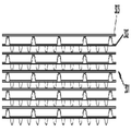
도 7은 본 개시에 따른 특징부를 구비한 필터 장치에 사용 가능하며, 예를 들어 도 1에 따른 매체의 스트립으로 제조되는 적층형(stacked) 매체 팩 장치의 개략적인 사시도이다.
도 8은 도 1의 매체에 대한 대안적인 매체를 사용하며, 본 개시에 따른 선택된 필터 카트리지에 대안적으로 사용될 수 있는 필터 매체 팩의 개략적인 유동 단부도이다.
도 8a는 도 8의 도면과 반대편에 있는 개략적인 유동 단부도이다.
도 8b는 도 8 및 도 8a의 매체 팩의 개략적인 단면도이다.
도 9는 본 개시에 따른 특징부를 구비한 필터 카트리지의 매체 팩에 사용 가능한 다른 대안적인 매체 유형의 개략적인 부분 단면도이다.
도 10은 도 9의 매체 유형의 제1 변형예의 개략적인 부분 단면도이다.
도 11a는 본 개시에 따른 다른 사용 가능한 플루트형 시트/대향 시트 조합의 개략도이다.
도 11b는 도 11a의 매체의 유형의 제2 개략도이다.
도 11c는 매체의 또 다른 변형예의 개략적인 부분 평면도이다.
도 12는 본 개시에 따른 사용 가능한 매체의 다른 변형예의 개략도이다.
도 13은 본 개시에 따른 특징부 및 컴포넌트를 포함하는 공기 청정기 조립체의 개략적인 상부 사시도이다.
도 14는 하우징 섹션이 제거되고, 소개 밸브 컴포넌트가 분해도로 도시되어 있는, 도 13의 공기 청정기 조립체의 개략적인 사시도이다.
도 15는 도 13 및 도 14의 공기 청정기 조립체 내에 설치 가능한 필터 카트리지 컴포넌트의 개략적인 사시도이다.
도 16은 도 15에 도시된 필터 카트리지의 일부의 개략적인 부분 확대 사시도이다.
도 17은 도 15의 필터 카트리지의 제2 개략적인 사시도로, 도 17의 도면은 도 15의 도면과 반대편에 있는 카트리지의 단부를 향한다.
도 18은 도 17의 필터 카트리지의 일부의 개략적인 부분 확대도이다.
도 19는 도 13의 공기 청정기 조립체의 하우징 컴포넌트의 개략적인 사시도이다.
도 20은 도 19의 하우징 컴포넌트의 제2 개략적인 사시도이다.
도 21은 도 20의 하우징 컴포넌트의 단부의 개략적인 부분 확대 사시도이다.
도 22는 도 13의 조립체의 공기 청정기 하우징의 제2 하우징 섹션 컴포넌트의 개략적인 상부 사시도이다.
도 23은 내부를 향한, 도 22의 하우징 섹션의 제2 개략적인 사시도이다.
도 24는 안쪽 부분을 향한, 도 23의 하우징 섹션의 일부의 개략적인 부분 확대 사시도이다.
도 25는 도 22의 커버 섹션의 바깥쪽 부분의 개략적인 부분 확대 사시도이다.
도 26은 전체적으로 26-26 라인을 따른, 도 15의 필터 카트리지 컴포넌트의 개략적인 단면 사시도이다.
도 27은 도 26의 일부의 개략적인 부분 확대도이다.
도 28은 전체적으로 도 13의 28-28 라인을 따른, 도 13의 공기 청정기 조립체의 일부의 개략적인 부분 단면도이다.
도 29는 도 13의 공기 청정기 조립체의 일부의 개략적인 부분 확대 단면도이다.
도 30은 전체적으로 도 13의 30-30 라인을 따른, 도 29의 일부의 개략적인 부분 확대도이다.
도 31은 전체적으로 도 13의 31-31 라인을 따른, 도 15의 필터 카트리지의 일부의 제2 개략적인 단면도이다.
도 32는 도 31의 일부의 개략적인 부분 확대도이다.
도 33은 전체적으로 도 13의 33-33 라인을 따른, 도 13의 조립체의 부분 확대 단면도이다.
도 34는 전체적으로 도 13의 34-34 라인을 따른, 그러나 도 33과는 상이한 관점의, 도 13의 공기 청정기 조립체의 제2 개략적인 부분 확대 단면도이다.
도 35는 도 13의 35-35 라인을 따른, 도 34와 유사하지만 상이한 관점의, 개략적인 부분 확대 사시도이다.
도 36은 도 15의 필터 카트리지의 성형 컴포넌트의 개략적인 부분 확대 사시도이다.
도 37은 도 36의 성형 컴포넌트의 제2 개략적인 부분 확대 사시도이다.
도 38은 도 13의 38-38 라인을 따른, 도 13의 공기 청정기 조립체의 일부의 개략적인 부분 확대 단면도이다.
도 39는 도 38에 도시된 조립체의 일부의 개략적인 부분 확대 단면 단부 사시도이다.
도 40은 전체적으로 도 39에 도시된 40-40 부분을 따른, 도 13의 공기 청정기 조립체의 일부의 개략적인 부분 확대 단면도이다.
도 41은 본 개시에 따른 대안적인 필터 카트리지 구현 원리의 개략적인 사시도이다.
도 42는 도 41의 필터 카트리지의 개략적인 측입면도이다.
도 43은 도 42의 식별된 부분의 개략적인 부분 확대도이다.
도 44는 전체적으로 도 15에 따른, 그러나 대안적인 특정 특징부를 포함하는 필터 카트리지의 개략적인 부분 확대도이다.
도 45는 도 44를 향한 필터 카트리지의 반대편 단부를 향한 개략적인 부분도이다.
도 46은 도 13의 공기 청정기 조립체에 대한 대안적인 공기 청정기 조립체의 상부 사시도이다.
도 47은 하우징 컴포넌트가 제거되어 있는, 도 45의 공기 청정기 조립체의 개략적인 사시도이다.
도 48은 도 46 및 도 47의 공기 청정기 조립체의 필터 카트리지 컴포넌트의 개략적인 사시도이다.
도 49는 도 48의 필터 카트리지의 일부의 개략적인 부분 확대 사시도이다.
도 50은 카트리지의 반대편 단부를 향한, 도 48 및 도 49의 카트리지의 식별된 부분의 개략적인 부분 확대 사시도이다.
도 51은 여전히 카트리지의 동일 단부를 향하지만 상이한 관점의, 도 49에 도시된 필터 카트리지의 일부의 개략적인 사시도이다.
도 52는 도 51에 도시된 필터 카트리지의 일부의 개략적인 부분 평면도이다.
도 53은 도 48에 도시된 필터 카트리지의 개략적인 단면도이다.
도 54는 도 53과 동일 평면이지만 상이한 관점으로 카트리지를 도시한 개략적인 부분 확대 단면도이다.
도 55는 도 54와 유사한 관점이지만 상이한 위치에서 단면 평면을 갖는 제2 부분 단면도이다.
도 56은 도 48의 필터 카트리지의 하우징 밀봉 맞물림부의 선택된 부분의 부분 확대 사시도이다.
도 57은 상이한 관점으로 도시된 도 56의 하우징 맞물림 장치의 일부의 개략적인 사시도이다.
도 58은 도 57의 컴포넌트의 일부의 부분 확대 단면도이다.
도 59는 도 46의 공기 청정기 조립체의 하우징 섹션의 개략적인 사시도이다.
도 60은 도 59의 하우징 컴포넌트의 내부를 향한 부분 확대 사시도이다.
도 61은 도 60의 하우징 컴포넌트를 향한 부분 확대 평면도이다.
도 62는 도 61의 하우징 컴포넌트의 측면을 향한 부분 외부 평면도이다.
도 63은 도 62에 도시된 하우징 컴포넌트의 일부를 향한 부분 사시도이다.
도 64는 본 개시에 따른 다른 사용 가능한 플루트형 시트/대향 시트 조합의 개략도이다.
도 65는 도 64에 도시된 사용 가능한 플루트형 시트/대향 시트 조합의 일부의 사시도이다.1 is a schematic fragmentary perspective view of a first exemplary media type usable in an apparatus according to the present disclosure;
FIG. 2 is a schematic enlarged cross-sectional view of a portion of the media type shown in FIG. 1 ;
3 includes schematic diagrams of examples of various fluted media definitions for the tangible media of FIGS. 1 and 2 ;
4 is a schematic diagram of an exemplary process for making the type of media of FIGS.
5 is a schematic cross-sectional view of an optional end dart for media flutes of the type of FIGS. 1-4 ;
FIG. 6 is a schematic perspective view of a coiled filter device usable for a filter cartridge with features according to the present disclosure, for example made from a strip of media according to FIG. 1 ;
7 is a schematic perspective view of a stacked media pack device usable in a filter device with features according to the present disclosure, for example made from a strip of media according to FIG. 1 ;
FIG. 8 is a schematic flow end view of a filter media pack that uses an alternative media to the media of FIG. 1 and can be used alternatively to selected filter cartridges in accordance with the present disclosure;
Fig. 8a is a schematic flow end view opposite the view of Fig. 8;
8B is a schematic cross-sectional view of the media pack of FIGS. 8 and 8A ;
9 is a schematic partial cross-sectional view of another alternative media type usable in a media pack of a filter cartridge with features according to the present disclosure;
FIG. 10 is a schematic partial cross-sectional view of a first variant of the media type of FIG. 9 ;
11A is a schematic diagram of another usable fluted sheet/facing sheet combination in accordance with the present disclosure.
11B is a second schematic diagram of the type of media of FIG. 11A .
11c is a schematic partial plan view of yet another variant of the medium;
12 is a schematic diagram of another variant of a usable medium according to the present disclosure.
13 is a schematic top perspective view of an air purifier assembly including features and components in accordance with the present disclosure;
14 is a schematic perspective view of the air purifier assembly of FIG. 13 with the housing section removed and the evacuation valve component shown in an exploded view;
15 is a schematic perspective view of a filter cartridge component installable within the air purifier assembly of FIGS. 13 and 14;
FIG. 16 is a schematic partial enlarged perspective view of a part of the filter cartridge shown in FIG. 15 .
Fig. 17 is a second schematic perspective view of the filter cartridge of Fig. 15, the view of Fig. 17 facing the end of the cartridge opposite the view of Fig. 15;
18 is a schematic partial enlarged view of a portion of the filter cartridge of FIG. 17 ;
19 is a schematic perspective view of a housing component of the air purifier assembly of FIG. 13 ;
FIG. 20 is a second schematic perspective view of the housing component of FIG. 19 ;
Fig. 21 is a schematic fragmentary enlarged perspective view of an end of the housing component of Fig. 20;
22 is a schematic top perspective view of a second housing section component of the air cleaner housing of the assembly of FIG. 13 ;
FIG. 23 is a second schematic perspective view of the housing section of FIG. 22 , facing inward; FIG.
FIG. 24 is a schematic fragmentary enlarged perspective view of a portion of the housing section of FIG. 23 , facing the inner part;
Fig. 25 is a schematic fragmentary enlarged perspective view of an outer portion of the cover section of Fig. 22;
FIG. 26 is a schematic cross-sectional perspective view of the filter cartridge component of FIG. 15, generally taken along line 26-26;
FIG. 27 is a schematic partial enlarged view of a part of FIG. 26 .
FIG. 28 is a schematic partial cross-sectional view of a portion of the air purifier assembly of FIG. 13 , generally taken along line 28-28 of FIG. 13 ;
29 is a schematic partial enlarged cross-sectional view of a portion of the air purifier assembly of FIG. 13 ;
FIG. 30 is a schematic fragmentary enlarged view of a portion of FIG. 29, generally taken along line 30-30 of FIG. 13;
Fig. 31 is a second schematic cross-sectional view of a portion of the filter cartridge of Fig. 15, generally taken along line 31-31 of Fig. 13;
FIG. 32 is a schematic partial enlarged view of a part of FIG. 31 .
FIG. 33 is an enlarged fragmentary cross-sectional view of the assembly of FIG. 13, generally taken along line 33-33 of FIG. 13;
FIG. 34 is a second schematic fragmentary enlarged cross-sectional view of the air purifier assembly of FIG. 13 , generally taken along line 34-34 of FIG. 13 , but from a different perspective than FIG. 33 ;
FIG. 35 is a schematic fragmentary enlarged perspective view similar to but different from FIG. 34 along line 35-35 of FIG. 13 ;
Fig. 36 is a schematic fragmentary enlarged perspective view of a molding component of the filter cartridge of Fig. 15;
FIG. 37 is a second schematic fragmentary enlarged perspective view of the forming component of FIG. 36 ;
FIG. 38 is a schematic fragmentary enlarged cross-sectional view of a portion of the air purifier assembly of FIG. 13 taken along line 38-38 of FIG. 13 ;
39 is a schematic fragmentary enlarged cross-sectional end perspective view of a portion of the assembly shown in FIG. 38 ;
FIG. 40 is a schematic fragmentary enlarged cross-sectional view of a portion of the air purifier assembly of FIG. 13 , generally along portions 40-40 shown in FIG. 39 ;
41 is a schematic perspective view of an alternative filter cartridge implementation principle according to the present disclosure;
Figure 42 is a schematic side elevational view of the filter cartridge of Figure 41;
Fig. 43 is a schematic partial enlarged view of the identified portion of Fig. 42;
FIG. 44 is a schematic fragmentary enlarged view of a filter cartridge generally according to FIG. 15 , but with alternative specific features;
FIG. 45 is a schematic partial view towards the opposite end of the filter cartridge towards FIG. 44 ;
Figure 46 is a top perspective view of an alternative air cleaner assembly to the air cleaner assembly of Figure 13;
FIG. 47 is a schematic perspective view of the air purifier assembly of FIG. 45 with the housing component removed;
48 is a schematic perspective view of a filter cartridge component of the air purifier assembly of FIGS. 46 and 47;
49 is a schematic partial enlarged perspective view of a portion of the filter cartridge of FIG. 48;
Figure 50 is a schematic fragmentary enlarged perspective view of the identified portion of the cartridge of Figures 48 and 49, facing the opposite end of the cartridge;
Figure 51 is a schematic perspective view of a portion of the filter cartridge shown in Figure 49, still facing the same end of the cartridge, but from a different perspective;
FIG. 52 is a schematic partial plan view of a portion of the filter cartridge shown in FIG. 51;
Fig. 53 is a schematic cross-sectional view of the filter cartridge shown in Fig. 48;
Fig. 54 is a schematic partial enlarged cross-sectional view showing the cartridge from a different perspective, but on the same plane as Fig. 53;
FIG. 55 is a second partial cross-sectional view similar to that of FIG. 54 but with a cross-sectional plane at a different location.
FIG. 56 is a partially enlarged perspective view of a selected portion of the housing seal engagement portion of the filter cartridge of FIG. 48;
FIG. 57 is a schematic perspective view of a portion of the housing engagement device of FIG. 56 viewed from a different perspective;
58 is a partially enlarged cross-sectional view of a portion of the component of FIG. 57 ;
59 is a schematic perspective view of a housing section of the air purifier assembly of FIG. 46 ;
FIG. 60 is a partially enlarged perspective view of the housing component of FIG. 59 facing inward; FIG.
FIG. 61 is a partially enlarged plan view of the housing component of FIG. 60 ;
FIG. 62 is a side-facing partial exterior plan view of the housing component of FIG. 61 ;
63 is a partial perspective view facing a portion of the housing component shown in FIG. 62 ;
64 is a schematic diagram of another usable fluted seat/opposite seat combination in accordance with the present disclosure.
FIG. 65 is a perspective view of a portion of a usable fluted seat/opposite seat combination shown in FIG. 64 ;
I. 일반적인 예시적인 매체 구성I. GENERAL EXAMPLE MEDIA CONFIGURATIONS
본 개시에 따른 원리는 이하에 논의되는 특정의 선택된 원하는 결과를 달성하기 위한 유리한 방식의 필터 카트리지와 공기 청정기 시스템 사이의 상호작용에 관한 것이다. 필터 카트리지는 일반적으로 여과 작동 중에 공기 및 다른 가스가 통과하는 필터 매체를 포함할 것이다. 매체는 다양한 유형 및 구성으로 이루어질 수 있고, 다양한 재료를 이용하여 제조될 수 있다. 예를 들어, 이하에 논의되는 바와 같이, 주름형(pleated) 매체 장치가 본 개시의 원리에 따른 카트리지에 사용될 수 있다.The principles according to the present disclosure relate to the interaction between the filter cartridge and the air purifier system in an advantageous manner to achieve certain selected desired results discussed below. A filter cartridge will generally contain a filter medium through which air and other gases pass during filtration operations. Media can be of various types and configurations, and can be manufactured using a variety of materials. For example, as discussed below, pleated media devices may be used with cartridges according to the principles of the present disclosure.
본 원리는 매체가 카트리지의 유입 및 토출 단부들 사이의 연장부에 상당히 깊이 놓인 상황에서 사용하도록 특히 양호하게 조절되지만, 대안이 가능하다. 또한, 본 원리는 상대적으로 큰 단면 크기를 갖는 카트리지에 종종 사용된다. 이와 같은 장치에 의해, 주름형 매체에 대한 대안적인 매체 유형이 종종 요구될 것이다.Although this principle is particularly well adapted for use in situations where the media is placed quite deep in the extension between the inlet and outlet ends of the cartridge, alternatives are possible. Also, the present principles are often used for cartridges with relatively large cross-sectional sizes. With such an arrangement, an alternative media type to pleated media will often be desired.
이 장에서는, 본원에 설명된 기술과 사용 가능한 일부 매체 장치들의 예들이 제공된다. 그러나, 다양한 대안적인 매체 유형들이 사용될 수 있음은 물론이다. 매체 유형의 선정은 일반적으로: 가용성, 주어진 적용 상황에서의 기능, 제조 용이성 등에 대한 선호 중 하나에 따르며, 이 선정은 본원에 규정된 다양한 필터 카트리지/공기 청정기 상호작용 특징부들 중 선택된 하나의 전체 기능과 반드시 구체적으로 관련되지는 않는다.In this chapter, examples of some media devices that can be used with the techniques described herein are provided. It should be understood, however, that various alternative media types may be used. The selection of the media type generally depends on one of preference for: availability, function in a given application situation, ease of manufacture, etc., this selection being the overall function of a selected one of the various filter cartridge/air purifier interaction features defined herein. is not necessarily specifically related to
A. 대향 매체에 고정되는 매체 A. Medium fixed to the opposite medium 리지들(플루트들)을ridges (flutes) 구비한 필터 매체를 이용한 매체 팩 장치 Media pack device using the provided filter media
플루트형 필터 매체(매체 리지들을 구비한 매체)가 다양한 방식들로 유체 필터 구조를 제공하는 데에 사용될 수 있다. 하나의 널리 공지된 방식은 본원에서 z-필터 구조(z-filter construction)로 규정된다. 본원에 사용된 바와 같이, "z-필터 구조"는 개별 파형, 절곡형, 또는 달리 형성된 필터 플루트들이 매체를 통한 유체 유동을 위한 종방향의, 통상적으로 평행한 유입 및 토출 필터 플루트들의 세트를 (통상적으로 대향 매체와 함께) 정의하는 데에 사용되는 일종의 필터 구조를 포함하도록(그러나 이에 제한되지 않도록) 의도된다. z-필터 매체의 몇몇 예들이 미국 특허 5,820,646; 5,772,883; 5,902,364; 5,792,247; 5,895,574; 6,210,469; 6,190,432; 6,350,296; 6,179,890; 6,235,195; 디자인 399,944; 디자인 428,128; 디자인 396,098; 디자인 398,046; 및 디자인 437,401에 제공되어 있고; 이러한 인용된 참고문헌들은 각각 본원에 참조로 포함된다.Fluted filter media (media with media ridges) can be used to provide a fluid filter structure in a variety of ways. One well-known approach is defined herein as a z-filter construction. As used herein, a "z-filter structure" means a set of longitudinal, typically parallel inlet and outlet filter flutes for fluid flow through a medium in which individual corrugated, bent, or otherwise formed filter flutes are formed. It is intended to include (but is not limited to) a filter structure of some sort, typically used to define (with an opposing medium). Some examples of z-filter media are described in U.S. Patent Nos. 5,820,646; 5,772,883; 5,902,364; 5,792,247; 5,895,574; 6,210,469; 6,190,432; 6,350,296; 6,179,890; 6,235,195; design 399,944; design 428,128; design 396,098; design 398,046; and Design 437,401; Each of these cited references is incorporated herein by reference.
z-필터 매체의 하나의 유형은 서로 결합되는 2개의 특정 매체 컴포넌트를 사용하여 매체 구조를 형성한다. 2개의 컴포넌트는: (1) 플루트형(통상적으로 파형) 매체 시트 또는 시트 섹션, 및 (2) 대향 매체 시트 또는 시트 섹션이다. 대향 매체 시트는 통상적으로 파형이 아니지만, 예를 들어 플루트 방향에 수직으로 파형일 수 있는데, 이는 본원에 참조로 포함되는, 2004년 2월 11일에 출원되고 2005년 8월 25일에 PCT WO 05/077487로 공개된 미국 가출원 60/543,804에 기재되어 있다.One type of z-filter media uses two specific media components that are coupled together to form a media structure. The two components are: (1) a fluted (usually corrugated) media sheet or sheet section, and (2) an opposing media sheet or sheet section. The opposing media sheet is typically not corrugated, but may, for example, be corrugated perpendicular to the direction of the flutes, filed Feb. 11, 2004, and PCT WO 05, Aug. 25, 2005, which is incorporated herein by reference. US Provisional Application 60/543,804, published as /077487.
플루트형 매체 섹션 및 대향 매체 섹션은 서로 간에 별개의 재료를 포함할 수 있다. 그러나, 이들은 또한 대향 매체 재료가 매체의 플루트형 매체 부분과 적절하게 병치될 수 있도록 절곡되는 단일 매체 시트의 섹션들일 수 있다.The fluted media section and the opposing media section may comprise separate materials from each other. However, they can also be sections of a single media sheet that are bent so that the opposing media material can be properly juxtaposed with the fluted media portion of the media.
플루트형(통상적으로 파형) 매체 시트 및 대향 매체 시트 또는 시트 섹션은 함께 평행한 플루트들을 구비한 매체를 정의하는 데에 통상적으로 사용된다. 경우에 따라, 플루트형 시트 및 대향 시트는 별개이며, 이후 서로 고정된 후, 매체 스트립으로서 권취되어, z-필터 매체 구조를 형성한다. 이와 같은 장치는 예를 들어 US 6,235,195 및 6,179,890에 기재되어 있고, 이들 각각은 본원에 참조로 포함된다. 특정의 다른 장치에서, 대향 매체에 고정되는 플루트형(통상적으로 파형) 매체의 몇몇 비권취 섹션들 또는 스트립들은 서로 적층되어, 필터 구조를 형성한다. 그 일례가 본원에 참조로 포함되는 US 5,820,646의 도 11에 기재되어 있다.A fluted (usually corrugated) media sheet and an opposing media sheet or sheet section are commonly used to define media with flutes parallel to one another. Optionally, the fluted sheet and the opposing sheet are separate, then fixed to each other and then wound as a media strip to form a z-filter media structure. Such devices are described, for example, in US Pat. Nos. 6,235,195 and 6,179,890, each of which is incorporated herein by reference. In certain other devices, several unwound sections or strips of a fluted (usually corrugated) medium secured to an opposing medium are stacked together to form a filter structure. An example of this is described in FIG. 11 of US 5,820,646, which is incorporated herein by reference.
본원에서, 파형 시트에 고정되는 플루트형 시트(또는 리지들을 갖는 매체의 시트)를 포함하는 재료의 스트립들(이들은 이후 적층 조립되어 매체 팩을 형성한다)은 때때로 "단일 대향체(single facer) 스트립", "단일 대향된(single faced) 스트립", 또는 "단일 대향체" 또는 "단일 대향된" 매체로 지칭된다. 이 용어들 및 이들의 변형들은 플루트형(통상적으로 파형) 시트의 하나의 면, 즉 단일면이 각각의 스트립에서 대향 시트에 의해 대향되는 것을 가리키도록 의도된다.As used herein, strips of material comprising a fluted sheet (or sheet of media having ridges) secured to a corrugated sheet (which are then laminated to form a media pack) are sometimes referred to as "single facer strips" ", "single faced strip", or "single faced" or "single faced" media. These terms and variations thereof are intended to refer to one side, ie, a single side, of a fluted (usually corrugated) sheet being opposed by an opposing sheet in each strip.
통상적으로, 권취형 매체 팩을 형성하기 위한 플루트형 시트/대향 시트(즉, 단일 대향체) 조합의 스트립의 그 자체의 권취는 대향 시트가 외부를 향한 상태로 수행된다. 몇몇 권취 기술이 2003년 5월 2일에 출원된 미국 가출원 60/467,521, 및 2004년 3월 17일에 출원되고 이제 WO 04/082795로 공개된 PCT 출원 04/07927에 기재되어 있고, 이들 각각은 본원에 참조로 포함된다. 그 결과, 최종 권취형 장치는 일반적으로 대향 시트의 일부를 매체 팩의 외표면으로서 구비한다.Typically, the self-winding of the strip of fluted sheet/opposite sheet (ie, single opposing body) combination to form the wound media pack is performed with the opposing sheet facing outward. Several winding techniques are described in U.S. Provisional Application 60/467,521, filed May 2, 2003, and PCT Application 04/07927, filed March 17, 2004 and now published as WO 04/082795, each of which incorporated herein by reference. As a result, the final take-up device generally has a portion of the opposing sheet as the outer surface of the media pack.
매체 내의 구조를 가리키도록 본원에 사용된 "파형"이라는 용어는 매체를 2개의 파형화 롤러 사이로, 즉 2개의 롤러 사이의 닙 또는 바이트 내로 통과시킴으로써 형성되는 플루트 구조를 가리키도록 종종 사용되되, 이들 롤러들은 각각 최종 매체에서 파형화를 야기하기에 적절한 표면 특징부를 구비한다. 그러나, "파형화"라는 용어는, 기술에 의해 매체를 파형화 롤러들 사이의 바이트 내로 통과시키는 것을 수반하는 플루트에서 기인한다는 것이 명시되지 않는 한, 이와 같은 플루트에 제한되도록 의도되지 않는다. "파형"이라는 용어는 매체가 예를 들어 절곡 기술에 의해 파형화 후에 추가로 수정되거나 변형될지라도 적용되도록 의도되는데, 이 절곡 기술은 본원에 참조로 포함되는, 2004년 1월 22일에 공개된 PCT WO 04/007054에 기재되어 있다.The term "corrugated" as used herein to refer to a structure in a medium is often used to refer to a fluted structure formed by passing a medium between two corrugating rollers, i.e., into a nip or bite between the two rollers, Each of these rollers has appropriate surface features to cause corrugation in the final medium. However, the term “corrugating” is not intended to be limited to such flutes, unless it is specified by the technique that they result from flutes that involve passing media into bites between corrugating rollers. The term "waveform" is intended to apply even if the medium is further modified or deformed after corrugation, for example by a bending technique, which was published on January 22, 2004, which is incorporated herein by reference. PCT WO 04/007054.
파형 매체는 특정 형태의 플루트형 매체이다. 플루트형 매체는 이를 가로질러 연장되는 (예를 들어, 파형화 또는 절곡에 의해 형성된) 개별 플루트들 또는 리지들을 구비한 매체이다.A corrugated medium is a specific type of fluted medium. A fluted medium is a medium with individual flutes or ridges (eg, formed by corrugation or bending) extending across it.
z-필터 매체를 이용한 서비스 가능한 필터 요소 또는 필터 카트리지 구성은 때때로 "직선 통과 유동 구성" 또는 그 변형으로 지칭된다. 일반적으로, 이런 맥락에서, 서비스 가능한 필터 요소 또는 필터 카트리지는 일반적으로 유입 유동 단부(또는 면) 및 반대편 토출 유동 단부(또는 면)를 구비하되, 유동이 대략 동일한 직선 통과 방향으로 필터 카트리지에 유입 및 토출되는 것을 의미한다. 이런 맥락에서, "서비스 가능한"이라는 용어는 매체 포함 필터 카트리지가 대응하는 유체(예를 들어, 공기) 청정기로부터 주기적으로 제거되고 교체되는 것을 가리키도록 의도된다. 경우에 따라, 유입 유동 단부(또는 면) 및 토출 유동 단부(또는 면) 각각은 서로 평행한 상태로 대략 평탄하거나 평면일 것이다. 그러나, 이들의 변형들, 예를 들어 평면이 아닌 면이 가능하다.Serviceable filter element or filter cartridge configurations using z-filter media are sometimes referred to as "straight through flow configurations" or variations thereof. Generally, in this context, a serviceable filter element or filter cartridge generally has an inlet flow end (or face) and an opposite outlet flow end (or face), wherein the flow enters and exits the filter cartridge in approximately the same straight-through direction. means to be discharged. In this context, the term “serviceable” is intended to indicate that the media containing filter cartridge is periodically removed and replaced from a corresponding fluid (eg, air) purifier. In some cases, each of the inlet flow end (or face) and outlet flow end (or face) will be approximately flat or planar, parallel to each other. However, variants of these are possible, for example non-planar surfaces.
(특히 권취형 또는 적층형 매체 팩을 위한) 직선 통과 유동 구성은 예를 들어 본원에 참조로 포함되는 미국 특허 6,039,778에 나타낸 유형의 원통형 주름형 필터 카트리지와 같은 서비스 가능한 필터 카트리지와 대조되는데, 여기서 유동은 매체 안팎으로 통과할 때 일반적으로 실질적인 방향 전환을 수행한다. 즉, 6,039,778 필터에서, 유동은 원통측을 통해 원통형 필터 카트리지에 들어간 후, 방향을 전환하여, (순방향-유동 시스템에서) 매체의 개방 단부를 통해 빠져나간다. 통상적인 역방향-유동 시스템에서, 유동은 매체의 개방 단부를 통해 서비스 가능한 원통형 카트리지에 들어간 후, 방향을 전환하여, 원통형 필터 매체의 측면을 통해 빠져나간다. 이와 같은 역방향-유동 시스템의 일례가 본원에 참조로 포함되는 미국 특허 5,613,992에 기재되어 있다.The straight-through flow configuration (especially for wound or stacked media packs) contrasts with serviceable filter cartridges, such as, for example, cylindrical pleated filter cartridges of the type shown in US Pat. No. 6,039,778, incorporated herein by reference, where the flow is When passing in and out of the medium, it usually makes a substantial change of direction. That is, in the 6,039,778 filter, flow enters the cylindrical filter cartridge through the cylindrical side, then reverses direction and exits through the open end of the medium (in a forward-flow system). In a typical counter-flow system, flow enters a serviceable cylindrical cartridge through the open end of the media, then diverts and exits through the side of the cylindrical filter media. An example of such a counter-flow system is described in US Pat. No. 5,613,992, which is incorporated herein by reference.
본원에 사용된 바와 같은 "z-필터 매체 구조"라는 용어 및 그 변형은: 유입 및 토출 플루트들의 정의를 허용하기에 적절한 밀봉(폐쇄)과 함께, 시트들이 단일 웨브의 일부이든 별개의 것이든, (대향) 매체에 고정되는 파형 또는 다른 플루트형 매체(매체 리지들을 구비한 매체)의 웨브; 및/또는 이와 같은 매체로부터 유입 및 토출 플루트들의 3차원 네트워크로 구성되거나 형성되는 매체 팩; 및/또는 이와 같은 매체 팩을 포함하는 필터 카트리지 또는 구조 중 일부 또는 전부를 포함하지만 이에 반드시 제한되진 않도록 의도된다.As used herein, the term "z-filter media structure" and variations thereof include: whether the sheets are part of a single web or separate a web of corrugated or other fluted media (media with media ridges) secured to (opposite) media; and/or a media pack composed or formed of a three-dimensional network of inlet and outlet flutes from such media; and/or some or all of the filter cartridges or structures comprising such media packs.
도 1에는 z-필터 매체 구조에 사용 가능한 매체(1)의 일례가 도시되어 있다. 매체(1)는 플루트형, 이 경우에는 파형 시트(3) 및 대향 시트(4)로 형성된다. 매체(1)와 같은 구조는 본원에서 단일 대향체 또는 단일 대향된 스트립으로 지칭된다.1 shows an example of a medium 1 usable in a z-filter medium construction. The
때때로, 도 1의 파형 플루트형 또는 리지형 시트(3)는 플루트들, 리지들, 또는 파형들(7)의 규칙적인 만곡된 웨이브 패턴을 갖는 것으로 본원에 일반적으로 규정된 유형이다. 이런 맥락에서, "웨이브 패턴"이라는 용어는 교번적인 트로프들(7b)과 리지들(7a)의 플루트, 리지 또는 파형 패턴을 가리키도록 의도된다. 이런 맥락에서, "규칙적"이라는 용어는 트로프들과 리지들(7b, 7a)의 쌍들이 대략 동일한 반복 파형(플루트 또는 리지) 형상 및 크기로 교번하는 것을 가리키도록 의도된다(또한, 통상의 규칙적인 구성에서, 각각의 트로프(7b)는 각각의 리지(7a)에 대해 실질적으로 반전된 리지이다). 따라서, "규칙적"이라는 용어는 파형(또는 플루트) 패턴이, 플루트들의 적어도 70%의 길이를 따른 파형의 크기 및 형상의 실질적인 수정 없이, (인접한 트로프와 리지를 포함하는) 각각의 쌍이 반복된 상태로, 트로프들(반전된 리지들) 및 리지들을 포함하는 것을 나타내도록 의도된다. 이런 맥락에서, "실질적인"이라는 용어는, 매체 시트(3)가 가요성이라는 사실에서 기인한 사소한 변형과는 달리, 파형 또는 플루트형 시트를 제조하기 위해 사용되는 형태 또는 공정의 변화에서 기인한 수정을 가리킨다. 반복 패턴의 규정과 관련하여, 이는 임의의 주어진 필터 구조에서 동일한 개수의 리지와 트로프가 반드시 존재하는 것을 의미하진 않는다. 매체(1)는 예를 들어 리지와 트로프를 포함하는 쌍 사이에서, 또는 부분적으로 리지와 트로프를 포함하는 쌍을 따라 끝날 수 있다. (예를 들어, 도 1에서, 부분도로 도시된 매체(1)는 8개의 완전한 리지(7a)와 7개의 완전한 트로프(7b)를 구비한다.) 또한, 양 플루트 단부(트로프들과 리지들의 단부들)는 서로 다를 수 있다. 이와 같은 단부 변형은 구체적으로 명시되지 않는 한 이러한 정의에서 무시된다. 즉, 플루트들의 단부들의 변형은 상기 정의에 의해 포괄되도록 의도된 것이다.Sometimes, the corrugated fluted or ridged sheet 3 of FIG. 1 is of the type generally defined herein as having a regular curved wave pattern of flutes, ridges, or corrugations 7 . In this context, the term “wave pattern” is intended to refer to a flute, ridge or wavy pattern of alternating
파형의 "만곡된" 웨이브 패턴의 규정의 맥락에서, 특정 경우에, 파형 패턴은 매체에 제공되는 절곡 또는 접힘 형상의 결과가 아니라, 각각의 리지의 정점(7a)과 각각의 트로프의 바닥(7b)이 반경 만곡부(radiused curve)를 따라 형성된다. 이와 같은 z-필터 매체의 통상적인 반경은 0.25 mm 이상이며, 통상적으로 3 mm 이하일 것이다.In the context of the definition of a "curved" wave pattern of a corrugation, in certain cases, the wavy pattern is not the result of a bent or folded shape provided in the medium, but rather the apex 7a of each ridge and the bottom 7b of each trough. ) is formed along a radiused curve. A typical radius of such z-filter media is greater than or equal to 0.25 mm, and will typically be less than or equal to 3 mm.
파형 시트(3)에 대해 도 1에 도시된 특정의 규칙적인 만곡된 웨이브 패턴의 추가적인 특성은, 플루트들(7)의 대부분의 길이를 따른 각각의 트로프와 각각의 인접한 리지 사이의 대략 중간점(30)에, 곡률이 반전되는 전이 영역이 위치된다는 것이다. 예를 들어, 도 1의 후방측 또는 면(3a)을 바라볼 때, 트로프(7b)는 오목한 영역이고, 리지(7a)는 볼록한 영역이다. 물론, 전방측 또는 면(3b)을 향해 바라볼 때, 측(3a)의 트로프(7b)는 리지를 형성하고, 면(3a)의 리지(7a)는 트로프를 형성한다. (경우에 따라, 영역(30)은 점이 아닌 직선 세그먼트일 수 있고, 곡률이 세그먼트(30)의 양 단부에서 반전된다.)A further characteristic of the particular regular curved wave pattern shown in FIG. 1 for the corrugated sheet 3 is that approximately midpoint between each trough and each adjacent ridge along most of the length of the flutes 7 ( 30), a transition region in which the curvature is reversed is located. For example, when looking at the rear side or face 3a of FIG. 1 , the
도 1에 도시된 특정의 규칙적인 웨이브 패턴 플루트형(이 경우, 파형) 시트(3)의 특성은 개별 파형들, 리지들, 또는 플루트들이 대략 직선이라는 것이지만, 대안이 가능하다. 이런 맥락에서, "직선"은, 적어도 70%, 통상적으로 적어도 80%의 길이를 통해, 리지들(7a)과 트로프들(또는 반전된 리지들; 7b)의 단면이 실질적으로 변하지 않는다는 것을 의미한다. 도 1에 도시된 파형 패턴을 참조한 "직선"이라는 용어는 부분적으로 패턴을, 본원에 참조로 포함되는 2003년 6월 12일에 공개된 WO 97/40918 및 PCT 공개 WO 03/47722의 도 1에 기재된 파형 매체의 테이퍼진 플루트들과 구별한다. 예를 들어, WO 97/40918의 도 1의 테이퍼진 플루트들은 본원에 사용된 용어와 같이 직선 플루트들의 패턴 또는 "규칙적인" 패턴이 아니라, 만곡된 웨이브 패턴일 것이다.Although the characteristic of the particular regular wave pattern fluted (in this case, corrugated) sheet 3 shown in FIG. 1 is that the individual corrugations, ridges, or flutes are approximately straight, alternatives are possible. In this context, "straight line" means that, through a length of at least 70%, typically at least 80%, the cross-section of the ridges 7a and the troughs (or inverted ridges; 7b) does not change substantially. . The term "straight line" with reference to the wavy pattern shown in FIG. 1 refers in part to FIG. 1 of WO 97/40918 and PCT publication WO 03/47722, published June 12, 2003, which are incorporated herein by reference. Distinguish from the tapered flutes of the described corrugated medium. For example, the tapered flutes of FIG. 1 of WO 97/40918 would be a curved wave pattern rather than a pattern of straight flutes or a “regular” pattern as the term is used herein.
도 1을 참조하면, 상기에 언급된 바와 같이, 매체(1)는 제1 및 제2 양 가장자리(8, 9)를 구비한다. 매체(1)가 매체 팩으로 형성될 때, 일반적으로 가장자리(9)는 매체 팩을 위한 유입 단부 또는 면을 형성할 것이고, 가장자리(8)는 토출 단부 또는 면을 형성할 것이지만, 정반대의 배향이 가능하다.Referring to FIG. 1 , as mentioned above, the
도시된 예에서, 다양한 플루트들(7)이 양 가장자리(8, 9) 사이에 완전히 연장되지만, 대안이 가능하다. 예를 들어, 이들은 가장자리들을 완전히 통해서가 아닌, 가장자리들 인근 또는 가까이의 위치까지 연장될 수 있다. 또한, 예를 들어 본원에 참조로 포함되는 US 2014/0208705 A1의 매체에서와 같이, 이들은 매체의 중간에서 중단 및 시작될 수 있다.In the example shown, the various flutes 7 extend completely between both edges 8 , 9 , although alternatives are possible. For example, they may extend to a location near or near the edges, but not completely through the edges. Also, as in the medium of US 2014/0208705 A1, which is incorporated herein by reference, for example, they may stop and begin in the middle of the medium.
매체가 도 1에 도시된 바와 같을 때, 인접한 가장자리(8)는 파형 시트(3) 및 대향 시트(4)를 함께 밀봉하는 실런트 비드(10)를 구비할 수 있다. 비드(10)는 단일 대향체(단일 대향된) 매체 스트립(1)을 형성하는 파형 시트(3)와 대향 시트(4) 사이의 비드이기 때문에, 때때로 "단일 대향체" 또는 "단일 대향된" 비드, 또는 변형으로 지칭될 수 있다. 실런트 비드(10)는 여기로부터의(또는 대향 유동에서는 여기로의) 공기의 통과에 대해, 가장자리(8)에 인접한 개별 플루트들(11)을 폐쇄 밀봉한다.When the medium is as shown in FIG. 1 , adjacent edges 8 may have
도 1에 도시된 매체에서, 인접한 가장자리(9)는 밀봉 비드(14)를 구비한다. 밀봉 비드(14)는 일반적으로 여기로부터의 미여과 유체(또는 대향 유동에서는 이 안의 유동)의 통과에 대해, 가장자리(9)에 인접한 플루트들(15)을 폐쇄한다. 비드(14)는 통상적으로 매체(1)가 매체 팩으로 구성될 때 적용될 것이다. 매체 팩이 스트립들(1)의 적층체로 이루어지는 경우, 비드(14)는 대향 시트(4)의 후방측(17)과 다음의 인접한 파형 시트(3)의 측(18) 사이의 밀봉부를 형성할 것이다. 매체(1)가 권취되는 것이 아니라 스트립으로 절단되고 적층될 때, 비드(14)는 "적층 비드"로 지칭된다. (비드(14)가 매체(1)의 기다란 스트립으로 형성되는 권취형 장치에 사용될 때, 이는 "권선 비드(winding bead)"로 지칭될 수 있다.)In the medium shown in FIG. 1 , the adjacent edge 9 is provided with a sealing bead 14 . The sealing bead 14 generally closes the
통과 유동 매체의 대안적인 유형들에서, 밀봉 재료는 상이하게 위치될 수 있고, 심지어 실런트 또는 접착제의 추가가 방지될 수 있다. 예를 들어, 경우에 따라, 매체는 절곡되어 하나의 단부 또는 가장자리 시임을 형성할 수 있다; 또는 매체는 초음파 응용 등과 같은 대안적인 기술에 의해 폐쇄 밀봉될 수 있다. 게다가, 실런트 재료가 사용될 때에도, 이는 양 단부에 인접할 필요가 없다.In alternative types of flow-through media, the sealing material may be positioned differently, and even the addition of sealant or adhesive may be prevented. For example, if desired, the media may be bent to form one end or edge seam; Alternatively, the media may be hermetically sealed by alternative techniques such as ultrasonic applications. Moreover, even when a sealant material is used, it need not be adjacent to both ends.
도 1을 참조하면, 필터 매체(1)가 예를 들어 적층 또는 권취에 의해 매체 팩으로 통합되면, 이는 다음과 같이 작동될 수 있다. 먼저, 화살표(12) 방향으로의 공기가 단부(9)에 인접한 개방 플루트들(11)에 들어갈 것이다. 비드(10)에 의한 단부(8)에서의 폐쇄로 인해, 공기는 예를 들어 화살표(13)로 도시된 바와 같이 필터 매체(1)를 통과할 것이다. 이후, 이는 매체 팩의 단부(8)에 인접한 플루트들(15)의 개방 단부들(15a)을 통과함으로써 매체 또는 매체 팩을 빠져나갈 것이다. 물론, 작동은 반대 방향의 공기 유동으로 수행될 수 있다.Referring to FIG. 1 , once the
본원에서 도 1에 도시된 특정 장치의 경우, 평행한 파형들(7a, 7b)은 가장자리(8)에서 가장자리(9)까지 완전히 매체를 가로질러 대략 직선이다. 직선 플루트들, 리지들, 또는 파형들은 선택된 위치들, 특히 단부들에서 변형되거나 절곡될 수 있다. 폐쇄를 위한 플루트 단부들에서의 수정은 일반적으로 "규칙적인" "만곡된" "웨이브 패턴"의 상기 정의에서 일반적으로 무시된다.In the case of the particular device shown herein in FIG. 1 , the
직선의 규칙적인 만곡된 웨이브 패턴 파형 형상을 사용하지 않는 Z-필터 구조가 공지되어 있다. 예를 들어, Yamada 등의 US 5,562,825에는, (만곡된 측면을 갖는) 좁은 V자형 토출 플루트들에 인접한 약간 반원형(단면) 유입 플루트들을 사용하는 파형 패턴이 도시되어 있다(5,562,825의 도 1 및 도 3 참조). Matsumoto 등의 US 5,049,326에는, 반관을 구비한 하나의 시트를 반관을 구비한 다른 시트에 부착함으로써 정의되는 원형(단면) 또는 관형 플루트들이 도시되어 있는데, 최종 평행한 직선 플루트들 사이에 평탄한 영역들이 있다(Matsumoto '326의 도 2 참조). Ishii 등의 US 4,925,561(도 1)에는, 직사각형 단면을 갖도록 절곡되는 플루트들이 도시되어 있고, 여기서 플루트들은 그 길이를 따라 테이퍼진다. WO 97/40918(도 1)에는, (인접한 만곡된 볼록 및 오목 트로프들로부터) 만곡된 웨이브 패턴을 갖지만, 길이를 따라 테이퍼진(그에 따라 직선이 아닌) 플루트들 또는 평행한 파형들이 도시되어 있다. 또한, WO 97/40918에는, 만곡된 웨이브 패턴을 갖지만 상이한 크기의 리지들과 트로프들을 갖는 플루트들이 도시되어 있다. 또한, 다양한 리지들을 포함하도록 수정된 형상을 갖는 플루트들이 공지되어 있다.Z-filter structures are known which do not use straight, regular curved wave pattern wavy shapes. For example, in US 5,562,825 to Yamada et al., there is shown a wavy pattern using slightly semicircular (cross-section) inlet flutes adjacent to narrow V-shaped outlet flutes (with curved sides) (Figures 1 and 3 of 5,562,825). Reference). US 5,049,326 to Matsumoto et al. shows circular (cross-section) or tubular flutes defined by attaching one sheet with semi-tubes to another sheet with semi-tubes, with flat areas between the final parallel straight flutes. (See FIG. 2 of Matsumoto '326). In US 4,925,561 to Ishii et al. ( FIG. 1 ), flutes are shown that are bent to have a rectangular cross-section, wherein the flutes taper along their length. In WO 97/40918 ( FIG. 1 ) flutes or parallel waveforms are shown having a curved wave pattern (from adjacent curved convex and concave troughs), but tapering (and thus not straight) along the length. . Also, WO 97/40918 shows flutes with a curved wave pattern but with ridges and troughs of different sizes. Also known are flutes having a modified shape to include various ridges.
일반적으로, 필터 매체는, 종종 수지를 포함하며 때때로 추가 재료로 처리되는, 상대적으로 가요성 재료, 통상적으로 (셀룰로오스 섬유, 합성 섬유, 또는 둘 다의) 부직포 섬유 재료이다. 따라서, 이는 용인 불가능한 매체 손상 없이 다양한 파형 패턴들로 구성되거나 순응될 수 있다. 또한, 이는 다시 용인 불가능한 매체 손상 없이 쉽게 권취되거나 달리 구성되어 사용될 수 있다. 물론, 이는 사용 중에 필수 파형 구성을 유지하는 성질을 가져야 한다.In general, the filter media is a relatively flexible material, typically a nonwoven fibrous material (of cellulosic fibers, synthetic fibers, or both), often comprising a resin and sometimes treated with additional materials. Thus, it can be constructed or conformed to various wavy patterns without unacceptable media damage. It can also be easily wound or otherwise constructed and used without again unacceptable media damage. Of course, it should have the property of maintaining the requisite waveform configuration during use.
통상적으로, 파형화 공정에서, 비탄성 변형이 매체에 야기된다. 이는 매체가 원래 형상으로 복귀하는 것을 방지한다. 그러나, 일단 장력이 해제되면, 플루트 또는 파형은 스프링백하여, 일어난 신장 및 굽힘의 단지 일부를 회복하는 경향이 있을 것이다. 대향 매체 시트는 때때로 플루트형 매체 시트에 가접되어(tacked), 파형 시트 내의 이러한 스프링백을 방지한다. 이와 같은 가접은 20으로 표시된다.Typically, in the corrugation process, inelastic deformation is caused in the medium. This prevents the media from returning to its original shape. However, once the tension is released, the flute or corrugation will tend to spring back, recovering only some of the stretching and bending that has occurred. The opposing media sheet is sometimes tacked to the fluted media sheet to prevent this springback in the corrugated sheet. Such a temporary folding is indicated by 20.
또한, 통상적으로, 매체는 수지를 포함한다. 파형화 공정 중에, 매체는 수지의 유리 전이 온도 이상까지 가열될 수 있다. 이후, 수지가 냉각될 때, 이는 플루트형 형상을 유지하는 데에 도움이 될 것이다.Also, typically, the medium comprises a resin. During the corrugation process, the medium can be heated to above the glass transition temperature of the resin. Then, as the resin cools, it will help to maintain the fluted shape.
파형(플루트형) 시트(3), 대향 시트(4), 또는 둘 다의 매체는, 예를 들어 본원에 참조로 포함되는 US 6,673,136에 따라, 일측 또는 양측에 미세 섬유 재료를 구비할 수 있다. 경우에 따라, 이와 같은 미세 섬유 재료가 사용될 때, 미세 섬유를 플루트들의 내부 및 재료의 상류측에 제공하는 것이 바람직할 수 있다. 이와 같은 일이 일어날 때, 공기 유동은 여과 중에 통상적으로 적층 비드를 포함하는 가장자리로 들어갈 것이다.A corrugated (fluted) sheet 3, opposing sheet 4, or both media may be provided with a fine fiber material on one or both sides, for example according to US 6,673,136, which is incorporated herein by reference. In some cases, when such a fine fiber material is used, it may be desirable to provide fine fibers inside the flutes and upstream of the material. When this happens, the air flow will enter the edge that normally contains the laminated beads during filtration.
z-필터 구조와 관련한 문제는 개별 플루트 단부들의 폐쇄에 관한 것이다. 통상적으로, 실런트 또는 접착제가 구비되어 폐쇄를 달성하지만, 대안이 가능하다. 상기 논의로부터 명확한 바와 같이, 특히 플루트 밀봉을 위한 실런트 및 테이퍼진 플루트들과 달리 직선 플루트들을 사용하는 통상적인 z-필터 매체에서는, 상류 단부와 하류 단부 모두에서 큰 실런트 표면적(및 부피)이 필요하다. 이 위치들에서의 고품질 밀봉은 최종 매체 구조의 적절한 작동에 중요하다. 높은 실린트 부피 및 면적은 이와 관련된 문제를 일으킨다.A problem with the z-filter structure relates to the closure of the individual flute ends. Typically, a sealant or adhesive is provided to achieve closure, although alternatives are possible. As is clear from the above discussion, a large sealant surface area (and volume) is required at both the upstream and downstream ends, especially in conventional z-filter media using straight flutes as opposed to sealant and tapered flutes for sealing flutes. . A high-quality seal at these locations is important for proper operation of the final media structure. The high slint volume and area causes problems associated with it.
이제 도 2를 참조하면, z-필터 매체, 즉 규칙적인 만곡된 웨이브 패턴 파형 시트(43) 및 평탄한 비파형 시트(44)를 이용한 z-필터 매체 구조(40), 즉 단일 대향체 스트립이 개략적으로 도시되어 있다. 점들(50, 51) 사이의 거리(D1)는 주어진 파형 플루트(53) 아래의 영역(52)에서의 평탄한 매체(44)의 연장부를 정의한다. 동일한 거리(D1)에 걸친 파형 플루트(53)에 대한 아치형 매체의 길이(D2)는 물론 파형 플루트(53)의 형상으로 인해 D1보다 더 크다. 플루트형 필터 응용에 사용되는 통상의 규칙적인 형상의 매체의 경우, 점들(50, 51) 사이의 매체(53)의 선형 길이(D2)는 종종 D1의 1.2배 이상일 것이다. 통상적으로, D2는 D1의 1.2배 내지 2배의 범위일 것이다. 공기 필터를 위한 하나의 특히 편리한 장치는 D2가 약 1.25 내지 1.35xD1인 구성을 갖는다. 이와 같은 매체는 예를 들어 Donaldson PowercoreTM z-필터 장치에 상업적으로 사용되었다. 다른 잠재적으로 편리한 크기는 D2가 D1의 약 1.4배 내지 1.6배인 크기일 것이다. 본원에서, D2/D1 비율은 때때로 파형 매체를 위한 플루트/평탄부 비율 또는 매체 드로우(media draw)로 규정될 것이다.Referring now to FIG. 2 , a z-
파형 판지 산업에서, 예를 들어 표준 E 플루트, 표준 X 플루트, 표준 B 플루트, 표준 C 플루트, 및 표준 A 플루트와 같은 다양한 표준 플루트들이 정의되었다. 아래 표 A와 함께 첨부된 도 3은 이러한 플루트들의 정의를 제공한다.In the corrugated cardboard industry, various standard flutes have been defined, such as, for example, standard E flute, standard X flute, standard B flute, standard C flute, and standard A flute. 3 attached together with Table A below provides definitions of these flutes.
본 개시의 양수인인 Donaldson Company, Inc.(DCI)는 다양한 z-필터 장치들 중 표준 A 및 표준 B 플루트들의 변형을 사용하였다. 이러한 플루트들은 표 A와 도 3에도 정의되어 있다.Donaldson Company, Inc. (DCI), the assignee of this disclosure, used variations of the Standard A and Standard B flutes among various z-filter devices. These flutes are also defined in Table A and FIG. 3 .
표 ATable A

물론, 파형 박스 산업의 기타 다른 표준 플루트 정의들이 공지되어 있다.Of course, other standard flute definitions in the corrugated box industry are known.
일반적으로, 파형 박스 산업의 표준 플루트 구성은 파형 매체를 위한 파형 형상 또는 대략 파형 형상을 정의하는 데에 사용될 수 있다. DCI A 플루트와 DCI B 플루트 사이, 및 파형 산업 표준 A 플루트와 표준 B 플루트 사이의 상기 비교는 몇몇 편리한 변형들을 나타낸다.In general, standard flute constructions in the corrugated box industry can be used to define a corrugated or approximately corrugated shape for a corrugated medium. The above comparison between DCI A flute and DCI B flute, and between waveform industry standard A flute and standard B flute, shows some convenient variations.
2008년 6월 26일에 출원되고 US 2009/0127211로 공개된 USSN 12/215,718; 2008년 2월 4일에 출원되고 US 2008/0282890으로 공개된 US 12/012,785, 및/또는 US 2010/0032365로 공개된 US 12/537,069에 규정된 바와 같은 대안적인 플루트 정의들이 본원에서 이하에 규정되는 공기 청정기 특징부와 함께 사용될 수 있음을 주목한다. US 2009/0127211, US 2008/0282890, 및 US 2010/0032365 각각의 전체 개시내용이 본원에 참조로 포함된다.
대향 매체가 고정되어 있는 플루트형 매체를 포함하는 다른 매체 변형이 적층 또는 권취 형태로 본 개시에 따른 장치에 사용될 수 있고, 이는 본원에 참조로 포함되는, 2014년 7월 31일에 공개된 Baldwin Filters, Inc. 소유의 US 2014/0208705 A1에 기재되어 있다.Other media variants comprising a fluted media having an opposing media fixed may be used in the apparatus according to the present disclosure in stacked or wound form, which is incorporated herein by reference, the Baldwin Filters published July 31, 2014. , Inc. proprietary US 2014/0208705 A1.
B. 도 1 B. Fig. 1 내지 도to degree 3의 매체를 포함하는 매체 팩 구성의 제조(도 4 Preparation of a media pack configuration comprising the media of 3 (FIG. 4) 내지 도to degree 7 참조) see 7)
도 4에는, 도 1의 스트립(1)에 대응하는 매체 스트립(단일 대향체)을 제조하는 제조 공정의 일례가 도시되어 있다. 일반적으로, 대향 시트(64) 및 플루트들(68)을 구비한 플루트형(파형) 시트(66)를 결합하여 매체 웨브(69)를 형성하되, 접착제 비드가 70에서 이들 사이에 위치된다. 접착제 비드(70)는 도 1의 단일 대향체 비드(10)를 형성할 것이다. 선택적인 다트 공정(darting process)이 스테이션(71)에서 일어나, 중간-웨브에 위치되는 중심 다트 섹션(72)을 형성한다. z-필터 매체 또는 Z-매체 스트립(74)을 비드(70)를 따라 75에서 절단하거나 분할하여, z-필터 매체(74)의 2개의 부품 또는 스트립(76, 77)을 형성할 수 있는데, 이들 각각은 파형 시트와 대향 시트 사이에 연장되는 실런트의 스트립(단일 대향체 비드)을 갖는 가장자리를 구비한다. 물론, 선택적인 다트 공정이 사용되는 경우, 실런트의 스트립(단일 대향체 비드)을 갖는 가장자리는 또한 이 위치에서 다트된 플루트들의 세트를 더 구비할 것이다.FIG. 4 shows an example of a manufacturing process for manufacturing a media strip (single opposing body) corresponding to the
도 4와 관련하여 규정된 바와 같은 공정을 수행하는 기술은 본원에 참조로 포함되는, 2004년 1월 22일에 공개된 PCT WO 04/007054에 기재되어 있다.Techniques for carrying out the process as defined in relation to FIG. 4 are described in PCT WO 04/007054 published on January 22, 2004, which is incorporated herein by reference.
계속 도 4를 참조하면, z-필터 매체(74)가 다트 스테이션(71)을 통과하여 결국에는 75에서 분할되기 전에, 이를 형성해야 한다. 도 4에 도시된 개략도에서, 이는 필터 매체의 시트(92)를 한 쌍의 파형화 롤러(94, 95)를 통해 통과시킴으로써 이행된다. 도 4에 도시된 개략도에서, 필터 매체의 시트(92)를 롤(96)로부터 풀고, 인장 롤러들(98) 주위에 권취한 후, 파형화 롤러들(94, 95) 사이의 닙 또는 바이트(102)를 통해 통과시킨다. 파형화 롤러들(94, 95)은 평탄한 시트(92)가 닙(102)을 통과한 후 일반적으로 원하는 형상의 파형을 부여하는 톱니부(104)를 구비한다. 닙(102)을 통과한 후, 시트(92)는 기계 방향을 가로질러 파형이 되고, 66에서 파형 시트로 지칭된다. 이후, 파형 시트(66)를 대향 시트(64)에 고정한다. (파형화 공정은 경우에 따라 매체를 가열하는 것을 수반할 수 있다).With continued reference to FIG. 4 , the z-
계속 도 4를 참조하면, 공정은 또한 대향 시트(64)가 다트 공정 스테이션(71)으로 경로지정되는 것을 도시한다. 대향 시트(64)는 롤(106) 상에 보관된 후, 파형 시트(66)로 안내되어, Z-매체(74)를 형성하는 것으로 도시된다. 파형 시트(66) 및 대향 시트(64)는 일반적으로 접착제 또는 기타 다른 수단에 의해(예를 들어, 음파 용접에 의해) 서로 고정될 것이다.With continued reference to FIG. 4 , the process also shows the opposing
도 4를 참조하면, 접착제 라인(70)이 실런트 비드로서 파형 시트(66) 및 대향 시트(64)를 서로 고정하는 데에 사용되는 것으로 도시된다. 대안적으로, 대향 비드를 형성하기 위한 실런트 비드가 70a로 도시된 바와 같이 적용될 수 있다. 실런트가 70a에서 적용되는 경우, 비드(70a)를 수용하기 위해, 파형화 롤러(95), 가능하게는 2개의 파형화 롤러(94, 95) 내에 갭을 형성하는 것이 바람직할 수 있다.Referring to FIG. 4 , an
물론, 도 4의 장비는 필요시 도 1의 가접 비드(20)를 제공하도록 수정될 수 있다.Of course, the equipment of FIG. 4 may be modified to provide the
파형 매체에 제공되는 파형의 유형은 선택의 문제이며, 파형화 롤러들(94, 95)의 파형 또는 파형 톱니부에 의해 좌우될 것이다. 하나의 유용한 파형 패턴은 상기에 정의된 바와 같이 직선 플루트들 또는 리지들의 규칙적인 절곡된 웨이브 패턴 파형일 것이다. 사용되는 통상의 규칙적인 만곡된 웨이브 패턴은 상기에 정의된 바와 같은 파형 패턴 내의 거리(D2)가 상기에 정의된 바와 같은 거리(D1)의 적어도 1.2배인 패턴일 것이다. 예시적인 응용들에서, 통상적으로, D2 = 1.25 - 1.35 x D1이지만, 대안이 가능하다. 경우에 따라, 기술은, 예를 들어 직선 플루트들을 사용하지 않는 것을 비롯한, "규칙적"이지 않은 만곡된 웨이브 패턴과 함께 적용될 수 있다. 또한, 도시되는 만곡된 웨이브 패턴으로부터의 변형이 가능하다.The type of corrugation provided to the corrugated medium is a matter of choice and will be dictated by the corrugation or corrugation teeth of the
전술한 바와 같이, 도 4에 도시된 공정은 중심 다트 섹션(72)을 형성하는 데에 사용될 수 있다. 도 5는 다트 및 분할 후의 하나의 플루트(68)의 단면을 도시한다.As noted above, the process shown in FIG. 4 may be used to form the central dart section 72 . 5 shows a cross-section of a dart and one flute 68 after splitting.
4개의 접힘부(crease; 121a, 121b, 121c, 121d)를 갖는 다트 플루트(120)를 형성하는 절곡 장치(118)를 확인할 수 있다. 절곡 장치(118)는 대향 시트(64)에 고정되는 평탄한 제1 층 또는 부분(122)을 포함한다. 제2 층 또는 부분(124)이 제1 층 또는 부분(122)에 가압된 것으로 도시된다. 제2 층 또는 부분(124)은 바람직하게는 제1 층 또는 부분(122)의 양 외부 단부(126, 127)를 절곡시킴으로써 형성된다.It can be seen that the
계속 도 5를 참조하면, 2개의 절곡부 또는 접힘부(121a, 121b)는 일반적으로 본원에서 "상부 내향" 절곡부 또는 접힘부로 지칭될 것이다. 이런 맥락에서, "상부"라는 용어는, 도 5의 배향을 기준으로 절곡부(120)를 바라볼 때, 접힘부들이 전체 절곡부(120)의 상부에 놓이는 것을 나타내도록 의도된다. "내향"이라는 용어는 각각의 접힘부(121a, 121b)의 절곡선 또는 접힘선이 서로를 향하는 것을 가리키도록 의도된다.With continued reference to FIG. 5 , the two bends or folds 121a , 121b will generally be referred to herein as “upper inward” bends or folds. In this context, the term “top” is intended to indicate that the folds lie on top of the
도 5에서, 접힘부들(121c, 121d)은 일반적으로 본원에서 "하부 외향" 접힘부로 지칭될 것이다. 이런 맥락에서, "하부"라는 용어는, 접힘부들(121c, 121d)이 도 5의 배향에서 접힘부들(121a, 121b)과 같이 상부에 위치되지 않는 것을 가리킨다. "외향"이라는 용어는 접힘부들(121c, 121d)의 절곡선들이 서로 반대 방향을 향하는 것을 나타내도록 의도된다.5 , folds 121c and 121d will generally be referred to herein as “lower outward” folds. In this context, the term “lower” indicates that the
이런 맥락에서 사용된 "상부" 및 "하부"라는 용어는 구체적으로 도 5의 배향으로부터 바라볼 때 절곡부(120)를 가리키도록 의도된다. 즉, 이들은 절곡부(120)가 사용을 위해 실제 제품 내에 배향될 때 달리 방향을 나타내도록 의도되지 않는다.The terms "upper" and "lower" used in this context are specifically intended to refer to the
도 5의 이러한 규정 및 검토에 기초하면, 본 개시의 도 5에 따른 규칙적인 절곡 장치(118)는 적어도 2개의 "상부 내향 접힘부"를 포함하는 장치라는 것을 알 수 있다. 이러한 내향 접힘부들은 고유하며, 절곡이 인접한 플루트들에 대한 상당한 침입을 야기하지 않는 전체 장치를 제공하는 데에 도움이 된다.Based on this definition and review of FIG. 5 , it can be seen that the
제3 층 또는 부분(128)이 또한 제2 층 또는 부분(124)에 가압되는 것을 알 수 있다. 제3 층 또는 부분(128)은 제3 층(128)의 양 내부 단부(130, 131)로부터 절곡함으로써 형성된다.It can be seen that the third layer or
절곡 장치(118)를 바라보는 다른 방식은 파형 시트(66)의 교번하는 리지들과 트로프들의 기하형상과 관련된다. 제1 층 또는 부분(122)은 반전된 리지로 형성된다. 제2 층 또는 부분(124)은, 반전된 리지 쪽으로 절곡되고, 바람직한 장치에서는, 반전된 리지에 반하여 절곡되는, (리지를 반전한 후의) 이중 피크에 대응한다.Another way of looking at the
바람직한 방식으로 도 5와 관련하여 설명된 선택적인 다트를 제공하는 기술은 본원에 참조로 포함되는 PCT WO 04/007054에 기재되어 있다. 권선 비드를 적용하여 매체를 권취하는 기술은 본원에 참조로 포함되는, 2004년 3월 17일에 출원되고 WO 04/082795로 공개된 PCT 출원 US 04/07927에 기재되어 있다.A technique for providing the selective dart described in connection with FIG. 5 in a preferred manner is described in PCT WO 04/007054, which is incorporated herein by reference. A technique for winding media by applying a wound bead is described in PCT application US 04/07927, filed March 17, 2004 and published as WO 04/082795, which is incorporated herein by reference.
폐쇄되는 플루트형 단부들을 다트하는 대안적인 접근방안이 가능하다. 이와 같은 접근방안은 예를 들어: 각각의 플루트의 중앙에 있지 않은 다트; 및 다양한 플루트들에 걸친 압연, 가압, 또는 절곡을 수반할 수 있다. 일반적으로, 다트는 플루트형 단부에 인접한 매체를 절곡하거나 달리 조작하여, 압축 폐쇄된 상태를 달성하는 것을 수반한다.An alternative approach of darting the fluted ends to be closed is possible. Such approaches include, for example: darts that are not centered on each flute; and rolling, pressing, or bending across various flutes. In general, darts involve bending or otherwise manipulating the media adjacent the fluted end to achieve a compression closed condition.
본원에 설명된 기술은 파형 시트/대향 시트 조합, 즉 "단일 대향체" 스트립을 포함하는 단일 시트를 권취하는 단계에서 기인한 매체 팩에 사용하기 위해 특히 양호하게 조절된다. 그러나, 이들은 또한 적층형 장치로 만들어질 수 있다.The techniques described herein are particularly well adapted for use in media packs resulting from winding a single sheet comprising a corrugated sheet/opposite sheet combination, i.e. a “single opposing body” strip. However, they can also be made into stacked devices.
권취형 매체 또는 매체 팩 장치는 다양한 외주 둘레 정의들을 구비할 수 있다. 이런 맥락에서, "외주 둘레 정의"라는 용어 및 그 변형은, 매체 또는 매체 팩의 유입 단부 또는 토출 단부를 바라볼 때, 정의되는 외부 둘레 형상을 가리키도록 의도된다. 통상적인 형상은 PCT WO 04/007054에 기재된 바와 같이 원형이다. 기타 다른 사용 가능한 형상은 장박형(obround)이고, 장박형의 몇몇 예들은 타원형(oval) 형상이다. 일반적으로, 타원형 형상은 한 쌍의 양 측면에 의해 연결되는 양 만곡 단부를 구비한다. 일부 타원형 형상들에서, 양 측면이 또한 만곡된다. 때때로 경주장 트랙 형상으로 지칭되는 다른 타원형 형상들에서, 양 측면은 대략 직선이다. 경주장 트랙 형상은 예를 들어 PCT WO 04/007054, 및 WO 04/082795로 공개된 PCT 출원 US 04/07927에 기재되어 있고, 이들 각각은 본원에 참조로 포함된다.A wound media or media pack device may have a variety of perimeter definitions. In this context, the term "perimeter definition" and variations thereof are intended to refer to the defined outer perimeter shape when looking at the inlet end or outlet end of a media or media pack. A typical shape is circular as described in PCT WO 04/007054. Other usable shapes are obround, and some examples of oblong are oval shapes. Generally, the elliptical shape has both curved ends connected by a pair of opposite sides. In some elliptical shapes, both sides are also curved. In other elliptical shapes, sometimes referred to as racetrack track shapes, both sides are approximately straight. Racetrack track configurations are described, for example, in PCT WO 04/007054, and in PCT application US 04/07927 published as WO 04/082795, each of which is incorporated herein by reference.
외주 또는 둘레 형상을 기술하는 다른 방식은 권취부의 권선 액세스에 직교하는 방향으로 매체 팩을 통한 단면에서 기인한 둘레를 정의하는 것이다.Another way to describe the perimeter or perimeter shape is to define the perimeter resulting from a cross-section through the media pack in a direction orthogonal to the winding access of the winding.
매체 또는 매체 팩의 양 유동 단부 또는 유동면은 여러 상이한 정의들을 구비할 수 있다. 많은 장치에서, 단부들 또는 단부면들은 대략 평탄하고(평면이고) 서로 수직이다. 기타 다른 장치들에서, 단부면들 중 하나 또는 둘 다는, 매체 팩의 측벽의 축방향 단부로부터 축방향 외부로 돌출되거나; 또는 매체 팩의 측벽의 단부로부터 축방향 내부로 돌출되도록 정의될 수 있는 테이퍼진, 예를 들어 단차진 부분들을 포함한다.Both flow ends or flow surfaces of a medium or media pack may have several different definitions. In many devices, the ends or end faces are approximately flat (planar) and perpendicular to each other. In other arrangements, one or both of the end faces protrude axially outward from the axial end of the sidewall of the media pack; or tapered, eg stepped portions, which may be defined to project axially inwardly from the end of the sidewall of the media pack.
(예를 들어, 단일 대향체 비드, 권선 비드, 또는 적층 비드로부터의) 플루트 밀봉은 다양한 재료들로 형성될 수 있다. 인용 및 통합된 다양한 참조 문헌들에서는, 핫멜트(hot melt) 또는 폴리우레탄 밀봉이 다양한 응용들에 가능한 것으로 기재되어 있다.A flute seal (eg, from a single opposing body bead, a wound bead, or a laminated bead) can be formed from a variety of materials. In various references cited and incorporated, it is described that hot melt or polyurethane seals are possible for a variety of applications.
도 6에는, 단일 대향된 매체의 단일 스트립을 권취함으로써 구성되는 권취형 매체 팩(또는 권취형 매체; 130)이 전체적으로 도시되어 있다. 도시되는 특정 권취형 매체 팩은 타원형 매체 팩(130a), 구체적으로 경주장 트랙 형상의 매체 팩(131)이다. 매체 팩(130)의 외부에 있는 매체의 미단부(tail end)는 131x로 표시된다. 편의상 그리고 밀봉을 위해 매체 팩(130)의 직선 섹션을 따라 이 미단부를 끝내는 것이 통상적일 것이다. 통상적으로, 핫멜트 밀봉 비드 또는 밀봉 비드가 미단부를 따라 위치되어 밀봉을 보장한다. 매체 팩(130)에서, 양 유동 (단부)면은 132, 133으로 지정된다. 일 면은 유입 유동면, 다른 면은 토출 유동면일 것이다.6, there is shown generally a wound media pack (or wound media) 130 constructed by winding a single strip of single opposed media. The particular wound media pack shown is an elliptical media pack 130a, specifically a racetrack track-shaped
도 7에는, z-필터 매체 스트립들로 적층형 z-필터 매체(또는 매체 팩)를 형성하는 단계가 (개략적으로) 도시되는데, 각각의 스트립은 대향 시트에 고정되는 플루트형 시트이다. 도 6을 참조하면, 단일 대향체 스트립(200)이 스트립(200)과 유사한 스트립들(202)의 적층체(201)에 추가된 것으로 도시된다. 스트립(200)은 도 4의 스트립들(76, 77) 중 어느 하나로부터 절단될 수 있다. 도 6의 205에서, 단일 대향체 비드 또는 밀봉으로부터 반대편 가장자리에서 스트립(200, 202)에 대응하는 각각의 층 사이에 적층 비드(206)를 적용하는 것이 도시된다. (적층은 또한 각각의 층이 상부가 아닌 적층체의 하부에 추가된 상태로 이행될 수 있다.)7, the step of forming a stacked z-filter media (or media pack) from z-filter media strips is shown (schematically), each strip being a fluted sheet secured to an opposing sheet. Referring to FIG. 6 , a single
도 7을 참조하면, 각각의 스트립(200, 202)은 전후방 가장자리(207, 208) 및 양 측면 가장자리(209a, 209b)를 구비한다. 각각의 스트립(200, 202)을 포함하는 파형 시트/대향 시트의 조합의 유입 및 토출 플루트들은 일반적으로 전후방 가장자리(207, 208) 사이에서 측면 가장자리들(209a, 209b)과 평행하게 연장된다.Referring to Figure 7, each
계속 도 7을 참조하면, 형성되는 매체 또는 매체 팩(201)에서, 양 유동면은 210, 211로 표시된다. 여과 중에 면(210, 211)들 중 어느 면을 유입 단부면으로, 어느 면을 토출 단부면으로 선택할지는 선택의 문제이다. 어떤 경우에는, 적층 비드(206)가 상류 또는 유입면(211)에 인접하게 위치되고; 다른 경우에는 반대가 된다. 유동면(210, 211)들은 양 측면(220, 221) 사이에서 연장된다.With continued reference to FIG. 7 , in the media or
도 7에 형성되는 것으로 도시된 적층형 매체 구성 또는 팩(201)은 때때로 본원에서 "차단된(blocked)" 적층형 매체 팩으로 지칭된다. 이런 맥락에서, "차단된"이라는 용어는 모든 면들이 모든 인접한 벽면들에 대해 90도인 직사각형 블록으로 장치가 형성되는 것을 나타낸다. 예를 들어, 경우에 따라, 적층체는 각각의 스트립(200)이 인접한 스트립과의 정렬로부터 약간 오프셋된 상태로 형성되어, 유입면과 토출면이 서로 평행하지만 상면과 하면에 수직하지는 않는 평행사변형 또는 경사진 블록 형상을 형성할 수 있다.The stacked media configuration or pack 201 shown to be formed in FIG. 7 is sometimes referred to herein as a “blocked” stacked media pack. In this context, the term “blocked” denotes that the device is formed of a rectangular block with all sides at 90 degrees to all adjacent walls. For example, in some cases, the laminate is formed with each
경우에 따라, 매체 또는 매체 팩은 임의의 단면에서 평행사변형 형상을 가지는 것으로 언급될 것이며, 이는 임의의 2개의 양 측면이 서로 대략 평행하게 연장되는 것을 의미한다.In some cases, a media or media pack will be referred to as having a parallelogram shape in any cross-section, meaning that any two sides extend approximately parallel to each other.
도 7에 대응하는 차단된 적층형 장치는 본원에 참조로 포함되는 US 5,820,646의 종래 기술에 기재되어 있는 것을 주목한다. 적층형 장치는 US 5,772,883; 5,792,247; 2003년 3월 25일에 출원된 미국 가출원 60/457,255; 및 2003년 12월 8일에 출원되고 2004/0187689로 공개된 USSN 10/731,564에 기재되어 있는 것을 또한 주목한다. 이 후자의 참조 문헌들은 각각 본원에 참조로 포함된다. 2005/0130508로 공개된 USSN 10/731,504에 도시된 적층형 장치는 경사진 적층형 장치인 것을 주목한다.It is noted that a blocked stacked device corresponding to FIG. 7 is described in the prior art of US 5,820,646, which is incorporated herein by reference. Stacked devices are described in US 5,772,883; 5,792,247; U.S. Provisional Application 60/457,255, filed March 25, 2003; and
또한, 경우에 따라, 2개 이상의 적층체가 단일 매체 팩에 통합될 수 있다는 것을 주목한다. 또한, 경우에 따라, 적층체는, 예를 들어 본원에 참조로 포함되는 US 7,625,419에 도시된 바와 같이, 리세스를 구비한 하나 이상의 유동면으로 형성될 수 있다.It is also noted that, in some cases, two or more stacks may be integrated into a single media pack. In addition, if desired, the laminate may be formed of one or more flow surfaces with recesses, as shown, for example, in US Pat. No. 7,625,419, which is incorporated herein by reference.
C. 플루트형 매체의 다수의 C. A plurality of fluted media 이격된spaced apart 권취부를winding 포함하는 선택된 매체 또는 매체 팩 장치(도 8 A selected media or media pack device containing (FIG. 8) 내지 도to degree 8b 참조) see 8b)
양 단부 사이에 연장되는 플루트들을 수반하는 대안적인 유형의 매체 장치 또는 팩이 본 개시에 따른 선택된 원리와 함께 사용될 수 있다. 이와 같은 대안적인 매체 장치 또는 팩의 일례는 도 8 내지 도 8b에 도시되어 있다. 도 8 내지 도 8b의 매체는 DE 20 2008 017 059 U1에 도시되고 기재된 것과 유사하며; 때때로 Mann & Hummel의 마크 "IQORON"로 입수 가능한 장치에서 발견될 수 있다.Alternative types of media devices or packs involving flutes extending between opposite ends may be used with selected principles in accordance with the present disclosure. An example of such an alternative media device or pack is shown in Figures 8-8B. The medium of FIGS. 8 to 8b is similar to that shown and described in
도 8을 참조하면, 매체 또는 매체 팩은 전체적으로 250으로 표시된다. 매체 또는 매체 팩(250)은 제1 외부 주름형(리지형) 매체 루프(251) 및 제2 내부 주름형(리지형) 매체 루프(252)를 포함하되, 각각의 매체 루프는 양 유동 단부 사이에 연장되는 주름 첨단들(또는 리지들)을 갖는다. 도 8의 도면은 매체 팩 (유동) 단부(255)를 향한 것이다. 도시되는 단부(255)는 선택된 유동 방향에 따라 유입 (유동) 단부 또는 토출 (유동) 단부일 수 있다. 규정되는 원리를 이용한 많은 장치의 경우, 매체 팩(250)은 단부(255)가 유입 유동 단부가 되도록 필터 카트리지 내에 구성될 것이다.Referring to FIG. 8 , media or media packs are indicated generally at 250 . The media or
계속 도 8을 참조하면, 외부 주름형(리지형) 매체 루프(251)는 타원형 형상으로 구성되지만, 대안이 가능하다. 260에서, 예를 들어 제자리에 성형되는(molded in place) 주름 단부 폐쇄부는 매체 팩 단부(255)에서 주름들 또는 리지들(251)의 단부를 폐쇄하는 것으로 도시된다.With continued reference to FIG. 8 , the outer corrugated (ridge-like)
주름들 또는 리지들(252)(및 관련 주름 첨단들)은 루프(251)로부터 이격되고 이에 의해 둘러싸인 상태로 위치되고, 그에 따라 주름형 매체 루프(252)는 또한 약간 타원형 구성으로 도시된다. 이 경우에, 루프(252) 내의 개별 주름들 또는 리지들(252p)의 단부들(252e)은 폐쇄 밀봉된다. 또한, 루프(252)는 통상적으로 제자리-성형되는 재료의 중심 스트립(253)에 의해 폐쇄되는 중심(252c)을 둘러싼다.The pleats or ridges 252 (and associated pleat tips) are positioned spaced apart from and surrounded by the
여과 중에, 단부(255)가 유입 유동 단부일 때, 공기는 매체의 2개의 루프(251, 252) 사이의 갭(265)에 들어간다. 이후, 공기는 여과에 따라 매체 팩(250)을 통해 이동하기 때문에 루프(251) 또는 루프(252)를 통해 흐른다.During filtration, when the
도시되는 예에서, 루프(251)는 단부(255)로부터 멀리 있는 연장부에서 루프(252) 쪽으로 내향 경사지도록 구성된다. 또한, 스페이서들(266)이 구조적 무결성을 위해 루프(252)의 단부를 둘러싸는 중심 링(267)을 지지하는 것으로 도시된다.In the example shown,
도 8a에서, 단부(255)의 반대편에 있는 카트리지(250)의 단부(256)를 볼 수 있다. 여기서, 개방 가스 유동 영역(270)을 둘러싸는 루프(252)의 내부를 확인할 수 있다. 공기가 대략 단부(256)를 향하고 단부(255)로부터 멀어지는 방향으로 카트리지(250)를 통해 안내될 때, 루프(252)를 통과하는 공기 중 일부는 중심 영역(270)에 들어가고 단부(256)에서 이로부터 빠져나간다. 물론 여과 중에 도 8의 매체 루프(251)에 들어간 공기는 일반적으로 단부(256)의 외부 둘레(256p) 주위를(위를) 통과할 것이다.In FIG. 8A , the
도 8b에는, 카트리지(250)의 개략적인 단면도가 제공되어 있다. 선택된 식별되고 설명된 특징부는 유사한 참조 번호들에 의해 표시된다.8B, a schematic cross-sectional view of
도 8 내지 도 8b의 검토, 즉 상기 설명으로부터, 전술한 카트리지(250)는 일반적으로 양 유동 단부(255, 256) 사이에 종방향으로 연장되는 매체 첨단들을 구비한 카트리지임을 이해할 것이다.8-8B, ie, from the description above, it will be appreciated that the
도 8 내지 도 8b의 장치에서, 매체 팩(250)은 타원형, 특히 경주장 트랙 형상의 둘레로 도시된다. 이하의 많은 예에서 공기 필터 카트리지가 타원형 또는 경주장 트랙 형상의 구성을 갖기 때문에, 이는 이런 방식으로 도시된다. 그러나, 원리는 다양한 대안적인 외주 형상들로 구현될 수 있다.In the arrangement of Figures 8-8B, the
D. D. 기타 다른other 매체 media 변형예들variants (도 9 (Fig. 9 내지 도to degree 12 참조) 12)
본원에서, 도 9 내지 도 12에는, 본원에 규정된 원리의 선택된 응용들에 사용될 수 있는 매체 유형들의 또 다른 대안적인 변형예들의 몇몇 개략적인 부분 단면도들이 제공된다. 특정 예들이 본 개시의 양수인인 Donaldson Company, Inc.가 소유하는 2014년 11월 10일에 출원된 USSN 62/077,749에 기재되어 있다. 일반적으로, 도 9 내지 도 12의 각각의 장치는, 직선 통과 유동과 함께, 양 유입 및 토출 유동 단부(또는 면)을 구비한 장치로 적층되거나 권취될 수 있는 매체 유형을 나타낸다.9-12 are provided herein, in partial schematic cross-sectional views, of still other alternative variants of media types that may be used in selected applications of the principles defined herein. Specific examples are described in
도 9에는, USSN 62/077,749의 예시적인 매체 장치(301)가 도시되어 있고, 여기서 양각 시트(302)가 비양각 시트(303)에 고정된 후, 매체 팩으로 적층되고 권취되되, 본원의 도 1에 대해 전술한 유형의 양 가장자리를 따른 밀봉부를 구비한다.9, an exemplary media device 301 of
도 10에는, USSN 62/077,749의 대안적인 예시적인 매체 장치(310)가 도시되어 있고, 여기서 제1 양각 시트(311)가 제2 양각 시트(312)에 고정된 후, 적층형 또는 권취형 매체 팩으로 형성되되, 일반적으로 본원의 도 1에 따른 가장자리 밀봉부를 구비한다.10, an alternative exemplary media device 310 of
삭제delete
가장자리 밀봉부는 상류 단부 또는 하류 단부 또는 경우에 따라 둘 다에 수행될 수 있다. 특히 매체가 여과 중에 화학 물질과 마주칠 가능성이 있을 때, 통상적인 접착제 또는 실런트를 피하는 것이 바람직할 수 있다.The edge seal may be performed at the upstream end or the downstream end or both, as the case may be. It may be desirable to avoid conventional adhesives or sealants, especially when the media is likely to encounter chemicals during filtration.
도 11a에는, 플루트형 시트(X)가 대향 시트(Y)와의 맞물림을 위해 다양한 양각들을 구비하는 단면도가 도시되어 있다. 다시, 이들은 별개일 수 있거나, 동일한 매체 시트의 섹션들일 수 있다.11A, a cross-sectional view is shown in which the fluted sheet X has various reliefs for engagement with the opposing sheet Y. As shown in FIG. Again, they can be separate or sections of the same media sheet.
도 11b에는, 플루트형 시트(X)와 대향 시트(Y) 사이의 이와 같은 장치의 개략도가 또한 도시되어 있다.Fig. 11b also shows a schematic view of such a device between the fluted sheet X and the opposing sheet Y.
도 11c에는, 플루트형 시트(X)와 대향 시트(Y) 사이의 이와 같은 원리의 또 다른 변형예가 도시되어 있다. 이들은 다양한 접근방안들이 어떻게 가능한지에 대한 이해를 돕기 위한 것이다.Another variant of this principle between the fluted sheet X and the opposing sheet Y is shown in Fig. 11c. These are intended to help you understand how the various approaches are possible.
도 12에는, 플루트형 시트(X)와 대향 시트(Y)의 또 다른 가능한 변형예가 도시되어 있다.12, another possible variant of the fluted sheet X and the opposing sheet Y is shown.
도 64 및 도 65에는, 플루트형 시트(6402)가 대향 시트(6403)에 고정되는 예시적인 매체 장치(6401)가 도시되어 있다. 대향 시트(6403)는 평탄한 시트일 수 있다. 이후, 매체 장치(6401)는 매체 팩으로 적층되거나 권취될 수 있되, 본원의 도 1에 대해 전술한 유형의 양 가장자리를 따른 밀봉부를 구비한다. 도시되는 구현예에서, 플루트형 시트(6402)의 플루트들(6404)은 일련의 피크들(6405)과 마루들(6406)을 포함하는 파상 리지라인을 구비한다. 인접한 플루트들(6404)의 피크들(6405)은 도 64 및 도 65에 도시된 바와 같이 정렬되거나 오프셋될 수 있다. 게다가, 피크 높이 및/또는 밀도는 플루트들(6404)의 길이를 따라 증가하거나, 감소하거나, 일정하게 유지될 수 있다. 피크 플루트 높이 대 마루 플루트 높이의 비는 약 1.5:1에서 1.1:약 1까지 달라질 수 있다.64 and 65 , an
플루트형 시트 섹션 및 대향 시트 섹션에 동일한 매체를 사용해야 한다는 구체적인 요건은 없다는 것을 주목한다. 상이한 효과를 달성하기 위해 각각에서 상이한 매체가 바람직할 수 있다. 예를 들어, 하나는 셀룰로오스 매체인 반면, 다른 하나는 약간의 비셀룰로오스 섬유를 포함하는 매체이다. 이들은 원하는 결과를 달성하기 위해 상이한 공극율 또는 상이한 구조적 특성을 가질 수 있다.Note that there is no specific requirement that the same media be used for the fluted seat section and the opposing seat section. Different media may be desirable in each to achieve different effects. For example, one is a cellulosic medium while the other is a medium containing some non-cellulosic fibers. They may have different porosities or different structural properties to achieve desired results.
다양한 재료들이 사용될 수 있다. 예를 들어, 플루트형 시트 섹션 또는 대향 시트 섹션은 셀룰로오스 재료, 합성 재료, 또는 이들의 혼합물을 포함할 수 있다. 일부 구현예들에서, 플루트형 시트 섹션 및 대향 시트 섹션 중 하나는 셀룰로오스 재료를 포함하고, 플루트형 시트 섹션 및 대향 시트 섹션 중 다른 하나는 합성 재료를 포함한다.A variety of materials may be used. For example, the fluted seat section or the opposing seat section may comprise a cellulosic material, a synthetic material, or a mixture thereof. In some embodiments, one of the fluted seat section and the opposing seat section comprises a cellulosic material, and the other of the fluted seat section and the opposing seat section comprises a synthetic material.
합성 재료(들)는 폴리올레핀, 폴리아미드, 폴리에스테르, 폴리비닐 클로라이드, (다양한 가수 분해도의) 폴리비닐 알코올, 및 폴리비닐 아세테이트 섬유와 같은 중합체 섬유를 포함할 수 있다. 적절한 합성 섬유는 예를 들어, 폴리에틸렌 테레프탈레이트, 폴리에틸렌, 폴리프로필렌, 나일론 및 레이온 섬유를 포함한다. 기타 다른 적절한 합성 섬유는 열가소성 중합체로 이루어진 섬유, 열가소성 중합체로 코팅된 셀룰로오스 및 다른 섬유, 및 적어도 하나의 성분이 열가소성 중합체를 포함하는 다성분 섬유를 포함한다. 단일 및 다성분 섬유들은 폴리에스테르, 폴리에틸렌, 폴리프로필렌, 및 다른 기존의 열가소성 섬유 재료들로 제조될 수 있다. 도 9 내지 도 12, 도 64, 및 도 65의 예들은 일반적으로 다양한 대안적인 매체 팩들이 본원의 원리에 따라 사용될 수 있음을 나타내도록 의도된다. 일부 대안적인 매체 유형들의 구성 및 적용의 일반적인 원리와 관련하여, 본원에 참조로 포함되는 USSN 62/077,749를 또한 주목한다.The synthetic material(s) may include polymer fibers such as polyolefins, polyamides, polyesters, polyvinyl chloride, polyvinyl alcohol (of varying degrees of hydrolysis), and polyvinyl acetate fibers. Suitable synthetic fibers include, for example, polyethylene terephthalate, polyethylene, polypropylene, nylon and rayon fibers. Other suitable synthetic fibers include fibers made of thermoplastic polymers, cellulose and other fibers coated with thermoplastic polymers, and multicomponent fibers wherein at least one component comprises a thermoplastic polymer. Single and multicomponent fibers can be made from polyester, polyethylene, polypropylene, and other conventional thermoplastic fiber materials. The examples of FIGS. 9-12 , 64 , and 65 are generally intended to show that various alternative media packs may be used in accordance with the principles herein. With regard to the general principles of construction and application of some alternative media types, reference is also made to
E. 또 다른 매체 유형들E. Other Media Types
본원에 규정된 다수의 기술은 바람직하게는 카트리지의 양 유동 단부 사이의 여과를 위해 배향되는 매체가 이 양 단부 사이의 방향으로 연장되는 플루트들 또는 주름 첨단들을 구비한 매체일 때 적용될 것이다. 그러나, 대안이 가능하다. 밀봉 장치 정의와 관련하여 본원에 규정된 기술은, 양 유동 단부를 구비한 필터 카트리지에서, 매체가 이 단부들 사이의 방향으로 연장되는 플루트들 또는 주름 첨단들을 포함하지 않을 때에도, 매체가 이 단부들 사이의 유체 유동을 여과하도록 위치된 상태로 적용될 수 있다. 매체는 예를 들어 깊이 매체이거나, 대안적인 방향으로 주름질 수 있거나, 비주름 재료일 수 있다.Many of the techniques defined herein will preferably be applied when the medium oriented for filtration between both flow ends of the cartridge is a medium with flutes or pleat tips extending in the direction between the opposite ends. However, alternatives are possible. The technique defined herein with respect to the sealing device definition is that, in a filter cartridge having both flow ends, the medium does not contain flutes or pleat tips extending in a direction between these ends, even when the medium does not have these ends. It can be applied in a position to filter the fluid flow therebetween. The medium may be, for example, a depth medium, may be pleated in an alternative direction, or may be a non-corrugated material.
그러나, 실제로, 본원에 규정된 기술은 유동 단부들 사이의 연장부에서 상대적으로 깊은 카트리지(대개 적어도 100 mm, 통상 적어도 150 mm, 종종 적어도 200 mm, 때때로 적어도 250 mm, 그리고 경우에 따라 300 mm 이상)와 함께 사용하기에 특히 유리하고, 사용 중에 큰 적재 부피를 위해 구성된다. 이런 유형의 시스템은 통상적으로 매체가 양 유동 단부 사이의 방향으로 연장되는 주름 첨단들 또는 플루트들로 구성되는 매체일 것이다.In practice, however, the technique defined herein provides relatively deep cartridges (usually at least 100 mm, usually at least 150 mm, often at least 200 mm, sometimes at least 250 mm, and in some cases at least 300 mm) in the extension between the flow ends. ) are particularly advantageous for use with ) and are constructed for large loading volumes during use. A system of this type will typically be a medium in which the medium consists of flutes or corrugation tips extending in the direction between both flow ends.
II. 다양한 II. various 공기 청정기들의of air purifiers 선택된 식별된 문제 Selected identified issues
A. 총론A. General
예를 들어, 일반적으로 도 6 내지 도 12 중 하나 이상을 따른 매체를 이용한 상대적으로 깊은 필터 매체 팩을 사용하는 공기 청정기 설계, 특히 조립체가 급증하였다. 시판되는 예시적인 실제 제품에 대해, "Powercore"라는 상표명으로 판매되는 본 개시의 양수인인 Donaldson Company, Inc.의 공기 청정기, 및 또한 "IQORON"이라는 명칭으로 제공되는 Mann & Hummel의 제품을 주목한다.For example, there has been a proliferation of air purifier designs, particularly assemblies, using relatively deep filter media packs using media according to one or more of FIGS. 6-12 in general. For exemplary actual products on the market, attention is drawn to the air purifier of Donaldson Company, Inc., the assignee of the present disclosure, sold under the trade name “Powercore,” and the product of Mann & Hummel, also offered under the designation “IQORON.”
또한, 이와 같은 매체 팩을 이용한 공기 청정기 조립체는 세계적으로 다양한 주문자 장비(온로드 트럭, 버스; 오프로드 건설 장비, 농업 및 광산 장비 등)에 통합될 수 있다. 서비스 부품 및 서비스는 광범위한 공급자와 서비스 회사에 의해 제공된다.In addition, the air purifier assembly using such a media pack can be integrated into various customer equipment worldwide (on-road truck, bus; off-road construction equipment, agricultural and mining equipment, etc.). Service parts and services are provided by a wide range of suppliers and service companies.
B. 적절한 필터 카트리지의 식별B. Identification of an appropriate filter cartridge
서비스를 위해 선택되는 필터 카트리지가 해당 공기 청정기에 적절한 것이어야 한다는 점은 매우 중요하다. 공기 청정기는 전체 장비에서 중요한 컴포넌트이다. 서비스가 의도한 것보다 더 자주 일어나야 하는 경우, 그 결과 비용 추가, 수반되는 장비의 다운시간(downtime), 및 생산성 감소로 이어질 수 있다. 서비스가 적절한 부품으로 이행되지 않는 경우, 장비 고장 또는 다른 문제가 발생할 수 있다.It is very important that the filter cartridge selected for service must be suitable for the air purifier in question. The air purifier is an important component of the overall equipment. If service must occur more frequently than intended, the result can lead to added cost, accompanying equipment downtime, and reduced productivity. Equipment failure or other problems may occur if service is not performed with appropriate parts.
해당 공기 청정기 및 해당 장비에 적절한 카트리지는 일반적으로: 공기 청정기 제조사에 의한 제품 공학/테스트; 및 장비 제조사 및/또는 엔진 제조사에 의한 사양/사용법/테스트 및 자격검증을 거친 제품이다. 이 분야의 서비스는 직원이 이전에 설치된 것과 유사한 것으로 보이지만 수반되는 시스템에 적절한 자격 있는 컴포넌트가 아닌 부품을 선택하는 것을 포함할 수 있다.Appropriate cartridges for such air purifiers and such equipment are generally: product engineering/testing by the air purifier manufacturer; And it is a product that has passed the specifications/usage/test and qualification verification by the equipment manufacturer and/or engine manufacturer. Services in this area may involve personnel selecting parts that appear similar to those previously installed but are not qualified components appropriate for the accompanying system.
적절한(또는 부적절한) 필터 카트리지로 조립체에 서비스하려 시도하고 있다는 것을 서비스 제공자에게 즉각적으로 알리는 데에 도움이 될 특징부를, 매체 특정 유형에 상관없이, 공기 청정기 조립체에 제공하는 것이 바람직하다. 본원에 설명된 선택적인 특징부 및 기술은 후술하는 바와 같이 이러한 이점을 달성하기 위해 제공될 수 있다.It is desirable to provide the air purifier assembly with features, regardless of the media specific type, that will help immediately inform the service provider that an appropriate (or inappropriate) filter cartridge is attempting to service the assembly. Optional features and techniques described herein may be provided to achieve these advantages as described below.
또한, 제조 및/또는 필터 컴포넌트 무결성과 관련하여 유리한 조립체 특징부 및 기술이 설명된다. 이들은 적절한 카트리지가 조립체 또는 대안적인 응용에 설치되도록 보장하는 데에 도움이 되는 관련 유형의 특징부 및 기술로 구현될 수 있다.Further, advantageous assembly features and techniques with respect to manufacturing and/or filter component integrity are described. They may be implemented with related types of features and techniques to help ensure that the appropriate cartridge is installed in an assembly or alternative application.
C. 공기 C. Air 유동량flow rate 센서 문제 sensor problem
많은 시스템에서, 공기 유동량 센서는 필터 카트리지의 하류 및 엔진의 상류에 구비되어, 공기 유동 특성 및 오염물질 특성을 모니터링한다. 경우에 따라, 매체 팩 구성 및 배향의 작은 수정이 공기 유동량 센서 작동의 변동으로 이어질 수 있다. 그러므로, 필터 카트리지로부터의 공기 유동의 변동을 상대적인 최소값으로 관리하도록, 필터 카트리지 및 공기 청정기 내의 특징부를 공기 청정기 조립체에 제공하는 것이 때때로 바람직하다. 이는 공기 유동량 센서의 사용 및 작동을 용이하게 할 수 있다. 본원에 설명된 특징부 및 기술은 이러한 이점을 유리하게 달성하기 위해 제공될 수 있다.In many systems, airflow sensors are provided downstream of the filter cartridge and upstream of the engine to monitor airflow characteristics and contaminant characteristics. In some cases, small modifications in media pack configuration and orientation can lead to variations in airflow sensor operation. Therefore, it is sometimes desirable to provide the air cleaner assembly with features within the filter cartridge and air cleaner to manage fluctuations in airflow from the filter cartridge to a relative minimum. This may facilitate the use and operation of the air flow rate sensor. The features and techniques described herein may be provided to advantageously achieve these advantages.
D. 안정적인 필터 카트리지 설치D. Stable filter cartridge installation
많은 경우에, 공기 청정기가 위치되는 장비는 작동 중에 상당한 진동과 충격을 받는다. 도 6 내지 도 12와 관련하여 전술한 매체 팩의 유형은 종종 상대적으로 깊다(즉, 공기 유동 방향으로의 연장부의 깊이가 적어도 50 mm, 종종 적어도 80 mm 이상, 많은 경우에 100 mm 초과이다). 이와 같은 깊은 필터 카트리지는 사용 중에 상당량의 오염물질이 적재되어, 중량이 실질적으로 증가될 수 있다. 따라서, 이들은 작동 중에 상당한 진동 모멘텀을 받을 수 있다. 카트리지의 안정적인 위치지정을 보장하고, 움직임의 발생 시에 매체(또는 매체 팩)의 손상을 방지하고, 이와 같은 진동과 충격 중에 밀봉 실패를 방지하는 데에 도움이 되는 특징부를 필터 카트리지 내에 제공하는 것이 바람직하다.In many cases, the equipment on which the air purifier is located is subjected to significant vibrations and shocks during operation. The types of media packs described above with respect to FIGS. 6-12 are often relatively deep (ie the depth of the extension in the air flow direction is at least 50 mm, often at least 80 mm or more, and in many cases more than 100 mm). Such deep filter cartridges can be loaded with significant amounts of contaminants during use, which can substantially increase their weight. Thus, they can be subjected to significant vibrational momentum during operation. It is important to provide features within the filter cartridge that help ensure reliable positioning of the cartridge, prevent damage to the media (or media pack) when movement occurs, and prevent sealing failure during such vibrations and shocks. desirable.
유사하게, 장비는 보관 및 사용 중에 다양한 온도 범위를 거칠 수 있다. 이는 재료들의 서로에 대한 팽창/수축으로 이어질 수 있다. 밀봉 무결성이 이런 상황에서 손상되지 않도록 필터 카트리지 및 공기 청정기가 구성되도록 보장하는 것이 바람직하다. 본원에 설명된 특징부 및 기술은 이하에 논의되는 바와 같이 이러한 문제를 해결하기 위해 적용될 수 있다.Similarly, equipment may undergo various temperature ranges during storage and use. This can lead to expansion/contraction of the materials relative to each other. It is desirable to ensure that the filter cartridge and air purifier are constructed so that the seal integrity is not compromised in this situation. The features and techniques described herein can be applied to solve these problems as discussed below.
E. 잘못된 삽입의 방지E. Prevention of incorrect insertion
다양한 장치들이 전술한 유형의 문제를 해결하기 위해 개발되었다(예를 들어, WO 2006/076479; WO 2006/076456; WO 2007/133635; WO 2014/210541 및 62/097,060, 이들 각각은 본원에 참조로 포함된다). 그러나, 때때로 필터 카트리지 장치에 발생할 수 있는 다른 문제는, 견고한 밀봉을 위한 특징부를 구비하지 않는 카트리지가 여전히 설치될 수 있고, 경우에 따라, 하우징은 설치된 카트리지가 해당 하우징에 적절하게 밀봉되는 적절한 카트리지가 아님에도 불구하고 폐쇄될 수 있다는 것이다.Various devices have been developed to solve problems of the type described above (e.g. WO 2006/076479; WO 2006/076456; WO 2007/133635; WO 2014/210541 and 62/097,060, each of which is incorporated herein by reference. included). However, another problem that can sometimes arise with filter cartridge devices is that cartridges that do not have features for a tight seal may still be installed, and in some cases, the housing may require that the installed cartridge be properly sealed to that housing. Even if not, it can be closed.
보다 일반적으로, 상기에 규정된 문제를 해결하는 필터 카트리지를 제공하되, 또한 예를 들어 하우징에 들어맞는 것처럼 보이지만 적절한 밀봉 특성을 갖지 않는 카트리지의 사용을 통해 이와 같은 "잘못된 설치"가 일어난 경우, 공기 청정기 하우징이 적절하게 폐쇄되지 않도록 구성되는 필터 카트리지를 제공하는 것이 바람직하다. 본원에 설명된 기술은 이러한 문제를 해결한다. 이들은 WO 2006/076479; WO 2006/076456; WO 2007/133635; WO 2014/210541 및/또는 62/097,060에 규정된 바와 같은 장치들의 특징부와 관련하여 사용될 수 있지만, 독자적으로도 사용될 수 있다. 이는 하기 논의에서 이해될 것이다.More generally, it provides a filter cartridge that solves the problems set out above, but also, if such "misinstallation" occurs, for example, through the use of a cartridge that appears to fit into the housing but does not have adequate sealing properties, the air It would be desirable to provide a filter cartridge that is configured such that the purifier housing does not close properly. The techniques described herein solve this problem. These are described in WO 2006/076479; WO 2006/076456; WO 2007/133635; It can be used in connection with the features of devices as defined in WO 2014/210541 and/or 62/097,060, but can also be used on their own. This will be understood in the discussion below.
F. 개요F. Overview
본원에 규정된 특징부는 전술한 문제들 중 하나 이상을 해결하기 위해 유리하게 사용될 수 있다. 특징부가 모든 문제를 최대한 해결하는 방식으로 구현되어야 한다는 특정 요건이 있는 것은 아니다. 그러나, 상기에 식별된 모든 문제들을 상당한 그리고 바람직한 정도로 해결하는 선택된 구현예들이 설명된다.The features defined herein may advantageously be used to solve one or more of the problems described above. There is no specific requirement that a feature be implemented in a way that best solves all problems. However, selected implementations are described which solve all problems identified above to a significant and desirable extent.
III. 예시적인 조립체(도 13 III. Exemplary assembly (FIG. 13) 내지 도to degree 40) 40)
A. 일반적인 공기 A. Normal air
청정기purifier
특징부(도 13 Features (Fig. 13)
내지 도to
도 13의 참조 번호 500은 전체적으로 본 개시에 따른 특징부를 포함하는 공기 청정기 시스템 또는 조립체를 나타낸다. 도시되는 공기 청정기 조립체(500)는 필터 카트리지(502)가 착탈 가능하게 위치되는 하우징(501)을 포함한다. 즉, 필터 카트리지(502)는 서비스 가능한 컴포넌트이다; 즉, 이는 하우징(501)의 내부(501i)에 착탈 가능하게 위치된다. 이와 같은 서비스를 수용하기 위해, 하우징(501)은 일반적으로 카트리지(502)의 제거 및 교체를 위한 액세스를 허용하기 위해 예를 들어 조인트(501j)를 따라 선택적으로 분리되거나 개방되는 2개의 하우징 섹션(503, 504)으로 구성된다. 도시되는 예시적인 공기 청정기(500)에서: 섹션(503)은 하우징 바디 컴포넌트 또는 조립체이고; 섹션(504)은 액세스 커버 컴포넌트 또는 조립체이다.
통상적인 사용시, 하우징 섹션들 중 하나, 보통 하우징 바디(503)는 장비 상에 장착되어 사용되며; 서비스 중에 이러한 장착으로부터 제거되지 않는다. 통상적으로, 하우징 커버 컴포넌트(504)는 카트리지(502)의 서비스를 위해 공기 청정기 하우징(501)에 대한 개방 액세스를 허용하는 액세스 커버 역할을 한다.In normal use, one of the housing sections, usually the
계속 도 13을 참조하면, 하우징(501)은 공기 유동 유입 장치(505) 및 여과 공기 유동 토출구 또는 토출 장치(506)를 포함한다. 통상적인 작동 시에, 여과될 공기는 유입 장치(505)를 통해 공기 청정기 조립체(500) 내로 유입된다. 이는 여과와 함께 카트리지(502)를 통과한 후, 토출 장치(506)를 통해 하우징으로부터 제거되어, 하류 장비, 예를 들어 엔진 연소 공기 흡기구로 안내된다. 도시되는 하우징(501)의 조립체에서, 유입구(505)는 일반적으로 설비 내에서 상부를 향하도록 배향되고, 토출구(506)는 일반적으로 유입 방향에 약간 직교하는 방향을 향하도록 배향된다. 그러나, 대안이 가능하다.With continued reference to FIG. 13 , the
도시되는 예시적인 공기 청정기 조립체(500)에서, 공기 유동 유입 장치(505)는 액세스 커버(504)에 있고; 공기 유동 토출 장치(506)는 하우징 바디(503)에 있다. 대안이 가능하다.In the illustrated exemplary
일부 공기 청정기 장치들에서는 예비 청정기(precleaner; 미도시)가 공기 청정기 조립체와 관련하여 사용될 수 있다는 것을 주목한다. 예비 청정기는 본 개시에 따른 원리와 함께 사용될 수 있다.It is noted that in some air cleaner devices a precleaner (not shown) may be used in conjunction with the air cleaner assembly. A spare purifier can be used with the principles according to the present disclosure.
계속 도 13을 참조하면, 섹션(504)은 이 예에서는 볼트들(507)을 포함하는 체결 장치에 의해, 도시되는 예에서 섹션(503) 상에 착탈 가능하게 장착된다. 물론, 래치를 비롯한 대안적인 체결 장치들이 사용될 수 있다.With continued reference to FIG. 13 ,
도시되는 예시적인 공기 청정기 조립체(500)에서, 액세스 커버 하우징 섹션(504)은 서비스 중에 하우징 바디(503)로부터 완전히 제거될 수 있다. 대안이 가능하다. 예를 들어, 힌지 장착이 본원에 설명된 원리와 함께 사용될 수 있다.In the illustrated exemplary
계속 도 13을 참조하면, 510에서, 공기 청정기 조립체(500)를, 이를 사용하는 차량과 같은 장비에 고정하기 위한 선택적인 장착 패드 장치가 도시되어 있다. 이 예에서, 하우징 섹션(503)이 사용 중에 장비 상의 제자리에 고정될 것이기 때문에, 장착 패드 장치(510)는 하우징 섹션(503) 상에 위치된다. 대안이 가능하다.With continued reference to FIG. 13 , at 510 , an optional mounting pad arrangement for securing the
도 14에는, 하우징 섹션(504; 즉, 액세스 커버)이 완전히 제거된 상태로 (도 13의) 공기 청정기 조립체(500)가 도시되어 있다. 그러므로, 카트리지(502)는 적절하게 설치될 때 또는 제거될 준비가 될 때와 같이 하우징 섹션(503) 상에 위치되는 것을 알 수 있다. 도 14에서, 선택적인 소개 밸브 부재(511)가 조립체(500)로부터 "분해된" 것으로 도시된다. 이는 대개는 액세스 커버(504) 내에 포함될 것이며, 이하에 규정된다. 또한, 계속 도 14를 참조하면, 체결구들 또는 볼트들(507)이 통상적으로 장착되는 위치에서 도시된다.In Fig. 14, the air purifier assembly 500 (of Fig. 13) is shown with the housing section 504 (ie, the access cover) completely removed. Thus, it can be seen that the
또한, 도 14에서, 복수의 선택적인 이격된 둘레 수용부(515)가 개방 단부에 인접하게 하우징 섹션(503) 상에 위치되는 것을 볼 수 있다. 도시된 수용부들(515)은 액세스 커버(504)가 하우징 바디(503)에 부착되는 동안 액세스 커버(504) 상의 복수의 돌출부 중 하나를 각각 수용하도록 배향되는 하우징 상의 개방된 외부 루프들이다.Also in FIG. 14 , it can be seen that a plurality of optionally spaced-apart
보다 일반적으로 말하면, 하우징(501)은 두 섹션(503/504) 사이의 연결이 일어날 때 섹션(504)을 섹션(503)으로 안내하는 데에 도움이 되는 선택적인 돌출부/수용부 장치를 두 섹션(503/504) 사이에 포함한다. 이러한 돌출부/수용부 장치는 하나의 섹션(503/504) 상의 복수의 제1 부재(도 22의 돌출부(536) 참조) 및 다른 섹션(503/504) 상의 복수의 제2 부재(515; 예를 들어, 수용부)를 포함한다. 이 예에서, 수용부들(515)은 바디 섹션(503) 상에 있지만, 대안이 가능하다. 또한, 돌출부와 수용부 모두가 각각의 하우징 컴포넌트 또는 섹션(503, 504) 상에 적절하게 위치되는 혼합 장치가 사용될 수 있다.More generally speaking, the
도 15에서, 카트리지(502)는 하우징(501)으로부터 분리된 것으로 도시된다. 카트리지(502)는 일반적으로 매체(516), 및 매체(516) 주위에 연장되는 하우징 맞물림 장치(517)를 포함한다. 하우징 맞물림 장치(517)는 하우징 밀봉 부재(518)를 포함한다. 일반적으로, 하우징 맞물림 장치(517)는: 설치 중에 하우징 섹션(503) 상에 카트리지(502)를 적절하게 배향하고; 적절한 공기 청정기 조립 작동을 위해 하우징(501)에 대한 카트리지(502)의 밀봉을 제공하며; 사용 중에 하우징(501) 내의 카트리지(502)의 지지 및 완충을 제공하도록 구성된다. 도시되는 예에서, 하우징 맞물림 장치(517)는 선호되는 제자리-성형 컴포넌트이지만, 대안이 가능하다.In FIG. 15 ,
이제 도 19를 참조하면, 액세스 커버(504) 및 카트리지(502)가 제거된 상태로 하우징 섹션(503)이 도시되어 있다. 장착 패드 장치(510) 및 수용부들(515)을 볼 수 있다. 또한, 도 19에서는, 도 14의 볼트들(507)을 위한 수용부들(525)을 볼 수 있다.Referring now to FIG. 19 ,
도 19를 참조하면, 526에서, 하우징(501) 내에 제한 표시기와 같은 모니터링 장비의 장착을 제공하는 데에 사용될 수 있는 보조 포트 장치가 제공된다. 또한, 도 19에서, 보조 여과 공기 토출구(528)를 볼 수 있다. 보조 여과 공기 토출구(528)는, 예를 들어 압축 공기 시스템 및/또는 제동 시스템과 같은 장비의 작동을 위해, 여과 공기가 토출구(506) 이외의 다른 위치로 이송되는 것을 허용할 수 있다.Referring to FIG. 19 , at 526 , an auxiliary port arrangement is provided that can be used to provide mounting of monitoring equipment, such as a limit indicator, within
이제 도 19를 참조하면, 추가의 일반적인 특징부를 볼 수 있다. 예를 들어, 하우징 바디(503)는 하우징(501)이 플라스틱으로 성형될 때 구조적 무결성을 위해 그 위에 보강 리지들, 거싯들, 및 격자빔들(530)을 포함한다. 또한, 531에서, 몇몇 내하부 리브들이 도시되는데, 카트리지(502)는 설치시 이에 슬라이딩하거나 안착하도록 위치될 수 있다. 게다가, 532에서, 측단부 접경부가 도시되어 있다. 이는 카트리지 설치 중에 필요시 카트리지(502)의 단부와 맞물리는 데에 사용될 수 있다. 이는 필요시 카트리지와의 돌출부/수용부 상호작용을 위한 형상으로 구성될 수 있다. 이와 같은 접경부/상호작용은 본원에 참조로 포함되는 WO 2007/044677에 도시되고 기재되어 있다.Referring now to FIG. 19 , additional general features can be seen. For example,
도 19를 참조하면, 도시되는 특정 공기 청정기 조립체(501)는 이차 또는 안전 카트리지 없이 사용하도록 구성되는 것을 주목한다. 이는 필요시 메인 카트리지(502)의 하류에 안전 카트리지를 수용하도록 구성될 수 있다.19 , it is noted that the particular
도 19에서, 밀봉면(568)이 내부 림(567)과 외부 림(569) 사이에 도시된다. 사용시, 이하에 논의되는 카트리지(502) 상의 밀봉 부재(560)는 밀봉을 위해 내부 림(567)과 외부 림(569) 사이의 밀봉면(568)에 가압되도록 위치된다. 도 19에서, 리브(568r)가 밀봉면(568)으로부터 돌출되는 것을 알 수 있다. 이는 밀봉 중에 밀봉 재료 내로 가압될 것이다.19 , a sealing
도 20에는, 하우징 섹션(503)의 제2 사시도가 제공된다. 앞서 나타내고 규정된 특징부는: 토출구(506); 보조 포트(526); 보조 여과 공기 토출 포트(528); 수용부들(515); 볼트들(507)을 위한 체결구 수용부들(525); 접경부(532); 밀봉면(568); 리브(568r); 외부 림(569) 및 내부 리브(567)를 포함한다.20 , a second perspective view of the
도 22에는, 제2 하우징 섹션(504), 이 예에서는 액세스 커버가 도시되어 있다. 사용시 섹션(503)과 맞물리는 가장자리 영역(535)에서, 섹션(504)은 복수의 탭 또는 둘레 돌출부(536)를 포함하고, 이들 중 적어도 일부는 설치 중에 수용부들(515) 내로 밀어 넣어지도록 배향되는 것을 알 수 있다. 그러므로, 수용부들(515) 및 돌출부 장치들(536)은 함께 맞물림을 위한 돌출부/수용부 장치를 포함한다. 다시, 돌출부/수용부 장치는 필터 섹션(503) 상의 돌출부 장치 및 제2 섹션(504) 상의 수용부 장치를 가지고, 또는 각각에 각각의 일부를 가지고 구성될 수 있다.22 , a
계속 도 22를 참조하면, 섹션(504)은 또한 설치 중에 볼트 또는 다른 체결구를 위한 복수의 둘레 수용부(504)를 포함한다. 게다가, 섹션(504)은 강도 및 재료 무결성을 위해 다양한 격자빔들, 리브들, 및 거싯들(541)을 포함한다.With continued reference to FIG. 22 ,
도 22에서, 유입 장치(505)를 통해, 섹션(504)의 내부(504i)를 확인할 수 있다. 545에서, 사용시 카트리지(502)의 상류에 있는 섹션(504)의 일부에서 하부 배수 요홈부 또는 리세스를 확인할 수 있다. 이러한 하부 배수 요홈부 또는 리세스(541)는 사용 중에 배수구(546)를 통한 배수 및 집수를 위해 사용될 수 있다. 상기에 언급된 도 14의 소개 밸브 부재(511)는 이와 같은 재료의 소개 제어를 용이하게 하기 위해 배수구(546)의 외부에 걸쳐 위치될 수 있다. 이와 같은 배수 장치는 공기 청정기 조립체에 공지되어 있다; 예를 들어, 본원에 참조로 포함되는 WO 2007/133635를 참조한다.In FIG. 22 , through the
도 23에는, 액세스 커버 또는 하우징 섹션(504)의 제2 도면이 도시되어 있다. 여기서, 예를 들어 공기 유동 유입 장치(505)의 일부; 내부(504i); 리세스(545); 배수구(546); 돌출부들(536); 및 볼트 수용부들(540)과 같은, 앞서 규정된 몇몇 특징부를 또한 확인할 수 있다.23, a second view of the access cover or
B. 선택된 일반적인 필터 카트리지 특징부(도 15 B. Selected Typical Filter Cartridge Features (FIG. 15) 내지 도to degree 18) 18)
다시, 카트리지(502)를 도시하는 도 15를 주목한다. 앞서 나타낸 바와 같이, 카트리지(502)는 매체(516) 및 하우징 맞물림 장치(517)를 포함한다.Again, attention is drawn to FIG. 15 which shows the
일반적으로 말하면, 카트리지(502)는 양 유동 단부(550, 551)를 구비한다. 여과 중에, 공기는 유동 단부들(550, 551) 사이에서 "직선 통과" 유동 방향으로 필터 카트리지를 통과한다. 통상적으로, 하나의 유동 단부는 유입 유동 단부 또는 유동면이고, 다른 유동 단부는 토출 유동 단부 또는 유동면이다. 도 13에 도시된 공기 청정기(500)와 함께 사용될 때, 도시되는 예시적인 필터 카트리지(502)에 대한 대안이 가능하지만, 유동 단부 또는 면(550)은 미여과 공기를 위한 유입 단부이고, 반대편 유동 단부 또는 면(551)은 여과 공기를 위한 토출 단부이다. 도 17에는, 카트리지(502)가 유동 토출 단부(551)를 향한 도면으로 도시되어 있다.Generally speaking,
일반적으로 말하면, 공기가 동일한 방향을 따른 유동과 함께 여과 중에 카트리지(502)에 들어가고 빠져나가도록 카트리지(502) 및 매체(516)가 구성된다는 것을 참조하면, 일반적으로 카트리지(502) 유형의 카트리지는 사용 중에 "직선 통과 유동" 또는 "축방향 유동"을 위해 구성되는 것으로 본원에 규정될 것이다. 이는 상기에 언급된 임의의 매체 유형 및 변형으로 수용될 수 있다.Generally speaking, referring to that
도 15에 도시된 예시적인 카트리지(502)는 일반적으로 유동 방향에 수직인 평면에서 "직사각형" 둘레 형상; 그리고 그 결과 직사각형 유입 단부 또는 면(550) 및 직사각형 토출 단부 또는 면(551)을 구비한다. 예를 들어 타원형 및 다른 둘레 형상을 비롯한 대안적인 형상이 가능하다.The
도시되는 예시적인 카트리지(502)의 경우, 매체(516)는 카트리지 유입 단부(550)와 인접한 유입 단부(516i); 및 반대편 토출 단부(516o; 도 15에 미도시, 도 17 참조)를 구비하도록 구성된다. 양 표면 또는 단부(516i, 516o)는 각각 대략 평탄한 것으로 도시되고, 이들 각각은 카트리지(502)를 통한 유동 방향에 대략 수직인 평면에 있다. 대향 매체 섹션들에 고정되는 플루트형 매체 섹션들을 구비하는, 상기에 규정된 매체의 유형에 의하면, 이는 통상적일 것이지만; 대안이 가능하다. 예를 들어, 표면들(516i, 516o)은 유동 방향에 대해 경사질 수 있고/있거나; 그 안의 변형들, 예를 들어 리세스들 또는 돌출부들로 구성될 수 있다. 예를 들어, WO 2007/133635; WO 2005/123222; 및 WO 2007/044677에서 발견되는 유형의 변형들은 본 개시에 따른 장치와 함께 사용될 수 있다.For the illustrated
계속 도 15를 참조하면, 도시되는 특정 카트리지(502)는 매체(516)의 양 단부에 양 측면 패널(554, 555)을 포함한다. 양 패널(554, 555)은 양 매체 단부(516x, 516y)를 폐쇄하고 구조적 무결성을 제공하기 위해 본원에 규정된 다양한 유형의 매체들과 함께 사용될 수 있다. 물론, 타원형 유닛이 사용되거나 다른 매체와 함께 사용되는 경우, 이와 같은 패널들(554, 555)이 필요하지 않을 수 있다. 상기에 규정된 다양한 유형의 매체들을 폐쇄하기 위한 양 패널의 용도는 예를 들어 본원에 참조로 포함되는, WO 2005/123222; WO 2006/017790; WO 2006/076479; WO 2006/076456; 및 WO 2007/133635와 같은 참고문헌들에서 유사한 직사각형 매체 팩들과 사용되는 것으로 기재되어 있다. 패널들(554, 555)은 제자리-성형될 수 있고 (통상적으로 및 바람직하게) 제자리-성형될 것이지만, 실런트로 매체 단부들(516x, 516y) 상에 고정되는 예비성형 부품들을 포함할 수 있다.With continued reference to FIG. 15 , the
도시되는 특정 패널들(554, 555)은 예를 들어 폐쇄되는 양 단부(516x, 516y)를 밀봉하는 폴리우레탄과 같은 재료로 제자리-성형된다. 패널들(554, 555)은 패널(554) 내의 도 15의 가공물(554x)과 같은 성형 가공물을 구비할 수 있는데, 이는 패널(554) 대신 성형 중에 몰드 내에 사용되는 매체 격리부(stand-off)에서 기인한다.The
계속 도 15를 참조하면, 도시되는 특정 카트리지(502)는, 양 단부(516x, 516y) 사이의 연장부, 즉 양 패널(554, 555) 사이의 연장부에서 매체 팩(550)을 가로질러 연장되며 이를 폐쇄하는 선택적인 양 커버 부품 또는 패널(558, 559)을 구비하는 것으로 도시된다. 이와 같은 패널들 또는 커버 부품들(558, 559)은 예를 들어 조작 중에 카트리지 매체(516)를 보호하는 데에 유용할 수 있다. 이들은 제자리-성형될 수 있거나, 매체에 부착되는 별도의 부품들을 포함할 수 있다. 도시되는 예에서, 이들은 예를 들어 제자리-성형 패널들(554, 555)에 매립됨으로써 제자리에 고정되는 폴리카보네이트 플라스틱을 포함하는 플라스틱 시트들을 포함한다. 플라스틱 네트와 같은 대안이 가능하다. 도시되는 방식으로 구성될 때, 카트리지(502)를 통한 누출 경로를 방지하기 위해, 일반적으로 실런트가 패널들(558, 559)과 매체(516) 사이에 구비될 것이다.With continued reference to FIG. 15 , the
본원에 설명된 기술의 일부 응용들에서, 각각의 표면 상의 커버들(558, 559)은 각각 2개의 부품으로 구성될 수 있되, 이들 사이의 조인트가 제자리-성형 장치(517) 아래에 위치하되, 그에 따라 장치(517)의 제자리-성형은 밀봉의 제공에 도움이 되도록 매체에 직접 부분적으로 이루어질 수 있다.In some applications of the technology described herein, the
앞서 나타낸 바와 같이, 카트리지(502)는 하우징 맞물림 장치(517)를 포함한다. 하우징 맞물림 장치(517)는 일반적으로 둘레 장치이다. 즉, 카트리지(502)의 나머지 부분의 둘레 주위에 연장된다. 하우징 맞물림 장치(517)의 일부는 일반적으로 하우징 밀봉 부재(518), 예를 들어 핀치 밀봉 플랜지(560)를 포함한다. 하우징 밀봉 플랜지(560)는 일반적으로 카트리지(502)가 적절하게 설치될 때 하우징(501)과의 밀봉을 형성하도록 위치되고 구성된다. 도시되는 특정 하우징 밀봉 부재(518)는 하우징(501)이 폐쇄될 때 하우징 섹션들(503/504) 사이에 압착되도록 구성되는 핀치 밀봉 플랜지(560)이다.As previously indicated, the
하우징 밀봉 장치(518)의 밀봉을 위한 중요한 표면은 통상적으로 더 하류의 표면이다; 즉, 시스템(501)의 청정 공기측을 향한 위치에서 사용 중에 하우징(501)과 맞물릴 표면이다. 이 예에서, 이는 바디(503)와 밀봉되도록 가압되는 표면이다. 이 표면은 밀봉부(560)의 하류 또는 청정 공기측에 있기 때문에 더 중요한 밀봉면이다. 이러한 더 중요한 밀봉면은 전체적으로 도 17의 560d로 표시된다.The critical surface for sealing of
도 17을 참조하면, 표면(560d)은 도시되는 예에서 일반적으로 평탄하고 평면인 단조로운 표면이다. 이는 예를 들어 본원에 참조로 포함되는 WO 201/210541 및/또는 USSN 62/097,060의 개시에 따라 윤곽 형성된 특징부로; 및/또는 이하에 도시되고 논의되는 변형예들에서 달라질 수 있다(윤곽이 형성될 수 있다).Referring to FIG. 17 ,
다시 도 15를 참조하면, 표면(560d)의 반대편에서, 핀치 밀봉 부재(560)는 설치 중에 액세스 커버 또는 하우징 섹션(504) 상의 플랜지 또는 다른 구조에 의해 일반적으로 맞물려지는 상류 핀치 밀봉면(560u)을 포함한다. 이는, 표면(560d)이 하우징 섹션(503) 내의 적절한 표면(568)에 대해 밀봉되도록 보장하기 위해, 도시된 예에서, 압착 시 핀치 밀봉 부재(560)에 압력이 가해지는 곳이다. 도시된 예에서는, 표면(560u)에서의 밀봉이 표면(560d)에서의 밀봉보다 중요하지 않다.Referring again to FIG. 15 , on the opposite side of
계속 도 15를 참조하면, 밀봉 부재(560)는 양 핀치 밀봉면(560u, 560d) 사이의 연장부에 위치되는 외부 외주면(560p)을 포함한다. 외부 외주면(560p)은 일반적으로 적절한 설치를 위해 필요시 도 19의 림(569)과 같은 선택된 하우징 특징부 내에 끼워지도록 구성된다.With continued reference to FIG. 15 , the sealing
표면들(560d, 560u) 사이의 영역(560)의 두께는 달라질 수 있다. 이는 통상적으로 적어도 5 mm, 대개는 약 20 mm 이하, 종종 5 mm 내지 15 mm일 것이지만, 변형이 가능하다.The thickness of the
도 15 및 도 16을 참조하면, 예시적인 도시된 밀봉면(560d)은 적어도 일부가 카트리지 매체(516)를 통한 유동 방향(즉, 단부들(550, 551) 사이의 방향)에 대략 비직교 연장된 상태로 구성되고 위치된다. 본원에 설명된 원리는 또한 직교 연장되는 대안적인 장치, 예를 들어 도 42의 대안적인 구현예와 함께 사용될 수 있다.15 and 16 , the exemplary
도시된 바와 같이 밀봉면(560d)의 적어도 일부가 비직교 연장될 때, 핀치 밀봉부(560)는 때때로 경사진 밀봉부로 지칭될 수 있다. 도시된 예에서, 특히 표면(560d)이 대략 평면일 때, 경사부(들)는 예를 들어 직각으로부터 적어도 2도의 밀봉 경사각으로 정의될 수 있다. 통상적으로, 경사각이 사용될 때, 경사각은 일반적으로 적어도 4도, 대개는 적어도 5도, 종종 5도 내지 30도, 예를 들어 7도 내지 20도의 범위일 것이다. 물론, 대안이 가능하다. 본원에 규정된 일반적인 유형의 필터 카트리지와 함께 사용될 수 있는 경사진 핀치 밀봉부는 예를 들어 본원에 참조로 포함되는 WO 2006/076456 및 WO 2006/076479에 기재되어 있다.When at least a portion of the sealing
도 13, 도 14, 및 도 15를 참조하면, 밀봉 장치(517)가 카트리지를 통한 유동 방향에 비직교 연장되는 핀치 밀봉 부재(560)를 구비할 때, 카트리지(502)가 하우징(501)에 대해 하나의 회전 배향으로만 설치될 수 있도록, 카트리지(502)는 하우징(501)과 관련하여 구성될 수 있다. 이는 경우에 따라 유리할 수 있지만, 필수적인 것은 아니다.13 , 14 , and 15 , when the
또한, 도 15를 참조하면, 양 패널(554 또는 555)을 가로지른 연장부에서, 밀봉부(560)는 비직교 연장되지만; 일반적으로, 패널들(554 또는 555) 사이의 연장부에서, 즉 도 15에 도시된 카트리지의 더 긴 치수를 따라, 핀치 밀봉 부재(560)는 일반적으로 유동 방향에 수직인 연장 경로를 따라 연장되는 것을 주목한다. 이는 통상적이지만, 대안이 가능하다.15, in extensions across both
또한, 직사각형 구성의 측면들(554, 555) 중 하나를 가로질러 연장될 때, 핀치 밀봉 부재(560)는 일반적으로 직선 경로를 따라 연장되는 것을 주목한다. 이는 통상적이지만, 대안이 가능하다.It is also noted that when extending across one of the
표면(560d)이 예를 들어 WO 2014/210541의 유형의 불규칙 또는 비평면 특성을 가질지라도, 밀봉부의 나머지 부분은 규정된 원리에 따라 평면 또는 경사면을 정의하는 것으로 여전히 나타낼 수 있다. 즉, 표면(560d)이 평면이 아니라 윤곽이 형성될지라도, 전체 밀봉부(560)는 대략 경사각을 갖는 것으로 규정될 수 있다. 그러나, 다시, 대안적인 형상 및 가능성이 있다.Even if the
계속 도 15를 참조하면, 하우징 맞물림 장치(517)는 카트리지(502)의 나머지 부분 상에서 핀치 밀봉 부재(560)를 지지하는 기저, 지지, 웨브부 또는 부재(565)를 포함한다. 도시되는 특정 지지 또는 웨브부(565)는 외주 핀치 밀봉 부재(560)와 일체로 성형되지만, 대안이 가능하다. 서로 일체로 성형되는 것이 선호되는데, 이는 둘 사이의 밀봉을 필요로 하지 않기 때문이다.With continued reference to FIG. 15 ,
다시, 하우징 밀봉 부재는 제자리-성형되지 않는 지지체 상에 성형될 수 있으며, 이후 카트리지에 부착된다. 이는 일부 응용들에서 편리할 수 있지만, 통상적으로 단일 제자리-성형 부품이 선호될 것이다.Again, the housing sealing member may be molded onto a support that is not molded in place, which is then attached to the cartridge. This may be convenient in some applications, but typically a single in-place-formed part will be preferred.
또한, 특정 하우징 맞물림 장치(517)는 외주 컴포넌트로서 카트리지의 나머지 부분 상에서 제자리-성형된다. 이는 양호한 구조적 무결성과 함께 둘 사이의 양호한 견고한 밀봉을 보장하는 데에 도움이 되므로 통상적일 것이며 선호될 것이다. 카트리지(502)의 나머지 부분과 맞물리는 하우징 맞물림 장치(517)의 일부는 일반적으로 웨브 또는 지지부(565)이다.Also, a particular
이제 도 17을 참조하면, 토출 단부(551), 즉 도 15에서 볼 수 있는 단부와 반대편에 있는 단부를 향한 필터 카트리지(502)의 도면이 도시되어 있다. 특히 리세스 또는 홈(566)을 주목한다. 리세스 또는 홈(566)은 핀치 밀봉 부재(560)의 일부와 카트리지(502)의 나머지 부분 사이에 위치된다. 홈(566)은 설치 중에 하우징(501)의 내부 림부(567; 도 20 참조)를, 그 안에 돌출된 상태로, 수용하도록 위치되는 리세스, 수용부, 또는 홈이다. 예시적인 도시된 리세스, 홈, 또는 트로프(560)는 밀봉 부재(560)와 매체(516) 사이의 위치에서 카트리지(502) 주위에 완전히 외주 연장된다. 불연속 리세스와 같은 대안이 특히 불연속 림(567)과 함께 사용될 수 있다. 예를 들어, 트로프가 달리 대략 직사각형 구성을 정의할 때 "모서리들"에서 리세스 내에 갭을 제공하는 것이 유리할 수 있다. 그 일례로, "트로프"를 제공하는데, 이는 4개의 측면 각각을 따라 직선 섹션으로 연장되지만, 4개의 모서리 중 적어도 하나, 통상적으로는 각각을 향해(즉, 그 내부 또는 주위로) 연장되는 트로프 섹션으로 끝난다. 즉, 경우에 따라, 트로프는 모서리가 없을 것이다. 실제로, 리세스(566)는 일부 응용들에서 선택적이다.Referring now to FIG. 17 , there is shown a view of the
도시되는 특정 예의 경우, 도 19를 참조하면, 하우징 섹션(503)은 설치될 때 리세스(502) 내로 돌출되도록 구성되고 크기가 정해지는 선택적인 림 섹션(567)을 포함한다. 이러한 림(567)은 연속적이거나 불연속적일 수 있으며, 다수의 기능을 제공한다. 첫 번째로, 이는 카트리지(502)가 알맞게 안착되도록 돕는다. 두 번째로, 이는 핀치부(560)와 카트리지 바디 사이의 격리 기능을 제공하여, 카트리지 바디에 먼지가 적재되고 중량이 증가되기 시작할 때 카트리지 바디 및 그에 따른 진동 모멘텀을 안정화시키는 경향이 있다. 이와 같은 트로프 또는 리세스는 일반적으로 예를 들어 본원에 참조로 포함되는 WO 2006/076479; WO 2006/076456; WO 2006/017790; WO 2007/133635; USSN 62/097,060; 및 WO 2014/210541과 같은 참고문헌들에 기재되어 있다.19 ,
또한, 도 19를 참조하면, 밀봉면(560u)이 밀봉 중에 압축되는 표면인 하우징 섹션(503) 내의 밀봉면(568)은 카트리지(또는 하우징 내부) 주위에 외주 연장되는 중심 리브(568r)를 포함한다. 이러한 리브(568r)는 밀봉을 용이하게 하기 위해 설치 중에 핀치 밀봉 부재(560)의 표면(560u) 내로 가압될 것이다. 또한, 밀봉면(568)은 2개의 벽, 즉 림(567)과 외부 림 또는 벽(569) 사이에 오목하게 위치된다. 이는 통상적이다.19, sealing
리브(568r)와 같은 특징부가 WO 2014/210541에 기재되어 있다. 리브(568r)는 통상적으로 연속적이며, 하우징(501)의 바로 인접한 부분들로부터 적어도 0.5 mm, 예를 들어 0.5 mm 내지 3 mm 돌출될 것이다.Features such as
C. 필터 카트리지와 C. filter cartridge and 하우징housing 사이의 설치 보안 장치 Installation between security devices
1. 총론1. General
여기서, 카트리지가 적절한 밀봉 특징부를 갖는 적절한 인증된 카트리지가 아니라면, 공기 청정기 하우징이 설치 중에 폐쇄될 수 있도록 카트리지가 하우징 내에 위치되는 것이 가능하지 않도록 보장하는 데에 도움이 되는, 필터 카트리지와 하우징 사이의 보안 설치 억제 장치가 설명되고 제공된다. 이는 서비스 제공자로 하여금 시스템에 들어맞는 것처럼 보이지만 시스템에 적절한 인증된 카트리지가 아닌 카트리지를 우발적으로 설치하는 것을 방지할 것이다.wherein, unless the cartridge is a suitable certified cartridge with appropriate sealing features, it helps to ensure that it is not possible for the cartridge to be positioned within the housing so that the air purifier housing can be closed during installation. A secure installation deterrent device is described and provided. This will prevent the service provider from accidentally installing a cartridge that appears to fit into the system but is not an authorized cartridge suitable for the system.
특히, 전술한 바와 같이, 서비스는 종종 현장에서 이행되며, 다양한 카트리지들에 액세스하는 서비스 제공자에 의해 이행될 수 있다. 설치되는 카트리지가, 시스템에 들어맞는 것처럼 보이지만 시스템에 적절하지 않은 카트리지가 아니라는 것을 보장하는 것은 매우 중요할 수 있다. 이를 제어할 수 있는 방식은, 카트리지와 하우징 사이의 맞물림을 수반하는 장치를 이용하여, 카트리지가 적절한 카트리지가 아니라면, 카트리지가 밀봉 위치에 완전히 적절하게 안착되는 것을 방지하는 것이다.In particular, as noted above, service is often performed on-site, and may be performed by a service provider with access to various cartridges. It can be very important to ensure that the cartridge being installed is not a cartridge that appears to fit the system but is not suitable for the system. One way to control this is to use a device that involves engagement between the cartridge and the housing to prevent the cartridge from fully and properly seated in the sealed position unless the cartridge is an appropriate cartridge.
이를 해결하는 다양한 접근방안들이 본원에 규정된다. 이러한 특징부는 예를 들어 카트리지(502)와 하우징 바디(503) 사이의 맞물림을 위해 위치될 수 있고/있으며; 카트리지(502)와 액세스 커버(504) 사이의 맞물림을 위해 구성될 수 있다. 각각의 예가 규정되며, 따로따로 또는 함께 사용될 수 있다.Various approaches to address this are defined herein. Such features may be positioned for engagement between, for example,
본원에서, 카트리지가 적절하게 삽입되는 적절하게 밀봉 및 인증된 적절한 카트리지가 아니라면 액세스 커버가 완전히 폐쇄되는 것을 방지하는 특징부 또는 특징부들은 때때로 "보안 하우징 폐쇄 억제 장치" 또는 유사한 용어로 지칭될 것이다.Herein, the feature or features that prevent the access cover from being fully closed unless the cartridge is a properly sealed and authenticated proper cartridge into which the cartridge is properly inserted will sometimes be referred to as a "secure housing closure restraint device" or similar terminology.
이러한 효과를 달성하기 위해 사용 가능한 다양한 특징부가 본원에 설명되고 제시된다.Various features that can be used to achieve this effect are described and presented herein.
2. 카트리지(502)와 2.
먼저 도 19를 참조하면, 이 예에서는 하류 하우징 섹션인 하우징 섹션(503)은 보안 하우징 폐쇄 억제 장치(570x)의 제1 부재를 포함하는 돌출부 장치(570)를 갖는 개방 (유입) 단부(513o)를 구비한다. 도시되는 예에서, 돌출부 장치(570)는 단일 돌출부(570p)를 포함하지만, 대안이 가능하다. 또한, 도시되는 예에서, 돌출부(570p)는 하우징(501)(또는 섹션(503))의 짧은 측면들 중 하나와 정렬되어 위치되지만, 대안적인 위치가 가능하다.Referring first to FIG. 19 ,
일반적으로, (하우징 섹션(503)에 들어맞는 것처럼 보이지만, 해당 시스템(500)에 적절한 카트리지가 아닌) 잘못된 카트리지를 설치하려 시도하는 경우, 돌출부 장치(570)는 잘못된 카트리지와 맞물려서, 이것이 하우징 섹션(503) 내에 완전히 위치되거나 안착될 수 없게 하고, 그에 따라 액세스 커버(504)가 장착될 수 없게 할 것이다. 그러나, 카트리지(502)가 올바른 또는 적절한 카트리지인 경우, 카트리지(502)는 돌출부 장치(570)를 수용하도록 적절하게 위치되는 돌출부 수용부 장치의 제2 부재를 구비하는데, 이는 액세스 커버(504)가 이후 설치될 수 있도록 카트리지(502)가 적절한 완전 안착 위치에 밀어 넣어지는 것을 허용할 것이다.In general, if an attempt is made to install the wrong cartridge (which appears to fit in the
계속 도 19를 참조하면, 특정 돌출부 장치(570)는 설치 중에 카트리지 리세스(566; 도 17) 내로 연장되는 방사상 내부 림 돌출부(567) 상에 위치되는 것을 주목한다. 대안이 가능하다. 주된 문제는, 적절하게 위치되는 적절한 카트리지(502)가 사용되지 않는 경우, 하우징 맞물림 장치(517)의 일부와 맞물려 하우징 섹션(503)으로의 완전한 카트리지 설치를 방지하도록 구성되고 크기가 정해지는 돌출부 장치(570)를 구비하는 것이다.With continued reference to Fig. 19, it is noted that a
도 20에서, 돌출부 장치(570), 즉 돌출부(570p)를 내부로부터 확인할 수 있다. 보강 리브들(571)을 볼 수 있다. 도 21에는, 도 20과 약간 유사한 부분 확대 사시도가 더 큰 각도로 제공된다.In FIG. 20 , the
카트리지(502) 상에 위치되는 예시적인 보안 하우징 폐쇄 억제 장치(570x)의 일부의 이해를 위해 이제 도 17을 참조한다. 특히, 다시 도 17을 참조하면, 카트리지(502)는 토출 단부(516o)를 향해, 즉 설치 중에 하우징 섹션(503) 상에 또는 이에 대해 수용되는 카트리지(502)의 일부를 향해 도시되어 있다. 하류 밀봉면(560d)을 갖는 핀치 밀봉 부재(560)를 포함하는 밀봉 장치(518)를 볼 수 있다. 566에서, 하우징(501) 상의 림(567)을 수용하는 상기에 규정된 리세스가 도시되어 있다. 본 발명의 결과로, 완전한 설치가 가능하도록 적절한 추가 릴리프가 없는한, 이러한 리세스(566)는 도 19의 돌출부 장치(570)에 의해 (설치에 대한) 억제 방식으로 맞물려질 정도로 충분히 얕다는 것을 주목한다. 이러한 릴리프는 수용 포켓 장치(575)로 도 17에서 볼 수 있다. 특정의 도시된 수용 포켓 장치(575)는 단 하나의 돌출부(570p), 및 카트리지(502)를 위한 단 하나의 가능한 적절한 설치 배향이 있기 때문에 단일 포켓(525r)을 포함한다. 수용 포켓 또는 수용부(580r)는 카트리지(502)가 하우징(503) 내에 설치되는 경우 돌출부 장치(570)가 하우징 맞물림 장치(521)의 완전한 설치를 차단하지 않도록 구성된다. 그러나, 카트리지(502)와 비교적 유사하지만 적절하게 위치된 수용 포켓(575r)을 포함하지 않는 카트리지를 설치하려 시도하는 경우, 돌출부(570)는 하우징 맞물림 장치(517)와 간섭하여, 완전한 카트리지 설치를 방지하고, 궁극적으로는 완전한 액세스 커버 폐쇄를 방지한다.Reference is now made to FIG. 17 for an understanding of a portion of an exemplary secure housing
도 18에는, 장치(575), 즉 수용부(575r)를 보여주는 부분 확대도가 도시되어 있다.18, a partial enlarged view is shown showing the
앞서 나타낸 바와 같이, 도시되는 특정의 예시적인 장치는 돌출부 장치(570) 내의 단일 돌출부(570p)를 포함한다. 도시되는 예에서, 카트리지(502)는 단일 결합 가능 수용 부재(575), 즉 포켓(575r)을 포함한다.As indicated above, the particular exemplary device shown includes a
수용 부재(575)는 필요시 복수의 포켓(575r)을 포함할 수 있고; 돌출부 장치(570)는 필요시 복수의 돌출부(570p)를 포함할 수 있다.Receiving
다시, 앞서 나타낸 바와 같이, 밀봉 부재(560)가 도시된 바와 같이 구성되고, 하우징(501)이 맞물림을 위해 유사하게 구성될 때, 최종 카트리지(502)는 경사진 밀봉부(560d)로 인해 단일 회전 배향으로만 설치될 수 있다. 그러나 유사한 장치가 밀봉부(560d)의 경사 없이 사용된 경우, 카트리지는 이론적으로 2개의 회전 방향 중 어느 하나로 위치될 수 있다. 이와 같은 경우, 다시 2개의 가능한 회전 설치 배향을 수용하기 위해, 단일 돌출부(570p)가 사용될지라도, 카트리지의 양측에 하나씩 2개의 포켓(525r)을 구비하는 것이 바람직할 수 있되, 이들 각각은 돌출부(570p)와의 가능한 완전한 맞물림을 위해 구성된다.Again, as previously indicated, when the sealing
회전 배향수를 하나로 제어하는 것이 바람직한 경우, 밀봉부(560)가 경사지지 않을지라도, 단 하나의 수용 포켓(575r)을 구비하는 것이 바람직할 수 있다.If it is desirable to control the number of rotational orientations to one, it may be desirable to have only one receiving
도 15에는, 575x에서, 하우징 맞물림 컴포넌트(517)의 바깥 부분의 외부도가 도시되어 있는데, 그 아래에 내부 수용부 또는 포켓(575r)이 위치된다.15, there is shown, at 575x, an external view of the outer portion of
본원에서, 포켓(575r)은 하우징 맞물림 장치(517)의 일부(575x)의 내부에 위치되기 때문에, 즉 카트리지의 외표면 상에 있는 것이 아니라 내부 장치이기 때문에, 도시된 구성에 있을 때 "내부 포켓"으로 규정된다. 이는 또한 사용시 외부에 임의의 방식으로 개방되는 것이 아니라, 사용시 도시된 방식으로 돌출부 부재(570p)를 수용한다는 점에서 "폐쇄된" 내부 장치이다.Herein, the
도 23을 참조하면, 액세스 커버(504)는 이 부재(575x)를 수용하기 위한 간극을 제공하기 위해 내부 리세스 또는 수용부 장치(590)를 구비하는 것을 알 수 있다.Referring to FIG. 23 , it can be seen that the
이 예에서, 단 하나의 부재(570p), 하나의 포켓(575r)이 있고, 액세스 커버(504)가 단지 하나의 배향으로 장착될 수 있기 때문에, 장치(590) 내에 단 하나의 수용부(590r)가 있다. 물론, 대안이 가능하다.In this example, there is only one
도 24에는, 수용부 장치(590) 및 리세스(590r)의 부분 확대도가 제공된다.24, a partial enlarged view of the
도 25에는, 액세스 커버(504)의 일부의 외부 부분도가 제공된다. 여기서, 수용부 장치(590)의 바깥 부분(590x)이 도시되어 있다. 이 바깥 섹션(590x)으로 인해, 공기 청정기 장치가 본 개시의 선택된 특징부에 따른 보안 하우징 폐쇄 억제 장치를 구비하는 것을, 조립된 공기 청정기(500; 도 13 참조)에서 쉽게 관찰할 수 있다.25 , an external partial view of a portion of the
이 장에 도시되는 예에서, 설명되는 보안 하우징 폐쇄 억제 장치는: 하류 또는 청정 공기측을 포함하는 하우징 섹션(503) 상의 하나의 부재; 및 카트리지(502) 상의 제2 부재를 갖는 돌출부/수용부 장치를 포함한다. 카트리지 상의 일부와 맞물리는 하우징 상의 일부는 밀봉 장치(560)의 하류측을 향해 삽입되도록 위치되기 때문에, 이러한 유형의 장치는 때때로 이에 "하류" 특징부 또는 장치로 규정될 것이다. 이하의 논의에서 명확해지는 바와 같이, 대안이 가능하다.In the example shown in this chapter, the described secure housing closure restraint device comprises: one member on the
또한, 하우징(503) 상의 보안 하우징 폐쇄 억제 장치의 일부(즉, 돌출부 장치(570) 또는 돌출부(570p))는 하우징 핀치 밀봉 부재(560)의 둘레(560p)로부터 방사상 내부로, 특히 표면(570d)으로부터 방사상 내부로 위치되는 것을 주목한다. 달리 말하면, 돌출부 장치(570)(돌출부(570p))는 관련 하우징 컴포넌트(503)와 카트리지(502) 상의 밀봉 부재 또는 장치(560) 사이의 밀봉이 일어나는 곳으로부터 방사상 내부로 위치된다. 이런 맥락에서, "방사상" 내부는, 위치지정이 밀봉 서비스(560d) 및/또는 둘레(560p)에 의해 정의되는 패턴의 안쪽으로, 즉 카트리지(502)의 유동 방향 중심축 쪽으로 이루어지는 것을 의미한다. 이와 같은 구성은 때때로 "방사상 내부 맞물림" 장치 또는 그 변형으로 규정될 것이다. 방사상 내부 맞물림 장치에 대한 대안이 가능하다.Also, a portion of the secure housing closure restraint device on the housing 503 (ie, the
도시되는 특정 돌출부 장치(570; 즉, 돌출부(570p))는 상기에 규정된 리지(567) 상에 위치되는 것을 또한 주목한다. 이는 통상적이며, 조립 및 사용이 간단하지만, 대안이 가능하다.It is also noted that the
3. 액세스 커버 또는 3. access cover or
하우징housing
섹션(504)을 수반하는 예시적인 보안 Exemplary
상기에서, 카트리지가 수용부 리세스(575r)와 같은 적절한 결합을 위한 특징부를 포함하지 않는한, 액세스 커버(504)가 장착될 수 있도록 카트리지가 하우징 섹션(503) 내에 충분히 안착되는 것을 방지하는 보안 하우징 폐쇄 억제 장치가 규정된다. 규정되는 특정의 바람직한 접근방안은 하우징 바디와 카트리지(502) 사이에 이루어지므로, 설치자는 액세스 커버를 제자리에 놓기 시작하기 전에도, 카트리지가 적절하게 설치되어 사용될 수 있는 적절한 인증된 카트리지가 아님을 알게 된다.In the above, security to prevent the cartridge from sufficiently seated within the
(적절한 카트리지가 수반되지 않는한) 액세스 커버의 완전한 설치를 어렵게 하기 위해, 부적절한 카트리지가 사용되는 경우, 카트리지와 액세스 커버 사이에 충분한 상호작용이 있는 대안적인 또는 추가적인 접근방안이 사용될 수 있다. 이는 상기에 규정된 장치와 함께 또는 일부 장치들에서 대안적으로 사용될 수 있다. 일례가 하기 내용에 의해 이해될 수 있다.To make complete installation of the access cover difficult (unless a suitable cartridge is involved) alternative or additional approaches may be used where there is sufficient interaction between the cartridge and the access cover if an inappropriate cartridge is used. It may be used in conjunction with the device defined above or alternatively in some devices. An example can be understood by the following content.
다시 도 15를 참조한다. 도 15에는, 600에서, 다른 보안 하우징 폐쇄 간섭 장치(600x)의 제1 부재(600)가 도시되어 있고, 이 경우, 하우징 바디(503) 내에 설치되는 카트리지(502)가 적절하게 설치되는 올바른 카트리지가 아니면, 액세스 커버(504)가 간섭하여 폐쇄되지 않도록 보장하기 위해 구성되어 사용된다. 이러한 장치는 장치(570x)와 함께 사용될 수 있거나, 따로따로 사용될 수 있다. 도시되는 특정 장치(600x)는 하우징 밀봉 부재(518)의 상류측에 맞물리도록 위치되기 때문에 "상류" 장치에 해당할 것이다. 이는 또한 장치(517)에 대해 "개방된" "외부" 장치이다. 그 일부가 표면(560u)의 방사상 내부에 있을 수 있지만, 적어도 하나의 장치가 밀봉부(560)에 의해 수용되지 않기 때문에 "외부"이다.Reference is again made to FIG. 15 . 15 , at 600 , a
도 15에서, 도시되는 부재(600)는 하우징 맞물림 장치(517)의 일부, 이 예에서는 웨브(565) 내에서 방사상 내부로 연장되는 적어도 하나의 수용부 또는 리세스 장치(601)이다. 도시된 예에서, 2개 이상의 리세스(601)가 도시되어 있지만, 일부 응용들에서는 하나만 사용될 수 있다. 도 16에는, 도 15의 부분 확대도가 도시되어 있고, 리세스들(601)을 볼 수 있다.In FIG. 15 , the illustrated
도 23을 참조하면, 내부(504i)를 따라, 액세스 커버(504)는 리세스 장치(600) 내로 돌출되도록 위치되는 605로 표시된 돌출부 장치를 포함한다. 2개의 이격된 돌출부(605)가 도시되지만, 대안적인 개수가 가능하다. 접근방안은, 맞물림을 위해 적절한 수용부 장치(601)가 카트리지(502) 상에 위치되지 않는한, 돌출부들(605)로 인해 간섭이 일어나도록, 맞물림 장치(600x)의 크기를 정하고 위치시키는 것이다.Referring to FIG. 23 , along interior 504i ,
물론, 카트리지(502)가 2개의 회전 배향 중 어느 하나로 맞물릴 수 있도록 구성되는 경우, 돌출부들(605)과 유사한 돌출부들의 제2 세트가 액세스 커버(502)의 반대편측을 따라 위치될 수 있다.Of course, if
4. 예시적인 4. Exemplary 구현예의embodiment 나머지 도면들(도 13 The rest of the drawings (Fig. 13) 내지 도to degree 40) 40)
상기에서, 예시적인 공기 청정기(500)에 대한 도 13 내지 도 40 중 선택된 도면이 설명되었다. 특징부 및 원리를 완전히 이해하기 위해 추가 도면이 제공된다. 상기에 구체적으로 논의되지 않은 선택된 추가 도면이 이에 참조된다. 도 26에는, 카트리지(502)의 단면도가 제공된다. 단면도는 수용부(575r)를 통한 위치에서 하우징 맞물림 장치(517)를 통한 것이다. 도 27에는, 카트리지(516)의 이러한 부분의 부분 확대도가 도시되어 있다.In the above, selected views of FIGS. 13 to 40 for an
도 28에는, 밀봉면(560u)이 내부 림(567)과 외부 림(569) 사이의 하우징 표면(568)과 리브(568r)에 가압되는 것을 나타내는 공기 청정기 조립체의 단면도가 도시되어 있다.28 is a cross-sectional view of the air cleaner assembly showing
도 29에는, 수용부(575r) 내로 연장되는 림(587) 상의 돌출부(570p)를 보여주는 부분 단면도가 도시되어 있다. 또한, 밀봉 부재(560)는 액세스 커버(504)와 하우징 바디(503) 사이에 위치되는 것을 알 수 있다. 부재(560)와 하우징 섹션들(503, 504)의 다양한 부재들 사이의 중첩은 압축이 일어나는 곳, 그리고 필요시 사용될 수 있는 압축의 적절한 양을 나타낸다. 대안이 가능하다.29, a partial cross-sectional view is shown showing the
도 30에는, 도 29와 유사한 제2 부분 확대도가 도시되어 있다. 앞서 규정된 식별된 특징부 외에도, 리브(568r)가 밀봉 장치 상의 표면(560d) 내로 돌출되는 것을 알 수 있다.FIG. 30 shows a second partial enlarged view similar to FIG. 29 . In addition to the identified features defined above, it can be seen that
도 31에는, 카트리지(502)의 제2 단면도가 도시되어 있다. 여기서, 단면도는, 수용부(575r)를 구비하지 않지만 리세스(601)를 포함하는 하우징 맞물림 장치(517)의 일부를 통한 것이다.31, a second cross-sectional view of the
도 32에는, 도 31의 카트리지(502)의 일부의 부분 확대도가 도시되어 있다. 다시, 단면도는 외부 수용부 리세스(601)를 통한 것임을 알 수 있다.FIG. 32 shows a partial enlarged view of a portion of the
도 33에는, 공기 청정기 조립체의 이러한 부분의 확대 단면도가 도시되어 있다. 밀봉 부재(560)는 섹션들(503, 504) 사이에서 압축되는 것을 알 수 있다. 또한, 수용부 리세스(601) 내로 돌출되는 액세스 커버(504)의 일부(605)를 확인할 수 있다. 게다가, 돌출부(570p)를 포함하지 않는 위치에서 림(567)은 트로프(566) 내로 연장되는 것을 알 수 있다.33 shows an enlarged cross-sectional view of this portion of the air purifier assembly. It can be seen that the sealing
도 34에는, 유사한 특징부를 나타내는 도 33의 대안적인 사시도가 도시되어 있다.FIG. 34 shows an alternative perspective view of FIG. 33 showing similar features.
도 35에는, 또 다른 대안적인 사시도가 도시되어 있다. 여기서, 리브(568r)가 밀봉 부재(560) 내로 돌출되는 것을 알 수 있다.35 , another alternative perspective view is shown. Here, it can be seen that the
도 36에는, 맞물림 장치(517)의 일부의 부분 확대 사시도가 카트리지(502)와 별개로 도시되어 있다. 물론, 도시된 것은 제자리에 성형될 것이기 때문에 통상적으로 이런 방식으로 구성되지 않을 것이다. 그러나, 이 도면은 앞서 나타낸 선택된 특징부의 검사를 가능하게 한다.In FIG. 36 , a partially enlarged perspective view of a portion of the
도 37에는, 유사한 도면의 내부가 도시되어 있다. 여기서, 리세스(575r)를 볼 수 있다.37, the interior of a similar view is shown. Here, the
도 38에는, 또 다른 단면이 제공되어 있다. 돌출부(570p)가 리세스(575r) 내로 돌출되는 것을 알 수 있다.38, another cross-section is provided. It can be seen that the
도 39에는, 이 영역에서의 공기 청정기 조립체의 또 다른 단면도가 사시도로 도시되어 있다.39, another cross-sectional perspective view of the air purifier assembly in this area is shown.
도 40에서, 도 39의 단면도 및 일반적인 평면도를 볼 수 있다. 성형부(517)의 재료 내로 돌출되며 이에 의해 둘러싸인 돌출부(570p)를 확인할 수 있다.In FIG. 40 , a cross-sectional view and a general plan view of FIG. 39 can be seen. It can be seen that the
앞서 나타낸 바와 같이, 기술의 변형 및 응용이 가능하다. 또한, 크기, 형태, 위치 및 맞물림량의 변형이 가능하다. 다음의 몇몇 장에서는, 이러한 가능한 변형예들 중 일부가 규정된다.As indicated above, variations and applications of the technique are possible. Also, variations in size, shape, position and engagement amount are possible. In the next few chapters, some of these possible variants are defined.
IV. 일부 예시적인 조립체 IV. Some Exemplary Assemblies 변형예들variants (도 41 (Fig. 41 내지 도to degree 44) 44)
A. 타원형 매체 팩의 맥락에서 도시된 예시적인 A. Exemplary illustrated in the context of an oval media pack 변형예들variants
앞서 나타낸 바와 같이, 다양한 유형의 매체들이 사용될 수 있다. 하나의 가능성은 도 6에 도시된 바와 같은 권취형 장치를 포함한다. 또한, 앞서 나타낸 바와 같이, 직사각형 장치에 대한 대안이 가능하다. 도 41 내지 도 43의 예시적인 장치에서는, 매체 팩이 하나의 단면 장축 및 하나의 단면 단축을 갖는 대략 타원형 구성을 구비하고; 매체 팩이 예를 들어 도 6과 관련하여 규정된 바와 같은 권취형 장치로 구성될 수 있는 장치가 도시되어 있다.As indicated above, various types of media may be used. One possibility involves a wound type device as shown in FIG. 6 . Also, as indicated above, alternatives to rectangular devices are possible. 41-43, the media pack has a generally elliptical configuration with one major cross-sectional axis and one cross-sectional minor axis; A device is shown in which the media pack can be configured as a roll-on device, for example as defined in connection with FIG. 6 .
게다가, 앞서 나타낸 바와 같이, 본원에 규정된 기술은, 평탄한 평면 하류 밀봉면을 구비하지 않지만, 일반적으로 WO 2014/210541에 따른 특징부에 의해서와 같이 윤곽부를 구비하는 밀봉 장치와 관련하여 사용될 수 있다. 도 41 내지 도 43에는, 그 일례가 도시된 맥락에서 도시되어 있다.Moreover, as indicated above, the technique defined herein can be used in connection with a sealing device which does not have a planar, planar downstream sealing surface, but generally has a contour, such as by means of a feature according to WO 2014/210541. . 41 to 43, an example is shown in the context shown.
또한, 기술은, 경사진 것이 아니라, 매체 팩 주위의 연장부에서, 매체 팩을 통한 공기 유동의 방향에 대략 수직인 밀봉 장치로 적용될 수 있음을 상기에 나타내었다. 그 일례가 도 41 내지 도 43의 구현예에 도시되어 있다.It has also been shown above that the technique can be applied as a sealing device that is not inclined, but rather perpendicular to the direction of air flow through the media pack, in an extension around the media pack. An example of this is shown in the implementations of FIGS. 41-43 .
물론, 도 41 내지 도 43의 구현예와 관련하여 설명된 다양한 기술이 대안적인 장치들에서 따로따로 또는 함께 사용될 수 있다.Of course, the various techniques described in connection with the implementation of FIGS. 41-43 may be used separately or together in alternative devices.
도 41을 참조하면, 제1 및 반대편 단부 또는 면(702, 703) 사이에 연장되는 매체(701)를 포함하는 카트리지(700)가 도시되어 있다. 하우징 맞물림 장치(710)가 매체(701) 주위에 외주 연장되는 위치에서 카트리지(700) 상에 위치되는 것으로 도시된다. 하우징 맞물림 장치는 밀봉부(711) 및 지지 또는 웨브부(712)를 포함한다. 이 부분들은 전술한 구현예들의 유사한 부분들과 대략 유사하게 형성될 수 있다. 따라서, 밀봉부(711)는 양 핀치면(716, 717)을 구비한 핀치 밀봉부(715)를 포함한다. 통상적으로, 표면(716)은 하류 또는 중요 밀봉면일 것이다. 밀봉 장치(715)는 또한 외주면(720)을 포함한다.Referring to FIG. 41 , there is shown a
724에서, 하우징 상호작용 특징부가 하우징 맞물림부(710) 내에, 특히 밀봉 부재(711) 내에 도시되어 있다. 이러한 장치(724)는 일반적으로 본원에 참조로 포함되는 WO 2014/210541 및/또는 USSN 62/097,060에 기재된 바와 유사하다. 이 예는 표면(716)의 편평부로부터의 왜곡 또는 윤곽 영역(724), 특히 단차들 또는 돌출부들(또는 돌출 섹션들; 728, 729, 730)을 포함하는 단차 영역(725)을 도시한다. 이들은 사용 중에 하우징의 대응하는 밀봉면의 결합 변형부들과 맞물리도록 위치되고 크기가 정해진다. 상기 맞물림은 예를 들어 본원에 참조로 포함되는 WO 2014/210541 및/또는 USSN 62/097,060에 기재되어 있다. 통상적으로, 돌출 섹션들(728, 729, 730)은, 전체적으로 731로 표시된 바와 같이, 이들 사이에 또는 이들 중 다양한 부분과 밀봉면(716)의 다른 부분 사이에 전이 섹션을 구비할 것이다. 다수의 돌출부 및 다수의 이격된 돌출부를 비롯한 이와 같은 다양한 단차 장치들이 가능하다. 통상적으로, 영역(725)에 대한 돌출부의 최대 전체 범위는 적어도 약 5 mm, 때때로 적어도 10 mm, 종종 5 mm 내지 20 mm의 범위일 것이지만, 대안이 가능하다.At 724 , a housing interaction feature is shown within the
또한, 영역(724)에서, 외주 림(720)은 이 경우에는 외주 리세스부(740)로 수정된다. 외주 리세스부(740)는 일반적으로 WO 2014/210541 및/또는 USSN 62/097,060의 설명에 따를 수 있고, 그로부터 변경될 수 있다. 이는 단일 위치 또는 다수의 이격된 섹션에 구비될 수 있다. 특정 예에서, 이는 단차 영역(725)을 구비한 밀봉 장치(711)의 동일한 부분(724)과 정렬되어 배향된다. 대안이 가능하다. 리세스 영역(740)은 설치를 위해 적절한 시스템에서 하우징 특징부에 의해 맞물려지도록 구성될 수 있다.Also in
통상적으로, 하우징 맞물림부(710) 및 밀봉 부재(711)를 포함하는 하우징 밀봉 장치는 도 17의 홈(566)과 대략 유사한 수용부 리세스 또는 홈으로 구성될 것이다. 이는 하우징 섹션 상의 리지 또는 림을, 그 안에 돌출된 상태로, 수용하도록 유사하게 사용될 수 있다.Typically, a housing sealing arrangement comprising
도 41을 참조하면, 이와 같은 카트리지의 경우, 보안 하우징 폐쇄 상호작용 장치가 어떻게 구비될 수 있는지의 일례가 제공된다. 이와 관련하여, 내부적으로, 돌출부(370p)와 유사한 돌출부를 위한 수용부 포켓(750r)이 위치되는 특징부(750); 및 전술한 리세스들(601)과 유사하게 사용될 수 있는 리세스들(751)을 주목한다.Referring to FIG. 41 , an example of how a secure housing closure interaction device may be provided for such a cartridge is provided. In this regard, internally, a
물론, 단차 영역(725)은 필요시 영역들(750, 751) 중 하나 또는 둘 다와 중첩되어 위치될 수 있다.Of course, the stepped
도 42에는, 카트리지(700)의 측입면도가 도시되어 있다. 도 43에는, 도 42의 일부의 부분 확대도가 도시되어 있다. 전이 영역들(731)을 볼 수 있다. 이와 같은 전이 영역들(731)은 통상적으로 카트리지를 통한 유동 방향에 수직인 평면에 대해 약 35도 내지 85도의 각도(A)에 걸쳐 연장될 것이다. 또한, 도 43에서 내부 리세스 영역(740)을 볼 수 있는데, 이는 대개는 최대 적어도 2 mm, 종종 적어도 4 mm, 통상적으로 20 mm 이하의 내부 리세스에 대응할 것이다.42, a side elevational view of the
카트리지(700) 유형의 카트리지에서, 본원에 참조로 포함되는 WO 2014/210541 및/또는 USSN 62/097,060에 기재된 바와 같은 보호 차폐물 또는 외장으로 매체를 둘러싸는 것이 때때로 바람직하다는 것을 주목한다. 필요시, 이와 같은 외장이 사용될 수 있다. 또한, 하우징 밀봉 부재(711)의 성형 재료 내에 내장되는 지지 또는 예비성형 지지 영역을 제공하는 것이 때때로 바람직하고, 이와 같은 부재는 WO 2014/210541 및/또는 USSN 62/097,060에서의 사용과 유사하게 이에 사용될 수 있다. 물론, 이들이 사용된 경우, 본원에 규정된 특징부를 수용하기 위해 이들에 포켓 리세스를 포함시키는 것이 바람직할 수 있다.It is noted that in cartridges of the
WO 2014/210541 및/또는 USSN 62/097,060과 같은 장치에서, 도 41의 장치(710)와 유사한 하우징 맞물림 장치는 때때로 매체와 직접 접촉하는 부분과 함께 제자리-성형된다. 두 실시 모두 필요시 본 발명에 따른 기술로 적용될 수 있다.In devices such as WO 2014/210541 and/or
도 41 내지 도 43의 구현예에서, 영역(724)이 외주 리세스(740)와 함께 도시되지만, 외주 윤곽부는 필요시 돌출부 장치이거나 돌출부 및 리세스 장치일 수 있다. 또한, 밀봉면(716)이 돌출부 장치(725)와 함께 도시되지만, 이는 필요시 대안적으로 리세스이거나 리세스 및 돌출부의 조합일 수 있다.41-43 ,
B. 보안 B. Security 하우징housing 폐쇄 억제 장치의 특징부가 The feature of the closure restraint device is 하우징housing 밀봉 부재 내로 외주 연장되는 추가의 가능한 Further possible extensions circumferentially into the sealing member 변형예들variants
상기에서, 도 13 내지 도 40의 구현예에 대해 그리고 도 41 내지 도 43의 구현예에 대해 설명되고 도시된 장치에서, 카트리지 상의 보안 하우징 폐쇄 억제 장치의 특징부는, 핀치 밀봉 부재가 아닌, 예를 들어 핀치 밀봉 부재들(560, 711)이 아닌, 하우징 맞물림 장치의 웨브 또는 지지부 내에 위치되는 것으로 도시된다. 대안이 가능하다. 보다 구체적으로, 다양한 특징부는 웨브 섹션, 핀치 밀봉 섹션, 또는 이들의 임의의 조합에 있을 수 있다. 둘 다에 걸쳐 있는 특징부도 있을 수 있다. 예시적인 대안이 도 44 및 도 45에 제공된다.In the device described and shown above for the embodiment of FIGS. 13-40 and with respect to the embodiment of FIGS. 41-43 , the feature of the secure housing closure restraining device on the cartridge is, for example, not a pinch sealing member. It is shown positioned within the web or support of the housing engagement device, rather than the
특히, 도 44를 참조하면, 카트리지(800)의 부분도가 도시되어 있다. 카트리지(800)는 양 단부 또는 유동면(802, 803)을 갖는 매체(801)를 포함한다. 카트리지(800)는 도시되는 예에서 하우징 맞물림 장치(805)를 포함하는데, 이는 카트리지의 나머지 부분 주위의 연장부에서 제자리-성형된다. 예시적인 카트리지는 (도 15의 패널(554)과 유사한) 단부 패널(810), 및 도 15의 커버들(559, 558)과 유사한 보호 커버들 또는 패널들(811, 812)을 포함한다. 실제로, 도시되는 예시적인 카트리지(800)는 후술하는 것을 제외하면 카트리지(502)와 유사하도록 의도된다.In particular, referring to FIG. 44 , a fragmentary view of a
하우징 맞물림 장치(805)는 핀치 밀봉부(820) 및 지지 웨브(821)를 포함한다. 추가적인 핀치 밀봉부(820)는 양 핀치 밀봉면(820d, 820u)을 포함한다. 이는 또한 외주부(820x)를 구비한다.The
여기서, 선택적인 리세스들(830)이 도 16의 선택적인 리세스들(601)과 유사하게 작동하도록 도시되되, 액세스 커버와의 맞물림이 적절하게 구성될 것이다. 그러나, 차이점에 의해 주목된 바와 같이, 리세스들(830)은 밀봉 부재(820) 내에 또는 그 안에 부분적으로, 또는 밀봉 부재(820)와 웨브(805) 둘 다에 부분적으로 위치될 수 있다.Here,
도 45를 참조하면, 도 17의 포켓(575r)과 유사하게 작동하는 포켓(840)이 도시되어 있다. 그러나, 도 45의 구현예의 경우, 포켓(840)은 도 17의 포켓(575r)과 달리 밀봉 부재(820) 내로 적어도 부분적으로 연장되는 방사상 연장부를 구비하는 것을 주목한다.Referring to FIG. 45 , a
도 44 및 도 45의 구현예에서 볼 수 있는 다른 특징부는 도 13 내지 도 40의 구현예에서 앞서 규정된 것들과 대략 유사하다.Other features visible in the implementations of FIGS. 44 and 45 are approximately similar to those defined above in the implementations of FIGS. 13-40 .
V. 추가의 예시적인 장치(도 46 V. ADDITIONAL EXAMPLE DEVICES (FIG. 46) 내지 도to degree 63) 63)
상기에서, 도 41 내지 도 43의 영역(725)과 약간 유사한, 윤곽 형성된, 예를 들어 "단차진" 또는 수정된 밀봉 영역이 도 13 내지 도 40의 유형의 조립체와 관련하여 사용될 수 있다는 것을 나타내었다. 게다가, 수정된 밀봉 영역(725)은 필요시 보안 하우징 폐쇄 억제 장치와 정렬될 수 있다는 것을 나타내었다. 이들 각각의 가능성을 도시한 일례가 도 46 내지 도 63에 제공된다.The above indicates that a contoured, eg “stepped” or modified sealing region slightly similar to
도 46 내지 도 63의 예시적인 장치는 다른 경우엔 도 13 내지 도 40의 구현예와 유사한 구현예에 도시된다. 이 장에서는, 차이점을 나타내는 특징부에 중점을 둘 것이다. 유사한 특징부를 나타내는 대략 유사한 용어들 또는 묘사들은 유사한 기능을 갖는 특징부를 나타내도록 의도된다.The exemplary apparatus of FIGS. 46-63 is shown in implementations that are otherwise similar to the implementations of FIGS. 13-40. In this chapter, we will focus on the features that represent the differences. Approximately similar terms or depictions of similar features are intended to indicate features having a similar function.
도 46을 참조하면, 공기 청정기 조립체(900)가 착탈식 서비스 가능한 필터 카트리지(902)를 수용하는 하우징(901)을 포함하는 것으로 도시되어 있다. 하우징(900)은 볼트 체결구 또는 유사한 체결구(미도시)와 같은 적절한 수단에 의해 고정될 수 있는 분리 가능한 하우징 섹션들(903, 904)을 포함한다. 하우징(901)은 공기 유동 유입 장치(905) 및 여과 공기 토출 장치(906)를 포함한다. 하우징 섹션들(903, 904)은 영역(907)을 따라 분리된다.Referring to FIG. 46 , an
도 47에서, 공기 청정기 조립체(900)는 액세스 커버(904)가 제거된 상태로 도시되어 있고, 그에 따라 하우징 섹션(903) 상에 완전히 안착된 카트리지(902)를 볼 수 있다. 수용부들(515)과 유사한 수용부들(915)을 갖는 섹션(903)이 도시된다.In FIG. 47 , the
도 48에서, 카트리지(902)의 사시도가 도시되어 있다. 카트리지(902)는 유입 매체 단부 또는 면(916i) 및 반대편 토출 매체 단부 또는 면(916o; 미도시) 을 갖는 매체(916)를 포함한다. 따라서, 카트리지(902)는 상류 유동 단부 또는 면(950) 및 반대편 하류 단부 또는 면(951)을 구비한다.In Figure 48, a perspective view of
특정 카트리지(902)는 (패널들(544, 545)과 유사한) 반대편의, 이 예에서는 제자리-성형된 패널들(944, 945), 및 또한 (커버링들(558, 559)과 유사한) 보호 커버링들 또는 연장부들(958, 959)을 포함한다. 이러한 커버링들(958, 959)은 패널들(944, 945) 사이에 연장되며 이들에 매립되는 것으로 도시된다.
하우징 맞물림 장치(917)가 카트리지(902)의 나머지 부분의 둘레 주위에 제자리-성형된 상태로 도시되어 있다. 하우징 맞물림 장치는 밀봉 부재(960) 및 지지 또는 웨브 섹션(965)을 포함한다.
도 48에서, 내부 리세스 또는 수용부 포켓이 975r에 도시되며, 외부 리세스 장치가 997에 도시된다.In FIG. 48 , an inner recess or receptacle pocket is shown at 975r and an outer recess device is shown at 997 .
도 48을 참조하면, 1005에서, 도 41 및 도 42의 영역(724)과 대략 유사한 윤곽 영역이 도시되어 있다. 이러한 영역은 밀봉 부재(960)의 외부 둘레(960p)의 윤곽 장치(1006), 및 또한 하류 밀봉면(906d)의 단차 윤곽 섹션(1007)(즉, 반대면(960u))을 모두 포함한다. 예시적인 장치에서, 윤곽 장치(1006)는 리세스이지만, 대안적으로는 돌출부이거나 양자의 양상을 가질 수 있다. 또한, 윤곽 섹션(1007)은 돌출 섹션으로 도시되지만, 대안적은 응용들에서는 리세스 섹션이거나 둘 다의 양상을 가질 수 있다.Referring to FIG. 48 , at 1005 a contoured region approximately similar to
도 49에는, 영역(1005)을 보여주는 부분 확대도가 도시되어 있다.In FIG. 49 , a partial enlarged
도 50에는, 대략 동일한 영역(1005)의, 그러나 하류 밀봉면(960d)을 향한 제2 부분 사시도가 도시되어 있다.50 , a second partial perspective view of approximately the
도 51에는, 내부 수용 포켓(975r) 및 트로프 또는 수용 홈(966)을 볼 수 있도록, 도 50과 유사하지만 상이한 관점의 도면이 도시되어 있다.In FIG. 51 , a view similar to FIG. 50 but from a different perspective is shown, such that the
도 52에는, 수용부(975r) 및 트로프(966)의 추가 검사를 위해, 카트리지(502)의 유사한 부분들의 다른 도면, 여기서는 평면도가 도시되어 있다.52 , another view, here a top view, of similar parts of
도 53에는, 전체적으로 도 48의 53-53 라인을 따른 카트리지의 제1 단면도가 도시되어 있다. 여기서, 단면은 외부 수용부(997)를 통한 것이다.FIG. 53 shows a first cross-sectional view of the cartridge generally along line 53-53 of FIG. 48 . Here, the cross-section is through the
도 54에는, 동일한 단면에 대응하는, 그러나 전체적으로 밀봉 장치(960)의 표면(960d)을 향한 부분 사시도가 도시되어 있다.54 , there is shown a partial perspective view corresponding to the same cross-section, but generally facing the
도 55에는, 전체적으로 도 48의 55-55 라인을 따른 제2 부분 단면도가 도시되어 있다. 여기서, 단면도는 수용부 포켓(975r)을 통한 것으로, 이러한 특징부의 검사를 제공한다. 도면은 여전히 일반적으로 하류 표면(960d) 및 밀봉 부재(960)를 향한다. 이는 또한 단차 영역(1007)의 최대 단차(1010)를 통한 것이다.FIG. 55 shows a second partial cross-sectional view taken generally along line 55-55 of FIG. 48 . Here, a cross-sectional view is through
도 56에는, 하우징 맞물림 장치(917)의 제자리-성형된 부분의 부분 확대도가 도시되어 있다.56 , a partial enlarged view of the molded in place portion of the
도 57에는, 장치(917)의 동일한 부분의 내부도가 도시되어 있다.57, an interior view of the same part of
도 58에는, 도 57의 58-58 평면에서의 단면도가 도시되어 있다.FIG. 58 shows a cross-sectional view in the plane 58-58 of FIG. 57 .
도 59에는, 하우징 섹션(903)의 사시도가 도시되어 있다. 격자빔(930), 토출구(906), 보조 토출구(928), 장착 패드(910), 가이드/슬라이드 리브(931), 수용부(915), 돌출부(970p)를 포함하는 돌출부 장치(970)를 볼 수 있다. 논의되는 변형예들에서 앞서 언급된 것과 외관 및 위치가 대략 유사한 특징부가 사용될 수 있다.59 , a perspective view of the
도 60에서, 하우징 섹션(903)의 제2 부분 사시도를 볼 수 있다.In FIG. 60 , a second partial perspective view of the
도 61에는, 하우징 섹션(903)의 평면도가 도시되어 있다. 여기서, 단차 영역(1007)과의 맞물림을 위한 결합 단차 리세스 섹션(968s)이 도시되어 있다. 또한, 사용시 밀봉 부재 내로 가압되는 밀봉 리브(968r)가 내부 림(967)과 외부 림(969) 사이의 밀봉면(968) 내에 도시되어 있다.61 , a top view of the
도 62에는, 단차 영역(968s)을 향한 하우징 섹션(903)의 외부도가 도시되어 있다.62, an exterior view of the
도 63에는, 도 62의 섹션의 사시도가 도시되어 있다.FIG. 63 shows a perspective view of the section of FIG. 62 .
액세스 커버(904)의 내부는 도시되지 않음을 주목한다. 도시되는 특정 구현예의 경우, 액세스 커버(904)는 액세스 커버(504)와 대략 동일할 수 있다.Note that the interior of the
도 46 내지 도 63의 상기 설명 및 검사로부터, 예를 들어 본원에 참조로 포함되는 WO 2014/210541 및/또는 USSN 62/097,060에 따른 윤곽 형성된 밀봉 영역이 다른 경우엔 도 13 내지 도 40과 유사한 장치에서 적용될 수 있다는 점에서, 본원의 원리가 적용될 수 있다는 것을 이해할 수 있다. 게다가, 이는 수용 포켓(575r), 즉 보안 하우징 폐쇄 억제 장치의 일부를 또한 포함하는 카트리지의 일부와 정렬 또는 중첩된 것으로 도시된다. 물론, 필요시, 이는 이와 같이 정렬되어 위치되지 않을 수 있다.A device similar to FIGS. 13 to 40 except from the above description and examination of FIGS. 46 to 63 , for example a contoured sealing area according to WO 2014/210541 and/or
게다가, 원리는 도 46 내지 도 63에서 경사진 밀봉부와 관련하여 도시되지만, 이는, 윤곽 영역(1007)이 없다면, 경사지는 것이 아니라 일반적으로 카트리지를 통한 유동 방향에 수직인 평면에서 연장되는 밀봉부를 비롯한 대안적인 밀봉부로 구현될 수 있다.Moreover, although the principle is shown with respect to a beveled seal in FIGS. 46-63, this would mean that, without the
VI. 일부 선택된 특정 특징부들 및 추가 VI. Some selected specific features and additions 변형예들variants
A. 내부 폐쇄 보안 A. Internally Closed Security
하우징housing
폐쇄 억제 장치의 일부로서 돌출부(570, 570p; 970, 970p)와 유사한 돌출부 장치의 형상, 크기 및 위치의 of the shape, size and location of the protrusion device similar to the
상기에서, 예시적인 돌출부 장치들(570, 970)이, 하우징 바디(각각 503, 903) 상에 위치되며 액세스 커버(각각 504, 904)를 향해 돌출되는 부분 또는 돌출부 장치로서, 다양한 구현예들에 설명되고 도시된다. 전술한 바와 같이, 이러한 장치들의 변형이 가능하다. 도시되는 특정의 예시적인 장치들은 각각 하나의 돌출부(각각 570p, 970p)를 포함하였다. 이와 같은 돌출부들의 개수 및 위치는 달라질 수 있다.In the above,
통상적으로, 각각의 돌출부(예를 들어, 570, 570p, 970, 970p)는 다른 하우징 섹션(504, 904)을 향한 돌출 길이가 적어도 20 mm, 대개는 적어도 30 mm, 종종 적어도 40 mm일 것이다. 이는 의도한 작업을 위해 부적절한 카트리지와의 적절한 간섭을 보장하는 데에 도움이 될 것이다. 돌출부(570p, 970p)의 최대 길이는 부적절한 카트리지와의 원하는 상호작용을 보장하기에 충분히 길다면, 해당 시스템에 대한 선택의 문제이다. 통상적으로, 최대 길이는 다양한 시스템에서 100 mm 이하, 종종 80 mm 이하일 것이다.Typically, each projection (eg, 570 , 570p , 970 , 970p ) will have a projection length towards the
통상적으로 및 바람직하게는, 돌출부 장치(570, 970)(즉, 돌출부들(570p, 970p))의 돌출 범위는 (수용 포켓(575r, 975r)이 없다면) 관련 카트리지 내의 임의의 수용 홈(566, 966)의 깊이보다 적어도 15 mm 더 깊다. 대개는, 적어도 25 mm, 종종 적어도 35 mm 더 깊다.Typically and preferably, the extent of protrusion of
통상적으로, 돌출부 장치(570, 970)((570p, 970p))의 연장량은 상류 또는 반대편 밀봉면(560u, 960u)을 넘어 축방향으로 연장되기에 적절하게 크고, 그에 따라 적절한 카트리지가 설치될 때, 돌출부 장치는 다른 하우징 부품 또는 액세스 커버(504, 904)를 향한 연장부에서 밀봉 장치(560, 960)를 지나 충분히 연장된다. 바람직하게는, 이러한 연장량은 적어도 15 mm, 대개는 적어도 25 mm이며; 종종 적어도 35 mm이다. 유사하게, 적어도 하나의 수용 포켓(575r, 975r)이 바람직하게는 양 밀봉면보다 매체 팩의 카트리지 단부 또는 유동면을 향해 적어도 15 mm, 대개는 적어도 25 mm, 종종 적어도 35 mm 더 연장된다. 핀치 밀봉부로부터 연장되는 수용 포켓이 향하는 단부 또는 유동면은 때때로 "관련" 단부 또는 유동면으로 지칭될 것이다.Typically, the amount of extension of the
개별 돌출부들(570p, 590p)을 위한 다양한 형상들이 사용될 수 있다. 자유단 또는 첨단을 향한 동일 치수의 좁은 테이퍼와 함께, 하우징의 나머지 부분에 부착되는 부분인 외주 연장부에서 비교적 넓은 기저 영역을 구비한 형상이 선호되는데, 이는 서비스 제공자가 카트리지를 지지하며 위치시키는 동안 삽입에 도움이 된다. 통상적으로, 폭이 적어도 15 mm, 대개는 적어도 25 mm, 종종 적어도 35 mm인 기저부; 및 폭이 기저부의 약 90%, 통상적으로 기저부의 약 80% 이하인 자유단 또는 첨단이 선호된다. 도시되는 예에서, 돌출부들(570p, 590p)은 뭉툭한 첨단 또는 자유단을 구비하지만, 대안이 가능하다.Various shapes for the
통상적으로 및 바람직하게는, 개별 돌출부들(570p, 590p)은 도 20의 리브들(571)의 영역에서도 두께(방사상 외부와 방사상 내부 사이의 치수)가 비교적 얇다. 10 ㎜ 이하, 통상적으로 5 ㎜ 이하의 두께가 사용될 수 있을 것이다. 대안이 가능하다.Typically and preferably, the
도시되는 예시적인 장치에서, 도 20의 측면 가장자리들은 각각 기저부로부터 자유단을 향해 (동일하거나 상이한) 둔각으로 연장된다. 이는 통상적이지만, 대안이 가능하다.In the exemplary device shown, the side edges of FIG. 20 each extend at an obtuse angle (either the same or different) from the base toward the free end. This is typical, but alternatives are possible.
통상적으로 및 바람직하게, 개별 돌출부들(570p, 590p)은 액세스 커버를 향해 (유동 방향으로) 직선으로 돌출되도록 배향된다. 이는 카트리지 설치를 용이하게 하지만, 대안이 가능하다.Typically and preferably, the
도시되는 예에서, 돌출부들(570p, 590p)은 각각 림들(566, 966) 상에 위치되며 이들과 일체형인 것을 주목한다. 이는 통상적이지만, 대안이 가능하다.Note that in the example shown,
도시되는 예들에서, 돌출부들(570p, 590p)은 더 짧은 치수의 직사각형 카트리지, 또는 만곡된 단부 및 더 짧은 치수의 타원형 카트리지와 중첩되어 위치된다. 이는 통상적이지만, 대안이 가능하다. 예를 들어, 돌출부 장치는 측면 대신에 더 긴 치수와 정렬되어 배향될 수 있다. 그러나, 부적절한 카트리지가 사용되는 경우, 서비스 제공자가 간섭 상호작용 억제 폐쇄를 감지하는 데에 도움이 되도록, 사용시 서비스 제공자 인근에 위치되는 측면을 따라 이들을 위치시키는 것이 바람직하다.In the examples shown, the
B. 필터 카트리지 상의 보안 B. Security on filter cartridge 하우징housing 폐쇄 억제 장치의 일부에서의 선택적인 특징부들 및 optional features on a portion of the closure restraint device; and 변형예들variants
상기에서는, 도 13 내지 도 40 및 도 46 내지 도 63의 예들에서, 필터 카트리지 상의 보안 하우징 폐쇄 억제 장치의 부재는 각각 수용 포켓 또는 리세스 장치(575r, 975r)이다. 이 예에서, 이러한 포켓(575r, 975r)은, 약간 얕으며 다른 경우엔 카트리지 주위에 전체적으로 연장되는 수용 홈(566, 966)과 맞물리는 깊은 부분이다. 이는 통상적이지만, 대안이 가능하다.Above, in the examples of FIGS. 13-40 and 46-63 , the member of the secure housing closure restraining device on the filter cartridge is a receiving pocket or
통상적으로, 수용 포켓들(575r, 975r)은 관련 트로프 또는 리세스(566, 966)보다 적어도 10 mm, 대개는 적어도 20 mm 더 깊다. 종종, 이들은 적어도 200%(3배), 대개는 적어도 400%(5배), 또는 그 이상 더 깊다.Typically, receiving
통상적으로, 각각의 수용 포켓(575r, 975r)은 밀봉 부재(560, 960)로부터(즉, 양 핀치 밀봉면으로부터) 관련 카트리지 단부면을 향해 적어도 10 mm, 통상적으로 적어도 20 mm, 대개는 적어도 30 mm, 또는 그 이상, 예를 들어 적어도 35 mm, 또는 심지어 적어도 40 mm 연장된다. 통상적으로, 이들 각각의 깊이는 적어도 20 mm, 대개는 적어도 25 mm이다.Typically, each receiving
통상적으로, 입구에서의 수용 포켓들(575r, 975r)의 최장 치수는 적어도 15 mm, 대개는 적어도 20 mm, 종종 25 mm 초과이다. 통상적으로, 이는 핀치 밀봉부의 양 표면(예를 들어, 표면들(560d, 560u)) 각각보다 적어도 10 mm, 대개는 적어도 20 mm, 종종 적어도 25 mm 더 연장된다.Typically, the longest dimension of the receiving pockets 575r, 975r at the inlet is at least 15 mm, usually at least 20 mm, and often more than 25 mm. Typically, it extends at least 10 mm, usually at least 20 mm, and often at least 25 mm more than each of both surfaces (eg, surfaces 560d and 560u) of the pinch seal.
도시되는 예들에서, 하우징 맞물림부들(519, 917)은 제자리-성형 재료를 포함한다. 이는 통상적이지만, 경우에 따라 이들의 일부는 성형 및 예비성형된 섹션들일 수 있다.In the examples shown, the
하우징 맞물림부들은 제자리-성형 장치들로 제조될 때, 통상적으로 하우징 밀봉 장치에 사용되는 것과 동일한 재료로 성형되고, 이들과 일체형이다. 이와 같은 재료는 예를 들어 0.48 g/cc 이하, 통상적으로 0.35 g/cc 이하의 성형시 밀도(as-molded density); 및 30 이하, 통상적으로 20 이하, 종종 10 내지 20의 범위의 쇼어 A 경도로 성형되는 폴리우레탄 또는 다른 발포 재료를 포함한다. 물론, 대안이 가능하다.When manufactured with in-place-moulding devices, the housing engaging portions are typically molded from, and integral with, the same material used for the housing sealing device. Such materials may have an as-molded density of, for example, 0.48 g/cc or less, typically 0.35 g/cc or less; and polyurethane or other foam materials molded to a Shore A hardness of 30 or less, typically 20 or less, and often in the range of 10-20. Of course, alternatives are possible.
도면을 참조하면, 외부 리세스들(601, 901)은 하우징 맞물림 장치의 인접한 부분으로부터 최대 릴리프에 있어서 통상적으로 적어도 3 mm, 적어도 일부 인접한 부분들로부터 최대 릴리프에 있어서 통상적으로 적어도 7 mm, 때때로 10 mm 또는 그 이상의 깊이이다.Referring to the drawings, the
하우징 밀봉 장치가 도 42의 724 및 도 50의 1007의 도시에 따른 단차 특징부를 포함할 때, 대개는 각각의 개별 단차는 밀봉면의 바로 인접한 부분에 대한 최대 돌출량이 적어도 2 mm, 종종 적어도 5 mm, 대개는 5 mm 내지 20 mm의 범위이며; 전체 단차 영역은 동일한 밀봉면의 비단차 영역에 대한 최대 돌출량이 적어도 5 mm, 대개는 적어도 8 mm, 종종 10 내지 30 mm의 범위이다. 둘레 주위의 다수의 돌출 영역 및 이격된 돌출 영역이 사용될 수 있다. 이들은 필요시 긴 측면, 만곡된 측면, 및 양 측면 등을 따라 위치될 수 있다.When the housing sealing device comprises step features according to the illustration of 724 in FIG. 42 and 1007 in FIG. 50, usually each individual step has a maximum protrusion relative to the immediately adjacent portion of the sealing surface of at least 2 mm, often at least 5 mm , usually in the range from 5 mm to 20 mm; The total step area is in the range of at least 5 mm, usually at least 8 mm, often 10 to 30 mm, with respect to the non-stepped area of the same sealing surface. Multiple protruding areas around the perimeter and spaced apart protruding areas may be used. They can be positioned along the long side, the curved side, and both sides, etc. if desired.
둘레 부분의 윤곽은 예를 들어 도 42의 740 및 도 50의 1006에서 설명되었다. 이들은 단차 영역과 중첩되어 도시되지만, 대안이 가능하다. 하나 이상의 윤곽 영역이 사용될 수 있다. 이들이 사용될 때, 이들은 일반적으로 최대 릴리프가 이들이 위치되는 밀봉 부재의 외부 둘레의 비윤곽부들에 대해 적어도 2 mm, 대개는 적어도 5 mm이다.The contours of the perimeter portion have been described, for example, at 740 in FIG. 42 and 1006 in FIG. 50 . Although they are shown overlapping the step area, alternatives are possible. One or more contour regions may be used. When they are used, they generally have a maximum relief of at least 2 mm, usually at least 5 mm, for non-contours around the outer perimeter of the sealing member on which they are located.
C. 매체 팩의 형상 및 크기; 카트리지의 대칭/비대칭; 다른 카트리지 섹션들C. The shape and size of the media pack; symmetric/asymmetric of cartridges; different cartridge sections
도시되는 장치는 일반적으로 매체 팩에 대해 비원형 형상이다. 직사각형 둘레와 타원형 둘레가 모두 도시되어 있다. 본원에 규정된 특징부는 하나의 비교적 긴 폭(횡단면) 치수 및 이에 수직인 더 짧은 치수를 갖는 카트리지와 함께 사용될 때 특히 바람직하다. 통상적으로, 매체 팩은 최장 폭 횡단면-치수 대 이에 수직인 최대 횡단면-치수가 적어도 1.5, 대개는 적어도 2, 종종 2 내지 5의 범위일 것이다.The device shown is generally non-circular in shape with respect to the media pack. Both rectangular and oval perimeters are shown. The features defined herein are particularly desirable when used with cartridges having one relatively long width (cross-sectional) dimension and a shorter dimension perpendicular thereto. Typically, the media pack will have a longest width cross-section-dimension to a maximum cross-section-dimension perpendicular thereto in the range of at least 1.5, usually at least 2, often in the range of 2 to 5.
종종, 매체 팩은 비교적 클 것이며, 전체 폭이 적어도 150 mm, 예를 들어 적어도 300 mm, 때때로 약 400 mm 내지 800 mm이다. 종종, 수직인 치수는 200 mm이하일 것이다. 이와 같은 (폭에 수직인) 크고 넓으며 얕은 매체 팩은 다양한 장비에 적합하도록 사용될 수 있다. 본원에 규정된 특징부는 다른 크기 및 형상의 매체 팩과 함께 사용될 수 있지만, 이는 이와 같은 대형 매체 팩과 관련된 다수의 현장 문제를 수용하도록 개발되었다.Often, the media pack will be relatively large, with an overall width of at least 150 mm, such as at least 300 mm, sometimes between about 400 mm and 800 mm. Often, the vertical dimension will be 200 mm or less. These large (perpendicular to width), wide and shallow media packs can be used to fit a variety of equipment. Although the features defined herein may be used with media packs of other sizes and shapes, they have been developed to accommodate many of the field challenges associated with such large media packs.
규정되는 특징부는 특히 상류 및 하류 단부 사이의 연장부에서 비교적 깊은 매체 팩과 함께 사용하도록 개발되었다. 기술이 다른 유형의 매체 팩들과 함께 사용될 수 있지만, 이는 통상적으로 양 유동 단부 사이의 길이가 적어도 50 mm, 통상적으로 적어도 80 mm, 종종 약 90 mm 내지 450 mm인 매체 팩과 함께 사용될 것이다.The defined features have been developed for use with relatively deep media packs, particularly in the extension between the upstream and downstream ends. Although the technique can be used with other types of media packs, it will typically be used with media packs with a length between both flow ends of at least 50 mm, typically at least 80 mm, and often between about 90 mm and 450 mm.
카트리지 특징부는 필요시 비대칭 장치 또는 대칭 장치 내에 구비될 수 있다. 대칭 또는 비대칭은 모두 유동 단부들 사이의 연장부에서 매체 팩을 통한 축에 대해; 또는 매체 팩을 통한 평면에 대해: 더 긴 횡단면-치수를 따라 중간까지 및 이에 수직으로; 또는 더 짧은 횡단면-치수를 따라 중간까지 및 이에 수직으로 회전될 수 있다. 하우징 맞물림 장치의 다양한 특징부는 필요시 이들 개념들 중 어느 하나에 대해 대칭 또는 비대칭으로 제조될 수 있다. 비대칭 장치는 필요시 카트리지가 단일 배향으로만 설치될 수 있도록 보장하는 데에 사용될 수 있다. 대칭 장치는 카트리지가 2개 이상의 배향으로 설치될 수 있도록 사용될 수 있다. 물론, 하우징 역시 이러한 원리에 따라 일반적으로 수정될 수 있다.Cartridge features may be provided in an asymmetric device or a symmetric device if desired. Symmetry or asymmetry is both about the axis through the media pack in the extension between the flow ends; or for a plane through the media pack: to the middle along the longer cross-dimension-dimension and perpendicular thereto; or it can be rotated halfway along and perpendicular to the shorter cross-section-dimensions. The various features of the housing engagement device can be made symmetrical or asymmetrical with respect to either of these concepts if desired. Asymmetrical devices can be used to ensure that cartridges can only be installed in a single orientation when needed. A symmetrical arrangement may be used so that the cartridge can be installed in more than one orientation. Of course, the housing can also be modified in general according to this principle.
카트리지는 유입측에 인접한 핸들 장치를 구비할 수 있다. 또한, 카트리지 및 액세스 커버는 밀봉 압력을 제공하기 위해 상이하게 맞물리도록 구성될 수 있다.The cartridge may have a handle arrangement adjacent the inlet side. Additionally, the cartridge and access cover may be configured to engage differently to provide sealing pressure.
하우징은 보안 하우징 폐쇄 억제 장치의 부재와의 맞물림에 적절한 특징부(부재)를 구비하지 않는 카트리지와 함께 사용될 수 없지만; 카트리지는 통상적으로, 보안 하우징 폐쇄 억제 장치의 부재를 구비하지 않지만 다른 경우엔 유사한 하우징 내에 적절하게 설치될 수 있다는 것을 주목한다.The housing cannot be used with cartridges that do not have features (members) suitable for engagement with members of the secure housing closure restraint device; It is noted that the cartridge does not typically have a member of the secure housing closure restraint device, but may in other cases be suitably installed within a similar housing.
D. D. 하우징housing 구성의 constitutive 변형예들variants
하우징은 도시된 것과 상이한 다양한 변형들로 구성될 수 있다. 예를 들어, 유입구와 토출구는 교번적으로 위치되고 구성될 수 있다.The housing may be constructed in various variations different from those shown. For example, the inlet and outlet may be alternately positioned and configured.
게다가, 하우징은 카트리지가 외부 가장자리와 인접하고 중첩되는 대신에 하우징 섹션의 리세스부 내에 있도록 구성될 수 있다. 이것이 이행될 때, 결합 하우징 섹션은 통상적으로 밀봉 장치를 원하는 밀봉 맞물림으로 만들기 위해 하우징 내로 충분히 연장되는 돌출부를 구비할 것이다. 이와 같은 특징부는 예를 들어 본원에 참조로 포함되는 WO 2014/210541 및/또는 USSN 62/097,060에 도시되고 기재되어 있고, 본 개시에 따른 보안 하우징 폐쇄 장치와 관련하여 사용될 수 있다.Furthermore, the housing may be configured such that the cartridge is in a recessed portion of the housing section instead of abutting and overlapping the outer edge. When this is done, the mating housing section will typically have a projection that extends sufficiently into the housing to bring the sealing arrangement into the desired sealing engagement. Such features are shown and described, for example, in WO 2014/210541 and/or
하우징은 예를 들어 본원에 참조로 포함되는 USSN 62/097,060에 기재된 바와 같이 하우징의 일부로서 프리-클리너(pre-cleaner)로 구성될 수 있다.The housing may be constructed as a pre-cleaner as part of the housing, for example as described in
하우징의 크기는 다양한 응용들에서 굉장히 달라질 수 있다. 그러나, 특징부는 비교적 큰 카트리지를 수용하는 하우징과 함께 사용하도록 특히 양호하게 구성된다.The size of the housing can vary greatly in various applications. However, the features are particularly well configured for use with housings that receive relatively large cartridges.
VII. 일부 최종 의견 및 관찰VII. Some final comments and observations
하기 장에서는, 청구범위 형태의 내용이 제공된다. 청구범위는 본 개시의 교시에 따라 사용될 수 있는 다양한 옵션들, 특징부들, 및 특징부 조합들을 나타내는 규정들을 포함한다. 본원의 상기 설명과 일치하는, 주어진 규정들의 대안적인 규정들이 가능하다.In the following chapters, content is provided in the form of claims. The claims include provisions indicating various options, features, and combinations of features that may be used in accordance with the teachings of this disclosure. Alternative provisions of the given provisions consistent with the above description herein are possible.
Claims (95)
(a) 외부 둘레 및 양 유동면을 구비한 매체 팩; 및
(b) 상기 매체 팩을 둘러싸며, 핀치 밀봉부 및 밀봉 지지부를 구비한 밀봉 장치를 포함하는 하우징 맞물림 부재; 및
(c) 상기 하우징 맞물림 부재 내에 위치되는 공기 청정기 보안 하우징 폐쇄 억제 장치의 부재를 포함하되;
(i) 상기 하우징 맞물림 부재는 적어도 하나의 수용 포켓을 포함하는 포켓 장치를 포함하고;
(A) 상기 적어도 하나의 수용 포켓은 폐쇄된 내부 포켓이고;
(B) 상기 핀치 밀봉부는 외부 둘레 및 양 표면들을 구비하고;
(C) 상기 적어도 하나의 수용 포켓은 상기 핀치 밀봉부의 외부 둘레로부터 방사상 내부로 위치되고; 그리고
(D) 상기 포켓 장치의 상기 적어도 하나의 수용 포켓은 상기 핀치 밀봉부의 상기 양 표면 각각의 인접한 부분들보다 상기 유동면들 중 하나의 유동면을 향하여 더 연장되는, 공기 필터 카트리지.An air filter cartridge comprising:
(a) a media pack having an outer perimeter and both flow surfaces; and
(b) a housing engagement member surrounding the media pack, the housing engaging member including a sealing device having a pinch seal and a sealing support; and
(c) a member of an air purifier secure housing closure restraining device positioned within the housing engagement member;
(i) the housing engagement member comprises a pocket device comprising at least one receiving pocket;
(A) said at least one receiving pocket is a closed inner pocket;
(B) the pinch seal has an outer perimeter and both surfaces;
(C) the at least one receiving pocket is positioned radially inward from the outer perimeter of the pinch seal; and
(D) the at least one receiving pocket of the pocket device extends further towards the flow face of one of the flow faces than adjacent portions of each of the both surfaces of the pinch seal.
(a) 상기 보안 하우징 폐쇄 억제 장치의 상기 적어도 하나의 수용 포켓은 사용시 상기 밀봉 장치의 하류측을 향한 하우징 상의 일부에 의해 맞물려지는 하류 장치를 포함하는, 공기 필터 카트리지.The method according to claim 1,
(a) the at least one receiving pocket of the secure housing closure restraint device comprises a downstream device engaged by a portion on the housing facing downstream of the sealing device in use.
(a) 상기 포켓 장치는 단일 수용 포켓을 포함하는, 공기 필터 카트리지.5. The method according to claim 1 or 4,
(a) the pocket device comprises a single receiving pocket.
(a) 상기 유동면들 중 하나는 상류 유동면이며;
(b) 상기 수용 포켓은 인접한 핀치 밀봉부로부터 상기 상류 유동면을 향해 연장되도록 구성되는, 공기 필터 카트리지.5. The method according to claim 1 or 4,
(a) one of the flow faces is an upstream flow face;
(b) the receiving pocket is configured to extend from an adjacent pinch seal toward the upstream flow surface.
(a) 상기 포켓 장치의 각각의 수용 포켓은 상기 핀치 밀봉부의 상기 양 표면 각각의 인접한 부분들보다 상기 유동면들 중 하나를 향해 적어도 10 mm 더 연장되는, 공기 필터 카트리지.5. The method according to claim 1 or 4,
(a) each receiving pocket of the pocket device extends at least 10 mm further towards one of the flow faces than adjacent portions of each of the both surfaces of the pinch seal.
(a) 상기 포켓 장치의 각각의 수용 포켓은 상기 핀치 밀봉부의 상기 양 표면 각각의 인접한 부분들보다 상기 유동면들 중 하나를 향해 적어도 20 mm 더 연장되는, 공기 필터 카트리지.5. The method according to claim 1 or 4,
(a) each receiving pocket of the pocket device extends at least 20 mm further towards one of the flow faces than adjacent portions of each of the both surfaces of the pinch seal.
(a) 상기 포켓 장치의 각각의 수용 포켓은 상기 핀치 밀봉부의 상기 양 표면 각각의 인접한 부분들보다 상기 유동면들 중 하나를 향해 적어도 25 mm 더 연장되는, 공기 필터 카트리지.5. The method according to claim 1 or 4,
(a) each receiving pocket of the pocket device extends at least 25 mm further towards one of the flow faces than adjacent portions of each of the both surfaces of the pinch seal.
(a) 상기 하우징 맞물림 부재는 상기 하우징 맞물림 부재의 적어도 일부와 상기 필터 카트리지의 나머지 부분 사이에 수용 트로프를 정의하도록 구성되되;
(i) 상기 하우징 맞물림 부재의 상기 적어도 하나의 수용 포켓은 상기 수용 트로프의 일부보다 더 깊은 리세스를 정의하는, 공기 필터 카트리지.5. The method according to claim 1 or 4,
(a) the housing engagement member is configured to define a receiving trough between at least a portion of the housing engagement member and the remainder of the filter cartridge;
(i) the at least one receiving pocket of the housing engaging member defines a recess deeper than a portion of the receiving trough.
(a) 상기 수용 트로프는 상기 매체 주위의 연장부에서 연속적인, 공기 필터 카트리지.12. The method of claim 11,
(a) the receiving trough is continuous at an extension around the media.
(a) 상기 수용 트로프는 상기 매체 주위의 연장부에서 불연속적인, 공기 필터 카트리지.12. The method of claim 11,
(a) the receiving trough is discontinuous at an extension around the media.
(a) 상기 매체 팩은 직사각형 둘레를 구비하며;
(b) 상기 수용 트로프는 상기 직사각형 둘레의 적어도 하나의 모서리 내로 연장되지 않는, 공기 필터 카트리지.14. The method of claim 13,
(a) the media pack has a rectangular perimeter;
(b) the receiving trough does not extend into at least one edge of the perimeter of the rectangle.
(a) 상기 트로프는 4개의 직선 섹션을 포함하며 모서리 섹션이 없는, 공기 필터 카트리지.15. The method of claim 14,
(a) The trough comprises four straight sections and has no edge sections.
(a) 상기 하우징 맞물림 부재의 상기 적어도 하나의 수용 포켓은 적어도 20 mm 깊은 폐쇄 포켓인, 공기 필터 카트리지.5. The method according to claim 1 or 4,
(a) the at least one receiving pocket of the housing engaging member is an at least 20 mm deep closure pocket.
(a) 상기 매체 팩은 상기 양 유동면 사이의 치수가 적어도 50 mm인, 공기 필터 카트리지.5. The method according to claim 1 or 4,
(a) the media pack has a dimension of at least 50 mm between the two flow surfaces.
(a) 상기 양 유동면은 평면인, 공기 필터 카트리지.5. The method according to claim 1 or 4,
(a) wherein both flow surfaces are planar.
(a) 상기 양 유동면은 상기 양 유동면 사이의 유동 방향에 수직인 평면에서 평면인, 공기 필터 카트리지.34. The method of claim 33,
(a) the both flow surfaces are planar in a plane perpendicular to the flow direction between the both flow surfaces.
(a) 상기 양 유동면은 직사각형인, 공기 필터 카트리지.5. The method according to claim 1 or 4,
(a) wherein both flow surfaces are rectangular.
(a) 상기 양 유동면은 제1 최장 횡단면-치수가 적어도 150 mm인, 공기 필터 카트리지.5. The method according to claim 1 or 4,
(a) said both flow surfaces have a first longest cross-sectional-dimension of at least 150 mm.
(a) 상기 양 유동면은 제1 최장 횡단면-치수가 적어도 300 mm인, 공기 필터 카트리지.5. The method according to claim 1 or 4,
(a) the both flow surfaces have a first longest cross-sectional-dimension of at least 300 mm.
(a) 각각의 유동면은 긴 횡단면-치수 대 짧은 횡단면-치수비가 적어도 1.5인, 공기 필터 카트리지.5. The method according to claim 1 or 4,
(a) each flow surface having a long cross-sectional-dimension to short cross-sectional-dimension ratio of at least 1.5.
(a) 각각의 유동면은 긴 횡단면-치수 대 짧은 횡단면-치수비가 적어도 2인, 공기 필터 카트리지.37. The method of claim 36,
(a) each flow surface having a long cross-sectional-dimension to short cross-sectional-dimension ratio of at least two.
(a) 상기 핀치 밀봉부는 상기 양 유동면 사이의 유동 방향에 대해 경사진 부분을 구비하는, 공기 필터 카트리지.5. The method according to claim 1 or 4,
(a) the pinch seal has a portion inclined with respect to the flow direction between the both flow surfaces.
(a) 상기 핀치 밀봉부는 적어도 2도의 경사각으로 연장되는, 공기 필터 카트리지.41. The method of claim 40,
(a) the pinch seal extends at an inclination angle of at least 2 degrees.
(a) 상기 핀치 밀봉부는 상기 매체 포켓의 2개의 양 측면을 완전히 가로지른 연장부에서 경사각으로 연장되며, 상기 2개의 양 측면 사이의 연장부에서 유동 방향에 평행한 경로를 따라 연장되는, 공기 필터 카트리지.42. The method of claim 41,
(a) the pinch seal extends at an oblique angle in an extension completely transverse to both sides of the media pocket and extends along a path parallel to the flow direction in an extension between the two opposite sides. cartridge.
(a) 상기 핀치 밀봉부는 평탄한 평면 밀봉면인, 공기 필터 카트리지.5. The method according to claim 1 or 4,
(a) the pinch seal is a flat planar seal surface.
(a) 상기 핀치 밀봉부는 윤곽 형성된 밀봉면인, 공기 필터 카트리지.5. The method according to claim 1 or 4,
(a) the pinch seal is a contoured sealing surface.
(a) 상기 하우징 맞물림 장치는 상기 필터 카트리지의 나머지 부분 상에 제자리-성형되는, 공기 필터 카트리지.5. The method according to claim 1 or 4,
(a) the housing engaging device is molded in place on the remainder of the filter cartridge.
(a) 상기 매체 팩은 플루트형 매체 섹션에 고정되는 대향 매체 섹션을 포함하는, 공기 필터 카트리지.5. The method according to claim 1 or 4,
(a) the media pack includes an opposing media section secured to the fluted media section.
(a) 상기 매체 팩은 플루트형 매체에 고정되는 대향 매체의 스트립들의 적층체를 포함하는, 공기 필터 카트리지.63. The method of claim 62,
(a) the media pack comprises a stack of strips of opposing media secured to a fluted media.
(a) 상기 매체 팩은 플루트형 매체에 고정되는 대향 매체의 권취형 스트립을 포함하는, 공기 필터 카트리지.64. The method of claim 63,
(a) the media pack comprises a wound strip of opposing media secured to the fluted media.
(a) 상기 매체 팩은 주름형 매체를 포함하는, 공기 필터 카트리지.5. The method according to claim 1 or 4,
(a) the media pack comprises pleated media.
(a) 상기 매체 팩은 타원 형상인, 공기 필터 카트리지.5. The method according to claim 1 or 4,
(a) the media pack is elliptical in shape.
(a) 상기 매체 팩은 경주장 트랙 형상인, 공기 필터 카트리지.5. The method according to claim 1 or 4,
(a) the media pack is in the shape of a racetrack track.
(a) 상기 포켓 장치는 복수의 수용 포켓을 포함하는, 공기 필터 카트리지.5. The method according to claim 1 or 4,
(a) the pocket device comprises a plurality of receiving pockets.
(a) 상기 포켓 장치는, 상기 공기 필터 카트리지의 양 측면에 있는 2개의 수용 포켓을 포함하는, 공기 필터 카트리지.5. The method according to claim 1 or 4,
(a) the pocket device comprises two receiving pockets on either side of the air filter cartridge.
Applications Claiming Priority (5)
| Application Number | Priority Date | Filing Date | Title |
|---|---|---|---|
| US201562127166P | 2015-03-02 | 2015-03-02 | |
| US62/127,166 | 2015-03-02 | ||
| US201562188861P | 2015-07-06 | 2015-07-06 | |
| US62/188,861 | 2015-07-06 | ||
| PCT/US2016/020506 WO2016141097A2 (en) | 2015-03-02 | 2016-03-02 | Filter cartridges; air cleaner assemblies; housings; features; components; and, methods |
Publications (2)
| Publication Number | Publication Date |
|---|---|
| KR20170122175A KR20170122175A (en) | 2017-11-03 |
| KR102423166B1 true KR102423166B1 (en) | 2022-07-20 |
Family
ID=55524472
Family Applications (1)
| Application Number | Title | Priority Date | Filing Date |
|---|---|---|---|
| KR1020177018649A KR102423166B1 (en) | 2015-03-02 | 2016-03-02 | Air filter cartridge and air cleaner assembly |
Country Status (10)
| Country | Link |
|---|---|
| US (4) | US10512868B2 (en) |
| EP (3) | EP3799944B1 (en) |
| JP (3) | JP6774949B2 (en) |
| KR (1) | KR102423166B1 (en) |
| CN (4) | CN114471011B (en) |
| AU (2) | AU2016226223B2 (en) |
| BR (2) | BR112017014178B1 (en) |
| PL (1) | PL3265209T3 (en) |
| RU (1) | RU2709693C2 (en) |
| WO (1) | WO2016141097A2 (en) |
Families Citing this family (20)
| Publication number | Priority date | Publication date | Assignee | Title |
|---|---|---|---|---|
| ATE487529T1 (en) | 2004-06-14 | 2010-11-15 | Donaldson Co Inc | AIR FILTER ARRANGEMENT AND METHOD |
| BRPI0514104B8 (en) | 2004-08-06 | 2016-10-11 | Donaldson Co Inc | filter cartridge arrangement, air cleaner and method for forming a filter cartridge arrangement |
| CN102512889B (en) | 2005-01-13 | 2015-11-25 | 唐纳森公司 | Air filter cartridge and air cleaner assembly |
| JP5053099B2 (en) | 2005-01-13 | 2012-10-17 | ドナルドソン カンパニー,インコーポレイティド | Air filter device |
| KR101575553B1 (en) | 2005-10-11 | 2015-12-07 | 도날드슨 컴파니, 인코포레이티드 | Air filter arrangement, assembly, and methods |
| WO2016044293A1 (en) | 2014-09-15 | 2016-03-24 | Donaldson Company, Inc. | Filter cartridges; air cleaner assemblies; housings; features; components; and, methods |
| PL3265209T3 (en) * | 2015-03-02 | 2021-07-26 | Donaldson Company, Inc. | Air filter cartridge and air cleaner assembly |
| JP6779275B2 (en) | 2015-07-15 | 2020-11-04 | ボールドウィン・フィルターズ・インコーポレーテッドBaldwin Filters Inc | Multi-component holding assembly for multi-panel air filters |
| US10369508B2 (en) * | 2017-02-23 | 2019-08-06 | Baldwin Filters, Inc. | Filter with shield features |
| US10974188B2 (en) | 2015-07-15 | 2021-04-13 | Baldwin Filters, Inc. | Filter with shield features |
| WO2017218966A1 (en) * | 2016-06-17 | 2017-12-21 | Donaldson Company, Inc. | Air cleaner assemblies and cartridge |
| CN110267726B (en) | 2016-12-12 | 2022-07-15 | 唐纳森公司 | Filter media, filter media pack, and filter element |
| WO2019046614A1 (en) | 2017-08-31 | 2019-03-07 | Donaldson Company, Inc. | Filter cartridges; air cleaner assemblies; housings; features; components; and, methods |
| MX2020013316A (en) | 2018-06-11 | 2021-02-22 | Donaldson Co Inc | Filter media, filter media packs, and filter elements. |
| KR102080874B1 (en) * | 2018-07-06 | 2020-02-24 | (주)테슬라시스템 | Fine Dust Elimination Service Method based on Vehicle |
| CN114746163A (en) | 2019-09-13 | 2022-07-12 | 唐纳森公司 | Air filter system, filter bag assembly, filter bag |
| US11498025B1 (en) * | 2019-12-04 | 2022-11-15 | Thursday Pools | Exhaust scrubber system and method |
| JP1694292S (en) * | 2020-09-25 | 2021-09-06 | ||
| US20220126227A1 (en) * | 2020-10-28 | 2022-04-28 | Baldwin Filters, Inc. | Gasket and frame assembly for air filter |
| CN114672368A (en) * | 2022-03-28 | 2022-06-28 | 河南爱伊辣食品科技有限公司 | Feed residue filtering structure and feed oil production equipment for fresh pepper sauce |
Citations (3)
| Publication number | Priority date | Publication date | Assignee | Title |
|---|---|---|---|---|
| WO2007149561A2 (en) | 2006-06-22 | 2007-12-27 | Donaldson Company, Inc. | Air cleaner arrangements; components thereof; and, methods |
| WO2013003769A2 (en) | 2011-06-30 | 2013-01-03 | Donaldson Company, Inc. | Air/oil separator assemblies; components; and, methods |
| WO2014210541A1 (en) | 2013-06-28 | 2014-12-31 | Donaldson Company, Inc. | Filter cartridge for an air cleaner assembly |
Family Cites Families (111)
| Publication number | Priority date | Publication date | Assignee | Title |
|---|---|---|---|---|
| US399944A (en) | 1889-03-19 | Lantern-frame | ||
| US428128A (en) | 1890-05-20 | Cloth-piling machine | ||
| US437401A (en) | 1890-09-30 | John h | ||
| US398046A (en) | 1889-02-19 | Garment fastener and support | ||
| US396098A (en) | 1889-01-15 | Combined strawberry-vine cutter and cultivator | ||
| US1278508A (en) | 1917-07-14 | 1918-09-10 | Oscar C Roos | Radiotelegraph transmitting system. |
| US3401803A (en) * | 1965-12-06 | 1968-09-17 | Mine Safety Appliances Co | Filter formed from corrugated and flat sheets |
| GB1121896A (en) * | 1966-07-21 | 1968-07-31 | Gen Motors Ltd | Air filters |
| US3767053A (en) * | 1971-08-18 | 1973-10-23 | Aro Corp | Swivel filter |
| DE2743805C3 (en) * | 1977-09-29 | 1985-08-22 | Adolf Dipl.-Ing. 3060 Stadthagen Margraf | Device with a filtering separator |
| US4925561A (en) | 1988-03-31 | 1990-05-15 | Tsuchiya Mfg. Co., Ltd. | Composite planar and triangularly pleated filter element |
| JP2830080B2 (en) | 1988-07-08 | 1998-12-02 | 株式会社デンソー | Filter element and manufacturing method thereof |
| JP3362453B2 (en) | 1993-05-21 | 2003-01-07 | 株式会社デンソー | Filtration element |
| US5843198A (en) | 1994-06-20 | 1998-12-01 | Walker; R. Karl | Air filter |
| US5613992A (en) | 1994-11-23 | 1997-03-25 | Donaldson Company, Inc. | Reverse flow air filter arrangement and method |
| DE19505583C5 (en) * | 1995-02-18 | 2014-10-02 | Mann + Hummel Gmbh | Filter, in particular for filtering the air for the interior of a vehicle |
| DE29509806U1 (en) * | 1995-06-16 | 1995-08-24 | Hengst Walter Gmbh & Co Kg | Liquid filter |
| JPH09136536A (en) * | 1995-11-16 | 1997-05-27 | Kansei Corp | Filter body structure for air cleaner |
| DE19654188C5 (en) | 1995-12-26 | 2010-09-23 | Toyoda Boshoku Corp., Kariya-shi | Filter element and method for its production |
| USD399944S (en) | 1996-04-26 | 1998-10-20 | Donaldson Company, Inc. | Conical filter |
| KR20000065029A (en) | 1996-04-26 | 2000-11-06 | 노만 씨. 린넬 | Grooved filter media and its manufacturing method |
| US5792247A (en) | 1996-04-26 | 1998-08-11 | Donaldson Company, Inc. | Integrated resonator and filter apparatus |
| US5902364A (en) | 1996-04-26 | 1999-05-11 | Donaldson Company, Inc. | Conical filter |
| US5895574A (en) | 1996-04-26 | 1999-04-20 | Donaldson Company, Inc. | Rolled liquid filter using fluted media |
| USD398046S (en) | 1996-04-26 | 1998-09-08 | Donaldson Company, Inc. | Combined filter element and frame therefor |
| US5772883A (en) | 1996-04-26 | 1998-06-30 | Donaldson Company, Inc. | Slanted inline filter |
| US5820646A (en) | 1996-04-26 | 1998-10-13 | Donaldson Company, Inc. | Inline filter apparatus |
| BR9712563A (en) | 1996-10-24 | 1999-10-19 | Minnesota Miming And Manufactu | Filter device for filtering a fluid |
| DE69724639T2 (en) | 1996-12-01 | 2004-07-01 | Warner, Clifford Roy, Bucklands Beach | MAGNETIC DECONTAMINATION DEVICE |
| US6051042A (en) | 1997-09-12 | 2000-04-18 | Donaldson Company, Inc. | Air cleaner assembly |
| IT245039Y1 (en) * | 1998-03-25 | 2002-03-19 | Hiross Spa | STRUCTURE OF AIR FILTER, ESPECIALLY FOR CONDITIONING-POWER UNITS |
| JP3298052B2 (en) | 1998-08-21 | 2002-07-02 | 豊田紡織株式会社 | Air filter |
| US6235195B1 (en) | 1999-02-26 | 2001-05-22 | Donaldson Company, Inc. | Filter element incorporating a handle member |
| US6190432B1 (en) | 1999-02-26 | 2001-02-20 | Donaldson Company, Inc. | Filter arrangement; sealing system; and methods |
| USD437401S1 (en) | 1999-02-26 | 2001-02-06 | Donaldson Company, Inc. | In-line air cleaner |
| US6210469B1 (en) | 1999-02-26 | 2001-04-03 | Donaldson Company, Inc. | Air filter arrangement having first and second filter media dividing a housing and methods |
| US6179890B1 (en) | 1999-02-26 | 2001-01-30 | Donaldson Company, Inc. | Air cleaner having sealing arrangement between media arrangement and housing |
| DE19913181A1 (en) * | 1999-03-24 | 2000-09-28 | Mann & Hummel Filter | Filters with cup-shaped housing and round filter cartridge |
| DE19940610A1 (en) | 1999-08-27 | 2001-03-01 | Mann & Hummel Filter | Air filter |
| JP3837275B2 (en) * | 2000-03-31 | 2006-10-25 | 本田技研工業株式会社 | Air cleaner |
| JP3459224B2 (en) * | 2000-06-02 | 2003-10-20 | 株式会社ケーヒン | Automotive air conditioner casing |
| CN1212877C (en) * | 2000-08-11 | 2005-08-03 | 罗格·P·里德 | Keyed system for connection of filter cartridge to filter holder |
| US7476314B2 (en) * | 2000-08-11 | 2009-01-13 | Reid Roger P | Keyed system for connection of filter cartridge to filter holder |
| US6673136B2 (en) | 2000-09-05 | 2004-01-06 | Donaldson Company, Inc. | Air filtration arrangements having fluted media constructions and methods |
| DE10137926B4 (en) * | 2001-08-07 | 2004-02-05 | Carl Freudenberg Kg | cassette filters |
| EP1453588B1 (en) | 2001-12-03 | 2010-06-30 | Donaldson Company, Inc. | Filter element using corrugated media sheet |
| JP2003287139A (en) * | 2002-03-29 | 2003-10-10 | Uchiyama Mfg Corp | Gasket |
| US6966940B2 (en) * | 2002-04-04 | 2005-11-22 | Donaldson Company, Inc. | Air filter cartridge |
| EP2269709B1 (en) * | 2002-05-09 | 2012-02-01 | Donaldson Company, Inc. | Air filter having side-entry |
| CA2491926A1 (en) | 2002-07-10 | 2004-01-22 | Donaldson Company, Inc. | Fluted filter medium and process for its manufacture |
| WO2004052504A2 (en) | 2002-12-11 | 2004-06-24 | Donaldson Company, Inc. | Z-filter media with reverse-flow cleaning systems and methods |
| KR20050098922A (en) | 2003-02-11 | 2005-10-12 | 도널드선 컴파니 인코포레이티드 | Air cleaner arrangements; serviceable filter elements;and,method |
| EP1608453B1 (en) | 2003-03-18 | 2010-06-02 | Donaldson Company, Inc. | Improved process for coiling z-filter media |
| US7300486B1 (en) | 2003-04-02 | 2007-11-27 | Wix Filtration Corp Llc | Filter elements having injection molded thermoplastic seals and methods of making same |
| US7070641B1 (en) | 2003-12-03 | 2006-07-04 | Fleetguard, Inc. | Carbon media filter element |
| US20050130508A1 (en) | 2003-12-10 | 2005-06-16 | Sheng-Hsing Yeh | Structure of connector |
| WO2005077487A1 (en) | 2004-02-10 | 2005-08-25 | Donaldson Company, Inc. | Media arrangement; filter constructions; and, methods |
| WO2005094655A2 (en) * | 2004-03-24 | 2005-10-13 | Donaldson Company, Inc. | Filter elements; air cleaner; assembly; and, methods |
| WO2005107924A2 (en) * | 2004-04-30 | 2005-11-17 | Donaldson Company, Inc. | Filter arrangements; housings; assemblies; and, methods |
| JP4638495B2 (en) * | 2004-06-08 | 2011-02-23 | ドナルドソン カンパニー,インコーポレイティド | Z-type filtration medium packing structure and manufacturing method thereof |
| ATE487529T1 (en) | 2004-06-14 | 2010-11-15 | Donaldson Co Inc | AIR FILTER ARRANGEMENT AND METHOD |
| BRPI0514104B8 (en) | 2004-08-06 | 2016-10-11 | Donaldson Co Inc | filter cartridge arrangement, air cleaner and method for forming a filter cartridge arrangement |
| CN102350151B (en) * | 2004-08-25 | 2015-11-25 | 唐纳森公司 | Air filter; Removable filter element and method |
| JP5053099B2 (en) | 2005-01-13 | 2012-10-17 | ドナルドソン カンパニー,インコーポレイティド | Air filter device |
| CN102512889B (en) | 2005-01-13 | 2015-11-25 | 唐纳森公司 | Air filter cartridge and air cleaner assembly |
| DE102005031058A1 (en) * | 2005-07-02 | 2007-01-04 | Mahle International Gmbh | Filter element and a filter housing suitable for receiving it |
| KR101575553B1 (en) | 2005-10-11 | 2015-12-07 | 도날드슨 컴파니, 인코포레이티드 | Air filter arrangement, assembly, and methods |
| EP1986761A2 (en) * | 2006-01-20 | 2008-11-05 | Donaldson Company, Inc. | Air cleaner configured for receipt of various sized filter cartridges; components thereof; and, methods |
| US7625419B2 (en) | 2006-05-10 | 2009-12-01 | Donaldson Company, Inc. | Air filter arrangement; assembly; and, methods |
| DE202006020287U1 (en) | 2006-11-07 | 2008-03-06 | Carl Freudenberg Kg | Filter element with deep-drawn frame |
| AU2008210304B2 (en) | 2007-02-02 | 2013-09-12 | Donaldson Company, Inc. | Air filtration media pack, filter element, air filtration media, and methods |
| EP2134444B1 (en) * | 2007-02-26 | 2018-06-20 | Donaldson Company, Inc. | Air filter cartridge |
| EP2167218B1 (en) * | 2007-06-14 | 2013-10-09 | Donaldson Company, Inc. | Crankcase ventilation filter arrangements; components; and, methods |
| US8404029B2 (en) * | 2007-06-14 | 2013-03-26 | Donaldson Company, Inc. | Crankcase ventilation filter arrangments; components; and, methods |
| US8545589B2 (en) | 2007-06-26 | 2013-10-01 | Donaldson Company, Inc. | Filtration media pack, filter element, and methods |
| US8292984B2 (en) | 2007-07-20 | 2012-10-23 | Donaldson Company, Inc. | Air cleaner arrangments with end support for cartridge; components; and, methods |
| US8066791B2 (en) | 2007-07-20 | 2011-11-29 | Donaldson Company, Inc. | Air cleaner arrangements with internal and external support for cartridge; components; and, methods |
| RU2440300C2 (en) | 2007-07-31 | 2012-01-20 | Селвин Корпорейт Лтд. | Percolation filter system |
| GB2452517B (en) | 2007-09-05 | 2012-04-25 | Visteon Global Tech Inc | Internal Combustion Engine Air Filtration |
| US8728193B2 (en) * | 2007-09-07 | 2014-05-20 | Donaldson Company, Inc. | Air filter assembly; components thereof and methods |
| CN101909719B (en) * | 2007-11-15 | 2014-01-22 | 唐纳森公司 | Air filter structure, assembly and method |
| CN100569337C (en) * | 2008-04-22 | 2009-12-16 | 苏州科佳环境科技有限公司 | Efficiency high temperature resistance box type filter in the glue-free mechanical self-sealing formula |
| DE102008027507A1 (en) * | 2008-06-10 | 2009-12-31 | Carl Freudenberg Kg | Filter element with a 2-K frame |
| DE102009009066A1 (en) | 2009-02-16 | 2010-08-26 | Mann + Hummel Gmbh | Filter device for the filtration of gaseous fluids |
| CA2995098C (en) * | 2008-07-22 | 2021-01-05 | Donaldson Company, Inc. | Air cleaner assembly and components therefor |
| JP5607624B2 (en) | 2008-08-06 | 2014-10-15 | ドナルドソン カンパニー,インコーポレイティド | One-side laminate in which filter media sheets with flutes are laminated on one side of a face-to-face filter media sheet, method for forming the same, and filter element |
| DE202008017059U1 (en) | 2008-12-23 | 2010-05-12 | Mann + Hummel Gmbh | Filter device for internal combustion engines |
| US8464842B2 (en) | 2009-02-17 | 2013-06-18 | Goodrich Corporation | Brake wear measurement system and method |
| EP2414071B1 (en) | 2009-03-31 | 2014-10-01 | Donaldson Company, Inc. | Air cleaner, components thereof, and methods |
| US8061530B2 (en) | 2009-04-09 | 2011-11-22 | Cummins Filtration Ip, Inc. | Filtration sealing system |
| DE102009048412B3 (en) * | 2009-10-06 | 2011-02-10 | Mann+Hummel Gmbh | Filter system for filtration of e.g. diesel in motor vehicle, has safety device, and elastic safety-spring element located in bowl when edge-track section is arranged at head or located at head when edge section is arranged in bowl |
| DE102010014277B4 (en) * | 2009-10-12 | 2020-03-12 | Mann+Hummel Gmbh | Filter device and main filter element for a filter device |
| WO2011143464A2 (en) * | 2010-05-13 | 2011-11-17 | Donaldson Company, Inc. | Engine crankcase ventilation filter assembly; components; feature; and methods |
| DE102010038297A1 (en) | 2010-07-22 | 2012-01-26 | Chemische Fabrik Budenheim Kg | Food preparation with processed cheese |
| CN103282638B (en) * | 2011-01-11 | 2017-02-08 | 曼·胡默尔有限公司 | Air cleaner assembly and air filter element |
| DE102011011595A1 (en) | 2011-02-17 | 2012-08-23 | Mann + Hummel Gmbh | filter element |
| DE102011077710A1 (en) | 2011-06-17 | 2012-12-20 | Mahle International Gmbh | Ring filter element |
| DE102011078057A1 (en) | 2011-06-24 | 2013-01-10 | Mahle International Gmbh | Plate filter element |
| WO2013104792A1 (en) | 2012-01-13 | 2013-07-18 | Mann+Hummel Gmbh | Air filter element having a specific retaining geometry |
| CN104039418B (en) | 2012-01-13 | 2016-12-14 | 曼·胡默尔有限公司 | With the air filter element keeping geometry |
| JP6214555B2 (en) | 2012-01-13 | 2017-10-18 | マン ウント フンメル ゲゼルシャフト ミット ベシュレンクテル ハフツング | Air filter element having a retaining shape |
| DE102012005530A1 (en) * | 2012-03-21 | 2013-09-26 | Mann+Hummel Gmbh | Method for producing a filter element provided with a sealing part |
| CN104220142B (en) * | 2012-03-23 | 2017-12-12 | 曼·胡默尔有限公司 | Filter element and air cleaner |
| US20140208705A1 (en) | 2013-01-25 | 2014-07-31 | Baldwin Filters, Inc. | Mutli-Pass Fluted Filter |
| DE102013003753A1 (en) * | 2013-03-06 | 2014-09-11 | Mann + Hummel Gmbh | Filter, filter element and filter housing |
| DE102014009706A1 (en) * | 2013-07-12 | 2015-01-15 | Mann + Hummel Gmbh | Filter element with holding surfaces, filter with a filter element and filter housing of a filter |
| DE102014009887A1 (en) * | 2013-07-12 | 2015-01-15 | Mann + Hummel Gmbh | Filter element, filter with a filter element and filter housing of a filter |
| DE102014012881A1 (en) | 2014-09-04 | 2016-03-10 | Mann + Hummel Gmbh | Air filter housing and air filter for an air intake tract of an internal combustion engine |
| EP3915663B1 (en) | 2014-11-10 | 2023-04-05 | Donaldson Company, Inc. | Filtration media packs |
| JP6687623B2 (en) | 2014-12-27 | 2020-04-22 | ドナルドソン カンパニー,インコーポレイティド | Air cleaner assembly and filter cartridge |
| PL3265209T3 (en) * | 2015-03-02 | 2021-07-26 | Donaldson Company, Inc. | Air filter cartridge and air cleaner assembly |
-
2016
- 2016-03-02 PL PL16709657T patent/PL3265209T3/en unknown
- 2016-03-02 CN CN202210012273.2A patent/CN114471011B/en active Active
- 2016-03-02 EP EP20203378.3A patent/EP3799944B1/en active Active
- 2016-03-02 EP EP16709657.7A patent/EP3265209B1/en active Active
- 2016-03-02 RU RU2017121647A patent/RU2709693C2/en active
- 2016-03-02 BR BR112017014178-7A patent/BR112017014178B1/en active IP Right Grant
- 2016-03-02 WO PCT/US2016/020506 patent/WO2016141097A2/en active Application Filing
- 2016-03-02 JP JP2017531900A patent/JP6774949B2/en active Active
- 2016-03-02 CN CN202010211700.0A patent/CN111495070B/en active Active
- 2016-03-02 CN CN202311074903.XA patent/CN117072355A/en active Pending
- 2016-03-02 US US15/541,122 patent/US10512868B2/en active Active
- 2016-03-02 AU AU2016226223A patent/AU2016226223B2/en active Active
- 2016-03-02 KR KR1020177018649A patent/KR102423166B1/en active IP Right Grant
- 2016-03-02 EP EP23191579.4A patent/EP4292690A1/en active Pending
- 2016-03-02 CN CN201680004655.3A patent/CN107847843B/en active Active
- 2016-03-02 BR BR122022010023-6A patent/BR122022010023B1/en active IP Right Grant
-
2019
- 2019-11-05 US US16/674,760 patent/US11198083B2/en active Active
-
2020
- 2020-10-05 JP JP2020168626A patent/JP7000526B2/en active Active
-
2021
- 2021-06-23 AU AU2021204254A patent/AU2021204254B2/en active Active
- 2021-09-08 US US17/447,162 patent/US11660558B2/en active Active
- 2021-12-23 JP JP2021209662A patent/JP7326420B2/en active Active
-
2023
- 2023-04-24 US US18/138,384 patent/US20230338883A1/en active Pending
Patent Citations (3)
| Publication number | Priority date | Publication date | Assignee | Title |
|---|---|---|---|---|
| WO2007149561A2 (en) | 2006-06-22 | 2007-12-27 | Donaldson Company, Inc. | Air cleaner arrangements; components thereof; and, methods |
| WO2013003769A2 (en) | 2011-06-30 | 2013-01-03 | Donaldson Company, Inc. | Air/oil separator assemblies; components; and, methods |
| WO2014210541A1 (en) | 2013-06-28 | 2014-12-31 | Donaldson Company, Inc. | Filter cartridge for an air cleaner assembly |
Also Published As
Similar Documents
| Publication | Publication Date | Title |
|---|---|---|
| KR102423166B1 (en) | Air filter cartridge and air cleaner assembly | |
| EP4000712B1 (en) | Filter cartridges and air cleaner assemblies | |
| US11951433B2 (en) | Air cleaner assemblies and methods of use | |
| EP2328669A2 (en) | Air cleaner assembly and components therefore |
Legal Events
| Date | Code | Title | Description |
|---|---|---|---|
| A201 | Request for examination | ||
| E701 | Decision to grant or registration of patent right |