KR102410274B1 - Power tool with position control - Google Patents
Power tool with position control Download PDFInfo
- Publication number
- KR102410274B1 KR102410274B1 KR1020177018988A KR20177018988A KR102410274B1 KR 102410274 B1 KR102410274 B1 KR 102410274B1 KR 1020177018988 A KR1020177018988 A KR 1020177018988A KR 20177018988 A KR20177018988 A KR 20177018988A KR 102410274 B1 KR102410274 B1 KR 102410274B1
- Authority
- KR
- South Korea
- Prior art keywords
- output shaft
- power wrench
- housing
- output end
- fastener
- Prior art date
Links
Images

Classifications
-
- B—PERFORMING OPERATIONS; TRANSPORTING
- B23—MACHINE TOOLS; METAL-WORKING NOT OTHERWISE PROVIDED FOR
- B23P—METAL-WORKING NOT OTHERWISE PROVIDED FOR; COMBINED OPERATIONS; UNIVERSAL MACHINE TOOLS
- B23P19/00—Machines for simply fitting together or separating metal parts or objects, or metal and non-metal parts, whether or not involving some deformation; Tools or devices therefor so far as not provided for in other classes
- B23P19/04—Machines for simply fitting together or separating metal parts or objects, or metal and non-metal parts, whether or not involving some deformation; Tools or devices therefor so far as not provided for in other classes for assembling or disassembling parts
- B23P19/06—Screw or nut setting or loosening machines
- B23P19/065—Arrangements for torque limiters or torque indicators in screw or nut setting machines
-
- B—PERFORMING OPERATIONS; TRANSPORTING
- B25—HAND TOOLS; PORTABLE POWER-DRIVEN TOOLS; MANIPULATORS
- B25B—TOOLS OR BENCH DEVICES NOT OTHERWISE PROVIDED FOR, FOR FASTENING, CONNECTING, DISENGAGING OR HOLDING
- B25B21/00—Portable power-driven screw or nut setting or loosening tools; Attachments for drilling apparatus serving the same purpose
-
- B—PERFORMING OPERATIONS; TRANSPORTING
- B23—MACHINE TOOLS; METAL-WORKING NOT OTHERWISE PROVIDED FOR
- B23P—METAL-WORKING NOT OTHERWISE PROVIDED FOR; COMBINED OPERATIONS; UNIVERSAL MACHINE TOOLS
- B23P19/00—Machines for simply fitting together or separating metal parts or objects, or metal and non-metal parts, whether or not involving some deformation; Tools or devices therefor so far as not provided for in other classes
- B23P19/04—Machines for simply fitting together or separating metal parts or objects, or metal and non-metal parts, whether or not involving some deformation; Tools or devices therefor so far as not provided for in other classes for assembling or disassembling parts
- B23P19/06—Screw or nut setting or loosening machines
- B23P19/069—Multi-spindle machines
-
- B—PERFORMING OPERATIONS; TRANSPORTING
- B25—HAND TOOLS; PORTABLE POWER-DRIVEN TOOLS; MANIPULATORS
- B25B—TOOLS OR BENCH DEVICES NOT OTHERWISE PROVIDED FOR, FOR FASTENING, CONNECTING, DISENGAGING OR HOLDING
- B25B23/00—Details of, or accessories for, spanners, wrenches, screwdrivers
-
- B—PERFORMING OPERATIONS; TRANSPORTING
- B25—HAND TOOLS; PORTABLE POWER-DRIVEN TOOLS; MANIPULATORS
- B25H—WORKSHOP EQUIPMENT, e.g. FOR MARKING-OUT WORK; STORAGE MEANS FOR WORKSHOPS
- B25H1/00—Work benches; Portable stands or supports for positioning portable tools or work to be operated on thereby
- B25H1/0021—Stands, supports or guiding devices for positioning portable tools or for securing them to the work
-
- B—PERFORMING OPERATIONS; TRANSPORTING
- B25—HAND TOOLS; PORTABLE POWER-DRIVEN TOOLS; MANIPULATORS
- B25B—TOOLS OR BENCH DEVICES NOT OTHERWISE PROVIDED FOR, FOR FASTENING, CONNECTING, DISENGAGING OR HOLDING
- B25B5/00—Clamps
- B25B5/06—Arrangements for positively actuating jaws
- B25B5/068—Arrangements for positively actuating jaws with at least one jaw sliding along a bar
-
- B—PERFORMING OPERATIONS; TRANSPORTING
- B25—HAND TOOLS; PORTABLE POWER-DRIVEN TOOLS; MANIPULATORS
- B25B—TOOLS OR BENCH DEVICES NOT OTHERWISE PROVIDED FOR, FOR FASTENING, CONNECTING, DISENGAGING OR HOLDING
- B25B9/00—Hand-held gripping tools other than those covered by group B25B7/00
-
- B—PERFORMING OPERATIONS; TRANSPORTING
- B25—HAND TOOLS; PORTABLE POWER-DRIVEN TOOLS; MANIPULATORS
- B25D—PERCUSSIVE TOOLS
- B25D3/00—Hand chisels
Landscapes
- Engineering & Computer Science (AREA)
- Mechanical Engineering (AREA)
- Details Of Spanners, Wrenches, And Screw Drivers And Accessories (AREA)
Abstract
위치를 재설정할 수 있는 파워 렌치(10)가 공개되고, 상기 파워렌치는 하우징(11), 상기 하우징(11)내에 배열된 모터(12) 및 상기 모터와 회전운동하도록 연결된 출력 샤프트(14)를 포함하고, 상기 출력 샤프트(14)는 상기 하우징(11)에 대해 다단접힘식으로 배열되어 상기 출력 샤프트(14)가 최대 연장 위치(Emax) 및 최대 압축 위치사이에서 상기 하우징(11)에 대해 축 방향으로 이동할 수 있다. 상기 출력 샤프트(14)를 상기 최대 연장위치(Emax)를 향해 가압하는 탄성 부재(25)를 포함한다. 상기 출력 샤프트(14)는 패스너와 상호작용하도록 배열된 출력 단부(15)를 포함하고, 상기 하우징(11)에 대해 상기 출력 샤프트(14)의 연장 크기(E)를 감시하기 위해 센서(17)가 배열되어 상기 출력 샤프트(14)의 연장 크기(E)와 무관하게 상기 출력 샤프트(14)의 출력 단부(15)의 위치가 결정될 수 있다. A repositionable power wrench (10) is disclosed, wherein the power wrench includes a housing (11), a motor (12) arranged in the housing (11), and an output shaft (14) connected for rotational movement with the motor. wherein the output shaft (14) is arranged in a foldable relation with respect to the housing (11) so that the output shaft (14) is axial with respect to the housing (11) between a maximum extended position (Emax) and a maximum compressed position. direction can be moved. and an elastic member 25 for urging the output shaft 14 toward the maximum extended position Emax. The output shaft 14 comprises an output end 15 arranged to interact with a fastener, and a sensor 17 for monitoring the extent of extension E of the output shaft 14 with respect to the housing 11 . is arranged so that the position of the output end 15 of the output shaft 14 can be determined irrespective of the extension size E of the output shaft 14 .
Description
본 발명은 다단 접힘식(telescoping)으로 배열된 출력 축을 가지고 위치를 재설정(respositionable) 가능한 파워 렌치에 관한 것이다. 특히, 본 발명은 패스너(fastener)와 상호 작용이 개선된 기능을 가진 공구에 관한 것이다.The present invention relates to a repositionable power wrench having an output shaft arranged in a telescoping manner. In particular, the present invention relates to a tool with improved interaction with fasteners.
위치를 재설정할 수 있는 파워 렌치는, 스크류와 같은 패스너를 고속에서 자동으로 조일 때 사용된다. 상기 파워 렌치는, 체결되어야 하는 패스너에 자동으로 위치설정되고, 상기 파워 렌치가 서로 다른 위치들에 배열되거나 상기 패스너가 파워 렌치를 지나 이송될 때 여러 개의 패스너들이 연속적으로 조여질 수 있다. 일반적으로, 한 세트의 파워 렌치가 볼트 당 한 개의 렌치를 동시에 사용하여 여러 개의 볼트를 동시에 조일 수 있도록 공통 구조체상에 배열된다. 새로운 공작물들이 상기 공통 구조체 옆으로 들어가거나 나오며 이송될 때 상기 공통 구조체는 작업 위치로 들어가나 나오며 이동한다. 선택적으로, 공작물은 파워 렌치를 향하여 횡 방향으로 이동하여, 상기 파워 렌치를 고정하는 상기 공통 구조체는 정지 상태로 유지될 수 있다.A repositionable power wrench is used to automatically tighten fasteners such as screws at high speed. The power wrench is automatically positioned to the fastener to be tightened, and several fasteners can be tightened in series when the power wrench is arranged in different positions or the fastener is transported past the power wrench. Typically, a set of power wrenches is arranged on a common structure so that multiple bolts can be tightened simultaneously using one wrench per bolt. The common structure moves in and out of the working position as new workpieces are transported into or out of the common structure. Optionally, the workpiece may be moved laterally towards the power wrench so that the common structure holding the power wrench remains stationary.
상기 형태의 파워 렌치는 종종, 패스너가 조여짐에 따라 상기 렌치의 출력 단부가 패스너의 축 방향 운동을 추종하는 것을 허용하고 스프링 하중을 받는 다단접힘식 출력 샤프트를 가진다. 따라서, 상기 파워 렌치는 파워 렌치의 출력 단부를 위해 특정 범위내에서 축 방향으로 배열되어 전체 조임 작업 동안 패스너를 추종하면 된다.Power wrenches of this type often have a retractable output shaft that is spring loaded and allows the output end of the wrench to follow the axial motion of the fastener as the fastener is tightened. Accordingly, the power wrench may be axially arranged within a certain range for the output end of the power wrench to follow the fastener during the entire tightening operation.
여러 개의 유사한 파워 렌치들이, 서로 다른 위치 및 높이에서 공통 구조체에 배열되어 공작물의 해당 위치 및 높이에 배열된 볼트를 조인다. 각각의 렌치는 특정 위치 및 특정 축 방향 높이에서 특정 길이의 볼트를 조일 수 있다. 다단접힘식 출력 샤프트는 각각의 특정 파워 렌치에 대해, 서로 다른 공작물과 볼트 사이에 존재할 수 있는 축 방향 공차를 수용하도록 적응된다.Several similar power wrenches are arranged on a common structure at different positions and heights to tighten bolts arranged at corresponding positions and heights on the workpiece. Each wrench can tighten a specific length of bolt at a specific location and at a specific axial height. The multi-fold output shaft is adapted, for each particular power wrench, to accommodate the axial tolerances that may exist between the different workpieces and bolts.
다단접힘식 출력 샤프트에 의하면, 서로 다른 길이를 가진 패스너들이 동일한 파워 렌치에 의해 조여질 수 있는 유연성(flexibility)이 제공된다.The multi-fold output shaft provides the flexibility that fasteners of different lengths can be tightened by the same power wrench.
그러나 일부 적용예들에 의하면, 특정 길이의 패스너가 특정 위치에서 사용되는 것이 중요하다. 이 경우, 패스너의 길이를 추정하는 것이 중요할 수 있다.However, in some applications it is important that a particular length of fastener be used in a particular location. In this case, it can be important to estimate the length of the fastener.
패스너의 길이를 제어하는 방법은, 문헌제US 2003/0037423 A1호에 공개된다. 상기 방법에 따르면, 패스너의 길이는 조임 작업 동안 공구의 시간에 따른 진동을 나타내는 "나사 삽입 기호(Screw Insertion Signature)"로부터 추정할 수 있다. 그러나 상기 방법과 관련하여, 출력 샤프트가 패스너에 도달하여 접촉할 때를 추정하기 어려운 문제점이 있다. 그러나 출력 샤프트의 회전이 항상 패스너의 생산적 회전과 정확히 일치하는 것은 아니다. 일부 경우에서, 출력 샤프트는 출력 샤프트가 패스너에 도달하여 연결접촉하기 전에 회전할 수 있고 때로는 패스너는 패스너가 조여져야 하는 나사 구멍속으로 정확하게 삽입되지 않은 상태에 회전할 수 있다. 따라서, 상기 패스너가 공작물위에서 조인트와 나사 체결된 상태로 회전하기 시작하는 정확한 시점이 진동을 나타내는 곡선으로부터 평가하기 어렵고 따라서 패스너의 길이를 추정하기 어려울 수 있다. 또한, 패스너의 길이는 조임 작업의 초기 단계가 아니라 조임 작업이 완료된 후에만 평가될 수 있다.A method for controlling the length of a fastener is disclosed in document US 2003/0037423 A1. According to this method, the length of the fastener can be estimated from the "Screw Insertion Signature" representing the vibration over time of the tool during the tightening operation. However, in relation to the above method, there is a problem in that it is difficult to estimate when the output shaft reaches and contacts the fastener. However, the rotation of the output shaft does not always exactly match the productive rotation of the fastener. In some cases, the output shaft may rotate before the output shaft reaches and makes connection contact with the fastener, and sometimes the fastener may rotate without being correctly inserted into the threaded hole into which the fastener is to be tightened. Therefore, the exact point at which the fastener begins to rotate while being screwed with the joint on the workpiece is difficult to estimate from the curve representing the vibration and thus it may be difficult to estimate the length of the fastener. Also, the length of the fastener can be evaluated only after the tightening operation is completed, not at the initial stage of the tightening operation.
문헌 제JP 2012-223841 A호는 자동 나사 조임 장치를 공개한다. 나사 조임 장치는 나사가 없는 것을 인식하여 조임 동작이 중단될 수 있고 공구 비트(bit)가 나사 구멍과 접촉하여 나사 구멍을 손상시키지 못한다. 이를 위해, 나사가 예상 위치에서 접촉하지 못할 때 작업을 중단하도록 상기 공구 비트의 위치가 감시된다. 상기 자동 나사 조임 장치는, 불충분한 길이를 가진 나사가 특정 위치에 공급되는 가를 인식할 수도 있다.Document JP 2012-223841 A discloses an automatic screw tightening device. The screw fastener recognizes that the screw is missing, so that the tightening operation can be stopped, and the tool bit does not come into contact with the screw hole and damage the screw hole. To this end, the position of the tool bit is monitored so as to stop working when the screw fails to make contact in the expected position. The automatic screw tightening device may recognize whether a screw having an insufficient length is supplied to a specific position.
문헌 제JP 2012-223841 A호에 공개된 장치의 문제점은, 상기 공구 비트가 나사와 맞대는 접촉(butt contact)상태를 가진다는 것이다. 따라서, 상기 공구 비트가 나사를 너무 강하게 가압하여 나사, 나사산 또는 조인트를 손상시키지 않고 나사와 일정한 접촉상태를 가지기 위해 매우 높은 정밀도가 필요하다.A problem with the device disclosed in document JP 2012-223841 A is that the tool bit is in butt contact with the screw. Therefore, very high precision is required to have a constant state of contact with the screw without the tool bit pressing the screw too hard to damage the screw, thread or joint.
따라서, 유연하지만 조여진 나사의 길이를 신뢰성 있게 감시할 수 있는 파워 렌치가 필요하다.Therefore, there is a need for a power wrench that is flexible but can reliably monitor the length of the screw being tightened.
본 발명의 목적은, 조임 과정을 고도로 제어할 수있고 다단 접힘식으로 배열된 출력 샤프트를 갖는 파워 렌치를 제공하는 것이다.SUMMARY OF THE INVENTION It is an object of the present invention to provide a power wrench having a highly controllable tightening process and having an output shaft arranged in a multi-stage foldable manner.
상기 목적을 달성하기 위해 위치를 재설정할 수 있는 파워 렌치에 관한 본 발명에 의하면 상기 파워 렌치는 According to the present invention regarding a power wrench capable of resetting the position to achieve the above object, the power wrench is
하우징,housing,
상기 하우징내에 배열된 모터 및a motor arranged in the housing; and
상기 모터와 회전운동하도록 연결된 출력 샤프트를 포함하고, 상기 출력 샤프트는 상기 하우징에 대해 다단접힘식으로 배열되어 상기 출력 샤프트가 최대 연장 위치(Emax) 및 최대 압축 위치사이에서 상기 하우징에 대해 축 방향으로 이동할 수 있고, 상기 출력 샤프트를 상기 최대 연장위치(Emax)를 향해 가압하는 탄성 부재를 포함하며, 상기 파워 렌치는 상기 파워 렌치의 위치를 감시하기 위해 배열된 위치 설정 시스템을 추가로 포함하거나 연결되고, 상기 출력 샤프트는 패스너와 상호작용하도록 배열된 출력 단부를 포함하고, 상기 하우징에 대해 상기 출력 샤프트의 연장 크기(E)를 감시하기 위해 센서가 배열되어 상기 출력 샤프트의 출력 단부의 위치가 결정될 수 있다.an output shaft coupled for rotational movement with the motor, the output shaft being arranged in a cascade relative to the housing so that the output shaft is axially relative to the housing between a maximum extended position (Emax) and a maximum compressed position. and a resilient member movable and urging the output shaft towards the maximum extended position (Emax), wherein the power wrench further comprises or is connected to a positioning system arranged to monitor a position of the power wrench; , wherein the output shaft includes an output end arranged to cooperate with a fastener, and a sensor arranged to monitor an extent of extension (E) of the output shaft with respect to the housing so that the position of the output end of the output shaft can be determined have.
상기 출력 샤프트는 하우징에 대해 다단접힘식으로 배열되고 상기 출력 샤프트의 연장 크기를 결정하기 위한 센서를 가지기 때문에 상기 출력 단부의 정확한 위치를 예상할 수 있고 출력 단부가 공작물위에서 조여져야 하는 패스너의 위치를 적응하며 추종할 수 있게 한다.Because the output shaft is arranged in a cascade with respect to the housing and has a sensor for determining the extent of extension of the output shaft, the exact position of the output end can be predicted and the position of the fastener to which the output end must be tightened on the workpiece. Adapt and follow.
따라서, 작업을 감시할 수 있으면서도 조인트의 밀착상태(closeness)를 손상시키지 않고 부드럽고 매끄러운 접촉이 형성된다.Thus, a smooth and smooth contact is formed without compromising the closeness of the joint while allowing operation to be monitored.
본 발명의 다른 특징들 및 장점들이 도시된 실시예에 관한 하기 설명 및 도면으로부터 이해된다.Other features and advantages of the present invention are understood from the following description and drawings of the illustrated embodiment.
하기 상세한 설명은 첨부된 도면들을 참고한다.The following detailed description refers to the accompanying drawings.
도 1은 본 발명의 특정 실시예를 따르고 위치를 재설정할 수 있는 토크 렌치를 도시한 개략도.
도 2는 도 1에 도시되고 위치를 재설정할 수 있는 토크 렌치의 작동 위치를 도시한 개략도.
도 3은 전형적인 조임 작업 동안 패스너의 런닝 다운(rundown)에 관한 전달 토크를 도시한 도면.
도 4는 본 발명의 특정 실시예를 따르는 다중 토크 렌치를 포함한 구조체를 개략적으로 도시한 도면.1 is a schematic diagram illustrating a repositionable torque wrench in accordance with a particular embodiment of the present invention;
Fig. 2 is a schematic view showing the operating position of the repositionable torque wrench shown in Fig. 1;
Fig. 3 shows the transmitted torque in relation to the rundown of the fastener during a typical tightening operation;
4 is a schematic diagram of a structure including a multi-torque wrench in accordance with certain embodiments of the present invention;
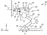
도 1 및 도 2를 참고할 때, 본 발명의 특정 실시 예를 따르고 위치를 재설정할 수 있는 토크 렌치(10)가 도시된다.1 and 2, there is shown a
상기 위치를 재설정할 수 있는 토크 렌치(10)는 하우징(11)을 포함하고, 상기 하우징내에 모터(12)가 배열된다. 또한, 파워 렌치(10)의 위치를 감시하기 위해 위치 설정 시스템(13)이 제공된다.The repositionable torque wrench (10) includes a housing (11) in which a motor (12) is arranged. A
출력 샤프트(14)는 상기 모터(12)와 회전 가능하게 연결되어 구동되고 하우징(11)에 대해 다단 접힘(telescopically)식으로 배열되어 출력 샤프트(14)를 축 방향으로 이동가능하게 한다. 출력 샤프트(14)는 최대 연장 위치(Emax)(도 1에 도시됨) 및 최대 압축 위치(Emin)사이에서 연장될 수 있고, 상기 출력 샤프트(14)를 최대 연장 위치(Emax)를 향해 가압하도록 탄성 부재(25)가 배열된다.The
상기 출력 샤프트(14)는, 나사, 볼트 또는 너트와 같은 패스너(fastener)(16)와 상호 작용하도록 배열된 출력 단부(15), 전형적으로 소켓을 포함한다. 상기 패스너(16)는 공작물(26) 내에 배열된다. 하우징(11)에 대한 출력 샤프트(14)의 연장 정도(E)를 감시하기 위해 센서(17)가 배열되어, 출력 샤프트(14)의 출력 단부(15)의 위치가 결정된다. 상기 센서(17)는 예를 들어, 홀 센서, 유도(inductive)형 센서 또는 용량(capacitive)형 센서를 포함한다.The
전형적인 실시예에서, 모터(12)는 스플라인을 통해 출력 샤프트(14)에 연결된 모터 샤프트(도시되지 않음)를 구동한다. 이 경우, 탄성 부재(25)는 출력 샤프트(14)를 모터 샤프트에 대한 최대 연장 위치를 향해 가압하도록 배열된다. 또한, 다수의 유성 기어와 같은 하나 또는 복수의 기어들이 상기 모터(12)와 출력 샤프트(14) 사이에 배열될 수 있다.In a typical embodiment,
도시된 실시 예에서, 상기 파워 렌치(10)는 홀더(18)에 의해 이동가능하다. 상기 홀더는 링크 연결된 두 개의 레그(19,20)들을 포함하고, 상기 레그들에 의해 상기 파워 렌치(10)는 상향 및 하향으로, 즉 도시된 3D- 좌표계에서 Y- 방향으로 이동할 수 있다. 상기 홀더의 베이스 부(21)는 레일(22)위에 배열된다. 도시된 실시예에서 상기 베이스 부(21)은 상기 레일(22)을 따라 Z- 방향으로 이동할 수 있다. 전형적으로, 베이스 부(21)는 X 방향, 도면들 내부 및 외부로 이동하여 서로 다른 작업 스테이션 및/또는 나사, 볼트 또는 너트와 같은 패스너(16) 사이를 이동하도록 배열된다. 위치 설정 시스템(13)은 파워 렌치 하우징(11)의 현재 위치를 연속적으로 감시하도록 배열되고, 출력 샤프트(14)의 연장 정도(E)를 감시하는 센서(17)를 추가하면, 출력 샤프트(14)의 출력 단부(15)의 위치가 연속적으로 감시될 수 있다.In the illustrated embodiment, the
도 1에서, 출력 샤프트(14)는 외부 요인에 의해 영향을 받지 않아서, 출력 샤프트(14)는 가장 외측 위치(Emax)에 배열된다. 도 2에서, 파워 렌치는 레그(19, 20)에 의해 위쪽으로 이동하고 레일(22)을 따라 이동하는 베이스 부(21)에 의해 패스너(16)를 향하여 z- 방향을 따라 전방으로 이동한다. 파워 렌치의 정확한 이동에 의해 출력 샤프트(14)의 출력 단부(15)는 패스너(16)와 결합된 상태로 접촉하고 결과적으로 출력 샤프트(14)는 최대 연장 위치(Emax) 및 최소 연장 위치(Emin)의 간격에 속하는 연장 정도(E)로 압축된다. 조임 작업이 수행되고 패스너(16)가 조여짐에 따라, 출력 샤프트(14)가 연속적으로 연장되어 출력 단부(15)는 축 방향으로 상기 패스너(16)를 따라 내부로 이동하여 공작물(26)의 연결부(joint)속으로 이동한다. 1 , the
도시된 실시 예에서, 파워 렌치(10)는 출력 샤프트(14)의 출력 단부(15)의 위치를 출력 단부(15)의 미리 정해진 위치와 비교하기 위한 제어 유닛(23)을 추가로 포함한다. 상기 제어 유닛(23) 및 위치 설정 시스템(13)도 파워 렌치(10)의 외측에서 떨어져 위치한다. 이 경우, 상기 파워 렌치(10)는 예를 들어, 유선 또는 IR, 블루투스(Bluetooth) 등과 같은 무선 연결에 의해 제어 유닛(23) 및 위치 설정 시스템(13)과 연결되어야 한다. 상기 연결은 당업자에게는 자명하며 본 명세서에서는 상세히 설명하지 않는다.In the illustrated embodiment, the
표시 유닛(24)은, 출력 샤프트(14)의 출력 단부(15)의 위치가 상기 출력 단부(15)의 미리 정해진 위치와 일치하지 못하면 작업자 또는 자동화된 시스템에 경고하도록 배열된다. 상기 표시 유닛(24)은, 파워 렌치 하우징(11)에 위치하거나 파워렌치 하우징으로부터 떨어져 위치한다. 상기 표시 유닛(24)은 작업자 또는 자동화 된 시스템에 경고하여 적절한 작업이 취해질 수 있도록 한다. 따라서, 표시 유닛(24)은 조작자에 의해 인지될 수 있도록 배열된다. 또한, 본 발명의 특정 실시 예에서, 상기 표시 유닛(24)은 패스너의 조임과 같은 각각의 작업의 상태만을 기록(register)하고, 각각의 작동은 추적 가능하며 의심스러운 품질의 작동이 표시 될 수 있다. 상기 실시 예에서, 모든 작동은 품질에 관계없이 완료되며, 각 작동의 품질은 나중에 조치가 취해지도록 기록된다.The
통상적으로, 파워 렌치(10)의 제어 유닛(23)은, 하우징(11)에 대한 출력 샤프트(14)의 연장 정도(E)가 미리 정해진 범위(Emin- Emax)내에 있을 때에만 특정 작동이 개시하도록 구성된다. 파워렌치의 상기 구성은, 패스너의 길이가 다양하고 패스너의 특정 길이가 특정 위치에서 있는 것으로 예상되는 경우에 유용하다. 현재 나사가 예상 길이와 일치하지 않는다는 신호를 가진 위치에 나사가 배열되면, 작업이 중단될 수 있다. 즉, 부정확한 길이의 나사가 잘못된 위치에서 조여지면 문제가 발생할 수 있다. 나사가 너무 짧으면 조인트가 완전히 조여지지 못하고 나사가 너무 길면 조인트의 뒤쪽에서 나사가 너무 멀리 돌출하여 조인트가 파괴될 수 있다.Typically, the
종종 이동식 벨트(moving belt) 위에서 상당한 스트레스를 받으며 일하는 작업자의 수작업에 의해 나사가 제공되기 때문에, 부정확한 길이를 가진 나사들이 원하지 않는 위치들에 배열될 수 있다. 시간이 지남에 따라 몇 개의 나사가 잘못된 위치에 배열될 수 있다. 부정확한 길이를 가진 패스너가 발견될 때 및 조임 작업이 완료되기 전에 조임 작업이 중단되어 조인트가 손상되지 않게 하는 본 발명의 파워렌치에 의하면 상기 부정확한 위치설정에 따른 문제들이 방지될 수 있다. Since the screws are often provided by the manual labor of a worker working under significant stress on a moving belt, screws of incorrect length can be arranged in undesirable positions. Over time, several screws may be misaligned. With the power wrench of the present invention, when a fastener of incorrect length is found and before the tightening operation is completed, the tightening operation is stopped so that the joint is not damaged, the problems resulting from the incorrect positioning can be avoided.
위치 설정 시스템(13)은 패스너(16)에 대한 파워 렌치 하우징(11)의 위치에 관한 정보를 제공하도록 구성될 수 있다. 센서(17)를 이용하여 감시되는 상기 하우징(11)에 대한 출력 샤프트(14)의 연장 정도가 상기 정보에 추가되어 상기 출력 샤프트(14)의 출력 단부(15)의 정확한 축 방향 위치가 구해진다. The
제어 유닛(23)은, 패스너(16)가 예상 위치에 도달할 때 상기 출력 샤프트(14)의 출력 단부(15)의 실제 위치를 비교하고 상기 실제 위치가 상기 예상 위치와 일치하지 않으면 공구의 작업자에게 경고하도록 구성된다.The
제어 유닛은 출력 샤프트(14)의 연장 정도(E)를 감시하여 고정(fastening) 작업을 제어하고 상기 감시작업에 기초하여 출력 샤프트의 각속도를 조정한다.The control unit monitors the extension degree E of the
즉, 조임 작업을 가능한 한 짧은 시간 동안 수행하기 위해, 조임 작업의 러닝 다운(running down) 과정 동안 높은 각속도를 유지하는 것이 바람직하다. 전달된 토크는 오버 슈트(overshot)될 수 있는 문제가 존재한다. 상기 문제는, 특히 토크가 증가하는 과정 동안 상기 패스너가 일회전(lap)의 일부분 예를 들어 30- 60°만 회전하고 조인트들을 강하게 조일 때 문제를 일으킨다. 이 경우, 증가된 토크에 응답하여 모터를 감속하기 시작하기에는 너무 늦게 되고, 목표 값(토크, 각도 등)은 오버슈트되기 쉽고, 불필요하고 불리한 인장력이 발생할 수 있다. That is, in order to perform the tightening operation for as short a time as possible, it is desirable to maintain a high angular velocity during the running down process of the tightening operation. There is a problem that the transmitted torque may be overshot. The problem is particularly problematic when the fastener rotates only a fraction of a lap, eg 30-60°, and tightens the joints during the course of increasing torque. In this case, it becomes too late to start decelerating the motor in response to the increased torque, the target value (torque, angle, etc.) is likely to overshoot, and unnecessary and unfavorable tensile forces may occur.
즉, 종래 기술에 의하면, 조임 작동은 전달된 토크 값의 피드백 및/또는 출력 샤프트의 각도 위치의 피드백에 의해 제어된다. 상기 설명과 같이 종래기술은 불충분 한데, 조임 작업의 바로 마지막 부분에서만 토크가 증가하고 감시되는 각 위치는 부정확할 수 있기 때문이다.That is, according to the prior art, the tightening operation is controlled by feedback of the transmitted torque value and/or feedback of the angular position of the output shaft. As described above, the prior art is insufficient because the torque increases only in the very last part of the tightening operation and the angular position monitored can be inaccurate.
출력 샤프트(14)의 연장 정도(E)를 감시하면, 조임 작동의 진행상태를 보다 신뢰성 있게 표시할 수 있다. 공지된 패스너의 경우, 패스너의 런닝 다운(running down) 부분의 길이가 알려지고 그 결과 토크가 증가하기 시작하는 출력 샤프트(14)의 연장 위치(E)가 알려져서 상기 연장 위치 앞에서 각속도가 감소될 수 있다.Monitoring the extension degree E of the
즉, 제어 유닛에 의해, 고정 작업의 제1 위상 동안 높은 각속도가 제공되고, 고정 작동이 출력 샤프트(14)의 연장 정도(E)를 감시하는 것에 기초하여 설정된 목표 값에 근접함에 따라 각속도가 감소되는 것이 보장된다.That is, a high angular velocity is provided by the control unit during the first phase of the fixing operation, and the angular velocity is reduced as the fixing operation approaches a target value set on the basis of monitoring the degree of extension E of the
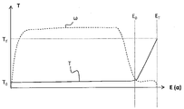
도 3을 참고할 때, 토크(T)는 출력 샤프트(14)의 연장 정도(E) 및 패스너의 각위치(α)의 함수로서 도시된다. 상기 출력 샤프트(14)의 연장 정도(E)는 패스너의 나사 산이 조인트의 나사 산과 결합되는 부분에 대하여 패스너의 각 위치(α) 및 패스너의 런닝 다운(rundown)에 비례하는 것으로 정의된다. 상기 패스너가 조인트와 결합하지 않고 회전하면, 출력 샤프트(14)의 연장 정도(E)가 발생되지 않는다. 본 발명에 따른 상기 구성에 의하면, 발생되지 않는 회전(non productive rotation)운동이 감지될 수 있고, 특히 패스너의 위치를 감지하기 위해 상기 출력 샤프트의 연장 정도가 감시되면 충분하다.Referring to FIG. 3 , the torque T is plotted as a function of the extent of extension E of the
런닝 다운의 초기 단계 동안 토크(T)는 매우 작고 초기 토크(T0)로 일정하다. 초기 단계가 종료될 때, 패스너는 토크가 증가하기 시작하는 위치에 도달한다. 상기 위치에서 출력 샤프트(14)는 연장 정도(E0)에 도달한다. 상기 위치 이후에 상기 패스너와 공작물 사이의 조인트에서 증가함에 따라 토크(T)는 목표 토크(TT)를 향해 증가하기 시작한다.During the initial phase of running down, the torque T is very small and constant with the initial torque T0. At the end of the initial phase, the fastener reaches a position where the torque begins to increase. In this position the
본 발명의 목적은, 조임 작업 동안 목표 토크(TT)를 오버 슈트(overshoot)하지 않고 가능한 한 오랜동안 출력 샤프트의 높은 각속도(ω)를 유지하는 것이다. 전형적으로, 상기 각 속도(ω)는 런닝 다운 과정의 대부분에 걸쳐서 가능한 높게 유지되어야 한다.It is an object of the present invention to maintain a high angular velocity ω of the output shaft for as long as possible without overshooting the target torque T T during the tightening operation. Typically, the angular velocity ω should be kept as high as possible throughout most of the run down process.
출력 샤프트의 연장 정도(E)를 감시하면, 대부분의 런닝 다운 과정동안 각속도(ω)를 유지할 수 있고 목표 토크(TT)에 도달하기 전에 각속도(ω)를 감소시킬 수 있다. 이를 위해 전형적으로 토크가 증가하기 시작하는 연장 정도(E0) 이전에 각속도(ω)가 감소되기 시작한다.Monitoring the extension (E) of the output shaft allows to maintain the angular velocity (ω) during most of the running-down process and reduce the angular velocity (ω) before reaching the target torque (T T ). For this, the angular velocity ω begins to decrease, typically before the extent of extension E 0 , at which the torque begins to increase.
본 발명의 특징에 따르면, 본 발명은 조임 작동시 발생하는 출력 샤프트의 연장 크기의 차이가 패스너의 축 방향 이동거리와 일치한다는 사실에 기초한다. 그러나, 어떤 경우에서, 조여지고 있는 패스너의 운동을 추종하기 위해, 조임 작업 동안 파워 렌치(10)가 이동한다. 이 경우, 패스너의 축 방향 이동거리를 계산하기 위해, 파워 렌치(10)의 모든 운동에 대해 출력 샤프트의 출력 단부의 연장 크기(E)가 보상되어야 한다. 따라서, 출력 샤프트(14)의 출력 단부(15)와 패스너(16) 사이에서 정확한 접촉이 형성되는 위치로부터 출력 샤프트의 출력 단부(15)의 현재 위치까지 패스너의 상기 이동 경로가 예측된다.According to a feature of the present invention, the present invention is based on the fact that the difference in the extension size of the output shaft that occurs during the tightening operation coincides with the axial travel distance of the fastener. However, in some cases, the
다시 말해, 패스너(16)와 공작물(26)에 대한 파워 렌치(10)의 위치는, 출력 샤프트(14)의 출력 단부(15)의 실제 위치를 감시하여 감시된다. 이를 위해, 파워 렌치의 위치 및 출력 샤프트(14)의 연장 크기(E)가 감시된다. 또한, 패스너(16)가 완전히 조여지는 공지 위치가 출력 단부(15)의 기록된 위치(registered position)와 추가로 비교된다. 이 경우, 조임 작업의 목표 위치와 근접하지만 상기 조임 작업이 목표 토크를 오버슈팅하지 않고 종료할 수 있도록 충분히 떨어진 위치에 해당하는 출력 샤프트(14)의 출력 단부(15)의 특정 위치에서 각속도를 감소시키도록 제어 유닛이 구성될 수 있다.In other words, the position of the
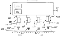
도 4를 참고할 때, 본 발명의 전형적인 실시 예가 도시된다. 상기 실시예에서, 복수의 렌치(110,110')가 개별 다단접힘식 출력 샤프트(114,114')를 가진 공통 구조체(27) 상에 배열된다. 상기 공통 구조체(27)가 조여져야 하는 복수의 패스너(116,116)를 가진 공작물(126)을 향해 하강하거나 공작물이 상기 공통 구조체(27)를 향해 상승된다. 상기 렌치(110,110')들은 개별적으로 작동되거나 모두 한 번에 작동된다. 위치 설정 시스템(113)과 제어 유닛(123)은, 각각의 출력 샤프트(114,114')의 출력 단부(115, 115')의 위치를 감시하도록 배열될 수 있다. 상기 개별 파워 렌치(110, 110')는 도 1 및 도 2를 참고하여 설명된 파워 렌치(10)와 동일한 기능을 가지며 복수의 파워 렌치 및 패스너를 이용하는 조임 작동 시 개별적으로 제어될 수 있다.Referring to Figure 4, an exemplary embodiment of the present invention is shown. In this embodiment, a plurality of
도시된 실시 예에서, 도 4의 우측에 도시된 파워 렌치(110')는 패스너(116')를 위해 개별적으로 이용되고 상기 패스너(116')는 나머지 패스너(116)들과 서로 다른 높이에 위치한다. 상기 파워 렌치(110')의 개별적인 적응에 의해 출력 단부(115')는 다른 출력 샤프트(114)와 해당 패스너(116) 사이의 상호 위치에 대응하는 패스너(116')의 초기 위치를 가져서, 각 패스너를 위해 유사한 스팬(span)의 유연성이 제공된다. 도 4의 좌측에 도시된 패스너(116")는 다른 패스너들 보다 다소 길다. 이것은 의도적일 수도 있고 아닐 수도 있으며, 출력 샤프트(114)의 스팬은 모든 형태의 조인트에 대해 충분하도록 배열될 수 있다. 본 발명에 따르면, 위치 설정 시스템은, 출력 샤프트(114)의 연장 정도를 감시하여 출력 단부(115)가 패스너(116")에 도달할 때를 인식하고, 패스너(116")가 정확한 길이를 가지지 않는 것을 나타내는 위치에 상기 패스너(116")가 도달하면 작업자 또는 자동 시스템에게 경고한다.In the illustrated embodiment, the power wrench 110' shown on the right side of FIG. 4 is used individually for the fasteners 116' and the fasteners 116' are located at a different height than the rest of the
상기 설명에서 본 발명은 특정 실시 예를 참고하여 설명되었다. 그러나, 본 발명은 상기 실시 예로 한정되지 않는다. 당업자는, 본 발명이 하기 청구범위에 의해 한정되는 보호범위내에서 다른 실시예들을 포함하는 것을 이해한다.In the above description, the present invention has been described with reference to specific embodiments. However, the present invention is not limited to the above embodiment. A person skilled in the art will understand that the present invention includes other embodiments within the scope of protection defined by the following claims.
10......파워 렌치,
11......하우징,
12......모터,
14......출력 샤프트,
25......탄성 부재,
17......센서.10....power wrench,
11......Housing,
12....Motor,
14......Output shaft,
25......elastic absence,
17....sensor.
Claims (13)
하우징(11),
상기 하우징(11) 내에 배열된 모터(12) 및
상기 모터와 회전운동하도록 연결된 출력 샤프트(14)를 포함하고, 상기 출력 샤프트(14)는 하우징(11)에 대해 다단접힘식으로 배열되어 출력 샤프트(14)가 최대 연장 위치(Emax) 및 최대 압축 위치 사이에서 하우징(11)에 대해 축 방향으로 이동할 수 있고, 출력 샤프트(14)를 상기 최대 연장 위치(Emax)를 향해 가압하는 탄성 부재(25)를 포함하며, 상기 파워 렌치(10)는 하우징(11)의 위치를 감시하기 위해 배열된 위치 설정 시스템(13)을 추가로 포함하거나 위치 설정 시스템(13)에 연결되고,
출력 샤프트(14)는 패스너와 상호작용하도록 배열된 출력 단부(15)를 포함하며, 하우징(11)에 대해 출력 샤프트(14)의 연장 크기(E)를 연속적으로 감시하기 위해 센서(17)가 배열되어,
출력 샤프트(14)의 출력 단부(15)의 정확한 위치는, 위치 설정 시스템(13)에 의해 감시되는 하우징(11)의 위치 및 센서(17)에 의해 감시되는 연장 크기(E)에 기초하여 결정될 수 있으며,
위치 설정 시스템(13)은 하우징(11)의 현재 위치를 연속적으로 감시하도록 배열되어 출력 샤프트(14)의 출력 단부(15)의 정확한 위치가 연속적으로 감시되는, 것을 특징으로 하는 파워 렌치.
A repositionable power wrench (10) comprising:
housing (11);
a motor 12 arranged in the housing 11 and
an output shaft (14) connected for rotational movement with the motor, the output shaft (14) being arranged in a multi-stage fold with respect to the housing (11) so that the output shaft (14) is in a maximum extended position (Emax) and maximum compression and a resilient member (25) movable axially with respect to the housing (11) between positions and for urging the output shaft (14) towards said maximum extended position (Emax), said power wrench (10) comprising: (11) further comprising or connected to a positioning system (13) arranged for monitoring the position of (11);
The output shaft 14 comprises an output end 15 arranged to interact with a fastener, and a sensor 17 to continuously monitor the extent of extension E of the output shaft 14 with respect to the housing 11 . arranged,
The exact position of the output end 15 of the output shaft 14 will be determined based on the position of the housing 11 monitored by the positioning system 13 and the extension size E monitored by the sensor 17 . can,
The positioning system (13) is arranged to continuously monitor the current position of the housing (11) so that the exact position of the output end (15) of the output shaft (14) is continuously monitored.
2. The power wrench (10) according to claim 1, further comprising a control unit (23) for comparing the position of the output end (15) of the output shaft (14) with a predetermined position of the output end (15). or a power wrench, characterized in that it is connected.
3. Power wrench according to claim 2, characterized in that an indication unit (24) is arranged to warn if the position of the output end (15) of the output shaft (14) does not match the predetermined position of the output end (15). .
4. The control unit (23) according to claim 2 or 3, wherein the control unit (23) is configured to initiate a specific operation only when the extension size (E) of the output shaft (14) with respect to the housing (11) is within a predetermined range. A power wrench characterized in that it becomes.
The output shaft to the housing (11) according to claim 4, wherein the positioning system (13) is configured to provide information about the position of the housing (11) with respect to the fastener (16) and is monitored by a sensor (17) The power wrench, characterized in that the extent of extension of (14) is added to the information to obtain the correct axial position of the output end (15) of the output shaft (14) relative to the fastener (16).
6. The control unit (23) according to claim 5, wherein the control unit (23) compares the actual position of the output end (15) of the output shaft (14) when the fastener (16) reaches the expected position, and A power wrench characterized in that an operator of the power wrench (10) is alerted if the actual position of the output end (15) does not match the expected position.
4. The control unit (23) according to claim 2 or 3, wherein the control unit (23) monitors the extension size (E) of the output shaft (14) to monitor a fixing operation and controls the angular velocity of the output shaft (14) based on the monitoring A power wrench, characterized in that
8. The power wrench according to claim 7, wherein an angular velocity (ω) is provided by the control unit during a first phase of the fixing operation and the angular velocity (ω) is reduced as the fixing operation approaches a set target value.
2. The motor (12) of claim 1, wherein the motor (12) drives a motor shaft connected to the output shaft (14) via splines, and the elastic member (25) urges the output shaft (14) toward a position of maximum extension relative to the motor shaft. Power wrench, characterized in that arranged.
2. Power wrench according to claim 1, characterized in that the sensor (17) is a Hall sensor, an inductive sensor or a capacitive sensor.
A power wrench according to claim 2 , a positioning system arranged to monitor the position of the power wrench ( 10 ) and a predetermined position of the output end ( 15 ) of the output shaft ( 14 ) Power wrench system, characterized in that it comprises a control unit (23) for comparing with.
12. The power wrench according to claim 11, comprising a plurality of power wrenches (110) arranged on a common structure (27), said control unit (23) comprising an output end (15) of an output shaft (14) of each power wrench (110) ) and comparing the position of each output end (15) with a predetermined position.
파워 렌치(10)의 하우징(11)의 위치를 연속적으로 감시하는 단계,
파워 렌치(10)의 하우징(11)에 대해 출력 샤프트의 연장 크기(E)를 감시하는 단계, 및
하우징(11)의 감시된 위치 및 하우징(11)에 대한 출력 샤프트의 감시된 연장 크기(E)에 기초하여 출력 샤프트의 출력 단부의 위치를 연속적으로 결정하는 단계를 포함하는, 것을 특징으로 하는 방법. A method for monitoring the position of an output end of a foldable output shaft of a repositionable power wrench (10) according to claim 1, said method comprising:
continuously monitoring the position of the housing (11) of the power wrench (10);
monitoring the extension size (E) of the output shaft with respect to the housing (11) of the power wrench (10), and
Method, characterized in that it comprises the step of successively determining the position of the output end of the output shaft on the basis of the monitored position of the housing (11) and the monitored extension size (E) of the output shaft with respect to the housing (11). .
Applications Claiming Priority (3)
| Application Number | Priority Date | Filing Date | Title |
|---|---|---|---|
| SE1451504A SE1451504A1 (en) | 2014-12-10 | 2014-12-10 | Power tool with position control |
| SE1451504-3 | 2014-12-10 | ||
| PCT/EP2015/068284 WO2016091404A1 (en) | 2014-12-10 | 2015-08-07 | Power tool with position control |
Publications (2)
| Publication Number | Publication Date |
|---|---|
| KR20170093233A KR20170093233A (en) | 2017-08-14 |
| KR102410274B1 true KR102410274B1 (en) | 2022-06-16 |
Family
ID=53836577
Family Applications (1)
| Application Number | Title | Priority Date | Filing Date |
|---|---|---|---|
| KR1020177018988A KR102410274B1 (en) | 2014-12-10 | 2015-08-07 | Power tool with position control |
Country Status (7)
| Country | Link |
|---|---|
| US (1) | US11097386B2 (en) |
| EP (1) | EP3230009B1 (en) |
| JP (1) | JP6793121B2 (en) |
| KR (1) | KR102410274B1 (en) |
| CN (1) | CN107000179B (en) |
| SE (1) | SE1451504A1 (en) |
| WO (1) | WO2016091404A1 (en) |
Families Citing this family (5)
| Publication number | Priority date | Publication date | Assignee | Title |
|---|---|---|---|---|
| JP7157548B2 (en) * | 2018-04-21 | 2022-10-20 | 日東精工株式会社 | Screw tightening robot |
| CN110303448A (en) * | 2019-07-18 | 2019-10-08 | 中铁十八局集团有限公司 | It is a kind of with positioning and memory function assist installation torque wrench system |
| TWI788040B (en) * | 2020-10-06 | 2022-12-21 | 湛積股份有限公司 | Smart handheld tool |
| KR20220081011A (en) * | 2020-12-08 | 2022-06-15 | (주)볼팅마스타 | Torque wrench control system |
| US11850691B2 (en) * | 2021-09-08 | 2023-12-26 | Honda Motor Co., Ltd | Fastening system and fastening method |
Citations (1)
| Publication number | Priority date | Publication date | Assignee | Title |
|---|---|---|---|---|
| JP2005121132A (en) * | 2003-10-16 | 2005-05-12 | Tohnichi Mfg Co Ltd | Fastening management system for fastening member |
Family Cites Families (14)
| Publication number | Priority date | Publication date | Assignee | Title |
|---|---|---|---|---|
| BE791093A (en) * | 1971-12-30 | 1973-03-01 | Gardner Denver Co | TOOL SPEED AUTOMATIC VARIATOR |
| JPH0445787Y2 (en) * | 1984-09-28 | 1992-10-28 | ||
| DE3620137A1 (en) * | 1986-06-14 | 1987-12-17 | Raimund Wilhelm | SCREW MACHINE AND METHOD FOR THEIR OPERATION |
| JP2675351B2 (en) * | 1988-09-20 | 1997-11-12 | マツダ株式会社 | Fastening device for fastening members |
| JPH06304826A (en) * | 1993-04-26 | 1994-11-01 | Nikko Eng Kk | Automatic screw tightening machine |
| JPH07223130A (en) * | 1994-02-08 | 1995-08-22 | Nippondenso Co Ltd | Screw tightening device |
| JP3280522B2 (en) * | 1994-07-26 | 2002-05-13 | 松下電工株式会社 | Trimmer adjustment method and device |
| US6571179B2 (en) | 2001-08-24 | 2003-05-27 | Xerox Corporation | Intelligent power tool |
| SE532501C2 (en) * | 2008-11-07 | 2010-02-09 | Atlas Copco Tools Ab | Method and device for position locking of nut wrenches for correcting unacceptable results in screw joint tightening |
| CN101941192B (en) * | 2009-07-10 | 2012-11-21 | 苏州宝时得电动工具有限公司 | Electric tool |
| JP5745321B2 (en) | 2011-04-15 | 2015-07-08 | 日東精工株式会社 | Automatic screw tightening device |
| JP5807750B2 (en) | 2012-01-05 | 2015-11-10 | トヨタ自動車株式会社 | Fastening device and fastening method |
| CN103386665B (en) * | 2012-05-07 | 2015-07-01 | 苏州宝时得电动工具有限公司 | Control method of electric tool and electric tool used for executing control method |
| JP5741617B2 (en) | 2013-03-19 | 2015-07-01 | 株式会社安川電機 | Robot equipment |
-
2014
- 2014-12-10 SE SE1451504A patent/SE1451504A1/en unknown
-
2015
- 2015-08-07 US US15/535,037 patent/US11097386B2/en active Active
- 2015-08-07 EP EP15750374.9A patent/EP3230009B1/en active Active
- 2015-08-07 WO PCT/EP2015/068284 patent/WO2016091404A1/en active Application Filing
- 2015-08-07 CN CN201580066488.0A patent/CN107000179B/en active Active
- 2015-08-07 KR KR1020177018988A patent/KR102410274B1/en active IP Right Grant
- 2015-08-07 JP JP2017531280A patent/JP6793121B2/en active Active
Patent Citations (1)
| Publication number | Priority date | Publication date | Assignee | Title |
|---|---|---|---|---|
| JP2005121132A (en) * | 2003-10-16 | 2005-05-12 | Tohnichi Mfg Co Ltd | Fastening management system for fastening member |
Also Published As
| Publication number | Publication date |
|---|---|
| SE538301C2 (en) | 2016-05-03 |
| CN107000179A (en) | 2017-08-01 |
| JP6793121B2 (en) | 2020-12-02 |
| EP3230009B1 (en) | 2019-01-09 |
| US20170326695A1 (en) | 2017-11-16 |
| WO2016091404A1 (en) | 2016-06-16 |
| KR20170093233A (en) | 2017-08-14 |
| SE1451504A1 (en) | 2016-05-03 |
| CN107000179B (en) | 2019-09-24 |
| JP2017538592A (en) | 2017-12-28 |
| EP3230009A1 (en) | 2017-10-18 |
| US11097386B2 (en) | 2021-08-24 |
Similar Documents
| Publication | Publication Date | Title |
|---|---|---|
| KR102410274B1 (en) | Power tool with position control | |
| JP5565550B2 (en) | Automatic screw tightening device and control method thereof | |
| DK2729281T3 (en) | Work device and method | |
| US20220324118A1 (en) | Work robot system | |
| JP5745321B2 (en) | Automatic screw tightening device | |
| US20160167235A1 (en) | Gear gripping device and method for gripping a gear | |
| JP5824354B2 (en) | Automatic screw tightening device | |
| JP5711550B2 (en) | Automatic screwing machine | |
| JP5775480B2 (en) | Screw fastening method and screw fastening device | |
| JP6154689B2 (en) | Automatic screwing machine | |
| JP6146154B2 (en) | Bolt fastening method and bolt fastening device | |
| US20210283753A1 (en) | Electric pulse tool | |
| JP5837769B2 (en) | Automatic screw tightening device | |
| JP4924823B2 (en) | Bolt or nut loosening method and device | |
| JP2019188503A (en) | Screw fastening robot | |
| US20190302728A1 (en) | Motor control device | |
| JP2008126320A (en) | Nut tightening method and manufacturing device of assembly | |
| KR100594795B1 (en) | Bolt fastening method | |
| JP6527405B2 (en) | Screw tightening device | |
| CN115229480A (en) | Tightening device for automatically performing a tightening process | |
| JP2010201537A (en) | Method of monitoring poor screw fastening | |
| JPH1015846A (en) | Method of deciding fastening, method of fastening, and equipment therefor |
Legal Events
| Date | Code | Title | Description |
|---|---|---|---|
| E902 | Notification of reason for refusal | ||
| E701 | Decision to grant or registration of patent right | ||
| GRNT | Written decision to grant |