KR102239214B1 - Power train apparatus for electric motor vehicle - Google Patents
Power train apparatus for electric motor vehicle Download PDFInfo
- Publication number
- KR102239214B1 KR102239214B1 KR1020190165665A KR20190165665A KR102239214B1 KR 102239214 B1 KR102239214 B1 KR 102239214B1 KR 1020190165665 A KR1020190165665 A KR 1020190165665A KR 20190165665 A KR20190165665 A KR 20190165665A KR 102239214 B1 KR102239214 B1 KR 102239214B1
- Authority
- KR
- South Korea
- Prior art keywords
- motor
- power
- gearbox
- clutch
- driving
- Prior art date
Links
Images
Classifications
-
- B—PERFORMING OPERATIONS; TRANSPORTING
- B60—VEHICLES IN GENERAL
- B60K—ARRANGEMENT OR MOUNTING OF PROPULSION UNITS OR OF TRANSMISSIONS IN VEHICLES; ARRANGEMENT OR MOUNTING OF PLURAL DIVERSE PRIME-MOVERS IN VEHICLES; AUXILIARY DRIVES FOR VEHICLES; INSTRUMENTATION OR DASHBOARDS FOR VEHICLES; ARRANGEMENTS IN CONNECTION WITH COOLING, AIR INTAKE, GAS EXHAUST OR FUEL SUPPLY OF PROPULSION UNITS IN VEHICLES
- B60K17/00—Arrangement or mounting of transmissions in vehicles
- B60K17/34—Arrangement or mounting of transmissions in vehicles for driving both front and rear wheels, e.g. four wheel drive vehicles
-
- B—PERFORMING OPERATIONS; TRANSPORTING
- B60—VEHICLES IN GENERAL
- B60K—ARRANGEMENT OR MOUNTING OF PROPULSION UNITS OR OF TRANSMISSIONS IN VEHICLES; ARRANGEMENT OR MOUNTING OF PLURAL DIVERSE PRIME-MOVERS IN VEHICLES; AUXILIARY DRIVES FOR VEHICLES; INSTRUMENTATION OR DASHBOARDS FOR VEHICLES; ARRANGEMENTS IN CONNECTION WITH COOLING, AIR INTAKE, GAS EXHAUST OR FUEL SUPPLY OF PROPULSION UNITS IN VEHICLES
- B60K1/00—Arrangement or mounting of electrical propulsion units
- B60K1/02—Arrangement or mounting of electrical propulsion units comprising more than one electric motor
-
- B—PERFORMING OPERATIONS; TRANSPORTING
- B60—VEHICLES IN GENERAL
- B60K—ARRANGEMENT OR MOUNTING OF PROPULSION UNITS OR OF TRANSMISSIONS IN VEHICLES; ARRANGEMENT OR MOUNTING OF PLURAL DIVERSE PRIME-MOVERS IN VEHICLES; AUXILIARY DRIVES FOR VEHICLES; INSTRUMENTATION OR DASHBOARDS FOR VEHICLES; ARRANGEMENTS IN CONNECTION WITH COOLING, AIR INTAKE, GAS EXHAUST OR FUEL SUPPLY OF PROPULSION UNITS IN VEHICLES
- B60K17/00—Arrangement or mounting of transmissions in vehicles
- B60K17/02—Arrangement or mounting of transmissions in vehicles characterised by arrangement, location, or kind of clutch
-
- F—MECHANICAL ENGINEERING; LIGHTING; HEATING; WEAPONS; BLASTING
- F16—ENGINEERING ELEMENTS AND UNITS; GENERAL MEASURES FOR PRODUCING AND MAINTAINING EFFECTIVE FUNCTIONING OF MACHINES OR INSTALLATIONS; THERMAL INSULATION IN GENERAL
- F16H—GEARING
- F16H57/00—General details of gearing
- F16H57/02—Gearboxes; Mounting gearing therein
-
- B—PERFORMING OPERATIONS; TRANSPORTING
- B60—VEHICLES IN GENERAL
- B60Y—INDEXING SCHEME RELATING TO ASPECTS CROSS-CUTTING VEHICLE TECHNOLOGY
- B60Y2200/00—Type of vehicle
- B60Y2200/90—Vehicles comprising electric prime movers
- B60Y2200/91—Electric vehicles
Abstract
Description
본 발명은 전기 차량용 동력 전달계 장치에 관한 것이다.The present invention relates to a power transmission system device for an electric vehicle.
일반적으로 전기 에너지를 이용하여 구동 모터를 구동시켜 주행하는 전기 차량에는 가솔린 차량에 적용되는 변속기와 유사한 기능을 수행하는 전기 차량용 감속기가 장착된다. 가솔린 차량에서 변속기는 동력원인 엔진의 효율을 위하여 다단을 사용하지만, 전기 차량의 경우 동력원이 모터이기 때문에 전기적으로 토크와 속도의 효율적인 제어가 가능하다. 이때, 전기 차량에는 차량의 주행 환경에 맞는 속도와 토크 제어를 위하여 전기 차량용 감속기가 장착된다. 따라서 효율적인 감속기의 구동을 가능하게 하는 기어의 배열 및 크기는 동력 손실 및 운전자의 승차감과 직결되는 요소에 해당한다. 이러한 전기 차량용 감속기는 배터리에 저장된 전기 에너지에 의해 구동하는 모터의 구동 샤프트에 설치된 드라이브 기어가 회전하게 되고, 이 드라이브 기어의 회전에 연동하는 트랜스퍼 드리븐 기어의 회전에 따라 치합된 디퍼렌셜 기어(differential gear)가 회전함으로써 모터로부터의 동력을 구동륜에 전달하여 차량의 주행이 이루어진다. 이와 같은 기능을 수행하는 전기 차량용 감속기를 위해서 구동 모터와 배터리의 용량이 커야 하며, 또한 감속기만으로는 등판 능력 및 가속성이 낮은 문제가 있다. 이러한 문제점을 개선하기 위해 전기 차량에 2단 감속기(변속기)를 장착하고 있다.In general, electric vehicles driven by driving a drive motor using electric energy are equipped with a speed reducer for an electric vehicle that performs a function similar to a transmission applied to a gasoline vehicle. In gasoline vehicles, the transmission uses multiple stages for the efficiency of the engine, which is a power source, but in the case of an electric vehicle, since the power source is a motor, efficient control of torque and speed is possible electrically. At this time, the electric vehicle is equipped with a reducer for an electric vehicle in order to control speed and torque suitable for the driving environment of the vehicle. Therefore, the arrangement and size of gears that enable the efficient driving of the reducer correspond to factors directly connected to power loss and driver's ride comfort. In such an electric vehicle reducer, the drive gear installed on the drive shaft of the motor driven by the electric energy stored in the battery rotates, and a differential gear engaged with the rotation of the transfer-driven gear linked to the rotation of the drive gear. By rotating, the power from the motor is transmitted to the drive wheels, and the vehicle is driven. For the electric vehicle reducer to perform such a function, the capacity of the drive motor and the battery must be large, and there is a problem of low climbing ability and acceleration only with the reducer. To improve this problem, an electric vehicle is equipped with a two-speed reducer (transmission).
그런데 현재 전기 차량용 2단 감속기의 변속 기능 구현에 어려움이 있다. 구체적으로 싱크로 기구의 과다한 각속도로 인한 소손 및 내구성 부족, 습식 클러치 사용으로 인한 효율 저하, 모터의 고속 구동에 따른 베어링 및 기어의 기술적 한계, 단일 기어비 감속기 사용에 따른 모터의 용량 증대 등과 같은 다양한 문제로 인하여 전기 차량용 2단 감속기의 변속 기능 구현에 어려움을 겪고 있는 실정이다.However, there is a difficulty in implementing the shifting function of a two-stage reducer for an electric vehicle. Specifically, due to various problems such as burnout and lack of durability due to excessive angular speed of the synchro mechanism, decrease in efficiency due to the use of a wet clutch, technical limitations of bearings and gears due to high-speed driving of the motor, and increase in the capacity of the motor due to the use of a single gear ratio reducer. Therefore, it is difficult to implement the shift function of the two-stage reducer for electric vehicles.
이에 대하여, 본 발명은 저속 주행 또는 고속 주행에 따라 전륜 구동으로 주행하거나 후륜 구동으로 주행할 수 있는 메커니즘을 제시하고자 한다.On the other hand, the present invention is to provide a mechanism capable of driving with front-wheel drive or rear-wheel drive according to low-speed driving or high-speed driving.
전술한 문제를 해결하기 위하여, 본 발명은 저속시 전륜 구동으로 주행하고 고속시 후륜 구동으로 주행하는 등 주행 속도에 맞추어 최적의 효율적인 동력 전달이 이루어질 수 있도록 한 전기 차량용 동력 전달계 장치를 제공하고자 한다.In order to solve the above-described problem, the present invention is to provide a power transmission system device for an electric vehicle capable of achieving optimal and efficient power transmission according to a driving speed, such as driving with front wheel drive at low speed and driving with rear wheel drive at high speed.
전술한 목적을 이루기 위해 본 발명은, 전륜 및 후륜 양방향으로 동력 전달이 가능한 모터; 상기 모터의 일측 동력 전달축과 연결되고 모터에서 전달 받은 동력을 전륜에 전달하는 제1 기어박스; 및 상기 모터의 타측 동력 전달축과 연결되고 모터에서 전달 받은 동력을 후륜에 전달하는 제2 기어박스; 를 포함하는 전기 차량용 동력 전달계 장치를 제공한다.In order to achieve the above object, the present invention is a motor capable of transmitting power in both directions of the front wheel and the rear wheel; A first gearbox connected to a power transmission shaft of one side of the motor and transmitting power received from the motor to the front wheels; And a second gearbox connected to the other power transmission shaft of the motor and transmitting power received from the motor to the rear wheels. It provides a power transmission system device for an electric vehicle comprising a.
또한, 상기 모터와 제1 기어박스 사이에서 모터와 제1 기어박스 사이의 동력을 연결하거나 끊는 전륜 클러치가 구비된다.In addition, a front wheel clutch is provided between the motor and the first gearbox to connect or disconnect power between the motor and the first gearbox.
또한, 상기 모터와 제2 기어박스 사이에서 모터와 제2 기어박스 사이의 동력을 연결하거나 끊는 후륜 클러치가 구비된다.In addition, a rear wheel clutch is provided between the motor and the second gearbox to connect or disconnect power between the motor and the second gearbox.
또한, 상기 전륜의 반경과 후륜의 반경은 서로 다르다.Further, the radius of the front wheel and the radius of the rear wheel are different from each other.
또한, 상기 전륜의 반경 보다 후륜의 반경이 더 크다.In addition, the radius of the rear wheel is larger than that of the front wheel.
또한, 상기 제1 기어박스의 기어비와 제2 기어박스의 기어비는 서로 다르다.In addition, a gear ratio of the first gearbox and a gear ratio of the second gearbox are different from each other.
또한, 상기 제1 기어박스의 기어비가 제2 기어박스의 기어비 보다 더 크다.In addition, the gear ratio of the first gearbox is greater than that of the second gearbox.
또한, 스타트 또는 저속 구동시에는 상기 전륜 클러치는 동력을 연결하고 상기 후륜 클러치는 동력을 끊어 전륜 구동으로 주행한다.In addition, when starting or driving at a low speed, the front wheel clutch connects power and the rear wheel clutch disconnects the power to drive the front wheel.
또한, 상기 저속 주행은 50km/h 이하 주행이다.In addition, the low-speed driving is a driving of 50 km/h or less.
또한, 시프트시에는 상기 전륜 클러치와 후륜 클러치 모두 동력을 끊은 상태에서 상기 모터의 스피드 체인지 후 동력을 전달하고자 하는 전륜 클러치 또는 후륜 클러치의 동력을 연결한다.In addition, during the shift, the power of the front clutch or the rear clutch to be transmitted after the speed change of the motor is connected in a state in which both the front clutch and the rear clutch are powered off.
또한, 고속 주행시에는 상기 전륜 클러치는 동력을 끊고 후륜 클러치는 동력을 연결하여 후륜 구동으로 주행한다.In addition, during high-speed driving, the front clutch disconnects the power and the rear clutch connects the power to drive the rear wheel.
또한, 상기 고속 주행은 50km/h 초과 주행이다.In addition, the high-speed driving is a driving exceeding 50 km/h.
본 발명은 저속시 전륜 구동으로 주행하고 고속시 후륜 구동으로 주행하는 등 주행 속도에 맞추어 최적의 효율적인 동력 전달이 이루어질 수 있다.According to the present invention, optimal and efficient power transmission can be achieved according to the driving speed, such as driving with front wheel drive at low speed and driving with rear wheel drive at high speed.
또한, 본 발명은 전륜 및 후륜의 부품 구성을 균등 분배할 수 있다.In addition, the present invention can evenly distribute the component configurations of the front and rear wheels.
또한, 본 발명은 스타트 및 저속 주행시 전륜 구동으로 주행하고, 고속 주행시 후륜 구동을 사용하므로 발진 성능 향상 및 주행시 승차감을 높일 수 있다.Further, according to the present invention, it is possible to improve start performance and improve riding comfort when driving, since the present invention drives with front wheel drive during start and low speed driving and uses rear wheel drive when driving at high speed.
또한, 본 발명은 코너링 성능 향상 및 고속 주행시 후륜 구동으로 인해 언더스티어(understeer)를 방지할 수 있다.In addition, the present invention can improve cornering performance and prevent understeer due to rear wheel driving during high-speed driving.
또한, 본 발명은 변속 전 모터 속도 조정을 통해 동기화를 실시할 수 있고 변속 과정에서 쇼크(Shock) 등의 발생을 방지할 수 있다.In addition, according to the present invention, synchronization can be performed by adjusting the motor speed before shifting, and occurrence of a shock or the like can be prevented during the shifting process.
또한, 본 발명은 전륜 측 기어박스의 높은 기어비와 후륜 보다 작은 전륜 반경을 통해 가속성능을 확보할 수 있고, 모터 사이즈를 낮출 수 있다.In addition, the present invention can secure acceleration performance through a high gear ratio of the front wheel side gearbox and a front wheel radius smaller than that of the rear wheel, and reduce the motor size.
또한, 본 발명은 후륜 측 기어박스의 낮은 기어비와 전륜 보다 큰 후륜 반경을 통해 고속 주행 성능 확보 및 모터 용량을 최소화할 수 있다.In addition, the present invention can secure high-speed driving performance and minimize motor capacity through a lower gear ratio of the rear wheel side gearbox and a rear wheel radius larger than that of the front wheel.
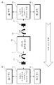
도 1은 본 발명의 바람직한 일 실시예에 따른 전기 차량용 동력 전달계 장치를 개략적으로 나타내는 도면이다.1 is a view schematically showing a power transmission system device for an electric vehicle according to an embodiment of the present invention.
이하, 본 발명의 바람직한 실시예를 첨부된 도면들을 참조하여 상세히 설명한다. 우선 각 도면의 구성 요소들에 참조 부호를 부가함에 있어서, 동일한 구성 요소들에 대해서는 비록 다른 도면상에 표시되더라도 가능한 한 동일한 부호를 가지도록 하고 있음에 유의해야 한다. 또한, 본 발명을 설명함에 있어, 관련된 공지 구성 또는 기능에 대한 구체적인 설명이 본 발명의 요지를 흐릴 수 있다고 판단되는 경우에는 그 상세한 설명은 생략한다. 또한, 이하에서 본 발명의 바람직한 실시예를 설명할 것이나, 본 발명의 기술적 사상은 이에 한정하거나 제한되지 않고 당업자에 의해 변형되어 다양하게 실시될 수 있음은 물론이다.Hereinafter, preferred embodiments of the present invention will be described in detail with reference to the accompanying drawings. First of all, in adding reference numerals to elements of each drawing, it should be noted that the same elements are assigned the same numerals as possible, even if they are indicated on different drawings. In addition, in describing the present invention, when it is determined that a detailed description of a related known configuration or function may obscure the subject matter of the present invention, a detailed description thereof will be omitted. In addition, a preferred embodiment of the present invention will be described below, but the technical idea of the present invention is not limited or limited thereto, and may be modified and variously implemented by a person skilled in the art.
현재 전기 차량용 2단 감속기의 변속 기능 구현에 어려움이 있다. 구체적으로 싱크로 기구의 과다한 각속도로 인한 소손 및 내구성 부족, 습식 클러치 사용으로 인한 효율 저하, 모터의 고속 구동에 따른 베어링 및 기어의 기술적 한계, 단일 기어비 감속기 사용에 따른 모터의 용량 증대 등과 같은 다양한 문제로 인하여 전기 차량용 2단 감속기의 변속 기능 구현에 어려움을 겪고 있는 실정이다. 이에 대하여, 본 발명은 저속 주행 또는 고속 주행에 따라 전륜 구동으로 주행하거나 후륜 구동으로 주행할 수 있는 메커니즘을 제시하고자 한다.Currently, there is a difficulty in implementing the shifting function of a two-speed reducer for an electric vehicle. Specifically, due to various problems such as burnout and lack of durability due to excessive angular speed of the synchro mechanism, decrease in efficiency due to the use of a wet clutch, technical limitations of bearings and gears due to high-speed driving of the motor, and increase in the capacity of the motor due to the use of a single gear ratio reducer. Therefore, it is difficult to implement the shift function of the two-stage reducer for electric vehicles. On the other hand, the present invention is to provide a mechanism capable of driving with front-wheel drive or rear-wheel drive according to low-speed driving or high-speed driving.
도 1은 본 발명의 바람직한 일 실시예에 따른 전기 차량용 동력 전달계 장치를 개략적으로 나타내는 도면이다.1 is a view schematically showing a power transmission system device for an electric vehicle according to an embodiment of the present invention.
본 발명은 양방향 출력형 모터(10), 모터(10)와 연결되고 모터(10)의 동력을 전륜(41, 42)에 전달하는 제1 기어박스(31), 모터(10)와 연결되고 모터(10)의 동력을 후륜(43, 44)에 전달하는 제2 기어박스(32), 모터(10)와 제1 기어박스(31) 사이에서 동력을 연결하거나 끊는 전륜 클러치(21) 및 모터(10)와 제2 기어박스(32) 사이에서 동력을 연결하거나 끊는 후륜 클러치(22)를 포함한다.The present invention is a bidirectional
모터(10)는 양방향으로 동력이 출력되는 양방향 출력형 모터이다. 모터(10)는 양방향으로 동력을 출력하기 위해 전륜(41, 42) 방향으로 일측 동력 전달축(11)이 구비되고, 후륜(43, 44) 방향으로 타측 동력 전달축(12)이 구비된다.The
제1 기어박스(31)는 모터(10)의 일측 동력 전달축(11)과 연결된다. 제1 기어박스(31)는 모터(10)에서 전달 받은 동력을 전륜(41, 42)에 전달한다.The
일예로서, 제1 기어박스(31)는 리어 액슬(Rear Axle) 구조의 RH타입 하이포이드 기어박스일 수 있다.As an example, the
전륜(41, 42)은 제1 기어박스(31)를 중심으로 좌우 양측으로 구비된다. 전륜(41, 42)은 후륜(43, 44) 보다 휠 반경이 작게 형성된다. 전륜(41, 42)의 휠 반경이 후륜(43, 44) 보다 작기 때문에 제1 기어박스(31)의 기어비를 제2 기어박스(32)의 기어비 보다 크게 설계하는 것이 바람직하다.The
모터(10)와 제1 기어박스(31) 사이에 전륜 클러치(21)가 구비된다. 차량의 스타트(Start) 또는 50km/h 이하 등과 같은 저속 주행시 전륜 클러치(21)는 동력을 연결하여 모터(10)의 동력이 제1 기어박스(31)를 거쳐 전륜(41, 42)에 전달되게 함으로써 전륜(41, 42) 구동으로 주행할 수 있도록 한다.A
50km/h 초과 등과 같은 고속 주행시 전륜 클러치(21)는 동력을 끊어 모터(10)의 동력이 제1 기어박스(31)로 전달되지 않게 한다.When driving at a high speed such as over 50km/h, the
제2 기어박스(32)는 모터(10)의 타측 동력 전달축(12)과 연결된다. 제2 기어박스(32)는 모터(10)에서 전달 받은 동력을 후륜(43, 44)에 전달한다.The
일예로서, 제2 기어박스(32)는 리어 액슬(Rear Axle) 구조의 LH타입 하이포이드 기어박스일 수 있다.As an example, the
후륜(43, 44)은 제2 기어박스(32)를 중심으로 좌우 양측으로 구비된다. 후륜(43, 44)은 전륜(41, 42) 보다 휠 반경이 크게 형성된다. 후륜(43, 44)의 휠 반경이 전륜(41, 42) 보다 크기 때문에 제2 기어박스(32)의 기어비를 제1 기어박스(31)의 기어비 보다 작게 설계하는 것이 바람직하다.The
모터(10)와 제2 기어박스(32) 사이에 후륜 클러치(22)가 구비된다. 50km/h 를 초과하는 고속 주행시 후륜 클러치(22)는 동력을 연결하여 모터(10)의 동력이 제2 기어박스(32)를 거쳐 전륜(41, 42)에 전달되게 함으로써 후륜(43, 44) 구동으로 주행할 수 있도록 한다.A
50km/h 이하의 저속 주행시 후륜 클러치(22)는 동력을 끊어 모터(10)의 동력이 제2 기어박스(32)로 전달되지 않게 한다.When traveling at a low speed of 50 km/h or less, the rear clutch 22 cuts off the power so that the power of the
다음은 본 발명에 따른 전기 차량용 동력 전달계 장치의 스타트 또는 저속 구동시 작동에 대해 설명한다.The following describes the operation of the power transmission system device for an electric vehicle according to the present invention at the start or low speed drive.
도 1과 같이, 차량의 스타트 또는 저속 구동시에는 전륜 구동 주행이 더 효율적이므로 전륜 클러치(21)만 동력 연결이 이루어진다.As shown in FIG. 1, when the vehicle is started or driven at a low speed, front-wheel drive driving is more efficient, so that only the front-
전륜 클러치(21)만 동력이 연결됨에 따라 모터(10)의 동력은 제1 기어박스(31)를 거쳐 좌우 양측의 전륜(41, 42)으로 전달된다. 이로 인해 전륜(41, 42) 구동으로 주행할 수 있다.As the power is connected only to the front clutch 21, the power of the
이때, 후륜 클러치(22)는 동력이 끊어진 상태로 차량의 스타트 또는 저속시에는 모터(10) 동력이 제2 기어박스(32)에 전달되지 않는다.At this time, the
다음은 본 발명에 따른 전기 차량용 동력 전달계 장치의 변속을 위한 시프트시 작동에 대해 설명한다.Next, a description will be given of a shift operation for shifting of the power transmission system device for an electric vehicle according to the present invention.
도 1과 같이, 변속을 위한 시프트(Shift)시에는 전륜 클러치(21)와 후륜 클러치(22) 모두 동력을 끊는다.As shown in FIG. 1, during a shift for shifting, both the front clutch 21 and the rear clutch 22 cut off the power.
모터(10)의 동력이 제1 기어박스(31) 또는 제2 기어박스(32)에 전달되지 않도록 전륜 클러치(21)와 후륜 클러치(22) 모두 동력을 끊은 상태에서 모터(10)의 스피드 체인지(Speed Change)를 진행한다.Speed change of the
모터(10)의 스피드 체인지 후 동력을 전달하고자 하는 전륜 클러치(21) 또는 후륜 클러치(22)의 동력을 연결한다.After the speed change of the
예컨대, 체인지가 이루어진 모터(10)의 스피드가 저속일 경우 전륜 클러치(21)의 동력을 연결한다. 반대로 체인지가 이루어진 모터(10)의 스피드가 고속일 경우 후륜 클러치(22)의 동력을 연결한다.For example, when the speed of the changed
다음은 본 발명에 따른 전기 차량용 동력 전달계 장치의 고속 주행시 작동에 대해 설명한다.The following describes the operation of the power transmission system device for an electric vehicle according to the present invention during high speed driving.
도 1과 같이, 고속 주행시에는 후륜 구동 주행이 더 효율적이므로 후륜 클러치(22)만 동력 연결이 이루어진다.As shown in FIG. 1, when driving at a high speed, the rear wheel drive is more efficient, so that only the
후륜 클러치(22)만 동력이 연결됨에 따라 모터(10)의 동력은 제2 기어박스(32)를 거쳐 좌우 양측의 후륜(43, 44)에 전달된다. 이로 인해 후륜(43, 44) 구동으로 주행할 수 있다.As the power is connected only to the
이때, 전륜 클러치(21)는 동력이 끊어진 상태로 차량의 고속 주행시에는 모터(10) 동력이 제1 기어박스(31)에 전달되지 않는다.At this time, the power of the front clutch 21 is not transmitted to the
살펴본 바와 같이 본 발명은 저속시 전륜 구동으로 주행하고 고속시 후륜 구동으로 주행하는 등 주행 속도에 맞추어 최적의 효율적인 동력 전달이 이루어질 수 있다. 또한, 본 발명은 전륜 및 후륜의 부품 구성을 균등 분배할 수 있다. 또한, 본 발명은 스타트 및 저속 주행시 전륜 구동으로 주행하고, 고속 주행시 후륜 구동을 사용하므로 발진 성능 향상 및 주행시 승차감을 높일 수 있다. 또한, 본 발명은 코너링 성능 향상 및 고속 주행시 후륜 구동으로 인해 언더스티어(understeer)를 방지할 수 있다. 또한, 본 발명은 변속 전 모터 속도 조정을 통해 동기화를 실시할 수 있고 변속 과정에서 쇼크(Shock) 등의 발생을 방지할 수 있다. 또한, 본 발명은 전륜 측 기어박스의 높은 기어비와 후륜 보다 작은 전륜 반경을 통해 가속성능을 확보할 수 있고, 모터 사이즈를 낮출 수 있다. 또한, 본 발명은 후륜 측 기어박스의 낮은 기어비와 전륜 보다 큰 후륜 반경을 통해 고속 주행 성능 확보 및 모터 용량을 최소화할 수 있다.As described above, according to the present invention, optimal and efficient power transmission can be achieved according to the driving speed, such as driving with front wheel drive at low speed and driving with rear wheel drive at high speed. In addition, the present invention can evenly distribute the component configurations of the front and rear wheels. Further, according to the present invention, it is possible to improve start performance and improve riding comfort when driving, since the present invention drives with front wheel drive during start and low speed driving and uses rear wheel drive when driving at high speed. In addition, the present invention can improve cornering performance and prevent understeer due to rear wheel driving during high-speed driving. In addition, according to the present invention, synchronization can be performed by adjusting the motor speed before shifting, and occurrence of a shock or the like can be prevented during the shifting process. In addition, the present invention can secure acceleration performance through a high gear ratio of the front wheel side gearbox and a front wheel radius smaller than that of the rear wheel, and reduce the motor size. In addition, the present invention can secure high-speed driving performance and minimize motor capacity through a lower gear ratio of the rear wheel side gearbox and a rear wheel radius larger than that of the front wheel.
이상의 설명은 본 발명의 기술 사상을 예시적으로 설명한 것에 불과한 것으로서, 본 발명이 속하는 기술 분야에서 통상의 지식을 가진 자라면 본 발명의 본질적인 특성에서 벗어나지 않는 범위 내에서 다양한 수정, 변경 및 치환이 가능할 것이다. 따라서, 본 발명에 개시된 실시예 및 첨부된 도면들은 본 발명의 기술 사상을 한정하기 위한 것이 아니라 설명하기 위한 것이고, 이러한 실시예 및 첨부된 도면에 의하여 본 발명의 기술 사상의 범위가 한정되는 것은 아니다. 본 발명의 보호 범위는 아래의 청구범위에 의하여 해석되어야 하며, 그와 동등한 범위 내에 있는 모든 기술 사상은 본 발명의 권리범위에 포함되는 것으로 해석되어야 할 것이다.The above description is merely illustrative of the technical idea of the present invention, and those of ordinary skill in the technical field to which the present invention belongs can make various modifications, changes, and substitutions within the scope not departing from the essential characteristics of the present invention. will be. Accordingly, the embodiments disclosed in the present invention and the accompanying drawings are not intended to limit the technical idea of the present invention, but are for illustrative purposes, and the scope of the technical idea of the present invention is not limited by these embodiments and the accompanying drawings. . The scope of protection of the present invention should be interpreted by the following claims, and all technical ideas within the scope equivalent thereto should be construed as being included in the scope of the present invention.
10 : 모터
11 : 일측 동력 전달축
12 : 타측 동력 전달축
21 : 전륜 클러치
22 : 후륜 클러치
31 : 제1 기어박스
32 : 제2 기어박스
41, 42 : 전륜
43. 44 : 후륜10: motor
11: one side power transmission shaft
12: other side power transmission shaft
21: front wheel clutch
22: rear wheel clutch
31: first gearbox
32: second gearbox
41, 42: front wheel
43. 44: rear wheel
Claims (12)
상기 모터의 일측 동력 전달축과 연결되고 모터에서 전달 받은 동력을 전륜에 전달하는 제1 기어박스; 및
상기 모터의 타측 동력 전달축과 연결되고 모터에서 전달 받은 동력을 후륜에 전달하는 제2 기어박스;
를 포함하고,
상기 모터와 제1 기어박스 사이에서 모터와 제1 기어박스 사이의 동력을 연결하거나 끊는 전륜 클러치가 구비되며,
상기 모터와 제2 기어박스 사이에서 모터와 제2 기어박스 사이의 동력을 연결하거나 끊는 후륜 클러치가 구비되고,
시프트시에는,
상기 전륜 클러치와 후륜 클러치 모두 동력을 끊은 상태에서 상기 모터의 스피드 체인지 후 동력을 전달하고자 하는 전륜 클러치 또는 후륜 클러치의 동력을 연결하는 것을 특징으로 하는 전기 차량용 동력 전달계 장치.A motor capable of transmitting power in both directions of the front and rear wheels;
A first gearbox connected to a power transmission shaft of one side of the motor and transmitting power received from the motor to the front wheels; And
A second gearbox connected to the other power transmission shaft of the motor and transmitting power received from the motor to the rear wheels;
Including,
A front wheel clutch for connecting or disconnecting power between the motor and the first gearbox is provided between the motor and the first gearbox,
A rear wheel clutch for connecting or disconnecting power between the motor and the second gearbox is provided between the motor and the second gearbox,
When shifting,
A power transmission system device for an electric vehicle, characterized in that, in a state in which both the front clutch and the rear clutch are powered off, the power of a front clutch or a rear clutch to be transmitted after a speed change of the motor is connected.
상기 전륜의 반경과 후륜의 반경은 서로 다른 것을 특징으로 하는 전기 차량용 동력 전달계 장치.The method of claim 1,
The power transmission system device for an electric vehicle, characterized in that the radius of the front wheel and the radius of the rear wheel are different from each other.
상기 전륜의 반경 보다 후륜의 반경이 더 큰 것을 특징으로 하는 전기 차량용 동력 전달계 장치.The method of claim 4,
A power transmission system device for an electric vehicle, characterized in that the radius of the rear wheel is larger than that of the front wheel.
상기 제1 기어박스의 기어비와 제2 기어박스의 기어비는 서로 다른 것을 특징으로 하는 전기 차량용 동력 전달계 장치.The method of claim 1,
A power transmission system device for an electric vehicle, characterized in that a gear ratio of the first gearbox and a gear ratio of the second gearbox are different from each other.
상기 제1 기어박스의 기어비가 제2 기어박스의 기어비 보다 더 큰 것을 특징으로 하는 전기 차량용 동력 전달계 장치.The method of claim 6,
A power transmission system device for an electric vehicle, characterized in that the gear ratio of the first gearbox is greater than that of the second gearbox.
스타트 또는 저속 구동시에는,
상기 전륜 클러치는 동력을 연결하고 상기 후륜 클러치는 동력을 끊어 전륜 구동으로 주행하는 것을 특징으로 하는 전기 차량용 동력 전달계 장치.The method of claim 1,
When starting or driving at low speed,
The power transmission system device for an electric vehicle, wherein the front wheel clutch connects power and the rear wheel clutch disconnects the power to drive the front wheel.
상기 저속 주행은,
50km/h 이하 주행인 것을 특징으로 하는 전기 차량용 동력 전달계 장치.The method of claim 8,
The low-speed driving,
A power transmission system device for an electric vehicle, characterized in that the driving is 50 km/h or less.
고속 주행시에는,
상기 전륜 클러치는 동력을 끊고 후륜 클러치는 동력을 연결하여 후륜 구동으로 주행하는 것을 특징으로 하는 전기 차량용 동력 전달계 장치.The method of claim 1,
When driving at high speed,
The power transmission system device for an electric vehicle, characterized in that the front clutch cuts off power and the rear clutch connects the power to drive the rear wheel.
상기 고속 주행은,
50km/h 초과 주행인 것을 특징으로 하는 전기 차량용 동력 전달계 장치.The method of claim 11,
The high-speed driving,
A power transmission system device for an electric vehicle, characterized in that the driving exceeds 50 km/h.
Priority Applications (1)
| Application Number | Priority Date | Filing Date | Title |
|---|---|---|---|
| KR1020190165665A KR102239214B1 (en) | 2019-12-12 | 2019-12-12 | Power train apparatus for electric motor vehicle |
Applications Claiming Priority (1)
| Application Number | Priority Date | Filing Date | Title |
|---|---|---|---|
| KR1020190165665A KR102239214B1 (en) | 2019-12-12 | 2019-12-12 | Power train apparatus for electric motor vehicle |
Publications (1)
| Publication Number | Publication Date |
|---|---|
| KR102239214B1 true KR102239214B1 (en) | 2021-04-09 |
Family
ID=75443955
Family Applications (1)
| Application Number | Title | Priority Date | Filing Date |
|---|---|---|---|
| KR1020190165665A KR102239214B1 (en) | 2019-12-12 | 2019-12-12 | Power train apparatus for electric motor vehicle |
Country Status (1)
| Country | Link |
|---|---|
| KR (1) | KR102239214B1 (en) |
Citations (9)
| Publication number | Priority date | Publication date | Assignee | Title |
|---|---|---|---|---|
| KR0134200B1 (en) * | 1994-09-21 | 1998-04-18 | 쭈지 요시후미 | Four wheel driving e system |
| KR20010036649A (en) * | 1999-10-11 | 2001-05-07 | 이계안 | Driving system for hybrid electric vehicles |
| KR100887579B1 (en) * | 2006-03-29 | 2009-03-09 | 한국델파이주식회사 | Method for detecting a ambient temperature of car outside using a filltering |
| JP2012091687A (en) * | 2010-10-27 | 2012-05-17 | Komatsu Ltd | Working vehicle |
| WO2013042211A1 (en) * | 2011-09-20 | 2013-03-28 | トヨタ自動車株式会社 | Vehicle drive device |
| KR20130076095A (en) * | 2011-12-28 | 2013-07-08 | 대동공업주식회사 | Weight combining secondary battery for emergency driving and electric vehicle for agriculture with the same |
| KR101408465B1 (en) | 2012-12-28 | 2014-06-17 | 현대위아 주식회사 | Two-speed transmission for electric vehicle |
| KR101481088B1 (en) * | 2013-03-06 | 2015-01-14 | 한국생산기술연구원 | electric car |
| KR101749271B1 (en) * | 2015-11-17 | 2017-06-21 | 한국생산기술연구원 | An electric vehicle using difference of speed reduction ratio |
-
2019
- 2019-12-12 KR KR1020190165665A patent/KR102239214B1/en active IP Right Grant
Patent Citations (9)
| Publication number | Priority date | Publication date | Assignee | Title |
|---|---|---|---|---|
| KR0134200B1 (en) * | 1994-09-21 | 1998-04-18 | 쭈지 요시후미 | Four wheel driving e system |
| KR20010036649A (en) * | 1999-10-11 | 2001-05-07 | 이계안 | Driving system for hybrid electric vehicles |
| KR100887579B1 (en) * | 2006-03-29 | 2009-03-09 | 한국델파이주식회사 | Method for detecting a ambient temperature of car outside using a filltering |
| JP2012091687A (en) * | 2010-10-27 | 2012-05-17 | Komatsu Ltd | Working vehicle |
| WO2013042211A1 (en) * | 2011-09-20 | 2013-03-28 | トヨタ自動車株式会社 | Vehicle drive device |
| KR20130076095A (en) * | 2011-12-28 | 2013-07-08 | 대동공업주식회사 | Weight combining secondary battery for emergency driving and electric vehicle for agriculture with the same |
| KR101408465B1 (en) | 2012-12-28 | 2014-06-17 | 현대위아 주식회사 | Two-speed transmission for electric vehicle |
| KR101481088B1 (en) * | 2013-03-06 | 2015-01-14 | 한국생산기술연구원 | electric car |
| KR101749271B1 (en) * | 2015-11-17 | 2017-06-21 | 한국생산기술연구원 | An electric vehicle using difference of speed reduction ratio |
Similar Documents
| Publication | Publication Date | Title |
|---|---|---|
| KR101979476B1 (en) | Drive train of a purely electrically all-wheel drivable motor vehicle | |
| CN107428234B (en) | Electric shaft | |
| US8678968B2 (en) | Drive unit, particularly rear drive unit, for an all-wheel drive of a motor vehicle | |
| JP5809350B2 (en) | Power equipment | |
| US11002350B2 (en) | Axle assembly | |
| CN103434389B (en) | There is endless-track vehicle electric actuator and the method for straight servomechanism | |
| CN103963638B (en) | Multiple-axle vehicle wheel motor power coupling driving system | |
| CN111152650A (en) | Hybrid axle drive with torque vectoring | |
| JP2014519448A (en) | Powertrain for amphibious vehicles | |
| CN207814352U (en) | Speed changer, power-driven system and vehicle | |
| WO2011105017A1 (en) | Power transmission device for four-wheel-drive hybrid vehicle | |
| JPH11208304A (en) | Four-wheel drive vehicle | |
| KR102239214B1 (en) | Power train apparatus for electric motor vehicle | |
| JP2019513619A (en) | Vehicle driveline system | |
| CN107054043B (en) | Power transmission system, vehicle with power transmission system and method for controlling vehicle | |
| CN104648143A (en) | Chain type racing bicycle driving system | |
| RU188506U1 (en) | Four-axle vehicle with a combined power plant | |
| CN115195431A (en) | Power transmission for a utility vehicle having an electric axle | |
| CN108016285A (en) | Electric drive unit and the power drive system including electric drive unit | |
| KR20130005407A (en) | Electric vehicle 4-wheel driven transfer apparatus | |
| CN205601594U (en) | Parallel hybrid system | |
| CN107933283B (en) | Double-shaft input hybrid power system and driving method | |
| CN207617487U (en) | Transmission system of electric automobile | |
| CN112297838A (en) | Driving device of electric motor type four-wheel drive vehicle | |
| CN104527414A (en) | Middle double-drive racing car transmission system |
Legal Events
| Date | Code | Title | Description |
|---|---|---|---|
| E701 | Decision to grant or registration of patent right | ||
| GRNT | Written decision to grant |