KR102154694B1 - Light-emitting element - Google Patents
Light-emitting element Download PDFInfo
- Publication number
- KR102154694B1 KR102154694B1 KR1020207015017A KR20207015017A KR102154694B1 KR 102154694 B1 KR102154694 B1 KR 102154694B1 KR 1020207015017 A KR1020207015017 A KR 1020207015017A KR 20207015017 A KR20207015017 A KR 20207015017A KR 102154694 B1 KR102154694 B1 KR 102154694B1
- Authority
- KR
- South Korea
- Prior art keywords
- light
- organic compound
- compound
- layer
- emitting element
- Prior art date
Links
- 150000002894 organic compounds Chemical class 0.000 claims abstract description 181
- 150000001875 compounds Chemical class 0.000 claims abstract description 102
- 230000005284 excitation Effects 0.000 claims abstract description 92
- 238000000295 emission spectrum Methods 0.000 claims abstract description 74
- 238000000862 absorption spectrum Methods 0.000 claims abstract description 34
- 238000000034 method Methods 0.000 claims description 41
- 238000010521 absorption reaction Methods 0.000 claims description 34
- -1 carbazole compound Chemical class 0.000 claims description 30
- 229910052741 iridium Inorganic materials 0.000 claims description 10
- GKOZUEZYRPOHIO-UHFFFAOYSA-N iridium atom Chemical compound [Ir] GKOZUEZYRPOHIO-UHFFFAOYSA-N 0.000 claims description 10
- 125000002524 organometallic group Chemical group 0.000 claims description 8
- UJOBWOGCFQCDNV-UHFFFAOYSA-N Carbazole Natural products C1=CC=C2C3=CC=CC=C3NC2=C1 UJOBWOGCFQCDNV-UHFFFAOYSA-N 0.000 claims 2
- 125000000609 carbazolyl group Chemical group C1(=CC=CC=2C3=CC=CC=C3NC12)* 0.000 claims 2
- 238000012546 transfer Methods 0.000 abstract description 43
- 239000010410 layer Substances 0.000 description 198
- 239000000463 material Substances 0.000 description 110
- 238000002347 injection Methods 0.000 description 52
- 239000007924 injection Substances 0.000 description 52
- 230000005281 excited state Effects 0.000 description 41
- 238000005401 electroluminescence Methods 0.000 description 36
- 230000005525 hole transport Effects 0.000 description 35
- CUJRVFIICFDLGR-UHFFFAOYSA-N acetylacetonate Chemical compound CC(=O)[CH-]C(C)=O CUJRVFIICFDLGR-UHFFFAOYSA-N 0.000 description 28
- 239000002131 composite material Substances 0.000 description 26
- 230000008569 process Effects 0.000 description 23
- 238000001704 evaporation Methods 0.000 description 20
- 230000008020 evaporation Effects 0.000 description 20
- 238000004768 lowest unoccupied molecular orbital Methods 0.000 description 20
- 239000000758 substrate Substances 0.000 description 18
- XGCDBGRZEKYHNV-UHFFFAOYSA-N 1,1-bis(diphenylphosphino)methane Chemical compound C=1C=CC=CC=1P(C=1C=CC=CC=1)CP(C=1C=CC=CC=1)C1=CC=CC=C1 XGCDBGRZEKYHNV-UHFFFAOYSA-N 0.000 description 16
- 238000000151 deposition Methods 0.000 description 15
- 239000000370 acceptor Substances 0.000 description 14
- PQXKHYXIUOZZFA-UHFFFAOYSA-M lithium fluoride Chemical compound [Li+].[F-] PQXKHYXIUOZZFA-UHFFFAOYSA-M 0.000 description 14
- IEQIEDJGQAUEQZ-UHFFFAOYSA-N phthalocyanine Chemical class N1C(N=C2C3=CC=CC=C3C(N=C3C4=CC=CC=C4C(=N4)N3)=N2)=C(C=CC=C2)C2=C1N=C1C2=CC=CC=C2C4=N1 IEQIEDJGQAUEQZ-UHFFFAOYSA-N 0.000 description 14
- 230000005283 ground state Effects 0.000 description 13
- 230000007246 mechanism Effects 0.000 description 13
- YMWUJEATGCHHMB-UHFFFAOYSA-N Dichloromethane Chemical compound ClCCl YMWUJEATGCHHMB-UHFFFAOYSA-N 0.000 description 12
- 238000004770 highest occupied molecular orbital Methods 0.000 description 12
- 229910052751 metal Inorganic materials 0.000 description 12
- 239000002184 metal Substances 0.000 description 12
- 230000007423 decrease Effects 0.000 description 10
- 230000006870 function Effects 0.000 description 10
- MILUBEOXRNEUHS-UHFFFAOYSA-N iridium(3+) Chemical compound [Ir+3] MILUBEOXRNEUHS-UHFFFAOYSA-N 0.000 description 10
- 229910052760 oxygen Inorganic materials 0.000 description 10
- 239000000126 substance Substances 0.000 description 10
- 239000000872 buffer Substances 0.000 description 9
- 230000009849 deactivation Effects 0.000 description 9
- 150000004820 halides Chemical class 0.000 description 9
- 238000010438 heat treatment Methods 0.000 description 9
- 238000007738 vacuum evaporation Methods 0.000 description 9
- DHDHJYNTEFLIHY-UHFFFAOYSA-N 4,7-diphenyl-1,10-phenanthroline Chemical compound C1=CC=CC=C1C1=CC=NC2=C1C=CC1=C(C=3C=CC=CC=3)C=CN=C21 DHDHJYNTEFLIHY-UHFFFAOYSA-N 0.000 description 8
- 229910052782 aluminium Inorganic materials 0.000 description 8
- 150000004649 carbonic acid derivatives Chemical class 0.000 description 8
- 239000001301 oxygen Substances 0.000 description 8
- 238000010791 quenching Methods 0.000 description 8
- 230000000171 quenching effect Effects 0.000 description 8
- 238000007740 vapor deposition Methods 0.000 description 8
- XAGFODPZIPBFFR-UHFFFAOYSA-N aluminium Chemical compound [Al] XAGFODPZIPBFFR-UHFFFAOYSA-N 0.000 description 7
- 230000015572 biosynthetic process Effects 0.000 description 7
- 150000004696 coordination complex Chemical class 0.000 description 7
- 238000002189 fluorescence spectrum Methods 0.000 description 7
- 239000007850 fluorescent dye Substances 0.000 description 7
- ODHXBMXNKOYIBV-UHFFFAOYSA-N triphenylamine Chemical compound C1=CC=CC=C1N(C=1C=CC=CC=1)C1=CC=CC=C1 ODHXBMXNKOYIBV-UHFFFAOYSA-N 0.000 description 7
- XLOMVQKBTHCTTD-UHFFFAOYSA-N Zinc monoxide Chemical compound [Zn]=O XLOMVQKBTHCTTD-UHFFFAOYSA-N 0.000 description 6
- 125000005595 acetylacetonate group Chemical group 0.000 description 6
- 229910052783 alkali metal Inorganic materials 0.000 description 6
- 150000001340 alkali metals Chemical class 0.000 description 6
- 229910052784 alkaline earth metal Inorganic materials 0.000 description 6
- 150000001342 alkaline earth metals Chemical class 0.000 description 6
- 229910045601 alloy Inorganic materials 0.000 description 6
- 239000000956 alloy Substances 0.000 description 6
- 239000012298 atmosphere Substances 0.000 description 6
- ZUOUZKKEUPVFJK-UHFFFAOYSA-N diphenyl Chemical compound C1=CC=CC=C1C1=CC=CC=C1 ZUOUZKKEUPVFJK-UHFFFAOYSA-N 0.000 description 6
- 239000000203 mixture Substances 0.000 description 6
- 229910000476 molybdenum oxide Inorganic materials 0.000 description 6
- PQQKPALAQIIWST-UHFFFAOYSA-N oxomolybdenum Chemical compound [Mo]=O PQQKPALAQIIWST-UHFFFAOYSA-N 0.000 description 6
- 229920000642 polymer Polymers 0.000 description 6
- 230000006798 recombination Effects 0.000 description 6
- 238000005215 recombination Methods 0.000 description 6
- 238000004544 sputter deposition Methods 0.000 description 6
- 239000010409 thin film Substances 0.000 description 6
- 239000010408 film Substances 0.000 description 5
- FUJCRWPEOMXPAD-UHFFFAOYSA-N lithium oxide Chemical compound [Li+].[Li+].[O-2] FUJCRWPEOMXPAD-UHFFFAOYSA-N 0.000 description 5
- 229910001947 lithium oxide Inorganic materials 0.000 description 5
- 239000011159 matrix material Substances 0.000 description 5
- IBHBKWKFFTZAHE-UHFFFAOYSA-N n-[4-[4-(n-naphthalen-1-ylanilino)phenyl]phenyl]-n-phenylnaphthalen-1-amine Chemical group C1=CC=CC=C1N(C=1C2=CC=CC=C2C=CC=1)C1=CC=C(C=2C=CC(=CC=2)N(C=2C=CC=CC=2)C=2C3=CC=CC=C3C=CC=2)C=C1 IBHBKWKFFTZAHE-UHFFFAOYSA-N 0.000 description 5
- 229910052761 rare earth metal Inorganic materials 0.000 description 5
- 150000002910 rare earth metals Chemical class 0.000 description 5
- 239000010703 silicon Substances 0.000 description 5
- 230000007704 transition Effects 0.000 description 5
- XEEYBQQBJWHFJM-UHFFFAOYSA-N Iron Chemical compound [Fe] XEEYBQQBJWHFJM-UHFFFAOYSA-N 0.000 description 4
- 150000001450 anions Chemical class 0.000 description 4
- MWPLVEDNUUSJAV-UHFFFAOYSA-N anthracene Chemical compound C1=CC=CC2=CC3=CC=CC=C3C=C21 MWPLVEDNUUSJAV-UHFFFAOYSA-N 0.000 description 4
- 150000001768 cations Chemical class 0.000 description 4
- XCJYREBRNVKWGJ-UHFFFAOYSA-N copper(II) phthalocyanine Chemical compound [Cu+2].C12=CC=CC=C2C(N=C2[N-]C(C3=CC=CC=C32)=N2)=NC1=NC([C]1C=CC=CC1=1)=NC=1N=C1[C]3C=CC=CC3=C2[N-]1 XCJYREBRNVKWGJ-UHFFFAOYSA-N 0.000 description 4
- AMWRITDGCCNYAT-UHFFFAOYSA-L hydroxy(oxo)manganese;manganese Chemical compound [Mn].O[Mn]=O.O[Mn]=O AMWRITDGCCNYAT-UHFFFAOYSA-L 0.000 description 4
- 229910003437 indium oxide Inorganic materials 0.000 description 4
- PJXISJQVUVHSOJ-UHFFFAOYSA-N indium(iii) oxide Chemical compound [O-2].[O-2].[O-2].[In+3].[In+3] PJXISJQVUVHSOJ-UHFFFAOYSA-N 0.000 description 4
- AMGQUBHHOARCQH-UHFFFAOYSA-N indium;oxotin Chemical compound [In].[Sn]=O AMGQUBHHOARCQH-UHFFFAOYSA-N 0.000 description 4
- 150000002739 metals Chemical class 0.000 description 4
- QGLKJKCYBOYXKC-UHFFFAOYSA-N nonaoxidotritungsten Chemical compound O=[W]1(=O)O[W](=O)(=O)O[W](=O)(=O)O1 QGLKJKCYBOYXKC-UHFFFAOYSA-N 0.000 description 4
- 125000001997 phenyl group Chemical group [H]C1=C([H])C([H])=C(*)C([H])=C1[H] 0.000 description 4
- 229920003227 poly(N-vinyl carbazole) Polymers 0.000 description 4
- 150000002909 rare earth metal compounds Chemical class 0.000 description 4
- 229910052710 silicon Inorganic materials 0.000 description 4
- 229910052709 silver Inorganic materials 0.000 description 4
- 239000000243 solution Substances 0.000 description 4
- 229910001930 tungsten oxide Inorganic materials 0.000 description 4
- IYZMXHQDXZKNCY-UHFFFAOYSA-N 1-n,1-n-diphenyl-4-n,4-n-bis[4-(n-phenylanilino)phenyl]benzene-1,4-diamine Chemical compound C1=CC=CC=C1N(C=1C=CC(=CC=1)N(C=1C=CC(=CC=1)N(C=1C=CC=CC=1)C=1C=CC=CC=1)C=1C=CC(=CC=1)N(C=1C=CC=CC=1)C=1C=CC=CC=1)C1=CC=CC=C1 IYZMXHQDXZKNCY-UHFFFAOYSA-N 0.000 description 3
- VFUDMQLBKNMONU-UHFFFAOYSA-N 9-[4-(4-carbazol-9-ylphenyl)phenyl]carbazole Chemical group C12=CC=CC=C2C2=CC=CC=C2N1C1=CC=C(C=2C=CC(=CC=2)N2C3=CC=CC=C3C3=CC=CC=C32)C=C1 VFUDMQLBKNMONU-UHFFFAOYSA-N 0.000 description 3
- OYPRJOBELJOOCE-UHFFFAOYSA-N Calcium Chemical compound [Ca] OYPRJOBELJOOCE-UHFFFAOYSA-N 0.000 description 3
- WHXSMMKQMYFTQS-UHFFFAOYSA-N Lithium Chemical compound [Li] WHXSMMKQMYFTQS-UHFFFAOYSA-N 0.000 description 3
- 229910015711 MoOx Inorganic materials 0.000 description 3
- CBENFWSGALASAD-UHFFFAOYSA-N Ozone Chemical compound [O-][O+]=O CBENFWSGALASAD-UHFFFAOYSA-N 0.000 description 3
- VYPSYNLAJGMNEJ-UHFFFAOYSA-N Silicium dioxide Chemical compound O=[Si]=O VYPSYNLAJGMNEJ-UHFFFAOYSA-N 0.000 description 3
- BQCADISMDOOEFD-UHFFFAOYSA-N Silver Chemical compound [Ag] BQCADISMDOOEFD-UHFFFAOYSA-N 0.000 description 3
- 150000001339 alkali metal compounds Chemical class 0.000 description 3
- 150000001341 alkaline earth metal compounds Chemical class 0.000 description 3
- 150000001491 aromatic compounds Chemical class 0.000 description 3
- 150000004945 aromatic hydrocarbons Chemical class 0.000 description 3
- 125000003118 aryl group Chemical group 0.000 description 3
- 235000010290 biphenyl Nutrition 0.000 description 3
- 239000004305 biphenyl Substances 0.000 description 3
- 229910052792 caesium Inorganic materials 0.000 description 3
- TVFDJXOCXUVLDH-UHFFFAOYSA-N caesium atom Chemical compound [Cs] TVFDJXOCXUVLDH-UHFFFAOYSA-N 0.000 description 3
- FJDQFPXHSGXQBY-UHFFFAOYSA-L caesium carbonate Chemical compound [Cs+].[Cs+].[O-]C([O-])=O FJDQFPXHSGXQBY-UHFFFAOYSA-L 0.000 description 3
- 229910000024 caesium carbonate Inorganic materials 0.000 description 3
- 229910052791 calcium Inorganic materials 0.000 description 3
- 239000011575 calcium Substances 0.000 description 3
- 150000001716 carbazoles Chemical class 0.000 description 3
- 238000010304 firing Methods 0.000 description 3
- 239000011521 glass Substances 0.000 description 3
- 230000002779 inactivation Effects 0.000 description 3
- 239000003446 ligand Substances 0.000 description 3
- 229910052744 lithium Inorganic materials 0.000 description 3
- XGZVUEUWXADBQD-UHFFFAOYSA-L lithium carbonate Chemical compound [Li+].[Li+].[O-]C([O-])=O XGZVUEUWXADBQD-UHFFFAOYSA-L 0.000 description 3
- 229910052808 lithium carbonate Inorganic materials 0.000 description 3
- 238000005259 measurement Methods 0.000 description 3
- JKQOBWVOAYFWKG-UHFFFAOYSA-N molybdenum trioxide Chemical compound O=[Mo](=O)=O JKQOBWVOAYFWKG-UHFFFAOYSA-N 0.000 description 3
- 239000012299 nitrogen atmosphere Substances 0.000 description 3
- QJGQUHMNIGDVPM-UHFFFAOYSA-N nitrogen group Chemical group [N] QJGQUHMNIGDVPM-UHFFFAOYSA-N 0.000 description 3
- 125000002080 perylenyl group Chemical group C1(=CC=C2C=CC=C3C4=CC=CC5=CC=CC(C1=C23)=C45)* 0.000 description 3
- 125000000951 phenoxy group Chemical group [H]C1=C([H])C([H])=C(O*)C([H])=C1[H] 0.000 description 3
- 229920001721 polyimide Polymers 0.000 description 3
- 238000007789 sealing Methods 0.000 description 3
- 239000004332 silver Substances 0.000 description 3
- 229940035637 spectrum-4 Drugs 0.000 description 3
- XLYOFNOQVPJJNP-UHFFFAOYSA-N water Substances O XLYOFNOQVPJJNP-UHFFFAOYSA-N 0.000 description 3
- 239000011701 zinc Substances 0.000 description 3
- 239000011787 zinc oxide Substances 0.000 description 3
- SPDPTFAJSFKAMT-UHFFFAOYSA-N 1-n-[4-[4-(n-[4-(3-methyl-n-(3-methylphenyl)anilino)phenyl]anilino)phenyl]phenyl]-4-n,4-n-bis(3-methylphenyl)-1-n-phenylbenzene-1,4-diamine Chemical compound CC1=CC=CC(N(C=2C=CC(=CC=2)N(C=2C=CC=CC=2)C=2C=CC(=CC=2)C=2C=CC(=CC=2)N(C=2C=CC=CC=2)C=2C=CC(=CC=2)N(C=2C=C(C)C=CC=2)C=2C=C(C)C=CC=2)C=2C=C(C)C=CC=2)=C1 SPDPTFAJSFKAMT-UHFFFAOYSA-N 0.000 description 2
- FQJQNLKWTRGIEB-UHFFFAOYSA-N 2-(4-tert-butylphenyl)-5-[3-[5-(4-tert-butylphenyl)-1,3,4-oxadiazol-2-yl]phenyl]-1,3,4-oxadiazole Chemical compound C1=CC(C(C)(C)C)=CC=C1C1=NN=C(C=2C=C(C=CC=2)C=2OC(=NN=2)C=2C=CC(=CC=2)C(C)(C)C)O1 FQJQNLKWTRGIEB-UHFFFAOYSA-N 0.000 description 2
- MKAQNAJLIITRHR-UHFFFAOYSA-N 3-(3-dibenzothiophen-4-ylphenyl)phenanthro[9,10-b]pyrazine Chemical compound C1=CC=C2C3=NC(C=4C=CC=C(C=4)C4=C5SC=6C(C5=CC=C4)=CC=CC=6)=CN=C3C3=CC=CC=C3C2=C1 MKAQNAJLIITRHR-UHFFFAOYSA-N 0.000 description 2
- RYGMFSIKBFXOCR-UHFFFAOYSA-N Copper Chemical compound [Cu] RYGMFSIKBFXOCR-UHFFFAOYSA-N 0.000 description 2
- FYYHWMGAXLPEAU-UHFFFAOYSA-N Magnesium Chemical compound [Mg] FYYHWMGAXLPEAU-UHFFFAOYSA-N 0.000 description 2
- PXHVJJICTQNCMI-UHFFFAOYSA-N Nickel Chemical compound [Ni] PXHVJJICTQNCMI-UHFFFAOYSA-N 0.000 description 2
- KDLHZDBZIXYQEI-UHFFFAOYSA-N Palladium Chemical compound [Pd] KDLHZDBZIXYQEI-UHFFFAOYSA-N 0.000 description 2
- 229920001609 Poly(3,4-ethylenedioxythiophene) Polymers 0.000 description 2
- XUIMIQQOPSSXEZ-UHFFFAOYSA-N Silicon Chemical compound [Si] XUIMIQQOPSSXEZ-UHFFFAOYSA-N 0.000 description 2
- GWEVSGVZZGPLCZ-UHFFFAOYSA-N Titan oxide Chemical compound O=[Ti]=O GWEVSGVZZGPLCZ-UHFFFAOYSA-N 0.000 description 2
- WGLPBDUCMAPZCE-UHFFFAOYSA-N Trioxochromium Chemical compound O=[Cr](=O)=O WGLPBDUCMAPZCE-UHFFFAOYSA-N 0.000 description 2
- 239000007983 Tris buffer Substances 0.000 description 2
- 229910052769 Ytterbium Inorganic materials 0.000 description 2
- HCHKCACWOHOZIP-UHFFFAOYSA-N Zinc Chemical compound [Zn] HCHKCACWOHOZIP-UHFFFAOYSA-N 0.000 description 2
- XHCLAFWTIXFWPH-UHFFFAOYSA-N [O-2].[O-2].[O-2].[O-2].[O-2].[V+5].[V+5] Chemical compound [O-2].[O-2].[O-2].[O-2].[O-2].[V+5].[V+5] XHCLAFWTIXFWPH-UHFFFAOYSA-N 0.000 description 2
- QVQLCTNNEUAWMS-UHFFFAOYSA-N barium oxide Chemical compound [Ba]=O QVQLCTNNEUAWMS-UHFFFAOYSA-N 0.000 description 2
- 230000008901 benefit Effects 0.000 description 2
- XJHCXCQVJFPJIK-UHFFFAOYSA-M caesium fluoride Chemical compound [F-].[Cs+] XJHCXCQVJFPJIK-UHFFFAOYSA-M 0.000 description 2
- 229910000423 chromium oxide Inorganic materials 0.000 description 2
- 238000000576 coating method Methods 0.000 description 2
- 229910052802 copper Inorganic materials 0.000 description 2
- 239000010949 copper Substances 0.000 description 2
- VPUGDVKSAQVFFS-UHFFFAOYSA-N coronene Chemical compound C1=C(C2=C34)C=CC3=CC=C(C=C3)C4=C4C3=CC=C(C=C3)C4=C2C3=C1 VPUGDVKSAQVFFS-UHFFFAOYSA-N 0.000 description 2
- 239000000412 dendrimer Substances 0.000 description 2
- 229920000736 dendritic polymer Polymers 0.000 description 2
- 230000006866 deterioration Effects 0.000 description 2
- 239000002019 doping agent Substances 0.000 description 2
- 230000000694 effects Effects 0.000 description 2
- 238000010893 electron trap Methods 0.000 description 2
- PCHJSUWPFVWCPO-UHFFFAOYSA-N gold Chemical compound [Au] PCHJSUWPFVWCPO-UHFFFAOYSA-N 0.000 description 2
- 229910052737 gold Inorganic materials 0.000 description 2
- 239000010931 gold Substances 0.000 description 2
- 150000002390 heteroarenes Chemical class 0.000 description 2
- 229910052742 iron Inorganic materials 0.000 description 2
- 238000001748 luminescence spectrum Methods 0.000 description 2
- 238000004020 luminiscence type Methods 0.000 description 2
- 229910052749 magnesium Inorganic materials 0.000 description 2
- 239000011777 magnesium Substances 0.000 description 2
- 229910044991 metal oxide Inorganic materials 0.000 description 2
- 150000004706 metal oxides Chemical class 0.000 description 2
- YTVNOVQHSGMMOV-UHFFFAOYSA-N naphthalenetetracarboxylic dianhydride Chemical compound C1=CC(C(=O)OC2=O)=C3C2=CC=C2C(=O)OC(=O)C1=C32 YTVNOVQHSGMMOV-UHFFFAOYSA-N 0.000 description 2
- DYIZHKNUQPHNJY-UHFFFAOYSA-N oxorhenium Chemical compound [Re]=O DYIZHKNUQPHNJY-UHFFFAOYSA-N 0.000 description 2
- BPUBBGLMJRNUCC-UHFFFAOYSA-N oxygen(2-);tantalum(5+) Chemical compound [O-2].[O-2].[O-2].[O-2].[O-2].[Ta+5].[Ta+5] BPUBBGLMJRNUCC-UHFFFAOYSA-N 0.000 description 2
- YRZZLAGRKZIJJI-UHFFFAOYSA-N oxyvanadium phthalocyanine Chemical compound [V+2]=O.C12=CC=CC=C2C(N=C2[N-]C(C3=CC=CC=C32)=N2)=NC1=NC([C]1C=CC=CC1=1)=NC=1N=C1[C]3C=CC=CC3=C2[N-]1 YRZZLAGRKZIJJI-UHFFFAOYSA-N 0.000 description 2
- 230000000737 periodic effect Effects 0.000 description 2
- 238000001296 phosphorescence spectrum Methods 0.000 description 2
- CLYVDMAATCIVBF-UHFFFAOYSA-N pigment red 224 Chemical compound C=12C3=CC=C(C(OC4=O)=O)C2=C4C=CC=1C1=CC=C2C(=O)OC(=O)C4=CC=C3C1=C42 CLYVDMAATCIVBF-UHFFFAOYSA-N 0.000 description 2
- BASFCYQUMIYNBI-UHFFFAOYSA-N platinum Chemical compound [Pt] BASFCYQUMIYNBI-UHFFFAOYSA-N 0.000 description 2
- 229920000172 poly(styrenesulfonic acid) Polymers 0.000 description 2
- LYKXFSYCKWNWEZ-UHFFFAOYSA-N pyrazino[2,3-f][1,10]phenanthroline-2,3-dicarbonitrile Chemical compound N1=CC=CC2=C(N=C(C(C#N)=N3)C#N)C3=C(C=CC=N3)C3=C21 LYKXFSYCKWNWEZ-UHFFFAOYSA-N 0.000 description 2
- 239000010453 quartz Substances 0.000 description 2
- 229910003449 rhenium oxide Inorganic materials 0.000 description 2
- 229910052814 silicon oxide Inorganic materials 0.000 description 2
- NDVLTYZPCACLMA-UHFFFAOYSA-N silver oxide Chemical compound [O-2].[Ag+].[Ag+] NDVLTYZPCACLMA-UHFFFAOYSA-N 0.000 description 2
- 239000002356 single layer Substances 0.000 description 2
- 229910001936 tantalum oxide Inorganic materials 0.000 description 2
- FHCPAXDKURNIOZ-UHFFFAOYSA-N tetrathiafulvalene Chemical compound S1C=CSC1=C1SC=CS1 FHCPAXDKURNIOZ-UHFFFAOYSA-N 0.000 description 2
- XOLBLPGZBRYERU-UHFFFAOYSA-N tin dioxide Chemical compound O=[Sn]=O XOLBLPGZBRYERU-UHFFFAOYSA-N 0.000 description 2
- OGIDPMRJRNCKJF-UHFFFAOYSA-N titanium oxide Inorganic materials [Ti]=O OGIDPMRJRNCKJF-UHFFFAOYSA-N 0.000 description 2
- 238000000870 ultraviolet spectroscopy Methods 0.000 description 2
- 229910001935 vanadium oxide Inorganic materials 0.000 description 2
- NAWDYIZEMPQZHO-UHFFFAOYSA-N ytterbium Chemical compound [Yb] NAWDYIZEMPQZHO-UHFFFAOYSA-N 0.000 description 2
- 229910052725 zinc Inorganic materials 0.000 description 2
- OYQCBJZGELKKPM-UHFFFAOYSA-N zinc indium(3+) oxygen(2-) Chemical compound [O-2].[Zn+2].[O-2].[In+3] OYQCBJZGELKKPM-UHFFFAOYSA-N 0.000 description 2
- RTSZQXSYCGBHMO-UHFFFAOYSA-N 1,2,4-trichloro-3-prop-1-ynoxybenzene Chemical compound CC#COC1=C(Cl)C=CC(Cl)=C1Cl RTSZQXSYCGBHMO-UHFFFAOYSA-N 0.000 description 1
- UHXOHPVVEHBKKT-UHFFFAOYSA-N 1-(2,2-diphenylethenyl)-4-[4-(2,2-diphenylethenyl)phenyl]benzene Chemical compound C=1C=C(C=2C=CC(C=C(C=3C=CC=CC=3)C=3C=CC=CC=3)=CC=2)C=CC=1C=C(C=1C=CC=CC=1)C1=CC=CC=C1 UHXOHPVVEHBKKT-UHFFFAOYSA-N 0.000 description 1
- XOYZGLGJSAZOAG-UHFFFAOYSA-N 1-n,1-n,4-n-triphenyl-4-n-[4-[4-(n-[4-(n-phenylanilino)phenyl]anilino)phenyl]phenyl]benzene-1,4-diamine Chemical group C1=CC=CC=C1N(C=1C=CC(=CC=1)N(C=1C=CC=CC=1)C=1C=CC(=CC=1)C=1C=CC(=CC=1)N(C=1C=CC=CC=1)C=1C=CC(=CC=1)N(C=1C=CC=CC=1)C=1C=CC=CC=1)C1=CC=CC=C1 XOYZGLGJSAZOAG-UHFFFAOYSA-N 0.000 description 1
- 125000001637 1-naphthyl group Chemical group [H]C1=C([H])C([H])=C2C(*)=C([H])C([H])=C([H])C2=C1[H] 0.000 description 1
- NYPMWIHVZGWERR-UHFFFAOYSA-N 10-(3-dibenzothiophen-4-ylphenyl)phenanthro[9,10-b]pyrazine Chemical compound C1=C2C3=CC=CC=C3C3=NC=CN=C3C2=CC=C1C1=CC(C2=C3SC=4C(C3=CC=C2)=CC=CC=4)=CC=C1 NYPMWIHVZGWERR-UHFFFAOYSA-N 0.000 description 1
- OOWLPGTVRWFLCX-UHFFFAOYSA-N 2,3,6,7-tetramethyl-9,10-dinaphthalen-1-ylanthracene Chemical compound C1=CC=C2C(C=3C4=CC(C)=C(C)C=C4C(C=4C5=CC=CC=C5C=CC=4)=C4C=C(C(=CC4=3)C)C)=CC=CC2=C1 OOWLPGTVRWFLCX-UHFFFAOYSA-N 0.000 description 1
- JEBPFDQAOYARIB-UHFFFAOYSA-N 2,3,6,7-tetramethyl-9,10-dinaphthalen-2-ylanthracene Chemical compound C1=CC=CC2=CC(C=3C4=CC(C)=C(C)C=C4C(C=4C=C5C=CC=CC5=CC=4)=C4C=C(C(=CC4=3)C)C)=CC=C21 JEBPFDQAOYARIB-UHFFFAOYSA-N 0.000 description 1
- NTOCEJPHYKUUAZ-UHFFFAOYSA-N 2,3-bis(4-fluorophenyl)pyrido[2,3-b]pyrazine Chemical compound C1=CC(F)=CC=C1C1=NC2=CC=CN=C2N=C1C1=CC=C(F)C=C1 NTOCEJPHYKUUAZ-UHFFFAOYSA-N 0.000 description 1
- RBAXWBRRSJYIIW-UHFFFAOYSA-N 2,3-diphenylpyrido[2,3-b]pyrazine Chemical compound C1=CC=CC=C1C1=NC2=CC=CN=C2N=C1C1=CC=CC=C1 RBAXWBRRSJYIIW-UHFFFAOYSA-N 0.000 description 1
- BFTIPCRZWILUIY-UHFFFAOYSA-N 2,5,8,11-tetratert-butylperylene Chemical group CC(C)(C)C1=CC(C2=CC(C(C)(C)C)=CC=3C2=C2C=C(C=3)C(C)(C)C)=C3C2=CC(C(C)(C)C)=CC3=C1 BFTIPCRZWILUIY-UHFFFAOYSA-N 0.000 description 1
- UOCMXZLNHQBBOS-UHFFFAOYSA-N 2-(1,3-benzoxazol-2-yl)phenol zinc Chemical compound [Zn].Oc1ccccc1-c1nc2ccccc2o1.Oc1ccccc1-c1nc2ccccc2o1 UOCMXZLNHQBBOS-UHFFFAOYSA-N 0.000 description 1
- IXHWGNYCZPISET-UHFFFAOYSA-N 2-[4-(dicyanomethylidene)-2,3,5,6-tetrafluorocyclohexa-2,5-dien-1-ylidene]propanedinitrile Chemical compound FC1=C(F)C(=C(C#N)C#N)C(F)=C(F)C1=C(C#N)C#N IXHWGNYCZPISET-UHFFFAOYSA-N 0.000 description 1
- IBHNCJLKIQIKFU-UHFFFAOYSA-N 2-tert-butyl-9,10-bis(2-naphthalen-1-ylphenyl)anthracene Chemical compound C1=CC=C2C(C3=CC=CC=C3C3=C4C=CC=CC4=C(C=4C(=CC=CC=4)C=4C5=CC=CC=C5C=CC=4)C4=CC=C(C=C43)C(C)(C)C)=CC=CC2=C1 IBHNCJLKIQIKFU-UHFFFAOYSA-N 0.000 description 1
- MNHPNCZSKTUPMB-UHFFFAOYSA-N 2-tert-butyl-9,10-bis(4-phenylphenyl)anthracene Chemical compound C=12C=CC=CC2=C(C=2C=CC(=CC=2)C=2C=CC=CC=2)C2=CC(C(C)(C)C)=CC=C2C=1C(C=C1)=CC=C1C1=CC=CC=C1 MNHPNCZSKTUPMB-UHFFFAOYSA-N 0.000 description 1
- ONMVVYFKZFORGI-UHFFFAOYSA-N 2-tert-butyl-9,10-dinaphthalen-1-ylanthracene Chemical compound C1=CC=C2C(C3=C4C=CC=CC4=C(C=4C5=CC=CC=C5C=CC=4)C4=CC=C(C=C43)C(C)(C)C)=CC=CC2=C1 ONMVVYFKZFORGI-UHFFFAOYSA-N 0.000 description 1
- OBAJPWYDYFEBTF-UHFFFAOYSA-N 2-tert-butyl-9,10-dinaphthalen-2-ylanthracene Chemical compound C1=CC=CC2=CC(C3=C4C=CC=CC4=C(C=4C=C5C=CC=CC5=CC=4)C4=CC=C(C=C43)C(C)(C)C)=CC=C21 OBAJPWYDYFEBTF-UHFFFAOYSA-N 0.000 description 1
- WBPXZSIKOVBSAS-UHFFFAOYSA-N 2-tert-butylanthracene Chemical compound C1=CC=CC2=CC3=CC(C(C)(C)C)=CC=C3C=C21 WBPXZSIKOVBSAS-UHFFFAOYSA-N 0.000 description 1
- PZLZJGZGJHZQAU-UHFFFAOYSA-N 3-(4-tert-butylphenyl)-4-(4-ethylphenyl)-5-(4-phenylphenyl)-1,2,4-triazole Chemical compound C1=CC(CC)=CC=C1N1C(C=2C=CC(=CC=2)C(C)(C)C)=NN=C1C1=CC=C(C=2C=CC=CC=2)C=C1 PZLZJGZGJHZQAU-UHFFFAOYSA-N 0.000 description 1
- TVMBOHMLKCZFFW-UHFFFAOYSA-N 3-N,6-N,9-triphenyl-3-N,6-N-bis(9-phenylcarbazol-3-yl)carbazole-3,6-diamine Chemical compound C1=CC=CC=C1N(C=1C=C2C3=CC(=CC=C3N(C=3C=CC=CC=3)C2=CC=1)N(C=1C=CC=CC=1)C=1C=C2C3=CC=CC=C3N(C=3C=CC=CC=3)C2=CC=1)C1=CC=C(N(C=2C=CC=CC=2)C=2C3=CC=CC=2)C3=C1 TVMBOHMLKCZFFW-UHFFFAOYSA-N 0.000 description 1
- IHPRFEGMZFFUMH-UHFFFAOYSA-N 3-[4-(3,6-diphenylcarbazol-9-yl)phenyl]phenanthro[9,10-b]pyrazine Chemical compound C1=CC=CC=C1C1=CC=C(N(C=2C=CC(=CC=2)C=2N=C3C4=CC=CC=C4C4=CC=CC=C4C3=NC=2)C=2C3=CC(=CC=2)C=2C=CC=CC=2)C3=C1 IHPRFEGMZFFUMH-UHFFFAOYSA-N 0.000 description 1
- OGGKVJMNFFSDEV-UHFFFAOYSA-N 3-methyl-n-[4-[4-(n-(3-methylphenyl)anilino)phenyl]phenyl]-n-phenylaniline Chemical compound CC1=CC=CC(N(C=2C=CC=CC=2)C=2C=CC(=CC=2)C=2C=CC(=CC=2)N(C=2C=CC=CC=2)C=2C=C(C)C=CC=2)=C1 OGGKVJMNFFSDEV-UHFFFAOYSA-N 0.000 description 1
- SMAJQIMJGFHCCR-UHFFFAOYSA-N 4-[3,5-di(dibenzothiophen-4-yl)phenyl]dibenzothiophene Chemical compound C12=CC=CC=C2SC2=C1C=CC=C2C1=CC(C=2C=3SC4=CC=CC=C4C=3C=CC=2)=CC(C2=C3SC=4C(C3=CC=C2)=CC=CC=4)=C1 SMAJQIMJGFHCCR-UHFFFAOYSA-N 0.000 description 1
- LGDCSNDMFFFSHY-UHFFFAOYSA-N 4-butyl-n,n-diphenylaniline Polymers C1=CC(CCCC)=CC=C1N(C=1C=CC=CC=1)C1=CC=CC=C1 LGDCSNDMFFFSHY-UHFFFAOYSA-N 0.000 description 1
- ZCAPDAJQDNCVAE-UHFFFAOYSA-N 5,6,7,8,14,15,16,17,23,24,25,26,32,33,34,35-hexadecafluoro-2,11,20,29,37,38,39,40-octazanonacyclo[28.6.1.13,10.112,19.121,28.04,9.013,18.022,27.031,36]tetraconta-1,3,5,7,9,11,13(18),14,16,19,21(38),22(27),23,25,28,30(37),31(36),32,34-nonadecaene Chemical compound C12=C(F)C(F)=C(F)C(F)=C2C(N=C2NC(C3=C(F)C(F)=C(F)C(F)=C32)=N2)=NC1=NC([C]1C(F)=C(F)C(F)=C(F)C1=1)=NC=1N=C1[C]3C(F)=C(F)C(F)=C(F)C3=C2N1 ZCAPDAJQDNCVAE-UHFFFAOYSA-N 0.000 description 1
- GUIIZZCUSXBMJN-UHFFFAOYSA-N 5,8-bis(2,2,3,3,4,4,5,5,6,6,7,7,8,8,8-pentadecafluorooctylcarbamoyl)naphthalene-1,4-dicarboxylic acid Chemical compound C1=CC(C(O)=NCC(F)(F)C(F)(F)C(F)(F)C(F)(F)C(F)(F)C(F)(F)C(F)(F)F)=C2C(C(=O)O)=CC=C(C(O)=O)C2=C1C(O)=NCC(F)(F)C(F)(F)C(F)(F)C(F)(F)C(F)(F)C(F)(F)C(F)(F)F GUIIZZCUSXBMJN-UHFFFAOYSA-N 0.000 description 1
- RXXVCHIRRGNGCO-UHFFFAOYSA-N 5-methyl-12h-quinolino[2,3-b]acridine-7,14-dione Chemical compound N1C2=CC=CC=C2C(=O)C2=C1C=C1C(=O)C3=CC=CC=C3N(C)C1=C2 RXXVCHIRRGNGCO-UHFFFAOYSA-N 0.000 description 1
- UCVFLGABQASTCC-UHFFFAOYSA-N 6-(3-dibenzothiophen-4-ylphenyl)phenanthro[9,10-b]pyrazine Chemical compound C1=CN=C2C3=CC(C=4C=CC=C(C=4)C4=C5SC=6C(C5=CC=C4)=CC=CC=6)=CC=C3C3=CC=CC=C3C2=N1 UCVFLGABQASTCC-UHFFFAOYSA-N 0.000 description 1
- XQNMSKCVXVXEJT-UHFFFAOYSA-N 7,14,25,32-tetrazaundecacyclo[21.13.2.22,5.03,19.04,16.06,14.08,13.020,37.024,32.026,31.034,38]tetraconta-1(36),2,4,6,8,10,12,16,18,20(37),21,23(38),24,26,28,30,34,39-octadecaene-15,33-dione 7,14,25,32-tetrazaundecacyclo[21.13.2.22,5.03,19.04,16.06,14.08,13.020,37.025,33.026,31.034,38]tetraconta-1(37),2,4,6,8,10,12,16,18,20,22,26,28,30,32,34(38),35,39-octadecaene-15,24-dione Chemical compound O=c1c2ccc3c4ccc5c6nc7ccccc7n6c(=O)c6ccc(c7ccc(c8nc9ccccc9n18)c2c37)c4c56.O=c1c2ccc3c4ccc5c6c(ccc(c7ccc(c8nc9ccccc9n18)c2c37)c46)c1nc2ccccc2n1c5=O XQNMSKCVXVXEJT-UHFFFAOYSA-N 0.000 description 1
- USIXUMGAHVBSHQ-UHFFFAOYSA-N 9,10-bis(3,5-diphenylphenyl)anthracene Chemical compound C1=CC=CC=C1C1=CC(C=2C=CC=CC=2)=CC(C=2C3=CC=CC=C3C(C=3C=C(C=C(C=3)C=3C=CC=CC=3)C=3C=CC=CC=3)=C3C=CC=CC3=2)=C1 USIXUMGAHVBSHQ-UHFFFAOYSA-N 0.000 description 1
- YTSGZCWSEMDTBC-UHFFFAOYSA-N 9,10-bis(4-methylnaphthalen-1-yl)anthracene Chemical compound C12=CC=CC=C2C(C)=CC=C1C(C1=CC=CC=C11)=C(C=CC=C2)C2=C1C1=CC=C(C)C2=CC=CC=C12 YTSGZCWSEMDTBC-UHFFFAOYSA-N 0.000 description 1
- RGEOJBAJNJQRPF-UHFFFAOYSA-N 9,10-bis(hexylcarbamoyl)perylene-3,4-dicarboxylic acid Chemical compound C=12C3=CC=C(C(O)=O)C2=C(C(O)=O)C=CC=1C1=CC=C(C(=O)NCCCCCC)C2=C1C3=CC=C2C(=O)NCCCCCC RGEOJBAJNJQRPF-UHFFFAOYSA-N 0.000 description 1
- ULYOATJQTYIRQV-UHFFFAOYSA-N 9,10-bis(octylcarbamoyl)perylene-3,4-dicarboxylic acid Chemical compound C=12C3=CC=C(C(O)=O)C2=C(C(O)=O)C=CC=1C1=CC=C(C(=O)NCCCCCCCC)C2=C1C3=CC=C2C(=O)NCCCCCCCC ULYOATJQTYIRQV-UHFFFAOYSA-N 0.000 description 1
- BITWULPDIGXQDL-UHFFFAOYSA-N 9,10-bis[4-(2,2-diphenylethenyl)phenyl]anthracene Chemical compound C=1C=C(C=2C3=CC=CC=C3C(C=3C=CC(C=C(C=4C=CC=CC=4)C=4C=CC=CC=4)=CC=3)=C3C=CC=CC3=2)C=CC=1C=C(C=1C=CC=CC=1)C1=CC=CC=C1 BITWULPDIGXQDL-UHFFFAOYSA-N 0.000 description 1
- VIZUPBYFLORCRA-UHFFFAOYSA-N 9,10-dinaphthalen-2-ylanthracene Chemical compound C12=CC=CC=C2C(C2=CC3=CC=CC=C3C=C2)=C(C=CC=C2)C2=C1C1=CC=C(C=CC=C2)C2=C1 VIZUPBYFLORCRA-UHFFFAOYSA-N 0.000 description 1
- FCNCGHJSNVOIKE-UHFFFAOYSA-N 9,10-diphenylanthracene Chemical compound C1=CC=CC=C1C(C1=CC=CC=C11)=C(C=CC=C2)C2=C1C1=CC=CC=C1 FCNCGHJSNVOIKE-UHFFFAOYSA-N 0.000 description 1
- UQVFZEYHQJJGPD-UHFFFAOYSA-N 9-[4-(10-phenylanthracen-9-yl)phenyl]carbazole Chemical compound C1=CC=CC=C1C(C1=CC=CC=C11)=C(C=CC=C2)C2=C1C1=CC=C(N2C3=CC=CC=C3C3=CC=CC=C32)C=C1 UQVFZEYHQJJGPD-UHFFFAOYSA-N 0.000 description 1
- XCICDYGIJBPNPC-UHFFFAOYSA-N 9-[4-[3,5-bis(4-carbazol-9-ylphenyl)phenyl]phenyl]carbazole Chemical compound C12=CC=CC=C2C2=CC=CC=C2N1C1=CC=C(C=2C=C(C=C(C=2)C=2C=CC(=CC=2)N2C3=CC=CC=C3C3=CC=CC=C32)C=2C=CC(=CC=2)N2C3=CC=CC=C3C3=CC=CC=C32)C=C1 XCICDYGIJBPNPC-UHFFFAOYSA-N 0.000 description 1
- SXGIRTCIFPJUEQ-UHFFFAOYSA-N 9-anthracen-9-ylanthracene Chemical group C1=CC=CC2=CC3=CC=CC=C3C(C=3C4=CC=CC=C4C=C4C=CC=CC4=3)=C21 SXGIRTCIFPJUEQ-UHFFFAOYSA-N 0.000 description 1
- DDCOSPFEMPUOFY-UHFFFAOYSA-N 9-phenyl-3-[4-(10-phenylanthracen-9-yl)phenyl]carbazole Chemical compound C1=CC=CC=C1C(C1=CC=CC=C11)=C(C=CC=C2)C2=C1C1=CC=C(C=2C=C3C4=CC=CC=C4N(C=4C=CC=CC=4)C3=CC=2)C=C1 DDCOSPFEMPUOFY-UHFFFAOYSA-N 0.000 description 1
- 229910018125 Al-Si Inorganic materials 0.000 description 1
- 229910018520 Al—Si Inorganic materials 0.000 description 1
- NLZUEZXRPGMBCV-UHFFFAOYSA-N Butylhydroxytoluene Chemical compound CC1=CC(C(C)(C)C)=C(O)C(C(C)(C)C)=C1 NLZUEZXRPGMBCV-UHFFFAOYSA-N 0.000 description 1
- ZKHISQHQYQCSJE-UHFFFAOYSA-N C1=CC=CC=C1N(C=1C=CC(=CC=1)N(C=1C=CC=CC=1)C=1C=C(C=C(C=1)N(C=1C=CC=CC=1)C=1C=CC(=CC=1)N(C=1C=CC=CC=1)C=1C=CC=CC=1)N(C=1C=CC=CC=1)C=1C=CC(=CC=1)N(C=1C=CC=CC=1)C=1C=CC=CC=1)C1=CC=CC=C1 Chemical compound C1=CC=CC=C1N(C=1C=CC(=CC=1)N(C=1C=CC=CC=1)C=1C=C(C=C(C=1)N(C=1C=CC=CC=1)C=1C=CC(=CC=1)N(C=1C=CC=CC=1)C=1C=CC=CC=1)N(C=1C=CC=CC=1)C=1C=CC(=CC=1)N(C=1C=CC=CC=1)C=1C=CC=CC=1)C1=CC=CC=C1 ZKHISQHQYQCSJE-UHFFFAOYSA-N 0.000 description 1
- OKTJSMMVPCPJKN-UHFFFAOYSA-N Carbon Chemical compound [C] OKTJSMMVPCPJKN-UHFFFAOYSA-N 0.000 description 1
- BVKZGUZCCUSVTD-UHFFFAOYSA-L Carbonate Chemical compound [O-]C([O-])=O BVKZGUZCCUSVTD-UHFFFAOYSA-L 0.000 description 1
- ZAMOUSCENKQFHK-UHFFFAOYSA-N Chlorine atom Chemical group [Cl] ZAMOUSCENKQFHK-UHFFFAOYSA-N 0.000 description 1
- VYZAMTAEIAYCRO-UHFFFAOYSA-N Chromium Chemical compound [Cr] VYZAMTAEIAYCRO-UHFFFAOYSA-N 0.000 description 1
- 229910052691 Erbium Inorganic materials 0.000 description 1
- 229910052693 Europium Inorganic materials 0.000 description 1
- JGFBQFKZKSSODQ-UHFFFAOYSA-N Isothiocyanatocyclopropane Chemical compound S=C=NC1CC1 JGFBQFKZKSSODQ-UHFFFAOYSA-N 0.000 description 1
- 239000002879 Lewis base Substances 0.000 description 1
- 229910019015 Mg-Ag Inorganic materials 0.000 description 1
- ZOKXTWBITQBERF-UHFFFAOYSA-N Molybdenum Chemical compound [Mo] ZOKXTWBITQBERF-UHFFFAOYSA-N 0.000 description 1
- VUMVABVDHWICAZ-UHFFFAOYSA-N N-phenyl-N-[4-[4-[N-(9,9'-spirobi[fluorene]-2-yl)anilino]phenyl]phenyl]-9,9'-spirobi[fluorene]-2-amine Chemical group C1=CC=CC=C1N(C=1C=C2C3(C4=CC=CC=C4C4=CC=CC=C43)C3=CC=CC=C3C2=CC=1)C1=CC=C(C=2C=CC(=CC=2)N(C=2C=CC=CC=2)C=2C=C3C4(C5=CC=CC=C5C5=CC=CC=C54)C4=CC=CC=C4C3=CC=2)C=C1 VUMVABVDHWICAZ-UHFFFAOYSA-N 0.000 description 1
- PJANXHGTPQOBST-VAWYXSNFSA-N Stilbene Natural products C=1C=CC=CC=1/C=C/C1=CC=CC=C1 PJANXHGTPQOBST-VAWYXSNFSA-N 0.000 description 1
- XBDYBAVJXHJMNQ-UHFFFAOYSA-N Tetrahydroanthracene Natural products C1=CC=C2C=C(CCCC3)C3=CC2=C1 XBDYBAVJXHJMNQ-UHFFFAOYSA-N 0.000 description 1
- NRTOMJZYCJJWKI-UHFFFAOYSA-N Titanium nitride Chemical compound [Ti]#N NRTOMJZYCJJWKI-UHFFFAOYSA-N 0.000 description 1
- 101150046432 Tril gene Proteins 0.000 description 1
- SDXHEKVPVRFSRP-UHFFFAOYSA-N [Si]=O.[Sn]=O Chemical compound [Si]=O.[Sn]=O SDXHEKVPVRFSRP-UHFFFAOYSA-N 0.000 description 1
- AZWHFTKIBIQKCA-UHFFFAOYSA-N [Sn+2]=O.[O-2].[In+3] Chemical compound [Sn+2]=O.[O-2].[In+3] AZWHFTKIBIQKCA-UHFFFAOYSA-N 0.000 description 1
- SORGEQQSQGNZFI-UHFFFAOYSA-N [azido(phenoxy)phosphoryl]oxybenzene Chemical compound C=1C=CC=CC=1OP(=O)(N=[N+]=[N-])OC1=CC=CC=C1 SORGEQQSQGNZFI-UHFFFAOYSA-N 0.000 description 1
- 239000002253 acid Substances 0.000 description 1
- 230000002776 aggregation Effects 0.000 description 1
- 238000004220 aggregation Methods 0.000 description 1
- 229910000272 alkali metal oxide Inorganic materials 0.000 description 1
- 229910000287 alkaline earth metal oxide Inorganic materials 0.000 description 1
- 150000001454 anthracenes Chemical class 0.000 description 1
- 230000004888 barrier function Effects 0.000 description 1
- GQVWHWAWLPCBHB-UHFFFAOYSA-L beryllium;benzo[h]quinolin-10-olate Chemical compound [Be+2].C1=CC=NC2=C3C([O-])=CC=CC3=CC=C21.C1=CC=NC2=C3C([O-])=CC=CC3=CC=C21 GQVWHWAWLPCBHB-UHFFFAOYSA-L 0.000 description 1
- UFVXQDWNSAGPHN-UHFFFAOYSA-K bis[(2-methylquinolin-8-yl)oxy]-(4-phenylphenoxy)alumane Chemical compound [Al+3].C1=CC=C([O-])C2=NC(C)=CC=C21.C1=CC=C([O-])C2=NC(C)=CC=C21.C1=CC([O-])=CC=C1C1=CC=CC=C1 UFVXQDWNSAGPHN-UHFFFAOYSA-K 0.000 description 1
- XZCJVWCMJYNSQO-UHFFFAOYSA-N butyl pbd Chemical compound C1=CC(C(C)(C)C)=CC=C1C1=NN=C(C=2C=CC(=CC=2)C=2C=CC=CC=2)O1 XZCJVWCMJYNSQO-UHFFFAOYSA-N 0.000 description 1
- PWLNAUNEAKQYLH-UHFFFAOYSA-N butyric acid octyl ester Natural products CCCCCCCCOC(=O)CCC PWLNAUNEAKQYLH-UHFFFAOYSA-N 0.000 description 1
- WUKWITHWXAAZEY-UHFFFAOYSA-L calcium difluoride Chemical compound [F-].[F-].[Ca+2] WUKWITHWXAAZEY-UHFFFAOYSA-L 0.000 description 1
- 229910001634 calcium fluoride Inorganic materials 0.000 description 1
- BRPQOXSCLDDYGP-UHFFFAOYSA-N calcium oxide Chemical compound [O-2].[Ca+2] BRPQOXSCLDDYGP-UHFFFAOYSA-N 0.000 description 1
- ODINCKMPIJJUCX-UHFFFAOYSA-N calcium oxide Inorganic materials [Ca]=O ODINCKMPIJJUCX-UHFFFAOYSA-N 0.000 description 1
- 239000000292 calcium oxide Substances 0.000 description 1
- 239000000969 carrier Substances 0.000 description 1
- 229910052804 chromium Inorganic materials 0.000 description 1
- 239000011651 chromium Substances 0.000 description 1
- 238000010549 co-Evaporation Methods 0.000 description 1
- 229910017052 cobalt Inorganic materials 0.000 description 1
- 239000010941 cobalt Substances 0.000 description 1
- GUTLYIVDDKVIGB-UHFFFAOYSA-N cobalt atom Chemical compound [Co] GUTLYIVDDKVIGB-UHFFFAOYSA-N 0.000 description 1
- 229910000152 cobalt phosphate Inorganic materials 0.000 description 1
- ZBDSFTZNNQNSQM-UHFFFAOYSA-H cobalt(2+);diphosphate Chemical compound [Co+2].[Co+2].[Co+2].[O-]P([O-])([O-])=O.[O-]P([O-])([O-])=O ZBDSFTZNNQNSQM-UHFFFAOYSA-H 0.000 description 1
- 239000003086 colorant Substances 0.000 description 1
- 230000000295 complement effect Effects 0.000 description 1
- 239000004020 conductor Substances 0.000 description 1
- BHQBDOOJEZXHPS-UHFFFAOYSA-N ctk3i0272 Chemical group C1=CC=CC=C1C(C(=C(C=1C=CC=CC=1)C(=C1C=2C=CC=CC=2)C=2C3=CC=CC=C3C(C=3C4=CC=CC=C4C(C=4C(=C(C=5C=CC=CC=5)C(C=5C=CC=CC=5)=C(C=5C=CC=CC=5)C=4C=4C=CC=CC=4)C=4C=CC=CC=4)=C4C=CC=CC4=3)=C3C=CC=CC3=2)C=2C=CC=CC=2)=C1C1=CC=CC=C1 BHQBDOOJEZXHPS-UHFFFAOYSA-N 0.000 description 1
- BHMABKBIKLSYGX-UHFFFAOYSA-N cyclopenta-1,3-diene 5-methylcyclopenta-1,3-diene nickel(2+) Chemical compound [Ni++].c1cc[cH-]c1.C[c-]1cccc1 BHMABKBIKLSYGX-UHFFFAOYSA-N 0.000 description 1
- 230000008021 deposition Effects 0.000 description 1
- DKHNGUNXLDCATP-UHFFFAOYSA-N dipyrazino[2,3-f:2',3'-h]quinoxaline-2,3,6,7,10,11-hexacarbonitrile Chemical group C12=NC(C#N)=C(C#N)N=C2C2=NC(C#N)=C(C#N)N=C2C2=C1N=C(C#N)C(C#N)=N2 DKHNGUNXLDCATP-UHFFFAOYSA-N 0.000 description 1
- 230000008034 disappearance Effects 0.000 description 1
- UYAHIZSMUZPPFV-UHFFFAOYSA-N erbium Chemical compound [Er] UYAHIZSMUZPPFV-UHFFFAOYSA-N 0.000 description 1
- OGPBJKLSAFTDLK-UHFFFAOYSA-N europium atom Chemical compound [Eu] OGPBJKLSAFTDLK-UHFFFAOYSA-N 0.000 description 1
- 230000004907 flux Effects 0.000 description 1
- 229910021389 graphene Inorganic materials 0.000 description 1
- 230000006872 improvement Effects 0.000 description 1
- 150000002484 inorganic compounds Chemical class 0.000 description 1
- 229910010272 inorganic material Inorganic materials 0.000 description 1
- 230000003993 interaction Effects 0.000 description 1
- 238000010030 laminating Methods 0.000 description 1
- 150000007527 lewis bases Chemical class 0.000 description 1
- 239000004973 liquid crystal related substance Substances 0.000 description 1
- CPLXHLVBOLITMK-UHFFFAOYSA-N magnesium oxide Inorganic materials [Mg]=O CPLXHLVBOLITMK-UHFFFAOYSA-N 0.000 description 1
- 239000000395 magnesium oxide Substances 0.000 description 1
- AXZKOIWUVFPNLO-UHFFFAOYSA-N magnesium;oxygen(2-) Chemical compound [O-2].[Mg+2] AXZKOIWUVFPNLO-UHFFFAOYSA-N 0.000 description 1
- 238000012423 maintenance Methods 0.000 description 1
- 239000007769 metal material Substances 0.000 description 1
- FQPSGWSUVKBHSU-UHFFFAOYSA-N methacrylamide Chemical compound CC(=C)C(N)=O FQPSGWSUVKBHSU-UHFFFAOYSA-N 0.000 description 1
- 229910052750 molybdenum Inorganic materials 0.000 description 1
- 239000011733 molybdenum Substances 0.000 description 1
- WOYDRSOIBHFMGB-UHFFFAOYSA-N n,9-diphenyl-n-(9-phenylcarbazol-3-yl)carbazol-3-amine Chemical compound C1=CC=CC=C1N(C=1C=C2C3=CC=CC=C3N(C=3C=CC=CC=3)C2=CC=1)C1=CC=C(N(C=2C=CC=CC=2)C=2C3=CC=CC=2)C3=C1 WOYDRSOIBHFMGB-UHFFFAOYSA-N 0.000 description 1
- UMFJAHHVKNCGLG-UHFFFAOYSA-N n-Nitrosodimethylamine Chemical compound CN(C)N=O UMFJAHHVKNCGLG-UHFFFAOYSA-N 0.000 description 1
- VZYZZKOUCVXTOJ-UHFFFAOYSA-N n-[4-[4-(n-(9,9-dimethylfluoren-2-yl)anilino)phenyl]phenyl]-9,9-dimethyl-n-phenylfluoren-2-amine Chemical group C1=C2C(C)(C)C3=CC=CC=C3C2=CC=C1N(C=1C=CC(=CC=1)C=1C=CC(=CC=1)N(C=1C=CC=CC=1)C=1C=C2C(C)(C)C3=CC=CC=C3C2=CC=1)C1=CC=CC=C1 VZYZZKOUCVXTOJ-UHFFFAOYSA-N 0.000 description 1
- UUIQMZJEGPQKFD-UHFFFAOYSA-N n-butyric acid methyl ester Natural products CCCC(=O)OC UUIQMZJEGPQKFD-UHFFFAOYSA-N 0.000 description 1
- 229910052759 nickel Inorganic materials 0.000 description 1
- FPOBXNYAWLLCGZ-UHFFFAOYSA-N nickel(2+);1,2,3,4,5-pentamethylcyclopenta-1,3-diene Chemical compound [Ni+2].CC=1C(C)=C(C)[C-](C)C=1C.CC=1C(C)=C(C)[C-](C)C=1C FPOBXNYAWLLCGZ-UHFFFAOYSA-N 0.000 description 1
- 229910000484 niobium oxide Inorganic materials 0.000 description 1
- URLJKFSTXLNXLG-UHFFFAOYSA-N niobium(5+);oxygen(2-) Chemical compound [O-2].[O-2].[O-2].[O-2].[O-2].[Nb+5].[Nb+5] URLJKFSTXLNXLG-UHFFFAOYSA-N 0.000 description 1
- 150000004767 nitrides Chemical class 0.000 description 1
- NGSMDHYQABJENH-UHFFFAOYSA-N oxovanadium(2+) 6,15,24,33-tetraphenoxy-2,11,20,29,37,39-hexaza-38,40-diazanidanonacyclo[28.6.1.13,10.112,19.121,28.04,9.013,18.022,27.031,36]tetraconta-1,3,5,7,9,11,13(18),14,16,19(39),20,22(27),23,25,28,30(37),31(36),32,34-nonadecaene Chemical compound [V+2]=O.C=1C=C2C(N=C3[N-]C(C4=CC=C(OC=5C=CC=CC=5)C=C43)=NC3=NC(C4=CC=C(OC=5C=CC=CC=5)C=C43)=NC=3[N-]C(=C4C=CC(OC=5C=CC=CC=5)=CC4=3)N=3)=NC=3C2=CC=1OC1=CC=CC=C1 NGSMDHYQABJENH-UHFFFAOYSA-N 0.000 description 1
- RVTZCBVAJQQJTK-UHFFFAOYSA-N oxygen(2-);zirconium(4+) Chemical compound [O-2].[O-2].[Zr+4] RVTZCBVAJQQJTK-UHFFFAOYSA-N 0.000 description 1
- 229910052763 palladium Inorganic materials 0.000 description 1
- SLIUAWYAILUBJU-UHFFFAOYSA-N pentacene Chemical compound C1=CC=CC2=CC3=CC4=CC5=CC=CC=C5C=C4C=C3C=C21 SLIUAWYAILUBJU-UHFFFAOYSA-N 0.000 description 1
- AZVQGIPHTOBHAF-UHFFFAOYSA-N perfluoropentacene Chemical compound FC1=C(F)C(F)=C(F)C2=C(F)C3=C(F)C4=C(F)C5=C(F)C(F)=C(F)C(F)=C5C(F)=C4C(F)=C3C(F)=C21 AZVQGIPHTOBHAF-UHFFFAOYSA-N 0.000 description 1
- CSHWQDPOILHKBI-UHFFFAOYSA-N peryrene Natural products C1=CC(C2=CC=CC=3C2=C2C=CC=3)=C3C2=CC=CC3=C1 CSHWQDPOILHKBI-UHFFFAOYSA-N 0.000 description 1
- 230000000704 physical effect Effects 0.000 description 1
- 229910052697 platinum Inorganic materials 0.000 description 1
- 229920000078 poly(4-vinyltriphenylamine) Polymers 0.000 description 1
- 229920000767 polyaniline Polymers 0.000 description 1
- 125000002924 primary amino group Chemical group [H]N([H])* 0.000 description 1
- 230000002250 progressing effect Effects 0.000 description 1
- 230000009467 reduction Effects 0.000 description 1
- 238000012827 research and development Methods 0.000 description 1
- 238000002165 resonance energy transfer Methods 0.000 description 1
- 230000027756 respiratory electron transport chain Effects 0.000 description 1
- YYMBJDOZVAITBP-UHFFFAOYSA-N rubrene Chemical compound C1=CC=CC=C1C(C1=C(C=2C=CC=CC=2)C2=CC=CC=C2C(C=2C=CC=CC=2)=C11)=C(C=CC=C2)C2=C1C1=CC=CC=C1 YYMBJDOZVAITBP-UHFFFAOYSA-N 0.000 description 1
- 229910001925 ruthenium oxide Inorganic materials 0.000 description 1
- WOCIAKWEIIZHES-UHFFFAOYSA-N ruthenium(iv) oxide Chemical compound O=[Ru]=O WOCIAKWEIIZHES-UHFFFAOYSA-N 0.000 description 1
- 229910001923 silver oxide Inorganic materials 0.000 description 1
- 238000003980 solgel method Methods 0.000 description 1
- 239000002904 solvent Substances 0.000 description 1
- 238000001228 spectrum Methods 0.000 description 1
- PJANXHGTPQOBST-UHFFFAOYSA-N stilbene Chemical compound C=1C=CC=CC=1C=CC1=CC=CC=C1 PJANXHGTPQOBST-UHFFFAOYSA-N 0.000 description 1
- 235000021286 stilbenes Nutrition 0.000 description 1
- 229910052712 strontium Inorganic materials 0.000 description 1
- CIOAGBVUUVVLOB-UHFFFAOYSA-N strontium atom Chemical compound [Sr] CIOAGBVUUVVLOB-UHFFFAOYSA-N 0.000 description 1
- IFLREYGFSNHWGE-UHFFFAOYSA-N tetracene Chemical compound C1=CC=CC2=CC3=CC4=CC=CC=C4C=C3C=C21 IFLREYGFSNHWGE-UHFFFAOYSA-N 0.000 description 1
- PCCVSPMFGIFTHU-UHFFFAOYSA-N tetracyanoquinodimethane Chemical compound N#CC(C#N)=C1C=CC(=C(C#N)C#N)C=C1 PCCVSPMFGIFTHU-UHFFFAOYSA-N 0.000 description 1
- LLVONELOQJAYBZ-UHFFFAOYSA-N tin(ii) phthalocyanine Chemical compound N1=C(C2=CC=CC=C2C2=NC=3C4=CC=CC=C4C(=N4)N=3)N2[Sn]N2C4=C(C=CC=C3)C3=C2N=C2C3=CC=CC=C3C1=N2 LLVONELOQJAYBZ-UHFFFAOYSA-N 0.000 description 1
- 229910000314 transition metal oxide Inorganic materials 0.000 description 1
- TVIVIEFSHFOWTE-UHFFFAOYSA-K tri(quinolin-8-yloxy)alumane Chemical compound [Al+3].C1=CN=C2C([O-])=CC=CC2=C1.C1=CN=C2C([O-])=CC=CC2=C1.C1=CN=C2C([O-])=CC=CC2=C1 TVIVIEFSHFOWTE-UHFFFAOYSA-K 0.000 description 1
- QGJSAGBHFTXOTM-UHFFFAOYSA-K trifluoroerbium Chemical compound F[Er](F)F QGJSAGBHFTXOTM-UHFFFAOYSA-K 0.000 description 1
- WFKWXMTUELFFGS-UHFFFAOYSA-N tungsten Chemical compound [W] WFKWXMTUELFFGS-UHFFFAOYSA-N 0.000 description 1
- 229910052721 tungsten Inorganic materials 0.000 description 1
- 239000010937 tungsten Substances 0.000 description 1
- 238000001771 vacuum deposition Methods 0.000 description 1
- YVTHLONGBIQYBO-UHFFFAOYSA-N zinc indium(3+) oxygen(2-) Chemical compound [O--].[Zn++].[In+3] YVTHLONGBIQYBO-UHFFFAOYSA-N 0.000 description 1
- 229910001928 zirconium oxide Inorganic materials 0.000 description 1
Images


Classifications
-
- H—ELECTRICITY
- H10—SEMICONDUCTOR DEVICES; ELECTRIC SOLID-STATE DEVICES NOT OTHERWISE PROVIDED FOR
- H10K—ORGANIC ELECTRIC SOLID-STATE DEVICES
- H10K50/00—Organic light-emitting devices
- H10K50/10—OLEDs or polymer light-emitting diodes [PLED]
- H10K50/11—OLEDs or polymer light-emitting diodes [PLED] characterised by the electroluminescent [EL] layers
- H10K50/12—OLEDs or polymer light-emitting diodes [PLED] characterised by the electroluminescent [EL] layers comprising dopants
- H10K50/121—OLEDs or polymer light-emitting diodes [PLED] characterised by the electroluminescent [EL] layers comprising dopants for assisting energy transfer, e.g. sensitization
-
- H01L51/5012—
-
- H—ELECTRICITY
- H10—SEMICONDUCTOR DEVICES; ELECTRIC SOLID-STATE DEVICES NOT OTHERWISE PROVIDED FOR
- H10K—ORGANIC ELECTRIC SOLID-STATE DEVICES
- H10K50/00—Organic light-emitting devices
- H10K50/10—OLEDs or polymer light-emitting diodes [PLED]
- H10K50/11—OLEDs or polymer light-emitting diodes [PLED] characterised by the electroluminescent [EL] layers
-
- C—CHEMISTRY; METALLURGY
- C09—DYES; PAINTS; POLISHES; NATURAL RESINS; ADHESIVES; COMPOSITIONS NOT OTHERWISE PROVIDED FOR; APPLICATIONS OF MATERIALS NOT OTHERWISE PROVIDED FOR
- C09K—MATERIALS FOR MISCELLANEOUS APPLICATIONS, NOT PROVIDED FOR ELSEWHERE
- C09K11/00—Luminescent, e.g. electroluminescent, chemiluminescent materials
- C09K11/06—Luminescent, e.g. electroluminescent, chemiluminescent materials containing organic luminescent materials
-
- H01L27/32—
-
- H01L51/5048—
-
- H—ELECTRICITY
- H05—ELECTRIC TECHNIQUES NOT OTHERWISE PROVIDED FOR
- H05B—ELECTRIC HEATING; ELECTRIC LIGHT SOURCES NOT OTHERWISE PROVIDED FOR; CIRCUIT ARRANGEMENTS FOR ELECTRIC LIGHT SOURCES, IN GENERAL
- H05B33/00—Electroluminescent light sources
- H05B33/12—Light sources with substantially two-dimensional radiating surfaces
- H05B33/14—Light sources with substantially two-dimensional radiating surfaces characterised by the chemical or physical composition or the arrangement of the electroluminescent material, or by the simultaneous addition of the electroluminescent material in or onto the light source
-
- H—ELECTRICITY
- H10—SEMICONDUCTOR DEVICES; ELECTRIC SOLID-STATE DEVICES NOT OTHERWISE PROVIDED FOR
- H10K—ORGANIC ELECTRIC SOLID-STATE DEVICES
- H10K50/00—Organic light-emitting devices
- H10K50/10—OLEDs or polymer light-emitting diodes [PLED]
- H10K50/11—OLEDs or polymer light-emitting diodes [PLED] characterised by the electroluminescent [EL] layers
- H10K50/12—OLEDs or polymer light-emitting diodes [PLED] characterised by the electroluminescent [EL] layers comprising dopants
-
- C—CHEMISTRY; METALLURGY
- C09—DYES; PAINTS; POLISHES; NATURAL RESINS; ADHESIVES; COMPOSITIONS NOT OTHERWISE PROVIDED FOR; APPLICATIONS OF MATERIALS NOT OTHERWISE PROVIDED FOR
- C09K—MATERIALS FOR MISCELLANEOUS APPLICATIONS, NOT PROVIDED FOR ELSEWHERE
- C09K2211/00—Chemical nature of organic luminescent or tenebrescent compounds
- C09K2211/10—Non-macromolecular compounds
- C09K2211/1003—Carbocyclic compounds
- C09K2211/1007—Non-condensed systems
-
- C—CHEMISTRY; METALLURGY
- C09—DYES; PAINTS; POLISHES; NATURAL RESINS; ADHESIVES; COMPOSITIONS NOT OTHERWISE PROVIDED FOR; APPLICATIONS OF MATERIALS NOT OTHERWISE PROVIDED FOR
- C09K—MATERIALS FOR MISCELLANEOUS APPLICATIONS, NOT PROVIDED FOR ELSEWHERE
- C09K2211/00—Chemical nature of organic luminescent or tenebrescent compounds
- C09K2211/10—Non-macromolecular compounds
- C09K2211/1018—Heterocyclic compounds
- C09K2211/1025—Heterocyclic compounds characterised by ligands
- C09K2211/1044—Heterocyclic compounds characterised by ligands containing two nitrogen atoms as heteroatoms
-
- C—CHEMISTRY; METALLURGY
- C09—DYES; PAINTS; POLISHES; NATURAL RESINS; ADHESIVES; COMPOSITIONS NOT OTHERWISE PROVIDED FOR; APPLICATIONS OF MATERIALS NOT OTHERWISE PROVIDED FOR
- C09K—MATERIALS FOR MISCELLANEOUS APPLICATIONS, NOT PROVIDED FOR ELSEWHERE
- C09K2211/00—Chemical nature of organic luminescent or tenebrescent compounds
- C09K2211/18—Metal complexes
- C09K2211/185—Metal complexes of the platinum group, i.e. Os, Ir, Pt, Ru, Rh or Pd
-
- H01L2251/5376—
-
- H—ELECTRICITY
- H10—SEMICONDUCTOR DEVICES; ELECTRIC SOLID-STATE DEVICES NOT OTHERWISE PROVIDED FOR
- H10K—ORGANIC ELECTRIC SOLID-STATE DEVICES
- H10K2101/00—Properties of the organic materials covered by group H10K85/00
- H10K2101/10—Triplet emission
-
- H—ELECTRICITY
- H10—SEMICONDUCTOR DEVICES; ELECTRIC SOLID-STATE DEVICES NOT OTHERWISE PROVIDED FOR
- H10K—ORGANIC ELECTRIC SOLID-STATE DEVICES
- H10K2101/00—Properties of the organic materials covered by group H10K85/00
- H10K2101/20—Delayed fluorescence emission
- H10K2101/25—Delayed fluorescence emission using exciplex
-
- H—ELECTRICITY
- H10—SEMICONDUCTOR DEVICES; ELECTRIC SOLID-STATE DEVICES NOT OTHERWISE PROVIDED FOR
- H10K—ORGANIC ELECTRIC SOLID-STATE DEVICES
- H10K2101/00—Properties of the organic materials covered by group H10K85/00
- H10K2101/90—Multiple hosts in the emissive layer
-
- H—ELECTRICITY
- H10—SEMICONDUCTOR DEVICES; ELECTRIC SOLID-STATE DEVICES NOT OTHERWISE PROVIDED FOR
- H10K—ORGANIC ELECTRIC SOLID-STATE DEVICES
- H10K85/00—Organic materials used in the body or electrodes of devices covered by this subclass
- H10K85/30—Coordination compounds
- H10K85/341—Transition metal complexes, e.g. Ru(II)polypyridine complexes
- H10K85/342—Transition metal complexes, e.g. Ru(II)polypyridine complexes comprising iridium
-
- H—ELECTRICITY
- H10—SEMICONDUCTOR DEVICES; ELECTRIC SOLID-STATE DEVICES NOT OTHERWISE PROVIDED FOR
- H10K—ORGANIC ELECTRIC SOLID-STATE DEVICES
- H10K85/00—Organic materials used in the body or electrodes of devices covered by this subclass
- H10K85/60—Organic compounds having low molecular weight
- H10K85/649—Aromatic compounds comprising a hetero atom
- H10K85/657—Polycyclic condensed heteroaromatic hydrocarbons
- H10K85/6572—Polycyclic condensed heteroaromatic hydrocarbons comprising only nitrogen in the heteroaromatic polycondensed ring system, e.g. phenanthroline or carbazole
-
- H—ELECTRICITY
- H10—SEMICONDUCTOR DEVICES; ELECTRIC SOLID-STATE DEVICES NOT OTHERWISE PROVIDED FOR
- H10K—ORGANIC ELECTRIC SOLID-STATE DEVICES
- H10K85/00—Organic materials used in the body or electrodes of devices covered by this subclass
- H10K85/60—Organic compounds having low molecular weight
- H10K85/649—Aromatic compounds comprising a hetero atom
- H10K85/657—Polycyclic condensed heteroaromatic hydrocarbons
- H10K85/6576—Polycyclic condensed heteroaromatic hydrocarbons comprising only sulfur in the heteroaromatic polycondensed ring system, e.g. benzothiophene
Abstract
본 발명은, 인광성 화합물의 사용량이 적으며 발광 효율이 높거나 수명이 긴 발광 소자를 제공하는 것이다. 한 쌍의 전극 사이에 발광층을 포함하는 발광 소자를 제공하는 것이며, 이 발광 소자는 인광성 화합물, 제 1 유기 화합물, 및 제 2 유기 화합물을 포함하고, 제 1 유기 화합물과 제 2 유기 화합물의 조합은 여기 착체를 형성한다. 이 발광 소자는 여기 착체의 발광 스펙트럼과 인광성 화합물의 흡수 스펙트럼의 중첩을 이용하여 에너지를 이동하기 때문에, 인광성 화합물의 농도가 낮은 경우에도 에너지 이동 효율이 높다.An object of the present invention is to provide a light-emitting device in which a phosphorescent compound is used in a small amount and has high luminous efficiency or has a long lifetime. It is to provide a light-emitting device comprising a light-emitting layer between a pair of electrodes, the light-emitting device comprising a phosphorescent compound, a first organic compound, and a second organic compound, and a combination of a first organic compound and a second organic compound Forms a complex here. Since this light-emitting device transfers energy by using the superposition of the emission spectrum of the excitation complex and the absorption spectrum of the phosphorescent compound, energy transfer efficiency is high even when the concentration of the phosphorescent compound is low.

Description
본 발명은 유기 일렉트로루미네선스(EL)(이하에서는 유기 EL 소자라고도 함)를 이용한 발광 소자에 관한 것이다.The present invention relates to a light-emitting device using organic electroluminescence (EL) (hereinafter also referred to as an organic EL device).
유기 EL 소자의 연구 개발이 활발히 진행되고 있다(특허 문헌 1, 특허 문헌 2, 및 비특허 문헌 1 참조). 유기 EL 소자의 기본적인 구성에 있어서는, 한 쌍의 전극 사이에 발광성 유기 화합물을 포함한 층(이하에서는 발광층이라고도 함)이 개재(介在)된다. 유기 EL 소자는 박형화 및 경량화가 가능하고, 입력 신호에 대하여 고속으로 응답하고, 또한 직류 저전압 구동이 가능한 등의 특성에 의하여, 차세대 평판(flat panel) 디스플레이 소자로서 주목을 받고 있다.Research and development of organic EL devices are actively progressing (see
또한, 이러한 발광 소자를 사용한 디스플레이는, 콘트라스트 및 화질이 우수하고, 시야각이 넓다는 특징을 갖는다. 또한, 유기 EL 소자는 면광원이기 때문에, 상기 발광 소자는 액정 디스플레이의 백 라이트 및 조명 장치 등 광원으로서 적용되는 것이 고려되고 있다.In addition, a display using such a light emitting element has features of excellent contrast and image quality, and a wide viewing angle. Further, since the organic EL element is a surface light source, it is considered that the light emitting element is applied as a light source such as a backlight for a liquid crystal display and a lighting device.
유기 EL 소자의 발광 기구는 캐리어 주입 체계(carrier-injection system)이다. 즉, 전극 사이에 개재된 발광층에 전압을 인가함으로써, 전극으로부터 주입된 전자 및 정공은 재결합하여 발광 물질을 여기시키고, 여기 상태가 기저 상태로 되돌아올 때 광이 방출된다. 가능한 여기 상태로서는 일중항 여기 상태(S*)와 삼중항 여기 상태(T*)의 2종류가 있다. 또한, 발광 소자에 있어서의 그 통계적인 생성 비율은 S*:T*=1:3인 것으로 생각되고 있다.The light emitting mechanism of the organic EL device is a carrier-injection system. That is, by applying a voltage to the light emitting layer interposed between the electrodes, electrons and holes injected from the electrodes recombine to excite the light emitting material, and light is emitted when the excited state returns to the ground state. There are two types of possible excited states: a singlet excited state (S * ) and a triplet excited state (T * ). In addition, the statistical generation ratio in the light-emitting element is considered to be S * :T * =1:3.
일반적으로는 발광성 유기 화합물의 기저 상태가 일중항 상태이다. 따라서, 일중항 여기 상태(S*)로부터의 발광은, 동일 스핀 다중도 사이의 전자 전이(electron transition)에 의하여 발생하기 때문에 형광이라고 불린다. 한편, 삼중항 여기 상태(T*)로부터의 발광은, 상이한 스핀 다중도 사이에서 전자 전이가 발생하는 인광이라고 불린다. 여기서 일반적으로는, 형광을 발하는 화합물(이하에서는 형광성 화합물이라고 함)에 있어서, 실온에서 인광은 관측되지 않고 형광만이 관측된다. 따라서, 형광성 화합물을 사용한 발광 소자에 있어서의 내부 양자 효율(주입된 캐리어에 대하여 발생한 포톤(photon)의 비율)은 S*:T*=1:3에 기초하여 이론적 한계가 25%라고 추정된다.In general, the ground state of the light-emitting organic compound is a singlet state. Accordingly, light emission from the singlet excited state (S * ) is called fluorescence because it occurs due to electron transitions between the same spin multiplicity. On the other hand, light emission from the triplet excited state (T * ) is called phosphorescence in which electron transition occurs between different spin multiplicities. Here, in general, in a compound that emits fluorescence (hereinafter referred to as a fluorescent compound), phosphorescence is not observed at room temperature, only fluorescence is observed. Therefore, the internal quantum efficiency (the ratio of photons generated with respect to the injected carrier) in the light emitting device using the fluorescent compound is estimated to have a theoretical limit of 25% based on S * :T * = 1:3.
한편, 인광을 발하는 화합물(이하에서는 인광성 화합물이라고 함)을 사용하면 이론상으로는 100%의 내부 양자 효율을 달성할 수 있다. 즉, 형광성 화합물을 사용하는 경우보다 높은 발광 효율을 얻을 수 있다. 따라서, 고효율의 발광 소자를 실현하기 위해서, 인광성 화합물을 사용한 발광 소자가 근년 활발히 개발되고 있다. 특히, 인광성 화합물로는, 그 인광 양자 효율이 높기 때문에, 이리듐 등을 중심 금속으로서 갖는 유기금속 착체가 주목을 받고 있으며, 예를 들어 특허 문헌 1에서는, 이리듐을 중심 금속으로서 갖는 유기금속 착체가 인광 재료로서 개시(開示)되어 있다.On the other hand, using a phosphorescent compound (hereinafter referred to as a phosphorescent compound) can theoretically achieve an internal quantum efficiency of 100%. That is, higher luminous efficiency can be obtained than when using a fluorescent compound. Therefore, in order to realize a highly efficient light emitting device, light emitting devices using phosphorescent compounds have been actively developed in recent years. In particular, as a phosphorescent compound, since its phosphorescence quantum efficiency is high, an organometallic complex having iridium or the like as a central metal is attracting attention.For example, in
상술한 인광성 화합물을 사용하여 발광 소자의 발광층을 형성하는 경우, 인광성 화합물에서의 농도 소광(消光)이나 삼중항-삼중항 소멸에 기인한 소광을 억제하기 위하여, 다른 화합물의 매트릭스 중에 상기 인광성 화합물이 분산되도록 발광층을 형성하는 경우가 많다. 여기서, 매트릭스를 구성하는 화합물은 호스트라고 불리고, 인광성 화합물과 같이 매트릭스 중에 분산되는 화합물은 게스트(또는 도펀트(dopant))라고 불린다.In the case of forming the light-emitting layer of a light-emitting device using the above-described phosphorescent compound, in order to suppress the quenching caused by concentration quenching in the phosphorescent compound or triplet-triplet disappearance, the phosphorescence in the matrix of another compound In many cases, a light emitting layer is formed so that the sex compound is dispersed. Here, the compound constituting the matrix is called a host, and the compound dispersed in the matrix, such as a phosphorescent compound, is called a guest (or dopant).
또한, 특허 문헌 2 또는 비특허 문헌 1에는 전자 수송성이 높은 재료와 정공 수송성이 높은 재료의 혼합을 사용하여 발광층을 형성하는 방법이 설명되어 있다. 예를 들어, 비특허 문헌 1에서는, 전자 수송성이 높은 트리스(8-퀴놀리놀라토)알루미늄 착체(약칭: Alq3) 및 정공 수송성이 높은 4,4'-비스[N-(1-나프틸)-N-페닐아미노]바이페닐(약칭: NPB)의 2가지 재료, 및 게스트(도펀트)로서 메틸퀴나크리돈(약칭: mqa)을 사용하는 발광 장치가 제안되어 있다.In addition,
이러한 구조의 발광층에서는, 2가지 호스트가 상이한 기능을 갖기 때문에, 전자 및 정공이 좋은 밸런스로 이동될 수 있다. 즉, 전자는 Alq3에 의하여 이동되고 정공은 NPB에 의하여 이동되어 전자 및 정공이 mqa에 도달함으로써 mqa는 여기될 수 있다. mqa로부터는 형광만이 방출되지만, 특허 문헌 2에는 인광성 화합물을 게스트로서 사용하여 삼중항 여기 상태로부터의 발광을 얻을 수 있는 것이 개시되어 있다.In the light emitting layer of this structure, since the two hosts have different functions, electrons and holes can be moved in good balance. That is, electrons are moved by Alq 3 and holes are moved by NPB, so that the electrons and holes reach mqa, so that mqa can be excited. Although only fluorescence is emitted from mqa,
이리듐은 희소 원소(또는 희소 금속)(클라크 수 1×10⁻⁷%)이고, 지표(地表) 근방의 이리듐 매장량은, 이리듐보다 비싼 백금(클라크 수 5×10⁻⁷%)과 금(클라크 수 5×10⁻⁷%)의 매장량보다 적다. 따라서, 이리듐의 안정적인 공급이 우려되고 있어, 그 사용량은 적은 것이 요구된다.Iridium is a rare element (or rare metal) (1 × 10 -7 % of the number of Clarks), and the reserves of iridium near the surface are more expensive than iridium (5 × 10 -7 % of Clarks) and gold (number of Clarks). 5×10 -7 %) of reserves. Therefore, there is a concern about a stable supply of iridium, and the amount of the iridium is required to be small.
그런데, 일반적으로는, 인광성 화합물이 게스트이고 이 게스트의 농도가 현저히 저하되면, 발광 효율이 저하된다. 이 이유는 이하와 같이 설명할 수 있다. 게스트 분자를 여기시키는 데 대략 2개의 과정이 생각된다. 하나는, 전자와 정공을 게스트 분자에 주입하여 게스트 분자를 여기시키는 직접 재결합 과정이다. 다른 하나는, 여기된 호스트 분자의 상태가 게스트 분자로 이동되는 에너지 이동 과정이다.However, in general, when the phosphorescent compound is a guest and the concentration of the guest is significantly lowered, the luminous efficiency decreases. This reason can be explained as follows. Approximately two processes are conceived to excite the guest molecule. One is a direct recombination process in which electrons and holes are injected into the guest molecule to excite the guest molecule. The other is the energy transfer process in which the state of the excited host molecule is transferred to the guest molecule.
직접 재결합 과정의 비율을 높이기 위해서는, 게스트 농도가 높을 필요가 있다. 따라서, 게스트 농도가 저하되면 재결합 확률도 떨어져 발광 효율이 저하된다.In order to increase the rate of the direct recombination process, the guest concentration needs to be high. Therefore, when the guest concentration decreases, the probability of recombination decreases and the luminous efficiency decreases.
한편, 에너지 이동 과정에 관해서는, 포스터(![]()
![]()
포스터 기구(포스터 공명 에너지 이동이라고도 함)는 에너지 이동에 분자 사이의 직접적인 접촉이 필요하지 않다. 호스트 분자와 게스트 분자 사이의 쌍극자 진동의 공명 현상을 통하여 에너지가 이동한다고 생각된다. 쌍극자 진동의 공명 현상에 의하여 호스트 분자는 게스트 분자에 에너지를 제공하여, 호스트 분자는 기저 상태가 되고 게스트 분자는 여기 상태가 된다. 포스터 기구의 속도 상수 kh * →g는 수학식 (1)로 나타내어진다.The poster mechanism (also known as poster resonance energy transfer) does not require direct contact between molecules for energy transfer. It is thought that energy moves through the resonance phenomenon of the dipole vibration between the host molecule and the guest molecule. The host molecule provides energy to the guest molecule by the resonance phenomenon of the dipole vibration, so that the host molecule becomes a ground state and the guest molecule becomes an excited state. The speed constant k h * → g of the Foster mechanism is expressed by Equation (1).
[수학식 1][Equation 1]

수학식 (1)에 있어서, v는 진동수를 나타내고, f'h(ν)는 호스트 분자의 규격화된 발광 스펙트럼(일중항 여기 상태로부터의 에너지 이동에서의 형광 스펙트럼, 및 삼중항 여기 상태로부터의 에너지 이동에서의 인광 스펙트럼)을 나타내고, εg(ν)는 게스트 분자의 몰 흡수 계수를 나타내고, N은 아보가드로 수(Avogadro's number)를 나타내고, n은 매체의 굴절률을 나타내고, R은 호스트 분자와 게스트 분자의 분자간 거리를 나타내고, τ은 여기 상태의 측정되는 수명(형광 수명 또는 인광 수명)을 나타내고, c는 광속을 나타내고, φ은 발광 양자 효율(일중항 여기 상태로부터의 에너지 이동에서의 형광 양자 효율, 및 삼중항 여기 상태로부터의 에너지 이동에서의 인광 양자 효율)을 나타내고, K2는 호스트 분자와 게스트 분자 사이의 전이 쌍극자 모멘트의 배향의 계수(0 내지 4)를 나타낸다. 또한, 랜덤 배향에서 K2=2/3이다.According to equation (1), v is the show, f 'h (ν) is the fluorescence spectrum in the energy transfer from the normalized emission spectrum of the host molecule (a singlet excited state, and the triplet energy from the excited state frequency Phosphorescence spectrum), ε g (ν) represents the molar absorption coefficient of the guest molecule, N represents the Avogadro's number, n represents the refractive index of the medium, and R represents the host molecule and the guest molecule. Represents the intermolecular distance of, τ represents the measured lifetime (fluorescence lifetime or phosphorescence lifetime) of the excited state, c represents the luminous flux, and φ represents the luminescence quantum efficiency (fluorescence quantum efficiency in energy transfer from the singlet excited state, And phosphorescence quantum efficiency in energy transfer from the triplet excited state), and K 2 represents the coefficient of the orientation of the transition dipole moment between the host molecule and the guest molecule (0 to 4). Also, K 2 =2/3 in random orientation.
덱스터 기구(덱스터 전자 이동이라고도 함)에서는, 호스트 분자와 게스트 분자가 그들의 궤도가 중첩되는 접촉 유효 거리(contact effective range)에 근접하여, 여기 상태의 호스트 분자와 기저 상태의 게스트 분자가 전자를 교환함으로써, 에너지 이동을 일으킨다. 덱스터 기구의 속도 상수 kh * →g는 수학식 (2)로 나타내어진다.In the Dexter mechanism (also called dexter electron transfer), the host molecule and the guest molecule are close to the contact effective range at which their orbits overlap, so that the excited host molecule and the ground-state guest molecule exchange electrons. , Causing energy transfer. The rate constant k h * → g of the Dexter mechanism is expressed by Equation (2).
[수학식 2][Equation 2]

수학식 (2)에 있어서, h는 플랑크(Planck) 상수를 나타내고, K는 에너지 차원을 갖는 상수를 나타내고, ν는 진동수를 나타내고, f'h(ν)는 호스트 분자의 규격화된 발광 스펙트럼(일중항 여기 상태로부터의 에너지 이동에서의 형광 스펙트럼, 삼중항 여기 상태로부터의 에너지 이동에서의 인광 스펙트럼)을 나타내고, ε'g(ν)는 게스트 분자의 규격화된 흡수 스펙트럼을 나타내고, L은 실효 분자 반경(effective molecular radius)을 나타내고, R은 호스트 분자와 게스트 분자의 분자간 거리를 나타낸다.According to equation (2), h represents a Planck (Planck) constant, K represents a constant having an energy level, ν denotes the frequency, f 'h (ν) is the normalized emission spectrum of the host molecule (one singlet excited indicates the fluorescence spectrum, the triplet phosphorescent spectrum in the energy transfer from the excited state of the energy transfer from the state), ε 'g (ν) denotes a normalized absorption spectrum of the guest molecule, L is the effective molecular radius (effective molecular radius), R represents the intermolecular distance between the host molecule and the guest molecule.
일반적으로는, 덱스터 기구에 의한 에너지 이동 가능 거리는 1nm 이하 정도이고, 포스터 기구에 의한 에너지 이동 가능 거리는 10nm 이하 정도이다. 따라서, 게스트 농도가 낮고 게스트 분자와 여기된 호스트 분자간의 거리가 크면, 에너지 이동 효율은 현저히 저하된다. 그래서, 게스트 농도는 3% 이상일 필요가 있다.In general, the energy transfer distance possible by the Dexter mechanism is about 1 nm or less, and the energy transfer distance possible by the poster mechanism is about 10 nm or less. Therefore, when the guest concentration is low and the distance between the guest molecules and the excited host molecules is large, the energy transfer efficiency is significantly lowered. So, the guest concentration needs to be 3% or more.
상술한 바와 같이, 캐리어의 재결합으로부터 여기된 게스트의 형성까지의 소과정(elementary process)을 생각하면, 효율적으로 게스트를 여기 상태로 하기 위하여 게스트 농도는 높을 필요가 있다. 그런데, 게스트 농도가 높으면, 게스트의 응집으로 인한 발광 효율의 저하, 소위 농도 소광이 생기기 때문에, 게스트가 효율적으로 여기 상태로 되더라도 결과적으로 소자의 발광 효율은 저하된다. 즉, 게스트 농도가 낮으면 여기된 게스트의 생성 효율이 낮아지는 한편, 게스트 농도가 높으면 농도 소광이 생긴다. 어느 쪽이든 발광 효율이 저하된다는 딜레마가 있다.As described above, considering the elementary process from carrier recombination to the formation of an excited guest, the guest concentration needs to be high in order to efficiently put the guest into an excited state. However, when the guest concentration is high, the luminous efficiency of the device decreases due to the aggregation of the guests, so-called concentration quenching occurs. Even if the guest is efficiently excited, the luminous efficiency of the device decreases as a result. That is, when the guest concentration is low, the efficiency of generating excited guests is lowered, while when the guest concentration is high, concentration quenching occurs. Either way, there is a dilemma that the luminous efficiency decreases.
상술한 문제를 감안하여, 본 발명의 일 형태의 목적은 신규의 발광 기구를 사용하여 게스트 농도가 저하된 발광 소자를 제공하는 것이다. 또한, 본 발명의 일 형태의 목적은 효율이 높은 발광 장치를 제공하는 것이다. 또한, 본 발명의 일 형태의 목적은 수명이 긴 발광 장치를 제공하는 것이다. 또한, 본 발명의 일 형태의 목적은 열화가 적은 발광 장치를 제공하는 것이다. 또한, 본 발명의 일 형태의 목적은 신뢰성이 높은 발광 장치를 제공하는 것이다. 본 발명의 일 형태는 상기 목적들 중 적어도 하나를 달성할 수 있다.In view of the above-described problem, an object of one embodiment of the present invention is to provide a light-emitting device having a lower guest concentration by using a novel light-emitting mechanism. Further, an object of one embodiment of the present invention is to provide a light emitting device with high efficiency. Further, an object of one embodiment of the present invention is to provide a light emitting device having a long life. Further, an object of one embodiment of the present invention is to provide a light-emitting device with little deterioration. Further, an object of one embodiment of the present invention is to provide a highly reliable light emitting device. One aspect of the present invention can achieve at least one of the above objects.
본 발명의 일 형태는, 인광성 화합물, 제 1 유기 화합물, 및 제 2 유기 화합물을 포함하는 발광층을 한 쌍의 전극 사이에 갖고, 제 1 유기 화합물과 제 2 유기 화합물은 여기 착체를 형성하고, 제 1 유기 화합물과 제 2 유기 화합물의 합계 중량에 대한 인광성 화합물의 중량비가 0.1% 내지 2.5%, 바람직하게는 0.1% 내지 1.5%, 더 바람직하게는 0.1% 내지 0.5%인 발광 소자이다.One embodiment of the present invention has a light emitting layer containing a phosphorescent compound, a first organic compound, and a second organic compound between a pair of electrodes, the first organic compound and the second organic compound form an excitation complex, It is a light-emitting device in which the weight ratio of the phosphorescent compound to the total weight of the first organic compound and the second organic compound is 0.1% to 2.5%, preferably 0.1% to 1.5%, and more preferably 0.1% to 0.5%.
본 발명의 다른 형태는, 인광성 화합물, 제 1 유기 화합물, 및 제 2 유기 화합물을 한 쌍의 전극 사이에 포함하는 발광층을 갖고, 적어도 하나의 제 1 유기 화합물과 적어도 하나의 제 2 유기 화합물이 여기 착체를 형성하고, 여기 착체는 인광성 화합물에 작용하여 인광성 화합물이 인광을 발하고, 제 1 유기 화합물과 제 2 유기 화합물의 합계 중량에 대한 인광성 화합물의 중량비가 0.1% 내지 2.5%, 바람직하게는 0.1% 내지 1.5%, 더 바람직하게는 0.1% 내지 0.5%인 발광 소자이다.Another aspect of the present invention has a light emitting layer comprising a phosphorescent compound, a first organic compound, and a second organic compound between a pair of electrodes, and at least one first organic compound and at least one second organic compound are An excitation complex is formed, and the excitation complex acts on the phosphorescent compound so that the phosphorescent compound emits phosphorescence, and the weight ratio of the phosphorescent compound to the total weight of the first organic compound and the second organic compound is 0.1% to 2.5%, Preferably, it is a light emitting device of 0.1% to 1.5%, more preferably 0.1% to 0.5%.
본 발명의 다른 형태는, 인광성 화합물, 제 1 유기 화합물, 및 제 2 유기 화합물을 포함하는 발광층을 한 쌍의 전극 사이에 갖고, 제 1 유기 화합물 또는 제 2 유기 화합물의 일중항 여기자(exciton)로부터 제 1 유기 화합물과 제 2 유기 화합물의 여기 착체가 형성되고, 제 1 유기 화합물과 제 2 유기 화합물의 합계 중량에 대한 인광성 화합물의 중량비가 0.1% 내지 2.5%, 바람직하게는 0.1% 내지 1.5%, 더 바람직하게는 0.1% 내지 0.5%인 발광 소자이다.Another embodiment of the present invention has a light emitting layer comprising a phosphorescent compound, a first organic compound, and a second organic compound between a pair of electrodes, and a singlet excitons of the first organic compound or the second organic compound From this, an excitation complex of the first organic compound and the second organic compound is formed, and the weight ratio of the phosphorescent compound to the total weight of the first organic compound and the second organic compound is 0.1% to 2.5%, preferably 0.1% to 1.5 %, more preferably 0.1% to 0.5%.
본 발명의 다른 형태는, 인광성 화합물, 제 1 유기 화합물, 및 제 2 유기 화합물을 포함하는 발광층을 한 쌍의 전극 사이에 갖고, 제 1 유기 화합물의 음이온 및 제 2 유기 화합물의 양이온으로부터 제 1 유기 화합물과 제 2 유기 화합물의 여기 착체가 형성되고, 제 1 유기 화합물과 제 2 유기 화합물의 합계 중량에 대한 인광성 화합물의 중량비가 0.1% 내지 2.5%, 바람직하게는 0.1% 내지 1.5%, 더 바람직하게는 0.1% 내지 0.5%인 발광 소자이다.Another aspect of the present invention has a light emitting layer comprising a phosphorescent compound, a first organic compound, and a second organic compound between a pair of electrodes, and the first organic compound from the anion of the first organic compound and the cation of the second organic compound. An excitation complex of the organic compound and the second organic compound is formed, and the weight ratio of the phosphorescent compound to the total weight of the first organic compound and the second organic compound is 0.1% to 2.5%, preferably 0.1% to 1.5%, further It is preferably a light emitting device of 0.1% to 0.5%.
상술한 발광 소자 중 어느 것에 있어서, 여기 착체의 여기 에너지는 인광성 화합물로 이동하여 인광성 화합물이 인광을 발하는 것이 바람직하다.In any of the above-described light emitting devices, it is preferable that the excitation energy of the excitation complex moves to the phosphorescent compound and the phosphorescent compound emits phosphorescence.
상술한 발광 소자 중 어느 것에 있어서, 제 1 유기 화합물 및 제 2 유기 화합물 중 적어도 하나는 형광성 화합물인 것이 바람직하다.In any of the above-described light emitting devices, it is preferable that at least one of the first organic compound and the second organic compound is a fluorescent compound.
상술한 발광 소자 중 어느 것에 있어서, 인광성 화합물은 이리듐을 함유한 유기금속 착체인 것이 바람직하다.In any of the above-described light emitting devices, it is preferable that the phosphorescent compound is an organometallic complex containing iridium.
상술한 발광 소자 중 어느 것에 있어서, 여기 착체의 발광 스펙트럼의 피크에서 인광성 화합물의 몰 흡수 계수는 5000M-1cm-1 이상인 것이 바람직하다.In any of the above-described light emitting devices, it is preferable that the molar absorption coefficient of the phosphorescent compound at the peak of the emission spectrum of the excitation complex is 5000 M -1 cm -1 or more.
상술한 발광 소자 중 어느 것에 있어서, 제 1 유기 화합물은 정공 수송성보다 전자 수송성이 높고, 제 2 유기 화합물은 전자 수송성보다 정공 수송성이 높은 것이 바람직하다.In any of the above-described light emitting devices, it is preferable that the first organic compound has higher electron transport properties than the hole transport property, and the second organic compound has higher hole transport properties than the electron transport property.
본 발명의 일 형태에 따른 발광 소자는 발광 장치, 전자 기기, 및 조명 장치에 적용할 수 있다.The light-emitting element according to one embodiment of the present invention can be applied to a light-emitting device, an electronic device, and a lighting device.
상술한 에너지 이동 과정에 있어서, 호스트 분자로부터 게스트 분자로의 에너지 이동의 효율(에너지 이동 효율 ΦET)은 수학식 (3)으로 나타내어진다고 생각된다. 이 수학식에 있어서, kr은 호스트 분자의 발광 과정(호스트 분자의 일중항 여기 상태로부터의 에너지 이동에서의 형광, 및 호스트 분자의 삼중항 여기 상태로부터의 에너지 이동에서의 인광)의 속도 상수를 나타내고, kn은 비발광 과정(열 실활(thermal deactivation) 또는 항간 교차(intersystem crossing))의 속도 상수를 나타내고, τ는 호스트 분자의 여기 상태의 측정되는 수명을 나타낸다.In the above-described energy transfer process, the efficiency of energy transfer from the host molecule to the guest molecule (energy transfer efficiency Φ ET ) is considered to be expressed by Equation (3). In this equation, k r is the rate constant of the luminescence process of the host molecule (fluorescence in energy transfer from the singlet excited state of the host molecule, and phosphorescence in energy transfer from the triplet excited state of the host molecule) And k n represents the rate constant of the non-luminescent process (thermal deactivation or intersystem crossing), and τ represents the measured lifetime of the excited state of the host molecule.
[수학식 3][Equation 3]

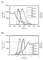
우선, 수학식 (3)으로부터, 다른 경합하는 속도 상수 kr+kn(=1/τ)에 비하여 에너지 이동의 속도 상수 kh * →g를 훨씬 높임으로써 에너지 이동 효율 ΦET를 높일 수 있는 것을 알 수 있다. 그리고, 에너지 이동의 속도 상수 kh * →g를 높이기 위해서는 수학식 (1) 및 수학식 (2)에 기초하여, 포스터 기구 및 덱스터 기구에 있어서, 호스트 분자의 발광 스펙트럼(일중항 여기 상태로부터의 에너지 이동에서의 형광 스펙트럼, 및 삼중항 여기 상태로부터의 에너지 이동에서의 인광 스펙트럼)이 게스트 분자의 흡수 스펙트럼과 크게 중첩되는 것이 바람직하다.First of all, from Equation (3), the energy transfer efficiency Φ ET can be increased by significantly increasing the rate constant k h * → g of energy transfer compared to other competing speed constants k r +k n (=1/τ). Can be seen. And, in order to increase the rate constant k h * → g of energy transfer, based on Equations (1) and (2), in the Foster mechanism and the Dexter mechanism, the emission spectrum of the host molecule (from the singlet excited state It is preferred that the fluorescence spectrum in the energy transfer and the phosphorescence spectrum in the energy transfer from the triplet excited state) greatly overlap the absorption spectrum of the guest molecule.
또한, 호스트 분자의 발광 피크에서 게스트 분자의 흡수력이 높을수록, 호스트 분자로부터 게스트 분자로 에너지가 더 쉽게 이동할 수 있는 것을 알 수 있다.In addition, it can be seen that the higher the absorption power of the guest molecule in the emission peak of the host molecule, the easier energy can be transferred from the host molecule to the guest molecule.
즉, 호스트 분자의 여기 상태의 에너지 준위와 게스트 분자의 여기 상태의 에너지 준위가 대략 같게 되도록 설정하고 게스트 분자의 여기 상태로의 전이 확률을 높임으로써, 에너지가 더 쉽게 이동한다.That is, by setting the energy level of the excited state of the host molecule and the energy level of the excited state of the guest molecule to be approximately the same and increasing the probability of the transition of the guest molecule to the excited state, energy is more easily transferred.
그런데, 이 조건으로는, 종래와 같이 호스트로서 단일 재료를 사용하면, 여기된 게스트 분자의 에너지가 기저 상태의 호스트 분자로 쉽게 이동하기 때문에 결과적으로 발광 효율의 저하를 초래한다.However, under this condition, when a single material is used as a host as in the prior art, the energy of the excited guest molecules easily moves to the host molecules in the ground state, resulting in a decrease in luminous efficiency.
이 문제는 여기 착체를 사용하여 해결할 수 있다. 여기서, 여기 착체에 대하여 설명한다. 여기 착체(여기된 착체)는 여기 상태에서의 이종 분자들간의 상호 작용에 의하여 형성된다. 여기 착체는 비교적 깊은 LUMO(Lowest Unoccupied Molecular Orbital) 준위를 갖는 재료와 비교적 얕은 HOMO(Highest Occupied Molecular Orbital) 준위를 갖는 재료 사이에 형성되기 쉽다고 알려져 있다.This problem can be solved using the complex here. Here, the complex is described here. Excitation complexes (excited complexes) are formed by interactions between heterogeneous molecules in an excited state. It is known that the complex is easily formed between a material having a relatively deep Lowest Unoccupied Molecular Orbital (LUMO) level and a material having a relatively shallow Highest Occupied Molecular Orbital (HOMO) level.
여기서, 본 발명의 일 형태에 사용되는 제 1 유기 화합물 및 제 2 유기 화합물의 HOMO 준위 및 LUMO 준위는 서로 상이하다. 구체적으로 에너지 준위는, 제 1 유기 화합물의 HOMO 준위<제 2 유기 화합물의 HOMO 준위<제 1 유기 화합물의 LUMO 준위<제 2 유기 화합물의 LUMO 준위의 순서로 높다.Here, the HOMO level and the LUMO level of the first organic compound and the second organic compound used in one embodiment of the present invention are different from each other. Specifically, the energy level is higher in the order of the HOMO level of the first organic compound <the HOMO level of the second organic compound <the LUMO level of the first organic compound <the LUMO level of the second organic compound.
하지만, 이 조건이 만족되어도 반드시 여기 착체가 형성되는 것은 아니하며, 예를 들어 비특허 문헌 1의 Alq3과 NPB는 여기 착체를 형성하지 않는다. 또한, 여기 착체가 형성되지 않을 때는 이하의 효과를 얻지 못한다.However, even if this condition is satisfied, the excitation complex is not necessarily formed, and for example, Alq 3 and NPB of
제 1 유기 화합물과 제 2 유기 화합물에 의하여 여기 착체가 형성될 때, 여기 착체의 LUMO 준위 제 1 유기 화합물에서, HOMO 준위는 제 2 유기 화합물에서 유래한다. 따라서, 여기 착체의 에너지 차는 제 1 유기 화합물의 에너지 차 및 제 2 유기 화합물의 에너지 차보다 작다. 즉, 여기 착체의 발광 파장은 제 1 유기 화합물 및 제 2 유기 화합물의 발광 파장보다 긴 파장 측으로 위치된다.When the excitation complex is formed by the first organic compound and the second organic compound, the LUMO level of the excitation complex In the first organic compound, the HOMO level is derived from the second organic compound. Therefore, the energy difference of the excitation complex is smaller than the energy difference of the first organic compound and the energy difference of the second organic compound. That is, the emission wavelength of the excitation complex is located toward a wavelength side longer than that of the first organic compound and the second organic compound.
여기 착체의 형성 과정은 크게 분류하여 다음 2개의 과정이 생각된다. 제 1 과정은 일렉트로플렉스(electroplex)의 형성이다. 본 명세서에서는 "일렉트로플렉스"라는 용어는 기저 상태의 제 1 유기 화합물 및 기저 상태의 제 2 유기 화합물이 직접 여기 착체를 형성하는 것을 말한다. 구체적으로는, 제 1 유기 화합물의 음이온과 제 2 유기 화합물의 양이온이 인접한 경우에 양쪽이 여기 착체를 형성한다.Here, the process of formation of the complex is largely classified, and the following two processes are considered. The first process is the formation of an electroplex. In the present specification, the term "electroplex" refers to a first organic compound in a ground state and a second organic compound in a ground state directly forming an excitation complex. Specifically, when the anion of the first organic compound and the cation of the second organic compound are adjacent to each other, both form an excitation complex.
상술한 관계로부터, 제 1 유기 화합물이 전자 트랩성을 갖는 화합물이고 제 2 유기 화합물이 정공 트랩성을 갖는 화합물인 경우, 일렉트로플렉스는 제 1 유기 화합물의 음이온과 제 2 유기 화합물의 양이온으로부터 직접 형성된다.From the above-described relationship, when the first organic compound is a compound having electron trapping property and the second organic compound is a compound having hole trapping property, the electroplex is formed directly from the anion of the first organic compound and the cation of the second organic compound. do.
형성된 일렉트로플렉스의 발광 스펙트럼은 제 1 유기 화합물 및 제 2 유기 화합물 각각의 발광 파장보다 긴 파장 측으로 위치된다.The emission spectrum of the formed electroplex is positioned toward a wavelength side longer than the emission wavelength of each of the first organic compound and the second organic compound.
일렉트로플렉스의 발광 스펙트럼과 인광성 화합물의 흡수 스펙트럼의 중첩은 제 1 유기 화합물(또는 제 2 유기 화합물)의 발광 스펙트럼과 인광성 화합물의 흡수 스펙트럼의 중첩보다 크다. 본 발명의 일 형태에 따른 발광 소자는 여기 착체의 발광 스펙트럼과 게스트로서 기능하는 인광성 화합물의 흡수 스펙트럼의 중첩을 이용하여 에너지를 이동시키기 때문에 에너지 이동 효율이 높다. 따라서, 본 발명의 일 형태에 따르면, 외부 양자 효율이 높은 발광 소자를 얻을 수 있다.The overlap of the emission spectrum of the Electroplex and the absorption spectrum of the phosphorescent compound is greater than the overlap of the emission spectrum of the first organic compound (or the second organic compound) and the absorption spectrum of the phosphorescent compound. The light-emitting device according to one embodiment of the present invention has high energy transfer efficiency because energy is transferred by using the superposition of the emission spectrum of the excitation complex and the absorption spectrum of the phosphorescent compound serving as a guest. Accordingly, according to one embodiment of the present invention, a light emitting device having high external quantum efficiency can be obtained.
상술한 바와 같이, 일반적으로는, 전자 및 정공이 호스트 재료에서 재결합한 경우, 여기 에너지는 여기 상태의 호스트 분자로부터 게스트 분자로 이동함으로써, 게스트 분자가 여기 상태로 되어 발광한다.As described above, in general, when electrons and holes recombine in a host material, excitation energy moves from the host molecule in the excited state to the guest molecule, thereby causing the guest molecule to become excited and emit light.
이 때, 호스트 분자로부터 게스트 분자로 여기 에너지가 이동하기 전에, 호스트 분자 자체가 원하지 않는 파장으로 발광하거나, 여기 에너지가 열 에너지로 되면, 여기 에너지의 일부를 잃는다(실활). 특히, 호스트 분자가 일중항 여기 상태에 있는 경우에는, 삼중항 여기 상태에 있는 경우보다 여기 수명이 짧아, 일중항 여기자의 실활이 일어나기 쉬워진다. 여기자의 실활은 발광 소자의 수명의 저하의 요인의 하나이다.At this time, before the excitation energy moves from the host molecule to the guest molecule, the host molecule itself emits light at an unwanted wavelength, or when the excitation energy becomes thermal energy, a part of the excitation energy is lost (deactivation). Particularly, when the host molecule is in the singlet excited state, the excitation life is shorter than that in the triplet excited state, and deactivation of the singlet excitons is likely to occur. The deactivation of excitons is one of the causes of the reduction in the life of the light emitting element.
그런데, 본 발명의 일 형태에 따르면, 일렉트로플렉스는 캐리어(양이온 또는 음이온)를 갖는 제 1 유기 화합물 및 제 2 유기 화합물로부터 형성되기 때문에, 여기 수명이 짧은 일중항 여기자의 형성을 억제할 수 있다. 즉, 일중항 여기자를 형성하지 않고 여기 착체를 직접 형성하는 과정이 있을 수 있다. 이로써, 상기 일중항 여기자의 실활을 억제할 수 있다. 따라서, 수명이 긴 발광 소자를 얻을 수 있다.However, according to one embodiment of the present invention, since the electroplex is formed from the first organic compound and the second organic compound having carriers (cations or anions), the formation of singlet excitons having a short excitation life can be suppressed. That is, there may be a process of directly forming an excitation complex without forming a singlet excitons. Thereby, the inactivation of the singlet excitons can be suppressed. Thus, a light emitting device having a long life can be obtained.
이와 같이, 호스트의 일중항 여기 상태의 발생을 억제하고, 일렉트로플렉스로부터 게스트 분자로 에너지를 이동함으로써 발광 효율이 높은 발광 소자를 얻는 것은 새로운 개념이다.Thus, it is a novel concept to obtain a light emitting device with high luminous efficiency by suppressing the occurrence of the singlet excited state of the host and transferring energy from the electroplex to the guest molecules.
다른 과정으로는, 호스트로서 기능하는 제 1 유기 화합물 및 제 2 유기 화합물 중 하나가 일중항 여기자를 형성한 후, 기저 상태의 다른 하나와 상호 작용하여 여기 착체를 형성하는 소과정이 생각될 수 있다. 일렉트로플렉스와 달리, 호스트의 일중항 여기자가 이 경우에 일시적으로 생성되지만, 이는 여기 착체로 신속하게 전환되어 일중항 여기자의 실활을 억제할 수 있다.As another process, a small process in which one of the first organic compound and the second organic compound functioning as a host forms a singlet exciton and then interacts with the other in the ground state to form an excitation complex may be considered. . Unlike the Electroflex, the singlet excitons of the host are temporarily generated in this case, but they are quickly converted to the excitation complex to suppress the deactivation of the singlet excitons.
하기의 실험 결과도, 호스트의 일중항 여기자가 여기 착체로 신속하게 전환되는 것을 나타낸다. 그러므로, 호스트의 실활을 억제할 수 있다. 따라서, 본 발명의 일 형태에 따르면, 수명이 긴 발광 소자를 얻을 수 있다.The following experimental results also show that the singlet excitons of the host are rapidly converted to the excitation complex. Therefore, inactivation of the host can be suppressed. Therefore, according to one embodiment of the present invention, a light emitting device having a long life can be obtained.
이 경우도, 형성된 여기 착체의 발광 스펙트럼은 제 1 유기 화합물 및 제 2 유기 화합물의 각각의 발광 파장보다 긴 파장 측으로 위치된다.Also in this case, the emission spectrum of the formed excitation complex is located on the side of a wavelength longer than each of the emission wavelengths of the first organic compound and the second organic compound.
여기 착체의 발광 스펙트럼과 인광성 화합물의 흡수 스펙트럼의 중첩은 제 1 유기 화합물(또는 제 2 유기 화합물)의 발광 스펙트럼과 인광성 화합물의 흡수 스펙트럼의 중첩보다 크다. 본 발명의 일 형태에 따른 발광 소자는 여기 착체의 발광 스펙트럼과 인광성 화합물의 흡수 스펙트럼의 중첩을 이용하여 에너지를 이동시키기 때문에 에너지 이동 효율이 높다. 따라서, 본 발명의 일 형태에 따르면, 외부 양자 효율이 높은 발광 소자를 제공할 수 있다.The overlap of the emission spectrum of the excitation complex and the absorption spectrum of the phosphorescent compound is greater than the overlap of the emission spectrum of the first organic compound (or the second organic compound) and the absorption spectrum of the phosphorescent compound. The light-emitting device according to one embodiment of the present invention has high energy transfer efficiency because energy is transferred by using the superposition of the emission spectrum of the excitation complex and the absorption spectrum of the phosphorescent compound. Therefore, according to one embodiment of the present invention, a light emitting device having high external quantum efficiency can be provided.
또한, 상술한 관계에 따르면, 제 1 유기 화합물은 전자 트랩성을 갖는 화합물인 한편 제 2 유기 화합물은 정공 트랩성을 갖는 화합물이다. 이들 화합물의 HOMO 준위와 LUMO 준위의 차가 큰 경우(구체적으로는 0.3eV 이상)에는, 전자는 우선적으로 제 1 유기 화합물에 들어가고 정공은 우선적으로 제 2 유기 화합물에 들어간다. 이 경우, 일중항 여기자를 거쳐 여기 착체가 형성되는 과정보다 일렉트로플렉스가 형성되는 과정이 우선적이라고 생각된다.Further, according to the above-described relationship, the first organic compound is a compound having electron trapping properties while the second organic compound is a compound having hole trapping properties. When the difference between the HOMO level and the LUMO level of these compounds is large (specifically, 0.3 eV or more), electrons preferentially enter the first organic compound and holes preferentially enter the second organic compound. In this case, it is considered that the process of forming the electroplex is preferred over the process of forming the excitation complex through the singlet excitons.
또한, 여기 착체는 그 여기 상태에서만 에너지 준위를 갖는다는 개념이 있다. 따라서, 여기 착체를 형성하는 분자는 기저 상태에서 독립된 2개 이상의 분자이고, 이들 분자는 기저 상태에서 어느 여기 착체도 형성하지 않는다.In addition, there is a concept that an excitation complex has an energy level only in its excited state. Thus, the molecules forming the excitation complex are two or more molecules that are independent in the ground state, and these molecules do not form any excitation complex in the ground state.
예를 들어, 여기 상태의 여기 착체로부터 기저 상태의 게스트 분자로 에너지가 이동하여 게스트 분자가 여기 상태가 될 때, 이 게스트 분자가 다른 분자를 여기시키고자 하는 경우에, 여기될 분자는 본 발명의 일 형태에서는 제 1 유기 화합물 또는 제 2 유기 화합물만이다. 여기 상태의 게스트 분자가 제 1 유기 화합물 또는 제 2 유기 화합물을 여기시키고자 하는 경우, 여기 상태의 게스트 분자의 에너지가 충분하지 않기 때문에 여기가 일어날 수 없다.For example, when energy moves from an excited complex in an excited state to a guest molecule in a ground state and the guest molecule becomes excited, when the guest molecule tries to excite another molecule, the molecule to be excited is In one aspect, it is only the first organic compound or the second organic compound. When a guest molecule in an excited state tries to excite the first organic compound or the second organic compound, excitation cannot occur because the energy of the guest molecule in the excited state is insufficient.
즉, 게스트 분자의 여기 상태의 에너지가 여기 착체로 반대 이동하는 것으로 인한 발광(즉, 발광 효율의 손실) 전의 게스트 분자의 실활 현상은 원리적으로 일어나지 않는다고 생각된다. 이것도 발광 효율의 향상에 기여한다.That is, it is considered that the inactivation phenomenon of the guest molecules before light emission (ie, loss of luminous efficiency) due to the opposite movement of the excited state energy of the guest molecules to the excitation complex does not occur in principle. This also contributes to the improvement of luminous efficiency.
상술한 바와 같이, 본 발명의 일 형태에 따르면, 에너지가 이동하는 분자간의 여기 상태와 기저 상태의 에너지 차는 대략 같은 것이 바람직하다. 즉, 여기 착체의 여기 에너지 준위와 게스트의 여기 에너지 준위는 대략 같다. 한편, 여기 착체를 형성하는 제 1 유기 화합물 및 제 2 유기 화합물의 여기 에너지 준위는 여기 착체의 여기 에너지 준위보다 높다.As described above, according to one embodiment of the present invention, it is preferable that the energy difference between the excited state and the ground state between molecules in which energy moves is approximately the same. That is, the excitation energy level of the excitation complex and the excitation energy level of the guest are approximately the same. On the other hand, the excitation energy levels of the first organic compound and the second organic compound forming the excitation complex are higher than the excitation energy levels of the excitation complex.
즉, 여기 상태의 게스트 분자가 제 1 유기 화합물 또는 제 2 유기 화합물을 여기시키고자 할 때, 에너지가 충분하지 않기 때문에 게스트 분자로부터 다른 분자로 에너지가 이동하는 확률은 매우 낮다. 따라서, 본 발명의 일 형태에 따르면 발광 효율이 높아진다. 또한, 열 실활을 억제할 수 있어, 발광 소자는 수명이 길고, 열화가 적고, 높은 신뢰성을 가질 수 있다.That is, when an excited guest molecule attempts to excite the first or second organic compound, the probability of energy transfer from the guest molecule to another molecule is very low because energy is insufficient. Therefore, according to one embodiment of the present invention, the luminous efficiency is increased. In addition, heat deactivation can be suppressed, and the light emitting element can have a long life, little deterioration, and high reliability.
또한, 상술한 바와 같이, 제 1 유기 화합물 또는 제 2 유기 화합물의 일중항 여기자로부터 여기 착체가 형성되는 경우가 있다. 즉, 가능한 여기 착체 형성의 소과정은 제 1 유기 화합물 및 제 2 유기 화합물 중 한쪽이 일중항 여기자를 형성한 후, 기저 상태의 다른 쪽과 상호 작용하는 것이다. 이 과정은 매우 신속하게 수행된다고 생각된다.Further, as described above, an excitation complex may be formed from the singlet excitons of the first organic compound or the second organic compound. That is, a possible sub-process of formation of the excitation complex is that one of the first organic compound and the second organic compound forms a singlet excitons, and then interacts with the other of the ground state. It is believed that this process is performed very quickly.
일중항 여기자는 여기 수명이 짧다(τ가 작음). 따라서, 여기 에너지가 호스트의 일중항 여기자로부터 게스트 재료로 이동하기 전에 (원하지 않는 파장에서의 발광 또는 열 실활을 통하여) 여기 에너지의 일부를 잃는다는 문제가 있다(수학식 (3)에서 ΦET는 작아지는 경향이 있다).Singlet excitons have a short excitation life (small τ). Therefore, there is a problem that some of the excitation energy is lost (through light emission or thermal deactivation at an undesired wavelength) before the excitation energy moves from the singlet excitons of the host to the guest material (in Equation (3), Φ ET is Tends to be small).
하지만, 본 발명의 일 형태에 따르면, 호스트의 일중항 여기자가 신속하게 여기 착체를 형성하기 때문에 여기 에너지의 실활을 억제할 수 있다. 또한, 여기 착체는 여기 수명이 비교적 길고, 이것은 에너지 이동 효율 ΦET를 높게 한다고 생각된다. 따라서, 소자의 효율뿐 아니라 그 수명에도 영향을 미칠 수 있는 호스트의 일중항 여기자의 실활을 억제할 수 있어서 수명이 긴 발광 소자를 실현할 수 있다.However, according to one embodiment of the present invention, since the singlet excitons of the host quickly form an excitation complex, deactivation of excitation energy can be suppressed. In addition, the excitation complex has a relatively long excitation life, and this is considered to increase the energy transfer efficiency phi ET . Accordingly, deactivation of singlet excitons of the host, which may affect not only the efficiency of the device but also its life, can be suppressed, and a light emitting device having a long life can be realized.
또한, 여기 착체의 여기 에너지는 인광성 화합물로 충분히 이동하여, 여기 착체로부터의 발광은 소자로부터 실질적으로 관찰되지 않는 것이 바람직하다. 따라서, 호스트의 여기 착체를 통하여 인광성 화합물로 에너지를 이동시켜 인광성 화합물이 인광을 발하는 것이 바람직하다.In addition, it is preferable that the excitation energy of the excitation complex sufficiently moves to the phosphorescent compound so that light emission from the excitation complex is not substantially observed from the device. Therefore, it is preferable that the phosphorescent compound emits phosphorescence by transferring energy to the phosphorescent compound through the excitation complex of the host.
상술한 에너지 이동의 개념에 따르면, 제 1 유기 화합물 및 제 2 유기 화합물 중 적어도 하나가 형광성 화합물(즉, 일중항 여기 상태로부터 발광이나 열 실활이 일어나기 쉬운 화합물)인 경우는 효과적이다. 따라서, 제 1 유기 화합물 및 제 2 유기 화합물 중 적어도 하나는 형광성 화합물인 것이 바람직하다.According to the concept of energy transfer described above, it is effective when at least one of the first organic compound and the second organic compound is a fluorescent compound (that is, a compound that is liable to emit light or deactivate heat from a singlet excited state). Therefore, it is preferable that at least one of the first organic compound and the second organic compound is a fluorescent compound.
호스트 재료로서 기능하는 유기 화합물(제 1 유기 화합물 및/또는 제 2 유기 화합물)로서 인광성 화합물을 사용하는 경우, 이 유기 화합물 자체가 발광되기 쉬워지고 게스트 재료로 에너지를 이동시키기 어려워진다. 이 경우, 유기 화합물은 효과적으로 발광하면 좋지만, 호스트로서 기능하는 유기 화합물은 농도 소광의 문제를 일으키기 때문에 높은 발광 효율을 달성하기 어렵다. 이 이유로부터, 이 유기 화합물은 형광성 화합물이고 상술한 구성에 의하여 에너지 이동이 달성되는 것이 바람직하다.When a phosphorescent compound is used as the organic compound (first organic compound and/or second organic compound) functioning as a host material, the organic compound itself is liable to emit light, and energy is difficult to transfer to the guest material. In this case, the organic compound needs to emit light effectively, but the organic compound functioning as a host causes a problem of concentration quenching, so it is difficult to achieve high luminous efficiency. For this reason, it is preferable that this organic compound is a fluorescent compound and energy transfer is achieved by the above-described configuration.
또한, 제 1 유기 화합물 및 제 2 유기 화합물로부터 여기 착체가 형성될 때 상술한 효과를 얻을 수 있다. 예를 들어, 비특허 문헌 1에 개시된 방법으로는 여기 착체가 형성되지 않기 때문에, 직접 재결합 과정을 통하여 게스트 분자가 여기될 수 있어서 발광 효율은 충분히 높지 않다.Further, the above-described effect can be obtained when the excitation complex is formed from the first organic compound and the second organic compound. For example, since the excitation complex is not formed by the method disclosed in
또한 일반적으로, 발광 소자의 발광층으로의 여기 착체의 사용은 발광색을 제어할 수 있는 등의 유용성을 갖지만, 발광 효율의 상당한 감소를 일으키는 경우가 많다. 따라서, 여기 착체의 사용은 고효율의 발광 소자를 얻는 데 적절하지 않은 것으로 고려되어 왔다.In addition, in general, the use of an excitation complex as a light emitting layer of a light emitting element has utility such as being able to control a light emission color, but in many cases causes a significant decrease in light emission efficiency. Therefore, it has been considered that the use of the excitation complex is not suitable for obtaining a highly efficient light emitting device.
하지만, 본 발명자들은 인광성 화합물로의 에너지 이동을 위한 매체로서 여기 착체를 사용하는 것은, 본 발명의 일 형태에서 기재한 바와 같이, 반대로 발광 효율을 최대화할 수 있다는 것을 발견하였다. 이 기술적 개념은 종래의 고정 개념과는 대립된다.However, the present inventors have found that using an excitation complex as a medium for energy transfer to a phosphorescent compound can, on the contrary, maximize luminous efficiency, as described in one embodiment of the present invention. This technical concept contradicts the conventional fixed concept.
또한, 본 발명의 일 형태에 따르면, 여기 착체의 여기 에너지 준위 및 여기 상태의 게스트의 에너지 준위를 대략 같게 되도록 설정하고, 게스트의 여기 상태로의 전이 확률을 높임으로써, 에너지 이동 과정의 확률이 높아진다. 그 결과, 게스트 농도가 0.1% 내지 2.5%, 바람직하게는 0.1% 내지 1.5%, 더 바람직하게는 0.1% 내지 0.5%인 경우라도 충분한 에너지 이동을 실현할 수 있다. 이러한 농도에 의하여 농도 소광이 억제될 수 있음으로써, 발광 효율이 최대화될 수 있다.In addition, according to one embodiment of the present invention, the probability of the energy transfer process is increased by setting the excitation energy level of the excitation complex and the energy level of the guest in the excited state to be approximately the same, and increasing the probability of the transition to the excited state of the guest. . As a result, even when the guest concentration is 0.1% to 2.5%, preferably 0.1% to 1.5%, and more preferably 0.1% to 0.5%, sufficient energy transfer can be realized. Since concentration quenching can be suppressed by this concentration, luminous efficiency can be maximized.
도면에 있어서,
도 1의 (A) 내지 (C)는 각각 본 발명의 일 형태에 따른 발광 소자를 도시한 것이고,
도 2의 (A) 및 (B)는 각각 실시예 1에서의 흡수 스펙트럼 및 발광 스펙트럼을 나타낸 것이고,
도 3의 (A) 및 (B)는 각각 실시예 2에서의 흡수 스펙트럼 및 발광 스펙트럼을 나타낸 것이고,
도 4는 실시예 3에서의 발광 소자의 휘도와 전류 밀도의 관계를 나타낸 것이고,
도 5는 실시예 3에서의 발광 소자의 휘도와 전압의 관계를 나타낸 것이고,
도 6은 실시예 3에서의 발광 소자의 전류와 전압의 관계를 나타낸 것이고,
도 7은 실시예 3에서의 발광 소자의 색도와 휘도의 관계를 나타낸 것이고,
도 8은 실시예 3에서의 발광 소자의 전류 효율과 휘도의 관계를 나타낸 것이고,
도 9는 실시예 3에서의 발광 소자의 파워 효율과 휘도의 관계를 나타낸 것이고,
도 10은 실시예 3에서의 발광 소자의 양자 효율과 휘도의 관계를 나타낸 것이고,
도 11은 실시예 3에서의 발광 소자의 발광 스펙트럼을 나타낸 것이고,
도 12는 실시예 4에서의 발광 소자의 휘도와 전류 밀도의 관계를 나타낸 것이고,
도 13은 실시예 4에서의 발광 소자의 휘도와 전압의 관계를 나타낸 것이고,
도 14는 실시예 4에서의 발광 소자의 전류와 전압의 관계를 나타낸 것이고,
도 15는 실시예 4에서의 발광 소자의 색도와 휘도의 관계를 나타낸 것이고,
도 16은 실시예 4에서의 발광 소자의 전류 효율과 휘도의 관계를 나타낸 것이고,
도 17은 실시예 4에서의 발광 소자의 파워 효율과 휘도의 관계를 나타낸 것이고,
도 18은 실시예 4에서의 발광 소자의 외부 양자 효율과 휘도의 관계를 나타낸 것이고,
도 19는 실시예 4에서의 발광 소자의 발광 스펙트럼을 나타낸 것이고,
도 20은 실시예 5에서의 발광 소자의 휘도와 전류 밀도의 관계를 나타낸 것이고,
도 21은 실시예 5에서의 발광 소자의 휘도와 전압의 관계를 나타낸 것이고,
도 22는 실시예 5에서의 발광 소자의 전류와 전압의 관계를 나타낸 것이고,
도 23은 실시예 5에서의 발광 소자의 색도와 휘도의 관계를 나타낸 것이고,
도 24는 실시예 5에서의 발광 소자의 전류 효율과 휘도의 관계를 나타낸 것이고,
도 25는 실시예 5에서의 발광 소자의 파워 효율과 휘도의 관계를 나타낸 것이고,
도 26은 실시예 5에서의 발광 소자의 외부 양자 효율과 휘도의 관계를 나타낸 것이고,
도 27은 실시예 5에서의 발광 소자의 외부 에너지 효율과 휘도의 관계를 나타낸 것이고,
도 28은 실시예 5에서의 발광 소자의 발광 스펙트럼을 나타낸 것이다.In the drawing,
1A to 1C each show a light emitting device according to an embodiment of the present invention,
2A and 2B show absorption spectrum and emission spectrum in Example 1, respectively,
3A and 3B show the absorption spectrum and the emission spectrum in Example 2, respectively,
4 shows the relationship between the luminance and current density of the light-emitting element in Example 3,
5 shows the relationship between the luminance and voltage of the light emitting device in Example 3,
6 shows the relationship between the current and the voltage of the light emitting device in Example 3,
7 shows the relationship between the chromaticity and luminance of the light-emitting element in Example 3,
8 shows the relationship between the current efficiency and luminance of the light emitting device in Example 3,
9 shows the relationship between power efficiency and luminance of the light emitting device in Example 3,
10 shows the relationship between quantum efficiency and luminance of the light emitting device in Example 3,
11 shows the emission spectrum of the light emitting device in Example 3,
12 shows the relationship between the luminance and current density of the light emitting device in Example 4,
13 shows the relationship between the luminance and voltage of the light emitting device in Example 4,
14 shows the relationship between the current and the voltage of the light emitting element in Example 4,
15 shows the relationship between the chromaticity and luminance of the light emitting element in Example 4,
16 shows the relationship between the current efficiency and the luminance of the light emitting device in Example 4,
17 shows the relationship between power efficiency and luminance of the light emitting device in Example 4,
18 shows the relationship between the external quantum efficiency and luminance of the light emitting device in Example 4,
19 shows the emission spectrum of the light emitting device in Example 4,
20 shows the relationship between the luminance and the current density of the light emitting device in Example 5,
21 shows the relationship between the luminance and voltage of the light emitting element in Example 5,
22 shows the relationship between the current and voltage of the light emitting element in Example 5,
23 shows the relationship between the chromaticity and luminance of the light-emitting element in Example 5,
24 shows the relationship between the current efficiency and luminance of the light-emitting element in Example 5,
25 shows the relationship between power efficiency and luminance of the light emitting device in Example 5,
26 shows the relationship between the external quantum efficiency and luminance of the light emitting device in Example 5,
27 shows the relationship between external energy efficiency and luminance of the light emitting device in Example 5,
28 shows the emission spectrum of the light emitting device in Example 5.
이하에서 실시형태에 대하여 도면을 참조하여 자세히 설명한다. 다만, 본 발명의 이하의 설명에 한정되지 않고, 본 발명의 취지 및 범위에서 벗어남이 없이 다양하게 변경할 수 있는 것은 당업자에 의하여 용이하게 이해될 수 있다. 따라서, 본 발명은 이하의 실시형태의 설명에 한정되어 해석되면 안된다. 또한, 이하에서 설명하는 본 발명의 구성에 있어서, 동일 부분 또는 유사한 기능을 갖는 부분을 다른 도면간에서 같은 부호에 의하여 나타내고, 이러한 부분의 설명은 반복하지 않는다.Hereinafter, embodiments will be described in detail with reference to the drawings. However, it is not limited to the following description of the present invention, and that various changes can be made without departing from the spirit and scope of the present invention can be easily understood by those skilled in the art. Therefore, this invention is limited to the description of the following embodiment and should not be interpreted. In addition, in the configuration of the present invention described below, the same part or parts having similar functions are denoted by the same reference numerals between different drawings, and the description of such parts is not repeated.
(실시형태 1)(Embodiment 1)
본 실시형태에서는 본 발명의 일 형태에 따른 발광 소자에 대하여 설명한다. 본 실시형태의 발광 소자는 발광 물질로서 게스트와, 게스트가 분산되는 호스트를 포함하는 발광층을 포함한다. 구체적으로는, 인광성 화합물을 게스트로서 사용하고 제 1 유기 화합물과 제 2 유기 화합물을 호스트로서 사용한다. 또한, 제 1 유기 화합물 및 제 2 유기 화합물의 조합은 여기 착체를 형성한다.In this embodiment, a light emitting device according to an embodiment of the present invention will be described. The light-emitting element of the present embodiment includes a light-emitting layer including a guest as a light-emitting material and a host in which the guest is dispersed. Specifically, a phosphorescent compound is used as a guest, and a first organic compound and a second organic compound are used as hosts. Further, the combination of the first organic compound and the second organic compound forms an excitation complex.
본 실시형태에서, 호스트로서 사용한 각 유기 화합물의 삼중항 여기 에너지의 준위(T* 준위)는 게스트의 삼중항 여기 에너지의 준위보다 높은 것이 바람직하다. 이 이유는, 호스트의 T* 준위가 게스트의 T* 준위보다 낮으면, 발광에 기여하는 게스트의 삼중항 여기 에너지가 호스트에 의하여 소광(퀀칭)되어, 발광 효율이 저하되기 때문이다.In this embodiment, it is preferable that the triplet excitation energy level (T * level) of each organic compound used as the host is higher than the triplet excitation energy level of the guest. This is because, when the T * level of the host is lower than the T * level of the guest, the triplet excitation energy of the guest that contributes to light emission is quenched (quenched) by the host, and luminous efficiency decreases.
상술한 바와 같이, 게스트의 T* 준위가 여기 착체의 T* 준위와 대략 같은 경우, 게스트의 T* 준위는 제 1 유기 화합물(또는 제 2 유기 화합물)의 T* 준위보다 낮다. 그래서, 많은 경우에 이 문제는 극복할 수 있다.As described above, if the guest T * T * level substantially equals the level of this complex, the guest level is less than T * T * level of the first organic compound (or the second organic compound). So, in many cases this problem can be overcome.
호스트로서 기능하는 제 1 유기 화합물 및 제 2 유기 화합물은 여기 착체를 형성한다. 형성된 여기 착체가 발광할 때, 그 발광 파장은 제 1 유기 화합물과 제 2 유기 화합물 각각의 발광 파장(형광 파장)보다 긴 파장 측으로 위치된다. 바꿔 말하면, 여기 착체의 형성에 의하여, 제 1 유기 화합물의 형광 스펙트럼과 제 2 유기 화합물의 형광 스펙트럼은 더 긴 파장 측으로 위치되는 발광 스펙트럼으로 변환될 수 있다.The first organic compound and the second organic compound functioning as a host form an excitation complex. When the formed excitation complex emits light, its emission wavelength is positioned on the side of a wavelength longer than the emission wavelength (fluorescence wavelength) of each of the first organic compound and the second organic compound. In other words, by the formation of the excitation complex, the fluorescence spectrum of the first organic compound and the fluorescence spectrum of the second organic compound can be converted into an emission spectrum positioned toward the longer wavelength side.
따라서, 제 1 유기 화합물(또는 제 2 유기 화합물)의 형광 스펙트럼이 인광성 화합물의 가장 긴 파장 측으로 위치되는 흡수 밴드보다 짧은 파장 측으로 위치되고 흡수 밴드와 중첩되지 않는 경우라도, 여기 착체를 형성함으로써, 흡수 밴드와의 큰 중첩을 갖도록 형광 스펙트럼을 긴 파장의 발광 스펙트럼으로 변환할 수 있다.Therefore, even when the fluorescence spectrum of the first organic compound (or the second organic compound) is located on the shorter wavelength side than the absorption band located on the longest wavelength side of the phosphorescent compound and does not overlap with the absorption band, by forming an excitation complex, The fluorescence spectrum can be converted into a long wavelength emission spectrum so as to have a large overlap with the absorption band.
본 실시형태의 발광 소자는 여기 착체의 발광 스펙트럼과 인광성 화합물의 흡수 스펙트럼의 중첩을 사용하여 여기 착체로부터 인광성 화합물로 에너지를 이동하기 때문에, 게스트 농도가 0.1% 내지 2.5%, 바람직하게는 0.1% 내지 1.5%, 더 바람직하게는 0.1% 내지 0.5%인 경우라도 충분한 에너지 이동 효율을 제공할 수 있다.Since the light emitting device of this embodiment transfers energy from the excitation complex to the phosphorescent compound by using the superposition of the emission spectrum of the excitation complex and the absorption spectrum of the phosphorescent compound, the guest concentration is 0.1% to 2.5%, preferably 0.1 Even in the case of% to 1.5%, more preferably 0.1% to 0.5%, sufficient energy transfer efficiency can be provided.
여기 착체의 발광 스펙트럼과 게스트 재료의 흡수 스펙트럼을 충분히 중첩시키기 위해서는, 발광 스펙트럼의 피크의 에너지와 흡수 스펙트럼의 가장 낮은 에너지 측의 흡수 밴드의 피크의 에너지의 차가 0.3eV 이하인 것이 바람직하다. 이 차가 0.2eV 이하인 것이 더 바람직하고, 0.1eV 이하인 것이 더욱 바람직하다.In order to sufficiently overlap the emission spectrum of the excitation complex and the absorption spectrum of the guest material, the difference between the energy of the peak of the emission spectrum and the peak of the absorption band at the lowest energy side of the absorption spectrum is preferably 0.3 eV or less. It is more preferable that this difference is 0.2 eV or less, and it is still more preferable that it is 0.1 eV or less.
본 실시형태의 발광 소자에 대하여 도 1의 (A) 내지 (C)를 참조하여 설명한다.The light-emitting element of this embodiment will be described with reference to Figs. 1A to 1C.
도 1의 (A)는 제 1 전극(101)과 제 2 전극(103) 사이에 EL층(102)을 갖는 발광 소자를 도시한 것이다. 도 1의 (A)의 발광 소자는, 제 1 전극(101) 위에 순차적으로 적층된 정공 주입층(111), 정공 수송층(112), 발광층(113), 전자 수송층(114), 전자 주입층(115), 및 전자 주입층(115) 위에 제공된 제 2 전극(103)을 포함한다.1A shows a light-emitting element having an
제 1 전극(101)으로서는 일함수가 큰(구체적으로는 4.0eV 이상의 일함수) 금속, 합금, 전기 전도성 화합물, 및 이들의 혼합물 등을 사용하는 것이 바람직하다. 구체적인 예로서는, 산화 인듐-산화 주석(ITO: indium tin oxide), 실리콘 또는 산화 실리콘을 함유한 산화 인듐-산화 주석, 산화 인듐-산화 아연(인듐 아연 옥사이드), 산화 텅스텐과 산화 아연을 함유한 산화 인듐(IWZO) 등을 들 수 있다.As the
이러한 도전성 금속 산화물막은 보통 스퍼터링법에 의하여 형성하지만, 졸-겔(sol-gel)법 등에 의하여 형성하여도 좋다. 예를 들어, 산화 인듐-산화 아연의 막은 산화 인듐에 1wt% 내지 20wt%의 산화 아연이 첨가된 타깃을 사용하여 스퍼터링법으로 형성할 수 있다. IWZO막은 산화 인듐에 0.5wt% 내지 5wt%의 산화 텅스텐과 0.1wt% 내지 1wt%의 산화 아연이 첨가된 타깃을 사용하여 스퍼터링법으로 형성할 수 있다.Such a conductive metal oxide film is usually formed by a sputtering method, but may be formed by a sol-gel method or the like. For example, a film of indium oxide-zinc oxide may be formed by sputtering using a target in which 1 wt% to 20 wt% of zinc oxide is added to indium oxide. The IWZO film can be formed by sputtering using a target in which 0.5wt% to 5wt% tungsten oxide and 0.1wt% to 1wt% zinc oxide are added to indium oxide.
다른 예로서는 그래핀, 금, 백금, 니켈, 텅스텐, 크롬, 몰리브덴, 철, 코발트, 구리, 팔라듐, 및 금속 재료의 질화물(예를 들어 질화 티타늄) 등을 들 수 있다.Other examples include graphene, gold, platinum, nickel, tungsten, chromium, molybdenum, iron, cobalt, copper, palladium, and nitrides of metal materials (eg, titanium nitride).
또한, EL층(102)에 있어서, 제 1 전극(101)에 접하여 형성되는 층은, 후술하는 유기 화합물과 전자 수용체(억셉터)가 혼합된 복합 재료를 사용하여 형성하는 경우에는, 일함수에 관계없이, 다양한 금속, 합금, 전기 전도성 화합물, 및 이들의 혼합물 등 중 어느 것을 사용하여 제 1 전극(101)을 형성할 수 있다. 예를 들어, 알루미늄(Al), 은(Ag), 또는 알루미늄을 함유한 합금(예를 들어, Al-Si) 등을 사용할 수 있다.In addition, in the
제 1 전극(101)은 예를 들어 스퍼터링법 또는 증착법(진공 증착법을 포함함) 등으로 형성할 수 있다.The
제 2 전극(103)으로서는, 일함수가 작은(구체적으로는 3.8eV 이하의 일함수) 금속, 합금, 전기 전도성 화합물, 및 이들의 혼합물 등 중 어느 것이 사용되는 것이 바람직하다. 그 구체적인 예로서는, 주기율표의 제 1 족 및 제 2 족에 속하는 원소, 즉 리튬 및 세슘 등의 알칼리 금속, 칼슘 및 스트론튬 등의 알칼리 토금속, 마그네슘, 이들의 합금(예를 들면, Mg-Ag, Al-Li), 유로퓸 및 이테르븀 등의 희토류 금속, 이들의 합금, 알루미늄, 및 은 등을 들 수 있다.As the
EL층(102)에 포함되고 제 2 전극(103)에 접하는 층이 후술하는 유기 화합물과 전자 공여체(도너)를 포함한 복합 재료를 사용하여 형성되는 경우, 일함수에 관계없이, Al, Ag, ITO, 실리콘 또는 산화 실리콘을 함유한 산화 인듐-산화 주석 등 다양한 도전성 재료의 어느 것을 사용할 수 있다.When the layer included in the
또한, 제 2 전극(103)은 진공 증착법 또는 스퍼터링법으로 형성할 수 있다. 또는, 은 페이스트 등을 사용할 경우에는, 도포법 또는 잉크젯법 등을 사용할 수 있다.In addition, the
EL층(102)은 적어도 발광층(113)을 포함한다. EL층(102)의 일부에는 공지의 물질을 사용할 수 있고, 저분자 화합물 및 고분자 화합물 중 하나를 사용할 수 있다. 또한, EL층(102)을 형성하는 물질은 유기 화합물만으로 이루어질 수 있고, 또는 일부에 무기 화합물을 포함할 수도 있다.The
또한, 도 1의 (A)에 도시된 바와 같이, EL층(102)은, 발광층(113)에 더하여, 정공 수송성이 높은 물질을 함유한 정공 주입층(111), 정공 수송성이 높은 물질을 함유한 정공 수송층(112), 전자 수송성이 높은 물질을 함유한 전자 수송층(114), 전자 주입성이 높은 물질을 함유한 전자 주입층(115) 등을 적절히 적층함으로써 형성된다.In addition, as shown in Fig. 1A, the
정공 주입층(111)은 정공 주입성이 높은 물질을 함유한 층이다. 정공 주입성이 높은 물질로서는, 산화 몰리브덴, 산화 티타늄, 산화 바나듐, 산화 레늄, 산화 루테늄, 산화 크롬, 산화 지르코늄, 산화 프늄, 산화 탄탈, 산화 은, 산화 텅스텐, 산화 망간 등의 금속 산화물을 사용할 수 있다. 프탈로사이아닌(약칭: H2Pc) 또는 구리(II)프탈로사이아닌(약칭: CuPc) 등의 프탈로사이아닌계 화합물을 사용할 수도 있다.The
또는, 저분자의 유기 화합물인 4,4',4''-트리스(N,N-다이페닐아미노)트라이페닐아민(약칭: TDATA), 4,4',4''-트리스[N-(3-메틸페닐)-N-페닐아미노]트라이페닐아민(약칭: MTDATA), 4,4'-비스[N-(4-다이페닐아미노페닐)-N-페닐아미노]바이페닐(약칭: DPAB), 4,4'-비스(N-{4-[N'-(3-메틸페닐)-N'-페닐아미노]페닐}-N-페닐아미노)바이페닐(약칭: DNTPD), 1,3,5-트리스[N-(4-다이페닐아미노페닐)-N-페닐아미노]벤젠(약칭: DPA3B), 3-[N-(9-페닐카바졸-3-일)-N-페닐아미노]-9-페닐카바졸(약칭: PCzPCA1), 3,6-비스[N-(9-페닐카바졸-3-일)-N-페닐아미노]-9-페닐카바졸(약칭: PCzPCA2), 3-[N-(1-나프틸)-N-(9-페닐카바졸-3-일)아미노]-9-페닐카바졸(약칭: PCzPCN1) 등의 방향족 아민 화합물을 사용할 수 있다.Or, 4,4',4''-tris(N,N-diphenylamino)triphenylamine (abbreviation: TDATA), 4,4',4''-tris[N-(3 -Methylphenyl)-N-phenylamino]triphenylamine (abbreviation: MTDATA), 4,4'-bis[N-(4-diphenylaminophenyl)-N-phenylamino]biphenyl (abbreviation: DPAB), 4 ,4'-bis(N-{4-[N'-(3-methylphenyl)-N'-phenylamino]phenyl}-N-phenylamino)biphenyl (abbreviation: DNTPD), 1,3,5-tris [N-(4-diphenylaminophenyl)-N-phenylamino]benzene (abbreviation: DPA3B), 3-[N-(9-phenylcarbazol-3-yl)-N-phenylamino]-9-phenyl Carbazole (abbreviation: PCzPCA1), 3,6-bis[N-(9-phenylcarbazol-3-yl)-N-phenylamino]-9-phenylcarbazole (abbreviation: PCzPCA2), 3-[N- Aromatic amine compounds such as (1-naphthyl)-N-(9-phenylcarbazol-3-yl)amino]-9-phenylcarbazole (abbreviation: PCzPCN1) can be used.
또는, 고분자 화합물(예를 들어 올리고머, 덴드리머, 또는 폴리머)을 사용할 수 있다. 예를 들어, 폴리(N-비닐카바졸)(약칭: PVK), 폴리(4-비닐트라이페닐아민)(약칭: PVTPA), 폴리[N-(4-{N'-[4-(4-다이페닐아미노)페닐]페닐-N'-페닐아미노}페닐)메타크릴아마이드](약칭: PTPDMA), 폴리[N,N'-비스(4-부틸페닐)-N,N'-비스(페닐)벤지딘](약칭: Poly-TPD) 등의 고분자 화합물을 사용할 수 있다. 폴리(3,4-에틸렌다이옥시티오펜)/폴리(스타이렌설폰산)(PEDOT/PSS), 폴리아닐린/폴리(스타이렌설폰산)(PAni/PSS) 등의 산이 첨가된 고분자 화합물을 사용할 수도 있다.Alternatively, a polymer compound (eg, oligomer, dendrimer, or polymer) may be used. For example, poly(N-vinylcarbazole) (abbreviation: PVK), poly(4-vinyltriphenylamine) (abbreviation: PVTPA), poly[N-(4-{N'-[4-(4- Diphenylamino)phenyl]phenyl-N'-phenylamino}phenyl)methacrylamide] (abbreviation: PTPDMA), poly[N,N'-bis(4-butylphenyl)-N,N'-bis(phenyl) Benzidine] (abbreviation: Poly-TPD) can be used. A polymer compound to which an acid is added, such as poly(3,4-ethylenedioxythiophene)/poly(styrenesulfonic acid) (PEDOT/PSS), and polyaniline/poly(styrenesulfonic acid) (PAni/PSS), may also be used.
정공 주입층(111)에는 유기 화합물과 전자 수용체(억셉터)를 혼합한 복합 재료를 사용하여도 좋다. 이러한 복합 재료는, 전자 수용체에 의하여 유기 화합물에 정공이 발생하기 때문에, 정공 주입성 및 정공 수송성이 우수하다. 이 경우, 유기 화합물은, 발생한 정공의 수송이 우수한 재료(정공 수송성이 높은 물질)인 것이 바람직하다.For the
복합 재료에 사용되는 유기 화합물로서, 방향족 아민 화합물, 카바졸 유도체, 방향족 탄화수소, 고분자 화합물(올리고머, 덴드리머, 또는 폴리머 등)과 같은 다양한 화합물을 사용할 수 있다. 복합 재료에 사용하는 유기 화합물은 정공 수송성이 높은 유기 화합물인 것이 바람직하다. 구체적으로는, 10-6cm2/Vs 이상의 정공 이동도를 갖는 물질을 사용하는 것이 바람직하다. 다만, 전자 수송성보다 정공 수송성이 높은 물질이면 상술한 물질 이외의 물질을 사용하여도 좋다. 이하에서는, 복합 재료에 사용할 수 있는 유기 화합물을 구체적으로 열거한다.As the organic compound used in the composite material, various compounds such as aromatic amine compounds, carbazole derivatives, aromatic hydrocarbons, and high molecular compounds (oligomers, dendrimers, polymers, etc.) can be used. It is preferable that the organic compound used for a composite material is an organic compound with high hole transport property. Specifically, it is preferable to use a material having a hole mobility of 10 -6 cm 2 /Vs or more. However, any material other than the above-described material may be used as long as it has a higher hole transport property than the electron transport property. Hereinafter, the organic compounds that can be used for the composite material are specifically listed.
복합 재료에 사용할 수 있는 유기 화합물의 예로서는 TDATA, MTDATA, DPAB, DNTPD, DPA3B, PCzPCA1, PCzPCA2, PCzPCN1, 4,4'-비스[N-(1-나프틸)-N-페닐아미노]바이페닐(약칭: NPB 또는 α-NPD), N, N'-비스(3-메틸페닐)-N, N'-다이페닐-[1,1'-바이페닐]-4,4'-다이아민(약칭: TPD), 4-페닐-4'-(9-페닐플루오렌-9-일)트라이페닐아민(약칭: BPAFLP) 등의 방향족 아민 화합물이나, 4,4'-다이(N-카바졸일)바이페닐(약칭: CBP), 1,3,5-트리스[4-(N-카바졸일)페닐]벤젠(약칭: TCPB), 9-[4-(N-카바졸일)페닐]-10-페닐안트라센(약칭: CzPA), 9-페닐-3-[4-(10-페닐-9-안트릴)페닐]-9H-카바졸(약칭: PCzPA), 1,4-비스[4-(N-카바졸일)페닐]-2,3,5,6-테트라페닐벤젠 등의 카바졸 유도체를 들 수 있다.Examples of organic compounds that can be used for composite materials include TDATA, MTDATA, DPAB, DNTPD, DPA3B, PCzPCA1, PCzPCA2, PCzPCN1, 4,4'-bis[N-(1-naphthyl)-N-phenylamino]biphenyl( Abbreviation: NPB or α-NPD), N, N'-bis(3-methylphenyl)-N, N'-diphenyl-[1,1'-biphenyl]-4,4'-diamine (abbreviation: TPD ), 4-phenyl-4'-(9-phenylfluoren-9-yl)triphenylamine (abbreviation: BPAFLP) and other aromatic amine compounds, and 4,4'-di(N-carbazolyl)biphenyl ( Abbreviation: CBP), 1,3,5-tris[4-(N-carbazolyl)phenyl]benzene (abbreviation: TCPB), 9-[4-(N-carbazolyl)phenyl]-10-phenylanthracene (abbreviation : CzPA), 9-phenyl-3-[4-(10-phenyl-9-anthryl)phenyl]-9H-carbazole (abbreviation: PCzPA), 1,4-bis[4-(N-carbazolyl) And carbazole derivatives such as phenyl]-2,3,5,6-tetraphenylbenzene.
또한, 2-tert-부틸-9,10-다이(2-나프틸)안트라센(약칭: t-BuDNA), 2-tert-부틸-9,10-다이(1-나프틸)안트라센, 9,10-비스(3,5-다이페닐페닐)안트라센(약칭: DPPA), 2-tert-부틸-9,10-비스(4-페닐페닐)안트라센(약칭: t-BuDBA), 9,10-다이(2-나프틸)안트라센(약칭: DNA), 9,10-다이페닐안트라센(약칭: DPAnth), 2-tert-부틸안트라센(약칭: t-BuAnth), 9,10-비스(4-메틸-1-나프틸)안트라센(약칭: DMNA), 9,10-비스[2-(1-나프틸)페닐]-2-tert-부틸안트라센, 9,10-비스[2-(1-나프틸)페닐]안트라센, 2,3,6,7-테트라메틸-9,10-다이(1-나프틸)안트라센 등의 방향족 탄화수소 화합물을 사용할 수 있다.In addition, 2-tert-butyl-9,10-di(2-naphthyl)anthracene (abbreviation: t-BuDNA), 2-tert-butyl-9,10-di(1-naphthyl)anthracene, 9,10 -Bis(3,5-diphenylphenyl)anthracene (abbreviation: DPPA), 2-tert-butyl-9,10-bis(4-phenylphenyl) anthracene (abbreviation: t-BuDBA), 9,10-di( 2-naphthyl) anthracene (abbreviation: DNA), 9,10-diphenylanthracene (abbreviation: DPAnth), 2-tert-butylanthracene (abbreviation: t-BuAnth), 9,10-bis (4-methyl-1 -Naphthyl)anthracene (abbreviation: DMNA), 9,10-bis[2-(1-naphthyl)phenyl]-2-tert-butylanthracene, 9,10-bis[2-(1-naphthyl)phenyl ]Aromatic hydrocarbon compounds such as anthracene and 2,3,6,7-tetramethyl-9,10-di(1-naphthyl)anthracene can be used.
또는, 2,3,6,7-테트라메틸-9,10-다이(2-나프틸)안트라센, 9,9'-바이안트릴, 10,10'-다이페닐-9,9'-바이안트릴, 10,10'-비스(2-페닐페닐)-9,9'-바이안트릴, 10,10'-비스[(2,3,4,5,6-펜타페닐)페닐]-9,9'-바이안트릴, 안트라센, 테트라센, 루브렌, 페릴렌, 2,5,8,11-테트라(tert-부틸)페릴렌, 펜타센, 코로넨, 4,4'-비스(2,2-다이페닐비닐)바이페닐(약칭: DPVBi), 9,10-비스[4-(2,2-다이페닐비닐)페닐]안트라센(약칭: DPVPA) 등의 방향족 탄화수소 화합물을 사용할 수 있다.Or, 2,3,6,7-tetramethyl-9,10-di(2-naphthyl)anthracene, 9,9'-bianthryl, 10,10'-diphenyl-9,9'-bian Tril, 10,10'-bis(2-phenylphenyl)-9,9'-biathryl, 10,10'-bis[(2,3,4,5,6-pentaphenyl)phenyl]-9, 9'-Bianthryl, anthracene, tetracene, rubrene, perylene, 2,5,8,11-tetra(tert-butyl)perylene, pentacene, coronene, 4,4'-bis(2, An aromatic hydrocarbon compound such as 2-diphenylvinyl)biphenyl (abbreviation: DPVBi) and 9,10-bis[4-(2,2-diphenylvinyl)phenyl]anthracene (abbreviation: DPVPA) can be used.
또한, 전자 수용체로서는 7,7,8,8-테트라시아노-2,3,5,6-테트라플루오르퀴노다이메탄(약칭: F4-TCNQ), 클로라닐 등의 유기 화합물, 및 전이 금속 산화물을 들 수 있다. 또한, 주기율표의 제 4 족 내지 제 8 족에 속하는 금속의 산화물을 들 수도 있다. 구체적으로는, 산화 바나듐, 산화 니오브, 산화 탄탈, 산화 크롬, 산화 몰리브덴, 산화 텅스텐, 산화 망간, 및 산화 레늄은 전자 수용성이 높기 때문에 바람직하다. 그 중에서도, 특히 산화 몰리브덴은 대기 중에서도 안정적이고 흡습성이 낮으며 취급하기 쉽기 때문에 바람직하다.In addition, as electron acceptors, organic compounds such as 7,7,8,8-tetracyano-2,3,5,6-tetrafluoroquinodimethane (abbreviation: F 4 -TCNQ), chloranyl, and transition metal oxides Can be mentioned. Further, oxides of metals belonging to
또한, 상술한 PVK, PVTPA, PTPDMA, Poly-TPD 등의 고분자 화합물과, 상술한 전자 수용체의 복합 재료를 사용하여 정공 주입층(111)을 형성하여도 좋다.Further, the
정공 수송층(112)은 정공 수송성이 높은 물질을 함유한 층이다. 정공 수송성이 높은 물질의 예로서는 NPB, TPD, BPAFLP, 4,4'-비스[N-(9,9-다이메틸플루오렌-2-일)-N-페닐아미노]바이페닐(약칭: DFLDPBi), 4,4'-비스[N-(스피로-9,9'-바이플루오렌-2-일)-N-페닐아미노]바이페닐(약칭: BSPB) 등의 방향족 아민 화합물을 들 수 있다. 여기서 기술한 물질은 주로 10-6cm2/Vs 이상의 정공 이동도를 갖는 물질이다. 다만, 전자 수송성보다 정공의 수송성이 높은 물질이면 상술한 재료 이외의 물질을 사용하여도 좋다. 정공 수송성이 높은 물질을 함유한 층은 단층에 한정되지 않고 상술한 물질들을 함유한 2층 이상의 층이 적층되어도 좋다.The
정공 수송층(112)에는 CBP, CzPA, 또는 PCzPA 등의 카바졸 유도체나 t-BuDNA, DNA, 또는 DPAnth 등의 안트라센 유도체를 사용하여도 좋다.For the
또는, 정공 수송층(112)에는, PVK, PVTPA, PTPDMA, 또는 Poly-TPD 등의 고분자 화합물을 사용할 수 있다.Alternatively, a polymer compound such as PVK, PVTPA, PTPDMA, or Poly-TPD may be used for the
발광층(113)은 발광 물질을 포함한 층이다. 본 실시형태의 발광층(113)은 게스트로서 인광성 화합물, 호스트로서 제 1 유기 화합물 및 제 2 유기 화합물을 포함한다. 2가지 이상의 호스트를 사용할 수 있다. 게스트의 중량비는, 호스트의 합계 중량(호스트로서 제 1 유기 화합물 및 제 2 유기 화합물이 사용될 때는 그들의 합계 중량)의 0.1% 내지 2.5%, 바람직하게는 0.1% 내지 1.5%, 더 바람직하게는 0.1% 내지 0.5%이다.The light-emitting
인광성 화합물로서는, 유기금속 착체가 바람직하며, 특히 이리듐 착체가 바람직하다. 상술한 포스터 기구에 의한 에너지 이동을 고려하면, 가장 긴 파장 측에 위치되는 인광성 화합물의 흡수 밴드의 몰 흡수 계수는 2000M-1·cm-1 이상이 바람직하며, 5000M-1·cm-1 이상이 더 바람직하다.As the phosphorescent compound, an organometallic complex is preferable, and an iridium complex is particularly preferable. Considering the energy transfer by the poster mechanism, the molar absorption coefficient of the absorption band of the phosphorescent compound located on the longest wavelength side is preferably 2000M -1 ·cm -1 or more, and 5000M -1 ·cm -1 or more. This is more preferable.
이와 같이 몰 흡수 계수가 높은 화합물의 예로서는, 비스(3,5-다이메틸-2-페닐피라지나토)(다이피발로일메타나토)이리듐(III)(약칭: [Ir(mppr-Me)2(dpm)]), (아세틸아세토나토)비스(4,6-다이페닐피리미디나토)이리듐(III)(약칭: [Ir(dppm)2(acac)]), (아세틸아세토나토)비스[4-(2-노르보르닐)-6-페닐피리미디나토]이리듐(III)(약칭: [Ir(nbppm)2(acac)]), (2,6-다이메틸-3,5-헵탄디오나토-κ2O,O')비스[4-메틸-2-(3-메틸-4-피리미디닐-κN3)페닐-κC)]이리듐(III)(약칭: [Ir(5mdppm)2(dibm)]), (아세틸아세토나토)비스(2-페닐다이벤조[f,h]퀴녹살리나토)이리듐(III)(약칭: [Ir(dbq-P)2(acac)]) 등을 들 수 있다. 특히, [Ir(dppm)2(acac)]과 같이, 5000M-1·cm-1 이상의 몰 흡수 계수를 갖는 재료를 사용하면, 30% 정도의 외부 양자 효율을 실현할 수 있는 발광 소자를 얻을 수 있다.As an example of a compound having such a high molar absorption coefficient, bis(3,5-dimethyl-2-phenylpyrazinato) (dipivaloylmethanato) iridium (III) (abbreviation: [Ir(mppr-Me) 2 (dpm)]), (acetylacetonato)bis(4,6-diphenylpyrimidinato)iridium(III) (abbreviation: [Ir(dppm) 2 (acac)]), (acetylacetonato)bis[4 -(2-Norbornyl)-6-phenylpyrimidinato]iridium(III) (abbreviation: [Ir(nbppm) 2 (acac)]), (2,6-dimethyl-3,5-heptanedionato -κ 2 O,O')bis[4-methyl-2-(3-methyl-4-pyrimidinyl-κN3)phenyl-κC)]iridium(III) (abbreviation: [Ir(5mdppm) 2 (dibm)) ]), (acetylacetonato)bis(2-phenyldibenzo[f,h]quinoxalinato)iridium(III) (abbreviation: [Ir(dbq-P) 2 (acac)]), and the like. In particular, if a material having a molar absorption coefficient of 5000M -1 ·cm -1 or more, such as [Ir(dppm) 2 (acac)] is used, a light emitting device capable of realizing an external quantum efficiency of about 30% can be obtained. .
제 1 유기 화합물과 제 2 유기 화합물의 조합의 예로서는, 2-[3-(다이벤조티오펜-4-일)페닐]다이벤조[f,h]퀴녹살린(약칭: 2mDBTPDBq-II), 2-[4-(3,6-다이페닐-9H-카바졸-9-일)페닐]다이벤조[f,h]퀴녹살린(약칭: 2CzPDBq-III), 7-[3-(다이벤조티오펜-4-일)페닐]다이벤조[f,h]퀴녹살린(약칭: 7mDBTPDBq-II), 6-[3-(다이벤조티오펜-4-일)페닐]다이벤조[f, h]퀴녹살린(약칭: 6mDBTPDBq-II)과 같은 전자를 수용하기 쉬운 화합물 중 적어도 하나와, 4,4'-비스[N-(1-나프틸)-N-페닐아미노]바이페닐(약칭: NPB 또는 α-NPD), 4-페닐-4'-(9-페닐-9H-카바졸-3-일)트라이페닐아민(약칭: PCBA1BP), 4,4'-다이(1-나프틸)-4''-(9-페닐-9H-카바졸-3-일)트라이페닐아민(약칭: PCBNBB)과 같은 정공을 수용하기 쉬운 화합물 중 적어도 하나의 조합이 바람직하다. 다만, 그 조합이 여기 착체를 형성할 수 있으면, 본 발명은 이들 화합물에 한정되지 않는다.Examples of the combination of the first organic compound and the second organic compound include 2-[3-(dibenzothiophen-4-yl)phenyl]dibenzo[f,h]quinoxaline (abbreviation: 2mDBTPDBq-II), 2- [4-(3,6-diphenyl-9H-carbazol-9-yl)phenyl]dibenzo[f,h]quinoxaline (abbreviation: 2CzPDBq-III), 7-[3-(dibenzothiophene- 4-yl)phenyl]dibenzo[f,h]quinoxaline (abbreviation: 7mDBTPDBq-II), 6-[3-(dibenzothiophen-4-yl)phenyl]dibenzo[f,h]quinoxaline ( Abbreviation: 6mDBTPDBq-II) and at least one of the compounds that are easy to accept electrons, and 4,4'-bis[N-(1-naphthyl)-N-phenylamino]biphenyl (abbreviation: NPB or α-NPD ), 4-phenyl-4'-(9-phenyl-9H-carbazol-3-yl)triphenylamine (abbreviation: PCBA1BP), 4,4'-di(1-naphthyl)-4''-( A combination of at least one of compounds that are easy to accept holes, such as 9-phenyl-9H-carbazol-3-yl)triphenylamine (abbreviation: PCBNBB) is preferred. However, as long as the combination can form an excitation complex, the present invention is not limited to these compounds.
표 1은 2mDBTPDBq-II, PCBNBB, 및 이들을 사용할 때에 적합한 인광성 화합물인 [Ir(dppm)2(acac)] 및 [Ir(mppr-Me)2(dpm)]의 주된 물리적 특성을 나타낸 것이다.Table 1 shows the main physical properties of 2mDBTPDBq-II, PCBNBB, and phosphorescent compounds [Ir(dppm) 2 (acac)] and [Ir(mppr-Me) 2 (dpm)] which are suitable phosphorescent compounds when using them.
2mDBTPDBq-II와 PCBNBB가 혼합된 발광층(113)에서는, LUMO 준위는 -2.78eV이고 HOMO 준위는 -5.46eV이다. 이들 준위는 2mDBTPDBq-II와 PCBNBB의 여기 착체의 LUMO 준위 및 HOMO 준위와 동일하다. 또한, 인광성 화합물인 [Ir(mppr-Me)2(dpm)]의 LUMO 준위 및 HOMO 준위도 실질적으로 동일한 준위이다.In the
한편, [Ir(dppm)2(acac)]의 LUMO 준위 및 HOMO 준위는 양쪽 모두가 상술한 것보다 낮기 때문에, [Ir(dppm)2(acac)]는 전자를 트랩하기 쉬운 것으로 알 수 있다. 이는 [Ir(dppm)2(acac)]를 게스트로서 사용한 경우에는, [Ir(mppr-Me)2(dpm)]을 사용한 경우보다 직접 재결합 과정의 확률이 높다는 것을 시사한다.On the other hand, [Ir (dppm) 2 (acac )] LUMO level and the HOMO level of the lower than that is both described above, [Ir (dppm) 2 ( acac)] It can be seen that the easy-to trap electrons. This suggests that when [Ir(dppm) 2 (acac)] is used as a guest, the probability of direct recombination is higher than when [Ir(mppr-Me) 2 (dpm)] is used.
또한, 삼중항 여기 상태의 [Ir(mppr-Me)2(dpm)] 및 [Ir(dppm)2(acac)] 각각의 에너지 준위(T* 준위)는 삼중항 여기 상태의 2mDBTPDBq-II 및 PCBNBB 각각의 에너지 준위보다 0.1eV 이상 낮다. 따라서, 삼중항 여기 상태의 [Ir(mppr-Me)2(dpm)] 또는 [Ir(dppm)2(acac)]가 2mDBTPDBq-II 또는 PCBNBB의 삼중항 여기 상태로 이동할 확률은 낮다. 특히, [Ir(dppm)2(acac)]의 T* 준위는 0.18eV 이상 낮고, 이는 [Ir(dppm)2(acac)]가 [Ir(mppr-Me)2(dpm)]보다 발광 효율이 높다는 것을 시사한다.In addition, the energy levels (T * level) of [Ir(mppr-Me) 2 (dpm)] and [Ir(dppm) 2 (acac)] in the triplet excited state are 2mDBTPDBq-II and PCBNBB in the triplet excited state It is 0.1 eV or more lower than each energy level. Therefore, the probability that [Ir(mppr-Me) 2 (dpm)] or [Ir(dppm) 2 (acac)] in the triplet excited state moves to the triplet excited state of 2mDBTPDBq-II or PCBNBB is low. In particular, [Ir (dppm) 2 ( acac)] of the T * level is lower than 0.18eV, which [Ir (dppm) 2 (acac )] is [Ir (mppr-Me) 2 (dpm)] than the efficiency of light emission of Suggests that it is high.
전자 수송층(114)은 전자 수송성이 높은 물질을 함유한 층이다. 전자 수송성이 높은 물질로서는, Alq3, 트리스(4-메틸-8-퀴놀리놀라토)알루미늄(약칭: Almq3), 비스(10-하이드록시벤조[h]-퀴놀리나토)베릴륨(약칭: BeBq2), BAlq, Zn(BOX)2, 비스[2-(2-하이드록시페닐)벤조티아졸라토]아연(약칭: Zn(BTZ)2) 등의 금속 착체를 들 수 있다. 또한, 2-(4-바이페닐릴)-5-(4-tert-부틸페닐)-1,3,4-옥사디아졸(약칭: PBD), 1,3-비스[5-(p-tert-부틸페닐)-1,3,4-옥사디아졸―2-일]벤젠(약칭: OXD-7), 3-(4-tert-부틸페닐)-4-페닐―5-(4-바이페닐릴)-1,2,4-트라이아졸(약칭: TAZ), 3-(4-tert-부틸페닐)-4-(4-에틸페닐)-5-(4-바이페닐릴)-1,2,4-트라이아졸(약칭: p-EtTAZ), 바소페난트롤린(약칭: BPhen), 바소쿠프로인(약칭: BCP), 4,4'-비스(5-메틸벤조옥사졸―2-일)스틸벤(약칭: BzOs) 등의 복소 방향족 화합물도 사용할 수 있다. 또는, 폴리(2,5-피리딘다이일)(약칭: PPy), 폴리[(9,9-다이헥실플루오렌-2,7-다이일)-co-(피리딘-3,5-다이일)](약칭: PF-Py), 폴리[(9,9-다이옥틸플루오렌-2,7-다이일)-co-(2,2'-바이피리딘-6,6'-다이일)](약칭: PF-BPy) 등의 고분자 화합물을 사용할 수 있다. 여기에 든 물질은 주로 10-6cm2/Vs 이상의 전자 이동도를 갖는 물질이다. 다만, 정공 수송성보다 전자 수송성이 높은 물질이면, 상기 이외의 물질을 전자 수송층에 사용하여도 좋다.The
또한, 전자 수송층은 단층에 한정되지 않고, 상술한 물질로 이루어지는 2층 이상을 적층하여도 좋다.Further, the electron transport layer is not limited to a single layer, and two or more layers made of the above-described materials may be laminated.
전자 주입층(115)은 전자 주입성이 높은 물질을 포함한 층이다. 전자 주입층(115)에는 리튬, 세슘, 칼슘, 불화 리튬, 불화 세슘, 불화 칼슘, 또는 산화 리튬 등의 알칼리 금속, 알칼리 토금속, 또는 그들의 화합물을 사용할 수 있다. 또한, 불화 에르븀과 같은 희토류 금속 화합물을 사용할 수도 있다. 또는, 상술한 전자 수송층(114)을 형성하는 물질을 사용할 수도 있다.The
또는, 전자 주입층(115)에 유기 화합물과 전자 공여체(도너)를 혼합한 복합 재료를 사용하여도 좋다. 이 복합 재료는 전자 공여체에 의하여 유기 화합물에 전자가 발생하기 때문에, 전자 주입성 및 전자 수송성이 우수하다.Alternatively, a composite material obtained by mixing an organic compound and an electron donor (donor) for the
이 경우, 유기 화합물은, 발생한 전자의 수송이 우수한 재료인 것이 바람직하다. 구체적으로는, 예를 들어 상술한 전자 수송층(114)을 형성하는 재료(예를 들어 금속 착체 또는 복소 방향족 화합물)를 사용할 수 있다.In this case, it is preferable that the organic compound is a material excellent in transport of generated electrons. Specifically, for example, a material (for example, a metal complex or a heteroaromatic compound) forming the
전자 공여체로서는, 유기 화합물에 대하여 전자 공여성을 나타내는 물질을 사용할 수 있고, 구체적으로는 리튬, 세슘, 마그네슘, 칼슘, 에르븀, 이테르븀 등, 알칼리 금속, 알칼리 토금속 또는 희토류 금속을 사용하는 것이 바람직하다. 또한, 알칼리 금속 산화물이나 알칼리 토금속 산화물이 바람직하고, 예를 들어 산화 리튬, 산화 칼슘, 및 산화 바륨 등을 들 수 있다. 또는, 산화 마그네슘과 같은 루이스 염기를 사용할 수도 있다. 또는, 테트라티아플발렌(약칭: TTF) 등의 유기 화합물을 사용할 수 있다.As the electron donor, a substance that exhibits electron donation to an organic compound can be used. Specifically, it is preferable to use an alkali metal, alkaline earth metal or rare earth metal such as lithium, cesium, magnesium, calcium, erbium, ytterbium, etc. Further, an alkali metal oxide or an alkaline earth metal oxide is preferable, and examples thereof include lithium oxide, calcium oxide, and barium oxide. Alternatively, a Lewis base such as magnesium oxide may be used. Alternatively, an organic compound such as tetrathiafulvalene (abbreviation: TTF) can be used.
또한, 상술한 정공 주입층(111), 정공 수송층(112), 발광층(113), 전자 수송층(114), 및 전자 주입층(115)은 각각 증착법(진공 증착법 등), 잉크젯법, 도포법 등의 방법으로 형성할 수 있다.In addition, the above-described
도 1의 (B)에 도시된 바와 같이, 제 1 전극(101)과 제 2 전극(103) 사이에 복수의 EL층이 적층되어도 좋다. 이 경우, 적층된 제 1 EL층(104)과 제 2 EL층(105) 사이에 전하 발생층(106)을 제공하는 것이 바람직하다. 전하 발생층(106)은 상술한 복합 재료 중 어느 것을 사용하여 형성할 수 있다.As shown in Fig. 1B, a plurality of EL layers may be stacked between the
또한, 전하 발생층(106)은, 복합 재료를 함유한 층과 다른 재료를 함유한 층을 포함하는 적층 구조를 가져도 좋다. 이 경우, 다른 재료를 함유한 층으로서는, 전자 공여성 물질과 전자 수송성이 높은 물질을 포함하는 층, 투명 도전막으로 형성된 층 등을 사용할 수 있다.Further, the
이와 같은 구성을 갖는 발광 소자에 관해서는, 에너지의 이동 및 소광 등의 문제가 일어나기 어렵고, 재료의 선택의 여지가 넓어짐으로써 발광 효율이 높고 긴 수명을 갖는 발광 소자를 용이하게 얻을 수 있다. 또한, 한쪽의 EL층으로부터 인광, 다른 쪽의 EL층으로부터 형광을 제공하는 발광 소자를 용이하게 얻을 수 있다. 또한, 이 구조는 상술한 EL층의 구조와 조합할 수 있다.In the light-emitting device having such a configuration, problems such as energy transfer and quenching are less likely to occur, and the choice of material is widened, so that a light-emitting device having high luminous efficiency and a long life can be easily obtained. Further, it is possible to easily obtain a light-emitting element that provides phosphorescence from one EL layer and fluorescence from the other EL layer. Further, this structure can be combined with the structure of the EL layer described above.
또한, 각각이 다른 색을 발광하는 EL층을 형성함으로써, 발광 소자는 전체로서 원하는 색의 발광을 제공할 수 있다. 예를 들어, 제 1 EL층의 발광색과 제 2 EL층의 발광색이 보색이 되도록 2개의 EL층을 갖는 발광 소자를 형성함으로써, 발광 소자는 전체로서 백색 발광을 제공할 수 있다. 이것은 3개 이상의 EL층을 갖는 발광 소자에도 적용될 수 있다.Further, by forming an EL layer each emitting a different color, the light emitting element can provide light emission of a desired color as a whole. For example, by forming a light emitting element having two EL layers so that the light emission color of the first EL layer and the light emission color of the second EL layer become complementary colors, the light emitting element can provide white light emission as a whole. This can also be applied to a light-emitting element having three or more EL layers.
도 1의 (C)에 도시된 바와 같이, EL층(102)은 제 1 전극(101)과 제 2 전극(103) 사이에 정공 주입층(111), 정공 수송층(112), 발광층(113), 전자 수송층(114), 전자 주입 버퍼층(116), 전자 릴레이층(117), 및 제 2 전극(103)과 접하는 복합 재료층(118)을 포함하여도 좋다.1C, the
제 2 전극(103)과 접하는 복합 재료층(118)을 제공하면, 특히 스퍼터링법을 사용하여 제 2 전극(103)을 형성할 때에 EL층(102)에 주어지는 대미지를 저감할 수 있어서 바람직하다. 복합 재료층(118)은, 상술한 정공 수송성이 높은 유기 화합물에 억셉터 물질이 함유된 복합 재료를 사용하여 형성할 수 있다.Providing the
또한, 전자 주입 버퍼층(116)을 제공함으로써, 복합 재료층(118)과 전자 수송층(114) 사이의 주입 장벽을 저감할 수 있기 때문에, 복합 재료층(118)에서 발생한 전자를 전자 수송층(114)에 용이하게 주입할 수 있다.In addition, by providing the electron
전자 주입 버퍼층(116)에는, 알칼리 금속, 알칼리 토금속, 희토류 금속, 이들 금속의 화합물(예를 들어, 알칼리 금속 화합물(산화 리튬 등의 산화물, 할로겐화물, 탄산 리튬이나 탄산 세슘 등의 탄산염 등), 알칼리 토금속 화합물(산화물, 할로겐화물, 탄산염 등), 희토류 금속의 화합물(산화물, 할로겐화물, 탄산염 등)) 등, 전자 주입성이 높은 물질을 사용할 수 있다.The electron
또한, 전자 주입 버퍼층(116)이 전자 수송성이 높은 물질과 도너 물질을 포함하는 경우에는, 전자 수송성이 높은 물질에 대한 도너 물질의 질량비가 0.001:1 내지 0.1:1이 되도록 도너 물질을 첨가하는 것이 바람직하다.In addition, when the electron
또한, 도너 물질로서는, 알칼리 금속, 알칼리 토금속, 희토류 금속, 상술한 금속의 화합물(예를 들어 알칼리 금속 화합물(산화 리튬 등의 산화물, 할로겐화물, 탄산 리튬이나 탄산 세슘 등의 탄산염을 포함함), 알칼리 토금속 화합물(산화물, 할로겐화물, 탄산 염을 포함함), 또는 희토류 금속의 화합물(산화물, 할로겐화물, 탄산염을 포함함)) 외에도, 테트라티아나프타센(약칭: TTN), 니켈로센, 데카메틸니켈로센 등의 유기 화합물을 사용할 수 있다.In addition, as a donor substance, an alkali metal, an alkaline earth metal, a rare earth metal, a compound of the above-described metal (for example, an alkali metal compound (including an oxide such as lithium oxide, a halide, a carbonate such as lithium carbonate or cesium carbonate), In addition to alkaline earth metal compounds (including oxides, halides, carbonates), or rare earth metal compounds (including oxides, halides, carbonates)), tetratianapthacene (abbreviation: TTN), nickellocene, deca Organic compounds such as methylnickelocene can be used.
또한, 전자 수송성이 높은 물질로서는, 상술한 전자 수송층(114)에 사용되는 재료와 같은 재료를 사용할 수 있다.Further, as the material having high electron transport properties, the same material as the material used for the
또한, 전자 주입 버퍼층(116)과 복합 재료층(118) 사이에 전자 릴레이층(117)을 형성하는 것이 바람직하다. 전자 릴레이층(117)은 반드시 제공할 필요는 없지만, 전자 수송성이 높은 전자 릴레이층(117)을 제공함으로써, 전자 주입 버퍼층(116)에 전자를 신속하게 수송할 수 있다.In addition, it is preferable to form an
복합 재료층(118)과 전자 주입 버퍼층(116) 사이에 전자 릴레이층(117)이 끼워진 구조는, 복합 재료층(118)에 함유된 억셉터 물질과, 전자 주입 버퍼층(116)에 함유된 도너 물질이 상호 작용하기 어려워, 이들의 기능이 상호 간섭하는 것은 거의 없다. 따라서, 구동 전압의 상승을 방지할 수 있다.The structure in which the
전자 릴레이층(117)은 전자 수송성이 높은 물질을 함유하며, 전자 수송성이 높은 물질의 LUMO 준위가, 복합 재료층(118)에 함유된 억셉터 물질의 LUMO 준위와, 전자 수송층(114)에 함유된 전자 수송성이 높은 물질의 LUMO 준위 사이에 위치되도록 형성된다.The
전자 릴레이층(117)이 도너 물질을 함유하는 경우에는, 이 도너 물질의 도너 준위는 복합 재료층(118)의 억셉터 물질의 LUMO 준위와 전자 수송층(114)에 함유된 전자 수송성이 높은 물질의 LUMO 준위의 사이에 위치되도록 제어된다. 구체적인 에너지 준위의 수치로서는, 전자 릴레이층(117)에 함유된 전자 수송성이 높은 물질의 LUMO 준위는 바람직하게는 -5.0eV 이상, 더 바람직하게는 -5.0eV 이상 -3.0eV 이하이다.When the
전자 릴레이층(117)에 포함되는 전자 수송성이 뛰어난 물질로서는 프탈로사이아닌계 재료 또는 금속-산소 결합과 방향족 배위자를 갖는 금속 착체를 사용하는 것이 바람직하다.It is preferable to use a phthalocyanine-based material or a metal complex having a metal-oxygen bond and an aromatic ligand as a material included in the
전자 릴레이층(117)에 함유되는 프탈로사이아닌계 재료로서는, 구체적으로는 CuPc, 프탈로사이아닌 주석(II) 착체(SnPc), 프탈로사이아닌 아연 착체(ZnPc), 코발트(II) 프탈로사이아닌, β-폼(CoPc), 프탈로사이아닌 철(FePc), 바나딜 2,9,16,23-테트라페녹시-29H,31H-프탈로사이아닌(PhO-VOPc) 중 어느 것을 사용하는 것이 바람직하다.Examples of the phthalocyanine-based material contained in the
전자 릴레이층(117)에 포함되고 금속-산소 결합과 방향족 배위자를 갖는 금속 착체로서는, 금속-산소 이중 결합을 갖는 금속 착체를 사용하는 것이 바람직하다. 금속-산소 이중 결합은 억셉터성(전자를 수용하기 쉬운 성질)을 갖기 때문에, 더 용이하게 전자가 이동(주고 받음)될 수 있다. 또한, 금속-산소 이중 결합을 갖는 금속 착체는 안정적이라고 생각된다. 따라서, 금속-산소 이중 결합을 갖는 금속 착체를 사용함으로써 발광 소자를 저전압으로 더 안정적으로 구동할 수 있다.As the metal complex included in the
금속-산소 결합과 방향족 배위자를 갖는 금속 착체로서는 프탈로사이아닌계 재료가 바람직하다. 구체적으로는, 바나딜 프탈로사이아닌(VOPc), 프탈로사이아닌 주석(IV) 옥사이드 착체(SnOPc), 및 프탈로사이아닌 티타늄 옥사이드 착체(TiOPc) 중 어느 것이, 분자 구조의 관점에서 금속-산소 이중 결합이 다른 분자에 작용하기 쉽고 억셉터성이 높기 때문에 바람직하다.As a metal complex having a metal-oxygen bond and an aromatic ligand, a phthalocyanine-based material is preferable. Specifically, any of vanadyl phthalocyanine (VOPc), phthalocyanine tin (IV) oxide complex (SnOPc), and phthalocyanine titanium oxide complex (TiOPc) is a metal- Oxygen double bonds are preferred because they tend to act on other molecules and have high acceptability.
또한, 상술한 프탈로사이아닌계 재료로서는 페녹시기를 갖는 프탈로사이아닌계 재료가 바람직하다. 구체적으로는, PhO-VOPc 등 페녹시기를 갖는 프탈로사이아닌 유도체가 바람직하다. 페녹시기를 갖는 프탈로사이아닌 유도체는 용매에 용해될 수 있다. 이 이유로부터, 이러한 프탈로사이아닌 유도체는 발광 소자를 형성하는 데 취급하기 쉽다는 이점과, 막 형성에 사용하는 장치의 메인터넌스(maintenance)가 용이해진다는 이점을 갖는다.Further, as the phthalocyanine-based material described above, a phthalocyanine-based material having a phenoxy group is preferable. Specifically, a phthalocyanine derivative having a phenoxy group such as PhO-VOPc is preferable. Phthalocyanine derivatives having a phenoxy group can be dissolved in a solvent. For this reason, such a phthalocyanine derivative has an advantage that it is easy to handle for forming a light emitting element, and an advantage that maintenance of an apparatus used for film formation becomes easy.
전자 릴레이층(117)은 도너 물질을 추가적으로 함유하여도 좋다. 도너 물질의 예로서는 알칼리 금속, 알칼리 토금속, 희토류 금속, 및 상술한 금속의 화합물(알칼리 금속 화합물(산화 리튬 등의 산화물, 할로겐화물, 탄산 리튬이나 탄산 세슘 등의 탄산염을 포함함), 알칼리 토금속 화합물(산화물, 할로겐화물, 탄산염을 포함함), 및 희토류 금속 화합물(산화물, 할로겐화물, 탄산염을 포함함) 등) 외에도, 테트라티아나프타센(약칭: TTN), 니켈로센, 데카메틸니켈로센 등의 유기 화합물을 들 수 있다. 전자 릴레이층(117)에 이러한 도너 물질을 포함시키면, 전자가 이동하기 쉬워져서 발광 소자를 더 낮은 전압으로 구동할 수 있다.The
전자 릴레이층(117)에 도너 물질을 포함시킬 경우, 전자 수송성이 높은 물질로서 상술한 재료 외에, 복합 재료층(118)에 포함되는 억셉터 물질의 억셉터 준위보다 높은 LUMO 준위를 갖는 물질을 사용할 수 있다.When the donor material is included in the
구체적인 에너지 준위로서는 LUMO 준위가 -5.0eV 이상, 바람직하게는 -5.0eV 이상 -3.0eV 이하이다. 이러한 물질의 예로서는 페릴렌 유도체 및 질소 함유 축합 방향족 화합물을 들 수 있다. 또한, 질소 함유 축합 방향족 화합물은 안정적이기 때문에, 전자 릴레이층(117)에 사용하는 것이 바람직하다.As a specific energy level, the LUMO level is -5.0 eV or more, preferably -5.0 eV or more and -3.0 eV or less. Examples of such substances include perylene derivatives and nitrogen-containing condensed aromatic compounds. Further, since the nitrogen-containing condensed aromatic compound is stable, it is preferably used for the
페릴렌 유도체의 구체적인 예로서는 3,4,9,10-페릴렌테트라카르복실릭다이안하이드라이드(약칭: PTCDA), 3,4,9,10-페릴렌테트라카르복실릭-비스-벤즈이미다졸(약칭: PTCBI), N,N'-다이옥틸-3,4,9,10-페릴렌테트라카복실산다이이미드(약칭: PTCDI-C8H), N,N'-다이헥실-3,4,9,10-페릴렌테트라카복실산다이이미드(약칭: Hex PTC) 등을 들 수 있다.Specific examples of perylene derivatives include 3,4,9,10-perylenetetracarboxylic dianhydride (abbreviation: PTCDA), 3,4,9,10-perylenetetracarboxylic-bis-benzimidazole ( Abbreviation: PTCBI), N,N'-dioctyl-3,4,9,10-perylenetetracarboxylic diimide (abbreviation: PTCDI-C8H), N,N'-dihexyl-3,4,9,10 -Perylene tetracarboxylic diimide (abbreviation: Hex PTC), etc. are mentioned.
질소 함유 축합 방향족 화합물의 구체적인 예로서는, 피라지노[2,3-f][1,10]페난트롤린-2,3-다이카르보나이트릴(약칭: PPDN), 2,3,6,7,10,11-헥사시아노-1,4,5,8,9,12-헥사아자트라이페닐렌(약칭: HAT(CN)6), 2,3-다이페닐피리도[2,3-b]피라진(약칭: 2PYPR), 2,3-비스(4-플루오로페닐)피리도[2,3-b]피라진(약칭: F2PYPR) 등을 들 수 있다.Specific examples of the nitrogen-containing condensed aromatic compound include pyrazino[2,3-f][1,10]phenanthroline-2,3-dicarbonitrile (abbreviation: PPDN), 2,3,6,7,10 ,11-hexacyano-1,4,5,8,9,12-hexaazatriphenylene (abbreviation: HAT(CN) 6 ), 2,3-diphenylpyrido[2,3-b]pyrazine (Abbreviation: 2PYPR), 2,3-bis(4-fluorophenyl)pyrido[2,3-b]pyrazine (abbreviation: F2PYPR), etc. are mentioned.
그 외에도, 7,7,8,8-테트라시아노퀴노다이메탄(약칭: TCNQ), 1,4,5,8-나프탈렌테트라카복실산다이안하이드라이드(약칭: NTCDA), 퍼플루오로펜타센, 구리헥사데카플루오로프탈로사이아닌(약칭: F16CuPc), N,N'-비스(2,2,3,3,4,4,5,5,6,6,7,7,8,8,8-펜타데카플루오로옥틸)-1,4,5,8-나프탈렌테트라카복실산다이이미드(약칭: NTCDI-C8F), 3',4'-다이부틸-5,5''-비스(다이시아노메틸렌)-5,5''-다이하이드로-2,2':5',2''-테르티오펜)(약칭: DCMT), 메타노플러렌(예를 들어, [6,6]-페닐C61부티르산메틸에스테르 등을 사용할 수 있다.In addition, 7,7,8,8-tetracyanoquinodimethane (abbreviation: TCNQ), 1,4,5,8-naphthalenetetracarboxylic dianhydride (abbreviation: NTCDA), perfluoropentacene, copper Hexadecafluorophthalocyanine (abbreviation: F 16 CuPc), N,N'-bis(2,2,3,3,4,4,5,5,6,6,7,7,8,8, 8-pentadecafluorooctyl)-1,4,5,8-naphthalenetetracarboxylic diimide (abbreviation: NTCDI-C8F), 3',4'-dibutyl-5,5''-bis(dicyano Methylene)-5,5''-dihydro-2,2':5',2''-terthiophene) (abbreviation: DCMT), metanofullerene (e.g., [6,6]-phenyl C 61 Methyl butyrate and the like can be used.
또한, 전자 릴레이층(117)에 도너 물질을 포함시키는 경우, 전자 수송성이 높은 물질과 도너 물질의 공증착 등의 방법에 의하여 전자 릴레이층(117)을 형성할 수 있다.In addition, when a donor material is included in the
정공 주입층(111), 정공 수송층(112), 발광층(113), 및 전자 수송층(114)은 상술한 재료 중 어느 것을 사용하여 각각 형성할 수 있다.The
상술한 바와 같이 하여 본 실시형태의 EL층(102)을 형성할 수 있다.As described above, the
상술한 발광 소자에서는, 제 1 전극(101)과 제 2 전극(103) 사이에 생긴 전위차에 의하여 전류가 흘러, EL층(102)에서 정공과 전자가 재결합함으로써 발광한다. 그리고, 이 발광은 제 1 전극(101) 및 제 2 전극(103) 중 한쪽 또는 양쪽을 통하여 외부에 추출된다. 따라서, 제 1 전극(101) 및 제 2 전극(103) 중 한쪽 또는 양쪽이 가시광을 투과시키는 특성을 갖는 전극이다.In the above-described light-emitting element, a current flows due to a potential difference generated between the
또한, 제 1 전극(101)과 제 2 전극(103) 사이에 제공되는 층의 구성은 상술한 구조에 한정되지 않는다. 또는, 발광 영역과 금속의 근접으로 인한 소광을 방지하기 위하여, 제 1 전극(101) 및 제 2 전극(103)으로부터 떨어진 부위에 정공과 전자가 재결합하는 발광 영역을 제공하는 한 상술한 구조 이외의 구조를 사용하여도 좋다.Further, the structure of the layer provided between the
즉, 층의 적층 구조는 특별히 한정되지 않고, 전자 수송성이 높은 물질, 정공 수송성이 높은 물질, 전자 주입성이 높은 물질, 정공 주입성이 높은 물질, 바이폴러성 물질(전자 수송성 및 정공 수송성이 높은 물질), 또는 정공 블록 재료 등으로 이루어진 층을 발광층과 자유로이 조합할 수 있다.That is, the layered structure of the layer is not particularly limited, and materials having high electron transport properties, materials having high hole transport properties, materials having high electron injection properties, materials having high hole injection properties, and bipolar materials ( Material), or a layer made of a hole block material, or the like, can be freely combined with the light emitting layer.
또한, 본 실시형태에서 설명한 발광 소자를 사용하여 패시브 매트릭스형 발광 장치, 또는 트랜지스터가 발광 소자의 구동을 제어하는 액티브 매트릭스형 발광 장치를 형성할 수 있다. 또한, 상기 발광 장치를 전자 기기 또는 조명 장치 등에 적용할 수 있다.Further, a passive matrix type light emitting device or an active matrix type light emitting device in which a transistor controls driving of the light emitting element can be formed by using the light emitting element described in this embodiment. In addition, the light emitting device can be applied to an electronic device or a lighting device.
상술한 바와 같이 하여 본 발명의 일 형태에 따른 발광 소자를 제작할 수 있다. 본 실시형태는 다른 실시형태의 어느 것을 적절히 조합할 수 있다.As described above, a light emitting device according to an embodiment of the present invention can be manufactured. This embodiment can suitably combine any of the other embodiments.
(실시예 1)(Example 1)
본 실시예에서는, 본 발명의 일 형태에 따른 발광 소자에 사용될 수 있는 제 1 유기 화합물, 제 2 유기 화합물, 및 인광성 화합물의 조합의 예에 대하여 도 2의 (A) 및 (B)를 참조하여 설명한다.In this embodiment, refer to FIGS. 2A and 2B for an example of a combination of a first organic compound, a second organic compound, and a phosphorescent compound that can be used in the light emitting device according to one embodiment of the present invention. This will be explained.
본 실시예에 사용된 인광성 화합물은 비스(3,5-다이메틸-2-페닐피라지나토)(다이피발로일메타나토)이리듐(III)(약칭: [Ir(mppr-Me)2(dpm)])이다. 본 실시예에 사용된 제 1 유기 화합물은 2-[3-(다이벤조티오펜-4-일)페닐]다이벤조[f,h]퀴녹살린(약칭: 2mDBTPDBq-II)이다. 본 실시예에 사용된 제 2 유기 화합물은 4,4'-다이(1-나프틸)-4"-(9-페닐-9H-카바졸-3-일)트라이페닐아민(약칭: PCBNBB)이다. 상술한 재료의 화학식을 이하에 나타낸다.The phosphorescent compound used in this example is bis(3,5-dimethyl-2-phenylpyrazinato)(dipivaloylmethanato)iridium(III) (abbreviation: [Ir(mppr-Me) 2 ( dpm)]). The first organic compound used in this example is 2-[3-(dibenzothiophen-4-yl)phenyl]dibenzo[f,h]quinoxaline (abbreviation: 2mDBTPDBq-II). The second organic compound used in this example is 4,4'-di(1-naphthyl)-4"-(9-phenyl-9H-carbazol-3-yl)triphenylamine (abbreviation: PCBNBB). The chemical formula of the above-described material is shown below.

<흡수 스펙트럼><absorption spectrum>
도 2의 (A) 및 (B)는 다이클로로메탄 용액 중의 인광성 화합물인 [Ir(mppr-Me)2(dpm)]의 자외-가시 흡수 스펙트럼(흡수 스펙트럼 A)을 각각 도시한 것이다. 흡수 스펙트럼은, 자외-가시 분광 광도계(JASCO 주식회사에 의하여 제조된 V-550)를 사용하여, 다이클로로메탄 용액(0.093mmol/L)을 석영 셀에 넣고 실온에서 측정하였다.2A and 2B show ultraviolet-visible absorption spectra (absorption spectrum A) of a phosphorescent compound [Ir(mppr-Me) 2 (dpm)] in a dichloromethane solution, respectively. The absorption spectrum was measured at room temperature by putting a dichloromethane solution (0.093 mmol/L) into a quartz cell using an ultraviolet-visible spectrophotometer (V-550 manufactured by JASCO Corporation).
<발광 스펙트럼><Emission spectrum>
도 2의 (A) 및 (B)에는 제 1 유기 화합물인 2mDBTPDBq-II의 박막의 발광 스펙트럼(발광 스펙트럼 1), 제 2 유기 화합물인 PCBNBB의 박막의 발광 스펙트럼(발광 스펙트럼 2), 및 2mDBTPDBq-II와 PCBNBB의 혼합 재료의 박막의 발광 스펙트럼(발광 스펙트럼 3)을 각각 도시하였다. 도 2의 (A)에서 가로축은 파장(nm)을 나타내고 세로축은 몰 흡수 계수 ε(M-1·cm-1) 및 발광 강도(임의 단위)를 나타낸다. 도 2의 (B)에서 가로축은 에너지(eV)를 나타내고 세로축은 몰 흡수 계수 ε(M-1·cm-1) 및 발광 강도(임의 단위)를 나타낸다.2A and 2B show the emission spectrum of the thin film of 2mDBTPDBq-II as the first organic compound (emission spectrum 1), the emission spectrum of the thin film of PCBNBB as the second organic compound (emission spectrum 2), and 2mDBTPDBq- The emission spectrum (luminescence spectrum 3) of the thin film of the mixed material of II and PCBNBB was shown, respectively. In FIG. 2A, the horizontal axis represents wavelength (nm), and the vertical axis represents the molar absorption coefficient ε (M -1 ·cm -1 ) and emission intensity (arbitrary unit). In FIG. 2B, the horizontal axis represents energy (eV), and the vertical axis represents the molar absorption coefficient ε (M -1 ·cm -1 ) and light emission intensity (arbitrary unit).
도 2의 (A)의 흡수 스펙트럼 A로부터 알 수 있듯이, [Ir(mppr-Me)2(dpm)]은 500nm 부근에 넓은 흡수 밴드를 갖는다. 이 흡수 밴드는 발광에 크게 기여한다고 고려된다.As can be seen from the absorption spectrum A of FIG. 2A, [Ir(mppr-Me) 2 (dpm)] has a wide absorption band around 500 nm. It is considered that this absorption band greatly contributes to light emission.
발광 스펙트럼 3은 발광 스펙트럼 1 및 발광 스펙트럼 2보다 더 긴 파장(더 낮은 에너지)에서 피크를 갖는다. 또한, 발광 스펙트럼 3의 피크는 발광 스펙트럼 1 및 발광 스펙트럼 2의 피크보다 흡수 밴드에 더 근접한다. 도 2의 (A) 및 (B)는 발광 스펙트럼 3이 발광에 크게 기여하는 흡수 스펙트럼 A의 흡수 밴드와 최대 중첩을 갖는 것을 나타낸다. 구체적으로는, 흡수 스펙트럼 A와 발광 스펙트럼 3간의 피크 차는 0.10eV이다.
2mDBTPDBq-II와 PCBNBB의 혼합 재료의 발광 스펙트럼은 각각의 유기 화합물 단독의 발광 스펙트럼보다 더 긴 파장(더 낮은 에너지)에서 피크를 갖는 것을 알았다. 이는 2mDBTPDBq-II와 PCBNBB의 혼합물로부터 여기 착체가 형성된다는 것을 나타낸다.It was found that the emission spectrum of the mixed material of 2mDBTPDBq-II and PCBNBB had a peak at a longer wavelength (lower energy) than the emission spectrum of each organic compound alone. This indicates that an excitation complex is formed from a mixture of 2mDBTPDBq-II and PCBNBB.
혼합 재료의 발광 스펙트럼은 발광에 크게 기여하는 것으로 고려되는 [Ir(mppr-Me)2(dpm)]의 흡수 스펙트럼에서의 흡수 밴드와 큰 중첩을 갖는 것을 알았다. 따라서, 게스트로서 [Ir(mppr-Me)2(dpm)]을, 호스트로서 2mDBTPDBq-II와 PCBNBB의 혼합 재료를 포함하는 발광 소자는, 혼합 재료의 발광 스펙트럼과 인광성 화합물의 흡수 스펙트럼의 중첩을 사용하여 에너지를 이동시키기 때문에 에너지 이동 효율이 높은 것이 시사된다. 따라서, 외부 양자 효율이 높은 발광 소자를 제공할 수 있다.It was found that the emission spectrum of the mixed material has a large overlap with the absorption band in the absorption spectrum of [Ir(mppr-Me) 2 (dpm)], which is considered to contribute greatly to the emission. Therefore, a light-emitting device comprising a mixed material of [Ir(mppr-Me) 2 (dpm)] as a guest and a mixed material of 2mDBTPDBq-II and PCBNBB as a host, overlaps the emission spectrum of the mixed material and the absorption spectrum of the phosphorescent compound. It is suggested that energy transfer efficiency is high because it is used to transfer energy. Accordingly, a light emitting device having high external quantum efficiency can be provided.
(실시예 2)(Example 2)
본 실시예에서는, 본 발명의 일 형태에 따른 발광 소자에 사용될 수 있는 제 1 유기 화합물, 제 2 유기 화합물, 및 인광성 화합물의 조합의 예에 대하여 도 3의 (A) 및 (B)를 참조하여 설명한다.In this embodiment, refer to FIGS. 3A and 3B for examples of combinations of a first organic compound, a second organic compound, and a phosphorescent compound that can be used in the light emitting device according to one embodiment of the present invention. This will be explained.
본 실시예에 사용된 인광성 화합물은 (아세틸아세토나토)비스(4,6-다이페닐피리미디나토)이리듐(III)(약칭: [Ir(dppm)2(acac)])이다. 본 실시예에 사용된 제 1 유기 화합물은 2mDBTPDBq-II이다. 본 실시예에 사용된 제 2 유기 화합물은 PCBNBB이다. 본 실시예에 사용된 재료의 화학식을 이하에 나타낸다. 또한, 실시예 1에 사용된 재료의 화학식은 여기서는 나타내지 않는다.The phosphorescent compound used in this example is (acetylacetonato)bis(4,6-diphenylpyrimidinato)iridium(III) (abbreviation: [Ir(dppm) 2 (acac)]). The first organic compound used in this example is 2mDBTPDBq-II. The second organic compound used in this example is PCBNBB. The chemical formula of the material used in this example is shown below. In addition, the chemical formula of the material used in Example 1 is not shown here.

<흡수 스펙트럼><absorption spectrum>
도 3의 (A) 및 (B)는 다이클로로메탄 용액 중의 인광성 화합물인 [Ir(dppm)2(acac)]의 자외-가시 흡수 스펙트럼(흡수 스펙트럼 B)을 각각 도시한 것이다. 흡수 스펙트럼은, 자외-가시 분광 광도계(JASCO 주식회사에 의하여 제조된 V-550)를 사용하여, 다이클로로메탄 용액(0.093mmol/L)을 석영 셀에 넣고 실온에서 측정하였다.3A and 3B show ultraviolet-visible absorption spectra (absorption spectrum B) of the phosphorescent compound [Ir(dppm) 2 (acac)] in a dichloromethane solution, respectively. The absorption spectrum was measured at room temperature by putting a dichloromethane solution (0.093 mmol/L) into a quartz cell using an ultraviolet-visible spectrophotometer (V-550 manufactured by JASCO Corporation).
<발광 스펙트럼><Emission spectrum>
도 3의 (A) 및 (B)에는 제 1 유기 화합물인 2mDBTPDBq-II의 박막의 발광 스펙트럼(발광 스펙트럼 4), 제 2 유기 화합물인 PCBNBB의 박막의 발광 스펙트럼(발광 스펙트럼 5), 및 2mDBTPDBq-II와 PCBNBB의 혼합 재료의 박막의 발광 스펙트럼(발광 스펙트럼 6)을 각각 도시하였다. 도 3의 (A)에서 가로축은 파장(nm)을 나타내고 세로축은 몰 흡수 계수 ε(M-1·cm-1) 및 발광 강도(임의 단위)를 나타낸다. 도 3의 (B)에서 가로축은 에너지(eV)를 나타내고 세로축은 몰 흡수 계수 ε(M-1·cm-1) 및 발광 강도(임의 단위)를 나타낸다.3A and 3B show the emission spectrum of the thin film of 2mDBTPDBq-II as a first organic compound (emission spectrum 4), the emission spectrum of the thin film of PCBNBB as the second organic compound (emission spectrum 5), and 2mDBTPDBq- The emission spectrum (luminescence spectrum 6) of the thin film of the mixed material of II and PCBNBB was shown, respectively. In FIG. 3A, the horizontal axis represents wavelength (nm), and the vertical axis represents the molar absorption coefficient ε (M -1 ·cm -1 ) and emission intensity (arbitrary units). In FIG. 3B, the horizontal axis represents energy (eV), and the vertical axis represents the molar absorption coefficient ε (M -1 ·cm -1 ) and emission intensity (arbitrary units).
도 3의 (A)의 흡수 스펙트럼 B로부터 알 수 있듯이, [Ir(dppm)2(acac)]은 520nm 부근에 넓은 흡수 밴드를 갖는다. 이 흡수 밴드는 발광에 크게 기여한다고 고려된다.As can be seen from the absorption spectrum B of Fig. 3A, [Ir(dppm) 2 (acac)] has a wide absorption band around 520 nm. It is considered that this absorption band greatly contributes to light emission.
발광 스펙트럼 6은 발광 스펙트럼 4 및 발광 스펙트럼 5보다 더 긴 파장(더 낮은 에너지)에서 피크를 갖는다. 또한, 발광 스펙트럼 6의 피크는 발광 스펙트럼 4 및 발광 스펙트럼 5의 피크보다 흡수 밴드에 더 근접한다. 도 3의 (A) 및 (B)는 발광 스펙트럼 6이 발광에 크게 기여하는 흡수 스펙트럼 B의 흡수 밴드와 최대 중첩을 갖는 것을 나타낸다. 구체적으로는, 흡수 스펙트럼 B와 발광 스펙트럼 6의 피크 차는 0.02eV이다.
2mDBTPDBq-II와 PCBNBB의 혼합 재료의 각각의 발광 스펙트럼은 유기 화합물 단독의 발광 스펙트럼보다 더 긴 파장(더 낮은 에너지)에서 피크를 갖는 것을 알았다. 이는 2mDBTPDBq-II와 PCBNBB의 혼합물로부터 여기 착체가 형성된다는 것을 나타낸다.It was found that each emission spectrum of the mixed material of 2mDBTPDBq-II and PCBNBB had a peak at a longer wavelength (lower energy) than that of the organic compound alone. This indicates that an excitation complex is formed from a mixture of 2mDBTPDBq-II and PCBNBB.
혼합 재료의 발광 스펙트럼의 피크는 발광에 크게 기여하는 것으로 고려되는 [Ir(dppm)2(acac)]의 흡수 스펙트럼에서의 흡수 밴드와 큰 중첩을 갖는 것을 알았다. 또한, 몰 흡수 계수는 5000M-1·cm-1이다. 따라서, 게스트로서 [Ir(dppm)2(acac)]을, 호스트로서 2mDBTPDBq-II와 PCBNBB의 혼합 재료를 포함하는 발광 소자는, 혼합 재료의 발광 스펙트럼과 인광성 화합물의 흡수 스펙트럼의 중첩을 사용하여 에너지를 이동시키기 때문에 에너지 이동 효율이 높은 것이 시사된다. 게스트 농도가 낮더라도 충분한 에너지 이동이 기대될 수 있다.It was found that the peak of the emission spectrum of the mixed material had a large overlap with the absorption band in the absorption spectrum of [Ir(dppm) 2 (acac)], which is considered to contribute significantly to the emission. In addition, the molar absorption coefficient is 5000M -1 ·cm -1 . Therefore, a light-emitting device comprising a mixed material of [Ir(dppm) 2 (acac)] as a guest and a mixed material of 2mDBTPDBq-II and PCBNBB as a host uses the superposition of the emission spectrum of the mixed material and the absorption spectrum of the phosphorescent compound. It is suggested that energy transfer efficiency is high because it transfers energy. Even if the guest concentration is low, sufficient energy transfer can be expected.
(실시예 3)(Example 3)
본 실시예에서는, 발광 소자에 있어서, 인광성 화합물로서 기능하는 유기금속 착체, (아세틸아세토나토)비스[4-(2-노르보르닐)-6-페닐피리미디나토]이리듐(III)(약칭: [Ir(nbppm)2(acac)])을 게스트로서 사용하고, 게스트 농도를 변화시켰다. 이와 같이 하여, 발광 소자의 특성을 측정하였다. [Ir(nbppm)2(acac)]의 구조를 이하에 나타낸다.In this embodiment, in the light emitting device, an organometallic complex that functions as a phosphorescent compound, (acetylacetonato)bis[4-(2-norbornyl)-6-phenylpyrimidinato]iridium(III) (abbreviation : [Ir(nbppm) 2 (acac)]) was used as a guest, and the guest concentration was changed. In this way, the characteristics of the light emitting device were measured. The structure of [Ir(nbppm) 2 (acac)] is shown below.

본 실시예에 사용된 제 1 유기 화합물은 2mDBTPDBq-II이다. 본 실시예에 사용된 제 2 유기 화합물은 4-페닐-4'-(9-페닐-9H-카바졸-3-일)트라이페닐아민(약칭: PCBA1BP)이다. 실시예 1의 2mDBTPDBq-II와 PCBNBB의 조합과 마찬가지로, 2mDBTPDBq-II와 PCBA1BP의 조합은 여기 착체를 형성하고, 발광 스펙트럼은 실시예 1과 대략 같은 부분에 위치된다.The first organic compound used in this example is 2mDBTPDBq-II. The second organic compound used in this example is 4-phenyl-4'-(9-phenyl-9H-carbazol-3-yl)triphenylamine (abbreviation: PCBA1BP). Similar to the combination of 2mDBTPDBq-II and PCBNBB in Example 1, the combination of 2mDBTPDBq-II and PCBA1BP forms an excitation complex, and the emission spectrum is located at approximately the same part as in Example 1.
본 실시예에서는, 게스트 농도가 다른 발광 소자 1, 발광 소자 2, 및 발광 소자 3을 제작하고, 이들의 특성을 비교하였다. 발광 소자 1, 발광 소자 2, 및 발광 소자 3의 구조를 도 1의 (A)에 도시하였다. 본 실시예에 사용된 유기 화합물의 구조식을 이하에 나타내지만, 상술한 화합물은 제외하였다.In this example, light-emitting

양극으로서 기능하는 제 1 전극(101)으로서 110nm의 두께로 실리콘을 포함한 인듐 주석 산화물(ITSO)이 형성된 유리 기판을 준비하였다. ITSO 표면은, 표면 면적의 2mm×2mm가 노출되도록 폴리이미드막으로 덮었다. 전극 면적은 2mm×2mm로 하였다. 이 기판 위에 발광 소자를 형성하기 위한 전처리로서, 기판 표면을 물로 세정하고, 200℃로 1시간 동안 소성한 후, UV 오존 처리를 370초 동안 수행하였다.As the
그 후, 10-4Pa 정도까지 감압된 진공 증착 장치 내에 기판을 도입하고, 진공 증착 장치의 가열실에 있어서 170℃로 30분 동안 진공 소성한 후, 이 기판을 30분 정도 식혔다. 그리고, ITSO가 제공된 면이 하방을 향하도록, 진공 증착 장치 내의 증착실에 제공된 홀더에 기판을 고정하였다.Thereafter, the substrate was introduced into a vacuum evaporation apparatus reduced to about 10 -4 Pa, and after vacuum firing at 170 DEG C for 30 minutes in a heating chamber of the vacuum evaporation apparatus, the substrate was cooled for about 30 minutes. Then, the substrate was fixed to the holder provided in the evaporation chamber in the vacuum evaporation apparatus so that the side provided with the ITSO was facing downward.
증착실 내의 압력을 10-4Pa 정도까지 감소시켰다. 그리고, 1,3,5-트라이(다이벤조티오펜-4-일)벤젠(약칭: DBT3P-II)과 산화 몰리브덴(VI)을 산화 몰리브덴에 대한 DBT3P-II의 중량비가 4:2가 되도록 공증착함으로써 정공 주입층(111)을 형성하였다. 정공 주입층(111)의 두께는 40nm로 하였다. 또한, 공증착 방법은 상이한 복수의 물질을 각각 다른 증착원으로부터 동시에 증발시키는 증착 방법이다.The pressure in the evaporation chamber was reduced to about 10 -4 Pa. In addition, 1,3,5-tri(dibenzothiophen-4-yl)benzene (abbreviation: DBT3P-II) and molybdenum (VI) oxide were prepared so that the weight ratio of DBT3P-II to molybdenum oxide was 4:2. The
다음에, 4-페닐-4'-(9-페닐플루오렌-9-일)트라이페닐아민(약칭: BPAFLP)을 20nm의 두께로 증착에 의해 퇴적시킴으로써 정공 수송층(112)을 형성하였다.Next, the
정공 수송층(112) 위에, 2mDBTPDBq-II, PCBA1BP, 및 [Ir(nbppm)2(acac)]을, PCBA1BP와 [Ir(nbppm)2(acac)]에 대한 2mDBTPDBq-II의 중량비가 0.8:0.2:x가 되도록 공증착함으로써, 두께 40nm의 발광층(113)을 형성하였다. 이 때, 발광 소자 1의 경우에는 x는 0.01, 발광 소자 2의 경우에는 x는 0.025, 발광 소자 3의 경우에는 x는 0.05로 하였다.On the
다음에, 2mDBTPDBq-II를 10nm의 두께로 증착에 의해 퇴적시키고, 그 후 바소페난트롤린(약칭: BPhen)을 20nm의 두께로 증착에 의해 퇴적시킴으로써, 전자 수송층(114)을 형성하였다. 즉, 본 실시예에서는, 전자 수송층(114)은 두께가 10nm인 2mDBTPDBq-II의 제 1 전자 수송층과 두께가 20nm인 BPhen의 제 2 전자 수송층을 포함한다.Next, 2mDBTPDBq-II was deposited by evaporation to a thickness of 10 nm, and then vasophenanthroline (abbreviation: BPhen) was deposited by evaporation to a thickness of 20 nm, thereby forming the
또한, 전자 수송층(114) 위에 1nm의 두께로 불화 리튬을 증착에 의해 퇴적시킴으로써 전자 주입층(115)을 형성하였다. 이와 같이 하여 EL층(102)을 형성하였다. 또한, 상술한 증착 공정에 있어서, 증착은 모두 저항 가열법으로 수행하였다.Further, the
마지막에, 음극으로서 기능하는 제 2 전극(103)으로서 알루미늄을 두께 200nm로 퇴적시킴으로써, 발광 소자를 제작하였다. 표 2는 발광 소자의 적층 구조를 나타낸 것이다. 표 2에서, 발광 소자 1의 경우에는 x는 0.01, 발광 소자 2의 경우에는 x는 0.025, 발광 소자 3의 경우에는 x는 0.05로 하였다.Finally, a light-emitting element was fabricated by depositing aluminum to a thickness of 200 nm as the
이와 같이 하여 제작된 발광 소자(발광 소자 1 내지 발광 소자 3)를 대기에 노출시키지 않고 질소 분위기하의 글러브 박스에서 밀봉하였다(1시간 동안 80℃의 가열 처리에 의한 밀봉). 그 후에, 발광 소자의 작동 특성을 측정하였다. 또한, 측정은 실온(25℃로 유지된 분위기)에서 수행하였다.The light-emitting elements (light-emitting
도 4는 발광 소자 1 내지 발광 소자 3의 휘도와 전류 밀도의 관계를 나타낸 것이다. 도 4에서 세로축은 휘도(cd/m2), 가로축은 전류 밀도(mA/cm2)를 나타낸다. 도 5는 발광 소자 1 내지 3의 휘도와 전압의 관계를 나타낸 것이다. 도 5에서 세로축은 휘도(cd/m2), 가로축은 전압(V)을 나타낸다. 도 6은 발광 소자 1 내지 3의 전류와 전압의 관계를 나타낸 것이다. 도 6에서 세로축은 전류(mA), 가로축은 전압(V)을 나타낸다. 도 7은 발광 소자 1 내지 3의 색도와 휘도의 관계를 나타낸 것이다. 도 7에서 세로축은 색도, 가로축은 휘도(cd/m2)를 나타낸다.4 shows the relationship between the luminance and the current density of Light-Emitting
도 8은 발광 소자 1 내지 3의 전류 효율과 휘도의 관계를 나타낸 것이다. 도 8에서 세로축은 전류 효율(cd/A), 가로축은 휘도(cd/m2)를 나타낸다. 도 9는 발광 소자 1 내지 3의 파워 효율과 휘도의 관계를 나타낸 것이다. 도 9에서 세로축은 파워 효율(lm/W), 가로축은 휘도(cd/m2)를 나타낸다. 도 10은 발광 소자 1 내지 3의 양자 효율과 휘도의 관계를 나타낸 것이다. 도 10에서 세로축은 외부 양자 효율(%), 가로축은 휘도(cd/m2)를 나타낸다. 도 11은 발광 소자 1 내지 3의 발광 스펙트럼을 나타낸 것이다. 도 11에서 세로축은 발광 강도(임의 단위), 가로축은 파장(nm)을 나타낸다.8 shows the relationship between current efficiency and luminance of Light-Emitting
도 4 내지 도 11에 있어서, LE1은 발광 소자 1을 나타내고, LE2는 발광 소자 2를 나타내고, LE3은 발광 소자 3을 나타낸다.In FIGS. 4 to 11, LE1 denotes light-emitting
도 4 내지 도 11에 따르면, 게스트 농도가 낮은 발광 소자 1은 발광 소자 2 및 발광 소자 3보다 발광 효율이 높은 것을 알 수 있다. 표 3은 발광 소자 1 내지 발광 소자 3의 주된 특성을 나타낸 것이다. 표 3에서 LE1은 발광 소자 1을 나타내고, LE2는 발광 소자 2를 나타내고, LE3은 발광 소자 3을 나타낸다. 표 3에서는 호스트의 합계 중량에 대한 게스트의 중량비가 1%인 발광 소자 1은 상기 발광 소자 1보다 상기 게스트의 비율이 높은 발광 소자 2 및 발광 소자 3보다 더 뛰어난 특성을 나타낼 수 있다는 것을 밝힌다.4 to 11, it can be seen that light-emitting
(실시예 4)(Example 4)
본 실시예에서는, 인광성 화합물로서 기능하는 유기금속 착체, (2,6-다이메틸-3,5-헵탄디오나토-κ2O,O')비스[4-메틸-2-(3-메틸-4-피리미디닐-κN3)페닐-κC)]이리듐(III)(약칭: [Ir(5mdppm)2(dibm)])을 게스트로서 사용하고, 게스트 농도를 변화시켰다. 이와 같이 하여 발광 소자의 특성을 측정하였다. [Ir(5mdppm)2(dibm)]의 구조는 이하에 나타낸다.In this example, an organometallic complex functioning as a phosphorescent compound, (2,6-dimethyl-3,5-heptanedionato-κ 2 O,O')bis[4-methyl-2-(3-methyl -4-pyrimidinyl-κN3)phenyl-κC)]iridium(III) (abbreviation: [Ir(5mdppm) 2 (dibm)]) was used as a guest, and the guest concentration was changed. In this way, the characteristics of the light emitting device were measured. The structure of [Ir(5mdppm) 2 (dibm)] is shown below.

본 실시예에 사용된 제 1 유기 화합물은 2mDBTPDBq-II이다. 본 실시예에서 사용된 제 2 유기 화합물은 4,4'-비스[N-(1-나프틸)-N-페닐아미노]바이페닐(약칭: NPB)이다. NPB의 구조식을 이하에 나타낸다. 2mDBTPDBq-II와 NPB의 조합은 실시예 1에서의 조합과 마찬가지로 여기 착체를 형성하고, 발광 스펙트럼은 실시예 1과 대략 같은 부분에 위치된다.The first organic compound used in this example is 2mDBTPDBq-II. The second organic compound used in this example is 4,4'-bis[N-(1-naphthyl)-N-phenylamino]biphenyl (abbreviation: NPB). The structural formula of NPB is shown below. The combination of 2mDBTPDBq-II and NPB forms an excitation complex like the combination in Example 1, and the emission spectrum is located at approximately the same part as in Example 1.

본 실시예에서는, 게스트 농도가 다른 발광 소자 4, 발광 소자 5, 및 발광 소자 6을 제작하고, 이들의 특성을 비교하였다. 도 1의 (A)에 발광 소자 4, 발광 소자 5, 및 발광 소자 6의 구조를 도시하였다.In this example, light-emitting
양극으로서 기능하는 제 1 전극(101)으로서 110nm의 두께로 실리콘을 포함한 인듐 주석 산화물(ITSO)이 형성된 유리 기판을 준비하였다. ITSO 표면은, 표면 면적의 2mm×2mm가 노출되도록 폴리이미드막으로 덮었다. 전극 면적은 2mm×2mm로 하였다. 이 기판 위에 발광 소자를 형성하기 위한 전처리로서, 기판 표면을 물로 세정하고, 200℃로 1시간 동안 소성한 후, UV 오존 처리를 370초 동안 수행하였다.As the
그 후, 10-4Pa 정도까지 감압된 진공 증착 장치 내에 기판을 도입하고, 진공 증착 장치의 가열실에 있어서 170℃로 30분 동안 진공 소성한 후, 이 기판을 30분 정도 식혔다. 그리고, ITSO가 제공된 면이 하방을 향하도록, 기판을 진공 증착 장치 내의 증착실에 제공된 홀더에 고정하였다.Thereafter, the substrate was introduced into a vacuum evaporation apparatus reduced to about 10 -4 Pa, and after vacuum firing at 170 DEG C for 30 minutes in a heating chamber of the vacuum evaporation apparatus, the substrate was cooled for about 30 minutes. Then, the substrate was fixed to the holder provided in the evaporation chamber in the vacuum evaporation apparatus so that the side provided with the ITSO was facing downward.
증착실 내의 압력을 10-4Pa 정도까지 감소시켰다. 그리고, DBT3P-II와 산화 몰리브덴(VI)을 산화 몰리브덴에 대한 DBT3P-II의 중량비가 4:2가 되도록 공증착함으로써 정공 주입층(111)을 형성하였다. 정공 주입층(111)의 두께는 40nm로 하였다.The pressure in the evaporation chamber was reduced to about 10 -4 Pa. Then, the
다음에, BPAFLP를 20nm의 두께로 증착에 의해 퇴적시킴으로써 정공 수송층(112)을 형성하였다.Next, the
정공 수송층(112) 위에, 2mDBTPDBq-II, NBP, 및 [Ir(5mdppm)2(dibm)]을, NBP와 [Ir(5mdppm)2(dibm)]에 대한 2mDBTPDBq-II의 중량비가 0.8:0.2:x가 되도록 공증착함으로써, 두께 40nm의 발광층(113)을 형성하였다. 이 때, 발광 소자 4의 경우에는 x는 0.01, 발광 소자 52의 경우에는 x는 0.025, 발광 소자 6의 경우에는 x는 0.05로 하였다.On the
다음에, 2mDBTPDBq-II를 10nm의 두께로 증착하고, 그 후 BPhen을 20nm의 두께로 증착에 의해 퇴적시킴으로써, 전자 수송층(114)을 형성하였다. 그리고, 전자 수송층(114) 위에 1nm의 두께로 불화 리튬을 증착에 의해 퇴적시킴으로써 전자 주입층(115)을 형성하였다. 이와 같이 하여 EL층(102)을 형성하였다. 또한, 상술한 증착 공정에 있어서, 증착은 모두 저항 가열법으로 수행하였다.Next, 2mDBTPDBq-II was deposited to a thickness of 10 nm, and then BPhen was deposited by evaporation to a thickness of 20 nm, thereby forming the
마지막에, 음극으로서 기능하는 제 2 전극(103)으로서 알루미늄을 두께 200nm로 퇴적시킴으로써, 발광 소자를 제작하였다. 표 4는 발광 소자의 적층 구조를 나타낸 것이다. 표 4에서, 발광 소자 4의 경우에는 x는 0.01, 발광 소자 5의 경우에는 x는 0.025, 발광 소자 6의 경우에는 x는 0.05로 하였다.Finally, a light-emitting element was fabricated by depositing aluminum to a thickness of 200 nm as the
이와 같이 하여 제작된 발광 소자(발광 소자 4 내지 발광 소자 6)를 대기에 노출시키지 않고 질소 분위기하의 글러브 박스에서 밀봉하였다(1시간 동안 80℃의 가열 처리에 의한 밀봉). 그 후에, 발광 소자의 작동 특성을 측정하였다. 또한, 측정은 실온(25℃로 유지된 분위기)에서 수행하였다.The light-emitting elements (Light-Emitting
도 12는 발광 소자 4 내지 6의 휘도와 전류 밀도의 관계를 나타낸 것이다. 도 12에서 세로축은 휘도(cd/m2), 가로축은 전류 밀도(mA/cm2)를 나타낸다. 도 13은 발광 소자 4 내지 6의 휘도와 전압의 관계를 나타낸 것이다. 도 13에서 세로축은 휘도(cd/m2), 가로축은 전압(V)을 나타낸다. 도 14는 발광 소자 4 내지 6의 전류와 전압의 관계를 나타낸 것이다. 도 14에서 세로축은 전류(mA), 가로축은 전압(V)을 나타낸다. 도 15는 발광 소자 4 내지 6의 색도와 휘도의 관계를 나타낸 것이다. 도 15에서 세로축은 색도, 가로축은 휘도(cd/m2)를 나타낸다.12 shows the relationship between the luminance and the current density of Light-Emitting
도 16은 발광 소자 4 내지 6의 전류 효율과 휘도의 관계를 나타낸 것이다. 도 16에서 세로축은 전류 효율(cd/A), 가로축은 휘도(cd/m2)를 나타낸다. 도 17은 발광 소자 4 내지 6의 파워 효율과 휘도의 관계를 나타낸 것이다. 도 17에서 세로축은 파워 효율(lm/W), 가로축은 휘도(cd/m2)를 나타낸다. 도 18은 발광 소자 4 내지 6의 외부 양자 효율과 휘도의 관계를 나타낸 것이다. 도 18에서 세로축은 외부 양자 효율(%), 가로축은 휘도(cd/m2)를 나타낸다. 도 19는 발광 소자 4 내지 6의 발광 스펙트럼을 나타낸 것이다. 도 19에서 세로축은 발광 강도(임의 단위), 가로축은 파장(nm)을 나타낸다.16 shows the relationship between current efficiency and luminance of Light-Emitting
도 12 내지 도 19에 있어서, LE4는 발광 소자 4를 나타내고, LE5는 발광 소자 5를 나타내고, LE6은 발광 소자 6을 나타낸다.12 to 19, LE4 denotes light-emitting
도 12 내지 도 19에 따르면, 게스트 농도가 낮은 발광 소자 4는 발광 소자 5 및 발광 소자 6보다 발광 효율이 높은 것을 알 수 있다. 표 5는 발광 소자 4 내지 발광 소자 6의 주된 특성을 나타낸 것이다. 표 5에서 LE4는 발광 소자 4를 나타내고, LE5는 발광 소자 5를 나타내고, LE6은 발광 소자 6을 나타낸다. 표 5에서는 호스트의 합계 중량에 대한 게스트의 중량비가 1%인 발광 소자 4는 상기 발광 소자 4보다 상기 게스트의 비율이 높은 발광 소자 5 및 발광 소자 6보다 더 뛰어난 특성을 나타낼 수 있다는 것을 밝힌다.12 to 19, it can be seen that light-emitting
(실시예 5)(Example 5)
본 실시예에서는, 인광성 화합물로서 기능하는 유기금속 착체, (아세틸아세토나토)비스(2-페닐다이벤조[f,h]퀴녹살리나토)이리듐(III)(약칭: [Ir(dbq-P)2(acac)])을 게스트로서 사용하고, 게스트 농도를 변화시켰다. 이와 같이 하여 발광 소자의 특성을 측정하였다. [Ir(dbq-P)2(acac)]의 구조는 이하에 나타낸다.In this example, an organometallic complex functioning as a phosphorescent compound, (acetylacetonato)bis(2-phenyldibenzo[f,h]quinoxalinato)iridium(III) (abbreviation: [Ir(dbq-P)) 2 (acac)]) was used as a guest and the guest concentration was changed. In this way, the characteristics of the light emitting device were measured. The structure of [Ir(dbq-P) 2 (acac)] is shown below.

본 실시예에 사용된 제 1 유기 화합물은 2mDBTPDBq-II이다. 본 실시예에서 사용된 제 2 유기 화합물은 NPB이다. 2mDBTPDBq-II와 NPB의 조합은 실시예 1의 조합(2mDBTPDBq-II와 PCBNBB)과 마찬가지로 여기 착체를 형성하고, 발광 스펙트럼은 실시예 1과 대략 같은 부분에 위치된다.The first organic compound used in this example is 2mDBTPDBq-II. The second organic compound used in this example is NPB. The combination of 2mDBTPDBq-II and NPB forms an excitation complex similarly to the combination of Example 1 (2mDBTPDBq-II and PCBNBB), and the emission spectrum is located at approximately the same part as in Example 1.
본 실시예에서는, 게스트 농도가 다른 발광 소자 7, 발광 소자 8, 및 발광 소자 9를 제작하고, 이들의 특성을 비교하였다. 도 1의 (A)에 발광 소자 7, 발광 소자 8, 및 발광 소자 9의 구조를 도시하였다.In this example, light-emitting elements 7, light-emitting
양극으로서 기능하는 제 1 전극(101)으로서 110nm의 두께로 실리콘을 포함한 인듐 주석 산화물(ITSO)이 형성된 유리 기판을 준비하였다. ITSO 표면은, 표면 면적의 2mm×2mm가 노출되도록 폴리이미드막으로 덮었다. 전극 면적은 2mm×2mm로 하였다. 이 기판 위에 발광 소자를 형성하기 위한 전처리로서, 기판 표면을 물로 세정하고, 200℃로 1시간 동안 소성한 후, UV 오존 처리를 370초 동안 수행하였다.As the
그 후, 10-4Pa 정도까지 감압된 진공 증착 장치 내에 기판을 도입하고, 진공 증착 장치의 가열실에 있어서 170℃로 30분 동안 진공 소성한 후, 이 기판을 30분 정도 식혔다. 그리고, ITSO가 제공된 면이 하방을 향하도록, 기판을 진공 증착 장치 내의 증착실에 제공된 홀더에 고정하였다.Thereafter, the substrate was introduced into a vacuum evaporation apparatus reduced to about 10 -4 Pa, and after vacuum firing at 170 DEG C for 30 minutes in a heating chamber of the vacuum evaporation apparatus, the substrate was cooled for about 30 minutes. Then, the substrate was fixed to the holder provided in the evaporation chamber in the vacuum evaporation apparatus so that the side provided with the ITSO was facing downward.
증착실 내의 압력을 10-4Pa 정도까지 감소시켰다. 그리고, DBT3P-II와 산화 몰리브덴(VI)을 산화 몰리브덴에 대한 DBT3P-II의 중량비가 4:2가 되도록 공증착함으로써 정공 주입층(111)을 형성하였다. 정공 주입층(111)의 두께는 40nm로 하였다.The pressure in the evaporation chamber was reduced to about 10 -4 Pa. Then, the
다음에, BPAFLP를 20nm의 두께로 증착에 의해 퇴적시킴으로써 정공 수송층(112)을 형성하였다.Next, the
정공 수송층(112) 위에, 2mDBTPDBq-II, NBP, 및 [Ir(dbq-P)2(acac)]을, NBP와 [Ir(dbq-P)2(acac)]에 대한 2mDBTPDBq-II의 중량비가 0.8:0.2:x가 되도록 공증착함으로써, 두께 40nm의 발광층(113)을 형성하였다. 이 때, 발광 소자 7의 경우에는 x는 0.01, 발광 소자 8의 경우에는 x는 0.025, 발광 소자 9의 경우에는 x는 0.05로 하였다.On the
다음에, 2mDBTPDBq-II를 10nm의 두께로 증착에 의해 퇴적시키고, 그 후 BPhen을 20nm의 두께로 증착에 의해 퇴적시킴으로써, 전자 수송층(114)을 형성하였다. 또한, 전자 수송층(114) 위에 1nm의 두께로 불화 리튬을 증착함으로써 전자 주입층(115)을 형성하였다. 이와 같이 하여 EL층(102)을 형성하였다. 또한, 상술한 증착 공정에 있어서, 증착은 모두 저항 가열법으로 수행하였다.Next, 2mDBTPDBq-II was deposited by evaporation to a thickness of 10 nm, and then BPhen was deposited by evaporation to a thickness of 20 nm, thereby forming the
마지막에, 음극으로서 기능하는 제 2 전극(103)으로서 알루미늄을 두께 200nm로 형성함으로써, 발광 소자를 제작하였다. 표 6은 발광 소자의 적층 구조를 나타낸 것이다. 표 6에서, 발광 소자 7의 경우에는 x는 0.01, 발광 소자 8의 경우에는 x는 0.025, 발광 소자 9의 경우에는 x는 0.05로 하였다.Finally, a light-emitting element was fabricated by forming aluminum to a thickness of 200 nm as the
이와 같이 하여 제작된 발광 소자(발광 소자 7 내지 발광 소자 9)를 대기에 노출시키지 않고 질소 분위기하의 글러브 박스에서 밀봉하였다(1시간 동안 80℃의 가열 처리에 의한 밀봉). 그 후에, 발광 소자의 작동 특성을 측정하였다. 또한, 측정은 실온(25℃로 유지된 분위기)에서 수행하였다.The light-emitting elements (light-emitting elements 7 to 9) thus fabricated were sealed in a glove box under a nitrogen atmosphere without exposure to the atmosphere (sealing by heat treatment at 80° C. for 1 hour). After that, the operating characteristics of the light emitting device were measured. In addition, the measurement was performed at room temperature (atmosphere maintained at 25°C).
도 20은 발광 소자 7 내지 9의 휘도와 전류 밀도의 관계를 나타낸 것이다. 도 20에서 세로축은 휘도(cd/m2), 가로축은 전류 밀도(mA/cm2)를 나타낸다. 도 21은 발광 소자 7 내지 9의 휘도와 전압의 관계를 나타낸 것이다. 도 21에서 세로축은 휘도(cd/m2), 가로축은 전압(V)을 나타낸다. 도 22는 발광 소자 7 내지 9의 전류와 전압의 관계를 나타낸 것이다. 도 22에서 세로축은 전류(mA), 가로축은 전압(V)을 나타낸다. 도 23은 발광 소자 7 내지 9의 색도와 휘도의 관계를 나타낸 것이다. 도 23에서 세로축은 색도, 가로축은 휘도(cd/m2)를 나타낸다.20 shows the relationship between the luminance and current density of Light-Emitting Elements 7 to 9. In FIG. 20, the vertical axis represents luminance (cd/m 2 ), and the horizontal axis represents current density (mA/cm 2 ). 21 shows the relationship between the luminance and voltage of the light-emitting elements 7 to 9; In FIG. 21, the vertical axis represents luminance (cd/m 2 ), and the horizontal axis represents voltage (V). 22 shows the relationship between the current and the voltage of the light-emitting elements 7 to 9. In FIG. 22, the vertical axis represents current (mA), and the horizontal axis represents voltage (V). 23 shows the relationship between chromaticity and luminance of Light-Emitting Elements 7 to 9. In FIG. 23, the vertical axis represents chromaticity and the horizontal axis represents luminance (cd/m 2 ).
도 24는 발광 소자 7 내지 9의 전류 효율과 휘도의 관계를 나타낸 것이다. 도 24에서 세로축은 전류 효율(cd/A), 가로축은 휘도(cd/m2)를 나타낸다. 도 25는 발광 소자 7 내지 9의 파워 효율과 휘도의 관계를 나타낸 것이다. 도 25에서 세로축은 파워 효율(lm/W), 가로축은 휘도(cd/m2)를 나타낸다. 도 26은 발광 소자 7 내지 9의 외부 양자 효율과 휘도의 관계를 나타낸 것이다. 도 26에서 세로축은 외부 양자 효율(%), 가로축은 휘도(cd/m2)를 나타낸다. 도 27은 발광 소자 7 내지 9의 외부 에너지 효율과 휘도의 관계를 나타낸 것이다. 도 27에서 세로축은 외부 에너지 효율(%), 가로축은 휘도(cd/m2)를 나타낸다. 도 28은 발광 소자 7 내지 9의 발광 스펙트럼을 나타낸 것이다. 도 28에서 세로축은 발광 강도(임의 단위), 가로축은 파장(nm)을 나타낸다.24 shows the relationship between current efficiency and luminance of Light-Emitting Elements 7 to 9. In FIG. 24, the vertical axis represents current efficiency (cd/A), and the horizontal axis represents luminance (cd/m 2 ). 25 shows the relationship between power efficiency and luminance of Light-Emitting Elements 7 to 9. In FIG. 25, the vertical axis represents power efficiency (lm/W), and the horizontal axis represents luminance (cd/m 2 ). 26 shows the relationship between external quantum efficiency and luminance of Light-Emitting Elements 7 to 9. In FIG. 26, the vertical axis represents external quantum efficiency (%), and the horizontal axis represents luminance (cd/m 2 ). 27 shows the relationship between external energy efficiency and luminance of Light-Emitting Elements 7 to 9. In FIG. 27, the vertical axis represents external energy efficiency (%), and the horizontal axis represents luminance (cd/m 2 ). 28 shows emission spectra of Light-Emitting Elements 7 to 9. In FIG. 28, the vertical axis represents light emission intensity (arbitrary unit), and the horizontal axis represents wavelength (nm).
도 20 내지 도 28에 있어서, LE7은 발광 소자 7을 나타내고, LE8은 발광 소자 8을 나타내고, LE9는 발광 소자 9를 나타낸다.20 to 28, LE7 denotes light-emitting element 7, LE8 denotes light-emitting
도 20 내지 도 28에 따르면, 게스트 농도가 낮은 발광 소자 7은 발광 소자 8 및 발광 소자 9보다 발광 효율이 높은 것을 알 수 있다. 표 7은 발광 소자 7 내지 발광 소자 9의 주된 특성을 나타낸 것이다. 표 7에서 LE7은 발광 소자 7을 나타내고, LE8은 발광 소자 8을 나타내고, LE9는 발광 소자 9를 나타낸다. 표 7에서는 호스트의 합계 중량에 대한 게스트의 중량비가 1%인 발광 소자 7은 상기 발광 소자 7보다 상기 게스트의 비율이 높은 발광 소자 8 및 발광 소자 9보다 더 뛰어난 특성을 나타낼 수 있다는 것을 밝힌다.20 to 28, it can be seen that light-emitting element 7 having a low guest concentration has higher luminous efficiency than light-emitting
본 출원은 2011년 4월 7일에 일본 특허청에 출원된 일련 번호가 2011-085423인 일본 특허 출원에 기초하고, 본 명세서에 그 전문이 참조로 통합된다.This application is based on a Japanese patent application whose serial number is 2011-085423 for which it applied to the Japan Patent Office on April 7, 2011, and the whole is incorporated by reference in this specification.
101: 제 1 전극, 102: EL층, 103: 제 2 전극, 104: 제 1 EL층, 105: 제 2 EL층, 106: 전하 발생층, 111: 정공 주입층, 112: 정공 수송층, 113: 발광층, 114: 전자 수송층, 115: 전자 주입층, 116: 전자 주입 버퍼층, 117: 전자 릴레이층, 118: 복합 재료층Reference Numerals 101: first electrode, 102: EL layer, 103: second electrode, 104: first EL layer, 105: second EL layer, 106: charge generation layer, 111: hole injection layer, 112: hole transport layer, 113: Light emitting layer, 114: electron transport layer, 115: electron injection layer, 116: electron injection buffer layer, 117: electron relay layer, 118: composite material layer
Claims (9)
한 쌍의 전극 사이에 발광층을 포함하고,
상기 발광층은 인광성 화합물, 제 1 유기 화합물, 및 제 2 유기 화합물을 포함하고,
상기 제 1 유기 화합물과 상기 제 2 유기 화합물은 여기 착체를 형성하는 조합이고,
상기 제 1 유기 화합물과 상기 제 2 유기 화합물 중 한쪽은 카바졸 고리의 3위가 치환된 카바졸 화합물이고,
상기 여기 착체의 발광 스펙트럼과 상기 인광성 화합물의 가장 긴 파장 측에 위치하는 흡수 밴드는 중첩되고,
상기 여기 착체의 발광 스펙트럼의 피크는 상기 제 1 유기 화합물의 발광 스펙트럼의 피크 및 상기 제 2 유기 화합물의 발광 스펙트럼의 피크에 비해 상기 인광성 화합물의 가장 긴 파장 측에 위치하는 흡수 밴드와 가까운 위치에 있는, 발광 소자.As a light-emitting element,
Including a light emitting layer between the pair of electrodes,
The emission layer includes a phosphorescent compound, a first organic compound, and a second organic compound,
The first organic compound and the second organic compound are a combination forming an excitation complex,
One of the first organic compound and the second organic compound is a carbazole compound in which the 3rd position of the carbazole ring is substituted,
The emission spectrum of the excitation complex and the absorption band located on the longest wavelength side of the phosphorescent compound overlap,
The peak of the emission spectrum of the excitation complex is at a position close to the absorption band located on the longest wavelength side of the phosphorescent compound compared to the peak of the emission spectrum of the first organic compound and the peak of the emission spectrum of the second organic compound. There is a light emitting element.
한 쌍의 전극 사이에 발광층을 포함하고,
상기 발광층은 인광성 화합물, 제 1 유기 화합물, 및 제 2 유기 화합물을 포함하고,
상기 제 1 유기 화합물과 상기 제 2 유기 화합물은 여기 착체를 형성하는 조합이고,
상기 제 1 유기 화합물과 상기 제 2 유기 화합물 중 한쪽은 카바졸 고리의 3위가 치환된 카바졸 화합물이고,
상기 여기 착체의 발광 스펙트럼과 상기 인광성 화합물의 가장 긴 파장 측에 위치하는 흡수 밴드는 중첩되고,
상기 여기 착체의 발광 스펙트럼의 피크는 상기 제 1 유기 화합물의 발광 스펙트럼의 피크 및 상기 제 2 유기 화합물의 발광 스펙트럼의 피크에 비해 상기 인광성 화합물의 가장 긴 파장 측에 위치하는 흡수 밴드의 피크와 가까운 위치에 있는, 발광 소자.As a light-emitting element,
Including a light emitting layer between the pair of electrodes,
The emission layer includes a phosphorescent compound, a first organic compound, and a second organic compound,
The first organic compound and the second organic compound are a combination forming an excitation complex,
One of the first organic compound and the second organic compound is a carbazole compound in which the 3rd position of the carbazole ring is substituted,
The emission spectrum of the excitation complex and the absorption band located on the longest wavelength side of the phosphorescent compound overlap,
The peak of the emission spectrum of the excitation complex is close to the peak of the absorption band located at the longest wavelength side of the phosphorescent compound compared to the peak of the emission spectrum of the first organic compound and the peak of the emission spectrum of the second organic compound. In position, light-emitting element.
상기 제 1 유기 화합물과 상기 제 2 유기 화합물의 합계 중량에 대한 상기 인광성 화합물의 중량비가 0.1% 이상 2.5% 이하인, 발광 소자.The method according to claim 1 or 2,
A light-emitting device, wherein a weight ratio of the phosphorescent compound to the total weight of the first organic compound and the second organic compound is 0.1% or more and 2.5% or less.
상기 인광성 화합물은 유기금속 착체인, 발광 소자.The method according to claim 1 or 2,
The phosphorescent compound is an organometallic complex, a light-emitting device.
상기 인광성 화합물은 이리듐을 포함하는, 발광 소자.The method according to claim 1 or 2,
The phosphorescent compound comprises iridium, a light-emitting device.
상기 여기 착체의 발광 스펙트럼의 피크의 에너지와 상기 인광성 화합물의 흡수 스펙트럼의 가장 긴 파장 측에 위치하는 흡수 대역의 피크의 에너지의 차이가 0.2eV 이하인, 발광 소자.The method according to claim 1 or 2,
A light-emitting element, wherein a difference between the energy of the peak of the emission spectrum of the excitation complex and the energy of the peak of the absorption band located at the longest wavelength side of the absorption spectrum of the phosphorescent compound is 0.2 eV or less.
상기 여기 착체의 발광 스펙트럼의 피크의 에너지와 상기 인광성 화합물의 흡수 스펙트럼의 가장 긴 파장 측에 위치하는 흡수 대역의 피크의 에너지의 차이가 0.1eV 이하인, 발광 소자.The method according to claim 1 or 2,
A light-emitting element, wherein a difference between the energy of the peak of the emission spectrum of the excitation complex and the energy of the peak of the absorption band located at the longest wavelength side of the absorption spectrum of the phosphorescent compound is 0.1 eV or less.
상기 인광성 화합물의 가장 긴 파장 측에 위치하는 흡수 대역의 몰 흡수 계수가 5000M-1cm-1 이상인, 발광 소자.The method according to claim 1 or 2,
The light-emitting device, wherein the molar absorption coefficient of the absorption band located on the longest wavelength side of the phosphorescent compound is 5000M -1 cm -1 or more.
Priority Applications (1)
| Application Number | Priority Date | Filing Date | Title |
|---|---|---|---|
| KR1020207025622A KR102310048B1 (en) | 2011-04-07 | 2012-03-26 | Light-emitting element |
Applications Claiming Priority (3)
| Application Number | Priority Date | Filing Date | Title |
|---|---|---|---|
| JPJP-P-2011-085423 | 2011-04-07 | ||
| JP2011085423 | 2011-04-07 | ||
| PCT/JP2012/058770 WO2012137693A1 (en) | 2011-04-07 | 2012-03-26 | Light-emitting element |
Related Parent Applications (1)
| Application Number | Title | Priority Date | Filing Date |
|---|---|---|---|
| KR1020197020153A Division KR102159895B1 (en) | 2011-04-07 | 2012-03-26 | Light-emitting element |
Related Child Applications (1)
| Application Number | Title | Priority Date | Filing Date |
|---|---|---|---|
| KR1020207025622A Division KR102310048B1 (en) | 2011-04-07 | 2012-03-26 | Light-emitting element |
Publications (2)
| Publication Number | Publication Date |
|---|---|
| KR20200062381A KR20200062381A (en) | 2020-06-03 |
| KR102154694B1 true KR102154694B1 (en) | 2020-09-10 |
Family
ID=46965558
Family Applications (7)
| Application Number | Title | Priority Date | Filing Date |
|---|---|---|---|
| KR1020207025622A KR102310048B1 (en) | 2011-04-07 | 2012-03-26 | Light-emitting element |
| KR1020137029148A KR20140023962A (en) | 2011-04-07 | 2012-03-26 | Light-emitting element |
| KR1020237037132A KR20230154099A (en) | 2011-04-07 | 2012-03-26 | Light-emitting element |
| KR1020207015017A KR102154694B1 (en) | 2011-04-07 | 2012-03-26 | Light-emitting element |
| KR1020227044275A KR102596809B1 (en) | 2011-04-07 | 2012-03-26 | Light-emitting element |
| KR1020197020153A KR102159895B1 (en) | 2011-04-07 | 2012-03-26 | Light-emitting element |
| KR1020217031527A KR102479832B1 (en) | 2011-04-07 | 2012-03-26 | Light-emitting element |
Family Applications Before (3)
| Application Number | Title | Priority Date | Filing Date |
|---|---|---|---|
| KR1020207025622A KR102310048B1 (en) | 2011-04-07 | 2012-03-26 | Light-emitting element |
| KR1020137029148A KR20140023962A (en) | 2011-04-07 | 2012-03-26 | Light-emitting element |
| KR1020237037132A KR20230154099A (en) | 2011-04-07 | 2012-03-26 | Light-emitting element |
Family Applications After (3)
| Application Number | Title | Priority Date | Filing Date |
|---|---|---|---|
| KR1020227044275A KR102596809B1 (en) | 2011-04-07 | 2012-03-26 | Light-emitting element |
| KR1020197020153A KR102159895B1 (en) | 2011-04-07 | 2012-03-26 | Light-emitting element |
| KR1020217031527A KR102479832B1 (en) | 2011-04-07 | 2012-03-26 | Light-emitting element |
Country Status (6)
| Country | Link |
|---|---|
| US (2) | US8736157B2 (en) |
| JP (6) | JP6013754B2 (en) |
| KR (7) | KR102310048B1 (en) |
| CN (1) | CN103518270B (en) |
| TW (1) | TWI573307B (en) |
| WO (1) | WO2012137693A1 (en) |
Families Citing this family (69)
| Publication number | Priority date | Publication date | Assignee | Title |
|---|---|---|---|---|
| DE202012013752U1 (en) | 2011-02-16 | 2021-03-01 | Semiconductor Energy Laboratory Co., Ltd. | Light emitting element |
| KR101793880B1 (en) | 2011-02-16 | 2017-11-03 | 가부시키가이샤 한도오따이 에네루기 켄큐쇼 | Light-emitting element |
| US8969854B2 (en) | 2011-02-28 | 2015-03-03 | Semiconductor Energy Laboratory Co., Ltd. | Light-emitting layer and light-emitting element |
| DE112012001364B4 (en) | 2011-03-23 | 2017-09-21 | Semiconductor Energy Laboratory Co., Ltd. | Light-emitting element |
| KR102128592B1 (en) | 2011-03-30 | 2020-06-30 | 가부시키가이샤 한도오따이 에네루기 켄큐쇼 | Light-emitting element |
| WO2012147896A1 (en) | 2011-04-29 | 2012-11-01 | Semiconductor Energy Laboratory Co., Ltd. | Organometallic complex, light-emitting element, light-emitting device, electronic device, and lighting device |
| TWI532822B (en) | 2011-04-29 | 2016-05-11 | 半導體能源研究所股份有限公司 | Light-emitting device, electronic device, and lighting device utilizing phosphorescence |
| JP2013147490A (en) | 2011-12-23 | 2013-08-01 | Semiconductor Energy Lab Co Ltd | Iridium complex, light-emitting element, light-emitting device, electronic device, and lighting device |
| KR101803537B1 (en) | 2012-02-09 | 2017-11-30 | 가부시키가이샤 한도오따이 에네루기 켄큐쇼 | Light-emitting element |
| KR102347025B1 (en) | 2012-03-14 | 2022-01-03 | 가부시키가이샤 한도오따이 에네루기 켄큐쇼 | Light-emitting element |
| DE112013001439B4 (en) | 2012-03-14 | 2022-01-20 | Semiconductor Energy Laboratory Co., Ltd. | Light-emitting device, electronic device and lighting device |
| JP2013232629A (en) | 2012-04-06 | 2013-11-14 | Semiconductor Energy Lab Co Ltd | Light-emitting element, light-emitting device, electronic device, and lighting device |
| JP6158542B2 (en) | 2012-04-13 | 2017-07-05 | 株式会社半導体エネルギー研究所 | LIGHT EMITTING ELEMENT, LIGHT EMITTING DEVICE, ELECTRONIC DEVICE, AND LIGHTING DEVICE |
| JP6158543B2 (en) | 2012-04-13 | 2017-07-05 | 株式会社半導体エネルギー研究所 | LIGHT EMITTING ELEMENT, LIGHT EMITTING DEVICE, ELECTRONIC DEVICE, AND LIGHTING DEVICE |
| KR20220044854A (en) | 2012-04-20 | 2022-04-11 | 가부시키가이샤 한도오따이 에네루기 켄큐쇼 | Light-emitting element, light-emitting device, electronic appliance, and lighting device |
| WO2013157591A1 (en) | 2012-04-20 | 2013-10-24 | Semiconductor Energy Laboratory Co., Ltd. | Light-emitting element, light-emitting device, electronic appliance, and lighting device |
| JP6076153B2 (en) | 2012-04-20 | 2017-02-08 | 株式会社半導体エネルギー研究所 | LIGHT EMITTING ELEMENT, LIGHT EMITTING DEVICE, DISPLAY DEVICE, ELECTRONIC DEVICE, AND LIGHTING DEVICE |
| US8994013B2 (en) | 2012-05-18 | 2015-03-31 | Semiconductor Energy Laboratory Co., Ltd. | Light-emitting element, light-emitting device, display device, electronic device, and lighting device |
| US8916897B2 (en) | 2012-05-31 | 2014-12-23 | Semiconductor Energy Laboratory Co., Ltd. | Light-emitting element, light-emitting device, display device, electronic device, and lighting device |
| JP6117618B2 (en) | 2012-06-01 | 2017-04-19 | 株式会社半導体エネルギー研究所 | Organometallic complex, light emitting element, light emitting device, electronic device, and lighting device |
| US20140014930A1 (en) | 2012-07-13 | 2014-01-16 | Semiconductor Energy Laboratory Co., Ltd. | Organic Compound, Light-Emitting Element, Light-Emitting Device, Electronic Device, and Lighting Device |
| JP6312960B2 (en) | 2012-08-03 | 2018-04-18 | 株式会社半導体エネルギー研究所 | Light emitting element, light emitting device, electronic device, lighting device, and heterocyclic compound |
| CN107068913B (en) | 2012-08-03 | 2019-04-30 | 株式会社半导体能源研究所 | Light-emitting component, light emitting device, electronic equipment and lighting device |
| KR102285527B1 (en) | 2012-08-03 | 2021-08-04 | 가부시키가이샤 한도오따이 에네루기 켄큐쇼 | Light-emitting element, light-emitting device, display device, electronic appliance, and lighting device |
| TWI733065B (en) | 2012-08-03 | 2021-07-11 | 日商半導體能源研究所股份有限公司 | Light-emitting element, light-emitting device, display device, electronic appliance, and lighting device |
| JP2014043437A (en) | 2012-08-03 | 2014-03-13 | Semiconductor Energy Lab Co Ltd | Organic compound, light-emitting element, light-emitting device, electronic device, and lighting device |
| TWI666299B (en) | 2012-08-03 | 2019-07-21 | 日商半導體能源研究所股份有限公司 | Light-emitting element |
| US9142710B2 (en) | 2012-08-10 | 2015-09-22 | Semiconductor Energy Laboratory Co., Ltd. | Light-emitting element, light-emitting device, display device, electronic device, and lighting device |
| JP2014082235A (en) * | 2012-10-12 | 2014-05-08 | Semiconductor Energy Lab Co Ltd | Light-emitting element |
| US9496503B2 (en) * | 2013-03-25 | 2016-11-15 | Semiconductor Energy Laboratory Co., Ltd. | Organic compound, light-emitting element, light-emitting device, electronic device, and lighting device |
| KR102495679B1 (en) * | 2013-03-26 | 2023-02-06 | 가부시키가이샤 한도오따이 에네루기 켄큐쇼 | Light-emitting element, compound, organic compound, display module, lighting module, light-emitting device, display device, lighting device, and electronic device |
| KR102399864B1 (en) * | 2013-03-26 | 2022-05-20 | 가부시키가이샤 한도오따이 에네루기 켄큐쇼 | Organic compound, light-emitting element, light-emitting device, display device, electronic device, and lighting device |
| KR102178256B1 (en) | 2013-03-27 | 2020-11-12 | 가부시키가이샤 한도오따이 에네루기 켄큐쇼 | Light-emitting element, light-emitting device, electronic appliance, and lighting device |
| CN105074950B (en) | 2013-04-08 | 2018-05-11 | 默克专利有限公司 | Organic electroluminescence device with hot activation delayed fluorescence material |
| US10043982B2 (en) | 2013-04-26 | 2018-08-07 | Semiconductor Energy Laboratory Co., Ltd. | Light-emitting element, light-emitting device, display device, electronic device, and lighting device |
| KR102084170B1 (en) * | 2013-07-25 | 2020-03-04 | 삼성디스플레이 주식회사 | An organic light emitting device, an organic light emitting display appratus having the organic light emitting device and a method of manufacturing the same |
| WO2015029808A1 (en) | 2013-08-26 | 2015-03-05 | Semiconductor Energy Laboratory Co., Ltd. | Light-emitting element, display module, lighting module, light-emitting device, display device, electronic appliance, and lighting device |
| KR102511847B1 (en) | 2013-12-02 | 2023-03-21 | 가부시키가이샤 한도오따이 에네루기 켄큐쇼 | Light-emitting element, display module, lighting module, light-emitting device, display device, electronic appliance, and lighting device |
| KR102088883B1 (en) * | 2013-12-02 | 2020-03-16 | 엘지디스플레이 주식회사 | Organic Light Emitting Display Device |
| WO2015091716A1 (en) | 2013-12-20 | 2015-06-25 | Basf Se | Highly efficient oled devices with very short decay times |
| TWI777568B (en) | 2014-05-30 | 2022-09-11 | 日商半導體能源研究所股份有限公司 | Light-emitting element, light-emitting device, electronic device, and lighting device |
| JP6780925B2 (en) * | 2014-07-25 | 2020-11-04 | 株式会社半導体エネルギー研究所 | Light emitting elements, light emitting devices, electronic devices and lighting devices |
| KR102353647B1 (en) | 2014-08-29 | 2022-01-20 | 가부시키가이샤 한도오따이 에네루기 켄큐쇼 | Light-emitting element, display device, electronic device, and lighting device |
| KR102409803B1 (en) | 2014-10-10 | 2022-06-17 | 가부시키가이샤 한도오따이 에네루기 켄큐쇼 | Light-emitting element, display device, electronic device, and lighting device |
| KR102344729B1 (en) * | 2014-12-15 | 2021-12-31 | 엘지디스플레이 주식회사 | Organic Light Emitting Display Device |
| KR101706752B1 (en) * | 2015-02-17 | 2017-02-27 | 서울대학교산학협력단 | Organic light-emitting device comprising delayed fluorescent host, phosphorescent dopant and fluorescent dopant |
| US10903440B2 (en) | 2015-02-24 | 2021-01-26 | Semiconductor Energy Laboratory Co., Ltd. | Light-emitting element, light-emitting device, electronic device, and lighting device |
| TW202404148A (en) | 2015-03-09 | 2024-01-16 | 日商半導體能源研究所股份有限公司 | Light-emitting element, display device, electronic device, and lighting device |
| JP6697299B2 (en) | 2015-04-01 | 2020-05-20 | 株式会社半導体エネルギー研究所 | Organometallic complex, light emitting element, light emitting device, electronic device, and lighting device |
| CN106206996A (en) * | 2015-04-29 | 2016-12-07 | 北京维信诺科技有限公司 | A kind of organic electroluminescence device |
| CN106206958B (en) * | 2015-04-30 | 2019-01-25 | 北京维信诺科技有限公司 | A kind of white light organic electroluminescent device |
| KR20180017077A (en) * | 2015-06-17 | 2018-02-20 | 가부시키가이샤 한도오따이 에네루기 켄큐쇼 | Iridium complexes, light-emitting devices, display devices, electronic devices, and lighting devices |
| WO2017013526A1 (en) * | 2015-07-21 | 2017-01-26 | Semiconductor Energy Laboratory Co., Ltd. | Light-emitting element, display device, electronic device, and lighting device |
| CN111354874B (en) * | 2015-09-30 | 2023-07-04 | 株式会社半导体能源研究所 | Light emitting element, display device, electronic device, and lighting device |
| JP6619021B2 (en) * | 2015-11-10 | 2019-12-11 | シャープ株式会社 | Light emitting device and light emitting method |
| US20170271610A1 (en) * | 2016-03-18 | 2017-09-21 | Semiconductor Energy Laboratory Co., Ltd. | Light-emitting element, display device, electronic device, and lighting device |
| KR102388993B1 (en) * | 2016-04-01 | 2022-04-22 | 가부시키가이샤 한도오따이 에네루기 켄큐쇼 | Light-emitting element, light-emitting device, electronic device, and lighting device |
| KR101885898B1 (en) * | 2016-11-16 | 2018-08-06 | 주식회사 엘지화학 | Organic light emitting device |
| US10270039B2 (en) * | 2016-11-17 | 2019-04-23 | Semiconductor Energy Laboratory Co., Ltd. | Light-emitting element, display device, electronic device, and lighting device |
| TWI611612B (en) | 2016-11-30 | 2018-01-11 | 財團法人工業技術研究院 | Organic light-emitting diode and white organic light-emitting diode |
| WO2018100476A1 (en) | 2016-11-30 | 2018-06-07 | Semiconductor Energy Laboratory Co., Ltd. | Light-emitting element, light-emitting device, electronic device, and lighting device |
| WO2018109621A1 (en) * | 2016-12-16 | 2018-06-21 | Semiconductor Energy Laboratory Co., Ltd. | Organometallic complex, light-emitting element, light-emitting device, electronic device, and lighting device |
| CN106816540B (en) * | 2016-12-28 | 2019-04-23 | 上海天马有机发光显示技术有限公司 | A kind of organic light emitting display panel and device |
| KR20200130348A (en) | 2018-03-07 | 2020-11-18 | 가부시키가이샤 한도오따이 에네루기 켄큐쇼 | Light-emitting elements, display devices, electronic devices, organic compounds, and lighting devices |
| KR102383315B1 (en) * | 2018-03-30 | 2022-04-06 | 캐논 가부시끼가이샤 | Organic light emitting element, display apparatus, image pickup apparatus, and illumination apparatus |
| US20220123253A1 (en) * | 2019-02-06 | 2022-04-21 | Semiconductor Energy Laboratory Co., Ltd. | Light-Emitting Device, Light-Emitting Apparatus, Electronic Device, Display Device, and Lighting Device |
| US11930653B2 (en) | 2019-02-06 | 2024-03-12 | Semiconductor Energy Laboratory Co., Ltd. | Light-emitting device, light-emitting appliance, display device, electronic appliance, and lighting device |
| KR20200127117A (en) * | 2019-04-30 | 2020-11-10 | 삼성디스플레이 주식회사 | Organic light emitting device |
| US20230095786A1 (en) * | 2020-01-10 | 2023-03-30 | Kyushu University, National University Corporation | Light emitting material, delayed phosphor, organic light emitting diode, screen, display and method for producing display |
Citations (16)
| Publication number | Priority date | Publication date | Assignee | Title |
|---|---|---|---|---|
| EP1202608A2 (en) | 2000-10-30 | 2002-05-02 | Kabushiki Kaisha Toyota Chuo Kenkyusho | Organic light-emitting devices |
| JP2002203683A (en) | 2000-10-30 | 2002-07-19 | Toyota Central Res & Dev Lab Inc | Organic electroluminescent element |
| JP2003317966A (en) | 2002-04-25 | 2003-11-07 | Canon Inc | Carbazole-based material for guest-host electroluminescence system |
| JP2004506305A (en) | 2000-08-11 | 2004-02-26 | ザ、トラスティーズ オブ プリンストン ユニバーシティ | Organometallic compounds and radiation-transfer organic electrophosphors |
| US20050056815A1 (en) | 2003-06-02 | 2005-03-17 | Tzenka Miteva | Composition for photon-energy up-conversion |
| JP2006182775A (en) | 2004-12-03 | 2006-07-13 | Semiconductor Energy Lab Co Ltd | Organometallic complex, and photoelectronics device, light-emitting element and light-emitting apparatus obtained using the same |
| JP2006203172A (en) | 2004-12-22 | 2006-08-03 | Fuji Photo Film Co Ltd | Organic electroluminescent element |
| JP2008247810A (en) | 2007-03-30 | 2008-10-16 | Chemiprokasei Kaisha Ltd | Polycyclic heterocyclic compound, hole transport material and hole light-emitting material composed of the compound and field-effect transistor and organic el device using the compound |
| JP2008288344A (en) | 2007-05-16 | 2008-11-27 | Nippon Hoso Kyokai <Nhk> | Organic el element |
| JP2010030996A (en) | 2008-06-25 | 2010-02-12 | Semiconductor Energy Lab Co Ltd | Organometallic complex, light-emitting element, light-emitting apparatus and electronic device using the organometallic complex |
| WO2010026859A1 (en) | 2008-09-05 | 2010-03-11 | Semiconductor Energy Laboratory Co., Ltd. | Light-emitting element, light-emitting device, and electronic device |
| JP2010222331A (en) | 2009-03-25 | 2010-10-07 | Toshiba Corp | Luminescent layer compound and organic electroluminescent element |
| JP2012004526A (en) | 2010-05-17 | 2012-01-05 | Semiconductor Energy Lab Co Ltd | Light-emitting element, light-emitting device, electronic apparatus and lighting apparatus |
| JP2012044125A (en) | 2009-08-27 | 2012-03-01 | Nippon Hoso Kyokai <Nhk> | Organic el element, display device, and illumination apparatus |
| JP2012243983A (en) | 2011-05-20 | 2012-12-10 | Nippon Hoso Kyokai <Nhk> | Organic electroluminescent element |
| EP2363398B1 (en) | 2010-03-01 | 2017-10-18 | Semiconductor Energy Laboratory Co., Ltd. | Heterocyclic compound, light-emitting element, light-emitting device, electronic device, and lighting device |
Family Cites Families (74)
| Publication number | Priority date | Publication date | Assignee | Title |
|---|---|---|---|---|
| JPH06107648A (en) | 1992-09-29 | 1994-04-19 | Ricoh Co Ltd | New oxadiazole compound |
| JPH06145658A (en) | 1992-04-14 | 1994-05-27 | Ricoh Co Ltd | Electroluminescent element |
| US5420288A (en) | 1992-04-14 | 1995-05-30 | Ricoh Company, Ltd. | Electroluminescent device comprising oxadiazole compounds luminescent material, oxadiazole compounds for the device, and method of producing oxadiazole compounds |
| JPH0665569A (en) | 1992-06-20 | 1994-03-08 | Ricoh Co Ltd | Electroluminescent element |
| JP3341090B2 (en) | 1992-07-27 | 2002-11-05 | 株式会社リコー | Oxadiazole derivative and method for producing the same |
| JPH0785972A (en) | 1993-09-20 | 1995-03-31 | Toshiba Corp | Organic el element |
| US5597890A (en) * | 1993-11-01 | 1997-01-28 | Research Corporation Technologies, Inc. | Conjugated polymer exciplexes and applications thereof |
| US5409783A (en) | 1994-02-24 | 1995-04-25 | Eastman Kodak Company | Red-emitting organic electroluminescent device |
| US5709492A (en) | 1994-04-27 | 1998-01-20 | Sakura Color Products Corp. | Liquid applicator |
| JPH0963770A (en) * | 1995-08-24 | 1997-03-07 | Kemipuro Kasei Kk | White light emitting single layer type organic electroluminescent element |
| US6097147A (en) | 1998-09-14 | 2000-08-01 | The Trustees Of Princeton University | Structure for high efficiency electroluminescent device |
| EP1729327B2 (en) | 1999-05-13 | 2022-08-10 | The Trustees Of Princeton University | Use of a phosphorescent iridium compound as emissive molecule in an organic light emitting device |
| JP4712232B2 (en) * | 2000-07-17 | 2011-06-29 | 富士フイルム株式会社 | Light emitting device and azole compound |
| SG148030A1 (en) | 2000-12-28 | 2008-12-31 | Semiconductor Energy Lab | Luminescent device |
| ITTO20010692A1 (en) | 2001-07-13 | 2003-01-13 | Consiglio Nazionale Ricerche | ORGANIC ELECTROLUMINESCENT DEVICE BASED ON THE EMISSION OF EXCIPLEXES OR ELECTROPLLEXES AND ITS REALIZATION. |
| US6863997B2 (en) * | 2001-12-28 | 2005-03-08 | The Trustees Of Princeton University | White light emitting OLEDs from combined monomer and aggregate emission |
| US6869695B2 (en) | 2001-12-28 | 2005-03-22 | The Trustees Of Princeton University | White light emitting OLEDs from combined monomer and aggregate emission |
| US6951694B2 (en) | 2002-03-29 | 2005-10-04 | The University Of Southern California | Organic light emitting devices with electron blocking layers |
| ITBO20020165A1 (en) * | 2002-03-29 | 2003-09-29 | Consiglio Nazionale Ricerche | ORGANIC ELECTROLUMINESCENT DEVICE WITH CHROMOPHOR DROGANTS |
| TWI314947B (en) | 2002-04-24 | 2009-09-21 | Eastman Kodak Compan | Organic light emitting diode devices with improved operational stability |
| JP2004292423A (en) * | 2002-08-30 | 2004-10-21 | Dainippon Ink & Chem Inc | Iridium (iii) complex and organic electroluminescent element including the same |
| TWI316827B (en) | 2003-02-27 | 2009-11-01 | Toyota Jidoshokki Kk | Organic electroluminescent device |
| JP4531342B2 (en) | 2003-03-17 | 2010-08-25 | 株式会社半導体エネルギー研究所 | White organic light emitting device and light emitting device |
| US7175922B2 (en) * | 2003-10-22 | 2007-02-13 | Eastman Kodak Company | Aggregate organic light emitting diode devices with improved operational stability |
| WO2005073338A2 (en) | 2003-12-04 | 2005-08-11 | Massachusetts Institute Of Technology | Fluorescent, semi-conductive polymers, and devices comprising them |
| US7374828B2 (en) * | 2003-12-05 | 2008-05-20 | Eastman Kodak Company | Organic electroluminescent devices with additive |
| US20060008670A1 (en) * | 2004-07-06 | 2006-01-12 | Chun Lin | Organic light emitting materials and devices |
| EP1803172B1 (en) * | 2004-09-24 | 2017-10-25 | Semiconductor Energy Laboratory Co., Ltd. | Light emitting device |
| JP4362461B2 (en) * | 2004-11-05 | 2009-11-11 | 三星モバイルディスプレイ株式會社 | Organic electroluminescence device |
| US20060134464A1 (en) | 2004-12-22 | 2006-06-22 | Fuji Photo Film Co. Ltd | Organic electroluminescent element |
| JP2007073620A (en) * | 2005-09-05 | 2007-03-22 | Fujifilm Corp | Organic electroluminescent element |
| JP5019837B2 (en) * | 2005-09-30 | 2012-09-05 | 株式会社半導体エネルギー研究所 | Spirofluorene derivative, material for light emitting element, light emitting element, light emitting device and electronic device |
| KR101478004B1 (en) | 2005-12-05 | 2015-01-02 | 가부시키가이샤 한도오따이 에네루기 켄큐쇼 | Organometallic Complex and Light-Emitting Element, Light-Emitting Device and Electronic Device using the Same |
| JP5063155B2 (en) * | 2006-03-21 | 2012-10-31 | 株式会社半導体エネルギー研究所 | Quinoxaline derivative, and light-emitting element, light-emitting device, and electronic device using quinoxaline derivative |
| EP2254173B1 (en) | 2006-03-21 | 2013-09-18 | Semiconductor Energy Laboratory Co, Ltd. | Organometallic complex and light emitting element, light emitting device, and electronic device using the organometallic complex |
| EP2004616B1 (en) * | 2006-03-21 | 2014-05-21 | Semiconductor Energy Laboratory Co., Ltd. | Quinoxaline derivative, and light-emitting element, light-emitting device, electronic device using the quinoxaline derivative |
| US7579773B2 (en) * | 2006-06-05 | 2009-08-25 | The Trustees Of Princeton University | Organic light-emitting device with a phosphor-sensitized fluorescent emission layer |
| JP2007329176A (en) * | 2006-06-06 | 2007-12-20 | Univ Nihon | Organic electroluminescence element |
| JP5238227B2 (en) | 2006-12-27 | 2013-07-17 | 株式会社半導体エネルギー研究所 | ORGANIC METAL COMPLEX AND LIGHT EMITTING ELEMENT, LIGHT EMITTING DEVICE, AND ELECTRONIC DEVICE |
| CN105669765A (en) * | 2007-05-18 | 2016-06-15 | 株式会社半导体能源研究所 | Organometallic Complex, Composition and Light Emitting Element Including the Organometallic Complex |
| JP5325402B2 (en) * | 2007-08-03 | 2013-10-23 | ケミプロ化成株式会社 | Novel bicarbazole derivative, host material and organic electroluminescence device using the same |
| KR102127998B1 (en) * | 2007-12-03 | 2020-06-29 | 가부시키가이샤 한도오따이 에네루기 켄큐쇼 | Carbazole derivative, and light-emitting element, light-emitting device, and electronic device using carbazole derivative |
| EP2224510A1 (en) * | 2007-12-21 | 2010-09-01 | Idemitsu Kosan Co., Ltd. | Organic electroluminescent device |
| JP5325707B2 (en) | 2008-09-01 | 2013-10-23 | 株式会社半導体エネルギー研究所 | Light emitting element |
| JP5429673B2 (en) * | 2008-10-17 | 2014-02-26 | 三井化学株式会社 | Aromatic amine derivatives and organic electroluminescence device using them |
| JP5497284B2 (en) | 2008-12-08 | 2014-05-21 | ユー・ディー・シー アイルランド リミテッド | White organic electroluminescence device |
| WO2010085676A1 (en) | 2009-01-22 | 2010-07-29 | University Of Rochester | Hybrid host materials for electrophosphorescent devices |
| US8766269B2 (en) | 2009-07-02 | 2014-07-01 | Semiconductor Energy Laboratory Co., Ltd. | Light-emitting device, lighting device, and electronic device |
| JP5732463B2 (en) | 2009-10-05 | 2015-06-10 | トルン ライティング リミテッドThorn Lighting Limited | Multi-layer organic element |
| EP2517275B1 (en) * | 2009-12-22 | 2018-11-07 | Merck Patent GmbH | Formulations comprising phase-separated functional materials |
| DE102010005697A1 (en) * | 2010-01-25 | 2011-07-28 | Merck Patent GmbH, 64293 | Connections for electronic devices |
| JP2011153269A (en) | 2010-01-28 | 2011-08-11 | Nara Institute Of Science & Technology | White light emitting polymer composite material and method of production thereof |
| EP2366753B1 (en) | 2010-03-02 | 2015-06-17 | Semiconductor Energy Laboratory Co., Ltd. | Light-Emitting Element and Lighting Device |
| DE102010010481A1 (en) * | 2010-03-06 | 2011-09-08 | Merck Patent Gmbh | Organic electroluminescent device |
| JP5324513B2 (en) | 2010-03-31 | 2013-10-23 | ユー・ディー・シー アイルランド リミテッド | Organic electroluminescence device |
| CN104592206B (en) * | 2010-04-20 | 2019-12-31 | 出光兴产株式会社 | Bicarbazole derivative, material for organic electroluminescent element, and organic electroluminescent element using same |
| WO2012026780A1 (en) * | 2010-08-27 | 2012-03-01 | Rohm And Haas Electronic Materials Korea Ltd. | Novel organic electroluminescent compounds and organic electroluminescent device using the same |
| JP5847420B2 (en) * | 2010-09-08 | 2016-01-20 | ユー・ディー・シー アイルランド リミテッド | Organic electroluminescent device and compound |
| KR102071726B1 (en) | 2010-10-22 | 2020-01-30 | 가부시키가이샤 한도오따이 에네루기 켄큐쇼 | Organometallic complex, light-emitting element, light-emitting device, electronic device and lighting device |
| US9067916B2 (en) * | 2011-02-01 | 2015-06-30 | Semiconductor Energy Laboratory Co., Ltd. | Heterocyclic compound |
| DE202012013752U1 (en) | 2011-02-16 | 2021-03-01 | Semiconductor Energy Laboratory Co., Ltd. | Light emitting element |
| WO2012111680A1 (en) | 2011-02-16 | 2012-08-23 | Semiconductor Energy Laboratory Co., Ltd. | Light-emitting body, light-emitting layer, and light-emitting device |
| KR101793880B1 (en) | 2011-02-16 | 2017-11-03 | 가부시키가이샤 한도오따이 에네루기 켄큐쇼 | Light-emitting element |
| TWI617064B (en) | 2011-02-28 | 2018-03-01 | 半導體能源研究所股份有限公司 | Light-emitting device |
| US8969854B2 (en) | 2011-02-28 | 2015-03-03 | Semiconductor Energy Laboratory Co., Ltd. | Light-emitting layer and light-emitting element |
| JP5694019B2 (en) * | 2011-03-17 | 2015-04-01 | 株式会社東芝 | Organic electroluminescent element, display device and lighting device |
| DE112012001364B4 (en) | 2011-03-23 | 2017-09-21 | Semiconductor Energy Laboratory Co., Ltd. | Light-emitting element |
| KR102128592B1 (en) | 2011-03-30 | 2020-06-30 | 가부시키가이샤 한도오따이 에네루기 켄큐쇼 | Light-emitting element |
| US9273079B2 (en) * | 2011-06-29 | 2016-03-01 | Semiconductor Energy Laboratory Co., Ltd. | Organometallic complex, light-emitting element, light-emitting device, electronic device, and lighting device |
| TWI727297B (en) | 2011-08-25 | 2021-05-11 | 日商半導體能源研究所股份有限公司 | Light-emitting element, light-emitting device, electronic device, lighting device, and novel organic compound |
| KR101803537B1 (en) * | 2012-02-09 | 2017-11-30 | 가부시키가이샤 한도오따이 에네루기 켄큐쇼 | Light-emitting element |
| JP5993934B2 (en) * | 2012-02-29 | 2016-09-14 | 出光興産株式会社 | Material for organic electroluminescence device and organic electroluminescence device |
| JP6158543B2 (en) * | 2012-04-13 | 2017-07-05 | 株式会社半導体エネルギー研究所 | LIGHT EMITTING ELEMENT, LIGHT EMITTING DEVICE, ELECTRONIC DEVICE, AND LIGHTING DEVICE |
| TWI666299B (en) * | 2012-08-03 | 2019-07-21 | 日商半導體能源研究所股份有限公司 | Light-emitting element |
-
2012
- 2012-03-26 KR KR1020207025622A patent/KR102310048B1/en active Application Filing
- 2012-03-26 WO PCT/JP2012/058770 patent/WO2012137693A1/en active Application Filing
- 2012-03-26 KR KR1020137029148A patent/KR20140023962A/en active Search and Examination
- 2012-03-26 KR KR1020237037132A patent/KR20230154099A/en active IP Right Grant
- 2012-03-26 KR KR1020207015017A patent/KR102154694B1/en active IP Right Grant
- 2012-03-26 KR KR1020227044275A patent/KR102596809B1/en active IP Right Grant
- 2012-03-26 KR KR1020197020153A patent/KR102159895B1/en active IP Right Grant
- 2012-03-26 KR KR1020217031527A patent/KR102479832B1/en active IP Right Grant
- 2012-03-26 CN CN201280022226.0A patent/CN103518270B/en active Active
- 2012-03-29 US US13/433,508 patent/US8736157B2/en active Active
- 2012-04-05 TW TW101112061A patent/TWI573307B/en active
- 2012-04-06 JP JP2012087368A patent/JP6013754B2/en active Active
-
2014
- 2014-05-23 US US14/285,754 patent/US9123907B2/en active Active
-
2016
- 2016-09-23 JP JP2016185026A patent/JP6216429B2/en active Active
-
2017
- 2017-09-22 JP JP2017181970A patent/JP6634421B2/en active Active
-
2019
- 2019-12-16 JP JP2019226255A patent/JP6935481B2/en active Active
-
2021
- 2021-08-25 JP JP2021136949A patent/JP2021185616A/en not_active Withdrawn
-
2023
- 2023-10-02 JP JP2023171433A patent/JP2023166022A/en active Pending
Patent Citations (17)
| Publication number | Priority date | Publication date | Assignee | Title |
|---|---|---|---|---|
| JP2004506305A (en) | 2000-08-11 | 2004-02-26 | ザ、トラスティーズ オブ プリンストン ユニバーシティ | Organometallic compounds and radiation-transfer organic electrophosphors |
| EP1202608A2 (en) | 2000-10-30 | 2002-05-02 | Kabushiki Kaisha Toyota Chuo Kenkyusho | Organic light-emitting devices |
| JP2002203683A (en) | 2000-10-30 | 2002-07-19 | Toyota Central Res & Dev Lab Inc | Organic electroluminescent element |
| JP2003317966A (en) | 2002-04-25 | 2003-11-07 | Canon Inc | Carbazole-based material for guest-host electroluminescence system |
| US20050056815A1 (en) | 2003-06-02 | 2005-03-17 | Tzenka Miteva | Composition for photon-energy up-conversion |
| KR100689124B1 (en) | 2003-06-02 | 2007-03-08 | 소니 도이칠란트 게엠베하 | Composition for photon energy up-conversion and a device comprising the same |
| JP2006182775A (en) | 2004-12-03 | 2006-07-13 | Semiconductor Energy Lab Co Ltd | Organometallic complex, and photoelectronics device, light-emitting element and light-emitting apparatus obtained using the same |
| JP2006203172A (en) | 2004-12-22 | 2006-08-03 | Fuji Photo Film Co Ltd | Organic electroluminescent element |
| JP2008247810A (en) | 2007-03-30 | 2008-10-16 | Chemiprokasei Kaisha Ltd | Polycyclic heterocyclic compound, hole transport material and hole light-emitting material composed of the compound and field-effect transistor and organic el device using the compound |
| JP2008288344A (en) | 2007-05-16 | 2008-11-27 | Nippon Hoso Kyokai <Nhk> | Organic el element |
| JP2010030996A (en) | 2008-06-25 | 2010-02-12 | Semiconductor Energy Lab Co Ltd | Organometallic complex, light-emitting element, light-emitting apparatus and electronic device using the organometallic complex |
| WO2010026859A1 (en) | 2008-09-05 | 2010-03-11 | Semiconductor Energy Laboratory Co., Ltd. | Light-emitting element, light-emitting device, and electronic device |
| JP2010222331A (en) | 2009-03-25 | 2010-10-07 | Toshiba Corp | Luminescent layer compound and organic electroluminescent element |
| JP2012044125A (en) | 2009-08-27 | 2012-03-01 | Nippon Hoso Kyokai <Nhk> | Organic el element, display device, and illumination apparatus |
| EP2363398B1 (en) | 2010-03-01 | 2017-10-18 | Semiconductor Energy Laboratory Co., Ltd. | Heterocyclic compound, light-emitting element, light-emitting device, electronic device, and lighting device |
| JP2012004526A (en) | 2010-05-17 | 2012-01-05 | Semiconductor Energy Lab Co Ltd | Light-emitting element, light-emitting device, electronic apparatus and lighting apparatus |
| JP2012243983A (en) | 2011-05-20 | 2012-12-10 | Nippon Hoso Kyokai <Nhk> | Organic electroluminescent element |
Non-Patent Citations (6)
| Title |
|---|
| Dalton Trans., 2008, pp.2081-2099. |
| J. of Applied Physics, 2004, Vol. 95, pp. 948-953. |
| Organic Electronics, 2009, pp.240-246. |
| Sci. Technol. Adv. Mater., 15, 034202, 2014 (2014.05.27.) |
| Semicond. Sci. Technol. 2006, Vol. 21, pp. R35-R47. |
| Semicond. Sci. Technol. 2006, Vol.21 pp. 1373-1376. |
Also Published As
| Publication number | Publication date |
|---|---|
| JP2012227524A (en) | 2012-11-15 |
| KR102596809B1 (en) | 2023-11-02 |
| KR102479832B1 (en) | 2022-12-22 |
| JP2021185616A (en) | 2021-12-09 |
| JP2018014525A (en) | 2018-01-25 |
| KR20200106563A (en) | 2020-09-14 |
| KR20140023962A (en) | 2014-02-27 |
| CN103518270A (en) | 2014-01-15 |
| JP2023166022A (en) | 2023-11-17 |
| KR20230003645A (en) | 2023-01-06 |
| KR20200062381A (en) | 2020-06-03 |
| KR20210121314A (en) | 2021-10-07 |
| US9123907B2 (en) | 2015-09-01 |
| KR102159895B1 (en) | 2020-09-24 |
| KR102310048B1 (en) | 2021-10-08 |
| US8736157B2 (en) | 2014-05-27 |
| CN103518270B (en) | 2016-04-06 |
| JP2020039007A (en) | 2020-03-12 |
| KR20230154099A (en) | 2023-11-07 |
| KR20190086585A (en) | 2019-07-22 |
| JP6216429B2 (en) | 2017-10-18 |
| JP2016213512A (en) | 2016-12-15 |
| US20120256535A1 (en) | 2012-10-11 |
| TWI573307B (en) | 2017-03-01 |
| TW201244212A (en) | 2012-11-01 |
| JP6935481B2 (en) | 2021-09-15 |
| WO2012137693A1 (en) | 2012-10-11 |
| JP6013754B2 (en) | 2016-10-25 |
| JP6634421B2 (en) | 2020-01-22 |
| US20140252338A1 (en) | 2014-09-11 |
Similar Documents
| Publication | Publication Date | Title |
|---|---|---|
| JP6935481B2 (en) | Light emitting element | |
| KR102248531B1 (en) | Light-emitting device | |
| JP7308908B2 (en) | light emitting device |
Legal Events
| Date | Code | Title | Description |
|---|---|---|---|
| A107 | Divisional application of patent | ||
| A302 | Request for accelerated examination | ||
| E701 | Decision to grant or registration of patent right |