KR102047741B1 - Display apparatus - Google Patents
Display apparatus Download PDFInfo
- Publication number
- KR102047741B1 KR102047741B1 KR1020157017778A KR20157017778A KR102047741B1 KR 102047741 B1 KR102047741 B1 KR 102047741B1 KR 1020157017778 A KR1020157017778 A KR 1020157017778A KR 20157017778 A KR20157017778 A KR 20157017778A KR 102047741 B1 KR102047741 B1 KR 102047741B1
- Authority
- KR
- South Korea
- Prior art keywords
- display device
- light
- optical film
- anisotropic optical
- color change
- Prior art date
Links
Images


Classifications
-
- G—PHYSICS
- G02—OPTICS
- G02B—OPTICAL ELEMENTS, SYSTEMS OR APPARATUS
- G02B5/00—Optical elements other than lenses
- G02B5/02—Diffusing elements; Afocal elements
- G02B5/0205—Diffusing elements; Afocal elements characterised by the diffusing properties
- G02B5/0263—Diffusing elements; Afocal elements characterised by the diffusing properties with positional variation of the diffusing properties, e.g. gradient or patterned diffuser
-
- G—PHYSICS
- G02—OPTICS
- G02B—OPTICAL ELEMENTS, SYSTEMS OR APPARATUS
- G02B5/00—Optical elements other than lenses
- G02B5/02—Diffusing elements; Afocal elements
- G02B5/0205—Diffusing elements; Afocal elements characterised by the diffusing properties
- G02B5/0236—Diffusing elements; Afocal elements characterised by the diffusing properties the diffusion taking place within the volume of the element
- G02B5/0242—Diffusing elements; Afocal elements characterised by the diffusing properties the diffusion taking place within the volume of the element by means of dispersed particles
-
- G—PHYSICS
- G02—OPTICS
- G02B—OPTICAL ELEMENTS, SYSTEMS OR APPARATUS
- G02B5/00—Optical elements other than lenses
- G02B5/02—Diffusing elements; Afocal elements
- G02B5/0205—Diffusing elements; Afocal elements characterised by the diffusing properties
- G02B5/0257—Diffusing elements; Afocal elements characterised by the diffusing properties creating an anisotropic diffusion characteristic, i.e. distributing output differently in two perpendicular axes
-
- G—PHYSICS
- G02—OPTICS
- G02B—OPTICAL ELEMENTS, SYSTEMS OR APPARATUS
- G02B5/00—Optical elements other than lenses
- G02B5/02—Diffusing elements; Afocal elements
- G02B5/0273—Diffusing elements; Afocal elements characterized by the use
- G02B5/0278—Diffusing elements; Afocal elements characterized by the use used in transmission
-
- G—PHYSICS
- G02—OPTICS
- G02F—OPTICAL DEVICES OR ARRANGEMENTS FOR THE CONTROL OF LIGHT BY MODIFICATION OF THE OPTICAL PROPERTIES OF THE MEDIA OF THE ELEMENTS INVOLVED THEREIN; NON-LINEAR OPTICS; FREQUENCY-CHANGING OF LIGHT; OPTICAL LOGIC ELEMENTS; OPTICAL ANALOGUE/DIGITAL CONVERTERS
- G02F1/00—Devices or arrangements for the control of the intensity, colour, phase, polarisation or direction of light arriving from an independent light source, e.g. switching, gating or modulating; Non-linear optics
- G02F1/01—Devices or arrangements for the control of the intensity, colour, phase, polarisation or direction of light arriving from an independent light source, e.g. switching, gating or modulating; Non-linear optics for the control of the intensity, phase, polarisation or colour
- G02F1/13—Devices or arrangements for the control of the intensity, colour, phase, polarisation or direction of light arriving from an independent light source, e.g. switching, gating or modulating; Non-linear optics for the control of the intensity, phase, polarisation or colour based on liquid crystals, e.g. single liquid crystal display cells
- G02F1/133—Constructional arrangements; Operation of liquid crystal cells; Circuit arrangements
- G02F1/1333—Constructional arrangements; Manufacturing methods
- G02F1/1335—Structural association of cells with optical devices, e.g. polarisers or reflectors
- G02F1/133504—Diffusing, scattering, diffracting elements
-
- G—PHYSICS
- G02—OPTICS
- G02F—OPTICAL DEVICES OR ARRANGEMENTS FOR THE CONTROL OF LIGHT BY MODIFICATION OF THE OPTICAL PROPERTIES OF THE MEDIA OF THE ELEMENTS INVOLVED THEREIN; NON-LINEAR OPTICS; FREQUENCY-CHANGING OF LIGHT; OPTICAL LOGIC ELEMENTS; OPTICAL ANALOGUE/DIGITAL CONVERTERS
- G02F1/00—Devices or arrangements for the control of the intensity, colour, phase, polarisation or direction of light arriving from an independent light source, e.g. switching, gating or modulating; Non-linear optics
- G02F1/01—Devices or arrangements for the control of the intensity, colour, phase, polarisation or direction of light arriving from an independent light source, e.g. switching, gating or modulating; Non-linear optics for the control of the intensity, phase, polarisation or colour
- G02F1/13—Devices or arrangements for the control of the intensity, colour, phase, polarisation or direction of light arriving from an independent light source, e.g. switching, gating or modulating; Non-linear optics for the control of the intensity, phase, polarisation or colour based on liquid crystals, e.g. single liquid crystal display cells
- G02F1/133—Constructional arrangements; Operation of liquid crystal cells; Circuit arrangements
- G02F1/1333—Constructional arrangements; Manufacturing methods
- G02F1/1335—Structural association of cells with optical devices, e.g. polarisers or reflectors
- G02F1/133528—Polarisers
-
- G—PHYSICS
- G02—OPTICS
- G02F—OPTICAL DEVICES OR ARRANGEMENTS FOR THE CONTROL OF LIGHT BY MODIFICATION OF THE OPTICAL PROPERTIES OF THE MEDIA OF THE ELEMENTS INVOLVED THEREIN; NON-LINEAR OPTICS; FREQUENCY-CHANGING OF LIGHT; OPTICAL LOGIC ELEMENTS; OPTICAL ANALOGUE/DIGITAL CONVERTERS
- G02F1/00—Devices or arrangements for the control of the intensity, colour, phase, polarisation or direction of light arriving from an independent light source, e.g. switching, gating or modulating; Non-linear optics
- G02F1/01—Devices or arrangements for the control of the intensity, colour, phase, polarisation or direction of light arriving from an independent light source, e.g. switching, gating or modulating; Non-linear optics for the control of the intensity, phase, polarisation or colour
- G02F1/13—Devices or arrangements for the control of the intensity, colour, phase, polarisation or direction of light arriving from an independent light source, e.g. switching, gating or modulating; Non-linear optics for the control of the intensity, phase, polarisation or colour based on liquid crystals, e.g. single liquid crystal display cells
- G02F1/133—Constructional arrangements; Operation of liquid crystal cells; Circuit arrangements
- G02F1/1333—Constructional arrangements; Manufacturing methods
- G02F1/1335—Structural association of cells with optical devices, e.g. polarisers or reflectors
- G02F1/1336—Illuminating devices
- G02F1/133602—Direct backlight
- G02F1/133606—Direct backlight including a specially adapted diffusing, scattering or light controlling members
-
- G—PHYSICS
- G02—OPTICS
- G02F—OPTICAL DEVICES OR ARRANGEMENTS FOR THE CONTROL OF LIGHT BY MODIFICATION OF THE OPTICAL PROPERTIES OF THE MEDIA OF THE ELEMENTS INVOLVED THEREIN; NON-LINEAR OPTICS; FREQUENCY-CHANGING OF LIGHT; OPTICAL LOGIC ELEMENTS; OPTICAL ANALOGUE/DIGITAL CONVERTERS
- G02F1/00—Devices or arrangements for the control of the intensity, colour, phase, polarisation or direction of light arriving from an independent light source, e.g. switching, gating or modulating; Non-linear optics
- G02F1/01—Devices or arrangements for the control of the intensity, colour, phase, polarisation or direction of light arriving from an independent light source, e.g. switching, gating or modulating; Non-linear optics for the control of the intensity, phase, polarisation or colour
- G02F1/13—Devices or arrangements for the control of the intensity, colour, phase, polarisation or direction of light arriving from an independent light source, e.g. switching, gating or modulating; Non-linear optics for the control of the intensity, phase, polarisation or colour based on liquid crystals, e.g. single liquid crystal display cells
- G02F1/133—Constructional arrangements; Operation of liquid crystal cells; Circuit arrangements
- G02F1/1333—Constructional arrangements; Manufacturing methods
- G02F1/1335—Structural association of cells with optical devices, e.g. polarisers or reflectors
- G02F1/133504—Diffusing, scattering, diffracting elements
- G02F1/133507—Films for enhancing the luminance
-
- G—PHYSICS
- G02—OPTICS
- G02F—OPTICAL DEVICES OR ARRANGEMENTS FOR THE CONTROL OF LIGHT BY MODIFICATION OF THE OPTICAL PROPERTIES OF THE MEDIA OF THE ELEMENTS INVOLVED THEREIN; NON-LINEAR OPTICS; FREQUENCY-CHANGING OF LIGHT; OPTICAL LOGIC ELEMENTS; OPTICAL ANALOGUE/DIGITAL CONVERTERS
- G02F2202/00—Materials and properties
- G02F2202/02—Materials and properties organic material
- G02F2202/022—Materials and properties organic material polymeric
- G02F2202/023—Materials and properties organic material polymeric curable
Abstract
본 발명은 큰 시야각에서도 충분한 휘도를 가질뿐만 아니라, 색변화의 문제도 개선할 수 있는 표시장치를 제공하는 것을 목적으로 한다. 본 발명에 관한 표시장치(1)는, 시야각에 수반하는 색변화를 갖는 표시 디바이스(100)와, 빛의 입사각에 의해 확산성이 변화하는 이방성 광학 필름(30)을 구비하고, 상기 이방성 광학 필름은 적어도 1개의 산란 중심축을 가지며, 상기 산란 중심축과, 상기 표시 디바이스의 색변화가 최소가 되는 방향이 이루는 각도가 20°~65° 또는 -20°~-65°의 범위에 있는 것을 특징으로 한다.An object of the present invention is to provide a display device that can not only have sufficient luminance even at a large viewing angle, but can also improve the problem of color change. The display apparatus 1 which concerns on this invention is equipped with the display device 100 which has a color change with a viewing angle, and the anisotropic optical film 30 whose diffusivity changes with the incident angle of light, The said anisotropic optical film Has at least one scattering central axis, and the angle between the scattering central axis and the direction in which the color change of the display device is minimized is in a range of 20 ° to 65 ° or -20 ° to -65 °. do.
Description
본 발명은 시야각에 수반하는 휘도와 색변화를 개선할 수 있는 표시장치에 관한 것이다.The present invention relates to a display device capable of improving luminance and color change associated with a viewing angle.
표시장치의 거의 전체에 있어서, 그 표시 성능은 시야각에 수반하여 변화한다. 그 전형예로서는, 트위스티드 네마틱(Twisted nematic; TN) 모드로 대표되는 액정표시장치를 들 수 있다.In almost the entirety of the display device, its display performance changes with the viewing angle. A typical example thereof is a liquid crystal display device represented by a twisted nematic (TN) mode.
「시야각에 수반해 변화한다」라는 것은, 정면 방향(표시장치의 관찰면 법선 방향, 시야각이 0°인 방향)에서 관찰했을 경우와 경사 방향(시야각이 0°보다 큰 방향 또는 작은 방향)에서 관찰했을 경우에서, 콘트라스트비, 계조(階調) 특성, 색도 등의 표시 성능이 다른 것을 의미한다. 일반적으로, 이들 표시 성능은, 정면 방향에서 관찰했을 경우보다도 경사 방향에서 관찰했을 경우의 쪽이 좋지 않은 것이 알려져 있다.The term "changes with viewing angle" is observed in the front direction (the direction of the viewing surface normal line of the display device, the direction in which the viewing angle is 0 °) and in the inclination direction (the direction in which the viewing angle is larger or smaller than 0 °). In this case, it means that the display performance such as contrast ratio, gradation characteristics, and chromaticity is different. In general, it is known that these display performances are better when observed in the inclined direction than when observed in the front direction.
표시장치에 요구되는 표시 성능으로서는 여러 가지 있지만, 예를 들면, 밝은 표시를 유지하면서 시야각을 증대시키는 것과, 시야각의 증대에 수반하는 색변화를 감소시키는 것을 들 수 있다.There are various display performances required for the display device. Examples thereof include increasing the viewing angle while maintaining a bright display, and reducing the color change accompanying the increase in the viewing angle.
「시야각」이란, 정면 방향(표시장치의 관찰면 법선 방향, 시야각이 0°인 방향)을 0°로 했을 때, -90°~0°의 범위와 0°~+90°의 범위에 있어서, 관찰자가 보는 각도를 말한다. 여기서, 시야각의 값이 음이 되는 것은, 한쪽을 양의 값으로 했을 경우에 다른 쪽을 음으로 한 것에 지나지 않으며, 편의적인 것이다. 이 시야각의 절대값이 늘어남에 따라 휘도가 감소하는 것이 일반적이다. 액정표시장치 등의 플랫 패널 디스플레이(FPD)에 있어서는, 그 구조상의 이유와 단파장이 될수록 빛이 확산하기 쉬운 성질로부터, 시야각의 절대값이 증대함으로써 색의 밸런스가 무너지는 결과, 색변화가 생기기 쉬운 문제가 있다."Viewing angle" means a range of -90 ° to 0 ° and a range of 0 ° to + 90 ° when the front direction (the observation plane normal direction of the display device, the direction in which the viewing angle is 0 °) is 0 °. Refers to the angle the observer sees. Here, the negative value of the viewing angle is merely a negative value when one side is a positive value and is convenient. It is common for the luminance to decrease as the absolute value of this viewing angle increases. In flat panel displays (FPDs) such as liquid crystal displays, the reason for the structure and the shorter wavelength tends to diffuse light, resulting in a color balance deterioration due to an increase in the absolute value of the viewing angle. there is a problem.
그렇지만, 종래의 기술에 있어서는 시야각의 절대값을 증대하는 것에 수반하여 휘도가 저하하는 문제와 시야각의 절대값의 증대에 수반하는 색변화를 감소시키는 효과는 충분한 것이 아니었다.However, in the prior art, the problem of lowering the luminance with increasing the absolute value of the viewing angle and the effect of reducing the color change accompanying the increase of the absolute value of the viewing angle were not sufficient.
이 종래의 기술로서 등방성의 광 확산성을 가지는 부재(예를 들면, 특허문헌 1 참조)를 표시장치에 사용하는 것을 생각할 수 있다. 이 광 확산 부재의 광 확산 발현 기구로서는, 표면에 형성된 요철에 의한 산란(표면 산란), 매트릭스 수지와 그 중에 분산된 미립자 간의 굴절률 차이에 의한 산란(내부 산란) 및 표면 산란과 내부 산란의 양쪽 모두에 의한 것이 있다.As this conventional technique, it is conceivable to use a member having an isotropic light diffusing property (for example, see Patent Document 1) in the display device. As the light diffusion expression mechanism of this light diffusing member, scattering (surface scattering) due to irregularities formed on the surface, scattering (internal scattering) due to a difference in refractive index between the matrix resin and fine particles dispersed therein, and both surface scattering and internal scattering There is something by.
그렇지만, 특허문헌 1에 기재된 광 확산 필름은 면 광원에 사용하는 것이기 때문에 이를 표시장치의 관찰면에 사용하면 시야각은 약간 향상하지만, 밝은 표시를 유지하면서 시야각의 절대값을 증대시키는 것은 매우 곤란하고, 시야각의 절대값의 증대에 수반하는 색변화를 감소시키는 것은 어려운 문제가 있었다. 또한, 상기의 광 확산 부재는 등방성 확산의 성질을 가질 뿐이므로, 화상의 흐름이 생기기 쉬운 문제를 가지고 있었다.However, since the light diffusing film described in
한편, 상기의 광 확산 부재와 다른 광학 특성을 가지는 것으로서 일정한 각도 영역의 입사광은 강하게 확산하고, 그 이외 각도의 입사광은 투과한다고 하는, 광 제어판이나 이방성 확산 매체가 알려져 있다. 광 제어판은 도 6에 나타내는 바와 같이 내부에 판상의 구조를 가지는 것이고(예를 들면, 특허문헌 1), 이방성 확산 매체는 도 7에 나타내는 바와 같이 내부에 주상 구조를 가지는 것이다(예를 들면, 특허문헌 2).On the other hand, an optical control panel and an anisotropic diffusion medium are known in which incident light in a constant angle region is strongly diffused and incident light in other angles is transmitted as having an optical characteristic different from that of the light diffusing member. As shown in FIG. 6, the optical control panel has a plate-like structure therein (for example, Patent Document 1), and the anisotropic diffusion medium has a columnar structure therein as shown in FIG. 7 (for example, a patent). Document 2).
입사각에 따라 확산성이 다른(이방성을 나타낸다) 것은, 도 8에 나타내는 방법으로 확인할 수 있다. 도 8에 나타내는 바와 같이, 도시하지 않은 광원과 수광기(3) 사이에 샘플을 배치하고, 샘플 표면의 직선 L을 중심 축으로 하여 각도를 변화시키면서 샘플을 직진 투과하여 수광기(3)에 들어가는 직선 투과율을 측정할 수 있다.It can be confirmed by the method shown in FIG. 8 that diffusivity (it shows anisotropy) changes with incident angle. As shown in FIG. 8, a sample is disposed between a light source (not shown) and the
도 8에 나타내는 방법을 이용해 측정한 도 6에 나타내는 광 제어판(50)이 가지는 산란 특성의 입사각 의존성을 도 9에 나타낸다. 세로축은 산란의 정도를 표현하는 지표인 직선 투과율(소정의 광량의 평행 광선을 입사시켰을 때에, 입사 방향과 같은 방향으로 출사된 평행 광선의 광량)을 나타내고, 가로축은 입사각을 나타낸다. 도 9 중의 실선 및 파선은 각각, 도 6 중의 A-A축(판상 구조를 관통한다) 및 B-B축(판상 구조에 평행)을 중심으로 광 제어판(50)을 회전시켰을 경우를 나타낸다. 도 9에 나타내는 바와 같이, 광 제어판(50)은 축을 바꿈에 따라, 특성이 변화하는 것을 알 수 있다.FIG. 9 shows the incident angle dependence of the scattering characteristics of the
도 8에 나타내는 방법을 이용해 측정한 도 7에 나타내는 이방성 확산 매체가 가지는 산란 특성의 입사각 의존성을 도 10에 나타낸다. 도 10에 나타내는 바와 같이, 이방성 확산 매체는 축을 바꾸어도, 특성이 별로 변화하지 않음을 알 수 있다.Fig. 10 shows the incident angle dependence of the scattering characteristics of the anisotropic diffusion medium shown in Fig. 7 measured using the method shown in Fig. 8. As shown in FIG. 10, it can be seen that the characteristics of the anisotropic diffusion medium do not change much even if the axes are changed.
상기 문제를 감안하여, 본 발명은 큰 시야각에서도 충분한 휘도를 가질 뿐만 아니라, 색변화의 문제도 개선할 수 있는 표시장치를 제공하는 것을 목적으로 한다.In view of the above problems, an object of the present invention is to provide a display device which can not only have sufficient luminance even at a large viewing angle, but can also improve the problem of color change.
상기의 광 제어판 및 이방성 확산 매체(이하, 광 제어판과 이방성 확산 매체의 양자를 포함하는 것을 「이방성 광학 필름」이라고 호칭한다)를 표시장치에 사용하는 경우, 확산성이나 집광성을 가지는 필름으로서 사용된다.When using the said optical control panel and anisotropic diffusion medium (henceforth an "anisotropic optical film" containing both an optical control panel and an anisotropic diffusion medium) for a display apparatus, it is used as a film which has diffusivity and light condensation. do.
본 발명자들이 예의 검토한 결과, 이방성 광학 필름 내에 형성되는 구조체를 소정의 각도로 경사시킨 것을 제작하고, 이를 소정의 표시 디바이스와 조합함으로써, 상기 과제를 해결할 수 있었던 것이다.MEANS TO SOLVE THE PROBLEM As a result of earnestly examining by the present inventors, the said subject was able to be solved by manufacturing what inclined the structure formed in an anisotropic optical film at a predetermined angle, and combining this with a predetermined display device.
본 발명은 하기의 기술적 구성에 의해 상기 과제를 해결할 수 있었던 것이다.The present invention was able to solve the above problems by the following technical configuration.
(1) 시야각에 수반하는 색변화를 가지는 표시 디바이스와, 빛의 입사각에 의해 확산성이 변화하는 이방성 광학 필름을 구비하는 표시장치로서, 상기 이방성 광학 필름은 적어도 1개의 산란 중심축을 가지며, 상기 산란 중심축과, 상기 표시 디바이스의 색변화가 최소로 되는 방향이 이루는 각도가 20°~65° 또는 -20°~-65°의 범위에 있는 것을 특징으로 하는 표시장치.(1) A display device having a display device having a color change accompanying a viewing angle and an anisotropic optical film whose diffusivity is changed by an incident angle of light, wherein the anisotropic optical film has at least one scattering central axis, and the scattering And an angle formed by a central axis and a direction in which color change of the display device is minimized is in a range of 20 ° to 65 ° or -20 ° to -65 °.
(2) 시야각에 수반하는 색변화를 가지는 표시 디바이스와, 빛의 입사각에 의해 확산성이 변화하는 이방성 광학 필름을 구비하는 표시장치로서, 상기 이방성 광학 필름은 적어도 2개의 산란 중심축을 가지며, 상기 산란 중심축의 한쪽이, 상기 표시 디바이스의 색변화가 최소로 되는 방향과 이루는 각도가 20°~65°의 범위에 있으며, 상기 산란 중심축의 다른 쪽이, 상기 표시 디바이스의 색변화가 최소로 되는 방향과 이루는 각도가 -20°~-65°의 범위에 있는 것을 특징으로 하는 표시장치.(2) a display device having a display device having a color change accompanying a viewing angle and an anisotropic optical film whose diffusivity changes with an incident angle of light, wherein the anisotropic optical film has at least two scattering central axes, and the scattering One side of the central axis is in a range of 20 ° to 65 ° with a direction in which the color change of the display device is minimized, and the other side of the scattering central axis is in a direction in which the color change of the display device is minimized. A display device characterized in that the angle formed is in the range of -20 ° to -65 °.
(3) 상기 산란 중심축과, 상기 표시 디바이스의 관찰면의 법선 방향이 이루는 각도가 -60°로부터 60°의 범위에 있는 것을 특징으로 하는 상기 (1) 또는 (2)에 기재된 표시장치.(3) The display device according to (1) or (2), wherein an angle between the scattering central axis and the normal direction of the viewing surface of the display device is in a range of -60 ° to 60 °.
(4) 상기 이방성 광학 필름이, 판상 영역을 가지는 것을 특징으로 하는 상기 (1) 또는 (2)에 기재된 표시장치.(4) The display device according to (1) or (2), wherein the anisotropic optical film has a plate-shaped region.
(5) 상기 표시 디바이스가 액정 표시 디바이스, 플라즈마 디스플레이 패널 또는 유기 EL 디바이스의 어느 하나인 것을 특징으로 하는 상기 (1)에 기재된 표시장치.(5) The display device according to (1), wherein the display device is any one of a liquid crystal display device, a plasma display panel, and an organic EL device.
(6) 상기 액정 표시 디바이스는, 1쌍의 기판 간에 액정이 협지된 액정 셀과 편광 소자를 가지는 것을 특징으로 하는 상기 (5)에 기재된 표시장치.(6) The display device according to (5), wherein the liquid crystal display device has a liquid crystal cell in which a liquid crystal is sandwiched between a pair of substrates and a polarizing element.
본 발명에 의하면, 큰 시야각에서도 충분한 휘도를 가질 뿐 아니라, 색변화의 문제도 개선할 수 있는 표시장치를 제공할 수 있다.According to the present invention, it is possible to provide a display device which can not only have sufficient luminance even at a large viewing angle, but can also improve the problem of color change.
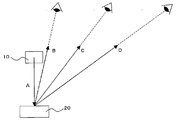
도 1은 시야각에 수반하는 색변화가 생기는 메커니즘을 설명하기 위한 도이다.
도 2는 이방성 광학 필름을 통과시킴으로써 시야각에 수반하는 색변화가 개선되는 것을 나타내는 도면이다.
도 3은 표시장치의 휘도가 시야각에 따라서 다른 것을 나타낸 일례이다.
도 4는 본 발명의 표시장치를 나타낸 일례이다.
도 5는 이방성 광학 필름의 단면도이다.
도 6은 광 제어판의 모식도이다.
도 7은 이방성 확산 매체의 모식도이다.
도 8은 광학 프로파일의 측정 방법을 나타내는 도면이다.
도 9는 광 제어판의 광학 프로파일을 나타낸다.
도 10은 이방성 확산 매체의 광학 프로파일을 나타낸다.1 is a view for explaining the mechanism that the color change occurs with the viewing angle.
2 is a view showing that the color change accompanying the viewing angle is improved by passing the anisotropic optical film.
3 illustrates an example in which the luminance of the display device varies depending on the viewing angle.
4 shows an example of the display device of the present invention.
5 is a cross-sectional view of the anisotropic optical film.
6 is a schematic diagram of an optical control panel.
7 is a schematic diagram of an anisotropic diffusion medium.
8 is a diagram illustrating a method for measuring an optical profile.
9 shows the optical profile of the light control panel.
10 shows the optical profile of an anisotropic diffusion medium.
여기에서, 본 특허청구의 범위 및 본 명세서에서의 각 용어의 정의를 설명한다.Here, the scope of the claims and the definition of each term in the present specification will be described.
「저굴절률 영역」과 「고굴절률 영역」은, 이방성 광학 필름을 구성하는 재료의 국소적인 굴절률의 고저차에 의해 형성되는 영역으로서, 다른 쪽에 비해 굴절률이 낮은지 높은지를 나타낸 상대적인 것이다. 이들 영역은, 이방성 광학 필름을 형성하는 재료가 경화할 때에 형성된다.The "low refractive index area" and the "high refractive index area" are regions formed by the high and low difference in the local refractive index of the material constituting the anisotropic optical film, and are relative to indicate whether the refractive index is low or high compared with the other. These regions are formed when the material forming the anisotropic optical film is cured.
「산란 중심축」이란, 입사각을 변화시켰을 때에 산란 특성이 그 입사각을 경계로 대략 대칭성을 가지는 빛의 입사각과 일치하는 방향을 의미한다. 「대략 대칭성을 가진다」라고 한 것은, 엄밀하게 광학 특성의 대칭성을 가지지 않기 때문이다. 산란 중심축은, 필름 단면의 기울기를 광학 현미경에 의해서 관찰하는 것이나, 이방성 광학 필름을 개재한 빛의 투영 형상을 입사각을 변화시켜 관찰함으로써 찾아낼 수 있다.The "scattering central axis" means a direction in which the scattering characteristics coincide with the incident angle of light having substantially symmetry around the incident angle when the incident angle is changed. The reason for having "approximately symmetry" is because it does not strictly have symmetry of optical characteristics. A scattering central axis can be found by observing the inclination of a film cross section with an optical microscope, and observing the projection shape of the light through an anisotropic optical film by changing an incident angle.
직선 투과율은, 광학 필름에 대해서 입사한 빛의 직선 투과성에 관해, 어느 입사각으로부터 입사했을 때에, 직선 방향의 투과 광량과 입사한 빛의 광량의 비율이며, 하기 식으로 나타낸다.The linear transmittance is a ratio of the amount of transmitted light in the linear direction and the amount of light incident on the linear transmissivity of light incident on the optical film when incident from a certain incident angle, and is represented by the following formula.
직선 투과율(%)=(직선 투과 광량/입사 광량)×100Linear transmittance (%) = (linearly transmitted light amount / incident light amount) × 100
「단파장」과「장파장」은 상대적인 의미로 사용하고 있는 것으로서, 특정의 파장 범위를 의미하는 것은 아니다."Short wavelength" and "long wavelength" are used in a relative meaning and do not mean a specific wavelength range.
이하, 본 발명의 내용에 대해 설명한다.EMBODIMENT OF THE INVENTION Hereinafter, the content of this invention is demonstrated.
우선, 표시장치에서의 시야각에 수반하는 색 변화가 생기는 메커니즘(추정)에 대해 도 1을 이용하여 설명한다. 도 1은, 광원(10)으로부터의 출사광 A가 매체(20)의 표면에서 반사되며 반사광 B, C, D가 얻어지는 것을 나타낸 도면이다. 출사광 A는 가시광 영역의 복수의 파장을 가지는 것이다. 빛의 산란·반사는 빛의 파장에 따라서 다르며, 단파장이 될수록 확산하기 쉽고, 장파장이 될수록 확산하기 어려운 성질을 가진다. 여기에서, 반사광 B를 각 파장의 밸런스가 잡힌 빛이라고 하면, 반사광 C는 반사광 B 보다도 빛의 밸런스가 무너진 것이 된다(단파장의 빛이 많고, 장파장의 빛이 적다). 마찬가지로, 반사광 D는 반사광 C 보다도 빛의 밸런스가 무너진 것이 된다(단파장의 빛이 많고, 장파장의 빛이 적다). 이와 같이, 빛의 밸런스가 무너짐으로써, 시야각에 수반하는 색변화(이하, 간단하게 「색변화」라고 하는 경우가 있다)의 문제가 발생한다고 생각된다. 그 결과, 반사광 B, C, D의 연장선상에 있는 관찰자는 상이한 색을 확인하게 된다. 또한, 도 1에 있어서, 법선 방향의 시야각을 0도로 하면, 반사광 B의 시야각이 가장 작고, 반사광 D의 시야각이 가장 크게 된다.First, the mechanism (estimation) in which the color change accompanying a viewing angle in a display apparatus arises is demonstrated using FIG. FIG. 1 is a diagram showing that the outgoing light A from the
도 1에서는 반사광에 대해 빛의 밸런스가 무너지는 것을 기재하고 있지만, 반사광에 한정되는 현상이 아니고, 마찬가지의 현상이 확산광(산란광)에서도 볼 수 있다. 따라서, 반사형의 표시장치뿐만 아니라, 투과형의 표시장치나 반투과 반반사형의 표시장치에 있어서도 동일하게 빛의 밸런스가 무너지는 문제가 발생한다. 한편, 빛의 반사나 산란이 발생할수록 빛의 밸런스가 무너지기 쉽기 때문에, 빛의 밸런스가 무너지기 쉬운 순서로서는, 반사형, 반투과 반반사형, 투과형의 표시장치가 된다.Although the balance of light with respect to reflected light is described in FIG. 1, it is not a phenomenon limited to reflected light, The same phenomenon can be seen also in diffused light (scattered light). Therefore, not only the reflective display device but also the transmissive display device and the transflective and semi-reflective display device have the same problem that the light balance is broken. On the other hand, since the balance of light tends to collapse as the reflection or scattering of light occurs, the display device of the reflective, semi-transmissive, semi-reflective, and transmissive type is used as an order in which the balance of light tends to collapse.
색변화가 생긴 빛을 이방성 광학 필름에 통과시킴으로써, 색변화가 적은 밸런스를 정돈한 빛으로 할 수 있다. 도 2를 이용해 설명하면, 반사광 B는 이방성 광학 필름(30)을 통과하는 것에 의해서, 확산광이 적은 투과광 B1을 얻을 수 있다. 도시하고 있지 않지만, 반사광 B는 투과광 B1과 함께 약간의 확산광도 얻을 수 있다.By passing the light which a color change generate | occur | produced through an anisotropic optical film, the balance with few color changes can be made into ordered light. When it demonstrates using FIG. 2, the reflected light B passes through the anisotropic
도 2에 있어서, 반사광 C가 이방성 광학 필름(30)을 통과하면, 확산광 C1~C5가 된다. 확산광 C1과 C5는 대략 동일한 밸런스를 가지며, 확산광 C2와 C4는 대략 동일한 밸런스를 가진다. 확산광 C3는 단파장의 빛이 적고, 장파장의 빛이 많은 것이다. 확산광 C2 및 C4는 확산광 C3에 비해, 단파장의 빛이 많고, 장파장의 빛이 적은 것이다. 마찬가지로, 확산광 C1 및 C5는 확산광 C2 및 C4에 비해, 단파장의 빛이 많고, 장파장의 빛이 적은 것이다. 따라서, 반사광 B와 반사광 C에서는, 이방성 광학 필름(30)을 통과하는 빛의 특성이 다르게 된다. 이것은 이방성 광학 필름(30) 내의 구조체(주상 구조, 판상 구조 또는 그 양자)의 기울기가, 빛의 확산성에 기여하고 있음에 의한다. 또한, 반사광 D는 소정의 출사각을 넘고 있기 때문에, 이방성 광학 필름의 표면에서 전반사 되어 반사광 D1이 된다.In FIG. 2, when the reflected light C passes through the anisotropic
본 발명은, 소정의 입사각으로부터 이방성 광학 필름(30)에 입사하는 빛을 선택적으로 확산시키는 것에 의해서, 휘도의 부족이나 색변화가 생기기 쉬운 시야각 영역에 빛을 공급하는 것을 가능하게 하고, 빛의 밸런스의 전체 최적화를 달성할 수 있는 것이다.According to the present invention, by selectively diffusing light incident on the anisotropic
도 2에 있어서, 이방성 광학 필름(30)의 법선 방향 S를 0도로 하면, 이방성 광학 필름(30) 내의 구조체(주상 구조, 판상 구조 또는 그 양자)의 기울기 R의 경사각 θ는 0도~60도의 범위 또는 0도~-60도의 범위로 하는 것이 바람직하고, 20도~50도의 범위 또는 -20도~-50도로 하는 것이 보다 바람직하다. 경사각 θ가 너무 작거나 너무 커도 색변화의 개선 효과를 얻기 어려워진다.In FIG. 2, when the normal direction S of the anisotropic
본원 발명은, 시야각에 수반하는 색변화를 가지는 표시 디바이스를 사용하는 것이다. 표시 디바이스란, 표시를 하기 위한 디바이스이면 특별히 한정되지 않으며, 예를 들면, 액정 표시 디바이스, 플라즈마 디스플레이 패널 또는 유기 EL 디바이스를 들 수 있다. 액정 표시 디바이스는, 1쌍의 기판 간에 협지된 액정 셀과 편광 소자를 가진다. 액정 셀의 형태로서는, 특별히 한정되지 않으며, 예를 들면, 박막 트랜지스터 어레이 기판과 컬러 필터 기판과의 사이에 협지된 액정을 가지는 형태를 들 수 있다. 또한, 편광판의 형태로서는, 특별히 한정되지 않지만, 액정 셀의 측으로부터 편광 소자, 지지 필름의 순으로 포함하는 형태, 액정 셀의 측으로부터 지지 필름, 편광 소자의 순으로 포함하는 형태, 액정 셀의 측으로부터 제1의 지지 필름, 편광 소자, 제2의 지지 필름의 순으로 포함하는 형태를 들 수 있다. 상기 지지 필름으로서는, 이방성 산란 필름의 투명 기체와 마찬가지의 것을 이용할 수 있다. 또한, 상기 편광판은, 통상, 액정 셀의 관찰면 측 및 배면 측의 양쪽 모두에 배치되지만, 관찰면 측에만 배치되어도 되고, 배면 측에만 배치되어도 된다. 상기 편광판은, 위상차 필름을 더욱 포함하는 것이 바람직하다. 이로써, 액정 표시 디바이스의 색도 등의 시야각 의존성도 보다 개선할 수도 있다.This invention uses the display device which has a color change with a viewing angle. The display device is not particularly limited as long as it is a device for displaying, and examples thereof include a liquid crystal display device, a plasma display panel, and an organic EL device. The liquid crystal display device has a liquid crystal cell and a polarizing element sandwiched between a pair of substrates. As a form of a liquid crystal cell, it does not specifically limit, For example, the form which has the liquid crystal clamped between a thin film transistor array substrate and a color filter substrate is mentioned. Moreover, although it does not specifically limit as a form of a polarizing plate, The form included in order of a polarizing element and a support film from the side of a liquid crystal cell, The form included in order of a support film, a polarizing element from the side of a liquid crystal cell, and the side of a liquid crystal cell. The form included in order of a 1st support film, a polarizing element, and a 2nd support film is mentioned. As said support film, the thing similar to the transparent base of an anisotropic scattering film can be used. In addition, although the said polarizing plate is normally arrange | positioned at both the observation surface side and the back side of a liquid crystal cell, it may be arrange | positioned only at the observation surface side and may be arrange | positioned only at the back side. It is preferable that the said polarizing plate further contains a retardation film. Thereby, viewing angle dependence, such as chromaticity, of a liquid crystal display device can also be improved more.
시야각에 수반하는 색변화란, 표시 디바이스의 표시 성능의 하나이다. 구체적으로는, 표시 디바이스의 색변화가 최소가 되는 방향과 상기 방향과 60도 또는 -60도 다른 방향(어느 쪽이든 측정 가능한 것으로 충분하다)에서 각각 휘도(L*) 및 색수(a*, b*)를 측정하여, △E*ab(색차)로 산출할 수 있다. 구체적으로는, 이하의 식으로 구할 수 있다. 또한, 이하의 식에 있어서는, 표시 디바이스의 색변화가 최소가 되는 방향을 0도로 하여 △L*, △a*, △b*를 산출하고 있다.The color change with viewing angle is one of the display performances of a display device. Specifically, the luminance L * and the number of colors a * , b * in a direction where the color change of the display device is minimized and in a direction different from the above direction by 60 degrees or -60 degrees, whichever is sufficient. ) Can be measured and calculated as ΔE * ab (color difference). Specifically, it can obtain | require by the following formula. In the following equation, ΔL * , Δa * , and Δb * are calculated by setting the direction where the color change of the display device is minimum to 0 degrees.
△E*ab=[(△L*)2+(△a*)2+(△b*)2]1/2 △ E * ab = [(△ L * ) 2 + (△ a * ) 2 + (△ b * ) 2 ] 1/2
단, △L*=L*(60°)-L*(0°)However, △ L * = L * (60 °) -L * (0 °)
△a*=a*(60°)-a*(0°)Δa * = a * (60 °) -a * (0 °)
△b*=b*(60°)-b*(0°)Δb * = b * (60 °) -b * (0 °)
이다.to be.
△E*ab의 값이 낮을수록, 시야각에 수반하는 색변화가 적은 것을 나타낸다. △E*ab의 값은 60 이하인 것이 바람직하고, 50 이하인 것이 보다 바람직하며, 45 이하인 것이 더욱 바람직하다. 하한값이 낮을수록 색변화의 관점에서는 바람직한 것이지만, 하한값이 너무 낮아지면 헤이즈가 높아져 화상이 흐려져서 표시되기 쉽다는 문제나 정면 방향의 휘도가 저하하기 쉬워지는 문제가 있어, 10 이상인 것이 바람직하고, 20 이상인 것이 보다 바람직하다.The lower the value of ΔE * ab, the smaller the color change accompanying the viewing angle. It is preferable that the value of (DELTA) E * ab is 60 or less, It is more preferable that it is 50 or less, It is further more preferable that it is 45 or less. The lower the lower limit, the more preferable from the viewpoint of color change. However, if the lower limit is too low, there is a problem that the haze becomes high and the image is blurred and easily displayed, and the brightness in the front direction tends to be lowered. It is more preferable.
본 발명의 표시장치는, 법선 방향에서의 L*(0°)은 높을수록 바람직하다. 표시 디바이스의 종류에 따라 L*(0°)의 값은 크게 다르다.In the display device of the present invention, the higher L * (0 °) in the normal direction is, the more preferable. The value of L * (0 °) varies greatly depending on the type of display device.
상기 표시장치의 관찰면의 법선 방향에 대해 60° 기울였을 때의 L*(60°)로부터 법선 방향의 L*(0°)을 뺀 차이, 또는 법선 방향에 대해 -60도 기울였을 때의 L*(-60°)로부터 법선 방향의 L*(0°)를 뺀 차이는 낮을수록 바람직하다. △L*의 값을 낮게 함에 따라, 법선 방향의 휘도와 60° 또는 -60° 방향의 휘도의 차가 적게 되기 때문에, 시야각이 변화해도 위화감이 적은 화상을 얻을 수 있다. L*(60°)로부터 법선 방향의 L*(0°)을 뺀 차이는 표시 디바이스의 종류에 따라서 다르다.L * (60 °) minus L * (0 °) in the normal direction or 60 ° inclination with respect to the normal direction from L * (60 °) when tilted 60 ° with respect to the viewing direction of the display device. The lower the difference obtained by subtracting L * (0 °) in the normal direction from * (-60 °) is preferable. As the value of ΔL * is lowered, the difference between the luminance in the normal direction and the luminance in the 60 ° or -60 ° direction is reduced, so that an image with less discomfort can be obtained even if the viewing angle changes. The difference of L * (60 °) minus L * (0 °) in the normal direction depends on the type of display device.
시야각에 수반하는 색변화란, 정면 방향(표시장치의 관찰면 법선 방향, 시각이 0°인 방향)에서 관찰했을 경우와 경사 방향(시야각이 0°보다 큰 방향)에서 관찰했을 경우에, 색상이 다른 것을 의미한다. 또한, 통상, 표시 디바이스의 색상은 정면 방향에 가까운 방향일수록 크지만, 그 반대여도 된다.The color change associated with the viewing angle refers to the color change when observed in the front direction (the normal direction of the viewing surface of the display device, the direction in which the time is 0 °) and in the inclined direction (the direction in which the viewing angle is greater than 0 °). It means something else. In general, the color of the display device is larger in the direction closer to the front direction, but may be reversed.
도 3은 표시장치의 휘도가 시야각에 따라서 다름을 나타낸 일례이다. 표시장치의 휘도는 광원에 따라서는 다양한 파장을 가지는 집합이지만, 이를 단파장과 장파장으로 편의적으로 나누면, 단파장일수록 확산하기 쉽고, 장파장일수록 확산하기 어렵기 때문에, 60°의 휘도는 단파장만큼 많고 장파장만큼 적게 된다. 도 3에 있어서는 단파장과 장파장을 구별하지 않고, 이들 집합으로서 기재하고 있다.3 illustrates an example in which the luminance of the display device varies depending on the viewing angle. The luminance of the display device is a set having various wavelengths depending on the light source, but if it is conveniently divided into short wavelengths and long wavelengths, the shorter wavelengths are easier to diffuse and the longer wavelengths are difficult to diffuse, so 60 ° brightness is as much as short wavelengths and as little as long wavelengths. do. In FIG. 3, short wavelengths and long wavelengths are not distinguished and described as these sets.
도 3은 0°를 중심으로 한 정규 분포가 되고 있다. 도 3의 실선이 종래 기술의 것이며, 큰 시야각(-60° 및 60°)에서는 휘도가 적게 된다.3 is a normal distribution centering on 0 °. The solid line in Fig. 3 is a prior art, and the luminance is low at large viewing angles (-60 ° and 60 °).
도 3의 점선이 본원 발명의 표시장치를 나타낸 것이다. 본원 발명은 정면 방향(0°)의 휘도의 일부를 보다 큰 시야각에 배분하는 것으로, 큰 시야각에서도 충분한 휘도를 가지는 표시장치를 제공할 수 있다. 또한, 본원 발명은 시야각에 수반하는 색변화도 감소시키는 것이 가능해진다.3 shows a display device of the present invention. The present invention distributes a part of the luminance in the front direction (0 °) to a larger viewing angle, thereby providing a display device having sufficient luminance even at a large viewing angle. In addition, the present invention can also reduce the color change accompanying the viewing angle.
또한, 도 3에 있어서는 0°를 중심으로 한 정규 분포를 나타내는 표시장치를 예시하고 있지만, 이에 한정되는 것은 아니다. 예를 들면, 30°를 중심으로 한 정규 분포를 나타내는 표시장치나, -30°를 중심으로 한 대략 대칭성을 나타내는 표시장치에 적용할 수 있다.In addition, although the display apparatus which shows the normal distribution centering on 0 degree in FIG. 3 is illustrated, it is not limited to this. For example, the present invention can be applied to a display device showing a normal distribution centered on 30 ° or a display device showing approximately symmetry around -30 °.
도 4는 시야각에 수반하는 색변화를 가지는 표시 디바이스(100)와, 빛의 입사각에 의해 확산성이 변화하는 이방성 광학 필름(30)을 가지는 표시장치(1)이다. 이방성 광학 필름(30)은 표시 디바이스(100)의 관찰면측에 설치되는 것이 바람직하다. 도 4에 있어서는, 이방성 광학 필름(30)은 1개의 산란 중심축을 가진다. 법선 방향 S를 0°로 했을 때, 표시 디바이스(100)의 색변화가 최소가 되는 방향은, -90°보다 크고 +90°보다 작은 범위에서 임의로 정할 수 있지만, -30°이상 +30°이하인 것이 바람직하며, -15°이상 +15°이하인 것이 보다 바람직하다. 표시장치는 대략 대칭이 되는 표시 성능을 가지는 것이기 때문에, 너무 극단적인 방향으로 색변화가 최소가 되는 방향을 가지게 되면, 다른 쪽의 방향에 있어서 표시장치로서 기능하지 않게 되기 때문이다.4 is a
이방성 광학 필름(30)의 산란 중심축과, 표시 디바이스(100)의 색변화가 최소가 되는 방향이 이루는 각도는 20°~65° 또는 -20°~-65°의 범위에 있는 것이 필요하다. 30°~55° 또는 -30°~-55°의 범위에 있는 것이 바람직하다. 상기 범위로 함으로써, 표시 디바이스(100)의 색변화가 최소가 되는 방향의 빛을 보다 큰 시야각에 배분하는 것이 가능해진다. 이것에 의해, 큰 시야각에서도 충분한 휘도를 가지는 표시장치를 제공하는 것과, 시야각에 수반하는 색변화도 감소시키는 것이 가능해진다.The angle formed between the scattering central axis of the anisotropic
산란 중심축은 이방성 광학 필름(30) 내에 1개 있으면 되고, 2개 이상 가지는 것도 된다. 다른 산란 중심축을 가지는 이방성 광학 필름을 적층하는 것도 가능하다. 한 장의 이방성 광학 필름 내에 2개 이상 산란 중심축을 가지든지, 다른 산란 중심축을 가지는 두 장의 이방성 광학 필름을 적층하는 경우, 상기 산란 중심축의 한쪽이, 상기 표시 디바이스의 색변화가 최소가 되는 방향과 이루는 각도가 20°~65°의 범위에 있으며, 상기 산란 중심축의 다른 쪽이, 상기 표시 디바이스의 색변화가 최소가 되는 방향과 이루는 각도가 -20°~-65°의 범위에 있는 것이 바람직하다. 보다 바람직하게는, 상기 산란 중심축의 한쪽이 상기 표시 디바이스의 색변화가 최소가 되는 방향과 이루는 각도가 30°~55°의 범위에 있으며, 상기 산란 중심축의 다른 쪽이, 상기 표시 디바이스의 색변화가 최소가 되는 방향과 이루는 각도가 -30°~-55°의 범위에 있는 것이 바람직하다. 상기 범위로 함으로써, 대략 대칭성을 가지는 광학 특성을 얻는 것이 가능해진다.One scattering central axis may be provided in the anisotropic
이방성 광학 필름에는, 그 내부에 판상 구조를 가지는 것과 주상 구조를 가지는 것의 양자가 포함된다. 또한, 이들 구조를 동시에 포함하게 하는 것도 가능하다.Anisotropic optical films include both those having a plate-like structure and those having a columnar structure therein. It is also possible to include these structures at the same time.
판상 구조를 가지는 것과 주상 구조를 가지는 것에 대해서, 얻어진 색변화의 개선 효과를 비교하면, 이방성 광학 필름의 내부에 판상 구조를 가짐으로써, 색변화의 개선 효과를 보다 향상시킬 수 있지만, 시야각의 변화에 수반하여 색변화의 개선이 급격하게 변화하는 경우가 있어, 관찰자에게 부자연스러운 인상을 받게 하는 경우가 있다. 한편, 이방성 광학 필름의 내부에 주상 구조를 가짐으로써, 색변화의 개선 효과는 약간 뒤떨어지지만, 시야각의 변화에 수반하는 색변화의 개선 효과가 완만하게 변화하기 때문에, 관찰자에게 부자연스러운 인상을 받게 하는 경우가 적다. 또한, 이방성 광학 필름의 내부에 판상 구조와 주상 구조의 양자를 포함하게 하면, 각각 중간의 성질을 가지게 된다.Comparing the improvement effect of the color change obtained with having a plate-like structure and having a columnar structure, by having the plate-like structure inside the anisotropic optical film, the improvement effect of the color change can be further improved, In some cases, the improvement of the color change may change drastically, and the observer may have an unnatural impression. On the other hand, by having a columnar structure inside the anisotropic optical film, the improvement effect of the color change is slightly inferior, but the improvement effect of the color change accompanying the change of the viewing angle is changed slowly, which gives the viewer an unnatural impression. Few cases. Moreover, when both an plate-shaped structure and columnar structure are included in the inside of an anisotropic optical film, it will have the intermediate property, respectively.
이방성 광학 필름의 내부 구조는, 사용 목적에 따라 적절히 조정하는 것이 바람직하다.It is preferable to adjust the internal structure of an anisotropic optical film suitably according to a use purpose.
도 5는 본 발명의 이방성 광학 필름(30)의 모식도이다. 도 5(a)에 나타낸 바와 같이, 이방성 광학 필름(30)의 단면에 있어서는, 저굴절률 영역(31)과 고굴절률 영역(32)을 교대로 포함하는 것이다. 도 5(b)에 나타낸 바와 같이, 인접하는 고굴절률 영역(32)을 교차시키도록 해도 된다. 인접하는 고굴절률 영역(32)을 교차시키는 경우는, 이방성 광학 필름(30a)의 모든 부위에 있어 교차시켜도 되고, 부분적으로 교차시켜도 된다. 교차시킴으로써, 정반대의 2 방향의 시야각에서의 색변화를 개선시킬 수 있다.5 is a schematic view of the anisotropic
또한, 도 5(b)에 있어서, 고굴절률 영역 대신에 저굴절률 영역이 교차하는 경우와 기울기가 바뀌는 경우가 되어도 무방하다.In addition, in FIG.5 (b), the case where the low refractive index area | region crosses instead of a high refractive index area | region and a case where inclination may change may be sufficient.
저굴절 영역과 고굴절률 영역의 굴절률차(절대값)는, 0.02 이상인 것이 바람직하다. 보다 바람직하게는 0.03 이상이며, 더욱 바람직하게는 0.04 이상이다. 굴절률차가 커질수록, 이방성의 정도가 커진다.It is preferable that the refractive index difference (absolute value) between the low refractive index region and the high refractive index region is 0.02 or more. More preferably, it is 0.03 or more, More preferably, it is 0.04 or more. The larger the refractive index difference, the greater the degree of anisotropy.
도 5에 있어서는, 저굴절률 영역(31)과 고굴절률 영역(32)의 계면을 직선으로서 그리고 있지만, 계면은 대략 직선상이거나 곡선상이어도 된다. 대략 직선상 또는 곡선상이어도, 도 9 또는 도 10에 나타낸 바와 같은 입사각 의존성을 나타낸다.In FIG. 5, although the interface of the low refractive index area |
또한, 도 5에 있어서는 저굴절률 영역(31)과 고굴절률 영역(32)의 계면을 기재하고 있지만, 이 계면은 실질적으로 존재하지 않아도 된다.In addition, although the interface of the low refractive index area |
굴절률이 점증 또는 점감하는 경우에 있어서는, 굴절률을 측정하는 것이 곤란하지만, 이방성 광학 필름의 국소적인 굴절률을 복수회 측정한 경우에 있어서, 가장 굴절률이 낮은 부분과 가장 굴절률이 높은 부분의 굴절률차가 0.02 이상 있는 것이 바람직하다. 보다 바람직하게는 0.03 이상이며, 더욱 바람직하게는 0.04 이상이다. 굴절률차가 커질수록, 이방성의 정도가 커진다.In the case where the refractive index is increased or decreased, it is difficult to measure the refractive index, but when the local refractive index of the anisotropic optical film is measured multiple times, the difference in refractive index between the portion with the lowest refractive index and the portion with the highest refractive index is 0.02 or more. It is desirable to have. More preferably, it is 0.03 or more, More preferably, it is 0.04 or more. The larger the refractive index difference, the greater the degree of anisotropy.
이방성Anisotropy 광학 필름의 제조 방법 Manufacturing method of optical film
본 발명의 이방성 광학 필름은, 특정의 광 경화성 화합물에 특수한 조건으로 자외선(UV) 조사를 실시함으로써 제작할 수 있다. 이하, 우선 이방성 광학 필름의 원료를 설명하고, 이어서 제조 프로세스를 설명한다.The anisotropic optical film of this invention can be produced by giving ultraviolet (UV) irradiation on a specific photocurable compound on special conditions. Hereinafter, the raw material of an anisotropic optical film is demonstrated first, and then a manufacturing process is demonstrated.
이방성Anisotropy 광학 필름의 원료 Raw material of optical film
본 발명의 이방성 광학 필름을 형성하는 재료는, 적어도 광 경화성 화합물의 모노머, 올리고머, 프리폴리머, 폴리머 또는 매크로 모노머와 광 개시제로 구성되며, 자외선 및/또는 가시광선을 조사함으로써 중합·고화하는 재료이다. 광 경화성 화합물에 추가하여, 경화 방식이 다른 수지 또는 상기 광 경화성 화합물을 사용하는 것이 바람직하다. 경화 방식이 다른 수지로서는, 열가소성 수지 및 열경화성 수지를 들 수 있다. 광 경화성 화합물과 열가소성 수지의 조합, 광 경화성 화합물과 열경화성 수지의 조합, 광 경화성 화합물과 열가소성 수지와 열경화성 수지의 조합을 적절히 채용할 수 있다.The material which forms the anisotropic optical film of this invention is comprised from the monomer, oligomer, prepolymer, polymer or macromonomer of a photocurable compound, and a photoinitiator, and is a material which superposes | polymerizes and solidifies by irradiating an ultraviolet-ray and / or visible light. In addition to a photocurable compound, it is preferable to use resin in which a hardening system differs, or the said photocurable compound. Examples of the resin having different curing methods include thermoplastic resins and thermosetting resins. The combination of a photocurable compound and a thermoplastic resin, the combination of a photocurable compound and a thermosetting resin, and the combination of a photocurable compound, a thermoplastic resin, and a thermosetting resin can be employ | adopted suitably.
여기에서, 이방성 광학 필름을 형성하는 재료가 1 종류이어도, 밀도의 고저차가 생김으로써 굴절률차가 발생한다. UV의 조사 강도가 강한 부분은 경화 속도가 빨리 되기 때문에, 그 경화 영역 주위에 경화 재료가 이동하여, 결과적으로 굴절률이 높아지는 영역과 굴절률이 낮아지는 영역이 형성되기 때문이다.Here, even if there is only one kind of material for forming the anisotropic optical film, a difference in refractive index occurs because a difference in density is generated. This is because a portion where the UV irradiation intensity is strong increases the curing speed, and thus the cured material moves around the cured region, resulting in a region where the refractive index is increased and a region where the refractive index is decreased.
(광 경화성 화합물)(Photocurable compound)
광 경화성 화합물은, 라디칼 중합성 또는 양이온 중합성의 관능기를 가지는 모노머, 올리고머, 프리폴리머 또는 매크로 모노머이다. 라디칼 중합성의 관능기로서는, 아크릴로일기, 메타크릴로일기, 알릴기 등을 들 수 있으며, 양이온 중합성의 관능기로서는, 에폭시기, 옥세탄기 등을 들 수 있다. 이들 관능기의 종류와 수에 특별히 제한은 없지만, 관능기가 많을수록 가교 밀도가 올라, 굴절률의 차가 생기기 쉽기 때문에 바람직하다는 점에서, 다관능의 아크릴로일기 또는 메타크릴로일기를 가지는 것이 바람직하다.A photocurable compound is a monomer, oligomer, prepolymer, or macromonomer which has a radically polymerizable or cationically polymerizable functional group. Acryloyl group, methacryloyl group, an allyl group, etc. are mentioned as a radically polymerizable functional group, An epoxy group, an oxetane group, etc. are mentioned as a cationically polymerizable functional group. Although there is no restriction | limiting in particular in the kind and number of these functional groups, It is preferable to have a polyfunctional acryloyl group or a methacryloyl group from the point which is preferable, because more crosslinking density increases and the difference of refractive index tends to occur more.
라디칼 중합성 화합물은, 주로 분자 중에 1개 이상의 불포화 이중 결합을 함유하는 것으로, 구체적으로는 메틸 아크릴레이트, 에폭시 아크릴레이트, 우레탄 아크릴레이트, 폴리에스테르 아크릴레이트, 폴리에테르 아크릴레이트, 폴리부타디엔 아크릴레이트 등의 명칭으로 불리는 아크릴 올리고머와 2-에틸헥실 아크릴레이트, 이소아밀 아크릴레이트, 부톡시에틸 아크릴레이트, 에톡시디에틸렌글리콜 아크릴레이트, 페녹시에틸 아크릴레이트, 테트라히드로퍼푸릴 아크릴레이트, 이소노르보르닐 아크릴레이트, 2-히드록시에틸 아크릴레이트, 2-히드록시프로필 아크릴레이트, 2-아크릴로일옥시프탈산, 디시클로펜테닐 아크릴레이트, 트리에틸렌글리콜 디아크릴레이트, 네오펜틸글리콜 디아크릴레이트, 1,6-헥산디올 디아크릴레이트, 비스페놀A의 EO 부가물 디아크릴레이트, EO 변성 페닐 아크릴레이트, 아다만탄 아크릴레이트, 비페닐 아크릴레이트, 페녹시페닐 아크릴레이트, 트리메틸올프로판 트리아크릴레이트, EO 변성 트리메틸올프로판 트리아크릴레이트, 펜타에리트리톨 트리아크릴레이트, 펜타에리트리톨 테트라아크릴레이트, 디트리메틸올프로판 테트라아크릴레이트, 디펜타에리트리톨 헥사아크릴레이트 등의 아크릴레이트 모노머를 들 수 있다. 또한, 이들 화합물은, 각 단체로 이용해도 되고, 복수 혼합하여 이용해도 된다. 또한, 동일하게 메타크릴레이트도 사용 가능하지만, 일반적으로는 메타크릴레이트 보다도 아크릴레이트 쪽이 광 중합 속도가 빠르기 때문에 바람직하다.The radically polymerizable compound mainly contains at least one unsaturated double bond in the molecule, and specifically, methyl acrylate, epoxy acrylate, urethane acrylate, polyester acrylate, polyether acrylate, polybutadiene acrylate, or the like. Acryl oligomer and 2-ethylhexyl acrylate, isoamyl acrylate, butoxyethyl acrylate, ethoxydiethyleneglycol acrylate, phenoxyethyl acrylate, tetrahydrofurfuryl acrylate, isonorbornyl acrylic Latex, 2-hydroxyethyl acrylate, 2-hydroxypropyl acrylate, 2-acryloyloxyphthalic acid, dicyclopentenyl acrylate, triethylene glycol diacrylate, neopentylglycol diacrylate, 1,6 -Hexanediol diacrylate, EO adduct of bisphenol A Diacrylate, EO-modified phenyl acrylate, adamantane acrylate, biphenyl acrylate, phenoxyphenyl acrylate, trimethylolpropane triacrylate, EO-modified trimethylolpropane triacrylate, pentaerythritol triacrylate, And acrylate monomers such as pentaerythritol tetraacrylate, ditrimethylolpropane tetraacrylate, and dipentaerythritol hexaacrylate. In addition, these compounds may be used individually, and may be used in mixture of many. Moreover, although methacrylate can also be used similarly, since acrylate is generally faster than methacrylate, since photopolymerization rate is faster, it is preferable.
양이온 중합성 화합물로서는, 분자 중에 에폭시기나 비닐에테르기, 옥세탄기를 1개 이상 가지는 화합물을 사용할 수 있다. 에폭시기를 가지는 화합물로서는, 2-에틸헥실디글리콜글리시딜에테르, 비페닐의 글리시딜에테르, 비스페놀A, 수소 첨가 비스페놀A, 비스페놀F, 비스페놀AD, 비스페놀S, 테트라메틸 비스페놀A, 테트라메틸 비스페놀F, 테트라클로로 비스페놀A, 테트라브로모 비스페놀A 등의 비스페놀류의 디글리시딜에테르류, 페놀 노볼락, 크레졸 노볼락, 브롬화페놀 노볼락, 오르토크레졸 노볼락 등의 노볼락 수지의 폴리글리시딜에테르류, 에틸렌글리콜, 폴리에틸렌글리콜, 폴리프로필렌글리콜, 부탄디올, 1,6-헥산디올, 네오펜틸글리콜, 트리메틸올프로판, 1,4-시클로헥산디메탄올, 비스페놀A의 EO 부가물, 비스페놀A의 PO 부가물 등의 알킬렌글리콜류의 디글리시딜에테르류, 헥사히드로프탈산의 글리시딜에스테르나 다이머산의 디글리시딜에스테르 등의 글리시딜에스테르류를 들 수 있다.As a cationically polymerizable compound, the compound which has 1 or more of an epoxy group, a vinyl ether group, and an oxetane group can be used in a molecule | numerator. As a compound which has an epoxy group, 2-ethylhexyl diglycol glycidyl ether, biphenyl glycidyl ether, bisphenol A, hydrogenated bisphenol A, bisphenol F, bisphenol AD, bisphenol S, tetramethyl bisphenol A, tetramethyl bisphenol Polyglycides of novolak resins such as diglycidyl ethers of bisphenols such as F, tetrachloro bisphenol A and tetrabromo bisphenol A, phenol novolac, cresol novolac, brominated phenol novolac and orthocresol novolac Dimethyl ether, ethylene glycol, polyethylene glycol, polypropylene glycol, butanediol, 1,6-hexanediol, neopentyl glycol, trimethylolpropane, 1,4-cyclohexanedimethanol, EO adduct of bisphenol A, bisphenol A Glycidyl esters, such as diglycidyl ethers of alkylene glycols, such as PO addition products, glycidyl ester of hexahydrophthalic acid, and diglycidyl ester of dimer acid It may be a flow.
또한, 3,4-에폭시시클로헥실메틸-3',4'-에폭시시클로헥산카르복실레이트, 2-(3,4-에폭시시클로헥실-5,5-스피로-3,4-에폭시)시클로헥산-메타-디옥산, 디(3,4-에폭시시클로헥실메틸)아디페이트, 디(3,4-에폭시-6-메틸시클로헥실메틸)아디페이트, 3,4-에폭시-6-메틸시클로헥실-3',4'-에폭시-6'-메틸시클로헥산카르복실레이트, 메틸렌비스(3,4-에폭시시클로헥산), 디시클로펜타디엔디에폭사이드, 에틸렌글리콜의 디(3,4-에폭시시클로헥실메틸)에테르, 에틸렌비스(3,4-에폭시시클로헥산카르복실레이트), 락톤 변성 3,4-에폭시시클로헥실메틸-3',4'-에폭시시클로헥산카르복실레이트, 테트라(3,4-에폭시시클로헥실메틸)부탄테트라카르복실레이트, 디(3,4-에폭시시클로헥실메틸)-4,5-에폭시테트라히드로프탈레이트 등의 지환식 에폭시 화합물도 들 수 있지만, 이들에 한정되는 것은 아니다.Furthermore, 3, 4- epoxycyclohexyl methyl-3 ', 4'- epoxy cyclohexane carboxylate, 2- (3, 4- epoxy cyclohexyl-5, 5- spiro-3, 4- epoxy) cyclohexane- Meta-dioxane, di (3,4-epoxycyclohexylmethyl) adipate, di (3,4-epoxy-6-methylcyclohexylmethyl) adipate, 3,4-epoxy-6-methylcyclohexyl-3 ', 4'-epoxy-6'-methylcyclohexanecarboxylate, methylenebis (3,4-epoxycyclohexane), dicyclopentadiene diepoxide, di (3,4-epoxycyclohexylmethyl of ethylene glycol Ether, ethylenebis (3,4-epoxycyclohexanecarboxylate), lactone-modified 3,4-epoxycyclohexylmethyl-3 ', 4'-epoxycyclohexanecarboxylate, tetra (3,4-epoxycyclo Alicyclic epoxy compounds, such as hexyl methyl) butane tetracarboxylate and di (3, 4- epoxycyclohexyl methyl) -4, 5- epoxy tetrahydrophthalate, are also mentioned, What is limited to these Is not.
비닐에테르기를 가지는 화합물로서는, 예를 들면 디에틸렌글리콜 디비닐에테르, 트리에틸렌글리콜 디비닐에테르, 부탄디올 디비닐에테르, 헥산디올 디비닐에테르, 시클로헥산디메탄올 디비닐에테르, 히드록시부틸 비닐에테르, 에틸 비닐에테르, 도데실 비닐에테르, 트리메틸올프로판 트리비닐에테르, 프로페닐에테르프로필렌카보네이트 등을 들 수 있지만, 이들에 한정되는 것은 아니다. 또한, 비닐에테르 화합물은, 일반적으로는 양이온 중합성이지만, 아크릴레이트와 조합시켜 라디칼 중합도 가능하다.Examples of the compound having a vinyl ether group include diethylene glycol divinyl ether, triethylene glycol divinyl ether, butanediol divinyl ether, hexanediol divinyl ether, cyclohexanedimethanol divinyl ether, hydroxybutyl vinyl ether, and ethyl. Vinyl ether, dodecyl vinyl ether, trimethylolpropane trivinyl ether, propenyl ether propylene carbonate, etc. are mentioned, It is not limited to these. Moreover, although a vinyl ether compound is generally cationically polymerizable, radical polymerization is also possible in combination with an acrylate.
옥세탄기를 가지는 화합물로서는, 1,4-비스[(3-에틸-3-옥세타닐메톡시)메틸]벤젠, 3-에틸-3-(히드록시메틸)-옥세탄 등을 사용할 수 있다.As the compound having an oxetane group, 1,4-bis [(3-ethyl-3-oxetanylmethoxy) methyl] benzene, 3-ethyl-3- (hydroxymethyl) -oxetane and the like can be used.
또한, 이상의 양이온 중합성 화합물은, 각 단체로 이용해도 되고, 복수 혼합하여 이용해도 된다. 상기 광 중합성 화합물은, 상기 기술한 것에 한정되는 것은 아니다. 또한, 충분한 굴절률차를 발생시키도록, 상기 광 중합성 화합물에는, 저굴절률화를 도모하기 위해 불소 원자(F)를 도입해도 되고, 고굴절률화를 도모하기 위해 황 원자(S), 브롬 원자(Br), 각종 금속 원자를 도입해도 된다.In addition, the above cationically polymerizable compound may be used individually, or may be mixed and used for it. The said photopolymerizable compound is not limited to what was mentioned above. In addition, in order to generate | occur | produce a sufficient refractive index difference, the said photopolymerizable compound may introduce | transduce a fluorine atom (F) in order to aim at low refractive index, and a sulfur atom (S) and a bromine atom ( Br) and various metal atoms may be introduced.
(열가소성 수지)(Thermoplastic)
열가소성 수지로서는, 폴리에스테르, 폴리에테르, 폴리우레탄, 폴리아미드, 폴리에폭사이드, 폴리스티렌, 폴리카보네이트, 폴리아세탈, 폴리비닐알코올, 폴리아세트산비닐, 폴리비닐부티랄, 아크릴 수지와 그 공중합체나 변성물을 들 수 있다. 열가소성 수지를 이용하는 경우에 있어서는 열가소성 수지가 용해하는 용제를 사용해 용해하고, 도포, 건조 후에 자외선으로 광 경화성 화합물을 경화시켜 이방성 광학 필름을 성형한다.As the thermoplastic resin, polyester, polyether, polyurethane, polyamide, polyepoxide, polystyrene, polycarbonate, polyacetal, polyvinyl alcohol, polyvinyl acetate, polyvinyl butyral, acrylic resin and its copolymer or modified Water is available. When using a thermoplastic resin, it melt | dissolves using the solvent in which a thermoplastic resin melt | dissolves, and after an application | coating and drying, harden | cure a photocurable compound with an ultraviolet-ray, and shape an anisotropic optical film.
용제는 열가소성 수지를 용해시킬 수 있는 것이면 되지만, 예를 들면, 에탄올, 이소프로판올 또는 부탄올 등의 알코올, 아세톤 등의 케톤, 아세트산에틸 등의 에스테르, 테트라히드로푸란 등의 에테르 및 헥산, 벤젠, 톨루엔, 클로로포름 등의 지방족, 방향족 및 할로겐화 탄화수소이다.The solvent may be any one capable of dissolving the thermoplastic resin, but for example, alcohols such as ethanol, isopropanol or butanol, ketones such as acetone, esters such as ethyl acetate, ethers such as tetrahydrofuran and hexane, benzene, toluene and chloroform And aliphatic, aromatic and halogenated hydrocarbons.
(열경화성 수지)(Thermosetting resin)
열경화성 수지로서는, 에폭시 수지, 페놀 수지, 멜라민 수지, 요소수지, 불포화 폴리에스테르와 그 공중합체나 변성물을 들 수 있다. 열경화성 수지를 이용하는 경우에 있어서는, 자외선으로 광 경화성 화합물을 경화시킨 후에 적절히 가열함으로써, 열경화성 수지를 경화시켜 이방성 광학 필름을 성형한다.Examples of the thermosetting resin include epoxy resins, phenol resins, melamine resins, urea resins, unsaturated polyesters, copolymers and modified substances thereof. When using a thermosetting resin, after hardening a photocurable compound with an ultraviolet-ray, it heats suitably, and hardens a thermosetting resin and shape | molds an anisotropic optical film.
(광 개시제)(Photoinitiator)
라디칼 중합성 화합물을 중합시킬 수 있는 광 개시제로서는, 벤조페논, 벤질, 미힐러 케톤, 2-클로로티옥산톤, 2,4-디에틸티옥산톤, 벤조인에틸에테르, 벤조인이소프로필에테르, 벤조인이소부틸에테르, 2,2-디에톡시아세토페논, 벤질디메틸케탈, 2,2-디메톡시-1,2-디페닐에탄-1-온, 2-히드록시-2-메틸-1-페닐프로판-1-온, 1-히드록시시클로헥실페닐케톤, 2-메틸-1-[4-(메틸티오)페닐]-2-몰폴리노프로파논-1,1-[4-(2-히드록시에톡시)-페닐]-2-히드록시-2-메틸-1-프로판-1-온, 비스(시클로펜타디에닐)-비스(2,6-디플루오로-3-(필-1-일)티타늄, 2-벤질-2-디메틸아미노-1-(4-몰폴리노페닐)-부타논-1,2,4,6-트리메틸벤조일디페닐포스핀옥사이드 등을 들 수 있다. 또한, 이들 화합물은, 각 단체로 이용해도 되고, 복수 혼합하여 이용해도 된다.As a photoinitiator which can superpose | polymerize a radically polymerizable compound, benzophenone, benzyl, Michler's ketone, 2-chloro thioxanthone, 2, 4- diethyl thioxanthone, benzoin ethyl ether, benzoin isopropyl ether, Benzoin isobutyl ether, 2,2-diethoxyacetophenone, benzyldimethyl ketal, 2,2-dimethoxy-1,2-diphenylethan-1-one, 2-hydroxy-2-methyl-1-phenyl Propane-1-one, 1-hydroxycyclohexylphenylketone, 2-methyl-1- [4- (methylthio) phenyl] -2-morpholinopropaneone-1,1- [4- (2-hydride Hydroxyethoxy) -phenyl] -2-hydroxy-2-methyl-1-propan-1-one, bis (cyclopentadienyl) -bis (2,6-difluoro-3- (phyl-1-) I) titanium, 2-benzyl-2-dimethylamino-1- (4-morpholinophenyl) -butanone-1,2,4,6-trimethylbenzoyldiphenylphosphine oxide, etc. are mentioned. These compounds may be used individually, or may be mixed and used for them.
양이온 중합성 화합물의 광 개시제는, 광 조사에 의해서 산을 발생하며, 이 발생한 산에 의해 상술의 양이온 중합성 화합물을 중합시킬 수 있는 화합물이며, 일반적으로는, 오늄염, 메탈로센 착체가 매우 적합하게 이용된다. 오늄염으로서는, 디아조늄염, 설포늄염, 요오드늄염, 포스포늄염, 셀레늄염 등이 사용되며, 이들 짝이온에는, BF4 -, PF6 -, AsF6 -, SbF6 - 등의 음이온이 이용된다. 구체적인 예로서는, 4-클로로벤젠디아조늄헥사플루오로포스페이트, 트리페닐설포늄헥사플루오로안티모네이트, 트리페닐설포늄헥사플루오로포스페이트, (4-페닐티오페닐)디페닐설포늄헥사플루오로안티모네이트, (4-페닐티오페닐)디페닐설포늄헥사플루오로포스페이트, 비스[4-(디페닐설포니오)페닐]설피드-비스-헥사플루오로안티모네이트, 비스[4-(디페닐설포니오)페닐]설피드-비스-헥사플루오로포스페이트, (4-메톡시페닐)디페닐설포늄헥사플루오로안티모네이트, (4-메톡시페닐)페닐요오드늄헥사플루오로안티모네이트, 비스(4-t-부틸페닐)요오드늄헥사플루오로포스페이트, 벤질트리페닐포스포늄헥사플루오로안티모네이트, 트리페닐셀레늄헥사플루오로포스페이트, (η5-이소프로필 벤젠)(η5-시클로펜타디에닐)철(II)헥사플루오로포스페이트 등을 들 수 있지만, 이들에 한정되는 것은 아니다. 또한, 이들 화합물은, 각 단체로 이용해도 되고, 복수 혼합하여 이용해도 된다.The photoinitiator of a cationically polymerizable compound produces | generates an acid by light irradiation, and is a compound which can superpose | polymerize the above-mentioned cationically polymerizable compound by the generated acid, and generally, an onium salt and a metallocene complex are very It is suitably used. Onium salts as, diazonium salts, sulfonium salt, iodonium salt, phosphonium salt, in the like selenium salt is used, and these counter-ion, BF 4 -, PF 6 - , AsF 6 -, SbF 6 - anion, such as using do. Specific examples include 4-chlorobenzenediazonium hexafluorophosphate, triphenylsulfonium hexafluoroantimonate, triphenylsulfonium hexafluorophosphate, (4-phenylthiophenyl) diphenylsulfonium hexafluoroantimo Nate, (4-phenylthiophenyl) diphenylsulfonium hexafluorophosphate, bis [4- (diphenylsulfonio) phenyl] sulfide-bis-hexafluoroantimonate, bis [4- (diphenyl Sulfonio) phenyl] sulfide-bis-hexafluorophosphate, (4-methoxyphenyl) diphenylsulfonium hexafluoroantimonate, (4-methoxyphenyl) phenyliodonium hexafluoroantimonate , Bis (4-t-butylphenyl) iodonium hexafluorophosphate, benzyltriphenylphosphonium hexafluoroantimonate, triphenylselenium hexafluorophosphate, (η5-isopropyl benzene) (η5-cyclopentadiene Nil) iron (II) hexafluorophosphate, etc. But it is not limited to these. In addition, these compounds may be used individually, and may be used in mixture of many.
(기능성 첨가제)(Functional additive)
이방성 광학 필름에 색변화의 개선 효과를 부여하기 위해서, 기능성 첨가제를 함유시키는 것이 바람직하다. 기능성 첨가제로서는, (a) 축합한 실란 화합물, (b) 표면을 개질한 초미립자, (c) 유연제를 들 수 있다.In order to provide the improvement effect of a color change to an anisotropic optical film, it is preferable to contain a functional additive. As a functional additive, (a) the condensed silane compound, (b) the ultrafine particle which modified the surface, and (c) softening agent are mentioned.
(a) 축합한 실란 화합물(a) condensed silane compounds
실란은, 1, 2, 3 또는 4개의, 바람직하게는 2 또는 3개의 가수분해성 기를 가지는 것 및 이들 혼합물이다. 가수분해성 기의 예는, 수소 또는 F, Cl, Br 혹은 I 등의 할로겐, 알콕시, 바람직하게는 예를 들어 메톡시, 에톡시, n-프로폭시, i-프로폭시 및 부톡시 등의 C1~6 알콕시; 아릴 옥시, 바람직하게는 예를 들어 페녹시 등의 C6~10 아릴 옥시; 예를 들어 아세톡시 또는 프로피오닐옥시 등의 아실 옥시; 알킬카르보닐, 바람직하게는 예를 들어 아세틸 등의 C2~7 알킬카르보닐; 아미노, 바람직하게는 알킬기 중에 1~12개, 특히 1~6개의 탄소 원자를 갖는 모노알킬아미노 또는 디알킬아미노이다.Silanes are those having 1, 2, 3 or 4, preferably 2 or 3 hydrolysable groups and mixtures thereof. Examples of the hydrolyzable group are hydrogen or halogen, alkoxy such as F, Cl, Br or I, preferably C1 ~ such as methoxy, ethoxy, n-propoxy, i-propoxy and butoxy. 6 alkoxy; Aryl oxy, preferably, for example, C 6-10 aryl oxy such as phenoxy; Acyloxy, such as, for example, acetoxy or propionyloxy; Alkylcarbonyl, preferably C2-7 alkylcarbonyl such as, for example, acetyl; Amino, preferably monoalkylamino or dialkylamino having 1 to 12, in particular 1 to 6, carbon atoms in the alkyl group.
특히 바람직한 실란은, 예를 들어 메타크릴옥시프로필트리메톡시실란, 아크릴옥시프로필트리메톡시실란, 디메틸디메톡시실란, 디메틸디에톡시실란, 3-글리시딜옥시-프로필트리메톡시실란, 글리시딜옥시-프로필트리에톡시실란, 비닐트리에톡시실란, 메틸트리에톡시실란이다.Particularly preferred silanes are, for example, methacryloxypropyltrimethoxysilane, acryloxypropyltrimethoxysilane, dimethyldimethoxysilane, dimethyldiethoxysilane, 3-glycidyloxy-propyltrimethoxysilane, glycy Dialkyl-propyltriethoxysilane, vinyltriethoxysilane and methyltriethoxysilane.
실란의 부분적 축합은 예를 들면, 물, HCl 수용액, HNO3 수용액 또는 암모니아수 등의 가수분해제를, 부족 당량, 예를 들어 화학양론 양의 0.3~0.9배를 이용해 실시할 수 있다. 실란은 완전하게 축합시켜도 된다. 가수분해제의 양은, 이 경우 33~100%의 무기 축합비가 얻어지도록 할당되어 있는 것이 바람직하다. 평균 33%의 무기 축합율이란, 예를 들어 실란의 가수분해성 잔기의 대체로 3개 중 1개가 축합 하여 -Si-O-Si- 가교 결합을 형성하는 것을 의미한다. 축합비 100%에서는, 상기 실란 분자 전체의 가수분해성 잔기가 축합된다. 가수분해제에 의한 축합은, 바람직하게는 5~40℃의 사이의 온도로 실시된다.Partial condensation of the silane can be carried out, for example, using a hydrolysis agent such as water, aqueous HCl solution, aqueous HNO 3 solution or aqueous ammonia using a shortage equivalent, for example, 0.3 to 0.9 times the stoichiometric amount. The silane may be completely condensed. It is preferable that the quantity of a hydrolysing agent is allocated so that the inorganic condensation ratio of 33-100% may be obtained in this case. An inorganic condensation rate of 33% on average means that for example, approximately one in three of the hydrolyzable residues of the silane condenses to form a -Si-O-Si- crosslink. At 100% condensation ratio, the hydrolyzable residues of the entire silane molecule are condensed. Condensation by a hydrolysis agent, Preferably it is performed at the temperature between 5-40 degreeC.
실란의 축합은, UV 조사에 의해 중합하는 방법으로 실시해도 된다.You may perform condensation of a silane by the method of superposing | polymerizing by UV irradiation.
실란의 유기 변환율은 0~95%인 것이 바람직하고, 보다 바람직하게는 5~60%이다. 유기 변환율은, 측쇄 중에 존재하는 C=C 이중 결합 또는 에폭시기의 부가 중합 반응의 정도를 나타낸다. 95%의 유기 변환율이란, 예를 들어 전체의 C=C 이중 결합 또는 에폭시기의 95%가 반응한 것을 의미한다. C=C 이중 결합, 예를 들어 아크릴레이트 잔기의 경우는, 유기 변환율은 적외 스펙트럼의 C=C 진동대의 감소에 의해 측정할 수 있다. 부가 중합은, 에폭시기의 경우는 산 또는 염기 가수분해, 또는 C=C 이중 결합의 경우는 UV 조사 등의 통상의 방법에 의해 유도된다.It is preferable that the organic conversion rate of a silane is 0 to 95%, More preferably, it is 5 to 60%. An organic conversion rate shows the grade of addition polymerization reaction of C = C double bond or an epoxy group which exists in a side chain. 95% of organic conversion means that 95% of the whole C = C double bond or an epoxy group reacted, for example. In the case of C = C double bonds, for example acrylate residues, the organic conversion can be measured by reduction of the C = C shaking band in the infrared spectrum. Addition polymerization is induced by conventional methods such as acid or base hydrolysis in the case of epoxy groups or UV irradiation in the case of C = C double bonds.
또한, 부분적으로 미리 유기 실란을 축합시킴으로써, 선구 물질(바람직하게는 알콕시드)의 가수분해 및 축합에 의해, 후술하는 초미립자가 생성되는 경우가 있다.In addition, by partially condensing the organic silane in advance, ultrafine particles described later may be generated by hydrolysis and condensation of the precursor (preferably alkoxide).
축합한 실란 화합물의 배합량은, 이방성 광학 필름의 전고형분에 대해서 0.00120중량%로 하는 것이 바람직하다.It is preferable that the compounding quantity of the condensed silane compound shall be 0.00120 weight% with respect to the total solid of an anisotropic optical film.
(b) 표면을 개질한 초미립자(b) ultra-fine particles with modified surface
표면을 개질한 초미립자는, 바람직하게는 산화물, ZnO, CdO, SiO2, TiO2, ZrO2, CeO2, SnO2, Al2O3, In2O3, La2O3, Fe2O3, Ta2O5, Cu2O, V2O5, MoO3 및 WO3 및 할로겐화물, AgCl, AgBr, AgI, CuI, CuBr, CdI2 및 PbI2를 포함한다. 표면 기는, 라디칼, 양이온 혹은 음이온, 열 혹은 광화학 중합, 또는 열 또는 광화학 축합중합에 감수성이 있는, 유기 중합성 및/또는 축합중합성 기일 수 있다. 본 발명에 의하면, (메타)아크릴, 알릴, 비닐 또는 에폭시기를 가지는 표면 기가 바람직하고, (메타)아크릴 및 에폭시기가 특히 바람직하다. 주된 관련하는 축합중합성 기는, 나노 규모 입자 및 실란 사이에 그것을 이용해 에테르, 에스테르 및 아미드 결합을 얻는 것이 가능한, 히드록실, 카르복실 및 아미노기이다.The ultrafine particles modified surface are preferably oxide, ZnO, CdO, SiO 2 , TiO 2 , ZrO 2 , CeO 2 , SnO 2 , Al 2 O 3 , In 2 O 3 , La 2 O 3 , Fe 2 O 3 , and a Ta 2 O 5, Cu 2 O , V 2 O 5,
표면을 개질한 초미립자를 얻는 방법으로서는, 중합성의 기를 포함한 화합물, 예를 들어 불포화 카르복시산, 특히 메타크릴산, 아크릴산 및 아크릴로실란 및/또는 불포화 β디케톤과 반응시켜 개질하면 된다.As a method of obtaining the surface-modified ultrafine particles, a compound containing a polymerizable group, for example, unsaturated carboxylic acid, especially methacrylic acid, acrylic acid and acrylosilane and / or unsaturated β diketone may be reacted and modified.
초미립자의 표면 위에 존재하며, 중합성 및/또는 축합중합성 기를 포함하는 유기기는, 바람직하게는 300 미만, 특히 200 미만의 분자량을 가진다.Organic groups present on the surface of the ultrafine particles and comprising polymerizable and / or condensation polymerizable groups preferably have a molecular weight of less than 300, in particular less than 200.
예를 들어 독일 특허 DE-A-19719948호에 기재된 것처럼, 전체 통례의 제조 방법은, 표면 개질 나노 입자의 제조에 적합하다.For example, as described in German Patent DE-A-19719948, the entire conventional production method is suitable for the production of surface modified nanoparticles.
초미립자는, 바람직하게는 100nm 이하, 특히 50nm 이하의 직경(1차 입경)을 가진다. 하한에 관해서는 특정의 제한은 없지만, 실용적인 이유로 이 하한은 일반적으로 0.5nm, 특히 1nm, 종종 4nm이다.The ultrafine particles preferably have a diameter (primary particle diameter) of 100 nm or less, in particular 50 nm or less. There is no specific limitation regarding the lower limit, but for practical reasons this lower limit is generally 0.5 nm, in particular 1 nm, often 4 nm.
초미립자 표면을 개질하는 방법으로서는, 예를 들면, 초미립자 표면을 먼저, 중합성의 기를 포함한 화합물, 예를 들어 불포화 카르복시산, 특히 메타크릴산, 아크릴산 및 아크릴로실란 및/또는 불포화 β 케톤과 반응시켜 개질할 수 있다.As a method for modifying the ultrafine particle surface, for example, the ultrafine particle surface may be modified by first reacting with a compound containing a polymerizable group, for example, unsaturated carboxylic acid, in particular methacrylic acid, acrylic acid and acrylosilane and / or unsaturated β ketone. Can be.
표면을 개질한 초미립자의 배합량은, 이방성 광학 필름의 전고형분에 대해서 0.01~20중량%로 하는 것이 바람직하다.It is preferable to make the compounding quantity of the ultrafine particle which modified the surface into 0.01-20 weight% with respect to the total solid of an anisotropic optical film.
(c) 유연제(c) softeners
유연제로서는, DIN 55945(1988년 12월)에 따라서 탄성 또는 연화 특성을 가지는 전체 화합물이 원칙으로서 적합하지만, 주로 에스테르 타입의 것이 적합하다. 이하의 군으로부터의 가소제가 바람직하다: 비환식 지방족 디카르복실산에스테르, 예를 들어 아디프산디-n-옥틸, 아디프산비스-(2-에틸헥실), 아디프산디이소데실 등의 아디프산 에스테르, 세바스산디부틸, 세바스산디옥틸 및 세바스산비스-(2-에틸헥실); C6~C12 디카르복실산과 폴리알킬렌글리콜과의 에스테르, 예를 들어 트리에틸렌글리콜비스-(n-헵타노에이트), 트리에틸렌글리콜비스-(2-에틸헥사노에이트), 트리에틸렌글리콜비스-(이소나노에이트); C6~C12 디카르복실산과 폴리알킬렌글리콜과의 에스테르, 예를 들어 트리에틸렌글리콜비스-(2-에틸부틸레이트); 폴리프로필렌글리콜 디아크릴레이트 또는 디메타크릴레이트, 폴리에틸렌글리콜 디아크릴레이트 또는 디메타크릴레이트 등의, (메타)아크릴산과 폴리알킬렌글리콜의 디에스테르, 예를 들어 테트라에틸렌글리콜디(메타)아크릴레이트를 들 수 있다.As the softening agent, according to DIN 55945 (December 1988), all compounds having elasticity or softening properties are suitable as a principle, but mainly of ester type. Plasticizers from the following groups are preferred: acyclic aliphatic dicarboxylic acid esters such as adipic di-n-octyl, adipic bis- (2-ethylhexyl), adipic diisodecyl and the like Diflic acid ester, dibutyl sebacate, dioctyl sebacate and bis sebacate- (2-ethylhexyl); Ester of C6-C12 dicarboxylic acid and polyalkylene glycol, for example, triethylene glycol bis- (n-heptanoate), triethylene glycol bis- (2-ethylhexanoate), triethylene glycol bis- (Isonanoate); Esters of C 6 -C 12 dicarboxylic acids with polyalkylene glycols, for example triethylene glycol bis- (2-ethylbutylate); Diesters of (meth) acrylic acid and polyalkylene glycols such as polypropylene glycol diacrylate or dimethacrylate, polyethylene glycol diacrylate or dimethacrylate, for example tetraethylene glycol di (meth) acrylate Can be mentioned.
유연제의 배합량은, 이방성 광학 필름의 전 고형분에 대해서 0.1~20중량%로 하는 것이 바람직하다.It is preferable that the compounding quantity of a softening agent shall be 0.1-20 weight% with respect to the total solid of an anisotropic optical film.
이방성Anisotropy 광학 필름의 원료(배합량, 그 외 임의 성분) Raw material (compound amount, other optional components) of optical film
본 발명에 있어서, 상기 광 개시제는, 광 경화성 화합물 100중량부에 대해서, 0.01~10중량부, 바람직하게는 0.1~7중량부, 보다 바람직하게는 0.1~5중량부 정도 배합된다. 이것은, 0.01중량부 미만에서는 광 경화성이 저하하고, 10중량부를 넘어 배합했을 경우에는, 표면만이 경화하여 내부의 경화성이 저하해 버리는 폐해, 이방성의 저하, 판상 구조 형성의 저해를 부르기 때문이다. 이들 광 개시제는, 통상 분체를 상기 조성물의 혼합물 중에 직접 용해하여 사용되지만, 용해성이 나쁜 경우는 광 개시제를 미리 극소량의 용제에 고농도로 용해시킨 것을 사용할 수도 있다. 이러한 용제로서는 광 중합성인 것이 더욱 바람직하고, 구체적으로는 탄산프로필렌, γ-부티로락톤 등을 들 수 있다. 또한, 광 중합성을 향상시키기 위해서 공지의 각종 염료나 증감제를 첨가하는 것도 가능하다. 추가로 광 중합성 화합물을 가열에 의해 경화시킬 수 있는 열경화 개시제를 광 개시제와 함께 병용할 수도 있다. 이 경우, 광 경화 후에 가열함으로써 광 중합성 화합물의 중합 경화를 더욱 촉진하여 완전한 것으로 하는 것을 기대할 수 있다.In this invention, the said photoinitiator is mix | blended with 0.01-10 weight part, Preferably it is 0.1-7 weight part, More preferably, about 0.1-5 weight part with respect to 100 weight part of photocurable compounds. This is because when less than 0.01 weight part, photocurability falls, and when mix | blending more than 10 weight part, only the surface hardens and the internal hardenability falls, it calls for the fall of anisotropy, and inhibition of plate-shaped structure formation. These photoinitiators are normally used by directly dissolving powder in a mixture of the composition, but in the case of poor solubility, those obtained by dissolving the photoinitiator in a very small amount of solvent in advance in high concentration can also be used. It is more preferable that it is photopolymerizable as such a solvent, Specifically, a propylene carbonate, (gamma) -butyrolactone, etc. are mentioned. Moreover, in order to improve photopolymerizability, it is also possible to add well-known various dye and sensitizer. Furthermore, the thermosetting initiator which can harden a photopolymerizable compound by heating can also be used together with a photoinitiator. In this case, by heating after photocuring, the polymerization hardening of a photopolymerizable compound can be further accelerated | stimulated, and it can be expected to make it perfect.
열경화 개시제는, 과산화디아실, 퍼옥시디카보네이트, 알킬퍼에스테르, 과산화디알킬, 퍼케탈, 과산화케톤 및 알킬히드로퍼옥사이드 형태의 유기 과산화물이 바람직하다. 이러한 열경화 개시제의 예는, 과산화디벤조일, 과벤조산t-부틸 및 아조비스 이소부티로니트릴이다. 양이온 열개시제의 예는, 1-메틸이미다졸이다. 열경화성 개시제는, 열경화성 수지 100중량부에 대해서, 0.01~20중량부 정도 함유시키면 된다.The thermosetting initiator is preferably organic peroxide in the form of diacyl peroxide, peroxydicarbonate, alkylperester, dialkyl peroxide, perketal, ketone peroxide and alkylhydroperoxide. Examples of such thermosetting initiators are dibenzoyl peroxide, t-butyl perbenzoate and azobis isobutyronitrile. An example of a cationic thermal initiator is 1-methylimidazole. What is necessary is just to contain about 0.01-20 weight part of thermosetting initiators with respect to 100 weight part of thermosetting resins.
본 발명에서는, 광 경화성 화합물을 경화시켜, 이방성 광학 필름을 형성할 수 있다. 이방성 광학 필름을 구성하는 재료는 어느 것이든 복수를 혼합할 수 있다. 또한, 조성물 중에 필요에 따라서, 가소제, 산화 방지제, 광 안정화제, 계면활성제, 레벨링제 등, 기존의 첨가제를 첨가하는 것도 가능하다. 특히 가소제, 계면활성제, 레벨링제 가소제 등은 제막성 등을 향상하기 위해서는 유효하고, 프탈산 폴리에스테르, 아디프산 폴리에스테르 등의 가소제, 실리콘계나 아크릴계의 레벨링제를 들 수 있으며 첨가량은 전 조성물 중 0.5~10중량%가 바람직하다.In this invention, a photocurable compound can be hardened and an anisotropic optical film can be formed. As for the material which comprises an anisotropic optical film, a plurality can be mixed. Moreover, it is also possible to add existing additives, such as a plasticizer, antioxidant, a light stabilizer, surfactant, a leveling agent, as needed in a composition. In particular, plasticizers, surfactants, leveling agents, and plasticizers are effective for improving film forming properties, and include plasticizers such as phthalic acid polyesters and adipic acid polyesters, and silicone or acrylic leveling agents. -10 weight% is preferable.
실리콘 골격을 가지는 광 경화성 화합물과 실리콘 골격을 갖지 않는 화합물의 비율은 질량비로 15:85~85:15의 범위에 있는 것이 바람직하다. 보다 바람직하게는 30:70~70:30의 범위이다. 상기 범위로 함으로써, 저굴절률 영역과 고굴절률 영역의 상분리가 진행되기 쉬워진다. 실리콘 골격을 가지는 광 경화성 화합물의 비율이 하한값 미만 또는 상한값 초과이면, 상분리가 진행되기 어려워져 버려, 이방성 부족의 문제를 해결하기 어려워진다. 카르드 구조를 가지는 화합물, 1 분자 중에 2개 이상의 방향족환을 가지는 화합물, 가교 구조를 가지는 환상 탄화수소 화합물 및 스피로 화합물로부터 선택되는 적어도 일종의 화합물 어느 하나인 화합물의 배합량은, 전 광 경화성 수지 조성물 중에 대해서 10~60중량%인 것이 바람직하다. 하한값보다 첨가량이 적으면 분자 배향을 어지럽히는 효과가 없어져 위상차를 낮게 하는 효과를 바랄 수 없고, 또 첨가량이 너무 많으면 배향이 너무 흐트러져서 본래의 광학 이방성을 손상하는 것으로 연결된다. 보다 바람직한 배합량으로서는 15~45중량%로서, 충분한 위상차의 저하를 발현하는 것이 가능하다. 본 발명의 이방성 광학 필름은, 이들 화합물과 그 배합량을 적절히 선택함으로써, 종래 할 수 없었던 이방성과 저위상차의 양립을 실현할 수 있는 것으로, 그 위상차는 광학 필름으로서 충분히 낮은 25nm 이하로 할 수 있다. 아울러, 10nm 이하로 하는 것도 가능하고, 저위상차 필름으로서 종래부터 사용되고 있는 TAC 필름, COP 필름이나 폴리카보네이트(PC) 시트와 동등의 위상차로 할 수 있어 이들 재료의 대체로 하는 것도 가능하다. 즉, 본 발명의 이방성 광학 필름을 편광판용 보호 필름으로서 사용할 수 있다. 상술한 대로 본 발명으로 얻어진 이방 광학 필름은 위상차가 낮기 때문에, 편광판의 직교 니콜 사이에 존재했을 경우에 있어서도 광 누설을 발생시키는 일은 적고, 또한, 편광판의 평행 니콜 사이에 존재했을 경우에서도 광 손실을 발생시키는 일이 적으며, 디플레이 등에 이용했을 경우에 있어서는, 휘도의 저하를 억제하여, 콘트라스트의 향상에 기여한다.It is preferable that the ratio of the photocurable compound which has a silicone skeleton, and the compound which does not have a silicone skeleton exists in the range of 15: 85-85: 15 by mass ratio. More preferably, it is the range of 30: 70-70: 30. By setting it as said range, phase separation of a low refractive index area | region and a high refractive index area | region becomes easy to advance. When the ratio of the photocurable compound which has a silicone skeleton is less than a lower limit or more than an upper limit, phase separation will become difficult to progress and it will become difficult to solve the problem of lack of anisotropy. The compounding quantity of the compound which is any one of the compound which has a card | curd structure, the compound which has 2 or more aromatic rings in 1 molecule, the cyclic hydrocarbon compound which has a crosslinked structure, and a spiro compound is any one with respect to an all-photocurable resin composition It is preferable that it is 10 to 60 weight%. If the amount is less than the lower limit, the effect of disturbing the molecular orientation is no longer disturbed, and the effect of lowering the phase difference cannot be expected. If the amount is too large, the orientation is too disturbed, leading to damage to the original optical anisotropy. As a more preferable compounding quantity, it is possible to express sufficient fall of phase difference as 15 to 45 weight%. By suitably selecting these compounds and its compounding quantity, the anisotropic optical film of this invention can implement | achieve both anisotropy and a low phase difference which were not possible conventionally, The phase difference can be made into 25 nm or less low enough as an optical film. Moreover, it can also be 10 nm or less, can be made into the phase difference equivalent to the TAC film, COP film, and polycarbonate (PC) sheet conventionally used as a low phase difference film, and can also substitute these materials. That is, the anisotropic optical film of this invention can be used as a protective film for polarizing plates. As described above, the anisotropic optical film obtained by the present invention has a low phase difference, so that light leakage rarely occurs even when present between orthogonal nicols of the polarizing plate, and even when present between parallel Nicols of the polarizing plate, It rarely generates, and when used for de-playing or the like, it is possible to suppress a decrease in luminance and to contribute to the improvement of contrast.
[프로세스][process]
다음으로 본 발명의 이방성 광학 필름의 제조 방법(프로세스)에 대해 설명한다.Next, the manufacturing method (process) of the anisotropic optical film of this invention is demonstrated.
우선, 상술의 이방성 광학 필름의 형성 재료(광 경화성 수지 조성물)를 투명 폴리에틸렌테레프탈레이트(PET) 필름과 같이 적당한 기재상에 도공해 도공막을 설치한다. 필요에 따라서 건조하여 용제를 휘발시키지만, 그 건조 막 두께는 10~500㎛, 보다 바람직하게는 20~200㎛, 더욱 바람직하게는 30~100㎛이다. 건조 막 두께가 10㎛ 미만에서는, 후술하는 UV 조사 프로세스를 거쳐 얻을 수 있는 광 확산성이 부족하기 때문에 바람직하지 않다. 한쪽 건조 막 두께가 500㎛를 넘는 경우, 전체의 확산성이 너무 강해서 본 발명의 특징적인 이방성을 얻을 수 있기 어려울뿐만 아니라, 비용 상승, 박형화 용도에 부적합하다는 점에서도 바람직하지 않다. 또한, 이 도공막상에는 이형 필름이나 후술하는 마스크를 라미네이트하여 감광성의 적층체를 만들 수도 있다.First, the forming material (photocurable resin composition) of the above-mentioned anisotropic optical film is coated on a suitable base material like a transparent polyethylene terephthalate (PET) film, and a coating film is provided. Although it dries as needed and volatilizes a solvent, the dry film thickness is 10-500 micrometers, More preferably, it is 20-200 micrometers, More preferably, it is 30-100 micrometers. When the dry film thickness is less than 10 micrometers, since the light diffusivity obtained through the UV irradiation process mentioned later is insufficient, it is unpreferable. When one dry film thickness exceeds 500 micrometers, the diffusivity of the whole is too strong to obtain the characteristic anisotropy of this invention, and it is also unpreferable from the point of being unsuitable for cost increase and thinning use. Moreover, on this coating film, a release film and the mask mentioned later can also be laminated and a photosensitive laminated body can be made.
(광 경화성 수지 조성물을 기재상에 시트상으로 설치하는 방법)(Method of Installing Photocurable Resin Composition in Sheet Form on Substrate)
여기에서, 광 경화성 화합물을 포함하는 광 경화성 수지 조성물을 기재상에 시트상으로 설치하는 방법으로서는, 통상의 도공 방식이나 인쇄 방식이 적용된다. 구체적으로는, 에어 닥터 코팅, 바 코팅, 블레이드 코팅, 나이프 코팅, 리버스 코팅, 트랜스퍼 롤 코팅, 그라비아 롤 코팅, 키스 코팅, 캐스트 코팅, 스프레이 코팅, 슬롯 오리피스 코팅, 캘린더 코팅, 댐 코팅, 딥 코팅, 다이 코팅 등의 코팅이나, 그라비아 인쇄 등의 요판 인쇄, 스크린 인쇄 등의 공판 인쇄 등의 인쇄 등을 사용할 수 있다. 광 경화성 수지 조성물이 저점도인 경우는, 기체의 주위에 일정한 높이의 보를 마련하고, 이 보로 둘러싸인 안에 광 경화성 수지 조성물을 캐스트할 수도 있다.Here, as a method of installing the photocurable resin composition containing a photocurable compound in a sheet form on a base material, the normal coating system and the printing system are applied. Specifically, air doctor coating, bar coating, blade coating, knife coating, reverse coating, transfer roll coating, gravure roll coating, kiss coating, cast coating, spray coating, slot orifice coating, calender coating, dam coating, dip coating, Coating such as die coating, intaglio printing such as gravure printing, printing such as stencil printing such as screen printing, and the like can be used. When the photocurable resin composition is low viscosity, a beam of constant height may be provided around the substrate, and the photocurable resin composition may be cast inside the beam.
(광원)(Light source)
도공막에 광 조사를 실시하기 위한 광원으로서는, 통상은 쇼트 아크의 자외선 발생 광원이 사용되며, 구체적으로는 고압 수은등, 저압 수은등, 메타할라이드 램프, 크세논 램프 등이 사용 가능하다. 광 경화성 화합물을 포함하는 광 경화성 수지 조성물에 조사하는 광선은, 상기 광 경화성 화합물을 경화 가능한 파장을 포함하고 있는 것이 필요하고, 통상은 수은등의 365nm를 중심으로 하는 파장의 빛이 이용된다.As a light source for irradiating the coating film with light, a short arc ultraviolet light source is usually used. Specifically, a high pressure mercury lamp, a low pressure mercury lamp, a metahalide lamp, a xenon lamp, or the like can be used. The light ray irradiated to the photocurable resin composition containing a photocurable compound needs to contain the wavelength which can harden | cure the said photocurable compound, and the light of the wavelength centering on 365 nm, such as a mercury lamp, is used normally.
광원의 형상은 선상 또는 점상인 것이 바람직하고, 피조사 위치에서 보아 광원이 대략 선상으로 보이는 듯한 것을 사용해도 된다. 이방성 광학 필름 내에, 판상 구조를 형성하는 경우는 선상 광원, 주상 구조를 형성하는 경우는 점상 광원을 사용하는 것이 바람직하다. 이방성 광학 필름 내에 판상 구조와 주상 구조의 양자를 형성하는 경우는, 선상 광원과 점상 광원을 사용하면 된다.It is preferable that the shape of a light source is linear or point shape, and you may use what looks like a light source substantially linearly seen from an irradiation position. When forming a plate-shaped structure in an anisotropic optical film, it is preferable to use a point light source, when forming a linear light source and columnar structure. When forming both a plate-shaped structure and columnar structure in an anisotropic optical film, a linear light source and a point light source may be used.
선상 광선을 얻는 방법으로서는 여러가지 광원이나 렌즈를 이용한 기존의 방법을 이용할 수 있다. 본 발명에서는 간편한 방법으로서 확산 광원을 프레넬 렌즈 등으로 평행 광선으로 변환하고, 다시 평행 광선을 렌티큘러 렌즈를 통해서 한쪽 방향으로만 확산한 선상 광선으로 변환한 광원을 이용하는 예를 나타내지만, 이에 제한되는 것은 아니다.As a method of obtaining a linear light beam, the existing method using various light sources or a lens can be used. In the present invention, as an easy method, an example of using a light source in which a diffused light source is converted into parallel light beams by a Fresnel lens or the like and converting the parallel light beam into linear light beams diffused only in one direction through the lenticular lens is shown. It is not.
상기의 쇼트 아크의 UV 광선에서의 빛으로부터 평행 광선을 만들기 위해서는, 예를 들면 광원의 배후에 반사경을 배치하여, 소정의 방향으로 점광원으로서 빛이 출사하도록 하고, 다시 그 빛을 프레넬 렌즈에 의해 평행 광으로 할 수 있다. 프레넬 렌즈란, 통상의 렌즈를 동심원상의 영역으로 분할하여 두께를 줄인 렌즈로서, 톱 모양의 단면을 가지는 것이다. 점상 광원으로부터 출사된 광선이 프레넬 렌즈를 통과하면, 방향이 흩어져 있던 빛의 방향이 일방향으로 통일되어 평행 광선이 되는 것이다. 단, 본 발명의 이방성 광학 필름을 제작하는데 있어서 필요한 평행한 UV 출사광을 얻기 위해서, 반드시 프레넬 렌즈를 필수로 하는 것은 아니며, 레이저를 포함해 다양한 방법을 사용할 수 있다.In order to make parallel light rays from the light in the above UV light of the short arc, for example, a reflecting mirror is arranged behind the light source, and the light is emitted as a point light source in a predetermined direction, and the light is again directed to the Fresnel lens. It can be set as parallel light by this. A Fresnel lens is a lens obtained by dividing a normal lens into concentric circular regions to reduce thickness, and having a saw-shaped cross section. When the light beam emitted from the point light source passes through the Fresnel lens, the direction of the light scattered in the direction is unified in one direction to become a parallel light beam. However, in order to obtain the parallel UV output light required for producing the anisotropic optical film of the present invention, a Fresnel lens is not necessarily required, and various methods including a laser can be used.
상술한 평행 광선을 렌티큘러 렌즈의 평탄한 면에 입사시켜, 이 렌티큘러 렌즈의 요철면으로부터 출사시킴으로써, 평행 광선의 일부가 선상 광선으로 변환된다. 즉, 렌티큘러 렌즈를 개재시킴으로써, 평행 광선과 선상 광선을 얻을 수 있다.A part of parallel rays is converted into linear rays by injecting the above-mentioned parallel rays into the flat surface of the lenticular lens and exiting from the uneven surface of this lenticular lens. That is, parallel rays and linear rays can be obtained by interposing a lenticular lens.
또한, 렌티큘러 렌즈를 사용하는 상술의 UV 조사 방법은, 본 발명의 이방성 광학 필름을 제작하기 위한 하나의 방법이며, 본 발명은 이에 한정되는 것은 아니다. 요점은, 광 경화성 조성물층 안에 특정의 내부 구조를 형성하기 위해서, 평면 부채꼴형에 펼쳐지는 것과 같은 UV 광을 감광성 적층체에 조사하는 것이 중요하다.In addition, the above-mentioned UV irradiation method using a lenticular lens is one method for producing the anisotropic optical film of this invention, and this invention is not limited to this. The point is, in order to form a specific internal structure in a photocurable composition layer, it is important to irradiate the photosensitive laminated body with UV light like spreading in planar fan shape.
즉, 광 경화성 조성물층에 대해서 평면 부채꼴형으로 퍼짐을 갖게 한 빛을 조사하는 공정에 의해, 본 발명에 따른 굴절률의 고저로 이루어진 미세한 구조가 형성된다. 또한, 조사하는 빛은, 상기 광 경화성 조성물을 경화시킬 수 있는 파장을 가진다. 또한, 상기의 조사하는 공정에서는, 평행 광선을 평면 부채꼴형으로 확산시킨 빛을 사용하는 것이 매우 적합하다.That is, the fine structure which consists of the height of the refractive index which concerns on this invention is formed by the process of irradiating the light which made the photocurable composition layer spread in planar fan shape. Moreover, the light to irradiate has a wavelength which can harden the said photocurable composition. Moreover, in the said irradiating process, it is very suitable to use the light which spread the parallel light ray in planar fan shape.
본 발명의 이방성 광학 필름을 제작하는 경우, 도공막에 조사되는 UV 광의 조도로서는, 0.01~100mW/cm2의 범위인 것이 바람직하고, 보다 바람직하게는 0.1~20mW/cm2의 범위이다. 조도가 0.01mW/cm2 이하이면, 경화에 장시간을 필요로 하기 때문에, 생산 효율이 나빠지고, 100mW/cm2 이상이면, 광 경화성 화합물의 경화가 너무 빨라서 구조 형성을 일으키지 않아, 목적의 이방성 확산 특성을 발현할 수 없게 되기 때문이다.When producing the anisotropic optical film of this invention, it is preferable that it is the range of 0.01-100 mW / cm <2> as a roughness of UV light irradiated to a coating film, More preferably, it is the range of 0.1-20 mW / cm <2> . If the illuminance is 0.01 mW / cm 2 or less, since a long time is required for curing, the production efficiency is poor, and if it is 100 mW / cm 2 or more, the curing of the photocurable compound is too fast and does not cause structure formation, and thus anisotropic diffusion This is because the characteristics cannot be expressed.
UV의 조사 시간은 특별히 한정되지 않지만, 10~180초간, 보다 바람직하게는 30~120초간이다. 그 후, 이형 필름을 박리함으로써, 본 발명의 이방성 광학 필름을 얻을 수 있다.Although the irradiation time of UV is not specifically limited, It is for 10 to 180 second, More preferably, it is for 30 to 120 second. Then, the anisotropic optical film of this invention can be obtained by peeling a release film.
본 발명의 이방성 광학 필름은, 상술한 바와 같이 저조도 UV 광을 비교적 장시간 조사함으로써 광 경화성 조성물 중에 특정의 내부 구조가 형성되는 것으로 얻어지는 것이다. 그 때문에, 이러한 UV 조사만으로는 미반응의 모노머 성분이 잔존하여, 끈적임을 일으키거나 해서 취급성이나 내구성에 문제가 있는 경우가 있다. 그러한 경우는, 1000mW/cm2 이상의 고조도의 UV 광을 추가 조사하여 잔존 모노머를 중합시킬 수 있다. 이때의 UV 조사는, 먼저 UV 조사를 실시한 방향의 반대측(기재측)에서 실시하는 것이 바람직하다.As described above, the anisotropic optical film of the present invention is obtained by forming a specific internal structure in the photocurable composition by irradiating low-light UV light for a relatively long time. Therefore, only such UV irradiation may leave unreacted monomer components and cause stickiness, which may cause problems in handling and durability. In such a case, it is possible to polymerize the remaining monomer by further irradiating UV light of 1000 mW / cm 2 or higher high intensity. It is preferable to perform UV irradiation at this time on the opposite side (base material side) of the direction which irradiated UV first.
표시장치Display
본 발명을 구성하는 표시 디바이스와 이방성 광학 필름을 구비하는 표시장치로서는, 액정표시장치(LCD), 플라즈마 디스플레이 패널(PDP), 전계 발광 디스플레이(ELD)나 음극관 표시장치(CRT), 표면 전계 디스플레이(SED), 전자 페이퍼와 같은 표시장치에 적용할 수 있다. 본 발명의 이방성 광학 필름은, 투과형, 반사형 또는 반투과형의 액정표시장치, 탑 에미션형 또는 바텀 에미션형의 유기 EL에 바람직하게 이용할 수 있다. 이들 표시장치에 있어서는, 컬러 시프트의 문제가 일어나기 쉽기 때문이다. 액정표시장치에 있어서는 액정에 의해 빛이 뒤틀리고, 컬러 시프트가 발생한다. 유기 EL에 있어서는, 특히 바텀 에미션형으로 컬러 시프트의 문제가 생기기 쉽다. 이것은, 반사광을 사용하기 때문이다.As a display device comprising the display device and the anisotropic optical film constituting the present invention, a liquid crystal display (LCD), a plasma display panel (PDP), an electroluminescent display (ELD), a cathode ray tube display (CRT), a surface electric field display ( SED), and can be applied to display devices such as electronic paper. The anisotropic optical film of the present invention can be suitably used for a transmissive, reflective or semi-transmissive liquid crystal display device, a top emission type or a bottom emission type organic EL. This is because the problem of color shift is likely to occur in these display devices. In a liquid crystal display device, light is distorted by the liquid crystal and color shift occurs. In organic EL, especially the bottom emission type, a problem of color shifting tends to occur. This is because reflected light is used.
본 발명의 이방성 광학 필름은, 접착 강도의 문제는 적고, 접착층이나 점착층을 통해서, 원하는 장소에 첩합하여 사용할 수 있다.The anisotropic optical film of this invention has little problem of adhesive strength, and can be bonded to a desired place through an adhesive layer or an adhesion layer, and can be used.
실시예Example
이하의 방법에 따라서, 본 발명을 구성하는 이방성 광학 필름 및 비교예의 이방성 광학 필름을 제조하였다.According to the following method, the anisotropic optical film and the anisotropic optical film of the comparative example which comprise this invention were manufactured.
[실시예 1]Example 1
두께 100㎛, 76×26mm 사이즈의 PET 필름(토요보사제, 상품명: A4300)의 연부 전체 주위에, 디스펜서를 사용해 경화성 수지로 높이 0.2mm의 격벽을 형성하였다. 이 안에 하기의 광 경화성 수지 조성물을 충전하고, 다른 PET 필름으로 커버하였다.A partition having a height of 0.2 mm was formed with a curable resin using a dispenser around the entire edge of the PET film (Toyobo Corporation, trade name: A4300) having a thickness of 100 μm and a size of 76 × 26 mm. The following photocurable resin composition was filled in this, and it covered with another PET film.
·실리콘·우레탄·아크릴레이트(굴절률: 1.460) 65중량부65 parts by weight of silicon urethane acrylate (refractive index: 1.460)
(RAHN사제, 상품명: 00-225/TM18, 중량평균분자량: 5,890)(Made by RAHN Corporation, brand name: 00-225 / TM18, weight average molecular weight: 5,890)
·비스페놀A의 EO 부가물 디아크릴레이트(굴절률: 1.536) 35중량부EO adduct diacrylate of bisphenol A (refractive index: 1.536) 35 parts by weight
(다이셀사이텍사제, 상품명: Ebecyl150)(Made by Daicel Cytec, brand name: Ebecyl150)
·2,2-디메톡시-1,2-디페닐에탄-1-온 4중량부4 parts by weight of 2,2-dimethoxy-1,2-diphenylethan-1-one
(BASF사제, 상품명: Irgacure651)(Product made by BASF Corporation, a brand name: Irgacure651)
이 양면을 PET 필름으로 끼운 0.1mm 두께의 액막에 대해서, UV 스팟 광원(하마마츠 포토닉스사제, 상품명: L2859-01)의 낙사(落射)용 조사 유닛으로부터 출사되는 평행 광선을 렌티큘러 렌즈를 통해서 선상 광선으로 변환한 자외선을 액막의 법선 방향에서 60°의 각도가 되도록, 조사 강도 10mW/cm2로서 1분간 조사하여, 도 6(단, 산란 중심축 각도가 다르다)에 나타낸 것과 같은 선상의 미소한 영역을 다수 가지는 실시예 1의 이방성 광학 필름을 얻었다. 거기로부터, PET 필름을 벗겨 본 발명의 이방성 광학 필름을 얻었다.On a 0.1 mm-thick liquid film sandwiched with PET film on both sides, parallel rays emitted from the irradiation unit for fall spots of a UV spot light source (manufactured by Hamamatsu Photonics, trade name: L2859-01) were obtained through a lenticular lens. UV light was irradiated for 1 minute at an irradiation intensity of 10 mW / cm 2 so as to have an angle of 60 ° from the normal direction of the liquid film, and a minute line area as shown in FIG. 6 (however, the angle of scattering central axis is different). The anisotropic optical film of Example 1 which has many is obtained. From there, the PET film was peeled off to obtain the anisotropic optical film of the present invention.
[실시예 2]Example 2
자외선을 액막의 법선 방향에서 45°의 각도가 되도록 변경하는 것 이외는, 실시예 1과 동일하게 하여, 본 발명의 이방성 광학 필름을 얻었다.The anisotropic optical film of the present invention was obtained in the same manner as in Example 1 except that the ultraviolet ray was changed to be an angle of 45 ° in the normal direction of the liquid film.
[실시예 3]Example 3
액막의 두께를 0.05mm로 하고, 자외선을 액막의 법선 방향에서 45°의 각도가 되도록 변경하는 것 이외는, 실시예 1과 동일하게 하여, 본 발명의 이방성 광학 필름을 얻었다.The anisotropic optical film of the present invention was obtained in the same manner as in Example 1 except that the thickness of the liquid film was 0.05 mm and the ultraviolet ray was changed so as to be an angle of 45 ° from the normal direction of the liquid film.
[비교예 1]Comparative Example 1
본 발명을 구성하는 이방성 광학 필름을 작성하는 일 없이, 시판되고 있는 미립자 분산 타입의 등방 확산성 필름을 준비하였다. 준비한 등방성 확산 필름의 막 두께의 합계는 120㎛이며, HAZE는 80%로 전 광선 투과율은 85%였다.A commercially available isotropic diffused film of a fine particle dispersion type was prepared without producing an anisotropic optical film constituting the present invention. The total thickness of the prepared isotropic diffused film was 120 µm, the HAZE was 80%, and the total light transmittance was 85%.
[비교예 2]Comparative Example 2
본 발명을 구성하는 이방성 광학 필름을 작성하는 일 없이, 시판되고 있는 투명한 클리어·하드코트·필름을 준비하였다. 준비한 클리어·하드코트·필름의 막 두께의 합계는 90㎛이며, HAZE는 2%로 전 광선 투과율은 92%였다.The commercially available transparent clear hard coat film was prepared, without making the anisotropic optical film which comprises this invention. The sum total of the film thickness of the prepared clear hard coat film was 90 micrometers, HAZE was 2%, and the total light transmittance was 92%.
실시예 1~3, 비교예 1~2에서 사용한 실리콘·우레탄·아크릴레이트의 중량평균분자량(Mw)의 측정은, 폴리스티렌 환산 분자량으로서 GPC법을 이용해 하기 조건으로 실시하였다.The measurement of the weight average molecular weight (Mw) of the silicone urethane acrylate used by Examples 1-3 and Comparative Examples 1-2 was performed on condition of the following using GPC method as polystyrene conversion molecular weight.
탈기기(degasser): DG-980-51(니혼분코주식회사제)Degasser: DG-980-51 (made by Nihon Bunko Co., Ltd.)
펌프: PU-980-51(니혼분코주식회사제)Pump: PU-980-51 (made by Nippon Bunko Corporation)
오토 샘플러: AS-950(니혼분코주식회사제)Auto sampler: AS-950 (manufactured by Nihon Bunko Co., Ltd.)
항온조: C-965(니혼분코주식회사제)Thermostat: C-965 (made by Nihon Bunko Co., Ltd.)
컬럼: Shodex KF-806L × 2개 (쇼와덴코주식회사제)Column: Shodex KF-806L × 2 (made by Showa Denko Co., Ltd.)
검출기: RI (SHIMAMURA YDR-880)Detector: RI (SHIMAMURA YDR-880)
온도: 40℃Temperature: 40 ℃
용리액: THFEluent: THF
주입량: 150㎕Injection volume: 150 μl
유량: 1.0ml/minFlow rate: 1.0ml / min
샘플 농도: 0.2%Sample concentration: 0.2%
(SEM 및 EDS에 의한 평가)(Evaluation by SEM and EDS)
SEM 및 EDS에 대해서는 다음의 조건으로 촬영하였다.SEM and EDS were photographed under the following conditions.
SEMSEM
실시예 1에서 얻어진 이방성 광학 필름의 단면의 상태, 및 함유 원소의 정보를, SEM 및 EDS에 의해 관찰하였다. 관찰은, 이방성 광학층의 표면에 카본 증착한 후 실시하였다. 이하에, SEM 및 EDS 관찰의 조건을 나타낸다.The state of the cross section of the anisotropic optical film obtained in Example 1, and the information of a containing element were observed by SEM and EDS. Observation was performed after carbon vapor deposition on the surface of the anisotropic optical layer. Below, the conditions of SEM and EDS observation are shown.
분석 장치 JSM-6460LV(니혼덴시샤제)/ INCA(OXFORD사제) Analysis apparatus JSM-6460LV (product made in Nippon Denshisha) / INCA (product made by OXFORD company)
전처리 장치 C(카본) 코팅: 45nm SC-701C(산유덴시샤제)Pretreatment unit C (carbon) coating: 45nm SC-701C (product of Sanyu Denshisha)
SEM 조건 가속 전압 : 15KVSEM condition acceleration voltage: 15KV
조사 전류 : 0.15nAIrradiation Current: 0.15nA
진공도 : 고진공Vacuum degree: High vacuum
화상 검출기 : 반사 전자 검출기 Image detector: Reflective electron detector
시료 경사 : 0도Sample slope: 0 degrees
(이방성 광학 필름의 이방성 평가)(Anisotropic Evaluation of Anisotropic Optical Film)
광원의 투광각, 수광기의 수광각을 임의로 가변할 수 있는 변각 광도계 고니오 포토메터(제네시아사제)를 이용하여, 실시예 및 비교예의 이방성 광학 필름의 평가를 실시하였다. 광원으로부터의 직진 광을 받는 위치에 수광부를 고정하고, 그 사이의 샘플 홀더에 실시예 및 비교예에서 얻어진 이방성 광학 필름을 세트하였다. 도 8에 나타낸 바와 같이 회전축(L)으로서 샘플을 회전시켜 각각의 입사각에 대응하는 직선 투과 광량을 측정하였다. 이 평가방법에 의해서, 어느 각도의 범위에서 입사되는 빛이 확산하는지를 평가할 수 있어 즉, 확산의 이방성을 알 수 있다. 이 회전축(L)은, 도 6(a)에 나타내는 샘플의 구조에 있어서의 B-B축과 같은 축이다. 직선 투과 광량의 측정은, 시 감도 필터를 이용하여 가시광 영역의 파장을 측정하였다.The anisotropic optical films of the examples and the comparative examples were evaluated using a variable photometer gonio photometer (manufactured by Genesia), which can arbitrarily vary the light transmission angle of the light source and the light reception angle of the light receiver. The light receiving part was fixed at the position which receives straight light from a light source, and the anisotropic optical film obtained by the Example and the comparative example was set to the sample holder in between. As shown in FIG. 8, the sample was rotated as the rotation axis L, and the amount of linearly transmitted light corresponding to each incident angle was measured. By this evaluation method, it is possible to evaluate at what angle range the incident light diffuses, that is, the anisotropy of diffusion can be known. This rotation axis L is the same axis as the B-B axis in the structure of the sample shown in Fig. 6A. In the measurement of the amount of linearly transmitted light, the wavelength of the visible light region was measured using an optical sensitivity filter.
(LCD의 시야각의 평가)(Evaluation of the viewing angle of the LCD)
실시예 및 비교예에서 준비한 필름을, TN형의 액정 표시 디바이스의 상 편광판의 표면에 투명 점착재로 밀착시키고, 시야각에 대한 평가를 실시하였다. 실시예의 이방성 광학 필름에 있어서는, 확산이 강한 산란 중심축을 가지는 방향과 측정하는 시야각을 동일하게 하였다. 비교예의 필름은 등방성이기 때문에, 필름의 방향은 임의이지만, 표시 디바이스의 시야각 방향은 실시예의 경우와 동일하게 하였다. 또한, 상기의 액정 표시 디바이스의 색변화가 최소가 되는 방향은 0도였다.The film prepared by the Example and the comparative example was made to adhere to the surface of the upper polarizing plate of a TN type liquid crystal display device with a transparent adhesive material, and the viewing angle was evaluated. In the anisotropic optical film of the Example, the direction which has the scattering center axis | shaft with strong diffusion, and the viewing angle to measure were made the same. Since the film of a comparative example is isotropic, the direction of a film is arbitrary, but the viewing angle direction of a display device was made the same as the case of an Example. In addition, the direction in which the color change of the said liquid crystal display device is minimum was 0 degree.
평가는, 각각의 필름을 첩합하여 패널의 시야각 0도와 60도에서 각각, 휘도(L*) 및 색수(a*, b*)를 측정하였다. 0도 때의 휘도를 L*, 0도와 60도에서의 휘도의 차이는 △L*, 색차는 △E*ab로서 산출하였다. 결과를 표 1에 나타내었다.Evaluation bonded each film, and measured luminance (L * ) and chromaticity (a * , b * ), respectively at the viewing angle of 0 degree and 60 degree of a panel. The luminance of 0 °
표 1에 나타낸 바와 같이, 본 발명을 구성하는 이방성 광학 필름을 이용했을 경우, 산란 중심축을 가지는 시야각의 광학 특성이 개선됨을 알 수 있다. 실시예에서는 비교예 1에 대해서 L*의 저하가 적다. 한편, △L* 및 △E*ab의 평가 결과로부터 알 수 있는 바와 같이, 0도와 60도의 차이에 있어서, 실시예는 비교예에 비해서 차이가 감소하고 있으며, 휘도(△L*) 및 색차(△E*ab)의 양쪽 모두에서 시야각이 변화한 차이의 위화감을 경감할 수 있다.As shown in Table 1, when using the anisotropic optical film which comprises this invention, it turns out that the optical characteristic of the viewing angle which has a scattering central axis improves. In Example, the fall of L * is less than that of Comparative Example 1. On the other hand, as can be seen from the evaluation results of ΔL * and ΔE * ab, in the difference between 0 degrees and 60 degrees, the difference is reduced in the Example compared to the comparative example, and the luminance (ΔL * ) and the color difference ( It is possible to reduce the discomfort of the difference in which the viewing angle is changed in both ΔE * ab).
산업상의 이용 가능성Industrial availability
이상 설명한 바와 같이, 본 발명에 의하면, 충분한 휘도를 가지면서, 색변화의 문제도 개선할 수 있는 표시장치를 제공할 수 있다.As described above, according to the present invention, it is possible to provide a display device having sufficient luminance and also improving the problem of color change.
Claims (6)
상기 이방성 광학 필름은 적어도 1개의 산란 중심축을 가지며,
상기 산란 중심축과, 상기 표시 디바이스의 색변화가 최소로 되는 방향이 이루는 각도가 30°∼65° 또는 -30°∼-65°의 범위에 있는 것을 특징으로 하는 표시장치.A display device comprising a display device having a color change accompanying a viewing angle and an anisotropic optical film whose diffusivity is changed by an incident angle of light,
The anisotropic optical film has at least one scattering central axis,
And an angle formed by the scattering central axis and the direction in which the color change of the display device is minimized is in a range of 30 ° to 65 ° or -30 ° to -65 °.
상기 이방성 광학 필름은 적어도 2개의 산란 중심축을 가지며,
상기 산란 중심축의 한쪽이, 상기 표시 디바이스의 색변화가 최소로 되는 방향과 이루는 각도가 30°∼65°의 범위에 있으며,
상기 산란 중심축의 다른 쪽이, 상기 표시 디바이스의 색변화가 최소로 되는 방향과 이루는 각도가 -30°∼-65°의 범위에 있는 것을 특징으로 하는 표시장치.A display device comprising a display device having a color change accompanying a viewing angle and an anisotropic optical film whose diffusivity is changed by an incident angle of light,
The anisotropic optical film has at least two scattering central axes,
One of the scattering central axes has an angle in a range of 30 ° to 65 ° with a direction in which the color change of the display device is minimized.
And an angle between the other scattering central axis and a direction in which the color change of the display device is minimized is in the range of -30 ° to -65 °.
상기 산란 중심축과, 상기 표시 디바이스의 관찰면의 법선 방향이 이루는 각도가 -60°로부터 60°의 범위에 있는 것을 특징으로 하는 표시장치.The method according to claim 1 or 2,
And the angle formed between the scattering central axis and the normal direction of the viewing surface of the display device is in the range of -60 ° to 60 °.
상기 이방성 광학 필름이, 그 내부에 판상 영역을 가지는 것을 특징으로 하는 표시장치.The method according to claim 1 or 2,
And the anisotropic optical film has a plate-like region therein.
상기 표시 디바이스가 액정 표시 디바이스, 플라즈마 디스플레이 패널 또는 유기 EL 디바이스 중 어느 하나인 것을 특징으로 하는 표시장치.The method according to claim 1,
The display device is any one of a liquid crystal display device, a plasma display panel, and an organic EL device.
상기 액정 표시 디바이스는, 1쌍의 기판 간에 액정이 협지된 액정 셀과,
편광 소자를 가지는 것을 특징으로 하는 표시장치.The method according to claim 5,
The liquid crystal display device includes a liquid crystal cell in which a liquid crystal is sandwiched between a pair of substrates,
A display device having a polarizing element.
Applications Claiming Priority (3)
| Application Number | Priority Date | Filing Date | Title |
|---|---|---|---|
| JP2012268784A JP5695633B2 (en) | 2012-12-07 | 2012-12-07 | Display device |
| JPJP-P-2012-268784 | 2012-12-07 | ||
| PCT/JP2013/082766 WO2014088086A1 (en) | 2012-12-07 | 2013-12-06 | Display apparatus |
Publications (2)
| Publication Number | Publication Date |
|---|---|
| KR20150093751A KR20150093751A (en) | 2015-08-18 |
| KR102047741B1 true KR102047741B1 (en) | 2019-11-25 |
Family
ID=50883498
Family Applications (1)
| Application Number | Title | Priority Date | Filing Date |
|---|---|---|---|
| KR1020157017778A KR102047741B1 (en) | 2012-12-07 | 2013-12-06 | Display apparatus |
Country Status (5)
| Country | Link |
|---|---|
| US (1) | US9581738B2 (en) |
| JP (1) | JP5695633B2 (en) |
| KR (1) | KR102047741B1 (en) |
| CN (1) | CN104854643B (en) |
| WO (1) | WO2014088086A1 (en) |
Families Citing this family (8)
| Publication number | Priority date | Publication date | Assignee | Title |
|---|---|---|---|---|
| US10739501B2 (en) * | 2016-09-14 | 2020-08-11 | Tomoegawa Co., Ltd. | Light diffusion film laminate for reflective display device and reflective display device including the same |
| JP6993976B2 (en) * | 2016-09-14 | 2022-01-14 | 株式会社巴川製紙所 | Light diffusion film laminate for reflective display device and reflective display device using this |
| TWI759451B (en) * | 2017-03-31 | 2022-04-01 | 日商巴川製紙所股份有限公司 | Light guiding laminate using anisortropic optical film and planar light source device using the same |
| JP6955885B2 (en) * | 2017-03-31 | 2021-10-27 | リンテック株式会社 | Projection screen |
| JP6616921B1 (en) * | 2018-05-14 | 2019-12-04 | 株式会社巴川製紙所 | Head mounted display |
| KR102649006B1 (en) | 2018-07-06 | 2024-03-20 | 삼성전자주식회사 | Display apparatus |
| KR102162846B1 (en) * | 2020-08-20 | 2020-10-07 | 에스케이씨하이테크앤마케팅(주) | Optical composite sheet and display apparatus comprising same |
| JP2023148723A (en) | 2022-03-30 | 2023-10-13 | リンテック株式会社 | Field-of-view angle control film |
Citations (4)
| Publication number | Priority date | Publication date | Assignee | Title |
|---|---|---|---|---|
| JP2004264345A (en) | 2003-02-03 | 2004-09-24 | Nitto Denko Corp | Retardation film and its manufacturing method |
| JP2011086419A (en) | 2009-10-14 | 2011-04-28 | Hitachi Ltd | Transparent structure, light source module and lighting system using the same, liquid crystal display device, and image display apparatus |
| JP2012155068A (en) * | 2011-01-25 | 2012-08-16 | Sony Mobile Display Corp | Display panel, display device and electronic apparatus |
| WO2012157512A1 (en) | 2011-05-13 | 2012-11-22 | シャープ株式会社 | Light diffusion member, method for producing same, and display device |
Family Cites Families (15)
| Publication number | Priority date | Publication date | Assignee | Title |
|---|---|---|---|---|
| DE3789858T2 (en) | 1986-12-18 | 1994-09-01 | Sumitomo Chemical Co | Light control plates. |
| JP2547417B2 (en) | 1987-08-07 | 1996-10-23 | 日本板硝子株式会社 | Method of manufacturing light control plate |
| US6995820B2 (en) | 2003-05-16 | 2006-02-07 | Fuji Photo Film Co., Ltd. | Anisotropic spectral scattering films, polarizers and liquid crystal displays |
| JP2004341309A (en) * | 2003-05-16 | 2004-12-02 | Fuji Photo Film Co Ltd | Spectral anisotropic light scattering film, polarizing plate and liquid crystal display device |
| TW200600825A (en) | 2004-03-16 | 2006-01-01 | Tomoegawa Paper Co Ltd | Anisotropic light diffusion medium and production method therefor |
| JP2005265915A (en) | 2004-03-16 | 2005-09-29 | Tomoegawa Paper Co Ltd | Anisotropic diffusion medium and its manufacturing method |
| US20070011097A1 (en) | 2005-07-06 | 2007-01-11 | Andreas Eckleder | License server and user processor |
| JP2007079855A (en) | 2005-09-13 | 2007-03-29 | I L C:Kk | Information processor, program providing device, program providing method, and program making computer execute the method |
| US7800719B2 (en) * | 2006-02-17 | 2010-09-21 | Sharp Kabushiki Kaisha | Display |
| JP4564504B2 (en) * | 2006-02-17 | 2010-10-20 | シャープ株式会社 | Display device |
| CN100504544C (en) * | 2006-02-17 | 2009-06-24 | 夏普株式会社 | Display device |
| JP5090861B2 (en) * | 2007-11-07 | 2012-12-05 | 株式会社巴川製紙所 | Anisotropic diffusion media |
| JP5738006B2 (en) * | 2011-03-01 | 2015-06-17 | 株式会社巴川製紙所 | Optical film |
| JP5749960B2 (en) * | 2011-03-30 | 2015-07-15 | 株式会社ジャパンディスプレイ | Display device and electronic device |
| JP2012226158A (en) * | 2011-04-20 | 2012-11-15 | Toyobo Co Ltd | Film for improving viewing angle, film laminate for improving viewing angle, and liquid crystal display device |
-
2012
- 2012-12-07 JP JP2012268784A patent/JP5695633B2/en active Active
-
2013
- 2013-12-06 KR KR1020157017778A patent/KR102047741B1/en active IP Right Grant
- 2013-12-06 CN CN201380063790.1A patent/CN104854643B/en active Active
- 2013-12-06 US US14/650,481 patent/US9581738B2/en active Active
- 2013-12-06 WO PCT/JP2013/082766 patent/WO2014088086A1/en active Application Filing
Patent Citations (4)
| Publication number | Priority date | Publication date | Assignee | Title |
|---|---|---|---|---|
| JP2004264345A (en) | 2003-02-03 | 2004-09-24 | Nitto Denko Corp | Retardation film and its manufacturing method |
| JP2011086419A (en) | 2009-10-14 | 2011-04-28 | Hitachi Ltd | Transparent structure, light source module and lighting system using the same, liquid crystal display device, and image display apparatus |
| JP2012155068A (en) * | 2011-01-25 | 2012-08-16 | Sony Mobile Display Corp | Display panel, display device and electronic apparatus |
| WO2012157512A1 (en) | 2011-05-13 | 2012-11-22 | シャープ株式会社 | Light diffusion member, method for producing same, and display device |
Also Published As
| Publication number | Publication date |
|---|---|
| JP5695633B2 (en) | 2015-04-08 |
| WO2014088086A1 (en) | 2014-06-12 |
| CN104854643A (en) | 2015-08-19 |
| KR20150093751A (en) | 2015-08-18 |
| US9581738B2 (en) | 2017-02-28 |
| JP2014115421A (en) | 2014-06-26 |
| US20150338698A1 (en) | 2015-11-26 |
| CN104854643B (en) | 2018-11-27 |
Similar Documents
| Publication | Publication Date | Title |
|---|---|---|
| KR102047741B1 (en) | Display apparatus | |
| TWI654087B (en) | Anisotropic optical film | |
| JP6483030B2 (en) | Anisotropic optical film | |
| WO2014084361A1 (en) | Anisotropic optical film | |
| WO2018180541A1 (en) | Anti-glare film and display device | |
| JP6039911B2 (en) | Anisotropic optical film for polarizing plate and method for producing the same | |
| KR20160117313A (en) | Process for Production of Anisotropic Optical Film | |
| JP5977955B2 (en) | Anisotropic optical film and method for producing the same | |
| JP5947410B2 (en) | Display device | |
| JP6616921B1 (en) | Head mounted display | |
| JP2017181829A (en) | Anisotropic optical film | |
| TWI820126B (en) | Head-mounted display | |
| JP2007134281A (en) | Backlight unit and liquid crystal display device using same | |
| JP6581329B1 (en) | Head mounted display | |
| WO2022209567A1 (en) | Anisotropic light-diffusing film and display device | |
| WO2021200891A1 (en) | Anisotropic light-diffusing film and display device |
Legal Events
| Date | Code | Title | Description |
|---|---|---|---|
| E902 | Notification of reason for refusal | ||
| E701 | Decision to grant or registration of patent right | ||
| GRNT | Written decision to grant |