JP5695633B2 - Display device - Google Patents
Display device Download PDFInfo
- Publication number
- JP5695633B2 JP5695633B2 JP2012268784A JP2012268784A JP5695633B2 JP 5695633 B2 JP5695633 B2 JP 5695633B2 JP 2012268784 A JP2012268784 A JP 2012268784A JP 2012268784 A JP2012268784 A JP 2012268784A JP 5695633 B2 JP5695633 B2 JP 5695633B2
- Authority
- JP
- Japan
- Prior art keywords
- display device
- light
- optical film
- anisotropic optical
- color change
- Prior art date
- Legal status (The legal status is an assumption and is not a legal conclusion. Google has not performed a legal analysis and makes no representation as to the accuracy of the status listed.)
- Active
Links
- 239000012788 optical film Substances 0.000 claims description 85
- 230000008859 change Effects 0.000 claims description 54
- 239000004973 liquid crystal related substance Substances 0.000 claims description 26
- 239000000758 substrate Substances 0.000 claims description 10
- 210000002858 crystal cell Anatomy 0.000 claims description 8
- 150000001875 compounds Chemical class 0.000 description 47
- 239000010408 film Substances 0.000 description 38
- -1 methacryloyl group Chemical group 0.000 description 30
- 238000000034 method Methods 0.000 description 20
- 238000000576 coating method Methods 0.000 description 17
- 239000011248 coating agent Substances 0.000 description 16
- IISBACLAFKSPIT-UHFFFAOYSA-N bisphenol A Chemical compound C=1C=C(O)C=CC=1C(C)(C)C1=CC=C(O)C=C1 IISBACLAFKSPIT-UHFFFAOYSA-N 0.000 description 14
- 238000009792 diffusion process Methods 0.000 description 14
- 230000003287 optical effect Effects 0.000 description 12
- 229920005989 resin Polymers 0.000 description 12
- 239000011347 resin Substances 0.000 description 12
- 229920001187 thermosetting polymer Polymers 0.000 description 12
- 229910000077 silane Inorganic materials 0.000 description 11
- 230000000052 comparative effect Effects 0.000 description 10
- 238000009833 condensation Methods 0.000 description 10
- 230000005494 condensation Effects 0.000 description 10
- 239000000463 material Substances 0.000 description 10
- 239000000203 mixture Substances 0.000 description 10
- 239000011882 ultra-fine particle Substances 0.000 description 10
- NIXOWILDQLNWCW-UHFFFAOYSA-M Acrylate Chemical compound [O-]C(=O)C=C NIXOWILDQLNWCW-UHFFFAOYSA-M 0.000 description 9
- 230000007423 decrease Effects 0.000 description 9
- 230000000694 effects Effects 0.000 description 9
- BLRPTPMANUNPDV-UHFFFAOYSA-N Silane Chemical compound [SiH4] BLRPTPMANUNPDV-UHFFFAOYSA-N 0.000 description 8
- 238000001723 curing Methods 0.000 description 8
- 125000003700 epoxy group Chemical group 0.000 description 8
- 150000002148 esters Chemical class 0.000 description 8
- 239000011342 resin composition Substances 0.000 description 8
- 229920005992 thermoplastic resin Polymers 0.000 description 8
- 238000009281 ultraviolet germicidal irradiation Methods 0.000 description 8
- 238000004519 manufacturing process Methods 0.000 description 7
- LYCAIKOWRPUZTN-UHFFFAOYSA-N Ethylene glycol Chemical compound OCCO LYCAIKOWRPUZTN-UHFFFAOYSA-N 0.000 description 6
- 125000002091 cationic group Chemical group 0.000 description 6
- 239000003795 chemical substances by application Substances 0.000 description 6
- 238000011156 evaluation Methods 0.000 description 6
- 229920001296 polysiloxane Polymers 0.000 description 6
- 239000002904 solvent Substances 0.000 description 6
- 238000002834 transmittance Methods 0.000 description 6
- NIXOWILDQLNWCW-UHFFFAOYSA-N acrylic acid group Chemical group C(C=C)(=O)O NIXOWILDQLNWCW-UHFFFAOYSA-N 0.000 description 5
- 238000006243 chemical reaction Methods 0.000 description 5
- 125000000524 functional group Chemical group 0.000 description 5
- 239000003999 initiator Substances 0.000 description 5
- 239000007788 liquid Substances 0.000 description 5
- 238000002156 mixing Methods 0.000 description 5
- 239000000178 monomer Substances 0.000 description 5
- 229920003986 novolac Polymers 0.000 description 5
- 239000004014 plasticizer Substances 0.000 description 5
- 229920002799 BoPET Polymers 0.000 description 4
- RTZKZFJDLAIYFH-UHFFFAOYSA-N Diethyl ether Chemical compound CCOCC RTZKZFJDLAIYFH-UHFFFAOYSA-N 0.000 description 4
- LFQSCWFLJHTTHZ-UHFFFAOYSA-N Ethanol Chemical compound CCO LFQSCWFLJHTTHZ-UHFFFAOYSA-N 0.000 description 4
- WYURNTSHIVDZCO-UHFFFAOYSA-N Tetrahydrofuran Chemical compound C1CCOC1 WYURNTSHIVDZCO-UHFFFAOYSA-N 0.000 description 4
- 239000002253 acid Substances 0.000 description 4
- WNLRTRBMVRJNCN-UHFFFAOYSA-N adipic acid Chemical compound OC(=O)CCCCC(O)=O WNLRTRBMVRJNCN-UHFFFAOYSA-N 0.000 description 4
- 125000004386 diacrylate group Chemical group 0.000 description 4
- GYZLOYUZLJXAJU-UHFFFAOYSA-N diglycidyl ether Chemical compound C1OC1COCC1CO1 GYZLOYUZLJXAJU-UHFFFAOYSA-N 0.000 description 4
- 230000006872 improvement Effects 0.000 description 4
- 230000001678 irradiating effect Effects 0.000 description 4
- 229920000728 polyester Polymers 0.000 description 4
- 238000007639 printing Methods 0.000 description 4
- KWVGIHKZDCUPEU-UHFFFAOYSA-N 2,2-dimethoxy-2-phenylacetophenone Chemical compound C=1C=CC=CC=1C(OC)(OC)C(=O)C1=CC=CC=C1 KWVGIHKZDCUPEU-UHFFFAOYSA-N 0.000 description 3
- SMZOUWXMTYCWNB-UHFFFAOYSA-N 2-(2-methoxy-5-methylphenyl)ethanamine Chemical compound COC1=CC=C(C)C=C1CCN SMZOUWXMTYCWNB-UHFFFAOYSA-N 0.000 description 3
- UHOVQNZJYSORNB-UHFFFAOYSA-N Benzene Chemical compound C1=CC=CC=C1 UHOVQNZJYSORNB-UHFFFAOYSA-N 0.000 description 3
- XEKOWRVHYACXOJ-UHFFFAOYSA-N Ethyl acetate Chemical compound CCOC(C)=O XEKOWRVHYACXOJ-UHFFFAOYSA-N 0.000 description 3
- YXFVVABEGXRONW-UHFFFAOYSA-N Toluene Chemical compound CC1=CC=CC=C1 YXFVVABEGXRONW-UHFFFAOYSA-N 0.000 description 3
- QYKIQEUNHZKYBP-UHFFFAOYSA-N Vinyl ether Chemical group C=COC=C QYKIQEUNHZKYBP-UHFFFAOYSA-N 0.000 description 3
- 238000007796 conventional method Methods 0.000 description 3
- 238000010586 diagram Methods 0.000 description 3
- ZUOUZKKEUPVFJK-UHFFFAOYSA-N diphenyl Chemical compound C1=CC=CC=C1C1=CC=CC=C1 ZUOUZKKEUPVFJK-UHFFFAOYSA-N 0.000 description 3
- 238000009826 distribution Methods 0.000 description 3
- 239000013538 functional additive Substances 0.000 description 3
- 238000010438 heat treatment Methods 0.000 description 3
- 230000003301 hydrolyzing effect Effects 0.000 description 3
- 239000010410 layer Substances 0.000 description 3
- 230000007246 mechanism Effects 0.000 description 3
- QSHDDOUJBYECFT-UHFFFAOYSA-N mercury Chemical compound [Hg] QSHDDOUJBYECFT-UHFFFAOYSA-N 0.000 description 3
- 229910052753 mercury Inorganic materials 0.000 description 3
- VLKZOEOYAKHREP-UHFFFAOYSA-N n-Hexane Chemical compound CCCCCC VLKZOEOYAKHREP-UHFFFAOYSA-N 0.000 description 3
- 125000003566 oxetanyl group Chemical group 0.000 description 3
- 125000001997 phenyl group Chemical group [H]C1=C([H])C([H])=C(*)C([H])=C1[H] 0.000 description 3
- 229920001515 polyalkylene glycol Polymers 0.000 description 3
- 229920001223 polyethylene glycol Polymers 0.000 description 3
- 230000008569 process Effects 0.000 description 3
- 239000002994 raw material Substances 0.000 description 3
- 239000007787 solid Substances 0.000 description 3
- OZAIFHULBGXAKX-UHFFFAOYSA-N 2-(2-cyanopropan-2-yldiazenyl)-2-methylpropanenitrile Chemical compound N#CC(C)(C)N=NC(C)(C)C#N OZAIFHULBGXAKX-UHFFFAOYSA-N 0.000 description 2
- INQDDHNZXOAFFD-UHFFFAOYSA-N 2-[2-(2-prop-2-enoyloxyethoxy)ethoxy]ethyl prop-2-enoate Chemical compound C=CC(=O)OCCOCCOCCOC(=O)C=C INQDDHNZXOAFFD-UHFFFAOYSA-N 0.000 description 2
- 125000003903 2-propenyl group Chemical group [H]C([*])([H])C([H])=C([H])[H] 0.000 description 2
- VVBLNCFGVYUYGU-UHFFFAOYSA-N 4,4'-Bis(dimethylamino)benzophenone Chemical compound C1=CC(N(C)C)=CC=C1C(=O)C1=CC=C(N(C)C)C=C1 VVBLNCFGVYUYGU-UHFFFAOYSA-N 0.000 description 2
- VPWNQTHUCYMVMZ-UHFFFAOYSA-N 4,4'-sulfonyldiphenol Chemical compound C1=CC(O)=CC=C1S(=O)(=O)C1=CC=C(O)C=C1 VPWNQTHUCYMVMZ-UHFFFAOYSA-N 0.000 description 2
- YEJRWHAVMIAJKC-UHFFFAOYSA-N 4-Butyrolactone Chemical compound O=C1CCCO1 YEJRWHAVMIAJKC-UHFFFAOYSA-N 0.000 description 2
- CSCPPACGZOOCGX-UHFFFAOYSA-N Acetone Chemical compound CC(C)=O CSCPPACGZOOCGX-UHFFFAOYSA-N 0.000 description 2
- 229930185605 Bisphenol Natural products 0.000 description 2
- OKTJSMMVPCPJKN-UHFFFAOYSA-N Carbon Chemical compound [C] OKTJSMMVPCPJKN-UHFFFAOYSA-N 0.000 description 2
- HEDRZPFGACZZDS-UHFFFAOYSA-N Chloroform Chemical compound ClC(Cl)Cl HEDRZPFGACZZDS-UHFFFAOYSA-N 0.000 description 2
- 239000004593 Epoxy Substances 0.000 description 2
- KFZMGEQAYNKOFK-UHFFFAOYSA-N Isopropanol Chemical compound CC(C)O KFZMGEQAYNKOFK-UHFFFAOYSA-N 0.000 description 2
- CERQOIWHTDAKMF-UHFFFAOYSA-M Methacrylate Chemical compound CC(=C)C([O-])=O CERQOIWHTDAKMF-UHFFFAOYSA-M 0.000 description 2
- CERQOIWHTDAKMF-UHFFFAOYSA-N Methacrylic acid Chemical compound CC(=C)C(O)=O CERQOIWHTDAKMF-UHFFFAOYSA-N 0.000 description 2
- BAPJBEWLBFYGME-UHFFFAOYSA-N Methyl acrylate Chemical compound COC(=O)C=C BAPJBEWLBFYGME-UHFFFAOYSA-N 0.000 description 2
- LRHPLDYGYMQRHN-UHFFFAOYSA-N N-Butanol Chemical compound CCCCO LRHPLDYGYMQRHN-UHFFFAOYSA-N 0.000 description 2
- 239000002202 Polyethylene glycol Substances 0.000 description 2
- 239000004721 Polyphenylene oxide Substances 0.000 description 2
- ATUOYWHBWRKTHZ-UHFFFAOYSA-N Propane Chemical compound CCC ATUOYWHBWRKTHZ-UHFFFAOYSA-N 0.000 description 2
- 239000004902 Softening Agent Substances 0.000 description 2
- 125000003647 acryloyl group Chemical group O=C([*])C([H])=C([H])[H] 0.000 description 2
- 238000012644 addition polymerization Methods 0.000 description 2
- 239000000853 adhesive Substances 0.000 description 2
- 230000001070 adhesive effect Effects 0.000 description 2
- 239000012790 adhesive layer Substances 0.000 description 2
- 235000011037 adipic acid Nutrition 0.000 description 2
- 239000001361 adipic acid Substances 0.000 description 2
- 125000004448 alkyl carbonyl group Chemical group 0.000 description 2
- 150000001450 anions Chemical class 0.000 description 2
- 125000004104 aryloxy group Chemical group 0.000 description 2
- 235000010290 biphenyl Nutrition 0.000 description 2
- 239000004305 biphenyl Substances 0.000 description 2
- PXKLMJQFEQBVLD-UHFFFAOYSA-N bisphenol F Chemical compound C1=CC(O)=CC=C1CC1=CC=C(O)C=C1 PXKLMJQFEQBVLD-UHFFFAOYSA-N 0.000 description 2
- 229910052799 carbon Inorganic materials 0.000 description 2
- 150000001732 carboxylic acid derivatives Chemical class 0.000 description 2
- 239000003086 colorant Substances 0.000 description 2
- VJHINFRRDQUWOJ-UHFFFAOYSA-N dioctyl sebacate Chemical compound CCCCC(CC)COC(=O)CCCCCCCCC(=O)OCC(CC)CCCC VJHINFRRDQUWOJ-UHFFFAOYSA-N 0.000 description 2
- FJKIXWOMBXYWOQ-UHFFFAOYSA-N ethenoxyethane Chemical compound CCOC=C FJKIXWOMBXYWOQ-UHFFFAOYSA-N 0.000 description 2
- UHESRSKEBRADOO-UHFFFAOYSA-N ethyl carbamate;prop-2-enoic acid Chemical compound OC(=O)C=C.CCOC(N)=O UHESRSKEBRADOO-UHFFFAOYSA-N 0.000 description 2
- 239000010419 fine particle Substances 0.000 description 2
- 230000007062 hydrolysis Effects 0.000 description 2
- 238000006460 hydrolysis reaction Methods 0.000 description 2
- 238000005286 illumination Methods 0.000 description 2
- 239000002105 nanoparticle Substances 0.000 description 2
- QWVGKYWNOKOFNN-UHFFFAOYSA-N o-cresol Chemical compound CC1=CC=CC=C1O QWVGKYWNOKOFNN-UHFFFAOYSA-N 0.000 description 2
- 238000005191 phase separation Methods 0.000 description 2
- 238000000016 photochemical curing Methods 0.000 description 2
- 239000004417 polycarbonate Substances 0.000 description 2
- 229920000515 polycarbonate Polymers 0.000 description 2
- 229920000647 polyepoxide Polymers 0.000 description 2
- 229920000570 polyether Polymers 0.000 description 2
- 229920000139 polyethylene terephthalate Polymers 0.000 description 2
- 239000005020 polyethylene terephthalate Substances 0.000 description 2
- 238000006116 polymerization reaction Methods 0.000 description 2
- 229920001451 polypropylene glycol Polymers 0.000 description 2
- 150000003839 salts Chemical class 0.000 description 2
- CXMXRPHRNRROMY-UHFFFAOYSA-N sebacic acid Chemical compound OC(=O)CCCCCCCCC(O)=O CXMXRPHRNRROMY-UHFFFAOYSA-N 0.000 description 2
- 150000004756 silanes Chemical class 0.000 description 2
- 239000004094 surface-active agent Substances 0.000 description 2
- ZIBGPFATKBEMQZ-UHFFFAOYSA-N triethylene glycol Chemical compound OCCOCCOCCO ZIBGPFATKBEMQZ-UHFFFAOYSA-N 0.000 description 2
- VBZYOUKCVUZHFJ-UHFFFAOYSA-N (2-phenoxyphenyl) prop-2-enoate Chemical compound C=CC(=O)OC1=CC=CC=C1OC1=CC=CC=C1 VBZYOUKCVUZHFJ-UHFFFAOYSA-N 0.000 description 1
- ZMZHRHTZJDBLEX-UHFFFAOYSA-N (2-phenylphenyl) prop-2-enoate Chemical compound C=CC(=O)OC1=CC=CC=C1C1=CC=CC=C1 ZMZHRHTZJDBLEX-UHFFFAOYSA-N 0.000 description 1
- UNMJLQGKEDTEKJ-UHFFFAOYSA-N (3-ethyloxetan-3-yl)methanol Chemical compound CCC1(CO)COC1 UNMJLQGKEDTEKJ-UHFFFAOYSA-N 0.000 description 1
- 125000004191 (C1-C6) alkoxy group Chemical group 0.000 description 1
- GPHWXFINOWXMDN-UHFFFAOYSA-N 1,1-bis(ethenoxy)hexane Chemical compound CCCCCC(OC=C)OC=C GPHWXFINOWXMDN-UHFFFAOYSA-N 0.000 description 1
- HIYIGPVBMDKPCR-UHFFFAOYSA-N 1,1-bis(ethenoxymethyl)cyclohexane Chemical compound C=COCC1(COC=C)CCCCC1 HIYIGPVBMDKPCR-UHFFFAOYSA-N 0.000 description 1
- BEQKKZICTDFVMG-UHFFFAOYSA-N 1,2,3,4,6-pentaoxepane-5,7-dione Chemical compound O=C1OOOOC(=O)O1 BEQKKZICTDFVMG-UHFFFAOYSA-N 0.000 description 1
- MYWOJODOMFBVCB-UHFFFAOYSA-N 1,2,6-trimethylphenanthrene Chemical compound CC1=CC=C2C3=CC(C)=CC=C3C=CC2=C1C MYWOJODOMFBVCB-UHFFFAOYSA-N 0.000 description 1
- CYIGRWUIQAVBFG-UHFFFAOYSA-N 1,2-bis(2-ethenoxyethoxy)ethane Chemical compound C=COCCOCCOCCOC=C CYIGRWUIQAVBFG-UHFFFAOYSA-N 0.000 description 1
- MSAHTMIQULFMRG-UHFFFAOYSA-N 1,2-diphenyl-2-propan-2-yloxyethanone Chemical compound C=1C=CC=CC=1C(OC(C)C)C(=O)C1=CC=CC=C1 MSAHTMIQULFMRG-UHFFFAOYSA-N 0.000 description 1
- MWZJGRDWJVHRDV-UHFFFAOYSA-N 1,4-bis(ethenoxy)butane Chemical compound C=COCCCCOC=C MWZJGRDWJVHRDV-UHFFFAOYSA-N 0.000 description 1
- DKEGCUDAFWNSSO-UHFFFAOYSA-N 1,8-dibromooctane Chemical compound BrCCCCCCCCBr DKEGCUDAFWNSSO-UHFFFAOYSA-N 0.000 description 1
- CZAVRNDQSIORTH-UHFFFAOYSA-N 1-ethenoxy-2,2-bis(ethenoxymethyl)butane Chemical compound C=COCC(CC)(COC=C)COC=C CZAVRNDQSIORTH-UHFFFAOYSA-N 0.000 description 1
- SAMJGBVVQUEMGC-UHFFFAOYSA-N 1-ethenoxy-2-(2-ethenoxyethoxy)ethane Chemical compound C=COCCOCCOC=C SAMJGBVVQUEMGC-UHFFFAOYSA-N 0.000 description 1
- LAYAKLSFVAPMEL-UHFFFAOYSA-N 1-ethenoxydodecane Chemical compound CCCCCCCCCCCCOC=C LAYAKLSFVAPMEL-UHFFFAOYSA-N 0.000 description 1
- OBNIRVVPHSLTEP-UHFFFAOYSA-N 1-ethoxy-2-(2-hydroxyethoxy)ethanol;prop-2-enoic acid Chemical compound OC(=O)C=C.CCOC(O)COCCO OBNIRVVPHSLTEP-UHFFFAOYSA-N 0.000 description 1
- 239000012956 1-hydroxycyclohexylphenyl-ketone Substances 0.000 description 1
- MCTWTZJPVLRJOU-UHFFFAOYSA-N 1-methyl-1H-imidazole Chemical group CN1C=CN=C1 MCTWTZJPVLRJOU-UHFFFAOYSA-N 0.000 description 1
- ZACYPAQBANPHSS-UHFFFAOYSA-N 1-prop-2-enoyloxycyclohexa-3,5-diene-1,2-dicarboxylic acid Chemical compound OC(=O)C1C=CC=CC1(OC(=O)C=C)C(O)=O ZACYPAQBANPHSS-UHFFFAOYSA-N 0.000 description 1
- PIZHFBODNLEQBL-UHFFFAOYSA-N 2,2-diethoxy-1-phenylethanone Chemical compound CCOC(OCC)C(=O)C1=CC=CC=C1 PIZHFBODNLEQBL-UHFFFAOYSA-N 0.000 description 1
- BTJPUDCSZVCXFQ-UHFFFAOYSA-N 2,4-diethylthioxanthen-9-one Chemical compound C1=CC=C2C(=O)C3=CC(CC)=CC(CC)=C3SC2=C1 BTJPUDCSZVCXFQ-UHFFFAOYSA-N 0.000 description 1
- GOXQRTZXKQZDDN-UHFFFAOYSA-N 2-Ethylhexyl acrylate Chemical compound CCCCC(CC)COC(=O)C=C GOXQRTZXKQZDDN-UHFFFAOYSA-N 0.000 description 1
- OADIZUFHUPTFAG-UHFFFAOYSA-N 2-[2-(2-ethylhexoxy)ethoxy]ethanol Chemical compound CCCCC(CC)COCCOCCO OADIZUFHUPTFAG-UHFFFAOYSA-N 0.000 description 1
- GCDUWJFWXVRGSM-UHFFFAOYSA-N 2-[2-(2-heptanoyloxyethoxy)ethoxy]ethyl heptanoate Chemical compound CCCCCCC(=O)OCCOCCOCCOC(=O)CCCCCC GCDUWJFWXVRGSM-UHFFFAOYSA-N 0.000 description 1
- JEYLQCXBYFQJRO-UHFFFAOYSA-N 2-[2-[2-(2-ethylbutanoyloxy)ethoxy]ethoxy]ethyl 2-ethylbutanoate Chemical compound CCC(CC)C(=O)OCCOCCOCCOC(=O)C(CC)CC JEYLQCXBYFQJRO-UHFFFAOYSA-N 0.000 description 1
- ASAQRGCLIPUSEK-UHFFFAOYSA-N 2-[4-amino-n-(2-hydroxyethyl)-3-nitroanilino]ethanol;hydrochloride Chemical compound Cl.NC1=CC=C(N(CCO)CCO)C=C1[N+]([O-])=O ASAQRGCLIPUSEK-UHFFFAOYSA-N 0.000 description 1
- PTJDGKYFJYEAOK-UHFFFAOYSA-N 2-butoxyethyl prop-2-enoate Chemical compound CCCCOCCOC(=O)C=C PTJDGKYFJYEAOK-UHFFFAOYSA-N 0.000 description 1
- ZCDADJXRUCOCJE-UHFFFAOYSA-N 2-chlorothioxanthen-9-one Chemical compound C1=CC=C2C(=O)C3=CC(Cl)=CC=C3SC2=C1 ZCDADJXRUCOCJE-UHFFFAOYSA-N 0.000 description 1
- KMNCBSZOIQAUFX-UHFFFAOYSA-N 2-ethoxy-1,2-diphenylethanone Chemical compound C=1C=CC=CC=1C(OCC)C(=O)C1=CC=CC=C1 KMNCBSZOIQAUFX-UHFFFAOYSA-N 0.000 description 1
- TZLVUWBGUNVFES-UHFFFAOYSA-N 2-ethyl-5-methylpyrazol-3-amine Chemical compound CCN1N=C(C)C=C1N TZLVUWBGUNVFES-UHFFFAOYSA-N 0.000 description 1
- XMLYCEVDHLAQEL-UHFFFAOYSA-N 2-hydroxy-2-methyl-1-phenylpropan-1-one Chemical compound CC(C)(O)C(=O)C1=CC=CC=C1 XMLYCEVDHLAQEL-UHFFFAOYSA-N 0.000 description 1
- OMIGHNLMNHATMP-UHFFFAOYSA-N 2-hydroxyethyl prop-2-enoate Chemical compound OCCOC(=O)C=C OMIGHNLMNHATMP-UHFFFAOYSA-N 0.000 description 1
- GWZMWHWAWHPNHN-UHFFFAOYSA-N 2-hydroxypropyl prop-2-enoate Chemical compound CC(O)COC(=O)C=C GWZMWHWAWHPNHN-UHFFFAOYSA-N 0.000 description 1
- QTWJRLJHJPIABL-UHFFFAOYSA-N 2-methylphenol;3-methylphenol;4-methylphenol Chemical compound CC1=CC=C(O)C=C1.CC1=CC=CC(O)=C1.CC1=CC=CC=C1O QTWJRLJHJPIABL-UHFFFAOYSA-N 0.000 description 1
- RZVINYQDSSQUKO-UHFFFAOYSA-N 2-phenoxyethyl prop-2-enoate Chemical compound C=CC(=O)OCCOC1=CC=CC=C1 RZVINYQDSSQUKO-UHFFFAOYSA-N 0.000 description 1
- VEORPZCZECFIRK-UHFFFAOYSA-N 3,3',5,5'-tetrabromobisphenol A Chemical compound C=1C(Br)=C(O)C(Br)=CC=1C(C)(C)C1=CC(Br)=C(O)C(Br)=C1 VEORPZCZECFIRK-UHFFFAOYSA-N 0.000 description 1
- ZEOTVWNHWUYXQC-UHFFFAOYSA-N 3,4-bis(7-oxabicyclo[4.1.0]heptan-3-ylmethyl)-7-oxabicyclo[4.1.0]hept-1-ene-3,4-dicarboxylic acid Chemical compound C1CC2OC2CC1CC1(C(O)=O)C=C2OC2CC1(C(=O)O)CC1CC2OC2CC1 ZEOTVWNHWUYXQC-UHFFFAOYSA-N 0.000 description 1
- ALKCLFLTXBBMMP-UHFFFAOYSA-N 3,7-dimethylocta-1,6-dien-3-yl hexanoate Chemical compound CCCCCC(=O)OC(C)(C=C)CCC=C(C)C ALKCLFLTXBBMMP-UHFFFAOYSA-N 0.000 description 1
- LMIOYAVXLAOXJI-UHFFFAOYSA-N 3-ethyl-3-[[4-[(3-ethyloxetan-3-yl)methoxymethyl]phenyl]methoxymethyl]oxetane Chemical compound C=1C=C(COCC2(CC)COC2)C=CC=1COCC1(CC)COC1 LMIOYAVXLAOXJI-UHFFFAOYSA-N 0.000 description 1
- ZVYGIPWYVVJFRW-UHFFFAOYSA-N 3-methylbutyl prop-2-enoate Chemical compound CC(C)CCOC(=O)C=C ZVYGIPWYVVJFRW-UHFFFAOYSA-N 0.000 description 1
- XDLMVUHYZWKMMD-UHFFFAOYSA-N 3-trimethoxysilylpropyl 2-methylprop-2-enoate Chemical compound CO[Si](OC)(OC)CCCOC(=O)C(C)=C XDLMVUHYZWKMMD-UHFFFAOYSA-N 0.000 description 1
- RRXFVFZYPPCDAW-UHFFFAOYSA-N 4-(7-oxabicyclo[4.1.0]heptan-4-ylmethoxymethyl)-7-oxabicyclo[4.1.0]heptane Chemical compound C1CC2OC2CC1COCC1CC2OC2CC1 RRXFVFZYPPCDAW-UHFFFAOYSA-N 0.000 description 1
- HYYPKCMPDGCDHE-UHFFFAOYSA-N 4-(7-oxabicyclo[4.1.0]heptan-4-ylmethyl)-7-oxabicyclo[4.1.0]heptane Chemical compound C1CC2OC2CC1CC1CC2OC2CC1 HYYPKCMPDGCDHE-UHFFFAOYSA-N 0.000 description 1
- IMDQDSLAUVKLAO-UHFFFAOYSA-N 4-[2-(4-carboxy-7-oxabicyclo[4.1.0]heptan-4-yl)ethyl]-7-oxabicyclo[4.1.0]heptane-4-carboxylic acid Chemical compound C1CC2OC2CC1(C(O)=O)CCC1(C(=O)O)CC2OC2CC1 IMDQDSLAUVKLAO-UHFFFAOYSA-N 0.000 description 1
- ODJUOZPKKHIEOZ-UHFFFAOYSA-N 4-[2-(4-hydroxy-3,5-dimethylphenyl)propan-2-yl]-2,6-dimethylphenol Chemical compound CC1=C(O)C(C)=CC(C(C)(C)C=2C=C(C)C(O)=C(C)C=2)=C1 ODJUOZPKKHIEOZ-UHFFFAOYSA-N 0.000 description 1
- HMBNQNDUEFFFNZ-UHFFFAOYSA-N 4-ethenoxybutan-1-ol Chemical compound OCCCCOC=C HMBNQNDUEFFFNZ-UHFFFAOYSA-N 0.000 description 1
- CFBIJCTVJKLRCH-UHFFFAOYSA-N 4-methyl-1,3-dioxolan-2-one;1-prop-1-enoxyprop-1-ene Chemical compound CC=COC=CC.CC1COC(=O)O1 CFBIJCTVJKLRCH-UHFFFAOYSA-N 0.000 description 1
- FIHBHSQYSYVZQE-UHFFFAOYSA-N 6-prop-2-enoyloxyhexyl prop-2-enoate Chemical compound C=CC(=O)OCCCCCCOC(=O)C=C FIHBHSQYSYVZQE-UHFFFAOYSA-N 0.000 description 1
- YXALYBMHAYZKAP-UHFFFAOYSA-N 7-oxabicyclo[4.1.0]heptan-4-ylmethyl 7-oxabicyclo[4.1.0]heptane-4-carboxylate Chemical compound C1CC2OC2CC1C(=O)OCC1CC2OC2CC1 YXALYBMHAYZKAP-UHFFFAOYSA-N 0.000 description 1
- 229920000178 Acrylic resin Polymers 0.000 description 1
- 239000004925 Acrylic resin Substances 0.000 description 1
- 229910018072 Al 2 O 3 Inorganic materials 0.000 description 1
- VHUUQVKOLVNVRT-UHFFFAOYSA-N Ammonium hydroxide Chemical compound [NH4+].[OH-] VHUUQVKOLVNVRT-UHFFFAOYSA-N 0.000 description 1
- 229910017008 AsF 6 Inorganic materials 0.000 description 1
- OMPJBNCRMGITSC-UHFFFAOYSA-N Benzoylperoxide Chemical compound C=1C=CC=CC=1C(=O)OOC(=O)C1=CC=CC=C1 OMPJBNCRMGITSC-UHFFFAOYSA-N 0.000 description 1
- 229910021589 Copper(I) bromide Inorganic materials 0.000 description 1
- RWSOTUBLDIXVET-UHFFFAOYSA-N Dihydrogen sulfide Chemical class S RWSOTUBLDIXVET-UHFFFAOYSA-N 0.000 description 1
- NEHDRDVHPTWWFG-UHFFFAOYSA-N Dioctyl hexanedioate Chemical compound CCCCCCCCOC(=O)CCCCC(=O)OCCCCCCCC NEHDRDVHPTWWFG-UHFFFAOYSA-N 0.000 description 1
- JOYRKODLDBILNP-UHFFFAOYSA-N Ethyl urethane Chemical compound CCOC(N)=O JOYRKODLDBILNP-UHFFFAOYSA-N 0.000 description 1
- CWYNVVGOOAEACU-UHFFFAOYSA-N Fe2+ Chemical compound [Fe+2] CWYNVVGOOAEACU-UHFFFAOYSA-N 0.000 description 1
- UFHFLCQGNIYNRP-UHFFFAOYSA-N Hydrogen Chemical compound [H][H] UFHFLCQGNIYNRP-UHFFFAOYSA-N 0.000 description 1
- 241000976924 Inca Species 0.000 description 1
- 229910021193 La 2 O 3 Inorganic materials 0.000 description 1
- 229920000877 Melamine resin Polymers 0.000 description 1
- ISWSIDIOOBJBQZ-UHFFFAOYSA-N Phenol Chemical compound OC1=CC=CC=C1 ISWSIDIOOBJBQZ-UHFFFAOYSA-N 0.000 description 1
- 229930182556 Polyacetal Natural products 0.000 description 1
- 239000004952 Polyamide Substances 0.000 description 1
- 239000005062 Polybutadiene Substances 0.000 description 1
- 239000004793 Polystyrene Substances 0.000 description 1
- 239000004372 Polyvinyl alcohol Substances 0.000 description 1
- 229910018286 SbF 6 Inorganic materials 0.000 description 1
- 229910004298 SiO 2 Inorganic materials 0.000 description 1
- 229910021607 Silver chloride Inorganic materials 0.000 description 1
- 229910006404 SnO 2 Inorganic materials 0.000 description 1
- 229910010413 TiO 2 Inorganic materials 0.000 description 1
- RTAQQCXQSZGOHL-UHFFFAOYSA-N Titanium Chemical compound [Ti] RTAQQCXQSZGOHL-UHFFFAOYSA-N 0.000 description 1
- ZJCCRDAZUWHFQH-UHFFFAOYSA-N Trimethylolpropane Chemical class CCC(CO)(CO)CO ZJCCRDAZUWHFQH-UHFFFAOYSA-N 0.000 description 1
- DAKWPKUUDNSNPN-UHFFFAOYSA-N Trimethylolpropane triacrylate Chemical compound C=CC(=O)OCC(CC)(COC(=O)C=C)COC(=O)C=C DAKWPKUUDNSNPN-UHFFFAOYSA-N 0.000 description 1
- 229920001807 Urea-formaldehyde Polymers 0.000 description 1
- GEIAQOFPUVMAGM-UHFFFAOYSA-N ZrO Inorganic materials [Zr]=O GEIAQOFPUVMAGM-UHFFFAOYSA-N 0.000 description 1
- HVVWZTWDBSEWIH-UHFFFAOYSA-N [2-(hydroxymethyl)-3-prop-2-enoyloxy-2-(prop-2-enoyloxymethyl)propyl] prop-2-enoate Chemical compound C=CC(=O)OCC(CO)(COC(=O)C=C)COC(=O)C=C HVVWZTWDBSEWIH-UHFFFAOYSA-N 0.000 description 1
- XRMBQHTWUBGQDN-UHFFFAOYSA-N [2-[2,2-bis(prop-2-enoyloxymethyl)butoxymethyl]-2-(prop-2-enoyloxymethyl)butyl] prop-2-enoate Chemical compound C=CC(=O)OCC(COC(=O)C=C)(CC)COCC(CC)(COC(=O)C=C)COC(=O)C=C XRMBQHTWUBGQDN-UHFFFAOYSA-N 0.000 description 1
- MPIAGWXWVAHQBB-UHFFFAOYSA-N [3-prop-2-enoyloxy-2-[[3-prop-2-enoyloxy-2,2-bis(prop-2-enoyloxymethyl)propoxy]methyl]-2-(prop-2-enoyloxymethyl)propyl] prop-2-enoate Chemical compound C=CC(=O)OCC(COC(=O)C=C)(COC(=O)C=C)COCC(COC(=O)C=C)(COC(=O)C=C)COC(=O)C=C MPIAGWXWVAHQBB-UHFFFAOYSA-N 0.000 description 1
- YIMQCDZDWXUDCA-UHFFFAOYSA-N [4-(hydroxymethyl)cyclohexyl]methanol Chemical compound OCC1CCC(CO)CC1 YIMQCDZDWXUDCA-UHFFFAOYSA-N 0.000 description 1
- RMKZLFMHXZAGTM-UHFFFAOYSA-N [dimethoxy(propyl)silyl]oxymethyl prop-2-enoate Chemical compound CCC[Si](OC)(OC)OCOC(=O)C=C RMKZLFMHXZAGTM-UHFFFAOYSA-N 0.000 description 1
- 230000001133 acceleration Effects 0.000 description 1
- 125000002777 acetyl group Chemical group [H]C([H])([H])C(*)=O 0.000 description 1
- 125000003668 acetyloxy group Chemical group [H]C([H])([H])C(=O)O[*] 0.000 description 1
- 150000001252 acrylic acid derivatives Chemical class 0.000 description 1
- 229920006243 acrylic copolymer Polymers 0.000 description 1
- 125000004423 acyloxy group Chemical group 0.000 description 1
- WIJGTIIKQPGTSQ-UHFFFAOYSA-N adamantane;prop-2-enoic acid Chemical compound OC(=O)C=C.C1C(C2)CC3CC1CC2C3 WIJGTIIKQPGTSQ-UHFFFAOYSA-N 0.000 description 1
- 239000000654 additive Substances 0.000 description 1
- 125000002723 alicyclic group Chemical group 0.000 description 1
- 150000001338 aliphatic hydrocarbons Chemical class 0.000 description 1
- 150000004703 alkoxides Chemical class 0.000 description 1
- 125000003545 alkoxy group Chemical group 0.000 description 1
- 125000000217 alkyl group Chemical group 0.000 description 1
- 150000001408 amides Chemical class 0.000 description 1
- 125000003277 amino group Chemical group 0.000 description 1
- QGZKDVFQNNGYKY-UHFFFAOYSA-N ammonia Natural products N QGZKDVFQNNGYKY-UHFFFAOYSA-N 0.000 description 1
- 239000003963 antioxidant agent Substances 0.000 description 1
- 230000003078 antioxidant effect Effects 0.000 description 1
- 150000004945 aromatic hydrocarbons Chemical class 0.000 description 1
- 125000003118 aryl group Chemical group 0.000 description 1
- 125000004429 atom Chemical group 0.000 description 1
- RWCCWEUUXYIKHB-UHFFFAOYSA-N benzophenone Chemical compound C=1C=CC=CC=1C(=O)C1=CC=CC=C1 RWCCWEUUXYIKHB-UHFFFAOYSA-N 0.000 description 1
- 239000012965 benzophenone Substances 0.000 description 1
- 235000019400 benzoyl peroxide Nutrition 0.000 description 1
- 125000001797 benzyl group Chemical group [H]C1=C([H])C([H])=C(C([H])=C1[H])C([H])([H])* 0.000 description 1
- 230000015572 biosynthetic process Effects 0.000 description 1
- 125000006267 biphenyl group Chemical group 0.000 description 1
- SAOKZLXYCUGLFA-UHFFFAOYSA-N bis(2-ethylhexyl) adipate Chemical compound CCCCC(CC)COC(=O)CCCCC(=O)OCC(CC)CCCC SAOKZLXYCUGLFA-UHFFFAOYSA-N 0.000 description 1
- DJUWPHRCMMMSCV-UHFFFAOYSA-N bis(7-oxabicyclo[4.1.0]heptan-4-ylmethyl) hexanedioate Chemical compound C1CC2OC2CC1COC(=O)CCCCC(=O)OCC1CC2OC2CC1 DJUWPHRCMMMSCV-UHFFFAOYSA-N 0.000 description 1
- LMMDJMWIHPEQSJ-UHFFFAOYSA-N bis[(3-methyl-7-oxabicyclo[4.1.0]heptan-4-yl)methyl] hexanedioate Chemical compound C1C2OC2CC(C)C1COC(=O)CCCCC(=O)OCC1CC2OC2CC1C LMMDJMWIHPEQSJ-UHFFFAOYSA-N 0.000 description 1
- MQDJYUACMFCOFT-UHFFFAOYSA-N bis[2-(1-hydroxycyclohexyl)phenyl]methanone Chemical compound C=1C=CC=C(C(=O)C=2C(=CC=CC=2)C2(O)CCCCC2)C=1C1(O)CCCCC1 MQDJYUACMFCOFT-UHFFFAOYSA-N 0.000 description 1
- 229910052794 bromium Inorganic materials 0.000 description 1
- 125000001246 bromo group Chemical group Br* 0.000 description 1
- CDQSJQSWAWPGKG-UHFFFAOYSA-N butane-1,1-diol Chemical compound CCCC(O)O CDQSJQSWAWPGKG-UHFFFAOYSA-N 0.000 description 1
- 125000004106 butoxy group Chemical group [*]OC([H])([H])C([H])([H])C(C([H])([H])[H])([H])[H] 0.000 description 1
- CXKCTMHTOKXKQT-UHFFFAOYSA-N cadmium oxide Inorganic materials [Cd]=O CXKCTMHTOKXKQT-UHFFFAOYSA-N 0.000 description 1
- 125000004432 carbon atom Chemical group C* 0.000 description 1
- 125000003178 carboxy group Chemical group [H]OC(*)=O 0.000 description 1
- 150000001768 cations Chemical class 0.000 description 1
- 229910052801 chlorine Inorganic materials 0.000 description 1
- 238000013329 compounding Methods 0.000 description 1
- 229920001577 copolymer Polymers 0.000 description 1
- 229930003836 cresol Natural products 0.000 description 1
- 125000000753 cycloalkyl group Chemical group 0.000 description 1
- QSAWQNUELGIYBC-UHFFFAOYSA-N cyclohexane-1,2-dicarboxylic acid Chemical compound OC(=O)C1CCCCC1C(O)=O QSAWQNUELGIYBC-UHFFFAOYSA-N 0.000 description 1
- DNWBGZGLCKETOT-UHFFFAOYSA-N cyclohexane;1,3-dioxane Chemical compound C1CCCCC1.C1COCOC1 DNWBGZGLCKETOT-UHFFFAOYSA-N 0.000 description 1
- 230000008021 deposition Effects 0.000 description 1
- 239000012933 diacyl peroxide Substances 0.000 description 1
- 125000004663 dialkyl amino group Chemical group 0.000 description 1
- 239000012954 diazonium Substances 0.000 description 1
- 150000001989 diazonium salts Chemical class 0.000 description 1
- 238000007607 die coating method Methods 0.000 description 1
- 150000005690 diesters Chemical class 0.000 description 1
- 125000005594 diketone group Chemical group 0.000 description 1
- 239000000539 dimer Substances 0.000 description 1
- JJQZDUKDJDQPMQ-UHFFFAOYSA-N dimethoxy(dimethyl)silane Chemical compound CO[Si](C)(C)OC JJQZDUKDJDQPMQ-UHFFFAOYSA-N 0.000 description 1
- YYLGKUPAFFKGRQ-UHFFFAOYSA-N dimethyldiethoxysilane Chemical compound CCO[Si](C)(C)OCC YYLGKUPAFFKGRQ-UHFFFAOYSA-N 0.000 description 1
- 238000003618 dip coating Methods 0.000 description 1
- VFHVQBAGLAREND-UHFFFAOYSA-N diphenylphosphoryl-(2,4,6-trimethylphenyl)methanone Chemical compound CC1=CC(C)=CC(C)=C1C(=O)P(=O)(C=1C=CC=CC=1)C1=CC=CC=C1 VFHVQBAGLAREND-UHFFFAOYSA-N 0.000 description 1
- 239000006185 dispersion Substances 0.000 description 1
- 238000001035 drying Methods 0.000 description 1
- 239000000975 dye Substances 0.000 description 1
- 230000005684 electric field Effects 0.000 description 1
- 238000005401 electroluminescence Methods 0.000 description 1
- 239000003480 eluent Substances 0.000 description 1
- 239000003822 epoxy resin Substances 0.000 description 1
- 150000002170 ethers Chemical class 0.000 description 1
- 229940052303 ethers for general anesthesia Drugs 0.000 description 1
- DWYMPOCYEZONEA-UHFFFAOYSA-L fluoridophosphate Chemical compound [O-]P([O-])(F)=O DWYMPOCYEZONEA-UHFFFAOYSA-L 0.000 description 1
- 229910052731 fluorine Inorganic materials 0.000 description 1
- 125000001153 fluoro group Chemical group F* 0.000 description 1
- 125000003055 glycidyl group Chemical group C(C1CO1)* 0.000 description 1
- 238000007646 gravure printing Methods 0.000 description 1
- 150000004820 halides Chemical class 0.000 description 1
- 150000008282 halocarbons Chemical class 0.000 description 1
- 229910052736 halogen Inorganic materials 0.000 description 1
- 150000002367 halogens Chemical class 0.000 description 1
- LNEPOXFFQSENCJ-UHFFFAOYSA-N haloperidol Chemical compound C1CC(O)(C=2C=CC(Cl)=CC=2)CCN1CCCC(=O)C1=CC=C(F)C=C1 LNEPOXFFQSENCJ-UHFFFAOYSA-N 0.000 description 1
- XXMIOPMDWAUFGU-UHFFFAOYSA-N hexane-1,6-diol Chemical compound OCCCCCCO XXMIOPMDWAUFGU-UHFFFAOYSA-N 0.000 description 1
- 229910052739 hydrogen Inorganic materials 0.000 description 1
- 239000001257 hydrogen Substances 0.000 description 1
- XMBWDFGMSWQBCA-UHFFFAOYSA-N hydrogen iodide Chemical class I XMBWDFGMSWQBCA-UHFFFAOYSA-N 0.000 description 1
- 125000002887 hydroxy group Chemical group [H]O* 0.000 description 1
- 230000001771 impaired effect Effects 0.000 description 1
- 238000002329 infrared spectrum Methods 0.000 description 1
- 230000005764 inhibitory process Effects 0.000 description 1
- 238000002347 injection Methods 0.000 description 1
- 239000007924 injection Substances 0.000 description 1
- 238000011835 investigation Methods 0.000 description 1
- 229910052740 iodine Inorganic materials 0.000 description 1
- 150000002500 ions Chemical class 0.000 description 1
- XEEYBQQBJWHFJM-UHFFFAOYSA-N iron Substances [Fe] XEEYBQQBJWHFJM-UHFFFAOYSA-N 0.000 description 1
- FPCCSQOGAWCVBH-UHFFFAOYSA-N ketanserin Chemical compound C1=CC(F)=CC=C1C(=O)C1CCN(CCN2C(C3=CC=CC=C3NC2=O)=O)CC1 FPCCSQOGAWCVBH-UHFFFAOYSA-N 0.000 description 1
- 150000002576 ketones Chemical class 0.000 description 1
- 238000007759 kiss coating Methods 0.000 description 1
- 150000002596 lactones Chemical class 0.000 description 1
- RQQRAHKHDFPBMC-UHFFFAOYSA-L lead(ii) iodide Chemical compound I[Pb]I RQQRAHKHDFPBMC-UHFFFAOYSA-L 0.000 description 1
- 239000004611 light stabiliser Substances 0.000 description 1
- 239000011159 matrix material Substances 0.000 description 1
- 238000005259 measurement Methods 0.000 description 1
- 229910052751 metal Inorganic materials 0.000 description 1
- 239000002184 metal Substances 0.000 description 1
- LUCXVPAZUDVVBT-UHFFFAOYSA-N methyl-[3-(2-methylphenoxy)-3-phenylpropyl]azanium;chloride Chemical compound Cl.C=1C=CC=CC=1C(CCNC)OC1=CC=CC=C1C LUCXVPAZUDVVBT-UHFFFAOYSA-N 0.000 description 1
- 125000002816 methylsulfanyl group Chemical group [H]C([H])([H])S[*] 0.000 description 1
- 230000004048 modification Effects 0.000 description 1
- 238000012986 modification Methods 0.000 description 1
- SLCVBVWXLSEKPL-UHFFFAOYSA-N neopentyl glycol Chemical compound OCC(C)(C)CO SLCVBVWXLSEKPL-UHFFFAOYSA-N 0.000 description 1
- 238000005457 optimization Methods 0.000 description 1
- 125000000962 organic group Chemical group 0.000 description 1
- 150000001451 organic peroxides Chemical class 0.000 description 1
- 150000001282 organosilanes Chemical class 0.000 description 1
- 229910052760 oxygen Inorganic materials 0.000 description 1
- 238000005192 partition Methods 0.000 description 1
- 150000002978 peroxides Chemical class 0.000 description 1
- 239000005011 phenolic resin Substances 0.000 description 1
- 150000002989 phenols Chemical class 0.000 description 1
- 125000000951 phenoxy group Chemical group [H]C1=C([H])C([H])=C(O*)C([H])=C1[H] 0.000 description 1
- WRAQQYDMVSCOTE-UHFFFAOYSA-N phenyl prop-2-enoate Chemical class C=CC(=O)OC1=CC=CC=C1 WRAQQYDMVSCOTE-UHFFFAOYSA-N 0.000 description 1
- 150000004714 phosphonium salts Chemical class 0.000 description 1
- 229920002037 poly(vinyl butyral) polymer Polymers 0.000 description 1
- 229920002647 polyamide Polymers 0.000 description 1
- 229920002857 polybutadiene Polymers 0.000 description 1
- 238000012643 polycondensation polymerization Methods 0.000 description 1
- 229920000642 polymer Polymers 0.000 description 1
- 230000000379 polymerizing effect Effects 0.000 description 1
- 229920006324 polyoxymethylene Polymers 0.000 description 1
- 229920002223 polystyrene Polymers 0.000 description 1
- 229920002635 polyurethane Polymers 0.000 description 1
- 239000004814 polyurethane Substances 0.000 description 1
- 229920002689 polyvinyl acetate Polymers 0.000 description 1
- 239000011118 polyvinyl acetate Substances 0.000 description 1
- 229920002451 polyvinyl alcohol Polymers 0.000 description 1
- 239000000843 powder Substances 0.000 description 1
- 239000002243 precursor Substances 0.000 description 1
- 125000002924 primary amino group Chemical group [H]N([H])* 0.000 description 1
- 239000011164 primary particle Substances 0.000 description 1
- KCTAWXVAICEBSD-UHFFFAOYSA-N prop-2-enoyloxy prop-2-eneperoxoate Chemical compound C=CC(=O)OOOC(=O)C=C KCTAWXVAICEBSD-UHFFFAOYSA-N 0.000 description 1
- 239000001294 propane Substances 0.000 description 1
- RUOJZAUFBMNUDX-UHFFFAOYSA-N propylene carbonate Chemical compound CC1COC(=O)O1 RUOJZAUFBMNUDX-UHFFFAOYSA-N 0.000 description 1
- 230000001681 protective effect Effects 0.000 description 1
- 238000010526 radical polymerization reaction Methods 0.000 description 1
- 150000003254 radicals Chemical class 0.000 description 1
- 230000009467 reduction Effects 0.000 description 1
- 238000007650 screen-printing Methods 0.000 description 1
- 150000003342 selenium Chemical class 0.000 description 1
- ADZWSOLPGZMUMY-UHFFFAOYSA-M silver bromide Chemical compound [Ag]Br ADZWSOLPGZMUMY-UHFFFAOYSA-M 0.000 description 1
- HKZLPVFGJNLROG-UHFFFAOYSA-M silver monochloride Chemical compound [Cl-].[Ag+] HKZLPVFGJNLROG-UHFFFAOYSA-M 0.000 description 1
- 150000003413 spiro compounds Chemical class 0.000 description 1
- 238000005507 spraying Methods 0.000 description 1
- 230000007480 spreading Effects 0.000 description 1
- 238000003892 spreading Methods 0.000 description 1
- 125000004434 sulfur atom Chemical group 0.000 description 1
- MUTNCGKQJGXKEM-UHFFFAOYSA-N tamibarotene Chemical compound C=1C=C2C(C)(C)CCC(C)(C)C2=CC=1NC(=O)C1=CC=C(C(O)=O)C=C1 MUTNCGKQJGXKEM-UHFFFAOYSA-N 0.000 description 1
- 238000010345 tape casting Methods 0.000 description 1
- GJBRNHKUVLOCEB-UHFFFAOYSA-N tert-butyl benzenecarboperoxoate Chemical compound CC(C)(C)OOC(=O)C1=CC=CC=C1 GJBRNHKUVLOCEB-UHFFFAOYSA-N 0.000 description 1
- UWHCKJMYHZGTIT-UHFFFAOYSA-N tetraethylene glycol Chemical compound OCCOCCOCCOCCO UWHCKJMYHZGTIT-UHFFFAOYSA-N 0.000 description 1
- YLQBMQCUIZJEEH-UHFFFAOYSA-N tetrahydrofuran Natural products C=1C=COC=1 YLQBMQCUIZJEEH-UHFFFAOYSA-N 0.000 description 1
- UXKIKTPOJMDBEZ-UHFFFAOYSA-N tetrakis(7-oxabicyclo[4.1.0]heptan-4-ylmethyl) butane-1,1,1,2-tetracarboxylate Chemical compound C1CC2OC2CC1COC(=O)C(C(=O)OCC1CC2OC2CC1)(C(=O)OCC1CC2OC2CC1)C(CC)C(=O)OCC1CC2OC2CC1 UXKIKTPOJMDBEZ-UHFFFAOYSA-N 0.000 description 1
- 239000010409 thin film Substances 0.000 description 1
- 239000010936 titanium Substances 0.000 description 1
- 229910052719 titanium Inorganic materials 0.000 description 1
- 238000012546 transfer Methods 0.000 description 1
- CPUDPFPXCZDNGI-UHFFFAOYSA-N triethoxy(methyl)silane Chemical compound CCO[Si](C)(OCC)OCC CPUDPFPXCZDNGI-UHFFFAOYSA-N 0.000 description 1
- JXUKBNICSRJFAP-UHFFFAOYSA-N triethoxy-[3-(oxiran-2-ylmethoxy)propyl]silane Chemical compound CCO[Si](OCC)(OCC)CCCOCC1CO1 JXUKBNICSRJFAP-UHFFFAOYSA-N 0.000 description 1
- BPSIOYPQMFLKFR-UHFFFAOYSA-N trimethoxy-[3-(oxiran-2-ylmethoxy)propyl]silane Chemical compound CO[Si](OC)(OC)CCCOCC1CO1 BPSIOYPQMFLKFR-UHFFFAOYSA-N 0.000 description 1
- 229920006305 unsaturated polyester Polymers 0.000 description 1
- 125000000391 vinyl group Chemical group [H]C([*])=C([H])[H] 0.000 description 1
- 229920002554 vinyl polymer Polymers 0.000 description 1
- XLYOFNOQVPJJNP-UHFFFAOYSA-N water Substances O XLYOFNOQVPJJNP-UHFFFAOYSA-N 0.000 description 1
- 229910052724 xenon Inorganic materials 0.000 description 1
- FHNFHKCVQCLJFQ-UHFFFAOYSA-N xenon atom Chemical compound [Xe] FHNFHKCVQCLJFQ-UHFFFAOYSA-N 0.000 description 1
- XLOMVQKBTHCTTD-UHFFFAOYSA-N zinc oxide Inorganic materials [Zn]=O XLOMVQKBTHCTTD-UHFFFAOYSA-N 0.000 description 1
Images


Classifications
-
- G—PHYSICS
- G02—OPTICS
- G02B—OPTICAL ELEMENTS, SYSTEMS OR APPARATUS
- G02B5/00—Optical elements other than lenses
- G02B5/02—Diffusing elements; Afocal elements
- G02B5/0205—Diffusing elements; Afocal elements characterised by the diffusing properties
- G02B5/0263—Diffusing elements; Afocal elements characterised by the diffusing properties with positional variation of the diffusing properties, e.g. gradient or patterned diffuser
-
- G—PHYSICS
- G02—OPTICS
- G02B—OPTICAL ELEMENTS, SYSTEMS OR APPARATUS
- G02B5/00—Optical elements other than lenses
- G02B5/02—Diffusing elements; Afocal elements
- G02B5/0205—Diffusing elements; Afocal elements characterised by the diffusing properties
- G02B5/0236—Diffusing elements; Afocal elements characterised by the diffusing properties the diffusion taking place within the volume of the element
- G02B5/0242—Diffusing elements; Afocal elements characterised by the diffusing properties the diffusion taking place within the volume of the element by means of dispersed particles
-
- G—PHYSICS
- G02—OPTICS
- G02B—OPTICAL ELEMENTS, SYSTEMS OR APPARATUS
- G02B5/00—Optical elements other than lenses
- G02B5/02—Diffusing elements; Afocal elements
- G02B5/0205—Diffusing elements; Afocal elements characterised by the diffusing properties
- G02B5/0257—Diffusing elements; Afocal elements characterised by the diffusing properties creating an anisotropic diffusion characteristic, i.e. distributing output differently in two perpendicular axes
-
- G—PHYSICS
- G02—OPTICS
- G02B—OPTICAL ELEMENTS, SYSTEMS OR APPARATUS
- G02B5/00—Optical elements other than lenses
- G02B5/02—Diffusing elements; Afocal elements
- G02B5/0273—Diffusing elements; Afocal elements characterized by the use
- G02B5/0278—Diffusing elements; Afocal elements characterized by the use used in transmission
-
- G—PHYSICS
- G02—OPTICS
- G02F—OPTICAL DEVICES OR ARRANGEMENTS FOR THE CONTROL OF LIGHT BY MODIFICATION OF THE OPTICAL PROPERTIES OF THE MEDIA OF THE ELEMENTS INVOLVED THEREIN; NON-LINEAR OPTICS; FREQUENCY-CHANGING OF LIGHT; OPTICAL LOGIC ELEMENTS; OPTICAL ANALOGUE/DIGITAL CONVERTERS
- G02F1/00—Devices or arrangements for the control of the intensity, colour, phase, polarisation or direction of light arriving from an independent light source, e.g. switching, gating or modulating; Non-linear optics
- G02F1/01—Devices or arrangements for the control of the intensity, colour, phase, polarisation or direction of light arriving from an independent light source, e.g. switching, gating or modulating; Non-linear optics for the control of the intensity, phase, polarisation or colour
- G02F1/13—Devices or arrangements for the control of the intensity, colour, phase, polarisation or direction of light arriving from an independent light source, e.g. switching, gating or modulating; Non-linear optics for the control of the intensity, phase, polarisation or colour based on liquid crystals, e.g. single liquid crystal display cells
- G02F1/133—Constructional arrangements; Operation of liquid crystal cells; Circuit arrangements
- G02F1/1333—Constructional arrangements; Manufacturing methods
- G02F1/1335—Structural association of cells with optical devices, e.g. polarisers or reflectors
- G02F1/133504—Diffusing, scattering, diffracting elements
-
- G—PHYSICS
- G02—OPTICS
- G02F—OPTICAL DEVICES OR ARRANGEMENTS FOR THE CONTROL OF LIGHT BY MODIFICATION OF THE OPTICAL PROPERTIES OF THE MEDIA OF THE ELEMENTS INVOLVED THEREIN; NON-LINEAR OPTICS; FREQUENCY-CHANGING OF LIGHT; OPTICAL LOGIC ELEMENTS; OPTICAL ANALOGUE/DIGITAL CONVERTERS
- G02F1/00—Devices or arrangements for the control of the intensity, colour, phase, polarisation or direction of light arriving from an independent light source, e.g. switching, gating or modulating; Non-linear optics
- G02F1/01—Devices or arrangements for the control of the intensity, colour, phase, polarisation or direction of light arriving from an independent light source, e.g. switching, gating or modulating; Non-linear optics for the control of the intensity, phase, polarisation or colour
- G02F1/13—Devices or arrangements for the control of the intensity, colour, phase, polarisation or direction of light arriving from an independent light source, e.g. switching, gating or modulating; Non-linear optics for the control of the intensity, phase, polarisation or colour based on liquid crystals, e.g. single liquid crystal display cells
- G02F1/133—Constructional arrangements; Operation of liquid crystal cells; Circuit arrangements
- G02F1/1333—Constructional arrangements; Manufacturing methods
- G02F1/1335—Structural association of cells with optical devices, e.g. polarisers or reflectors
- G02F1/133528—Polarisers
-
- G—PHYSICS
- G02—OPTICS
- G02F—OPTICAL DEVICES OR ARRANGEMENTS FOR THE CONTROL OF LIGHT BY MODIFICATION OF THE OPTICAL PROPERTIES OF THE MEDIA OF THE ELEMENTS INVOLVED THEREIN; NON-LINEAR OPTICS; FREQUENCY-CHANGING OF LIGHT; OPTICAL LOGIC ELEMENTS; OPTICAL ANALOGUE/DIGITAL CONVERTERS
- G02F1/00—Devices or arrangements for the control of the intensity, colour, phase, polarisation or direction of light arriving from an independent light source, e.g. switching, gating or modulating; Non-linear optics
- G02F1/01—Devices or arrangements for the control of the intensity, colour, phase, polarisation or direction of light arriving from an independent light source, e.g. switching, gating or modulating; Non-linear optics for the control of the intensity, phase, polarisation or colour
- G02F1/13—Devices or arrangements for the control of the intensity, colour, phase, polarisation or direction of light arriving from an independent light source, e.g. switching, gating or modulating; Non-linear optics for the control of the intensity, phase, polarisation or colour based on liquid crystals, e.g. single liquid crystal display cells
- G02F1/133—Constructional arrangements; Operation of liquid crystal cells; Circuit arrangements
- G02F1/1333—Constructional arrangements; Manufacturing methods
- G02F1/1335—Structural association of cells with optical devices, e.g. polarisers or reflectors
- G02F1/1336—Illuminating devices
- G02F1/133602—Direct backlight
- G02F1/133606—Direct backlight including a specially adapted diffusing, scattering or light controlling members
-
- G—PHYSICS
- G02—OPTICS
- G02F—OPTICAL DEVICES OR ARRANGEMENTS FOR THE CONTROL OF LIGHT BY MODIFICATION OF THE OPTICAL PROPERTIES OF THE MEDIA OF THE ELEMENTS INVOLVED THEREIN; NON-LINEAR OPTICS; FREQUENCY-CHANGING OF LIGHT; OPTICAL LOGIC ELEMENTS; OPTICAL ANALOGUE/DIGITAL CONVERTERS
- G02F1/00—Devices or arrangements for the control of the intensity, colour, phase, polarisation or direction of light arriving from an independent light source, e.g. switching, gating or modulating; Non-linear optics
- G02F1/01—Devices or arrangements for the control of the intensity, colour, phase, polarisation or direction of light arriving from an independent light source, e.g. switching, gating or modulating; Non-linear optics for the control of the intensity, phase, polarisation or colour
- G02F1/13—Devices or arrangements for the control of the intensity, colour, phase, polarisation or direction of light arriving from an independent light source, e.g. switching, gating or modulating; Non-linear optics for the control of the intensity, phase, polarisation or colour based on liquid crystals, e.g. single liquid crystal display cells
- G02F1/133—Constructional arrangements; Operation of liquid crystal cells; Circuit arrangements
- G02F1/1333—Constructional arrangements; Manufacturing methods
- G02F1/1335—Structural association of cells with optical devices, e.g. polarisers or reflectors
- G02F1/133504—Diffusing, scattering, diffracting elements
- G02F1/133507—Films for enhancing the luminance
-
- G—PHYSICS
- G02—OPTICS
- G02F—OPTICAL DEVICES OR ARRANGEMENTS FOR THE CONTROL OF LIGHT BY MODIFICATION OF THE OPTICAL PROPERTIES OF THE MEDIA OF THE ELEMENTS INVOLVED THEREIN; NON-LINEAR OPTICS; FREQUENCY-CHANGING OF LIGHT; OPTICAL LOGIC ELEMENTS; OPTICAL ANALOGUE/DIGITAL CONVERTERS
- G02F2202/00—Materials and properties
- G02F2202/02—Materials and properties organic material
- G02F2202/022—Materials and properties organic material polymeric
- G02F2202/023—Materials and properties organic material polymeric curable
Description
本発明は、視野角に伴う輝度と色変化を改善することができる表示装置に関する。 The present invention relates to a display device that can improve luminance and color change associated with a viewing angle.
表示装置のほとんど全てにおいて、その表示性能は視野角に伴い変化する。その典型例としては、ツイステッド・ネマチック(Twisted nematic;TN)モードに代表される液晶表示装置が挙げられる。
「視野角に伴い変化する」とは、正面方向(表示装置の観察面法線方向、視角が0°の方向)から観察した場合と斜め方向(視野角が0°より大きい方向または小さい方向)から観察した場合とで、コントラスト比、階調特性、色度等の表示性能が異なることを意味する。一般的に、これらの表示性能は、正面方向から観察した場合よりも斜め方向から観察した場合の方がよくないことが知られている。
In almost all display devices, the display performance varies with the viewing angle. A typical example is a liquid crystal display device typified by a twisted nematic (TN) mode.
“Changes with viewing angle” means when observed from the front direction (the normal direction of the viewing surface of the display device, the viewing angle is 0 °) and the oblique direction (the viewing angle is larger or smaller than 0 °). This means that the display performance such as contrast ratio, gradation characteristics, chromaticity, and the like is different from that observed from above. In general, it is known that these display performances are not better when observed from an oblique direction than when viewed from the front direction.
表示装置に求められる表示性能としては種々あるが、例えば、明るい表示を維持しつつ視野角を増大させることと、視野角の増大に伴う色変化を減少させることが挙げられる。
「視野角」とは、正面方向(表示装置の観察面法線方向、視野角が0°の方向)を0°としたとき、−90°〜0°の範囲と0°〜+90°の範囲において、観察者が見る角度をいう。ここで、視野角の値が負となるのは、一方を正の値とした場合に他方を負としたものであるにすぎず、便宜的なものである。この視野角の絶対値が増すにつれ輝度が減少することが一般的である。液晶表示装置などのフラットパネルディスプレイ(FPD)においては、その構造上の理由と短波長になるほど光が拡散しやすい性質から、視野角の絶対値が増大することで色のバランスが崩れる結果、色変化が生じやすい問題がある。
しかしながら、従来の技術においては視野角の絶対値を増大することに伴って輝度が低下する問題と、視野角の絶対値の増大に伴う色変化を減少させる効果は十分なものではなかった。
There are various display performances required for the display device. For example, it is possible to increase the viewing angle while maintaining a bright display, and to reduce the color change accompanying the increase in the viewing angle.
“Viewing angle” means a range of −90 ° to 0 ° and a range of 0 ° to + 90 ° when the front direction (the normal direction of the viewing surface of the display device and the viewing angle is 0 °) is 0 °. The angle at which the observer sees. Here, the value of the viewing angle is negative only when one is a positive value and the other is negative, for convenience. In general, the luminance decreases as the absolute value of the viewing angle increases. In a flat panel display (FPD) such as a liquid crystal display device, the color balance is lost as the absolute value of the viewing angle increases due to the structural reason and the property that light is more easily diffused as the wavelength becomes shorter. There is a problem that tends to change.
However, in the conventional technique, the problem that the luminance decreases as the absolute value of the viewing angle increases and the effect of reducing the color change accompanying the increase of the absolute value of the viewing angle is not sufficient.
この従来の技術として、等方性の光拡散性を有する部材(例えば、特許文献1参照)を表示装置に使用することが考えられる。この光拡散部材の光拡散発現機構としては、表面に形成された凹凸による散乱(表面散乱)、マトリックス樹脂とその中に分散された微粒子間の屈折率差による散乱(内部散乱)、及び表面散乱と内部散乱の両方によるものがある。
しかしながら、特許文献1に記載の光拡散フィルムは面光源に使用するものであるため、これを表示装置の観察面に使用すると、視野角は若干向上するものの、明るい表示を維持しつつ視野角の絶対値を増大させることは極めて困難であり、視野角の絶対値の増大に伴う色変化を減少させることは難しい問題があった。また、上記の光拡散部材は等方性拡散の性質を有するだけのものであるので、画像のボケが生じやすい問題を有するものであった。
As this conventional technique, it is conceivable to use a member having isotropic light diffusibility (for example, see Patent Document 1) for a display device. The light diffusion manifesting mechanism of this light diffusing member includes scattering due to irregularities formed on the surface (surface scattering), scattering due to a difference in refractive index between the matrix resin and fine particles dispersed therein (internal scattering), and surface scattering. And internal scattering.
However, since the light diffusing film described in Patent Document 1 is used for a surface light source, when this is used for an observation surface of a display device, the viewing angle is slightly improved, but the viewing angle is maintained while maintaining a bright display. It has been extremely difficult to increase the absolute value, and it has been difficult to reduce the color change accompanying the increase in the absolute value of the viewing angle. Further, since the above light diffusing member has only the property of isotropic diffusion, it has a problem that image blur is likely to occur.
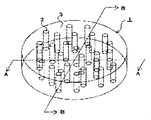
一方、上記の光拡散部材と異なる光学特性を有するものとして、一定の角度領域の入射光は強く拡散し、それ以外の角度の入射光は透過するという、光制御板や異方性拡散媒体が知られている。光制御板は図6に示すように内部に板状の構造を有するものであり(例えば、特許文献1)、異方性拡散媒体は図9に示すように内部に柱状の構造を有するものである(例えば、特許文献2)。 On the other hand, there are optical control plates and anisotropic diffusion media that have optical characteristics different from those of the above light diffusing members, such that incident light in a certain angle region is strongly diffused and incident light at other angles is transmitted. Are known. The light control plate has a plate-like structure inside as shown in FIG. 6 (for example, Patent Document 1), and the anisotropic diffusion medium has a columnar structure inside as shown in FIG. There is (for example, Patent Document 2).
入射角により拡散性が異なる(異方性を示す)ことは、図8に示す方法で確認することができる。図8に示すように、図示しない光源と受光器3との間にサンプルを配置し、サンプル表面の直線Lを中心軸として角度を変化させながらサンプルを直進透過して受光器3に入る直線透過率を測定することができる。
It can be confirmed by the method shown in FIG. 8 that the diffusibility varies depending on the incident angle (shows anisotropy). As shown in FIG. 8, a sample is arranged between a light source (not shown) and the
図8に示す方法を用いて測定した図6に示す光制御板50が有する散乱特性の入射角依存性を図9に示す。縦軸は散乱の程度を表す指標である直線透過率(所定の光量の平行光線を入射させたときに、入射方向と同じ方向に出射された平行光線の光量)を示し、横軸は入射角を示す。図9中の実線及び破線はそれぞれ、図6中のA−A軸(板状構造を突き抜ける)及びB−B軸(板状構造に平行)を中心に光制御板50を回転させた場合を示す。図9に示すように、光制御板50は軸を変えることにより、特性が変化することがわかる。
FIG. 9 shows the incident angle dependence of the scattering characteristics of the
図8に示す方法を用いて測定した図7に示す異方性拡散媒体1が有する散乱特性の入射角依存性を図10に示す。図10に示すように、異方性拡散媒体1は軸を変えても、特性があまり変化しないことがわかる。 FIG. 10 shows the incident angle dependence of the scattering characteristics of the anisotropic diffusion medium 1 shown in FIG. 7 measured using the method shown in FIG. As shown in FIG. 10, it can be seen that the characteristics of the anisotropic diffusion medium 1 do not change much even if the axis is changed.
上記問題に鑑み、本発明は大きな視野角であっても十分な輝度を有した上で、色変化の問題をも改善することができる表示装置を提供することを目的とする。 In view of the above problems, an object of the present invention is to provide a display device that can improve the problem of color change while having sufficient luminance even at a large viewing angle.
上記の光制御板および異方性拡散媒体(以下、光制御板と異方性拡散媒体の両者を含むものを「異方性光学フィルム」と呼称する)を表示装置に使用する場合、拡散性や集光性を有するフィルムとして使用される。
本発明者らが鋭意検討したところ、異方性光学フィルム内に形成される構造体を所定の角度に傾斜させたものを作成し、これを所定の表示デバイスと組み合わせることにより、上記課題を解決できたものである。
本発明は下記の技術的構成により上記課題を解決できたものである。
When the above light control plate and anisotropic diffusion medium (hereinafter referred to as “anisotropic optical film” including both the light control plate and the anisotropic diffusion medium) are used for a display device, And used as a film having a light collecting property.
As a result of intensive investigations by the present inventors, a structure in which the structure formed in the anisotropic optical film is inclined at a predetermined angle, and this is combined with a predetermined display device to solve the above problem. It was made.
The present invention has solved the above problems by the following technical configuration.
(1)視野角に伴う色変化を有する表示デバイスと、光の入射角により拡散性が変化する異方性光学フィルムとを備える表示装置であって、該異方性光学フィルムは少なくとも2つの散乱中心軸を有し、該散乱中心軸の一方と、該表示デバイスの色変化が最小となる方向と、がなす角度が30°〜65°の範囲にあり、該散乱中心軸の他方と、該表示デバイスの色変化が最小となる方向と、がなす角度が−30°〜−65°の範囲にあることを特徴とする表示装置。
(2)前記少なくとも2つの散乱中心軸と、前記表示デバイスの観察面の法線方向と、がなす角度が−60°から60°の範囲にあることを特徴とする前記(1)に記載の表示装置。
(3)前記異方性光学フィルムが、その内部に板状領域を有することを特徴とする前記(1)に記載の表示装置。
(4)前記表示デバイスが液晶表示デバイス、プラズマディスプレイパネルまたは有機ELデバイスのいずれかであることを特徴とする前記(1)に記載の表示装置。
(5)前記液晶表示デバイスは、1対の基板間に液晶が挟持された液晶セルと、偏光素子とを有することを特徴とする前記(4)に記載の表示装置。
(1) A display device including a display device having a color change according to a viewing angle and an anisotropic optical film whose diffusivity changes depending on an incident angle of light, and the anisotropic optical film has at least two scatterings. An angle formed by one of the scattering central axes and a direction in which the color change of the display device is minimized is in a range of 30 ° to 65 °, and the other of the scattering central axes, A display device characterized in that the direction formed by the color change of the display device and the angle formed by the display device is in the range of −30 ° to −65 °.
(2) The angle defined by the at least two scattering central axes and the normal direction of the observation surface of the display device is in the range of −60 ° to 60 °, as described in (1) above Display device.
(3) the anisotropic optical film, a display device according to (1), characterized in that it comprises a plate-shaped region therein.
(4) The display device according to (1), wherein the display device is any one of a liquid crystal display device, a plasma display panel, and an organic EL device.
(5) The liquid crystal display device, the display device according to above, wherein the liquid crystal cell in which liquid crystal is sandwiched between a pair of substrates, that it has a polarizing element (4).
本発明によれば、大きな視野角であっても十分な輝度を有した上で、色変化の問題をも改善することができる表示装置を提供することができる。 According to the present invention, it is possible to provide a display device capable of improving the problem of color change while having sufficient luminance even at a large viewing angle.
ここで、本特許請求の範囲及び本明細書における各用語の定義を説明する。 Here, the definitions of each term in the claims and the specification will be described.
「低屈折率領域」と「高屈折率領域」は、異方性光学フィルムを構成する材料の局所的な屈折率の高低差により形成される領域であって、他方に比べて屈折率が低いか高いかを示した相対的なものである。これらの領域は、異方性光学フィルムを形成する材料が硬化する際に形成される。 The “low refractive index region” and the “high refractive index region” are regions formed by a difference in local refractive index of the material constituting the anisotropic optical film and have a lower refractive index than the other. It is a relative one indicating whether it is expensive. These regions are formed when the material forming the anisotropic optical film is cured.
「散乱中心軸」とは、入射角を変化させた際に散乱特性がその入射角を境に略対称性を有する光の入射角と一致する方向を意味する。「略対称性を有する」としたのは、厳密に光学特性の対称性を有しないためである。散乱中心軸は、フィルム断面の傾きを光学顕微鏡によって観察することや、異方性光学フィルムを介した光の投影形状を入射角を変化させて観察することにより見出せる。 The "scattering center axis" means in a direction scattering characteristic when changing the angle of incidence matches the angle of incidence of light having a Ryakutai symmetries the boundary of the incident angle. To that "having a substantially symmetry" is to not exactly have the symmetry of the optical properties. The scattering center axis can be found by observing the inclination of the film cross section with an optical microscope or by observing the projected shape of light through the anisotropic optical film while changing the incident angle.
直線透過率は、光学フィルムに対して入射した光の直線透過性に関し、ある入射角から入射した際に、直線方向の透過光量と、入射した光の光量との比率であり、下記式で表される。
直線透過率(%)=(直線透過光量/入射光量)×100
The linear transmittance relates to the linear transmittance of light incident on the optical film, and is the ratio between the amount of transmitted light in the linear direction and the amount of incident light when incident from a certain incident angle. Is done.
Linear transmittance (%) = (Linear transmitted light amount / incident light amount) × 100
「短波長」と「長波長」は相対的な意味で使用しているものであって、特定の波長範囲を意味するものではない。 “Short wavelength” and “long wavelength” are used in relative meanings, and do not mean a specific wavelength range.
以下、本発明の内容について説明する。
まず、表示装置における視野角に伴う色変化が生じるメカニズム(推定)について図1を用いて説明する。図1は、光源10からの出射光Aが媒体20の表面で反射され、反射光B、C、Dが得られることを示した図である。出射光Aは可視光領域の複数の波長を有するものである。光の散乱・反射は光の波長によって異なり、短波長になるほど拡散しやすく、長波長になるほど拡散し難い性質を有する。ここで、反射光Bを各波長のバランスがとれた光だとすると、反射光Cは反射光Bよりも光のバランスが崩れることになる(短波長の光が多く、長波長の光が少ない)。同様に、反射光Dは反射光Cよりも光のバランスが崩れることになる(短波長の光が多く、長波長の光が少ない)。このように、光のバランスが崩れることにより、視野角に伴う色変化(以下、単に「色変化」という場合がある)の問題が生ずると考えられる。その結果、反射光B、C、Dの延長線上にいる観察者は異なる色を確認することとなる。なお、図1において、法線方向の視野角をゼロ度とすると、反射光Bの視野角が最も小さく、反射光Dの視野角が最も大きいことになる。
図1においては反射光について光のバランスが崩れることを記載しているが、反射光に限られる現象ではなく、同様の現象が拡散光(散乱光)でも見られる。したがって、反射型の表示装置のみならず、透過型の表示装置や半透過半反射型の表示装置においても同様に光のバランスが崩れる問題が生ずる。一方、光の反射や散乱が生ずるほど光のバランスが崩れやすくなるため、光のバランスが崩れやすい順としては、反射型、半透過半反射型、透過型の表示装置となる。
The contents of the present invention will be described below.
First, a mechanism (estimation) in which a color change with a viewing angle in a display device occurs will be described with reference to FIG. FIG. 1 is a diagram showing that the emitted light A from the
Although it is described in FIG. 1 that the balance of the light is lost with respect to the reflected light, the phenomenon is not limited to the reflected light, and the same phenomenon can be seen in the diffused light (scattered light). Accordingly, not only the reflective display device but also the transmissive display device and the semi-transmissive / semi-reflective display device have a problem that the balance of light is similarly lost. On the other hand, since the light balance is likely to be lost as the light is reflected or scattered, the order of the light balance being easily lost is a reflective display device, a transflective display device, and a transmissive display device.
色変化が生じた光を異方性光学フィルムに通過させることによって、色変化の少ないバランスを整えた光にすることができる。図2を用いて説明すると、反射光Bは異方性光学フィルム30を通過することによって、拡散光の少ない透過光B1が得られる。図示していないが、反射光Bは透過光B1とともに若干の拡散光も得られる。
図2において、反射光Cが異方性光学フィルム30を通過すると、拡散光C1〜C5となる。拡散光C1とC5は略等しいバランスを有し、拡散光C2とC4は略等しいバランスを有する。拡散光C3は短波長の光が少なく、長波長の光が多いものである。拡散光C2およびC4は拡散光C3に比べ、短波長の光が多く、長波長の光が少ないものである。同様に拡散光C1およびC5は拡散光C2およびC4に比べ、短波長の光が多く、長波長の光が少ないものである。したがって、反射光Bと反射光Cとでは、異方性光学フィルム30を通過する光の特性が異なることとなる。これは異方性光学フィルム30内の構造体(柱状構造、板状構造またはその両者)の傾きが、光の拡散性に寄与していることによる。また、反射光Dは所定の出射角を超えているため、異方性光学フィルムの表面で全反射され反射光D1となる。
本発明は、所定の入射角から異方性光学フィルム30に入射する光を選択的に拡散させることによって、輝度の不足や色変化が生じやすい視野角領域に光を供給することを可能とし、光のバランスの全体最適化を達成することができるものである。
By allowing light having undergone a color change to pass through the anisotropic optical film, it is possible to obtain light with a balanced color change. If it demonstrates using FIG. 2, the reflected light B will pass the anisotropic
In FIG. 2, when the reflected light C passes through the anisotropic
The present invention makes it possible to supply light to a viewing angle region where a lack of luminance or a color change is likely to occur by selectively diffusing light incident on the anisotropic
図2において、異方性光学フィルム30の法線方向Sをゼロ度とすると、異方性光学フィルム30内の構造体(柱状構造、板状構造またはその両者)の傾きRの傾斜角θは0度〜60度の範囲または0度〜−60度の範囲にすることが好ましく、20度〜50度の範囲または−20度〜−50度にすることがより好ましい。傾斜角θが小さすぎても大きすぎても色変化の改善効果が得られ難くなる。
In FIG. 2, when the normal direction S of the anisotropic
本願発明は、視野角に伴う色変化を有する表示デバイスを使用するものである。表示デバイスとは、表示を行うためのデバイスである限り特に限定されず、例えば、液晶表示デバイス、プラズマディスプレイパネルまたは有機ELデバイスが挙げられる。液晶表示デバイスは、1対の基板間に挟持された液晶セルと、偏光素子とを有する。液晶セルの形態としては、特に限定されず、例えは、薄膜トランジスタアレイ基板とカラーフィルタ基板との間に狭持された液晶を有する形態が挙げられる。また、偏光板の形態としては、特に限定されないが、液晶セルの側から偏光素子、支持フィルムの順に含む形態、液晶セルの側から支持フィルム、偏光素子の順に含む形態、液晶セルの側から第1の支持フィルム、偏光素子、第2の支持フィルムの順に含む形態が挙げられる。上記支持フィルムとしては、異方性散乱フィルムの透明基体と同様のものを用いることができる。更に、上記偏光板は、通常、液晶セルの観察面側及び背面側の両方に配置されるが、観察面側のみに配置されてもよく、背面側のみに配置されてもよい。上記偏光板は、位相差フィルムを更に含むことが好ましい。これにより、液晶表示デバイスの色度等の視角依存性もより改善することもできる。 The present invention uses a display device having a color change with a viewing angle. The display device is not particularly limited as long as it is a device for performing display, and examples thereof include a liquid crystal display device, a plasma display panel, and an organic EL device. The liquid crystal display device includes a liquid crystal cell sandwiched between a pair of substrates and a polarizing element. The form of the liquid crystal cell is not particularly limited, and examples thereof include a form having a liquid crystal sandwiched between a thin film transistor array substrate and a color filter substrate. Further, the form of the polarizing plate is not particularly limited, but the form including the polarizing element and the support film in this order from the liquid crystal cell side, the form including the support film and the polarizing element in the order from the liquid crystal cell side, the first order from the liquid crystal cell side. The form containing 1 support film, a polarizing element, and a 2nd support film in order is mentioned. As said support film, the thing similar to the transparent base | substrate of an anisotropic scattering film can be used. Furthermore, although the said polarizing plate is normally arrange | positioned at both the observation surface side and back side of a liquid crystal cell, it may be arrange | positioned only at the observation surface side and may be arrange | positioned only at the back side. The polarizing plate preferably further includes a retardation film. Thereby, the viewing angle dependency such as chromaticity of the liquid crystal display device can be further improved.
視野角に伴う色変化とは、表示デバイスの表示性能の1つである。具体的には、表示デバイスの色変化が最小となる方向と、当該方向と60度または−60度異なる方向(どちらか測定可能なもので足りる)とで、それぞれ輝度(L*)および色数(a*、b*)を測定し、ΔE*ab(色差)で算出することができる。具体的には、以下の式で求めることができる。なお、以下の式においては、表示デバイスの色変化が最小となる方向をゼロ度としてΔL*、Δa*、Δb*を算出している。
ΔE*ab=[(ΔL*)2+(Δa*)2+(Δb*)2]1/2
ただし、ΔL*=L*(60°)−L*(0°)
Δa*=a*(60°)−a*(0°)
Δb*=b*(60°)−b*(0°)
である。
ΔE*abの値が低いほど、視野角に伴う色変化が少ないことを示す。ΔE*abの値は60以下であることが好ましく、50以下であることがより好ましく、45以下であることがさらに好ましい。下限値が低いほど色変化の観点からは好ましいのであるが、下限値が低くなりすぎるとヘイズが高くなり画像がボケて表示されやすい問題や正面方向の輝度が低下しやすくなる問題から、10以上であることが好ましく、20以上であることがより好ましい。
The color change with the viewing angle is one of display performances of the display device. Specifically, the luminance (L *) and the number of colors in the direction in which the color change of the display device is minimum and the direction different from the direction by 60 degrees or −60 degrees (whichever is sufficient) can be measured. (A *, b *) can be measured and calculated by ΔE * ab (color difference). Specifically, it can be obtained by the following equation. In the following equations, ΔL *, Δa *, and Δb * are calculated with the direction in which the color change of the display device is minimized as zero degrees.
ΔE * ab = [(ΔL *) 2 + (Δa *) 2 + (Δb *) 2 ] 1/2
However, ΔL * = L * (60 °) −L * (0 °)
Δa * = a * (60 °) −a * (0 °)
Δb * = b * (60 °) −b * (0 °)
It is.
The lower the value of ΔE * ab, the smaller the color change associated with the viewing angle. The value of ΔE * ab is preferably 60 or less, more preferably 50 or less, and even more preferably 45 or less. The lower limit value is preferable from the viewpoint of color change. However, if the lower limit value is too low, the haze increases and the image tends to be blurred and displayed, or the luminance in the front direction tends to decrease. It is preferable that it is, and it is more preferable that it is 20 or more.
本発明の表示装置は、法線方向におけるL*(0°)は高いほど好ましい。表示デバイスの種類によってL*(0°)の値は大きく異なる。 In the display device of the present invention, it is preferable that L * (0 °) in the normal direction is higher. The value of L * (0 °) varies greatly depending on the type of display device.
前記表示装置の観察面の法線方向に対し60°傾けたときのL*(60°)から法線方向のL*(0°)を引いた差、または法線方向に対し−60度傾けたときのL*(−60°)から法線方向のL*(0°)を引いた差は低いほど好ましい。ΔL*の値を低くするにつれ、法線方向の輝度と、60°または−60°方向の輝度の差が少なくなるため、視野角が変化しても違和感が少ない画像を得ることができる。L*(60°)から法線方向のL*(0°)を引いた差は表示デバイスの種類によって異なる。 The difference obtained by subtracting L * (0 °) in the normal direction from L * (60 °) when tilted by 60 ° with respect to the normal direction of the observation surface of the display device, or -60 ° with respect to the normal direction The difference obtained by subtracting L * (0 °) in the normal direction from L * (−60 °) is preferably as low as possible. As the value of ΔL * is lowered, the difference between the luminance in the normal direction and the luminance in the 60 ° or −60 ° direction is reduced, so that an image with less discomfort can be obtained even if the viewing angle changes. The difference obtained by subtracting L * (0 °) in the normal direction from L * (60 °) varies depending on the type of display device.
視野角に伴う色変化とは、正面方向(表示装置の観察面法線方向、視角が0°の方向)から観察した場合と斜め方向(視角が0°より大きい方向)から観察した場合とで、色相が異なることを意味する。なお、通常、表示デバイスの色相は正面方向に近い方向ほど大きいが、その逆であってもよい。 The color change according to the viewing angle is observed when viewed from the front direction (the normal direction of the display surface of the display device, the viewing angle is 0 °) and when observed from the oblique direction (the viewing angle is greater than 0 °). , Meaning the hue is different. In general, the hue of the display device is larger in the direction closer to the front direction, but the opposite may be possible.
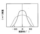
図3は表示装置の輝度が視野角によって異なることを示した一例である。表示装置の輝度は光源によっては様々な波長を有する集合であるが、これを短波長と長波長に便宜的に分けると、短波長ほど拡散しやすく長波長ほど拡散し難いため、60°の輝度は短波長ほど多く長波長ほど少ないことになる。図3においては短波長と長波長を区別せずに、これらの集合として記載している。 FIG. 3 is an example showing that the luminance of the display device varies depending on the viewing angle. The luminance of the display device is a set having various wavelengths depending on the light source. However, if this is divided into a short wavelength and a long wavelength for convenience, the short wavelength is easy to diffuse and the long wavelength is difficult to diffuse. The shorter the wavelength, the more the longer the wavelength. In FIG. 3, short wavelengths and long wavelengths are not distinguished from each other and are described as a set of these.
図3は0°を中心とした正規分布となっている。図3の実線が従来技術のものであり、大きな視野角(−60°および60°)では輝度が少なくなる。
図3の点線が本願発明の表示装置を示したものである。本願発明は正面方向(0°)の輝度の一部をより大きな視野角に振り分けることにより、大きな視野角であっても十分な輝度を有する表示装置を提供することができる。また、本願発明は視野角に伴う色変化も減少させることが可能となる。
なお、図3においては0°を中心とした正規分布を示す表示装置を例示しているが、これに限られるものではない。例えば、30°を中心とした正規分布を示す表示装置や、−30°を中心とした略対称性を示す表示装置に適用することができる。
FIG. 3 shows a normal distribution centered on 0 °. The solid line in FIG. 3 is that of the prior art, and the luminance decreases at large viewing angles (−60 ° and 60 °).
The dotted line in FIG. 3 shows the display device of the present invention. The present invention can provide a display device having sufficient luminance even at a large viewing angle by distributing a part of the luminance in the front direction (0 °) to a larger viewing angle. In addition, the present invention can also reduce the color change accompanying the viewing angle.
In addition, although the display apparatus which shows normal distribution centering on 0 degree is illustrated in FIG. 3, it is not restricted to this. For example, it is possible to apply a 30 ° display device and indicating the normal distribution centered on the display device showing a substantially symmetry around the -30 °.
図4は視野角に伴う色変化を有する表示デバイス100と、光の入射角により拡散性が変化する異方性光学フィルム30を有する表示装置1である。異方性光学フィルム30は表示デバイス100の観察面側に設けることが好ましい。図4においては、異方性光学フィルム30は1つの散乱中心軸をする。法線方向Sを0°としたとき、表示デバイス100の色変化が最小となる方向は、−90°より大きく+90°より小さい範囲で任意に決めることができるが、−30°以上+30°以下であることが好ましく、−15°以上+15°以下であることがより好ましい。表示装置は略対称となる表示性能を有するものであることから、あまり極端な方向に色変化が最小となる方向を有することになると、他方の方向において表示装置として機能しなくなるからである。
異方性光学フィルム30の散乱中心軸と、表示デバイス100の色変化が最小となる方向と、がなす角度は20°〜65°または−20°〜−65°の範囲にあることが必要である。30°〜55°または−30°〜−55°の範囲にあることが好ましい。当該範囲にすることによって、表示デバイス100の色変化が最小となる方向の光をより大きな視野角に振り分けることが可能となる。これにより、大きな視野角であっても十分な輝度を有する表示装置を提供することと、視野角に伴う色変化も減少させることが可能となる。
FIG. 4 shows a
The angle formed by the scattering center axis of the anisotropic
散乱中心軸は異方性光学フィルム30内に1つあればよく、2つ以上有するものであってもよい。異なる散乱中心軸を有する異方性光学フィルムを積層することも可能である。
一枚の異方性光学フィルム内に2つ以上散乱中心軸を有するか、異なる散乱中心軸を有する2枚の異方性光学フィルムを積層する場合、該散乱中心軸の一方が、該表示デバイスの色変化が最小となる方向と、がなす角度が20°〜65°の範囲にあり、該散乱中心軸の他方が、該表示デバイスの色変化が最小となる方向と、がなす角度が−20°〜−65°の範囲にあることが好ましい。より好ましくは、上記散乱中心軸の一方が該表示デバイスの色変化が最小となる方向と、がなす角度が30°〜55°の範囲にあり、該散乱中心軸の他方が、該表示デバイスの色変化が最小となる方向と、がなす角度が−30°〜−55°の範囲にあることが好ましい。当該範囲にすることによって、略対称性を有する光学特性を得ることが可能となる。
There may be only one scattering central axis in the anisotropic
When two anisotropic optical films having two or more scattering center axes or different scattering center axes are laminated in one anisotropic optical film, one of the scattering center axes is the display device. The angle formed between the direction in which the color change of the display device is minimum and the angle formed by the other of the scattering central axes is in the range of 20 ° to 65 °, and the direction in which the color change of the display device is minimized is − It is preferably in the range of 20 ° to -65 °. More preferably, one of the scattering center axes is in a range of 30 ° to 55 ° with the direction in which the color change of the display device is minimized, and the other of the scattering center axes is in the range of the display device. It is preferable that the angle formed by the direction in which the color change is minimal and the angle formed is in the range of −30 ° to −55 °. By the said range, it is possible to obtain an optical characteristic having a substantially symmetry.
異方性光学フィルムには、その内部に板状構造を有するものと柱状構造を有するものの両者が含まれる。また、これらの構造を同時に含ませることも可能である。
板状構造を有するものと柱状構造を有するものについて、得られる色変化の改善効果を比較すると、異方性光学フィルムの内部に板状構造を有することで、色変化の改善効果をより向上させることができるものの、視野角の変化に伴い色変化の改善が急激に変化することがあり、観察者に不自然な印象を抱かせることがある。一方、異方性光学フィルムの内部に柱状構造を有することで、色変化の改善効果はやや劣るものの、視野角の変化に伴う色変化の改善効果が緩やかに変化するため、観察者に不自然な印象を抱かせることが少ない。また、異方性光学フィルムの内部に板状構造と柱状構造の両者を含ませると、それぞれ中間の性質を有することとなる。
異方性光学フィルムの内部構造は、使用目的に応じて適宜調整することが好ましい。
The anisotropic optical film includes both those having a plate-like structure and those having a columnar structure therein. It is also possible to include these structures simultaneously.
Comparing the improvement effect of the obtained color change between the one having a plate-like structure and the one having a columnar structure, the improvement effect of the color change is further improved by having the plate-like structure inside the anisotropic optical film. However, the improvement in the color change may change abruptly as the viewing angle changes, which may cause an unnatural impression to the viewer. On the other hand, although the anisotropic optical film has a columnar structure, the effect of improving the color change is slightly inferior, but the effect of improving the color change accompanying the change of the viewing angle changes gradually, which is unnatural to the observer. It is rare to have a strong impression. Further, when both the plate-like structure and the columnar structure are included in the anisotropic optical film, each has an intermediate property.
The internal structure of the anisotropic optical film is preferably adjusted as appropriate according to the purpose of use.
図5は本発明の異方性光学フィルム30の模式図である。図5(a)に示すように、異方性光学フィルム30の断面においては、低屈折率領域31と高屈折率領域32を交互に含むものである。図5(b)に示すように、隣合う高屈折率領域32を交差させるようにしてもよい。隣合う高屈折率領域32を交差させる場合は、異方性光学フィルム30aの全ての部位において交差させてもよいし、部分的に交差させてもよい。交差させることで、正反対の2方向の視野角における色変化を改善させることができる。
また、図5(b)において、高屈折率領域の代わりに低屈折率領域が交差する場合と傾きが変わる場合となってもよい。
FIG. 5 is a schematic view of the anisotropic
Further, in FIG. 5B, the case where the low refractive index region intersects instead of the high refractive index region may be different from the case where the inclination is changed.
低屈折領域と高屈折率領域の屈折率差(絶対値)は、0.02以上あることが好ましい。より好ましくは0.03以上であり、さらに好ましくは0.04以上である。屈折率差が大きくなるほど、異方性の程度が大きくなる。 The refractive index difference (absolute value) between the low refractive index region and the high refractive index region is preferably 0.02 or more. More preferably, it is 0.03 or more, More preferably, it is 0.04 or more. The greater the refractive index difference, the greater the degree of anisotropy.
図5においては、低屈折率領域31と高屈折率領域32の界面を直線として描いているが、界面は略直線状であっても曲線状であってもよい。略直線状または曲線状であっても、図9または図10に示すような入射角依存性を示す。
In FIG. 5, the interface between the low
また、図5においては低屈折率領域31と高屈折率領域32の界面を記載しているが、この界面は実質的に存在しなくてもよい。
屈折率が漸増または漸減する場合においては、屈折率を測定することが困難であるが、異方性光学フィルムの局所的な屈折率を複数回測定した場合において、最も屈折率の低い部分と最も屈折率の高い部分との屈折率差が0.02以上あることが好ましい。より好ましくは0.03以上であり、さらに好ましくは0.04以上である。屈折率差が大きくなるほど、異方性の程度が大きくなる。
In FIG. 5, the interface between the low
When the refractive index gradually increases or decreases, it is difficult to measure the refractive index. However, when the local refractive index of the anisotropic optical film is measured a plurality of times, the lowest refractive index portion and the lowest refractive index portion are measured. It is preferable that the difference in refractive index from the portion having a high refractive index is 0.02 or more. More preferably, it is 0.03 or more, More preferably, it is 0.04 or more. The greater the refractive index difference, the greater the degree of anisotropy.
異方性光学フィルムの製造方法
本発明の異方性光学フィルムは、特定の光硬化性化合物に特殊な条件で紫外線(UV)照射を行うことにより作製することが出来る。以下、まず異方性光学フィルムの原料を説明し、次いで製造プロセスを説明する。
Method for Producing Anisotropic Optical Film The anisotropic optical film of the present invention can be produced by irradiating a specific photocurable compound with ultraviolet (UV) light under special conditions. Hereinafter, the raw material of the anisotropic optical film will be described first, and then the manufacturing process will be described.
異方性光学フィルムの原料
本発明の異方性光学フィルムを形成する材料は、少なくとも光硬化性化合物のモノマー、オリゴマー、プレポリマー、ポリマーまたはマクロモノマーと光開始剤とから構成され、紫外線及び/又は可視光線を照射することにより重合・固化する材料である。光硬化性化合物に加えて、硬化方式の異なる樹脂または上記光硬化性化合物を使用することが好ましい。硬化方式の異なる樹脂としては、熱可塑性樹脂および熱硬化性樹脂を挙げることができる。光硬化性化合物と熱可塑性樹脂の組み合わせ、光硬化性化合物と熱硬化性樹脂の組み合わせ、光硬化性化合物と熱可塑性樹脂と熱硬化性樹脂の組み合わせを適宜採用することができる。
ここで、異方性光学フィルムを形成する材料が1種類であっても、密度の高低差ができることによって屈折率差が生ずる。UVの照射強度が強い部分は硬化速度が早くなるため、その硬化領域周囲に硬化材料が移動し、結果として屈折率が高くなる領域と屈折率が低くなる領域が形成されるからである。
Raw Material for Anisotropic Optical Film The material for forming the anisotropic optical film of the present invention is composed of at least a monomer, oligomer, prepolymer, polymer or macromonomer of a photocurable compound and a photoinitiator. Alternatively, it is a material that is polymerized and solidified by irradiation with visible light. In addition to the photocurable compound, it is preferable to use a resin having a different curing method or the photocurable compound. Examples of resins with different curing methods include thermoplastic resins and thermosetting resins. A combination of a photocurable compound and a thermoplastic resin, a combination of a photocurable compound and a thermosetting resin, or a combination of a photocurable compound, a thermoplastic resin, and a thermosetting resin can be appropriately employed.
Here, even if there is only one kind of material for forming the anisotropic optical film, a difference in refractive index occurs due to the difference in density. This is because a portion having a high UV irradiation intensity has a fast curing speed, and thus the cured material moves around the cured region, and as a result, a region having a higher refractive index and a region having a lower refractive index are formed.
(光硬化性化合物)
光硬化性化合物は、ラジカル重合性又はカチオン重合性の官能基を有するモノマー、オリゴマー、プレポリマーまたはマクロモノマーである。ラジカル重合性の官能基としては、アクリロイル基、メタクリロイル基、アリル基などが挙げられ、カチオン重合性の官能基としては、エポキシ基、オキセタン基などが挙げられる。これらの官能基の種類と数に特に制限はないが、官能基が多いほど架橋密度が上がり、屈折率の差が生じやすいため好ましいことから、多官能のアクリロイル基またはメタクリロイル基を有することが好ましい。
(Photocurable compound)
The photocurable compound is a monomer, oligomer, prepolymer or macromonomer having a radical polymerizable or cationic polymerizable functional group. Examples of the radical polymerizable functional group include an acryloyl group, a methacryloyl group, and an allyl group. Examples of the cationic polymerizable functional group include an epoxy group and an oxetane group. There are no particular restrictions on the type and number of these functional groups, but it is preferable to have a polyfunctional acryloyl group or methacryloyl group because the higher the functional groups, the higher the crosslink density and the greater the difference in refractive index. .
ラジカル重合性化合物は、主に分子中に1個以上の不飽和二重結合を含有するもので、具体的にはメチルアクリレート、エポキシアクリレート、ウレタンアクリレート、ポリエステルアクリレート、ポリエーテルアクリレート、ポリブタジエンアクリレート等の名称で呼ばれるアクリルオリゴマーと、2−エチルヘキシルアクリレート、イソアミルアクリレート、ブトキシエチルアクリレート、エトキシジエチレングリコールアクリレート、フェノキシエチルアクリレート、テトラヒドロフルフリルアクリレート、イソノルボルニルアクリレート、2−ヒドロキシエチルアクリレート、2−ヒドロキシプロピルアクリレート、2−アクリロイロキシフタル酸、ジシクロペンテニルアクリレート、トリエチレングリコールジアクリレート、ネオペンチルグリコールジアクリレート、1,6−ヘキサンジオールジアクリレート、ビスフェノールAのEO付加物ジアクリレート、EO変性フェニルアクリレート、アダマンタンアクリレート、ビフェニルアクリレート、フェノキシフェニルアクリレート、トリメチロールプロパントリアクリレート、EO変成トリメチロールプロパントリアクリレート、ペンタエリスリトールトリアクリレート、ペンタエリスリトールテトラアクリレート、ジトリメチロールプロパンテトラアクリレート、ジペンタエリスリトールヘキサアクリレート等のアクリレートモノマーが挙げられる。又、これらの化合物は、各単体で用いてもよく、複数混合して用いてもよい。尚、同様にメタクリレートも使用可能であるが、一般にはメタクリレートよりもアクリレートの方が光重合速度が速いので好ましい。 The radically polymerizable compound mainly contains one or more unsaturated double bonds in the molecule, and specifically includes methyl acrylate, epoxy acrylate, urethane acrylate, polyester acrylate, polyether acrylate, polybutadiene acrylate, and the like. An acrylic oligomer called by name, 2-ethylhexyl acrylate, isoamyl acrylate, butoxyethyl acrylate, ethoxydiethylene glycol acrylate, phenoxyethyl acrylate, tetrahydrofurfuryl acrylate, isonorbornyl acrylate, 2-hydroxyethyl acrylate, 2-hydroxypropyl acrylate, 2-acryloyloxyphthalic acid, dicyclopentenyl acrylate, triethylene glycol diacrylate, neo Nylglycol diacrylate, 1,6-hexanediol diacrylate, EO adduct diacrylate of bisphenol A, EO modified phenyl acrylate, adamantane acrylate, biphenyl acrylate, phenoxyphenyl acrylate, trimethylolpropane triacrylate, EO modified trimethylolpropane Examples include acrylate monomers such as triacrylate, pentaerythritol triacrylate, pentaerythritol tetraacrylate, ditrimethylolpropane tetraacrylate, and dipentaerythritol hexaacrylate. In addition, these compounds may be used alone or in combination. Similarly, although methacrylate can be used, acrylate is generally preferable to methacrylate because it has a higher photopolymerization rate.
カチオン重合性化合物としては、分子中にエポキシ基やビニルエーテル基、オキセタン基を1個以上有する化合物が使用できる。エポキシ基を有する化合物としては、2−エチルヘキシルジグリコールグリシジルエーテル、ビフェニルのグリシジルエーテル、ビスフェノールA、水添ビスフェノールA、ビスフェノールF、ビスフェノールAD、ビスフェノールS、テトラメチルビスフェノールA、テトラメチルビスフェノールF、テトラクロロビスフェノールA、テトラブロモビスフェノールA等のビスフェノール類のジグリシジルエーテル類、フェノールノボラック、クレゾールノボラック、ブロム化フェノールノボラック、オルトクレゾールノボラック等のノボラック樹脂のポリグリシジルエーテル類、エチレングリコール、ポリエチレングリコール、ポリプロピレングリコール、ブタンジオール、1,6−ヘキサンジオール、ネオペンチルグリコール、トリメチロールプロパン、1,4−シクロヘキサンジメタノール、ビスフェノールAのEO付加物、ビスフェノールAのPO付加物等のアルキレングリコール類のジグリシジルエーテル類、ヘキサヒドロフタル酸のグリシジルエステルやダイマー酸のジグリシジルエステル等のグリシジルエステル類が挙げられる。 As the cationically polymerizable compound, a compound having at least one epoxy group, vinyl ether group or oxetane group in the molecule can be used. The compounds having an epoxy group include 2-ethylhexyl diglycol glycidyl ether, glycidyl ether of biphenyl, bisphenol A, hydrogenated bisphenol A, bisphenol F, bisphenol AD, bisphenol S, tetramethylbisphenol A, tetramethylbisphenol F, tetrachloro Diglycidyl ethers of bisphenols such as bisphenol A and tetrabromobisphenol A, polyglycidyl ethers of novolac resins such as phenol novolak, cresol novolak, brominated phenol novolak, orthocresol novolak, ethylene glycol, polyethylene glycol, polypropylene glycol, Butanediol, 1,6-hexanediol, neopentyl glycol, trimethyl Diglycidyl ethers of alkylene glycols such as propane adduct of 1,4-cyclohexanedimethanol, bisphenol A, PO adduct of bisphenol A, glycidyl ester of hexahydrophthalic acid, diglycidyl ester of dimer acid, etc. Examples thereof include glycidyl esters.
更に、3,4−エポキシシクロヘキシルメチル−3’,4’−エポキシシクロヘキサンカルボキシレート、2−(3,4−エポキシシクロヘキシル−5,5−スピロ−3,4−エポキシ)シクロヘキサン−メタ−ジオキサン、ジ(3,4−エポキシシクロヘキシルメチル)アジペート、ジ(3,4−エポキシ−6−メチルシクロヘキシルメチル)アジペート、3,4−エポキシ−6−メチルシクロヘキシル−3’,4’−エポキシ−6’−メチルシクロヘキサンカルボキシレート、メチレンビス(3,4−エポキシシクロヘキサン)、ジシクロペンタジエンジエポキシド、エチレングリコールのジ(3,4−エポキシシクロヘキシルメチル)エーテル、エチレンビス(3,4−エポキシシクロヘキサンカルボキシレート)、ラクトン変性3,4−エポキシシクロヘキシルメチル−3’,4’−エポキシシクロヘキサンカルボキシレート、テトラ(3,4−エポキシシクロヘキシルメチル)ブタンテトラカルボキシレート、ジ(3,4−エポキシシクロヘキシルメチル)−4,5−エポキシテトラヒドロフタレート等の脂環式エポキシ化合物も挙げられるが、これらに限定されるものではない。
Further, 3,4-epoxycyclohexylmethyl-3 ′, 4′-epoxycyclohexanecarboxylate, 2- (3,4-epoxycyclohexyl-5,5-spiro-3,4-epoxy) cyclohexane-meta-dioxane, di (3,4-epoxycyclohexylmethyl) adipate, di (3,4-epoxy-6-methylcyclohexylmethyl) adipate, 3,4-epoxy-6-methylcyclohexyl-3 ′, 4′-epoxy-6′-methyl Cyclohexanecarboxylate, methylenebis (3,4-epoxycyclohexane), dicyclopentadiene diepoxide, di (3,4-epoxycyclohexylmethyl) ether of ethylene glycol, ethylenebis (3,4-epoxycyclohexanecarboxylate),
ビニルエーテル基を有する化合物としては、例えばジエチレングリコールジビニルエーテル、トリエチレングリコールジビニルエーテル、ブタンジオールジビニルエーテル、ヘキサンジオールジビニルエーテル、シクロヘキサンジメタノールジビニルエーテル、ヒドロキシブチルビニルエーテル、エチルビニルエーテル、ドデシルビニルエーテル、トリメチロールプロパントリビニルエーテル、プロペニルエーテルプロピレンカーボネート等が挙げられるが、これらに限定されるものではない。尚ビニルエーテル化合物は、一般にはカチオン重合性であるが、アクリレートと組み合わせることによりラジカル重合も可能である。 Examples of the compound having a vinyl ether group include diethylene glycol divinyl ether, triethylene glycol divinyl ether, butanediol divinyl ether, hexanediol divinyl ether, cyclohexanedimethanol divinyl ether, hydroxybutyl vinyl ether, ethyl vinyl ether, dodecyl vinyl ether, and trimethylolpropane trivinyl ether. , Propenyl ether propylene carbonate and the like, but are not limited thereto. Vinyl ether compounds are generally cationically polymerizable, but radical polymerization is also possible by combining with acrylates.
オキセタン基を有する化合物としては、1,4−ビス[(3−エチル−3−オキセタニルメトキシ)メチル]ベンゼン、3−エチル−3−(ヒドロキシメチル)−オキセタン等が使用できる。 As the compound having an oxetane group, 1,4-bis [(3-ethyl-3-oxetanylmethoxy) methyl] benzene, 3-ethyl-3- (hydroxymethyl) -oxetane and the like can be used.
尚、以上のカチオン重合性化合物は、各単体で用いてもよく、複数混合して用いてもよい。上記光重合性化合物は、上述に限定されるものではない。又、十分な屈折率差を生じさせるべく、上記光重合性化合物には、低屈折率化を図るために、フッ素原子(F)を導入しても良く、高屈折率化を図るために、硫黄原子(S)、臭素原子(Br)、各種金属原子を導入しても良い。 The above cationic polymerizable compounds may be used alone or in combination. The photopolymerizable compound is not limited to the above. In order to cause a sufficient difference in refractive index, fluorine atoms (F) may be introduced into the photopolymerizable compound in order to reduce the refractive index, and in order to increase the refractive index, Sulfur atoms (S), bromine atoms (Br), and various metal atoms may be introduced.
(熱可塑性樹脂)
熱可塑性樹脂としては、ポリエステル、ポリエーテル、ポリウレタン、ポリアミド、ポリエポキシド、ポリスチレン、ポリカーボネート、ポリアセタール、ポリビニルアルコール、ポリ酢酸ビニル、ポリビニルブチラール、アクリル樹脂とその共重合体や変性物が挙げられる。熱可塑性樹脂を用いる場合においては熱可塑性樹脂が溶解する溶剤を使用して溶解し、塗布、乾燥後に紫外線で光硬化性化合物を硬化せしめて異方性光学フィルムを成形する。
溶剤は熱可塑性樹脂を溶解させることができるものであればよいが、例えば、エタノール、イソプロパノールまたはブタノールなどのアルコール、アセトンなどのケトン、酢酸エチルなどのエステル、テトラヒドロフランなどのエーテルならびにびヘキサン、ベンゼン、トルエン、クロロホルムなどの脂肪族、芳香族およびハロゲン化炭化水素である。
(Thermoplastic resin)
Examples of the thermoplastic resin include polyester, polyether, polyurethane, polyamide, polyepoxide, polystyrene, polycarbonate, polyacetal, polyvinyl alcohol, polyvinyl acetate, polyvinyl butyral, acrylic resin, and copolymers and modified products thereof. In the case of using a thermoplastic resin, it is dissolved using a solvent in which the thermoplastic resin dissolves, and after application and drying, the photocurable compound is cured with ultraviolet rays to form an anisotropic optical film.
The solvent may be any solvent as long as it can dissolve the thermoplastic resin. For example, alcohol such as ethanol, isopropanol or butanol, ketone such as acetone, ester such as ethyl acetate, ether such as tetrahydrofuran, hexane, benzene, Aliphatic, aromatic and halogenated hydrocarbons such as toluene and chloroform.
(熱硬化性樹脂)
熱硬化性樹脂としては、エポキシ樹脂、フェノール樹脂、メラミン樹脂、尿素樹脂、不飽和ポリエステルとその共重合体や変性物が挙げられる。熱硬化性樹脂を用いる場合においては、紫外線で光硬化性化合物を硬化させた後に適宜加熱することで、熱硬化性樹脂を硬化せしめて異方性光学フィルムを成形する。
(Thermosetting resin)
Examples of the thermosetting resin include epoxy resins, phenol resins, melamine resins, urea resins, unsaturated polyesters, copolymers thereof, and modified products. In the case of using the thermosetting resin, the anisotropic optical film is formed by curing the thermosetting resin by appropriately heating after curing the photocurable compound with ultraviolet rays.
(光開始剤)
ラジカル重合性化合物を重合させることのできる光開始剤としては、ベンゾフェノン、ベンジル、ミヒラーズケトン、2−クロロチオキサントン、2,4−ジエチルチオキサントン、ベンゾインエチルエーテル、ベンゾインイソプロピルエーテル、ベンゾインイソブチルエーテル、2,2−ジエトキシアセトフェノン、ベンジルジメチルケタール、2,2−ジメトキシ−1,2−ジフェニルエタン−1−オン、2−ヒドロキシ−2−メチル−1−フェニルプロパン−1−オン、1−ヒドロキシシクロヘキシルフェニルケトン、2−メチル−1−[4−(メチルチオ)フェニル]−2−モルフォリノプロパノン−1、1−[4−(2−ヒドロキシエトキシ)−フェニル]−2−ヒドロキシ−2−メチル−1−プロパン−1−オン、ビス(シクロペンタジエニル)−ビス(2,6−ジフルオロ−3−(ピル−1−イル)チタニウム、2−ベンジル−2−ジメチルアミノ−1−(4−モルフォリノフェニル)−ブタノン−1、2,4,6−トリメチルベンゾイルジフェニルフォスフィンオキサイド等が挙げられる。又、これらの化合物は、各単体で用いてもよく、複数混合して用いてもよい。
(Photoinitiator)
Photoinitiators that can polymerize radically polymerizable compounds include benzophenone, benzyl, Michler's ketone, 2-chlorothioxanthone, 2,4-diethylthioxanthone, benzoin ethyl ether, benzoin isopropyl ether, benzoin isobutyl ether, 2,2- Diethoxyacetophenone, benzyldimethyl ketal, 2,2-dimethoxy-1,2-diphenylethane-1-one, 2-hydroxy-2-methyl-1-phenylpropan-1-one, 1-hydroxycyclohexyl phenyl ketone, 2 -Methyl-1- [4- (methylthio) phenyl] -2-morpholinopropanone-1, 1- [4- (2-hydroxyethoxy) -phenyl] -2-hydroxy-2-methyl-1-propane-1 -One, bis (cyclo Ntadienyl) -bis (2,6-difluoro-3- (pyr-1-yl) titanium, 2-benzyl-2-dimethylamino-1- (4-morpholinophenyl) -butanone-1,2,4,6 -Trimethyl benzoyl diphenyl phosphine oxide etc. Moreover, these compounds may be used individually or may be used in mixture of two or more.
カチオン重合性化合物の光開始剤は、光照射によって酸を発生し、この発生した酸により上述のカチオン重合性化合物を重合させることができる化合物であり、一般的には、オニウム塩、メタロセン錯体が好適に用いられる。オニウム塩としては、ジアゾニウム塩、スルホニウム塩、ヨードニウム塩、ホスホニウム塩、セレニウム塩等が使用され、これらの対イオンには、BF4 −、PF6 −、AsF6 −、SbF6 −等のアニオンが用いられる。具体例としては、4−クロロベンゼンジアゾニウムヘキサフルオロホスフェート、トリフェニルスルホニウムヘキサフルオロアンチモネート、トリフェニルスルホニウムヘキサフルオロホスフェート、(4−フェニルチオフェニル)ジフェニルスルホニウムヘキサフルオロアンチモネート、(4−フェニルチオフェニル)ジフェニルスルホニウムヘキサフルオロホスフェート、ビス[4−(ジフェニルスルホニオ)フェニル]スルフィド−ビス−ヘキサフルオロアンチモネート、ビス[4−(ジフェニルスルホニオ)フェニル]スルフィド−ビス−ヘキサフルオロホスフェート、(4−メトキシフェニル)ジフェニルスルホニウムヘキサフルオロアンチモネート、(4−メトキシフェニル)フェニルヨードニウムヘキサフルオロアンチモネート、ビス(4−t−ブチルフェニル)ヨードニウムヘキサフルオロホスフェート、ベンジルトリフェニルホスホニウムヘキサフルオロアンチモネート、トリフェニルセレニウムヘキサフルオロホスフェート、(η5−イソプロピルベンゼン)(η5−シクロペンタジエニル)鉄(II)ヘキサフルオロホスフェート等が挙げられるが、これらに限定されるものではない。又、これらの化合物は、各単体で用いてもよく、複数混合して用いてもよい。 The photoinitiator of a cationic polymerizable compound is a compound that generates an acid by light irradiation and can polymerize the above-mentioned cationic polymerizable compound with the generated acid. Generally, an onium salt or a metallocene complex is used. Preferably used. As the onium salt, a diazonium salt, a sulfonium salt, an iodonium salt, a phosphonium salt, a selenium salt, or the like is used, and these counter ions include anions such as BF 4 − , PF 6 − , AsF 6 − , SbF 6 − and the like. Used. Specific examples include 4-chlorobenzenediazonium hexafluorophosphate, triphenylsulfonium hexafluoroantimonate, triphenylsulfonium hexafluorophosphate, (4-phenylthiophenyl) diphenylsulfonium hexafluoroantimonate, (4-phenylthiophenyl) diphenyl. Sulfonium hexafluorophosphate, bis [4- (diphenylsulfonio) phenyl] sulfide-bis-hexafluoroantimonate, bis [4- (diphenylsulfonio) phenyl] sulfide-bis-hexafluorophosphate, (4-methoxyphenyl) Diphenylsulfonium hexafluoroantimonate, (4-methoxyphenyl) phenyliodonium hexafluoroantimonate Bis (4-t-butylphenyl) iodonium hexafluorophosphate, benzyltriphenylphosphonium hexafluoroantimonate, triphenyl selenium hexafluorophosphate, (η5-isopropylbenzene) (η5-cyclopentadienyl) iron (II) hexa Although fluorophosphate etc. are mentioned, it is not limited to these. In addition, these compounds may be used alone or in combination.
(機能性添加剤)
異方性光学フィルムに色変化の改善効果を付与するために、機能性添加剤を含有させることが好ましい。機能性添加剤としては、(a)縮合したシラン化合物、(b)表面を改質した超微粒子、(c)柔軟剤、を挙げることができる。
(Functional additives)
In order to impart an effect of improving color change to the anisotropic optical film, it is preferable to contain a functional additive. Examples of the functional additive include (a) a condensed silane compound, (b) ultrafine particles with a modified surface, and (c) a softening agent.
(a)縮合したシラン化合物
シランは、1、2、3または4個の、好ましくは2または3個の加水分解性基を有するもの、およびこれらの混合物である。加水分解性基の例は、水素またはF、Cl、BrもしくはIなどのハロゲン、アルコキシ、好ましくはたとえばメトキシ、エトキシ、n−プロポキシ、i−プロポキシおよびブトキシなどのC1〜6アルコキシ;アリールオキシ、好ましくはたとえばフェノキシなどのC6〜10アリールオキシ;たとえばアセトキシまたはプロピオニルオキシなどのアシルオキシ;アルキルカルボニル、好ましくはたとえばアセチルなどのC2〜7アルキルカルボニル;アミノ、好ましくはアルキル基中に1〜12個、特に1〜6個の炭素原子を有するモノアルキルアミノまたはジアルキルアミノである。
特に好ましいシランは、たとえばメタクリルオキシプロピルトリメトキシシラン、アクリルオキシプロピルトリメトキシシラン、ジメチルジメトキシシラン、ジメチルジエトキシシラン、3−グリシジルオキシ−プロピルトリメトキシシラン、グリシジルオキシ−プロピルトリエトキシシラン、ビニルトリエトキシシラン、メチルトリエトキシシランである。
(A) Condensed silane compound The silane is one having 1, 2, 3 or 4, preferably 2 or 3, hydrolyzable groups, and a mixture thereof. Examples of hydrolyzable groups are hydrogen or halogens such as F, Cl, Br or I, alkoxy, preferably C1-6 alkoxy such as methoxy, ethoxy, n-propoxy, i-propoxy and butoxy; aryloxy, preferably For example C6-10 aryloxy such as phenoxy; acyloxy such as acetoxy or propionyloxy; alkylcarbonyl, preferably C2-7 alkylcarbonyl such as acetyl; amino, preferably 1-12 in the alkyl group, especially 1 Monoalkylamino or dialkylamino having ˜6 carbon atoms.
Particularly preferred silanes are, for example, methacryloxypropyltrimethoxysilane, acryloxypropyltrimethoxysilane, dimethyldimethoxysilane, dimethyldiethoxysilane, 3-glycidyloxy-propyltrimethoxysilane, glycidyloxy-propyltriethoxysilane, vinyltriethoxy. Silane and methyltriethoxysilane.
シランの部分的縮合は例えば、水、HCl水溶液、HNO3水溶液またはアンモニア水などの加水分解剤を、不足当量、たとえば化学量論量の0.3〜0.9倍を用いて実施することができる。シランは完全に縮合させてもよい。加水分解剤の量は、この場合33〜100%の無機縮合比が得られるように割り当てられていることが好ましい。平均33%の無機縮合率とは、たとえばシランの加水分解性残基の概して3個のうち1個が縮合して、−Si−O−Si−架橋結合を形成することを意味する。縮合比100%では、当該シラン分子のすべての加水分解性残基が縮合される。加水分解剤による縮合は、好ましくは5〜40℃の間の温度で実施される。
シランの縮合は、UV照射により重合する方法で行ってもよい。
The partial condensation of silane can be carried out, for example, with a hydrolyzing agent such as water, aqueous HCl, aqueous HNO 3 or aqueous ammonia, using a short equivalent, for example 0.3 to 0.9 times the stoichiometric amount. it can. Silane may be fully condensed. The amount of hydrolyzing agent is preferably assigned in this case so that an inorganic condensation ratio of 33 to 100% is obtained. An inorganic condensation rate of 33% on average means that, for example, generally one out of three hydrolyzable residues of silane is condensed to form —Si—O—Si— crosslinks. At a condensation ratio of 100%, all hydrolyzable residues of the silane molecule are condensed. The condensation with a hydrolyzing agent is preferably carried out at a temperature between 5 and 40 ° C.
The condensation of silane may be performed by a method of polymerizing by UV irradiation.
シランの有機変換率は0〜95%であることが好ましく、より好ましくは5〜60%である。有機変換率は、側鎖中に存在するC=C二重結合またはエポキシ基の付加重合反応の程度を示す。95%の有機変換とは、たとえばすべてのC=C二重結合またはエポキシ基の95%が反応したことを意味する。C=C二重結合、たとえばアクリレート残基の場合は、有機変換率は赤外スペクトルのC=C振動帯の減少により測定することができる。付加重合は、エポキシ基の場合は酸または塩基加水分解、またはC=C二重結合の場合はUV照射などの通常の方法により誘導される。 The organic conversion rate of silane is preferably 0 to 95%, more preferably 5 to 60%. The organic conversion rate indicates the degree of addition polymerization reaction of C═C double bond or epoxy group present in the side chain. 95% organic conversion means, for example, that 95% of all C═C double bonds or epoxy groups have reacted. In the case of C = C double bonds, such as acrylate residues, the organic conversion can be measured by a decrease in the C = C vibration band of the infrared spectrum. Addition polymerization is induced by conventional methods such as acid or base hydrolysis in the case of epoxy groups, or UV irradiation in the case of C═C double bonds.
また、部分的にかつ前もって有機シランを縮合させることで、前駆物質(好ましくはアルコキシド)の加水分解および縮合により、後述する超微粒子が生成されることがある。 In addition, when the organosilane is partially condensed in advance, ultrafine particles described later may be generated by hydrolysis and condensation of the precursor (preferably alkoxide).
縮合したシラン化合物の配合量は、異方性光学フィルムの全固形分に対して0.00120質量%とすることが好ましい。 The amount of the condensed silane compound is preferably 0.00120% by mass relative to the total solid content of the anisotropic optical film.
(b)表面を改質した超微粒子
表面を改質した超微粒子は、好ましくは酸化物、ZnO、CdO、SiO2、TiO2、ZrO2、CeO2、SnO2、Al2O3、In2O3、La2O3、Fe2O3、Ta2O5、Cu2O、V2O5、MoO3およびWO3ならびにハロゲン化物、AgCl、AgBr、AgI、CuI、CuBr、CdI2およびPbI2を含む。表面基は、ラジカル、カチオンもしくはアニオン、熱もしくは光化学重合、または熱または光化学縮合重合に感受性がある、有機重合性および/または縮合重合性の基であり得る。本発明によれば、(メタ)アクリル、アリル、ビニルまたはエポキシ基を有する表面基が好ましく、(メタ)アクリルおよびエポキシ基が特に好ましい。主な関連する縮合重合性の基は、ナノ規模粒子およびシランの間にそれを用いてエーテル、エステルおよびアミド結合を得ることが可能な、ヒドロキシル、カルボキシルおよびアミノ基である。
表面を改質した超微粒子を得る方法としては、重合性の基を含んだ化合物、たとえば不飽和カルボン酸、特にメタクリル酸、アクリル酸、およびアクリロシランおよび/または不飽和βジケトンと反応させることにより改質すればよい。
(B) Ultra fine particles whose surface is modified Ultra fine particles whose surface is modified are preferably oxides, ZnO, CdO, SiO 2 , TiO 2 , ZrO 2 , CeO 2 , SnO 2 , Al 2 O 3 , In 2. O 3 , La 2 O 3 , Fe 2 O 3 , Ta 2 O 5 , Cu 2 O, V 2 O 5 , MoO 3 and WO 3 and halides, AgCl, AgBr, AgI, CuI, CuBr, CdI 2 and PbI2 including. The surface group can be an organic polymerizable and / or condensation polymerizable group that is sensitive to radicals, cations or anions, thermal or photochemical polymerization, or thermal or photochemical condensation polymerization. According to the invention, surface groups having (meth) acryl, allyl, vinyl or epoxy groups are preferred, with (meth) acryl and epoxy groups being particularly preferred. The main relevant condensation polymerizable groups are hydroxyl, carboxyl and amino groups which can be used between nanoscale particles and silanes to obtain ether, ester and amide linkages.
As a method for obtaining ultrafine particles having a modified surface, a compound containing a polymerizable group, for example, an unsaturated carboxylic acid, particularly methacrylic acid, acrylic acid, and acrylosilane and / or an unsaturated β-diketone is modified. Just do it.
超微粒子の表面上に存在し、重合性および/または縮合重合性の基を含む有機基は、好ましくは300未満、特に200未満の分子量を有する。 The organic group present on the surface of the ultrafine particles and containing a polymerizable and / or condensation polymerizable group preferably has a molecular weight of less than 300, in particular less than 200.
たとえば独国特許DE−A−19719948号に記載されたように、すべての通例の製造方法は、表面改質ナノ粒子の製造に適している。 All customary production methods are suitable for the production of surface-modified nanoparticles, for example as described in DE-A-197199948.
超微粒子は、好ましくは100nm以下、特に50nm以下の直径(一次粒径)を有する。下限に関しては特定の制限は無いが、実用的な理由でこの下限は一般に0.5nm、特に1nm、しばしば4nmである。 The ultrafine particles preferably have a diameter (primary particle size) of 100 nm or less, particularly 50 nm or less. There is no particular restriction on the lower limit, but for practical reasons this lower limit is generally 0.5 nm, in particular 1 nm, often 4 nm.
超微粒子表面を改質する方法としては、例えば、超微粒子表面を先ず、重合性の基を含んだ化合物、たとえば不飽和カルボン酸、特にメタクリル酸、アクリル酸、およびアクリロシランおよび/または不飽和βジケトンと反応させることにより改質することができる。 As a method for modifying the surface of the ultrafine particles, for example, the surface of the ultrafine particles is first subjected to a compound containing a polymerizable group, such as an unsaturated carboxylic acid, particularly methacrylic acid, acrylic acid, and acrylosilane and / or an unsaturated β diketone. Can be modified by reacting with.
表面を改質した超微粒子の配合量は、異方性光学フィルムの全固形分に対して0.01〜20質量%とすることが好ましい。 The blending amount of the ultrafine particles whose surface is modified is preferably 0.01 to 20% by mass with respect to the total solid content of the anisotropic optical film.
(c)柔軟剤
柔軟剤としては、DIN 55945(1988年12月)に従って弾性または軟化特性を有するすべての化合物が原則として適しているが、主としてエステルタイプのものが適する。以下の群からの可塑剤が好ましい:非環式脂肪族ジカルボン酸エステル、たとえばアジピン酸ジ−n−オクチル、アジピン酸ビス−(2−エチルヘキシル)、アジピン酸ジイソデシルなどのアジピン酸のエステル、セバシン酸ジブチル、セバシン酸ジオクチルおよびセバシン酸ビス−(2−エチルヘキシル);C6〜C12ジカルボン酸とポリアルキレングリコールとのエステル、たとえばトリエチレングリコールビス−(n−ヘプタノアート)、トリエチレングリコールビス−(2−エチルヘキサノアート)、トリエチレングリコールビス−(イソナノアート);C6〜C12ジカルボン酸とポリアルキレングリコールとのエステル、たとえばトリエチレングリコールビス−(2−エチルブチラート);ポリプロピレングリコールジアクリレートまたはジメタクリレート、ポリエチレングリコールジアクリレートまたはジメタクリレートなどの、(メタ)アクリル酸とポリアルキレングリコールのジエステル、たとえばテトラエチレングリコールジ(メタ)アクリレートが挙げられる。
(C) Softeners As softeners, all compounds with elastic or softening properties are suitable in principle according to DIN 55945 (December 1988), but mainly those of the ester type. Plasticizers from the following groups are preferred: acyclic aliphatic dicarboxylic esters such as di-n-octyl adipate, bis- (2-ethylhexyl) adipate, esters of adipic acid such as diisodecyl adipate, sebacic acid Dibutyl, dioctyl sebacate and bis- (2-ethylhexyl) sebacate; esters of C6-C12 dicarboxylic acids with polyalkylene glycols such as triethylene glycol bis- (n-heptanoate), triethylene glycol bis- (2-ethyl) Hexanoate), triethylene glycol bis- (isonanoate); esters of C6-C12 dicarboxylic acids and polyalkylene glycols such as triethylene glycol bis- (2-ethylbutyrate); polypropylene glycol diacri Over preparative or dimethacrylates, such as polyethylene glycol diacrylate or dimethacrylate, (meth) diesters of acrylic acid and polyalkylene glycol include, for example, tetraethylene glycol di (meth) acrylate.
柔軟剤の配合量は、異方性光学フィルムの全固形分に対して0.1〜20質量%とすることが好ましい。 The blending amount of the softening agent is preferably 0.1 to 20% by mass with respect to the total solid content of the anisotropic optical film.
異方性光学フィルムの原料(配合量、その他任意成分)
本発明において、上記光開始剤は、光硬化性化合物100質量部に対して、0.01〜10質量部、好ましくは0.1〜7質量部、より好ましくは0.1〜5質量部程度配合される。これは、0.01質量部未満では光硬化性が低下し、10質量部を超えて配合した場合には、表面だけが硬化して内部の硬化性が低下してしまう弊害、異方性の低下、板状構造の形成の阻害を招くからである。これらの光開始剤は、通常粉体を上記組成物の混合物中に直接溶解して使用されるが、溶解性が悪い場合は光開始剤を予め極少量の溶剤に高濃度に溶解させたものを使用することもできる。このような溶剤としては光重合性であることが更に好ましく、具体的には炭酸プロピレン、γ−ブチロラクトン等が挙げられる。又、光重合性を向上させるために公知の各種染料や増感剤を添加することも可能である。更に光重合性化合物を加熱により硬化させることのできる熱硬化開始剤を光開始剤と共に併用することもできる。この場合、光硬化の後に加熱することにより光重合性化合物の重合硬化を更に促進し完全なものにすることが期待できる。
熱硬化開始剤は、過酸化ジアシル、パーオキシジカーボネート、アルキルパーエステル、過酸化ジアルキル、パーケタール、過酸化ケトンおよびアルキルヒドロパーオキシドの形態の有機過酸化物が好ましい。こうした熱硬化開始剤の例は、過酸化ジベンゾイル、過安息香酸t−ブチルおよびアゾビスイソブチロニトリルである。カチオン熱開始剤の例は、1−メチルイミダゾールである。熱硬化性開始剤は、熱硬化性樹脂100質量部に対して、0.01〜20質量部程度含有させればよい。
Raw material for anisotropic optical film (blending amount, other optional components)
In this invention, the said photoinitiator is 0.01-10 mass parts with respect to 100 mass parts of photocurable compounds, Preferably it is 0.1-7 mass parts, More preferably, it is about 0.1-5 mass parts. Blended. This is because if less than 0.01 parts by mass, the photocurability is lowered, and if more than 10 parts by mass is blended, only the surface is cured and the internal curability is lowered, resulting in anisotropy. This is because the reduction and the inhibition of the formation of the plate-like structure are caused. These photoinitiators are usually used by dissolving the powder directly in the mixture of the above composition, but if the solubility is poor, the photoinitiator is dissolved in a very small amount of solvent in advance at a high concentration. Can also be used. Such a solvent is more preferably photopolymerizable, and specific examples thereof include propylene carbonate and γ-butyrolactone. It is also possible to add various known dyes and sensitizers in order to improve the photopolymerizability. Further, a thermosetting initiator capable of curing the photopolymerizable compound by heating can be used in combination with the photoinitiator. In this case, by heating after photocuring, it can be expected to further accelerate the polymerization and curing of the photopolymerizable compound to complete it.
The thermosetting initiator is preferably an organic peroxide in the form of diacyl peroxide, peroxydicarbonate, alkyl perester, dialkyl peroxide, perketal, ketone peroxide and alkyl hydroperoxide. Examples of such thermosetting initiators are dibenzoyl peroxide, t-butyl perbenzoate and azobisisobutyronitrile. An example of a cationic thermal initiator is 1-methylimidazole. What is necessary is just to make a thermosetting initiator contain about 0.01-20 mass parts with respect to 100 mass parts of thermosetting resins.
本発明では、光硬化性化合物を硬化させて、異方性光学フィルムを形成することができる。異方性光学フィルムを構成する材料はいずれも複数を混合することができる。また、組成物中に必要に応じて、可塑剤、酸化防止剤、光安定化剤、界面活性剤、レベリング剤など、既知の添加剤を添加することも可能である。特に可塑剤、界面活性剤、レベリング剤可塑剤などは製膜性などを向上するためには有効で、フタル酸ポリエステル、アジピン酸ポリエステルなどの可塑剤、シリコーン系やアクリル系のレベリング剤が挙げられ、添加量は全組成物中0.5〜10重量%が好ましい。 In the present invention, the photocurable compound can be cured to form an anisotropic optical film. A plurality of materials constituting the anisotropic optical film can be mixed. In addition, known additives such as a plasticizer, an antioxidant, a light stabilizer, a surfactant, and a leveling agent can be added to the composition as necessary. In particular, plasticizers, surfactants, leveling agents, plasticizers, etc. are effective for improving film-forming properties, and include plasticizers such as phthalic polyester and adipic acid polyester, and silicone and acrylic leveling agents. The addition amount is preferably 0.5 to 10% by weight in the total composition.
シリコーン骨格を有する光硬化性化合物と、シリコーン骨格を有さない化合物の比率は質量比で15:85〜85:15の範囲にあることが好ましい。より好ましくは30:70〜70:30の範囲である。当該範囲にすることによって、低屈折領域と高屈折率領域の相分離が進みやすくなる。シリコーン骨格を有する光硬化性化合物の比率が下限値未満または上限値超であると、相分離が進みにくくなってしまい、異方性不足の問題を解決しにくくなる。カルド構造を有する化合物、一分子中に2個以上の芳香族環を有する化合物、架橋構造を持つ環状炭化水素化合物およびスピロ化合物から選択される少なくとも一種の化合物いずれかである化合物の配合量は、全光硬化性樹脂組成物中に対して10〜60質量%であることが好ましい。下限値より添加量が少ないと分子配向を乱す効果がなくなり位相差を低くする効果が望めなく、また添加量が多すぎると配向が乱れすぎて本来の光学異方性を損ねることに繋がる。より好ましい配合量としては15〜45質量%であり、充分な位相差の低下を発現することが可能である。本発明の異方性光学フィルムは、これら化合物とその配合量を適宜選択することによって、従来なし得なかった異方性と低位相差の両立を実現できるものであり、その位相差は光学フィルムとして充分に低い25nm以下とすることができる。さらには、10nm以下にすることも可能であり、低位相差フィルムとして従来より使用されているTACフィルム、COPフィルムやポリカーボネート(PC)シートと同等の位相差とすることができ、これら材料の代替とすることも可能である。すなわち、本発明の異方性光学フィルムを偏光板用保護フィルムとして使用することができる。上述の通り本発明で得られる異方光学フィルムは位相差が低いため、偏光板のクロスニコルの間に存在した場合においても光漏れを生じることは少なく、また、偏光板のパラレルニコルの間に存在した場合でも光損失を生じることが少なく、ディプレイなどに用いた場合においては、輝度の低下を抑制し、コントラストの向上に寄与する。
The ratio of the photocurable compound having a silicone skeleton and the compound not having a silicone skeleton is preferably in the range of 15:85 to 85:15 by mass ratio. More preferably, it is the range of 30: 70-70: 30. By setting it in this range, the phase separation between the low refractive index region and the high refractive index region can easily proceed. If the ratio of the photocurable compound having a silicone skeleton is less than the lower limit value or exceeds the upper limit value, the phase separation is difficult to proceed, and the problem of insufficient anisotropy is difficult to solve. The compounding amount of the compound which is at least one compound selected from a compound having a cardo structure, a compound having two or more aromatic rings in one molecule, a cyclic hydrocarbon compound having a crosslinked structure, and a spiro compound, It is preferable that it is 10-60 mass% with respect to the whole photocurable resin composition. If the addition amount is less than the lower limit, the effect of disturbing the molecular orientation is lost and the effect of lowering the phase difference cannot be expected. If the addition amount is too large, the orientation is too disturbed and the original optical anisotropy is impaired. A more preferable blending amount is 15 to 45% by mass, and a sufficient decrease in retardation can be exhibited. The anisotropic optical film of the present invention can realize both anisotropy and a low retardation that could not be achieved conventionally by appropriately selecting the compound and the blending amount thereof, and the retardation is an optical film. It can be made sufficiently low 25 nm or less. Furthermore, it is possible to make the
[プロセス]
次に本発明の異方性光学フィルムの製造方法(プロセス)について説明する。
まず、上述の異方性光学フィルムの形成材料(光硬化性樹脂組成物)を透明ポリエチレンテレフタレート(PET)フィルムのような適当な基材上に塗工して塗工膜を設ける。必要に応じて乾燥して溶剤を揮発させるが、その乾燥膜厚は10〜500μm、より好ましくは20〜200μm、更に好ましくは30〜100μmである。乾燥膜厚が10μm未満では、後述するUV照射プロセスを経て得られる光拡散性が乏しいため好ましくない。一方乾燥膜厚が500μmを越えるような場合、全体の拡散性が強すぎて本発明の特徴的な異方性が得られ難くなると共に、コストアップ、薄型化用途に不適合といったことからも好ましくない。更に、この塗工膜上には離型フィルムや後述するマスクをラミネートして感光性の積層体を作ることもできる。
[process]
Next, the manufacturing method (process) of the anisotropic optical film of this invention is demonstrated.
First, the above-mentioned anisotropic optical film forming material (photocurable resin composition) is coated on a suitable substrate such as a transparent polyethylene terephthalate (PET) film to provide a coating film. Although it dries as needed and a solvent is volatilized, the dry film thickness is 10-500 micrometers, More preferably, it is 20-200 micrometers, More preferably, it is 30-100 micrometers. When the dry film thickness is less than 10 μm, the light diffusibility obtained through the UV irradiation process described later is poor, which is not preferable. On the other hand, when the dry film thickness exceeds 500 μm, the overall diffusibility is too strong, and it becomes difficult to obtain the characteristic anisotropy of the present invention, and it is not preferable because of cost increase and incompatibility with thinning applications. . Furthermore, a release film or a mask described later can be laminated on the coating film to produce a photosensitive laminate.
(光硬化性樹脂組成物を基材上にシート状に設ける手法)
ここで、光硬化性化合物を含む光硬化性樹脂組成物を基材上にシート状に設ける手法としては、通常の塗工方式や印刷方式が適用される。具体的には、エアドクターコーティング、バーコーティング、ブレードコーティング、ナイフコーティング、リバースコーティング、トランスファロールコーティング、グラビアロールコーティング、キスコーティング、キャストコーティング、スプレーコーティング、スロットオリフィスコーティング、カレンダーコーティング、ダムコーティング、ディップコーティング、ダイコーティング等のコーティングや、グラビア印刷等の凹版印刷、スクリーン印刷等の孔版印刷等の印刷等が使用できる。光硬化性樹脂組成物が低粘度の場合は、基体の周囲に一定の高さの堰を設けて、この堰で囲まれた中に光硬化性樹脂組成物をキャストすることもできる。
(Method of providing a photocurable resin composition in a sheet form on a substrate)
Here, as a method of providing a photocurable resin composition containing a photocurable compound in a sheet form on a substrate, a normal coating method or printing method is applied. Specifically, air doctor coating, bar coating, blade coating, knife coating, reverse coating, transfer roll coating, gravure roll coating, kiss coating, cast coating, spray coating, slot orifice coating, calendar coating, dam coating, dip coating Coating such as die coating, intaglio printing such as gravure printing, printing such as stencil printing such as screen printing, and the like can be used. When the photocurable resin composition has a low viscosity, a weir with a certain height can be provided around the substrate, and the photocurable resin composition can be cast in the area surrounded by the weir.
(光源)
塗工膜に光照射を行うための光源としては、通常はショートアークの紫外線発生光源が使用され、具体的には高圧水銀灯、低圧水銀灯、メタハライドランプ、キセノンランプ等が使用可能である。光硬化性化合物を含む光硬化性樹脂組成物に照射する光線は、該光硬化性化合物を硬化可能な波長を含んでいることが必要で、通常は水銀灯の365nmを中心とする波長の光が利用される。
光源の形状は線状または点状であることが好ましく、被照射位置から見て光源が略線状に見えるようなものを使用してもよい。異方性光学フィルム内に、板状構造を形成する場合は線状光源、柱状構造を形成する場合は点状光源を使用することが好ましい。異方性光学フィルム内に板状構造と柱状構造の両者を形成する場合は、線状光源と点状光源を使用すれば良い。
線状光線を得る方法としては種種の光源やレンズを用いた既知の方法を用いることができる。本発明では簡便な方法として、拡散光源をフレネルレンズ等で平行光線に変換し、さらに平行光線をレンチキュラーレンズを介して一方向にのみ拡散した線状光線に変換した光源を用いる例を示すが、この限りではない。
(light source)
As a light source for irradiating the coating film with light, a short arc ultraviolet ray generating light source is usually used. Specifically, a high pressure mercury lamp, a low pressure mercury lamp, a metahalide lamp, a xenon lamp, or the like can be used. The light beam applied to the photocurable resin composition containing the photocurable compound needs to include a wavelength capable of curing the photocurable compound. Usually, light having a wavelength centered at 365 nm of a mercury lamp is emitted. Used.
The shape of the light source is preferably linear or dot-like, and a light source that looks substantially linear when viewed from the irradiated position may be used. When forming a plate-like structure in the anisotropic optical film, it is preferable to use a linear light source, and when forming a columnar structure, a point light source is preferably used. When both a plate-like structure and a columnar structure are formed in the anisotropic optical film, a linear light source and a point light source may be used.
As a method for obtaining a linear light beam, a known method using various light sources and lenses can be used. In the present invention, as a simple method, an example is shown in which a diffused light source is converted into a parallel light beam using a Fresnel lens or the like, and the parallel light beam is further converted into a linear light beam diffused in only one direction via a lenticular lens. This is not the case.
上記のショートアークのUV光線からの光から平行光線を作るためには、例えば光源の背後に反射鏡を配置して、所定の方向に点光源として光が出射するようにし、更にその光をフレネルレンズにより平行光とすることができる。フレネルレンズとは、通常のレンズを同心円状の領域に分割し厚みを減らしたレンズであり、のこぎり状の断面を持つものである。点状光源から出射された光線がフレネルレンズを通ると、方向がばらばらであった光の向きが一方向に統一され、平行光線となるものである。但し、本発明の異方性光学フィルムを作製する上で必要な平行なUV出射光を得るために、必ずしもフレネルレンズを必須とするものではなく、レーザーを含め色々な方法を使用することが出来る。 In order to make a parallel light beam from the light from the short arc UV light, for example, a reflecting mirror is arranged behind the light source so that the light is emitted as a point light source in a predetermined direction, and the light is further emitted into the Fresnel. The lens can make parallel light. A Fresnel lens is a lens in which a normal lens is divided into concentric regions to reduce the thickness, and has a saw-like cross section. When the light beam emitted from the point light source passes through the Fresnel lens, the directions of the light beams having different directions are unified in one direction to become parallel light beams. However, in order to obtain parallel UV emission light necessary for producing the anisotropic optical film of the present invention, a Fresnel lens is not necessarily required, and various methods including a laser can be used. .
上述した平行光線をレンチキュラーレンズの平坦な面に入射させ、このレンチキュラーレンズの凹凸面から出射させることによって、平行光線の一部が線状光線に変換される。すなわち、レンチキュラーレンズを介することによって、平行光線と線状光線を得ることができる。 A part of the parallel light beam is converted into a linear light beam by causing the parallel light beam described above to enter the flat surface of the lenticular lens and to be emitted from the uneven surface of the lenticular lens. That is, a parallel light beam and a linear light beam can be obtained through the lenticular lens.
なお、レンチキュラーレンズを使用する上述のUV照射方法は、本発明の異方性光学フィルムを作製するためのひとつの方法であり、本発明はこれに限定されるものではない。要は、光硬化性組成物層中に特定の内部構造を形成するために、平面扇形に拡がるようなUV光を感光性積層体に照射することが重要である。 The above-described UV irradiation method using a lenticular lens is one method for producing the anisotropic optical film of the present invention, and the present invention is not limited to this. In short, in order to form a specific internal structure in the photocurable composition layer, it is important to irradiate the photosensitive laminate with UV light that spreads in a flat fan shape.
すなわち、光硬化性組成物層に対して平面扇形に広がりを持たせた光を照射する工程により、本発明に係る屈折率の高低からなる微細な構造が形成される。尚、照射する光は、当該光硬化性組成物を硬化させることのできる波長を有する。また、上記の照射する工程では、平行光線を平面扇形に拡散させた光を使用することが好適である。 That is, a fine structure having a high and low refractive index according to the present invention is formed by the step of irradiating the photocurable composition layer with light spreading in a plane fan shape. In addition, the light to irradiate has a wavelength which can harden the said photocurable composition. In the irradiation step, it is preferable to use light obtained by diffusing parallel rays into a flat fan shape.
本発明の異方性光学フィルムを作製する場合、塗工膜に照射されるUV光の照度としては、0.01〜100mW/cm2の範囲であることが好ましく、より好ましくは0.1〜20mW/cm2の範囲である。照度が0.01mW/cm2以下であると硬化に長時間を要するため、生産効率が悪くなり、100mW/cm2以上であると光硬化性化合物の硬化が速すぎて構造形成を生じず、目的の異方性拡散特性を発現できなくなるからである。 When producing the anisotropic optical film of this invention, it is preferable that it is the range of 0.01-100 mW / cm < 2 > as illumination intensity of UV light irradiated to a coating film, More preferably, it is 0.1-0.1. The range is 20 mW / cm 2 . If the illuminance is 0.01 mW / cm 2 or less, it takes a long time to cure, resulting in poor production efficiency. If the illuminance is 100 mW / cm 2 or more, the photo-curing compound is cured too quickly to form a structure, This is because the desired anisotropic diffusion characteristic cannot be expressed.
UVの照射時間は特に限定されないが、10〜180秒間、より好ましくは30〜120秒間である。その後、離型フィルムを剥離することで、本発明の異方性光学フィルムを得ることができる。 Although the irradiation time of UV is not particularly limited, it is 10 to 180 seconds, more preferably 30 to 120 seconds. Then, the anisotropic optical film of this invention can be obtained by peeling a release film.
本発明の異方性光学フィルムは、上述の如く低照度UV光を比較的長時間照射することにより光硬化性組成物中に特定の内部構造が形成されることで得られるものである。そのため、このようなUV照射だけでは未反応のモノマー成分が残存して、べたつきを生じたりしてハンドリング性や耐久性に問題がある場合がある。そのような場合は、1000mW/cm2以上の高照度のUV光を追加照射して残存モノマーを重合させることが出来る。この時のUV照射は、先にUV照射を行った方向の逆側(基材側)から行うのが好ましい。 The anisotropic optical film of the present invention is obtained by forming a specific internal structure in a photocurable composition by irradiating with low-intensity UV light for a relatively long time as described above. For this reason, unreacted monomer components remain by such UV irradiation alone, and stickiness may occur, which may cause problems in handling properties and durability. In such a case, the residual monomer can be polymerized by additional irradiation with UV light having a high illuminance of 1000 mW / cm 2 or more. The UV irradiation at this time is preferably performed from the opposite side (base material side) of the direction in which the UV irradiation was performed first.
表示装置
本発明を構成する表示デバイスと異方性光学フィルムを備える表示装置としては、液晶表示装置(LCD)、プラズマディスプレイパネル(PDP)、エレクトロルミネッセンスディスプレイ(ELD)や陰極管表示装置(CRT)、表面電界ディスプレイ(SED)、電子ペーパーのような表示装置に適用することができる。本発明の異方性光学フィルムは、透過型、反射型、または半透過型の液晶表示装置、トップエミッション型またはボトムエミッション型の有機ELに好ましく用いることができる。これらの表示装置においては、カラーシフトの問題が起こりやすいからである。液晶表示装置においては液晶により光がねじれ、カラーシフトが生ずる。有機ELにおいては、特にボトムエミッション型でカラーシフトの問題が生じやすい。これは、反射光を使用するからである。
本発明の異方性光学フィルムは、接着強度の問題は少なく、接着層や粘着層を介して、所望の場所に貼り合わせて使用することができる。
Display device As a display device comprising the display device constituting the present invention and an anisotropic optical film, a liquid crystal display device (LCD), a plasma display panel (PDP), an electroluminescence display (ELD), and a cathode ray tube display device (CRT) It can be applied to display devices such as surface electric field display (SED) and electronic paper. The anisotropic optical film of the present invention can be preferably used for a transmissive, reflective, or transflective liquid crystal display device, top emission type, or bottom emission type organic EL. This is because these display devices tend to cause a color shift problem. In a liquid crystal display device, light is twisted by a liquid crystal and a color shift occurs. In organic EL, the bottom emission type is particularly likely to cause a color shift problem. This is because reflected light is used.
The anisotropic optical film of the present invention has few problems of adhesive strength, and can be used by being bonded to a desired place via an adhesive layer or an adhesive layer.
以下の方法に従って、本発明を構成する異方性光学フィルム及び比較例の異方性光学フィルムを製造した。 According to the following method, the anisotropic optical film which comprises this invention, and the anisotropic optical film of the comparative example were manufactured.
厚さ100μm、76×26mmサイズのPETフィルム(東洋紡社製、商品名:A4300)の縁部全周に、ディスペンサーを使い硬化性樹脂で高さ0.2mmの隔壁を形成した。この中に下記の光硬化性樹脂組成物を充填し、別のPETフィルムでカバーした。
・シリコーン・ウレタン・アクリレート(屈折率:1.460) 65重量部
(RAHN社製、商品名:00−225/TM18、重量平均分子量:5,890)
・ビスフェノールAのEO付加物ジアクリレート(屈折率:1.536) 35重量部
(ダイセルサイテック社製、商品名:Ebecyl150)
・2,2−ジメトキシ−1,2−ジフェニルエタン−1−オン 4重量部
(BASF社製、商品名:Irgacure651)
この両面をPETフィルムで挟まれた0.1mmの厚さの液膜に対して、UVスポット光源(浜松ホトニクス社製、商品名:L2859−01)の落射用照射ユニットから出射される平行光線をレンチキュラーレンズを介して線状光線に変換した紫外線を液膜の法線方向から60°の角度になる様に、照射強度10mW/cm2として1分間照射して、図6(ただし、散乱中心軸角度が異なる)に示すような線状の微小な領域を多数有する実施例1の異方性光学フィルムを得た。そこから、PETフィルムを剥がして本発明の異方性光学フィルムを得た。
A partition wall having a height of 0.2 mm was formed with a curable resin on the entire periphery of the edge of a PET film (trade name: A4300, manufactured by Toyobo Co., Ltd.) having a thickness of 100 μm and a size of 76 × 26 mm. This was filled with the following photocurable resin composition and covered with another PET film.
-Silicone urethane acrylate (refractive index: 1.460) 65 parts by weight (manufactured by RAHN, trade name: 00-225 / TM18, weight average molecular weight: 5,890)
Bisphenol A EO adduct diacrylate (refractive index: 1.536) 35 parts by weight (manufactured by Daicel Cytec, trade name: Ebecyl 150)
・ 2,2-dimethoxy-1,2-diphenylethane-1-one 4 parts by weight (manufactured by BASF, trade name: Irgacure 651)
Parallel light emitted from an epi-illumination unit of a UV spot light source (product name: L2859-01, manufactured by Hamamatsu Photonics) is applied to a liquid film having a thickness of 0.1 mm between both surfaces sandwiched by PET films. as becomes ultraviolet light was converted into a linear light beam through the lenticular lens at an angle of 60 ° from the normal direction of the liquid film, and irradiated for 1 minute as the
[実施例2]
紫外線を液膜の法線方向から45°の角度になる様に変更する以外は、実施例1と同様にして、本発明の異方性光学フィルムを得た。
[Example 2]
An anisotropic optical film of the present invention was obtained in the same manner as in Example 1 except that the ultraviolet ray was changed to an angle of 45 ° from the normal direction of the liquid film.
[実施例3]
液膜の厚さを0.05mmとし、紫外線を液膜の法線方向から45°の角度になる様に変更する以外は、実施例1と同様にして、本発明の異方性光学フィルムを得た。
[Example 3]
The anisotropic optical film of the present invention was prepared in the same manner as in Example 1 except that the thickness of the liquid film was 0.05 mm and the ultraviolet ray was changed to an angle of 45 ° from the normal direction of the liquid film. Obtained.
[比較例1]
本発明を構成する異方性光学フィルムを作成することなく、市販されている微粒子分散タイプの等方拡散性フィルムを準備した。準備した等方性拡散フィルムの膜厚の合計は120μmであり、HAZEは80%で全光線透過率は85%であった。
[Comparative Example 1]
A commercially available fine particle dispersion type isotropic diffusive film was prepared without producing an anisotropic optical film constituting the present invention. The total film thickness of the prepared isotropic diffusion film was 120 μm, HAZE was 80%, and total light transmittance was 85%.
[比較例2]
本発明を構成する異方性光学フィルムを作成することなく、市販されている透明なクリアー・ハードコート・フィルムを準備した。準備したクリアー・ハードコート・フィルムの膜厚の合計は90μmであり、HAZEは2%で全光線透過率は92%であった。
[Comparative Example 2]
A commercially available transparent clear hard coat film was prepared without preparing the anisotropic optical film constituting the present invention. The total thickness of the prepared clear hard coat film was 90 μm, HAZE was 2%, and total light transmittance was 92%.
実施例1〜3、比較例1〜2で使用したシリコーン・ウレタン・アクリレートの重量平均分子量(Mw)の測定は、ポリスチレン換算分子量として、GPC法を用いて下記条件で行った。
デガッサー:DG-980-51(日本分光株式会社製)
ポンプ:PU-980-51(日本分光株式会社製)
オートサンプラー:AS-950(日本分光株式会社製)
恒温槽:C-965(日本分光株式会社製)
カラム:Shodex KF-806L × 2本 (昭和電工株式会社製)
検出器:RI (SHIMAMURA YDR-880)
温度:40℃
溶離液:THF
注入量:150μl
流量:1.0ml/min
サンプル濃度:0.2%
The measurement of the weight average molecular weight (Mw) of the silicone / urethane / acrylate used in Examples 1 to 3 and Comparative Examples 1 and 2 was carried out under the following conditions using a GPC method as a polystyrene-equivalent molecular weight.
Degasser: DG-980-51 (manufactured by JASCO Corporation)
Pump: PU-980-51 (manufactured by JASCO Corporation)
Autosampler: AS-950 (manufactured by JASCO Corporation)
Thermostatic chamber: C-965 (manufactured by JASCO Corporation)
Column: Shodex KF-806L x 2 (made by Showa Denko KK)
Detector: RI (SHIMAMURA YDR-880)
Temperature: 40 ° C
Eluent: THF
Injection volume: 150 μl
Flow rate: 1.0ml / min
Sample concentration: 0.2%
(SEM及びEDSによる評価)
SEM及びEDSについては次の条件で撮影した。
SEM
実施例1で得られた異方性光学フィルムの断面の状態、および含有元素の情報を、SEMおよびEDSにより観察した。観察は、異方性光学層の表面にカーボン蒸着したのち行った。以下に、SEMおよびEDS観察の条件を示す。
分析装置 JSM−6460LV(日本電子社製)/INCA(OXFORD社製)
前処理装置 C(カーボン)コーティング:45nm SC−701C(サンユー電子社製)
SEM条件 加速電圧 :15KV
照射電流 :0.15nA
真空度 :高真空
画像検出器:反射電子検出器
試料傾斜 :0度
(Evaluation by SEM and EDS)
SEM and EDS were photographed under the following conditions.
SEM
The cross-sectional state of the anisotropic optical film obtained in Example 1 and information on the contained elements were observed by SEM and EDS. Observation was performed after carbon deposition on the surface of the anisotropic optical layer. The conditions for SEM and EDS observation are shown below.
Analyzer JSM-6460LV (manufactured by JEOL Ltd.) / INCA (manufactured by OXFORD)
Pretreatment device C (carbon) coating: 45 nm SC-701C (manufactured by Sanyu Electronics Co., Ltd.)
SEM condition Acceleration voltage: 15KV
Irradiation current: 0.15 nA
Degree of vacuum: High vacuum
Image detector: backscattered electron detector
Sample tilt: 0 degree
(異方性光学フィルムの異方性評価)
光源の投光角、受光器の受光角を任意に可変できる変角光度計ゴニオフォトメータ(ジェネシア社製)を用いて、実施例および比較例の異方性光学フィルムの評価を行った。光源からの直進光を受ける位置に受光部を固定し、その間のサンプルホルダーに実施例および比較例で得られた異方性光学フィルムをセットした。図8に示すように回転軸(L)としてサンプルを回転させてそれぞれの入射角に対応する直線透過光量を測定した。この評価方法によって、どの角度の範囲で入射される光が拡散するかを評価することができ、つまり、拡散の異方性を知ることができる。この回転軸(L)は、図6(a)に示されるサンプルの構造において、B−B軸と同じ軸である。直線透過光量の測定は、視感度フィルターを用いて可視光領域の波長を測定した。
(Anisotropy evaluation of anisotropic optical film)
The anisotropic optical films of Examples and Comparative Examples were evaluated using a variable angle photometer goniophotometer (manufactured by Genesia Co., Ltd.) that can arbitrarily change the light projecting angle of the light source and the light receiving angle of the light receiver. The light receiving part was fixed at a position where the light traveling straight from the light source was received, and the anisotropic optical films obtained in Examples and Comparative Examples were set in the sample holder therebetween. As shown in FIG. 8, the sample was rotated as the rotation axis (L), and the linear transmitted light amount corresponding to each incident angle was measured. By this evaluation method, it is possible to evaluate in which angle range the incident light is diffused, that is, it is possible to know the diffusion anisotropy. The rotation axis (L) is the same axis as the BB axis in the sample structure shown in FIG. The linear transmitted light amount was measured by measuring the wavelength in the visible light region using a visibility filter.
(LCDの視野角の評価)
実施例および比較例で準備したフィルムを、TN型の液晶表示デバイスの上偏光板の表面に透明粘着材にて密着させて、視野角に対する評価を行った。実施例の異方性光学フィルムにおいては、拡散が強い拡散中心軸を有する方向と測定する視野角を同じにした。比較例のフィルムは等方性であるため、フィルムの方向は任意であるが、表示デバイスの視野角方向は実施例の場合と同一にした。なお、上記の液晶表示デバイスの色変化が最小となる方向はゼロ度であった。
評価は、それぞれのフィルムを貼り合わせ、パネルの視野角0度と60度にてそれぞれ、輝度(L*)および色数(a*、b*)を測定した。0度のときの輝度をL*、0度と60度での輝度の差はΔL*、色差はΔE*abとして算出した。結果を表1に示した。
(Evaluation of viewing angle of LCD)
The films prepared in Examples and Comparative Examples were adhered to the surface of the upper polarizing plate of the TN type liquid crystal display device with a transparent adhesive material, and the viewing angle was evaluated. In the anisotropic optical films of the examples, the viewing angle to be measured was the same as the direction having a diffusion center axis with strong diffusion. Since the film of the comparative example is isotropic, the direction of the film is arbitrary, but the viewing angle direction of the display device was the same as in the example. Note that the direction in which the color change of the liquid crystal display device was minimized was zero degrees.
Evaluation was made by bonding the respective films and measuring the luminance (L *) and the number of colors (a *, b *) at a viewing angle of 0 ° and 60 °, respectively. The brightness at 0 degree was calculated as L *, the difference between 0 and 60 degrees as ΔL *, and the color difference as ΔE * ab. The results are shown in Table 1.

表1に示されるとおり、本発明を構成する異方性光学フィルムを用いた場合、散乱中心軸を有する視野角の光学特性が改善されることが分かる。実施例では比較例1に対してL*の低下が少ない。一方で、ΔL*およびΔE*abの評価結果からわかるように、0度と60度との差において、実施例は比較例に対して差が減少しており、輝度(ΔL*)および色相(ΔE*ab)の両方で視野角が変化した差異の違和感を軽減することができる。 As shown in Table 1, it is understood that when the anisotropic optical film constituting the present invention is used, the optical characteristics of the viewing angle having the scattering center axis are improved. In the examples, the decrease in L * is less than that in Comparative Example 1. On the other hand, as can be seen from the evaluation results of ΔL * and ΔE * ab, in the difference between 0 degrees and 60 degrees, the difference in the example is smaller than that in the comparative example, and the luminance (ΔL *) and hue ( It is possible to reduce a sense of discomfort due to the difference in the viewing angle in both cases of ΔE * ab).
以上説明したように、本発明によれば、十分な輝度を有した上で、色変化の問題をも改善することができる表示装置を提供することができる。 As described above, according to the present invention, it is possible to provide a display device capable of improving the problem of color change while having sufficient luminance.
Claims (5)
該異方性光学フィルムは少なくとも2つの散乱中心軸を有し、
該散乱中心軸の一方と、該表示デバイスの色変化が最小となる方向と、がなす角度が30°〜65°の範囲にあり、
該散乱中心軸の他方と、該表示デバイスの色変化が最小となる方向と、がなす角度が−30°〜−65°の範囲にあることを特徴とする表示装置。 A display device comprising a display device having a color change according to a viewing angle, and an anisotropic optical film whose diffusivity changes depending on an incident angle of light,
The anisotropic optical film has at least two scattering central axes;
An angle formed between one of the scattering central axes and a direction in which the color change of the display device is minimized is in a range of 30 ° to 65 °,
A display device, characterized in that an angle formed between the other of the scattering central axes and a direction in which the color change of the display device is minimized is in a range of −30 ° to −65 °.
偏光素子とを有することを特徴とする請求項4に記載の表示装置。 The liquid crystal display device includes a liquid crystal cell in which liquid crystal is sandwiched between a pair of substrates,
Viewing apparatus according to claim 4, characterized in that it comprises a polarizing element.
Priority Applications (5)
| Application Number | Priority Date | Filing Date | Title |
|---|---|---|---|
| JP2012268784A JP5695633B2 (en) | 2012-12-07 | 2012-12-07 | Display device |
| KR1020157017778A KR102047741B1 (en) | 2012-12-07 | 2013-12-06 | Display apparatus |
| PCT/JP2013/082766 WO2014088086A1 (en) | 2012-12-07 | 2013-12-06 | Display apparatus |
| US14/650,481 US9581738B2 (en) | 2012-12-07 | 2013-12-06 | Display apparatus |
| CN201380063790.1A CN104854643B (en) | 2012-12-07 | 2013-12-06 | Display device |
Applications Claiming Priority (1)
| Application Number | Priority Date | Filing Date | Title |
|---|---|---|---|
| JP2012268784A JP5695633B2 (en) | 2012-12-07 | 2012-12-07 | Display device |
Related Child Applications (1)
| Application Number | Title | Priority Date | Filing Date |
|---|---|---|---|
| JP2015020856A Division JP5947410B2 (en) | 2015-02-05 | 2015-02-05 | Display device |
Publications (3)
| Publication Number | Publication Date |
|---|---|
| JP2014115421A JP2014115421A (en) | 2014-06-26 |
| JP2014115421A5 JP2014115421A5 (en) | 2014-08-07 |
| JP5695633B2 true JP5695633B2 (en) | 2015-04-08 |
Family
ID=50883498
Family Applications (1)
| Application Number | Title | Priority Date | Filing Date |
|---|---|---|---|
| JP2012268784A Active JP5695633B2 (en) | 2012-12-07 | 2012-12-07 | Display device |
Country Status (5)
| Country | Link |
|---|---|
| US (1) | US9581738B2 (en) |
| JP (1) | JP5695633B2 (en) |
| KR (1) | KR102047741B1 (en) |
| CN (1) | CN104854643B (en) |
| WO (1) | WO2014088086A1 (en) |
Families Citing this family (8)
| Publication number | Priority date | Publication date | Assignee | Title |
|---|---|---|---|---|
| KR102360349B1 (en) * | 2016-09-14 | 2022-02-10 | 가부시키가이샤 도모에가와 세이시쇼 | Light-diffusion film laminate for reflective display device and reflective display device using same |
| KR102372287B1 (en) * | 2016-09-14 | 2022-03-08 | 가부시키가이샤 도모에가와 세이시쇼 | Light-diffusion film laminate for reflective display device and reflective display device using same |
| TWI759451B (en) | 2017-03-31 | 2022-04-01 | 日商巴川製紙所股份有限公司 | Light guiding laminate using anisortropic optical film and planar light source device using the same |
| JP6955885B2 (en) * | 2017-03-31 | 2021-10-27 | リンテック株式会社 | Projection screen |
| JP6616921B1 (en) * | 2018-05-14 | 2019-12-04 | 株式会社巴川製紙所 | Head mounted display |
| KR102649006B1 (en) * | 2018-07-06 | 2024-03-20 | 삼성전자주식회사 | Display apparatus |
| KR102162846B1 (en) * | 2020-08-20 | 2020-10-07 | 에스케이씨하이테크앤마케팅(주) | Optical composite sheet and display apparatus comprising same |
| JP2023148723A (en) | 2022-03-30 | 2023-10-13 | リンテック株式会社 | Field-of-view angle control film |
Family Cites Families (19)
| Publication number | Priority date | Publication date | Assignee | Title |
|---|---|---|---|---|
| JP2547417B2 (en) | 1987-08-07 | 1996-10-23 | 日本板硝子株式会社 | Method of manufacturing light control plate |
| EP0272582B1 (en) | 1986-12-18 | 1994-05-18 | Sumitomo Chemical Company, Limited | Light control sheets |
| JP2004264345A (en) * | 2003-02-03 | 2004-09-24 | Nitto Denko Corp | Retardation film and its manufacturing method |
| US6995820B2 (en) | 2003-05-16 | 2006-02-07 | Fuji Photo Film Co., Ltd. | Anisotropic spectral scattering films, polarizers and liquid crystal displays |
| JP2004341309A (en) * | 2003-05-16 | 2004-12-02 | Fuji Photo Film Co Ltd | Spectral anisotropic light scattering film, polarizing plate and liquid crystal display device |
| JP2005265915A (en) | 2004-03-16 | 2005-09-29 | Tomoegawa Paper Co Ltd | Anisotropic diffusion medium and its manufacturing method |
| US20070110957A1 (en) | 2004-03-16 | 2007-05-17 | Kensaku Higashi | Anisotropic diffusing medium and production method therefor |
| US20070011097A1 (en) | 2005-07-06 | 2007-01-11 | Andreas Eckleder | License server and user processor |
| JP2007079855A (en) | 2005-09-13 | 2007-03-29 | I L C:Kk | Information processor, program providing device, program providing method, and program making computer execute the method |
| JP4564504B2 (en) * | 2006-02-17 | 2010-10-20 | シャープ株式会社 | Display device |
| US7800719B2 (en) * | 2006-02-17 | 2010-09-21 | Sharp Kabushiki Kaisha | Display |
| CN100504544C (en) * | 2006-02-17 | 2009-06-24 | 夏普株式会社 | Display device |
| JP5090861B2 (en) * | 2007-11-07 | 2012-12-05 | 株式会社巴川製紙所 | Anisotropic diffusion media |
| JP5320250B2 (en) * | 2009-10-14 | 2013-10-23 | 株式会社日立製作所 | Transparent structure, light source module, and illumination device, liquid crystal display device, and video display device using the same |
| JP2012155068A (en) * | 2011-01-25 | 2012-08-16 | Sony Mobile Display Corp | Display panel, display device and electronic apparatus |
| JP5738006B2 (en) * | 2011-03-01 | 2015-06-17 | 株式会社巴川製紙所 | Optical film |
| JP5749960B2 (en) | 2011-03-30 | 2015-07-15 | 株式会社ジャパンディスプレイ | Display device and electronic device |
| JP2012226158A (en) * | 2011-04-20 | 2012-11-15 | Toyobo Co Ltd | Film for improving viewing angle, film laminate for improving viewing angle, and liquid crystal display device |
| WO2012157512A1 (en) * | 2011-05-13 | 2012-11-22 | シャープ株式会社 | Light diffusion member, method for producing same, and display device |
-
2012
- 2012-12-07 JP JP2012268784A patent/JP5695633B2/en active Active
-
2013
- 2013-12-06 US US14/650,481 patent/US9581738B2/en active Active
- 2013-12-06 WO PCT/JP2013/082766 patent/WO2014088086A1/en active Application Filing
- 2013-12-06 CN CN201380063790.1A patent/CN104854643B/en active Active
- 2013-12-06 KR KR1020157017778A patent/KR102047741B1/en active IP Right Grant
Also Published As
| Publication number | Publication date |
|---|---|
| CN104854643B (en) | 2018-11-27 |
| JP2014115421A (en) | 2014-06-26 |
| CN104854643A (en) | 2015-08-19 |
| US9581738B2 (en) | 2017-02-28 |
| US20150338698A1 (en) | 2015-11-26 |
| KR20150093751A (en) | 2015-08-18 |
| KR102047741B1 (en) | 2019-11-25 |
| WO2014088086A1 (en) | 2014-06-12 |
Similar Documents
| Publication | Publication Date | Title |
|---|---|---|
| JP5695633B2 (en) | Display device | |
| JP6483030B2 (en) | Anisotropic optical film | |
| TWI654087B (en) | Anisotropic optical film | |
| TWI760456B (en) | Antiglare film and display device | |
| JP6039911B2 (en) | Anisotropic optical film for polarizing plate and method for producing the same | |
| JP6093113B2 (en) | Anisotropic optical film | |
| JPWO2014084361A1 (en) | Anisotropic optical film | |
| JP5977955B2 (en) | Anisotropic optical film and method for producing the same | |
| JP5947410B2 (en) | Display device | |
| JP6616921B1 (en) | Head mounted display | |
| JP6542007B2 (en) | Anisotropic optical film and method for producing the same | |
| JP2015222441A (en) | Anisotropic optical film | |
| WO2019220775A1 (en) | Head-mounted display | |
| JP6581329B1 (en) | Head mounted display | |
| WO2022209567A1 (en) | Anisotropic light-diffusing film and display device | |
| WO2021200891A1 (en) | Anisotropic light-diffusing film and display device |
Legal Events
| Date | Code | Title | Description |
|---|---|---|---|
| A521 | Request for written amendment filed |
Free format text: JAPANESE INTERMEDIATE CODE: A523 Effective date: 20140519 |
|
| A621 | Written request for application examination |
Free format text: JAPANESE INTERMEDIATE CODE: A621 Effective date: 20140519 |
|
| A871 | Explanation of circumstances concerning accelerated examination |
Free format text: JAPANESE INTERMEDIATE CODE: A871 Effective date: 20140527 |
|
| A975 | Report on accelerated examination |
Free format text: JAPANESE INTERMEDIATE CODE: A971005 Effective date: 20140619 |
|
| A131 | Notification of reasons for refusal |
Free format text: JAPANESE INTERMEDIATE CODE: A131 Effective date: 20140701 |
|
| A521 | Request for written amendment filed |
Free format text: JAPANESE INTERMEDIATE CODE: A523 Effective date: 20140829 |
|
| A131 | Notification of reasons for refusal |
Free format text: JAPANESE INTERMEDIATE CODE: A131 Effective date: 20141007 |
|
| A521 | Request for written amendment filed |
Free format text: JAPANESE INTERMEDIATE CODE: A523 Effective date: 20141119 |
|
| TRDD | Decision of grant or rejection written | ||
| A01 | Written decision to grant a patent or to grant a registration (utility model) |
Free format text: JAPANESE INTERMEDIATE CODE: A01 Effective date: 20150120 |
|
| A61 | First payment of annual fees (during grant procedure) |
Free format text: JAPANESE INTERMEDIATE CODE: A61 Effective date: 20150206 |
|
| R150 | Certificate of patent or registration of utility model |
Ref document number: 5695633 Country of ref document: JP Free format text: JAPANESE INTERMEDIATE CODE: R150 |
|
| R250 | Receipt of annual fees |
Free format text: JAPANESE INTERMEDIATE CODE: R250 |
|
| R250 | Receipt of annual fees |
Free format text: JAPANESE INTERMEDIATE CODE: R250 |
|
| R250 | Receipt of annual fees |
Free format text: JAPANESE INTERMEDIATE CODE: R250 |
|
| R250 | Receipt of annual fees |
Free format text: JAPANESE INTERMEDIATE CODE: R250 |
|
| R250 | Receipt of annual fees |
Free format text: JAPANESE INTERMEDIATE CODE: R250 |
|
| R250 | Receipt of annual fees |
Free format text: JAPANESE INTERMEDIATE CODE: R250 |
|
| R250 | Receipt of annual fees |
Free format text: JAPANESE INTERMEDIATE CODE: R250 |