KR102045552B1 - Lithium secondary battery manufacturing method - Google Patents
Lithium secondary battery manufacturing method Download PDFInfo
- Publication number
- KR102045552B1 KR102045552B1 KR1020170109588A KR20170109588A KR102045552B1 KR 102045552 B1 KR102045552 B1 KR 102045552B1 KR 1020170109588 A KR1020170109588 A KR 1020170109588A KR 20170109588 A KR20170109588 A KR 20170109588A KR 102045552 B1 KR102045552 B1 KR 102045552B1
- Authority
- KR
- South Korea
- Prior art keywords
- negative electrode
- current collector
- separator
- electrolyte
- secondary battery
- Prior art date
- Legal status (The legal status is an assumption and is not a legal conclusion. Google has not performed a legal analysis and makes no representation as to the accuracy of the status listed.)
- Active
Links
Images


Classifications
-
- H—ELECTRICITY
- H01—ELECTRIC ELEMENTS
- H01M—PROCESSES OR MEANS, e.g. BATTERIES, FOR THE DIRECT CONVERSION OF CHEMICAL ENERGY INTO ELECTRICAL ENERGY
- H01M10/00—Secondary cells; Manufacture thereof
- H01M10/05—Accumulators with non-aqueous electrolyte
- H01M10/058—Construction or manufacture
- H01M10/0585—Construction or manufacture of accumulators having only flat construction elements, i.e. flat positive electrodes, flat negative electrodes and flat separators
-
- H—ELECTRICITY
- H01—ELECTRIC ELEMENTS
- H01M—PROCESSES OR MEANS, e.g. BATTERIES, FOR THE DIRECT CONVERSION OF CHEMICAL ENERGY INTO ELECTRICAL ENERGY
- H01M10/00—Secondary cells; Manufacture thereof
- H01M10/05—Accumulators with non-aqueous electrolyte
- H01M10/052—Li-accumulators
-
- H01M2/145—
-
- H01M2/1673—
-
- H01M2/18—
-
- H—ELECTRICITY
- H01—ELECTRIC ELEMENTS
- H01M—PROCESSES OR MEANS, e.g. BATTERIES, FOR THE DIRECT CONVERSION OF CHEMICAL ENERGY INTO ELECTRICAL ENERGY
- H01M4/00—Electrodes
- H01M4/02—Electrodes composed of, or comprising, active material
- H01M4/04—Processes of manufacture in general
- H01M4/0438—Processes of manufacture in general by electrochemical processing
- H01M4/045—Electrochemical coating; Electrochemical impregnation
- H01M4/0452—Electrochemical coating; Electrochemical impregnation from solutions
-
- H—ELECTRICITY
- H01—ELECTRIC ELEMENTS
- H01M—PROCESSES OR MEANS, e.g. BATTERIES, FOR THE DIRECT CONVERSION OF CHEMICAL ENERGY INTO ELECTRICAL ENERGY
- H01M4/00—Electrodes
- H01M4/02—Electrodes composed of, or comprising, active material
- H01M4/13—Electrodes for accumulators with non-aqueous electrolyte, e.g. for lithium-accumulators; Processes of manufacture thereof
- H01M4/139—Processes of manufacture
- H01M4/1395—Processes of manufacture of electrodes based on metals, Si or alloys
-
- H—ELECTRICITY
- H01—ELECTRIC ELEMENTS
- H01M—PROCESSES OR MEANS, e.g. BATTERIES, FOR THE DIRECT CONVERSION OF CHEMICAL ENERGY INTO ELECTRICAL ENERGY
- H01M50/00—Constructional details or processes of manufacture of the non-active parts of electrochemical cells other than fuel cells, e.g. hybrid cells
- H01M50/40—Separators; Membranes; Diaphragms; Spacing elements inside cells
- H01M50/403—Manufacturing processes of separators, membranes or diaphragms
-
- H—ELECTRICITY
- H01—ELECTRIC ELEMENTS
- H01M—PROCESSES OR MEANS, e.g. BATTERIES, FOR THE DIRECT CONVERSION OF CHEMICAL ENERGY INTO ELECTRICAL ENERGY
- H01M50/00—Constructional details or processes of manufacture of the non-active parts of electrochemical cells other than fuel cells, e.g. hybrid cells
- H01M50/40—Separators; Membranes; Diaphragms; Spacing elements inside cells
- H01M50/46—Separators, membranes or diaphragms characterised by their combination with electrodes
-
- H—ELECTRICITY
- H01—ELECTRIC ELEMENTS
- H01M—PROCESSES OR MEANS, e.g. BATTERIES, FOR THE DIRECT CONVERSION OF CHEMICAL ENERGY INTO ELECTRICAL ENERGY
- H01M50/00—Constructional details or processes of manufacture of the non-active parts of electrochemical cells other than fuel cells, e.g. hybrid cells
- H01M50/40—Separators; Membranes; Diaphragms; Spacing elements inside cells
- H01M50/463—Separators, membranes or diaphragms characterised by their shape
-
- Y—GENERAL TAGGING OF NEW TECHNOLOGICAL DEVELOPMENTS; GENERAL TAGGING OF CROSS-SECTIONAL TECHNOLOGIES SPANNING OVER SEVERAL SECTIONS OF THE IPC; TECHNICAL SUBJECTS COVERED BY FORMER USPC CROSS-REFERENCE ART COLLECTIONS [XRACs] AND DIGESTS
- Y02—TECHNOLOGIES OR APPLICATIONS FOR MITIGATION OR ADAPTATION AGAINST CLIMATE CHANGE
- Y02E—REDUCTION OF GREENHOUSE GAS [GHG] EMISSIONS, RELATED TO ENERGY GENERATION, TRANSMISSION OR DISTRIBUTION
- Y02E60/00—Enabling technologies; Technologies with a potential or indirect contribution to GHG emissions mitigation
- Y02E60/10—Energy storage using batteries
-
- Y—GENERAL TAGGING OF NEW TECHNOLOGICAL DEVELOPMENTS; GENERAL TAGGING OF CROSS-SECTIONAL TECHNOLOGIES SPANNING OVER SEVERAL SECTIONS OF THE IPC; TECHNICAL SUBJECTS COVERED BY FORMER USPC CROSS-REFERENCE ART COLLECTIONS [XRACs] AND DIGESTS
- Y02—TECHNOLOGIES OR APPLICATIONS FOR MITIGATION OR ADAPTATION AGAINST CLIMATE CHANGE
- Y02P—CLIMATE CHANGE MITIGATION TECHNOLOGIES IN THE PRODUCTION OR PROCESSING OF GOODS
- Y02P70/00—Climate change mitigation technologies in the production process for final industrial or consumer products
- Y02P70/50—Manufacturing or production processes characterised by the final manufactured product
Landscapes
- Chemical & Material Sciences (AREA)
- Engineering & Computer Science (AREA)
- Chemical Kinetics & Catalysis (AREA)
- Electrochemistry (AREA)
- General Chemical & Material Sciences (AREA)
- Manufacturing & Machinery (AREA)
- Materials Engineering (AREA)
- Cell Electrode Carriers And Collectors (AREA)
- Secondary Cells (AREA)
Abstract
본 발명의 일 실시예에 따른 리튬 이차전지는 집전체, 전해질 분리막, 전극층으로 형성되는 리튬 이차전지에 있어서, 상기 집전체 중에서, 상기 전해질 분리막과 일정 간격 이격되어 제공되는 음극 집전체 및 상기 전극층 중에서, 상기 전해질 분리막과 상기 음극 집전체 사이에 제공되는 음극층을 포함하며, 상기 전해질 분리막은, 일면에 요철부가 형성되어, 상기 요철부에 대응되는 형상으로 형성된 상기 음극층과 밀착될 수 있다.In a lithium secondary battery according to an embodiment of the present invention, a lithium secondary battery formed of a current collector, an electrolyte separator, and an electrode layer, among the current collector, the negative electrode current collector and the electrode layer provided at a predetermined interval apart from the electrolyte separator And a negative electrode layer provided between the electrolyte separator and the negative electrode current collector, and the electrolyte separator may have an uneven portion formed on one surface thereof to be in close contact with the negative electrode layer formed in a shape corresponding to the uneven portion.
Description
본 발명은 리튬 이차전지 제조방법에 관한 것이다.The present invention relates to a lithium secondary battery manufacturing method.
이차전지의 저가격화 및 고에너지밀도 향상을 위하여, 리튬 이차전지의 음극으로 리튬 금속 전극을 사용하는 것이 필수 불가결한 상황이다. In order to reduce the cost of the secondary battery and improve the high energy density, it is essential to use a lithium metal electrode as a negative electrode of the lithium secondary battery.
리튬 금속 음극을 형성하기 위하여 음극 집전체인 구리 호일(Cu foil)과 리튬 호일을 압연하거나 구리 호일 위에 리튬 박막을 증착하는 방법을 사용하고 있다. 그런데, 압연에 의한 방법의 경우 약 20㎛ 이하의 리튬 두께의 구현이 어렵고, 박막 증착에 의한 방법의 경우는 경제성이 낮은 단점이 있다. In order to form a lithium metal cathode, a copper foil (Cu foil) and a lithium foil, which are negative electrode current collectors, are rolled or a method of depositing a lithium thin film on the copper foil is used. However, in the case of the method by rolling, it is difficult to implement a lithium thickness of about 20 μm or less, and in the case of the method by thin film deposition, there is a disadvantage in low economic efficiency.
이러한 단점을 해결하기 위해 전기화학적 방법을 이용하여 구리 호일 위에 리튬층을 전착하여 음극을 형성하는 방법이 제시되기도 하였다.In order to solve this disadvantage, a method of forming an anode by electrodepositing a lithium layer on a copper foil using an electrochemical method has been proposed.
그러나, 이러한 방법의 경우에는 전해질 분리막과 별도로 결합해야 하고, 또한 전해질 분리막과의 밀착력이 확보되지 않아 저항 증가로 전력이 소비되는 문제가 있다.However, in such a method, it must be combined with the electrolyte separator separately, and there is a problem that power is consumed due to an increase in resistance because adhesion to the electrolyte separator is not secured.
한편, 리튬 이차전지의 용량을 향상시키기 위하여 전극의 표면적을 극대화하고자 하는 기술들이 개발되고 있는데, 일례로 집전체의 표면에 건식 또는 습식의 에칭을 통해 요철 패턴을 형성하여 집전체와 활물질의 접촉 표면적을 증가시키고자 하거나, 집전체의 표면에 조화 처리를 하여 표면 조도가 형성되도록 한 다음 음극 활물질을 도포하여 접촉 면적을 확대하고자 하는 기술이 개발되고 있다. Meanwhile, in order to improve the capacity of a lithium secondary battery, technologies for maximizing the surface area of an electrode have been developed. For example, the surface of the current collector and the active material is formed by forming an uneven pattern through dry or wet etching on the surface of the current collector. To increase the surface area, or to roughen the surface of the current collector to form a surface roughness and then to apply a negative electrode active material to expand the contact area has been developed.
그러나, 상기의 기술들은 에칭, 식각, 조화 처리 등의 별도 공정의 수행이 복잡하고, 경제성이 낮은 단점이 있고, 또한 전해질 분리막과의 결합 면적은 확보되지 않아 리튬 이차전지의 용량 증가에 한계가 있는 단점이 있다.However, the above-described techniques have a disadvantage in that a separate process such as etching, etching, and roughening treatment is complicated, and economic efficiency is low, and the bonding area with the electrolyte separator is not secured, thus limiting the capacity increase of the lithium secondary battery. There are disadvantages.
본 발명의 목적은 동일 체적에 대한 리튬 이차전지의 용량을 증가시키는 리튬 이차전지 제조방법을 제공하는 것이다.An object of the present invention is to provide a method for manufacturing a lithium secondary battery that increases the capacity of the lithium secondary battery for the same volume.
또한, 리튬 이차전지의 전력 손실을 방지하는 리튬 이차전지 제조방법을 제공하는 것이다.In addition, to provide a lithium secondary battery manufacturing method for preventing the power loss of the lithium secondary battery.
본 발명의 일 실시예에 따른 리튬 이차전지는 집전체, 전해질 분리막, 전극층으로 형성되는 리튬 이차전지에 있어서, 상기 집전체 중에서, 상기 전해질 분리막과 일정 간격 이격되어 제공되는 음극 집전체 및 상기 전극층 중에서, 상기 전해질 분리막과 상기 음극 집전체 사이에 제공되는 음극층을 포함하며, 상기 전해질 분리막은, 일면에 요철부가 형성되어, 상기 요철부에 대응되는 형상으로 형성된 상기 음극층과 밀착될 수 있다.In a lithium secondary battery according to an embodiment of the present invention, a lithium secondary battery formed of a current collector, an electrolyte separator, and an electrode layer, among the current collector, the negative electrode current collector and the electrode layer provided at a predetermined interval apart from the electrolyte separator And a negative electrode layer provided between the electrolyte separator and the negative electrode current collector, and the electrolyte separator may have an uneven portion formed on one surface thereof to be in close contact with the negative electrode layer formed in a shape corresponding to the uneven portion.
여기서, 본 발명의 일 실시예에 따른 리튬 이차전지의 상기 전해질 분리막은, 상기 음극층을 매개로 하여 상기 음극 집전체와 결합되어 제공되는 것을 특징으로 할 수 있다.Here, the electrolyte separator of the lithium secondary battery according to an embodiment of the present invention may be provided in combination with the negative electrode current collector through the negative electrode layer.
그리고, 본 발명의 일 실시예에 따른 리튬 이차전지의 상기 요철부는, 돌출된 철부의 평면 형상이 원형, 벌집형, 동심링형, 직선바형으로 형성된 것을 특징으로 할 수 있다.The convex-concave portion of the lithium secondary battery according to the exemplary embodiment of the present invention may have a planar shape of the protruding convex portion formed in a circular, honeycomb, concentric ring, and straight bar shape.
또한, 본 발명의 일 실시예에 따른 리튬 이차전지의 상기 음극 집전체는, 일면 또는 양면에 상기 음극층이 형성되는 것을 특징으로 할 수 있다.In addition, the negative electrode current collector of the lithium secondary battery according to an embodiment of the present invention may be characterized in that the negative electrode layer is formed on one side or both sides.
본 발명의 다른 실시예에 따른 리튬 이차전지 제조방법은 집전체, 전해질 분리막, 전극층으로 형성되는 리튬 이차전지를 제조하는 리튬 이차전지 제조방법에 있어서, 상기 집전체 중에서 음극 집전체를 제공하는 음극 집전체 제공단계, 전해질 분리막을 상기 음극 집전체와 일정 간격 이격하여 제공하는 분리막 제공단계 및 상기 음극 집전체와 전해질 분리막 사이에 전착에 의해서 음극층을 형성하는 음극층 형성단계를 포함할 수 있다.According to another exemplary embodiment of the present invention, a method of manufacturing a lithium secondary battery includes a negative electrode current collector including a negative electrode current collector in the current collector in the lithium secondary battery manufacturing method of manufacturing a lithium secondary battery formed of a current collector, an electrolyte separator, and an electrode layer. It may include a whole providing step, a separator providing step of providing an electrolyte separator spaced apart from the negative electrode current collector by a predetermined interval and a negative electrode layer forming step of forming a negative electrode layer by electrodeposition between the negative electrode current collector and the electrolyte separator.
특히, 본 발명의 다른 실시예에 따른 리튬 이차전지 제조방법의 상기 분리막 제공단계는, 상기 전해질 분리막의 표면에 요철부를 형성하여 제공하는 것을 특징으로 할 수 있다.In particular, the separator providing step of the lithium secondary battery manufacturing method according to another embodiment of the present invention, it may be characterized in that to provide an uneven portion formed on the surface of the electrolyte separator.
그리고, 본 발명의 다른 실시예에 따른 리튬 이차전지 제조방법의 상기 분리막 제공단계는, 블랭크 분리막에 복수의 홈을 형성하여, 요철부가 형성된 전해질 분리막을 형성하는 분리막 형성단계 및 상기 음극 집전체와 일정 간격 이격되게 상기 전해질 분리막을 위치시키는 포지셔닝 단계를 포함할 수 있다.The separator providing step of the method of manufacturing a rechargeable lithium battery according to another embodiment of the present invention may include forming a plurality of grooves in a blank separator and forming an electrolyte separator in which an uneven portion is formed, and a constant with the negative electrode current collector. And positioning the electrolyte separator at intervals.
또는 본 발명의 다른 실시예에 따른 리튬 이차전지 제조방법의 상기 분리막 제공단계는, 블랭크 분리막에 복수의 홀을 형성하여 펀칭된 분리막을 형성하는 펀칭단계, 또 다른 블랭크 분리막과 상기 펀칭된 분리막을 압착에 의해 결합하여, 요철부가 형성된 전해질 분리막을 형성하는 분리막 형성단계 및 상기 음극 집전체와 일정 간격 이격되게 상기 전해질 분리막을 위치시키는 포지셔닝 단계를 포함할 수 있다.Alternatively, the separator providing step of the lithium secondary battery manufacturing method according to another embodiment of the present invention, a punching step of forming a punched separator by forming a plurality of holes in the blank separator, another blank separator and the punched separator crimped By combining to form a separator forming step of forming an electrolyte separator formed with an uneven portion and positioning the electrolyte separator to be spaced apart from the negative electrode current collector by a predetermined interval.
그리고, 본 발명의 다른 실시예에 따른 리튬 이차전지 제조방법의 상기 음극층 형성단계는, 상기 음극 집전체와 전해질 분리막 사이에 리튬 이온이 용해된 전해액을 제공하는 전해액 제공단계 및 상기 전해액에 전류를 인가하여, 상기 음극 집전체와 상기 전해질 분리막 사이에 리튬 금속을 전착시키는 전착단계를 포함할 수 있다.Further, the negative electrode layer forming step of the lithium secondary battery manufacturing method according to another embodiment of the present invention, the electrolyte providing step of providing an electrolyte solution in which lithium ions are dissolved between the negative electrode current collector and the electrolyte separator and the current to the electrolyte solution And an electrodeposition step of depositing lithium metal between the negative electrode current collector and the electrolyte separator.
또는 본 발명의 다른 실시예에 따른 리튬 이차전지 제조방법의 상기 음극층 형성단계는, 상기 음극 집전체와 전해질 분리막 사이에 전해액을 제공하는 전해액 제공단계, 상기 음극 집전체와의 사이에 상기 전해질 분리막이 구비되게 리튬 합금 또는 리튬 금속판을 제공하는 리튬 제공단계 및 상기 금속판과 상기 음극 집전체에 접촉되는 전해액에 전류를 인가하여, 상기 금속판에서 제공되는 리튬이온을 상기 음극 집전체와 상기 전해질 분리막 사이에 리튬 금속으로 전착시키는 전착단계를 포함할 수 있다.Alternatively, the negative electrode layer forming step of the lithium secondary battery manufacturing method according to another embodiment of the present invention, the electrolyte providing step of providing an electrolyte between the negative electrode current collector and the electrolyte separator, the electrolyte separator between the negative electrode current collector A lithium providing step of providing a lithium alloy or a lithium metal plate to be provided and applying a current to the electrolyte solution in contact with the metal plate and the negative electrode current collector, the lithium ion provided from the metal plate between the negative electrode current collector and the electrolyte separator It may include an electrodeposition step of electrodeposition with lithium metal.
본 발명의 리튬 이차전지 제조방법은 동일 체적에 대한 리튬 이차전지의 용량을 증가시킬 수 있는 이점이 있다.The lithium secondary battery manufacturing method of the present invention has the advantage of increasing the capacity of the lithium secondary battery for the same volume.
또한, 리튬 이차전지의 전력 손실을 방지하여 고효율을 충방전을 가능하게 하는 효과가 있다.In addition, it is possible to prevent the power loss of the lithium secondary battery to enable high efficiency charge and discharge.
이에 의해서, 본 발명의 리튬 이차전지 제조방법에 의하면 동일 체적에 대한 리튬 이차전지 사용시간을 증대시킴으로써, 휴대성을 증가시킬 수 있게 된다.Thereby, according to the lithium secondary battery manufacturing method of the present invention, by increasing the lithium secondary battery using time for the same volume, it is possible to increase the portability.
또한, 본 발명의 리튬 이차전지 제조방법은 구조적 안정성을 확보할 수 있으며, 리튬 이차전지의 조립 공정을 단순화하여 생산비용을 절감하는 이점도 확보할 수 있다.In addition, the lithium secondary battery manufacturing method of the present invention can ensure the structural stability, it can also secure the advantage of reducing the production cost by simplifying the assembly process of the lithium secondary battery.
도 1은 본 발명의 리튬 이차전지를 도시한 단면도이다.
도 2는 본 발명의 리튬 이차전지에서 전해질 분리막을 도시한 평면도이다.
도 3은 본 발명의 리튬 이차전지에서 음극 집전체의 양면에 음극층이 형성된 실시예를 도시한 단면도이다.
도 4는 본 발명의 리튬 이차전지의 제조방법을 순서대로 도시한 평면도이다.
도 5는 본 발명의 리튬 이차전지의 제조방법에서 분리막 제공단계의 제1실시예를 순서대로 도시한 평면도이다.
도 6은 본 발명의 리튬 이차전지의 제조방법에서 분리막 제공단계의 제2실시예를 순서대로 도시한 평면도이다.
도 7은 본 발명의 리튬 이차전지의 제조방법에서 음극층 형성단계의 제1실시예를 순서대로 도시한 평면도이다.
도 8은 본 발명의 리튬 이차전지의 제조방법에서 음극층 형성단계의 제2실시예를 순서대로 도시한 평면도이다.1 is a cross-sectional view showing a lithium secondary battery of the present invention.
2 is a plan view illustrating an electrolyte separator in a lithium secondary battery of the present invention.
3 is a cross-sectional view showing an embodiment in which a negative electrode layer is formed on both surfaces of a negative electrode current collector in a lithium secondary battery of the present invention.
4 is a plan view sequentially illustrating a method of manufacturing a lithium secondary battery of the present invention.
5 is a plan view sequentially illustrating a first embodiment of a separator providing step in a method of manufacturing a lithium secondary battery of the present invention.
6 is a plan view sequentially illustrating a second embodiment of a separator providing step in a method of manufacturing a lithium secondary battery of the present invention.
7 is a plan view sequentially illustrating a first embodiment of a negative electrode layer forming step in a method of manufacturing a lithium secondary battery of the present invention.
8 is a plan view sequentially showing a second embodiment of a negative electrode layer forming step in a method of manufacturing a lithium secondary battery of the present invention.
이하에서는 도면을 참조하여 본 발명의 구체적인 실시예를 상세하게 설명한다. 다만, 본 발명의 사상은 제시되는 실시예에 제한되지 아니하고, 본 발명의 사상을 이해하는 당업자는 동일한 사상의 범위 내에서 다른 구성요소를 추가, 변경, 삭제 등을 통하여, 퇴보적인 다른 발명이나 본 발명 사상의 범위 내에 포함되는 다른 실시예를 용이하게 제안할 수 있을 것이나, 이 또한 본원 발명 사상 범위 내에 포함된다고 할 것이다.Hereinafter, with reference to the drawings will be described in detail a specific embodiment of the present invention. However, the spirit of the present invention is not limited to the embodiments presented, and those skilled in the art who understand the spirit of the present invention may deteriorate other inventions or the present invention by adding, modifying, or deleting other elements within the scope of the same idea. Other embodiments that fall within the scope of the inventive concept may be readily proposed, but they will also be included within the scope of the inventive concept.
또한, 각 실시예의 도면에 나타나는 동일한 사상의 범위 내의 기능이 동일한 구성요소는 동일한 참조부호를 사용하여 설명한다.
In addition, the components with the same functions within the scope of the same idea shown in the drawings of each embodiment will be described using the same reference numerals.
본 발명은 리튬 이차전지 제조방법에 관한 것으로, 동일 체적에 대한 리튬 이차전지의 용량을 증가시킬 수 있고, 또한 리튬 이차전지의 전력 손실을 방지하여 고효율을 충방전을 가능하게 한다.The present invention relates to a method for manufacturing a lithium secondary battery, which can increase the capacity of the lithium secondary battery for the same volume, and also prevents power loss of the lithium secondary battery, thereby enabling high efficiency charge and discharge.
이에 의해서, 동일 체적에 대한 리튬 이차전지 사용시간을 증대시킴으로써, 휴대성을 증가시킬 수 있게 된다.
As a result, by increasing the use time of the lithium secondary battery for the same volume, portability can be increased.
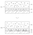
이를 도면을 참조하여 설명하면, 도 1은 본 발명의 리튬 이차전지를 도시한 단면도로서, 이를 참조하면, 본 발명의 일 실시예에 따른 리튬 이차전지는 집전체, 전해질 분리막(30), 전극층으로 형성되는 리튬 이차전지에 있어서, 상기 집전체 중에서, 상기 전해질 분리막(30)과 일정 간격 이격되어 제공되는 음극 집전체(10) 및 상기 전극층 중에서, 상기 전해질 분리막(30)과 상기 음극 집전체(10) 사이에 제공되는 음극층(20)을 포함하며, 상기 전해질 분리막(30)은, 일면에 요철부(31)가 형성되어, 상기 요철부(31)에 대응되는 형상으로 형성된 상기 음극층(20)과 밀착될 수 있다.1 is a cross-sectional view showing a lithium secondary battery of the present invention, referring to this, the lithium secondary battery according to an embodiment of the present invention is a current collector, an
즉, 상기 전해질 분리막(30)과 상기 음극층(20)의 접촉 면적을 증가시켜 리튬 이차전지의 용량을 증가시키게 구성된 것이다.That is, the capacity of the lithium secondary battery is increased by increasing the contact area between the
다시 말해, 종전에는 상기 음극 집전체(10)와 음극층(20)으로 형성된 음극 구조와 상기 전해질 분리막(30)과의 결합 면적에 한계가 있어 리튬 이차전지의 용량 증가에 한계가 있었으나, 본 발명의 리튬 이차전지는 상기 전해질 분리막(30)에 형성된 요철부(31)에 의해서 상기 음극층(20)과의 밀착 면적을 증가시켜 동일 체적의 리튬 이차전지에 대한 고용량의 에너지밀도를 구현하게 구성된 것이다.
In other words, in the past, there was a limit in the bonding area between the negative electrode structure formed of the negative electrode
상기 집전체에는 음극 집전체(10), 양극 집전체(50)가 포함되며, 특히 상기 음극 집전체(10)는 상기 전해질 분리막(30)과 일정 간격 이격되게 제공되고, 그 사이에 음극층(20)이 형성되게 제공된다.The current collector includes a negative electrode
이러한 집전체는 전기 도전성을 가지거나 전기 화학적으로 내구성이 있는 재료라면 특별히 제한되지 않는다. 특히, 내열성을 갖는다는 관점에서, 예를 들어, 구리(Cu), 니켈(Ni), 철(Fe), 망간(Mn), 티타늄(Ti), 바나듐(V), 코발트(Co), 아연(Zn), 크롬(Cr), 알루미늄(Al) 및 스테인리스 스틸로 이루어진 군에서 선택된 하나 이상인 것이 바람직하다.Such a current collector is not particularly limited as long as it is an electrically conductive or electrochemically durable material. In particular, from the viewpoint of heat resistance, for example, copper (Cu), nickel (Ni), iron (Fe), manganese (Mn), titanium (Ti), vanadium (V), cobalt (Co), zinc ( Zn), chromium (Cr), aluminum (Al) and is preferably at least one selected from the group consisting of stainless steel.
일례로, 음극 집전체(10)는 구리로 형성하고, 양극 집전체(50)는 알루미늄으로 형성하여 제공할 수 있다.For example, the negative electrode
여기서, 상기 음극 집전체(10)는 종래의 기술에서 제시된 것과 같이, 상기 음극층(20)과 결합되는 부분에 요철 등이 형성하거나 표면 조도를 증가시켜 상기 음극측과 접촉되는 면적을 증가시킬 수도 있다. In this case, as shown in the related art, the negative electrode
특히, 본 발명에서는 이러한 음극 집전체(10)와 음극층(20) 사이의 접촉 면적을 증가시키는 것에 더하여, 상기 전해질 분리막(30)과의 접촉 면적도 증가시킴으로써, 종래의 기술보다 더 고용량의 에너지밀도를 구현하게 구성된다. Particularly, in the present invention, in addition to increasing the contact area between the negative electrode
그리고, 본 발명의 일 실시예에 따른 리튬 이차전지의 상기 음극 집전체(10)는, 일면 또는 양면에 상기 음극층(20)이 형성되는 것을 특징으로 할 수 있다.In addition, the negative electrode
즉, 상기 음극 집전체(10)에 형성되는 음극층(20)은 상기 음극 집전체(10)의 일면에 제공될 수도 있으나, 복수의 리튬 이차전지를 적층하여 전지 용량을 증가시켜 구성하는 경우에는 상기 음극 집전체(10)의 양면에 상기 음극층(20)이 형성될 수 있으며, 순차적으로 전해질 분리막(30), 양극층(40), 양극 집전체(50)가 제공되게 되는 것이다. That is, the
이에 대하여는 도 3에 도시되어 있다. 즉, 도 3은 본 발명의 리튬 이차전지에서 음극 집전체(10)의 양면에 음극층(20)이 형성된 실시예를 도시한 단면도로서 제시된 것이다.
This is illustrated in FIG. 3. That is, Figure 3 is shown as a cross-sectional view showing an embodiment in which the
상기 전극층은 음극층(20)과 양극층(40)을 포함하며, 이러한 음극층(20)과 양극층(40)에서 리튬 등의 금속 이온 등을 순환시키면서 전류를 충방전하게 구성된다.The electrode layer includes a
특히, 상기 음극층(20)은 상기 전해질 분리막(30)에 형성된 요철부(31)에 대응되는 형태로 형성됨에 의해서, 상기 전해질 분리막(30)과의 접촉 면적을 증가시키게 구성된다. 이에 따라 본 발명의 리튬 이차전지는 고용량의 에너지밀도를 구현하게 된다.In particular, the
더욱이, 상기 음극층(20)은 상기 전해질 분리막(30)와 음극 집전체(10)가 일정 간격 이격되어 위치하면 그 사이에 형성됨으로써, 상기 전해질 분리막(30), 음극 집전체(10)와 함께 하나의 유닛으로써 형성되게 된다. 이에 의해서, 상기 음극층(20), 음극 집전체(10)가 결합된 음극 구조를 별도로 상기 전해질 분리막(30)과 결합하는 공정 등을 거치지 않을 수 있는 공정 단순화가 가능하다.In addition, the
이러한 음극층(20)은 리튬 금속 또는 리튬 합금일 수 있으며, 상기 리튬 합금으로는 리튬과, 실리콘(Si), 주석(Sn), 알루미늄(Al), 납(Pb), 게르마늄(Ge) 및 탄소(C)로 이루어진 군에서 선택된 하나 이상으로 이루어진 합금을 사용할 수 있다.The
이와 같은 리튬 금속은 표준 환원 전위가 낮고 에너지 밀도가 높으므로, 상기 리튬 금속 또는 리튬 합금을 사용하면 전지의 용량을 증가시킬 수 있다.Since such lithium metal has a low standard reduction potential and a high energy density, the lithium metal or the lithium alloy may increase the capacity of the battery.
한편, 상기 양극층(40)은 활물질 및 도전 소재를 포함하며, 상기 도전 소재는 금속, 고체 전해질 또는 이들의 혼합물로 이루어질 수 있다.On the other hand, the
상기 양극층(40)에 포함되는 활물질은 이온을 효율적으로 방출 또는 흡착하는 재료라면 제한 없이 이용 가능하나, 예를 들어, 천이 금속 산화물 및 천이 금속 복합 산화물을 이용하는 것이 가능하나, 일례로 리튬 산화물들이 양극층(40)으로써 포함될 수 있다.
The active material included in the
상기 전해질 분리막(30)은 상기 음극층(20), 음극 집전체(10)로 구성된 음극 구조와 양극층(40), 양극 집전체(50)로 구성된 양극 구조 사이에 구비되어, 상기 음극 구조와 양극 구조 사이에서 금속 이온 등의 이동을 조정하는 역할을 하게 된다.The
즉, 상기 전해질 분리막(30)은 리튬 이차전지의 충전과 방전시의 리튬 이온 등의 금속 이온을 양극 구조 또는 음극 구조 방향으로 이동시키게 구성된 것이다.That is, the
특히, 상기 전해질 분리막(30)은 고체로 형성됨으로써, 상기 음극층(20)과의 밀착 면적을 높일 수 있게 구성될 수 있다. 이를 위해서, 상기 전해질 분리막(30)에는 요철 형상의 요철부(31)가 형성될 수 있으며, 상기 음극층(20)은 이러한 전해질 분리막(30)의 요철부(31)에 대응되는 형상으로 형성됨으로써, 접촉 면적의 증가에 의한 고용량의 리튬 이차전지를 구성할 수 있게 된다.In particular, the
그리고, 이러한 전해질 분리막(30)의 재질로는 폴리프로필렌(Polypropylene: PP), 폴리아크릴로아나이트릴(Polyacrylonitrile: PAN), 폴리에틸렌(Polyethylene: PE)으로 이루어진 소재 군에서 1종 이상으로 구성될 수 있다.And, the material of the
그리고, 상기 전해질 분리막(30)의 요철부(31)는 오목한 요(凹)부와 볼록한 철(凸)부의 패턴으로 형성되며, 이러한 요철부(31)에 대응되는 형태의 음극층(20)에서 볼록한 철부에 대응되는 음극층(20) 부분의 리튬 금속 등의 음극층(20)의 두께는 약 5㎛ 내지 100㎛이며, 오목한 요부에 대응되는 음극층(20) 부분의 리튬 금속 등의 음극층(20)의 두께는 약 10㎛ 내지 200㎛로 형성될 수 있다.In addition, the
그리고, 상기 요철부(31)에서 요부 또는 철부의 폭은 약 50㎛ 내지 200㎛일 수 있다.In addition, the width of the recessed portion or the convex portion in the
여기서, 본 발명의 일 실시예에 따른 리튬 이차전지의 상기 전해질 분리막(30)은, 상기 음극층(20)을 매개로 하여 상기 음극 집전체(10)와 결합되어 제공되는 것을 특징으로 할 수 있다.Here, the
다시 말해, 상기 전해질 분리막(30)과 상기 음극 집전체(10) 사이에서 상기 음극층(20)이 전착 등에 의해서 형성되어 제공됨에 따라, 상기 음극층(20)은 상기 음극 집전체(10)와 견고하게 결합되는 것은 물론, 상기 전해질 분리막(30)과도 견고하게 결합되어 제공될 수 있는 것이다.In other words, as the
이에 따라, 상기 전해질 분리막(30)을 음극 집전체(10)와 음극층(20)으로 구성된 음극 구조와 결합하기 위한 별도의 공정이 불필요하여 리튬 이차전지의 제조 공정을 단순화하게 된다.Accordingly, a separate process for combining the
다시 말해, 본 발명의 리튬 이차전지 제조방법은 상기 전해질 분리막(30), 음극층(20), 음극 집전체(10)를 견고하여 일체로 형성하여 제공함으로써, 구조적 안정성을 확보할 수 있으며, 또한 리튬 이차전지의 조립 공정을 단순화하여 생산비용을 절감할 수 있는 것이다.In other words, the method of manufacturing a lithium secondary battery of the present invention by providing the
도 2는 본 발명의 리튬 이차전지에서 전해질 분리막(30)을 도시한 평면도로서, 이를 참조하면, 본 발명의 일 실시예에 따른 리튬 이차전지의 상기 요철부(31)는, 돌출된 철부의 평면 형상이 원형, 벌집형, 동심링형, 직선바형으로 형성된 것을 특징으로 할 수 있다.2 is a plan view showing the
다시 말해, 상기 전해질 분리막(30)에 형성된 요철부(31)의 패턴 형상을 상기와 같이, 원형, 벌집형, 동심링형, 직선바형으로 구비시킬 수 있는 것이다. 다만, 본 발명의 리튬 이차전지의 상기 전해질 분리막(30)의 요철부(31)가 상기 형상에 한정되는 것은 아니며, 요부와 철부로 구성된 요철부(31)의 형태라면 본 발명의 요철부(31)의 형태로 제시될 수 있다.
In other words, the pattern shape of the concave-
도 4는 본 발명의 리튬 이차전지의 제조방법을 순서대로 도시한 평면도로서, 이를 참조하면, 본 발명의 다른 실시예에 따른 리튬 이차전지 제조방법은 집전체, 전해질 분리막(30), 전극층으로 형성되는 리튬 이차전지를 제조하는 리튬 이차전지 제조방법에 있어서, 상기 집전체 중에서 음극 집전체(10)를 제공하는 음극 집전체 제공단계(S1), 전해질 분리막(30)을 상기 음극 집전체(10)와 일정 간격 이격하여 제공하는 분리막 제공단계(S2) 및 상기 음극 집전체(10)와 전해질 분리막(30) 사이에 전착에 의해서 음극층(20)을 형성하는 음극층 형성단계(S3)를 포함할 수 있다.4 is a plan view sequentially showing a method of manufacturing a lithium secondary battery of the present invention. Referring to this, a method of manufacturing a lithium secondary battery according to another embodiment of the present invention is formed of a current collector, an
이와 같이 상기 음극층 형성단계(S3)에서 상기 음극층(20)을 상기 음극 집전체(10)와 전해질 분리막(30) 사이에 전착시켜 제공함으로써, 상기 음극층(20)은 상기 음극 집전체(10)와 견고하게 결합되어 형성되는 것에 더하여, 상기 전해질 분리막(30)과도 견고하게 결합되어 형성될 수 있게 된다.As described above, the
이에 의해서, 상기 음극 집전체(10)와 상기 음극층(20)이 일체로 제공되는 것에 더하여, 상기 전해질 분리막(30)도 상기 음극 집전체(10), 음극층(20)과 일체로 제공됨으로써, 별도로 상기 전해질 분리막(30)을 상기 음극 집전체(10), 음극층(20)으로 형성된 음극 구조와 결합하는 공정을 불요하게 된다.As a result, the negative electrode
이에 따라, 상기 전해질 분리막(30), 음극층(20), 음극 집전체(10)를 견고하여 일체로 형성한 구조적 안정성을 확보할 수 있으며, 또한 리튬 이차전지 제조방법의 조립 공정을 단순화하여 생산비용을 절감할 수 있게 된다.Accordingly, it is possible to secure structural stability integrally formed by firmly solidifying the
특히, 본 발명의 다른 실시예에 따른 리튬 이차전지 제조방법의 상기 분리막 제공단계(S2)는, 상기 전해질 분리막(30)의 표면에 요철부(31)를 형성하여 제공하는 것을 특징으로 할 수 있다. 이에 따라서 상기 음극층(20)과 상기 음극 집전체(10)의 결합 면적 증가와는 별도로, 상기 음극층(20)과 상기 전해질 분리막(30)의 결합 면적을 증가시킴으로써 고용량의 리튬 이차전지를 생산할 수 있게 된다.
In particular, the separator providing step (S2) of the lithium secondary battery manufacturing method according to another exemplary embodiment of the present disclosure may be provided by forming an
이러한 전해질 분리막(30)의 요철부(31)를 형성하기 위하여, 아래에서 분리막 제공단계(S2)의 두 가지의 실시예를 제시한다.In order to form the concave-
도 5는 본 발명의 리튬 이차전지의 제조방법에서 분리막 제공단계(S2)의 제1실시예를 순서대로 도시한 평면도로서, 이를 참조하면, 본 발명의 다른 실시예에 따른 리튬 이차전지 제조방법의 상기 분리막 제공단계(S2)는, 블랭크 분리막(30a)에 복수의 홈을 형성하여, 요철부(31)가 형성된 전해질 분리막(30)을 형성하는 분리막 형성단계(S22) 및 상기 음극 집전체(10)와 일정 간격 이격되게 상기 전해질 분리막(30)을 위치시키는 포지셔닝 단계(S23)를 포함할 수 있다.5 is a plan view showing a first embodiment of the separator providing step (S2) in order in the method of manufacturing a lithium secondary battery of the present invention, referring to this, of the method of manufacturing a lithium secondary battery according to another embodiment of the present invention In the separator providing step (S2), a plurality of grooves are formed in the
다시 말해, 상기 요철부(31)를 형성하는 단계는 상기 분리막 형성단계(S22)로서, 여기서 상기 요철부(31)는 블랭크 분리막(30a)에 홈을 형성함으로써 형성되게 된다. In other words, the step of forming the
이러한 요철부(31)가 형성된 전해질 분리막(30)을 제조한 후에 이를 상기 음극 집전체(10)와 일정 간격 이격되게 위치시킴으로써, 상기 분리막 제공단계(S2)를 수행하게 된다.After preparing the
도 6은 본 발명의 리튬 이차전지의 제조방법에서 분리막 제공단계(S2)의 제2실시예를 순서대로 도시한 평면도로서, 이를 참조하면, 본 발명의 다른 실시예에 따른 리튬 이차전지 제조방법의 상기 분리막 제공단계(S2)는, 블랭크 분리막(30a)에 복수의 홀을 형성하여 펀칭된 분리막(30b)을 형성하는 펀칭단계(S21), 또 다른 블랭크 분리막(30a)과 상기 펀칭된 분리막(30b)을 압착에 의해 결합하여, 요철부(31)가 형성된 전해질 분리막(30)을 형성하는 분리막 형성단계(S22) 및 상기 음극 집전체(10)와 일정 간격 이격되게 상기 전해질 분리막(30)을 위치시키는 포지셔닝 단계(S23)를 포함할 수 있다.6 is a plan view showing a second embodiment of the separator providing step (S2) in order in the method of manufacturing a lithium secondary battery of the present invention, with reference to this, of the lithium secondary battery manufacturing method according to another embodiment of the present invention The separator providing step (S2) is a punching step (S21) to form a plurality of holes in the
여기서는 상기 전해질 분리막(30)의 요철부(31)를 형성하기 위해서 우선 블랭크 분리막(30a)에 홀을 형성하여 펀칭된 분리막(30b)을 형성하고, 이러한 펀칭된 분리막(30b)을 다시 블랭크 분리막(30a)과 압착하여 결합함으로써, 요철부(31)가 형성된 전해질 분리막(30)을 제조하게 된다.In this case, in order to form the
상기 펀칭된 분리막(30b)을 형성하기 위한 펀칭 작업은 일례로 레이저 펀칭기 등으로 형성할 수 있다.The punching operation for forming the punched
이와 같이 요철부(31)가 형성된 전해질 분리막(30)을 제조한 후에는 이를 음극 집전체(10)와 간격을 형성하게 위치시킴으로써, 분리막 제공단계(S2)를 수행하게 된다.
After the
다음으로 설명할 것은 음극층 형성단계(S3)의 구체적 단계로써, 상기 음극층 형성단계(S3)도 두 가지의 실시예로 제시될 수 있다.Next will be described as a specific step of the cathode layer forming step (S3), the cathode layer forming step (S3) may also be presented in two embodiments.
우선, 도 7은 본 발명의 리튬 이차전지의 제조방법에서 음극층 형성단계(S3)의 제1실시예를 순서대로 도시한 평면도로서, 이를 참조하면, 본 발명의 다른 실시예에 따른 리튬 이차전지 제조방법의 상기 음극층 형성단계(S3)는, 상기 음극 집전체(10)와 전해질 분리막(30) 사이에 리튬 이온이 용해된 전해액(ES)을 제공하는 전해액 제공단계(S31) 및 상기 전해액(ES)에 전류를 인가하여, 상기 음극 집전체(10)와 상기 전해질 분리막(30) 사이에 리튬 금속을 전착시키는 전착단계(S33)를 포함할 수 있다.First, Figure 7 is a plan view showing a first embodiment of the negative electrode layer forming step (S3) in order in the method of manufacturing a lithium secondary battery of the present invention, referring to this, a lithium secondary battery according to another embodiment of the present invention In the negative electrode layer forming step (S3) of the manufacturing method, an electrolyte solution providing step (S31) and an electrolyte solution (ES) in which lithium ions are dissolved between the negative electrode
다시 말해, 상기 음극층(20)을 전착에 의해서 형성할 때 사용하는 전해액(ES)에는 리튬 이온이 충분히 용해되어 제공됨으로써, 전류의 인가시에 상기 음극 집전체(10)와 전해질 분리막(30) 사이에 리튬 이온이 전착되어 형성될 수 있는 것이다.In other words, lithium ions are sufficiently dissolved in the electrolyte (ES) used when the
이러한 리튬 이온으로 용해된 리튬염은 LiCl, LiCO3, LiNO3, LiPF6, LiFSI, LiTFSI, LiAsF6, LiClO4, LiN(SO2CF3)2 중 1종 이상으로 구성될 수 있으며, 용매에 0.1M 내지 3.0M의 농도로 용해되어 제공될 수 있다. Lithium salt dissolved with these lithium ions may be composed of one or more of LiCl, LiCO 3 , LiNO 3 , LiPF 6 , LiFSI, LiTFSI, LiAsF 6 , LiClO 4 , LiN (SO 2 CF 3 ) 2 , in a solvent It can be provided dissolved in a concentration of 0.1M to 3.0M.
여기서의 용매는 에테르계, 카보네이트계 또는 이들의 조합으로 구성되어 제공될 수 있다. The solvent here may be provided consisting of ether, carbonate or a combination thereof.
그리고, 에테르계 용매는 1,3,5-trioxane, 1,2-dimethoxyethane, Diethylene glycol dimethyl ether, Tetraethylene glycol dimethyl ether, Tetrahydrofuran, 1,3-dioxolane, 1,4-dioxane 및 이들의 혼합물을 포함하는 군에서 선택된 것일 수 있다.The ether solvent includes 1,3,5-trioxane, 1,2-dimethoxyethane, Diethylene glycol dimethyl ether, Tetraethylene glycol dimethyl ether, Tetrahydrofuran, 1,3-dioxolane, 1,4-dioxane, and mixtures thereof. It may be selected from the group.
그리고, 카보네이트계 용매는 Ethylene carbonate, Propylene carbonate, Dimethyl carbonate, Ethyl methyl carbonate, Diethyl carbonate, Fluoroethylene carbonate 및 이들의 혼합물을 포함하는 군에서 선택된 것일 수 있다.
In addition, the carbonate-based solvent may be selected from the group comprising Ethylene carbonate, Propylene carbonate, Dimethyl carbonate, Ethyl methyl carbonate, Diethyl carbonate, Fluoroethylene carbonate, and mixtures thereof.
다음으로, 도 8은 본 발명의 리튬 이차전지의 제조방법에서 음극층 형성단계(S3)의 제2실시예를 순서대로 도시한 평면도로서, 이를 참조하면, 본 발명의 다른 실시예에 따른 리튬 이차전지 제조방법의 상기 음극층 형성단계(S3)는, 상기 음극 집전체(10)와 전해질 분리막(30) 사이에 전해액(ES)을 제공하는 전해액 제공단계(S31), 상기 음극 집전체(10)와의 사이에 상기 전해질 분리막(30)이 구비되게 리튬 합금 또는 리튬 금속판(LP)을 제공하는 리튬 제공단계(S32) 및 상기 금속판(LP)과 상기 음극 집전체(10)에 접촉되는 전해액(ES)에 전류를 인가하여, 상기 금속판(LP)에서 제공되는 리튬이온을 상기 음극 집전체(10)와 상기 전해질 분리막(30) 사이에 리튬 금속으로 전착시키는 전착단계(S33)를 포함할 수 있다.Next, Figure 8 is a plan view showing a second embodiment of the negative electrode layer forming step (S3) in order in the method of manufacturing a lithium secondary battery of the present invention, referring to this, lithium secondary according to another embodiment of the present invention In the negative electrode layer forming step (S3) of the battery manufacturing method, an electrolyte providing step (S31) of providing an electrolyte solution (ES) between the negative electrode
다시 말해, 전술한 음극층 형성단계(S3)의 제1실시예와 달리 음극층 형성단계(S3)의 제2실시예는 리튬 이온의 공급원이 상기 전해액(ES)에 용해된 리튬 이온에 한정되는 것이 아니라, 리튬 금속판(LP) 또는 리튬 합금 금속판(LP)으로 제공될 수도 있는 것이다.In other words, unlike the first embodiment of the above-described negative electrode layer forming step S3, the second embodiment of the negative electrode layer forming step S3 is limited to a lithium ion source of lithium ions dissolved in the electrolyte ES. Rather, it may be provided as a lithium metal plate LP or a lithium alloy metal plate LP.
여기서의 리튬 합금은 리튬과, 실리콘(Si), 주석(Sn), 알루미늄(Al), 납(Pb), 게르마늄(Ge) 및 탄소(C)로 이루어진 군에서 선택된 하나 이상으로 이루어진 합금을 사용할 수 있다.Here, the lithium alloy may use an alloy consisting of lithium and at least one selected from the group consisting of silicon (Si), tin (Sn), aluminum (Al), lead (Pb), germanium (Ge), and carbon (C). have.
또한 이러한 음극층 형성단계(S3)의 제2실시예에서는 리튬 제공단계(S32)에서 상기 리튬 금속판(LP) 또는 리튬 합금 금속판(LP)에 의해서 리튬이 전해액(ES)에 용해될 수 있기 때문에, 상기 전해액 제공단계(S31)의 전해액(ES)에 리튬 이온이 용해되어 제공될 필요는 없다.In addition, in the second embodiment of the cathode layer forming step S3, since lithium may be dissolved in the electrolyte ES by the lithium metal plate LP or the lithium alloy metal plate LP in the lithium providing step S32, It is not necessary to provide lithium ions dissolved in the electrolyte solution ES of the electrolyte providing step S31.
다만 상기 전해액 제공단계(S31)에서 제공되는 전해액(ES)에 리튬 이온이 용해된 경우도 포함될 수 있으며, 이러한 경우에는 상기 리튬 제공단계(S32)는 전해액(ES)에 용해된 리튬 이온의 부족분을 추가로 공급하는 역할을 하게 된다.
However, lithium ions may be dissolved in the electrolyte (ES) provided in the electrolyte providing step (S31), and in this case, the lithium providing step (S32) may provide a shortage of lithium ions dissolved in the electrolyte (ES). It will serve as an additional supply.
이상에서 본 발명의 실시예에 대하여 설명하였지만 본 발명의 권리범위는 이에 한정되는 것은 아니고, 청구범위에 기재된 본 발명의 기술적 사상을 벗어나지 않는 범위 내에서 다양한 수정 및 변형이 가능하다는 것은 당 기술분야의 통상의 지식을 가진 자에게는 자명할 것이다.Although the embodiments of the present invention have been described above, the scope of the present invention is not limited thereto, and various modifications and variations can be made without departing from the technical spirit of the present invention described in the claims. It will be obvious to one with ordinary knowledge.
10: 음극 집전체 20: 음극층
30: 전해질 분리막 31: 요철부
40: 양극층 50: 양극 집전체10: negative electrode current collector 20: negative electrode layer
30: electrolyte separator 31: uneven portion
40: anode layer 50: anode current collector
Claims (10)
상기 집전체 중에서 음극 집전체를 제공하는 음극 집전체 제공단계;
전해질 분리막을 상기 음극 집전체와 일정 간격 이격하여 제공하는 분리막 제공단계; 및
상기 음극 집전체와 전해질 분리막 사이에 전착에 의해서 음극층을 형성하는 음극층 형성단계;
를 포함하며,
상기 음극층 형성단계는,
상기 음극 집전체와 전해질 분리막 사이에 전해액을 제공하는 전해액 제공단계;
상기 음극 집전체와의 사이에 상기 전해질 분리막이 구비되게 리튬 합금 또는 리튬 금속판을 제공하는 리튬 제공단계; 및
상기 금속판과 상기 음극 집전체에 접촉되는 전해액에 전류를 인가하여, 상기 금속판에서 제공되는 리튬이온을 상기 음극 집전체와 상기 전해질 분리막 사이에 리튬 금속으로 전착시키는 전착단계;
를 포함하는 리튬 이차전지 제조방법.In the lithium secondary battery manufacturing method for manufacturing a lithium secondary battery formed of a current collector, an electrolyte separator, an electrode layer,
A negative electrode current collector providing a negative electrode current collector among the current collectors;
Providing a separator spaced apart from the negative electrode current collector by a predetermined interval; And
A negative electrode layer forming step of forming a negative electrode layer by electrodeposition between the negative electrode current collector and the electrolyte separator;
Including;
The cathode layer forming step,
Providing an electrolyte solution between the negative electrode current collector and an electrolyte separator;
Providing a lithium alloy or a lithium metal plate such that the electrolyte separator is provided between the negative electrode current collector; And
An electrodeposition step of applying an electric current to an electrolyte solution in contact with the metal plate and the negative electrode current collector, thereby depositing lithium ions provided from the metal plate with lithium metal between the negative electrode current collector and the electrolyte separator;
Lithium secondary battery manufacturing method comprising a.
상기 분리막 제공단계는, 상기 전해질 분리막의 표면에 요철부를 형성하여 제공하는 것을 특징으로 하는 리튬 이차전지 제조방법.The method of claim 5,
The separator providing step, the lithium secondary battery manufacturing method characterized in that to provide an uneven portion formed on the surface of the electrolyte separator.
상기 분리막 제공단계는,
블랭크 분리막에 복수의 홈을 형성하여, 요철부가 형성된 전해질 분리막을 형성하는 분리막 형성단계; 및
상기 음극 집전체와 일정 간격 이격되게 상기 전해질 분리막을 위치시키는 포지셔닝 단계;
를 포함하는 리튬 이차전지 제조방법.The method of claim 6,
The separator providing step,
A separator forming step of forming a plurality of grooves in the blank separator to form an electrolyte separator having an uneven portion formed therein; And
Positioning the electrolyte separator to be spaced apart from the negative electrode current collector at a predetermined interval;
Lithium secondary battery manufacturing method comprising a.
상기 집전체 중에서 음극 집전체를 제공하는 음극 집전체 제공단계;
전해질 분리막을 상기 음극 집전체와 일정 간격 이격하여 제공하되, 상기 전해질 분리막의 표면에 요철부를 형성하여 제공하는 분리막 제공단계; 및
상기 음극 집전체와 전해질 분리막 사이에 전착에 의해서 음극층을 형성하는 음극층 형성단계;
를 포함하며,
상기 분리막 제공단계는,
블랭크 분리막에 복수의 홀을 형성하여 펀칭된 분리막을 형성하는 펀칭단계;
또 다른 블랭크 분리막과 상기 펀칭된 분리막을 압착에 의해 결합하여, 요철부가 형성된 전해질 분리막을 형성하는 분리막 형성단계; 및
상기 음극 집전체와 일정 간격 이격되게 상기 전해질 분리막을 위치시키는 포지셔닝 단계;
를 포함하는 리튬 이차전지 제조방법.In the lithium secondary battery manufacturing method for manufacturing a lithium secondary battery formed of a current collector, an electrolyte separator, an electrode layer,
A negative electrode current collector providing a negative electrode current collector among the current collectors;
Providing an electrolyte separator spaced apart from the negative electrode current collector at a predetermined interval, and providing a separator by forming an uneven portion on the surface of the electrolyte separator; And
A negative electrode layer forming step of forming a negative electrode layer by electrodeposition between the negative electrode current collector and the electrolyte separator;
Including;
The separator providing step,
A punching step of forming a plurality of holes in the blank separator to form a punched separator;
A separator forming step of bonding another blank separator and the punched separator by pressing to form an electrolyte separator having an uneven portion formed therein; And
Positioning the electrolyte separator to be spaced apart from the negative electrode current collector at a predetermined interval;
Lithium secondary battery manufacturing method comprising a.
상기 음극층 형성단계는,
상기 음극 집전체와 전해질 분리막 사이에 리튬 이온이 용해된 전해액을 제공하는 전해액 제공단계; 및
상기 전해액에 전류를 인가하여, 상기 음극 집전체와 상기 전해질 분리막 사이에 리튬 금속을 전착시키는 전착단계;
를 포함하는 리튬 이차전지 제조방법.The method of claim 8,
The cathode layer forming step,
Providing an electrolyte solution in which lithium ions are dissolved between the negative electrode current collector and the electrolyte separator; And
An electrodeposition step of depositing lithium metal between the anode current collector and the electrolyte separator by applying a current to the electrolyte solution;
Lithium secondary battery manufacturing method comprising a.
상기 음극층 형성단계는,
상기 음극 집전체와 전해질 분리막 사이에 전해액을 제공하는 전해액 제공단계;
상기 음극 집전체와의 사이에 상기 전해질 분리막이 구비되게 리튬 합금 또는 리튬 금속판을 제공하는 리튬 제공단계; 및
상기 금속판과 상기 음극 집전체에 접촉되는 전해액에 전류를 인가하여, 상기 금속판에서 제공되는 리튬이온을 상기 음극 집전체와 상기 전해질 분리막 사이에 리튬 금속으로 전착시키는 전착단계;
를 포함하는 리튬 이차전지 제조방법.The method of claim 8,
The cathode layer forming step,
Providing an electrolyte solution between the negative electrode current collector and an electrolyte separator;
Providing a lithium alloy or a lithium metal plate such that the electrolyte separator is provided between the negative electrode current collector; And
An electrodeposition step of applying an electric current to an electrolyte solution in contact with the metal plate and the negative electrode current collector, thereby depositing lithium ions provided from the metal plate with lithium metal between the negative electrode current collector and the electrolyte separator;
Lithium secondary battery manufacturing method comprising a.
Priority Applications (1)
| Application Number | Priority Date | Filing Date | Title |
|---|---|---|---|
| KR1020170109588A KR102045552B1 (en) | 2017-08-29 | 2017-08-29 | Lithium secondary battery manufacturing method |
Applications Claiming Priority (1)
| Application Number | Priority Date | Filing Date | Title |
|---|---|---|---|
| KR1020170109588A KR102045552B1 (en) | 2017-08-29 | 2017-08-29 | Lithium secondary battery manufacturing method |
Publications (2)
| Publication Number | Publication Date |
|---|---|
| KR20190025124A KR20190025124A (en) | 2019-03-11 |
| KR102045552B1 true KR102045552B1 (en) | 2019-11-19 |
Family
ID=65758372
Family Applications (1)
| Application Number | Title | Priority Date | Filing Date |
|---|---|---|---|
| KR1020170109588A Active KR102045552B1 (en) | 2017-08-29 | 2017-08-29 | Lithium secondary battery manufacturing method |
Country Status (1)
| Country | Link |
|---|---|
| KR (1) | KR102045552B1 (en) |
Families Citing this family (4)
| Publication number | Priority date | Publication date | Assignee | Title |
|---|---|---|---|---|
| KR102176349B1 (en) | 2018-11-08 | 2020-11-09 | 주식회사 포스코 | Negative electrode of lithium metal, method of preparing the saem, and lithium secondary battery using the same |
| KR102935072B1 (en) * | 2019-07-10 | 2026-03-05 | 현대자동차주식회사 | A composite anode for all-solid state battery |
| KR102908664B1 (en) * | 2020-06-17 | 2026-01-06 | 현대자동차주식회사 | All solid state battery having electrolyte layer comprising impregnated pattern |
| WO2025199737A1 (en) * | 2024-03-26 | 2025-10-02 | 厦门新能安科技有限公司 | Secondary battery and electronic device |
Citations (2)
| Publication number | Priority date | Publication date | Assignee | Title |
|---|---|---|---|---|
| JP2009054484A (en) * | 2007-08-28 | 2009-03-12 | Seiko Epson Corp | All solid lithium secondary battery and its manufacturing method |
| JP2013062047A (en) * | 2011-09-12 | 2013-04-04 | Hitachi Cable Ltd | Negative-electrode copper foil collector for lithium ion secondary battery, negative-electrode for lithium ion secondary battery, lithium ion secondary battery and method for manufacturing negative-electrode copper foil collector for lithium ion secondary battery |
Family Cites Families (3)
| Publication number | Priority date | Publication date | Assignee | Title |
|---|---|---|---|---|
| KR20060107139A (en) | 2005-04-07 | 2006-10-13 | 주식회사 아이레보 | Hot air jet device |
| KR100779000B1 (en) * | 2005-12-27 | 2007-11-22 | 삼성에스디아이 주식회사 | Lithium secondary battery |
| US9184436B2 (en) * | 2012-02-07 | 2015-11-10 | Battelle Memorial Institute | Methods and energy storage devices utilizing electrolytes having surface-smoothing additives |
-
2017
- 2017-08-29 KR KR1020170109588A patent/KR102045552B1/en active Active
Patent Citations (2)
| Publication number | Priority date | Publication date | Assignee | Title |
|---|---|---|---|---|
| JP2009054484A (en) * | 2007-08-28 | 2009-03-12 | Seiko Epson Corp | All solid lithium secondary battery and its manufacturing method |
| JP2013062047A (en) * | 2011-09-12 | 2013-04-04 | Hitachi Cable Ltd | Negative-electrode copper foil collector for lithium ion secondary battery, negative-electrode for lithium ion secondary battery, lithium ion secondary battery and method for manufacturing negative-electrode copper foil collector for lithium ion secondary battery |
Also Published As
| Publication number | Publication date |
|---|---|
| KR20190025124A (en) | 2019-03-11 |
Similar Documents
| Publication | Publication Date | Title |
|---|---|---|
| JP7070052B2 (en) | All solid state battery | |
| US10840538B2 (en) | Lithium metal secondary battery using lithium metal as negative electrode active material | |
| JP6885309B2 (en) | Series stacked all-solid-state battery | |
| KR101664244B1 (en) | Method forming electrode surface pattern and the electrode manufactured by the method and secondary battery including the same | |
| JP6998551B2 (en) | Lithium secondary battery | |
| KR102045552B1 (en) | Lithium secondary battery manufacturing method | |
| US10497962B2 (en) | Electrode including an increased active material content | |
| KR20150082958A (en) | Electrode for secondary battery and Method for manufacturing the same | |
| KR101850180B1 (en) | Secondary Battery Comprising Current Collector with Through Hole | |
| US11652242B2 (en) | Solid-state battery electrolyte layers | |
| JP2007329050A (en) | Sheet type battery and its manufacturing method | |
| JP2014532955A (en) | Secondary battery | |
| CN107437609B (en) | Rechargeable electrochemical lithium-ion battery cells | |
| JP2009032408A (en) | Secondary battery separator | |
| US20180337391A1 (en) | Pressing process of creating a patterned surface on battery electrodes | |
| JP2015018670A (en) | Bipolar battery | |
| US20220158152A1 (en) | Electrode and method for manufacturing the same | |
| US20230268518A1 (en) | High surface area electrode for solid-state battery | |
| JPH06260168A (en) | Lithium secondary battery | |
| KR20240000462U (en) | lithium ion battery | |
| JP7279632B2 (en) | All-solid battery | |
| JP7168473B2 (en) | Negative electrode for all-solid-state battery | |
| US12500234B2 (en) | Solid-state battery and method of manufacturing solid-state battery | |
| JP2024144832A (en) | Method for recovering electrodes of an electric storage device, method for manufacturing an electric storage device, and an electric storage device | |
| KR102083296B1 (en) | Method of Preparing Battery Cell Comprising Electrode Having Hole |
Legal Events
| Date | Code | Title | Description |
|---|---|---|---|
| A201 | Request for examination | ||
| PA0109 | Patent application |
St.27 status event code: A-0-1-A10-A12-nap-PA0109 |
|
| PA0201 | Request for examination |
St.27 status event code: A-1-2-D10-D11-exm-PA0201 |
|
| D13-X000 | Search requested |
St.27 status event code: A-1-2-D10-D13-srh-X000 |
|
| D14-X000 | Search report completed |
St.27 status event code: A-1-2-D10-D14-srh-X000 |
|
| R18-X000 | Changes to party contact information recorded |
St.27 status event code: A-3-3-R10-R18-oth-X000 |
|
| E902 | Notification of reason for refusal | ||
| PE0902 | Notice of grounds for rejection |
St.27 status event code: A-1-2-D10-D21-exm-PE0902 |
|
| P11-X000 | Amendment of application requested |
St.27 status event code: A-2-2-P10-P11-nap-X000 |
|
| P13-X000 | Application amended |
St.27 status event code: A-2-2-P10-P13-nap-X000 |
|
| PG1501 | Laying open of application |
St.27 status event code: A-1-1-Q10-Q12-nap-PG1501 |
|
| E902 | Notification of reason for refusal | ||
| PE0902 | Notice of grounds for rejection |
St.27 status event code: A-1-2-D10-D21-exm-PE0902 |
|
| E13-X000 | Pre-grant limitation requested |
St.27 status event code: A-2-3-E10-E13-lim-X000 |
|
| P11-X000 | Amendment of application requested |
St.27 status event code: A-2-2-P10-P11-nap-X000 |
|
| P13-X000 | Application amended |
St.27 status event code: A-2-2-P10-P13-nap-X000 |
|
| R18-X000 | Changes to party contact information recorded |
St.27 status event code: A-3-3-R10-R18-oth-X000 |
|
| R18-X000 | Changes to party contact information recorded |
St.27 status event code: A-3-3-R10-R18-oth-X000 |
|
| R18-X000 | Changes to party contact information recorded |
St.27 status event code: A-3-3-R10-R18-oth-X000 |
|
| E701 | Decision to grant or registration of patent right | ||
| PE0701 | Decision of registration |
St.27 status event code: A-1-2-D10-D22-exm-PE0701 |
|
| GRNT | Written decision to grant | ||
| PR0701 | Registration of establishment |
St.27 status event code: A-2-4-F10-F11-exm-PR0701 |
|
| PR1002 | Payment of registration fee |
St.27 status event code: A-2-2-U10-U11-oth-PR1002 Fee payment year number: 1 |
|
| PG1601 | Publication of registration |
St.27 status event code: A-4-4-Q10-Q13-nap-PG1601 |
|
| R18-X000 | Changes to party contact information recorded |
St.27 status event code: A-5-5-R10-R18-oth-X000 |
|
| P22-X000 | Classification modified |
St.27 status event code: A-4-4-P10-P22-nap-X000 |
|
| P22-X000 | Classification modified |
St.27 status event code: A-4-4-P10-P22-nap-X000 |
|
| R18-X000 | Changes to party contact information recorded |
St.27 status event code: A-5-5-R10-R18-oth-X000 |
|
| P22-X000 | Classification modified |
St.27 status event code: A-4-4-P10-P22-nap-X000 |
|
| PR1001 | Payment of annual fee |
St.27 status event code: A-4-4-U10-U11-oth-PR1001 Fee payment year number: 4 |
|
| R18-X000 | Changes to party contact information recorded |
St.27 status event code: A-5-5-R10-R18-oth-X000 |
|
| PR1001 | Payment of annual fee |
St.27 status event code: A-4-4-U10-U11-oth-PR1001 Fee payment year number: 5 |
|
| R18-X000 | Changes to party contact information recorded |
St.27 status event code: A-5-5-R10-R18-oth-X000 |
|
| R18-X000 | Changes to party contact information recorded |
St.27 status event code: A-5-5-R10-R18-oth-X000 |
|
| PR1001 | Payment of annual fee |
St.27 status event code: A-4-4-U10-U11-oth-PR1001 Fee payment year number: 6 |
|
| R18 | Changes to party contact information recorded |
Free format text: ST27 STATUS EVENT CODE: A-5-5-R10-R18-OTH-X000 (AS PROVIDED BY THE NATIONAL OFFICE) |
|
| R18-X000 | Changes to party contact information recorded |
St.27 status event code: A-5-5-R10-R18-oth-X000 |
|
| PR1001 | Payment of annual fee |
St.27 status event code: A-4-4-U10-U11-oth-PR1001 Fee payment year number: 7 |
|
| U11 | Full renewal or maintenance fee paid |
Free format text: ST27 STATUS EVENT CODE: A-4-4-U10-U11-OTH-PR1001 (AS PROVIDED BY THE NATIONAL OFFICE) Year of fee payment: 7 |
|
| R18 | Changes to party contact information recorded |
Free format text: ST27 STATUS EVENT CODE: A-5-5-R10-R18-OTH-X000 (AS PROVIDED BY THE NATIONAL OFFICE) |
|
| R18-X000 | Changes to party contact information recorded |
St.27 status event code: A-5-5-R10-R18-oth-X000 |