KR101992503B1 - Systems and methods for detecting the presence of a selected volume of material in a sample processing device - Google Patents
Systems and methods for detecting the presence of a selected volume of material in a sample processing device Download PDFInfo
- Publication number
- KR101992503B1 KR101992503B1 KR1020137033201A KR20137033201A KR101992503B1 KR 101992503 B1 KR101992503 B1 KR 101992503B1 KR 1020137033201 A KR1020137033201 A KR 1020137033201A KR 20137033201 A KR20137033201 A KR 20137033201A KR 101992503 B1 KR101992503 B1 KR 101992503B1
- Authority
- KR
- South Korea
- Prior art keywords
- sample
- sample processing
- detection chamber
- processing apparatus
- chamber
- Prior art date
Links
Images


Classifications
-
- B—PERFORMING OPERATIONS; TRANSPORTING
- B01—PHYSICAL OR CHEMICAL PROCESSES OR APPARATUS IN GENERAL
- B01L—CHEMICAL OR PHYSICAL LABORATORY APPARATUS FOR GENERAL USE
- B01L3/00—Containers or dishes for laboratory use, e.g. laboratory glassware; Droppers
- B01L3/50—Containers for the purpose of retaining a material to be analysed, e.g. test tubes
- B01L3/502—Containers for the purpose of retaining a material to be analysed, e.g. test tubes with fluid transport, e.g. in multi-compartment structures
- B01L3/5027—Containers for the purpose of retaining a material to be analysed, e.g. test tubes with fluid transport, e.g. in multi-compartment structures by integrated microfluidic structures, i.e. dimensions of channels and chambers are such that surface tension forces are important, e.g. lab-on-a-chip
- B01L3/502715—Containers for the purpose of retaining a material to be analysed, e.g. test tubes with fluid transport, e.g. in multi-compartment structures by integrated microfluidic structures, i.e. dimensions of channels and chambers are such that surface tension forces are important, e.g. lab-on-a-chip characterised by interfacing components, e.g. fluidic, electrical, optical or mechanical interfaces
-
- B—PERFORMING OPERATIONS; TRANSPORTING
- B01—PHYSICAL OR CHEMICAL PROCESSES OR APPARATUS IN GENERAL
- B01L—CHEMICAL OR PHYSICAL LABORATORY APPARATUS FOR GENERAL USE
- B01L99/00—Subject matter not provided for in other groups of this subclass
-
- C—CHEMISTRY; METALLURGY
- C12—BIOCHEMISTRY; BEER; SPIRITS; WINE; VINEGAR; MICROBIOLOGY; ENZYMOLOGY; MUTATION OR GENETIC ENGINEERING
- C12Q—MEASURING OR TESTING PROCESSES INVOLVING ENZYMES, NUCLEIC ACIDS OR MICROORGANISMS; COMPOSITIONS OR TEST PAPERS THEREFOR; PROCESSES OF PREPARING SUCH COMPOSITIONS; CONDITION-RESPONSIVE CONTROL IN MICROBIOLOGICAL OR ENZYMOLOGICAL PROCESSES
- C12Q1/00—Measuring or testing processes involving enzymes, nucleic acids or microorganisms; Compositions therefor; Processes of preparing such compositions
- C12Q1/68—Measuring or testing processes involving enzymes, nucleic acids or microorganisms; Compositions therefor; Processes of preparing such compositions involving nucleic acids
- C12Q1/6844—Nucleic acid amplification reactions
- C12Q1/686—Polymerase chain reaction [PCR]
-
- G—PHYSICS
- G01—MEASURING; TESTING
- G01N—INVESTIGATING OR ANALYSING MATERIALS BY DETERMINING THEIR CHEMICAL OR PHYSICAL PROPERTIES
- G01N21/00—Investigating or analysing materials by the use of optical means, i.e. using sub-millimetre waves, infrared, visible or ultraviolet light
- G01N21/62—Systems in which the material investigated is excited whereby it emits light or causes a change in wavelength of the incident light
- G01N21/63—Systems in which the material investigated is excited whereby it emits light or causes a change in wavelength of the incident light optically excited
- G01N21/64—Fluorescence; Phosphorescence
- G01N21/6486—Measuring fluorescence of biological material, e.g. DNA, RNA, cells
-
- G—PHYSICS
- G01—MEASURING; TESTING
- G01N—INVESTIGATING OR ANALYSING MATERIALS BY DETERMINING THEIR CHEMICAL OR PHYSICAL PROPERTIES
- G01N35/00—Automatic analysis not limited to methods or materials provided for in any single one of groups G01N1/00 - G01N33/00; Handling materials therefor
- G01N35/02—Automatic analysis not limited to methods or materials provided for in any single one of groups G01N1/00 - G01N33/00; Handling materials therefor using a plurality of sample containers moved by a conveyor system past one or more treatment or analysis stations
- G01N35/025—Automatic analysis not limited to methods or materials provided for in any single one of groups G01N1/00 - G01N33/00; Handling materials therefor using a plurality of sample containers moved by a conveyor system past one or more treatment or analysis stations having a carousel or turntable for reaction cells or cuvettes
-
- G—PHYSICS
- G01—MEASURING; TESTING
- G01N—INVESTIGATING OR ANALYSING MATERIALS BY DETERMINING THEIR CHEMICAL OR PHYSICAL PROPERTIES
- G01N35/00—Automatic analysis not limited to methods or materials provided for in any single one of groups G01N1/00 - G01N33/00; Handling materials therefor
- G01N35/02—Automatic analysis not limited to methods or materials provided for in any single one of groups G01N1/00 - G01N33/00; Handling materials therefor using a plurality of sample containers moved by a conveyor system past one or more treatment or analysis stations
- G01N35/04—Details of the conveyor system
-
- B—PERFORMING OPERATIONS; TRANSPORTING
- B01—PHYSICAL OR CHEMICAL PROCESSES OR APPARATUS IN GENERAL
- B01L—CHEMICAL OR PHYSICAL LABORATORY APPARATUS FOR GENERAL USE
- B01L2200/00—Solutions for specific problems relating to chemical or physical laboratory apparatus
- B01L2200/06—Fluid handling related problems
- B01L2200/0605—Metering of fluids
-
- B—PERFORMING OPERATIONS; TRANSPORTING
- B01—PHYSICAL OR CHEMICAL PROCESSES OR APPARATUS IN GENERAL
- B01L—CHEMICAL OR PHYSICAL LABORATORY APPARATUS FOR GENERAL USE
- B01L2300/00—Additional constructional details
- B01L2300/08—Geometry, shape and general structure
- B01L2300/0861—Configuration of multiple channels and/or chambers in a single devices
- B01L2300/087—Multiple sequential chambers
-
- B—PERFORMING OPERATIONS; TRANSPORTING
- B01—PHYSICAL OR CHEMICAL PROCESSES OR APPARATUS IN GENERAL
- B01L—CHEMICAL OR PHYSICAL LABORATORY APPARATUS FOR GENERAL USE
- B01L2400/00—Moving or stopping fluids
- B01L2400/04—Moving fluids with specific forces or mechanical means
- B01L2400/0403—Moving fluids with specific forces or mechanical means specific forces
- B01L2400/0409—Moving fluids with specific forces or mechanical means specific forces centrifugal forces
-
- G—PHYSICS
- G01—MEASURING; TESTING
- G01N—INVESTIGATING OR ANALYSING MATERIALS BY DETERMINING THEIR CHEMICAL OR PHYSICAL PROPERTIES
- G01N35/00—Automatic analysis not limited to methods or materials provided for in any single one of groups G01N1/00 - G01N33/00; Handling materials therefor
- G01N35/02—Automatic analysis not limited to methods or materials provided for in any single one of groups G01N1/00 - G01N33/00; Handling materials therefor using a plurality of sample containers moved by a conveyor system past one or more treatment or analysis stations
- G01N35/04—Details of the conveyor system
- G01N2035/0439—Rotary sample carriers, i.e. carousels
- G01N2035/0441—Rotary sample carriers, i.e. carousels for samples
Abstract
샘플 처리 장치들을 처리하는 시스템 및 방법. 시스템은, 검출 챔버를 포함하는 샘플 처리 장치, 샘플 처리 장치를 회전축을 중심으로 회전시키도록 구성된 모터, 및 샘플 처리 장치에 대해 조작가능하게 위치결정되고, 선택된 부피의 물질이 샘플 처리 장치의 검출 챔버에 존재하는지를 판단하도록 구성된 광학 모듈을 포함을 포함할 수 있다. 방법은, 샘플 처리 장치를 회전축을 중심으로 회전시키는 단계, 및 샘플 처리 장치를 회전시키면서, 선택된 부피의 물질이 검출 챔버에 존재하는지를 판단하는 단계를 포함할 수 있다. 어떤 실시예들에 있어서, 선택된 부피의 물질이 존재하는지를 판단하는 단계는 검출 챔버를 물질의 광학적 특성에 대해 광학적으로 조사함으로써 수행될 수 있다.A system and method for processing sample processing devices. The system includes a sample processing device including a detection chamber, a motor configured to rotate the sample processing device about a rotation axis, and a sample processing device operatively positioned relative to the sample processing device, And an optical module configured to determine whether the optical module is present in the optical module. The method may include rotating the sample processing apparatus about a rotation axis and determining whether a selected volume of material is present in the detection chamber while rotating the sample processing apparatus. In some embodiments, determining whether a selected volume of material is present may be performed by optically probing the detection chamber with respect to the optical characteristics of the material.

Description
계속 출원 데이터Continued application data
본 출원은 여기에 인용되어 포괄된, 2011년 5월 18일자로 출원된 미국 가출원 일련 번호 제61/487,618호의 이익을 주장한다.This application claims the benefit of U.S. Provisional Application Serial No. 61 / 487,618, filed May 18, 2011, which is incorporated herein by reference.
보조금 정보Grant Information
본 발명은 미국 보건 복지부 바이오메디컬 고급 연구 및 개발 기관(Biomedical Advanced Research & Development Authority: BARDA)의 보조금 번호 HHSO100201000049C 하에 미국 정부의 지원에 의해 형성되었을 수 있다.The invention may have been formulated with the assistance of the United States Government under subsidy number HHSO100201000049C of the Biomedical Advanced Research & Development Authority (BARDA) of the US Department of Health and Human Services.
본 개시는 일반적으로 샘플 처리, 또는 분석, 장치들, 시스템들, 및 방법들에 관한 것으로, 구체적으로는, 선택된 부피의 물질이 샘플 처리 장치의 특정 챔버에 존재하는지를 판단하는 시스템들 및 방법들에 관한 것이고, 더 구체적으로는, 선택된 부피의 물질이 챔버에 존재하는지를 판단하기 위해 샘플 처리 장치의 특정 챔버를 광학적으로 조사하는(optically interrogating) 시스템들 및 방법들에 관한 것이다.This disclosure generally relates to sample processing or analysis, devices, systems, and methods, and more particularly to systems and methods for determining whether a selected volume of material is present in a particular chamber of a sample processing apparatus. And more specifically to systems and methods for optically interrogating a particular chamber of a sample processing apparatus to determine if a selected volume of material is present in the chamber.
광학 디스크 시스템들은 유전적-기반의 분석이나 면역 분석 등의 다양한 생물학적, 화학적 또는 생화학적 분석을 수행하기 위해 이용될 수 있다. 이러한 시스템들에서는, 여러 개의 챔버를 구비한 회전가능 디스크가 혈액, 혈장, 혈청, 소변 또는 다른 유체 등의 유체 표본들을 저장하고 처리하기 위한 매체로서 사용될 수 있다. 하나의 디스크에 있어서의 여러 개의 챔버는 한 개의 샘플 또는 여러 개의 샘플의 여러 개의 부분을 동시에 처리하는 것을 허용할 수 있음으로써, 여러 개의 샘플 또는 한 개의 샘플의 여러 부분들을 처리하는 시간과 비용을 절감한다.Optical disk systems can be used to perform a variety of biological, chemical, or biochemical analyzes, such as genetic-based analysis or immunoassay. In such systems, a rotatable disk with multiple chambers may be used as a medium to store and process fluid samples, such as blood, plasma, serum, urine or other fluids. Multiple chambers in one disk can allow processing of multiple samples of a sample or multiple samples simultaneously, thereby saving time and cost of processing multiple samples or portions of one sample do.
정확한 챔버-대-챔버 온도 제어, 비슷한 온도 전환 속도들 및/또는 온도들 간의 고속 전환을 필요로 할 수 있는 어떤 반응들의 예로서는, 예를 들어, 유전자 코드의 복호화시에 지원하기 위한 핵산 샘플의 조작을 포함한다. 핵산 조작 기술들은 중합효소 연쇄 반응(polymerase chain reaction: PCR) 등의 증폭 방법들, 자가-유지 염기서열 복제(self-sustained sequence replication: 3SR) 및 가닥-변위 증폭(strand-displacement amplification: SDA) 등의 표적 폴리뉴클레오티드 증폭 방법들, "분지 쇄(branched chain)" DNA 증폭 등의 표적 폴리뉴클레오티드에 첨부된 신호의 증폭에 기초한 방법들, 리가아제 연쇄 반응(ligase chain reaction: LCR) 및 QB 복제효소 증폭(QBR) 등의 프로브 DNA의 증폭에 기초한 방법들, 연결 활성 전사(LAT) 및 핵산 서열-기반의 증폭(nucleic acid sequence-based amplification: NASBA) 등의 전사에 기초한 방법들, 및 복구 연쇄 반응(repair chain reaction: RCR) 및 사이클링 프로브 반응(cycling probe reaction: CPR) 등의 각종 다른 증폭 방법들을 포함할 수 있다. 핵산 조작 기술들의 다른 예로서는, 예를 들어, 생어 시퀀싱(Sanger sequencing), 리간드-결합 분석 등을 포함한다.Examples of certain reactions that may require accurate chamber-to-chamber temperature control, similar temperature switching rates and / or rapid transitions between temperatures include, for example, manipulation of nucleic acid samples . Nucleic acid manipulation techniques include amplification methods such as polymerase chain reaction (PCR), self-sustained sequence replication (3SR), and strand-displacement amplification (SDA) Methods based on amplification of signals attached to a target polynucleotide such as "branched chain" DNA amplification, ligase chain reaction (LCR) and QB replication enzyme amplification Methods based on amplification of probe DNA, such as QBR, methods based on transcription, such as linkage activation transcription (LAT) and nucleic acid sequence-based amplification (NASBA) repair chain reaction (RCR), and cycling probe reaction (CPR). Other examples of nucleic acid manipulation techniques include, for example, Sanger sequencing, ligand-binding analysis, and the like.
PCR은 핵산 서열 분석에 사용될 수 있다. 특히, PCR은 DNA 시퀀싱, 클로닝, 유전자 매핑, 및 핵산 서열 분석의 다른 형태들을 위해 사용될 수 있다.PCR can be used for nucleic acid sequence analysis. In particular, PCR can be used for DNA sequencing, cloning, gene mapping, and other forms of nucleic acid sequencing.
일반적으로, PCR은 고온에서 안정적으로 유지하기 위해 DNA-복제 효소의 능력에 의존한다. PCR에는 3개의 주요 단계들, 즉, 변성, 어닐링(annealing), 및 확장이 있다. 변성 동안, 액체 샘플은 약 94 ℃에서 가열된다. 이 처리 동안, 이중 DNA 가닥이 "용해"되어 단일 가닥의 DNA로 열리고 모든 효소 반응들이 중지한다. 어닐링 동안, 단일 가닥의 DNA는 54 ℃로 냉각된다. 이 온도에서, 프라이머들이 DNA 가닥들의 끝단들에 결합 또는 "어닐"한다. 확장 동안, 샘플은 75 ℃로 가열된다. 이 온도에서, 뉴클레오티드들은 프라이머들에 부가되고 결국 DNA 템플릿의 상보 카피가 형성된다.Generally, PCR is dependent on the ability of the DNA-replicating enzyme to remain stable at high temperatures. There are three main steps in PCR: denaturation, annealing, and expansion. During denaturation, the liquid sample is heated at about 94 占 폚. During this process, the double strand of DNA "lyses" and opens into a single strand of DNA, stopping all enzyme reactions. During annealing, a single strand of DNA is cooled to 54 占 폚. At this temperature, the primers bind or "anneal" to the ends of the DNA strands. During expansion, the sample is heated to 75 占 폚. At this temperature, the nucleotides are added to the primers and eventually a complementary copy of the DNA template is formed.
PCR 동안 샘플 내의 특정 DNA 및 RNA 시퀀스들의 레벨들을 실시간으로 판단하기 위해 설계된 기존의 다수의 PCR 장비들이 있다. 그 장비들의 대부분은 형광 염료의 사용에 기초한다. 특히, 많은 종래의 실시간 PCR 장비들은 PCR 제품의 증폭 동안 비례적으로 생성되는 형광 신호를 검출한다.There are a number of conventional PCR instruments designed to determine in real time the levels of specific DNA and RNA sequences in a sample during PCR. Most of the equipment is based on the use of fluorescent dyes. In particular, many conventional real-time PCR instruments detect fluorescence signals generated proportionally during amplification of the PCR product.
본 개시의 샘플 처리 장치들을 처리하기 위한 시스템들 및 방법들은 샘플 처리 장치 내의 물질의 존재를 판단하기 위해 사용될 수 있다. 어떤 실시예들에서, 샘플 처리 장치는 샘플 처리 시스템 및 방법을 이용하여 처리, 핸들링, 및 분석되는 "샘플에 대해 대답하는" 소모품 장치 또는 "디스크"일 수 있다. 이러한 시스템들 및 방법들은 처리 동안 디스크들의 성능에 오류 또는 장애를 식별하는 수단 및 단계를 포함할 수 있다. 오류가 식별되면, 실행이 인터럽트될 수 있거나 또는 무효화될 수 있으며, 그리고/또는 오류 또는 장애 리포트가 생성될 수 있다. 어떤 실시예들에서, 디스크에 장애가 발생하면, 물질(예를 들어, 샘플)이, 나중에 관심의 분석 물질의 존재 또는 부재가 분석되거나 조사될, 검출 챔버에 적절하게 이동될 수 없을 수 있다. 결과적으로, 본 개시의 시스템들, 방법들, 및 장치들은 물질분석 결과의 유효성을 판단하거나 확인하기 위해 특정 검출 챔버에 물질이 존재하는지를 판단하기 위해 사용될 수 있다. 물질이 존재하지 않는다면, 물질을 검출 챔버로 수송할 때 오류가 발생했다고 추론될 수 있고, 잘못된 분석 결과를 회피할 수 있다.Systems and methods for processing sample processing devices of the present disclosure can be used to determine the presence of a material in a sample processing device. In some embodiments, the sample processing device may be a consumable device or "disk" that "answers a sample " that is processed, handled, and analyzed using a sample processing system and method. Such systems and methods may include means and steps for identifying errors or faults in the performance of the disks during processing. If an error is identified, execution may be interrupted or invalidated, and / or an error or failure report may be generated. In some embodiments, when a disk failure occurs, the material (e.g., sample) may not be properly transferred to the detection chamber, after which the presence or absence of analytes of interest may be analyzed or irradiated. As a result, the systems, methods, and apparatus of the present disclosure can be used to determine whether a substance is present in a particular detection chamber to determine or validate the validity of a substance analysis result. If the material is not present, it can be deduced that an error occurred when transporting the substance to the detection chamber, and the false analysis result can be avoided.
본 개시의 어떤 양태들은 샘플 처리 장치들을 처리하는 방법을 제공한다. 이 방법은, 검출 챔버를 포함하는 샘플 처리 장치를 제공하는 단계, 샘플 처리 장치를 회전축을 중심으로 회전시키는 단계, 및 샘플 처리 장치를 회전시키면서, 선택된 부피의 물질이 검출 챔버에 존재하는지를 판단하는 단계를 포함할 수 있다.Certain aspects of the present disclosure provide methods of processing sample processing devices. The method includes the steps of providing a sample processing apparatus including a detection chamber, rotating the sample processing apparatus about a rotation axis, and determining whether a selected volume of material is present in the detection chamber while rotating the sample processing apparatus . ≪ / RTI >
본 개시의 어떤 양태들은 샘플 처리 장치들을 처리하는 방법을 제공한다. 이 방법은, 검출 챔버를 포함하는 샘플 처리 장치를 제공하는 단계, 샘플 처리 장치를 회전축을 중심으로 회전시키는 단계, 및 물질이 검출 챔버에 존재하는지를 판단하기 위해 물질의 광학적 특성에 대해 검출 챔버를 광학적으로 조사하는 단계를 포함할 수 있고, 광학적으로 조사하는 단계는 샘플 처리 장치를 회전시키면서 발생한다.Certain aspects of the present disclosure provide methods of processing sample processing devices. The method includes providing a sample processing apparatus including a detection chamber, rotating the sample processing apparatus about a rotation axis, and rotating the detection chamber relative to the optical characteristic of the material to determine whether the material is present in the detection chamber, , And the step of optically irradiating may occur while rotating the sample processing apparatus.
본 개시의 어떤 양태들은 샘플 처리 장치들을 처리하는 방법을 제공한다. 이 방법은 처리 어레이를 포함하는 샘플 처리 장치를 제공하는 단계를 포함할 수 있다. 처리 어레이는 입력 챔버, 검출 챔버, 및 입력 챔버와 검출 챔버를 유동적으로 커플링하도록 위치결정된 채널을 포함할 수 있다. 이 방법은 샘플 처리 장치의 처리 어레이의 입력 챔버에 샘플을 위치결정하는 단계, 및 샘플을 검출 챔버로 이동시키기 위해 샘플 처리 장치를 회전축을 중심으로 회전시키는 단계를 더 포함할 수 있다. 이 방법은 샘플을 검출 챔버로 이동시키기 위해 샘플 처리 장치를 회전시키는 단계 후에, 샘플이 검출 챔버로 이동했는지를 판단하기 위해 샘플의 광학적 특성에 대해 검출 챔버를 광학적으로 조사하는 단계를 더 포함할 수 있다. 샘플 처리 장치는 검출 챔버를 광학적으로 조사하면서 회전될 수 있다.Certain aspects of the present disclosure provide methods of processing sample processing devices. The method may comprise providing a sample processing apparatus comprising a processing array. The processing array may include an input chamber, a detection chamber, and a channel positioned to fluidly couple the detection chamber with the input chamber. The method may further comprise positioning the sample in the input chamber of the processing array of the sample processing apparatus, and rotating the sample processing apparatus about the rotation axis to move the sample to the detection chamber. The method may further include optically illuminating the detection chamber with respect to the optical characteristics of the sample to determine whether the sample has moved to the detection chamber after rotating the sample processing apparatus to move the sample to the detection chamber have. The sample processing apparatus can be rotated while optically irradiating the detection chamber.
본 개시의 어떤 양태들은 샘플 처리 장치들을 처리하는 방법을 제공한다. 이 방법은 처리 어레이를 포함하는 샘플 처리 장치를 제공하는 단계를 포함할 수 있다. 처리 어레이는 입력 챔버, 검출 챔버, 및 입력 챔버와 검출 챔버를 유동적으로 결합하도록 위치결정된 채널을 포함할 수 있다. 이 방법은 샘플 처리 장치 내의 적어도 하나의 처리 어레이의 입력 챔버에 샘플을 위치결정하는 단계, 및 샘플을 검출 챔버로 이동시키기 위해 샘플 처리 장치를 회전축을 중심으로 회전시키는 단계를 더 포함할 수 있다. 이 방법은 샘플을 검출 챔버로 이동시키기 위해 샘플 처리 장치를 회전시키는 단계 전에 처리 어레이의 검출 챔버를 제1 백그라운드 스캔을 획득하기 위해 광학적으로 조사하는 단계, 및 샘플을 검출 챔버로 이동시키기 위해 샘플 처리 장치를 회전시키는 단계 후에 처리 어레이의 검출 챔버를 제2 스캔을 획득하기 위해 광학적으로 조사하는 단계를 더 포함할 수 있다. 샘플 처리 장치는 제1 백그라운드 스캔과 제2 스캔 중 적어도 하나를 획득하기 위해 검출 챔버를 광학적으로 조사하면서 회전 축을 중심으로 회전될 수 있다. 이 방법은 제1 백그라운드 스캔과 제2 스캔 간에 임계값 변화가 존재하는지를 판단하기 위해 제1 백그라운드 스캔과 제2 스캔을 비교하는 단계를 더 포함할 수 있다.Certain aspects of the present disclosure provide methods of processing sample processing devices. The method may comprise providing a sample processing apparatus comprising a processing array. The processing array may include an input chamber, a detection chamber, and a channel positioned to fluidly couple the detection chamber with the input chamber. The method may further comprise positioning the sample in the input chamber of at least one processing array in the sample processing apparatus, and rotating the sample processing apparatus around the axis of rotation to move the sample to the detection chamber. The method includes the steps of optically irradiating the detection chamber of the processing array to obtain a first background scan prior to rotating the sample processing apparatus to move the sample to the detection chamber, Optically irradiating the detection chamber of the processing array to obtain a second scan after the step of rotating the device. The sample processing device may be rotated about the rotational axis while optically illuminating the detection chamber to obtain at least one of the first background scan and the second scan. The method may further include comparing the first background scan and the second scan to determine whether there is a threshold change between the first background scan and the second scan.
본 개시의 어떤 양태들은 샘플 처리 장치들을 처리하는 시스템을 제공한다. 이 시스템은 검출 챔버를 포함하는 샘플 처리 장치, 샘플 처리 장치를 회전축을 중심으로 회전시키도록 구성된 모터, 및 샘플 처리 장치에 대해 상대적으로 조작가능하게 위치결정되고, 선택된 부피의 물질이 샘플 처리 장치의 검출 챔버에 존재하는지를 판단하도록 구성된 광학 모듈을 포함할 수 있다.Certain aspects of the present disclosure provide a system for processing sample processing devices. The system includes a sample processing device including a detection chamber, a motor configured to rotate the sample processing device about a rotation axis, and a controller operatively positioned relative to the sample processing device, And an optical module configured to determine whether the detection chamber is present in the detection chamber.
본 개시의 다른 기능들과 양태들은 상세한 설명 및 첨부 도면을 고려함으로써 명백해질 것이다.Other features and aspects of the present disclosure will become apparent upon consideration of the detailed description and the accompanying drawings.
도 1은 본 개시의 일 실시예에 따른 다중 형광 검출 장치, 데이터 수집 장치, 및 디스크 핸들링 시스템을 포함하는 샘플 처리 시스템의 개략도이다.
도 2는 도 1의 다중 형광 검출 장치의 복수의 광학 모듈 중 임의의 것에 해당할 수 있는 예시적 광학 검출 모듈을 도시하는 개략도이다.
도 3은 본 개시의 일 실시예에 따른 제거가능 메인 광학 모듈 및 두 개의 제거가능 보조 광학 모듈을 포함하는, 하우징 내의 제거가능 광학 모듈들의 세트를 포함하는 검출 장치의 정면도이다.
도 4는 도 3의 검출 장치의 측면도이다.
도 5는 모듈 커넥터를 노출하기 위해 하나의 광학 모듈이 제거된, 도 3 내지 도 4의 검출 장치의 사시도이다.
도 6은 도 3 내지 도 5의 검출 장치의 예시적인 제거가능 메인 광학 모듈의 내부 부품들의 사시도이다.
도 7은 도 3 내지 도 5의 검출 장치의 예시적인 제거가능 보조 광학 모듈의 내부 부품들의 사시도이다.
도 8은 레이저 밸브 제어 시스템이 디스크의 슬롯 상방에 배치된 도 3 내지 도 5의 검출 장치 및 갠트리 시스템의 측면도이다.
도 9는 다중 형광 검출 장치의 실시예를 더 상세히 도시한 개략적인 블록도이다.
도 10은 광섬유 다발 중 네 개의 광 섬유에 결합된 단일 검출기의 블록도이다.
도 11은 다중 형광 검출 장치의 예시적인 동작을 나타낸 흐름도이다.
도 12는 검출 장치의 레이저 밸브 제어 시스템의 예시적인 동작을 나타낸 흐름도이다.
도 13a은 디스크의 슬롯의 예시도이다.
도 13b는 디스크의 슬롯의 내측 에지와 외측 에지를 검출하기 위한 예시적인 방법을 나타낸 타이밍도이다.
도 13c는 레이저 밸브 제어 시스템의 홈 위치를 결정하기 위한 예시적인 방법을 나타낸 타이밍도이다.
도 14는 레이저 밸브 제어 시스템의 홈 위치의 예시적인 결정을 나타낸 흐름도이다.
도 15는 디스크로부터 광을 검출하고 데이터를 샘플링하는 예시적인 방법을 나타낸 흐름도이다.
도 16은 본 개시의 일 실시예에 따른 샘플 처리 장치의 평면 사시도이다.
도 17는 도 16의 샘플 처리 장치의 저면 사시도이다.
도 18은 도 16 내지 도 17의 샘플 처리 장치의 평면도이다.
도 19는 도 16 내지 도 18의 샘플 처리 장치의 저면도이다.
도 20은 도 16 내지 도 19의 샘플 처리 장치의 일부분의 클로즈-업 평면도이다.
도 21은 도 20에 도시된 샘플 처리 장치의 일부분의 클로즈-업 저면도이다.
도 22는 도 21의 라인 22-22를 따라 취한 도 16 내지 도 21의 샘플 처리 장치의 측단면도이다.
도 23은 본 개시의 다른 실시예에 따른 샘플 처리 장치의 저면도이다.
도 24는 본 발명의 일 실시예에 따른 디스크 핸들링 시스템의 분해 사시도이다.
도 25는 샘플이 검출 챔버에 존재하는지를 판단하기 위해 검출 챔버의 두 개의 스캔을 비교하기 위한 방법의 일 실시예의 개략적인 그래픽 표현이다.
도 26은 샘플 처리 장치에 있어서 샘플을 처리하고 샘플이 샘플 처리 장치의 검출 챔버에 존재하는지를 판단하는 하나의 예시적인 방법을 나타낸 흐름도이다.
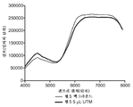
도 27 내지 도 30은 예 1에서 보고되는 바와 같이, 5 μL, 10 μL, 15 μL, 및 20 μL의 샘플들 각각에 대한 메니스커스(meniscus) 검출 결과들의 그래픽 표현을 도시하고, 각각의 도면은 갠트리 위치에 대한 후방산란 강도(임의의 단위)의 제1 백그라운드 스캔 및 제2 스캔을 나타낸다.
도 31은 예 3 및 접근방법 2에서 보고되는 바와 같이, 형광 검출을 사용하는 총 유체 레벨 검출의 그래픽 표현을 나타내고, 각각의 플롯은 갠트리 위치에 대한 백그라운드를 초과하는 형광의 백분율 증가를 나타낸다.1 is a schematic diagram of a sample processing system including a multiple fluorescence detection device, a data acquisition device, and a disk handling system in accordance with an embodiment of the present disclosure;
2 is a schematic diagram showing an exemplary optical detection module that may correspond to any of a plurality of optical modules of the multiple fluorescence detection device of Fig.
3 is a front view of a detection device comprising a set of removable optical modules in a housing, including a removable main optical module and two removable auxiliary optical modules according to one embodiment of the present disclosure;
4 is a side view of the detection device of Fig.
5 is a perspective view of the detection device of Figs. 3-4, with one optical module removed to expose the module connector; Fig.
Figure 6 is a perspective view of the internal components of an exemplary removable main optical module of the detection device of Figures 3-5.
Figure 7 is a perspective view of the internal components of an exemplary removable auxiliary optical module of the detection device of Figures 3-5.
8 is a side view of the detection apparatus and gantry system of Figs. 3-5, wherein the laser valve control system is disposed above the slot of the disc.
Fig. 9 is a schematic block diagram showing an embodiment of the multiple fluorescence detection apparatus in more detail.
10 is a block diagram of a single detector coupled to four optical fibers in an optical fiber bundle.
11 is a flowchart showing an exemplary operation of the multiple fluorescence detection apparatus.
12 is a flowchart showing an exemplary operation of the laser valve control system of the detection apparatus.
13A is an exemplary view of a slot of a disc.
13B is a timing diagram illustrating an exemplary method for detecting the inner and outer edges of a slot of a disc.
13C is a timing diagram illustrating an exemplary method for determining the home position of the laser valve control system.
14 is a flow chart illustrating an exemplary determination of the home position of the laser valve control system.
15 is a flow chart illustrating an exemplary method for detecting light from a disc and sampling data.
16 is a planar perspective view of a sample processing apparatus according to an embodiment of the present disclosure;
17 is a bottom perspective view of the sample processing apparatus of Fig.
18 is a plan view of the sample processing apparatus of Figs. 16 to 17. Fig.
FIG. 19 is a bottom view of the sample processing apparatus of FIGS. 16-18. FIG.
Fig. 20 is a close-up top view of a portion of the sample processing apparatus of Figs. 16-19. Fig.
21 is a close-up bottom view of a portion of the sample processing apparatus shown in Fig.
22 is a side cross-sectional view of the sample processing apparatus of Figs. 16-21 taken along line 22-22 of Fig.
23 is a bottom view of the sample processing apparatus according to another embodiment of the present disclosure;
24 is an exploded perspective view of a disc handling system according to an embodiment of the present invention.
25 is a schematic graphical representation of one embodiment of a method for comparing two scans of a detection chamber to determine if a sample is present in the detection chamber.
26 is a flowchart showing one exemplary method of processing a sample in the sample processing apparatus and determining whether the sample exists in the detection chamber of the sample processing apparatus.
Figures 27 to 30 illustrate graphical representations of meniscus detection results for each of 5 [mu] L, 10 [mu] L, 15 [mu] L, and 20 [mu] L samples, as reported in Example 1, Represents the first background scan and the second scan of the backscattering intensity (in arbitrary units) for the gantry position.
Figure 31 depicts a graphical representation of total fluid level detection using fluorescence detection, as reported in Example 3 and
본 개시의 임의의 실시예들을 상세히 설명하기 전에, 본 발명은 그의 응용에 있어서, 하기의 설명에 명시된 또는 하기의 도면에 도시된 부품들의 구성 및 배치의 상세로 한정되지 않는다는 것을 이해할 것이다. 본 발명은 다른 실시예들이 가능하고 다양한 방법들에 의해 실시될 수 있거나 수행될 수 있다. 또한, 본 명세서에 사용된 어법 및 용어는 설명의 목적을 위한 것이고, 제한적인 것으로서 간주되지 않아야 한다는 것을 이해할 것이다. 본 명세서에서 "포함하는", "포괄하는", 또는 "갖는" 및 그의 변형들의 사용은 그 뒤에 나열되는 항목들과 그의 등가물들뿐만 아니라 추가 항목들을 포괄하는 것을 의미한다. 달리 지정하거나 제한하지 않는 한, 용어 "장착된", "연결된", "지지된", 및 "결합된", 및 그 변형들은 광범위하게 사용되고, 직접 및 간접 양방의 장착, 연결, 지지, 및 결합을 포괄한다. 또한, "연결된"과 "결합된"은 물리적 또는 기계적 연결 또는 결합에 국한되지 않는다. 다른 실시예들이 활용될 수 있으며, 본 개시의 범위를 벗어나지 않고서 구조 또는 로직 변경들이 만들어질 수 있다는 것을 이해할 것이다. 또한, "앞", "뒤", "상", 및 "하" 등의 용어들은 단지 구성요소들이 서로 관련되는 것을 설명하기 위해 사용되지만, 어떠한 방식으로든, 장치의 필수적인 또는 요구되는 배향들을 나타내거나 암시하기 위해, 또는 본 명세서에 기재된 발명이 사용시에 어떻게 사용되고, 장착되고, 표시되고 또는 위치결정될 것인가를 지정하기 위해, 장치의 특정 배향들을 인용하는 것을 의미하지 않는다.Before describing in detail certain embodiments of the present disclosure, it is to be understood that the invention is not limited in its application to the details of construction and the arrangement of parts set forth in the following description or illustrated in the following drawings. The invention is capable of other embodiments and of being practiced or of being carried out in various ways. It is also to be understood that the phraseology and terminology used herein is for the purpose of description and should not be regarded as limiting. The use of "including", "including", or "having" and variations thereof in this specification is meant to encompass the items listed thereafter and equivalents thereof as well as additional items. The terms "attached," " coupled, "" supported," and " coupled, "and variations thereof, are used extensively and include both direct and indirect mounting, . Also, "connected" and "coupled" are not limited to physical or mechanical connections or couplings. It is to be understood that other embodiments may be utilized and that structural or logical changes may be made without departing from the scope of the present disclosure. It is also to be understood that terms such as "front," " back, "" Nor does it imply quoting certain orientations of the device to designate how the invention described herein will be used, mounted, displayed, or positioned in use.
본 개시는 일반적으로 샘플 처리 장치들을 처리하기 위한, 특히, 샘플 처리 장치의 특정 챔버에 물질이 존재하는지를 검출하기 위한 샘플 처리 시스템들, 방법들, 및 장치들에 관한 것이다. 더 구체적으로, 몇몇 실시예들에서는, 본 개시의 시스템들, 방법들, 및 장치들이 물질의 선택된 부피가 특정 챔버에 존재하는지를 검출하기 위해 사용될 수 있다. 어떤 경우들에서, 샘플을 유동적으로 처리하고 조작하기 위해 사용되는 샘플 처리 장치는 다양한 밸빙(valving) 및 계량 구성요소들을 포함할 수 있다. 예를 들어, 샘플은 샘플 처리 장치에 로딩될 수 있고, 다양한 밸브들, 채널들, 챔버들, 및 또는 계량 장치들이, 샘플 처리 장치의 여러 구획들을 통해 샘플을 처리하고 이동시키고 궁극적으로는 샘플의 관심의 분석물의 부재, 존재 및/또는 양을 결정하기 위해 샘플이 분석될 또는 (예를 들면, 광학적으로) 조사될, 처리 또는 검출 챔버에 샘플을 종착시키기 위해 사용될 수 있다. 샘플 처리 장치에서 샘플의 유동적 처리시에 장애가 발생했는지를 확인하기 위해, 샘플이 적절하게 처리 또는 검출 챔버로 수송되었는지를 아는 것이 유용할 수 있다. 결과적으로, 본 개시의 시스템들, 방법들, 및 장치들은 일반적으로 샘플 또는 샘플의 선택된 부피가 검출 챔버에 존재하는지를 판단하는 것에 관한 것이다.This disclosure generally relates to sample processing systems, methods, and apparatus for processing sample processing devices, and more particularly, for detecting whether a material is present in a particular chamber of a sample processing apparatus. More specifically, in some embodiments, systems, methods, and devices of the present disclosure may be used to detect whether a selected volume of material is present in a particular chamber. In some cases, the sample processing apparatus used to fluidly process and manipulate the sample may include various valving and metering components. For example, the sample may be loaded into the sample processing apparatus and various valves, channels, chambers, and / or metering devices may be used to process and move the sample through the various compartments of the sample processing apparatus and, ultimately, (E.g., optically) irradiated, to terminate the sample in the processing or detection chamber to determine the absence, presence and / or amount of the analyte of interest. It may be useful to know whether the sample has been properly transported to a treatment or detection chamber to determine if a failure occurred during the fluid handling of the sample in the sample processing apparatus. As a result, the systems, methods, and apparatus of the present disclosure generally relate to determining whether a selected volume of sample or sample is present in the detection chamber.
본 개시의 어떤 실시예들(예를 들어, 도 16 내지 도 22의 샘플 처리 장치(300)에 대해 하기에 설명됨)에서, 관심의 샘플(예를 들어, 원시 환자 샘플, 원시 환경 샘플 등의 원시 샘플)은 특정 분석을 위한 샘플 처리시에 사용될 다양한 시약 또는 매체와는 분리적으로 로딩될 수 있다. 어떤 실시예들에서, 이러한 시약들은 관심의 분석에 필요한 시약들을 모두 포함하는 하나의 단일 칵테일 또는 "마스터 믹스" 시약으로서 추가될 수 있다. 샘플은 희석제 내에 현탁될 수 있거나 또는 준비될 수 있고, 희석제는 관심의 분석을 위한 시약을 포함할 수 있거나 또는 그와 동일할 수 있다. 본 명세서에서 샘플과 희석제는 단순성을 위해 단순히 "샘플"이라고 일컬어질 것이며, 희석제와 결합된 샘플은 일반적으로, 처리, 측정, 또는 용해 등이 실질적으로 아직 수행되지 않았을 때, 여전히 원시 샘플이라고 간주된다.In some embodiments of the present disclosure (e.g., described below with respect to the
샘플은 고체, 액체, 반고체, 젤라틴 물질, 및 이들의 조합, 예를 들면, 액체 내의 입자들의 현탁액을 포함할 수 있다. 어떤 실시예들에서, 샘플은 수성액일 수 있다.The sample can include solid, liquid, semi-solid, gelatinous materials, and combinations thereof, for example, suspensions of particles in a liquid. In some embodiments, the sample may be an aqueous liquid.
그리고 샘플 처리 장치는, 샘플과 시약들을 샘플 처리 장치를 통해 이동시키고 궁극적으로 필요한 곳에서 필요한 때 샘플과 시약들을 결합하기 위한 수단을 포함할 수 있다. 어떤 실시예들에서, 시약들(예를 들면, 시약 마스터 믹스)은 반응 및 시약들이 작용하는 것을 확인하기 위해 사용될 수 있는 하나 이상의 내부 제어들을 포함할 수 있다. 예를 들어, 다중 검출 시스템의 한 채널은, 다중 검출 시스템의 다른 채널들에서 증폭이 검출되지 않을 때, 내부 제어를 검출하고 시약들이 샘플 처리 장치 내에서 적절하게 수송되었는지, 그리고 적절하게 작용했는지를 확인하기 위해 사용될 수 있다. 즉, 내부 제어는 오판 가능성을 확인하기 위해 사용될 수 있으며, 내부 제어 증폭의 부족은 실행을 무효화할 것이다. 그러나, 원시 샘플에 있어서, 유사한 내부 제어가 없다. 따라서, 샘플이 검출 챔버에 도달하지 못했고 시약 마스터 믹스와 결합된 적이 없는 등, 샘플 조작 및 수송의 실패(예를 들어, 밸빙 또는 계량 장치들에서)가 있다면, 시약 마스터 믹스의 내부 제어가 여전히 증폭할 것이어서, 오판 가능성에 이르게 된다. 본 개시의 샘플 처리 시스템들, 방법들, 및 장치들은 샘플이 검출 챔버로 이동한 것을 확인하고, 그리고/또는 샘플의 선택된 부피가 검출 챔버에 존재하는 것을 확인하기 위해 사용될 수 있다. 이러한 확증이 발견되지 않으면, 이것은 예를 들면, 경고를 개시함으로써, 장애 리포트를 작성함으로써, 실행을 무효화함으로써, 실행을 인터럽트함으로써, 등등 또는 이들의 조합에 의해 나타내어질 수 있다.And the sample processing apparatus may include means for moving the sample and the reagents through the sample processing apparatus and ultimately combining the sample and the reagents as needed at a required point. In some embodiments, the reagents (e.g., the reagent master mix) may include one or more internal controls that can be used to confirm that the reactions and reagents are acting. For example, one channel of the multiple detection system detects internal control when amplification is not detected in the other channels of the multiple detection system and determines whether the reagents were properly transported in the sample processing apparatus and acted properly Can be used to confirm. That is, the internal control can be used to confirm the possibility of misidentification, and the lack of internal control amplification will invalidate the execution. However, for raw samples, there is no similar internal control. Thus, if there is a failure of sample manipulation and transport (e.g., in the valving or metering devices), such as when the sample has not reached the detection chamber and has not been associated with the reagent master mix, then the internal control of the reagent master mix is still amplified It will lead to the possibility of misjudgment. The sample processing systems, methods, and apparatus of the present disclosure may be used to verify that a sample has moved to a detection chamber and / or to verify that a selected volume of sample is present in the detection chamber. If such affirmation is not found, this may be indicated by, for example, initiating a warning, creating a failure report, invalidating execution, interrupting execution, etc., or a combination thereof.
일반적으로, 문구 "원시 샘플"은 단지 희석제에 희석되거나 또는 현탁되는 것 외에, 샘플 처리 장치에 로딩되기 전에 임의의 처리나 조작을 받지 않은 샘플을 일컫기 위해 사용된다. 즉, 원시 샘플은 세포, 잔해물(debris), 억제제 등을 포함할 수 있고, 샘플 처리 장치에 로딩되기 전에 용해, 세척, 또는 버퍼링되지 않을 수 있다. 또한, 원시 샘플은 소스로부터 직접 얻어지고 조작 없이 하나의 컨테이너로부터 다른 컨테이너로 수송되는 샘플을 포함할 수 있다. 또한 원시 샘플은 수송 매체, 뇌척수액, 전혈, 혈청, 혈장 등을 포함하는 다양한 매체 내의 환자의 표본을 포함할 수 있지만, 이것들에 한정되지 않는다. 예를 들어, 환자로부터 얻은 바이러스 입자를 포함하는 비강 면봉 샘플은, 처리 전에 입자들을 현탁 및 안정화하기 위해 사용되는 수송 버퍼 또는 매체(항균제를 포함할 수 있음)에서 수송 및/또는 저장될 수 있다. 현탁 입자들을 갖는 수송 매체의 일부분은 "샘플"로서 간주될 수 있다. 본 개시의 장치들 및 시스템들에 사용되고 본 명세서에서 논의되는 "샘플들" 모두는 원시 샘플들일 수 있다.In general, the phrase "native sample" is used to refer to a sample that has not been subjected to any treatment or manipulation prior to being loaded into the sample processing apparatus, other than being diluted or suspended in the diluent. That is, the original sample may include cells, debris, inhibitors, and the like, and may not be dissolved, washed, or buffered before being loaded into the sample processing apparatus. The raw samples may also include samples taken directly from the source and transported from one container to another without manipulation. The native sample may also include, but is not limited to, a sample of patients in various media, including transport media, cerebrospinal fluid, whole blood, serum, plasma, and the like. For example, a nasal swab sample containing viral particles from a patient may be transported and / or stored in a transport buffer or medium (which may include an antimicrobial agent) used to suspend and stabilize the particles prior to treatment. A portion of the transport medium with suspended particles may be considered as a "sample ". Both "samples" used in the apparatus and systems of the present disclosure and discussed herein may be primitive samples.
도 1 내지 도 15는 일반적으로 본 개시에 따른 광학 검출을 위해 사용되는 구성요소들과 특징들을 포함한, 그러한 샘플 처리 시스템의 특징들, 구성요소들, 기능들, 및 작동 방법들을 포함하여, 샘플 처리 시스템을 도시한다. 이러한 샘플 처리 시스템은 샘플 처리 장치들을 처리하기 위해 사용될 수 있다. 샘플 처리 장치는 일반적으로 소모될 수 있고(예를 들어, 일회용) 관심의 샘플들을 지향시킬 수 있고 조작할 수 있는 다양한 유체들(즉, 미세유체들)을 포함할 수 있다. 샘플 처리 시스템은 샘플 및 샘플 처리 장치의 다양한 특징들을 검출하기 위해 사용될 수 있다.Figures 1-15 generally include features, components, functions, and operating methods of such a sample processing system, including components and features used for optical detection in accordance with the present disclosure, System. Such a sample processing system may be used to process sample processing devices. The sample processing apparatus may include various fluids (i.e., microfluids) that can be consumed and directed (e.g., disposable) to samples of interest. The sample processing system may be used to detect various features of the sample and sample processing apparatus.
도 16 내지 도 23은 본 개시에 따라 사용될 수 있고, 본 개시의 샘플 처리 시스템들에 채택될 수 있는 샘플 처리 장치들(예를 들어, "디스크들")의 예시적인 실시예들을 도시한다.Figures 16-23 illustrate exemplary embodiments of sample processing devices (e.g., "disks") that may be used in accordance with the present disclosure and that may be employed in the sample processing systems of the present disclosure.
도 24는 본 개시의 샘플 처리 시스템의 일부를 형성할 수 있거나, 또는 그와 함께 사용될 수 있는 본 개시의 일 예시의 디스크 핸들링 시스템의 적어도 일부를 도시한다. 특히, 도 24는 예시적인 샘플 처리 장치(즉, 도 16 내지 도 22의 샘플 처리 장치)와, 디스크 핸들링 시스템의 커버 및 베이스 플레이트와의 상호 작용을 도시한다. 즉, 도 24는 "디스크"가 물리적으로(예를 들어, 구조적으로, 기계적으로, 및/또는 열적으로) 본 개시의 샘플 처리 시스템의 다양한 구성요소들과 어떻게 상호작용할 수 있는지를 도시한다.24 illustrates at least a portion of an example disk handling system of this disclosure that may form part of, or be used with, the sample processing system of the present disclosure. In particular, Figure 24 illustrates the interaction of the exemplary sample processing apparatus (i.e., the sample processing apparatus of Figures 16-22) with the cover and base plate of a disk handling system. That is, Figure 24 illustrates how a "disk" can physically (e.g., structurally, mechanically, and / or thermally) interact with various components of the sample processing system of the present disclosure.
본 개시의 샘플 처리 장치들은 본 명세서에서 원형인 것으로서 도시되고 때로는 본 명세서에서 "디스크"라고 일컬어지지만, 본 개시의 샘플 처리 장치들의 다양한 다른 형태들 및 구성들이 가능하고, 본 개시는 원형의 샘플 처리 장치들에 한정되지 않는다는 것을 이해할 것이다. 결과적으로, 용어 "디스크"는 종종 간결성과 단순성을 위해 "샘플 처리 장치" 대신에 본 명세서에서 사용되지만, 이 용어는 제한하기 위한 것이 아니다.Although the sample processing devices of the present disclosure are shown herein as being circular and sometimes referred to herein as a "disk ", various other forms and configurations of the sample processing devices of the present disclosure are possible, It is to be understood that the invention is not limited to these devices. As a result, the term "disk" is often used herein instead of a "sample processing device " for brevity and simplicity, but the term is not intended to be limiting.
샘플 처리 시스템들Sample Processing Systems
본 개시의 샘플 처리 시스템들은, 열처리를 수반하는, 예를 들면, 중합효소 연쇄 반응(PCR) 증폭, 전사-매개 증폭(transcription-mediated amplification: TMA), 핵산 서열 기반 증폭(NASBA), 리가제 연쇄 반응(LCR), 자립-시퀀스 복제, 효소 운동 연구, 균일 리간드 결합 분석, 효소 결합 면역 분석(ELISA) 등의 면역분석, 및 정확한 열적 제어 및/또는 고속 열적 변화를 요구하는 더 복잡한 생화학적 또는 기타 처리들 등의 민감한 화학 처리들을 수반하는 방법들에 사용될 수 있다. 샘플 처리 시스템들은 장치들의 처리 챔버들에서 샘플 물질들의 온도의 제어를 행할 수 있는 것 외에도 샘플 처리 장치의 동시적 회전을 제공할 수 있다.The sample processing systems of the present disclosure can be used in a variety of applications including, for example, PCR amplification, transcription-mediated amplification (TMA), nucleic acid sequence-based amplification (NASBA), ligase sequencing Immunoassays such as reaction (LCR), autonomous-sequence replication, enzyme kinetic studies, homogeneous ligand binding assays, enzyme linked immunoassays (ELISA), and more complex biochemical or other ≪ / RTI > treatments, and the like. The sample processing systems can provide simultaneous rotation of the sample processing device in addition to being able to control the temperature of the sample materials in the processing chambers of the devices.
본 발명과 관련해서 사용하기 위해 채택될 수 있는 적합한 구성 기술들 또는 물질들의 몇 가지 예들은, 예를 들면, 제목이 ENHANCED SAMPLE PROCESSING DEVICES SYSTEMS AND METHODS(향상된 샘플 처리 장치, 시스템, 및 방법)(Bedingham et al.)이고 공동 양도된 미국 특허 번호 제6,734,401호, 제6987253호, 제7435933호, 제7164107호, 및 제7,435,933호; 제목이 MULTI-FORMAT SAMPLE PROCESSING DEVICES(멀티-포맷 샘플 처리 장치)(Bedingham et al.)인 미국 특허 번호 제6,720,187호; 제목이 MULTI-FORMAT SAMPLE PROCESSING DEVICES AND SYSTEMS(멀티-포맷 샘플 처리 장치 및 시스템)(Bedingham et al.)인 미국 특허 공개 제2004/0179974호; 제목이 MODULAR SYSTEMS AND METHODS FOR USING SAMPLE PROCESSING DEVICES(샘플 처리 장치를 사용하는 모듈식 시스템 및 방법)(Bedingham et al.)인 미국 특허 번호 제6,889,468호; 제목이 SYSTEMS FOR USING SAMPLE PROCESSING DEVICES(샘플 처리 장치를 사용하는 시스템)(Bedingham et al.)인 미국 특허 번호 제7,569,186호; 제목이 THERMAL STRUCTURE FOR SAMPLE PROCESSING SYSTEM(샘플 처리 시스템을 위한 열적 구조체)(Bedingham et al.)인 미국 특허 공개 제2009/0263280호; 제목이 VARIABLE VALVE APPARATUS AND METHOD(가변 밸브 장치 및 방법)(Bedingham et al.)인 미국 특허 번호 제7,322,254호, 및 미국 특허 공개 제2010/0167304호; 제목이 SAMPLE MIXING ON A MICROFLUIDIC DEVICE(미세유체 장치에서의 샘플 혼합)(Bedingham et al.)인 미국 특허 번호 제7,837,947호 및 미국 특허 공개 제2011/0027904호; 제목이 METHODS AND DEVICES FOR REMOVAL OF ORGANIC MOLECULES FROM BIOLOGICAL MIXTURES USING ANION EXCHANGE(음이온 교환을 사용하여 생물학적 혼합물로부터 유기 분자의 제거를 위한 방법 및 장치)(Parthasarathy et al.)인 미국 특허 제7,192,560호 및 제7,871,827호와, 미국 특허 공개 제2007/0160504호; 제목이 METHODS FOR NUCLEIC ACID ISOLATION AND KITS USING A MICROFLUIDIC DEVICE AND CONCENTRATION STEP(미세유체 장치 및 농축 단계를 이용하는 키트 및 핵산 분리용 방법)(Parthasarathy et al.)인 미국 특허 공개 제2005/0142663호; 제목이 SAMPLE PROCESSING DEVICE COMPRESSION SYSTEMS AND METHODS(샘플 처리 장치 압축 시스템 및 방법)(Aysta et al.)인 미국 특허 번호 제7,754,474호 및 미국 특허 공개 제2010/0240124호; 제목이 COMPLIANT MICROFLUIDIC SAMPLE PROCESSING DISKS(순응성 미세 유체 샘플 처리 디스크)(Bedingham et al.)인 미국 특허 번호 제7,763,210호 및 미국 특허 공개 제2010/0266456호; 제목이 MODULAR SAMPLE PROCESSING APPARATUS KITS AND MODULES(모듈식 샘플 처리 장치 키트 및 모듈)(Bedingham et al.)인 미국 특허 번호 제7,323,660호 및 제7,767,937호; 제목이 MULTIPLEX FLUORESCENCE DETECTION DEVICE HAVING FIBER BUNDLE COUPLING MULTIPLE OPTICAL MODULES TO A COMMON DETECTOR(여러 개의 광학 모듈을 공통 검출기에 결합하는 섬유 다발을 갖는 다중 형광 검출 장치)(Bedingham et al.)인 미국 특허 번호 제7,709,249호; 제목이 MULTIPLEX FLUORESCENCE DETECTION DEVICE HAVING REMOVABLE OPTICAL MODULES(제거가능한 광학 모듈을 갖는 다중 형광 검출 장치)(Bedingham et al.)인 미국 특허 번호 제7,507,575호; 제목이 VALVE CONTROL SYSTEM FOR A ROTATING MULTIPLEX FLUORESCENCE DETECTION DEVICE(회전 다중 형광 검출 장치의 밸브 제어 시스템)(Bedingham et al.)인 미국 특허 번호 제7,527,763호 및 제7,867,767호; 제목이 HEATING ELEMENT FOR A ROTATING MULTIPLEX FLUORESCENCE DETECTION DEVICE(Bedingham et al.)인 미국 특허 공개 제2007/0009382호; 제목이 METHODS FOR NUCLEIC AMPLIFICATION(핵산 증폭 방법)(Parthasarathy et al.)인 미국 특허 공개 제2010/0129878호; 제목이 THERMAL TRANSFER METHODS AND STRUCTURES FOR MICROFLUIDIC SYSTEMS(미세유체 시스템의 열 전달 방법 및 구조)(Bedingham et al.)인 미국 특허 공개 제2008/0149190호; 제목이 ENHANCED SAMPLE PROCESSING DEVICES, SYSTEMS AND METHODS(강화된 샘플 처리 장치, 시스템, 및 방법)(Bedingham et al.)인 미국 특허 공개 제2008/0152546호; 제목이 ANNULAR COMPRESSION SYSTEMS AND METHODS FOR SAMPLE PROCESSING DEVICES(샘플 처리 장치를 위한 환형 압축 시스템 및 방법)(Bedingham et al.)인 미국 특허 출원 공개 제2011/0117607호; 제목이 SYSTEMS AND METHODS FOR PROCESSING SAMPLE PROCESSING DEVICES(샘플 처리 장치를 처리하기 위한 시스템 및 방법)(Robole et al.)인 미국 특허 출원 공개 제2011/0117656호; 제목이 SAMPLE PROCESSING DEVICES, SYSTEMS AND METHODS(샘플 처리 장치, 시스템, 및 방법)(Bedingham et al.)이고 2000년 10월 2일자로 출원된 미국 특허 가출원 일련 번호 제60/237,151호; 제목이 SAMPLE PROCESSING DISC COVER(샘플 처리 디스크 커버)(Bedingham et al.)인 미국 특허 번호 제D638550호 및 제D638951호; 제목이 SAMPLE PROCESSING DISC COVER(샘플 처리 디스크 커버)(Bedingham et al.)이고 2011년 2월 4일자로 출원된 미국 특허 출원 번호 제29/384,821호; 제목이 ROTATABLE SAMPLE PROCESSING DISK(회전가능 샘플 처리 디스크)(Bedingham et al.)인 미국 특허 번호 제D564667호에 기재되어 있을 수 있다. 이 개시들의 전체 내용은 본 명세서에 참조되어 포괄된다.Some examples of suitable construction techniques or materials that may be employed for use in connection with the present invention are described in, for example, Bedingham, ENHANCED SAMPLE PROCESSING DEVICES SYSTEMS AND METHODS et al., commonly assigned U.S. Patent Nos. 6,734,401, 6987253, 7435933, 7164107, and 7,435,933; U.S. Patent No. 6,720,187, titled MULTI-FORMAT SAMPLE PROCESSING DEVICES (Bedingham et al.); U.S. Patent Publication No. 2004/0179974 entitled MULTI-FORMAT SAMPLE PROCESSING DEVICES AND SYSTEMS (Bedingham et al.); U.S. Patent No. 6,889,468 entitled MODULAR SYSTEMS AND METHODS FOR USING SAMPLE PROCESSING DEVICES (Modular System and Method Using a Sample Processing Device) (Bedingham et al.); U.S. Patent No. 7,569,186, titled SYSTEMS FOR USING SAMPLE PROCESSING DEVICES (Bedingham et al.); U.S. Patent Publication No. 2009/0263280 entitled THERMAL STRUCTURE FOR SAMPLE PROCESSING SYSTEM (Bedingham et al.); U.S. Patent No. 7,322,254, entitled VARIABLE VALVE APPARATUS AND METHOD, (Bedingham et al.), And U.S. Patent Publication No. 2010/0167304; U.S. Patent No. 7,837,947 and U.S. Patent Publication No. 2011/0027904, entitled SAMPLE MIXING ON A MICROFLUID DEVICE (Sample Mixing in Microfluidic Devices) (Bedingham et al.); U.S. Patent Nos. 7,192,560 and 7,871,827 to Parthasarathy et al. Entitled METHODS AND DEVICES FOR REMOVAL OF ORGANIC MOLECULES FROM BIOLOGICAL MIXTURES USING ANION EXCHANGE (Method and Apparatus for Removal of Organic Molecules from Biological Mixtures Using Anion Exchange) U.S. Patent Publication No. 2007/0160504; U.S. Patent Application Publication No. 2005/0142663 entitled METHODS FOR NUCLEIC ACID ISOLATION AND KITS USING A MICROFLUIDIC DEVICE AND CONCENTRATION STEP (a kit for microfluidic device and concentration steps and method for nucleic acid isolation) (Parthasarathy et al.); U.S. Patent No. 7,754,474 and U.S. Patent Publication No. 2010/0240124, entitled SAMPLE PROCESSING DEVICE COMPRESSION SYSTEMS AND METHODS (Aysta et al. U.S. Patent No. 7,763,210 and U.S. Patent Publication No. 2010/0266456, entitled COMPLIANT MICROFLUIDIC SAMPLE PROCESSING DISKS (Bedingham et al.); U.S. Patent Nos. 7,323,660 and 7,767,937, which are entitled MODULAR SAMPLE PROCESSING APPARATUS KITS AND MODULES (Bedingham et al.); Title: MULTIPLEX FLUORESCENCE DETECTION DEVICE HAVING FIBER BUNDLE COUPLING MULTIPLE OPTICAL MODULES TO A COMMON DETECTOR (US Pat. No. 7,709,249 to Bedingham et al.), Which is a multi-fluorescence detection device with fiber bundles that couple multiple optical modules to a common detector ; U.S. Patent No. 7,507,575, entitled MULTIPLEX FLUORESCENCE DETECTION DEVICE HAVING REMOVABLE OPTICAL MODULES (Multiple Fluorescence Detection Device with Removable Optical Module) (Bedingham et al.); U.S. Patent Nos. 7,527,763 and 7,867,767, entitled VALVE CONTROL SYSTEM FOR A ROTATING MULTIPLEX FLUORESCENCE DETECTION DEVICE, (Bedingham et al.); U.S. Patent Publication No. 2007/0009382 entitled HEATING ELEMENT FOR A ROTATING MULTIPLEX FLUORESCENCE DETECTION DEVICE (Bedingham et al.); U.S. Patent Publication No. 2010/0129878 entitled METHODS FOR NUCLEIC AMPLIFICATION (Parthasarathy et al.); U.S. Patent Publication No. 2008/0149190 to Bedingham et al., Entitled THERMAL TRANSFER METHODS AND STRUCTURES FOR MICROFLUIDIC SYSTEMS (Heat Transfer Method and Structure of Microfluidic Systems); U.S. Patent Publication No. 2008/0152546 entitled ENHANCED SAMPLE PROCESSING DEVICES, SYSTEMS AND METHODS (Enhanced Sample Processing Device, System, and Method) (Bedingham et al.); U.S. Patent Application Publication No. 2011/0117607, entitled ANNULAR COMPRESSION SYSTEMS AND METHODS FOR SAMPLE PROCESSING DEVICES (Bedingham et al.), Annular Compression System and Method for Sample Processing Device; U.S. Patent Application Publication No. 2011/0117656 entitled SYSTEMS AND METHODS FOR PROCESSING SAMPLE PROCESSING DEVICES (Robole et al.); U.S. Provisional Patent Application Serial No. 60 / 237,151, filed October 2, 2000, entitled SAMPLE PROCESSING DEVICES, SYSTEMS AND METHODS (Sample Processing Device, System and Method) (Bedingham et al. U.S. Patent Nos. D638550 and D638951, titled SAMPLE PROCESSING DISC COVER (Bedingham et al.); U.S. Patent Application No. 29 / 384,821, titled SAMPLE PROCESSING DISC COVER (Bedingham et al.), Filed February 4, 2011; The title can be found in U.S. Patent No. D564667, which is Rotatable Sample Processing Disk (Bedingham et al.). The entire contents of which are incorporated herein by reference.
다른 잠재적인 장치 구성들은 예를 들면, 제목이 CENTRIFUGAL FILLING OF SAMPLE PROCESSING DEVICES(샘플 처리 장치의 원심 충전)(Bedingham et al.)인 미국 특허 번호 제6,627,159호; 제목이 SAMPLE PROCESSING DEVICES(샘플 처리 장치)(Bedingham et al.)인 미국 특허 번호 제7,026,168호, 제7,855,083호, 및 제7,678,334호, 미국 특허 공개 번호 제2006/0228811호 및 제2011/0053785호; 제목이 SAMPLE PROCESSING DEVICES AND CARRIERS(샘플 처리 장치 및 캐리어)(Harms et al.)인 미국 특허 번호 제6,814,935호 및 제7,445,752호; 제목이 SAMPLE PROCESSING DEVICES AND CARRIERS(샘플 처리 장치 및 캐리어)(Bedingham et al.)인 미국 특허 번호 제7,595,200호에서 찾아볼 수 있다. 이 개시들의 전체 내용은 본 명세서에 참조되어 포괄된다.Other potential device configurations are described, for example, in U.S. Patent Nos. 6,627,159 entitled CENTRIFUGAL FILLING OF SAMPLE PROCESSING DEVICES (Bedingham et al.); U.S. Patent Nos. 7,026,168, 7,855,083, and 7,678,334, U.S. Patent Publications Nos. 2006/0228811 and 2011/0053785, entitled SAMPLE PROCESSING DEVICES (Bedingham et al.); U.S. Patent Nos. 6,814,935 and 7,445,752 entitled SAMPLE PROCESSING DEVICES AND CARRIERS (Harms et al.); Titled " SAMPLE PROCESSING DEVICES AND CARRIERS " (Bedingham et al.), U.S. Patent No. 7,595,200. The entire contents of which are incorporated herein by reference.
이제 다중 형광 검출이 가능한 샘플 처리 시스템에 대해 그러한 시스템의 다양한 특징, 구성요소, 및 동작을 포함하여 설명한다.The various features, components, and operation of such a system are now described for a sample processing system capable of multiple fluorescence detection.
도 1은 샘플 처리 시스템(12)의 일부로서 채택될 수 있는 다중 형광 검출 장치(10), 데이터 수집 장치(21), 및 디스크 핸들링 시스템(500)의 예시적인 실시예를 도시하는 개략도이다. 하기에서는 도 24를 참조하여 디스크 핸들링 시스템(500)에 대해 더 상세히 설명한다. 검출 장치(10)는 샘플 또는 샘플의 선택된 부피가 샘플 처리 장치(예를 들어, 회전 디스크(13))의 검출 챔버에 존재하는지를 포함한, 샘플의 다양한 특성을 검출하기 위해 사용될 수 있다. 어떤 실시예들에서, 샘플 처리 장치는 소모적이고 교체가능할 수 있으며, 반드시 샘플 처리 시스템(12)의 일부를 형성하는 것으로 간주되는 것은 아닐 수 있고, 오히려 샘플 처리 시스템(12)과 함께 사용될 수 있거나, 또는 그에 의해 처리될 수 있다.1 is a schematic diagram illustrating an exemplary embodiment of a multiple
도시된 예에서, 장치(10)는 네 개의 다른 염료의 광학적 검출을 위한 네 개의 "채널"을 제공하는 네 개의 광학 모듈(16)을 갖는다. 특히, 장치(10)는 임의의 주어진 시간에 회전 디스크(13)의 다른 영역들을 여기시키고 염료들로부터 방출된 다른 파장들의 형광 광 에너지를 수집하는 네 개의 광학 모듈(16)을 갖는다. 그 결과, 모듈(16)은 샘플(22) 내에서 발생하는 여러 병렬 반응들을 조사하며 그리고/또는 샘플(22) 또는 선택된 부피의 샘플(22)이 디스크(13)의 원하는 영역에(예를 들어, 특정 챔버 내에) 배치되어 있는지를 판단하기 위해 사용될 수 있다.In the illustrated example, the
여러 반응들이, 예를 들어, 회전 디스크(13)의 단일 챔버 내에서 동시에 발생할 수 있다. 광학 모듈들(16) 각각은 샘플(22)을 조사하고, 디스크(13)가 회전함에 따라 다른 파장들의 형광 광 에너지를 수집한다. 예를 들어, 모듈들(16) 내의 여기 소스들은 순차적으로 해당 파장들에서의 데이터를 수집하기 위한 기간들 동안 활성화될 수 있다. 즉, 제1 광학 모듈(16)은 제1 반응에 대응하는 제1 염료에 대해 선택된 파장의 제1 범위에서의 데이터를 수집하기에 충분한 기간 동안 활성화될 수 있다. 그리고 여기 소스는 비활성화될 수 있으며, 제2 광학 모듈(16) 내의 여기 소스가 제2 반응에 대응하는 제2 염료에 대해 선택된 파장의 제2 범위에서 샘플(22)을 조사하기 위해 활성화될 수 있다. 이 처리는 모든 광학 모듈들(16)로부터 데이터가 캡처될 때까지 계속될 수 있다. 일 실시예에서, 광학 모듈들(16) 내의 여기 소스들 각각이 약 0.5초의 초기 기간 동안 활성화되어 정상 상태(steady state)에 도달한 후에 디스크(13)의 10 내지 50 회전 동안 지속되는 조사 기간이 후속된다. 다른 실시예들에서, 여기 소스들은 더 짧은(예를 들어, 1 또는 2 밀리초) 기간 또는 더 긴 기간에 대해 시퀀싱될 수 있다. 어떤 실시예들에서, 한 개 초과의 광학 모듈이 디스크(13)의 회전을 중단하지 않고 샘플(22)의 동시 조사를 위해 동시에 활성화될 수 있다.Several reactions can occur simultaneously, for example, in a single chamber of the
단일 샘플(22)이 도시되지만, 디스크(13)는 샘플들을 보유하는 복수의 챔버를 포함할 수 있다. 광학 모듈들(16)은 서로 다른 파장들에서 서로 다른 챔버들의 일부 또는 전부를 조사할 수 있다. 일 실시예에서, 디스크(13)는 디스크(13)의 원주 주위에 96개의 챔버 공간을 포함한다. 96개의 챔버 디스크와 네 개의 광학 모듈(16)에 의해, 장치(10)는 384 개의 다른 종류의 데이터를 수집할 수 있다.Although a
일 실시예에서, 광학 모듈(16)은 다양한 파장들에서 상용화되어 있고 긴 수명(예를 들어, 100,000 시간 이상)을 갖는 저렴한 고출력 발광 다이오드들(LEDs)인 여기 소스들을 포함한다. 다른 실시예에서는, 통상의 할로겐 전구 또는 수은 램프가 여기 소스로서 사용될 수 있다.In one embodiment, the
도 1에 도시된 바와 같이, 광학 모듈들(16) 각각은 광섬유 다발(14) 중 한 개의 다리에 결합될 수 있다. 광섬유 다발(14)은 감도의 손실 없이 광학 모듈들(16)로부터 형광 신호들을 수집하기 위한 유연한 메커니즘을 제공한다. 일반적으로, 광섬유 다발은 나란히 배치되고 끝단들에서 함께 결합되고 유연한 보호 재킷 내에 감싸진 여러 광 섬유들을 포함한다. 대안적으로, 광섬유 다발(14)은 공통 끝단을 갖는 소수의 개별적이고 큰 직경의, 유리 또는 플라스틱 중 어느 것인, 다중 모드 섬유를 포함할 수 있다. 예를 들어, 네 개의 광학 모듈 장치에 대해, 광섬유 다발(16)은 네 개의 개별적인 다중 모드 섬유를 포함할 수 있고, 그 각각은 1 mm 코어 직경을 갖는다. 다발의 공통 끝단은 함께 묶여진 네 개의 섬유를 포함한다. 이 예에서, 검출기(18)의 어퍼처는 8 mm일 수 있는데, 이것은 네 개의 섬유에 결합하기에 충분하고도 남는다.As shown in FIG. 1, each of the
이 예에서, 광섬유 다발(14)은 광학 모듈들(16)을 하나의 검출기(18)에 결합한다. 광 섬유들은 광학 모듈들(16)에 의해 수집된 형광 광을 전송하고 캡처된 광을 효과적으로 검출기(18)에 전달한다. 일 실시예에서, 검출기(18)는 광전자증배관(photomultiplier tube)이다. 다른 실시예에서, 검출기는 단일 검출기 내에서 각각의 광 섬유에 대해 한 개씩의, 여러 광전자증배 소자들을 포함할 수 있다. 다른 실시예들에서, 하나 이상의 고체 검출기가 사용될 수 있다.In this example, the
단일 검출기(18)의 사용은, 단일 검출기만 사용될 필요가 있다는 점에서 최소 비용을 유지하면서, 고감도이고 아마도 고가인 검출기(예를 들면, 광전자증배기)의 사용을 허용한다는 점에서 유리할 수 있다. 단일 검출기가 본 명세서에서 논의되지만, 더 많은 수의 염료를 검출하기 위해 하나 이상의 검출기가 포함될 수 있다. 예를 들어, 하나의 디스크로부터 방출된 8 개의 다른 파장의 검출을 허용하기 위해, 네 개의 추가 광학 모듈(16)과 제2 검출기가 시스템에 추가될 수 있다. 회전 디스크(13)와 함께 이용하기 위한 단일 검출기에 결합되는 예시적인 광섬유 다발은, 2005년 7월 5일자로 출원되고, 제목이 MULTIPLEX FLUORESCENCE DETECTION DEVICE HAVING FIBER BUNDLE COUPLING MULTIPLE OPTICAL MODULES TO A COMMON DETECTOR(여러 광학 모듈들을 공통 검출기에 결합하는 섬유 다발을 갖는 다중 형광 검출 장치)인 미국 특허 번호 제7,709,249호에 설명되어 있고, 그 전체 내용이 본 명세서에 참조되어 포괄된다.The use of a
광학 모듈들(16)은 장치로부터 제거가능할 수 있고, 다른 파장들에서의 조사를 위해 최적화된 다른 광학 모듈들과 용이하게 교체될 수 있다. 예를 들어, 광학 모듈들(16)은 모듈 하우징의 위치들 내에 물리적으로 장착될 수 있다. 광학 모듈들(16) 각각은 광학 모듈의 하나 이상 마킹(예를 들어, 가이드 핀들)과 짝을 이루는 가이드들(예를 들어, 오목한 홈들)을 따라 하우징의 각각의 위치 내에 용이하게 삽입될 수 있다. 광학 모듈들(16) 각각은 래치, 자석, 나사, 또는 다른 고정 장치에 의해 캐리지 내에 고정될 수 있다. 각각의 광학 모듈은 광섬유 다발(14)의 하나의 다리에 결합하기 위한 광학 출력 포트(도 6 및 도 7에 도시됨)를 포함한다. 광학 출력 포트는 그 다리의 나사 커넥터에 결합된 나사 단부를 가질 수 있다. 대안적으로, 광섬유 다발(14)이 광학 출력 포트에 슬라이딩 가능하게 결합되고 그로부터 결합해제되는 것을 허용하는 "고속 연결"의 형태가 사용될 수 있다(예를 들어, O-링 및 캐치 핀을 갖는 슬라이딩 가능한 연결). 또한, 광학 모듈들(16) 각각은 완전히 삽입될 때 제어 유닛(23)에 전기적으로 결합하기 위한 하나 이상의 전기 컨택트 패드 또는 플렉스 회로를 가질 수 있다. 회전 디스크(13)와 함께 사용하기 위한 예시적인 제거가능한 광학 모듈들은 2005년 7월 5일자로 출원되고 제목이 "MULTIPLEX FLUORESCENCE DETECTION DEVICE HAVING REMOVABLE OPTICAL MODULES(제거가능한 광학 모듈을 갖는 다중 형광 검출 장치)"인 미국 특허 번호 제7,507,575호에 설명되어 있고, 그 전체 내용이 본 명세서에 참조되어 포괄된다.
장치(10)의 모듈식 구조는 장치가 다중 PCR 등의 소정의 분석 환경에서 사용되는 형광 염료들 모두에 대해 용이하게 적응되도록 허용한다. 장치(10)에 사용될 수 있는 다른 화학 수단들은, 인베이더(Invader)(써드 웨이브(Third Wave), 위스콘신주, 메디슨), 트랜스크립티드-미디에이티드 앰플리케이션(Transcripted-mediated Amplification)(젠프로브(GenProbe), 캘리포니아주, 샌 디에고), 형광 레이블식 효소 결합 면역 분석법(ELISA), 및/또는 형광 인 시추 혼성(fluorescence in situ hybridization: FISH)을 포함한다. 장치(10)의 모듈식 구조는, 다중 반응에서 대응하는 염료를 선택적으로 여기시키고 검출하기 위해, 파장의 작은 특정 타겟 범위에 대한 대응하는 여기 소스(도시되지 않음)와 여기 및 검출 필터들의 선택에 의해 각각의 광학 모듈(16)의 감도가 최적화될 수 있다는 점에서 또 다른 이점을 제공할 수 있다.The modular architecture of the
예시를 위해, 장치(10)는 4-색 다중 배열로 설명되지만, 더 많거나 더 적은 채널이 적절한 광섬유 다발(14)과 함께 사용될 수 있다. 이 모듈식 설계는, 사용자가, 간단히 다른 광학 모듈(16)을 장치(10)에 추가하고 새 광학 모듈에 광섬유 다발(14) 중 한 개의 다리를 삽입함으로써, 현장에서 장치(10)를 용이하게 업그레이드하는 것을 허용한다. 광학 모듈들(16)은, 내부 제어 모듈 또는 장치(10)의 다른 내부 전자회로(예를 들어, 제어 유닛(23))에 캘리브레이션 데이터를 다운로드하고 광학 모듈들을 식별하는 일체화된 전자회로들을 가질 수 있다.For purposes of illustration,
도 1의 예에서, 샘플들(22)은 제어 장치(23)의 제어 하에 회전 플랫폼에 장착된 디스크(13)의 챔버들에 담겨진다(회전 플랫폼의 일 실시예가 단지 예시적으로 도 24에 도시된다). 슬롯 센서 트리거(27)는 디스크 회전 동안 챔버 위치와 데이터 수집 장치(21)를 동기화하기 위해 제어 유닛(23)에 의해 활용되는 출력 신호를 제공한다. 슬롯 센서 트리거(27)는 기계적, 전기적, 자기적, 또는 광학적 센서일 수 있다. 예를 들어, 하기에서 더 상세히 설명되는 바와 같이, 슬롯 센서 트리거(27)는 디스크의 각 회전마다 검출되는 디스크(13)를 관통하여 형성된 슬롯을 통한 광 빔을 방출하는 광원을 포함할 수 있다. 다른 예로서, 슬롯 센서 트리거는 디스크(13)의 회전과 모듈(16) 및 검출기(18)에 의한 데이터 수집을 동기화할 목적으로 반사 광을 감지할 수 있다. 다른 실시예들에서, 디스크(13)는 슬롯 외에도 또는 슬롯 대신에 탭, 돌출부, 또는 반사 표면을 포함할 수 있다. 슬롯 센서 트리거(27)는 디스크가 회전할 때 디스크(13)의 반경방향 위치를 찾기 위한 임의의 물리적 구조 또는 메커니즘을 사용할 수 있다. 어느 때나 광학 모듈들(16)이 다른 챔버들과 중첩되도록, 광학 모듈들(16)은 회전 플랫폼(25) 상방에 물리적으로 장착될 수 있다.In the example of Figure 1, the
검출 장치(10)는 또한 디스크(13) 상의 샘플(22)의 온도를 조절하기 위한 가열 소자(도 1에는 도시되지 않지만 도 24에는 예시적인 가열 소자가 도시되고 하기에서 설명됨)를 포함할 수 있다. 가열 소자는 반사성 인클로저 내에 포함된 원통형의 할로겐 전구를 포함할 수 있다. 반사성 챔버는 전구로부터의 방사광을 디스크(13)의 반경 섹션 상에 포커스하도록 성형된다. 일반적으로, 디스크(13)의 가열되는 영역은 디스크(13)가 회전함에 따라 환형 링을 포함할 수 있다. 이 실시예에서, 반사성 인클로저의 형상은 정확한 포커싱을 허용하는 타원형과 구형 기하 구조들의 조합일 수 있다. 다른 실시예들에서, 반사성 인클로저는 다른 형상일 수 있거나 또는 전구는 광범위하게 더 넓은 영역을 조사할 수 있다. 다른 실시예들에서, 반사성 인클로저는 샘플(22)을 담고 있는 단일 처리 챔버 등, 디스크(13)의 단일 영역 상에 전구로부터의 방사광을 포커스하도록 성형될 수 있다.The
어떤 실시예들에서, 가열 소자는 온도를 조절하기 위해 공기를 가열할 수 있고 하나 이상의 샘플 상방에 뜨거운 공기를 강제시킬 수 있다. 또한, 샘플들은 디스크에 의해 직접 가열될 수 있다. 이 경우, 가열 소자는 플랫폼(25)에 배치될 수 있으며, 디스크(13)에 열적으로 결합될 수 있다. 가열 소자 내의 전기 저항은 제어 유닛(23)에 의해 제어될 때 디스크의 선택된 영역을 가열할 수 있다. 예를 들어, 영역은 하나 이상의 챔버, 아마도 전체 디스크를 포함할 수 있다. 회전 디스크(13)와 함께 사용하기 위한 예시적인 가열 소자는 2005년 7월 5일자로 출원되고 제목이 "HEATING ELEMENT FOR A ROTATING MULTIPLEX FLUORESCENCE DETECTION DEVICE(회전 다중 형광 검출 장치를 위한 가열 소자)"인 미국 특허 출원 공개 제2007/0009382호에 기재되어 있고, 그 전체 내용이 본 명세서에 참조되어 포괄된다.In some embodiments, the heating element can heat the air to regulate the temperature and force the hot air above one or more samples. In addition, the samples can be heated directly by the disc. In this case, the heating element may be arranged in the
대안적으로, 또는 추가적으로, 장치(10)는 냉각 부품(도시되지 않음)을 포함할 수 있다. 디스크(13)에 차가운 공기, 즉, 실온의 공기를 공급하기 위해 장치(10)에 팬이 포함될 수 있다. 냉각은 샘플의 온도를 적절하게 조절하기 위해 그리고 실험이 완료된 후 샘플들을 저장하기 위해 필요할 수 있다. 다른 실시예들에서, 냉각 부품은, 필요할 때 플랫폼(25)이 그의 온도를 줄일 수 있으므로, 플랫폼(25)과 디스크(13) 사이의 열 결합을 포함할 수 있다. 예를 들어, 어떤 생물학적 샘플들은 효소 활성 또는 단백질 변성을 줄이기 위해 4 ℃에 저장될 수 있다.Alternatively or additionally, the
검출 장치(10)는 또한 처리 챔버 내에 포함된 반응 종들을 제어가능할 수 있다. 예를 들어, 하나의 반응을 생성하고 제1 반응이 종료된 후 나중에 샘플에 다른 종류들을 추가하기 위해 처리 챔버에 몇몇 종들을 로딩하는 것이 도움이 될 수 있다. 밸브 제어 시스템이 처리 챔버로부터 내부 보유 챔버를 분리하는 밸브를 제어하기 위해 활용될 수 있음으로써, 디스크(13)의 회전 동안 챔버에의 종류들의 추가를 제어한다. 밸브 제어 시스템은 광학 모듈들(16) 중 하나 내에 배치될 수 있거나 또는 그에 장착될 수 있거나, 또는 광학 모듈들(16)로부터 분리될 수 있다. 레이저 바로 아래에, 디스크(13) 하부에, 레이저를 디스크(13)에 상대적으로 위치결정하기 위한 레이저 센서가 있을 수 있다.The
일 실시예에서, 밸브 제어 시스템은 센서와 함께 조합되어 두 개 이상의 전력 레벨에서 구동될 수 있는 근적외선(NIR) 레이저를 포함한다. 낮은 전원 설정 하에서, 레이저는, 예를 들면, 디스크(13)의 슬롯을 통해 레이저에 의해 방출되는 NIR 광을 감지하는 센서에 의해, 디스크(13)를 위치결정하고 선택 밸브들을 타겟팅하기 위해 사용될 수 있다. 일단 타겟팅된 밸브가 제 위치로 회전되면, 제어 유닛(23)은 밸브를 가열하여 타겟 밸브를 개방하기 위해 높은 전력 에너지의 짧은 버스트를 출력하도록 레이저에 지시할 수 있다. 에너지의 버스트는, 예를 들면, 피어싱, 융해, 또는 삭마(ablating)에 의해, 밸브 내에 보이드(void)를 형성하여, 밸브를 개방시켜 내부 보유 챔버로부터 채널을 통해 외부 처리 챔버에 유체가 흐르도록 허용한다. 어떤 실시예들에서, 디스크(13)는 복수의 반응들을 순차적으로 생성하기 위해 다양한 크기와 재질의 복수의 밸브를 포함할 수 있다. 여러 챔버 밸브들을 갖는 디스크를 활용할 때 밸브 제어 시스템들의 하나 초과의 세트가 사용될 수 있다.In one embodiment, the valve control system includes near infrared (NIR) lasers that can be combined with sensors to drive at more than two power levels. Under a low power setting, the laser can be used to position the
데이터 수집 장치(21)는 각각의 염료에 대해 장치(10)로부터 데이터를 순차적으로 또는 병렬적으로 수집할 수 있다. 일 실시예에서, 데이터 수집 시스템(21)은 광학 모듈들(16)로부터 데이터를 순차적으로 수집하고, 슬롯 센서 트리거(27)로부터 수신된 출력 신호로부터 측정된 광학 모듈들(16) 각각에 대해 트리거 지연에 의해 공간적 중첩을 보정한다.The
장치(10)의 하나의 응용은 실시간 PCR이지만, 본 명세서에서 설명되는 기술들은 여러 파장들에서 형광 검출을 활용하는 다른 플랫폼들로 확장될 수 있다. 장치(10)는 가열 소자를 활용하여 빠른 열 사이클링과, 원심 분리를 위해 구동된 미세 유체, 증폭, 및 핵산 검출을 결합할 수 있다. 다중 형광 검출을 이용함으로써, 여러 타겟 종들이 병렬적으로 발견될 수 있으며, 분석될 수 있다.One application of the
실시간 PCR의 경우, 형광은 세 가지 일반적인 방법 중 하나에 의해 증폭의 양을 측정하기 위해 사용된다. 첫 번째 기술은 이중가닥 DNA에 바인딩될 때 형광이 증가하는 사이브르 그린(Sybr Green)(몰리큘러 프로브(Molecular Probes), 오레건주, 유진) 등의 염료를 사용하는 것이다. 두 번째 기술은 증폭된 타겟 시퀀스에 바인딩될 때 형광이 변화하는 형광 레이블식 프로브들(혼성 프로브(hybridization probes), 헤어핀 프로브(hairpin probes) 등)을 사용하는 것이다. 이 기술은 이중가닥 DNA 바인딩 염료를 사용하는 것과 비슷하지만, 프로브가 타겟 시퀀스의 특정 섹션에만 결합할 것이기 때문에, 더 구체적이다. 세 번째 기술은 중합 효소의 엑소뉴클레아제 활성도가, PCR의 연장 페이즈 동안 프로브로부터의 형광억제(quencher) 분자를 쪼개어, 그것을 형광적으로 활성화시키는, 가수분해 프로브들(태크맨(Taqman)TM, 어플라이드 바이오시스템즈(Applied BioSystems), 캘리포니아주, 포스터 시티)을 이용하는 것이다.For real-time PCR, fluorescence is used to measure the amount of amplification by one of three common methods. The first technique uses dyes such as Sybr Green (Molecular Probes, Oregon, Eugene), which fluoresce when bound to double stranded DNA. The second technique is to use fluorescence-labeled probes (hybridization probes, hairpin probes, etc.) that change fluorescence when bound to the amplified target sequence. This technique is similar to using double-stranded DNA-binding dyes, but is more specific because the probe will bind only to a specific section of the target sequence. A third technique is the use of hydrolytic probes (Taqman TM, which cleaves fluorescence quencher molecules from the probe and activates it fluorescently during the extension phase of the PCR, Applied BioSystems, Foster City, Calif.).
접근 방법들 각각에 있어서, 형광은 증폭된 타겟 농도에 선형적으로 비례한다. 데이터 수집 시스템(21)은 거의 실시간으로 증폭을 관찰하기 위해 PCR 반응 동안 검출기(18)로부터의 출력 신호(또는 대안적으로는, 제어 장치(23)에 의해 선택적으로 샘플링되고 통신됨)를 측정한다. 다중 PCR에 있어서, 여러 타겟들은 독립적으로 측정되는 상이한 염료들에 의해 레이블된다. 일반적으로 말해서, 각각의 염료는 상이한 흡수 및 방출 스펙트럼을 가질 것이다. 이러한 이유 때문에, 광학 모듈들(16)은 상이한 파장들에서 샘플(22)의 조사를 위해 옵션적으로 선택된 여기 소스들, 렌즈들, 및 관련 필터들을 가질 수 있다.For each of the approaches, the fluorescence is linearly proportional to the amplified target concentration. The
도 2는 도 1의 광학 모듈들(16) 중 임의의 것에 해당할 수 있는 예시적인 광학 모듈(16A)을 도시하는 개략도이다. 이 예에서, 광학 모듈(16A)은 고전력 여기 소스, LED(30), 콜리메이팅 렌즈(collimating lens)(32), 여기 필터(34), 다이크로익 필터(dichroic filter)(36), 포커싱 렌즈(38), 검출 필터(40), 및 렌즈(42)를 포함하여 형광을 광섬유 다발(14) 중 하나의 다리에 포커싱한다.2 is a schematic diagram illustrating an exemplary
따라서, LED(30)로부터의 여기 광은 콜리메이팅 렌즈(32)에 의해 콜리메이팅되고, 여기 필터(34)에 의해 필터링되고, 다이크로익 필터(36)를 통해 전송되어, 포커싱 렌즈(38)에 의해 샘플(22)에 포커싱된다. 샘플에 의해 방출된 결과적인 형광은 동일한 포커싱 렌즈(38)에 의해 집광되고 다이크로익 필터(36)에서 반사되고, 광섬유 다발(14) 중 하나의 다리에 포커싱되기 전에 검출 필터(40)에 의해 필터링된다. 그 후 광섬유 다발(14)은 검출기(18)에 광을 전송한다.Thus, the excitation light from the
LED(30), 콜리메이팅 렌즈(32), 여기 필터(34), 다이크로익 필터(36), 포커싱 렌즈(38), 검출 필터(40), 및 렌즈(42)는 광학 모듈(16A)이 사용될 다중 염료의 특정 흡수 및 방출 대역들에 기초하여 선택된다. 이러한 방식으로, 여러 광학 모듈들(16)이 구성될 수 있으며, 상이한 염료들을 타겟팅하기 위해 장치(10) 내에 로딩될 수 있다.The
다음 표는 다양한 형광 염료들에 대한 4 채널 다중 형광 검출 장치(10)에 사용될 수 있는 예시적인 부품들을 나열한다. 적합한 염료들의 예들로서는, 5-카르복시플루오레세인 염료, 즉, 캘리포니아주, 노어워크의 어플러라(Applera)로부터 상품명 "FAM"으로 입수가능한 플루오레세인 유도체; 6-카르복시-2',4,4',5',7,7'-헥사클로로플루오레세인 염료, 즉, 어플러라(Applera)로부터 상품명 "HEX"로 입수가능한 플루오레세인 유도체; 6-카르복시-4',5'-디클로로-2',7'-디메톡시플루오레세인 염료, 즉, 어플러라(Applera)로부터 상품명 "JOE"로 입수가능한 플루오레세인 유도체; 어플러라(Applera)로부터 상품명 "VIC"으로 입수가능한 플루오레세인 유도체 염료; 어플러라(Applera)로부터 상품명 "TET"로 입수가능한 플루오레세인 유도체 염료; 6-카르복시-X-로다민 염료, 즉, 캘리포니아주, 칼스배드, 인비트로젠(Invitrogen)으로부터 상품명 "ROX"로 입수가능한 로다민 유도체; 인비트로젠(Invitrogen)으로부터 상품명 "SYBR"로 입수가능한 삽입 염료(하기의 표에서 "사이브르 그린(Sybr Green)"이라고 일컬어짐); 인비트로젠(Invitrogen)으로부터 상품명 "텍사스 레드(TEXAS RED)"로 입수가능한 로다민 유도체 염료(하기의 표에서 "Tx Red"라고 일컬어짐); 5-N-N'-디에틸테트라메틸인도디카르보시아닌(diethyltetramethylindodicarbocyanine) 염료, 즉, 영국, 버킹햄셔, 에머샴(Amersham)으로부터 상품명 "CY5"로 입수가능한 시아닌 유도체(하기의 표에서 "Cy5"로서 일컬어짐); 캘리포니아주, 노바토, 바아오서치 테크놀로지스(BioSearch Technologies)로부터 상품명 "칼 플루오르 레드(CAL FLUOR RED) 610"으로 입수가능한 포스포르아미다이트 유도체 염료(하기의 표 및 예들에서 "CFR610"이라고 일컬어짐); 및 캘리포니아주, 노바토, 바아오서치 테크놀로지스(BioSearch Technologies)로부터 상품명 "콰사르(QUASAR) 670"으로 입수가능한 인도카르보시아닌 유도체 염료(하기의 표에서 "Quasar 670"으로서 일컬어짐)를 포함하지만, 그것들에 한정되지 않는다.The following table lists exemplary components that may be used in a four channel

설명된 모듈식, 다중 검출 아키텍처의 한가지 장점은, 광범위하게 다양한 염료들에 대한 검출을 최적화하는 것 그리고/또는 물질 또는 선택된 부피의 물질이 디스크(13)의 특정 챔버들에 존재하는지를 판단하는 것에 있어서의 유연성이다. 생각건대, 사용자는 필요에 따라 장치(10)에 플러그인될 수 있는 몇 개의 상이한 광학 모듈들(16)의 뱅크를 가질 수 있으며, 그 중 N개가 언제나 사용될 수 있고, N은 장치에 의해 지원되는 채널의 최대 수이다. 또한, 하나 이상의 광학 모듈들(16)의 하나 이상의 광학 채널은 물질 또는 선택된 부피의 물질이 디스크(13)의 특정 챔버들에 존재하는지를 감지(예를 들면, 광학적으로 조사)하는 것에 전용일 수 있다. 예를 들어, 어떤 실시예들에서, FAM 광학 채널은 디스크(13)에 지향된 전자기 신호의 후면산란 반사를 검출하기 위해 특히 적합할 수 있고, 어떤 실시예들에서, CFR610 광학 채널은 형광을 사용하여 검출 챔버 내에서 물질 또는 선택된 부피의 물질의 존재를 검출하기 위해 특히 적합할 수 있다. 따라서, 장치(10) 및 광학 모듈들(16)은 임의의 형광 염료와 PCR 검출 방법과 함께 사용될 수 있다. 더 큰 광 섬유 다발이 더 많은 수의 검출 채널들을 지원하기 위해 사용될 수 있다. 또한, 여러 광섬유 다발들은 여러 검출기들과 함께 사용될 수 있다. 예를 들어, 두 개의 4-다리 광섬유 다발은 8개의 광학 모듈(16) 및 2개의 검출기(18)와 함께 사용될 수 있다.One advantage of the described modular, multiple detection architecture is that it can be used to optimize detection for a wide variety of dyes and / or to determine whether a material or a selected volume of material is present in particular chambers of the
도 3은 하우징 내의 제거가능 광학 모듈들의 예시적인 세트의 정면도를 도시한다. 도 3의 예에서, 장치(10)는 베이스 아암(44) 및 모듈 하우징(46)을 포함한다. 메인 광학 모듈(48), 보조 광학 모듈(52), 및 보조 광학 모듈(56)은 모듈 하우징(46) 내에 포함된다. 광학 모듈들(48, 52, 및 56)은 순차적으로 디스크(13)의 상이한 처리 챔버들을 여기시키는 광학 출력 빔들(43, 49, 53, 및 57)을 생성한다. 즉, 출력 빔들(43, 49, 53, 57)은 처리 챔버들을 포함하는 디스크의 동일한 반경방향 위치를 각각 여기시키기 위해 디스크(13)의 곡률을 따른다. 광학 모듈(48)은 각각 상이한 빔들(43, 49)을 출력하는 두 개의 광학 채널을 포함한다. 도시된 바와 같이, 슬롯 센서 트리거(27)는 검출기(33)에 의해 검출되는 광(35)을 생성하는 적외선 광원(31)을 포함할 수 있다.3 shows a front view of an exemplary set of removable optical modules in a housing. In the example of FIG. 3, the
광학 모듈들(48, 52, 및 56) 각각은 모듈 하우징(46)과의 연결을 위해 각각의 릴리스 레버(50, 54 또는 58)를 각각 포함할 수 있다. 각각의 릴리스 레버는 모듈 하우징(46) 내에 형성된 각각의 래치를 연결하기 위해 상향 바이어스를 제공할 수 있다. 기술자 또는 다른 사용자는 모듈 하우징(46)으로부터 광학 모듈(48, 52 또는 56)을 언래치 및 제거하기 위해 릴리스 레버(50, 54 또는 58)를 각각 누를 수 있다. 바코드 판독기(29)는 디스크(13)를 식별하기 위한 레이저(62)를 포함할 수 있다.Each of
베이스 아암(44)은 검출 장치(10)로부터 연장되고 모듈 하우징(46) 및 광학 모듈들(48, 52, 및 56)을 위한 받침대를 제공한다. 모듈 하우징(46)은 베이스 아암(44) 맨 위에 단단히 장착될 수 있다. 모듈 하우징(46)은 광학 모듈들(48, 52, 및 56) 중 각 하나를 수용하기 위해 구성된 장소를 포함할 수 있다. 모듈 하우징(46)에 대해 예시적 목적으로 설명하지만, 검출 장치(10)의 모듈 하우징(46)은 광학 모듈들(48, 52, 및 56)을 수용하기 위한 복수의 장소를 가질 수 있다. 즉, 광학 모듈들(48, 52, 및 56)에 대한 별도의 하우징이 사용될 필요가 없다.The
모듈 하우징(46)의 각 장소는, 기술자 또는 다른 사용자가 광학 모듈을 삽입할 때 연관된 광학 모듈을 장소 내에 올바르게 위치결정하는 것을 돕는 하나 이상의 트랙 또는 가이드를 포함할 수 있다. 이 가이드들은 각 장소들의 위쪽, 아래쪽, 또는 측면들을 따라 배치될 수 있다. 광학 모듈들(48, 52, 및 56) 각각은 모듈 하우징(46)의 장소들의 가이드들 또는 트랙들과 쌍을 이루는 가이드들 또는 트랙들을 포함할 수 있다. 예를 들어, 모듈 하우징(46)은 광학 모듈들(48, 52, 및 56) 내의 오목 가이드들과 짝을 이루는 돌출 가이드들을 가질 수 있다.Each location of the
어떤 실시예들에서, 모듈 하우징(46)은 광학 모듈들(48, 52, 및 56) 각각을 완전히 에워싸지 않을 수 있다. 예를 들어, 모듈 하우징(46)은 베이스 아암(44)에 광학 모듈들(48, 52, 및 56) 각각을 고정하기 위해 장착 지점들을 제공할 수 있지만, 광학 모듈의 일부 또는 모두가 노출될 수 있다. 다른 실시예들에서, 모듈 하우징(46)은 광학 모듈들(48, 52, 및 56) 각각을 완전히 에워쌀 수 있다. 예를 들어, 모듈 하우징(46)은 광학 모듈들(48, 52, 및 56)의 상방을 폐쇄할 단일 도어, 또는 모듈들 각각에 대한 각각의 도어를 포함할 수 있다. 본 실시예는 모듈이 거의 제거되지 않거나 또는 검출 장치(10)가 극한 환경 조건에 놓이는 응용들에 적합할 수 있다.In some embodiments, the
기술자가 광학 모듈들(48, 52, 또는 56) 중 임의의 것을 용이하게 제거할 수 있고, 이것은 한 손만을 사용하여 완료될 수 있다. 예를 들어, 기술자는 광학 모듈(52)의 릴리스 레버(54) 아래에 배치된 몰딩 립(lip) 하부에 그의 또는 그녀의 검지를 올려놓을 수 있다. 광학 모듈(52)을 모듈 하우징(46)으로부터 릴리즈하기 위해 기술자의 엄지가 릴리스 레버(54)를 아래로 누를 수 있다. 엄지와 검지 사이에 광학 모듈(52)을 잡고 있는 동안, 기술자는 검출 장치(10)로부터 광학 모듈을 제거하기 위해 광학 모듈을 후퇴시킬 수 있다. 양손에 의한 제거를 활용하는 방법들을 포함한 다른 방법들이 광학 모듈(48, 52, 또는 56) 중 임의의 것을 제거하기 위해 사용될 수 있다. 광학 모듈(48, 52 또는 56) 중 임의의 것의 삽입은 한 손 또는 양 손에 의해 역의 방식으로 완수될 수 있다.The technician can easily remove any of the
도 3의 예에서, 두 개의 광학 모듈의 부품들이 메인 광학 모듈(48)을 형성하기 위해 결합된다. 메인 광학 모듈(48)은 두 개의 파장의 광을 생성하는 광원들을 포함할 수 있고 디스크(13) 내의 샘플들로부터의 형광의 각각 상이한 파장을 검출하기 위한 검출기들을 포함할 수 있다. 따라서, 메인 광학 모듈(48)은 광섬유 다발(14)의 두 개의 다리에 연결될 수 있다. 이러한 방식으로, 메인 광학 모듈(48)은 두 개의 독립적인 광학 여기 및 수집 채널을 갖는 이중 채널 광학 모듈로서 볼 수 있다. 어떤 실시예들에서, 메인 광학 모듈(48)은 두 개 초과의 광학 모듈에 대한 광학 부품들을 포함할 수 있다. 다른 경우들에 있어서, 모듈 하우징(46)은 보조 광학 모듈(52 및 56) 등의 복수(예를 들어, 두 개 이상)의 단일 채널 광학 모듈을 포함한다. 또 다른 경우들에 있어서, 모듈 하우징(46)은 한 개 이상의 이중 채널 광학 모듈(48)과 한 개 이상의 단일 채널 광학 모듈(52, 56)의 조합을 포함한다.In the example of FIG. 3, the parts of the two optical modules are combined to form the main
도 3에 도시된 바와 같이, 메인 광학 모듈(48)은 레이저 밸브 제어 시스템(51)(광학 모듈(48) 내에 배치됨)에 대한 부품들도 포함할 수 있다. 레이저 밸브 제어 시스템(51)은 디스크(13)의 외측 에지 근처에 배치된 작은 슬롯에 의해 디스크(13) 장소를 검출한다. 검출기(도시되지 않음)는 디스크를 회전시키는 모터에 대하여 디스크(13)의 장소를 매핑하기 위해 저전력 레이저 광(55)을 검출한다. 제어 유닛(23)은 디스크(13)(도 3에 도시되지 않음) 상의 밸브들의 위치를 찾기 위해, 그리고 레이저 밸브 제어 시스템(51)을 통해 개방하기 위한 위치로 타겟 밸브들을 회전시키기 위해 맵을 사용한다.As shown in FIG. 3, the main
타겟 밸브가 제 위치에 오면, 레이저 밸브 제어 시스템(51)은 고전력의 하나 이상 짧은 버스트를 사용하여 밸브에 레이저 광(55)을 포커싱한다. 짧은 버스트들은 예를 들면, 밸브를 피어싱, 융해, 또는 삭마에 의해, 타겟 밸브 내에 보이드를 형성하여, 디스크(13)가 회전할 때 내부 보유 챔버의 내용물이 외측 처리 챔버에 흐르게 하는 것을 허용한다. 그 후 검출 장치(10)는 처리 챔버 내의 후속의 반응을 감시할 수 있으며, 그리고/또는 내용물 또는 그들의 선택된 부피가 유효하게 처리 챔버로 수송되었는지를 검출할 수 있다. 챔버 내의 내용물들은 액체 또는 고체 상태의 물질들을 포함할 수 있다.When the target valve is in position, the laser
어떤 실시예들에서, 레이저 밸브 제어 시스템(51)은 단일 채널 광학 모듈, 예를 들어, 보조 광학 모듈(54) 또는 보조 광학 모듈(56) 내에 포함될 수 있다. 다른 실시예들에서, 레이저 밸브 제어 시스템(51)은 광학 모듈들(48, 52, 또는 56) 중 임의의 것과는 별도로 검출 장치(10)에 장착될 수 있다. 이 경우, 레이저 밸브 제어 시스템(51)은 제거가능할 수 있고 모듈 하우징(46) 또는 검출 장치(10)의 다른 하우징 내의 위치와 연계되도록 구성될 수 있다.In some embodiments, the laser
도 3의 예에서, 슬롯 센서 트리거(27)는 디스크(13)의 양면 중 어느 곳에, 제거가능한 모듈들 근방에 배치된다. 일 실시예에서, 슬롯 센서 트리거(27)는 적외선(IR) 광(35)을 방출하기 위한 광원(31)을 포함한다. 검출기(33)는 디스크(13) 내의 슬롯이, 광이 디스크를 통과하여 검출기(33)에 이르도록 허용할 때, IR 광(35)을 검출한다. 제어 유닛(23)은 디스크(13)의 회전과 광학 모듈들(48, 54, 및 56)로부터의 데이터 수집을 동기화하기 위해 검출기(33)에 의해 생성된 출력 신호를 사용한다. 어떤 실시예들에서, 슬롯 센서 트리거(27)는 장치(10)의 작동 동안 디스크(13)의 외측 에지에 도달하도록 베이스 아암(44)으로부터 연장될 수 있다. 다른 실시예들에서, 기계적 검출기가 디스크(13)의 위치를 검출하기 위해 사용될 수 있다.In the example of FIG. 3, the
바코드 판독기(29)는 디스크(13)의 사이드 에지에 배치된 바코드를 판독하기 위해 레이저(62)를 사용한다. 바코드는 장치(10)의 적절한 동작을 허용하기 위해 디스크(13)의 타입을 식별한다. 어떤 실시예들에서, 바코드는 여러 디스크들(13)로부터 특정 샘플들에 대한 데이터를 추적하는 기술자를 지원하기 위해 실제 디스크를 식별할 수 있다.The
광학 모듈들(48, 52, 및 56)의 모든 표면 부품들은 고분자, 복합 물질, 또는 금속 합금으로 구성될 수 있다. 예를 들어, 고 분자량 폴리우레탄은 표면 부품들을 형성하기 위해 사용될 수 있다. 다른 경우들에는, 알루미늄 합금 또는 탄소 섬유 구조가 생성될 수 있다. 어느 경우든, 소재는 열, 피로, 스트레스, 및 부식에 대해 저항성이 있을 수 있다. 검출 장치(10)는 생물학적 물질들과 접촉될 수 있으므로, 구조들은 디스크(13)로부터 챔버 내용물이 누출되는 이벤트시에 멸균될 수 있다.All surface components of
도 4는 검출 장치(10)의 모듈 하우징(46) 내의 제거가능한 광학 모듈들(48, 52, 및 56)의 예시적인 세트의 측면도를 도시한다. 도 4의 예에서, 베이스 아암(44)은 모듈 하우징(46) 내에 부착된 제거가능한 광학 모듈들(48, 52, 및 56)뿐만 아니라 바코드 판독기(29)를 지지한다. 디스크(13)는 광학 모듈들(48, 52, 및 56) 아래에 배치되고 샘플들(22)은 시간적으로 서로 다른 순간들에 각 모듈들의 각각의 광로 아래에 배치된다.Figure 4 shows a side view of an exemplary set of removable
모듈 하우징(46) 내에서, 보조 모듈(56) 및 메인 광학 모듈(48)의 앞부분들이 보여질 수 있다. 보조 모듈(56)은 몰딩된 립(59)과 릴리스 레버(58)를 포함한다. 전술한 바와 같이, 몰딩된 립(59)은 모듈 하우징(46)에 모듈을 제거하거나 삽입할 때, 모듈(56)을 붙잡기 위해 사용될 수 있다. 광학 모듈들(48, 52, 및 56)은 모두 각각의 몰딩된 립과 릴리스 레버를 가질 수 있거나, 또는 단일 릴리스 레버가 광학 모듈을 모두 제거하기 위해 사용될 수 있다. 어떤 실시예들에서, 광학 모듈들(48, 52, 및 56)은 모듈을 붙잡기 위한 상이한 부품을 포함할 수 있다. 예를 들어, 광학 모듈들(48, 52, 및 56) 각각은 모듈 하우징(46)으로부터 수직 또는 수평 방향으로 각각의 모듈을 제거하기 위한 핸들을 포함할 수 있다.Within the
모듈 하우징(46) 내에서 광학 모듈들(48, 52 및 56)의 장소는 시간적으로 임의의 특정 순간에 디스크(13) 내의 서로 다른 샘플들을 개별적으로 여기시키기 위해 고정될 수 있다. 예를 들어, 메인 광학 모듈(48)은 보조 광학 모듈들(52, 56)보다 약간 더 베이스 아암(44) 쪽으로 배치될 수 있고, 보조 광학 모듈들은 메인 모듈의 양측에의 위치에 오프셋된다. 또한, 광학 모듈들(48, 52, 및 56)은 수평 방향으로 오프셋될 수 있어서(도 4에서는 화살표로 지시되고, X는 외부 광 빔들이 내부 광 빔들로부터 오프셋되는 거리임), 모듈들에 의해 생성된 여기 광 빔들이 디스크(13)의 곡률을 따른다. 이 배열에서, 광학 모듈들(48, 52, 및 56)에 의해 생성된 광 빔들은 디스크(13)가 회전할 때, 동일한 경로를 횡단함으로써, 경로를 따라 배치된 처리 챔버들로부터 광을 여기시키고 수집한다. 어떤 실시예들에서, 광학 모듈들(48, 52, 및 56)은 여기 광 빔들이 회전 디스크(13) 주위의 상이한 경로들을 횡단하도록 얼라인될 수 있다. 어떤 실시예들에서, 광학 모듈들(48, 52, 및 56)은 여기 광 빔들이 회전 디스크(13) 주위의 다른 경로들, 동일 경로들, 또는 그들의 조합을 횡단하도록 얼라인될 수 있다.The location of the
이 예에서, 베이스 아암(44)은 모듈 하우징(46) 내로 연장되는 전기적 컨택트 보드(66)를 포함한다. 모듈 하우징(46) 내부에서, 전기 컨택트 보드(66)는 광학 모듈들(48, 52, 및 56) 각각에 대한 전기 컨택트들을 포함할 수 있다. 전기 컨택트 보드(66)는 제어 유닛(23)에 전기적으로 결합될 수 있다. 어떤 실시예들에서, 광학 모듈들(48, 52, 및 56) 각각은 제어 유닛(23)에 접속되는 개별적인 연관된 전기 컨택트 보드를 가질 수 있다. 어떤 실시예들에서, 제어 유닛(23)과 데이터 수집 장치(21)의 적어도 일부는 도 3 내지 도 8의 장치(10)의 외부에 배치될 수 있다. 어떤 실시예들에서, 제어 유닛(23)의 적어도 일부는 광학 모듈들(48, 52, 및 56) 중 하나 이상 내에 배치될 수 있다.In this example, the
광섬유 커플러(68)는 광학 모듈(56)의 광학 출력 포트에 광섬유 다발(14)의 한 개의 다리를 결합한다. 도시되지 않았지만, 광학 모듈들(48, 52, 및 56) 각각은 모듈 하우징(46)에 장착된 각각의 광섬유 커플러와 연결되도록 구성된 광학 출력 포트를 포함한다. 광 섬유 커플러(68)와 광섬유 다발(14)의 다리 간의 접속은 나사 잠금, 스냅 클로저(snap closure), 또는 마찰 결합일 수 있다.The
바코드 판독기(29)는 디스크(13)의 바코드를 판독하기 위한 레이저 광(64)을 생성한다. 레이저 광(64)은 디스크(13)의 외측 에지와 상호 작용하는 직접 경로를 따른다. 광(64)은 한꺼번에 디스크(13)의 넓은 영역을 커버하기 위해 퍼질 수 있다. 어떤 실시예들에서, 디스크가 느린 속도로 회전할 때 바코드 판독기(29)는 디스크(13) 상의 바코드를 판독할 수 있다. 다른 실시예들에서, 바코드 판독기(29)는 새 디스크가 장치(10)에 로딩되지 않은 것을 확인하기 위해 작동 중에 주기적으로 바코드를 판독할 수 있다. 다른 실시예들에서 바코드 판독기(29)는 디스크(13) 상의 하나 초과의 바코드를 검출할 수 있다.The
어떤 실시예들에서, 베이스 아암(44)은 예를 들어, 다양한 갠트리 위치들 사이의 갠트리 시스템 상에서, 디스크(13)에 대하여 이동가능할 수 있다. 이 경우, 베이스 아암(44)은 상이한 크기의 디스크들 상의 샘플들, 또는 디스크(13)의 내부 안에 배치된 샘플들을 검출하도록 구성될 수 있을 것이다. 예를 들어, 베이스 아암(44)을 디스크(13)의 중심으로부터 더 멀리 이동시킴으로써, 더 많은 처리 챔버들 또는 더 큰 처리 챔버들을 포함하는 더 큰 디스크가 사용될 수 있다. 모듈 하우징(46)은 또한 광학 모듈(48, 52 또는 56) 각각의 구성가능한 위치를 가질 수 있어서, 각각의 모듈은 디스크(13) 주위의 처리 챔버들의 하나 이상의 원형 경로들로 이동될 수 있다. 어떤 실시예들에서, 베이스 아암(44)은 디스크(13)의 중심에 대해 상대적으로 반경방향 내측으로 그리고 반경방향 외측으로 이동가능할 수 있으며, 갠트리 위치들은 일반적으로 "반경방향 갠트리 위치들" 또는 "반경방향 위치들"이라고 일컬어질 수 있다.In some embodiments, the
도 5는 모듈 커넥터를 노출하도록 한 개의 모듈이 제거된 장치(10)를 도시한다. 특히, 모듈 하우징(46)은 도 5에 도시되지 않고, 광학 모듈(56)은 제거되는 모듈(56)에 대한 접속과 함께 광학 모듈들(52 및 48)을 노출시키기 위해 제거되었다.Figure 5 shows a
광학 모듈(56)의 릴리스 레버(58)(도 3)는 베이스 아암(44)에 장착된 부착 포스트(69)에 단단히 부착된다. 이 예에서, 부착 포스트(69)는 광학 모듈(56) 내로 연장되고 릴리스 레버(58)에 결합된다. 다른 실시예들에서, 나사 또는 스냅 고정 장치 등의 다른 부착 메커니즘들이 광학 모듈(56)을 베이스 아암(44)에 고정하기 위해 사용될 수 있다.The release lever 58 (FIG. 3) of the
베이스 아암(44)은 일단 삽입된 광학 모듈(56)을 수용하고 연결하기 위해 모듈 하우징(46) 내에서 두 개의 서로 다른 조작가능한 접속을 제공한다. 특히, 베이스 아암(44)은 전기 컨택트 보드(66)를 제공하고, 이 보드는 광학 모듈(56) 내에 포함된 전기 컨택트들(도시되지 않음)에 결합하기 위한 전기 접속들(70)을 포함한다. 전기 접속들(70)은 제어 유닛(23)이 모듈(56) 내의 전기 부품들과 통신하도록 해준다. 예를 들어, 모듈(56)은 전기 회로, 하드웨어, 펌웨어, 또는 이들의 임의의 조합을 포함할 수 있다. 일 예에서, 내부의 전기 부품들은 일련 번호 등의 고유 식별 정보를 저장할 수 있고 제어 유닛(23)에 출력할 수 있다. 대안적으로, 또는 추가적으로, 전기 부품들은 제거가능 모듈(56) 내에 포함된 광학 부품들의 특정적인 특성을 설명하는 정보를 제공할 수 있다. 예를 들어, 전기 부품들은 프로그램가능한 판독 전용 메모리(PROM), 플래시 메모리, 또는 다른 내부의 또는 제거가능한 저장 매체를 포함할 수 있다. 다른 실시예들은 광학 모듈들(48, 52, 또는 56)의 독특한 서명을 제어 유닛(23)에 출력하기 위한 저항들의 집합, 회로, 또는 임베디드 프로세서를 포함할 수 있다. 다른 예에서, 광학 모듈(56)은 레이저 소스와, 레이저 밸브 제어 시스템, 즉, 레이저 밸브 제어 시스템(51)의 일부를 형성하는 다른 부품들을 포함할 수 있다.The
전기 컨택트 보드(66)는 제거될 수 있거나, 다른 제거가능 광학 모듈과 연관된 또 다른 버전으로 교체될 수 있다. 이 옵션은 장치 기능의 업그레이드를 지원할 수 있다. 다른 실시예들에서, 접속들(70)은 더 많거나 더 적은 접속 핀들을 포함할 수 있다.The
또한, 베이스 아암(44) 및 모듈 하우징(46)은 광학 모듈(56)을 수용하기 위한 장소 내에 광학 채널(72)을 제공한다. 광학 채널(72)은 광섬유 다발(14)의 다리와 인터페이스하는 광섬유 커플러(68)(도 4)에 접속된다. 광학 채널(72)은 광학 모듈(56) 내의 장소에 삽입된다. 광학 모듈(56)에 의해 캡처된 광은 광학 채널(72), 광섬유 커플러(68), 및 광섬유 다발(15)을 통해 검출기(18)에 지향될 수 있다. 이 접속들 간에 피팅은 광이 광로를 이탈하지 않도록 또는 광로에 진입하지 않도록 보장하기 위해 타이트할 수 있다.The
어떤 실시예들에서, 광학 모듈(56)에의 접속들은 상이한 구성으로 배치될 수 있다. 예를 들어, 접속들은 다른 방향으로부터 광학 모듈(56)을 수용하기 위해 다른 위치에 배치될 수 있다. 다른 실시예들에서, 전기 접속들은 광학 모듈(56)의 일 측에 배치될 수 있고, 광학 접속들은 모듈(56)의 제2 표면에 배치된다. 어떠한 경우든, 모듈 하우징(46)의 장소 내에 배치된 전기 및 광학 접속들은 제거가능 광학 모듈, 즉, 이 예에서는 광학 모듈(56)을 수용한다.In some embodiments, the connections to
도 5에서 설명된 모듈(56)의 광학 및 전기 접속들은 광학 모듈들(48, 52)을 포함한, 임의의 모듈과 함께 사용될 수 있다. 또한, 각 광학 모듈에 대한 접속들은 동일하지 않을 수 있다. 접속들은 원하는 제거가능한 광학 모듈과의 결합을 위해 변경될 수 있기 때문에, 모듈 하우징(46)의 특정 장소 내에 삽입된 임의의 특정 광학 모듈에 의해 활용되는 접속들은 언제든지 달라질 수 있다.The optical and electrical connections of the
도 6은 예시적인 제거가능한 메인 광학 모듈(48)의 내부 부품들을 도시한다. 도 6의 예에서, 메인 광학 모듈(48)은 릴리스 레버(50), 피벗 핀(61), 및 래치(74)를 포함한다. 내부 하우징(78)은 모듈(48)의 각 측을 분리하고, 리본(81)에 접속된 전기 컨택트 패드(80)를 포함한다. 광학 부품들은 LED(82), 콜리메이팅 렌즈(84), 여기 필터(86), 다이크로익 필터(88), 포커싱 렌즈(90), 검출 필터(92), 및 렌즈(94)를 포함한다. 광학 출력 포트(17)는 광섬유 다발(14)의 다리에 결합된다. 제2 광학 채널(도시되지 않음)을 위한 별도의 광학 부품들의 세트가 내부 하우징(78)의 반대편에 배치된다. 또한, 메인 모듈(48)은 제어 장치(23)에 의해 제어되는 레이저 밸브 제어 시스템(51)의 일부로서 커넥터(96), 레이저 다이오드(98), 및 포커싱 렌즈(100)를 포함한다.FIG. 6 illustrates the internal components of an exemplary removable main
릴리스 레버(50)는 피벗 핀(61)에 의해 광학 모듈(48)에 부착된다. 피벗 핀(61)은 릴리스 레버(50)를 핀(61)의 축을 중심으로 회전하도록 허용한다. 릴리스 레버(50)가 눌러질 때, 아암(63)은 래치(74)를 올리기 위해 핀(61)의 축을 중심으로 반시계 방향으로 회전한다. 일단 래치(74)가 올려지면, 광학 모듈(48)은 모듈 하우징(46)으로부터의 제거가 자유로워질 수 있다. 래치(74)를 아래 위치에 유지하기 위해 릴리스 레버(50)에 대해 바이어스 힘을 유지하는 다른 메커니즘 또는 스프링이 있을 수 있다. 어떤 실시예들에서는, 래치(74)를 아래, 또는 래치된, 위치에 유지하는 모멘트 아암을 제공하기 위해 피벗 핀(61)의 주위에 스프링이 포함될 수 있다. 다른 실시예들에서는, 다른 장착 메커니즘들이 전술한 레버에 추가될 수 있거나 또는 그 대신에 사용될 수 있다. 예를 들어, 광학 모듈(48)은 하나 이상의 나사 또는 핀에 의해 모듈 하우징(46)에 부착될 수 있다.The
장착 보드(76)는 통신 리본(81)과 LED(82)를 부착하기 위해 광학 모듈(48) 내에 설치될 수 있다. 리본(81)은 전기 컨택트 패드(80)에 접속되고 광학 모듈(48) 내에서 패드와 전기 부품들 간의 접속을 제공한다. 컨택트 패드(80)와 리본(81)은, 레이저 밸브 제어 시스템(51) 및 임의의 내부 메모리 또는 다른 저장 매체를 포함하는 메인 광학 모듈(48)의 양 측들에 대해 필요한 정보를 실어 나를 수 있다. 리본(81)은 광학 모듈(48) 내에서의 위빙(weaving)을 위해 유연할 수 있다. 리본(81)은 전기 부품들과 제어 유닛(23) 간에 신호를 통신하기 위해 그리고/또는 전기 부품들에 전력을 공급하기 위해 복수의 전도성 와이어를 포함할 수 있다. 어떤 실시예들에서, 각 전기 부품은 그 부품을 제어 유닛(23)과 접속하는 별도의 케이블을 가질 수 있다. 기술자는 하우징으로부터 광학 모듈(48)을 제거할 때 모듈 하우징(46)으로부터 케이블 또는 플렉스 회로를 분리할 필요가 있을 수도 있다.The mounting
어떤 실시예들에서, 광학 모듈(48)은 디스크(13)로부터 광을 검출하기 위한 검출기, 및 데이터를 처리하고 저장하기 위한 전자 회로들을 포함할 수 있다. 전자 회로는 검출된 광을 나타내는 데이터를 제어 유닛(23)에 무선으로 전송하기 위한 원격 회로(telemetry circuit)를 포함할 수 있다. 무선 통신은 적외선, 무선 주파수, 블루투스, 또는 다른 원격 기술에 의해 수행될 수 있다. 또한, 광학 모듈(48)은 예를 들어, 제어 유닛(23)에 의해 재충전될 수 있는, 전자 회로에 전력을 공급하는 배터리를 포함할 수 있다.In some embodiments,
LED(82)는 장착 보드(76)에 부착되고 리본(81)에 전기적으로 결합된다. LED(82)는 샘플(22)을 여기시키기 위해 소정의 파장의 여기 광(49)을 생성한다. 여기 광(43)은 제2 광학 채널(도시되지 않음)에 의해 생성된다. 광(49)이 LED(82)를 떠나 후, 광은 여기 필터(86)에 입사되기 전에 콜리메이팅 렌즈(84)에 의해 확장된다. 하나의 파장 대역의 광(49)은 다이크로익 필터(88)에 통과되고 포커싱 렌즈(90)에 의해 샘플에 포커싱된다. 광(49)은 샘플을 여기시키고 형광은 포커싱 렌즈(90)에 의해 집광되고 다이크로익 필터(88)에 의해 검출 필터(92)에 전송된다. 그 결과 광의 파장 대역은 렌즈(94)에 의해 집광되고 광학 출력 포트(17)에 전송되며 이 경우 집광된 형광 광은 검출기(18)로의 전송을 위해 광섬유 다발(14)의 다리에 입사한다. 이러한 형광은 관심의 분석물의 존재(예를 들어, 당두한 분석의 결과로서)를 나타낼 수 있으며, 그리고/또는 그러한 형광은, 물질이 챔버 내의 특정 장소나 높이에 존재하는지를 확인하기 위해 챔버의 특정 위치(예를 들어, 반경방향 위치)를 광학적으로 조사함으로써, 선택된 부피의 물질의 존재를 나타낼 수 있다. 챔버가 광학적으로 조사될 때, 물질이 챔버에 존재하는지를 판단하기 위해, 챔버는 관심의 물질의 광학적 특성에 대해 조사된다. 이러한 광학적 특성은 흡수, 형광, 후방 Rayleigh(레일레이) 산란, 방출된 전자기 신호의 후방산란 반사, 등 또는 이들의 조합을 포함하지만, 이것들에 국한되지 않는 다양한 특성을 포함할 수 있다.The
"신호"는 상기의 광학적 특성들 중 임의의 것에 대해 조사함으로써 생성될 수 있고, 신호는 기준선으로부터 증가 및/또는 감소될 수 있다. 예를 들어, 신호는 다음의 모드들로부터 나올 수 있다.A "signal" may be generated by examining any of the above optical properties, and the signal may be increased and / or decreased from the baseline. For example, the signal may come from the following modes.
(i) 후방산란(또는 반사) - 후방산란은, 굴절률의 변화에 의해 액체의 메니스커스를 검출하는 것으로부터, 검출 중인 물질 내의 입자들을 검출하는 것으로부터, 조사 중인 디스크(13)의 챔버의 후면으로부터의 반사로부터, 또는 이들의 조합으로부터 파생될 수 있다.(i) Backscattering (or reflection) -backscattering can be detected by detecting the meniscus of the liquid by a change in the index of refraction, from detecting particles in the substance being detected, From reflection from the back side, or a combination thereof.
(ii) 형광 - (예를 들면, 접착제 또는 코팅 등에 통합됨으로써, 검출 챔버의 바닥을 형성하는 표면에 또는 그 표면 상에 형광체가 위치결정된다면) 배경 형광의 ?칭 또는 검출된 물질의 형광을 검출함에 의해.(ii) detection of fluorescence of the background fluorescence or fluorescence of the detected substance (for example, if the fluorescent material is positioned on or on the surface forming the bottom of the detection chamber by incorporation into the adhesive or coating, for example) By.
후방산란 및 형광, 이 두 검출 모드는 검출 중인 물질과 챔버 내의 공기와 디스크(13) 내의 잠재적 물질들 간의 굴절률 차이에 의해 영향을 받을 수 있다. 결과적인 굴절은 신호를 보강 또는 감쇠시킬 수 있다. 어떤 실시예들에서, 구조화된 표면은 광을 포커싱하거나 광을 분산하는 것을 보조하기 위해 관심있는 챔버의 바닥 또는 최상부를 형성하는 표면에 구조화된 표면이 위치결정될 수 있다. 예를 들어, 검출되고 있는 물질과 동일한 굴절률(=~1)을 갖는 구조화된 물질은, 건조할 때 검출 경로 밖으로 광을 반사할 수 있고 습할 때, 즉, 검출될 물질과 접촉할 때 직선 경로 반사를 허용할 수 있을 것이다.Backscattering and fluorescence, these two modes of detection can be influenced by the difference in refractive index between the substance being detected and the air in the chamber and the potential substances in the
또한, 이 두 검출 모드는 검출 중인 물질에 의한 그리고/또는 디스크(13)의 부품에 의한 신호의 흡수에 의해 영향을 받을 수 있다. 어떤 실시예들에서, 신호는 챔버의 바닥을 형성하는 표면(예를 들어, 접착제 또는 코팅 등에 일체화됨)에 또는 그 표면 상에 색소포를 위치시킴으로써 변조될 수 있다. 대안적으로, 또는 추가적으로, 어떤 실시예들에서, 물질이 디스크(13)에 로딩되기 전이나 후에, 검출 중인 물질에 색소포를 추가함으로써 신호가 변조될 수 있다.In addition, these two detection modes can be influenced by the substance being detected and / or by the absorption of the signal by the component of the
광(49)은, 반드시 샘플을 여기시켜 형광을 유발할 필요 없이, 디스크(13)에 의해, 또는 그 일부에 의해, 예를 들면 디스크(13) 상의 챔버 또는 디스크(13) 상의 챔버 내에 위치된 샘플(22)에 의해 후방산란될 수 있다. 예를 들어, 전자기 신호(예를 들면, 광(49))는 검출 챔버 내에 방출될 수 있으며, 검출 챔버로부터 전자기 신호의 후방산란 반사를 검출함으로써 스캔이 획득될 수 있다. 이러한 후방산란 반사는 형광과 마찬가지로 수집되고 검출될 수 있다. 즉, 후방산란 광은 렌즈(94)에 의해 수집될 수 있고 광학 출력 포트(17)에 전송될 수 있으며, 이 경우 수집된 후방산란 광은 검출기(18)로의 전송을 위해 광섬유 다발(14)의 다리에 입사한다. 단지 예시적으로, 디스크(13)로부터의 후방산란 광을 전송하고 수집하는 것은, 샘플 또는 샘플의 선택된 부피가 디스크(13) 상의 특정 챔버에 존재하는지를 (예를 들어, 광학적으로 조사함으로써) 판단하는 하나의 방법일 수 있다. 캘리브레이션이 이루어진다면, 후방산란 전자기 신호는 챔버 내의 물질의 양을 정량화하기 위해 사용될 수 있다.The light 49 is emitted by the
내부 하우징(78)은 샘플의 여기, 및 선택된 파장에 의해 샘플로부터 방출되는 형광 광의 검출에 포함되는 모든 부품들을 지지할 수 있다. 내부 하우징(78)의 반대편에, 상이한 파장의 광을 생성하고 대응하는 상이한 형광 파장을 검출하기 위해, 광학 부품들과 유사한 구성이 포함될 수 있다. 각 측의 분리는 하나의 측으로부터 다른 측의 광학 채널에 입사하는 광 오염을 제거할 수 있다.The
커넥터(96), 레이저 다이오드(98), 및 포커싱 렌즈(100)를 포함한, 레이저 밸브 제어 시스템(51)의 부품들은 모듈(48)의 각 측 간에 부분적으로 하우징될 수 있다. 내부 하우징(78)은 이 부품들에 대한 물리적 지지를 제공할 수 있다. 리본(81)은 레이저 소스에 구동 신호 및 전력을 통신하기 위해 커넥터(96)에 접속된다. 레이저 다이오드(98)는 커넥터(96)에 접속되고, 디스크(13) 상의 밸브들을 개방하기 위해 사용되는 레이저 에너지(55)를 생성한다. 레이저 다이오드(98)는 레이저 에너지(55)를 디스크(13) 상의 특정 밸브들에 지향시키기 위해 포커싱 렌즈(100)에 이 근적외선(NIR) 광을 전송할 수 있다. NIR 센서는 개방되어야 하는 특정 밸브들의 위치를 찾기 위해 디스크(13) 아래에 배치될 수 있다. 다른 실시예들에서, 이러한 부품들은 광학 부품들과는 별도로 하우징될 수 있다.The components of the laser
어떤 실시예들에서, 레이저 밸브 제어 시스템(51)의 방출 렌즈(98) 및 포커싱 렌즈(100)는 보조 광학 모듈들(52 및 56)(그림 3) 등의 단일 채널 광학 모듈 내에 포함될 수 있다.In some embodiments, the
도 7은 용이하게 검출 장치(10)에 삽입될 수 있고 그로부터의 제거될 수 있는 예시적인 보조 광학 모듈의 내부 부품들을 도시한다. 도 7의 예에서, 광학 모듈(56)은 메인 광학 모듈(48)과 마찬가지로, 릴리스 레버(58), 피벗 핀(59), 및 래치(102)를 포함한다. 광학 모듈(56)은 또한 리본(107)에 접속된 전기 컨택트 패드(106)를 포함한다. 리본(107)은 또한 장착 보드(104)에 접속될 수 있다. 메인 광학 모듈(48)과 마찬가지로, 광학 부품들은 LED(108), 콜리메이팅 렌즈(110), 여기 필터(112), 다이크로익 필터(114), 포커싱 렌즈(116), 검출 필터(118), 및 렌즈(120)를 포함한다. 광학 출력 포트(19)는 광섬유 다발(14)의 다리에 결합된다. 실질적으로 릴리스 레버(58)와 래치(102)는 도 6에 도시되고 상기에서 설명된 바와 같이 광학 모듈(48)과 마찬가지로 작동할 수 있다.Figure 7 shows the internal components of an exemplary auxiliary optical module that can be easily inserted into and removed from the
장착 보드(104)는 통신 리본(107)과 LED(108)를 부착하기 위해 광학 모듈(56) 내에 설치될 수 있다. 리본(107)은 전기 컨택트 패드(106)에 접속되고, 패드와 광학 모듈(56) 내의 전기 부품들 간의 접속을 제공한다. 컨택트 패드(106)와 리본(107)은 광학 부품들을 작동시키기 위해 필요한 정보를 실어 나를 수 있다. 리본(107)은 광학 모듈(56) 내에서의 위빙(weaving)을 위해 유연할 수 있다. 리본(107)은 부품들과 제어 유닛(23) 간에 신호를 통신하기 위해 그리고/또는 전기 부품들에 전력을 공급하기 위해 복수의 도전성 와이어를 포함할 수 있다. 어떤 실시예들에서, 각 전기 부품은 그 부품을 제어 유닛(23)과 접속하는 별도의 케이블을 가질 수 있다. 기술자는 하우징으로부터 광학 모듈(56)을 제거할 때 모듈 하우징(46)으로부터 케이블 또는 플렉스 회로를 분리할 필요가 있을 수도 있다.The mounting
도 6에 도시되고 상기에서 설명된 광학 모듈(48)과 마찬가지로, 어떤 실시예들에서, 광학 모듈(56)은 디스크(13)로부터 광을 검출하기 위한 검출기, 및 데이터를 처리하고 저장하기 위한 전자 회로들을 포함할 수 있다. 전자 회로들은 검출된 광을 나타내는 데이터를, 무선 통신 모드들 또는 상기에서 설명된 기술들 중 임의의 것을 이용하여 제어 유닛(23)에 무선으로 전송하기 위한 원격 회로를 포함할 수 있다. 광학 모듈(56)은 또한 예를 들어, 제어 유닛(23)에 의해 재충전될 수 있는, 전자 회로에 전력을 공급하는 배터리를 포함할 수 있다.6, and in some embodiments, as in the
LED(108)는 장착 보드(104)에 부착되고 리본(107)에 전기적으로 결합된다. LED(108)는 샘플(22)을 여기시키기 위해 소정의 파장의 여기 광(101)을 생성한다. 광(101)이 LED(108)를 떠나 후, 광은 여기 필터(112)에 입사되기 전에 콜리메이팅 렌즈(110)에 의해 확장된다. 하나의 파장 대역의 광(101)이 다이크로익 필터(114)에 통과되고 포커싱 렌즈(116)에 의해 샘플에 포커싱된다. 광(101)이 샘플을 여기시키고, 형광은 포커싱 렌즈(116)에 의해 수집되고 다이크로익 필터(114)에 의해 검출 필터(118)에 전송된다. 그 결과의 광의 파장 대역은 렌즈(120)에 의해 집광되고 광학 출력 포트(19)에 전송되고, 이 경우 집광된 형광 광은 검출기(18)로의 전송을 위해 광섬유 다발(14)의 다리에 입사한다.The
광학 모듈(48)과 마찬가지로, 광학 모듈(56)(및/또는 광학 모듈(52))은 또한(또는 광학 모듈(48) 대신에) 디스크(13)로부터의, 또는 그 일부, 예를 들면 디스크(13) 상의 챔버, 또는 디스크(13) 상의 챔버 내에 위치된 샘플(22)로부터의 후방산란 광을 전송하고 검출하기 위해 사용될 수 있다. 이러한 후방산란 광은 형광과 마찬가지로 집광되고 검출될 수 있다. 즉, 후방산란 광은 렌즈(120)에 의해 집광되고 광학 출력 포트(19)에 전송될 수 있고, 이 경우 집광된 후방산란 광은 검출기(18)로의 전송을 위해 광섬유 다발(14)의 다리에 입사한다. 광학 모듈(48)과 마찬가지로, 형광 및/또는 후방산란 광은 선택된 부피의 물질이 디스크(13)의 특정 챔버에 존재하는지를 판단하는 수단이 될 수 있다.As with
보조 광학 모듈(56)은 또한 레이저 밸브 제어 시스템(51)의 부품들을 포함할 수 있다. 레이저 밸브 제어 시스템(51)은 장치(10) 내에서 사용되는 유일한 시스템일 수 있거나 또는 복수의 레이저 밸브 제어 시스템 중 하나일 수 있다. 이 시스템에 사용되는 부품들은 도 6의 광학 모듈(48)에서 설명된 부품들과 마찬가지일 수 있다.The auxiliary
보조 광학 모듈(56)의 부품들은 하나의 파장 대역의 광을 방출하고 검출하기 위해 사용되는 임의의 보조 광학 모듈 또는 임의의 광학 모듈과 마찬가지일 수 있다. 어떤 실시예들에서, 부품들은 다른 실험적인 응용을 수용하기 위해 구성에 있어서 변경될 수 있다. 예를 들어, 임의의 광학 모듈들은 다른 방향으로부터 삽입되도록, 또는 디스크(13)에 대하여 다른 위치에서 장치 내에 배치되도록 변경될 수 있다. 어떤 경우든, 광학 모듈들은 장치(10)에 변경 유연성을 제공하기 위해 제거가능할 수 있다.The components of the auxiliary
도 8은 장치 하우징 내의 제거가능 광학 모듈들(48, 52, 및 56)의 예시적인 세트의 측면도를 도시하며, 레이저 밸브 제어 시스템이 디스크 상의 슬롯 상방에 배치된다. 도 8의 예는 도 4와 유사하다. 그러나, 레이저 밸브 제어 시스템(51)은 에너지 소스, 즉, 레이저 다이오드로부터 디스크(13)의 슬롯(75)을 통해 레이저 광(71)을 조준하도록 위치결정되었다. 광이 슬롯(75)을 통과할 때, 센서(73)는 레이저 광(71)을 검출한다.Figure 8 shows a side view of an exemplary set of removable
갠트리(60)는 디스크(13)의 중심에 대해 수평 방향(도 8에 화살표로서 도시되고 "X"로 지시됨)으로 모듈 하우징(46) 및 포함되어 있는 광학 모듈들(48, 52, 및 56)을 이동시키기 위해 사용될 수 있다. 즉, 모듈 하우징(46) 및 포함되어 있는 광학 모듈들(48, 52, 및 56)은 디스크(13)의 중심에 대해 반경방향으로 이동할 수 있다. 예를 들면, 2차원 평면, 3차원 공간 등에서의 갠트리(60)의 다른 방향의 운동도 채택될 수 있다. 레이저 광(71)은 디스크(13)에서 슬롯(75)의 위치를 찾기 위해 저전력 방사광(예를 들어, 근적외선(NIR) 광)을 생성하기 위해 감소된 전류에서 레이저에 의해 방출될 수 있다. 어떤 경우들에 있어서, 갠트리(60)는 수평 방향으로 모듈 하우징(46)을 이동시킬 수 있고, 레이저 밸브 제어 시스템(51)은 슬롯(75)의 위치를 찾기 위해 레이저 광(71)을 출력한다.The
일단 레이저 광이 슬롯(75)을 통해 진행하면 센서(73)는 레이저 광(71)을 검출할 수 있어서, 센서(73)는 감지된 저전력 레이저 광(71)을 나타내는 전기 신호를 제어 유닛(23)에 출력하도록 야기된다. 센서(73)로부터 전기 신호를 수신하면, 제어 유닛(23)은 감지된 디스크 위치를 회전 플랫폼(25)의 알려진 장소로 매핑하고, 회전 플랫폼(25)의 알려진 위치를 기준으로 상대적인 디스크(13)의 각각의 밸브의 위치를 식별하는 위치 맵을 구축한다. 그 후 제어 유닛(23)은 디스크(13)의 원하는 밸브들을 타겟팅하기 위해 레이저를 이동시키거나 디스크를 회전시키거나, 또는 둘 다를 하기 위해 구축된 위치 맵을 사용할 수 있다. 다른 실시예들에서, 센서(73)는 디스크(13)의 반사 부분 또는 부분들로부터의 레이저 광(71)을 검출하기 위해 디스크(13)의 레이저 밸브 제어 시스템(51)과 동일한 측에 배치될 수 있다.Once the laser light travels through the
선택된 밸브 상방에 레이저 밸브 제어 시스템(51)을 위치결정하면, 선택된 밸브를 개방하기 위해, 제어 유닛(23)은 고전력 에너지의 짧은 펄스들(예를 들어, 1 와트(W)로 1 초)을 제공하도록 레이저 밸브 제어 시스템에 지시한다. 밸브들은 방출된 전자기 에너지, 즉 레이저 광(71)을 흡수하는 폴리머 또는 그와 유사한 물질로 구성될 수 있어서, 폴리머를 파열시킴으로써, 내부 보유 챔버와 외부 처리 챔버 사이의 채널을 개방한다. 다른 에너지 소스들(예들 들면, 무선 주파수 에너지 소스)가 사용될 수 있고, 생성된 에너지를 흡수하여 파열(즉, 개방)되는 물질들이 선택될 수 있다. 일단 밸브들이 개방되면, 디스크(13)의 회전은 각각의 내부 보유 챔버의 내용물들을 각각의 외부 처리 챔버로 수송한다.Positioning the laser
어떤 실시예들에서, 레이저 밸브 제어 시스템(51)과 슬롯 센서 트리거(27)는 디스크(13)의 효과적인 위치결정을 위해 통신할 수 있다. 예를 들어, 슬롯 센서 트리거(27)는 일반적으로 슬롯(75)의 존재를 감지함으로써 디스크(13)의 반경방향 위치를 찾을 수 있다. 레이저 밸브 제어 시스템(51)은 특히 디스크(13)의 보다 정확한 반경방향의 그리고 각도의 위치를 위해 슬롯(75)의 에지들 각각을 구체적으로 검출할 수 있다. 슬롯(75)의 에지들이 슬롯(75) 자체보다 작은 형태들이기 때문에, 레이저 밸브 제어 시스템(51)은 슬롯 센서 트리거(27)보다 높은 공간 해상도 검출 시스템을 제공할 수 있다. 대안적으로, 슬롯 센서 트리거(27)는 슬롯(75) 위치가 높은 회전 속도로 검출될 수 있기 때문에 높은 시간적 해상도를 제공하는 것이 가능할 수 있다. 슬롯(75)의 에지들은 높은 회전 속도로 레이저 밸브 제어 시스템(51)에 의해 검출되지 않을 수 있다.In some embodiments, the laser
또한, 어떤 실시예들은 디스크(13) 상의 구조들과 광로들을 얼라인하기 위해 부품들을 수평 방향으로(또는 반경방향으로) 이동시키는 갠트리(60)를 포함하지 않을 수 있다. 예를 들어, 레이저 밸브 제어 시스템(51) 및 광학 모듈들(48, 52, 및 56)은 디스크(13)의 중심으로부터 적절한 반경 거리들에 고정될 수 있다. 다른 예로서, 레이저 밸브 제어 시스템(51) 및/또는 광학 모듈들(48, 52, 및 56)은 디스크(13)의 다른 반경방향 위치들에 레이저 광을 조준하기 위해 제어 유닛(23)의 지시 하에 피벗할 수 있다.In addition, some embodiments may not include
도 9는 다중 형광 검출 장치(10)의 기능 블록도이다. 특히, 도 9는 장치 부품들을 통한 일반적인 광로들(파선 화살표로 도시됨)과, 장치 부품들 간의 전기 접속들(실선 화살표로 도시됨)을 나타낸다. 도 9의 예에서, 장치(10)는 적어도 하나의 프로세서(122) 또는 기타 제어 로직, 메모리(124), 디스크 모터(126), 광원(30), 여기 필터(34), 렌즈(38), 검출 필터(40), 집광 렌즈(42), 검출기(18), 슬롯 센서 트리거(27), 통신 인터페이스(130), 가열 소자(134), 레이저(136), 및 전원(132)을 포함한다. 도 9에 도시된 바와 같이, 렌즈(38)와 집광 렌즈(42)는 전기적으로 다른 부품에 접속될 필요가 없다. 또한, 광원(30), 필터들(34, 40), 렌즈(38), 및 집광 렌즈(42)는 하나의 광학 모듈(16)을 나타낸다. 도 9에 도시되지 않았지만, 상기에서 설명된 바와 같이, 장치(10)는 추가의 광학 모듈들(16)을 포함할 수 있다. 그 경우, 각각의 추가 광학 모듈은 도 9에 도시된 것들과 실질적으로 마찬가지로 배열된 부품들을 포함할 수 있다.Fig. 9 is a functional block diagram of the multiple
광은 도 9의 몇 개의 부품들을 통해 특정 경로를 따른다. 일단 광이 광원(30)에 의해 방출되면, 그것은 여기 필터(34)에 입사하고 개별 파장의 광으로서 떠난다. 그런 다음 광은 렌즈(38)를 통과하여 검출 장치(10)를 떠나 처리 챔버(도시되지 않음) 내의 샘플(22)을 여기시킨다. 샘플(22)은 다른 파장에서의 형광 또는 광의 후방산란에 의해 응답하는데, 이때 이 광은 렌즈(38)에 입사하고 검출 필터(40)에 의해 필터링된다. 필터(40)는 샘플(22)로부터의 원하는 형광 또는 후방산란 광의 외부의 파장들의 배경 광을 제거한다. 나머지 광은 집광 렌즈(42)를 통해 전송되어 검출기(18)에 의해 검출되기 되기 전에 광섬유 다발(14)의 다리에 입사한다. 그 후에 검출기(18)는 수신된 광 신호를 증폭한다.The light follows a specific path through several parts of FIG. Once the light is emitted by the
프로세서(122), 메모리(124), 및 통신 인터페이스(130)는 제어 유닛(23)의 일부일 수 있고, 상기에서 언급한 바와 같이, 제어 유닛(23)의 하나 이상의 부품은 광학 모듈(16) 내에 배치될 수 있다. 프로세서(122)는 광학(예를 들어, 형광) 정보를 수집하기 위해 또는 디스크(13)를 통해 유체를 이동시키기 위해 필요할 때 디스크(13)를 회전시키거나 또는 돌리기 위해 디스크 모터(126)를 제어한다. 프로세서(122)는 디스크(13) 상의 챔버들의 장소를 회전 동안 식별하기 위해 그리고 디스크로부터 수신된 광학 데이터의 획득을 동기화하기 위해 슬롯 센서 트리거(27)로부터 수신된 디스크 위치 정보를 사용할 수 있다. 프로세서(122)는 또한 디스크(13)의 특정 챔버에서 필수적일 때 선택된 부피의 물질이 검출되지 않으면, 일시 정지, 취소, 및/또는 오류 코드, 경고, 또는 알림을 출력할 수 있다.The
프로세서(122)는 또한 광학 모듈(16) 내의 광원(30)의 전원이 켜지고 꺼지는 때를 제어할 수 있다. 어떤 실시예들에서, 프로세서(122)는 여기 필터(34) 및 검출 필터(40)를 제어한다. 조명되는 샘플에 따라, 프로세서(122)는 다른 파장의 여기 광이 샘플에 도달하도록, 또는 다른 파장의 형광이 집광 렌즈(42)에 도달하도록 허용하기 위해 필터를 변경할 수 있다. 어떤 실시예들에서, 한 개 또는 둘 다의 필터가 특정 광학 모듈(16)의 광원(30)에 최적화될 수 있고 프로세서(122)에 의해 변경되지 않을 수 있다.The
집광 렌즈(42)는, 집광 렌즈로부터 검출기(18)로의 광의 광로를 제공하는 섬유 다발(14)의 하나의 다리에 결합된다. 프로세서(122)는 검출기(18)의 동작을 제어할 수 있다. 검출기(18)가 계속적으로 모든 광을 검출할 수 있지만, 어떤 실시예들은 다른 수집 모드들을 활용할 수 있다. 프로세서(122)는 검출기(18)가 데이터를 수집할 때를 결정할 수 있고, 검출기(18)의 다른 구성 파라미터들을 프로그램으로 설정할 수 있다. 일 실시예에서, 검출기(18)는 집광 렌즈(42)에 의해 제공되는 광으로부터 형광 정보를 캡처하는 광전자증배관이다. 응답으로, 검출기(18)는 수신된 광을 나타내는 출력 신호(128)(예를 들어, 아날로그 출력 신호)를 생성한다. 도 9에 도시되지 않지만, 검출기(18)는 장치(10)의 다른 광학 모듈들(16)로부터의 광을 동시적으로 수신할 수 있다. 그 경우, 출력 신호(128)는 다양한 광학 모듈들(16)로부터 검출기(18)에 의해 수신된 광 입력의 조합을 전기적으로 나타내고, 또한 디스크(13) 상의 특정 챔버 내의 선택된 부피의 물질의 존재에 관한 정보를 포함할 수 있다.The
프로세서(122)는 장치(10)로부터의 데이터 흐름을 제어할 수 있다. 검출기(18)(예를 들어, 선택된 부피의 물질이 특정 챔버(들)에 존재하는지를 판단하기 위한 디스크(13) 상의 특정 챔버들을 기준으로 상대적인 특정 위치들(예를 들면, 갠트리 위치들)에서)로부터의 샘플링된 형광 또는 검출된 후방산란 광, 검출기(18)(예를 들어, 특정 분석의 결과들을 결정하기 위한)로부터의 샘플링된 형광, 발열체(134) 및 관련 센서들로부터의 샘플들의 온도, 및 디스크 회전 정보 등의 데이터는 분석을 위해 메모리(124)에 저장될 수 있다. 프로세서(122)는 마이크로 프로세서, 디지털 신호 프로세서(digital signal processor: DSP), 주문형 집적 회로(application specific integrated circuit: ASIC), field-programmable gate array: ASIC), 필드 프로그래머블 게이트 어레이(field-programmable gate array: FPGA), 또는 다른 디지털 로직 회로 중 임의의 하나 이상을 포함할 수 있다. 또한, 프로세서(122)는 메모리(124) 등의 컴퓨터 판독가능 기록 매체에 저장된 펌웨어, 소프트웨어, 또는 그들의 조합에 대한 운영 환경을 제공할 수 있다.
메모리(124)는 다양한 정보를 저장하기 위한 하나 이상의 메모리를 포함할 수 있다. 예를 들어, 하나의 메모리는 특정 구성 파라미터들, 실행가능한 명령들을 포함할 수 있고, 어떤 것은 수집된 데이터를 포함할 수 있다. 따라서, 프로세서(122)는 장치 작동 및 캘리브레이션을 제어하기 위해 메모리(124)에 저장된 데이터를 사용할 수 있다. 메모리(124)는 랜덤 액세스 메모리(random access memory: RAM), 판독 전용 메모리(read-only memory: ROM), 전자적으로 소거가능한 프로그래머블 ROM(electronically-erasable programmable ROM: EEPROM), 또는 플래시 메모리 등 중 임의의 하나 이상을 포함할 수 있다.The memory 124 may include one or more memories for storing various information. For example, one memory may include certain configuration parameters, executable instructions, and some may contain collected data. Thus, the
프로세서(122)는 추가적으로 가열 소자(134)를 제어할 수 있다. 메모리(124) 내에 포함된 명령들에 기초하여, 발열체(134)는 하나 이상의 챔버의 온도를 원하는 가열 프로파일에 따라 제어하기 위해 선택적으로 구동될 수 있다. 일반적으로, 가열 소자는 디스크가 회전할 때 디스크(13)의 하나의 반경방향 섹션을 가열한다. 발열체(134)는, 디스크(13)의 특정 영역에, 더 구체적으로는 회전 플랫폼(25) 상에, 또는 그것의 특정 영역에 가열 에너지를 포커싱하기 위한 할로겐 전구 및 반사경을 포함할 수 있고, 그 열은 그 후 플랫폼(25)으로부터 디스크(13)의 특정 영역에 전도될 수 있다. 어떤 실시예들에서, 발열체(134)는 하나 이상의 챔버를 순차적으로 가열할 수 있다. 이러한 실시예들은 플랫폼(25) 및/또는 디스크(13)의 일부분이 가열되는 동안 디스크(13)가 고정적일 것을 필요로 할 것이다. 임의의 실시예에서, 발열체(134)는 필요하다면 극히 빠르게 턴온 및 오프될 수 있다.The
레이저(136)는 보유 챔버의 내용물들이 디스크(13) 상의 다른 챔버, 예를 들어, 프로세스 또는 검출 챔버에 흐르도록 허용하는 밸브 개방을 제어하기 위해 사용된다. 프로세서(122) 및 지원용 하드웨어는 레이저(136)를 구동하여 디스크(13) 내에 포함된 특정 밸브들을 선택적으로 개방한다. 프로세서(122)는 원하는 밸브를 기준으로 하여 레이저 상대적 위치를 결정하기 위해 디스크(13) 아래에, 또는 그렇지 않으면 디스크에 대해 상대적으로 위치결정된 레이저 센서(도 8의 센서(73) 등)와 상호 작용할 수 있다. 그 후 프로세서(122)는 회전 플랫폼(25) 및 그에 따라 디스크(13)를 회전시켜 제 위치로 하기 위해 디스크 모터(126)와 상호 작용할 수 있다. 제 위치일 때, 프로세서(122)는 그 밸브를 타겟으로 한 에너지 버스트를 생성하도록 레이저(136)에 지시하는 신호를 출력한다. 어떤 경우들에서, 버스트는 약 0.5 초 동안 지속될 수 있는데 반해, 다른 실시예들은 더 짧은 또는 더 긴 기간의 개방 시간들을 포함할 수 있다. 레이저 에너지와 펄스 지속 시간은 레이저(136)와의 통신을 통해 프로세서(122)에 의해 제어될 수 있다.The
프로세서(122)는 데이터 수집 시스템(21)과 통신하기 위해 통신 인터페이스(130)를 활용한다. 통신 인터페이스(130)는 데이터를 전송하기 위해 단일 방법 또는 방법들의 조합을 포함할 수 있다. 어떤 방법들은 높은 데이터 전송 속도의 하드웨어 접속용 IEEE 1394 포트 또는 범용 직렬 버스(USB) 포트를 포함할 수 있다. 어떤 실시예들에서, 저장 장치는 데이터 저장 또는 그 후의 처리를 위해 이 포트들 중 하나에 직접 부착될 수 있다. 데이터는 프로세서(122)에 의해 미리 처리될 수 있고 뷰잉을 위해 준비될 수 있으며, 또는 분석을 시작할 수 있기 전에 원시 데이터가 완전히 처리될 필요가 있을 수도 있다.
검출 장치(10)와의 통신은 또한 무선 주파수(radio frequency: RF) 통신 또는 로컬 에어리어 네트워크(local area network: LAN) 접속에 의해 수행할 수 있다. 또한, 접속은 직접 접속에 의해, 또는 유선 또는 무선 통신을 지원할 수 허브 또는 라우터 등의 네트워크 액세스 포인트를 통해 달성될 수 있다. 예를 들어, 검출 장치(10)는 타겟 데이터 수집 장치(21)에 의한 수신을 위해 특정 RF 주파수로 데이터를 전송할 수 있다. 데이터 수집 장치(21)는 범용 컴퓨터, 노트북 컴퓨터, 휴대용 컴퓨팅 장치, 또는 주문형 장치일 수 있다. 또한, 여러 데이터 수집 장치들은 데이터를 동시적으로 수신할 수 있다. 다른 실시예들에서, 데이터 수집 장치(21)는 하나의 통합된 검출 및 수집 시스템으로서 검출 장치(10)와 함께 포함될 수 있다.Communication with the
또한, 검출 장치(10)는 인터넷 등의 네트워크를 통해 원격 장치로부터 업데이트된 소프트웨어, 펌웨어, 및 교정 데이터를 다운로드할 수 있다. 통신 인터페이스(130)는 또한 프로세서(122)가 재고를 모니터링하거나 임의의 실패나 오류를 보고하도록 할 수 있다. 운영 문제가 발생하면, 프로세서(122)는 운영 데이터를 제공함으로써 문제를 처리중인 사용자를 지원하기 위해 오류 정보를 출력할 수 있다. 예를 들어, 프로세서(122)는 사용자가 발열체 고장, 동기화 문제, 또는 디스크(13)에서의 다양한 계량 및/또는 밸빙 구조의 고장을 (예를 들어, 디스크(13)의 하나 이상의 챔버에 선택된 부피의 물질이 존재하지 않는다는 것을 나타내는 검출기(18)로부터의 정보를 수신함으로써) 진단하는 것을 돕기 위해 정보를 제공할 수 있다.In addition, the
전원(132)은 장치(10)의 부품들에 동작 전력을 제공한다. 전원(132)은 동작 전력을 생성하기 위해, 표준 115 볼트 전기 콘센트로부터의 전기를 활용할 수 있거나, 또는 배터리 및 전력 생성 회로를 포함할 수 있다. 어떤 실시예들에서, 배터리는 연장되는 동작을 허용하도록 재충전될 수 있다. 예를 들어, 장치(10)는 재해 지역 등의 긴급시에 생물학적 샘플의 검출을 위해 휴대가능할 수 있다. 재충전은 115 볼트 전기 콘센트를 통해 수행될 수 있다. 다른 실시예들에서는, 기존의 배터리들이 사용될 수 있다.The power supply 132 provides operating power to the components of the
도 10은 광섬유 다발(14) 중 네 개의 광섬유에 결합된 단일의 검출기(18)의 기능 블록도이다. 이 실시예에서, 검출기(18)는 광전자증배관이다. 광섬유 다발(14), 광섬유(14A), 광섬유(14B), 광섬유(14C), 및 광섬유(14D)의 각 다리는 검출기(18)의 광학 입력 인터페이스(138)에 결합된다. 이러한 방식으로, 광섬유들(14) 중 임의의 것에 의해 전송되는 광은 검출기(18)의 단일 광학 입력 인터페이스(138)에 제공된다. 광학 입력 인터페이스(138)는 집합 광을 전자 증배기(140)에 제공한다. 양극(142)은 전자들을 수집하고 대응하는 아날로그 신호를 출력 신호로서 생성한다.10 is a functional block diagram of a
즉, 도시된 바와 같이, 광섬유들(14)은 검출기(18)의 입력 광학 어퍼처 내에 끼워진다. 따라서, 검출기(18)는 광섬유 다발(14)의 각 다리로부터의 광을 동시에 검출하기 위해 사용될 수 있다. 광학 입력 인터페이스(138)는 전자 증배기(140)에 광을 제공한다. 광전자증배관에 있어서, 광섬유로부터의 광자들은 먼저 광전자방출성 음극에 충돌하고, 그 결과 이 음극은 광전자를 방출한다. 그리고 광전자들은 일련의 다이노드들(dynodes)을 때림으로써 연속되는데, 각 다이노드와의 접촉시에 더 많은 광전자가 방출된다. 전자들의 결과적인 그룹은 기본적으로 원래 광섬유(14)에 의해 전송된 작은 광 신호들을 증배했다. 증가된 수의 전자들은 최종적으로 양극(142)에 의해 수집된다. 양극(142)으로부터의 이 전류는, 복수의 광학 모듈(16)에 의해 제공된 샘플로부터의 광학 형광 신호들을 나타내는 아날로그 출력 신호로서 전압 증폭기(144)에의 전류로 전송된다.That is, as shown, the
어떤 실시예들에서, 제어 유닛(23)은, 아날로그 신호를 샘플링된 디지털 데이터의 스트림, 즉, 디지털 신호로 변환하는 아날로그 디지털(A/D) 컨버터(146)를 포함할 수 있다. 프로세서(122)는 디지털 신호를 수신하고, 상기에서 설명된 바와 같이, 데이터 수집 장치(21)에의 통신을 위해 메모리(124)에 샘플링된 데이터를 저장한다. 어떤 실시예들에서, A/D 컨버터(146)는 제어 유닛(23)의 일부분을 형성하는 것 대신에 검출기(18) 내에 포함될 수 있다.In some embodiments, the
이러한 방식으로, 단일의 검출기(18)는 광섬유 다발(14)로부터의 모든 광을 수집하고 그것을 나타내는 신호를 생성하기 위해 활용될 수 있다. 일단 신호가 증폭기(144)에 의해 증폭되고 디지털 신호로 변환되면, 그것은 각각의 광학 모듈(16)에 의해 수집된 광에 대응하는 데이터로 디지털 방식으로 분리될 수 있다. 전체(즉, 집계) 신호는 각각의 형광을 나타내는 각각의 검출 신호로 주파수 범위에 의해 분리될 수 있다. 이 주파수들은 데이터 수집 장치(21)에 의해 또는 장치(10) 내에서 적용되는 디지털 필터에 의해 분리될 수 있다.In this manner, a
다른 실시예들에서, 증폭된 신호는 아날로그 필터를 사용하여 주파수에 의해 분리될 수 있고 A/D 컨버터(146) 전의 개별 채널들에 전송될 수 있다. 그 후 각 채널은 개별적으로 디지털화되어 데이터 수집 장치에 전송될 수 있다. 어느 경우든, 단일 검출기가 각각의 광학 모듈(16)로부터의 모든 형광 정보, 또는 다른 광학 신호 또는 정보를 캡처할 수 있다. 그 후 데이터 수집 장치(21)는 여러 검출기들에 대한 필요 없이 실시간으로 디스크(13)의 각 웰(well)로부터 획득된 신호를 플롯 및 분석할 수 있다.In other embodiments, the amplified signal may be separated by frequency using an analog filter and transmitted to individual channels prior to A / D converter 146. [ Each channel can then be individually digitized and transmitted to a data acquisition device. In either case, a single detector can capture all fluorescence information, or other optical signals, or information from each
어떤 실시예들에서, 검출기(18)는 광전자증배관이 아닐 수 있다. 일반적으로, 검출기(18)는 광 전송 메커니즘, 즉, 섬유 다발(14)의 여러 다리들로부터의 광을 캡처할 수 있고 캡처된 광의 전송가능한 표현을 생성할 수 있는 아날로그 또는 디지털 검출 장치 중 임의의 타입일 수 있다.In some embodiments, the
도 11은 다중 형광 검출 장치(10)의 동작을 나타낸 흐름도이다. 처음에, 단계 148에서, 사용자는 데이터 수집 장치(21) 상에서 또는 제어 유닛(23)에 의해 인터페이스를 통해 프로그램 파라미터들을 지정한다. 예를 들어, 이 파라미터들은 디스크(13) 회전에 대한 속도와 시간 주기를 포함할 수 있고, 반응의 온도 프로파일, 및 디스크(13) 상의 샘플 위치를 정의할 수 있다.11 is a flow chart showing the operation of the multiple
다음으로, 단계 150에서, 사용자는 검출 장치(10)에 디스크(13)를 로딩할 수 있다. 장치(10)를 고정하면, 사용자는 제어 유닛(23)이 디스크를 지정된 속도로 회전시키는 것(154)을 시작하게 하는 프로그램을 기동할 수 있다(152). 디스크가 회전하기 시작한 후, 두 개의 동시적 프로세스가 발생할 수 있다.Next, at
먼저, 단계 156에서, 검출 장치(10)는 하나 이상의 샘플 내에서 하나 이상의 반응에 의해 생성된 여기 광으로부터 형광 또는 다른 광학 신호 또는 정보를 검출하기 시작할 수 있다. 검출기(18)는, 각각의 샘플과, 형광이 방출되는 시간에 동기화된(158), 각 샘플로부터의 광학(예를 들어, 형광) 신호들을 증폭한다. 이 처리 동안, 프로세서(122)는 캡처된 데이터를 메모리(124)에 저장하고, 실행의 진행 상황을 감시하고 추가 처리를 위해 실시간으로 데이터 수집 장치(21)에 데이터를 통신할 수 있다(160). 대안적으로, 프로세서(122)는 프로그램이 완료될 때까지 장치(10) 내에 데이터를 저장할 수 있다. 프로세서(122)는 프로그램이 완료될(162) 때까지 계속해서 샘플들의 형광을 검출하고 데이터를 저장한다. 실행이 완료되면, 제어 유닛(23)은 디스크의 회전을 정지한다(164).First, at
이 처리 동안, 제어 유닛(23)은 디스크 온도를 감시할 수 있고(166) 그 시간에 타겟 온도를 달성하기 위해 디스크 또는 각각의 샘플 온도를 조절할 수 있다(168). 프로그램이 완료될(170) 때까지 제어 유닛(23)은 계속해서 온도를 감시하고 제어할 수 있다. 실행이 완료되면, 제어 유닛(23)은 샘플들의 온도를 타겟 저장 온도, 일반적으로 섭씨 4도로 유지한다(172).During this process, the
장치(10)의 작동은 도 11의 예와 다를 수 있다. 예를 들어, 분당 디스크 회전은 프로그램을 통해 변경될 수 있고, 디스크(13) 상의 여러 챔버들은 물질의 선택된 부피가 존재하는지를 판단하기 위해 감시될 수 있고, 그리고/또는 여러 반응들 및/또는 물질의 이동을 허용하기 위해 디스크 상의 챔버들 사이의 밸브들을 개방하기 위해 레이저(136)가 활용될 수 있다. 이 단계들은 사용자가 정의하는 프로그램에 따라, 작업 내에서 임의의 순서로 발생할 수 있다.The operation of the
도 12는 검출 장치(10)의 레이저 밸브 제어 시스템(51)의 예시적인 동작을 나타낸 흐름도이다. 예시를 목적으로, 도 12는 디스크(13) 및 장치(10)를 참조하여 특히 도 8을 참조하여 설명될 것이다.Fig. 12 is a flowchart showing an exemplary operation of the laser
처음에, 제어 유닛(23)은 감소된 전류(149)를 활용하는 저전력 모드(또한 "타겟팅 모드"라고도 일컬어짐)에 레이저 밸브 제어 시스템(51)을 놓는다. 다음으로, 제어 유닛(23)은 디스크(13A)의 회전을 시작한다(151). 센서(73)(예를 들어, NIR 센서)는 디스크(13)가 회전함에 따라 슬롯(75)의 에지들을 검출하면 제어 유닛(23)에 트리거 신호를 출력함으로써, 제어 유닛(23)이 정확하게 디스크(13)의 배향과 디스크(13) 상의 밸브들의 장소들을 장치(10)의 회전 플랫폼(25)의 알려진 위치에 매핑하게 해준다(153).Initially, the
매핑을 사용하여, 제어 유닛(23)은 디스크(13)의 회전의 중심 또는 축(즉, 도 8의 좌측에 위치결정됨)을 기준으로 상대적인 밸브들의 알려진 장소에 레이저 밸브 제어 시스템(51)을 이동시키기 위해 갠트리(60)를 연결한다. 그 후 제어 유닛(23)은 개방될 제1 선택 밸브에까지 디스크(13)를 회전시킨다(157). 다음으로, 제어 유닛(23)은 레이저 밸브 제어 시스템(51)을 고전력 모드에 놓고, 밸브를 개방하기 위한 고에너지 레이저 광(71)의 펄스를 생성하도록 시스템에 지시한다(159). 추가적인 밸브가 개방될 필요가 있다면(161), 제어 유닛(23)은 다음 밸브(157)에까지 디스크(13)를 회전시키고 그 밸브를 개방한다(159). 이 처리는 개방되기 원하는 모든 밸브들이 개방될 때까지 계속된다. 그런 다음, 제어 유닛(23)은, 예를 들면, 디스크(13)의 회전 축에 가까이 배치된 챔버(때로는 "입력 챔버들" 또는 "보유 챔버들"이라고 일컬어짐)로부터 개방된 밸브를 통해, 디스크(13)의 주변 쪽 등, 회전 축으로부터 더 멀리 배치된 챔버(때로는 "처리 챔버" 또는 "검출 챔버"라고 일컬어짐)에 유체를 이동시키기 위해 디스크(13)를 회전시킨다(163). 다른 실시예들에서, 제어 유닛(23)은 밸브들을 개방하도록 레이저 밸브 제어 시스템(51)에 지시하면서 계속적으로 디스크(13)를 회전시킬 수 있다.Using the mapping, the
마지막으로, 제어 유닛(23)은 처리 챔버들 상방의 반경방향 위치에 광학 모듈들(48, 52, 및/또는 56)을 이동시키기 위해 갠트리(60)를 연결할 수 있고, 처리 챔버 내의 물질들 및/또는 반응들로부터 형광 또는 다른 광학 신호들의 검출을 시작한다(165). 어떤 실시예들에서, 보유 챔버들의 내용물들이 처리 챔버 내의 생성물들을 비활성화하거나 안정화하도록 작용할 수 있다. 이러한 경우들에서, 검출 장치(10)는 새 샘플들이나 반응들을 감시할 필요가 있을 수 있거나 또는 없을 수도 있다.Finally, the
도 13a는 디스크의 슬롯(75)의 예시도를 도시한다. 도 13a, 13b, 및 13c에 있어서, 디스크(13)는 장치(10)에 예시적인 디스크로서 사용될 것이다. 슬롯(75)은 외측 에지(210), 내측 에지(214), 리딩 에지(212), 및 트레일링 에지(216)를 포함한다. 레이저 밸브 제어 시스템(51)은 디스크(13) 위치의 정확한 맵을 제공하기 위해 각각의 에지를 검출한다. 거리 D는 슬롯(75)의 외측 에지 반경방향 위치로부터 내측 에지 반경방향 위치를 뺀 것이다. 각각의 에지(210, 212, 214, 및 216)는 슬롯(75)으로서 설명되는 디스크 내의 보이드와 디스크(13) 물질 사이의 검출가능한 경계를 생성한다. 어떤 실시예들에서, 슬롯(75)은 임의의 형상 또는 크기일 수 있다.13A shows an exemplary view of a
도 13b는 디스크의 슬롯의 내부 및 외측 에지들을 검출하기 위한 예시적인 방법을 설명하는 타이밍도를 도시한다. 제어 유닛(23)은 레이저 밸브 제어 시스템(51)을 디스크(13)로부터 멀리 이동시킨다. 갠트리(60)가 레이저 밸브 제어 시스템(51)을 디스크(13)의 중심 또는 회전축 쪽으로 이동시키는 동안, 디스크(13)는 회전된다.13B shows a timing diagram illustrating an exemplary method for detecting inner and outer edges of a slot of a disc. The
센서(73)는, 디스크(13)를 레이저 광(71)이 통과하도록 슬롯(75)이 허용할 때에만 레이저 광(71)을 검출한다(도 8). 갠트리(60)가 내측으로 진행하는 동안 슬롯(75)의 외측 에지(210)가 검출됨에 따라 센서(73)로부터의 신호(218)는 스파이크(220)에서 변화한다. 신호(218)는 슬롯(75)이 간헐적으로 레이저 광(71)을 통과시킴에 따라 계속해서 변조한다. 스파이크(222)는 제어 유닛(23)이 슬롯(75)의 내측 에지(214)로서 마크하는 최후의 신호 변화를 나타낸다. 슬롯(75)의 외부와 내측 에지들(210, 214)의 갠트리 위치들이 기록된다. 제어 유닛(23)은 이제 디스크(13) 위치의 맵의 반경방향 성분을 갖는다. 제어 유닛(23)은 내측과 외측 에지의 반경방향 위치들 사이의 중간의 반경방향 위치에 레이저 밸브 제어 시스템(51)을 이동시킨다. 이 위치는 내측 에지(214)의 반경방향 위치와 거리 D의 반을 더한 것이다. 슬롯(75)의 이 위치에 레이저 밸브 제어 시스템(51)을 위치결정하는 것은, 슬롯(75)의 에지의 각도 위치에 에러를 유발하는, 슬롯(75)의 코너, 예를 들면 내측 에지(214)와 트레일링 에지(216) 사이의 코너의 둥글림이 없이, 슬롯(75)의 각도 위치를 시스템이 검출하게 해준다. 어떤 실시예들에서, 디스크(13)는 레이저 밸브 제어 시스템(51)이 슬롯(75)의 내부와 외측 에지들을 검출하도록 회전될 필요가 없을 수 있다.The
도 13c는 레이저 밸브 제어 시스템(51)의 홈 위치를 결정하기 위한 예시적인 방법을 설명하는 타이밍도를 도시한다. 신호(224)는 레이저 광(71)의 존재를 나타내며 제어 유닛(23)에 전송된다. 레이저 밸브 제어 시스템(51)은 디스크(13) 상의 슬롯(75)의 리딩 에지(212)와 트레일링 에지(216)의 위치를 찾는다.Fig. 13C shows a timing diagram illustrating an exemplary method for determining the home position of the laser
디스크(13)가 정지상태일 때 신호(224)는 일정하다. 디스크(13)가 천천히 시계 방향으로 회전되면, 스파이크(226)는 슬롯(75)의 리딩 에지(212)의 각도 위치를 나타낸다. 트레일링 에지(216)가 스파이크(228)로서 검출될 때까지 레이저 광(71)이 센서(73)에 의해 검출된다. 그 후 제어 유닛(23)은 디스크(13)를 정지하고 스파이크(230)가 트레일링 에지(216)의 존재를 다시 한번 나타낼 때까지 디스크(13)를 반시계 방향으로 천천히 회전시킨다. 제어 유닛(23)은 이 각도 위치를 홈 각도 위치로서 저장한다. 레이저 밸브 제어 시스템(51)은 이제 디스크(13) 상의 밸브들 또는 다른 구조체들의 위치를 찾기 위해 도 13b로부터의 반경방향 위치 및 도 13c로부터의 각도 위치를 이용한다. 다른 실시예들에서, 레이저 밸브 제어 시스템(51)은 디스크(13)의 효과적인 위치결정을 위해 단지 리딩 에지(212) 또는 트레일링 에지(216)를 검출할 수 있다.The
어떤 실시예들에서, 드라이브 시스템(예를 들어, 모터를 포함함) 및/또는 회전 플랫폼(25)은 두 개의 다른 모드, 즉, 속도 모드 및 위치 모드에서 작동될 수 있다. 반경방향 홈의 위치, 또는 갠트리 홈은, 드라이브 시스템이 속도 모드에(예를 들어, 1500 rpm으로) 있을 때 일정한 속도에서 결정될 수 있다. 갠트리 홈이 결정된 후, 모터는 정지까지 느려질 수 있고 위치 모드로 전환될 수 있고, 이 위치 모드에서 갠트리 홈 위치를 찾으면서 하나의 틱(즉, 위치)으로부터 그 다음 틱으로 천천히 래스터(raster)할 수 있다. 속도 모드와 위치 모드 간의 차이점은 드라이브 시스템에 의해 사용되는 비례 적분 미분(proportional integral derivative: PID) 상수들일 수 있다. 위치 모드는, 예를 들어, 밸빙을 위해 사용될 수 있는 임의의 위치에서 타이트한 제어를 허용할 수 있다. 안정적인 속도가 필요할 때, 예를 들어, 형광 데이터 수집 동안, 속도 모드가 사용될 수 있다.In some embodiments, the drive system (e.g. including a motor) and / or the
어떤 실시예들에서, 디스크(13)는 반대 방향으로 회전될 수 있다. 다른 실시예들에서, 도 13b와 도 13c로부터의 예시적인 신호들은 반전될 수 있고 시간에 대한 신호 강도와 관련한 임의의 비율로 될 수 있다. 다른 실시예들에서, 레이저 밸브 제어 시스템(51)은 디스크(13)의 반경방향 위치를 검출하기 전에 디스크(13)의 각도 위치를 먼저 검출할 수 있다. 설명된 위치결정 방법의 순서는 특정 응용들, 디스크들, 또는 기술자 기호를 수용하기 위해 변경될 수 있다.In some embodiments, the
도 14는 레이저 밸브 제어 시스템의 홈 위치의 예시적인 결정을 나타내는 흐름도이다. 제어 유닛(23)은 디스크(13)를 회전시킴으로써(228) 시작할 수 있다. 디스크(13)의 외부로부터, 갠트리(60)는 디스크(13)의 중심을 향해 레이저 밸브 제어 시스템(51)을 이동시킬 수 있다(230). 레이저 밸브 제어 시스템(51)은 디스크(13) 내의 슬롯(75)의 외측 에지(210)의 위치를 찾을 수 있고 그 외측의 반경 위치를 저장할 수 있다(232). 갠트리(60)가 계속해서 이동함에 따라, 레이저 밸브 제어 시스템(51)은 레이저 광(71)이 더 이상 센서(73)에 의해 검출되지 않을 때, 슬롯(75)의 내측 에지(214)의 위치를 찾을 수 있고 그 내측의 반경방향 위치를 저장한다(234). 제어 유닛(23)은 두 개의 반경방향 위치를 저장할 수 있고, 디스크(13)의 회전을 정지한다(236).14 is a flow chart illustrating an exemplary determination of the home position of the laser valve control system. The
그 후 제어 유닛(23)은 내측과 외측 반경 위치들 사이의 중간에 바로 있는 반경방향 위치에 레이저 밸브 제어 시스템(51)을 이동시킬 수 있다(238). 제어 유닛(23)은 슬롯(75)의 선단 에지(212)와 트레일링 에지(216) 둘 다를 레이저 밸브 제어 시스템(51)을 지나 이동시키기 위해 디스크(13)를 천천히 회전시킬 수 있다(240). 일단 트레일링 에지(216)가 검출되면, 제어 유닛은 천천히 디스크(13)를 반대 방향으로 회전시킬 수 있다(242). 슬롯(75)의 트레일링 에지를 다시 검출하면, 제어 유닛(23)은 트레일링 에지(216)의 장소를 제로 각도 위치 또는 홈 각도 위치로서 저장할 수 있다(244). 제어 유닛(23)은 이제 슬롯(75)의 반경방향 위치와 각도 위치를 갖고, 이 정보를 디스크(13)의 홈 위치로서 저장할 수 있다(246).The
어떤 경우들에서, 슬롯 센서 트리거(27)는 정확하게 디스크(13) 위치를 매핑하기 위해 레이저 밸브 제어 시스템(51)과 함께 작동할 수 있다. 예를 들어, 레이저 밸브 제어 시스템(51)이 고해상도의 공간적 위치 정보를 제공하는 동안 슬롯 센서 트리거(27)는 고해상도의 시간적 위치 정보를 제공할 수 있다. 두 시스템은 모두 디스크(13)의 동일한 구조를 사용하기 때문에, 협동적 위치결정은 보다 정확한 위치결정 정보를 제공할 수 있다.In some cases, the
도 15는 디스크(13)로부터의 광을 검출하고 데이터를 샘플링하는 예시적인 방법을 설명하는 흐름도이다. 처음에, 사용자는 어느 광학 모듈(48, 52, 56)이 디스크(13)로부터의 형광을 검출할 것인지를 지정하고, 제어 유닛(23)은 모듈의 LED를 턴온한다(249). LED가 정상 상태까지 따뜻해지면, 디스크 슬롯(75)이 슬롯 센서(27)에 의해 검출될 때까지 제어 유닛(23)은 디스크(13)를 분당 약 1470 회전의 속도로 회전시킨다(251). 제어 유닛(23)은 하나의 전체 회전 동안 형광 데이터 수집을 시작할 수 있다. 그 회전 동안, 모듈은 디스크(13)의 처리(또는 "검출") 챔버들로부터 형광 광을 수집하고(253), 제어 유닛(23)은 각 처리 챔버와 연관된 메모리 빈(BIN)에 각 처리 챔버로부터의 원하는 샘플의 수(예를 들면, 16)를 배치한다(255). 제어 유닛(23)은 데이터가 올바른 모터 속도로 취득되는 것을 보장하기 위해 슬롯(75)의 두 번째 통과를 검출할 수 있고, 제어 유닛(23)은 메모리에 시간 종속적 데이터를 배치할 수 있다.15 is a flow chart illustrating an exemplary method of detecting light from
디스크(13)가 또 하나의 회전을 돌 필요가 있다면(257), 제어 유닛(23)은 디스크(13)의 또 하나의 회전을 실행한다(251). 원하는 수의 회전이 샘플링되었다면, 모듈은 LED에 의해 검출을 완료했다. 예를 들어, 16 회전이 샘플링되고, 각 회전이 각 처리 챔버로부터 16개의 샘플을 획득하면, 각 처리 챔버는 총 256회 샘플링된다. 원하는 개수의 회전이 완료된 후, 제어 유닛(23)은 LED를 턴오프할 수 있다(259). 검출을 계속하기 위해 또 하나의 모듈이 필요하다면(261), 제어 유닛(23)은 그 다음 모듈 LED를 턴온할 수 있다(249). 데이터를 수집하기 위해 다른 모듈이 필요하지 않다면, 제어 유닛(23)은 디스크(13)로부터 데이터의 수집을 중단할 수 있다. 데이터 수집 장치(21)는 각 모듈의 개별 스캔들을 통합할 수 있고, 각 웰 및 모듈에 대한 히스토그램 값을 계산할 수 있으며, 이것은 데이터 파일에 기록될 수 있다.If the
어떤 실시예들에서, 각 처리 챔버는 16 개의 샘플 16 회의 회전보다 더 많거나 적은 횟수로 샘플링될 수 있다. 제어 유닛(23)은 더 빠른 결과들을 제공하기 위해 디스크(13)를 더 빠른 속도로 회전시킬 수 있거나, 또는 더 많은 샘플들을 획득하기 위해 디스크(13)를 더 느리게 회전시킬 수 있다.In some embodiments, each processing chamber may be sampled more or less times than sixteen 16 sample rotations. The
도 15에 도시된 처리는, 예를 들어, 상기에서 설명된 형광 검출 및/또는 후방산란 광을 사용하여 관심의 분석물의 존재 또는 부재(예를 들어, 형광 검출을 사용하여)를 검출하기 위해 사용될 수 있고, 또한 선택된 부피의 물질이 디스크(13) 상의 특정 챔버에 존재하는지에 관한 정보를 수집하기 위해 사용될 수 있다. 디스크(13)가 회전하고 있는 동안, 디스크(13) 내의 챔버에 존재하는 물질은 챔버의 반경방향 최외측 에지에 대항하여 힘이 가해질 것이다. 그 결과, 갠트리(60)는 하나 이상의 광학 모듈을 반경방향 외측 위치로부터 반경방향 내측 위치로, 예를 들어, 챔버의 지난 반경방향 최외측 에지로부터 시작하여, 반경을 따라 디스크(13)의 중심을 향해 이동하면서, 인덱싱할 수 있다. 디스크(13)가 회전하고 있는 동안 물질은 챔버의 최외측 에지에 대항하여 힘이 가해지기 때문에, 챔버 내의 물질의 부피가 챔버의 내부 부피보다 작다면, 물질의 메니스커스층 또는 유체 레벨이 챔버의 반경방향 최내측 에지와 챔버의 반경방향 최외측 에지 사이에 있는 위치(예를 들어, 반경방향 위치)에 존재할 것이다. 그러한 유체 레벨은 예를 들어, 형광의 변화에 의해 또는 반사된 후방산란된 전자기 에너지의 굴절에 의해 검출될 수 있다.The process shown in Figure 15 may be used to detect the presence or absence of an analyte of interest (e.g., using fluorescence detection) using the fluorescence detection and / or backscattering light described above, for example And may also be used to collect information about whether a selected volume of material is present in a particular chamber on the
디스크(13)가 회전함에 따라 갠트리(60)는 반경을 따라 반경방향으로(예를 들면, 내측으로) 광학 모듈을 이동시킬 수 있어서, 도 15의 처리에 따라, 복수의 갠트리 위치에서 (예를 들어, 반경방향 복수의 위치에서) 데이터를 수집할 수 있다. 이러한 데이터는 이러한 유체 레벨 또는 메니스커스에 대해 분석될 수 있다. 예를 들어, 어떠한 물질도 관심 챔버(들) 내에 존재하지 않는다는 것을 알고 있는 경우 디스크(13)의 각 관심 챔버에 대해 백그라운드 스캔이 실행될 수 있고, 물질 또는 선택된 부피의 물질이 챔버(들) 내에 존재할 것이라고 추정된 후에 챔버(들)에 대해 또 하나의 스캔이 실행될 수 있다. 그 후 두 스캔은 유체 레벨(예를 들어, 메니스커스층)이 검출되는 반경방향 위치를 결정하기 위해 비교될 수 있다. 대안적으로, 또는 추가적으로, 갠트리(예를 들어, 반경방향) 위치는 부피에 대해(예를 들어, 이전의 캘리브레이션에 기초하여) 외삽될 수 있다. 대안적으로, 또는 추가적으로, 특정 갠트리 위치가 임계값으로서 사용될 수 있어서, 유체 레벨이 검출되는 갠트리 위치가 임계 수치보다 작다면, 데이터 수집 장치(21)는 분석을 위해 충분한 양의 물질이 존재하지 않는다는 결과(예를 들어, 무효한 분석, 에러 코드, 분석 실패, 또는 인터럽션 등)를 출력할 수 있으나, 유체 레벨이 검출되는 갠트리 위치가 임계 수치 이상이면, 원하는 부피의 물질이 확인될 수 있다.As the
샘플 처리 장치들Sample processing devices
본 개시의 하나의 예시적인 샘플 처리 장치 또는 디스크(300)가 도 16 내지 도 22에 도시된다. 샘플 처리 장치(300)의 추가적인 상세와 특징은, 본 명세서에 그 전체 내용이 참조되어 포괄되는, 2011년 5월 18일자로 출원된 미국 디자인 특허 출원 번호 제29/392,223호에서 찾을 수 있다.One exemplary sample processing apparatus or
샘플 처리 장치(300)는 모양이 원형인 것으로서만 예시적으로 도시된다. 샘플 처리 장치(300)는 중심(301)을 포함할 수 있고, 샘플 처리 장치(300)는 샘플 처리 장치(300)의 중심(301)을 통해 연장되는 회전 축 A-A를 중심으로 회전될 수 있다.The
샘플 처리 장치(300)는 기판 또는 본체(302), 기판(302)의 상면(306)에 결합된 하나 이상의 제1 층(304), 및 기판(302)의 하면(309)에 결합된 하나 이상의 제2 층(308)으로 형성된 다층 복합 구조일 수 있다. 도 22에 도시된 바와 같이, 기판(302)은 상면(306)에 세 개의 단차 또는 레벨(313)을 갖는 단차형 구성을 포함한다. 그 결과, 샘플 처리 장치(300)의 각 단차(313)에 물질(예를 들어, 샘플)의 부피를 보유하도록 설계된 유체 구조체(예를 들어, 챔버들)는 기판(302), 제1 층(304), 및 제2 층(308)에 의해 적어도 부분적으로 한정될 수 있다. 또한, 세 개의 단차(313)를 포함하는 단차형 구성 때문에, 샘플 처리 장치(300)는 샘플 처리 장치(300)의 각 단차(313)마다 하나씩인, 세 개의 제1 층(304)을 포함할 수 있다. 유체 구조체와 단차형 구성의 이 배치는 예시적으로만 도시되고, 본 개시는 그러한 설계에 의해 제한되는 것을 의도하지 않는다.The
기판(302)은 고분자, 유리, 실리콘, 석영, 세라믹, 또는 그들의 조합을 포함한, 그러나 그것들에 국한되지 않는 다양한 물질에 의해 형성될 수 있다. 기판(302)이 고분자인 실시예들에 있어서, 기판(302)은 몰딩 등의 비교적 손쉬운 방법들에 의해 형성될 수 있다. 기판(302)은 균일하며, 한 개의 일체화된 본체로서 묘사되지만, 대안적으로 그것은 예를 들어, 동일하거나 서로 다른 물질들의 층들로 형성되는, 비균일한 본체로서 제공될 수 있다. 기판(302)이 샘플 물질들과 직접 접촉될 그러한 샘플 처리 장치(300)에 있어서, 기판(302)은 샘플 물질들과 비-반응성인 하나 이상의 물질로 형성될 수 있다. 많은 상이한 바이오분석 응용들에서 기판에 사용될 수 있는 적합한 고분자 물질들 중 일부의 예로서는 폴리카보네이트, 폴리메틸 메타크릴레이트(PMMA), 폴리프로필렌(예를 들어, 아이소택틱 폴리프로필렌), 폴리에틸렌, 폴리에스테르 등 또는 그 조합들을 포함하지만, 그것에 국한되지 않는다. 이 폴리머들은 일반적으로 하기에 설명되는 바와 같이, 유체 구조체를 정의하기 위해 유용할 수 있는 소수성 표면들을 나타낸다. 폴리프로필렌은 일반적으로 폴리카보네이트 또는 PMMA 등의 다른 고분자 물질들 중의 일부보다 더 소수성이지만, 열거된 고분자 물질들은 모두 일반적으로 실리카-기반의 미세전자기계 시스템(MEMS) 장치들보다 더 소수성이다.The
도 17 및 도 19에 도시된 바와 같이, 샘플 처리 장치(300)는 도 12 내지 도 14에 관해 상기에서 설명된 바와 같이, 예를 들어, 전자기 에너지 소스들 및 광학 모듈들 등을 기준으로 상대적으로 샘플 처리 장치(300)를 홈에 배치하고 위치결정하기 위해 기판(302) 또는 다른 구조(예를 들어, 반사 탭 등)를 통해 형성된 슬롯(375)을 포함할 수 있다.As shown in FIGS. 17 and 19, the
샘플 처리 장치(300)는 복수의 프로세스 또는 검출 챔버(350)를 포함하고, 그 각각은 샘플, 및 샘플과 함께 열처리(예를 들어,사이클링)될 임의의 다른 물질들을 포함하기 위한 부피를 정의한다. 본 개시와 관련하여 사용될 때, "열처리"(및 그 변형들)는 원하는 반응들을 얻기 위해 샘플 물질들의 온도를 제어(예를 들어, 유지, 상승, 또는 하강)하는 것을 의미한다. 열처리의 한 형태로서 "열적 사이클링"(및 그 변형들)은 원하는 반응들을 얻기 위해 두 개 이상의 온도 설정 포인트 사이에서 샘플 물질들의 온도를 순차적으로 변화시키는 것을 의미한다. 열적 사이클링은 예를 들면, 낮은 온도와 높은 온도 사이의 사이클링, 그리고 낮은 온도, 높은 온도, 및 적어도 하나의 중간 온도 사이의 사이클링 등을 수반할 수 있다.The
도시된 장치(300)는 각 레인(303)에 대해 하나씩인, 여덟 개의 검출 챔버(350)를 포함하지만, 본 개시에 따라 제조되는 장치와 관련하여 제공되는 검출 챔버(350)의 정확한 개수는, 원하는 대로, 여덟 개보다 더 많거나 적을 수 있다는 것을 이해할 것이다.Although the
도시된 장치(300) 내의 검출 챔버들(350)은 챔버들의 형태이지만, 본 개시의 장치들 내의 검출 챔버들은 모세관, 통로, 채널, 홈, 또는 임의의 다른 적절하게 정의된 부피의 형태로 제공될 수 있다.Although the
어떤 실시예들에서, 샘플 처리 장치(300)의 기판(302), 제1 층들(304), 및 제2 층들(308)은, 예를 들어, 검출 챔버들(350) 내에 배치된 구성물들이 열처리 동안 급속하게 가열될 때, 검출 챔버들 내에서 발현할 수 있는 팽창력들에 대해 저항하기에 충분한 강도로 함께 부착 또는 결합될 수 있다. 부품들 간의 결합의 안정성은, 장치(300)가 열적 사이클링 처리, 예를 들면, PCR 증폭을 위해 사용될 것이라면, 특히 중요할 수 있다. 이러한 열적 사이클링에 수반된 반복적인 가열 및 냉각은 샘플 처리 장치(300)의 측면들 사이의 결합에 대해 더 엄격한 요구를 부과할 수 있다. 부품들 사이에 보다 강력한 결합에 의해 해결되는 또 하나의 잠재적인 문제는 부품들을 제조하기 위해 사용되는 상이한 물질들의 열팽창 계수들의 임의의 차이이다.In some embodiments, the
제1 층들(304)은 접착제-코팅된 폴리에스테, 폴리프로필렌 또는 금속 포일, 또는 이들의 조합 등의 투명, 불투명, 또는 반투명 필름 또는 포일에 의해 형성될 수 있어서, 샘플 처리 장치(300)의 하부 구조들이 가시적일 수 있다. 제2 층들(308)은 투명 또는 불투명할 수 있지만, 샘플 처리 장치(300)가 물리적으로 결합되는(그리고/또는 접촉되도록 압박되는) 플래턴 및/또는 열적 구조체(예를 들면, 회전 플랫폼(25)의 일부에 결합되거나 또는 그것을 형성함)로부터 전도에 의해 열 또는 냉기를 샘플 처리 장치(300)에 그리고 특히, 필요할 때에는, 검출 챔버들(350)에 전달하기 위해, 열-전도성 금속(예를 들면, 금속 포일) 또는 다른 적절한 열 전도성 물질로 종종 형성된다.The
제1 층 및 제2 층(304, 308)은 미국 특허 번호 제6,734,401호 및 미국 특허 출원 공개 번호 제2008/0314895호 및 제2008-0152546호에 설명된 바와 같이, 임의의 원하는 패시베이션층들, 접착제층들, 다른 적절한 층들, 또는 그들의 조합과 함께 사용될 수 있다. 또한, 제1 및 제2 층들(304, 308)은 미국 특허 번호 제6,734,401호 및 미국 특허 출원 공개 번호 제2008/0314895호 및 제2008/0152546호에 설명된 바와 같이, 접착제, 용접(화학적, 열적, 및/또는 음향적) 등을 포함한, 그러나 이것들에 국한되지 않는 임의의 원하는 기술 또는 기술들의 조합을 사용하여 기판(302)에 결합될 수 있다.The first and
단지 예시적으로, 샘플 처리 장치(300)는 여덟 개의 다른 레인, 웨지(wedges), 부분 또는 섹션(303)을 포함하는 것으로서 도시되며, 각 레인(303)은 다른 레인들(303)로부터 유동적으로 고립되어, 여덟 개의 다른 샘플이 샘플 처리 장치(300)에서 동시에 또는 다른 시간에(예를 들어, 순차적으로) 처리될 수 있다. 레인들(303) 간의 교차 오염을 억제하기 위해, 각 레인은, 예를 들어, 원시 샘플이 샘플 처리 장치(300)의 소정의 레인(303)에 로딩된 후, 사용 전 및 사용 동안 양방 모두에 있어서, 유동적으로 분위기로부터 고립될 수 있다. 예를 들어, 도 16에 도시된 바와 같이, 어떤 실시예들에서, 샘플 처리 장치(300)는, 사용 전에 샘플 처리 장치(300)의 상면(306)의 적어도 일부에 부착될 수 있고, 소정의 레인(303)으로부터 그 특정 레인의 사용 전에 선택적으로 (예를 들면, 필링에 의해) 제거될 수 있는 최내측의 제1 층(304)으로서 사전-이용층(305)(예를 들면, 압력에 민감한 접착제를 포함하는 필름, 또는 포일 등)을 포함할 수 있다.By way of example only, the
도 16에 도시된 바와 같이, 어떤 실시예들에서, 사전-이용층(305)은, 원하는 대로 샘플 처리 장치(300)의 하나 이상의 레인(303)을 선택적으로 노출시키기 위해 사전-이용층(305)의 일부만을 한 번에 제거하는 것을 용이하게 하는 주름, 개구 또는 스코어 라인(312)을 포함할 수 있다. 또한, 어떤 실시예들에서, 도 16에 도시된 바와 같이, 사전-이용층(305)은, 제거를 위해 사전-이용층(305)의 에지를 잡는 것을 용이하게 하기 위한 하나 이상의 탭(예를 들어, 레인(303) 당 하나의 탭)을 포함할 수 있다. 어떤 실시예들에서, 샘플 처리 장치(300) 및/또는 사전-이용층(305)은 명확하게 레인들(303)을 서로 구분하기 위해 레인들(303) 각각에 이웃하는 번호가 부여될 수 있다. 도 16에 예시적으로 도시된 바와 같이, 사전-이용층(305)은 샘플 처리 장치(300)의 1번 내지 3번의 레인으로부터 제거되지만, 4번 내지 8번의 레인으로부터는 제거되지 않는다. 사전-이용층(305)이 샘플 처리 장치(300)로부터 제거된 경우, "샘플(SAMPLE)"로서 지정된 제1 입력 어퍼처 또는 포트(310)와, 시약을 위해 "R"로서 지정된 제2 입력 어퍼처 또는 포트(360)가 드러난다.As shown in Figure 16, in some embodiments, the
또한, 레인들(303) 사이에, 레인(303)의 시약 물질 핸들링 부분과 레인(303)의 샘플 물질 핸들링 부분 사이에, 그리고/또는 분위기와 샘플 처리 장치(300)의 내부 간에 교차 오염을 더욱 억제하기 위해, 제1 및 제2 입력 어퍼처(310 및 360) 중 하나 또는 둘 다는, 예를 들어, 도 16에 도시된 바와 같은 플러그(307)에 의해 플러깅될(plugged) 수 있거나 또는 막을 수 있다. 입력 어퍼처들(310, 360)을 플러깅하기 위해 다양한 물질, 형태, 및 구조가 채택될 수 있으며, 플러그(307)는 단지 예시적으로 제1 입력 어퍼처(310) 및 제2 입력 어퍼처(360) 모두에 한 손가락으로 누름으로써 삽입될 수 있는 컴비네이션 플러그인 것으로서 도시된다. 대안적으로, 어떤 실시예들에서, 사전-이용층(305)은 밀봉 또는 커버층으로서도 기능할 수 있고, 샘플 및/또는 시약이 특정 레인(303)에 로딩된 후 레인(303)을 분위기로부터 재차 밀봉하기 위해 그 레인(303)의 상면(306)에 다시 도포될 수 있다. 그러한 실시예들에서, 층(305)이 당해 레인(303)의 상면(306)에 다시 도포된 후에 사전-이용층(305)의 각 섹션의 탭이 층(305)의 나머지 부분으로부터 제거될(예를 들면, 개구들을 따라 뜯어질) 수 있다. 탭의 제거는 밸빙, 디스크 회전 등의 임의의 처리 단계들과 탭 사이에 발생할 수 있는 임의의 간섭을 억제할 수 있다. 또한, 그러한 실시예들에서, 사전-이용층(305)은 제1 및 제2 입력 어퍼처(310, 360)를 노출시키기에 딱 충분하게 다시 벗겨질 수 있고, 그 후 상면(306)에 다시 깔리므로, 사전-이용층(305)은 결코 완전히 상면(306)으로부터 제거되지 않는다. 예를 들어, 어떤 실시예들에서, 사전-이용층(305)의 인접한 섹션들 사이의 개구들 또는 스코어 라인들(312)은 뜯기 멈춤체로서 작용할 수 있는 관통 개구에서 끝날 수 있다. 이러한 관통 개구는 사전-이용층(305)의 최내측 에지의 반경방향 외측에 위치결정될 수 있어서, 사전-이용층(305)의 각 섹션의 최내측 부분은 상면(306)으로부터 완전히 제거될 필요가 없다.Between the
도 17, 도 19, 및 도 21에 도시된 바와 같이, 도 16 내지 도 22의 예시된 실시예에서, 샘플 처리 장치(300)의 각 레인(303)은, 레인(303)의 샘플 핸들링 부분 또는 측(311), 레인(303)의 시약 핸들링 부분 또는 측(361)을 포함하고, 샘플 핸들링 부분(311)과 시약 핸들링 부분(361)은 예를 들어, 하기에 설명하는 바와 같이, 하나 이상의 밸브를 개방함으로써, 양측이 서로 유체 연통될 때까지는, 서로 유동적으로 격리될 수 있다. 각 레인(303)은 때로는 "분배 시스템" 또는 "처리 어레이"라고 일컬어질 수 있으며, 또는 어떤 실시예들에서는, 레인(303)의 각 측(311, 361)이 "분배 시스템" 또는 "처리 어레이"라고 일컬어질 수 있다. 그러나, 일반적으로, "처리 어레이"는 입력 챔버, 검출 챔버, 및 그들 간의 임의의 유체 연결을 일컫는다.16-22, each
도 17, 도 19, 및 도 21을 참조하면, 제1 입력 어퍼처(310)는 입력 웰 또는 챔버(315) 내로 개방된다. 유사한 입력 챔버(365)는 제2 입력 어퍼처(360)가 개방되는 레인(303)의 시약 핸들링 측(361)에 배치된다. 별도의 샘플 및 시약 입력 어퍼처들(310, 360), 입력 챔버들(315 및 365), 및 각 레인(303)의 핸들링 측들(311 및 361)은 실질적인, 또는 임의의 사전-처리, 희석, 계량, 또는 혼합 등이 필요없이 분석을 위해 샘플 처리 장치(300)에, 원시의, 처리되지 않은 샘플들이 로딩되는 것을 허용한다. 이와 같이, 샘플 및/또는 시약은 정확한 측정 또는 처리 없이 추가될 수 있다. 그 결과, 상대적으로 복잡한 "온-보드" 처리가, 많은 또는 임의의 사전-처리가 필요 없이, 샘플 처리 장치(300)에서 수행될 수 있기 때문에, 샘플 처리 장치(300)는 때때로 "모더레이트 컴플렉시티" 디스크라고 일컬어질 수 있다. 즉, 샘플 처리 장치(300)는 샘플 및/또는 시약 매체의 선택된 부피를 입력 챔버(315, 365)로부터 검출 챔버(350)로 수송하기 위해 사용될 수 있는 온-보드 계량 구조체를 포함할 수 있다. 검출 챔버(350)에 선택된 부피들을 수송함으로써, 사용자가 특정 부피의 샘플 또는 시약을 정확하게 계량하고 샘플 처리 장치(300)에 로딩할 필요없이, 시약에 대한 샘플의 원하는 비율이 달성될 수 있다. 오히려, 사용자는 샘플 처리 장치(300)에 비특정 양의 샘플 및/또는 시약을 로딩할 수 있고, 샘플 처리 장치(300) 자체가 검출 챔버(350)로의 물질의 원하는 양을 계량할 수 있다. 샘플 핸들링 측(311)을 먼저 설명할 것이다.17, 19, and 21, the
도시된 바와 같이, 어떤 실시예들에서, 입력 챔버(315)는 입력 챔버(315)를 적어도 계량 부분, 챔버, 또는 저장조(318)와, 폐기 부분, 챔버, 또는 저장조(320)로 분할하도록 위치결정된 하나 이상의 배플(baffles) 또는 벽(316) 또는 다른 적절한 유체 지향 구조체(fluid directing structures)를 포함할 수 있다. 배플(316)은 유체를 지향시키거나 입력 챔버(315)에 담는 기능을 할 수 있다.As shown, in some embodiments, the
예시된 실시예에 나타낸 바와 같이, 샘플은 입력 어퍼처(310)를 통해 샘플 처리 장치(300) 상의 하나 이상의 레인(303) 내에 로딩될 수 있다. 샘플 처리 장치(300)가 회전 축 A-A를 중심으로 회전됨에 따라, 샘플은 계량 저장조(318)에 지향될 것이다(예를 들어, 하나 이상의 배플(316)에 의해). 계량 저장조(318)는 선택된 부피의 물질을 유지 또는 보유하도록 구성되고, 초과분은 폐기 저장조(320)에 지향된다. 어떤 실시예들에서, 입력 챔버(315) 또는 그 일부는 "제1 챔버" 또는 "제1 처리 챔버"라고 일컬어질 수 있고, 검출 챔버(350)는 "제2 챔버" 또는 "제2 처리 챔버"라고 일컬어질 수 있다.As shown in the illustrated embodiment, the sample may be loaded into one or
도 21 및 도 22에 도시된 바와 같이, 계량 저장조(318)는 샘플 처리 장치(300)의 중심(301) 및 회전 축 A-A 쪽으로 위치결정된 제1 단부(322), 그리고 중심(301) 및 회전 축 A-A로부터 멀리(즉, 제1 단부(322)의 반경방향 외측으로) 위치결정된 제2 단부(324)를 포함하여, 샘플 처리 장치(300)가 회전됨에 따라, 샘플은 계량 저장조(318)의 제2 단부(324) 쪽으로 힘이 가해진다. 계량 저장조(318)의 제2 단부(324)를 한정하는 하나 이상의 배플 또는 벽(316)은 선택된 부피를 한정하기 위해 배치된 기부(323)와 측벽(326)(예를 들어, 부분 측벽; 도 21 참조)을 포함할 수 있다. 측벽(326)은 선택된 부피를 초과하는 임의의 부피가 측벽(326)을 넘쳐 흘러 폐기 저장조(320)에 유출되는 것을 허용하도록 배치되고 성형된다. 그 결과, 물질의 초과 부피를 폐기 저장조(320) 내로 이동시키는 것을 용이하게 하고, 반경방향-외측으로-향하는 힘 하에(예를 들면, 샘플 처리 장치(300)가 회전 축 A-A를 중심으로 회전되는 동안) 초과 부피가 계량 저장조(318) 내로 다시 이동하는 것을 억제하기 위해, 폐기 저장조(320)의 적어도 일부는 계량 저장조(318) 또는 입력 챔버(315)의 나머지 부분의 반경방향 외측에 위치결정될 수 있다.21 and 22, the
즉, 도 21을 계속해서 참조하면, 입력 챔버(315)는 입력 어퍼처(310)로부터 계량 저장조(318) 쪽으로 물질을 지향시키기 위해 위치결정되는 하나 이상의 제1 배플(316A), 선택된 부피의 유체를 담고 있기 위해 그리고/또는 선택된 부피를 초과하는 유체를 폐기 저장조(320)에 지향시키기 위해 위치결정되는 하나 이상의 제2 배플(316B)을 포함할 수 있다.21, the
도시된 바와 같이, 기부(323)는 모세관 밸브(330)의 적어도 일부를 형성하도록 구성할 수 있는 내부에 형성된 개구 또는 유체 통로(328)를 포함할 수 있다. 그 결과, 유체 통로(328)의 단면적은 계량 저장조(318)(또는 계량 저장조(318)에 보유되는 유체의 부피)에 비해 충분히 작을 수 있어서 유체가 모세관력에 기인하여 유체 통로(328)로 유입되는 것이 억제된다. 그 결과, 어떤 실시예들에서, 유체 통로(328)는 "수축" 또는 "수축된 통로"라고 일컬어질 수 있다.As shown, the
어떤 실시예들에서, 계량 저장조(318), 폐기 저장조(320), 하나 이상의 배플(316)(예를 들어, 기부(323), 측벽(326), 및 선택적으로 하나 이상의 제1 배플(316A)), 및 유체 통로(328)(또는 모세관 밸브(330))는 함께, 예를 들면, 원할 때 하류의 유체 구조체에 수송될 수 있는, 선택된 부피의 물질을 담고 있을 책임이 있는 "계량 구조체"라고 일컬어질 수 있다.In some embodiments, a
단지 예시적으로, 샘플 처리 장치(300)가 제1 속도(예를 들어, 각속도, RPM)로 회전 축 A-A를 중심으로 회전될 때, 제1 원심력이 샘플 처리 장치(300) 내의 물질에 작용한다. 계량 저장조(318)와 유체 통로(328)는 (예를 들어, 표면 에너지, 상대 크기 및 단면적 등의 측면에서), 제1 원심력이 소정의 표면 장력의 샘플이 상대적으로 좁은 유체 통로(328) 내로 힘을 받도록 유발하기에는 불충분하도록 구성될 수 있다. 그러나, 샘플 처리 장치(300)가 제2 속도(예를 들어, 각속도, RPM)로 회전될 때, 제2 원심력이 샘플 처리 장치(300) 내의 물질에 작용한다. 계량 저장조(318)와 유체 통로(328)는, 제2 원심력이 소정의 표면 장력의 샘플이 유체 통로(328) 내로 힘을 받도록 유발하기에 충분하도록 구성될 수 있다. 대안적으로, 원할 때, 샘플이 통로(328) 내로 흐르도록 유발하기 위해 첨가제(예를 들어, 계면 활성제)가 샘플의 표면 장력을 변경하기 위해 샘플에 추가될 수 있다. 어떤 실시예들에서, 제1 및 제2 힘은, 샘플 처리 장치(300)가 서로 다른 처리 단계들에서 회전되는 속도 및 가속도 프로파일을 제어함으로써, 적어도 부분적으로 제어될 수 있다. 그러한 속도 및 가속도는 도 26과 관련해서 더 상세히 설명된다.Merely by way of example, when the
어떤 실시예들에서, 입력 챔버(315)(또는 그의 일부, 예를 들면, 계량 저장조(318) 등)의 부피에 대한 유체 통로(328)의 단면적의 애스펙트 비율은, 예를 들면, 소정의 표면 장력의 유체에 대해, 바람직할 때까지는, 유체가 유체 통로(328) 내로 유입되지 않을 것을 적어도 부분적으로 보장하도록 제어될 수 있다.In some embodiments, the aspect ratio of the cross-sectional area of the
예를 들어, 어떤 실시예들에서, 유체가 유체 통로(328) 내로 이동할 수 있는 저장조(예를 들면, 입력 챔버(315), 또는 그의 일부, 예를 들면 계량 저장조(318) 등)의 부피(V)에 대한 유체 통로의 단면적(Ap)(예를 들어, 계량 저장조(318)의 기부(323)에서의 유체 통로(328)의 입구에서)의 비율, 즉, Ap:V는, 약 1:25로부터 1:500까지의 범위일 수 있고, 어떤 실시예들에서는 약 1:50으로부터 약 1:300까지의 범위일 수 있고, 그리고 어떤 실시예들에서는 약 1:100으로부터 약 1:200까지의 범위일 수 있다. 상기의 다른 방식은, 어떤 실시예들에서 Ap/V의 비율은 적어도 약 0.01일 수 있고, 어떤 실시예들에서는 적어도 약 0.02, 어떤 실시예들에서는 적어도 약 0.04일 수 있다. 어떤 실시예들에서 Ap/V의 비율은 약 0.005 이하일 수 있고, 어떤 실시예들에서는 약 0.003 이하, 어떤 실시예들에서는 약 0.002 이하일 수 있다. 또 다른 방식으로 보고하자면, 어떤 실시예들에서 V/Ap의 비율 또는 V 대 Ap의 분율이 적어도 약 25(즉, 25 대 1)일 수 있고, 어떤 실시예들에서는 적어도 약 50(즉, 약 50 대 1), 어떤 실시예들에서는 적어도 약 100(즉, 약 100 대 1)일 수 있다. 어떤 실시예들에서 V/Ap의 분율 또는 V 대 Ap의 비율이 적어도 약 500(즉, 약 500 대 1) 이하일 수 있고, 어떤 실시예들에서는 적어도 약 300(즉, 약 300 대 1) 이하, 어떤 실시예들에서는 적어도 약 200(즉, 약 200 대 1) 이하일 수 있다.For example, in some embodiments, the volume of the reservoir (e.g., the
어떤 실시예들에서, 이 비율들은 유체 통로(328)에 다양한 치수를 채택함으로써 달성될 수 있다. 예를 들어, 어떤 실시예들에서, 유체 통로(328)는 가로 치수(예를 들어, 지름, 폭, 깊이, 두께 등 중심(101)으로부터 반경을 따른 그의 길이에 대해 수직인)가 약 0.5 mm 이하일 수 있고, 어떤 실시예들에서는 약 0.25 mm 이하, 어떤 실시예들에서는 약 0.1 mm 이하일 수 있다. 어떤 실시예들에서, 유체 통로(328)의 단면적 AP는 약 0.1 mm2 이하일 수 있고, 어떤 실시예들에서는 약 0.075 mm2 이하, 어떤 실시예들에서는 약 0.5 mm2 이하일 수 있다. 어떤 실시예들에서 유체 통로(328)는 길이가 적어도 약 0.1 mm 일 수 있고, 어떤 실시예들에서는 적어도 약 0.5 mm, 어떤 실시예들에서는 적어도 약 1 mm일 수 있다. 어떤 실시예들에서 유체 통로(328)는 길이가 약 0.5 mm 이하일 수 있고, 어떤 실시예들에서는 약 0.25 mm 이하, 어떤 실시예들에서는 약 0.1 mm 이하일 수 있다. 어떤 실시예들에서, 예를 들어, 유체 통로(328)는 폭이 약 0.25 mm, 깊이가 약 0.25 mm(즉, 단면적이 약 0.0625 mm2), 길이가 약 0.25 mm일 수 있다.In certain embodiments, these ratios may be achieved by employing various dimensions in the
도 17, 도 19, 도 21, 및 도 22에 도시된 바와 같이, 모세관 밸브(330)는 계량 저장조(318)의 제2 단부(324)와 유체 연통하도록 배치할 수 있어서, 유체 통로(328)는 회전 축 A-A를 기준으로 상대적으로 계량 저장조(318)의 반경방향 외측에 위치결정된다. 모세관 밸브(330)는, 유체 통로(328)의 치수, 계량 저장조(318) 및/또는 유체 통로(328)를 한정하는 표면들의 표면 에너지, 유체의 표면 장력, 유체에 작용하는 힘, (예를 들면, 하기에 설명하는 바와 같이, 하류에 형성된 증기 폐색(vapor lock)의 결과로서) 존재할 수 있는 임의의 배압(back pressure), 및 이들의 조합들 중 적어도 하나에 의존하여, 계량 저장조(318)로부터 유체 통로(328) 내로 유체(즉, 액체)가 이동하는 것을 억제하도록 구성될 수 있다. 그 결과, 유체 통로(328)(예를 들면, 수축체)는, (예를 들면, 회전 축 A-A를 중심으로 한 샘플 처리 장치(300)의 회전에 의해) 유체에 작용하는 힘, 유체의 표면 장력, 및/또는 유체 통로(328)의 표면 에너지가 유체를 유체 통로(328)를 지나게 이동시키기에 충분할 때까지는, 유체가 밸브 챔버(334)에 들어가는 것을 억제하도록 구성(예를 들면, 치수가 결정)될 수 있다.
예시된 실시예에 도시된 바와 같이, 모세관 밸브(330)가 격막 밸브(332)의 반경방향 내측에 격막 밸브(332)의 입구와 유체 연통하게 위치결정되도록, 모세관 밸브(330)는 격막 밸브(332)와 직렬로 배열될 수 있다. 격막 밸브(332)는 밸브 챔버(334) 및 밸브 격막(336)을 포함할 수 있다. 회전 플랫폼에서 소정의 방향(예를 들어, 실질적으로 수평)으로, 유체의 흐름을 제어하기 위해 모세관력은 원심에 의해 균형이 잡혀질 수 있고 상쇄될 수 있다. 격막 밸브(332)(또한 때때로 "위상-변화형-밸브"라고 일컬어짐)는 밸브 격막(336)을 통해 통로를 개방하기 위해 밸브 격막(336)의 용해를 유발할 수 있는 열원(예를 들어, 전자기 에너지)을 받을 수 있다.The
격막(336)은 샘플 처리 장치(300)에 있어서 밸브 챔버(334)와 하나 이상의 하류 유체 구조체 사이에 배치될 수 있다. 이와 같이, 검출 챔버(350)는 격막 밸브(332)의 배출구(즉, 밸브 챔버(334))와 유체 연통할 수 있으며, 회전 축 A-A 및 중심(301)에 대해 상대적으로, 밸브 챔버(334)의 반경방향 외측에 적어도 부분적으로 위치결정될 수 있다. 격막(336)은 (i) 격막(336)이 유체(및 특히, 액체)에 대해 불침투성이며, 밸브 챔버(334)를 하류 유체 구조체들로부터 유동적으로 격리하도록 위치결정되는 폐쇄 구성, (ii) 격막(336)이 유체, 특히, 액체에 대해 침투성이며(예를 들어, 샘플이 그를 관통하여 흐르도록 조장하기 위한 크기의 하나 이상의 개구를 포함함), 밸브 챔버(334)와 임의의 하류 유체 구조체들 간의 유체 연통을 허용하는 개방 구성을 포함할 수 있다. 즉, 밸브 격막(336)은 그것이 본래 상태일 때 밸브 챔버(334)와 임의의 하류 유체 구조체들 사이에 유체(즉, 액체)가 이동하는 것을 방지할 수 있다.The
밸빙 구조 및 처리의 다양한 특징들과 상세들은 2011년 5월 18일자로 출원된 미국 특허 출원 번호 제61/487,669호, 2011년 5월 25일자로 출원된 미국 특허 출원 번호 제61/490,012호에 설명되어 있고, 그 각각의 전체 내용은 본 명세서에 참조되어 포괄된다.Various features and details of the valve structure and treatment are described in U.S. Patent Application Serial No. 61 / 487,669, filed May 18, 2011, and U.S. Patent Application No. 61 / 490,012, filed May 25, 2011 , The entire contents of each of which are incorporated herein by reference.
밸브 격막(336)은 가시, 적외 및/또는 자외 스펙트럼의 전자기 에너지 등의 전자기 에너지에 대해 불투명하거나 흡수성인 불침투성 장벽을 포함할 수 있거나 또는 그것으로 형성될 수 있다. 본 개시와 관련하여 사용되는 용어 "전자기 에너지"(및 그 변형)은 물리적 접촉이 없는 상태에서 원하는 위치 또는 물질에 소스로부터 전달될 수 있는 전자기 에너지(파장/주파수에 관계없이)를 의미한다. 전자기 에너지의 제한적이지 않은 예들은 레이저 에너지, 무선 주파수(RF), 마이크로파 방사광, 광 에너지(자외선 내지 적외선 스펙트럼을 포함함) 등을 포함한다. 어떤 실시예들에서, 전자기 에너지는 자외선 내지 적외선 스펙트럼(가시 스펙트럼을 포함함) 내에 들어오는 에너지로 제한될 수 있다.
밸브 격막(336) 또는 그의 일부는 기판(302)과 구별될 수 있다(예를 들어, 기판(302)에 사용되는 물질과는 다른 물질로 형성됨). 기판(302)과 밸브 격막(336)에 대해 서로 다른 물질을 사용함으로써, 각 물질은 그 원하는 특성을 위해 선택될 수 있다. 대안적으로, 밸브 격막(336)은 기판(302)과 일체화될 수 있고, 기판(302)과 같은 물질로 형성될 수 있다. 예를 들어, 밸브 격막(336)은 단순히 기판(302) 내에 몰딩될 수 있다. 그렇다면, 그것은 전자기 에너지를 흡수할 수 있는 그의 능력을 향상시키기 위해 코팅 또는 함침될 수 있다.The
밸브 격막(336)은 임의의 적합한 물질로 형성될 수 있지만, 격막(336)의 물질이, 샘플 처리 장치(300)에서 발생하는 반응들 또는 처리들과 인터페이스할 수 있는 임의의 어떤 상당한 부산물, 폐기물 등의 생성 없이 보이드들을 형성한다면(즉, 격막(336)이 개방될 때), 그것은 특히 유용할 수 있다. 밸브 격막(336) 또는 그의 일부로서 사용될 수 있는 물질의 부류의 일 예는, 예를 들면, 상업적으로 이용가능한 캔 라이너 또는 가방을 제조하기 위해 사용되는 필름 등 착색되고 배향된 폴리머 필름들을 포함한다. 적합한 필름은 명칭 406230E 하에 코네티컷주 댄버리의 히모린 인코퍼레이티드(Himolene Incorporated)로부터 입수할 수 있는 두께 1.18 mils의 블랙 캔 라이너(black can liner)일 수 있다. 그러나, 어떤 실시예들에서, 격막(336)은 기판(302) 자체와 동일한 물질로 형성될 수 있지만, 기판(302)의 다른 부분들보다 더 작은 두께를 가질 수 있다. 격막이 전자기 신호로부터 에너지를 흡수하여 충분히 개방될 정도로 충분히 얇도록, 격막 두께는 기판(302)을 형성하기 위해 사용되는 몰드 또는 도구에 의해 제어될 수 있다.The
어떤 실시예들에서, 밸브 격막(336)은 단면적이 적어도 약 1 mm2일 수 있고, 어떤 실시예들에서는 적어도 약 2 mm2, 어떤 실시예들에서는 적어도 약 5 mm2일 수 있다. 어떤 실시예들에서, 밸브 격막(336)은 단면적이 약 10 mm2 이하일 수 있고, 어떤 실시예들에서는 약 8 mm2 이하, 어떤 실시예들에서는 약 6 mm2 이하일 수 있다.In some embodiments, the
어떤 실시예들에서, 밸브 격막(336)은 두께가 적어도 약 0.1 mm일 수 있고, 어떤 실시예들에서는, 적어도 약 0.25 mm, 어떤 실시예들에서는, 적어도 약 0.4 mm 일 수 있다. 어떤 실시예들에서, 밸브 격막(336)은 두께가 약 1 mm 이하일 수 있고, 어떤 실시예들에서는 약 0.75 mm 이하, 어떤 실시예들에서는 약 0.5 mm 이하일 수 있다.In some embodiments, the
어떤 실시예들에서, 밸브 격막(336)은 일반적으로 원형일 수 있고, 직경이 약 1.5 mm(즉, 단면적이 약 5.3 mm2) 일 수 있고, 두께가 약 0.4 mm일 수 있다.In some embodiments, the
어떤 실시예들에서, 밸브 격막(336)은 선택된 파장의 전자기 에너지를 흡수하고 그 에너지를 열로 변환할 수 있는 물질을 포함할 수 있어서, 그 결과 밸브 격막(336)에 보이드를 형성한다. 흡수성 물질은 밸브 격막(336), 또는 그 일부에 함유될 수 있거나(예를 들어, 격막을 형성하는 물질(수지)에 함침됨), 또는 그 표면에 코팅될 수 있다. 예를 들어, 도 20에 도시된 바와 같이, 밸브 격막(336)은 상부로부터(즉, 기판(302)의 상면(306)에서의) 전자기 에너지로 조사되도록 구성될 수 있다. 그 결과, 밸브 격막 영역 상방의 제1 층(304)(도 16 참조)은, 밸브 격막(336) 내에 보이드를 생성하기 위해 사용되는 전자기 에너지의 선택된 파장 또는 파장 범위에 대해 투명할 수 있고, 밸브 격막(336)은 그러한 파장(들)을 흡수할 수 있다.In some embodiments, the
모세관 밸브(330)는 도 16 내지 도 22에 도시된 실시예에서 격막 밸브(332)와 직렬일 수 있고, 특히, 격막 밸브(332)의 입구 또는 상류 단부의 상류에 있고 그와 유체 연통할 수 있다. 모세관 밸브(330)와 격막 밸브(332)의 그러한 구성은, 밸브 격막(336)이 폐쇄된 구성이고 샘플 처리 장치(300) 내에서 샘플이 이동되고 압력이 발현되는 것이 허용될 때, 증기 폐색(즉, 밸브 챔버(334) 내에)을 생성할 수 있다. 이러한 구성은 또한 유체(즉, 액체)가 밸브 챔버(334)에 들어가고 밸브 격막(336)에 인접하여 모이도록 허가될 때를 사용자가 제어할 수 있게 해준다(예를 들어, 샘플의 표면 장력이 일정하게 유지될 때, 샘플에 가해지는 원심력에 영향을 미치는, 샘플 처리 장치(300)가 회전되는 속도를 제어함으로써, 그리고/또는 샘플의 표면 장력을 제어함으로써). 즉, 모세관 밸브(330)는 밸브 격막(336)이 폐쇄 구성일 때, 격막 밸브(332)를 개방하기 전에 유체(즉, 액체)가 밸브 챔버(334)에 들어가고 밸브 격막(336)에 인접하여 고이거나 모이는 것을 억제할 수 있다.The
모세관 밸브(330)와 격막 밸브(332)는 함께 또는 개별적으로, 샘플 처리 장치(300)의 "밸브" 또는 "밸빙 구조"라고 일컬어질 수 있다. 즉, 샘플 처리 장치(300)의 밸빙 구조는 모세관 밸브와 격막 밸브를 포함하는 것으로서 상기에서 일반적으로 설명되지만, 어떤 실시예들에서는, 샘플 처리 장치(300)의 밸브 또는 밸빙 구조가 유체 통로(328), 밸브 챔버(334), 및 밸브 격막(336)을 포함하는 것으로서 간단히 설명될 수다. 또한, 어떤 실시예들에서, 유체 통로(328)는 입력 챔버(315)의 일부를 형성하는 것으로서(예를 들면, 계량 저장조(318)의 일부를 형성하는 것으로서) 설명될 수 있어서, 하류 단부(324)는 바람직할 때까지는, 밸브 챔버(334)에 유체가 들어가는 것을 억제하도록 구성되는 유체 통로(328)를 포함한다.The
밸브 격막(336)의 한 측에 인접하여 유체(즉, 액체)가 모이는 것을 억제함으로써, 밸브 격막(336)은 개방될 수 있는데, 즉, 다른 문제의 간섭없이, 폐쇄 구성으로부터 개방 구성으로 변화될 수 있다. 예를 들어, 어떤 실시예들에서, 밸브 격막(336)의 일 측면에(예를 들어, 샘플 처리 장치(300)의 상면(306)에서) 적합한 파장의 전자기 에너지를 조사함에 의해 밸브 격막(336)에 보이드를 형성함으로써 밸브 격막(336)이 개방될 수 있다. 본 발명자들은 어떤 경우들에서, 액체가 밸브 격막(336)의 반대 측에 모이면, 전자기 에너지에 대한 열 싱크로서 기능함으로써 액체가 보이드 형성(예를 들어, 용해) 처리를 방해할 수 있어서, 밸브 격막(336)의 보이드를 형성하기 위해 필요한 전력 및/또는 시간을 증가시킬 수 있다는 것을 발견했다. 그 결과, 유체(즉, 액체)가 밸브 격막(336)의 일 측면에 인접하여 모이는 것을 억제함으로써, 유체(예를 들면, 샘플 또는 시약 등의 액체)가 밸브 격막(336)의 제2 측면에 존재하지 않을 때, 밸브 격막(336)의 제1 측면에 전자기 에너지를 조사함에 의해 밸브 격막(336)이 개방될 수 있다. 유체(예를 들면, 액체)가 밸브 격막(336)의 후면에 모이는 것을 억제함으로써, 격막 밸브(332)는 레이저 파워(예를 들면, 440, 560, 670, 780, 및 890 밀리와트(mW)), 레이저 펄스 폭 또는 기간(예를 들어, 1 또는 2 초), 및 레이저 펄스의 수(예를 들어, 1 또는 2 펄스) 등 다양한 밸빙 조건을 거쳐 확실하게 개방될 수 있다.By restraining fluid (i.e., liquid) from gathering adjacent to one side of the
그 결과, 모세관 밸브(330)는 (i) 계량 저장조(318)의 폐쇄 단부를 효과적으로 형성하여 샘플의 선택된 부피가 계량될 수 있고 하류 검출 챔버(350)에 수송될 수 있도록 기능하고, (ii) 밸브 격막(336)이 그의 폐쇄 구성인 상태일 때, 예를 들어, 밸브 챔버(334) 내에 증기 폐색을 형성함으로써, 밸브 격막(336)의 일 측에 인접하여 유체(예를 들면, 액체)가 모이는 것을 효과적으로 억제하는 기능을 한다.As a result, the
어떤 실시예들에서, 밸빙 구조는 샘플 처리 장치(300)의 중심(301)을 기준으로 실질적으로 반경방향으로 배향된 길이 방향을 포함할 수 있다. 어떤 실시예들에서, 밸브 격막(336)은 밸브 격막(336)에 형성될 수 있는 하나 이상의 개구 또는 보이드의 치수보다 더 많이 길이 방향으로 연장되는 길이를 포함할 수 있어서, 원하는 대로 하나 이상의 개구가 밸브 격막(336)의 길이를 따라 형성될 수 있다. 즉, 어떤 실시예들에서, 밸브 격막(336)에 길이를 따라 선택된 위치들에 개구들을 형성함으로써 샘플의 선택된 부분표본을 제거하는 것이 가능할 수 있다. 선택된 부분표본의 부피는 (예를 들어, 회전 축 A-A를 기준으로 측정된) 개구들 사이의 반경방향 거리와, 개구들 사이의 밸브 챔버(334)의 단면적에 기초하여 결정될 수 있다. 다른 실시예들 및 그러한 "가변 밸브"의 상세는 미국 특허 번호 제7,322,254호 및 미국 특허 출원 공개 번호 제2010/0167304호에서 찾을 수 있다. In some embodiments, the valving structure may include a longitudinal direction oriented substantially radially with respect to a
개구 또는 보이드가 밸브 격막(336)에 형성된 후에, 밸브 챔버(334)는 밸브 격막(336)의 보이드를 통해 검출 챔버(350) 등의 하류 유체 구조체와 유체 연통된다. 상기에서 언급한 바와 같이, 샘플이 레인(303)의 샘플 핸들링 측(311)에 로딩된 후에, 제1 입력 어퍼처(310)는 폐쇄, 밀봉, 및/또는 플러깅될 수 있다. 이와 같이, 샘플 처리 장치(300)는 처리 동안 분위기로부터 밀봉될 수 있거나 또는 "환기 안 될(unvented)" 수 있다.The
본 개시와 관련하여 사용될 때, "환기 안 되는 처리 어레이" 또는 "환기 안 되는 분배 시스템"은, 유체 구조체들의 부피 내로 인도하는 개구들만이 샘플의 입력 챔버(315)(또는 시약의 입력 챔버(365)) 내에 배치되는 분배 시스템(즉, "처리 챔버 어레이", "처리 어레이", 또는 "레인(303)")이다. 즉, 환기 안 되는 분배 시스템 내의 검출 챔버(350)에 도달하기 위해, 샘플(및/또는 시약) 물질들이 입력 챔버(315)(또는 입력 챔버(365))에 수송되고, 입력 챔버(315)는 이후 분위기로부터 밀봉된다. 도 16 내지 도 22에 도시된 바와 같이, 이러한 환기 안 되는 분배 시스템은 샘플 물질들을 검출 챔버(350)(예를 들어, 하류 방향으로) 수송하는 하나 이상의 전용 채널과, 샘플이 이동하는 것과는 다른 별도의 경로를 통해 공기 또는 다른 유체가 검출 챔버(350)를 나가게 해주는 하나 이상의 전용 채널을 포함할 수 있다. 반면, 환기되는 분배 시스템은 처리 동안 분위기에 개방될 것이고, 또한, 검출 챔버(350)의 근방 등 분배 시스템을 따라 하나 이상의 위치에 위치결정되는 공기 통풍구를 포함할 가능성이 클 것이다. 상기에서 언급한 바와 같이, 환기 안 되는 분배 시스템은 환경과 샘플 처리 장치(300)의 내부 사이의 오염(예를 들어, 샘플 처리 장치(300)로부터의 누출, 또는 환경이나 유저로부터 샘플 처리 장치(300)에 오염 물질의 도입)을 억제하고, 또한 하나의 샘플 처리 장치(300) 상의 여러 샘플들이나 레인들(303) 간의 교차 오염을 억제한다.A " non-ventilated processing array "or" non-ventilating dispensing system ", when used in connection with the present disclosure, means that only openings leading into the volume of fluid structures are present in the sample input chamber 315 (I.e., "processing chamber array "," processing array ", or "
도 17, 도 19, 및 도 21에 도시된 바와 같이, 처리 동안 샘플 처리 장치(300) 내의 유체 흐름을 촉진하기 위해, 레인(303)은 레인(303)의 하류 또는 반경방향 바깥 부분 (예를 들어, 검출 챔버(350))과, 검출 챔버(350)의 상류 또는 반경방향 내측에 있는 하나 이상의 유체 구조체(예를 들어, 입력 챔버(315)의 적어도 일부, 시약 핸들링 측(361)의 입력 챔버(365)의 적어도 일부, 또는 둘 다)를 유동적으로 결합하도록 위치결정된 하나 이상의 평형 채널(355)을 포함할 수 있다.The
단지 예를 들어, 예시된 샘플 처리 장치(300)의 각 레인(303)은, 도 20 및 도 21에 도시된 바와 같이, 검출 챔버(350)와, 레인(303)의 시약 핸들링 측(361)의 시약 입력 챔버(365)의 상류 또는 (즉, 중심(301)을 기준으로 상대적으로) 반경방향 내측 부분을 유동적으로 결합하도록 위치결정된 평형 채널(355)을 포함한다.For example, each
평형 채널(355)은, 샘플 처리 장치(300)의 증기 폐색된 영역들 이외의 영역들 내로 다른 유체(예를 들어, 샘플 물질, 액체 등)의 하류 쪽 이동을 촉진하기 위해 유체 구조체들의 증기 폐색된 하류 부분들 이외로부터 유체(예를 들면, 갇힌 공기 등의 가스)의 상류 쪽 이동을 허용하는 추가의 채널이다. 그러한 평형 채널(355)은, 샘플 처리 동안, 즉, 샘플 처리 장치(300)에서 유체의 이동 동안, 샘플 처리 장치(300)상의 유체 구조체들을 분위기에 대해 폐쇄되게 또는 환기되지 않게 유지하도록 허용한다. 그 결과, 어떤 실시예들에서, 평형 채널(355)은 "내부 환기" 또는 "환기 채널"이라고 일컬어질 수 있고, 물질 이동을 촉진하기 위해 갇힌 액체를 방출하는 처리는 "내부적 환기"이라고 일컬어질 수 있다.The
또 다른 방법은, 어떤 실시예들에서, 입력 챔버(315)(또는 시약 입력 챔버(365))로부터 검출 챔버(350)로의 샘플(또는 시약)의 흐름은 운동의 제1 방향을 정의할 수 있고, 평형 채널(355)은 제1 방향과는 다른, 운동의 제2 방향을 정의할 수 있다. 특히, 제2 방향은 제1 방향과는 반대, 또는 실질적으로 반대이다. 샘플(또는 시약)이 힘(예를 들어, 원심력)에 의해 검출 챔버(350)에 이동될 때, 제1 방향은 일반적으로 힘의 방향을 따라 배향될 수 있고, 제2 방향은 일반적으로 힘의 방향과 반대로 배향될 수 있다.Alternatively, in some embodiments, the flow of sample (or reagent) from the input chamber 315 (or the reagent input chamber 365) to the
밸브 격막(336)이 개방 구성(예를 들면, 격막(336)에 전자기 에너지를 방출함으로써)으로 변화될 때, 적어도 부분적으로, 밸브 격막(336)의 하류 측을 입력 챔버(365)에까지 다시 연결하는 평형 채널(355) 때문에, 밸브 챔버(334) 내의 증기 폐색이 해제될 수 있다. 증기 폐색의 해제는 유체(예를 들면, 액체)가 유체 통로(328) 내로, 밸브 챔버(334) 내로, 그리고 검출 챔버(350) 내로 흐르는 것을 허용할 수 있다. 어떤 실시예들에서, 이 현상은, 채널들과 챔버들이 소수성이거나 또는 소수성 표면들에 의해 일반적으로 정의될 때, 촉진될 수 있다. 즉, 어떤 실시예들에서, 채널들과 챔버들을 적어도 부분적으로 정의하는 기판(302) 및 임의의 커버들 또는 층들(304, 305, 및 308)(또는 예를 들어, 실리콘 폴리우레아를 포함하는, 그 위에 코팅된 접착제)이 소수성 물질로 형성될 수 있거나, 또는 수용성 샘플들 및/또는 시약 물질들에 비해, 특히, 소수성의 표면들을 포함할 수 있다.When the
어떤 실시예들에서, 물질 표면의 소수성은 관심의 액체의 방울과 관심의 표면 사이의 접촉각을 측정함으로써 결정될 수 있다. 현재의 경우, 이러한 측정은 다양한 샘플 및/또는 시약 물질과, 샘플 및/또는 시약과 접촉하게 될 샘플 처리 장치의 적어도 일부 표면을 형성하는 데 사용된 물질 사이에 행해질 수 있다. 어떤 실시예들에서, 샘플 및/또는 시약 물질들은 수성 액체(예를 들어, 현탁액 등)일 수 있다. 어떤 실시예들에서, 본 개시의 샘플 및/또는 시약과, 샘플 처리 장치(300)의 적어도 일부를 형성하는 기판 물질 사이의 접촉 각도는 적어도 약 70°일 수 있고, 어떤 실시예들에서는 적어도 약 75°, 어떤 실시예들에서는 적어도 약 80°, 어떤 실시예들에서는 적어도 약 90°, 어떤 실시예들에서는 적어도 약 95°, 어떤 실시예들에서는 적어도 약 99°일 수 있다.In some embodiments, the hydrophobicity of the material surface can be determined by measuring the contact angle between the droplet of liquid of interest and the surface of interest. In the present case, such measurements may be made between the various sample and / or reagent materials and the materials used to form at least some of the surfaces of the sample processing apparatus to be contacted with the sample and / or reagents. In some embodiments, the sample and / or reagent materials may be aqueous liquids (e.g., suspensions, etc.). In some embodiments, the contact angle between the sample and / or reagent of the present disclosure and the substrate material forming at least a portion of the
어떤 실시예들에서, 충분한 힘이 유체에 작용할 때(예를 들어, 유체에 대해 임계 힘이 달성된 때, 예를 들어, 회전 축 A-A를 중심으로 샘플 처리 장치(300)의 회전이 임계 가속도 또는 회전 가속도를 초과할 때), 유체는 유체 통로(328) 내로 흐를 수 있다. 유체가 모세관 밸브(330) 내의 모세관 힘을 극복한 후에, 유체는 개방된 밸브 격막(336)을 통해 하류의 유체 구조체(예를 들어, 검출 챔버(350))로 흐를 수 있다.In some embodiments, when sufficient force is exerted on the fluid (e.g., when a critical force is achieved for the fluid, e.g., rotation of the
본 개시를 통해 논의된 바와 같이, 샘플 처리 장치(300)를 통해 이동되는 샘플 및/또는 시약 물질의 표면 장력은, 물질을 유체 통로(328) 내로 이동시키기 위해, 그리고 모세관 힘을 극복하기 위해 필요한 힘의 크기에 영향을 미칠 수 있다. 일반적으로, 샘플 처리 장치(300)를 통해 이동되는 물질의 표면 장력이 작을수록, 모세관 힘을 극복하기 위해 물질에 가해지는 더 작은 힘이 필요하다. 어떤 실시예들에서, 샘플 및/또는 시약 물질의 표면 장력은 적어도 약 40 mN/m일 수 있고, 어떤 실시예들에서는 적어도 약 43 mN/m, 어떤 실시예들에서는 적어도 약 45 mN/m, 어떤 실시예들에서는 적어도 약 50 mN/m, 어떤 실시예들에서는 적어도 약 54mN/m일 수 있다. 어떤 실시예들에서 표면 장력은 약 80 nM/m 이하일 수 있고, 어떤 실시예들에서는 약 75 mN/m 이하, 어떤 실시예들에서는 약 72 mN/m 이하, 어떤 실시예들에서는 약 70 mN/m 이하, 어떤 실시예들에서는 약 60 mN/m 이하일 수 있다.As discussed throughout this disclosure, the surface tension of the sample and / or reagent material being moved through the
어떤 실시예들에서, 샘플 처리 장치(300)를 통해 이동되는 샘플 및/또는 시약 물질의 밀도는 적어도 약 1.00 g/mL 일 수 있고, 어떤 실시예들에서는 적어도 약 1.02 g/mL, 어떤 실시예들에서는 적어도 약 1.04 g/mL일 수 있다. 어떤 실시예들에서, 밀도는 약 1.08 g/mL 이하일 수 있고, 어떤 실시예들에서는, 약 1.06 g/mL 이하, 어떤 실시예들에서는, 약 1.05 g/mL 이하일 수 있다.In some embodiments, the density of the sample and / or reagent material being moved through the
어떤 실시예들에서, 샘플 처리 장치를 통해 이동되는 샘플 및/또는 시약 물질의 점도는 적어도 약 1 센티푸아즈(nMs/m2)일 수 있고, 어떤 실시예들에서는 적어도 약 1.5 센티푸아즈, 어떤 실시예들에서는 적어도 약 1.75 센티푸아즈일 수 있다. 어떤 실시예들에서 점도는 약 2.5 센티푸아즈 이하일 수 있고, 어떤 실시예들에서는 약 2.25 센티푸아즈 이하, 어떤 실시예들에서는 약 2.00 센티푸아즈 이하일 수 있다. 어떤 실시예들에서는 점도는 1.0019 센티푸아즈 또는 2.089 센티푸아즈일 수 있다.In some embodiments, the viscosity of the sample and / or reagent material being moved through the sample processing apparatus can be at least about 1 centipoise (nMs / m < 2 >) and in some embodiments is at least about 1.5 centipoise, In some embodiments, at least about 1.75 centipoise. In some embodiments, the viscosity may be less than or equal to about 2.5 centipoise, and in some embodiments less than or equal to about 2.25 centipoise, and in some embodiments, less than or equal to about 2.00 centipoise. In some embodiments, the viscosity may be 1.0019 centipoise or 2.089 centipoise.
하기의 표는 본 개시에 채택될 수 있는, 샘플 희석제 및/또는 시약 중 어느 것으로서의 수성 매체에 대한 다양한 데이터를 포함한다. 일 예는 바이러스, 클라미디아(Chlamydia), 마이코플라스마(Mycoplasma), 및 유레아플라즈마(Ureaplasma)에 대한 코판 유니버셜 트랜스포트 미디어(Copan Universal Transport Media: "UTM"), 3.0 mL 튜브, 부품 번호 330C, 로트 39P505(조지아주, 무리에타, 코판 다이아그노스틱스)이다. 이 UTM은 예들에 있어서 샘플로서 사용된다. 다른 예는 포커스 다이아그노스틱스(Focus Diagnostics) (캘리포니아주, 사이프레스)으로부터 입수가능한 시약 마스터 믹스("리에이전트(Reagent)")이다. 본 개시의 어떤 샘플 및/또는 시약 물질들은 물의 물성으로부터 물 중 25 % 글리세롤의 물성에 이르기까지를 포함하는 범위의 물성을 가질 수 있기 때문에, 25°C 물과 물 중 25 % 글리세롤에 대한 점도 및 밀도 데이터가 하기의 표에 포함된다. 하기의 표에 있어서 접촉각 측정은 플린트 힐스 리소시즈(Flint Hills Resources)(캔사스주, 위치타)의, 천연, 제품 번호 P4G3Z-039 폴리프로필렌과, 클레리언트 코포레이션(Clariant Corporation)(스위스, 무텐쯔)으로부터 입수가능한 클레리언트 컬러런트(Clariant Colorant) UN0055P, 딥 블랙(Deep Black)(카본 블랙), 3 % LDR을, 가압시, 결합함으로써 형성되는 블랙 폴리프로필렌 상에서 측정되었다. 그러한 블랙 폴리프로필렌은 본 개시의 샘플 처리 장치(예를 들어, 샘플 처리 장치(300))의 적어도 일부(예를 들어, 기판(302))를 형성하기 위해 어떤 실시예들에서 사용될 수 있다.The following table contains various data for an aqueous medium as either a sample diluent and / or a reagent, which may be employed in this disclosure. An example is the Copan Universal Transport Media ("UTM") for viruses, Chlamydia, Mycoplasma, and Ureaplasma, 3.0 mL tubes, Part No. 330C, Lot 39P505 (Georgia, Muriete, and Copan Diana). This UTM is used as a sample in the examples. Another example is the reagent master mix ("Reagent"), available from Focus Diagnostics (Cypress, Calif.). Because some of the samples and / or reagent materials of this disclosure may have physical properties ranging from the physical properties of water to the properties of 25% glycerol in water, the viscosity for 25% glycerol in 25 ° C water and water, Density data is included in the following table. In the following table, the contact angle measurement was carried out using natural, product number P4G3Z-039 polypropylene from Flint Hills Resources (Wichita, KS) and Clariant Corporation (Mutenz, Switzerland, Clayant Colorant UN0055P, Deep Black (carbon black), 3% LDR, available from Dow Chemical Company, Inc., under pressurized conditions. Such black polypropylene may be used in certain embodiments to form at least a portion (e.g., substrate 302) of the sample processing apparatus (e.g., sample processing apparatus 300) of the present disclosure.

환기 안 되는 분배 시스템을 포함하는 샘플 처리 장치 내에서의 샘플 물질의 이동은, 회전 동안 장치의 가속과 감속을 교대로 행함으로써, 본질적으로 다양한 채널들과 챔버들을 통해 샘플 물질들을 트림(burping)시킴으로써, 촉진될 수 있다. 회전은 적어도 두 개의 가속/감속 사이클, 즉, 초기의 가속, 그에 이어지는 감속, 두 번째 라운드의 가속, 및 두 번째 라운드의 감속을 이용하여 수행될 수 있다.The movement of the sample material within the sample processing apparatus, including the unventilated distribution system, is accomplished by alternately performing acceleration and deceleration of the apparatus during rotation, thereby burping the sample materials through essentially the various channels and chambers , Can be promoted. The rotation may be performed using at least two acceleration / deceleration cycles, i.e., initial acceleration, subsequent deceleration, acceleration of the second round, and deceleration of the second round.
가속/감속 사이클들은 평형 채널(355) 등의 평형 채널을 갖는 분배 시스템들을 포함하는 처리 장치들(예를 들어, 샘플 처리 장치(300))의 실시예들에 필수적이지 않을 수 있다. 평형 채널(355)은, 유체 구조체들을 통해 샘플 물질들의 흐름을 공기 또는 다른 유체들이 방해하는 것을 방지하기 위해 도움이 될 수 있다. 평형 채널(355)은 분배 시스템 내의 압력의 평형을 이루기 위해 변위되는 공기 또는 다른 유체가 검출 챔버(350)를 나가도록 경로들을 제공할 수 있으며, 이것은 분배 시스템을 "트림"시키기 위한 가속 및/또는 감속의 필요성을 최소화할 수 있다. 그러나, 여전히 가속 및/또는 감속 기술은 환기 안 되는 분배 시스템을 통해 샘플 물질들의 분배를 더욱 용이하게 하기 위해 사용될 수 있다. 또한 가속 및/또는 감속 기술은 EM 유도 밸빙에 의해 생성된 거친 에지, 불완전한 몰딩된 채널들/챔버들 등의 불규칙한 표면들 상방 및/또는 주위에서의 유체의 이동을 지원하기 위해 유용할 수 있다.The acceleration / deceleration cycles may not be necessary for embodiments of processing devices (e.g., sample processing device 300) that include dispensing systems having an equilibrium channel, such as an
가속 및/또는 감속이 빠르다면, 더욱 도움이 될 수 있다. 어떤 실시예들에서, 회전은 한 방향으로만 생길 수 있는데, 즉, 로딩 처리 동안 회전 방향을 반대로 하는 것은 필수적이지 않을 수 있다. 이러한 로딩 처리는, 시스템에의 개구(들)보다 샘플 처리 장치(300)의 회전 중심(301)으로부터 더 멀리 배치되는 시스템의 해당 부분들에서 샘플 물질이 공기를 변위시키는 것을 허용한다.If acceleration and / or deceleration is fast, it can be even more helpful. In some embodiments, rotation can occur in only one direction, i.e., it may not be necessary to reverse the direction of rotation during the loading process. This loading process allows the sample material to displace air at corresponding portions of the system that are located further from the center of
실제 가속도와 감속도는 온도, 장치의 크기, 회전 축으로부터 샘플 물질의 거리, 장치를 제조하기 위해 사용되는 물질, 샘플 물질의 특성(예를 들면, 점도) 등 다양한 요인들에 기초하여 달라질 수 있다. 유용한 가속/감속 처리의 일 예는 분당 약 4000 회전(rpm)까지의 초기의 가속, 뒤이어 약 1 초 기간에 걸친 약 1000 rpm까지의 감속, 그리고 1초 간격으로 장치의 회전 속도의 1000 rpm과 4000 rpm 간의 변동을 포함할 수 있다.Actual acceleration and deceleration may be varied based on various factors such as the temperature, the size of the device, the distance of the sample material from the axis of rotation, the material used to make the device, the characteristics of the sample material (e.g., viscosity) . An example of a useful acceleration / deceleration treatment is an initial acceleration up to about 4000 revolutions per minute (rpm) followed by a deceleration to about 1000 rpm over a period of about one second, and at a rate of 1000 rpm and 4000 rpm 0.0 > rpm. < / RTI >
유용한 로딩 처리의 다른 예는 제1 회전 속도 약 500 rpm까지 적어도 약 20 회전수/sec2의 초기의 가속, 뒤이어 제1 회전 속도에서의 5초 유지, 뒤이어 제2 회전 속도 약 1000 rpm까지 적어도 약 20 회전수/sec2의 제2 가속, 뒤이어 제2 회전 속도에서의 5초 유지를 포함할 수 있다. 유용한 로딩 처리의 다른 예는 회전 속도 약 1800 rpm까지 적어도 약 20 회전수/sec2의 초기의 가속과, 뒤이어 그 회전 속도에서 10초 유지를 포함할 수 있다.Other examples of useful loading process is a first rotational speed initial acceleration of the number of about at least about 20 rotates to 500 rpm / sec 2, following the first held for 5 seconds at speed, followed by the second rotation speed to about 1000 rpm, at least about A second acceleration of 20 revolutions / sec 2 , followed by a 5 second hold at the second rotation speed. Other examples of useful loading process may include an initial acceleration of the rotation speed of at least about 1800 can rotate about 20 / sec to 2 rpm and held for 10 seconds at the rotation speed follow.
도 20 및 도 21에 도시된 바와 같이, 평형 채널(355)은 기판(302)의 상면(306) 및/또는 하면(309) 상의 일련의 채널들, 및 기판(302)의 상면(306)의 단차형 부분들을 횡단하는 것을 도울 수 있는, 상면(306)과 하면(309) 사이에 연장된 하나 이상의 비아(vias)에 의해 형성될 수 있다. 구체적으로, 도 20에 도시된 바와 같이, 예시된 평형 채널(355)은 최외측 단차(313)의 상면(306)을 따라 연장되는 제1 채널 또는 부분(356), 평형 채널(355)이 상면(306)의 단차 부분을 횡단해야 하는 것을 회피하도록 상면(306)으로부터 하면(309)까지 연장되는 제1 비아(357), 및 입력 챔버(365)의 반경방향 내측 부분에 연장되는 제2 채널 또는 부분(358)(도 21 참조)을 포함한다.20 and 21, the
검출 챔버(350) 내의 공기 또는 다른 유체는 검출 챔버(350)가 샘플 물질 또는 다른 물질을 수용할 때 변위될 수 있다. 평형 채널(355)은 변위된 공기 또는 다른 유체가 검출 챔버(350)의 밖으로 통과하도록 경로를 제공할 수 있다. 평형 채널(355)은, 분배 시스템의 일부 채널들을 한 방향(예를 들어, 상류 또는 하류 방향)의 유체의 흐름에 전용화하는 것을 가능하게 함에 의해, 샘플 처리 장치(300)의 각 분배 시스템의 각 분배 시스템(예를 들어, 입력 챔버(315), 검출 챔버(350), 및 입력 챔버(315)와 검출 챔버(350)를 연결하는 다양한 채널들) 내의 압력을 평형화함으로써, 샘플 처리 장치(300)를 통한 유체의 보다 효율적인 이동에 도움이 될 수 있다. 도 16 내지 도 22에 도시된 실시예에 있어서, 샘플은 일반적으로 입력 챔버(315)로부터, 모세관 밸브(330)와 격막 밸브(332)를 통해, 분배 채널(340)을 통해, 검출 챔버(350)에 하류로 그리고 반경방향 외측으로(예를 들어, 샘플 처리 장치(300)가 중심(301)을 중심으로 회전될 때) 하류 및 반경방향 외측으로 일반적으로 흐른다. 다른 유체(예를 들어, 검출 챔버(350) 내에 존재하는 가스)는 일반적으로 검출 챔버(350)로부터, 평형 채널(355)을 통해, 입력 챔버(365)에 상류 또는 반경방향 내측으로, 즉, 일반적으로 샘플 이동 방향과 반대 방향으로 흐를 수 있다.Air or other fluid in the
밸빙 구조로 되돌아가면, 밸브 격막(336)의 하류 측(즉, 예시된 샘플 처리 장치(300)의 상면(306)에 직면함; 도 20 및 도 22 참조)은, 밸브 챔버(334)(및 궁극적 입력 챔버(315), 및 특히, 계량 저장조(318))와 검출 챔버(350)를 유동적으로 결합하는 분배 채널(340)에 직면하고 궁극적으로 분배 채널 내로 개방된다(예를 들어, 밸브 격막(336)에 구멍 또는 보이드가 형성된 후에). 평형 채널(355)과 마찬가지로, 분배 채널(340)은 기판(302)의 상면(306) 및/또는 하면(309) 상의 일련의 채널들, 및 기판(302)의 상면(306)의 단차형 부분들을 횡단하는 것을 도울 수 있는, 상면(306)과 하면(309) 사이에 연장된 하나 이상의 비아에 의해 형성될 수 있다. 예를 들어, 도 20 내지 도 22에 도시된 바와 같이, 어떤 실시예들에서, 분배 채널(340)은 기판(302)의 중간 단차(313)의 상면(306)을 따라 연장되는 제1 채널 또는 부분(342)(도 20 및 도 22 참조), 상면(306)으로부터 하면(309)까지 연장되는 제1 비아(344)(도 20 내지 도 22 참조), 단차형의 상면(306)을 횡단하는 것을 회피하도록 하면(309)을 따라 연장되는 제2 채널 또는 부분(346)(도 21 및 도 22 참조), 하면(309)으로부터 상면(306)까지 연장되는 제2 비아(347)(도 20 내지 도 22 참조), 및 상면(306)을 따라 연장되고 검출 챔버(350) 내로 비워지는 제3 채널 또는 부분(348)(도 20 및 도 22 참조)을 포함할 수 있다.Returning to the valve structure, the downstream side of the valve diaphragm 336 (i.e., facing the
모든 층들과 커버들은 단순성을 위해 도 18 내지 도 22의 샘플 처리 장치(300)로부터 제거되어 기판(302)만 도시되지만, 바닥면(309) 상에 형성되는 임의의 채널들과 챔버들은 또한 제2 층(들)(308)에 의해 적어도 부분적으로 한정될 수 있다는 것과, 도 16 내지 도 17에 도시된 바와 같이, 상면(306)에 형성되는 임의의 채널들과 챔버들은 또한 제1 층(들)(304)에 의해 적어도 부분적으로 한정될 수 있다는 것을 이해할 것이다.All of the layers and covers are removed from the
힘은 샘플에 가해질 수 있어서, 입력 챔버(315)(즉, 계량 저장조(318))로부터 유체 통로(328)를 통해 밸브 챔버(334) 내로, 밸브 격막(336)의 보이드를 통해, 분배 채널(340)을 따라 검출 챔버(350) 내로 샘플을 이동시킨다. 상기에서 언급한 바와 같이, 이러한 힘은, 회전축 A-A로부터 반경방향 외측으로 샘플을 이동시키기 위해(즉, 왜냐하면, 검출 챔버(350)의 적어도 일부가 입력 챔버(315)의 반경방향 외측에 배치되기 때문에), 예를 들어, 회전축 A-A를 중심으로 샘플 처리 장치(300)를 회전시킴으로써 생성될 수 있는 원심력일 수 있다. 그러나, 이러한 힘은 또한 압력 차이(예를 들면, 포지티브 및/또는 네거티브 압력) 및/또는 중력에 의해 확립될 수 있다. 적절한 힘 하에, 샘플은 비아들을 포함한, 다양한 유체 구조체를 통해 횡단할 수 있어서 궁극적으로 검출 챔버(350) 내에 존재한다. 특히, 계량 저장조(318)(즉, 그리고 배플들(316) 및 폐기 저장조(320))에 의해 제어되는, 샘플의 선택된 부피는, 격막 밸브(332)가 개방되고 샘플을 모세관 밸브(330)의 유체 통로(328)를 통해 이동시키기에 충분한 힘이 샘플에 가해진 후에, 검출 챔버(350)에 이동될 것이다.Forces can be applied to the sample and flow from the input chamber 315 (i.e., metering reservoir 318) through the
도 16 내지 도 22에 도시된 실시예에서, 밸브 격막(336)은 밸브 챔버(334)와 검출(또는 처리) 챔버(350) 사이에 배치되고, 특히, 밸브 챔버(334)와, 검출 챔버(350)에 이르게 되는 분배 채널(340) 사이에 배치된다. 단지 예시를 위해 분배 채널(340)이 도시되지만, 어떤 실시예들에서, 밸브 격막(336)이 밸브 챔버(334)와 검출 챔버(350) 사이에 직접 위치결정되도록, 밸브 챔버(334)가 검출 챔버(350) 내로 직접 개방될 수 있다는 것을 이해할 것이다.16-22, the
레인(303)의 시약 처리측(361)은 레인(303)의 샘플 핸들링 측(311)과 실질적으로 마찬가지로 구성될 수 있다. 따라서, 상기에서 설명된 샘플 핸들링 측(311)의 임의의 상세, 특징 또는 그 특징의 대안은 시약 핸들링 측(361)에 확장될 수 있다. 도 17, 도 19 및 도 21에 도시된 바와 같이, 시약 핸들링 측(361)은 입력 챔버 또는 웰(365) 내로 개방되는 제2 입력 어퍼처(360)를 포함한다. 도시된 바와 같이, 어떤 실시예들에서, 입력 챔버(365)는 입력 챔버(365)를 적어도 계량 부분, 챔버, 또는 저장조(368)와, 폐기 부분, 챔버, 또는 저장조(370)로 분할하도록 위치결정된 하나 이상의 배플 또는 벽(366) 또는 다른 적절한 유체 지향 구조체들을 포함할 수 있다. 배플들(366)은 유체를 입력 챔버(365)에 지향시키고 그리고/또는 담고 있는 기능을 할 수 있다. 예시된 실시예에 나타낸 바와 같이, 시약은 입력 어퍼처(360)를 통해 샘플 처리 장치(300) 상에 해당 샘플과 동일한 레인(303) 내로 로딩될 수 있다. 어떤 실시예들에서, 시약은 소정의 분석을 위해 소정의 시간에 로딩될 수 있는 완전한 시약 칵테일 또는 마스터 믹스를 포함할 수 있다. 그러나, 어떤 실시예들에서, 시약은, 특정 분석을 위해 필요할 때, 상이한 시간들에 로딩되는 여러 부분들을 포함할 수 있다. 시약이 분석 칵테일 또는 마스터 믹스의 형태인 경우에, 특정 분석에 필요한 모든 효소, 형광 레이블, 및 프로브 등이 한번에 로딩될 수 있고(예를 들면, 비-전문적 유저에 의해), 그 후 적절한 때 계량되어 샘플에 (샘플 처리 장치(300)에 의해) 수송될 수 있다는 특별한 이점을 주목한다.The
샘플 처리 장치(300) 상에 시약이 로딩된 후, 샘플 처리 장치(300)는 회전 축 A-A를 중심으로 회전될 수 있어서, 시약을 계량 저장조(368)에 지향시킨다(예를 들어, 하나 이상의 배플(366)에 의해). 계량 저장조(368)는 물질의 선택된 부피를 보유 또는 유지하도록 구성되고, 임의의 초과분은 폐기 저장조(370)에 지향된다. 어떤 실시예들에서, 입력 챔버(365) 또는 그 일부는 "제1 챔버" 또는 "제1 처리 챔버"라고 일컬어질 수 있으며, 검출 챔버(350)는 "제2 챔버" 또는 "제2 처리 챔버"라고 일컬어질 수 있다.After the reagent is loaded on the
도 21에 도시된 바와 같이, 계량 저장조(368)는 샘플 처리 장치(300)의 중심(301) 및 회전 축 A-A 쪽으로 위치결정된 제1 단부(372), 그리고 중심(301) 및 회전 축 A-A로부터 멀리(즉, 반경방향 제1 단부(372)의 반경방향 외측으로) 위치결정된 제2 단부(374)를 포함하여, 샘플 처리 장치(300)가 회전됨에 따라, 시약은 계량 저장조(368)의 제2 단부(374) 쪽으로 힘을 받는다. 계량 저장조(368)의 제2 단부(374)를 한정하는 하나 이상의 배플 또는 벽(366)은 선택된 부피를 한정하도록 배치되는 기부(373)와 측벽(376)(예를 들어, 부분적 측벽)을 포함할 수 있다. 측벽(376)은 선택된 부피를 초과하는 임의의 부피가 측벽(376)을 넘쳐 흘러 폐기 저장조(370) 내로 유출되는 것을 허용하도록 배치되고 성형된다. 그 결과, 물질의 초과 부피를 폐기 저장조(370) 내로 이동시키는 것을 용이하게 하고 샘플 처리 장치(300)가 회전됨에 따라 초과 부피가 계량 저장조(368) 내로 다시 이동하는 것을 억제하기 위해, 폐기 저장조(370)의 적어도 일부는 계량 저장조(368) 또는 입력 챔버(365)의 나머지 부분의 반경방향 외측에 위치결정될 수 있다.21, the
즉, 도 21을 계속해서 참조하면, 입력 챔버(365)는 입력 어퍼처(360)로부터 계량 저장조(368) 쪽으로 물질을 지향시키기 위해 위치결정되는 하나 이상의 제1 배플(366A), 선택된 부피의 유체를 담고 있기 위해 그리고/또는 선택된 부피를 초과하는 유체를 폐기 저장조(370)에 지향시키기 위해 위치결정되는 하나 이상의 제2 배플(366B)을 포함할 수 있다.21, the
도시된 바와 같이, 기부(373)는 모세관 밸브(380)의 적어도 일부를 형성하도록 구성될 수 있는 그 내부에 형성된 개구 또는 유체 통로(378)를 포함할 수 있다. 모세관 밸브(380) 및 계량 저장조(368)는 레인(303)의 샘플 처리측(311)의 모세관 밸브(330) 및 계량 저장조(318)와 동일하게 기능할 수 있다. 또한, 유체 통로(378)의 애스팩트 비율, 및 그 범위는 모세관 밸브(330)에 대해 상기에서 설명된 것과 동일할 수 있다.As shown, the
도 17, 도 19 및 도 21에 도시된 바와 같이, 어떤 실시예들에서, 시약 계량 저장조(368)는 샘플 계량 저장조(318)보다 큰 부피를 보유하도록 구성될 수 있다. 그 결과, 특정 분석에 필요한 샘플의 원하는(그리고 상대적으로 작은) 부피가 샘플 계량 저장조(318)에 의해 보유될 수 있으며, 처리를 위해 하류로(예를 들어, 밸빙 구조(330, 332) 및 분배 채널(340)을 통해) 검출 챔버(350)에 보내지고, 특정 분석(또는 그의 단계)에 필요한, 원하는(그리고 상대적으로 큰) 부피의 시약이 시약 계량 탱크(368)에 의해 보유될 수 있고, 이제 설명될 구조들을 통해 처리를 위해 하류의 검출 챔버(350)로 보내질 수 있다.17, 19, and 21, in some embodiments, the
샘플 핸들링 측(311)과 마찬가지로, 시약 핸들링 측(361)의 모세관 밸브(380)는 격막 밸브(382)와 직렬로 배치될 수 있다. 격막 밸브(382)는 밸브 챔버(384) 및 밸브 격막(386)을 포함할 수 있다. 격막(336)에 대해 상기에서 설명된 바와 같이, 격막(386)은 밸브 챔버(384)와 샘플 처리 장치(300) 내의 하나 이상의 하류 유체 구조체 사이에 배치될 수 있으며, 격막(386)은 폐쇄 및 개방 구성을 포함할 수 있고, 그것이 본래 상태일 때 밸브 챔버(384)와 임의의 하류 유체 구조체들 사이에 유체(즉, 액체)가 이동하는 것을 방지할 수 있다.Similar to the
밸브 격막(386)은 밸브 격막(336)에 대해 상기에서 설명된 물질들 중 임의의 것을 포함할 수 있거나 또는 그에 의해 형성될 수 있으며, 그와 마찬가지로 구성될 수 있고 작동될 수 있다. 어떤 실시예들에서, 시약 밸브 격막(386)은 샘플 밸브 격막(336)과는 다른 전자기 에너지 파장 또는 파장 범위에 민감할 수 있지만, 어떤 실시예들에서, 두 밸브 격막(336, 386)이 실질적으로 동일할 수 있고 동일한 전자기 에너지에 민감할 수 있어서, 하나의 에너지 소스(예를 들면, 레이저)가 샘플 처리 장치(300) 상의 격막 밸브들(330, 380) 모두를 개방하기 위해 사용될 수 있다.
개구 또는 보이드가 밸브 격막(386)에 형성된 후, 밸브 챔버(384)는 밸브 격막(386)의 보이드를 통해 검출 챔버(350) 등의 하류 유체 구조체들과 유체 연통하게 되고, 시약이 샘플과 결합될 수 있다.After the openings or voids are formed in the
시약이 레인(303)의 시약 핸들링 측(361) 내로 로딩된 후, 제2 입력 어퍼처(360)가 폐쇄, 밀봉 및/또는 플러깅될 수 있다. 이와 같이, 샘플 처리 장치(300)는 처리 동안 분위기로부터 밀봉될 수 있거나 또는 "환기가 안 될" 수 있다.After the reagent is loaded into the
도 16 내지 도 22에 도시된 실시예에서, 동일한 평형 채널(355)이, 동시에 또는 다른 시간들에 발생할 수 있는, 샘플 및 시약 둘 다의 검출 챔버(350)에의 이동을 지원하기 위해 샘플 핸들링 측(311) 및 시약 핸들링 측(361) 모두에서 하류 방향으로 유체의 이동을 촉진할 수 있다.In the embodiment shown in Figures 16-22, the
밸브 격막(386)의 하류측(즉, 예시된 샘플 처리 장치(300)의 상면(306)에 직면함; 도 20 참조)은, 밸브 챔버(384)(및 궁극적 입력 챔버(365), 및 특히, 계량 저장조(368))와 검출 챔버(350)를 유동적으로 결합하는 분배 채널(390)에 직면하고 궁극적으로 분배 채널 내로 개방된다(예를 들어, 밸브 격막(336)에 구멍 또는 보이드가 형성된 후). 평형 채널(355) 및 샘플 분배 채널(340)과 마찬가지로, 분배 채널(390)은 기판(302)의 상면(306) 및/또는 하면(309) 상의 일련의 채널들, 및 기판(302)의 상면(306)의 단차형 부분들을 횡단하는 것을 도울 수 있는, 상면(306)과 하면(309) 사이에 연장된 하나 이상의 비아에 의해 형성될 수 있다. 예를 들어, 도 20 및 도 21에 도시된 바와 같이, 어떤 실시예들에서, 분배 채널(390)은 기판(302)의 중간 단차(313)의 상면(306)을 따라 연장되는 제1 채널 또는 부분(392)(도 20 참조), 상면(306)으로부터 하면(309)까지 연장되는 제1 비아(394)(도 20 내지 도 21 참조), 단차형의 상면(306)을 횡단하는 것을 회피하도록 하면(309)을 따라 연장되는 제2 채널 또는 부분(396)(도 21 참조), 하면(309)으로부터 상면(306)까지 연장되는 제2 비아(397)(도 20 내지 도 21 참조), 및 상면(306)을 따라 연장되고 검출 챔버(350) 내로 비워지는 제3 채널 또는 부분(398)(도 20 참조)을 포함할 수 있다.The downstream side of the valve diaphragm 386 (i.e., facing the illustrated
힘은 시약에 가해질 수 있어서, 입력 챔버(365)(즉, 계량 저장조(368))로부터 유체 통로(378)를 통해 밸브 챔버(384) 내로, 밸브 격막(386)의 보이드를 통해, 분배 채널(390)을 따라 검출 챔버(350) 내로 시약을 이동시킨다. 상기에서 언급한 바와 같이, 이러한 힘은, 예를 들면, 회전축 A-A를 중심으로 샘플 처리 장치(300)를 회전시킴으로써 생성될 수 있는 원심력일 수 있지만, 이러한 힘은 또한 압력 차이(예를 들면, 포지티브 및/또는 네거티브 압력) 및/또는 중력에 의해 확립될 수 있다. 적절한 힘 하에, 시약은 비아들을 포함한, 다양한 유체 구조체들을 통해 횡단할 수 있어서 궁극적으로 검출 챔버(350) 내에 존재한다. 특히, 계량 저장조(368)(즉, 그리고 배플들(366) 및 폐기 저장조(370))에 의해 제어되는, 선택된 부피의 시약은, 격막 밸브(382)가 개방되고 시약을 모세관 밸브(380)의 유체 통로(378)를 통해 이동시키기에 충분한 힘이 시약에 가해진 후에, 검출 챔버(350)에 이동될 것이다.A force can be applied to the reagent and flow from the input chamber 365 (i.e., metering reservoir 368) through the
도 16 내지 도 22에 도시된 실시예에서, 밸브 격막(386)은 밸브 챔버(384)와 검출(또는 처리) 챔버(350) 사이에 배치되고, 특히, 밸브 챔버(384)와, 검출 챔버(350)에 이르게 되는 분배 채널(390) 사이에 배치된다. 단지 예시를 위해 분배 채널(390)이 도시되지만, 어떤 실시예들에서는, 밸브 챔버(384)가 검출 챔버(350) 내로 직접 개방될 수 있어서, 밸브 격막(386)이 밸브 챔버(384)와 검출 챔버(350) 사이에 직접 위치결정된다. 또한, 어떤 실시예들에서는, 도 16 내지 도 22에 도시된 바와 같이 둘 다가 아니라, 샘플 분배 채널(340)도 시약 분배 채널(390)도 채택되지 않거나, 또는 분배 채널들(340, 390) 중 하나만이 채택된다.16-22, the
샘플 처리 장치(300)는 예 2, 예 3 및 도 31에 사용되었다.The
도 23은 본 개시의 다른 실시예에 따른 다른 샘플 처리 장치(400)의 하나의 레인(403)을 도시하는데, 유사한 번호들은 유사한 구성요소들을 나타낸다. 샘플 처리 장치(400)는 도 16 내지 도 22에 도시된 실시예를 참조하여 상기에서 설명된 구성요소들 및 특징들 중 많은 것들을 공유한다. 따라서, 도 16 내지 도 22에 도시된 실시예의 구성요소들 및 특징들에 대응하는 구성요소들 및 특징들은 400 시리즈의 동일한 참조 번호가 제공된다. 도 23에 도시된 실시예의 기능들과 구성요소들(및 그러한 특징들과 구성요소들의 대안들)의 보다 완벽한 설명을 위해 도 16 내지 도 22를 수반하는 상기의 설명을 참조한다.Figure 23 shows one
샘플 처리 장치(400)는 또한 일반적으로 원형 또는 디스크 형상이며, 하나의 레인(403)이 단지 예시로서 도 23에 도시된다. 샘플 처리 장치(400)는 샘플 처리 장치(400)가 그를 통해 물질을 이동시키기 위해 회전될 수 있는 회전의 중심(401)을 포함한다. 샘플 처리 장치(400)는 샘플 핸들링 측(411) 및 시약 핸들링 측(461)을 포함한다. 샘플 처리 장치(400)는 기판(402)을 포함하고, 그의 하면(409)이 도 23에 도시되고, 또한 도 16 내지 도 22의 샘플 처리 장치(300)에 대해 상기에서 설명된 것과 같은 제1 및 제2 층(사전-이용층을 포함함)을 더 포함할 수 있다. 샘플 처리 장치(400)는 도 12 내지 도 14에 관해 상기에서 설명된 바와 같이, 예를 들어, 전자기 에너지 소스들 및 광학 모듈들 등을 기준으로 샘플 처리 장치(400)를 호밍(homing)하고 위치결정하기 위해 기판(402) 또는 다른 구조(예를 들어, 반사 탭 등)를 통해 형성된 슬롯(475)을 포함할 수 있다.The
각 측(411, 461)은 입력 어퍼처(410, 460), 입력 챔버(415, 465), 및 샘플과 시약을 각각 검출 챔버(450)로 수송하기 위한 분배 채널(440, 490)을 포함하고, 검출 챔버에서는 샘플과 시약이 결합될 수 있다. 도 23에 도시된 바와 같이, 어떤 실시예들에서, 샘플보다 큰 부피의 시약을 수용하기 위해 시약 입력 챔버(465)는 샘플 입력 챔버(415)보다 크기가 더 크게 정해질 수 있다.Each
샘플 처리 장치(300)와는 달리, 샘플 처리 장치(400)는 특수한 계량 또는 밸빙 구조를 포함한다. 그러나, 입력 챔버들(415, 465)로부터 검출 챔버(450)까지의 샘플 및/또는 시약의 수송 타이밍이 제어될 수 있도록, 각각의 입력 챔버들(415, 465)의 부피에 비해 분배 채널들(440, 490)의 입구의 단면적의 애스펙트 비율은 샘플 처리 장치(300)의 유체 통로(328)에 대하여 상기에서 설명된 것과 동일할 수 있다. 또한, 샘플 분배 채널(440)의 애스펙트 비율은 시약 분배 채널(490)의 것과 동일할 필요가 없어서, 샘플과 시약이 동시에 샘플 처리 장치(400)에 로딩되더라도, (예를 들어, 회전 속도에 기인하여) 물질들에 가해지는 힘에 따라, 샘플과 시약이 서로 다른 시간에 검출 챔버(450)에 여전히 수송될 수 있다.Unlike the
어떤 실시예들에서, 샘플은 샘플 처리 장치(400)에 먼저 로딩될 수 있고, 샘플 처리 장치(400)를 회전시킴으로써 검출 챔버(450)로 수송될 수 있고, 그 후 시약이 로딩될 수 있으며, 샘플 처리 장치(400)는 시약을 검출 챔버(450)로 수송하기 위해 회전될 수 있고, 검출 챔버에서 시약은 샘플과 결합될 수 있고 선택적으로 열처리될 수 있다.In some embodiments, the sample may first be loaded into the
어떤 경우들에서, 도 23의 샘플 처리 장치(400)는, 계량 및 밸빙 구조들의 변수가 제거되기 때문에, 물질 또는 선택된 부피의 물질이 샘플 처리 장치의 특정 챔버에 존재하는지를 판단하기 위한 처리 및 시스템의 테스팅을 위해 사용될 수 있다. 샘플 처리 장치(400)는 예 1 및 도 27 내지 도 30에 사용되었다.In some instances, the
예시적인 샘플 처리 장치를 포함하는 예시적인 디스크 핸들링 시스템An exemplary disk handling system including an exemplary sample processing device
본 개시의 샘플 처리 시스템들의 어떤 실시예들은 디스크 핸들링 시스템을 포함할 수 있다. 이러한 디스크 핸들링 시스템들은, 회전축을 중심으로 하는 베이스 플레이트의 회전을 제공하는 방식으로, 드라이브 시스템에 부착된 베이스 플레이트들(전술한 회전 플랫폼(25) 등)을 포함할 수 있다. 샘플 처리 장치가 베이스 플레이트에 고정될 때, 샘플 처리 장치는 베이스 플레이트와 함께 회전될 수 있다. 베이스 플레이트는 샘플 처리 장치의 일부들을 가열하기 위해 사용될 수 있는 적어도 하나의 열적 구조체를 포함할 수 있고, 다양한 다른 부품들, 예를 들면, 온도 센서, 저항 히터, 열전 모듈, 광원, 광 검출기, 송신기, 수신기 등도 또한 포함할 수 있다.Some embodiments of the sample processing systems of the present disclosure may include a disk handling system. Such disk handling systems may include base plates (such as the
샘플 처리 및/또는 핸들링 장치에 대한 시스템들 및 방법들의 다른 구성요소들과 특징들은 미국 특허 출원 공개 제2011/0117607호에서 찾을 수 있고, 그 전체 내용이 본 명세서에 참조되어 포괄된다.Other components and features of the systems and methods for sample processing and / or handling devices can be found in U.S. Patent Application Publication No. 2011/0117607, the entire contents of which are incorporated herein by reference.
하나의 예시적인 디스크 핸들링 시스템(500)이 도 24에 도시된다. 도 24에 도시된 시스템(500)은 샘플 처리 시스템(12)의 다른 부품들(예를 들어, 광학 모듈들 등, 도 24에는 도시되지 않음)에 대해 상대적인 위치에 샘플 처리 장치를 위치결정하는 것과 샘플 처리 장치를 회전시키는 것을 포함하여, 샘플 처리 장치(예를 들어, 샘플 처리 장치(300))를 핸들링하기 위해 일반적으로 구성된다. 또한, 시스템(500)은 예를 들어, 열처리를 위해 샘플 처리 장치를 가열 및/또는 냉각시키도록 구성될 수 있다.One exemplary
도 24에 도시된 바와 같이, 시스템(500)은 회전 축(511)을 중심으로 회전하는 베이스 플레이트(510)를 포함할 수 있다. 베이스 플레이트(510)는 또한 예를 들어, 샤프트(522)를 통해 드라이브 시스템(520)에 부착될 수 있다. 그러나, 베이스 플레이트(510)는 예를 들면, 벨트 또는 드라이브 휠이 베이스 플레이트(510) 등 상에서 직접 작동하는 등의 임의의 적합한 대안적인 배치를 통해 드라이브 시스템(520)에 결합될 수 있다는 것을 이해할 것이다.As shown in FIG. 24, the
또한, 도 24에는 베이스 플레이트(510)와 연결하여 사용될 수 있는 환형의 커버(560)와, 샘플 처리 장치(300)가 도시된다. 어떤 실시예들에서, 본 개시의 디스크 핸들링 시스템들 및/또는 샘플 처리 시스템들은 어떤 경우들에 있어서, 샘플 처리 장치들이 다양한 테스트 등을 수행하기 위해 사용된 후 버려지는 소모성 장치들이기 때문에, 실제로 샘플 처리 장치를 포함하지 않을 수 있다. 그 결과, 본 개시의 시스템들은 각종 상이한 샘플 처리 장치들과 함께 사용될 수 있고, 샘플 처리 장치(300)는 예를 들어, 단지 예시적으로 도시된다.24 shows an
도 24에 도시된 바와 같이, 묘사된 베이스 플레이트(510)는 베이스 플레이트(510)의 상면(512)에 노출되는 열 전사 표면(532)을 포함할 수 있는 열적 구조체(530)를 포함한다. "노출된다는 것"은, 열적 구조체(530)의 전사 표면(532)이 샘플 처리 장치(300)의 일부와 물리적인 접촉 상태에 놓일 수 있다는 것을 의미하여, 열적 구조체(530)와 샘플 처리 장치(550)가 전도에 의해 열 에너지를 전사하도록 열적으로 결합된다. 어떤 실시예들에서, 열적 구조체(530)의 전사 표면(532)은 샘플 처리 동안 샘플 처리 장치(300)의 선택된 부분들 바로 아래에 배치될 수 있다. 예를 들어, 어떤 실시예들에서, 샘플 처리 장치(300)의 선택된 부분들은 "열처리 챔버들"이라고 간주될 수 있는 처리 챔버들(350) 등의 하나 이상의 처리 챔버들을 포함할 수 있다. 처리 챔버들은, 예를 들어, 제목이 ENHANCED SAMPLE PROCESSING DEVICES SYSTEMS AND METHODS(향상된 샘플 처리 장치 시스템 및 방법)(Bedingham et al.)인 미국 특허 제6,734,401호에 논의된 것들을 포함할 수 있다. 다른 예에 의하면, 샘플 처리 장치(300)는 제목이 COMPLIANT MICROFLUIDIC SAMPLE PROCESSING DISKS(순응성 미세 유체 샘플 처리 디스크)(Bedingham et al.)인 미국 특허 공개 제2007/0009391호에 설명된 것들 등의 다양한 특징들과 구성요소들을 포함할 수 있다.24, the depicted
그 결과, 단지 예시적으로, 샘플 처리 장치(300)의 입력 챔버들(315, 365)은 때때로 "비-열적" 챔버들 또는 "비-열적" 처리 챔버들이라고 일컬어질 수 있고, 열처리 챔버들(350)과 유체 연통되도록 위치결정된다. 샘플은 샘플 처리 장치(300) 상에 로딩될 수 있고, 도 16 내지 도 22에 대해 상기에서 설명된 바와 같이, 채널들(예를 들어, 미세유체 채널들) 및/또는 밸브들을 통해 다른 챔버들 및/또는 궁극적 열처리 챔버(350)에 이동될 수 있다.As a result, by way of example only, the
어떤 실시예들에서, 도 24에 도시된 바와 같이, 입력 어퍼처들(310, 360)은 샘플 처리 장치(300)의 중심(301)과 열처리 챔버들(350) 중 적어도 하나 사이에 위치결정될 수 있다. 또한, 환형 커버(560)는 입력 어퍼처들(310, 360)을 포함하는 샘플 처리 장치(300)의 일부에 대한 접근을 허용하도록 구성될 수 있어서, 커버(560)가 샘플 처리 장치(300)에 인접하여 위치결정되거나 또는 그것에 결합될 때 입력 어퍼처들(310, 360)에 접근할 수 있다.24, the
도 24에 도시된 바와 같이, 예를 들어, 베이스 플레이트(510)의 열 구조(530)와 샘플 처리 장치(300) 간의 열적 결합을 강화하기 위해, 환형 커버(560)는 베이스 플레이트(510)와 함께, 그들 사이에 배치된 샘플 처리 장치(300)를 압박할 수 있다. 또한, 베이스 플레이트(510)가 드라이브 시스템(520)에 의해 축(511)을 중심으로 회전될 때 그와 함께 샘플 처리 장치(300) 및/또는 커버(560)가 회전할 수 있도록, 환형 커버(560)는 샘플 처리 장치(300)를 베이스 플레이트(510) 상에 보유 및/또는 유지하는 기능을 할 수 있다. 회전축(511)은 시스템(500)의 z-축을 정의할 수 있다.24, the
본 명세서에서 사용되는, 용어 "환형" 또는 그의 파생어들은 외측 에지와 내측 에지를 갖는 구조를 일컬을 수 있고, 내측 에지는 개구를 정의한다. 예를 들어, 환형 커버는 원형 또는 둥근형(예를 들면, 원형 링), 또는 삼각형, 사각형, 정사각형, 사다리꼴, 다각형 등, 또는 이들의 조합을 포함하지만, 이들에 국한되지 않는 임의의 다른 적절한 형상을 가질 수 있다. 또한, 본 발명의 "환형"은 반드시 대칭적일 필요는 없고, 오히려 비대칭 또는 불규칙한 형태일 수 있으나, 대칭 및/또는 원형 형태에 의해 확실한 장점들이 가능할 수 있다.As used herein, the term "annular" or derivatives thereof may refer to a structure having an outer edge and an inner edge, and an inner edge defines an opening. For example, the annular cover may comprise any suitable shape, including, but not limited to, a circular or round (e.g., a circular ring), or a triangle, a square, a square, a trapezoid, a polygon, Lt; / RTI > Furthermore, the "annulus" of the present invention need not necessarily be symmetrical, but rather may be asymmetric or irregular in shape, but certain advantages may be possible by symmetrical and / or circular shapes.
베이스 플레이트(510)와 커버(560) 사이에 발현되는 압박 힘들은 다양한 다른 구조들 또는 구조들의 조합을 사용하여 달성될 수 있다. 도 24의 실시예에 묘사된 하나의 예시적인 압박 구조는 커버(560) 상에 배치된(또는 적어도 조작적으로 결합된) 자기 소자들(570)과, 베이스 플레이트(510) 상에 배치된(또는 적어도 조작적으로 결합된) 대응하는 자기 소자들(572)을 포함한다. 자기 소자들(570, 572) 사이의 자기 인력은 커버(560)와 베이스 플레이트(510)를 서로를 향해 끌리도록 함으로써, 그들 사이에 배치된 샘플 처리 장치(300)를 압박, 보유, 및/또는 변형시키기 위해 사용될 수 있다. 그 결과, 샘플 처리 장치(300)의 적어도 일부가 베이스 플레이트(510)의 전사 표면(532)과 접촉하게 압박되도록, 자기 소자들(570, 572)은 시스템(500)의 z축을 따른 제1 방향 D1으로 환형 커버(560)에 힘을 가하기 위해 서로 끌리도록 구성될 수 있다.The pressing forces developed between the
본 명세서에서 사용된 "자기 소자"는 자기장에 의해 영향을 받거나 또는 자기장을 나타내는 구조 또는 제품이다. 어떤 실시예들에서, 자기장은 본 명세서에서 논의되는 샘플 처리 장치(300)와 베이스 플레이트(510)의 열적 구조체(530) 사이의 열적 커플링을 야기하는 원하는 압박력을 발현하기에 충분한 강도일 수 있다. 자기 소자들은 자성 물질, 즉, 영구 자기장을 나타내는 물질, 일시적 자기장을 나타낼 수 있는 물질, 및/또는 영구 또는 일시적 자기장에 의해 영향을 받는 물질 중 어느 것을 포함할 수 있다.As used herein, a "magnetic element" is a structure or product that is affected by a magnetic field or exhibits a magnetic field. In some embodiments, the magnetic field may be of sufficient intensity to produce the desired compressive force that results in thermal coupling between the
잠재적으로 적합한 자성 물질들의 일부 예들로서는, 예를 들면, 철 산화물과, 하나 이상의 다른 금속의 혼합물을 포함하는 물질인 자석 페라이트 또는 "페라이트", 예를 들면, 나노결정질 코발트 페라이트 등을 포함한다. 그러나, 다른 페라이트 물질이 사용될 수도 있다. 시스템(500)에서 사용될 수 있는 다른 자성 물질들은, 고분자 물질(예를 들면, 플라스틱, 고무 등); NdFeB(이 자성 물질은 또한 디스프로슘(Dysprosium)을 포함할 수 있음); 네오디뮴 붕화물; SmCo(사마륨 코발트); 및 알루미늄, 니켈, 코발트, 구리, 철, 티타늄 등의 조합; 및 다른 물질들과 결합될 수 있는 스트론튬 철 산화물로 만들어진 유연한 자성 물질과 세라믹을 포함할 수 있지만 이들에 국한되지 않는다. 자성 물질들은 또한, 예를 들어, 스테인리스강, 상자성 물질, 또는 자화가능 물질을 충분한 전기장 및/또는 자기장에 노출시킴으로써 충분히 자성이 부여될 수 있는 기타 자화가능 물질들을 포함할 수 있다.Some examples of potentially suitable magnetic materials include magnetic ferrite or "ferrite ", e.g., nanocrystalline cobalt ferrite, which is a material comprising, for example, iron oxide and a mixture of one or more other metals. However, other ferrite materials may be used. Other magnetic materials that may be used in the
어떤 실시예들에서, 자기 소자들(570) 및/또는 자기 소자들(572)은 시간에 따른 자성 손실을 줄이기 위해 강력한 강자성 물질을 포함할 수 있어서, 자기 소자들(570, 572)이 시간에 걸친 그 힘의 실질적인 손실 없이, 안정적인 자기력과 결합될 수 있다.In some embodiments, the
또한, 어떤 실시예들에서, 본 개시의 자기 소자들은 전자석을 포함할 수 있는데, 이 경우, 원할 때 원하는 구성에서 시스템(500)의 다양한 영역들의 자기장들을 활성화시키기 위해, 자기장들은 제1 자기 상태와 제2 비-자기 상태 간에 스위칭 온 및 오프될 수 있다.Further, in some embodiments, the magnetic elements of the present disclosure may include electromagnets, in which case, in order to activate the magnetic fields of the various regions of the
어떤 실시예들에서, 자기 소자들(570, 572)은 도 24에 도시된 바와 같이(자기 소자들(570, 572)이 개별적인 원통형 제품임), 커버(560) 및 베이스 플레이트(510)에 조작적으로 결합되는 별개의 제품들일 수 있다. 그러나, 어떤 실시예들에서, 베이스 플레이트(510), 열적 구조체(530), 및/또는 커버(560)는, 분리된 별개의 자기 소자들이 필요 없도록 (예를 들면, 부품의 구조 내에 몰딩되거나 또는 달리 제공되는) 충분한 자성 물질을 포함할 수 있다. 어떤 실시예들에서, 별개의 자기 소자들과 충분한 자성 물질(예를 들면, 몰딩되거나 또는 달리 제공됨)의 조합이 채택될 수 있다.In some embodiments, the
도 24에 도시된 바와 같이, 환형 커버(560)는 예시된 실시예에서 커버(560)가 베이스 플레이트(510)에 결합될 때 회전축(511)과 일치하는 중심(501)과, 적어도 부분적으로 개구(566)를 형성하는 내측 에지(563)와, 외측 에지(565)를 포함한다. 상기에서 설명된 바와 같이, 개구(566)는, 예를 들어, 환형 커버(560)가 샘플 처리 장치(300)에 인접하게 위치결정되거나 그에 결합되는 경우에도, 샘플 처리 장치(300)의 적어도 일부(예를 들어, 입력 어퍼처(310, 360)를 포함하는 부분)로의 접근을 용이하게 할 수 있다. 도 24에 도시된 바와 같이, 환형 커버(560)의 내측 에지(563)는, 예를 들어, 환형 커버(560)가 샘플 처리 장치(300)에 인접하게 위치결정되는 경우, 환형 커버(560)의 중심(501)에 대해 열처리 챔버(350)의 내측에 (예를 들어, 반경방향 내측에) 위치결정되도록 구성될 수 있다. 또한, 환형 커버(560)의 내측 에지(563)는 입력 어퍼처(310, 360)의 반경방향 외측에 위치되도록 구성될 수 있다. 또한, 어떤 실시예들에서, 도 24에 도시된 바와 같이, 환형 커버(560)의 외측 에지(565)는 열처리 챔버(350)의 외측에 (예를 들어, 반경방향 외측에) (그리고 또한 입력 어퍼처(310, 360)의 외측에) 위치결정되도록 구성될 수 있다.24, the
내측 에지(563)는 환형 커버(560)의 중심(501)으로부터 제1 거리 d1(예를 들어, 제1 반경방향 거리 또는 "제1 반경")에 위치될 수 있다. 그러한 실시예들에서, 환형 커버(560)가 사실상 원형 링 형상을 갖는다면, 개구(566)는 제1 거리 d1의 두 배인 직경을 가질 수 있다. 또한, 외측 에지(565)는 환형 커버(560) 중심(501)으로부터 제2 거리 d2(예를 들어, 제2 반경방향 거리 또는 "제2 반경")에 위치결정될 수 있다.The
또한, 환형 커버(560)는 내벽(562)(예를 들어, "내주연 벽" 또는 "반경방향 내벽"; 어떤 실시예에서, 후술하는 바와 같이, 내부 압축 링으로서 기능을 함) 및 외벽(564)(예를 들어, "외주연 벽" 또는 "반경방향 외벽"; 어떤 실시예들에서, 후술하는 바와 같이, 외부 압축 링으로서 기능을 함)을 포함할 수 있다. 어떤 실시예들에서, 내벽 및 외벽(562, 564)은 내측 에지 및 외측 에지(563, 565)를 각각 포함하거나 형성할 수 있어서, 내벽(562)은 열처리 챔버(350)의 내측에 (예를 들어, 반경방향 내측에) 위치될 수 있고 외벽(564)은 열처리 챔버(350)의 외측에(예를 들어, 반경방향 외측에) 위치될 수 있다. 도 24에 더 도시된 바와 같이, 어떤 실시예들에서, 내벽(562)은 자기 소자(570)를 포함할 수 있어서, 자기 소자(570)는 내벽(562)의 일부를 형성하거나 또는 그에 결합된다. 예를 들어, 어떤 실시예들에서, 자기 소자(570)는 내벽(562)에 내장(예를 들어, 몰딩)될 수 있다. 도 24에 도시된 바와 같이, 환형 커버(560)는, 열처리 챔버(350)를 포함하는 부분 등, 샘플 처리 장치(300)의 일부를 덮도록 위치될 수 있는 상부벽(567)을 더 포함할 수 있다.In addition, the
어떤 실시예들에서, 상부벽(567)은 내벽(562) 및 자기 소자(570)의 내측으로 (예를 들어, 반경방향 내측으로) 연장될 수 있다. 도 24에 예시된 실시예에서, 상부벽(567)은 내벽(562)의 내측으로 많이 연장되지 않는다. 그러나, 어떤 실시예들에서, 상부벽(567)은 내벽(562) 및/또는 자기 소자(570)의 더 내측으로 (예를 들어, 커버(560)의 중심(501)을 향해) 연장될 수 있어서, 예를 들어, 개구(566)의 크기가 도 24에 도시된 것보다 더 작다. 또한, 어떤 실시예들에서, 상부벽(567)은 내측 에지(563) 및/또는 외측 에지(565)를 한정할 수 있다.In some embodiments, the
어떤 실시예들에서, 커버(560)의 적어도 일부, 예를 들어, 내벽(562), 외벽(564), 및 상부벽(567) 중 하나 이상이 광학적으로 투명할 수 있다. 본 명세서에서 사용되는 바와 같이, 용어 "광학적으로 투명"은 적외선으로부터 자외선까지의 스펙트럼 범위(예를 들어, 약 10 nm로부터 약 10 μm(10,000 nm)까지)의 전자기 방사광에 대해 투광성인 물체를 일컬을 수 있으나, 어떤 실시예들에서, 용어 "광학적으로 투명"은 가시 스펙트럼(예를 들어, 약 400 nm로부터 약 700 nm까지)의 전자기 방사광에 대해 투광성인 물체를 일컬을 수 있다. 어떤 실시예들에서, 용어 "광학적으로 투명"은 상기 파장 범위들에서 적어도 약 80 %의 투광성을 갖는 물체를 일컬을 수 있다.In some embodiments, at least a portion of the
환형 커버(560)의 그러한 구성은 커버(560)가 샘플 처리 장치(300)에 결합되거나 또는 그에 인접하게 위치될 때 샘플 처리 장치(300)의 열처리 챔버(350)를 효율적으로 또는 실질적으로 고립시키는 기능을 할 수 있다. 예를 들어, 커버(560)는 열처리 챔버(350)를 포함하는 일부 등의 샘플 처리 장치(300)의 일부를 물리적으로, 광학적으로, 및/또는 열적으로 고립시킬 수 있다. 어떤 실시예들에서, 샘플 처리 장치(300)는 하나 이상의 열처리 챔버(350)를 포함할 수 있고, 어떤 실시예들에서, 하나 이상의 열처리 챔버(350)는 샘플 처리 장치(300)의 중심(301) 둘레에 환형으로 배열될 수 있어서, 때때로 "환형 처리 링"이라고 일컬어질 수 있다. 그러한 실시예들에서, 환형 커버(560)는 환형 처리 링 또는 열처리 챔버(350)를 포함하는 샘플 처리 장치(300)의 일부를 덮고 그리고/또는 고립시키도록 구성될 수 있다. 예를 들어, 환형 커버(560)는 열처리 챔버(350)를 포함하는 샘플 처리 장치(300)의 일부를 덮고 그리고/또는 고립시키도록 내벽(562), 외벽(564) 및 상부벽(567)을 포함한다. 어떤 실시예들에서, 내벽(562), 외벽(564) 및 상부벽(567) 중 하나 이상은 도시된 바와 같이 연속하는 벽일 수 있거나, 또는 내벽 또는 외벽(또는 내부 또는 외부 압축 링), 또는 상부벽으로서 함께 기능을 하는 복수의 부분들로 형성될 수 있다. 어떤 실시예들에서, 향상된 물리적 및/또는 열적 고립은 내벽(562), 외벽(564) 및 상부벽(567) 중 적어도 하나가 연속하는 벽인 경우 달성될 수 있다.Such an arrangement of the
또한, 어떤 실시예들에서, 열처리 챔버(350)를 분위기로부터 그리고/또는 시스템(500)의 다른 부분들로부터 효율적으로 열적으로 고립시키고 이를 덮기 위한 환형 커버(560)의 성능은 중요할 수 있는데, 이는 그렇지 않으면 베이스 플레이트(510) 및 샘플 처리 장치(300)가 회전축(511)에 대해 회전함에 따라서, 공기가 열처리 챔버(350)를 빠르게 지나가게 될 수 있어서, 예를 들어, 챔버(350)가 가열되기를 원하는 경우 열처리 챔버(350)가 원하지 않게 냉각될 수 있기 때문이다. 따라서, 어떤 실시예들에서, 샘플 처리 장치(300)의 구성에 따라서, 내벽(562), 상부벽(567) 및 외벽(564) 중 하나 이상이 단열에 있어서 중요할 수 있다.Also, in some embodiments, the performance of the
도 24에 도시된 바와 같이, 어떤 실시예들에서, 샘플 처리 장치(300)의 기판(302)은 외부 립(lip), 플랜지 또는 벽(395)을 포함할 수 있다. 어떤 실시예들에서, 도시된 바와 같이, 외벽(395)은 베이스 플레이트(510)와 협동하도록 구성된 부분(391) 및 환형 커버(560)와 협동하도록 구성된 부분(399)을 포함할 수 있다. 예를 들어, 도시된 바와 같이, 환형 커버(560)(예를 들어, 외벽(564))는 샘플 처리 장치(300)의 외벽(395)에 의해 국한된 영역 내에 수용되도록 치수가 정해질 수 있다. 결과적으로, 어떤 실시예들에서, 샘플 처리 장치(300)의 외벽(395)은 열처리 챔버(350)를 덮고 그리고/또는 고립시키도록 환형 커버(560)와 협동할 수 있다. 그러한 협동은 또한, 환형 커버(560)가 열처리 챔버(350)의 어느 부분도 가압하거나 접촉하지 않으면서 열처리 챔버(350)가 보호되고 덮이도록 샘플 처리 장치(300)에 대한 환형 커버(560)의 위치결정을 용이하게 할 수 있다.24, in some embodiments, the
어떤 실시예들에서, 샘플 처리 장치(300)의 외벽(395) 및 샘플 처리 장치(300)의 하나 이상의 단차(313)(예를 들어, 도 24에 도시된 중간 단차(313))는 환형 커버(560)의 적어도 일부가 위치결정될 수 있는 샘플 처리 장치(300)에 (예를 들어, 샘플 처리 장치(300)의 상면에) 리세스(예를 들어, 환형 리세스)(353)를 효과적으로 형성할 수 있다. 예를 들어, 도 24에 도시된 바와 같이, 내벽(562)(예를 들어, 자기 소자(570)를 포함함) 및 외벽(564)은 환형 커버(560)가 샘플 처리 장치(300) 위에 위치결정되거나 그에 결합될 때 샘플 처리 장치(300)의 리세스(353) 내에 위치결정될 수 있다. 결과적으로, 어떤 실시예들에서, 외벽(395), 단차(313) 및/또는 리세스(353)는 샘플 처리 장치(300)에 대한 커버(560)의 신뢰성 있는 위치결정을 제공할 수 있다.The
어떤 실시예들에서, 도시된 바와 같이, 커버(560)의 자기 소자(570)는 내벽(562)의 적어도 일부를 형성할 수 있거나 또는 그에 결합될 수 있어서, 자기 소자(570)는 베이스 플레이트(510)의 열적 구조체(530)의 열전달 표면(532)에 대항하여 샘플 처리 장치(300)를 압축, 보유 및/또는 변형시키도록 내부 압축 링(562)의 적어도 일부로서 기능을 할 수 있다. 도 24에 도시된 바와 같이, 자기 소자(570, 572) 중 하나 또는 둘 모두는, 예를 들어, 회전축(511) 둘레에 환형으로 배열될 수 있다. 또한, 어떤 실시예들에서, 자기 소자들(570, 572)의 적어도 하나는 그러한 환형 둘레에 자기력의 사실상 균일한 분포를 포함할 수 있다.The
또한, 커버(560) 내의 자기 소자(570)의 배열 및 베이스 플레이트(510) 내의 자기 소자(572)의 대응하는 배열은 샘플 처리 장치(300) 및 베이스 플레이트(510) 중 하나 또는 둘 모두에 대한 커버(560)의 추가 위치결정 지원을 제공할 수 있다. 예를 들어, 어떤 실시예들에서, 자기 소자들(570, 572)은 각각 자기 소자들의 특정 구성 또는 배열 및/또는 교번 극성의 섹션들을 포함할 수 있어서, 커버(560)의 자기 소자들(570) 및 베이스 플레이트(510)의 자기 소자들(572)은 서로에 대해 "조정될(keyed)" 수 있어서 샘플 처리 장치(300) 및 베이스 플레이트(510) 중 적어도 하나에 대한 원하는 배향(예를 들어, 회전축(511)에 대한 각도 위치)으로 커버(560)가 확실히 위치결정되도록 한다.The arrangement of the
도 24에 명시적으로 도시되어 있지는 않지만, 어떤 실시예들에서, 베이스 플레이트(510)는 열적 구조체(530)가 베이스 플레이트(510)의 제1 상면(512)은 물론 제2 바닥 표면(514) 상에 노출되도록 구성될 수 있다. 베이스 플레이트(510)의 상면(512) 상의 열적 구조체(530)를 (예를 들어, 단독으로 또는 바닥 표면(514)에 더하여) 노출시킴으로써, 직접 열 경로가 커버(560)와 베이스 플레이트(510) 사이에 위치된 샘플 처리 장치(300)와 열적 구조체(530)의 전달 표면(532) 사이에 제공될 수 있다.Although not explicitly shown in FIG. 24, in some embodiments, the
대안적으로 또는 추가적으로, 베이스 플레이트(510)의 바닥 표면(514) 상의 열적 구조체(530)를 노출시키면, 베이스 플레이트(510)의 바닥 표면(514) 상으로 전자기 에너지를 지향시키는 소스에 의해 방출된 전자기 에너지에 의해 열적 구조체(530)가 가열될 때 이점이 제공될 수 있다.Alternatively or additionally, exposing the
단지 일 예로서, 시스템(500)은 열 에너지를 열적 구조체(530)로 전달하도록 위치된 전자기 에너지 소스(590)를 포함하는데, 소스(590)에 의해 방출된 전자기 에너지는 베이스 플레이트(510)의 바닥 표면(514) 및 베이스 플레이트(510)의 바닥 표면(514) 상에 노출된 열적 구조체(530)의 일부 상으로 향하게 된다. 일부 적합한 전자기 에너지 소스들의 예들로서, 레이저, 광대역 전자기 에너지 소스(예를 들어, 백색광) 등을 포함할 수 있으나 이에 한정되지 않는다.The
시스템(500)이 전자기 에너지 소스(590)를 포함하는 것으로서 설명되지만, 어떤 실시예들에서, 열적 구조체(530)의 온도는 열 에너지를 열적 구조체(530)로 전달할 수 있는 임의의 적합한 에너지 소스에 의해 제어될 수 있다. 전자기 에너지 소스 이외에 본 발명과 관련하여 사용하기에 잠재적으로 적합한 에너지 소스의 예로서, 예를 들어, 펠티에(Peltier) 소자, 전기 저항 히터 등을 포함할 수 있다.Although the
시스템(500)은 본 발명의 샘플 처리 장치를 보유, 핸들링, 회전, 위치결정 및/또는 열처리하도록 구성될 수 있는 샘플 처리 시스템(즉, 디스크 핸들링 시스템)의 일부의 예이다. 시스템(500)은 도 1 내지 도 15의 시스템(12) 내에 병합될 수 있다. 예를 들어, 도 8을 참조하면, 샘플 처리 장치(300)는 디스크(13)를 대신할 수 있고, 시스템(500)은 시스템(12)의 다른 구성 요소에 대해 (예를 들어, 갠트리(60) 상에) 샘플 처리 장치(300)를 위치결정하기 위해 사용될 수 있다. 또한, 샘플(22)은 샘플 처리 장치(300) 상의 열처리 챔버(350) 내에 위치될 수 있다. 또한, 베이스 플레이트(510) 및 드라이브 시스템(520)은 도 1의 회전 플랫폼으로서 사용될 수 있다. 결과적으로, 상기에서 설명된 개시 내용 및 첨부 도면으로부터 본 발명의 디스크 또는 샘플 처리 장치가 시스템(12)의 다른 부품들(예를 들어, 검출 장치(10))에 대해 어떻게 보유, 핸들링, 회전, 열처리, 및/또는 위치결정될 수 있는지는 명백하다.The
본 발명의 다양한 실시예들은 단지 예로서 첨부 도면에 도시되지만, 본 명세서에서 설명되고 예시된 실시예들의 다양한 조합이 본 발명의 범위를 벗어나지 않고서 채택될 수 있다는 것을 이해할 것이다. 예를 들어, 샘플 처리 장치(300)가 도 24의 시스템(500)과 함께 사용되는 것으로 도시되지만, 도 23의 샘플 처리 장치(400)가 시스템(500)과 함께 대신 채택될 수 있다는 것을 이해할 것이다. 또한, 시스템(500)의 다양한 특징들은 도 1 내지 도 15의 전체 시스템(12)의 일부로서 채택될 수 있다. 또한, 도 16 내지 도 22의 샘플 처리 장치(300)의 다양한 특징들이 도 23의 샘플 처리 장치(400)에 채택될 수 있고 그 역도 마찬가지이다. 결과적으로, 본 발명은 다양한 특징들, 구성 요소들, 그리고 본 명세서에서 설명된 이들 특징들 및 구성 요소들에 대한 대안들뿐만 아니라 그러한 특징들 및 구성 요소들의 가능한 조합들 모두에 대해 전체로서 취해져야 한다.While the various embodiments of the invention are shown by way of example only in the accompanying drawings, it will be understood that various combinations of the embodiments described and illustrated herein can be employed without departing from the scope of the invention. For example, although the
선택된 부피의 물질이 존재하는지를 판단하는 처리Processing to determine whether a selected volume of material is present
샘플 및 시약을 샘플 처리 장치 내로 로딩하고 샘플의 선택된 부피가 검출 챔버(350)로 이동되었거나 또는 그에 존재하는 것을 확인하기 위한 예시적인 처리가 도 1 내지 도 15의 샘플 처리 시스템(12), 도 24의 시스템(500), 및 도 16 내지 도 22의 샘플 처리 장치(300)를 참조하여 설명될 것이다. 특히, 샘플 처리 장치(300)의 하나의 레인(303)이 샘플 이동에 대하여 설명될 것이다.Exemplary treatments for loading the sample and reagent into the sample processing apparatus and confirming that a selected volume of sample has been transferred to or is present in the
상기에서 언급된 바와 같이, 샘플이 주어진 레인(303)의 검출 챔버(350)로 이동했거나 또는 그에 존재하는 것을 검출하기 위하여, 다양한 방법들이 사용될 수 있다:As mentioned above, various methods can be used to detect that the sample has moved to or is in the
(1) 샘플만을 로딩한 후에 검출 챔버(350)를 스캔할 수 있고, 임의의 필요한 밸브들을(예를 들어, 레인(303)의 샘플 핸들링 측(311) 상에서) 개방시켰고, 샘플 처리 장치(300)를 회전시켜 샘플을 검출 챔버(350)로 이동시켰다;(E.g., on the
(2) 시약만을 로딩한 후에 검출 챔버(350)를 스캔할 수 있고, 임의의 필요한 밸브들을(예를 들어, 레인(303)의 시약 핸들링 측(361) 상에서) 개방시켰고, 샘플 처리 장치(300)를 회전시켜 시약을 검출 챔버(350)로 이동시켰다;(E.g., on the
(3) 샘플 및 시약 둘 모두를 로딩한 후에 검출 챔버(350)를 스캔할 수 있고, 임의의 필요한 밸브를 (예를 들어, 레인(303)의 양 측(311, 361) 상에서) 개방시키고, 샘플 처리 장치(300)를 회전시켜 샘플 및 시약을 검출 챔버(350)로 이동시켰다; 그리고/또는(3) After loading both the sample and the reagent, the
(4) 상기의 방법들의 임의의 조합(4) any combination of the above methods
방법 (4)는 예로서 시약만을 수송한 후에 검출 챔버(350)의 제1 스캔을 생성하는 단계와, 이어서 샘플을 검출 챔버(350)에 첨가한 후에 검출 챔버(350)의 제2 스캔을 생성하는 단계와, 이어서 2개의 스캔을 비교하는 단계를 포함할 수 있다. 본 예의 추가 개선은 하기에서 설명된다.Method 4 may include generating a first scan of the
어떤 실시예들에서 (예를 들어, 방법 (1)에서), 검출 장치(10)의 형광 검출 능력은 물질 내에서 메니스커스 층을 검출하기 위하여 광학 신호의 후방산란 반사를 검출하기 위해 사용될 수 있다. 그러나, 어떤 실시예들에서, 검출 장치(10)는 물질 내의 (예를 들어, 시약 내의) 하나 이상의 형광 프로브로부터 형광 신호를 검출할 수 있고, 그러한 신호의 '에지'(예를 들어, 피크)가 검출 시 유체의 양을 잘 나타낼 것이다. 여전히, 어떤 실시예들에서, 이들 검출 방식들의 조합이 채택될 수 있다.In some embodiments (e.g., in method (1)), the fluorescence detection capability of the
어떠한 유형의 검출 방식(즉, 후방산란 및/또는 형광)에서, 검출 챔버(350)는 다음의 방식들 중 하나 이상의 방식으로 스캔될 수 있다:In any type of detection scheme (i.e., backscattering and / or fluorescence), the
(a) 샘플(또는 샘플 및 시약)의 이동 전후에 검출 챔버(350)를 하나의 반경 단부에서 다른 반경 단부까지 스캔할 수 있고, 물질의 이동 전후에 (예를 들어, 그러한 스캔의 그래픽 표현에서, x-축이 갠트리 또는 반경방향 위치를 나타낼 수 있는 경우) 일 단부에서 타 단부까지 검출 챔버(350)를 나타내는 2개의 스캔을 생성할 수 있다;(a) before and after movement of the sample (or sample and reagent), the
(b) 물질이 존재할 때 스캔이 변화하는지를 판단하기 위해 샘플(또는 샘플 및 시약)의 검출 챔버(350)로의 이동 전후에 하나의 반경방향 위치에서 검출 챔버(350)를 스캔할 수 있다; 또는(b) scan the
(c) 이들의 조합.(c) a combination thereof.
어떠한 스캔 방법에서도, 물질의 존재 또는 부재가 검출될 수 있고, 그리고/또는 물질의 양이 결정될 수 있다. 모든 스캔 방법은, 검출 챔버(350) 내에 존재하는 어떠한 물질도 원심력을 받을 것이고 그리고 검출 챔버(350)의 반경방향 최내측 단부(또는 "내측 경계")(351)와 반경방향 최외측 단부(또는 "외측 경계")(352) 사이에 일반적으로 잘 형성되고 위치될 상부 레벨을 가질 현상을 활용하도록 샘플 처리 장치(300)가 회전하면서 수행될 수 있다(도 20 참조). 즉, 회전축 A-A에 대한 샘플 처리 장치(300)의 회전은 검출 챔버(350)에 존재하는 어떠한 물질도 회전축 A-A로부터 가장 멀리 위치된 검출 챔버(350) 내의 위치로 강제로 보낼 수 있어서, 물질은 검출 챔버(350)의 외측 경계(352)에 대항하여 힘이 가해지게 된다.In any scanning method, the presence or absence of a substance can be detected and / or the amount of a substance can be determined. All of the scanning methods are such that any material present in the
또한, 상기에서 언급한 바와 같이, 도 16 내지 도 22의 샘플 처리 장치(300)에 대한 경우인 것과 같이 원하는 부피를 계량함으로써, 또는 도 23의 샘플 처리 장치(400)에 대한 경우인 것과 같이 각각의 원하는 부피를 입력 웰(well) 내로 정확히 로딩함으로써 샘플 및 시약의 원하는 부피들이 검출 챔버(350)로 이동될 수 있다. 결과적으로, 시스템(12)은 검출 챔버(350) 내의 반경방향 위치(예를 들어, 도 8의 갠트리(60)의 갠트리 위치)를 물질의 부피와 상관시키도록 캘리브레이션될 수 있다.Also, as mentioned above, by metering the desired volume, as is the case with the
만일, 예를 들어, 방법 (1)이 사용되고, 그리고 만일 샘플의 부피(V1)(예를 들어, 10 마이크로리터)가 검출 챔버(350)로 수송되어야 한다면, 시스템(12)은 위치(P1)(예를 들어, 반경방향 또는 갠트리 위치; 도 20 참조)를 부피(V1)와 상관시키도록 캘리브레이션될 수 있거나, 또는 위치(P1)는 부피(V1)의 레벨 아래에, 또는 바로 아래에 있도록 선택될 수 있다. 그러한 위치(P1)는, 물질이 검출 챔버(350)의 반경방향 최외측 벽에 대항하여 힘이 가해지도록 샘플 처리 장치(300)가 회전되면서, 부피(V1)와 상관시켜질 것이다.If, for example,
만일, 예를 들어, 방법 (2)가 사용되고, 그리고 만일 시약의 부피(V2)(예를 들어, 40 마이크로리터)가 검출 챔버(350)로 수송되어야 한다면, 시스템(12)은 위치(P2)(도 20 참조)를 부피(V2)와 상관시키도록 캘리브레이션될 수 있거나, 또는 위치(P2)는 부피(V2)의 레벨 아래에, 또는 바로 아래에 있도록 선택될 수 있다.If, for example,
또한, 샘플 및 시약 둘 모두가 검출 챔버(350)로 이동하게 된 후에 총 부피(V3)(예를 들어, 40 마이크로리터의 시약 및 10 마이크로리터의 샘플이 로딩된다면, 50 마이크로리터)가 검출 챔버(350) 내에 존재하여야 하는 것을 사용자가 안다면, 시스템(12)은 위치(P3)(도 20 참조)를 부피(V3)와 상관시키도록 캘리브레이션될 수 있거나, 위치(P3)는 부피(V3)의 레벨 아래에, 또는 바로 아래에 있도록 선택될 수 있다. 어떤 실시예들에서, 위치(P3)는 검출 챔버(350)의 내측 경계(351)에 근접한 반경방향 위치일 수 있다.Further, the total volume (V 3) (for example, if the 40 reagent and 10 microliters of microliter sample loading, 50 microliters) is detected after both the samples and reagents to move to the
도 20 및 도 25를 참조하여, 어떤 실시예들에서, 샘플 또는 선택된 부피의 샘플이 검출 챔버(350)로 적절히 이동되었는지를 확인하기 위해, 샘플과 시약이 결합된 후에 시약 내 형광의 희석 현상이 이용될 수 있다. 예를 들어, 어떤 실시예들에서, 제1 시약만의 스캔(S1)(즉, 검출 챔버(350)의 외측 경계(352)로부터 내측 경계(351)까지)을 제2 샘플+시약의 스캔(S2)과 비교할 수 있다. 샘플이 시약에 첨가될 때 신호의 희석으로 인해 형광 프로브의 농도가 일반적으로 감소하여야 하기 때문에, 제1 스캔(즉, 시약만의 스캔)(S1)의 피크 형광은 제2 스캔(즉, 샘플+시약의 스캔)(S2)의 피크 형광보다 일반적으로 클 것이고, 위치(P2)에서 특히 그러할 것이다. 그러나, 제1 스캔(S1)의 위치(P3)에 물질이 존재하지 않을 것이기 때문에, 제1 스캔(S1)의 위치(P3)에서의 신호는 매우 낮아야 한다. 그와 반대로, 제2 스캔(S2)에서, 위치(P2)에서의 형광은 형광의 감소된 농도로 인하여 감소될 것이지만, 위치(P3)에서의 형광은 제1 스캔(S1)보다는 높아야 하는데, 이는 샘플 및 시약 둘 모두가 존재하는 경우 위치(P3)에서 물질이 존재할 것이기 때문이다. 결과적으로, 위치(P2)에서 두 스캔(S1, S2)의 형광의 차이(또는 백분율 감소) 및/또는 위치(P3)에서 두 스캔(S1, S2)의 형광의 차이(또는 백분율 증가)는 샘플 또는 그의 선택된 부피가 검출 챔버(350)로 이동하였는지를 확인하기 위해 사용될 수 있다. 어떤 실시예들에서, "신호" 단위는 상대 형광 강도 단위일 수 있고, 어떤 실시예들에서는, 배경 신호에 대한 백분율 변화일 수 있다.Referring to Figures 20 and 25, in some embodiments, a dilution of the fluorescence in the reagent after the sample and the reagent are combined, to confirm whether the sample or the sample of the selected volume has been properly transferred to the
샘플이 검출 챔버(350)로 이동한 것 또는 샘플의 원하는 부피가 이동한 것을 판단하기 위하여, 검출 챔버(350)는 샘플(또는 샘플 및 시약)의 검출 챔버(350)로의 이동 전후에 스캔될 수 있고, 스캔들은 비교될 수 있다. 즉, 제1 "백그라운드 스캔"은 검출 챔버(350)가 비어있는 것으로 추정될 때 취해질 수 있고, 그러한 스캔은 (i) 샘플, (ii) 시약, 및/또는 (iii) 샘플 및 시약이 검출 챔버(350) 내에 존재하는 것으로 추정될 때의 제2 스캔과 비교될 수 있다. 임계값 변화 또는 차이(예를 들어, 백분율 변화)가 (예를 들어, 원하는 반경방향 위치에서) 제1 백그라운드 스캔과 제2 스캔 사이에 존재한다면, 샘플 또는 샘플의 선택된 부피가 검출 챔버(350) 내에 존재하는 것으로 판단될 수 있다. 어떤 실시예들에서, 검출 챔버(350) 내의 물질의 부피는, 먼저 임계값 변화가 발견된 검출 챔버(350) 내의 반경방향 위치를 먼저 결정하고 그 후 검출 챔버(350) 내에 존재하는 물질의 부피를 결정하기 위하여 반경방향 위치를 부피와 상관시킴으로써 판단될 수 있다.The
샘플의 처리 중에 온도 변동의 결과로서 임의의 잠재적인 광학 신호 드리프트(drift)를 피하기 위하여, 검출 챔버(350)의 백그라운드 스캔은 (예를 들어, 세포 용해 온도에서) 이후 스캔들이 취해질 동일한 처리 온도에서 취해질 수 있다. 그러나, 어떤 실시예들에서, 샘플 처리 장치(300)는 이러한 방식으로 "예열"되지 않을 수 있고, 백그라운드 스캔은 실온에서 취해질 수 있다. 임의의 물질(예를 들어, 샘플)이 샘플 처리 장치(300) 상에 로딩되기 전에, 또는 물질이 로딩된 후이지만 임의의 밸브가 개방되기 전(즉, 임의의 물질이 검출 챔버(350)로 이동되도록 하기 전)에 백그라운드 스캔이 취해질 수 있다는 것에 유의하여야 한다.A background scan of the
예시적인 처리(600)의 상세한 설명이 도 26을 참조하여 이제 설명될 것이다.A detailed description of
단지 예시로서, 예시적인 처리(600)의 경우, 샘플 및 시약은 둘 다 샘플 처리 장치(300)가 시스템(500) 상에 위치결정되기 전에 샘플 처리 장치(300) 상에 로딩될 것이다. 그러나, 대신에 검출 챔버(350)의 백그라운드 스캔이 얻어진 후에 샘플 및 시약이 샘플 처리 장치(300) 상에 로딩될 수 있다는 것을 이해할 것이다.By way of example only, in the case of the
샘플 및 시약은, 관심 레인(303) 상방의 사전-이용 층(305)을 제거하고 원시 샘플을 레인(303)의 샘플 핸들링 측(311) 상의 입력 어퍼처(310)를 통해 입력 챔버(315) 내로 주입(예를 들어, 피펫팅)함으로써, 샘플 처리 장치 또는 "디스크"(300) 상에 로딩된다(도 26의 단계 602). 시약은 또한 이때 로딩될 수 있어서, 본 예의 경우, 시약을 레인(303)의 시약 핸들링 측(361) 상의 입력 어퍼처(360)를 통해 입력 챔버(365) 내로 주입함으로써 시약이 또한 디스크(300) 상에 로딩되는 것으로 추정할 것이다. 이어서, 플러그(307), 또는 다른 적절한 시일, 필름, 또는 커버가, 상기에서 설명된 바와 같이 어퍼처(310, 360)를 분위기로부터 밀봉하기 위해 사용될 수 있다. 예를 들어, 어떤 실시예들에서, 사전-이용 층(305)은 입력 어퍼처(310, 360) 상방에서 단순히 교체될 수 있다.The sample and reagent are removed from the
디스크(300)는 디스크 핸들링 시스템(500) 상에 로딩될 수 있고(단계 604), 베이스 플레이트(510)와 커버(560) 사이에 결합될 수 있어서, 디스크(300)와, 특히 검출 챔버(또는 열처리 챔버)(350)는 베이스 플레이트(510)의 전달 표면(532)과 접촉하도록 압박된다.The
드라이브 시스템(520)은 회전축(511)에 대해 베이스 플레이트(510)를 회전시키도록 작동될 수 있는데, 이적은 디스크(300)가 회전축(511)과 정렬되는 그의 중심(301)에 대해 회전하도록 한다. 디스크(300)는 샘플 및 시약을 그들 각각의 계량 저장조들(318, 368)에 강제로 넣기에 충분한 제1 속도(또는 속도 프로파일) 및 제1 가속도(또는 가속도 프로파일)로 회전될 수 있고, 이때 원하는 부피에 대한 임의의 초과분은 각각의 폐기물 저장조(320, 370) 내로 향한다(단계 606).The
예를 들어, 어떤 실시예들에서, 제1 속도 프로파일은 다음을 포함할 수 있다: 디스크(300)는 (i) 제1 속도로 회전하여 모든 물질을 폐기물 저장조(320, 370) 내에 강제로 넣지 않고 물질을 그들 각각의 계량 저장조(318, 368)로 이동시키도록 하고, (ii) 기간 (예를 들어, 3 초) 동안 유지되고, 그리고 (iii) 제2 속도로 회전하여 계량 저장조(318, 368)의 부피보다 큰 양의 물질이 폐기물 저장조(320, 370) 내로 넘쳐 흐르게 한다. 그러한 회전 방식은 "계량 프로파일" 또는 "계량 방식" 등이라고 일컬을 수 있는데, 이는 물질들이 폐기물 저장조(320, 370) 내로 전부 강제로 들어가지 않는 것을 보장하면서 물질들이 각각의 계량 저장조(318, 368) 내로 이동하도록 허용하기 때문이다. 이러한 예에서, 속도 및 가속도는 샘플 및/또는 시약이 각각의 유체 경로(328, 378) 내로 이동하게 하고 밸브 격막(336, 386)이 "습윤(wet out)"되게 할 속도 및 가속도 미만으로 유지된다. 속도 및 가속도 프로파일이 격막(336, 386)의 습윤을 일으킬 수 있는 것 미만으로 유지되면서 샘플 및 시약을 계량하기에는 충분할 것이기 때문에, 이는 단순히 "제1" 속도 및 가속도로 설명될 수 있다. 즉, 제1 속도 및 가속도는 샘플 또는 시약을 각각의 유체 경로(328, 378) 내에 강제로 넣기에는 충분하지 않아서, 샘플 및 시약의 계량된 부피는 그들 각각의 입력 챔버(315, 365) 내에 남아 있다.For example, in some embodiments, the first velocity profile may include: (i) rotating at a first velocity to force all materials into the
계량 시스템 및 처리의 다양한 특징 및 상세한 설명은 2011년 5월 18일자로 출원된 미국 특허 출원 제61/487,672호 및 2011년 5월 25일자로 출원된 미국 특허 출원 제61/490,014호에서 설명되며, 이들 각각은 그 전체 내용이 본 명세서에 참조되어 포괄된다.Various features and details of the metering system and treatment are described in U.S. Patent Application No. 61 / 487,672, filed May 18, 2011, and U.S. Patent Application No. 61 / 490,014, filed May 25, 2011, Each of which is incorporated herein by reference in its entirety.
디스크(300)는 연속하여 회전하도록 허용될 수 있고, 이어서 백그라운드 스캔은 일반적으로 도 15에 개략적으로 도시되고 상기에서 설명된 과정을 따라서 검출 챔버(350)에 대해 취해질 수 있다(단계 608). 전자기 소스(590)는 전원이 켜질 수 있어서, 전자기 소스(590)는 디스크(300)가 회전됨에 따라 열적 구조체(530)를 가열하고, 열적 구조체(530)의 전달 표면(532)은 전도에 의해 검출 챔버(350)를 가열한다. 그러한 가열은 상기에서 설명된 디스크(300)의 "예열"로서 기능을 할 수 있다.The
검출 장치(10)와, 특히 하나 이상의 광학 모듈(48, 52, 56)이 갠트리(60)에 의해 샘플 처리 장치(300)의 중심(301)에 대해 상대적으로 반경을 따라 이동될 수 있다. 광학 모듈(48)이 단지 예로서 설명될 것이다. 광학 모듈(48)은 상기에서 설명된 어느 하나의 검출 방식(즉, 후방산란 및/또는 형광)에 따라 검출 챔버(350)를 광학적으로 조사할 수 있고, 검출 챔버(350)의 반경방향 최외측 위치로부터 검출 챔버(350)의 반경방향 최내측 위치까지 계속 백그라운드 스캔을 전개할 수 있다. 대안적으로, 상기에서 설명된 바와 같이, 광학 모듈(48)은 하나 이상의 개별적인 반경방향 위치(예를 들어, 위치(P1, P2 및/또는 P3)에서 검출 챔버(350)를 조사할 수 있다.The
이때, 디스크(300)는 회전이 정지될 수 있고 샘플 격막 밸브(332) 및 시약 격막 밸브(382) 중 하나 또는 둘 모두는, 예를 들어, 레이저 밸브 제어 시스템(51)을 이용하여 밸브 격막(들)(336, 386)에 보이드를 형성함으로써 개방될 수 있다. 이러한 예를 위하여, 시약을 검출 챔버(350)로 이동시키기 전에 샘플만의 스캔이 취해질 것이어서, 샘플 격막 밸브(332)가 먼저 개방될 것(단계 610)이라는 것을 추정할 것이다. 샘플 밸브 격막(336)은 도 12 및 도 14에 개략적으로 도시되고 상기에서 설명된 처리들에 따라 위치결정될 수 있고 개방될 수 있어서 입력 챔버(315) 및 검출 챔버(350)를 하류 방향을 거쳐 유체 연통시킨다.At this time, the
그 후, 디스크(300)는 샘플을 유체 경로(328) 내로 이동하기에 충분한 (즉, 모세관 밸브(330)를 개방하고 샘플이 그를 통해 이동하도록 하기에 충분한) 제2 속도(또는 속도 프로파일) 및 제1 가속도(또는 가속도 프로파일)로 회전될 수 있고, 샘플은 격막(336)에 형성된 구멍을 통해, 분배 채널(340)을 통해, 그리고 검출 챔버(350) 내로 이동한다(단계 612). 한편, 검출 챔버(350) 내에 존재하는 임의의 유체(예를 들어, 가스)는 샘플이 검출 챔버(350) 내로 이동됨에 따라 평형 채널(355) 내로 변위될 수 있다. 이러한 회전 속도 및 가속도는 샘플을 검출 챔버(350)로 이동시키기에는 충분할 수 있지만 시약을 모세관 밸브(380)의 유체 경로(378) 내로 이동시키고 격막(386)을 습윤시키기에는 충분하지 않다.The
그 후, 디스크(300)는 회전될 수 있고, 검출 챔버(350)의 샘플만의 스캔이, 상기에서 설명된 바와 같이, 광학 모듈(48) 및 갠트리(60)를 작동시킴으로써 실행될 수 있다(단계 614). 이러한 검출 단계 동안 일어나는 디스크(300)의 회전은 제2 속도 및 가속도와 동일하거나 상이한 회전 속도 및 가속도일 수 있다. 또한, 디스크(300)는 샘플이 검출 챔버(350)로 이동되도록 하고 그 후 다시 검출을 위하여 회전된 후에 정지될 수 있거나, 디스크(300)는 샘플이 검출 챔버(350)로 이동된 것으로 추정된 후에 단순히 계속 회전될 수 있거나, 또는 이들의 조합일 수 있다. 이러한 단계는 또한 (예를 들어, 전자기 소스(390) 및 열적 구조체(530)를 이용하여) 검출 챔버(350)를 (예를 들어, 75 ℃까지) 가열하는 단계를 포함할 수 있다. 그러한 가열 단계는, 예를 들어, 샘플 내의 세포의 용해를 일으킬 수 있다. 어떤 실시예들에서, 이러한 가열 단계를 위하여 시약이 검출 챔버(350) 내에 존재하지 않는 것은 중요한데, 이는 열 세포 용해에 필요한 온도가 시약에 존재하는 필요한 효소(예를 들어, 역전사 효소)를 변성시킬 수 있기 때문이다. 열 세포 용해는 단지 예시로서 설명되어 있지만, 다른 (예를 들어, 화학적) 용해 프로토콜들이 대신 사용될 수 있다는 것을 이해할 것이다.The
그 후, 디스크(300)는 회전이 정지될 수 있고, 시약 격막 밸브(382)는 개방될 수 있다(단계 616). 밸브(382)는 레이저 밸브 제어 시스템(51)을 이용하여 (즉, 도 12 및 도 14에 개략적으로 나타낸 처리들에 따라) 개방될 수 있어서, 시약 밸브 격막(386) 내에 보이드를 형성하여 입력 챔버(365)를 하류 방향을 거쳐 검출 챔버(350)와 유체 연통시킨다.Thereafter, the
그 후, 디스크(200)는 제2 속도(또는 속도 프로파일) 및 제2 가속도(또는 가속도 프로파일), 또는 제2 속도 및 가속도보다 높은 속도 및/또는 가속도로 회전될 수 있어서, 시약을 검출 챔버(350)로 수송될 수 있다(단계 618). 즉, 회전 속도 및 가속도는 시약을 유체 경로(378) 내로 이동시키기에 충분할 (즉, 모세관 밸브(380)를 개방하고 시약이 그를 통해 이동하도록 하기에 충분할) 수 있고, 시약은 격막(386)에 형성된 개구를 통해, 분배 채널(390)을 통해, 그리고 검출 챔버(350) 내로 이동한다. 한편, 검출 챔버(350) 내에 존재하는 임의의 추가 유체(예를 들어, 가스)는 시약이 검출 챔버(350) 내로 이동됨에 따라 평형 채널(355) 내로 변위될 수 있다. 이는 특히 디스크(300)와 같은 실시예에 의해 가능한데, 디스크(300)가 회전할 때, 검출 챔버(350) 내에 존재하는 임의의 액체(예를 들어, 샘플)가 최외측 단부(352)에 강제로 대항하여 있어서, 검출 챔버(350) 내에 존재하는 임의의 액체는 분배 채널(390) 및 평형 채널(355)을 검출 챔버(350)에 연결하는 위치의 반경방향 외측에 위치되어 가스 교환이 일어날 수 있기 때문이다. 달리 말하면, 디스크(300)가 회전할 때, 분배 채널(390) 및 평형 채널(355)은 검출 챔버(350) 내의 유체 레벨의 상류에 (예를 들어, 반경방향 내측에) 있는 장소에서 검출 챔버(350)에 연결된다.The disc 200 may then be rotated at a second speed (or velocity profile) and a second acceleration (or acceleration profile), or at a speed and / or acceleration that is higher than the second velocity and acceleration, 350 (step 618). That is, the rotational speed and acceleration may be sufficient to move the reagent into the fluid path 378 (i. E., Sufficient to open the
본 처리의 단계 618은 물질 또는 물질의 선택된 부피가 검출 챔버(350) 내에 존재하는지 여부를 판단하기 위하여 검출 챔버(350)의 추가 스캔을 수행하도록 하나 이상의 광학 모듈을 작동하는 단계를 추가로 포함할 수 있다. 예를 들어, 어떤 실시예들에서, 백그라운드 스캔이 얻어질 수 있고, 제1 샘플만의 (또는 시약만의) 스캔이 얻어질 수 있고, 이어서 제2 샘플+시약의 스캔이 얻어질 수 있다. 위에서 언급한 바와 같이, 이들 스캔 중 임의의 또는 전체 스캔은 다수의 개별적인 반경방향 위치들에서, 또는 하나의 개별적인 반경방향 위치에서 검출 챔버(350)의 모든 반경방향 위치에 따른 스캔을 포함할 수 있다. 또한, 시약을 검출 챔버(350)로 이동시키기 위해 사용되는 회전 단계는 검출을 위하여 계속될 수 있고, 디스크(300)는 정지될 수 있고, 그 후 검출을 위해 다시 회전될 수 있거나, 또는 이의 조합일 수 있다.Step 618 of the present process further includes operating one or more optical modules to perform additional scans of the
그 후, 디스크(300)의 회전은 원하는 반응 및 검출 방식을 위해 필요에 따라 계속될 수 있다(단계 620). 예를 들어, 시약이 검출 챔버(350) 내에 존재하기 때문에, 검출 챔버(350)는 역전사를 시작하는 데 필요한 온도(예를 들어, 47 ℃)로 가열될 수 있다. 추가의 열 사이클링, 예를 들어, PCR에 필요한 가열 및 냉각 사이클 등이 필요에 따라 채택될 수 있다. The rotation of the
다양한 힘이 다양한 처리 스테이지에서 샘플 처리 장치(300) 내의 물질에 인가될 수 있다. 도 26에서 보고되고 상기에서 설명된 속도 및 가속도 방식에 의해 명백한 바와 같이, 그러한 힘들은 샘플 처리 장치(300)의 회전 속도 및 가속도 프로파일(예를 들어, 초 제곱당 회전 또는 회전수(회전수/sec2)로 보고되는 각가속도)을 제어함으로써 적어도 부분적으로 제어될 수 있다. 어떤 실시예들은 다음을 포함할 수 있다:Various forces can be applied to the material in the
(i) 샘플 처리 장치 상의 하나 이상의 처리 어레이(100)에서 유체를 계량하기 위해 사용될 수 있고 그러한 샘플 처리 장치 상의 임의의 처리 어레이(100)의 유체 경로(128) 내로 유체를 이동시키기에 충분하지 않은 제1 속도 및 제1 가속도; (i) can be used to meter fluid in one or
(ii) (예를 들어, 하류 격막 밸브(132)가 개방되지 않은 잔여 처리 어레이(100)의 유체 경로(128) 내로 유체가 이동하는 것을 여전히 억제하면서, 하류 격막 밸브(132)가 개방되어 있고 밸브 챔버(134) 내의 증기 폐색이 해제되어 있는 처리 어레이(100) 내에) 샘플 처리 장치 상의 적어도 하나의 처리 어레이(100)의 유체 경로(128) 내로 유체를 이동시키는데 사용될 수 있는 제2 속도 및 제1 가속도; 및 (ii) the downstream diaphragm valve 132 is open while still inhibiting fluid from moving into the
(iii) 샘플 처리 장치 상의 모든 처리 어레이들(100)의 유체 경로(128) 내로 유체를 이동시키기 위해 사용될 수 있는 제3 속도 및 제2 가속도.(iii) a third velocity and a second acceleration that may be used to move fluid into the
어떤 실시예들에서 제1 속도는 약 1000 rpm 이하일 수 있고, 어떤 실시예들에서는 약 975 rpm 이하, 어떤 실시예들에서는 약 750 rpm 이하, 어떤 실시예들에서는 약 525 rpm 이하일 수 있다. 어떤 실시예들에서, "제1 속도"는 실제로 2개의 분리된 속도 -하나는 물질을 계량 저장조(118) 내로 이동시키기 위한 속도이고, 다른 하나는 그 후에 계량 저장조(118)를 초과 충전하고 초과분을 폐기물 저장조(120) 내로 이동하게 허용함으로써 물질을 계량하기 위한 속도- 를 포함할 수 있다. 어떤 실시예들에서 제1 전달 속도는 약 525 rpm일 수 있고, 제2 계량 속도는 약 975 rpm일 수 있다. 둘 다는 동일한 가속도로 발생할 수 있다. In some embodiments, the first rate may be less than or equal to about 1000 rpm, in some embodiments less than or equal to about 975 rpm, in some embodiments less than or equal to about 750 rpm, and in some embodiments, less than or equal to about 525 rpm. In some embodiments, the "first rate" is actually the speed at which two separate rates-one to move the material into the
어떤 실시예들에서, 제1 가속도는 약 75 회전수/sec2 이하일 수 있고, 어떤 실시예들에서는 약 50 회전수/sec2 이하, 어떤 실시예들에서는 약 30 회전수/sec2 이하, 어떤 실시예들에서는 약 25 회전수/sec2 이하, 어떤 실시예들에서는 약 20 회전수/sec2 이하일 수 있다. 어떤 실시예들에서, 제1 가속도는 약 24.4 회전수/sec2 일 수 있다. In some embodiments, the first acceleration may be less than or equal to about 75 revolutions / sec 2 , and in some embodiments less than or equal to about 50 revolutions / sec 2 , in some embodiments less than or equal to about 30 revolutions / sec 2 , in the embodiments it may be about 20 rotation / sec 2 or less in the number of rotation of about 25 / sec 2 or less, in some embodiments. In some embodiments, the first acceleration may be a number / sec 2 rotates about 24.4.
어떤 실시예들에서 제2 속도는 약 2000 rpm 이하일 수 있고, 어떤 실시예들에서는 약 1800 rpm 이하, 어떤 실시예들에서는 약 1500 rpm 이하, 어떤 실시예들에서는 약 1200 rpm 이하일 수 있다. In some embodiments, the second speed may be less than or equal to about 2000 rpm, in some embodiments less than or equal to about 1800 rpm, in some embodiments less than or equal to about 1500 rpm, and in some embodiments, less than or equal to about 1200 rpm.
어떤 실시예들에서 제2 가속도는 적어도 약 150 회전수/sec2일 수 있고, 어떤 실시예들에서는 적어도 약 200 회전수/sec2, 어떤 실시예들에서는 적어도 약 250 회전수/sec2일 수 있다. 어떤 실시예들에서 제2 가속도는 약 244 회전수/sec2일 수 있다. A second acceleration in some embodiments may at least be approximately 150 rotation / sec 2, some embodiments, at least be about 200 rotation / sec 2, some embodiments, at least be about 250 rotation / sec 2 days have. In some embodiments the second acceleration may be a number / sec 2 about 244 turns.
어떤 실시예들에서, 제3 속도는 적어도 약 3000 rpm일 수 있고, 어떤 실시예들에서는 적어도 약 3500 rpm, 어떤 실시예들에서는 적어도 약 4000 rpm, 어떤 실시예들에서는 적어도 약 4500 rpm일 수 있다. 그러나, 어떤 실시예들에서, 제3 속도는, 속도 및 가속도 프로파일이 각각의 유체 경로(128) 내의 모세관력을 극복하기에 충분하기만 한다면, 제2 속도와 동일할 수 있다.In some embodiments, the third rate may be at least about 3000 rpm, in some embodiments at least about 3500 rpm, in some embodiments at least about 4000 rpm, and in some embodiments at least about 4500 rpm . However, in some embodiments, the third velocity may be the same as the second velocity, as long as the velocity and acceleration profile are sufficient to overcome the capillary forces in each
도 26의 처리(600)는 디스크(300) 상에서 한번에 하나의 레인(303)에 채택될 수 있거나, 또는 하나 이상의 레인이 도 26의 처리(600)에 따라 동시에 로딩 및 처리될 수 있다.The
본 개시의 하기의 실시예들은 예시적인 것으로 의도되고, 제한하려는 의도는 아니다.The following embodiments of the disclosure are intended to be illustrative, not limiting.
실시예들Examples
실시예 1은 샘플 처리 장치들을 처리하는 방법이며, 이 방법은,Embodiment 1 A method of processing sample processing devices,
검출 챔버를 포함하는 샘플 처리 장치를 제공하는 단계,Providing a sample processing apparatus comprising a detection chamber,
샘플 처리 장치를 회전축을 중심으로 회전시키는 단계, 및Rotating the sample processing apparatus around a rotation axis, and
샘플 처리 장치를 회전시키면서, 선택된 부피의 물질이 검출 챔버에 존재하는지를 판단하는 단계를 포함한다.And rotating the sample processing apparatus to determine whether a selected volume of material is present in the detection chamber.
실시예 2는 실시예 1에 있어서, 선택된 부피의 물질이 검출 챔버에 존재하는지를 판단하는 단계는, 샘플의 선택된 부피가 검출 챔버에 존재하는지를 판단하는 단계를 포함하는, 방법이다.
실시예 3은 실시예 1에 있어서, 선택된 부피의 물질이 검출 챔버에 존재하는지를 판단하는 단계는, 샘플과 시약 매체의 선택된 총 부피가 검출 챔버에 존재하는지를 판단하는 단계를 포함하는, 방법이다.
실시예 4는 실시예 1 내지 3중 어느 하나에 있어서, 선택된 부피의 물질이 검출 챔버에 존재하는지를 판단하는 단계는, 선택된 위치에 물질이 존재하는지를 판단하기 위해 검출 챔버를 선택된 위치에서 광학적으로 조사하는 단계를 포함하는, 방법이다.Embodiment 4 is according to any one of embodiments 1-3 wherein the step of determining whether a selected volume of material is present in the detection chamber comprises optically illuminating the detection chamber at a selected location to determine whether a material is present at the selected location / RTI >
실시예 5는 실시예 1 내지 4중 어느 하나에 있어서, 선택된 부피의 물질이 검출 챔버에 존재하는지를 판단하는 단계는, 검출 챔버에 샘플이 존재하는지를 판단하기 위해 검출 챔버를 샘플의 광학적 특성에 대해 광학적으로 조사하는 단계를 포함하는, 방법이다.
실시예 6은 실시예 1 내지 5중 어느 하나에 있어서, 검출 챔버는 회전축에 가장 가까이 배치된 내측 경계를 포함하고, 선택된 부피의 물질이 검출 챔버에 존재하는지를 판단하는 단계는, 검출 챔버의 그 내측 경계 근방의 갠트리 위치에서 검출 챔버를 광학적으로 조사하는 단계를 포함하는, 방법이다.Embodiment 6 is according to any of the embodiments 1-5 wherein the detection chamber comprises an inner boundary located closest to the axis of rotation and the step of determining whether a selected volume of material is present in the detection chamber comprises: And optically illuminating the detection chamber at a gantry position near the boundary.
실시예 7은 실시예 4 내지 6중 어느 하나에 있어서, 검출 챔버를 광학적으로 조사하는 단계는, 메니스커스에 대해 검출 챔버를 광학적으로 조사하는 단계를 포함하는, 방법이다.Embodiment 7 is a method according to any one of Embodiments 4 to 6, wherein the step of optically irradiating the detection chamber includes a step of optically irradiating the detection chamber with respect to the meniscus.
실시예 8은 실시예 4 내지 7 중 어느 하나에 있어서, 검출 챔버를 광학적으로 조사하는 단계는,Embodiment 8 In any one of Embodiments 4 to 7, the step of optically irradiating the detection chamber includes the steps of:
검출 챔버에 전자기 신호를 방출하는 단계, 및Emitting an electromagnetic signal to the detection chamber, and
검출 챔버에 전자기 신호를 방출하는 단계 후, 전자기 신호의 후방산란 반사를 검출하여 스캔을 획득하는 단계를 포함하는, 방법이다.And detecting the backscattering reflection of the electromagnetic signal to obtain a scan after emitting the electromagnetic signal to the detection chamber.
실시예 9는 실시예 8에 있어서, 스캔을 획득하는 단계는,Embodiment 9 In Embodiment 8, the step of acquiring a scan includes:
검출 챔버의 제1 백그라운드 스캔을 획득하는 단계,Obtaining a first background scan of the detection chamber,
검출 챔버에 샘플을 위치결정한 후, 검출 챔버의 제2 스캔을 획득하는 단계, 및After positioning the sample in the detection chamber, obtaining a second scan of the detection chamber, and
샘플의 선택된 부피가 검출 챔버에 배치되어 있는지를 판단하기 위해 제1 백그라운드 스캔과 제2 스캔을 비교하는 단계를 포함하는, 방법이다.And comparing the first background scan and the second scan to determine whether a selected volume of the sample is disposed in the detection chamber.
실시예 10은 실시예 9에 있어서, 샘플의 선택된 부피가 검출 챔버에 배치되어 있는지를 판단하기 위해 제1 백그라운드 스캔과 제2 스캔을 비교하는 단계는, 제1 백그라운드 스캔과 제2 스캔 간에 임계값 변화가 존재하는지를 판단하는 단계를 포함하는, 방법이다.
실시예 11은 실시예 10에 있어서, 갠트리 상에 샘플 처리 장치에 대해 상대적으로 조작가능하게 위치결정되는 광학 모듈을 제공하는 단계를 더 포함하고, 검출 챔버를 광학적으로 조사하는 단계는, 회전축에 대해 상대적인, 반경방향 복수의 위치에서 광학 모듈에 의해 검출 챔버를 광학적으로 조사하는 단계를 포함하는, 방법이다.Embodiment 11 is the method of
실시예 12는 실시예 11에 있어서,Example 12 was prepared in the same manner as in Example 11,
제1 백그라운드 스캔과 제2 스캔 간에 임계값 변화가 발견되는 반경방향 위치를 결정하는 단계, 및Determining a radial position at which a threshold change is found between the first background scan and the second scan, and
검출 챔버에 배치되는 샘플의 부피를 결정하기 위해 반경방향 위치를 이용하는 단계를 더 포함하는, 방법이다.And using the radial position to determine the volume of sample placed in the detection chamber.
실시예 13은 실시예 8 내지 12 중 어느 하나에 있어서, 전자기 신호의 후방산란 반사를 검출하여 스캔을 획득하는 단계는, FAM 광학 채널을 사용하여 수행되는, 방법이다.
실시예 14는 실시예 4 내지 7 중 어느 하나에 있어서, 광학적으로 조사하는 단계는,Example 14 is any of the embodiments 4 to 7, wherein the step of optically irradiating comprises:
검출 챔버에 전자기 신호를 방출하는 단계, 및Emitting an electromagnetic signal to the detection chamber, and
검출 챔버에 전자기 신호를 방출하는 단계 후, 검출 챔버에서 물질에 의해 방출되는 형광을 검출하여 스캔을 획득하는 단계를 포함하는, 방법이다.And detecting the fluorescence emitted by the substance in the detection chamber to obtain a scan after emitting the electromagnetic signal to the detection chamber.
실시예 15는 실시예 14에 있어서, 스캔을 획득하는 단계는,Embodiment 15 In
검출 챔버의 제1 백그라운드 스캔을 획득하는 단계,Obtaining a first background scan of the detection chamber,
검출 챔버에 샘플을 위치결정한 후, 검출 챔버의 제2 스캔을 획득하는 단계, 및After positioning the sample in the detection chamber, obtaining a second scan of the detection chamber, and
샘플의 선택된 부피가 검출 챔버에 존재하는지를 판단하기 위해 제1 백그라운드 스캔과 제2 스캔을 비교하는 단계를 포함하는, 방법이다.And comparing the first background scan and the second scan to determine whether a selected volume of the sample is present in the detection chamber.
실시예 16은 실시예 15에 있어서, 샘플의 선택된 부피가 검출 챔버에 배치되어 있는지를 판단하기 위해 제1 백그라운드 스캔과 제2 스캔을 비교하는 단계는, 제1 백그라운드 스캔과 제2 스캔 간에 형광의 임계값 변화가 존재하는지를 판단하는 단계를 포함하는, 방법이다.
실시예 17은 실시예 16에 있어서, 갠트리 상에 샘플 처리 장치에 대해 상대적으로 조작가능하게 위치결정되는 광학 모듈을 제공하는 단계를 더 포함하고, 검출 챔버를 조사하는 단계는, 회전축에 대해 상대적인, 반경방향 복수의 위치에서 광학 모듈에 의해 검출 챔버를 광학적으로 조사하는 단계를 포함하는, 방법이다.
실시예 18은 실시예 17에 있어서, Example 18 was prepared in the same manner as in Example 17,
제1 백그라운드 스캔과 제2 스캔 간에 형광의 임계값 변화가 발견되는 반경방향 위치를 결정하는 단계, 및Determining a radial position at which a threshold change in fluorescence is found between a first background scan and a second scan, and
검출 챔버에 존재하는 샘플의 부피를 결정하기 위해 반경방향 위치를 이용하는 단계를 더 포함하는, 방법이다.And using the radial position to determine the volume of the sample present in the detection chamber.
실시예 19는 실시예 1 내지 18 중 어느 하나에 있어서,Example 19 is similar to any one of Examples 1 to 18,
검출 챔버를 가열하는 단계를 더 포함하고,Further comprising heating the detection chamber,
검출 챔버를 가열하면서, 선택된 부피의 물질이 검출 챔버에 존재하는지를 판단하는 단계가 발생하는, 방법이다.While heating the detection chamber, determining that a selected volume of material is present in the detection chamber.
실시예 20은 실시예 4 내지 19 중 어느 하나에 있어서, 광학적으로 조사하는 단계는,Example 20 is any one of Examples 4-19, wherein the step of optically irradiating comprises:
제1 파장에서 검출 챔버에 전자기 신호를 방출하는 단계, 및Emitting an electromagnetic signal to the detection chamber at a first wavelength, and
제1 파장에서 검출 챔버에 전자기 신호를 방출하는 단계 후, 제2 파장에서 검출 챔버로부터 방출되는 전자기 신호를 검출하는 단계를 포함하는, 방법이다.Detecting the electromagnetic signal emitted from the detection chamber at the second wavelength after emitting the electromagnetic signal to the detection chamber at the first wavelength.
실시예 21은 실시예 4 내지 20 중 어느 하나에 있어서,Example 21 is the same as any one of Examples 4 to 20,
물질은 분석할 샘플과 시약 매체를 포함하고, 검출 챔버를 광학적으로 조사하는 단계는, 검출 챔버 내의 샘플과 시약 매체 중 적어도 하나의 광학적 특성에 대해 검출 챔버를 광학적으로 조사하는 단계를 포함하는, 방법이다.Wherein the material comprises a sample to be analyzed and a reagent medium and the step of optically illuminating the detection chamber comprises optically illuminating the detection chamber with respect to the optical characteristic of at least one of the sample in the detection chamber and the reagent medium to be.
실시예 22는 실시예 4 내지 21 중 어느 하나에 있어서,Example 22 is any of the examples 4 to 21,
갠트리 상에 샘플 처리 장치에 대해 상대적으로 조작가능하게 위치결정되는 광학 모듈을 제공하는 단계를 더 포함하고, 검출 챔버를 광학적으로 조사하는 단계는, 미리 정해진 갠트리 위치에 배치된 광학 모듈에 의해 검출 챔버를 광학적으로 조사하는 단계를 포함하는, 방법이다.Further comprising the step of providing an optical module positioned relative to the sample processing device on the gantry so as to be operably positioned, the step of optically illuminating the detection chamber comprises the steps of: Lt; RTI ID = 0.0 > of: < / RTI >
실시예 23은 실시예 4 내지 21 중 어느 하나에 있어서,Example 23 is any of the examples 4 to 21,
갠트리 상에 샘플 처리 장치에 대해 상대적으로 조작가능하게 위치결정되는 광학 모듈을 제공하는 단계를 더 포함하고, 검출 챔버를 광학적으로 조사하는 단계는, 복수의 갠트리 위치에서 광학 모듈에 의해 검출 챔버를 광학적으로 조사하는 단계를 포함하는, 방법이다.Further comprising providing an optical module positioned relative to the sample processing apparatus on the gantry, wherein the step of optically illuminating the detection chamber comprises the steps of: optically illuminating the detection chamber with an optical module at a plurality of gantry positions, . ≪ / RTI >
실시예 24는 실시예 23에 있어서, 복수의 갠트리 위치 각각은 물질의 양과 연관되고, 상기 방법은,Example 24 is according to
갠트리 위치에서 임계 신호를 검출하는 단계, 및Detecting a threshold signal at the gantry position, and
검출 챔버에 존재하는 물질의 양과 갠트리 위치를 상관시키는 단계를 더 포함하는, 방법이다.Further comprising correlating the gantry position with the amount of material present in the detection chamber.
실시예 25는 실시예 23 또는 24에 있어서,Example 25 is the same as Example 23 or 24,
복수의 갠트리 위치는 회전축에 상대적인, 검출 챔버 내의 반경방향의 다른 위치들을 포함하는, 방법이다.Wherein the plurality of gantry positions include other positions in the radial direction within the detection chamber relative to the rotational axis.
실시예 26은 실시예 23 내지 25 중 어느 하나에 있어서, 제1 갠트리 위치는 제2 갠트리 위치의 반경방향 외측에 위치결정되는, 방법이다.Embodiment 26 is the method as in any of the embodiments 23-25 wherein the first gantry position is positioned radially outward of the second gantry position.
실시예 27은 실시예 11 내지 12, 17 내지 18, 및 22 내지 26 중 어느 하나에 있어서, 광학 모듈은 다중 형광 검출을 위해 구성되는, 방법이다.Example 27 is a method according to any one of Examples 11-12, 17-18, and 22-26, wherein the optical module is configured for multiple fluorescence detection.
실시예 28은 실시예 1 내지 27 중 어느 하나에 있어서,Example 28 is the same as any one of Examples 1 to 27,
샘플 처리 장치는 복수의 검출 챔버를 포함하고,The sample processing apparatus includes a plurality of detection chambers,
검출 챔버를 광학적으로 조사하는 단계는, 샘플 처리 장치를 회전시키면서 복수의 검출 챔버 중 적어도 하나를 광학적으로 조사하는 단계를 포함하는, 방법이다.The step of optically illuminating the detection chamber comprises optically illuminating at least one of the plurality of detection chambers while rotating the sample processing apparatus.
실시예 29는 실시예 1 내지 28 중 어느 하나에 있어서,Example 29 is any of the
선택된 부피의 물질이 검출 챔버에 존재하는지를 판단하는 동안 샘플 처리 장치를 회전시키는 단계는, 검출 챔버에 존재하는 임의의 물질을 회전축으로부터 가장 멀리 배치되는 검출 챔버 내의 위치로 강제시키는, 방법이다.Rotating the sample processing apparatus while determining whether a selected volume of material is present in the detection chamber is to force any material present in the detection chamber to a position in the detection chamber located farthest from the rotation axis.
실시예 30은 실시예 1 내지 29 중 어느 하나에 있어서,Example 30 is the same as any one of Examples 1 to 29,
검출 챔버는 회전축으로부터 가장 멀리 위치결정된 외측 경계를 포함하고,The detection chamber includes an outer boundary positioned furthest from the rotation axis,
선택된 부피의 물질이 검출 챔버에 존재하는지를 판단하는 동안 샘플 처리 장치를 회전시키는 단계는, 검출 챔버에 존재하는 임의의 물질을 검출 챔버의 그 외측 경계 쪽으로 강제시키는, 방법이다.Rotating the sample processing apparatus while determining whether a selected volume of material is present in the detection chamber is a method of forcing any material present in the detection chamber toward its outer boundary of the detection chamber.
실시예 31은 실시예 1 내지 30 중 어느 하나에 있어서,Example 31 is any of the examples 1 to 30,
샘플 처리 장치는 처리 어레이를 포함하고, 처리 어레이는,The sample processing apparatus includes a processing array,
입력 챔버,The input chamber,
검출 챔버, 및Detection chamber, and
입력 챔버와 검출 챔버를 유동적으로 결합하도록 위치결정되는 채널을 포함하고, 이 방법은,And a channel positioned to fluidly couple the input chamber and the detection chamber, the method comprising:
샘플 처리 장치의 입력 챔버에 샘플을 위치결정하는 단계를 더 포함하고,Further comprising the step of positioning the sample in the input chamber of the sample processing apparatus,
회전축을 중심으로 샘플 처리 장치를 회전시키는 단계는, 샘플을 검출 챔버 로 이동시키는, 방법이다.The step of rotating the sample processing apparatus about the rotation axis is a method of moving the sample to the detection chamber.
실시예 32는 실시예 31에 있어서,Example 32 was prepared in the same manner as in Example 31,
샘플 처리 장치는 채널 내에 위치결정된 밸브를 더 포함하여, 입력 챔버와 검출 챔버는 밸브가 폐쇄된 때 채널을 통해 유체 연통이 안 되고, 밸브가 개방된 때 채널을 통해 유체 연통이 되도록 하고,The sample processing apparatus further includes a valve positioned within the channel such that the input chamber and the detection chamber are not in fluid communication through the channel when the valve is closed and fluid communication through the channel when the valve is open,
상기 방법은 밸브를 개방하는 단계를 더 포함하고,The method further comprises opening the valve,
샘플을 검출 챔버로 이동시키기 위해 샘플 처리 장치를 회전축을 중심으로 회전시키는 단계는, 밸브를 개방하는 단계 후에 발생하는, 방법이다.The step of rotating the sample processing device about the axis of rotation to move the sample to the detection chamber occurs after the step of opening the valve.
실시예 33은 실시예 31 또는 32에 있어서,Example 33 is the same as Example 31 or 32,
샘플을 검출 챔버로 이동시키기 위해 샘플 처리 장치를 회전축을 중심으로 회전시키는 단계는, 검출 챔버로의 샘플의 선택된 양을 계량하는 단계를 포함하는, 방법이다.Rotating the sample processing apparatus about a rotation axis to move the sample to the detection chamber comprises the step of quantifying a selected amount of sample into the detection chamber.
실시예 34는 실시예 31 내지 33 중 어느 하나에 있어서,Example 34 is any of the examples 31 to 33,
샘플을 검출 챔버로 이동시키기 위해 샘플 처리 장치를 회전축을 중심으로 회전시키는 단계는, 시약 매체를 검출 챔버로 이동시키는 단계를 포함하는, 방법이다.Rotating the sample processing apparatus about a rotation axis to move the sample to the detection chamber comprises moving the reagent medium to the detection chamber.
실시예 35는 실시예 1 내지 34 중 어느 하나에 있어서,Example 35 is the same as any one of Examples 1 to 34,
선택된 부피의 물질이 검출 챔버에 존재하는지를 판단하는 단계는, 검출 챔버를 광학적으로 조사하는 단계를 포함하는, 방법이다.Wherein the step of determining whether a selected volume of material is present in the detection chamber comprises optically illuminating the detection chamber.
실시예 36은 샘플 처리 장치들을 처리하는 방법이며, 이 방법은,
검출 챔버를 포함하는 샘플 처리 장치를 제공하는 단계,Providing a sample processing apparatus comprising a detection chamber,
샘플 처리 장치를 회전축을 중심으로 회전시키는 단계, 및Rotating the sample processing apparatus around a rotation axis, and
물질이 검출 챔버에 존재하는지를 판단하기 위해 물질의 광학적 특성에 대해 검출 챔버를 광학적으로 조사하는 단계를 포함하고,Optically illuminating the detection chamber with respect to the optical properties of the material to determine if the material is present in the detection chamber,
광학적으로 조사하는 단계는, 샘플 처리 장치를 회전시키면서 발생하는, 방법이다.The step of optically irradiating is performed by rotating the sample processing apparatus.
실시예 37은 실시예 36에 있어서,Example 37 is the same as Example 36,
검출 챔버는 샘플 처리 장치에서 처리 어레이의 일부를 형성하고, 상기 방법은,Wherein the detection chamber forms a part of the processing array in the sample processing apparatus,
샘플 처리 장치의 처리 어레이 내에 샘플을 위치결정하는 단계를 더 포함하는, 방법이다.And positioning the sample within the processing array of the sample processing apparatus.
실시예 38은 실시예 36에 있어서,Example 38 is the same as Example 36,
샘플 처리 장치를 회전축을 중심으로 회전시키는 단계는, 샘플을 검출 챔버로 이동시키는, 방법이다.The step of rotating the sample processing apparatus about the rotation axis is a method of moving the sample to the detection chamber.
실시예 39는 샘플 처리 장치들을 처리하는 방법이며,Embodiment 39 is a method of processing sample processing devices,
처리 어레이를 포함하는 샘플 처리 장치를 제공하는 단계 -처리 어레이는,A step-processing array providing a sample processing apparatus comprising a processing array,
입력 챔버,The input chamber,
검출 챔버, 및Detection chamber, and
입력 챔버와 검출 챔버를 유동적으로 결합하도록 위치결정된 채널을 포함함-,A channel positioned to fluidly couple the input chamber and the detection chamber,
샘플 처리 장치의 처리 어레이의 입력 챔버에 샘플을 위치결정하는 단계,Positioning the sample in the input chamber of the processing array of the sample processing apparatus,
샘플을 검출 챔버로 이동시키기 위해 샘플 처리 장치를 회전축을 중심으로 회전시키는 단계,Rotating the sample processing apparatus about a rotation axis to move the sample to the detection chamber,
샘플을 검출 챔버로 이동시키기 위해 샘플 처리 장치를 회전시키는 단계 후에, 샘플이 검출 챔버로 이동했는지를 판단하기 위해 샘플의 광학적 특성에 대해 검출 챔버를 광학적으로 조사하는 단계, 및Optically illuminating the detection chamber with respect to the optical characteristics of the sample to determine whether the sample has moved to the detection chamber after rotating the sample processing apparatus to move the sample to the detection chamber,
검출 챔버를 광학적으로 조사하면서 샘플 처리 장치를 회전시키는 단계를 포함하는, 방법이다.And rotating the sample processing apparatus while optically illuminating the detection chamber.
실시예 40은 실시예 39에 있어서,Example 40 was prepared in the same manner as in Example 39,
샘플 처리 장치는 채널 내에 위치결정된 밸브를 더 포함하여, 입력 챔버와 검출 챔버는 밸브가 폐쇄된 때 채널을 통해 유체 연통이 안 되고, 밸브가 개방된 때 채널을 통해 유체 연통이 되도록 하고,The sample processing apparatus further includes a valve positioned within the channel such that the input chamber and the detection chamber are not in fluid communication through the channel when the valve is closed and fluid communication through the channel when the valve is open,
상기 방법은 밸브를 개방하는 단계를 더 포함하고, The method further comprises opening the valve,
샘플을 검출 챔버로 이동시키기 위해 샘플 처리 장치를 회전축을 중심으로 회전시키는 단계는, 밸브를 개방하는 단계 후에 발생하는, 방법이다.The step of rotating the sample processing device about the axis of rotation to move the sample to the detection chamber occurs after the step of opening the valve.
실시예 41은 실시예 39 또는 40에 있어서,Example 41 is the same as Example 39 or 40,
샘플을 검출 챔버로 이동시키기 위해 샘플 처리 장치를 회전축을 중심으로 회전시키는 단계는, 샘플 처리 장치로의 샘플의 선택된 양을 계량하는 단계를 포함하는, 방법이다.Rotating the sample processing apparatus about a rotation axis to move the sample to the detection chamber comprises the step of quantifying a selected amount of sample to the sample processing apparatus.
실시예 42는 실시예 39 내지 41 중 어느 하나에 있어서,Example 42 is the same as any one of Examples 39 to 41,
샘플을 검출 챔버로 이동시키기 위해 샘플 처리 장치를 회전축을 중심으로 회전시키는 단계는, 시약 매체를 검출 챔버로 이동시키는 단계를 포함하는, 방법이다.Rotating the sample processing apparatus about a rotation axis to move the sample to the detection chamber comprises moving the reagent medium to the detection chamber.
실시예 43은 실시예 39 내지 42 중 어느 하나에 있어서,Example 43 is any one of Examples 39 to 42,
검출 챔버를 광학적으로 조사하면서 샘플 처리 장치를 회전시키는 단계는, 검출 챔버에 존재하는 임의의 물질을 회전축으로부터 가장 멀리 배치되는 검출 챔버 내의 위치로 강제시키는, 방법이다.Rotating the sample processing apparatus while optically illuminating the detection chamber is a method of forcing any material present in the detection chamber to a position in the detection chamber located farthest from the rotation axis.
실시예 44는 실시예 39 내지 43 중 어느 하나에 있어서,Example 44 is the same as any one of Examples 39 to 43,
검출 챔버는 회전축으로부터 가장 멀리 위치결정된 외측 경계를 포함하고,The detection chamber includes an outer boundary positioned furthest from the rotation axis,
검출 챔버를 광학적으로 조사하면서 샘플 처리 장치를 회전시키는 단계는, 검출 챔버에 존재하는 임의의 물질을 검출 챔버의 그 외측 경계 쪽으로 강제시키는, 방법이다.Rotating the sample processing apparatus while optically illuminating the detection chamber is a method of forcing any material present in the detection chamber toward its outer boundary of the detection chamber.
실시예 45는 실시예 39 내지 44 중 어느 하나에 있어서,Example 45 is identical to any one of Examples 39 to 44,
샘플 처리 장치는 제1 회전 단계로부터 제2 회전 단계를 거쳐 계속적으로 회전되어, 샘플 처리 장치가 회전 단계들 사이에서 회전이 정지되지 않는, 방법이다.The sample processing apparatus is continuously rotated from the first rotation stage through the second rotation stage so that the rotation of the sample processing apparatus between the rotation stages is not stopped.
실시예 46은 실시예 39 내지 45 중 어느 하나에 있어서,Example 46 is identical to any one of Examples 39 to 45,
검출 챔버를 광학적으로 조사하는 단계는, 메니스커스에 대해 검출 챔버를 광학적으로 조사하는 단계를 포함하는, 방법이다.The step of optically illuminating the detection chamber comprises the step of optically illuminating the detection chamber with respect to the meniscus.
실시예 47은 실시예 39 내지 46 중 어느 하나에 있어서,Example 47 is any one of Examples 39 to 46,
검출 챔버를 광학적으로 조사하는 단계는,The step of optically illuminating the detection chamber comprises:
검출 챔버에 전자기 신호를 방출하는 단계, 및Emitting an electromagnetic signal to the detection chamber, and
검출 챔버에 전자기 신호를 방출하는 단계 후, 전자기 신호의 후방산란 반사를 검출하여 스캔을 획득하는 단계를 포함하는, 방법이다.And detecting the backscattering reflection of the electromagnetic signal to obtain a scan after emitting the electromagnetic signal to the detection chamber.
실시예 48은 실시예 47에 있어서, 스캔을 획득하는 단계는,
샘플을 검출 챔버로 이동시키기 위해 샘플 처리 장치를 회전시키는 단계 전에 검출 챔버의 제1 백그라운드 스캔을 획득하는 단계,Obtaining a first background scan of the detection chamber prior to rotating the sample processing apparatus to move the sample to the detection chamber,
샘플을 검출 챔버로 이동시키기 위해 샘플 처리 장치를 회전시키는 단계 후에 검출 챔버의 제2 스캔을 획득하는 단계, 및Obtaining a second scan of the detection chamber after rotating the sample processing apparatus to move the sample to the detection chamber, and
샘플의 선택된 부피가 검출 챔버에 배치되어 있는지를 판단하기 위해 제1 백그라운드 스캔과 제2 스캔을 비교하는 단계를 포함하는, 방법이다.And comparing the first background scan and the second scan to determine whether a selected volume of the sample is disposed in the detection chamber.
실시예 49는 실시예 48에 있어서, 샘플의 선택된 부피가 검출 챔버에 배치되어 있는지를 판단하기 위해 제1 백그라운드 스캔과 제2 스캔을 비교하는 단계는, 제1 백그라운드 스캔과 제2 스캔 간에 임계값 변화가 존재하는지를 판단하는 단계를 포함하는, 방법이다.
실시예 50은 실시예 49에 있어서, Example 50 was prepared in the same manner as in Example 49,
샘플 처리 장치에 대해 상대적으로 조작가능하게 위치결정되는 광학 모듈을 제공하는 단계를 더 포함하고,Further comprising providing an optical module positioned relative to the sample processing apparatus so as to be operably positioned,
검출 챔버를 광학적으로 조사하는 단계는, 회전축에 대해 상대적인, 반경방향 복수의 위치에서 광학 모듈에 의해 검출 챔버를 광학적으로 조사하는 단계를 포함하는, 방법이다.The step of optically illuminating the detection chamber comprises the step of optically illuminating the detection chamber with an optical module at a plurality of radial positions relative to the axis of rotation.
실시예 51은 실시예 50에 있어서,Example 51 is the same as Example 50,
제1 백그라운드 스캔과 제2 스캔 간에 임계값 변화가 발견되는 반경방향 위치를 결정하는 단계, 및Determining a radial position at which a threshold change is found between the first background scan and the second scan, and
검출 챔버에 존재하는 샘플의 양을 결정하기 위해 반경방향 위치를 이용하는 단계를 더 포함하는, 방법이다.And using the radial position to determine the amount of sample present in the detection chamber.
실시예 52는 실시예 47 내지 51 중 어느 하나에 있어서,Example 52 is the same as any one of Examples 47 to 51,
전자기 신호의 후방산란 반사를 검출하여 스캔을 획득하는 단계는, FAM 광학 채널을 이용하여 수행되는, 방법이다.The step of detecting the backscattering reflection of the electromagnetic signal to obtain a scan is performed using a FAM optical channel.
실시예 53은 실시예 39 내지 46 중 어느 하나에 있어서, 광학적으로 조사하는 단계는,Example 53 is any of Examples 39 to 46, wherein the step of optically irradiating comprises the steps of:
검출 챔버에 전자기 신호를 방출하는 단계, 및Emitting an electromagnetic signal to the detection chamber, and
검출 챔버에 전자기 신호를 방출하는 단계 후, 검출 챔버에서 물질에 의해 방출되는 형광을 검출하여 스캔을 획득하는 단계를 포함하는, 방법이다.And detecting the fluorescence emitted by the substance in the detection chamber to obtain a scan after emitting the electromagnetic signal to the detection chamber.
실시예 54는 실시예 53에 있어서, 스캔을 획득하는 단계는,
샘플을 검출 챔버로 이동시키기 위해 샘플 처리 장치를 회전시키는 단계 전에 검출 챔버의 제1 백그라운드 스캔을 획득하는 단계,Obtaining a first background scan of the detection chamber prior to rotating the sample processing apparatus to move the sample to the detection chamber,
샘플을 검출 챔버로 이동시키기 위해 샘플 처리 장치를 회전시키는 단계 후에 검출 챔버의 제2 스캔을 획득하는 단계, 및Obtaining a second scan of the detection chamber after rotating the sample processing apparatus to move the sample to the detection chamber, and
샘플의 선택된 부피가 검출 챔버에 존재하는지를 판단하기 위해 제1 백그라운드 스캔과 제2 스캔을 비교하는 단계를 포함하는, 방법이다.And comparing the first background scan and the second scan to determine whether a selected volume of the sample is present in the detection chamber.
실시예 55는 실시예 54에 있어서,Example 55 is the same as Example 54,
샘플의 선택된 부피가 검출 챔버에 존재하는지를 판단하기 위해 제1 백그라운드 스캔과 제2 스캔을 비교하는 단계는, 제1 백그라운드 스캔과 제2 스캔 간에 형광의 임계값 변화가 존재하는지를 판단하는 단계를 포함하는, 방법이다.Comparing the first background scan and the second scan to determine whether a selected volume of the sample is present in the detection chamber includes determining whether there is a threshold change in fluorescence between the first background scan and the second scan .
실시예 56은 실시예 55에 있어서,Example 56 was prepared in the same manner as in Example 55,
샘플 처리 장치에 대해 상대적으로 조작가능하게 위치결정되는 광학 모듈을 제공하는 단계를 더 포함하고,Further comprising providing an optical module positioned relative to the sample processing apparatus so as to be operably positioned,
검출 챔버를 광학적으로 조사하는 단계는, 회전축에 대해 상대적인, 반경방향 복수의 위치에서 광학 모듈에 의해 검출 챔버를 광학적으로 조사하는 단계를 포함하는, 방법이다.The step of optically illuminating the detection chamber comprises the step of optically illuminating the detection chamber with an optical module at a plurality of radial positions relative to the axis of rotation.
실시예 57은 실시예 56에 있어서,Example 57 is the same as Example 56,
제1 백그라운드 스캔과 제2 스캔 간에 형광의 임계값 변화가 발견되는 반경방향 위치를 결정하는 단계, 및Determining a radial position at which a threshold change in fluorescence is found between a first background scan and a second scan, and
검출 챔버에 존재하는 샘플의 양을 결정하기 위해 반경방향 위치를 이용하는 단계를 더 포함하는, 방법이다.And using the radial position to determine the amount of sample present in the detection chamber.
실시예 58은 실시예 39 내지 57 중 어느 하나에 있어서,Example 58 is any of the examples 39-57,
검출 챔버를 가열하는 단계를 더 포함하고,Further comprising heating the detection chamber,
검출 챔버를 가열하면서, 물질의 선택된 부피가 검출 챔버에 존재하는지를 판단하는 단계가 발생하는, 방법이다.While heating the detection chamber, determining whether a selected volume of material is present in the detection chamber.
실시예 59는 실시예 38 내지 58 중 어느 하나에 있어서,Example 59 is any of the examples 38 to 58,
광학적으로 조사하는 단계는,The step of optically irradiating comprises:
제1 파장에서 검출 챔버에 전자기 신호를 방출하는 단계, 및Emitting an electromagnetic signal to the detection chamber at a first wavelength, and
제1 파장에서 검출 챔버에 전자기 신호를 방출하는 단계 후, 제2 파장에서 검출 챔버로부터 방출되는 전자기 신호를 검출하는 단계를 포함하는, 방법이다.Detecting the electromagnetic signal emitted from the detection chamber at the second wavelength after emitting the electromagnetic signal to the detection chamber at the first wavelength.
실시예 60은 실시예 39 내지 59 중 어느 하나에 있어서,Example 60 is any one of Examples 39-59,
샘플은 분석할 샘플과 시약 매체를 포함하고, 검출 챔버를 광학적으로 조사하는 단계는, 검출 챔버 내의 샘플과 시약 매체 중 적어도 하나의 광학적 특성에 대해 검출 챔버를 광학적으로 조사하는 단계를 포함하는, 방법이다.Wherein the sample comprises a sample to be analyzed and a reagent medium and the step of optically illuminating the detection chamber comprises optically illuminating the detection chamber with respect to the optical characteristic of at least one of the sample in the detection chamber and the reagent medium to be.
실시예 61은 실시예 39 내지 60 중 어느 하나에 있어서,Example 61 is any one of Examples 39 to 60,
갠트리 상에 샘플 처리 장치에 대해 상대적으로 조작가능하게 위치결정되는 광학 모듈을 제공하는 단계를 더 포함하고, 검출 챔버를 광학적으로 조사하는 단계는, 미리 정해진 갠트리 위치에 배치된 광학 모듈에 의해 검출 챔버를 광학적으로 조사하는 단계를 포함하는, 방법이다.Further comprising the step of providing an optical module positioned relative to the sample processing device on the gantry so as to be operably positioned, the step of optically illuminating the detection chamber comprises the steps of: Lt; RTI ID = 0.0 > of: < / RTI >
실시예 62는 실시예 39 내지 61 중 어느 하나에 있어서,Example 62 is the same as any one of Examples 39 to 61,
갠트리 상에 샘플 처리 장치에 대해 상대적으로 조작가능하게 위치결정되는 광학 모듈을 제공하는 단계를 더 포함하고, 검출 챔버를 광학적으로 조사하는 단계는, 복수의 갠트리 위치에서 광학 모듈에 의해 검출 챔버를 광학적으로 조사하는 단계를 포함하는, 방법이다.Further comprising providing an optical module positioned relative to the sample processing apparatus on the gantry, wherein the step of optically illuminating the detection chamber comprises the steps of: optically illuminating the detection chamber with an optical module at a plurality of gantry positions, . ≪ / RTI >
실시예 63은 실시예 62에 있어서,Example 63 is the same as Example 62,
복수의 갠트리 위치 각각은 물질의 양과 연관되고, 이 방법은,Each of the plurality of gantry positions being associated with an amount of material,
갠트리 위치에서 임계 신호를 검출하는 단계, 및Detecting a threshold signal at the gantry position, and
검출 챔버에 존재하는 물질의 양과 갠트리 위치를 상관시키는 단계를 더 포함하는, 방법이다.Further comprising correlating the gantry position with the amount of material present in the detection chamber.
실시예 64는 실시예 62 또는 63에 있어서,Example 64 is the same as Example 62 or 63,
복수의 갠트리 위치는 회전축에 상대적인, 검출 챔버 내의 반경방향의 다른 위치들을 포함하는, 방법이다.Wherein the plurality of gantry positions include other positions in the radial direction within the detection chamber relative to the rotational axis.
실시예 65는 실시예 62 내지 64 중 어느 하나에 있어서, 제1 갠트리 위치는 제2 갠트리 위치의 반경방향 외측에 위치결정되는, 방법이다.
실시예 66은 실시예 50 내지 51, 56 내지 57, 및 61 내지 65 중 어느 하나에 있어서, 광학 모듈은 다중 형광 검출을 위해 구성되는, 방법이다.Example 66 is a method according to any one of Examples 50 to 51, 56 to 57, and 61 to 65, wherein the optical module is configured for multiplex fluorescence detection.
실시예 67은 실시예 39 내지 66 중 어느 하나에 있어서,Example 67 is the same as any one of Examples 39 to 66,
검출 챔버에 존재하는 샘플의 양을 결정하기 위해 검출 챔버를 광학적으로 조사하는 단계를 더 포함하는, 방법이다.Further comprising the step of optically illuminating the detection chamber to determine the amount of sample present in the detection chamber.
실시예 68은 실시예 39 내지 67 중 어느 하나에 있어서,Example 68 is the same as any one of Examples 39 to 67,
상기 샘플 처리 장치는 복수의 처리 어레이 및 복수의 검출 챔버를 포함하고,Wherein the sample processing apparatus includes a plurality of processing arrays and a plurality of detection chambers,
검출 챔버를 광학적으로 조사하는 단계는, 샘플 처리 장치를 회전시키면서 복수의 검출 챔버 중 적어도 하나를 광학적으로 조사하는 단계를 포함하는, 방법이다.The step of optically illuminating the detection chamber comprises optically illuminating at least one of the plurality of detection chambers while rotating the sample processing apparatus.
실시예 69는 샘플 처리 장치들을 처리하는 방법이며, 이 방법은,
처리 어레이를 포함하는 샘플 처리 장치를 제공하는 단계 -처리 어레이는,A step-processing array providing a sample processing apparatus comprising a processing array,
입력 챔버,The input chamber,
검출 챔버, 및Detection chamber, and
입력 챔버와 검출 챔버를 유동적으로 결합하도록 위치결정된 채널을 포함함-,A channel positioned to fluidly couple the input chamber and the detection chamber,
샘플 처리 장치 내의 적어도 하나의 처리 어레이의 입력 챔버에 샘플을 위치결정하는 단계,Positioning the sample in an input chamber of at least one processing array in the sample processing apparatus,
샘플을 검출 챔버로 이동시키기 위해 샘플 처리 장치를 회전축을 중심으로 회전시키는 단계,Rotating the sample processing apparatus about a rotation axis to move the sample to the detection chamber,
샘플을 검출 챔버로 이동시키기 위해 샘플 처리 장치를 회전시키는 단계 전에 처리 어레이의 검출 챔버를 제1 백그라운드 스캔을 획득하기 위해 광학적으로 조사하는 단계,Optically irradiating the detection chamber of the processing array to obtain a first background scan prior to rotating the sample processing apparatus to move the sample to the detection chamber,
샘플을 검출 챔버로 이동시키기 위해 샘플 처리 장치를 회전시키는 단계 후에 처리 어레이의 검출 챔버를 제2 스캔을 획득하기 위해 광학적으로 조사하는 단계, 및Optically irradiating the detection chamber of the processing array to obtain a second scan after rotating the sample processing apparatus to move the sample to the detection chamber, and
검출 챔버를 제2 스캔을 획득하기 위해 광학적으로 조사하면서 샘플 처리 장치를 회전 축을 중심으로 회전시키는 단계, 및Rotating the sample processing apparatus about an axis of rotation while optically illuminating the detection chamber to obtain a second scan, and
제1 백그라운드 스캔과 제2 스캔 간에 임계값 변화가 존재하는지를 판단하기 위해 제1 백그라운드 스캔과 제2 스캔을 비교하는 단계를 포함하는, 방법이다.And comparing the first background scan and the second scan to determine if there is a threshold change between the first background scan and the second scan.
실시예 70은 실시예 69에 있어서,Example 70 was prepared in the same manner as in Example 69,
제1 백그라운드 스캔을 생성하기 위해 검출 챔버를 광학적으로 조사하는 단계와, 제2 스캔을 생성하기 위해 검출 챔버를 광학적으로 조사하는 단계는 동일 온도에서 발생하는, 방법이다.Optically illuminating the detection chamber to produce a first background scan and optically illuminating the detection chamber to produce a second scan occur at the same temperature.
실시예 71은 샘플 처리 장치들을 처리하는 시스템이며,
검출 챔버를 포함하는 샘플 처리 장치,A sample processing apparatus including a detection chamber,
샘플 처리 장치를 회전축을 중심으로 회전시키도록 구성된 모터, 및A motor configured to rotate the sample processing apparatus about a rotation axis, and
샘플 처리 장치에 대해 상대적으로 조작가능하게 위치결정되고, 선택된 부피의 물질이 샘플 처리 장치의 검출 챔버에 존재하는지를 판단하도록 구성된 광학 모듈을 포함하는, 시스템이다.And an optical module positioned to be operably positioned relative to the sample processing apparatus and configured to determine whether a selected volume of material is present in the detection chamber of the sample processing apparatus.
실시예 72는 실시예 71에 있어서,Example 72 is the same as Example 71,
광학 모듈은 모터가 샘플 처리 장치를 회전축을 중심으로 회전시키는 동안, 선택된 부피의 물질이 검출 챔버에 존재하는지를 판단하도록 구성된, 시스템이다.The optical module is configured to determine whether a selected volume of material is present in the detection chamber while the motor is rotating the sample processing apparatus about a rotational axis.
실시예 73은 실시예 71 또는 72에 있어서,Example 73 is the same as Example 71 or 72,
광학 모듈은 복수의 광학 채널을 포함하고, 광학 채널들 중 적어도 하나는 선택된 부피의 물질이 샘플 처리 장치의 검출 챔버에 존재하는지를 판단하도록 구성된, 시스템이다.Wherein the optical module includes a plurality of optical channels and at least one of the optical channels is configured to determine whether a selected volume of material is present in the detection chamber of the sample processing apparatus.
실시예 74는 실시예 71 내지 73 중 어느 하나에 있어서,Example 74 is the same as any one of Examples 71 to 73,
샘플 처리 장치는, The sample processing apparatus includes:
입력 챔버, 및Input chamber, and
입력 챔버와 검출 챔버를 유동적으로 결합하도록 위치결정된 채널을 포함하는, 시스템이다.And a channel positioned to fluidly couple the input chamber and the detection chamber.
실시예 75는 실시예 74에 있어서,Example 75 was prepared in the same manner as in Example 74,
샘플 처리 장치는 채널 내에 위치결정된 밸브를 더 포함하고, 밸브가 폐쇄된 때 입력 챔버와 검출 챔버는 채널을 통해 유체 연통이 안 되고, 밸브가 개방된 때 입력 챔버와 검출 챔버는 채널을 통해 유체 연통이 되는, 시스템이다.The sample processing apparatus further includes a valve positioned in the channel such that when the valve is closed, the input chamber and the detection chamber are not in fluid communication with the channel, and when the valve is opened, the input chamber and the detection chamber are in fluid communication .
실시예 76은 실시예 74 또는 75에 있어서,Example 76 is the same as Example 74 or 75,
입력 챔버는, 검출 챔버로의 샘플의 선택된 양을 계량하도록 구성된 계량 챔버를 포함하는, 시스템이다.The input chamber is a system comprising a metering chamber configured to meter a selected amount of sample into the detection chamber.
실시예 77은 실시예 71 내지 76 중 어느 하나에 있어서,Example 77 is any of the examples 71 to 76,
광학 모듈은 갠트리를 통해 샘플 처리 장치에 대해 상대적으로 조작가능하게 위치결정되고,The optical module is positioned operatively relative to the sample processing device through the gantry,
광학 모듈은 회전 축에 대해 상대적인 복수의 갠트리 위치에 위치 결정되도록 구성되고, 또한 복수의 갠트리 위치에서 검출 챔버를 광학적으로 조사하도록 구성된, 시스템이다.The optical module is configured to be positioned at a plurality of gantry positions relative to the axis of rotation and is further configured to optically illuminate the detection chamber at a plurality of gantry positions.
실시예 78은 실시예 77에 있어서,Example 78 was prepared in the same manner as in Example 77,
복수의 갠트리 위치는 회전축에 대해 상대적인, 검출 챔버 내의 반경방향의 다른 위치들에 대응하는, 시스템이다.Wherein the plurality of gantry positions correspond to other positions in the radial direction within the detection chamber relative to the rotational axis.
실시예 79는 실시예 77 또는 78에 있어서,Example 79 was prepared in the same manner as in Example 77 or 78 except that
제1 갠트리 위치는 제2 갠트리 위치의 반경방향 외측에 위치결정되는, 시스템이다.Wherein the first gantry position is positioned radially outward of the second gantry position.
실시예 80은 실시예 71 내지 76 중 어느 하나에 있어서,Example 80 is any of the examples 71 to 76,
광학 모듈은 갠트리를 통해 샘플 처리 장치에 대해 상대적으로 조작가능하게 위치결정되고,The optical module is positioned operatively relative to the sample processing device through the gantry,
광학 모듈은 회전 축에 대해 상대적인 미리 정해진 갠트리 위치에 위치 결정되도록 구성되고, 또한 미리 정해진 갠트리 위치에서 검출 챔버를 광학적으로 조사하도록 구성된, 시스템이다.The optical module is configured to be positioned at a predetermined gantry position relative to the axis of rotation and is also configured to optically illuminate the detection chamber at a predetermined gantry position.
실시예 81은 실시예 80에 있어서,Example 81 was prepared in the same manner as in Example 80,
검출 챔버는 회전축에 가장 가까이 배치된 내측 경계를 포함하고, 광학 모듈은 검출 챔버의 그 내측 경계 근방의 갠트리 위치에서 검출 챔버를 광학적으로 조사하도록 구성된, 시스템이다.Wherein the detection chamber includes an inner boundary disposed closest to the rotation axis and the optical module is configured to optically illuminate the detection chamber at a gantry position near its inner boundary of the detection chamber.
실시예 82는 실시예 71 내지 81 중 어느 하나에 있어서,Example 82 is the same as any one of Examples 71 to 81,
광학 모듈은 선택된 부피의 물질이 검출 챔버에 존재하는지를 판단하기 위해 검출 챔버를 광학적으로 조사하도록 구성된, 시스템이다.The optical module is configured to optically illuminate the detection chamber to determine if a selected volume of material is present in the detection chamber.
실시예 83은 실시예 71 내지 82 중 어느 하나에 있어서,Example 83 is the same as any one of Examples 71 to 82,
광학 모듈은 다중 형광 검출을 위해 구성되는, 시스템이다.The optical module is a system configured for multiple fluorescence detection.
실시예 84는 실시예 71 내지 83 중 어느 하나에 있어서,Example 84 is the same as any one of Examples 71 to 83,
광학 모듈은, In the optical module,
검출 챔버에 전자기 신호를 방출하는 단계, 및Emitting an electromagnetic signal to the detection chamber, and
전자기 신호의 후방산란 반사를 검출하는 단계에 의해 선택된 부피의 물질이 검출 챔버에 존재하는지를 판단하도록 구성된, 시스템이다.And to determine whether a volume of material selected by the step of detecting backscattering reflection of the electromagnetic signal is present in the detection chamber.
실시예 85는 실시예 71 내지 84 중 어느 하나에 있어서,Example 85 is the same as any one of Examples 71 to 84,
광학 모듈은,In the optical module,
검출 챔버에 전자기 신호를 방출하는 단계, 및Emitting an electromagnetic signal to the detection chamber, and
검출 챔버에서 물질에 의해 방출되는 형광을 검출하는 단계에 의해 선택된 부피의 물질이 검출 챔버에 존재하는지를 판단하도록 구성된, 시스템이다.And to determine whether a substance of a selected volume is present in the detection chamber by detecting fluorescence emitted by the substance in the detection chamber.
실시예 86은 실시예 71 내지 85 중 어느 하나에 있어서,Example 86 is the same as any one of Examples 71 to 85,
광학 모듈은,In the optical module,
제1 파장에서 검출 챔버에 전자기 신호를 방출하는 단계, 및Emitting an electromagnetic signal to the detection chamber at a first wavelength, and
제1 파장에서 검출 챔버에 전자기 신호를 방출하는 단계 후, 제2 파장에서 검출 챔버로부터 방출되는 전자기 신호를 검출하는 단계에 의해 선택된 부피의 물질이 검출 챔버에 존재하는지를 판단하도록 구성된, 시스템이다.And to determine whether the selected volume of material is present in the detection chamber by detecting an electromagnetic signal emitted from the detection chamber at the second wavelength after emitting the electromagnetic signal to the detection chamber at the first wavelength.
실시예 87은 실시예 71 내지 86 중 어느 하나에 있어서,Example 87 is the same as any one of Examples 71 to 86,
광학 모듈은 또한 검출 챔버에 존재하는 샘플의 양을 결정하도록 구성된, 시스템이다.The optical module is also a system configured to determine the amount of sample present in the detection chamber.
다음의 작업 예들은 본 개시를 예시하도록 의도되고 제한하지 않는다.The following working examples are intended and are not intended to illustrate the present disclosure.
예들Examples
예 1Example 1
예 1은 채널 디벨롭먼트 디스크(Channel Development Disk)의 검출 채널들 내의 직접 샘플(유체) 검출을 시연했다.Example 1 demonstrated direct sample (fluid) detection in the detection channels of a channel development disk.
물질matter
샘플: 바이러스, 클라미디아, 마이코플라스마, 및 유레아플라즈마의 코판 유니버셜 트랜스포트 미디엄(Copan Universal Transport Medium: UTM), 3.0 ml 튜브, 부품 번호 330C, 로트 39P505(조지아주, 무리에타, 코판 다이아그노스틱스)Sample: Copan Universal Transport Medium (UTM), 3.0 ml tube, part number 330C, lot 39P505 (Georgia, Murieta, Copanagen) from viruses, chlamydia, mycoplasma and urea plasmas.
장비: Equipment :
상기에서 설명하고 도 23에 도시된, 미네소타 세인트 폴의 3M 컴퍼니로부터 입수가능한 "채널 디벨롭먼트 디스크"가 이 예에서 샘플 처리 장치 또는 "디스크"로서 사용되었다.A "channel development disk ", as described above and shown in FIG. 23, available from 3M Company, St. Paul, Minn., Was used as a sample processing device or" disk "in this example.
미네소타 세인트 폴의 3M 컴퍼니로부터 입수가능한 인티그레이티드 사이클러 모델(Integrated Cycler Model) 3954가 채널 디벨롭먼트 디스크와 함께 이 예에서 샘플 처리 시스템 또는 "기기"로서 사용되었다. 기기는 FAM 모듈(블루 LED, 475 nm 여기 필터, 520 nm 검출 필터)을 포함했다.An Integrated Cycler Model 3954, available from 3M Company, St. Paul, Minn., Was used as a sample processing system or "device" in this example with a channel development disk. The instrument included a FAM module (blue LED, 475 nm excitation filter, 520 nm detection filter).
채널 디벨롭먼트 디스크에서 샘플 유체 검출 분석을 위한 절차: Procedure for sample fluid detection analysis on a channel development disk :
1. 비어있는 채널 디벨롭먼트 디스크를 인티그레이티드 사이클러 기기에 추가함.1. Added an empty channel development disk to the integrated cycler device.
2. 도 14에 대해 상기에서 설명된 방법에 따라 레이저 호밍을 수행함.2. Perform laser homing according to the method described above with respect to Fig.
3. 모든 검출 챔버들에 대해 백그라운드 스캔을 수행함; 처음 갠트리=4000 내지 마지막 갠트리=8000, 스텝 크기=100, 설정 포인트 온도=25 ℃, FAM 모듈을 사용함.3. Perform a background scan for all detection chambers; First gantry = 4000 to last gantry = 8000, step size = 100, set point temperature = 25 ° C, using FAM module.
4. 디스크를 정지하고 디스크를 기기로부터 제거함.4. Stop the disc and remove the disc from the unit.
5. 다양한 양들의 UTM 샘플을 디스크의 상이한 레인들에 추가함.5. Add different amounts of UTM samples to different lanes of disk.
a. 레인 5: 5 μL 수송 매체a. Lane 5: 5 μL transport medium
b. 레인 6: 10 μL 수송 매체b. Lane 6: 10 μL transport medium
c. 레인 7: 15 μL 수송 매체c. Lane 7: 15 μL transport medium
d. 레인 8: 20 μL 수송 매체d. Lane 8: 20 μL transport medium
6. 로딩된 디스크를 다시 기기상에 재배치함.6. Relocate the loaded disk back on the machine.
7. 도 14에 대해 상기에서 설명된 방법에 따라 다시 레이저 호밍을 수행함.7. Perform laser homing again according to the method described above with respect to Fig.
8. 하기의 회전 방식에 따른, 디스크의 회전을 통해 유체를 검출 챔버들에 로딩함: 8. Loading fluid into the detection chambers through rotation of the disk according to the following rotation scheme:
a. 가속도 244 회전수/sec2으로 4500 rpm까지 가속함.a. The
b. 1 sec 동안 4500에서 유지.b. Maintain at 4500 for 1 sec.
c. 감속도 244 회전수/sec2으로 750 rpm까지 감속함.c. Deceleration Deceleration to 750 rpm at 244 revolutions / sec 2 .
d. 1 sec 동안 750 rpm에서 유지d. Maintained at 750 rpm for 1 sec
의 5 사이클.5 cycles of.
9. 샘플 검출 스캔을 수행함; 처음 갠트리=4000 내지 마지막 갠트리=9000; 스텝 크기=100; 설정 포인트 온도=25 ℃; FAM 모듈을 사용함.9. Perform a sample detection scan; First gantry = 4000 to last gantry = 9000; Step size = 100; Set point temperature = 25 ° C; FAM module is used.
도 27을 참조: 레인 #5의 검출 챔버 내의 5 μL UTMSee FIG. 27: 5 μL UTM in the detection chamber of
도 28을 참조: 레인 #6의 검출 챔버 내의 10 μL UTMSee FIG. 28: 10 μL UTM in lane # 6 detection chamber
도 29를 참조: 레인 #7의 검출 챔버 내의 15 μL UTMSee FIG. 29: 15 μL UTM in the detection chamber of lane # 7
도 30을 참조: 레인 #8의 검출 챔버 내의 20 μL UTMSee FIG. 30: 20 μL UTM in the detection chamber of lane # 8
도 27 내지 도 30은 5 μL, 10 μL, 15 μL, 및 20 μL의 샘플들 각각에 대한 메니스커스 검출 결과들을 나타낸다. 플롯들 각각은 갠트리를 반경방향 내측으로 이동시키면서, 갠트리 위치에 대한 후방산란 강도(임의의 단위)의 스캔이며, 갠트리가 반경방향 외측 위치로부터 반경방향 내측 위치로 이동됨에 따라 갠트리 위치가 증가한다. 메니스커스는 여기 광 빔의 굴절을 유발했고, 후방산란 강도에 있어서 이것은 갠트리 위치 6000 내지 7000 사이의 딥으로서 나타났다. FAM 모듈에서 최다 및 최고의 신뢰성 있는 측정이 획득되었다. 딥들의 크기는 백그라운드 스캔의 값으로부터 10 내지 15 %까지 변화했다. 도 27에 도시된 5 μL의 샘플에 대한 결과는, 액체의 이 낮은 레벨에서, 메니스커스가 신뢰성 있게 검출될 수 없다는 것을 나타냈다. 그러나, 10 μL, 15 μL, 및 20 μL의 샘플 유체 레벨들에서는, 메니스커스가 검출될 수 있다.Figures 27-30 illustrate the meniscus detection results for each of 5, 10, 15, and 20 [mu] L samples. Each of the plots is a scan of the backscattering intensity (arbitrary unit) with respect to the gantry position while moving the gantry radially inward, and the gantry position increases as the gantry is moved from the radially outer position to the radially inner position. The meniscus caused the refraction of the excitation beam, and for the backscattering intensity it appeared as a dip between 6000 and 7000 gantry positions. The highest and most reliable measurements were obtained on the FAM module. The size of the dips varied from 10 to 15% from the value of the background scan. The results for the 5 [mu] L sample shown in Fig. 27 indicated that at this low level of liquid, the meniscus could not be reliably detected. However, at sample fluid levels of 10 [mu] L, 15 [mu] L, and 20 [mu] L, a meniscus can be detected.
예 2Example 2
예 2는 모더레이트 컴플렉시티 디스크에서 10-μL 샘플을 자동으로 검출하기 위한 최적의 갠트리 위치와 임계값의 판단이었다.Example 2 was the determination of the optimum gantry position and threshold for automatically detecting 10-μL samples in a moderate complexity disk.
물질:matter:
샘플: 바이러스, 클라미디아, 마이코플라스마, 및 유레아플라즈마의 코판 유니버셜 트랜스포트 미디엄(Copan Universal Transport Medium: UTM), 3.0 ml 튜브, 부품 번호 330C, 로트 39P505(조지아주, 무리에타, 코판 다이아그노스틱스)Sample: Copan Universal Transport Medium (UTM), 3.0 ml tube, part number 330C, lot 39P505 (Georgia, Murieta, Copanagen) from viruses, chlamydia, mycoplasma and urea plasmas.
장비:equipment:
FAM 모듈(블루 LED, 475nm 여기 필터, 520 nm 검출 필터)을 포함하고, 미네소타 세인트 폴의 3M 컴퍼니로부터 입수가능한 인티그레이티드 사이클러 기기 모델 3954와, 상기에서 설명하고 도 16 내지 도 22에 도시되고, 미네소타 세인트 폴의 3M 컴퍼니로부터 제품 번호 3958로서 입수가능한 두 개의 "모더레이트 컴플렉시티 디스크"가 이 예에서 샘플 처리 장치 또는 "디스크"로서 사용되었다. "샘플 존재" 경우를 나타내는 제1 디스크는 레인 1 내지 레인 8의 샘플 포트 내에 50 μL UTM이 로딩되었다. "샘플 부재" 경우를 나타내는 제2 디스크는 어떠한 물질도 로딩되지 않았다. 두 개의 디스크가 모두 하기의 절차에 의해 동일하게 처리되었다.An integrated signal cycler model 3954, including the FAM module (Blue LED, 475 nm excitation filter, 520 nm detection filter), available from 3M Company, St Paul, Minn. Two "Moderate Complexity Disks" available as Product Number 3958 from the 3M Company of St. Paul, Minn. Were used as sample processing devices or "disks" in this example. The first disk representing the "sample present" case was loaded with 50 [mu] L UTM in the sample port of
1. 디스크를 인티그레이티드 사이클러 기기 상에 배치함.1. Place the disc on an integrated cycler.
2. 계량을 수행: 디스크는 가속도 24.4 회전수/sec2으로 525 rpm으로 회전되었고, 5초 동안 유지되었고, 가속도 24.4 회전수/sec2으로 975 rpm으로 회전되었고, 5초 동안 유지되었다.2. perform quantified: disk was rotated at 525 rpm to be / sec 2 acceleration rotation 24.4, was maintained for 5 seconds, and was rotated at 975 rpm in the rotational acceleration can be 24.4 / sec 2, was maintained for 5 seconds.
3. 도 14에 도시되고 상기에서 설명된 처리에 따라 레이저 호밍을 수행함. 사용된 레이저는 일본 도쿄의 소니 코퍼레이션(Sony Corporation)으로부터 입수가능한 부품 번호 SLD323V의 고전력 밀도 레이저 다이오드이었다.3. Perform laser homing according to the process shown in FIG. 14 and described above. The laser used was a high power density laser diode of part number SLD323V available from Sony Corporation, Tokyo, Japan.
4. FAM 모듈을 사용하여 갠트리 위치(처음 갠트리=4000, 마지막 갠트리=9000, 스텝 크기=100)의 함수로서 검출 챔버들의 백그라운드 스캔을 수행했다.4. A FAM module was used to perform background scans of detection chambers as a function of gantry position (first gantry = 4000, last gantry = 9000, step size = 100).
5. 도 12에 도시되고 상기에서 설명된 처리에 따라, 모터를 정지했고 800 밀리와트(mW)에서 2초에 한 개의 레이저 펄스에 의해 샘플 밸브들을 개방했다.5. Following the process shown in Figure 12 and described above, the motor was stopped and the sample valves were opened by one laser pulse at 2 milliseconds (mW) at 2 milliseconds.
6. 디스크를 가속도 24.4 회전수/sec2에서 1800 rpm으로 회전시킴으로써 샘플을 검출 챔버들로 수송했고, 10초 동안 유지했다.6. The sample was transported to the detection chambers by rotating the disk at 18.4 rpm at an acceleration rate of 24.4 rev / sec 2 and maintained for 10 seconds.
7. FAM 모듈을 사용하여 갠트리 위치의 함수로서 검출 챔버들을 스캔했다; 처음 갠트리=4000, 마지막 갠트리=9000, 스텝 크기=100.7. Using the FAM module, scan the detection chambers as a function of gantry position; First gantry = 4000, last gantry = 9000, step size = 100.
각각의 디스크 상의 각 검출 챔버에 있어서, 백그라운드로부터의 신호의 퍼센트 변화는 FAM 모듈에 대한 갠트리 위치의 함수로서 계산되었다. 상이한 갠트리 위치들에서의 데이터의 일부가 하기의 표 1에 도시된다. 디스크 1(샘플 존재) 상의 각 검출 챔버는 갠트리 위치 5900에서 신호의 최대 변화가 있었다. 디스크 2(샘플 부재) 상의 각 검출 챔버는 갠트리 위치 5900에서 신호의 무시할만한 퍼센트 변화가 있었고; 사실 모든 갠트리 위치들에서 무시할만한 퍼센트 변화가 있었다. 각각의 디스크로부터의 데이터의 평균 및 표준 편차가 계산되었고 하기의 표 1 및 표 2에 나타내어진다.For each detector chamber on each disk, the percentage change in the signal from the background was calculated as a function of the gantry position for the FAM module. Some of the data at the different gantry positions are shown in Table 1 below. Each detection chamber on disk 1 (sample present) had a maximum change in signal at gantry position 5900. Each detection chamber on disk 2 (sample member) had a negligible percent change in signal at gantry position 5900; In fact, there was a negligible percentage change in all gantry positions. The mean and standard deviation of the data from each disc were calculated and are shown in Tables 1 and 2 below.


데이터는 샘플 존재 디스크와 샘플 부재 디스크 간에 상당한 차이를 나타낸다. 최적 갠트리 위치 5900에서 임상 분석시에 샘플의 존재를 자동으로 검출하기 위한 임계값은, 디스크(1)에 대해 갠트리 위치 5900에서 퍼센트 변화의 평균값으로부터 3개의 표준 편차를 감산함으로써 계산되었다. 계산된 임계값은 12.298 - (3 x 1.814) = 6.85이었다.The data show a significant difference between the sample presence disk and the sample member disk. The threshold for automatically detecting the presence of a sample at the time of the clinical analysis at the optimal gantry position 5900 was calculated by subtracting three standard deviations from the mean value of the percentage change at the gantry position 5900 relative to the
예 3Example 3
예 3은 형광 시약 마스터 믹스에 의해 모더레이트 컴플렉시티 디스크에서의 두 개의 상이한 유체 검출 방법들을 시연했다.Example 3 demonstrated two different fluid detection methods in a moderate complexity disk by a fluorescence reagent master mix.
물질:matter:
샘플: 바이러스, 클라미디아, 마이코플라스마, 및 유레아플라즈마의 코판 유니버셜 트랜스포트 미디엄(Copan Universal Transport Medium: UTM), 3.0 ml 튜브, 부품 번호 330C, 로트 39P505(조지아주, 무리에타, 코판 다이아그노스틱스).Sample: Copan Universal Transport Medium (UTM), 3.0 ml tube, part number 330C, lot 39P505 (Georgia, Murieta, Copanagen) from viruses, chlamydia, mycoplasma and urea plasmas. .
시약 마스터 믹스: 뉴클레아제-없는 물로 1x로 희석되고, "ROX" 레퍼런스 다이(ROX Reference Dye), 인비트로젠(Invitrogen)(캘리포니아주, 칼스배드) P/N 12223-012, 로트 번호 786140에 의해 스파이크된(spiked), 어플라이드 바이오시스템즈(Applied BioSystems)(캘리포니아주, 포스터 시티) 10x PCR 버퍼, P/N 4376230, 로트 번호 1006020. 최종 염료 농도는 800 nM이었다.Reagent Master Mix: diluted 1x with nuclease-free water and diluted to 1x with ROX Reference Dye, Invitrogen (Carlsbad, Calif.) P / N 12223-012, lot # 786140 Spiked by Applied BioSystems (Foster City, CA) 10x PCR Buffer, P / N 4376230, lot # 1006020. The final dye concentration was 800 nM.
장비:equipment:
상기에서 설명하고 도 16 내지 도 22에 도시되고, 미네소타 세인트 폴의 3M 컴퍼니로부터 제품 번호 3958로서 입수가능한 "모더레이트 컴플렉시티 디스크"가 이 예에서 샘플 처리 장치 또는 "디스크"로서 사용되었다.A "Moderate Complexity Disk ", described above and shown in Figures 16-22, and available as product number 3958 from the 3M Company of St. Paul, Minnesota, was used as the sample processing device or" disk "in this example.
FAM 모듈(예 1 및 예 2를 참조)과, CFR 610 모듈(옐로우 LED, 580 nm 여기 필터, 및 610 nm 방출 필터)을 구비하고, 미네소타 세인트 폴의 3M 컴퍼니로부터 입수가능한 인티그레이티드 사이클러 모델 3954가 이 예에서 샘플 처리 시스템 또는 "기기"로서 사용되었다.An integrated cycler model equipped with a FAM module (see examples 1 and 2), a
모더레이트Moderate 컴플렉시티Complexity 디스크에서 샘플 및 총 유체 검출을 위한 절차: Procedures for sample and total fluid detection on disk:
1. 하기의 방식으로 디스크의 각 레인에 로딩함.1. Load in each lane of disk in the following way.

2. 로딩된 디스크를 기기 상에 위치결정한다.2. Position the loaded disc on the machine.
3. 다음의 절차, 즉, 디스크가 가속도 24.4 회전수/sec2으로 525 rpm으로 회전되었고, 5초 동안 유지되었고, 그 후 가속도 24.4 회전수/sec2으로 975 rpm으로 회전되었고, 5초 동안 유지되는 절차에 의해, 계량 저장조들 내로 샘플과 시약 유체들(10 μL 샘플과 40 μL 시약)을 계량했다.3. In the following procedure, namely, the disk was rotated at 525 rpm to be 24.4 acceleration rotation / sec 2, it was maintained for 5 seconds, and then the acceleration can rotate 24.4 / sec 2 was rotated at 975 rpm, maintained for 5 seconds Sample and reagent fluids (10 [mu] L samples and 40 [mu] L reagent) were weighed into the metering reservoirs.
4. 도 14에 도시되고 상기에서 설명된 처리에 따라 레이저 호밍을 수행했다. 사용된 레이저는 일본 도쿄의 소니 코퍼레이션(Sony Corporation)으로부터 입수가능한 부품 번호 SLD323V의 고전력 밀도 레이저 다이오드이었다.4. Laser homing was performed according to the process shown in Fig. 14 and described above. The laser used was a high power density laser diode of part number SLD323V available from Sony Corporation, Tokyo, Japan.
5. FAM 모듈을 사용하여 갠트리 위치(처음 갠트리=4000, 마지막 갠트리=9000, 스텝 크기=100)의 함수로서 검출 챔버들의 백그라운드 스캔을 수행했다.5. A FAM module was used to perform background scans of detection chambers as a function of gantry position (first gantry = 4000, last gantry = 9000, step size = 100).
6. 도 12에 도시되고 상기에서 설명된 바와 같은 처리에 따라, 모터를 정지했고, 800 mW에서 2초에 하나의 레이저 펄스에 의해 샘플 격막 밸브들을 개방했다.6. Following the process shown in FIG. 12 and described above, the motor was stopped and the sample diaphragm valves were opened by one laser pulse at 800 mW at 2 seconds.
7. 가속도 24.4 회전수/sec2에 의해 디스크를 1800 rpm으로 회전시킴으로써 UTM 샘플을 검출 챔버들로 수송했고, 10 초 동안 유지했다.7. Acceleration 24.4 by rotating the disc by the rotation number / sec 2 to 1800 rpm was transported UTM sample into the detection chamber, maintained for 10 seconds.
8. FAM 모듈을 사용하여 갠트리 위치의 함수로서 검출 챔버들을 스캔했다; 처음 갠트리=4000, 마지막 갠트리=9000, 스텝 크기=100.8. Using the FAM module, scan the detection chambers as a function of gantry position; First gantry = 4000, last gantry = 9000, step size = 100.
9. 도 12에 대해 상기에서 설명된 방법에 따라, 모터를 정지했고, 800 mW에서 2초에 하나의 레이저 펄스에 의해 시약 격막 밸브들을 개방했다.9. Following the method described above with respect to Fig. 12, the motor was stopped and the reagent diaphragm valves were opened by one laser pulse at 800 mW at 2 seconds.
10. 가속도 244 회전수/sec2에 의해 디스크를 2250 rpm으로 회전시킴으로써 PCR 버퍼+ROX 시약을 검출 챔버들로 수송했고, 10 초 동안 유지했다.10. The PCR buffer + ROX reagent was transported to the detection chambers by rotating the disk at 2250 rpm with an acceleration of 244 rev / sec 2 and maintained for 10 seconds.
11. CFR610 모듈을 사용하여 갠트리 위치의 함수로서 검출 챔버들을 스캔했다(처음 갠트리=4000, 마지막 갠트리=9000, 스텝 크기=100).11. The CFR610 module was used to scan the detection chambers as a function of gantry position (first gantry = 4000, last gantry = 9000, step size = 100).
접근방법 1: FAM 모듈을 사용한 샘플-만의 메니스커스 검출Approach 1: Sample-only meniscus detection using FAM module
샘플이 검출 챔버로 수송된 후(단계 7), 갠트리 위치 5900에서의 메니스커스 레벨에서 후방산란 강도의 퍼센트 변화를 계산하기 위해 단계 8에서 수집된 데이터가 사용되었다. 예 2에서 결정된 검출 챔버 내의 샘플의 존재를 자동으로 검출하기 위한 임계값 6.85가 표 4에 나타낸 퍼센트 변화 결과들에 적용되었다. 검출 챔버 내의 샘플의 존재 및 부재는 표 4에 결과들에 의해 나타낸 바와 같이 정확하게 판단되었다.After the sample was transported to the detection chamber (step 7), the data collected in step 8 was used to calculate the percentage change in backscattering intensity at the meniscus level at the gantry position 5900. [ A threshold value of 6.85 for automatically detecting the presence of a sample in the detection chamber determined in Example 2 was applied to the percent change results shown in Table 4. The presence and absence of the sample in the detection chamber was accurately determined as shown by the results in Table 4. < tb > < TABLE >

접근방법 2: CFR610 모듈을 사용한 총 유체(샘플+시약)의 검출Approach 2: Detection of total fluid (sample + reagent) using CFR610 module
단계 11로부터 획득된 CFR610 모듈의 데이터는 총 유체 레벨 검출을 위해 처리되었다. 이 경우, 신호는 버퍼 내의 ROX 염료로부터의 형광이었다. 샘플-만 및 빈 검출 챔버들에서는 신호가 없었다. 10 μL 샘플이 40 μL 버퍼에 추가되는 희석 효과와, 부피가 클수록 검출 챔버들의 내측 에지에 더 가까이 도달하는 것 때문에, 시약만(PCR 버퍼+ROX)으로부터 검출된 신호는, 샘플+시약의 경우들에 비해 낮은 갠트리 위치에 있고 피크가 더 높았다. 도 31은 예를 들어, 검출 챔버들 1 및 7에 비해 검출 챔버들 3 및 5의 큰 % 증가를 나타내는 이 예를 도시한다. 레인 2, 4, 6, 및 8은 도 31에서 생략되었는데, 왜냐하면 그들은 각각 레인 1, 3, 5, 및 7의 복제물들이었기 때문이다.The data of the CFR610 module obtained from step 11 was processed for total fluid level detection. In this case, the signal was fluorescence from the ROX dye in the buffer. There were no signals in the sample-only and empty detection chambers. The signal detected from the reagent only (PCR buffer + ROX), due to the dilution effect added by the 10 [mu] L sample to the 40 [mu] L buffer and the closer to the inner edge of the detection chambers the larger the volume, In the lower gantry position and higher peak. Fig. 31 shows this example showing, for example, a large% increase of
예 2의 처리와 유사한 처리에 따라, (i) PCR 버퍼+ROX 또는 (ii) PCR 버퍼+ROX 및 샘플 중 어느 것을 담고 있는 검출 챔버들을 갖는 일련의 디스크들이, 시약 대 시약+샘플 챔버들의 경우들을 기술하기 위한 최적의 갠트리 위치와 임계값을 결정하기 위해 사용되었다. 최적의 갠트리 위치는 시약-만 챔버들과 시약+샘플 챔버들 간의 신호의 차이가 가장 컸던 위치로서 결정되었다. 최적의 갠트리 위치는 7600인 것으로 결정되었고, 임계값은 1398 %인 것으로 결정되었다. 갠트리 위치 7600에서 임계값 1398 %를 사용하여, 검출 챔버들 3 및 4 내의 총 유체 50 μL의 존재가 정확하게 검출되었다. 10 μL의 샘플(UTM)만을 담고 있는 검출 챔버들 1 & 2; 40 μL의 시약(PCR 버퍼+ROX)만을 담고 있는 검출 챔버들 3 & 4; 비어 있는 검출 챔버들 7 & 8, 그 모두는 퍼센트 변화값들이 임계값 1398보다 낮았고, 따라서 정확한 총 유체 레벨을 갖지 않는 것으로 지정되었다. 표 5는 갠트리 위치=7600을 사용하여 예 3에서 총 유체 레벨 검출 접근방법을 디스크에 적용한 결과들을 나타낸다.A series of disks with detection chambers containing either (i) PCR buffer + ROX or (ii) PCR buffer + ROX and samples were prepared according to a process similar to that of Example 2, except that in the case of reagent versus reagent + sample chambers Was used to determine the optimal gantry position and threshold to describe. The optimal gantry position was determined as the position where the difference in signal between reagent-only chambers and reagent + sample chambers was the greatest. The optimal gantry position was determined to be 7600, and the threshold was determined to be 1398%. Using the threshold 1398% at gantry position 7600, the presence of 50 μL of total fluid in

상기에서 설명되고 도면에 도시된 실시예들은 단지 예시적으로 제시되고 본 개시의 개념들 및 원리들에 대한 제한으로서 의도되지 않는다. 이와 같이, 당업자는 구성요소들 및 그들의 구성 및 배치의 다양한 변화가 본 개시의 사상 및 범위로부터 벗어나지 않고 가능하다는 것을 이해할 것이다.The embodiments described above and illustrated in the drawings are presented by way of example only and are not intended as limitations on the concepts and principles of the present disclosure. As such, those skilled in the art will appreciate that various changes to the components and their construction and arrangement are possible without departing from the spirit and scope of the disclosure.
본 명세서에서 인용된 참고 문헌들과 공개물들은 그들의 전체 내용이 본 명세서에 참조되어 명시적으로 포괄된다.Reference and publications cited in this specification are expressly incorporated herein by reference in their entirety.
본 개시의 다양한 특징들과 양태들이 하기의 청구범위에 기재된다.Various features and aspects of the disclosure are set forth in the following claims.
Claims (28)
검출 챔버를 포함하는 샘플 처리 장치를 제공하는 단계,
샘플 처리 장치를 회전축을 중심으로 회전시키는 단계, 및
샘플 처리 장치를 회전시키면서, 선택된 부피의 물질이 검출 챔버에 존재하는지를 판단하는 단계를 포함하고,
선택된 부피의 물질이 검출 챔버에 존재하는지를 판단하는 단계는, 선택된 위치에 물질이 존재하는지를 판단하기 위해 검출 챔버를 선택된 위치에서 광학적으로 조사(interrogate)하는 단계를 포함하고,
검출 챔버를 광학적으로 조사하는 단계는, 회전축에 대해 상대적인 반경방향 복수의 위치에서 광학 모듈에 의해 검출 챔버를 광학적으로 조사하는 단계를 포함하고,
광학 모듈은 갠트리 상에 샘플 처리 장치에 대해 상대적으로 조작가능하게 위치 결정되는, 샘플 처리 장치들을 처리하는 방법.CLAIMS 1. A method of processing sample processing devices,
Providing a sample processing apparatus comprising a detection chamber,
Rotating the sample processing apparatus around a rotation axis, and
Determining whether a selected volume of material is present in the detection chamber while rotating the sample processing apparatus,
Wherein determining whether a selected volume of material is present in the detection chamber comprises optically interrogating the detection chamber at a selected location to determine if a material is present at the selected location,
The step of optically illuminating the detection chamber comprises optically illuminating the detection chamber by the optical module at a plurality of radial positions relative to the axis of rotation,
Wherein the optical module is positioned operatively relative to the sample processing device on the gantry.
검출 챔버를 광학적으로 조사하는 단계는, 메니스커스(meniscus)에 대해 검출 챔버를 광학적으로 조사하는 단계를 포함하는, 샘플 처리 장치들을 처리하는 방법.The method according to claim 1,
Wherein optically illuminating the detection chamber comprises optically illuminating the detection chamber with respect to the meniscus.
검출 챔버를 광학적으로 조사하는 단계는, 미리 정해진 갠트리 위치에 배치된 광학 모듈에 의해 검출 챔버를 광학적으로 조사하는 단계를 포함하는, 샘플 처리 장치들을 처리하는 방법.The method according to claim 1,
Wherein the step of optically illuminating the detection chamber comprises optically illuminating the detection chamber with an optical module disposed at a predetermined gantry position.
검출 챔버를 광학적으로 조사하는 단계는, 복수의 갠트리 위치에서 광학 모듈에 의해 검출 챔버를 광학적으로 조사하는 단계를 포함하는, 샘플 처리 장치들을 처리하는 방법.The method according to claim 1,
Wherein optically illuminating the detection chamber comprises optically illuminating the detection chamber with an optical module at a plurality of gantry positions.
복수의 갠트리 위치 각각은 물질의 양과 연관되고, 상기 방법은,
갠트리 위치에서 임계 신호를 검출하는 단계, 및
검출 챔버에 존재하는 물질의 양과 갠트리 위치를 상관시키는 단계를 더 포함하는, 샘플 처리 장치들을 처리하는 방법.5. The method of claim 4,
Wherein each of the plurality of gantry positions is associated with an amount of material,
Detecting a threshold signal at the gantry position, and
Further comprising correlating the gantry position with the amount of material present in the detection chamber.
복수의 갠트리 위치는 회전축에 상대적인, 검출 챔버 내의 반경방향의 다른 위치들을 포함하는, 샘플 처리 장치들을 처리하는 방법.The method according to claim 4 or 5,
Wherein the plurality of gantry positions include other positions in the radial direction within the detection chamber relative to the axis of rotation.
검출 챔버를 광학적으로 조사하는 단계는,
검출 챔버에 전자기 신호를 방출하는 단계, 및
검출 챔버에 전자기 신호를 방출한 후 전자기 신호의 후방산란 반사를 검출하거나 검출 챔버에 전자기 신호를 방출한 후 검출 챔버에서 물질에 의해 방출된 형광을 검출함으로써 스캔을 획득하는 단계를 포함하는, 샘플 처리 장치들을 처리하는 방법.The method according to claim 1,
The step of optically illuminating the detection chamber comprises:
Emitting an electromagnetic signal to the detection chamber, and
Acquiring a scan by emitting an electromagnetic signal to a detection chamber, detecting a backscattering reflection of the electromagnetic signal, or emitting an electromagnetic signal to the detection chamber, and detecting fluorescence emitted by the material in the detection chamber. A method for processing devices.
검출 챔버를 포함하는 샘플 처리 장치,
샘플 처리 장치를 회전축을 중심으로 회전시키도록 구성된 모터, 및
갠트리 상에 샘플 처리 장치에 대해 상대적으로 조작가능하게 위치결정되고, 선택된 위치에 물질이 존재하는지를 판단하기 위해 검출 챔버를 선택된 위치에서 광학적으로 조사함으로써, 모터가 샘플 처리 장치를 회전축을 중심으로 회전시키면서 선택된 부피의 물질이 샘플 처리 장치의 검출 챔버에 존재하는지를 판단하도록 구성된 광학 모듈을 포함하고,
광학 모듈은 회전축에 대해 상대적인 반경방향 복수의 위치에서 검출 챔버를 광학적으로 조사하도록 구성되는, 샘플 처리 장치들을 처리하는 시스템.A system for processing sample processing devices,
A sample processing apparatus including a detection chamber,
A motor configured to rotate the sample processing apparatus about a rotation axis, and
By optically irradiating the detection chamber at a selected position to determine whether there is material at the selected location, the motor is positioned relative to the sample processing apparatus on the gantry, and the motor rotates the sample processing apparatus about the rotation axis And an optical module configured to determine whether a selected volume of material is present in the detection chamber of the sample processing apparatus,
Wherein the optical module is configured to optically illuminate the detection chamber at a plurality of radial positions relative to the axis of rotation.
Applications Claiming Priority (3)
| Application Number | Priority Date | Filing Date | Title |
|---|---|---|---|
| US201161487618P | 2011-05-18 | 2011-05-18 | |
| US61/487,618 | 2011-05-18 | ||
| PCT/US2012/038498 WO2012158997A1 (en) | 2011-05-18 | 2012-05-18 | Systems and methods for detecting the presence of a selected volume of material in a sample processing device |
Publications (2)
| Publication Number | Publication Date |
|---|---|
| KR20140056186A KR20140056186A (en) | 2014-05-09 |
| KR101992503B1 true KR101992503B1 (en) | 2019-06-24 |
Family
ID=46298663
Family Applications (1)
| Application Number | Title | Priority Date | Filing Date |
|---|---|---|---|
| KR1020137033201A KR101992503B1 (en) | 2011-05-18 | 2012-05-18 | Systems and methods for detecting the presence of a selected volume of material in a sample processing device |
Country Status (11)
| Country | Link |
|---|---|
| US (2) | US9168523B2 (en) |
| EP (1) | EP2709762B1 (en) |
| JP (1) | JP6235462B2 (en) |
| KR (1) | KR101992503B1 (en) |
| CN (2) | CN105170203B (en) |
| AU (1) | AU2012255151B2 (en) |
| BR (1) | BR112013029181B1 (en) |
| ES (1) | ES2870874T3 (en) |
| HK (1) | HK1212286A1 (en) |
| MX (1) | MX337943B (en) |
| WO (1) | WO2012158997A1 (en) |
Families Citing this family (42)
| Publication number | Priority date | Publication date | Assignee | Title |
|---|---|---|---|---|
| CN104502579B (en) | 2007-10-02 | 2018-04-13 | 赛拉诺斯知识产权有限责任公司 | Modular point-of-care devices and its application |
| EP2666008B1 (en) | 2011-01-21 | 2021-08-11 | Labrador Diagnostics LLC | Systems and methods for sample use maximization |
| JP5822534B2 (en) * | 2011-05-13 | 2015-11-24 | 株式会社日立ハイテクノロジーズ | Automatic analyzer |
| US9664702B2 (en) | 2011-09-25 | 2017-05-30 | Theranos, Inc. | Fluid handling apparatus and configurations |
| US20140170735A1 (en) | 2011-09-25 | 2014-06-19 | Elizabeth A. Holmes | Systems and methods for multi-analysis |
| US8475739B2 (en) | 2011-09-25 | 2013-07-02 | Theranos, Inc. | Systems and methods for fluid handling |
| US9632102B2 (en) | 2011-09-25 | 2017-04-25 | Theranos, Inc. | Systems and methods for multi-purpose analysis |
| US10012664B2 (en) | 2011-09-25 | 2018-07-03 | Theranos Ip Company, Llc | Systems and methods for fluid and component handling |
| US9810704B2 (en) | 2013-02-18 | 2017-11-07 | Theranos, Inc. | Systems and methods for multi-analysis |
| DK2780866T3 (en) * | 2011-11-15 | 2021-11-15 | Nestle Sa | CARRIER AND Capsule FOR PREPARING A BEVERAGE BY CENTRIFUGATION, SYSTEM AND PROCEDURE FOR PREPARING A BEVERAGE BY CENTRIFUGATION |
| US11008628B1 (en) * | 2013-02-18 | 2021-05-18 | Labrador Diagnostics Llc | Systems and methods for analyte testing and laboratory oversight |
| US10401373B1 (en) | 2013-02-18 | 2019-09-03 | Theranos Ip Company, Llc | Systems and methods for analyte testing and laboratory oversight |
| US8858886B1 (en) | 2013-05-08 | 2014-10-14 | Agilent Technologies, Inc. | Scanning system with interchangeable optical cartridges for fluorescence measurements |
| DE102013012609A1 (en) * | 2013-07-26 | 2015-01-29 | Carl Zeiss Microscopy Gmbh | Opto-electronic detector, in particular for high-resolution light scanning microscopes |
| KR102176587B1 (en) * | 2013-10-15 | 2020-11-10 | 삼성전자주식회사 | Sample analysis method, and dynamic valve operating method |
| WO2015127034A1 (en) * | 2014-02-20 | 2015-08-27 | Rosemount Analytical Inc. | Colorimetric analyzer with de-bubbling |
| AU2015221851B2 (en) * | 2014-02-25 | 2019-05-09 | C.Y. O'connor Erade Village Foundation Inc. | Methods and systems for measuring melting temperatures |
| US11360107B1 (en) | 2014-02-25 | 2022-06-14 | Labrador Diagnostics Llc | Systems and methods for sample handling |
| CA2959992A1 (en) | 2014-09-04 | 2016-03-10 | Theranos, Inc. | Pathogen and antimicrobial resistance testing |
| US10697002B2 (en) | 2014-11-25 | 2020-06-30 | Quest Diagnostics Investments Incorporated | Amplification and detection of nucleic acids in a biological sample |
| CN107003233B (en) * | 2014-12-26 | 2021-02-12 | 希森美康株式会社 | Cell imaging device, cell imaging method, and sample cell |
| KR20160081022A (en) | 2014-12-30 | 2016-07-08 | 삼성전자주식회사 | Microfluidic device and method of detecting sample supplied to the same |
| US9335248B1 (en) * | 2015-03-05 | 2016-05-10 | Lam Research Corporation | Systems and methods for quantifying particle performance in a substrate processing system |
| KR101811018B1 (en) * | 2015-06-16 | 2017-12-20 | (주)타스컴 | Biometer |
| WO2016210413A1 (en) | 2015-06-26 | 2016-12-29 | Abbott Laboratories | Reaction vessel moving member for moving reaction vessels from a processing track to a rotating device in a diagnostic analyzer |
| US11376594B2 (en) * | 2015-11-04 | 2022-07-05 | Nitto Denko Corporation | Apparatus and system for biofluid sample dispensing and/or assay |
| US10272510B2 (en) * | 2016-01-14 | 2019-04-30 | United Technologies Corporation | Electrical discharge machining apparatus |
| WO2018017760A1 (en) * | 2016-07-21 | 2018-01-25 | Siemens Healthcare Diagnostics Inc. | Photometric cuvette mapping |
| US10324041B2 (en) * | 2016-12-21 | 2019-06-18 | Abbott Japan Co., Ltd. | Optical imaging system using lateral illumination for digital assays |
| US10677741B2 (en) * | 2017-07-31 | 2020-06-09 | United States Of America As Represented By The Administrator Of Nasa | Laser surface treatment and spectroscopic analysis system |
| EP3450959A1 (en) * | 2017-09-05 | 2019-03-06 | Biosurfit, S.A. | Detection method |
| NO346147B1 (en) | 2017-11-09 | 2022-03-21 | Spinchip Diagnostics As | Method and apparatus for controlling a focus point of stationary beam focusing on a sample in a rotating cartridge placed in a rotating disc |
| SG11202012644TA (en) | 2018-11-16 | 2021-01-28 | Illumina Inc | Laminate fluidic circuit for a fluid cartridge |
| CN110161003B (en) * | 2019-05-17 | 2022-07-22 | 深圳市刚竹医疗科技有限公司 | Optical detection device and real-time fluorescence quantitative nucleic acid amplification detection system |
| JP2022532789A (en) * | 2019-05-22 | 2022-07-19 | シトロジーン インコーポレイテッド | Rapid identification of microorganisms and methods |
| CN110514591B (en) * | 2019-08-27 | 2022-01-11 | 南京林业大学 | Plant luminous environment influence experiment device and method based on phenotype information acquisition |
| US11826707B2 (en) * | 2020-03-10 | 2023-11-28 | Wellsim Biomedical Technologies, Inc | Isolation chip for isolating target particles from liquid sample, and device and method for detecting the target particles |
| MX2022014474A (en) * | 2020-05-18 | 2022-12-13 | Truvian Sciences Inc | Continuous scanning optical assembly and method of use thereof. |
| US11353381B1 (en) * | 2020-06-09 | 2022-06-07 | Applied Materials, Inc. | Portable disc to measure chemical gas contaminants within semiconductor equipment and clean room |
| EP3974839B1 (en) * | 2020-09-23 | 2024-03-27 | Roche Diagnostics GmbH | A method for detecting and reporting an operation error in an in-vitro diagnostic system, a transport device for a laboratory sample distribution system, and a laboratory sample distribution system |
| KR102514955B1 (en) * | 2021-05-10 | 2023-03-29 | 건국대학교 산학협력단 | Fluid control chip for PCR inspection and system for PCR inspection using thereof |
| CN114965995B (en) * | 2022-05-20 | 2023-04-11 | 河南申友医学检验所有限公司 | Immunochromatography analysis detection system and method |
Citations (3)
| Publication number | Priority date | Publication date | Assignee | Title |
|---|---|---|---|---|
| JP2008519978A (en) * | 2004-11-10 | 2008-06-12 | ユィロス・パテント・アクチボラグ | Liquid detection and reliability determination |
| JP2008164360A (en) * | 2006-12-27 | 2008-07-17 | Rohm Co Ltd | Method of determining whether liquid quantity and/or quality of liquid reagent in liquid reagent built-in type microchip are/is normal or not, and liquid reagent built-in type microchip |
| JP2008261733A (en) * | 2007-04-12 | 2008-10-30 | Matsushita Electric Ind Co Ltd | Blood analyzer |
Family Cites Families (292)
| Publication number | Priority date | Publication date | Assignee | Title |
|---|---|---|---|---|
| US3555284A (en) | 1968-12-18 | 1971-01-12 | Norman G Anderson | Multistation, single channel analytical photometer and method of use |
| US3595386A (en) | 1969-01-27 | 1971-07-27 | Joseph R Hradel | Process for beneficiation of nonmagnetic material |
| US3713124A (en) | 1970-07-13 | 1973-01-23 | Beckman Instruments Inc | Temperature telemetering apparatus |
| US3798459A (en) | 1972-10-06 | 1974-03-19 | Atomic Energy Commission | Compact dynamic multistation photometer utilizing disposable cuvette rotor |
| US3856470A (en) | 1973-01-10 | 1974-12-24 | Baxter Laboratories Inc | Rotor apparatus |
| US3795451A (en) | 1973-04-24 | 1974-03-05 | Atomic Energy Commission | Rotor for fast analyzer of rotary cuvette type |
| US3873217A (en) | 1973-07-24 | 1975-03-25 | Atomic Energy Commission | Simplified rotor for fast analyzer of rotary cuvette type |
| US3912799A (en) | 1973-10-15 | 1975-10-14 | Dow Chemical Co | Centrifugal extrusion employing eddy currents |
| DE2450482C1 (en) | 1974-10-24 | 1985-10-31 | Messerschmitt-Bölkow-Blohm GmbH, 8000 München | Heated centrifuge |
| US3964867A (en) | 1975-02-25 | 1976-06-22 | Hycel, Inc. | Reaction container |
| US4046511A (en) | 1975-06-16 | 1977-09-06 | Union Carbide Corporation | Pipettor apparatus |
| US4053054A (en) | 1975-10-07 | 1977-10-11 | Padeg A.G. | Package having individual isolated cells |
| US4030834A (en) | 1976-04-08 | 1977-06-21 | The United States Of America As Represented By The United States Energy Research And Development Administration | Dynamic multistation photometer |
| US4123173A (en) | 1976-06-09 | 1978-10-31 | Electro-Nucleonics, Inc. | Rotatable flexible cuvette arrays |
| IT1097442B (en) | 1977-08-18 | 1985-08-31 | Guigan Jean | CONDITIONING DEVICE OF A LIQUID SAMPLE IN PREPARATION OF ITS ANALYSIS |
| US4252538A (en) | 1979-03-02 | 1981-02-24 | Engineering & Research Associates, Inc. | Apparatus and method for antibody screening, typing and compatibility testing of red blood cells |
| JPS5677746A (en) | 1979-11-30 | 1981-06-26 | Fuji Photo Film Co Ltd | Chemical analyzing device |
| US4284602A (en) | 1979-12-10 | 1981-08-18 | Immutron, Inc. | Integrated fluid manipulator |
| US4256696A (en) | 1980-01-21 | 1981-03-17 | Baxter Travenol Laboratories, Inc. | Cuvette rotor assembly |
| US4298570A (en) | 1980-04-18 | 1981-11-03 | Beckman Instruments, Inc. | Tray section for automated sample handling apparatus |
| DE3044372A1 (en) | 1980-11-25 | 1982-07-08 | Boehringer Mannheim Gmbh, 6800 Mannheim | ROTOR UNIT WITH INSERT ELEMENTS FOR A CENTRIFUGAL ANALYZER |
| USD271993S (en) | 1981-05-22 | 1983-12-27 | Swartz Peter J | Cuvette array |
| US4384193A (en) | 1981-06-09 | 1983-05-17 | Immulok, Inc. | Incubating device for specimen mounted on glass slides in immunoassays |
| DE3130245A1 (en) | 1981-07-31 | 1983-02-17 | Bodenseewerk Perkin-Elmer & Co GmbH, 7770 Überlingen | SAMPLER FOR GAS SAMPLING IN GAS CHROMATOGRAPHY |
| US4396579A (en) | 1981-08-06 | 1983-08-02 | Miles Laboratories, Inc. | Luminescence detection device |
| US4390499A (en) | 1981-08-13 | 1983-06-28 | International Business Machines Corporation | Chemical analysis system including a test package and rotor combination |
| US5496520A (en) | 1982-01-08 | 1996-03-05 | Kelton; Arden A. | Rotary fluid manipulator |
| USD277891S (en) | 1982-09-13 | 1985-03-05 | Technicon Instruments Corporation | Cuvette tray |
| US4673657A (en) | 1983-08-26 | 1987-06-16 | The Regents Of The University Of California | Multiple assay card and system |
| USD274553S (en) | 1983-10-03 | 1984-07-03 | American Hospital Supply Corporation | Cuvette rotor |
| US4580896A (en) | 1983-11-07 | 1986-04-08 | Allied Corporation | Multicuvette centrifugal analyzer rotor with annular recessed optical window channel |
| US4554436A (en) | 1984-03-15 | 1985-11-19 | Bodenseewerk Perkin-Elmer & Co., Gmbh | Electric heater for a rotating sample vessel container in a sampling device for gas chromatography |
| EP0160901B1 (en) * | 1984-05-03 | 1989-06-07 | Abbott Laboratories | Centrifuge |
| US4632908A (en) | 1984-05-03 | 1986-12-30 | Abbott Laboratories | Heating system for rotating members |
| JPS60241884A (en) | 1984-05-15 | 1985-11-30 | Tokyo Daigaku | Automation cycling reaction apparatus and automatic analyzer using same |
| USD288124S (en) | 1984-05-31 | 1987-02-03 | Fisher Scientific Company | Centrifugal analyzer rotor |
| US4580898A (en) | 1984-05-31 | 1986-04-08 | Allied Corporation | Analytical system |
| US4766078A (en) | 1985-03-07 | 1988-08-23 | Henry Gang | Automated consecutive reaction analyzer |
| US4839296A (en) | 1985-10-18 | 1989-06-13 | Chem-Elec, Inc. | Blood plasma test method |
| US4695430A (en) | 1985-10-31 | 1987-09-22 | Bio/Data Corporation | Analytical apparatus |
| US4814279A (en) | 1986-03-17 | 1989-03-21 | Fuji Photo Film Co., Ltd. | Incubator for chemical-analytical slide |
| US4933146A (en) | 1986-07-11 | 1990-06-12 | Beckman Instruments, Inc. | Temperature control apparatus for automated clinical analyzer |
| DE3712624A1 (en) | 1987-04-14 | 1988-11-03 | Holzer Walter | Miniature centrifuge |
| US4906432B1 (en) | 1987-07-17 | 1991-06-25 | Liquid handling | |
| US4990075A (en) | 1988-04-11 | 1991-02-05 | Miles Inc. | Reaction vessel for performing sequential analytical assays |
| USRE35716E (en) | 1988-08-02 | 1998-01-20 | Gene Tec Corporation | Temperature control apparatus and method |
| US5281516A (en) | 1988-08-02 | 1994-01-25 | Gene Tec Corporation | Temperature control apparatus and method |
| US5160702A (en) | 1989-01-17 | 1992-11-03 | Molecular Devices Corporation | Analyzer with improved rotor structure |
| US6645758B1 (en) | 1989-02-03 | 2003-11-11 | Johnson & Johnson Clinical Diagnostics, Inc. | Containment cuvette for PCR and method of use |
| US5229297A (en) | 1989-02-03 | 1993-07-20 | Eastman Kodak Company | Containment cuvette for PCR and method of use |
| US5182083A (en) | 1989-03-13 | 1993-01-26 | Beckman Instruments, Inc. | Sample wheel for chemistry analyzers |
| CA1329698C (en) | 1989-06-12 | 1994-05-24 | Mark Joseph Devaney, Jr. | Temperature control device |
| US5089233A (en) | 1989-06-12 | 1992-02-18 | Eastman Kodak Company | Processing apparatus for a chemical reaction pack |
| US5149505A (en) | 1989-07-18 | 1992-09-22 | Abbott Laboratories | Diagnostic testing device |
| USD329024S (en) | 1989-11-14 | 1992-09-01 | Palintest Ltd. | Color disc for an analytical instrument |
| US5089229A (en) | 1989-11-22 | 1992-02-18 | Vettest S.A. | Chemical analyzer |
| US5770029A (en) | 1996-07-30 | 1998-06-23 | Soane Biosciences | Integrated electrophoretic microdevices |
| WO1991013350A2 (en) | 1990-03-02 | 1991-09-05 | Tekmar Company | Analyzer transport device |
| US5258163A (en) | 1990-04-14 | 1993-11-02 | Boehringer Mannheim Gmbh | Test carrier for analysis of fluids |
| US5219526A (en) | 1990-04-27 | 1993-06-15 | Pb Diagnostic Systems Inc. | Assay cartridge |
| US5207987A (en) | 1990-05-21 | 1993-05-04 | Pb Diagnostic Systems Inc. | Temperature controlled chamber for diagnostic analyzer |
| CA2084342A1 (en) | 1990-06-15 | 1991-12-16 | Rich T. Smethers | Self-contained assay assembly and apparatus |
| KR100236506B1 (en) | 1990-11-29 | 2000-01-15 | 퍼킨-엘머시터스인스트루먼츠 | Apparatus for polymerase chain reaction |
| US5264184A (en) | 1991-03-19 | 1993-11-23 | Minnesota Mining And Manufacturing Company | Device and a method for separating liquid samples |
| US5278377A (en) | 1991-11-27 | 1994-01-11 | Minnesota Mining And Manufacturing Company | Electromagnetic radiation susceptor material employing ferromagnetic amorphous alloy particles |
| FI915731A0 (en) | 1991-12-05 | 1991-12-05 | Derek Henry Potter | FOERFARANDE OCH ANORDNING FOER REGLERING AV TEMPERATUREN I ETT FLERTAL PROV. |
| US5254479A (en) | 1991-12-19 | 1993-10-19 | Eastman Kodak Company | Methods for preventing air injection into a detection chamber supplied with injected liquid |
| US5438128A (en) | 1992-02-07 | 1995-08-01 | Millipore Corporation | Method for rapid purifiction of nucleic acids using layered ion-exchange membranes |
| US6190617B1 (en) | 1992-03-27 | 2001-02-20 | Abbott Laboratories | Sample container segment assembly |
| AU4047493A (en) | 1992-04-02 | 1993-11-08 | Abaxis, Inc. | Analytical rotor with dye mixing chamber |
| US5637469A (en) | 1992-05-01 | 1997-06-10 | Trustees Of The University Of Pennsylvania | Methods and apparatus for the detection of an analyte utilizing mesoscale flow systems |
| US5726026A (en) | 1992-05-01 | 1998-03-10 | Trustees Of The University Of Pennsylvania | Mesoscale sample preparation device and systems for determination and processing of analytes |
| US5587128A (en) | 1992-05-01 | 1996-12-24 | The Trustees Of The University Of Pennsylvania | Mesoscale polynucleotide amplification devices |
| US5601141A (en) | 1992-10-13 | 1997-02-11 | Intelligent Automation Systems, Inc. | High throughput thermal cycler |
| US5422271A (en) | 1992-11-20 | 1995-06-06 | Eastman Kodak Company | Nucleic acid material amplification and detection without washing |
| US5288463A (en) | 1992-10-23 | 1994-02-22 | Eastman Kodak Company | Positive flow control in an unvented container |
| JP3305322B2 (en) | 1992-11-06 | 2002-07-22 | バイオログ,インコーポレーテッド | Liquid and suspension analyzers |
| EP0612848A3 (en) | 1993-02-24 | 1995-05-24 | Sandoz Ltd | Hyper-sensitivity related gene. |
| WO1994026414A1 (en) | 1993-05-17 | 1994-11-24 | Syntex (U.S.A.) Inc. | Reaction container for specific binding assays and method for its use |
| SE501380C2 (en) | 1993-06-15 | 1995-01-30 | Pharmacia Lkb Biotech | Ways to manufacture microchannel / microcavity structures |
| DE69429038T2 (en) | 1993-07-28 | 2002-03-21 | Pe Corp Ny Norwalk | Device and method for nucleic acid amplification |
| US6235531B1 (en) | 1993-09-01 | 2001-05-22 | Abaxis, Inc. | Modified siphons for improved metering precision |
| CA2130013C (en) | 1993-09-10 | 1999-03-30 | Rolf Moser | Apparatus for automatic performance of temperature cycles |
| US5439649A (en) | 1993-09-29 | 1995-08-08 | Biogenex Laboratories | Automated staining apparatus |
| US5415839A (en) | 1993-10-21 | 1995-05-16 | Abbott Laboratories | Apparatus and method for amplifying and detecting target nucleic acids |
| JP3051626B2 (en) | 1993-12-09 | 2000-06-12 | 富士写真フイルム株式会社 | incubator |
| US5411065A (en) | 1994-01-10 | 1995-05-02 | Kvm Technologies, Inc. | Liquid specimen transfer apparatus and method |
| ES2120174T3 (en) | 1994-01-11 | 1998-10-16 | Abbott Lab | APPARATUS AND PROCEDURE FOR THERMAL CYCLING OF DOSAGES OF NUCLEIC ACIDS. |
| AU1553495A (en) | 1994-01-25 | 1995-08-08 | Rodrick, Richard J. | Assays for (mycobacterium tuberculosis) using monospecific antibodies |
| US6780818B2 (en) | 1994-02-02 | 2004-08-24 | The Regents Of The University Of California | Quantitative organic vapor-particle sampler |
| US5525514A (en) | 1994-04-06 | 1996-06-11 | Johnson & Johnson Clinical Diagnostics, Inc. | Wash detection method for dried chemistry test elements |
| AU698953B2 (en) | 1994-04-29 | 1998-11-12 | Applied Biosystems, Llc | System for real time detection of nucleic acid amplification products |
| CA2192196C (en) | 1994-06-06 | 2004-11-23 | Anne R. Kopf-Sill | Modified siphons for improved metering precision |
| US5700695A (en) | 1994-06-30 | 1997-12-23 | Zia Yassinzadeh | Sample collection and manipulation method |
| US5639428A (en) | 1994-07-19 | 1997-06-17 | Becton Dickinson And Company | Method and apparatus for fully automated nucleic acid amplification, nucleic acid assay and immunoassay |
| US5571410A (en) | 1994-10-19 | 1996-11-05 | Hewlett Packard Company | Fully integrated miniaturized planar liquid sample handling and analysis device |
| WO1996015576A1 (en) | 1994-11-10 | 1996-05-23 | David Sarnoff Research Center, Inc. | Liquid distribution system |
| US5585069A (en) | 1994-11-10 | 1996-12-17 | David Sarnoff Research Center, Inc. | Partitioned microelectronic and fluidic device array for clinical diagnostics and chemical synthesis |
| US5599501A (en) | 1994-11-10 | 1997-02-04 | Ciba Corning Diagnostics Corp. | Incubation chamber |
| US5578270A (en) | 1995-03-24 | 1996-11-26 | Becton Dickinson And Company | System for nucleic acid based diagnostic assay |
| US5886863A (en) | 1995-05-09 | 1999-03-23 | Kyocera Corporation | Wafer support member |
| US5604130A (en) | 1995-05-31 | 1997-02-18 | Chiron Corporation | Releasable multiwell plate cover |
| WO1996041865A1 (en) | 1995-06-07 | 1996-12-27 | Ariad Gene Therapeutics, Inc. | Rapamcycin-based regulation of biological events |
| WO1996041864A1 (en) | 1995-06-13 | 1996-12-27 | The Regents Of The University Of California | Diode laser heated micro-reaction chamber with sample detection means |
| US5856174A (en) | 1995-06-29 | 1999-01-05 | Affymetrix, Inc. | Integrated nucleic acid diagnostic device |
| US6168948B1 (en) | 1995-06-29 | 2001-01-02 | Affymetrix, Inc. | Miniaturized genetic analysis systems and methods |
| WO1997021090A1 (en) | 1995-12-05 | 1997-06-12 | Gamera Bioscience | Devices and methods for using centripetal acceleration to drive fluid movement in a microfluidics system with on-board informatics |
| US20010055812A1 (en) | 1995-12-05 | 2001-12-27 | Alec Mian | Devices and method for using centripetal acceleration to drive fluid movement in a microfluidics system with on-board informatics |
| US6709869B2 (en) | 1995-12-18 | 2004-03-23 | Tecan Trading Ag | Devices and methods for using centripetal acceleration to drive fluid movement in a microfluidics system |
| US6068751A (en) | 1995-12-18 | 2000-05-30 | Neukermans; Armand P. | Microfluidic valve and integrated microfluidic system |
| US5833923A (en) | 1995-12-22 | 1998-11-10 | Universal Healthwatch, Inc. | Sampling-assay interface system |
| US5721123A (en) | 1996-01-05 | 1998-02-24 | Microfab Technology, Inc. | Methods and apparatus for direct heating of biological material |
| US5863502A (en) | 1996-01-24 | 1999-01-26 | Sarnoff Corporation | Parallel reaction cassette and associated devices |
| FR2744803B1 (en) | 1996-02-12 | 1998-03-13 | Bio Merieux | METHOD AND DEVICE FOR PROCESSING AN ANALYSIS CARD |
| US6825047B1 (en) | 1996-04-03 | 2004-11-30 | Applera Corporation | Device and method for multiple analyte detection |
| US5837203A (en) | 1996-04-09 | 1998-11-17 | Sievers Instruments, Inc. | Device to alternately supply a fluid to an analyzer |
| US6399023B1 (en) | 1996-04-16 | 2002-06-04 | Caliper Technologies Corp. | Analytical system and method |
| ES2434258T3 (en) | 1996-06-04 | 2013-12-16 | University Of Utah Research Foundation | Apparatus for carrying out PCR and monitoring the reaction in real time during temperature cycles |
| DE19622402C1 (en) | 1996-06-04 | 1997-10-16 | Siemens Ag | Substrate induction heating apparatus especially for CVD |
| US5863801A (en) | 1996-06-14 | 1999-01-26 | Sarnoff Corporation | Automated nucleic acid isolation |
| NZ333346A (en) | 1996-06-28 | 2000-03-27 | Caliper Techn Corp | High-throughput screening assay systems in microscale fluidic devices |
| US6074827A (en) | 1996-07-30 | 2000-06-13 | Aclara Biosciences, Inc. | Microfluidic method for nucleic acid purification and processing |
| US6143248A (en) | 1996-08-12 | 2000-11-07 | Gamera Bioscience Corp. | Capillary microvalve |
| US5856194A (en) | 1996-09-19 | 1999-01-05 | Abbott Laboratories | Method for determination of item of interest in a sample |
| US5804141A (en) | 1996-10-15 | 1998-09-08 | Chianese; David | Reagent strip slide treating apparatus |
| US5811296A (en) | 1996-12-20 | 1998-09-22 | Johnson & Johnson Clinical Diagnostics, Inc. | Blocked compartments in a PCR reaction vessel |
| WO1998028623A1 (en) | 1996-12-20 | 1998-07-02 | Gamera Bioscience Corporation | An affinity binding-based system for detecting particulates in a fluid |
| US6048457A (en) | 1997-02-26 | 2000-04-11 | Millipore Corporation | Cast membrane structures for sample preparation |
| US5997818A (en) | 1997-02-27 | 1999-12-07 | Minnesota Mining And Manufacturing Company | Cassette for tonometric calibration |
| AP9901660A0 (en) | 1997-02-28 | 1999-09-30 | Burstein Lab Inc | Laboratory in a disk. |
| AUPO652997A0 (en) | 1997-04-30 | 1997-05-29 | Kindconi Pty Limited | Temperature cycling device and method |
| AU7477398A (en) | 1997-05-09 | 1998-11-27 | Regents Of The University Of California, The | Peltier-assisted microfabricated reaction chambers for thermal cycling |
| AU7591998A (en) | 1997-05-23 | 1998-12-11 | Gamera Bioscience Corporation | Devices and methods for using centripetal acceleration to drive fluid movement in a microfluidics system |
| US6632399B1 (en) | 1998-05-22 | 2003-10-14 | Tecan Trading Ag | Devices and methods for using centripetal acceleration to drive fluid movement in a microfluidics system for performing biological fluid assays |
| JP3896447B2 (en) | 1997-06-12 | 2007-03-22 | アークレイ株式会社 | Clinical laboratory equipment |
| US6001643A (en) | 1997-08-04 | 1999-12-14 | C-Med Inc. | Controlled hydrodynamic cell culture environment for three dimensional tissue growth |
| US5876675A (en) | 1997-08-05 | 1999-03-02 | Caliper Technologies Corp. | Microfluidic devices and systems |
| US6440725B1 (en) | 1997-12-24 | 2002-08-27 | Cepheid | Integrated fluid manipulation cartridge |
| AU9020698A (en) | 1997-08-15 | 1999-03-08 | Alexion Pharmaceuticals, Inc. | Apparatus for performing assays at reaction sites |
| WO1999015876A1 (en) | 1997-09-19 | 1999-04-01 | Aclara Biosciences, Inc. | Apparatus and method for transferring liquids |
| CA2301592A1 (en) | 1997-09-19 | 1999-04-01 | David S. Soane | Capillary electroflow apparatus and method |
| US6558947B1 (en) | 1997-09-26 | 2003-05-06 | Applied Chemical & Engineering Systems, Inc. | Thermal cycler |
| US6013513A (en) | 1997-10-30 | 2000-01-11 | Motorola, Inc. | Molecular detection apparatus |
| US5922617A (en) | 1997-11-12 | 1999-07-13 | Functional Genetics, Inc. | Rapid screening assay methods and devices |
| US5948227A (en) | 1997-12-17 | 1999-09-07 | Caliper Technologies Corp. | Methods and systems for performing electrophoretic molecular separations |
| ID23862A (en) | 1998-02-20 | 2000-05-25 | Scil Diagnotics Gmbh | ANALYSIS SYSTEM |
| US7396508B1 (en) | 2000-07-12 | 2008-07-08 | Ventana Medical Systems, Inc. | Automated molecular pathology apparatus having independent slide heaters |
| AU763354B2 (en) | 1998-02-27 | 2003-07-17 | Ventana Medical Systems, Inc. | Automated molecular pathology apparatus having independent slide heaters |
| US6183693B1 (en) | 1998-02-27 | 2001-02-06 | Cytologix Corporation | Random access slide stainer with independent slide heating regulation |
| GB9804483D0 (en) | 1998-03-02 | 1998-04-29 | Central Research Lab Ltd | Apparatus for and method of controlling the rate of flow of fluid along a pathway |
| US6663833B1 (en) | 1998-03-10 | 2003-12-16 | Strategic Diagnostics Inc. | Integrated assay device and methods of production and use |
| US6265168B1 (en) | 1998-10-06 | 2001-07-24 | Transgenomic, Inc. | Apparatus and method for separating and purifying polynucleotides |
| GB9808836D0 (en) | 1998-04-27 | 1998-06-24 | Amersham Pharm Biotech Uk Ltd | Microfabricated apparatus for cell based assays |
| GB9809943D0 (en) | 1998-05-08 | 1998-07-08 | Amersham Pharm Biotech Ab | Microfluidic device |
| US6093370A (en) | 1998-06-11 | 2000-07-25 | Hitachi, Ltd. | Polynucleotide separation method and apparatus therefor |
| US6153148A (en) | 1998-06-15 | 2000-11-28 | Becton, Dickinson And Company | Centrifugal hematology disposable |
| WO1999067639A1 (en) | 1998-06-25 | 1999-12-29 | Caliper Technologies Corporation | High throughput methods, systems and apparatus for performing cell based screening assays |
| US6465225B1 (en) | 1998-06-29 | 2002-10-15 | Evotec Oai Ag | Method and device for manipulating particles in microsystems |
| US6103199A (en) | 1998-09-15 | 2000-08-15 | Aclara Biosciences, Inc. | Capillary electroflow apparatus and method |
| US6572830B1 (en) | 1998-10-09 | 2003-06-03 | Motorola, Inc. | Integrated multilayered microfludic devices and methods for making the same |
| US6240790B1 (en) | 1998-11-09 | 2001-06-05 | Agilent Technologies, Inc. | Device for high throughout sample processing, analysis and collection, and methods of use thereof |
| DE19858443A1 (en) | 1998-12-17 | 2000-07-06 | Inst Mikrotechnik Mainz Gmbh | Method for dispensing a fluid, fluidic component and device for handling such components |
| GB9828785D0 (en) | 1998-12-30 | 1999-02-17 | Amersham Pharm Biotech Ab | Sequencing systems |
| US6391264B2 (en) | 1999-02-11 | 2002-05-21 | Careside, Inc. | Cartridge-based analytical instrument with rotor balance and cartridge lock/eject system |
| GB9903474D0 (en) | 1999-02-17 | 1999-04-07 | Univ Newcastle | Process for the conversion of a fluid phase substrate by dynamic heterogenous contact with an agent |
| EP1163052B1 (en) | 1999-02-23 | 2010-06-02 | Caliper Life Sciences, Inc. | Manipulation of microparticles in microfluidic systems |
| US6479300B1 (en) | 1999-03-15 | 2002-11-12 | Millipore Corporation | Metal loaded ligand bound membranes for metal ion affinity chromatography |
| US6306273B1 (en) | 1999-04-13 | 2001-10-23 | Aclara Biosciences, Inc. | Methods and compositions for conducting processes in microfluidic devices |
| US20040053290A1 (en) | 2000-01-11 | 2004-03-18 | Terbrueggen Robert Henry | Devices and methods for biochip multiplexing |
| US7332326B1 (en) | 1999-05-14 | 2008-02-19 | Tecan Trading Ag | Centripetally-motivated microfluidics system for performing in vitro hybridization and amplification of nucleic acids |
| AU4713400A (en) | 1999-05-14 | 2000-12-05 | Gamera Bioscience Corporation | A centripetally-motivated microfluidics system for performing in vitro hybridization and amplification of nucleic acids |
| JP2004529312A (en) | 1999-06-18 | 2004-09-24 | ガメラ バイオサイエンス コーポレイション | Devices and methods for miniaturized homogeneous assays |
| ATE395136T1 (en) | 1999-06-22 | 2008-05-15 | Tecan Trading Ag | DEVICES FOR PERFORMING MINIATURIZED IN VITRO AMPLIFICATION ASSAY |
| US6706519B1 (en) | 1999-06-22 | 2004-03-16 | Tecan Trading Ag | Devices and methods for the performance of miniaturized in vitro amplification assays |
| US6878540B2 (en) | 1999-06-25 | 2005-04-12 | Cepheid | Device for lysing cells, spores, or microorganisms |
| EP1813683A1 (en) | 1999-07-16 | 2007-08-01 | Applera Corporation | Method for polymerase chain reaction in a microfluidic device |
| USD441873S1 (en) | 1999-07-21 | 2001-05-08 | Eppendorf Ag | Rotor for a centrifuge |
| US6461287B1 (en) | 1999-07-22 | 2002-10-08 | Thermo Savant Inc. | Centrifugal vacuum concentrator and modular structured rotor assembly for use therein |
| WO2001007892A1 (en) | 1999-07-27 | 2001-02-01 | Esperion Therapeutics, Inc. | Method and device for measurement of cholesterol efflux |
| US6524456B1 (en) | 1999-08-12 | 2003-02-25 | Ut-Battelle, Llc | Microfluidic devices for the controlled manipulation of small volumes |
| US6414136B1 (en) | 1999-10-06 | 2002-07-02 | Prolinx, Inc. | Removal of dye-labeled dideoxy terminators from DNA sequencing reactions |
| GB2355717A (en) | 1999-10-28 | 2001-05-02 | Amersham Pharm Biotech Uk Ltd | DNA isolation method |
| CA2290731A1 (en) | 1999-11-26 | 2001-05-26 | D. Jed Harrison | Apparatus and method for trapping bead based reagents within microfluidic analysis system |
| US6692596B2 (en) | 1999-12-23 | 2004-02-17 | 3M Innovative Properties Company | Micro-titer plate and method of making same |
| KR20020089357A (en) | 2000-02-23 | 2002-11-29 | 자이오믹스, 인코포레이티드 | Chips having elevated sample surfaces |
| US6593143B1 (en) | 2000-02-29 | 2003-07-15 | Agilent Technologies, Inc. | Centrifuge system with contactless regulation of chemical-sample temperature using eddy currents |
| EP1134586A1 (en) | 2000-03-08 | 2001-09-19 | Tibotec N.V. | Method for adding a fluid in a series of wells |
| US6824738B1 (en) | 2000-04-14 | 2004-11-30 | Discovery Partners International, Inc. | System and method for treatment of samples on solid supports |
| US6432365B1 (en) | 2000-04-14 | 2002-08-13 | Discovery Partners International, Inc. | System and method for dispensing solution to a multi-well container |
| WO2001087487A2 (en) | 2000-05-15 | 2001-11-22 | Tecan Trading Ag | Bidirectional flow centrifugal microfluidic devices |
| US6627159B1 (en) | 2000-06-28 | 2003-09-30 | 3M Innovative Properties Company | Centrifugal filling of sample processing devices |
| US6734401B2 (en) | 2000-06-28 | 2004-05-11 | 3M Innovative Properties Company | Enhanced sample processing devices, systems and methods |
| US6566637B1 (en) | 2000-06-28 | 2003-05-20 | Cem Corporation | Microwave assisted content analyzer |
| EP2388074B1 (en) | 2000-06-28 | 2013-12-11 | 3M Innovative Properties Co. | Enhanced sample processing devices, systems and methods |
| US6720187B2 (en) | 2000-06-28 | 2004-04-13 | 3M Innovative Properties Company | Multi-format sample processing devices |
| CN1346058A (en) * | 2000-09-22 | 2002-04-24 | 迪亚西斯公司 | Apparatus for automatic treating liquid sample |
| US6648853B1 (en) | 2000-10-31 | 2003-11-18 | Agilent Technologies Inc. | Septum |
| US8097471B2 (en) | 2000-11-10 | 2012-01-17 | 3M Innovative Properties Company | Sample processing devices |
| AU2002219979A1 (en) | 2000-12-01 | 2002-06-11 | Burstein Technologies, Inc. | Apparatus and methods for separating components of particulate suspension |
| US6467275B1 (en) | 2000-12-07 | 2002-10-22 | International Business Machines Corporation | Cold point design for efficient thermoelectric coolers |
| US6617136B2 (en) | 2001-04-24 | 2003-09-09 | 3M Innovative Properties Company | Biological sample processing methods and compositions that include surfactants |
| US20030017567A1 (en) | 2001-04-24 | 2003-01-23 | 3M Innovative Properties Company | Biological sample processing methods and compositions that include surfactants |
| WO2004058405A1 (en) | 2001-05-02 | 2004-07-15 | 3M Innovative Properties Company | Sample processing device with resealable process chamber |
| US6565808B2 (en) | 2001-05-18 | 2003-05-20 | Acon Laboratories | Line test device and methods of use |
| US6919058B2 (en) | 2001-08-28 | 2005-07-19 | Gyros Ab | Retaining microfluidic microcavity and other microfluidic structures |
| DE60237289D1 (en) | 2001-09-17 | 2010-09-23 | Gyros Patent Ab | A CONTROLLED POWER IN A MICROFLUID DEVICE ENABLING FUNCTION UNIT |
| US7347976B2 (en) | 2001-12-20 | 2008-03-25 | 3M Innovative Properties Company | Methods and devices for removal of organic molecules from biological mixtures using a hydrophilic solid support in a hydrophobic matrix |
| US7192560B2 (en) | 2001-12-20 | 2007-03-20 | 3M Innovative Properties Company | Methods and devices for removal of organic molecules from biological mixtures using anion exchange |
| US6532997B1 (en) | 2001-12-28 | 2003-03-18 | 3M Innovative Properties Company | Sample processing device with integral electrophoresis channels |
| US6889468B2 (en) | 2001-12-28 | 2005-05-10 | 3M Innovative Properties Company | Modular systems and methods for using sample processing devices |
| US6833238B2 (en) | 2002-01-04 | 2004-12-21 | Applera Corporation | Petal-array support for use with microplates |
| US6723236B2 (en) | 2002-03-19 | 2004-04-20 | Waters Investments Limited | Device for solid phase extraction and method for purifying samples prior to analysis |
| US20050277195A1 (en) | 2002-04-30 | 2005-12-15 | Gyros Ab | Integrated microfluidic device (ea) |
| AU2003235970A1 (en) | 2002-04-30 | 2003-11-17 | Arkray, Inc. | Analysis instrument, sample analysis method and analysis device using the instrument, and method of forming opening in the instrument |
| US6833536B2 (en) | 2002-05-22 | 2004-12-21 | Applera Corporation | Non-contact radiant heating and temperature sensing device for a chemical reaction chamber |
| US6679279B1 (en) | 2002-07-10 | 2004-01-20 | Motorola, Inc. | Fluidic valve having a bi-phase valve element |
| US7198759B2 (en) | 2002-07-26 | 2007-04-03 | Applera Corporation | Microfluidic devices, methods, and systems |
| CA2492450A1 (en) | 2002-07-26 | 2004-02-05 | Applera Corporation | Microfluidic device including purification column with excess diluent, and method |
| JP4290696B2 (en) | 2002-07-26 | 2009-07-08 | アプレラ コーポレイション | Valve assembly for a microfluidic device and method for opening and closing the same |
| US6817373B2 (en) | 2002-07-26 | 2004-11-16 | Applera Corporation | One-directional microball valve for a microfluidic device |
| US7214348B2 (en) | 2002-07-26 | 2007-05-08 | Applera Corporation | Microfluidic size-exclusion devices, systems, and methods |
| CA2493700A1 (en) | 2002-07-26 | 2004-02-05 | Applera Corporation | Micro-channel design features that facilitate centripetal fluid transfer |
| EP1534430A4 (en) | 2002-07-26 | 2005-11-23 | Applera Corp | Microfluidic size-exclusion devices, systems, and methods |
| EP1534982A4 (en) | 2002-07-26 | 2006-02-08 | Applera Corp | One-directional microball valve for a microfluidic device |
| US7041258B2 (en) | 2002-07-26 | 2006-05-09 | Applera Corporation | Micro-channel design features that facilitate centripetal fluid transfer |
| US7201881B2 (en) | 2002-07-26 | 2007-04-10 | Applera Corporation | Actuator for deformable valves in a microfluidic device, and method |
| US20040016702A1 (en) | 2002-07-26 | 2004-01-29 | Applera Corporation | Device and method for purification of nucleic acids |
| WO2004011142A1 (en) | 2002-07-26 | 2004-02-05 | Applera Corporation | Device and method for purification of nucleic acids |
| US7452712B2 (en) | 2002-07-30 | 2008-11-18 | Applied Biosystems Inc. | Sample block apparatus and method of maintaining a microcard on a sample block |
| CN101158447B (en) | 2002-12-04 | 2012-12-26 | 斯宾克斯公司 | Devices and methods for programmable microscale manipulation of fluids |
| US7507376B2 (en) | 2002-12-19 | 2009-03-24 | 3M Innovative Properties Company | Integrated sample processing devices |
| US7049558B2 (en) | 2003-01-27 | 2006-05-23 | Arcturas Bioscience, Inc. | Apparatus and method for heating microfluidic volumes and moving fluids |
| US7981600B2 (en) | 2003-04-17 | 2011-07-19 | 3M Innovative Properties Company | Methods and devices for removal of organic molecules from biological mixtures using an anion exchange material that includes a polyoxyalkylene |
| WO2005016532A2 (en) | 2003-06-13 | 2005-02-24 | Corning Incorporated | Automated reaction chamber system for biological assays |
| US7238269B2 (en) | 2003-07-01 | 2007-07-03 | 3M Innovative Properties Company | Sample processing device with unvented channel |
| US8012768B2 (en) | 2003-07-18 | 2011-09-06 | Bio-Rad Laboratories, Inc. | System and method for multi-analyte detection |
| US7273591B2 (en) | 2003-08-12 | 2007-09-25 | Idexx Laboratories, Inc. | Slide cartridge and reagent test slides for use with a chemical analyzer, and chemical analyzer for same |
| US7347617B2 (en) | 2003-08-19 | 2008-03-25 | Siemens Healthcare Diagnostics Inc. | Mixing in microfluidic devices |
| WO2005028096A2 (en) | 2003-09-15 | 2005-03-31 | Tecan Trading Ag | Microfluidics devices and methods for performing cell based assays |
| WO2005048814A2 (en) | 2003-11-12 | 2005-06-02 | Van Lue Stephen J | Magnetic devices and apparatus for medical/surgical procedures and methods for using same |
| US7322254B2 (en) | 2003-12-12 | 2008-01-29 | 3M Innovative Properties Company | Variable valve apparatus and methods |
| US7837947B2 (en) | 2003-12-12 | 2010-11-23 | 3M Innovative Properties Company | Sample mixing on a microfluidic device |
| US20050130177A1 (en) | 2003-12-12 | 2005-06-16 | 3M Innovative Properties Company | Variable valve apparatus and methods |
| US20050142571A1 (en) | 2003-12-24 | 2005-06-30 | 3M Innovative Properties Company | Methods for nucleic acid isolation and kits using solid phase material |
| US7727710B2 (en) | 2003-12-24 | 2010-06-01 | 3M Innovative Properties Company | Materials, methods, and kits for reducing nonspecific binding of molecules to a surface |
| US20050142570A1 (en) | 2003-12-24 | 2005-06-30 | 3M Innovative Properties Company | Methods for nucleic acid isolation and kits using a microfluidic device and sedimenting reagent |
| US7939249B2 (en) | 2003-12-24 | 2011-05-10 | 3M Innovative Properties Company | Methods for nucleic acid isolation and kits using a microfluidic device and concentration step |
| EP1715954A1 (en) | 2004-02-18 | 2006-11-02 | Applera Corporation | Multi-step bioassays on modular microfluidic application platforms |
| JP2005274241A (en) | 2004-03-23 | 2005-10-06 | Advance Co Ltd | Biological information detection unit |
| JP4527431B2 (en) | 2004-04-08 | 2010-08-18 | 東京エレクトロン株式会社 | Plasma processing equipment |
| US20060040273A1 (en) | 2004-08-17 | 2006-02-23 | Alison Chaiken | Method and apparatus for magnetic sensing and control of reagents |
| SE0402731D0 (en) | 2004-11-10 | 2004-11-10 | Gyros Ab | Liquid detection and confidence determination |
| JP4422623B2 (en) | 2005-01-17 | 2010-02-24 | 株式会社日立ハイテクノロジーズ | Chemical analysis apparatus and chemical analysis cartridge |
| GB0502556D0 (en) * | 2005-02-08 | 2005-03-16 | Lab901 Ltd | Analysis instrument |
| USD560284S1 (en) | 2005-03-30 | 2008-01-22 | Tokyo Electron Limited | Cover ring |
| USD559994S1 (en) | 2005-03-30 | 2008-01-15 | Tokyo Electron Limited | Cover ring |
| USD559993S1 (en) | 2005-03-30 | 2008-01-15 | Tokyo Electron Limited | Cover ring |
| US7507575B2 (en) | 2005-04-01 | 2009-03-24 | 3M Innovative Properties Company | Multiplex fluorescence detection device having removable optical modules |
| US7709249B2 (en) | 2005-04-01 | 2010-05-04 | 3M Innovative Properties Company | Multiplex fluorescence detection device having fiber bundle coupling multiple optical modules to a common detector |
| US7628954B2 (en) | 2005-05-04 | 2009-12-08 | Abbott Laboratories, Inc. | Reagent and sample handling device for automatic testing system |
| JP2008542743A (en) | 2005-06-03 | 2008-11-27 | スピンエックス インコーポレイテッド | Meters for programmable microscale manipulation of fluids |
| US7323660B2 (en) | 2005-07-05 | 2008-01-29 | 3M Innovative Properties Company | Modular sample processing apparatus kits and modules |
| US7763210B2 (en) | 2005-07-05 | 2010-07-27 | 3M Innovative Properties Company | Compliant microfluidic sample processing disks |
| US20070009382A1 (en) | 2005-07-05 | 2007-01-11 | William Bedingham | Heating element for a rotating multiplex fluorescence detection device |
| US7527763B2 (en) * | 2005-07-05 | 2009-05-05 | 3M Innovative Properties Company | Valve control system for a rotating multiplex fluorescence detection device |
| USD564667S1 (en) | 2005-07-05 | 2008-03-18 | 3M Innovative Properties Company | Rotatable sample processing disk |
| US7754474B2 (en) | 2005-07-05 | 2010-07-13 | 3M Innovative Properties Company | Sample processing device compression systems and methods |
| USD557425S1 (en) | 2005-08-25 | 2007-12-11 | Hitachi High-Technologies Corporation | Cover ring for a plasma processing apparatus |
| DE202005019472U1 (en) | 2005-12-13 | 2006-02-23 | Eppendorf Ag | Laboratory device with a control device |
| KR100818274B1 (en) | 2006-09-05 | 2008-04-01 | 삼성전자주식회사 | Apparatus and method of controlling the microfluidic system, and the microfluidic system |
| KR101343034B1 (en) | 2006-09-05 | 2013-12-18 | 삼성전자 주식회사 | Centrifugal microfluidic device for target protein detection and microfluidic system comprising the same |
| US7857141B2 (en) | 2006-12-11 | 2010-12-28 | Samsung Electronics Co., Ltd. | Apparatus and method for separating components |
| KR101596189B1 (en) | 2006-12-22 | 2016-02-19 | 쓰리엠 이노베이티브 프로퍼티즈 컴파니 | Thermal transfer methods and structures for microfluidic systems |
| TW200844420A (en) | 2006-12-22 | 2008-11-16 | 3M Innovative Properties Co | Enhanced sample processing devices, systems and methods |
| US8343428B2 (en) * | 2007-10-29 | 2013-01-01 | Rohm Co., Ltd. | Microchip and method of using the same |
| EP2140001A2 (en) | 2007-04-25 | 2010-01-06 | 3M Innovative Properties Company | Methods for nucleic acid amplification |
| KR101228308B1 (en) | 2007-05-23 | 2013-01-31 | 삼성전자주식회사 | Disk type microfluidic device using microfluidic chip and disk type microfluidic device using biomolecule microarray chip |
| WO2008157689A2 (en) | 2007-06-19 | 2008-12-24 | University Of Utah Research Foundation | Methods of nucleic acid amplification analysis |
| US20090181366A1 (en) | 2007-07-30 | 2009-07-16 | Quest Diagnostics Investments Incorporated | Internal positive control for nucleic acid assays |
| JP5183255B2 (en) | 2008-03-07 | 2013-04-17 | パナソニック株式会社 | Analytical device driving apparatus and analytical apparatus having the same |
| WO2009085884A1 (en) | 2007-12-28 | 2009-07-09 | 3M Innovative Properties Company | Sample processing device with optical elements |
| USD605206S1 (en) | 2008-05-07 | 2009-12-01 | Komatsu Ltd. | Fan shroud for construction machinery |
| USD600722S1 (en) | 2008-05-07 | 2009-09-22 | Komatsu Ltd. | Fan shroud for construction machinery |
| JP5224961B2 (en) * | 2008-07-31 | 2013-07-03 | パナソニック株式会社 | Analytical devices and methods |
| KR101390717B1 (en) | 2008-09-02 | 2014-04-30 | 삼성전자주식회사 | Microfluidic device and method of loading sample thereto |
| USD638550S1 (en) | 2009-11-13 | 2011-05-24 | 3M Innovative Properties Company | Sample processing disk cover |
| US8834792B2 (en) | 2009-11-13 | 2014-09-16 | 3M Innovative Properties Company | Systems for processing sample processing devices |
| US20110117607A1 (en) | 2009-11-13 | 2011-05-19 | 3M Innovative Properties Company | Annular compression systems and methods for sample processing devices |
| USD667561S1 (en) | 2009-11-13 | 2012-09-18 | 3M Innovative Properties Company | Sample processing disk cover |
| USD638951S1 (en) | 2009-11-13 | 2011-05-31 | 3M Innovative Properties Company | Sample processing disk cover |
| KR101422573B1 (en) | 2009-11-26 | 2014-07-25 | 삼성전자 주식회사 | Centrifugal Micro-fluidic Device and Method to measure biological makers from liquid specimen |
| USD672467S1 (en) | 2011-05-18 | 2012-12-11 | 3M Innovative Properties Company | Rotatable sample processing disk |
-
2012
- 2012-05-18 ES ES12727701T patent/ES2870874T3/en active Active
- 2012-05-18 JP JP2014511569A patent/JP6235462B2/en active Active
- 2012-05-18 KR KR1020137033201A patent/KR101992503B1/en active IP Right Grant
- 2012-05-18 CN CN201510501889.6A patent/CN105170203B/en active Active
- 2012-05-18 AU AU2012255151A patent/AU2012255151B2/en active Active
- 2012-05-18 EP EP12727701.0A patent/EP2709762B1/en active Active
- 2012-05-18 BR BR112013029181-8A patent/BR112013029181B1/en active IP Right Grant
- 2012-05-18 US US13/474,903 patent/US9168523B2/en active Active
- 2012-05-18 WO PCT/US2012/038498 patent/WO2012158997A1/en active Application Filing
- 2012-05-18 MX MX2013013149A patent/MX337943B/en active IP Right Grant
- 2012-05-18 CN CN201280035189.7A patent/CN103648649A/en active Pending
-
2015
- 2015-10-13 US US14/881,506 patent/US9725762B2/en active Active
-
2016
- 2016-01-08 HK HK16100209.9A patent/HK1212286A1/en unknown
Patent Citations (3)
| Publication number | Priority date | Publication date | Assignee | Title |
|---|---|---|---|---|
| JP2008519978A (en) * | 2004-11-10 | 2008-06-12 | ユィロス・パテント・アクチボラグ | Liquid detection and reliability determination |
| JP2008164360A (en) * | 2006-12-27 | 2008-07-17 | Rohm Co Ltd | Method of determining whether liquid quantity and/or quality of liquid reagent in liquid reagent built-in type microchip are/is normal or not, and liquid reagent built-in type microchip |
| JP2008261733A (en) * | 2007-04-12 | 2008-10-30 | Matsushita Electric Ind Co Ltd | Blood analyzer |
Also Published As
| Publication number | Publication date |
|---|---|
| WO2012158997A9 (en) | 2013-12-05 |
| US9168523B2 (en) | 2015-10-27 |
| KR20140056186A (en) | 2014-05-09 |
| AU2012255151A1 (en) | 2013-12-05 |
| US20160040213A1 (en) | 2016-02-11 |
| JP2014517293A (en) | 2014-07-17 |
| EP2709762B1 (en) | 2021-03-31 |
| BR112013029181A2 (en) | 2017-01-31 |
| HK1212286A1 (en) | 2016-06-10 |
| BR112013029181B1 (en) | 2020-11-03 |
| MX337943B (en) | 2016-03-29 |
| JP6235462B2 (en) | 2017-11-22 |
| CN105170203B (en) | 2017-07-18 |
| AU2012255151B2 (en) | 2015-09-03 |
| US9725762B2 (en) | 2017-08-08 |
| US20120293796A1 (en) | 2012-11-22 |
| WO2012158997A1 (en) | 2012-11-22 |
| CN103648649A (en) | 2014-03-19 |
| EP2709762A1 (en) | 2014-03-26 |
| MX2013013149A (en) | 2014-05-27 |
| CN105170203A (en) | 2015-12-23 |
| ES2870874T3 (en) | 2021-10-27 |
Similar Documents
| Publication | Publication Date | Title |
|---|---|---|
| KR101992503B1 (en) | Systems and methods for detecting the presence of a selected volume of material in a sample processing device | |
| US7867767B2 (en) | Valve control system for a rotating multiplex fluorescence detection device | |
| CN108220155B (en) | Systems and methods for molecular diagnostics | |
| JP6105644B2 (en) | Fluid centripetal device | |
| US20070009382A1 (en) | Heating element for a rotating multiplex fluorescence detection device | |
| KR20140092753A (en) | Heat sensitive polymer composite based Nucleic Acid Amplification disc apparatus and analysis method using the same |
Legal Events
| Date | Code | Title | Description |
|---|---|---|---|
| E902 | Notification of reason for refusal | ||
| E902 | Notification of reason for refusal | ||
| E701 | Decision to grant or registration of patent right | ||
| GRNT | Written decision to grant |