KR101989207B1 - Optical stack with asymmetric diffuser - Google Patents
Optical stack with asymmetric diffuser Download PDFInfo
- Publication number
- KR101989207B1 KR101989207B1 KR1020147016759A KR20147016759A KR101989207B1 KR 101989207 B1 KR101989207 B1 KR 101989207B1 KR 1020147016759 A KR1020147016759 A KR 1020147016759A KR 20147016759 A KR20147016759 A KR 20147016759A KR 101989207 B1 KR101989207 B1 KR 101989207B1
- Authority
- KR
- South Korea
- Prior art keywords
- optical stack
- item
- optical
- light
- reflective polarizer
- Prior art date
Links
Images


Classifications
-
- G—PHYSICS
- G02—OPTICS
- G02F—OPTICAL DEVICES OR ARRANGEMENTS FOR THE CONTROL OF LIGHT BY MODIFICATION OF THE OPTICAL PROPERTIES OF THE MEDIA OF THE ELEMENTS INVOLVED THEREIN; NON-LINEAR OPTICS; FREQUENCY-CHANGING OF LIGHT; OPTICAL LOGIC ELEMENTS; OPTICAL ANALOGUE/DIGITAL CONVERTERS
- G02F1/00—Devices or arrangements for the control of the intensity, colour, phase, polarisation or direction of light arriving from an independent light source, e.g. switching, gating or modulating; Non-linear optics
- G02F1/01—Devices or arrangements for the control of the intensity, colour, phase, polarisation or direction of light arriving from an independent light source, e.g. switching, gating or modulating; Non-linear optics for the control of the intensity, phase, polarisation or colour
- G02F1/13—Devices or arrangements for the control of the intensity, colour, phase, polarisation or direction of light arriving from an independent light source, e.g. switching, gating or modulating; Non-linear optics for the control of the intensity, phase, polarisation or colour based on liquid crystals, e.g. single liquid crystal display cells
- G02F1/133—Constructional arrangements; Operation of liquid crystal cells; Circuit arrangements
- G02F1/1333—Constructional arrangements; Manufacturing methods
- G02F1/1335—Structural association of cells with optical devices, e.g. polarisers or reflectors
- G02F1/1336—Illuminating devices
- G02F1/133602—Direct backlight
- G02F1/133606—Direct backlight including a specially adapted diffusing, scattering or light controlling members
-
- G—PHYSICS
- G02—OPTICS
- G02F—OPTICAL DEVICES OR ARRANGEMENTS FOR THE CONTROL OF LIGHT BY MODIFICATION OF THE OPTICAL PROPERTIES OF THE MEDIA OF THE ELEMENTS INVOLVED THEREIN; NON-LINEAR OPTICS; FREQUENCY-CHANGING OF LIGHT; OPTICAL LOGIC ELEMENTS; OPTICAL ANALOGUE/DIGITAL CONVERTERS
- G02F1/00—Devices or arrangements for the control of the intensity, colour, phase, polarisation or direction of light arriving from an independent light source, e.g. switching, gating or modulating; Non-linear optics
- G02F1/01—Devices or arrangements for the control of the intensity, colour, phase, polarisation or direction of light arriving from an independent light source, e.g. switching, gating or modulating; Non-linear optics for the control of the intensity, phase, polarisation or colour
- G02F1/13—Devices or arrangements for the control of the intensity, colour, phase, polarisation or direction of light arriving from an independent light source, e.g. switching, gating or modulating; Non-linear optics for the control of the intensity, phase, polarisation or colour based on liquid crystals, e.g. single liquid crystal display cells
- G02F1/133—Constructional arrangements; Operation of liquid crystal cells; Circuit arrangements
- G02F1/1333—Constructional arrangements; Manufacturing methods
- G02F1/1335—Structural association of cells with optical devices, e.g. polarisers or reflectors
- G02F1/133504—Diffusing, scattering, diffracting elements
-
- G—PHYSICS
- G02—OPTICS
- G02F—OPTICAL DEVICES OR ARRANGEMENTS FOR THE CONTROL OF LIGHT BY MODIFICATION OF THE OPTICAL PROPERTIES OF THE MEDIA OF THE ELEMENTS INVOLVED THEREIN; NON-LINEAR OPTICS; FREQUENCY-CHANGING OF LIGHT; OPTICAL LOGIC ELEMENTS; OPTICAL ANALOGUE/DIGITAL CONVERTERS
- G02F1/00—Devices or arrangements for the control of the intensity, colour, phase, polarisation or direction of light arriving from an independent light source, e.g. switching, gating or modulating; Non-linear optics
- G02F1/01—Devices or arrangements for the control of the intensity, colour, phase, polarisation or direction of light arriving from an independent light source, e.g. switching, gating or modulating; Non-linear optics for the control of the intensity, phase, polarisation or colour
- G02F1/13—Devices or arrangements for the control of the intensity, colour, phase, polarisation or direction of light arriving from an independent light source, e.g. switching, gating or modulating; Non-linear optics for the control of the intensity, phase, polarisation or colour based on liquid crystals, e.g. single liquid crystal display cells
- G02F1/133—Constructional arrangements; Operation of liquid crystal cells; Circuit arrangements
- G02F1/1333—Constructional arrangements; Manufacturing methods
- G02F1/1335—Structural association of cells with optical devices, e.g. polarisers or reflectors
- G02F1/133528—Polarisers
- G02F1/133536—Reflective polarizers
-
- G—PHYSICS
- G02—OPTICS
- G02F—OPTICAL DEVICES OR ARRANGEMENTS FOR THE CONTROL OF LIGHT BY MODIFICATION OF THE OPTICAL PROPERTIES OF THE MEDIA OF THE ELEMENTS INVOLVED THEREIN; NON-LINEAR OPTICS; FREQUENCY-CHANGING OF LIGHT; OPTICAL LOGIC ELEMENTS; OPTICAL ANALOGUE/DIGITAL CONVERTERS
- G02F1/00—Devices or arrangements for the control of the intensity, colour, phase, polarisation or direction of light arriving from an independent light source, e.g. switching, gating or modulating; Non-linear optics
- G02F1/01—Devices or arrangements for the control of the intensity, colour, phase, polarisation or direction of light arriving from an independent light source, e.g. switching, gating or modulating; Non-linear optics for the control of the intensity, phase, polarisation or colour
- G02F1/13—Devices or arrangements for the control of the intensity, colour, phase, polarisation or direction of light arriving from an independent light source, e.g. switching, gating or modulating; Non-linear optics for the control of the intensity, phase, polarisation or colour based on liquid crystals, e.g. single liquid crystal display cells
- G02F1/133—Constructional arrangements; Operation of liquid crystal cells; Circuit arrangements
- G02F1/1333—Constructional arrangements; Manufacturing methods
- G02F1/1335—Structural association of cells with optical devices, e.g. polarisers or reflectors
- G02F1/1336—Illuminating devices
- G02F1/133602—Direct backlight
- G02F1/133606—Direct backlight including a specially adapted diffusing, scattering or light controlling members
- G02F1/133607—Direct backlight including a specially adapted diffusing, scattering or light controlling members the light controlling member including light directing or refracting elements, e.g. prisms or lenses
Landscapes
- Physics & Mathematics (AREA)
- Nonlinear Science (AREA)
- Mathematical Physics (AREA)
- Chemical & Material Sciences (AREA)
- Crystallography & Structural Chemistry (AREA)
- General Physics & Mathematics (AREA)
- Optics & Photonics (AREA)
- Optical Elements Other Than Lenses (AREA)
- Polarising Elements (AREA)
- Liquid Crystal (AREA)
- Planar Illumination Modules (AREA)
Abstract
본 개시내용은 비대칭적 확산기를 포함하는 광학 스택을 기술한다. 본 명세서에서 기술되는 바와 같이, 광학 스택에서 비대칭적 확산기를 이용하는 것은 디스플레이에서의 바람직하지 않은 결함을 저감시키면서, 디스플레이의 광 이득 및/또는 대비를 유지한다. 비대칭적 확산기는 해당 광 방향 지정 필름의 선형 연장 구조체와 평행한 제1 방향을 따라 덜 확산적이다.The present disclosure describes an optical stack comprising an asymmetric diffuser. As described herein, the use of an asymmetric diffuser in an optical stack maintains the optical gain and / or contrast of the display while reducing undesirable defects in the display. The asymmetric diffuser is less diffuse along a first direction parallel to the linear extension structure of the light directing film.
Description
본 개시내용은 다른 것들 중에서도 특히 비대칭적 확산기(asymmetric diffuser)를 포함하는 광학 디스플레이(optical display)에 관한 것이다.This disclosure is directed to an optical display, among other things, that includes an asymmetric diffuser.
액정 디스플레이(LCD)(liquid crystal display) 시스템과 같은 디스플레이 시스템은 각종의 응용 및 구매 가능한 장치 - 예를 들어, 컴퓨터 모니터, PDA(personal digital assistant), 휴대폰, 소형 음악 플레이어, 및 박형 LCD 텔레비전 등 - 에서 사용된다. 많은 LCD가 액정 패널 및 액정 패널을 조명하기 위한 넓은 면광원(extended area light source) - 흔히 배면광(backlight)이라고 지칭됨 - 을 포함한다. 배면광은 하나 이상의 램프(lamp) 및 다수의 광 관리 필름(light management film)을 포함할 수 있다.A display system such as a liquid crystal display (LCD) system can be used for various applications and purchasable devices such as a computer monitor, a personal digital assistant (PDA), a cell phone, a small music player, Lt; / RTI > Many LCDs include liquid crystal panels and extended area light sources (often referred to as backlights) for illuminating liquid crystal panels. The backlight may include one or more lamps and a plurality of light management films.
본 개시내용은 다른 양태들 중에서도 특히 비대칭적 확산기를 포함하는 광학 스택(optical stack)을 기술한다.The present disclosure describes, among other aspects, an optical stack including an asymmetric diffuser.
많은 실시예에서, 광학 스택이 기술된다. 광학 스택은 제1 광학 스택 및 제1 광학 스택 상에 배치되는 제2 광학 스택을 포함한다. 제1 광학 스택은 1.3 이상의 평균 유효 투과율(average effective transmission)을 갖고, 제1 방향을 따라 연장하는 복수의 선형 구조체(linear structure)로 된 구조화 제1 주 표면(structured first major surface)을 갖는 광 방향 지정 필름(light directing film)을 포함한다. 제2 광학 스택은 액정 패널(liquid crystal panel), 액정 패널 상에 배치되는 반사 편광기(reflective polarizer), 및 반사 편광기 상에 배치되는 비대칭적 광 확산기(asymmetric light diffuser)를 포함한다. 비대칭적 광 확산기는 제1 방향을 따라 덜 확산적이고 제1 방향에 대해 직교하는 제2 방향을 따라 더 확산적이다. 반사 편광기는 제1 편광 상태를 갖는 광을 실질적으로 반사하고 제1 편광 상태에 대해 직각을 이루는 제2 편광 상태를 갖는 광을 실질적으로 투과시킨다. 제2 광학 스택에서의 각각 두개의 인접 주 표면의 상당한 부분이 서로 물리적 접촉한다. 광학 스택의 평균 유효 투과율은 시야각이 약 35 도로부터 약 55 도까지 증가함에 따라 시야각의 함수로서 단조롭게 부증가(monotonically non-increasing)하고 있다.In many embodiments, an optical stack is described. The optical stack includes a first optical stack and a second optical stack disposed on the first optical stack. The first optical stack has an average effective transmission of 1.3 or more and has an optical direction with a structured first major surface in a plurality of linear structures extending in a first direction And a light directing film. The second optical stack includes a liquid crystal panel, a reflective polarizer disposed on the liquid crystal panel, and an asymmetric light diffuser disposed on the reflective polarizer. The asymmetric optical diffuser is more diffusing along a second direction that is less diffuse along the first direction and orthogonal to the first direction. The reflective polarizer substantially transmits light having a second polarization state that substantially reflects light having the first polarization state and is at right angles to the first polarization state. A substantial portion of each of the two adjacent major surfaces in the second optical stack is in physical contact with each other. The average effective transmittance of the optical stack is monotonically non-increasing as a function of viewing angle as the viewing angle increases from about 35 degrees to about 55 degrees.
본 명세서에서 기술되는 광학 스택 및 대응하는 디스플레이는 종래의 광학 스택 또는 디스플레이보다 하나 이상의 이점을 제공할 수 있을 것이다. 예를 들어, 종래의 디스플레이는 모아레(moire) 및 다른 광학적 결함과 같은 바람직하지 않은 결함을 겪었다. 이러한 바람직하지 않은 결함을 숨기기 위한 종래의 시도는 디스플레이에서의 저감된 광 이득(reduced optical gain) 및 저감된 대비(reduced contrast)로 귀결되었다. 본 개시내용은 디스플레이의 광 이득 및/또는 대비를 유지하면서 바람직하지 않은 결함을 저감하는 비대칭적 확산기의 이용을 기술한다. 본 명세서에 기술되는 광학 스택 및 디스플레이의 다양한 실시예의 상기 및 기타의 이점은 본 명세서에 제공된 개시내용을 읽을 때 이 기술분야에서 숙련된 자에게 쉽게 명백해질 것이다.The optical stacks and corresponding displays described herein may provide one or more advantages over conventional optical stacks or displays. For example, conventional displays have suffered from undesirable defects such as moire and other optical defects. Conventional attempts to mask such undesirable defects have resulted in reduced optical gain and reduced contrast in the display. This disclosure describes the use of an asymmetric diffuser to reduce undesirable defects while maintaining the optical gain and / or contrast of the display. These and other advantages of various embodiments of the optical stack and display described herein will be readily apparent to those skilled in the art when reading the disclosure provided herein.
본 개시내용은 첨부 도면과 관련하여 본 개시내용의 다양한 실시예에 대한 다음의 상세한 설명에 의해 더욱 완전하게 이해될 수 있으며, 도면에서:
<도 1>
도 1은 예시적 디스플레이의 개략적 측면도이고;
<도 2>
도 2는 유효 투과율을 측정하는 광학 시스템의 개략적 측면도이며;
<도 3>
도 3은 예시적 비대칭적 확산기의 상면 광학 현미경 사진이고;
<도 4>
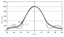
도 4는 수직 편각의 함수로서의 디스플레이의 휘도 (유효 투과율)의 그래프이다.
본 명세서에 제공된 개략적 도면들은 반드시 축척에 따른 것은 아니다. 도면에서 사용되는 유사한 도면 부호는 유사한 구성요소 및 단계 등을 지칭한다. 그러나, 주어진 도면에서 특정한 구성요소를 지칭하기 위해 도면 부호를 사용하는 것이 다른 한 도면에서 동일한 도면 부호로 표시된 구성요소를 제한하려는 것은 아님이 이해될 것이다. 또한, 구성요소들을 지칭하기 위해 상이한 도면 부호들을 사용하는 것이 상이한 도면 부호로 표시된 구성요소들이 동일하거나 또는 유사한 것일 수 없음을 나타내려는 것은 아니다.
(발명의 상세한 설명)
다음의 상세한 기술에서, 본 명세서의 일부를 이루는 첨부 도면에 대한 참조가 이루어지며, 도면에서는 장치, 시스템 및 방법에 대한 몇몇 구체적 실시예가 예시적 방식으로 도시된다. 본 개시내용의 범주 또는 사상으로부터 벗어남이 없이 다른 실시예가 고려되고 이루어질 수 있음을 이해하여야 한다. 따라서, 다음의 상세한 설명은 제한적인 의미로 취해져서는 안 된다.
본 명세서에서 사용되는 모든 과학 및 기술 용어는, 달리 명시되지 않는 한, 이 기술 분야에서 통상적으로 사용되는 의미를 갖는다. 본 명세서에 제공된 정의는 본 명세서에서 빈번하게 사용되는 특정 용어들의 이해를 용이하게 하기 위한 것이며 본 개시내용의 범위를 한정하고자 하는 것은 아니다.
본 명세서 및 첨부된 특허청구범위에서 사용될 때, 단수 형태("a", "an" 및 "the")는, 그 내용이 명백하게 다르게 지시하지 않는 한, 복수의 지시 대상을 갖는 실시예를 포함한다.
본 명세서 및 첨부된 특허청구범위에서 사용될 때, 용어 "또는"은 일반적으로 그 내용이 명백하게 달리 지시하지 않는 한 "및/또는"을 포함하는 그의 의미로 이용된다.
본 명세서에서 사용될 때, "갖다(have)", "갖는(having)", "포함하다(include)", "포함하는(including)", "포함하다(comprise)", 또는 "포함하는(comprising)" 등은 그것들의 개방 종결형 의미로 이용되며, 일반적으로 "포함하지만, 거기에 한정되지는 않음"을 의미한다. 용어 "~로 이루어지는(consisting of)" 및 "본질적으로 ~로 이루어지는(consisting essentially of)"은 용어 "포함하는(comprising)" 등에 포함됨을 알 것이다.
"상", "하", "좌", "우", "상부", "하부", "위", "아래" 및 다른 방향 및 배향과 같은, 본 명세서에서 언급하는 어떤 방향이든 도면에 대한 참조를 명료하게 하기 위해 본 명세서에 기술되며, 실제의 장치 또는 시스템 또는 장치 또는 시스템의 이용을 제한하고 있는 것은 아니다. 본 명세서에서 기술되는 장치, 용품 또는 시스템 중 많은 것이 다수의 방향 및 배향으로 이용될 수 있을 것이다.
본 개시내용은 다른 것들 중에서도 특히 비대칭적 확산기를 포함하는 광학 스택을 기술한다. 본 명세서에서 기술되는 바와 같이, 광학 스택에서 비대칭적 확산기를 이용하는 것은 디스플레이에서의 바람직하지 않은 결함을 저감시키면서, 디스플레이의 광 이득(optical gain) 및/또는 대비(contrast)를 유지한다. 비대칭적 확산기는 해당 광 방향 지정 필름의 선형 연장 구조체와 평행한 제1 방향을 따라 덜 확산적이다. 본 개시내용이 그다지 한정적인 것은 아니며, 아래에 제공된 예들의 설명을 통해 본 개시내용의 다양한 양태에 대한 인식이 얻어질 것이다.
도 1은 관찰자(1)에게 정보를 표시하기 위한 예시적 디스플레이(10)의 개략적 측면도이다. 디스플레이(10)는 제2 광학 스택(30)과 배면광(40) 사이에 광학적으로 배치되는 제1 광학 스택(20)을 포함한다. 제1 광학 스택(20) 및 제2 광학 스택(30)은 광학 스택(25)을 이룬다.
제1 광학 스택(20)은 광 방향 변경 필름(light redirecting film)(21)을 포함한다. 광 방향 변경 필름(21)은 제1 방향 또는 y축을 따라 연장하는 복수의 선형 구조체(24)를 갖는 구조화 표면(22)을 포함한다. 많은 실시예에서, 선형 구조체(24)는 제2 광학 스택(30)을 향할 수 있다. 어떤 실시예에서는, 선형 구조체(24)는 제2 광학 스택(30)으로부터 멀어지는 쪽으로 향하거나 또는 배면광(40)을 향할 수 있다. 선형 구조체(24)가 제2 광학 스택(30)으로부터 이격될 수 있거나 또는 공극이 선형 구조체(24)의 적어도 일부를 제2 광학 스택(30)으로부터 분리할 수 있다. 선형 구조체(24)는 70 내지 120 도의 범위에 있거나, 또는 80 내지 110 도의 범위에 있거나, 85 내지 95 도의 범위에 있거나, 88 내지 92 도의 범위에 있거나, 89 내지 90 도의 범위에 있는 꼭지각(apex angle) 또는 피크 각도(peak angle)를 갖는 프리즘 또는 프리즘 구조체일 수 있다.
제2 광학 스택(30)은 액정 패널(32), 액정 패널(32) 상에 배치되는 반사 편광기(34), 및 반사 편광기(34) 상에 배치되는 비대칭적 확산기(36)를 포함한다. 어떤 실시예에서는, 접착제 층(38)이 액정 패널(32)을 반사 편광기(34)에 접착한다. 많은 실시예에서, 비대칭적 확산기(36)는 제1 광학 스택(20) 또는 구조화 표면(22)을 향한다. 어떤 실시예에서는, 공극(38)이 액정 패널(32)을 반사 편광기(34)로부터 분리한다. 이러한 실시예에서, 비대칭적 확산기(36)는 제1 광학 스택(20) 또는 구조화 표면(22)으로부터 멀어지는 쪽을 향하며, 액정 패널(32)을 향한다.
액정 패널(32)은 어떤 유용한 크기든 가질 수 있으며, 많은 실시예에서 텔레비전으로서 활용된다. 많은 실시예에서, 액정 패널(32)은 50 cm 이상 또는 75 cm 이상인 측면 또는 대각선 치수를 갖는다. 많은 실시예에서, 제2 광학 스택(30)에서의 각각 두개의 인접 표면의 상당한 부분이 서로 물리적 접촉한다. 예를 들어, 제2 광학 스택(30)에서의 각각 두개의 인접 표면의 50% 이상, 또는 60% 이상, 또는 70% 이상, 또는 80% 이상, 또는 90% 이상이 서로 물리적 접촉한다. 어떤 실시예에서는, 제2 광학 스택(30)에서의 각각의 층이 제2 광학 스택에서의 인접 층 상에 직접적으로 성형되거나 또는 접착제에 의해 인접 층에 접착된다. 그래서, 이러한 실시예에서, 제2 광학 스택에서의 인접 층들은 서로로부터 이격되지 않거나 또는 공극에 의해 분리된다.
예시적 배면광(40)은 측방 반사기(45) 속에 내장되는 램프 또는 광원(44)으로부터 광 통로(42)의 에지를 통해 광을 받아들이는 광 통로(42)를 포함한다. 후방 반사기(41)는 후방 반사기(41) 상에 입사되는 광을 관찰자(1) 및 광 확산기(43)를 향해 반사하여 광 통로(42)의 발광면(47)을 빠져나가는 광(46)을 균질화한다. 다른 실시예에서는, 배면광이 직접 비춰진다(도시되지 않은).
반사 편광기(34)는 제1 편광 상태를 갖는 광을 실질적으로 반사하고 제2 편광 상태를 갖는 광을 실질적으로 투과시키며, 두개의 편광 상태는 서로 직교하거나 또는 서로에 대해 직각을 이룬다. 예를 들어, 반사 편광기에 의해 실질적으로 반사되는 편광 상태에 대한 가시광에서의 반사 편광기(34)의 평균 반사율은 약 50% 이상, 또는 약 60% 이상, 또는 약 70% 이상, 또는 약 80% 이상, 또는 약 90% 이상, 또는 약 95% 이상이다. 다른 한 예로서, 반사 편광기에 의해 실질적으로 투과되는 편광 상태에 대한 가시광에서의 반사 편광기(34)의 평균 투과율은 약 50% 이상, 또는 약 60% 이상, 또는 약 70% 이상, 또는 약 80% 이상, 또는 약 90% 이상, 또는 약 95% 이상, 또는 약 97% 이상, 또는 약 98% 이상, 또는 약 99% 이상이다. 어떤 경우에는, 반사 편광기(34)는 제1 선형 편광 상태를 갖는 광을 (예를 들어, x방향을 따라) 실질적으로 반사하고, 제2 선형 편광 상태를 갖는 광을 (예를 들어, y방향을 따라) 실질적으로 투과시킨다.
예를 들어, MOF(multilayer optical film) 반사 편광기, 미국, 미네소타주, 세인트 폴 소재의 쓰리엠 컴퍼니(3M Company)로부터 구입 가능한 Vikuiti™ DRPF(Diffuse Reflective Polarizer Film)와 같은 연속상(continuous phase) 및 분산상(disperse phase)을 가지는 DRPF(diffusely reflective polarizing film, 확산 반사 편광 필름), 예를 들어, 미국 특허 6,719,426호에 기술된 와이어 격자 반사 편광기(wire grid reflective polarizer), 또는 콜레스테릭 반사 편광기(cholesteric reflective polarizer)와 같은 어떤 적합한 유형의 반사 편광기든 반사 편광기 층(34)에 사용될 수 있다.
예를 들어, 어떤 경우에는, 반사 편광기(34)는 상이한 중합체 물질의 교번 층으로 이루어진 MOF 반사 편광기일 수 있거나 이를 포함할 수 있고, 교번 층들의 세트 중 하나는 복굴절 물질로 이루어져 있으며, 상이한 물질의 굴절률이 하나의 선형 편광 상태로 편광된 광을 위해 알맞고, 거기에 직교하는 선형 편광 상태의 광에 대해서는 알맞지 않다. 이러한 경우에, 알맞은 편광 상태에 있는 입사광은 반사 편광기(34)를 통해 실질적으로 투과되고, 알맞지 않은 편광 상태에 있는 입사광은 반사 편광기(34)에 의해 실질적으로 반사된다. 어떤 경우에는, MOF 반사 편광기(34)는 무기 유전체 층의 스택을 포함할 수 있다.
다른 일례로서, 반사 편광기(34)는 통과 상태(pass state)에서 중간의 축상 평균 반사율을 가지는 부분 반사층일 수 있거나 이를 포함할 수 있다. 예를 들어, 부분 반사층은 xy-평면과 같은 제1 평면에서 편광된 가시광에 대한 약 90% 이상의 축상 평균 반사율, 및 제1 평면에 수직인 xz-평면과 같은 제2 평면에서 편광된 가시광에 대한 약 25% 내지 약 90% 범위의 축상 평균 반사율을 가질 수 있다. 그러한 부분 반사층은, 예를 들어, 미국 특허 공보 2008/064133호에 기술되어 있고, 그 개시내용 전부가 본 명세서에 참고로 포함된다.
어떤 경우에는, 반사 편광기(34)는 원형 반사 편광기일 수 있거나 이를 포함할 수 있고, 시계 방향 또는 반시계 방향일 수 있는 한 방향으로 원형 편광된 광(우회전 또는 좌회전 원편광이라고도 함)이 우선적으로 투과되고, 반대 방향으로 편광된 광이 우선적으로 반사된다. 한 유형의 원형 편광기는 콜레스테릭 액정 편광기(cholesteric liquid crystal polarizer)를 포함한다.
광 확산기(43)는 램프 또는 광원(44)을 숨기거나 또는 차폐하고 광 통로(42)에 의해 발광면(47)에서 방출되는 광(46)을 균질화하는 주요 기능을 갖는다. 광 확산기(43)는 높은 광학 탁도 및/또는 높은 확산 광 반사율을 가진다. 많은 실시예에서, 광 확산기(43)의 광학 탁도는 약 40% 이상, 또는 약 50% 이상, 또는 약 60% 이상, 또는 약 70% 이상, 또는 약 80% 이상, 또는 약 85% 이상, 또는 약 90% 이상, 또는 약 95% 이상이다. 다른 한 예로서, 광 확산기의 확산성 광학 반사율은 약 30% 이상, 또는 약 40% 이상, 또는 약 50% 이상, 또는 약 60% 이상이다. 광 확산기(43)는 응용에 바람직하거나 및/또는 이용 가능할 수 있는 임의의 광 확산기일 수 있거나 이를 포함할 수 있다. 예를 들어, 광 확산기(43)는 표면 확산기(surface diffuser), 체적 확산기(volume diffuser), 또는 그것들의 조합일 수 있거나 이를 포함할 수 있다.
후방 반사기(41)는 광 통로(42)에 의해 관찰자(1)로부터 멀어지는 쪽으로 음의 z방향을 따라 방출되는 광을 받아들이고, 받아들인 광을 관찰자(1)를 향해 반사한다. 램프 또는 광원(44)이 광 통로의 에지를 따라 배치되는 디스플레이 시스템(10)과 같은 디스플레이 시스템들은 일반적으로 에지 조명 또는 배면 조명 디스플레이 또는 광학 시스템이라고 지칭된다. 후방 반사기(41)는 응용에 바람직하거나 및/또는 실용적일 수 있는 임의의 유형의 반사기일 수 있다. 예를 들어, 후방 반사기는 정반사성 반사기(specular reflector), 반-정반사성 또는 반-확산성 반사기(semi-specular or semi-diffuse reflector), 또는 확산성 반사기(diffuse reflector)일 수 있다. 예를 들어, 반사기는 개선된 정반사성 반사기 (ESR)(enhanced specular reflector) 필름 (미국, 미네소타, 세인트폴 소재의 쓰리엠 컴퍼니로부터 구입 가능한)과 같은 알루미늄 도금 필름 또는 다층 중합체성 반사 필름일 수 있다.
비대칭적 확산기(36)는 체적 광 확산기(volume light diffuser) 또는 표면 광 확산기(surface light diffuser)일 수 있다. 비대칭적 확산기(36)는 제1 방향을 따라 덜 확산적이고 제2 방향을 따라 더 확산적이며, 제2 방향은 제1 방향에 대해 직교한다. 많은 실시예에서, 제1 방향은 광 방향 변경 필름(20)의 선형 구조체(24)의 제1 방향 또는 y축과 평행하거나 또는 그것을 따라 정렬된다. 이러한 실시예에서, 광 방향 변경 필름(20)의 선형 구조체(24)는 y축을 따르는 제1 방향으로 연장하며, 비대칭적 확산기(36)는 y축을 따르는 동일한 제1 방향으로 덜 확산적이다. 밝혀진 것은, 비대칭적 확산기(36) 및 광 방향 변경 필름(20)의 선형 구조체(24)를 이 방식으로 배향하는 것은 디스플레이에서의 바람직하지 않은 광학적 결함을 차단하거나 또는 제거하면서 디스플레이의 밝기 및 대비를 유지한다는 점이다. 어떤 실시예에서는, 프리즘 구조체(24)의 선형 연장 방향과 비대칭적 확산기(36)의 덜 확산적인 방향 사이에 0이 아닌 어떤 각도(some non-zero angle)가 있는 것이 바람직할 수 있을 것이다.
많은 실시예에서, 비대칭적 광 확산기(36)는 제1 방향을 따라 제1 시야각으로 및 제2 방향을 따라 제2 시야각으로 광을 산란시키며, 제1 시야각에 대한 제2 시야각의 비는 1.5 이상이거나, 또는 2 이상이거나, 또는 2.5 이상이거나, 또는 3 이상이다.
액정 디스플레이 시스템에서 이용되는 광 방향 변경 필름(20)은 디스플레이의 밝기를 증가시키거나 또는 향상시킬 수 있다. 이러한 경우에, 광 방향 변경 필름은 1보다 더 큰 유효 투과율 (ET)(effective transmission) 또는 상대 이득을 갖는다. 본 명세서에서 사용될 때, "유효 투과율(effective transmission)"은 디스플레이 시스템에서의 제자리에 있는 필름을 갖는 디스플레이 시스템의 휘도 대 제자리에 있는 필름을 갖지 않는 디스플레이의 휘도의 비이다.
도 2는 유효 투과율을 측정하기 위한 광학 시스템(100)의 개략적 측면도이다. 광학 시스템(100)은 광축(150) 상에 중심을 두며, 발광 또는 출광면(emitting or exit surface)(112), 선형 흡광 편광기(120), 및 광 검출기(130)를 통해 램버트 광(115)을 방출하는 중공형 램버트 광 박스(hollow lambertian light box)(110)를 포함한다. 광 박스(110)는 광섬유(170)를 통해 광 박스의 내부(180)에 연결된 안정된 광대역 광원(160)에 의해 조명된다. ET가 광학 시스템에 의해 측정될 테스트 샘플이 광 박스와 흡광 선형 편광기 사이의 위치(140)에 배치된다.
광학 스택(25) 또는 광 방향 지정 필름(20)의 ET는 광학 스택(25) 또는 광 방향 지정 필름(20)을 위치(140)에서 선형 프리즘(22)이 광 검출기를 향하게 배치함으로써 측정될 수 있다. 스펙트럼으로 가중된 축방향 휘도 I1 (광축(250)을 따르는 휘도)는 선형 흡광 편광기를 통해 광 검출기에 의해 측정된다. 광학 스택(25) 또는 광 방향 지정 필름(20)이 제거되고, 스펙트럼으로 가중된 휘도 I2는 광학 스택(25) 또는 광 방향 지정 필름(20)이 위치(140)에 배치되지 않은 상태에서 측정된다. ET는 비 I1/I2이다. ET0는 선형 프리즘(22)이 선형 흡수 편광기(120)의 편광축에 평행인 방향을 따라 연장할 때의 유효 투과율이고, ET90는 선형 프리즘(22)이 선형 흡수 편광기의 편광축에 수직인 방향을 따라 연장할 때의 유효 투과율이다. 평균 유효 투과율(ETA)은 ET0와 ET90의 평균이다.
본 명세서에 개시된 측정 유효 투과율 값은 SpectraScan™ PR-650 SpectraColorimeter (미국 캘리포니아주 챗스워스 소재의 포토 리서치 인코포레이티드(Photo Research, Inc)로부터 구입 가능한)를 광 검출기(130)로 사용하여 측정되었다. 광 박스(110)는 약 85%의 총 반사율을 가지는 테플론 입방체(Teflon cube)였다.
광 방향 변경 필름(20)이 디스플레이 시스템(10)에서 이용되어 밝기를 증가시키고 선형 프리즘이 약 1.6보다 더 큰 굴절률을 갖는 때와 같은, 어떤 경우에는, 광 방향 변경 필름의 평균 유효 투과율 (ETA)이 약 1.3 이상, 또는 약 1.4 이상, 또는 약 1.5 이상, 또는 약 1.6 이상, 또는 약 1.65 이상, 또는 약 1.7 이상, 또는 약 1.75 이상, 또는 약 1.8 이상이다.
예에서 예시된 바와 같이, 광학 스택(25)의 평균 유효 투과율은 시야각이 증가함에 따라 고르게 감소한다. 이 광학 특성은 관찰자가 시야각을 변화시킴에 따라 광학적 결함을 저감시키거나 또는 제거한다. 많은 실시예에서, 광학 스택(25)의 평균 유효 투과율은 시야각이 약 35 도로부터 약 55 도까지, 또는 30 도로부터 약 60 도까지, 또는 25 도로부터 약 65 도까지, 또는 20 도로부터 약 70 도까지, 또는 15 도로부터 약 75 도까지, 또는 10 도로부터 약 80 도까지, 또는 5 도로부터 약 85 도까지 증가함에 따라 단조롭게 감소한다. 어떤 실시예에서는, 광학 스택(25)의 평균 유효 투과율은 시야각이 약 5 도로부터 약 85 도까지 증가함에 따라 단조롭게 감소하거나 또는 일정하게 유지된다.
많은 실시예에서, 광학 스택(25)의 평균 유효 투과율은 비대칭적 광 확산기를 포함하지 않는 것을 제외하고는 동일한 구성을 갖는 광학 스택에 비해 더 적지 않거나 또는 약 15% 이하만큼 더 적다. 다른 실시예에서, 광학 스택(25)의 평균 유효 투과율은 비대칭적 광 확산기를 포함하지 않는 것을 제외하고는 동일한 구성을 갖는 광학 스택에 비해 더 적지 않거나 또는 약 10% 이하만큼 더 적다. 다른 실시예에서, 광학 스택(25)의 평균 유효 투과율은 비대칭적 광 확산기를 포함하지 않는 것을 제외하고는 동일한 구성을 갖는 광학 스택에 비해 더 적지 않거나 또는 약 8% 이하만큼 더 적다. 다른 실시예에서, 광학 스택(25)의 평균 유효 투과율은 비대칭적 광 확산기를 포함하지 않는 것을 제외하고는 동일한 구성을 갖는 광학 스택에 비해 더 적지 않거나 또는 약 5% 이하만큼 더 적다.
예 1
광학 스택은 다음과 같이 조립되었다. LCD 패널은 소니(Sony) NSX-32GT1 텔레비전 수상기(television set) (미국, 뉴욕, 뉴욕 소재의 소니 유에스에이(Sony USA)로부터 구입 가능한)로부터 확보되었다. 반사 편광기 시트(DBEF-Q, 미국, 미네소타, 세인트폴 소재의 쓰리엠 컴퍼니로부터 구입 가능한)는 패널의 하면에 광학상 투명 접착제 (쓰리엠 컴퍼니로부터 OCA 8171로서 구입 가능한)를 이용하여 편광기의 통과 축이 LCD 패널의 수평 방향을 따라 배향되게 라미네이팅되었다. 반사 편광기 시트의 LCD 패널로부터 멀어지는 쪽을 향하는 면 상에 성형된 비대칭적 확산기가 아래에서 더 상세하게 기술되며; 이 비대칭적 확산기는 구조체들의 평행한 세트들을 가졌고, 각각의 구조체는 대략적인 긴 타원의 형상을 가졌다. 비대칭적 확산기는 타원의 장축이 반사 편광기의 통과 축에 평행하도록 배향되었고; 이 방식으로 배향되면, 최대 확산의 방향은 수직하고 통과 축에 대해 직각을 이루었다. 프리즘 필름 (BEF III-10T, 90 도 꼭지각 및 50 마이크로미터 피치를 갖고, 쓰리엠 컴퍼니로부터 구입 가능한)이 반사 편광기 시트의 아래에 있고, 그로부터 공극에 의해 분리된다. 프리즘은 긴 타원의 긴 방향에 대해 대체로 평행하게 배향되었다. 삼성 UN32C4000 텔레비전 수상기 (미국, 뉴저지, 리치필드 파크 소재의 삼성 유에스에이(Samsung USA)로부터 구입 가능한)로부터 확보된 마이크로렌즈 시트 (확산기)가 프리즘 필름 바로 아래에 있고, 그로부터 공극에 의해 분리되었다. 마찬가지로 소니 NSX-32GT1 텔레비전 수상기로부터 확보된 광 통로 판(light guide plate)이 마이크로렌즈 시트 바로 아래에 있고, 그로부터 공극에 의해 분리되었다. 이 수상기로부터의 광 통로는 상단 에지에서 80개의 3 mm X 5 mm LED를 이용하여 조명되었다.
반사 편광기의 하면 상의 비대칭적 확산기가 다음과 같이 준비되었다. 예를 들어, PCT 공개 출원 WO 00/48037호, 및 미국 특허 7,350,442호 및 7,328,638호에 기술된 고속 공구대(FTS)(fast tool servo)를 갖는 다이아몬드 터닝 시스템(diamond turning system)이 원통형 미소복제 공구를 생성하기 위해 이용되었다. 실린더가 그 중심축을 따라 회전됨에 따라, 다이아몬드 커터가 실린더의 표면에 대해 직교해서 이동되어 원통형 롤(cylindrical roll)의 둘레에 나선 경로를 절삭했다. 커터가 롤 표면에 대해 직교하는 방향을 따라 이동되어 롤 재료(roll material)를 절단했고, 커터가 안과 밖으로 이동되거나 또는 요동침에 따라 커터에 의해 절단되는 재료의 폭이 변하였다. 미소복제 공구를 생성하는 공정은 PCT 공개 출원 WO2010/041261호 및 미국 계류중인 특허 출원 61/236772호에 더 기술되어 있다. 그 후, 원통형 공구에 생성된 구조체가 반사 편광기의 하면 상에 미국 특허 5,175,030호(루(Lu)) 및 5,183,597호(루)에 기술된 방법을 이용하여 복제되었다. 도 3은 비대칭적 확산기의 상면 광학 현미경 사진이다.
도 3에 도시된 긴 구조체는 약 160 마이크로미터의 평균 길이 및 대략적으로 10 마이크로미터의 최대폭 부분에서의 평균 폭을 갖는다. 구조체의 평균 최대 높이는 대략적으로 2 마이크로미터이었다.
수직 편각의 함수로서의 디스플레이의 휘도 (유효 투과율)는 Eldim EZContrast88LW (미국, 캘리포니아, 스코츠 밸리 소재의 마켓 테크 인코포레이티드(Market Tech Inc.)로부터 구입 가능한)를 이용하여 측정되었다. 생성된 데이터는 도 4의 도표에 도시되어 있다.
예 2
광학 스택은 예 1에서처럼 조립되었고, 다만, 비대칭적 확산기 구조체는 그 예에서의 구조체의 방향에 대해 직각을 이루게 성형되어, 구조체가 프리즘에 대해 대략적으로 직각을 이루게 했다. 이 배향에서, 최대 확산의 방향은 수평이었다.
수직 편각의 함수로서의 디스플레이의 휘도 (유효 투과율)는 예 1에 기술된 바와 같이 측정되었다. 생성된 데이터는 도 4의 도표에 도시되어 있다.
예 3
광학 스택은 예 1에서처럼 조립되었고, 다만, 비대칭적 확산기를 갖는 반사 편광기 필름은 어떤 확산기도 갖지 않는 반사 편광기 (DBEF-Q, 쓰리엠 컴퍼니로부터 구입 가능한)에 의해 대체되었다.
수직 편각의 함수로서의 디스플레이의 휘도 (유효 투과율)는 예 1에 기술된 바와 같이 측정되었다. 생성된 데이터는 도 4의 도표에 도시되어 있다.
예 4
예 1의 비대칭적 확산기를 갖는 반사 편광기로 이루어지는 단일의 필름을 위해 시야각이 측정되었다. 수평 시야각 (밝기가 그것의 피크 값의 절반으로 떨어지는 각도)은 1.5 도인 것으로 판정되었고, 수직 시야각은 17.1 도이었다. 이것들은 시준 광원 및 밝은 이미징 구체(radiant imaging sphere)(미국, 워싱턴, 레드먼드 소재의 라디안트 제맥스, 엘엘시(Radiant ZEMAX, LLC)로부터 IS-Sa 산광기 및 외관 측정 시스템(IS-Sa Scatter and Appearance Measurement System)으로서 구입 가능한)에 의해 측정되었다.
예 5
종래의 대칭적 확산기를 갖는 반사 편광기인 DBEF-D2-400 (쓰리엠 컴퍼니로부터 구입 가능한)로 이루어지는 단일의 필름에 의해 시야각이 측정되었다. 시야각은 예 4에서처럼 측정되었고, 수평에서 11.3 도 및 수직에서 12.8 도인 것으로 판정되었다.
예 6
예 1, 예 2 및 예 3의 광학 스택을 위해 PR705 SpectraScan 분광복사기 (미국, 캘리포니아, 채츠워스 소재의 포토 리서치 인코포레이티드(Photo Research Inc.)로부터 구입 가능한)를 이용하여 축방향 휘도가 측정되었다. 예 1 및 예 2의 광학적 조립체가 예 3의 광학적 조립체의 축방향 휘도의 91%를 갖는 것으로 밝혀졌다.
그래서, 비대칭적 확산기를 갖는 광학 스택의 실시예들이 개시된다. 이 기술분야에서 숙련된 자는 본 명세서에 기술된 광학적 필름 및 필름 용품이 개시된 것들과 다른 실시예로 실시될 수 있음을 알 것이다. 개시된 실시예는 제한이 아니라 예시를 위하여 제공된다.
예시적인 실시예는 다음의 것들을 포함한다:
항목 1. 광학 스택(optical stack)으로서,
제1 광학 스택 및 제1 광학 스택 상에 배치되는 제2 광학 스택을 포함하고,
제1 광학 스택은 1.3 이상의 평균 유효 투과율(average effective transmission)을 갖고, 제1 방향을 따라 연장하는 복수의 선형 구조체(linear structure)를 포함하는 구조화 제1 주 표면(structured first major surface)을 포함하는 광 방향 지정 필름(light directing film)을 포함하며,
제2 광학 스택은:
액정 패널(liquid crystal panel);
액정 패널 상에 배치되는 반사 편광기(reflective polarizer) - 반사 편광기는 제1 편광 상태(polarization state)를 갖는 광을 실질적으로 반사하고, 제1 편광 상태에 대해 직각을 이루는 제2 편광 상태를 갖는 광을 실질적으로 투과시킴 -; 및
반사 편광기 상에 배치되고 제1 방향을 따라 덜 확산적이며 제1 방향에 직교하는 제2 방향을 따라 더 확산적인 비대칭적 광 확산기를 포함하고, 제2 광학 스택에서의 각각 두개의 인접 주 표면의 상당한 부분은 서로 물리적 접촉하며, 광학 스택의 평균 유효 투과율은 시야각이 약 35 도로부터 약 55 도까지 증가함에 따라 시야각의 함수로서 단조롭게 부증가(monotonically non-increasing)하는, 광학 스택.
항목 2. 항목 1의 광학 스택으로서, 광 방향 지정 필름은 1.4 이상의 평균 유효 투과율을 갖는, 광학 스택.
항목 3. 항목 1의 광학 스택으로서, 광 방향 지정 필름은 1.5 이상의 평균 유효 투과율을 갖는, 광학 스택.
항목 4. 항목 1의 광학 스택으로서, 광 방향 지정 필름은 1.6 이상의 평균 유효 투과율을 갖는, 광학 스택.
항목 5. 항목 1의 광학 스택으로서, 광 방향 지정 필름의 제1 주 표면에서의 복수의 선형 구조체는 제1 방향을 따라 연장하는 복수의 선형 프리즘 구조체(linear prismatic structure)를 포함하는, 광학 스택.
항목 6. 항목 5의 광학 스택으로서, 각각의 선형 프리즘 구조체는 피크(peak) 및 피크 각도(peak angle)를 가지며, 피크 각도는 70 내지 120 도의 범위에 있는, 광학 스택.
항목 7. 항목 5의 광학 스택으로서, 각각의 선형 프리즘 구조체는 피크 및 피크 각도를 가지며, 피크 각도는 80 내지 110 도의 범위에 있는, 광학 스택.
항목 8. 항목 5의 광학 스택으로서, 각각의 선형 프리즘 구조체는 피크 및 피크 각도를 가지며, 피크 각도는 85 내지 95 도의 범위에 있는, 광학 스택.
항목 9. 항목 5의 광학 스택으로서, 각각의 선형 프리즘 구조체는 피크 및 피크 각도를 가지며, 피크 각도는 88 내지 92 도의 범위에 있는, 광학 스택.
항목 10. 항목 1의 광학 스택으로서, 광 방향 지정 필름의 구조화 제1 주 표면은 제2 광학 스택을 향하는, 광학 스택.
항목 11. 항목 1의 광학 스택으로서, 광 방향 지정 필름의 구조화 제1 주 표면은 제2 광학 스택으로부터 멀어지는 쪽을 향하는, 광학 스택.
항목 12. 항목 1의 광학 스택으로서, 광 방향 지정 필름은 구조화 제1 주 표면의 반대쪽인 제2 주 표면을 포함하고, 제2 주 표면은 구조화 되는, 광학 스택.
항목 13. 항목 1의 광학 스택으로서, 광 방향 지정 필름은 구조화 제1 주 표면의 반대쪽인 제2 주 표면을 포함하고, 제2 주 표면은 구조화 되지 않는, 광학 스택.
항목 14. 항목 1의 광학 스택으로서, 액정 패널의 주 표면은 50 cm 이상인 대각선을 갖는, 광학 스택.
항목 15. 항목 1의 광학 스택으로서, 액정 패널의 주 표면은 75 cm 이상인 대각선을 갖는, 광학 스택.
항목 16. 항목 1의 광학 스택으로서, 반사 편광기는 제1 편광 상태를 갖는 광의 60% 이상을 반사하고 제2 편광 상태를 갖는 광의 60% 이상을 투과시키는, 광학 스택.
항목 17. 항목 1의 광학 스택으로서, 반사 편광기는 제1 편광 상태를 갖는 광의 70% 이상을 반사하고 제2 편광 상태를 갖는 광의 70% 이상을 투과시키는, 광학 스택.
항목 18. 항목 1의 광학 스택으로서, 반사 편광기는 제1 편광 상태를 갖는 광의 80% 이상을 반사하고 제2 편광 상태를 갖는 광의 80% 이상을 투과시키는, 광학 스택.
항목 19. 항목 1의 광학 스택으로서, 반사 편광기는 제1 편광 상태를 갖는 광의 90% 이상을 반사하고 제2 편광 상태를 갖는 광의 90% 이상을 투과시키는, 광학 스택.
항목 20. 항목 1의 광학 스택으로서, 비대칭적 광 확산기는 체적 광 확산기(volume light diffuser)를 포함하는, 광학 스택.
항목 21. 항목 1의 광학 스택으로서, 비대칭적 광 확산기는 표면 광 확산기(surface light diffuser)를 포함하는, 광학 스택.
항목 22. 항목 1의 광학 스택으로서, 비대칭적 광 확산기는 제1 방향을 따라 제1 시야각으로 및 제2 방향을 따라 제2 시야각으로 광을 산란시키며, 제1 시야각에 대한 제2 시야각의 비는 1.5 이상인, 광학 스택.
항목 23. 항목 1의 광학 스택으로서, 비대칭적 광 확산기는 제1 방향을 따라 제1 시야각으로 및 제2 방향을 따라 제2 시야각으로 광을 산란시키며, 제1 시야각에 대한 제2 시야각의 비는 2 이상인, 광학 스택.
항목 24. 항목 1의 광학 스택으로서, 비대칭적 광 확산기는 제1 방향을 따라 제1 시야각으로 및 제2 방향을 따라 제2 시야각으로 광을 산란시키며, 제1 시야각에 대한 제2 시야각의 비는 2.5 이상인, 광학 스택.
항목 25. 항목 1의 광학 스택으로서, 비대칭적 광 확산기는 제1 방향을 따라 제1 시야각으로 및 제2 방향을 따라 제2 시야각으로 광을 산란시키며, 제1 시야각에 대한 제2 시야각의 비는 3 이상인, 광학 스택.
항목 26. 항목 1의 광학 스택으로서, 제2 광학 스택에서의 각각 두개의 인접 주 표면의 50% 이상이 서로 물리적 접촉하는, 광학 스택.
항목 27. 항목 1의 광학 스택으로서, 제2 광학 스택에서의 각각 두개의 인접 주 표면의 60% 이상이 서로 물리적 접촉하는, 광학 스택.
항목 28. 항목 1의 광학 스택으로서, 제2 광학 스택에서의 각각 두개의 인접 주 표면의 70% 이상이 서로 물리적 접촉하는, 광학 스택.
항목 29. 항목 1의 광학 스택으로서, 제2 광학 스택에서의 각각 두개의 인접 주 표면의 80% 이상이 서로 물리적 접촉하는, 광학 스택.
항목 30. 항목 1의 광학 스택으로서, 제2 광학 스택에서의 각각 두개의 인접 주 표면의 90% 이상이 서로 물리적 접촉하는, 광학 스택.
항목 31. 항목 1의 광학 스택으로서, 제2 광학 스택에서의 각각의 층은 제2 광학 스택에서의 인접 층 상에 직접적으로 성형되거나 또는 접착제에 의해 인접 층에 접착되는, 광학 스택.
항목 32. 항목 1의 광학 스택으로서, 광학 스택의 평균 유효 투과율은 시야각이 약 30 도로부터 약 60 도까지 증가함에 따라 단조롭게 감소하는, 광학 스택.
항목 33. 항목 1의 광학 스택으로서, 광학 스택의 평균 유효 투과율은 시야각이 약 25 도로부터 약 65 도까지 증가함에 따라 단조롭게 감소하는, 광학 스택.
항목 34. 항목 1의 광학 스택으로서, 광학 스택의 평균 유효 투과율은 시야각이 약 20 도로부터 약 70 도까지 증가함에 따라 단조롭게 감소하는, 광학 스택.
항목 35. 항목 1의 광학 스택으로서, 광학 스택의 평균 유효 투과율은 시야각이 약 15 도로부터 약 75 도까지 증가함에 따라 단조롭게 감소하는, 광학 스택.
항목 36. 항목 1의 광학 스택으로서, 광학 스택의 평균 유효 투과율은 시야각이 약 10 도로부터 약 80 도까지 증가함에 따라 단조롭게 감소하는, 광학 스택.
항목 37. 항목 1의 광학 스택으로서, 광학 스택의 평균 유효 투과율은 시야각이 약 5 도로부터 약 85 도까지 증가함에 따라 단조롭게 감소하는, 광학 스택.
항목 38. 항목 37의 광학 스택으로서, 광학 스택의 평균 유효 투과율은 시야각이 5 내지 85 도의 시야각 범위의 일부 내에서 증가함에 따라 일정하게 유지되는, 광학 스택.
항목 39. 항목 1의 광학 스택으로서, 제1 광학 스택과 제2 광학 스택 사이의 공극(air gap)을 포함하는, 광학 스택.
항목 40. 항목 1의 광학 스택으로서, 광학 스택의 평균 유효 투과율은 비대칭적 광 확산기를 포함하지 않는 것을 제외하고는 동일한 구성을 갖는 광학 스택에 비해 더 적지 않거나 또는 약 15% 이하만큼 더 적은, 광학 스택.
항목 41. 항목 1의 광학 스택으로서, 광학 스택의 평균 유효 투과율은 비대칭적 광 확산기를 포함하지 않는 것을 제외하고는 동일한 구성을 갖는 광학 스택에 비해 더 적지 않거나 또는 약 10% 이하만큼 더 적은, 광학 스택.
항목 42. 항목 1의 광학 스택으로서, 광학 스택의 평균 유효 투과율은 비대칭적 광 확산기를 포함하지 않는 것을 제외하고는 동일한 구성을 갖는 광학 스택에 비해 더 적지 않거나 또는 약 8% 이하만큼 더 적은, 광학 스택.
항목 43. 항목 1의 광학 스택으로서, 광학 스택의 평균 유효 투과율은 비대칭적 광 확산기를 포함하지 않는 것을 제외하고는 동일한 구성을 갖는 광학 스택에 비해 더 적지 않거나 또는 약 5% 이하만큼 더 적은, 광학 스택.
항목 44. 항목 1의 광학 스택으로서, 비대칭적 광 확산기는 광 방향 지정 필름의 구조화 제1 주 표면을 향하는, 광학 스택.
항목 45. 항목 1의 광학 스택으로서, 비대칭적 광 확산기는 광 방향 지정 필름의 구조화 제1 주 표면으로부터 멀어지는 쪽을 향하는, 광학 스택.
항목 46. 항목 1의 광학 스택으로서, 반사 편광기 층은 교번 층(alternating layer)들을 포함하고, 교번 층들 중 하나 이상은 복굴절 물질(birefringent material)을 포함하는, 광학 스택.
항목 47. 항목 1의 광학 스택으로서, 반사 편광기 층은 와이어 그리드 반사 편광기(wire grid reflective polarizer)를 포함하는, 광학 스택.
항목 48. 항목 1의 광학 스택으로서, 반사 편광기 층은 콜레스테릭 반사 편광기(cholesteric reflective polarizer)를 포함하는, 광학 스택.
항목 49. 항목 1의 광학 스택으로서, 반사 편광기 층은 복수의 실질적으로 평행한 섬유들을 포함하고, 섬유는 복굴절 물질을 포함하는, 광학 스택.
항목 50. 항목 1의 광학 스택으로서, 반사 편광기 층은 확산 반사 편광 필름(DRPF)(diffusely reflective polarizing film)을 포함하는, 광학 스택.The present disclosure may be more fully understood by the following detailed description of various embodiments of the disclosure in connection with the accompanying drawings, wherein:
≪ 1 >
1 is a schematic side view of an exemplary display;
2,
2 is a schematic side view of an optical system for measuring effective transmittance;
3,
Figure 3 is a top-view optical micrograph of an exemplary asymmetric diffuser;
<Fig. 4>
4 is a graph of the luminance (effective transmittance) of the display as a function of the vertical declination.
The schematic drawings provided herein are not necessarily to scale. Like reference numerals used in the drawings refer to like elements and steps and the like. It will, however, be understood that the use of reference numerals to designate a particular component in a given drawing is not intended to limit the components denoted by the same reference numeral in the other. Also, the use of different reference numerals to designate components is not intended to indicate that the components indicated by different reference numerals can be the same or similar.
DETAILED DESCRIPTION OF THE INVENTION [
In the following detailed description, reference is made to the accompanying drawings, which form a part hereof, and in which is shown by way of illustration specific embodiments of apparatus, systems and methods. It is to be understood that other embodiments may be contemplated and may be made without departing from the scope or spirit of the disclosure. Accordingly, the following detailed description should not be taken in a limiting sense.
All scientific and technical terms used herein have the meanings commonly used in the art unless otherwise specified. The definitions provided herein are intended to facilitate an understanding of certain terms that are frequently used herein and are not intended to limit the scope of the present disclosure.
As used in this specification and the appended claims, the singular forms "a," "an," and "the" include embodiments having a plurality of referents unless the context clearly dictates otherwise .
As used in this specification and the appended claims, the term "or" is generally used in its sense including "and / or" unless the content clearly dictates otherwise.
As used herein, the terms "have", "having", "includes", "including", "comprise", or "comprising" ) "Are used in their open-ended sense and generally mean" including but not limited to ". The terms "consisting of " and " consisting essentially of" are to be understood to be included in the term " comprising ", and the like.
Any direction referred to herein, such as "top," "bottom," "left," "right," "top," "bottom," "above," "below," and other orientations and orientations, And are not intended to limit the use of an actual apparatus or system or apparatus or system. Many of the devices, articles, or systems described herein may be used in a number of orientations and orientations.
This disclosure describes, among other things, an optical stack comprising an asymmetric diffuser. As described herein, the use of an asymmetric diffuser in an optical stack maintains the optical gain and / or contrast of the display while reducing undesirable defects in the display. The asymmetric diffuser is less diffuse along a first direction parallel to the linear extension structure of the light directing film. The present disclosure is not so limited and an appreciation of the various aspects of the disclosure will be gained through the description of the examples provided below.
Fig. 1 is a schematic side view of an
The first
The second
The
The
The
For example, a multilayer optical film (MOF) reflective polarizer, a continuous phase and a disperse phase, such as a Vikuiti (TM) Reflective Polarizer Film (DRPF) available from 3M Company, St. Paul, Minn. a diffusely reflective polarizing film (DRPF) having a disperse phase, for example a wire grid reflective polarizer as described in U.S. Patent No. 6,719,426, or a cholesteric reflective polarizer Any suitable type of reflective polarizer, such as a polarizer, can be used for the
For example, in some cases, the
As another example, the
In some cases, the
The
The
The
In many embodiments, the asymmetric
The
2 is a schematic side view of an
The ET of
The measured effective transmittance values disclosed herein were measured using a SpectraScan (TM) PR-650 SpectraColorimeter (available from Photo Research, Inc., Chatsworth, CA) as the
In some cases, such as when the
As illustrated in the example, the average effective transmittance of the
In many embodiments, the average effective transmittance of the
Example 1
The optical stack was assembled as follows. The LCD panel was obtained from a Sony NSX-32GT1 television set (available from Sony USA, New York, NY, USA). A reflective polarizer sheet (DBEF-Q, available from 3M Company, St. Paul, Minnesota, USA) was coated with optically transparent adhesive (available as OCA 8171 from 3M Company) on the bottom of the panel, Lt; RTI ID = 0.0 > horizontal < / RTI > The asymmetric diffuser formed on the face of the reflective polarizer sheet facing away from the LCD panel is described in more detail below; This asymmetric diffuser had parallel sets of structures, each of which had an approximate long oval shape. The asymmetric diffuser is oriented such that the major axis of the ellipse is parallel to the pass axis of the reflective polarizer; When oriented in this way, the direction of maximum diffusion is vertical and perpendicular to the pass axis. A prism film (BEF III-10T, available from 3M Company, having a 90 degree apex angle and a 50 micrometer pitch) is below the reflective polarizer sheet and separated therefrom by voids. The prisms were oriented substantially parallel to the long direction of the long ellipses. A micro lens sheet (diffuser) secured from a Samsung UN32C4000 television receiver (available from Samsung USA, Richfield Park, NJ, USA) was located beneath the prism film and separated from it by pores. Likewise, a light guide plate, obtained from the Sony NSX-32GT1 television receiver, was just below the micro-lens sheet and separated from it by a gap. The light path from this receiver was illuminated with 80 3 mm x 5 mm LEDs at the top edge.
The asymmetric diffuser on the lower surface of the reflective polarizer was prepared as follows. For example, a diamond turning system having a fast tool servo (FTS) as described in PCT Published Application WO 00/48037, and U.S. Patent Nos. 7,350,442 and 7,328,638, Lt; / RTI > As the cylinder was rotated along its central axis, the diamond cutter was moved orthogonally to the surface of the cylinder to cut the spiral path around the cylindrical roll. The cutter was moved along a direction orthogonal to the roll surface to cut the roll material and the width of the material that was cut by the cutter as the cutter was moved in and out or changed was changed. Processes for creating smile replication tools are further described in PCT open application WO < RTI ID = 0.0 > 2010/041261 < / RTI > and U. S. patent application 61/236772. The structure created on the cylindrical tool was then replicated on the lower surface of the reflective polarizer using the method described in U.S. Patent 5,175,030 (Lu) and 5,183,597 (Lu). 3 is a top view optical microscope picture of an asymmetric diffuser.
The elongate structure shown in Figure 3 has an average length of about 160 micrometers and an average width at a maximum width of about 10 micrometers. The average maximum height of the structure was approximately 2 micrometers.
The luminance (effective transmittance) of the display as a function of the vertical declination was measured using Eldim EZ Contrast 88 LW (available from Market Tech Inc., Scotts Valley, California, USA). The generated data is shown in the table of FIG.
Example 2
The optical stack was assembled as in Example 1, except that the asymmetric diffuser structure was shaped at right angles to the orientation of the structure in the example so that the structure was approximately perpendicular to the prism. In this orientation, the direction of maximum diffusion was horizontal.
The luminance (effective transmittance) of the display as a function of the vertical declination was measured as described in Example 1. The generated data is shown in the table of FIG.
Example 3
The optical stack was assembled as in Example 1, except that a reflective polarizer film with an asymmetric diffuser was replaced by a reflective polarizer (DBEF-Q, available from 3M Company) without any diffuser.
The luminance (effective transmittance) of the display as a function of the vertical declination was measured as described in Example 1. The generated data is shown in the table of FIG.
Example 4
A viewing angle was measured for a single film consisting of a reflective polarizer with an asymmetric diffuser of Example 1. The horizontal viewing angle (the angle at which the brightness dropped to half its peak value) was determined to be 1.5 degrees and the vertical viewing angle was 17.1 degrees. These include IS-Sa Scattering and Appearance Measurement Systems (IS-Sa Scatter and Radiometric Imaging Systems) from Radiant ZEMAX, LLC of Radiant Imaging Sphere (Radiant Imager, LLC, Redmond, Wash. Appearance Measurement System).
Example 5
A viewing angle was measured by a single film consisting of a reflective polarizer DBEF-D2-400 (available from 3M Company) having a conventional symmetric diffuser. The viewing angle was measured as in Example 4 and was determined to be 11.3 degrees in horizontal and 12.8 degrees in vertical.
Example 6
The axial brightness was measured using a PR705 SpectraScan spectrophotometer (available from Photo Research Inc., Chatsworth, California) for the optical stacks of Examples 1, 2, . It has been found that the optical assemblies of Examples 1 and 2 have 91% of the axial brightness of the optical assembly of Example 3.
Thus, embodiments of an optical stack having asymmetric diffusers are disclosed. Those skilled in the art will recognize that the optical film and film articles described herein can be practiced with other embodiments than those disclosed. The disclosed embodiments are provided for purposes of illustration and not limitation.
Exemplary embodiments include the following:
Item 1. An optical stack,
A first optical stack and a second optical stack disposed on the first optical stack,
The first optical stack has an average effective transmission of at least 1.3 and includes a structured first major surface comprising a plurality of linear structures extending along a first direction, A light directing film,
The second optical stack comprises:
A liquid crystal panel;
A reflective polarizer disposed on the liquid crystal panel, the reflective polarizer being configured to substantially reflect light having a first polarization state and to reflect light having a second polarization state perpendicular to the first polarization state, Substantially permeable; And
And a more diffusive asymmetric optical diffuser disposed on the reflective polarizer along a second direction that is less diffusing along the first direction and orthogonal to the first direction, and wherein each of the two adjacent major surfaces in the second optical stack A substantial portion of which is in physical contact with one another and the average effective transmittance of the optical stack is monotonically non-increasing as a function of viewing angle as the viewing angle increases from about 35 degrees to about 55 degrees.
Item 2. The optical stack of item 1, wherein the light directing film has an average effective transmittance of at least 1.4.
Item 3. The optical stack of item 1, wherein the light directing film has an average effective transmittance of at least 1.5.
Item 4. The optical stack of item 1, wherein the light directing film has an average effective transmittance of 1.6 or more.
Item 5. The optical stack of item 1, wherein a plurality of linear structures at a first major surface of the light directing film comprises a plurality of linear prismatic structures extending along a first direction.
Item 6. The optical stack of item 5, wherein each linear prism structure has a peak and a peak angle, and the peak angle is in the range of 70 to 120 degrees.
Item 7. The optical stack of item 5, wherein each linear prism structure has a peak and a peak angle, and a peak angle is in a range of 80 to 110 degrees.
Item 8. The optical stack of item 5, wherein each linear prism structure has a peak and a peak angle, and a peak angle is in a range of 85 to 95 degrees.
Item 9. The optical stack of item 5, wherein each linear prism structure has a peak and a peak angle, and a peak angle is in a range of 88 to 92 degrees.
Item 11. The optical stack of item 1, wherein the structured first major surface of the light directing film faces away from the second optical stack.
Item 12. The optical stack of item 1, wherein the light directing film comprises a second major surface opposite the structured first major surface and the second major surface is structured.
Item 13. The optical stack of item 1, wherein the light directing film comprises a second major surface opposite the structured first major surface and the second major surface is unstructured.
Item 14. The optical stack of item 1, wherein the main surface of the liquid crystal panel has a diagonal of 50 cm or more.
Item 15. The optical stack of item 1, wherein the major surface of the liquid crystal panel has a diagonal of at least 75 cm.
Item 16. The optical stack of item 1, wherein the reflective polarizer reflects at least 60% of the light having the first polarization state and at least 60% of the light having the second polarization state.
Item 17. The optical stack of item 1, wherein the reflective polarizer reflects at least 70% of the light having the first polarization state and at least 70% of the light having the second polarization state.
Item 18. The optical stack of item 1, wherein the reflective polarizer reflects at least 80% of the light having the first polarization state and at least 80% of the light having the second polarization state.
Item 19. The optical stack of item 1, wherein the reflective polarizer reflects at least 90% of the light having the first polarization state and at least 90% of the light having the second polarization state.
Item 26. The optical stack of item 1, wherein at least 50% of each two adjacent major surfaces in the second optical stack are in physical contact with each other.
Item 27. The optical stack of item 1, wherein at least 60% of each two adjacent major surfaces in the second optical stack are in physical contact with each other.
Item 28. The optical stack of item 1, wherein at least 70% of each two adjacent major surfaces in the second optical stack are in physical contact with each other.
Item 29. The optical stack of item 1, wherein at least 80% of each two adjacent major surfaces in the second optical stack are in physical contact with each other.
Item 31. The optical stack of item 1, wherein each layer in the second optical stack is molded directly on an adjacent layer in the second optical stack or bonded to an adjacent layer by an adhesive.
Item 33. The optical stack of item 1, wherein the average effective transmittance of the optical stack monotonously decreases as the viewing angle increases from about 25 degrees to about 65 degrees.
Item 35. The optical stack of item 1, wherein the average effective transmittance of the optical stack monotonously decreases as the viewing angle increases from about 15 degrees to about 75 degrees.
Item 37. The optical stack of item 1, wherein the average effective transmittance of the optical stack monotonously decreases as the viewing angle increases from about 5 degrees to about 85 degrees.
Item 39. The optical stack of item 1, wherein the optical stack includes an air gap between the first optical stack and the second optical stack.
Item 42. The optical stack of item 1, wherein the average effective transmittance of the optical stack is less than or equal to about 8% less than an optical stack having the same configuration, except that it does not include an asymmetrical optical diffuser. stack.
Item 47. The optical stack of item 1, wherein the reflective polarizer layer comprises a wire grid reflective polarizer.
Item 48. The optical stack of item 1, wherein the reflective polarizer layer comprises a cholesteric reflective polarizer.
Item 49. The optical stack of item 1, wherein the reflective polarizer layer comprises a plurality of substantially parallel fibers, and the fiber comprises a birefringent material.
Item 50. The optical stack of item 1, wherein the reflective polarizer layer comprises a diffusely reflective polarizing film (DRPF).
Claims (10)
제1 광학 스택 및 제1 광학 스택 상에 배치되는 제2 광학 스택을 포함하고,
제1 광학 스택은 1.3 이상의 평균 유효 투과율(average effective transmission)을 갖고, 제1 방향을 따라 연장하는 복수의 선형 구조체(linear structure)를 포함하는 구조화 제1 주 표면(structured first major surface)을 포함하는 광 방향 지정 필름(light directing film)을 포함하며,
제2 광학 스택은:
액정 패널(liquid crystal panel);
액정 패널 상에 배치되는 반사 편광기(reflective polarizer) - 반사 편광기는 제1 편광 상태(polarization state)를 갖는 광을 실질적으로 반사하고, 제1 편광 상태에 대해 직각을 이루는 제2 편광 상태를 갖는 광을 실질적으로 투과시킴 -; 및
반사 편광기 상에 배치되고 제1 방향을 따라 덜 확산적이며 제1 방향에 직교하는 제2 방향을 따라 더 확산적인 비대칭적 광 확산기를 포함하고, 제2 광학 스택에서의 각각 두개의 인접 주 표면의 상당한 부분은 서로 물리적 접촉하며, 광학 스택의 평균 유효 투과율은 시야각이 35 도로부터 55 도까지 증가함에 따라 시야각의 함수로서 단조롭게 부증가(monotonically non-increasing)하고, 비대칭적 광 확산기는 제1 방향을 따라 제1 시야각으로 및 제2 방향을 따라 제2 시야각으로 광을 산란시키며, 제1 시야각에 대한 제2 시야각의 비는 1.5 이상인, 광학 스택.As an optical stack,
A first optical stack and a second optical stack disposed on the first optical stack,
The first optical stack has an average effective transmission of at least 1.3 and includes a structured first major surface comprising a plurality of linear structures extending along a first direction, A light directing film,
The second optical stack comprises:
A liquid crystal panel;
A reflective polarizer disposed on the liquid crystal panel, the reflective polarizer being configured to substantially reflect light having a first polarization state and to reflect light having a second polarization state perpendicular to the first polarization state, Substantially permeable; And
And a more diffusive asymmetric optical diffuser disposed on the reflective polarizer along a second direction that is less diffusing along the first direction and orthogonal to the first direction, and wherein each of the two adjacent major surfaces in the second optical stack Significant portions are in physical contact with one another and the average effective transmittance of the optical stack is monotonically non-increasing as a function of viewing angle as the viewing angle increases from 35 to 55 degrees, Wherein the ratio of the second viewing angle to the first viewing angle is greater than or equal to 1.5.
Applications Claiming Priority (3)
| Application Number | Priority Date | Filing Date | Title |
|---|---|---|---|
| US201161563145P | 2011-11-23 | 2011-11-23 | |
| US61/563,145 | 2011-11-23 | ||
| PCT/US2012/066213 WO2013078278A1 (en) | 2011-11-23 | 2012-11-21 | Optical stack with asymmetric diffuser |
Publications (2)
| Publication Number | Publication Date |
|---|---|
| KR20140097407A KR20140097407A (en) | 2014-08-06 |
| KR101989207B1 true KR101989207B1 (en) | 2019-06-13 |
Family
ID=47326385
Family Applications (1)
| Application Number | Title | Priority Date | Filing Date |
|---|---|---|---|
| KR1020147016759A KR101989207B1 (en) | 2011-11-23 | 2012-11-21 | Optical stack with asymmetric diffuser |
Country Status (6)
| Country | Link |
|---|---|
| US (1) | US9618791B2 (en) |
| JP (1) | JP6243344B2 (en) |
| KR (1) | KR101989207B1 (en) |
| CN (1) | CN104335109B (en) |
| TW (1) | TWI606271B (en) |
| WO (1) | WO2013078278A1 (en) |
Families Citing this family (7)
| Publication number | Priority date | Publication date | Assignee | Title |
|---|---|---|---|---|
| US9070312B2 (en) * | 2013-11-05 | 2015-06-30 | 3M Innovative Properties Company | Hybrid self illuminated and actively back lit signage for printed graphics |
| US10590697B2 (en) | 2014-01-22 | 2020-03-17 | 3M Innovative Properties Company | Microoptics for glazing |
| US9921345B2 (en) * | 2014-05-30 | 2018-03-20 | 3M Innovative Properties Company | Optical systems having variable viewing angles |
| WO2016064565A1 (en) | 2014-10-20 | 2016-04-28 | 3M Innovative Properties Company | Insulated glazing units and microoptical layer comprising microstructured diffuser and methods |
| US10466398B2 (en) * | 2015-06-15 | 2019-11-05 | 3M Innovative Properties Company | Optical stack including reflecting-absorbing polarizer |
| CN108288260A (en) * | 2018-01-30 | 2018-07-17 | 苏州亚相素自动化科技有限公司 | The image pre-processing method of real-time deep or light correction |
| CN113196115A (en) | 2018-12-14 | 2021-07-30 | 3M创新有限公司 | Liquid crystal display with front side light control film |
Citations (1)
| Publication number | Priority date | Publication date | Assignee | Title |
|---|---|---|---|---|
| WO2006026743A1 (en) * | 2004-08-31 | 2006-03-09 | Fusion Optix, Inc. | Enhanced light diffusing sheet |
Family Cites Families (19)
| Publication number | Priority date | Publication date | Assignee | Title |
|---|---|---|---|---|
| US5183597A (en) | 1989-02-10 | 1993-02-02 | Minnesota Mining And Manufacturing Company | Method of molding microstructure bearing composite plastic articles |
| US5175030A (en) | 1989-02-10 | 1992-12-29 | Minnesota Mining And Manufacturing Company | Microstructure-bearing composite plastic articles and method of making |
| DE69435173D1 (en) * | 1993-12-21 | 2009-01-15 | Minnesota Mining & Mfg | Multilayer optical film |
| US6322236B1 (en) | 1999-02-09 | 2001-11-27 | 3M Innovative Properties Company | Optical film with defect-reducing surface and method for making same |
| JP2002540557A (en) * | 1999-03-24 | 2002-11-26 | エルジー ケミカル エルティーディー. | Backlight system |
| EP1478965A1 (en) | 2002-02-28 | 2004-11-24 | 3M Innovative Properties Company | Compound polarization beam splitters |
| KR100576870B1 (en) | 2004-08-11 | 2006-05-10 | 삼성전기주식회사 | Nitride semiconductor light emitting diode and method of producing the same |
| WO2006031545A1 (en) * | 2004-09-09 | 2006-03-23 | Fusion Optix, Inc. | Enhanced lcd backlight |
| US7446827B2 (en) * | 2004-10-15 | 2008-11-04 | 3M Innovative Properties Company | Direct-lit liquid crystal displays with laminated diffuser plates |
| JP2006251395A (en) | 2005-03-10 | 2006-09-21 | Daicel Chem Ind Ltd | Anisotropic scattering sheet |
| KR101255296B1 (en) | 2005-06-29 | 2013-04-15 | 엘지디스플레이 주식회사 | Prims sheet and back light unit using the same |
| US7350442B2 (en) | 2005-11-15 | 2008-04-01 | 3M Innovative Properties Company | Cutting tool having variable movement in a z-direction laterally along a work piece for making microstructures |
| US7328638B2 (en) | 2005-12-27 | 2008-02-12 | 3M Innovative Properties Company | Cutting tool using interrupted cut fast tool servo |
| DE112007002760T5 (en) | 2006-11-15 | 2009-09-24 | 3M Innovative Properties Co., Saint Paul | Backlight Display with high illumination uniformity |
| US20090040772A1 (en) * | 2007-08-08 | 2009-02-12 | Rohm And Haas Denmark Finance A/S | Optical element comprising restrained asymmetrical diffuser |
| US8632497B2 (en) | 2008-10-09 | 2014-01-21 | Roche Diagnostics Operations Inc. | Skin securable drug delivery device with a shock absorbing protective shield |
| US8657472B2 (en) * | 2009-06-02 | 2014-02-25 | 3M Innovative Properties Company | Light redirecting film and display system incorporating same |
| WO2011005897A2 (en) | 2009-07-09 | 2011-01-13 | Silhouette Medical Inc. | Apparatus for treating medical conditions of hollow anatomical structures |
| CN102483473B (en) | 2009-08-25 | 2014-11-05 | 3M创新有限公司 | Light redirecting film and display system incorporating same |
-
2012
- 2012-11-21 US US14/360,105 patent/US9618791B2/en active Active
- 2012-11-21 CN CN201280057447.1A patent/CN104335109B/en active Active
- 2012-11-21 KR KR1020147016759A patent/KR101989207B1/en active IP Right Grant
- 2012-11-21 WO PCT/US2012/066213 patent/WO2013078278A1/en active Application Filing
- 2012-11-21 JP JP2014543552A patent/JP6243344B2/en active Active
- 2012-11-22 TW TW101143792A patent/TWI606271B/en not_active IP Right Cessation
Patent Citations (1)
| Publication number | Priority date | Publication date | Assignee | Title |
|---|---|---|---|---|
| WO2006026743A1 (en) * | 2004-08-31 | 2006-03-09 | Fusion Optix, Inc. | Enhanced light diffusing sheet |
Also Published As
| Publication number | Publication date |
|---|---|
| US20140285749A1 (en) | 2014-09-25 |
| CN104335109A (en) | 2015-02-04 |
| KR20140097407A (en) | 2014-08-06 |
| TW201329528A (en) | 2013-07-16 |
| CN104335109B (en) | 2018-01-12 |
| JP2015504536A (en) | 2015-02-12 |
| JP6243344B2 (en) | 2017-12-06 |
| US9618791B2 (en) | 2017-04-11 |
| WO2013078278A1 (en) | 2013-05-30 |
| TWI606271B (en) | 2017-11-21 |
Similar Documents
| Publication | Publication Date | Title |
|---|---|---|
| US9389355B2 (en) | Structured optical film | |
| KR101989207B1 (en) | Optical stack with asymmetric diffuser | |
| US8007118B2 (en) | Direct-lit backlight with angle-dependent birefringent diffuser | |
| JP6073935B2 (en) | Black light for light guide and display system with optical film containing voids | |
| US9625640B2 (en) | Optical film and display system incorporating same | |
| TWI659247B (en) | Liquid crystal display device | |
| US8888333B2 (en) | Light redirecting film and display system incorporating same | |
| CN104246590B (en) | Liquid crystal display | |
| TWI364600B (en) | An illumination device an image display device using the illumination device and a light diffusing board used by the devices | |
| CN102066994B (en) | Optical film | |
| CN101512400B (en) | Polarization control system and display device | |
| CN101535878A (en) | Back-lit displays with high illumination uniformity | |
| CN101535880A (en) | Back-lit displays with high illumination uniformity | |
| KR20140103172A (en) | Optical film stack | |
| US20140009960A1 (en) | Backlight device | |
| JP7237018B2 (en) | Backlight comprising a wide web turning film and a reflective polarizer with a quarter wave retarder | |
| US9229141B2 (en) | Optical assembly |
Legal Events
| Date | Code | Title | Description |
|---|---|---|---|
| A201 | Request for examination | ||
| E902 | Notification of reason for refusal | ||
| E701 | Decision to grant or registration of patent right |