KR101982532B1 - Steam diminisher having recycling and fueling for wasted styrofoam - Google Patents
Steam diminisher having recycling and fueling for wasted styrofoam Download PDFInfo
- Publication number
- KR101982532B1 KR101982532B1 KR1020170086316A KR20170086316A KR101982532B1 KR 101982532 B1 KR101982532 B1 KR 101982532B1 KR 1020170086316 A KR1020170086316 A KR 1020170086316A KR 20170086316 A KR20170086316 A KR 20170086316A KR 101982532 B1 KR101982532 B1 KR 101982532B1
- Authority
- KR
- South Korea
- Prior art keywords
- steam
- styrofoam
- water
- washing
- crushing
- Prior art date
Links
Images


Classifications
-
- B—PERFORMING OPERATIONS; TRANSPORTING
- B29—WORKING OF PLASTICS; WORKING OF SUBSTANCES IN A PLASTIC STATE IN GENERAL
- B29B—PREPARATION OR PRETREATMENT OF THE MATERIAL TO BE SHAPED; MAKING GRANULES OR PREFORMS; RECOVERY OF PLASTICS OR OTHER CONSTITUENTS OF WASTE MATERIAL CONTAINING PLASTICS
- B29B17/00—Recovery of plastics or other constituents of waste material containing plastics
- B29B17/0026—Recovery of plastics or other constituents of waste material containing plastics by agglomeration or compacting
-
- B—PERFORMING OPERATIONS; TRANSPORTING
- B29—WORKING OF PLASTICS; WORKING OF SUBSTANCES IN A PLASTIC STATE IN GENERAL
- B29B—PREPARATION OR PRETREATMENT OF THE MATERIAL TO BE SHAPED; MAKING GRANULES OR PREFORMS; RECOVERY OF PLASTICS OR OTHER CONSTITUENTS OF WASTE MATERIAL CONTAINING PLASTICS
- B29B17/00—Recovery of plastics or other constituents of waste material containing plastics
- B29B2017/001—Pretreating the materials before recovery
- B29B2017/0015—Washing, rinsing
-
- Y—GENERAL TAGGING OF NEW TECHNOLOGICAL DEVELOPMENTS; GENERAL TAGGING OF CROSS-SECTIONAL TECHNOLOGIES SPANNING OVER SEVERAL SECTIONS OF THE IPC; TECHNICAL SUBJECTS COVERED BY FORMER USPC CROSS-REFERENCE ART COLLECTIONS [XRACs] AND DIGESTS
- Y02—TECHNOLOGIES OR APPLICATIONS FOR MITIGATION OR ADAPTATION AGAINST CLIMATE CHANGE
- Y02W—CLIMATE CHANGE MITIGATION TECHNOLOGIES RELATED TO WASTEWATER TREATMENT OR WASTE MANAGEMENT
- Y02W30/00—Technologies for solid waste management
- Y02W30/50—Reuse, recycling or recovery technologies
- Y02W30/62—Plastics recycling; Rubber recycling
Abstract
본 발명은 스팀식 압축감용기에 관한 것으로, 기존 방식으로 재활용하기 어려운 오염된 폐스티로폼도 전처리 과정을 거쳐 재활용이 가능하며 양질의 폐스티로폼 압축품과 함께 양질의 고형연료를 생산할 수 있는 대용량 스팀식 감용기에 관한 것이다.
본 발명은 폐스티로폼의 연속 투입이 가능하도록 통로형으로 마련된 파쇄기투입구(110); 다수개의 돌기형 파쇄날이 일정하게 구비되어 상기 파쇄기투입구(110)에 의해 투입된 폐스티로폼을 회전하면서 파쇄하는 파쇄드럼(120); 상기 파쇄드럼(120)에 의해 파쇄된 스티로폼을 이송하는 송풍기(130); 뾰족부가 하부에 위치하는 삼각형상으로 마련되고, 상기 송풍기(130)에 의해 이송된 파쇄 스티로폼을 수중에서 세척하되 다공형 더블 패들에 의해 교반하는 세척기(200); 타공판이 마련되어 체인의 회전에 의해 상기 세척된 파쇄 스티로폼을 이송하고, 상기 세척기(200)에서 사용된 세척수는 세척조로 흘려보내도록 경사형으로 구성된 이송버켓(230); 스팀발생기(300)에서 생성된 스팀을 저장한 후 분배하는 스팀발생기(300); 상기 이송버켓(230)에 의해 이동한 세척 스티로폼에 상기 스팀을 분사하면서 압출스크류(422)에 의해 연속 압축하는 연속압출기(400); 상기 연속압출기(400)에서 사용된 스팀을 냉각하여 세척수로 재활용하는 수분배출장치(430); 상기 연속압출기(400)와 수분배출기에서 생성된 이물질을 배출하는 스트레이너(432);를 포함하여 구성되는 것을 특징으로 한다. The present invention relates to a steam compression type container, and it is possible to recycle waste styrofoam, which is difficult to recycle by conventional methods, through a pretreatment process, and to produce high quality solid fuel together with high- Quot;
A crusher inlet (110) provided in the form of a passage so that waste styrofoam can be continuously introduced; A crushing drum 120 having a plurality of protruding crushing blades fixedly provided therein, the crushing drum 120 rotating and crushing the waste styrofoam charged by the crushing device inlet 110; A blower 130 for conveying the styrofoam crushed by the crush drum 120; A washer 200 provided in a triangular shape with a pointed portion located at the lower portion thereof and washing the broken styrofoam conveyed by the blower 130 in water and stirring by a multi-pore double paddle; A conveying bucket 230 configured to convey the washed foamed styrofoam by rotation of the chain with a perforated plate and having an inclined shape to allow the washing water used in the washing machine 200 to flow into the washing tub; A steam generator 300 for storing and distributing the steam generated by the steam generator 300; A continuous extruder 400 for continuously compressing the washed styrofoam by the extrusion screw 422 while spraying the steam onto the washed styrofoam moved by the transfer bucket 230; A water discharging device 430 for cooling the steam used in the continuous extruder 400 and recycling it as washing water; And a strainer 432 for discharging the foreign substances generated in the continuous extruder 400 and the water discharger.
Description
본 발명은 스팀식 압축감용기에 관한 것으로, 기존 방식으로 재활용하기 어려운 오염된 폐스티로폼도 세척교반등의 전처리 과정을 거쳐 압축감용하여 폐스티로폼을 압축품 및 고형연료 생산할 수 있는 대용량 스팀식 감용기에 관한 것이다. The present invention relates to a steam type compression container, and it relates to a steam type compression container which is capable of compressing and decompressing contaminated waste styrofoam, which is difficult to recycle by conventional methods, such as washing and stirring, .
스티로폼은 전자제품 포장, 과일 및 채소 등의 운반용기, 양식장, 건축단열재 등으로 사용되고 있으며, 그 사용이 지속적으로 증가되고 있다. 스티로폼의 사용 후, 대부분 소각 및 매립 등의 방법으로 처리되고 재활용 가능한 폐스티로폼은 열감용과 기계적 감용 등으로 처리되는데 이러한 방법은 유독 가스(다이옥신 등) 및 분진, 소음, 악취 등이 발생하고 있는 실정이다. Styrofoam is used in electronic packaging, transportation containers for fruits and vegetables, farms, construction insulation, etc., and its use is continuously increasing. After using styrofoam, waste styrofoam, which is mostly recycled and recycled by incineration and landfill, is treated with heat and mechanical deterioration. Such methods are toxic gases (such as dioxins), dust, noise and odor .
재활용되는 스티로폼은 높은 발열량(5,000kcal 이상)에도 불구하고 연료로서는 이용되지 못하고, 주로 감용 후 용융과정을 통해 재생플라스틱으로만 이용되고 있다. 그러나 저급품질의 압축감용품은 판매에 어려움이 있으며, 분리설비 등 추가설비가 필요하여 경제성이 떨어져 판로에 어려움이 있다. Styrofoam recycled can not be used as a fuel in spite of high calorific value (over 5,000kcal), and it is mainly used only as recycled plastic through melting process after persimmon. However, it is difficult to sell compressible articles of low quality and it is difficult to sell because of the lack of economical efficiency due to the necessity of additional facilities such as separation facilities.
한편, 폐스티로폼을 재활용하기 위한 감용기에 대한 국내 기술은 열선을 이용한 열감용 기술 및 기계적 감용 기술로 나눌 수 있다. On the other hand, the domestic technology for the container for recycling the waste styrofoam can be divided into the heat-sensitive technology using the heat wire and the mechanical depressurization technology.
상기 열선을 이용한 열 감용기는 오염되지 않은 상태가 비교적 양호한 폐스티로폼 처리 시에만 사용할 수 있고, 열선을 이용하므로 화재의 위험성이 있으며 감융 중에 악취가 발생한다. 또한, 전기가 과다하게 소모되는 단점이 있고 부대설비가 많이 요구된다. 또한, 열감용 기술 적용 시 발생 오염원은 이산화탄소, 질소산화물, 황산화물, 염화수소가 발생하여 환경오염과 작업자의 안전을 위협할 수 있다. The thermally sensitive container using the hot wire can be used only when the waste styrofoam is not contaminated, and there is a risk of fire due to the use of hot wire, and a malodor occurs during the melting. In addition, there is a disadvantage in that electricity is excessively consumed, and additional facilities are required. In addition, the application of heat technology may cause pollution sources such as carbon dioxide, nitrogen oxides, sulfur oxides, and hydrogen chloride, which may jeopardize environmental pollution and safety of workers.
상기 기계적 감용기는 고속 스크류를 이용한 마찰열을 이용하므로 소음이 매우 심하고, 압축비가 낮으며 양질의 폐스티로폼 재활용에만 사용이 가능한 문제점이 있다. Since the mechanical pressure vessel uses frictional heat using a high-speed screw, there is a problem that the noise is very high, the compression ratio is low, and it can be used only for recycling waste styrofoam of good quality.
본 발명은 이물질이 다량으로 함유된 폐스티로폼도 재활용 가능한 대용량 스팀식 감용기를 제공하는데 그 목적이 있다. It is an object of the present invention to provide a large-capacity steam-type sensing container capable of recycling waste styrofoam containing a large amount of foreign matter.
또한, 본 발명은 감용 과정에서 악취 등 작업환경에 유해한 인자 및 유해가스 발생이 없는 스팀식 감용기를 제공하는데 그 목적이 있다. It is another object of the present invention to provide a steam-type container which is harmless to a working environment such as a malodor and does not generate noxious gas during the cooking process.
또한, 본 발명은 열선을 사용하지 않아 화재 위험이 없는 스팀식 감용기를 제공하는데 그 목적이 있다. It is another object of the present invention to provide a steam-type sensing container which does not use a hot wire and thus does not cause a fire hazard.
또한, 본 발명은 소음발생이 적고, 분진을 최소화되며 파쇄물의 체류시간을 최소화 시킨 스팀식 감용기를 제공하는데 그 목적이 있다. It is another object of the present invention to provide a steam-type sensing container which minimizes noise generation, minimizes dust, and minimizes the residence time of a crushed product.
또한, 본 발명은 폐스티로폼을 1/80 수준으로 감용하고 감용품의 이동 및 운반이 용이하도록 제조된 스팀식 감용기를 제공하는데 그 목적이 있다. It is another object of the present invention to provide a steam-type sensing container which is manufactured to reduce waste styrofoam to 1/80 level and to facilitate the movement and transportation of articles to be inspected.
또한, 본 발명은 설비구성을 최소화하여 설치면적을 획기적으로 줄인 스팀식 감용기를 제공하는데 그 목적이 있다. It is another object of the present invention to provide a steam-type sensing vessel with a minimized installation area and a drastically reduced installation area.
또한, 본 발명은 자동화가 가능한 제어설비가 마련된 스팀식 감용기를 제공하는데 그 목적이 있다. It is another object of the present invention to provide a steam-type sensing container provided with a control facility capable of automation.
발명이 해결하고자 하는 기술적 과제들은 이상에서 언급한 기술적 과제들로 제한되지 않으며, 언급되지 않은 또 다른 기술적 과제들은 아래의 기재로부터 본 발명이 속하는 기술분야에서 통상의 지식을 가진 자에게 명확하게 이해될 수 있을 것이다.It is to be understood that both the foregoing general description and the following detailed description are exemplary and explanatory and are not restrictive of the invention as set forth in the accompanying drawings. It will be possible.
본 발명은 폐스티로폼의 연속 투입이 가능하도록 통로형으로 마련된 파쇄기투입구(110); 다수개의 돌기형 파쇄날이 일정하게 구비되어 상기 파쇄기투입구(110)에 의해 투입된 폐스티로폼을 회전하면서 파쇄하는 파쇄드럼(120); 상기 파쇄드럼(120)에 의해 파쇄된 스티로폼을 이송하는 송풍기(130); 뾰족부가 하부에 위치하는 삼각형상으로 마련되고, 상기 송풍기(130)에 의해 이송된 파쇄 스티로폼을 수중에서 세척하되 다공형 더블 패들에 의해 교반하는 세척기(200); 타공판이 마련되어 체인의 회전에 의해 상기 세척된 파쇄 스티로폼을 이송하고, 상기 세척기(200)에서 사용된 세척수는 세척조로 흘려보내도록 경사형으로 구성된 이송버켓(230); 스팀을 생성하여 저장한 후 분배하는 스팀발생기(300); 상기 이송버켓(230)에 의해 이동한 세척 스티로폼에 상기 스팀을 분사하면서 압출스크류(422)에 의해 연속 압축하는 연속압출기(400); 상기 연속압출기(400)에서 사용된 스팀을 냉각하여 세척수로 재활용하는 수분배출장치(430); 상기 연속압출기(400)와 수분배출기에서 생성된 이물질을 배출하는 스트레이너(432);를 포함하여 구성되는 것을 특징으로 한다. A crusher inlet (110) provided in the form of a passage so that waste styrofoam can be continuously introduced; A crushing
상기 과제의 해결 수단에 의해, 본 발명은 이물질 분리하는 선별기를 구비하고 있어 이물질이 다량으로 함유된 폐스티로폼도 재활용 가능한 대용량 스팀식 감용기를 제공할 수 있다. According to the solution of the above-mentioned problems, the present invention can provide a large-capacity steam-type sensing container which can recycle waste styrofoam containing a large amount of foreign matter by having a sorter for separating foreign matters.
또한, 본 발명은 감용 과정에서 악취 등 작업환경에 유해한 인자 및 유해가스 발생이 없는 스팀식 감용기를 제공할 수 있다. In addition, the present invention can provide a steam-type vacuum container free from harmful gases and harmful gases generated during operation of the vacuum process.
또한, 본 발명은 열선을 사용하지 않아 화재 위험이 없는 스팀식 감용기를 제공할 수 있다. Further, the present invention can provide a steam-type sensitive container which does not use hot wire and thus does not cause a fire hazard.
또한, 본 발명은 소음발생이 적고, 분진을 최소화되며 파쇄물의 체류시간을 최소화 시킨 스팀식 감용기를 제공할 수 있다.In addition, the present invention can provide a steam-type sensitive container which generates little noise, minimizes dust, and minimizes the residence time of the crushed material.
또한, 본 발명은 폐스티로폼을 1/80으로 감용하고 감용품의 이동 및 운반이 용이하도록 제조된 스팀식 감용기를 제공할 수 있다. In addition, the present invention can provide a steam-type sensitive container manufactured by cutting waste styrofoam at 1/80 and facilitating movement and transportation of articles to be inspected.
또한, 본 발명은 설비구성을 최소화하여 설치면적을 획기적으로 줄인 스팀식 감용기를 제공할 수 있다. In addition, the present invention can provide a steam-type sensing vessel with a minimized installation area and drastically reduced installation area.
또한, 본 발명은 자동화가 가능한 제어설비가 마련된 스팀식 감용기를 제공할 수 있다.In addition, the present invention can provide a steam-type sensing container provided with a control facility capable of automation.
또한, 본 발명은 스팀냉각 후 배출되는 수분을 펌핑 후 세척수로 재활용 가능하여 에너지 효율을 높인 스팀식 감용기를 제공할 수 있다. In addition, the present invention can provide a steam-type sensing vessel that can be recycled as washing water after pumping moisture discharged after steam cooling, thereby improving energy efficiency.
또한, 본 발명은 감용기 내부 및 외부의 스팀량이 일정하게 분사되도록 마련되고, 압력을 동일하게 유지할 수 있도록 구성되어 열효율을 증가시킨 스팀식 감용기를 제공할 수 있다. In addition, the present invention can provide a steam-type sensing container which is provided to uniformly spray the amount of steam inside and outside the pressure vessel, and can maintain the same pressure so that the thermal efficiency is increased.
또한, 본 발명은 압축다이스의 효율적인 설계를 통해, 압축성형품이 일정한 형태와 강도를 유지하여 배출될 수 있다. Further, through the efficient design of the compression dies, the compression molded product of the present invention can be discharged while maintaining a constant shape and strength.
도 1은 본 발명인 폐스티로폼 재활용 및 연료화를 위한 대용량 스팀식 감용기의 측면도이다.
도 2는 본 발명인 폐스티로폼 재활용 및 연료화를 위한 대용량 스팀식 감용기의 평면도이다.
도 3은 본 발명인 폐스티로폼 재활용 및 연료화를 위한 대용량 스팀식 감용기의 측면 사진이다.
도 4는 파쇄기투입구(110)의 형상을 나타낸 사진이다.
도 5는 파쇄기(100)의 파쇄드럼(120)의 형상을 나타낸 사진이다.
도 6은 파쇄기(100)의 후단배출구 형상을 나타낸 사진이다.
도 7은 파쇄기(100) 후면에 위치한 송풍기(130)의 형상을 나타낸 사진이다.
도 8은 세척기(200)의 전체 형상을 나타낸 사진이다.
도 9는 세척기(200) 내부의 수중교반장치(210) 및 배출스크류(220)를 나타낸 사진이다.
도 10은 세척기(200) 내부의 이송버켓(230)을 나타낸 사진이다.
도 11은 이송버켓(230)관로를 나타낸 사진이다.
도 12는 세척기(200) 내부를 관찰할 수 있는 점검창(250)을 나타낸 사진이다.
도 13은 세척기(200) 내부의 배출스크류(220)를 나타낸 사진이다.
도 14는 세척기(200) 외부로 배출된 이물질의 배출관로를 나타낸 사진이다.
도 15는 세척기(200) 하단에 구획 분리된 보일러수 저장소를 나타낸 사진 및 도면이다.
도 16은 스팀발생기(300)를 나타낸 사진이다.
도 17은 스팀을 발생시키는 버너(320)를 나타낸 사진이다.
도 18은 발생된 스팀을 배출하는 스팀배출밸브(310)를 나타낸 사진이다.
도 19는 발생된 스팀을 분배하는 스팀분배기(340)를 나타낸 사진이다.
도 20은 연속압출기(400)를 나타낸 측면도이다.
도 21은 연속압출기(400)의 내부 상세도이다.
도 22는 연속압출기(400)의 정면도이다.
도 23은 연속압출기(400)의 측면을 나타낸 사진이다.
도 24는 압출스크류(422)를 나타낸 사진이다.
도 25는 압출스크류(422)의 정면을 나타낸 사진이다.
도 26은 수분배출장치(430)를 나타낸 사진이다.
도 27은 수분리사이클장치(431)를 나타낸 사진이다.
도 28은 압출관(420)의 내부 스팀캡(421)을 나타낸 사진이다.
도 29는 압출관(420)의 외부를 나타낸 사진이다.
도 30은 압축다이스(440)를 개방하기 전 사진이다.
도 31은 압축다이스(440)를 개방했을 때 사진이다.
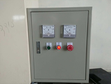
도 32는 제어부(500)를 나타낸 사진이다.
도 33은 제어부(500)의 수동조작을 나타낸 사진이다.
도 34는 시간당 200kg 처리기술에 대한 효과를 입증하는 사진이다.
도 35는 5mm 이하 크기의 파쇄기술에 대한 효과를 입증하는 사진이다.
도 36은 1/80 수준의 감용기술에 대한 효과를 입증하는 사진이다.
도 37은 폐스티로폼 이물질 제거 기술 효과를 입증하는 사진이다.
도 38은 폐스티로폼을 이용한 고형연료(SRF) 제조기술 효과를 입증하는 사진이다. FIG. 1 is a side view of a large-capacity steam-sensitive container for recycling and fueling waste plastics of the present invention.
FIG. 2 is a plan view of a large capacity steam-sensitive container for recycling and fueling waste plastics of the present invention.
FIG. 3 is a side view of a large-capacity steam-sensitive container for recycling and fueling waste plastics of the present invention.
4 is a photograph showing the shape of the
5 is a photograph showing the shape of the
6 is a photograph showing the shape of the rear end discharge port of the
7 is a photograph showing the shape of the
8 is a photograph showing the overall shape of the
FIG. 9 is a photograph showing the water stirring
10 is a photograph showing the
11 is a photograph showing the conduit of the
12 is a photograph showing an
13 is a photograph showing the discharge screw 220 inside the
14 is a photograph showing a discharge pipe of a foreign substance discharged to the outside of the
FIG. 15 is a photograph and a view showing a boiler water reservoir demarcated at the lower end of the
16 is a photograph showing the
17 is a photograph showing the burner 320 generating steam.
18 is a photograph showing the steam discharge valve 310 for discharging the generated steam.
19 is a photograph showing the steam distributor 340 for distributing the generated steam.
20 is a side view showing a
21 is an internal detail view of the
22 is a front view of the
23 is a photograph showing the side surface of the
24 is a photograph showing the
25 is a photograph showing the front face of the
26 is a photograph showing the
Fig. 27 is a photograph showing the water recycling apparatus 431. Fig.
28 is a photograph showing the
29 is a photograph showing the outside of the
30 is a photograph before opening the
31 is a photograph when the
Fig. 32 is a photograph showing the
33 is a photograph showing the manual operation of the
Figure 34 is a photograph demonstrating the effect of a 200 kg treatment technique per hour.
Figure 35 is a photograph demonstrating the effect of a crushing technique of size 5 mm or less.
FIG. 36 is a photograph demonstrating the effect of the scraping technique at the 1/80 level.
FIG. 37 is a photograph demonstrating the effect of the waste styrofoam foreign matter removal technique.
38 is a photograph demonstrating the effect of the technology for producing solid fuel (SRF) using waste styrofoam.
본 발명은 스팀식 압축감용기에 관한 것으로, 기존 방식으로 재활용하기 어려운 오염된 폐스티로폼도 세척하여 재사용 가능하며 폐스티로폼을 양질의 고형연료를 생산할 수 있는 대용량 스팀식 감용기에 관한 것이다. The present invention relates to a steam-type pressure-sensitive container, and more particularly, to a large-capacity steam-type container capable of producing a solid fuel of waste styrofoam which can be reused by washing even contaminated waste styrofoam which is difficult to recycle by conventional methods.
이상과 같은 본 발명에 대한 해결하려는 과제, 과제의 해결 수단, 발명의 효과를 포함한 구체적인 사항들은 다음에 기재할 일실시예 및 도면들에 포함되어 있다. 본 발명의 이점 및 특징, 그리고 그것들을 달성하는 방법은 첨부되는 도면과 함께 상세하게 후술되어 있는 일실시예를 참조하면 명확해질 것이다.The above and other objects, features and advantages of the present invention will be more apparent from the following detailed description taken in conjunction with the accompanying drawings, in which: FIG. BRIEF DESCRIPTION OF THE DRAWINGS The advantages and features of the present invention and the manner of achieving them will become apparent by reference to an embodiment which will be described in detail below with reference to the accompanying drawings.
건축 폐자재 등에서 발생하는 오염이 심한 폐스티로폼은 기존의 열감용 방식이나 기계 마찰식 감용 방식으로 재처리가 불가함으로 새로운 감용 기술이 필요하다. 또한, 고온고압의 스팀을 이용하여 감용 하는 새로운 감용 방식이 필요하며 설비구성을 최소화하고 자동화가 가능한 설비를 개발할 필요가 있다. Waste styrofoam, which is polluted by construction waste, is not able to be reprocessed by conventional heat - sensitive method or mechanical friction type. In addition, it is necessary to develop a new tuning system that uses steam at high temperature and high pressure, and it is necessary to develop facilities capable of minimizing equipment configuration and automation.
하기에는 본 발명의 폐스티로폼 재활용 및 연료화를 위한 대용량 스팀식 감용기를 도면을 이용하여 상세하게 설명한다. Hereinafter, the large-capacity steam-type sensing container for recycling and fueling the waste styrene foam of the present invention will be described in detail with reference to the drawings.
도 1은 본 발명인 폐스티로폼 재활용 및 연료화를 위한 대용량 스팀식 감용기의 측면도이다. 본 발명은, 도 1 내지 도 3에 나타난 바와 같이, 크게 파쇄기(100), 세척기(200), 스팀발생기(300), 연속압출기(400) 및 제어부(500)로 구성된다.FIG. 1 is a side view of a large-capacity steam-sensitive container for recycling and fueling waste plastics of the present invention. 1 to 3, the present invention mainly comprises a
보다 구체적으로, 본 발명은 폐스티로폼의 분쇄 및 파쇄공정, 오염 물질의 분리와 양질의 폐스티로폼만을 수거하는 세척 및 교반장치, 스팀을 이용하여 연속 압출하고, 감용이 일어나는 감용장치로 3단 공정이 이루어지고, 각 공정들이 유기적이고 정밀한 제어 시스템 안에서 가동이 이루어질 때 최상의 효율이 구현된다. More specifically, the present invention relates to a three-step process for pulverizing and crushing waste styrofoam, separating contaminants, continuously extracting only waste styrofoam of good quality, continuously extruding by using steam, And the best efficiency is achieved when each process is operated in an organic and precise control system.
먼저, 상기 파쇄기(100)는, 도 4 내지 도 7에 나타난 바와 같이, 파쇄기투입구(110), 파쇄드럼(120) 및 송풍기(130)로 구성된다. 4 to 7, the
상기 파쇄기투입구(110)는 폐스티로폼의 연속 투입이 가능하도록 통로형으로 마련된다. 또한, 상기 파쇄기투입구(110)는 상기 폐스티로폼을 투입한 후 밀폐할 수 있도록 투입문이 구비되는 것이 바람직하다. The
상기 파쇄기투입구(110)가 통로형으로 마련되어 파쇄과정에서 발생하는 분진을 최소화하고 순차적으로 투입이 가능하다. The
다음으로, 상기 파쇄드럼(120)은 다수개의 돌기형 파쇄날이 일정하게 구비되어 상기 파쇄기투입구(110)에 의해 투입된 폐스티로폼을 회전하면서 파쇄한다. Next, the shredding
보다 구체적으로, 상기 파쇄드럼(120)은 회전충격 및 드럼형 파쇄기(100)를 혼합하여 구성된 것으로, 파쇄능력을 극대화하기 위해 고속으로 회전하는 드럼에 돌기형 파쇄날을 부착하는 것이 바람직하다. 상기 드럼형에 상기 다수개의 돌기형 파쇄날이 일정하게 구비되어 있어 상기 폐스티로폼이 일정한 크기로 분쇄할 수 있고, 상기 일정한 크기로 분쇄된 폐스티로폼에 의해 재활용률을 증가시킬 수 있다. More specifically, the
상기 폐스티로폼의 최적 분쇄를 위해서는 커팅 날의 형상 및 강도 설계와 분쇄 및 파쇄 속도가 매우 중요하며, 오염된 폐스티로폼 재활용률을 증가 시키기 위해서 일정한 크기의 분쇄가 이루어져야 한다. 본 발명에서 최적 분쇄 입자 크기는 1 내지 5mm 인 것이 바람직하며, 상기 크기를 통해 폐스티로폼에 포함되어 있는 이물질 등의 오염원과의 분리가 용이하다. For optimum pulverization of the waste styrofoam, the shape and strength design of the cutting blades and the pulverization and crushing speed are very important. In order to increase the recycling rate of the polluted waste styrofoam, a certain size of pulverization must be performed. In the present invention, it is preferable that the optimal crushed particle size is 1 to 5 mm, and it is easy to separate the contaminant from contaminants such as foreign substances contained in the waste styrofoam.
다음으로, 상기 송풍기(130)는 상기 파쇄드럼(120)에 의해 파쇄된 스티로폼을 이송한다.Next, the
보다 구체적으로, 도 1에 나타나 바와 같이, 상기 파쇄드럼(120)에 의해 분쇄된 폐스티로폼의 체류시간을 최소화하고 즉시 이송하기 위해 후단 배출구 상단에 상기 송풍기(130)를 마련하는 것이 바람직하다. More specifically, as shown in FIG. 1, it is preferable to provide the
다음으로, 상기 세척기(200)는 상기 송풍기(130)에 의해 이송된 파쇄 스티로폼을 수중에서 세척한 뒤 비중 차이에 따라 오염원과 상기 파쇄스티로폼을 분리한다. 보다 구체적으로, 상기 세척기(200) 내부는 뾰족부가 하부에 위치하는 삼각형상으로 마련되어 교반과정을 거쳐 분리된 비중이 높은 이물질은 아래로 빠져나가고, 교반된 파쇄 스티로폼은 세척수 위로 뜨도록 구성된다. 또한, 상기 파쇄 스티로폼을 다공형 더블 패들에 의해 교반하면서 세척된다. Next, the
상기 폐스티로폼은 건축, 일반생활, 해양 양식 등에 사용되며 다양한 원인으로 인해 오염이 발생하는데, 상기 건축용 폐스티로폼의 경우 접착제 및 부착물 등이 주를 이루고, 상기 해양 양식용 폐스티로폼의 경우 해조류, 담치, 따개비, 멍게, 말미잘 등의 부착성 해양 동물 등이 주요 오염원이다. The waste styrofoam is used in construction, general life, marine aquaculture, etc., and pollution occurs due to various causes. In the case of the waste styrofoam for construction, the adhesive is mainly composed of adhesives and attachments. In the case of waste styrofoam for marine aquaculture, And sticky marine animals such as barnacles, sea urchins, and sea anemones.
상기 세척기(200)는, 스티로폼의 98%가 공간이고 물성이 2%인 특성을 이용하여 비중차에 따라 분리한다. 상기 부착성 해양 동물이 오염원일 경우 오염원의 비중이 2.7 정도이고, 상기 분쇄 스티로폼의 경우 0.01 내지 0.03으로 비중 차이가 매우 큼을 알 수 있다. The
파쇄된 폐스티로폼의 최적 선별을 위해서는 세척조의 설계와 비중선별을 위한 교반장치의 설계가 매우 중요하며, 상기 세척기(200)에 의해 세척 및 선별된 스티로폼의 이송을 위한 장치와 분리된 오염물질의 배출을 위한 배출장치가 필요하다. In order to optimize the selection of the pulverized waste styrofoam, the design of the washing tank and the design of the agitator for the specific gravity separation are very important. The apparatus for transferring the styrofoam washed and sorted by the
상기 세척기(200)는 상기 송풍기(130)에 의해 이송된 파쇄 스티로폼을 세척하되, 상기 송풍기(130)의 공기를 투입하도록 구성되어 상기 세척기(200) 내부에서 버블효과를 발생한다. 상기 파쇄 스티로폼을 수중에서 상기 공기를 투입하여 분산시키게 되면, 비중이 큰 이물질은 아래로 가라앉고 상기 파쇄 스티로폼은 세척되면서 상부로 뜨게 된다. The
보다 구체적으로, 도 8 내지 도 11에 나타난 바와 같이, 상기 세척기(200)는 수중교반장치(210), 배출스크류(220), 이송버켓(230), 이송버켓상부관로(240) 및 점검창(250)으로 구성되는 것이 바람직하다. 8 to 11, the
먼저, 상기 수중교반장치(210)는, 도 9에 나타난 바와 같이, 상기 세척기(200) 내부 상단과 하단에 각각 교반봉이 설치되고 상기 교반봉에 교차로 더블 패들형식으로 패들이 설치되는 것이 바람직하다. 또한, 상기 더블 패들은 일정한 간격으로 다수개의 구멍이 형성되어 상기 투입된 공기와 세척수가 상기 더블 패들을 관통할 수 있도록 구성된다. As shown in FIG. 9, the underwater agitating
상기 세척기(200) 내부에 투입된 공기와 상기 파쇄 스티로폼을 일정한 속도로 회전시켜 상기 파쇄 스티로폼 외부에 포함된 이물질을 분리하고, 상기 이송버켓(230)으로 상기 파쇄 스티로폼을 이송시킨다. The air introduced into the cleaner 200 and the crushed styrofoam are rotated at a constant speed to separate the foreign substances contained in the crushed styrofoam and the crushed styrofoam is transported to the
다음으로, 상기 배출스크류(220)는, 도 13에 나타난 바와 같이, 상기 세척기(200) 하부의 뾰족부에 침전된 이물질이 외부로 용이하게 배출될 수 있도록 스크류형태로 구성되는 것이 바람직하다. 또한, 도 14에 나타난 바와 같이, 상기 배출스크류(220)에 의해 분리된 이물질이 상기 세척기(200) 외부로 배출될 수 있도록 이물질배출밸브가 마련되는 것이 바람직하다. Next, as shown in FIG. 13, the discharge screw 220 is preferably formed in a screw shape so that the foreign substances precipitated in the sharp point of the lower part of the cleaner 200 can be easily discharged to the outside. As shown in FIG. 14, it is preferable that a foreign matter discharge valve is provided so that the foreign matter separated by the discharge screw 220 can be discharged to the outside of the
다음으로, 상기 이송버켓(230)은, 도 10에 나타난 바와 같이, 상기 세척된 파쇄 스티로폼을 이송한다. 보다 구체적으로, 상기 이송버켓(230)은 타공판이 마련되어 체인의 회전에 의해 상기 세척된 파쇄 스티로폼을 이송하고, 상기 세척기(200)에서 사용된 세척수는 세척조로 흘려보내도록 경사형으로 구성되며, 상기 이송버켓(230)은 컨베이어 형태로 구성되어 정량이송을 가능하게 하는 것이 바람직하다.Next, the
다음으로, 상기 이송버켓상부관로(240)는, 도 11에 나타난 바와 같이, 상기 이송버켓(230) 외부를 감싸도록 구성된다. 상기 이송버켓(230)에 의해 이송되는 세척된 스티로폼에 이물질이 달라붙거나 외부환경에 노출되지 않도록 상기 이송버켓상부관로(240)를 구성하는것이 바람직하다. 또한, 상기 이송버켓상부관로(240) 상단에 이송버켓(230)모터를 더 구비하여 이송이 용이하도록 구성된다. Next, the transfer bucket
다음으로, 점검창(250)은, 도 12에 나타난 바와 같이, 상기 세척기(200) 내부를 확인할 수 있도록 창이 마련된다. 상기 점검창(250)은 투명한 아크릴로 구성되어 상기 세척기(200) 내부의 파쇄 스티로폼의 저장량을 확인하고, 교반상태 및 이송상태 등을 점검할 수 있다. Next, as shown in FIG. 12, the
또한, 상기 세척기(200) 하단은 보일러수가 마련되도록 구획 분리되도록 구성하되, 상기 세척수가 상단에 위치하고, 상기 보일러수가 하단에 마련되도록 구성한다. 보다 구체적으로, 도 15에 나타난 바와 같이, 상기 세척수 하단에 상기 보일러수를 마련하여 설치면적을 최소화하는 것이 바람직하다. In addition, the lower end of the
다음으로, 상기 스팀발생기(300)는 스팀을 생성하여 저장한 후 분배한다. Next, the
상기 세척된 스티로폼의 부피감용을 위해 낮은 열량을 이용하여 부피를 감용하기 위해서는, 직접열원을 사용하지 않고 증기열을 이용하여 감용하는 것이 바람직하다. 스팀을 발생하는 장치는 스팀보일러를 이용하며, 열원은 열효율이 높은 경유 버너(320)를 사용하는 것이 바람직하다. In order to reduce the volume by using a low calorie amount for the volume of the washed styrofoam, it is preferable to use the heat of steam without using a heat source directly. It is preferable to use a steam boiler as a device for generating steam and a light oil burner 320 having a high thermal efficiency as a heat source.
보다 구체적으로, 상기 스팀발생기(300)는, 도 16에 나타난 바와 같이, 버너(320), 스팀배출밸브(310), 스팀저장기, 스팀분배기(340)로 구성된다. More specifically, as shown in FIG. 16, the
상기 버너(320)는, 도 17에 나타난 바와 같이, 열효율이 높은 경유버너(320)를 사용한다. As shown in FIG. 17, the burner 320 uses a light oil burner 320 having a high thermal efficiency.
다음으로, 상기 스팀배출밸브(310)는, 도 18에 나타난 바와 같이, 상기 스팀의 흐름 방향을 제어한다. 상기 스팀배출밸브(310)는 전자석의 힘을 이용하여 밸브를 개폐시키는 솔레노이드 밸브를 이용하는 것이 바람직하며, 상기 솔레노이드 밸브를 사용하여 스팀 사용량 및 분사시간을 조정이 용이하도록 구성한다. Next, the steam discharge valve 310 controls the flow direction of the steam as shown in FIG. The steam discharge valve 310 preferably uses a solenoid valve that opens and closes the valve by using the force of the electromagnet. The solenoid valve is configured to facilitate adjustment of the amount of steam and the injection time.
다음으로, 상기 스팀분배기(340)는, 도 19에 나타난 바와 같이, 하기 연속압출기(400)에 분배되도록 구성한다. Next, the steam distributor 340 is configured to be distributed to the following
다음으로, 상기 연속압출기(400)는 상기 이송버켓(230)에 의해 이동한 세척 스티로폼에 상기 스팀을 분사하면서 압출스크류(422)에 의해 연속 압축한다. 도 20 내지 도 22에 나타난 바와 같이, 상기 연속압출기(400)는 이송버켓하부관로(410), 압출관(420), 수분배출장치(430), 압축다이스(440), 및 연속압출기(400)모터로 구성된다. Next, the
상기 분쇄와 세척을 거친 미세한 입자의 폐스티로폼 감용을 위해서는 고온 고압의 스팀이 압축 금형 용기에 동일하게 분사되어 일정 온도가 유지 되어야 양질의 압축품을 생성할 수 있다. 따라서 고온 고압의 스팀이 균일하게 분사되기 위한 스팀 주입관 개발이 필요하며, 상기 폐스티로폼을 연속으로 압축할 수 있는 압출스크류(422)가 필요하다. In order to reduce the pulverized and washed pulverized styrofoam particles, high-temperature and high-pressure steam is uniformly sprayed into the compression mold vessel and a constant temperature must be maintained to produce high-quality compressed products. Accordingly, it is necessary to develop a steam injection tube for uniformly injecting steam of high temperature and high pressure, and an
보다 구체적으로, 상기 이송버켓하부관로(410)는, 상기 세척된 스티로폼이 상기 이송버켓상부관로(240)를 통해 이송된 후 상기 연속압출기(400)로 투입되도록 통로가 마련된다. More specifically, the transfer bucket
다음으로, 상기 압출관(420)은, 도 28 내지 29에 나타난 바와 같이, 2중관으로 구비되어 내부와 외부관 사이에 상기 스팀이 일정시간 체류할 수 있도록 구성되며, 내부에 압출스크류(422)가 마련된다. 상기 이송버켓하부관로(410)를 통해 이송된 세척된 스티로폼이 상기 압출관(420)으로 투입되면, 상기 스팀분배기(340)에 의해 삽입된 스팀이 상기 세척된 스티로폼과 함께 혼합되면서 압출된다. 28 through 29, the
또한, 상기 압출관(420)의 내부관은 다수개의 다공형으로 구비된 스팀캡(421)이 마련된다. 상기 스팀캡(421)은 내부에 유입된 상기 스팀을 외부로 미세하게 분사 시킬 수 있도록 미세한 구멍이 타공되어 있다. 상기 스팀캡(421)을 통해 상기 압출관(420) 내부의 압력을 일정하게 유지한다. 상기 스팀캡(421) 외부로 분출된 스팀은 상기 압출관(420)의 내부관과 외부관 사이에 일정시간 체류하며 스팀의 양을 유지하도록 구성된다. In addition, the inner tube of the
상기 압출스크류(422)는, 도 21에 나타난 바와 같이, 상기 세척된 스티로폼이 상기 스팀에 의해 압출될 수 있도록 압출관(420) 내에서 이동하며 압축한다. 이 때, 상기 압출스크류(422)는, 비중이 낮은 스티로폼의 특성을 고려하여 200kg/hr 이상 이송이 가능하게 하여 부하변동에 대한 충분한 대처가 가능하도록 구성하는 것이 바람직하다. The
다음으로, 상기 수분배출장치(430)는, 도 26 내지 도 27에 나타난 바와 같이, 상기 압출관(420) 하부에 마련되어, 상기 연속압출기(400)에서 사용된 스팀을 냉각하여 세척수로 재활용한다. 도 27에 나타난 바와 같이, 상기 압출관(420) 내부에서 사용된 스팀을 냉각하여 배출되는 증류수는 펌핑 후 세척수로 재활용하는 것이 바람직하다. Next, as shown in FIGS. 26 to 27, the
또한, 상기 압출과정에서 발생하는 이물질 및 상기 수분배출장치(430)에서 생성되는 이물질을 배출하기 위해 상기 압출관(420) 하부에 스트레나를 설치하여 이물질 배출이 용이하도록 구성한다. Further, a strainer is installed under the
다음으로, 상기 압축다이스(440)는, 도 30 내지 도 31에 나타난 바와 같이, 상기 압출관(420) 에 연장 연결되어 구성되어 상기 압출스크류(422)에 의해 이송된 세척 스티로폼을 일정한 형태와 강도를 가지도록 더욱 압축한다. Next, as shown in FIGS. 30 to 31, the compression dies 440 are connected to the
상기 압축다이스(440)는 좌우가 뾰족하게 맞물리는 쌍미닫이문이 구비되며, 상기 압축다이스(440) 상단에 스프링(441)이 구비되어 있다. 상기 압출스크류(422)의 미는 힘에 의해 상기 세척 스티로폼이 압축된 후, 상기 스프링(441)의 장력에 의해 닫힌 상태로 유지된 상기 쌍미닫이문을 밀면서 더욱 압축되도록 한다. 상기 세척 스티로폼이 상기 압출관(420)에서 일정한 압축강도에 이르면, 상기 압축다이스(440) 상부에 설치된 스프링(441)의 장력과 상기 압출스크류(422)의 미는 힘에 의해 상기 쌍미닫이문이 개방되며 압출된 성형품이 배출된다. The compression die 440 is provided with a pair of sliding doors which are vertically engaged with each other, and a spring 441 is provided at an upper end of the compression die 440. After the cleaned styrofoam is compressed by the pushing force of the
또한, 상기 압축다이스(440)는 외부가 코일(442)로 감싸지게 구성된다. 보다 구체적으로, 상기 압축다이스(440) 외부에 상기 스팀이 관통하는 코일(442)을 감아, 상기 압출된 성형품의 수분을 건조시킴과 동시에 상기 압축다이스(440) 내부의 온도를 일정하게 유지시킴으로 잉고트화를 방지하여 배출을 용이하게 한다. 상기 압축다이스(440)를 회전하며 관통한 스팀은 다시 상기 압출관(420)으로 이송시켜 재이용한다. In addition, the compression die 440 is constructed such that an outer portion thereof is surrounded by a coil 442. More specifically, the coil 442 through which the steam penetrates is wound on the outside of the compression die 440, and the moisture of the extruded molded article is dried and the temperature inside the compression die 440 is kept constant, Thereby preventing discharge and facilitating discharge. Steam penetrating through the compression die 440 is transferred to the
다음으로, 상기 연속압출기(400)모터는, 도 20 및 도 22에 나타난 바와 같이, 상기 압출관(420)의 측면에 구비되어, 상기 압출스크류(422)의 동력을 발생시킨다. Next, the
다음으로, 상기 제어부(500)는, 도 32 내지 도 33에 나타난 바와 같이, 상기 파쇄기(100) 일측에 구비되어 본 발명의 전체 설비를 자동 및 수동 조작이 가능하도록 제어한다. 상기 제어부(500)는 판넬(PANEL) 설계를 통해 제작되는 것이 바람직하며, 상기 연속압출기(400)는 전력소모량이 크므로 별도의 제어 판넬(PANEL)로 설치되는 것이 바람직하다. Next, as shown in FIGS. 32 to 33, the
하기에는 본 발명인 폐스티로폼 재활용 및 연료화를 위한 대용량 스팀식 감용기의 제작사양 및 설계 데이터에 대해 상세하게 설명하고자 한다. Hereinafter, the manufacturing specifications and the design data of the large-capacity steam-type sensing container for recycling and fueling the waste styrene foam of the present invention will be described in detail.
ㄱ. 파쇄기(100) 제작A. Manufacture of crusher (100)
상기 파쇄기(100)는 드럼형으로 구성되고, 200kg/hr의 폐스티로폼의 처리용량을 포함하며 7.5kW의 동력으로 구성되도록 제작될 수 있다. The
ㄴ. 세척기(200) 제작N. Manufacture of washing machine (200)
상기 세척기(200)는 사각호퍼의 저장형식으로 설계용량이 3㎥이고, 상기 이송버켓(230)의 공급방식은 체인버켓으로 설계용량이 300kg/hr이며, 0.75kW의 동력으로 구성될 수 있다. 또한, 상기 수중교반장치(210)는 더블 패들식으로 교반하여 0.75kW의 동력으로 구성될 수 있고, 배출방식은 스크류 형태로 배출하여 0.75kW의 동력으로 구성될 수 있다. The cleaner 200 has a design capacity of 3 m3 as a storage form of a square hopper, and the feeding type of the
ㄷ. 스팀발생기(300) 제작C. Production of
상기 스팀발생기(300)는 경유를 사용하는 스팀보일러 형식으로 상기 버너(320)의 발열량이 70,000kcal/hr, 스팀생산량이 100kg/hr, 최고사용압력이 9kg/㎠, 효율이 87%가 되도록 제작될 수 있다. The
ㄹ. 연속압출기(400) 제작D. Production of continuous extruder (400)
상기 연속압출기(400)는 스크류 번베이어 형식으로 처리용량이 200kg/hr이고, 22kW(30HP)의 동력이 되도록 제작될 수 있다. The
하기에는 본원발명인 폐스티로폼 재활용 및 연료화를 위한 대용량 스팀식 감용기의 효과를 입증하기 위해 본 발명에 의해 생성된 재활용 스티로폼의 배출 결과를 비교한다. In order to verify the effect of the large-capacity steam-type container for recycling and fueling the waste styrofoam according to the present invention, the discharge results of the recycled styrofoam produced by the present invention are compared.
ㄱ. 시간당 200kg 처리기술 확보A. 200kg / hour processing technology secured
도 34 (A)에 나타난 바와 같이, 본원발명에 의해 생성된 압축품은 3.5kg/min의 속도로 감용되어 압축품이 생성되었다. 따라서, 시간당 210kg의 속도로 압축품이 생성됨을 확인할 수 있다. As shown in Fig. 34 (A), the compressed product produced by the present invention was scraped at a rate of 3.5 kg / min to produce a compressed product. Therefore, it can be confirmed that the compressed product is produced at a rate of 210 kg per hour.
또한, 도 34 (B)에 나타난 바와 같이, 길이 30cm에 약 7kg의 무게를 나타내어 압축률이 높음을 확인할 수 있었다. Further, as shown in Fig. 34 (B), a weight of about 7 kg was observed at a length of 30 cm, indicating that the compression rate was high.
ㄴ. 5mm 이하 크기의 파쇄기술 확보N. Grinding technology of less than 5mm size
도 35 (A)에 나타난 바와 같이, 기존 파쇄기(100)의 파쇄물은 크기가 고르지 못하고 파쇄된 입자에 불순물이 다량 혼합되어 있음을 알 수 있다. 반면, 도 35 (B)에 나타난 바와 같이, 본원발명에 의해 제조된 파쇄물은 크기가 고르며 불순물의 제거가 높음을 확인할 수 있다. As shown in FIG. 35 (A), the crusher of the existing
또한, 도 35 (C)에 나타난 바와 같이, 기존 파쇄기(100)의 파쇄물은 지름이 8mm 이상임을 알 수 있다. 반면, 도 35 (D)에 나타난 바와 같이, 본원발명에 의해 제조된 파쇄물은 지름이 5mm 이하임을 확인할 수 있다. Further, as shown in Fig. 35 (C), it can be seen that the crushed product of the existing
ㄷ. 1/80 수준의 감용기술 확보C. Securing 1/80 level of technology
도 37 (A)에 나타난 바와 같이, 상기 연속압출기(400)에 의해 감용 되기 전 부피는 7kg 당 약 1.9㎥(1.2mX1.2mX1.3m)이나, 도 37 (B)에 나타난 바와 같이, 상기 연속압출기(400)에 의해 감용된 경우 7kg 당 약 0.025㎥(0.07㎡X0.35m)임을 확인할 수 있다. 상기 연속압출기(400)에 의한 감용 전후의 부피비는 약 1 대 77임을 알 수 있다. As shown in Fig. 37 (A), the volume before being entrained by the
ㄹ. 폐스티로폼 이물질 제거 기술 확보D. Obtained technology to remove styrofoam from waste
도 37 (A)에 나타난 바와 같이, 본원발명을 사용 하기 전 건축용 폐스티로폼의 표면에는 건축용 접착제 및 건축물 표면의 녹 등이 묻어 있으며, 수집 및 운반과정에서 상당량의 수분이 함유되어 있으나, 도 37 (B)에 나타난 바와 같이, 본원발명의 파쇄 및 세척, 선별 과정을 거치면서 이물질이 대부분 제거된 것을 육안으로 확인 할 수 있다.As shown in FIG. 37 (A), prior to the use of the present invention, the architectural adhesive and the surface of the building were covered with rust on the surface of the waste polyethylene foam, and a considerable amount of water was contained in the collection and transportation process. B), it can be visually confirmed that most of the foreign matters are removed by the crushing, washing, and sorting process of the present invention.
ㅁ. 폐스티로폼을 이용한 고형연료(SRF) 제조기술 확보ㅁ. Obtained technology for manufacturing solid fuel (SRF) using waste styrofoam
도 38 (A)에 나타난 바와 같이, 본원발명에 의해 제조된 재활용 스티로폼은 상기 압축다이스(440)의 강도 조절에 따라 다양한 강도와 형상 및 길이의 압축품을 생산할 수 있었다. 또한, 도 38 (B)에 나타난 바와 같이, 본 발명에 의해 제조된 재활용 스티로폼은 별도의 성형 없이 파쇄 후 고형연료(SRF)로 이용할 수 있다. As shown in FIG. 38 (A), the recycled styrofoam produced by the present invention was able to produce compressed articles of various strengths, shapes, and lengths in accordance with the strength of the compression dies 440. Further, as shown in FIG. 38 (B), the recycled styrofoam produced by the present invention can be used as a solid fuel (SRF) after crushing without additional molding.
이와 같이, 상술한 본 발명의 기술적 구성은 본 발명이 속하는 기술분야의 당업자가 본 발명의 그 기술적 사상이나 필수적 특징을 변경하지 않고서 다른 구체적인 형태로 실시될 수 있다는 것을 이해할 수 있을 것이다.As described above, it is to be understood that the technical structure of the present invention can be embodied in other specific forms without departing from the spirit and essential characteristics of the present invention.
그러므로 이상에서 기술한 실시예들은 모든 면에서 예시적인 것이며 한정적인 것이 아닌 것으로서 이해되어야 하고, 본 발명의 범위는 상기 상세한 설명보다는 후술하는 특허청구범위에 의하여 나타나며, 특허청구범위의 의미 및 범위 그리고 그 등가 개념으로부터 도출되는 모든 변경 또는 변형된 형태가 본 발명의 범위에 포함되는 것으로 해석되어야 한다.Therefore, it should be understood that the above-described embodiments are to be considered in all respects as illustrative and not restrictive, the scope of the invention being indicated by the appended claims rather than the foregoing description, All changes or modifications that come within the scope of the equivalent concept are to be construed as being included within the scope of the present invention.
100. 파쇄기
110. 파쇄기투입구
120. 파쇄드럼
130. 송풍기
200. 세척기
210. 수중교반장치
220. 배출스크류
230. 이송버켓
240. 이송버켓상부관로
250. 점검창
300. 스팀발생기
310. 스팀배출밸브
320. 버너
330. 스팀저장기
340. 스팀분배기
400. 연속압출기
410. 이송버켓하부관로
420. 압출관
421. 스팀캡
422. 압출스크류
430. 수분배출장치
431. 수분리사이클장치
432. 스트레이너
440. 압축다이스
441. 스프링
442. 코일
500. 제어부100. Crusher
110. Crusher inlet
120. Breaking drum
130. Blower
200. Washer
210. Underwater stirring device
220. Discharge screw
230. Transfer bucket
240. Transfer bucket upper pipe
250. Check window
300. Steam generator
310. Steam drain valve
320. Burner
330. Steam reservoir
340. Steam distributor
400. Continuous extruder
410. Transfer bucket bottom line
420. Extrusion tube
421. Steam Cap
422. Extrusion screw
430. Water drainage device
431. Water recycling equipment
432. Strainer
440. Compression dice
441. Spring
442. Coil
500. Control unit
Claims (9)
다수개의 돌기형 파쇄날이 일정하게 구비되어 상기 파쇄기투입구(110)에 의해 투입된 폐스티로폼을 회전하면서 파쇄하는 파쇄드럼(120);
상기 파쇄드럼(120)에 의해 파쇄된 스티로폼을 이송하는 송풍기(130);
뾰족부가 하부에 위치하는 삼각형상으로 마련되고, 상기 송풍기(130)에 의해 이송된 파쇄 스티로폼을 수중에서 세척하되 상기 송풍기(130)의 공기를 수중에 투입하여 상기 이송된 파쇄 스티로폼을 분산시키는 세척기(200);
상기 세척기(200) 내부 상단과 하단에 각각 설치된 교반봉과 상기 교반봉에 교차로 더블 패들이 설치되고 다수개의 구멍이 형성되어 상기 세척기(200)로 이송된 파쇄 스티로폼을 세척하는 수중교반장치(210);
타공판이 마련되어 체인의 회전에 의해 상기 세척된 파쇄 스티로폼을 이송하고, 상기 세척기(200)에서 사용된 세척수는 세척조로 흘려보내도록 경사형으로 구성된 이송버켓(230);
스팀을 생성하여 저장한 후 분배하는 스팀발생기(300);
상기 이송버켓(230)에 의해 이동한 세척 스티로폼에 상기 스팀을 분사하면서 압출스크류(422)에 의해 연속 압축하는 연속압출기(400);
2중관으로 구비되어 내부관과 외부관 사이에 상기 스팀이 일정시간 체류할 수 있도록 구성되며 상기 내부관 안에 상기 압출스크류(422)가 마련되는 압출관(420);
상기 압출관(420)의 내부관에 다수개의 다공이 구비되어 상기 스팀을 외부로 분사시켜 압력을 일정하게 유지하는 스팀캡(421);
상기 연속압출기(400)에서 사용된 스팀을 냉각하여 세척수로 재활용하는 수분배출장치(430);
상기 연속압출기(400)와 수분배출기에서 생성된 이물질을 배출하는 스트레이너(432);를 포함하여 구성하되,
상기 연속압출기(400) 전단부는,
좌우가 뾰족하게 맞물리는 쌍미닫이가 마련된 압축다이스(440)가 구비되고,
상기 압축다이스(440) 상단에 스프링(441)이 구비되어 있어,
상기 압출스크류(422)에 의해 이송된 세척 스티로폼의 압력과 상기 스프링(441)의 장력에 의해 상기 압축다이스(440)가 개방되어 배출되는 압출된 성형품이 측면으로 배출되도록 마련되는 것을 특징으로 하는 폐스티로폼 재활용 및 연료화를 위한 대용량 스팀식 감용기A crusher inlet 110 provided in a passage type so that waste styrofoam can be continuously introduced;
A crushing drum 120 having a plurality of protruding crushing blades fixedly provided therein, the crushing drum 120 rotating and crushing the waste styrofoam charged by the crushing device inlet 110;
A blower 130 for conveying the styrofoam crushed by the crush drum 120;
And a washing machine for washing the broken styrofoam fed by the blower 130 with water and injecting the air of the blower 130 into water to disperse the conveyed broken styrofoam 200);
An underwater agitating device 210 for washing the foamed styrofoam provided at the upper and lower ends of the washer 200 and a plurality of holes formed at intersections of the stirring rods,
A conveying bucket 230 configured to convey the washed foamed styrofoam by rotation of the chain with a perforated plate and having an inclined shape to allow the washing water used in the washing machine 200 to flow into the washing tub;
A steam generator 300 for generating, storing, and distributing steam;
A continuous extruder 400 for continuously compressing the washed styrofoam by the extrusion screw 422 while spraying the steam onto the washed styrofoam moved by the transfer bucket 230;
An extrusion pipe 420 provided as a double pipe and configured to allow the steam to stay for a predetermined time between an inner pipe and an outer pipe and the extrusion screw 422 is provided in the inner pipe;
A steam cap (421) having a plurality of openings in the inner pipe of the extrusion pipe (420) and injecting the steam to the outside to maintain the pressure constant;
A water discharging device 430 for cooling the steam used in the continuous extruder 400 and recycling it as washing water;
And a strainer 432 for discharging the foreign substances generated in the continuous extruder 400 and the water discharger,
The front end of the continuous extruder (400)
A compression die 440 provided with a pair of sliding doors which are biased in right and left directions,
A spring 441 is provided at the upper end of the compression die 440,
Characterized in that the compressed die (440) is opened by the pressure of the cleaned styrofoam conveyed by the extrusion screw (422) and the tension of the spring (441) so that the extruded molded article discharged is discharged to the side Large-capacity steam-sensitive container for recycling and fueling styrofoam
상기 세척기(200)의 세척수 하단에 보일러수가 마련되도록 구획 분리되는 것을 특징으로 하는 폐스티로폼 재활용 및 연료화를 위한 대용량 스팀식 감용기The method according to claim 1,
Wherein the waste water is separated and separated from the washing water of the washing machine (200) so that the boiler water is provided at the lower end of the washing water.
상기 세척기(200) 하부 뾰족부에 침전된 이물질을 외부로 이송하도록 배출스크류(220)가 구비된 폐스티로폼 재활용 및 연료화를 위한 대용량 스팀식 감용기The method according to claim 1,
A large capacity steam-sensitive container for recycling and fueling the waste styrofoam provided with the discharge screw 220 for transferring the foreign substances settled to the lower sharp point of the washing machine 200 to the outside,
상기 연속압출기(400) 내부는 다수개의 다공형으로 구비된 스팀캡(421)이 마련되는 폐스티로폼 재활용 및 연료화를 위한 대용량 스팀식 감용기The method according to claim 1,
The continuous steam extruder (400) is provided with a plurality of steam caps (421) provided in the form of a plurality of pores.
상기 연속압출기(400)는 2중관으로 구비되어 내부와 외부관 사이에 상기 스팀이 일정시간 체류할 수 있도록 구성된 폐스티로폼 재활용 및 연료화를 위한 대용량 스팀식 감용기The method according to claim 1,
The continuous extruder (400) is provided with a double pipe and is configured to allow the steam to stay for a predetermined time between an inner and an outer pipe.
상기 압축다이스(440)는,
외부에 스팀이 통과하는 코일(442)이 구비되는 것을 특징으로 하는 폐스티로폼 재활용 및 연료화를 위한 대용량 스팀식 감용기The method according to claim 1,
The compression dice (440)
And a coil (442) through which steam is passed is provided on the outer surface of the large-capacity steam-
상기 스팀은,
상기 연속압출기(400)에서 재이용되는 폐스티로폼 재활용 및 연료화를 위한 대용량 스팀식 감용기9. The method of claim 8,
The steam,
A large-capacity steam-sensitive container for recycling and fueling the waste styrene foam recycled in the continuous extruder (400)
Priority Applications (1)
| Application Number | Priority Date | Filing Date | Title |
|---|---|---|---|
| KR1020170086316A KR101982532B1 (en) | 2017-07-07 | 2017-07-07 | Steam diminisher having recycling and fueling for wasted styrofoam |
Applications Claiming Priority (1)
| Application Number | Priority Date | Filing Date | Title |
|---|---|---|---|
| KR1020170086316A KR101982532B1 (en) | 2017-07-07 | 2017-07-07 | Steam diminisher having recycling and fueling for wasted styrofoam |
Publications (2)
| Publication Number | Publication Date |
|---|---|
| KR20190006131A KR20190006131A (en) | 2019-01-17 |
| KR101982532B1 true KR101982532B1 (en) | 2019-05-28 |
Family
ID=65279979
Family Applications (1)
| Application Number | Title | Priority Date | Filing Date |
|---|---|---|---|
| KR1020170086316A KR101982532B1 (en) | 2017-07-07 | 2017-07-07 | Steam diminisher having recycling and fueling for wasted styrofoam |
Country Status (1)
| Country | Link |
|---|---|
| KR (1) | KR101982532B1 (en) |
Families Citing this family (3)
| Publication number | Priority date | Publication date | Assignee | Title |
|---|---|---|---|---|
| KR102148931B1 (en) * | 2019-10-17 | 2020-08-28 | 누리마루산업 주식회사 | Volume reducing apparatus for styroforam |
| KR102144688B1 (en) * | 2020-05-20 | 2020-08-14 | 이상진 | Waste Styrofoam Recycling Capacity Reduction Device |
| WO2022122105A1 (en) * | 2020-12-09 | 2022-06-16 | Shark Containers A/S | Drum shredder and a shredder system |
Citations (2)
| Publication number | Priority date | Publication date | Assignee | Title |
|---|---|---|---|---|
| KR100618317B1 (en) * | 2005-04-20 | 2006-08-31 | 주식회사 세림쵸프밀 | Revival processing device of styrofoam |
| KR100988036B1 (en) * | 2010-02-04 | 2010-10-18 | 박안수 | Typic diminisher for waste styrofoam |
Family Cites Families (1)
| Publication number | Priority date | Publication date | Assignee | Title |
|---|---|---|---|---|
| KR20050015872A (en) | 2003-08-06 | 2005-02-21 | 곽희덕 | Hi-Capacity Styrofoam Diminisher haying Screw Compressing Rooms |
-
2017
- 2017-07-07 KR KR1020170086316A patent/KR101982532B1/en active IP Right Grant
Patent Citations (2)
| Publication number | Priority date | Publication date | Assignee | Title |
|---|---|---|---|---|
| KR100618317B1 (en) * | 2005-04-20 | 2006-08-31 | 주식회사 세림쵸프밀 | Revival processing device of styrofoam |
| KR100988036B1 (en) * | 2010-02-04 | 2010-10-18 | 박안수 | Typic diminisher for waste styrofoam |
Also Published As
| Publication number | Publication date |
|---|---|
| KR20190006131A (en) | 2019-01-17 |
Similar Documents
| Publication | Publication Date | Title |
|---|---|---|
| KR101213717B1 (en) | Spent fishing- nets for regenerative apparatus | |
| KR101529644B1 (en) | Pellet manufacturing equipment using waste plastic | |
| KR100441917B1 (en) | Automatic crushing and sorting equipment of garbage and method for sorting out foreign substance in the garbage | |
| KR101982532B1 (en) | Steam diminisher having recycling and fueling for wasted styrofoam | |
| KR101207454B1 (en) | device of molding using refuse derived fuel | |
| JP2011089085A (en) | Production plant for solid fuel using mixed waste | |
| KR100952903B1 (en) | Foreign material removal apparatus for waste-vinyl and waste-vinyl reproduction system using the same | |
| KR101583305B1 (en) | Recycling method of waste synthetic resin | |
| KR20200111130A (en) | crushing equipment of construction waste | |
| KR100287790B1 (en) | Solid Fuel Manufacturing System Using General Waste | |
| KR101497911B1 (en) | Apparatus for cleaning vinyl bag of food garbage and pretreatment method for making refuse plastic fuel from vinyl bag of food garbage using the same | |
| KR102030024B1 (en) | Apparatus for reducing volume of waste styrofoam | |
| KR19990003753A (en) | Total Waste Recycling Method | |
| CN105170611A (en) | Crushing method for industrial plastic garbage | |
| KR102203422B1 (en) | A apparatus for disposing of food waste | |
| KR102065365B1 (en) | Eco-Environment Food Waste Treating Apparatus | |
| KR101206068B1 (en) | Recycling Method for Plastic Clothes of Waste Electric Line | |
| KR100316152B1 (en) | Method and system for recycling recyclable scrapped materials | |
| JP3771847B2 (en) | Molding method of waste plastic | |
| CN210585313U (en) | Solid waste sorting equipment and garbage disposal system | |
| CN209191066U (en) | A kind of insulating board for building leftover bits and pieces recycling storage system | |
| JP4256730B2 (en) | Waste plastic crushing method and conveying method | |
| KR102562450B1 (en) | Pellet Production Method and apparatus for Using Waste Synthetic Resin | |
| KR100616114B1 (en) | Apparatus for Drying Waste Styrofoam | |
| JP2006056267A (en) | Molding process of discarded plastic |
Legal Events
| Date | Code | Title | Description |
|---|---|---|---|
| A201 | Request for examination | ||
| E902 | Notification of reason for refusal | ||
| E701 | Decision to grant or registration of patent right | ||
| GRNT | Written decision to grant |