KR101979071B1 - All climate battery and manufacturing and using same - Google Patents
All climate battery and manufacturing and using same Download PDFInfo
- Publication number
- KR101979071B1 KR101979071B1 KR1020167010745A KR20167010745A KR101979071B1 KR 101979071 B1 KR101979071 B1 KR 101979071B1 KR 1020167010745 A KR1020167010745 A KR 1020167010745A KR 20167010745 A KR20167010745 A KR 20167010745A KR 101979071 B1 KR101979071 B1 KR 101979071B1
- Authority
- KR
- South Korea
- Prior art keywords
- battery
- terminal
- resistance
- resistor sheet
- temperature
- Prior art date
Links
- 238000004519 manufacturing process Methods 0.000 title description 2
- 230000000712 assembly Effects 0.000 claims description 29
- 238000000429 assembly Methods 0.000 claims description 29
- 238000000034 method Methods 0.000 claims description 29
- 229910001416 lithium ion Inorganic materials 0.000 claims description 13
- HBBGRARXTFLTSG-UHFFFAOYSA-N Lithium ion Chemical group [Li+] HBBGRARXTFLTSG-UHFFFAOYSA-N 0.000 claims description 11
- PXHVJJICTQNCMI-UHFFFAOYSA-N Nickel Chemical compound [Ni] PXHVJJICTQNCMI-UHFFFAOYSA-N 0.000 claims description 11
- RYGMFSIKBFXOCR-UHFFFAOYSA-N Copper Chemical compound [Cu] RYGMFSIKBFXOCR-UHFFFAOYSA-N 0.000 claims description 10
- OKTJSMMVPCPJKN-UHFFFAOYSA-N Carbon Chemical compound [C] OKTJSMMVPCPJKN-UHFFFAOYSA-N 0.000 claims description 9
- 229910052782 aluminium Inorganic materials 0.000 claims description 9
- XAGFODPZIPBFFR-UHFFFAOYSA-N aluminium Chemical compound [Al] XAGFODPZIPBFFR-UHFFFAOYSA-N 0.000 claims description 8
- 229910002804 graphite Inorganic materials 0.000 claims description 8
- 239000010439 graphite Substances 0.000 claims description 8
- 239000010949 copper Substances 0.000 claims description 7
- 230000003213 activating effect Effects 0.000 claims description 6
- 229910052802 copper Inorganic materials 0.000 claims description 6
- 229910052759 nickel Inorganic materials 0.000 claims description 6
- RTAQQCXQSZGOHL-UHFFFAOYSA-N Titanium Chemical compound [Ti] RTAQQCXQSZGOHL-UHFFFAOYSA-N 0.000 claims description 4
- 230000008859 change Effects 0.000 claims description 4
- 229910052804 chromium Inorganic materials 0.000 claims description 4
- 239000011651 chromium Substances 0.000 claims description 4
- 229910001220 stainless steel Inorganic materials 0.000 claims description 4
- 239000010935 stainless steel Substances 0.000 claims description 4
- 239000010936 titanium Substances 0.000 claims description 4
- 229910052719 titanium Inorganic materials 0.000 claims description 4
- VYZAMTAEIAYCRO-UHFFFAOYSA-N Chromium Chemical compound [Cr] VYZAMTAEIAYCRO-UHFFFAOYSA-N 0.000 claims description 3
- 229910001120 nichrome Inorganic materials 0.000 claims description 3
- 229910052987 metal hydride Inorganic materials 0.000 claims description 2
- 230000008014 freezing Effects 0.000 abstract description 8
- 238000007710 freezing Methods 0.000 abstract description 8
- 235000015110 jellies Nutrition 0.000 description 29
- 239000008274 jelly Substances 0.000 description 29
- 239000011888 foil Substances 0.000 description 20
- 238000013461 design Methods 0.000 description 15
- 239000000463 material Substances 0.000 description 14
- 238000012360 testing method Methods 0.000 description 11
- 238000001994 activation Methods 0.000 description 9
- 239000003792 electrolyte Substances 0.000 description 9
- 239000011253 protective coating Substances 0.000 description 9
- 230000004913 activation Effects 0.000 description 7
- 239000008151 electrolyte solution Substances 0.000 description 7
- 230000008901 benefit Effects 0.000 description 6
- 239000011248 coating agent Substances 0.000 description 6
- 238000000576 coating method Methods 0.000 description 6
- 239000010410 layer Substances 0.000 description 6
- 238000000059 patterning Methods 0.000 description 5
- 229920000642 polymer Polymers 0.000 description 5
- 239000002253 acid Substances 0.000 description 4
- 229910052744 lithium Inorganic materials 0.000 description 4
- -1 polyethylene Polymers 0.000 description 4
- XLYOFNOQVPJJNP-UHFFFAOYSA-N water Substances O XLYOFNOQVPJJNP-UHFFFAOYSA-N 0.000 description 4
- 238000003466 welding Methods 0.000 description 4
- WHXSMMKQMYFTQS-UHFFFAOYSA-N Lithium Chemical compound [Li] WHXSMMKQMYFTQS-UHFFFAOYSA-N 0.000 description 3
- 239000002033 PVDF binder Substances 0.000 description 3
- 239000011230 binding agent Substances 0.000 description 3
- 239000011889 copper foil Substances 0.000 description 3
- 238000004146 energy storage Methods 0.000 description 3
- 229920002981 polyvinylidene fluoride Polymers 0.000 description 3
- 238000007725 thermal activation Methods 0.000 description 3
- KMTRUDSVKNLOMY-UHFFFAOYSA-N Ethylene carbonate Chemical compound O=C1OCCO1 KMTRUDSVKNLOMY-UHFFFAOYSA-N 0.000 description 2
- 239000004743 Polypropylene Substances 0.000 description 2
- SOXUFMZTHZXOGC-UHFFFAOYSA-N [Li].[Mn].[Co].[Ni] Chemical compound [Li].[Mn].[Co].[Ni] SOXUFMZTHZXOGC-UHFFFAOYSA-N 0.000 description 2
- JDZCKJOXGCMJGS-UHFFFAOYSA-N [Li].[S] Chemical compound [Li].[S] JDZCKJOXGCMJGS-UHFFFAOYSA-N 0.000 description 2
- 239000011149 active material Substances 0.000 description 2
- 230000002411 adverse Effects 0.000 description 2
- 229910045601 alloy Inorganic materials 0.000 description 2
- 239000000956 alloy Substances 0.000 description 2
- 239000002775 capsule Substances 0.000 description 2
- 238000012512 characterization method Methods 0.000 description 2
- 238000005520 cutting process Methods 0.000 description 2
- 238000007599 discharging Methods 0.000 description 2
- 238000009760 electrical discharge machining Methods 0.000 description 2
- JBTWLSYIZRCDFO-UHFFFAOYSA-N ethyl methyl carbonate Chemical compound CCOC(=O)OC JBTWLSYIZRCDFO-UHFFFAOYSA-N 0.000 description 2
- 238000002474 experimental method Methods 0.000 description 2
- 229910052739 hydrogen Inorganic materials 0.000 description 2
- 239000001257 hydrogen Substances 0.000 description 2
- 238000003698 laser cutting Methods 0.000 description 2
- 239000007788 liquid Substances 0.000 description 2
- 229910003002 lithium salt Inorganic materials 0.000 description 2
- 159000000002 lithium salts Chemical class 0.000 description 2
- 229910052751 metal Inorganic materials 0.000 description 2
- 239000002184 metal Substances 0.000 description 2
- 229910044991 metal oxide Inorganic materials 0.000 description 2
- 150000004706 metal oxides Chemical class 0.000 description 2
- 239000000203 mixture Substances 0.000 description 2
- 238000001259 photo etching Methods 0.000 description 2
- 229920001155 polypropylene Polymers 0.000 description 2
- 230000008569 process Effects 0.000 description 2
- RUOJZAUFBMNUDX-UHFFFAOYSA-N propylene carbonate Chemical compound CC1COC(=O)O1 RUOJZAUFBMNUDX-UHFFFAOYSA-N 0.000 description 2
- 230000004044 response Effects 0.000 description 2
- 239000002904 solvent Substances 0.000 description 2
- 238000004804 winding Methods 0.000 description 2
- BVKZGUZCCUSVTD-UHFFFAOYSA-L Carbonate Chemical compound [O-]C([O-])=O BVKZGUZCCUSVTD-UHFFFAOYSA-L 0.000 description 1
- 229920002134 Carboxymethyl cellulose Polymers 0.000 description 1
- OIFBSDVPJOWBCH-UHFFFAOYSA-N Diethyl carbonate Chemical compound CCOC(=O)OCC OIFBSDVPJOWBCH-UHFFFAOYSA-N 0.000 description 1
- 229910000878 H alloy Inorganic materials 0.000 description 1
- 229910000733 Li alloy Inorganic materials 0.000 description 1
- 229910013063 LiBF 4 Inorganic materials 0.000 description 1
- 229910013870 LiPF 6 Inorganic materials 0.000 description 1
- 229910018095 Ni-MH Inorganic materials 0.000 description 1
- 229910018477 Ni—MH Inorganic materials 0.000 description 1
- 239000004677 Nylon Substances 0.000 description 1
- 239000004698 Polyethylene Substances 0.000 description 1
- 239000004642 Polyimide Substances 0.000 description 1
- 229910000676 Si alloy Inorganic materials 0.000 description 1
- XUIMIQQOPSSXEZ-UHFFFAOYSA-N Silicon Chemical compound [Si] XUIMIQQOPSSXEZ-UHFFFAOYSA-N 0.000 description 1
- 229910000831 Steel Inorganic materials 0.000 description 1
- KFDQGLPGKXUTMZ-UHFFFAOYSA-N [Mn].[Co].[Ni] Chemical compound [Mn].[Co].[Ni] KFDQGLPGKXUTMZ-UHFFFAOYSA-N 0.000 description 1
- FBDMTTNVIIVBKI-UHFFFAOYSA-N [O-2].[Mn+2].[Co+2].[Ni+2].[Li+] Chemical class [O-2].[Mn+2].[Co+2].[Ni+2].[Li+] FBDMTTNVIIVBKI-UHFFFAOYSA-N 0.000 description 1
- 239000000853 adhesive Substances 0.000 description 1
- 230000001070 adhesive effect Effects 0.000 description 1
- 239000006183 anode active material Substances 0.000 description 1
- 238000000231 atomic layer deposition Methods 0.000 description 1
- 229910052799 carbon Inorganic materials 0.000 description 1
- 238000005266 casting Methods 0.000 description 1
- 239000006182 cathode active material Substances 0.000 description 1
- 238000006243 chemical reaction Methods 0.000 description 1
- 239000003795 chemical substances by application Substances 0.000 description 1
- 238000005229 chemical vapour deposition Methods 0.000 description 1
- 230000000052 comparative effect Effects 0.000 description 1
- 239000004020 conductor Substances 0.000 description 1
- 229920001577 copolymer Polymers 0.000 description 1
- 238000005260 corrosion Methods 0.000 description 1
- 230000007797 corrosion Effects 0.000 description 1
- 150000005676 cyclic carbonates Chemical class 0.000 description 1
- 125000004122 cyclic group Chemical group 0.000 description 1
- 239000003085 diluting agent Substances 0.000 description 1
- IEJIGPNLZYLLBP-UHFFFAOYSA-N dimethyl carbonate Chemical compound COC(=O)OC IEJIGPNLZYLLBP-UHFFFAOYSA-N 0.000 description 1
- 238000003618 dip coating Methods 0.000 description 1
- UZZWBUYVTBPQIV-UHFFFAOYSA-N dme dimethoxyethane Chemical compound COCCOC.COCCOC UZZWBUYVTBPQIV-UHFFFAOYSA-N 0.000 description 1
- 238000012983 electrochemical energy storage Methods 0.000 description 1
- 239000011262 electrochemically active material Substances 0.000 description 1
- 238000004070 electrodeposition Methods 0.000 description 1
- 230000001747 exhibiting effect Effects 0.000 description 1
- 239000011245 gel electrolyte Substances 0.000 description 1
- 230000020169 heat generation Effects 0.000 description 1
- 238000010438 heat treatment Methods 0.000 description 1
- 229910052742 iron Inorganic materials 0.000 description 1
- XEEYBQQBJWHFJM-UHFFFAOYSA-N iron Substances [Fe] XEEYBQQBJWHFJM-UHFFFAOYSA-N 0.000 description 1
- 238000010030 laminating Methods 0.000 description 1
- 239000001989 lithium alloy Substances 0.000 description 1
- 229910000625 lithium cobalt oxide Inorganic materials 0.000 description 1
- 229910002102 lithium manganese oxide Inorganic materials 0.000 description 1
- 229910001386 lithium phosphate Inorganic materials 0.000 description 1
- BFZPBUKRYWOWDV-UHFFFAOYSA-N lithium;oxido(oxo)cobalt Chemical compound [Li+].[O-][Co]=O BFZPBUKRYWOWDV-UHFFFAOYSA-N 0.000 description 1
- VLXXBCXTUVRROQ-UHFFFAOYSA-N lithium;oxido-oxo-(oxomanganiooxy)manganese Chemical compound [Li+].[O-][Mn](=O)O[Mn]=O VLXXBCXTUVRROQ-UHFFFAOYSA-N 0.000 description 1
- 229910052749 magnesium Inorganic materials 0.000 description 1
- 229910052748 manganese Inorganic materials 0.000 description 1
- 239000011572 manganese Substances 0.000 description 1
- 150000002828 nitro derivatives Chemical class 0.000 description 1
- 229920001778 nylon Polymers 0.000 description 1
- 238000004806 packaging method and process Methods 0.000 description 1
- 239000012782 phase change material Substances 0.000 description 1
- 229920000728 polyester Polymers 0.000 description 1
- 229920000573 polyethylene Polymers 0.000 description 1
- 229920001721 polyimide Polymers 0.000 description 1
- 239000004810 polytetrafluoroethylene Substances 0.000 description 1
- 229920001343 polytetrafluoroethylene Polymers 0.000 description 1
- 239000002094 self assembled monolayer Substances 0.000 description 1
- 229910052710 silicon Inorganic materials 0.000 description 1
- 239000010703 silicon Substances 0.000 description 1
- 159000000000 sodium salts Chemical class 0.000 description 1
- 239000007787 solid Substances 0.000 description 1
- 239000011343 solid material Substances 0.000 description 1
- 238000004528 spin coating Methods 0.000 description 1
- 238000005507 spraying Methods 0.000 description 1
- 239000010959 steel Substances 0.000 description 1
- 229920003048 styrene butadiene rubber Polymers 0.000 description 1
- 239000000758 substrate Substances 0.000 description 1
- 238000012546 transfer Methods 0.000 description 1
- 230000007704 transition Effects 0.000 description 1
- TWQULNDIKKJZPH-UHFFFAOYSA-K trilithium;phosphate Chemical compound [Li+].[Li+].[Li+].[O-]P([O-])([O-])=O TWQULNDIKKJZPH-UHFFFAOYSA-K 0.000 description 1
- 229910052720 vanadium Inorganic materials 0.000 description 1
- 229910052725 zinc Inorganic materials 0.000 description 1
- 239000011701 zinc Substances 0.000 description 1
Images


Classifications
-
- H—ELECTRICITY
- H01—ELECTRIC ELEMENTS
- H01M—PROCESSES OR MEANS, e.g. BATTERIES, FOR THE DIRECT CONVERSION OF CHEMICAL ENERGY INTO ELECTRICAL ENERGY
- H01M10/00—Secondary cells; Manufacture thereof
- H01M10/04—Construction or manufacture in general
- H01M10/0413—Large-sized flat cells or batteries for motive or stationary systems with plate-like electrodes
-
- H—ELECTRICITY
- H01—ELECTRIC ELEMENTS
- H01M—PROCESSES OR MEANS, e.g. BATTERIES, FOR THE DIRECT CONVERSION OF CHEMICAL ENERGY INTO ELECTRICAL ENERGY
- H01M10/00—Secondary cells; Manufacture thereof
- H01M10/04—Construction or manufacture in general
- H01M10/0431—Cells with wound or folded electrodes
-
- H—ELECTRICITY
- H01—ELECTRIC ELEMENTS
- H01M—PROCESSES OR MEANS, e.g. BATTERIES, FOR THE DIRECT CONVERSION OF CHEMICAL ENERGY INTO ELECTRICAL ENERGY
- H01M10/00—Secondary cells; Manufacture thereof
- H01M10/05—Accumulators with non-aqueous electrolyte
- H01M10/058—Construction or manufacture
-
- H—ELECTRICITY
- H01—ELECTRIC ELEMENTS
- H01M—PROCESSES OR MEANS, e.g. BATTERIES, FOR THE DIRECT CONVERSION OF CHEMICAL ENERGY INTO ELECTRICAL ENERGY
- H01M10/00—Secondary cells; Manufacture thereof
- H01M10/42—Methods or arrangements for servicing or maintenance of secondary cells or secondary half-cells
- H01M10/44—Methods for charging or discharging
- H01M10/443—Methods for charging or discharging in response to temperature
-
- H—ELECTRICITY
- H01—ELECTRIC ELEMENTS
- H01M—PROCESSES OR MEANS, e.g. BATTERIES, FOR THE DIRECT CONVERSION OF CHEMICAL ENERGY INTO ELECTRICAL ENERGY
- H01M10/00—Secondary cells; Manufacture thereof
- H01M10/42—Methods or arrangements for servicing or maintenance of secondary cells or secondary half-cells
- H01M10/48—Accumulators combined with arrangements for measuring, testing or indicating the condition of cells, e.g. the level or density of the electrolyte
- H01M10/486—Accumulators combined with arrangements for measuring, testing or indicating the condition of cells, e.g. the level or density of the electrolyte for measuring temperature
-
- H—ELECTRICITY
- H01—ELECTRIC ELEMENTS
- H01M—PROCESSES OR MEANS, e.g. BATTERIES, FOR THE DIRECT CONVERSION OF CHEMICAL ENERGY INTO ELECTRICAL ENERGY
- H01M10/00—Secondary cells; Manufacture thereof
- H01M10/60—Heating or cooling; Temperature control
- H01M10/61—Types of temperature control
- H01M10/615—Heating or keeping warm
-
- H—ELECTRICITY
- H01—ELECTRIC ELEMENTS
- H01M—PROCESSES OR MEANS, e.g. BATTERIES, FOR THE DIRECT CONVERSION OF CHEMICAL ENERGY INTO ELECTRICAL ENERGY
- H01M10/00—Secondary cells; Manufacture thereof
- H01M10/60—Heating or cooling; Temperature control
- H01M10/63—Control systems
-
- H—ELECTRICITY
- H01—ELECTRIC ELEMENTS
- H01M—PROCESSES OR MEANS, e.g. BATTERIES, FOR THE DIRECT CONVERSION OF CHEMICAL ENERGY INTO ELECTRICAL ENERGY
- H01M10/00—Secondary cells; Manufacture thereof
- H01M10/60—Heating or cooling; Temperature control
- H01M10/65—Means for temperature control structurally associated with the cells
- H01M10/657—Means for temperature control structurally associated with the cells by electric or electromagnetic means
- H01M10/6571—Resistive heaters
-
- H01M2/30—
-
- H01M2/348—
-
- H—ELECTRICITY
- H01—ELECTRIC ELEMENTS
- H01M—PROCESSES OR MEANS, e.g. BATTERIES, FOR THE DIRECT CONVERSION OF CHEMICAL ENERGY INTO ELECTRICAL ENERGY
- H01M4/00—Electrodes
- H01M4/02—Electrodes composed of, or comprising, active material
- H01M4/64—Carriers or collectors
- H01M4/66—Selection of materials
-
- H—ELECTRICITY
- H01—ELECTRIC ELEMENTS
- H01M—PROCESSES OR MEANS, e.g. BATTERIES, FOR THE DIRECT CONVERSION OF CHEMICAL ENERGY INTO ELECTRICAL ENERGY
- H01M50/00—Constructional details or processes of manufacture of the non-active parts of electrochemical cells other than fuel cells, e.g. hybrid cells
- H01M50/50—Current conducting connections for cells or batteries
- H01M50/543—Terminals
- H01M50/547—Terminals characterised by the disposition of the terminals on the cells
- H01M50/548—Terminals characterised by the disposition of the terminals on the cells on opposite sides of the cell
-
- H—ELECTRICITY
- H01—ELECTRIC ELEMENTS
- H01M—PROCESSES OR MEANS, e.g. BATTERIES, FOR THE DIRECT CONVERSION OF CHEMICAL ENERGY INTO ELECTRICAL ENERGY
- H01M50/00—Constructional details or processes of manufacture of the non-active parts of electrochemical cells other than fuel cells, e.g. hybrid cells
- H01M50/50—Current conducting connections for cells or batteries
- H01M50/572—Means for preventing undesired use or discharge
- H01M50/574—Devices or arrangements for the interruption of current
- H01M50/581—Devices or arrangements for the interruption of current in response to temperature
-
- H—ELECTRICITY
- H01—ELECTRIC ELEMENTS
- H01M—PROCESSES OR MEANS, e.g. BATTERIES, FOR THE DIRECT CONVERSION OF CHEMICAL ENERGY INTO ELECTRICAL ENERGY
- H01M10/00—Secondary cells; Manufacture thereof
- H01M10/05—Accumulators with non-aqueous electrolyte
- H01M10/052—Li-accumulators
- H01M10/0525—Rocking-chair batteries, i.e. batteries with lithium insertion or intercalation in both electrodes; Lithium-ion batteries
-
- H—ELECTRICITY
- H01—ELECTRIC ELEMENTS
- H01M—PROCESSES OR MEANS, e.g. BATTERIES, FOR THE DIRECT CONVERSION OF CHEMICAL ENERGY INTO ELECTRICAL ENERGY
- H01M10/00—Secondary cells; Manufacture thereof
- H01M10/24—Alkaline accumulators
- H01M10/30—Nickel accumulators
-
- H—ELECTRICITY
- H01—ELECTRIC ELEMENTS
- H01M—PROCESSES OR MEANS, e.g. BATTERIES, FOR THE DIRECT CONVERSION OF CHEMICAL ENERGY INTO ELECTRICAL ENERGY
- H01M2220/00—Batteries for particular applications
- H01M2220/10—Batteries in stationary systems, e.g. emergency power source in plant
-
- H—ELECTRICITY
- H01—ELECTRIC ELEMENTS
- H01M—PROCESSES OR MEANS, e.g. BATTERIES, FOR THE DIRECT CONVERSION OF CHEMICAL ENERGY INTO ELECTRICAL ENERGY
- H01M2220/00—Batteries for particular applications
- H01M2220/20—Batteries in motive systems, e.g. vehicle, ship, plane
-
- H—ELECTRICITY
- H01—ELECTRIC ELEMENTS
- H01M—PROCESSES OR MEANS, e.g. BATTERIES, FOR THE DIRECT CONVERSION OF CHEMICAL ENERGY INTO ELECTRICAL ENERGY
- H01M50/00—Constructional details or processes of manufacture of the non-active parts of electrochemical cells other than fuel cells, e.g. hybrid cells
- H01M50/50—Current conducting connections for cells or batteries
- H01M50/543—Terminals
- H01M50/564—Terminals characterised by their manufacturing process
- H01M50/566—Terminals characterised by their manufacturing process by welding, soldering or brazing
-
- Y—GENERAL TAGGING OF NEW TECHNOLOGICAL DEVELOPMENTS; GENERAL TAGGING OF CROSS-SECTIONAL TECHNOLOGIES SPANNING OVER SEVERAL SECTIONS OF THE IPC; TECHNICAL SUBJECTS COVERED BY FORMER USPC CROSS-REFERENCE ART COLLECTIONS [XRACs] AND DIGESTS
- Y02—TECHNOLOGIES OR APPLICATIONS FOR MITIGATION OR ADAPTATION AGAINST CLIMATE CHANGE
- Y02E—REDUCTION OF GREENHOUSE GAS [GHG] EMISSIONS, RELATED TO ENERGY GENERATION, TRANSMISSION OR DISTRIBUTION
- Y02E60/00—Enabling technologies; Technologies with a potential or indirect contribution to GHG emissions mitigation
- Y02E60/10—Energy storage using batteries
-
- Y02E60/122—
-
- Y—GENERAL TAGGING OF NEW TECHNOLOGICAL DEVELOPMENTS; GENERAL TAGGING OF CROSS-SECTIONAL TECHNOLOGIES SPANNING OVER SEVERAL SECTIONS OF THE IPC; TECHNICAL SUBJECTS COVERED BY FORMER USPC CROSS-REFERENCE ART COLLECTIONS [XRACs] AND DIGESTS
- Y02—TECHNOLOGIES OR APPLICATIONS FOR MITIGATION OR ADAPTATION AGAINST CLIMATE CHANGE
- Y02P—CLIMATE CHANGE MITIGATION TECHNOLOGIES IN THE PRODUCTION OR PROCESSING OF GOODS
- Y02P70/00—Climate change mitigation technologies in the production process for final industrial or consumer products
- Y02P70/50—Manufacturing or production processes characterised by the final manufactured product
Landscapes
- Chemical & Material Sciences (AREA)
- Chemical Kinetics & Catalysis (AREA)
- Electrochemistry (AREA)
- General Chemical & Material Sciences (AREA)
- Engineering & Computer Science (AREA)
- Manufacturing & Machinery (AREA)
- Materials Engineering (AREA)
- Electromagnetism (AREA)
- Physics & Mathematics (AREA)
- Automation & Control Theory (AREA)
- Secondary Cells (AREA)
- Connection Of Batteries Or Terminals (AREA)
- Battery Electrode And Active Subsutance (AREA)
- Cell Electrode Carriers And Collectors (AREA)
Abstract
서로 다른 온도로 동작하는 내부 저항의 서로 다른 레벨들을 가진 재충전 가능한 배터리, 모듈 또는 팩이 개시된다. 빙점하의 환경에서, 배터리는 동작 또는 활성화될 시에 배터리의 열을 내부에서 신속하게 상승시키기 위해 열을 발생하는 고 저항을 포함할 수 있다. 배터리가 정상 동작 온도에 이르게 되면, 배터리는 저 저항 동작 모드로 스위칭할 수 있어, 매우 낮은 주변 온도에서 동작함에도 불구하고 우수한 파워 및 에너지를 전달할 수 있다.A rechargeable battery, module or pack having different levels of internal resistance operating at different temperatures is disclosed. In a freezing point environment, the battery may include a high resistance that generates heat to quickly raise the heat of the battery internally when activated or activated. When the battery reaches its normal operating temperature, the battery can switch to a low-resistance operating mode, delivering excellent power and energy despite operating at very low ambient temperatures.
Description
본 출원은 2014년 4월 17일 자로 출원된 미국 출원 제14/255,780호, 2013년 10월 11일 자로 출원된 미국 가출원 제61/890,012호의 우선권 주장 출원이며, 이들 출원 둘 다는 본원에서 참조로 병합된다.This application is a priority application of U.S. Provisional Application No. 14 / 255,780, filed Apr. 17, 2014, and U.S. Provisional Application No. 61 / 890,012, filed on October 11, 2013, both of which are incorporated herein by reference do.
본 발명은 일반적으로 재충전 가능한 배터리들에 관한 것으로, 보다 구체적으로, 빙점하의 온도에서 고 파워 및 에너지를 전달하는 재충전 가능한 배터리에 관한 것이다. 상기와 같은 배터리들은 차량, 그리드 (grid) 에너지 저장부 및 실외 파워 백업 시스템용 리튬-이온 배터리들을 포함한다.The present invention relates generally to rechargeable batteries, and more particularly to rechargeable batteries that deliver high power and energy at temperatures below freezing. Such batteries include vehicles, grid energy storage, and lithium-ion batteries for outdoor power backup systems.
전자 기기, 이송 및 그리드 에너지 저장부용 재충전 가능한 배터리들은 극도의 온도에서 저 성능 및 안전성 우려를 일반적으로 겪는다. 저온에서, 특히 빙점하의 온도에서, 재충전 가능한 배터리들, 특히 리튬-이온 배터리들은 부진한 전기 화학 운동 및 배터리 전지에서 일어나는 운반 과정으로 인해 매우 낮은 파워 성능 및 저 에너지를 보인다. 고온에서, 리튬-이온 배터리들은 안전성에 있어 위험하게 된다.Rechargeable batteries for electronics, transport and grid energy storage typically suffer from low performance and safety concerns at extreme temperatures. At low temperatures, especially below the freezing point, rechargeable batteries, especially lithium-ion batteries, exhibit very low power performance and low energy due to sluggish electrochemical movements and transport processes taking place in battery cells. At high temperatures, lithium-ion batteries are at risk for safety.
모든 주변 온도에서 고성능을 효율성 있게 그리고 안전성 있게 전달하는 모든 기후 배터리들 (all climate batteries, ACB)이 절실하게 필요하다.All climate batteries (ACBs) that deliver high performance efficiently and safely at all ambient temperatures are in desperately needed.
본원의 이점은 리튬 이온 배터리와 같은 재충전 가능한 배터리이고, 상기 재충전 가능한 배터리는 제 1 온도 (T1) 내지 제 2 온도 (T2) 사이의 배터리의 온도 범위에 걸치 제 1 레벨의 내부 저항 (R1) 및 T1 또는 T2 밖에 있는 제 2 레벨의 내부 저항 (R2), 및 상기 배터리의 온도가 T1 또는 T2 밖에 있을 시에, R2를 활성화시키는 스위치를 가진다. 상기와 같은 재충전 가능한 배터리는 온도 범위에 걸친 제 1 내부 저항 레벨로 동작될 수 있고, 예컨대, 상기 배터리는 정상 동작 온도에 걸친 배터리의 정상 동작 동안 저 레벨의 내부 저항으로 동작될 수 있으며, 그리고 다른 온도 또는 범위에 걸친 다른 내부 저항 레벨로 동작될 수 있다. 예를 들면, 재충전 가능한 배터리는 바람직하게 빙점하의 온도에서 특이한 고 내부 저항을 포함할 수 있고, 그 결과 R2로 배터리를 동작시킴으로써 발생된 내부 열은 충분히 증대되어 배터리의 열이 빠르게 오를 수 있도록 하고, 이는 그 뒤에 배터리가 저 주변 온도 환경에서 동작함에도 불구하고 고 파워 및 에너지를 출력하는 것을 가능하게 한다.An advantage of the present application is a rechargeable battery, such as a lithium ion battery, wherein the rechargeable battery has a first level of internal resistance (R) ranging from a first temperature (T 1 ) to a second temperature (T 2 ) 1), and when the T 1 or T 2, the internal resistance of a second level that is outside (R 2), and temperature of the battery is outside T 1 or T 2, has a switch to activate the R 2. Such a rechargeable battery may be operated at a first internal resistance level over a temperature range, for example, the battery may be operated with a low level internal resistance during normal operation of the battery over its normal operating temperature, Temperature or other internal resistance levels over a range. For example, the rechargeable battery may preferably include a specific high internal resistance at a temperature below the freezing point, so that the internal heat generated by operating the battery with R 2 is sufficiently increased to allow the heat of the battery to rise rapidly , Which in turn makes it possible to output high power and energy despite the battery operating in a low ambient temperature environment.
이들 및 다른 이점들은 재충전 가능한 배터리에 의해 적어도 부분적으로 만족되고, 이때 상기 재충전 가능한 배터리는: 제 1 온도 (T1) 내지 제 2 온도 (T2) 사이의 배터리의 온도 범위에 걸친 제 1 레벨의 내부 저항 (R1)으로 배터리를 동작시키는 적어도 하나의 음의 단자 및 적어도 하나의 양의 단자; T1 또는 T2 밖에서는 제 2 레벨의 내부 저항 (R2)으로 배터리를 동작시키는 적어도 하나의 고 저항 단자; 및 상기 배터리의 온도가 T1 또는 T2 밖에 있을 시에, R2를 활성화시키는 스위치를 포함한다. 본원의 실시예들에서 포함되는 바와 같이, R2의 값이 T1 아래로 약 2 ℃에서 결정되고 R1이 T1에서 결정될 시에, R2/R1의 값은 2 내지 500이고, 예컨대, R2/R1의 값은 2 내지 100, 또는 2 내지 50이다. 추가적인 또는 대안적인 실시예들에서 포함되는 바와 같이, R2의 값이 T2 위로 약 2 ℃에서 결정되고 R1이 T2에서 결정될 시에, R2/R1의 값은 2 내지 500이고, 예컨대, R2/R1의 값은 2 내지 100, 또는 2 내지 50이다.These and other advantages are at least partly satisfied by the rechargeable battery, this time is the rechargeable battery: the first level over the temperature range of the battery between the first temperature (T 1) to a second temperature (T 2) At least one negative terminal and at least one positive terminal for operating the battery with an internal resistance R 1 ; At least one high resistance terminal for operating the battery with a second level internal resistance (R 2 ) outside of T 1 or T 2 ; And a switch for activating R 2 when the temperature of the battery is outside of T 1 or T 2 . As included in embodiments herein, when the value of R 2 is determined at about 2 ° C below T 1 and R 1 is determined at T 1 , the value of R 2 / R 1 is from 2 to 500, , The value of R 2 / R 1 is 2 to 100, or 2 to 50. When the value of R 2 is determined at about 2 ° C above T 2 and R 1 is determined at T 2 , the value of R 2 / R 1 is from 2 to 500, as included in additional or alternative embodiments, For example, the value of R 2 / R 1 is 2 to 100, or 2 to 50.
본원의 소정의 양태들에서, 재충전 가능한 배터리에서 포함되는 바와 같이, 적어도 하나의 고 저항 단자는 배터리의 전지 내의 또는 배터리의 전지들 사이의 적어도 하나의 저항기 시트에 전기적으로 연결되거나, 또는 상기 적어도 하나의 고 저항 단자는 배터리의 전지 내의 적어도 하나의 저항기 시트에 전기적으로 연결되거나, 또는 적어도 하나의 저항기 시트는 배터리의 전지의 전극의 전류 콜렉터의 일체형 부분이다. 예를 들면, 재충전 가능한 배터리는 종래의 배터리의 전극-세퍼레이터 시트들의 스택들 또는 젤리-롤들 (jelly-rolls) 내에 매립된 하나 이상의 저항기 시트들, 및 배터리를 동작시키는 3 개의 단자들을 포함할 수 있다. 상기 단자들은 저-저항 레벨 (R1)에서 또는 고-저항 레벨 (R2)에서 배터리의 동작을 허용한다. 3 개의 단자들은 1 개의 양의 및 2 개의 음의 단자들 또는 2 개의 양의 단자들 및 1 개의 음의 단자를 포함할 수 있다. 전자 쪽의 구성이 바람직하다. 2 개의 동일-극성 단자들은 열로 자가 활성화되거나 (self-activated), 또는 온도 제어기에 의해 구동되는 스위치에 의해 더 연결될 수 있고, 그 결과 상기 배터리는 배터리 온도에 의존하여, R1로 배터리를 동작시키는 단자들과 R2로 배터리를 동작시키는 단자들 사이를 스위칭한다.In certain aspects of the invention, as contained in a rechargeable battery, the at least one high resistance terminal is electrically connected to at least one resistor sheet in the battery of the battery or between the batteries of the battery, or the at least one The high resistance terminal of the battery is electrically connected to at least one resistor sheet in the battery or the at least one resistor sheet is an integral part of the current collector of the battery electrode of the battery. For example, a rechargeable battery may include three terminals for operating the battery and one or more resistor sheets embedded in stacks of electrode-separator sheets or jelly-rolls of conventional batteries . The terminals allow operation of the battery at a low-resistance level (R 1 ) or at a high-resistance level (R 2 ). The three terminals may comprise one positive and two negative terminals or two positive terminals and one negative terminal. The configuration on the former side is preferable. Two same-polarity terminals of a column is activated, or (self-activated), or may be further coupled by a switch driven by the temperature controller, and as a result to the battery depends on the battery temperature and operating a battery as R 1 Terminals and the terminals that operate the battery with R 2 .
본원의 실시예들에서 포함되는 바와 같이, 적어도 하나의 저항기 시트는 2 개의 탭들을 가지도록 구성되고, 상기 2개의 탭들 중 일 측의 탭은 저-저항 단자를 형성하기 위해 상기 배터리에서 다른 전극 탭들과 전기적으로 연결되며, 그리고 상기 적어도 하나의 저항기 시트 중 타 측 탭은 상기 적어도 하나의 고-저항 단자를 형성하거나, 또는 상기 적어도 하나의 저항기 시트는 배터리 전지에 사용된 2 개의 금속 전류 콜렉터들, 또는 상기 2 개의 금속 전류 콜렉터들의 일부 중 하나 또는 둘 다와 동일하다.As included in the embodiments herein, the at least one resistor sheet is configured to have two taps, and one of the two taps may be connected to another electrode tab in the battery to form a low- And the other one of the at least one resistor sheet forms the at least one high-resistance terminal, or the at least one resistor sheet is electrically connected to two metal current collectors used in a battery cell, Or one or both of the portions of the two metal current collectors.
본원의 추가적인 실시예들에서 포함되는 바와 같이, 재충전 가능한 배터리는 모듈 내의 배터리 전지들 외부에서 그리고 상기 배터리 전지들 사이에서 하나 이상의 저항기 시트들 또는 호일들을 포함하고, 그 결과 저항기 시트들은 배터리 전해액과 직접적으로 접촉하지 않으며, 그리고 배터리 전지들은 수정될 필요가 없다. 저항기 시트들은 그들 사이에서 열 활성화 스위치로 배터리 전지들과 직렬로 연결된다. 상기와 같은 구성은 온도의 함수로서 배터리 모듈의 저항 레벨들을 변화시키기 위해 작동될 수 있다.As included in additional embodiments herein, the rechargeable battery includes one or more resistor sheets or foils outside the battery cells in the module and between the battery cells, such that the resistor sheets are directly , And battery cells do not need to be modified. The resistor sheets are connected in series with the battery cells with a thermal activation switch between them. Such a configuration can be operated to change the resistance levels of the battery module as a function of temperature.
본원의 또 다른 양태는 재충전 가능한 배터리를 동작시키는 방법이다. 상기 방법은 제 1 온도 (T1)와 제 2 온도 (T2) 사이의 배터리의 온도 범위에 있는 제 1 레벨의 내부 저항 (R1)을 포함한 배터리를 동작시키는 단계, 및 상기 배터리의 온도가 T1 또는 T2 밖에 있을 시에, R2를 활성화시키는 스위치를 활성화함으로써, T1 또는 T2 밖에서는 제 2 레벨의 내부 저항 (R2)으로 상기 배터리를 동작시키는 단계를 포함한다.Another aspect of the invention is a method of operating a rechargeable battery. The method includes operating a battery including a first level internal resistance (R 1 ) in a temperature range of the battery between a first temperature (T 1 ) and a second temperature (T 2 ), and operating the battery by the time it is outside T 1 or T 2, to enable the switch to activate the R 2, and outside the T 1 or T 2 comprises operating the battery to the internal resistance (R 2) of the second level.
본원의 또 다른 양태는 고 파워 및 에너지 출력을 위해 매우 낮은 주변 온도, 예컨대 -40 ℃에서 재충전 가능한 배터리를 활성화시키는 방법이다. 상기와 같은 추운 환경에서, 배터리는 고 저항 레벨로 초기에 있으며, 그리고 활성 처리는 정-전압, 정-전류 (CVCC) 사이클에 의해 배터리를 방전하는 단계를 포함하고, 이때 정전압은 예를 들면, 0.2 내지 1 V로 설정되고, 전류 한계는 1 C 내지 10 C의 범위로 설정된다. 그 후, 상기 한계에 있는 정전류가 뒤따른다. 이러한 활성 처리는 배터리 내의 상당한 내부 열의 발생을 초래하고, 매우 짧은 기간, 예컨대 30 초에서 매우 높게 배터리 온도를 상승시킨다. 보다 높은 배터리 온도에서, 모든 기후 배터리는 자동으로 저 저항 모드로 스위칭하여, 실내 온도의 것에서 비교할만한 고 파워 및 에너지를 출력할 수 있다.Another aspect of the invention is a method of activating a rechargeable battery at a very low ambient temperature, e.g., -40 C, for high power and energy output. In such a cold environment, the battery is initially at a high resistance level, and the activation process comprises discharging the battery by a constant-voltage, constant-current (CVCC) cycle, where the constant voltage is, for example, 0.2 to 1 V, and the current limit is set in the range of 1 C to 10 C. Thereafter, the constant current at the limit is followed. This activation process results in the generation of considerable internal heat in the battery and raises the battery temperature very high for a very short period of time, e.g. 30 seconds. At higher battery temperatures, all climate batteries automatically switch to a low-resistance mode, capable of outputting comparable high power and energy at room temperature.
방법들의 실시예들은 본원의 재충전 가능한 배터리의 다양한 특징들 및 구성들의 각각 또는 조합을 포함한다. 일부 실시예들에서, 예를 들면, R2의 값이 T1 아래로 약 2 ℃에서 결정되고 R1이 T1에서 결정될 시에, R2/R1의 값은 2 내지 500이고, 예컨대, R2/R1의 값은 2 내지 100, 또는 2 내지 50이다. 추가적인 또는 대안적인 실시예들에서 포함되는 바와 같이, R2의 값이 T2 위로 약 2 ℃에서 결정되고 R1이 T2에서 결정될 시에, R2/R1의 값은 2 내지 500이고, 예컨대, R2/R1의 값은 2 내지 100, 또는 2 내지 50이다.Embodiments of the methods include each or a combination of various features and configurations of the rechargeable battery of the present disclosure. In some embodiments, for example, when the value of R 2 is determined at about 2 ° C below T 1 and R 1 is determined at T 1 , the value of R 2 / R 1 is from 2 to 500, The value of R 2 / R 1 is 2 to 100, or 2 to 50. When the value of R 2 is determined at about 2 ° C above T 2 and R 1 is determined at T 2 , the value of R 2 / R 1 is from 2 to 500, as included in additional or alternative embodiments, For example, the value of R 2 / R 1 is 2 to 100, or 2 to 50.
본 발명의 추가적인 이점들은 기술 분야의 통상의 기술자에게 다음의 상세한 설명으로부터 손쉽게 명백해 질 것이며, 단지 본 발명의 바람직한 실시예는 본 발명을 수행할 시에 고려된 최적의 모드의 설명 방식으로 간단하게 도시 및 기술된다. 인식될 바와 같이, 본 발명은 다른 및 서로 다른 실시예들을 가능케 하며, 그리고 그의 여러 개의 세부 사항들은 본 발명으로부터 전혀 벗어남 없이 다양한 명백한 사항들로 수정될 수 있다. 이에 따라서, 도면 및 설명은 사실상 제한적이지 않고 예시적인 것으로 간주되어야 한다.Additional advantages of the present invention will become readily apparent to those of ordinary skill in the art from the following detailed description, merely by way of illustration of the best mode contemplated for carrying out the invention, And the like. As will be appreciated, the present invention enables other and different embodiments, and its several details can be modified with various obvious matters without departing from the invention in any way. Accordingly, the drawings and description are to be regarded as illustrative in nature and not as restrictive.
첨부된 도면에서 참조가 이루어지고, 동일한 참조 번호 지정을 가진 요소들은 유사한 요소들로 전부 나타내며, 도면에서:
도 1은 본원의 실시예에 따른, 전극-세퍼레이터 (separator) 조립체들의 스택 내에 매립된 여러 개의 저항기 시트들/호일들 (foils), 하나의 고-저항 음의 단자 HiR (-) 및 하나의 저-저항 음의 단자 LoR (-), 하나의 양의 단자 (+), 및 HiR (-) 및 LoR (-) 단자들을 연결하는 열 활성화 스위치를 가진, 모든 기후 배터리 (ACB)의 구성을 개략적으로 도시한다.
도 2는 본원의 실시예에 따른, 전극-세퍼레이터 조립체의 스택의 중간에 매립된 하나의 저항기 시트/호일로 구성된 모든 기후 배터리의 구성을 도시한다.
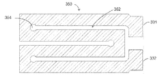
도 3a-3f는 본원의 실시예들에 따른, 2 개의 탭들을 갖는 저항기 시트/호일의 6 개의 설계들을 도시한다. 일 측의 탭은 LoR (-) 단자를 형성하기 위해 음의 전극 시트들의 모든 탭들에 전기적으로 연결 또는 용접되며, 그리고 타 측의 탭은 HiR (-) 단자에 연결된다. 도 3a는 2 개의 탭들 사이의 저항 경로를 제어하기 위해 중간에서 작은 컷에 의해 분리된 시트의 동일 측면 상에 위치된 2 개의 탭들을 도시하고; 도 3b는 서로 마주하는 측면 상에 위치된 2 개의 탭들을 도시하고; 도 3c는 외부 에지들을 향하여 동일 측면 상에 위치된 2 개의 탭들을 도시하고; 도 3d는 외부 에지들을 향하여 서로 마주하는 측면 상에 위치된 2 개의 탭들을 도시하고; 도 3e는 패턴화된 저항기 시트를 도시하고; 도 3f는 선택적인 코팅을 갖는 저항기 시트를 도시한다.
도 4는 본원의 실시예에 따른, 2 개의 전지들 사이에, 즉 배터리 전해액과 직접적인 접촉 없이 각각의 전지 케이스 외부에 하나의 저항기 시트/호일을 갖는 트윈-전지 배터리 모듈의 구성을 도시한다.
도 5는 본원의 실시예에 따른, 하드 케이스 내에 삽입되기 전에, 또는 파우치 전지에 패키징되기 전에, 하나의 저항기 시트/호일이 개재된 한 쌍의 젤리 롤들을 도시한다.
도 6은 본원의 실시예에 따른, 파우치 전지에 포함되어 펼쳐진 젤리 롤을 개략적으로 도시한 것으로, 이때 양의 전극 시트는 양의 단자 (+)를 형성하기 위해 함께 용접되고 밀접하게 이격된 다수의 탭들을 가지며, 음의 전극 시트는 저-저항 단자 LoR (-)를 형성하기 위해 함께 용접되고 밀접하게 이격된 일부 탭들, 나아가 고-저항 단자 HiR (-)을 형성하는 멀리 있는 탭을 가진다. LoR (-) 단자는 열 활성화 스위치에 의해 HiR (-) 단자와 연결된다.
도 7은 본원의 실시예에 따른, 다수의 밀접하게 이격된 탭들 및 멀리 있는 탭을 특징으로 하는 양의 및 음의 전극 시트들 둘 다를 각각 가져 펼쳐진 젤리 롤의 서로 다른 설계를 도시한다. 이러한 설계는 전지 케이스 외부의 4 개의 단자들, 즉 2 개의 양의 LoR (+) 및 HiR (+), 및 2 개의 음의 LoR (-) 및 HiR (-)을 가진다. 두 측면들 상의 2 개의 스위치들은 배터리 온도 및 스위칭 알고리즘에 따라 3 개 이상의 레벨들의 내부 저항을 제공한다.
도 8, 9 및 10은 본원의 실시예들에 따른, 하나 이상의 저항기 시트들을 가진 평탄한 젤리 롤 전극 조립체들을 도시한다.
도 11a-11b는 본원의 실시예에 따른, 26 Ah의 모든 기후 배터리 (ACB)의 -30 ℃에서 1 C 방전 거동을 도시한 일련의 그래프들을 도시한다. 도 11a는 -30 ℃에서, ACB의 1 C 방전 곡선과 종래의 리튬-이온 배터리 (LiB)를 비교한다. 도 11b는 배터리 온도 전개와 ACB와 종래의 LiB 사이의 시간을 비교한다.
도 12a 및 12b 각각은 ACB 및 종래의 LiB 둘 다에 대한 주변 온도의 함수로서 배터리 용량 및 에너지를 도시한다.
도 13a-13c는 하이브리드 파워 펄스 특성 (hybrid power pulse characterization, HPPC) 테스트 하에, -30 ℃에서 ACB의 파워 성능을 도시한 일련의 그래프들이다. 도 13a는 하이브리드 파워 펄스 특성 (HPPC) 테스트의 전류 프로파일을 도시한다; 도 13b는 HPPC 테스트에서 26Ah의 ACB의 전압 응답을 도시한다; 그리고 도 13c는 -30 ℃에서 26Ah의 ACB의 방전 및 충전 파워를 도시한다.BRIEF DESCRIPTION OF THE DRAWINGS Reference is made in the accompanying drawings, wherein elements having the same reference designations are all represented by like elements,
Figure 1 is a cross-sectional view of several resistor sheets / foils embedded in a stack of electrode-separator assemblies, one high-resistance negative terminal HiR (-), and one low- - a schematic representation of all climate batteries (ACB) with a thermally activated switch connecting the terminals LoR (-), positive (+), and HiR (-) and LoR Respectively.
Figure 2 shows a configuration of all climate batteries constructed from one resistor sheet / foil embedded in the middle of a stack of electrode-separator assemblies, according to an embodiment of the present invention.
Figures 3a-3f illustrate six designs of a resistor sheet / foil having two taps, according to embodiments of the present invention. The tab on one side is electrically connected or welded to all the tabs of the negative electrode sheets to form the LoR (-) terminal, and the tab on the other side is connected to the HiR (-) terminal. Figure 3a shows two tabs positioned on the same side of the sheet separated by a small cut in the middle to control the resistance path between the two taps; Figure 3b shows two tabs positioned on opposite sides; Figure 3c shows two tabs positioned on the same side towards the outer edges; Figure 3d shows two tabs positioned on opposite sides facing each other towards the outer edges; Figure 3E shows a patterned resist sheet; Figure 3f shows a resistor sheet with a selective coating.
4 shows a configuration of a twin-cell battery module having one resistor sheet / foil outside each battery case, without the direct contact with the battery electrolyte, between two cells according to an embodiment of the present invention.
Figure 5 shows a pair of jelly rolls with one resistor sheet / foil interposed before being inserted into the hard case or before packaging into the pouch battery, according to embodiments of the present invention.
Figure 6 schematically illustrates a jelly roll unfolded in a pouch battery, according to an embodiment of the present invention, wherein the positive electrode sheets are welded together to form a positive terminal (+) and a plurality of closely spaced And the negative electrode sheet has some taps welded together and closely spaced to form a low-resistance terminal LoR (-), as well as a remote tab forming a high-resistance terminal HiR (-). The LoR (-) terminal is connected to the HiR (-) terminal by the thermal activation switch.
FIG. 7 illustrates a different design of a jellyroll roll, each with both positive and negative electrode sheets featuring a plurality of closely spaced tabs and a remote tab, according to an embodiment of the present invention. This design has four terminals external to the battery case: two positive LoR (+) and HiR (+), and two negative LoR (-) and HiR (-). The two switches on two sides provide an internal resistance of three or more levels depending on the battery temperature and switching algorithm.
Figures 8,9, and 10 illustrate flat jelly roll electrode assemblies having one or more resistor sheets, according to embodiments of the present invention.
Figures 11A-11B show a series of graphs illustrating 1 C discharge behavior at -30 캜 for all climate batteries (ACB) of 26 Ah, according to embodiments of the present invention. 11A compares the 1 C discharge curve of ACB with a conventional Li-ion battery (LiB) at -30 캜. 11B compares battery temperature evolution and time between ACB and conventional LiB.
12A and 12B each show battery capacity and energy as a function of ambient temperature for both ACB and conventional LiB.
13A-13C are a series of graphs illustrating the power performance of the ACB at -30 [deg.] C under hybrid power pulse characterization (HPPC) testing. 13A shows the current profile of the hybrid power pulse characteristic (HPPC) test; Figure 13b shows the voltage response of ACA of 26 Ah in the HPPC test; And Fig. 13C shows discharge and charging power of ACA of 26 Ah at -30 캜.
본원은 종래의 재충전 가능한 배터리들에 비교하여 빙점하의 온도에서 개선된 파워 및 에너지를 전달할 수 있는 재충전 가능한 배터리에 관한 것이다. 상기와 같은 배터리들은 본원에서 모든 기후 배터리 (ACB)를 의미한다. 본원에서 사용되는 바와 같이, 용어 배터리는 하나 이상의 전기 화학 전지들을 포함한 임의의 재충전 가능한 전기 화학 에너지 저장 디바이스를 나타낸다. 배터리 전지의 기본적인 요소들은 전류 콜렉터 상에 코팅된 애노드 전극, 세퍼레이터, 또 다른 전류 콜렉터 상에 코팅된 캐소드 전극, 및 전해액을 포함한다.The present invention relates to a rechargeable battery that is capable of delivering improved power and energy at temperatures below freezing as compared to conventional rechargeable batteries. Such batteries are referred to herein as all climate batteries (ACB). As used herein, the term battery refers to any rechargeable electrochemical energy storage device, including one or more electrochemical cells. The basic elements of a battery cell include an anode electrode coated on a current collector, a separator, a cathode electrode coated on another current collector, and an electrolyte.
본원의 일 양태에서, 재충전 가능한 배터리는 저 주변 온도에서 배터리 전지들 내에 내부 열을 증대할 수 있고, 그 결과 배터리 성능을 제어하는 전기 화학 및 운반 과정은 크게 향상될 수 있다. 배터리의 내부 열은, 배터리의 전지들 중 하나 이상을 가열시키는 하나 이상의 저항기 시트들을 갖는 배터리, 및 상기 배터리가 배터리 온도에 의존하여 고 저항 또는 저 저항으로 동작하도록 할 수 있는 스위치를 구성함으로써, 부분적으로 해결될 수 있다.In one aspect of the invention, the rechargeable battery can augment internal heat in battery cells at low ambient temperatures, and as a result, the electrochemical and transport processes for controlling battery performance can be greatly improved. The internal heat of the battery includes a battery having one or more resistor sheets for heating at least one of the batteries of the battery and a switch capable of causing the battery to operate at a high or low resistance depending on the battery temperature, . ≪ / RTI >
본원의 배터리 구성은 리튬-이온, 리튬-폴리머, 납-산, 니켈-수소 합금 (nickel-metal hydride), 니켈-망간-코발트, 리튬-황, 리튬-에어 및 모든 솔리드-스테이트 배터리들 등을 포함하지만 이에 제한되지 않은 다양한 배터리들에 적용될 수 있다. 재충전 가능한 배터리는 예를 들면, 파우치형, 원통형, 각기둥형, 또는 각진 형태로 형성될 수 있다. 상기와 같은 배터리들은 수송, 항공우주, 군사 및 고정 에너지 저장 적용들에 대해 유용하다.The battery arrangement of the present application may be a lithium-ion, lithium-polymer, lead-acid, nickel-metal hydride, nickel-manganese-cobalt, lithium-sulfur, lithium-air and all solid- But are not limited to, various types of batteries. The rechargeable battery may be formed, for example, in the form of a pouch, a cylinder, a prism, or an angular shape. Such batteries are useful for transportation, aerospace, military and fixed energy storage applications.
본원의 모든 기후 배터리의 이점은, 배터리의 내부 저항이 정상 동작 온도 미만의 온도, 예컨대, 5 ℃ 미만, 또는 빙점하의 온도 (약 0 ℃ 미만의 온도, 예컨대, 약 -10 ℃, -20 ℃, -30 ℃, 또는 -40 ℃ 미만)에서 매우 높게 된다는 점이다. 배터리의 고 내부 저항은 배터리의 열을 오르게 하기 위해 사용될 수 있는 배터리 내에 열을 생성한다. 바람직하게, 배터리의 내부 저항은 몇 초 내에 또는 최대 몇 분 내에 10 도의 섭씨 온도까지 배터리의 열을 빠르게 오르게 하기에 충분히 높게 된다. 배터리 온도가 0 ℃ 내지 배터리의 정상 동작 온도 범위, 통상적으로 약 5 ℃ 또는 그 초과의 온도에 도달한 이후에, 고 내부 저항은 비활성되어, 종래의 배터리들과 같이 낮게 저 내부 저항 모드로 ACB가 동작되도록 함으로써, 배터리가 매우 낮은 주변 온도 환경에 있음에도 불구하고, 고 파워 및 에너지를 전달하는 것을 가능하게 한다. 바람직하게, 본원의 재충전 가능한 배터리들은 온도를 갖는 배터리의 내부 저항을 변화시키기 위해 전압 부스터들을 필요로 하지 않는다. 예를 들면, 본원의 재충전 가능한 배터리들은 실시예로서, 온도를 갖는 배터리의 내부 저항을 변화시키기 위해, 저항기에 파워를 가하는 트랜스포머 또는 DC/DC 컨버터를 포함하지 않는다.An advantage of all climate batteries herein is that the internal resistance of the battery is maintained at a temperature below the normal operating temperature, such as less than 5 占 폚, or below the freezing point (less than about 0 占 폚, for example, about -10, -30 < 0 > C, or -40 < 0 > C). The high internal resistance of the battery creates heat within the battery that can be used to heat up the battery. Preferably, the internal resistance of the battery is high enough to rapidly heat the battery within a few seconds or up to 10 degrees Celsius within a few minutes. After the battery temperature reaches a normal operating temperature range of 0 ° C to the battery's normal operating temperature range, typically about 5 ° C or higher, the high internal resistance is deactivated, causing the ACB to go low in internal resistance mode, Thereby making it possible to deliver high power and energy despite the battery being in a very low ambient temperature environment. Preferably, the rechargeable batteries of the present invention do not require voltage boosters to change the internal resistance of a battery having a temperature. For example, the present rechargeable batteries do not include a transformer or a DC / DC converter that powers a resistor to change the internal resistance of a battery having a temperature as an embodiment.
본원의 양태에서, 재충전 가능한 배터리는 제 1 온도 (T1) 내지 제 2 온도 (T2) 사이의 배터리의 온도 범위에 걸친 제 1 레벨의 내부 저항 (R1), 및 T1 또는 T2 밖에 있는 제 2 레벨의 내부 저항 (R2)을 포함한다. 일부 실시예들에서, R2의 값이 T1 아래로 약 2 ℃에서 결정되고 R1이 T1에서 결정될 시에, R2/R1의 값은 2 내지 500이고, 예컨대, R2/R1의 값은 2 내지 100, 또는 2 내지 50이다. 추가적인 또는 대안적인 실시예들에서 포함되는 바와 같이, R2의 값이 T2 위로 약 2 ℃에서 결정되고 R1이 T2에서 결정될 시에, R2/R1의 값은 2 내지 500이고, 예컨대, R2/R1의 값은 2 내지 100, 또는 2 내지 50이다. 추가적 또는 대안적 실시예들에서, T1은 약 5 ℃ 미만, 예컨대, 바람직하게 약 0 ℃, -10 ℃, -20 ℃, -30 ℃, 또는 -40 ℃ 미만이고; T2는 주어진 재충전 가능한 배터리의 정상 또는 최적 동작 온도 정도보다 큰 온도, 예컨대, 약 50 ℃보다 큰 온도이다.In embodiments herein, the rechargeable battery has a first temperature (T 1) to a second temperature (T 2) the internal resistance of the first level over the temperature range of the battery between the (R 1), and the T 1 or T 2 only And a second level internal resistance R 2 . In some embodiments, when the value of R 2 is determined at about 2 ° C below T 1 and R 1 is determined at T 1 , the value of R 2 / R 1 is from 2 to 500, for example, R 2 / R The value of 1 is 2 to 100, or 2 to 50. When the value of R 2 is determined at about 2 ° C above T 2 and R 1 is determined at T 2 , the value of R 2 / R 1 is from 2 to 500, as included in additional or alternative embodiments, For example, the value of R 2 / R 1 is 2 to 100, or 2 to 50. In further or alternative embodiments, T 1 is less than about 5 ° C, for example, preferably about 0 ° C, -10 ° C, -20 ° C, -30 ° C, or -40 ° C; T 2 is a temperature greater than the normal or optimal operating temperature of a given rechargeable battery, for example, greater than about 50 ° C.
상기와 같은 배터리의 예시는 T1 내지 T2에서, R1로, 예컨대 저 내부 저항 레벨 (LoR)로 배터리를 동작시키는 적어도 하나의 음의 단자 및 적어도 하나의 양의 단자, 배터리 온도가 T1 또는 T2 밖에 있게 될 시에, R2에서, 예컨대 고 내부 저항 레벨 (HiR)에서, 배터리를 동작시키는 적어도 하나의 고 저항 단자를 포함한 재충전 가능한 배터리를 포함한다. 고 저항 단자는 추가적인 음의 단자 (즉, HiR (-)) 또는 추가적인 양의 단자 (즉, HiR (+))일 수 있다.Examples of such batteries include at least one negative terminal and at least one positive terminal for operating the battery at R 1 , e.g., a low internal resistance level (LoR), at T 1 to T 2 , a battery temperature T 1 Or at least one high resistance terminal for operating the battery, for example at a high internal resistance level (HiR), at R 2 when it is outside T 2 . The high resistance terminal may be an additional negative terminal (i.e., HiR (-)) or an additional positive terminal (i.e., HiR (+)).
상기와 같은 재충전 가능한 배터리는 배터리의 저항 레벨들을 스위칭하는 스위치를 포함할 수 있다. 예를 들면, 스위치는, 배터리의 온도가 T1 내지 T2에 있을 시에, 배터리를 동작시키기 위해, 배터리의 저 저항 단자들, 예컨대, LoR (-) 및/또는 LoR (+)과 맞닿을 수 있으며, 그리고 배터리 온도가 T1 또는 T2 밖에 있을 시에, 하나 이상의 고 저항 단자, 예컨대, HiR (-) 및/또는 HiR (+)과 맞닿을 수 있다.Such a rechargeable battery may include a switch for switching the resistance levels of the battery. For example, the switch may be in contact with the low resistance terminals of the battery, e.g., LoR (-) and / or LoR (+), to operate the battery when the temperature of the battery is between T 1 and T 2 (-) and / or HiR (+) when the battery temperature is outside of T 1 or T 2 .
본원의 스위치는, 예를 들면 결빙될 시에 팽창하고 스위치 열림을 푸싱하는 (push) 글리콜-물 (glycol-water) 액체 캡슐, T1 또는 T2, 또는 둘 다에서 상 전이 (phase transition) 및 주목할 만한 볼륨 변화를 겪게 되는 상-변화 (phase-change) 물질, 또는 바이메탈 (bimetal) 스위치, 또는 볼륨이 온도 T1 또는 T2, 또는 둘 다에서 주목할 정도로 팽창되는 솔리드 물질과 같은 열 감지 디바이스들에 의해 활성화된 스위치를 포함할 수 있다.The switch of the present disclosure may be used in a glycol-water liquid capsule, such as, for example, a glycol-water liquid capsule that expands when frozen and pushes the switch open, a phase transition at T 1 or T 2 , Phase-change materials or bimetal switches that undergo notable volume changes, or heat-sensing devices such as solid materials whose volume is noticeably expanded at temperatures T 1 or T 2 , or both Lt; RTI ID = 0.0 > switch. ≪ / RTI >
본원의 스위치는 전기 기계 릴레이 및 온도 제어기, 또는 온도 센서를 갖는 솔리드-스테이트 릴레이, 온도 센서를 갖는 파워 MOSFET, 또는 온도 센서를 갖는 고-전류 스위치로 구성될 수 있다. 대안적으로, LoR (-) 및 HiR (-) 단자들을 연결하는 스위치는 배터리 관리 시스템에서 전기 회로 및 전지 온도 센서를 가진 제어기에 의해 수행될 수 있다.The switches herein may be comprised of electromechanical relays and temperature controllers, or solid-state relays with temperature sensors, power MOSFETs with temperature sensors, or high-current switches with temperature sensors. Alternatively, the switch connecting the LoR (-) and HiR (-) terminals may be performed by a controller having an electrical circuit and a battery temperature sensor in a battery management system.
본원의 실시예에서, 상기 재충전 가능한 배터리는 고 저항 단자에 전기적으로 연결된 적어도 하나의 저항기 시트를 포함한다. 상기 적어도 하나의 저항기 시트는 배터리 전지 (전해액에 노출됨) 내부에, 또는 2 개의 배터리 전지들 외부에 그리고 상기 2 개의 배터리 전지들 사이에, 또는 전지들 내부의 일부 저항기 시트들과 전지들 외부의 일부 저항기 시트들의 조합에 위치될 수 있다. 추가로, 배터리의 전지 내에 구성된 저항기 시트는 배터리의 전지의 전극의 전류 콜렉터의 일체형 부분일 수 있다.In an embodiment of the invention, the rechargeable battery includes at least one resistor sheet electrically connected to a high resistance terminal. The at least one resistor sheet may be disposed within a battery cell (exposed to electrolyte), or outside the two battery cells and between the two battery cells, or between some of the resistor sheets within the cells and a portion May be located in a combination of resistor sheets. In addition, the resistor sheet formed in the battery of the battery may be an integral part of the current collector of the electrode of the battery of the battery.
본원에서 사용되는 바와 같이, 저항기 시트는 배터리 전극의 변형되지 않은 전류-수집 호일에 대해 유사하거나 낮은 전기 전도도를 가지지만, 배터리 동작 동안 활성화될 시에 배터리의 내부 전기 저항에 상당한 증가를 일으키는 물질이다. 저항기 시트는 바람직하게 0.1 내지 5를 배터리의 용량 Ah (Amp-hours)로, 예컨대 약 0.5 내지 2를 배터리의 용량 Ah로 나눈 수치 값과 동일한 Ohm의 단위인 저항을 가진다. 예를 들면, 20 Ah 배터리용 저항기 시트는 바람직하게, 약 0.005 Ohm (0.1을 20으로 나눔) 내지 약 0.25 Ohm (5를 20으로 나눔), 예컨대 약 0.025 Ohm (0.5를 20으로 나눔) 내지 약 0.1 Ohm (2를 20으로 나눔)이다.As used herein, a resistor sheet has a similar or low electrical conductivity to an unmodified current-collecting foil of a battery electrode, but is a material that causes a significant increase in the internal electrical resistance of the battery when activated during battery operation . The resistor sheet preferably has a resistance in the unit of Ohm, which is equal to a numerical value of 0.1 to 5 divided by the capacity Ah (Amp-hours) of the battery, e.g., about 0.5 to 2 divided by the capacity Ah of the battery. For example, a 20 Ah battery resistor sheet preferably has a resistance value of about 0.005 Ohm (0.1 divided by 20) to about 0.25 Ohm (5 divided by 20), such as about 0.025 Ohm (0.5 divided by 20) to about 0.1 Ohm (2 divided by 20).
본원의 저항기 시트들은, 배터리 전해액에 노출될 시에 안정되며 그리고 저항기 시트가 상기와 같은 환경에 노출될 시에 모든 기후 배터리의 전기 화학 전압 창 (window) 내에 있는 임의의 충분한 물질일 수 있다. 상기와 같은 저항기 시트들은 예를 들면, 그라파이트, 고 방향 피롤리틱 그라파이트 (highly ordered pyrolytic graphite, HOPG), 스테인리스 강, 니켈, 크롬, 니크롬, 구리, 알루미늄, 티타늄, 또는 그의 조합들로 구성될 수 있다. 배터리 전지들 외부에서 그리고 모듈 내의 2 개의 인접한 전지들 사이에서 사용되는 경우, 저항기 시트들은 내부식성일 필요가 없으며, 이로써, 추가 물질들이 본원의 저항기 시트들로서 사용되기에 이용 가능하다. 소정의 실시예들에서, 본원의 저항기 시트는 바람직하게 평탄하고 표면적이 크고, 그 결과 인접한 배터리 컴포넌트들과 우수한 접촉을 할 수 있다. 본원의 저항기 시트들은 약 1 마이크로미터 내지 약 150 마이크로미터의 두께, 바람직하게는 약 5 내지 약 60 마이크로미터의 두께 범위를 가질 수 있다. 큰 전기 저항, 높은 열 전도도, 및 작은 열 용량을 가진 저항기 시트들은 본원의 소정의 실시예들에 대해 유용하다.The resistor sheets herein are stable enough when exposed to battery electrolyte and can be any sufficient material within the electrochemical voltage window of all climate batteries when the resistor sheet is exposed to such an environment. Such resistor sheets may be composed of, for example, graphite, highly ordered pyrolytic graphite (HOPG), stainless steel, nickel, chromium, nichrome, copper, aluminum, titanium, have. When used outside of battery cells and between two adjacent cells in a module, the resistor sheets need not be corrosion-resistant, so that additional materials are available for use as the resistor sheets of the present invention. In certain embodiments, the resistor sheet of the present disclosure is preferably flat and has a large surface area, so that excellent contact with adjacent battery components is possible. The resistor sheets herein may have a thickness ranging from about 1 micrometer to about 150 micrometers, preferably from about 5 to about 60 micrometers. Resistor sheets with large electrical resistance, high thermal conductivity, and small thermal capacity are useful for certain embodiments of the present disclosure.
저항기 시트의 저항은 시트를 패턴화함으로써, 즉 저항기 시트로부터 물질을 제거함으로써 조정될 수 있다. 패턴화는 저항기 시트가 기계적 강도 및 용접성에 대해 충분한 두께를 가지지만 감소된 저항을 가지도록 한다. 원형 코너들을 가진 패턴들은 패턴의 코너에서 온도 증가 (build-up)를 줄이는 이점을 가진다. 패턴화된 저항기 시트들은 포토 에칭, 방전 가공, 워터 제트 컷팅, 레이저 컷팅, 스탬핑 등에 의해 제조될 수 있다.The resistance of the resistor sheet can be adjusted by patterning the sheet, i. E. Removing the material from the resistor sheet. The patterning allows the resistor sheet to have a thickness that is sufficient for mechanical strength and weldability but has a reduced resistance. Patterns with rounded corners have the advantage of reducing the build-up at the corners of the pattern. The patterned resistive sheets can be produced by photoetching, electrical discharge machining, water jet cutting, laser cutting, stamping and the like.
일부 실시예들에서, 저항기 시트 표면의 실질적인 부분은 전해액과의 원치 않는 화학 반응 또는 전기 연결을 방지하기 위해 코팅될 수 있다. 예를 들면, 저항기 시트들은 선택적으로 코팅될 수 있고, 이때 그들의 표면 일부는 다른 탭들 또는 단자들과 전기 연결을 위해 코팅되지 않고, 표면의 나머지는 코팅되고, 이로써, 전기적으로 그리고 화학적으로 격리된다. 보호 코팅은 시작 시에 저항기 시트들의 전체 표면을 완전하게 덮기 위해 적용될 수 있고, 그 이후에 소정의 구역에서의 코팅은 다른 탭들 또는 단자들과의 필요한 전기 연결을 허용하기 위해 선택적으로 제거될 수 있다. 보호 코팅은 열 전도성이 있고, 전기적으로 절연되고, 배터리 전지 내에서 화학적으로 안정되어야 한다. 보호 코팅은 폴리머들, 금속 산화들, 및 다른 것들로 구성될 수 있다. 보호 코팅에 대한 폴리머 물질들의 예시들은 다음을 포함한다: 폴리에틸렌, 폴리프로필렌, 염소화 (chlorinated) 폴리프로필렌, 폴리에스터, 폴리이미드, PVDF, PTFE, 나일론, 또는 이들의 코 (co)-폴리머들. 보호 코팅에 대한 금속 산화 물질들의 예시들은 Mg, Al, Ti, V, Cr, Mn, Fe, Co, Ni, Cu, Zn, 및 그의 조합물의 산화물들을 포함한다. 보호 코팅은 고 유전율 (dielectric constant)을 가지는 것이 바람직하다. 일부 실시예들에서, 접착제는 저항기 시트들과 보호 코팅 사이에서 사용될 수 있다. 보호 코팅의 두께는 10nm 내지 100um, 바람직하게 10 nm 내지 50 um일 수 있다. 코팅은 우수한 열 전달을 허용하지만 배터리 전지 내부의 전해액과 저항기 시트가 접촉되는 것을 보호하기 위해 불침투성이기에 충분히 얇아야 한다. 보호 코팅은 테이핑, 라미네이팅, 딥 코팅, 스핀 코팅, 스프레잉 코팅, 화학 증기 증착, 원자 층 증착, 용해 주조, 전착 (electrodeposition), 자가-조립 모노층, 스테레오리소그라피 (stereolithography), 표면 산화 및 기타 등등과 같은 방법에 의해 저항기 시트들 상에 도포될 수 있다.In some embodiments, a substantial portion of the surface of the resistor sheet may be coated to prevent unwanted chemical reactions or electrical connections with the electrolyte. For example, the resistor sheets may be selectively coated, wherein some of their surfaces are not coated for electrical connection with other taps or terminals, and the remainder of the surface is coated, thereby electrically and chemically isolating. The protective coating can be applied to completely cover the entire surface of the resistor sheets at start-up, after which the coating in a given area can be selectively removed to allow the necessary electrical connection with other taps or terminals . The protective coating must be thermally conductive, electrically insulated, and chemically stable within the battery cell. The protective coating may be comprised of polymers, metal oxides, and others. Examples of polymeric materials for the protective coating include: polyethylene, polypropylene, chlorinated polypropylene, polyester, polyimide, PVDF, PTFE, nylon, or co-polymers thereof. Examples of metal oxide materials for the protective coating include oxides of Mg, Al, Ti, V, Cr, Mn, Fe, Co, Ni, Cu, Zn, and combinations thereof. The protective coating preferably has a high dielectric constant. In some embodiments, an adhesive may be used between the resistor sheets and the protective coating. The thickness of the protective coating may be between 10 nm and 100 um, preferably between 10 nm and 50 um. The coating should be thin enough to allow good heat transfer, but impermeable to protect the electrolyte in the battery cell from contact with the resistor sheet. Protective coatings may be applied to a substrate such as by taping, laminating, dip coating, spin coating, spray coating, chemical vapor deposition, atomic layer deposition, melt casting, electrodeposition, self-assembling monolayer, stereolithography, , ≪ / RTI > on the resistor sheets.
본원의 소정의 구성들에서, 재충전 가능한 배터리는 하나 이상의 고 저항 탭들 또는 단자들 및 하나 이상의 저 저항 탭들 또는 단자들을 포함한다. 고 저항 단자들은 전기적으로 하나 이상의 저항 시트들을 연결하며, 그리고 저 저항 탭들 또는 단자들은 저 내부 저항 모드로 배터리를 동작시키기 위해 구성된다.In certain embodiments of the present application, a rechargeable battery includes one or more high resistance taps or terminals and one or more low resistance taps or terminals. The high resistance terminals electrically couple one or more resistance sheets, and the low resistance taps or terminals are configured to operate the battery in a low internal resistance mode.
바람직하게, 본원의 재충전 가능한 배터리는 소정의 실시예들에서 최소 변형으로 종래의 재충전 가능한 배터리 컴포넌트들로 손쉽게 구성될 수 있다. 일반적인 말로, 리튬-이온 배터리와 같은 종래의 배터리는, 젤리 롤로 스택화되거나 권취되고 파우치 커버 또는 하드 케이스로 패키지화될 수 있는 애노드 전극들, 세퍼레이터들 및 캐소드 전극들 중 하나 이상의 시트들을 포함한다. 그 후에, 파우치 또는 케이스는 전해액으로 충전된다. 캐소드 활성 물질들은 예를 들면, 리튬 코발트 산화물, 리튬 인산철 (iron phosphate), 리튬 망간 산화물, 리튬 니켈-코발트-망간 산화물들, 리튬-풍부 층 산화물들, 또는 이들의 혼합물들 등을 포함할 수 있다. 애노드 활성 물질들은 예를 들면, 그라파이트, 실리콘, 실리콘 합금들, 리튬 금속, 리튬 합금들 예를 들면 리튬 티탄산염, 이들의 혼합물들 등을 포함할 수 있다.Preferably, the rechargeable battery of the present invention can be readily configured with conventional rechargeable battery components with minimal variations in certain embodiments. In general, a conventional battery, such as a lithium-ion battery, includes one or more sheets of anode electrodes, separators, and cathode electrodes that can be stacked or rolled into a jellyroll and packaged in a pouch cover or hard case. Thereafter, the pouch or case is filled with the electrolytic solution. The cathode active materials may include, for example, lithium cobalt oxide, lithium phosphate, lithium manganese oxide, lithium nickel-cobalt-manganese oxides, lithium-rich layer oxides, have. The anode active materials may include, for example, graphite, silicon, silicon alloys, lithium metal, lithium alloys such as lithium titanate, mixtures thereof, and the like.
예를 들면, 종래의 리튬-이온 배터리는 양의 전극, 음의 전극, 세퍼레이터, 양의 전극 전류 콜렉터, 음의 전극 전류 콜렉터, 전해액 및 배터리 커버 또는 캔을 포함한다. 하나의 전류 수집 호일 (예컨대 Al 호일) 상에 코팅된 양의 전극 및 또 다른 전류 수집 호일 (예컨대 Cu 호일) 상에 코팅된 음의 전극은 그 사이에 개재된 세퍼레이터와 함께 스택화되거나 권취되며, 그리고 전해액이 솔벤트에서 용해되는 전해액 용액은 세퍼레이터 및 2 개의 다공성 전극들에 스며들게 된다.For example, a conventional lithium-ion battery includes a positive electrode, a negative electrode, a separator, a positive electrode current collector, a negative electrode current collector, an electrolyte, and a battery cover or can. A positive electrode coated on one current collecting foil (e.g., Al foil) and a negative electrode coated on another current collecting foil (e.g., a Cu foil) are stacked or wound together with a separator interposed therebetween, And the electrolyte solution in which the electrolyte is dissolved in the solvent is impregnated into the separator and the two porous electrodes.
양의 및 음의 전극들 둘 다는 필요하면 상술된 활성 물질들, 바인더들 및 도전제들 (conducting agents)을 포함한다. 공통 바인더들은 PVDF (Polyvinylidene fluoride) 및 SBR (styrene-butadiene rubber) 및 CMC (carboxymethyl cellulose)의 소듐 염을 포함한다. 도전제들은 일반적으로 탄소를 기반으로 하고 활성 물질들과 혼합되어, 전극 전도도를 증가시킨다.Both positive and negative electrodes include the active materials, binders, and conducting agents described above, if desired. Common binders include polyvinylidene fluoride (PVDF) and sodium salts of styrene-butadiene rubber (SBR) and carboxymethyl cellulose (CMC). Conductors are generally based on carbon and are mixed with active materials to increase electrode conductivity.
리튬 염들 예를 들면 LiPF6, LiBF4 등은 전해액으로서 단독으로 또는 조합하여 사용될 수 있다. 연쇄형 카보네이트 (chained carbonate), 환형 카보네이트, 환형 에스테르, 니트로 화합물 등은 리튬 염들을 용해시키기 위해 사용된 솔벤트로서 사용될 수 있다. 그의 특정 예시들은 에틸렌 카보네이트 (ethylene carbonate, EC), 에틸 메틸 카보네이트 (ethyl methyl carbonate, EMC), 디메틸 카보네이트 (dimethyl carbonate, DMC), 프로필렌 카보네이트 (propylene carbonate, PC), 디에틸 카보네이트, 디메톡시에탄 (dimethoxyethane) 등을 포함한다. 추가로, 폴리머-젤 (gel) 전해액 또는 솔리드 전해액이 전해액으로 사용될 수 있다.Lithium salts such as LiPF 6 , LiBF 4 and the like can be used alone or in combination as an electrolytic solution. Chained carbonate, cyclic carbonates, cyclic esters, nitro compounds and the like can be used as the solvent used to dissolve lithium salts. Specific examples thereof include ethylene carbonate (EC), ethyl methyl carbonate (EMC), dimethyl carbonate (DMC), propylene carbonate (PC), diethyl carbonate, dimethoxyethane dimethoxyethane) and the like. In addition, a polymer-gel electrolyte or a solid electrolytic solution can be used as an electrolytic solution.
본원의 재충전 가능한 배터리는 재충전 가능한 배터리의 종래의 컴포넌트들을 포함하고, 추가적으로 예를 들면 하나 이상의 저항기 시트들에 연결된 하나 이상의 고 저항 단자들을 포함할 수 있다. 하나 이상의 저항기 시트들은 배터리의 전지 내에, 또는 배터리의 전지들 사이에, 또는 이들의 일부 조합에 위치되어, 배터리 내에 열을 발생시킬 수 있다. 다음의 도면은 본원의 소정의 실시예들을 도시한다.The rechargeable battery of the present disclosure includes conventional components of a rechargeable battery and may additionally include one or more high resistance terminals connected to one or more resistor sheets, for example. The one or more resistor sheets may be located within the battery of the battery, or between the batteries of the battery, or some combination thereof, to generate heat within the battery. The following figures illustrate certain embodiments of the invention.
도 1 및 2는 본원의 실시예들을 도시한다. 도 1에 도시된 바와 같이, 재충전 가능한 배터리 (110)는 전극-세퍼레이터 조립체들의 스택 내에 매립된 여러 개의 저항기 시트들 (112)을 가진다. 전극-세퍼레이터 조립체들은 애노드 탭들 (114a)을 가진 애노드 전극들 (114), 세퍼레이터들 (116) 및 캐소드 탭들 (118a)을 가진 캐소드 전극들 (118)을 포함한다. 배터리 (110)는 하나의 저-저항 음의 단자 LoR (-) (120) 및 하나의 고-저항 음의 단자 HiR (-) (122), 스위치 (124) 및 양의 단자 (+) (126)를 더 포함한다.Figures 1 and 2 illustrate embodiments of the present application. As shown in Figure 1, the
이러한 실시예에서, 각각의 저항기 시트는 용접에 의해 부착될 수 있는 2 개의 탭들 (112a, 112b)을 가진다. 저항기 탭 (112a) 및 애노드 전극들 (114)의 애노드 탭들 (114a)은 저 전기 저항 회로를 형성하기 위해 저-저항 음의 단자 LoR (-) (120)에 전기적으로 연결된다. 저항기 탭 (112b)은 스위치 (124)에 의해 활성화되는 고 전기 저항 레벨 회로를 형성하기 위해 고-저항 음의 단자 HiR (-) (122)에 전기적으로 연결된다. 캐소드 전극들 (118)의 캐소드 탭들 (118a)은 함께 양의 단자 (126)에 전기적으로 연결된다. 이러한 특정 예시에서, 스위치 (124)는 LoR (-) 단자 (120) 및 HiR (-) 단자 (122)를 전기적으로 연결 또는 분리시킬 수 있는 열 활성화 (thermally activated) 스위치이다.In this embodiment, each resistor sheet has two
애노드-세퍼레이터-캐소드-저항기 시트 조립체는 적절한 패키지에, 예컨대 파우치 전지의 케이스에 위치되어 전해액으로 충전될 수 있다. 이러한 실시예에서, 애노드-세퍼레이터-캐소드-저항기 시트 조립체는 케이스 (140)에 포함된다. 음의 및 양의 단자들은 외부 회로 (128a 및 128b)에 전기적으로 연결될 수 있다.The anode-separator-cathode-resistor sheet assembly may be placed in a suitable package, for example a case of a pouch battery, and filled with an electrolytic solution. In this embodiment, the anode-separator-cathode-resistor sheet assembly is included in
요약해서 말하면, 도 1에 도시된 재충전 가능한 배터리는 케이스 (140)의 외부 상의 3 개의 단자들, 2 개의 음의 단자들 (LoR (-) 및 HiR (-)), 및 하나의 양의 단자 (+)의 특징을 이룬다. 2 개의 음의 단자들 (LoR (-) 및 HiR (-))은 배터리의 외부에서 온도-감지 스위치에 의해 즉각적으로 더 연결된다. 동작 시에, 배터리 온도가 제 1 온도 (T1) 내지 제 2 온도 (T2)로 정의된 정상 동작 범위 내에 있을 시에, 스위치는 닫히게 되며 (CLOSED), 그리고 배터리 전류는 저항기 시트들을 우회하는데, 이는 전류가 저-저항 회로를 통해 흐르는 것을 선호하기 때문이다. 이러한 경우에, 배터리는 단자들 (+)과 LoR (-) 사이에서 동작되어, 저 내부 저항을 보인다. 배터리 온도가 T1 및 T2의 정상 범위를 벗어날 시에, 스위치는 열리게 되어 (OPEN), 단자들 (+) 및 HiR (-)가 동작하게 된다. 이는 배터리 전류가 저항기 시트들을 통해 흐르도록 힘이 가해지며, 이로써, 고 내부 저항을 보인다. 예를 들면, 배터리 온도가 정상 범위 미만일 시에, 예를 들면 약 5 ℃ 미만, 또는 빙점하의 환경에 있을 시에, 배터리의 내부 저항은 전류 흐름 경로에 저항기 시트들의 존재로 인해, 몇 배 높게 (several-fold higher) 된다. 동작 또는 활성화되면, 강렬한 내부 열이 있고 (배터리의 열 발생은 그의 내부 저항에 비례하기 때문임), 이는 온도-감지 스위치를 CLOSED로 트리거링하는 지점으로 배터리 온도를 빨리 상승시킨다. CLOSED 스위치는 즉각적으로 LoR (-) 단자가 동작되도록 할 수 있으며, 배터리 내부 저항을 낮춘다. 저 내부 저항 및 고 내부 온도의 조합은 실질적으로 빙점하의 환경에서 동작함에도 불구하고, 배터리의 파워 및 에너지 출력을 개선시킨다.In short, the rechargeable battery shown in Fig. 1 has three terminals on the exterior of the
도 2는 배터리에서 열을 발생시키는 전극-세퍼레이터 조립체들의 스택 사이에 삽입된 적어도 하나의 저항기 시트들을 가진 재충전 가능한 배터리의 또 다른 구성을 도시한다. 이러한 실시예에서, 재충전 가능한 배터리 (210)는 2 개의 전극-세퍼레이터 조립체들 (213a 및 213b) 사이에 위치된 저항기 시트 (212)를 포함한다. 저항기 시트는 열이 보다 균일해지도록 전극들의 스택의 중간에 바람직하게 위치되며, 그리고 세퍼레이터들 (216)과 동일하거나 서로 다를 수 있는 세퍼레이터들 (217)에 의해 개재될 수 있다. 각각의 전극-세퍼레이터 조립체는 애노드 전극들 (214), 세퍼레이터들 (216) 및 캐소드 전극들 (218)을 포함한다. 배터리 (210)는 하나의 저-저항 음의 단자 LoR (-) (220), 하나의 고-저항 음의 단자 HiR (-) (222), 스위치 (224) 및 양의 단자 (+) (226)를 더 포함한다. Figure 2 shows another configuration of a rechargeable battery having at least one resistor sheets inserted between the stacks of electrode-separator assemblies that generate heat in the battery. In this embodiment, the
이러한 실시예에서, 저항기 시트 (212)는 용접에 의해 부착될 수 있는 2 개의 탭들 (212a, 212b)을 가진다. 저항기 탭 (212a) 및 애노드 전극들 (214)의 애노드 탭들 (214a)은 저 전기 저항 회로를 형성하기 위해 저-저항 음의 단자 LoR (-) (220)에 전기적으로 연결된다. 저항기 탭 (212b)은 스위치 (224)에 의해 활성화되는 고 전기 저항 레벨 회로를 형성하기 위해 고-저항 음의 단자 HiR (-) (222)에 전기적으로 연결된다. 캐소드 전극들 (218)의 캐소드 탭들 (218a)은 함께 양의 단자 (226)에 전기적으로 연결된다. 이러한 특정 예시에서, 스위치 (224)는 LoR (-) 단자 (220) 및 HiR (-) 단자 (222)를 전기적으로 연결 또는 분리시킬 수 있는 열 활성화 스위치이다.In this embodiment, the
애노드-세퍼레이터-캐소드-저항기 시트 조립체는 적절한 패키지에, 예컨대 파우치 전지의 케이스에 위치되어 전해액으로 충전될 수 있다. 이러한 실시예에서, 애노드-세퍼레이터-캐소드-저항기 시트 조립체는 케이스 (240)에 포함된다. 음의 및 양의 단자들은 외부 회로 (228a 및 228b)에 전기적으로 연결될 수 있다. 도 2의 재충전 가능한 배터리 (210)는 도 1에 대해 기술된 바와 동일한 방식으로 동작될 수 있다.The anode-separator-cathode-resistor sheet assembly may be placed in a suitable package, for example a case of a pouch battery, and filled with an electrolytic solution. In this embodiment, the anode-separator-cathode-resistor sheet assembly is included in
도 3은 도 1 및 도 2에 도시된 구성들에 포함되는, 본원의 재충전 가능한 배터리들에 사용될 수 있는 서로 다른 저항기 시트 구성들을 도시한다. 각각의 저항기 시트 (310, 320, 330, 340, 350, 360)는 용접에 의해 부착될 수 있는 2 개의 탭들을 가진다. 다양한 저항기 시트들 상의 탭들은 도 3에 도시된 바와 같이, 다양한 구성들에 위치될 수 있다. 이러한 구성들은 다음을 포함한다: (a) 컷 (314)에 의해 분리된 동일 측면 상의 2 개의 탭들 (311, 312); (b) 저항기 시트의 서로 마주하는 측면 상에 있고 에지의 중간 가까이에 위치된 2 개의 탭들 (321, 322); (c) 및 (e) 동일 측면 상에 있지만, 저항기 시트의 외부 에지들 상에 있고 컷 (334)에 의해 분리된 2 개의 탭들 (331, 332); 및 (d) 및 (f) 저항기 시트의 서로 마주하는 측면 상에 있지만 외부 에지들 상에 있는 2 개의 탭들 (341, 342).FIG. 3 illustrates different resistor sheet configurations that may be used in rechargeable batteries of the present invention, included in the configurations shown in FIGS. 1 and 2. Each
일부 실시예들에서, 저항기 시트의 저항은 패턴화 (patterning)를 통해 조정될 수 있다. 상기와 같은 패턴화는, 시트를 보다 얇게 하여 시트의 저항을 조정하는 경우 (다른 탭들과의 저항기 시트의 기계적 강도 또는 용접성 (weldability)에 악영향을 줄 수 있음)보다 더 저항기 시트를 두껍게 하는 것을 허용한다. 패턴화할 시에, 핫 스팟들을 최소화시키기 위해, 원형 코너들이 직선 코터들에 비해 선호된다. 패턴화된 저항기 시트들은 포토 에칭 (photo etching), 방전 가공 (electrical discharge machining), 워터 제트 컷팅 (water jet cutting), 레이저 컷팅 (laser cutting), 스탬핑 등에 의해 제조될 수 있다. 도 3e는 본원의 재충전 가능한 배터리들에 사용될 수 있는 패턴화된 저항기 시트를 도시한다. 도 3e는 동일 측면 상에 있지만 저항기 시트의 외부 에지들 상에 있는 2 개의 탭들 (331, 332)을 도시하며, 또한 원형 코너들 (354)과 함께 시트의 내부 (즉, 일반적인 패턴 (352))로부터 제거된 물질을 도시한다. 다른 실시예들에서 또는 다른 실시예들과 조합하여, 저항기 시트는, 배터리 전지 내에서 열 전도성이고, 전기적으로 절연되며, 화학적으로 안정된 폴리머 또는 산화 박형 (thin) 층으로 코팅될 수 있다. 도 3f는 시트의 두 주요 측면들 상에 코팅을 가진 저항기 시트를 도시한다. 이러한 특정 실시예에서, 코팅은 저항기 시트 (364)를 완전하게 둘러싸지만 탭들 (341, 342)을 노출시킨 라미네이트 (laminate) (362)이다.In some embodiments, the resistance of the resistor sheet can be adjusted through patterning. Such patterning allows thicker resistor sheets than when thinning the sheet to adjust the resistance of the sheet (which can adversely affect the mechanical strength or weldability of the resistor sheet with other taps) do. When patterning, circular corners are preferred over straight coaters to minimize hot spots. The patterned resistive sheets can be produced by photo etching, electrical discharge machining, water jet cutting, laser cutting, stamping, and the like. Figure 3e illustrates a patterned resistive sheet that can be used in rechargeable batteries of the present invention. Figure 3e shows two
본원의 일 실시예에서, 도 3에 도시된 저항기 시트들 중 하나 이상은 도 1 또는 도 2의 구성들에 사용될 수 있다. 예를 들면, 도 3에서의 임의의 저항기 시트에 대해, 탭 1로 라벨링된 탭들은 배터리에서 애노드 전극 시트들의 모든 탭들과 연결될 수 있다 (예컨대 용접될 수 있다). 함께, 그들은 도 1 또는 도 2에서의 저-저항 단자 LoR (-)를 형성한다. 도 3에 도시된 바와 같은 탭들 (2)은 도 1 또는 도 2에서의 고-저항 단자 HiR (-)를 형성하기 위해 함께 용접될 수 있다.In one embodiment of the invention, one or more of the resistor sheets shown in FIG. 3 may be used in the configurations of FIG. 1 or FIG. For example, for any resistor sheet in FIG. 3, the tabs labeled as
본원의 다른 실시예들에서, 재충전 가능한 배터리는 배터리의 전지 외부에 하나 이상의 저항기 시트들을 위치시킴으로써 구성될 수 있다. 예를 들면, 다수의 전지들을 포함한 배터리 모듈에서, 하나 이상의 저항기 시트들은 배터리 모듈 내의 2 개의 인접한 전지들 사이에 개재될 수 있다. 도 4는 상기와 같은 실시예를 도시한다.In other embodiments of the invention, a rechargeable battery may be configured by placing one or more resistor sheets on the outside of the battery of the battery. For example, in a battery module comprising a plurality of cells, one or more resistor sheets may be interposed between two adjacent cells in the battery module. Fig. 4 shows such an embodiment.
도 4에 도시된 바와 같이, 배터리 모듈 (410)은 2 개의 전지들 (413a 및 413b) 사이에 위치된 저항기 시트 (412)를 포함한다. 저항기 시트는 전지들 및 배터리 모듈의 균일한 열을 제공하기 위해 전지들 사이에 바람직하게 위치되고, 예를 들면, 2 개의 전지들 사이에서 단단하게 개재된다. 각각의 전지는 애노드 전극들 (414), 세퍼레이터들 (416) 및 캐소드 전극들 (418)을 포함한다. 배터리 모듈 (410)은 상기 모듈의 각 전지에 전기적으로 연결된 하나의 저-저항 음의 단자 LoR (-) (420), 및 저항기 시트에 전기적으로 연결된 하나의 고-저항 음의 단자 HiR (-) (422)을 더 포함한다. 배터리 모듈은 또한 스위치 (424) 및 양의 단자들 (+) (426a 및 426b)을 포함한다. 음의 및 양의 단자들은 외부 회로 (428a 및 428b)에 전기적으로 연결될 수 있다. 도 4의 재충전 가능한 배터리 모듈 (410)은 도 1에 대해 기술된 바와 같이 동일한 방식으로 동작될 수 있다.As shown in FIG. 4, the
도 4에서의 배터리 모듈 (410)이 2 개의 전지들 사이에 하나의 저항기 시트를 갖는 트윈-전지 모듈로서 도시되지만, 본원의 배터리 모듈들은 3 개 이상의 전지들을 가질 수 있고, 그리고/또는 전지 모듈들의 중간에 위치된 2 개 이상의 저항기 시트들을 가질 수 있다. 예를 들면, 배터리 모듈은, 전지들 사이에, 그리고 상기 전지들 근방의 다른 위치들 주위에 위치된 하나 이상의 저항기 시트들을 갖는 4 개, 5 개 또는 6 개의 전지들을 가질 수 있다.Although the
본원의 일 실시예에서, 도 3에 도시된 저항기 시트들 중 하나 이상은 도 4의 구성들에서 사용될 수 있다. 예를 들면, 도 3에서의 임의의 저항기 시트에 대해, 탭 1로 라벨링된 탭들은 전지들의 음의 단자들에 연결되어, 배터리 모듈용 저-저항 단자 LoR (-)를 형성할 수 있다. 도 3에 도시된 저항기 시트들 중 어느 것의 탭 (2)은 배터리 모듈의 고 저항 단자 HiR (-)를 형성하기 위해 함께 용접될 수 있다. 상기와 같은 배터리 모듈의 활성 및 동작은 처음에 기술된 단일 전지와 동일하다.In one embodiment of the invention, one or more of the resistor sheets shown in Figure 3 may be used in the arrangements of Figure 4. For example, for any of the resistor sheets in FIG. 3, the tabs labeled as
본원의 또 다른 실시예에서, 하나 이상의 저항기 시트들은 재충전 가능한 배터리의 전극-세퍼레이터 조립체의 2 개의 젤리 롤들 사이에 개재될 수 있다. 도 5는 상기와 같은 실시예를 도시한다. 도 5에 도시된 바와 같이, 저항기 시트 (512)는 2 개의 젤리 롤들 (513a, 513b) 사이에 개재된다. 이러한 실시예에서의 설계는 젤리 롤 전극 조립체들을 포함한 임의의 종래의 재충전 가능한 배터리로 사용될 수 있다. 도 5에 더 도시된 바와 같이, 전기 저항기 시트 (512)는 용접에 의해 부착될 수 있는 2 개의 탭들 (512a, 512b)을 가진다. 저항기 탭 (512a)은 젤리 롤의 애노드 전극들 (설명 편의를 위해 미도시)의 애노드 탭들 (514a)에, 그리고 저-저항 음의 단자 LoR (-) (미도시)에 전기적으로 연결되어, 저 전기 저항 회로를 형성한다. 저항기 탭 (512b)은 고-저항 음의 단자 HiR (-) (미도시)에 전기적으로 연결되어, 고 전기 저항 레벨 회로를 형성한다. 젤리 롤의 캐소드 전극들의 캐소드 탭들 (518a)은 함께, 그리고 양의 단자 (설명 편의를 위해 미도시)에 전기적으로 연결된다. 이러한 실시예에서 재충전 가능한 배터리는 또한 LoR (-) 단자 및 HiR (-) 단자를 전기적으로 연결 또는 분리시킬 수 있는 배터리 외부에서 스위치를 포함할 수 있다. 도 5의 재충전 가능한 배터리 (510)는 도 1에 대해 기술된 바와 같이 동일한 방식으로 동작될 수 있다.In another embodiment of the present application, one or more resistor sheets may be interposed between two jelly rolls of the electrode-separator assembly of the rechargeable battery. FIG. 5 shows such an embodiment. As shown in Figure 5, a
도 5에서의 배터리 구성이 2 개의 젤리 롤들 사이에서 하나의 저항 시트를 갖는 2 개의 젤리 롤들로 도시되지만, 본원의 재충전 가능한 배터리들은 3 개 이상의 젤리 롤들 및/또는 상기 젤리 롤의 중간에 위치된 2 개 이상의 저항기 시트를 가질 수 있다. 추가적으로, 하나 이상의 저항기 시트들은 폴리머 또는 산화물의 박형 층으로 코팅되어, 배터리 내의 전해액으로부터 상기 시트를 격리시킬 수 있다. 예를 들면, 배터리는 한 쌍의 젤리 롤들 사이에, 그리고/또는 상기 젤리 롤들 각각 또는 일부 근방의 다른 위치들 주위에 위치된 하나 이상의 저항기 시트들을 갖는 3 개 또는 그 초과의 젤리 롤들을 가질 수 있다.Although the battery configuration in Figure 5 is shown as two jelly rolls with one resistive sheet between the two jelly rolls, the rechargeable batteries of the present invention may include three or more jelly rolls and / or two jelly rolls positioned midway between the jelly rolls. More than one resistor sheet. Additionally, one or more of the resistor sheets may be coated with a thin layer of polymer or oxide to isolate the sheet from the electrolyte in the battery. For example, a battery may have three or more jelly rolls having one or more resistor sheets positioned between a pair of jelly rolls, and / or around other locations in the vicinity of each or a portion of the jelly rolls .
본원의 일 실시예에서, 도 3에 도시된 저항기 시트들 중 하나 이상은 도 5의 구성들에 사용될 수 있다. 예를 들면, 도 3에서의 임의의 저항기 시트에 대해, 탭 1로 라벨링된 탭들은 전지들의 음의 단자들에 연결되어, 배터리용 저-저항 단자 LoR (-)를 형성할 수 있다. 도 3에 도시된 저항기 시트들 중 어느 것의 탭 (2)은 배터리의 고 저항 단자 HiR (-)를 형성하기 위해 함께 용접될 수 있다. 상기와 같은 배터리의 활성 및 동작은 도 1의 배터리에 대해 기술된 바와 동일하다.In one embodiment of the invention, one or more of the resistor sheets shown in Figure 3 may be used in the configurations of Figure 5. For example, for any of the resistor sheets in FIG. 3, the tabs labeled as
본원의 실시예에서, 재충전 가능한 배터리는 고 전기 내부 저항 레벨의 배터리를 만들어 내기 위해 별개의 저항기 시트를 사용함 없이 구조화될 수 있다. 예를 들면, 고 전기 저항 회로는 배터리의 전지의 전극의 전류 콜렉터의 일체형 부분 (integrally part)으로 구성될 수 있다. 본원의 일 실시예에서, 재충전 가능한 배터리는 T1 및 T2에 걸친 R1로 배터리를 동작시키는 적어도 하나의 음의 단자 및 적어도 하나의 양의 단자; T1 또는 T2 밖에서는 R2로 배터리를 동작시키는 적어도 하나의 고 저항 단자 (예컨대, 추가 음의 또는 양의 단자); 및 배터리의 온도가 T1 또는 T2 밖에 있을 시에, R2를 활성화시키는 스위치를 포함하며, 상기 적어도 하나의 고 저항 단자는 배터리의 전지 내의 적어도 하나의 저항기 시트에 전기적으로 연결되며, 그리고 적어도 하나의 저항기 시트는 배터리의 전지의 전극의 전류 콜렉터의 일체형 부분이다.In embodiments herein, the rechargeable battery may be structured without the use of a separate resistor sheet to produce a battery of high electrical internal resistance level. For example, the high-resistance circuit may comprise an integrally part of the current collector of the battery's electrode of the battery. In one embodiment of the invention, the rechargeable battery comprises at least one positive terminal and at least one positive terminal for operating the battery with R 1 across T 1 and T 2 ; T 1 or at least one high-resistance terminals (e.g., more negative or positive terminal) for operating the battery in the R 2 T 2 from outside; And a switch for activating R 2 when the temperature of the battery is outside of T 1 or T 2 , said at least one high resistance terminal being electrically connected to at least one resistor sheet in the battery of the battery, One resistor sheet is an integral part of the current collector of the battery's electrode of the battery.
도 6은 상기와 같은 실시예를 도시한다. 도 6은 애노드 전극 (614), 세퍼레이터 (616) 및 캐소드 전극 (618)을 포함한 조립체를 도시한다. 이러한 조립체는 전지 케이스에서 젤리 롤 설계와 같은 매우 다양한 재충전 가능한 배터리 구성들에 적용 가능하다. 이러한 실시예에서, 캐소드 (양의) 전극 (618)은 단자 (+) (626)를 형성하기 위해 전기적으로 연결되고 (예컨대, 함께 용접된), 밀접하게 (closely) 이격된 다수의 탭들 (618a)을 포함한다. 다른 한편으로는, 애노드 (음의) 전극 (614)은 단자 LoR (-) (620)을 형성하기 위해 함께 전기적으로 연결되고, 밀접하게 이격된 소수의 탭들 (614a), 및 가장 가까운 탭 (614a)으로부터 떨어져 있는 탭 (614b)을 포함한다. 탭 (614b)은 고 전기 저항 단자에 전기적으로 연결될 수 있다. 이러한 예시에서, 탭 (614b)은 고 전기 저항 단자 HiR (-)를 형성한다.Figure 6 shows an embodiment like this. 6 shows an assembly including an
이러한 설계에서, 탭 (614b) (멀리 있는 탭) 및 가장 가까이에 있는, 밀접하게 이격된 탭 (탭 (614a)) 사이에서, 음의 전극 호일의 부분, 즉 Cu 호일은 배터리 온도가 정상 범위 미만일 시, 즉 T1 미만일 시에 동작되기 위해 큰 저항으로 작동한다. 다시 말하면, 탭들 (614a 및 614b) 사이의 물질 (630으로 지정)은 이러한 배터리 설계를 위한 저항기 시트로서 작동된다. 전지 케이스 외부 상에서, 단자들 LoR (-) 및 HiR (-)은 스위치 (624), 예컨대, 온도-감지 스위치를 통해 전기적으로 연결 및 분리될 수 있다. 도 6에 도시된 구성을 갖는 배터리의 활성 및 동작은 도 1에서의 배터리에 대해 기술된 바와 같은 동일한 방식으로 이행될 수 있다.In this design, between the
630의 전기 저항은 다른 것들 중에서, 탭 (614b)과 가장 가까운 탭 (614a) 사이의 거리, 전류 콜렉터를 형성하기 위해 사용된 물질, 예컨대 호일의 조성물, 및 2 개의 탭들 사이의 호일 상의 임의의 물질 및 고 저항 단자의 원하는 저항 레벨에 의존할 것이다. 재충전 가능한 배터리의 전극들은 바인더 (binder) 및/또는 전도성 희석액 (conductive diluent)을 갖거나 가지지 않은 하나 이상의 전기 화학 활성 물질들을 전류 콜렉터 상에 코팅함으로써 통상적으로 형성된다. 상기와 같은 물질들은 또한 630의 전기 저항에 영향을 미칠 수 있다.The electrical resistance of 630 is, among other things, the distance between the
도 7은 배터리의 전지의 전극의 전류 콜렉터의 일체형 부분인 저항기 시트를 포함한 본원의 재충전 가능한 배터리의 또 다른 실시예를 도시한다. 이러한 실시예에서, 애노드 전극 (714), 세퍼레이터 (716) 및 캐소드 전극 (718)을 포함한 조립체가 도시된다. 도 6의 구성에 대해 유의한 바와 같이, 도 7에 도시된 조립체는 매우 다양한 재충전 가능한 배터리 구성들에 적용 가능하다. 이러한 예시에서, 캐소드 및 애노드 전극들 둘 다는 단자들 LoR (+) 및 LoR (-)을 형성하기 위해 전기적으로 연결되고 밀접하게 이격된 다수의 탭들, 나아가, HiR (+) 및 HiR (-)을 형성하기 위한 멀리 있는 탭들을 가진다. 특히, 캐소드 (양의) 전극 (718)은 단자 (+) (726)를 형성하기 위해 전기적으로 연결되고 밀접하게 이격된 다수의 탭들 (718a) 및 고 전기 저항 단자 HiR (+)을 형성하고 가장 가까운 탭 (718a)으로부터 떨어져 있는 탭 (718b)을 포함한다. 애노드 (음의) 전극 (714)은 단자 LoR (-) (720)를 형성하기 위해 함께 전기적으로 연결되고 밀접하게 이격된 소수의 탭들 (714a) 및 고 전기 저항 단자 HiR (-)를 형성하고 가장 가까운 탭 (714a)으로부터 떨어져 있는 탭 (714b)을 포함한다.7 shows another embodiment of the present rechargeable battery including a resistor sheet which is an integral part of the current collector of the electrode of the battery of the battery. In this embodiment, an assembly including an
이러한 설계에서, 밀접하게 이격된 탭 그룹과 멀리 있는 탭 사이에서 음의 전극 호일의 부분 (즉 Cu) 및 양의 전극 호일의 부분 (즉 Al)은, 배터리 온도가 정상 범위 미만, 즉 T1 미만일 시에 동작되기 위해 큰 저항으로 작동한다. 다시 말하면, 탭들 (714a 및 714b) 사이의 물질 (730a로 지정) 및 탭들 (718a 및 718b) 사이의 물질 (730b로 지정)은 이러한 배터리 설계에 대한 저항기 시트들로서 작동한다.In this design, the portion of the sound between the closely spaced group of tabs and away with tap electrode foil (i.e. Cu), and part of the positive electrode foil (i.e., Al) is, the battery temperature is lower than the normal range, that is, T 1 is less than It operates with a large resistance to operate at the time. In other words, material (designated as 730b) between
전지 케이스 (740)의 외부 상에서, 2 개의 독립적인 스위치들 (724a, 724b) 각각은 단자 LoR (+)와 HiR (+)를 연결시키기 위해, 그리고 LoR (-)와 HiR (-)를 연결시키기 위해 사용될 수 있다. 2 개의 스위치들은 동시에 동작될 수 있거나, 또는 서로 독립적으로 동작될 수 있거나, 또는 배터리 온도의 함수로서 알고리즘에 따라 동작될 수 있다. 그렇지 않으면, 도 7에 도시된 구성을 갖는 배터리의 활성 및 동작은 도 1에서의 배터리에 대해 기술된 바와 같은 동일한 방식으로 이행될 수 있다.On the outside of the
재충전 가능한 배터리의 젤리 롤 구성에 대한 보다 많은 탭 설계들은, 탭들의 일 측 그룹이 저 저항을 제공하고, 탭들의 타 측 그룹이 고 저항을 제공하는 한 가능하다.More tap designs for the jelly roll configuration of rechargeable batteries are possible as long as one side group of taps provides low resistance and the other side group of taps provide high resistance.
본원의 또 다른 실시예에서, 하나 이상의 저항기 시트들은 재충전 가능한 배터리의 롤링된 전극 조립체로 포함될 수 있다. 도 8, 9 및 10은 하나 이상의 저항기 시트들을 가진 젤리 롤형 전극 조립체의 실시예들을 도시한다. 도 8에 도시된 바와 같이, 저항기 시트 (812)는 젤리 롤 조립체의 중앙 주위 내에 포함된다. 이러한 실시예에서, 저항기는 임의의 전극과 직접적으로 접촉하지 않으며, 그리고 전지의 용량에 악 영향을 미치지 않아야 한다. 저항기 시트는, 젤리 롤이 조립된 후에, 또는 젤리 롤을 조립하는 동안에 삽입될 수 있다. 저항기 시트는 또한 젤리 롤 조립체에 대한 구조적 지지체로서 바람직하게 작동될 수 있다. 이러한 실시예에서의 설계는 젤리 롤 전극 조립체들을 포함한 임의의 종래의 재충전 가능한 배터리로 사용될 수 있다. 도 8에 더 도시된 바와 같이, 젤리 롤 조립체 (813)는 전류 콜렉터 (815) 상의 애노드 전극 (814), 예컨대, 구리 호일, 제 1 세퍼레이터 (816a), 전류 콜렉터 (819) 상의 캐소드 전극 (818), 예컨대, 알루미늄 호일, 제 2 세퍼레이터 (816b)를 더 포함한다. 젤리 롤 조립체의 중앙 부근 (more or less)에 저항기 시트를 가지는 것과 더불어, 저항기 시트는 젤리 롤의 최외곽 층 상에 포함될 수 있다. 젤리 롤은 도 8에 도시된 바와 같이 형상이 평탄화될 수 있거나, 원통형이 될 수 있다.In another embodiment of the present application, one or more resistor sheets may be included as a rolled electrode assembly of a rechargeable battery. Figures 8,9, and 10 illustrate embodiments of a jellyroll-type electrode assembly having one or more resistor sheets. As shown in FIG. 8, the
도 9는 저항기 시트를 가진 젤리 롤 전극 조립체의 또 다른 실시예를 도시한다. 이러한 실시예에서, 일련의 저항기 시트들은 일련의 젤리 롤 조립체들 주위에서 랩핑된다. 도 9에 도시된 바와 같이, 저항기 시트들 (912a 및 912b)은 젤리 롤 조립체들 (913a 및 913b) 주위에서 랩핑된다. 도 9는 외부 원주 상에서 저항기 시트를 가진 2 개의 젤리 롤 조립체들 각각을 도시한다. 이러한 구성은 추가적인 젤리 롤 조립체들로 확장될 수 있으며, 이때 상기 추가적 젤리 롤 조립체들 일부 또는 모두는 일련의 젤리 롤 조립체들 주위에서 랩핑된 일련의 저항기 시트들을 가진 젤릴 롤 조립체를 형성하기 위해 외부 원주 상에 저항기 시트를 가진다. 상기와 같은 조립체는 젤리 롤 조립체를 권취하고, 그 후에 외부 원주 상에 저항기 시트를 랩핑하고, 그 다음에 저항기 시트들을 갖거나 가지지 않은 추가적 젤리 톨 조립체들을 권취함으로써 제조될 수 있다.Figure 9 shows another embodiment of a jellyroll electrode assembly having a resistor sheet. In this embodiment, a series of resistor sheets are wrapped around a series of jellyroll assemblies. As shown in FIG. 9,
젤리 롤 조립체들 각각은 애노드 전극, 캐소드 전극, 및 세퍼레이터를 포함한다. 예를 들면 젤리 롤 조립체들 (913a 및 913b)은 전류 콜렉터 (915) 상의 애노드 전극 (914), 예컨대, 구리 호일, 제 1 세퍼레이터 (916a), 전류 콜렉터 (919) 상의 캐소드 전극 (918), 예컨대, 알루미늄 호일을 포함한다. 도면에서 도시되지 않은 제 2 세퍼레이터는 전류 콜렉터 (919) 다음에 포함될 수 있다. 젤리 롤의 최외곽 층 주위에 랩핑된 저항기 시트들을 가지는 것과 더불어, 저항기 시트는 최내곽 젤리 롤 조립체의 중앙 부근에 포함될 수 있다.Each of the jellyroll assemblies includes an anode electrode, a cathode electrode, and a separator. E. G., Copper foil, a
도 10은 저항기 시트를 가진 젤리 롤 전극 조립체의 또 다른 실시예를 도시한다. 이러한 실시예에서, 젤리 롤 조립체 또는 조립체들을 유지하는 컨테이너는 시트의 형상이 아닐지라도 저항기 시트로서 작동될 수 있다. 도 10에 도시된 바와 같이, 저항기 시트 (1012)는 2 개의 젤리 롤 조립체들 (1013a 및 1013b)를 둘러싼다. 저항기 시트 (1012)는 젤리 롤 조립체들의 최외곽 층의 실질적인 부분과 접촉하는 내부 표면 (1012a)을 가진다. 저항기 시트는 조립체들을 유지하는 컨테이너, 예컨대 스틸 캔 (steel can)일 수 있다. 이러한 실시예에서, 저항기 시트 (1012)는 2 개의 젤리 롤 조립체들을 유지하기 위해 2 개의 격실들 (compartments)을 가지는 것으로 형상화되지만, 그러나 이러한 실시예는 저항기 시트 (1012)의 내부 표면이 젤리 롤 조립체들 중 적어도 하나의 실질적인 부분과 접촉하는 한, 상기와 같은 형상에 제한되지 않으며, 저항기 시트는 본원에 기술된 바와 같은 기능을 할 수 있다. 추가로, 도 10의 구성은 추가적인 젤리 롤 조립체들로 확장될 수 있으며, 이때 상기 추가적 젤리 롤 조립체들 일부 또는 모두는 하나 이상의 격실들에 위치되거나, 또는 저항기 시트와 접촉된다.Figure 10 shows another embodiment of a jellyroll electrode assembly having a resistor sheet. In such an embodiment, the container holding the jelly roll assembly or assemblies may be operated as a resistor sheet, although not in the shape of the sheet. As shown in FIG. 10, a
각각의 젤리 롤 조립체들은 애노드 전극, 제 1 세퍼레이터, 캐소드 전극, 및 제 2 세퍼레이터를 포함한다. 예를 들면, 젤리 롤 조립체들 (1013a 및 1013b)은 전류 콜렉터 (1015) 상의 애노드 전극 (1014), 예컨대, 구리 호일, 제 1 세퍼레이터 (1016a), 전류 콜렉터 (1019) 상의 캐소드 전극 (1018), 예컨대 알루미늄 호일을 포함한다. 도면에서 도시되지 않은 제 2 세퍼레이터는 전류 콜렉터 (919) 다음에 포함될 수 있다. 저항기 시트 (1012)와 더불어, 저항기 시트는 이러한 실시예에서 젤리 롤 조립체들 중 하나 또는 모두의 중앙 부근에 포함될 수 있다.Each jellyroll assembly includes an anode electrode, a first separator, a cathode electrode, and a second separator. For example, the
도 8, 9, 및 10에서의 배터리 구성들이 비대칭 형상을 가진 젤리 롤들로서 도시되었지만, 젤리 롤들 및 저항기 시트들은 해당 원통형 저항기 시트들을 갖는 원통형 젤리 롤 조립체들과 같이 대칭적으로 이루어질 수 있다.While the battery configurations in Figures 8, 9, and 10 are shown as jelly rolls with asymmetric shapes, the jelly rolls and resistor sheets may be symmetrical, such as cylindrical jellyroll assemblies having corresponding cylindrical resistor sheets.
도 8, 9, 10에 도시된 요소들과 더불어, 설명 편의를 위해 미도시된 추가 요소들은 도 8, 9 및 10의 구성들을 갖는 워킹 배터리들을 형성하기 위해 포함된다. 이러한 요소들은 예를 들면, 고 전기 저항 레벨 회로의 일부로서 저항기 시트에 전기적으로 연결된 고 저항 단자; 저 전기 저항 회로를 형성하기 위해, 저항기 시트에 그리고 전극들 중 하나에 예컨대, 애노드 또는 캐소드 전극들에 전기적으로 연결된 저 저항 단자; 저 저항 및 고 저항 단자들을 전기적으로 연결 또는 분리시킬 수 있는 스위치를 포함한다. 도 8, 9 및 10 각각의 재충전 가능한 배터리 (810, 910 및 1010)는 예를 들면, 도 1에 대해 기술된 바와 같은 동일한 방식으로으로 동작될 수 있다.In addition to the elements shown in Figures 8, 9 and 10, additional elements not shown for the purpose of illustration are included to form working batteries having the configurations of Figures 8, 9 and 10. Such elements include, for example, a high resistance terminal electrically connected to the resistor sheet as part of a high resistance level circuit; A low resistance terminal electrically connected to the resistor sheet and to one of the electrodes, for example, to the anode or the cathode electrodes, to form a low electric resistance circuit; And a switch capable of electrically connecting or disconnecting the low-resistance and high-resistance terminals. Each of the
본원의 또 다른 실시예에서, 도 3에 도시된 저항기 시트들 중 하나 이상은 도 8, 9 및 10의 구성들에서 사용될 수 있다. 예를 들면, 도 3에서의 임의의 저항기 시트에 대해, 탭 1로 라벨링된 탭들은 전지들의 음의 단자들에 연결되어, 배터리용 저-저항 단자 LoR (-)를 형성할 수 있다. 도 3에 도시된 저항기 시트들 중 어느 것의 탭 (2)은 배터리의 고 저항 단자 HiR (-)를 형성하기 위해 함께 용접될 수 있다. 상기와 같은 배터리의 활성 및 동작은 도 1의 배터리에 대해 기술된 바와 동일하다.In yet another embodiment of the present application, one or more of the resistor sheets shown in Figure 3 may be used in the configurations of Figures 8, 9 and 10. For example, for any of the resistor sheets in FIG. 3, the tabs labeled as
상술된 모든 배터리 설계들은 재충전 가능한 배터리들, 예를 들면, 리튬-이온 (Li-ion), 니켈-수소 합금, 납-산 등에 적용 가능하다. 바람직하게, 본원의 재충전 가능한 배터리는 모든 배터리 화학적 성질, 예를 들면 재충전 가능한 리튬 이온, 니켈-수소 합금, 또는 고급 리튬 배터리들, 예를 들면 리튬-황, 리튬-폴리머, 리튬-에어 배터리들 또는 모든 솔리드-스테이트 배터리들에 대해, 그리고 모든 형태의 팩터들, 파우치형, 원통형, 각기둥형, 또는 각진 형태에 대해 구현될 수 있다. 도 1-10에 대해 상기에서 기술된 전지 설계들은 일 세트의 단자들용 저 내부 저항 (R1) 및 제 2 세트의 단자들용 고 내부 저항 (R2)을 갖는 모든 기후 배터리를 제조하기 위해 사용될 수 있다. 전지 구조체는 다른 설계들 중에서, 롤링형 전극 및 스택형 전극 설계들을 수용할 수 있다.All of the battery designs described above are applicable to rechargeable batteries, for example, Li-ion, nickel-hydrogen alloy, lead-acid, and the like. Preferably, the rechargeable battery of the present invention can be used with all battery chemistries such as rechargeable lithium ions, nickel-hydrogen alloys, or high-grade lithium batteries, such as lithium-sulfur, lithium-polymer, lithium- For all solid-state batteries, and for all types of factors, pouches, cylinders, prisms, or angled shapes. The battery designs described above with respect to FIGS. 1-10 are designed to produce all climate batteries having a low internal resistance R 1 for a set of terminals and a high internal resistance R 2 for a second set of terminals Can be used. The battery structure may accommodate, among other designs, rolled electrodes and stacked electrode designs.
본원의 일 양태에서, 재충전 가능한 배터리는 배터리의 온도가 T1과 T2 사이에 있을 시에 R1로 동작되며, 그리고 배터리의 온도가 T1 또는 T2 밖에 있을 시에 R2를 활성화시키는 스위치를 활성화시킴으로써, T1 또는 T2 밖에서 R2로 동작된다. 고 저항 레벨 (R2)로 배터리를 동작시키는 것은 배터리의 내부 온도를 증가시키기 위해, 정전압 - 정전류 (constant voltage - constant current, CVCC) 사이클을 적용하는 것을 포함할 수 있다. 상기와 같은 활성 사이클은 저 전지 전압 하에 고-저항 모드로 배터리를 동작시킴으로써 큰 양의 내부 열을 발생시킬 수 있다. 활성 사이클은 정전압에 이은 정전류 한계 하에 배터리를 동작시키는 것을 포함할 수 있다. 소정의 실시예들에서, 정전압은 0.2 내지 1 V의 범위로 설정되며, 그리고 전류 한계는 1 C 내지 10 C (본원에서 정의된 C-비율은 배터리 공칭 용량에 대한 전류 (Amps)의 비율임; 말하자면, 10 Ah 배터리에 대해, 1 C는 10 A를 의미함)의 범위로 설정된다. 바람직하게 정전압은 0.4 V 내지 1.0 V의 범위에 있으며, 그리고 전류 한계는 2C 내지 5C, 예컨대 4C이다.In one aspect of the invention, a rechargeable battery is operated as R 1 when the temperature of the battery is between T 1 and T 2 , and a switch activating R 2 when the temperature of the battery is outside T 1 or T 2 by activating, the operation R 2 as outside the T 1 or T 2. Operating the battery with a high resistance level (R 2 ) may include applying a constant voltage-constant current (CVCC) cycle to increase the internal temperature of the battery. Such an activation cycle can generate a large amount of internal heat by operating the battery in a high-resistance mode under a low battery voltage. The active cycle may include operating the battery under a constant current limit followed by a constant voltage. In certain embodiments, the constant voltage is set in the range of 0.2 to 1 V, and the current limit is in the range of 1 C to 10 C (where the C-ratio defined herein is the ratio of the current (Amps) to the battery nominal capacity; That is, for a 10 Ah battery, 1 C means 10 A). Preferably, the constant voltage is in the range of 0.4 V to 1.0 V, and the current limit is 2C to 5C, such as 4C.
예시 example
다음 예시는 본 발명의 소정의 바람직한 실시예들을 더 도시하기 위한 것으로 의도되며, 그리고 사실상 제한되지 않는다. 기술 분야의 통상의 기술자라면 단지 일상적인 실험을 사용하여, 본원에서 기술된 특정 물질 및 절차에 대한 다수의 균등물을 인식하거나 또는 확인할 수 있을 것이다.The following examples are intended to further illustrate certain preferred embodiments of the invention, and are not intended to be limiting in nature. Those skilled in the art will recognize, or be able to ascertain using no more than routine experimentation, many equivalents to the specific materials and procedures described herein.
파우치 전지의 형태를 하고 리튬-니켈-망간-코발트 (NMC) 캐소드 및 그라파이트 애노드로 구성된 26Ah의 시험적 생산 (pilot-production) 배터리는 도 1에 기술된 구조에 따라 개발되었다. 저항기 시트는 25 cm 길이, 6 cm 폭 및 100 um 두께를 가진 스테인리스 강 호일이다. 그의 저항은 대략 0.05 Ohm이며, 그리고 그의 무게는 총 배터리 무게의 약 2.3%인 ~13 그램이다. LoR (-) 단자와 HiR (-) 단자 사이의 스위치는 온도 제어기에 의해 구동된 전기 기계 릴레이에 의해 이행된다. 릴레이는 약 0 ℃에서 스위치로 설정된다. 릴레이 무게는 약 7 그램이다. 테스트 이전에, 테스트 배터리는 완충되며, 그 이후에 빙점하의 온도로 사전설정된 열 챔버에서 5-6 시간 동안 있게 된다. 26Ah의 기후 배터리 모두를 테스트하는 동안, 여러 개의 써모 커플들 (thermo couples)은 배터리 상에 장착되며, 그리고 전압계들에 연결되어 릴레이를 구동하는 평균 배터리 온도를 판독한다. 저항기 호일 및 온도-감지 스위치가 없지만, 동일한 상태에 있는 베이스라인 전지는 또한 비교 연구를 위해 테스트된다.A 26Ah pilot-production battery in the form of a pouch battery and composed of a lithium-nickel-manganese-cobalt (NMC) cathode and a graphite anode was developed according to the structure described in FIG. The resistor sheet is a stainless steel foil having a length of 25 cm, a width of 6 cm and a thickness of 100 um. Its resistance is about 0.05 Ohm, and its weight is ~ 13 grams, which is about 2.3% of the total battery weight. The switch between the LoR (-) terminal and the HiR (-) terminal is implemented by an electromechanical relay driven by a temperature controller. The relay is set to switch at about 0 ° C. The relay weighs about 7 grams. Prior to the test, the test battery is buffered, and thereafter for 5-6 hours in a preset thermal chamber at a temperature below freezing point. During testing of all 26 Ah weather batteries, several thermocouples are mounted on the battery and connected to voltmeters to read the average battery temperature driving the relay. A baseline cell with no resistor foil and temperature-sensitive switch, but in the same state, is also tested for comparative study.
-30 ℃로부터 1C 방전하는 모든 기후 배터리 (도 11에서 ACB로 라벨링됨) 및 베이스라인 배터리 (도 11에서 conv. LiB로 라벨링됨)의 테스트 결과들은 도 11a에서 도시된다. ACB의 경우에서, 배터리 테스트는 2C (즉, 52A)와 동등한 정전류가 약 142 초 동안 고-저항 단자들에 인가되는 짧은 활성 기간으로 시작된다. 전지 전압은 도 11a에서 0.6 내지 1.3 V에 있는 것으로 보인다. 이러한 활성 기간에서, 전지 내부에 매립된 저항기 시트는 신속하게 가열되고, 도 11b에 도시된 평균 배터리 온도에 의해 나타난 바와 같이 전지의 열을 빨리 오르게 한다 (warm up). 배터리 온도가 약 0 ℃에, 배터리가 저 내부 저항에 스위칭하는 설정 지점에 이르게 될 시에, 활성은 완료되며, 그리고 배터리는 도 11a에 도시된 바와 같이 표준 1C (즉 26A) 방전에 처하게 된다. ACB의 방전 곡선은 종래의 LiB의 방전 곡선과 대비되며, 이는 ACB의 경우에서 실질적으로 전압, 용량 및 에너지 출력이 개선됨을 보여준다. 다양한 주변 온도에서 ACB 및 종래의 LiB의 1C 방전 실험들이 유사하게 수행되었다. 용량 및 방전 에너지는 도 12a 및 12b 각각에 도시된다. 볼 수 있는 바와 같이, -30 ℃ 환경에서 ACB는 90%보다 큰 (> 90%) 실내-온도 용량, 및 82%보다 큰 (> 82%) 실내-온도 에너지를 전달한다. 비교하면, 종래의 LiB는 -30 ℃에서 단지 60% 및 50%의 실내-온도 용량 및 에너지를 출력한다. -40 ℃에서 ACB 성능은 보다 더 실질적으로 85% 및 70%의 실내-온도 용량 및 에너지를 유지하여 개선되는 반면, 종래의 LiB는 동일한 주변 조건 하에서 거의 제로의 용량 및 에너지 출력을 가진다. 2C 방전 실험들 또한 수행되었으며, 파워 및 에너지 출력은 동일하게 인상적이었다.The test results of all climate batteries (labeled ACB in FIG. 11) and baseline batteries (labeled in FIG. 11 as LiB) discharging at 1 C from -30 ° C are shown in FIG. In the case of the ACB, the battery test begins with a short active period in which a constant current equal to 2C (i.e., 52A) is applied to the high-resistance terminals for about 142 seconds. The battery voltage appears to be in the range of 0.6 to 1.3 V in Fig. 11A. In this active period, the resistor sheet embedded inside the cell is quickly heated and warms up the heat of the battery as shown by the average battery temperature shown in FIG. 11B. When the battery temperature reaches about 0 DEG C and the battery reaches a set point where it switches to a low internal resistance, the activation is complete and the battery is subjected to a standard 1C (i.e., 26A) discharge as shown in FIG. 11A . The discharge curves of the ACB are compared to the discharge curves of the conventional LiB, which shows substantially improved voltage, capacity and energy output in the case of ACB. 1C discharge experiments of ACB and conventional LiB at various ambient temperatures were similarly performed. Capacitance and discharge energy are shown in Figures 12A and 12B, respectively. As can be seen, in the -30 < 0 > C environment, the ACB delivers an indoor-temperature capacity greater than 90% (> 90%) and an indoor-temperature energy greater than 82% (> 82%). By comparison, conventional LiB outputs only 60% and 50% room-temperature capacity and energy at -30 ° C. At -40 ° C, ACB performance is improved by maintaining substantially more room-temperature capacities and energies of 85% and 70%, while conventional LiB has almost zero capacity and energy output under the same ambient conditions. 2C discharge experiments were also performed and the power and energy output were equally impressive.
하이브리드 파워 펄스 특성 (hybrid power pulse characterization, HPPC) 테스트는 또한 26Ah ACB의 파워 능력을 정량화하기 위해 진행되었다. HPPC 테스트는 주어진 충전 상태 (state of charge, SOC)로부터 시작되었으며, 그리고 20 초, 그 후에 나머지 20 초 동안 3C 방전 펄스로 진행되고, 그 다음에 20 초 동안 1C 방전 펄스로 진행된다. 상기와 같은 HPPC 부하에 대한 전압 응답은 도 13b에 도시된다. 각각의 20-초 펄스 종료 시에 전지 전압과 방전/충전 전류를 곱함으로써 계산된 방전 및 충전 파워는 도 13c에 도시된다. -30 ℃에서 이러한 방전 및 충전 파워는 종래의 LiB에 의한 것보다 약 6-7 배이다.The hybrid power pulse characterization (HPPC) test was also conducted to quantify the power capability of the 26Ah ACB. The HPPC test was initiated from a given state of charge (SOC) and proceeded with a 3 C discharge pulse for 20 seconds followed by the remaining 20 seconds, followed by a 1 C discharge pulse for 20 seconds. The voltage response to such HPPC load is shown in Figure 13B. The discharge and charge power calculated by multiplying the battery voltage by the discharge / charge current at the end of each 20-second pulse is shown in Fig. 13C. This discharge and charging power at -30 캜 is about 6-7 times higher than that of conventional LiB.
상술된 테스트 결과들이 규칙적인 리튬-이온 배터리에 대해 도시되었지만, 고급 리튬-이온 배터리들, 니켈-수소 합금 (Ni-MH), 납-산 (Pb-acid) 및 다른 배터리 화학적 성질에 기반한 모든 기후 배터리들은 동일한 이점을 가지는 것으로 여겨진다.Although the above-described test results are shown for regular lithium-ion batteries, all climates based on advanced lithium-ion batteries, nickel-hydrogen alloys (Ni-MH), lead acid (Pb-acid) Batteries are considered to have the same advantages.
단지 본 발명의 바람직한 실시예 및 다용도 목적의 예시들이 본원에 도시 및 기술된다. 이해되어야 하는 바와 같이, 본 발명은 다양한 다른 조합들 및 환경들에 사용될 수 있고 본원에 나타낸 바와 같은 독창적인 개념의 권리 범위 내에 변화 또는 수정될 수 있다. 이로써, 예를 들면, 기술 분야의 통상의 기술자라면, 단지 일상적인 실험을 사용하여, 본원에서 기술된 특정 물질, 절차 및 배치에 대한 다수의 균등물을 인식하거나 또는 확인할 수 있을 것이다. 상기와 같은 균등물들은 본 발명의 권리 범위 내에 있는 것으로 고려되며, 그리고 다음 청구항들에 의해 포괄된다.Merely preferred embodiments of the invention and examples of multipurpose objects are shown and described herein. As should be understood, the present invention may be used in various other combinations and environments and may be varied or modified within the scope of the inventive concept as shown herein. Thus, for example, one of ordinary skill in the art will recognize, or be able to ascertain using no more than routine experimentation, numerous equivalents to the specific materials, procedures, and arrangements set forth herein. Such equivalents are considered to be within the scope of the present invention and are covered by the following claims.
Claims (29)
제 2 내부 저항 (R2)을 형성하는 적어도 하나의 고 저항 단자, 여기서 상기 고 저항 단자는 상기 배터리의 전지 내에 있거나, 상기 전지에 인접한 적어도 하나의 저항기 시트와 전기적으로 연결되고, R2는 R1보다 높음; 및
상기 적어도 하나의 고 저항 단자를 상기 적어도 하나의 양의 단자 또는 상기 적어도 하나의 음의 단자와 전기적으로 연결 또는 분리시키도록 구성된 스위치, 여기서 상기 스위치는, 상기 배터리의 온도가 T1 또는 T2 밖에 있을 시에 R2를 활성화시킴;를 포함하는, 재충전 가능한 배터리.At least one negative terminal forming a first internal resistance (R 1 ) over a temperature range of a battery of a first temperature (T 1 ) to a second temperature (T 2 ) Terminals;
A second at least one high-resistance terminal, and the where the resistor terminal to form the internal resistance (R 2) is either in the cell of the battery, is connected adjacent to the battery by at least one resistor sheet and electrically, R 2 is R Higher than 1 ; And
A switch configured to electrically connect or disconnect the at least one high resistance terminal to the at least one positive terminal or the at least one negative terminal, wherein the switch is configured such that the temperature of the battery is only T 1 or T 2 And activating R 2 when present.
상기 적어도 하나의 저항기 시트는 상기 배터리의 전지 내에 있는, 재충전 가능한 배터리.The method according to claim 1,
Wherein the at least one resistor sheet is within the battery of the battery.
상기 적어도 하나의 고 저항 단자는 추가적인 양의 단자인, 재충전 가능한 배터리.The method according to claim 1,
Wherein the at least one high resistance terminal is an additional positive terminal.
상기 적어도 하나의 저항기 시트는 니켈, 구리, 알루미늄 또는 이들의 조합들을 포함하는, 재충전 가능한 배터리.The method according to claim 1,
Wherein the at least one resistor sheet comprises nickel, copper, aluminum or combinations thereof.
상기 적어도 하나의 저항기 시트는 상기 배터리의 전지 내에 위치되는, 재충전 가능한 배터리.The method of claim 4,
Wherein the at least one resistor sheet is located within the battery of the battery.
상기 적어도 하나의 저항기 시트는 그라파이트 (graphite), 고 방향 피롤리틱 그라파이트 (highly ordered pyrolytic graphite, HOPG), 스테인리스 강, 니켈, 크롬, 니크롬, 구리, 알루미늄, 티타늄, 또는 이들의 조합들로 구성되는, 재충전 가능한 배터리.The method according to claim 1,
Wherein the at least one resistor sheet is formed of graphite, highly ordered pyrolytic graphite (HOPG), stainless steel, nickel, chromium, nichrome, copper, aluminum, titanium, , Rechargeable battery.
상기 적어도 하나의 저항기 시트는 1-150 마이크로미터의 두께를 가지는, 재충전 가능한 배터리.The method according to claim 1,
Wherein the at least one resistor sheet has a thickness of 1-150 micrometers.
상기 적어도 하나의 저항기 시트는 전극-세퍼레이터 스택 내부에 개재되거나, 또는 젤리 롤 전극 조립체들 내부 또는 사이에 개재되는, 재충전 가능한 배터리.The method according to claim 1,
Wherein the at least one resistor sheet is interposed within or between the electrode-separator stacks, or between the jellyroll electrode assemblies.
상기 적어도 하나의 저항기 시트는 2 개의 탭들을 가지도록 구성되고,
상기 2 개의 탭들 중 일 측 탭은 상기 배터리에서 다른 전극 탭들과 전기적으로 연결되며, 그리고
상기 적어도 하나의 저항기 시트의 타 측 탭은 상기 적어도 하나의 고-저항 단자와 전기적으로 연결되는, 재충전 가능한 배터리.The method according to claim 1,
Wherein the at least one resistor sheet is configured to have two taps,
One of the two taps is electrically connected to the other electrode taps in the battery,
And the other-side tab of the at least one resistor sheet is electrically connected to the at least one high-resistance terminal.
전극 세퍼레이터 조립체들의 스택 내에 매립된 여러 저항기 시트들을 포함하며, 각각의 저항기 시트는 2 개의 탭들을 가지고, 상기 2 개의 탭들 중 일 측 탭은 상기 배터리에서 다른 전극 탭들과 전기적으로 연결되며, 그리고 상기 저항기 시트의 타측 탭은 상기 적어도 하나의 고-저항 단자와 전기적으로 연결되는, 재충전 가능한 배터리.The method according to claim 1,
Wherein each resistor sheet has two taps, one of the two taps being electrically connected to the other electrode taps in the battery, and the resistor sheet And the other side tab of the sheet is electrically connected to the at least one high-resistance terminal.
상기 적어도 하나의 저항기 시트는, 0.1 내지 5를 배터리의 용량 Ah (Amp-hours)로 나눈 수치 값과 동일한 옴(Ohm, Ω)의 단위인 저항을 가지는, 재충전 가능한 배터리.The method according to claim 1,
Wherein the at least one resistor sheet has a resistance that is a unit of ohms (?) Equal to a numeric value of 0.1 to 5 divided by the capacity Ah (Amp-hours) of the battery.
상기 적어도 하나의 고 저항 단자는 추가적인 음의 단자인, 재충전 가능한 배터리.The method according to claim 1,
Wherein the at least one high resistance terminal is an additional negative terminal.
상기 스위치는, 상기 배터리의 온도가 T1 아래에 있을 시에, 상기 적어도 하나의 고 저항 단자를 상기 적어도 하나의 양의 단자 또는 상기 적어도 하나의 음의 단자와 전기적으로 연결 또는 분리시키도록 구성된 열 활성화(thermally activated) 스위치인, 재충전 가능한 배터리.The method according to claim 1,
The switch being arranged to electrically connect or disconnect the at least one high resistance terminal to the at least one positive terminal or the at least one negative terminal when the temperature of the battery is below T 1 Rechargeable battery, a thermally activated switch.
상기 배터리는 니켈-수소 합금(nickel-metal hydride) 배터리인, 재충전 가능한 배터리.The method according to claim 1,
Wherein the battery is a nickel-metal hydride battery.
상기 배터리는 리튬 이온 배터리인, 재충전 가능한 배터리.The method according to claim 1,
Wherein the battery is a lithium ion battery.
상기 음의 단자와 전기적으로 연결되는 애노드;
상기 양의 단자와 전기적으로 연결되는 캐소드;
상기 음의 단자 또는 상기 양의 단자와 전기적으로 연결된 적어도 하나의 저항기 시트와 전기적으로 연결되는 고 저항 단자, 여기서 상기 고 저항 단자는 R1보다 높은 제 2 내부 저항 (R2)을 형성함; 및
상기 고 저항 단자를 상기 음의 단자 또는 상기 양의 단자와 전기적으로 연결 또는 분리시키도록 구성된 스위치, 여기서 상기 스위치는, 상기 배터리의 온도가 T1 또는 T2 밖에 있을 시에 R2를 활성화시킴;를 포함하는, 재충전 가능한 배터리.At least one negative terminal forming a first internal resistance (R 1 ) over a temperature range of a battery of a first temperature (T 1 ) to a second temperature (T 2 ) Terminals;
An anode electrically connected to the negative terminal;
A cathode electrically connected to the positive terminal;
A high resistance terminal electrically connected to the negative terminal or at least one resistor sheet electrically connected to the positive terminal, wherein the high resistance terminal forms a second internal resistance (R 2 ) higher than R 1 ; And
A switch configured to electrically couple or disconnect the high resistance terminal to the negative terminal or the positive terminal, wherein the switch activates R 2 when the temperature of the battery is outside of T 1 or T 2 ; And a rechargeable battery.
상기 적어도 하나의 저항기 시트는 상기 배터리의 전지에 인접하는, 재충전 가능한 배터리.18. The method of claim 17,
Wherein the at least one resistor sheet is adjacent to the battery of the battery.
상기 적어도 하나의 고 저항 단자는 추가적인 음의 단자인, 재충전 가능한 배터리.18. The method of claim 17,
Wherein the at least one high resistance terminal is an additional negative terminal.
상기 적어도 하나의 고 저항 단자는 추가적인 양의 단자인, 재충전 가능한 배터리.18. The method of claim 17,
Wherein the at least one high resistance terminal is an additional positive terminal.
상기 적어도 하나의 저항기 시트는 그라파이트, 고 방향 피롤리틱 그라파이트 (HOPG), 스테인리스 강, 니켈, 크롬, 니크롬, 구리, 알루미늄, 티타늄, 또는 이들의 조합들로 구성되는, 재충전 가능한 배터리.18. The method of claim 17,
Wherein said at least one resistor sheet is comprised of graphite, highly oriented pyrrolitic graphite (HOPG), stainless steel, nickel, chromium, nichrome, copper, aluminum, titanium, or combinations thereof.
상기 적어도 하나의 저항기 시트는, 0.1 내지 5를 배터리의 용량 Ah (Amp-hours)로 나눈 수치 값과 동일한 옴(Ω)의 단위인 저항을 가지는, 재충전 가능한 배터리.18. The method of claim 17,
Wherein the at least one resistor sheet has a resistance in ohms equal to a numeric value of 0.1 to 5 divided by the capacity Ah (Amp-hours) of the battery.
상기 음의 단자와 전기적으로 연결되는 애노드;
상기 양의 단자와 전기적으로 연결되는 캐소드;
상기 음의 단자 또는 상기 양의 단자와 전기적으로 연결된 적어도 하나의 저항기 시트와 전기적으로 연결되는 고 저항 단자, 여기서 상기 적어도 하나의 저항기 시트는 배터리의 전지 내에 있고, 상기 고 저항 단자는 R1보다 높은 제 2 내부 저항 (R2)을 형성함; 및
상기 고 저항 단자를 상기 음의 단자 또는 상기 양의 단자와 전기적으로 연결 또는 분리시키도록 구성된 스위치, 여기서 상기 스위치는, 상기 배터리의 온도가 T1 또는 T2 밖에 있을 시에 R2를 활성화시킴;를 포함하는, 재충전 가능한 배터리.At least one negative terminal forming a first internal resistance (R 1 ) over a temperature range of a battery of a first temperature (T 1 ) to a second temperature (T 2 ) Terminals;
An anode electrically connected to the negative terminal;
A cathode electrically connected to the positive terminal;
High resistance terminal coupled to the at least one resistor sheet and the electrical effort of the negative terminal or attached the the positive terminal and electrically, in which the at least one resistor sheet is within the cell of the battery, the high-resistance terminals is greater than R 1 Forming a second internal resistance (R 2 ); And
A switch configured to electrically couple or disconnect the high resistance terminal to the negative terminal or the positive terminal, wherein the switch activates R 2 when the temperature of the battery is outside of T 1 or T 2 ; And a rechargeable battery.
상기 적어도 하나의 저항기 시트는 니켈, 구리, 알루미늄, 또는 이들의 조합들을 포함하는, 재충전 가능한 배터리.24. The method of claim 23,
Wherein the at least one resistor sheet comprises nickel, copper, aluminum, or combinations thereof.
상기 적어도 하나의 저항기 시트는, 0.1 내지 5를 배터리의 용량 Ah (Amp-hours)로 나눈 수치 값과 동일한 옴(Ω)의 단위인 저항을 가지는, 재충전 가능한 배터리.24. The method of claim 23,
Wherein the at least one resistor sheet has a resistance in ohms equal to a numeric value of 0.1 to 5 divided by the capacity Ah (Amp-hours) of the battery.
Applications Claiming Priority (5)
| Application Number | Priority Date | Filing Date | Title |
|---|---|---|---|
| US201361890012P | 2013-10-11 | 2013-10-11 | |
| US61/890,012 | 2013-10-11 | ||
| US14/255,780 US9882197B2 (en) | 2013-10-11 | 2014-04-17 | All climate battery and manufacturing and using the same |
| US14/255,780 | 2014-04-17 | ||
| PCT/US2014/059726 WO2015102708A2 (en) | 2013-10-11 | 2014-10-08 | All climate battery and manufacturing and using same |
Publications (2)
| Publication Number | Publication Date |
|---|---|
| KR20160070767A KR20160070767A (en) | 2016-06-20 |
| KR101979071B1 true KR101979071B1 (en) | 2019-05-15 |
Family
ID=53494191
Family Applications (1)
| Application Number | Title | Priority Date | Filing Date |
|---|---|---|---|
| KR1020167010745A KR101979071B1 (en) | 2013-10-11 | 2014-10-08 | All climate battery and manufacturing and using same |
Country Status (9)
| Country | Link |
|---|---|
| US (1) | US9882197B2 (en) |
| EP (1) | EP3055899B1 (en) |
| JP (1) | JP6581974B2 (en) |
| KR (1) | KR101979071B1 (en) |
| CN (1) | CN105849968B (en) |
| ES (1) | ES2710780T3 (en) |
| HU (1) | HUE043148T2 (en) |
| PL (1) | PL3055899T3 (en) |
| WO (1) | WO2015102708A2 (en) |
Families Citing this family (33)
| Publication number | Priority date | Publication date | Assignee | Title |
|---|---|---|---|---|
| US10033071B2 (en) | 2013-10-11 | 2018-07-24 | Ec Power, Llc | Ohmically modulated battery |
| US9502708B2 (en) | 2013-10-11 | 2016-11-22 | Ec Power, Llc | Ohmically modulated battery |
| WO2016018830A1 (en) * | 2014-07-28 | 2016-02-04 | Ec Power, Llc | Systems and methods for fast charging batteries at low temperatures |
| WO2016089698A1 (en) | 2014-12-01 | 2016-06-09 | Ec Power, Llc | All solid-state lithium battery |
| WO2016118740A1 (en) | 2015-01-21 | 2016-07-28 | Ec Power, Llc | Self-heating fuel cell systems |
| US10431858B2 (en) | 2015-02-04 | 2019-10-01 | Global Web Horizons, Llc | Systems, structures and materials for electrochemical device thermal management |
| KR20160097677A (en) * | 2015-02-09 | 2016-08-18 | 삼성에스디아이 주식회사 | Negative active material for rechargeable lithium battery and rechargeable lithium battery comprising same |
| CA3020913C (en) | 2016-04-15 | 2024-01-02 | President And Fellows Of Harvard College | Systems and methods for the collection of droplets and/or other entities |
| US11387507B2 (en) | 2017-01-19 | 2022-07-12 | National Research Council Of Canada | Apparatus and method for initiating thermal runaway in a battery |
| CN106684458B (en) * | 2017-01-22 | 2019-09-17 | 湖南立方新能源科技有限责任公司 | A kind of lithium ion battery and preparation method thereof improving low temperature charge-discharge performance |
| JP2018147704A (en) * | 2017-03-06 | 2018-09-20 | マツダ株式会社 | Lithium ion battery structure |
| DE112017007094T5 (en) * | 2017-03-22 | 2019-11-21 | GM Global Technology Operations LLC | Self-heating battery |
| JP1609254S (en) | 2017-04-03 | 2018-07-17 | ||
| EP3413393A1 (en) * | 2017-06-07 | 2018-12-12 | Robert Bosch GmbH | Electrode assembly for a battery module |
| CN107275895A (en) * | 2017-06-13 | 2017-10-20 | 安顺云首创科技开发有限公司 | A kind of automatic switchover resistor connector |
| DE102017211001A1 (en) | 2017-06-29 | 2019-01-03 | Robert Bosch Gmbh | Hybrid battery system and method of operating a hybrid battery system |
| US11367910B2 (en) | 2018-04-16 | 2022-06-21 | Ec Power, Llc | Systems and method of battery charging assisted by heating |
| JP7014030B2 (en) * | 2018-04-20 | 2022-02-01 | マツダ株式会社 | Vehicle power storage device |
| DE102018209461A1 (en) * | 2018-06-13 | 2019-12-19 | Bayerische Motoren Werke Aktiengesellschaft | Method for impedance-controlled rapid charging, control unit for a charging system, energy storage and working device |
| DE102018210660A1 (en) | 2018-06-28 | 2020-01-02 | Bayerische Motoren Werke Aktiengesellschaft | Storage cell for an energy storage device of a motor vehicle and energy storage device for a motor vehicle |
| CN109378556B (en) * | 2018-10-30 | 2021-07-02 | 江苏塔菲尔新能源科技股份有限公司 | Thermal resistance composite foil with rapid heating function, and battery cell and battery adopting thermal resistance composite foil |
| CN109244599B (en) * | 2018-10-30 | 2021-09-21 | 宁德时代新能源科技股份有限公司 | Composite negative pole piece with rapid heating function, and battery cell and battery adopting composite negative pole piece |
| CN109244598B (en) * | 2018-10-30 | 2021-06-01 | 江苏塔菲尔新能源科技股份有限公司 | Composite positive pole piece with rapid heating function, and battery cell and battery adopting composite positive pole piece |
| CN109755656B (en) * | 2019-01-14 | 2022-03-22 | 西北工业大学 | Novel self-activated lithium ion secondary storage battery and preparation method thereof |
| US20200259232A1 (en) * | 2019-02-13 | 2020-08-13 | Ec Power, Llc | Stable battery with high performance on demand |
| US11444339B2 (en) | 2019-07-23 | 2022-09-13 | Global Graphene Group, Inc. | Battery fast-charging system and method of operating same |
| US11502341B2 (en) | 2019-07-24 | 2022-11-15 | Global Graphene Group, Inc. | Battery fast-charging and cooling system and method of operating same |
| CN112151851B (en) * | 2020-10-30 | 2022-03-29 | 珠海冠宇电池股份有限公司 | Laminated lithium ion battery stack core capable of reducing internal temperature rise |
| CN112670622A (en) * | 2020-12-22 | 2021-04-16 | 山东大学 | Low-temperature lithium ion battery alternating-current preheating method based on constant-current constant-voltage charging and discharging |
| CN113437351B (en) * | 2021-06-22 | 2023-01-24 | 宁德新能源科技有限公司 | Electrochemical device and electric equipment comprising same |
| WO2023004774A1 (en) * | 2021-07-30 | 2023-02-02 | 宁德时代新能源科技股份有限公司 | Battery group, battery pack and electric apparatus |
| DE102021004055A1 (en) * | 2021-08-05 | 2021-12-02 | Daimler Ag | Method of heating a battery and battery |
| WO2023147701A1 (en) * | 2022-02-07 | 2023-08-10 | 宁德新能源科技有限公司 | Electrochemical device and electric device |
Citations (3)
| Publication number | Priority date | Publication date | Assignee | Title |
|---|---|---|---|---|
| JP2001319636A (en) * | 2000-05-11 | 2001-11-16 | Japan Storage Battery Co Ltd | Nonaqueous electrolyte secondary battery |
| JP2009118729A (en) * | 2007-10-17 | 2009-05-28 | Denso Corp | Heating device of electrical storage means for vehicle |
| JP2010205710A (en) * | 2009-03-06 | 2010-09-16 | Toyota Motor Corp | Device for adjusting battery temperature |
Family Cites Families (28)
| Publication number | Priority date | Publication date | Assignee | Title |
|---|---|---|---|---|
| JPS5718402B2 (en) * | 1973-11-28 | 1982-04-16 | ||
| JPS63205049A (en) * | 1987-02-20 | 1988-08-24 | Shin Kobe Electric Mach Co Ltd | Lithium battery |
| JPH0992335A (en) | 1995-09-27 | 1997-04-04 | Sony Corp | Cylindrical secondary battery |
| JPH11162310A (en) * | 1997-11-28 | 1999-06-18 | Alps Electric Co Ltd | Thermally actuated switch and electrical apparatus using thermally actuated switch |
| WO1999067836A1 (en) | 1998-06-25 | 1999-12-29 | Mitsubishi Denki Kabushiki Kaisha | Cell and method of producing the same |
| US6072301A (en) | 1998-10-20 | 2000-06-06 | Chrysler Corporation | Efficient resonant self-heating battery electric circuit |
| JP2001035641A (en) * | 1999-07-23 | 2001-02-09 | Nok Corp | Planar heating element |
| JP2002125326A (en) | 2000-10-12 | 2002-04-26 | Honda Motor Co Ltd | Battery charge control method |
| KR100470287B1 (en) * | 2000-12-28 | 2005-02-05 | 마쯔시다덴기산교 가부시키가이샤 | Nonaqueous electrolytic secondary battery |
| JP2002369402A (en) | 2001-06-04 | 2002-12-20 | Toyota Motor Corp | Charging controller |
| JP2005285624A (en) * | 2004-03-30 | 2005-10-13 | Sanyo Electric Co Ltd | Secondary battery with self-restoration type safety mechanism |
| KR100786941B1 (en) * | 2005-05-10 | 2007-12-17 | 주식회사 엘지화학 | Protection circuit for secondary battery and secondary battery comprising the same |
| DE102007029744A1 (en) * | 2007-06-27 | 2009-01-08 | Robert Bosch Gmbh | Arrangement with at least one battery |
| JP5314872B2 (en) | 2007-10-01 | 2013-10-16 | 株式会社オハラ | Secondary battery with heat generation mechanism |
| JP5315742B2 (en) * | 2008-03-25 | 2013-10-16 | 株式会社Gsユアサ | battery |
| JP2010067386A (en) * | 2008-09-09 | 2010-03-25 | Toyota Motor Corp | Temperature raising structure of electricity storing element, and electricity storing device |
| US9431688B2 (en) * | 2010-05-21 | 2016-08-30 | GM Global Technology Operations LLC | Method for heating a high voltage vehicle battery |
| US8334675B2 (en) | 2010-07-28 | 2012-12-18 | Honda Motor Co., Ltd. | Method of charging battery based on calcualtion of an ion concentration of a solid active material and battery charging control system |
| CN201936966U (en) | 2010-07-30 | 2011-08-17 | 比亚迪股份有限公司 | Battery heating circuit |
| JP5617473B2 (en) | 2010-09-21 | 2014-11-05 | 株式会社デンソー | Battery heating device |
| JP2012069496A (en) | 2010-09-27 | 2012-04-05 | Denso Corp | Battery heating device |
| JP5924269B2 (en) * | 2011-02-02 | 2016-05-25 | 株式会社Gsユアサ | Battery system |
| JP5708070B2 (en) | 2011-03-11 | 2015-04-30 | 日産自動車株式会社 | Battery temperature control device |
| US9252624B2 (en) * | 2011-06-10 | 2016-02-02 | Hitachi Automotive Systems, Ltd. | Battery control device and battery system |
| DE102012210146A1 (en) | 2012-06-15 | 2013-12-19 | Robert Bosch Gmbh | Apparatus and method for heating a battery, battery and motor vehicle with battery |
| JP5842759B2 (en) * | 2012-07-30 | 2016-01-13 | 株式会社豊田自動織機 | Temperature estimation method and temperature estimation device |
| US9502708B2 (en) * | 2013-10-11 | 2016-11-22 | Ec Power, Llc | Ohmically modulated battery |
| US9627723B2 (en) * | 2014-07-30 | 2017-04-18 | Ec Power, Llc | Operation of electrochemical energy systems |
-
2014
- 2014-04-17 US US14/255,780 patent/US9882197B2/en active Active
- 2014-10-08 EP EP14877290.8A patent/EP3055899B1/en active Active
- 2014-10-08 PL PL14877290T patent/PL3055899T3/en unknown
- 2014-10-08 WO PCT/US2014/059726 patent/WO2015102708A2/en active Application Filing
- 2014-10-08 JP JP2016521719A patent/JP6581974B2/en active Active
- 2014-10-08 HU HUE14877290A patent/HUE043148T2/en unknown
- 2014-10-08 ES ES14877290T patent/ES2710780T3/en active Active
- 2014-10-08 CN CN201480055954.0A patent/CN105849968B/en active Active
- 2014-10-08 KR KR1020167010745A patent/KR101979071B1/en active IP Right Grant
Patent Citations (3)
| Publication number | Priority date | Publication date | Assignee | Title |
|---|---|---|---|---|
| JP2001319636A (en) * | 2000-05-11 | 2001-11-16 | Japan Storage Battery Co Ltd | Nonaqueous electrolyte secondary battery |
| JP2009118729A (en) * | 2007-10-17 | 2009-05-28 | Denso Corp | Heating device of electrical storage means for vehicle |
| JP2010205710A (en) * | 2009-03-06 | 2010-09-16 | Toyota Motor Corp | Device for adjusting battery temperature |
Also Published As
| Publication number | Publication date |
|---|---|
| CN105849968A (en) | 2016-08-10 |
| EP3055899B1 (en) | 2019-01-02 |
| KR20160070767A (en) | 2016-06-20 |
| HUE043148T2 (en) | 2019-08-28 |
| PL3055899T3 (en) | 2019-06-28 |
| JP2016538683A (en) | 2016-12-08 |
| JP6581974B2 (en) | 2019-09-25 |
| CN105849968B (en) | 2019-05-21 |
| EP3055899A4 (en) | 2017-04-19 |
| EP3055899A2 (en) | 2016-08-17 |
| US20150303444A1 (en) | 2015-10-22 |
| US9882197B2 (en) | 2018-01-30 |
| ES2710780T3 (en) | 2019-04-26 |
| WO2015102708A2 (en) | 2015-07-09 |
| WO2015102708A3 (en) | 2015-08-20 |
Similar Documents
| Publication | Publication Date | Title |
|---|---|---|
| KR101979071B1 (en) | All climate battery and manufacturing and using same | |
| KR102082864B1 (en) | Ohmically modulated battery | |
| US10033071B2 (en) | Ohmically modulated battery | |
| KR102213020B1 (en) | Systems and methods for fast charging batteries at low temperatures | |
| EP3227950B1 (en) | All solid-state lithium battery | |
| EP2997619B1 (en) | Rechargeable battery with multiple resistance levels | |
| US20200235444A1 (en) | Self-heating battery | |
| KR20130089376A (en) | Secondary battery having temperature sensor | |
| JP2001167800A (en) | Lithium secondry battery |
Legal Events
| Date | Code | Title | Description |
|---|---|---|---|
| E902 | Notification of reason for refusal | ||
| E701 | Decision to grant or registration of patent right | ||
| GRNT | Written decision to grant |