KR101884037B1 - Rotationally configurable backshell for an electrical connector - Google Patents
Rotationally configurable backshell for an electrical connector Download PDFInfo
- Publication number
- KR101884037B1 KR101884037B1 KR1020137010447A KR20137010447A KR101884037B1 KR 101884037 B1 KR101884037 B1 KR 101884037B1 KR 1020137010447 A KR1020137010447 A KR 1020137010447A KR 20137010447 A KR20137010447 A KR 20137010447A KR 101884037 B1 KR101884037 B1 KR 101884037B1
- Authority
- KR
- South Korea
- Prior art keywords
- shield
- connector
- strain relief
- relief
- backshell
- Prior art date
Links
Images


Classifications
-
- H—ELECTRICITY
- H01—ELECTRIC ELEMENTS
- H01R—ELECTRICALLY-CONDUCTIVE CONNECTIONS; STRUCTURAL ASSOCIATIONS OF A PLURALITY OF MUTUALLY-INSULATED ELECTRICAL CONNECTING ELEMENTS; COUPLING DEVICES; CURRENT COLLECTORS
- H01R13/00—Details of coupling devices of the kinds covered by groups H01R12/70 or H01R24/00 - H01R33/00
- H01R13/58—Means for relieving strain on wire connection, e.g. cord grip, for avoiding loosening of connections between wires and terminals within a coupling device terminating a cable
- H01R13/5841—Means for relieving strain on wire connection, e.g. cord grip, for avoiding loosening of connections between wires and terminals within a coupling device terminating a cable allowing different orientations of the cable with respect to the coupling direction
-
- H—ELECTRICITY
- H01—ELECTRIC ELEMENTS
- H01R—ELECTRICALLY-CONDUCTIVE CONNECTIONS; STRUCTURAL ASSOCIATIONS OF A PLURALITY OF MUTUALLY-INSULATED ELECTRICAL CONNECTING ELEMENTS; COUPLING DEVICES; CURRENT COLLECTORS
- H01R13/00—Details of coupling devices of the kinds covered by groups H01R12/70 or H01R24/00 - H01R33/00
- H01R13/58—Means for relieving strain on wire connection, e.g. cord grip, for avoiding loosening of connections between wires and terminals within a coupling device terminating a cable
-
- H—ELECTRICITY
- H01—ELECTRIC ELEMENTS
- H01R—ELECTRICALLY-CONDUCTIVE CONNECTIONS; STRUCTURAL ASSOCIATIONS OF A PLURALITY OF MUTUALLY-INSULATED ELECTRICAL CONNECTING ELEMENTS; COUPLING DEVICES; CURRENT COLLECTORS
- H01R13/00—Details of coupling devices of the kinds covered by groups H01R12/70 or H01R24/00 - H01R33/00
- H01R13/46—Bases; Cases
- H01R13/502—Bases; Cases composed of different pieces
-
- H—ELECTRICITY
- H01—ELECTRIC ELEMENTS
- H01R—ELECTRICALLY-CONDUCTIVE CONNECTIONS; STRUCTURAL ASSOCIATIONS OF A PLURALITY OF MUTUALLY-INSULATED ELECTRICAL CONNECTING ELEMENTS; COUPLING DEVICES; CURRENT COLLECTORS
- H01R13/00—Details of coupling devices of the kinds covered by groups H01R12/70 or H01R24/00 - H01R33/00
- H01R13/46—Bases; Cases
- H01R13/516—Means for holding or embracing insulating body, e.g. casing, hoods
-
- H—ELECTRICITY
- H01—ELECTRIC ELEMENTS
- H01R—ELECTRICALLY-CONDUCTIVE CONNECTIONS; STRUCTURAL ASSOCIATIONS OF A PLURALITY OF MUTUALLY-INSULATED ELECTRICAL CONNECTING ELEMENTS; COUPLING DEVICES; CURRENT COLLECTORS
- H01R13/00—Details of coupling devices of the kinds covered by groups H01R12/70 or H01R24/00 - H01R33/00
- H01R13/648—Protective earth or shield arrangements on coupling devices, e.g. anti-static shielding
- H01R13/658—High frequency shielding arrangements, e.g. against EMI [Electro-Magnetic Interference] or EMP [Electro-Magnetic Pulse]
- H01R13/6591—Specific features or arrangements of connection of shield to conductive members
- H01R13/65912—Specific features or arrangements of connection of shield to conductive members for shielded multiconductor cable
-
- H—ELECTRICITY
- H01—ELECTRIC ELEMENTS
- H01R—ELECTRICALLY-CONDUCTIVE CONNECTIONS; STRUCTURAL ASSOCIATIONS OF A PLURALITY OF MUTUALLY-INSULATED ELECTRICAL CONNECTING ELEMENTS; COUPLING DEVICES; CURRENT COLLECTORS
- H01R13/00—Details of coupling devices of the kinds covered by groups H01R12/70 or H01R24/00 - H01R33/00
- H01R13/648—Protective earth or shield arrangements on coupling devices, e.g. anti-static shielding
- H01R13/658—High frequency shielding arrangements, e.g. against EMI [Electro-Magnetic Interference] or EMP [Electro-Magnetic Pulse]
- H01R13/6591—Specific features or arrangements of connection of shield to conductive members
- H01R13/6592—Specific features or arrangements of connection of shield to conductive members the conductive member being a shielded cable
- H01R13/6593—Specific features or arrangements of connection of shield to conductive members the conductive member being a shielded cable the shield being composed of different pieces
-
- H—ELECTRICITY
- H01—ELECTRIC ELEMENTS
- H01R—ELECTRICALLY-CONDUCTIVE CONNECTIONS; STRUCTURAL ASSOCIATIONS OF A PLURALITY OF MUTUALLY-INSULATED ELECTRICAL CONNECTING ELEMENTS; COUPLING DEVICES; CURRENT COLLECTORS
- H01R9/00—Structural associations of a plurality of mutually-insulated electrical connecting elements, e.g. terminal strips or terminal blocks; Terminals or binding posts mounted upon a base or in a case; Bases therefor
- H01R9/03—Connectors arranged to contact a plurality of the conductors of a multiconductor cable, e.g. tapping connections
-
- H—ELECTRICITY
- H01—ELECTRIC ELEMENTS
- H01R—ELECTRICALLY-CONDUCTIVE CONNECTIONS; STRUCTURAL ASSOCIATIONS OF A PLURALITY OF MUTUALLY-INSULATED ELECTRICAL CONNECTING ELEMENTS; COUPLING DEVICES; CURRENT COLLECTORS
- H01R13/00—Details of coupling devices of the kinds covered by groups H01R12/70 or H01R24/00 - H01R33/00
- H01R13/58—Means for relieving strain on wire connection, e.g. cord grip, for avoiding loosening of connections between wires and terminals within a coupling device terminating a cable
- H01R13/5804—Means for relieving strain on wire connection, e.g. cord grip, for avoiding loosening of connections between wires and terminals within a coupling device terminating a cable comprising a separate cable clamping part
- H01R13/5812—Means for relieving strain on wire connection, e.g. cord grip, for avoiding loosening of connections between wires and terminals within a coupling device terminating a cable comprising a separate cable clamping part the cable clamping being achieved by mounting the separate part on the housing of the coupling device
-
- H—ELECTRICITY
- H01—ELECTRIC ELEMENTS
- H01R—ELECTRICALLY-CONDUCTIVE CONNECTIONS; STRUCTURAL ASSOCIATIONS OF A PLURALITY OF MUTUALLY-INSULATED ELECTRICAL CONNECTING ELEMENTS; COUPLING DEVICES; CURRENT COLLECTORS
- H01R35/00—Flexible or turnable line connectors, i.e. the rotation angle being limited
Abstract
전기 조립체(50)용 백쉘(60)이 제공된다. 백쉘은 커넥터 단부(116) 및 릴리프 단부(118)를 갖는 실드 종단 본체(114)를 포함한다. 커넥터 단부는 전기 커넥터(52)의 케이블 단부(56)에 연결되도록 구성된다. 커넥터 단부의 면(117)은 릴리프 단부의 면(121)에 대해 소정 각도로 배향된다. 실드 단부(128) 및 케이블 클램프 단부(126)를 갖는 스트레인 릴리프(124)가 제공된다. 실드 단부의 면(129)은 케이블 클램프 단부의 면(125)에 대해 소정 각도로 배향된다. 실드 단부는 실드 종단 본체의 릴리프 단부에 회전 가능하게 커플링된다. 스트레인 릴리프의 실드 단부는 실드 종단 본체의 릴리프 단부에 대해 회전될 수 있으며, 이에 의해 스트레인 릴리프의 케이블 클램프 단부의 면이 실드 종단 본체의 커넥터 단부의 면에 대해 여러 각도로 위치될 수 있다. A backshell 60 for the electrical assembly 50 is provided. The backshell includes a shield termination body (114) having a connector end (116) and a relief end (118). The connector end is configured to be connected to the cable end 56 of the electrical connector 52. The surface 117 of the connector end is oriented at an angle relative to the surface 121 of the relief end. A strain relief 124 having a shield end 128 and a cable clamp end 126 is provided. The shield end face 129 is oriented at an angle to the face 125 of the cable clamp end. The shield end is rotatably coupled to the relief end of the shielded termination body. The shield end of the strain relief can be rotated relative to the relief end of the shield termination body such that the face of the cable clamp end of the strain relief can be positioned at various angles with respect to the face of the connector end of the shield termination body.
Description
본 발명은 전체적으로 전기 커넥터용 백쉘에 관한 것으로, 보다 구체적으로는 전기 커넥터용 회전식 구조 백쉘에 관한 것이다. The present invention relates generally to a backshell for an electrical connector, and more particularly to a rotating structure backshell for an electrical connector.
전기 커넥터는 일반적으로 커넥터의 케이블 단부로부터 연장되는 루즈 케이블 및/또는 와이어 다발을 포함한다. 케이블은 전기 구성요소와 결합되도록 구성된다. 그러나, 케이블은 통상적으로 고정되지 않으며 전기 구성요소 및/또는 전기 커넥터로부터 케이블을 결합 해제시키려는 힘에 의한 영향을 받을 수 있다. 케이블은 백쉘에 의해 보호될 수 있다. 백쉘은 커넥터의 케이블 단부에 고정되며, 케이블을 고정하기 위한 스트레인 릴리프 메커니즘을 포함한다. 백쉘은 전기 커넥터에 대해 세 개의 배향 중 어느 한 배향으로 통상 배열된다. 백쉘은 일직선으로, 즉 커넥터에 대해 0도 각도로 배향될 수 있고, 또는 커넥터에 대해 45도 각도 또는 90도 각도로 배향될 수 있다. 이들 각도 구조는 전기 커넥터의 대부분 분야에 적용된다. The electrical connector typically includes a routed cable and / or wire bundle extending from the cable end of the connector. The cable is configured to be coupled with the electrical component. However, the cable is not normally fixed and can be influenced by the force to disengage the cable from the electrical component and / or the electrical connector. The cable can be protected by a backshell. The backshell is secured to the cable end of the connector and includes a strain relief mechanism for securing the cable. The backshell is typically arranged in any orientation of the three orientations relative to the electrical connector. The backshell may be aligned in a straight line, i.e. at a 0 degree angle to the connector, or at a 45 degree angle or a 90 degree angle to the connector. These angular structures apply to most fields of electrical connectors.
그러나, 대부분의 백쉘은 상이한 구조를 수용함에 있어 호환성을 갖지 않는다. 대신에, 각각의 각도를 수용하도록 다른 백쉘들의 사용을 필요로 한다. 이에 따라, 전기 커넥터의 적용 분야가 달라지면, 새로운 백쉘이 전기 커넥터에 커플링되어야만 한다. 몇몇 백쉘이 상이한 각도들을 수용하도록 구성된다. 그러나, 이들 백쉘은 일반적으로 전기 커넥터 및 백쉘의 본체에 대해 독립적으로 회전하는 한 쌍의 아암을 포함한다. 이에 따라, 원하는 각도로 아암을 적절히 정렬하기가 어렵다. 또한 아암은 다수의 나사를 이용하여 보유된다. 각각의 나사는 백쉘의 각도를 조정하기 위해 조작되어야 하고 개별적인 작업을 필요로 한다. 이와 같이, 이들 백쉘은 다루기가 어렵고 조정을 위해 상당한 시간 및 작업을 필요로 한다. However, most backshells are incompatible in accommodating different structures. Instead, it requires the use of different backshells to accommodate each angle. Thus, when the application field of the electrical connector is changed, a new back shell must be coupled to the electrical connector. Several backshells are configured to accommodate different angles. However, these backshells typically include a pair of arms that rotate independently of the body of the electrical connector and the backshell. As a result, it is difficult to properly align the arms at a desired angle. The arm is also held using a plurality of screws. Each screw must be manipulated to adjust the angle of the backshell and requires individual work. As such, these backshells are difficult to handle and require considerable time and effort to adjust.
따라서, 용이하게 조정될 수 있는 조정 가능한 회전식 구조 백쉘에 대한 요구가 있다. Thus, there is a need for an adjustable swivel structure backshell that can be easily adjusted.
일 실시예에서, 전기 커넥터에 연결되는 회전식 구조 백쉘이 제공된다. 회전식 구조 백쉘은 커넥터 인터페이스 및 실드 인터페이스를 갖는 커넥터 본체를 포함한다. 커넥터 인터페이스는 전기 커넥터와 결합하여 전기적 접속을 형성하도록 구성된다. 커넥터 단부 및 릴리프 단부를 갖는 실드 종단 본체가 제공된다. 커넥터 단부는 커넥터 본체의 커넥터 인터페이스에 연결된다. 커넥터 단부는 릴리프 단부에 대해 소정 각도로 배향된다. 실드 종단 본체는 전기 커넥터로부터 연장되는 케이블을 차폐하도록 구성된다. 실드 단부 및 케이블 클램프 단부를 갖는 스트레인 릴리프가 제공된다. 실드 단부는 케이블 클램프 단부에 대해 소정 각도로 배향된다. 실드 단부는 실드 종단 본체의 릴리프 단부에 대해 회전 가능하게 연결된다. 스트레인 릴리프의 실드 단부는 실드 종단 본체의 릴리프 단부에 대해 회전될 수 있고, 이에 의해 스트레인 릴리프의 케이블 클램프 단부가 실드 종단 본체의 커넥터 단부에 대해 여러 각도로 위치될 수 있다. 스트레인 릴리프의 케이블 클램프 단부는 전기 커넥터로부터 연장되는 케이블을 고정하도록 구성된다. In one embodiment, a rotatable structural backshell is provided that is connected to an electrical connector. The rotary structure backshell includes a connector body having a connector interface and a shield interface. The connector interface is configured to engage the electrical connector to form an electrical connection. A shielded termination body is provided having a connector end and a relief end. The connector end is connected to the connector interface of the connector body. The connector end is oriented at an angle relative to the relief end. The shield termination body is configured to shield a cable extending from the electrical connector. A strain relief having a shield end and a cable clamp end is provided. The shield end is oriented at an angle relative to the cable clamp end. The shield end is rotatably connected to the relief end of the shielded termination body. The shield end of the strain relief can be rotated relative to the relief end of the shield termination body whereby the cable clamp end of the strain relief can be positioned at various angles relative to the connector end of the shield termination body. The cable clamp end of the strain relief is configured to secure a cable extending from the electrical connector.
다른 실시예에서, 전기 조립체용 백쉘이 제공된다. 백쉘은 커넥터 단부 및 릴리프 단부를 갖는 실드 종단 본체를 포함한다. 커넥터 단부는 전기 커넥터의 케이블 단부에 연결되도록 구성된다. 커넥터 단부의 면은 릴리프 단부의 면에 대해 소정 각도로 배향된다. 실드 단부 및 케이블 클램프 단부를 갖는 스트레인 릴리프가 제공된다. 실드 단부의 면은 케이블 클램프 단부의 면에 대해 소정 각도로 배향된다. 실드 단부는 실드 종단 본체의 릴리프 단부에 회전 가능하게 커플링된다. 스트레인 릴리프의 실드 단부는 실드 종단 본체의 릴리프 단부에 대해 회전될 수 있고, 이에 의해 스트레인 릴리프의 케이블 클램프 단부의 면이 실드 종단 본체의 커넥터 단부의 면에 대해 여러 각도로 위치될 수 있다. In another embodiment, a backsheet for a power assembly is provided. The backshell includes a shield termination body having a connector end and a relief end. The connector end is configured to be connected to the cable end of the electrical connector. The face of the connector end is oriented at an angle relative to the face of the relief end. A strain relief having a shield end and a cable clamp end is provided. The surface of the shield end is oriented at a predetermined angle with respect to the surface of the cable clamp end. The shield end is rotatably coupled to the relief end of the shielded termination body. The shield end of the strain relief can be rotated relative to the relief end of the shield termination body so that the face of the cable clamp end of the strain relief can be positioned at various angles with respect to the face of the connector end of the shield termination body.
도 1은 전기 조립체의 분해도이다.
도 2는 도 1에 도시된 전기 조립체와 함께 사용될 수 있는, 실시예에 따라 형성된 백쉘의 사시도이다.
도 3은 도 2에 도시된 선(3-3)을 따라 취한 백쉘의 단면도이다.
도 4는 도 2에 도시된 실시예의 커플링 너트의 확대도이다.
도 5는 도 2에 도시된 백쉘과 함께 사용될 수 있는, 실시예에 따라 형성된 다른 커플링 너트의 확대도이다.
도 6은 도 2에 도시된 실시예의 케이블 클램프의 확대도이다.
도 7은 도 2에 도시된 실시예의 실드 종단 본체의 부분 확대도이다.
도 8은 도 2에 도시된 실시예의 밴드의 정면도이다.
도 9a 내지 도 9c는 도 2에 도시된 실시예의 백쉘의 여러 위치를 도시한다.
도 10은 도 1에 도시된 전기 조립체와 함께 사용될 수 있는, 실시예에 따라 형성된 백쉘의 분해도이다.
도 11a 내지 도 11c는 도 2에 도시된 백쉘 및/또는 도 10에 도시된 백쉘과 함께 사용될 수 있는, 실시예에 따라 형성된 스트레인 릴리프의 사시도이다.
도 12a 내지 도 12c는 도 2에 도시된 백쉘 및/또는 도 10에 도시된 백쉘과 함께 사용될 수 있는, 실시예에 따라 형성된 스트레인 릴리프의 사시도이다.
도 13은 다른 실시예에 따라 형성된 스트레인 릴리프 및 실드 종단 본체의 사시도이다.
도 14a는 제1 진입 위치에 있는 도 13에 도시된 스트레인 릴리프 및 실드 종단 본체의 사시도이다.
도 14b는 45도 위치로 회전된, 도 14a에 도시된 스트레인 릴리프 및 실드 종단 본체의 사시도이다.
도 14c는 90도 위치로 회전된, 도 14a에 도시된 스트레인 릴리프 및 실드 종단 본체의 사시도이다.
도 15a는 제2 진입 위치에 있는, 도 13에 도시된 스트레인 릴리프 및 실드 종단 본체의 사시도이다.
도 15b는 0도 위치로 회전된, 도 15a에 도시된 스트레인 릴리프 및 실드 종단 본체의 사시도이다.
도 15c는 45도 위치로 회전된, 도 15a에 도시된 스트레인 릴리프 및 실드 종단 본체의 사시도이다.1 is an exploded view of an electrical assembly;
2 is a perspective view of a backshell formed in accordance with an embodiment that may be used with the electrical assembly shown in FIG.
3 is a cross-sectional view of the backshell taken along line 3-3 shown in Fig.
Figure 4 is an enlarged view of the coupling nut of the embodiment shown in Figure 2;
Figure 5 is an enlarged view of another coupling nut formed in accordance with an embodiment that may be used with the backshell shown in Figure 2;
6 is an enlarged view of the cable clamp of the embodiment shown in Fig.
Figure 7 is a partial enlarged view of the shielded termination body of the embodiment shown in Figure 2;
Figure 8 is a front view of the band of the embodiment shown in Figure 2;
Figures 9a-9c illustrate various locations of the backshell of the embodiment shown in Figure 2.
10 is an exploded view of a backshell formed in accordance with an embodiment that may be used with the electrical assembly shown in FIG.
Figs. 11A-11C are perspective views of a strain relief formed in accordance with an embodiment, which may be used with the backshell shown in Fig. 2 and / or the backshell shown in Fig.
Figs. 12A-12C are perspective views of a strain relief formed in accordance with an embodiment, which may be used with the backshell shown in Fig. 2 and / or the backshell shown in Fig.
13 is a perspective view of a strain relief and shielded termination body formed in accordance with another embodiment.
14A is a perspective view of the strain relief and shield termination body shown in Fig. 13 in a first entry position; Fig.
14B is a perspective view of the strain relief and shield termination body shown in FIG. 14A, rotated to a 45 degree position.
14C is a perspective view of the strain relief and shield termination body shown in FIG. 14A, rotated to a 90 degree position.
15A is a perspective view of the strain relief and shield termination body shown in FIG. 13 in a second entry position.
15B is a perspective view of the strain relief and shield termination body shown in Fig. 15A, rotated to a zero degree position.
15C is a perspective view of the strain relief and shield termination body shown in FIG. 15A, rotated to a 45 degree position.
특정 실시예들에 대한 이하의 상세한 설명과 요약서는 첨부된 도면들을 참조하여 더욱 명확하게 이해될 것이다. 본 명세서에서, 단수로 기재된 요소 또는 단계는, 명확한 기재가 없는 이상 복수의 요소 또는 단계를 배제하는 것으로 해석되어서는 아니 된다. 또한, "일 실시예"라는 기재는 기재된 특징들을 또한 포함하는 다른 실시예들의 존재를 배제하는 것으로서 해석되어서는 아니 된다. 또한, 명확한 기재가 없는 이상, 특정 특성을 갖는 단일 요소 또는 복수의 요소를 "포함하는" 또는 "가지는" 실시예들은 이런 특성이 있지 않은 다른 요소를 포함하는 것으로 해석될 수 있다. The following detailed description and summary of specific embodiments will be more clearly understood with reference to the accompanying drawings. In this specification, elements or steps recited in a singular should not be construed as excluding a plurality of elements or steps unless explicitly stated. Furthermore, the appearances of the "one embodiment" should not be construed as excluding the existence of other embodiments which also include the stated features. Also, unless explicitly stated, embodiments having " comprising " or "having " a single element or plural elements having particular characteristics may be interpreted to include other elements not having such a characteristic.
도 1은 전기 조립체(50)의 분해도이다. 전기 조립체(50)는 전기 커넥터(52)를 포함한다. 전기 커넥터(52)는 항공우주 산업 및 자동차 산업 등에 사용되는 임의의 적합한 커넥터일 수 있다. 대안적으로, 전기 커넥터(52)는 임의의 전기 분야에 적합할 수 있다. 전기 커넥터(52)는 정합 단부(54) 및 케이블 단부(56)를 구비한 본체(53)를 포함한다. 정합 단부(54)는 대응 커넥터에 커플링되도록 구성된다. 케이블 단부(56)는 케이블 단부로부터 연장되는 케이블 다발(58)을 포함한다. 대안적으로, 다수의 케이블 및/또는 루즈 와이어가 케이블 단부(56)로부터 연장될 수 있다. 케이블 다발(58)은 (도시되지 않은) 전기 구성요소에 연결되도록 구성된다. 전기 커넥터(52)는 전기 구성요소로부터 대응 커넥터에 커플링된 다른 전기 구성요소로 전력 및/또는 데이터 신호를 전송한다. 대안적으로, 전기 커넥터(52)는 광신호 또는 임의의 다른 적절한 신호를 대응 커넥터로 전송할 수 있다. 케이블 다발(58)은 정해진 와이어 하니스 경로 및/또는 채널을 수용하도록 전기 커넥터(52)로부터 소정 각도로 연장될 수 있다. 케이블 다발(58)은 종축(59)을 가지며, 전기 커넥터(52)는 종축(55)을 가진다. 케이블 다발(58)은 케이블 다발(58)의 종축(59)이 전기 커넥터(52)의 종축(55)에 대해 소정 각도로 배향되도록 전기 커넥터(52)로부터 연장될 수 있다. 종축(59, 55)들은 임의 각도로 배향될 수 있다. 일 실시예에서, 종축(59, 55)들은 0도 내지 180도 사이의 임의 각도로 배향될 수 있다. 1 is an exploded view of an
백쉘(60)은 전기 커넥터(52)의 케이블 단부(56)의 나사 영역(59)에 고정되도록 구성된다. 선택적으로, 백쉘(60)은 전기 커넥터(52)의 케이블 단부(56) 상에 스냅 체결될 수 있다. 백쉘(60)은 케이블 다발(58)을 수용하도록 구성된다. 백쉘(60)은 케이블 다발(58)을 고정하고, 케이블 다발(58) 및/또는 전기 커넥터(52)에 가해질 수 있는 힘으로부터 케이블 다발(58)을 보호한다. 또한, 백쉘(60)은 케이블 다발(58)이 전기 커넥터(52) 및/또는 대응 전기 구성요소로부터 결합 해제되는 것을 방지한다. 또한, 백쉘(60)은 케이블 다발(58)에 대한 전자기 차폐를 제공한다. 백쉘(60)은 커넥터 단부(62) 및 케이블 클램프 단부(64)를 포함한다. 케이블 다발(58)은 커넥터 단부(62)로 삽입된다. 커넥터 단부(62)는 케이블 다발(58)의 실드를 종단하기 위해 (도 2에 도시된) 케이블 실드 종단 본체(114)를 포함할 수 있다. 케이블 실드 종단 본체는 내-부식성 강으로 제조된 종단 밴드 등을 포함할 수 있다. 케이블 다발(58)은 백쉘(60)을 통해 연장되어 케이블 클램프 단부(64)에 고정된다. 케이블 클램프 단부(64)는 케이블 타이, 새들 클램프, 케이블 번들링 스트링, 및/또는 열-회복성 부츠, 예컨대 열-수축성 부츠, 예컨대 열-수축성 성형 부츠를 포함할 수 있다. 대안적으로, 케이블 클램프 단부(64)는 본 명세서에 설명된 바와 같이 열-회복성 구성요소와 유사한 형상으로, 반경 방향으로 팽창 가능한 엘라스토머 재료로 제조될 수 있다. The
도 2는 백쉘(60) 대신에, 전기 조립체(50)와 함께 사용될 수 있는 실시예에 따라 형성된 백쉘(100)의 사시도이다. 도 3은 선(3-3)을 따라 취한 백쉘(100)의 단면도이다. 백쉘(100)은 스트레인 릴리프 단부(102) 및 커넥터 단부(104)를 포함한다. 커넥터 단부(104)는 (도 3에 도시된) 실드 인터페이스(107) 및 커넥터 인터페이스(106)를 갖는 커넥터 본체(105)를 포함한다. 커플링 너트(108)는 커넥터 인터페이스(106)에 연결된다. 커플링 너트(108)는 전기 커넥터(52)에 커플링되도록 구성된다. 예를 들어, 커플링 너트(108)는 전기 커넥터(52)의 후방 부속 나사부(59)에 결합될 수 있다. 커넥터 본체(105)는 케이블 다발(58)에 의해 발생한 전자기 간섭으로부터 백쉘(100)을 보호하기 위해 전기 커넥터(52)에 전기적 접속을 제공한다. 커넥터 본체(105)는 치형부(117)를 포함하며, 상기 치형부는 백쉘(100)이 전기 커넥터(52)에 대해 회전되는 것을 방지하도록 전기 커넥터(52)와 맞물리도록 구성된다. 커플링 너트(108)는 커넥터 본체(105)를 전기 커넥터(52)에 고정하기 위해 커넥터 인터페이스(106)에 결합된다. 도 3을 참조하면, 커넥터 본체(105)의 외측 표면(110)은 커플링 너트(108)의 내측 표면(112)과 결합되며, 이에 의해 커넥터 본체(105)가 커플링 너트(108) 내에 위치된다. 2 is a perspective view of a
다시 도 2를 참조하면, 실드 종단 본체(114)는 커넥터 본체(105)의 실드 인터페이스(107)에 연결된다. 실드 종단 본체(114)는 미리 정해진 전자기 적합성을 달성하기 위해 전자기 차폐를 제공하도록 구성된다. 예를 들면, 실드 종단 본체(114)는 백쉘(100)의 전자기 적합성을 최적화하도록 구성될 수 있다. 실드 종단 본체(114)는 실드 종단 장치, 예컨대 내-부식성 실드 종단 밴드 등을 포함할 수 있다. 실드 종단 본체(114)는 커넥터 단부(116) 및 릴리프 단부(118)를 포함한다. 커넥터 단부(116)는 평면을 한정하는 면(117)과 종축(115)을 가진다. 릴리프 단부(118)는 평면을 한정하는 면(121)과 종축(119)을 가진다. 커넥터 단부(116)의 면(117)은 릴리프 단부(118)의 면(121)에 대해 각도(A)로 배향된다. 예시의 실시예에서, 면(117)은 면(121)에 대해 대략 45도로 배향된다. 대안적으로, 면(117)은 면(121)에 대해 임의 각도로 배향될 수 있다. 종축(115, 119)들도 서로에 대해 소정 각도로 배향된다. 일 실시예에서, 종축(115, 119)들은 0도 내지 180도 사이의 각도로 배향될 수 있다. Referring again to FIG. 2, the
커넥터 본체(105)의 실드 인터페이스(107)는 (도 3에 도시된) 탭(122)을 포함한다. 실드 인터페이스(107)는 실드 종단 본체(114)의 커넥터 단부(116)로 삽입되고, 이에 따라 탭(122)이 실드 종단 본체(114)를 커넥터 본체(105)에 고정한다. 실드 종단 본체(114)는 또한 스프링(115)을 포함한다. 스프링(115)은 커플링 너트(108)에서 치형부(117)와 맞물리도록 구성된다. 스프링(115)은 실드 종단 본체(114)에 대한 커플링 너트(108)의 회전을 제한하기 위해 치형부(117)와 맞물린다. 스프링(115)은 커플링 너트가 실드 종단 본체(114)에 고정되고 이로부터 결합 해제될 수 있도록 시계 방향 및 반-시계 방향으로 커플링 너트(108)의 회전을 허용한다. 대안적으로, 스프링(115)은 커플링 너트(108)가 실드 종단 본체(114)에 고정되도록 단일 방향으로 커플링 너트(108)의 회전만을 허용할 수 있다. 이런 실시예에서, 스프링(115)은 실드 종단 본체(114)로부터 커플링 너트(108)를 결합 해제하기 위해 치형부(117)로부터 맞물림 해제되어야 한다. The
도 4는 커플링 너트(108)의 확대 부분도이다. 커플링 너트(108)는 커플링 너트(108)가 양 방향(228, 230)으로 회전할 수 있도록 하는 치형부(220)를 가진다. 각각의 치형부(220)는 커플링 너트(108)의 단부(224)로부터 외향 연장되고 피크(226)에서 합쳐지는 표면(222)들에 의해 형성된다. 표면(222)들은 커플링 너트(108)의 단부(224)에 의해 형성된 평면(223)에 대해 비-직교 각도로 연장된다. 스프링(115)은 커플링 너트(108)를 실드 종단 본체(114)에 보유하기 위해 치형부(220) 내에 유지되도록 구성된다. 스프링(115)은, 양 방향(228, 230) 중 어느 한 방향으로 커플링 너트(108)를 회전시킴으로써 치형부(220)로부터 맞물림 해제될 수 있다. 커플링 너트(108)가 회전될 때, 스프링(115)은 커플링 너트(108)가 원하는 위치에 위치될 때까지 표면(222)을 따라 래칭하도록 치형부(220)를 따라 활주한다. 4 is an enlarged partial view of the
도 5는 백쉘(100)과 함께 사용될 수 있는 실시예에 따라 형성된 다른 커플링 너트(241)를 도시한다. 커플링 너트(241)는 커플링 너트(241)가 단일 방향(242)으로 회전할 수 있도록 하는 치형부(240)를 가진다. 치형부(240)는 커플링 너트(241)를 제 위치에 잠금하며, 방향(244)으로의 커플링 너트(241)의 회전을 방지한다. 각각의 치형부(240)는 한 쌍의 표면(246, 248)들로 형성된다. 표면(246)은 커플링 너트(241)의 단부(243)에 의해 형성된 평면(241)에 대해 90도 각도로 연장된다. 대안적으로, 표면(246)은 치형부(240) 내에 스프링(115)을 잠금하는 90도 미만의 임의 각도로 연장될 수 있다. 표면(248)은 커플링 너트(241)의 단부(243)로부터 90도 초과의 각도로 연장된다. 대안적으로, 커플링 너트(241)와 스프링(115)의 수평 측면은 원하는 결합 해제력을 달성하기 위해 도 4와 같이 수평 각도와 45도 각도 사이에서 증가될 수 있다. FIG. 5 illustrates another
표면(248)은 커플링 너트(241)가 방향(242)으로 회전할 수 있도록 한다. 커플링 너트(241)가 방향(242)으로 회전될 때, 스프링(115)은 커플링 너트(241)가 원하는 위치에 위치될 때까지 치형부(240)를 따라 래칭하도록 표면(248)을 따라 활주한다. 스프링(115)은 치형부(240) 내에 잠금되며, 이에 의해 스프링이 표면(246)과 맞물리게 된다. 스프링(115)은 표면(246)을 따른 활주가 방지되어, 커플링 너트(241)가 방향(244)으로 회전하는 것을 방지한다. 커플링 너트(241)를 방향(244)으로 회전시키기 위해서는, 스프링(115)이 먼저 커플링 너트(241)의 치형부(240)로부터 수동으로 결합 해제되어야 한다.The
다시 도 2를 참조하면, 스트레인 릴리프(124)는 실드 종단 본체(114)의 릴리프 단부(118)에 연결된다. 스트레인 릴리프(124)는 케이블 클램프 단부(126) 및 실드 단부(128)를 포함한다. 실드 단부(128)는 실드 종단 본체(114)의 릴리프 단부(118)에 연결된다. 실드 단부(128)는 실드 종단 본체(114)의 릴리프 단부(118) 둘레를 감싸는 밴드(130)를 포함한다. 밴드(130)는 잠금 핀(132)에 의해 실드 종단 본체(114)에 고정된다. 예시의 실시예에서, 잠금 핀(132)은 밴드(130)에 고정되거나 및/또는 밴드로부터 제거되기 위해 툴을 필요로 하지 않는다. 잠금 핀(132)에 의해 밴드(130)가 실드 종단 본체(114)로부터 결합 해제될 수 있고, 이에 의해 스트레인 릴리프(124)가 실드 종단 본체(114)에 대해 회전될 수 있다. Referring again to FIG. 2,
스트레인 릴리프(124)의 케이블 클램프 단부(126)는 케이블 클램프(134)를 포함한다. 도시된 실시예에서, 케이블 클램프(134)는 새들 클램프(135)를 포함한다. 다른 실시예에서, 케이블 클램프(134)는 열-회복성 구성요소, 예컨대 열-수축성 성형 부츠를 포함할 수 있다. 케이블 클램프(134)는 케이블 타이-다운 바(cable tie-down bar; 136)를 포함한다. 케이블 타이-다운 바(136)는 부착 메커니즘, 예를 들면 케이블 타이 및/또는 케이블 번들링 스트링을 이용하여 케이블 다발(58)을 고정하도록 구성된다. 새들 클램프(135)는 케이블 다발(58)이 새들 클램프(135)와 케이블 타이-다운 바(136) 사이에 위치될 수 있도록 클램프 앵커(138)를 중심으로 회전한다.The
도 6은 케이블 클램프(134)를 도시한다. 새들 클램프(135)는 툴-레스 잠금 핀(tool-less locking pin; 140, 142)을 이용하여 케이블 타이-다운 바(136)에 고정된다. 툴-레스 잠금 핀(140)은, 케이블 클램프(134)를 케이블 타이-다운 바(136)에 고정하기 위해 케이블 클램프(134) 및 케이블 타이-다운 바(136)의 개구(141)를 통해 삽입된다. 툴-레스 잠금 핀(142)은, 툴-레스 잠금 핀(140)을 케이블 타이-다운 바(136)에 고정하기 위해 개구(143)로 수용되어 툴-레스 잠금 핀(140)과 결합된다. Figure 6 shows a
도 2를 다시 참조하면, 스트레인 릴리프(124)의 케이블 클램프 단부(126)는 평면을 한정하는 면(125)과 종축(123)을 포함한다. 스트레인 릴리프(124)의 실드 단부(128)는 평면을 한정하는 면(129)과 종축(127)을 포함한다. 케이블 클램프 단부(126)의 면(125)은 실드 단부(128)의 면(129)에 대해 각도(B)로 배향된다. 도시된 실시예에서, 각도(B)는 대략 45도이다. 대안적으로, 각도(B)는 임의 각도일 수 있다. 선택적으로, 종축(123, 127)들은 소정 각도로 배향될 수 있다. 각도(A, B)들은 스트레인 릴리프(124)의 케이블 클램프 단부(126)의 면(129)이 실드 종단 본체(114)의 커넥터 단부(116)의 면(117)에 대해 각도(C)로 위치하도록 구성된다. 각도(C)는 임의 각도일 수 있다. 일 실시예에서, 각도(C)는 0도 내지 180도 사이의 임의 각도이다. 스트레인 릴리프(124)는 실드 종단 본체(114)의 면(117)이 스트레인 릴리프(124)의 면(129)에 대해 각도(C)로 위치하도록 실드 종단 본체(114)에 대해 회전하도록 구성된다. 도 2 및 도 3은 0도인 각도(C)로 평행한 면(117, 129)들을 도시한다. 선택적으로, 스트레인 릴리프(124)는, 실드 종단 본체(114)의 종축(115)과 스트레인 릴리프(124)의 종축(127) 사이의 각도를 조정하도록 실드 종단 본체(114)에 대해 회전될 수 있다. Referring again to FIG. 2, the
도 7은 실드 종단 본체(114)의 릴리프 단부(118)의 확대 부분도이다. 도 8은 스트레인 릴리프(124)의 밴드(130)의 정면도이다. 실드 종단 본체(114)의 릴리프 단부(118)는 릴리프 단부(118)의 주연 둘레를 따라 연장되는 (도 7에 도시된) 홈(144)을 포함한다. 밴드(130)는 홈(144)에 위치되도록 구성되며, 이에 의해 밴드(130)는 홈(144) 내에서 회전한다. 스트레인 릴리프(124)는 실드 종단 본체(114)에 대해 회전하며, 이에 따라 케이블 클램프 단부(126)의 면(129)이 실드 종단 본체(114)의 커넥터 단부(116)의 면(117)에 대해 여러 각도(C)로 위치될 수 있다. 일 실시예에서, 스트레인 릴리프(124)의 면(129)은 실드 종단 본체(114)의 면(117)에 대해 0도, 45도 및 90도로 위치하도록 구성된다. 선택적으로 면(117, 129)들은 임의 각도(C)로 배향될 수 있다. 7 is an enlarged partial view of the
일 실시예에서, 홈(144)은 (도 7에 도시된) 돌출부(146)를 포함한다. 돌출부(146)는 180도 증분 각도로 홈(144) 둘레에 위치된다. 대안적으로, 홈(144)은 홈(144) 둘레에 90도 증분 각도로 위치된 4개의 돌출부(146)를 포함할 수 있다. 다른 실시예에서, 홈(144)은 임의 개수의 돌출부(146)를 포함할 수 있다. 밴드(130)는 (도 8에 도시된) 대응 노치(148)를 포함한다. 노치(148)는 밴드(130) 둘레에 90도 증분 각도로 위치된다. 대안적으로, 밴드(130)는 돌출부(146)의 개수에 상응하는 임의 개수의 노치(148)를 포함할 수 있다. 노치(148)는 돌출부(146)를 수용하도록 구성되고, 이에 의해 밴드(130)가 홈(144)의 소정 위치에 잠금된다. 일 실시예에서, 노치(148) 및 돌출부(146)는, 스트레인 릴리프(124)의 면(129)이 실드 종단 본체(114)의 면(117)에 대해 0도, 45도, 90도로 배향되는 위치에서 잠금되도록 배향된다. 대안적으로, 백쉘(100)은 돌출부(146) 및 노치(148)를 포함하지 않을 수 있다. 이런 실시예에서, 밴드(130)는 홈(144)에서 자유로이 회전할 수 있으며, 이에 의해 스트레인 릴리프(124)의 면(129)이 실드 종단 본체(114)의 면(117)에 대해 임의 각도(C)로 배향될 수 있다. 대안적으로, 스트레인 릴리프(124)는, 설치하는 동안 본체(114) 및 스트레인 릴리프(124)를 함께 조립하기 위해 본체(114) 상의 정합 탭 및 하나 이상의 개구를 통해 끼움 결합될 수 있다. 홈(362) 둘레에 위치한 돌출부 또는 돌출부(144)들은 원하는 각도, 예컨대 0도, 45도, 또는 90도에서 스트레인 릴리프(124)의 회전을 정지시키도록 하나 이상의 위치에 배치될 수 있다. In one embodiment, the
도 9a 내지 도 9c는 백쉘(100)의 여러 위치를 도시한다. 위치(200)에서, 백쉘(100)의 면(117, 129)들은 0도를 갖는 각도(C)로 배향된다. 위치(202)에서, 백쉘(100)의 면(117, 129)들은 45도를 갖는 각도(C)로 배향된다. 위치(204)에서, 백쉘(100)의 면(117, 129)들은 90도를 갖는 각도(C)로 배향된다. 백쉘(100)의 스트레인 릴리프(124)는 임의의 한 위치(200, 202, 204)에 백쉘(100)을 위치시키도록 실드 종단 본체(114)에 대해 회전한다. 스트레인 릴리프(124)의 각도(B)와 실드 종단 본체(114)의 각도(A)는 실드 종단 본체(114)의 면(117)과 스트레인 릴리프(124)의 면(129) 사이의 각도(C)를 형성한다.Figures 9A-9C illustrate various locations of the
각도(C)는 다양한 분야에서 백쉘(100)의 사용을 제공한다. 백쉘(100)은 0도, 45도 및 90도 중 임의 각도에서 사용되도록 조정 가능하다. 일 실시예에서, 돌출부(146) 및 노치(148)는 0도, 45도 및 90도 중 임의의 한 각도 위치에 백쉘을 잠금한다. 선택적으로, 스트레인 릴리프(124)는 백쉘(100)의 면(117, 129)들을 임의의 각도로 위치시키기 위해 실드 종단 본체(114)에 대해 자유로이 회전할 수 있다. 잠금 핀(132)은 스트레인 릴리프(124)의 밴드(130)가 실드 종단 본체(114)의 홈(144)으로부터 결합 해제될 수 있도록 한다. 일 실시예에서, 잠금 핀(132)은 밴드(130)를 홈(144)으로부터 결합 해제시키는 툴 없이 작동된다. 홈(144)으로부터의 밴드(130)의 결합 해제는 스트레인 릴리프(124)가 실드 종단 본체(114)에 대해 회전하는 것을 가능케 한다. 스트레인 릴리프(124)는 위치(200, 202, 204) 중 임의의 일 위치에 백쉘(100)을 위치시키도록 회전된다. 다른 실시예에서, 스트레인 릴리프(124)는 백쉘(100)의 면(117, 129)들을 임의 각도로 위치시키기 위해 회전될 수 있다. The angle C provides the use of the
도 10은 전기 조립체(50)에 사용될 수 있는 실시예에 따라 형성된 백쉘(300)을 도시한다. 백쉘(300)은 스트레인 릴리프 단부(302) 및 커넥터 단부(304)를 가진다. 커넥터 단부(304)는 백쉘 본체(306) 및 커플링 너트(308)를 포함한다. 백쉘 본체(306)는 커넥터 인터페이스(305) 및 실드 인터페이스(307)를 포함한다. 커플링 너트(308)는 백쉘(300)과 전기 커넥터(52)를 커플링하기 위해 전기 커넥터(52)의 후방 부속 나사부(59)에 연결되도록 구성된다. 백쉘 본체(306)는 케이블 다발(58)에 의해 발생한 전자기 간섭으로부터 백쉘(300)을 보호하기 위해 전기 커넥터(52)의 본체와 연결된다. 백쉘 본체(306)는 또한 전기 커넥터(52)에 대한 백쉘(300)의 회전을 제한하기 위해 치형부(310)를 포함할 수 있다. 커플링 너트(308)는 백쉘 본체(306)를 전기 커넥터(52)에 연결하기 위해 백쉘 본체(306)의 커넥터 인터페이스(305) 상에 나사 결합된다. 10 illustrates a backshell 300 formed in accordance with an embodiment that may be used in the
백쉘 본체(306)는 적어도 하나의 스프링(312)을 포함하며, 상기 스프링은 커플링 너트(308)에 제공되는 치형부(314)와 맞물리도록 구성된다. 스프링(312)은 백쉘 본체(306)에 대한 커플링 너트(308)의 회전을 제한하기 위해 치형부(314)와 맞물린다. 도시된 실시예에서, 치형부(314)는 커플링 너트(308)가 양 방향(316 또는 318)으로 회전할 수 있도록 할 수 있다. 각각의 치형부(314)는 커플링 너트(308)의 단부(322)로부터 90도 초과하는 각도로 연장되는 표면(320)들을 포함한다. 스프링(312)은 백쉘 본체(306)에 커플링 너트(308)를 보유하기 위해 치형부(314) 내에 안착하도록 구성된다. 커플링 너트(308)가 양 방향(316, 318)으로 회전될 때, 스프링(312)은 커플링 너트(308)가 원하는 위치에 위치될 때까지 치형부(314) 내에서 래칭한다. 방향(316, 318)들 중 한 방향은 백쉘 본체(306) 상에 커플링 너트(308)를 조인다. 다른 방향(316, 318)은 백쉘 본체(306)로부터 커플링 너트(308)를 결합 해제시킨다. 다른 실시예에서, 커플링 너트(308)의 치형부(314)는 방향(316, 318) 중 어느 한 방향으로만 커플링 너트(308)의 회전을 허용하도록 구성될 수 있다. 이런 실시예에서, 스프링(312)은 커플링 너트(308)를 백쉘 본체(306)로부터 결합 해제시키기 위해 치형부(314)로부터 수동으로 결합 해제되어야 한다. The
실드 종단 본체(324)는 리듀서 디스크(326)를 거쳐 백쉘 본체(306)에 연결된다. 실드 종단 본체(324)는 백쉘(300)의 미리 정해진 전자기 능력을 달성하기 위해 전자기 차폐를 제공한다. 실드 종단 본체(324)는 실드 종단 장치, 예컨대 내부식성 실드 종단 밴드 등을 포함할 수 있다. 실드 종단 본체(324)는 커넥터 단부(328) 및 릴리프 단부(330)를 포함한다. 리듀서 디스크(326)는 실드 종단 본체(324)의 커넥터 단부(328)에 위치되도록 구성된다. 리듀서 디스크(326)는 외경(332) 및 내경(334)을 포함한다. 리듀서 디스크(326)의 내경(334)은 실드 종단 본체(324)의 커넥터 단부(328)의 외경(336)에 대응하도록 크기가 정해진다. 리듀서 디스크(326)의 외경(332)은 백쉘 본체(306)의 실드 인터페이스(307)의 내경(338)에 대응하도록 크기가 정해진다. The
리듀서 디스크(326)의 내경(334) 및 외경(332)은 임의의 크기로 정해진 실드 종단 본체(324) 및 백쉘(306)에 대한 크기에 맞게 정해질 수 있다. 리듀서 디스크(326)는 상이한 크기를 갖는 실드 종단 본체(324) 및 커넥터 인터페이스(306)가 실드 종단 본체(324) 및/또는 백쉘 본체(306)에 조작 없이 연결되도록 할 수 있다. 또한, 리듀서 디스크는 실드 종단 본체(324) 및 백쉘 본체(306)가 대응하는 크기를 갖는 않을 경우 실드 종단 본체(324) 및/또는 백쉘 본체(306)의 교체 필요성을 배제시킨다. 리듀서 디스크(326)는 임의 크기 및/또는 임의 형상의 실드 종단 본체(324) 및 백쉘(306)에 대한 크기 및 형상으로 정해질 수 있다. The
실드 종단 본체(324)의 커넥터 단부(328)는 실드 종단 본체(324)의 릴리프 단부(330)의 면(331)에 대해 각도(X)로 배향되는 면(323)을 포함한다. 예시의 실시예에서, 면(323)에 의해 한정된 평면은 면(331)에 의해 한정된 평면에 대해 45도 각도로 배향된다. 대안적으로, 면(323)은 면(331)에 대해 임의 각도로 배향될 수 있다. The
스트레인 릴리프(340)는 실드 종단 본체(324)의 릴리프 단부(330)에 연결된다. 스트레인 릴리프(340)는 케이블 클램프 단부(342) 및 실드 단부(344)를 포함한다. 실드 단부(344)는 실드 종단 본체(324)의 릴리프 단부(330)에 연결된다. 실드 단부(344)는 실드 종단 본체(324)의 릴리프 단부(330) 둘레를 감싸는 밴드(346)를 포함한다. 밴드(346)는 한 쌍의 잠금 핀(348, 349)에 의해 실드 종단 본체(324)에 고정된다. 예시의 실시예에서, 잠금 핀(348, 349)은 밴드(346)에 고정되거나 및/또는 이로부터 제거되기 위한 툴을 필요로 하지 않는다. 잠금 핀(348, 349)에 의해 밴드(346)가 실드 종단 본체(324)로부터 결합 해제될 수 있고, 이에 의해 스트레인 릴리프(340)가 실드 종단 본체(324)에 대해 회전할 수 있다.The
스트레인 릴리프(340)의 케이블 클램프 단부(342)는 케이블 클램프(350)를 포함한다. 예시된 실시예에서, 케이블 클램프(350)는 새들 클램프(351)를 포함한다. 케이블 클램프(350)는 부착 메커니즘을 이용하여 케이블 다발(58)을 고정하기 위한 케이블 타이-다운 바(352)를 포함한다. 케이블 클램프(350)는 케이블 클램프 앵커(354)에 대해 회전하며, 이에 의해 케이블 다발(58)이 케이블 클램프(350)와 케이블 타이-다운 바(352) 사이에 위치될 수 있다. 케이블 클램프(350)는 나사(356) 및 와셔(358)에 의해 케이블 타이-다운 바(352)에 고정된다. 대안적으로, 케이블 클램프(350)는 툴-레스 잠금 핀, 래치, 스냅 등에 의해 고정될 수 있다. The
스트레인 릴리프(340)의 케이블 클램프 단부(342)는 스트레인 릴리프(340)의 실드 단부(344)의 면(343)에 대해 각도(Y)로 배향되는 면(341)을 포함한다. 예시된 실시예에서, 각도(Y)는 대략 45도이다. 대안적으로, 각도(Y)는 임의 각도일 수 있다. 각도(Y, X)들은 실드 종단 본체(324)의 면(323)에 의해 한정된 평면에 대해 스트레인 릴리프(340)의 면(341)의 의해 한정된 평면을 각도(Z)로 위치하도록 구성된다. 각도(Z)는 임의의 각도일 수 있다. 스트레인 릴리프(340)는 실드 종단 본체(324)의 면(323)에 대해 스트레인 릴리프(340)의 면(341)을 각도(Z)로 위치하도록 실드 종단 본체(324)에 대해 활주식으로 회전하도록 구성된다. The
실드 종단 본체(324)의 릴리프 단부(330)는 릴리프 단부(330)의 주연 둘레를 따라 연장되는 홈(360)을 포함한다. 밴드(346)는 밴드(346)가 홈(360) 내에서 활주식으로 회전 가능하게 홈(360)에 위치하도록 구성된다. 스트레인 릴리프(340)는 실드 종단 본체(324)에 대해 회전하며, 이에 의해 케이블 클램프 단부(342)가 실드 종단 본체(324)의 커넥터 단부(328)에 대해 여러 각도(Z)들로 위치될 수 있다. 일 실시예에서, 케이블 클램프 단부(342)의 면(341)은 실드 종단 본체(324)의 면(323)에 대해 0도, 45도, 90도로 위치하도록 구성된다. 대안적으로, 면(323, 341)들은 임의의 각도(Z)에 위치될 수 있다.The
홈(360)은 돌출부(362)를 포함하고 밴드(346)는 (도시되지 않은) 노치를 포함한다. 노치는 홈(360)의 돌출부(362)에 대응하도록 밴드(346) 둘레에 배향된다. 노치는 실드 종단 본체(324)에 대해 스트레인 릴리프(340)를 고정하기 위해 돌출부(362)와 결합되도록 구성된다. 노치 및 돌출부(362)는, 면(323, 341)들이 0도, 45도, 90도로 배향된 위치에서 스트레인 릴리프(340)가 잠금되도록 배향된다. 대안적으로, 백쉘(300)은 돌출부(362) 및 노치를 포함하지 않을 수 있다. 이런 실시예에서는 밴드(346)는 홈(360) 내에서 자유로이 회전할 수 있고, 따라서 면(323, 341)들의 케이블 클램프 단부(342)가 임의의 각도(Z)로 배향될 수 있다. (스트레인 릴리프 상의) 홈(363) 및 형상 전환 플랜지는 사실상 회전 불가능한 한 쌍의 타원형 개구(364)가 서로에 대해 회전 가능하도록 전환한다. The
각도(Z)는 다양한 분야에서 백쉘(300)의 사용을 제공한다. 백쉘(300)은 임의의 각도에서 사용되도록 조정 가능하다. 일 실시예에서, 백쉘은 0도, 45도 및 90도 중 임의의 각도에서 사용되도록 조정 가능하다. 일 실시예에서, 돌출부(362) 및 노치는 백쉘(300)을 소정 위치에 잠금한다. 선택적으로, 스트레인 릴리프(340)는 백쉘(300)을 임의의 각도에 위치시키기 위해 실드 종단 본체(324)에 대해 자유로이 회전할 수 있다. 밴드(346)는, 스트레인 릴리프(340)가 실드 종단 본체(324)에 대해 회전하도록 홈(360)으로부터 해제될 수 있다. 스트레인 릴리프(340)는 백쉘(300)의 커넥터 단부(304)에 대해 백쉘(300)의 스트레인 릴리프 단부(302)를 소정 각도로 회전시키도록 회전될 수 있다. The angle Z provides use of the backshell 300 in various fields. The backshell 300 is adjustable for use at any angle. In one embodiment, the backshell is adjustable to be used at any of 0, 45, and 90 degrees. In one embodiment, the
도 11a 내지 11c는 실시예에 따라 형성되고 위치(402, 404, 406)에 배향된 스트레인 릴리프(400)의 각각의 사시도이다. 스트레인 릴리프(400)는 백쉘(100) 및/또는 백쉘(300)과 함께 사용될 수 있다. 스트레인 릴리프(400)는 열-회복성 구성요소, 예컨대 열-수축성 성형 부츠 또는 열-수축성 튜브로 제조된다. 대안적으로, 스트레인 릴리프는 열-회복성 구성요소로서 본 명세서에 설명된 바와 같은 유사한 형상의 반경 방향으로 확장된 엘라스토머 재료로 제조될 수 있다. 부츠 또는 튜브는 여러 환경 및 제공 조건에 적절한 다양한 재료로 제조될 수 있다. 스트레인 릴리프(400)는, 커플링 너트(410), 커넥터 인터페이스(412) 및 실드 종단 본체(414)를 갖는 백쉘 본체(408)에 커플링된다. 백쉘 본체(408)는 (도시되지 않은) 전기 커넥터와의 결합을 위한 정합 단부(401)를 포함한다. 스트레인 릴리프(400)는 실드 종단 본체(414)의 스트레인 릴리프 단부(416)에 커플링된다. 스트레인 릴리프(400)는 실드 단부(418) 및 케이블 단부(420)를 포함한다. 실드 단부(418)는 실드 종단 본체(414)에 연결된다. 실드 단부(418)는 케이블 단부(420)의 직경(424)보다 작은 직경(422)을 가진다. 대안적으로, 실드 단부(418)의 직경(422)은 케이블 단부(420)의 직경(424)과 유사할 수 있다. 부츠의 실드 단부에는 인터페이스에서의 실링을 촉진하기 위해, 미리 설치되거나, 사용자에 의해 설치된 접착제를 가질 수 있다. 접착 재료는 상이한 환경 조건, 상이한 화학적 조건 및 상이한 다른 조건들을 수용하기 위해 달라질 수 있다. Figs. 11A-11C are perspective views of each of the
실드 단부(418)의 면(417)은 케이블 단부(420)의 면(419)에 대해 각도(L)로 배향된다. 예시된 실시예에서, 각도(L)는 대략 45도이다. 대안적으로, 각도(L)는 0도 내지 90도 사이의 임의 각도일 수 있다. 스트레인 릴리프(400)는 실드 종단 본체(414)에 대해 회전하며, 이에 의해 케이블 단부(420)의 면(419)이 백쉘 본체(408)의 정합 단부(401)의 면(403)에 대해 각도(M)로 위치된다. 위치(402)는 45도의 각도(M)의 면(403, 419)들을 도시한다. 위치(404)는 90도의 각도(M)의 면(403, 419)들을 도시한다. 위치(406)는 0도의 각도(M)의 면(403, 419)들을 도시한다.The
스트레인 릴리프(400)는 소정 각도(M)를 제공하도록 백쉘 본체(408)에 대해 위치된다. 전기 커넥터의 (도시되지 않은) 케이블 다발은 스트레인 릴리프(400)를 통해 연장된다. 스트레인 릴리프(400)는 스트레인 릴리프(400)가 케이블 다발에 순응하도록 열 처리될 수 있다. 대안적으로, 스트레인 릴리프(400)는 케이블 다발에 클램핑되거나 및/또는 커플링될 수 있다. 스트레인 릴리프(400)는 케이블 다발이 전기 커넥터 및/또는 백쉘 본체(408)로부터 결합 해제되는 것을 방지한다. The
도 12a 내지 도 12c는 실시예에 따라 형성되고 위치(452, 454, 456)에 배향된 스트레인 릴리프(450)의 각각의 사시도이다. 스트레인 릴리프(450)는 백쉘(100) 및/또는 백쉘(300)과 함께 사용될 수 있다. 스트레인 릴리프(450)는 예컨대 부츠 형태의 열-수축성 성형 부품으로 제조된다. 스트레인 릴리프(450)는 백쉘 본체(408)에 커플링되도록 구성된다. 스트레인 릴리프(450)는 실드 단부(468) 및 케이블 단부(470)를 포함한다. 실드 단부(468)는 케이블 단부(470)의 직경(474)보다 큰 직경(472)을 가진다. 대안적으로, 실드 단부(468)의 직경(472)은 케이블 단부(470)의 직경(474)과 유사할 수 있다. Figs. 12A-12C are perspective views of each of the
실드 단부(468)의 면(467)은 케이블 단부(470)의 면(469)에 대해 각도(R)로 배향된다. 예시된 실시예에서, 각도(R)는 대략 45도이다. 대안적으로, 각도(R)는 임의의 각도일 수 있다. 스트레인 릴리프(450)는 실드 종단 본체(414)에 대해 회전하며, 이에 의해 케이블 단부(470)의 면(469)이 백쉘 본체(408)의 정합 단부(401)의 면(403)에 대해 각도(S)로 위치된다. 위치(452)는 45도의 각도(S)의 면(403, 469)들을 도시한다. 위치(454)는 90도의 각도(S)의 면(403, 469)들을 도시한다. 위치(456)는 0도의 각도(S)의 면(403, 469)들을 도시한다. The
스트레인 릴리프(450)는 소정 각도(S)를 제공하도록 백쉘(408)에 대해 위치된다. 전기 커넥터의 (도시되지 않은) 케이블 다발은 스트레인 릴리프(450)룰 통해 연장된다. 스트레인 릴리프(450)는 스트레인 릴리프(450)가 케이블 다발에 순응하도록 열 처리될 수 있다. 대안적으로, 스트레인 릴리프(450)는 케이블 다발에 클램핑되거나 및/또는 이에 고정될 수 있다. 스트레인 릴리프(450)는 케이블 다발이 전기 커넥터 및/또는 백쉘 본체(408)로부터 결합 해제되는 것을 방지한다. The
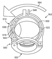
도 13은 다른 실시예에 따라 형성된 스트레인 릴리프(500)를 도시한다. 스트레인 릴리프(500)는 실드 종단 본체(502)에 커플링되도록 구성된다. 실드 종단 본체(502)는 릴리프 단부(504) 및 커넥터 단부(506)를 포함한다. 릴리프 단부(504)는 면(508)을 포함하고 커넥터 단부(506)는 면(510)을 포함한다. 면(508)은 면(510)에 대해 대략 45도 각도로 배향된다. 정합 부재(512)는 실드 종단 본체(502)의 릴리프 단부(504)에 위치된다. 정합 부재(512)는 대체로 원형이며 외측 표면(514)을 포함한다. 제1 탭(516)은 표면(514)으로부터 방사상 외향으로 연장된다. 제1 립(518)은 정합 부재(512)에 인접하여 실드 종단 본체(502)에 형성된다. 제1 립(518)은 제1 탭(516)과 정렬되고, 이에 의해 제1 립(518)과 제1 탭(516) 사이에 공간(520)이 형성된다. (도 14a 내지 도 15c에 도시된) 제2 탭(522)은 표면(514)으로부터 방사상 외향으로 연장된다. 제2 탭(522)은 제1 탭(516)으로부터 대략 180도에 위치된다. 제2 립(524)은 정합 부재(512)에 인접하여 실드 종단 본체(502)에 형성된다. 제2 립(524)은 제2 탭(522)에 정렬되고, 이에 의해 제2 립(524)과 제2 탭(522) 사이에 공간(526)이 형성된다. Figure 13 illustrates a
스트레인 릴리프(500)는 실드 단부(530) 및 케이블 클램프 단부(532)를 포함한다. 도시된 실시예에서, 케이블 클램프 단부(532)는 새들 클램프(533)를 포함한다. 실드 단부(530)는 실드 종단 본체(502)의 릴리프 단부(504)와 정합하도록 구성된다. 실드 종단 본체(502)의 릴리프 단부(504)는 스트레인 릴리프(504)의 실드 단부(530) 내에 수용되도록 구성된다. 스트레인 릴리프(504)의 실드 단부(530)는 정합 부재(534)를 포함한다. 실드 종단 본체(502)의 정합 부재(512)는 스트레인 릴리프(500)의 정합 부재(534)에 수용되도록 크기가 정해진다. The
실드 단부(530)의 정합 부재(534)는 대체로 원형이며 내측 표면(536)을 포함한다. 플랜지(538)는 내측 표면(536)에 대해 주연 방향으로 연장된다. 플랜지(538)는 (도 14a 및 도 15a에 도시된) 제1 개구(540) 및 제2 개구(542)를 포함한다. 제1 개구(540)는 제2 개구(542)로부터 대략 180도에 위치된다. 제1 개구(540) 및 제2 개구(542)는 실드 종단 본체(502)의 제1 탭(516) 또는 제2 탭(522)을 수용하도록 크기가 정해진다. 제1 개구(540)는 제1 탭(516) 또는 제2 탭(522) 중 하나를 수용하도록 구성된다. 제2 개구(542)는 제1 탭(516) 및 제2 탭(522) 중 다른 하나를 수용하도록 구성된다. The
제1 돌출부(544) 및 제2 돌출부(546)는 플랜지(538)로부터 연장된다. 제1 돌출부(544)는 제1 개구(540) 근처에 위치된다. 제2 돌출부(546)는 제2 개구(542) 근처에 위치된다. 제1 돌출부(544)는 제1 개구(540)와 제2 돌출부(546) 사이에 위치된다. 제2 돌출부(546)는 제2 개구(542)와 제1 돌출부(544) 사이에 위치된다. The
정합 부재(534)는 잠금부(548)를 포함한다. 잠금부(548)는 (도시되지 않은) 잠금 핀을 수용하도록 구성된다. 잠금부(548)는 정합 부재(534)를 정합 부재(512)에 고정하도록 구성된다. 잠금부(548)는 정합 부재(534) 내에서 정합 부재(512)의 회전을 방지한다. 잠금 핀은, 정합 부재(534) 내에서 정합 부재(512)가 회전할 수 있도록 잠금부(548)로부터 제거될 수 있다. The
스트레인 릴리프(500)의 실드 단부(530)는 면(550)을 포함한다. 스트레인 릴리프(500)의 케이블 클램프 단부(532)는 면(552)을 포함한다. 면(550)은 면(552)에 대해 대략 45도로 배향된다. The
도 14a는 제1 진입 위치(560)에서 스트레인 릴리프(500)로 삽입된 실드 종단 본체(502)의 사시도이다. 제1 진입 위치(560)에서, 실드 종단 본체(502)의 정합 부재(512)는 스트레인 릴리프(500)의 정합 부재(534)로 삽입된다. 제1 탭(516)은 제1 개구(540)를 통해 삽입된다. 제2 탭(522)은 제2 개구(542)로 삽입된다. 정합 부재(512)는 정합 부재(534) 내에서 회전될 수 있다. 14A is a perspective view of shielded
도 14b는 제1 45도 위치(562)로 회전된 스트레인 릴리프(500)의 사시도이다. 스트레인 릴리프(500)는 화살표(564) 방향으로 회전된다. 스트레인 릴리프(500)는 실드 종단 본체(502)에 대해 회전한다. 플랜지(538)는 실드 종단 본체(502)의 공간(520, 526) 내에서 회전한다. 플랜지(538)는 실드 종단 본체(502)가 스트레인 릴리프(500)로부터 분리되는 것을 방지하도록 제1 탭(516)과 제1 립(518) 사이에 위치된다. 또한, 플랜지(538)는 실드 종단 본체(502)가 스트레인 릴리프(500)로부터 분리되는 것을 방지하도록 제2 탭(522)과 제2 립(524) 사이에 위치된다. 플랜지(538)는 스트레인 릴리프(500)를 실드 종단 본체(502)에 고정하기 위해 제1 탭(516) 및 제2 탭(522)에 결합된다. 14B is a perspective view of the
제1 45도 위치(562)에서, 제1 탭(516)은 제1 돌출부(544) 쪽으로 회전된다. 제1 탭(516)은 제1 돌출부(544)와 맞닿는다. 제1 돌출부(544)는 화살표(564) 방향으로의 스트레인 릴리프(500)의 추가 회전을 방지한다. 제1 45도 위치(562)에서, 스트레인 릴리프(500)의 케이블 클램프 단부(532)에 의해 형성된 면(552)은 실드 종단 본체(502)의 커넥터 단부(506)에 의해 형성된 면(510)에 대해 대략 45도로 배향된다. 잠금부(548)는 실드 종단 본체(502) 및 스트레인 릴리프(500)를 45도 위치에 보유하도록 고정된다. At the first 45
스트레인 릴리프(500)는 제1 진입 위치(560)와 제1 45도 각도 위치(562) 사이의 임의의 중간 위치로 회전될 수 있고, 이에 의해 면(552)이 면(510)에 대해 간헐 각도로 배향될 수 있다. 잠금부(548)는 실드 종단 본체(502)에 대해 스트레인 릴리프(500)의 회전을 방지하도록 고정된다. 잠금부(548)는 제1 진입 위치(560)와 제1 45도 위치(562) 사이의 중간 위치에서 스트레인 릴리프(500)를 실드 종단 본체(502)에 고정한다. The
도 14c는 90도 위치(566)로 회전된 스트레인 릴리프(500)의 사시도이다. 스트레인 릴리프(500)는 화살표(568)의 방향으로 회전된다. 화살표(568)의 방향은 화살표(564)의 반대 방향이다. 90도 위치(566)에서, 제2 탭(522)은 제2 돌출부(546) 쪽으로 회전된다. 제2 탭(522)은 제2 돌출부(546)와 맞닿는다. 제2 돌출부(546)는 화살표(568)의 방향으로의 스트레인 릴리프(500)의 추가 회전을 방지한다. 90도 위치(566)에서, 스트레인 릴리프(500)의 케이블 클램프 단부(532)에 의해 형성된 면(552)은 실드 종단 본체(502)의 커넥터 단부(506)에 의해 형성된 면(510)에 대해 대략 90도로 배향된다. 14C is a perspective view of the
스트레인 릴리프(500)는 제1 진입 위치(560)와 90도 위치(566) 사이의 임의의 중간 위치로 회전될 수 있고, 이에 의해 면(552)이 면(510)에 대해 간헐 각도로 배향될 수 있다. 잠금부(548)는 실드 종단 본체(502)에 대해 스트레인 릴리프(500)의 회전을 방지하도록 고정된다. 잠금부(548)는 제1 진입 위치(560)와 90도 위치(566) 사이의 중간 위치에서 스트레인 릴리프(500)를 실드 종단 본체(502)에 고정한다. The
도 15a는 제2 진입 위치(570)에서 실드 종단 본체(502)에 커플링된 스트레인 릴리프(500)의 사시도이다. 제2 진입 위치(570)에서, 스트레인 릴리프(500)는 제1 진입 위치(560)에서의 스트레인 릴리프(500)의 배향에 대해 대략 180도로 배향된다. 제1 탭(516)은 제2 개구(542)를 통해 삽입된다. 제2 탭(522)은 제1 개구(540)로 삽입된다. 정합 부재(512)는 정합 부재(534) 내에서 회전될 수 있다. 15A is a perspective view of
도 15b는 0도 위치(572)로 회전된 스트레인 릴리프(500)의 사시도이다. 스트레인 릴리프(500)는 화살표(574)의 방향으로 회전된다. 0도 위치(572)에서, 제1 탭(516)은 제2 돌출부(546)와 맞닿는다. 제2 돌출부(546)는 화살표(574) 방향으로의 스트레인 릴리프(500)의 추가 회전을 방지한다. 0도 위치(572)에서, 스트레인 릴리프(500)의 케이블 클램프 단부(532)에 의해 형성된 면(552)은 실드 종단 본체(502)의 커넥터 단부(506)에 의해 형성된 면(510)에 대해 대략 0도로 배향된다.15B is a perspective view of
스트레인 릴리프(500)는 제2 진입 위치(570)와 0도 위치(572) 사이의 임의의 중간 위치로 회전될 수 있고, 이에 의해 면(552)이 면(510)에 대해 간헐 각도로 배향될 수 있다. 잠금부(548)는 실드 종단 본체(502)에 대해 스트레인 릴리프(500)의 추가 회전을 방지하도록 고정된다. 잠금부(548)는 제2 진입 위치(570)와 0도 위치(572) 사이의 중간 위치에서 스트레인 릴리프(500)를 실드 종단 본체(502)에 고정한다. The
도 15c는 제2 45도 위치(576)로 회전된 스트레인 릴리프(500)의 사시도이다. 스트레인 릴리프(500)는 화살표(578)의 방향으로 회전된다. 제2 45도 위치(576)에서, 제2 탭(522)은 제1 돌출부(544)와 맞닿는다. 제1 돌출부(544)는 화살표(578) 방향으로의 스트레인 릴리프(500)의 추가 회전을 방지한다. 제2 45도 위치(576)에서, 스트레인 릴리프(500)의 케이블 클램프 단부(532)에 의해 형성된 면(552)은 실드 종단 본체(502)의 커넥터 본체(506)에 의해 형성된 면(510)에 대해 대략 45도로 배향된다. 15C is a perspective view of
스트레인 릴리프(500)는 제2 진입 위치(570)와 제2 45도 위치(576) 사이의 임의의 중간 위치로 회전될 수 있고, 이에 의해 면(552)이 면(510)에 대해 간헐 각도로 배향될 수 있다. 잠금부(548)는 실드 종단 본체(502)에 대해 스트레인 릴리프(500)의 회전을 방지하도록 고정된다. 잠금부(548)는 제2 진입 위치(570)와 제2 45도 위치(576) 사이의 중간 위치에서 스트레인 릴리프(500)를 실드 종단 본체(502)에 고정한다.The
전술한 내용은 단지 예시이며 제한하고자 의도하는 것이 아님을 알아야 한다. 예를 들면, 전술된 실시예들(및/또는 이의 태양들)은 상호 조합되어 사용될 수 있다. 또한, 본 발명의 범주로부터 벗어남 없이 본 발명의 다양한 실시예들의 개시 내용에 대해 특정 조건 또는 재료에 적합하도록 여러 변형례로 구현될 수 있다. 본 명세서에 설명된 치수 및 재료들의 타입은 본 발명의 다양한 실시예들의 파라미터를 한정하기 위한 것으로, 단지 예시에 해당하며 실시예들을 제한하고자 의도한 것은 아니다. 전술한 내용에 기초하여 많은 다른 실시예들이 본 기술분야의 기술자에게 자명할 것이다. 이에 따라, 본 발명의 다양한 실시예들의 범주는 첨부된 청구범위와, 이런 청구범위의 등가물의 전체 범주에 따라 결정되어야 한다. It should be understood that the foregoing is merely illustrative and not intended to be limiting. For example, the above-described embodiments (and / or aspects thereof) may be used in combination with one another. In addition, various modifications may be made to adapt a particular condition or material to the teachings of the various embodiments of the invention without departing from the scope of the invention. The dimensions and types of materials described herein are for the purpose of limiting the parameters of various embodiments of the invention and are merely illustrative and are not intended to limit the embodiments. Many other embodiments will be apparent to those skilled in the art on the basis of the foregoing description. Accordingly, the scope of the various embodiments of the invention should be determined with reference to the appended claims, along with the full scope of equivalents of such claims.
Claims (10)
커넥터 인터페이스 및 실드 인터페이스를 갖는 커넥터 본체와,
커넥터 단부 및 릴리프 단부를 갖는 실드 종단 본체와,
실드 단부 및 케이블 클램프 단부를 갖는 스트레인 릴리프를 포함하며,
상기 커넥터 인터페이스는 상기 전기 커넥터와 결합하여 전기적 접속을 형성하도록 구성되고,
상기 커넥터 단부는 상기 커넥터 본체의 상기 커넥터 인터페이스에 연결되고, 상기 커넥터 단부의 면은 상기 릴리프 단부의 면에 대해 소정 각도로 배향되며, 상기 실드 종단 본체는 상기 전기 커넥터로부터 연장되는 케이블을 차폐하도록 구성되고,
상기 실드 단부의 면은 상기 케이블 클램프 단부의 면에 대해 소정 각도로 배향되고, 상기 실드 단부는 상기 실드 종단 본체의 상기 릴리프 단부에 회전 가능하도록 연결되며, 상기 스트레인 릴리프의 상기 실드 단부는 상기 실드 종단 본체의 상기 릴리프 단부에 대해 자유로이 회전 가능하고, 이에 의해 상기 스트레인 릴리프의 상기 케이블 클램프 단부의 면이 상기 실드 종단 본체의 상기 커넥터 단부의 면에 대해 0도 내지 90도 사이의 임의의 각도로 위치될 수 있고, 상기 스트레인 릴리프의 상기 케이블 클램프 단부는 상기 전기 커넥터로부터 연장되는 상기 케이블을 고정하도록 구성되고,
상기 실드 종단 본체의 상기 릴리프 단부는 돌출부를 포함하고, 상기 스트레인 릴리프의 상기 실드 단부는 노치를 포함하며, 상기 스트레인 릴리프의 상기 노치는 상기 실드 종단 본체에 대해 상기 스트레인 릴리프의 회전을 제한하기 위해 상기 실드 종단 본체의 상기 돌출부를 수용하도록 구성되는,
회전식 구조 백쉘.A rotary structure backshell connected to an electrical connector,
A connector body having a connector interface and a shield interface,
A shield termination body having a connector end and a relief end,
A strain relief having a shield end and a cable clamp end,
Wherein the connector interface is configured to engage the electrical connector to form an electrical connection,
Wherein the connector end is connected to the connector interface of the connector body and the face of the connector end is oriented at an angle to the face of the relief end and the shield termination body is configured to shield a cable extending from the electrical connector And,
Wherein the shield end is oriented at an angle relative to a plane of the cable clamp end and the shield end is rotatably connected to the relief end of the shield termination body and the shield end of the strain relief is connected to the shield termination Wherein the surface of the cable clamp end of the strain relief is positioned at any angle between 0 and 90 degrees with respect to the surface of the connector end of the shielded termination body so that it is free to rotate about the relief end of the body And the cable clamp end of the strain relief is configured to secure the cable extending from the electrical connector,
Wherein the relief end of the shielded termination body comprises a protrusion and the shield end of the strain relief comprises a notch and the notch of the strain relief comprises a notch, A shielded terminal body configured to receive the projection of the shielded termination body,
Rotating structure backshell.
Applications Claiming Priority (3)
| Application Number | Priority Date | Filing Date | Title |
|---|---|---|---|
| US12/911,111 | 2010-10-25 | ||
| US12/911,111 US8435066B2 (en) | 2010-10-25 | 2010-10-25 | Rotationally configurable backshell for an electrical connector |
| PCT/US2011/057503 WO2012061072A1 (en) | 2010-10-25 | 2011-10-24 | Rotationally configurable backshell for an electrical connector |
Publications (2)
| Publication Number | Publication Date |
|---|---|
| KR20130123386A KR20130123386A (en) | 2013-11-12 |
| KR101884037B1 true KR101884037B1 (en) | 2018-07-31 |
Family
ID=44906459
Family Applications (1)
| Application Number | Title | Priority Date | Filing Date |
|---|---|---|---|
| KR1020137010447A KR101884037B1 (en) | 2010-10-25 | 2011-10-24 | Rotationally configurable backshell for an electrical connector |
Country Status (11)
| Country | Link |
|---|---|
| US (1) | US8435066B2 (en) |
| EP (1) | EP2633588B1 (en) |
| JP (1) | JP5883017B2 (en) |
| KR (1) | KR101884037B1 (en) |
| CN (1) | CN103181035B (en) |
| AU (1) | AU2011323818B2 (en) |
| BR (1) | BR112013009857A2 (en) |
| CA (1) | CA2815784C (en) |
| IL (1) | IL225903A (en) |
| SG (1) | SG189508A1 (en) |
| WO (1) | WO2012061072A1 (en) |
Families Citing this family (19)
| Publication number | Priority date | Publication date | Assignee | Title |
|---|---|---|---|---|
| US20140045365A1 (en) * | 2012-08-08 | 2014-02-13 | Power In Operation, LLC | Adjustable backshell for wiring harness |
| US20140265308A1 (en) * | 2012-08-08 | 2014-09-18 | Power In Operation, LLC | Adjustable backshell for wiring harness |
| US9391393B2 (en) | 2012-11-08 | 2016-07-12 | Delphi Technologies, Inc. | Connector backshell having multiple cable exit configurations |
| US9118158B2 (en) | 2013-01-18 | 2015-08-25 | R. Kern Engineering & Manufacturing Corp. | Cable assembly backshell |
| DE102013204203A1 (en) * | 2013-03-12 | 2014-09-18 | MCQ TECH GmbH | Connector for a multi-core data and / or telecommunication cable |
| US9209571B2 (en) | 2013-10-16 | 2015-12-08 | Tyco Electronics Corporation | Connector assembly having multiple shield current paths |
| CN204130823U (en) * | 2014-08-15 | 2015-01-28 | 中兴通讯股份有限公司 | Cable connector |
| US9197008B1 (en) | 2014-08-26 | 2015-11-24 | Tyco Electronics Corporation | Electrical assembly having a threaded coupling nut and retaining ring |
| FR3032307B1 (en) * | 2015-02-04 | 2018-06-29 | Safran Electrical & Power | REAR FITTING FOR ELECTRICAL CONNECTOR |
| US9627800B2 (en) * | 2015-06-10 | 2017-04-18 | Glenair, Inc. | Connector with spring-locked swing arms |
| US9413116B1 (en) * | 2015-08-03 | 2016-08-09 | Glenair, Inc. | Slotted, clamped termination ring for an electrical connector assembly |
| US9960527B2 (en) * | 2016-08-18 | 2018-05-01 | Te Connectivity Corporation | Electrical assembly having a backshell with a cable follower |
| US9905963B1 (en) * | 2017-01-30 | 2018-02-27 | Te Connectivity Corporation | Adjustable strain relief for electrical connectors |
| DE102017120180B3 (en) | 2017-09-01 | 2019-01-03 | HARTING Electronics GmbH | Angled connector |
| CN107732597A (en) * | 2017-09-30 | 2018-02-23 | 江西洪都航空工业集团有限责任公司 | A kind of line outlet annex for outgoing lines mouth tail accessory |
| US11349254B2 (en) * | 2018-03-06 | 2022-05-31 | Textron Innovations Inc. | Hinged strain relief backshells, cable assemblies and methods for strain relief |
| CA3119787A1 (en) * | 2018-11-30 | 2020-06-04 | John Mezzalingua Associates, LLC | Torque limiting clamp for helical outer conductor cables |
| CN110635297B (en) * | 2019-04-23 | 2021-05-18 | 中航光电科技股份有限公司 | Connector tail accessory and connector assembly |
| GB202011186D0 (en) * | 2020-07-20 | 2020-09-02 | Robinson Dominic James | Universal locking system for managing pre-wired data cable bundles |
Citations (3)
| Publication number | Priority date | Publication date | Assignee | Title |
|---|---|---|---|---|
| FR2864713A1 (en) * | 2003-12-24 | 2005-07-01 | Amphenol Air Lb | Seal connection for electrical cable, has bent intermediate sleeve placed between outlet portion extending passage of support traversed by cable bundle and inlet portion of another bent sleeve having outlet portion cooperating with seal |
| US20090111319A1 (en) * | 2007-10-24 | 2009-04-30 | Amphenol Corporation | Strain relief backshell assembly |
| US20100124837A1 (en) | 2008-11-20 | 2010-05-20 | Amphenol Socapex | Backshell coupling for an electrical component |
Family Cites Families (13)
| Publication number | Priority date | Publication date | Assignee | Title |
|---|---|---|---|---|
| US4863396A (en) * | 1981-06-15 | 1989-09-05 | Johnson Lyle F | Strain relief clamp assembly |
| US4869687A (en) * | 1985-03-18 | 1989-09-26 | Lyle Johnson | Strain relief clamp assembly |
| US4808123A (en) * | 1987-02-04 | 1989-02-28 | Diverse Termination Products, Inc. | Self-locking strain-relief end bell for electrical connector assembly |
| JPH02110793U (en) * | 1989-02-22 | 1990-09-05 | ||
| DE4202176A1 (en) * | 1992-01-27 | 1993-07-29 | Gore W L & Ass Gmbh | CABLE CONNECTORS AND CABLE GLANDS |
| US5580278A (en) * | 1994-10-04 | 1996-12-03 | Glenair, Inc. | Grounding and antidecoupling backshell interface for electrical connectors |
| FR2770041B1 (en) * | 1997-10-22 | 2000-01-07 | Aerospatiale | REMOVABLE REAR CONNECTION FOR A CONNECTOR SUCH AS A CIRCULAR ELECTRIC CONNECTOR |
| US6419519B1 (en) | 2000-08-01 | 2002-07-16 | Glenair Inc. | Strain relief for electrical connectors |
| CN100338829C (en) * | 2003-06-12 | 2007-09-19 | 宇东电浆科技股份有限公司 | Switching communication socket capable of changing angle |
| US7419402B2 (en) * | 2005-08-10 | 2008-09-02 | Deutsch Engineered Connecting Devices, Inc. | Backshell device for a connector |
| US20070037433A1 (en) | 2005-08-10 | 2007-02-15 | Deutsch Engineered Connecting Devices | Backshell device for a connector |
| DE102007018945B4 (en) * | 2007-04-21 | 2014-11-27 | Wilhelm Rutenbeck Gmbh & Co. Kg | Socket for telecommunication and data transmission systems |
| US7438579B1 (en) * | 2007-07-17 | 2008-10-21 | Lockheed Martin Corporation | Anti-Decoupling device for a spin coupling |
-
2010
- 2010-10-25 US US12/911,111 patent/US8435066B2/en active Active
-
2011
- 2011-10-24 AU AU2011323818A patent/AU2011323818B2/en not_active Ceased
- 2011-10-24 JP JP2013536699A patent/JP5883017B2/en not_active Expired - Fee Related
- 2011-10-24 CN CN201180051142.5A patent/CN103181035B/en not_active Expired - Fee Related
- 2011-10-24 EP EP11778765.5A patent/EP2633588B1/en not_active Not-in-force
- 2011-10-24 CA CA2815784A patent/CA2815784C/en not_active Expired - Fee Related
- 2011-10-24 KR KR1020137010447A patent/KR101884037B1/en active IP Right Grant
- 2011-10-24 BR BR112013009857A patent/BR112013009857A2/en not_active Application Discontinuation
- 2011-10-24 WO PCT/US2011/057503 patent/WO2012061072A1/en active Application Filing
- 2011-10-24 SG SG2013030705A patent/SG189508A1/en unknown
-
2013
- 2013-04-23 IL IL225903A patent/IL225903A/en active IP Right Grant
Patent Citations (3)
| Publication number | Priority date | Publication date | Assignee | Title |
|---|---|---|---|---|
| FR2864713A1 (en) * | 2003-12-24 | 2005-07-01 | Amphenol Air Lb | Seal connection for electrical cable, has bent intermediate sleeve placed between outlet portion extending passage of support traversed by cable bundle and inlet portion of another bent sleeve having outlet portion cooperating with seal |
| US20090111319A1 (en) * | 2007-10-24 | 2009-04-30 | Amphenol Corporation | Strain relief backshell assembly |
| US20100124837A1 (en) | 2008-11-20 | 2010-05-20 | Amphenol Socapex | Backshell coupling for an electrical component |
Also Published As
| Publication number | Publication date |
|---|---|
| KR20130123386A (en) | 2013-11-12 |
| AU2011323818B2 (en) | 2016-02-11 |
| WO2012061072A1 (en) | 2012-05-10 |
| CA2815784C (en) | 2018-09-11 |
| IL225903A (en) | 2017-11-30 |
| CN103181035A (en) | 2013-06-26 |
| JP2013541174A (en) | 2013-11-07 |
| BR112013009857A2 (en) | 2016-07-26 |
| JP5883017B2 (en) | 2016-03-09 |
| AU2011323818A1 (en) | 2013-05-02 |
| EP2633588B1 (en) | 2018-08-29 |
| IL225903A0 (en) | 2013-07-31 |
| EP2633588A1 (en) | 2013-09-04 |
| SG189508A1 (en) | 2013-05-31 |
| US20120100745A1 (en) | 2012-04-26 |
| CN103181035B (en) | 2016-08-17 |
| CA2815784A1 (en) | 2012-05-10 |
| US8435066B2 (en) | 2013-05-07 |
Similar Documents
| Publication | Publication Date | Title |
|---|---|---|
| KR101884037B1 (en) | Rotationally configurable backshell for an electrical connector | |
| EP3308433B1 (en) | Connector with spring-locked swing arms | |
| US6419519B1 (en) | Strain relief for electrical connectors | |
| AU2019248403B2 (en) | Plug assembly for data cables | |
| EP2779321B1 (en) | Anti-decoupling member for connector component | |
| EP3291384B1 (en) | Elbow connector | |
| US6033251A (en) | Extension cord locking device | |
| JP5480821B2 (en) | cable clamp | |
| US20200406838A1 (en) | Connector including a shell with an orientable conduit and a method for mounting a connector | |
| US9231336B2 (en) | Device for fixing a cable to a cable outlet connector | |
| GB2517969A (en) | Electrical connector | |
| EP3355413B1 (en) | Backshell assembly with adjustable strain relief | |
| GB2597837A (en) | A backshell assembly | |
| US20140045365A1 (en) | Adjustable backshell for wiring harness |
Legal Events
| Date | Code | Title | Description |
|---|---|---|---|
| A201 | Request for examination | ||
| E902 | Notification of reason for refusal | ||
| E701 | Decision to grant or registration of patent right | ||
| GRNT | Written decision to grant |