KR101840552B1 - Load lock apparatus and substrate processing system - Google Patents
Load lock apparatus and substrate processing system Download PDFInfo
- Publication number
- KR101840552B1 KR101840552B1 KR1020160087328A KR20160087328A KR101840552B1 KR 101840552 B1 KR101840552 B1 KR 101840552B1 KR 1020160087328 A KR1020160087328 A KR 1020160087328A KR 20160087328 A KR20160087328 A KR 20160087328A KR 101840552 B1 KR101840552 B1 KR 101840552B1
- Authority
- KR
- South Korea
- Prior art keywords
- load lock
- lock chamber
- substrate container
- inert gas
- substrate
- Prior art date
- Legal status (The legal status is an assumption and is not a legal conclusion. Google has not performed a legal analysis and makes no representation as to the accuracy of the status listed.)
- Active
Links
Images


Classifications
-
- H—ELECTRICITY
- H10—SEMICONDUCTOR DEVICES; ELECTRIC SOLID-STATE DEVICES NOT OTHERWISE PROVIDED FOR
- H10P—GENERIC PROCESSES OR APPARATUS FOR THE MANUFACTURE OR TREATMENT OF DEVICES COVERED BY CLASS H10
- H10P72/00—Handling or holding of wafers, substrates or devices during manufacture or treatment thereof
- H10P72/04—Apparatus for manufacture or treatment
- H10P72/0451—Apparatus for manufacturing or treating in a plurality of work-stations
- H10P72/0466—Apparatus for manufacturing or treating in a plurality of work-stations characterised by the construction of the load-lock chamber
-
- H01L21/67772—
-
- B—PERFORMING OPERATIONS; TRANSPORTING
- B65—CONVEYING; PACKING; STORING; HANDLING THIN OR FILAMENTARY MATERIAL
- B65G—TRANSPORT OR STORAGE DEVICES, e.g. CONVEYORS FOR LOADING OR TIPPING, SHOP CONVEYOR SYSTEMS OR PNEUMATIC TUBE CONVEYORS
- B65G49/00—Conveying systems characterised by their application for specified purposes not otherwise provided for
- B65G49/05—Conveying systems characterised by their application for specified purposes not otherwise provided for for fragile or damageable materials or articles
- B65G49/06—Conveying systems characterised by their application for specified purposes not otherwise provided for for fragile or damageable materials or articles for fragile sheets, e.g. glass
- B65G49/061—Lifting, gripping, or carrying means, for one or more sheets forming independent means of transport, e.g. suction cups, transport frames
-
- H01L21/67739—
-
- H01L21/67766—
-
- H01L21/67778—
-
- H01L21/68742—
-
- H—ELECTRICITY
- H10—SEMICONDUCTOR DEVICES; ELECTRIC SOLID-STATE DEVICES NOT OTHERWISE PROVIDED FOR
- H10P—GENERIC PROCESSES OR APPARATUS FOR THE MANUFACTURE OR TREATMENT OF DEVICES COVERED BY CLASS H10
- H10P72/00—Handling or holding of wafers, substrates or devices during manufacture or treatment thereof
- H10P72/10—Handling or holding of wafers, substrates or devices during manufacture or treatment thereof using carriers specially adapted therefor, e.g. front opening unified pods [FOUP]
- H10P72/19—Handling or holding of wafers, substrates or devices during manufacture or treatment thereof using carriers specially adapted therefor, e.g. front opening unified pods [FOUP] closed carriers
- H10P72/1914—Handling or holding of wafers, substrates or devices during manufacture or treatment thereof using carriers specially adapted therefor, e.g. front opening unified pods [FOUP] closed carriers characterised by locking systems
-
- H—ELECTRICITY
- H10—SEMICONDUCTOR DEVICES; ELECTRIC SOLID-STATE DEVICES NOT OTHERWISE PROVIDED FOR
- H10P—GENERIC PROCESSES OR APPARATUS FOR THE MANUFACTURE OR TREATMENT OF DEVICES COVERED BY CLASS H10
- H10P72/00—Handling or holding of wafers, substrates or devices during manufacture or treatment thereof
- H10P72/30—Handling or holding of wafers, substrates or devices during manufacture or treatment thereof for conveying, e.g. between different workstations
- H10P72/33—Handling or holding of wafers, substrates or devices during manufacture or treatment thereof for conveying, e.g. between different workstations into and out of processing chamber
-
- H—ELECTRICITY
- H10—SEMICONDUCTOR DEVICES; ELECTRIC SOLID-STATE DEVICES NOT OTHERWISE PROVIDED FOR
- H10P—GENERIC PROCESSES OR APPARATUS FOR THE MANUFACTURE OR TREATMENT OF DEVICES COVERED BY CLASS H10
- H10P72/00—Handling or holding of wafers, substrates or devices during manufacture or treatment thereof
- H10P72/30—Handling or holding of wafers, substrates or devices during manufacture or treatment thereof for conveying, e.g. between different workstations
- H10P72/34—Handling or holding of wafers, substrates or devices during manufacture or treatment thereof for conveying, e.g. between different workstations the wafers being stored in a carrier, involving loading and unloading
- H10P72/3402—Mechanical parts of transfer devices
-
- H—ELECTRICITY
- H10—SEMICONDUCTOR DEVICES; ELECTRIC SOLID-STATE DEVICES NOT OTHERWISE PROVIDED FOR
- H10P—GENERIC PROCESSES OR APPARATUS FOR THE MANUFACTURE OR TREATMENT OF DEVICES COVERED BY CLASS H10
- H10P72/00—Handling or holding of wafers, substrates or devices during manufacture or treatment thereof
- H10P72/30—Handling or holding of wafers, substrates or devices during manufacture or treatment thereof for conveying, e.g. between different workstations
- H10P72/34—Handling or holding of wafers, substrates or devices during manufacture or treatment thereof for conveying, e.g. between different workstations the wafers being stored in a carrier, involving loading and unloading
- H10P72/3406—Handling or holding of wafers, substrates or devices during manufacture or treatment thereof for conveying, e.g. between different workstations the wafers being stored in a carrier, involving loading and unloading involving removal of lid, door or cover
-
- H—ELECTRICITY
- H10—SEMICONDUCTOR DEVICES; ELECTRIC SOLID-STATE DEVICES NOT OTHERWISE PROVIDED FOR
- H10P—GENERIC PROCESSES OR APPARATUS FOR THE MANUFACTURE OR TREATMENT OF DEVICES COVERED BY CLASS H10
- H10P72/00—Handling or holding of wafers, substrates or devices during manufacture or treatment thereof
- H10P72/30—Handling or holding of wafers, substrates or devices during manufacture or treatment thereof for conveying, e.g. between different workstations
- H10P72/34—Handling or holding of wafers, substrates or devices during manufacture or treatment thereof for conveying, e.g. between different workstations the wafers being stored in a carrier, involving loading and unloading
- H10P72/3411—Handling or holding of wafers, substrates or devices during manufacture or treatment thereof for conveying, e.g. between different workstations the wafers being stored in a carrier, involving loading and unloading involving loading and unloading of wafers
-
- H—ELECTRICITY
- H10—SEMICONDUCTOR DEVICES; ELECTRIC SOLID-STATE DEVICES NOT OTHERWISE PROVIDED FOR
- H10P—GENERIC PROCESSES OR APPARATUS FOR THE MANUFACTURE OR TREATMENT OF DEVICES COVERED BY CLASS H10
- H10P72/00—Handling or holding of wafers, substrates or devices during manufacture or treatment thereof
- H10P72/70—Handling or holding of wafers, substrates or devices during manufacture or treatment thereof for supporting or gripping
- H10P72/76—Handling or holding of wafers, substrates or devices during manufacture or treatment thereof for supporting or gripping using mechanical means, e.g. clamps or pinches
- H10P72/7604—Handling or holding of wafers, substrates or devices during manufacture or treatment thereof for supporting or gripping using mechanical means, e.g. clamps or pinches the wafers being placed on a susceptor, stage or support
- H10P72/7612—Handling or holding of wafers, substrates or devices during manufacture or treatment thereof for supporting or gripping using mechanical means, e.g. clamps or pinches the wafers being placed on a susceptor, stage or support characterised by lifting arrangements, e.g. lift pins
-
- B—PERFORMING OPERATIONS; TRANSPORTING
- B65—CONVEYING; PACKING; STORING; HANDLING THIN OR FILAMENTARY MATERIAL
- B65G—TRANSPORT OR STORAGE DEVICES, e.g. CONVEYORS FOR LOADING OR TIPPING, SHOP CONVEYOR SYSTEMS OR PNEUMATIC TUBE CONVEYORS
- B65G2201/00—Indexing codes relating to handling devices, e.g. conveyors, characterised by the type of product or load being conveyed or handled
- B65G2201/02—Articles
- B65G2201/0297—Wafer cassette
Landscapes
- Container, Conveyance, Adherence, Positioning, Of Wafer (AREA)
- Engineering & Computer Science (AREA)
- Robotics (AREA)
Abstract
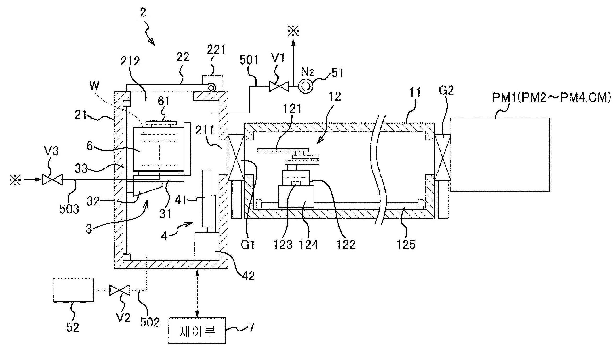
본 발명은 간소한 구성으로 로드 로크실 내의 기판 용기로부터의 덮개의 착탈, 덮개가 제거된 기판 용기로부터의 기판의 출입을 행하는 것이 가능한 로드 로크 장치 등을 제공한다. 로드 로크 장치(2)는, 진공 반송실에 대하여 연통구(211)를 통해서 접속되고, 내부의 압력을 대기압 상태와 진공압 상태로 전환 가능한 로드 로크실을 구비하고, 로드 로크실 본체(21)는, 착탈 가능한 덮개(62)가 측면에 설치된 기판 용기(6)의 반출입이 행하여지는 반입출구(212)와, 그 개폐를 행하는 개폐 도어(22)를 구비하고, 덮개 착탈 기구(4)는, 상기 연통구(211)와 상하 방향으로 배열하는 높이 위치에 설치되고, 상기 기판 용기에 대한 덮개의 착탈을 실행한다. 승강 기구(3)는, 기판 용기(6)가 적재되는 적재대(31)를 구비하고, 기판 용기(6)의 덮개(62)측의 측면을, 연통구(211)에 대향하는 높이 위치와, 덮개 착탈 기구(4)에 대향하는 높이 위치로 이동시키도록 적재대(31)를 승강시킨다.The present invention provides a load lock apparatus and the like that can attach and detach a lid from a substrate container in a load lock chamber with a simple structure, and can move a substrate out of a substrate container from which a lid is removed. The load lock apparatus 2 includes a load lock chamber which is connected to the vacuum transfer chamber through a communication port 211 and is capable of switching the internal pressure into an atmospheric pressure and a vacuum pressure state, Includes a loading and unloading port (212) for loading and unloading the substrate container (6) provided with a detachable lid (62) on its side and an opening and closing door (22) And is installed at a height position vertically aligned with the communication hole 211 to attach and detach the lid to the substrate container. The lifting mechanism 3 is provided with a loading table 31 on which the substrate container 6 is loaded and a side surface of the substrate container 6 on the side of the lid 62 is set at a height position opposed to the communication hole 211 , The stacking table 31 is moved up and down so as to move to the height position opposed to the cover attaching / detaching mechanism 4.
Description
본 발명은, 진공압 상태 하에서의 기판의 처리를 행하기 위해서, 기판 처리 시스템과 외부와의 사이에서 기판의 반출입을 행하는 기술에 관한 것이다.TECHNICAL FIELD [0001] The present invention relates to a technique for carrying a substrate in and out between a substrate processing system and the outside in order to process a substrate under a vacuum pressure condition.
기판인 반도체 웨이퍼(이하, 웨이퍼라고 함)의 표면에 집적 회로의 적층 구조를 형성하는 반도체 장치의 제조 공정에는, 진공 배기된 처리 모듈(기판 처리실) 내에 웨이퍼를 1매씩 배치한 후, 처리 가스를 공급해서 웨이퍼에 대하여 성막이나 에칭 등을 행하는 낱장식의 진공 처리가 있다. 처리 대상의 웨이퍼는, 예를 들어 FOUP(Front Open Unified Pod) 등의 기판 용기에 다수매 수납된 상태에서 공장 내에 반송된 후, 1매씩 취출되어서 소정의 처리를 실행하는 처리 모듈에 반입된다.In a manufacturing process of a semiconductor device for forming a laminated structure of an integrated circuit on the surface of a semiconductor wafer (hereinafter referred to as a wafer) as a substrate, wafers are arranged one by one in a vacuum-processed process module (substrate process chamber) And a single-type vacuum processing in which film formation, etching, and the like are performed on the wafer. The wafers to be processed are transferred into a factory in a state in which a plurality of wafers are housed in a substrate container such as a front open unified pod (FOUP), for example, and are taken out one by one to the processing module for executing predetermined processing.
이때, FOUP가 반송되는 공장 내는, 대기압 상태인 한편, 처리 모듈 내는, 통상, 진공압 상태로 유지되어 있다. 이 때문에, FOUP와 처리실과의 사이의 웨이퍼의 반송은, 내부의 압력을 대기압 상태와, 진공압 상태로 전환하는 것이 가능한 로드 로크실을 통해서 행하여진다.At this time, the inside of the factory where the FOUP is conveyed is kept at the atmospheric pressure state, while the inside of the processing module is normally kept in the vacuum pressure state. Therefore, the transfer of the wafer between the FOUP and the processing chamber is performed through the load lock chamber capable of switching the internal pressure to the atmospheric pressure state and the vacuum pressure state.
그런데, 로드 로크실에 1매씩 웨이퍼를 반입하여, 대기압 상태-진공압 상태의 전환을 행하면, FOUP-로드 로크실간 및 로드 로크실-처리 모듈간의 각각에 웨이퍼의 반송 기구를 설치할 필요가 있어, 반송 기구나 로드 로크실, 처리 모듈을 포함하는 웨이퍼 처리 시스템 전체의 구성이 대규모가 된다.However, when the wafers are carried into the load lock chamber one by one and the atmospheric pressure-vacuum pressure state is switched, it is necessary to provide the wafer transfer mechanism between the FOUP-load lock chamber and the load lock chamber- The entire structure of the wafer processing system including the mechanism, the load lock chamber, and the processing module becomes large-scale.
이 점, 특허문헌 1에는, 저면측의 덮개를 제거함으로써, 복수의 웨이퍼를 유지한 카세트를 취출하는 것이 가능한 기판 용기인 BOP(Bottom Opening Pod)를 이용하여, 로드 로크실 내에 웨이퍼를 유지한 카세트 전체를 반입함으로써, 기판 용기-로드 로크실간의 웨이퍼의 반송 기구를 생략한 진공 처리 장치가 기재되어 있다.In this respect,
그러나, 반도체 공장에서 일반적으로 사용되고 있는 FOUP는, 카세트를 취출하는 구조가 아니며, 또한 웨이퍼의 출입을 행할 때 제거되는 덮개는, FOUP의 측면에 설치되어 있기 때문에, 특허문헌 1에 기재된 기술을 그대로 채용할 수는 없다.However, since the FOUP, which is generally used in a semiconductor factory, is not a structure for taking out the cassette, and the lid removed when the wafer enters and exits is installed on the side of the FOUP, the technology described in
또한 특허문헌 2에는, 하우징 내에 반입된 FOUP를 연직축을 중심으로 회전 가능한 적재대 위에 적재하고, 회전대를 회전시킴으로써, FOUP의 덮개의 개폐(착탈)를 행하는 덮개 개폐 기구와, 덮개가 제거된 FOUP로부터, 기판의 검사를 행하는 프로브 유닛에의 기판의 전달구와의 사이에서 FOUP의 방향을 바꾸는 프로브 장치가 기재되어 있다.
그러나, 특허문헌 2에 기재된 하우징은 로드 로크실이 아니고, 외부와 로드 로크실과의 사이의 FOUP의 반출입 등도 감안한 효율적인 덮개 개폐 기구 및 웨이퍼의 전달구의 배치는 불분명하다.However, the housing described in
본 발명은, 간소한 구성으로 로드 로크실 내의 기판 용기로부터의 덮개의 착탈, 덮개가 제거된 기판 용기로부터의 기판의 출입을 행하는 것이 가능한 로드 로크 장치, 및 이것을 구비한 기판 처리 시스템을 제공한다.SUMMARY OF THE INVENTION The present invention provides a load lock apparatus and a substrate processing system having the load lock apparatus capable of loading and unloading a lid from a substrate container in a load lock chamber and removing and removing a substrate from a substrate container in which a lid is removed with a simple structure.
본 발명의 로드 로크 장치는, 진공압 상태 하에서 기판의 반송이 행하여지는 진공 반송실에 대하여, 게이트 밸브에 의해 개폐되는 연통구를 통해서 접속되고, 내부의 압력을 대기압 상태와, 진공압 상태로 전환 가능한 로드 로크실을 구비한 로드 로크 장치로서,The load lock apparatus of the present invention is connected to a vacuum transport chamber in which a substrate is transported under a vacuum pressure state through a communication port that is opened and closed by a gate valve so that the pressure inside the vacuum transport chamber is switched from an atmospheric pressure state to a
복수의 기판을 수용하고, 착탈 가능한 덮개가 측면에 설치된 기판 용기의 반출입이 행하여지는 반입출구와, 이 반입출구를 개폐하는 개폐 도어를 구비하고, 측면에 상기 연통구가 형성된 로드 로크실 본체와,A load lock chamber body having a plurality of substrates accommodated therein and having a loading / unloading port for loading / unloading a substrate container provided with a removable lid on its side and an opening / closing door for opening and closing the loading / unloading port,
상기 로드 로크실 내의, 상기 연통구와 상하 방향으로 배열하는 높이 위치에 설치되고, 상기 기판 용기에 대한 상기 덮개의 착탈을 실행하는 착탈 위치와, 이 착탈 위치로부터 후퇴한 후퇴 위치와의 사이를 가로 방향으로 진퇴 가능하게 구성된 덮개 착탈 기구와,Wherein the cover is provided at a height position arranged in the vertical direction with the communication port in the load lock chamber and between a detaching position for detaching and attaching the cover to the substrate container and a retracting position for retracting from the detaching position, A lid detachable mechanism configured to be movable forward and backward,
상기 로드 로크실 내에 설치되고, 상기 기판 용기가 적재되는 적재대를 구비하고, 상기 적재대에 적재된 상기 기판 용기의 상기 덮개측의 측면을, 상기 연통구에 대향하는 높이 위치와, 상기 덮개 착탈 기구에 대향하는 높이 위치로 이동시키도록, 상기 적재대를 승강시키는 승강 기구를 포함한다.A side wall of the substrate container mounted on the mounting table is disposed at a height position opposed to the communication hole, And an elevating mechanism for elevating and lowering the stacking table so as to move to a height position opposed to the mechanism.
상기 로드 로크 장치는, 이하의 구성을 포함하고 있어도 된다.The load lock device may include the following configuration.
(a) 상기 반입출구는, 상기 로드 로크실 본체의 천장면에 설치되고, 상기 승강 기구는, 상기 반입출구를 통해서 상기 기판 용기의 반출입이 행하여지는 높이 위치까지 상기 적재대를 상승시키는 것.(a) the loading / unloading port is installed on a ceiling surface of the load lock chamber main body, and the elevating mechanism elevates the loading table to a height position where the substrate container is loaded / unloaded through the loading / unloading port.
(b) 상기 로드 로크실 내의 진공 배기를 실행하는 진공 배기부를 더 포함하고, 상기 로드 로크실 내에 상기 기판 용기를 반입하고 나서, 상기 덮개 착탈 기구에 의해 상기 기판 용기의 상기 덮개를 제거할 때까지의 기간 중, 상기 기판 용기 내의 압력을 상기 로드 로크실 내의 압력보다도 높은 상태로 유지하기 위해서, 상기 로드 로크실 내가 상기 대기압 상태보다도 낮고, 상기 진공압 상태 이상의 압력 상태가 되도록 상기 진공 배기부에 의한 진공 배기를 행하는 것. 또한, 상기 기판 용기 내에 불활성 가스를 공급하는 불활성 가스 공급부를 더 포함하고, 상기 로드 로크실 내에 상기 기판 용기를 반입하고 나서, 상기 덮개 착탈 기구에 의해 상기 기판 용기의 상기 덮개를 제거할 때까지의 기간 중, 상기 기판 용기 내의 압력을 상기 로드 로크실 내의 압력보다도 높은 상태로 유지하기 위해서, 상기 불활성 가스 공급부로부터 상기 기판 용기 내에 불활성 가스를 공급하는 것.(b) a vacuum evacuation unit for evacuating the inside of the load lock chamber, and after the substrate container is carried into the load lock chamber, until the cover of the substrate container is removed by the cover attaching / detaching mechanism The load lock chamber is kept at a pressure lower than the atmospheric pressure state and a pressure state equal to or higher than the vacuum pressure state in order to maintain the pressure in the substrate container higher than the pressure in the load lock chamber during the period of Performing vacuum evacuation. Further, it is preferable that the apparatus further includes an inert gas supply unit for supplying an inert gas into the substrate container, wherein after the substrate container is carried into the load lock chamber, until the cover of the substrate container is removed by the cover attaching / detaching mechanism Wherein inert gas is supplied from the inert gas supply unit to the substrate container in order to maintain the pressure in the substrate container higher than the pressure in the load lock chamber during the period.
(c) 상기 기판 용기 내에 불활성 가스를 공급하는 불활성 가스 공급부를 더 포함하고, 상기 덮개 착탈 기구에 의해 상기 기판 용기의 상기 덮개가 제거되어 있는 기간 중, 상기 불활성 가스 공급부로부터 상기 기판 용기 내에 불활성 가스를 공급하는 것.(c) an inert gas supply unit for supplying an inert gas into the substrate container, wherein during the period when the lid of the substrate container is removed by the lid attaching / detaching mechanism, inert gas .
(d) 상기 기판 용기 내에 불활성 가스를 공급하는 제1 불활성 가스 공급부와, 상기 로드 로크실 내에 불활성 가스를 공급하는 제2 불활성 가스 공급부를 더 포함하고, 로드 로크실 내의 압력의 전환을 실행하는 압력 전환 기구와, 진공 상태인 상기 로드 로크실 내에서, 상기 덮개가 제거된 상기 기판 용기로부터의 기판의 출입이 행하여진 후, 상기 게이트 밸브를 폐쇄하고, 상기 로드 로크실을 상기 진공 반송실로부터 분리하는 스텝과, 상기 제1 불활성 가스 공급부로부터 상기 기판 용기에 불활성 가스를 공급하면서 상기 덮개 착탈 기구에 의해 상기 기판 용기에 상기 덮개를 설치하는 스텝과, 상기 기판 용기에 상기 덮개가 설치된 후, 상기 제2 불활성 가스 공급부로부터 불활성 가스를 공급해서 상기 로드 로크실 내를 대기압 상태로 전환하는 스텝과, 상기 로드 로크실 내가 대기압 상태로 전환된 후, 상기 제2 불활성 가스 공급부로부터의 불활성 가스의 공급을 정지하고, 상기 반입출구의 상기 개폐 도어를 개방하여, 상기 덮개가 설치된 상기 기판 용기를 반출하는 스텝을 실행하도록 제어 신호를 출력하는 제어부를 더 포함하는 것. 이때, 상기 제어부는, 상기 로드 로크실 내를 대기압 상태로 전환하는 스텝의 실행 중, 상기 기판 용기 내의 압력이 상기 로드 로크실 내의 압력보다도 높은 상태가 유지되도록, 상기 제1 불활성 가스 공급부 및 상기 제2 불활성 가스 공급부로부터의 불활성 가스의 공급량을 조절하는 것.(d) a first inert gas supply unit for supplying an inert gas into the substrate container, and a second inert gas supply unit for supplying inert gas into the load lock chamber, wherein the pressure in the load lock chamber Wherein the gate valve is closed and the load lock chamber is separated from the vacuum transfer chamber after the substrate is removed from the substrate container from which the cover has been removed in the load lock chamber in a vacuum state, A step of installing the lid on the substrate container by the lid attaching / detaching mechanism while supplying an inert gas to the substrate container from the first inert gas supply unit; and after the lid is attached to the substrate container, 2) supplying an inert gas from an inert gas supply unit to switch the inside of the load lock chamber to an atmospheric pressure state; The step of stopping the supply of the inert gas from the second inert gas supply unit and opening the opening and closing door of the loading and unloading outlet and taking out the substrate container provided with the cover after the atmospheric pressure state of the base load lock chamber is switched to And a control unit for outputting a control signal to execute the control signal. At this time, the control unit controls the first inert gas supply unit and the second inert gas supply unit so that the pressure in the substrate container is maintained higher than the pressure in the load lock chamber during the step of switching the inside of the load lock chamber to the atmospheric pressure state. 2 controlling the supply of inert gas from the inert gas supply.
(e) 상기 덮개 착탈 기구는, 상기 기판 용기의 상기 덮개에 연결되는 래치 키를 구비하고, 상기 래치 키를 통해서 상기 덮개를 유지하는 것.(e) the lid attaching / detaching mechanism has a latch key connected to the lid of the substrate container, and holding the lid through the latch key.
또한, 본 발명의 기판 처리 시스템은, 상술한 로드 로크 장치와,Further, the substrate processing system of the present invention includes the above-described load lock apparatus,
상기 연통구를 통해서 상기 로드 로크실에 접속되고, 기판의 반송을 실행하는 기판 반송 기구가 설치된 진공 반송실과,A vacuum transport chamber connected to the load lock chamber through the communication port and provided with a substrate transport mechanism for transporting the substrate,
상기 진공 반송실에 접속되고, 상기 기판 반송 기구에 의해 반송된 기판의 처리를 실행하는 기판 처리실을 포함한다.And a substrate processing chamber connected to the vacuum transport chamber and performing processing of the substrate carried by the substrate transport mechanism.
당해 기판 처리 시스템은, 상기 진공 반송실에 접속되고, 상기 기판 처리실에서 처리된 기판을 상기 로드 로크실 내의 상기 기판 용기로 되돌리기 전에, 기판의 냉각을 행하는 냉각실을 포함해도 된다.The substrate processing system may include a cooling chamber that is connected to the vacuum transport chamber and performs cooling of the substrate before returning the substrate processed in the substrate processing chamber to the substrate container in the load lock chamber.
본 발명은, 기판 용기에 대한 덮개의 착탈을 실행하는 덮개 착탈 기구와, 기판 용기로부터의 기판의 출입이 행하여지는 진공 반송실에의 연통구가 상하로 배열해서 배치되어 있으므로, 공통의 승강 기구를 사용해서 기판 용기를 승강시키는 것만으로, 덮개 착탈 기구에 대향하는 높이 위치와, 연통구에 대향하는 높이 위치로 기판 용기를 이동시킬 수 있다.Since the lid attaching / detaching mechanism for attaching / detaching the lid to / from the substrate container and the communication ports to the vacuum transfer chamber in which the substrate from the substrate container is carried out are arranged vertically, the common elevating mechanism It is possible to move the substrate container to a height position opposed to the lid attaching / detaching mechanism and a height position opposed to the communicating port by simply raising and lowering the substrate container by using it.
도 1은 실시 형태에 따른 로드로크 모듈을 구비한 웨이퍼 처리 시스템의 횡단 평면도이다.
도 2는 상기 웨이퍼 처리 시스템의 종단 측면도이다.
도 3은 상기 로드로크 모듈에 반입되는 FOUP의 정면도이다.
도 4는 상기 FOUP에 대한 덮개의 고정 기구의 제1 확대도이다.
도 5는 상기 덮개의 고정 기구의 제2 확대도이다.
도 6은 상기 FOUP에 대한 덮개의 착탈을 행하는 착탈부의 정면도이다.
도 7은 상기 착탈부에 설치되어 있는 고정 핀의 종단 측면도이다.
도 8은 상기 로드로크 모듈에의 FOUP의 반입부터, 반출까지의 동작에 관한 공정도이다.
도 9는 로드로크 모듈의 제1 작용 설명도이다.
도 10은 로드로크 모듈의 제2 작용 설명도이다.
도 11은 로드로크 모듈의 제3 작용 설명도이다.
도 12는 로드로크 모듈의 제4 작용 설명도이다.
도 13은 로드로크 모듈의 제5 작용 설명도이다.
도 14는 로드로크 모듈의 제6 작용 설명도이다.
도 15는 로드로크 모듈의 제7 작용 설명도이다.
도 16은 로드로크 모듈의 제8 작용 설명도이다.
도 17은 로드로크 모듈의 제9 작용 설명도이다.
도 18은 로드로크 모듈의 제10 작용 설명도이다.
도 19는 FOUP의 퍼지 가스 공급부의 다른 구성예를 도시하는 평면도이다.
도 20은 상기 다른 구성예에 관한 퍼지 가스 공급부의 측면도이다.1 is a cross-sectional plan view of a wafer processing system with a load lock module according to an embodiment.
Figure 2 is a longitudinal side view of the wafer processing system.
Figure 3 is a front view of a FOUP loaded into the load lock module.
4 is a first enlarged view of the lid locking mechanism for the FOUP;
5 is a second enlarged view of the fixing mechanism of the lid.
6 is a front view of a detachable portion for attaching and detaching the lid to the FOUP.
7 is a longitudinal side view of the fixing pin provided in the detachable portion.
Fig. 8 is a process diagram for the operation from FOUP loading to unloading to the load lock module.
9 is a first operation explanatory diagram of the load lock module.
10 is a second operation explanatory view of the load lock module.
11 is a third operation explanatory view of the load lock module.
12 is a fourth operation explanatory view of the load lock module.
13 is a fifth operation explanatory view of the load lock module.
14 is a sixth operation explanatory view of the load lock module.
15 is a seventh operation explanatory view of the load lock module.
16 is an explanatory view of the eighth operation of the load lock module.
17 is a ninth explanatory view of the load lock module.
18 is a tenth operation explanatory view of the load lock module.
19 is a plan view showing another configuration example of the purge gas supply portion of the FOUP.
20 is a side view of the purge gas supply unit according to another example of the configuration.
본 발명의 실시 형태로서, 처리 대상의 웨이퍼(W)를 소정 매수, 예를 들어 25매 수용한 기판 용기인 FOUP(6)의 반출입이 행하여지는 로드 로크 장치인 로드로크 모듈(2)을 구비한 웨이퍼 처리 시스템(기판 처리 시스템)(1)의 예에 대해서, 도 1, 도 2를 참조하면서 설명한다. 도 1에 도시한 바와 같이, 웨이퍼 처리 시스템(1)은, 실시 형태에 따른 복수의 로드로크 모듈(2)과, 진공압 상태 하에서 웨이퍼(W)의 반송이 행하여지는 진공 반송실을 이루는 진공 반송 모듈(11)과, 웨이퍼(W)에 처리를 실시하기 위한 처리실을 구비하는 처리 모듈(PM1 내지 PM4)을 구비하고 있다. FOUP(6)의 반출입 위치에서 볼 때, 이들 모듈은, 로드로크 모듈(2), 진공 반송 모듈(11), 처리 모듈(PM1 내지 PM4)의 순서대로 배열되어 있고, 인접하는 모듈끼리는 게이트 밸브(G1, G2)를 통해서 기밀하게 접속되어 있다.A
로드로크 모듈(2)은, 진공 반송 모듈(11)의 하나의 측벽면에 가로 방향으로 배열되어, 예를 들어 3개 설치되어 있다. 이들 로드로크 모듈(2)은, 그 내부에 FOUP(6) 전체를 반입하여, 대기압 상태와 진공압 상태를 전환하여, 진공 반송 모듈(11)에의 웨이퍼(W)의 출입을 행하는 것이 가능한 구성으로 되어 있는데, 그 상세한 구성에 대해서는 후술한다.The
도 1에 도시한 바와 같이 진공 반송 모듈(11)은, 개략의 평면 형상이 다각 형상으로 형성되어 있음으로써, 복수의 로드로크 모듈(2)이나 처리 모듈(PM1 내지 PM4) 등이 접속되는 측벽면을 구비하고, 그 내부는 진공 분위기로 되어 있다. 이미 설명한 3개의 로드로크 모듈(2)이 설치되어 있는 면을 전방측으로 했을 때, 전방측에서 볼 때 좌우의 양 측벽면 및 후방측의 측벽면에는, 처리 모듈(PM1 내지 PM4)이나, 이들 처리 모듈(PM1 내지 PM4)에서 처리된 후의 웨이퍼(W)의 냉각을 행하기 위한 냉각 모듈(CM)이 접속된다. 진공 반송 모듈(11) 내에는, 로드로크 모듈(2)이나 각 처리 모듈(PM1 내지 PM4), 냉각 모듈(CM)간에서 웨이퍼(W)의 반송을 행하는 웨이퍼 반송 기구(기판 반송 기구)(12)가 설치되어 있다.As shown in Fig. 1, since the
도 1, 도 2에 도시한 바와 같이, 웨이퍼 반송 기구(12)는, 신축 가능한 예를 들어 2개의 반송 아암(121)을 구비하고, 이들 반송 아암(121)은, 연직축을 중심으로 회전 가능한 기체부(122)에 지지되어 있다. 이 기체부(122)는, 횡 이동 레일(123)을 구비한 슬라이더(124) 상에 설치되어 있고, 도시하지 않은 이동 기구에 의해 횡 이동 레일(123)을 따라, 전방측에서 볼 때 좌우 방향으로 이동할 수 있다. 또한 당해 슬라이더(124)는, 진공 반송 모듈(11)의 바닥면에 배치된 전후 이동 레일(125) 상에 설치되고, 도시하지 않은 이동 기구에 의해 진공 반송 모듈(11) 내를 전후 방향으로 이동할 수 있다. 이러한 구성에 의해, 각 반송 아암(121)은 3개의 로드로크 모듈(2) 및 각 처리 모듈(PM1 내지 PM4), 냉각 모듈(CM) 내에 진입하여, 이들 모듈(2, PM1 내지 PM4, CM)과의 사이에서 웨이퍼(W)의 전달을 행하는 것이 가능하게 되어 있다.As shown in Figs. 1 and 2, the
또한 진공 반송 모듈(11)은, 그 내부의 진공 배기를 행하여, 진공 반송 모듈(11) 내를 미리 설정된 압력의 진공압 상태로 유지하기 위한, 도시하지 않은 진공 배기 기구에 접속되어 있다.Further, the
처리 모듈(PM1 내지 PM4)은, 진공압 상태의 처리실 내에 웨이퍼(W)를 배치하고, 처리 가스를 공급하여, 웨이퍼(W)에 대한 처리를 행한다. 처리의 종류로서는, 성막 가스를 사용해서 웨이퍼(W)의 표면에 성막을 행하는 성막 처리나, 어닐 가스의 공급 분위기 하에서 성막 처리 후의 웨이퍼(W)의 가열 처리를 행하는 어닐 처리, 에칭 가스를 사용해서 웨이퍼(W)의 표면에 성막된 박막을 에칭하는 에칭 처리, 애싱 가스를 사용해서 웨이퍼(W)의 표면의 불필요한 레지스트막 등을 제거하는 애싱 처리 등을 들 수 있다. 처리 모듈(PM1 내지 PM4)에는, 필요에 따라, 처리 가스의 공급 기구나 처리 가스의 반응성을 향상시키기 위한 플라즈마화 기구, 웨이퍼(W)의 적재대나, 적재대 상의 웨이퍼(W)의 가열을 행하는 가열 기구 등이 설치된다.The processing modules PM1 to PM4 arrange the wafers W in the processing chamber in the vacuum pressure state and supply the processing gas to perform the processing on the wafers W. As the kind of the treatment, there are a film forming process for forming a film on the surface of the wafer W using a film forming gas, an annealing process for performing a heat process for the wafer W after the film forming process in a supply atmosphere of the annealing gas, An etching process for etching a thin film formed on the surface of the wafer W, an ashing process for removing an unnecessary resist film or the like on the surface of the wafer W by using an ashing gas, and the like. The processing modules PM1 to PM4 are provided with a plasma processing mechanism for improving the reactivity of the processing gas supply mechanism and the process gas, the wafer W on the table or the wafer W on the table A heating mechanism and the like are installed.
진공 반송 모듈(11)에 접속되는 처리 모듈(PM1 내지 PM4)은, 웨이퍼(W)에 대하여 서로 종류가 다른 처리를 행하는 것이어도 되고, 공통의 종류의 처리를 행하는 것이어도 된다. 서로 다른 처리가 행하여지는 처리 모듈(PM1 내지 PM4)에서는, FOUP(6)로부터 취출된 웨이퍼(W)는, 미리 설정된 순서로 각 처리 모듈(PM1 내지 PM4)사이에 반송되어서 복수의 처리가 실행되고, 필요한 모든 처리가 실시된 웨이퍼(W)가 FOUP(6)로 되돌려진다. 이때, 처리 시간 등의 요청에 따라, 일부 또는 모든 처리의 처리 모듈(PM1 내지 PM4)을 복수 조씩 설치해도 된다.The processing modules PM1 to PM4 connected to the
또한, 모든 처리 모듈(PM1 내지 PM4)에서 공통의 종류의 처리가 행하여지는 경우에는, FOUP(6)로부터 취출된 웨이퍼(W)는, 소정의 처리 모듈(PM1 내지 PM4)에 반송되어서 병렬로 처리가 행하여진 후, FOUP(6)로 되돌려진다.When a common type of processing is performed in all of the processing modules PM1 to PM4, the wafer W taken out from the
또한 진공 반송 모듈(11)에 대해서는, 냉각 모듈(CM)을 접속해도 된다. 처리 모듈(PM1 내지 PM4) 내에서 실행되는 처리에는, 웨이퍼(W)의 온도 상승을 수반하는 것이 있고, 이 경우에는, 처리 후의 웨이퍼(W)는, FOUP(6)에서 수용 가능한 온도로 냉각하고 나서 복귀시킬 필요가 있다. 한편, 각 처리 모듈(PM1 내지 PM4)이나 진공 반송 모듈(11) 내는, 고도의 진공압 상태로 유지되어 있기 때문에, 이들 모듈(PM1 내지 PM4, 11)에 반송되어 있는 기간 중에 웨이퍼(W)의 온도가 거의 저하되지 않는 경우가 있다. 냉각 모듈(CM)은, 이러한 경우에 웨이퍼(W)의 냉각을 전용으로 행한다.The
예를 들어 냉각 모듈(CM)은, 냉각실 내에, 1매의 웨이퍼(W)가 적재되는 적재대 또는 복수매의 웨이퍼(W)가 1매씩 적재되는 복수단의 적재 선반을 구비하고, 이들 적재대나 적재 선반의 각 선반 단에는, 적재된 웨이퍼(W)를 냉각하는 냉각 기구가 설치되어 있다. 냉각 기구는, 적재대나 선반 단의 내부에 냉매를 통류시키는 유로를 설치해서 웨이퍼(W)의 냉각을 행하는 방식이어도 되고, 펠티에 소자 등을 사용해서 웨이퍼(W)의 냉각을 행해도 된다. 이미 설명한 처리 모듈(PM1 내지 PM4)이나 진공 반송 모듈(11)과 동일 정도의 진공압 상태 하에서는, 냉각 기구에 의한 웨이퍼(W)의 냉각을 신속히 행하는 것이 곤란한 경우에는, 게이트 밸브(G2)를 폐쇄한 후, 냉각 모듈(CM) 내에 압력 조정용의 가스를 공급하거나, 웨이퍼(W)와 적재대, 선반 단과의 간극에 전열용의 가스를 통류시키거나 해도 된다.For example, the cooling module CM is provided with a loading table on which one wafer W is loaded or a plurality of loading shelves on which a plurality of wafers W are loaded one by one in the cooling chamber, A cooling mechanism for cooling the stacked wafers W is provided at each shelf end of the stacking shelf. The cooling mechanism may be a system in which the wafer W is cooled by providing a flow path through which coolant flows in the stage or shelf stage, or the wafer W may be cooled using a Peltier element or the like. When it is difficult to quickly cool the wafer W by the cooling mechanism under the vacuum pressure state of the same degree as that of the processing modules PM1 to PM4 or the
이상으로 설명한 처리 모듈(PM1 내지 PM4), 냉각 모듈(CM) 외에, 진공 반송 모듈(11)에는, FOUP(6)로부터 취출된 웨이퍼(W)를 각 처리 모듈(PM1 내지 PM4)에 반입하기 전에, 각 웨이퍼(W)의 중심 위치나 둘레 방향을 향한 위치 정렬을 행하는 얼라인먼트 실(도시하지 않음)을 접속해도 된다. 얼라인먼트 실을 진공 반송 모듈(11)에 접속하는 경우에는, 이들의 위치 정렬은 진공 분위기 하에서 행하여진다. 또한, 진공 반송 모듈(11) 내에 직접 얼라인먼트 기구를 설치해도 된다.Before the wafer W taken out from the
계속해서, 상술한 구성을 구비한 웨이퍼 처리 시스템(1)에 접속되는 로드로크 모듈(2)의 상세한 구성에 대해서 설명한다. 이미 설명한 바와 같이, 진공 반송 모듈(11)의 전방면에 예를 들어 3개 설치되어 있는 로드로크 모듈(2)은, 서로 공통의 구성을 구비하고 있다. 도 1에서, 3개의 로드로크 모듈(2) 중, 우측의 도는 로드로크 모듈(2)의 횡단 평면도를 나타내고, 가운데 및 좌측의 로드로크 모듈(2)은, 상면측으로부터의 외관 평면도를 나타내고 있다.Next, a detailed configuration of the
도 1, 도 2에 도시한 바와 같이 로드로크 모듈(2)은, 그 내부 공간이 로드 로크실이 되는 로드 로크실 본체(21)와, 로드 로크실 내에서 FOUP(6)를 상하 방향으로 이동시키기 위한 승강 기구(3)와, FOUP(6)의 측면에 설치된 덮개(62)의 착탈을 행하기 위한 덮개 착탈 기구(4)를 구비한다.As shown in Figs. 1 and 2, the
로드 로크실 본체(21)는, 그 내부에 FOUP(6)를 반입하고, 또한 반입된 FOUP(6)를 상하 방향으로 이동시키는 것이 가능한 내부 공간을 갖는 직육면체 형상의 하우징으로서 구성되어 있다. 로드 로크실 본체(21)의 측면에는, 진공 반송 모듈(11) 내에 설치된 웨이퍼 반송 기구(12)의 반송 아암(121)을 신장시켰을 때, 당해 반송 아암(121)을 로드 로크실 본체(21) 내에 진입시키는 것이 가능한 높이 위치에 연통구(211)가 개구되어 있다. 연통구(211)는, 게이트 밸브인 게이트 밸브(G1)를 통해서 진공 반송 모듈(11)측의 개구와 접속되고, 이 게이트 밸브(G1)의 개폐에 의해, 로드 로크실 본체(21) 및 진공 반송 모듈(11)의 내부 분위기를 서로 연통시키고, 또한 분리할 수 있다.The load
로드 로크실 본체(21)의 상면에는, FOUP(6)의 반출입이 행하여지는 반입출구(212)가 개구되어 있다. 본 예의 웨이퍼 처리 시스템(1)이 배치되는 공장의 천장부에는, 도 1에 도시하는 3개의 로드로크 모듈(2)의 배열 방향을 따라, FOUP(6)의 반송을 행하는 OHT(Overhead Hoist Transport)의 레일(도시하지 않음)이 배치되어 있다. 도 9에 도시한 바와 같이, OHT는 FOUP(6)의 상면에 설치된 플랜지부(61)를 파지부(8)(OHT의 본체부측은 도시하지 않음)로 파지해서 FOUP(6)를 반송할 수 있다. 그 결과, OHT는, 상기 레일을 따라 반송해 온 FOUP(6)를 각 로드 로크실 본체(21)의 반입출구(212)를 향해서 강하시키고, 또한 반입출구(212)를 통해서 수취한 FOUP(6)를 들어올려, 다음 반송처를 향해서 반송할 수 있다.On the upper surface of the load
또한 로드 로크실 본체(21)의 상면측에는, 반입출구(212)를 개폐하기 위한 개폐 도어(22)가 설치되어 있다. 개폐 도어(22)는, 로드 로크실 본체(21)의 상면에 고정된 힌지부(221)에 설치되고, 당해 힌지부(221) 내에 설치된 도시하지 않은 구동 기구에 의해, 당해 힌지부(221)를 중심축을 중심으로 회동 가능하게 구성되어 있다. 이 개폐 도어(22)에 의해, 로드 로크실 본체(21)의 내부 공간은, FOUP(6)의 반출입 시에, 상방의 OHT를 향해서 반입출구(212)를 개방하는 개방 상태(도 1의 좌측의 로드로크 모듈(2) 참조)와, 반입출구(212)에 의해 반입출구(212)를 폐쇄하고, 외부 분위기로부터 로드 로크실 본체(21)를 구획하는 밀폐 상태(도 1의 중앙의 로드로크 모듈(2) 및 도 2 참조)로 전환된다.An opening / closing
로드 로크실 본체(21) 내에 설치된 승강 기구(3)는, 이미 설명한 연통 구(211)에 대향하는 로드 로크실 본체(21)의 내측벽면을 따라 설치됨과 함께, 상하 방향으로 신장되도록 배치된 승강 레일(33)과, 도시하지 않은 승강 기구에 의해 구동되어, 승강 레일(33)을 따라 상하 방향으로 이동 가능한 승강판(32)과, 이 승강판(32)에 의해 하면측으로부터 지지되고, 그 상면측에 FOUP(6)가 적재되는 적재대(31)를 구비한다.The
적재대(31)의 상면에는, FOUP(6)의 저면에 형성된 도시하지 않은 위치 결정 구멍에 끼워 맞추어, 착탈 가능한 덮개(62)측의 면을 연통구(211)를 향해서 FOUP(6)를 유지하기 위한, 예를 들어 3개의 위치 결정 핀(311)이 설치되어 있다.The face of the
승강판(32)은, 승강 레일(33)의 상단부측에서부터 하단부측까지의 영역을 자유롭게 승강하는 것이 가능하고, 반입출구(212)를 통해서 적재대(31) 상에 FOUP(6)를 수취하고, 또한 OHT(파지부(8))에 의해 적재대(31) 상의 FOUP(6)가 들어올려지는 높이 위치와, 덮개 착탈 기구(4)에 의한 덮개(62)의 착탈이 실행되는 높이 위치와, FOUP(6) 내의 웨이퍼(W)의 출입이 행하여지는 높이 위치를 포함하는 미리 설정된 높이 위치에, 적재대(31)를 이동시킬 수 있다.The lifting
도 2에 도시한 바와 같이 적재대(31)에는, FOUP(6) 내에 퍼지용의 질소 가스를 공급하기 위한 퍼지 가스 공급 라인(503)이 접속되어 있다. 퍼지 가스 공급 라인(503)의 하류단은, 적재대(31)의 상면에 설치된 도시하지 않은 커넥터부에 접속되어 있다. 한편, 퍼지 가스 공급 라인(503)의 상류측은, 개폐 밸브(V3)를 통해서, 공장의 질소 가스 공급 라인 등으로 이루어지는 질소 공급원(51)에 접속되어 있다.As shown in Fig. 2, a purge
여기에서 일반적인 FOUP(6)의 저면에는, 예를 들어 밸브를 가진 2개의 개구부(도시하지 않음)가 형성되어 있다. 이 개구부는 필터를 통해서 FOUP(6) 내의 분위기와 외부의 분위기를 연통하여, FOUP(6)의 내외의 압력의 밸런스를 맞추도록 작용한다.Here, on the bottom surface of the
본 예의 적재대(31)에 FOUP(6)를 적재하면, 상술한 퍼지 가스 공급 라인(503)의 커넥터부가 2개의 개구부의 일방측에 접속되어, FOUP(6) 내에 퍼지 가스로서 질소 가스를 공급할 수 있는 구성으로 되어 있다(편의상, 도 2, 도 11 내지 도 18에는, 퍼지 가스 공급 라인(503)의 하류단이 FOUP(6) 내에 삽입된 상태로 도시되어 있음). 2개의 개구부의 다른 쪽은, 도시하지 않은 배기 라인에 접속되어, FOUP(6) 내의 기체를 외부로 배출할 수 있는 구성으로 되어 있다.When the
로드 로크실 본체(21) 내에 배치된 퍼지 가스 공급 라인(503)이나, FOUP(6)의 배기 라인은, 가요성의 배관 부재 등에 의해 구성되어, 승강 레일(33) 상의 어느 위치에서도, 적재대(31)에의 퍼지 가스의 공급, 배기를 행할 수 있다. 퍼지 가스 공급 라인(503)은, FOUP(6)에 불활성 가스를 공급하는 불활성 가스 공급부(제1 불활성 가스 공급부)에 상당한다.The purge
또한, 로드 로크실 본체(21) 내에는, 이미 설명한 연통구(211)와 상하 방향으로 배열하는 위치, 예를 들어 연통구(211)의 하방측 위치에, 덮개 착탈 기구(4)가 배치되어 있다. 덮개 착탈 기구(4)는, FOUP(6)의 측면에 설치된 덮개(62)의 착탈을 실행하는 착탈부(41)와, 당해 착탈이 실행되는 착탈 위치와, 이 착탈 위치로부터 후퇴한 후퇴 위치와의 사이에서 착탈부(41)를 도 2에서 가로 방향으로 이동시키는 구동부(42)를 구비한다.A lid attaching /
여기서, 진공압 상태로 전환되는 로드로크 모듈(2) 내에서는, 일반적으로 이용되고 있는 진공 흡착식의 덮개 착탈 기구를 채용하는 것이 곤란하다. 따라서, 본 예의 로드로크 모듈(2)은, 래치 키(411)를 사용해서 덮개(62)의 착탈을 행하는 메카니즘 래치 방식의 덮개 착탈 기구(4)가 설치되어 있다.Here, in the
도 3은, 덮개(62) 및 FOUP(6)를 정면측에서 본 일부 파단도이며, 도 4, 도 5는, FOUP(6)에 대한 덮개(62)의 고정 기구(63)의 확대도이다.3 and 4 are enlarged views of the
덮개(62)는, FOUP(6)의 정면측에 형성된 개구에 끼워 맞춤 가능한, 사각형의 판상의 부재로서 구성되어 있다. 덮개(62)는, 내부가 중공으로 되어 있고, 그 내부에는, 덮개(62)를 FOUP(6)에 대하여 고정한 상태와, 이 고정을 해제한 상태와의 전환을 행하는 고정 기구(63)가 내장되어 있다.The
도 3에 도시한 바와 같이 본 예의 덮개(62)를 정면측에서 보았을 때, 고정 기구(63)는, 덮개(62)의 좌우 2군데에 설치되어 있다. 각 고정 기구(63)는, 덮개(62)의 높이 방향의 거의 중앙부에 배치되고, 중심축을 중심으로 회동 가능하게 설치된 원판 형상의 디스크판(631)과, 이 디스크판(631)으로부터 상하 방향을 향해서 연장 설치된 로크 플레이트(634)를 구비한다.As shown in Fig. 3, when the
각 디스크판(631)에는, 그 둘레 방향을 따라 2개의 홈 캠(632)이 형성되어 있다. 각 홈 캠(632)은, 나선의 일부를 잘라낸 형상으로 형성되고, 일단측의 위치(도 4에서, 후술하는 연결 핀(635)이 삽입되어 있는 위치)로부터, 타단측의 위치(도 5에서, 상기 연결 핀(635)이 삽입되어 있는 위치)를 향해서, 디스크판(631)의 중심으로부터의 직경 방향의 거리가 짧아져 있다.In each
상하의 각 로크 플레이트(634)의 기단부(디스크판(631)의 측의 단부)에는, 연결 핀(635)이 설치되고, 각 연결 핀(635)은 대응하는 홈 캠(632) 내에 삽입되어 있다. 이들 연결 핀(635)은, 예를 들어 덮개(62)의 서로 대향하는 내측면에 형성된 도시하지 않은 홈 내에 삽입되어, 상하 방향으로 이동 가능하게 유지되어 있다.A connecting
디스크판(631)의 정면측에는, 한 쌍의 돌기체(633)가 형성되어 있다. 도 4에 도시한 바와 같이, 고정 기구(63)에 의해 덮개(62)가 고정된 상태에서, 한 쌍의 돌기체(633)는 거의 수평인 방향을 향하고 있다. 한편, 도 3에 도시한 바와 같이, 덮개(6)를 정면에서 보았을 때, 상기 돌기체(633)가 배치되어 있는 위치에는, 후술하는 착탈부(41)측의 래치 키(411)를 삽입하기 위한 열쇠 구멍(620)이 형성되어 있다. 래치 키(411)는, 이들 돌기체(633)의 사이에 끼워 맞춤 가능한 방향에서 열쇠 구멍(620)에 삽입된다.On the front face side of the
또한 도 3에 도시한 바와 같이, 각 로크 플레이트(634)가 배치되어 있는 영역의 FOUP(6)의 상하의 내벽면에는, 이들 로크 플레이트(634)의 상단부, 하단부를 끼워 맞추게 하는 것이 가능한 끼워 맞춤 구멍(601)이 형성되어 있다.3, upper and lower inner wall surfaces of the
도 6은, 덮개 착탈 기구(4)를 구성하는 착탈부(41)에 있어서의, 덮개(62)와의 대향면을 나타내고 있다. 당해 대향면에는, 덮개(62)측에 형성되어 있는 열쇠 구멍(620)에 대응하는 위치에, 이미 설명한 한 쌍의 돌기체(633)의 사이에 끼워 맞춤 가능한 형상의 래치 키(411)가 설치되어 있다. 래치 키(411)는, 착탈부(41)에 설치되어 있는 도시하지 않은 구동 기구에 의해, 상기 돌기체(633)의 사이에 끼워 맞추는 방향(도 4)과, 이들 돌기체(633)의 사이에 끼워 맞춘 상태에서, 반시계 방향으로 90° 회전한 방향(도 5)과의 사이를 회전 가능하게 구성되어 있다.6 shows a face of the attaching / detaching
또한 착탈부(41)에는, 사각 형상의 덮개(62)(도 6 중, 파선으로 나타내고 있음)의 네 코너에 대응하는 위치에, 덮개(62)를 안정된 상태로 유지하기 위한 가압 핀(412)이 설치되어 있다. 도 7에 도시하는 바와 같이 각 가압 핀(412)은 판상의 착탈부(41)를 관통하도록 설치되어 있다. 가압 핀(412)의 후단측에는 가이드부(413)가 설치되고, 가이드부(413)는, 착탈부(41)의 배면측에 고정된 커버체(415) 내에 삽입되어 있다. 이들 가이드부(413)와 커버체(415)의 내벽면과의 사이에는, 스프링(414)이 개재 삽입되고, 가압 핀(412)은, 착탈부(41)의 상기 대향면으로부터 돌출된 방향을 향해서 가압되어 있다.The
착탈부(41)는, 상술한 대향면을 덮개(62)측을 향한 상태에서 지지부(421)에 지지되고, 이 지지부(421)를 통해서 구동부(42)에 연결되어 있다.The
상술한 구성을 구비한 착탈부(41)를 사용해서 FOUP(6)에 대한 덮개(62)의 착탈을 행하는 동작에 대해 간단하게 설명해 둔다. 도 11에 도시한 바와 같이, 적재대(31) 상에 적재된 FOUP(6)의 덮개(62)를 착탈부(41)에 대향하는 높이 위치까지 강하시키고, 구동부(42)에 의해 착탈부(41)를 착탈 위치까지 FOUP(6)측으로 전진시키면, 덮개(62)측의 열쇠 구멍(620)에 착탈부(41)측의 래치 키(411)가 삽입된다.An operation of attaching and detaching the
열쇠 구멍(620)을 통해서 덮개(6)의 내부에 진입한 래치 키(411)는, 한 쌍의 돌기체(633)의 사이에 끼워 맞춘 상태가 된다(도 4). 그런 뒤, 착탈부(41)측의 도시하지 않은 구동 기구에 의해, 래치 키(411)를 중심축을 중심으로 반시계 방향의 방향으로 회전시키면, 돌기체(633)를 통해서 디스크판(631)이 래치 키(411)와 동축으로 반시계 방향으로 회전한다. 그 결과, 홈 캠(632)에 안내된 연결 핀(635)이 디스크판(631)의 직경 방향 내측을 향해서 이동하는 동작(도 5)에 대응하여, 상하의 로크 플레이트(634)의 선단부가, FOUP(6)측의 끼워 맞춤 구멍(601)으로부터 뽑아진다. 그런 뒤, 착탈부(41)를 후퇴 위치까지 후퇴시키면, FOUP(6)로부터 덮개(62)가 제거된다.The
착탈부(41)에 유지된 덮개(62)에 대해서는, 네 코너의 가압 핀(412)에 의해, 착탈부(41)의 대향면으로부터 멀어지는 방향으로 되돌려지는 힘이 작용하는 한편, 당해 덮개(62)는, 열쇠 구멍(620) 내에 삽입된 래치 키(411)에 의해 걸리어 있다. 이들 가압 핀(412) 및 래치 키(411)로부터 받는 힘이 균형을 이룸으로써, FOUP(6)로부터 제거된 덮개(62)는 착탈부(41)에 의해 안정된 상태로 유지된다.The
제거된 덮개(62)의 장착은, 상술한 동작의 반대 수순에 의해 실행된다.Mounting of the removed
여기서 도 2에 도시한 바와 같이, 덮개(62)의 착탈을 실행하는 착탈부(41)의 상단(덮개(62)에 대향하는 대향면의 상단)은, 연통구(211)를 통해서 로드 로크실 본체(21) 내에 진입해 오는 반송 아암(121)의 진입 경로(웨이퍼(W)의 반송 경로)보다도 하방측에 설정되어 있다.2, the upper end of the attaching / detaching portion 41 (the upper end of the opposed surface opposed to the lid 62) for attaching / detaching the
또한 도 2에 도시한 바와 같이, 로드 로크실 본체(21)에는, 로드 로크실 본체(21)의 내부의 진공 배기를 행하는 배기 라인(502), 및 로드 로크실 본체(21) 내에 불활성 가스인 질소 가스를 공급하는 질소 공급 라인(501)이 접속되어 있다. 배기 라인(502)의 하류측에는, 개폐 밸브(V2)를 통해서 진공 배기부(52)가 접속되어 있다. 또한, 질소 공급 라인(501)의 상류측에는, 개폐 밸브(V1)를 통해서 질소 공급원(51)이 접속되어 있다.2, the rod
웨이퍼(W)의 표면에 형성되는 집적 회로의 미세화에 수반하여, 웨이퍼(W)의 주위의 물 분자나 산소 분자 등이 회로 특성에 미치는 영향이 커지게 되어, 어떤 처리를 행하고 나서 다음 처리를 행할 때까지 허용되는 최대의 대기 시간인 Q 타임(Queuing Time)이 짧아지는 경향이 있다. 그러나 Q 타임이 과도하게 짧아지면, 공장 내에서의 웨이퍼(W)의 처리 스케줄의 제약이 커져버리기 때문에, 상술한 물 분자나 산소 분자 등의 영향을 억제할 필요가 발생하고 있다. 따라서 본 예의 로드로크 모듈(2)에서는, 로드 로크실 본체(21)에 불활성 가스인 질소 가스를 공급함으로써, 처리 모듈(PM1 내지 PM4)에 의한 처리를 종료한 웨이퍼(W)를 수용한 FOUP(6)도 불활성 가스인 질소 가스로 채우도록 하고 있다. 이에 의해, 웨이퍼(W)의 주위의 물 분자나 산소 분자의 농도를 저감해서 Q 타임의 단시간화를 억제하고 있다.As the integrated circuit formed on the surface of the wafer W is miniaturized, the influence of water molecules, oxygen molecules, and the like around the wafer W on the circuit characteristics becomes large, The Q time (Queuing Time), which is the maximum allowable waiting time, tends to be shortened. However, if the Q time becomes excessively short, the restriction on the processing schedule of the wafer W in the factory becomes large, and it is therefore necessary to suppress the influence of the above-mentioned water molecules, oxygen molecules and the like. Therefore, in the
질소 공급 라인(501), 배기 라인(502)이나 진공 배기부(52) 등은, 로드로크 모듈(2) 내의 압력의 전환을 실행하는 압력 전환 기구에 상당하고, 질소 공급 라인(501)은, 당해 압력 전환 기구에 설치된 제2 불활성 가스 공급부에 상당한다. 또한, 도 2, 도 11 내지 도 18 이외의 도에서는, 질소 공급 라인(501), 배기 라인(502), 퍼지 가스 공급 라인(503), 질소 공급원(51)이나 진공 배기부(52) 등의 기재는 생략되어 있다.The
또한 도 1, 도 2에 도시한 바와 같이, 웨이퍼 처리 시스템(1)에는 제어부(7)가 설치되어 있다. 제어부(7)는, 도시하지 않은 CPU(Central Processing Unit)와 기억부를 구비한 컴퓨터로 이루어지고, 이 기억부에는 상술한 로드로크 모듈(2), 진공 반송 모듈(11), 처리 모듈(PM1 내지 PM4)이나 냉각 모듈(CM)의 각 동작을 실행시키는 제어 신호를 출력하기 위한 스텝(명령)군이 짜여진 프로그램이 기록되어 있다. 이 프로그램은, 예를 들어 하드 디스크, 콤팩트 디스크, 마그네트 옵티컬 디스크, 메모리 카드 등의 기억 매체에 저장되고, 거기로부터 기억부에 인스톨된다.1 and 2, the
이상으로 설명한 구성을 구비하는 로드로크 모듈(2)의 작용에 대해서 도 8 내지 도 18을 참조하면서 설명한다. 도 8은, 로드로크 모듈(2)에의 FOUP(6)의 반입으로부터, FOUP(6) 내의 웨이퍼(W)를 처리해서 FOUP(6)를 반출할 때까지의 동작에 관한 공정도이며, 도 9 내지 도 18은, 각 동작 시에 있어서의 로드로크 모듈(2)의 작용도이다.The operation of the
우선, 처리 대상의 웨이퍼(W)를 수용한 FOUP(6)가 공장 내의 OHT에 의해 반송되어, 당해 FOUP(6)가 반입되는 로드로크 모듈(2)의 상방 위치에 도달한다. 이때, 로드로크 모듈(2)은, 반입출구(212)를 개방 상태로 하고, 승강 기구(3)는, 적재대(31)를 반입출구(212) 부근의 높이 위치까지 상승시켜서 대기하고, OHT는, 당해 적재대(31)를 향해서 FOUP(6)를 강하시킨다(도 9). 또한 이때, 게이트 밸브(G1)는 폐쇄 상태로 되어 있어 로드로크 모듈(2)은 진공 반송 모듈(11)로부터 분리되어 있다.First, the
FOUP(6)가 적재대(31) 상에 적재되고, 위치 결정 핀(311)에 의해 소정의 위치에 유지되면, OHT는 파지부(8)에 의한 플랜지부(61)의 파지를 해제하고, 파지부(8)를 상방측으로 퇴피시킨다(도 8의 P1, 도 10). 그런 뒤, 덮개(62)가 설치되어 있는 FOUP(6)의 측면이 덮개 착탈 기구(4)의 착탈부(41)에 대향하는 높이 위치까지 적재대(31)를 강하시켜서, FOUP(6)를 로드로크 모듈(2) 내에 반입함과 함께, 개폐 도어(22)에 의해 반입출구(212)를 폐쇄해서 밀폐 상태로 한다(도 8의 P2, 도 11).When the
계속해서, 착탈부(41)를 착탈 위치까지 전진시켜, 도 4, 도 5를 사용해서 설명한 방법에 의해 덮개(62)의 고정을 해제하는 동작을 실행한다(도 12).Subsequently, the
여기서, 개폐 도어(22)를 개방했을 때, 반입출구(212)를 통해서 웨이퍼 처리 시스템(1)의 적재 분위기와 연통하는 로드 로크실 본체(21)의 내부는, FOUP(6) 내와 비교해서 파티클이 많은 상태로 되어 있을 우려가 있다. 이 상태에서 덮개(62)를 제거했을 때, FOUP(6) 내의 압력이 로드 로크실 본체(21) 내의 압력보다도 낮아져 있으면, FOUP(6) 내에 파티클이 진입하여, 웨이퍼(W)를 오염시킬 가능성도 있다. 이러한 상태의 발생을 억제하기 위해서, 본 예의 로드로크 모듈(2)은, FOUP(6) 내의 압력이 로드 로크실 본체(21) 내의 압력보다도 높은 상태로 유지되도록 압력 조절을 행할 수 있다.The inside of the load
구체적인 방법으로서는, 도 11에 도시하는 바와 같이 배기 라인(502)의 개폐 밸브(V2)를 개방하고, 진공 배기부(52)를 작동시켜서, 로드 로크실 본체(21) 내의 압력을 대기압 상태보다도 약간 낮은 감압 상태(진공압 상태 이상의 압력)로 조절한다. 또한, 도 11에 도시한 바와 같이, 퍼지 가스 공급 라인(503)의 개폐 밸브(V3)를 개방하고, FOUP(6) 내에 퍼지 가스를 도입하는 한편, 도시하지 않은 배기 라인으로부터의 배기량을 조절하여, FOUP(6) 내의 압력이 로드 로크실 본체(21) 내의 압력보다도 높아지도록 조절해도 된다.11, the opening / closing valve V2 of the
이들 방법은, 어느 한쪽을 채용해도 되고, 양쪽을 채용해도 된다.Either one of these methods may be employed, or both of them may be adopted.
이와 같이, FOUP(6)의 내부와, 로드 로크실 본체(21)의 내부와의 사이에 압력차가 형성되는 경우에는, 착탈부(41)에 의해 덮개(62)의 고정을 해제하면, 착탈 위치로부터 후퇴시키는 방향으로 착탈부(41)를 밀어 원래 위치로 되돌리는 힘이 작용한다.In this way, when a pressure difference is formed between the inside of the
이 착탈부(41)를 이동시키는 구동부(42)의 구동 기구가 에어 실린더 등에 의해 구성되어 있는 경우에는, 이 당해 착탈부(41)를 밀어 원래 위치로 되돌리는 힘(FOUP(6) 내의 압력)이 미리 설정된 값으로 된 것을 조건으로 해서, 착탈부(41)를 후퇴시키는 구성으로 해도 된다. 또한, 구동부(42)의 구동 기구가 리니어 모터 등에 의해 구성되어 있는 경우에는, 인코더 등을 사용한 위치 제어에 의해, FOUP(6)와 덮개(62)와의 간극이 약간 벌어진 위치에서 정지시켜, FOUP(6)로부터 로드 로크실 본체(21) 내를 향해서 흐르는 기류를 형성해도 된다.(The pressure in the FOUP 6) to push the
상술한 압력 조절을 행한 후, 착탈부(41)를 후퇴 위치까지 후퇴시켜서 FOUP(6)로부터 덮개(62)를 제거한다(도 8의 P3, 도 13). 그 후, 진공 배기부(52)에 의한 배기량을 증가시켜서, 진공 반송 모듈(11)과 연통 가능한 진공압 상태까지 로드 로크실 본체(21)의 내부(로드 로크실)의 진공 배기를 실행한다(도 8의 P4, 도 14).After the pressure is adjusted as described above, the
상기 로드로크 모듈(2) 내의 진공 배기와 병행하여, 덮개(62)가 제거된 FOUP(6)의 측면이 연통구(211)에 대향한 상태로 되는 높이 위치까지 적재대(31)를 상승시킨다. 상세하게는, 승강 기구(3)는, FOUP(6)로부터 최초로 취출되는 웨이퍼(W)가 유지된 슬롯(도시하지 않음)을 향해서, 반송 아암(121)을 진입시키는 것이 가능한 높이 위치에 FOUP(6)를 위치시킨다(도 14).In parallel with the vacuum evacuation in the
진공 배기가 완료되고, 로드 로크실 본체(21)의 내부(로드 로크실 내)가 미리 설정한 압력의 진공압 상태로 되면, 진공 배기부(52)에 의한 진공 배기를 계속하면서, 게이트 밸브(G1)를 개방하여, 로드로크 모듈(2)과 진공 반송 모듈(11)을 연통시킨다. 그리고, 반송 아암(121)을 로드로크 모듈(2) 내에 진입시켜, 당해 반송 아암(121)을 FOUP(6)의 내부에 삽입해서 웨이퍼(W)를 취출한다(도 8의 P5, 도 15).When the vacuum evacuation is completed and the inside of the load lock chamber body 21 (in the load lock chamber) becomes the vacuum pressure state of the preset pressure, the vacuum evacuation by the
예를 들어, FOUP(6) 내의 상하 방향에 선반 스테이지 형상으로 형성된 슬롯의 최 상단으로부터 하방측을 향해서 웨이퍼(W)를 취출해 가는 경우, 1매째의 웨이퍼(W)가 취출되면, 승강 기구(3)는 FOUP(6)를 슬롯 1단분만큼 상승시킨다. 이 FOUP(6)에 반송 아암(121)을 삽입해서 2매째의 웨이퍼(W)를 취출하고, 이 동작을 반복함으로써, 순차적으로, 웨이퍼(W)를 취출해 간다(도 16).For example, when the wafer W is taken out from the uppermost end of the slot formed in the form of a lathe stage in the vertical direction in the
FOUP(6)로부터 취출된 웨이퍼(W)는, 진공 반송 모듈(11) 내에 반입되어, 얼라인먼트 기구에 의해 위치 정렬이 행하여진 후, 처리 모듈(PM1 내지 PM4)에 반입되어서 소정의 처리가 실행된다. 처리 모듈(PM1 내지 PM4)에서 처리가 행하여진 웨이퍼(W)는, 필요한 경우에는 냉각 모듈(CM)에서 냉각된 후, 로드로크 모듈(2) 내에서 대기하고 있는 FOUP(6)로 되돌려진다(도 8의 P5). 여기서 제어부(7)는, 각 웨이퍼(W)와, 이들 웨이퍼(W)를 유지하는 FOUP(6) 내의 슬롯과의 대응 관계를 기억하고 있어, 처리 후의 웨이퍼(W)를 FOUP(6)로 되돌릴 때, 그 웨이퍼(W)가 유지되어 있던 슬롯으로 복귀되도록, 승강 기구(3)에 의해 FOUP(6)를 승강시키는 제어를 행한다.The wafer W taken out from the
이들 웨이퍼(W)의 출입 동작에 있어서, 본 실시 형태의 로드로크 모듈(2)은, 연통구(211)의 하방측에 배치되어 있는 착탈부(41)(덮개 착탈 기구(4))의 상단이, 반송 아암(121)의 진입 경로(웨이퍼(W)의 반송 경로)보다도 하방측에 배치되어, 착탈부(41)와 반송 아암(121)이 간섭하지 않는 구성으로 되어 있다. 그 결과, 웨이퍼(W)의 반송 경로로부터 착탈부(41)를 퇴피시키는 독자의 승강 기구를 설치하지 않아도, 공통의 승강 기구(3)만을 사용해서 FOUP(6)를 이동시키는 것만으로, 덮개(62)의 착탈이나 웨이퍼(W)의 출입을 행할 수 있다.The
또한, FOUP(6)로부터 덮개(62)를 제거하고, 웨이퍼(W)의 출입 동작을 행하고 있는 기간 중에도, 퍼지 가스 공급 라인(503)으로부터 FOUP(6)에의 퍼지 가스의 공급 동작은 계속되고 있다(도 13 내지 도 16). 퍼지 가스의 공급을 계속함으로써, 처리 후의 웨이퍼(W)로부터 발생하는 가스에 의한, 처리 전의 웨이퍼(W)의 크로스 콘터미네이션을 방지하는 것이 가능하게 된다.The operation of supplying the purge gas from the purge
덮개(62)를 제거한 상태에서, FOUP(6)는, 진공압 상태로 되어 있는 로드 로크실 본체(21)의 내부와 연통한 상태로 되어 있다. 그 결과, 대기압 상태 하에서 웨이퍼(W)의 반출입을 행하는 경우와 비교하여, 웨이퍼(W)에 성막된 막이나 처리에 사용한 처리 가스의 포화 증기압의 관계로부터, 처리 후의 웨이퍼(W)로부터의 가스의 발생이 일어나기 쉬워지는 경우가 있다(진공 승화). 덮개(62)를 제거한 상태에서의 FOUP(6) 내에의 퍼지 가스의 공급의 계속은, 이렇게 가스가 발생하기 쉬운 조건 하에서의 웨이퍼(W)의 출입에 유효하다.With the
모든 웨이퍼(W)의 처리가 완료되고 FOUP(6)에 모든 웨이퍼(W)가 복귀되면, 게이트 밸브(G1)를 폐쇄하고, FOUP(6) 내에의 퍼지 가스의 공급을 계속한 채, 착탈부(41)와 대향하는 위치까지 FOUP(6)를 강하시킨다. 그런 뒤, 착탈부(41)를 착탈 위치까지 이동시키고, FOUP(6)에 덮개(62)를 설치한다(도 8의 P6, 도 17). 그리고, 진공 배기를 정지함과 함께, 질소 공급 라인(501)으로부터 로드 로크실 본체(21) 내에 질소 가스를 도입하여, 당해 로드 로크실 본체(21) 내의 압력을 대기압 상태로 한다(도 18).When the processing of all the wafers W is completed and all the wafers W are returned to the
또한, 덮개(62)을 폐쇄할 때 FOUP(6) 내에의 퍼지 가스의 공급을 계속하고, 이때 도시하지 않은 배기 라인으로부터의 배기량을 조절함으로써, FOUP(6) 내의 압력을 로드 로크실 본체(21)의 내부 압력보다도 높은 상태로 유지할 수 있다. 그리고, FOUP(6) 내의 압력이 로드 로크실 본체(21) 내의 압력보다도 높은 상태가 유지되도록, 이들 공간에의 질소 가스의 공급 유량을 조절한다. 그런 뒤, 로드 로크실 본체(21)의 내부가 대기압 상태로 되고, FOUP(6) 내의 압력이 대기압보다도 약간 높은 압력 상태(FOUP(6)에 과대한 응력이 가해지지 않을 정도의 압력 상태)가 되면, 로드 로크실 본체(21) 내에의 퍼지 가스의 도입을 정지한다(도 8의 P7). 퍼지 가스 공급 라인(503)으로부터의 FOUP(6) 내에의 질소 가스의 도입은, 로드 로크실 본체(21) 내에의 퍼지 가스의 도입 정지에 맞춰서 정지해도 되고, 로드 로크실 본체(21)에의 도입 정지 전, 또는 FOUP(6)가 반출된 후에 정지해도 된다.The supply of the purge gas into the
이러한 조작의 결과, FOUP(6) 내는 질소 가스로 채워지고, 웨이퍼(W)의 주위의 물 분자나 산소 분자 농도가 낮은 상태가 된다.As a result of this operation, the inside of the
여기서 진공압 상태의 FOUP(6) 내에 질소 가스를 공급함으로써, 예를 들어 공기에 의해 로드 로크실 본체(21) 내의 압력을 대기압 상태로 조절하고, 덮개(62)를 폐쇄하고 나서 FOUP(6) 내를 질소 가스 분위기로 치환하는 경우에 비해, 효율적으로 질소 가스의 충전을 행할 수 있다.The nitrogen gas is supplied into the
FOUP(6) 내 및 로드 로크실 본체(21) 내가 소정의 압력 상태로 되면, 개폐 도어(22)를 개방해서 반입출구(212)를 개방 상태로 한다. 그런 뒤, OHT에의 전달 위치까지 FOUP(6)를 상승시키면, OHT의 파지부(8)에 의해 FOUP(6)의 플랜지부(61)가 파지되어, FOUP(6)가 들어 올려짐으로써 반출 동작이 완료된다(도 8의 P8). 또한, 개폐 도어(22)를 개방할 때 로드로크 모듈(2) 내로부터 질소 가스가 유출하는 것을 억제하기 위해서, FOUP(6)에 덮개(62)를 설치한 후, 또한 로드로크 모듈(2) 내를 공기로 치환해도 좋다. 또한, 반입출구(212)에 에어 커튼을 형성해서 대기(공기)와 로드로크 모듈(2) 내의 질소 가스 분위기를 격리해도 된다.When the inside of the
본 실시 형태에 따른 로드로크 모듈(2)에 의하면 이하의 효과가 있다. FOUP(6)에 대한 덮개(62)의 착탈을 실행하는 덮개 착탈 기구(4)와, FOUP(6)로부터의 웨이퍼(W)의 출입이 행하여지는 진공 반송 모듈(11)에의 연통구(211)가 상하로 배열해서 배치되어 있으므로, 공통의 승강 기구(3)를 사용해서 FOUP(6)를 승강시키는 것만으로, 덮개 착탈 기구(4)에 대향하는 높이 위치와, 연통구(211)에 대향하는 높이 위치로 FOUP(6)를 이동시킬 수 있다.The
그 결과, 덮개 착탈 기구(4)에 독자적인 승강 기구를 설치해서 연통구(211)로부터 퇴피시키는 동작을 행하지 않아도, 승강 기구(3)만을 이용하여, 덮개(62)의 착탈 동작 및 FOUP(6)로부터의 웨이퍼(W)의 출입을 행하는 것이 가능하게 된다.As a result, only the
또한 반입출구(212)가 로드로크 모듈(2)의 천장면에 개구되어 있음으로써, 승강 기구(3)에 의한 FOUP(6)의 승강 동작을 이용하여, 덮개(62)의 착탈, 웨이퍼(W)의 출입 외에, 로드로크 모듈(2)에 대한 FOUP(6)의 반출입 동작도 실행할 수 있다.Since the loading / unloading
단, FOUP(6)의 반출입은 로드로크 모듈(2)의 천장면측의 반입출구(212)를 통해서 행하는 경우에 한정되지 않는다. 예를 들어, 도 1에 도시하는 좌우 양 옆의 로드로크 모듈(2)에 대해서는, 각각 좌측, 우측의 측벽면에도 반입출구(212)를 형성하여, AGV(Automated Guided Vehicle) 등, 공장 내의 바닥면 상을 이동하는 반송 기구에 의해 반송되어 온 FOUP(6)를 수용 가능한 구성으로 해도 된다. 또한 도 1에서, 승강 기구(3)가 설치되어 있는 로드로크 모듈(2)의 측벽면을 전후 방향으로 인출 가능하면서 또한 연직 방향으로 신장되는 회전축을 중심으로 회전 가능하게 구성하여, 각 로드로크 모듈(2)의 전방면측으로부터 반송되어 온 FOUP(6)를 적재대(31) 상에 적재하는 것이 가능한 구성으로 해도 된다.However, the loading / unloading of the
도 19, 도 20은, 덮개(62)를 제거한 후의 개구부에 노즐(341)을 삽입하여, 당해 개구부를 통해서 FOUP(6) 내에 퍼지 가스인 질소 가스를 공급하는 퍼지 가스 공급부(불활성 가스 공급부)의 일례를 나타내고 있다. 도 20에 도시한 바와 같이, 적재대(31)의 좌우 양측면에는, 연직축 방향으로 신장되도록 퍼지 가스 공급관(342)이 연장 설치되고, 각 퍼지 가스 공급관(342)의 높이 방향을 따라서, 복수개의 노즐(341)이 서로 간격을 두고 설치되어 있다. 퍼지 가스 공급관(342)의 기단부에는, 퍼지 가스 공급관(342)을 연직축을 중심으로 회전시키는 회전 구동부(343)가 설치되어 있다.19 and 20 show a state in which a
도 19에 도시한 바와 같이, 노즐(341)의 평면 형상은, 퍼지 가스 공급관(342)을 기단으로 해서, 갈고리 모양으로 굴곡된 형상으로 되어 있다. 이러한 구성을 구비한 퍼지 가스 공급부는, 퍼지 가스 공급관(342)을 연직축을 중심으로 회전시킴으로써, 퍼지 가스 공급 시에, 덮개(62)가 제거된 FOUP(6)의 개구부 내에 노즐(341)의 선단을 삽입한 상태와, 덮개(62)의 설치 시에 개구부로부터 노즐(341)을 퇴피시킨 상태와의 사이를 이동시킬 수 있다.As shown in Fig. 19, the
또한 덮개 착탈 기구(4)의 배치 위치에 대해서는, 도 2 등에 도시하는 바와 같이 연통구(211)의 하방측에 배치하는 경우에 한정되는 것은 아니다. 예를 들어, 덮개 착탈 기구(4)를 상하 반전시켜 로드 로크실 본체(21)의 천장면으로부터 현수하여, 연통구(211)의 상방측에 덮개 착탈 기구(4)(착탈부(41))를 배치하는 구성으로 해도 된다.The arrangement position of the lid attaching /
CM : 냉각 모듈 PM1 내지 PM4 : 처리 모듈
W : 웨이퍼 1 : 웨이퍼 처리 시스템
11 : 진공 반송 모듈 12 : 웨이퍼 반송 기구
121 : 반송 아암 2 : 로드로크 모듈
21 : 로드 로크실 본체 211 : 연통구
212 : 반입출구 3 : 승강 기구
31 : 적재대 4 : 덮개 착탈 기구
411 : 래치 키 501 : 질소 공급 라인
502 : 배기 라인 503 : 퍼지 가스 공급 라인
52 : 진공 배기부 6 : FOUP
62 : 덮개 63 : 고정 기구
7 : 제어부CM: cooling module PM1 to PM4: processing module
W: Wafer 1: Wafer processing system
11: Vacuum conveying module 12: Wafer conveying mechanism
121: transfer arm 2: load lock module
21: load lock chamber body 211:
212: Incoming and outgoing exit 3: Lift mechanism
31: Loading stand 4: Cover attachment / detachment mechanism
411: latch key 501: nitrogen supply line
502: exhaust line 503: purge gas supply line
52: Vacuum exhaust part 6: FOUP
62: lid 63:
7:
Claims (10)
복수의 기판을 수용하고, 착탈 가능한 덮개가 측면에 설치된 기판 용기의 반출입이 행하여지는 반입출구와, 이 반입출구를 개폐하는 개폐 도어를 포함하고, 측면에 상기 연통구가 형성된 로드 로크실 본체와,
상기 로드 로크실 내의, 상기 연통구와 상하 방향으로 배열하는 높이 위치에 설치되고, 상기 기판 용기에 대한 상기 덮개의 착탈을 실행하는 착탈 위치와, 이 착탈 위치로부터 후퇴한 후퇴 위치와의 사이를 가로 방향으로 진퇴 가능하게 구성된 덮개 착탈 기구와,
상기 로드 로크실 내에 설치되고, 상기 기판 용기가 적재되는 적재대를 포함하고, 상기 적재대에 적재된 상기 기판 용기의 상기 덮개 측의 측면을, 상기 연통구에 대향하는 높이 위치와, 상기 덮개 착탈 기구에 대향하는 높이 위치로 이동시키도록, 상기 적재대를 승강시키는 승강 기구와,
상기 로드 로크실 내의 진공 배기를 실행하는 진공 배기부를 포함하고,
상기 로드 로크실 내에 상기 기판 용기를 반입하고 나서, 상기 덮개 착탈 기구에 의해 상기 기판 용기의 상기 덮개를 제거할 때까지의 기간 중, 상기 기판 용기 내의 압력을 상기 로드 로크실 내의 압력보다도 높은 상태로 유지하기 위해서, 상기 로드 로크실 내가 상기 대기압 상태보다도 낮고, 상기 진공압 상태 이상의 압력 상태가 되도록 상기 진공 배기부에 의한 진공 배기를 행하는, 로드 로크 장치.A load lock chamber including a load lock chamber which is connected to a vacuum transfer chamber through which a substrate is transferred under a vacuum pressure state through a communication port opened and closed by a gate valve and whose internal pressure can be switched between an atmospheric pressure state and a vacuum pneumatic state As an apparatus,
A load lock chamber body including a plurality of substrates and including a loading / unloading port for loading / unloading a substrate container provided with a removable lid on its side and an opening / closing door for opening / closing the loading / unloading port,
Wherein the cover is provided at a height position arranged in the vertical direction with the communication port in the load lock chamber and between a detaching position for detaching and attaching the cover to the substrate container and a retracting position for retracting from the detaching position, A lid detachable mechanism configured to be movable forward and backward,
A side wall on the side of the lid of the substrate container which is mounted on the mounting table is disposed at a height position opposed to the communication hole, A lifting mechanism for lifting and lowering the loading table so as to move to a height position opposed to the mechanism,
And a vacuum evacuation unit for evacuating the inside of the load lock chamber,
The pressure in the substrate container is higher than the pressure in the load lock chamber during a period from the time when the substrate container is carried into the load lock chamber until the cover of the substrate container is removed by the cover attaching / Wherein the vacuum lock valve performs vacuum evacuation by the vacuum evacuation section so that the load lock chamber is lower than the atmospheric pressure state and is in a pressure state equal to or higher than the vacuum pressure state.
상기 반입출구는, 상기 로드 로크실 본체의 천장면에 설치되고, 상기 승강 기구는, 상기 반입출구를 통해서 상기 기판 용기의 반출입이 행하여지는 높이 위치까지 상기 적재대를 상승시키는, 로드 로크 장치.The method according to claim 1,
Wherein the loading / unloading port is provided in a ceiling surface of the load lock chamber main body, and the elevating mechanism raises the loading table to a height position at which the substrate container is loaded / unloaded through the loading / unloading port.
상기 기판 용기 내에 불활성 가스를 공급하는 불활성 가스 공급부를 더 포함하고,
상기 로드 로크실 내에 상기 기판 용기를 반입하고 나서, 상기 덮개 착탈 기구에 의해 상기 기판 용기의 상기 덮개를 제거할 때까지의 기간 중, 상기 기판 용기 내의 압력을 상기 로드 로크실 내의 압력보다도 높은 상태로 유지하기 위해서, 상기 불활성 가스 공급부로부터 상기 기판 용기 내에 불활성 가스를 공급하는, 로드 로크 장치.3. The method according to claim 1 or 2,
Further comprising an inert gas supply unit for supplying an inert gas into the substrate container,
The pressure in the substrate container is higher than the pressure in the load lock chamber during a period from the time when the substrate container is carried into the load lock chamber until the cover of the substrate container is removed by the cover attaching / To supply inert gas into the substrate container from the inert gas supply unit.
상기 기판 용기 내에 불활성 가스를 공급하는 불활성 가스 공급부를 더 포함하고, 상기 덮개 착탈 기구에 의해 상기 기판 용기의 상기 덮개가 제거되어 있는 기간 중, 상기 불활성 가스 공급부로부터 상기 기판 용기 내에 불활성 가스를 공급하는, 로드 로크 장치.3. The method according to claim 1 or 2,
And an inert gas supply unit for supplying an inert gas into the substrate container, wherein inert gas is supplied from the inert gas supply unit to the substrate container during the period in which the cover of the substrate container is removed by the cover attaching / detaching mechanism , Load lock device.
상기 기판 용기 내에 불활성 가스를 공급하는 제1 불활성 가스 공급부와,
상기 로드 로크실 내에 불활성 가스를 공급하는 제2 불활성 가스 공급부를 포함하고, 로드 로크실 내의 압력의 전환을 실행하는 압력 전환 기구와,
진공 상태인 상기 로드 로크실 내에서, 상기 덮개가 제거된 상기 기판 용기로부터의 기판의 출입이 행하여진 후, 상기 게이트 밸브를 폐쇄하여, 상기 로드 로크실을 상기 진공 반송실로부터 분리하는 스텝과, 상기 제1 불활성 가스 공급부로부터 상기 기판 용기에 불활성 가스를 공급하면서 상기 덮개 착탈 기구에 의해 상기 기판 용기에 상기 덮개를 설치하는 스텝과, 상기 기판 용기에 상기 덮개가 설치된 후, 상기 제2 불활성 가스 공급부로부터 불활성 가스를 공급해서 상기 로드 로크실 내를 대기압 상태로 전환하는 스텝과, 상기 로드 로크실 내가 대기압 상태로 전환된 후, 상기 제2 불활성 가스 공급부로부터의 불활성 가스의 공급을 정지하고, 상기 반입출구의 상기 개폐 도어를 개방하여, 상기 덮개가 설치된 상기 기판 용기를 반출하는 스텝을 실행하도록 제어 신호를 출력하는 제어부를 더 포함하고,
상기 제어부는, 상기 로드 로크실 내를 대기압 상태로 전환하는 스텝의 실행 중, 상기 기판 용기 내의 압력이 상기 로드 로크실 내의 압력보다도 높은 상태로 유지되도록, 상기 제1 불활성 가스 공급부 및 상기 제2 불활성 가스 공급부로부터의 불활성 가스의 공급량을 조절하는, 로드 로크 장치.3. The method according to claim 1 or 2,
A first inert gas supply unit for supplying an inert gas into the substrate container;
And a second inert gas supply unit for supplying an inert gas into the load lock chamber, the pressure inert gas supply unit including a pressure switching mechanism for switching the pressure in the load lock chamber,
A step of closing the gate valve and separating the load lock chamber from the vacuum transfer chamber after the substrate is taken in and out of the substrate container from which the cover has been removed in the load lock chamber in a vacuum state, A step of installing the lid on the substrate container by the lid attaching / detaching mechanism while supplying an inert gas to the substrate container from the first inert gas supply part; and after the lid is attached to the substrate container, A step of stopping the supply of the inert gas from the second inert gas supply unit after the load lock chamber is switched to the atmospheric pressure state, Opening the opening and closing door of the outlet, and carrying out the step of taking out the substrate container provided with the cover Further comprising: a control unit for outputting a control signal to the control unit,
Wherein the control unit controls the first inert gas supply unit and the second inert gas supply unit so that the pressure in the substrate container is maintained higher than the pressure in the load lock chamber during the step of switching the inside of the load lock chamber to the atmospheric pressure state, And adjusts the supply amount of the inert gas from the gas supply unit.
상기 덮개 착탈 기구는, 상기 기판 용기의 상기 덮개에 연결되는 래치 키를 포함하고, 상기 래치 키를 통해서 상기 덮개를 유지하는, 로드 로크 장치.3. The method according to claim 1 or 2,
Wherein the cover attaching / detaching mechanism includes a latch key connected to the cover of the substrate container, and holds the cover through the latch key.
상기 연통구를 통해서 상기 로드 로크실에 접속되고, 기판의 반송을 실행하는 기판 반송 기구가 설치된 진공 반송실과,
상기 진공 반송실에 접속되고, 상기 기판 반송 기구에 의해 반송된 기판의 처리를 실행하는 기판 처리실을 포함하는 하는 기판 처리 시스템.A load lock apparatus according to claim 1 or 2,
A vacuum transport chamber connected to the load lock chamber through the communication port and provided with a substrate transport mechanism for transporting the substrate,
And a substrate processing chamber connected to the vacuum transport chamber and configured to perform processing of the substrate carried by the substrate transport mechanism.
상기 진공 반송실에 접속되고, 상기 기판 처리실에서 처리된 기판을 상기 로드 로크실 내의 상기 기판 용기로 되돌리기 전에, 기판의 냉각을 행하는 냉각실을 더 포함하는, 기판 처리 시스템.10. The method of claim 9,
And a cooling chamber connected to the vacuum transport chamber and configured to cool the substrate before returning the substrate processed in the substrate processing chamber to the substrate container in the load lock chamber.
Applications Claiming Priority (2)
| Application Number | Priority Date | Filing Date | Title |
|---|---|---|---|
| JPJP-P-2015-146912 | 2015-07-24 | ||
| JP2015146912A JP6582676B2 (en) | 2015-07-24 | 2015-07-24 | Load lock device and substrate processing system |
Publications (2)
| Publication Number | Publication Date |
|---|---|
| KR20170012031A KR20170012031A (en) | 2017-02-02 |
| KR101840552B1 true KR101840552B1 (en) | 2018-03-20 |
Family
ID=57836263
Family Applications (1)
| Application Number | Title | Priority Date | Filing Date |
|---|---|---|---|
| KR1020160087328A Active KR101840552B1 (en) | 2015-07-24 | 2016-07-11 | Load lock apparatus and substrate processing system |
Country Status (4)
| Country | Link |
|---|---|
| US (1) | US10431481B2 (en) |
| JP (1) | JP6582676B2 (en) |
| KR (1) | KR101840552B1 (en) |
| TW (1) | TWI701757B (en) |
Families Citing this family (24)
| Publication number | Priority date | Publication date | Assignee | Title |
|---|---|---|---|---|
| KR20180045316A (en) * | 2016-10-25 | 2018-05-04 | 삼성전자주식회사 | Equipment front end module and semiconductor manufacturing apparatus including the same |
| US10262884B2 (en) | 2016-11-10 | 2019-04-16 | Applied Materials, Inc. | Systems, apparatus, and methods for an improved load port |
| US10224224B2 (en) * | 2017-03-10 | 2019-03-05 | Micromaterials, LLC | High pressure wafer processing systems and related methods |
| JP2018170347A (en) * | 2017-03-29 | 2018-11-01 | 株式会社ダン・タクマ | Wafer transfer apparatus and wafer transfer method |
| US10388547B2 (en) * | 2017-06-23 | 2019-08-20 | Applied Materials, Inc. | Side storage pods, equipment front end modules, and methods for processing substrates |
| TWI717034B (en) * | 2017-06-23 | 2021-01-21 | 美商應用材料股份有限公司 | Side storage pod, electronic device processing systems, and methods of processing substrates |
| JP7018370B2 (en) * | 2017-09-26 | 2022-02-10 | 株式会社Kokusai Electric | Manufacturing methods and programs for substrate processing equipment and semiconductor equipment |
| KR102206194B1 (en) * | 2017-09-26 | 2021-01-22 | 가부시키가이샤 코쿠사이 엘렉트릭 | Substrate processing apparatus and method of manufacturing semiconductor device |
| DE102018102762B3 (en) * | 2018-02-07 | 2019-08-01 | Uwe Beier | Load lock for a substrate container, device with a load lock and method for operating a load lock |
| JP2019204821A (en) * | 2018-05-21 | 2019-11-28 | 株式会社ディスコ | Processing equipment |
| KR102592920B1 (en) | 2018-07-16 | 2023-10-23 | 삼성전자주식회사 | Loadlock module and semiconductor manufacturing apparatus including the same |
| US11380564B2 (en) * | 2018-09-19 | 2022-07-05 | Applied Materials, Inc. | Processing system having a front opening unified pod (FOUP) load lock |
| US11414748B2 (en) * | 2019-09-25 | 2022-08-16 | Intevac, Inc. | System with dual-motion substrate carriers |
| TWI866102B (en) * | 2019-05-28 | 2024-12-11 | 日商國際電氣股份有限公司 | Semiconductor device manufacturing method, substrate processing device and program |
| US20200395232A1 (en) * | 2019-06-14 | 2020-12-17 | Brooks Automation, Inc. | Substrate process apparatus |
| KR102848955B1 (en) | 2019-07-30 | 2025-08-20 | 삼성전자주식회사 | semiconductor manufacturing apparatus |
| JP7458760B2 (en) * | 2019-12-03 | 2024-04-01 | 株式会社ディスコ | processing equipment |
| CN111312653B (en) * | 2020-03-16 | 2023-08-18 | 北京北方华创微电子装备有限公司 | Wafer carrying device and semiconductor processing equipment |
| JP7422577B2 (en) * | 2020-03-23 | 2024-01-26 | 平田機工株式会社 | Load port and control method |
| KR102822951B1 (en) | 2021-09-09 | 2025-06-20 | 삼성전자주식회사 | Wafer processing device comprising efem and method for processing wafer |
| KR102391237B1 (en) * | 2021-10-14 | 2022-04-27 | 알파그래핀 주식회사 | Graphene Transfer System Using Heat Treatment Module and Method for Transferring Graphene Using the Same |
| CN118581424A (en) * | 2023-03-01 | 2024-09-03 | 联芯集成电路制造(厦门)有限公司 | Semiconductor manufacturing process machine and operation method thereof |
| KR102859306B1 (en) * | 2023-05-09 | 2025-09-12 | 주식회사 저스템 | Fosb purge device |
| TW202603946A (en) * | 2024-03-22 | 2026-01-16 | 日商東京威力科創股份有限公司 | Substrate processing system and magnetic levitation vacuum transport unit |
Citations (2)
| Publication number | Priority date | Publication date | Assignee | Title |
|---|---|---|---|---|
| JP2004087781A (en) | 2002-08-27 | 2004-03-18 | Ulvac Japan Ltd | Vacuum processing method and apparatus |
| JP2014103298A (en) * | 2012-11-21 | 2014-06-05 | Tdk Corp | Load lock chamber |
Family Cites Families (8)
| Publication number | Priority date | Publication date | Assignee | Title |
|---|---|---|---|---|
| JP2600399B2 (en) * | 1989-10-23 | 1997-04-16 | 富士電機株式会社 | Semiconductor wafer processing equipment |
| JPH10321698A (en) | 1997-05-21 | 1998-12-04 | Tokyo Electron Ltd | Substrate processing method and apparatus |
| KR100462237B1 (en) | 2000-02-28 | 2004-12-17 | 주성엔지니어링(주) | Cluster tool for semiconductor device fabrication having a substrate cooling apparatus |
| US6902623B2 (en) * | 2001-06-07 | 2005-06-07 | Veeco Instruments Inc. | Reactor having a movable shutter |
| WO2004102655A1 (en) * | 2003-05-15 | 2004-11-25 | Tdk Corporation | Clean device with clean box-opening/closing device |
| JP4896899B2 (en) * | 2007-01-31 | 2012-03-14 | 東京エレクトロン株式会社 | Substrate processing apparatus and particle adhesion preventing method |
| JP2009054859A (en) | 2007-08-28 | 2009-03-12 | Tokyo Electron Ltd | Substrate receiving apparatus and substrate receiving method |
| JP5338335B2 (en) | 2008-08-13 | 2013-11-13 | 東京エレクトロン株式会社 | Opening / closing device and probe device of transfer container |
-
2015
- 2015-07-24 JP JP2015146912A patent/JP6582676B2/en active Active
-
2016
- 2016-07-11 KR KR1020160087328A patent/KR101840552B1/en active Active
- 2016-07-21 TW TW105122983A patent/TWI701757B/en active
- 2016-07-21 US US15/216,161 patent/US10431481B2/en active Active
Patent Citations (2)
| Publication number | Priority date | Publication date | Assignee | Title |
|---|---|---|---|---|
| JP2004087781A (en) | 2002-08-27 | 2004-03-18 | Ulvac Japan Ltd | Vacuum processing method and apparatus |
| JP2014103298A (en) * | 2012-11-21 | 2014-06-05 | Tdk Corp | Load lock chamber |
Also Published As
| Publication number | Publication date |
|---|---|
| US10431481B2 (en) | 2019-10-01 |
| JP6582676B2 (en) | 2019-10-02 |
| TWI701757B (en) | 2020-08-11 |
| JP2017028158A (en) | 2017-02-02 |
| US20170025290A1 (en) | 2017-01-26 |
| KR20170012031A (en) | 2017-02-02 |
| TW201712785A (en) | 2017-04-01 |
Similar Documents
| Publication | Publication Date | Title |
|---|---|---|
| KR101840552B1 (en) | Load lock apparatus and substrate processing system | |
| CN104103558B (en) | Accommodate the atmosphere management method in container | |
| CN110770890B (en) | Indexable side storage bin devices, heated side storage bin devices, systems and methods | |
| KR101879021B1 (en) | Conveying method and substrate processing apparatus | |
| US6641350B2 (en) | Dual loading port semiconductor processing equipment | |
| CN110729224B (en) | Load lock module and semiconductor manufacturing equipment including the same | |
| US20190096702A1 (en) | Substrate processing apparatus, substrate processing method, and computer storage medium | |
| KR20180111592A (en) | Substrate processing apparatus | |
| KR20230049730A (en) | Substrate processing device and substrate processing method | |
| JP2014093489A (en) | Substrate processing device | |
| KR101530024B1 (en) | Substrate processing module, substrate processing apparatus and substrate transfering method including the same | |
| JP5610009B2 (en) | Substrate processing equipment | |
| CN104060074B (en) | Magnetic annealing device | |
| KR101883032B1 (en) | Substrate heat treatment apparatus, method of installing substrate heat treatment apparatus | |
| CN103681405A (en) | Semiconductor apparatus with inner wafer carrier buffer and method | |
| KR20090118632A (en) | Multi-chamber substrate processing apparatus and method | |
| JP2018170347A (en) | Wafer transfer apparatus and wafer transfer method | |
| JP2018098387A (en) | Substrate processing device | |
| US20160086835A1 (en) | Cover opening/closing apparatus and cover opening/closing method | |
| JP2018093087A (en) | Substrate processing equipment | |
| US20230282503A1 (en) | Substrate processing system and substrate transfer method | |
| JP4359109B2 (en) | Substrate processing apparatus and substrate processing method | |
| JP2004023032A (en) | Semiconductor manufacturing equipment | |
| KR101661217B1 (en) | load port And Cluster Apparatus Including The Same | |
| JP2005093928A (en) | Substrate processing equipment |
Legal Events
| Date | Code | Title | Description |
|---|---|---|---|
| A201 | Request for examination | ||
| PA0109 | Patent application |
St.27 status event code: A-0-1-A10-A12-nap-PA0109 |
|
| PA0201 | Request for examination |
St.27 status event code: A-1-2-D10-D11-exm-PA0201 |
|
| PG1501 | Laying open of application |
St.27 status event code: A-1-1-Q10-Q12-nap-PG1501 |
|
| D13-X000 | Search requested |
St.27 status event code: A-1-2-D10-D13-srh-X000 |
|
| D14-X000 | Search report completed |
St.27 status event code: A-1-2-D10-D14-srh-X000 |
|
| E902 | Notification of reason for refusal | ||
| PE0902 | Notice of grounds for rejection |
St.27 status event code: A-1-2-D10-D21-exm-PE0902 |
|
| AMND | Amendment | ||
| P11-X000 | Amendment of application requested |
St.27 status event code: A-2-2-P10-P11-nap-X000 |
|
| P13-X000 | Application amended |
St.27 status event code: A-2-2-P10-P13-nap-X000 |
|
| PE0601 | Decision on rejection of patent |
St.27 status event code: N-2-6-B10-B15-exm-PE0601 |
|
| AMND | Amendment | ||
| E13-X000 | Pre-grant limitation requested |
St.27 status event code: A-2-3-E10-E13-lim-X000 |
|
| P11-X000 | Amendment of application requested |
St.27 status event code: A-2-2-P10-P11-nap-X000 |
|
| P13-X000 | Application amended |
St.27 status event code: A-2-2-P10-P13-nap-X000 |
|
| PX0901 | Re-examination |
St.27 status event code: A-2-3-E10-E12-rex-PX0901 |
|
| PX0701 | Decision of registration after re-examination |
St.27 status event code: A-3-4-F10-F13-rex-PX0701 |
|
| X701 | Decision to grant (after re-examination) | ||
| PR0701 | Registration of establishment |
St.27 status event code: A-2-4-F10-F11-exm-PR0701 |
|
| PR1002 | Payment of registration fee |
St.27 status event code: A-2-2-U10-U11-oth-PR1002 Fee payment year number: 1 |
|
| PG1601 | Publication of registration |
St.27 status event code: A-4-4-Q10-Q13-nap-PG1601 |
|
| PR1001 | Payment of annual fee |
St.27 status event code: A-4-4-U10-U11-oth-PR1001 Fee payment year number: 4 |
|
| PR1001 | Payment of annual fee |
St.27 status event code: A-4-4-U10-U11-oth-PR1001 Fee payment year number: 5 |
|
| PR1001 | Payment of annual fee |
St.27 status event code: A-4-4-U10-U11-oth-PR1001 Fee payment year number: 6 |
|
| PR1001 | Payment of annual fee |
St.27 status event code: A-4-4-U10-U11-oth-PR1001 Fee payment year number: 7 |
|
| PR1001 | Payment of annual fee |
St.27 status event code: A-4-4-U10-U11-oth-PR1001 Fee payment year number: 8 |
|
| P22-X000 | Classification modified |
St.27 status event code: A-4-4-P10-P22-nap-X000 |