KR101787222B1 - Wafer temperature measurement tool - Google Patents
Wafer temperature measurement tool Download PDFInfo
- Publication number
- KR101787222B1 KR101787222B1 KR1020157023878A KR20157023878A KR101787222B1 KR 101787222 B1 KR101787222 B1 KR 101787222B1 KR 1020157023878 A KR1020157023878 A KR 1020157023878A KR 20157023878 A KR20157023878 A KR 20157023878A KR 101787222 B1 KR101787222 B1 KR 101787222B1
- Authority
- KR
- South Korea
- Prior art keywords
- tool
- wafer
- temperature
- temperature sensor
- tool body
- Prior art date
Links
Images


Classifications
-
- G—PHYSICS
- G01—MEASURING; TESTING
- G01K—MEASURING TEMPERATURE; MEASURING QUANTITY OF HEAT; THERMALLY-SENSITIVE ELEMENTS NOT OTHERWISE PROVIDED FOR
- G01K1/00—Details of thermometers not specially adapted for particular types of thermometer
- G01K1/14—Supports; Fastening devices; Arrangements for mounting thermometers in particular locations
- G01K1/143—Supports; Fastening devices; Arrangements for mounting thermometers in particular locations for measuring surface temperatures
-
- G—PHYSICS
- G01—MEASURING; TESTING
- G01K—MEASURING TEMPERATURE; MEASURING QUANTITY OF HEAT; THERMALLY-SENSITIVE ELEMENTS NOT OTHERWISE PROVIDED FOR
- G01K1/00—Details of thermometers not specially adapted for particular types of thermometer
- G01K1/14—Supports; Fastening devices; Arrangements for mounting thermometers in particular locations
- G01K1/146—Supports; Fastening devices; Arrangements for mounting thermometers in particular locations arrangements for moving thermometers to or from a measuring position
-
- G—PHYSICS
- G01—MEASURING; TESTING
- G01K—MEASURING TEMPERATURE; MEASURING QUANTITY OF HEAT; THERMALLY-SENSITIVE ELEMENTS NOT OTHERWISE PROVIDED FOR
- G01K1/00—Details of thermometers not specially adapted for particular types of thermometer
- G01K1/16—Special arrangements for conducting heat from the object to the sensitive element
-
- H—ELECTRICITY
- H01—ELECTRIC ELEMENTS
- H01L—SEMICONDUCTOR DEVICES NOT COVERED BY CLASS H10
- H01L21/00—Processes or apparatus adapted for the manufacture or treatment of semiconductor or solid state devices or of parts thereof
- H01L21/67—Apparatus specially adapted for handling semiconductor or electric solid state devices during manufacture or treatment thereof; Apparatus specially adapted for handling wafers during manufacture or treatment of semiconductor or electric solid state devices or components ; Apparatus not specifically provided for elsewhere
- H01L21/67005—Apparatus not specifically provided for elsewhere
- H01L21/67242—Apparatus for monitoring, sorting or marking
- H01L21/67248—Temperature monitoring
-
- H—ELECTRICITY
- H01—ELECTRIC ELEMENTS
- H01L—SEMICONDUCTOR DEVICES NOT COVERED BY CLASS H10
- H01L22/00—Testing or measuring during manufacture or treatment; Reliability measurements, i.e. testing of parts without further processing to modify the parts as such; Structural arrangements therefor
- H01L22/10—Measuring as part of the manufacturing process
- H01L22/12—Measuring as part of the manufacturing process for structural parameters, e.g. thickness, line width, refractive index, temperature, warp, bond strength, defects, optical inspection, electrical measurement of structural dimensions, metallurgic measurement of diffusions
-
- H—ELECTRICITY
- H01—ELECTRIC ELEMENTS
- H01L—SEMICONDUCTOR DEVICES NOT COVERED BY CLASS H10
- H01L22/00—Testing or measuring during manufacture or treatment; Reliability measurements, i.e. testing of parts without further processing to modify the parts as such; Structural arrangements therefor
- H01L22/30—Structural arrangements specially adapted for testing or measuring during manufacture or treatment, or specially adapted for reliability measurements
Abstract
반도체 웨이퍼의 표면 온도를 측정하기 위한 웨이퍼 온도 측정 공구. 상기 공구는 웨이퍼의 서로 다른 부분들에서 온도를 측정하여 높은 분해능의 온도 분포지도를 제공하기 위해 이용될 수 있다. 상기 공구는, 공구 몸체 내에 미끄럼 가능하게 배열된 내부의 교정 추를 포함한다. 온도 센서는 상기 교정 추의 하부에 부착된다. 세라믹 스탠드들이 상기 공구 몸체의 하부에 부착된다. 중력이 상기 교정 추에 대해 아래로 끌어 당겨서, 상기 공구 몸체의 세라믹 스탠드들이 상기 웨이퍼 상에 배열될 때 상기 온도 센서는 상기 웨이퍼와 접촉한다.A wafer temperature measurement tool for measuring a surface temperature of a semiconductor wafer. The tool can be used to measure temperature at different parts of the wafer to provide a high resolution temperature distribution map. The tool includes an internal calibration weight slidably arranged in the tool body. A temperature sensor is attached to the bottom of the calibration weight. Ceramic stands are attached to the bottom of the tool body. Gravity is pulled down relative to the calibration weight so that when the ceramic stands of the tool body are arranged on the wafer, the temperature sensor contacts the wafer.

Description
본 발명은 일반적으로, 고온 척 표면(hot chuck surface)의 온도를 측정하기 위한 기구에 관한 것이다.The present invention generally relates to a mechanism for measuring the temperature of a hot chuck surface.
웨이퍼 레벨 신뢰성(wafer level reliability(WLR) 시험으로 알려진 반도체 신뢰성 시험은 전형적으로 350℃의 주위 온도에서 수행된다. 상기 WLR 시험의 지속시간은 몇 분으로부터 몇 주에 이를 수 있다. WLR 시험이 웨이퍼를 가로질러 다수의 다이스(dice)위에서 시퀀스에 따라 수행되거나 동시에 수행될 때 전체 웨이퍼를 균일한 온도로 유지하는 것이 중요하다.Semiconductor reliability testing, also known as wafer level reliability (WLR) testing, is typically performed at an ambient temperature of 350 DEG C. The duration of the WLR test can range from minutes to weeks. It is important to keep the entire wafer at a uniform temperature when performed across multiple dice across a sequence or simultaneously performed.
전체 웨이퍼에 걸쳐서 균일한 온도를 형성하고 유지하기 위해, 웨이퍼의 온도는 측정되어야 한다. 따라서 비용 효율적이고 신뢰성있는 웨이퍼 온도 측정 공구가 필요하다.To form and maintain a uniform temperature across the entire wafer, the temperature of the wafer must be measured. Therefore, cost effective and reliable wafer temperature measurement tools are needed.
실시예에 의하면, 웨이퍼 온도 측정 공구가 제공된다. 상기 공구는 공구 몸체, 교정 추, 지지부 및 온도 센서를 포함한다. 상기 교정 추는 상기 공구 몸체 내에서 미끄럼 가능하게 배열된다. 상기 지지부는 상기 교정 추의 하측 단부에 부착되고 상기 공구 몸체의 하측 단부로부터 돌출한다. 상기 온도 센서는 상기 지지부의 하부 표면으로부터 연장된다.According to an embodiment, a wafer temperature measurement tool is provided. The tool includes a tool body, a calibration weight, a support and a temperature sensor. The calibration weight is slidably arranged in the tool body. The support portion is attached to the lower end of the calibration weight and protrudes from the lower end of the tool body. The temperature sensor extends from the lower surface of the support.
또 다른 실시예에 의하면, 웨이퍼 표면 온도의 측정 방법이 제공된다. 웨이퍼 상에 온도 측정 공구를 배열된다. 상기 공구는 공구 몸체 내에서 미끄럼 가능하게 배열된 교정 추를 가지고 상기 교정 추의 하측 단부에 부착된 세라믹 지지부를 가진다. 온도 센서는 상기 세라믹 지지부의 하부 표면으로부터 연장된다. 상기 온도 센서가 상기 웨이퍼와 열적으로 접촉하도록 중력이 상기 세라믹 지지부를 아래로 끌어내린다. 상기 온도 센서로부터 온도 측정값이 구해진다.According to yet another embodiment, a method of measuring wafer surface temperature is provided. A temperature measurement tool is arranged on the wafer. The tool has a ceramic support which is attached to the lower end of the calibration weight with a calibration weight slidably arranged in the tool body. A temperature sensor extends from the lower surface of the ceramic support. Gravity pulls down the ceramic support to bring the temperature sensor into thermal contact with the wafer. A temperature measurement value is obtained from the temperature sensor.
또 다른 실시예에 의하면, 웨이퍼 온도 측정 공구가 제공된다. 상기 웨이퍼 온도 측정 공구는 원통형 공구 몸체, 교정 추, 세라믹 스탠드 및 온도 센서를 포함한다. 상기 교정 추는 상기 공구 몸체 내에서 미끄럼 가능하게 배열된다. 상기 세라믹 스탠드는 상기 공구 몸체의 하측 단부로부터 연장된다. 상기 온도 센서는 상기 교정 추의 하측 단부에서 세라믹 지지대에 부착되고, 상기 세라믹 지지대 및 온도 센서는 상기 공구 몸체의 외부에 위치한다.According to yet another embodiment, a wafer temperature measurement tool is provided. The wafer temperature measuring tool includes a cylindrical tool body, a calibration weight, a ceramic stand and a temperature sensor. The calibration weight is slidably arranged in the tool body. The ceramic stand extends from the lower end of the tool body. The temperature sensor is attached to the ceramic support at the lower end of the calibration weight, and the ceramic support and the temperature sensor are located outside the tool body.
본 발명의 다른 목적 및 장점과 함께 본 발명이 첨부된 도면들과 관련한 하기 설명을 참고하여 가장 양호하게 이해된다.Together with other objects and advantages of the invention, the invention will be best understood by reference to the following description taken in conjunction with the accompanying drawings, in which:
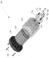
도 1은 실시예를 따르는 웨이퍼 표면 온도 측정공구를 도시한 분해 사시도.
도 2A는, 공구 몸체 내에 배열된 내부 교정 추를 도시하는 웨이퍼 표면 온도 측정공구의 실시예를 도시하는 측단면도.
도 2B는 도 2A에 도시된 공구의 측면도.
도 3A는, 부착된 세라믹 지지부를 가진 내부 교정 추의 실시예를 도시한 사시도.
도 3B는, 부착된 세라믹 지지부가 없는 도 3A의 내부 교정 추를 도시한 사시도.
도 4A는, 웨이퍼 표면 온도 측정 공구의 실시예를 도시한 저면도.
도 4B는 조립된 웨이퍼 표면 온도 측정 공구의 실시예를 도시한 사시도.
도 5는 웨이퍼 표면 온도 측정 공구를 이용하여 수행된 온도교정의 방법을 도시한 플로우 차트.1 is an exploded perspective view showing a wafer surface temperature measurement tool according to an embodiment;
2A is a side cross-sectional view illustrating an embodiment of a wafer surface temperature measurement tool showing internal calibration weights arranged in a tool body;
Figure 2B is a side view of the tool shown in Figure 2A.
Figure 3A is a perspective view illustrating an embodiment of an internal calibration weight with attached ceramic support;
Figure 3B is a perspective view showing the internal calibration weight of Figure 3A without the attached ceramic support.
4A is a bottom plan view of an embodiment of a wafer surface temperature measurement tool.
4B is a perspective view illustrating an embodiment of an assembled wafer surface temperature measurement tool.
5 is a flow chart illustrating a method of temperature calibration performed using a wafer surface temperature measurement tool.
도면들에서 동일한 도면부호는 동일한 구성요소들을 나타낸다. 또한, 도면에 도시된 구성은 개략적으로 표시되고 일정비율로 표시된 것은 아니다.Like numbers refer to like elements throughout the drawings. In addition, the configurations shown in the drawings are schematically shown and are not shown at a certain ratio.
본 발명은 일반적으로, 반도체 웨이퍼 표면을 가로질러 온도를 측정하는 것과 관련된다. 상기 설명과 같이, WLR 시험은 웨이퍼가 균일한 온도로 유지되는 것을 요구한다. 본 명세서의 실시예들은, 웨이퍼 표면 온도 측정 공구 및 웨이퍼를 가로질러 온도를 측정하기 위한 방법을 설명한다. 상기 공구는, WLR 시험이 이루어지는 동안 균일한 웨이퍼 온도를 형성하기 위해 중요한 요소이고 반복할 수 있고 신뢰성을 가지며 정확하고 실용적인 온도 교정(temperature calibration) 방법을 제공한다.The present invention generally relates to measuring temperature across a semiconductor wafer surface. As described above, the WLR test requires that the wafer be maintained at a uniform temperature. Embodiments herein describe a wafer surface temperature measurement tool and a method for measuring temperature across a wafer. The tool provides an accurate and practical temperature calibration method that is critical, repeatable and reliable to form uniform wafer temperatures during WLR testing.
상기 웨이퍼 표면 온도 측정 공구는, 웨이퍼의 표면 온도를 정확하게 구하기 위해 가열된 웨이퍼의 표면에 배열될 수 있다. 상기 공구의 온도 센서는 상대적으로 작은 크기를 가져서, 온도 센서가 웨이퍼와 접촉하는 면적은 최소화된다. 상기 작은 접촉 면적에 의해, 웨이퍼 상에 반복적인 배열은 높은 표면 분해능(areal resolution)을 제공하고 상세한 웨이퍼 온도 분포 지도를 형성할 수 있다.The wafer surface temperature measuring tool can be arranged on the surface of the heated wafer to accurately obtain the surface temperature of the wafer. The temperature sensor of the tool has a relatively small size so that the area of contact of the temperature sensor with the wafer is minimized. Due to the small contact area, iterative arrangement on the wafer provides high areal resolution and can form a detailed wafer temperature distribution map.
전형적으로 상승된 온도(예를 들어, 25℃ 내지 300℃)에서 WLR 시험은, 일반적으로 "고온 척"으로 알려지고 특수설계된 금속 척위에서 수행된다. 상기 고온 척은, 상기 척의 상부 표면에서 온도를 제어하는 전용 제어 시스템에 의해 가열된다. 시험되는 웨이퍼의 후방 측부는, 상기 척과 웨이퍼사이에서 양호한 물리적 접촉 및 열적 접촉을 형성하기 위해 척내부의 소형 진공 구멍을 이용하여 척의 상부 표면에 배열된다. 그러나, 상기 척의 상부 표면에서 제어 온도는, 웨이퍼의 상부 표면에 위치한 시험 장치의 실제 온도와 다르다.The WLR test, typically at elevated temperatures (eg, 25 ° C. to 300 ° C.), is generally known as "hot chucking" and is performed on specially designed metal chucks. The hot chuck is heated by a dedicated control system which controls the temperature at the upper surface of the chuck. The back side of the wafer being tested is arranged on the upper surface of the chuck using a small vacuum hole inside the chuck to form good physical and thermal contact between the chuck and the wafer. However, the control temperature at the upper surface of the chuck differs from the actual temperature of the test apparatus located at the upper surface of the wafer.
이론상으로, 시험되는 웨이퍼를 가로지르는 모든 다이(위치)는 전용 온도 센서를 가질 수 있다. 상기 웨이퍼의 전체 영역을 커버하는 다수의 상기 온도 센서들의 측정값(readings)이 전용 제어 시스템과 함께 이용되면, 상기 척의 표면보다는 상기 웨이퍼의 상부 표면에서 시험 장치를 가로질러 온도가 측정되고 제어될 수 있다. 웨이퍼의 전체 영역을 가로질러 다수의 온도 센서들을 이용하는 상기 방법은 이론적으로 실행가능할지라도 실용적이지 못한 데, 각각의 모든 시험 웨이퍼는 척, 다수의 온도 센서 및 전용 제어 시스템을 포함한 시스템과 물리적으로 그리고 전자적으로 일체 구성되어야 하기 때문이다.In theory, every die (position) across a wafer being tested can have a dedicated temperature sensor. If the readings of a number of the temperature sensors covering the entire area of the wafer are used with a dedicated control system, the temperature can be measured and controlled across the testing device at the upper surface of the wafer rather than at the surface of the chuck have. The above method of using multiple temperature sensors across the entire area of the wafer is impractical although it is theoretically feasible that each and every test wafer may be physically and electronically coupled to a system including a chuck, As shown in FIG.
상기 실시예에 의하면, 교정단계가 실제 웨이퍼 레벨 신뢰성 시험이전에 수행된다. 상기 교정 단계 동안, 웨이퍼의 상부 표면을 가로질러 온도가 각각의 오프셋 번호(offset numbers)들의 배열로서 구해진다. 교정 단계 이후에, 설정된 척 온도가 이에 따라 조정되어 잔류하는 온도 편차가 알려져 있고 고려될 수 있을 때, 각 시험 장치의 측정 온도는 목표 값과 더욱 근접하게 된다.According to this embodiment, the calibration step is performed before the actual wafer level reliability test. During the calibration step, the temperature across the upper surface of the wafer is obtained as an array of respective offset numbers. After the calibration step, when the set chuck temperature is adjusted accordingly and the residual temperature deviation is known and can be considered, the measured temperature of each testing device becomes closer to the target value.
웨이퍼를 가로질러 표면 온도를 구하는 두 가지 일반적인 방법, (1) 상업적으로 제조된 실리콘 교정 웨이퍼를 이용 및, (2) 소형의 고정밀 온도 센서를 이용하는 것이 존재한다. 상업적으로 제조된 실리콘 교정 웨이퍼가 이용될 때, 상기 웨이퍼 내에 박혀진 다수의 고정밀 온도 센서들이 와이어에 의해 측정기(meter)에 연결되어 웨이퍼에 걸쳐 각 측정값들의 지도를 제공한다. 상기 방법은 정확하고 신뢰성 있는 결과를 제공한다. 그러나, 상기 교정 웨이퍼는 매우 비싸며, 교정 웨이퍼와 다른 (예를 들어, 기질 도핑(substrate- doping, 두께)) 웨이퍼들은 고온 척 표면과 웨이퍼 표면 사이에서 상이한 온도 오프셋을 가질 수 있다.There are two general methods of obtaining the surface temperature across a wafer: (1) using a commercially manufactured silicon calibration wafer, and (2) using a small, high precision temperature sensor. When a commercially manufactured silicon calibration wafer is used, a number of high precision temperature sensors embedded in the wafer are connected to a meter by a wire to provide a map of each measurement value across the wafer. The method provides accurate and reliable results. However, the calibration wafer is very expensive, and different (e.g., substrate-doping, thickness) wafers than the calibration wafer may have different temperature offsets between the hot chuck surface and the wafer surface.
소형의 고정밀 온도 센서가 이용될 때 온도 센서는 작업자에 의해 낮은 열전도 공구(예를 들어, 면봉(cotton swab))를 이용하여 웨이퍼에 접촉하고 웨이퍼를 가로질러 이동하여 웨이퍼를 가로질러 온도의 지도를 제공한다. 그러나, 작업자에 의해 상기 센서로 가해지는 수직 하중은 측정과정 동안 웨이퍼를 가로질러 여러 위치들에서 변화하기 때문에 이러한 방법은 본질적으로 불일치하게 된다. 상기 가변성에 대해 상기 측정 온도는 1.0℃보다 크게 매우 민감하다. 본 명세서에서 설명되는 실시예들은, 매번 일정한 교정 하중을 이용하여 작업자에 의해 가해지는 상기 온도 센서를 통해 상기 방법이 가지는 상기 가변성을 완화시킨다. 결과적으로 저 비용의 공구는 간단하며 사용하기 쉽고, 웨이퍼에 걸쳐서 정확하고 일치하며 신뢰성있는 온도 측정값을 허용한다. 따라서, 상승된 온도에서 웨이퍼 레벨 신뢰성 시험을 하기 전에 효과적인 온도 교정이 제공된다.When a small, high-precision temperature sensor is used, the temperature sensor contacts the wafer using a low thermal conductivity tool (e.g., a cotton swab) by the operator and moves across the wafer to map the temperature across the wafer to provide. However, this method is inherently inconsistent because the vertical load applied by the operator to the sensor varies at various positions across the wafer during the measurement process. For the above variability, the measurement temperature is very sensitive to greater than 1.0 ° C. The embodiments described herein alleviate the variability of the method through the temperature sensor applied by the operator using a constant calibration load each time. As a result, low-cost tools are simple and easy to use, allowing accurate, consistent and reliable temperature measurements across the wafer. Thus, effective temperature calibration is provided prior to wafer level reliability testing at elevated temperatures.
도 1을 참고할 때, 웨이퍼 표면 온도 측정 공구(100)의 실시예가 분해 사시도로서 제공된다. 도 1에 도시된 실시예에 의하면, 공구(100)는 사실상 원통 형상을 가지고 경미하게 더 넓은 캡(cap)(110) 및 테이퍼 부분을 가진 원통형 공구 몸체(130)를 포함한다. 상기 캡(110)은 사용자를 위한 핸들로서 이용되고 도 1에 도시된 것처럼, 공구 몸체(130)의 상부에 부착된다. 도 1에 도시된 것처럼, 상기 캡(110)은, 세 개의 나사(140)들 및 상기 공구 몸체(130)의 상부 표면 및 상기 캡(110)을 통과하는 해당 나사 구멍들에 의해 상기 공구 몸체(130)의 상부에 부착된다. 실시예에 의하면, 상기 캡(110)은 플라스틱으로 제조될 수 있다. 다른 실시예에서, 상기 캡은 예를 들어, 유리섬유, 코르크 또는 고무와 같은 다른 재료로 제조될 수 있다.Referring to Figure 1, an embodiment of a wafer surface
상기 공구 몸체(130)는 스테인레스 강으로 제조될 수 있다. 도 1에 도시된 것처럼, 상기 공구 몸체(130)는 내부의 원통형 공동을 가진다. 스테인레스 강재질의 교정 추(calibrated weight)(120)가 상기 공동내부에서 미끄럼가능하게 배열된다. 도 1에 도시된 것처럼, 교정 추(120)는 상기 공동내부에 상대적으로 느슨하게 조립되어 상기 추(120)는 중력에 의해 공동내부로 미끄럼 운동할 수 있다. 다른 실시예에서, 상기 추는 적합한 밀도의 모든 재료로 제조될 수 있고 적합한 강성의 모든 재료로 제조될 수 있다. 도 2A는 상기 공구 몸체(130) 내부에 위치한 내부의 교정 추를 도시하고 상기 공구(100)의 주축을 따라 본 측 단면도이며, 도 2B는 상기 공구(100)의 측면도이다. 상기 실시예에서, 내부 교정 추(120)는 동일한 주축을 따라 세 개의 원통형 섹션들을 형성하도록 기계가공되며 스테인레스 강으로 제조된 일체형 단일 부분으로부터 제조된다. 특정 실시예에서, 상기 교정 추(120)의 중량은 약 1.24 파운드이다.The
상기 추(120)는 (가장 크고 가장 무거운 부분인) 상부의 원통형 부분(120A), 상대적으로 작은 원통형의 중간 부분(120B) 및 하부 부분(120C)을 포함한다. 도 2A에 도시된 것처럼, 상기 하부부분(120C)은, 세라믹 지지부(foot)(150)의 상부 표면을 통해 나사구조의 오리피스 속으로 조립되는 나사구조의 스터드이다(도 1 및 도 3을 참고). 내부 교정 추(120)의 상대적으로 큰 상부 부분(120A)은 상기 공구 몸체(130) 내부의 해당 공동보다 약간 더 짧게 형성되어, 전체 내부 교정 추(120)는 상기 공동내부에서 미끄럼 운동할 수 있다. 상기 공구(100)가 정상적으로 고정(즉 우측부가 위로 배열되고 상부 플라스틱 캡(110)이 위로 배열)될 때 상기 추(120)는 중력에 의해 아래로 당겨지거나 상기 공구(100)가 상측이 아래로 고정될 때 반대로 당겨진다. 상기 세라믹 지지부(150)는 나사구조의 스터드(120C)에 의해 상기 내부 교정 추(120)의 상대적으로 작은 중간 부분(120B)의 하부 표면에 부착되고, 상기 스터드는 상기 세라믹 지지부(150) 내부의 나사 오리피스 속으로 나사 체결된다. 전기 와이어(165)의 배열을 위해, 상기 세라믹 지지부는 도 3A에 도시된 것처럼 각을 형성하여, 와이어(165)들은 자유롭게 매달려서 공구의 어떠한 부분에 의해서도 방해되지 않는다. 또한, 상기 지지부(150)의 형성각(angling)은 상대적으로 작은 점유공간(footprint)을 허용한다.The
도시된 실시예에서, 웨이퍼의 온도를 측정하기 위해 크기가 작고 얇은 직사각형 저항 온도 장치(RTD) 또는 온도 센서(160)가 상기 공구(100)의 하부에 제공된다. 상기 온도 센서(160)는, 웨이퍼의 감지된 온도를 표시 및/또는 기록하기 위해 전기적 와이어에 의해 컴퓨터와 연결된다. 도 2A에 도시된 것처럼, 상기 온도 센서(160)는 상기 전기적 와이어(165)에 의해 고정되고, 상기 전기적 와이어들은 세라믹 판(170) 내부의 작은 개구부를 느슨하게 통과한다. 도 2A 및 도 2B에 도시된 실시예에서, 상기 전기적 와이어(165)는 상기 세라믹 판(170) 내부의 작은 개구부로부터 컴퓨터까지 연장된다. 상기 세라믹 판(170)은 또한 중앙의 구멍을 가지며 상기 구멍을 통해 상기 세라믹 지지부(150)는 상기 내부 교정 추(120)의 나사구조 스터드(120C)와 나사 체결된다. 도 3A는, 부착된 세라믹 지지부(150)를 가진 내부 교정 추(120)를 도시한 사시도이다. 도 3B는 부착된 세라믹 지지부(150)가 없는 내부 교정 추(120)를 도시한다. 상기 실시예에서, 나사(175) 및 상기 교정 추(120)의 나사구조 스터드(120C)에 대해 상기 세라믹 지지부(150)가 연결되어 상기 공구 몸체(130)에 대해 상기 세라믹 판(170)은 제위치에 고정된다. 상기 판(170)을 상기 공구 몸체(130)에 부착하기 위해 나사(175)들이 이용된다. 다른 실시예에서, 온도 센서는 다른 형상을 가질 수 있다. 다른 실시예들에서, 상기 센서는 서모커플(thermocouple) 또는 서미스터(thermistor)일 수 있다.In the illustrated embodiment, a small, thin rectangular resistance temperature device (RTD) or
상기 공구(100)가 아래위가 거꾸로 고정될 때, 상기 온도 센서(160)는 상기 세라믹 지지부(150) 위로 수 밀리미터 매달려 배열된다. 상기 공구(100)가 정상적으로 고정(우측부가 위로 고정)될 때 교정 추(120)는 상기 공구 몸체(130)내에서 아래를 향해 미끄럼운동하며, 부착된 세라믹 지지부(150)는 충분히 아래로 미끄럼 운동하여 상기 온도 센서(160)를 웨이퍼 표면에 대해 가압하고, 온도 센서의 전기적 와이어를 조금 끌어당긴다. 상기 전기적 와이어(165)가 통과하는 세라믹 판(170) 내부의 개구부는 효과적인 스트레인 릴리프(strain relief)로서 작용한다.When the
도 4A는 조립된 공구(100)의 저면도이고 도 4B는 기울어진 사시도이다. 웨이퍼 위에서 내부 교정 추(120)의 안정된 위치설정을 보장하기 위해, 도 4A 및 도 4B에 도시된 것처럼 도시된 실시예에서 세라믹 판(170)에 세 개의 세라믹 스탠드(stand)(180)들이 제공된다. 하부 웨이퍼와 함께 형성되는 상기 스탠드(180)들의 작은 접촉영역 및 세라믹 재료의 낮은 열전도성은, 상기 온도 센서(160)에 의해 측정되어야 하는 실제 온도에 대한 영향을 최소화한다.4A is a bottom view of the assembled
도시된 실시예에서, 세 개의 스터드(190)들은 세라믹 판(170) 내부의 구멍을 통해 연장되고 세라믹 스탠드(180) 내부의 나사구조 오리피스 속에 조립된다(도 1). 상기 실시예에서, 세 개의 나사(175)들은 상기 세라믹 지지부(150) 내부에서 다른 세트의 구멍들을 통해 연장되고 나사구조 오리피스 속에 조립에 의해 상기 세라믹 판(170)을 상기 공구 몸체(130)의 하부 표면에 부착시킨다. 다른 실시예에서, (지지부(150)와 판(170)뿐만 아니라) 스탠드(180)는 예를 들어, 운모(mica), 유리, 수정 또는 석재와 같은 비전도성 재료로 제조될 수 있다.In the illustrated embodiment, three
도 5는, 본 명세서에서 설명되는 웨이퍼 표면 온도 측정 공구를 이용하여 수행되는 온도 교정 방법(500)에 관한 플로우 차트이다. 단계(510)에서, 상기 온도 측정 공구는 상기 세라믹 스탠드가 웨이퍼와 접촉할 때 웨이퍼 표면의 선택된 영역에 배열된다. 상기 공구는 공구의 하부에서 세라믹 지지부를 가지며 상기 온도 센서는 상기 세라믹 지지부의 하부 표면으로부터 연장된다. 상기 세라믹 지지부는, 상기 공구 몸체 내부에 미끄럼가능하게 배열된 교정 추의 하측 단부에 부착된다.5 is a flow chart of a
단계(520)에서, 중력은 상기 세라믹 지지부를 아래로 끌어내리는 것이 허용되어, 상기 온도 센서는 상기 웨이퍼와 양호한 열적 접촉을 형성한다. 공구가 상기 웨이퍼 상에 배열될 때 중력이 상기 세라믹 지지부를 아래로 끌어내림에 따라, 온도 센서는 공구 몸체 내부에 위치한 스테인레스 강 재질의 교정 추의 중량과 동일한 하중을 받고, 각각의 반작용 하중(반대방향으로 동일한 강도)은 하부 표면을 위로 가압한다. 그 결과, 온도 센서는, 내부에 위치한 스테인레스 강재질의 교정 추의 최적 중량을 이용하여 동일한 하중에 의해 항상 유지된다. 따라서, 중력이 교정 추상에서 끌어당기고 따라서 상기 온도 센서가 매번 서로 다른 작업자의 하중 대신에 스테인레스 강재질의 교정 추에 대해 온도 센서를 가압하기 때문에, 상기 공구가 웨이퍼 상의 위치들을 이동할 때 동일한 하중이 매번 온도 센서에 가해진다.In
단계(530)에서 상기 온도 센서 측정값은 안정화되는 것이 허용된다. 온도 측정값이 안정화되면, 단계(540)에서 온도 센서의 측정값이 구해진다. 온도 측정값은, 컴퓨터와 같은 장치에 의해 구해질 수 있다. 상기 장치는 전기적으로 상기 온도 센서와 연결될 수 있다. 실시예에서 온도 센서와 장치는 전기적 와이어에 의해 전기적으로 연결된다. 상기 설명과 같이, 상기 전기적 와이어는 세라믹 판과 같은 공구의 일부분을 통과할 수 있다. 다른 실시예에서, 상기 온도 센서와 컴퓨터는 무선으로 연결될 수 있다.In
온도 측정값이 구해진 후에, 단계(550)에서 공구는 웨이퍼 상의 다른 위치로 이동하여 웨이퍼의 다른 위치에서 온도 측정값을 구할 수 있다. 단계(510) 내지 단계(550)는 웨이퍼의 온도 지도를 구하기 위해 반복될 수 있다. 상기 공구를 이용하여, 방법(500)은 웨이퍼에 관한 정확하고 일치하며 신뢰할 수 있는 영역 온도지도를 형성할 수 있다.After the temperature measurement is determined, the tool moves to another location on the wafer in
본 발명에 관한 몇몇 실시예들만 상세하게 설명될지라도, 본 발명은 본 발명의 범위 내에서 다수의 다른 형태로 실시될 수 있다. 상기 웨이퍼의 온도 측정 공구는 광범위한 적용예들에서 이용될 수 있다. 상기 설명을 고려할 때, 상기 실시예들은 설명을 위해 제공되며 본 발명을 제한하지 않고, 본 발명은 상기 설명에 의해 제한되지 않지만 첨부된 청구범위 내에서 수정될 수 있다.Although only some embodiments of the present invention are described in detail, the present invention may be embodied in many different forms within the scope of the present invention. The wafer temperature measurement tool can be used in a wide variety of applications. In view of the above description, the above embodiments are provided for explanation and do not limit the present invention, but the present invention is not limited by the above description, but may be modified within the scope of the appended claims.
100....웨이퍼 표면 온도 측정 공구,
110....캡,
130....공구 몸체,
140....나사.100 .... Wafer surface temperature measurement Tool,
110 .... cap,
130 .... Tool body,
140 .... screws.
Claims (19)
공구 몸체;
상기 공구 몸체 내에서 미끄럼 가능하게 배열된 교정 추를 포함하되, 상기 교정 추는 중력에 의해 공구 몸체 내에서 미끄럼 운동이 가능하며;
상기 교정 추의 하측 단부에 부착되고 상기 공구 몸체의 하측 단부로부터 돌출하는 지지부; 및
상기 지지부의 하부 표면으로부터 연장되는 온도 센서를 포함하되, 상기 온도 센서는 상기 교정 추가 중력에 의해 공구 몸체 내에서 미끄럼 운동할 때 웨이퍼와 접촉하도록 구성되는 것을 특징으로 하는 웨이퍼 온도 측정 공구.
A wafer temperature measurement tool, said wafer temperature measurement tool comprising:
A tool body;
A calibration weight slidably arranged in the tool body, the calibration weight being capable of sliding in the tool body by gravity;
A support attached to a lower end of the calibration weight and projecting from a lower end of the tool body; And
And a temperature sensor extending from a lower surface of the support, the temperature sensor being configured to contact the wafer as it slides within the tool body by the calibration additional gravity.
The tool according to claim 1, wherein the calibration weight is made of stainless steel.
The tool of claim 1, wherein the support protrudes through the plate from the tool body.
The tool according to claim 3, wherein a plurality of stands are attached to the plate.
The tool according to claim 4, wherein the support, the plate and the stand are made of ceramic.
The tool according to any one of the preceding claims, wherein the tool body is cylindrical.
The tool of claim 1, wherein the temperature sensor is operatively connected to a computer.
웨이퍼 상에 온도 측정 공구를 배열하는 단계를 포함하며, 상기 온도 측정 공구는 공구 몸체 내에서 미끄럼 가능하게 배열된 교정 추 및 상기 교정 추의 하측 단부에 부착된 세라믹 지지부를 포함하되, 상기 교정 추는 중력에 의해 공구 몸체 내에서 미끄럼 운동이 가능하고, 온도 센서가 상기 세라믹 지지부의 하부 표면으로부터 연장되며, 상기 온도 센서는 상기 교정 추가 중력에 의해 공구 몸체 내에서 미끄럼 운동할 때 웨이퍼와 접촉하도록 구성되고;
중력이 상기 세라믹 지지부를 아래로 끌어내려 온도 센서가 웨이퍼와 열적으로 접촉하게 하는 단계를 포함하며;
상기 온도 센서로부터 온도 측정값을 구하는 단계를 포함하는 것을 특징으로 하는 웨이퍼 표면 온도의 측정 방법.
A method of measuring a wafer surface temperature, the method comprising:
Wherein the temperature measuring tool comprises a calibration weight slidably arranged in the tool body and a ceramic support attached to a lower end of the calibration weight, A temperature sensor extending from a lower surface of the ceramic support, the temperature sensor being configured to contact the wafer when sliding in the tool body by the calibration additional gravity;
Gravity pulls the ceramic support down and causes the temperature sensor to make thermal contact with the wafer;
And obtaining a temperature measurement value from the temperature sensor.
9. The method of claim 8, further comprising moving the temperature measurement tool to another location on the wafer after determining the temperature measurement value.
9. The method according to claim 8, wherein the step of obtaining a temperature measurement value is performed by a computer.
11. The method of claim 10, wherein the temperature sensor and the computer are operatively connected.
12. A method according to any one of claims 8 to 11, wherein the temperature measurement value is allowed to stabilize before determining a temperature measurement value.
The method according to any one of claims 8 to 11, characterized in that when the temperature measuring tool is arranged on the wafer, only the stands located below the temperature measuring tool are in contact with the wafer .
원통형 공구 몸체;
상기 공구 몸체 내에서 미끄럼 가능하게 배열된 교정 추를 포함하되, 상기 교정 추는 중력에 의해 공구 몸체 내에서 미끄럼 운동이 가능하며;
상기 공구 몸체의 하측 단부로부터 연장되는 세라믹 스탠드; 및
상기 교정 추의 하측 단부에서 세라믹 지지대에 부착된 온도 센서를 포함하되, 상기 온도 센서는 상기 교정 추가 중력에 의해 공구 몸체 내에서 미끄럼 운동할 때 웨이퍼와 접촉하도록 구성되고, 상기 세라믹 지지대 및 온도 센서는 상기 공구 몸체의 외부에 위치하는 것을 특징으로 하는 웨이퍼 온도 측정 공구.
A wafer temperature measurement tool, said wafer temperature measurement tool comprising:
A cylindrical tool body;
A calibration weight slidably arranged in the tool body, the calibration weight being capable of sliding in the tool body by gravity;
A ceramic stand extending from a lower end of the tool body; And
And a temperature sensor attached to the ceramic support at the lower end of the calibration weight, the temperature sensor being configured to contact the wafer when sliding in the tool body by the calibration additional gravity, the ceramic support and the temperature sensor Wherein the tool body is located outside the tool body.
15. The method according to claim 14, wherein the tool is configured such that when the tool is arranged on the wafer, the ceramic supports contact the wafer and gravity pulls down the calibration weight in the tool body so that the temperature sensor contacts the wafer. Wherein the wafer temperature measuring tool is a wafer temperature measuring tool.
The tool according to claim 14 or 15, wherein the calibration weight is made of stainless steel.
16. The tool according to claim 14 or 15, wherein the temperature sensor is operatively connected to the computer.
18. The tool of claim 17, wherein the temperature sensor is wirelessly coupled to the computer.
18. The tool of claim 17, wherein the electrical wire connects the temperature sensor to the computer.
Applications Claiming Priority (3)
| Application Number | Priority Date | Filing Date | Title |
|---|---|---|---|
| US13/827,490 US9196516B2 (en) | 2013-03-14 | 2013-03-14 | Wafer temperature measurement tool |
| US13/827,490 | 2013-03-14 | ||
| PCT/US2014/018070 WO2014158549A1 (en) | 2013-03-14 | 2014-02-24 | Wafer temperature measurement tool |
Publications (2)
| Publication Number | Publication Date |
|---|---|
| KR20150113188A KR20150113188A (en) | 2015-10-07 |
| KR101787222B1 true KR101787222B1 (en) | 2017-10-18 |
Family
ID=50280490
Family Applications (1)
| Application Number | Title | Priority Date | Filing Date |
|---|---|---|---|
| KR1020157023878A KR101787222B1 (en) | 2013-03-14 | 2014-02-24 | Wafer temperature measurement tool |
Country Status (7)
| Country | Link |
|---|---|
| US (1) | US9196516B2 (en) |
| JP (1) | JP6336027B2 (en) |
| KR (1) | KR101787222B1 (en) |
| CN (1) | CN104838244B (en) |
| DE (1) | DE112014001341B4 (en) |
| TW (1) | TWI633285B (en) |
| WO (1) | WO2014158549A1 (en) |
Families Citing this family (4)
| Publication number | Priority date | Publication date | Assignee | Title |
|---|---|---|---|---|
| US9196516B2 (en) * | 2013-03-14 | 2015-11-24 | Qualitau, Inc. | Wafer temperature measurement tool |
| US10522380B2 (en) * | 2014-06-20 | 2019-12-31 | Applied Materials, Inc. | Method and apparatus for determining substrate placement in a process chamber |
| CN110998820B (en) | 2017-08-17 | 2023-10-20 | 东京毅力科创株式会社 | Apparatus and method for sensing attributes in industrial manufacturing equipment in real time |
| WO2019245729A1 (en) | 2018-06-18 | 2019-12-26 | Tokyo Electron Limited | Reduced interference, real-time sensing of properties in manufacturing equipment |
Citations (1)
| Publication number | Priority date | Publication date | Assignee | Title |
|---|---|---|---|---|
| JP4909986B2 (en) * | 2005-04-12 | 2012-04-04 | シトリニック ゲス フュール エレクトロテクニッシュ オウスルゥスタング エム ベー ハー ウント コー カー ゲー | Sensor device for surface temperature measurement |
Family Cites Families (19)
| Publication number | Priority date | Publication date | Assignee | Title |
|---|---|---|---|---|
| US5059032A (en) | 1990-08-16 | 1991-10-22 | The Dow Chemical Company | Free standing fluxmeter fixture with dual infrared pyrometers |
| US5446824A (en) * | 1991-10-11 | 1995-08-29 | Texas Instruments | Lamp-heated chuck for uniform wafer processing |
| US5436494A (en) | 1994-01-12 | 1995-07-25 | Texas Instruments Incorporated | Temperature sensor calibration wafer structure and method of fabrication |
| JP3067962B2 (en) * | 1994-10-19 | 2000-07-24 | 新日本製鐵株式会社 | Contact type temperature sensor |
| WO1997003342A1 (en) | 1995-07-10 | 1997-01-30 | Cvc Products, Inc. | Automated calibration of temperature sensors in rapid thermal processing |
| JPH0945752A (en) * | 1995-07-27 | 1997-02-14 | Dainippon Screen Mfg Co Ltd | Substrate treatment device |
| JPH11125566A (en) * | 1997-10-22 | 1999-05-11 | Sumitomo Electric Ind Ltd | Surface temperature measurement sensor and temperature measurement probe |
| US6110288A (en) | 1998-12-17 | 2000-08-29 | Eaton Corporation | Temperature probe and measurement method for low pressure process |
| JP2001085488A (en) | 1999-09-16 | 2001-03-30 | Bridgestone Corp | Thermometer wafer |
| US6355994B1 (en) * | 1999-11-05 | 2002-03-12 | Multibeam Systems, Inc. | Precision stage |
| JP3567855B2 (en) | 2000-01-20 | 2004-09-22 | 住友電気工業株式会社 | Wafer holder for semiconductor manufacturing equipment |
| US6572265B1 (en) * | 2001-04-20 | 2003-06-03 | Luxtron Corporation | In situ optical surface temperature measuring techniques and devices |
| JP2004022803A (en) | 2002-06-17 | 2004-01-22 | Taiheiyo Cement Corp | Push-up pin with temperature measuring function |
| JP2004200619A (en) | 2002-12-20 | 2004-07-15 | Kyocera Corp | Wafer supporting member |
| US6976782B1 (en) * | 2003-11-24 | 2005-12-20 | Lam Research Corporation | Methods and apparatus for in situ substrate temperature monitoring |
| US7275861B2 (en) * | 2005-01-31 | 2007-10-02 | Veeco Instruments Inc. | Calibration wafer and method of calibrating in situ temperatures |
| US20080034855A1 (en) | 2006-08-11 | 2008-02-14 | Maximiliaan Peeters | Sliding weight borehole gravimeter |
| JP2012230023A (en) * | 2011-04-27 | 2012-11-22 | Tokyo Electron Ltd | Temperature measurement device and temperature calibration device and method thereof |
| US9196516B2 (en) * | 2013-03-14 | 2015-11-24 | Qualitau, Inc. | Wafer temperature measurement tool |
-
2013
- 2013-03-14 US US13/827,490 patent/US9196516B2/en active Active
-
2014
- 2014-02-24 CN CN201480003511.7A patent/CN104838244B/en active Active
- 2014-02-24 WO PCT/US2014/018070 patent/WO2014158549A1/en active Application Filing
- 2014-02-24 JP JP2016500365A patent/JP6336027B2/en active Active
- 2014-02-24 DE DE112014001341.2T patent/DE112014001341B4/en active Active
- 2014-02-24 KR KR1020157023878A patent/KR101787222B1/en active IP Right Grant
- 2014-03-03 TW TW103107033A patent/TWI633285B/en active
Patent Citations (1)
| Publication number | Priority date | Publication date | Assignee | Title |
|---|---|---|---|---|
| JP4909986B2 (en) * | 2005-04-12 | 2012-04-04 | シトリニック ゲス フュール エレクトロテクニッシュ オウスルゥスタング エム ベー ハー ウント コー カー ゲー | Sensor device for surface temperature measurement |
Also Published As
| Publication number | Publication date |
|---|---|
| CN104838244B (en) | 2017-09-15 |
| DE112014001341T5 (en) | 2015-12-03 |
| JP6336027B2 (en) | 2018-06-06 |
| KR20150113188A (en) | 2015-10-07 |
| TWI633285B (en) | 2018-08-21 |
| US9196516B2 (en) | 2015-11-24 |
| DE112014001341B4 (en) | 2021-05-06 |
| WO2014158549A1 (en) | 2014-10-02 |
| JP2016516992A (en) | 2016-06-09 |
| CN104838244A (en) | 2015-08-12 |
| US20140269822A1 (en) | 2014-09-18 |
| TW201502479A (en) | 2015-01-16 |
Similar Documents
| Publication | Publication Date | Title |
|---|---|---|
| Iervolino et al. | Temperature calibration and electrical characterization of the differential scanning calorimeter chip UFS1 for the Mettler-Toledo Flash DSC 1 | |
| KR101787222B1 (en) | Wafer temperature measurement tool | |
| US4095453A (en) | Differential thermal analysis cell | |
| US9857247B2 (en) | Method and device for sensing isotropic stress and providing a compensation for the piezo-hall effect | |
| US10018520B2 (en) | Temperature calibration for a measuring apparatus | |
| WO2019179229A1 (en) | Method using dry block temperature calibrator to calibrate short temperature measuring apparatus | |
| KR101922020B1 (en) | Temperature measurement of active device under test on strip tester | |
| WO2015137075A1 (en) | Internal temperature measurement method and internal temperature measurement device | |
| JP4770402B2 (en) | Calibration method of temperature data logger and soaking block used therefor | |
| CN109725183B (en) | Probe for portable thermoelectric potential detector | |
| EP0984273A2 (en) | Device for measuring thermophysical properties of solid materials and method therefor | |
| US10352781B2 (en) | Micro heater integrated with thermal sensing assembly | |
| US20230131448A1 (en) | Heat-loss pressure microsensors | |
| JP6299876B2 (en) | Surface temperature sensor calibration device | |
| JP2909922B2 (en) | Temperature compensation method for thermomechanical analysis | |
| JP3926657B2 (en) | Mold temperature measuring jig and measuring method | |
| CN106770434A (en) | Radiometer method hemispherical emissivity tester | |
| US20160334442A1 (en) | Measuring system and measuring method with power calibration | |
| JP4854470B2 (en) | High precision temperature recorder | |
| JP2022178910A5 (en) | ||
| SU830145A2 (en) | Device for measuring solid body surface temperature | |
| CN110376244A (en) | A kind of heat conductivity measuring device | |
| CN108469308A (en) | A kind of surface temperature measurement instrument | |
| CZ302897B6 (en) | Method of and device for measuring heat conductivity | |
| Miklavec et al. | Blackbody and procedure for calibration of thermal imagers |
Legal Events
| Date | Code | Title | Description |
|---|---|---|---|
| A201 | Request for examination | ||
| E902 | Notification of reason for refusal | ||
| AMND | Amendment | ||
| E601 | Decision to refuse application | ||
| AMND | Amendment | ||
| X701 | Decision to grant (after re-examination) | ||
| GRNT | Written decision to grant |