KR101614566B1 - Filtration system - Google Patents
Filtration system Download PDFInfo
- Publication number
- KR101614566B1 KR101614566B1 KR1020117007568A KR20117007568A KR101614566B1 KR 101614566 B1 KR101614566 B1 KR 101614566B1 KR 1020117007568 A KR1020117007568 A KR 1020117007568A KR 20117007568 A KR20117007568 A KR 20117007568A KR 101614566 B1 KR101614566 B1 KR 101614566B1
- Authority
- KR
- South Korea
- Prior art keywords
- cartridge
- manifold
- filter
- delete delete
- handle
- Prior art date
Links
- 238000001914 filtration Methods 0.000 title claims abstract description 93
- 238000000926 separation method Methods 0.000 claims description 17
- 238000000034 method Methods 0.000 claims description 12
- 239000000706 filtrate Substances 0.000 claims description 3
- 239000000463 material Substances 0.000 description 15
- 239000012530 fluid Substances 0.000 description 13
- 238000007789 sealing Methods 0.000 description 13
- XLYOFNOQVPJJNP-UHFFFAOYSA-N water Substances O XLYOFNOQVPJJNP-UHFFFAOYSA-N 0.000 description 11
- 238000006073 displacement reaction Methods 0.000 description 7
- 238000004873 anchoring Methods 0.000 description 5
- 239000004677 Nylon Substances 0.000 description 4
- 239000004743 Polypropylene Substances 0.000 description 4
- 239000004793 Polystyrene Substances 0.000 description 4
- 230000008901 benefit Effects 0.000 description 4
- 150000002170 ethers Chemical class 0.000 description 4
- 239000004744 fabric Substances 0.000 description 4
- 229920001778 nylon Polymers 0.000 description 4
- 229920001955 polyphenylene ether Polymers 0.000 description 4
- -1 polypropylene Polymers 0.000 description 4
- 229920001155 polypropylene Polymers 0.000 description 4
- 229920002223 polystyrene Polymers 0.000 description 4
- 229910052782 aluminium Inorganic materials 0.000 description 3
- XAGFODPZIPBFFR-UHFFFAOYSA-N aluminium Chemical compound [Al] XAGFODPZIPBFFR-UHFFFAOYSA-N 0.000 description 3
- 230000007613 environmental effect Effects 0.000 description 3
- 238000009434 installation Methods 0.000 description 3
- 229910052751 metal Inorganic materials 0.000 description 3
- 239000002184 metal Substances 0.000 description 3
- 230000008569 process Effects 0.000 description 3
- 229910001220 stainless steel Inorganic materials 0.000 description 3
- 239000010935 stainless steel Substances 0.000 description 3
- 239000002699 waste material Substances 0.000 description 3
- 238000004891 communication Methods 0.000 description 2
- 230000000295 complement effect Effects 0.000 description 2
- 230000000717 retained effect Effects 0.000 description 2
- 239000007787 solid Substances 0.000 description 2
- OKTJSMMVPCPJKN-UHFFFAOYSA-N Carbon Chemical compound [C] OKTJSMMVPCPJKN-UHFFFAOYSA-N 0.000 description 1
- 230000009471 action Effects 0.000 description 1
- 239000000853 adhesive Substances 0.000 description 1
- 230000001070 adhesive effect Effects 0.000 description 1
- 230000004075 alteration Effects 0.000 description 1
- 230000009286 beneficial effect Effects 0.000 description 1
- 229910052799 carbon Inorganic materials 0.000 description 1
- 238000004140 cleaning Methods 0.000 description 1
- 230000008878 coupling Effects 0.000 description 1
- 238000010168 coupling process Methods 0.000 description 1
- 238000005859 coupling reaction Methods 0.000 description 1
- 239000003651 drinking water Substances 0.000 description 1
- 235000020188 drinking water Nutrition 0.000 description 1
- 230000003993 interaction Effects 0.000 description 1
- 238000002955 isolation Methods 0.000 description 1
- 229920001684 low density polyethylene Polymers 0.000 description 1
- 239000004702 low-density polyethylene Substances 0.000 description 1
- 238000003754 machining Methods 0.000 description 1
- 238000012423 maintenance Methods 0.000 description 1
- 230000013011 mating Effects 0.000 description 1
- 239000012528 membrane Substances 0.000 description 1
- 239000000203 mixture Substances 0.000 description 1
- 238000012986 modification Methods 0.000 description 1
- 230000004048 modification Effects 0.000 description 1
- 239000004745 nonwoven fabric Substances 0.000 description 1
- 229920000642 polymer Polymers 0.000 description 1
- 230000009467 reduction Effects 0.000 description 1
- 239000012858 resilient material Substances 0.000 description 1
- 238000007493 shaping process Methods 0.000 description 1
- 239000000758 substrate Substances 0.000 description 1
- 238000011144 upstream manufacturing Methods 0.000 description 1
Images


Classifications
-
- B—PERFORMING OPERATIONS; TRANSPORTING
- B01—PHYSICAL OR CHEMICAL PROCESSES OR APPARATUS IN GENERAL
- B01D—SEPARATION
- B01D27/00—Cartridge filters of the throw-away type
- B01D27/08—Construction of the casing
-
- B—PERFORMING OPERATIONS; TRANSPORTING
- B01—PHYSICAL OR CHEMICAL PROCESSES OR APPARATUS IN GENERAL
- B01D—SEPARATION
- B01D35/00—Filtering devices having features not specifically covered by groups B01D24/00 - B01D33/00, or for applications not specifically covered by groups B01D24/00 - B01D33/00; Auxiliary devices for filtration; Filter housing constructions
- B01D35/30—Filter housing constructions
-
- B—PERFORMING OPERATIONS; TRANSPORTING
- B01—PHYSICAL OR CHEMICAL PROCESSES OR APPARATUS IN GENERAL
- B01D—SEPARATION
- B01D2201/00—Details relating to filtering apparatus
- B01D2201/30—Filter housing constructions
- B01D2201/301—Details of removable closures, lids, caps, filter heads
- B01D2201/302—Details of removable closures, lids, caps, filter heads having inlet or outlet ports
-
- B—PERFORMING OPERATIONS; TRANSPORTING
- B01—PHYSICAL OR CHEMICAL PROCESSES OR APPARATUS IN GENERAL
- B01D—SEPARATION
- B01D2201/00—Details relating to filtering apparatus
- B01D2201/40—Special measures for connecting different parts of the filter
- B01D2201/4015—Bayonet connecting means
-
- B—PERFORMING OPERATIONS; TRANSPORTING
- B01—PHYSICAL OR CHEMICAL PROCESSES OR APPARATUS IN GENERAL
- B01D—SEPARATION
- B01D2201/00—Details relating to filtering apparatus
- B01D2201/40—Special measures for connecting different parts of the filter
- B01D2201/4023—Means for connecting filter housings to supports
-
- B—PERFORMING OPERATIONS; TRANSPORTING
- B01—PHYSICAL OR CHEMICAL PROCESSES OR APPARATUS IN GENERAL
- B01D—SEPARATION
- B01D2201/00—Details relating to filtering apparatus
- B01D2201/40—Special measures for connecting different parts of the filter
- B01D2201/4076—Anti-rotational means
-
- Y—GENERAL TAGGING OF NEW TECHNOLOGICAL DEVELOPMENTS; GENERAL TAGGING OF CROSS-SECTIONAL TECHNOLOGIES SPANNING OVER SEVERAL SECTIONS OF THE IPC; TECHNICAL SUBJECTS COVERED BY FORMER USPC CROSS-REFERENCE ART COLLECTIONS [XRACs] AND DIGESTS
- Y10—TECHNICAL SUBJECTS COVERED BY FORMER USPC
- Y10T—TECHNICAL SUBJECTS COVERED BY FORMER US CLASSIFICATION
- Y10T29/00—Metal working
- Y10T29/49—Method of mechanical manufacture
- Y10T29/49826—Assembling or joining
Abstract
필터 매니폴드 및 필터 카트리지를 포함하는 여과 시스템이 개시되어 있다. 필터 매니폴드는 브라켓, 밸브, 매니폴드 피드 포트, 매니폴드 여과 포트 및 손잡이를 포함한다. 밸브는 브라켓에 의해 보유되고, 브라켓에 부착된 고정 부분 및 회전 부분을 포함하고 있다. 손잡이는 회전 부분에 연결되어 동작하고, 캠밍 램프 또는 캠밍 러그 리프터 계합 특징부 중 하나를 가지는 카트리지 리프터를 포함하고 있다. 손잡이는 서비스 위치 및 분리된 위치에 대해 회전가능하고, 매니폴드 피드 포트는, 손잡이가 분리된 위치에 있을 때, 밸브에 의해 블로킹된다. 필터 카트리지는 카트리지 피드 포트, 카트리지 여과 포트, 및 리프터 계합 특징부를 계합시키는 캠밍 러그 또는 캠밍 램프 중 하나를 가지는 외부 카트리지 표면을 포함한다.A filter system comprising a filter manifold and a filter cartridge is disclosed. The filter manifold includes a bracket, a valve, a manifold feed port, a manifold filtration port, and a handle. The valve is held by the bracket and includes a fixed portion and a rotating portion attached to the bracket. The handle includes a cartridge lifter operatively connected to the rotating portion and having one of a camming ram or cam lug lifter engagement feature. The handle is rotatable relative to the service position and the discrete position, and the manifold feed port is blocked by the valve when the handle is in the disengaged position. The filter cartridge includes a cartridge feed port, a cartridge filtration port, and an external cartridge surface having one of camming lugs or camming rams engaging the lifter engagement features.
Description
물 여과 시스템은 주거 및 +상업 응용에서 종종 이용된다. 이러한 시스템은 전형적으로 급수 시설에 설치되고, 여과된 물을 수도꼭지, 식용수 분배기 등에 제공하는 동작을 한다. 일부 주거 응용에서, 여과 시스템은, 예를 들어, 주방에 있는 조리대 아래에 설치된다. 많은 경우에, 이러한 시스템은 주택 소유자가 교환할 수 있는 일회용 필터 카트리지를 가진다. 일회용 필터 카트리지의 서비스 수명이 만료될 때, 주택 소유자는 사용한 필터 카트리지를 제거하고 새 필터 카트리지를 설치해야만 한다. 이러한 시스템이 조리대 아래에 위치하는 경우에, 주택 소유자가 그 시스템에 접근하여 필요한 설치 단계를 수행하는 것이 어려울 수 있다. 종종, 이러한 위치는 비좁고, 시스템 자체에 대한 이용가능한 공간 및 주택 소유자가 시스템에 접근하기 위해 이용가능한 공간 모두가 제한되어 있다. 새 필터 카트리지가 설치된 후에, 사용한 필터 카트리지 전체는 전형적으로 폐기된다.Water filtration systems are often used in residential and commercial applications. Such a system is typically installed in a water supply facility and operates to provide filtered water to faucets, drinking water dispensers, and the like. In some residential applications, the filtration system is installed, for example, below a countertop in the kitchen. In many cases, such systems have disposable filter cartridges that the homeowner can exchange. When the service life of the disposable filter cartridge expires, the homeowner must remove the used filter cartridge and install a new filter cartridge. If such a system is located under a countertop, it may be difficult for the homeowner to access the system and perform the necessary installation steps. Often, these locations are cramped, and there is a limit to both the available space for the system itself and the space available for the homeowner to access the system. After the new filter cartridge is installed, the entire filter cartridge used is typically discarded.
공간을 덜 차지하고 유지 보수가 빠르고 간편하며 사용한 필터 카트리지를 폐기할 때 환경 쓰레기를 덜 발생하는 여과 시스템이 계속하여 필요하다.There is a continuing need for filtration systems that take up less space, are quick and easy to maintain, and produce less environmental waste when disposing used filter cartridges.
본 개시 내용은 일반적으로 여과 시스템을 관리하는 데 필요한 시간 및 노력을 절감할 수 있는 필터 매니폴드 및 여과 시스템에 관한 것이다. 본 개시 내용에 따른 필터 카트리지는 손잡이를 한번 잡아당겨 필터 카트리지를 들어 올리고 이를 필터 매니폴드에 계합시킴으로써 설치될 수 있다. 본 개시 내용의 필터 매니폴드 및 여과 시스템은 물 여과 시스템이 차지하는 공간을 감소시킬 수 있는 낮은 모양의 구조를 가질 수 있다. 게다가, 재료가 덜 사용될 수 있기 때문에, 본 발명은 사용한 필터 카트리지를 폐기하는 것과 연관된 환경 쓰레기를 감소시킬 수 있다.The present disclosure relates generally to filter manifolds and filtration systems that can reduce the time and effort required to manage a filtration system. The filter cartridge according to the present disclosure can be installed by pulling the handle once to lift the filter cartridge and engage it with the filter manifold. The filter manifold and filtration system of the present disclosure can have a low-profile structure that can reduce the space occupied by the water filtration system. In addition, since less material can be used, the present invention can reduce environmental waste associated with disposing of used filter cartridges.
본 출원은 밸브를 포함하는 필터 매니폴드를 개시하고 있다. 일부 실시 형태에서, 밸브는 고정 부분, 회전 부분, 및 회전 부분에 연결된 회전 잠금 장치를 포함한다. 매니폴드는 매니폴드 피드 포트(manifold feed port) 및 매니폴드 여과 포트(manifold filtrate port)를 추가로 포함하고 있다. 손잡이는 회전 부분에 연결되어 동작하고, 카트리지 리프터(cartridge lifter)를 포함하고 있다. 일부 실시 형태에서, 카트리지 리프터는 캠밍 램프(camming ramp) 및 캠밍 러그(camming lug)로 이루어지는 그룹으로부터 선택된 리프터 계합 특징부(lifter engagement feature)를 포함한다. 손잡이는 서비스 위치 및 잠금된 위치에 대해 회전가능하고, 여기서, 손잡이가 잠금된 위치에 있을 때, 회전이 회전 잠금 장치에 의해 방지되고 매니폴드 피드 포트가 밸브에 의해 블로킹된다.The present application discloses a filter manifold comprising a valve. In some embodiments, the valve includes a fixed portion, a rotating portion, and a rotational locking device coupled to the rotating portion. The manifold further includes a manifold feed port and a manifold filtrate port. The handle is operatively connected to the rotating portion and includes a cartridge lifter. In some embodiments, the cartridge lifter includes a lifter engagement feature selected from the group consisting of a camming ram and a camming lug. Wherein the handle is rotatable relative to the service position and the locked position, wherein when the handle is in the locked position, rotation is prevented by the rotary lock and the manifold feed port is blocked by the valve.
일 실시 형태에서, 필터 매니폴드는 브라켓을 추가로 포함하고, 여기서 밸브는 브라켓에 의해 보유되고, 고정 부분은 브라켓에 부착되어 있다.In one embodiment, the filter manifold further comprises a bracket, wherein the valve is held by the bracket and the securing portion is attached to the bracket.
일 실시 형태에서, 필터 매니폴드는 카트리지 지지 선반을 추가로 포함한다. 카트리지 지지 선반은, 손잡이가 서비스 위치에 있을 때, 카트리지 리프터 아래의 위치에서 브라켓 상에 배치될 수 있다. 카트리지 지지 선반은, 다른 대안으로서, 밸브의 고정 부분의 일부일 수 있다.In an embodiment, the filter manifold further comprises a cartridge support shelf. The cartridge support shelf may be disposed on the bracket in a position below the cartridge lifter when the handle is in the service position. The cartridge support shelf may alternatively be part of the fixed portion of the valve.
일부 실시 형태에서, 회전 잠금 장치는, 밸브의 회전 부분에 연결되고 밸브의 고정 부분에 있는 개구부를 통해 돌출하는 누름가능 부재(depressible member)를 포함한다. 일 실시 형태에서, 누름가능 부재는 잠금 위치로부터 잠금 해제 위치로 눌러질 수 있다. 일부 실시 형태에서, 누름가능 부재는 잠금 위치에 있을 때 개구부를 통해 돌출하고, 잠금 해제 위치에 있을 때 밸브의 고정 부분 내로 후퇴한다. 일 실시 형태에서, 누름가능 부재는, 손잡이가 서비스 위치에 있을 때, 잠금 해제 위치에 있다.In some embodiments, the rotational locking device includes a depressible member that is connected to a rotating portion of the valve and projects through an opening in the fixed portion of the valve. In one embodiment, the pressable member can be pushed from the locked position to the unlocked position. In some embodiments, the pressable member protrudes through the opening when in the locked position and retracts into the fixed portion of the valve when in the unlocked position. In one embodiment, the pressable member is in the unlocked position when the handle is in the service position.
일 실시 형태에서, 밸브의 회전 부분은, 손잡이가 잠금된 위치에 있을 때, 매니폴드 피드 포트를 매니폴드 여과 포트에 유체 연결시키는 바이패스 채널(bypass channel)을 포함한다. 적절한 경우, 밸브의 회전 부분은 2-부품 쉘(two-part shell)을 포함하며, 2-부품 쉘은 제1 원통형 부분 및 제2 원통형 부분을 가지며, 각각의 원통형 부분은 누름가능 부재를 위치시키기 위한 리세스(recess) 및 바이패스 채널의 일부분에 대한 유체 연결기를 가지는 연결 단부를 포함한다. 누름가능 부재를 위치시키고 바이패스 채널을 유체 연결시키기 위해, 제1 및 제2 원통형 부분의 연결 단부가 베이어네트 연결부(bayonet connection)에 의해 서로 연결된다.In one embodiment, the rotating portion of the valve includes a bypass channel for fluidly connecting the manifold feed port to the manifold filtration port when the handle is in the locked position. Where appropriate, the rotating portion of the valve includes a two-part shell, the two-part shell having a first cylindrical portion and a second cylindrical portion, each cylindrical portion having a first cylindrical portion and a second cylindrical portion, And a connection end having a fluid connector for a portion of the bypass channel. To position the pressable member and fluidly connect the bypass channel, the connecting ends of the first and second cylindrical portions are connected to each other by a bayonet connection.
일부 실시 형태에서, 밸브의 고정 부분은 세로축, 세로축을 따라 배향된 제1 단부, 및 제1 단부의 반대쪽에 있는 제2 단부를 포함한다. 이러한 실시 형태에서, 회전 부분의 제1 축방향 연장부는 제1 단부로부터 돌출하고, 회전 부분의 제2 축방향 연장부는 제2 단부로부터 돌출한다. 손잡이는 제1 및 제2 축방향 연장부(axial extension)에 부착될 수 있다.In some embodiments, the fixed portion of the valve includes a longitudinal axis, a first end oriented along a longitudinal axis, and a second end opposite the first end. In this embodiment, the first axially extending portion of the rotating portion projects from the first end, and the second axially extending portion of the rotating portion projects from the second end portion. The handle may be attached to the first and second axial extensions.
일부 실시 형태에서, 필터 매니폴드는 카트리지 피드 포트, 카트리지 여과 포트, 및 회전 키를 가지는 필터 카트리지를 추가로 포함하며, 여기서 회전 키는 누름가능 부재를 잠금 해제 위치로 누른다. 일 실시 형태에서, 누름가능 부재는 제1 원단 표면(distal surface)을 포함하고, 회전 키는 필터 카트리지로부터의 돌출부를 포함한다. 돌출부는 제2 원단 표면을 가질 수 있으며, 여기서 제2 원단 표면은 누름가능 부재를 누르기 위해 제1 원단 표면과 접촉한다.In some embodiments, the filter manifold further includes a filter cartridge having a cartridge feed port, a cartridge filtration port, and a rotary key, wherein the rotary key presses the pushable member into the unlocked position. In one embodiment, the pressable member includes a first distal surface, and the rotational key includes a protrusion from the filter cartridge. The protrusion may have a second fabric surface, wherein the second fabric surface is in contact with the first fabric surface to press the pressable member.
본 출원은 또한 필터 매니폴드 및 필터 카트리지를 포함하는 여과 시스템을 개시하고 있다. 일부 실시 형태에서, 필터 매니폴드는 브라켓 및 브라켓에 의해 보유되는 밸브를 포함할 수 있고, 밸브는 브라켓에 부착된 고정 부분 및 회전 부분을 포함하고 있다. 일 실시 형태에서, 브라켓은, 손잡이가 서비스 위치에 있을 때, 카트리지 리프터 아래의 위치에서 브라켓 상에 배치되는 카트리지 지지 선반을 포함한다. 일부 실시 형태에서, 필터 매니폴드는 브라켓 없이 제공된다. 이러한 실시 형태에서, 카트리지 지지 선반은 밸브의 고정 부분의 일부로서 제공될 수 있다. 일 실시 형태에서, 필터 매니폴드는 매니폴드 피드 포트 및 매니폴드 여과 포트를 추가로 포함하고 있다. 일부 실시 형태에서, 손잡이는 회전 부분에 연결되어 동작하고, 캠밍 램프 또는 캠밍 러그 리프터 계합 특징부 중 하나를 가지는 카트리지 리프터를 포함하고 있다. 손잡이는 서비스 위치 및 분리된 위치에 대해 회전가능하고, 매니폴드 피드 포트는, 손잡이가 분리된 위치에 있을 때, 밸브에 의해 블로킹된다.The present application also discloses a filtration system including a filter manifold and a filter cartridge. In some embodiments, the filter manifold may include a bracket and a valve held by the bracket, wherein the valve includes a fixed portion and a rotating portion attached to the bracket. In one embodiment, the bracket includes a cartridge support shelf disposed on the bracket at a location below the cartridge lifter when the handle is in the service position. In some embodiments, the filter manifold is provided without a bracket. In this embodiment, the cartridge support shelf may be provided as part of the fixed portion of the valve. In one embodiment, the filter manifold further includes a manifold feed port and a manifold filtration port. In some embodiments, the handle includes a cartridge lifter that is operatively connected to the rotating portion and has one of a camming ram or cam lug lifter engagement feature. The handle is rotatable relative to the service position and the discrete position, and the manifold feed port is blocked by the valve when the handle is in the disengaged position.
개시된 여과 시스템에서, 필터 카트리지는 카트리지 피드 포트, 카트리지 여과 포트, 및 리프터 계합 특징부를 계합시키는 캠밍 러그 또는 캠밍 램프 중 하나를 가지는 외부 카트리지 표면을 포함할 수 있다.In the disclosed filtration system, the filter cartridge may include an external cartridge surface having one of a camming lug or camming ram that engages the cartridge feed port, the cartridge filtration port, and the lifter engagement feature.
일부 실시 형태에서, 캠밍 러그는 선단 에지 및 주 표면을 포함하고, 선단 에지는, 주 표면이 캠밍 램프와 접촉하기 전에, 캠밍 램프와 접촉한다.In some embodiments, the cam lugs include a leading edge and a major surface, wherein the leading edge contacts the camming ramp before the main surface contacts the camming ramp.
일 실시 형태에서, 캠밍 램프는 제1 램프 부분 및 제2 램프 부분을 포함하고, 제1 램프 부분은 제2 램프 부분보다 더 큰 속도로 필터 매니폴드 쪽으로 캠밍 러그를 전진시킨다. 일 실시 형태에서, 제1 램프 부분은 직선 프로파일을 포함하고, 제2 램프 부분은 곡선 프로파일을 포함한다. 다른 실시 형태에서, 제1 및 제2 램프 부분 각각은 곡선 프로파일을 포함한다.In one embodiment, the camming ramp includes a first ramp portion and a second ramp portion, wherein the first ramp portion advances the cam lugs toward the filter manifold at a greater speed than the second ramp portion. In one embodiment, the first ramp portion comprises a straight profile and the second ramp portion comprises a curved profile. In another embodiment, each of the first and second ramp portions comprises a curved profile.
일부 실시 형태에서, 손잡이는 손잡이 분리 특징부를 포함하고, 필터 카트리지는 카트리지 분리 특징부를 포함한다. 이러한 실시 형태에서, 손잡이 분리 특징부는, 손잡이가 회전할 때, 카트리지 분리 특징부와 협력하여, 필터 카트리지의 제거 동안에 필터 카트리지를 필터 매니폴드로부터 멀어지게 밀어내는 것을 돕는다.In some embodiments, the handle includes a handle separation feature, and the filter cartridge includes a cartridge separation feature. In this embodiment, the handle separation feature assists in pushing the filter cartridge away from the filter manifold during removal of the filter cartridge, in cooperation with the cartridge separation feature, as the handle rotates.
개시된 여과 시스템의 일부 실시 형태에서, 필터 카트리지는 내부 체적 및 일회용 필터 요소를 가지는 경성 섬프(rigid sump)를 포함한다. 일회용 필터 요소의 적어도 일부분은 내부 체적 내에 배치가능하다. 일 실시 형태에서, 외부 카트리지 표면은 경성 섬프 상에 있다. 다른 실시 형태에서, 외부 카트리지 표면은 일회용 필터 요소 상에 있다.In some embodiments of the disclosed filtration system, the filter cartridge includes a rigid sump having an interior volume and a disposable filter element. At least a portion of the disposable filter element is deployable in the interior volume. In one embodiment, the outer cartridge surface is on a rigid sump. In another embodiment, the outer cartridge surface is on a disposable filter element.
개시된 여과 시스템의 일 실시 형태에서, 밸브는 회전 부분에 연결된 회전 잠금 장치를 추가로 포함한다. 이러한 실시 형태에서, 손잡이가 분리된 위치에 있을 때, 손잡이의 회전이 회전 잠금 장치에 의해 방지될 수 있다. 일부 실시 형태에서, 회전 잠금 장치는, 밸브의 회전 부분에 연결되고 밸브의 고정 부분에 있는 개구부를 통해 돌출하는 누름가능 부재를 포함한다. 일 실시 형태에서, 누름가능 부재는 잠금 위치로부터 잠금 해제 위치로 눌러질 수 있다. 일부 실시 형태에서, 필터 카트리지는 회전 키를 추가로 포함하고, 회전 키는 누름가능 부재를 잠금 해제 위치로 누른다.In one embodiment of the disclosed filtration system, the valve further comprises a rotational locking device connected to the rotating portion. In this embodiment, when the knob is in the disengaged position, the rotation of the knob can be prevented by the rotation locking device. In some embodiments, the rotation locking device includes a pressable member that is connected to a rotating portion of the valve and projects through an opening in a fixed portion of the valve. In one embodiment, the pressable member can be pushed from the locked position to the unlocked position. In some embodiments, the filter cartridge further comprises a rotary key, wherein the rotary key presses the pressable member into the unlocked position.
본 출원은 또한 전술한 여과 시스템을 관리하는 방법을 개시하고 있다. 일 실시 형태에서, 이 방법은 (i) 손잡이가 분리된 위치에 있는 동안에, 필터 매니폴드 아래에 필터 카트리지를 제공하는 단계, (ii) 손잡이를 서비스 위치로 회전시키고, 그로써 카트리지 리프터로 하여금 캠밍 램프를 캠밍 러그와 접촉하게 하며, 그로써 필터 카트리지를 필터 매니폴드 쪽으로 잡아당기는 단계, (iii) 카트리지 피드 포트를 매니폴드 피드 포트에 계합시키는 단계, (iv) 카트리지 여과 포트를 매니폴드 여과 포트에 계합시키는 단계, 및 (v) 밸브를 작동시켜 매니폴드 피드 포트를 언블로킹하는 단계를 포함한다.The present application also discloses a method for managing the filtration system described above. In one embodiment, the method comprises the steps of: (i) providing a filter cartridge under the filter manifold while the handle is in the disengaged position, (ii) rotating the handle to a service position, thereby causing the cartridge lifter (Iii) engaging the cartridge feed port with the manifold feed port, (iv) engaging the cartridge filtration port with the manifold filtration port, and And (v) actuating the valve to unblock the manifold feed port.
다른 실시 형태에서, 이 방법은 (i) 손잡이가 분리된 위치에 있는 동안에, 카트리지 지지 선반 상에 필터 카트리지를 두는 단계, (ii) 손잡이를 서비스 위치로 회전시키고, 그로써 카트리지 리프터로 하여금 캠밍 램프를 캠밍 러그와 접촉하게 하여 필터 카트리지를 카트리지 지지 선반으로부터 들어올려 필터 카트리지를 필터 매니폴드 쪽으로 잡아당기는 단계, (iii) 카트리지 피드 포트를 매니폴드 피드 포트에 계합시키는 단계, (iv) 카트리지 여과 포트를 매니폴드 여과 포트에 계합시키는 단계, 및 (v) 밸브를 작동시켜 매니폴드 피드 포트를 언블로킹하는 단계를 포함한다.In another embodiment, the method includes the steps of (i) placing the filter cartridge on the cartridge support shelf while the handle is in the disengaged position, (ii) rotating the handle to the service position, thereby causing the cartridge lifter (Iii) engaging the cartridge feed port with the manifold feed port, (iv) engaging the cartridge filtration port with the manifold feed port, and (iv) withdrawing the cartridge cartridge from the cartridge support shelf, And (v) actuating the valve to unblock the manifold feed port.
다른 실시 형태에서, 이 방법은 (i) 손잡이가 분리된 위치에 있는 동안에, 필터 매니폴드 아래에 필터 카트리지를 제공하는 단계, (ii) 회전 키를 회전 잠금 장치에 접촉시키는 단계, (iii) 손잡이를 서비스 위치로 회전시키고, 그로써 카트리지 리프터로 하여금 캠밍 램프를 캠밍 러그와 접촉하게 하여 필터 카트리지를 필터 매니폴드 쪽으로 잡아당기는 단계, (iv) 카트리지 피드 포트를 매니폴드 피드 포트에 계합시키는 단계, (v) 카트리지 여과 포트를 매니폴드 여과 포트에 계합시키는 단계, 및 (vi) 밸브를 작동시켜 매니폴드 피드 포트를 언블로킹하는 단계를 포함한다.In another embodiment, the method includes the steps of (i) providing a filter cartridge under the filter manifold while the handle is in the disengaged position, (ii) contacting the rotary key with the rotary lock, (iii) (Iv) engaging the cartridge feed port with the manifold feed port; (v) engaging the cartridge feed port with the manifold feed port; ) Engaging the cartridge filtration port with the manifold filtration port, and (vi) actuating the valve to unblock the manifold feed port.
전술한 방법들 중 임의의 방법은 필터 카트리지를 매니폴드로부터 제거하는 단계를 추가로 포함할 수 있으며, 이 제거하는 단계는 (i) 손잡이를 반대 반향으로 회전시키는 단계, (ii) 손잡이 분리 특징부를 카트리지 분리 특징부에 접촉시키는 단계, 및 (iii) 손잡이를 계속 회전시킴으로써 필터 카트리지를 매니폴드로부터 멀어지게 밀어내는 단계를 포함하는 방법에 의한다.Any of the foregoing methods may further comprise removing the filter cartridge from the manifold, the removing comprising: (i) rotating the handle in opposite eccentricity, (ii) disengaging the handle separation feature Contacting the cartridge detachment feature, and (iii) pushing the filter cartridge away from the manifold by continuously rotating the handle.
본 발명의 이러한 태양 및 다른 태양들은 하기의 상세한 설명으로부터 명백해질 것이다. 그러나, 어떠한 경우에도 상기 개요는 청구된 요지에 대한 제한으로서 해석되어서는 안 되며, 그 요지는 절차의 수행 동안 보정될 수 있는 첨부된 특허청구범위에 의해서만 한정된다.These and other aspects of the present invention will become apparent from the following detailed description. However, in no event shall the above summary be construed as a limitation on the claimed subject matter, which is limited solely by the appended claims, which may be amended during the course of the proceedings.
명세서 전체에 걸쳐, 유사한 참조 번호가 유사한 요소를 지시하는 첨부 도면을 참조한다.
<도 1>
도 1은 필터 매니폴드의 사시도.
<도 1a>
도 1a는 도 1의 필터 매니폴드의 하부 사시도.
<도 2>
도 2는 도 1의 2-2를 따라 절취한, 필터 카트리지가 필터 매니폴드 아래에 배치된 상태에서, 손잡이 및 잠금된 위치에 있는 밸브를 가지는 필터 매니폴드의 일부분의 단면도.
<도 2a>
도 2a는 도 1의 2A-2A를 따라 절취한, 필터 카트리지가 매니폴드에 완전히 설치되고 손잡이 및 밸브가 서비스 위치에 있는 도 2의 조립체를 나타낸 부분 단면도.
<도 3>
도 3은 밸브의 회전 부분의 사시도.
<도 3a>
도 3a는 도 3의 3A-3A를 따라 절취한, 밸브의 회전 부분의 단면도.
<도 3b>
도 3b는 도 3의 3B-3B를 따라 절취한, 밸브의 회전 부분의 단면도.
<도 3c>
도 3c는 밸브의 회전 부분의 분해도.
<도 4>
도 4는 조립된 상태에서 필터 카트리지의 사시도.
<도 5>
도 5는 필터 카트리지가 설치되고 손잡이가 서비스 위치에 있는 상태에서 여과 시스템의 사시도.
<도 5a>
도 5a는 필터 카트리지가 제거되고 손잡이가 잠금된 위치에 있는 상태에서 여과 시스템을 나타낸 도면.
<도 6>
도 6은 도 5의 6-6을 따라 절취한, 캠밍 램프를 가지는 손잡이의 단면도.
<도 6a>
도 6a는 필터 카트리지 상의 캠밍 러그를 나타낸 도면.
<도 7>
도 7은 필터 카트리지가 제거되고 손잡이가 잠금된 위치에 있는 상태에서 여과 시스템의 사시도로서, 여기서 필터 카트리지는 일회용 필터 요소 및 경성 섬프를 포함함.Throughout the description, reference is made to the accompanying drawings, in which like reference numerals designate like elements.
≪ 1 >
1 is a perspective view of a filter manifold;
≪ RTI ID =
Figure 1a is a bottom perspective view of the filter manifold of Figure 1;
2,
2 is a cross-sectional view of a portion of a filter manifold having a handle and a valve in a locked position, with the filter cartridge disposed below the filter manifold, cut along 2-2 of Fig.
≪
2A is a partial cross-sectional view of the assembly of FIG. 2, cut along 2A-2A of FIG. 1, with the filter cartridge fully installed in the manifold and the handle and valve in the service position;
3,
3 is a perspective view of a rotating portion of the valve;
3A,
FIG. 3A is a cross-sectional view of a rotating portion of the valve taken along 3A-3A of FIG. 3;
3b,
3B is a cross-sectional view of the rotating portion of the valve taken along
3C,
3C is an exploded view of a rotating portion of the valve.
<Fig. 4>
4 is a perspective view of the filter cartridge in the assembled state;
5,
5 is a perspective view of the filtration system with the filter cartridge installed and the handle in the service position;
5A)
Figure 5a shows the filtration system with the filter cartridge removed and the handle in the locked position.
6,
6 is a cross-sectional view of a handle with a camming ram, taken along line 6-6 of Fig. 5;
6A,
6A shows a cam lug on a filter cartridge.
7,
Figure 7 is a perspective view of the filtration system with the filter cartridge removed and the handle in the locked position, wherein the filter cartridge includes a disposable filter element and a rigid sump.
도 1 및 도 1a는 필터 매니폴드(100)의 예시적인 실시 형태를 나타낸 것이다. 필터 매니폴드(100)는 전형적으로 브라켓(104)을 포함한다. 브라켓(104)은 필터 매니폴드(100)가 벽 또는 기타 적당한 배킹에 부착될 수 있게 해주는 추가의 장착 구조물을 포함할 수 있다. 필터 매니폴드(100)는 급수 공급원(feed water source)(111), 여과 출구(filtrate outlet)(112), 밸브(110), 및 필터 카트리지를 필터 매니폴드(100) 쪽으로 잡아당기기 위해 필터 카트리지[예를 들어, 필터 카트리지(460)] 상의 상응하는 기하형태(compatible geometry)를 계합시키는 구조물을 가지는 손잡이(134)를 추가로 포함한다. 도 1 및 도 1a에서, 손잡이(134)는 잠금된 위치 또는 분리된 위치에서 도시되어 있다. 밸브(110)는 전형적으로, 도 2 및 도 2a에 더 상세히 도시된 바와 같이, 고정 부분(114) 및 회전 부분(218)을 포함한다. 손잡이(134)는 밸브(110)의 회전 부분(218)에 연결되어 동작한다. 일 실시 형태에서, 손잡이(134)는 사용자가 한쪽 손으로, 바람직하게는 아래쪽으로의 한번의 스트로크(single downward stroke)로 손잡이(134)를 작동시킬 수 있게 해주는 잡는 부분(gripping portion)을 포함한다.Figures 1 and 1a show an exemplary embodiment of a
일부 실시 형태에서, 필터 매니폴드(100)는 브라켓(104) 없이 제공된다. 이러한 실시 형태에서, 밸브(110)의 고정 부분(114)은 밸브(110)를 벽 또는 기타 배킹에 직접 장착하는 것을 가능하게 해주는 장착 구조물을 구비할 수 있다. 적당한 장착 구조물은, 예를 들어, 나사가 있는 체결구(threaded fastener)를 받아들이는 보어(bore)를 가지는 상승된 보스(raised boss)를 포함한다. 다른 적당한 장착 구조물은, 예를 들어, 벽 또는 기타 배킹 상의 상보적 스냅 특징부를 계합시키는 수 또는 암 스냅 특징부(snap feature)를 포함한다.In some embodiments, the
이상에서 그리고 나중에 기술되는 실시 형태에서 기술된 바와 같이, 필터 매니폴드(100)의 다양한 부품은 적절한 강도 및 제조성을 가지는 임의의 적당한 재료로 구성될 수 있다. 적당한 재료의 일례는 폴리프로필렌, 폴리스티렌, 나일론, 및 다양한 폴리페닐렌 에테르 화합물을 포함한다. 또한, 예를 들어, 더 큰 강도를 필요로 하는 응용에서, 부품은 스테인레스강 및 알루미늄 등의 금속으로 구성될 수 있는 것도 생각되고 있다.As described above and in the embodiments described below, the various components of the
일부 실시 형태에서, 필터 매니폴드(100)는 적어도 하나의 카트리지 지지 선반(106)을 포함한다. 전형적으로, 카트리지 지지 선반(106)은 브라켓(104)에 부착되어 있다. 일부 실시 형태에서, 도 1 및 도 1a에 도시된 바와 같이, 브라켓(104)은 대향하는 측면을 포함하며, 브라켓(104)의 각각의 대향하는 측면에 하나의 카트리지 지지 선반(106)이 배치되어 있다. 카트리지 지지 선반(106)은, 필터 카트리지(460)를 필터 매니폴드(100)에 조립하기 전에 또는 필터 카트리지(460)를 필터 매니폴드(100)로부터 해체한 후에, 준비 위치에서 필터 카트리지(460)를 지지하도록 위치되어 있다. 일부 실시 형태에서, 준비 위치는 필터 카트리지(460)가 손잡이(134) 상의 카트리지 리프터(138)와 협력하는 위치에 놓일 수 있게 해주도록 위치해 있다. 이러한 실시 형태에서, 손잡이(134)가 회전될 때, 카트리지 리프터(138)는 필터 카트리지(460) 상의 상응하는 특징부와 계합할 수 있고, 그로써 필터 카트리지(460)를 카트리지 지지 선반(106)으로부터 들어올리고 필터 카트리지(460)를 필터 매니폴드(100) 쪽으로 잡아당긴다. 카트리지 지지 선반(106)은 필터 카트리지(460)를 두기 위한 편리한 장소를 제공하며, 또한 카트리지 리프터(138)와 협력하기 위해 필터 카트리지(460)의 적절한 정렬을 보장해주는 데 도움을 준다. 카트리지 지지 선반(106)은 필터 카트리지(460)가 필터 매니폴드(100)로부터 제거되고 있을 때 필터 카트리지(460)에 대한 하드 정지부(hard stop)라는 추가의 기능을 제공할 수 있으며, 그로써 동작 압력 하에서 제거할 시에 필터 카트리지(460)가 떨어지거나 필터 매니폴드(100)로부터 다른 방식으로 배출되는 것을 방지하는 데 도움을 준다.In some embodiments, the
필터 매니폴드(100)가 브라켓(104) 없이 제공되는 실시 형태에서, 카트리지 지지 선반(106)은 밸브(110)의 고정 부분(114)의 일부로서 제공될 수 있다. 예를 들어, 카트리지 지지 선반(106)은 고정 부분(114)으로부터 돌출하는 하나 이상의 돌출부 상에 일체로 성형될 수 있다. 카트리지 지지 선반(106)은, 다른 대안으로서, 적당한 체결구에 의해 고정 부분(114)에 체결되는 별도의 부품으로서 제공될 수 있다. 적당한 체결구의 일례는 나사, 스냅(snap), 리벳, 접착제 등을 포함한다. 카트리지 지지 선반(106)이 고정 부분(114)의 일부로서 제공되는 실시 형태에서, 도 1에 도시된 바와 같이, 카트리지 지지 선반(106)이 고정 부분(114)에 대해 실질적으로 동일한 위치에 위치되는 것이 생각되고 있으며, 도 1에서 카트리지 지지 선반(106)은 브라켓(104)의 일부로서 도시되어 있다.In an embodiment in which the
도 1a에서는 도 1의 필터 매니폴드(100)가, 그의 아래쪽을 보여주기 위해, 회전되어 도시되어 있다. 도시된 바와 같이, 누름가능 부재(126)의 적어도 일부분이 밸브(110)의 고정 부분(114)에 있는 개구부(116) 내로 돌출한다. 개구부(116)의 양 측면에 매니폴드 피드 포트(130) 및 매니폴드 여과 포트(132)가 배치되어 있다. 일부 실시 형태에서, 개구부(116)는 매니폴드 피드 포트(130) 및 매니폴드 여과 포트(132) 둘다의 한쪽 측면 또는 다른쪽 측면에 배치될 수 있다. 누름가능 부재(126) 및 개구부(116)에 대해서는 이하에서 도 2 및 도 2a와 관련하여 더 상세히 논의된다.In FIG. 1A, the
일부 실시 형태에서, 매니폴드 피드 포트(130) 및 매니폴드 여과 포트(132) 중 하나 또는 둘다는, 도 1a에 도시된 바와 같이, 필터 카트리지가 필터 매니폴드(100)로부터 제거될 때, 카트리지 피드 포트(470) 및 카트리지 여과 포트(472)(둘다 도 4에 도시되어 있음) 중 하나 또는 둘다에 있는 시일을 통과하는 우회로가 생기도록 구성되어 있는 배출구(vent)(133)를 포함하고 있다. 일부 실시 형태에서, 카트리지 피드 포트(470) 및 카트리지 여과 포트(472) 각각은, 도 4에 도시된 바와 같이, 카트리지 피드 포트(470)를 카트리지 여과 포트(472)에 그리고 카트리지 여과 포트(472)를 매니폴드 여과 포트(132)에 밀봉 결합시키기 위해 포트 밀봉 부재(471)를 포함한다. 포트 밀봉 부재(471)는, 예를 들어, O-링, 개스킷, 또는 과성형된 탄성 시일(overmolded elastomeric seal)을 포함할 수 있다. 배출구(133)는 일련의 배출구 특징부를 포함할 수 있다. 각각의 배출구 특징부는 매니폴드 피드 포트(130) 및 매니폴드 여과 포트(132) 중 어느 하나 또는 둘다의 내부벽에 부채꼴 형상의 리세스(scalloped recess)를 포함할 수 있다. 각각의 부채꼴 형상의 리세스는, 필터 카트리지(460)가 필터 매니폴드(100)로부터 제거될 때, 포트 밀봉 부재(471)를 통과하는 우회로가 생기도록 구성되어 있다. 필터 카트리지(460)가 필터 매니폴드(100)로부터 완전히 제거되기 전에, 필터 카트리지(460)에 남아 있는 임의의 가압된 유체가 이어서 배출구(133)를 통해 보다 낮은 압력의 영역으로 빠져 나갈 수 있다. 일부 실시 형태에서, 우회로가 생성되어 가압된 유체가 배출될 때, 필터 카트리지(460)는 카트리지 리프터(138)에 의해 보유된 채로 있다. 이러한 실시 형태에서, 배출구(133) 및 카트리지 리프터(138)는 함께 필터 매니폴드(100)로부터 필터 카트리지의 급격한 제어되지 않는 분리를 방지하는 동작을 한다.In some embodiments, one or both of the
일부 실시 형태에서, 필터 카트리지(460) 또는 필터 매니폴드(100) 중 하나에 섬프 밀봉 부재(101)가 추가로 제공되어 있다. 섬프 밀봉 부재(101)는 필터 카트리지(460)를 필터 매니폴드(100)에 밀봉 결합시키며, 그로써 내부 연결 챔버(102)를 주변 환경으로부터 격리시킨다. 섬프 밀봉 부재(101)는, 예를 들어, O-링, 개스킷, 또는 과성형된 탄성 시일(overmolded elastomeric seal)을 포함할 수 있다. 섬프 밀봉 부재(101)는 전형적으로, 배출구(133)를 통한 가압된 유체 우회 동안에, 내부 연결 챔버(102)의 격리를 유지하도록 배치되어 있다. 이러한 실시 형태에서, 배출구(133)를 통해 빠져 나가는 임의의 가압된 유체는, 필터 카트리지(460)가 필터 매니폴드(100)로부터 완전히 분리되기 전에, 내부 연결 챔버(102) 내에 들어 있다.In some embodiments, one of the
도 2 및 도 2a는 잠금된 위치(도 2) 및 잠금 해제된 위치(도 2a) 둘다에서의 밸브(110)의 예시적인 실시 형태를 나타낸 것이다. 명확함을 위해 브라켓(104)이 생략되어 있다. 잠금된 또는 분리된 위치는 도 4에 도시된 필터 카트리지(460)가 제거되어 있는 상태에 대응한다. 잠금 해제된 위치는 필터 카트리지(460)가 설치된 상태에 대응한다. 밸브(110)는 고정 부분(114) 및 회전 부분(218)을 포함할 수 있다. 고정 부분(114)은 전형적으로 세로축(115)을 가지는 원통형 보어를 가지는 본체를 포함한다. 도 2 및 도 2a에 도시된 바와 같이, 급수 공급원(111)[도시되지 않은 여과 출구(112)와 함께]은 전형적으로 고정 부분(114)에 부착되어 있다. 일부 실시 형태에서, 고정 부분(114)은 섬프 밀봉 부재(101)를 추가로 포함한다. 회전 부분(218)은 전형적으로 도 3에 도시된 바와 같이 세로축(115a)을 가지는 실린더를 포함하고 있다. 고정 부분(114) 및 회전 부분(218)은 중첩되어(nested) 있고, 회전 부분(218)은 고정 부분(114)에 대해 회전한다. 회전 부분(218)이 잠금된 위치에 있을 때, 매니폴드 피드 포트(130)는 블로킹된다. 회전 부분(218)의 잠금 해제된 위치로의 회전은 매니폴드 피드 포트(130)를 언블로킹한다. 일부 실시 형태에서, 회전 부분(218)은 잠금된 위치에 있을 때 제한된 원호에 걸쳐 자유롭게 회전한다. 일 실시 형태에서, 제한된 원호는 약 45도의 회전 부분(218)의 각도 변위에 대응한다. 다른 실시 형태에서, 각도 변위는 약 30도이다. 추가의 실시 형태에서, 각도 변위는 약 15도이다. 전형적으로, 매니폴드 피드 포트(130)는 제한된 원호에 걸친 회전 동안에 블로킹된 채로 있다. 손잡이가 제한된 원호에 걸쳐 이동할 수 있게 하면, 매니폴드 피드 포트(130)를 언블로킹하지 않고, 카트리지 리프터(138)가 부분적으로 필터 카트리지(460)와 계합할 수 있다. 이 특징은, 필터 카트리지(460)를 설치 및 제거 동안에 제자리에 보유하는 데 도움을 줌으로써, 관리를 용이하게 해줄 수 있다. 일부 실시 형태에서, 이 특징은 카트리지 지지 선반(106)과 함께 필터 카트리지(460)를 설치 및 제거 동안에 제자리에 보유하는 데 도움을 주는 동작을 한다.Figures 2 and 2a show an exemplary embodiment of a
도 2 및 도 2a에 도시된 바와 같이, 바이패스 채널(220)은 회전 부분(218)에 형성되거나 다른 방식으로 배치될 수 있다. 이러한 실시 형태에서, 회전 부분(218)이 잠금된 위치에 있을 때, 바이패스 채널(220)은 급수 공급원(111)을 필터 매니폴드(100)의 여과 출구(112)에 유체 연결시킨다. 회전 부분(218)이 잠금 해제된 위치에 있을 때, 바이패스 채널(220)은 급수 공급원(111) 및 여과 출구(112)와 유체 연통되지 않게 된다. 바이패스 채널(220)은, 필터 카트리지(460)가 제거될 때, 유체가 필터 매니폴드(100)를 통해 계속하여 흐를 수 있게 해줄 수 있는 반면, 필터 카트리지(460)가 설치될 때 유체는 필터 카트리지(460)를 통해 보내진다.As shown in FIGS. 2 and 2A, the
일부 실시 형태에서, 회전 부분(218)은 회전 잠금 장치(124)에 의해 잠금 해제된 위치로 회전하지 못하게 되어 있다. 회전 잠금 장치(124)는 고정 부분(114)에 있는 개구부(116)의 적어도 일부분을 통해 뻗어 있는 누름가능 부재(126)를 포함할 수 있다. 누름가능 부재(126)와 개구부(116)의 제1 벽(217) 사이의 간섭은 회전 부분(218)이 제한된 원호를 넘어 회전하는 것을 방지한다. 일부 실시 형태에서, 누름가능 부재(126)는 스프링-장착 핀을 포함한다. 일부 실시 형태에서, 누름가능 부재(126)는 제1 원단 표면(228)이 코일 스프링에 의해 배킹되는 중실 핀 부분(solid pin portion)을 포함한다. 다른 탄성 부재가 누름가능 부재(126)의 중실 핀 부분을 배킹하는 데 사용될 수 있는 것이 생각되고 있다. 또한, 누름가능 부재(126)가 전적으로, 예를 들어, 고무 또는 기타 탄성 재료로 구성될 수 있는 것도 생각되고 있다. 누름가능 부재(126)는, 다른 대안으로서, 코일 스프링을 포함할 수 있다.In some embodiments, the rotating
일부 실시 형태에서, 누름가능 부재(126)는 회전 부분(218)의 세로축(115a)에 직교인 방향으로 향해 있는 제1 원단 표면(228)을 포함한다. 누름가능 부재(126)가 충분한 정도까지 눌러질 때, 회전 부분(218)은 제한된 원호를 넘어 그리고 제1 벽(217)을 넘어 자유롭게 회전하며, 이 때 누름가능 부재(126)의 제1 원단 표면(228)은 개구부(116)를 통해 개구부(116)를 지나서 고정 부분(114)의 내부 실린더 벽을 따라 슬라이딩한다. 회전 부분(218)이 잠금 해제된 위치까지 회전될 때, 매니폴드 피드 포트(130)는 언블로킹된다. 일 실시 형태에서, 잠금된 위치로부터 잠금 해제된 위치로 회전할 때 회전 부분(218)의 최대 각도 변위는 약 90도이다. 다른 실시 형태에서, 최대 각도 변위는 약 120도이다. 다른 실시 형태에서, 최대 각도 변위는 약 60도이다. 필터 카트리지(460)의 한손 서비스에 대한 인간공학적 이점을 최대화하기 위해 손잡이(134)의 원하는 스트로크 길이(stroke length)를 제공하도록 최대 각도 변위가 선택될 수 있다.In some embodiments, the
전형적으로, 회전 잠금 장치(124)는, 도 2 및 도 2a에 도시된 바와 같이, 필터 카트리지(460) 상의 회전 키(274)에 의해 눌러질 수 있다. 필터 카트리지(460)가 필터 매니폴드(100)에 설치될 때, 회전 키(274)는 회전 잠금 장치(124)를 누르고, 그로써 회전 부분(218)이 잠금된 위치로부터 잠금 해제된 위치로 회전할 수 있다. 일부 실시 형태에서, 회전 키(274)는 제2 원단 표면(278)을 가지는 돌출부(276)를 포함한다. 이러한 실시 형태에서, 제2 원단 표면(278)은 제1 원단 표면(228)과 접촉하여 회전 잠금 장치(124)를 누르게 된다. 일 실시 형태에서, 회전 키(274)는 필터 카트리지(460)의 필터 헤드(filter head)(473) 상에 배치된다. 일부 실시 형태에서, 회전 키(274)는 도 4에 도시된 카트리지 피드 포트(470)와 카트리지 여과 포트(472) 사이에서 필터 헤드(473) 상에 위치되어 있다. 일부 실시 형태에서, 회전 키(274)는, 필터 카트리지(460)가 단지 단일의 배향으로 필터 매니폴드(100)에 설치될 수 있도록 하는 정렬 특징부로서 추가적으로 동작하기 위해, 카트리지 피드 포트(470) 및 카트리지 여과 포트(472)로부터 오프셋되어 있다.Typically,
도 3, 도 3a, 도 3b 및 도 3c는 밸브(110)의 회전 부분(218)의 예시적인 실시 형태를 나타낸 것이다. 일부 실시 형태에서, 회전 부분(218)은 2-부품 쉘(322)을 포함한다. 2-부품 쉘(322)은 제1 원통형 부분(322a) 및 제2 원통형 부분(322b)을 포함한다. 제1 원통형 부분(322a)은 피드 채널(330a)을 포함하고, 제2 원통형 부분(322b)은 여과 채널(332a)을 포함한다. 일 실시 형태에서, 제1 원통형 부분(322a) 및 제2 원통형 부분(322b) 각각은 바이패스 채널(220)의 일부분 및 바이패스 채널(220)의 2개의 부분을 유체 연결시키는 유체 연결기(322e)를 포함한다. 바이패스 채널(220)은 급수 공급원(111)을 여과 출구(112)에 유체 연결시키도록 구성되어 있다. 제1 원통형 부분(322a) 및 제2 원통형 부분(322b) 각각은 누름가능 부재(126)를 위치시키기 위한 리세스(322d)를 포함하는 연결 단부(322c)를 가질 수 있다. 다른 대안으로서, 리세스(322d)는 제1 원통형 부분(322a) 또는 제2 원통형 부분(322b) 중 하나에 형성될 수 있다. 각각의 연결 단부(322c)는 베이어네트 연결부(322f)를 추가로 포함할 수 있다. 제1 원통형 부분(322a) 및 제2 원통형 부분(322b)이 서로 연결될 때, 적용가능한 실시 형태에서, 유체 연결기(322e)는 바이패스 채널(220)의 2 부분을 유체 연결시킨다. 회전 부분(218)은, 바이패스 채널(220) 등의 내부 특징부를 포함하기 위해, 단일 부품 대신에 2-부품 쉘(322)로서 제공될 수 있다. 2-부품 구조체가 없는 경우, 당업자라면 잘 알 것인 바와 같이, 이러한 내부 특징부의 성형 또는 기계 가공(machining)은 어려운 난제를 유발한다. 출원인은 회전 부분(218)을 단일 부품보다 쉽게 그리고 저렴한 비용으로 제조될 수 있는 2-부품 쉘(322)로서 제공함으로써 어려운 난제를 해결하였다.Figures 3, 3a, 3b, and 3c illustrate an exemplary embodiment of a
일부 실시 형태에서, 회전 부분(218)은 고정 부분(114)의 각자의 제1 단부(114a) 및 제2 단부(114b)를 넘어 뻗어 있도록 구성된 제1 축방향 연장부(318a) 및 제2 축방향 연장부(318b)를 포함한다. 회전 부분(218)이 2-부품 쉘(322)을 포함하는 실시 형태에서, 제1 축방향 연장부(318a)는 제1 원통형 부분(322a) 상에 배치되고, 제2 축방향 연장부(318b)는 제2 원통형 부분(322b) 상에 배치된다. 제1 및 제2 축방향 연장부(318a, 318b)는 손잡이(134)가 밸브(110)를 작동시킬 수 있도록 손잡이(134)에 연결되어 동작할 수 있다. 본 출원과 관련하여, 출원인은 "연결되어 동작"을 "지정된 기능을 수행하도록 연결되어"를 의미하도록 정의한다. 따라서, 앞서 사용된 바와 같이, 제1 및 제2 축방향 연장부(318a, 318b)는 손잡이(134)에 연결되어 밸브(110)를 작동시키는 기능을 수행한다. 예를 들어, 손잡이(134)와 제1 및 제2 축방향 연장부(318a, 318b)는 서로에게 직접 부착될 수 있다. 도 3에 도시된 바와 같이, 제1 및 제2 축방향 연장부(318a, 318b)는 평탄한 외부 표면 부분을 포함할 수 있다. 도 6에 도시된 바와 같이, 손잡이(134)는 각각이 평탄한 내부 표면 부분을 가지는 원통형 보어를 포함하는 2개의 측면을 포함할 수 있다. 손잡이(134) 상의 각각의 보어는 평탄한 내부 및 외부 표면 부분이 서로에 대해 짝을 이룬 상태로 각자의 제1 및 제2 축방향 연장부(318a, 318b) 상에 압착될 수 있다. 이러한 조립체는 추가로 접착되거나, 용접되거나, 다른 방식으로 보유될 수 있다.In some embodiments, the rotating
다른 실시 형태에서, 손잡이(134)와 제1 및 제2 축방향 연장부(318a, 318b)는 연결부(linkage)를 통해 연결될 수 있다. 다른 실시 형태에서, 손잡이(134)와 제1 및 제2 축방향 연장부(318a, 318b)는 기어 트레인(gear train)을 통해 연결될 수 있다.In other embodiments, the
도 4는 필터 카트리지(460)의 예시적인 실시 형태를 나타낸 것이다. 일부 실시 형태에서, 필터 카트리지(460)는 카트리지 피드 포트(470), 카트리지 여과 포트(472), 회전 키(274), 및 필터 카트리지(460)의 한쪽 단부에 부착된 필터 헤드(473)를 가지는 압력 용기로 둘러싸인 여과 매체를 포함한다. 일 실시 형태에서, 카트리지 피드 포트(470), 카트리지 여과 포트(472) 및 회전 키(274)는 필터 헤드(473) 상에 배치된다. 일부 실시 형태에서, 카트리지 피드 포트(470) 및 카트리지 여과 포트(472) 각각은 포트 밀봉 부재(471)를 포함한다. 필터 카트리지(460)는 외부 카트리지 표면(464)을 포함한다. 일부 실시 형태에서, 도 6에 도시된 바와 같이 적어도 하나의 캠밍 러그(644) 또는 적어도 하나의 캠밍 램프(642)는 외부 카트리지 표면(464) 상에 배치된다. 도 4에 도시된 실시 형태에서 캠밍 러그가 필터 헤드(473) 근방에 배치되는 것으로 도시되어 있지만, 캠밍 러그 또는 캠밍 램프가 외부 카트리지 표면(464) 상의 어느 위치에라도 배치될 수 있는 것이 생각되고 있다. 필터 헤드(473) 및 외부 카트리지 표면(464)은 임의의 적당한 경성 재료로 구성될 수 있다. 적당한 재료의 일례는 폴리프로필렌, 폴리스티렌, 나일론, 및 다양한 폴리페닐렌 에테르 화합물을 포함한다. 또한, 예를 들어, 더 큰 강도를 필요로 하는 응용에서, 필터 헤드(473) 및 외부 카트리지 표면(464) 중 하나 또는 둘다가 스테인레스강 및 알루미늄 등의 금속으로 구성될 수 있는 것도 생각되고 있다.4 illustrates an exemplary embodiment of a
카트리지 피드 포트(470)가 여과 매체의 상부 부분(upstream portion)에 유체 연결되는 반면, 카트리지 여과 포트(472)는 여과 매체의 하부 부분(downstream portion)에 유체 연결된다. 따라서, 전형적인 실시 형태에서, 카트리지 피드 포트(470)를 통해 필터 카트리지(460)에 들어가는 임의의 유체는 카트리지 여과 포트(472)에 도달하기 위해 여과 매체를 통해 흘러야만 한다. 적당한 여과 매체는, 예를 들어, 카본 블록(carbon block), 주름진 매체(pleated media), 부직포, 막, 다층 여과 매체, 및 다공성 중합체 블록을 포함한다.The
일부 실시 형태에서, 필터 카트리지(460)는 일반적으로 단면이 타원형이며, 예를 들어, 원통형 필터 카트리지보다 작은 깊이를 소비할 수 있다. 이러한 실시 형태에서, 여과 매체는 또한 일반적으로 타원형인 단면을 구비할 수 있다. 필터 매니폴드(100)의 대응하는 카트리지 정합 부분(cartridge mating portion)도 역시 일반적으로 타원형인 단면을 구비할 수 있다. 본 개시 내용에 따른 여과 시스템이 벽에 장착되어 있는 응용에서, 이러한 타원형 기하 형태에 의해 여과 시스템은 동일한 여과 용량을 가지는 비슷한 원통형 기하형태보다 작은 거리만큼 벽으로부터 돌출할 수 있다.In some embodiments, the
도 5 및 도 5a는 서비스 상태 및 해체된 상태 둘다에서의 여과 시스템(590)의 예시적인 실시 형태를 나타낸 것이다. 전형적으로, 여과 시스템(590)은 필터 매니폴드(100) 및 필터 카트리지(460)를 포함한다. 도 5에서, 필터 카트리지(460)가 설치되고, 손잡이(134)는 잠금 해제된 또는 서비스 위치에 있다. 도 5a에서, 필터 카트리지(460)가 제거되고, 손잡이(134)는 잠금된 또는 분리된 위치에 있다. 일 실시 형태에서, 필터 매니폴드(100)는 브라켓(104), 손잡이(134), 밸브(110), 카트리지 지지 선반(106), 도 1a에 도시된 바와 같은 매니폴드 피드 포트(130), 도 1a에 도시된 바와 같은 매니폴드 여과 포트(132), 급수 공급원(111), 및 여과 출구(112)를 포함한다. 앞서 논의된 바와 같이, 일부 실시 형태에서, 필터 매니폴드(100)는 브라켓(104) 없이 제공된다. 이러한 실시 형태에서, 앞서 논의된 바와 같이, 카트리지 지지 선반(106)은 고정 부분(114)의 일부로서 제공될 수 있다. 일부 실시 형태에서, 필터 매니폴드(100)는 섬프 밀봉 부재(101)를 포함한다. 일 실시 형태에서, 섬프 밀봉 부재(101)는 밸브(110)의 고정 부분(114) 상에 제공된다. 손잡이(134)는 캠밍 램프(642) 또는 캠밍 러그(644) 리프터 계합 특징부(640) 중 하나를 가지는 카트리지 리프터(138)를 추가로 포함한다. 일 실시 형태에서, 필터 카트리지(460)는 외부 카트리지 표면(464), 카트리지 피드 포트(470), 카트리지 여과 포트(472), 포트 밀봉 부재(471), 회전 키(274), 및 리프터 계합 특징부(640)를 계합시키는 적어도 하나의 캠밍 러그(644) 또는 캠밍 램프(642)를 포함한다. 일부 실시 형태에서, 회전 키(274)는 제2 원단 표면(278)을 가지는 돌출부(276)를 포함한다.Figures 5 and 5A illustrate an exemplary embodiment of a
외부 카트리지 표면(464) 및 카트리지 리프터(138)가 상보적인 계합 특징부를 포함하는 것이 생각되고 있다. 예를 들어, 리프터 계합 특징부(640)는 캠밍 램프(642)를 포함할 수 있고, 외부 카트리지 표면(464)은 캠밍 러그(644)를 포함할 수 있다. 이와 유사하게, 리프터 계합 특징부(640)는 캠밍 러그(644)를 포함할 수 있고, 외부 카트리지 표면(464)은 캠밍 램프(642)를 포함할 수 있다. 또한, 손잡이(134)가 2개 이상의 카트리지 리프터(138)를 포함할 수 있는 것과 카트리지 리프터(138)가 동일한 또는 다른 유형의 리프터 계합 특징부(640)를 포함할 수 있는 것이 생각되고 있다. 예를 들어, 손잡이(134)는, 필터 카트리지(460)의 각각의 측면에 대해 하나씩, 2개의 대향하는 카트리지 리프터(138)를 포함할 수 있다. 하나의 카트리지 리프터(138)는 캠밍 램프(642)를 포함할 수 있는 반면, 대향하는 카트리지 리프터(138)는 캠밍 러그(644)를 포함할 수 있다. 이러한 실시 형태에서, 외부 카트리지 표면(464)은 캠밍 램프(642) 리프터 계합 특징부(640)에 대응하는 캠밍 러그(644) 및 캠밍 러그(644) 리프터 계합 특징부(640)에 대응하는 캠밍 램프(642)를 포함한다.It is contemplated that the
일 실시 형태에서, 여과 시스템(590)은 (i) 손잡이(134)가 분리된 위치에 있는 동안에, 필터 매니폴드(100) 아래에 필터 카트리지(460)를 제공하는 단계, (ii) 손잡이(134)를 서비스 위치로 회전시키고, 그로써 카트리지 리프터(138)로 하여금 캠밍 램프(642)를 캠밍 러그(644)와 접촉하게 하여 필터 카트리지(460)를 필터 매니폴드(100) 쪽으로 잡아당기는 단계, (iii) 카트리지 피드 포트(470)를 매니폴드 피드 포트(130)에 계합시키는 단계, (iv) 카트리지 여과 포트(472)를 매니폴드 여과 포트(132)에 계합시키는 단계, 및 (v) 밸브(110)를 작동시켜 매니폴드 피드 포트(130)를 언블로킹하는 단계에 의해 조립된다.In one embodiment, the
다른 실시 형태에서, 여과 시스템(590)은 (i) 손잡이(134)가 분리된 위치에 있는 동안에, 카트리지 지지 선반(106) 상의 준비 위치에 필터 카트리지(460)를 두는 단계, (ii) 손잡이(134)를 서비스 위치로 회전시키고, 그로써 카트리지 리프터(138)로 하여금 캠밍 램프(642)를 캠밍 러그(644)와 접촉하게 하여 필터 카트리지(460)를 카트리지 지지 선반(106)으로부터 들어올려 필터 카트리지(460)를 필터 매니폴드(100) 쪽으로 잡아당기는 단계, (iii) 카트리지 피드 포트(470)를 매니폴드 피드 포트(130)에 계합시키는 단계, (iv) 카트리지 여과 포트(472)를 매니폴드 여과 포트(132)에 계합시키는 단계, 및 (v) 밸브(110)를 작동시켜 매니폴드 피드 포트(130)를 언블로킹하는 단계에 의해 조립된다.In another embodiment, the
다른 실시 형태에서, 여과 시스템(590)은 (i) 손잡이(134)가 분리된 위치에 있는 동안에, 필터 매니폴드(100) 아래에 필터 카트리지(460)를 제공하는 단계, (ii) 도 1a에 도시된 바와 같이 회전 키(274)를 회전 잠금 장치(124)에 접촉시키는 단계, (iii) 손잡이(134)를 서비스 위치로 회전시키고, 그로써 카트리지 리프터(138)로 하여금 캠밍 램프(642)를 캠밍 러그(644)와 접촉하게 하여 필터 카트리지(460)를 필터 매니폴드(100) 쪽으로 잡아당기는 단계, (iv) 카트리지 피드 포트(470)를 매니폴드 피드 포트(130)에 계합시키는 단계, (v) 카트리지 여과 포트(472)를 매니폴드 여과 포트(132)에 계합시키는 단계, 및 (vi) 밸브(110)를 작동시켜 매니폴드 피드 포트(130)를 언블로킹하는 단계에 의해 조립된다.In another embodiment, the
다른 실시 형태에서, 여과 시스템(590)은 (i) 손잡이(134)가 분리된 위치에 있는 동안에 그리고 바이패스 채널(220)이 급수 공급원(111)과 여과 출구(512)를 유체 연결시키는 동안에, 필터 매니폴드(100) 아래에 필터 카트리지(460)를 제공하는 단계, (ii) 손잡이(134)를 서비스 위치로 회전시키고, 그로써 카트리지 리프터(138)로 하여금 캠밍 램프(642)를 캠밍 러그(644)와 접촉하게 하여 필터 카트리지(460)를 필터 매니폴드(100) 쪽으로 잡아당기는 단계, (iii) 카트리지 피드 포트(470)를 매니폴드 피드 포트(130)에 계합시키는 단계, (iv) 카트리지 여과 포트(472)를 매니폴드 여과 포트(132)에 계합시키는 단계, (v) 바이패스 채널(220)을 급수 공급원(111) 및 여과 출구(112)와 유체 연결되지 않도록 하는 단계, 및 (vi) 밸브(110)를 작동시켜 매니폴드 피드 포트(130)를 언블로킹하는 단계에 의해 조립된다.In another embodiment, the
이상의 방법들에 기술된 일부 단계들이 순차적일 필요가 없다는 것을 잘 알 것이다. 예를 들어, 전형적인 실시 형태에서, 카트리지 피드 포트(470)를 도 1a에 도시된 바와 같은 매니폴드 피드 포트(130)에 계합시키는 것은 카트리지 여과 포트(472)를 도 1a에 도시된 바와 같은 매니폴드 여과 포트(132)에 계합시키는 것과 실질적으로 동시에 일어난다. 또한, 전술한 방법들로부터의 단계가 그 단계가 기술되어 있는 실시 형태에만 속하는 것이 아니라는 것을 잘 알 것이다. 예를 들어, 손잡이(134)가 분리된 위치에 있는 동안에, 카트리지 지지 선반(106) 상의 준비 위치에 필터 카트리지(460)를 두는 단계는 동일한 방법에서 회전 키(274)를 회전 잠금 장치(124)에 접촉시키는 단계와 결합될 수 있다. 기타 방법 단계들도 이와 유사하게 결합될 수 있다.It will be appreciated that some of the steps described in the above methods need not be sequential. For example, in an exemplary embodiment, engaging the
도 6은 카트리지 리프터(138) 상에 배치된 캠밍 램프(642) 리프터 계합 특징부(640)를 가지는 손잡이(134)의 단면도를 나타낸 것이다. 일부 실시 형태에서, 캠밍 램프(642)는 제1 램프 부분(642a) 및 제2 램프 부분(642b)을 포함한다. 일 실시 형태에서, 제1 램프 부분(642a)은 제2 램프 부분(642b)보다 큰 기울기를 가진다. 이러한 실시 형태에서, 필터 카트리지(460)를 필터 매니폴드(100)에 계합시키는 것이 기술된 단계들에 의해 다음과 같이 행해질 수 있다. 손잡이(134)가 회전하기 시작하여 카트리지 리프터(138)가 필터 카트리지(460)를 계합시킬 수 있게 될 때, 제1 램프 부분(642a)은, 섬프 밀봉 부재(101)가 필터 카트리지(460)를 필터 매니폴드(100)에 밀봉 결합시킬 때까지, 필터 카트리지(460)를 카트리지 지지 선반(106)으로부터 신속하게 들어올리기 위해 캠밍 러그(644)를 계합시킬 수 있다. 계합 프로세스의 이러한 지점에서, 카트리지 피드 포트(470)는 매니폴드 피드 포트(130)와 부분적으로 계합되고, 카트리지 여과 포트는 매니폴드 여과 포트(132)와 부분적으로 계합되며, 배출구(133)는 각각의 포트 밀봉 부재(471)를 통과하는 우회로를 생성한다. 이어서, 손잡이(134)의 추가 회전 시에, 캠밍 러그(644)는 제2 램프 부분(642b)과 접촉하게 이동하고, 이 때 필터 카트리지(460)는 보다 점진적으로 들어올려진다. 보다 점진적인 들어올림은 필터 매니폴드(100)에서 필터 카트리지(460)를 회전 부분(218)의 각도 위치에 대해 보다 정확하게 위치시킬 수 있게 해준다. 예를 들어, 각각의 포트 밀봉 부재(471)가 배출구(133)를 넘어 이동하여 완벽한 시일을 생성할 때까지, 매니폴드 피드 포트(130)가 블로킹된 채로 있는 것이 중요할 수 있다. 이러한 시일이 생성된 후에, 손잡이(134)는 계속하여 회전하고, 그로써 필터 카트리지(460)가 필터 매니폴드(100)에 대해 완전히 안착되고 매니폴드 피드 포트(130)가 언블로킹될 때까지, 캠밍 러그(644)가 제2 램프 부분(642b) 상에서 계속하여 슬라이딩할 수 있다. 제1 및 제2 램프 부분(642a, 642b)은 직선 프로파일 또는 곡선 프로파일을 포함할 수 있다. 캠밍 램프는, 다른 대안으로서, 외부 카트리지 표면(464) 상에 배치될 수 있다.6 shows a cross-sectional view of
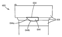
도 6a는 리프터 계합 특징부(640)를 계합시키는 캠밍 러그(644)를 가지는 필터 카트리지(460)의 일부분을 나타낸 것이며, 여기서 캠밍 러그(644)는 외부 카트리지 표면(464) 상에 배치되어 있다. 일부 실시 형태에서, 캠밍 러그(644)는 선단 에지(644a) 및 주 표면(644b)을 포함한다. 이러한 실시 형태에서, 선단 에지(644a)는 필터 카트리지(460)를 카트리지 지지 선반(106)으로부터 신속하게 들어올리는 것을 돕기 위해 제1 램프 부분(642a)과 협력하여 슬라이딩할 수 있는 반면, 주 표면(644b)은 필터 카트리지(460)를 필터 매니폴드(100)에 보다 점진적이고 정확하게 계합시키기 위해 제2 램프 부분(642b)과 협력하여 슬라이딩할 수 있다. 캠밍 러그는, 다른 대안으로서, 리프터 계합 특징부(640) 상에 배치될 수 있다.Figure 6a illustrates a portion of a
일부 실시 형태에서, 캠밍 램프(642)를 캠밍 러그(644)와 계합시키는 것은 2-단계 프로세스를 포함한다. 첫째, 손잡이(134)가 도 6에 나타낸 바와 같이 분리된 위치로부터 서비스 위치로 반시계방향으로 회전할 때, 제1 램프 부분(642a)은 선단 에지(644a)와 접촉하고, 그로써 필터 카트리지(460)를 필터 매니폴드(100) 쪽으로 잡아당긴다. 둘째, 손잡이(134)가 계속하여 회전함에 따라, 제2 램프 부분(642b)은 주 표면(644b)과 접촉하고, 그로써 필터 카트리지(460)를 필터 매니폴드(100) 쪽으로 계속하여 잡아당긴다. 제1 램프 부분(642a)이 제2 램프 부분(642b)보다 큰 기울기를 가지는 실시 형태에서, 필터 카트리지(460)는 단계 2 동안보다 단계 1 동안에 더 큰 속도로 필터 매니폴드(100) 쪽으로 잡아당겨진다. 앞서 기술한 이점과 함께, 이러한 2-단계 프로세스는 (i) 제1 단계 동안에, 필터 카트리지(460)를 필터 매니폴드(100)에 비교적 신속하게 밀봉할 수 있음으로써, 필터 카트리지 설치 동안에 어떤 유체도 여과 시스템(590)을 빠져 나가지 못하게 돕는 반면, (ii) 제2 단계 동안에, 필터 카트리지(460)가 필터 매니폴드(100)에 대해 완전히 안착되고 매니폴드 피드 포트(130)가 언블로킹될 때, 회전 부분(218)과 필터 카트리지(460) 사이의 보다 점진적이고 정확한 시간별 상호작용을 가능하게 해줄 수 있다.In some embodiments, engaging
일부 실시 형태에서, 손잡이(134)는 손잡이 분리 특징부(652)를 추가로 포함한다. 도 6에 도시된 바와 같이, 손잡이 분리 특징부(652)는 캠밍 램프(642) 리프터 계합 특징부(640)와 대향하는 위치에 배치된 캠밍 표면을 포함할 수 있다. 이러한 실시 형태가 이용되는 경우, 외부 카트리지 표면(464) 상의 캠밍 러그(644)는 카트리지 분리 특징부(654)를 포함할 수 있다. 도 6a에 도시된 바와 같이, 카트리지 분리 특징부(654)는 주 표면(644b)과 대향하는 위치에 배치된 캠밍 표면을 포함할 수 있다. 손잡이(134)가 도 6에 도시된 바와 같이 시계 방향으로 회전될 때, 손잡이 분리 특징부(652) 및 카트리지 분리 특징부(654)는 협력하여 필터 카트리지(460)를 필터 매니폴드(100)로부터 제거하는 것을 도울 수 있다. 손잡이(134)가 시계 방향으로 회전될 때, 손잡이 분리 특징부(652)는 카트리지 분리 특징부(654)와 접촉하여 필터 카트리지(460)를 필터 매니폴드(100)로부터 멀어지게 밀어낸다. 이러한 분리 특징부의 결합은, 손잡이(134)를 작동시켜 얻어진 기계적 이점을 사용하여 각각의 포트 밀봉 부재(471)를 각자의 매니폴드 피드 포트(130) 및 매니폴드 여과 포트(132)로부터 분리시키는 것을 도움으로써, 사용자가 필터 카트리지(460)를 필터 매니폴드(100)로부터 제거하는 것을 용이하게 해줄 수 있다. 이러한 도움은, 예를 들어, O-링 등의 밀봉 부재가 오랜 기간 압착되는 것으로 인해 일시적으로 "경화"되고 그로 인해 밀봉되는 표면에 고착되는 경우에 유익할 수 있다.In some embodiments, the
도 7은 해체된 상태에 있는 여과 시스템(590)의 예시적인 실시 형태를 나타낸 것이며, 여기서 필터 카트리지(460)는 일회용 필터 요소(768) 및 내부 체적(767)을 가지는 경성 섬프(766)를 포함한다. 일회용 필터 요소(768)의 적어도 일부분이 내부 체적(767) 내에 배치가능하다. 일부 실시 형태에서, 일회용 필터 요소(768)가 교체될 때마다 경성 섬프(766)가 재사용된다. 이러한 실시 형태에서, 필터의 일회용 필터 요소(768) 교체 시에 보다 적은 재료가 폐기될 수 있기 때문에, 환경 쓰레기의 감소가 실현될 수 있다.7 illustrates an exemplary embodiment of a
일부 실시 형태에서, 일회용 필터 요소(768)는 카트리지 피드 포트(470), 카트리지 여과 포트(472), 회전 키(274), 및 일회용 필터 요소(768)의 한쪽 단부에 부착된 필터 헤드(773)를 가지는 케이싱(768a)으로 둘러싸인 여과 매체를 포함한다. 일 실시 형태에서, 카트리지 피드 포트(470), 카트리지 여과 포트(472) 및 회전 키(274)는 필터 헤드(773) 상에 배치된다. 케이싱(768a)은 비침투성 재료를 포함한다. 일부 실시 형태에서, 케이싱(768a)은 가요성 비침투성 재료, 예를 들어, 저밀도 폴리에틸렌을 포함한다. 전형적으로, 필터 헤드(773)는 케이싱(768a)에 비해 비교적 경성인 재료를 포함한다. 필터 헤드(773)는 임의의 적당한 경성 재료로 구성될 수 있다. 적당한 재료의 일례는 폴리프로필렌, 폴리스티렌, 나일론, 및 다양한 폴리페닐렌 에테르 화합물을 포함한다.In some embodiments, the
일부 실시 형태에서, 경성 섬프(766)는 케이싱(768a)보다 큰 동작 압력에 견디도록 설계되어 있는 압력 용기로 구성되어 있다. 경성 섬프(766)는 임의의 적당한 경성 재료로 구성될 수 있다. 적당한 재료의 일례는 폴리프로필렌, 폴리스티렌, 나일론, 및 다양한 폴리페닐렌 에테르 화합물을 포함한다. 또한, 예를 들어, 더 큰 강도를 필요로 하는 응용에서, 경성 섬프(766)는 스테인레스강 및 알루미늄 등의 금속으로 구성될 수 있는 것도 생각되고 있다. 여과 시스템(590)의 전형적인 실시 형태가 조립되고 동작 압력 하에 둘 때, 케이싱(768a)은 경성 섬프(766)의 내부 체적(767)의 측벽에 대해 버티고 있다. 케이싱(768a)이 경성 섬프(766)와 동일한 압력을 견딜 수 있을 필요가 없기 때문에, 일회용 필터 요소(768)는 그렇지 않았으면 필요하게 될 것보다 훨씬 더 적은 재료로 구성될 수 있다. 따라서, 일회용 필터 요소(768)가 교체될 때마다 보다 적은 재료가 폐기된다. 케이싱(768a)은 내부 체적(767)이 피드 유체(feed fluid)로 젖는 것을 방지하는 추가의 이점을 제공한다. 따라서, 어떤 필요한 경성 섬프(766)의 세정이 감소되거나 제거될 수 있다.In some embodiments, the
외부 카트리지 표면(464)이 경성 섬프(766) 또는 일회용 필터 요소(768)의 일부일 수 있는 것이 생각되고 있다. 그렇지만, 전형적으로, 외부 카트리지 표면(464)은 경성 섬프(766)의 일부이다.It is contemplated that the
필터 카트리지(460)가 일회용 필터 요소(768) 및 경성 섬프(766)를 포함하는 실시 형태에서, 회전 키(274)는 전형적으로 필터 헤드(773) 상에 배치된다. 따라서, 비어 있는 경성 섬프(766)가 필터 매니폴드(100) 상에 놓이는 경우, 회전 키(274)가 도 1a에 도시된 회전 잠금 장치(124)를 누르지 않게 되며, 손잡이(134)가 서비스 위치로 회전하는 것이 방지될 것이다. 손잡이(134)가 서비스 위치로 회전하지 않을 것이기 때문에, 도 1a에 도시된 매니폴드 피드 포트(130)는 블로킹된 채로 있을 것이다. 이러한 실시 형태에서, 여과 시스템(590)은, 필터 카트리지(460)를 필터 매니폴드(100)에 설치하기 전에 상응하는 일회용 필터 요소(768)가 경성 섬프(766)에 설치될 때, 매니폴드 피드 포트(130)를 언블로킹하는 것만을 가능하게 해줄 것이다. 이러한 실시 형태에서, 경성 섬프(766)를 재설치할 때 사용자 또는 서비스 기술자가 잘못하여 일회용 필터 요소(768)를 빼먹는 것이 방지된다. 따라서, 이러한 실시 형태에서, 사용자는, 경성 섬프(766)가 설치되고 손잡이(134)가 서비스 위치에 있는 경우, 여과 시스템(590)이 여과 기능을 수행하고 있다는 것을 확신할 수 있다.In embodiments where the
본 발명의 다양한 수정 및 변경이 본 발명의 사상 및 범위를 벗어나지 않고 당업자에게 명백하게 될 것이다. 본 발명이 본 명세서에 기술된 예시적인 실시 형태로 제한되지 않는다는 것을 잘 알 것이다.Various modifications and alterations of this invention will become apparent to those skilled in the art without departing from the spirit and scope of the invention. It will be appreciated that the invention is not limited to the exemplary embodiments described herein.
Claims (32)
고정 부분 및 고정 부분에 배치되는 회전 부분을 포함하는 밸브,
매니폴드 피드 포트(manifold feed port) 및 매니폴드 여과 포트(manifold filtrate port), 및
회전 부분에 연결되어 동작하는 손잡이 - 손잡이는 카트리지 리프터(cartridge lifter)와, 카트리지 리프터에 대향하여 위치하는 캠밍 표면을 갖는 손잡이 분리 특징부를 포함하고, 손잡이는 서비스 위치 및 분리된 위치로 회전가능하며, 여기서 매니폴드 피드 포트는, 손잡이가 분리된 위치에 있을 때, 밸브에 의해 블로킹되거나 바이패스 채널에 대해 개방되고, 손잡이가 서비스 위치에 있을 때, 밸브에 의해 언블로킹되거나 바이패스 채널에 대해 차단됨 - 를 포함하고,
상기 분리된 위치로의 이동시, 손잡이 분리 특징부는 필터 카트리지가 완전히 분리되도록 매니폴드로부터 멀어지는 방향으로 필터 카트리지를 밀어내는
필터 매니폴드.As a filter manifold,
A valve including a fixed portion and a rotating portion disposed in the fixed portion,
A manifold feed port and a manifold filtrate port,
The handle-handle operatively connected to the rotating portion includes a cartridge lifter and a handle separation feature having a camming surface located opposite the cartridge lifter, the handle being rotatable to a service position and a discrete position, Wherein the manifold feed port is unblocked by the valve or blocked against the bypass channel when the handle is in the service position, when the handle is in the disengaged position, blocked by the valve or open to the bypass channel, Lt; / RTI >
Upon movement to the disengaged position, the handle separation feature pushes the filter cartridge away from the manifold such that the filter cartridge is fully disengaged
Filter manifold.
필터 매니폴드 및 필터 카트리지를 포함하고,
필터 매니폴드는
고정 부분 및 회전 부분을 포함하는 밸브,
매니폴드 피드 포트 및 매니폴드 여과 포트, 및
회전 부분에 연결되어 동작하는 손잡이 - 손잡이는 캠밍 램프 또는 캠밍 러그 리프터 계합 특징부 중 하나를 가지는 카트리지 리프터와, 카트리지 리프터에 대향하여 위치하는 캠밍 표면을 갖는 손잡이 분리 특징부를 포함하고, 손잡이는 서비스 위치 및 분리된 위치로 회전가능하며, 여기서 매니폴드 피드 포트는, 손잡이가 분리된 위치에 있을 때, 밸브에 의해 블로킹되고, 손잡이가 서비스 위치에 있을 때, 밸브에 의해 언블로킹됨 - 를 포함하며,
상기 분리된 위치로의 이동시, 손잡이 분리 특징부는 필터 카트리지가 완전히 분리되도록 매니폴드로부터 멀어지는 방향으로 필터 카트리지를 밀어내고,
필터 카트리지는
카트리지 피드 포트, 카트리지 여과 포트, 및 리프터 계합 특징부를 계합시키는 캠밍 러그 또는 캠밍 램프 중 하나와 카트리지 분리 특징부를 가지는 외부 카트리지 표면을 포함하는 여과 시스템.As a filtration system,
A filter manifold and a filter cartridge,
The filter manifold
A valve including a fixed portion and a rotating portion,
A manifold feed port and a manifold filtration port, and
The handle-handle operatively connected to the rotating portion includes a cartridge lifter having one of a camming ram or cam lug lifter engagement feature and a handle separation feature having a camming surface located opposite the cartridge lifter, And wherein the manifold feed port is blocked by the valve when the handle is in the disengaged position and unblocked by the valve when the handle is in the service position,
Upon movement to the disengaged position, the pullout feature pushes the filter cartridge away from the manifold so that the filter cartridge is fully disengaged,
The filter cartridge
A cartridge feed port, a cartridge filtration port, and a lifting engagement feature; and an outer cartridge surface having a cartridge detachment feature.
손잡이가 분리된 위치에 있는 동안에, 필터 매니폴드 아래에 필터 카트리지를 제공하는 단계,
손잡이를 서비스 위치로 회전시키고, 그로써 카트리지 리프터로 하여금 캠밍 램프를 캠밍 러그와 접촉하게 하며, 그로써 필터 카트리지를 필터 매니폴드 쪽으로 잡아당기는 단계,
카트리지 피드 포트를 매니폴드 피드 포트에 계합시키는 단계,
카트리지 여과 포트를 매니폴드 여과 포트에 계합시키는 단계, 및
밸브를 작동시켜 매니폴드 피드 포트를 언블로킹하는 단계를 포함하는 방법.A method of assembling the filtration system of claim 2,
Providing the filter cartridge under the filter manifold while the handle is in the disengaged position,
Rotating the handle to the service position such that the cartridge lifter causes the camming ram to contact the camming lug, thereby pulling the filter cartridge toward the filter manifold,
Engaging the cartridge feed port with the manifold feed port,
Engaging the cartridge filtration port with the manifold filtration port, and
And actuating the valve to unblock the manifold feed port.
Applications Claiming Priority (2)
| Application Number | Priority Date | Filing Date | Title |
|---|---|---|---|
| US9473708P | 2008-09-05 | 2008-09-05 | |
| US61/094,737 | 2008-09-05 |
Publications (2)
| Publication Number | Publication Date |
|---|---|
| KR20110053380A KR20110053380A (en) | 2011-05-20 |
| KR101614566B1 true KR101614566B1 (en) | 2016-04-21 |
Family
ID=41797814
Family Applications (1)
| Application Number | Title | Priority Date | Filing Date |
|---|---|---|---|
| KR1020117007568A KR101614566B1 (en) | 2008-09-05 | 2009-09-02 | Filtration system |
Country Status (7)
| Country | Link |
|---|---|
| US (1) | US9044699B2 (en) |
| EP (1) | EP2355914B1 (en) |
| JP (1) | JP5536774B2 (en) |
| KR (1) | KR101614566B1 (en) |
| CN (1) | CN102176955B (en) |
| BR (1) | BRPI0913488A2 (en) |
| WO (1) | WO2010027989A2 (en) |
Cited By (1)
| Publication number | Priority date | Publication date | Assignee | Title |
|---|---|---|---|---|
| KR20200105121A (en) * | 2019-02-28 | 2020-09-07 | 청호나이스 주식회사 | Connecting structure for filter and water purifier having the same |
Families Citing this family (44)
| Publication number | Priority date | Publication date | Assignee | Title |
|---|---|---|---|---|
| BRPI0610315A2 (en) | 2005-05-16 | 2010-06-15 | 3M Innovative Properties Co | spool valve pipe interconnect to a filter system |
| WO2010027989A2 (en) | 2008-09-05 | 2010-03-11 | 3M Innovative Properties Company | Filtration system |
| US10843108B2 (en) * | 2011-06-21 | 2020-11-24 | Kinetico Incorporated | Water treatment system |
| KR101318423B1 (en) * | 2011-06-24 | 2013-10-15 | 위니맥스 주식회사 | Water filter assembly and refrigerator and water purifier having the same |
| JP5913595B2 (en) | 2011-09-07 | 2016-04-27 | エレクトロリティック、オゾン、インコーポレイテッドElectrolytic Ozone Inc. | Removable cartridge and hub that generates ozonated water |
| WO2013134916A1 (en) * | 2012-03-12 | 2013-09-19 | 深圳市兴日生实业有限公司 | Out-of-vat liquid filter for ensuring reliable connection of water pipe connector |
| US8945383B2 (en) * | 2012-03-16 | 2015-02-03 | Kx Technologies Llc | Filtration system |
| US8951415B2 (en) | 2012-03-16 | 2015-02-10 | Kx Technologies Llc | Filtration system |
| JP2013230410A (en) * | 2012-04-27 | 2013-11-14 | Sharp Corp | Liquid filter |
| US9789424B2 (en) | 2013-06-26 | 2017-10-17 | Pentair Residential Filtration, Llc | Water filtration system and method |
| US9527021B2 (en) | 2013-10-31 | 2016-12-27 | Pall Corporation | Filter manifold |
| US9757670B2 (en) * | 2013-10-31 | 2017-09-12 | Pall Corporation | Methods for moving a filter along a manifold assembly; filter arrangements including a filter and a manifold assembly; and filters |
| US9492770B2 (en) | 2013-10-31 | 2016-11-15 | Pall Corporation | Filters |
| US9713782B2 (en) | 2013-11-11 | 2017-07-25 | Pall Corporation | Filters and filter arrangements which include a filter and a manifold assembly |
| USD755344S1 (en) | 2014-06-26 | 2016-05-03 | Pentair Residential Filtration, Llc | Filter cartridge |
| CN205598746U (en) * | 2015-04-09 | 2016-09-28 | 碧然德有限公司 | A device, liquid treatment device and liquid processing core for forming liquid treatment device |
| EP3302185A4 (en) | 2015-05-27 | 2019-01-16 | Flow Control LLC. | Cartridge pump |
| US20170095757A1 (en) | 2015-05-27 | 2017-04-06 | Flow Control LLC | Cartridge Accumulator |
| CN108136284A (en) | 2015-09-14 | 2018-06-08 | 流量控制有限责任公司 | Store up device cylinder |
| KR101788965B1 (en) | 2016-03-22 | 2017-10-20 | 엘지전자 주식회사 | water purifing apparatus refrigerator |
| ES2944575T3 (en) | 2016-10-20 | 2023-06-22 | Emd Millipore Corp | Tube management and valve protection device |
| WO2018153435A1 (en) * | 2017-02-21 | 2018-08-30 | Mahle International Gmbh | Fuel filter device for an internal combustion engine |
| US20180318738A1 (en) * | 2017-05-04 | 2018-11-08 | Haier Us Appliance Solutions, Inc. | Enhanced filter installation |
| JP2020528120A (en) * | 2017-07-17 | 2020-09-17 | カストロール リミテッド | Replaceable fluid container with removable manifold |
| PL234666B1 (en) * | 2018-04-26 | 2020-03-31 | Aquael Janusz Jankiewicz Spolka Z Ograniczona Odpowiedzialnoscia | Water filter for an aquarium |
| CN108644426B (en) * | 2018-06-26 | 2019-10-29 | 浙江沁园水处理科技有限公司 | A kind of series connection bivalve module and its water purifier |
| CN108644424B (en) * | 2018-06-26 | 2019-10-29 | 浙江沁园水处理科技有限公司 | A kind of independent bivalve module and its water purifier |
| CN108644411B (en) * | 2018-06-26 | 2020-01-03 | 浙江沁园水处理科技有限公司 | Flushing valve and water purifier thereof |
| CN108644423B (en) * | 2018-06-26 | 2020-01-03 | 浙江沁园水处理科技有限公司 | Bivalve module and water purifier with wash function |
| CN108644425B (en) * | 2018-06-26 | 2019-10-29 | 浙江沁园水处理科技有限公司 | A kind of inlet valve and its water purifier with pressure-reduction module |
| CN108895164B (en) * | 2018-06-26 | 2020-01-24 | 浙江沁园水处理科技有限公司 | Water inlet valve and water purifier thereof |
| CN108644427B (en) * | 2018-06-26 | 2019-10-29 | 浙江沁园水处理科技有限公司 | A kind of integral type bivalve module and its water purifier |
| CN108889023B (en) * | 2018-06-26 | 2021-02-12 | 浙江沁园水处理科技有限公司 | Water purifier with filter flask capable of being quickly disassembled and assembled |
| CN108980403B (en) * | 2018-06-26 | 2019-12-13 | 浙江沁园水处理科技有限公司 | Water inlet valve with flow meter and water purifier thereof |
| DE102018129752A1 (en) * | 2018-11-26 | 2020-05-28 | Franke Technology And Trademark Ltd | FILTER DEVICE FOR DRINKING WATER FILTERING |
| KR102052554B1 (en) * | 2019-01-31 | 2019-12-05 | 주식회사 교원 | Filter connector and water purifier including the same |
| US11660554B2 (en) * | 2019-11-11 | 2023-05-30 | Qingdao Ecopure Filler Co., Ltd. | Appliance water filter cartridge |
| WO2021195386A1 (en) * | 2020-03-27 | 2021-09-30 | Spx Flow Technology Usa, Inc. | Filter assembly and media |
| IL283156A (en) * | 2020-06-08 | 2022-01-01 | Pall Corp | Manifold assembly and method of use |
| CN113828047B (en) | 2020-06-08 | 2023-02-24 | 帕尔公司 | Manifold assembly and method of use |
| US11389555B2 (en) | 2020-07-24 | 2022-07-19 | 3Oe Scientific, LLC | Aqueous ozone sanitizing system with ozone generator cartridge docking station |
| JP2022120541A (en) * | 2021-02-05 | 2022-08-18 | オルガノ株式会社 | Cartridge mounting structure and cartridge |
| WO2022229927A1 (en) | 2021-04-30 | 2022-11-03 | Whirlpool Corporation | Filter assembly |
| CN116764321A (en) * | 2021-11-29 | 2023-09-19 | 南京菡束环保设备有限公司 | Filter element mounting structure |
Family Cites Families (60)
| Publication number | Priority date | Publication date | Assignee | Title |
|---|---|---|---|---|
| US1688326A (en) | 1925-09-16 | 1928-10-23 | Zenith Carburateur Soc Du | Filter |
| US2857128A (en) | 1956-10-18 | 1958-10-21 | Stern Daniel | Safety shutoff coupling |
| US3399776A (en) | 1965-09-02 | 1968-09-03 | Robert R. Knuth | Detachable snap-on filter for a hydraulic system |
| US3742970A (en) | 1970-02-13 | 1973-07-03 | Pall Corp | Flow-sensitive sensing and shut-off device |
| US3643692A (en) | 1970-09-28 | 1972-02-22 | Paul L Traylor | Valve |
| US3684100A (en) | 1971-04-05 | 1972-08-15 | Sam Close | Filter assembly and disposable filter element therefor |
| CH537546A (en) | 1971-04-06 | 1973-05-31 | Saffin Von Corpon Paul | Robinet mélangeur |
| BE791684A (en) | 1971-11-22 | 1973-03-16 | Ogden Hubert S | REMOVABLE FILTER CARTRIDGE |
| JPS5129619A (en) | 1974-09-02 | 1976-03-13 | Matsushita Electric Ind Co Ltd | Nainenkikanno haikigasujokasochi |
| US3926187A (en) | 1974-12-19 | 1975-12-16 | Jose J Iglesias | Urological bladder evacuator |
| US4108207A (en) | 1977-04-13 | 1978-08-22 | The United States Of America As Represented By The United States Department Of Energy | Multiple-port valve |
| DE3126507A1 (en) * | 1981-07-04 | 1983-01-20 | Surculus AG, Vaduz | "ARMATURE" |
| JPS5867510A (en) | 1981-10-20 | 1983-04-22 | Nippon Denso Co Ltd | Automobile ventilator |
| JPS5867510U (en) * | 1981-10-30 | 1983-05-09 | 三菱農機株式会社 | Oil filter installation structure |
| JPS58116008U (en) * | 1982-01-28 | 1983-08-08 | 三菱農機株式会社 | oil filter |
| US4469131A (en) | 1982-07-12 | 1984-09-04 | Traylor Paul L | Spool valve |
| DE3520139A1 (en) | 1985-06-05 | 1986-12-11 | Joachim 7252 Weil der Stadt Wolf | FILTER DEVICE |
| DE3640531C1 (en) | 1986-11-27 | 1987-09-03 | Bayerische Motoren Werke Ag | Filter arrangement for cleaning liquid operating materials, especially the lubricating oil of internal combustion engines |
| US4979530A (en) | 1987-12-24 | 1990-12-25 | Ameri-Can Brass Faucet Inc. | Modular valve assembly |
| GB2216030B (en) | 1988-05-11 | 1991-10-09 | Joachim Wolf | A filter |
| GB2216028B (en) | 1988-05-16 | 1991-09-25 | Joachim Wolf | A filter manifold |
| IL87280A (en) | 1988-08-01 | 1991-01-31 | Dolev Moshe | Quick-disconnect hose coupling device |
| US5152321A (en) | 1991-10-07 | 1992-10-06 | Ecowater Systems, Inc. | Bypass valve |
| DE4135867A1 (en) | 1991-10-31 | 1993-05-06 | Alfred Teves Gmbh, 6000 Frankfurt, De | CUFF RETURN VALVE |
| US5230812A (en) | 1992-07-29 | 1993-07-27 | Williams Richard T | Pressure vessel |
| US5461948A (en) | 1992-08-27 | 1995-10-31 | Perrero, Jr.; Thomas | Socket type tool for removing oil filter cartridge |
| US5389260A (en) * | 1993-04-02 | 1995-02-14 | Clack Corporation | Brine seal for tubular filter |
| US5397462A (en) | 1993-08-24 | 1995-03-14 | Matsushita Electric Industrial Co., Ltd. | Filter with laterally removable element and valve means |
| US5445734A (en) | 1994-11-18 | 1995-08-29 | Chen; Ching-Wen | Water filter |
| US5882511A (en) | 1996-10-30 | 1999-03-16 | Fil-Tech Corporation | Filter apparatus with coupling and latch mechanism |
| US5919362A (en) | 1997-04-28 | 1999-07-06 | Cuno, Inc. | Expandable encapsulated filter cartridge assembly |
| US5931196A (en) | 1998-04-29 | 1999-08-03 | United States Filter Corporation | Bypass valve |
| US6579455B1 (en) | 1999-09-09 | 2003-06-17 | Pti Advanced Filtration | Filter and valve apparatus |
| US6953526B1 (en) | 2000-03-22 | 2005-10-11 | Cuno Incorporated | Filter assembly |
| US6949189B2 (en) | 2000-04-20 | 2005-09-27 | Cuno Incorporated | Keyed filter assembly |
| US6458269B1 (en) | 2000-04-20 | 2002-10-01 | Cuno Incorporated | Keyed filter assembly |
| US7407148B2 (en) | 2000-04-20 | 2008-08-05 | 3M Innovative Properties Company | Rotary valve assembly for fluid filtration system |
| US6457698B2 (en) | 2000-06-16 | 2002-10-01 | United States Filter Corporation | Bypass valve |
| JP3514724B2 (en) | 2000-11-29 | 2004-03-31 | 日東工器株式会社 | Pipe fittings |
| ITPD20010179A1 (en) | 2001-07-17 | 2003-01-17 | Askoll Holding Srl | PIPE FITTING GROUP WITH SAFETY LOCK FOR EXTERNAL FILTERS FOR AQUARIUMS. |
| US6632355B2 (en) | 2001-07-30 | 2003-10-14 | Pentapure Incorporated | Low spillage replaceable water filter assembly |
| US20030019819A1 (en) | 2001-07-30 | 2003-01-30 | Karl Fritze | Hot disconnect replaceable water filter assembly |
| US6857670B2 (en) | 2001-12-05 | 2005-02-22 | Cuno Incorporated | Plastic tube joint |
| US7638042B2 (en) | 2002-02-15 | 2009-12-29 | 3M Innovative Properties Company | System for monitoring the performance of fluid treatment cartridges |
| JP4234938B2 (en) * | 2002-02-28 | 2009-03-04 | インテグリス・インコーポレーテッド | Connector device for filter cartridge |
| JP4125051B2 (en) * | 2002-06-20 | 2008-07-23 | インテグリス・インコーポレーテッド | Seal structure of connector device |
| JP4011986B2 (en) * | 2002-06-21 | 2007-11-21 | クリタック株式会社 | Water purification cartridge mounting device |
| JP3829117B2 (en) | 2002-12-27 | 2006-10-04 | 日東工器株式会社 | Pipe fitting |
| US7000894B2 (en) | 2003-04-25 | 2006-02-21 | Pur Water Purification Products, Inc. | Fluidic cartridges and end pieces thereof |
| US7147773B2 (en) | 2003-04-25 | 2006-12-12 | Whirlpool Corporation | Refrigerator with treated water |
| US20050167352A1 (en) * | 2004-02-03 | 2005-08-04 | Oasis Corporation | Filter cartridge and manifold for a water purification system |
| US20060032806A1 (en) | 2004-08-16 | 2006-02-16 | Parker Mark A | Apparatus to filter water |
| BRPI0610315A2 (en) * | 2005-05-16 | 2010-06-15 | 3M Innovative Properties Co | spool valve pipe interconnect to a filter system |
| US7651070B2 (en) * | 2006-01-19 | 2010-01-26 | Clean & Clear Corporation | Canter element controlled combination manifold, valve and filter module system |
| KR100772889B1 (en) * | 2006-04-18 | 2007-11-02 | 주식회사 위닉스 | Water filters and water filter assembly connector and water purifier structure these |
| US20080000820A1 (en) * | 2006-06-30 | 2008-01-03 | Mitchell Alan J | Water Filter Cartridge and Valve with Autobypass Feature |
| US20080156711A1 (en) | 2006-12-29 | 2008-07-03 | Vitan Craig R | Water filter assembly and filter cartridge for use therewith |
| KR100870572B1 (en) * | 2007-02-28 | 2008-11-27 | 주식회사 영우워터라인 | Water Purification Filter Assembly using a swivel type connector |
| KR100930665B1 (en) | 2008-01-28 | 2009-12-09 | 앨트웰텍 주식회사 | Rotary Detachable Filter Supporter |
| WO2010027989A2 (en) | 2008-09-05 | 2010-03-11 | 3M Innovative Properties Company | Filtration system |
-
2009
- 2009-09-02 WO PCT/US2009/055643 patent/WO2010027989A2/en active Application Filing
- 2009-09-02 US US13/062,008 patent/US9044699B2/en not_active Expired - Fee Related
- 2009-09-02 BR BRPI0913488A patent/BRPI0913488A2/en not_active IP Right Cessation
- 2009-09-02 EP EP09812126.2A patent/EP2355914B1/en not_active Not-in-force
- 2009-09-02 CN CN200980139908.8A patent/CN102176955B/en not_active Expired - Fee Related
- 2009-09-02 KR KR1020117007568A patent/KR101614566B1/en not_active IP Right Cessation
- 2009-09-02 JP JP2011526139A patent/JP5536774B2/en not_active Expired - Fee Related
Cited By (2)
| Publication number | Priority date | Publication date | Assignee | Title |
|---|---|---|---|---|
| KR20200105121A (en) * | 2019-02-28 | 2020-09-07 | 청호나이스 주식회사 | Connecting structure for filter and water purifier having the same |
| KR102177297B1 (en) * | 2019-02-28 | 2020-11-10 | 청호나이스 주식회사 | Connecting structure for filter and water purifier having the same |
Also Published As
| Publication number | Publication date |
|---|---|
| EP2355914B1 (en) | 2014-06-11 |
| KR20110053380A (en) | 2011-05-20 |
| BRPI0913488A2 (en) | 2017-05-30 |
| JP2012501832A (en) | 2012-01-26 |
| WO2010027989A2 (en) | 2010-03-11 |
| US9044699B2 (en) | 2015-06-02 |
| EP2355914A2 (en) | 2011-08-17 |
| CN102176955B (en) | 2014-03-12 |
| CN102176955A (en) | 2011-09-07 |
| JP5536774B2 (en) | 2014-07-02 |
| WO2010027989A3 (en) | 2010-05-14 |
| US20110247974A1 (en) | 2011-10-13 |
| EP2355914A4 (en) | 2013-01-02 |
Similar Documents
| Publication | Publication Date | Title |
|---|---|---|
| KR101614566B1 (en) | Filtration system | |
| TWI432252B (en) | Push filter with floating key lock | |
| AU2009202398B2 (en) | Filter element and filter assembly including locking mechanism | |
| EP3352881B1 (en) | A filter insert and a filter arrangement | |
| US20180036659A1 (en) | Water Filtration System and Method | |
| US7871517B2 (en) | Filter device | |
| US20070227963A1 (en) | Fluid filter element and bypass adaptor | |
| EP2151269B1 (en) | Filter with ejection mechanism | |
| EP1817093B1 (en) | Fuel filter assembly | |
| TW200827010A (en) | Filter housing apparatus with rotating filter replacement mechanism | |
| JP2003534130A (en) | Drip prevention member extension / locking assembly and container therefor | |
| JP2008540976A (en) | Interconnection of spool valve manifolds for filter systems | |
| WO2014059120A1 (en) | Fluid filter and head with quick connector | |
| WO2010053903A2 (en) | Fluid interconnect | |
| WO2012103046A1 (en) | Filter cartridges and manifolds for linear motion installation | |
| CN111757776B (en) | Air filter easy to maintain | |
| WO2007117958A2 (en) | Fluid filter element and bypass insert | |
| JP3624157B2 (en) | Water purifier mounting device | |
| CN114413007B (en) | Water stop valve, filter element and water purifying device | |
| CN217549126U (en) | Leachate back-spraying device | |
| CN217016114U (en) | End cover, filter core and purifier | |
| CN202366527U (en) | Filtering machine with integrally-molded filter barrel |
Legal Events
| Date | Code | Title | Description |
|---|---|---|---|
| A201 | Request for examination | ||
| E902 | Notification of reason for refusal | ||
| E701 | Decision to grant or registration of patent right | ||
| LAPS | Lapse due to unpaid annual fee |