JP5536774B2 - Filtration system - Google Patents
Filtration system Download PDFInfo
- Publication number
- JP5536774B2 JP5536774B2 JP2011526139A JP2011526139A JP5536774B2 JP 5536774 B2 JP5536774 B2 JP 5536774B2 JP 2011526139 A JP2011526139 A JP 2011526139A JP 2011526139 A JP2011526139 A JP 2011526139A JP 5536774 B2 JP5536774 B2 JP 5536774B2
- Authority
- JP
- Japan
- Prior art keywords
- cartridge
- filter
- manifold
- handle
- valve
- Prior art date
- Legal status (The legal status is an assumption and is not a legal conclusion. Google has not performed a legal analysis and makes no representation as to the accuracy of the status listed.)
- Expired - Fee Related
Links
- 238000001914 filtration Methods 0.000 title claims description 40
- 239000000706 filtrate Substances 0.000 claims description 56
- 230000007246 mechanism Effects 0.000 claims description 47
- 238000000034 method Methods 0.000 claims description 17
- 238000012423 maintenance Methods 0.000 claims description 4
- 230000003213 activating effect Effects 0.000 claims description 2
- 239000000463 material Substances 0.000 description 15
- 238000007789 sealing Methods 0.000 description 14
- 239000012530 fluid Substances 0.000 description 13
- XLYOFNOQVPJJNP-UHFFFAOYSA-N water Substances O XLYOFNOQVPJJNP-UHFFFAOYSA-N 0.000 description 11
- 238000006073 displacement reaction Methods 0.000 description 7
- 238000009434 installation Methods 0.000 description 5
- -1 polypropylene Polymers 0.000 description 5
- 230000008569 process Effects 0.000 description 5
- 239000004677 Nylon Substances 0.000 description 4
- 239000004743 Polypropylene Substances 0.000 description 4
- 239000004793 Polystyrene Substances 0.000 description 4
- 230000008901 benefit Effects 0.000 description 4
- 150000002170 ethers Chemical class 0.000 description 4
- 229920001778 nylon Polymers 0.000 description 4
- 229920001955 polyphenylene ether Polymers 0.000 description 4
- 229920001155 polypropylene Polymers 0.000 description 4
- 229920002223 polystyrene Polymers 0.000 description 4
- 239000007787 solid Substances 0.000 description 4
- 229910052782 aluminium Inorganic materials 0.000 description 3
- XAGFODPZIPBFFR-UHFFFAOYSA-N aluminium Chemical compound [Al] XAGFODPZIPBFFR-UHFFFAOYSA-N 0.000 description 3
- 229920001971 elastomer Polymers 0.000 description 3
- 230000007613 environmental effect Effects 0.000 description 3
- 229910052751 metal Inorganic materials 0.000 description 3
- 239000002184 metal Substances 0.000 description 3
- 229910001220 stainless steel Inorganic materials 0.000 description 3
- 239000010935 stainless steel Substances 0.000 description 3
- 239000002699 waste material Substances 0.000 description 3
- 230000000295 complement effect Effects 0.000 description 2
- 230000008878 coupling Effects 0.000 description 2
- 238000010168 coupling process Methods 0.000 description 2
- 238000005859 coupling reaction Methods 0.000 description 2
- 239000000806 elastomer Substances 0.000 description 2
- 150000002739 metals Chemical class 0.000 description 2
- OKTJSMMVPCPJKN-UHFFFAOYSA-N Carbon Chemical compound [C] OKTJSMMVPCPJKN-UHFFFAOYSA-N 0.000 description 1
- 239000000853 adhesive Substances 0.000 description 1
- 238000004026 adhesive bonding Methods 0.000 description 1
- 230000001070 adhesive effect Effects 0.000 description 1
- 230000009286 beneficial effect Effects 0.000 description 1
- 235000012206 bottled water Nutrition 0.000 description 1
- 229910052799 carbon Inorganic materials 0.000 description 1
- 238000004140 cleaning Methods 0.000 description 1
- 238000004891 communication Methods 0.000 description 1
- 238000011118 depth filtration Methods 0.000 description 1
- 239000003651 drinking water Substances 0.000 description 1
- 230000003993 interaction Effects 0.000 description 1
- 238000002955 isolation Methods 0.000 description 1
- 229920001684 low density polyethylene Polymers 0.000 description 1
- 239000004702 low-density polyethylene Substances 0.000 description 1
- 238000003754 machining Methods 0.000 description 1
- 239000012528 membrane Substances 0.000 description 1
- 238000012986 modification Methods 0.000 description 1
- 230000004048 modification Effects 0.000 description 1
- 238000000465 moulding Methods 0.000 description 1
- 239000004745 nonwoven fabric Substances 0.000 description 1
- 229920000642 polymer Polymers 0.000 description 1
- 238000012545 processing Methods 0.000 description 1
- 239000012858 resilient material Substances 0.000 description 1
- 230000000717 retained effect Effects 0.000 description 1
- 238000011144 upstream manufacturing Methods 0.000 description 1
- 238000003466 welding Methods 0.000 description 1
Images


Classifications
-
- B—PERFORMING OPERATIONS; TRANSPORTING
- B01—PHYSICAL OR CHEMICAL PROCESSES OR APPARATUS IN GENERAL
- B01D—SEPARATION
- B01D27/00—Cartridge filters of the throw-away type
- B01D27/08—Construction of the casing
-
- B—PERFORMING OPERATIONS; TRANSPORTING
- B01—PHYSICAL OR CHEMICAL PROCESSES OR APPARATUS IN GENERAL
- B01D—SEPARATION
- B01D35/00—Filtering devices having features not specifically covered by groups B01D24/00 - B01D33/00, or for applications not specifically covered by groups B01D24/00 - B01D33/00; Auxiliary devices for filtration; Filter housing constructions
- B01D35/30—Filter housing constructions
-
- B—PERFORMING OPERATIONS; TRANSPORTING
- B01—PHYSICAL OR CHEMICAL PROCESSES OR APPARATUS IN GENERAL
- B01D—SEPARATION
- B01D2201/00—Details relating to filtering apparatus
- B01D2201/30—Filter housing constructions
- B01D2201/301—Details of removable closures, lids, caps, filter heads
- B01D2201/302—Details of removable closures, lids, caps, filter heads having inlet or outlet ports
-
- B—PERFORMING OPERATIONS; TRANSPORTING
- B01—PHYSICAL OR CHEMICAL PROCESSES OR APPARATUS IN GENERAL
- B01D—SEPARATION
- B01D2201/00—Details relating to filtering apparatus
- B01D2201/40—Special measures for connecting different parts of the filter
- B01D2201/4015—Bayonet connecting means
-
- B—PERFORMING OPERATIONS; TRANSPORTING
- B01—PHYSICAL OR CHEMICAL PROCESSES OR APPARATUS IN GENERAL
- B01D—SEPARATION
- B01D2201/00—Details relating to filtering apparatus
- B01D2201/40—Special measures for connecting different parts of the filter
- B01D2201/4023—Means for connecting filter housings to supports
-
- B—PERFORMING OPERATIONS; TRANSPORTING
- B01—PHYSICAL OR CHEMICAL PROCESSES OR APPARATUS IN GENERAL
- B01D—SEPARATION
- B01D2201/00—Details relating to filtering apparatus
- B01D2201/40—Special measures for connecting different parts of the filter
- B01D2201/4076—Anti-rotational means
-
- Y—GENERAL TAGGING OF NEW TECHNOLOGICAL DEVELOPMENTS; GENERAL TAGGING OF CROSS-SECTIONAL TECHNOLOGIES SPANNING OVER SEVERAL SECTIONS OF THE IPC; TECHNICAL SUBJECTS COVERED BY FORMER USPC CROSS-REFERENCE ART COLLECTIONS [XRACs] AND DIGESTS
- Y10—TECHNICAL SUBJECTS COVERED BY FORMER USPC
- Y10T—TECHNICAL SUBJECTS COVERED BY FORMER US CLASSIFICATION
- Y10T29/00—Metal working
- Y10T29/49—Method of mechanical manufacture
- Y10T29/49826—Assembling or joining
Description
水濾過システムは、住宅用及び商業用にしばしば採用される。そのようなシステムは典型的には給水系に設置され、水道栓及び飲用水分配器などに濾過水を提供するように機能する。いくつかの住宅用途では、濾過システムは例えばキッチンのカウンター台の下に設置される。多くの場合、そのようなシステムは、家主が交換可能な使い捨てのフィルタカートリッジを有する。使い捨てフィルタカートリッジの有効寿命が満了したとき、家主はその使い終わったフィルタカートリッジを取り出し、新しいフィルタカートリッジを設置しなくてはならない。そのようなシステムがカウンター台の下に位置する場合、家主がシステムに到達して必要な設置工程を実行することが困難である場合がある。しばしば、そのような位置は狭く、システム自体にとっても家主にとっても利用可能なスペースは限られている。新しいフィルタカートリッジが設置された後、使用済みのフィルタカートリッジ全体が通常は廃棄される。 Water filtration systems are often employed for residential and commercial use. Such systems are typically installed in a water supply system and function to provide filtered water to taps and potable water distributors. In some residential applications, the filtration system is installed, for example, under a kitchen counter. Often, such systems have a disposable filter cartridge that is replaceable by the landlord. When the useful life of a disposable filter cartridge expires, the landlord must remove the used filter cartridge and install a new filter cartridge. If such a system is located under a counter stand, it may be difficult for the landlord to reach the system and perform the necessary installation steps. Often, such locations are narrow and the space available to the system itself and the landlord is limited. After a new filter cartridge is installed, the entire used filter cartridge is usually discarded.
占有スペースがより少なく、維持管理が迅速かつ簡易で、かつ使用済みのフィルタカートリッジを廃棄するときに出す環境ごみがより少ない濾過システムの必要は継続的にある。 There is a continuing need for a filtration system that occupies less space, is quick and simple to maintain, and produces less environmental waste when discarding used filter cartridges.
本開示は、概して、濾過システムを整備するために必要な時間及び労力を削減することが可能なフィルタマニホールド及び濾過システムに関する。本開示によるフィルタカートリッジは、ハンドルを1回引いてフィルタカートリッジを取り上げフィルタマニホールドと係合させて設置することができる。本開示のフィルタマニホールド及び濾過システムは、水濾過システムによって占有されるスペースを減らすことが可能な薄型の構造物を有することができる。更に、より少ない材料が使用され得るので、本発明は使用済みのフィルタカートリッジの廃棄に伴う環境ごみを削減することができる。 The present disclosure relates generally to filter manifolds and filtration systems that can reduce the time and effort required to service a filtration system. The filter cartridge according to the present disclosure can be installed by pulling the handle once to pick up the filter cartridge and engage the filter manifold. The filter manifold and filtration system of the present disclosure can have a thin structure that can reduce the space occupied by the water filtration system. Furthermore, since less material can be used, the present invention can reduce environmental waste associated with the disposal of used filter cartridges.
本特許出願は、弁を備えるフィルタマニホールドを開示する。いくつかの実施形態では、弁は、固定部分と、回転可能な部分と、この回転可能な部分に接続された回転ロックと、を備える。マニホールドは、マニホールド供給ポート及びマニホールド濾液ポートを更に備える。ハンドルは、回転可能な部分に動作可能に接続されており、カートリッジリフターを備える。いくつかの実施形態では、カートリッジリフターはカムランプとカムラグとからなる群から選択されるリフター係合機構を備える。ハンドルは整備位置及びロックされた位置に回転可能であり、ハンドルがロックされた位置にあるとき、回転は回転ロックによって防がれ、マニホールド供給ポートは弁によって封鎖される。 This patent application discloses a filter manifold with valves. In some embodiments, the valve comprises a fixed portion, a rotatable portion, and a rotation lock connected to the rotatable portion. The manifold further comprises a manifold supply port and a manifold filtrate port. The handle is operably connected to the rotatable portion and includes a cartridge lifter. In some embodiments, the cartridge lifter includes a lifter engagement mechanism selected from the group consisting of a cam ramp and a cam lug. The handle is rotatable to a service position and a locked position, and when the handle is in the locked position, rotation is prevented by a rotation lock and the manifold supply port is blocked by a valve.
一実施形態では、フィルタマニホールドはブラケットを更に備え、弁はブラケットによって保持され、固定部分はブラケットに付着される。 In one embodiment, the filter manifold further comprises a bracket, the valve is retained by the bracket, and the fixed portion is attached to the bracket.
一実施形態では、フィルタマニホールドはカートリッジ支持棚を更に備える。カートリッジ支持棚は、ハンドルが整備位置にあるときにカートリッジリフターの下の位置のブラケット上に配置され得る。あるいは、カートリッジ支持棚は弁の固定部分の一部であってもよい。 In one embodiment, the filter manifold further comprises a cartridge support shelf. The cartridge support shelf may be placed on the bracket in a position below the cartridge lifter when the handle is in the service position. Alternatively, the cartridge support shelf may be part of the fixed portion of the valve.
いくつかの実施形態では、回転ロックは、弁の回転可能な部分に接続されていて弁の固定部分の開口から突出している押圧可能な部材を備える。一実施形態では、押圧可能な部材をロックする位置からロック解除する位置に押圧することができる。いくつかの実施形態では、押圧可能な部材は、ロックする位置にあるときに開口から突出し、ロック解除する位置にあるときに弁の固定部分内に収納されている。一実施形態では、押圧可能な部材は、ハンドルが整備位置にあるときはロック解除する位置にある。 In some embodiments, the rotation lock comprises a pushable member connected to a rotatable portion of the valve and protruding from an opening in the fixed portion of the valve. In one embodiment, a pressable member can be pressed from a locked position to a unlocked position. In some embodiments, the pushable member protrudes from the opening when in the locked position and is housed within the fixed portion of the valve when in the unlocked position. In one embodiment, the pushable member is in the unlocked position when the handle is in the service position.
一実施形態では、弁の回転可能な部分は、ハンドルがロックされた位置にあるときにマニホールド供給ポートをマニホールド濾液ポートに流体接続するバイパスチャネルを備える。適切な場合は、弁の回転可能な部分は2つの部品からなる外殻を備え、2つの部品からなる外殻は第1の円筒形部分と第2の円筒形部分とを有し、各円筒形部分はそれぞれ、押圧可能な部材を位置づけるためにそれ自体に凹部を有する接続端と、バイパスチャネルの一部分のための流体コネクタとを備える。第1及び第2の円筒形部分の接続端はバイオネット接続によって互いに接続して、押圧可能な部材を位置づけ、バイパスチャネルを流体接続する。 In one embodiment, the rotatable portion of the valve comprises a bypass channel that fluidly connects the manifold supply port to the manifold filtrate port when the handle is in the locked position. Where appropriate, the rotatable part of the valve comprises a two-part shell, the two-part shell having a first cylindrical part and a second cylindrical part, each cylinder Each shaped part comprises a connecting end having a recess in itself for positioning the pushable member and a fluid connector for a part of the bypass channel. The connecting ends of the first and second cylindrical portions are connected to each other by a bayonet connection to locate the pushable member and fluidly connect the bypass channel.
いくつかの実施形態では、弁の固定部分は長手方向軸と、この長手方向軸に沿って配向された第1の端と、この第1の端に対向する第2の端と、を備える。そのような実施形態では、回転可能な部分の第1の軸方向伸張部は第1の端から突出し、回転可能な部分の第2の軸方向伸張部は第2の端から突出する。ハンドルは、第1及び第2の軸方向伸張部に付着することができる。 In some embodiments, the fixed portion of the valve comprises a longitudinal axis, a first end oriented along the longitudinal axis, and a second end opposite the first end. In such an embodiment, the first axial extension of the rotatable portion protrudes from the first end and the second axial extension of the rotatable portion protrudes from the second end. A handle can be attached to the first and second axial extensions.
いくつかの実施形態では、フィルタマニホールドは、カートリッジ供給ポートと、カートリッジ濾液ポートと、回転キーと、を有するフィルタカートリッジを更に備えており、回転キーは押圧可能な部材を押圧してロック解除する位置にする。一実施形態では、押圧可能な部材は第1の遠位表面を備え、回転キーはフィルタカートリッジからの突出を備える。この突出は第2の遠位表面を有することができ、第2の遠位表面は第1の遠位表面に接触して押圧可能な部材を押圧する。 In some embodiments, the filter manifold further comprises a filter cartridge having a cartridge supply port, a cartridge filtrate port, and a rotation key, wherein the rotation key presses the depressible member to unlock it. To. In one embodiment, the pushable member comprises a first distal surface and the rotation key comprises a protrusion from the filter cartridge. The protrusion can have a second distal surface that contacts the first distal surface and presses the pressable member.
本特許出願はまた、フィルタマニホールドとフィルタカートリッジとを備える濾過システムも開示する。いくつかの実施形態では、フィルタマニホールドはブラケットを備えることができ、このブラケットによって弁が保持されており、この弁はブラケットに付着された固定部分と回転可能な部分とを備える。一実施形態では、ブラケットは、ハンドルが整備位置にあるときにカートリッジリフターの下の位置にあるブラケット上に配置されたカートリッジ支持棚を備える。いくつかの実施形態では、フィルタマニホールドはブラケットなしに提供される。そのような実施形態では、カートリッジ支持棚を弁の固定部分の一部として提供することができる。一実施形態では、フィルタマニホールドは、マニホールド供給ポートとマニホールド濾液ポートとを更に備える。いくつかの実施形態では、ハンドルは回転可能な部分に動作可能に接続されており、カムランプのリフター係合機構又はカムラグのリフター係合機構のうち1つを有するカートリッジリフターを備える。ハンドルは整備位置及び解放位置に回転可能であり、マニホールド供給ポートはハンドルが解放位置にあるときに弁によって封鎖される。 This patent application also discloses a filtration system comprising a filter manifold and a filter cartridge. In some embodiments, the filter manifold can include a bracket with a valve held by the bracket, the valve including a fixed portion and a rotatable portion attached to the bracket. In one embodiment, the bracket includes a cartridge support shelf disposed on the bracket that is in a position below the cartridge lifter when the handle is in the service position. In some embodiments, the filter manifold is provided without a bracket. In such embodiments, a cartridge support shelf can be provided as part of the fixed portion of the valve. In one embodiment, the filter manifold further comprises a manifold supply port and a manifold filtrate port. In some embodiments, the handle is operably connected to the rotatable portion and includes a cartridge lifter having one of a cam ramp lifter engagement mechanism or a cam lug lifter engagement mechanism. The handle is rotatable to a service position and a release position, and the manifold supply port is blocked by a valve when the handle is in the release position.
開示される濾過システムでは、フィルタカートリッジはカートリッジ供給ポートと、カートリッジ濾液ポートと、リフター係合機構を係合するためのカムラグ又はカムランプのうち1つを有するカートリッジ外面と、を備えることができる。 In the disclosed filtration system, the filter cartridge can comprise a cartridge supply port, a cartridge filtrate port, and a cartridge outer surface having one of a cam lug or cam ramp for engaging a lifter engagement mechanism.
いくつかの実施形態では、カムラグは先端と主面とを備えており、先端は、主面がカムランプと接触する前にカムランプと接触する。 In some embodiments, the cam lug includes a tip and a major surface, and the tip contacts the cam ramp before the major surface contacts the cam ramp.
一実施形態では、カムランプは第1のランプ部分と第2のランプ部分とを備えており、第1のランプ部分は第2のランプ部分より速い速度でカムラグをフィルタマニホールドに向けて前進させる。一実施形態では、第1のランプ部分は線形輪郭を備え、第2のランプ部分は曲線輪郭を備える。別の実施形態では、第1及び第2のランプ部分はそれぞれ曲線輪郭を備える。 In one embodiment, the cam ramp includes a first ramp portion and a second ramp portion that advances the cam lug toward the filter manifold at a faster rate than the second ramp portion. In one embodiment, the first ramp portion comprises a linear contour and the second ramp portion comprises a curved contour. In another embodiment, the first and second ramp portions each comprise a curved contour.
いくつかの実施形態では、ハンドルはハンドル解放機構を備え、フィルタカートリッジはカートリッジ解放機構を備える。そのような実施形態では、ハンドル解放機構はハンドルが回転する際にカートリッジ解放機構と協調動作して、フィルタカートリッジの取り外し中にフィルタカートリッジを押してフィルタマニホールドから離すのを支援する。 In some embodiments, the handle comprises a handle release mechanism and the filter cartridge comprises a cartridge release mechanism. In such embodiments, the handle release mechanism cooperates with the cartridge release mechanism as the handle rotates to assist in pushing the filter cartridge away from the filter manifold during removal of the filter cartridge.
開示されている濾過システムのいくつかの実施形態では、フィルタカートリッジは内部体積と使い捨てフィルタ要素とを有する剛性サンプを備える。使い捨てフィルタ要素の少なくとも一部分は内部体積内に位置づけることが可能である。一実施形態では、カートリッジ外面は剛性サンプ上にある。別の実施形態では、カートリッジ外面は使い捨てフィルタ要素上にある。 In some embodiments of the disclosed filtration system, the filter cartridge comprises a rigid sump having an internal volume and a disposable filter element. At least a portion of the disposable filter element can be positioned within the interior volume. In one embodiment, the cartridge outer surface is on a rigid sump. In another embodiment, the cartridge outer surface is on a disposable filter element.
開示されている濾過システムの一実施形態では、弁は、回転可能な部分に接続された回転ロックを更に備える。そのような実施形態では、ハンドルが解放位置にあるときに回転ロックによってハンドルの回転が阻止される。いくつかの実施形態では、回転ロックは、弁の回転可能な部分に接続されていて弁の固定部分の開口から突出している押圧可能な部材を備える。一実施形態では、押圧可能な部材をロックする位置からロック解除する位置に押圧することができる。いくつかの実施形態では、フィルタカートリッジは回転キーを更に備えており、回転キーは押圧可能な部材を押圧してロック解除する位置にする。 In one embodiment of the disclosed filtration system, the valve further comprises a rotation lock connected to the rotatable portion. In such embodiments, the rotation lock prevents rotation of the handle when the handle is in the release position. In some embodiments, the rotation lock comprises a pushable member connected to a rotatable portion of the valve and protruding from an opening in the fixed portion of the valve. In one embodiment, a pressable member can be pressed from a locked position to a unlocked position. In some embodiments, the filter cartridge further includes a rotation key that presses the depressible member into the unlocked position.
本特許出願はまた、上述の濾過システムを整備するための方法も開示する。一実施形態では、この方法は、(i)ハンドルが解放位置にある間にフィルタマニホールドの下にフィルタカートリッジを提供する工程と、(ii)ハンドルを整備位置に回転することによってカートリッジリフターをカムラグでカムランプと接触させ、それによってフィルタカートリッジをフィルタマニホールドの方へ引き寄せる工程と、(iii)カートリッジ供給ポートをマニホールド供給ポートと係合する工程と、(iv)カートリッジ濾液ポートをマニホールド濾液ポートと係合する工程と、(v)弁を作動してマニホールド供給ポートの封鎖を解く工程と、を含む。 The present patent application also discloses a method for maintaining the filtration system described above. In one embodiment, the method includes: (i) providing a filter cartridge under the filter manifold while the handle is in the release position; and (ii) rotating the handle to the service position to remove the cartridge lifter with the cam lug. Contacting the cam ramp, thereby drawing the filter cartridge toward the filter manifold; (iii) engaging the cartridge supply port with the manifold supply port; and (iv) engaging the cartridge filtrate port with the manifold filtrate port. And (v) actuating a valve to unlock the manifold supply port.
別の実施形態では、この方法は、(i)ハンドルが解放位置にある間にフィルタカートリッジをカートリッジ支持棚上に静置する工程と、(ii)ハンドルを整備位置に回転することによってカートリッジリフターをカムラグでカムランプと接触させ、それによってフィルタカートリッジをカートリッジ支持棚から持ち上げてフィルタカートリッジをフィルタマニホールドの方へ引き寄せる工程と、(iii)カートリッジ供給ポートをマニホールド供給ポートと係合する工程と、(iv)カートリッジ濾液ポートをマニホールド濾液ポートと係合する工程と、(v)弁を作動してマニホールド供給ポートの封鎖を解く工程と、を含む。 In another embodiment, the method includes (i) placing the filter cartridge on the cartridge support shelf while the handle is in the release position; and (ii) rotating the cartridge lifter by rotating the handle to the service position. Contacting the cam ramp with a cam lug, thereby lifting the filter cartridge from the cartridge support shelf and pulling the filter cartridge toward the filter manifold; (iii) engaging the cartridge supply port with the manifold supply port; and (iv) Engaging the cartridge filtrate port with the manifold filtrate port; and (v) actuating a valve to unlock the manifold supply port.
別の実施形態では、この方法は、(i)ハンドルが解放位置にある間にフィルタカートリッジをフィルタマニホールドの下に提供する工程と、(ii)回転キーを回転ロックと接触させる工程と、(iii)ハンドルを整備位置に回転することによってカートリッジリフターをカムラグでカムランプと接触させてフィルタカートリッジをフィルタマニホールドの方へ引き寄せる工程と、(iv)カートリッジ供給ポートをマニホールド供給ポートと係合する工程と、(v)カートリッジ濾液ポートをマニホールド濾液ポートと係合する工程と、(vi)弁を作動してマニホールド供給ポートの封鎖を解く工程と、を含む。 In another embodiment, the method includes (i) providing a filter cartridge under the filter manifold while the handle is in a release position; (ii) contacting a rotation key with a rotation lock; (iii) ) Rotating the handle to the service position to bring the cartridge lifter into contact with the cam ramp with the cam lug and pulling the filter cartridge toward the filter manifold; and (iv) engaging the cartridge supply port with the manifold supply port; v) engaging the cartridge filtrate port with the manifold filtrate port; and (vi) activating a valve to unlock the manifold supply port.
上述の方法はいずれも、(i)ハンドルを反対方向に回転する工程と、(ii)ハンドル解放機構をカートリッジ解放機構と接触させる工程と、(iii)ハンドルを回転し続けることによってフィルタカートリッジを押してマニホールドから離す工程と、を含む方法によってマニホールドからフィルタカートリッジを取り外す工程を更に含むことができる。 In any of the above methods, (i) rotating the handle in the opposite direction; (ii) contacting the handle release mechanism with the cartridge release mechanism; and (iii) pushing the filter cartridge by continuing to rotate the handle. Removing the filter cartridge from the manifold by a method comprising: separating from the manifold.
本発明のこれら及び他の態様は、以下の「発明を実施するための形態」から明らかになるであろう。しかし、決して、上記要約は、請求された主題に関する限定として解釈されるべきでなく、主題は、手続処理の間補正することができるような書類名特許請求の範囲によってのみ規定される。 These and other aspects of the invention will become apparent from the following Detailed Description. However, in no way should the above summary be construed as a limitation on the claimed subject matter, which is defined only by the claims that may be amended during processing.
本明細書全体にわたって、類似の参照数字が類似の要素を指す添付図面が参照される。
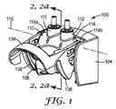
図1及び1Aはフィルタマニホールド100の代表的な実施形態を図示する。フィルタマニホールド100は、典型的にはブラケット104を備える。ブラケット104は、フィルタマニホールド100を壁又は他の適した支持体に付着することを可能にする装着構造を更に備えることができる。フィルタマニホールド100は、給水源111と、濾液出口112と、弁110と、フィルタカートリッジをフィルタマニホールド100の方へ引き寄せるためにフィルタカートリッジ(例えばフィルタカートリッジ460)上の適合可能な立体形状と係合する構造物をその上に有するハンドル134と、を更に備える。図1及び1Aで、ハンドル134はロックされた、すなわち係合が解かれた位置で示されている。弁110は、典型的には、図2及び図2Aにより大きく詳細に示されているように、固定部分114と回転可能な部分218とを備える。ハンドル134は弁110の回転可能な部分218に動作可能に接続される。一実施形態では、ハンドル134は使用者が片手で好ましくは下方へのストロークによってハンドル134を作動することを可能にする把持部分を備える。
1 and 1A illustrate an exemplary embodiment of a
いくつかの実施形態では、フィルタマニホールド100はブラケット104なしに提供される。そのような実施形態では、弁110の固定部分114に装着構造物を提供して、弁110を壁又は他の支持体に直接装着することを可能にすることができる。好適な装着構造物としては、例えば、ねじ山のある締結部品を受容するために中に穴を有する隆起したボスが挙げられる。他の好適な装着構造物としては、例えば、壁又は他の支持体上の相補的スナップ嵌め機構と係合する雄又は雌のスナップ嵌め機構が挙げられる。
In some embodiments, the
上述の及び後に記述される実施形態のフィルタマニホールド100の様々な部品は、十分な強度及び加工性を有する任意の好適な材料から構築され得る。好適な材料の例としては、ポリプロピレン、ポリスチレン、ナイロン、及び様々なポリフェニレンエーテル化合物が挙げられる。また、より高い強度を必要とする用途では、例えば、部品をステンレススチール及びアルミニウムのような金属で構築してもよいと想定される。
The various parts of the
いくつかの実施形態では、フィルタマニホールド100は少なくとも1つのカートリッジ支持棚106を備える。典型的には、カートリッジ支持棚106はブラケット104に付着される。図1及び1Aに示されるようないくつかの実施形態では、ブラケット104は対向する側部を備え、ブラケット104の対向する側部のそれぞれに1つのカートリッジ支持棚106が配置される。カートリッジ支持棚106は、フィルタカートリッジ460の組み立ての前に又はフィルタマニホールド100からのその取り外しの後にフィルタカートリッジ460を準備位置に支持するように位置づけられる。いくつかの実施形態では、準備位置は、フィルタカートリッジ460をハンドル134のカートリッジリフター138と協調動作する位置に静置することを可能にするために位置づけられる。そのような実施形態では、ハンドル134が回転する際に、カートリッジリフター138がフィルタカートリッジ460の適合可能な機構を係合し、それによってフィルタカートリッジ460をカートリッジ支持棚106から持ち上げ、フィルタカートリッジ460をフィルタマニホールド100の方へ引き寄せることができる。カートリッジ支持棚106はフィルタカートリッジ460を静置するのに便利な場所を提供し、かつフィルタカートリッジ460がカートリッジリフター138と協調動作するための正しい整列を確保するのを助ける。カートリッジ支持棚106は、フィルタカートリッジ460がフィルタマニホールド100から取り外される際に、それを停止させる機能も更に提供し、それによってフィルタカートリッジ460が動作圧下で取り外される際にフィルタマニホールド100から落下することないしは別の方法で射出されることを防ぐのを助けることができる。
In some embodiments, the
フィルタマニホールド100にブラケット104が提供される実施形態では、カートリッジ支持棚106を弁110の固定部分の一部として提供することができる。例えば、カートリッジ支持棚106は、固定部分114から突出している1つ以上の突出部と一体成形することができる。あるいは、カートリッジ支持棚106は、好適な締結具によって固定部分114に締結される個別部品として提供することもできる。好適な締結具の例としては、ねじ、スナップ、リベット、接着剤などが挙げられる。カートリッジ支持棚106が固定部分114の一部として提供される実施形態では、カートリッジ支持棚106は、カートリッジ支持棚106がブラケット104の一部として示されている図1に示されるように、固定部分114に対して実質的に同じ位置に位置づけられると想定される。
In embodiments where the
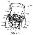
図1Aは、その下側が図示されるように回転された、図1のフィルタマニホールド100を図示する。図示されているように、押圧可能な部材126の少なくとも一部分は、弁110の固定部分114の開口116内に突出している。開口116はマニホールド供給ポート130及びマニホールド濾液ポート132の片側に位置づけられる。いくつかの実施形態では、開口116はマニホールド供給ポート130及びマニホールド濾液ポート132の両方の片側又は他方の側に位置づけられる場合がある。押圧可能な部材126及び開口116については、下記図2及び2Aを参照して詳述する。
FIG. 1A illustrates the
いくつかの実施形態では、マニホールド供給ポート130及びマニホールド濾液ポート132の1つ又は両方は、フィルタカートリッジがフィルタマニホールド100から取り外される際に、カートリッジ供給ポート470及びカートリッジ濾液ポート472(両方とも図4に示されている)の1つ又は両方のシールを通り過ぎるバイパスを引き起こすように構成された、図1Aが示すような排出口133を備える。いくつかの実施形態において、図4に図示されるように、カートリッジ供給ポート470及びカートリッジ濾液ポート472のそれぞれは、カートリッジ供給ポート470をマニホールド供給ポート130と密封連結し、カートリッジ濾液ポート472をマニホールド濾液ポート132と密封連結するためにポート密封部材471を備える。ポート密封部材471は、例えば、Oリング、ガスケット、又はオーバーモールドされたエラストマーシールを備えることができる。排出口133は、一連の排出機構を備えることができる。各排出機構は、マニホールド供給ポート130及びマニホールド濾液ポート132のいずれか又は両方の内壁上の連続扇形の凹部を備えることができる。連続扇形の凹部のそれぞれは、フィルタカートリッジ460がフィルタマニホールド100から取り外される際に、ポート密封部材471を通り過ぎるバイパスを引き起こすように構成される。すると、フィルタカートリッジ460内に残っている全ての加圧された流体が、フィルタカートリッジ460がフィルタマニホールド100から完全に取り外される前に排出口133を通って、圧力のより低い領域に流れることができる。いくつかの実施形態では、フィルタカートリッジ460は、バイパスが生成されて加圧流体が排出される際、カートリッジリフター138によって保持されたまま残る。そのような実施形態では、排出口133及びカートリッジリフター138は共に作用し、フィルタカートリッジがフィルタマニホールド100から急速かつ無制御に解放されるのを防ぐ。
In some embodiments, one or both of the
いくつかの実施形態では、フィルタカートリッジ460又はフィルタマニホールド100の1つにサンプ密封部材101が更に提供される。サンプ密封部材101は、フィルタカートリッジ460をフィルタマニホールド100に連結することによって内部接続チャンバ102を周囲環境から隔離する。サンプ密封部材101は、例えば、Oリング、ガスケット、又はオーバーモールドされたエラストマーシールを備えることができる。サンプ密封部材101は、典型的には、加圧された流体が排出口133を通ってバイパスする間、内部接続チャンバ102の隔離を維持するように位置づけられる。そのような実施形態では、排出口133を通って流れる全ての加圧された流体は、フィルタカートリッジ460がフィルタマニホールド100から完全に解放されるまでは内部接続チャンバ102内に封じ込められる。
In some embodiments, a
図2及び2Aは、ロック位置(図2)とロック解除位置(図2A)との両方における弁110の代表的な実施形態を図示する。明瞭さのためにブラケット104は省かれている。このロックされた位置すなわち解放位置は、図4に示されるフィルタカートリッジ460が取り外された状態に対応する。このロック解除の位置は、フィルタカートリッジ460が設置された状態に対応する。弁110は、固定部分114と回転可能な部分218とを備えることができる。固定部分114は、典型的には、長手方向軸115を有する円筒形の穴を有する本体を備える。図2及び2Aに示されるように、給水源111(及び図示されていない濾液出口112)は、典型的には、固定部分114に付着される。いくつかの実施形態では、固定部分114は、サンプ密封部材101を更に備える。回転可能な部分218は、典型的には、図3に示されるような長手方向軸115aを有する円筒を備える。固定部分114及び回転可能な部分218は入れ子状態であり、回転可能な部分218は固定部分114に対して回転する。マニホールド供給ポート130は、回転可能な部分218がロック位置にあるとき、封鎖されている。回転可能な部分218をロック解除位置に回転すると、マニホールド供給ポート130が開通する。いくつかの実施形態では、回転可能な部分218はロック位置にあるとき、限られた弧にわたって自由に回転する。一実施形態では、限られた弧は回転可能な部分218の約45度の角変位に対応する。別の実施形態では、角変位は約30度である。更なる実施形態では、角変位は約15度である。典型的には、マニホールド供給ポート130は、限られた弧にわたる回転の間、封鎖されたままである。限られた弧にわたってハンドルを移動させることは、マニホールド供給ポート130を開通せずにカートリッジリフター138がフィルタカートリッジ460を部分的に係合することを可能にする。この機構は、設置及び取り外しの間にフィルタカートリッジ460を定位置に保持することを助けることによって整備を容易にすることができる。いくつかの実施形態では、この機構はカートリッジ支持棚106と共に作用して、設置及び取り外し中にフィルタカートリッジ460を定位置に保持することを助ける。
2 and 2A illustrate an exemplary embodiment of the
図2及び図2Aに示されるように、バイパスチャネル220は回転可能な部分218内に形成され得るないしは別の方法で配置され得る。そのような実施形態では、バイパスチャネル220は、回転可能な部分218がロック位置にあるときに給水源111をフィルタマニホールド100の濾液出口112に流体接続する。回転可能な部分218がロック解除位置にあるとき、バイパスチャネル220は給水源111及び濾液出口112との流体連通から外される。バイパスチャネル220は、フィルタカートリッジ460が外されているときに流体がフィルタマニホールド100を通って流れ続けることを可能にすることができるが、フィルタカートリッジ460が設置されているときは、流体はフィルタカートリッジ460を通して方向づけられる。
As shown in FIGS. 2 and 2A, the
いくつかの実施形態では、回転可能な部分218は回転ロック124によってロック解除位置への回転を阻止される。回転ロック124は、固定部分114の開口116の少なくとも一部分を通って延在する押圧可能な部材126を備えることができる。押圧可能な部材126と、開口116の第1の壁217との間の干渉は、限られた弧を超えて回転可能な部分218が回転することを阻止する。いくつかの実施形態では、押圧可能な部材126はバネ仕掛けのピンを備える。いくつかの実施形態では、押圧可能な部材126はコイルバネによって支持された第1の遠位表面228を有する固体ピン部分を備える。押圧可能な部材126の固体ピン部分を支持するために、他の弾力的な部材を使用することができると想定される。また、押圧可能な部材126は、例えばゴム又は他の弾力的な材料で全体を構築され得ると想定される。あるいは、押圧可能な部材126はコイルバネを備えてもよい。
In some embodiments, the
いくつかの実施形態では、押圧可能な部材126は、回転可能な部分218の長手方向軸115aに直交する方向に面する第1の遠位表面228を備える。押圧可能な部材126が十分な範囲まで押圧されると、回転可能な部分218は限られた弧を通り過ぎ、第1の壁217を通り過ぎて自由に回転し、その際、押圧可能な部材126の第1の遠位表面228は、開口116を通り過ぎ、固定された部分114の円筒壁の内側に沿って滑走する。回転可能な部分218がロック解除位置に回転されると、マニホールド供給ポート130は開通する。一実施形態では、ロック位置からロック解除位置への回転における回転可能な部分218の最大角変位は、約90度である。別の実施形態では、最大角変位は約120度である。別の実施形態では、最大角変位は約60度である。最大角変位は、フィルタカートリッジ460を片手で整備するための人間工学的便益を最大にするために、ハンドル134の所望のストロークの長さをもたらすように選択され得る。
In some embodiments, the
典型的には、回転ロック124は、図2及び2Aに示されるように、フィルタカートリッジ460上の回転キー274によって押圧可能である。フィルタカートリッジ460がフィルタマニホールド100に設置されると、回転キー274は回転ロック124を押圧し、それによって回転可能な部分218がロック位置からロック解除位置に回転することを可能にする。いくつかの実施形態では、回転キー274は、その上に第2の遠位表面278を有する突出部276を備える。そのような実施形態では、第2の遠位表面278は第1の遠位表面228と接触して、回転ロック124を押圧する。一実施形態では、回転キー274はフィルタカートリッジ460のフィルタ頭部473上に配置される。いくつかの実施形態では、回転キー274は、図4に示されるカートリッジ供給ポート470とカートリッジ濾液ポート472との間のフィルタ頭部473に位置づけられる。いくつかの実施形態では、回転キーはカートリッジ供給ポート470及びカートリッジ濾液ポート472からずれており、フィルタカートリッジ460が単一の配向でのみフィルタマニホールド100に設置され得るように整列機構として更に働く。
Typically, the
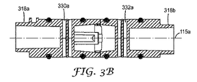
図3、3A、3B、及び3Cは、弁110の回転可能な部分218の代表的な実施形態を示す。いくつかの実施形態では、回転可能な部分218は2つの部品からなる外殻322を備える。2つの部品からなる外殻322は、第1の円筒形部分322aと第2の円筒形部分322bとを備える。第1の円筒形部分322aは供給チャネル330aを備え、第2の円筒形部分322bは濾液チャネル332aを備える。一実施形態では、第1の円筒形部分322a及び第2の円筒形部分322bはそれぞれバイパスチャネル220の部分と流体コネクタ322eの部分とを備え、それら2つの部品のバイパスチャネル220を流体接続する。バイパスチャネル220は、給水源111を濾液出口112に流体接続するように構成される。第1の円筒形部分322a及び第2の円筒形部分322bはそれぞれ、押圧可能な部材126を位置づけるために内部に凹部322dを備える接続端322cを有することができる。あるいは、凹部322dは、第1の円筒形部分322a又は第2の円筒形部分322bの1つにのみ形成されてもよい。各接続端322cは、バイオネット接続322fを更に備えることができる。第1の円筒形部分322aと第2の円筒形部分322bとが、該当する実施形態において互いに接続されていると、流体コネクタ322eはそれら2つの部品のバイパスチャネル220を流体接続する。回転可能な部分218は、バイパスチャネル220のような内部機構を含むために、単一部品ではなく2つの部品からなる外殻322として提供され得る。当業者には理解されるように、2つの部品からなる構造物がないと、そのような内部機構の成形又は機械加工は難しい問題を提示する。出願者らは、単一部品より容易にかつより低コストで製造することが可能な2つの部品からなる外殻322として回転可能な部分218を提供することによって、その難しい問題を解決した。
3, 3A, 3B, and 3C show an exemplary embodiment of the
いくつかの実施形態では、回転可能な部分218は、固定部分114の第1及び第2の端114a及び114bを超えてそれぞれ延在するように構成された第1の軸方向の伸張部分318aと第2の軸方向の伸張部分318bとを備える。回転可能な部分218が2つの部品からなる外殻322を備える実施形態では、第1の軸方向の伸張部分318aは第1の円筒形部分322a上に配置され、第2の軸方向の伸張部分318bは第2の円筒形部分322b上に配置される。第1及び第2の軸方向の伸張部分318a及び318bは、ハンドル134による弁110の作動を可能にするためにハンドル134に動作可能に接続される。本特許出願の文脈において、出願者らは、用語「動作可能に接続される」を、「指定された機能を実行するようなやり方で接続される」という意味に定義する。したがって、上記において使用されているように、第1及び第2の軸方向の伸張部分318a及び318bは、弁110を作動するという機能を実行するようにハンドル134と接続される。例えば、ハンドル134と、第1及び第2の軸方向の伸張部分318a及び318bとは、互いに直接付着され得る。図3に図示するように、第1及び第2の軸方向の伸張部分318a及び318bは、平坦な外面部分を備えることができる。図6に図示するように、ハンドル134は、それぞれが平坦な内面部分を有する円筒形の穴を備える2つの側面を備えることができる。ハンドル134のそれぞれの穴を、対応する第1及び第2の軸方向の伸張部分318a及び318bに被せて押し付け、平坦な内面部分と外面部分とを互いに結合させることができる。そのような組み立てを更に接着、溶接、又は他の何らかの方法で保持することができる。
In some embodiments, the
別の実施形態では、ハンドル134と、第1及び第2の軸方向の伸張部分318a及び318bとを連結具によって接続することができる。別の実施形態では、ハンドル134と、第1及び第2の軸方向の伸張部分318a及び318bとをギヤトレーンによって接続することができる。
In another embodiment, the
図4は、フィルタカートリッジ460の代表的な実施形態を図示する。いくつかの実施形態では、フィルタカートリッジ460は、カートリッジ供給ポート470と、カートリッジ濾液ポート472と、回転キー274と、一端に付着されたフィルタ頭部473を有する圧力容器に囲まれた濾過媒体と、を備える。一実施形態では、カートリッジ供給ポート470、カートリッジ濾液ポート472、及び回転キー274は、フィルタ頭部473上に配置される。いくつかの実施形態では、カートリッジ供給ポート470及びカートリッジ濾液ポート472はそれぞれ、ポート密封部材471を備える。フィルタカートリッジ460はカートリッジ外面464を備える。いくつかの実施形態では、図6が示すような少なくとも1つのカムラグ644又は少なくとも1つのカムランプ642はカートリッジ外面464上に配置される。図4に図示した実施形態はフィルタ頭部473の近くに配置されたカムラグを示しているが、カムラグ又はカムランプはカートリッジ外面464の任意の位置に配置され得ると想定される。フィルタ頭部473及びカートリッジ外面464は任意の好適な剛性材料で構築され得る。好適な材料の例としては、ポリプロピレン、ポリスチレン、ナイロン、及び様々なポリフェニレンエーテル化合物が挙げられる。また、より高い強度を要求する用途においては、例えば、フィルタ頭部473及びカートリッジ外面464の1つ又は両方をステンレススチール及びアルミニウムのような金属で構築することができる。
FIG. 4 illustrates an exemplary embodiment of the
カートリッジ供給ポート470は濾過媒体の上流部分に流体接続され、一方、カートリッジ濾液ポート472は濾過媒体の下流部分に流体接続される。したがって、典型的な実施形態では、カートリッジ供給ポート470を通ってフィルタカートリッジ460に流入する全ての流体は、濾過媒体を流れて通ってカートリッジ濾液ポート472に到達しなくてはならない。好適な濾過媒体としては、例えば、炭素ブロック、プリーツ加工された媒体、不織布、膜、デプスフィルトレーション媒体、及び多孔質ポリマーブロックが挙げられる。
いくつかの実施形態では、フィルタカートリッジ460の断面は概して楕円形であるので、例えば円筒形のフィルタカートリッジより小さい奥行を使うことが可能になる。そのような実施形態では、濾過媒体にもまた概して楕円形の断面をもたらすことが可能である。フィルタマニホールド100の、対応するカートリッジ結合部分に、概して楕円形の断面をもたらすこともまた可能である。本開示による濾過システムが壁に装着される用途では、そのような楕円の立体形状のおかげで、濾過システムが壁から突出する距離は、匹敵する同じ濾過能力を有する円筒形の立体形状に比べて短くなる。
In some embodiments, the cross-section of the
図5及び5Aは、濾過システム590の代表的な実施形態をその整備状態及び解体された状態の両方で図示する。典型的には、濾過システム590はフィルタマニホールド100とフィルタカートリッジ460とを備える。図5では、フィルタカートリッジ460は設置されており、ハンドル134はロック解除された位置すなわち整備位置にある。図5Aでは、フィルタカートリッジ460は外されていて、ハンドル134はロック位置すなわち解放位置にある。一実施形態では、フィルタマニホールド100はブラケット104と、ハンドル134と、弁110と、カートリッジ支持棚106と、図1Aに示されるようなマニホールド供給ポート130と、図1Aに示されるようなマニホールド濾液ポート132と、給水源111と、濾液出口112と、を備える。上述したように、いくつかの実施形態では、フィルタマニホールド100はブラケット104なしに提供される。そのような実施形態では、上述したようにカートリッジ支持棚106を固定部分114の一部として提供することができる。いくつかの実施形態では、フィルタマニホールド100はサンプ密封部材101を備える。一実施形態では、サンプ密封部材101は弁110の固定部分114上に提供される。ハンドル134は、カムランプ642のリフター係合機構又はカムラグ644のリフター係合機構640のうち1つを有するカートリッジリフター138を更に備える。一実施形態では、フィルタカートリッジ460は、カートリッジ外面464と、カートリッジ供給ポート470と、カートリッジ濾液ポート472と、ポート密封部材471と、回転キー274と、リフター係合機構640を係合するための少なくとも1つのカムラグ644又はカムランプ642と、を備える。いくつかの実施形態では、回転キー274は、第2の遠位表面278を有する突出部276を備える。
FIGS. 5 and 5A illustrate an exemplary embodiment of a
カートリッジ外面464及びカートリッジリフター138は相補的係合機構を備えると想定される。例えば、リフター係合機構640はカムランプ642を備えることができ、カートリッジ外面464はカムラグ644を備えることができる。同様に、リフター係合機構640はカムラグ644を備えることができ、カートリッジ外面464はカムランプ642を備えることができる。また、ハンドル134は複数のカートリッジリフター138を備えることができ、カートリッジリフター138は同じ又は異なるタイプのリフター係合機構640を備えることができると想定される。例えば、ハンドル134は、2つの対向するカートリッジリフター138(フィルタカートリッジ460の各側部に1つ)を備えることができる。1つのカートリッジリフター138はカムランプ642を備えることができ、一方、対向するカートリッジリフター138はカムラグ644を備えることができる。そのような実施形態では、カートリッジ外面464は、カムランプ642のリフター係合機構640に対応するカムラグ644と、カムラグ644のリフター係合機構640に対応するカムランプ642と、を備える。
It is envisioned that the cartridge
一実施形態では、濾過システム590は、(i)ハンドル134が解放位置にある間にフィルタマニホールド100の下にフィルタカートリッジ460を提供する工程と、(ii)整備位置にハンドル134を回転し、それによってカートリッジリフター138をカムラグ644でカムランプ642に接触させて、それによってフィルタカートリッジ460をフィルタマニホールド100の方へ引き寄せる工程と、(iii)カートリッジ供給ポート470をマニホールド供給ポート130と係合させる工程と、(iv)カートリッジ濾液ポート472をマニホールド濾液ポート132と係合させる工程と、(v)マニホールド供給ポート130を開通するために弁110を作動する工程と、によって組み立てられる。
In one embodiment, the
別の実施形態では、濾過システム590は、(i)ハンドル134が解放位置にある間にフィルタカートリッジ460をカートリッジ支持棚106上で準備位置に静置する工程と、(ii)整備位置にハンドル134を回転し、それによってカートリッジリフター138をカムラグ644でカムランプ642に接触させて、それによってフィルタカートリッジ460をカートリッジ支持棚106から持ち上げてフィルタマニホールド100の方へ引き寄せる工程と、(iii)カートリッジ供給ポート470をマニホールド供給ポート130と係合させる工程と、(iv)カートリッジ濾液ポート472をマニホールド濾液ポート132と係合させる工程と、(v)マニホールド供給ポート130を開通するために弁110を作動する工程と、によって組み立てられる。
In another embodiment, the
別の実施形態では、濾過システム590は、(i)ハンドル134が解放位置にある間にフィルタカートリッジ460をフィルタマニホールド100の下に提供する工程と、(ii)図1Aに示されるように回転キー274を回転ロック124に接触させる工程と、(iii)整備位置にハンドル134を回転し、それによってカートリッジリフター138をカムラグ644でカムランプ642に接触させて、それによってフィルタカートリッジ460をフィルタマニホールド100の方へ引き寄せる工程と、(iv)カートリッジ供給ポート470をマニホールド供給ポート130と係合させる工程と、(v)カートリッジ濾液ポート472をマニホールド濾液ポート132と係合させる工程と、(vi)マニホールド供給ポート130を開通するために弁110を作動する工程と、によって組み立てられる。
In another embodiment, the
別の実施形態では、濾過システム590は、(i)ハンドル134が解放位置にある間及びバイパスチャネル220が給水源111と濾液出口512とを流体接続している間にフィルタカートリッジ460をフィルタマニホールド100の下に提供する工程と、(ii)整備位置にハンドル134を回転し、それによってカートリッジリフター138をカムラグ644でカムランプ642に接触させて、それによってフィルタカートリッジ460をフィルタマニホールド100の方へ引き寄せる工程と、(iii)カートリッジ供給ポート470をマニホールド供給ポート130と係合させる工程と、(iv)カートリッジ濾液ポート472をマニホールド濾液ポート132と係合させる工程と、(v)バイパスチャネル220を動かして給水源111及び濾液出口112との流体接続から外す工程と、(vi)マニホールド供給ポート130を開通するために弁110を作動する工程と、によって組み立てられる。
In another embodiment, the
上記方法のいくつかの工程は必ずしも順次でなくてもよいと理解されたい。例えば、典型的な実施形態では、カートリッジ供給ポート470を図1Aに示すようなマニホールド供給ポート130と係合する工程は、カートリッジ濾液ポート472を図1Aに示すようなマニホールド濾液ポート132と係合する工程と実質的に同時に生じる。また、上述の方法の工程は、それらが記述されている実施形態のみに限定されないと理解されたい。例えば、ハンドル134が解放位置にある間にフィルタカートリッジ460をカートリッジ支持棚106上で準備位置に静置する工程は、回転キー274を同じ方法において回転ロック124と接触させる工程と組み合わせることができる。他の方法工程を同様に組み合わせてもよい。
It should be understood that some steps of the above method need not be sequential. For example, in an exemplary embodiment, engaging
図6は、カートリッジリフター138に配置されたカムランプ642のリフター係合機構640を有するハンドル134の断面図を図示する。いくつかの実施形態では、カムランプ642は第1のランプ部分642aと第2のランプ部分642bとを備える。一実施形態では、第1のランプ部分642aは、第2のランプ部分642bより大きい傾斜を有する。そのような実施形態では、フィルタマニホールド100へのフィルタカートリッジ460の係合は、以下のような工程によって為し得る。ハンドル134が回転し始めてカートリッジリフター138によるフィルタカートリッジ460の係合が可能になる際に、第1のランプ部分642aはカムラグ644を係合して、サンプ密封部材101がフィルタカートリッジ460をフィルタマニホールド100に密封連結するまで、フィルタカートリッジ460をカートリッジ支持棚106からすばやく持ち上げることができる。係合プロセスのその時点で、カートリッジ供給ポート470はマニホールド供給ポート130と部分的に係合され、カートリッジ濾液ポートはマニホールド濾液ポート132と部分的に係合され、排出口133は各ポート密封部材471を通り過ぎるバイパスを作り出す。次いで、ハンドル134が更に回転されると、カムラグ644は移動して第2のランプ部分642bと接触し、それと同時に、フィルタカートリッジ460はよりゆっくりと持ち上げられる。よりゆっくりと持ち上げるほど、回転可能な部分218の角位置に対してカートリッジ460をフィルタマニホールド100内により正確に位置づけることを可能にする。場合によっては、例えば、各ポート密封部材471が排出口133を超えて移動して完全なシールを生成するまでマニホールド供給ポート130が封鎖され続けることは重要であり得る。そのようなシールが生成された後、ハンドル134は引き続き回転することによって、フィルタカートリッジ460がフィルタマニホールド100に対して完全に座り、マニホールド供給ポート130が封鎖されるまで、カムラグ644が引き続き第2のランプ部分642bを滑走することを可能にする。第1及び第2のランプ部分642a及び642bは、直線輪郭又は曲線輪郭を備えることができる。あるいは、カムランプをカートリッジ外面464上に配置してもよい。
FIG. 6 illustrates a cross-sectional view of the
図6Aは、リフター係合機構640と係合するカムラグ644を有するフィルタカートリッジ460の一部分を示し、カムラグ644はカートリッジ外面464上に配置される。いくつかの実施形態では、カムラグ644は先端644aと主面644bとを備える。そのような実施形態では、先端644aは第1のランプ部分642aを摺動して協調動作し、カートリッジ支持棚106からのフィルタカートリッジ460の迅速な持ち上げを支援することができ、一方、主面644bは第2のランプ部分642bを摺動して協調動作し、フィルタカートリッジ460をフィルタマニホールド100によりゆっくりと正確に係合することができる。あるいは、カムラグをリフター係合機構640上に配置してもよい。
FIG. 6A shows a portion of a
いくつかの実施形態では、カムランプ642とカムラグ644との係合は2工程のプロセスを含む。第1に、ハンドル134が解放位置から反時計回りに回転して図6に示されるように整備位置になる際に、第1のランプ部分642aは先端644aに接触し、それによってフィルタカートリッジ460をフィルタマニホールド100の方へ引き寄せる。第2に、ハンドル134が回転し続ける際に、第2のランプ部分642bが主面644bと接触し、それによってフィルタカートリッジ460をフィルタマニホールド100の方へ引き続き引き寄せる。第1のランプ部分642aが第2のランプ部分642bより大きい傾斜を有する実施形態では、フィルタカートリッジ460は第2の工程中より第1の工程中により速い速度でフィルタマニホールド100の方へ引き寄せられる。上述の便益と共に、そのような2工程のプロセスは、(i)第1の工程中にフィルタカートリッジ460をフィルタマニホールド100に比較的迅速に密封することによって、フィルタカートリッジの設置中の濾過システム590からのいかなる流体の漏れをも防ぐことを助けること、その一方で、(ii)第2の工程中に、フィルタカートリッジ460がフィルタマニホールド100に対して完全に密封され、マニホールド供給ポート130が開通する際に、回転可能な部分218とフィルタカートリッジ460間の正確で時宜にかなった相互作用を可能にすることを、可能にすることができる。
In some embodiments, the engagement of
いくつかの実施形態では、ハンドル134は、ハンドル解放機構652を更に備える。図6に示されるように、ハンドル解放機構652はカムランプ642のリフター係合機構640に対向する位置に位置づけられたカム面を備えることができる。そのような実施形態が採用される場合、カートリッジ外面464上のカムラグ644はカートリッジ解放機構654を備えることができる。図6Aに示されるように、カートリッジ解放機構654は主面644bに対向する位置に位置づけられたカム面を備えることができる。ハンドル解放機構652とカートリッジ解放機構654は協調動作して、図6が示すようにハンドル134が時計回りの方向に回転されたとき、フィルタマニホールド100からのフィルタカートリッジ460の取り外しを支援することができる。ハンドル134が時計回りの方向に回転される際に、ハンドル解放機構652はカートリッジ解放機構654と接触して、フィルタカートリッジ460を押してフィルタマニホールド100から離れる。解放機構のこの組み合わせは、各ポート密封部材471をそれぞれ対応するマニホールド供給ポート130及びマニホールド濾液ポート132から外すのを支援するためにハンドル134を作動することによって得られる機械的利益を使用することによって、使用者がフィルタマニホールド100からフィルタカートリッジ460を取り外すのを容易にすることができる。そのような支援は、例えば、Oリングのような密封部材が長期間にかけて圧縮されたために一時的に「固定され」て、それらが密着している表面に固着している場合に、有益となり得る。
In some embodiments, the
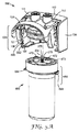
図7は、解体された状態にある濾過システム590の代表的な実施形態を示し、フィルタカートリッジ460は使い捨てのフィルタ要素768と、内部体積767を有する剛性サンプ766と、を備える。使い捨てのフィルタ要素768の少なくとも一部分は内部体積767内に位置づけることが可能である。いくつかの実施形態では、剛性サンプ766は、使い捨てフィルタ要素768が交換される度に再利用される。そのような実施形態では、フィルタ使い捨てフィルタ要素768の交換の際により少ない物質が廃棄されるので、環境ごみの削減を実現することができる。
FIG. 7 illustrates an exemplary embodiment of the
いくつかの実施形態では、使い捨てフィルタ要素768は、カートリッジ供給ポート470と、カートリッジ濾液ポート472と、回転キー274と、一端に付着されたフィルタ頭部773を有するケーシング768aによって囲まれた濾過媒体と、を備える。一実施形態では、カートリッジ供給ポート470、カートリッジ濾液ポート472、及び回転キー274は、フィルタ頭部773上に配置される。ケーシング768aは不透水性材料を含む。いくつかの実施形態では、ケーシング768aは、例えば低密度ポリエチレンのような可撓性の不透水性材料を含む。典型的には、フィルタ頭部773は、ケーシング768aに比べて比較的剛性の材料を含む。フィルタ頭部773は任意の好適な剛性材料で構築され得る。好適な材料の例としては、ポリプロピレン、ポリスチレン、ナイロン、及び様々なポリフェニレンエーテル化合物が挙げられる。
In some embodiments, the
いくつかの実施形態では、剛性サンプ766は、ケーシング768aより高い動作圧に耐えるように設計された圧力容器として構成される。剛性サンプ766は任意の好適な剛性材料で構築され得る。好適な材料の例としては、ポリプロピレン、ポリスチレン、ナイロン、及び様々なポリフェニレンエーテル化合物が挙げられる。また、より高い強度を必要とする用途では、例えば、剛性サンプ766をステンレススチール及びアルミニウムのような金属で構築してもよいと想定される。濾過システム590の典型的な実施形態が組み立てられて動作圧下に置かれると、ケーシング768aは剛性サンプ766の内部体積767の側壁にもたれる。ケーシング768aは剛性サンプ766と同じ耐圧能力を有する必要がないので、使い捨てのフィルタ要素768は、もしそのような耐圧能力が必要であれば必要となるであろうよりはるかに少ない材料で構築され得る。結果的に、使い捨てフィルタ要素768の交換の度に、より少ない材料が廃棄される。ケーシング768aは、供給される流体で内部体積767が濡れるのを防ぐという更なる利点を提供する。結果的に、剛性サンプ766に要求されるいかなる洗浄をも削減又は排除することができる。
In some embodiments,
カートリッジ外面464は、剛性サンプ766又は使い捨てフィルタ要素768のいずれかの一部であってよいと想定される。しかし典型的には、カートリッジ外面464は剛性サンプ766の一部である。
It is envisioned that cartridge
フィルタカートリッジ460が使い捨てフィルタ要素768と剛性サンプ766とを備える実施形態では、回転キー274は典型的にはフィルタ頭部773上に配置される。結果的に、空の剛性サンプ766がフィルタマニホールド100に位置づけられると、回転キー274は図1Aに示された回転ロック124を押圧することがなく、ハンドル134は整備位置への回転を阻止されることになる。ハンドル134が整備位置に回転されないので、図1Aに示されたマニホールド供給ポート130は封鎖されたままになる。そのような実施形態では、濾過システム590は、フィルタマニホールド100へのフィルタカートリッジ460の設置の前に、適合可能な使い捨てのフィルタ要素768が剛性サンプ766に設置されたときにのみ、マニホールド供給ポート130の開通を可能にすることになる。そのような実施形態では、使用者又は整備技士が剛性サンプ766を再び設置するときに誤って使い捨てフィルタ要素768を省くことが防がれる。結果的に、そのような実施形態では、使用者は、剛性サンプ766が設置されてハンドル134が整備位置にあれば、濾過システム590が濾過機能を実行していると確信することができる。
In embodiments where the
この発明の種々の修正及び変更が発明の趣旨及び範囲から逸脱しないことは、当業者には分かるであろう。本発明は、本明細書において説明した例示の実施形態に制限されないことを理解されたい。 It will be apparent to those skilled in the art that various modifications and variations of the present invention can be made without departing from the spirit and scope of the invention. It should be understood that the present invention is not limited to the exemplary embodiments described herein.
Claims (6)
マニホールド供給ポート、及びマニホールド濾液ポートと、
前記回転可能な部分とともに回転可能となるように該回転可能な部分に動作可能に接続されるハンドルと、を備えるフィルタマニホールドであって、
前記ハンドルは、該ハンドルから延びるカートリッジリフターを有し、
前記カートリッジリフターは、カムランプのリフター係合機構、及びカムラグのリフター係合機構のうちの1つと、ハンドル解放機構と、を有し、
前記ハンドルは、整備位置と解放位置とに回転可能であり、
前記マニホールド供給ポートは、
前記ハンドルが前記整備位置にあるときに、前記弁によって開通され、
前記ハンドルが前記解放位置にあるときに、前記弁によって封鎖され、
前記ハンドルが前記解放位置へ移動したときに、前記ハンドル解放機構は、前記フィルタマニホールドに装着されるフィルタカートリッジを、前記フィルタマニホールドから完全に解放するように、前記フィルタマニホールドから離れる方向へ押す、フィルタマニホールド。 Fixed part, and a valve having an internal arranged rotatable portion of said fixed portion,
Manifold feed port, and a manifold filtrate port,
Wherein a handle with rotatable portion Ru operably connected to said rotatable portion so as to be rotatable, a filter manifold Ru provided with,
It said handle has a cartridge lifter extending from the handle,
The cartridge lifter includes one of a cam lamp lifter engagement mechanism and a cam lug lifter engagement mechanism, and a handle release mechanism.
The handle is rotatable between a maintenance position and a release position ;
The manifold supply port is
Opened by the valve when the handle is in the service position;
When the handle is in the release position, it is blocked by the valve;
When the handle is moved to the release position, the handle release mechanism pushes a filter cartridge attached to the filter manifold in a direction away from the filter manifold so as to completely release the filter cartridge. Manifold.
フィルタカートリッジと、を備え、
前記フィルタカートリッジは、カートリッジ供給ポートと、カートリッジ濾液ポートと、カートリッジ外面とを有し、
前記カートリッジ外面は、前記リフター係合機構と係合するためのカムラグ又はカムランプのうちの1つと、カートリッジ解放機構とを含む、濾過システム。 A filter manifold according to claim 1 ;
Provided with a filter cartridge, the,
Before SL filter cartridge has a cartridge feed port, a cartridge filtrate port, and a cartridge outer surface,
It said cartridge outer surface, and one of the camming lug or cam ramp for engaging the lifter engagement feature comprises a cartridge release mechanism, filtration system.
前記ハンドルが前記解放位置にある間に、前記フィルタマニホールドの下に前記フィルタカートリッジを提供する工程と、
前記ハンドルを前記整備位置に回転させて、前記カートリッジリフターを前記カムラグによって前記カムランプと接触させ、前記フィルタカートリッジを前記フィルタマニホールドの方へ引き寄せる工程と、
前記カートリッジ供給ポートを前記マニホールド供給ポートと係合させる工程と、
前記カートリッジ濾液ポートを前記マニホールド濾液ポートと係合する工程と、
前記マニホールド供給ポートを開通するために前記弁を作動させる工程と、を備える、組み立て方法。 A method for assembling a filtration system according to claim 2,
Providing the filter cartridge under the filter manifold while the handle is in the release position;
By rotating the handle to the maintenance position, the cartridge lifter to contact with the cam ramp by the camming lug, a step of drawing the previous SL filter cartridge toward the filter manifold,
A step of Ru said cartridge feed port to engage the manifold feed port,
Engaging the cartridge filtrate port with the manifold filtrate port;
And a step of activating the valve to open the manifold feed port, the assembly method.
前記ハンドルが前記解放位置にあるときに、前記回転ロックによって前記回転可能な部分の回転が阻止される、請求項1に記載のフィルタマニホールド。The filter manifold of claim 1, wherein the rotatable portion prevents rotation of the rotatable portion when the handle is in the release position.
前記押圧可能な部材は、The pressable member is
前記弁の前記回転可能な部分に接続され、前記弁の前記固定部分に設けられた開口から突出し、Connected to the rotatable portion of the valve and protruding from an opening provided in the fixed portion of the valve;
ロックする位置からロック解除する位置へ押圧可能である、請求項4に記載のフィルタマニホールド。The filter manifold according to claim 4, wherein the filter manifold can be pressed from a locked position to a unlocked position.
前記第1のランプ部分は、前記第2のランプ部分より大きい傾斜を有する、請求項1に記載のフィルタマニホールド。The filter manifold of claim 1, wherein the first ramp portion has a greater slope than the second ramp portion.
Applications Claiming Priority (3)
| Application Number | Priority Date | Filing Date | Title |
|---|---|---|---|
| US9473708P | 2008-09-05 | 2008-09-05 | |
| US61/094,737 | 2008-09-05 | ||
| PCT/US2009/055643 WO2010027989A2 (en) | 2008-09-05 | 2009-09-02 | Filtration system |
Publications (3)
| Publication Number | Publication Date |
|---|---|
| JP2012501832A JP2012501832A (en) | 2012-01-26 |
| JP2012501832A5 JP2012501832A5 (en) | 2012-10-18 |
| JP5536774B2 true JP5536774B2 (en) | 2014-07-02 |
Family
ID=41797814
Family Applications (1)
| Application Number | Title | Priority Date | Filing Date |
|---|---|---|---|
| JP2011526139A Expired - Fee Related JP5536774B2 (en) | 2008-09-05 | 2009-09-02 | Filtration system |
Country Status (7)
| Country | Link |
|---|---|
| US (1) | US9044699B2 (en) |
| EP (1) | EP2355914B1 (en) |
| JP (1) | JP5536774B2 (en) |
| KR (1) | KR101614566B1 (en) |
| CN (1) | CN102176955B (en) |
| BR (1) | BRPI0913488A2 (en) |
| WO (1) | WO2010027989A2 (en) |
Families Citing this family (45)
| Publication number | Priority date | Publication date | Assignee | Title |
|---|---|---|---|---|
| US8097158B2 (en) | 2005-05-16 | 2012-01-17 | 3M Innovative Properties Company | Spool valve manifold interconnect for a filter system |
| BRPI0913488A2 (en) | 2008-09-05 | 2017-05-30 | 3M Innovative Properties Co | "filtration system" |
| US10843108B2 (en) * | 2011-06-21 | 2020-11-24 | Kinetico Incorporated | Water treatment system |
| KR101318423B1 (en) * | 2011-06-24 | 2013-10-15 | 위니맥스 주식회사 | Water filter assembly and refrigerator and water purifier having the same |
| JP5913595B2 (en) * | 2011-09-07 | 2016-04-27 | エレクトロリティック、オゾン、インコーポレイテッドElectrolytic Ozone Inc. | Removable cartridge and hub that generates ozonated water |
| EP2826533B1 (en) * | 2012-03-12 | 2016-12-21 | Shenzhen Xingrisheng Industrial Co., Ltd. | Out-of-vat liquid filter for ensuring reliable connection of water pipe connector |
| US8945383B2 (en) | 2012-03-16 | 2015-02-03 | Kx Technologies Llc | Filtration system |
| US8951415B2 (en) | 2012-03-16 | 2015-02-10 | Kx Technologies Llc | Filtration system |
| JP2013230410A (en) * | 2012-04-27 | 2013-11-14 | Sharp Corp | Liquid filter |
| US9789424B2 (en) | 2013-06-26 | 2017-10-17 | Pentair Residential Filtration, Llc | Water filtration system and method |
| US9757670B2 (en) * | 2013-10-31 | 2017-09-12 | Pall Corporation | Methods for moving a filter along a manifold assembly; filter arrangements including a filter and a manifold assembly; and filters |
| US9527021B2 (en) * | 2013-10-31 | 2016-12-27 | Pall Corporation | Filter manifold |
| US9492770B2 (en) | 2013-10-31 | 2016-11-15 | Pall Corporation | Filters |
| US9713782B2 (en) | 2013-11-11 | 2017-07-25 | Pall Corporation | Filters and filter arrangements which include a filter and a manifold assembly |
| USD755344S1 (en) | 2014-06-26 | 2016-05-03 | Pentair Residential Filtration, Llc | Filter cartridge |
| CN106039816B (en) | 2015-04-09 | 2020-07-03 | 碧然德有限公司 | Device for forming liquid treatment apparatus and liquid treatment apparatus |
| US20170095757A1 (en) | 2015-05-27 | 2017-04-06 | Flow Control LLC | Cartridge Accumulator |
| MX2017015112A (en) | 2015-05-27 | 2018-05-17 | Flow Control LLC | Cartridge pump. |
| JP7049991B2 (en) | 2015-09-14 | 2022-04-07 | フロー コントロール リミティド ライアビリティ カンパニー | Cartridge accumulator |
| KR101788965B1 (en) * | 2016-03-22 | 2017-10-20 | 엘지전자 주식회사 | water purifing apparatus refrigerator |
| ES2944575T3 (en) * | 2016-10-20 | 2023-06-22 | Emd Millipore Corp | Tube management and valve protection device |
| WO2018153435A1 (en) * | 2017-02-21 | 2018-08-30 | Mahle International Gmbh | Fuel filter device for an internal combustion engine |
| US20180318738A1 (en) * | 2017-05-04 | 2018-11-08 | Haier Us Appliance Solutions, Inc. | Enhanced filter installation |
| WO2019016167A1 (en) * | 2017-07-17 | 2019-01-24 | Castrol Limited | Replaceable fluid container with removable manifold |
| PL234666B1 (en) * | 2018-04-26 | 2020-03-31 | Aquael Janusz Jankiewicz Spolka Z Ograniczona Odpowiedzialnoscia | Water filter for an aquarium |
| CN108895164B (en) * | 2018-06-26 | 2020-01-24 | 浙江沁园水处理科技有限公司 | Water inlet valve and water purifier thereof |
| CN108644426B (en) * | 2018-06-26 | 2019-10-29 | 浙江沁园水处理科技有限公司 | A kind of series connection bivalve module and its water purifier |
| CN108889023B (en) * | 2018-06-26 | 2021-02-12 | 浙江沁园水处理科技有限公司 | Water purifier with filter flask capable of being quickly disassembled and assembled |
| CN108644423B (en) * | 2018-06-26 | 2020-01-03 | 浙江沁园水处理科技有限公司 | Bivalve module and water purifier with wash function |
| CN108644427B (en) * | 2018-06-26 | 2019-10-29 | 浙江沁园水处理科技有限公司 | A kind of integral type bivalve module and its water purifier |
| CN108644424B (en) * | 2018-06-26 | 2019-10-29 | 浙江沁园水处理科技有限公司 | A kind of independent bivalve module and its water purifier |
| CN108644411B (en) * | 2018-06-26 | 2020-01-03 | 浙江沁园水处理科技有限公司 | Flushing valve and water purifier thereof |
| CN108644425B (en) * | 2018-06-26 | 2019-10-29 | 浙江沁园水处理科技有限公司 | A kind of inlet valve and its water purifier with pressure-reduction module |
| CN108980403B (en) * | 2018-06-26 | 2019-12-13 | 浙江沁园水处理科技有限公司 | Water inlet valve with flow meter and water purifier thereof |
| DE102018129752A1 (en) * | 2018-11-26 | 2020-05-28 | Franke Technology And Trademark Ltd | FILTER DEVICE FOR DRINKING WATER FILTERING |
| KR102052554B1 (en) * | 2019-01-31 | 2019-12-05 | 주식회사 교원 | Filter connector and water purifier including the same |
| KR102177297B1 (en) * | 2019-02-28 | 2020-11-10 | 청호나이스 주식회사 | Connecting structure for filter and water purifier having the same |
| US11660554B2 (en) * | 2019-11-11 | 2023-05-30 | Qingdao Ecopure Filler Co., Ltd. | Appliance water filter cartridge |
| WO2021195386A1 (en) * | 2020-03-27 | 2021-09-30 | Spx Flow Technology Usa, Inc. | Filter assembly and media |
| CN113828047B (en) | 2020-06-08 | 2023-02-24 | 帕尔公司 | Manifold assembly and method of use |
| IL283156A (en) * | 2020-06-08 | 2022-01-01 | Pall Corp | Manifold assembly and method of use |
| WO2022020776A1 (en) | 2020-07-24 | 2022-01-27 | 3Oe Scientific, LLC | Aqueous ozone sanitizing system with ozone generator cartridge docking station |
| JP2022120541A (en) * | 2021-02-05 | 2022-08-18 | オルガノ株式会社 | Cartridge mounting structure and cartridge |
| WO2022229927A1 (en) | 2021-04-30 | 2022-11-03 | Whirlpool Corporation | Filter assembly |
| CN116764321A (en) * | 2021-11-29 | 2023-09-19 | 南京菡束环保设备有限公司 | Filter element mounting structure |
Family Cites Families (60)
| Publication number | Priority date | Publication date | Assignee | Title |
|---|---|---|---|---|
| US1688326A (en) | 1925-09-16 | 1928-10-23 | Zenith Carburateur Soc Du | Filter |
| US2857128A (en) | 1956-10-18 | 1958-10-21 | Stern Daniel | Safety shutoff coupling |
| US3399776A (en) | 1965-09-02 | 1968-09-03 | Robert R. Knuth | Detachable snap-on filter for a hydraulic system |
| US3742970A (en) | 1970-02-13 | 1973-07-03 | Pall Corp | Flow-sensitive sensing and shut-off device |
| US3643692A (en) | 1970-09-28 | 1972-02-22 | Paul L Traylor | Valve |
| US3684100A (en) | 1971-04-05 | 1972-08-15 | Sam Close | Filter assembly and disposable filter element therefor |
| CH537546A (en) | 1971-04-06 | 1973-05-31 | Saffin Von Corpon Paul | Robinet mélangeur |
| BE791684A (en) | 1971-11-22 | 1973-03-16 | Ogden Hubert S | REMOVABLE FILTER CARTRIDGE |
| JPS5129619A (en) | 1974-09-02 | 1976-03-13 | Matsushita Electric Ind Co Ltd | Nainenkikanno haikigasujokasochi |
| US3926187A (en) | 1974-12-19 | 1975-12-16 | Jose J Iglesias | Urological bladder evacuator |
| US4108207A (en) | 1977-04-13 | 1978-08-22 | The United States Of America As Represented By The United States Department Of Energy | Multiple-port valve |
| DE3126507A1 (en) * | 1981-07-04 | 1983-01-20 | Surculus AG, Vaduz | "ARMATURE" |
| JPS5867510A (en) | 1981-10-20 | 1983-04-22 | Nippon Denso Co Ltd | Automobile ventilator |
| JPS5867510U (en) * | 1981-10-30 | 1983-05-09 | 三菱農機株式会社 | Oil filter installation structure |
| JPS58116008U (en) * | 1982-01-28 | 1983-08-08 | 三菱農機株式会社 | oil filter |
| US4469131A (en) | 1982-07-12 | 1984-09-04 | Traylor Paul L | Spool valve |
| DE3520139A1 (en) | 1985-06-05 | 1986-12-11 | Joachim 7252 Weil der Stadt Wolf | FILTER DEVICE |
| DE3640531C1 (en) | 1986-11-27 | 1987-09-03 | Bayerische Motoren Werke Ag | Filter arrangement for cleaning liquid operating materials, especially the lubricating oil of internal combustion engines |
| US4979530A (en) | 1987-12-24 | 1990-12-25 | Ameri-Can Brass Faucet Inc. | Modular valve assembly |
| GB2216030B (en) | 1988-05-11 | 1991-10-09 | Joachim Wolf | A filter |
| GB2216028B (en) | 1988-05-16 | 1991-09-25 | Joachim Wolf | A filter manifold |
| IL87280A (en) | 1988-08-01 | 1991-01-31 | Dolev Moshe | Quick-disconnect hose coupling device |
| US5152321A (en) | 1991-10-07 | 1992-10-06 | Ecowater Systems, Inc. | Bypass valve |
| DE4135867A1 (en) | 1991-10-31 | 1993-05-06 | Alfred Teves Gmbh, 6000 Frankfurt, De | CUFF RETURN VALVE |
| US5230812A (en) | 1992-07-29 | 1993-07-27 | Williams Richard T | Pressure vessel |
| US5461948A (en) | 1992-08-27 | 1995-10-31 | Perrero, Jr.; Thomas | Socket type tool for removing oil filter cartridge |
| US5389260A (en) * | 1993-04-02 | 1995-02-14 | Clack Corporation | Brine seal for tubular filter |
| US5397462A (en) | 1993-08-24 | 1995-03-14 | Matsushita Electric Industrial Co., Ltd. | Filter with laterally removable element and valve means |
| US5445734A (en) | 1994-11-18 | 1995-08-29 | Chen; Ching-Wen | Water filter |
| US5882511A (en) | 1996-10-30 | 1999-03-16 | Fil-Tech Corporation | Filter apparatus with coupling and latch mechanism |
| US5919362A (en) | 1997-04-28 | 1999-07-06 | Cuno, Inc. | Expandable encapsulated filter cartridge assembly |
| US5931196A (en) | 1998-04-29 | 1999-08-03 | United States Filter Corporation | Bypass valve |
| US6579455B1 (en) | 1999-09-09 | 2003-06-17 | Pti Advanced Filtration | Filter and valve apparatus |
| US6953526B1 (en) | 2000-03-22 | 2005-10-11 | Cuno Incorporated | Filter assembly |
| US6949189B2 (en) | 2000-04-20 | 2005-09-27 | Cuno Incorporated | Keyed filter assembly |
| US6458269B1 (en) | 2000-04-20 | 2002-10-01 | Cuno Incorporated | Keyed filter assembly |
| US7407148B2 (en) | 2000-04-20 | 2008-08-05 | 3M Innovative Properties Company | Rotary valve assembly for fluid filtration system |
| US6457698B2 (en) | 2000-06-16 | 2002-10-01 | United States Filter Corporation | Bypass valve |
| JP3514724B2 (en) | 2000-11-29 | 2004-03-31 | 日東工器株式会社 | Pipe fittings |
| ITPD20010179A1 (en) | 2001-07-17 | 2003-01-17 | Askoll Holding Srl | PIPE FITTING GROUP WITH SAFETY LOCK FOR EXTERNAL FILTERS FOR AQUARIUMS. |
| US20030019819A1 (en) | 2001-07-30 | 2003-01-30 | Karl Fritze | Hot disconnect replaceable water filter assembly |
| US6632355B2 (en) | 2001-07-30 | 2003-10-14 | Pentapure Incorporated | Low spillage replaceable water filter assembly |
| US6857670B2 (en) | 2001-12-05 | 2005-02-22 | Cuno Incorporated | Plastic tube joint |
| US7638042B2 (en) | 2002-02-15 | 2009-12-29 | 3M Innovative Properties Company | System for monitoring the performance of fluid treatment cartridges |
| JP4234938B2 (en) * | 2002-02-28 | 2009-03-04 | インテグリス・インコーポレーテッド | Connector device for filter cartridge |
| JP4125051B2 (en) * | 2002-06-20 | 2008-07-23 | インテグリス・インコーポレーテッド | Seal structure of connector device |
| JP4011986B2 (en) * | 2002-06-21 | 2007-11-21 | クリタック株式会社 | Water purification cartridge mounting device |
| JP3829117B2 (en) | 2002-12-27 | 2006-10-04 | 日東工器株式会社 | Pipe fitting |
| US7147773B2 (en) | 2003-04-25 | 2006-12-12 | Whirlpool Corporation | Refrigerator with treated water |
| US7000894B2 (en) | 2003-04-25 | 2006-02-21 | Pur Water Purification Products, Inc. | Fluidic cartridges and end pieces thereof |
| MXPA06008658A (en) | 2004-02-03 | 2007-04-25 | Zohar Waterworks Llc | Filter cartridge and manifold for a water purification system. |
| US20060032806A1 (en) | 2004-08-16 | 2006-02-16 | Parker Mark A | Apparatus to filter water |
| US8097158B2 (en) * | 2005-05-16 | 2012-01-17 | 3M Innovative Properties Company | Spool valve manifold interconnect for a filter system |
| US7651070B2 (en) * | 2006-01-19 | 2010-01-26 | Clean & Clear Corporation | Canter element controlled combination manifold, valve and filter module system |
| KR100772889B1 (en) * | 2006-04-18 | 2007-11-02 | 주식회사 위닉스 | Water filters and water filter assembly connector and water purifier structure these |
| US20080000820A1 (en) * | 2006-06-30 | 2008-01-03 | Mitchell Alan J | Water Filter Cartridge and Valve with Autobypass Feature |
| US20080156711A1 (en) | 2006-12-29 | 2008-07-03 | Vitan Craig R | Water filter assembly and filter cartridge for use therewith |
| KR100870572B1 (en) | 2007-02-28 | 2008-11-27 | 주식회사 영우워터라인 | Water Purification Filter Assembly using a swivel type connector |
| KR100930665B1 (en) | 2008-01-28 | 2009-12-09 | 앨트웰텍 주식회사 | Rotary Detachable Filter Supporter |
| BRPI0913488A2 (en) | 2008-09-05 | 2017-05-30 | 3M Innovative Properties Co | "filtration system" |
-
2009
- 2009-09-02 BR BRPI0913488A patent/BRPI0913488A2/en not_active IP Right Cessation
- 2009-09-02 CN CN200980139908.8A patent/CN102176955B/en not_active Expired - Fee Related
- 2009-09-02 EP EP09812126.2A patent/EP2355914B1/en not_active Not-in-force
- 2009-09-02 KR KR1020117007568A patent/KR101614566B1/en not_active IP Right Cessation
- 2009-09-02 US US13/062,008 patent/US9044699B2/en not_active Expired - Fee Related
- 2009-09-02 WO PCT/US2009/055643 patent/WO2010027989A2/en active Application Filing
- 2009-09-02 JP JP2011526139A patent/JP5536774B2/en not_active Expired - Fee Related
Also Published As
| Publication number | Publication date |
|---|---|
| US9044699B2 (en) | 2015-06-02 |
| CN102176955B (en) | 2014-03-12 |
| EP2355914B1 (en) | 2014-06-11 |
| EP2355914A2 (en) | 2011-08-17 |
| BRPI0913488A2 (en) | 2017-05-30 |
| US20110247974A1 (en) | 2011-10-13 |
| EP2355914A4 (en) | 2013-01-02 |
| WO2010027989A2 (en) | 2010-03-11 |
| JP2012501832A (en) | 2012-01-26 |
| CN102176955A (en) | 2011-09-07 |
| KR20110053380A (en) | 2011-05-20 |
| KR101614566B1 (en) | 2016-04-21 |
| WO2010027989A3 (en) | 2010-05-14 |
Similar Documents
| Publication | Publication Date | Title |
|---|---|---|
| JP5536774B2 (en) | Filtration system | |
| US20230139571A1 (en) | Water Filtration System and Method | |
| JP5001936B2 (en) | Interconnection of spool valve manifolds for filter systems | |
| TWI432252B (en) | Push filter with floating key lock | |
| US7871517B2 (en) | Filter device | |
| EP2298431B1 (en) | Fluid filtration system | |
| US9782706B1 (en) | Flow connector for connecting screw-type filtration head to lug-type sump | |
| KR101572918B1 (en) | Filter Assembly | |
| US8795524B2 (en) | Fluid treatment arrangements and methods for operating fluid treatment arrangements | |
| KR100637044B1 (en) | Single and multi adapter capable of being detached by one touch, filter assembly detachably engaged with the same, and water purifying system adapting these elememts | |
| US20110297604A1 (en) | Fluid interconnect | |
| WO2017050367A1 (en) | A filter insert and a filter arrangement | |
| KR20090053528A (en) | A device for self-locking and unlock of purifier in gas mask | |
| CN111757776B (en) | Air filter easy to maintain | |
| JP3624157B2 (en) | Water purifier mounting device | |
| CN211435343U (en) | Water purifier convenient to dismouting | |
| CN202366527U (en) | Filtering machine with integrally-molded filter barrel | |
| JPS63264187A (en) | Cartridge for fluid treatment | |
| CN113929163A (en) | Water purifier | |
| JPH0560586U (en) | Stationary water purifier |
Legal Events
| Date | Code | Title | Description |
|---|---|---|---|
| A521 | Written amendment |
Free format text: JAPANESE INTERMEDIATE CODE: A523 Effective date: 20120830 |
|
| A621 | Written request for application examination |
Free format text: JAPANESE INTERMEDIATE CODE: A621 Effective date: 20120830 |
|
| A977 | Report on retrieval |
Free format text: JAPANESE INTERMEDIATE CODE: A971007 Effective date: 20130712 |
|
| A131 | Notification of reasons for refusal |
Free format text: JAPANESE INTERMEDIATE CODE: A131 Effective date: 20130730 |
|
| A601 | Written request for extension of time |
Free format text: JAPANESE INTERMEDIATE CODE: A601 Effective date: 20131029 |
|
| A602 | Written permission of extension of time |
Free format text: JAPANESE INTERMEDIATE CODE: A602 Effective date: 20131106 |
|
| A521 | Written amendment |
Free format text: JAPANESE INTERMEDIATE CODE: A523 Effective date: 20131122 |
|
| TRDD | Decision of grant or rejection written | ||
| A01 | Written decision to grant a patent or to grant a registration (utility model) |
Free format text: JAPANESE INTERMEDIATE CODE: A01 Effective date: 20140325 |
|
| A61 | First payment of annual fees (during grant procedure) |
Free format text: JAPANESE INTERMEDIATE CODE: A61 Effective date: 20140424 |
|
| R150 | Certificate of patent or registration of utility model |
Ref document number: 5536774 Country of ref document: JP Free format text: JAPANESE INTERMEDIATE CODE: R150 |
|
| LAPS | Cancellation because of no payment of annual fees |