KR101494028B1 - Apparatus and method for encoding and decoding signals - Google Patents
Apparatus and method for encoding and decoding signals Download PDFInfo
- Publication number
- KR101494028B1 KR101494028B1 KR1020097023799A KR20097023799A KR101494028B1 KR 101494028 B1 KR101494028 B1 KR 101494028B1 KR 1020097023799 A KR1020097023799 A KR 1020097023799A KR 20097023799 A KR20097023799 A KR 20097023799A KR 101494028 B1 KR101494028 B1 KR 101494028B1
- Authority
- KR
- South Korea
- Prior art keywords
- data
- encoder
- byte
- bytes
- decoder
- Prior art date
Links
Images


Classifications
-
- H—ELECTRICITY
- H04—ELECTRIC COMMUNICATION TECHNIQUE
- H04N—PICTORIAL COMMUNICATION, e.g. TELEVISION
- H04N19/00—Methods or arrangements for coding, decoding, compressing or decompressing digital video signals
- H04N19/10—Methods or arrangements for coding, decoding, compressing or decompressing digital video signals using adaptive coding
- H04N19/134—Methods or arrangements for coding, decoding, compressing or decompressing digital video signals using adaptive coding characterised by the element, parameter or criterion affecting or controlling the adaptive coding
- H04N19/156—Availability of hardware or computational resources, e.g. encoding based on power-saving criteria
-
- H—ELECTRICITY
- H03—ELECTRONIC CIRCUITRY
- H03M—CODING; DECODING; CODE CONVERSION IN GENERAL
- H03M13/00—Coding, decoding or code conversion, for error detection or error correction; Coding theory basic assumptions; Coding bounds; Error probability evaluation methods; Channel models; Simulation or testing of codes
- H03M13/03—Error detection or forward error correction by redundancy in data representation, i.e. code words containing more digits than the source words
- H03M13/05—Error detection or forward error correction by redundancy in data representation, i.e. code words containing more digits than the source words using block codes, i.e. a predetermined number of check bits joined to a predetermined number of information bits
- H03M13/09—Error detection only, e.g. using cyclic redundancy check [CRC] codes or single parity bit
-
- H—ELECTRICITY
- H03—ELECTRONIC CIRCUITRY
- H03M—CODING; DECODING; CODE CONVERSION IN GENERAL
- H03M13/00—Coding, decoding or code conversion, for error detection or error correction; Coding theory basic assumptions; Coding bounds; Error probability evaluation methods; Channel models; Simulation or testing of codes
- H03M13/03—Error detection or forward error correction by redundancy in data representation, i.e. code words containing more digits than the source words
- H03M13/05—Error detection or forward error correction by redundancy in data representation, i.e. code words containing more digits than the source words using block codes, i.e. a predetermined number of check bits joined to a predetermined number of information bits
- H03M13/09—Error detection only, e.g. using cyclic redundancy check [CRC] codes or single parity bit
- H03M13/095—Error detection codes other than CRC and single parity bit codes
- H03M13/096—Checksums
-
- H—ELECTRICITY
- H03—ELECTRONIC CIRCUITRY
- H03M—CODING; DECODING; CODE CONVERSION IN GENERAL
- H03M13/00—Coding, decoding or code conversion, for error detection or error correction; Coding theory basic assumptions; Coding bounds; Error probability evaluation methods; Channel models; Simulation or testing of codes
- H03M13/03—Error detection or forward error correction by redundancy in data representation, i.e. code words containing more digits than the source words
- H03M13/05—Error detection or forward error correction by redundancy in data representation, i.e. code words containing more digits than the source words using block codes, i.e. a predetermined number of check bits joined to a predetermined number of information bits
- H03M13/13—Linear codes
- H03M13/134—Non-binary linear block codes not provided for otherwise
-
- H—ELECTRICITY
- H03—ELECTRONIC CIRCUITRY
- H03M—CODING; DECODING; CODE CONVERSION IN GENERAL
- H03M13/00—Coding, decoding or code conversion, for error detection or error correction; Coding theory basic assumptions; Coding bounds; Error probability evaluation methods; Channel models; Simulation or testing of codes
- H03M13/03—Error detection or forward error correction by redundancy in data representation, i.e. code words containing more digits than the source words
- H03M13/05—Error detection or forward error correction by redundancy in data representation, i.e. code words containing more digits than the source words using block codes, i.e. a predetermined number of check bits joined to a predetermined number of information bits
- H03M13/13—Linear codes
- H03M13/15—Cyclic codes, i.e. cyclic shifts of codewords produce other codewords, e.g. codes defined by a generator polynomial, Bose-Chaudhuri-Hocquenghem [BCH] codes
- H03M13/151—Cyclic codes, i.e. cyclic shifts of codewords produce other codewords, e.g. codes defined by a generator polynomial, Bose-Chaudhuri-Hocquenghem [BCH] codes using error location or error correction polynomials
-
- H—ELECTRICITY
- H03—ELECTRONIC CIRCUITRY
- H03M—CODING; DECODING; CODE CONVERSION IN GENERAL
- H03M13/00—Coding, decoding or code conversion, for error detection or error correction; Coding theory basic assumptions; Coding bounds; Error probability evaluation methods; Channel models; Simulation or testing of codes
- H03M13/25—Error detection or forward error correction by signal space coding, i.e. adding redundancy in the signal constellation, e.g. Trellis Coded Modulation [TCM]
- H03M13/253—Error detection or forward error correction by signal space coding, i.e. adding redundancy in the signal constellation, e.g. Trellis Coded Modulation [TCM] with concatenated codes
-
- H—ELECTRICITY
- H03—ELECTRONIC CIRCUITRY
- H03M—CODING; DECODING; CODE CONVERSION IN GENERAL
- H03M13/00—Coding, decoding or code conversion, for error detection or error correction; Coding theory basic assumptions; Coding bounds; Error probability evaluation methods; Channel models; Simulation or testing of codes
- H03M13/27—Coding, decoding or code conversion, for error detection or error correction; Coding theory basic assumptions; Coding bounds; Error probability evaluation methods; Channel models; Simulation or testing of codes using interleaving techniques
-
- H—ELECTRICITY
- H03—ELECTRONIC CIRCUITRY
- H03M—CODING; DECODING; CODE CONVERSION IN GENERAL
- H03M13/00—Coding, decoding or code conversion, for error detection or error correction; Coding theory basic assumptions; Coding bounds; Error probability evaluation methods; Channel models; Simulation or testing of codes
- H03M13/29—Coding, decoding or code conversion, for error detection or error correction; Coding theory basic assumptions; Coding bounds; Error probability evaluation methods; Channel models; Simulation or testing of codes combining two or more codes or code structures, e.g. product codes, generalised product codes, concatenated codes, inner and outer codes
- H03M13/2906—Coding, decoding or code conversion, for error detection or error correction; Coding theory basic assumptions; Coding bounds; Error probability evaluation methods; Channel models; Simulation or testing of codes combining two or more codes or code structures, e.g. product codes, generalised product codes, concatenated codes, inner and outer codes using block codes
-
- H—ELECTRICITY
- H03—ELECTRONIC CIRCUITRY
- H03M—CODING; DECODING; CODE CONVERSION IN GENERAL
- H03M13/00—Coding, decoding or code conversion, for error detection or error correction; Coding theory basic assumptions; Coding bounds; Error probability evaluation methods; Channel models; Simulation or testing of codes
- H03M13/37—Decoding methods or techniques, not specific to the particular type of coding provided for in groups H03M13/03 - H03M13/35
- H03M13/39—Sequence estimation, i.e. using statistical methods for the reconstruction of the original codes
- H03M13/41—Sequence estimation, i.e. using statistical methods for the reconstruction of the original codes using the Viterbi algorithm or Viterbi processors
-
- H—ELECTRICITY
- H03—ELECTRONIC CIRCUITRY
- H03M—CODING; DECODING; CODE CONVERSION IN GENERAL
- H03M13/00—Coding, decoding or code conversion, for error detection or error correction; Coding theory basic assumptions; Coding bounds; Error probability evaluation methods; Channel models; Simulation or testing of codes
- H03M13/63—Joint error correction and other techniques
- H03M13/635—Error control coding in combination with rate matching
- H03M13/6356—Error control coding in combination with rate matching by repetition or insertion of dummy data, i.e. rate reduction
-
- H—ELECTRICITY
- H03—ELECTRONIC CIRCUITRY
- H03M—CODING; DECODING; CODE CONVERSION IN GENERAL
- H03M13/00—Coding, decoding or code conversion, for error detection or error correction; Coding theory basic assumptions; Coding bounds; Error probability evaluation methods; Channel models; Simulation or testing of codes
- H03M13/63—Joint error correction and other techniques
- H03M13/635—Error control coding in combination with rate matching
- H03M13/6362—Error control coding in combination with rate matching by puncturing
-
- H—ELECTRICITY
- H03—ELECTRONIC CIRCUITRY
- H03M—CODING; DECODING; CODE CONVERSION IN GENERAL
- H03M13/00—Coding, decoding or code conversion, for error detection or error correction; Coding theory basic assumptions; Coding bounds; Error probability evaluation methods; Channel models; Simulation or testing of codes
- H03M13/65—Purpose and implementation aspects
- H03M13/6522—Intended application, e.g. transmission or communication standard
- H03M13/6538—ATSC VBS systems
-
- H—ELECTRICITY
- H04—ELECTRIC COMMUNICATION TECHNIQUE
- H04L—TRANSMISSION OF DIGITAL INFORMATION, e.g. TELEGRAPHIC COMMUNICATION
- H04L1/00—Arrangements for detecting or preventing errors in the information received
- H04L1/004—Arrangements for detecting or preventing errors in the information received by using forward error control
- H04L1/0045—Arrangements at the receiver end
- H04L1/0047—Decoding adapted to other signal detection operation
- H04L1/005—Iterative decoding, including iteration between signal detection and decoding operation
-
- H—ELECTRICITY
- H04—ELECTRIC COMMUNICATION TECHNIQUE
- H04L—TRANSMISSION OF DIGITAL INFORMATION, e.g. TELEGRAPHIC COMMUNICATION
- H04L1/00—Arrangements for detecting or preventing errors in the information received
- H04L1/004—Arrangements for detecting or preventing errors in the information received by using forward error control
- H04L1/0056—Systems characterized by the type of code used
- H04L1/0064—Concatenated codes
- H04L1/0065—Serial concatenated codes
-
- H—ELECTRICITY
- H04—ELECTRIC COMMUNICATION TECHNIQUE
- H04L—TRANSMISSION OF DIGITAL INFORMATION, e.g. TELEGRAPHIC COMMUNICATION
- H04L1/00—Arrangements for detecting or preventing errors in the information received
- H04L1/004—Arrangements for detecting or preventing errors in the information received by using forward error control
- H04L1/0072—Error control for data other than payload data, e.g. control data
-
- H—ELECTRICITY
- H04—ELECTRIC COMMUNICATION TECHNIQUE
- H04L—TRANSMISSION OF DIGITAL INFORMATION, e.g. TELEGRAPHIC COMMUNICATION
- H04L1/00—Arrangements for detecting or preventing errors in the information received
- H04L1/0078—Avoidance of errors by organising the transmitted data in a format specifically designed to deal with errors, e.g. location
- H04L1/0079—Formats for control data
-
- H—ELECTRICITY
- H04—ELECTRIC COMMUNICATION TECHNIQUE
- H04N—PICTORIAL COMMUNICATION, e.g. TELEVISION
- H04N19/00—Methods or arrangements for coding, decoding, compressing or decompressing digital video signals
- H04N19/10—Methods or arrangements for coding, decoding, compressing or decompressing digital video signals using adaptive coding
- H04N19/134—Methods or arrangements for coding, decoding, compressing or decompressing digital video signals using adaptive coding characterised by the element, parameter or criterion affecting or controlling the adaptive coding
- H04N19/157—Assigned coding mode, i.e. the coding mode being predefined or preselected to be further used for selection of another element or parameter
-
- H—ELECTRICITY
- H04—ELECTRIC COMMUNICATION TECHNIQUE
- H04N—PICTORIAL COMMUNICATION, e.g. TELEVISION
- H04N19/00—Methods or arrangements for coding, decoding, compressing or decompressing digital video signals
- H04N19/10—Methods or arrangements for coding, decoding, compressing or decompressing digital video signals using adaptive coding
- H04N19/169—Methods or arrangements for coding, decoding, compressing or decompressing digital video signals using adaptive coding characterised by the coding unit, i.e. the structural portion or semantic portion of the video signal being the object or the subject of the adaptive coding
- H04N19/17—Methods or arrangements for coding, decoding, compressing or decompressing digital video signals using adaptive coding characterised by the coding unit, i.e. the structural portion or semantic portion of the video signal being the object or the subject of the adaptive coding the unit being an image region, e.g. an object
- H04N19/172—Methods or arrangements for coding, decoding, compressing or decompressing digital video signals using adaptive coding characterised by the coding unit, i.e. the structural portion or semantic portion of the video signal being the object or the subject of the adaptive coding the unit being an image region, e.g. an object the region being a picture, frame or field
-
- H—ELECTRICITY
- H04—ELECTRIC COMMUNICATION TECHNIQUE
- H04N—PICTORIAL COMMUNICATION, e.g. TELEVISION
- H04N19/00—Methods or arrangements for coding, decoding, compressing or decompressing digital video signals
- H04N19/10—Methods or arrangements for coding, decoding, compressing or decompressing digital video signals using adaptive coding
- H04N19/169—Methods or arrangements for coding, decoding, compressing or decompressing digital video signals using adaptive coding characterised by the coding unit, i.e. the structural portion or semantic portion of the video signal being the object or the subject of the adaptive coding
- H04N19/17—Methods or arrangements for coding, decoding, compressing or decompressing digital video signals using adaptive coding characterised by the coding unit, i.e. the structural portion or semantic portion of the video signal being the object or the subject of the adaptive coding the unit being an image region, e.g. an object
- H04N19/176—Methods or arrangements for coding, decoding, compressing or decompressing digital video signals using adaptive coding characterised by the coding unit, i.e. the structural portion or semantic portion of the video signal being the object or the subject of the adaptive coding the unit being an image region, e.g. an object the region being a block, e.g. a macroblock
-
- H—ELECTRICITY
- H04—ELECTRIC COMMUNICATION TECHNIQUE
- H04N—PICTORIAL COMMUNICATION, e.g. TELEVISION
- H04N19/00—Methods or arrangements for coding, decoding, compressing or decompressing digital video signals
- H04N19/60—Methods or arrangements for coding, decoding, compressing or decompressing digital video signals using transform coding
- H04N19/61—Methods or arrangements for coding, decoding, compressing or decompressing digital video signals using transform coding in combination with predictive coding
-
- H—ELECTRICITY
- H04—ELECTRIC COMMUNICATION TECHNIQUE
- H04N—PICTORIAL COMMUNICATION, e.g. TELEVISION
- H04N7/00—Television systems
- H04N7/24—Systems for the transmission of television signals using pulse code modulation
- H04N7/52—Systems for transmission of a pulse code modulated video signal with one or more other pulse code modulated signals, e.g. an audio signal or a synchronizing signal
Abstract
종래의 방송 전송이 모바일 장치에 이용가능하게 하는 새로운 기술이 제공된다. 본 실시예는 신호를 인코딩하고 디코딩하는 장치 및 방법에 대해 설명한다. 장치(600)는 데이터를 수신하고 제1 바이트 코드 인코딩 프로세스를 이용하여 상기 데이터를 인코딩하는 제1 인코더(602); 상기 제1 인코더(602)에 결합되어 상기 제1 인코더(602)로부터 상기 인코딩된 데이터를 수신하고 상기 데이터를 재순서화(re-order)하기 위한 인터리버(604); 및 상기 인터리버(604)에 결합되어 상기 재순서화된 데이터를 수신하고 제2 바이트 코드 인코딩 프로세스를 이용하여 상기 재순서화된 데이터를 인코딩하기 위한 제2 인코더(606)를 포함한다. 방법(1600)은 데이터를 수신하는 단계(1610); 제1 바이트 코드 인코딩 프로세스를 이용하여 상기 데이터를 인코딩하는 단계(1620); 상기 인코딩된 데이터를 인터리빙하는 단계(1630); 및 제2 바이트 코드 인코딩 프로세스를 이용하여 상기 인터리빙된 데이터를 인코딩하는 단계(1640)를 포함한다. 신호를 디코딩하는 장치 및 방법도 설명된다.A new technique is provided that enables conventional broadcast transmissions to be made available to mobile devices. The present embodiment describes an apparatus and method for encoding and decoding a signal. Apparatus 600 includes a first encoder 602 that receives data and encodes the data using a first bytecode encoding process; An interleaver (604) coupled to the first encoder (602) for receiving the encoded data from the first encoder (602) and re-ordering the data; And a second encoder (606) coupled to the interleaver (604) for receiving the reordered data and encoding the reordered data using a second bytecode encoding process. The method 1600 includes receiving (1610) data; Encoding (1620) said data using a first bytecode encoding process; Interleaving (1630) the encoded data; And encoding (1640) the interleaved data using a second bytecode encoding process. An apparatus and method for decoding a signal are also described.
인코더, 인터리버, 디코더, 디인터리버, 패킷타이저 Encoder, interleaver, decoder, deinterleaver, packetizer
Description
본 출원은 2007년 5월 16일에 출원된 미국 가출원 60/930683, 2007년 5월 17일에 출원된 미국 가출원 60/930591, 2007년 6월 20일에 출원된 미국 가출원 60/936360, 및 2007년 7월 6일에 출원된 미국 가출원 60/958581의 35 U.S.C. 119조에 따른 우선권 주장 출원이다.This application claims the benefit of U.S. Provisional Application No. 60 / 930,683, filed May 16, 2007, U.S. Provisional Application No. 60 / 930,591, filed May 17, 2007, U.S. Provisional Application No. 60/936360, filed June 20, 2007, US Provisional Application No. 60/958581, filed July 6, Priority claim under Article 119.
본 발명은 디지털 방송 시스템의 동작에 관한 것으로, 특히 이동용, 보행자용 및 개인용 장치에서의 사용을 위한 방송 텔레비전용 데이터의 인코딩 및 디코딩에 관한 것이다.BACKGROUND OF THE
본 절은 다음에서 설명되는 본 발명의 다양한 양태에 관련될 수 있는 당해 기술분야의 다양한 양태에 대해 소개하기 위한 것이다. 본 논의는 본 발명의 다양한 양태의 이해를 용이하게 하는 배경 정보를 제공하는 데 도움이 될 것이다. 따라서, 본 설명은 이러한 관점에서 이해되어야 하는 것이지 종래 기술의 인정으로 이해되지 않아야 한다. This section is intended to introduce various aspects of the art which may be related to the various aspects of the invention described below. This discussion will assist in providing background information that facilitates understanding of various aspects of the present invention. Accordingly, the description should be understood in this light of the description and should not be construed as an acknowledgment of the prior art.
전 세계의 텔레비전 방송 시스템은 아날로그 오디오 및 비디오 신호의 전달에서 현대 디지털 통신 시스템으로 바뀌었다. 예컨대, 미국에서, ATSC (Advanced Television Standards Committee)는 "ATSC 표준: 디지털 텔레비전 표준 A/53" (A53 표준)이라고 하는 표준을 개발하였다. A53 표준은 디지털 텔레비전 방송 데이터가 인코딩되고 디코딩되는 방식을 정의한다. 또한, 미국 FCC (Federal Communications Commission)는 텔레비전 방송을 위해 전자기 스펙트럼의 일부를 할당하였다. FCC는 할당 부분 내에서 연속해 인접하는(contiguous) 6MHz 채널을 육상 (즉, 케이블이나 위성이 아닌) 디지털 텔레비전 방송의 전달을 위한 방송사에게 할당한다. 각 6MHz 채널은 A53 표준에서 인코딩 및 변조 포맷에 기초하여 대략 19Mb/초의 채널 용량을 갖는다. 또한, FCC는 6MHz 채널을 통한 육상 디지털 텔레비전 데이터의 전송은 A53 표준에 따라야 한다고 요구하였다. The worldwide television broadcasting system has changed from the transmission of analog audio and video signals to the modern digital communication system. For example, in the United States, the Advanced Television Standards Committee (ATSC) has developed a standard called "ATSC Standard: Digital Television Standard A / 53" The A53 standard defines how digital television broadcast data is encoded and decoded. In addition, the US Federal Communications Commission (FCC) has allocated some of the electromagnetic spectrum for television broadcasting. The FCC allocates a contiguous 6 MHz channel in the allocation portion to a broadcaster for the delivery of terrestrial (ie not cable or satellite) digital television broadcasts. Each 6 MHz channel has a channel capacity of approximately 19 Mb / sec based on the encoding and modulation format in the A53 standard. The FCC also requested that the transmission of terrestrial digital television data over the 6 MHz channel be subject to the A53 standard.
A53 표준은 소스 데이터 (예컨대, 디지털 오디오 및 비디오 데이터)가 채널을 통해 전송되는 신호가 되도록 처리되어 변조되는 방식에 대해 정의한다. 이 처리는 리던던트(redundant) 정보를 소스 데이터에 추가하여 채널로부터 신호를 수신하는 수신기가 채널이 전송 신호에 노이즈와 다중경로 간섭을 부가하더라도 소스 데이터를 복구할 수 있도록 한다. 소스 데이터에 추가된 리던던트 정보는 소스 데이터가 전송되는 유효 데이터 속도를 감소시키지만 전송 신호로부터 소스 데이터의 성공적인 복구 가능성을 증가시킨다.The A53 standard defines how the source data (e.g., digital audio and video data) is processed and modulated to be a signal transmitted over the channel. This process adds redundant information to the source data so that the receiver receiving the signal from the channel can recover the source data even if the channel adds noise and multipath interference to the transmitted signal. The redundant information added to the source data reduces the effective data rate at which the source data is transmitted, but increases the likelihood of successful recovery of the source data from the transmitted signal.
도 1은 A53 표준에 따르는 신호를 전송하는 일반적인 전송 시스템(100)의 블록도이다. 데이터는 전송 소스(102)에 의해 생성되어 패킷으로 배열된다. 패킷은 크기가 187 바이트이고 하나 또는 그 이상의 코드워드를 포함할 수 있다. 각 패킷은 3바이트 헤더를 포함하는데 이 중 13비트는 패킷으로 보내지는 데이터의 종류를 식별하는 패킷 ID (PID)이다. 예컨대, 0x11 (hex 11) 값을 갖는 PID를 갖는 패킷은 이 콘텐츠를 제1 비디오 스트림을 갖는 것으로 식별할 수 있고 0x14 값을 갖는 PID를 포함하는 패킷은 이 패킷의 콘텐츠를 제1 오디오 스트림으로 식별할 수 있다. 데이터 랜더마이저(104)는 패킷을 랜더마이징(randomize)하여 이를 리드-솔로몬 (Reed-Solomon) 인코더(106)로 제공한다. 리드-솔로몬 인코더(106)는 20 패러티 바이트를 계산하여 랜더마이징된 데이터에 연결시켜(concatenate) 207 바이트를 갖는 R-S 패킷을 생성한다.1 is a block diagram of a
컨볼루션 인터리버(108)는 때 맞추어 데이터를 더 랜더마이즈하기 위해 R-S 패킷을 인터리빙한다. 트렐리스 인코더(110)는 인터리빙된 패킷을 인코딩하여 한 블록의 828개의 3비트 심볼을 생성한다. A53 표준은 12개의 트렐리스 인코더의 사용을 규정하는데, 각 트렐리스 인코더는 인터리빙된 패킷에 존재하는 매 2비트에 대해 3비트 심볼을 생성하는 2/3 레이트 트렐리스 인코더이다. 그 결과, 트렐리스 인코더(110)는 디멀티플렉서, 12개의 병렬 2/3 레이트 트렐리스 인코더, 및 멀티플렉서를 포함한다. 컨볼루션 인터리버(108)로부터의 데이터는 디멀티플렉싱되어 12개의 트렐리스 인코더로 분배되고 12개의 트렐리스 인코더에 의해 생성된 심볼들은 심볼들의 스트림이 되도록 멀티플렉싱된다.The
싱크 멀티플렉서(sync multiplexer)(112)는 각 828 심볼 블록의 시작에서 4개의 미리 정의된 세그먼트 싱크 심볼을 삽입하여 832 심볼 세그먼트를 생성한다. 또한, 싱크 멀티플렉서(112)는 생성되는 매 312개의 세그먼트마다 832개의 심볼을 포함하는 필드 싱크를 삽입한다. 특히, 필드 싱크 심볼들은 312개의 세그먼트보다 선행한다.A
8-VSB 변조기(114)는 8-VSB (잔류 측파대)를 이용하여 캐리어 신호를 변조하기 위해 트렐리스 인코더(110)에 의해 인코딩된 데이터, 세그먼트 싱크 심볼, 및 필드 싱크를 포함하는 멀티플렉싱된 심볼을 사용한다. 구체적으로, 8-VSB 변조기(114)는 신호를 생성하는데, 이 신호의 진폭은 8개의 이산 레벨 중 하나에 있고, 각 이산 레벨은 특정 3비트 심볼에 대응한다. 이 신호는 그후 여기 도시되지 않은 회로를 이용하여 디지털에서 아날로그 신호 포맷으로 변환되어 무선 주파수로 상향변환(up-converted)된다. 무선 주파수 신호는 안테나(116)를 이용하여 전송된다. 일반적으로, 데이터 랜더마이저(104), 리드-솔로몬 인코더(106), 컨볼루션 인터리버(108) 및 트렐리스 인코더(110)의 조합을 8-VSB 인코더(120)라 한다. 8-VSB 인코더(120)는 A53 인코더 또는 ATSC 인코더라고도 할 수 있다.The 8-
전송 소스(102)에 의해 생성된 데이터는 ISO/IEC (International Standards Organization/International Electrotechnical Commission) 13818-2 포맷과 등가인 MPEG (motion picture entertainment group) 2 포맷을 이용하여 인코딩되는 소스인 비디오를 포함한다. 전송 소스(102)는 또한 AC-3 (Dolby Arc Consistency algorithm #3)을 이용하여 인코딩되는 소스인 오디오 데이터를 포함한다. A53 표준은 또한 프로그램 가이드 데이터와 같은 다른 프로그램 요소에 대한 메타데이터의 사용을 허용하고 이러한 프로그램 요소는 다른 방법을 이용하여 인코딩되는 소스일 수 있다. 또한, A53 표준은 표준 화질 인터레이스 텔레비전 품질부터 프로그레시브 스캔 와이드스크린 고선명 화질에 이르는 다양한 디스플레이 포맷 및 비디 오 품질 레벨에서의 비디오의 전송을 허용한다. FCC는 방송사가 A53 표준을 이용하여 전송 소스(102)에 의해 생성된 데이터를 인코딩할 것을 요구한다. 디지털 텔레비전 프로그램 방송의 전송이 할당된 채널의 전체 19Mb/초 용량을 필요로 하지 않는다면, 방송하는 자는 다른 서비스들을 방송하는 데에, 가능하다면 심지어 휴대용 수신기 및 셀룰라 폰과 같은 장치에게 방송하는 데에 여분의 용량을 활용할 수 있다. 그러나, FCC는 여분의 용량을 사용하여 이러한 장치에 전송되는 데이터는 A53 표준에 따라 전송될 것을 요구한다. A53 표준의 개정이 가능하고 ATSC에 의해 고려되고 있지만, 기존의 또는 소위 레거시(legacy) 디지털 텔레비전 수신기가 계속 사용될 수 있도록 개발이 이뤄져야 한다. 유사하게는, 기존의 A53 표준에 따른 신호의 인코딩 및 전송을 레거시 인코딩 및 전송이라고도 할 수 있다.The data generated by
도 2는 기존 또는 레거시 A53 표준에 부합하는 수신 신호로부터 소스 정보를 추출하기 위해 사용될 수 있는 수신기(200)의 블록도이다. 안테나(202)는 공중파(airwaves)를 통해 전송되는 전자기(electromagnetic) 신호로부터 수신 전기 신호를 디벨롭(develop)한다. 아날로그-디지털 (A/D) 컨버터(204)는 수신 신호의 디지털 샘플을 생성하고 트렐리스 디코더(206)는 디지털 샘플을 디코딩하여 트렐리스 디코딩된 비트 추정치(estimates)의 스트림을 데이터 스트림으로 생성한다. A/D 컨버터(204)는 또한 수신 신호 내에서 원하는 채널을 수신하기 위한 튜너와 같은 추가 프론트 엔드 처리 회로를 포함할 수 있다. 기존 또는 레거시 A53 표준에 따르면, 트렐리스 디코더(206)는 신호 디멀티플렉서, 12개의 2/3 레이트 트렐리스 디코더 및 신호 멀티플렉서를 포함한다. 디멀티플렉서는 12개의 2/3 레이트 트렐리 스 디코더 사이에서 디지털 샘플을 분배하고 멀티플렉서는 12개의 2/3 레이트 트렐리스 디코더 각각에 의해 생성된 추정치를 멀티플렉싱한다.2 is a block diagram of a
컨볼루션 디인터리버(208)는 트렐리스 디코딩된 비트 추정치의 스트림을 디인터리빙하여 207 바이트를 포함하도록 배열된 시퀀스 또는 패킷을 생성한다. 패킷 배열은 동기 신호들의 위치의 결정 및 식별과 연관하여 수행된다 (도시되지 않음). 리드-솔로몬 오류 정정 회로(210)는 디인터리버(208)에 의해 생성된 207 바이트의 각 시퀀스를 하나 또는 그 이상의 코드워드로 간주하고 코드워드나 패킷에서의 임의의 바이트가 전송 중 오류에 의해 잘못되었는지 결정한다. 이 결정은 코드워드들에 대한 오류 패턴들이나 신드롬(syndromes) 집합을 계산하고 평가함으로써 수행된다. 오류가 검출되면, 리드-솔로몬 오류 정정 회로(210)는 패러티 바이트에서 인코딩된 정보를 이용하여 오류 바이트 복구를 시도한다. 결과적인 오류 정정된 데이터 스트림은 디랜더마이저 (de-randomizer)(212)에 의해 디랜더마이즈된 후 전송되는 콘텐츠의 종류에 따라 데이터 스트림을 디코딩하는 데이터 디코더(214)에 제공된다. 일반적으로, 트렐리스 디코더(206), 디인터리버(208), 리드-솔로몬 디코더(210), 및 디랜더마이저(212)의 조합은 수신기(200) 내에서 8-VSB 디코더(220)로 식별된다. 일반적으로 레거시 A53 표준에 부합하는 신호를 수신하기 위한 일반적인 수신기는 전송 프로세스의 역순으로 수신 프로세스를 수행함에 유의하는 것이 중요하다.The
일반적으로, 리드-솔로몬 인코딩 및 디코딩에서 이용되는 알고리즘은 당업자에게 잘 알려져 있다. 상기한 바와 같이, 도 1의 리드-솔로몬 인코더(106)는 20 패러티 바이트를 187 바이트를 갖는 데이터 패킷에 부가함으로서 207 바이트를 갖는 코드워드를 생성한다. 도 2의 리드-솔로몬 디코더(210)는 10 바이트까지의 코드워드 내에서 오류를 정정하기 위해 인코더에 의해 부가된 20 바이트를 이용한다.Generally, the algorithms used in Reed-Solomon encoding and decoding are well known to those skilled in the art. As described above, the Reed-Solomon
리드-솔로몬 오류 정정 알고리즘은 갈루아 필드 (Galois Field)의 특성을 이용한다. 구체적으로, 갈루아 필드 GF(pn)은 유한 수의 성분 pn (p 및 n은 정수)을 포함하는 수학적 집합이다. 특정 갈루아 필드는 생성 다항식 g(x)를 이용하여 정의된다. 갈루아 필드의 각 성분은 n 비트를 갖는 유일 비트 패턴으로 표현될 수 있다. 또한, pn 차 유일 다항식은 각 성분과 연관될 수 있고 여기서 다항식의 각 계수는 0과 p-1 사이의 값이다. 또한, 갈루아 필드에서의 수학적 연산은 중요한 성질을 갖고 있다. 갈루아 필드 GF(pn)의 두 성분의 덧셈은 가산되는 두 성분과 연관된 다항식들의 계수들의 모듈로-p 합(mudulo-p sum)인 계수들을 갖는 다항식과 연관된 성분으로 정의된다. 유사하게, 두 성분의 곱셈은 두 성분과 연관된 다항식들과 갈루아 필드와 연관된 생성 다항식 g(x) 간의 모듈로(modulo) 연산값들의 곱셈으로 정의된다(Similarly, multiplication of two elements is defined as the multiplication of the polynomials associated with the two elements modulo the generator polynomial g(x) associated with the Galois Field). 덧셈 및 곱셈 연산자는 갈루아 필드의 임의의 두 성분의 합 및 곱이 갈루아 필드의 성분이 되도록 갈루아 필드에 대해 정의된다. 리드-솔로몬 코드워드의 특성은, 코드워드의 각 바이트를 갈루아 필드의 한 성분으로 곱하는 것이 결과적으로 다른 유효한 리드-솔로 몬 코드워드로 된다는 점이다. 또한, 두개의 리드-솔로몬 코드워드의 바이트끼리의(byte-by-byte) 덧셈은 또다른 리드-솔로몬 코드워드를 생성한다. 레거시 A53 표준은 리드-솔로몬 알고리즘에서 사용을 위한 256 성분 갈루아 필드 GF(28) 및 관련된 생성 다항식 g(x)을 정의한다. 갈루아 필드의 특성은 또한 오류를 결정하기 위해 코드워드에 대한 신드롬을 생성하는 능력을 생성한다.The Reed-Solomon error correction algorithm utilizes the characteristics of the Galois Field. Specifically, Galois field GF (p n ) is a mathematical set that includes a finite number of components p n (where p and n are integers). The specific Galois field is defined using the generator polynomial g (x). Each component of the Galois field may be represented by a unique bit pattern with n bits. Also, a p n -order unique polynomial can be associated with each component, where each coefficient of the polynomial is a value between 0 and p-1. Also, mathematical operations in Galois field have important properties. The addition of the two components of the Galois field GF (p n ) is defined as the component associated with the polynomial having coefficients that are modulo-p sum of coefficients of the polynomials associated with the two components being added. Similarly, the multiplication of two components is defined as the multiplication of the modulo operation values between the polynomials associated with the two components and the generator polynomial g (x) associated with the Galois field (Similarly, multiplication of two elements is defined as multiplication (x) associated with the Galois Field). The addition and multiplication operators are defined for the Galois field so that the sum and product of any two components of the Galois field are the components of the Galois field. The characteristic of the Reed-Solomon codeword is that multiplying each byte of the codeword by one component of the Galois field results in another valid lead-solomon codeword. In addition, the byte-by-byte addition of two Reed-Solomon codewords produces another Reed-Solomon codeword. The legacy A53 standard defines a 256 component Galois field GF (2 8 ) and an associated generator polynomial g (x) for use in the Reed-Solomon algorithm. The properties of the Galois field also create the ability to generate syndromes for codewords to determine errors.
디랜더마이저로부터의 출력 패킷은 데이터 디코더(214)에 제공된다. 데이터 디코더(214)는 패킷으로 반송되는 정보의 종류와 이러한 정보를 디코딩하는 방법을 결정하기 위해 디코딩된 패킷의 헤더에서 PID를 이용한다. 헤더에 있는 PID는, 데이터 스트림의 일부로서 주기적으로 전송되고 수신기에서 주기적으로 업데이트될 수 있는 프로그램 맵 테이블 (PMT)에 있는 정보와 비교된다. 데이터 디코더(214)는 인식되는 종류가 아닌 데이터 패킷에 대한 PID를 갖는 임의의 패킷을 무시한다. 이런 식으로, 레거시 A53 표준은 전송 소스가 새로운 패킷 종류에 대해 고유한 PID 값을 할당할 수 있게 함으로써 원래 표준에서는 고려되지 않은 새로운 패킷 종류의 생성을 허용한다. 새로운 패킷 종류를 지원하지 않는 레거시 디코더는 이러한 패킷을 무시할 것이고 새로운 패킷 종류를 인식하는 새로운 디코더는 이러한 패킷을 처리할 수 있다.An output packet from the derandomizer is provided to the
명백한 바와 같이, 수신기(200)에서 2/3 레이트 트렐리스 디코더(206) 및 리드-솔로몬 디코더(210)에 의해 적절히 디코딩되는 패킷들만이 데이터 디코더(214)로 제공될 것이다. 트렐리스 디코더(206) 또는 리드-솔로몬 디코더(210)가 패킷을 디코딩할 수 없으면, 수신기는 일반적으로 이러한 패킷을 오류 패킷으로 취급하여 폐기한다. 너무 많은 오류 패킷이 수신되면, A53 표준에 따르는 신호를 수신할 수 있는 일부 수신기는 송신기와의 재동기를 시도할 수 있다.As will be apparent, only packets properly decoded at the
A53 표준에 따르는 신호는 일반적으로 동축 케이블이나 전화 회선을 통한 전송을 포함하여 공중(air)이 아닌 다른 방식으로 전송될 수 있다는 것에 유의한다.Note that signals conforming to the A53 standard may generally be transmitted in a manner other than air, including transmission over a coaxial cable or telephone line.
기존 또는 레거시 A53 표준은 현재 일반적으로 (예컨대, 집에서와 같이) 고정되어 있고 전송된 신호를 캡처하기 위한 대형 안테나에 결합된 수신기에 의한 의도된 사용을 위해 신호를 생성하고 전송하는 것을 정의한다. 그러나, 전송 신호는 휴대용 텔레비전, 차량용 텔레비전, 셀룰라 폰, PDA 등에서 사용되는 작은 안테나를 갖는 수신기나 모바일 수신기가 이러한 신호에서 인코딩된 소스 데이터를 효과적으로 추출할 수 있게 할 정도로 충분히 튼튼하거나(rugged) 강건(robust)하지 않다. 특히, 2/3 레이트 트렐리스 인코더에 의해 제공되는 리던던시(redundancy)는 충분하지 않고, 더 낮은 레이트의 인코더(즉, 더 큰 리던던시를 갖는 인코더)가 모바일 애플리케이션에 필요하다. 따라서, 이동용, 휴대용 및 보행자용 장치에서 향상된 수신기를 이용하여 더 잘 수행하도록 적용된 더 강건한 인코딩 프로세스를 도입하는 것이 바람직하다.The existing or legacy A53 standard defines the generation and transmission of signals for intended use by receivers that are currently fixed (such as at home, for example) and coupled to a large antenna for capturing transmitted signals. However, the transmission signal may be robust enough (rugged) to allow a receiver or mobile receiver with a small antenna used in portable televisions, automotive televisions, cell phones, PDAs, etc. to effectively extract the encoded source data from such a signal robust. In particular, the redundancy provided by the 2/3 rate trellis encoder is not sufficient and a lower rate encoder (i.e., an encoder with greater redundancy) is needed for mobile applications. Accordingly, it is desirable to introduce a more robust encoding process adapted to perform better using enhanced receivers in mobile, portable and pedestrian devices.
본 실시예의 일 양태에 따르면, 데이터를 수신하는 단계, 제1 바이트 코드 인코딩 프로세스를 이용하여 상기 데이터를 인코딩하는 단계, 상기 인코딩된 데이터를 인터리빙하는 단계, 및 제2 바이트 코드 인코딩 프로세스를 이용하여 상기 인터리빙된 데이터를 인코딩하는 단계를 포함하는 방법이 설명된다.According to one aspect of the present embodiment, there is provided a method of encoding data, comprising: receiving data; encoding the data using a first byte code encoding process; interleaving the encoded data; A method including encoding the interleaved data is described.
본 실시예의 다른 양태에 따르면, 데이터를 수신하고 제1 바이트 코드 인코딩 프로세스를 이용하여 상기 데이터를 인코딩하는 제1 인코더, 상기 제1 인코더에 연결되어 상기 제1 인코더로부터 상기 인코딩된 데이터를 수신하고 상기 데이터를 재배열하기 위한 인터리버, 및 상기 인터리버에 연결되어 상기 재배열된 데이터를 수신하고 제2 바이트 코드 인코딩 프로세스를 이용하여 상기 재배열된 데이터를 인코딩하기 위한 제2 인코더를 포함하는 장치가 설명된다.According to another aspect of this embodiment, there is provided an apparatus comprising: a first encoder for receiving data and encoding the data using a first bytecode encoding process; a second encoder coupled to the first encoder for receiving the encoded data from the first encoder, An apparatus is described that includes an interleaver for rearranging data and a second encoder coupled to the interleaver to receive the rearranged data and to encode the rearranged data using a second bytecode encoding process .
본 실시예의 다른 양태에 따르면, 데이터를 수신하는 단계, 제1 바이트 코드 디코딩 프로세스를 이용하여 상기 데이터를 디코딩하는 단계, 상기 인코딩된 데이터를 디인터리빙하는 단계, 및 제2 바이트 코드 디코딩 프로세스를 이용하여 상기 디인터리빙된 데이터를 디코딩하는 단계를 포함하는 방법이 설명된다.According to another aspect of this embodiment, there is provided a method of decoding data, comprising receiving data, decoding the data using a first byte code decoding process, deinterleaving the encoded data, and using a second byte code decoding process A method including decoding the deinterleaved data is described.
본 실시예의 다른 양태에 따르면, 신호를 수신하는 장치에 있어서, 데이터를 수신하고 제1 바이트 코드 디코딩 프로세스를 이용하여 상기 데이터를 디코딩하는 제1 디코더, 상기 제1 디코더에 연결되어 상기 디코딩된 데이터를 재배열하기 위한 디인터리버, 및 상기 디인터리버에 연결되어 제2 바이트 코드 디코딩 프로세스를 이용하여 상기 재배열된 데이터를 디코딩하기 위한 제2 디코더를 포함하는 장치가 설명된다.According to another aspect of this embodiment, there is provided an apparatus for receiving a signal, the apparatus comprising: a first decoder for receiving data and decoding the data using a first bytecode decoding process; a decoder coupled to the first decoder for decoding the decoded data An apparatus is described that includes a deinterleaver for rearranging and a second decoder coupled to the deinterleaver for decoding the rearranged data using a second bytecode decoding process.
도 1은 A53 표준에 따르는 신호를 전송하는 일반적인 송신 시스템의 블록도이다.Figure 1 is a block diagram of a general transmission system for transmitting signals conforming to the A53 standard.
도 2는 A53 표준에 따르는 신호를 수신하는 일반적인 수신기의 블록도이다.2 is a block diagram of a typical receiver for receiving signals conforming to the A53 standard.
도 3은 본 발명의 인코더의 일 실시예의 블록도이다.3 is a block diagram of one embodiment of an encoder of the present invention.
도 4는 본 발명의 인코더의 다른 실시예의 블록도이다.4 is a block diagram of another embodiment of the encoder of the present invention.
도 5는 본 발명의 인코더의 또다른 실시예의 블록도이다.5 is a block diagram of another embodiment of the encoder of the present invention.
도 6은 본 발명의 연쇄(concatenated) 바이트 코드 인코더의 일 실시예의 블록도이다.6 is a block diagram of one embodiment of a concatenated bytecode encoder of the present invention.
도 7은 본 발명의 데이터 인터리빙의 맵을 도시하는 테이블이다.7 is a table showing a map of data interleaving according to the present invention.
도 8은 본 발명의 연쇄 바이트 코드 인코더의 다른 실시예의 블록도이다.8 is a block diagram of another embodiment of a chain bytecode encoder of the present invention.
도 9는 본 발명의 연쇄 바이트 코드 인코더의 또다른 실시예의 블록도이다.9 is a block diagram of another embodiment of a chain bytecode encoder of the present invention.
도 10은 본 발명의 연쇄 바이트 코드 인코더의 또다른 실시예의 블록도이다.10 is a block diagram of another embodiment of a chain bytecode encoder of the present invention.
도 11은 본 발명의 데이터 인터리빙의 다른 맵을 도시하는 테이블이다.11 is a table showing another map of data interleaving according to the present invention.
도 12는 본 발명의 연쇄 바이트 코드 인코더의 또다른 실시예의 블록도이다.12 is a block diagram of another embodiment of a chain bytecode encoder of the present invention.
도 13은 본 발명의 송신 장치에서 사용되는 인코더의 또다른 실시예의 블록도이다.13 is a block diagram of another embodiment of an encoder used in the transmitting apparatus of the present invention.
도 14는 본 발명의 행 방향의 데이터를 도시하는 테이블이다.14 is a table showing data in the row direction of the present invention.
도 15는 본 발명의 열 방향의 데이터를 도시하는 테이블이다.15 is a table showing data in the column direction of the present invention.
도 16은 본 발명의 인코딩 프로세스의 일 실시예의 흐름도이다.16 is a flow diagram of one embodiment of the encoding process of the present invention.
도 17은 본 발명의 인코딩 프로세스의 다른 실시예의 흐름도이다.17 is a flow diagram of another embodiment of the encoding process of the present invention.
도 18은 본 발명의 심볼들에 대한 비트들의 매핑을 도시하는 테이블이다.18 is a table showing the mapping of bits for the symbols of the present invention.
도 19는 본 발명의 인터리버에서 바이트들의 매핑을 도시하는 테이블이다.19 is a table showing the mapping of bytes in the interleaver of the present invention.
도 20은 본 발명의 디코더의 일 실시예의 블록도이다.20 is a block diagram of one embodiment of a decoder of the present invention.
도 21은 본 발명의 디코더의 다른 실시예의 블록도이다.21 is a block diagram of another embodiment of the decoder of the present invention.
도 22는 본 발명의 연쇄 바이트 코드 디코더의 일 실시예의 블록도이다.22 is a block diagram of one embodiment of a chain bytecode decoder of the present invention.
도 23은 본 발명의 연쇄 바이트 코드 디코더의 다른 실시예의 블록도이다.23 is a block diagram of another embodiment of a chain by byte code decoder of the present invention.
도 24는 본 발명의 연쇄 바이트 코드 디코더의 또다른 실시예의 블록도이다.24 is a block diagram of another embodiment of a chain bytecode decoder of the present invention.
본 발명의 특징 및 이점은 예를 드는 식으로 주어진 이하의 설명으로부터 보다 명백해질 수 있다.The features and advantages of the present invention may be more apparent from the following description, given by way of example.
본 발명의 하나 또는 그 이상의 특정 실시예에 대해 이하에서 설명하기로 한다. 이 실시예의 간명한 설명을 제공하기 위해, 실제 구현예의 모든 특징이 본 명세서에서 설명되지는 않았다. 임의의 이러한 실제 구현예의 전개에서, 임의의 엔지니어링 또는 설계 프로젝트에서와 같이, 다수의 구현예 특정적인 결정은 구현예마다 다를 수 있는 시스템 관련 및 비즈니스 관련 제약의 준수와 같은 개발자의 특정 목적을 달성하기 위해 이루어져야 한다. 또한, 이러한 개발 노력은 본 발명의 혜택을 입은 통상의 기술자에게는 설계, 제조 및 제작하는데 있어서 일상적인 과제임은 물론이다.One or more specific embodiments of the present invention will be described below. In order to provide a simplified description of this embodiment, not all features of an actual implementation have been described herein. In the development of any such actual implementation, as in any engineering or design project, a number of implementation-specific decisions may be made to achieve a developer's specific purpose, such as compliance with system-related and business- . Such development efforts are, of course, a routine task in the design, manufacture, and fabrication of conventional engineers who benefit from the present invention.
이하의 설명은 텔레비전 방송 신호에 관한 시스템을 기술하는데, 예를 들어 특히 미국에서의 사용을 위해 정의된 방송 신호에 관한 시스템을 기술한다. 본 실시예들은 이동용, 휴대용 또는 보행용 장치에서 사용될 수 있다. 이러한 장치의 예로는 셀룰라 폰, 인텔리전트 폰, PDA, 랩탑 컴퓨터 및 휴대용 텔레비전이 있지 만, 이에 한정되는 것은 아니다. 다른 종류의 신호를 송수신하기 위해 이용되는 다른 시스템은 유사한 구조 및 프로세스를 포함할 수 있다. 당업자라면 여기 설명된 회로 및 프로세스의 실시예는 가능한 실시예들의 일 집합일 뿐이라는 것을 이해할 것이다. 이로써, 다른 실시예에서, 시스템의 컴포넌트들이 재배열되거나 생략될 수 있고, 또는 다른 컴포넌트들이 추가될 수 있다. 예컨대, 사소한 수정으로, 본 시스템은 세상의 다른 장소에서 사용되는 서비스를 포함하여 위성 비디오 및 오디오 서비스 또는 전화 데이터 서비스에서의 사용을 위해 구성될 수 있다.The following description describes a system for a television broadcast signal, for example a system for a broadcast signal defined for use in the United States in particular. The embodiments can be used in mobile, portable or walking devices. Examples of such devices include, but are not limited to, cellular phones, intelligent phones, PDAs, laptop computers, and portable televisions. Other systems used to transmit and receive different types of signals may include similar structures and processes. Those skilled in the art will appreciate that the embodiments of the circuits and processes described herein are merely a collection of possible embodiments. Thus, in other embodiments, the components of the system may be rearranged or omitted, or other components may be added. For example, with minor modifications, the system may be configured for use in satellite video and audio services or telephony data services, including services used elsewhere in the world.
도 3을 참조하면, 인코더(300)의 일 실시예의 블록도가 도시되어 있다. 인코더(300)는 데이터를 인코딩하여 튼튼하거나 강건한 (rugged or robust) 데이터 스트림을 낳도록 적응된 처리 회로를 포함한다. 러기드(rugged) 데이터 스트림이 되도록 데이터를 인코딩하는 것은 어려운 전송 환경 하에서 데이터의 복구를 허용한다. 예컨대, 인코더(300)에 의해 생성된 러기드 데이터 스트림은 휴대용, 이동용 또는 보행자용 수신 장치에 의한 방송 텔레비전 신호의 개선된 수신을 허용한다. 전송 소스(302)는 랜더마이저(304)에 연결된다. 랜더마이저(304)는 신호 M을 리드-솔로몬 인코더(306)에 제공하고 이에 연결된다. 리드-솔로몬 인코더(306)는 신호 C를 바이트 코드 인코더(308)에 제공하고 이에 연결된다. 바이트 코드 인코더(308)는 두개의 신호 A 및 A'를 인터리버(310)에 제공하고 이에 연결된다. 인터리버(310)는 출력 신호 I를 트렐리스 인코더(312)에 제공하고 이에 연결된다. 특정 블록들은 이전에 설명된 블록과 유사하고 따라서 여기서 상술되지 않는다.Referring now to FIG. 3, a block diagram of one embodiment of an
도 3에서 데이터 랜더마이저(304)는 전송 소스(302)로부터의 데이터 패킷의 스트림을 랜더마이즈한다. 데이터 패킷 스트림은 187 바이트의 그룹들이 되도록 조직된다. 데이터 패킷 스트림에 대한 다른 배열도 가능함에 유의한다. 또한, 각 데이터 패킷은 하나 또는 그 이상의 코드워드를 포함할 수 있다. 리드-솔로몬 인코더(306)는 각각의 187 바이트 랜더마이즈된 패킷을 인코딩하여 하나 또는 그 이상의 코드워드를 포함하는 207 바이트 패킷을 생성한다. 리드-솔로몬 인코더(306)는 일반적으로 새로운 20 바이트를 생성하고 이 20 바이트를 187 바이트 코드워드의 끝에 첨부한다. 바이트 코드 인코더(308)는 신호 C를 더 수신하고 각각의 207 바이트 리드-솔로몬 패킷을 인코딩하여 추가 207 바이트 코드워드를 생성한다. 일 실시예에서, 바이트 코드 인코더(308)는 레이트 1/2 인코더이다. 레이트 1/2 인코더는 입력에서 제공된 각각의 코드워드에 대해 2개의 출력 코드워드를 제공한다. 각각의 코드워드는 도 3에 도시된 바와 같이 신호 A 및 A'처럼 별개로 제공될 수 있다. 다른 코드 레이트 인코더가 바이트 코드 인코더(308)에 대해 사용될 수 있고 이하에서 상술하기로 한다. 컨볼루션 인터리버(310)는 207 바이트 코드워드의 각각을 인터리빙하고 그 결과를 신호 I로 변조 및 전송에 대비하여 트렐리스 인코더(312)로 제공한다. 리드-솔로몬 인코더(306), 컨볼루션 인터리버(310), 및 트렐리스 인코더(312)는 레거시 A53 표준과 같은 기존 텔레비전 방송 표준에 따르는 레거시 송신기에서 사용되는 것과 동일할 수 있다.In FIG. 3, the
상기한 바와 같이, 레이트 1/2 바이트 코드 인코더(308)에 의해 생성된 두개의 코드워드나 패킷은 원래 입력된 리드-솔로몬 패킷의 사본(duplicate)과 리드-솔로몬 패킷에 리던던시를 제공하는 새로운 코드워드를 포함한다. 두개의 코드워드 는 또한 체계적 데이터 및 비체계적 데이터로 설명될 수 있다. 체계적 및 비체계적 데이터를 나타내는 코드워드는 더 큰 데이터 구조를 형성하도록 배열될 수 있음에 유의한다. 바람직한 실시예에서, 코드워드는 데이터 패킷의 러기드 데이터 스트림을 형성하도록 조직될 수 있다. 러기드 데이터 스트림은 스트림 A에서 데이터 패킷의 사본인 체계적 패킷과 스트림 A'에서 바이트 코드 인코더의 처리에 의해 생성된 비체계적 패킷을 포함한다. 비체계적 패킷은 또한 러기드 데이터 스트림의 다른 체계적 및 비체계적 패킷으로부터 도출될 수 있는 패킷을 포함한다. 또한, 러기드 데이터 스트림내 패킷은 체계적 바이트 및 비체계적 바이트로 더 구성될 수 있다. 이러한 실시예에서, 체계적 바이트는 콘텐츠 데이터의 바이트의 사본이고 비체계적 바이트는 다른 체계적 및 비체계적 바이트로부터 도출된 것이다.As noted above, the two codewords or packets generated by the
바이트 코드 인코더에 의해 출력된, 리던던트 또는 비체계적 코드워드나 패킷은 리드-솔로몬 패킷의 각 요소(element)를 갈루아 필드의 성분 b에 곱한 결과이다. 일 실시예에서, 전송 소스(302) 및 데이터 랜더마이저(304)가 바이트 M(1), M(2),..., M(187) (여기서, M(1)은 메시지의 제1 바이트, M(2)는 메시지의 제2 바이트 등)로 구성된 메시지 M을 생성하면, 리드-솔로몬 인코더(306)는 메시지 M으로부터 패킷 또는 코드워드 C를 생성한다 (여기서, 코드워드 C는 바이트 C(1), C(2),..., C(207) 포함). 다음에, 바이트 코드 인코더(308)는 코드워드 C로부터 코드워드 A 및 A'를 다음과 같이 생성한다.The redundant or unstructured code word or packet output by the bytecode encoder is the result of multiplying each element of the Reed-Solomon packet by the component b of the Galois field. In one embodiment, the

값 b는 리드-솔로몬 인코더(306)에 의해 사용될 수 있는 동일한 갈루아 필드 GF(28)의 미리 결정된 (영이 아닌 (non-zero)) 성분이다. 일 실시예에서, b 성분의 값은 2이다. 코드워드 A'도 리드-솔로몬 코드워드임은 명백하다. 즉, 레거시 A53 표준에 따르는 수신기에서 리드-솔로몬 디코더는 신호 전송 중에 코드워드 A'에 오류가 도입되었는지를 결정하기 위해 코드워드 A'로부터 유효한 신드롬들을 계산하고 계산된 신드롬들을 이용하여 임의의 이러한 오류를 정정한다.The value b is a predetermined (non-zero) component of the same Galois field GF (2 8 ) that can be used by the Reed-
도 4를 참조하면, 인코더(400)의 다른 실시예의 블록도가 도시되어 있다. 인코더(400)에서 블록은 기본적으로 인코더(300)에 대해 이전에 설명된 것과 동일한 기능을 갖는다. 그러나, 일부 블록은 동작 순서로 재배열되었다. 바이트 코드 인코더(406)가 리드-솔로몬 인코더(408) 앞에 위치하였다. 이 배열에서, 전송 소스(402) 및 데이터 랜더마이저(404)는 메시지 스트림 M을 생성한다. 이 메시지 스트림은 예컨대 187 바이트 패킷으로 배열될 수 있다. 1/2 레이트 인코더로서 도시된 바이트 코드 인코더(406)는 각각의 들어오는(incoming) 187 바이트 메시지 패킷에 대해 두개의 187 바이트 패킷을 생성한다. 이전처럼, 두개의 187 바이트 패킷은, A로 표기되어 체계적 패킷으로 식별된 메시지 패킷의 사본과 함께, 리던던트 데이터를 포함하는 비체계적 패킷으로 식별된 새로운 패킷 A'를 포함한다. 도 4에서 A 및 A'로 표기된 패킷은 도 3에서 패킷 A 및 A'과 다르다는 것에 유의해야 한다.Referring now to FIG. 4, a block diagram of another embodiment of an
리드-솔로몬 인코더(408)는 두개의 패킷 A 및 A'를 차례로 인코딩하여 두개 의 207 바이트 코드워드 C 및 C'를 각각 생성한다. 컨볼루션 인터리버(410)는 각각의 코드워드 C 및 C'를 인터리빙하고 트렐리스 인코더(412)는 그후 변조를 대비하여 인터리빙된 데이터를 인코딩한다. 바이트 코드 인코더(406) 및 리드-솔로몬 인코더(408)에 의해 사용되는 갈루아 필드 산술의 특성은 코드워드 C 및 C'가 코드워드 A 및 A'와 각각 동일하다는 것을 보증한다. 블록들의 재순서화가 블록 처리때문에 가능하고 기본적인 수학적 관계가 동일 갈루아 필드에 대한 선형 연산임에 유의해야 한다.The Reed-
도 5를 참조하면, 인코더(500)의 다른 실시예의 블록도가 도시되어 있다. 이전처럼, 인코더(500)에서의 블록들은 기본적으로 인코더(300 및 400)에 대해 이전에 설명된 것과 동일한 기능을 갖는다. 그러나, 일부 블록은 동작 순서로 재배열되었다. 바이트 코드 인코더(504)가 랜더마이저(506) 전에 위치하였다. 데이터 생성기(502)는 예컨대 187 바이트 데이터 패킷으로 배열된 메시지 스트림을 생성한다. 각각의 이러한 데이터 패킷에 대해 바이트 코드 인코더(504)는 체계적(systematic) 패킷(즉, 데이터 패킷의 사본)을 생성하고 추가적인 비체계적(non-systematic) 패킷(즉, 데이터 패킷의 바이트 코드 인코딩에 의한 바이트 인코딩된 패킷)을 생성한다. 바이트 코드 인코더(504)에 의해 생성된 패킷들(원래 데이터 및 인코딩된 것)은 레거시 8-VSB 신호 인코더(530)에게 제공될 수 있는 러기드 데이터 스트림에 포함된다. 레거시 8-VSB 신호 인코더(530)는 도 1에 도시된 8-VSB 인코더(120)와 기능이 유사하다. 레거시 8-VSB 인코더(530)는 데이터 랜더마이저(506), 리드-솔로몬 인코더(508), 컨볼루션 인터리버(510) 및 트렐리스 인코 더(512)를 포함한다. 레거시 8-VSB 인코더(530)는 앞서 설명된 바와 같이 A53 표준에 따르는 체계적 패킷 및 비체계적 패킷을 동일하게 인코딩한다. 도시된 바와 같이, 데이터 생성기(502) 및 바이트 코드 인코더(504)는 전송 소스(520)의 일부로서 간주될 수 있다. 또한, 러기드 또는 로버스트 데이터 스트림을 생성하는 바이트 코드 인코더의 추가 기능이 레거시 8-VSB 인코더(530)와 같은 기존 전송 설비의 기존 하드웨어 구조에 대한 최소한의 변경으로 추가될 수 있다. 랜더마이저(506) 및 바이트 코드 인코더(504)의 재위치 지정이 블록 처리때문에 가능하고 기본적인 수학적 관계가 동일 갈루아 필드에 대한 선형 연산이라는 점에 유의해야 한다. 리드-솔로몬 인코더와 같이 랜더마이저(506)는 데이터내 각각의 바이트를 일정한 값으로 곱하는 선형 연산을 이용한다.Referring now to Fig. 5, a block diagram of another embodiment of an
바이트 코드 인코더(504)는 PID를 포함한 헤더를 형성하는 바이트를 포함하여 데이터 패킷의 모든 바이트를 인코딩하여 러기드 데이터 스트림의 하나 또는 그 이상의 비체계적 패킷을 생성한다. 따라서, 각 비체계적 패킷의 PID는 바이트 코드 인코딩되고, 수신 장치에 의해 인식가능한 PID 값을 더 이상 나타낼 수 없다.The
인코더(500)로 묘사된 송신기 실시예에 의해 인코딩된 임의의 패킷은 도 2에서 설명된 디코더(220)와 유사한 디코더의 일 실시예에 의해 디코딩될 수 있음은 물론이다 (예컨대, A53 표준에 따르는 레거시 수신기). 디코더(216)는 러기드 데이터 스트림의 패킷을 데이터 디코더(214)로 제공한다. 러기드 데이터 스트림은 바이트 코드 인코더를 이용하여 인코딩되었고 디코더(220)에 의해서는 올바로 디코딩되지 않을 비체계적 패킷을 포함한다. 그러나, 이러한 패킷은 기존 또는 레거시 데이터 포맷으로 프로그램 맵 테이블(PMT)과 연관되지 않은 PID를 갖기 때문에, 레거시 수신기내 데이터 디코더(214)는 러기드 데이터 스트림의 이런 비체계적 패킷을 무시한다. It is understood that any packet encoded by the transmitter embodiment depicted by the
바이트 코드 인코더(504)는 상기 수학식 (2)를 이용하여 각각의 체계적 패킷에 대한 비체계적 패킷을 생성하고 양 패킷의 전송을 위해 레거시 8-VSB 인코더(530)로 제공하는데, 유효 데이터 레이트 1/2 (즉, 1바이트 인, 2 바이트 아웃)을 갖는 인코딩된 스트림을 생성한다. 상기한 바와 같이, 바이트 코드 인코더(504)는 다른 유효 데이터 레이트를 생성하기 위해 다른 인코딩 레이트를 이용할 수 있다. 일부 실시예에서, 바이트 코드 인코더는 데이터 생성기(502)에 의해 생성된 매 두개의 소스 패킷에 대해 하나의 바이트 인코딩된 패킷을 생성하여 다음과 같이 계산되는 두 개의 체계적 패킷과 하나의 비체계적 패킷을 포함하는 레이트 2/3의 러기드 데이터 스트림을 생성한다.The
![]()
![]()
여기서, MA 및 MB는 데이터 생성기(502)에 의해 생성된 연속하는 체계적 패킷이고 b1 및 b2는 리드-솔로몬 인코더(508)에 의해 사용되는 갈루아 필드와 같은 갈루아 필드의 미리 정해진 성분들이다. 일 실시예에서, b1 및 b2 성분의 값은 2이다. 일부 실시예에서, b1 및 b2의 값은 동일하지 않을 수 있다. 바이트 코드 인코더(504)는 패킷 MA, MB 및 MAB를 추후 인코딩 및 전송을 위해 레거시 8-VSB 인코 더(530)로 제공한다.Where M A and M B are contiguous systematic packets generated by the
바이트 코드 인코더(504)는 리던던트 패킷을 생성하기 위한 추가 입력 데이터 패킷을 포함시킴으로써 러기드 데이터 스트림(즉, 더 낮은 데이터 레이트를 갖는 것)을 생성하도록 서로 다른 코딩 레이트를 이용할 수 있다. 바이트 코드 인코더(504)의 일 실시예는 데이터 생성기(502)로부터의 4개의 체계적 패킷 MA, MB, MC 및 MD와 다음과 같이 계산되는 5개의 비체계적 패킷을 이용하여 레이트 4/9 데이터 스트림을 생성한다.The

값 b1, b2,..., b10은 갈루아 필드로부터 선택된 미리결정된 성분들이다. 일 실시예에서, b1, b2,..., b10에 대한 값은 2이다. 또한, 식(8)에서 나타난 바와 같이, 패킷 MABCD는 다른 리던던트 패킷들, 특히 패킷 MAB 및 MCD로부터만 생성된 리던던트 패킷이다. 리던던트 패킷 MABCD는 이와 달리 리던던트 패킷 MAC 및 MBC의 요소들을 이용하여 생성될 수 있음은 물론이다. 전송 소스 생성기(520)의 일부 실시예에서, 하나 또는 그 이상의 비체계적 패킷의 제거는 펑츄어링(puncturing)으로 알려진 동작에서 수행될 수 있다. 예컨대, 펑츄어링된 레이트 4/8는 예컨대 리던던 트 패킷만을 채택했을 패킷들 중 하나(즉, 이 경우, MABCD)를 생성하지 않음으로써 산출될 수 있다. 코드 펑츄어링은 전송된 패킷이나 코드워드의 수에 대한 특정 제한을 충족시키기 위해 전송 패킷의 수를 변경하도록 사용될 수 있다. Values b 1, b 2, ..., b 10 are the predetermined component selected from the Galois field. In one embodiment, the value for b 1 , b 2 , ..., b 10 is 2. Also, as shown in equation (8), the packet M ABCD is a redundant packet generated only from other redundant packets, especially packets M AB and M CD . The redundant packet M ABCD may alternatively be generated using the elements of the redundant packets M AC and M BC . In some embodiments of the
또한, 바이트 코드 인코더(504)는 다음과 같이 8개의 데이터 패킷 MA, MB,..., MH을 이용하여 19개의 비체계적 패킷을 생성함으로써 데이터 레이트 8/27을 갖는 러기드 데이터 스트림을 생성할 수 있다.The

또한, 데이터 레이트 8/26을 갖는 펑츄어링된 코드는 패킷 MABCDEFGH 또는 리던던트 패킷들로부터만 생성된 그 외의 패킷을 생성하지 않음으로써 바이트 코드 인 코더(504)에 의해 산출될 수 있다. Further, the punctured code with a data rate of 8/26 can be computed by the
상기한 바와 같이, 바이트 코드 인코더는 사용된 코드워드나 패킷의 수 및 단일 인코딩 프로세스를 통해 형성된 코드워드나 패킷의 수에 기초하여 특정의 인코딩 코드 레이트들을 생성하도록 구성될 수 있다. 또한, 더 복잡한 코드 레이트들은 앞서 설명한 코드 레이트 인코더의 특정 배열을 빌딩 블록들 또는 성분을 이루는(constituent) 코드 레이트 인코더들로서 이용하여 구성될 수 있다. 또한, 추가 처리 블록들이 연쇄 바이트 코드 인코더를 형성하기 위해 포함될 수 있다. 예컨대, 연쇄 바이트 코드 인코더는 생성된 데이터 스트림의 러기드 특성(ruggedness)을 개선하기 위한 리던던시 이외에 성분을 이루는 바이트 코드 인코더들 사이에 추가적인 인터리빙 블록들을 사용할 수 있다. 연쇄 바이트 코드 인코더의 다양한 실시예에 대해 이하에서 설명하기로 한다.As described above, the byte-code encoder can be configured to generate specific encoding code rates based on the number of codewords or packets used and the number of codewords or packets formed through a single encoding process. In addition, more complex code rates may be configured using a particular arrangement of the above-described code rate encoder as building blocks or constituent code rate encoders. Further processing blocks may be included to form a chained byte code encoder. For example, a chain bytecode encoder may use additional interleaving blocks between the constituent byte code encoders in addition to the redundancy to improve the ruggedness of the generated data stream. Various embodiments of a chain bytecode encoder will be described below.
도 6을 참조하면, 연쇄 바이트 코드 인코더(600)의 일 실시예가 도시되어 있다. 연쇄 바이트 코드 인코더는 패킷들이나 코드워드들을 수신하고 이들을 제1의 2/3 레이트 바이트 인코더(602)로 제공한다. 제1의 2/3 레이트 바이트 코드 인코더(602)의 출력은 인터리버(604)로 제공된다. 인터리버(604)의 출력은 제2의 2/3 레이트 바이트 코드 인코더(606)로 제공된다. 제2의 2/3 레이트 바이트 코드 인코더(606)의 출력은 바이트 펑츄어(puncture) 블록(608)으로 제공된다. 펑츄어 블록(608)의 출력은 데이터 패킷타이저(610)로 제공된다. 데이터 패킷타이저(610)의 출력은 추가 처리 (예컨대, 도 5에서 설명된 레거시 전송 인코딩)를 위해 제공될 수 있다.Referring to FIG. 6, an embodiment of a chained
제1의 2/3 레이트 바이트 코드 인코더(602)는 12 바이트의 콘텐츠 데이터 패킷을 수신하고 12 바이트로부터 제1 바이트 코드 인코딩된 스트림을 생성한다. 12 바이트 중의 매 두개의 콘텐츠 데이터 바이트 MA 및 MB에 대해, 제1 바이트 코드 인코딩된 스트림은 바이트 MA 및 MB의 사본과 앞서 설명된 바와 같이 계산되는 리던던트 바이트 MAB를 포함한다. 일부 실시예에서, 콘텐츠 데이터 바이트들 MA 및 MB는 데이터 생성기 (예컨대, 도 5의 데이터 생성기(502))에 의해 생성된 하나의 콘텐츠 데이터 패킷의 바이트들이다. 다른 실시예에서, 제1의 2/3 레이트 바이트 코드 인코더(602)는 두개의 서로 다른 콘텐츠 데이터 패킷 A 및 B로부터 각각 콘텐츠 데이터 바이트 MA 및 MB를 선택한다. 콘텐츠 데이터의 매 12 바이트에 대해, 18 바이트가 제1 바이트 코드 인코딩된 출력 스트림의 일부로서 출력된다.The first 2/3
제1 바이트 코드 인코딩된 스트림은 18 인터리빙된 바이트를 포함하는 인터리빙된 스트림을 생성하기 위해 인터리버(604)에 의해 인터리빙된다. 인터리버(604) 뿐만 아니라 이하의 다른 인터리버는 당해 기술분야에서 잘 알려진 임의의 인터리빙 방법(예컨대, 의사랜덤, 행렬, 코드 최적화 등)을 이용할 수 있다. 또한, 인터리버는 전체 인터리버 데이터 길이를 저장할 수 있는 저장 용량을 갖는 메모리를 포함할 수도 있다. 바람직한 실시예에서, 인터리버(604)는 도 7에 도시된 테이블(700)에서 제공된 대로 출력 바이트들을 배열한다. 테이블(700)은 입력에서 바이트들의 위치를 나타내는 행(710)을 포함한다. 행(720)은 바이트들이 출력에서 판독될 때의 순서를 나타낸다. 인터리빙된 스트림은 제2의 2/3 레이트 바이트 코 드 인코더(606)로 제공된다. 제2의 2/3 레이트 바이트 코드 인코더(606)는 인터리빙된 스트림에서 18 인터리빙된 바이트의 그룹들을 인코딩하여 27 바이트의 그룹을 포함하는 제2 바이트 코드 인코딩된 스트림을 생성한다. 상기한 바와 같이, 인터리버에 의해 생성된 매 두개의 바이트 IA 및 IB에 대해, 제2의 2/3 레이트 바이트 코딩 스트림은 두개의 바이트 IA 및 IB의 사본 및 바이트 IAB를 갖는다. 바이트 IA는 데이터 생성기 (예컨대, 도 5의 데이터 생성기(502))에 의해 생성된 콘텐츠 데이터의 바이트들 중 하나의 사본일 수 있거나 제1 바이트 코드 인코더(602)에 의해 리던던트나 비체계적 바이트로 디벨롭된 바이트일 수 있음은 물론이다. 유사하게, 바이트 IB는 콘텐츠 데이터의 한 바이트의 사본이거나 제1 바이트 코드 인코더(602)에 의해 리던던트나 비체계적 바이트로 디벨롭된 바이트일 수 있다.The first byte-code encoded stream is interleaved by the
선형 인코더에서 사용되는 인터리버들은 전통적으로 인터리버 길이나 깊이가 매우 길다. 연쇄 바이트 코드 인코더들에서 사용되는 인터리버(604)와 같은 인터리버들은 길이가 짧고 코딩 레이트에 대해 최적화된다. 종래 접근법과 달리, 바이트 코드 인터리버들은 예를 들어 적은 레이턴시(latency)를 강조한다.The interleavers used in linear encoders traditionally have very long interleaver lengths and depths. Interleavers, such as the
바이트 펑츄어 블록(608)은 제2 바이트 코드 인코딩된 스트림에서 27 바이트의 그룹으로부터 한 바이트를 제거하여 26 바이트 그룹을 포함하는 펑츄어링된 스트림을 생성한다. 바이트 펑츄어링은 주어진 코딩 구조를 위해 제공되고 전송되는 바이트의 수를 감소시킴으로써 데이터 효율을 개선하기 위해 사용된다. 그러나, 개선된 데이터 효율은 데이터 스트림으로부터 하나 또는 그 이상의 인코딩된 바이 트의 부재에 기인하여 수신기내 디코딩 회로에서의 결과적인 성능 저하와 상충 관계를 갖는다. 바이트 펑츄어링은 전송 포맷을 위해 편리한 인코딩된 데이터의 패킷 또는 바이트의 그룹 또는 블록을 생성하기 위해 사용될 수도 있다. 특정의 바이트들 또는 패킷들 그룹화에 기초한 코딩 구조들은 종종 블록 코드들이라 부른다.The
바이트 펑츄어 블록(608)은 제2 인코딩된 스트림으로부터 2 바이트 이상을 제거할 수 있다. 예컨대, 12/24 레이트 데이터 스트림을 생성하기 위해 제거될 수 있는 3 바이트를 식별하는 것이 가능할 수 있다. 1 바이트 이상을 펑츄어링하면 코딩 레이트의 개선을 가져오는 반면 인코딩의 유효성을 더 저하시킬 것이다. 바이트 펑츄어 블록(608)에서의 추가 바이트들의 제거는 인터리버(604)에서의 최적의 인터리빙에 기초하여 달성된다. 이런 식으로 펑츄어링 및 인터리빙은 출력 패킷들의 주어진 출력 블록 크기를 생성하는 것에 기초한 최적의 코드 레이트를 허용하도록 상호작용한다.The
패킷타이저(610)는 펑츄어링된 스트림으로부터 바이트를 조합하여 187 바이트의 분리된 패킷들이 되도록 그룹화한다. 바이트 코드 인코더(600)의 컴포넌트에 의해 생성된 러기드 데이터 스트림은 12/26 레이트 데이터 스트림을 생성한다. 바이트 코드 인코더(600)는 바이트 펑츄어 블록(608)이 사용되지 않으면 12/27 레이트 데이터 스트림을 생성할 수 있다.
연쇄 바이트 코드 인코더(600)와 유사한 연쇄 바이트 코드 인코더들은 상술한 12/27 레이트 및 12/26 레이트의 러기드 데이터 스트림이 아닌 다른 러기드 데이터 스트림을 생성하기 위해 사용될 수 있다. 도 8을 참조하면, 연쇄 바이트 코 드 인코더(800)의 일 실시예의 다른 블록도가 도시되어 있다. 연쇄 바이트 코드 인코더(800)는 제1의 2/3 레이트 바이트 코드 인코더(802)가 매 4 바이트의 콘텐츠 데이터에 대해 6 바이트의 그룹을 포함하는 제1 바이트 코드 인코딩된 데이터 스트림을 생성한다는 점을 제외하고 바이트 코드 인코더(600)와 유사하다. 인터리버(804)는 6 바이트를 인터리빙하고 제2의 2/3 레이트 바이트 코드 인코더(806)는 제공된 매 6 바이트에 대해 9 바이트의 그룹을 포함하는 제2 바이트 코드 인코딩된 데이터 스트림을 생성한다. 인터리버(804)는 두개의 2/3 레이트 바이트 코드 디코더의 연쇄에 대한 가장 작은 가능한 인터리버 길이를 나타낸다. 바이트 펑츄어(808)는 제2의 2/3 레이트 바이트 코드 인코더(806)에 의해 생성된 매 9 바이트에 대해 1 바이트를 제거한다. 바이트 코드 인코더(800)에 의해 생성된 러기드 데이터 스트림은 4/8 레이트 바이트 코드로서 인코딩된다. 바이트 코드 인코더(800)는 바이트 펑츄어(808)가 사용되지 않으면 4/9 레이트 바이트 코드를 생성하기 위해 사용될 수 있다.Chain byte code encoders similar to the chained
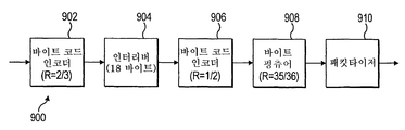
도 9를 참조하면, 연쇄 바이트 코드 인코더(900)의 또다른 실시예의 블록도가 도시되어 있다. 제1 바이트 코드 인코더(902) 및 인터리버(904)는 바이트 코드 인코더(600)의 그것과 동일하다. 그러나, 제2 바이트 코드 인코더(906)는 1/2 레이트 바이트 코드 인코더이다. 1/2 레이트 바이트 코드 인코더(906)는 인터리빙된 스트림에서 18 인터리빙된 바이트의 그룹들을 인코딩하여 27 바이트의 그룹들을 포함하는 제2 바이트 코드 인코딩된 스트림을 생성한다. 상기한 바와 같이, 인터리버(904)에 의해 생성된 매 1 바이트 I에 대해, 1/2 레이트 바이트 코드 인코딩된 스트림은 바이트 I의 사본 및 비체계적 바이트 I'를 포함한다. 바이트 I는 데이터 생성기 (예컨대, 도 5의 데이터 생성기(502))에 의해 생성된 콘텐츠 데이터 바이트들 중 하나의 사본이거나 제1 바이트 코드 인코더(902)에 의해 리던던트 또는 비체계적 바이트로서 디벨롭된 바이트일 수 있음은 물론이다. Referring to FIG. 9, a block diagram of another embodiment of a chained
바이트 펑츄어 블록(908)은 제2 바이트 코드 인코딩된 스트림에서 36 바이트의 그룹으로부터 1 바이트를 제거하여 35 바이트 그룹을 포함하는 펑츄어링된 스트림을 생성한다. 연쇄 바이트 코드 인코더(900)는 12/35 레이트의 펑츄어링된 러기드 데이터 스트림 또는 레이트 12/36의 펑츄어링되지 않은 데이터 스트림을 생성할 수 있다.The
도 6, 8 및 9가 두개의 구성 바이트 코드 인코더 및 하나의 인터리버를 이용하는 연쇄 바이트 코더 인코더의 실시예들을 도시하지만, 바이트 코더의 다른 실시예들은 다른 데이터 레이트를 갖는 러기드 데이터 스트림을 생성하기 위해 추가의 구성 바이트 코드 인코더 및 인터리버를 포함할 수 있다. 도 10을 참조하면, 연쇄 바이트 코드 인코더(1000)의 다른 실시예의 블록도가 도시된다. 인코더(1000)는 3개의 구성 바이트 코드 인코더, 2개의 인터리버 및 1개의 펑츄어 블록을 포함한다. 1/2 레이트 바이트 코드 인코더(1002)는 데이터 생성기 (예컨대 데이터 생성기(502))로부터 콘텐츠 데이터 바이트를 수신한다. 1/2 레이트 바이트 코드 인코더는 수신된 콘텐츠 데이터의 매 12 바이트에 대해 제1 바이트 코드 인코딩된 스트림에서 24 바이트의 그룹들을 생성한다.Although Figures 6, 8 and 9 illustrate embodiments of a cascaded byte coder encoder using two constituent byte code encoders and one interleaver, other embodiments of the byte coder may be used to generate rugged data streams with different data rates Additional configuration byte code encoders and interleavers. Referring to FIG. 10, a block diagram of another embodiment of a chained
제1 인터리버(1004)는 제1 바이트 코드 인코딩된 스트림에서 24 바이트 그룹 들을 인터리빙하고 제1 인터리빙된 스트림에서 24 바이트의 인터리빙된 그룹을 제1의 2/3 레이트 바이트 코드 인코더(1006)로 제공한다. 바람직한 실시예에서, 제1 인터리버(1004)는 도 11에 도시된 테이블(1100)에서 제시된 바와 같이 출력 바이트를 배열한다. 테이블(1100)은 입력에서의 바이트들의 위치를 나타내는 행(1110)을 포함한다. 행(1120)은 출력에서 판독되는 바이트들의 순서를 나타낸다. 제1의 2/3 레이트 바이트 코드 인코더(1006)는 제공된 24 바이트의 각 그룹에 대해 36 바이트의 그룹을 포함하는 제2 바이트 코드 인코딩된 스트림을 생성한다. 제2 인터리버(1008)는 36 바이트의 각 그룹을 18 바이트씩 두 세트로 나눔으로써 36 바이트 제2 바이트 코드 인코딩된 스트림을 인터리빙한다. 제2 인터리버(1008)는 18 바이트의 각 세트를 인터리빙하고 이 인터리빙된 데이터를 두개의 18 바이트 인터리빙된 스트림으로서 제2의 2/3 레이트 바이트 코드 인코더(1010)로 제공한다. 제2의 2/3 레이트 바이트 코드 인코더(1010)는 제1의 2/3 레이트 바이트 코드 인코더(1006)와 유사한 방식으로 동작하고 각 18 바이트 인터리빙된 스트림을 인코딩하여 27 바이트의 그룹들을 포함하는 제3 바이트 인코딩된 스트림을 생성한다. 바이트 펑츄어 블록(1012)은 제3 바이트 인코딩된 스트림의 1 바이트를 펑츄어링하고 26 바이트들을 패킷타이저(1014)로 제공한다. 패킷타이저(1014)는 인터리버(1008)에 의해 분리된 26 바이트의 세트들을 다시 그룹화한다. 패킷타이저(1014)는 또한 상기한 바와 같이 펑츄어링된 스트림으로부터 바이트를 조합하여 이를 187 바이트의 이산 패킷들로 그룹화한다. 제2의 2/3 레이트 바이트 코드 인코더(910)가 인코더(1000)의 입력에서 수신된 매 12 바이트에 대해 2개의 27 바이트 바이트 코드 인 코딩된 스트림들을 생성하기 때문에 연쇄 바이트 코드 인코더(1000)는 12/54의 펑츄어링되지 않은 러기드 데이터 스트림이나 12/52의 펑츄어링된 데이터 스트림을 생성한다.The
도 12를 참조하면, 연쇄 바이트 코드 인코더(1200)의 또다른 실시예의 블록도가 도시되어 있다. 연쇄 바이트 코드 인코더(1200)는 병렬로 연결되어 동작하는 두개의 성분 바이트 코드 인코더를 포함한다. 즉, 이 연쇄는 앞서 설명한 직렬 연쇄와 달리 병렬 연쇄이다. 입력 스트림으로부터의 17 바이트는 16 바이트의 제1 그룹 및 1 바이트의 제2 그룹으로 나뉜다. 2/3 레이트 바이트 코드 인코더(1210)는 16 바이트의 제1 그룹을 수신하고 수신된 매 16 바이트의 콘텐츠 데이터에 대해 24 바이트의 제1 바이트 코드 인코딩된 스트림을 생성한다. 1/2 레이트 바이트 코드 인코더(1220)는 1 바이트의 제2 그룹을 수신하고 수신된 매 1 바이트의 콘텐츠 데이터에 대해 2 바이트의 제2 바이트 코드 인코딩된 스트림을 생성한다. 24 바이트의 그룹들을 포함하는 제1 바이트 코드 인코딩된 스트림 및 2 바이트의 그룹들을 포함하는 제2 바이트 코드 인코딩된 스트림은 연쇄되어 26 바이트의 그룹들을 포함하는 최종 바이트 코드 인코딩된 스트림을 형성한다. 연쇄 바이트 코드 인코더(1200)는 레이트 17/26의 펑츄어링되지 않은 러기드 데이터 스트림을 생성한다.12, a block diagram of another embodiment of a chained
도 6, 8, 9, 10 및 12에 도시된 것과 다른 레이트를 갖는 연쇄 바이트 코드 인코더가 다양한 코드 레이트로 러기드 데이터 스트림을 생성하기 위해 사용될 수 있음은 당업자에게 명백하다. 마찬가지로, 다른 종류나 배열의 인터리버나 펑츄어 블록이 상기 실시예에서 사용된 것 대신에 사용될 수 있다.It will be apparent to those skilled in the art that a chain bytecode encoder with different rates than those shown in Figures 6, 8, 9, 10, and 12 may be used to generate the rerogated data stream at various code rates. Likewise, interleavers or punctured blocks of other types or arrangements may be used in place of those used in the above embodiments.
도 13을 참조하면, 인코더(1300)의 또다른 실시예의 블록도가 도시된다. 인코더(1300)는 도 5에 도시된 인코더(500)의 대안으로서 MPEG 전송 스트림 소스(1302)를 포함한다. MPEG 전송 스트림 소스(1302)는 몇개의 추가 블록을 포함하는 ATSC M/H 블록(1310)에 연결된다. ATSC M/H 블록(1310) 내에 포함된 블록들은 들어오는 데이터 스트림을 처리하고 이동용, 보행자용 및 휴대용 장치에 의한 수신 및 사용을 위해 적응된 러기드 데이터 스트림을 생성한다. 이 블록에 대해서는 추후 더 설명하기로 한다. ATSC M/H 블록(1310)은 역시 내부에 몇개의 추가 블록을 포함하는 ATSC A53 레거시 블록(1350)에 연결된다. ATSC A53 레거시 블록(1350) 내에 포함된 데이터 랜더마이저(1352), 리드-솔로몬 인코더(1354), 컨볼루션 바이트 인터리버(1356), 트렐리스 인코더(1358), 싱크 삽입 블록(1360), 및 변조 블록(1362)은 도 1에서 설명한 블록들과 유사하다. 따라서, 이 블록들에 대해서는 더 설명하지 않는다.13, a block diagram of another embodiment of
ATSC M/H 블록(1310) 내에서, 패킷 인터리버(1312)는 패킷들로 배열된 데이터 스트림을 수신한다. 각 패킷은 187 바이트를 포함하고 패킷 식별을 위해 사용되는 3 바이트 헤더를 포함한다. 패킷 인터리버(1312)의 출력은 GF(256) 직렬 연쇄 블록 코더 (SCBC)(1314)로 제공된다. GF(256) SCBC(1314)의 출력은 패킷 디인터리버(1316)에 연결된다. 패킷 디인터리버(1316)의 출력은 전송 스트림 헤더 수정기(1318)에 연결된다. 전송 스트림 헤더 수정기(1318)의 출력은 아프리오리(a-priori) 트랜스포트 패킷 삽입기(1320)에 연결된다. 아프리오리 트랜스포트 패킷 삽입기(1320)의 출력은 ATSC A53 레거시 인코더(1350)에 연결된다.Within the ATSC M /
패킷 인터리버(1312)는 행들로 배열된 패킷들로서 수신된 데이터를 패킷들의 행들로부터의 바이트의 열들에 기초한 코드워드들로 재배열한다. 패킷 인터리버(1312)는 도 14에 도시된 바와 같이 행별 순서로 고정된 수의 연속 패킷으로부터 바이트를 취하고, 이 바이트를 도 15에 도시된 바와 같이 열별로 출력한다. 특히, 도 14 및 도 15는 12 행의 187 바이트 패킷들의 판독 및 187 열의 12 바이트 코드워드들의 출력을 도시한다. 패킷 인터리빙의 결과, 바이트 0으로 표기된 모든 제1 바이트들이 함께 그룹화되고, 바이트 1로 표기된 모든 제2 바이트들이 함께 그룹화되고, 그 이후에 대해서도 마찬가지로 그룹화된다. 인터리버 내로 판독된 패킷들의 수는 소스 프레임을 구성하고 GF(256) SCBC(1314)에서의 처리를 위해 필요한 소스 코드워드들이나 심볼들의 수와 동일하다. 패킷 인터리버(1312)의 디멘젼은 포함된 페모리의 종류 및 크기에 따라 바뀔 수 있음에 유의해야 한다. 예컨대, 제1 디멘젼은 열들로 변경되고 제2 디멘젼은 행들로 변경될 수 있다. 또한 다른 디멘젼의 배열들이 사용될 수도 있다.The
GF(256) SCBC(1314)는 앞서 설명한 바이트 코드 인코더들과 유사한 블록 코드 인코더이다. 특히, GF(256) SCBC(1314)는 갈루아 필드(256) 공간 상에서의 짧은 선형 블록 코드들을 이용하여 구현된다. 두개의 성분 블록 코드가 사용될 수 있다. 레이트 1/2 블록 코드 인코더는 다음 생성 행렬을 이용한다.The GF (256)
![]()
![]()
식 (28)의 행렬은 제2 열에 존재하는 식 (1)로부터 한 값을 갖는 b 성분을 포함한다. 레이트 2/3 블록 코드 인코더는 다음 생성 행렬을 이용한다.The matrix of equation (28) includes a b component having a value from equation (1) existing in the second column. The

생성 행렬은 아이덴티티 행렬 및 b 성분들의 열을 이용하여 형성된다. 행렬 (29)에서 제3 열은 값 2를 갖는 식 (2) 및 (3)으로부터의 b 성분들을 포함한다. 각 성분 코드에 대한 생성 행렬에서의 계수들은 전체 오류 정정 시스템 및 변조 프로세스에 대한 블록 코드 인코딩의 관계에 기초하여 최적화되었다. 이 최적화는 특히 8-VSB 변조에서 트렐리스 코딩 및 비트 투 심볼(bit to symbol) 매핑을 고려하였는데 그 이유는 이런 성질들이 수신 및 복조 프로세스에서 제1 성질이기 때문이다.The generating matrix is formed using the identity matrix and the column of b components. The third column in
GF(256) SCBC(1314)는 단일 또는 연쇄 블록 코드 인코더일 수 있다. 연쇄 블록 코드 인코더는 상기한 바와 같이 인터리빙 및 펑츄어링과 같은 다른 기능을 포함할 수 있다. GF(256) SCBC(1314)는 다중 인코딩된 레이트들을 인코딩할 수 있고 도시되지 않았지만 레이트 모드 제어기를 통해 레이트 모드들을 스위칭할 수도 있다. 바람직한 실시예에서, GF(256) SCBC(1314)는 상기 레이트 1/2 성분 코드, 도 6에 도시된 레이트 12/26 코드, 도 10에 도시된 레이트 12/52 코드, 또는 도 12에 도시된 레이트 17/26 코드 중 하나를 이용하여 데이터의 들어오는 스트림을 인코딩하도록 적응될 수 있다.The GF (256)
GF(256) SCBC(1314)는 인터리버(1312)로부터 출력된 열들을 따른 바이트를 인코딩한다. 즉, GF(256) SCBC(1314)는 패킷 인터리버(1312)에서의 처리를 통해 형성된 인터리버 행렬의 제2 디멘젼을 따라 인코딩한다.The GF (256)
패킷 디인터리버(1316)는 GF(256) SCBC(1314)에 의해 생성된 코드워드들의 인코딩된 스트림을 수신하고 187 바이트 패킷들의 재구성 행들을 출력한다. 패킷 디인터리버(1316)는 인코딩된 코드워드들을 열별 순서로 입력하는데, 각 열은 GF(256) SCBC(1314)에서의 처리에 의해 추가된 리던던트나 비체계적 바이트를 포함하고, 이 바이트를 행별 배열로 출력한다. 이 프로세스는 근본적으로 패킷 인터리버(1312)에 대해 설명한 프로세스의 반대인데, 도 14 및 15의 순서를 역으로 한 것이다. 패킷 디인터리버(1312)는 동일 갯수의 코드워드들의 열들을 입력하는데, 각 코드워드는 비체계적 바이트의 인코딩된 집합을 이제 포함한다. 출력에서의 행들의 수는 인코딩된 코드워드 길이에 대응한다. 예컨대, 12/26 코드 레이트에서, 26 행들의 패킷들이 출력될 것이다. 패킷 디인터리버(1316)의 디멘젼은 포함된 메모리의 종류 및 크기에 기초하여 변할 수 있음에 유의한다. 또한, 제1 디멘젼은 행으로 바뀔 수 있고 제2 디멘젼은 열로 바뀔 수 있다. 또한 다른 디멘젼의 배열도 사용될 수 있다.
패킷들은 두개의 별개의 그룹들로 배열될 수 있다. 제1 그룹의 패킷들은 체계적 패킷들이라 할 수 있고 트랜스포트 스트림 소스(1302)에 의해 제공된 원래 데이터 패킷들과 동일하다. 제2 그룹의 패킷들은 비체계적 패킷들이라 할 수 있고 GF(256) SCBC(1314)에서 블록 코딩 프로세스에 의해 형성된 패러티 패킷들이다. 블록 인코딩 프로세스의 결과, 열들의 수 (즉, 제2 디멘젼의 크기)가 증가하였음에 유의해야 한다.Packets can be arranged into two distinct groups. The packets of the first group may be systematic packets and are identical to the original data packets provided by the
MPEG 트랜스포트 스트림 헤더 수정기(1318)는 체계적 및 비체계적 패킷들의 그룹들을 포함하는 디인터리빙된 187 바이트 패킷들을 수신한다. 상술한 바와 같이, 각 패킷은 3 바이트 헤더를 포함한다. 3 바이트는 패킷에 대한 정보를 나르기 위해 사용되는 몇개의 다른 비트나 비트 그룹과 함께 PID도 포함한다. 레거시또는 A53 방송 신호를 수신하지만 ATSC M/H 인코딩된 패킷들을 올바로 디코딩할 수 없는 수신기 (예컨대, 레거시 수신기)의 가장 효율적인 동작을 유지하기 위해, ATSC M/H 패킷들의 일부의 헤더들에서의 특정 비트들이 수정될 수 있다. 비체계적 패킷 헤더들에서 이 비트들을 수정함으로써, 레거시 수신기들은 이 패킷들을 오류가 있는 것으로 간주하지 않으면서 이 패킷들을 무시하여야 한다. 예컨대, MPEG 트랜스포트 스트림 헤더 수정기(1318)는 TEI 비트, 페이로드 유닛 시작 표시 비트, 및 트랜스포트 우선순위 비트를 비트값 '0'으로 설정할 수 있다. 또한, 스크램블링 제어 및 적응(adaptation) 필드 비트들(각각 2비트)은 '00'으로 설정될 수 있다. 3비트 길이의 연속(countinuity) 카운터는 '000'으로 설정될 수 있다. 마지막으로, PID는 모든 레거시 수신기에 의해 무시될 알려진 값과 같은 고유하고 사용되지 않은 값으로 설정될 수 있다. MPEG 트랜스포트 스트림 헤더 수정기(1318)가 비체계적 패킷들의 그룹에 대한 각각의 헤더를 수정할 것이므로, GF(256) SCBC(134)가 비체계적 패킷 그룹에 대한 헤더들을 처리할 필요가 없을 수 있음에 유의해야 한다. 또한, MPEG 트랜스포트 스트림 헤더 수정기(1318)는 체계적 패킷들이 레거시 수신기에 의해 처리되지 않고 올바로 디코딩되지 않는다면 이 패킷들의 헤더들을 수정할 수 있다. 체계적 패킷들이 GF(256) SCBC 인코더(1314)에 의해 인코딩되지 않거나 MPEG 트랜스포트 스트림 헤더 수정기(1318)에 의해 처리되지 않으면, 결과적인 데이터 스트림은 모바일 장치 및 레거시 수신기의 양자로 동시 캐스팅되고 이에 의해 수신될 수 있다.MPEG transport
아프리오리(a-priori) 트래킹 패킷 삽입기(1320)는 미리 정해진 트래킹 패킷들을 러기드 데이터 스트림 내에 위치시킬 수 있다. 미리 정해진 패킷들은 이동용, 보행자용 또는 휴대용 장치에서 사용되는 수신기와 같이 러기드 데이터 스트림을 수신할 수 있는 수신기에 완전히 또는 대부분 알려진 정보 패킷들을 나타낸다. 미리 정해진 패킷들은 신호 인코딩 및 전송의 레거시 또는 기존의 A53 인코딩 부분 동안에 생성된 트렐리스 상태를 디코딩할 때 지원하기 위해 수신기에서 사용된다. 미리 정해진 패킷들은 수신기의 이퀄라이저부에서 컨버전스(convergence)로 지원할 수도 있다. 미리 정해진 패킷들은 레거시 수신기에서의 수신을 개선하려는 것은 아니지만 결과적으로 잠재적인 개선을 가져올 수 있다. 또한, 종래의 트레이닝 정보와 달리, 미리 정해진 패킷들은 추가적인 레거시 인코딩이 수행되기 전에 추가되기 때문에 송신기 출력에서 직접 식별가능하지 않다. 특히, 미리 정해진 패킷들은 트렐리스 인코딩의 처리에 의해 변경된다. 그 결과, 미리 정해진 패킷들은 트렐리스 디코딩 동안에 직접적인 트레이닝을 제공하기 보다는 트렐리스 디코딩 맵 또는 브랜치를 결정하는 데에 사용되는 아프리오리 브랜치 정보를 제공한다.The a-priori
미리 정해진 트래킹 패킷들은 알려진 트레이닝 시퀀스 프로세스를 이용하여 다양한 방법으로 생성될 수 있다. 바람직한 실시예에서, 미리 정해진 트래킹 패킷은 수신기에도 알려진 의사 난수 (PN) 생성기를 이용하여 생성되는 잔여 바이트를 갖는 유효 헤더를 포함한다. 아프리오리 트레이닝 데이터, 트렐리스 불명료 (trellis-obscured) 트레이닝 데이터, 또는 의사(pseudo) 트레이닝 패킷이라고도 지칭되는 미리 정해진 트래킹 패킷들은 ATSC M/H 전송 동안 몇몇 방식으로 분배될 수 있거나, ATSC M/H 신호 전송을 위한 프리앰블로서 기능하는 방식으로 패킷들 또는 패킷들의 그룹들을 배치하는 것을 포함하여 한 그룹 내에 클러스터링될 수 있다.The predetermined tracking packets can be generated in various ways using a known training sequence process. In a preferred embodiment, the predetermined tracking packet includes a valid header with the remaining bytes generated using a pseudo-random number (PN) generator, also known to the receiver. Predefined tracking packets, also referred to as sporadic training data, trellis-obscured training data, or pseudo training packets, may be distributed in some manner during an ATSC M / H transmission, May be clustered within a group, including placing packets or groups of packets in a manner that acts as a preamble for transmission.
레거시 ATSC 인코더(1350)는 상기한 바와 같이 레거시 A53 표준에 따라 체계적 패킷들 및 비체계적 패킷들을 동일하게 인코딩한다. 러기드 또는 로버스트 데이터 스트림을 생성할 ATSC M/H 블록(1310)의 추가 기능은 전송 설비의 기존 하드웨어 구조에 최소한의 변경을 가하여 추가될 수 있다. 또한, MPEG 트랜스포트 소스(1302)로부터의 들어오는 패킷들의 부분들은 ATSC M/H 블록(1310)에서 하나 또는 그 이상의 인코딩된 레이트로 인코딩하기 위해 추출될 수 있다. 인코딩된 패킷은 입력 패킷들의 나머지 미처리된 부분 내에 재삽입되거나 또는 이것에 부가될 수 있고 인코딩된 부분과 미처리된 부분의 양자 모두는 ATSC 레거시 인코더(1350)에서 인코딩될 수 있다. 이와 달리, 별개의 패킷들의 스트림은 ATSC M/H 블록(1310)에 제공될 수 있고 인코딩된 출력은 제2 패킷들의 스트림에 삽입 또는 부가되어 ATSC 레거시 인코더(1350)에 제공될 수 있다.The
도 16을 참조하면, 인코딩 프로세스(1600)의 일 실시예를 도시하는 흐름도가 도시되어 있다. 프로세스(1600)는 입력 데이터 스트림으로부터 러기드 데이터 스트림을 생성하기 위해 사용될 수 있는 연쇄 바이트 코드 인코딩 프로세스를 나타낸다. 프로세스(1600)는 주로 도 6에 도시된 연쇄 바이트 코드 인코더(600)를 참조 하여 설명된다. 그러나, 이 프로세스는 도 6, 8, 9, 10 및 12와 앞서 설명된 인코더를 포함한 임의의 바이트 코드 인코더에 용이하게 적응될 수 있다. 프로세스(1600)는 이산 처리 블록들을 수반하는 하드웨어 또는 일부 또는 모든 필요한 블록을 포함하는 집적 회로를 사용하여, 마이크로프로세서 장치에서 동작하는 소프트웨어를 사용하여, 또는 하드웨어 및 소프트웨어의 조합을 이용하여 수행될 수 있음에 유의해야 한다. 또한, 프로세스(1600)는 바이트, 코드워드들 및 데이터 패킷들을 참조하여 설명될 것이다. 그러나, 다른 데이터 구성이나 배열도 가능하고 사용될 수 있음은 당업자에게 명백할 것이다.Referring to FIG. 16, a flow chart illustrating one embodiment of an
먼저, 단계 1610에서, 데이터 스트림이 수신된다. 데이터 스트림은 데이터의 바이트가 코드워드들로 그룹지어질 수 있고 하나 또는 그 이상의 코드워드의 전부나 일부를 포함하는 패킷들로 더 배열되는 식으로 배열될 수 있다. 예컨대, 데이터는 187 바이트의 데이터를 포함하는 패킷들로 배열될 수 있는데, 각 패킷은 식별 목적을 위해 사용되는 패킷 헤더를 포함한다. 다음에, 단계 1620에서, 데이터 패킷들은 바이트 코드 인코딩된다. 단계 1620에서의 인코딩은 앞서 논의한 성분 인코더들 중 하나를 이용하여 수행될 수 있다. 예컨대, 인코딩 단계 1620은 레이트 2/3 바이트 코드 인코딩을 이용할 수 있고 이것은 결과적으로 매 12 입력 바이트의 데이터에 대해 18 바이트의 데이터의 출력을 낳는다. 이와 달리, 인코딩 단계는 레이트 1/2와 같은 다른 바이트 코드 인코딩 레이트를 이용할 수 있다. 인코딩 단계 1620은 식(28) 및 식(29)에서 표시된 생성 행렬을 이용하여 입력 데이터 바이트를 보충(supplement)할 수 있다. 입력 데이터를 보충하는 것은 바이트 코드 나 블록 코드 인코딩 프로세스와 같은 인코딩 프로세스를 통해 오류 정정 또는 리던던트 데이터 바이트를 생성하는 것을 포함한다. 출력 바이트는 6바이트의 리던던트 또는 비체계적 데이터와 함께 체계적 바이트로 알려진 12 바이트 입력 데이터의 사본을 포함한다.First, in
다음으로, 단계 1630에서, 단계 1620로부터의 인코딩된 데이터 바이트가 인터리빙된다. 몇개의 인터리빙된 배열이 사용될 수 있다. 예컨대, 도 7에 도시된 인터리빙된 배열이 사용될 수 있다. 도 7의 인터리빙된 배열은 바이트 코드 인코딩 단계 1620에서 생성된 코드들의 거리를 최대화하면서 비교적 작은 인터리버 크기를 제공한다. 즉, 인터리버 크기는 백색 잡음 (white noise)이 있는 경우에 바이트 오류 레이트를 줄이도록 최적화될 수 있다. 다음에, 단계 1640에서, 단계 1630으로부터의 인터리빙된 바이트가 두번째 바이트 코드 인코딩된다. 제2 바이트 코드 인코딩 단계 1640은 상술한 성분 인코더들 중 하나를 이용하여 수행될 수 있다. 예컨대, 단계 1620에서의 인코딩은 레이트 2/3 바이트 코드 인코딩을 이용할 수 있고 결과적으로 매 18 입력 데이터 바이트에 대해 27 바이트의 데이터의 출력을 낳는다. 이와 달리, 인코딩 단계는 레이트 1/2와 같은 다른 바이트 코드 인코딩 레이트를 이용할 수 있다. 인코딩 단계 1640은 상기한 바와 같이 식(28) 및 식(29)에 나타낸 생성 행렬을 이용하여 데이터의 입력 바이트를 보충할 수 있다. 출력 바이트는 9 바이트의 리던던트나 비체계적 데이터와 함께 체계적 바이트로 알려진 18 입력 바이트의 데이터의 사본들을 포함한다. 몇몇 체계적 바이트는 원래 입력 데이터의 바이트들 중 하나의 사본들일 수 있고 또는 제1 바이트 코드 인코딩 단계 1620에 의해 리던던트나 비체계적 바이트로 디벨롭되는 한 바이트일 수 있음은 물론이다.Next, at
다음에, 단계 1650에서, 데이터의 바이트의 제2 인코딩된 스트림이 펑츄어링된다. 펑츄어링 단계 1650은 제2 인코딩된 스트림으로부터 데이터 바이트들 중 하나를 제거한다. 제거된 바이트는 제2 인코딩 단계 1640의 비체계적 바이트일 수 있고, 또한 제1 인코딩 단계 1620으로부터의 비체계적 바이트일 수 있다. 마지막으로, 단계 1660에서, 데이터 스트림이 레거시 또는 기존 A53 인코딩과 같은 추가 처리를 위해 제공된다. 단계 1660은 데이터 스트림을 제공하기 전에 원래 수신된 배열과 유사한 패킷들이 되도록 인코딩된 바이트를 다시 패킷타이징하는 단계를 포함할 수 있다. 상기 프로세스(1600)로 레이트 12/26 바이트 코드 인코딩된 데이터 스트림이 생성된다.Next, at
단계 1650에서 펑츄어링은 프로세스(1600)로부터 제거될 수 있다. 제거를 위한 바이트의 선택은 단계 1630에서 인터리빙에 기초하여 수행된다. 예컨대, 제2 인코딩 단계 1640은 그 인코딩의 일환으로서 비체계적 바이트들 중 하나를 생성하지 않을 수 있어서 바로 펑츄어링된 스트림을 낳을 수 있다. 또한, 펑츄어링되지 않은 레이트 12/27 바이트 코드 인코딩된 데이터 스트림을 생성하기 위해 펑츄어링 단계 1650이 생략될 수도 있다.At
단계 1650에서의 펑츄어링은 제2 인코딩된 스트림으로부터 1 바이트 이상 제거할 수도 있다. 예컨대, 레이트 12/24 바이트 코드 인코딩된 데이터 스트림을 생성하기 위해 제거될 수 있는 3 바이트를 식별하는 것이 가능할 수 있다. 1 바이트 이상의 펑츄어링은 코딩 레이트에서의 개선을 얻어 내기는 하지만 인코딩의 유효성을 더 열화시킬 것이다. 펑츄어링 단계 1650에서의 추가 바이트의 제거는 단계 1630에서의 최적 인터리빙에 기초하여 달성된다. 이런 방식으로 펑츄어링 및 인터리빙은 출력 패킷들의 주어진 출력 블록 크기의 생성에 기초하여 최적의 코드 레이트를 허용하도록 상호작용한다.The puncturing at
단계 1630 및 단계 1640은 두번의 인터리빙 단계 및 세번의 바이트 코드 인코딩 단계를 포함한 서로 다른 연쇄 바이트 코드 인코딩 프로세스를 형성하기 위해 반복될 수 있음에 유의한다. 반복 단계 1530 및 1540을 이용하는 프로세스는 레이트 12/52의 러기드 데이터 스트림을 생성하기 위해 도 9에 도시된 인코더(900)와 같은 인코더에 의해 사용될 수 있다. 프로세스(1600)는 앞서 설명한 것과 같은 다른 코드 레이트에 용이하게 적응될 수 있다.Note that steps 1630 and 1640 may be repeated to form different chained bytecode encoding processes including two interleaving steps and three bytecode encoding steps. The process using repeating steps 1530 and 1540 may be used by an encoder, such as
도 17을 참조하면, 인코딩 프로세스(1700)의 다른 실시예를 도시하는 흐름도가 도시되어 있다. 프로세스(1700)는 기존 또는 레거시 A53 신호 포맷에 따르는 체계적 및 비체계적 또는 리던던트 데이터 패킷을 포함하는 ATSC M/H 데이터 스트림을 인코딩하고 전송하는 단계를 나타낸다. 프로세스(1700)는 도 13에서의 인코더(1300)를 주로 참조하여 설명될 것이다. 상기한 바와 같이, 프로세스(1700)는 일부 또는 모든 필요한 블록을 포함하는 집적 회로나 이산 처리 블록을 수반하는 하드웨어, 마이크로프로세서 장치에서 동작하는 소프트웨어, 또는 하드웨어와 소프트웨어의 조합을 이용하여 수행될 수 있다. 프로세스(1700)는 요구되는 구현에 기초하여 특정 단계를 제거 또는 재배열함으로써 적응될 수 있음에 유의한다.17, a flow diagram illustrating another embodiment of an
먼저, 단계 1710에서, 패킷들의 전송 스트림이 수신된다. 각 패킷은 187 바이트를 포함하고 헤더를 포함한다. 헤더는 PID 뿐만 아니라 패킷에 관한 다른 정보를 포함한다. 다음에, 단계 1720에서, ATSC M/H 패킷들에 대해 사용되는 것으로 식별되는 패킷들이 분리되거나 추출된다. 나머지 패킷들은 미처리로 식별된다. ATSC M/H 패킷들은 조합된 단일 트랜스포트 스트림으로부터 추출되는 대신에 패킷들의 별개의 입력 트랜스포트 스트림으로서 제공될 수 있다. 또한, 트랜스포트 스트림에서의 모든 패킷들은 ATSC M/H 패킷들로 식별될 수 있다. 이 조건들 중 어느 것이라도 추출 단계 1720의 필요성을 제거할 수 있다. 또한, ATSC M/H이나 미처리로 식별된 패킷들은 그룹지어질 수 있고 ATSC M/H 식별된 패킷들은 별개의 인코딩 코드 레이트들에 의해 더욱 식별되어 그룹지어질 수 있다.First, in
다음에, 단계 1730에서, ATSC M/H 식별된 패킷들의 집합들 또는 그룹들은 판독되고 또는 행들로 입력되고 열들로 출력되고 또는 패킷 인터리빙된다. 출력 데이터의 열들은 각 코드워드의 크기가 패킷들의 그룹의 크기와 동일하게 되면서 코드워드들에 동등하다. 도 14 및 도 15는 단계 1730에서 행들로 판독하고 열들을 출력하는 패킷 인터리빙을 나타내는 행렬을 도시한다. 단계 1730에서 사용된 인터리버의 디멘젼은 예컨대 열들을 입력하고 행들을 출력하는 것으로 변경되거나 또는 인터리버 구현에 기초한 임의의 다른 디멘젼 양태들을 이용하도록 변경될 수 있음에 유의한다. 다음에, 단계 1740에서, 단계 1730으로부터의 각 코드워드가 블록 코드 인코딩된다. 단계 1730에서의 블록 코드 인코딩은 프로세스(1600)에서의 바이트 코드 인코딩과 유사하고 간단한 인코딩 프로세스나 연쇄 인코딩 프로세스를 이용할 수 있다. 예컨대, 블록 코드 인코딩 단계 1730은 레이트 1/2 구성 코드, 레이트 12/26 코드, 레이트 12/52 코드 또는 레이트 17/26 코드를 이용하여 코드워드들을 인코딩할 수 있다.Next, at
다음에, 단계 1750에서, 인코딩된 코드워드들의 집합은 코드워드들을 열들로서 입력하고 데이터 패킷들을 행들로서 출력함으로써 패킷 디인터리빙된다. 입력 코드워드들은 단계 1730에서 블록 코드 인코딩에 의해 생성된 바이트의 수를 포함한다. 출력 패킷들은 187 바이트를 포함하는 패킷들로 재구성된다. 블록 코드 인코딩 단계 1730에서 생성된 비체계적 바이트는 인코딩된 데이터 스트림에서 추가 패킷들의 행들을 구성한다. 단계 1760에서 사용되는 디인터리버의 디멘젼은 예컨대 열들을 입력하고 행들을 출력하는 것으로 변경되거나 인터리버 구현에 기초한 임의의 다른 디멘젼 양태들을 사용하도록 변경될 수 있음에 유의해야 한다.Next, at
다음에, 단계 1760에서, 인코딩된 디인터리빙 패킷들에서의 헤더 바이트가 변경된다. 변경 단계 1760은 헤더 정보가 레거시 수신기에 의해 인식되지 못하게 함으로써 ATSC M/H 데이터 패킷들을 디코딩할 수 없는 수신기에서의 성능 문제를 방지하는 방법을 제공한다. 단계 1760에서의 변경은 TEI 비트, 페이로드 유닛 시작 표시 비트 및 전송 패러티 비트를 비트값 '0'으로 설정하는 단계를 포함할 수 있다. 단계 1760에서의 변경은 또한 스크램블링 제어 및 적응 필드 비트들 (각각 2 비트)을 '00'으로 설정하는 단계를 포함할 수 있다. 변경 단계 1760은 또한 3 비트인 연속 카운터를 '000'으로 설정하는 단계를 포함할 수 있다. 마지막으로, 단계 1760에서의 변경은 모든 레거시 수신기에 의해 무시될 알려진 값과 같은 고유 하고 미사용된 값으로 PID를 설정하는 단계를 포함할 수 있다. 헤더 바이트가 무시될 수 있고 인코딩 단계 1640에서 처리되지 않을 수 있음을 유의해야 한다.Next, at
단계 1770에서, 미리 정해진 패킷들이나 아프리오리 트래킹 패킷들은 변경된 헤더 정보를 포함하는 인코딩된 패킷들의 스트림내로 삽입된다. 아프리오리 트래킹 패킷들의 삽입은 ATSC M/H 또는 모바일 영상 인코딩된 신호를 수신할 수 있는 수신기의 성능을 개선한다. 삽입 단계 1770는 기존의 리던던트 또는 비체계적 패킷을 대체하거나, 데이터 패킷들의 스트림에서의 널(null) 패킷으로서 단계 1710에서 원래 제공된 패킷을 대체할 수 있음에 유의해야 한다.In
단계 1780에서, 단계 1770으로부터의 ATSC M/H 인코딩된 패킷들은 데이터의 트랜스포트 스트림의 미처리 부분과 조합된다. ATSC M/H 인코딩된 패킷들은 데이터 패킷들의 트랜스포트 스트림의 이전에 식별된 미처리된 부분에 삽입되거나 부가될 수 있다. 이와 달리, 단계 1770으로부터의 ATSC M/H 인코딩된 패킷들은 레거시 방송 수신만을 위해 식별되는 제2 전송 스트림과 조합되거나, 이에 삽입되거나, 또는 부가될 수 있다. 단계 1710에서의 모든 패킷이 ATSC M/H 데이터 패킷들로서 식별되어 처리되었다면 단계 1780은 제거될 수도 있음에 유의해야 한다. 다음에, 단계 1790에서, ATSC M/H 인코딩되거나 되지 않은 모든 패킷을 포함한 완전한 데이터 스트림이 A53 표준에 따르는 레거시 또는 기존의 인코딩을 이용하여 처리된다. 단계 1790에서의 레거시 인코딩은 리드-솔로몬 인코딩, 랜더마이징, 인터리빙, 트렐링(trelling) 인코딩 및 동기화 삽입을 포함한다. 레거시 인코딩 단계 1790은 레거시 인코더(1350)에서 도시된 것과 같은 블록에 의해 수행될 수 있다.At
마지막으로, 단계 1795에서, ATSC M/H 데이터로서 인코딩된 모든 또는 일부 스트림을 포함한 완전히 인코딩된 데이터 스트림이 전송된다. 전송 단계 1795는 특정하게 식별된 주파수 범위를 이용하여 전송하는 단계를 포함할 수 있고 동축 케이블과 같은 유선 기술을 이용하거나 전자기적으로 공중파를 통해 전송하는 단계를 포함할 수 있다. ATSC M/H 데이터가 연속적으로 전송될 수 있음에 유의해야 한다. 이 모드에서, ATSC M/H 체계적 패킷은 또한 레거시 수신기에서 데이터 패킷들로서 기능한다. 비체계적 패킷들은 무시될 것이다. 그러나, 별개의 ATSC M/H 및 레거시 데이터는 ATSC M/H 데이터가 주기적으로 전송되거나 짧은 비연속 시구간들 동안 연속적으로 전송되는 방식으로 전송될 수 있다.Finally, at
도 18을 참조하면, 테이블(1800)은 심볼의 전송 포맷의 비트들로의 매핑을 도시한다. 테이블(1800)은 전송 데이터의 두 개의 비트 Z1 및 Z2를 나타내는 심볼들 0-4 세트의 매핑을 도시한다. 이 매핑은 각 심볼에 대응하는 신호 진폭을 4-PAM 신호로서 변조함으로써 전송될 수 있다. 심볼의 최상위 비트 (Z2)에 대한 두 개의 값 또는 상태 사이의 평균으로서의 전압 또는 진폭 차이는, 심볼의 최하위 비트 (Z1)에 대한 두 개의 값 또는 상태 사이의 전압 또는 진폭 차이보다 훨씬 더 크다. 그 결과, 특정 심볼에 대응하는 신호가 잡음이 심한 전송 채널을 통해 전송될 때, 수신기에서 Z2 비트를 올바로 추정할 확률은 Z1 비트를 올바로 추정할 확률보다 크다. 데이터 심볼 및 이 데이터 심볼의 주기적 순환(a cyclic rotation)인 제2 심볼을 전송하면 전송된 심볼의 Z1 및 Z2 비트를 올바로 복구할 확률을 크게 증가시킬 수 있는 코드를 산출할 수 있다. 수학식 (1) 내지 (27)에서 사용된 갈루아 필드의 성분 bi 값들 및 수학식 (28) 및 (29)에서 사용된 생성 행렬들은 패킷을 포함하는 바이트의 비트들을 주기적으로 순환 (및/또는 랩(wrap))하도록 선택될 수 있고 따라서 이러한 수학식들을 이용하는 바이트 코드 인코더들에 의해 생성된 데이터 스트림의 강건한 특성을 더 개선할 수 있다. 주기적 순환의 선택은, 바이트의 마지막 비트가 갈루아 필드의 특정 특성에 기초하여 제1 바이트로 랩 어라운드(wrap around)될 때 간단한 주기적 순환으로부터 수정되는 결과를 가져올 수 있다. 도 1에 도시된 것과 같은 트렐리스 인코더에 의한 추가 처리는 원래의 비트 투 심볼 매핑에 대해 크게 영향을 미치지 않으면서 전송된 신호에 리던던트 정보를 더 추가할 것임에 유의해야 한다. 트렐리스 인코딩 및 추가 신호 필터링은 여기 설명된 4-PAM 신호를 A53 표준에서 설명된 8-VSB 신호로 변환하는 결과를 가져올 것이다.Referring to FIG. 18, table 1800 illustrates the mapping of symbols to bits in the transmission format. Table 1800 shows a mapping of 0-4 sets of symbols representing the two bits Z1 and Z2 of the transmitted data. This mapping can be transmitted by modulating the signal amplitude corresponding to each symbol as a 4-PAM signal. The voltage or amplitude difference as an average between two values or states for the most significant bit (Z2) of the symbol is much larger than the voltage or amplitude difference between the two values or states for the least significant bit (Z1) of the symbol. As a result, when a signal corresponding to a specific symbol is transmitted over a noisy transmission channel, the probability that the receiver correctly estimates the Z2 bit is greater than the probability of correctly estimating the Z1 bit. The transmission of a data symbol and a second symbol, which is a cyclic rotation of the data symbol, can yield a code that can greatly increase the probability of correctly recovering the Z1 and Z2 bits of the transmitted symbol. The components b i values of the Galois field used in equations (1) through (27) and the generation matrices used in equations (28) and (29) may be used to cyclically cycle the bits of the byte containing the packet And thus can further improve the robustness of the data stream generated by the bytecode encoders using these equations. The choice of cyclic cycling may result in a modification from a simple cyclic cycle when the last bit of the byte is wrapped around to the first byte based on a particular characteristic of the Galois field. It should be noted that the additional processing by the trellis encoder as shown in Fig. 1 will add more redundant information to the transmitted signal without significantly affecting the original bit-to-symbol mapping. Trellis encoding and additional signal filtering will result in the conversion of the 4-PAM signal described herein to the 8-VSB signal described in the A53 standard.
도 19를 참조하면, 컨볼루션 인터리버에서 처리되는 바이트의 인터리버 맵(1900)을 나타내는 도면이 도시된다. 인터리버 맵(1900)은 도 13의 ATSC 레거시 인코더(1350)에서 사용되는 인터리버(1356)와 같은 컨볼루션 인터리버의 처리 동안에 데이터의 들어오는 바이트의 조직을 도시한다. 인터리버(1356)가 일련의 지연 라인들을 이용하여 구현될 수 있지만, 인터리버 맵(1900)은 인터리버를 위한 메모리 맵이라고 고려될 수 있다. 인터리버 맵(1900)은 배치되거나 기입되는 입력 바이트의 위치와 출력 바이트의 판독 방법을 표시한다. 인터리버 맵(1900)의 디멘젼은 상단의 0 부터 206 까지의 바이트 및 측면의 위에서 아래로 0 부터 103 까지의 행으로 표시된다. 라인 1910은 바이트가 판독 출력되는 순서를 나타낸다. 예컨대, 라인 1910이 행 20을 나타내면, 행 20에 있는 모든 바이트가 바이트 0에서 시작하여 바이트 206에서 끝날 때까지 판독 출력될 것이다. 마지막 바이트 206이 행 20으로부터 판독 출력될 때, 판독이 한 행 더 앞으로 나가 행 21로 진행하고, 이는 인터리버의 마지막 행이 판독될 때까지 계속된다. 마지막 행이 판독 출력될 때, 첫 행 판독으로 (새로운 패킷 데이터로) 다시 시작한다.Referring to FIG. 19, a diagram showing an
라인 1920은 207 바이트 코드 인코딩된 제1 패킷의 처음 52 바이트와 리드-솔로몬 바이트의 위치를 나타내고, 이는 인터리버로의 이 바이트들의 판독에 기초한다. 라인 1920은 패킷에서 바이트 0의 위치에서 시작하고 바이트 51의 위치에서 중앙 라인 1990에서 종료한다. 라인 1922, 1924, 1926a 및 1926b는 제1 패킷에서 나머지 바이트의 위치를 보여준다. 라인 1922는 라인의 상단의 바이트 52의 위치에서 시작하고, 이런 식으로 계속되며, 각 라인 1922, 1924 및 1926a에 대한 바이트 위치들에서 처리한다. 바이트의 나머지 부분은 라인 1926b를 따라 위치하고 라인 1990의 한 행 아래의 행의 한 위치에서 바이트 206에서 종료한다. 연속하는 패킷들에서 바이트의 위치는 제1 패킷에 대한 위치들의 오른쪽으로 계속되고 라인 1990 위의 진행 및 위치를 미러링(mirroring)하는 라인 1990 아래의 맵의 부분으로 진행한다. 예컨대, 라인 1930은 인터리버에서 52번째 패킷 (즉 제1 패킷 이후의 패킷 입력 52 패킷들)에 대한 바이트의 일부의 위치를 나타낸다. 라인 1950은 패킷 그룹의 전송을 위한 경계선을 나타낸다. 각 연속하는 패킷에서, 그 패킷으로부터 다음 연속하는 바이트가 경계선에 닿는다(fall on). 그 결과, 라인 1950은 패 킷 0 바이트 0 위치, 패킷 1 바이트 1 위치, 이렇게 계속하여 패킷 52 바이트 52 위치까지 나타낸다. 라인 1960은 라인 1950과 라인 1920 사이의 한 행에 있는 바이트의 위치를 나타낸다. 특히, 라인 1960은 도 14에 도시된 바와 같이 행들로 배향된 패킷 세트의 열 26으로부터의 바이트들인 바이트 그룹의 위치를 나타낸다. 다음 행의 바이트는 이 패킷 집합의 일부의 바이트 27을 포함한다. 바이트 코드 인코딩된 바이트가 인터리버로부터 짧은 연속 시구간 동안 그룹들로 출력되어 전송될 것이므로 라인 1960은 상기 바이트 코드 인코딩 프로세스를 이용하여 데이터를 인코딩하는 이점을 도시한다.
패킷 세트의 특정 배열은 로버스트 데이터 스트림의 보다 최적의 전송 배열을 제공할 수 있음에 유의한다. 로버스트 데이터 스트림의 배열은 로버스트 데이터 스트림이 연속적으로 전송되지 않은 경우에 (즉, 데이터 스트림의 일부가 레거시 데이터인 경우) 중요할 수 있다. 예컨대, 도 19에 도시된 바와 같이, 52 패킷의 세트는 결과적으로 수신 시스템에서 디인터리빙 프로세스를 이용하여 용이하게 예측되고 식별될 수 있는 방식으로 로버스트 데이터를 전송하는 것을 포함하는 전송 특성으로 된다.Note that a particular arrangement of packet sets may provide a more optimal transmission arrangement of the robust data stream. The arrangement of the robust data stream may be important if the robust data stream is not continuously transmitted (i. E., A portion of the data stream is legacy data). For example, as shown in FIG. 19, a set of 52 packets results in a transmission characteristic that includes transmitting robust data in a manner that can be easily predicted and identified using a deinterleaving process in the receiving system.
도 20을 참조하면, 수신기 시스템에서 사용되는 디코더(2000)의 일 실시예의 블록도가 도시되어 있다. 디코더(2000)는 수신기에 의해 수신되는 데이터를 디코딩할 때 돕기 위하여 앞서 설명한 바와 같이 데이터 스트림에서 비체계적 패킷과 같은 리던던트 패킷을 사용하도록 적응되는 회로 소자를 포함한다. 디코더(2000)는 일반적으로 레거시 또는 기존 A53 표준을 이용하여 인코딩된 데이터를 디코딩할 수 있다.Referring to FIG. 20, a block diagram of an embodiment of a
디코더(2000)에서, 초기 튜닝, 복조 및 다른 회로 (도시되지 않음)에 의한 처리 이후, 트렐리스 디코더(2002)는 들어오는 신호를 수신한다. 트렐리스 디코더(2002)는 컨볼루션 디인터리버(2004)에 연결된다. 컨볼루션 디인터리버(2004)의 출력은 바이트 코드 디코더(2006)에 연결된다. 바이트 코드 디코더(2006)는 리드-솔로몬 디코더(2008)에 연결된 출력을 갖는다. 리드-솔로몬 디코더(2008)의 출력은 디랜더마이저(2010)에 연결된다. 디랜더마이저(2010)의 출력은 데이터 디코더(2012)에 연결된다. 데이터 디코더(2012)는 비디오 디스플레이 또는 오디오 재생과 같은 수신기 시스템의 나머지 부분에서 사용을 위한 출력 신호를 제공한다. 트렐리스 디코더(2002), 디인터리버(2004), 리드-솔로몬 디코더(2008), 디랜더마이저(2010) 및 데이터 디코더(2012)는 도 2에 도시된 블록과 기능이 유사하므로 더 이상 상술하지 않는다.In the
데이터 패킷들에서 데이터의 바이트 형태로 수신된 데이터는 트렐리스 디코더(2002)에 의해 디코딩되고 디인터리버(2004)에 의해 디인터리빙된다. 데이터 패킷들은 207 바이트의 데이터를 포함할 수 있고 그룹들이나 24, 26 또는 52 패킷으로 더 그룹지어질 수 있다. 트렐리스 디코더(2002) 및 디인터리버(2004)는 레거시 포맷의 들어오는 데이터는 물론 바이트 코드 인코딩된 데이터를 처리할 수 있다. 수신기에 의해 알려져 있는 미리 정해진 패킷 전송 시퀀스에 기초하여, 바이트 코드 디코더(2006)는 패킷이 바이트 코드 인코딩된 또는 로버스트 데이터 스트림에 포함된 패킷인지 결정한다. 수신된 패킷이 바이트 코드 인코딩된 데이터 스트림으 로부터가 아니라면, 수신된 패킷은 바이트 코드 디코더(2006)에서의 임의의 추가 처리 없이 리드-솔로몬 디코더(2008)로 제공된다. 바이트 코드 디코더(2006)는 인코딩 중에 데이터 스트림에 의해 곱해지거나 이것에 가산되는 알려진 상수 시퀀스를 제거하는 디랜더마이저를 포함할 수도 있다. 러기드 데이터 스트림은 원 데이터와 동일한 바이트와 체계적 패킷들 및 리던던트 데이터를 포함하는 바이트와 비체계적 패킷들을 모두 포함함에 유의한다.The data received in the form of bytes of data in the data packets is decoded by the
바이트 코드 디코더(2006)가 수신된 패킷이 로버스트 또는 러기드 데이터 스트림에 속하는 바이트 코드 인코딩된 패킷이라고 결정하면, 패킷은 동일한 데이터 스트림을 포함하는 다른 패킷들과 함께 디코딩될 수 있다. 일 실시예에서, 동일 데이터 스트림의 바이트 코드 인코딩된 패킷들은 패킷내 각 바이트를 상기 식(2)에 도시된 바와 같이 바이트 코딩된 패킷을 디벨롭하도록 사용된 b 성분의 값의 역(inverse)으로 곱함으로써 디코딩된다. 비체계적 패킷의 바이트의 디코딩 값은 체계적 패킷의 바이트의 값에 비교되고, 동일하지 않은 두개의 패킷에서 임의의 바이트의 값들은 체계적 패킷에서 제거(즉, 0으로 설정)되거나 비체계적 패킷에서의 정보에 의해 대체될 수 있다. 오류 바이트가 제거된 체계적 패킷은 그후 리드-솔로몬 디코더(2008)에서 수행되는 리드-솔로몬 디코딩을 이용하여 디코딩될 수 있다. 바이트 코드 디코더의 다른 실시예에 대한 추가 설명이 이하에서 논의될 것이다.If the
바이트 코드 디코더(2006)는 도 13에 도시된 바와 같이 인코딩된 신호를 디코딩하기 위한 블록 코더로서 동작하도록 적응될 수 있다. 예컨대, 바이트 코드 디코더(2006)는 패킷 인터리버(1312)와 유사한 패킷 인터리버 및 패킷 디인터리버(1316)와 유사한 패킷 디인터리버를 포함할 수 있다. 또한, 바이트 코드 인코더 기능은 GF(256) SCBC (Serial Concatenated Block Coded) 신호를 디코딩하도록 적응될 수 있다. 바이트 코드 디코더(2006)는 모바일 또는 ATSC M/H 수신을 위해 인코딩되는 데이터의 식별 및/또는 아프리오리 트레이닝 패킷의 식별을 위해 사용되는 식별 블록을 더 포함할 수 있다. 또한, 식별 블록은 예컨대 들어오는 패킷들의 헤더가 모바일 수신을 위해 사용되는 PID를 포함하는지 여부를 결정하기 위해 패킷 식별 블록을 포함할 수 있다.The
도 5에 도시된 인코더(500)와 같은 바람직한 인코더에서, 바이트 코드 인코딩은 데이터 패킷들의 리드-솔로몬 인코딩에 우선함에 유의해야 한다. 그러나, 여기 도시된 디코더(2000)에서, 들어오는 데이터는 리드-솔로몬 디코딩 전에 바이트 코드 디코딩된다. 바이트 코드 동작과 리드-솔로몬 코드 동작이 A53 표준에서 사용되는 갈루아 필드(256)에 대해서 선형이고 선형 연산자가 갈루아 필드에서 가환이기 때문에 재순서화(re-ordering)가 가능하다. 재순서화의 중요성은 바이트 코드 인코딩이 수신 신호에서의 오류를 복구하는 데에 더 높은 신뢰도를 제공하는 것에 있다. 그 결과, 리드-솔로몬 디코딩 이전에 바이트 코드 디코딩을 수행하는 것은 비트 오류율 및 신호 대 잡음비의 면에서 볼 때 수신기 성능이 개선되게 한다.It should be noted that in a preferred encoder such as the
또한, 도 5의 인코더(500)와 도 13의 인코더(1300)의 실시예에 대한 설명으로, 바이트 코드 디코딩 요소들과 프로세스는 레거시 수신기에 최소한의 변경으로 레거시 수신기에서 필요하고 사용되는 요소들, 컴포넌트들 및 회로들에 부가될 수 있다. 그러나, 디코딩 프로세스는 바이트 코드 디코딩 프로세스의 특징을 레거시 수신기의 다른 블록 내에 포함시킴으로써 향상될 수 있다.In addition, in the description of the embodiment of the
도 21을 참조하면, 수신기에서 사용되는 디코더(2100)의 다른 실시예의 블록도가 도시되어 있다. 디코더(2100)는 공중을 통한 전자기파와 같은 전송 매체를 통해 신호의 전송에 의해 악영향을 받은 신호를 수신하여 디코딩하기 위한 추가적인 회로 소자 및 처리를 포함한다. 디코더(2100)는 레거시 데이터 스트림 뿐만 아니라 러기드 데이터 스트림도 디코딩할 수 있다. Referring to FIG. 21, a block diagram of another embodiment of a
디코더(2100)에서, 들어오는 신호가 초기 처리 이후 이퀄라이저(2106)로 제공된다. 이퀄라이저(2106)는 두개의 출력을 제공하는 트렐리스 디코더(2110)에 연결된다. 트렐리스 디코더(2110)로부터의 제1 출력은 피드백을 제공하고 이퀄라이저(2106)에 피드백 입력으로서 다시 연결된다. 트렐리스 디코더(2110)로부터의 제2 출력은 컨볼루션 디인터리버(2114)에 연결된다. 컨볼루션 디인터리버(2114)는 두개의 출력을 역시 제공하는 바이트 코드 디코더(2116)에 연결된다. 바이트 코드 디코더(2116)로부터의 제1 출력은 컨볼루션 인터리버(2118)를 통해 트렐리스 디코더(2110)에 피드백 입력으로 다시 연결된다. 바이트 코드 디코더(2116)로부터의 제2 출력은 리드-솔로몬 디코더(2120)에 연결된다. 리드-솔로몬 디코더(2120)의 출력은 디랜더마이저(2124)에 연결된다. 디랜더마이저(2124)의 출력은 데이터 디코더(2126)에 연결된다. 리드-솔로몬 디코더(2120), 디랜더마이저(2124), 및 데이터 디코더(2126)는 도 2에서 설명한 리드-솔로몬, 디랜더마이저 및 데이터 디코더 블록과 유사한 방식으로 연결되어 기능적으로 동작하고 이에 대해서는 더 설명하지 않는다.At
수신기 (도시되지 않음)의 프론트엔드 처리(예컨대, 안테나, 튜너, 복조기, A/D 변환기)로부터의 입력 신호는 이퀄라이저(2106)로 제공된다. 이퀄라이저(2106)는 수신 신호를 복구하도록 전송 채널 효과를 완전히 또는 부분적으로 제거하기 위해 수신 신호를 처리한다. 다양한 제거 또는 이퀄라이징 방법이 당업자에게 잘 알려져 있으므로 여기서는 논의하지 않는다. 이퀄라이저(2106)는 피드 포워드 이퀄라이저 (FFE) 섹션 및 결정 피드백 이퀄라이저 (DFE) 섹션을 포함하는 다수 섹션의 처리 회로 소자를 포함할 수 있다.An input signal from a front end processing (e.g., antenna, tuner, demodulator, A / D converter) of a receiver (not shown) is provided to an
이퀄라이징된 신호는 트렐리스 디코더(2110)로 제공된다. 트렐리스 디코더(2110)는 이퀄라이저(2106)의 DFE 섹션에 제공되는 결정값 세트를 일 출력으로서 생성한다. 트렐리스 디코더(2110)는 이퀄라이저(2106)의 DFE 섹션에 역시 제공되는 중간 결정값들을 생성할 수 있다. DFE 섹션은 이퀄라이저(2106)에서 필터 탭의 값을 조정하기 위해 트렐리스 디코더(2110)로부터의 중간 결정값들과 함께 결정값들을 사용한다. 조정된 필터 탭 값은 수신된 신호에 존재하는 간섭 및 신호 반사를 제거한다. 반복적인 프로세스는 트렐리스 디코더(2110)로부터의 피드백의 도움으로 이퀄라이저(2106)가 시간에 따라 잠재적으로 변화하는 신호 전송 환경 조건에 동적으로 맞출 수 있게 한다. 반복적인 프로세스는 디지털 텔레비전 방송 신호에 대한 19 Mb/s와 같은 신호의 들어오는 데이터 레이트와 유사한 레이트로 발생할 수 있음에 유의한다. 반복적인 프로세스는 들어오는 데이터 레이트보다 더 높은 레이트로 발생할 수도 있다.The equalized signal is provided to a
트렐리스 디코더(2110)는 트렐리스 디코딩된 데이터 스트림을 컨볼루션 디인터리버(2114)로 제공한다. 컨볼루션 디인터리버(2114)는 도 20에서 설명된 디인터리버와 유사하게 동작하고 데이터 패킷 내에서 조직된 디인터리빙된 바이트를 생성한다. 데이터 패킷은 바이트 코드 디코더(2116)에 제공된다. 상기한 바와 같이, 러기드 데이터 스트림의 일부가 아닌 패킷은 단순히 바이트 코드 디코더(2116)를 통해 리드-솔로몬 디코더(2120)로 전달된다. 바이트 코드 디코더(2116)가 패킷 그룹을 러기드 데이터 스트림의 일부로서 식별하면, 바이트 코드 디코더(2116)는 비체계적 패킷 내의 리던던트 정보를 사용하여 앞서 설명된 바와 같이 초기에 패킷들내의 바이트를 디코딩한다.The
바이트 코드 디코더(2116) 및 트렐리스 디코더(2110)는 러기드 데이터 스트림을 디코딩하기 위해 터보 디코더라고 하는 반복적인 방식으로 동작한다. 구체적으로, 트렐리스 디코더(2110)는 컨볼루션 디인터리버(2114)에 의한 디인터리빙 후에 러기드 데이터 스트림에 포함된 패킷들의 각 바이트에 대해 제1 연판정(soft decision) 벡터를 바이트 코드 디코더(2116)에 제공한다. 일반적으로, 트렐리스 디코더(2110)는 확률값들의 벡터로서 연판정을 생성한다. 일부 실시예에서, 벡터에서의 각 확률값은 이 벡터와 연관된 바이트가 가질 수 있는 값과 연관된다. 다른 실시예에서, 확률값들의 벡터는 2/3 레이트 트렐리스 디코더가 2비트 심볼을 추정하기 때문에 체계적 패킷에 포함된 매 1/2 니블 (즉, 2 비트)에 대해 생성된다. 일부 실시예에서, 트렐리스 디코더(2110)는 바이트가 가질 수 있는 값들의 확률들의 벡터인 하나의 연판정을 생성하기 위해 한 바이트의 네 개의 1/2 니블과 연관된 4개의 연판정을 조합한다. 이러한 실시예에서, 바이트에 대응하는 연판정들이 바이트 코드 디코더(2116)에 제공된다. 다른 실시예에서, 바이트 코드 디코더는 체계적 패킷의 1 바이트에 대한 연판정을 4개의 연판정 벡터로 분리하는데, 여기서 각 연판정은 바이트의 1/2 니블과 연관된다.The
바이트 코드 디코더(2116)는 러기드 데이터 스트림의 패킷들을 포함하는 바이트와 연관된 연판정 벡터를 이용하여 이 패킷들을 포함하는 바이트의 제1 추정을 산출한다. 바이트 코드 디코더(616)는 체계적 및 비체계적 패킷을 이용하여 러기드 스트림을 포함하는 패킷들의 각 바이트에 대한 제2 연판정 벡터를 생성하고 컨볼루션 인터리버(2118)에 의한 리인터리빙 후에 제2 연판정 벡터를 트렐리스 디코더(2110)에 제공한다. 트렐리스 디코더(2110)는 그후 제2 연판정 벡터를 이용하여 제1 연판정 벡터의 추가적인 반복을 생성하고, 이는 바이트 코드 디코더(2116)로 제공된다. 트렐리스 디코더(2110) 및 바이트 코드 디코더(2116)는 트렐리스 디코더와 바이트 코드 디코더에 의해 생성된 연판정 벡터가 수렴하거나 소정 횟수의 반복이 수행될 때까지 이런 방식으로 반복한다. 그후, 바이트 코드 디코더(2116)는 체계적 패킷의 각 바이트에 대한 연판정 벡터에서의 확률값들을 이용하여 체계적 패킷들의 각 바이트에 대해 경판정(hard decision)을 생성한다. 경판정값들(즉, 디코딩된 바이트)은 바이트 코드 인코더(2116)로부터 리드-솔로몬 디코더(2120)로 출력된다. 트렐리스 디코더(2110)는 MAP (Maximum a Posteriori) 디코더를 이용하여 구현될 수 있고 바이트나 1/2 니블 (심볼) 연판정들에서 동작할 수 있다.
터보 디코딩은 일반적으로 들어오는 데이터 레이트들 보다 더 높은, 블록들 사이의 결정 데이터의 전달과 연관된 반복 레이트들을 이용함에 유의한다. 가능한 반복의 수는 데이터 레이트 및 반복 레이트의 비에 제한된다. 그 결과 및 실제적인 범위에서, 터보 디코더에서의 더 높은 반복 레이트는 일반적으로 오류 정정 결과를 개선한다. 일 실시예에서, 들어오는 데이터 레이트의 8배인 반복 레이트가 사용될 수 있다.Note that turbo decoding uses repetition rates associated with the transfer of decision data between blocks, which is generally higher than incoming data rates. The number of possible iterations is limited to the ratio of data rate and repetition rate. In the result and practical range, the higher repetition rate in the turbo decoder generally improves the error correction result. In one embodiment, a repetition rate that is eight times the incoming data rate may be used.
도 21에서 설명된 것과 같은 SISO (soft input soft output) 바이트 코드 디코더는 벡터 디코딩 기능을 포함할 수 있다. 벡터 디코딩은 체계적 및 비체계적 바이트를 포함하는 데이터의 바이트를 그룹짓는 것을 포함한다. 예컨대, 레이트 1/2 바이트 코드 인코딩된 스트림의 경우, 1 체계적 및 1 비체계적 바이트가 그룹지어질 것이다. 두 개의 바이트는 64,000개 이상의 가능한 값을 가진다. 벡터 디코더는 두 개의 바이트의 가능한 값들 각각에 대한 확률을 결정 또는 추정하고 확률 맵을 생성한다. 연판정은 일부 또는 모든 가능성들의 확률의 가중 및 가능한 코드워드까지의 유클리드 거리에 기초하여 이루어진다. 경판정은 유클리드 거리의 에러가 한계값 아래로 떨어질 때 이루어질 수 있다.A soft input soft output (SISO) bytecode decoder such as that illustrated in FIG. 21 may include a vector decoding function. Vector decoding involves grouping bytes of data, including systematic and unstructured bytes. For example, for a
도 20 및 21에서 설명된 바이트 코드 디코더는 단순한 바이트 코드 인코더나 연쇄 바이트 코드 인코더에 의한 인코딩을 포함하여 상기 바이트 코드 인코더에 의해 인코딩된 러기드 데이터 스트림을 디코딩할 수 있다. 도 20 및 21의 바이트 코드 디코더는 단일 인코딩 단계만을 포함하는 단순 또는 성분 바이트 코드 인코더에 의해 인코딩되는 러기드 데이터 스트림을 디코딩하는 것을 설명한다. 연쇄 바이트 코드 디코딩은 디인터리빙, 디펑츄어링 및 재삽입과 같은 중간 처리 이외에 하나 이상의 디코딩 단계에서 들어오는 코드워드나 바이트를 디코딩하는 것을 포함한다.The bytecode decoder described in FIGS. 20 and 21 may decode a rubbed data stream encoded by the bytecode encoder, including encoding by a simple bytecode encoder or a chain bytecode encoder. The bytecode decoder of FIGS. 20 and 21 describes decoding a rubbed data stream encoded by a simple or component byte code encoder comprising only a single encoding step. Chained byte-code decoding involves decoding codewords or bytes that come in one or more decoding steps in addition to intermediate processing such as de-interleaving, de-interleaving, and re-insertion.
도 22를 참조하면, 연쇄 바이트 코드 디코더(2200)의 일 실시예의 블록도가 도시되어 있다. 연쇄 바이트 코드 디코더(2200)는 도 21에 도시된 것과 같은 터보 디코더 구성에서 동작하도록 구성된다. 연쇄 바이트 코드 디코더(2200)는 또한 러기드 데이터 스트림에서 연쇄 바이트 코드 인코딩 패킷을 디코딩하기 위해 반복 프로세스를 이용하는 터보 디코더로서 내부적으로 동작한다. 연쇄 바이트 코드 디코더(2200)는 레이트 12/26 바이트 코드 인코딩된 신호 스트림을 디코딩하도록 적응되어 원래 인코딩된 26 바이트로부터 12 바이트의 데이터를 생성한다.Referring to FIG. 22, a block diagram of one embodiment of a chain
26 바이트의 연판정값들을 나타내는 데이터 스트림이 바이트 삽입 블록(2202)에 제공된다. 바이트 삽입 블록(2202)의 출력은 제1의 2/3 레이트 바이트 코드 디코더(2204)에 연결된다. 제1의 2/3 레이트 바이트 코드 디코더(2204)는 두개의 출력을 제공한다. 제1 출력은 펑츄어 블록(2206)에 연결되고, 펑츄어 블록의 출력은 도 21에 도시된 바와 같이 인터리버를 통해 트렐리스 디코더에 피드백 입력으로 연결된다. 제1의 2/3 레이트 바이트 코드 디코더(2204)의 제2 출력은 디인터리버(2208)에 연결된다. 심볼 디인터리버(2208)의 출력은 역시 두개의 출력을 갖는 제2의 2/3 레이트 디코더(2210)에 연결된다. 제1 출력은 인터리버(2212)를 통해 제1의 2/3 레이트 바이트 코드 디코더(2204)에 피드백 입력으로 연결된다. 제2 출력은 리드-솔로몬 디코더와 같은 다른 처리 블록에 연결된다.A data stream representing the soft decision values of 26 bytes is provided to the
바이트 삽입 블록(2202)으로 입력되는 26 바이트는 데이터의 체계적 바이트나 체계적 패킷에 관한 도 21의 트렐리스 디코더(2110)와 같은 트렐리스 디코더에 의해 생성되는 제1 연판정들 및 데이터의 비체계적 바이트나 비체계적 패킷에 관한 연판정들을 포함한다. 데이터의 체계적 및 비체계적 바이트는 바이트 코드 인코딩된 패킷으로부터 올 수 있다. 2/3 레이트 바이트 코드 디코더는 2 데이터 바이트를 디코딩하기 위해 3 바이트를 필요로 한다. 그러나, 원래의 연쇄 인코딩은 바람직하게는 하나의 비체계적 바이트를 제거함으로써 27 바이트로부터의 코드워드를 26 바이트로 줄이기 위해 1 바이트를 감소시킨다. 그 결과, 1 바이트가 인코딩 프로세스에서의 펑츄어링에 의해 제거된 바이트를 대체하기 위해 필요하다. 또한, 트렐리스 디코더는, 트렐리스 디코더로의 입력 스트림이 바이트를 포함하지 않았기 때문에, 데이터 스트림에서 펑츄어링된 바이트에 대한 어떠한 연판정들도 생성하지 않는다. 그 결과, 펑츄어링된 바이트의 값이 동일하게 가능하다는 것을 나타내는 연판정값이 삽입된다. 바이트 삽입 블록(2202)으로부터의 삽입된 연판정값을 포함한 제1 연판정들이 제1의 2/3 레이트 바이트 코드 디코더(2204)에 제공된다. 제1의 2/3 레이트 바이트 코드 디코더(2204)는 제1 연판정들을 이용하여 체계적 및 비체계적 패킷의 바이트를 디코딩하는 것에 기초하여 제2 연판정들을 생성한다. 연판정들의 생성은 예컨대 상기 수학식 (2) 및 (3)에 도시된 바이트 코딩된 패킷을 디벨롭하기 위해 사용된 b1 및 b2 성분의 값의 역(inverse)과 바이트 집합의 곱을 이용한다.The 26 bytes input to the
제1의 2/3 레이트 바이트 코드 디코더로부터의 27 바이트 소프트가 펑츄어 블록(2206)에 제공된다. 27 바이트 소프트 출력은 제1의 2/3 레이트 바이트 코드 디코더에서의 디코딩 이후에 체계적 및 비체계적 바이트에 대한 갱신된 연판정값 집합을 나타낸다. 펑츄어 블록(2206)은 바이트 포맷을 트렐리스 디코더에 의해 원래 처리된 26 바이트 포맷으로 복구하기 위해 이전에 삽입된 연판정 바이트를 제거한다.27 bytes of soft data from the first 2/3 rate byte code decoder is provided to the
체계적 바이트만을 나타내는 제1의 2/3 레이트 바이트 코드 디코더로부터의 18 바이트 소프트 출력은 디인터리버(2208)로 제공된다. 디인터리버(2208)는 2/3 레이트 바이트 코드 인코딩 프로세스에서 수행된 인터리빙을 역으로 하는 방식으로 18 바이트의 데이터를 디인터리빙한다. 디인터리버(2206)는 예컨대 도 7에서 행 710 및 720을 역으로 함으로써 인코더에서 인터리빙 맵을 정확히 역으로 한다.An 18 byte soft output from a first 2/3 rate byte code decoder representing only systematic bytes is provided to
디인터리빙된 바이트는 제2의 2/3 레이트 바이트 코드 디코더(2210)로 제공된다. 제2의 2/3 레이트 바이트 코드 디코더(2210)는 디인터리빙된 연판정 체계적 바이트를 이용하여 상기의 것과 유사한 방식으로 연판정 바이트의 두개의 추가 출력을 생성한다. 18 바이트 소프트 출력이 인터리버(2212)로 제공된다. 18 바이트 소프트 출력은 제1의 2/3 레이트 바이트 코드 디코더(2204)에서의 디코딩으로부터의 체계적 및 비체계적 바이트 모두에 대한 갱신된 연판정값 집합을 나타낸다. 인터리버(2212)는 디인터리빙된 바이트를 제1의 2/3 레이트 바이트 코드 디코더에 의해 사용되는 바이트 포맷으로 다시 되돌려 놓기 위해 이를 다시 인터리빙한다. 인터리버(2212)는 도 6의 인터리버와 같은 인코더에서 사용되는 인터리버와 실질적으로 동일하고 다시 인터리빙된 18 바이트의 집합을 제1의 2/3 바이트 코드 디코더(2204)로 제공한다. 다시 인터리빙된 18 바이트의 집합은 제1의 2/3 레이트 바이트 코드 디코더(2204)에 의해 이루어진 연판정들을 개선하기 위해 사용된다.The deinterleaved bytes are provided to a second 2/3
제2의 2/3 레이트 바이트 코드 디코더(2210)로부터의 12 바이트 출력은 12/26 레이트 바이트 코드 인코딩된 러기드 데이터 스트림에 대한 체계적 바이트 디코딩된 데이터 출력을 나타낸다. 제2의 2/3 레이트 바이트 코드 디코더(2210)에 의해 생성된 12 체계적 출력 바이트에 대한 연판정들이 최종적이거나 올바른 데이터 값들로서 최종적인 미리 정해진 한계값 내에 있으면, 제2의 2/3 레이트 바이트 코드 디코더(2210)는 연판정들을 이용하여 12 출력 바이트에 대한 경판정들을 생성하고 12 출력 바이트를 리드-솔로몬 디코더와 같은 추가 처리 블록으로 제공한다. 그러나, 제2의 2/3 레이트 바이트 코드 디코더에 의해 생성된 연판정들이 최종적이 아니라면, 이전의 반복 동안에 디벨롭되고 피드백된 소프트 정보를 이용하여 상기와 같이 추가 반복이 전개된다. 이 추가적인 소프트 정보는 그 연속하는 디코더에 의해 각 소프트 디코더로 제공된다. 즉, 트렐리스 디코더는 펑츄어 블록(2206)을 통해 제공되는 제1의 2/3 레이트 바이트 코드 디코더(2204)로부터의 피드백을 이용하고, 제1의 2/3 레이트 바이트 코드 디코더(2204)는 인터리버(2212)를 통해 제공되는 제2의 2/3 레이트 바이트 코드 디코더(2210)로부터의 피드백을 이용한다. 이런 식으로 제2의 2/3 레이트 바이트 코드 디코더(2210)에 의해 생성된 연판정들이 충분히 수렴할 때까지 또는 소정 횟수의 반복이 수행될 때까지 반복이 계속된다. 상기한 바와 같이, 사용되는 터보 디코딩은 일반적으로 들어오는 데이터 레이트 보다 더 높은, 블록들 사이의 결정 데이터 전달에 관련된 반복 레이트를 이용한다.The 12 byte output from the second 2/3
도 23을 참조하면, 연쇄 바이트 코드 디코더(2300)의 다른 실시예의 블록도가 도시된다. 연쇄 바이트 코드 디코더(2300)는 도 21에 도시된 것과 같은 터보 디코더 구성에서 동작하도록 유사하게 구성된다. 연쇄 바이트 코드 디코더(2300)는 또한 러기드 데이터 스트리에서 연쇄 바이트 코드 인코딩된 패킷을 디코딩하기 위해 3개의 성분 바이트 코드 디코더를 포함하는 반복 프로세스를 이용하는 터보 디코더로서 내부적으로 동작한다. 연쇄 바이트 코드 디코더(2300)는 레이트 12/52 블록 코드 인코딩된 신호 스트림을 디코딩하도록 적응되어 원래 인코딩된 52 바이트로부터 12 바이트의 데이터를 생성한다.Referring to FIG. 23, a block diagram of another embodiment of a chain by
52 바이트의 연판정값들을 나타내는 데이터 스트림이 패킷 삽입 블록(2302)으로 제공된다. 패킷 삽입 블록(2302)의 출력은 제1의 2/3 레이트 바이트 코드 디코더(2304)에 연결된다. 제1의 2/3 레이트 바이트 코드 디코더(2304)는 두개의 출력을 제공한다. 제1 출력은 펑츄어 블록(2306)에 연결되고, 펑츄어 블록의 출력은 도시되지 않았지만 인터리버를 통해 트렐리스 디코더에 피드백 입력으로 연결된다. 제1의 2/3 레이트 바이트 코드 디코더(2304)의 제2 출력은 제1 디인터리버(2308)에 연결된다. 제1 디인터리버(2308)의 출력은 역시 두개의 출력을 갖는 제2의 2/3 레이트 바이트 코드 디코더(2310)에 연결된다. 제1 출력은 제1 인터리버(2312)를 통해 제1의 2/3 레이트 바이트 코드 디코더(2304)에 피드백 입력으로 연결된다. 제2 출력은 제2 디인터리버(2314)에 연결된다. 제2 디인터리버(2314)의 출력은 역시 두개의 출력을 갖는 1/2 레이트 바이트 코드 디코더(2316)에 연결된다. 제1 출력은 제2 인터리버(2318)를 통해 제2의 2/3 레이트 바이트 코드 디코더(2310)에 피드백 입력으로 연결된다. 제2 출력은 리드-솔로몬 디코더와 같은 다른 처리 블록에 연결된다.A data stream representing the soft decision values of 52 bytes is provided to the
트렐리스 디코더로부터의 제1 연판정들을 포함하는 52 바이트 입력이 패킷 삽입 블록(2302)에 제공된다. 패킷 삽입 블록(2302)은 52 바이트를 두 세트의 26 바이트로 분리한다. 이 분리는 도 9의 인코더(900)와 같은 인코더에 의해 바이트 코드 인코딩 중에 수행되는 분리와 매칭시키기 위해 수행된다. 패킷 삽입 블록(2302)은 두 세트의 27 바이트를 생성하기 위해 26 바이트의 각 세트에서 상술한 바와 같이 표시된 동일한 확률값을 갖는 연판정 바이트를 삽입한다. 두 세트의 27 바이트는 추후 바이트 코드 디코딩 단계에서의 세트를 재조합하는 것을 허용하기 위해 처리에서 링크된 상태로 남아 있다. 제1의 2/3 레이트 바이트 코드 디코더(2304), 제1 디인터리버(2308), 및 제1 인터리버(2310)는 제1의 2/3 레이트 바이트 코드 디코더의 출력에서 두 세트의 27 연판정 바이트와 다음 두 세트의 18 연판정 바이트 사이의 링크를 처리하고 유지한다는 점을 제외하고 도 22에 도시된 것과 유사한 방식으로 동작한다. 펑츄어 블록(2306)은 두 세트의 27 소프트 출력 바이트로부터 이전에 삽입된 연판정 바이트를 제거하고 두 세트를 함께 연쇄한다. 이 연쇄는 트렐리스 디코더에 의해 원래 처리되는 52 바이트 포맷으로 바이트 포맷을 돌려 놓기 위해 필요하다. 펑츄어 블록(2306)에 제공되는 두개의 27 바이트 소프트 출력 세트는 제1의 2/3 레이트 바이트 코드 디코더에서의 디코딩 이후에 체계적 및 비체계적 바이트에 대한 갱신된 연판정값 세트를 나타낸다.A 52 byte input containing the first soft decisions from the trellis decoder is provided to the
제2의 2/3 레이트 바이트 코드 디코더(2310)는 상기한 대로 2 세트의 18 바이트를 처리하지만, 디코딩된 데이터의 체계적 바이트를 나타내는 2 세트의 12 바이트를 연쇄시켜 24 바이트 연판정 출력을 형성한다. 24 바이트 연판정 출력은 제 2 디인터리버(2314)로 제공된다. 제2 디인터리버(2314)는 도 10에서 설명된 인코딩 프로세스의 일부로서 인터리버(1004)에서 수행된 인터리빙과 역의 방식으로 24 바이트의 데이터를 디인터리빙한다. 제2 디인터리버(2314)는 예컨대 도 11의 행 1110 및 1120을 역으로 함으로써 인코더에서의 인터리빙 맵을 역으로 한다.The second 2/3
디인터리빙된 24 연판정 바이트는 1/2 레이트 바이트 코드 디코더(2316)에 제공된다. 1/2 레이트 바이트 코드 디코더(2316)는 디인터리빙된 연판정 체계적 바이트를 이용하여 상기의 것과 유사한 방식으로 연판정 바이트의 2개의 추가 출력을 생성한다. 24 바이트 소프트 출력은 제2 인터리버(2318)에 제공된다. 24 바이트 소프트 출력은 1/2 레이트 바이트 코드 디코더에서의 디코딩으로부터의 체계적 및 비체계적 바이트에 대한 갱신된 연판정값 세트를 나타낸다. 인터리버(2318)는 디인터리빙된 바이트를 제2의 2/3 레이트 바이트 코드 디코더(2310)에 의해 사용되는 포맷으로 되돌려 놓기 위해 이를 다시 인터리빙한다. 인터리버(2318)는 도 6의 인터리버(604)와 같은 인코더에서 사용되는 인터리버와 실질적으로 동일하고 다시 인터리빙된 24 바이트의 세트를 제2의 2/3 바이트 코드 디코더(2310)로 제공한다. 24 바이트의 다시 인터리빙된 세트는 제2의 2/3 레이트 바이트 코드 디코더(2310)에 의해 이루어진 연판정들을 개선하기 위해 사용된다.The 24 interleaved soft decision bytes are provided to the half rate
상기한 바와 같이, 1/2 레이트 바이트 코드 디코더(2316)의 출력에서 12 체계적 바이트에 관한 연판정들이 최종적이거나 올바른 데이터 값으로서 최종적인 것의 소정 한계값 내에 있다면, 1/2 레이트 바이트 코드 디코더(2316)는 12 출력 바이트에 관한 경판정을 생성하기 위해 연판정들을 이용하고 12 출력 바이트를 리드- 솔로몬 디코더에서의 디코딩과 같은 추가 처리 블록으로 제공한다. 그러나, 1/2 레이트 바이트 코드 디코더(2316)에 의해 생성된 연판정들이 최종적이 아니면, 이전의 반복 동안에 디벨롭되고 피드백된 소프트 정보를 이용하여 추가 반복이 전개된다. 이 추가 소프트 정보는 그 연속하는 디코더에 의해 각 소프트 디코더에게 제공된다. 즉, 트렐리스 디코더는 펑츄어 블록(2306)을 통해 제공되는 제1의 2/3 레이트 바이트 코드 디코더(2304)로부터의 피드백을 이용하고, 제1의 2/3 레이트 바이트 코드 디코더(2304)는 제1 인터리버(2312)를 통해 제공되는 제2의 2/3 레이트 바이트 코드 디코더(2310)로부터의 피드백을 이용하고, 제2의 2/3 레이트 바이트 코드 디코더(2304)는 제2 인터리버(2318)을 통해 제공되는 1/2 레이트 바이트 코드 디코더(2316)로부터의 피드백을 이용한다. 이런 식으로 1/2 레이트 바이트 코드 디코더(2316)에 의해 생성된 연판정들이 충분히 수렴하거나 소정 횟수의 반복이 수행될 때까지 반복이 계속된다. 상기와 같이, 사용되는 터보 디코딩은 일반적으로 들어오는 데이터 레이트 보다 더 높은, 블록들 사이의 결정 데이터를 전달하는 것과 관련된 반복 레이트들을 이용한다.As described above, if the soft decisions for the twelve systematic bytes at the output of the half-
도 24를 참조하면, 연쇄 바이트 코드 디코더(2400)의 다른 실시예의 블록도가 도시되어 있다. 연쇄 바이트 코드 디코더(2400)는 도 21에 도시된 것과 같은 터보 디코더 구성에서 동작하도록 유사하게 구성된다. 연쇄 바이트 코드 디코더(2400)는 러기드 데이터 스트림에서의 바이트 코드 인코딩된 패킷과 병렬로 연결되어 동작하는, 두개의 성분 바이트 코드 디코더인, 2/3 레이트 디코더(2402) 및 1/2 레이트 디코더(2402)를 포함한다. 연쇄 바이트 코드 디코더(2400)는 레이트 17/26 바이트 코드 인코딩된 신호 스트림을 디코딩하도록 적응되어 원래 인코딩된 26 바이트로부터 17 바이트의 데이터를 생성한다.Referring to FIG. 24, a block diagram of another embodiment of a chain
트렐리스 디코더로부터 26 바이트에 대한 연판정값들의 들어오는 데이터 스트림은 제1 그룹의 24 바이트와 제2 그룹의 2 바이트로 분리된다. 이 분리는 도 12의 인코더(1200)와 같은 인코더에 의해 바이트의 그룹의 조합을 위한 배열에 기초하여 수행되고 일반적으로 수신 장치에 알려져 있다. 이 분리는 도시되지 않았지만 신호 또는 패킷 멀티플렉서를 이용하여 수행될 수 있다. 이와 달리, 분리 및 그룹화는 예컨대 어느 바이트를 처리할지를 선택하기 위해 들어오는 바이트를 카운트함으로서 각 바이트 코드 인코더 내에서 수행될 수 있다. 제1 그룹의 24 연판정 바이트는 상기한 바와 같이 2/3 레이트 바이트 코드 디코더(2402)에 의해 디코딩된다. 제2 그룹의 2 연판정 바이트는 상기한 바와 같이 1/2 레이트 바이트 코드 디코더(2404)에 의해 유사하게 디코딩된다.The incoming data stream of soft decisions for 26 bytes from the trellis decoder is divided into 24 bytes of the first group and 2 bytes of the second group. This separation is performed based on an arrangement for a combination of groups of bytes by an encoder, such as the
2/3 레이트 바이트 코드 디코더(2402)에서의 디코딩으로부터 체계적 및 비체계적 바이트에 대한 갱신된 연판정값 세트를 나타내는 24 바이트 소프트 출력과 1/2 레이트 바이트 코드 디코더(2404)에서의 디코딩으로부터 체계적 및 비체계적 바이트에 대한 갱신된 연판정값 세트를 나타내는 2 바이트 소프트 출력은 26 바이트 소프트 출력을 형성하기 위해 연쇄된다. 26 바이트 소프트 출력은 다음 터보 디코더 반복 동안에 바이트에 대한 소프트 값 판정들을 실질적으로 개선하기 위해 트렐리스 디코더로 제공된다.From the decoding at the 2/3
마찬가지로, 2/3 레이트 바이트 코드 디코더(2402)로부터의 체계적 바이트를 포함하는 16 바이트 소프트 출력과 1/2 레이트 바이트 코드 디코더(2404)로부터의 체계적 바이트를 포함하는 1 바이트 소프트 출력은 17 바이트 소프트 출력을 형성하기 위해 연쇄된다. 17 체계적 바이트에 대한 연판정들이 최종적이거나 올바른 데이터값으로서 최종적인 것의 미리 정해진 한계값 이내에 있으면, 2/3 레이트 바이트 코드 디코더(2402) 및 1/2 레이트 바이트 코드 디코더(2402)는 연판정들을 이용하여 17 출력 바이트에 관한 경판정들을 생성하고 17 출력 바이트를 리드-솔로몬 디코더와 같은 추가 처리 블록으로 제공한다.Likewise, a one-byte soft output containing a systematic byte from the 2/3
그러나, 17 출력 바이트에 대한 연판정들이 최종적이 아니면, 이전의 반복 동안에 디벨롭되고 피드백된 소프트 정보를 이용하여 추가 반복이 전개된다. 이 추가 소프트 정보는 그 연속하는 디코더에 의해 각 소프트 디코더로 제공된다. 즉, 트렐리스 디코더는 2/3 레이트 바이트 코드 디코더(2402) 및 1/2 레이트 바이트 코드 디코더(2404)의 연쇄 출력들로부터의 피드백을 이용한다. 이런 식으로 연판정들이 충분히 수렴하거나 소정 횟수의 반복이 수행될 때까지 반복이 계속된다. 상기와 같이, 사용된 터보 디코딩은 일반적으로 들어오는 데이터 레이트보다 더 높은, 블록들 사이의 결정 데이터를 전달하는 것에 관한 반복 레이트를 이용한다.However, if the soft decisions for 17 output bytes are not final, additional iterations are developed using the soft information that was developed and fed back during the previous iteration. This additional soft information is provided to each soft decoder by its successive decoder. That is, the trellis decoder uses feedback from the chain outputs of the 2/3 rate
도 20-24에서 설명된 바이트 코드 디코더는 도 13에 설명된 GF(256) SCBC에 의해 인코딩된 직렬 연쇄 블록 코드를 이용하여 인코딩된 데이터를 디코딩하도록 구성될 수 있음에 유의해야 한다.It should be noted that the bytecode decoder described in FIGS. 20-24 can be configured to decode the encoded data using the serial chain block code encoded by the GF (256) SCBC described in FIG.
상기 바이트 코드 인코딩 및 디코딩의 배열을 이용하는 다양한 시스템은 기존 또는 레거시 방송 시스템의 적용의 확장을 허용한다. 첫째, 기존 수신기는 ATSC M/H를 이용하여 인코딩되는 추가적인 패킷들의 존재로부터 혜택을 얻을 수 있다. 보다 강건한 SCBC 인코딩 패킷 및 아프리오리 트래킹 패킷은 동적인 신호 환경 조건에서 트래킹을 개선하도록 트렐리스 디코더 및 이퀄라이저에 의해 처리될 수 있다. 둘째, 로버스트 또는 러기드 데이터를 생성하는 ATSC M/H 인코딩 데이터는 이동용, 휴대용 및 보행자용 장치에서의 수신 시스템이 레거시 A53 전송이 수신될 수 없는 신호 환경 하에서 로버스트 스트림을 수신할 수 있게 한다. 예컨대, 레이트 12/52에서의 ATSC M/H 인코딩은, 레거시 A53 수신에 대해 백색 잡음 한계값이 15dB 정도인 것에 비해, 3.5dB인 백색 잡음 한계값에서 신호 수신을 허용한다. ATSC M/H 패킷들을 생성하고 이 패킷들을 레거시 A53 데이터와 함께 주기적인 방식으로 전송함으로써 동작이 더욱 향상된다. 주기적 전송은 방송 재료의 비디오 및 오디오 전달을 허용하기 위해 중요하다. ATSC M/H 패킷들은 또한 하나 또는 그 이상의 전송 버스트로서 그룹화되어 전송될 수 있다. 버스트들로의 전송은 이동용, 휴대용, 또는 보행자용 장치에 의한 추후 사용을 위해 저장될 수 있는 데이터 콘텐츠 또는 콘텐츠의 전달을 위해 중요하다.Various systems that utilize the arrangement of the bytecode encoding and decoding allow expansion of the application of existing or legacy broadcast systems. First, existing receivers can benefit from the presence of additional packets encoded using ATSC M / H. More robust SCBC encoded packets and sporadic tracking packets may be processed by the trellis decoder and equalizer to improve tracking in dynamic signal environment conditions. Second, the ATSC M / H encoded data generating robust or ruddy data allows the receiving system in mobile, portable, and pedestrian devices to receive the robust stream in a signaling environment where legacy A53 transmissions can not be received . For example, the ATSC M / H encoding at
특정 실시예들은 도면에서 예를 통해 제시되었고 상술되었지만, 본 실시예들에 대한 다양한 수정과 변형 형태도 가능하다. 그러나, 본 설명은 개시된 특정 형태에 한정되는 것이 아님은 물론이다. 그보다는, 이하의 청구범위에 의해 정의된 바와 같이 본 발명의 사상과 범위 내의 모든 수정, 균등물 및 변형을 포함하는 것이다.While specific embodiments have been shown and described herein with reference to the drawings, various modifications and variations of the embodiments are possible. However, it should be understood that the description is not limited to the specific forms disclosed. Rather, it is intended to cover all modifications, equivalents, and alternatives falling within the spirit and scope of the invention as defined by the following claims.
Claims (39)
17
14
Applications Claiming Priority (9)
| Application Number | Priority Date | Filing Date | Title |
|---|---|---|---|
| US93068307P | 2007-05-16 | 2007-05-16 | |
| US60/930,683 | 2007-05-16 | ||
| US93059107P | 2007-05-17 | 2007-05-17 | |
| US60/930,591 | 2007-05-17 | ||
| US93636007P | 2007-06-20 | 2007-06-20 | |
| US60/936,360 | 2007-06-20 | ||
| US95858107P | 2007-07-06 | 2007-07-06 | |
| US60/958,581 | 2007-07-06 | ||
| PCT/US2008/006334 WO2008144004A1 (en) | 2007-05-16 | 2008-05-16 | Apparatus and method for encoding and decoding signals |
Publications (2)
| Publication Number | Publication Date |
|---|---|
| KR20100020945A KR20100020945A (en) | 2010-02-23 |
| KR101494028B1 true KR101494028B1 (en) | 2015-02-16 |
Family
ID=39722491
Family Applications (3)
| Application Number | Title | Priority Date | Filing Date |
|---|---|---|---|
| KR1020097023799A KR101494028B1 (en) | 2007-05-16 | 2008-05-16 | Apparatus and method for encoding and decoding signals |
| KR1020097023797A KR101495934B1 (en) | 2007-05-16 | 2008-05-16 | Apparatus and method for encoding and decoding signals |
| KR1020097023798A KR20100016556A (en) | 2007-05-16 | 2008-05-16 | Apparatus and method for encoding and decoding signals |
Family Applications After (2)
| Application Number | Title | Priority Date | Filing Date |
|---|---|---|---|
| KR1020097023797A KR101495934B1 (en) | 2007-05-16 | 2008-05-16 | Apparatus and method for encoding and decoding signals |
| KR1020097023798A KR20100016556A (en) | 2007-05-16 | 2008-05-16 | Apparatus and method for encoding and decoding signals |
Country Status (9)
| Country | Link |
|---|---|
| US (4) | US20100246663A1 (en) |
| EP (3) | EP2153566A1 (en) |
| JP (3) | JP5317222B2 (en) |
| KR (3) | KR101494028B1 (en) |
| CN (3) | CN101933235B (en) |
| BR (3) | BRPI0811587A2 (en) |
| CA (4) | CA2685241C (en) |
| MX (4) | MX2009012391A (en) |
| WO (5) | WO2008144004A1 (en) |
Families Citing this family (104)
| Publication number | Priority date | Publication date | Assignee | Title |
|---|---|---|---|---|
| US6307487B1 (en) | 1998-09-23 | 2001-10-23 | Digital Fountain, Inc. | Information additive code generator and decoder for communication systems |
| US7068729B2 (en) | 2001-12-21 | 2006-06-27 | Digital Fountain, Inc. | Multi-stage code generator and decoder for communication systems |
| US9240810B2 (en) | 2002-06-11 | 2016-01-19 | Digital Fountain, Inc. | Systems and processes for decoding chain reaction codes through inactivation |
| US6909383B2 (en) | 2002-10-05 | 2005-06-21 | Digital Fountain, Inc. | Systematic encoding and decoding of chain reaction codes |
| CN101834610B (en) | 2003-10-06 | 2013-01-30 | 数字方敦股份有限公司 | Method and device for receiving data transmitted from source through communication channel |
| KR101161193B1 (en) | 2004-05-07 | 2012-07-02 | 디지털 파운튼, 인크. | File download and streaming system |
| EP1985021A4 (en) | 2006-02-13 | 2013-05-29 | Digital Fountain Inc | Streaming and buffering using variable fec overhead and protection periods |
| US9270414B2 (en) | 2006-02-21 | 2016-02-23 | Digital Fountain, Inc. | Multiple-field based code generator and decoder for communications systems |
| US7971129B2 (en) | 2006-05-10 | 2011-06-28 | Digital Fountain, Inc. | Code generator and decoder for communications systems operating using hybrid codes to allow for multiple efficient users of the communications systems |
| US9380096B2 (en) | 2006-06-09 | 2016-06-28 | Qualcomm Incorporated | Enhanced block-request streaming system for handling low-latency streaming |
| US9419749B2 (en) | 2009-08-19 | 2016-08-16 | Qualcomm Incorporated | Methods and apparatus employing FEC codes with permanent inactivation of symbols for encoding and decoding processes |
| US9209934B2 (en) | 2006-06-09 | 2015-12-08 | Qualcomm Incorporated | Enhanced block-request streaming using cooperative parallel HTTP and forward error correction |
| US9178535B2 (en) | 2006-06-09 | 2015-11-03 | Digital Fountain, Inc. | Dynamic stream interleaving and sub-stream based delivery |
| US9386064B2 (en) | 2006-06-09 | 2016-07-05 | Qualcomm Incorporated | Enhanced block-request streaming using URL templates and construction rules |
| US9432433B2 (en) | 2006-06-09 | 2016-08-30 | Qualcomm Incorporated | Enhanced block-request streaming system using signaling or block creation |
| US11265024B1 (en) | 2007-04-19 | 2022-03-01 | Primos Storage Technology, LLC | Systems, methods and computer program products including features of transforming data involving a secure format from which the data is recoverable |
| US10439654B1 (en) * | 2007-04-19 | 2019-10-08 | Primos Storage Technology, LLC | Systems, methods and computer program products including features of transforming data involving a secure format from which the data is recoverable |
| JP5317222B2 (en) * | 2007-05-16 | 2013-10-16 | トムソン ライセンシング | Method and apparatus for encoding and decoding signals |
| US8065594B2 (en) * | 2007-06-29 | 2011-11-22 | Limberg Allen Leroy | 8VSB DTV signals with PCCC and subsequent trellis coding |
| WO2009036378A1 (en) | 2007-09-12 | 2009-03-19 | Digital Fountain, Inc. | Generating and communicating source identification information to enable reliable communications |
| JP5232865B2 (en) | 2007-10-15 | 2013-07-10 | トムソン ライセンシング | Preamble of digital television system |
| JP2011502384A (en) | 2007-10-15 | 2011-01-20 | トムソン ライセンシング | High-definition television transmission with mobile function |
| KR20110006666A (en) * | 2008-03-28 | 2011-01-20 | 톰슨 라이센싱 | Apparatus and method for decoding signals |
| JP5391583B2 (en) * | 2008-05-29 | 2014-01-15 | 富士通株式会社 | SEARCH DEVICE, GENERATION DEVICE, PROGRAM, SEARCH METHOD, AND GENERATION METHOD |
| WO2009151246A2 (en) * | 2008-06-09 | 2009-12-17 | Lg Electronics Inc. | Transmitting/receiving system and method of processing broadcast signal in transmitting/receiving system |
| US8583979B1 (en) * | 2008-10-17 | 2013-11-12 | Sk Hynix Memory Solutions Inc. | Multiple interleavers in a coding system |
| US8121232B2 (en) * | 2008-11-06 | 2012-02-21 | Lg Electronics Inc. | Transmitting/receiving system and method of processing broadcast signal in transmitting/receiving system |
| US9281847B2 (en) | 2009-02-27 | 2016-03-08 | Qualcomm Incorporated | Mobile reception of digital video broadcasting—terrestrial services |
| KR101570472B1 (en) * | 2009-03-10 | 2015-11-23 | 삼성전자주식회사 | Data processing system with concatenated encoding and decoding structure |
| US20100328545A1 (en) * | 2009-06-25 | 2010-12-30 | Delphi Technologies, Inc. | Receiver system and method of receiving a broadcast to provide a content output |
| US9288010B2 (en) | 2009-08-19 | 2016-03-15 | Qualcomm Incorporated | Universal file delivery methods for providing unequal error protection and bundled file delivery services |
| US9917874B2 (en) | 2009-09-22 | 2018-03-13 | Qualcomm Incorporated | Enhanced block-request streaming using block partitioning or request controls for improved client-side handling |
| KR20110038585A (en) * | 2009-10-08 | 2011-04-14 | 엘지전자 주식회사 | Apparatus and method for uplink transmission in multiple antenna system |
| US9253000B2 (en) * | 2009-12-29 | 2016-02-02 | Lg Electronics Inc. | Digital broadcasting system and method for transmitting and receiving digital broadcast signal |
| US10353774B2 (en) * | 2015-10-30 | 2019-07-16 | International Business Machines Corporation | Utilizing storage unit latency data in a dispersed storage network |
| US8699641B2 (en) * | 2010-06-10 | 2014-04-15 | Qualcomm Incorporated | Method and apparatus for ATSC signal processing |
| WO2011162735A1 (en) | 2010-06-25 | 2011-12-29 | Thomson Licensing | A priori training in a mobile dtv system |
| US9485546B2 (en) | 2010-06-29 | 2016-11-01 | Qualcomm Incorporated | Signaling video samples for trick mode video representations |
| US8918533B2 (en) | 2010-07-13 | 2014-12-23 | Qualcomm Incorporated | Video switching for streaming video data |
| US9185439B2 (en) | 2010-07-15 | 2015-11-10 | Qualcomm Incorporated | Signaling data for multiplexing video components |
| US9596447B2 (en) | 2010-07-21 | 2017-03-14 | Qualcomm Incorporated | Providing frame packing type information for video coding |
| US8806050B2 (en) | 2010-08-10 | 2014-08-12 | Qualcomm Incorporated | Manifest file updates for network streaming of coded multimedia data |
| US9001270B2 (en) * | 2010-12-16 | 2015-04-07 | Zenith Electronics Llc | Data analyzing and/or combined main/mobile receiving |
| US8958375B2 (en) | 2011-02-11 | 2015-02-17 | Qualcomm Incorporated | Framing for an improved radio link protocol including FEC |
| US9270299B2 (en) | 2011-02-11 | 2016-02-23 | Qualcomm Incorporated | Encoding and decoding using elastic codes with flexible source block mapping |
| US9253233B2 (en) | 2011-08-31 | 2016-02-02 | Qualcomm Incorporated | Switch signaling methods providing improved switching between representations for adaptive HTTP streaming |
| US9843844B2 (en) | 2011-10-05 | 2017-12-12 | Qualcomm Incorporated | Network streaming of media data |
| US20130198582A1 (en) * | 2012-01-30 | 2013-08-01 | Broadcom Corporation | Supercharged codes |
| US9294226B2 (en) | 2012-03-26 | 2016-03-22 | Qualcomm Incorporated | Universal object delivery and template-based file delivery |
| US8995302B1 (en) | 2013-01-16 | 2015-03-31 | Pmc-Sierra Us, Inc. | Method and apparatus for translated routing in an interconnect switch |
| US9092353B1 (en) | 2013-01-29 | 2015-07-28 | Pmc-Sierra Us, Inc. | Apparatus and method based on LDPC codes for adjusting a correctable raw bit error rate limit in a memory system |
| US9128858B1 (en) * | 2013-01-29 | 2015-09-08 | Pmc-Sierra Us, Inc. | Apparatus and method for adjusting a correctable raw bit error rate limit in a memory system using strong log-likelihood (LLR) values |
| US9813080B1 (en) | 2013-03-05 | 2017-11-07 | Microsemi Solutions (U.S.), Inc. | Layer specific LDPC decoder |
| US10230396B1 (en) | 2013-03-05 | 2019-03-12 | Microsemi Solutions (Us), Inc. | Method and apparatus for layer-specific LDPC decoding |
| US8990661B1 (en) | 2013-03-05 | 2015-03-24 | Pmc-Sierra Us, Inc. | Layer specific attenuation factor LDPC decoder |
| US9397701B1 (en) | 2013-03-11 | 2016-07-19 | Microsemi Storage Solutions (Us), Inc. | System and method for lifetime specific LDPC decoding |
| US8935598B1 (en) | 2013-03-12 | 2015-01-13 | Pmc-Sierra Us, Inc. | System and method for adaptive check node approximation in LDPC decoding |
| US8984376B1 (en) | 2013-03-14 | 2015-03-17 | Pmc-Sierra Us, Inc. | System and method for avoiding error mechanisms in layered iterative decoding |
| US8984365B1 (en) | 2013-03-14 | 2015-03-17 | Pmc-Sierra Us, Inc. | System and method for reduced memory storage in LDPC decoding |
| US9450610B1 (en) | 2013-03-15 | 2016-09-20 | Microsemi Storage Solutions (Us), Inc. | High quality log likelihood ratios determined using two-index look-up table |
| US9590656B2 (en) | 2013-03-15 | 2017-03-07 | Microsemi Storage Solutions (Us), Inc. | System and method for higher quality log likelihood ratios in LDPC decoding |
| US9454414B2 (en) | 2013-03-15 | 2016-09-27 | Microsemi Storage Solutions (Us), Inc. | System and method for accumulating soft information in LDPC decoding |
| US9235467B2 (en) | 2013-03-15 | 2016-01-12 | Pmc-Sierra Us, Inc. | System and method with reference voltage partitioning for low density parity check decoding |
| US10523490B2 (en) * | 2013-08-06 | 2019-12-31 | Agilepq, Inc. | Authentication of a subscribed code table user utilizing optimized code table signaling |
| CN103986476B (en) * | 2014-05-21 | 2017-05-31 | 北京京东尚科信息技术有限公司 | A kind of cascade error-correction coding method and device for D bar code |
| EP3164942A1 (en) | 2014-07-02 | 2017-05-10 | Agilepq, Inc. | Data recovery utilizing optimized code table signaling |
| US9417804B2 (en) | 2014-07-07 | 2016-08-16 | Microsemi Storage Solutions (Us), Inc. | System and method for memory block pool wear leveling |
| US9326295B1 (en) * | 2014-12-10 | 2016-04-26 | Sony Corporation | Method and apparatus for transmitting a-priori information in a communication system |
| JP6427461B2 (en) * | 2015-04-22 | 2018-11-21 | 株式会社日立国際電気 | Receiving device, wireless communication system, and wireless communication method |
| US10332613B1 (en) | 2015-05-18 | 2019-06-25 | Microsemi Solutions (Us), Inc. | Nonvolatile memory system with retention monitor |
| US9799405B1 (en) | 2015-07-29 | 2017-10-24 | Ip Gem Group, Llc | Nonvolatile memory system with read circuit for performing reads using threshold voltage shift read instruction |
| RU2015139057A (en) | 2015-09-14 | 2017-03-17 | ИЭмСи КОРПОРЕЙШН | METHOD AND SYSTEM OF DISTRIBUTED DATA STORAGE |
| KR101982841B1 (en) * | 2015-09-22 | 2019-08-28 | 에스케이하이닉스 주식회사 | Data transmission apparatus, data reception apparatus, data transmission and reception system |
| US10157161B2 (en) | 2015-10-16 | 2018-12-18 | Qualcomm Incorporated | Conditional embedding of dynamically shielded information on a bus |
| US9886214B2 (en) | 2015-12-11 | 2018-02-06 | Ip Gem Group, Llc | Nonvolatile memory system with erase suspend circuit and method for erase suspend management |
| US10061697B2 (en) | 2015-12-16 | 2018-08-28 | EMC IP Holding Company LLC | Garbage collection scope detection for distributed storage |
| US10133770B2 (en) | 2015-12-16 | 2018-11-20 | EMC IP Holding Company LLC | Copying garbage collector for B+ trees under multi-version concurrency control |
| US10146600B2 (en) | 2015-12-16 | 2018-12-04 | EMC IP Holding Company LLC | Mutable data objects content verification tool |
| US10067696B2 (en) | 2015-12-18 | 2018-09-04 | Emc Corporation | Capacity exhaustion prevention for distributed storage |
| US10379780B2 (en) | 2015-12-21 | 2019-08-13 | EMC IP Holding Company LLC | Statistics management for scale-out storage |
| US10152248B2 (en) | 2015-12-25 | 2018-12-11 | EMC IP Holding Company LLC | Erasure coding for elastic cloud storage |
| US10291265B2 (en) | 2015-12-25 | 2019-05-14 | EMC IP Holding Company LLC | Accelerated Galois field coding for storage systems |
| US9892794B2 (en) | 2016-01-04 | 2018-02-13 | Ip Gem Group, Llc | Method and apparatus with program suspend using test mode |
| US9899092B2 (en) | 2016-01-27 | 2018-02-20 | Ip Gem Group, Llc | Nonvolatile memory system with program step manager and method for program step management |
| US10110258B2 (en) | 2016-03-30 | 2018-10-23 | EMC IP Holding Company LLC | Accelerated erasure coding for storage systems |
| WO2017214060A1 (en) | 2016-06-06 | 2017-12-14 | Agilepq, Inc. | Data conversion systems and methods |
| US10795872B2 (en) | 2016-06-29 | 2020-10-06 | EMC IP Holding Company LLC | Incremental bloom filter rebuild for B+ trees under multi-version concurrency control |
| US10248326B2 (en) | 2016-06-29 | 2019-04-02 | EMC IP Holding Company LLC | Incremental erasure coding for storage systems |
| US10152376B2 (en) * | 2016-06-29 | 2018-12-11 | EMC IP Holding Company LLC | Data object recovery for storage systems |
| US10283215B2 (en) | 2016-07-28 | 2019-05-07 | Ip Gem Group, Llc | Nonvolatile memory system with background reference positioning and local reference positioning |
| US10236915B2 (en) | 2016-07-29 | 2019-03-19 | Microsemi Solutions (U.S.), Inc. | Variable T BCH encoding |
| US10831742B2 (en) | 2016-12-09 | 2020-11-10 | EMC IP Holding Company LLC | Data set verification |
| US10564883B2 (en) | 2016-12-13 | 2020-02-18 | EMC IP Holding Company LLC | Efficient migration to distributed storage |
| US10776322B2 (en) | 2016-12-13 | 2020-09-15 | EMC IP Holding Company LLC | Transformation processing for objects between storage systems |
| CN107193685B (en) * | 2017-06-13 | 2020-08-04 | 北京中航通用科技有限公司 | Erasure method and device based on flash memory storage device |
| US10949303B2 (en) | 2017-12-11 | 2021-03-16 | Fungible, Inc. | Durable block storage in data center access nodes with inline erasure coding |
| KR101870750B1 (en) * | 2017-12-28 | 2018-06-26 | 오픈스택 주식회사 | Apparatus for encoding video using rearranging transmission order and method thereof |
| US10419034B2 (en) * | 2018-01-30 | 2019-09-17 | The Boeing Company | Satellite communication system architecture for enhanced partial processing |
| US10783022B2 (en) | 2018-08-03 | 2020-09-22 | EMC IP Holding Company LLC | Immediate replication for dedicated data blocks |
| CN109525249B (en) * | 2018-09-30 | 2023-10-27 | 湖南瑞利德信息科技有限公司 | Encoding and decoding method, system, readable storage medium and computer device |
| US10990478B2 (en) * | 2019-02-01 | 2021-04-27 | Fungible, Inc. | Flexible reliability coding for storage on a network |
| US10761931B2 (en) | 2018-10-24 | 2020-09-01 | Fungible, Inc. | Inline reliability coding for storage on a network |
| US10651871B1 (en) * | 2019-07-10 | 2020-05-12 | Citrix Systems, Inc. | Real-time history-based byte stream compression |
| US11630729B2 (en) | 2020-04-27 | 2023-04-18 | Fungible, Inc. | Reliability coding with reduced network traffic |
Citations (2)
| Publication number | Priority date | Publication date | Assignee | Title |
|---|---|---|---|---|
| KR100277764B1 (en) | 1998-12-10 | 2001-01-15 | 윤종용 | Encoder and decoder comprising serial concatenation structre in communication system |
| KR20020027293A (en) * | 2000-10-06 | 2002-04-13 | 윤종용 | APPARATUS FOR GENERATING (n,3) CODEWORD, (n,4) CODEWORD BY USING SIMPLEX CODE AND METHOD THEREOF |
Family Cites Families (173)
| Publication number | Priority date | Publication date | Assignee | Title |
|---|---|---|---|---|
| US3652998A (en) * | 1970-03-01 | 1972-03-28 | Codex Corp | Interleavers |
| US3873920A (en) * | 1973-12-12 | 1975-03-25 | Bell Telephone Labor Inc | Variable block length synchronization system |
| US4677625A (en) * | 1985-03-01 | 1987-06-30 | Paradyne Corporation | Distributed trellis encoder |
| BE1000414A7 (en) | 1987-03-18 | 1988-11-22 | Bell Telephone Mfg | Asynchronous based on time division operating communication. |
| JPH0716206B2 (en) | 1988-08-05 | 1995-02-22 | 日本電気株式会社 | Signal detector |
| JP3137119B2 (en) | 1989-06-07 | 2001-02-19 | キヤノン株式会社 | Error correction device |
| US5050164A (en) | 1989-10-31 | 1991-09-17 | Bell Communications Research, Inc. | Optical customer premises network |
| US5087975A (en) * | 1990-11-09 | 1992-02-11 | Zenith Electronics Corporation | VSB HDTV transmission system with reduced NTSC co-channel interference |
| US5534938A (en) | 1991-07-18 | 1996-07-09 | Citta; Richard W. | Digital TV system using segment and field sync signals |
| US5369641A (en) | 1991-11-12 | 1994-11-29 | Storage Technology Corporation | Method and apparatus for detecting and correcting errors in data on magnetic tape media |
| US5353313A (en) * | 1992-04-10 | 1994-10-04 | At&T Bell Laboratories | Transmission of a clock signal over an asynchronous data channel |
| US5438369A (en) * | 1992-08-17 | 1995-08-01 | Zenith Electronics Corporation | Digital data interleaving system with improved error correctability for vertically correlated interference |
| US5557532A (en) * | 1992-11-12 | 1996-09-17 | Vlsi Technology, Inc. | Parameterized generic compiler |
| US5452009A (en) * | 1993-12-29 | 1995-09-19 | Zenith Electronics Corp. | Digital transmission system with data rate optimized for noise in transmission medium |
| US5572532A (en) | 1993-12-29 | 1996-11-05 | Zenith Electronics Corp. | Convolutional interleaver and deinterleaver |
| US5398073A (en) * | 1994-04-12 | 1995-03-14 | At&T Corp. | Concatenated coded vestigial sideband modulation for high definition television |
| US5768539A (en) | 1994-05-27 | 1998-06-16 | Bell Atlantic Network Services, Inc. | Downloading applications software through a broadcast channel |
| US5629958A (en) * | 1994-07-08 | 1997-05-13 | Zenith Electronics Corporation | Data frame structure and synchronization system for digital television signal |
| US5583889A (en) * | 1994-07-08 | 1996-12-10 | Zenith Electronics Corporation | Trellis coded modulation system for HDTV |
| JP3161283B2 (en) | 1995-06-15 | 2001-04-25 | トヨタ自動車株式会社 | Vehicle lateral acceleration detector |
| US6079041A (en) * | 1995-08-04 | 2000-06-20 | Sanyo Electric Co., Ltd. | Digital modulation circuit and digital demodulation circuit |
| US5809242A (en) | 1996-04-19 | 1998-09-15 | Juno Online Services, L.P. | Electronic mail system for displaying advertisement at local computer received from remote system while the local computer is off-line the remote system |
| US7046694B2 (en) | 1996-06-19 | 2006-05-16 | Digital Radio Express, Inc. | In-band on-channel digital broadcasting method and system |
| US5835730A (en) | 1996-07-31 | 1998-11-10 | General Instrument Corporation Of Delaware | MPEG packet header compression for television modems |
| US6614847B1 (en) | 1996-10-25 | 2003-09-02 | Texas Instruments Incorporated | Content-based video compression |
| US6072810A (en) * | 1996-11-08 | 2000-06-06 | Alcatel | Method to transparently transport an incoming clock signal over a network segment, and related transmitter and receiver unit |
| JP3193947B2 (en) | 1997-01-08 | 2001-07-30 | 株式会社ディジタル・ビジョン・ラボラトリーズ | Data transmission system and data transmission method |
| GB9709285D0 (en) | 1997-05-08 | 1997-06-25 | Philips Electronics Nv | Flexible two-way telecommunications system |
| JPH11196072A (en) | 1997-12-30 | 1999-07-21 | Sony Corp | Error correction encoding method and device and data transmission method |
| US6798736B1 (en) | 1998-09-22 | 2004-09-28 | Qualcomm Incorporated | Method and apparatus for transmitting and receiving variable rate data |
| FI107108B (en) | 1998-11-05 | 2001-05-31 | Nokia Mobile Phones Ltd | Error detection in low bit rate video transmission |
| US6553540B1 (en) | 1998-12-07 | 2003-04-22 | Telefonaktiebolaget Lm Ericsson | Efficient system and method for forward error correction |
| US6499128B1 (en) * | 1999-02-18 | 2002-12-24 | Cisco Technology, Inc. | Iterated soft-decision decoding of block codes |
| DE19909921A1 (en) * | 1999-03-06 | 2000-09-14 | Bosch Gmbh Robert | Data transmission device and method |
| US6169759B1 (en) | 1999-03-22 | 2001-01-02 | Golden Bridge Technology | Common packet channel |
| US6714563B1 (en) | 1999-04-26 | 2004-03-30 | Cisco Technology, Inc. | Network clock synchronization scheme |
| US6687310B1 (en) * | 1999-05-27 | 2004-02-03 | Zenith Electronics Corporation | Trellis coded modulation system for digital television signal with trellis coded data and synchronization symbols |
| US6529558B1 (en) * | 1999-05-27 | 2003-03-04 | Zenith Electronics Corporation | Coding and decoding a signal modified in accordance with the feedback states of an encoder |
| CN1294743C (en) | 1999-05-27 | 2007-01-10 | 真尼诗电子有限公司 | Receiver of 8MHz channel digital television system |
| US6493402B1 (en) * | 1999-05-27 | 2002-12-10 | Zenith Electronics Corporation | Mode control for trellis decoder |
| US6487251B1 (en) | 1999-08-30 | 2002-11-26 | Hughes Electronics Corporation | System and method for performing combined multi-rate convolutional coding |
| US6559894B2 (en) | 1999-10-21 | 2003-05-06 | Digeo, Inc. | Block-adaptive equalization using partial decision feedback in digital broadcast communications |
| WO2001043310A2 (en) * | 1999-12-03 | 2001-06-14 | Broadcom Corporation | Embedded training sequences for carrier acquisition and tracking |
| US20010024457A1 (en) | 2000-01-18 | 2001-09-27 | Barry Richard A. | Encoding signaling information at a physical layer of a network protocol |
| DE10012873A1 (en) | 2000-03-16 | 2001-09-27 | Infineon Technologies Ag | Turbo-decoder for turbo-coded data signals e.g. for mobile radio communications |
| JP4153646B2 (en) | 2000-03-24 | 2008-09-24 | 株式会社東芝 | Information data transmission system and its transmitter and receiver |
| US6958781B2 (en) | 2000-04-18 | 2005-10-25 | Zenith Electronics Corporation | Mapping arrangement for digital communication system |
| US6996133B2 (en) | 2000-04-18 | 2006-02-07 | Zenith Electronics Corporation | Digital communication system for transmitting and receiving robustly encoded data |
| US20030021341A1 (en) | 2000-04-24 | 2003-01-30 | Vigil Armando J. | Method of effective backwards compatible ATSC-DTV multipath equalization through training symbol induction |
| US7116710B1 (en) | 2000-05-18 | 2006-10-03 | California Institute Of Technology | Serial concatenation of interleaved convolutional codes forming turbo-like codes |
| CN1266909C (en) | 2000-05-25 | 2006-07-26 | 索马网络公司 | Quality dependent data communication channel |
| US7042908B1 (en) * | 2000-07-10 | 2006-05-09 | Nortel Networks Limited | Method and apparatus for transmitting arbitrary electrical signals over a data network |
| US20050203927A1 (en) | 2000-07-24 | 2005-09-15 | Vivcom, Inc. | Fast metadata generation and delivery |
| US20060064716A1 (en) | 2000-07-24 | 2006-03-23 | Vivcom, Inc. | Techniques for navigating multiple video streams |
| US20050210145A1 (en) | 2000-07-24 | 2005-09-22 | Vivcom, Inc. | Delivering and processing multimedia bookmark |
| US20050204385A1 (en) | 2000-07-24 | 2005-09-15 | Vivcom, Inc. | Processing and presentation of infomercials for audio-visual programs |
| US20050193408A1 (en) | 2000-07-24 | 2005-09-01 | Vivcom, Inc. | Generating, transporting, processing, storing and presenting segmentation information for audio-visual programs |
| US20050193425A1 (en) * | 2000-07-24 | 2005-09-01 | Sanghoon Sull | Delivery and presentation of content-relevant information associated with frames of audio-visual programs |
| US6757860B2 (en) | 2000-08-25 | 2004-06-29 | Agere Systems Inc. | Channel error protection implementable across network layers in a communication system |
| US6772184B2 (en) | 2000-08-28 | 2004-08-03 | Sun Microsystems, Inc. | Method for efficient modular division over prime integer fields |
| US6721771B1 (en) * | 2000-08-28 | 2004-04-13 | Sun Microsystems, Inc. | Method for efficient modular polynomial division in finite fields f(2{circumflex over ( )}m) |
| AU2001286842A1 (en) | 2000-09-06 | 2002-03-22 | Motorola, Inc. | Soft-output error-trellis decoder for convolutional codes |
| US7061977B2 (en) * | 2000-09-11 | 2006-06-13 | Koninklijke Philips Electronics N.V. | Apparatus and method for using adaptive algorithms to exploit sparsity in target weight vectors in an adaptive channel equalizer |
| US6754170B1 (en) * | 2000-09-29 | 2004-06-22 | Symbol Technologies, Inc. | Timing synchronization in OFDM communications receivers |
| ATE277774T1 (en) * | 2000-10-11 | 2004-10-15 | Ilford Imaging Ch Gmbh | RECORDING MATERIAL FOR INKJET PRINTING |
| US6987543B1 (en) * | 2000-11-30 | 2006-01-17 | Lsi Logic Corporation | System to efficiently transmit two HDTV channels over satellite using turbo coded 8PSK modulation for DSS compliant receivers |
| KR100673419B1 (en) * | 2000-12-28 | 2007-01-24 | 엘지전자 주식회사 | Transmitting system and data processing method |
| US20030140345A1 (en) | 2001-02-09 | 2003-07-24 | Fisk Julian B. | System for and method of distributing television, video and other signals |
| ATE364271T1 (en) | 2001-02-26 | 2007-06-15 | Juniper Networks Inc | METHOD AND DEVICE FOR EFFICIENT AND ACCURATE COARSE TIME SYNCHRONIZATION IN PULSE DEMODULATORS |
| US7187698B2 (en) * | 2001-03-13 | 2007-03-06 | Zenith Electronics Corporation | Robust digital communication system |
| CA2438138C (en) | 2001-03-30 | 2007-03-13 | S. Merrill Weiss | Digital signal transmitter synchronization system |
| US7206352B2 (en) * | 2001-04-02 | 2007-04-17 | Koninklijke Philips Electronics N.V. | ATSC digital television system |
| US7111221B2 (en) * | 2001-04-02 | 2006-09-19 | Koninklijke Philips Electronics N.V. | Digital transmission system for an enhanced ATSC 8-VSB system |
| US7675994B2 (en) | 2001-04-02 | 2010-03-09 | Koninklijke Philips Electronics N.V. | Packet identification mechanism at the transmitter and receiver for an enhanced ATSC 8-VSB system |
| US7042949B1 (en) * | 2001-04-03 | 2006-05-09 | Rosum Corporation | Robust data transmission using broadcast digital television signals |
| US7006566B2 (en) * | 2001-04-10 | 2006-02-28 | Koninklijke Philips Electronics N.V. | Two stage equalizer for trellis coded systems |
| US6734920B2 (en) | 2001-04-23 | 2004-05-11 | Koninklijke Philips Electronics N.V. | System and method for reducing error propagation in a decision feedback equalizer of ATSC VSB receiver |
| US6823489B2 (en) * | 2001-04-23 | 2004-11-23 | Koninklijke Philips Electronics N.V. | Generation of decision feedback equalizer data using trellis decoder traceback output in an ATSC HDTV receiver |
| KR100736500B1 (en) | 2001-04-25 | 2007-07-06 | 엘지전자 주식회사 | Communication system of VSB digital TV |
| US8391482B2 (en) * | 2001-05-04 | 2013-03-05 | Hewlett-Packard Development Company, L.P. | Signal format that facilitates easy scalability of data streams |
| US20030099303A1 (en) | 2001-06-04 | 2003-05-29 | Koninklijke Philips Electronics N.V. | Digital television (DTV) transmission system using enhanced coding schemes |
| JP4188818B2 (en) * | 2001-06-25 | 2008-12-03 | ノキア コーポレイション | Optimized MCS and multicode with TFCI signaling system |
| ES2278661T3 (en) | 2001-07-10 | 2007-08-16 | Sony Deutschland Gmbh | REFERENCE SYMBOLS FOR THE ESTIMATION OF CHANNELS WITH MULTIPORT CARRIAGE. |
| KR100510679B1 (en) | 2003-03-21 | 2005-08-31 | 엘지전자 주식회사 | Digital VSB transmitting system and enhanced data multiplexing method in a VSB transmitting system |
| KR100896352B1 (en) * | 2001-08-23 | 2009-05-08 | 노오텔 네트웍스 리미티드 | System and method for reducing the peak power in multi-carrier modulation |
| US6563436B2 (en) | 2001-09-24 | 2003-05-13 | Zenith Electronics Corporation | Kerdock coding and decoding system for map data |
| US6806816B2 (en) * | 2001-09-24 | 2004-10-19 | Zenith Electronics Corporation | Robust system for transmitting and receiving map data |
| US6765508B2 (en) * | 2001-09-24 | 2004-07-20 | Zenith Electronics Corporation | Robust system for transmitting and receiving map data |
| US6924753B2 (en) | 2001-09-24 | 2005-08-02 | Zenith Electronics Corporation | Robust system for transmitting and receiving map data |
| US6762698B2 (en) * | 2001-09-24 | 2004-07-13 | Zenith Electronics Corporation | Robust system for transmitting and receiving map data |
| US7006436B1 (en) * | 2001-11-13 | 2006-02-28 | At&T Corp. | Method for providing voice-over-IP service |
| US6973137B2 (en) * | 2001-12-03 | 2005-12-06 | Koninklijke Philips Electronics N.V. | Apparatus and method for generating robust ATSC 8-VSB bit streams |
| US7227914B2 (en) * | 2001-12-12 | 2007-06-05 | Harris Corporation | Automatic gain control for digital signals |
| US6826235B2 (en) | 2002-01-04 | 2004-11-30 | Itran Communications Ltd. | Robust communications system utilizing repetition code and cumulative decoder associated therewith |
| FI20020108A0 (en) | 2002-01-21 | 2002-01-21 | Nokia Corp | Procedure and apparatus for forming wall metrics in trellis |
| US20030227913A1 (en) | 2002-06-05 | 2003-12-11 | Litchfield Communications, Inc. | Adaptive timing recovery of synchronous transport signals |
| JP2004032467A (en) | 2002-06-27 | 2004-01-29 | Sharp Corp | Packet communication apparatus |
| US7010037B2 (en) | 2002-08-06 | 2006-03-07 | Koninklijke Philips Electronics N.V. | System and method for rate-distortion optimized data partitioning for video coding using backward adaptation |
| US20040047367A1 (en) * | 2002-09-05 | 2004-03-11 | Litchfield Communications, Inc. | Method and system for optimizing the size of a variable buffer |
| CN1679339B (en) | 2002-09-06 | 2011-11-16 | 皇家飞利浦电子股份有限公司 | Packet insertion mechanism for an improved ATSC DTV system |
| US7194047B2 (en) | 2002-09-20 | 2007-03-20 | Ati Technologies Inc. | Receiver for robust data extension for 8VSB signaling |
| US7564905B2 (en) | 2002-12-20 | 2009-07-21 | Electronics And Telecommunications Research Institute | System and method for providing terrestrial digital broadcasting service using single frequency network |
| GB2396995B (en) | 2002-12-30 | 2005-03-16 | Motorola Inc | A cellular radio communication system and method for call restoration or handover |
| US7197685B2 (en) | 2003-01-02 | 2007-03-27 | Samsung Electronics, Co., Ltd. | Robust signal transmission in digital television broadcasting |
| EP3160123B1 (en) | 2003-01-21 | 2020-07-08 | Nokia Technologies Oy | Digital broadband transmission |
| US7260109B1 (en) * | 2003-02-19 | 2007-08-21 | L-3 Communications Corporation | High bandwidth legacy compatible multiplexer framing formats |
| JP4015054B2 (en) | 2003-04-24 | 2007-11-28 | 京セラ株式会社 | Adaptive array antenna system, radio apparatus, and array output signal generation method |
| KR100698620B1 (en) | 2003-06-16 | 2007-03-21 | 삼성전자주식회사 | Digital transmitter/receiver system having a robust error correction coding/decoding apparatus and a method error correction coding/decoding therof |
| US8149939B2 (en) * | 2003-07-07 | 2012-04-03 | Samsung Electronics Co., Ltd. | System of robust DTV signal transmissions that legacy DTV receivers will disregard |
| US7676826B2 (en) * | 2003-07-24 | 2010-03-09 | Time Warner Interactive Video Group, Inc. | Technique for communicating relatively high and low priority data between a terminal and a remote location |
| KR100585933B1 (en) | 2003-08-20 | 2006-06-01 | 한국전자통신연구원 | System ? Method for Digital Multimedia Broadcasting |
| US7321788B2 (en) | 2003-09-11 | 2008-01-22 | Honeywell International, Inc. | Synchronizing RF system |
| US6771197B1 (en) | 2003-09-26 | 2004-08-03 | Mitsubishi Electric Research Laboratories, Inc. | Quantizing signals using sparse generator factor graph codes |
| EP2051510B1 (en) | 2003-10-30 | 2013-08-14 | Panasonic Corporation | Mobile-terminal-orientated transmission method and apparatus |
| EP1528702B1 (en) | 2003-11-03 | 2008-01-23 | Broadcom Corporation | FEC (forward error correction) decoding with dynamic parameters |
| US7016409B2 (en) * | 2003-11-12 | 2006-03-21 | Sony Corporation | Apparatus and method for use in providing dynamic bit rate encoding |
| EP1533727A1 (en) | 2003-11-19 | 2005-05-25 | France Telecom | System and method for service-based billing in a data packet network using identifiers in packet headers |
| KR100770902B1 (en) * | 2004-01-20 | 2007-10-26 | 삼성전자주식회사 | Apparatus and method for generating and decoding forward error correction codes of variable rate by using high rate data wireless communication |
| US7995667B2 (en) * | 2004-02-13 | 2011-08-09 | Broadcom Corporation | Reduced latency concatenated reed solomon-convolutional coding for MIMO wireless LAN |
| CA2561182A1 (en) * | 2004-04-01 | 2006-01-12 | Electronics And Telecommunications Research Institute | Apparatus and method for receiving digital television signal with backward compatibility byte |
| JP2005328334A (en) | 2004-05-14 | 2005-11-24 | Sony Corp | Transmission system and method, transmission device and method, and receiving apparatus and method |
| JP4594645B2 (en) | 2004-05-14 | 2010-12-08 | 日本放送協会 | Transmitter and receiver in interleave transmission |
| CA2565863C (en) | 2004-05-20 | 2013-04-02 | Samsung Electronics Co., Ltd. | Digital broadcasting transmission/reception devices capable of improving a receiving performance and signal processing method thereof |
| KR100667329B1 (en) * | 2004-05-20 | 2007-01-12 | 삼성전자주식회사 | Digital broadcasting transmission/reception devices capable of improving a receiving performance and signal processing method thereof |
| US8634477B2 (en) * | 2004-06-05 | 2014-01-21 | Samsung Electronics Co., Ltd. | Digital broadcasting transmission/reception system utilizing SRS and TRS code to improve receiving performance and signal processing method thereof |
| KR100757469B1 (en) * | 2004-06-07 | 2007-09-11 | 삼성전자주식회사 | Digital broadcasting transmission/reception system utilizing null packet and TRS code to improve receiving performance and signal processing method thereof |
| JP3967338B2 (en) * | 2004-06-09 | 2007-08-29 | 株式会社日立国際電気 | Wireless packet transfer device |
| KR100744055B1 (en) | 2004-06-23 | 2007-07-30 | 삼성전자주식회사 | Digital broadcasting transmission/reception system capable of improving receiving and equalizing performance and signal processing method thereof |
| GB0417459D0 (en) * | 2004-08-05 | 2004-09-08 | Domnick Hunter Ltd | Filter assembly |
| DE102004054804A1 (en) | 2004-11-12 | 2006-05-18 | Voith Fabrics Patent Gmbh | Paper machine clothing |
| US7809064B2 (en) * | 2004-11-15 | 2010-10-05 | Industrial Technology Research Institute | Systems and methods of flexible power management applicable to digital broadcasting |
| MXPA05012227A (en) | 2004-11-16 | 2006-05-31 | Lg Electronics Inc | Enhanced vsb viterbi decoder. |
| KR100735218B1 (en) | 2004-12-14 | 2007-07-03 | 삼성전자주식회사 | Device and method for displaying broadcasting information in digital broadcasting receiver |
| US7532857B2 (en) | 2005-03-02 | 2009-05-12 | Rohde & Schwarz Gmbh & Co. Kg | Apparatus, systems and methods for providing time diversity for mobile broadcast services |
| US7822139B2 (en) | 2005-03-02 | 2010-10-26 | Rohde & Schwarz Gmbh & Co. Kg | Apparatus, systems, methods and computer products for providing a virtual enhanced training sequence |
| US7418649B2 (en) * | 2005-03-15 | 2008-08-26 | Microsoft Corporation | Efficient implementation of reed-solomon erasure resilient codes in high-rate applications |
| WO2006104519A1 (en) | 2005-03-29 | 2006-10-05 | Thomson Licensing | Method and apparatus for providing robust reception in a wireless communications system |
| WO2006126841A1 (en) | 2005-05-26 | 2006-11-30 | Lg Electronics Inc. | Method for providing and using information about inter-layer prediction for video signal |
| US20070002871A1 (en) * | 2005-06-30 | 2007-01-04 | Nokia Corporation | Padding time-slice frames with useful data |
| US7894535B2 (en) | 2005-08-23 | 2011-02-22 | Sony Ericsson Mobile Communications Ab | Systems and methods for distributing and/or playing multicasted video signals in multiple display formats |
| EP1768285A1 (en) | 2005-09-23 | 2007-03-28 | Udcast | Method and device for processing a DVB-H (Digital Video Broadcasting - Handheld) compliant transport stream |
| JP4058067B2 (en) | 2005-09-28 | 2008-03-05 | 株式会社日立コミュニケーションテクノロジー | Communications system |
| US7840868B2 (en) | 2005-10-05 | 2010-11-23 | Lg Electronics Inc. | Method of processing traffic information and digital broadcast system |
| CA2562194C (en) * | 2005-10-05 | 2012-02-21 | Lg Electronics Inc. | Method of processing traffic information and digital broadcast system |
| US8711947B2 (en) | 2005-10-11 | 2014-04-29 | Samsung Electronics Co., Ltd. | Digital broadcasting transmission and reception system, and a signal processing method using turbo processing and turbo decoding |
| KR100740210B1 (en) * | 2005-10-21 | 2007-07-18 | 삼성전자주식회사 | Dual transmission stream generating device and method thereof |
| KR100759002B1 (en) | 2005-10-21 | 2007-09-17 | 삼성전자주식회사 | System for processing and transmitting digital broadcasting signal and method thereof |
| US7684425B2 (en) | 2005-10-28 | 2010-03-23 | Viasat, Inc. | Adaptive coding and modulation queuing methods and devices |
| US8054842B2 (en) * | 2005-10-31 | 2011-11-08 | Alcatel Lucent | Apparatus for providing internet protocol television service and internet service |
| US7983354B2 (en) | 2005-11-25 | 2011-07-19 | Samsung Electronics Co., Ltd. | Digital broadcast transmitter/receiver having an improved receiving performance and signal processing method thereof |
| US20070140271A1 (en) * | 2005-12-21 | 2007-06-21 | Amante Shane M | Method and system for terminating SONET/SDH circuits in an IP network |
| US7826536B2 (en) * | 2005-12-29 | 2010-11-02 | Nokia Corporation | Tune in time reduction |
| US7823051B2 (en) | 2006-01-03 | 2010-10-26 | Samsung Electronics Co., Ltd. | Digital broadcasting transmission system and method thereof |
| WO2007081108A1 (en) | 2006-01-13 | 2007-07-19 | Lg Electronics Inc. | Digital broadcasting system and method of processing data |
| US7840866B2 (en) | 2006-02-06 | 2010-11-23 | Samsung Electronics Co., Ltd. | Digital broadcasting transmission apparatus and robust stream coding method thereof |
| JP4571079B2 (en) | 2006-02-09 | 2010-10-27 | 日本電信電話株式会社 | Wireless communication system and method |
| EP1827009A1 (en) | 2006-02-28 | 2007-08-29 | Matsushita Electric Industrial Co., Ltd. | Video encoder and decoder for an improved zapping service for mobile video reception |
| WO2007100185A1 (en) | 2006-02-28 | 2007-09-07 | Lg Electronics Inc. | Digital broadcasting system and method of processing data |
| US8605570B2 (en) | 2006-03-07 | 2013-12-10 | Samsung Electronics Co., Ltd. | Method and system for generating a superframe preamble in an orthogonal frequency division multiplexing network |
| US20070211671A1 (en) | 2006-03-09 | 2007-09-13 | Interdigital Technology Corporation | Method and apparatus for a flexible preamble and efficient transmission thereof |
| JP4545109B2 (en) | 2006-03-28 | 2010-09-15 | 京セラ株式会社 | Communication path control device |
| US20070230564A1 (en) * | 2006-03-29 | 2007-10-04 | Qualcomm Incorporated | Video processing with scalability |
| US7639751B2 (en) | 2006-04-04 | 2009-12-29 | Samsung Electronics Co., Ltd. | Advanced-VSB system (A-VSB) |
| US8000395B2 (en) * | 2006-05-24 | 2011-08-16 | Newport Media, Inc. | System and method for statistical multiplexing of video channels for DVB-H mobile TV applications |
| WO2007148863A1 (en) * | 2006-06-20 | 2007-12-27 | Lg Electronics Inc. | Digital broadcasting system and method of processing data |
| US7860128B2 (en) | 2006-06-28 | 2010-12-28 | Samsung Electronics Co., Ltd. | System and method for wireless communication of uncompressed video having a preamble design |
| KR20110089187A (en) | 2006-07-28 | 2011-08-04 | 콸콤 인코포레이티드 | Data encoding method and apparatus for flash- type signaling |
| US20080101493A1 (en) * | 2006-10-27 | 2008-05-01 | Samsung Electronics Co., Ltd. | Method and system for computing a spatial spreading matrix for space-time coding in wireless communication systems |
| US8005166B2 (en) | 2006-11-14 | 2011-08-23 | Samsung Electronics Co., Ltd. | System for digital television broadcasting using modified 2/3 trellis coding |
| US20080168844A1 (en) * | 2007-01-16 | 2008-07-17 | Bruno Lequesne | Magnetostrictive strain sensor (airgap control) |
| KR101351019B1 (en) | 2007-04-13 | 2014-01-13 | 엘지전자 주식회사 | apparatus for transmitting and receiving a broadcast signal and method of transmitting and receiving a broadcast signal |
| JP5317222B2 (en) * | 2007-05-16 | 2013-10-16 | トムソン ライセンシング | Method and apparatus for encoding and decoding signals |
| US8151174B2 (en) * | 2008-02-13 | 2012-04-03 | Sunrise IP, LLC | Block modulus coding (BMC) systems and methods for block coding with non-binary modulus |
-
2008
- 2008-05-16 JP JP2010508448A patent/JP5317222B2/en not_active Expired - Fee Related
- 2008-05-16 EP EP08767772A patent/EP2153566A1/en not_active Withdrawn
- 2008-05-16 US US12/599,355 patent/US20100246663A1/en not_active Abandoned
- 2008-05-16 EP EP08754521A patent/EP2156565A1/en not_active Withdrawn
- 2008-05-16 WO PCT/US2008/006334 patent/WO2008144004A1/en active Application Filing
- 2008-05-16 CN CN200880016135.XA patent/CN101933235B/en not_active Expired - Fee Related
- 2008-05-16 KR KR1020097023799A patent/KR101494028B1/en not_active IP Right Cessation
- 2008-05-16 BR BRPI0811587-7A patent/BRPI0811587A2/en not_active Application Discontinuation
- 2008-05-16 WO PCT/US2008/006331 patent/WO2008144001A1/en active Application Filing
- 2008-05-16 JP JP2010508449A patent/JP5317223B2/en not_active Expired - Fee Related
- 2008-05-16 JP JP2010508447A patent/JP2010527558A/en not_active Withdrawn
- 2008-05-16 US US12/599,391 patent/US8964831B2/en not_active Expired - Fee Related
- 2008-05-16 MX MX2009012391A patent/MX2009012391A/en active IP Right Grant
- 2008-05-16 CN CN200880016275A patent/CN101682466A/en active Pending
- 2008-05-16 KR KR1020097023797A patent/KR101495934B1/en not_active IP Right Cessation
- 2008-05-16 WO PCT/US2008/006332 patent/WO2008144002A1/en active Application Filing
- 2008-05-16 US US12/599,734 patent/US8848781B2/en not_active Expired - Fee Related
- 2008-05-16 CA CA2685241A patent/CA2685241C/en not_active Expired - Fee Related
- 2008-05-16 CN CN200880016139.8A patent/CN101682337B/en not_active Expired - Fee Related
- 2008-05-16 EP EP08767773A patent/EP2153528A1/en not_active Withdrawn
- 2008-05-16 US US12/599,757 patent/US8873620B2/en not_active Expired - Fee Related
- 2008-05-16 CA CA002686557A patent/CA2686557A1/en not_active Abandoned
- 2008-05-16 WO PCT/US2008/006335 patent/WO2008144005A1/en active Application Filing
- 2008-05-16 CA CA002685250A patent/CA2685250A1/en not_active Abandoned
- 2008-05-16 MX MX2009012392A patent/MX2009012392A/en active IP Right Grant
- 2008-05-16 MX MX2009012361A patent/MX2009012361A/en active IP Right Grant
- 2008-05-16 WO PCT/US2008/006333 patent/WO2008144003A1/en active Application Filing
- 2008-05-16 BR BRPI0811117-0A2A patent/BRPI0811117A2/en not_active Application Discontinuation
- 2008-05-16 BR BRPI0811586-9A patent/BRPI0811586A2/en not_active IP Right Cessation
- 2008-05-16 CA CA2685244A patent/CA2685244C/en not_active Expired - Fee Related
- 2008-05-16 MX MX2009012385A patent/MX2009012385A/en active IP Right Grant
- 2008-05-16 KR KR1020097023798A patent/KR20100016556A/en not_active Application Discontinuation
Patent Citations (2)
| Publication number | Priority date | Publication date | Assignee | Title |
|---|---|---|---|---|
| KR100277764B1 (en) | 1998-12-10 | 2001-01-15 | 윤종용 | Encoder and decoder comprising serial concatenation structre in communication system |
| KR20020027293A (en) * | 2000-10-06 | 2002-04-13 | 윤종용 | APPARATUS FOR GENERATING (n,3) CODEWORD, (n,4) CODEWORD BY USING SIMPLEX CODE AND METHOD THEREOF |
Non-Patent Citations (1)
| Title |
|---|
| A/53: ATSC Digital Television Standard, Part 1-6, Advanced Television Systems Committee, Inc., 9 Jan. 2007.. * |
Also Published As
Similar Documents
| Publication | Publication Date | Title |
|---|---|---|
| KR101494028B1 (en) | Apparatus and method for encoding and decoding signals | |
| US8908773B2 (en) | Apparatus and method for encoding and decoding signals | |
| JP5534528B2 (en) | Apparatus and method for decoding signals | |
| CA2701640C (en) | Apparatus and method for communicating burst mode activity |
Legal Events
| Date | Code | Title | Description |
|---|---|---|---|
| A201 | Request for examination | ||
| E902 | Notification of reason for refusal | ||
| E701 | Decision to grant or registration of patent right | ||
| LAPS | Lapse due to unpaid annual fee |