JP5534528B2 - Apparatus and method for decoding signals - Google Patents
Apparatus and method for decoding signals Download PDFInfo
- Publication number
- JP5534528B2 JP5534528B2 JP2011502100A JP2011502100A JP5534528B2 JP 5534528 B2 JP5534528 B2 JP 5534528B2 JP 2011502100 A JP2011502100 A JP 2011502100A JP 2011502100 A JP2011502100 A JP 2011502100A JP 5534528 B2 JP5534528 B2 JP 5534528B2
- Authority
- JP
- Japan
- Prior art keywords
- decoder
- byte code
- trellis
- decoding
- block
- Prior art date
- Legal status (The legal status is an assumption and is not a legal conclusion. Google has not performed a legal analysis and makes no representation as to the accuracy of the status listed.)
- Expired - Fee Related
Links
Images


Classifications
-
- H—ELECTRICITY
- H03—ELECTRONIC CIRCUITRY
- H03M—CODING; DECODING; CODE CONVERSION IN GENERAL
- H03M13/00—Coding, decoding or code conversion, for error detection or error correction; Coding theory basic assumptions; Coding bounds; Error probability evaluation methods; Channel models; Simulation or testing of codes
- H03M13/03—Error detection or forward error correction by redundancy in data representation, i.e. code words containing more digits than the source words
- H03M13/05—Error detection or forward error correction by redundancy in data representation, i.e. code words containing more digits than the source words using block codes, i.e. a predetermined number of check bits joined to a predetermined number of information bits
- H03M13/11—Error detection or forward error correction by redundancy in data representation, i.e. code words containing more digits than the source words using block codes, i.e. a predetermined number of check bits joined to a predetermined number of information bits using multiple parity bits
- H03M13/1102—Codes on graphs and decoding on graphs, e.g. low-density parity check [LDPC] codes
- H03M13/1148—Structural properties of the code parity-check or generator matrix
- H03M13/1171—Parity-check or generator matrices with non-binary elements, e.g. for non-binary LDPC codes
-
- H—ELECTRICITY
- H03—ELECTRONIC CIRCUITRY
- H03M—CODING; DECODING; CODE CONVERSION IN GENERAL
- H03M13/00—Coding, decoding or code conversion, for error detection or error correction; Coding theory basic assumptions; Coding bounds; Error probability evaluation methods; Channel models; Simulation or testing of codes
- H03M13/25—Error detection or forward error correction by signal space coding, i.e. adding redundancy in the signal constellation, e.g. Trellis Coded Modulation [TCM]
- H03M13/258—Error detection or forward error correction by signal space coding, i.e. adding redundancy in the signal constellation, e.g. Trellis Coded Modulation [TCM] with turbo codes, e.g. Turbo Trellis Coded Modulation [TTCM]
-
- H—ELECTRICITY
- H03—ELECTRONIC CIRCUITRY
- H03M—CODING; DECODING; CODE CONVERSION IN GENERAL
- H03M13/00—Coding, decoding or code conversion, for error detection or error correction; Coding theory basic assumptions; Coding bounds; Error probability evaluation methods; Channel models; Simulation or testing of codes
- H03M13/37—Decoding methods or techniques, not specific to the particular type of coding provided for in groups H03M13/03 - H03M13/35
- H03M13/39—Sequence estimation, i.e. using statistical methods for the reconstruction of the original codes
- H03M13/3944—Sequence estimation, i.e. using statistical methods for the reconstruction of the original codes for block codes, especially trellis or lattice decoding thereof
-
- H—ELECTRICITY
- H03—ELECTRONIC CIRCUITRY
- H03M—CODING; DECODING; CODE CONVERSION IN GENERAL
- H03M13/00—Coding, decoding or code conversion, for error detection or error correction; Coding theory basic assumptions; Coding bounds; Error probability evaluation methods; Channel models; Simulation or testing of codes
- H03M13/37—Decoding methods or techniques, not specific to the particular type of coding provided for in groups H03M13/03 - H03M13/35
- H03M13/39—Sequence estimation, i.e. using statistical methods for the reconstruction of the original codes
- H03M13/395—Sequence estimation, i.e. using statistical methods for the reconstruction of the original codes using a collapsed trellis, e.g. M-step algorithm, radix-n architectures with n>2
Description
(関連出願の相互参照)
本願は、2008年3月28日出願の米国仮特許出願第61/072316号の米国特許法119条に基づく特典、および2008年8月7日出願の欧州特許出願EP08162031号の米国特許法119条に基づく特典を請求するものである。
(Cross-reference of related applications)
This application is based on US Provisional Patent Application No. 61/072316 filed on Mar. 28, 2008 under US Patent Act No. 119, and European Patent Application No. EP 08162031 filed on Aug. 7, 2008, US Patent Act No. 119. Claim a privilege based on.
本開示は、一般に、ディジタル信号データ伝送システムの動作に関し、より詳細には、移動デバイス、ペデストリアン・デバイス(pedestrian device)、パーソナル・デバイスで使用される放送テレビジョン用データの復号に関する。 The present disclosure relates generally to the operation of digital signal data transmission systems and, more particularly, to decoding data for broadcast television used in mobile devices, pedestrian devices, and personal devices.
最初に、以下に述べる本発明の様々な態様と関係がある可能性のある当技術分野の様々な態様を、読者に紹介しておく。ここで述べる内容は、本発明の様々な態様の理解を容易にする背景情報を読者に提供するのに役立つものと考えられるものである。つまり、以下の記述は、この点に鑑みて読まれるべきものであり、従来技術を承認するものではないことを理解されたい。 First, the reader will be introduced to various aspects of the art that may be related to the various aspects of the invention described below. What is described herein is believed to be helpful in providing the reader with background information that facilitates understanding of various aspects of the present invention. That is, it should be understood that the following description should be read in view of this point and does not approve the prior art.
世界中のテレビジョン放送システムが、アナログの音声信号および映像信号を送出するものから、最新のディジタル通信システムに移行している。例えば、米国では、ATSC(Advanced Television Systems Committee)が、「ATSC標準:ディジタル・テレビジョン標準A/53」(A53標準)という標準を開発している。A53標準は、ディジタル・テレビジョン放送用のデータの符号化および復号の方法を規定するものである。さらに、米国連邦通信委員会(FCC)により、電磁スペクトルの一部がテレビジョン放送に割り当てられている。FCCは、この割当て部分の中から、連続する6MHzのチャネルを、地上波(すなわちケーブルや衛星でない)ディジタル・テレビジョン放送の伝送を行う各放送業者に割り当てている。A53標準の符号化および変調のフォーマットに基づき、6MHzチャネルそれぞれのチャネル容量は毎秒約19Mbである。さらに、FCCは、6MHzチャネルを介した地上波ディジタル・テレビジョン・データの伝送は、A53標準に準拠していなければならないと定めている。 Television broadcast systems around the world are moving from those that send analog audio and video signals to modern digital communication systems. For example, in the United States, the Advanced Television Systems Committee (ATSC) has developed a standard called “ATSC Standard: Digital Television Standard A / 53” (A53 Standard). The A53 standard defines a method for encoding and decoding data for digital television broadcasting. In addition, a portion of the electromagnetic spectrum is allocated to television broadcasting by the Federal Communications Commission (FCC). The FCC assigns a continuous 6 MHz channel to each broadcaster that transmits terrestrial (that is, not cable or satellite) digital television broadcasts. Based on the A53 standard encoding and modulation format, the channel capacity of each 6 MHz channel is about 19 Mb per second. Furthermore, the FCC stipulates that transmission of terrestrial digital television data over a 6 MHz channel must comply with the A53 standard.
A53標準などのディジタル放送信号伝送標準は、ソース・データ(例えばディジタル音声データおよびディジタル映像データ)をどのように処理および変調して上記チャネルを介して伝送される信号にするかを規定している。この処理では、チャネルによって伝送信号に雑音およびマルチパス干渉が付加された場合でも、チャネルから信号を受信した受信側がソース・データを回復することができるように、ソース・データに冗長情報を付加する。ソース・データに冗長情報を付加することにより、ソース・データを伝送する有効データ・レートは低下するが、伝送信号からソース・データをうまく回復できる可能性は高くなる。 Digital broadcast signal transmission standards such as the A53 standard specify how source data (eg, digital audio data and digital video data) is processed and modulated into signals that are transmitted over the channel. . This process adds redundant information to the source data so that the receiver receiving the signal from the channel can recover the source data even when noise and multipath interference are added to the transmitted signal by the channel. . Adding redundant information to the source data reduces the effective data rate at which the source data is transmitted, but increases the likelihood that the source data can be successfully recovered from the transmitted signal.
A53標準の開発プロセスでは、高精細度テレビジョン(HDTV)および固定受信に焦点を当てていた。このシステムは、既に市場に出回り始めていた大型の高解像度テレビジョン画面用の映像ビット・レートを最大限に高めるように設計されていた。ATSC A53標準または旧来の符号化/伝送標準によって放送される伝送信号は、移動受信機では問題を生じる。 The development process of the A53 standard focused on high definition television (HDTV) and fixed reception. The system was designed to maximize the video bit rate for large high-definition television screens that were already on the market. Transmission signals that are broadcast according to the ATSC A53 standard or legacy encoding / transmission standards cause problems in mobile receivers.
この点を踏まえ、ATSCは、2007年に、放送業者が自分のディジタル放送信号を使ってテレビジョン・コンテンツおよびテレビジョン・データを移動デバイスおよびハンドヘルド・デバイスに配信できるようにする標準を開発するプロセスを立ち上げることを発表した。旧来の伝送標準からの変更点としては、さらなるデータ冗長性を導入する追加符号化方式がある。この追加符号化は、旧来のA53標準との後方互換性を維持しながら、移動デバイス、ハンドヘルド・デバイス、およびペデストリアン・デバイスの最新の受信機でより良好に実行されるように適応されている。その提案された変更により、既存の受信機器に悪影響を与えることなく、同じ無線周波(RF)チャネルで既存のATSCサービスを動作させることも可能になっている。 In light of this, ATSC developed a standard in 2007 that enables broadcasters to use their digital broadcast signals to deliver television content and television data to mobile and handheld devices. Announced to launch. A change from the old transmission standard is an additional coding scheme that introduces further data redundancy. This additional coding is adapted to perform better on modern receivers of mobile devices, handheld devices, and pedestrian devices while maintaining backward compatibility with the legacy A53 standard. The proposed changes also allow existing ATSC services to operate on the same radio frequency (RF) channel without adversely affecting existing receiving equipment.
しかし、現行のA53標準の放送信号に導入された新たな符号化方式は何れも、ATSC M/H受信機の復号プロセスをさらに複雑にするものである。例えば、旧来の動作で既に行われているトレリス復号およびリード・ソロモン復号に加えて、連結ブロック・コード化が追加されることにより、ブロック復号にしばしば使用される反復アポステリオリ型デコーダに関連する既知の順次入力ビット処理に基づく受信機における処理時間が大幅に増加することもある。復号処理の性能は、最適または所望の復号出力を得るのに必要な反復の回数と直接関係があることが多い。デコーダにおける反復回数、すなわち効率は、デコーダのアーキテクチャと当該デコーダ・アーキテクチャが入来メッセージ信号を処理できる速度の組合せによって制限されることになる。さらに、デコーダの処理時間を短縮するために使用される大きな参照テーブルを使用することにより、デコーダ・アーキテクチャの物理的サイズに関する非効率性が生じる。従って、復号アーキテクチャを改善することによって、復号プロセスおよびデコーダ効率を改善することが望ましい。 However, any new coding scheme introduced into the current A53 standard broadcast signal further complicates the decoding process of the ATSC M / H receiver. For example, in addition to trellis decoding and Reed-Solomon decoding already performed in the traditional operation, the addition of concatenated block coding makes it possible to use the known associated with iterative a posteriori decoders often used for block decoding. Processing time at the receiver based on sequential input bit processing can be significantly increased. The performance of the decoding process is often directly related to the number of iterations necessary to obtain an optimal or desired decoded output. The number of iterations or efficiency at the decoder will be limited by the combination of the decoder architecture and the speed at which the decoder architecture can process incoming message signals. In addition, the use of a large lookup table that is used to reduce the processing time of the decoder results in inefficiencies regarding the physical size of the decoder architecture. Therefore, it is desirable to improve the decoding process and decoder efficiency by improving the decoding architecture.
本発明の実施例の特徴によれば、バイト・コード符号化プロセスを用いて符号化された復調済みビットストリームを受信するステップと、前記復調済みビットストリームの一部分をビット・サブセットに配列するステップと、前記ビット・サブセットを並べ替えるステップと、前記並べ替えを行ったビット・サブセットおよび前記バイト・コード符号化プロセスの性質に基づいて前記ビット・サブセットを復号するステップとを含む、ビットストリームを復号する方法について述べる。 According to a feature of an embodiment of the present invention, receiving a demodulated bitstream encoded using a byte code encoding process; arranging a portion of the demodulated bitstream into a bit subset; Reordering the bit subset and decoding the bit subset based on the reordered bit subset and the nature of the byte code encoding process. The method is described.
本発明の実施例の別の特徴によれば、復調済みビットストリームを受信するステップと、前記復調済みビットストリームの一部分をビット・サブセットに配列するステップと、前記ビット・サブセット中のシンボルを特定するステップと、前記シンボルの以前の復号状態、および前記ビット・サブセット中の少なくとも2つのビットの間の関係に基づいて、前記シンボルの現在状態を復号するステップとを含む、ビットストリームを復号する方法について述べる。 According to another feature of an embodiment of the present invention, receiving a demodulated bitstream, arranging a portion of the demodulated bitstream into a bit subset, and identifying symbols in the bit subset A method of decoding a bitstream, comprising: decoding a current state of the symbol based on a previous decoding state of the symbol and a relationship between at least two bits in the bit subset State.
本発明の実施例の別の特徴によれば、バイト・コード符号化プロセスを用いて符号化された復調済みビットストリームを受信する手段と、前記復調済みビットストリームの一部分をビット・サブセットにグループ化する手段と、前記ビット・サブセットを並べ替える手段と、前記並べ替えを行ったビット・サブセットおよび前記バイト・コード符号化プロセスの性質に基づいて前記ビット・サブセットを復号する手段とを備える装置について述べる。 According to another feature of an embodiment of the present invention, means for receiving a demodulated bitstream encoded using a byte code encoding process, and grouping a portion of the demodulated bitstream into bit subsets An apparatus comprising: means for reordering; means for reordering the bit subset; and means for decoding the bit subset based on the nature of the permuted bit subset and the byte code encoding process .
本発明の実施例の別の特徴によれば、復調済みビットストリームを受信する手段と、前記復調済みビットストリームの一部分をビット・サブセットに配列する手段と、前記ビット・サブセット中のシンボルを特定する手段と、前記シンボルの以前の復号状態、および前記ビット・サブセット中の少なくとも2つのビットの間の関係に基づいて、前記シンボルの現在状態を復号する手段と、を備える装置について述べる。 According to another feature of an embodiment of the present invention, means for receiving a demodulated bitstream, means for arranging a portion of the demodulated bitstream into a bit subset, and identifying symbols in the bit subset An apparatus is provided comprising means and means for decoding the current state of the symbol based on a previous decoding state of the symbol and a relationship between at least two bits in the bit subset.
本開示の特徴および利点は、例示を目的として与える以下の説明を読めば、さらに明らかになるであろう。 The features and advantages of the present disclosure will become more apparent from the following description, given by way of example.
以下、本開示の1つまたは複数の具体的な実施例を説明する。これらの実施例の説明を簡潔にするために、本明細書では、実際の実施態様の全ての特性について述べているわけではない。他のエンジニアリングまたは設計プロジェクトと同様に、これらの実際の実施態様の開発においても、システム関係の制約およびビジネス関係の制約の遵守など、実施態様によって変わる可能性のある開発者の目的を達成するためには、実施態様に特有の決定を多数行わなければならないことを理解されたい。それでも、こうした開発努力は、本開示の恩恵を受ける当業者にとっては、日常的な設計、作製、および製造業務であることも理解されたい。 In the following, one or more specific embodiments of the present disclosure will be described. In an effort to simplify the description of these examples, not all features of an actual implementation are described herein. Like other engineering or design projects, in developing these actual implementations, to achieve developer objectives that may vary from implementation to implementation, such as compliance with system and business relationship constraints. It should be understood that a number of implementation specific decisions must be made. Nevertheless, it should also be understood that such development efforts are routine design, fabrication, and manufacturing operations for those skilled in the art who benefit from the present disclosure.
以下は、テレビジョン放送信号、さらに具体的には、米国での使用のために規定された放送信号に関するシステムについて説明する。記載する実施例は、移動受信デバイス、ハンドヘルド受信デバイス、またはペデストリアン受信デバイスで使用することができる。使用されるデバイスの例としては、携帯電話機、インテリジェント電話機、携帯情報端末、ラップトップ・コンピュータ、携帯テレビジョン受信機などがあるが、これらに限定されるわけではない。その他のタイプの信号を送受信するために利用されるその他のシステムも、同様の構造およびプロセスを含むことがある。当業者なら、本明細書に記載する回路およびプロセスの実施例は、考えられる実施例をまとめた一例に過ぎないことを理解するであろう。一般に、A53標準などの放送および無線の標準に準拠する信号は、衛星リンク、同軸ケーブルまたは電話回線による伝送など、空気を介する以外の方法でも伝送することができることに留意されたい。従って、代替の実施例では、システムの構成要素を再配列する、または省略する、あるいは追加の構成要素を加えることもできる。例えば、小さな修正を加えることによって、記載のシステムを、世界の別の場所で使用されるサービスも含めて、その他の地上波放送サービス、衛星による映像および音声サービス、または電話データ・サービスに使用できるような構成にすることもできる。 The following describes a system for television broadcast signals, and more specifically, broadcast signals defined for use in the United States. The described embodiments can be used in mobile receiving devices, handheld receiving devices, or pedestrian receiving devices. Examples of devices used include, but are not limited to, mobile phones, intelligent phones, personal digital assistants, laptop computers, mobile television receivers, and the like. Other systems utilized to send and receive other types of signals may include similar structures and processes. Those skilled in the art will appreciate that the circuit and process embodiments described herein are merely examples of possible embodiments. Note that in general, signals compliant with broadcast and wireless standards such as the A53 standard can be transmitted in other ways than via air, such as by satellite link, coaxial cable or telephone line. Thus, in alternative embodiments, system components can be rearranged or omitted, or additional components can be added. For example, with minor modifications, the described system can be used for other terrestrial broadcast services, satellite video and audio services, or telephone data services, including services used elsewhere in the world. Such a configuration can also be adopted.
以下に述べる実施例は、主として信号の送受信に関係している。特定の制御信号や電源接続など(ただしこれらに限定されない)、実施例の特定の特徴については、説明または図示をしていないが、当業者なら容易に突きとめることができる。これらの実施例は、マイクロプロセッサとプログラム・コードまたはカスタム集積回路を使用するなど、ハードウェアまたはソフトウェアあるいはその両者の任意の組合せを用いて実施することができることに留意されたい。また、これらの実施例の多くは、当該実施例の様々な要素間の動作および接続を反復することを含むことにも留意されたい。本明細書に記載の反復動作実施例の代わりに、またはそれに加えて、同一の要素を直列に接続して繰り返し利用するパイプライン・アーキテクチャを使用して、代替の実施例とすることができることもある。 The embodiments described below relate mainly to signal transmission and reception. Certain features of the embodiments, such as, but not limited to, specific control signals and power connections, are not described or illustrated, but can be readily ascertained by those skilled in the art. Note that these embodiments can be implemented using hardware and / or software, or any combination of both, such as using a microprocessor and program code or a custom integrated circuit. It should also be noted that many of these embodiments include repeating the operations and connections between the various elements of the embodiments. In lieu of or in addition to the repetitive operation described herein, an alternative embodiment may be made using a pipeline architecture that repeatedly uses the same elements connected in series. is there.
図1は、エンコーダ100の1実施例を示すブロック図である。エンコーダ100は、A53伝送標準に関連するラギッド(rugged)またはロバストなデータ・ストリームを符号化し、伝送するのに特に適している。エンコーダ100は、MPEGトランスポート・ストリーム・ソース102を備える。MPEGトランスポート・ストリーム・ソース102は、いくつかの追加ブロックを含むATSC M/Hブロック110に接続される。ATSC M/Hブロック110に含まれるブロックは、入来データ・ストリームを処理し、移動デバイス、ペデストリアン・デバイス、およびハンドヘルド・デバイスでの受信および使用に適したラギッド・データ・ストリームを生成する。これらのブロックについては、後に詳細に述べる。ATSC M/Hブロック110は、mux130に接続される。mux130は、旧来のATSC A53のみの符号化で使用されるトランスポート・データ・コンテンツも受信する。mux130は、やはりいくつかの追加ブロックを含むATSC A53レガシー・ブロック150に接続する。ATSC A53レガシー・ブロック150内のブロックは、A53信号フォーマットの現行の放送信号を符号化および伝送するために使用されるブロックを表すこともある。これらのブロックについても、後に詳細に述べる。制御装置170は、mux130およびMPEGトランスポート・ストリーム・ソース102に接続される。制御装置170は、エンコーダ100内のその他のブロックに接続されることもある。
FIG. 1 is a block diagram showing an embodiment of the
ATSC M/Hブロック110内では、パケット・インタリーバ112が、パケット構成のデータ・ストリームを受信する。各パケットは、187バイトであり、パケット識別に使用される3バイトのヘッダを含む。パケット・インタリーバ112の出力は、ガロア体GF(256)直列連結ブロック・コーダ(SCBC)114に送られる。GF(256)SCBC114の出力部は、パケット・デインタリーバ116に接続される。パケット・デインタリーバ116の出力部は、トランスポート・ストリーム・ヘッダ修正器118に接続される。トランスポート・ストリーム・ヘッダ修正器118の出力部は、アプリオリ・トランスポート・パケット挿入器120に接続される。アプリオリ・トランスポート・パケット挿入器120の出力部は、mux130に接続される。
Within the ATSC M / H block 110, a
パケット・インタリーバ112は、通常は列として配列されるパケットの形で受信したデータを再配列して、各パケット列からバイトの縦列を作ってコードワードにする。パケット・インタリーバ112は、ある固定数の連続したパケットの各列から順番にバイトを取り出し、これらのバイトを縦列ごとに出力する。1実施例では、パケット・インタリーバ112は、187バイトのパケットを12列読み込み、12バイトのコードワードを187列出力する。パケット・インタリービングを行った結果として、全ての第1のバイトがグループ化され、全ての第2のバイトがグループ化され、以下同様にグループ化される。パケット・インタリーバ112に読み込まれただけのパケットがソース・フレームとなり、その数は、GF(256)SCBC114での処理に必要なソース・コードワードまたはシンボルの数と等しい。パケット・インタリーバ112の大きさは、使用されるメモリのタイプおよびサイズによって変わる可能性があることに留意されたい。
The
GF(256)SCBC114は、バイト・コード・エンコーダの1実施例である。特に、GF(256)SCBC114は、ガロア体(256)空間上で短い線形ブロック・コードを用いて実施される。使用することができる要素ブロック・コードはいくつかある。例えば、レート1/2バイト・コード・エンコーダは、以下の生成行列を使用することができる。
GF (256)
![]()
![]()
レート2/3バイト・コード・エンコーダは、以下の生成行列を使用することができる。
A

この生成行列は、恒等行列と、上記の数式1および2の最後の列に値として示すb個の要素からなる列行列とを用いて形成される。その他のコード・レートを使用することもできる。
This generator matrix is formed by using an identity matrix and a column matrix composed of b elements indicated as values in the last column of the above-described
各要素コードの生成行列の係数は、ブロック・コード符号化と誤り訂正システム全体および変調プロセスとの関係に基づいて最適化されていることに留意されたい。その他の係数を使用することもできる。最適化では、特にATSC 8−VSB変調におけるトレリス・コード化およびビット/シンボル・マッピングを考慮するが、これは、これらの特徴が、受信および復調プロセスで最初に遭遇する特徴であるからである。 Note that the coefficients of each element code generator matrix are optimized based on the relationship between block code encoding and the overall error correction system and modulation process. Other coefficients can also be used. The optimization considers trellis coding and bit / symbol mapping, particularly in ATSC 8-VSB modulation, because these features are the first features encountered in the reception and demodulation process.
GF(256)SCBC114は、単純なブロック・コード・エンコーダであっても、連結ブロック・コード・エンコーダであってもよい。連結ブロック・コード・エンコーダは、インタリービングやパンクチャリングなど、その他の機能を含むこともできる。連結ブロック・コード・エンコーダの1実施例については、以下でさらに詳細に述べる。GF(256)SCBC114は、複数の符号化レートで符号化を行うことができることもあり、また、レート・モード制御装置(図示せず)によって、レート・モードを切り換えることができることもある。好ましい実施例では、GF(256)SCBC114は、レート1/2要素コード、レート12/26連結コード、またはレート24/208連結コードの1つを用いて入来データ・ストリームを符号化するように適合することもできる。
The GF (256)
GF(256)SCBC114は、インタリーバ112から出力される列に沿ってバイトを符号化する。換言すれば、GF(256)SCBC114は、パケット・インタリーバ112の処理によってインタリーバ行列の第2の次元に従って符号化を行う。
The GF (256)
パケット・デインタリーバ116は、GF(256)SCBC114が生成した符号化コードワード・ストリームを受信して、再構成した187バイト・パケットの列を出力する。パケット・デインタリーバ116は、オリジナル・メッセージまたはシステマティック・バイトおよびGF(256)SCBC114の処理で追加された冗長または非システマティック・バイトの両方をそれぞれ含む列単位の順番で符号化コードワードを入力して、行単位の配列のバイトを出力する。このプロセスは、基本的には、パケット・インタリーバ112で述べたプロセスと逆のプロセスである。パケット・デインタリーバ116は、同じ列数のコードワードを入力し、各コードワードは、この時点では非システマティック・バイトの符号化セットを含む。出力における行の数は、符号化されたコードワードの長さに対応する。例えば、12/26コード・レートでは、26行のパケットが出力されることになる。
The
MPEGトランスポート・ストリーム・ヘッダ修正器118は、システマティック・パケットおよび非システマティック・パケットのグループを複数含むデインタリービングされた187バイト・パケットを受信し、各パケットに含まれる3バイト識別子ヘッダを修正する。この3バイトは、プログラム識別子(PID)、ならびに当該パケットに関する情報を搬送するために使用されるその他のいくつかのビットまたはビット・グループを含む。旧来の、またはA53放送信号を受信することはできるがATSC M/H符号化されたパケットの正しい復号および/または認識を行うことはできない受信機(例えば旧来の受信機)の最も効率的な動作を維持するために、ATSC M/Hパケットの一部分のヘッダの特定のビットを修正してもよいことに留意されたい。
An MPEG transport
アプリオリ・トラッキング・パケット挿入器120は、ラギッド・データ・ストリーム中に所定のトラッキング・パケットを配置することができる。これらの所定のパケットとは、移動デバイス、ペデストリアン・デバイスまたはハンドヘルド・デバイスで使用される受信機など、ラギッド・データ・ストリームを受信することができる受信機が完全に、または大部分を知っている情報のパケットである。これらの所定のパケットは、受信機において、信号符号化および伝送の旧来または現行のA53符号化部分の間に生じるトレリス状態の復号を補助するために使用される。これら所定のパケットは、受信機の等化器部分の収束も補助することができる。これら所定のパケットは、旧来の受信機の受信を改善することを目的としたものではないが、潜在的に改善をもたらす可能性はあることに留意されたい。所定のトラッキング・パケットは、受信機に既知の疑似乱数生成器シーケンスなど、既知のトレーニング・シーケンス・プロセスを用いたいくつかの方法で生成することができる。
The a priori tracking
ATSC M/Hブロック110で生成されるラギッドまたはロバストなデータ・ストリームは、mux130に供給される。mux130は、図示しないデータ・ソースから旧来のデータ・ストリームも受信する。実施例によっては、旧来のデータ・ストリームがMPEGトランスポート・ストリーム・ソース102から供給されることもあることに留意されたい。mux130は、入来するロバストATSC M/Hデータ・ストリームおよび旧来のデータ・ストリームの一部を記憶するために、バッファ・メモリを備えることもできる。mux130は、ラギッドATSC M/Hデータ・ストリームと旧来のデータ・ストリームの時間多重を生成し、この多重化ストリームをATSC A53レガシー・ブロック150に供給する。
The rugged or robust data stream generated by ATSC M / H block 110 is provided to mux 130. The
mux130は、制御装置170によって制御される。制御装置170は、マイクロプロセッサまたはマイクロコントローラとして埋め込まれた別個の回路とすることができる。あるいは、制御装置170は、MPEGトランスポート・ストリーム・ソース102など、その他のブロックの1つに含めることもできる。また、制御装置170は、変調/伝送装置全体の動作を制御するために使用される別の制御装置に組み込むこともできる。
The
レガシーATSCエンコーダ150は、多重化データ・ストリームとして与えられたラギッド・パケットおよびレガシー・パケットを、旧来のA53標準に従って同じように符号化する。データ・ランダマイザ152は、パケットをランダム化し、当該パケットをリード・ソロモン・エンコーダ154に供給する。データのランダム化は、通常は、受信機に既知の乱数シーケンスでデータ・パケットを多重化することによって行われる。リード・ソロモン・エンコーダ154は、20のパリティ・バイトを計算し、ランダム化データに連結して、207バイトを有するR−Sパケットを生成する。
畳み込みインタリーバ156は、データをさらに時間的にランダム化するために、R−Sパケットをインタリービングする。トレリス・エンコーダ158は、インタリービングされたパケットを符号化して、828個の3ビット・シンボルのブロックを生成する。A53標準では、12個のトレリス・エンコーダを使用し、各トレリス・エンコーダは、インタリービングされたパケット中の2ビットごとに1つの3ビット・シンボルを生成する2/3レート・トレリス・エンコーダとすると指定している。その結果、トレリス・エンコーダ158は、デマルチプレクサ、12個の並列の2/3レート・トレリス・エンコーダ、およびマルチプレクサを含む。畳み込みインタリーバ156のデータは、逆多重化されて12個のトレリス・エンコーダに分配され、12個のトレリス・エンコーダによって生成されたシンボルが多重化されて、シンボル・ストリームとなる。
A
同期挿入器160は、4つの既定のセグメント同期シンボルを、各828シンボル・ブロックの先頭に挿入して、832シンボル・セグメントを生成する。さらに、同期挿入器160は、生成される312個のセグメントごとに、832個のシンボルを含む同期フィールドを挿入する。詳細には、同期フィールドのシンボルは、312個のセグメントの前に位置する。
8−VSB変調器162は、トレリス・エンコーダ158によって符号化されたデータ、セグメント付きシンボル、および同期フィールドを含む多重化シンボルを使用して、8−VSB(残留側波帯)変調を用いて搬送波信号を変調する。詳細には、8−VSB変調器162は、パルス振幅変調(PAM)信号を生成する。PAM信号の振幅は、特定の3ビット・シンボルにそれぞれ対応する、8つの離散レベルのうちの1つとなる。PAM信号は、図示しない回路を用いて、ディジタル信号フォーマットからアナログ信号フォーマットに変換され、正しい信号パルス形状を生成するためにフィルタリングされ、無線周波数にアップコンバートされる。
The 8-
motion picture entertainment group(MPEG)トランスポート・ストリーム・ソース102やレガシー・コンテンツ用のソースなどの伝送ソースによって生成されたデータは、International Standards Organization/International Electrotechnical Commission(ISO/IEC)13818−2フォーマットと同等のMPEG2フォーマットを用いて符号化されるソースである映像を含む。このデータは、Dolby Arc Consistency algorithm #3(AC−3)を用いて符号化されたソースである音声データも含む。A53標準では、プログラム・ガイド・データなど、その他のプログラム要素のメタデータを使用することもでき、これらのプログラム要素を、その他の方法を用いて符号化されたソースとすることもできる。さらに、A53標準では、標準精細度インタレース方式のテレビジョン画質や、順次走査方式の大画面高精細度テレビジョン画質など(ただしこれらに限定されない)、様々な映像品質レベルおよび表示フォーマットの映像を伝送することができる。
data generated by transmission sources such as motion picture entertainment group (MPEG)
図2は、連結バイト・コード・エンコーダ200の1実施例を示すブロック図である。連結バイト・コード・エンコーダ200は、図1に示したGF(256)SCBC114の代わりに使用することができ、12/26コード・レートを用いたデータ・ストリーム中のコードワードの符号化を可能にする。連結バイト・コード・エンコーダ200は、パケットまたはコードワードを受信し、それらを第1の2/3レート・バイト・コード・エンコーダ202に供給する。第1の2/3レート・バイト・コード・エンコーダ202の出力は、インタリーバ204に供給される。インタリーバ204の出力は、第2の2/3レート・バイト・コード・エンコーダ206に供給される。第2の2/3レート・バイト・コード・エンコーダ206の出力は、バイト・パンクチャリング・ブロック208に供給される。パンクチャリング・ブロック208の出力は、データ・パケット化器210に供給される。データ・パケット化器210の出力は、さらなる処理(例えば図1で前述したレガシー伝送符号化など)に送ることもできる。
FIG. 2 is a block diagram illustrating one embodiment of a concatenated
第1の2/3レート・バイト・コード・エンコーダ202は、コンテンツ・データ・パケットの12バイトを受信し、その12バイトから、第1のバイト・コード符号化ストリームを生成する。12バイトのうちの2バイト、コンテンツ・データ・バイトMAおよびMBごとに、第1のバイト・コード符号化ストリームは、バイトMAおよびMBの複製と、数式2の生成行列を用いて計算した冗長バイトMABとを含む。実施例によっては、コンテンツ・データ・バイトMAおよびMBは、データ生成器(例えば図1のデータ生成器102)によって生成される1つのコンテンツ・データ・パケットのバイトである。また、実施例によっては、第1の2/3レート・バイト・コード・エンコーダ202は、2つの異なるコンテンツ・データ・パケットAおよびBからコンテンツ・データ・バイトMAおよびMBをそれぞれ選択する。コンテンツ・データ12バイトごとに、18バイトが、第1のバイト・コード符号化出力ストリームの一部として出力される。
A first 2/3 rate
第1のバイト・コード・エンコーダ202からのバイト・コード符号化ストリームを、インタリーバ204がインタリービングして、インタリーブされた18バイトを含むインタリーブされたストリームを生成する。インタリーバ204、ならびに後述するその他のインタリーバは、当技術分野で既知の任意のインタリービング方法(例えば疑似乱数、行/列、コード最適化など)を使用することができる。さらに、インタリーバは、インタリーバのデータ長全体を記憶する記憶容量を有するメモリを備えることもできる。
The byte code encoded stream from the first
インタリーブされたストリームは、第2の2/3レート・バイト・コード・エンコーダ206に供給される。第2の2/3レート・バイト・コード・エンコーダ206は、インタリーブされたストリーム中のインタリーブされた18バイトのグループを符号化して、27バイトのグループを含む第2のバイト・コード符号化ストリームを生成する。上述のように、インタリーバによって生成された2バイトMAおよびMBごとに、第2の2/3レート・バイト・コード符号化ストリームは、2つのバイトMAおよびMBの複製と、生成された冗長バイトMABとを有する。バイトMAは、データ生成器(例えば図1のデータ生成器102)によって生成されたコンテンツ・データのバイトの1つの複製であってもよいし、第1のバイト・コード・エンコーダ202によって冗長または非システマティック・バイトとして形成されたバイトであってもよいことは、明らかであろう。同様に、バイトMBも、コンテンツ・データのバイトの複製であってもよいし、第1のバイト・コード・エンコーダ202によって冗長または非システマティック・バイトとして形成されたバイトであってもよい。
The interleaved stream is supplied to a second 2/3 rate
バイト・パンクチャリング・ブロック208は、第2のバイト・コード符号化ストリーム中の27バイトのグループから1バイトを除去して、26バイトのグループを含むパンクチャリング済みストリームを生成する。バイト・パンクチャリングは、所与のコード化構造で供給され伝送されるバイト数を減少させることによってデータ効率を改善するために使用される。ただし、データ効率の改善と引き替えに、データ・ストリームから1つまたは複数の符号化バイトがなくなることにより、受信機の復号回路の性能が低下することになる。バイト・パンクチャリングを使用して、伝送フォーマットに好都合な符号化データのバイトまたはパケットのグループまたはブロックを生成することもできる。バイトまたはパケットの特定のグループ化に基づくコード化構造は、しばしばブロック・コードと呼ばれる。
パケット化器210は、パンクチャリング済みストリームのバイトを結合し、グループ化して、187バイトの離散パケットにする。バイト・コード・エンコーダ200の構成要素によって生成されるラギッド・データ・ストリームは、12/26レート・データ・ストリームとなる。また、バイト・パンクチャリング・ブロック208を使用しない場合には、バイト・コード・エンコーダ200は、12/27レート・データ・ストリームを生成することができる。
Packetizer 210 combines the bytes of the punctured stream and groups them into 187 byte discrete packets. The rugged data stream generated by the components of the
連結バイト・コード・エンコーダ600に似た連結バイト・コード・エンコーダを利用して、上述の12/27レートおよび12/26レートのラギッド・データ・ストリーム以外のラギッド・データ・ストリームを生成することもできる。例えば、要素バイト・コード・エンコーダ、インタリーバ、およびパンクチャリング・ブロックを様々な組合せにすることにより、17/26レートや12/52レートなどのコード・レートを有するデータ・ストリームを生成することもできる。同様に、その他のタイプまたは配列のインタリーバまたはパンクチャリング・ブロックを、記載の実施例で使用したものの代わりに用いることもできる。
A concatenated byte code encoder similar to the concatenated
図3は、受信機で使用されるデコーダ300の1実施例を示すブロック図である。デコーダ300は、空気中の電磁波などの伝送媒体を介した信号の伝送によって悪影響を受けた信号を受信し、復号する回路および処理を含む。デコーダ300は、ラギッド・データ・ストリームおよびレガシー・データ・ストリームの両方を復号することができる。例えば、デコーダ300は、ATSC M/H信号として伝送された信号を受信して復号することができる受信機に含めることができる。
FIG. 3 is a block diagram illustrating one embodiment of a
デコーダ300中では、入来信号は、初期処理の後で、等化器310に供給される。等化器310は、トレリス・デコーダ320に接続され、トレリス・デコーダ320は、2つの出力を提供する。トレリス・デコーダ320の第1の出力は、フィードバックを提供するものであり、等化器310にフィードバック入力として接続される。トレリス・デコーダ320の第2の出力部は、畳み込みデインタリーバ330に接続される。畳み込みデインタリーバ330は、デランダマイザ(de−randomizer)340に接続される。デランダマイザ340の出力部は、バイト・コード・デコーダ350に接続され、このバイト・コード・デコーダ350も、2つの出力を提供する。バイト・コード・デコーダ350の第1の出力部は、畳み込みインタリーバ360およびランダマイザ370を介して、トレリス・デコーダ320にフィードバック入力として接続される。バイト・コード・デコーダ350の第2の出力部は、リード・ソロモン・デコーダ380に接続される。リード・ソロモン・デコーダ380の出力部は、データ・デコーダ390に接続される。ラギッド・ストリーム制御装置395は、バイト・コード・デコーダ350およびリード・ソロモン・デコーダ380に接続される。等化器310、トレリス・デコーダ320、畳み込みデインタリーバ、デランダマイザ340、リード・ソロモン・デコーダ380、およびデータ・デコーダ390は、ATSC A53レガシー放送信号を受信するために使用される従来の受信機におけるそれらのブロックと同様に接続され、機能的に動作することに留意されたい。
In the
受信機(図示せず)のフロントエンド処理(例えばアンテナ、チューナ、復調器、AD変換器)からの入力信号は、等化器310に供給される。等化器310は、受信信号を回復するために、受信信号を処理して伝送チャネル効果を完全または部分的に除去する。当業者には様々な除去または等価方法が周知であり、本明細書ではそれらについては述べない。等化器310は、フィードフォワード等化器(FFE)部や判定帰還等化器(DFE)部など、複数の処理回路部を含むことができる。等化器310は、同期除去、タイミング、およびアプリオリ・トレーニング・パケット処理用の回路を含むこともできる。
An input signal from a front end process (for example, an antenna, a tuner, a demodulator, and an AD converter) of a receiver (not shown) is supplied to the
等化信号は、トレリス・デコーダ320に供給される。トレリス・デコーダ320は、1つの出力として、等化器310のDFE部に供給される判定値のセットを生成する。トレリス・デコーダ320は、やはり等化器310のDFE部に供給される中間判定値を生成することもできる。DFE部は、トレリス・デコーダ320からの判定値ならびに中間判定値を使用して、等化器310のフィルタ・タップの値を調節する。調節済みのフィルタ・タップ値は、受信信号中の干渉および信号反射を打ち消すものである。この反復プロセスによって、等化器310は、トレリス・デコーダ320からのフィードバックも援用して、時間とともに変化する可能性のある信号伝送環境条件に対して動的に合わせることができる。反復プロセスは、ディジタル・テレビジョン放送信号の毎秒19Mbなど、信号の入来データ・レートと同様のレートで行うことができることに留意されたい。反復プロセスは、入来データ・レートより高いレートで行ってもよい。
The equalized signal is supplied to
トレリス・デコーダ320は、また、トレリス復号データ・ストリームを畳み込みデインタリーバ330に供給する。畳み込みデインタリーバ330は、エンコーダにおいて畳み込みバイト・インタリーバ156などによって実行されたインタリービングを逆にした方法で、データ・パケット内で構成されたデインタリービング済みのバイトを生成する。デインタリービング済みのパケットは、デランダマイザ340によってランダム化解除される。デランダマイザ340は、データ・ランダマイザ152などエンコーダのランダマイザで使用した複素数シーケンスの補数によってパケットを多重化することにより、エンコーダで付加されたランダム化コンテンツを除去する。ランダム化解除されたパケットは、バイト・コード・デコーダ350に供給される。バイト・コード・デコーダ350は、通常は、ラギッドまたはロバスト・データ・ストリームのパケットしか処理しない。そのため、ラギッド・データ・ストリームの一部でないパケットは、そのままバイト・コード・デコーダ350を通過して、リード・ソロモン・デコーダ380に渡される。デコーダ300の残りのブロックに供給されるトレリス復号ストリームは、データ・ストリームに含まれる情報の確率または信頼度の形態であってもよいことに留意されたい。
バイト・コード・デコーダ350およびトレリス・デコーダ320は、ターボ・デコーダと呼ばれる反復方式で動作して、ラギッド・データ・ストリームを復号する。詳細には、トレリス・デコーダ320は、デインタリービングおよびランダム化解除の後で、ラギッド・データ・ストリームに含まれるパケットの各バイトごとに、第1の軟判定ベクトルを、バイト・コード・デコーダ350に供給する。通常は、トレリス・デコーダ320は、確率値のベクトルとして軟判定を生成する。実施例によっては、ベクトル内の各確率値は、当該ベクトルと関連するバイトが有する可能性がある値と関連付けられる。また、実施例によっては、2/3レート・トレリス・デコーダは2ビット・シンボルを推定するので、システマティック・パケットに含まれる半ニブル(すなわち2ビット)ごとに確率値のベクトルを生成する。また、実施例によっては、トレリス・デコーダ320は、1バイトの4つの半ニブルに関連する4つの軟判定を組み合わせて、当該バイトが有する可能性のある値の確率のベクトルとなる1つの軟判定を生成する。これらの実施例では、当該バイトに対応する軟判定が、バイト・コード・デコーダ350に供給される。他の実施例では、バイト・コード・デコーダは、システマティック・パケットの1つのバイトに関連する軟判定を4つの軟判定ベクトルに分割し、4つの軟判定をそれぞれ当該バイトの半ニブルと関連付ける。
バイト・コード・デコーダ350は、ラギッド・データ・ストリームのパケットを構成するバイトに関連する軟判定ベクトルを使用して、当該パケットを構成するバイトの第1の推定値を生成する。バイト・コード・デコーダ350は、システマティック・パケットおよび非システマティック・パケットの両方を使用して、当該ラギッド・ストリームを構成するパケットの各バイトの第2の軟判定ベクトルを生成し、畳み込みインタリーバ360による再インタリービングおよびランダマイザ370による再ランダム化の後で、この第2の軟判定ベクトルをトレリス・デコーダ320に供給する。畳み込みインタリーバ360およびランダマイザ370は、図1に示した畳み込みバイト・インタリーバ156およびデータ・ランダマイザ152と同じように機能的に動作することに留意されたい。その後、トレリス・デコーダ320は、第2の軟判定ベクトルを使用して、第1の判定ベクトルの反復をさらに行い、これがバイト・コード・デコーダ350に供給される。トレリス・デコーダ320およびバイト・コード・デコーダ350は、トレリス・デコーダおよびバイト・コード・デコーダが生成した軟判定ベクトルが収束する、または所定回数の反復が行われるまで、このようにして反復を行う。その後、バイト・コード・デコーダ350は、システマティック・パケットの各バイトの軟判定ベクトルの確率値を使用して、システマティック・パケットの各バイトの硬判定を生成する。トレリス・デコーダ320は、最大アポステリオリ確率(MAP)デコーダを用いて実施することができ、バイトの軟判定を基に動作することも、半ニブル(シンボル)の軟判定を基に動作することもできる。
The
ターボ復号では、通常、入来データ・レートより高い、ブロック間の判定データの受け渡しに関係する反復レートを利用することに留意されたい。可能な反復回数は、データ・レートと反復レートの比に制限される。その結果、実現可能な範囲で、ターボ・デコーダの反復レートが高い方が、一般に誤り訂正結果は良好である。1実施例では、入来データ・レートの8倍の反復レートを使用することができる。 Note that turbo decoding typically utilizes a repetition rate that is related to passing decision data between blocks that is higher than the incoming data rate. The number of possible iterations is limited to the ratio of the data rate to the repetition rate. As a result, the error correction result is generally better when the repetition rate of the turbo decoder is higher within the feasible range. In one embodiment, a repetition rate of 8 times the incoming data rate can be used.
図3に示すような軟入力軟出力バイト・コード・デコーダは、ベクトル復号機能を備えることができる。ベクトル復号では、システマティック・バイトおよび非システマティック・バイトを含めて、データのバイトをグループ化する。例えば、レート1/2バイト・コード符号化ストリームでは、1つのシステマティック・バイトと1つの非システマティック・バイトをグループ化する。この2バイトで、64000を超える値を取り得る。ベクトル・デコーダは、この2バイトが取り得る値のそれぞれの確率を決定または推定して、確率マップを作成する。軟判定は、一部または全ての可能性の確率の重み付け、および可能なコードワードまでのユークリッド距離に基づいて行われる。硬判定は、ユークリッド距離の誤差がしきい値未満であるときに行うことができる。
A soft input soft output byte code decoder as shown in FIG. 3 may have a vector decoding function. Vector decoding groups the bytes of data, including systematic and non-systematic bytes. For example, in a
バイト・コード・デコーダ350の硬出力(すなわちバイト・コード復号情報)は、リード・ソロモン・デコーダ380に供給される。リード・ソロモン・デコーダ380は、出力データを例えば207バイトのパケットの形態にする。リード・ソロモン・デコーダ380は、バイト・コード・デコーダ350によって生成される207バイトのシーケンスそれぞれを1つまたは複数のリード・ソロモン・コードワードと見なして、当該コードワードまたはパケット内の任意のバイトが伝送中のエラーによって破損しているかどうかを判定する。この判定は、当該コードワードの1組のシンドロームまたはエラー・パターンを計算し、評価することによって行うことが多い。破損が検出された場合には、リード・ソロモン・デコーダ380は、パリティ・バイト中に符号化された情報を使用して、破損したバイトの回復を試みる。その結果得られた誤り訂正データ・ストリームは、その後、伝送中のコンテンツのタイプに応じてデータ・ストリームを復号するデータ・デコーダ390に供給される。
The hard output of the byte code decoder 350 (ie, byte code decoding information) is supplied to the Reed-
データ・デコーダ390は、復号されたパケットのヘッダ中のPIDなどの識別子を使用して、パケット内で搬送される情報のタイプ、およびその情報を復号する方法を決定する。ヘッダ中のPIDは、データ・ストリームの一部として定期的に伝送し、受信機で更新することができるプログラム・マップ・テーブル(PMT)中の情報と比較される。データ・デコーダ390は、認識されたタイプではないデータ・パケットのPIDを有するパケットは全て無視する。
ラギッド・ストリーム制御装置395も、誤り訂正データ・ストリームを受信する。ラギッド・ストリーム制御装置395は、マイクロプロセッサまたはマイクロコントローラとして埋め込まれる別個の回路とすることができる。あるいは、ラギッド・ストリーム制御装置395は、バイト・コード・デコーダ350など、その他のブロックの1つに含めることもできる。また、ラギッド・ストリーム制御装置395は、受信装置全体の動作を制御するために使用される制御装置に組み込むこともできる。ラギッド・ストリーム制御装置395は、例えばラギッド・データ・ストリームに使用されるプリアンブルの形態のアプリオリ・トランスポート・パケットが存在するかどうかを判定することができる。アプリオリ・トランスポート・パケットが存在していれば、ラギッド・ストリーム制御装置395は、ラギッド・データ・ストリーム中の制御情報を識別し、復号する。
図3に示すようなデコーダは、単純なバイト・コード・エンコーダによる符号化も連結バイト・コード・エンコーダによる符号化も含めて、前述のバイト・コード・エンコーダによって符号化されているラギッド・データ・ストリームを復号することができる。図3のデコーダは、符号化ステップを1度しか行わない単純なバイト・コード・エンコーダまたは要素バイト・コード・エンコーダによって符号化されたラギッド・データ・ストリームを復号するものとして示してある。連結バイト・コード復号では、デインタリービング、デパンクチャリング(de−puncturing)、再挿入などの中間処理に加えて、入来コードワードまたはバイトを複数の復号ステップで復号をすることを含む。 The decoder as shown in FIG. 3 includes a rugged data encoder encoded by the aforementioned byte code encoder, including encoding by a simple byte code encoder and encoding by a concatenated byte code encoder. The stream can be decoded. The decoder of FIG. 3 is shown as decoding a rugged data stream encoded by a simple byte code encoder or elemental byte code encoder that performs the encoding step only once. Concatenated byte code decoding involves decoding incoming codewords or bytes in multiple decoding steps, in addition to intermediate processing such as deinterleaving, de-puncturing and reinsertion.
図4は、連結バイト・コード・デコーダ400の1実施例を示すブロック図である。連結バイト・コード・デコーダ400は、図3のバイト・コード・デコーダ350の代わりに使用することができる。連結バイト・コード・デコーダ400は、ターボ・デコーダ構成で動作するように構成することができる。連結バイト・コード・デコーダ400は、その内部で、反復プロセスを使用してラギッド・データ・ストリーム中の連結バイト・コード符号化パケットを復号するターボ・デコーダとして動作する。連結バイト・コード・デコーダ400は、レート12/26バイト・コード符号化信号ストリームを復号して、最初に符号化された26バイトから12バイトのデータを生成するように適合される。
FIG. 4 is a block diagram illustrating one embodiment of a concatenated
通常は26バイトの軟判定値を表す入来メッセージ・データ・ストリームは、バイト挿入ブロック402に供給される。バイト挿入ブロック402の出力部は、第1の2/3レート・バイト・コード・デコーダ404に接続される。第1の2/3レート・バイト・コード・デコーダ404は、2つの出力を提供する。第1の出力部は、パンクチャリング・ブロック406に接続され、パンクチャリング・ブロック406の出力部は、インタリーバを介してトレリス・デコーダにフィードバック入力として接続される。第1の2/3レート・バイト・コード・デコーダ404の第2の出力部は、デインタリーバ408に接続される。シンボル・デインタリーバ408の出力部は、第2の2/3レート・デコーダ410に接続され、第2の2/3レート・デコーダ410は、やはり2つの出力部を有する。第1の出力部は、インタリーバ412を介して第1の2/3レート・バイト・コード・デコーダ404にフィードバック入力として接続される。第2の出力部は、リード・ソロモン・デコーダなど、その他の処理ブロックに接続される。
An incoming message data stream, typically representing a 26 byte soft decision value, is provided to the
バイト挿入ブロック402への26バイト入力は、トレリス・デコーダによって生成される、データのシステマティック・バイトまたはシステマティック・パケットに関する第1の軟判定と、データの非システマティック・バイトまたは非システマティック・パケットに関する軟判定とを含む。データのシステマティック・バイトおよび非システマティック・バイトは、バイト・コード符号化されたパケットのバイトとすることができる。2/3レート・バイト・コード・デコーダは、2データ・バイトを復号するのに3バイト必要とする。しかし、元の連結符号化では、1バイト、好ましくは非システマティック・バイトを除去して、27バイトから26バイトにコードワードを短縮している。その結果として、符号化プロセスのパンクチャリングで除去されたバイトの代わりとなる1バイトが必要となる。さらに、トレリス・デコーダへの入力ストリームは、パンクチャリングされたバイトは含まないので、トレリス・デコーダは、データ・ストリーム中のパンクチャリングされたバイトに関するいかなる軟判定も生成しない。その結果として、パンクチャリングされたバイトの値の確率が等しいことを示す軟判定値が挿入される。バイト挿入ブロック402で挿入された軟判定値を含む第1の軟判定は、第1の2/3レート・バイト・コード・デコーダ404に供給される。第1の2/3レート・バイト・コード・デコーダ404は、第1の軟判定を使用して、システマティック・パケットおよび非システマティック・パケットのバイトの復号に基づく第2の軟判定を生成する。軟判定の生成では、例えば、1組のバイト・セットに、上記の数式(2)および(3)に示すバイト・コード符号化パケットを形成するために使用したb1およびb2要素の値の逆数をかける乗算を利用する。
The 26 byte input to the
第1の2/3レート・バイト・コード・デコーダの27バイト軟出力は、パンクチャリング・ブロック406に供給される。この27バイト軟出力は、第1の2/3レート・バイト・コード・デコーダで復号が行われた後の、システマティック・バイトおよび非システマティック・バイトの両方の軟判定値の更新済みセットを表す。パンクチャリング・ブロック406は、バイト・フォーマットをトレリス・デコーダが最初に処理した26バイト・フォーマットに戻すために、以前に挿入された軟判定バイトを除去する。
The 27 byte soft output of the first 2/3 rate byte code decoder is provided to the
システマティック・バイトのみを表す第1の2/3レート・バイト・コード・デコーダの18バイト軟出力は、デインタリーバ408に供給される。デインタリーバ408は、2/3レート・バイト・コード符号化プロセスで行ったインタリービングを逆にした方法で、この18バイトのデータをデインタリービングする。デインタリーバ408は、エンコーダのインタリービング・マップを正確に反転する。デインタリービングされたバイトは、第2の2/3レート・バイト・コード・デコーダ410に供給される。第2の2/3レートバイト・コード・デコーダ410は、デインタリービングされた軟判定システマティック・バイトを使用して、上述したのと同様の方法で、軟判定バイトの2つの追加出力を生成する。18バイト軟出力は、インタリーバ412に供給される。この18バイト軟出力は、第1の2/3レートバイト・コード・デコーダ404における復号によって得られたシステマティック・バイトおよび非システマティック・バイトの両方の軟判定値の更新済みセットを含むフィードバック・メッセージを表す。インタリーバ412は、デインタリービング済みのバイトを第1の2/3レートバイト・コード・デコーダで使用したバイト・フォーマット中に配置するために、このデインタリービング済みのバイトを再インタリービングする。インタリーバ412は、図1のインタリーバ104など、エンコーダで使用するインタリーバと基本的には同じであり、18バイトの再インタリービング済みのセットを第1の2/3レートバイト・コード・デコーダ404に供給する。18バイトの再インタリービング済みのセットは、第1の2/3レートバイト・コード・デコーダ404が行う軟判定を改善するために使用される。
The 18 byte soft output of the first 2/3 rate byte code decoder representing only systematic bytes is provided to
第2の2/3レートバイト・コード・デコーダ410の12バイト出力は、システマティック・バイトを、12/26レート・バイト・コード符号化されたラギッド・データ・ストリームの完全に復号されたデータ出力として表す。好ましい実施例では、第2の2/3レートバイト・コード・デコーダ410によって生成された12個のシステマティック出力バイトの軟判定が決定的なものである、または正確なデータ値として決定的であるとする所定のしきい値以内である場合には、第2の2/3レート・バイト・コード・デコーダ410は、これらの軟判定を使用して、これら12個の出力バイトに関する硬判定を生成し、これら12個の出力バイトを、リード・ソロモン・デコーダなど後続の処理ブロックに供給する。しかし、第2の2/3レートバイト・コード・デコーダによって生成された軟判定が決定的なものでない場合には、直前の反復中に形成され、フィードバックされた軟情報を用いて、上記と同様にさらなる反復を行う。この追加の軟情報は、各軟デコーダに対し、その次のデコーダから供給される。すなわち、トレリス・デコーダは、パンクチャリング・ブロック406を介して供給される第1の2/3レート・バイト・コード・デコーダ404からのフィードバック・メッセージ信号を使用し、第1の2/3レートバイト・コード・デコーダ404は、インタリーバ412を介して供給される第2の2/3レートバイト・コード・デコーダ410からのフィードバック・メッセージ信号を使用する。このような反復は、第2の2/3レートバイト・コード・デコーダ410が生成する軟判定が十分に収束するまで、または所定回数の反復が行われるまで続く。ターボ復号では、通常は、入来データ・レートより高い、ブロック間の判定データの受け渡しに関係する反復レートを利用する。
The 12 byte output of the second 2/3 rate
図5は、要素バイト・コード・デコーダ500の1実施例を示すブロック図である。要素バイト・コード・デコーダ500は、図3に示すバイト・コード・デコーダ350として使用することも、図4に示すデコーダ404および410として使用することもできる。バイト・コード・デコーダ500は、2つの入力信号を受信する。第1の入力信号は、主にトレリス復号ブロックからの入来メッセージ信号である。第2の入力信号は、後続の復号ステージの出力からフィードバックされたフィードバック・メッセージ信号である。各入力部は、加算器510に接続される。加算器510の出力は、コア・ユニット520に供給される。コア・ユニット520内部で、加算器510の出力部は、エクストリンシック(extrinsic)計算ブロック522および加算器524の一方の入力部に接続される。エクストリンシック計算ブロック522の出力部は、加算器524の第2の入力部に接続される。加算器524の出力は、コア・ユニット520の出力を表し、加算器530および加算器540の一方の入力となる。オリジナルの入力メッセージの反転信号が、加算器530の第2の入力部に供給される。フィードバック・メッセージの反転信号が、加算器540の第2の入力部に供給される。加算器530および加算器540の出力は、要素デコーダ500の出力を表すものであり、図4のデコーダ404およびデコーダ410について述べた出力と同様である。
FIG. 5 is a block diagram illustrating one embodiment of an element
加算器510は、入来コード化メッセージ信号を未コード化フィードバック・メッセージと結合する。加算機能は、通常は、特定のビット、より詳細には、メッセージ信号中の各ビットの特定のビット信頼度に基づいて信号を結合するものである。コア・ユニット520は、結合メッセージ信号を受信し、エクストリンシック計算ブロック522において、加算器510から供給されるイントリンシック(intrinsic)信頼度情報を用いて入来ビットについてエクストリンシック情報を計算する。1実施例では、各入来ビット信頼度は、上述のように、ユークリッド距離技術および生成行列の逆転値を用いて処理する。エクストリンシック計算ユニット522で計算されるエクストリンシック情報を、加算器524が、加算器510から入力されるイントリンシック情報と結合または加算して、アポステリオリ情報を生成する。コア・ユニット520によって生成されたアポステリオリ情報は、オリジナルの信号メッセージ、フィードバック・メッセージ、および計算したエクストリンシック情報の組合せまたは合計を表す。
加算器540は、減算プロセスによって、入力部から供給されたフィードバック・メッセージ信号をアポステリオリ情報と結合する。好ましい実施例では、フィードバック・メッセージ信号は、加算器540に入力される前に反転される。その結果得られるメッセージ信号は、入力部からのオリジナルのコード化メッセージと、コア・ユニット520で計算され付加されたエクストリンシック情報とを表す。情報メッセージ信号は、通常は、メッセージ中のシステマティックおよび非システマティックな情報の確率または信頼度のセットとして、要素バイト・コード・デコーダ500との間で搬送されることに留意されたい。1つの好ましい実施例では、エクストリンシック計算ブロック522は、対数計算を実行し、その結果得られる加算器540の出力における信頼度は、対数尤度比で表される。入来メッセージが、対数尤度比のセットの形態で受信されることもある。メッセージ中のビットに基づく出力メッセージの信頼度は、連結バイト・コード・デコーダ中の後続のステージに供給されるか、あるいは、反復バイト・コード復号プロセスの最終出力を表すものとして、さらに別のデコーダに供給される。
The
同様に、加算器530は、減算プロセスによって、入力メッセージ信号をアポステリオリ情報と結合する。好ましい実施例では、入力メッセージ信号は、加算器530に入力される前に反転される。その結果得られる信号は、フィードバック・メッセージ信号と、付加されたエクストリンシック情報とを表す。上記と同様に、情報は、確率または信頼度のセットとして搬送される。コード化メッセージの信頼度のセットは、連接デコーダ内のそれより前のバイト・コード・デコーダにフィードバック信号として供給されるか、あるいは、反復復号をさらに改善するためにトレリス・デコーダなどのそれより前の復号ブロックにフィードバック信号として供給される。
Similarly,
要素バイト・コード・デコーダ500は、ビットごと、半ニブルごと、またはバイトごとに適用されるバイト・コード符号化に基づいて、入力メッセージ信号を反復処理することができる。前述のように、反復の回数は、ビット値の信頼度を改善することを考慮したものである。反復プロセスの数は、ハードウェアのサイズまたはハードウェアの速度によって制限されることがある。従って、アーキテクチャおよびプロセスはより効率的であることが望ましい。上述の逐次直接復号プロセスの代わりにガロア体空間に関連した性質を利用すれば、さらに改良した復号アーキテクチャを利用することができる。要素バイト・コードは、ガロア体GF(256)上で定義された短い線形ブロック・コードであることに留意されたい。ガロア体GF(256)は、GF(2)の拡大体であり、原始多項式によってさらに定義することができる。1つの好ましい原始多項式は、以下のようなものである。
Element
![]()
![]()
伝送されるコード化メッセージは、以下のように定義することができる。 The coded message to be transmitted can be defined as follows:
![]()
![]()
![]()
![]()
数式5において、Iは、8×8の大きさの恒等行列であり、Sは、以下のようにGF(2)で定義される部分行列である。
In
同様に、コード・レート2/3については、生成行列は、GF(2)では原始多項式に基づいて以下のように定義することができる。
Similarly, for
上記に定義した行列方程式は、GF(2)内のパリティ・チェック行列の生成をさらに可能にして、コード化メッセージからオリジナルのメッセージを回復することができることもある。パリティ・チェック式は、以下のように書くことができる。 The matrix equation defined above may further enable the generation of a parity check matrix in GF (2) to recover the original message from the coded message. The parity check expression can be written as follows:
![]()
![]()
コード・レート1/2のパリティ・チェック行列は、以下のように定義することができる。 A parity check matrix with a code rate of 1/2 can be defined as follows.
![]()
![]()
従って、Hは、以下のように行列形式で書くことができる。 Therefore, H can be written in matrix form as follows:
同様に、コード・レート2/3のパリティ・チェック行列は、以下のように定義することができる。
Similarly, a parity check matrix of
![]()
![]()
従って、コード・レート2/3のHは、以下のように書くことができる。
Thus, the
パリティ・チェック行列は、行列式による処理のためにビットを配列またはグループ化することにより、受信機で直接、入来バイト・コード・コード化メッセージに適用することができる。さらに、パリティ・チェック行列は、パリティ・チェック方程式としばしば呼ばれる1組の方程式のセットに変形することができる。各方程式は、入来メッセージのうちの特定のビットしか含まない。これらの方程式は、メッセージのグループまたはサブセット中のビットの最終的な値または尤度を求めるために、1組の連立方程式として処理し、解くことができる。入来ビットを配列してパリティ・チェック方程式またはパリティ・チェック行列にするデコーダ、特にバイト・コード・デコーダについては、以下で述べる実施例によりさらに明らかになるであろう。 The parity check matrix can be applied directly to the incoming byte code coded message at the receiver by arranging or grouping the bits for processing by the determinant. Furthermore, the parity check matrix can be transformed into a set of equations often referred to as parity check equations. Each equation contains only certain bits of the incoming message. These equations can be processed and solved as a set of simultaneous equations to determine the final value or likelihood of the bits in the group or subset of messages. A decoder, in particular a byte code decoder, that arranges the incoming bits into a parity check equation or parity check matrix will become more apparent from the embodiments described below.
図6は、本開示の複数の特徴を使用する要素バイト・コード・デコーダ600の別の実施例を示すブロック図である。要素バイト・コード・デコーダ600は、図4のデコーダ404およびデコーダ410の代わりに使用することができる。2つの入力信号、すなわち入来メッセージ信号およびフィードバック・メッセージ信号が、入力として加算器605に供給される。加算器605の出力部は、入力ビット並べ替えブロック615に接続される。入力並べ替えブロック615の第1の出力部は、遅延バッファ620およびアルファ・トレリス・ブロック625に接続される。入力並べ替えブロック615の第2の出力部は、ベータ・トレリス・ブロック630に接続される。アルファ・トレリス・ブロック625の出力部は、メモリ・バッファ635に接続される。ベータ・トレリス・ブロック630の出力部は、メモリ・バッファ640に接続される。遅延バッファ620、メモリ・バッファ635、およびメモリ・バッファ640の出力部は全て、アポステリオリ・プロセッサ645に接続される。アポステリオリ・プロセッサ645の出力部は、出力並べ替えブロック650に接続される。出力並べ替えブロック650の出力部は、加算器655および加算器660それぞれの一方の入力部に接続される。コード化メッセージ信号は、遅延バッファ610にも接続される。遅延バッファ610の出力部は、反転され、加算器655のもう一方の入力部に接続される。フィードバック・メッセージ信号は、遅延バッファ612にも接続される。遅延バッファ612の出力部は、反転され、加算器660のもう一方の入力部に接続される。図5の要素バイト・コード・デコーダ500について述べたのと同様に、加算器655および加算器660の出力は、要素デコーダ600の出力を表す。
FIG. 6 is a block diagram illustrating another embodiment of an element
加算器605は、2つの入力、すなわち入力メッセージ信号およびフィードバック・メッセージ信号を受信し、これらの信号の信頼度を結合または加算する。入力並べ替えブロック615は、結合されたメッセージ信号をビット・サブセットにグループ化し、信号中のビットの順序を変更し、並べ替えた入力信号をアルファ・トレリス・ブロック625およびベータ・トレリス・ブロック630に供給する。並べ替えは、デコーダの効率を改善するために行うこともでき、後に詳細に述べる。選択されるサブセットのサイズは、用いるパリティ・チェックプロセスによって決まることがある。好ましい実施例では、サブセット・サイズは16ビットであり、ベクトルb=[b0b1b2b3b4b5b6b7b8b9b10b11b12b13b14b15]で特定される。入力並べ替えブロック615は、最初の並べ替えビットから最後の並べ替えビットまでの、順方向並べ替え出力を生成し、これがアルファ・トレリス・ブロック625およびバッファ620に供給される。バッファ620は、イントリンシック信号も表す順方向並べ替え出力のタイミング遅延を行なって、トレリス処理の後で再結合することができるようにする。入力並べ替えブロック615は、最後の並べ替えビットから最初の並べ替えビットまでの、逆順序信号も生成し、この信号をベータ・トレリス・ブロック630に供給する。
アルファ・トレリス・ブロック625およびベータ・トレリス・ブロック630は、トレリス・ツリーまたはトレリス図と呼ばれる1組の計算の生成処理に基づいて、順方向メトリック値および逆方向メトリック値を計算する。トレリス・ツリーまたはトレリス図の詳細な実施態様およびアルファ・トレリス・ブロック625およびベータ・トレリス・ブロック630の動作については、後に詳細に述べる。順方向バッファ635および逆方向バッファ640は、アルファ・トレリス・ブロック625およびベータ・トレリス・ブロック630の出力を受信する。順方向バッファ635および逆方向バッファ640は、再結合のタイミング遅延を供給する。さらに、逆方向バッファ640は、ベータ・トレリス・ブロック630の出力のビット順序を逆転させる。
The
アルファ・トレリス・ブロック625およびベータ・トレリス・ブロック630からの順方向メトリック値および逆方向メトリック値は、アポステリオリ・ブロック645で、イントリンシック情報と結合される。アポステリオリ・ブロック645は、メッセージ・ストリーム中のビット・サブセットのアポステリオリ信頼度を計算する。出力並べ替えブロック650は、サブセットを元の順序に戻すために、サブセットのアポステリオリ信頼度情報を並べ替える。加算器655および660は、それぞれ減算のために反転されたフィードバック・メッセージと入力メッセージを、並べ替え済みのアポステリオリ・メッセージ信号と結合する。バッファ610および612は、出力されるアポステリオリ信頼度情報と適切に結合できるようにするために、入力メッセージおよびフィードバック・メッセージの必要なタイミング遅延を供給する。加算器660のフォワード出力および加算器655のコード化フィードバック出力は、フォワード出力値およびフィードバック出力値を表しており、図5の要素バイト・コード・デコーダ500について述べた出力と機能的には同じであることに留意されたい。
The forward and backward metric values from the
要素バイト・コード・デコーダ600は、ログ・マップ・デコーダを用い、メッセージ中の並べ替え済みビット・サブセットのトレリス復号に基づいて、入来メッセージを復号する。1つの可能なトレリス・アルゴリズムでは、BCJR(Bahl−Cocke−Jelinek−Raviv)アルゴリズムを利用する。トレリス・マッピングを用いたログ・マップ復号を適用するために、前述のパリティ行列から形成した1組のパリティ方程式に基づいて、入来メッセージを等価なビット・トレリス・ツリーに変換する。コード・レート1/2では、番号をふった以下の方程式の組を使用することができる。
Element
ビット・ベースのトレリス・アルゴリズムでは、形成したトレリス・ツリーを左から右に見ていく深さが増していく任意の特定の順序でビットを処理することができる。所与の深さでビットが選択されると、当該ビットを含む全てのパリティ・チェック方程式がアクティブになる。所与のパリティ・チェック方程式の全てのビットが処理されると、当該パリティ・チェック方程式はアクティブではなくなる。所与の深さにおけるパリティ・チェック方程式の現在状態を連結して、nビット状態を形成する。ここで、nは、アクティブなパリティ・チェック方程式の現在数である。アクティブなパリティ・チェック方程式の一部が理想的な状態にある可能性があるので、これらの方程式に対して1ビットだけでよい。全ての深さにわたるときの方程式の最大数nが可能な限り小さくなるようにビットを処理するビット順序を用いることで、効率的な復号が可能になる。好ましいビット・トレリス・ツリーを、図7に示す。 Bit-based trellis algorithms can process bits in any particular order that increases in depth as the formed trellis tree is viewed from left to right. When a bit is selected at a given depth, all parity check equations that include that bit become active. Once all bits of a given parity check equation have been processed, the parity check equation is no longer active. Concatenate the current state of the parity check equation at a given depth to form an n-bit state. Where n is the current number of active parity check equations. Since some of the active parity check equations may be in an ideal state, only one bit is needed for these equations. Efficient decoding is possible by using a bit order that processes the bits so that the maximum number n of equations over all depths is as small as possible. A preferred bit trellis tree is shown in FIG.
図7において、下側のx軸は、入力ビット並べ替えブロック615で実装されるビット順序を示す。順方向順序は、この軸上の左から右に示す順序であり、逆方向順序は、右から左に示す順序である。上側のx軸は、各ビット遷移または状態変化において使用される方程式の数を示す。実線は、次のビットの値または確率値が0であるときの、直前のビットから次のビットへの遷移を示す。破線は、次のビットの値または確率値が1であるときの、直前のビットから次のビットへの遷移を示す。
In FIG. 7, the lower x-axis indicates the bit order implemented by the input
コード・レート2/3のビット・トレリス・ツリーも、サブセット・サイズを24ビットとして、以下の番号付きパリティ・チェック方程式のセットを用いて、同様に形成することができる。
A
コード・レート2/3の好ましいトレリス・ツリーを、図8に示す。これは、図7に示すトレリス・ツリーと同様に説明することができる。 A preferred trellis tree with a code rate of 2/3 is shown in FIG. This can be explained in the same way as the trellis tree shown in FIG.
上述の復号プロセスに対して、代替のパリティ・チェック配列を使用することもできることに留意されたい。例えば、さらに小さなビット・サブセットを使用することもできる。その結果として、さらに小さなビット・サブセットであれば、それらのビットのうちの2つの間の関係を1つ使用するだけで復号することができる可能性もある。小さなビット・サブセットとパリティ関係の形態の単一の関係とを繰り返し復号してもよいし、サブセットにビットを加えたりサブセットからビットを除去したりして、単一の関係として別のパリティ方程式を後の復号ステップにおいて使用してもよい。 It should be noted that alternative parity check arrays can be used for the decoding process described above. For example, a smaller bit subset can be used. As a result, a smaller bit subset may be able to be decoded using only one relationship between two of those bits. A small bit subset and a single relationship in the form of a parity relationship may be iteratively decoded, or bits may be added to or removed from the subset to create another parity equation as a single relationship. It may be used in a later decoding step.
要素バイト・コード・デコーダ600では、その他の形でビットをグループ化することができることもある。例えば、16ビットまたは24ビットのサブセットを形成するグループ化に加えて、受信した伝送または変調シンボルとビットとの関係に基づいてビットをグループ化することによって第2のグループを形成することもできる。この追加のグループ化により、入来メッセージ中のビットに関連するイントリンシック情報が追加されるので、復号プロセスはさらに改善される。要素バイト・コード・デコーダは、メッセージの2ビットを含み、さらに4つの可能な値を表す各シンボルのコンスタレーション(constellation)値に基づいてメッセージ情報を受信し、処理する。1つのシンボル内の各ビットのコンスタレーション位置は、1つの信頼度値によって表される。従って、2ビットからなる1シンボルは、以下のように特定される4つの確率として表すことができる。
Element
![]()
![]()
ビットとシンボルの関係付けおよびマッピング、ならびに後のシンボル・メトリック値生成は、図3のトレリス・デコーダ320など、以前の処理ステージで行うことができることに留意されたい。シンボル・メトリック値およびシンボル・マップは、次いで、要素バイト・コード・デコーダ600の入力部に供給される。ビット・シンボル・マッピングおよびメトリック値生成は、加算器ブロック605や入力並べ替えブロック610などにおいてバイト・コード・デコーダ600の入力処理の一部として実行することもできるし、図示しない別個の処理ブロックにおいて実行することもできる。さらに、上述したメッセージにおけるビット確率と同様に、シンボル確率も、バイト・コード・デコーダ600で維持し、処理し、そこから出力することができる。
It should be noted that bit and symbol association and mapping, and subsequent symbol metric value generation, can be done in previous processing stages, such as
対応するシンボル・トレリスは、中間遷移を考慮して同一シンボルのビットの深さを単一の深さにまとめることによって形成される。シンボルsnの2進表現が「b2nb2n+1」であるとすると、例えば、シンボルs0=3=「11」は、状態1を経由する状態0から状態3への遷移を引き起こし、シンボルs0=2=「10」は、状態1を経由する状態0から状態2への遷移を引き起こし、シンボルs0=1=「01」は、状態0を経由する状態0から状態1への遷移を引き起こし、シンボルs0=0=「00」は、状態0を経由する状態0から状態0への遷移を引き起こす。このパターンが、全ての可能な状態のシンボル・トレリス全体が形成されるまで続く。
The corresponding symbol trellis is formed by combining the bit depths of the same symbol into a single depth taking into account intermediate transitions. If the binary representation of the symbol s n is “b 2n b 2n + 1 ”, for example, the symbol s 0 = 3 = “11” causes a transition from the
図9は、コード・レート1/2のシンボル・ベースのトレリス復号の好ましいトレリス・ツリーを示す。図9において、下側軸は、並べ替え済みのシンボルS0からS7と、各シンボルに関連する対応するビットとを示す。上述のように、順方向順序は、左から右に示す順序であり、逆方向順序は、右から左に示す順序である。上側軸は、コード・レート1/2のビット・ベースのトレリス・ツリーに関して上述した、各シンボル遷移または状態変化で使用されるパリティ・チェック方程式の数を示す。実線は、次のシンボルの値または確率値が「01」であるときの、直前のシンボルから次のシンボルへの遷移を示す。破線は、次のシンボルの値または確率値が「00」であるときの、直前のシンボルから次のシンボルへの遷移を示す。点線は、次のシンボルの値または確率値が「10」であるときの、直前のシンボルから次のシンボルへの遷移を示す。最後に、一点鎖線は、次のシンボルの値または確率値が「11」であるときの、直前のシンボルから次のシンボルへの遷移を示す。
FIG. 9 shows a preferred trellis tree for
同様に、図10は、24ビットのビット・グループ・サブセットを使用する、コード・レート2/3のシンボル・ベースのトレリス復号の好ましいトレリス・ツリーを示す。下側軸は、並べ替え済みのシンボルS0からS12と、各シンボルに関連する対応するビットとを示す。上側軸は、コード・レート2/3のビット・ベースのトレリス・ツリーに関して上述した、各シンボル遷移または状態変化で使用されるパリティ・チェック方程式の数を示す。各線によって示す遷移は、図9と同様である。
Similarly, FIG. 10 shows a preferred trellis tree for
図11Aおよび図11Bは、本開示の特徴を用いた要素バイト・コード・デコーダで使用されるトレリス・ブロック1100の実施例を示すブロック図である。トレリス・ブロック1100を用いて、図6のアルファ・トレリス・ブロック625またはベータ・トレリス・ブロック630の何れを実施することもできる。アルファ・トレリス・ブロック625は、後述するように、ベータ・トレリス・ブロック630とは異なる制御シーケンスを使用することができる。さらに、後述するように、各ブロックは、トレリス・ツリーの評価において、異なるメトリック計算を実施することもできる。
11A and 11B are block diagrams illustrating an example of a
トレリス・ブロック1100において、トレリス・ブロック1100に供給されたメッセージ信号は、input_selectブロック1110に接続される。一連の加算器1125a〜pが、入力メッセージの選択部分(すなわちビットまたはシンボル)を、feedback_selectブロック1120を介して選択されたメトリック計算出力の一部分(すなわちビットまたはシンボル)と結合する。メトリック計算は、コア・プロセス・ユニット1130a〜hおよび1135a〜dで行われる。アルファ・トレリス・ブロック625およびベータ・トレリス・ブロック630で実施されるメトリック計算についても、後述する。
In the
コア・プロセス・ユニット1130a〜hおよび1135a〜dで計算された各メトリックは、output_mux1140に接続される。output_mux1140の出力は、D_バッファ1150a〜hでバッファリングされる。D_バッファ1150a〜hは、計算されたメトリック値を、feedback_selectブロック1120に供給する。
Each metric calculated in
input_selectブロック1110、feedback_selectブロック1120、およびoutput_mux1140によって実行される選択動作および多重化動作は、制御ブロック1170によって制御される。トレリス・ブロック1100は、同期クロック信号およびストローブ信号も含み、非使用時に非活動化されたブロックのためのディセーブルmux1160を備え、さらに制御ブロック1170に供給される復号コード・レートを選択するためのコード・レート・モード入力信号も含む。
The selection and multiplexing operations performed by the
アルファ・トレリス・ブロック625によって生成される順方向メトリックは、トレリス・ツリーの左側から始まり、処理が進むにつれて右側に進む。アルファ・トレリス・ブロック625のトレリス・ツリーの順方向メトリック計算は、以下の式で表される。
The forward metric generated by the alpha trellis block 625 starts from the left side of the trellis tree and progresses to the right as processing proceeds. The forward metric calculation of the trellis tree of the
![]()
![]()
数式13において、 In Equation 13,
![]()
![]()
![]()
![]()
![]()
![]()
一般に、コア・プロセス・ユニットで実施されるコア計算は、以下のように評価することができる。 In general, the core calculations performed in the core process unit can be evaluated as follows.
![]()
![]()
数式15のa、b、およびcは指数係数を表し、コア・プロセス・ユニット1130a〜hおよび1135a〜dでは信号の標識として示される。計算速度を向上させるために、コア・プロセス・ユニット1130a〜hおよび1135a〜dは、以下のように計算を繰り返し実施する。
In Equation 15, a, b, and c represent exponential coefficients and are shown as signal indicators in the
![]()
![]()
上述のように、トレリス・ブロック1100のアーキテクチャを共有することができるが、アルファ・トレリス・ブロック625は、ベータ・トレリス・ブロック630とは異なる制御シーケンスを実施することができる。制御シーケンスは、トレリス・コードおよび使用するトレリス図から導出することができる。好ましい実施例では、アルファ・トレリス・ブロック625の一部として使用されるinput_selectブロック1110、feedback_selectブロック1120およびoutput_mux1140の制御シーケンスは、以下の表1に示すように実施することができる。
As described above, although the
この表の各空きエントリに対して、ハードウェアに符号のない最大値を与えることができる。さらに、アルファ・トレリスで使用される制御シーケンスをプログラミングするコードの例示的な実施例は、以下のように表すことができる。 For each empty entry in this table, a maximum value without a sign can be given to the hardware. Further, an exemplary embodiment of code for programming the control sequence used in the alpha trellis can be expressed as:
アルファ・トレリス・ブロック625が生成する順方向メトリックとは異なり、ベータ・トレリス・ブロック630が生成する逆方向メトリックは、トレリス・ツリーの右側から始まり、処理が進むにつれて左側に進む。ベータ・トレリス・ブロック630のトレリス・ツリーの逆方向メトリック計算は、以下のように表される。
Unlike the forward metric generated by the
![]()
![]()
数式18において、 In Equation 18,
![]()
![]()
![]()
![]()
![]()
![]()
好ましい実施例では、ベータ・トレリス・ブロック630の一部として使用されるinput_selectブロック1110、feedback_selectブロック1120およびoutput_mux1140の制御シーケンスは、以下の表2に示すように実施することができる。
In the preferred embodiment, the
図12Aおよび図12Bは、本開示の特徴を用いた要素バイト・コード・デコーダで使用されるアポステリオリ・ブロック1200の実施例を示すブロック図である。アポステリオリ・ブロック1200において、メッセージ信号は、fwd_selectブロック1210に接続される順方向メトリック、rvs_selectブロック1220に接続される逆方向メトリック、およびintrinsic_selectブロック1230に接続されるイントリンシック・メトリックを表す。一連の加算器1235a〜pおよび1240a〜pが、順方向メトリック・メッセージ、逆方向メトリック・メッセージおよびイントリンシック・メッセージの選択部分(すなわちビットまたはシンボル)を結合する。この新たなメトリック計算は、コア・プロセス・ユニット1250a〜hおよび1255a〜dで行われる。
12A and 12B are block diagrams illustrating an example of an a
コア・プロセス・ユニット1250a〜hおよび1255a〜dで計算された各メトリックは、post_mux1260に接続される。post_mux1260の出力は、D_バッファ1270a〜dでバッファリングされる。D_バッファ1270a〜dは、計算されたメトリック値を、出力としてアポステリオリ・ブロック1200に供給する。
Each metric calculated by the
fwd_selectブロック1210、rvs_selectブロック1220、intrinsic_selectブロック1230およびpost_mux1260によって実行される選択動作および多重化動作は、制御ブロック1280によって制御される。アポステリオリ・ブロック1200は、D_バッファ1275a〜bを介してさらに接続される同期クロック信号およびストローブ信号、ならびに制御ブロック1280に供給される復号コード・レートを選択するためのコード・レート・モード入力信号も含む。
The selection and multiplexing operations performed by the
アポステリオリ・ブロック1200は、以下の数式を用いてアポステリオリ・メトリックを計算する。
The a
好ましい実施例では、アポステリオリ・ブロック1200の一部として使用されるfwd_selectブロック1210、rvs_selectブロック1220、intrinsic_selectブロック1230、およびpost_mux1260の制御シーケンスは、以下の表3に示すように実施することができる。
In the preferred embodiment, the control sequence of the
図13は、本開示の特徴を用いたバイト・コード・デコーダ1300の実施例を示すブロック図である。バイト・コード・デコーダ1300は、上述のバイト・コード符号化プロセスとパリティ行列の関係に基づいて代替の復号プロセスを利用するために、入来情報のグループ化および並べ替えを利用する。入力コード化メッセージは、入力制御ブロック1310に供給される。入力制御ブロックの出力は、信号マルチプレクサ1320の一方の入力部に供給される。信号マルチプレクサ1320の出力部は、アポステリオリ・メモリ1330に接続される。アポステリオリ・メモリ1330の出力部は、加算器1340の一方の入力部に接続される。加算器の出力部は、遅延バッファ1350およびエクストリンシック計算プロセッサ1360に接続される。エクストリンシック計算プロセッサ1360の出力部は、エクストリンシック・メモリ1370に接続される。エクストリンシック・メモリ1370の出力部は、反転されて加算器1340の第2の入力部に接続され、加算器が減算機能を実施する。エクストリンシック計算プロセッサ1360および遅延バッファ1350の出力部は、加算器1380に接続される。加算器1380の出力部は、入力マルチプレクサ1320の第2の入力部に供給される。アポステリオリ・メモリ1330の出力は、反復復号プロセスの後で、バイト・コード・デコーダ1300の出力となる。
FIG. 13 is a block diagram illustrating an embodiment of a
入力制御ブロック1310は、入来メッセージを受信し、入来メッセージの一部分をグループ化してビット・サブセットにする。このサブセットは、入力メッセージとなるが、これは通常は、当該サブセット内の各ビットの確率、例えばLLR値などからなる。また、入力制御ブロック1310は、mux1320への入力メッセージの送達の制御またはゲートも行い、mux1320の入力切替を制御することもできる。デコーダ1300の反復動作は、mux1320によって制御される。mux1320は、初期復号の復号プロセス中の第1の反復時に入力メッセージ・ストリームを出力する、あるいは復号プロセス中の後の反復において加算器1380から供給される新たに計算されたフィードバック・メッセージを出力する。
mux1320の選択出力は、アポステリオリ・メモリ1330に供給される。アポステリオリ・メモリ1330は、mux1320から受信した情報を記憶し、配列する。好ましい実施例では、アポステリオリ・メモリ1330は、復号プロセスの第1の反復中に、ビット信頼度として受信した入来ビット・サブセットを並べ替える。前述のように、並べ替えにより、パリティ・チェック行列を含む復号プロセスを改善することができることもある。アポステリオリ・メモリ1330は、並べ替えされた情報メッセージを、ビット・サブセットまたはビット信頼度として、結合器1340に供給する。
The selection output of
結合器1340は、並べ替えされた情報メッセージを、エクストリンシック・メモリ1370から供給されるエクストリンシック情報メッセージと結合する。エクストリンシック・メモリ1370は、エクストリンシック計算ブロック1360で計算されたエクストリンシック情報メッセージのエクストリンシック情報値を記憶する。好ましい実施例では、結合器1340は、並べ替えされた情報メッセージ値からエクストリンシック情報メッセージ値を減算し、結合した情報メッセージ値をエクストリンシック計算ブロック1360に出力する。
The
エクストリンシック計算ブロック1360は、結合器1340から受け取った結合情報メッセージを処理する。エクストリンシック計算ブロック1360の機能については、後にさらに述べる。結合器1340からの結合情報メッセージは、バッファ1350にも供給される。バッファ1350は、結合器1380におけるエクストリンシック計算ブロック1360の出力との再結合を適切に行うことができるようにするために、結合情報メッセージを遅延させるために使用される。結合器1380は、この遅延された結合情報メッセージを、エクストリンシック計算ブロック1360から出力されるエクストリンシック情報と結合する。結合器1380は、アポステリオリ情報メッセージ値を含む信号を出力し、この信号を、反復復号プロセスの中で使用されるようにmux1320に供給する。
The
要素復号プロセスおよび連結復号プロセスは両方とも、1つのパリティ・チェック行列を用いて記述することができ、バイト・コード・デコーダ1300など単一のデコーダで処理することができることに留意されたい。連結復号プロセスでは、各要素復号プロセスを、それぞれのパリティ・チェック行列で定義することができる。両復号プロセス、従って両パリティ行列は、図4に示すようにインタリーバおよびデインタリーバを介して結合される。それらのパリティ・チェック行列を結合して、連結復号プロセスにおける両プロセスに使用できる単一のパリティ・チェック行列を形成することができる。インタリービング・ステップで、結合パリティ・チェック行列の非ゼロ要素の位置を規定する。
Note that both the element decoding process and the concatenated decoding process can be described with one parity check matrix and can be processed with a single decoder, such as
別々に接続された要素デコーダのパリティ・チェック行列を結合することにより、バイト・コード・デコーダ1300は、全ての可能なバイト・コード・コード・レート構成を復号することができる。入来メッセージの当該部分のLLR値はアポステリオリ・メモリに保存され、必要に応じて並べ替えられる。エクストリンシック情報は、アポステリオリ信頼度から減算される。その結果得られたイントリンシック情報が、バッファ1350およびエクストリンシック計算ブロック1360に送られる。計算したエクストリンシック情報は、エクストリンシック・メモリ1370に戻されて保存される。さらに、計算したエクストリンシック情報は、直前のイントリンシック情報にも付加され、アポステリオリ・メモリ1330に戻されて保存される。この計算プロセスは、各反復復号ステップについて繰り返される。反復復号は、情報メッセージのアポステリオリ信頼度値が信頼度しきい値を超えるまで、または割り当てられた復号時間が満了するまで、継続される。
By combining the parity check matrices of the separately connected element decoders, the
図14は、本発明の特徴を用いたバイト・コード・デコーダ1400の別の実施例を示すブロック図である。バイト・コード・デコーダ1400は、低密度パリティ・チェック(LDPC)復号と呼ばれる特定のパリティ・チェック復号プロセスを実施するように構成することができる。
FIG. 14 is a block diagram illustrating another embodiment of a
情報メッセージのビットの確率を表す8つの入力LLR値のシーケンスの形態をした入力メッセージが、パミュータ(permuter)1410の入力部に供給される。パミュータ1410は、アプリオリな(すなわち第1の反復の)、またはアポステリオリのLLR値を順次受信する。パミュータ1410は、単純なシフト・レジスタであり、入来LLR値を加算器1420a〜hおよび1440a〜cに直接接続することを可能にする。また、パミュータ1410により、入来値を右に1つ巡回桁送りすることが可能になることもある。パミュータ1410からの8つの出力部はそれぞれ、加算器1420a〜hの一方の入力部に接続される。さらに、L3、L4およびL5で示されるパミュータ1410の3つの出力は、それぞれ第2のセットの加算器1440a〜cの一方の入力部に供給される。
An input message in the form of a sequence of eight input LLR values representing the probability of the bits of the information message is supplied to the input of a
計算したエクストリンシック情報は、エッジ先入れ先出し(FIFO)バッファ1470およびエッジFIFOバッファ1472を介して、さらに乗算器1430および1450によって符号が反転されて、加算器1420a〜hおよび1440a〜cの第2の入力部に接続される。計算したエクストリンシック情報は、入来値から減算される。その結果得られる、加算器1420a〜hの出力におけるイントリンシック情報が、検査プロセス更新ユニット(CPU)1465a〜hおよびFIFOバッファ1460a〜hに供給される。CPU1465a〜hの動作については、後に詳細に述べる。CPU1465a〜hからの計算したエクストリンシック情報は、加算器1420a〜hおよび1440a〜cに供給されるだけでなく、FIFOバッファ1460a〜hにバッファリングされたイントリンシック情報と結合される。その結果得られる新たなアポステリオリ情報であるビットのLLR値は、必要に応じてパミュータ1495で元の位置にシフトバックされ、この新たなアポステリオリLLR値が、図13に示すアポステリオリ・メモリ1330などのメモリに戻されて保存される。
The calculated extrinsic information is inverted in sign by
CPU1465d、1465eおよび1465fは、2つのエクストリンシック情報値を計算することができる。CPU1465d、1465eおよび1465fは、第2の入力を、mux1445a〜cを介して加算器1440a〜cから受信する。FIFOバッファ1462a〜cは、直前に計算したエクストリンシック値を加算器1485a〜eに供給し、CPU1465d、1465eおよび1465fから供給される1組の新たに計算されたエクストリンシック値と結合されるようにする。
バイト・コード・デコーダ1400で使用される復号プロセスは、2進LDPC復号プロセスと見なすことができる。各パリティ・チェック方程式は、低密度パリティ・チェックコードと解釈される。バイト・コード・デコーダ1400の処理並列度は8である。すなわち、バイト・コード・デコーダ1400は、8つの方程式を1組として1度に処理することができる。
The decoding process used in
CPU1465a〜hは、ビット・ベースのLDPCアルゴリズムを使用してエクストリンシック情報を計算する。好ましい実施例では、LDPCアルゴリズムの方程式は、以下のように表すことができる。
上記の方程式で、 In the above equation,
![]()
![]()
![]()
![]()
S行列の第1列には、値が1である位置が複数ある。当該列の対応するアポステリオリ値は、当該列の各方程式の全てのエクストリンシック情報の和である。この加算は、加算器1485fおよびmux1492を用いて行われる。CPU1465hおよび加算器1480hの新たなアポステリオリ値を計算するために、CPU1465d、1465eおよび1465fでエクストリンシック値を計算し、加算器1480hからのアポステリオリ値を加算器1485の出力で結合する。
There are a plurality of positions having a value of 1 in the first column of the S matrix. The corresponding apostoriary value for the column is the sum of all extrinsic information for each equation in the column. This addition is performed using an
上述のバイト・コード・デコーダ1400では、その他のビットのグループ化が可能であることもある。例えば、2進LDPC復号プロセスで使用される8ビット以上のサブセットを形成するためのグループ化に加えて、当該サブセット内のビットをさらにグループ化してLDPCシンボルと呼ばれるシンボルを形成することにより、第2のグループを形成することもできる。この追加のグループ化により、LDPC復号プロセスを使用したときの復号時間が短縮されるので、復号プロセスはさらに改善される。
In the
ビットの代わりにLDPCシンボルを使用してエクストリンシック確率値およびアポステリオリ確率値を計算する復号アルゴリズムは、一般に、非2進LDPCコードと呼ばれ、ガロア体空間の性質を用いて定義することができる。好ましい実施例では、GF(8)で、原始多項式は、以下のように定義することができる。 A decoding algorithm for calculating extrinsic probability values and a posteriori probability values using LDPC symbols instead of bits is generally called a non-binary LDPC code and can be defined using the nature of Galois field space. In the preferred embodiment, with GF (8), the primitive polynomial can be defined as:
![]()
![]()
受信したコード化メッセージは、システマティック・ビット情報および非システマティック・ビット情報を含む3つのメッセージ・ビットを含むシンボルとして表すことができる。 The received coded message can be represented as a symbol that includes three message bits including systematic bit information and non-systematic bit information.
その結果として、各受信シンボルは、以下の8つの確率として表すことができる。 As a result, each received symbol can be expressed as the following eight probabilities:
LDPCシンボルを復号するために、以下のようにパリティ・チェック方程式を使用することができる。 To decode the LDPC symbol, a parity check equation can be used as follows.
![]()
![]()
数式22において、各シンボルciは、8つの異なるビット・コンスタレーションまたはビット確率を表す。方程式全体では、512(すなわち8×8×8)の異なる可能なビット・コンスタレーションを含むことになる。これらのコンスタレーション確率を入来情報に畳み込むことにより、新たなコンスタレーション確率を計算する。例えば、c0=0に対して可能なビット・コンスタレーションは、以下のように表すことができる。
In Equation 22, the symbol c i represents the eight different bit constellation or bit probabilities. The whole equation will contain 512 (
![]()
のそれぞれに対して、2p=8の異なる可能性がある。
![]()
There are 2 p = 8 different possibilities for each.
図15は、方程式25をタナー・グラフで表したものである。タナー・グラフは、非2進LDPC復号に含まれる複雑な数学的相互作用を図形的に表現するためにしばしば使用されるものである。図15は、ベクトル畳み込み関数による再配列した任意の値を含む値qx jのそれぞれの初期処理、およびベクトル畳み込み後に得られる出力値rn mを示す。 FIG. 15 is a Tanner graph representing Equation 25. Tanner graphs are often used to graphically represent the complex mathematical interactions involved in non-binary LDPC decoding. FIG. 15 shows initial processing of each value q x j including arbitrary values rearranged by the vector convolution function, and an output value r n m obtained after the vector convolution.
畳み込み関数、特に複雑なベクトル畳み込み関数の実施には、大量の計算が必要となる。ベクトルで表されるrn m値およびqx j値に変換関数を適用すれば、単純化することができる。変換関数を適用することにより、変換後のrn m値およびqx j値のベクトル乗算を簡単にすることができる。ベクトル乗算後に、その結果得られた出力値に、逆変換関数を適用する。好ましい実施例では、フーリエ変換関数を使用することができ、これをさらに、より簡単な高速フーリエ変換(FFT)としてハードウェアに実装することができる。FFTでは、乗算ステップではなく加算ステップで変換および逆変換を計算できるようにする、効率的なバタフライ演算技術をしばしば利用する。アダマール変換や離散コサイン変換など(ただしこれらに限定されない)、その他の変換関数を使用することもできることに留意されたい。 Implementation of convolution functions, particularly complex vector convolution functions, requires a large amount of computation. If a conversion function is applied to the r n m value and the q x j value represented by a vector, it can be simplified. By applying the conversion function, vector multiplication of the converted r n m value and q x j value can be simplified. After vector multiplication, an inverse transformation function is applied to the resulting output value. In the preferred embodiment, a Fourier transform function can be used, which can be further implemented in hardware as a simpler Fast Fourier Transform (FFT). FFT often utilizes efficient butterfly computing techniques that allow transforms and inverse transforms to be computed in an add step rather than a multiply step. Note that other transform functions may be used, such as but not limited to Hadamard transform and discrete cosine transform.
図16は、本発明の特徴を用いたバイト・コード・デコーダ1600の別の実施例を示すブロック図である。バイト・コード・デコーダ1600は、図13のデコーダ1300および図14のデコーダ1400について述べたのと同様の方法で、入来情報メッセージの一部分のグルーピングおよび並べ替えに関連する性質、ならびにバイト・コード符号化プロセスに関連するパリティ・チェック行列を利用する。
FIG. 16 is a block diagram illustrating another embodiment of a
バイト・コード・デコーダ1600において、入力メッセージは、入力制御ブロック1610に供給される。入力制御ブロックの出力は、信号マルチプレクサ1620の一方の入力部に供給される。信号マルチプレクサ1620の出力は、アポステリオリ・メモリ1630に接続される。アポステリオリ・メモリ1630の出力部は、加算器1635の一方の入力部に接続される。加算器の出力部は、遅延バッファ1640および尤度計算プロセッサ1642に接続される。尤度計算プロセッサ1642の出力部は、直列に、パミュータ1644、高速フーリエ変換プロセッサ(FFT)1646、乗算器1648、逆FFT1650、パミュータ1652、および対数尤度計算プロセッサ1654に順次接続される。対数尤度計算プロセッサ1654の出力部は、エクストリンシック・メモリ1670および加算器1660の一方の入力部に接続される。エクストリンシック・メモリ1670の出力部は、加算器1635の第2の入力部に接続される。バッファ1640の出力部は、加算器1660の第2の入力部に接続される。加算器1660の出力部は、入力マルチプレクサ1620の第2の入力部に供給される。アポステリオリ・メモリ1630の出力は、反復復号プロセスの後で、バイト・コード・デコーダ1600の出力となる。入力制御装置/挿入器1610、mux1620、アポステリオリ・メモリ1630、エクストリンシック・メモリ1670、加算器1635、バッファ1640および加算器1660が、バイト・コード・デコーダ1300について述べたそれぞれ同じブロックと同様に接続され、同じ機能を有することは重要であり、必要な場合を除き、以下ではこれ以上説明しないことに留意されたい。
In the
尤度計算プロセッサ1642は、加算器1635からイントリンシック情報メッセージを受信し、イントリンシック情報のビットのLLR値を線形確率または尤度確率に変換する。尤度計算プロセッサ1642は、非2進LDPC復号プロセスのシンボル・グループ化の追加ビットに基づいてLDPCシンボルの尤度値を再計算することもできる。パミュータ1644は、尤度計算プロセッサからLDPCシンボルの尤度値を受信し、非2進LDPC復号プロセスに必要なLDPCシンボルの任意の並べ替えまたは再配列を行う。パミュータ1644は、LDPCシンボルのどの組をFFT1646に供給するかをも制御する。
The
FFT1646、乗算器1648および逆FFT1650は、非2進LDPCアルゴリズムと併せて、上述の畳み込み関数を実行する。FFT1646は、入来する時間領域ベースのLDPCシンボルを、等価な周波数領域シンボルに変換する。周波数領域LDPCシンボルは、乗算器1648でベクトル乗算される。新たに計算された周波数領域LDPCシンボルは、逆FFT1650で変換されて、時間領域LDPCシンボルに戻される。この新たに計算された時間領域LDPCシンボルは、パミュータ1652に供給される。パミュータ1652は、パミュータ1644が実行した任意の並べ替えおよび再配列を元に戻す。
対数尤度計算プロセッサ1654は、LDPCシンボルに関連する線形尤度確率値をLLR値に変換する。対数尤度計算プロセッサ1654は、LDPCシンボル内のビットのLLR値を再計算することもできる。LDPCシンボルではなくビットのLLR値を変換することは、図3のトレリス・デコーダ320やリード・ソロモン・デコーダ380などのデコーダ内の以前または後続のブロックに新たなLLR値を供給するために必要になることがある。
A log
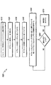
図17は、本発明の特徴を用いたバイト・コード符号化信号を復号するプロセスの実施例を示す流れ図である。プロセス1700は、主に要素バイト・コード・デコーダ1300に関連して説明する。ただし、プロセス1700は、要素バイト・コード・デコーダ600などその他のバイト・コード・デコーダにも適用可能であり、デコーダ300など複数のデコーダを含むさらに大きなプロセスの一部として使用することもできることに留意されたい。
FIG. 17 is a flow diagram illustrating an embodiment of a process for decoding a byte code encoded signal using features of the present invention.
プロセス1700は、最初に、ステップ1710で、システマティック・バイト・コード符号化データおよび非システマティック・バイト・コード符号化データのパケットまたはバイトを含むビットストリームとして、バイト・コード符号化メッセージを受信する。受信したメッセージ・ビットストリームは、図1のGF(256)SCBC114について述べたプロセスなど、線形ブロック符号化プロセスを用いた信号の符号化および伝送中に、バイト・コード符号化される。メッセージ・ビットストリームは、メッセージ中の各ビットのビット値を含む、あるいは好ましくは、ビット値の確率もしくは信頼度、またはシンボルなどのビット・グループの値の確率を含むことができる。
次に、ステップ1720で、入来メッセージをサブセットに配列する。入来メッセージ中のビットをサブセットにする配列は、主に使用する復号プロセスに基づいて決定することができる。前述のように、バイト・コード復号では、通常、ビット連続評価プロセスを行う。復号プロセスは、反復評価によって改善することができる。バイト・コード符号化信号の復号は、さらにガロア体の性質に基づいてバイト・コード符号化プロセスに関連する性質を利用することにより、さらに改善することができる。好ましい実施例では、入来メッセージを、LDPCパリティ・チェックプロセスを用いたパリティ・チェック行列の一部として処理される8ビットのサブセットに配列する。この配列は、パリティ・チェックプロセスにおける必要に応じて、サブセット中のビットの並べ替えまたは再配列をさらに含むこともあることに留意されたい。
Next,
次に、ステップ1730で、選択したサブセットの性質およびバイト・コード符号化プロセスの性質に基づいて選択した復号プロセスを用いて、これらのサブセットを復号する。好ましい実施例では、原始多項式およびGF(2)のパリティ行列の生成に基づいて、LDPCパリティ・チェック復号プロセスが選択される。復号効率を向上させるために、生成行列値の逆行列を用いてGF(256)空間で入来メッセージを復号するのではなく、GF(2)におけるLDPCパリティ・チェック復号プロセスを使用する。この復号ステップ1730は、サブセット中のメッセージ・ビットの現状態の信頼度のセットを計算することを含むこともある。メッセージ中のコード化冗長ビットについても確率を求め、これらを、復号ステップ1730で使用する別のパリティ・チェックプロセスなどのそれ以前の復号プロセス、またはそれ以前のトレリス復号プロセスにおいてフィードバック信号として使用できるようにする。
次に、ステップ1740で、復号プロセスが適切にメッセージを決定し、復号したかどうかを判定する。この判定は、計算した確率を、所定のしきい値のセットと突き合わせて比較することを含む。ステップ1740で復号プロセスが完了していない場合には、プロセスはステップ1730に戻り、もう一度復号ステップを行う。ステップ1740で復号プロセスが完了している場合には、ステップ1750で、この最終値を復号プロセスから出力する。好ましい実施例では、最終値は、要素バイト・コード・デコーダ1300の出力となる。最終値は、硬判定の値またはビット値として出力することもできるし、軟判定の確率値として出力することもできる。これらの出力を、別のバイト・コード・デコーダやリード・ソロモン・デコーダなど、さらに別のデコーダに供給することもできる。これらの出力は、トレリス復号をさらに改善するために、トレリス・デコーダなどの以前の復号ステージに戻すこともできる。ステップ1750は、出力メッセージ中のビットの適切な順序を回復するために、サブセット中のビットの並べ替えまたは再配列を含むこともできる。ステップ1730からステップ1740のプロセスは、復号が完了するまで、または復号ステップを完了するために割り当てられた特定の時間を超えるまで、反復することができることに留意されたい。
Next, in
図18は、別の実施例として、本発明の特徴を用いたバイト・コード符号化信号を復号するプロセス1800を示す流れ図である。プロセス1800は、主に図6の要素バイト・コード・デコーダ600に関連して説明する。ただし、プロセス1800は、その他のバイト・コード・デコーダにも適用可能であり、図3のデコーダ300など複数のデコーダを含むさらに大きなプロセスの一部として使用することもできることに留意されたい。
FIG. 18 is a flow diagram illustrating a
プロセス1800では、最初に、ステップ1810で、システマティック情報および非システマティック情報を含むビットストリームとして符号化メッセージを受信する。メッセージ・ビットストリームは、メッセージ中の各ビットのビット値を含む、あるいは好ましくは、ビット値の確率もしくは信頼度、またはシンボルなどのビット・グループの値の確率を含むことができる。メッセージは、受信したトレリス変調シンボル、およびシンボルとビットストリーム中のビットとの関係についての情報を含むこともできる。
In
次に、ステップ1820で、入来メッセージ・ストリームをサブセットに配列する。前述のように、バイト・コード符号化メッセージなどのブロック符号化メッセージの復号では、通常は、ビット連続評価プロセスを行う。復号プロセスは、反復評価によってしばしば改善することができる。バイト・コード符号化信号の復号は、符号化プロセスに関連する性質を利用することにより、さらに改善することができる。好ましい実施例では、入来メッセージを、16ビットのサブセットに配列し、BCJRアルゴリズムなどの反復トレリス・ツリーに基づくアルゴリズムを用いて復号する。
Next, in
次に、ステップ1830で、識別されたシンボル関係に基づいてビット・サブセットをさらにグループ化する。固有の伝送シンボルの関係に基づくビットのグループ化により、復号プロセスをさらに改善するために使用することができる追加のイントリンシック情報が得られる。ステップ1840で、トレリス復号プロセスを最適化するために、シンボルと、その元になったビットとを並べ替える。可能なシンボル並べ替えは、前述の図9および図10に示してある。
Next, in step 1830, the bit subsets are further grouped based on the identified symbol relationships. Bit grouping based on unique transmission symbol relationships provides additional intrinsic information that can be used to further improve the decoding process. At
次に、ステップ1850で、前述のBCJRアルゴリズムなどのシンボル・ベースのトレリス復号アルゴリズムを用い、さらに選択したサブセットの性質および符号化プロセスの性質に基づいて選択した1組のパリティ方程式のうちの1つまたは複数のパリティ方程式を用いて、サブセット中のシンボルを復号する。好ましい実施例では、パリティ・チェック方程式の組は、GF(2)のパリティ行列を用いて生成される。前述のように、復号中には、さらに小さく、場合によっては変化するビット・サブセットと、1つのパリティ方程式とを1度に使用することができることもある。復号ステップ1850は、サブセット中のメッセージ・ビットの1組の信頼度を計算することを含むこともある。メッセージ中のコード化冗長ビットについても確率を求め、これらを、それ以前の復号プロセスにおいてフィードバック信号として使用できるようにする。
Next, in
次に、ステップ1860で、復号プロセスが適切にメッセージを決定し、復号したかどうかを判定する。この判定は、計算した確率を、所定のしきい値のセットと突き合わせて比較することを含む。ステップ1860で復号プロセスが完了していない場合には、プロセスはステップ1850に戻り、もう一度復号ステップを行う。ステップ1860で復号プロセスが完了している場合には、ステップ1870で、この最終値を復号プロセスから出力する。好ましい実施例では、最終値は、要素バイト・コード・デコーダ600の出力となる。最終値は、硬判定の値またはビット値として出力することもできるし、軟判定の確率値として出力することもできる。これらの出力を、別のバイト・コード・デコーダやリード・ソロモン・デコーダなど、さらに別のデコーダに供給することもできる。これらの出力を、図3のトレリス・デコーダ320などの以前の復号ステージに戻して、復号プロセスをさらに改善することもできる。ステップ1870は、出力メッセージ中のビットの適切な順序を回復するために、サブセット中のビットの並べ替えまたは再配列を含むこともできる。ステップ1850からステップ1860のプロセスは、復号プロセスが完了するまで反復することもできるし、割り当てられた特定の復号完了時間に基づいて打ち切ることもできる。
Next, in
主にシンボル・ベースのトレリス復号プロセスに関連してプロセス1800について述べたが、プロセス1800を使用して、ビット・ベースのトレリス復号プロセスを実施することもできる。ビット・ベースのトレリス復号プロセスを用いてプロセス1800を実施する場合には、例えば、シンボルとビットの関係の特定に関するステップ1830を省略することができる。
Although the
本開示では、コード・レート1/2または2/3の要素コード・レートを有する特定の直列連結ブロック・コードについて述べている。本開示では、デコーダの効率および性能を向上させるために、非隣接のビットであってもよい入来ビットのグループ化を用いてコードを復号することができるという、特別な要素コード構造の性質を利用している。本開示では、2進LDPCプロセス、非2進LDPCプロセス、ビット・トレリス・マッピング・プロセス、および変調シンボル・トレリス・マッピング・プロセスなど、いくつかの可能なビット・グループ化の手法について述べている。
This disclosure describes certain serially concatenated block codes having an element code rate of
実施例は、様々な修正を加えることが可能であり、また様々な代替形態を持つことも可能であるが、例示を目的として、具体的な実施例を図面に示し、本明細書で詳細に説明した。ただし、本開示は、開示した特定の形態に限定されるものではないことを理解されたい。また、本開示は、以下の添付の特許請求の範囲によって定義される本開示の趣旨および範囲に含まれる全ての修正形態、均等物、および代替物を含むものとする。 While the embodiments may be variously modified and may have various alternative forms, specific examples are shown in the drawings for purposes of illustration and are described in detail herein. explained. However, it should be understood that the disclosure is not limited to the particular forms disclosed. This disclosure is also intended to include all modifications, equivalents, and alternatives falling within the spirit and scope of the disclosure as defined by the following appended claims.
Claims (5)
バイト・コード符号化プロセスを使用して符号化された復調済みビットストリームを受信するステップと、 Receiving a demodulated bitstream encoded using a byte code encoding process;
前記バイト・コード符号化プロセスに関連した復号プロセスに基づいて、前記復調済みビットストリームを複数のサブセットに配列するステップであって、該複数のサブセットの各々のサブセットが前記復調済みビットストリームの複数のビットを含み、前記復号プロセスが前記複数のビット間のパリティ関係を含む、該ステップと、 Arranging the demodulated bitstream into a plurality of subsets based on a decoding process associated with the byte code encoding process, wherein each subset of the plurality of subsets includes a plurality of demodulated bitstreams; Bits, and wherein the decoding process includes a parity relationship between the plurality of bits;
前記複数のサブセットの一つのサブセット中のシンボルのセットを特定するステップであって、該シンボルのセット中の各々のシンボルが前記複数のサブセットの前記サブセット中に少なくとも2つのビットを含み、前記シンボルのセットが前記復調済みビットストリームに対する変調フォーマットに関連する、該ステップと、 Identifying a set of symbols in one subset of the plurality of subsets, each symbol in the set of symbols including at least two bits in the subset of the plurality of subsets; The set is associated with a modulation format for the demodulated bitstream; and
前記複数のサブセットの前記サブセット中の前記シンボルのセットを並べ替えるステップと、 Reordering the set of symbols in the subset of the plurality of subsets;
前記シンボルのセット間のトレリス関係と、前記並べ替えたサブセット中の前記ビット間の前記パリティ関係とに基づいて、並べ替えたサブセットの各々を復号するステップと、 Decoding each of the sorted subsets based on a trellis relationship between the set of symbols and the parity relationship between the bits in the sorted subset;
を含む、前記方法。Said method.
バイト・コード符号化プロセスを使用して符号化された復調済みビットストリームを受信する手段と、 Means for receiving a demodulated bitstream encoded using a byte code encoding process;
前記バイト・コード符号化プロセスに関連した復号プロセスに基づいて、前記復調済みビットストリームを複数のサブセットに配列する手段であって、該複数のサブセットの各々のサブセットが前記復調済みビットストリームの複数のビットを含み、前記復号プロセスが前記複数のビット間のパリティ関係を含む、該手段と、 Means for arranging the demodulated bitstream into a plurality of subsets based on a decoding process associated with the byte code encoding process, wherein each subset of the plurality of subsets includes a plurality of demodulated bitstreams; Means for including a bit, and wherein the decoding process includes a parity relationship between the plurality of bits;
前記複数のサブセットの一つのサブセット中のシンボルのセットを特定する手段であって、該シンボルのセット中の各々のシンボルが前記複数のサブセットの前記サブセット中に少なくとも2つのビットを含み、前記シンボルのセットが前記復調済みビットストリームに対する変調フォーマットに関連する、該手段と、 Means for identifying a set of symbols in a subset of the plurality of subsets, each symbol in the set of symbols including at least two bits in the subset of the plurality of subsets; The means wherein the set is associated with a modulation format for the demodulated bitstream;
前記複数のサブセットの前記サブセット中の前記シンボルのセットを並べ替える手段と、 Means for reordering the set of symbols in the subset of the plurality of subsets;
前記シンボルのセット間のトレリス関係と、前記並べ替えたサブセット中の前記ビット間の前記パリティ関係とに基づいて、並べ替えたサブセットの各々を復号する手段と、 Means for decoding each of the sorted subsets based on a trellis relationship between the set of symbols and the parity relationship between the bits in the sorted subset;
を備える、前記装置。Comprising the apparatus.
Applications Claiming Priority (5)
| Application Number | Priority Date | Filing Date | Title |
|---|---|---|---|
| US61/072,316 | 2008-03-27 | ||
| US7231608P | 2008-03-28 | 2008-03-28 | |
| EP08162031 | 2008-08-07 | ||
| EP08162031.2 | 2008-08-07 | ||
| PCT/US2009/038542 WO2009120952A2 (en) | 2008-03-27 | 2009-03-27 | Apparatus and method for decoding signals |
Publications (3)
| Publication Number | Publication Date |
|---|---|
| JP2011528867A JP2011528867A (en) | 2011-11-24 |
| JP2011528867A5 JP2011528867A5 (en) | 2012-05-17 |
| JP5534528B2 true JP5534528B2 (en) | 2014-07-02 |
Family
ID=41114758
Family Applications (1)
| Application Number | Title | Priority Date | Filing Date |
|---|---|---|---|
| JP2011502100A Expired - Fee Related JP5534528B2 (en) | 2008-03-28 | 2009-03-27 | Apparatus and method for decoding signals |
Country Status (7)
| Country | Link |
|---|---|
| US (1) | US9008188B2 (en) |
| EP (1) | EP2258111A4 (en) |
| JP (1) | JP5534528B2 (en) |
| KR (1) | KR20110006666A (en) |
| CN (1) | CN101981932B (en) |
| BR (1) | BRPI0908963A2 (en) |
| WO (1) | WO2009120952A2 (en) |
Families Citing this family (19)
| Publication number | Priority date | Publication date | Assignee | Title |
|---|---|---|---|---|
| US8583979B1 (en) * | 2008-10-17 | 2013-11-12 | Sk Hynix Memory Solutions Inc. | Multiple interleavers in a coding system |
| US8635357B2 (en) * | 2009-09-08 | 2014-01-21 | Google Inc. | Dynamic selection of parameter sets for transcoding media data |
| KR20110038585A (en) * | 2009-10-08 | 2011-04-14 | 엘지전자 주식회사 | Apparatus and method for uplink transmission in multiple antenna system |
| KR101144816B1 (en) | 2009-11-13 | 2012-05-14 | 한국전자통신연구원 | Apparatus and method for receiving data in a communication system |
| US8699641B2 (en) * | 2010-06-10 | 2014-04-15 | Qualcomm Incorporated | Method and apparatus for ATSC signal processing |
| US20110307757A1 (en) * | 2010-06-11 | 2011-12-15 | MIRICS, Semiconductor Limited | Systems and methods for error correction |
| CN103069736B (en) * | 2010-09-16 | 2014-05-21 | 华为技术有限公司 | Feedback information relating to a mobile communications system using carrier aggregation |
| US9037564B2 (en) | 2011-04-29 | 2015-05-19 | Stephen Lesavich | Method and system for electronic content storage and retrieval with galois fields on cloud computing networks |
| US9137250B2 (en) | 2011-04-29 | 2015-09-15 | Stephen Lesavich | Method and system for electronic content storage and retrieval using galois fields and information entropy on cloud computing networks |
| US9361479B2 (en) | 2011-04-29 | 2016-06-07 | Stephen Lesavich | Method and system for electronic content storage and retrieval using Galois fields and geometric shapes on cloud computing networks |
| US9569771B2 (en) | 2011-04-29 | 2017-02-14 | Stephen Lesavich | Method and system for storage and retrieval of blockchain blocks using galois fields |
| US8819515B2 (en) * | 2011-12-30 | 2014-08-26 | Lsi Corporation | Mixed domain FFT-based non-binary LDPC decoder |
| KR102058499B1 (en) * | 2013-01-02 | 2020-01-22 | 삼성전자주식회사 | Semiconductor memory system including reed-solomon low density parity check decoder and read method thereof |
| RU2012152710A (en) * | 2012-12-06 | 2014-06-20 | ЭлЭсАй Корпорейшн | MODULATIVE CODING OF PARITY BITS FORMED USING CODE WITH ERROR CORRECTION |
| TWI565246B (en) * | 2015-01-12 | 2017-01-01 | 晨星半導體股份有限公司 | Decoding method for a convolutional code |
| TWI555339B (en) * | 2015-04-21 | 2016-10-21 | 國立清華大學 | Iterative decoding device, iterative signal inspecting device and information update method for the same |
| US11438014B2 (en) * | 2019-05-31 | 2022-09-06 | Washington State University | Deep neural network a posteriori probability detectors and media noise predictors for one- and two-dimensional magnetic recording |
| US11411593B2 (en) | 2020-04-29 | 2022-08-09 | Eagle Technology, Llc | Radio frequency (RF) system including programmable processing circuit performing butterfly computations and related methods |
| US11502715B2 (en) * | 2020-04-29 | 2022-11-15 | Eagle Technology, Llc | Radio frequency (RF) system including programmable processing circuit performing block coding computations and related methods |
Family Cites Families (14)
| Publication number | Priority date | Publication date | Assignee | Title |
|---|---|---|---|---|
| JP2003258776A (en) | 2002-02-28 | 2003-09-12 | Tama Tlo Kk | Communication device, communication system and video conference system |
| US7266749B1 (en) | 2002-06-27 | 2007-09-04 | Legend Silicon Corporation | Trellis construction based on parity check matrix for BCH code |
| US7555696B2 (en) * | 2004-12-09 | 2009-06-30 | General Instrument Corporation | Method and apparatus for forward error correction in a content distribution system |
| RU2373641C2 (en) | 2004-12-15 | 2009-11-20 | Нек Корпорейшн | Coding device with correction of errors and method of coding with correction of errors used in it |
| DE602006011240D1 (en) | 2005-06-21 | 2010-02-04 | Samsung Electronics Co Ltd | Device and method for transmitting / receiving data in a multi-antenna communication system using a structured Low Density Parity Check (LDPC) code |
| US8819518B2 (en) * | 2005-12-01 | 2014-08-26 | Thomson Licensing | Apparatus and method for decoding low density parity check coded signals |
| US7831887B2 (en) * | 2005-12-15 | 2010-11-09 | General Instrument Corporation | Method and apparatus for using long forward error correcting codes in a content distribution system |
| TWI333643B (en) * | 2006-01-18 | 2010-11-21 | Lg Electronics Inc | Apparatus and method for encoding and decoding signal |
| KR100933139B1 (en) | 2006-02-22 | 2009-12-21 | 삼성전자주식회사 | Apparatus and method for receiving signal in communication system |
| WO2007100185A1 (en) * | 2006-02-28 | 2007-09-07 | Lg Electronics Inc. | Digital broadcasting system and method of processing data |
| WO2007112767A1 (en) * | 2006-03-30 | 2007-10-11 | Fujitsu Limited | Construction of parity-check matrices for non-binarys ldpc codes |
| CN101056414A (en) * | 2006-12-22 | 2007-10-17 | 武汉大学 | A joint coding method for video data stream source and channel |
| CA2686557A1 (en) | 2007-05-16 | 2008-11-27 | Thomson Licensing | Apparatus and method for encoding and decoding signals |
| US9078034B2 (en) * | 2007-10-15 | 2015-07-07 | Thomson Licensing | Apparatus and method for communicating burst mode activity |
-
2009
- 2009-03-27 WO PCT/US2009/038542 patent/WO2009120952A2/en active Application Filing
- 2009-03-27 KR KR1020107024022A patent/KR20110006666A/en not_active Application Discontinuation
- 2009-03-27 EP EP09724578.1A patent/EP2258111A4/en not_active Withdrawn
- 2009-03-27 BR BRPI0908963-2A patent/BRPI0908963A2/en not_active IP Right Cessation
- 2009-03-27 CN CN200980110979.5A patent/CN101981932B/en not_active Expired - Fee Related
- 2009-03-27 JP JP2011502100A patent/JP5534528B2/en not_active Expired - Fee Related
- 2009-03-27 US US12/934,406 patent/US9008188B2/en active Active
Also Published As
| Publication number | Publication date |
|---|---|
| CN101981932A (en) | 2011-02-23 |
| US20110026601A1 (en) | 2011-02-03 |
| KR20110006666A (en) | 2011-01-20 |
| WO2009120952A3 (en) | 2010-02-18 |
| EP2258111A2 (en) | 2010-12-08 |
| CN101981932B (en) | 2013-03-13 |
| JP2011528867A (en) | 2011-11-24 |
| BRPI0908963A2 (en) | 2015-07-28 |
| EP2258111A4 (en) | 2014-01-22 |
| WO2009120952A8 (en) | 2010-12-09 |
| WO2009120952A2 (en) | 2009-10-01 |
| US9008188B2 (en) | 2015-04-14 |
Similar Documents
| Publication | Publication Date | Title |
|---|---|---|
| JP5534528B2 (en) | Apparatus and method for decoding signals | |
| JP5317223B2 (en) | Method and apparatus for encoding and decoding signals | |
| KR101532315B1 (en) | High definition television transmission with mobile capability | |
| JP5232865B2 (en) | Preamble of digital television system | |
| KR20100087163A (en) | Code enhanced staggercasting | |
| KR101215363B1 (en) | Digital broadcasting system and processing method | |
| WO2011081616A1 (en) | A priori processor for an iterative decoder |
Legal Events
| Date | Code | Title | Description |
|---|---|---|---|
| A521 | Request for written amendment filed |
Free format text: JAPANESE INTERMEDIATE CODE: A523 Effective date: 20120319 |
|
| A621 | Written request for application examination |
Free format text: JAPANESE INTERMEDIATE CODE: A621 Effective date: 20120319 |
|
| A977 | Report on retrieval |
Free format text: JAPANESE INTERMEDIATE CODE: A971007 Effective date: 20130208 |
|
| A131 | Notification of reasons for refusal |
Free format text: JAPANESE INTERMEDIATE CODE: A131 Effective date: 20130220 |
|
| A601 | Written request for extension of time |
Free format text: JAPANESE INTERMEDIATE CODE: A601 Effective date: 20130513 |
|
| A602 | Written permission of extension of time |
Free format text: JAPANESE INTERMEDIATE CODE: A602 Effective date: 20130520 |
|
| A521 | Request for written amendment filed |
Free format text: JAPANESE INTERMEDIATE CODE: A523 Effective date: 20130809 |
|
| A131 | Notification of reasons for refusal |
Free format text: JAPANESE INTERMEDIATE CODE: A131 Effective date: 20130918 |
|
| A601 | Written request for extension of time |
Free format text: JAPANESE INTERMEDIATE CODE: A601 Effective date: 20131211 |
|
| A602 | Written permission of extension of time |
Free format text: JAPANESE INTERMEDIATE CODE: A602 Effective date: 20131218 |
|
| A521 | Request for written amendment filed |
Free format text: JAPANESE INTERMEDIATE CODE: A523 Effective date: 20140317 |
|
| TRDD | Decision of grant or rejection written | ||
| A01 | Written decision to grant a patent or to grant a registration (utility model) |
Free format text: JAPANESE INTERMEDIATE CODE: A01 Effective date: 20140416 |
|
| A61 | First payment of annual fees (during grant procedure) |
Free format text: JAPANESE INTERMEDIATE CODE: A61 Effective date: 20140418 |
|
| R150 | Certificate of patent or registration of utility model |
Ref document number: 5534528 Country of ref document: JP Free format text: JAPANESE INTERMEDIATE CODE: R150 |
|
| LAPS | Cancellation because of no payment of annual fees |