US10831742B2 - Data set verification - Google Patents
Data set verification Download PDFInfo
- Publication number
- US10831742B2 US10831742B2 US15/620,900 US201715620900A US10831742B2 US 10831742 B2 US10831742 B2 US 10831742B2 US 201715620900 A US201715620900 A US 201715620900A US 10831742 B2 US10831742 B2 US 10831742B2
- Authority
- US
- United States
- Prior art keywords
- data set
- contents
- generator
- object identifier
- identifier
- Prior art date
- Legal status (The legal status is an assumption and is not a legal conclusion. Google has not performed a legal analysis and makes no representation as to the accuracy of the status listed.)
- Active, expires
Links
Images


Classifications
-
- G—PHYSICS
- G06—COMPUTING OR CALCULATING; COUNTING
- G06F—ELECTRIC DIGITAL DATA PROCESSING
- G06F16/00—Information retrieval; Database structures therefor; File system structures therefor
- G06F16/20—Information retrieval; Database structures therefor; File system structures therefor of structured data, e.g. relational data
- G06F16/23—Updating
- G06F16/2365—Ensuring data consistency and integrity
-
- G—PHYSICS
- G06—COMPUTING OR CALCULATING; COUNTING
- G06F—ELECTRIC DIGITAL DATA PROCESSING
- G06F11/00—Error detection; Error correction; Monitoring
- G06F11/07—Responding to the occurrence of a fault, e.g. fault tolerance
- G06F11/14—Error detection or correction of the data by redundancy in operations
- G06F11/1446—Point-in-time backing up or restoration of persistent data
- G06F11/1448—Management of the data involved in backup or backup restore
-
- G—PHYSICS
- G06—COMPUTING OR CALCULATING; COUNTING
- G06F—ELECTRIC DIGITAL DATA PROCESSING
- G06F11/00—Error detection; Error correction; Monitoring
- G06F11/22—Detection or location of defective computer hardware by testing during standby operation or during idle time, e.g. start-up testing
- G06F11/26—Functional testing
- G06F11/263—Generation of test inputs, e.g. test vectors, patterns or sequences ; with adaptation of the tested hardware for testability with external testers
-
- G—PHYSICS
- G06—COMPUTING OR CALCULATING; COUNTING
- G06F—ELECTRIC DIGITAL DATA PROCESSING
- G06F16/00—Information retrieval; Database structures therefor; File system structures therefor
- G06F16/10—File systems; File servers
- G06F16/17—Details of further file system functions
- G06F16/178—Techniques for file synchronisation in file systems
Definitions
- Data storage vendors offer a wide range of data storage systems. When new features or other changes are made to a data storage system, thorough testing is performed to maintain outstanding storage quality. For example, at each release development cycle, endurance testing (or “longevity testing”) may be performed. As part of endurance testing, several large data sets may be generated and stored to the storage system. Each data set may include a collection of data (e.g., a collection of objects). The data sets may be stored over some selected time period (e.g., some number of hours or days), after which the data sets may be read back from the storage system and their contents verified. Existing systems may require large amounts of testing data to be stored for data set verification.
- Described herein are embodiments of systems and methods for reliable data set verification that require relatively low storage capacity.
- a method comprises: receiving parameters including an object count (N) and an object size; generating a data set key; generating N object ids using the data set key and the object count; for each object id, generating corresponding object contents using the object id and the object size; adding the generated object ids and corresponding object contents to a storage system under testing; regenerating the N object ids using the data set key and the object count; for each object id, regenerating the corresponding object contents using the object id and the object size; retrieving, from the storage system under testing, object contents for each of the N regenerated object ids; and comparing, for each of the regenerated N object ids, the regenerated object contents to the retrieved object contents to determine if the storage system under testing corrupted one or more objects.
- the parameters further include a data set name
- the method further includes storing the data set key, object count (N), and object size to local storage using the data set name.
- comparing the regenerated object contents to the retrieved object contents includes determining if object contents could be retrieved from the storage system under testing for one or more of the regenerated N object ids.
- generating the data set key includes generating the data set key using a pseudo-random number generator (PRNG).
- PRNG pseudo-random number generator
- generating the N object ids using the data set key and the object count includes generating the N object ids using a pseudo-random number generator (PRNG) seeded with the data set key.
- generating object contents using an object id and the object size includes generating object contents using a pseudo-random number generator (PRNG) seeded with the object id.
- a system comprises one or more processors; a volatile memory; and a non-volatile memory storing computer program code that when executed on the processor causes execution across the one or more processors of a process operable to perform embodiments of the method described hereinabove.
- a computer program product tangibly embodied in a non-transitory computer-readable medium, the computer-readable medium storing program instructions that are executable to perform embodiments of the method described hereinabove.
- FIG. 1 is a block diagram of an illustrative storage system, according to an embodiment
- FIG. 2 is block diagram of an illustrative data set verification system, according to one embodiment
- FIG. 3 is diagram showing a technique for generating a data set, according to some embodiments.
- FIG. 4 is flow diagram illustrating processing that may occur within a data set verification tool, accordance to an embodiment.
- FIG. 5 is block diagram of a computer on which the processing of FIG. 4 may be implemented, according to an embodiment of the disclosure.
- the phrases “computer,” “computing system,” “computing environment,” “processing platform,” “data memory and storage system,” and “data memory and storage system environment” are intended to be broadly construed so as to encompass, for example, private or public cloud computing or storage systems, or parts thereof, as well as other types of systems comprising distributed virtual infrastructure and those not comprising virtual infrastructure.
- the terms “application,” “program,” “application program,” and “computer application program” herein refer to any type of software application, including desktop applications, server applications, database applications, and mobile applications.
- storage device refers to any non-volatile memory (NVM) device, including hard disk drives (HDDs), flash devices (e.g., NAND flash devices), and next generation NVM devices, any of which can be accessed locally and/or remotely (e.g., via a storage attached network (SAN)).
- HDDs hard disk drives
- flash devices e.g., NAND flash devices
- next generation NVM devices any of which can be accessed locally and/or remotely (e.g., via a storage attached network (SAN)).
- SAN storage attached network
- storage device can also refer to a storage array comprising one or more storage devices.
- the term “storage system” encompass, for example, private or public cloud computing systems for storing data as well as systems for storing data comprising virtual infrastructure and those not comprising virtual infrastructure.
- client and “user” may refer to any person, system, or other entity that uses a storage system to read/write data.
- I/O request or simply “I/O” may be used herein to refer to a request to read or write data.
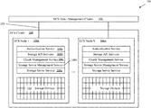
- an illustrative storage system 100 includes one or more clients 102 in communication with a storage cluster 104 via a network 103 .
- the network 103 may include any suitable type of communication network or combination thereof, including networks using protocols such as Ethernet, Internet Small Computer System Interface (iSCSI), Fibre Channel (FC), and/or wireless protocols.
- iSCSI Internet Small Computer System Interface
- FC Fibre Channel
- the storage cluster 104 includes one or more storage nodes 106 a . . . 106 n (generally denoted 106 ).
- Storage node 106 a which may be representative of other storage nodes, includes one or more services 108 and one or more storage devices 108 .
- a storage node 106 may include a processor (not shown) configured to execute the services 108 .
- the illustrative storage node 106 a includes the following services: an authentication service 108 a to authenticate requests from clients 102 ; storage API services 108 b to parse and interpret requests from clients 102 ; a chunk management service 108 c to facilitate chunk allocation/reclamation for different storage system needs and monitor chunk health and usage; a storage server management service 108 d to manage available storage devices capacity and to track storage devices states; and a storage server service 108 e to interface with the storage devices 110 .
- a storage device 100 may comprise one or more physical and/or logical storage devices attached to the storage node 106 a .
- a storage node 106 may utilize VNX, Symmetrix VMAX, and/or Full Automated Storage Tiering (FAST), which are available from Dell EMC of Hopkinton, Mass. While vendor-specific terminology may be used to facilitate understanding, it is understood that the concepts, techniques, and structures sought to be protected herein are not limited to use with any specific commercial products.
- the storage cluster 104 may be an object storage system. In some embodiments, the storage cluster 104 may be provided as Elastic Cloud Storage (ECS) from Dell EMC of Hopkinton, Mass.
- ECS Elastic Cloud Storage
- clients 102 send I/O requests to the storage cluster 104 to read/write data.
- the I/O requests include object ids to uniquely identify objects within the cluster 104 .
- Any available storage node 106 may receive a client I/O request.
- the receiving node 106 may process the request locally and/or may delegate request processing to one or more peer nodes 106 . For example, if a client issues an object read request, the receiving node may delegate/proxy the request to peer node where the object's data resides.
- a data set verification system 200 may be used to test a storage system 202 .
- the data set verification system 200 includes a user interface 204 , a data stream generator 206 , a data set generator 208 , an object writer 210 , a content verifier 212 , an object reader 214 , and storage API modules 216 .
- the data set verification system 200 has read/write access to a local storage 218 .
- local storage 218 may be provided as locally attached storage device (e.g., a disk drive).
- the data set verification system 200 uses local storage 218 to store information that can be used to regenerate data sets.
- the user interface 204 may include graphical and/or textual-based interfaces to allow a user to configure tests, to execute tests against the storage system 202 , and to view the results of such tests.
- the data stream generator 206 is configured to receive as input a key and a data size. In response, the data stream generator 206 generates as output a stream of quasi-random data that is reproducible based on the key and the data size. In some embodiments, the data stream generator 206 uses a pseudo-random number generator (PRNG) to generate the stream of data. In some embodiments, the PRNG may be seeded using the received key.
- PRNG pseudo-random number generator
- the data verification system 200 can be used to generate data sets and add the corresponding objects to the storage system 202 .
- user interface 204 may receive as input a data set name, an object count (N), and an object size (S). These parameters may be passed to the data set generator 208 , which in turn generates a data set key and passes the data set key and the object count (N) to the data stream generator 206 .
- the data stream generator 206 returns a quasi-random data stream that is used by the data set generator 208 as a list of N object ids.
- the data set generator 208 For each object id, the data set generator 208 passes the object id and the object size (S) to the data stream generator 206 , which returns a quasi-random data stream that the data set generator 208 uses as the object's contents. Next, the data set generator 208 may pass each object id and the respective object contents to the object writer 210 , which uses the storage API modules 216 to add the objects to the storage system 200 . The data set generator 208 may store the input parameters along with the generated data set key to local storage 218 . In certain embodiments, the data set name can be used to subsequently retrieve this information from local storage 218 (e.g., the information may be stored within a file named with the data set name).
- the data verification system 200 can be used to verify data sets stored within the storage system 202 .
- user interface 204 receives as input the name of the data set to be verified.
- the user interface 204 passes the data set name to the data set generator 208 , which uses the data set name to retrieve a data set key, object count, and object size from local storage 218 .
- the data set generator 208 passes the data set key and the object count (N) to the data stream generator 206 , which returns a quasi-random data stream that the data set generator 208 uses as a list of N object ids.
- the data set generator 208 may pass the object ids, one by one, to the object reader 214 , which uses the storage API modules 216 to retrieve object content from the storage system 202 .
- the data set generator 208 also passes the each object id, along with the object size, to the data stream generator 206 , which returns a quasi-random data stream that the data set generator 208 uses to regenerate object contents of size S. Owing to the semantics of the data stream generator 206 , as discussed above, the list of object ids and the respective object contents are identical to the object ids and contents that were previously generated when the data was added to storage 202 .
- the objects can be regenerated within the data set verification system 200 in parallel with the objects being retrieved from storage 202 .
- the object contents retrieved from the storage 202 may be compared to the regenerated object contents. If the object contents are not identical or if the object cannot be found in storage 202 (e.g., the storage replies with a “no such object” error code), then a verification failure may be reported via the user interface 204 .
- the data set verification system 200 can efficiently generate and verify a large number of data objects (e.g., thousands or even millions of objects), and thus is well suited for endurance-type tests.
- FIG. 3 illustrates a technique for generating a data set 300 in a reproducible manner.
- the data set 300 includes object ids 302 a - 302 n ( 302 generally) and respective object contents 304 a - 304 n .
- the data set 300 can be fully generated, in a reproducible manner, using an object count parameter 306 , an object size parameter 308 , and a data set key 310 .
- the data set key 310 may be generated using any suitable technique.
- the data set key 310 may be a random value.
- the data set key 310 can be used to generate the set of object ids 302 , which in turn can be used to generate object contents 304 , as discussed above. It should be appreciated that arbitrarily large data sets (e.g., data sets having 100 M objects of size 100 MB each) can be generated using just three values: a data set key 310 , an object count 306 , and an object size 308 .
- FIG. 4 is a flow diagram showing illustrative processing that can be implemented within a data set verification system (e.g., system 200 in FIG. 2 ).
- Rectangular elements (typified by element 402 ), herein denoted “processing blocks,” represent computer software instructions or groups of instructions.
- Diamond shaped elements (typified by element 418 ), herein denoted “decision blocks,” represent computer software instructions, or groups of instructions, which affect the execution of the computer software instructions represented by the processing blocks.
- processing and decision blocks may represent steps performed by functionally equivalent circuits such as a digital signal processor circuit or an application specific integrated circuit (ASIC).
- ASIC application specific integrated circuit
- the flow diagrams do not depict the syntax of any particular programming language. Rather, the flow diagrams illustrate the functional information one of ordinary skill in the art requires to fabricate circuits or to generate computer software to perform the processing required of the particular apparatus. It should be noted that many routine program elements, such as initialization of loops and variables and the use of temporary variables are not shown. It will be appreciated by those of ordinary skill in the art that unless otherwise indicated herein, the particular sequence of blocks described is illustrative only and can be varied without departing from the spirit of the concepts, structures, and techniques sought to be protected herein. Thus, unless otherwise stated the blocks described below are unordered meaning that, when possible, the functions represented by the blocks can be performed in any convenient or desirable order.
- a method 400 begins at block 402 , where an object count (N) and an object size parameter are received. In some embodiments, these parameters may be received from a user (e.g., via user interface 204 in FIG. 2 ).
- a data set key is generated.
- a set of N object ids may be generated in a reproducible manner based on the data set key and the object count.
- the set of object ids may be generated using a PRNG seeded within the data set key.
- corresponding object contents are generated in a reproducible manner using the object id, along with the object size parameter.
- an object's contents may be generated using a PRNG seeded within the object id.
- the generated objects i.e., the generated pairs of [object ids, object contents]—are added to a storage system (e.g., storage system 100 in FIG. 1 ).
- blocks 412 - 422 can be used to verify the contents of the data set within the storage system.
- the object ids and respective object contents are regenerated using the data set key, the object count, and the object size.
- the data set objects within the storage system may be retrieved using the regenerated object ids.
- the regenerated objects may be compared with the retrieved objects. For example, for each regenerated object id, the corresponding regenerated object contents may be compared, byte-for-byte, to the corresponding object contents retrieved from the storage system.
- a verification success may be reported (block 420 ). Otherwise, the data set in storage is determined to be corrupt and a verification failure may be reported (block 422 ). In some embodiments, verification success/failure may be reported to a user (e.g., via user interface 204 in FIG. 2 ).
- the data set verification techniques and structures described herein can be used to create testing systems for many different commercially available storage systems, including not only object-based storage systems but also file- and block-based storage systems.
- FIG. 5 shows an illustrative computer or other processing device 500 that can perform at least part of the processing described herein.
- the computer 500 includes a processor 502 , a volatile memory 504 , a non-volatile memory 506 (e.g., hard disk), an output device 508 and a graphical user interface (GUI) 510 (e.g., a mouse, a keyboard, a display, for example), each of which is coupled together by a bus 518 .
- the non-volatile memory 506 stores computer instructions 512 , an operating system 514 , and data 516 .
- the computer instructions 512 are executed by the processor 502 out of volatile memory 504 .
- a non-transitory computer readable medium 520 may be provided on which a computer program product may be tangibly embodied.
- the non-transitory computer-readable medium 520 may store program instructions that are executable to perform the processing of FIG. 4 .
- Processing may be implemented in hardware, software, or a combination of the two.
- processing is provided by computer programs executing on programmable computers/machines that each includes a processor, a storage medium or other article of manufacture that is readable by the processor (including volatile and non-volatile memory and/or storage elements), at least one input device, and one or more output devices.
- Program code may be applied to data entered using an input device to perform processing and to generate output information.
- the system can perform processing, at least in part, via a computer program product, (e.g., in a machine-readable storage device), for execution by, or to control the operation of, data processing apparatus (e.g., a programmable processor, a computer, or multiple computers).
- a computer program product e.g., in a machine-readable storage device
- data processing apparatus e.g., a programmable processor, a computer, or multiple computers.
- Each such program may be implemented in a high level procedural or object-oriented programming language to communicate with a computer system.
- the programs may be implemented in assembly or machine language.
- the language may be a compiled or an interpreted language and it may be deployed in any form, including as a stand-alone program or as a module, component, subroutine, or other unit suitable for use in a computing environment.
- a computer program may be deployed to be executed on one computer or on multiple computers at one site or distributed across multiple sites and interconnected by a communication network.
- a computer program may be stored on a storage medium or device (e.g., CD-ROM, hard disk, or magnetic diskette) that is readable by a general or special purpose programmable computer for configuring and operating the computer when the storage medium or device is read by the computer.
- Processing may also be implemented as a machine-readable storage medium, configured with a computer program, where upon execution, instructions in the computer program cause the computer to operate.
- Processing may be performed by one or more programmable processors executing one or more computer programs to perform the functions of the system. All or part of the system may be implemented as special purpose logic circuitry (e.g., an FPGA (field programmable gate array) and/or an ASIC (application-specific integrated circuit)).
- special purpose logic circuitry e.g., an FPGA (field programmable gate array) and/or an ASIC (application-specific integrated circuit)
Landscapes
- Engineering & Computer Science (AREA)
- Theoretical Computer Science (AREA)
- General Engineering & Computer Science (AREA)
- Physics & Mathematics (AREA)
- General Physics & Mathematics (AREA)
- Data Mining & Analysis (AREA)
- Databases & Information Systems (AREA)
- Quality & Reliability (AREA)
- Computer Security & Cryptography (AREA)
- Computer Hardware Design (AREA)
- Debugging And Monitoring (AREA)
Abstract
Description
Claims (15)
Applications Claiming Priority (2)
| Application Number | Priority Date | Filing Date | Title |
|---|---|---|---|
| RU2016148297 | 2016-12-09 | ||
| RU2016148297 | 2016-12-09 |
Publications (2)
| Publication Number | Publication Date |
|---|---|
| US20180165323A1 US20180165323A1 (en) | 2018-06-14 |
| US10831742B2 true US10831742B2 (en) | 2020-11-10 |
Family
ID=62489463
Family Applications (1)
| Application Number | Title | Priority Date | Filing Date |
|---|---|---|---|
| US15/620,900 Active 2038-01-01 US10831742B2 (en) | 2016-12-09 | 2017-06-13 | Data set verification |
Country Status (1)
| Country | Link |
|---|---|
| US (1) | US10831742B2 (en) |
Families Citing this family (4)
| Publication number | Priority date | Publication date | Assignee | Title |
|---|---|---|---|---|
| CN109062752A (en) * | 2018-07-19 | 2018-12-21 | 郑州云海信息技术有限公司 | A kind of fault-tolerant automation safety detecting method of height and device of BMC |
| US10783022B2 (en) | 2018-08-03 | 2020-09-22 | EMC IP Holding Company LLC | Immediate replication for dedicated data blocks |
| CN109976957B (en) * | 2019-02-11 | 2022-04-15 | 平安科技(深圳)有限公司 | Librgw performance test method and device and computer equipment |
| CN111581109A (en) * | 2020-05-15 | 2020-08-25 | 杭州安恒信息技术股份有限公司 | Method, system and equipment for checking interface return data |
Citations (34)
| Publication number | Priority date | Publication date | Assignee | Title |
|---|---|---|---|---|
| US6070003A (en) | 1989-11-17 | 2000-05-30 | Texas Instruments Incorporated | System and method of memory access in apparatus having plural processors and plural memories |
| US20020009134A1 (en) | 2000-01-10 | 2002-01-24 | Fischel Scott Eduard | Method and apparatus for testing wireless communication channels |
| US6550035B1 (en) | 1998-10-20 | 2003-04-15 | Texas Instruments Incorporated | Method and apparatus of Reed-Solomon encoding-decoding |
| US20050038968A1 (en) | 2003-08-11 | 2005-02-17 | Takashige Iwamura | Multi-site remote-copy system |
| US20060105724A1 (en) | 2004-11-12 | 2006-05-18 | Seigo Nakao | Transmitting and receiving method, and radio apparatus utilizing the same |
| US20060147219A1 (en) | 2003-07-16 | 2006-07-06 | Nippon Telegraph And Telephone Corp. | Optical communication system using optical frequency code, optical transmission device and optical reception device thereof, and reflection type optical communication device |
| US20080126357A1 (en) * | 2006-05-04 | 2008-05-29 | Wambo, Inc. | Distributed file storage and transmission system |
| US20090112953A1 (en) * | 2007-10-30 | 2009-04-30 | Eric Lawrence Barsness | Enhanced garbage collection in a multi-node environment |
| US7549110B2 (en) | 2002-01-21 | 2009-06-16 | Koninklijke Philips Electronics N.V. | Device for encoding and decoding using smaller block of symbols |
| US7559007B1 (en) | 2006-03-10 | 2009-07-07 | Xilinx, Inc. | Encoding and decoding with puncturing |
| US7581156B2 (en) | 2002-12-16 | 2009-08-25 | Microsoft Corporation | Systems and methods for providing improved encoding and reconstruction of data |
| US20100091842A1 (en) | 2007-10-19 | 2010-04-15 | Hiroshi Ikeda | Coding rate conversion apparatus, coding rate conversion method, and integrated circuit |
| US20100180176A1 (en) | 2006-08-31 | 2010-07-15 | Panasonic Corporation | Encoding method, encoder, and transmitter |
| US20100246663A1 (en) | 2007-05-16 | 2010-09-30 | Thomson Licensing, LLC | Apparatus and method for encoding and decoding signals |
| US20110055494A1 (en) | 2009-08-25 | 2011-03-03 | Yahoo! Inc. | Method for distributed direct object access storage |
| US20110053639A1 (en) | 2006-11-03 | 2011-03-03 | Alcoril Holdings Sa | Methods and devices for authenticating a product and a two-dimensional code and novel application of a two-dimensional code |
| US20110196900A1 (en) | 2010-02-09 | 2011-08-11 | Alexandre Drobychev | Storage of Data In A Distributed Storage System |
| US20120051208A1 (en) | 2010-08-27 | 2012-03-01 | Daoben Li | Methods and systems for multiple access encoding, transmission and decoding |
| US20120106595A1 (en) | 2010-05-04 | 2012-05-03 | Qualcomm Incorporated | Method and apparatus for optimizing power distribution between symbols |
| US20130067187A1 (en) | 2011-09-12 | 2013-03-14 | Microsoft Corporation | Allocation strategies for storage device sets |
| US8458515B1 (en) | 2009-11-16 | 2013-06-04 | Symantec Corporation | Raid5 recovery in a high availability object based file system |
| US8532212B2 (en) | 2008-10-10 | 2013-09-10 | Sony Corporation | Wireless communication system, wireless communication device, wireless communication method and computer program |
| US20140046997A1 (en) * | 2012-08-09 | 2014-02-13 | International Business Machines Corporation | Service management roles of processor nodes in distributed node service management |
| US8683296B2 (en) | 2011-12-30 | 2014-03-25 | Streamscale, Inc. | Accelerated erasure coding system and method |
| US20140136897A1 (en) * | 2012-11-13 | 2014-05-15 | Load DynamiX, Inc. | Data verification |
| US8762642B2 (en) | 2009-01-30 | 2014-06-24 | Twinstrata Inc | System and method for secure and reliable multi-cloud data replication |
| US8914706B2 (en) | 2011-12-30 | 2014-12-16 | Streamscale, Inc. | Using parity data for concurrent data authentication, correction, compression, and encryption |
| US20150363270A1 (en) * | 2014-06-11 | 2015-12-17 | Commvault Systems, Inc. | Conveying value of implementing an integrated data management and protection system |
| US20160004605A1 (en) * | 2014-07-01 | 2016-01-07 | Commvault Systems, Inc. | Lightweight data reconstruction based on backup data |
| US20160210202A1 (en) * | 2015-01-20 | 2016-07-21 | Commvault Systems, Inc. | Synchronizing selected portions of data in a storage management system |
| US20160239384A1 (en) | 2014-09-02 | 2016-08-18 | Netapp, Inc. | Hierarchical wide spreading of distributed storage |
| US20170046127A1 (en) | 2014-10-09 | 2017-02-16 | Splunk Inc. | Automatic event group actions |
| US20170075947A1 (en) | 2015-09-14 | 2017-03-16 | Emc Corporation | Weightless Data Objects Content Verification |
| US20170083549A1 (en) | 2015-09-14 | 2017-03-23 | Emc Corporation | Tracing garbage collector for search trees under multi-version concurrency control |
-
2017
- 2017-06-13 US US15/620,900 patent/US10831742B2/en active Active
Patent Citations (40)
| Publication number | Priority date | Publication date | Assignee | Title |
|---|---|---|---|---|
| US6070003A (en) | 1989-11-17 | 2000-05-30 | Texas Instruments Incorporated | System and method of memory access in apparatus having plural processors and plural memories |
| US6550035B1 (en) | 1998-10-20 | 2003-04-15 | Texas Instruments Incorporated | Method and apparatus of Reed-Solomon encoding-decoding |
| US20020009134A1 (en) | 2000-01-10 | 2002-01-24 | Fischel Scott Eduard | Method and apparatus for testing wireless communication channels |
| US7549110B2 (en) | 2002-01-21 | 2009-06-16 | Koninklijke Philips Electronics N.V. | Device for encoding and decoding using smaller block of symbols |
| US8683300B2 (en) | 2002-01-21 | 2014-03-25 | Koninklijke Philips N.V. | Method of encoding and decoding |
| US7581156B2 (en) | 2002-12-16 | 2009-08-25 | Microsoft Corporation | Systems and methods for providing improved encoding and reconstruction of data |
| US20060147219A1 (en) | 2003-07-16 | 2006-07-06 | Nippon Telegraph And Telephone Corp. | Optical communication system using optical frequency code, optical transmission device and optical reception device thereof, and reflection type optical communication device |
| US20050038968A1 (en) | 2003-08-11 | 2005-02-17 | Takashige Iwamura | Multi-site remote-copy system |
| US20060105724A1 (en) | 2004-11-12 | 2006-05-18 | Seigo Nakao | Transmitting and receiving method, and radio apparatus utilizing the same |
| US7559007B1 (en) | 2006-03-10 | 2009-07-07 | Xilinx, Inc. | Encoding and decoding with puncturing |
| US20080126357A1 (en) * | 2006-05-04 | 2008-05-29 | Wambo, Inc. | Distributed file storage and transmission system |
| US20100180176A1 (en) | 2006-08-31 | 2010-07-15 | Panasonic Corporation | Encoding method, encoder, and transmitter |
| US20110053639A1 (en) | 2006-11-03 | 2011-03-03 | Alcoril Holdings Sa | Methods and devices for authenticating a product and a two-dimensional code and novel application of a two-dimensional code |
| US20100246663A1 (en) | 2007-05-16 | 2010-09-30 | Thomson Licensing, LLC | Apparatus and method for encoding and decoding signals |
| US20100091842A1 (en) | 2007-10-19 | 2010-04-15 | Hiroshi Ikeda | Coding rate conversion apparatus, coding rate conversion method, and integrated circuit |
| US20090112953A1 (en) * | 2007-10-30 | 2009-04-30 | Eric Lawrence Barsness | Enhanced garbage collection in a multi-node environment |
| US8532212B2 (en) | 2008-10-10 | 2013-09-10 | Sony Corporation | Wireless communication system, wireless communication device, wireless communication method and computer program |
| US8762642B2 (en) | 2009-01-30 | 2014-06-24 | Twinstrata Inc | System and method for secure and reliable multi-cloud data replication |
| US20110055494A1 (en) | 2009-08-25 | 2011-03-03 | Yahoo! Inc. | Method for distributed direct object access storage |
| US8458515B1 (en) | 2009-11-16 | 2013-06-04 | Symantec Corporation | Raid5 recovery in a high availability object based file system |
| US20110196900A1 (en) | 2010-02-09 | 2011-08-11 | Alexandre Drobychev | Storage of Data In A Distributed Storage System |
| US20120106595A1 (en) | 2010-05-04 | 2012-05-03 | Qualcomm Incorporated | Method and apparatus for optimizing power distribution between symbols |
| US20120051208A1 (en) | 2010-08-27 | 2012-03-01 | Daoben Li | Methods and systems for multiple access encoding, transmission and decoding |
| US20130067187A1 (en) | 2011-09-12 | 2013-03-14 | Microsoft Corporation | Allocation strategies for storage device sets |
| US8683296B2 (en) | 2011-12-30 | 2014-03-25 | Streamscale, Inc. | Accelerated erasure coding system and method |
| US8914706B2 (en) | 2011-12-30 | 2014-12-16 | Streamscale, Inc. | Using parity data for concurrent data authentication, correction, compression, and encryption |
| US20140046997A1 (en) * | 2012-08-09 | 2014-02-13 | International Business Machines Corporation | Service management roles of processor nodes in distributed node service management |
| US20140136897A1 (en) * | 2012-11-13 | 2014-05-15 | Load DynamiX, Inc. | Data verification |
| US9760446B2 (en) * | 2014-06-11 | 2017-09-12 | Micron Technology, Inc. | Conveying value of implementing an integrated data management and protection system |
| US20150363270A1 (en) * | 2014-06-11 | 2015-12-17 | Commvault Systems, Inc. | Conveying value of implementing an integrated data management and protection system |
| US20160004605A1 (en) * | 2014-07-01 | 2016-01-07 | Commvault Systems, Inc. | Lightweight data reconstruction based on backup data |
| US20180113769A1 (en) * | 2014-07-01 | 2018-04-26 | Commvault Systems, Inc. | Lightweight data reconstruction based on backup data |
| US20160239384A1 (en) | 2014-09-02 | 2016-08-18 | Netapp, Inc. | Hierarchical wide spreading of distributed storage |
| US20170046127A1 (en) | 2014-10-09 | 2017-02-16 | Splunk Inc. | Automatic event group actions |
| US20160210202A1 (en) * | 2015-01-20 | 2016-07-21 | Commvault Systems, Inc. | Synchronizing selected portions of data in a storage management system |
| US20170131912A1 (en) * | 2015-01-20 | 2017-05-11 | Commvault Systems, Inc. | Synchronizing selected portions of data in a storage management system |
| US9928005B2 (en) * | 2015-01-20 | 2018-03-27 | Commvault Systems, Inc. | Synchronizing selected portions of data in a storage management system |
| US9588849B2 (en) * | 2015-01-20 | 2017-03-07 | Commvault Systems, Inc. | Synchronizing selected portions of data in a storage management system |
| US20170083549A1 (en) | 2015-09-14 | 2017-03-23 | Emc Corporation | Tracing garbage collector for search trees under multi-version concurrency control |
| US20170075947A1 (en) | 2015-09-14 | 2017-03-16 | Emc Corporation | Weightless Data Objects Content Verification |
Non-Patent Citations (31)
| Title |
|---|
| Anvin, "The mathematics of RAID-6;" Zytor; Dec. 20, 2011; 9 Pages. |
| Blomer et al.; "An XOR-Based Erasure-Resilient Coding Scheme;" International Computer Science Institute, Berkley, California; 1995; 19 Pages. |
| Final Office Action dated Dec. 5, 2018 for U.S. Appl. No. 14/929,788; 14 Pages. |
| Non-Final Office Action dated Jun. 11, 2019 for U.S. Appl. No. 14/929,788; 11 Pages. |
| Office Action dated Dec. 14, 2017 from U.S. Appl. No. 15/281,172; 9 Pages. |
| Office Action dated Nov. 27, 2017 from U.S. Appl. No. 15/186,576; 11 Pages. |
| Response to Office Action dated May 17, 2018 for U.S. Appl. No. 14/929,788, filed Aug. 14, 2018; 12 Pages. |
| Response to Office Action dated Oct. 18, 2017 from U.S. Appl. No. 15/193,145, filed Jan. 17, 2018; 12 Pages. |
| Response to Office Action dated Oct. 5, 2017 from U.S. Appl. No. 15/193,407, filed Dec. 20, 2017; 12 Pages. |
| Response to Office Action dated Sep. 15, 2017 from U.S. Appl. No. 15/193,409, filed Dec. 14, 2017; 11 Pages. |
| Response to U.S. Non-Final Office Action dated Nov. 27, 2017 for U.S. Appl. No. 15/186,576; Response filed Feb. 23, 2018; 7 pages. |
| U.S. Appl. No. 15/186,576, filed Jun. 20, 2016, Malygin et al. |
| U.S. Appl. No. 15/193,141, filed Jun. 27, 2016, Danilov et al. |
| U.S. Appl. No. 15/193,142, filed Jun. 27, 2016, Danilov et al. |
| U.S. Appl. No. 15/193,144, filed Jun. 27, 2016, Kurilov et al. |
| U.S. Appl. No. 15/193,145, filed Jun. 27, 2016, Fomin et al. |
| U.S. Appl. No. 15/193,407, filed Jun. 27, 2016, Danilov et al. |
| U.S. Appl. No. 15/193,409, filed Jun. 27, 2016, Trusov et al. |
| U.S. Appl. No. 15/281,172, filed Sep. 30, 2016, Trusov et al. |
| U.S. Appl. No. 15/398,819, filed Jan. 5, 2017, Danilov et al. |
| U.S. Appl. No. 15/398,832, filed Jan. 5, 2017, Danilov et al. |
| U.S. Appl. No. 15/620,892, filed Jun. 13, 2017, Danilov et al. |
| U.S. Appl. No. 15/620,897, filed Jun. 13, 2017, Danilov et al. |
| U.S. Appl. No. 15/620,898, filed Jun. 13, 2017, Danilov et al. |
| U.S. Final Office Action dated Mar. 1, 2018 for U.S. Appl. No. 15/193,145; 32 pages. |
| U.S. Final Office Action dated Mar. 2, 2018 for U.S. Appl. No. 15/193,409; 10 pages. |
| U.S. Non-Final Office Action dated Feb. 2, 2018 for U.S. Appl. No. 15/398,826; 16 Pages. |
| U.S. Non-Final Office Action dated May 17, 2018 for U.S. Appl. No. 14/929,788; 18 Pages. |
| U.S. Non-Final Office Action dated Oct. 18, 2017 for U.S. Appl. No. 15/193,145; 21 pages. |
| U.S. Non-Final Office Action dated Oct. 5, 2017 for U.S. Appl. No. 15/193,407; 14 pages. |
| U.S. Non-Final Office Action dated Sep. 15, 2017 for U.S. Appl. No. 15/193,409; 12 pages. |
Also Published As
| Publication number | Publication date |
|---|---|
| US20180165323A1 (en) | 2018-06-14 |
Similar Documents
| Publication | Publication Date | Title |
|---|---|---|
| US20170075947A1 (en) | Weightless Data Objects Content Verification | |
| US10146600B2 (en) | Mutable data objects content verification tool | |
| US11119841B2 (en) | Checking data integrity of data storage systems | |
| US11269884B2 (en) | Dynamically resizable structures for approximate membership queries | |
| US10642725B2 (en) | Automated test generation for multi-interface enterprise virtualization management environment | |
| US20220253439A1 (en) | Deterministic searching using compressed indexes | |
| US11036408B2 (en) | Rule-based modifications in a data storage appliance monitor | |
| US20200117534A1 (en) | Online failure span determination | |
| US10831742B2 (en) | Data set verification | |
| US11379349B2 (en) | Verifiable testcase workflow | |
| CN114746843A (en) | Memory health tracking for differentiated data recovery configurations | |
| US20130191105A1 (en) | Virtual systems testing | |
| US11521082B2 (en) | Prediction of a data protection activity time for a backup environment | |
| US10552306B2 (en) | Automated test generation for multi-interface and multi-platform enterprise virtualization management environment | |
| CN111858146B (en) | Method, apparatus and computer program product for recovering data | |
| US20180039548A1 (en) | Smart virtual machine snapshotting | |
| US11314442B2 (en) | Maintaining namespace health within a dispersed storage network | |
| US11880350B2 (en) | Identifying resource lock ownership across a clustered computing environment | |
| US11209988B2 (en) | Dynamic storage volume distribution according to wearing level | |
| CN107329894A (en) | Application program system method of testing, device and electronic equipment | |
| CN114756363A (en) | Resource allocation detection method and device | |
| US11190548B1 (en) | Coherent method of consistency for purpose of cloud authorization | |
| US20250370803A1 (en) | Adaptive sla enforcement and hardware abstraction with application-aware resource control | |
| US9934094B2 (en) | Process for verification of randomly generated I/O requests | |
| US20220188289A1 (en) | Online file system consistency check for container data on a clustered filesystem |
Legal Events
| Date | Code | Title | Description |
|---|---|---|---|
| AS | Assignment |
Owner name: EMC IP HOLDING COMPANY LLC, MASSACHUSETTS Free format text: ASSIGNMENT OF ASSIGNORS INTEREST;ASSIGNORS:DANILOV, MIKHAIL;KURILOV, ANDREY;MALYGIN, MIKHAIL;AND OTHERS;SIGNING DATES FROM 20161206 TO 20161219;REEL/FRAME:042719/0044 |
|
| AS | Assignment |
Owner name: THE BANK OF NEW YORK MELLON TRUST COMPANY, N.A., AS COLLATERAL AGENT, TEXAS Free format text: PATENT SECURITY AGREEMENT (NOTES);ASSIGNORS:DELL PRODUCTS L.P.;EMC CORPORATION;EMC IP HOLDING COMPANY LLC;REEL/FRAME:047648/0422 Effective date: 20180906 Owner name: CREDIT SUISSE AG, CAYMAN ISLANDS BRANCH, AS COLLATERAL AGENT, NORTH CAROLINA Free format text: PATENT SECURITY AGREEMENT (CREDIT);ASSIGNORS:DELL PRODUCTS L.P.;EMC CORPORATION;EMC IP HOLDING COMPANY LLC;REEL/FRAME:047648/0346 Effective date: 20180906 Owner name: CREDIT SUISSE AG, CAYMAN ISLANDS BRANCH, AS COLLAT Free format text: PATENT SECURITY AGREEMENT (CREDIT);ASSIGNORS:DELL PRODUCTS L.P.;EMC CORPORATION;EMC IP HOLDING COMPANY LLC;REEL/FRAME:047648/0346 Effective date: 20180906 Owner name: THE BANK OF NEW YORK MELLON TRUST COMPANY, N.A., A Free format text: PATENT SECURITY AGREEMENT (NOTES);ASSIGNORS:DELL PRODUCTS L.P.;EMC CORPORATION;EMC IP HOLDING COMPANY LLC;REEL/FRAME:047648/0422 Effective date: 20180906 |
|
| STPP | Information on status: patent application and granting procedure in general |
Free format text: NON FINAL ACTION MAILED |
|
| AS | Assignment |
Owner name: THE BANK OF NEW YORK MELLON TRUST COMPANY, N.A., T Free format text: SECURITY AGREEMENT;ASSIGNORS:CREDANT TECHNOLOGIES, INC.;DELL INTERNATIONAL L.L.C.;DELL MARKETING L.P.;AND OTHERS;REEL/FRAME:049452/0223 Effective date: 20190320 Owner name: THE BANK OF NEW YORK MELLON TRUST COMPANY, N.A., TEXAS Free format text: SECURITY AGREEMENT;ASSIGNORS:CREDANT TECHNOLOGIES, INC.;DELL INTERNATIONAL L.L.C.;DELL MARKETING L.P.;AND OTHERS;REEL/FRAME:049452/0223 Effective date: 20190320 |
|
| STPP | Information on status: patent application and granting procedure in general |
Free format text: RESPONSE TO NON-FINAL OFFICE ACTION ENTERED AND FORWARDED TO EXAMINER |
|
| STPP | Information on status: patent application and granting procedure in general |
Free format text: FINAL REJECTION MAILED |
|
| STPP | Information on status: patent application and granting procedure in general |
Free format text: NON FINAL ACTION MAILED |
|
| AS | Assignment |
Owner name: THE BANK OF NEW YORK MELLON TRUST COMPANY, N.A., TEXAS Free format text: SECURITY AGREEMENT;ASSIGNORS:CREDANT TECHNOLOGIES INC.;DELL INTERNATIONAL L.L.C.;DELL MARKETING L.P.;AND OTHERS;REEL/FRAME:053546/0001 Effective date: 20200409 |
|
| STPP | Information on status: patent application and granting procedure in general |
Free format text: NOTICE OF ALLOWANCE MAILED -- APPLICATION RECEIVED IN OFFICE OF PUBLICATIONS |
|
| STPP | Information on status: patent application and granting procedure in general |
Free format text: PUBLICATIONS -- ISSUE FEE PAYMENT VERIFIED |
|
| STCF | Information on status: patent grant |
Free format text: PATENTED CASE |
|
| AS | Assignment |
Owner name: EMC IP HOLDING COMPANY LLC, TEXAS Free format text: RELEASE OF SECURITY INTEREST AT REEL 047648 FRAME 0346;ASSIGNOR:CREDIT SUISSE AG, CAYMAN ISLANDS BRANCH;REEL/FRAME:058298/0510 Effective date: 20211101 Owner name: EMC CORPORATION, MASSACHUSETTS Free format text: RELEASE OF SECURITY INTEREST AT REEL 047648 FRAME 0346;ASSIGNOR:CREDIT SUISSE AG, CAYMAN ISLANDS BRANCH;REEL/FRAME:058298/0510 Effective date: 20211101 Owner name: DELL PRODUCTS L.P., TEXAS Free format text: RELEASE OF SECURITY INTEREST AT REEL 047648 FRAME 0346;ASSIGNOR:CREDIT SUISSE AG, CAYMAN ISLANDS BRANCH;REEL/FRAME:058298/0510 Effective date: 20211101 |
|
| AS | Assignment |
Owner name: EMC IP HOLDING COMPANY LLC, TEXAS Free format text: RELEASE OF SECURITY INTEREST IN PATENTS PREVIOUSLY RECORDED AT REEL/FRAME (047648/0422);ASSIGNOR:THE BANK OF NEW YORK MELLON TRUST COMPANY, N.A., AS NOTES COLLATERAL AGENT;REEL/FRAME:060160/0862 Effective date: 20220329 Owner name: EMC CORPORATION, MASSACHUSETTS Free format text: RELEASE OF SECURITY INTEREST IN PATENTS PREVIOUSLY RECORDED AT REEL/FRAME (047648/0422);ASSIGNOR:THE BANK OF NEW YORK MELLON TRUST COMPANY, N.A., AS NOTES COLLATERAL AGENT;REEL/FRAME:060160/0862 Effective date: 20220329 Owner name: DELL PRODUCTS L.P., TEXAS Free format text: RELEASE OF SECURITY INTEREST IN PATENTS PREVIOUSLY RECORDED AT REEL/FRAME (047648/0422);ASSIGNOR:THE BANK OF NEW YORK MELLON TRUST COMPANY, N.A., AS NOTES COLLATERAL AGENT;REEL/FRAME:060160/0862 Effective date: 20220329 |
|
| AS | Assignment |
Owner name: DELL MARKETING L.P. (ON BEHALF OF ITSELF AND AS SUCCESSOR-IN-INTEREST TO CREDANT TECHNOLOGIES, INC.), TEXAS Free format text: RELEASE OF SECURITY INTEREST IN PATENTS PREVIOUSLY RECORDED AT REEL/FRAME (053546/0001);ASSIGNOR:THE BANK OF NEW YORK MELLON TRUST COMPANY, N.A., AS NOTES COLLATERAL AGENT;REEL/FRAME:071642/0001 Effective date: 20220329 Owner name: DELL INTERNATIONAL L.L.C., TEXAS Free format text: RELEASE OF SECURITY INTEREST IN PATENTS PREVIOUSLY RECORDED AT REEL/FRAME (053546/0001);ASSIGNOR:THE BANK OF NEW YORK MELLON TRUST COMPANY, N.A., AS NOTES COLLATERAL AGENT;REEL/FRAME:071642/0001 Effective date: 20220329 Owner name: DELL PRODUCTS L.P., TEXAS Free format text: RELEASE OF SECURITY INTEREST IN PATENTS PREVIOUSLY RECORDED AT REEL/FRAME (053546/0001);ASSIGNOR:THE BANK OF NEW YORK MELLON TRUST COMPANY, N.A., AS NOTES COLLATERAL AGENT;REEL/FRAME:071642/0001 Effective date: 20220329 Owner name: DELL USA L.P., TEXAS Free format text: RELEASE OF SECURITY INTEREST IN PATENTS PREVIOUSLY RECORDED AT REEL/FRAME (053546/0001);ASSIGNOR:THE BANK OF NEW YORK MELLON TRUST COMPANY, N.A., AS NOTES COLLATERAL AGENT;REEL/FRAME:071642/0001 Effective date: 20220329 Owner name: EMC CORPORATION, MASSACHUSETTS Free format text: RELEASE OF SECURITY INTEREST IN PATENTS PREVIOUSLY RECORDED AT REEL/FRAME (053546/0001);ASSIGNOR:THE BANK OF NEW YORK MELLON TRUST COMPANY, N.A., AS NOTES COLLATERAL AGENT;REEL/FRAME:071642/0001 Effective date: 20220329 Owner name: DELL MARKETING CORPORATION (SUCCESSOR-IN-INTEREST TO FORCE10 NETWORKS, INC. AND WYSE TECHNOLOGY L.L.C.), TEXAS Free format text: RELEASE OF SECURITY INTEREST IN PATENTS PREVIOUSLY RECORDED AT REEL/FRAME (053546/0001);ASSIGNOR:THE BANK OF NEW YORK MELLON TRUST COMPANY, N.A., AS NOTES COLLATERAL AGENT;REEL/FRAME:071642/0001 Effective date: 20220329 Owner name: EMC IP HOLDING COMPANY LLC, TEXAS Free format text: RELEASE OF SECURITY INTEREST IN PATENTS PREVIOUSLY RECORDED AT REEL/FRAME (053546/0001);ASSIGNOR:THE BANK OF NEW YORK MELLON TRUST COMPANY, N.A., AS NOTES COLLATERAL AGENT;REEL/FRAME:071642/0001 Effective date: 20220329 |
|
| MAFP | Maintenance fee payment |
Free format text: PAYMENT OF MAINTENANCE FEE, 4TH YEAR, LARGE ENTITY (ORIGINAL EVENT CODE: M1551); ENTITY STATUS OF PATENT OWNER: LARGE ENTITY Year of fee payment: 4 |