KR101464757B1 - Object lens, optical pickup, and optical disc device - Google Patents
Object lens, optical pickup, and optical disc device Download PDFInfo
- Publication number
- KR101464757B1 KR101464757B1 KR1020080073873A KR20080073873A KR101464757B1 KR 101464757 B1 KR101464757 B1 KR 101464757B1 KR 1020080073873 A KR1020080073873 A KR 1020080073873A KR 20080073873 A KR20080073873 A KR 20080073873A KR 101464757 B1 KR101464757 B1 KR 101464757B1
- Authority
- KR
- South Korea
- Prior art keywords
- wavelength
- diffractive
- light beam
- objective lens
- optical
- Prior art date
Links
Images


Classifications
-
- G—PHYSICS
- G11—INFORMATION STORAGE
- G11B—INFORMATION STORAGE BASED ON RELATIVE MOVEMENT BETWEEN RECORD CARRIER AND TRANSDUCER
- G11B7/00—Recording or reproducing by optical means, e.g. recording using a thermal beam of optical radiation by modifying optical properties or the physical structure, reproducing using an optical beam at lower power by sensing optical properties; Record carriers therefor
- G11B7/12—Heads, e.g. forming of the optical beam spot or modulation of the optical beam
- G11B7/125—Optical beam sources therefor, e.g. laser control circuitry specially adapted for optical storage devices; Modulators, e.g. means for controlling the size or intensity of optical spots or optical traces
- G11B7/127—Lasers; Multiple laser arrays
- G11B7/1275—Two or more lasers having different wavelengths
-
- G—PHYSICS
- G11—INFORMATION STORAGE
- G11B—INFORMATION STORAGE BASED ON RELATIVE MOVEMENT BETWEEN RECORD CARRIER AND TRANSDUCER
- G11B7/00—Recording or reproducing by optical means, e.g. recording using a thermal beam of optical radiation by modifying optical properties or the physical structure, reproducing using an optical beam at lower power by sensing optical properties; Record carriers therefor
- G11B7/12—Heads, e.g. forming of the optical beam spot or modulation of the optical beam
- G11B7/135—Means for guiding the beam from the source to the record carrier or from the record carrier to the detector
- G11B7/1353—Diffractive elements, e.g. holograms or gratings
-
- G—PHYSICS
- G11—INFORMATION STORAGE
- G11B—INFORMATION STORAGE BASED ON RELATIVE MOVEMENT BETWEEN RECORD CARRIER AND TRANSDUCER
- G11B7/00—Recording or reproducing by optical means, e.g. recording using a thermal beam of optical radiation by modifying optical properties or the physical structure, reproducing using an optical beam at lower power by sensing optical properties; Record carriers therefor
- G11B7/12—Heads, e.g. forming of the optical beam spot or modulation of the optical beam
- G11B7/135—Means for guiding the beam from the source to the record carrier or from the record carrier to the detector
- G11B7/1372—Lenses
- G11B7/1374—Objective lenses
-
- G—PHYSICS
- G11—INFORMATION STORAGE
- G11B—INFORMATION STORAGE BASED ON RELATIVE MOVEMENT BETWEEN RECORD CARRIER AND TRANSDUCER
- G11B7/00—Recording or reproducing by optical means, e.g. recording using a thermal beam of optical radiation by modifying optical properties or the physical structure, reproducing using an optical beam at lower power by sensing optical properties; Record carriers therefor
- G11B2007/0003—Recording, reproducing or erasing systems characterised by the structure or type of the carrier
- G11B2007/0006—Recording, reproducing or erasing systems characterised by the structure or type of the carrier adapted for scanning different types of carrier, e.g. CD & DVD
Abstract
구성을 복잡하게 하는 일 없이 공통의 하나의 대물렌즈를 이용하여 각각 사용 파장을 달리하는 3종류의 광디스크에 대한 호환을 실현하는 본 발명은 제1 파장의 광 빔을 출사하는 제1 출사부와, 제2 파장의 광 빔을 출사하는 제2 출사부와, 제3 파장의 광 빔을 출사하는 제3 출사부와, 제1 내지 제3 출사부로부터 출사된 광 빔을 광디스크의 신호 기록면 상에 집광하는 대물렌즈(34)와, 제1 내지 제3 파장의 광 빔의 광로 상에 배치되는 광학 소자(50)의 일면에 설치되는 회절부(50)를 구비하고, 회절부(50)는 최내주부에 설치되고 대략 원형 형상의 제1 회절 영역(51)과, 제1 회절 영역의 외측에 설치되고 고리띠 형상의 제2 회절 영역(52)과, 제2 회절 영역의 외측에 설치되고 고리띠 형상의 제3 회절 영역(53)를 갖고, 제1 내지 제3 회절 영역(51, 52, 53)은 고리띠 형상이고 또한 소정의 깊이를 갖고 각각 상이한 구조로 된 제1 내지 제3 회절 구조가 형성된다.

대물렌즈, 회절부, 회절 영역, 출사부, 광디스크
The present invention realizes compatibility with three types of optical discs each having a different wavelength to be used by using one common objective lens without complicating the configuration. The present invention comprises a first emitting portion for emitting a light beam of a first wavelength, A third output section for outputting a light beam of a third wavelength; a second output section for outputting a light beam emitted from the first to third output sections onto a signal recording surface of the optical disc And a diffractive portion 50 provided on one surface of the optical element 50 disposed on the optical path of the first to third wavelength light beams, A second diffractive region 52 provided on the outer side of the first diffractive region and in the form of a ring-shaped band, a ring-shaped second diffractive region 52 provided on the outer side of the second diffractive region, And the first to third diffraction regions 51, 52, and 53 have a ring-shaped band shape Further, the first to third diffractive structures having a predetermined depth and different structures are formed.
An objective lens, a diffraction portion, a diffraction region, an output portion,
Description
본 발명은 상이한 3종류의 광디스크에 대하여 정보 신호의 기록 및/또는 재생을 행하는 광픽업에 이용되는 대물렌즈, 및 광픽업 및 이 광픽업을 이용한 광디스크 장치에 관한 것이다.The present invention relates to an objective lens used in an optical pickup for performing recording and / or reproducing of an information signal with respect to three different kinds of optical discs, and an optical pickup and an optical disc apparatus using the optical pickup.
최근, 차세대 광디스크 포맷으로서 청자색 반도체 레이저에 의한 파장 405nm 정도의 광 빔을 이용하여 신호의 기록 재생을 행하는 고밀도 기록이 가능한 광디스크(이하, 「고밀도 기록 광디스크」라고 한다.)가 제안되고 있다. 이 고밀도 기록 광디스크는 신호 기록층을 보호하는 커버층의 두께를 얇게, 예를 들어 0.1mm로 한 구조의 것이 제안되어 있다.Recently, an optical disk (hereinafter referred to as a " high-density recording optical disk ") capable of high-density recording in which signals are recorded and reproduced by using a light beam having a wavelength of about 405 nm by a violet semiconductor laser is proposed as a next-generation optical disk format. In this high-density recording optical disk, it has been proposed that the cover layer protecting the signal recording layer has a small thickness, for example, 0.1 mm.
이들 고밀도 기록 광디스크에 대응하는 광픽업을 제공하는데 있어서 종래의 사용 파장이 785nm 부근인 CD(Compact Disc), 사용 파장이 655nm 부근인 DVD(Digital Versatile Disc) 등의 포맷이 상이한 광디스크와의 호환성을 갖는 것이 요망되고 있다. 이와 같이 디스크 구조 및 이에 따르는 레이저 사양이 상이한 포맷의 광디스크 간의 호환성을 갖는 광픽업 및 광디스크 장치가 요구되고 있다.In providing an optical pickup corresponding to these high-density recording optical discs, a conventional optical disc having compatibility with an optical disc having a different format such as a CD (Compact Disc) having a wavelength of 785 nm and a DVD (Digital Versatile Disc) having a wavelength of 655 nm Is desired. Thus, there is a demand for an optical pickup and an optical disk apparatus having compatibility between an optical disk of a format different from that of a disk structure and a laser specification conforming thereto.
종래, 상이한 포맷으로 된 3종류의 광디스크에 대하여 정보 신호의 기록 또는 재생을 실현하는 방법으로서 예를 들어 도60에 도시하는 바와 같은 DVD·CD용, 및 고밀도 기록 광디스크용의 2종류의 대물렌즈와 2종류의 광학계를 설치하고, 각각의 대물렌즈를 사용 파장마다 절환하는 방식의 것이 있다.Conventionally, as a method for realizing the recording or reproducing of information signals for three types of optical discs of different formats, for example, two types of objective lenses for DVD and CD and high density recording optical disc as shown in Fig. 60 There is a system in which two types of optical systems are provided and each objective lens is switched for each wavelength of use.
도60에 도시하는 광픽업(430)은 2종류의 대물렌즈(433, 434)를 설치함으로써 상이한 종류의 광디스크의 기록 및/또는 재생을 실현하는 것으로, CD 등의 광디스크에 대하여 파장 785nm 정도의 광 빔을 출사하는 출사부와, DVD 등의 광디스크에 대하여 파장 655nm 정도의 광 빔을 출사하는 출사부를 갖는 레이저 다이오드 등의 광원부(432)와, 고밀도 기록 광디스크에 대하여 파장 405nm 정도의 광 빔을 출사하는 출사부를 갖는 레이저 다이오드 등의 광원부(431)와, DVD, CD 등의 광디스크용의 대물렌즈(434)와, 고밀도 기록 광디스크용의 대물렌즈(433)를 구비한다. 또한, 이 광픽업은 콜리메이터 렌즈(442A, 442B), 1/4 파장판(443A, 443B), 기동 미러(444A, 444B), 빔 스플리터(437, 438), 그레이팅(439, 440), 광검출기(445), 멀티 렌즈(446) 등을 구비한다.The
광원부(432)로부터 출사된 파장 785nm 정도의 광 빔은 빔 스플리터(437), 빔 스플리터(438)를 투과하여 대물렌즈(434)에 입사된다. 이 대물렌즈(434)에 의해 두께 1.1mm의 보호층(커버층)을 갖는 광디스크의 신호 기록면에 집광된다.The light beam having a wavelength of about 785 nm emitted from the
마찬가지로 광원부(432)로부터 출사된 파장 655nm 정도의 광 빔은 완전히 동일한 광로에 의해 대물렌즈(434)에 입사되어 두께 0.6mm의 보호층을 갖는 광디스크의 신호 기록면에 집광된다. 광디스크의 신호 기록면에서 반사된 파장 785nm 및 파장 655nm의 복귀광은 빔 스플리터(438)를 경유하여 광검출기 등을 갖는 광검출기(445)에서 검출된다.Similarly, the light beam having a wavelength of about 655 nm emitted from the
광원부(431)로부터 출사된 파장 405nm 정도의 광 빔은 빔 스플리터(437)에서 반사되어 빔 스플리터(438)를 경유하여 대물렌즈(433)에 입사된다. 이 대물렌즈(433)에 의해 두께 약 0.1mm의 보호층을 갖는 광디스크의 신호 기록면에 집광된다. 광디스크의 신호 기록면에서 반사된 파장 405nm의 복귀광은 빔 스플리터(438)를 경유하여 광검출기(445)에서 검출된다.The light beam having a wavelength of about 405 nm emitted from the
이상과 같은 도60에 도시하는 광픽업은 상술한 바와 같은 DVD/CD용의 대물렌즈(434)와, 고밀도 기록 광디스크용의 대물렌즈(433)의 2종류의 대물렌즈를 설치함으로써 상이한 3종류의 광디스크의 기록 및/또는 재생을 실현하고, 즉, 복수 종류의 광디스크간의 호환을 실현한다.The above-described optical pickup shown in FIG. 60 has two types of objective lenses, that is, the
그러나, 상술한 바와 같은 광픽업에서는 이하와 같은 문제가 있다. 우선, 각 광디스크마다 최적이 되는 대물렌즈의 기울기에 차이가 있어 상술한 광픽업에서는 2개의 대물렌즈(433, 434)를 사용함으로써 각각의 대물렌즈(433, 434)의 액추에이터의 렌즈 홀더에의 설치 각도가 부적절하게 되는 경우가 있어 이에 의해 광디스크에 대하여 최적의 대물렌즈의 기울기로 할 수 없는 경우가 있다. 이 결과, 재생 신호의 품질이 저하된다고 하는 문제가 있다. 또한, 상술한 광픽업에서는 2종류의 대물렌즈(433, 434)를 사용함으로써 기동 미러, 콜리메이터 렌즈 혹은 1/4 파장판과 같은 2종류의 광학계의 각각의 광로 내에 삽입할 필요가 있는 부품수가 증대되게 된다. 이로 인해 고비용이 되고, 광픽업이 대형화되어 버린다고 하는 문제가 있다. 또한, 상술한 광픽업에서는 2개의 대물렌즈(433, 434)를 대물렌즈 구동용의 액추에이터에 탑재할 필요가 있기 때문에 액추에이터의 중량이 증대하고, 감도가 저하된다고 하는 문제도 있었다.However, the above-described optical pickup has the following problems. At first, there is a difference in the slope of the objective lens which is optimal for each optical disk. In the optical pickup described above, by using the two
이에 대하여 전술한 바와 같은 문제를 해소하는 동시에 또한 광학 부품의 간소화를 가능하게 하기 위하여 복수 종류의 광디스크 및 3종류의 사용 파장에 대하여 공통의 단일 대물렌즈를 구비하는 광픽업도 검토되고 있다. 3파장의 광 빔에 대응한 대물렌즈를 설치할 경우의 기본적 지침으로서는 대물렌즈에 입사하기 전의 광로 상에 회절 광학 소자 등의 회절부를 설치함으로써 대물렌즈에 대하여 확산·수렴광의 상태로 입사시켜, 사용 파장과 미디어의 조합에 의해 발생하는 구면 수차를 보정한다고 하는 것이다.On the other hand, an optical pickup having a single objective lens common to a plurality of types of optical discs and three kinds of used wavelengths has been studied in order to solve the above-mentioned problems and also to simplify optical components. As a basic guideline in the case of providing an objective lens corresponding to a light beam of three wavelengths, a diffractive section such as a diffractive optical element is provided on an optical path before entering the objective lens to enter the objective lens in the state of diffused and converged light, And the spherical aberration generated by the combination of the medium and the medium is corrected.
그러나, 종래 검토되고 있는 광픽업에서는 회절부가 복수면에 설치되는 것에 의해 구성되어 있거나, 대물렌즈의 구면과는 상이한 구면 형상을 회절면에 설치할 필요가 있거나, 대물렌즈의 입사 전의 광로에 복잡한 구성을 갖는 액정 소자를 설치하는 것이 필요하거나 했다. 이들 구성은 모두 렌즈부, 회절부, 액정 소자 등이 별개로 형성된 뒤 조합되어 있어 이들의 위치 정렬이나 복수의 회절면의 접착에 상당히 높은 정밀도가 요구되게 되어 제조의 번잡화·복잡화와 같은 문제나, 이들의 정밀도가 충족되지 않는 것에 기인한 문제 등도 있었다.However, in the conventional optical pickup, the diffractive section is provided on a plurality of surfaces, or a spherical shape different from the spherical surface of the objective lens is required to be provided on the diffractive surface, or an optical path before the objective lens It is necessary or necessary to install a liquid crystal element. Since all of these structures are combined after the lens portion, the diffractive portion, the liquid crystal element, and the like are formed separately, a considerably high precision is required for the alignment of these portions and the adhesion of the plurality of diffractive surfaces, , Problems caused by the fact that their precision is not satisfied, and the like.
또한, 예를 들어 일본 특허 공개2004-265573호 공보에 기재된 바와 같이 회절부를 일면에 설치한 광픽업도 고안되고 있지만, 2파장 호환의 실현에 머무르고 있어 3파장 호환을 실현하기 위하여는 따로 나머지 1파장에 대응한 대물렌즈를 설 치할 필요가 있어 광학 부품의 증대 및 구성의 복잡화와 같은 문제가 있었다.(특허 문헌1 참조).In addition, although an optical pickup having a diffractive portion provided on one surface as described in, for example, Japanese Patent Laid-Open No. 2004-265573 has been proposed, the optical pickup is compatible with two wavelengths, It is necessary to install an objective lens corresponding to the optical system of the optical system. This increases the number of optical components and complicates the configuration.
[특허 문헌1] 일본 특허 공개2004-265573호 공보[Patent Document 1] Japanese Unexamined Patent Application Publication No. 2004-265573
본 발명의 목적은 구성을 복잡하게 하는 일 없이 각각 사용 파장을 달리하는 3종류의 광디스크에 대하여 공통의 하나의 대물렌즈를 이용하여 광 빔을 신호 기록면에 집광하여 정보신호의 기록 및/또는 재생을 실현하는 광픽업에 이용되는 대물렌즈 및 집광 광학 장치 및 광픽업 및 이 광픽업을 이용한 광디스크 장치를 제공하는 데 있다.It is an object of the present invention to provide a recording and / or reproducing apparatus for recording and / or reproducing an information signal by condensing a light beam on a signal recording surface by using one objective lens common to three kinds of optical discs, An objective lens and a condensing optical device used in an optical pickup to be realized, and an optical pickup and an optical disk apparatus using the optical pickup.
상기 목적을 달성하기 위하여 본 발명에 관한 대물렌즈는 적어도 제1 광디스크와, 상기 제1 광디스크와는 상이한 종류의 제2 광디스크와, 상기 제1 및 제2 광디스크와는 상이한 종류의 제3 광디스크에 대하여 광 빔을 조사하여 정보 신호의 기록 및/또는 재생을 행하는 광픽업에 이용되고, 상기 제1 광디스크에 대응한 제1 파장의 광 빔과, 상기 제2 광디스크에 대응한 상기 제1 파장보다 긴 제2 파장의 광 빔과, 상기 제3 광디스크에 대응한 상기 제2 파장보다 긴 제3 파장의 광 빔을 대응하는 광디스크의 신호 기록면 상에 집광하는 대물렌즈에 있어서 입사측의 면 또는 출사측의 면에 설치되는 회절부를 구비하고, 상기 회절부는 최내주부에 설치되고 대략 원형 형상의 제1 회절 영역과, 상기 제1 회절 영역의 외측에 설치되고 고리띠 형상의 제2 회절 영역과, 상기 제2 회절 영역의 외측에 설치되고 고리띠 형상의 제3 회절 영역을 갖고, 상기 제1 회절 영역은 고리띠(orbicular zone) 형상이고 또한 소정의 깊이를 갖는 제1 회절 구조가 형성되어 통과하는 상기 제1 파장의 광 빔의 상기 대물렌즈를 통하여 제1 광디스크의 신호 기록면에 집광되는 차수의 회절광을 발생시키고, 통과하는 상기 제2 파장의 광 빔의 당해 대물렌즈를 통하여 제2 광디스크의 신호 기록면에 집광되는 차수의 회절광을 발생시키며, 통과하는 상기 제3 파장의 광 빔의 당해 대물렌즈를 통하여 제3 광디스크의 신호 기록면에 집광되는 차수의 회절광을 발생시키고, 상기 제2 회절 영역은 고리띠 형상이고 또한 소정의 깊이를 갖고 상기 제1 회절 구조와는 상이한 구조의 제2 회절 구조가 형성되어 통과하는 상기 제1 파장의 광 빔의 당해 대물렌즈를 통하여 제1 광디스크의 신호 기록면에 집광되는 차수의 회절광을 발생시키고, 통과하는 상기 제2 파장의 광 빔의 당해 대물렌즈를 통하여 제2 광디스크의 신호 기록면에 집광되는 차수의 회절광을 발생시키는 동시에 통과하는 상기 제3 파장의 광 빔의 당해 대물렌즈를 통하여 제3 광디스크의 신호 기록면에 집광되는 차수 이외의 차수의 회절광이 지배적으로 되도록 발생시키고, 상기 제3 회절 영역은 고리띠 형상이고 또한 소정의 깊이를 갖고 상기 제1 및 제2 회절 구조와는 상이한 구조의 제3 회절 구조가 형성되어 통과하는 상기 제1 파장의 광 빔의 당해 대물렌즈를 통하여 제1 광디스크의 신호 기록면에 집광되는 차수의 회절광을 발생시키는 동시에 통과하는 상기 제2 파장의 광 빔의 당해 대물렌즈를 통하여 제2 광디스크의 신호 기록면에 집광되는 차수 이외의 차수의 회절광이 지배적으로 되도록 발생시키며, 통과하는 상기 제3 파장의 광 빔의 당해 대물렌즈를 통하여 제3 광디스크의 신호 기록면에 집광되는 차수 이외의 차수의 회절광이 지배적으로 되도록 발생시킨다.In order to attain the above object, the objective lens of the present invention is characterized in that at least a first optical disk, a second optical disk of a different kind from the first optical disk, and a third optical disk of a different kind from the first and second optical disks A second optical disk for use in an optical pickup for recording and / or reproducing an information signal by irradiating a light beam, wherein a light beam having a first wavelength corresponding to the first optical disk and a light beam having a wavelength longer than the first wavelength corresponding to the second optical disk In the objective lens for converging a light beam of two wavelengths and a light beam of a third wavelength longer than the second wavelength corresponding to the third optical disc on the signal recording surface of the corresponding optical disc, And the diffractive portion includes a first diffractive region provided in the innermost circumferential portion and having a substantially circular shape, a second diffractive region provided on the outer side of the first diffractive region and in the form of a ring- And a third diffractive region provided on the outer side of the first diffractive region and in the form of a ring-shaped band, wherein the first diffractive region is formed in a first diffractive structure having an orbicular zone shape and a predetermined depth, A diffracted light beam of the order of being condensed on the signal recording surface of the first optical disk through the objective lens of the light beam of the first wavelength and transmitting the diffracted light beam of the second optical disk through the objective lens of the light beam of the second wavelength, And the second diffractive region generates the diffracted light of the order of being condensed on the signal recording surface of the third optical disk through the objective lens of the light beam of the third wavelength passing therethrough, A second diffractive structure having a ring-shaped band shape and a predetermined depth and a structure different from the first diffractive structure is formed, and the objective lens of the light beam of the first wavelength, And generates diffracted light of an order to be condensed on the signal recording surface of the second optical disk through the objective lens of the light beam of the second wavelength passing therethrough And the third diffractive region is formed in a ring-like band shape and is formed in a predetermined shape on the signal recording surface of the third optical disk through the objective lens of the light beam of the third wavelength passing therethrough, And a third diffractive structure having a depth different from that of the first and second diffractive structures is formed and is condensed on the signal recording surface of the first optical disk through the objective lens of the light beam of the first wavelength passing therethrough The diffracted light is generated and is condensed on the signal recording surface of the second optical disk through the objective lens of the light beam of the second wavelength passing therethrough And the diffracted light of the order other than the order of being condensed on the signal recording surface of the third optical disk is dominant through the objective lens of the light beam of the third wavelength passing therethrough .
또한, 본 발명에 관한 광픽업은 제1 광디스크에 대응한 제1 파장의 광 빔을 출사하는 제1 출사부와, 상기 제1 광디스크와는 상이한 종류의 제2 광디스크에 대응한 상기 제1 파장보다 긴 제2 파장의 광 빔을 출사하는 제2 출사부와, 상기 제1 및 제2 광디스크와는 상이한 종류의 제3 광디스크에 대응한 상기 제2 파장보다 긴 제3 파장의 광 빔을 출사하는 제3 출사부와, 상기 제1 내지 제3 출사부로부터 출사된 광 빔을 광디스크의 신호 기록면 상에 집광하는 대물렌즈와, 상기 제1 내지 제3 파장의 광 빔의 광로 상에 배치되는 광학 소자 또는 상기 대물렌즈의 일면에 설치되는 회절부를 구비하고, 상기 회절부는 최내주부에 설치되고 대략 원형 형상의 제1 회절 영역과, 상기 제1 회절 영역의 외측에 설치되고 고리띠 형상의 제2 회절 영역과, 상기 제2 회절 영역의 외측에 설치되고 고리띠 형상의 제3 회절 영역을 갖고, 상기 제1 회절 영역은 고리띠 형상이고 또한 소정의 깊이를 갖는 제1 회절 구조가 형성되어 통과하는 상기 제1 파장의 광 빔의 상기 대물렌즈를 통하여 제1 광디스크의 신호 기록면에 집광되는 차수의 회절광을 발생시키고, 통과하는 상기 제2 파장의 광 빔의 상기 대물렌즈를 통하여 제2 광디스크의 신호 기록면에 집광되는 차수의 회절광을 발생시키며, 통과하는 상기 제3 파장의 광 빔의 상기 대물렌즈를 통하여 제3 광디스크의 신호 기록면에 집광되는 차수의 회절광을 발생시키고, 상기 제2 회절 영역은 고리띠 형상이고 또한 소정의 깊이를 갖고 상기 제1 회절 구조와는 상이한 구조의 제2 회절 구조가 형성되어 통과하는 상기 제1 파장의 광 빔의 상기 대물렌즈를 통하여 제1 광디스크의 신호 기록면에 집광되는 차수의 회절광을 발생시키고, 통과하는 상기 제2 파장의 광 빔의 상기 대물렌즈를 통하여 제2 광디스크의 신호 기록면에 집광되는 차수의 회절광을 발생시키는 동시에 통과하는 상기 제3 파장의 광 빔의 상기 대물렌즈를 통하여 제3 광디스크의 신호 기록면에 집광되는 차수 이외의 차수의 회절광이 지배적으로 되도록 발생시키고, 상기 제3 회절 영역은 고리띠 형상이고 또한 소정의 깊이를 갖고 상기 제1 및 제2 회절 구조와는 상이한 구조의 제3 회절 구조가 형성되어 통과하는 상기 제1 파장의 광 빔의 상기 대물렌즈를 통하여 제1 광디스크의 신호 기록면에 집광되는 차수의 회절광을 발생시키는 동시에 통과하는 상기 제2 파장의 광 빔의 상기 대물렌즈를 통하여 제2 광디스크의 신호 기록면에 집광되는 차수 이외의 차수의 회절광이 지배적으로 되도록 발생시키며, 통과하는 상기 제3 파장의 광 빔의 상기 대물렌즈를 통하여 제3 광디스크의 신호 기록면에 집광되는 차수 이외의 차수의 회절광이 지배적으로 되도록 발생시킨다.The optical pickup according to the present invention further includes a first output portion for emitting a light beam of a first wavelength corresponding to the first optical disk and a second output portion for emitting a light beam of a first wavelength corresponding to the second optical disk of a different kind from the first optical disk And a second output section for outputting a light beam of a third wavelength longer than the second wavelength corresponding to a third optical disc of a different kind from the first and second optical discs, An objective lens for converging the light beam emitted from the first to third light emitting units onto the signal recording surface of the optical disk, an optical element disposed on the optical path of the light beam of the first to third wavelengths, And a diffractive portion provided on one surface of the objective lens, wherein the diffractive portion has a first diffractive region provided in the innermost circumferential portion and having a substantially circular shape, a second diffractive region provided on the outer side of the first diffractive region, , The second diffractive region And the first diffractive region has a ring-shaped band and a first diffractive structure having a predetermined depth, the first diffractive structure having a ring-shaped band and a predetermined depth, A diffracted light of the order of being condensed on the signal recording surface of the first optical disk is generated through the lens and an ordered diffracted light is condensed on the signal recording surface of the second optical disk through the objective lens of the passing light beam of the second wavelength And the diffractive light beam is condensed on the signal recording surface of the third optical disk through the objective lens of the light beam of the third wavelength passing therethrough, and the second diffractive zone is ring-shaped and has a predetermined depth A second diffractive structure having a structure different from that of the first diffractive structure is formed and the signal recording of the first optical disk through the objective lens of the light beam of the first wavelength, And a second diffraction grating for diffracting the diffracted diffracted light of the second wavelength and passing through the second diffracted diffracted diffracted diffracted diffracted diffracted diffracted diffracted light on the signal recording surface of the second optical disk through the objective lens of the second diffracted light beam, Wherein the third diffractive region is formed in a ring-shaped band and has a predetermined depth and is arranged in the first diffractive region so as to dominate the diffractive light of the order other than that of the order condensed on the signal recording surface of the third optical disk through the objective lens of the light beam, And a third diffractive structure having a structure different from that of the second diffractive structure is formed and diffracted light of the order to be condensed on the signal recording surface of the first optical disk is transmitted through the objective lens of the light beam of the first wavelength passing therethrough, Diffracted light of the order other than the order of being condensed on the signal recording surface of the second optical disk through the objective lens of the light beam of the second wavelength And passes through the objective lens of the light beam of the third wavelength passing therethrough so that the diffracted light of the order other than the order of being condensed on the signal recording surface of the third optical disk becomes dominant.
또한, 본 발명에 관한 광디스크 장치는 적어도 제1 광디스크와, 상기 제1 광디스크와는 상이한 종류의 제2 광디스크와, 상기 제1 및 제2 광디스크와는 상이한 종류의 제3 광디스크로부터 임의로 선택되는 광디스크를 유지하여 회전 구동하는 구동 수단과, 상기 구동 수단에 의해 회전 구동되는 광디스크에 대하여 파장을 달리하는 복수의 광 빔을 선택적으로 조사함으로써 정보 신호의 기록 및/또는 재생을 행하는 광픽업을 갖는 광디스크 장치이며, 이 광디스크 장치에 이용하는 광픽업으로서 전술한 바와 같은 것을 이용한 것이다.Further, the optical disc apparatus according to the present invention includes at least a first optical disc, a second optical disc of a different type from the first optical disc, and an optical disc arbitrarily selected from a third optical disc of a different type from the first and second optical discs And an optical pickup for recording and / or reproducing an information signal by selectively irradiating a plurality of light beams having different wavelengths to an optical disc rotationally driven by the drive means , And the above-described optical pickup is used as the optical pickup used in this optical disc apparatus.
본 발명은 광 빔을 출사하는 출사부와 광디스크의 신호 기록면의 사이의 광로 상에 배치되는 광학 소자의 일면에 설치된 회절부에 의해 각각 사용 파장을 달 리하는 3종류의 광디스크에 대하여 공통의 하나의 대물렌즈를 이용하여 각각 대응하는 광 빔을 신호 기록면에 적절하게 집광하는 것을 가능하게 하여 구성을 복잡하게 하지 않고, 대물렌즈를 공통으로 한 3파장 호환을 실현하여 각각의 광디스크에 대하여 양호한 신호의 기록 및/또는 재생을 실현한다.The present invention is characterized in that, with respect to three types of optical discs whose wavelengths are used individually by the diffractive portion provided on one surface of the optical element disposed on the optical path between the emitting portion for emitting the light beam and the signal recording surface of the optical disc, It is possible to appropriately condense the corresponding light beam on the signal recording surface by using the objective lens so as to realize the compatibility of three wavelengths common to the objective lens without complicating the structure and to record a good signal And / or reproduction.
이하, 본 발명을 적용한 광픽업을 이용한 광디스크 장치에 대하여 도면을 참조하여 설명한다.Hereinafter, an optical disc apparatus using an optical pickup to which the present invention is applied will be described with reference to the drawings.
<1> 광디스크 장치의 전체 구성(도1)<1> Overall Configuration of the Optical Disc Device (FIG. 1)
본 발명이 적용된 광디스크 장치(1)는 도1에 도시하는 바와 같이 광디스크(2)로부터 정보기록 재생을 행하는 광픽업(3)과, 광디스크(2)를 회전 조작하는 구동 수단으로서의 스핀들 모터(4)와, 광픽업(3)을 광디스크(2)의 직경 방향으로 이동시키는 이송 모터(5)를 구비하고 있다. 이 광디스크 장치(1)는 포맷이 다른 3종류의 광디스크 및 기록층이 적층화된 광디스크에 대하여 정보의 기록 및/또는 재생을 행할 수 있는 3규격간 호환성을 실현한 광디스크 장치이다. 여기서 광디스크 장치(1)를 구성하는 광픽업으로서는 광픽업(3)에 한정되는 것이 아니라 후술하는 광픽업(103, 203) 등을 이용하도록 구성해도 좋다.1, the
여기에서 이용되는 광디스크는 예를 들어 발광 파장이 785nm 정도의 반도체 레이저를 이용한 CD(Compact Disc), CD-R(Recordable), CD-RW(ReWritable) 등의 광디스크나, 발광 파장이 655nm 정도의 반도체 레이저를 이용한 DVD(Digital Versatile Disc), DVD-R(Recordable), DVD-RW(ReWritable), DVD+RW(ReWritable) 등 의 광디스크나, 또한 발광 파장이 짧은 405nm 정도(청자색)의 반도체 레이저를 이용한 고밀도 기록이 가능한 BD[Blue-ray Disc(등록상표)] 등의 고밀도 기록 광디스크이다.The optical disc used herein may be an optical disc such as a CD (Compact Disc), a CD-R (Recordable) or a CD-RW (ReWritable) using a semiconductor laser having an emission wavelength of about 785 nm, An optical disc such as a DVD (Digital Versatile Disc), a DVD-R (Recordable), a DVD-RW (ReWritable) or a DVD + RW (ReWritable) using a laser or a semiconductor laser of about 405 nm And a BD (Blue-ray Disc (registered trademark)) capable of high-density recording.
특히, 이하에서 광디스크 장치(1)에 의해 정보의 재생 또는 기록을 행하는 3종류의 광디스크(2)로서 0.1mm 정도의 제1 두께로 형성된 보호층을 갖고 파장 405nm 정도의 광 빔을 기록 재생 광으로서 사용하는 고밀도 기록이 가능한 상술한 BD 등의 제1 광디스크(11)와, 0.6mm 정도의 제2 두께로 형성된 보호층을 갖고 파장 655nm 정도의 광 빔을 기록 재생 광으로서 사용하는 DVD 등의 제2 광디스크(12)와, 1.1mm 정도의 제3 두께로 형성된 보호층을 갖고 파장 785nm 정도의 광 빔을 기록 재생 광으로서 사용하는 CD 등의 제3 광디스크(13)를 이용하는 것으로 하여 설명한다.Particularly, in the following description, three types of
광디스크 장치(1)에 있어서 스핀들 모터(4) 및 이송 모터(5)는 디스크 종류 판별 수단도 되는 시스템 컨트롤러(7)로부터의 지령에 기초하여 제어되는 서보 제어부(9)에 의해 디스크 종류에 따라서 구동 제어되고 있어 예를 들어 제1 광디스크(11), 제2 광디스크(12), 제3 광디스크(13)에 따라서 소정의 회전수로 구동된다.The
광픽업(3)은 3파장 호환 광학계를 갖는 광픽업이며, 규격이 다른 광디스크의 기록층에 대하여 다른 파장의 광 빔을 보호층측으로부터 조사하는 동시에 이 광 빔의 기록층에 있어서의 반사광을 검출한다. 광픽업(3)은 검출한 반사광으로부터 각 광 빔에 대응하는 신호를 출력한다.The
광디스크 장치(1)는 광픽업(3)으로부터 출력된 신호에 기초하여 포커스 에러 신호, 트래킹 에러 신호, RF 신호 등을 생성하는 프리 앰프(14)와, 프리 앰프(14)로부터의 신호를 복조하거나 또는 외부 컴퓨터(17) 등으로부터의 신호를 변조하기 위한 신호 변복조기 및 에러 정정 부호 블록(이하, 신호 변복조기 & ECC 블록이라 한다.)(15)과, 인터페이스(16)와, D/A, A/D 변환기(18)와, 오디오·비쥬얼 처리부(19)와, 오디오·비쥬얼 신호 입출력부(20)를 구비한다.The
이 프리 앰프(14)는 광검출기로부터의 출력에 기초하여 비점 수차법 등에 의해 포커스 에러 신호를 생성하고 또한 3빔법, DPD법, DPP법 등에 의해 트래킹 에러 신호를 생성하고, 또한 RF 신호를 생성하여 RF 신호를 신호 변조 & ECC 블록(15)에 출력한다. 또한, 프리 앰프(14)는 포커스 에러 신호와 트래킹 에러 신호를 서보 제어부(9)에 출력한다.The
신호 변조 & ECC 블록(15)은 제1 광디스크에 대하여 데이터의 기록을 행할 때, 인터페이스(16) 또는 D/A, A/D 변환기(18)로부터 입력된 디지털 신호에 대하여 LDC-ECC 및 BIS 등의 에러 정정 방식에 의해 에러 정정 처리를 행하고, 계속하여 1-7PP방식 등의 변조 처리를 행한다. 또한, 신호 변조 & ECC 블록(15)은 제2 광디스크에 대하여 데이터를 기록할 때, PC(Product Code) 등의 에러 정정 방식을 따라서 에러 정정 처리를 행하고, 계속하여 8-16 변조 등의 변조 처리를 행한다. 또한 신호 변조 & ECC 블록(15)은 제3 광디스크에 대하여 데이터를 기록할 때 、 CIRC 등의 에러 정정 방식에 의해 에러 정정 처리를 행하고, 계속하여 8-14 변조 처리 등의 변조 처리를 행한다. 그리고, 신호 변조 & ECC 블록(15)은 변조된 데이터를 레이저 제어부(21)에 출력한다. 또한 신호 변조 & ECC 블록(15)은 각 광디스크의 재생을 행할 때, 프리 앰프(14)로부터 입력된 RF 신호에 기초하여 복조 처리를 행하고, 또한 에러 정정 처리를 행하여 인터페이스(16) 또는 데이터를 D/A, A/D 변환기(18)에 출력한다.The signal modulation &
또한, 데이터를 압축하여 데이터 기록할 때에는 압축 신장부를 신호 변조 & ECC 블록(15)과 인터페이스(16) 또는 D/A, A/D 변환기(18)의 사이에 설치해도 된다. 이 경우, 데이터는 MPEG2나 MPEG4와 같은 방식으로 데이터가 압축된다.Further, when data is compressed and data is recorded, the compression / expansion section may be provided between the signal modulation &
서보 제어부(9)는 프리 앰프(14)로부터 포커스 에러 신호나 트래킹 에러 신호가 입력된다. 서보 제어부(9)는 포커스 에러 신호나 트래킹 에러 신호가 0이 되는 포커스 서보 신호나 트래킹 서보 신호를 생성하고, 이들의 서보 신호에 기초하여 대물렌즈를 구동하는 2축 액추에이터 등의 대물렌즈 구동부를 구동 제어한다. 또한, 프리 앰프(14)로부터의 출력으로부터 동기신호 등을 검출하여 CLV(Constant Linear Velocity)나 CAV(Constant Angular Velocity), 나아가서는 이들의 조합의 방식 등으로, 스핀들 모터를 서보 제어한다.The servo control unit 9 receives a focus error signal and a tracking error signal from the
레이저 제어부(21)는 광픽업(3)의 레이저 광원을 제어한다. 특히, 이 구체예에서는 레이저 제어부(21)는 기록 모드 때와 재생 모드 때에 레이저 광원의 출력 파워를 다르게 하는 제어를 행하고 있다. 또한, 광디스크(2)의 종류에 따라서도 레이저 광원의 출력 파워를 다르게 하는 제어를 행하고 있다. 레이저 제어부(21)는 디스크 종류 판별부(22)에 의해 검출된 광디스크(2)의 종류에 따라서 광픽업(3)의 레이저 광원을 절환하고 있다.The
디스크 종류 판별부(22)는 제1 내지 제3 광디스크(11, 12, 13)의 사이의 표 면 반사율, 형상적 및 외형적인 차이 등으로부터 반사광량의 변화를 검출해 광디스크(2)의 다른 포맷을 검출할 수 있다.The disc
광디스크 장치(1)를 구성하는 각 블록은 디스크 종류 판별부(22)에 있어서의 검출 결과에 따라 장착되는 광디스크(2)의 사양에 기초한 신호 처리를 할 수 있도록 구성되어 있다.Each block constituting the
시스템 컨트롤러(7)는 디스크 종류 판별부(22)에서 판별된 광디스크(2)의 종류에 따라서 장치 전체를 제어한다. 또한, 시스템 컨트롤러(7)는 유저로부터의 조작 입력에 따라서 광디스크 최내주에 있는 프리 마스터드 피트(pre-mastered pit)나 그루브 등에 기록된 어드레스 정보나 목록 정보(Table Of Contents ; TOC)에 기초하여 기록 재생을 행하는 광디스크의 기록 위치나 재생 위치를 특정하고, 특정한 위치에 기초하여 각 부를 제어한다.The
이상과 같이 구성된 광디스크 장치(1)는 스핀들 모터(4)에 의해 광디스크(2)를 회전 조작하고, 서보 제어부(9)로부터의 제어 신호에 따라서 이송 모터(5)을 구동 제어하여 광픽업(3)을 광디스크(2)의 원하는 기록 트랙에 대응하는 위치에 이동 함으로써 광디스크(2)에 대하여 정보의 기록 재생을 행한다.The
구체적으로는 광디스크 장치(1)에 의해 기록 재생할 때에는, 서보 제어부(9)는 CAV나 CLV나 이들의 조합으로 광디스크(2)를 회전시킨다. 광픽업(3)은 광원으로부터 광 빔을 조사하여 광검출기에 의해 광디스크(2)로부터의 복귀하는 광 빔을 검출하여 포커스 에러 신호나 트래킹 에러 신호를 생성하고, 이들 포커스 에러 신호나 트래킹 에러 신호에 기초하여 대물렌즈 구동 기구에 의해 대물렌즈를 구동하 여 포커스 서보 및 트래킹 서보를 행한다.Concretely, when recording and reproducing by the
또한, 광디스크 장치(1)에 의해 기록할 때에는 외부 컴퓨터(17)로부터의 신호가 인터페이스(16)를 통하여 신호 변복조기 & ECC블록(15)에 입력된다. 신호 변복조기 & ECC블록(15)은 인터페이스(16) 또는 A/D 변환기(18)로부터 입력된 디지털 데이터에 대하여 전술한 바와 같은 소정의 에러 정정 부호를 부가하고, 거기에 소정의 변조 처리를 행한 후에 기록 신호를 생성한다. 레이저 제어부(21)는 신호 변복조기 & ECC 블록(15)에서 생성된 기록 신호에 기초하여 광픽업(3)의 레이저 광원을 제어하고여 소정의 광디스크에 기록한다.When recording is performed by the
또한, 광디스크(2)에 기록된 정보를 광디스크 장치(1)에 의해 재생하는 때에는 광검출기에서 검출된 신호에 대하여 신호 변복조기 & ECC블록(15)이 복조 처리를 행한다. 신호 변복조기 & ECC블록(15)에 의해 복조된 기록 신호가 컴퓨터의 데이터 스토리지용이면, 인터페이스(16)을 통하여 외부 컴퓨터(17)에 출력된다. 이에 의해 외부 컴퓨터(17)는 광디스크(2)에 기록된 신호에 기초하여 동작할 수 있다. 또한, 신호 변복조기 & ECC블록(15)에 의해 복조된 기록 신호가 오디오 비주얼용이면, D/A 변환기(18)에 의해 디지털 아날로그 변환되어 오디오·비쥬얼 처리부(19)에 공급된다. 그리고 오디오·비쥬얼 처리부(19)에서 오디오 비주얼 처리가행해지고, 오디오·비쥬얼 신호 입출력부(20)를 통하여 도시하지 않은 외부의 스피커나 모니터에 출력된다.When the information recorded on the
여기서 상술한 광디스크 장치(1)에 이용할 수 있는 기록 재생용 광픽업(3, 103, 203) 등에 대하여 상세하게 설명한다.Here, the recording and reproducing
<2> 광픽업의 제1 실시 형태(도2 내지 도19)≪ 2 > The first embodiment of the optical pickup (Figs. 2 to 19)
우선, 본 발명에 관한 광픽업의 제1 실시 형태로서 본 발명을 적용한 광픽업(3)에 대하여 도2 내지 도19를 이용하여 설명한다. 이 광픽업(3)은 상술한 바와 같이 보호층의 두께 등의 포맷이 상이한 3종류의 제1 내지 제3 광디스크(11, 12, 13)로부터 임의로 선택된 광디스크에 대하여 파장을 달리하는 복수의 광 빔을 선택적으로 조사함으로써 정보 신호의 기록 및/또는 재생을 행하는 광픽업이다.First, an
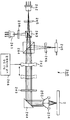
본 발명을 적용한 광픽업(3)은 도2에 도시하는 바와 같이 제1 파장의 광 빔을 출사하는 제1 출사부를 갖는 제1 광원부(31)와, 제1 파장보다 긴 제2 파장의 광 빔을 출사하는 제2 출사부를 갖는 제2 광원부(32)와, 제2 파장보다 긴 제3 파장의 광 빔을 출사하는 제3 출사부를 갖는 제3 광원부(33)와, 이 제1 내지 제3 출사부로부터 출사된 광 빔을 광디스크(2)의 신호 기록면 상에 집광하는 대물렌즈(34)와, 제1 내지 제3 출사부와 대물렌즈(34)의 사이의 광로 상에 설치되는 회절 광학 소자(35)를 구비한다.As shown in FIG. 2, the
또한, 광픽업(3)은 제2 및 제3 출사부와 회절 광학 소자(35)의 사이에 설치되어 제2 출사부로부터 출사된 제2 파장의 광 빔의 광로와 제3 출사부로부터 출사된 제3 파장의 광 빔의 광로를 합성하는 광로 합성 수단으로서 제1 빔 스플리터(36)와, 제1 빔 스플리터(36)와 회절 광학 소자(35)의 사이에 설치되어 제1 빔 스플리터(36)에 의해 광로가 합성된 제2 및 제3 파장의 광 빔의 광로와 제1 출사부로부터 출사된 제1 파장의 광 빔의 광로를 합성하는 광로 합성 수단으로서 제2 빔 스플리터(37)와, 제2 빔 스플리터(37)와 회절 광학 소자(35)의 사이에 설치되어 제 2 빔 스플리터(37)에 의해 광로가 합성된 제1 내지 제3 파장의 광 빔의 왕로(往路)의 광로와 광디스크에서 반사된 제1 내지 제3 파장의 광 빔의 복귀(이하, 「귀로」라고도 한다.) 광로를 분리하는 광로분리 수단으로서 제3 빔 스플리터(38)를 갖는다.The
또한, 광픽업(3)은 제1 광원부(31)의 제1 출사부와 제2 빔 스플리터(37)의 사이에 설치되어 제1 출사부로부터 출사된 제1 파장의 광 빔을 트래킹 에러 신호 등의 검출을 위하여 3빔으로 회절시키는 제1 그레이팅(39)과, 제2 광원부(32)의 제2 출사부와 제1 빔 스플리터(36)의 사이에 설치되어 제2 출사부로부터 출사된 제2 파장의 광 빔을 트래킹 에러 신호 등의 검출을 위하여 3빔으로 회절시키는 제2 그레이팅(40)과, 제3 광원부(33)의 제3 출사부와 제1 빔 스플리터(36)의 사이에 설치되어 제3 출사부로부터 출사된 제3 파장의 광 빔을 트래킹 에러 신호 등의 검출을 위하여 3빔으로 회절시키는 제3 그레이팅(41)을 갖는다.The
또한, 광픽업(3)은 제3 빔 스플리터(38)와 회절 광학 소자(35)의 사이에 설치되어 제3 빔 스플리터(38)에 의해 광로가 합성된 제1 내지 제3 파장의 광 빔의 발산각을 변환하여 대략 평행광의 상태 또는 대략 평행광에 대하여 확산 혹은 수렴된 상태가 되도록 조정하여 출사시키는 발산각 변환 수단으로서의 콜리메이터 렌즈(42)와, 콜리메이터 렌즈(42)와 회절 광학 소자(35)의 사이에 설치되어 콜리메이터 렌즈(42)에 발산각이 조정된 제1 내지 제3 파장의 광 빔에 1/4 파장의 위상차를 부여하는 1/4 파장판(43)과, 회절 광학 소자(35)와 1/4 파장판(43)의 사이에 설치되어 대물렌즈(34) 및 회절 광학 소자(35)의 광축에 대략 직교하는 평면 내에서 상 술한 광학 부품을 경유한 광 빔을 반사하여 기동함으로써 대물렌즈(34) 및 회절 광학 소자(35)의 광축 방향에 광 빔을 출사시키는 기동 미러(44)를 갖는다.The
또한, 광픽업(3)은 제3 빔 스플리터(38)에 의해 왕로의 제1 내지 제3 파장의 광 빔의 광로로부터 분리된 귀로의 제1 내지 제3 파장의 광 빔을 수광하여 검출하는 광검출기(45)와, 제3 빔 스플리터(38)와 광검출기(45)의 사이에 설치되어 제3 빔 스플리터(38)에 의해 분리된 귀로의 제1 내지 제3 파장의 광 빔을 광검출기(45)의 포토디텍터(photodetector) 등의 수광면에 집광시키는 동시에 포커스 에러 신호 등의 검출을 위한 비점 수차를 부여하는 멀티 렌즈(46)를 갖는다.The
제1 광원부(31)는 제1 광디스크(11)에 대하여 405nm 정도의 제1 파장의 광 빔을 출사하는 제1 출사부를 갖는다. 제2 광원부(32)는 제2 광디스크(12)에 대하여 655nm 정도의 제2 파장의 광 빔을 출사하는 제2 출사부를 갖는다. 제3 광원부(33)는 제3 광디스크에 대하여 785nm 정도의 제3 파장의 광 빔을 출사하는 제3 출사부를 갖는다. 또한, 여기서는 제1 내지 제3 출사부를 각각 별개의 광원부(31, 32, 33)에 배치하도록 구성했지만, 이에 한정되는 것이 아니라 제1 내지 제3 출사부 중의 2개의 출사부를 갖는 광원부와, 나머지 1개의 출사부를 갖는 광원부를 다른 위치에 배치하도록 구성해도 되며, 또한, 제1 내지 제3 출사부를 대략 동일 위치에 갖는 광원부가 되도록 구성해도 된다.The first
대물렌즈(34)는 입사된 제1 내지 제3 파장의 광 빔을 광디스크(2)의 신호 기록면 상에 집광시킨다. 이 대물렌즈(34)는 도시하지 않은 2축 액추에이터 등의 대물렌즈 구동 기구에 의해 이동 가능하도록 유지되어 있다. 그리고, 이 대물렌 즈(34)는 광검출기(45)에 의해 검출된 광디스크(2)로부터의 복귀광의 RF 신호에 의해 생성된 트래킹 에러 신호 및 포커스 에러 신호에 기초하여 2축 액추에이터 등에 의해 이동 조작됨으로써 광디스크(2)에 근접 이간하는 방향 및 광디스크(2)의 직경 방향의 2축 방향으로 이동된다. 대물렌즈(34)는 제1 내지 제3 출사부로부터 출사되는 광 빔이 광디스크(2)의 신호 기록면 상에서 항상 초점이 맞도록 이 광 빔을 수렴하는 동시에 이 수렴된 광 빔을 광디스크(2)의 신호 기록면 상에 형성된 기록 트랙에 추종시킨다. 또한, 대물렌즈(34)가 유지되는 대물렌즈 구동 기구의 렌즈 홀더에 이 대물렌즈(34)와 일체가 되도록 후술하는 회절 광학 소자(35)를 유지하도록 구성함으로써 대물렌즈(34)의 트래킹 방향으로의 이동 등의 시야 요동(visual field fluctuation) 시에도 회절 광학 소자(35)에 설치한 회절부(50)의 후술하는 작용 효과를 적절하게 발휘할 수 있다.The
회절 광학 소자(35)는 그 일면으로서 예를 들어 입사측의 면에 복수의 회절 영역으로 이루어지는 회절부(50)가 설치되어 있고, 이 회절부(50)에 의해 복수의 회절 영역마다 통과하는 제1 내지 제3 파장의 광 빔의 각각을 소정의 차수가 되도록 회절시켜 대물렌즈(34)에 입사시키고, 즉, 소정의 발산각을 갖는 확산 상태 또는 수렴 상태의 광 빔으로서 대물렌즈(34)에 입사시킴으로써 이 단일 대물렌즈(34)를 이용하여 제1 내지 제3 파장의 광 빔을 각각 대응하는 3종류의 광디스크의 신호 기록면에 구면 수차가 발생하지 않도록 적절하게 집광되는 것을 가능하게 한다. 이러한 회절 광학 소자(35)는 대물렌즈(34)와 함께 3개의 다른 파장의 광 빔을 각각 대응하는 광디스크의 신호 기록면에 구면 수차를 발생하지 않도록 적절하게 집 광되는 집광 광학 디바이스로서 기능한다.The diffractive
회절부(50)를 갖는 회절 광학 소자(35)는 예를 들어 도3의 (a)에 도시하는 바와 같이 회절부(50)를 통과한 제1 파장의 광 빔(BB0)을 +1차 회절광(BB1)이 되도록 회절시켜 대물렌즈(34)에 입사시키고, 즉, 소정의 발산각을 갖는 확산 상태의 광 빔으로서 대물렌즈(34)에 입사시킴으로써 제1 광디스크(11)의 신호 기록면에 적절하게 집광시키고, 도3의 (b)에 도시하는 바와 같이 회절부(50)를 통과한 제2 파장의 광 빔(BD0)을 -1차 회절광(BD1)이 되도록 회절시켜 대물렌즈(34)에 입사시키고, 즉, 소정의 발산각을 갖는 수렴 상태의 광 빔으로서 대물렌즈(34)에 입사시킴으로써 제2 광디스크(12)의 신호 기록면에 적절하게 집광시키고, 도3의 (c)에 도시하는 바와 같이 회절부(50)를 통과한 제3 파장의 광 빔(BC0)을 -2차 회절광(BC1)이 되도록 회절시켜 대물렌즈(34)에 입사시키고, 즉, 소정의 발산각을 갖는 수렴 상태의 광 빔으로서 대물렌즈(34)에 입사시킴으로써 제3 광디스크(13)의 신호 기록면에 적절하게 집광시킴으로써 단일의 대물렌즈(34)를 이용하여 3종류의 광디스크의 신호 기록면에 구면 수차를 발생하지 않도록 적절하게 집광되는 것을 가능하게 한다. 또한, 여기서는 회절부(50)의 복수의 회절 영역에 있어서 동일 파장의 광 빔을 동일 회절 차수의 회절광으로 하는 예에 대하여 도3을 이용하여 설명했지만, 본 발명을 적용한 광픽업(3)을 구성하는 회절부(50)는 후술하는 바와 같이 각 영역마다 각 파장에 대한 회절 차수를 설정하여 보다 구면 수차를 저감하도록 구성하는 것을 가능하게 한다.The diffractive
구체적으로, 도4의 (a) 및 도4의 (b)에 도시하는 바와 같이 회절 광학 소 자(35)의 입사측의 면에 설치된 회절부(50)는 최내주부에 설치되고 대략 원형 형상의 제1 회절 영역(이하, 「내측 고리띠」라고도 한다.)(51)과, 제1 회절 영역(51)의 외측에 설치되고 고리띠 형상의 제2 회절 영역(이하, 「중간 고리띠」라고도 한다.)(52)과, 제2 회절 영역(52)의 외측에 설치되고 고리띠 형상의 제3 회절 영역(이하, 「외측 고리띠」라고도 한다.)(53)을 갖는다.Specifically, as shown in Figs. 4A and 4B, the
내측 고리띠인 제1 회절 영역(51)은 고리띠 형상이고 또한 소정의 깊이를 갖는 제1 회절 구조가 형성되어 통과하는 제1 파장의 광 빔의 대물렌즈(34)를 통하여 제1 광디스크의 신호 기록면에 적절한 스폿을 형성하도록 집광되는 차수의 회절광이 지배적으로 되도록 즉, 다른 차수의 회절광에 대하여 최대의 회절 효율이 되도록 발생시킨다.The first
또한, 제1 회절 영역(51)은 제1 회절 구조에 의해 통과하는 제2 파장의 광 빔의 대물렌즈(34)를 통하여 제2 광디스크의 신호 기록면에 적절한 스폿을 형성하도록 집광되는 차수의 회절광이 지배적으로 되도록 즉, 다른 차수의 회절광에 대하여 최대의 회절 효율이 되도록 발생시킨다.The first
또한, 제1 회절 영역(51)은 제1 회절 구조에 의해 통과하는 제3 파장의 광 빔의 대물렌즈(34)를 통하여 제3 광디스크의 신호 기록면에 적절한 스폿을 형성하도록 집광되는 차수의 회절광이 지배적으로 되도록 즉, 다른 차수의 회절광에 대하여 최대의 회절 효율이 되도록 발생시킨다.The first
이와 같이 제1 회절 영역(51)은 상술한 각 파장의 광 빔에 대하여 상술한 소정의 차수의 회절광이 지배적으로 되는 데에 적합한 회절 구조가 형성되어 있기 때 문에 제1 회절 영역(51)을 통과하여 소정의 차수의 회절광으로 된 각 파장의 광 빔이 대물렌즈(34)에 의해 각각의 광디스크의 신호 기록면에 집광될 때의 구면 수차를 보정하여 저감하는 것을 가능하게 한다.As described above, the first
구체적으로는 제1 회절 영역(51)은 도4 및 도5의 (a)에 도시하는 바와 같이 광축을 중심으로 한 고리띠 형상으로 이 고리띠의 단면 형상이 소정의 깊이(이하, 「홈 깊이」라고도 한다.)(d)로 소정의 스텝수(S)(S는 정의 정수로 한다.)의 계단 형상(이하, 「멀티 스텝의 계단 형상」이라고도 한다.)이 반경 방향으로 연속하여 형성되어 있다. 여기서 상술한 회절 구조에 있어서의 고리띠의 단면 형상이란 고리띠의 반경 방향을 포함하는 면, 즉, 고리띠의 접선 방향에 직교하는 면에 있어서의 단면 형상을 의미한다. 또한, 여기서 소정의 스텝수(S)의 계단 형상을 갖는 회절 구조란 각 단의 깊이가 대략 동일 깊이로 된 제1 내지 제S의 단부를 갖는 단부가 반경 방향으로 연속하여 형성되어 있는 구조이며, 또한, 환언하면 광축 방향에 대략 동일 간격으로 형성된 제1 내지 제(S+1)의 회절면을 갖고서 형성되어 있는 구조이다. 또한, 회절 구조에 있어서의 소정의 깊이(d)는 계단 형상의 가장 표면측(최고단, 낮은 위치)에 위치되는 제(S+1) 회절면과, 계단 형상의 가장 소자측(최저단, 깊은 위치)에 위치되는 제1 회절면의 광축 방향의 길이를 의미한다. 이 점에 대하여는 후술하는 도5의 (b) 및 도5의 (c)에 대하여도 마찬가지이다. 또한, 도5의 (a) 내지 도5의 (c)에 있어서는 계단 형상의 각 단부 내에 있어서 단부가 반경 방향의 외측을 향하여 형성, 즉, 단부가 반경 방향의 외측을 향함에 따라서 표면측을 향하여 형성되도록 구성했지만, 이에 한정되는 것은 아니고, 내측 고리띠, 중간 고리띠 및 외측 고리띠의 회절 구조에 있어서 계단 형상의 각 단부 내에 있어서 단부가 반경 방향의 내측을 향하여 형성되도록 구성해도 좋다. 구체적으로는 각 회절 구조에 있어서의 지배적으로 되는 회절 차수 및 후술하는 홈 폭을 설정함으로써 소정의 회절 각도 및 회절 효율을 얻는 동시에 회절 차수가 플러스인지 마이너스인지에 따라서 계단 형상의 형성 방향을 설정함으로써 원하는 발산각을 갖는 확산 상태 또는 수렴 상태를 얻을 수 있다. 도5의 (a) 내지 도5의 (c) 중 RO는 고리띠의 반경 방향 외측을 향한 방향을 나타내는, 즉, 광축으로부터 이격되는 방향을 나타내는 것이다.Specifically, as shown in Figs. 4 and 5A, the first
또한, 제1 회절 영역(51)에 형성되는 제1 회절 구조 및 후술하는 제2 및 제3 회절 구조에 있어서 홈 깊이(d) 및 스텝수(S)는 지배적으로 되는 회절 차수, 및 회절 효율을 고려하여 결정되어 있다. 또한, 각 단부의 홈 폭(계단 형상의 각 단부의 반경 방향의 치수)은 도5의 (a) 내지 도5의 (c)에 도시하는 바와 같이 하나의의 계단부 내에 있어서 동일하게 형성되어 있는 동시에 반경 방향으로 연속하여 형성되어 있는 다른 계단부 간에 있어서 광축으로부터 이격함에 따라서 그 값이 작아지도록 형성되어 있다. 또한, 이 홈 폭은 광디스크의 신호 기록면 상에서 집광되는 스폿이 최적이 되도록 이 홈 폭으로 형성된 회절 영역으로 부여되는 위상차에 기초하여 결정되어 있다.In the first diffractive structure formed in the first
예를 들어 제1 회절 영역(51)의 회절 구조는 도5의 (a)에 도시하는 바와 같이 스텝수가 4(S = 4)로 된 회절 구조이며, 각 단의 깊이가 대략 동일 깊이(d/4)로 된 제1 내지 제4 계단부(51s1, 51s2, 51s3, 51s4)을 갖는 단부가 반경 방향으로 연속하여 형성어 있고 또한, 광축 방향으로 간격이 (d/4)로 동일 간격으로 형성된 제1 내지 제5 회절면(51f1, 51f2, 51f3, 51f4, 51f5)을 갖고서 형성되어 있다.For example, as shown in FIG. 5A, the diffractive structure of the first
또한, 여기에서는 고리띠의 단면 형상이 멀티 스텝의 계단 형상으로 되는 회절 구조를 갖는 제1 회절 영역(51)이 형성되어 있는 것으로서 설명하지만, 상술한 바와 같은 각 파장의 광 빔에 대하여 소정의 차수의 광 빔이 지배적으로 되는 회절 구조이면 되며, 예를 들어 고리띠의 단면 형상이 도6에 도시하는 바와 같은 소정의 깊이(d)의 블레이즈 형상이 되는 회절 구조를 갖는 회절 영역(51B)이 형성되도록 구성해도 좋다.Here, it is assumed that the
또한, 제1 회절 영역(51)은 통과하는 제1 파장의 광 빔의 차수(k1i)의 회절광이 지배적으로 되도록 즉, 회절 효율이 최대가 되도록 발생시키고 또한 통과하는 제2 파장의 광 빔의 차수(k2i)의 회절광이 지배적으로 되도록 즉, 회절 효율이 최대가 되도록 발생시키고 또한 통과하는 제3 파장의 광 빔의 차수(k3i)의 회절광이 지배적으로 되도록 발생시킬 경우에 k1i, k2i, k3i가 모두 0 이외의 것이고, k1i와 k2i가 이(異)부호(k1i×k2i <0)이며, k2i와 k3i가 동일 부호(k2i×k3i>0)로 되도록 되어 있다. 또한, 상술한 경우에 있어서 k1i와 k3i가 이부호가 되도록 되어 있다.The first
여기서 제1 회절 영역(51)은 회절 효율이 최대가 되는 제1 파장의 회절 차수(k1i)가 0 이외로 되어 있음으로써 대물렌즈(34)에 의한 커플링을 저하시킬 수 있고, 광원 복귀광 노이즈의 문제를 방지할 수 있어 종래의 광원 출사에 있어서 출력을 적당한 범위로 억제하지 않으면 안되는 등의 문제를 회피할 수 있다. 또한, 제1 회절 영역(51)에 있어서 회절 효율이 최대가 되는 제2 및 제3 파장의 회절 차수(k2i, k3i)를 0으로 했을 경우의 수차 및 효율이 최선이 되는 조합이 존재하지 않는다. 환언하면, 제1 회절 영역(51)에 있어서 k2i, k3i가 0 이외로 되어 있음으로써 수차 및 효율을 확보할 수 있는 조합이라고 할 수 있다.Here, the diffraction order (k1i) of the first wavelength at which the diffraction efficiency becomes the maximum is set to be other than 0 in the first
제1 회절 영역(51)은 회절 효율이 최대가 되는 각 파장의 회절 차수(k1i, k2i, k3i)의 관계가 k1i와 k2i가 이부호이고, k2i와 k3i가 동일 부호가 되도록 구성되어 있음으로써 복수 종류의 광디스크에 대하여 각 파장의 광 빔에 대하여 동일한 대물렌즈(34)에 의해 집광할 경우에 있어서 구면 수차를 보다 저감시키는 것을 가능하게 한다. 이는 상술한 바와 같은 제1 내지 제3 광디스크에 대하여 대물렌즈(34)를 설계할 경우에 보호층의 설계 센터를 0.1 내지 0.6으로 설정하는 경우가 많기 때문에 그 설계 센터에 대하여 제1 파장의 광 빔에 부여하는 극성과, 제2 및 제3 파장의 광 빔에 부여하는 극성이 반대로 되도록 함으로써 구면 수차를 억제할 수 있다고 하는 사고방식에 의한 것이다.The first
또한, 제1 회절 영역(51)은 회절 효율이 최대가 되는 각 파장의 회절 차수(k1i, k2i, k3i)가 이하에서 나타내는 관계 중 어느 하나가 되도록 구성되어 있다. (k1i, k2i, k3i) = (+1, -1, -2), (-1, +1, +2), (+1, -2, -3), (-1, +2, +3), (+2, -1, -2), (-2, +1, +2), (+2, -2, -3), (-2, +2, +3).The first
이하에 내측 고리띠인 제1 회절 영역(51)의 구체적인 실시예로서 깊이(d) 및 스텝수(S)에 관한 구체적인 수치를 들어 각 파장의 광 빔에 대하여 지배적으로 되는 차수의 회절광의 회절 차수, 및 그 회절 차수의 회절광의 회절 효율에 대하여 표1에 나타낸다. 또한, 표1은 제1 회절 영역(51)의 실시예로서 제1 내측 고리띠 구성예 내지 제4 내측 고리띠 구성예에 대하여 나타낸 것으로, 표1 중 k1i는 제1 파장의 광 빔의 회절 효율이 최대가 되는 회절 차수를 나타내고, eff1은 제1 파장의 광 빔의 회절 효율이 최대가 되는 회절 차수의 회절 효율을 나타내고, k2i는 제2 파장의 광 빔의 회절 효율이 최대가 되는 회절 차수를 나타내고, eff2은 제2 파장의 광 빔의 회절 효율이 최대가 되는 회절 차수의 회절 효율을 나타내고, k3i는 제3 파장의 광 빔의 회절 효율이 최대가 되는 회절 차수를 나타내고, eff3는, 제3 파장의 광 빔의 회절 효율이 최대가 되는 회절 차수의 회절 효율을 나타내고, d는 제1 회절 영역(51)의 홈 깊이 즉 계단 형상의 최저단으로부터 최고단까지의 거리를 나타내고, S는 제1 회절 영역(51)의 계단 형상의 스텝수를 나타내는 것이다.As a specific example of the
[표 1][Table 1]

여기서 표1에 도시하는 제1 내측 고리띠 구성예에 관하여 설명한다. 제1 내측 고리띠 구성예에 있어서는 표1에 나타내는 바와 같이 홈 깊이(d) = 3.8(μm), 스텝수(S) = 4로 했을 때의, 제1 파장의 광 빔의 회절 차수(k1i) = +1의 회절 효 율(eff1) = 0.81이며, 제2 파장의 광 빔의 회절 차수(k2i) = -1의 회절 효율(eff2) = 0.62이며, 제3 파장의 광 빔의 회절 차수(k3i) = -2의 회절 효율(eff3) = 0.57이다. 다음에 이 제1 내측 고리띠 구성예에 대하여 도7의 (a) 내지 도7의 (c)를 이용하여 더욱 구체적으로 설명한다. 도7의 (a)는 스텝수(S) = 4의 계단 형상의 홈 깊이(d)를 변화시켰을 경우의 제1 파장의 광 빔의 +1차 회절광의 회절 효율의 변화를 나타내는 도면이고, 도7의 (b)는 스텝수(S) = 4의 계단 형상의 홈 깊이(d)를 변화시켰을 경우의 제2 파장의 광 빔의 -1차 회절광의 회절 효율의 변화를 나타내는 도면이고, 도7의 (c)는 스텝수(S) = 4의 계단 형상의 홈 깊이(d)를 변화시켰을 경우의 제3 파장의 광 빔의 -2차 회절광의 회절 효율의 변화를 나타낸 도면이다. 도7의 (a) 내지 도7의 (c) 중에 있어서 가로축은 홈 깊이(nm)를 나타내고, 종축은 회절 효율(광의 강도)을 나타낸다. 그리고, 가로축이 3800nm의 위치에 있어서 도7의 (a)에 도시하는 바와 같이 eff1은 0.81이며, 도7의 (b)에 도시하는 바와 같이 eff2은 0.62이며, 도7의 (c)에 도시하는 바와 같이 eff3은 0.57이다.Here, the first inner ring band configuration example shown in Table 1 will be described. (K1i) of the light beam of the first wavelength when the groove depth (d) is 3.8 占 퐉 and the step number (S) is 4 as shown in Table 1 in the first inner ring band constitution example, = +1, the diffraction efficiency eff2 of the light beam of the second wavelength k2i = -1 is 0.62, the diffraction order of the light beam of the third wavelength k3i ) = -2 diffraction efficiency (eff3) = 0.57. Next, the first inner ring band constitution example will be described more specifically with reference to Figs. 7 (a) to 7 (c). 7A is a diagram showing a change in the diffraction efficiency of the + first-order diffracted light of the light beam of the first wavelength when the groove depth d of the step shape of step number S = 4 is changed, and FIG. (B) of Fig. 7 is a diagram showing the variation of the diffraction efficiency of the -1st-order diffracted light of the light beam of the second wavelength when the groove depth d of the step shape of the step number S is changed, (C) is a diagram showing a change in the diffraction efficiency of the second-order diffracted light of the light beam of the third wavelength when the groove depth d of the step shape of step number S = 4 is changed. 7A to 7C, the horizontal axis represents the groove depth (nm), and the vertical axis represents the diffraction efficiency (light intensity). 7 (a), eff1 is 0.81, and eff2 is 0.62 as shown in Fig. 7 (b), and as shown in Fig. 7 (c) As shown, eff3 is 0.57.
또한, 표1에 도시하는 제2 내측 고리띠 구성예에 대하여도 마찬가지로, d = 5.3(μm), S = 6으로 했을 때에 표1 및 도8의 (a) 내지 도8의 (c)에 도시하는 바와 같이 각 차수(k1i, k2i, k3i) 및 각 회절 효율(eff1, eff2, eff3)을 얻을 수 있고, 표1에 나타내는 제3 내측 고리띠 구성예에 대하여도 마찬가지로, d = 5.1(μm), S = 5로 했을 때에 표1 및 도9의 (a) 내지 도9의 (c)에 도시하는 바와 같이 각 차수(k1i, k2i, k3i) 및 각 회절 효율(eff1, eff2, eff3)을 얻을 수 있고, 표1에 나타내는 제4 내측 고리띠 구성예에 대하여도 마찬가지로, d = 5.8(μm), S = 6으로 했을 때에 표1 및 도10의 (a) 내지 도10의 (c)에 도시하는 바와 같이 각 차수(k1i, k2i, k3i) 및 각 회절 효율(eff1, eff2, eff3)을 얻을 수 있게 된다.8 (a) to 8 (c), when d = 5.3 (μm) and S = 6, similarly to the second example of the inner ring band shown in Table 1 And the diffraction efficiencies eff1, eff2 and eff3 are obtained as shown in Table 1. In the third inner ring band example shown in Table 1, d = 5.1 (mu m) (K1i, k2i, k3i) and the respective diffraction efficiencies eff1, eff2, eff3 are obtained as shown in Table 1 and FIGS. 9A to 9C when S = Similarly, for the fourth example of the inner ring band shown in Table 1, when d = 5.8 (μm) and S = 6, the results are shown in Tables 1 and 10 (a) to The respective orders k1i, k2i, k3i and the respective diffraction efficiencies eff1, eff2, eff3 can be obtained as shown in Fig.
중간 고리띠인 제2 회절 영역(52)은 고리띠 형상이고 또한 소정의 깊이를 갖고 제1 회절 구조와는 상이한 구조로 한 제2 회절 구조가 형성되어 통과하는 제1 파장의 광 빔의 대물렌즈(34)를 통하여 제1 광디스크의 신호 기록면에 적절한 스폿을 형성하도록 집광되는 차수의 회절광이 지배적으로 되도록 즉, 다른 차수의 회절광에 대하여 최대의 회절 효율이 되도록 발생시킨다.The second
또한, 제2 회절 영역(52)은 제2 회절 구조에 의해 통과하는 제2 파장의 광 빔의 대물렌즈(34)를 통하여 제2 광디스크의 신호 기록면에 적절한 스폿을 형성하도록 집광되는 차수의 회절광이 지배적으로 되도록 즉, 다른 차수의 회절광에 대하여 최대의 회절 효율이 되도록 발생시킨다.The second
또한, 제2 회절 영역(52)은 제2 회절 구조에 의해 통과하는 제3 파장의 광 빔의 대물렌즈(34)를 통하여 제3 광디스크의 신호 기록면에 적절한 스폿을 형성하도록 집광되는 차수 이외의 차수의 회절광이 지배적으로 되도록 즉, 다른 차수의 회절광에 대하여 최대의 회절 효율이 되도록 발생시킨다. 또한, 제2 회절 영역(52)은 제2 회절 구조에 의해 통과하는 제3 파장의 광 빔의 대물렌즈(34)를 통하여 제3 광디스크의 신호 기록면에 적절한 스폿을 형성하도록 집광되는 차수의 회절광의 회절 효율을 충분하게 저감할 수 있다.The second
이와 같이 제2 회절 영역(52)은 상술한 각 파장의 광 빔에 대하여 상술한 소정의 차수의 회절광이 지배적으로 되는데에 적합한 회절 구조가 형성되어 있기 때 문에 제2 회절 영역(52)을 통과하여 소정의 차수의 회절광으로 된 제1 및 제2 파장의 광 빔이 대물렌즈(34)에 의해 각각의 광디스크의 신호 기록면에 집광될 때의 구면 수차를 보정하여 저감하는 것을 가능하게 한다.As described above, the second
또한, 제2 회절 영역(52)은 제1 및 제2 파장의 광 빔에 대하여는 상술한 바와 같이 기능하는 동시에 제3 파장의 광 빔에 대하여는 이 제2 회절 영역(52)을 통과하여 대물렌즈(34)를 통하여 제3 광디스크의 신호 기록면에 집광되는 차수 이외의 차수의 회절광이 지배적으로 되도록 구성되어 있는 점에서 이 제2 회절 영역(52)을 통과한 제3 파장의 광 빔이 대물렌즈(34)에 입사해도 제3 광디스크의 신호 기록면에는 대부분 영향을 주는 일 없이 환언하면, 이 제2 회절 영역(52)을 통과하여 대물렌즈(34)에 의해 신호 기록면에 집광되는 제3 파장의 광 빔의 광량을 대폭 저감하여 대략 제로로 하여 제3 파장의 광 빔에 대하여 개구 제한을 행하도록 기능할 수 있다.The second
그런데, 상술한 제1 회절 영역(51)은 그 영역을 통과한 제3 파장의 광 빔이 NA = 0.45 정도로 개구 제한되는 광 빔과 동일한 상태로 대물렌즈(34)에 입사되는 바와 같은 크기로 형성되어 있고 또한 이 제1 회절 영역(51)의 외측에 형성되는 제2 회절 영역(52)은 이 영역을 통과한 제3 파장의 광 빔을 대물렌즈(34)를 통하여 제3 광디스크 상에 집광시키지 않고 있기 때문에 상기 구성으로 한 제1 및 제2 회절 영역(51, 52)을 구비하는 회절부(50)는 제3 파장의 광 빔에 대하여 NA = 0.45 정도로 개구 제한을 하도록 기능하게 된다. 여기에서는 회절부(50)에 있어서 제3 파장의 광 빔에 대하여 개구수(NA)를 0.45 정도로 개구 제한을 하도록 구성했지만, 상술한 구성에 의해 제한되는 개구수는 이에 한정되는 것은 아니다.The first
구체적으로는 제2 회절 영역(52)은 상술한 제1 회절 영역(51)과 마찬가지로, 도4 및 도5의 (b)에 도시하는 바와 같이 광축을 중심으로 한 고리띠 형상으로 이 고리띠의 단면 형상이 소정의 깊이(d)이고 소정의 스텝수(S)의 계단 형상이 반경 방향으로 연속하여 형성되어 있다. 또한, 여기서 제2 회절 영역(52)은 제1 회절 영역(51)의 경우와 비교하여 d 및/또는 S의 수치가 다르게 되어 있어 즉, 제1 회절 영역(51)에 설치된 제1 회절 구조와는 다른 제2 회절 구조가 형성되어 있다. 예를 들어 도5의 (b)에 도시하는 제2 회절 영역(52)의 회절 구조는 스텝수가 3(S = 3)으로 된 회절 구조이며, 각 단의 깊이가 대략 동일 깊이(d/3)로 된 제1 내지 제3 단부(52s1, 52s2, 52s3)를 갖는 단부가 반경 방향으로 연속하여 형성되어 있고 또한 광축 방향으로 간격이 (d/3)로 동일 간격으로 형성된 제1 내지 제4 회절면(52f1, 52f2, 52f3, 52f4)을 갖고서 형성되어 있다.4 and 5 (b), the second
또한, 여기에서는 고리띠의 단면 형상이 멀티 스텝의 계단 형상이 되는 바와 같은 회절 구조를 갖는 제2 회절 영역(52)이 형성되어 있는 것으로서 설명하지만, 상술한 제1 회절 영역과 마찬가지로, 상술한 바와 같은 각 파장의 광 빔에 대하여 소정의 차수의 광 빔이 지배적으로 되는 회절 구조이면 되며, 예를 들어 고리띠의 단면 형상이 상술한 도6에 도시하는 바와 같은 소정의 깊이(d)의 블레이즈 형상으로 되는 회절 구조를 갖는 회절 영역(52B)이 형성되도록 구성해도 좋다.Although the second
또한, 제2 회절 영역(52)은 통과하는 제1 파장의 광 빔의 차수(k1m)의 회절광이 지배적으로 되도록 즉, 회절 효율이 최대가 되도록 발생시키고 또한 통과하는 제2 파장의 광 빔의 차수(k2m)의 회절광이 지배적으로 되도록 즉, 회절 효율이 최대가 되도록 발생시킬 경우에 회절 차수(k1m, k2m)가 예를 들어 이하에서 나타내는 관계가 되도록 구성되어 있다. (k1m, k2m) = (+1, -1), (-1, +1), (+1, -2), (-1, +2), (+2, -1), (-2, +1).Further, the second
이하에 중간 고리띠인 제2 회절 영역(52)의 구체적인 실시예로서 깊이(d) 및 스텝수(S)에 관한 구체적인 수치를 들어 각 파장의 광 빔에 대하여 지배적으로 되는 차수의 회절광의 회절 차수, 및 그 회절 차수의 회절광의 회절 효율에 대하여 표2에 나타낸다. 또한, 표2는 제2 회절 영역(52)의 실시예로서 제1 중간 고리띠 구성예 내지 제3 중간 고리띠 구성예에 대하여 나타내는 것으로, 표2 중 k1m은 제1 파장의 광 빔의 회절 효율이 최대가 되는 회절 차수를 나타내고, eff1은 제1 파장의 광 빔의 회절 효율이 최대가 되는 회절 차수의 회절 효율을 나타내고, k2m은 제2 파장의 광 빔의 회절 효율이 최대가 되는 회절 차수를 나타내고, eff2은 제2 파장의 광 빔의 회절 효율이 최대가 되는 회절 차수의 회절 효율을 나타내고, k3m은 제3 파장의 광 빔의 하기와 같이 선택된 회절 차수를 나타내고, eff3은 제3 파장의 광 빔의 선택된 회절 차수의 회절 효율을 나타내고, d는 제2 회절 영역(52)의 홈 깊이 즉 계단 형상의 최저단으로부터 최고단까지의 거리를 나타내고, S는 제2 회절 영역(52)의 계단 형상의 스텝수를 나타내는 것이다. 또한, 표2 중 「※」은 이 구성예의 중간 고리띠를 통과하는 광 빔의 대물렌즈(34)를 통하여 대응하는 광디스크의 신호 기록면에 적절하게 스폿을 형성하도록 집광되는 회절 차수, 환언하면 대응하는 광디스크의 신호 기록면에 있어서 구면 수차 보정이 가능한 회절 차수를 나타 내는 것이며, 「~0」은 회절 효율이 대략 0의 상태를 나타내는 것이다.As a specific example of the second
[표 2][Table 2]

여기서 표2에 도시하는 제1 중간 고리띠 구성예에 관하여 설명한다. 제1 중간 고리띠 구성예에 있어서는 표2에 나타내는 바와 같이 홈 깊이(d) = 8.6(μm), 스텝수(S) = 3으로 했을 때, 제1 파장의 광 빔의 회절 차수(k1m) = -1의 회절 효율(eff1) = 0.76이며, 제2 파장의 광 빔의 회절 차수(k2m) = +1의 회절 효율(eff2) = 0.77이다. 또한, 이 영역을 통과하는 제3 파장의 광 빔의 대물렌즈(34)를 통하여 제3 광디스크의 신호 기록면에 스폿을 형성하도록 집광되는 회절 차수(k3m)의 회절 효율(eff3)이 대략 0이다.Here, the first intermediate loop band constitution example shown in Table 2 will be described. In the first intermediate loop band constitution example, when the groove depth d = 8.6 (μm) and the step number S = 3, the diffraction order (k1m) of the light beam of the first wavelength = -1 is 0.76, and the diffraction efficiency (eff2) of the diffraction order (k2m) = +1 of the light beam of the second wavelength = 0.77. The diffraction efficiency eff3 of the diffraction order (k3m) converged so as to form a spot on the signal recording surface of the third optical disk through the
다음에 이 제1 중간 고리띠 구성예에 대하여 도11의 (a) 내지 도11의 (c)를 이용하여 더욱 구체적으로 설명한다. 도11의 (a)는 스텝수(S) = 3의 계단 형상의 홈 깊이(d)를 변화시켰을 경우의 제1 파장의 광 빔의 -1차 회절광의 회절 효율의 변화를 나타내는 도면이고, 도11의 (b)는 스텝수(S) = 3의 계단 형상의 홈 깊이(d)를 변화시켰을 경우의 제2 파장의 광 빔의 +1차 회절광의 회절 효율의 변화를 나타내는 도면이고, 도11의 (c)는 스텝수(S) = 3의 계단 형상의 홈 깊이(d)를 변화시켰을 경우의 제3 파장의 광 빔의 +2차 회절광의 회절 효율의 변화를 나타낸 도면이다. 도11의 (a) 내지 도11의 (c) 중에 있어서 가로축은 홈 깊이(nm)를 나타내고, 종축은 회절 효율(광의 강도)을 나타낸 도면이다. 그리고, 가로축이 8600nm의 위치에 있어서 도11의 (a)에 도시하는 바와 같이 eff1은 0.76이며, 도11의 (b)에 도시하는 바와 같이 eff2는 0.77이며, 도11의 (c)에 도시하는 바와 같이 eff3은 대략 0이다. 또한, 여기서 상기에서 「※」로 나타낸 제3 파장의 광 빔의 회절 차수(k3m)는 k3m = +2이다.Next, the first intermediate loop band constitution example will be described more specifically with reference to Figs. 11 (a) to 11 (c). 11A is a diagram showing a change in the diffraction efficiency of -1st order diffracted light of the light beam of the first wavelength when the groove depth d of the step shape of step number S is changed, 11 (b) is a diagram showing a change in the diffraction efficiency of the + 1st-order diffracted light of the light beam of the second wavelength when the stepped groove depth d of step number S is changed, and FIG. 11 (C) is a diagram showing a change in the diffraction efficiency of the + 2nd-order diffracted light of the light beam of the third wavelength when the stepped groove depth d of step number S = 3 is changed. 11 (a) to 11 (c), the horizontal axis represents the groove depth (nm), and the vertical axis represents the diffraction efficiency (intensity of light). 11A, the eff1 is 0.76, and the eff2 is 0.77 as shown in Fig. 11B. In this case, as shown in Fig. 11C, As shown, eff3 is approximately zero. Here, the diffraction order (k3m) of the light beam of the third wavelength indicated by "*" in the above is k3m = +2.
또한, 표2에 나타내는 제2 중간 고리띠 구성예에 대하여도 마찬가지로, d = 14.8(μm), S = 5로 했을 때에 표2 및 도12의 (a) 내지 도12의 (c)에 도시하는 바와 같이 각 차수(k1m, k2m, k3m) 및 각 회절 효율(eff1, eff2, eff3)을 얻을 수 있고, 표2에 도시하는 제3 중간 고리띠 구성예에 대하여도 마찬가지로, d = 14.1(μm), S = 5로 했을 때에 표2 및 도13의 (a) 내지 도13의 (c)에 도시하는 바와 같이 각 차수(k1m, k2m, k3m) 및 각 회절 효율(eff1, eff2, eff3)을 얻을 수 있게 된다.Similarly, for the second intermediate loop band constitution example shown in Table 2, when d = 14.8 (μm) and S = 5, And the diffraction efficiencies eff1, eff2 and eff3 of each order are obtained as shown in Table 2. In the third intermediate loop band constitution example shown in Table 2, d = 14.1 (mu m) (K1m, k2m, k3m) and the respective diffraction efficiencies eff1, eff2, eff3 are obtained as shown in Table 2 and Figs. 13A to 13C when S = .
외측 고리띠인 제3 회절 영역(53)은 고리띠 형상이고 또한 소정의 깊이를 갖고 제1 및 제2 회절 구조와는 상이한 구조로 된 제3 회절 구조가 형성되어 통과하는 제1 파장의 광 빔의 대물렌즈(34)를 통하여 제1 광디스크의 신호 기록면에 적절한 스폿을 형성하도록 집광되는 차수의 회절광이 지배적으로 되도록 즉, 다른 차수의 회절광에 대하여 최대의 회절 효율이 되도록 발생시킨다.The third
또한, 제3 회절 영역(53)은 제3 회절 구조에 의해 통과하는 제2 파장의 광 빔의 대물렌즈(34)를 통하여 제2 광디스크의 신호 기록면에 적절한 스폿을 형성하도록 집광되는 차수 이외의 차수의 회절광이 지배적으로 되도록 즉, 다른 차수의 회절광에 대하여 최대의 회절 효율이 되도록 발생시킨다. 또한, 제3 회절 영역(53)은 제3 회절 구조에 의해 통과하는 제2 파장의 광 빔의 대물렌즈(34)를 통하여 제2 광디스크의 신호 기록면에 적절한 스폿을 형성하도록 집광되는 차수의 회절광의 회절 효율을 충분하게 저감할 수 있다.The third
또한, 제3 회절 영역(53)은 제3 회절 구조에 의해 통과하는 제3 파장의 광 빔의 대물렌즈(34)를 통하여 제3 광디스크의 신호 기록면에 적절한 스폿을 형성하 도록 집광되는 차수 이외의 차수의 회절광이 지배적으로 되도록 즉, 다른 차수의 회절광에 대하여 최대의 회절 효율이 되도록 발생시킨다. 또한, 제3 회절 영역(53)은 제3 회절 구조에 의해 통과하는 제3 파장의 광 빔의 대물렌즈(34)를 통하여 제3 광디스크의 신호 기록면에 적절한 스폿을 형성하도록 집광되는 차수의 회절광의 회절 효율을 충분하게 저감할 수 있다.The third
이와 같이 제3 회절 영역(53)은 상술한 각 파장의 광 빔에 대하여 상술한 소정의 차수의 회절광이 지배적으로 되는데에 적합한 회절 구조가 형성되어 있기 때문에 제3 회절 영역(53)을 통과하여 소정의 차수의 회절광으로 된 제1 파장의 광 빔이 대물렌즈(34)에 의해 광디스크의 신호 기록면에 집광될 때의 구면 수차를 보정하여 저감하는 것을 가능하게 한다.As described above, since the third
또한, 제3 회절 영역(53)은 제1 파장의 광 빔에 대하여는 상술한 바와 같이 기능하는 동시에 제2 및 제3 파장의 광 빔에 대하여는 이 제3 회절 영역(53)을 통과하여 대물렌즈(34)를 통하여 제2 및 제3 광디스크의 신호 기록면에 집광되는 차수 이외의 차수의 회절광이 지배적으로 되도록 구성되어 있다는 점에서 이 제3 회절 영역(53)을 통과한 제2 및 제3 파장의 광 빔이 대물렌즈(34)에 입사해도 제2 및 제3 광디스크의 신호 기록면에는 대부분 영향을 주지 않고, 환언하면, 이 제3 회절 영역(53)을 통과하여 대물렌즈(34)에 의해 신호 기록면에 집광되는 제2 및 제3 파장의 광 빔의 광량을 대폭 저감하여 대략 제로로 하여 제2 파장의 광 빔에 대하여 개구 제한을 행하도록 기능할 수 있다. 또한, 제3 회절 영역(53)은 제3 파장의 광 빔에 대하여는 상술한 제2 회절 영역(52)과 함께 개구 제한을 행하도록 기능할 수 있다.The
그런데, 상술한 제2 회절 영역(52)은 그 영역을 통과한 제2 파장의 광 빔이 NA = 0.6 정도로 개구 제한되는 광 빔과 마찬가지의 상태로 대물렌즈(34)에 입사하는 크기로 형성되어 있고, 또한 이 제2 회절 영역(52)의 외측에 형성되는 제3 회절 영역(53)은 이 영역을 통과한 제2 파장의 광 빔을 대물렌즈(34)를 통하여 광디스크 상에 집광시키지 않기 때문에 상기 구성으로 한 제2 및 제3 회절 영역(52, 53)을 구비하는 회절부(50)는 제2 파장의 광 빔에 대하여 NA = 0.6 정도로 개구 제한을 하도록 기능하게 된다. 여기에서는 회절부(50)에 있어서 제2 파장의 광 빔에 대하여 개구수(NA)를 0.6 정도로 개구 제한을 하도록 구성했지만, 상술한 구성에 의해 제한되는 개구수는 이에 한정되는 것은 아니다.The
또한, 제3 회절 영역(53)은 그 영역을 통과한 제1 파장의 광 빔이 NA = 0.85 정도로 개구 제한되는 광 빔과 마찬가지의 상태로 대물렌즈(34)에 입사하는 크기로 형성되어 있고, 또한 이 제3 회절 영역(53)의 외측에는 회절 구조가 형성되어 있지 않기 때문에 이 영역을 투과한 제1 파장의 광 빔을 대물렌즈(34)를 통하여 제1 광디스크 상에 집광시키지 않으므로, 상기 구성으로 한 제3 회절 영역(53)을 구비하는 회절부(50)는 제1 파장의 광 빔에 대하여 NA = 0.85 정도의 개구 제한을 하도록 기능하게 된다. 또한, 제3 회절 영역(53)을 통과하는 제1 파장의 광 빔은 예를 들어 -1차, +1차, +2차, -2차의 회절 차수의 것이 지배적으로 되도록 되어 있기 때문에 제3 회절 영역(53)의 외측의 영역을 투과한 0차 광은 대물렌즈(34)를 통하여 제1 광디스크 상에 집광되지 않는 경우가 대부분이지만, 이 0차 광이 대물렌즈(34)를 통하여 제1 광디스크 상에 집광되게 될 경우에는 제3 회절 영역(53)의 외측의 영역에 통과하는 광 빔을 차폐하는 차폐부 또는 통과하는 광 빔을 대물렌즈(34)를 통하여 제1 광디스크 상에 집광되는 차수 이외의 차수의 광 빔이 지배적으로 되는 회절 구조를 갖는 회절 영역을 설치함으로써 개구 제한을 하도록 구성해도 좋다. 여기에서는 회절부(50)에 있어서 제1 파장의 광 빔에 대하여 개구수(NA)를 0.85 정도로 개구 제한을 하도록 구성했지만, 상술한 구성에 의해 제한되는 개구수는 이에 한정되는 것은 아니다.The
구체적으로는 제3 회절 영역(53)은 상술한 제1 회절 영역(51)과 마찬가지로, 도4 및 도5의 (c)에 도시하는 바와 같이 광축을 중심으로 한 고리띠 형상으로 이 고리띠의 단면 형상이 소정의 깊이(d)로 소정의 스텝수(S)의 계단 형상이 반경 방향으로 연속하여 형성되어 있다. 또한, 여기서 제3 회절 영역(53)은 제1 및 제2 회절 영역(51, 52)의 경우와 비교하여 d 및/또는 S의 수치가 다르게 되어 있어 즉, 제1 및 제2 회절 영역(51, 52)에 설치된 제1 및 제2 회절 구조와는 다른 제3 회절 구조가 형성되어 있다. 예를 들어 도5의 (c)에 도시하는 제3 회절 영역(53)의 회절 구조는 스텝수가 2(S = 2)로 된 회절 구조이며, 각 단의 깊이가 대략 동일 깊이(d/2)로 된 제1 내지 제2 단부(53s1, 53s2)를 갖는 단부가 반경 방향으로 연속하여 형성되어 있고, 또한 광축 방향으로 간격이 (d/2)로 동일 간격으로 형성된 제1 내지 제3 회절면(53f1, 53f2, 53f3)을 갖고서 형성되어 있다.Specifically, the third
또한, 여기에서는 고리띠의 단면 형상이 멀티 스텝의 계단 형상으로 되는 회절 구조를 갖는 제3 회절 영역(53)이 형성되어 있는 것으로서 설명하지만, 상술한 제1 및 제2 회절 영역과 마찬가지로, 상술한 바와 같은 각 파장의 광 빔에 대하여 소정의 차수의 광 빔이 지배적으로 되는 회절 구조이면 되며, 예를 들어 고리띠의 단면 형상이 상술한 도6에 도시하는 바와 같은 소정의 깊이(d)의 블레이즈 형상이 되는 회절 구조를 갖는 회절 영역(53B_이 형성되도록 구성해도 좋다.Although the third
이하에 외측 고리띠인 제3 회절 영역(53)의 구체적인 실시예로서 깊이(d) 및 스텝수(S)에 관한 구체적인 수치를 들어 각 파장의 광 빔에 대하여 지배적으로 되는 차수의 회절광의 회절 차수, 및 그 회절 차수의 회절광의 회절 효율에 대하여 표3에 나타낸다. 또한, 표3은 제3 회절 영역(53)의 실시예로서 제1 외측 고리띠 구성예 내지 제4 외측 고리띠 구성예에 대하여 나타내는 것으로, 표3의 k1o는 제1 파장의 광 빔의 회절 효율이 최대가 되는 회절 차수를 나타내고, eff1은 제1 파장의 광 빔의 회절 효율이 최대가 되는 회절 차수의 회절 효율을 나타내고, k2o는 제2 파장의 광 빔의 하기와 같이 선택된 회절 차수를 나타내고, eff2은 제2 파장의 광 빔의 선택된 회절 차수의 회절 효율을 나타내고, k3o는 제3 파장의 광 빔의 하기와 같이 선택된 회절 차수를 나타내고, eff3은 제3의 파장의 광 빔의 선택된 회절 차수의 회절 효율을 나타내고, d는 제3 회절 영역(53)의 홈 깊이 즉 계단 형상의 최저단으로부터 최고단까지의 거리를 나타내고, S는 제3 회절 영역(53)의 계단 형상의 스텝수를 나타내는 것이다. 또한, 표3 중 「※」은 이 구성예의 외측 고리띠를 통과하는 광 빔의 대물렌즈(34)를 통하여 대응하는 광디스크의 신호 기록면에 적절하게 스폿을 형성하도록 집광되는 회절 차수, 환언하면 대응하는 광디스크의 신호 기록면에 있어서 구면 수차 보정이 가능한 회절 차수를 나타내는 것이며, 「~0」은 회절 효율이 대략 0의 상태를 나타내는 것이다.As a specific example of the third
[표 3][Table 3]

여기서 표3에 나타내는 제1 외측 고리띠 구성예에 관하여 설명한다. 제1 외 측 고리띠 구성예에 있어서는 표3에 나타내는 바와 같이 홈 깊이(d) = 4.2(μm), 스텝수(S) = 2으로 했을 때, 제1 파장의 광 빔의 회절 차수(k1o) = -1의 회절 효율(eff1) = 0.63이다. 또한, 이 영역을 통과하는 제2 파장의 광 빔의 대물렌즈(34)를 통하여 제2 광디스크의 신호 기록면에 스폿을 형성하도록 집광되는 회절 차수(k2o)의 회절 효율(eff2)이 대략 0이며, 이 영역을 통과하는 제3 파장의 광 빔의 대물렌즈(34)를 통하여 제3 광디스크의 신호 기록면에 스폿을 형성하도록 집광되는 회절 차수(k3o)의 회절 효율(eff3)이 대략 0이다.Here, an example of the configuration of the first outer ring band shown in Table 3 will be described. In the first outer ring band constitution example, as shown in Table 3, when the groove depth d = 4.2 (μm) and the step number S = 2, the diffraction order k1o of the light beam of the first wavelength, = -1, the diffraction efficiency (eff1) = 0.63. The diffraction efficiency eff2 of the diffraction order k2o focused to form a spot on the signal recording surface of the second optical disk through the
다음에 이 제1 외측 고리띠 구성예에 대하여 도14의 (a) 내지 도14의 (c)를 이용하여 더욱 구체적으로 설명한다. 도14의 (a)는 스텝수(S) = 2의 계단 형상의 홈 깊이(d)를 변화시켰을 경우의 제1 파장의 광 빔의 -1차 회절광의 회절 효율의 변화를 나타내는 도면이고, 도14의 (b)는 스텝수(S) = 2의 계단 형상의 홈 깊이(d)를 변화시켰을 경우의 제2 파장의 광 빔의 +1차 회절광의 회절 효율의 변화를 나타내는 도면이고, 도14의 (c)는 스텝수(S) = 2의 계단 형상의 홈 깊이(d)를 변화시켰을 경우의 제3 파장의 광 빔의 +2차 회절광의 회절 효율의 변화를 나타낸 도면이다. 도14의 (a) 내지 도14의 (c) 중에 있어서 가로축은 홈 깊이(nm)를 나타내고, 종축은 회절 효율(광의 강도)을 나타낸 도면이다. 그리고, 가로축이 4200nm의 위치에 있어서 도14의 (a)에 도시하는 바와 같이 eff1은 0.63이며, 도14의 (b)에 도시하는 바와 같이 eff2은 대략 0이며, 도14의 (c)에 도시하는 바와 같이 eff3은 대략 0이다. 또한, 여기서 상기에서 「※」로 나타낸 제2 및 제3 파장의 광 빔의 회절 차수(k2o, k3o)는 각각 k2o = +1, k3o = +2이다.Next, the first outer ring band constitution example will be described in more detail with reference to Figs. 14 (a) to 14 (c). 14A is a diagram showing a change in diffraction efficiency of -1st order diffracted light of the light beam of the first wavelength when the groove depth d of the step shape of step number S = 2 is changed, and FIG. 14B is a diagram showing a change in the diffraction efficiency of the + 1st-order diffracted light of the light beam of the second wavelength when the groove depth d of the step shape of step number S = 2 is changed, (C) is a diagram showing a change in the diffraction efficiency of the + 2nd-order diffracted light of the light beam of the third wavelength when the groove depth d of the step shape of step number S = 2 is changed. 14 (a) to 14 (c), the horizontal axis represents the groove depth (nm), and the vertical axis represents the diffraction efficiency (intensity of light). As shown in Fig. 14A, eff1 is 0.63 at the position of the horizontal axis at 4200 nm, and eff2 is substantially 0 as shown in Fig. 14B. In Fig. 14C, Eff3 is approximately zero as shown. Here, the diffraction orders (k2o, k3o) of the light beams of the second and third wavelengths indicated by "*" in the above are k2o = +1 and k3o = +2, respectively.
또한, 표3에 나타내는 외측 고리띠 구성예(2)에 대하여도 마찬가지로, d = 0.5(μm), S = 5로 했을 때에 표3 및 도15의 (a) 내지 도15의 (c)에 도시하는 바와 같이 각 차수(k1o, k2o, k3o) 및 각 회절 효율(eff1, eff2, eff3)을 얻을 수 있고, 표3에 나타내는 외측 고리띠 구성예(3)에 대하여도 마찬가지로, d = 1.2(μm), S = 5로 했을 때에 표3 및 도16의 (a) 내지 도16의 (c)에 도시하는 바와 같이 각 차수(k1o, k2o, k3o) 및 각 회절 효율(eff1, eff2, eff3)을 얻을 수 있고, 표3에 나타내는 제4 외측 고리띠 구성예에 대하여도 마찬가지로, d = 6.4(μm), S = 5로 했을 때에 표3 및 도17의 (a) 내지 도17의 (c)에 도시하는 바와 같이 각 차수(k1o, k2o, k3o) 및 각 회절 효율(eff1, eff2, eff3)을 얻을 수 있게 된다.15 (a) to 15 (c), when d = 0.5 (μm) and S = 5, similarly to the external annular band configuration example (2) (K1o, k2o, k3o) and the respective diffraction efficiencies eff1, eff2 and eff3 can be obtained as shown in Table 3. The outer ring band constitution example (K1o, k2o, k3o) and the respective diffraction efficiencies eff1, eff2, eff3 as shown in Table 3 and Figs. 16A to 16C when S = (D) is 6.4 (μm) and S is 5, the results are shown in Table 3 and FIGS. 17 (a) to 17 (c) The respective orders k1o, k2o and k3o and the respective diffraction efficiencies eff1, eff2 and eff3 can be obtained as shown in the figure.
이상과 같은 구성으로 한 제1 내지 제3 회절 영역(51, 52, 53)을 갖는 회절부(50)는 제1 회절 영역(51)을 통과하는 제1 내지 제3 파장의 광 빔을 공통의 대물렌즈(34)를 통하여 각각 대응하는 종류의 광디스크의 신호 기록면에 구면 수차가 발생하지 않는 발산각의 상태, 즉, 대물렌즈(34)를 통하여 구면 수차가 보정되는 발산 상태 또는 수렴 상태로 대물렌즈(34)에 입사되어 대응하는 광디스크의 신호 기록면에 적절한 스폿을 집광시킬 수 있고, 제2 회절 영역(52)을 통과하는 제1 및 제2의 파장의 광 빔을 공통의 대물렌즈(34)를 통하여 각각 대응하는 종류의 광디스크의 신호 기록면에 구면 수차가 발생하지 않는 발산각의 상태, 즉, 대물렌즈(34)를 통하여 구면 수차가 보정되는 발산 상태 또는 수렴 상태로 대물렌즈(34)에 입사되어 대응하는 광디스크의 신호 기록면에 적절한 스폿을 집광시킬 수 있고, 제3 회절 영역(53)을 통과하는 제1 파장의 광 빔을 대물렌즈(34)를 통하여 대응하는 종류 의 광디스크의 신호 기록면에 구면 수차가 발생하지 않는 발산각의 상태, 즉, 대물렌즈(34)를 통하여 공면 수차가 보정되는 발산 상태 또는 수렴 상태로 대물렌즈(34)에 입사되어 대응하는 광디스크의 신호 기록면에 적절한 스폿을 집광시킬 수 있다.The diffraction portion 50 having the first to third diffraction regions 51, 52, and 53 having the above-described structure is configured so that the light beams of the first to third wavelengths, which pass through the first diffraction region 51, Through the objective lens 34, the spherical aberration does not occur on the signal recording surface of the optical disc of the corresponding type, that is, the spherical aberration is corrected through the objective lens 34, The light beam of the first and second wavelengths passing through the second diffractive region 52 can be incident on the common objective lens 34 to be focused on the signal recording surface of the corresponding optical disk, Is incident on the objective lens 34 in a divergent angle state in which no spherical aberration is generated on the signal recording surface of the optical disc of the corresponding type, that is, in a divergent or convergent state in which the spherical aberration is corrected through the objective lens 34 On the signal recording surface of the corresponding optical disc It is possible to focus an appropriate spot on the signal recording surface of the optical disc of the corresponding kind through the objective lens 34 through the light beam of the first wavelength passing through the third diffractive zone 53, State, that is, in a diverging state or a converging state in which the coplanar aberration is corrected through the objective lens 34, is incident on the objective lens 34, and an appropriate spot can be focused on the signal recording surface of the corresponding optical disk.
즉, 광픽업(3)의 광학계에 있어서의 제1 내지 제3 출사부와 신호 기록면의 사이의 광로 상에 배치되는 회절 광학 소자(35)의 일면에 설치된 회절부(50)는 각각의 영역[제1 내지 제3 회절 영역(51, 52, 53)]을 통과하는 각각의 파장의 광 빔을 신호 기록면에 발생하는 구면 수차를 저감하는 상태로 대물렌즈(34)에 입사시킬 수 있으므로, 광픽업(3)에 있어서 제1 내지 제3 파장의 광 빔을 공통의 대물렌즈(34)를 이용하여 각각 대응하는 광디스크의 신호 기록면에 집광시켰을 때의 신호 기록면에 발생하는 구면 수차를 극한까지 저감할 수 있고, 즉, 3종류의 광디스크에 대하여 3종류의 파장으로 공통의 대물렌즈(34)를 이용한 광픽업의 3파장 호환을 실현하여 각각의 광디스크에 대하여 적절하게 정보 신호의 기록 및/또는 재생을 가능하게 한다.That is, the
또한, 제1 내지 제3 회절 영역(51, 52, 53)을 갖는 회절부(50)는 제2 및 제3 회절 영역(52, 53)을 통과하는 제3 파장의 광 빔을 대물렌즈(34)를 통하여 대응하는 종류의 광디스크의 신호 기록면에 적절하게 집광되는 회절 차수 이외의 차수가 지배적으로 되도록 함으로써 제3 파장의 광 빔에 대하여 제1 회절 영역(51)을 통과한 부분의 광 빔만을 대물렌즈(34)를 통하여 광디스크의 신호 기록면에 집광시키는 동시에 이 제1 회절 영역(51)이 이 영역을 통과하는 제3 파장의 광 빔을 소정의 NA 로 되는 크기로 형성되어 있음으로써 제3 파장의 광 빔에 대하여 예를 들어 0.45 정도의 NA가 되도록 개구 제한을 행하는 것을 가능하게 한다.The
또한, 회절부(50)는 제3 회절 영역(53)을 통과하는 제2 파장의 광 빔을 대물렌즈(34)를 통하여 대응하는 종류의 광디스크의 신호 기록면에 적절하게 집광되는 회절 차수 이외의 차수가 지배적으로 되도록 함으로써 제2 파장의 광 빔에 대하여 제1 및 제2 회절 영역(51, 52)을 통과한 부분의 광 빔만을 대물렌즈(34)를 통하여 광디스크의 신호 기록면에 집광시키는 동시에 이 제1 및 제2 회절 영역(51, 52)이 이 영역을 통과하는 제2 파장의 광 빔을 소정의 NA로 되는 크기로 형성되어 있음으로써 제2 파장의 광 빔에 대하여 예를 들어 0.60 정도의 NA가 되도록 개구 제한을 행하는 것을 가능하게 한다.The
또한, 회절부(50)는 제3 회절 영역(53)의 외측의 영역을 통과하는 제1 파장의 광 빔을 대물렌즈(34)를 통하여 대응하는 종류의 광디스크의 신호 기록면에 적절하게 집광하지 않는 상태 또는 차폐함으로써 제1 파장의 광 빔에 대하여 제1 내지 제3 회절 영역(51, 52, 53)을 통과한 부분의 광 빔만을 대물렌즈(34)를 통하여 광디스크의 신호 기록면에 집광시키는 동시에 이 제1 내지 제3 회절 영역(51, 52, 53)이 이 영역을 통과하는 제1 파장의 광 빔을 소정의 NA로 되는 크기로 형성되어 있음으로써 제1 파장의 광 빔에 대하여 예를 들어 0.85 정도의 NA가 되도록 개구 제한을 행하는 것을 가능하게 한다.The
이와 같이 상술한 바와 같은 광로 상에 배치되는 회절 광학 소자(35)의 일면에 설치된 회절부(50)는 3파장 호환을 실현할 뿐만 아니라 3종류의 광디스크 및 제 1 내지 제3 파장의 광 빔의 각각 따른 개구수로 개구 제한한 상태로 공통의 대물렌즈(34)에 각 파장의 광 빔을 입사시키는 것을 가능하게 한다. 즉, 회절부(50)는 3파장에 대응한 수차 보정의 기능을 가질 뿐만 아니라 개구 제한 수단으로서의 기능도 갖는다.The
또한, 상술한 각 회절 영역의 실시예를 적절하게 조합하여 회절부를 구성하는 것이 가능하다. 즉, 각 회절 영역을 통과하는 각 파장의 회절 차수는 적절하게 선택가능하다. 또한, 각 회절 영역을 통과하는 각 파장의 회절 차수를 바꿀 경우에는 이 각 영역을 통과한 각 파장의 각 회절 차수에 대응한 대물렌즈(34)를 이용하면 좋다.It is also possible to construct the diffraction portion by suitably combining the embodiments of the above-described diffraction regions. That is, the diffraction orders of the respective wavelengths passing through the respective diffraction regions can be appropriately selected. When the diffraction orders of the respective wavelengths passing through the respective diffraction regions are changed, an
또한, 여기에서는 제1 내지 제3 회절 영역(51, 52, 53)을 소정의 깊이의 단차부를 갖는 계단 형상으로 된 소위 멀티 스텝 형상의 회절 구조를 갖도록 형성했지만, 예를 들어 도6에 도시하는 바와 같은 블레이즈 형상에 의해 구성해도 좋다. 또한, 특히 제3 회절 영역 등의 홈 깊이(d)가 얕은 회절 구조가 형성되는 회절 영역에 있어서는 블레이즈 형상에 의해 형성함으로써 제조 공정이 용이해져 제조의 용이화 및 저비용화를 가능하게 한다.Although the first through
또한, 상기에서는 도18의 (a)에 도시하는 바와 같이 대물렌즈(34)와는 별개로 설치한 회절 광학 소자(35)의 입사측의 면에 3개의 회절 영역(51, 52, 53)으로 이루어지는 회절부(50)를 설치하도록 구성했지만, 이에 한정되는 것은 아니고, 회절 광학 소자(35)의 출사측의 면에 형성해도 된다. 또한, 제1 내지 제3 회절 영역(51, 52, 53)을 갖는 회절부(50)는 대물렌즈(34)의 입사측 또는 출사측의 면에 일체로 설치하도록 구성해도 좋고, 예를 들어 도18의 (b)에 도시하는 바와 같이 그 입사측의 면에 회절부(50)를 갖는 대물렌즈(34B)를 설치하도록 구성해도 좋다. 예를 들어 대물렌즈(34B)의 입사측의 면에 설치될 경우에는 대물렌즈로서의 기능으로서 요구되는 입사측의 면의 면 형상을 기준으로 하여 이에 상술한 바와 같은 회절 구조의 면 형상을 합한 것 같은 면 형상이 형성되게 된다. 이와 같이 구성되는 대물렌즈(34B)는 상술한 회절 광학 소자(35) 및 대물렌즈(34)가 2개의 소자에 의해 집광 광학 디바이스로서 기능하고 있었던 것에 대해 1개의 소자만으로, 3개의 다른 파장의 광 빔을 각각 대응하는 광디스크의 신호 기록면에 구면 수차를 발생하지 않도록 적절하게 집광되는 집광 광학 디바이스로서 기능한다. 회절부(50)를 대물렌즈(34B)에 일체로 설치함으로써 새로운 광학 부품의 삭감, 및 구성의 소형화를 가능하게 한다. 회절부(50)와 동일한 기능을 갖는 회절부를 입사측 또는 출사측의 면에 일체로 설치된 대물렌즈(34B)는 광픽업에 이용할 수 있음으로써 수차 등을 저감하여 광픽업의 3파장 호환을 실현하는 동시에 부품수를 삭감하고, 구성의 간소화 및 소형화를 가능하게 하고, 고생산성, 저비용화를 실현한다. 또한, 상술한 회절부(50)는 종래 곤란했던 3파장 호환을 위한 수차 보정용의 회절 구조를 일면에 설치하는 것만으로 충분하므로, 상술한 바와 같은 굴절 소자로서의 대물렌즈(34)에 일체로 형성하는 것을 가능하게 하고, 이에 의해 플라스틱 렌즈에 회절면을 직접 형성하는 구성을 가능하게 하고, 회절부(50)를 일체화한 대물렌즈(34B)를 플라스틱 재료에 의해 구성함으로써 보다 고생산성, 저비용화를 실현한다.In the above, as shown in Fig. 18 (a), the diffractive
회절 광학 소자(35)와 제3 빔 스플리터(38)의 사이에 설치된 콜리메이터 렌 즈(42)는 제2 빔 스플리터(37)에 의해 광로가 합성되어 제3 빔 스플리터(38)를 투과한, 제1 내지 제3 파장의 광 빔의 발산각을 각각 변환하고, 예를 들어 대략 평행광의 상태로 하여 1/4 파장판(43) 및 회절 광학 소자(35)측에 출사시킨다. 또한, 콜리메이터 렌즈(42)가 제1 및 제2 파장의 광 빔의 발산각을 대략 평행광의 상태로 하여 상술한 회절 광학 소자(35)에 입사시키는 동시에 제3 파장의 광 빔의 발산각을 평행광에 대하여 약간 확산 혹은 수렴된 발산각의 상태(이하, 「유한계의 상태」라고도 한다.)로 회절 광학 소자(35)에 입사시키도록 구성함으로써 제3 파장의 광 빔의 회절 광학 소자(35) 및 대물렌즈(34)를 통하여 제3 광디스크의 신호 기록면에 집광할 때의 구면 수차를 보다 저감하는 것을 가능하게 한다. 여기에서는 제3 파장의 광 빔을 출사시키는 제3 출사부를 갖는 제3 광원부(33)와 콜리메이터 렌즈(42)의 배치 관계에 의해 이 소정의 발산각의 상태로 회절 광학 소자(35)에 입사시키는 것을 실현했지만, 예를 들어 복수의 출사부를 공통의 광원부에 배치했을 경우에는 제3 파장의 광 빔의 발산각만을 변환하는 소자를 설치하거나, 콜리메이터 렌즈(42)를 구동하는 수단을 설치하는 것 등에 의해 소정의 발산각의 상태로 회절 광학 소자(35)에 입사시키는 것을 실현해도 좋다. 또한, 마찬가지로, 제2 파장의 광 빔, 또는 제2 및 제3 파장의 광 빔을 유한계의 상태로 회절 광학 소자(35)에 입사시키도록 구성하여 더욱 수차를 저감하도록 해도 좋다.The
멀티 렌즈(46)는 예를 들어 파장 선택성의 멀티 렌즈이며, 각 광디스크의 신호 기록면에서 반사되어 대물렌즈(34), 회절 광학 소자(35), 기동 미러(44), 1/4 파장판(43), 및 콜리메이터 렌즈(42)를 경유하고, 제3 빔 스플리터(38)에 의해 반 사되어 왕로의 광 빔에 의해 분리된 복귀하는 제1 내지 제3 파장의 광 빔을 광검출기(45)의 광검출기 등의 수광면에 적절하게 집광한다. 이때, 멀티 렌즈(46)는 포커스 에러 신호 등의 검출을 위한 비점 수차를 복귀하는 광 빔에 부여한다.The
광검출기(45)는 멀티 렌즈(46)로 집광된 복귀하는 광 빔을 수광하여 정보 신호와 함께 포커스 에러 신호 및 트래킹 에러 신호 등의 각종 검출 신호를 검출한다.The
이상과 같이 구성된 광픽업(3)은 광검출기(45)에 의해 얻어진 포커스 에러 신호 및 트래킹 에러 신호에 기초하여 대물렌즈(34)를 구동 변위시킴으로써 광디스크(2)의 신호 기록면에 대하여 대물렌즈(34)가 포커싱 위치에 이동되고, 광 빔이 광디스크(2)의 신호 기록면에 포커싱되어 광디스크(2)에 대하여 정보의 기록 또는 재생이 행하여진다.The
광픽업(3)은 회절 광학 소자(35)의 일면에 설치되고, 제1 내지 제3 회절 영역(51, 52, 53)을 갖는 회절부(50)에 의해 각 파장의 광 빔에 대하여 영역마다 최적인 회절 효율 및 회절각을 부여할 수 있고, 보호층의 두께 등의 포맷이 상이한 3종류의 제1 내지 제3 광디스크(11, 12, 13)의 신호 기록면에 있어서의 구면 수차를 충분하게 저감할 수 있고, 다른 3파장의 광 빔을 이용하여 복수 종류의 광디스크(11, 12, 13)에 대하여 신호의 판독 및 기입을 가능하게 한다.The
또한, 상술한 광픽업(3)의 회절부(50)를 갖는 회절 광학 소자(35) 및 대물렌즈(34)는 입사된 광 빔을 소정의 위치에 집광시키는 집광 광학 장치(집광 광학 디바이스)로서 기능할 수 있다. 이 집광 광학 장치는 회절 광학 소자(35)의 일면에 설치되는 회절부(50)에 의해 상이한 3종류의 광디스크에 대하여 광 빔을 조사하여 정보신호의 기록 및/또는 재생을 행하는 광픽업에 이용된 경우에 3종류의 광디스크의 신호 기록면에 대응하는 광 빔을 구면 수차를 충분하게 저감한 상태에서 적절하게 집광되는 것을 가능하게 하여 즉, 3파장에 대하여 공통의 대물렌즈(34)를 이용하는 광픽업의 3파장 호환을 가능하게 한다.The diffraction
또한, 상기에서는 회절부(50)가 설치된 회절 광학 소자(35) 및 대물렌즈(34)를 일체가 되도록 대물렌즈(34)를 구동하는 대물렌즈 구동 기구 등의 액추에이터에 설치하도록 구성했지만, 이 액추에이터의 렌즈 홀더에 세트시킬 때의 세트 정밀도를 높이는 동시에 세팅을 용이하게 하기 위하여 회절 광학 소자(35) 및 대물렌즈(34)를 유닛 형상으로 하여 일체가 되도록 한 집광 광학 유닛으로서 구성해도 좋다. 예를 들어 회절 광학 소자(35) 및 대물렌즈(34)를, 스페이서 등을 이용하여 위치, 간격 및 광축을 맞추면서 홀더에 의해 고정함으로써 일체화하여 집광 광학 유닛을 구성할 수 있다. 회절 광학 소자(35) 및 대물렌즈(34)는 상술한 바와 같이 대물렌즈 구동 기구에 일체로 세팅할 수 있음으로써 예를 들어 트래킹 방향으로 변위되는 등의 시야 요동(visual field fluctuation) 시에도 제1 내지 제3 파장의 광 빔의 구면 수차를 저감시킨 상태로 각 광디스크의 신호 기록면에 적절하게 집광하는 것이 가능해진다.In the above embodiment, the diffractive
다음에 상술한 바와 같이 구성된 광픽업(3)에 있어서의, 제1 내지 제3 광원부(31, 32, 33)로부터 출사된 광 빔의 광로에 대하여 도2를 이용하여 설명한다. 우선, 제1 광디스크(11)에 대하여 제1 파장의 광 빔을 출사시켜서 정보의 판독 또 는 기입을 행할 때의 광로에 관하여 설명한다.Next, the optical paths of the light beams emitted from the first to third
광디스크(2)의 종류가 제1 광디스크(11)인 것을 판별한 디스크 종류 판별부(22)는 제1 광원부(31)의 제1 출사부에서 제1 파장의 광 빔을 출사시킨다.The disc
제1 출사부로부터 출사된 제1 파장의 광 빔은 제1 그레이팅(39)에 의해 트래킹 에러 신호 등의 검출을 위하여 3빔으로 분할되어 제2 빔 스플리터(37)에 입사된다. 제2 빔 스플리터(37)에 입사된 제1 파장의 광 빔은 그 미러면(37a)에서 반사되어 제3 빔 스플리터(38)측에 출사된다.The light beam of the first wavelength emitted from the first emitting portion is divided into three beams for detection of a tracking error signal and the like by the
제3 빔 스플리터(38)에 입사된 제1 파장의 광 빔은 그 미러면(38a)을 투과하여 콜리메이터 렌즈(42)측에 출사되고, 콜리메이터 렌즈(42)에 의해 발산각이 변환되어 대략 평행광으로 되어, 1/4 파장판(43)에 소정의 위상차를 부여하여 기동 미러(44)에서 반사되어 회절 광학 소자(35)측에 출사된다.The light beam of the first wavelength incident on the
회절 광학 소자(35)에 입사된 제1 파장의 광 빔은 그 입사측의 면에 설치된 회절부(50)의 제1 내지 제3 회절 영역(51, 52, 53)에 의해 각 영역을 통과한 광 빔이 각각 상술한 바와 같이 소정의 회절 차수가 지배적으로 되도록 하여 출사되어 대물렌즈(34)에 입사된다. 또한, 회절 광학 소자(35)로부터 출사되는 제1 파장의 광 빔은 소정의 발산각의 상태로 되어 있을 뿐만 아니라 개구 제한된 상태로 되어 있다.The light beam of the first wavelength incident on the diffractive
대물렌즈(34)에 입사된 제1 파장의 광 빔은 각 영역(51, 52, 53)을 통과한 광 빔이 구면 수차를 저감할 수 있는 발산각의 상태로 입사되어 있으므로, 대물렌즈(34)에 의해 제1 광디스크(11)의 신호 기록면에 적절하게 집광된다.Since the light beam of the first wavelength incident on the
제1 광디스크(11)에서 집광된 광 빔은 신호 기록면에서 반사되고, 대물렌즈(34), 회절 광학 소자(35), 기동 미러(44), 1/4 파장판(43), 콜리메이터 렌즈(42)를 경유하여 제3 빔 스플리터(38)의 미러면(38a)에 의해 반사되어 광검출기(45)측에 출사된다.The light beam condensed on the first
제3 빔 스플리터(38)에 의해 반사된 왕로의 광 빔으로부터 광로 분기된 광 빔은 멀티 렌즈(46)에 의해 광검출기(45)에 수광면에 수렴되어 검출된다.The light beam branched from the light path of the forward path reflected by the
다음에 제2 광디스크(12)에 대하여 제2 파장의 광 빔을 출사시켜서 정보의 판독 또는 기입을 행할 때의 광로에 관하여 설명한다.Next, an optical path for reading or writing information by emitting a light beam of the second wavelength to the second
광디스크(2)의 종류가 제2 광디스크(12)인 것을 판별한 디스크 종류 판별부(22)는 제2 광원부(32)의 제2 출사부에서 제2 파장의 광 빔을 출사시킨다.The disc
제2 출사부로부터 출사된 제2 파장의 광 빔은 제2 그레이팅(40)에 의해 트래킹 에러 신호 등의 검출을 위하여 3빔으로 분할되어 제1 빔 스플리터(36)에 입사된다. 제1 빔 스플리터(36)에 입사된 제2 파장의 광 빔은 그 미러면(36a)을 투과하고 제2 빔 스플리터(37)의 미러면(37a)도 투과하여 제3 빔 스플리터(38)측에 출사된다.The light beam of the second wavelength emitted from the second emitting portion is divided into three beams for detection of a tracking error signal and the like by the
제3 빔 스플리터(38)에 입사된 제2 파장의 광 빔은 그 미러면(38a)을 투과하여 콜리메이터 렌즈(42)측에 출사되어 콜리메이터 렌즈(42)에 의해 발산각이 변환되어 대략 평행광으로 되어, 1/4 파장판(43)에 소정의 위상차를 부여하여 기동 미러(44)에서 반사되어 회절 광학 소자(35)측에 출사된다.The light beam of the second wavelength incident on the
회절 광학 소자(35)에 입사된 제2 파장의 광 빔은 그 입사측의 면에 설치된 회절부(50)의 제1 내지 제3 회절 영역(51, 52, 53)에 의해 각 영역을 통과한 광 빔이 각각 상술한 바와 같은 소정의 회절 차수가 지배적으로 되도록 하여 출사되어 대물렌즈(34)에 입사된다. 또한, 회절 광학 소자(35)로부터 출사되는 제2 파장의 광 빔은 소정의 발산각의 상태로 되어 있을 뿐만 아니라 대물렌즈(34)에 입사함으로써 개구 제한의 효과를 얻을 수 있는 상태로 되어 있다.The light beam of the second wavelength incident on the diffractive
대물렌즈(34)에 입사된 제2 파장의 광 빔은 제1 및 제2 회절 영역(51, 52)을 통과한 광 빔이 구면 수차를 저감할 수 있는 발산각의 상태로 입사되어 있으므로, 대물렌즈(34)에 의해 제2 광디스크(12)의 신호 기록면에 적절하게 집광된다.Since the light beam of the second wavelength incident on the
제2 광디스크(12)의 신호 기록면에서 반사된 광 빔의 귀로측의 광로에 대하여는 상술한 제1 파장의 광 빔과 동일하므로 생략한다.The optical path on the side of the return path of the light beam reflected by the signal recording surface of the second
다음에 제3 광디스크(13)에 대하여 제3 파장의 광 빔을 출사시켜서 정보의 판독 또는 기입을 행할 때의 광로에 관하여 설명한다.Next, an optical path for reading or writing information by emitting a light beam of a third wavelength to the third
광디스크(2)의 종류가 제3 광디스크(13)인 것을 판별한 디스크 종류 판별부(22)는 제3 광원부(33)의 제3 출사부에서 제3 파장의 광 빔을 출사시킨다.The disc
제3 출사부로부터 출사된 제3 파장의 광 빔은 제3 그레이팅(41)에 의해 트래킹 에러 신호 등의 검출을 위하여 3빔으로 분할되어 제1 빔 스플리터(36)에 입사된다. 제1 빔 스플리터(36)에 입사된 제3 파장의 광 빔은 그 미러면(36a)에서 반사되어 제2 빔 스플리터(37)의 미러면(37a)을 투과하여 제3 빔 스플리터(38)측에 출사된다.The light beam of the third wavelength emitted from the third emitting unit is divided into three beams for detection of the tracking error signal and the like by the
제3 빔 스플리터(38)에 입사된 제3 파장의 광 빔은 그 미러면(38a)을 투과하 여 콜리메이터 렌즈(42)측에 출사되어 콜리메이터 렌즈(42)에 의해 발산각이 변환되어 대략 평행광에 대하여 확산 혹은 수렴된 상태로 되고, 1/4 파장판(43)에 소정의 위상차를 부여하여 기동 미러(44)에서 반사되어 회절 광학 소자(35)측에 출사된다.The light beam of the third wavelength incident on the
회절 광학 소자(35)에 입사된 제3 파장의 광 빔은 그 입사측의 면에 설치된 회절부(50)의 제1 내지 제3 회절 영역(51, 52, 53)에 의해 각 영역을 통과한 광 빔이 각각 상술한 바와 같은 소정의 회절 차수가 지배적으로 되도록 하여 출사되어 대물렌즈(34)에 입사된다. 또한, 회절 광학 소자(35)로부터 출사되는 제3 파장의 광 빔은 소정의 발산각의 상태로 되어 있을 뿐만 아니라 대물렌즈(34)에 입사함으로써 개구 제한의 효과를 얻을 수 있는 상태로 되어 있다.The light beam of the third wavelength incident on the diffractive
대물렌즈(34)에 입사된 제3 파장의 광 빔은 제1 회절 영역(51)을 통과한 광 빔이 구면 수차를 저감할 수 있는 발산각의 상태로 입사되어 있으므로, 대물렌즈(34)에 의해 제3 광디스크(13)의 신호 기록면에 적절하게 집광된다.The light beam of the third wavelength incident on the
제3 광디스크(13)의 신호 기록면에서 반사된 광 빔의 귀로측의 광로에 대하여는 상술한 제1 파장의 광 빔과 동일하므로 생략한다.The optical path on the side of the return path of the light beam reflected by the signal recording surface of the third
또한, 여기서는 제3 파장의 광 빔은 제3 출사부의 배치를 조정함으로써 콜리메이터 렌즈(42)에 의해 발산각이 변환되어 회절 광학 소자(35)에 입사되는 광 빔을 대략 평행광의 상태에 대하여 확산 혹은 수렴된 상태가 되도록 구성했지만, 파장 선택성을 갖고서 발산각이 변환하는 소자를 설치함으로써 또는 콜리메이터 렌즈(42)를 광축 방향으로 구동하는 바와 같은 수단을 설치함으로써 회절 광학 소 자(35)에 입사하도록 구성해도 좋다.Here, the light beam of the third wavelength is converted by the
또한, 여기에서는 제1 및 제2 파장의 광 빔이 대략 평행광의 상태로 회절 광학 소자(35)에 입사시키는 동시에 제3 파장의 광 빔이 발산광 또는 수렴광의 상태로 회절 광학 소자(35)에 입사시키도록 구성했지만, 이에 한정되는 것은 아니고, 예를 들어 제1 내지 제3 파장의 광 빔 모두를 평행광의 상태로 또는 제1 내지 제3 파장의 광 빔 중 어느 하나 또는 모든 광 빔을 발산광 또는 수렴광의 상태로 회절 광학 소자에 입사하도록 구성해도 좋다.Here, the first and second wavelength light beams are made incident on the diffractive
본 발명을 적용한 광픽업(3)은 제1 내지 제3 파장의 광 빔을 출사하는 제1 내지 제3 출사부와, 제1 내지 제3 출사부로부터 출사된 제1 내지 제3 파장의 광 빔을 광디스크의 신호 기록면에 집광하는 대물렌즈(34)와, 제1 내지 제3 파장의 광 빔의 왕로의 광로 상에 배치되는 광학 소자의 일면에 설치되는 회절부(50)를 구비하고, 회절부(50)가 제1 내지 제3 회절 영역(51, 52, 53)을 갖고, 제1 내지 제3 회절 영역(51, 52, 53)이 고리띠 형상이고 또한 소정의 깊이를 갖는 각각 상이한 회절 구조로 하는 동시에 각 파장의 광 빔에 대하여 상술한 바와 같은 소정의 회절 차수의 회절광이 지배적으로 되도록 발생시키는 제1 내지 제3 회절 구조를 갖도록 구성함으로써 각각 사용 파장을 달리하는 3종류의 광디스크에 대하여 공통의 하나의 대물렌즈(34)를 이용하여 각각 대응하는 광 빔을 신호 기록면에 적절하게 집광하는 것을 가능하게 하고, 구성을 복잡하게 하는 일 없이 대물렌즈(34)를 공통으로 한 3파장 호환을 실현하여 각각의 광디스크에 대하여 양호한 정보 신호의 기록 및/또는 재생을 실현한다.The
즉, 본 발명을 적용한 광픽업(3)은 제1 내지 제3 파장의 광 빔의 광로 내의 일면에 설치된 회절부(50)에 의해 최적인 회절 효율 및 회절각을 얻음으로써 각 광원부(31, 32, 33)에 설치된 복수의 출사부로부터 출사되는 다른 파장의 광 빔을 이용하여 복수 종류의 광디스크(11, 12, 13)에 대하여 신호의 판독 및 기입을 가능하게 하는 동시에 대물렌즈(34) 등의 광학 부품을 공통화할 수 있으므로, 부품수를 삭감하고, 구성의 간소화 및 소형화를 가능하게 하고, 고생산성, 저코스트화를 실현한다.That is, the
또한, 본 발명을 적용한 광픽업(3)은 대물렌즈(34)를 3파장에 대하여 공통으로 할 수 있으므로, 액추에이터에 있어서의 가동부의 중량이 증대하는데 따른 감도 저하 등의 문제의 발생을 방지할 수 있다. 또한, 본 발명을 적용한 광픽업(3)은 3파장 호환 때의 공통의 대물렌즈(34)를 이용했을 경우에 문제가 되는 구면 수차를 광학 소자의 일면에 설치한 회절부(50)에 의해 충분하게 저감할 수 있으므로, 종래와 같은 구면 수차 저감용의 회절부를 복수면에 설치했을 경우의 각 회절부 간의 위치 정렬이나, 복수의 회절부를 설치하는 데 따른 회절 효율의 저하 등의 문제를 방지할 수 있고, 즉, 조립공정의 간소화 및 광의 이용 효율의 향상을 실현한다.In addition, the
또한, 본 발명을 적용한 광픽업(3)은 상술한 회절 광학 소자(35)의 일면에 설치된 회절부(50)에 의해 3파장 호환을 실현할 뿐만 아니라 3종류의 광디스크 및 3종류의 파장의 광 빔에 대응한 개구수로 개구 제한을 행할 수 있고 또한 구성의 간소화, 소형화, 및 저비용화를 실현한다.The
또한, 상기에서는 광픽업(3)에 있어서 제1 광원부(31)에 제1 출사부를 설치 하고, 제2 광원부(32)에 제2 출사부를 설치하고, 제3 광원부(33)에 제3 출사부를 설치하도록 구성했지만, 이에 한정되는 것은 아니고, 예를 들어 제1 내지 제3 출사부 중 2개의 출사부를 갖는 광원부와, 나머지 1개의 출사부를 갖는 광원부를 다른 위치에 배치하여 설치하도록 구성해도 좋다.In the
다음에 제1 출사부를 갖는 광원부와, 제2 및 제3 출사부를 갖는 광원부를 구비하는 도19에 도시하는 광픽업(60)에 관하여 설명한다. 또한, 이하의 설명에 있어서 상술한 광픽업(3)과 공통되는 부분에 대하여는 공통의 부호를 첨부하여 상세한 설명은 생략한다.Next, an
본 발명을 적용한 광픽업(60)은 도19에 도시하는 바와 같이 제1 파장의 광 빔을 출사하는 제1 출사부를 갖는 제1 광원부(61)와, 제2 파장의 광 빔을 출사하는 제2 출사부와, 제3 파장의 광 빔을 출사하는 제3 출사부를 갖는 제2 광원부(62)와, 이 제1 내지 제3 출사부로부터 출사된 광 빔을 광디스크(2)의 신호 기록면 상에 집광하는 대물렌즈(34)와, 제1 내지 제3 출사부와 대물렌즈(34)의 사이의 광로 상에 설치되는 회절 광학 소자(35)를 구비한다.As shown in FIG. 19, the
또한, 광픽업(60)은 제1 광원부(61)의 제1 출사부로부터 출사된 제1 파장의 광 빔의 광로와, 제2 광원부(62)의 제2 및 제3 출사부로부터 출사된 제2 및 제3 파장의 광 빔의 광로를 합성하는 광로 합성 수단으로서 빔 스플리터(63)와 상술한 제3 빔 스플리터(38)와 동일한 기능을 갖는 빔 스플리터(64)를 갖는다.The
또한, 광픽업(60)은 제1 그레이팅(39)과, 제2 광원부(62)와 빔 스플리터(63)의 사이에 설치되어 제2 및 제3 출사부로부터 출사된 제2 및 제3 파장의 광 빔을 트래킹 에러 신호 등의 검출을 위하여 각각 3빔으로 회절되는 파장 의존성을 갖는 그레이팅(65)을 갖는다.The
또한, 광픽업(60)은 콜리메이터 렌즈(42)와, 1/4 파장판(43)과, 기동 미러(44)와, 광검출기(45)와, 멀티 렌즈(46)를 갖는 동시에 이 콜리메이터 렌즈(42)를 광축 방향으로 구동하는 콜리메이터 렌즈 구동 수단(66)을 갖는다. 콜리메이터 렌즈 구동 수단(66)은 콜리메이터 렌즈(42)를 광축 방향으로 구동함으로써 상술한 바와 같이 콜리메이터 렌즈(42)를 통과한 광 빔의 발산각이 조정할 수 있게 됨으로써 구면 수차를 보다 저감하는 것을 가능하게 할 뿐만 아니라 장착된 광디스크가 신호 기록면을 복수 갖는 소위 다층 광디스크이었을 경우에는 그 중 어느 하나의 신호 기록면으로의 기록 및/또는 재생까지도 가능하게 한다.The
이상과 같이 구성된 광픽업(60)에 있어서 각 광학 부품의 기능은 상술한 것을 제외하고 광픽업(3)과 동일하고 제1 내지 제3 출사부로부터 출사된 제1 내지 제3 파장의 광 빔의 광로에 관하여도, 상술한 것을 제외하고, 즉 빔 스플리터(64)에 의해 각 파장의 광 빔의 광로가 합성된 후는 광픽업(3)과 동일하므로 상세한 설명은 생략한다.The function of each optical component in the
본 발명을 적용한 광픽업(60)은 제1 내지 제3 파장의 광 빔을 출사하는 제1 내지 제3 출사부와, 제1 내지 제3 출사부로부터 출사된 제1 내지 제3 파장의 광 빔을 광디스크의 신호 기록면에 집광하는 대물렌즈(34)와, 제1 내지 제3 파장의 광 빔의 왕로의 광로 상에 배치되는 광학 소자의 일면에 설치되는 회절부(50)를 구비하고, 회절부(50)이 제1 내지 제3 회절 영역(51, 52, 53)을 갖고, 제1 내지 제3 회 절 영역(51, 52, 53)이 고리띠 형상이고 또한 소정의 깊이를 갖는 각각 서로 다른 회절 구조로 하는 동시에 각 파장의 광 빔에 대하여 상술한 바와 같은 소정의 회절 차수의 회절광이 지배적으로 되도록 발생되는 제1 내지 제3 회절 구조를 갖도록 구성함으로써 각각 사용 파장을 달리하는 3종류의 광디스크에 대하여 공통의 하나의 대물렌즈(34)를 이용하여 각각 대응하는 광 빔을 신호 기록면에 적절하게 집광하는 것을 가능하게 하고, 구성을 복잡하게 하는 일 없이, 대물렌즈(34)를 공통으로 한 3파장 호환을 실현하여 각각의 광디스크에 대하여 양호한 정보 신호의 기록 및/또는 재생을 실현한다. 또한, 광픽업(60)은 그 밖의 상술한 광픽업(3)과 동일한 효과를 갖고 있다.The
또한, 광픽업(60)은 제2 및 제3 출사부를 공통의 광원부(62)에 배치하도록 구성한 점에서, 가일층의 구성의 간소화 및 소형화를 실현한다. 또한, 마찬가지로, 본 발명을 적용한 광픽업은 제1 내지 제3 출사부를 대략 동일 위치에 갖는 광원부에 배치하도록 구성해도 좋고, 그러한 구성으로 했을 경우에는 가일층의 구성의 간소화 및 소형화를 실현한다.Further, the
본 발명을 적용한 광디스크 장치(1)는 제1 내지 제3 광디스크로부터 임의로 선택되는 광디스크를 유지하여 회전 구동하는 구동 수단과, 이 구동 수단에 의해 회전 구동되는 광디스크에 대하여 파장을 달리하는 복수의 광 빔을 선택적으로 조사함으로써 정보 신호의 기록 및/또는 재생을 행하는 광픽업을 구비하고, 이 광픽업으로서 상술한 광픽업(3, 60)을 이용함으로써 제1 내지 제3 파장의 광 빔의 광로 상의 광학 소자의 일면에 설치된 회절부에 의해 각각 사용 파장을 달리하는 3종류 의 광디스크에 대하여 공통의 하나의 대물렌즈(34)를 이용하여 각각 대응하는 광 빔을 신호 기록면에 적절하게 집광하는 것을 가능하게 하고, 구성을 복잡하게 하는 일 없이 대물렌즈(34)를 공통으로 한 3파장 호환을 실현하므로, 구성의 간소화 및 소형화를 가능하게 하는 동시에 양호한 기록·재생 특성을 얻는 것을 실현한다.An optical disc apparatus (1) to which the present invention is applied comprises drive means for holding and rotating an optical disc arbitrarily selected from the first to third optical discs, a plurality of light beams having different wavelengths to the optical disc rotationally driven by the drive means And optical pickups for recording and / or reproducing information signals by selectively irradiating the
<3> 광픽업의 제2 실시 형태(도20 내지 도36)≪ 3 > A second embodiment of the optical pickup (Figs. 20 to 36)
다음에 상술한 광디스크 장치(1)에 이용되는 본 발명에 관한 광픽업의 제2 실시 형태로서 본 발명을 적용한 광픽업(103)에 대하여 도20 내지 도36을 이용하여 상세하게 설명한다. 이 광픽업(103)은 상술한 바와 같이 보호층의 두께 등의 포맷이 상이한 3종류의 제1 내지 제3 광디스크(11, 12, 13)로부터 임의로 선택된 광디스크에 대하여 파장을 달리하는 복수의 광 빔을 선택적으로 조사함으로써 정보 신호의 기록 및/또는 재생을 행하는 광픽업이다.Next, the
본 발명을 적용한 광픽업(103)은 도20에 도시하는 바와 같이 제1 파장의 광 빔을 출사하는 제1 출사부를 갖는 제1 광원부(131)와, 제1 파장보다 긴 제2 파장의 광 빔을 출사하는 제2 출사부를 갖는 제2 광원부(132)와, 제2 파장보다 긴 제3 파장의 광 빔을 출사하는 제3 출사부를 갖는 제3 광원부(133)와, 이 제1 내지 제3 출사부로부터 출사된 광 빔을 광디스크(2)의 신호 기록면 상에 집광하는 대물렌즈(134)와, 제1 내지 제3 출사부와 대물렌즈(134)의 사이의 광로 상에 설치되는 회절 광학 소자(135)를 구비한다.As shown in FIG. 20, the
또한, 광픽업(103)은 제2 및 제3 출사부와 회절 광학 소자(135)의 사이에 설치되어 제2 출사부로부터 출사된 제2 파장의 광 빔의 광로와 제3 출사부로부터 출 사된 제3 파장의 광 빔의 광로를 합성하는 광로 합성 수단으로서 제1 빔 스플리터(136)와, 제1 빔 스플리터(136)와 회절 광학 소자(135)의 사이에 설치되어 제1 빔 스플리터(136)에 의해 광로가 합성된 제2 및 제3 파장의 광 빔의 광로와, 제1 출사부로부터 출사된 제1 파장의 광 빔의 광로를 합성하는 광로 합성 수단으로서 제2 빔 스플리터(137)와, 제2 빔 스플리터(137)와 회절 광학 소자(135)의 사이에 설치되어 제2 빔 스플리터(137)에 의해 광로가 합성된 제1 내지 제3 파장의 광 빔의 왕로의 광로와, 광디스크에서 반사된 제1 내지 제3 파장의 광 빔의 복귀(이하, 「귀로」라고도 한다.)의 광로를 분리하는 광로 분리 수단으로서 제3 빔 스플리터(138)를 갖는다.The
또한, 광픽업(103)은 제1 광원부(131)의 제1 출사부와 제2 빔 스플리터(137)의 사이에 설치되어 제1 출사부로부터 출사된 제1 파장의 광 빔을 트래킹 에러 신호 등의 검출을 위하여 3빔으로 회절시키는 제1 그레이팅(139)과, 제2 광원부(132)의 제2 출사부와 제1 빔 스플리터(136)의 사이에 설치되어 제2 출사부로부터 출사된 제2 파장의 광 빔을 트래킹 에러 신호 등의 검출을 위하여 3빔으로 회절시키는 제2 그레이팅(140)과, 제3의 광원부(133)의 제3 출사부와 제1 빔 스플리터(136)의 사이에 설치되어 제3 출사부로부터 출사된 제3 파장의 광 빔을 트래킹 에러 신호 등의 검출을 위하여 3빔으로 회절시키는 제3 그레이팅(141)을 갖는다.The
또한, 광픽업(103)은 제3 빔 스플리터(138)와 회절 광학 소자(135)의 사이에 설치되어 제3 빔 스플리터(138)에 의해 광로가 합성된 제1 내지 제3 파장의 광 빔의 발산각을 변환하여 대략 평행광의 상태 또는 대략 평행광에 대하여 확산 혹은 수렴된 상태가 되도록 조정하여 출사시키는 발산각 변환 수단으로서의 콜리메이터 렌즈(142)와, 콜리메이터 렌즈(142)와 회절 광학 소자(135)의 사이에 설치되어 콜리메이터 렌즈(142)에 발산각이 조정된 제1 내지 제3 파장의 광 빔에 1/4 파장의 위상차를 부여하는 1/4 파장판(143)과, 회절 광학 소자(135)와 1/4 파장판(143)의 사이에 설치되어 대물렌즈(134) 및 회절 광학 소자(135)의 광축에 대략 직교하는 평면 내에서 상술한 광학 부품을 경유한 광 빔을 반사하여 기동함으로써 대물렌즈(134) 및 회절 광학 소자(135)의 광축 방향으로 광 빔을 출사시키는 기동 미러(144)를 갖는다.The
또한, 광픽업(103)은 제3 빔 스플리터(138)에서 왕로의 제1 내지 제3 파장의 광 빔의 광로로부터 분리된 귀로의 제1 내지 제3 파장의 광 빔을 수광하여 검출하는 광검출기(145)와, 제3 빔 스플리터(138)와 광검출기(145)의 사이에 설치되어 제3 빔 스플리터(138)에서 분리된 귀로의 제1 내지 제3 파장의 광 빔을 광검출기(145)의 광검출기 등의 수광면에 집광시키는 동시에 포커스 에러 신호 등의 검출을 위한 비점 수차를 부여하는 멀티 렌즈(146)를 갖는다.The
제1 광원부(131)는 제1 광디스크(11)에 대하여 405nm 정도의 제1 파장의 광 빔을 출사하는 제1 출사부를 갖는다. 제2 광원부(132)는 제2 광디스크(12)에 대하여 655nm 정도의 제2 파장의 광 빔을 출사하는 제2 출사부를 갖는다. 제3 광원부(133)는 785nm 정도의 제3 광디스크에 대하여 제3 파장의 광 빔을 출사하는 제3 출사부를 갖는다. 또한, 여기서는 제1 내지 제3 출사부를 각각 별개의 광원부(131, 132, 133)로 배치하도록 구성했지만, 이에 한정되는 것은 아니고, 제1 내 지 제3 출사부 중 2개의 출사부를 갖는 광원부와, 나머지 1개의 출사부를 갖는 광원부를 다른 위치에 배치하도록 구성해도 좋고 또한 제1 내지 제3 출사부를 대략 동일 위치에 갖는 광원부가 되도록 구성해도 좋다.The first
대물렌즈(134)는 입사된 제1 내지 제3 파장의 광 빔을 광디스크(2)의 신호 기록면 상에 집광시킨다. 이 대물렌즈(134)는 도시하지 않은 2축 액추에이터 등의 대물렌즈 구동 기구에 의해 이동 가능하도록 유지되어 있다. 그리고, 이 대물렌즈(134)는 광검출기(145)에 의해 검출된 광디스크(2)로부터의 복귀광의 RF 신호에 의해 생성된 트래킹 에러 신호 및 포커스 에러 신호에 기초하여 2축 액추에이터 등에 의해 이동 조작됨으로써 광디스크(2)에 근접 이간하는 방향 및 광디스크(2)의 직경 방향의 2축 방향으로 이동된다. 대물렌즈(134)는 제1 내지 제3 출사부로부터 출사되는 광 빔이 광디스크(2)의 신호 기록면 상에서 항상 초점이 맞도록 이 광 빔을 수렴하는 동시에 이 수렴된 광 빔을 광디스크(2)의 신호 기록면 상에 형성된 기록 트랙에 추종시킨다. 또한, 여기서는 대물렌즈(134)가 유지되는 대물렌즈 구동 기구의 렌즈 홀더에 이 대물렌즈(134)와 일체가 되도록 후술하는 회절 광학 소자(135)을 유지하도록 구성되어 있고, 상기 구성에 의해 대물렌즈(134)의 트래킹 방향으로 이동 등의 시야 요동 시에도 회절 광학 소자(135)에 설치한 회절부(150)의 후술하는 작용 효과를 적절하게 발휘할 수 있다.The
회절 광학 소자(135)는 그 한 쪽의 면으로서 예를 들어 입사측의 면에 복수의 회절 영역으로 이루어지는 회절부(150)가 설치되어 있고, 이 회절부(150)에 의해 복수의 회절 영역마다 통과하는 제1 내지 제3 파장의 광 빔의 각각을 소정의 차 수가 되도록 회절시켜 대물렌즈(134)에 입사시키고, 즉, 소정의 발산각을 갖는 확산 상태 또는 수렴 상태의 광 빔으로서 대물렌즈(134)에 입사시킴으로써 이 단일 대물렌즈(134)를 이용하여 제1 내지 제3 파장의 광 빔을 각각 대응하는 3종류의 광디스크의 신호 기록면에 구면 수차를 발생하지 않도록 적절하게 집광시키는 것을 가능하게 한다. 이러한 회절 광학 소자(135)는 대물렌즈(134)와 함께 3개의 다른 파장의 광 빔을 각각 대응하는 광디스크의 신호 기록면에 구면 수차를 발생하지 않도록 적절하게 집광되는 집광 광학 디바이스로서 기능한다.The diffractive
회절부(150)를 갖는 회절 광학 소자(135)는 예를 들어 도21의 (a)에 도시하는 바와 같이 회절부(150)를 통과한 제1 파장의 광 빔(BB0)을 +1차 회절광(BB1)이 되도록 회절시켜 대물렌즈(134)에 입사시키고, 즉, 소정의 발산각을 갖는 수렴 상태의 광 빔으로서 대물렌즈(134)에 입사시킴으로써 제1 광디스크(11)의 신호 기록면에 적절하게 집광시키고, 도21의 (b)에 도시하는 바와 같이 회절부(150)를 통과한 제2 파장의 광 빔(BD0)을 +1차 회절광(BD1)이 되도록 회절시켜 대물렌즈(134)에 입사시키고, 즉, 소정의 발산각을 갖는 수렴 상태의 광 빔으로서 대물렌즈(134)에 입사시킴으로써 제2 광디스크(12)의 신호 기록면에 적절하게 집광시키고, 도21의 (c)에 도시하는 바와 같이 회절부(150)를 통과한 제3 파장의 광 빔(BC0)을 +1차 회절광(BC1)이 되도록 회절시켜 대물렌즈(134)에 입사시키고, 즉, 소정의 발산각을 갖는 수렴 상태의 광 빔으로서 대물렌즈(134)에 입사시킴으로써 제3 광디스크(13)의 신호 기록면에 적절하게 집광시킴으로써 단일 대물렌즈(134)를 이용하여 3종류의 광디스크의 신호 기록면에 구면 수차를 발생하지 않도록 적절하게 집광되는 것 을 가능하게 한다. 또한, 여기서는 회절부(150)의 복수의 회절 영역에 있어서 동일 파장의 광 빔을 동일 회절 차수의 회절광으로 하는 예에 대하여 도21을 이용하여 설명했지만, 본 발명을 적용한 광픽업(103)을 구성하는 회절부(150)는 후술하는 바와 같이 각 영역마다 각 파장에 대한 회절 차수를 설정하고, 더욱 구면 수차를 저감하도록 구성하는 것을 가능하게 한다.The diffractive optical element 135 having the diffractive portion 150 is configured to diffract the light beam BB0 of the first wavelength that has passed through the diffractive portion 150, for example, as shown in Fig. 21 (a) Is incident on the objective lens 134 as a light beam in a converging state having a predetermined divergent angle so as to be incident on the signal recording surface of the first optical disk 11 And diffracts the light beam BD0 of the second wavelength that has passed through the diffraction portion 150 to be the + first diffraction light BD1 as shown in FIG. 21 (b) The light beam is converged on the signal recording surface of the second optical disk 12 by being made incident on the objective lens 134 as a light beam in a converging state having a predetermined divergent angle, The light beam BC0 of the third wavelength that has passed through the diffraction portion 150 is diffracted so as to be the + first-order diffracted light BC1 and is incident on the objective lens 134 , That is, the light beam is converged on the signal recording surface of the third optical disk 13 by being incident on the objective lens 134 as a light beam in a converging state having a predetermined divergent angle, so that three types of optical disks So that spherical aberration is not generated on the signal recording surface of the optical disc. 21, an example in which a light beam of the same wavelength is used as diffracted light of the same diffraction order in a plurality of diffraction regions of the
여기서 상술 및 이하의 회절 차수의 기재에 있어서 입사된 광 빔에 대하여 진행 방향으로 진행함에 따라서 광축측에 근접하는 방향으로 회절되는 차수를 정의 차수로 한다. 환언하면, 입사된 광 빔에 대하여 광축 방향을 향하여 회절되는 차수를 정의 차수로 한다. 즉, 상술한 바와 같이 제1 내지 제3 파장에 있어서 지배적으로 되도록 선택된 +1차 회절광이 입사된 각 파장의 광 빔에 대하여 비교하여 수렴하는 방향을 향하여 회절한다.Here, in the description of the above-mentioned and the following diffraction orders, the degree to be diffracted in the direction close to the optical axis side is defined as a definite order as it proceeds in the advancing direction with respect to the incident light beam. In other words, the degree to be diffracted toward the optical axis direction with respect to the incident light beam is defined as a definite order. That is, as described above, the + first-order diffracted light selected to become dominant in the first to third wavelengths is diffracted toward the converging direction with respect to the light beams of the respective incident wavelengths.
구체적으로, 도22의 (a) 및 도22의 (b)에 도시하는 바와 같이 회절 광학 소자(135)의 입사측의 면에 설치된 회절부(150)는 최내주부에 설치되고 대략 원형 형상의 제1 회절 영역(이하, 「내측 고리띠」라고도 한다.)(151)과, 제1 회절 영역(151)의 외측에 설치되고 고리띠 형상의 제2 회절 영역(이하, 「중간 고리띠」라고도 한다.)(152)과, 제2 회절 영역(152)의 외측에 설치되고 고리띠 형상의 제3 회절 영역(이하, 「외측 고리띠」라고도 한다.)(153)을 갖는다.Specifically, as shown in Figs. 22 (a) and 22 (b), the
내측 고리띠인 제1 회절 영역(151)은 고리띠 형상이고 또한 소정의 깊이를 갖는 제1 회절 구조가 형성되어 통과하는 제1 파장의 광 빔의 대물렌즈(134)를 통하여 제1 광디스크의 신호 기록면에 적절한 스폿을 형성하도록 집광되는 차수의 회 절광이 지배적으로 되도록 즉, 다른 차수의 회절광에 대하여 최대의 회절 효율이 되도록 발생시킨다.The first
또한, 제1 회절 영역(151)은 제1 회절 구조에 의해 통과하는 제2 파장의 광 빔의 대물렌즈(134)를 통하여 제2 광디스크의 신호 기록면에 적절한 스폿을 형성하도록 집광되는 차수의 회절광이 지배적으로 되도록 즉, 다른 차수의 회절광에 대하여 최대의 회절 효율이 되도록 발생시킨다.The first
또한, 제1 회절 영역(151)은 제1 회절 구조에 의해 통과하는 제3 파장의 광 빔의 대물렌즈(134)를 통하여 제3 광디스크의 신호 기록면에 적절한 스폿을 형성하도록 집광되는 차수의 회절광이 지배적으로 되도록 즉, 다른 차수의 회절광에 대하여 최대의 회절 효율이 되도록 발생시킨다.The first
이와 같이 제1 회절 영역(151)은 상술한 각 파장의 광 빔에 대하여 상술한 소정의 차수의 회절광이 지배적으로 되는데에 적합한 회절 구조가 형성되어 있기 때문에 제1 회절 영역(151)을 통과하여 소정의 차수의 회절광으로 된 각 파장의 광 빔이 대물렌즈(134)에 의해 각각의 광디스크의 신호 기록면에 집광될 때의 구면 수차를 보정하여 저감하는 것을 가능하게 한다.As described above, since the diffractive structure suitable for the above-mentioned diffraction light of the predetermined order dominates the light beam of each wavelength described above, the first
구체적으로는 제1 회절 영역(151)은 도22 및 도23의 (a)에 도시하는 바와 같이 광축을 중심으로 한 고리띠 형상으로 이 고리띠의 단면 형상이 소정의 깊이(이하, 「홈 깊이」라고도 한다.)(d)의 블레이즈 형상이 되도록 형성되어 있다. 여기서 상술한 회절 구조에 있어서의 고리띠의 단면 형상이란, 고리띠의 반경 방향을 포함하는 면, 즉, 고리띠의 접선 방향에 직교하는 면에 있어서의 단면 형상을 의미 한다. 또한, 도23의 (a)에 있어서는 톱니 형상의 요철의 경사면이 반경 방향의 내측을 향함에 따라서 표면측을 향하여 형성되도록 구성했지만, 이는 선택하는 회절 차수를 플러스로 하고, 원하는 발산각을 갖는 수렴 상태를 얻기 위해서이다. 또한, 여기서 수렴 상태를 얻기 위한 발산각은 마이너스의 발산각이다. 도23의 (a) 내지 도23의 (c) 중 RO는 고리띠의 반경 방향 외측을 향한 방향을 나타내고, 즉, 광축으로부터 이격하는 방향을 나타내는 것이다.Specifically, the first
또한, 제1 회절 영역(151)에 형성되는 제1 회절 구조에 있어서 홈 폭은 지배적으로 되는 회절 차수, 및 회절 효율을 고려하여 결정되어 있다. 또한, 홈 폭은 도23의 (a)에 도시하는 바와 같이 광축으로부터 이격함에 따라서 그 값이 작아지도록 형성되어 있다. 또한, 이 홈 폭은 광디스크의 신호 기록면 상에서 집광되는 스폿이 최적이 되도록 이 홈 폭으로 형성된 회절 영역에서 부여하는 위상차에 기초하여 결정되어 있다.In the first diffractive structure formed in the first
또한, 제1 회절 영역(151)은 통과하는 제1 파장의 광 빔의 차수(k1i)의 회절광이 지배적으로 되도록 즉, 회절 효율이 최대가 되도록 발생시키고 또한 통과하는 제2 파장의 광 빔의 차수(k2i)의 회절광이 지배적으로 되도록 즉, 회절 효율이 최대가 되도록 발생시키고 또한 통과하는 제3 파장의 광 빔의 차수(k3i)의 회절광이 지배적으로 되도록 즉, 회절 효율이 최대가 되도록 발생시킬 경우에 k1i 、k2i, k3i가 (k1i, k2i, k3i) = (+1, +1, +1)이 되도록 되어 있다.The first
여기서 제1 회절 영역(151)은 제1 관점으로서 각 파장에 있어서의 구면 수차 를 저감할 필요가 있고, 제2 관점으로서 온도 구면 수차 특성을 고려할 필요, 즉 온도 변화에 있어서 발생하는 구면 수차를 저감할 필요가 있고, 제3 관점으로서 제조상 유리한 구성으로 할 필요가 있어, 이들을 감안하여 상술한 회절 차수(k1i, k2i, k3i)가 최대의 회절 효율이 되는 회절 차수로서 선택되어 있지만, 이 점에 대하여 이하에 설명한다.Here, the first
우선, 제1 관점에 관하여 설명한다. 일반적으로, 제1 회절 영역(151)과 같은 기능을 갖는 영역에 있어서 제1 파장을 λ1(nm)으로 하고, 제2 파장을 λ2(nm)으로 하고, 제3 파장을 λ3(nm)으로 하고, 제1 파장의 광 빔의 선택되는 회절 차수를 k1i으로 하고, 제2 파장의 광 빔의 선택되는 회절 차수를 k2i으로 하고, 제3 파장의 광 빔의 선택되는 회절 차수를 k3i으로 하고, 제1 광디스크의 제1 보호층의 두께를 t1(mm)으로 하고, 제2 광디스크의 제2 보호층의 두께를 t2(mm)으로 하고, 제3 광디스크의 제3 보호층의 두께를 t3(mm)으로 했을 때에 (λ1×k1x-λ2×k2x)/(t1-t2)≒(λ1×k1x-λ3×k3x)/(t1-t3)의 조건식(내측 고리띠에 있어서 이 조건식 중의 k1x, k2x, k3x의 x는, x = i로 한다)을 충족시키는 것이 각 파장의 각 광디스크의 신호 기록면 상의 구면 수차를 보정하여 저감할 수 있는 조건인 것이 알려져 있다. 상술한 내측 고리띠로서의 제1 회절 영역(151)에 있어서는 λ1 = 405(nm), λ2 = 655(nm), λ3 = 785(nm), t1 = 0.1(mm), t2 = 0.6(mm), t3 = 1.1(mm)으로 했을 때에 k1i = +1, k2i = +1, k3i = +1이므로, 이 조건식을 만족하게 되어 구면 수차를 저감할 수 있는 것을 확인할 수 있었다. 또한, 이것은 환언하면, 도24에 도시하는 바와 같이 가로축에 파장 × 회절 차수(nm)에 의해 산출되 는 값을, 종축에 보호층 두께(mm)를 설정하여 각 점(Pλ1, Pλ2, Pλ3)을 플롯했을 때에 일직선 상에 위치했을 경우에 각 파장의 각 광디스크의 신호 기록면 상의 구면 수차를 보정하여 저감할 수 있는 것을 의미하지만, 실제로, 하기의 조건에서 각 점(Pλ1, Pλ2, Pλ3)을 플롯했을 경우에는 약 일직선의 설계 직선 상에 각 점이 위치하여 구면 수차가 가능한 것을 나타내고 있다. 그리고, 구체적으로 대물렌즈(134)는 도24에 도시하는 직선(L11)을 설계 직선으로 하여 구성 재료나 입사측 및 출사측의 면 형상이 결정되고 있고 이 설계 직선의 경사는 예를 들어 (t1-t2)/(λ1×k1x-λ2×k2x)에 의해 산출되는 Pλ1과 Pλ2를 연결하는 직선의 경사, 혹은 (t1-t3)/(λ1×k1x-λ3×k3x)에 의해 산출되는 Pλ1과 Pλ3를 연결하는 직선의 경사에 대략 근사되거나 또는 이들의 직선의 경사나 그 밖의 설계 조건을 고려하여 결정되어 있다. 또한, 도24에서 Pλ3가 약간 직선 상에서 괴리되어 있지만, 이는 대물렌즈(134) 및 회절 광학 소자(135) 중 각 출사부에 근접하는 측의 광학 소자로서 여기에서는 회절 광학 소자(135)로의 입사광을 발산광으로서 입사시킴으로써 구면 수차를 확실하게 보정할 수 있다.First, the first aspect will be described. In general, in a region having the same function as the first
다음에 제2 관점에 관하여 설명한다. 제1 회절 영역(151)과 같은 기능을 갖는 영역에 있어서 적절한 온도 구면 수차 특성, 즉 온도 변화에 의하지 않고 구면 수차를 저감하는 것을 실현하기 위하여 이들의 차수는 정이어야만 된다. 여기서 정의 회절 차수란 상술한 바와 같이 광 빔의 진행 방향에 대하여 광축 중심 방향을 향하여 회절되는 회절 차수다. 그리고, 온도 상승에 의해 발생하는 구면 수차는 온도 변화에 따른 대물렌즈(134)의 구성 재료의 굴절률 변동에 의한 영향항(ΔWn) 과, 온도 변화에 따른 입사광 빔의 파장 변동에 의한 영향항(ΔWλ)의 합으로 나타내져, 즉, 다음 관계식 ΔW = ΔWn+ΔWλ으로 얻어지는 ΔW로 나타내진다. 이 중, 후자의 파장 변동에 의한 영향항(ΔWλ)의 정부(正負)는 회절부(150)에 의한 회절 방향에 의해 규정되게 된다. 대물렌즈(134)는 정의 파워(굴절력)를 부여하고 있으므로, 온도 상승에 따라 굴절률이 저하하게 되어, 결과적으로, 정의 파워가 약해지는 방향으로 움직여서 굴절률 변동에 의한 영향항(Wn)은 ΔWn <0이 된다. 이 영향항(Wn)을 캔슬하기 위하여는 파장 변동에 의한 영향항(ΔWλ)이 ΔWλ>0이 될 필요가 있어 즉, 회절부(150)에 있어서 온도 상승시에 정의 파워가 강해지도록 하지 않으면 안된다. 이와 같이 회절부(150)에 있어서의 회절 차수는 정인 쪽이 온도 구면 수차 특성의 관점에서 유리하다.Next, the second aspect will be described. In order to realize an appropriate temperature spherical aberration characteristic in the region having the same function as the first
또한, 여기서 온도 상승에 의해 발생하는 구면 수차를 상술한 바와 같은 구성에 의해 서로 상쇄할 수 있는 것에 대하여 도25에 도시하는 바와 같은 세로 수차도를 이용하여 더욱 상세하게 설명한다. 그리고, 도25를 이용한 설명에 앞서서 도26을 이용하여 세로 수차도에 관하여 설명한다. 또한, 도26의 (a) 및 도26의 (b)에 있어서 X축 방향은 광축 방향을 나타내고, y축 방향은 상(像)의 높이 즉 광축에 직교하는 방향으로 향하게 한 광축으로부터의 높이를 나타내는 것이다.Here, the spherical aberration caused by the temperature rise can be offset with each other by the above-described configuration will be described in more detail using the vertical aberration chart as shown in Fig. Prior to the explanation using Fig. 25, the vertical aberration will be described with reference to Fig. 26A and 26B, the X axis direction indicates the optical axis direction, and the y axis direction indicates the height from the optical axis directed to the height of the image (i.e., the direction orthogonal to the optical axis) .
도26의 (a)에 도시하는 바와 같이 일반적으로 수차가 없는 렌즈를 통과한 광 빔은 렌즈의 광축에 직교하는 방향에 있어서의 입사 위치에 관계없이, 동일한 상면에 집광되어, 즉, 근축상점(近軸像点) 위치(A0)에 일치하여 집광되고 있다.As shown in Fig. 26 (a), a light beam having passed through a lens having no aberration is generally condensed on the same top surface irrespective of the incident position in a direction orthogonal to the optical axis of the lens, that is, (Paraxial image point) position (A0).
한편, 예를 들어 도26의 (b)에 도시하는 바와 같이 수차가 있는 렌즈를 통과 한 광 빔은 렌즈의 광축에 직교하는 방향에 있어서의 입사 위치에 따라, 다른 상면에 집광되어, 즉, 근축상점 위치(B0)에 대하여 X축 방향으로 어긋난 위치에 집광되고 있다. 이때, 세로 수차의 상태를 나타내는 선(LB)은 광 빔의 입사 위치의 광축으로부터의 높이(상의 높이)를 y축에 취하고, 이 광축으로부터의 높이의 위치에 입사된 광선에 의한 상면(像面)이 주 광선인 광축과 교차하는 위치를 X축에 취한 예를 들어 각 점(B1 내지 B7)을 연결한 곡선에 의해 나타난다. 구체적으로는 광축으로부터의 높이 위치(y1)에서 입사된 광선이 위치(x1)에서 광축과 교차하고 있는 것으로부터, 좌표(x1, y1)인 B1을 얻을 수 있다. 또한, 광축으로부터의 높이 위치(y2)에서 입사된 광선이 위치(x2)에서 광축과 교차하고 있는 것으로부터, 좌표(x2, y2)인 B2를 얻을 수 있다. B3 내지 B7에 대하여도 마찬가지로 얻을 수 있는 것이지만 여기에서는 상세한 설명을 생략한다.On the other hand, for example, as shown in Fig. 26 (b), the light beam having passed through the aberration lens is condensed on the other upper surface in accordance with the incident position in the direction orthogonal to the optical axis of the lens, And is condensed at a position shifted in the X-axis direction with respect to the shop position B0. At this time, the line LB indicating the longitudinal aberration takes the height (image height) from the optical axis at the incident position of the light beam on the y-axis, and the image plane For example, a point obtained by taking the position intersecting with the optical axis, which is the principal ray, on the X-axis, and connecting the points B1 to B7. Concretely, since the ray incident at the height position y1 from the optical axis crosses the optical axis at the position x1, B1 which is the coordinate (x1, y1) can be obtained. Further, since the ray incident at the height position y2 from the optical axis crosses the optical axis at the position (x2), B2 which is the coordinate (x2, y2) can be obtained. B3 to B7, but a detailed description thereof will be omitted here.
마찬가지로 도26의 (a)에 도시하는 바와 같은 렌즈에 있어서 세로 수차의 상태를 나타내는 선(LA)은 상술한 선(LB)과 마찬가지로, 광 빔의 입사 위치의 광축으로부터의 높이를 y축에 취하고 이 광축으로부터의 높이의 위치에 입사된 광선이 광축과 교차하는 위치에 취한 예를 들어 A1 내지 A7을 연결한 직선에 의해 나타난다. 또한, 도26의 (a)의 경우에는 y축의 위치에 의하지 않고, 광축과 교차하는 x축의 위치는 항상 일정하므로 세로 수차의 상태를 나타내는 선(LA)은 y축에 일치한다. 그리고, 일반적으로 세로 수차의 상태를 나타내는 선은 도26의 (a)에 도시하는 바와 같은 y축에 일치 또는 가능한 한 근접한 상태가 수차가 없는 상태 또는 수차가 적은 상태라고 할 수 있다.Similarly, the line LA indicating the longitudinal aberration state in the lens shown in Fig. 26A takes the height from the optical axis at the incident position of the light beam on the y-axis as in the case of the above-described line LB For example, a straight line connecting A1 to A7 taken at a position where the light beam incident on the position of the height from the optical axis crosses the optical axis. In the case of Fig. 26A, the position LA is always aligned with the y-axis because the position of the x-axis crossing the optical axis is always constant regardless of the position of the y-axis. In general, the line indicating the longitudinal aberration can be said to be in a state in which the line is coincident with the y-axis as shown in Fig. 26 (a) or as close as possible to a state in which there is no aberration or a state in which aberrations are small.
다음에 이상을 감안하여 상술한 회절 차수(k1i, k2i, k3i)를 선택함으로써 온도 상승에 의해 발생하는 구면 수차를 서로 상쇄할 수 있는 것에 대하여 도25를 이용하여 설명한다.Next, the spherical aberration caused by the temperature rise can be canceled out by selecting the above-described diffraction orders k1i, k2i, k3i in consideration of the above, with reference to Fig.
도25의 (a) 및 도25의 (b)는 온도 변화에 따른 구성 재료의 굴절률 변동에 의한 영향항(ΔWn) 및 온도 변화에 따른 입사광 빔의 파장 변동에 의한 영향항(ΔWλ)을 각각 세로 수차로서 개념적으로 도시한 도이다. 여기서 도25의 (a) 및 도25의 (b) 중, 파선(Lwn)은 굴절률 변화에 의한 세로 수차, 즉 구성 재료의 굴절률 변동에 의한 영향항(ΔWn)을 세로 수차로서 나타내고, 일점 쇄선(Lwλ1)은 선택된 회절 차수가 플러스의 회절 차수, 즉 이 회절부에 의해 정의 굴절력을 부여할 경우의 회절각 변화에 의한 세로 수차, 즉 파장 변동에 의한 영향항(ΔWλ)을 세로 수차로서 나타내고, 일점 쇄선(Lwλ2)은 Lwλ1과 비교하기 위하여 선택된 회절 차수가 마이너스의 회절 차수, 즉 이 회절부에 의해 부의 굴절력을 부여할 경우의 파장 변동에 의한 영향항(ΔWλ)을 세로 수차로서 나타내는 것이다. 그리고, 도25의 (a) 및 도25의 (b)에 있어서 실선(Lw1) 및 실선(Lw2)은 도25의 (a)에 도시하는 ΔWn 및 ΔWλ을 가산함으로써 얻어진 온도 상승에 의해 발생하는 구면 수차(ΔW)를 세로 수차로서 나타낸 것이다. 도25의 (b) 중, 실선(Lw1)은 도25의 (b)에서 도시한 파선(Lwn) 및 일점 쇄선(Lwλ1)을 서로 합한 도면, 즉, 회절 차수가 플러스의 경우의 구면 수차(ΔW)를 나타낸 것이고, 도25의 (a)중 실선(Lw2)은 도25의 (a)에서 도시한 파선(Lwn) 및 일점 쇄선(Lwλ2)을 서로 합한 도면, 즉, 회절 차수가 마이너스의 경우의 구면 수차(ΔW)를 나타낸 것이다.25 (a) and 25 (b) show the influence term ΔWn due to the refractive index fluctuation of the constituent material due to the temperature change and the influence term ΔWλ due to the wavelength variation of the incident light beam according to the temperature change, And is conceptually shown as aberration. 25 (a) and 25 (b), the broken line Lwn represents the vertical aberration caused by the refractive index change, that is, the influence term ΔWn caused by the refractive index fluctuation of the constituent material as longitudinal aberration, Lw lambda 1) represents a longitudinal aberration due to a positive diffraction order, that is, a longitudinal aberration caused by a diffraction angle change when the diffractive portion gives a positive refracting power, that is, an influence term (? W?) Due to wavelength fluctuation as a longitudinal aberration, The dashed line Lw? 2 represents the influence term? W? Caused by the wavelength variation when the diffraction order selected for comparison with Lw? 1 is a negative diffraction order, that is, when the diffracting unit imparts a negative refracting power. 25 (a) and 25 (b), the solid line Lw1 and the solid line Lw2 indicate the spherical aberration caused by the temperature rise obtained by adding? Wn and? W? And the aberration? W is expressed as a longitudinal aberration. 25B, the solid line Lw1 is a diagram obtained by adding the broken line Lwn and the one-dot chain line Lw? 1 shown in FIG. 25B to each other, that is, when the diffraction order is positive, the spherical aberration? W 25 (a), the broken line Lwn and the one-dot chain line Lw? 2 shown in FIG. 25 (a) are combined together. That is, the solid line Lw2 in FIG. 25 Spherical aberration? W.
도25의 (b)에 도시하는 바와 같이 제1 회절 영역(151)과 같은 기능을 갖는 영역에 있어서 상술한 회절 차수(k1i, k2i, k3i)를 선택함으로써 즉, 플러스의 회절 차수를 선택함으로써 세로 수차의 상태(Lw1)가 도26의 (a)에 도시하는 상태에 근접하게 되어 수차를 억제한 상태로 할 수 있다. 이에 대하여 도25의 (a)에 도시하는 바와 같이 마이너스의 회절 차수를 선택했을 경우에는 세로 수차의 상태(Lw2)가 수차가 억제되어 있지 않은, 즉, 온도 구면 수차 특성의 면에서 문제가 있는 상태가 된다. 이상과 같이 상술한 바와 같이 회절 차수(k1i, k2i, k3i)를 선택함으로써 온도 구면 수차 특성의 관점에서 유리하다.25 (b), by selecting the diffraction order (k1i, k2i, k3i) in the region having the same function as the
다음에 제3 관점에 관하여 설명한다. 제1 회절 영역(151)과 같은 기능을 갖는 회절부는 회절 광학 소자(135)의 일면, 또는 후술하는 바와 같이 대물렌즈의 일면에 그 회절 구조가 형성됨으로써 구성되기 때문에 선택되는 회절 차수가 너무에 클 경우에는 형성하는 회절 구조의 깊이(d)가 깊어진다. 그리고, 회절 구조의 깊이(d)가 깊어지면 형성 정밀도가 악화될 우려가 있을 뿐만 아니라 온도 변화에 의한 광로장의 증대 효과가 커져서, 온도 회절 효율 특성이 열화되어 버린다고 하는 문제가 발생할 우려가 있다. 이러한 이유로, 3 내지 4차 정도까지의 회절 차수를 선택하는 것이 타당하며 일반적이다. 즉, 상술한 제1 회절 영역(151)은 선택하는 회절 차수(k1i, k2i, k3i)로서 상술한 바와 같은 것을 선택하고 있는 점에서, 이러한 제조상의 관점에서도, 제조가 용이한 동시에 정밀도의 열화 등의 문제도 발생하지 않고, 품질을 높이는 것을 가능하게 하고, 결과적으로, 양호한 회절 효율을 갖는 회절광을 확실하게 발생시킬 수 있다.Next, the third aspect will be described. Since the diffractive portion having the same function as the first
이와 같이 내측 고리띠로서의 제1 회절 영역(151)은 구면 수차 저감이라는 제1 관점으로부터도, 온도 구면 수차 특성이라는 제2 관점으로부터도, 제작에 있어서의 형성하는 회절 구조의 깊이라고 하는 제3 관점으로부터도 우수한 차수를 선택한 것이며, 즉, 상술한 바와 같이 구성함으로써 구면 수차를 저감할 수 있고, 온도 변화 때의 수차 발생을 저감할 수 있고, 제조상 유리한 구성으로 할 수 있다.As described above, the first
중간 고리띠인 제2 회절 영역(152)은 고리띠 형상이고 또한 소정의 깊이를 갖고 제1 회절 구조와는 상이한 구조로 한 제2 회절 구조가 형성되어, 통과하는 제1 파장의 광 빔의 대물렌즈(134)를 통하여 제1 광디스크의 신호 기록면에 적절한 스폿을 형성하도록 집광되는 차수의 회절광이 지배적으로 되도록 즉, 다른 차수의 회절광에 대하여 최대의 회절 효율이 되도록 발생시킨다.The second
또한, 제2 회절 영역(152)은 제2 회절 구조에 의해 통과하는 제2 파장의 광 빔의 대물렌즈(134)를 통하여 제2 광디스크의 신호 기록면에 적절한 스폿을 형성하도록 집광되는 차수의 회절광이 지배적으로 되도록 즉, 다른 차수의 회절광에 대하여 최대의 회절 효율이 되도록 발생시킨다.The second
또한, 제2 회절 영역(152)은 제2 회절 구조에 의해 통과하는 제3 파장의 광 빔의 대물렌즈(134)를 통하여 제3 광디스크의 신호 기록면에 적절한 스폿을 형성하도록 집광되는 차수 이외의 차수의 회절광이 지배적으로 되도록 즉, 다른 차수의 회절광에 대하여 최대의 회절 효율이 되도록 발생시킨다. 또한, 제2 회절 영역(152)은 제2 회절 구조에 의해 통과하는 제3 파장의 광 빔의 대물렌즈(134)를 통하여 제3 광디스크의 신호 기록면에 적절한 스폿을 형성하도록 집광되는 차수의 회 절광의 회절 효율을 충분하게 저감할 수 있다.The second
이와 같이 제2 회절 영역(152)은 상술한 각 파장의 광 빔에 대하여 상술한 소정의 차수의 회절광이 지배적으로 되는데에 적합한 회절 구조가 형성되어 있기 때문에 제2 회절 영역(152)을 통과하여 소정의 차수의 회절광으로 된 제1 및 제2 파장의 광 빔이 대물렌즈(134)에 의해 각각의 광디스크의 신호 기록면에 집광될 때의 구면 수차를 보정하여 저감하는 것을 가능하게 한다.As described above, the second
또한, 제2 회절 영역(152)은 제1 및 제2 파장의 광 빔에 대하여는 상술한 바와 같이 기능하는 동시에 제3 파장의 광 빔에 대하여는 이 제2 회절 영역(152)을 통과하여 대물렌즈(134)를 통하여 제3 광디스크의 신호 기록면에 집광되는 차수 이외의 차수의 회절광이 지배적으로 되도록 구성되어 있기 때문에, 이 제2 회절 영역(152)을 통과한 제3 파장의 광 빔이 대물렌즈(134)에 입사해도 제3 광디스크의 신호 기록면에는 대부분 영향을 부여하는 일 없이, 환언하면, 이 제2 회절 영역(152)을 통과하여 대물렌즈(134)에 의해 신호 기록면에 집광되는 제3 파장의 광 빔의 광량을 대폭 저감하여 대략 제로로 하여 제3 파장의 광 빔에 대하여 개구 제한을 행하도록 기능할 수 있다.The second
그런데, 상술한 제1 회절 영역(151)은 그 영역을 통과한 제3 파장의 광 빔이 NA = 0.45 정도로 개구 제한되는 광 빔과 마찬가지의 상태로 대물렌즈(134)에 입사하는 크기로 형성되어 있고, 또한 이 제1 회절 영역(151)의 외측에 형성되는 제2 회절 영역(152)은 이 영역을 통과한 제3 파장의 광 빔을 대물렌즈(134)를 통하여 제3 광디스크 상에 집광시키지 않기 때문에 상기 구성으로 한 제1 및 제2 회절 영 역(151, 152)을 구비하는 회절부(150)는 제3 파장의 광 빔에 대하여 NA = 0.45 정도로 개구 제한을 하도록 기능하게 된다. 여기에서는 회절부(150)에 있어서 제3 파장의 광 빔에 대하여 개구수(NA)를 0.45 정도로 개구 제한을 하도록 구성했지만, 상술한 구성에 의해 제한되는 개구수는 이에 한정되는 것은 아니다.The
구체적으로는 제2 회절 영역(152)은 상술한 제1 회절 영역(151)과 마찬가지로, 도22 및 도23의 (a)에 도시하는 바와 같이 광축을 중심으로 한 고리띠 형상으로 이 고리띠의 단면 형상이 소정의 깊이(d)의 블레이즈 형상이 되도록 형성되어 있다.Specifically, as in the first
또한, 여기에서는 고리띠의 단면 형상이 블레이즈 형상이 되는 회절 구조를 갖는 제2 회절 영역이 형성되어 있는 것으로서 설명하지만, 상술한 바와 같은 각 파장의 광 빔에 대하여 소정의 차수의 광 빔이 지배적으로 되는 회절 구조이면 되며, 예를 들어 고리띠의 단면 형상이 도23의 (b)에 도시하는 바와 같은 광축을 중심으로 한 고리띠 형상으로 이 고리띠의 단면 형상이 소정의 깊이(d)이고 소정의 스텝수(S)의 계단 형상이 반경 방향으로 연속하여 형성된 회절 영역(152B)이 형성되도록 구성해도 된다.It is to be noted here that a second diffraction region having a diffractive structure in which the cross-sectional shape of the annular band is a blaze shape is formed. However, a light beam of a predetermined order is dominantly applied to the light beam of each wavelength as described above For example, if the cross-sectional shape of the ring-shaped band is a ring-shaped band centered on the optical axis as shown in FIG. 23 (b), the cross-sectional shape of the ring- And the
여기서 소정의 스텝수(S)의 계단 형상을 갖는 회절 구조란 각 단계의 깊이가 대략 동일 깊이로 된 제1 내지 제S의 단부를 갖는 단부가 반경 방향으로 연속하여 형성되어 있는 구조이며, 또한, 환언하면 광축 방향에 대략 동일 간격으로 형성된 제1 내지 제(S+1)의 회절면을 갖고서 형성되어 있는 구조이다. 또한, 회절 구조에 있어서의 소정의 깊이(d)는 계단 형상의 가장 표면측(최고단, 낮은 위치)에 위치되 는 제(S+1)의 회절면과, 계단 형상의 가장 소자측(최저단, 깊은 위치)에 위치되는 제1 회절면의 광축 방향의 길이를 의미한다. 이 점에 대하여는 후술하는 도23의 (c)에 대해서도 마찬가지이다. 또한, 도23의 (b) 및 도23의 (c)에 있어서는 계단 형상의 각 단부 내에 있어서 단부가 반경 방향의 내측을 향하여 형성, 즉, 단부가 반경 방향의 내측을 향함에 따라서 표면측을 향하여 형성되도록 구성했지만, 이는 선택하는 회절 차수를 플러스로 하고, 원하는 발산각을 갖는 수렴 상태를 얻기 위해서이다. 또한, 제2 및 후술하는 제3 회절 구조에 있어서 계단 형상으로 할 경우의 홈 깊이(d) 및 스텝수(S)는 지배적으로 되는 회절 차수, 및 회절 효율을 고려하여 결정되어 있다.Here, the diffractive structure having the stepped shape of the predetermined number of steps S is a structure in which the end portions having the first to S-th ends with substantially the same depth are formed continuously in the radial direction, In other words, the first to (S + 1) diffractive surfaces formed at substantially the same interval in the direction of the optical axis. In addition, the predetermined depth d in the diffractive structure is the (S + 1) th diffractive surface positioned at the most front side (highest position, lowest position) of the step shape and the (I.e., a deep position) of the first diffractive surface. This also applies to Fig. 23C, which will be described later. 23 (b) and 23 (c), the end portions are formed in the radial direction inwardly at the respective end portions of the stepped shape, that is, toward the surface side as the end portions are directed inward in the radial direction However, in order to obtain a convergence state having a desired divergence angle, the diffraction order to be selected is positive. In the second and third diffractive structures described later, the groove depth d and the step number S in the step-like shape are determined in consideration of the dominant degree of diffraction and the diffraction efficiency.
또한, 각 단부의 홈 폭(계단 형상의 각 단부의 반경 방향의 치수)은 도23의 (b) 내지 도23의 (c)에 도시하는 바와 같이, 하나의 계단부 내에 있어서 동등하게 형성되어 있는 동시에 반경 방향으로 연속하여 형성되어 있는 다른 계단부 간에 있어서 광축으로부터 이격함에 따라서 그 값이 커지도록 형성되어 있다. 또한, 이 홈 폭은 광디스크의 신호 기록면 상에서 집광되는 스폿이 최저가 되도록 이 홈 폭으로 형성된 회절 영역에서 부여하는 위상차에 기초하여 결정되어 있다.23 (b) to 23 (c), the groove width of each end portion (the dimension in the radial direction of each end portion of the step shape) is equally formed in one step portion At the same time, the other stepped portions formed continuously in the radial direction are formed so as to become larger as they are spaced apart from the optical axis. The groove width is determined based on the phase difference imparted in the diffraction region formed with the groove width so that the spot condensed on the signal recording surface of the optical disk is the lowest.
예를 들어 도23의 (b)에 도시하는 제2 회절 영역(152B)의 회절 구조는 스텝수가 3(S = 3)으로 된 회절 구조이며, 각 단계의 깊이가 대략 동일 깊이(d/3)로 된 제1 내지 제3 계단부(152s1, 152s2, 152s3)를 갖는 단부가 반경 방향으로 연속하여 형성되어 있고, 또한 광축 방향으로 간격이 (d/3)로 동일 간격으로 형성된 제1 내지 제4 회절면(152f1, 152f2, 152f3, 152f4)을 갖고서 형성되어 있다.For example, the diffractive structure of the second
또한, 제2 회절 영역(152)은 통과하는 제1 파장의 광 빔의 차수(k1m)의 회절광이 지배적으로 되도록 즉, 회절 효율이 최대가 되도록 발생시키고 또한 통과하는 제2 파장의 광 빔의 차수(k2m)의 회절광이 지배적으로 되도록 즉, 회절 효율이 최대가 되도록 발생시킬 경우에 회절 차수(k1m, k2m)가 예를 들어 이하에서 나타내는 관계가 되도록 구성되어 있다. (k1m, k2m) = (+1, +1), (+3, +2).In addition, the second
여기서 내측 고리띠로서의 제2 회절 영역(152)은 상술한 제1 회절 영역(151)의 설명에 있어서 나타낸 제1 내지 제3 관점으로부터도 우수한 차수를 선택한 것으로 즉, 구면 수차를 저감할 수 있고, 온도 변화 때의 수차 발생을 저감할 수 있어, 제조상 유리한 구성으로 할 수 있다.Here, the second
또한, 여기서 제2 회절 영역(152)은 상술한 바와 같이 제1 및 제2 광디스크의 신호 기록면에 적절한 스폿을 형성하도록 대물렌즈(134)를 통하여 집광되는 제1 및 제2 파장의 광 빔의 회절 차수(k1m, k2m)의 회절광의 회절 효율을 높은 상태에서 발생시키는 동시에 제3 광디스크의 신호 기록면에 집광되는 제3 파장의 광 빔의 회절 차수의 회절 효율을 최대한 억제하여 개구 제한 기능을 갖도록 구성되어 있지만, 이 제3 파장의 광 빔에 있어서의 이 회절 차수의 광 빔을 제3 광디스크의 신호 기록면에 초점을 결상시킨 상태로부터 어긋나게 하여 실질적으로 제3 광디스크의 신호 기록면에 집광되는 광 빔의 광량을 더욱 저감하도록 구성해도 좋다. 또한, 이하에서는 이 소정의 파장의 광 빔의 대물렌즈(134)를 통하여 결상되는 위치를 대응하는 광디스크의 신호 기록면으로부터 어긋나게 하여 실질적으로 신호 기록면에 집광되는 이 파장의 광 빔의 광량을 저감시키는 것을 「플레어화」라고도 한다.Here, the
여기서 제2 회절 영역(152)에 있어서 플레어화 시키는 것, 및 그 구성에 관하여 설명한다. 상술한 제1 회절 영역(151)의 설명에 있어서 조건식(λ1×k1x-λ2×k2x)/(t1-t2)≒(λ1×k1x-λ3×k3x)/(t1-t3)을 충족시키는 것이 요구되고 있는 것에 대하여 서술했지만, 이 조건식(중간 고리띠에 있어서 이 조건식 중의 k1x, k2x, k3x의 x는 x = m으로 한다)은 제2 회절 영역(152)에 있어서도 고려되는 것이다. 그리고, 이 중간 고리띠로서의 제2 회절 영역(152)에 있어서는 상술한 바와 같은 제1 및 제2 광디스크의 신호 기록면에 적절한 스폿을 형성하도록 대물렌즈(134)를 통하여 집광되는 제1 및 제2 파장의 광 빔의 회절 차수(k1m, k2m)의 회절광을 회절 효율을 높은 상태에서 발생시킨다고 하는 기능을 고려하면, 플롯되는 Pλ1과 Pλ2를 설계 직선 상에 위치시키면 좋으나, 다시 제3 파장에 대하여 플레어화 시키기 위하여 Pλ3에 대하여 고의로 이 설계 직선 상으로부터 괴리시키는 바와 같은 설계 직선을 선택하도록 하면 좋다. 즉, Pλ3에 대하여 설계 직선으로부터 괴리시킨 설계 직선에 기초하여 형성된 대물렌즈(134)를 구성함으로써 제3 파장의 광 빔의 당해 회절 차수의 회절광을 제3 광디스크의 신호 기록면에 초점을 결상시킨 상태로부터 어긋나게 할 수 있어, 실질적으로 제3 광디스크의 신호 기록면에 집광되는 제3 파장의 광 빔의 광량을 저감시킬 수 있고, 이에 의해 상술한 바와 같은 제3 파장의 광 빔에 대한 개구 제한을 확실하고 또한 양호하게 행하는 것을 가능하게 한다. 구체적으로는 후술하는 도33에 도시하는 바와 같은 (k1m, k2m, k3m) = (+3, +2, +2)으로 했을 경우에는 Pλ3이 설계 직선(L13)으로부터 괴리되어 있어 당초부터 기대되고 있었던 제2 회절 영역(152)에 형성된 회절 구조에 의해 제3 파장 의 당해 차수의 회절광의 회절 효율을 저감시키는 효과에 더해 이 플레어화의 효과를 추가로 얻어, 이들의 구성으로부터 제3 광디스크에 입사해버리는 제3 파장의 광 빔의 광량을 가일층 억제하는 것을 가능하게 한다.Here, flare is made in the
외측 고리띠인 제3 회절 영역(153)은 고리띠 형상이고 또한 소정의 깊이를 갖고 제1 및 제2 회절 구조와는 상이한 구조로 한 제3 회절 구조가 형성되어 통과하는 제1 파장의 광 빔의 대물렌즈(134)를 통하여 제1 광디스크의 신호 기록면에 적절한 스폿을 형성하도록 집광되는 차수의 회절광이 지배적으로 되도록 즉, 다른 차수의 회절광에 대하여 최대의 회절 효율이 되도록 발생시킨다.The third
또한, 제3 회절 영역(153)은 제3 회절 구조에 의해 통과하는 제2 파장의 광 빔의 대물렌즈(134)를 통하여 제2 광디스크의 신호 기록면에 적절한 스폿을 형성하도록 집광되는 차수 이외의 차수의 회절광이 지배적으로 되도록 즉, 다른 차수의 회절광에 대하여 최대의 회절 효율이 되도록 발생시킨다. 또한, 제3 회절 영역(153)은 제3 회절 구조에 의해 통과하는 제2 파장의 광 빔의 대물렌즈(134)를 통하여 제2 광디스크의 신호 기록면에 적절한 스폿을 형성하도록 집광되는 차수의 회절광의 회절 효율을 충분하게 저감할 수 있다.The
또한, 제3 회절 영역(153)은 제3 회절 구조에 의해 통과하는 제3 파장의 광 빔의 대물렌즈(134)를 통하여 제3 광디스크의 신호 기록면에 적절한 스폿을 형성하도록 집광되는 차수 이외의 차수의 회절광이 지배적으로 되도록 즉, 다른 차수의 회절광에 대하여 최대의 회절 효율이 되도록 발생시킨다. 또한, 제3 회절 영역(153)은 제3 회절 구조에 의해 통과하는 제3 파장의 광 빔의 대물렌즈(134)를 통 하여 제3 광디스크의 신호 기록면에 적절한 스폿을 형성하도록 집광되는 차수의 회절광의 회절 효율을 충분하게 저감할 수 있다.The third
이와 같이 제3 회절 영역(153)은 상술한 각 파장의 광 빔에 대하여 상술한 소정의 차수의 회절광이 지배적으로 되는데에 적합한 회절 구조가 형성되어 있기 때문에 제3 회절 영역(153)을 통과하여 소정의 차수의 회절광으로 된 제1 파장의 광 빔이 대물렌즈(134)에 의해 광디스크의 신호 기록면에 집광될 때의 구면 수차를 보정하여 저감하는 것을 가능하게 한다.As described above, since the diffractive structure suitable for the diffraction light of the predetermined order is dominant for the light beam of each wavelength described above is formed in the
또한, 제3 회절 영역(153)은 제1 파장의 광 빔에 대하여는 상술한 바와 같이 기능하는 동시에 제2 및 제3 파장의 광 빔에 대하여는 이 제3 회절 영역(153)을 통과하여 대물렌즈(134)를 통하여 제2 및 제3 광디스크의 신호 기록면에 집광되는 차수 이외의 차수의 회절광이 지배적으로 되도록 구성되어 있음으로써 이 제3 회절 영역(153)을 통과한 제2 및 제3 파장의 광 빔이 대물렌즈(134)에 입사해도 제2 및 제3 광디스크의 신호 기록면에는 대부분 영향을 부여하는 일 없이, 환언하면, 이 제3 회절 영역(153)을 통과하여 대물렌즈(134)에 의해 신호 기록면에 집광되는 제2 및 제3 파장의 광 빔의 광량을 대폭 저감하여 대략 제로로 하여 제2 파장의 광 빔에 대하여 개구 제한을 행하도록 기능할 수 있다. 또한, 제3 회절 영역(153)은 제3 파장의 광 빔에 대하여는 상술한 제2 회절 영역(152)과 함께 개구 제한을 행하도록 기능할 수 있다.The
그런데, 상술한 제2 회절 영역(152)은 그 영역을 통과한 제2 파장의 광 빔이 NA = 0.6 정도로 개구 제한되는 광 빔과 마찬가지의 상태로 대물렌즈(134)에 입사 하는 크기로 형성되어 있고, 또한 이 제2 회절 영역(152)의 외측에 형성되는 제3 회절 영역(153)은 이 영역을 통과한 제2 파장의 광 빔을 대물렌즈(134)를 통하여 광디스크 상에 집광시키지 않기 때문에 상기 구성으로 한 제2 및 제3 회절 영역(152, 153)을 구비하는 회절부(150)는 제2 파장의 광 빔에 대하여 NA = 0.6 정도로 개구 제한을 하도록 기능하게 된다. 여기에서는 회절부(150)에 있어서 제2 파장의 광 빔에 대하여 개구수(NA)를 0.6 정도로 개구 제한을 하도록 구성했지만, 상술한 구성에 의해 제한되는 개구수는 이에 한정되는 것은 아니다.The
또한, 제3 회절 영역(153)은 그 영역을 통과한 제1 파장의 광 빔이 NA = 0.85 정도로 개구 제한되는 광 빔과 마찬가지의 상태로 대물렌즈(134)에 입사하는 크기로 형성되어 있고, 또한 이 제3 회절 영역(153)의 외측에는 회절 구조가 형성되어 있지 않기 때문에 이 영역을 투과한 제1 파장의 광 빔을 대물렌즈(134)를 통하여 제1 광디스크 상에 집광시키지 않기 때문에 상기 구성으로 한 제3 회절 영역(153)을 구비하는 회절부(150)는 제1 파장의 광 빔에 대하여 NA = 0.85 정도의 개구 제한을 하도록 기능하게 된다. 또한, 제3 회절 영역(153)을 통과하는 제1 파장의 광 빔은 예를 들어 +1차, +2차, +3차, +4차, +5차의 회절 차수의 것이 지배적으로 되도록 되어 있기 때문에 제3 회절 영역(153)의 외측의 영역을 투과한 0차 광은 대물렌즈(134)를 통하여 제1 광디스크 상에 집광되지 않는 경우가 대부분이지만, 이 0차 광이 대물렌즈(134)를 통하여 제1 광디스크 상에 집광되게 될 경우에는 제3 회절 영역(153)의 외측의 영역에 통과하는 광 빔을 차폐하는 차폐부 또는 통과하는 광 빔을 대물렌즈(134)를 통하여 제1 광디스크 상에 집광되는 차수 이외의 차 수의 광 빔이 지배적으로 되는 회절 구조를 갖는 회절 영역을 설치함으로써 개구 제한을 하도록 구성해도 좋다. 여기에서는 회절부(150)에 있어서 제1 파장의 광 빔에 대하여 개구수(NA)를 0.85 정도로 개구 제한을 하도록 구성했지만, 상술한 구성에 의해 제한되는 개구수는 이에 한정되는 것은 아니다.The
구체적으로는 제3 회절 영역(153)은 상술한 제1 회절 영역(151)과 마찬가지로, 도22 및 도23의 (a)에 도시하는 바와 같이 광축을 중심으로 한 고리띠 형상으로 이 고리띠의 단면 형상이 소정의 깊이(d)의 블레이즈 형상이 되도록 형성되어 있다.Concretely, as in the first
또한, 여기에서는 고리띠의 단면 형상이 블레이즈 형상이 되는 회절 구조를 갖는 제2 회절 영역이 형성되어 있는 것으로서 설명하지만, 상술한 바와 같은 각 파장의 광 빔에 대하여 소정의 차수의 광 빔이 지배적으로 되는 회절 구조이면 되며, 예를 들어 고리띠의 단면 형상이 도23의 (c)에 도시하는 바와 같은 광축을 중심으로 한 고리띠 형상으로 이 고리띠의 단면 형상이 소정의 깊이(d)이고 소정의 스텝수(S)의 계단 형상이 반경 방향으로 연속하여 형성된 회절 영역(153B)이 형성되도록 구성해도 좋다.It is to be noted here that a second diffraction region having a diffractive structure in which the cross-sectional shape of the annular band is a blaze shape is formed. However, a light beam of a predetermined order is dominantly applied to the light beam of each wavelength as described above For example, if the cross-sectional shape of the ring-shaped band is a ring-shaped band centered on the optical axis as shown in FIG. 23 (c), the cross-sectional shape of the ring- And the
예를 들어 도23의 (c)에 도시하는 제3 회절 영역(153B)의 회절 구조는 스텝수가 2(S = 2)로 된 회절 구조이며, 각 단계의 깊이가 대략 동일 깊이(d/2)로 된 제1 내지 제2 단부(153s1, 153s2)를 갖는 단부가 반경 방향으로 연속하여 형성되어 있고, 또한 광축 방향으로 간격이 (d/2)로 동일 간격으로 형성된 제1 내지 제3 회절면(153f1, 153f2, 153f3)을 갖고서 형성되어 있다.For example, the diffractive structure of the third
또한, 제3 회절 영역(153)은 통과하는 제1 파장의 광 빔의 차수(k1o)의 회절광이 지배적으로 되도록 즉, 회절 효율이 최대가 되도록 발생시킬 경우에 회절 차수(k1o)가 예를 들어 이하에서 나타내는 관계가 되도록 구성되어 있다. 1≤k1o≤5(k1o는 정의 정수). 즉, k1o는 k1o = +1, +2, +3, +4, +5중 어느 하나가 되도록 되어 있다.The
여기서 외측 고리띠로서의 제3 회절 영역(153)은 상술한 제1 회절 영역(151)의 설명에 있어서 나타낸 제1 내지 제3 관점으로부터도 우수한 차수를 선택한 것이며, 즉, 구면 수차를 저감할 수 있고, 온도 변화 때의 수차 발생을 저감할 수 있고, 제조상 유리한 구성으로 할 수 있다.Here, the third
또한, 여기서 제3 회절 영역(153)은 상술한 바와 같이 제1 광디스크의 신호 기록면에 적절한 스폿을 형성하도록 대물렌즈(134)를 통하여 집광되는 제1 파장의 광 빔의 회절 차수(k1o)의 회절광의 회절 효율을 높은 상태에서 발생시키는 동시에 제2 및 제3 광디스크의 신호 기록면에 각각 집광되는 제2, 제3 파장의 광 빔의 회절 차수의 회절 효율을 최대한 억제하여 개구 제한 기능을 갖도록 구성되어 있지만, 이 제2 및 제3 파장의 광 빔에 있어서의 각각의 회절 차수의 광 빔을 제2, 제3 광디스크의 신호 기록면에 초점을 결상시킨 상태로부터 어긋나게 하여 실질적으로 제2, 제3 광디스크의 신호 기록면에 집광되는 광 빔의 광량을 더욱 저감, 즉 플레어화하도록 구성해도 좋다.Here, the
여기서 제3 회절 영역(153)에 있어서 플레어화 시키는 것, 및 그 구성에 관하여 설명한다. 상술한 제1 회절 영역(151)의 설명에 있어서 조건식 (λ1×k1x-λ 2×k2x)/(t1-t2)≒(λ1×k1x-λ3×k3x)/(t1-t3)을 충족시키는 것이 요구되고 있는 것에 대하여 서술했지만, 이 조건식(외측 고리띠에 있어서 이 조건식 중의 k1x, k2x, k3x의 x는 x = o으로 한다)은 제3 회절 영역(153)에 있어서도 고려되는 것이다. 그리고, 이 외측 고리띠로서의 제3 회절 영역(153)에 있어서는 상술한 바와 같은 제1 광디스크의 신호 기록면에 적절한 스폿을 형성하도록 대물렌즈(134)를 통하여 집광되는 제1 파장의 광 빔의 회절 차수(k1o)의 회절광을 회절 효율을 높은 상태에서 발생시킨다고 하는 기능을 고려하면, 플롯되는 Pλ1을 설계 직선 상에 위치시키면 좋지만, 또한 제2 파장 혹은 제3 파장, 또는 제2 및 제3 파장에 대하여 플레어화 시키기 위하여 각각 대응하는 Pλ2, Pλ3에 대하여 고의로 이 설계 직선 상에서 괴리시키는 바와 같은 설계 직선을 선택하도록 하면 좋다.Here, flare is made in the
즉, Pλ2에 대하여 설계 직선으로부터 괴리시킨 설계 직선에 기초하여 형성된 대물렌즈(134)를 구성함으로써 제2 파장의 광 빔의 당해 회절 차수의 회절광을 제2 광디스크의 신호 기록면에 초점을 결상시킨 상태로부터 어긋나게 할 수 있어, 실질적으로 제2 광디스크의 신호 기록면에 집광되는 제2 파장의 광 빔의 광량을 저감시킬 수 있고, 이에 의해 상술한 제2 파장의 광 빔에 대한 개구 제한을 확실 또한 양호하게 행하는 것을 가능하게 한다. 또한, Pλ3에 대하여 설계 직선으로부터 괴리시킨 설계 직선에 기초하여 형성된 대물렌즈(134)를 구성함으로써 제3 파장의 광 빔의 당해 회절 차수의 회절광을 제3 광디스크의 신호 기록면에 초점을 결상시킨 상태로부터 어긋나게 할 수 있어, 실질적으로 제3 광디스크의 신호 기록면에 집광되는 제3 파장의 광 빔의 광량을 저감시킬 수 있고, 이에 의해 상술한 제3 파장 의 광 빔에 대한 개구 제한을 확실 또한 양호하게 행하는 것을 가능하게 한다. 또한, Pλ2 및 Pλ3의 양자에 대하여 설계 직선으로부터 괴리시킨 설계 직선에 기초하여 형성된 대물렌즈(134)를 구성함으로써 상술한 양쪽의 효과, 즉, 대응하는 광디스크의 신호 기록면에 집광되어 제2 및 제3 파장의 광 빔의 광량을 저감시키는 것을 가능하게 한다.That is, by constructing the
구체적으로는 후술하는 도30에 도시하는 바와 같은 (k1o, k2o, k3o) = (+1, +2, +2)으로 했을 경우에는 Pλ2가 설계 직선(L12)로부터 괴리되어 있어 당초부터 기대되어 있었던 제3 회절 영역(153)에 형성된 회절 구조에 의해 제2 파장의 당해 차수의 회절광의 회절 효율을 저감시키는 효과에 더해 이 플레어화의 효과를 추가로 얻어, 이들의 구성으로부터 제2 광디스크에 입사해버리는 제2 파장의 광 빔의 광량을 가일층 억제하는 것을 가능하게 한다. 또한, 후술하는 도34에 도시하는 바와 같은 (k1o, k2o, k3o) = (+4, +3, +3)으로 했을 경우에는 Pλ2 및 Pλ3의 양자가 설계 직선(L14)로부터 괴리되어 있어 당초부터 기대되어 있었던 제3 회절 영역(153)에 형성된 회절 구조에 의해 제2 및 제3 파장의 당해 차수의 회절광의 회절 효율을 저감시키는 효과에 더해 이 플레어화의 효과를 추가로 얻어, 이들의 구성으로부터 제2 및 제3 광디스크에 각각 입사해버리는 제2 및 제3 파장의 광 빔의 광량을 가일층 억제하는 것을 가능하게 한다.Concretely, when (k1o, k2o, k3o) = (+1, +2, +2) as shown in Fig. 30 to be described later, P? 2 is deviated from the design straight line L12, In addition to the effect of reducing the diffraction efficiency of the diffracted light of the second wavelength in the diffractive structure by the diffractive structure formed in the third
이하에 상술한 내측 고리띠인 제1 회절 영역(151)과, 중간 고리띠인 제2 회절 영역(152)과, 외측 고리띠인 제3 회절 영역(153)를 갖는 회절부(150)의 구체적인 실시예로서 깊이(d) 및 블레이즈 형상 또는 계단 형상에 있어서의 스텝수(S)에 관한 구체적인 수치를 들고, 각 파장의 광 빔에 대하여 지배적으로 되는 차수의 회절광의 회절 차수, 및 그 회절 차수의 회절광의 회절 효율에 대하여 표4 및 후술하는 표5에 나타낸다. 또한, 표4는 회절부(150)의 제1 실시예를 나타내는 것이며, 표5는 회절부(150)의 제2 실시예를 나타내는 것이며, 표4 및 표5 중 k1은 각 고리띠에 있어서의 제1 파장의 광 빔의 대물렌즈(134)를 통하여 제1 광디스크의 신호 기록면에 적절하게 스폿을 형성하도록 집광되는 회절 차수(k1i, k1m, k1o), 즉, 회절 효율이 최대가 되는 회절 차수를 나타내고, eff1은 제1 파장의 광 빔의 당해 회절 차수(k1i, k1m, k1o)의 회절 효율을 나타내고, k2는 제2 파장의 광 빔의 대물렌즈(134)를 통하여 제2 광디스크의 신호 기록면에 적절하게 스폿을 형성하도록 집광되는 회절 차수(k2i, k2m, k2o), 특히 내측 고리띠 및 중간 고리띠에 있어서는 회절 효율이 최대가 되는 회절 차수를 나타내고, eff2는 제2 파장의 광 빔의 당해 회절 차수(k2i, k2m, k2o)의 회절 효율을 나타내고, k3은 제3 파장의 광 빔의 대물렌즈(134)를 통하여 제3 광디스크의 신호 기록면에 적절하게 스폿을 형성하도록 집광되는 회절 차수(k3i, k3m, k3o), 특히 내측 고리띠에 있어서는 회절 효율이 최대가 되는 회절 차수를 나타내고, eff3은 제3 파장의 광 빔의 당해 회절 차수(k3i, k3m, k3o)의 회절 효율을 나타내고, d는 각 회절 영역의 홈 깊이를 나타내고, S는 계단 형상의 경우에 있어서의 스텝수 또는 「∞」로 되어 있는 것은 블레이즈 형상인 것을 나타내는 것이다. 또한, 표4 및 표5 중 「※」은 각 실시예의 중간 고리띠 또는 외측 고리띠를 통과하는 광 빔의 대물렌즈(134)를 통하여 대응하는 광디스크의 신호 기록면에 적절하게 스폿을 형성하도록 집광되는 회절 차수, 환언하면 대응하 는 광디스크의 신호 기록면에 있어서 구면 수차가 가능한 회절 차수, 또는 후술하는 바와 같이 플레어화 된 상태의 회절 차수를 나타내는 것이며, 「~0」은 회절 효율이 대략 0의 상태를 나타내는 것이다.The
[표 4][Table 4]

여기서 표4에 나타내는 제1 실시예에 관하여 설명한다. 제1 실시예의 내측 고리띠에 있어서는 표4에 나타내는 바와 같이 홈 깊이(d) = 0.9(μm)의 블레이즈 형상(S = ∞)으로 했을 때의, 제1 파장의 광 빔의 회절 차수(k1i) = +1의 회절 효율(eff1) = 0.91이며, 제2 파장의 광 빔의 회절 차수(k2i) = +1의 회절 효율(eff2) = 0.73이며, 제3 파장의 광 빔의 회절 차수(k3i) = +1의 회절 효율(eff3) = 0.53이다.Here, the first embodiment shown in Table 4 will be described. In the inner ring band of the first embodiment, the diffraction order (k1i) of the light beam of the first wavelength when the blaze shape (S =?) Of the groove depth (d) = 0.9 The diffraction efficiency eff1 of +1 is 0.91, the diffraction efficiency eff2 of the light beam of the second wavelength k2i = +1 is 0.73, the diffraction order of the light beam of the third wavelength k3i = The diffraction efficiency (eff3) of +1 is 0.53.
다음에 이 제1 실시예의 내측 고리띠에 대하여 도27의 (a) 내지 도27의 (c)를 이용하여 더욱 구체적으로 설명한다. 도27의 (a)는 스텝수(S) = ∞의 블레이즈 형상의 홈 깊이(d)를 변화시켰을 경우의 제1 파장의 광 빔의 +1차 회절광의 회절 효율의 변화를 나타내는 도면이고, 도27의 (b)는 스텝수(S) = ∞의 블레이즈 형상의 홈 깊이(d)를 변화시켰을 경우의 제2 파장의 광 빔의 +1차 회절광의 회절 효율의 변화를 나타내는 도면이고, 도27의 (c)는 스텝수(S) = ∞의 블레이즈 형상의 홈 깊이(d)를 변화시켰을 경우의 제3 파장의 광 빔의 +1차 회절광의 회절 효율의 변화를 나타낸 도면이다. 도27의 (a) 내지 도27의 (c) 중에 있어서 가로축은 홈 깊이(nm)를 나타내고, 종축은 회절 효율(광의 강도)을 나타낸 도면이다. 그리고, 가로축이 900nm의 위치에 있어서 도27의 (a)에 도시하는 바와 같이 eff1은 0.91이며, 도27의 (b)에 도시하는 바와 같이 eff2은 0.73이며, 도27의 (c)에 도시하는 바와 같이 eff3은 0.53이다.Next, the inner ring band of the first embodiment will be described more specifically with reference to Figs. 27 (a) to 27 (c). 27A is a diagram showing a change in the diffraction efficiency of the + first-order diffracted light of the light beam of the first wavelength when the groove depth d of the blaze shape having the step number S = ∞ is changed, and FIG. 27 (b) is a diagram showing a change in the diffraction efficiency of the + 1st-order diffracted light of the light beam of the second wavelength when the groove depth d of the blaze shape having the step number S = (C) is a diagram showing the change of the diffraction efficiency of the + 1st-order diffracted light of the light beam of the third wavelength when the groove depth d of the blaze shape having the step number S = ∞ is changed. 27A to 27C, the horizontal axis represents the groove depth (nm), and the vertical axis represents the diffraction efficiency (light intensity). As shown in Fig. 27 (a), eff1 is 0.91 and eff2 is 0.73 as shown in Fig. 27 (b) at a position of 900 nm in the horizontal axis, As shown, eff3 is 0.53.
또한, 제1 실시예의 중간 고리띠에 있어서는 표4에 도시하는 바와 같이 홈 깊이(d) = 5.1(μm), 스텝수(S) = 3으로 했을 때, 제1 파장의 광 빔의 회절 차수(k1m) = +1의 회절 효율(eff1) = 0.72이며, 제2 파장의 광 빔의 회절 차수(k2m) = +1의 회절 효율(eff2) = 0.66이다. 또한, 이 영역을 통과하는 제3 파장의 광 빔 의 대물렌즈(134)를 통하여 제3 광디스크의 신호 기록면에 스폿을 형성하도록 집광되는 회절 차수(k3m)(※)의 회절 효율(eff3)이 대략 0이다.In the intermediate annular band of the first embodiment, as shown in Table 4, when the groove depth d = 5.1 (μm) and the step number S = 3, the diffraction order of the light beam of the first wavelength (k1m ) = +1 is 0.72 and the diffraction efficiency (eff2) of the diffraction order (k2m) = +1 of the light beam of the second wavelength is 0.66. Further, the diffraction efficiency (eff3) of the diffraction order (k3m) (*) focused to form a spot on the signal recording surface of the third optical disk through the
다음에 이 제1 실시예의 중간 고리띠에 대하여 도28의 (a) 내지 도28의 (c)를 이용하여 더욱 구체적으로 설명한다. 도28의 (a)는 스텝수(S) = 3의 계단 형상의 홈 깊이(d)를 변화시켰을 경우의 제1 파장의 광 빔의 +1차 회절광의 회절 효율의 변화를 나타내는 도면이고, 도28의 (b)는 스텝수(S) = 3의 계단 형상의 홈 깊이(d)를 변화시켰을 경우의 제2 파장의 광 빔의 +1차 회절광의 회절 효율의 변화를 나타내는 도면이고, 도28의 (c)는 스텝수(S) = 3의 계단 형상의 홈 깊이(d)를 변화시켰을 경우의 제3 파장의 광 빔의 +1차 회절광의 회절 효율의 변화를 나타낸 도면이다. 도28의 (a) 내지 도28의 (c) 중에 있어서 가로축은 홈 깊이(nm)를 나타내고, 종축은 회절 효율(광의 강도)을 나타낸 도면이다. 그리고, 가로축이 5100nm의 위치에 있어서 도28의 (a)에 도시하는 바와 같이 eff1은 0.72이며, 도28의 (b)에 도시하는 바와 같이 eff2은 0.66이며, 도28의 (c)에 도시하는 바와 같이 eff3은 대략 0이다. 또한, 여기서 표4 및 상기에서는 「※」로 표현한 제3 파장의 광 빔의 회절 차수는 +1이다.Next, the intermediate annular band of the first embodiment will be described in more detail with reference to Figs. 28 (a) to 28 (c). 28A is a diagram showing a change in the diffraction efficiency of the + first-order diffracted light of the light beam of the first wavelength when the groove depth d of the step shape of step number S = 3 is changed, and FIG. (B) of FIG. 28 is a diagram showing a change in the diffraction efficiency of the + 1st-order diffracted light of the light beam of the second wavelength when the stepped groove depth d of step number S is changed, and FIG. 28 (C) shows a change in the diffraction efficiency of the + 1st-order diffracted light of the light beam of the third wavelength when the groove depth d of the step shape of step number S = 3 is changed. 28 (a) to 28 (c), the horizontal axis represents the groove depth (nm), and the vertical axis represents the diffraction efficiency (intensity of light). As shown in Fig. 28 (a), eff1 is 0.72 and eff2 is 0.66 as shown in Fig. 28 (b) at a position of 5100 nm in the abscissa, As shown, eff3 is approximately zero. Here, in Table 4 and above, the diffraction order of the light beam of the third wavelength expressed by "*" is +1.
또한, 제1 실시예의 외측 고리띠에 있어서는 표4에 도시하는 바와 같이 홈 깊이(d) = 0.65(μm)의 블레이즈 형상(S = ∞)으로 했을 때의, 제1 파장의 광 빔의 회절 차수(k1o) = +1의 회절 효율(eff1) = 0.92이다. 또한, 이 영역을 통과하는 제2 파장의 광 빔의 대물렌즈(134)를 통하여 제2 광디스크의 신호 기록면에 스폿을 형성하도록 집광되는 회절 차수(k2o)(※)의 회절 효율(eff2)이 대략 0이며, 이 영 역을 통과하는 제3 파장의 광 빔의 대물렌즈(134)를 통하여 제3 광디스크의 신호 기록면에 스폿을 형성하도록 집광되는 회절 차수(k3o)(※)의 회절 효율(eff3)이 대략 0이다.In the outer ring band of the first embodiment, as shown in Table 4, when the blaze shape (S =?) Of the groove depth d = 0.65 (μm), the diffraction order of the light beam of the first wavelength the diffraction efficiency eff1 of k1o = +1 is 0.92. Further, the diffraction efficiency (eff2) of the diffraction order (k2o) (*) converged so as to form a spot on the signal recording surface of the second optical disk through the
다음에 이 제1 실시예의 외측 고리띠에 대하여 도29의 (a) 내지 도29의 (c)를 이용하여 더욱 구체적으로 설명한다. 도29의 (a)는 스텝수(S) = ∞의 블레이즈 형상의 홈 깊이(d)를 변화시켰을 경우의 제1 파장의 광 빔의 +1차 회절광의 회절 효율의 변화를 나타내는 도면이고, 도29의 (b)는 스텝수(S) = ∞의 블레이즈 형상의 홈 깊이(d)를 변화시켰을 경우의 제2파장의 광 빔의 +2차 회절광의 회절 효율의 변화를 나타내는 도면이고, 도29의 (c)는 스텝수(S) = ∞의 블레이즈 형상의 홈 깊이(d)를 변화시켰을 경우의 제3 파장의 광 빔의 +2차 회절광의 회절 효율의 변화를 나타낸 도면이다. 도29의 (a) 내지 도29의 (c) 중에 있어서 가로축은 홈 깊이(nm)를 나타내고, 종축은 회절 효율(광의 강도)을 나타낸 도면이다. 그리고, 가로축이 650nm의 위치에 있어서 도29의 (a)에 도시하는 바와 같이 eff1은 0.92이며, 도29의 (b)에 도시하는 바와 같이 eff2은 대략 0이며, 도29의 (c)에 도시하는 바와 같이 eff3은 대략 0이다. 또한, 여기서 표4 및 상기에서는 「※」로 표현한 제2 및 제3 파장의 광 빔의 회절 차수는 각각 +2, +2이다.Next, the outer annular band of the first embodiment will be described more specifically with reference to Figs. 29 (a) to 29 (c). 29A is a diagram showing a change in the diffraction efficiency of the + first-order diffracted light of the light beam of the first wavelength when the groove depth d of the blaze shape having the step number S = 29 (b) is a diagram showing a change in the diffraction efficiency of the + 2nd-order diffracted light of the light beam of the second wavelength when the groove depth d of the blaze shape having the step number S = (C) is a diagram showing a change in the diffraction efficiency of the + 2nd-order diffracted light of the light beam of the third wavelength when the groove depth d of the blaze shape having the step number S = ∞ is changed. 29 (a) to 29 (c), the horizontal axis represents the groove depth (nm), and the vertical axis represents the diffraction efficiency (light intensity). As shown in Fig. 29 (a), eff1 is 0.92 at the position of the horizontal axis at 650 nm, and eff2 is approximately 0 as shown in Fig. 29 (b) Eff3 is approximately zero as shown. The diffraction orders of the light beams of the second and third wavelengths represented by " * " in Table 4 and above are +2 and +2, respectively.
또한, 상술한 제1 실시예의 외측 고리띠에 있어서는 상술한 (파장×차수)와, 보호층 두께의 관계에 있어서의 설계 직선 중, 보호층 두께를 나타내는 종축을 Y축으로 했을 때의 Y절편 위치 및 경사를 대물렌즈의 설계에 의해 변동시켜서 제2 파장에 대하여 플레어화하고 있다. 따라서 이러한 설계 직선에 기초하여 적절한 대 물렌즈 설계를 행하면, 제2 파장의 광 빔의 광량을 또한 억제하여 이 제2 파장의 광 빔에 대하여 양호한 개구 제한을 행할 수 있다. 구체적으로는 제1 실시예의 외측 고리띠는 도30에 도시하는 바와 같이 각 회절 차수(k1o, k2o, k3o) = (+1, +2, +2)에서 각 점(Pλ1, Pλ2, Pλ3)을 플롯하고, L12에 도시하는 바와 같은 설계 직선을 설정한 것이다. 도30에 있어서 제1 파장의 설계점(Pλ1)과 제3 파장의 설계점(Pλ3)은 설계 직선(L12) 상에 위치하기 때문에 회절 차수(k1o, k3o)의 회절광의 수차는 대략 0이 된다. 한편, 제2 파장에 있어서의 플롯된 점(Pλ2)은 수차 제로 설계점과는 상당한 괴리를 갖고 있어 전술한 바와 같은 플레어화 되어 있는 것을 나타내고 있다. 또한, 도30에 있어서는 (k2o, k3o) = (2, 2)의 플롯 밖에 나타내고 있지 않지만 제2 및 제3 파장에 있어서 그 밖의 차수에서도 마찬가지로 설계 직선(L12)으로부터 괴리되어 있는 것이 된다. 이 결과, 제2 파장에 있어서는 수차가 남아, 즉, 결과적으로 이 외측 고리띠를 통과한 제2 파장의 광 빔은 신호 기록면에서 결상하지 않고, 제2 광디스크에 입사해버리는 제2 파장의 광 빔의 광량을 억제할 수 있다. 이 결과, 제2 파장의 회절 효율에 관계없이 적절한 개구 제한(N A = 0.6)을 실현할 수 있다.In the outer ring band of the first embodiment described above, among the design lines in the relationship between the above (wavelength x order) and the thickness of the protective layer, the Y intercept position when the vertical axis indicating the thickness of the protective layer is taken as the Y axis, and The inclination is changed by the design of the objective lens to flare with respect to the second wavelength. Therefore, if an appropriate counter lens design is made based on such a design straight line, the light amount of the light beam of the second wavelength can be also suppressed, so that a good aperture limitation can be performed on the light beam of the second wavelength. More specifically, as shown in Fig. 30, the outer ring-shaped band of the first embodiment is formed such that each point P? 1, P? 2, and P? 3 at each diffraction order (k1o, k2o, k3o) = (+1, +2, And a design straight line as shown in L12 is set. 30, since the design point P? 1 of the first wavelength and the design point P? 3 of the third wavelength are located on the design straight line L12, the aberration of the diffracted light of the diffraction orders k1o and k3o becomes approximately zero . On the other hand, the plotted point P? 2 at the second wavelength has considerable differences from the design point of the aberration, indicating that the flare is formed as described above. In Fig. 30, only the plot of (k2o, k3o) = (2, 2) is shown, but in the second and third wavelengths, the other orders are likewise deviated from the design straight line L12. As a result, the aberration remains at the second wavelength, that is, the light beam of the second wavelength, which has consequently passed through the outer annular band, is not imaged on the signal recording surface, and the light beam of the second wavelength incident on the second optical disc Can be suppressed. As a result, an appropriate aperture limit (N A = 0.6) can be realized regardless of the diffraction efficiency of the second wavelength.
이상과 같이 제1 실시예의 외측 고리띠는 회절면을 블레이즈화하고 있는 구성으로부터, 후술하는 바와 같이 대물렌즈의 일면에 이 회절부를 설치하는 경우에도, 외측 고리띠라는 성질상 렌즈 외주부의 렌즈면의 경사의 심한 곡면에 대하여도 비교적 용이하게 회절 홈을 형성할 수 있다. 또한, 제1 실시예의 외측 고리띠는 제2 파장과 마찬가지로 개구 제한을 행하고 싶은 제3 파장에 대하여 +2차를 선택함 으로써 구면 수차가 보정된 상태가 되어 집광되기는 하나, 도29에도 도시하는 바와 같이 회절 효율이 대략 0으로 되어 있기 때문에 개구 제한 기능을 발휘할 수 있다.As described above, since the outer annular band of the first embodiment blazes the diffractive surface, even when this diffractive portion is provided on one surface of the objective lens as described later, the outer annular band of the outer annular band The diffraction grooves can be relatively easily formed even on the curved surface of the warp. In the outer ring band of the first embodiment, spherical aberration is corrected and condensed by selecting + second order with respect to the third wavelength for which aperture limitation is desired, like the second wavelength, Since the diffraction efficiency is almost equal to zero, the aperture limiting function can be exhibited.
다음에 표5에 도시하는 제2 실시예에 관하여 설명한다. 또한, 제2 실시예의 내측 고리띠는 표4 및 표5에 도시하는 바와 같이 상술한 제1 실시예의 내측 고리띠와 같은 구성이므로 설명은 생략한다.Next, the second embodiment shown in Table 5 will be described. The inner ring band of the second embodiment has the same structure as the inner ring band of the first embodiment as shown in Tables 4 and 5, and a description thereof will be omitted.
[표 5][Table 5]

제2 실시예의 중간 고리띠에 있어서는 표5에 도시하는 바와 같이 홈 깊이(d) = 2.4(μm)의 블레이즈 형상(S = ∞)으로 했을 때의, 제1 파장의 광 빔의 회절 차수(k1m) = +3의 회절효율(eff1) = 0.96이며, 제2 파장의 광 빔의 회절 차수(k2m) = +2의 회절 효율(eff2) = 0.93이다. 또한, 이 영역을 통과하는 제3 파장의 광 빔의 대물렌즈(134)를 통하여 제3 광디스크의 신호 기록면에 스폿을 형성하도록 집광되는 회절 차수(k3m)(※)의 회절 효율(eff3) = 0.48이지만, 후술하는 바와 같이 스폿이 플레어화 되기 때문에 결상에는 기여하지 않는다.(K1m) of the light beam of the first wavelength when the intermediate annular band of the second embodiment is set to the blaze shape (S =?) Of the groove depth d = 2.4 (μm) as shown in Table 5, = +3 diffraction efficiency eff1 = 0.96 and the diffraction efficiency (eff2) of the diffraction order k2m of the light beam of the second wavelength = +2 = 0.93. The diffraction efficiency (eff3) of the diffraction order (k3m) (*) converged so as to form a spot on the signal recording surface of the third optical disk through the
다음에 이 제2 실시예의 중간 고리띠에 대하여 도31의 (a) 내지 도31의 (c)를 이용하여 더욱 구체적으로 설명한다. 도31의 (a)는 스텝수(S) = ∞의 블레이즈 형상의 홈 깊이(d)를 변화시켰을 경우의 제1 파장의 광 빔의 +3차 회절광의 회절 효율의 변화를 나타내는 도면이고, 도31의 (b)는 스텝수(S) = ∞의 블레이즈 형상의 홈 깊이(d)를 변화시켰을 경우의 제2 파장의 광 빔의 +2차 회절광의 회절 효율의 변화를 나타내는 도면이고, 도31의 (c)는 스텝수(S) = ∞의 블레이즈 형상의 홈 깊이(d)를 변화시켰을 경우의 제3 파장의 광 빔의 +2차 회절광의 회절 효율의 변화를 나타낸 도면이다. 도31의 (a) 내지 도31의 (c) 중에 있어서 가로축은 홈 깊이(nm)를 나타내고, 종축은 회절 효율(광의 강도)을 나타낸 도면이다. 그리고, 가로축이 2400nm의 위치에 있어서 도31의 (a)에 도시하는 바와 같이 eff1은 0.96이며, 도31의 (b)에 도시하는 바와 같이 eff2은 0.93이며, 도31의 (c)에 도시하는 바와 같이 eff3은 0.48이지만, 후술하는 바와 같이 스폿이 플레어화 된다. 또한, 여기서 표5 및 상기에서는 「※」로 표현한 제3 파장의 광 빔의 회절 차수는 +2이다.Next, the intermediate annular band of the second embodiment will be described more specifically with reference to Figs. 31 (a) to 31 (c). 31A is a diagram showing a change in the diffraction efficiency of the +3rd order diffracted light of the light beam of the first wavelength when the groove depth d of the blaze shape having the step number S = 31 (b) is a diagram showing a change in the diffraction efficiency of the + 2nd-order diffracted light of the light beam of the second wavelength when the groove depth d of the blaze shape having the step number S = (C) is a diagram showing a change in the diffraction efficiency of the + 2nd-order diffracted light of the light beam of the third wavelength when the groove depth d of the blaze shape having the step number S = ∞ is changed. 31 (a) to 31 (c), the horizontal axis represents the groove depth (nm), and the vertical axis represents the diffraction efficiency (intensity of light). As shown in Fig. 31 (a), eff1 is 0.96 and eff2 is 0.93 as shown in Fig. 31 (b) at the position of the horizontal axis at 2400 nm, As described above, eff3 is 0.48, but the spot is flared as described later. Here, in Table 5 and above, the diffraction order of the light beam of the third wavelength expressed by "*" is +2.
또한, 이 제2 실시예의 중간 고리띠에 있어서도, 상술한 제1 실시예의 외측 고리띠의 경우와 마찬가지로, 대물렌즈의 설계 직선을 변동시켜서 제3 파장에 대하여 플레어화하여 양호한 개구 제한을 하도록 구성하고 있다. 구체적으로는 제2 실 시예의 중간 고리띠는 도33에 도시하는 바와 같이 각 회절 차수(k1m, k2m, k3m) = (+3, +2, +2)에서 각 점(Pλ1, Pλ2, Pλ3)을 플롯하여 L13으로 나타내는 바와 같은 설계 직선을 설정한 것이다. 도33에 있어서 제1 파장의 설계점(Pλ1)과 제2 파장의 설계점(Pλ2)는 설계 직선(L13) 상에 위치하기 때문에 회절 차수(k1m, k2m)의 회절광의 수차는 대략 0이 된다. 한편, 제3 파장에 있어서의 플롯된 점(Pλ3)은 수차 제로 설계점과는 상당한 괴리를 갖고 있어 전술한 바와 같은 플레어화 되어 있는 것을 나타내고 있다. 또한, 도33에 있어서는 k3m = +2의 플롯 밖에 도시하지 않고 있지만, 제3 파장에 있어서 그 밖의 차수에서도 마찬가지로 설계 직선(L13)으로부터 괴리되어 있게 된다. 이 결과, 제3 파장에 있어서는 수차가 남게 되어, 즉, 결과적으로 이 중간 고리띠를 통과한 제3 파장의 광 빔은 신호 기록면에 결상하지 않고, 제3 광디스크에 입사해버리는 제3 파장의 광 빔의 광량을 억제할 수 있다. 이 결과, 도31에 도시하는 바와 같이 제3 파장의 광 빔의 회절 효율이 조금 존재하더라도 이들의 광 빔은 결상에 대하여 기여하지 않아 적절한 개구 제한(NA = 0.45)을 실현할 수 있다.Also in the middle ring-shaped band of the second embodiment, as in the case of the outer ring band of the above-described first embodiment, the design straight line of the objective lens is changed so as to flare the third wavelength, thereby satisfactorily limiting the aperture . Concretely, as shown in FIG. 33, the intermediate annular band of the second embodiment has the points (P? 1, P? 2, P? 3) in the respective diffraction orders (k1m, k2m, k3m) = (+3, +2, And a design straight line as indicated by L13 is set. 33, since the design point P? 1 of the first wavelength and the design point P? 2 of the second wavelength are located on the design straight line L13, the aberration of the diffracted light of the diffraction orders k1m and k2m becomes approximately zero . On the other hand, the plotted point P? 3 at the third wavelength has a considerable difference from the design point in terms of the aberration, indicating that the flare is formed as described above. In Fig. 33, only the plot of k3m = +2 is shown, but in the third wavelength, the other orders are likewise deviated from the design straight line L13. As a result, the aberration remains at the third wavelength, that is, the light beam of the third wavelength, which has consequently passed through the intermediate annular band, is not imaged on the signal recording surface, and the light of the third wavelength The amount of light of the beam can be suppressed. As a result, even if a diffraction efficiency of the light beam of the third wavelength is small as shown in Fig. 31, these light beams do not contribute to image formation, and appropriate aperture limitation (NA = 0.45) can be realized.
또한, 이상과 같은 제2 실시예의 중간 고리띠는 상술한 제1 실시예의 중간 고리띠보다 제1 파장에 대하여 높은 회절 효율을 갖고 있기 때문에 그 의미에 있어서 우수하다.The intermediate annular band of the second embodiment as described above has a higher diffraction efficiency than the intermediate annular band of the first embodiment described above with respect to the first wavelength, and is therefore excellent in the meaning thereof.
또한, 제2 실시예의 외측 고리띠에 있어서는 표5에 도시하는 바와 같이 홈 깊이(d) = 3.1(μm)의 블레이즈 형상(S = ∞)으로 했을 때의, 제1 파장의 광 빔의 회절 차수(k1o) = +4의 회절 효율(eff1) = 1.0이다. 또한, 이 영역을 통과하는 제 2 파장의 광 빔의 대물렌즈(134)를 통하여 제2 광디스크의 신호 기록면에 스폿을 형성하도록 집광되는 회절 차수(k2o)(※)의 회절 효율(eff2) = 0.25이지만, 후술하는 바와 같이 스폿이 플레어화 되기 때문에 결상에는 기여하지 않는다. 또한, 이 영역을 통과하는 제3 파장의 광 빔의 대물렌즈(134)를 통하여 제3 광디스크의 신호 기록면에 스폿을 형성하도록 집광되는 회절 차수(k3o)(※)의 회절 효율(eff3)이 대략 0이다.In the outer annular band of the second embodiment, as shown in Table 5, when the blaze shape (S = ∞) of the groove depth d = 3.1 (μm), the diffraction order of the light beam of the first wavelength k1o) = +4 is equal to 1.0. The diffraction efficiency (eff2) of the diffraction order (k2o) (*) converged so as to form a spot on the signal recording surface of the second optical disk through the
다음에 이 제2 실시예의 외측 고리띠에 대하여 도32의 (a) 내지 도32의 (c)를 이용하여 더욱 구체적으로 설명한다. 도32의 (a)는 스텝수(S) = ∞의 블레이즈 형상의 홈 깊이(d)를 변화시켰을 경우의 제1 파장의 광 빔의 +4차 회절광의 회절 효율의 변화를 나타내는 도면이고, 도32의 (b)는 스텝수(S) = ∞의 블레이즈 형상의 홈 깊이(d)를 변화시켰을 경우의 제2 파장의 광 빔의 +3차 회절광의 회절 효율의 변화를 나타내는 도면이고, 도32의 (c)는 스텝수(S) = ∞의 블레이즈 형상의 홈 깊이(d)를 변화시켰을 경우의 제3 파장의 광 빔의 +3차 회절광의 회절 효율의 변화를 나타낸 도면이다. 도32의 (a) 내지 도32의 (c) 중에 있어서 가로축은 홈 깊이(nm)를 나타내고, 종축은 회절 효율(광의 강도)을 나타낸 도면이다. 그리고, 가로축이 3100nm의 위치에 있어서 도32의 (a)에 도시하는 바와 같이 eff1은 1.0이며, 도32의 (b)에 도시하는 바와 같이 eff2은 0.25이지만, 후술하는 바와 같이 스폿이 플레어화 된다. 또한, 도32의 (c)에 도시하는 바와 같이 eff3은 대략 0이다. 또한, 여기서 표5 및 상기에서는 「※」로 표현한 제2 및 제3 파장의 광 빔의 회절 차수는 각각 +3, +3이다.Next, the outer annular band of the second embodiment will be described more specifically with reference to Figs. 32 (a) to 32 (c). FIG. 32A is a diagram showing a change in the diffraction efficiency of the + fourth-order diffracted light of the light beam of the first wavelength when the groove depth d of the blaze shape having the step number S = 32 (b) is a diagram showing a change in the diffraction efficiency of the +3-order diffracted light of the light beam of the second wavelength when the groove depth (d) of the blaze shape having the step number S = (C) is a diagram showing a change in the diffraction efficiency of the +3th-order diffracted light of the light beam of the third wavelength when the groove depth d of the blaze shape having the step number S = ∞ is changed. 32 (a) to 32 (c), the horizontal axis represents the groove depth (nm), and the vertical axis represents the diffraction efficiency (intensity of light). As shown in Figure 32 (a), the eff1 is 1.0 and the eff2 is 0.25 as shown in Figure 32 (b) at a position of 3100 nm in the horizontal axis, but the spot is flared as described later . Also, as shown in Fig. 32 (c), eff3 is substantially zero. Here, the diffraction orders of the light beams of the second and third wavelengths expressed by " * " in Table 5 and above are +3 and +3, respectively.
또한, 이 제2 실시예의 외측 고리띠에 있어서도, 상술한 제1 실시예의 외측 고리띠의 경우와 마찬가지로, 대물렌즈의 설계 직선을 변동시켜서 제2 및 제3 파장에 대하여 플레어화하여 양호한 개구 제한을 하도록 구성하고 있다. 구체적으로는 제2 실시예의 외측 고리띠는 도34에 도시하는 바와 같이 각 회절 차수(k1o, k2o, k3o) = (+4, +3, +3)에서 각 점(Pλ1, Pλ2, Pλ3)을 플롯하여 L14로 나타내는 바와 같은 설계 직선을 설정한 것이다. 도34에 있어서 제1 파장의 설계점(Pλ1)은 설계 직선(L14) 상에 위치하기 때문에 회절 차수(k1o)의 회절광의 수차는 대략 0이 된다. 한편, 제2 및 제3 파장에 있어서의 플롯된 점(Pλ2, Pλ3)은 수차 제로 설계점과는 상당한 괴리를 갖고 있어 전술한 바와 같은 플레어화 되어 있는 것을 나타내고 있다. 또한, 도34에 있어서는 (k2o, k3o) = (+3, +3)의 플롯 밖에 도시하지 않고 있지만, 제2 및 제3 파장에 있어서 그 밖의 차수에서도 마찬가지로 설계 직선(L14)으로부터 괴리되어 있게 된다. 이 결과, 제2 및 제3 파장에 있어서는 수차가 남게 되어, 즉, 결과적으로 이 외측 고리띠를 통과한 제2 및 제3 파장의 광 빔은 신호 기록면에 결상되지 않아 각각 제2 및 제3 광디스크로 입사해버리는 제2 및 제3 파장의 광 빔의 광량을 억제할 수 있다. 이 결과, 도32에 도시하는 바와 같이 제2 파장의 광 빔의 회절 효율이 조금 존재하더라도 이들의 광 빔은 결상에 대하여 기여하지 않아 적절한 개구 제한(NA = 0.6)을 실현할 수 있고 또한 제3 파장의 광 빔에 대하여는 더욱 적절한 개구 제한(NA = 0.45)을 실현할 수 있다.Also, in the outer ring band of the second embodiment, as in the case of the outer ring band of the first embodiment described above, the design straight line of the objective lens is varied so as to flare the second and third wavelengths, Respectively. More specifically, as shown in Fig. 34, the outer annular band of the second embodiment has the points P? 1, P? 2, and P? 3 at the respective diffraction orders (k1o, k2o, k3o) = (+4, And plotted to set a design straight line as indicated by L14. In Fig. 34, since the design point P? 1 of the first wavelength is located on the design straight line L14, the aberration of the diffraction order of the diffraction order k1o becomes approximately zero. On the other hand, the plotted points P? 2 and P? 3 at the second and third wavelengths have a considerable difference from the design point of the aberration zero, indicating that flare is generated as described above. In Fig. 34, although only the plot of (k2o, k3o) = (+3, +3) is shown, the other orders in the second and third wavelengths are likewise distanced from the design straight line L14 . As a result, the aberration remains at the second and third wavelengths, that is, the light beams of the second and third wavelengths, which have consequently passed through the outer annular band, are not imaged on the signal recording surface, It is possible to suppress the amount of light of the light beams of the second and third wavelengths which are incident on the light source. As a result, as shown in FIG. 32, even if there is a slight diffraction efficiency of the light beam of the second wavelength, these light beams do not contribute to image formation, and appropriate aperture limitation (NA = 0.6) A more suitable aperture limit (NA = 0.45) can be realized for the light beam of FIG.
또한, 외측 고리띠에 있어서는 제1 실시예의 것이 기본적으로 설계상 채용하기 쉽다고도 할 수 있지만, 상술한 바와 같이 이러한 외측 고리띠를 갖는 회절부에 있어서 상술한 바와 같이 온도에 의한 수차 변화량을 저감하고 싶다고 하는 요구가 있어 이러한 관점에서 제2 실시예의 외측 고리띠는 유리하다. 이것에 대하여 상술한 온도 변화에 따른 구성 재료의 굴절률 변동에 의한 영향항(ΔWn)과, 온도 변화에 따른 광 빔의 파장 변동에 의한 영향항(ΔWλ)를 이용하여 설명한다. 일반적으로, |ΔWn|은 |ΔWλ|보다도 크기 때문에, 1차 정도의 회절 차수에서는 ΔW≒0을 실현하는 것이 곤란하다. 그리고 영향항(ΔWλ)은 회절 차수에 대략 비례하기 때문에 회절 차수를 될수 있는 한 큰 것을 채용함으로써 회절에 의해 발생하는 수차 변화량이라고도 할 수 있는 ΔWλ을 증대시켜 온도 상승에 의해 발생하는 구면 수차량(ΔW)을 ΔW≒0으로 하는 것을 목표로 할 수 있다. 이러한 관점에 있어서의 설계예가 도32 및 도34을 이용하여 설명한 제2 실시예의 외측 고리띠(k1o = +4)이며, k1o = +1을 채용한 제1 실시예의 외측 고리띠보다도 온도 변화시의 발생 수차량을 저감할 수 있는 것이다. 또한, 이것을 상술한 도25을 이용하여 설명한 것과 마찬가지로 세로 수차도를 이용하여 설명하면 예를 들어 (k1i, k1m, k1o) = (+1, +1, +1)과 같은 경우의 온도 변화에 따른 세로 수차도를 도25의 (b)와 같이 얻을 수 있다고 하면, 중간 고리띠 및 외측 고리띠에 있어서 비교적 고차인 회절 차수를 선택하여 (k1i, k1m, k1o) = (+1, +3, +4)와 같은 경우에는 도25의 (c)과 같은 상태를 얻을 수 있게 된다. 도25의 (c) 중에 있어서 파선(Lwn)은 도25의 (b)의 경우와 마찬가지이고, 일점 쇄선(Lwλ3)은 중간 고리띠 및 외측 고리띠에 있어서 비교적 고차의 회절 차수를 선택했을 경우의 파장 변동에 의한 영향항(ΔWλ)을 세로 수차로서 나타내는 것이다. 그리고, 도25의 (c)에 도시한, 실선(Lw3)은 Lwn 및 Lw λ3에 의해 나타나는 영향항(ΔWn) 및 영향항(ΔWλ)을 가산한 온도 변화에 의해 발생하는 구면 수차량(ΔW)을 나타내는 것이다. 이와 같이 도25의 (c)에 따르면, 도25의 (b)에 도시하는 실선(Lw2)로 나타나는 세로 수차량과 비교해도, 더욱 세로 수차(Lw3)의 발생을 억제할 수 있는 것이 나타나 있다.In addition, in the outer ring band, the first embodiment is basically easy to adopt in design. However, as described above, in the diffractive portion having such outer ring-shaped band, it is desired to reduce the amount of change in the aberration caused by temperature And the outer annular band of the second embodiment is advantageous from this point of view. The influence term ΔWn due to the refractive index fluctuation of the constituent material in accordance with the temperature change described above and the influence term ΔWλ due to the wavelength fluctuation of the light beam due to the temperature change will be explained. In general, since |? Wn | is larger than |? W? |, It is difficult to realize? W? 0 in the diffraction order of the first order degree. Since the influence term (? W?) Is approximately proportional to the diffraction order, by adopting a diffraction order as large as possible, it is possible to increase? W? Which can be referred to as an aberration change amount caused by diffraction and to increase the spherical aberration? ) Can be set to be? W? 0. The design example in this view is the outer ring band (k1o = +4) of the second embodiment described with reference to Figs. 32 and 34, and the outer ring band of the first embodiment employing k1o = It is possible to reduce the number of generated vehicles. This will be described using a vertical aberration chart similar to that described above with reference to Fig. 25, for example, when the temperature changes in the case of (k1i, k1m, k1o) = (+1, +1, +1) 25 (b), the diffraction orders of relatively high order in the middle annular band and the outer ring band are selected so that (k1i, k1m, k1o) = (+1, +3, +4 ), The state shown in FIG. 25 (c) can be obtained. 25B, the dashed line Lwn is the same as the case of Fig. 25B, and the one-dot chain line Lw? 3 represents the wavelength in the case of selecting the diffraction order of a relatively high order in the middle annular band and the outer annular band And the influence term (? W?) Due to fluctuation is expressed as longitudinal aberration. The solid line Lw3 shown in Fig. 25C shows the spherical aberration DELTA W generated by the temperature change obtained by adding the influence term? Wn and the influence term? W? Denoted by Lwn and Lw? Lt; / RTI > 25C shows that the generation of the longitudinal aberration Lw3 can be further suppressed in comparison with the vertical aberration indicated by the solid line Lw2 shown in Fig. 25B.
이상과 같은 내측 고리띠, 중간 고리띠 및 외측 고리띠를 구비하는 제2 실시예의 회절부에서는 특히 제1 파장에 대한 회절 효율이 모든 고리띠에 걸쳐서 양호하여 3파장 호환에 있어서 특히 요구가 강하고, 또한 종래 검토되어 온 호환 렌즈에서는 곤란했었던 제1 파장에 대한 고회절 효율을 실현하는 것이다.Particularly, in the diffractive portion of the second embodiment having the inner ring band, the middle ring band and the outer ring band as described above, the diffraction efficiency with respect to the first wavelength is good over all the ring bands, The high diffraction efficiency with respect to the first wavelength, which has been difficult in the conventional compatible lens, has been realized.
이상과 같은 구성으로 한 제1 내지 제3 회절 영역(151, 152, 153)을 갖는 회절부(150) 및 대물렌즈(134)는 제1 회절 영역(151)을 통과하는 제1 내지 제3 파장의 광 빔을 공통의 대물렌즈(134)를 통하여 각각 대응하는 종류의 광디스크의 신호 기록면에 구면 수차가 발생하지 않는 발산각의 상태, 즉, 대물렌즈(134)를 통하여 구면 수차가 보정되는 수렴 상태로 대물렌즈(134)에 입사되어 대응하는 광디스크의 신호 기록면에 적절한 스폿을 집광시킬 수 있고, 제2 회절 영역(152)을 통과하는 제1 및 제2 파장의 광 빔을 공통의 대물렌즈(134)를 통하여 각각 대응하는 종류의 광디스크의 신호 기록면에 구면 수차가 발생하지 않는 발산각의 상태, 즉, 대물렌즈(134)를 통하여 구면 수차가 보정되는 수렴 상태로 대물렌즈(134)에 입사되어 대응하는 광디스크의 신호 기록면에 적절한 스폿을 집광시킬 수 있고, 제3 회절 영역(153)을 통과하는 제1 파장의 광 빔을 대물렌즈(134)를 통하여 대응하는 종류의 광디스크의 신호 기록면에 구면 수차가 발생하지 않는 발산각의 상태, 즉, 대물렌 즈(134)를 통하여 구면 수차가 보정되는 확산 상태 또는 수렴 상태로 대물렌즈(134)에 입사되어 대응하는 광디스크의 신호 기록면에 적절한 스폿을 집광시킬 수 있다.The diffraction portion 150 and the objective lens 134 having the first to third diffraction regions 151, 152 and 153 having the above-described structure are arranged in the order of the first to third wavelengths Through the common objective lens 134, to the signal recording surface of the optical disc of the corresponding type, a state of divergence where spherical aberration does not occur, that is, a convergence state in which the spherical aberration is corrected through the objective lens 134 The light beam of the first and second wavelengths passing through the second diffractive region 152 can be converged on the signal recording surface of the corresponding optical disk by the common objective lens 134 ) Are incident on the objective lens 134 in a converging state in which the spherical aberration is corrected through the objective lens 134, respectively, in the state of the divergent angle at which the spherical aberration does not occur on the signal recording surface of the optical disc of the corresponding type, The signal recording surface of the optical disk And the light beam of the first wavelength passing through the third diffraction region 153 is incident on the signal recording surface of the optical disc of the corresponding kind through the objective lens 134 in the state of the divergence angle in which spherical aberration does not occur That is, the objective lens 134, is incident on the objective lens 134 in a diffused state or in a converging state in which the spherical aberration is corrected, and the appropriate spot can be focused on the signal recording surface of the corresponding optical disk.
즉, 광픽업(103)의 광학계에 있어서의 제1 내지 제3 출사부와 신호 기록면의 사이의 광로 상에 배치되는 회절 광학 소자(135)의 일면에 설치된 회절부(150)는 각각의 영역[제1 내지 제3 회절 영역(151, 152, 153)]을 통과하는 각각의 파장의 광 빔을 신호 기록면에 발생하는 구면 수차를 저감하는 상태로 대물렌즈(134)에 입사시킬 수 있으므로, 광픽업(103)에 있어서 제1 내지 제3 파장의 광 빔을 공통의 대물렌즈(134)를 이용하여 각각 대응하는 광디스크의 신호 기록면에 집광시켰을 때의 신호 기록면에 발생하는 구면 수차를 극한까지 저감할 수 있고, 즉, 3종류의 광디스크에 대하여 3종류의 파장으로 공통의 대물렌즈(134)를 이용한 광픽업의 3파장 호환을 실현하여 각각의 광디스크에 대하여 적절하게 정보 신호의 기록 및/또는 재생을 가능하게 한다.That is, the
또한, 전술한 바와 같은 제1 내지 제3 회절 영역(151, 152, 153)을 갖는 회절부(150) 및 대물렌즈(134)는 내측 고리띠로서의 제1 회절 영역(151)에 의해 선택되어 대물렌즈(134)를 통하여 대응하는 광디스크의 신호 기록면에 집광되는 회절 차수(k1i, k2i, k3i)가 (+1, +1, +1)가 되도록 되어 있는 점에서, 3파장에 대하여 구면 수차를 저감한 상태로 또한 각각의 높은 회절 효율로 즉 광량이 충분한 상태로 각 광디스크의 신호 기록면에 집광시킬 수 있고 또한 온도변화로 발생하는 구면 수차를 저감할 수 있고 또한 형성해야 할 회절 구조의 홈 깊이가 지나치게 깊어지 는 것을 방지하여 제조가 용이한 동시에 정밀도의 열화 등의 문제도 방지하여 제조상 유리한 구성으로 할 수 있다.The
또한, 회절부(150) 및 대물렌즈(134)는 중간 고리띠로서의 제2 회절 영역(152)에 의해 선택되어 대물렌즈(134)를 통하여 대응하는 광디스크의 신호 기록면에 집광되어 회절 차수(k1m, k2m)가 (+1, +1) 또는 (+3, +2)이 되도록 구성됨으로써 제1 및 제2 파장에 대하여 구면 수차를 저감한 상태로 또한 광량이 충분한 상태로 각 광디스크의 신호 기록면에 집광시킬 수 있고 또한 온도 변화로 발생하는 구면 수차를 저감할 수 있어, 제조상 유리한 구성으로 할 수 있고 또한 상술한 플레어화에 의한 효과도 얻을 수 있다.The
또한 회절부(150) 및 대물렌즈(134)는 외측 고리띠로서의 제3 회절 영역(153)에 의해 선택되어 대물렌즈(134)를 통하여 대응하는 광디스크의 신호 기록면에 집광되는 회절 차수(k1o)가 +1, +2, +3, +4, +5가 되도록 구성됨으로써 제1 파장에 대하여 구면 수차가 저감한 상태로 또한 광량이 충분한 상태에서 각 광디스크의 신호 기록면에 집광시킬 수 있고 또한 온도 변화로 발생하는 구면 수차를 저감할 수 있고, 제조상 유리한 구성으로 할 수 있고 또한 상술한 플레어화에 의한 효과도 얻을 수 있다.The
또한, 제1 내지 제3 회절 영역(151, 152, 153)을 갖는 회절부(150)는 종래 검토되어 온 3파장 호환 렌즈에서는 해소가 곤란했던 회절 효율 및 온도 변동 때의 구면 수차의 문제점도 양호하게 해소할 수 있다. 즉, 종래 검토되어 왔던 3파장 호환 렌즈에서는 최단 파장인 제1 파장의 설계 효율을 높이는 것이 곤란하고 또한 3파장 호환을 위하여 렌즈 외주부에서 곡률이 커져 버리기 때문에 이 외주부에 형성되는 회절 구조의 형상 정밀도가 저하했을 경우에 회절 효율이 저하했을 때에 필요한 회절 효율을 얻을 수 없다는 문제나, 제1 내지 제3 파장에 있어서 이부호로 된 회절 차수를 선택한 것에서는 양자의 온도 변동 때의 행동이 역전하는 것, 이러한 회절부에 있어서 일반적으로 온도 상승시의 굴절률에 의한 구면 수차 발생량을 온도 상승시의 파장 변동에 의한 구면 수차 발생량으로 상쇄하도록 되어 있는 것, 및 온도 상승시의 파장 변동에 의한 구면 수차 발생량은 회절 방향에 따라 그 영향의 정부가 결정된다는 것으로부터 제1 내지 제3 파장에 있어서 동일 부호의 회절 차수를 선택한 파장에 있어서는 수차를 억제할 수 있어도, 이부호의 회절 차수를 선택한 파장에 있어서는 수차량이 증대해버리는 등의 문제가 있었던 것에 대해 상술한 제1 내지 제3 회절 영역(151, 152, 153)을 갖는 회절부(150)는 제1 파장에 대한 설계 효율을 100% 가까이 까지 높일 수 있는 동시에 온도 변동 때의 구면 수차의 발생도 억제할 수 있다.The
또한, 회절부(150)는 제1 회절 영역(151)에 있어서 홈 깊이가 얕은 블레이즈 형상에 의해 형성하여 3파장 호환을 실현함으로써 제조 공정이 용이하게 되고, 제조의 용이화 및 저비용화를 가능하게 하고, 특히, 후술하는 바와 같이 이 회절부의 대물렌즈에의 일체화의 때에는 제조상 유리한 구성으로 할 수 있다. 또한, 회절부(150)는 제2 및 제3 회절 영역(152, 153)에 있어서 홈 깊이가 얕은 블레이즈 형상에 의해 형성되도록 구성했을 경우에는 제조 공정이 용이하게 되고, 제조의 용이화 및 저비용화를 가능하게 하고, 특히, 후술하는 바와 같이 이 회절부의 대물렌즈 에의 일체화의 때에는 제조상 유리한 구성으로 할 수 있다.Further, the
또한, 제1 내지 제3 회절 영역(151, 152, 153)을 갖는 회절부(150)는 제2 및 제3 회절 영역(152, 153)을 통과하는 제3 파장의 광 빔을 대물렌즈(134)를 통하여 대응하는 종류의 광디스크의 신호 기록면에 적절하게 집광되는 회절 차수 이외의 차수가 지배적으로 되도록 함으로써 제3 파장의 광 빔에 대하여 제1 회절 영역(151)을 통과한 부분의 광 빔만을 대물렌즈(134)를 통하여 광디스크의 신호 기록면에 집광시키는 동시에 이 제1 회절 영역(151)이 이 영역을 통과하는 제3의 파장의 광 빔을 소정의 NA로 되는 크기로 형성되어 있음으로써 제3 파장의 광 빔에 대하여 예를 들어 0.45 정도의 NA가 되도록 개구 제한을 행하는 것을 가능하게 한다. 또한, 회절부(150) 및 대물렌즈(134)는 제2 및 제3 회절 영역(152, 153)의 한쪽 또는 양쪽에서 상술한 바와 같은 제3 파장에 대하여 플레어화하는 구성으로 함으로써 제3광디스크의 신호 기록면에 집광되는 제3 파장의 광 빔의 광량을 또한 억제하여 가일층 개구 제한의 기능을 발휘하는 것을 가능하게 한다.The
또한, 회절부(150)는 제3 회절 영역(153)을 통과하는 제2 파장의 광 빔을 대물렌즈(134)를 통하여 대응하는 종류의 광디스크의 신호 기록면에 적절하게 집광되는 회절 차수 이외의 차수가 지배적으로 되도록 함으로써 제2 파장의 광 빔에 대하여 제1 및 제2 회절 영역(151, 152)을 통과한 부분의 광 빔만을 대물렌즈(134)를 통하여 광디스크의 신호 기록면에 집광시키는 동시에 이 제1 및 제2 회절 영역(151, 152)이 이 영역을 통과하는 제2 파장의 광 빔을 소정의 NA로 되는 크기로 형성되어 있음으로써 제2 파장의 광 빔에 대하여 예를 들어 0.60 정도의 NA가 되도 록 개구 제한을 행하는 것을 가능하게 한다. 또한, 회절부(150) 및 대물렌즈(134)는 제3 회절 영역(153)에서 상술한 바와 같은 제2 파장에 대하여 플레어화하는 구성으로 함으로써 제2 광디스크의 신호 기록면에 집광되는 제2 파장의 광 빔의 광량을 더욱 억제하여 가일층 개구 제한의 기능을 발휘하는 것을 가능하게 한다.The
또한, 회절부(150)는 제3 회절 영역(153)의 외측의 영역을 통과하는 제1 파장의 광 빔을 대물렌즈(134)를 통하여 대응하는 종류의 광디스크의 신호 기록면에 적절하게 집광하지 않는 상태 또는 차폐함으로써 제1 파장의 광 빔에 대하여 제1 내지 제3 회절 영역(151, 152, 153)을 통과한 부분의 광 빔만을 대물렌즈(134)를 통하여 광디스크의 신호 기록면에 집광시키는 동시에 이 제1 내지 제3 회절 영역(151, 152, 153)이 이 영역을 통과하는 제1 파장의 광 빔을 소정의 NA로 되는 크기로 형성되어 있음으로써 제1 파장의 광 빔에 대하여 예를 들어 0.85 정도의 NA가 되도록 개구 제한을 행하는 것을 가능하게 한다.The
이와 같이 상술한 바와 같은 광로 상에 배치되는 회절 광학 소자(135)의 일면에 설치된 회절부(150)는 3파장 호환을 실현할 뿐만 아니라 3종류의 광디스크 및 제1 내지 제3 파장의 광 빔의 각각 적응한 개구수로 개구 제한한 상태에서 공통의 대물렌즈(134)에 각 파장의 광 빔을 입사시키는 것을 가능하게 한다. 즉, 회절부(150)는 3파장에 대응한 수차 보정의 기능을 가질 뿐만 아니라 개구 제한 수단으로서의 기능도 갖는다.The
또한, 상술한 실시예에 있어서의 각 회절 영역의 구성을 적절하게 조합하여 회절부를 구성하는 것이 가능하다. 즉, 각 회절 영역을 통과하는 각 파장의 회절 차수는 적절하게 선택 가능하다. 또한, 각 회절 영역을 통과하는 각 파장의 회절 차수를 바꿀 경우에는 이 각 영역을 통과한 각 파장의 각 회절 차수에 대응한 대물렌즈(134)를 이용하면 좋다.It is also possible to construct the diffraction section by appropriately combining the configurations of the diffraction regions in the above-described embodiment. That is, the diffraction orders of the respective wavelengths passing through the respective diffraction regions can be appropriately selected. When changing the diffraction orders of the respective wavelengths passing through the respective diffraction regions, the
또한, 상기에서는 도35의 (a)에 도시하는 바와 같이 대물렌즈(134)와는 별개로 설치한 회절 광학 소자(135)의 입사측의 면에 3개의 회절 영역(151, 152, 153)으로 이루어지는 회절부(150)를 설치하도록 구성했지만, 이에 한정되는 것은 아니고, 회절 광학 소자(135)의 출사측의 면에 형성해도 된다. 또한, 제1 내지 제3 회절 영역(151, 152, 153)을 갖는 회절부(150)는 대물렌즈의 입사측 또는 출사측의 면에 일체로 설치하도록 구성해도 좋고, 예를 들어 도35의 (b)에 도시하는 바와 같이 그 입사측의 면에 회절부(150)를 갖는 대물렌즈(134B)을 설치하도록 구성해도 좋다. 예를 들어 대물렌즈(134B)의 입사측의 면에 설치될 경우에는 대물렌즈로서의 기능으로서 요구되는 입사측의 면의 면 형상을 기준으로 하여 이에 상술한 바와 같은 회절 구조의 면 형상을 맞춘 것 같은 면 형상이 형성되게 된다. 이와 같이 구성되는 대물렌즈(134B)는 상술한 회절 광학 소자(135) 및 대물렌즈(134)가 2개의 소자에 의해 집광 광학 디바이스로서 기능하고 있었던 것에 대하여 1개의 소자만으로, 3개의 다른 파장의 광 빔을 각각 대응하는 광디스크의 신호 기록면에 구면 수차를 발생하지 않도록 적절하게 집광되는 집광 광학 디바이스로서 기능한다. 회절부(150)를 대물렌즈(134B)에 일체로 설치함으로써 가일층의 광학 부품의 삭감, 및 구성의 소형화를 가능하게 한다. 회절부(150)과 동일한 기능을 갖는 회절부를 입사측 또는 출사측의 면에 일체로 설치된 대물렌즈(134B)는 광픽업에 사용함으로써 수차 등을 저감하여 광픽업의 3파장 호환을 실현하는 동시에 부품수를 삭감하고, 구성의 간소화 및 소형화를 가능하게 하고, 고생산성, 저비용화를 실현한다. 또한, 상술한 회절부(150)는 종래 곤란했던 3파장 호환을 위한 수차 보정용의 회절 구조를 일면에 설치하는 것만으로 충분하므로, 상술한 바와 같은 굴절 소자로서의 대물렌즈(134)에 일체로 형성하는 것을 가능하게 하고, 이에 의해 플라스틱 렌즈에 회절면을 직접 형성하는 구성을 가능하게 하고, 회절부(150)를 일체화한 대물렌즈(134B)을 플라스틱재료에 의해 구성함으로써 보다 고생산성, 저비용화를 실현한다.In the above, as shown in Fig. 35A, three
회절 광학 소자(135)와 제3 빔 스플리터(138)의 사이에 설치된 콜리메이터 렌즈(142)는 제2 빔 스플리터(137)에 의해 광로가 합성되어 제3 빔 스플리터(138)를 투과한 제1 내지 제3 파장의 광 빔의 발산각을 각각 변환하고, 예를 들어 대략 평행광의 상태로 하여 1/4 파장판(143) 및 회절 광학 소자(135)측에 출사시킨다. 구체적으로, 콜리메이터 렌즈(142)는 제1 및 제2 파장의 광 빔의 발산각을 대략 평행광의 상태로 하여 상술한 회절 광학 소자(135)에 입사시키는 동시에 제3 파장의 광 빔의 발산각을 평행광에 대하여 약간 확산한 발산각의 상태(이하, 「유한계의 상태」라고도 한다.)로 회절 광학 소자(135)에 입사시키도록 구성함으로써 도24를 이용하여 설명한 제3 파장의 광 빔의 회절 광학 소자(135) 및 대물렌즈(134)를 통하여 제3 광디스크의 신호 기록면에 집광할 때에 약간 발생해버리는 구면 수차를 저감하여 보다 수차가 발생하지 않는 3파장 호환을 실현한다. 여기에서는 제3 파장의 광 빔을 출사시키는 제3 출사부를 갖는 제3 광원부(133)와 콜리메이터 렌 즈(142)의 배치 관계에 의해 이 소정의 발산각의 상태로 회절 광학 소자(135)에 입사시키는 것을 실현했지만, 예를 들어 복수의 출사부를 공통의 광원부에 배치했을 경우에는 제3 파장의 광 빔의 발산각만을 변환하는 소자를 설치하는 것이나, 콜리메이터 렌즈(142)를 구동하는 수단을 설치하는 것 등에 의해 소정의 발산각의 상태로 회절 광학 소자(135)에 입사시키는 것을 실현해도 좋다. 또한, 마찬가지로, 제2 파장의 광 빔, 또는 제2 및 제3 파장의 광 빔을 유한계의 상태에서 회절 광학 소자(135)에 입사시키도록 구성하여 더욱 수차를 저감하도록 해도 좋다. 또한, 제2 및 제3 파장의 광 빔을 유한계로 또한 확산 상태로 입사시킴으로써 복귀 배율을 조정하는 것을 실현하고, 복귀 배율의 조정에 의해 포커스 인입 범위 등을 포맷에 적합하게 한 원하는 상태로 하여 더욱 양호한 광학계의 호환성을 달성하도록 해도 좋다. 또한, 이 경우에는 상술한 파장×회절 차수와, 보호층 두께의 관계에서 제2 및 제3 파장에 대하여 플롯되는 점(Pλ2, Pλ3)에 대하여 설계 직선이 원하는 거리만큼 하방으로 위치하도록 설정하여 대물렌즈(134)를 형성하도록 하면 좋다.The
멀티 렌즈(146)는 예를 들어 파장 선택성의 멀티 렌즈이며, 각 광디스크의 신호 기록면에서 반사되어 대물렌즈(134), 회절 광학 소자(135), 기동 미러(144), 1/4 파장판(143), 및 콜리메이터 렌즈(142)를 경유하고, 제3 빔 스플리터(138)에 의해 반사되어 왕로의 광 빔으로부터 분리된 복귀하는 제1 내지 제3 파장의 광 빔을 광검출기(145)의 광검출기 등의 수광면에 적절하게 집광한다. 이때, 멀티 렌즈(146)는 포커스 에러 신호 등의 검출을 위한 비점 수차를 복귀하는 광 빔에 부여한다.The
광검출기(145)는 멀티 렌즈(146)로 집광된 복귀하는 광 빔을 수광하여 정보 신호와 함께 포커스 에러 신호 및 트래킹 에러 신호 등의 각종 검출 신호를 검출한다.The
이상과 같이 구성된 광픽업(103)은 광검출기(145)에 의해 얻어진 포커스 에러 신호 및 트래킹 에러 신호에 기초하여 대물렌즈(134)를 구동변위 시킴으로써 광디스크(2)의 신호 기록면에 대하여 대물렌즈(134)가 포커싱 위치에 이동되고, 광 빔이 광디스크(2)의 신호 기록면에 포커싱되어 광디스크(2)에 대하여 정보의 기록 또는 재생이 행하여진다.The
광픽업(103)은 회절 광학 소자(135)의 일면에 설치되고, 제1 내지 제3 회절 영역(151, 152, 153)을 갖는 회절부(150)에 의해 각 파장의 광 빔에 대하여 영역마다 최적인 회절 효율 및 회절각을 부여할 수 있고, 보호층의 두께 등의 포맷이 상이한 3종류의 제1 내지 제3 광디스크(11, 12, 13)의 신호 기록면에 있어서의 구면 수차를 충분하게 저감할 수 있고, 다른 3파장의 광 빔을 이용하여 복수 종류의 광디스크(11, 12, 13)에 대하여 신호의 판독 및 기입을 가능하게 한다.The
또한, 상술한 광픽업(103)의 회절부(150)를 갖는 회절 광학 소자(135) 및 대물렌즈(134)는 입사된 광 빔을 소정의 위치에 집광시키는 집광 광학 장치로서 기능할 수 있다. 이 집광 광학 장치는 회절 광학 소자(135)의 일면에 설치되는 회절부(150)에 의해 상이한 3종류의 광디스크에 대하여 광 빔을 조사하여 정보 신호의 기록 및/또는 재생을 행하는 광픽업에 이용된 경우에 3종류의 광디스크의 신호 기록면에 대응하는 광 빔을 구면 수차를 충분하게 저감한 상태에서 적절하게 집광되 는 것을 가능하게 하고, 즉, 3파장에 대하여 공통의 대물렌즈(134)를 이용하는 광픽업의 3파장 호환을 가능하게 한다.The diffraction
또한, 상기에서는 회절부(150)가 설치된 회절 광학 소자(135) 및 대물렌즈(134)를 일체가 되도록 대물렌즈(134)를 구동하는 대물렌즈 구동 기구 등의 액추에이터에 설치하도록 구성했지만, 이 액추에이터의 렌즈 홀더에 세트시킬 때의 조립 정밀도를 높이는 동시에 세트를 용이하게 하기 위하여 회절 광학 소자(135) 및 대물렌즈(134)를 유닛 형상으로 하여 일체로 한 집광 광학 유닛으로서 구성해도 좋다. 예를 들어 회절 광학 소자(135) 및 대물렌즈(134)를 스페이서 등을 이용하여 위치, 간격 및 광축을 맞추면서 홀더에 의해 고정함으로써 일체화하여 집광 광학 유닛을 구성할 수 있다. 회절 광학 소자(135) 및 대물렌즈(134)는 상술한 바와 같이 대물렌즈 구동 기구에 일체로 세팅할 수 있음으로써 예를 들어 트래킹 방향에 변위되는 등의 시야 요동 시에도 제1 내지 제3 파장의 광 빔의 구면 수차를 저감시킨 상태로 각 광디스크의 신호 기록면에 적절하게 집광되는 것이 가능해진다.Although the diffractive
다음에 상술한 바와 같이 구성된 광픽업(103)에 있어서의, 제1 내지 제3 광원부(131, 132, 133)로부터 출사된 광 빔의 광로에 대하여 도20을 이용하여 설명한다. 우선, 제1 광디스크(11)에 대하여 제1 파장의 광 빔을 출사시켜서 정보의 판독 또는 기입을 행할 때의 광로에 관하여 설명한다.Next, the optical paths of the light beams emitted from the first to third
광디스크(2)의 종류가 제1 광디스크(11)인 것을 판별한 디스크 종류 판별부(22)는 제1 광원부(131)의 제1 출사부에서 제1 파장의 광 빔을 출사시킨다.The disc
제1 출사부로부터 출사된 제1 파장의 광 빔은 제1 그레이팅(139)에 의해 트 래킹 에러 신호 등의 검출을 위하여 3빔으로 분할되어 제2 빔 스플리터(137)에 입사된다. 제2 빔 스플리터(137)에 입사된 제1 파장의 광 빔은 그 미러면(137a)에 의해 반사되어 제3 빔 스플리터(138)측에 출사된다.The light beam of the first wavelength emitted from the first emitting portion is divided into three beams for detection of a tracking error signal and the like by the
제3 빔 스플리터(138)에 입사된 제1 파장의 광 빔은 그 미러면(138a)을 투과하여 콜리메이터 렌즈(142)측에 출사되어 콜리메이터 렌즈(142)에 의해 발산각이 변환되어 대략 평행광으로 되어, 1/4 파장판(143)에 소정의 위상차를 부여하여 기동 미러(144)에 의해 반사되어 회절 광학 소자(135)측에 출사된다.The light beam of the first wavelength incident on the
회절 광학 소자(135)에 입사된 제1 파장의 광 빔은 그 입사측의 면에 설치된 회절부(150)의 제1 내지 제3 회절 영역(151, 152, 153)에 의해 각 영역을 통과한 광 빔이 각각 상술한 바와 같이 소정의 회절 차수(k1i, k1m, k1o)가 지배적으로 되도록 하여 출사되어 대물렌즈(134)에 입사된다. 또한, 회절 광학 소자(135)로부터 출사되는 제1 파장의 광 빔은 소정의 발산각의 상태로 되어 있을 뿐만 아니라 개구 제한된 상태로 되어 있다.The light beam of the first wavelength incident on the diffractive
대물렌즈(134)에 입사된 제1 파장의 광 빔은 각 영역(151, 152, 153)을 통과한 광 빔이 구면 수차를 저감할 수 있는 발산각의 상태(수렴 상태)로 입사되어 있으므로, 대물렌즈(134)에 의해 제1 광디스크(11)의 신호 기록면에 적절하게 집광된다.Since the light beam of the first wavelength incident on the
제1 광디스크(11)에 의해 집광된 광 빔은 신호 기록면에서 반사하고, 대물렌즈(134), 회절 광학 소자(135), 기동 미러(144), 1/4 파장판(143), 콜리메이터 렌즈(142)를 경유하고, 제3 빔 스플리터(138)의 미러면(138a)에 의해 반사되어 광검 출기(145)측에 출사된다.The light beam condensed by the first
제3 빔 스플리터(138)에 의해 반사된 왕로의 광 빔으로부터 광로 분기된 광 빔은 멀티 렌즈(146)에 의해 광검출기(145)에 수광면에 수렴되어 검출된다.The light beam diverged from the light path of the forward path reflected by the
다음에 제2 광디스크(12)에 대하여 제2 파장의 광 빔을 출사시켜서 정보의 판독 또는 기입을 행할 때의 광로에 관하여 설명한다.Next, an optical path for reading or writing information by emitting a light beam of the second wavelength to the second
광디스크(2)의 종류가 제2 광디스크(12)인 것을 판별한 디스크 종류 판별부(22)는 제2 광원부(132)의 제2 출사부에서 제2 파장의 광 빔을 출사시킨다.The disc
제2 출사부로부터 출사된 제2 파장의 광 빔은 제2 그레이팅(140)에 의해 트래킹 에러 신호 등의 검출을 위하여 3빔으로 분할되어 제1 빔 스플리터(136)에 입사된다. 제1 빔 스플리터(136)에 입사된 제2 파장의 광 빔은 그 미러면(136a)을 투과하여 제2 빔 스플리터(137)의 미러면(137a)도 투과하여 제3 빔 스플리터(138)측에 출사된다.The light beam of the second wavelength emitted from the second emitting portion is divided into three beams for detection of a tracking error signal and the like by the
제3 빔 스플리터(138)에 입사된 제2 파장의 광 빔은 그 미러면(138a)을 투과하여 콜리메이터 렌즈(142)측에 출사되어 콜리메이터 렌즈(142)에 의해 발산각이 변환되어 대략 평행광 또는 확산광으로 되고, 1/4 파장판(143)에 소정의 위상차를 부여하여 기동 미러(144)에 의해 반사되어 회절 광학 소자(135)측에 출사된다.The light beam of the second wavelength incident on the
회절 광학 소자(135)에 입사된 제2 파장의 광 빔은 그 입사측의 면에 설치된 회절부(150)의 제1 내지 제3 회절 영역(151, 152, 153)에 의해 각 영역을 통과한 광 빔이 각각 상술한 바와 같은 소정의 회절 차수가 지배적으로 되도록 하여 출사되어 대물렌즈(134)에 입사된다. 또한, 회절 광학 소자(135)로부터 출사되는 제2 파장의 광 빔은 소정의 발산각의 상태로 되어 있을 뿐만 아니라 대물렌즈(134)에 입사함으로써 개구 제한의 효과를 얻을 수 있는 상태로 되어 있다.The light beam of the second wavelength incident on the diffractive
대물렌즈(134)에 입사된 제2 파장의 광 빔은 제1 및 제2 회절 영역(151, 152)을 통과한 광 빔이 구면 수차를 저감할 수 있는 발산각의 상태로 입사되어 있으므로, 대물렌즈(134)에 의해 제2 광디스크(12)의 신호 기록면에 적절하게 집광된다.Since the light beam of the second wavelength incident on the
제2 광디스크(12)의 신호 기록면에서 반사된 광 빔의 귀로측의 광로에 대하여는 상술한 제1 파장의 광 빔과 동일하므로 생략한다.The optical path on the side of the return path of the light beam reflected by the signal recording surface of the second
다음에 제3 광디스크(13)에 대하여 제3 파장의 광 빔을 출사시켜서 정보의 판독 또는 기입을 행할 때의 광로에 관하여 설명한다.Next, an optical path for reading or writing information by emitting a light beam of a third wavelength to the third
광디스크(2)의 종류가 제3 광디스크(13)인 것을 판별한 디스크 종류 판별부(22)는 제3 광원부(133)의 제3 출사부에서 제3 파장의 광 빔을 출사시킨다.The disc
제3 출사부로부터 출사된 제3 파장의 광 빔은 제3 그레이팅(141)에 의해 트래킹 에러 신호 등의 검출을 위하여 3빔으로 분할되어 제1 빔 스플리터(136)에 입사된다. 제1 빔 스플리터(136)에 입사된 제3 파장의 광 빔은 그 미러면(136a)에 의해 반사되어 제2 빔 스플리터(137)의 미러면(137a)을 투과하여 제3 빔 스플리터(138)측에 출사된다.The light beam of the third wavelength emitted from the third light emitting unit is divided into three beams for detection of the tracking error signal and the like by the
제3 빔 스플리터(138)에 입사된 제3 파장의 광 빔은 그 미러면(138a)을 투과하여 콜리메이터 렌즈(142)측에 출사되어 콜리메이터 렌즈(142)에 의해 발산각이 변환되어 대략 평행광에 대하여 확산한 상태의 확산광으로 하고, 1/4 파장판(143) 에 소정의 위상차를 부여하여 기동 미러(144)에 의해 반사되어 회절 광학 소자(135)측에 출사된다.The light beam of the third wavelength incident on the
회절 광학 소자(135)에 입사된 제3 파장의 광 빔은 그 입사측의 면에 설치된 회절부(150)의 제1 내지 제3 회절 영역(151, 152, 153)에 의해 각 영역을 통과한 광 빔이 각각 상술한 바와 같은 소정의 회절 차수가 지배적으로 되도록 하여 출사되어 대물렌즈(134)에 입사된다. 또한, 회절 광학 소자(135)로부터 출사되는 제3 파장의 광 빔은 소정의 발산각의 상태로 되어 있을 뿐만 아니라 대물렌즈(134)에 입사함으로써 개구 제한의 효과를 얻을 수 있는 상태로 되어 있다.The light beam of the third wavelength incident on the diffractive
대물렌즈(134)에 입사된 제3 파장의 광 빔은 제1 회절 영역(151)을 통과한 광 빔이 구면 수차를 저감할 수 있는 발산각의 상태로 입사되어 있으므로, 대물렌즈(134)에 의해 제3 광디스크(13)의 신호 기록면에 적절하게 집광된다.The light beam of the third wavelength incident on the
제3 광디스크(13)의 신호 기록면에서 반사된 광 빔의 귀로측의 광로에 대하여는 상술한 제1 파장의 광 빔과 동일하므로 생략한다.The optical path on the side of the return path of the light beam reflected by the signal recording surface of the third
또한, 여기서는 제3 파장의 광 빔은 제3 출사부의 배치를 조정함으로써 콜리메이터 렌즈(142)에 의해 발산각이 변환되어 회절 광학 소자(135)에 입사되는 광 빔을 대략 평행광의 상태에 대하여 확산한 상태가 되도록 구성했지만, 파장 선택성을 갖고서 발산각이 변환하는 소자를 설치함으로써 또는 콜리메이터 렌즈(142)를 광축 방향으로 구동하는 바와 같은 수단을 설치함으로써 회절 광학 소자(135)에 입사하도록 구성해도 좋다.Here, the light beam of the third wavelength is converted by the
또한, 여기에서는 제1 파장의 광 빔이 대략 평행광의 상태로 회절 광학 소 자(135)에 입사되고, 제2 파장의 광 빔이 대략 평행광 또는 확산광의 상태로 회절 광학 소자(135)에 입사되는 동시에 제3 파장의 광 빔이 확산광의 상태로 회절 광학 소자(135)에 입사되도록 구성했지만, 이에 한정되는 것은 아니고, 예를 들어 대물렌즈(134)의 설계 직선과 회절부(150)에 의해 선택되는 회절 차수를 고려한 상태에서 제1 내지 제3 파장의 광 빔을 선택적으로 확산광, 평행광 또는 수렴광의 상태로 회절 광학 소자에 입사하도록 구성해도 좋다.Here, the light beam of the first wavelength is incident on the diffraction
본 발명을 적용한 광픽업(103)은 제1 내지 제3 파장의 광 빔을 출사하는 제1 내지 제3 출사부와, 제1 내지 제3 출사부로부터 출사된 제1 내지 제3 파장의 광 빔을 광디스크의 신호 기록면에 집광하는 대물렌즈(134)와, 제1 내지 제3 파장의 광 빔의 왕로의 광로 상에 배치되는 광학 소자의 일면에 설치되는 회절부(150)를 구비하고, 회절부(150)가 제1 내지 제3 회절 영역(151, 152, 153)을 갖고, 제1 내지 제3 회절 영역(151, 152, 153)이 고리띠 형상이고 또한 소정의 깊이를 갖는 각각 다른 회절 구조로 하는 동시에 각 파장의 광 빔에 대하여 상술한 바와 같은 소정의 회절 차수의 회절광이 지배적으로 되도록 발생시키는 제1 내지 제3 회절 구조를 갖도록 구성함으로써 각각 사용 파장을 달리하는 3종류의 광디스크에 대하여 공통의 하나의 대물렌즈(134)를 이용하여 각각 대응하는 광 빔을 신호 기록면에 적절하게 집광하는 것을 가능하게 하고, 구성을 복잡하게 하는 일 없이, 대물렌즈(134)를 공통으로 한 3파장 호환을 실현하여 각각의 광디스크에 대하여 양호한 정보 신호의 기록 및/또는 재생을 실현한다.The
즉, 본 발명을 적용한 광픽업(103)은 제1 내지 제3 파장의 광 빔의 광로 내 의 일면에 설치된 회절부(150)에 의해 최적인 회절 효율 및 회절각을 얻음으로써 각 광원부(131, 132, 133)에 설치된 복수의 출사부로부터 출사되는 다른 파장의 광 빔을 이용하여 복수 종류의 광디스크(11, 12, 13)에 대하여 신호의 판독 및 기입을 가능하게 하는 동시에 대물렌즈(134) 등의 광학 부품을 공통화할 수 있으므로, 부품수를 삭감하고, 구성의 간소화 및 소형화를 가능하게 하고, 고생산성, 저비용화를 실현한다.That is, the
그리고, 본 발명을 적용한 광픽업(103)은 제1 회절 영역(151)에 의해 선택되는 소정의 회절 차수(k1i, k2i, k3i)를 (+1, +1, +1)로 하여 회절부(150) 및 대물렌즈(134)가 구성되어 있음으로써 3파장에 대하여 구면 수차를 저감한 상태에서 또한 충분하게 높은 광 이용 효율로 각 광디스크의 신호 기록면에 집광시킬 수 있는 동시에 온도 변화시의 구면 수차 특성을 양호하게 할 수 있어 우수한 호환성을 실현하여 각각의 광디스크에 대하여 양호한 기록 및/또는 재생을 실현한다.The
또한, 본 발명을 적용한 광픽업(103)은 제2 및/또는 제3 회절 영역(152, 153)에 의해 선택되는 각각의 소정의 회절 차수(k1m, k2m)가 (+1, +1) 또는 (+3, +2)이며, k1o가 +1, +2, +3, +4, +5가도록 회절부(150) 및 대물렌즈(134)가 구성되어 있음으로써 대응하는 파장에 대하여 구면 수차를 저감한 상태에서 또한 충분하게 높은 광 이용 효율, 특히 제1 파장의 광 빔에 대하여 높은 광 이용 효율로 각 광디스크의 신호 기록면에 집광시킬 수 있는 동시에 온도 변화시의 구면 수차 특성을 더욱 양호하게 할 수 있고, 더욱 우수한 호환성을 실현하여 각각의 광디스크에 대하여 양호한 기록 및/또는 재생을 실현한다.The
또한, 본 발명을 적용한 광픽업(103)은 대물렌즈(134)를 3파장에 대하여 공통으로 할 수 있으므로, 액추에이터에 있어서의 가동부의 중량이 증대하는데 따른 감도 저하 등의 문제의 발생을 방지할 수 있다. 또한, 본 발명을 적용한 광픽업(103)은 3파장 호환 때의 공통의 대물렌즈(134)를 이용했을 경우에 문제가 되는 구면 수차를 광학 소자의 한눈에 설치한 회절부(150)에 의해 충분하게 저감할 수 있으므로, 종래와 같은 구면 수차 저감용의 회절부를 복수면에 설치했을 경우의 각 회절부간의 위치 정렬이나, 복수의 회절부를 설치하는 데 따른 회절 효율의 저하 등의 문제를 방지할 수 있고, 즉, 조립 공정의 간소화 및 광의 이용 효율의 향상을 실현한다. 또한, 본 발명을 적용한 광픽업(103)은 상술한 바와 같이 회절부(150)를 광학 소자의 일면에 설치하는 구성을 가능하게 함으로써 대물렌즈(134) 및 회절 광학 소자(135) 대신에 회절부(150)를 갖는 대물렌즈(134B)를 갖도록 구성하는 것을 가능하게 하고, 이 회절부(150)를 대물렌즈에 일체로 하는 구성에 의해 가일층의 구성의 간소화, 액추에이터의 가동부의 중량을 작게 하는 것, 조립공정의 간소화 및 광의 이용 효율의 향상을 실현한다.In addition, the
또한, 본 발명을 적용한 광픽업(103)은 상술한 회절 광학 소자(135)의 일면에 설치된 회절부(150)에 의해 3파장 호환을 실현할 뿐만 아니라 3종류의 광디스크 및 3종류의 파장의 광 빔에 대응한 개구수로 개구 제한을 행할 수 있고, 이에 의해 종래 필요했던 개구 제한 필터 등을 설치하는 것이나, 이것을 배치시킬 때의 조정이 불필요해지고 또한, 구성의 간소화, 소형화, 및 저비용화를 실현한다. 또한, 광픽업(103)은 회절부(150) 및 대물렌즈(134)에 있어서 제2 및 제3 회절 영역(152, 153)의 한쪽 또는 양쪽에서 상술한 플레어화 가능한 구성으로 함으로써 또한 양호한 개구 제한 기능을 발휘시킬 수 있다.In addition, the
또한, 상기에서는 광픽업(103)에 있어서 제1 광원부(131)에 제1 출사부를 설치하고, 제2 광원부(132)에 제2 출사부를 설치하고, 제3 광원부(133)에 제3 출사부를 설치하도록 구성했지만, 이에 한정되는 것은 아니고, 예를 들어 제1 내지 제3 출사부 중 2개의 출사부를 갖는 광원부와, 나머지 1개의 출사부를 갖는 광원부를 다른 위치에 배치하여 설치하도록 구성해도 좋다.In the
다음에 제1 출사부를 갖는 광원부와, 제2 및 제3 출사부를 갖는 광원부를 구비하는 도36에 도시하는 광픽업(160)에 관하여 설명한다. 또한, 이하의 설명에 있어서 상술한 광픽업(103)과 공통되는 부분에 대하여는 공통의 부호를 첨부하여 상세한 설명은 생략한다.Next, the
본 발명을 적용한 광픽업(160)은 도36에 도시하는 바와 같이 제1 파장의 광 빔을 출사하는 제1 출사부를 갖는 제1 광원부(161)와, 제2 파장의 광 빔을 출사하는 제2 출사부와, 제3 파장의 광 빔을 출사하는 제3 출사부를 갖는 제2 광원부(162)와, 이 제1 내지 제3 출사부로부터 출사된 광 빔을 광디스크(2)의 신호 기록면 상에 집광하는 대물렌즈(134)와, 제1 내지 제3 출사부와 대물렌즈(134)의 사이의 광로 상에 설치되는 회절 광학 소자(135)를 구비한다. 이 회절 광학 소자(135)에는 상술한 바와 같이 회절부(150)가 설치되어 있다. 또한, 여기서 설명하는 광픽업(160)에 있어서도, 대물렌즈(134) 및 회절 광학 소자(135) 대신에, 예를 들어 상술한 대물렌즈(134B)와 같은 입사측 또는 출사측의 일면에 회절부(150) 를 일체화한 대물렌즈를 설치하도록 구성해도 좋다.As shown in FIG. 36, the
또한, 광픽업(160)은 제1 광원부(161)의 제1 출사부로부터 출사된 제1 파장의 광 빔의 광로와, 제2 광원부(162)의 제2 및 제3 출사부로부터 출사된 제2 및 제3 파장의 광 빔의 광로를 합성하는 광로 합성 수단으로서 빔 스플리터(163)와, 상술한 제3 빔 스플리터(138)와 동일 기능을 갖는 빔 스플리터(164)를 갖는다.The
또한, 광픽업(160)은 제1 그레이팅(139)과, 제2 광원부(162)과 빔 스플리터(163)의 사이에 설치되어 제2 및 제3 출사부로부터 출사된 제2 및 제3 파장의 광 빔을 트래킹 에러 신호 등의 검출 때문에 각각 3빔으로 회절되는 파장 의존성을 갖는 그레이팅(165)을 갖는다.The
또한, 광픽업(160)은 콜리메이터 렌즈(142)와, 1/4 파장판(143)과, 기동 미러(144)와, 광검출기(145)와, 멀티 렌즈(146)를 갖는 동시에 이 콜리메이터 렌즈(142)를 광축 방향으로 구동하는 콜리메이터 렌즈 구동 수단(166)을 갖는다. 콜리메이터 렌즈 구동 수단(166)은 콜리메이터 렌즈(142)를 광축 방향으로 구동함으로써 상술한 바와 같이 콜리메이터 렌즈(142)를 통과한 광 빔의 발산각을 조정할 수 있게 됨으로써 원하는 상태로 회절 광학 소자(135) 및 대물렌즈(134)에 각 광 빔을 입사시켜, 구면 수차를 저감하는 것을 가능하게 할 뿐만 아니라 장착된 광디스크가 신호 기록면을 복수 갖는 소위 다층 광디스크이었을 경우에는 그 중 어느 하나의 신호 기록면으로의 기록 및/또는 재생도 가능하게 한다.The
이상과 같이 구성된 광픽업(160)에 있어서 각 광학 부품의 기능은 상술한 것을 제외하고 광픽업(103)과 동일하고, 제1 내지 제3 출사부로부터 출사된 제1 내지 제3 파장의 광 빔의 광로에 관하여도 상술한 것을 제외하고, 즉 빔 스플리터(164)에 의해 각 파장의 광 빔의 광로가 합성된 후는 광픽업(103)과 동일하므로 상세한 설명은 생략한다.In the
본 발명을 적용한 광픽업(160)은 제1 내지 제3 파장의 광 빔을 출사하는 제1 내지 제3 출사부와, 제1 내지 제3 출사부로부터 출사된 제1 내지 제3 파장의 광 빔을 광디스크의 신호 기록면에 집광하는 대물렌즈(134)와, 제1 내지 제3 파장의 광 빔의 왕로의 광로 상에 배치되는 광학 소자의 일면에 설치되는 회절부(150)를 구비하고, 회절부(150)가 제1 내지 제3 회절 영역(151, 152, 153)을 갖고, 제1 내지 제3 회절 영역(151, 152, 153)이 고리띠 형상이고 또한 소정의 깊이를 갖는 각각 다른 회절 구조로 하는 동시에 각 파장의 광 빔에 대하여 상술한 바와 같은 소정의 회절 차수의 회절광이 지배적으로 되도록 발생되는 제1 내지 제3 회절 구조를 갖도록 구성함으로써 각각 사용 파장을 달리하는 3종류의 광디스크에 대하여 공통의 하나의 대물렌즈(134)를 이용하여 각각 대응하는 광 빔을 신호 기록면에 적절하게 집광하는 것을 가능하게 하고, 구성을 복잡하게 하는 일 없이 대물렌즈(134)를 공통으로 한 3파장 호환을 실현하여 각각의 광디스크에 대하여 양호한 정보 신호의 기록 및/또는 재생을 실현한다. 또한, 광픽업(160)은 그 밖의 상술한 광픽업(103)과 동일한 효과를 갖고 있다.The
또한, 광픽업(160)은 제2 및 제3 출사부를 공통의 광원부(162)에 배치하도록 구성함으로써 가일층의 구성의 간소화 및 소형화를 실현한다. 또한, 마찬가지로, 본 발명을 적용한 광픽업은 제1 내지 제3 출사부를 대략 동일 위치에 갖는 광원부 에 배치하도록 구성해도 좋고, 그러한 구성으로 했을 경우에는 가일층의 구성의 간소화 및 소형화를 실현한다.In addition, the
본 발명을 적용한 광디스크 장치(1)는 제1 내지 제3 광디스크로부터 임의로 선택되는 광디스크를 유지하여 회전 구동하는 구동 수단과, 이 구동 수단에 의해 회전 구동되는 광디스크에 대하여 파장을 달리하는 복수의 광 빔을 선택적으로 조사함으로써 정보 신호의 기록 및/또는 재생을 행하는 광픽업을 구비하고, 이 광픽업으로서 상술한 광픽업(103, 160)을 이용함으로써 제1 내지 제3 파장의 광 빔의 광로 상의 광학 소자의 일면에 설치된 회절부에 의해 각각 사용 파장를 달리하는 3종류의 광디스크에 대하여 공통의 하나의 대물렌즈(134)를 이용하여 각각 대응하는 광 빔을 신호 기록면에 적절하게 집광하는 것을 가능하게 하고, 구성을 복잡하게 하는 일 없이 대물렌즈(134)를 공통된 3파장 호환을 실현하므로, 구성의 간소화 및 소형화를 가능하게 하는 동시에 양호한 기록·재생 특성을 얻는 것을 실현한다.An optical disc apparatus (1) to which the present invention is applied comprises drive means for holding and rotating an optical disc arbitrarily selected from first to third optical discs, and a plurality of light beams Or reproducing information signals by selectively irradiating the
<4> 광픽업의 제3 실시 형태(도37 내지 도59)≪ 4 > A third embodiment of the optical pickup (Figs. 37 to 59)
다음에 상술한 광디스크 장치(1)에 이용되는 본 발명에 관한 광픽업의 제3 실시 형태로서 본 발명을 적용한 광픽업(203)에 대하여 도37 내지 도59을 이용하여 상세하게 설명한다. 이 광픽업(203)은 상술한 바와 같이 보호층의 두께 등의 포맷이 상이한 3종류의 제1 내지 제3 광디스크(11, 12, 13)로부터 임의로 선택된 광디스크에 대하여 파장을 달리하는 복수의 광 빔을 선택적으로 조사함으로써 정보 신호의 기록 및/또는 재생을 행하는 광픽업이다.Next, the
또한, 여기서 설명하는 제3 실시 형태로서의 광픽업(203)은 상술한 광픽 업(3, 103)와 동일한 과제를 해결하는 동시에 이에 더하여 또한 이하의 과제를 해결하는 것이며, 보다 유리한 효과를 얻기 위한 구성을 구비하는 것이다. 우선, 첫번째로, 보다 광 이용 효율을 높이는 것을 실현하고 싶다는 요청에 대응할 수 있는 동시에 적절한 제3 파장의 작동 거리를 유지하면서 제1 파장에 대한 촛점 거리를 짧게 하고 싶다는 과제를 해결할 수 있고, 이 점에 있어서 상술한 광픽업(3)보다 더욱 우수하다. 그리고, 두번째로, 보다 불필요한 광의 입사를 저감시키고 싶다고 하는 요청에 대응할 수 있는 동시에 제1 및 제3 파장의 선택하는 회절 차수를 변화시킴으로써 작동 거리와 촛점 거리를 보다 적절한 것으로 하고 싶다고 하는 과제를 해결할 수 있고, 이 점에 있어서 상술한 광픽업(103)보다 더욱 우수하다.The
본 발명을 적용한 광픽업(203)은 도37에 도시하는 바와 같이 제1 파장의 광 빔을 출사하는 제1 출사부를 갖는 제1 광원부(231)와, 제1 파장보다 긴 제2 파장의 광 빔을 출사하는 제2 출사부를 갖는 제2 광원부(232)와, 제2 파장보다 긴 제3 파장의 광 빔을 출사하는 제3 출사부를 갖는 제3 광원부(233)와, 이 제1 내지 제3 출사부로부터 출사된 광 빔을 광디스크(2)의 신호 기록면 상에 집광하는 집광 광학 디바이스로서 기능하는 대물렌즈(234)를 구비한다.As shown in FIG. 37, the
또한, 광픽업(203)은 제2 및 제3 출사부와 대물렌즈(234)의 사이에 설치되어 제2 출사부로부터 출사된 제2 파장의 광 빔의 광로와 제3 출사부로부터 출사된 제3 파장의 광 빔의 광로를 합성하는 광로 합성 수단으로서 제1 빔 스플리터(236)와, 제1 빔 스플리터(236)와 대물렌즈(234)의 사이에 설치되어 제1 빔 스플리터(236)에 의해 광로가 합성된 제2 및 제3 파장의 광 빔의 광로와, 제1 출사부로부터 출사된 제1 파장의 광 빔의 광로를 합성하는 광로 합성 수단으로서 제2 빔 스플리터(237)와, 제2 빔 스플리터(237)와 대물렌즈(234)의 사이에 설치되어 제2 빔 스플리터(237)에 의해 광로가 합성된 제1 내지 제3 파장의 광 빔의 왕로의 광로와, 광디스크에서 반사된 제1 내지 제3 파장의 광 빔의 되돌아감(이하, 「귀로」라고도 한다.)의 광로를 분리하는 광로 분리 수단으로서 제3 빔 스플리터(238)를 갖는다.Further, the
또한, 광픽업(203)은 제1 광원부(231)의 제1 출사부와 제2 빔 스플리터(237)의 사이에 설치되어 제1 출사부로부터 출사된 제1 파장의 광 빔을 트래킹 에러 신호 등의 검출을 위하여 3빔으로 회절시키는 제1 그레이팅(239)과, 제2 광원부(232)의 제2 출사부와 제1 빔 스플리터(236)의 사이에 설치되어 제2 출사부로부터 출사된 제2 파장의 광 빔을 트래킹 에러 신호 등의 검출을 위하여 3빔으로 회절시키는 제2 그레이팅(240)과, 제3의 광원부(233)의 제3 출사부와 제1 빔 스플리터(236)의 사이에 설치되어 제3 출사부로부터 출사된 제3 파장의 광 빔을 트래킹 에러 신호 등의 검출을 위하여 3빔으로 회절시키는 제3 그레이팅(241)을 갖는다.The
또한, 광픽업(203)은 제3 빔 스플리터(238)와 대물렌즈(234)의 사이에 설치되어 제3 빔 스플리터(238)에 의해 광로가 합성된 제1 내지 제3 파장의 광 빔의 발산각을 변환하여 대략 평행광의 상태 또는 대략 평행광에 대하여 확산 혹은 수렴된 상태가 되도록 조정하여 출사시키는 발산각 변환 수단으로서의 콜리메이터 렌즈(242)와, 콜리메이터 렌즈(242)와 대물렌즈(234)의 사이에 설치되어 콜리메이터 렌즈(242)에 발산각이 조정된 제1 내지 제3 파장의 광 빔에 1/4 파장의 위상차를 부여하는 1/4 파장판(243)과, 대물렌즈(234)와 1/4 파장판(243)의 사이에 설치되어 대물렌즈(234)의 광축에 대략 직교하는 평면 내에서 상술한 광학 부품을 경유한 광 빔을 반사하여 기동함으로써 대물렌즈(234)의 광축 방향에 광 빔을 출사시키는 기동 미러(244)를 갖는다.The
또한, 광픽업(203)은 제3 빔 스플리터(238)에서 왕로의 제1 내지 제3 파장의 광 빔의 광로로부터 분리된 귀로의 제1 내지 제3 파장의 광 빔을 수광하여 검출하는 광검출기(245)와, 제3 빔 스플리터(238)와 광검출기(245)의 사이에 설치되어 제3 빔 스플리터(238)에서 분리된 귀로의 제1 내지 제3 파장의 광 빔을 광검출기(245)의 광검출기 등의 수광면에 집광시키는 동시에 포커스 에러 신호 등의 검출을 위한 비점 수차를 부여하는 멀티 렌즈(246)를 갖는다.Further, the
제1 광원부(231)는 제1 광디스크(11)에 대하여 405nm 정도의 제1 파장의 광 빔을 출사하는 제1 출사부를 갖는다. 제2 광원부(232)는 제2 광디스크(12)에 대하여 655nm 정도의 제2 파장의 광 빔을 출사하는 제2 출사부를 갖는다. 제3 광원부(233)는 785nm 정도의 제3 광디스크에 대하여 제3 파장의 광 빔을 출사하는 제3 출사부를갖는다. 또한, 여기서는 제1 내지 제3 출사부를 각각 따로 따로인 광원부(231, 232, 233)에 배치하도록 구성했지만, 이에 한정되는 것은 아니고, 제1 내지 제3 출사부 중 2개의 출사부를 갖는 광원부와, 나머지 1개의 출사부를 갖는 광원부를 다른 위치에 배치하도록 구성해도 좋고 또한 제1 내지 제3 출사부를 대략 동일 위치에 갖는 광원부가 되도록 구성해도 좋다.The first
대물렌즈(234)는 입사된 제1 내지 제3 파장의 광 빔을 광디스크(2)의 신호 기록면 상에 집광시킨다. 이 대물렌즈(234)는 도시하지 않은 2축 액추에이터 등의 대물렌즈 구동 기구에 의해 이동 가능하도록 유지되어 있다. 그리고, 이 대물렌즈(234)는 광검출기(245)에 의해 검출된 광디스크(2)로부터의 복귀광의 RF 신호에 의해 생성된 트래킹 에러 신호 및 포커스 에러 신호에 기초하여 2축 액추에이터 등에 의해 이동 조작됨으로써 광디스크(2)에 근접 이간하는 방향 및 광디스크(2)의 직경 방향의 2축 방향으로 이동된다. 대물렌즈(234)는 제1 내지 제3 출사부로부터 출사되는 광 빔이 광디스크(2)의 신호 기록면 상에서 항상 초점이 맞도록 이 광 빔을 수렴하는 동시에 이 수렴된 광 빔을 광디스크(2)의 신호 기록면 상에 형성된 기록 트랙에 추종시킨다. 또한, 후술하는 바와 같이 회절부(250)를 대물렌즈와는 별체의 광학 소자(회절 광학 소자(235B))에 설치할 경우(도58 참조)에는 대물렌즈(234B)가 유지되는 대물렌즈 구동 기구의 렌즈 홀더에 이 대물렌즈(234B)와 일체가 되도록 후술하는 회절 광학 소자(235B)를 유지하도록 구성되게 되어, 상기 구성에 의해 대물렌즈(234B)의 트래킹 방향에의 이동 등의 시야 요동 시에도 회절 광학 소자(235B)에 설치한 회절부(250)의 후술하는 작용 효과를 적절하게 발휘할 수 있다.The
또한, 대물렌즈(234)는 그 한편의 면으로서 예를 들어 입사측의 면에 복수의 회절 영역으로 이루어지는 회절부(250)가 설치되어 있고, 이 회절부(250)에 의해 복수의 회절 영역마다 통과하는 제1 내지 제3 파장의 광 빔의 각각을 소정의 차수가 되도록 회절하여 소정의 발산각을 갖는 확산 상태 또는 수렴 상태의 광 빔으로 하여 대물렌즈(234)에 입사되는 것과 동일한 상태로 함으로써 이 단일 대물렌즈(234)를 이용하여 제1 내지 제3 파장의 광 빔을 각각 대응하는 3종류의 광디스크 의 신호 기록면에 구면 수차를 발생하지 않도록 적절하게 집광되는 것을 가능하게 한다. 회절부(250)를 갖는 대물렌즈(234)는 기준이 되는 굴절력을 발생시키는 렌즈면 형상을 기준으로 하여 회절력을 발생시키는 회절 구조가 형성되어 있음으로써 3개의 다른 파장의 광 빔을 각각 대응하는 광디스크의 신호 기록면에 구면 수차를 발생하지 않도록 적절하게 집광되는 집광 광학 디바이스로서 기능한다. 또한, 이와 같이 대물렌즈(234)는 굴절 소자의 기능과 회절 소자의 기능을 겸비하고 있어 즉, 렌즈 곡면에 의한 굴절 기능과, 일면에 설치된 회절부(250)에 의한 회절 기능를 겸비하는 것이다.Further, the
여기서 회절부(250)의 회절 기능에 대하여 개념적으로 설명하기 위하여 후술하는 바와 같이 회절부(250)가 굴절력을 갖는 대물렌즈(234B)와 별체의 회절 광학 소자(235B)에 설치되어 있는 경우(도58 참조)를 예로 들어서 설명한다. 후술하는 바와 같이 굴절 기능만을 갖는 대물렌즈(234B)와 같이 사용되고, 회절부(250)를 갖는 회절 광학 소자(235B)는 예를 들어 도38의 (a)에 도시하는 바와 같이 회절부(250)를 통과한 제1 파장의 광 빔(BB0)을 +1차 회절광(BB1)이 되도록 회절시켜 대물렌즈(234B)에 입사시키고, 즉, 소정의 발산각을 갖는 확산 상태의 광 빔으로서 대물렌즈(234B)에 입사시킴으로써 제1 광디스크(11)의 신호 기록면에 적절하게 집광시키고, 도38의 (b)에 도시하는 바와 같이 회절부(250)를 통과한 제2 파장의 광 빔(BD0)을 -1차 회절광(BD1)이 되도록 회절시켜 대물렌즈(234B)에 입사시키고, 즉, 소정의 발산각을 갖는 수렴 상태의 광 빔으로서 대물렌즈(234B)에 입사시킴으로써 제2 광디스크(12)의 신호 기록면에 적절하게 집광시키고, 도38의 (c)에 도시하는 바와 같이 회절부(250)를 통과한 제3 파장의 광 빔(BC0)을 -2차 회절광(BC1)이 되도록 회절시켜 대물렌즈(234B)에 입사시키고, 즉, 소정의 발산각을 갖는 수렴 상태의 광 빔으로서 대물렌즈(234B)에 입사시킴으로써 제3 광디스크(13)의 신호 기록면에 적절하게 집광시킴으로써 단일 대물렌즈(234B)를 이용하여 3종류의 광디스크의 신호 기록면에 구면 수차를 발생하지 않도록 적절하게 집광되는 것을 가능하게 한다. 또한, 여기서는 회절부(250)의 복수의 회절 영역에 있어서 동일 파장의 광 빔을 동일 회절 차수의 회절광으로 하는 예에 대하여 도38을 이용하여 설명했지만, 본 발명을 적용한 광픽업(3)을 구성하는 회절부(250)는 후술하는 바와 같이 각 영역마다 각 파장에 대한 회절 차수를 설정하고, 적절한 개구 제한을 행하는 동시에 구면 수차를 저감하도록 구성하는 것을 가능하게 한다. 이상에서는 설명을 위하여 회절부(250)를 대물렌즈와 별체의 광학 소자에 설치했을 경우를 예로 들어서 설명했지만, 여기에서 설명하는 대물렌즈(234)의 일면에 일체로 설치한 회절부(250)도 그 회절 구조에 따른 회절력을 부여함으로써 동일한 기능을 갖는 것이며, 회절부(250)의 회절력과, 대물렌즈(234)의 기준이 되는 렌즈 곡면에 의한 굴절력에 의해 각 파장의 광 빔을 대응하는 광디스크의 신호 기록면에 구면 수차를 발생하지 않도록 적절하게 집광되는 것을 가능하게 한다.Here, in order to conceptually explain the diffraction function of the
상술 및 이하의 회절 차수의 기재에 있어서 입사된 광 빔에 대하여 진행 방향으로 진행함에 따라서 광축측에 근접하는 방향으로 회절되는 차수를 정의 차수로 하고 진행 방향으로 진행함에 따라서 광축으로부터 이격하는 방향으로 회절되는 차수를 부의 차수로 한다. 환언하면, 입사된 광 빔에 대하여 광축 방향을 향하여 회 절되는 차수를 정의 차수로 한다.In the description of the above and the following diffraction orders, diffracted in a direction away from the optical axis in a progressive direction with the degree of order diffracted in the direction close to the optical axis side as it proceeds in the advancing direction with respect to the incident light beam, The degree of order is negative. In other words, the degree to which the incident light beam is deflected toward the optical axis direction is defined as a definite order.
구체적으로, 도39의 (a) 및 도39의 (b)에 도시하는 바와 같이 대물렌즈(234)의 입사측의 면에 설치된 회절부(250)는 최내주부에 설치되고 대략 원형 형상의 제1 회절 영역(이하, 「내측 고리띠」라고도 한다.)(251)과, 제1 회절 영역(251)의 외측에 설치되고 고리띠 형상의 제2 회절 영역(이하, 「중간 고리띠」라고도 한다.)(252)과, 제2 회절 영역(252)의 외측에 설치되고 고리띠 형상의 제3 회절 영역(이하, 「외측 고리띠」라고도 한다.)(253)을 갖는다.Specifically, as shown in Figs. 39 (a) and 39 (b), the
내측 고리띠인 제1 회절 영역(251)은 고리띠 형상이고 또한 소정의 깊이를 갖는 제1 회절 구조가 형성되어 통과하는 제1 파장의 광 빔의 대물렌즈(234)를 통하여 제1 광디스크의 신호 기록면에 적절한 스폿을 형성하도록 집광되는 차수의 회절광이 지배적으로 되도록 즉, 다른 차수의 회절광에 대하여 최대의 회절 효율이 되도록 발생시킨다.The first
또한, 제1 회절 영역(251)은 제1 회절 구조에 의해 통과하는 제2 파장의 광 빔의 대물렌즈(234)를 통하여 제2 광디스크의 신호 기록면에 적절한 스폿을 형성하도록 집광되는 차수의 회절광이 지배적으로 되도록 즉, 다른 차수의 회절광에 대하여 최대의 회절 효율이 되도록 발생시킨다.The first
또한, 제1 회절 영역(251)은 제1 회절 구조에 의해 통과하는 제3 파장의 광 빔의 대물렌즈(234)를 통하여 제3 광디스크의 신호 기록면에 적절한 스폿을 형성하도록 집광되는 차수의 회절광이 지배적으로 되도록 즉, 다른 차수의 회절광에 대하여 최대의 회절 효율이 되도록 발생시킨다.The first
이와 같이 제1 회절 영역(251)은 상술한 각 파장의 광 빔에 대하여 상술한 소정의 차수의 회절광이 지배적으로 되는데에 적합한 회절 구조가 형성되어 있기 때문에 제1 회절 영역(251)을 통과하여 소정의 차수의 회절광으로 된 각 파장의 광 빔이 대물렌즈(234)에 의해 각각의 광디스크의 신호 기록면에 집광될 때의 구면 수차를 보정하여 저감하는 것을 가능하게 한다. 또한, 이 제1 회절 영역(251) 및 후술에서 상세하게 설명하는 제2 및 제3 회절 영역(252, 253)에 있어서 각 파장의 광 빔에 대하여 지배적으로 되도록 선택되는 소정의 차수의 회절광에는 투과 광, 즉, 0차 광이 포함되는 것으로 하여 상술 및 후술한다.As described above, the first
구체적으로는 제1 회절 영역(251)은 도39 및 도40의 (a)에 도시하는 바와 같이 광축을 중심으로 한 고리띠 형상이고 기준면에 대하여 이 고리띠의 단면 형상이 소정의 깊이(이하, 「홈 깊이」라고도 한다.)(d)로 소정의 스텝수(S)(S는 정의 정수로 한다.)의 계단 형상(이하, 「멀티 스텝의 계단 형상」이라고도 한다.)이 반경 방향으로 연속하여 형성되어 있다. 여기서 상술한 회절 구조에 있어서의 고리띠의 단면 형상이란, 고리띠의 반경 방향을 포함하는 면, 즉, 고리띠의 접선 방향에 직교하는 면에 있어서의 단면 형상을 의미한다.39 and 40 (a), the first
또한, 이 기준면은 대물렌즈(234)의 굴절 소자의 기능으로서 요구되는 입사측의 면의 면 형상을 의미하는 것으로 한다. 그리고, 이 제1 회절 영역(251)에는 실제로는 도39의 (a)에 도시하는 바와 같이 대물렌즈(234)의 굴절 소자의 기능으로서 요구되는 입사측의 면의 면 형상을 기준면으로 하여 이 기준면에 대하여 도40의 (a)에 도시하는 바와 같은 회절 기능을 갖는 회절 구조가 되는 고리띠 형상이고 계 단 형상의 면 형상을 합한 것 같은 면 형상이 형성되어 있지만, 도39의 (a) 내지 도39의 (c) 및 후술하는 도47에서는 설명을 위하여 그 기준면에 대한 회절 구조의 형상만을 도시하는 동시에 이하의 설명에 있어서도 기준면에 대한 형상에 관하여 설명하는 것으로 한다. 또한, 회절부(250)를 대물렌즈와 별체의 광학 소자[후술하는 회절 광학 소자(235B)]에 설치했을 경우에는 도39의 (a) 내지 도39의 (c)에 도시하는 형상이 당해 회절 광학 소자(235B)의 단면 형상이 된다. 또한, 이 도39 등으로 도시한 회절 구조는 실제로는 후술하는 바와 같이 미소한 치수로 형성되어 있어 도39 등은 확대 단면을 도시하는 것이다.It is to be noted that this reference plane means the surface shape of the incidence side surface required as a function of the refraction element of the
또한, 여기서 소정의 스텝수(S)의 계단 형상을 갖는 회절 구조란 각 단계의 깊이가 대략 동일 깊이로 된 제1 내지 제S의 단부를 갖는 계단부가 반경 방향으로 연속하여 형성되어 있는 구조이며, 또한, 환언하면 광축 방향으로 대략 동일 간격으로 형성된 제1 내지 제(S+1)의 회절면을 갖고서 형성되어 있는 구조이다. 또한, 회절 구조에 있어서의 소정의 깊이(d)는 계단 형상의 가장 표면측(최고단, 낮은 위치)에 위치되는 제(S+1)의 회절면과, 계단 형상의 가장 소자측(최저단, 깊은 위치)에 위치되는 제1 회절면의 광축 방향의 길이를 의미한다. 또한, 도40의 (a)에 있어서 계단 형상의 각 단부 내에 있어서 단부가 반경 방향의 내측을 향하여 형성, 즉, 단부가 반경 방향의 내측을 향함에 따라서 표면측을 향하여 형성되도록 구성했지만, 이 이유는 내측 고리띠에 있어서 후술하는 것과 같은 회절 차수가 최대 회절 효율 차수로서 선택되어 있기 때문이다. 또한, 도40의 (b), 도40의 (c) 및 후술하는 도47에 있어서는 내측 고리띠와 마찬가지로, 톱니 형상의 요철의 경사면 또는 계단 형상의 단부의 형성 방향이 반경 방향의 내측을 향함에 따라서 표면측을 향하여 형성되는 바와 같은 예에 대하여 도시하고 있지만, 이에 한정되는 것은 아니고, 선택되는 회절 차수에 따라서 블레이즈 형상 또는 계단 형상의 형성 방향이 설정되게 된다. 도40의 (a) 내지 도40의 (c)중 RO는 고리띠의 반경 방향 외측을 향한 방향을 나타내고, 즉, 광축으로부터 이격하는 방향을 나타내는 것이다.Here, the diffractive structure having the stepped shape of the predetermined number of steps S is a structure in which the stepped portions having the first to S-th ends with substantially the same depth are formed continuously in the radial direction, In other words, they are formed with first to (S + 1) diffractive surfaces formed at substantially equal intervals in the optical axis direction. In addition, the predetermined depth d in the diffractive structure is determined by the (S + 1) th diffractive surface located at the most front side (highest position, lowest position) of the step shape, , Deep position) of the first diffractive surface. 40 (a), the end portion is formed toward the inside in the radial direction, that is, the end portion is formed toward the surface side toward the inside in the radial direction. However, In the inner ring-shaped band, the diffraction order as described later is selected as the maximum diffraction efficiency order. 40 (b), 40 (c), and 47 (to be described later), as in the case of the inner ring band, the formation direction of the serrated or stepped end of the serrated irregularity is directed radially inwards However, the present invention is not limited to this, and the forming direction of the blaze shape or the step shape is set according to the selected diffraction order. 40 (a) to 40 (c), R o indicates the direction toward the radially outer side of the annular band, that is, the direction indicating the direction away from the optical axis.
또한, 제1 회절 영역(251)에 형성되는 제1 회절 구조 및 후술하는 제2 및 제3 회절 구조에 있어서 홈 깊이(d) 및 스텝수(S)는 지배적으로 되는 회절 차수, 및 회절 효율을 고려하여 결정되어 있다. 또한, 각 단부의 홈 폭(계단 형상의 각 단부의 반경 방향의 치수)은 도40의 (a)에 도시하는 바와 같이 하나의 계단부 내에 있어서 동일하게 형성되어 있는 동시에 반경 방향으로 연속하여 형성되어 있는 다른 계단부 간에 있어서 광축으로부터 이격함에 따라서 그 값이 작아지도록 형성되어 있다. 또한, 여기서는 상술한 바와 같이 구성하는 것으로서 설명했지만, 각 단부의 홈 폭이 반경 방향으로 연속하여 형성되어 있는 다른 계단부 간에 있어서 광축으로부터 이격함에 따라서 그 값이 커지도록 형성될 경우도 있다. 이 점에 대하여는 도40의 (b) 및 도40의 (c)에 대해서도 마찬가지이다. 또한, 이 홈 폭은 광디스크의 신호 기록면 상에서 집광되는 스폿이 최적이 되도록 이 홈 폭으로 형성된 회절 영역에서 부여하는 위상차에 기초하여 결정되어 있다.In the first diffractive structure formed in the first
예를 들어 제1 회절 영역(251)의 회절 구조는 도40의 (a)에 도시하는 바와 같이 스텝수가 4(S = 4)로 된 회절 구조이며, 각 단계의 깊이가 대략 동일 깊 이(d/4)로 된 제1 내지 제4 단부(251s1, 251s2, 251s3, 251s4)를 갖는 단부가 반경 방향으로 연속하여 형성되어 있고, 또한 광축 방향으로 간격이 (d/4)로 동일 간격으로 형성된 제1 내지 제5 회절면(251f1, 251f2, 251f3, 251f4, 251f5)을 갖고서 형성되어 있다.For example, as shown in FIG. 40A, the diffractive structure of the first
또한, 제1 회절 영역(251)은 통과하는 제1 파장의 광 빔의 차수(k1i)의 회절광이 지배적으로 되도록 즉, 회절 효율이 최대가 되도록 발생시키고 또한 통과하는 제2 파장의 광 빔의 차수(k2i)의 회절광이 지배적으로 되도록 즉, 회절 효율이 최대가 되도록 발생시키고 또한 통과하는 제3 파장의 광 빔의 차수(k3i)의 회절광이 지배적으로 되도록 발생시킬 경우에 k1i≥k2i>k3i의 관계를 갖도록 구성되어 있다.The first
이와 같이 제1 회절 영역(251)은 k1i≥k2i>k3i의 관계를 갖도록 회절광을 발생시키는 구성에 의해 적절하게 구면 수차를 저감할 수 있는 차수의 회절광을 지배적으로 하는 동시에 작동 거리와 촛점 거리의 관계를 최적인 상태로 할 수 있고, 제3 파장(λ3)을 이용할 경우의 작동 거리를 확보함으로써 제1 파장(λ1)에 대한 촛점 거리가 길어져, 이에 의해 대물렌즈의 렌즈 직경이나 광픽업 전체적으로 대형화해 버리는 등의 문제를 방지하는 동시에 회절 효율을 확보하면서 수차를 저감시킬 수 있다.As described above, the first
여기서 제1 회절 영역(251)에 있어서 k1i≥k2i>k3i의 관계를 갖도록 구성하는 이유를 포함시킨 최적의 회절 차수를 선택하는 수법에 대하여 이하의 제1 내지 제4 관점으로부터 설명한다. 환언하면, 제1 회절 영역(251)은 제1 관점으로서 각 파장에 있어서의 구면 수차를 저감할 필요가 있고, 제2 관점으로서 각 파장에 있어 서의 작동 거리 및 촛점 거리를 최적인 것으로 할 필요가 있고, 제3 및 제4 관점으로서 제조상 유리 및 제조 가능한 구성으로ㅗ 할 필요가 있고, 이들을 감안하여 회절 차수(k1i, k2i, k3i)가 최대의 회절 효율이 되는 회절 차수로서 선택되어 있지만, 이 점에 대하여 이하에 설명한다.Hereinafter, the method for selecting the optimal diffraction order including the reason for constituting the first
우선, 제1 관점에 관하여 설명한다. 제1 관점으로서는 내측 고리띠인 제1 회절 영역(251)에 있어서의 회절 차수는 대물렌즈(234)에 의한 집광 시에 대응하는 각 광디스크의 구면 수차를 보정할 수 있는 차수로 할 필요가 있다. 일반적으로, 제1 회절 영역(251)과 같은 기능을 갖는 영역에 있어서 재료 분산을 무시했을 경우, 제1 파장을 λ1(nm)으로 하고, 제2 파장을 λ2(nm)로 하고 제3 파장을 λ3(nm)으로 하고, 제1 파장의 광 빔의 선택되는 회절 차수를 k1i으로 하고, 제2 파장의 광 빔의 선택되는 회절 차수를 k2i로 하고, 제3 파장의 광 빔의 선택되는 회절 차수를 k3i으로 하고, 제1 광디스크의 제1 보호층의 두께를 t1(mm)으로 하고, 제2 광디스크의 제2 보호층의 두께를 t2(mm)로 하고, 제3 광디스크의 제3보호층의 두께를 t3(mm)으로 했을 때에 이하의 조건식1(내측 고리띠에 있어서 이 조건식 중의 k1x, k2x, k3x의 x는 x = i로 한다)을 충족시키는 것이 각 파장의 각 광디스크의 신호 기록면 상의 구면 수차를 보정하여 저감할 수 있는 조건인 것이 알려져 있다.First, the first aspect will be described. As a first aspect, the diffraction order in the first
[식 1][Formula 1]
(λ1×k1x-λ2×k2x)/(t1-t2)≒(λ1×k1x-λ3×k3x)/(t1-t3)(? 1 x k1x -? 2 x k2x) / (t1 - t2)? (? 1 x k1x -? 3 x k3x /
여기서 내측 고리띠로서의 제1 회절 영역(251)에 있어서는 λ1 = 405(nm), λ2 = 655(nm), λ3 = 785(nm), t1 = 0.1(mm), t2 = 0.6(mm), t3 = 1.1(mm)으로 했 을 때에 예를 들어 후술하는 바와 같이 최적인 조합의 일례로서의 k1i = +1, k2i = -1, k3i = -2의 경우에는 이 조건식을 만족하게 되어 구면 수차를 저감할 수 있는 것을 확인할 수 있었다. 또한, 이것은 환언하면, 도41에 도시하는 바와 같이 가로축에 파장×회절 차수(nm)에 의해 산출되는 값을, 종축에 보호층 두께(mm)를 설정하여 각 점(Pλ1, Pλ2, Pλ3)을 플롯했을 때에, 일직선 상에 위치했을 경우에 각 파장의 각 광디스크의 신호 기록면 상의 구면 수차를 보정하여 저감할 수 있는 것을 의미하지만, 실제로, 하기의 조건으에서 각 점(Pλ1, Pλ2, Pλ3)을 플롯했을 경우에는 약 일직선의 설계 직선 상에 각 점이 위치하여 구면 수차가 가능한 것을 나타내고 있다. 그리고, 구체적으로 대물렌즈(234)는 도41에 도시하는 직선(L21)을 설계 직선으로 하여 구성 재료나 입사측 및 출사측의 면 형상이 결정되고 있어 이 설계 직선의 경사는 예를 들어 (t1-t2)/(λ1×k1i-λ2×k2i)에 의해 산출되는 Pλ1과 Pλ2를 연결하는 직선의 경사, 혹은 (t1-t3)/(λ1×k1i-λ3×k3i)에 의해 산출되는 Pλ1과 Pλ3를 연결하는 직선의 경사에 대략 근사되거나 또는 이들의 직선의 경사나 그 밖의 설계 조건을 고려하여 결정되어 있다.In this case, in the first
또한, 도41에서 Pλ3이 약간 직선(L21) 상에서 괴리되어 있지만, 이는 회절부(250)가 설치된 대물렌즈(234)로의 입사광을 발산광으로서 입사시킴으로써 구면 수차를 확실하게 보정할 수 있다. 즉, 대물렌즈(234)에 대하여 발산광을 입사시킴으로써 외견상의 보호층 두께가 두꺼워지는 것과 같은 결과를 얻을 수 있기 때문이다. 또한, 후술하는 바와 같이 회절부(250)를 대물렌즈와는 별체의 광학 소자[회절 광학 소자(235B), 도58 참조]에 설치할 경우에는 대물렌즈(234B) 및 회절 광학 소자(235B) 중 각 출사부에 근접되는 쪽의 광학 소자로서 예를 들어 도58에서는 회절 광학 소자(235B)로의 입사광을 발산광으로서 입사시킴으로써 구면 수차를 확실하게 보정할 수 있다.In Fig. 41, P? 3 slightly deviates on the straight line L21, but this makes it possible to surely correct spherical aberration by making incident light incident on the
이 점에 대하여 이 보정의 개념을 도시한 도면(42)를 이용하여 설명한다. 구체적으로는 대물렌즈(234)에 제2 및 제3 파장(λ2, λ3)의 광 빔을 약간의 발산광으로 하여 입사시킴으로써 도42에 도시하는 바와 같이 제2 및 제3 파장을 나타내는 플롯(Pλ2’, Pλ3’)은 외견상의 보호층 두께에 의해 플롯(Pλ2, Pλ3)에 대하여 상방측에 시프트되게 된다. 그리고, 도42에 도시되어 있는 바와 같이 발산광의 배율을 적절하게 조정함으로써 이 3점(Pλ1, Pλ2’、Pλ3’)을 직선(L21’) 상에 완전하게 일직선 상으로 위치시켜서 보호층 두께의 차이 등에 기인하는 구면 수차를 충분하게 보정할 수 있다. 이때, 플롯(Pλ1, Pλ2’, Pλ3’)이 위치하는 직선(L21)’이 설계 직선으로 되게 된다.This point will be described with reference to the drawing (42) showing the concept of this correction. More specifically, the light beam of the second and third wavelengths? 2 and? 3 is incident on the
또한, 여기서 예를 들어 제3 파장(λ3)의 광 빔만 수렴광을 입사시켜 하방측에 시프트 시켜서 각 플롯을 일직선 상에 위치시켜서 구면 수차를 보정하는 것도 가능하나 수렴광을 이용할 경우에는 작동 거리가 짧아져 바람직하지 않을 경우가 있어 상술한 바와 같이 발산광을 이용하는 것이 바람직하다. 또한, 3파장 호환을 고려했을 때, 제2 및 제3 파장에 있어서 발산광을 대물렌즈에 입사시킨 쪽이 적절한 복귀 배율을 확보할 수 있다고 하는 관점에서도 유리하다고 할 수 있다.In this case, for example, only the light beam of the
또한, 상술한 관계식과 밀접하게 관계되는 도41을 이용하여 설명한 41, which is closely related to the above-described relational expression,
플롯(Pλ1, Pλ2, Pλ3)을 고려하면, 각 차수(k1i, k2i, k3i)의 사이에는 각 차수의 절대치가 3차 정도의 범위에 있다고 하면, 다음 식2A 또는 식2B의 관계식을 만족시킬 필요가 있다.Considering the plots P? 1, P? 2 and P? 3, assuming that the absolute value of each order is in the range of the third order between the orders k1i, k2i, k3i, .
[식 2A][Formula 2A]
k1i≤k2i≤k3ik1i? k2i? k3i
[식 2B][Formula 2B]
k1i≥k2i≥k3ik1i? k2i? k3i
다음에 제2 관점에 관하여 설명한다. 제2 관점으로서는 제3 파장(λ3)을 이용할 경우의 작동 거리(WD3)을 크게 유지하면서도, 제1 파장(λ1)에 대한 촛점 거리(f1)를 작게 할 수 있는 차수로 할 필요가 있다. 일반적으로, 작동 거리는 촛점 거리(f_를 폄으로써 신장된다. 그리고, 제1 파장(λ1)에 대한 촛점 거리(f1)는 작게 할 필요가 있고, 제3 파장(λ3)에 대한 촛점 거리(f3)는 크게 할 필요가 있다. 여기서 제1 파장(λ1)에 대한 촛점 거리(f1)는 2.2mm 이하인 것이 바람직하다. 또한, 제3 파장(λ3)을 이용할 경우의 작동 거리(워킹 디스턴스)는은 0.4mm 정도이상을 확보할 필요성이 있다. 그것을 위하여는 f1 = 2.2mm로 가정하는 동시에 대물렌즈(234)로의 입사를 무한 입사, 즉 평행광 입사로 가정했을 경우에 f3은 2.5mm 정도 이상으로 할 필요가 있다. 상술한 바와 같은 3파장(λ1, λ2, λ3)에 대응하는 플라스틱제의 대물렌즈의 재료는 분산이 큰 것이지만, 여기에서는 이를 무시하고, 개략의 값을 계산하는 것으로 한다.Next, the second aspect will be described. As the second aspect, it is necessary to make the focal distance f1 to the
대물렌즈(234)는 렌즈 곡면에 의한 굴절력과, 일면에 설치된 회절부(250)에 의한 회절력을 갖고 있다. 이 대물렌즈(234)의 회절부(250)의 회절에 의한 촛점 거리(fdif)는 이하의 식3을 따라 산출할 수 있는 것이 알려져 있다. 식3 중에 있어서 λ0은 제조 파장이며, 여기에서는 λ0 = λ1로 된다. 또한, C1은 위상차 함수 계수로 불리는 값이며, 회절 구조(회절격자)에 의해 주어지는 위상차 형상을 규정하는 계수이며, λ0의 값에 의해 달라지는 값이다. 또한, 식3 중 k는은 각 파장(λ1, λ2, λ3)에 있어서 선택되는 회절 차수를 나타내는 것이며, 구체적으로는 k1, k2, k3이다.The
[수학식 3]&Quot; (3) "

식3에 있어서 계수(C1)은 λ0 = λ1으로 했을 때 절대치가 1×10⁻²보다 작지 않으면, 피치량이 증대해버려 형 성불가능하게 된다. 또한, 대물렌즈의 굴절 및 회절 전체의 촛점 거리(fall)은 렌즈 곡면의 굴절력에 의한 촛점 거리를(fr)로 했을 때, 상술한 회절에 의한 촛점 거리(fdif)와 이 fr을 이용하여 식4의 관계에 의해 산출된다.In Expression (3), when the absolute value is not less than 1 x 10 -2 when? 0 =? 1, the coefficient C1 is increased and the pitch is increased, making it impossible to form. The focal length fall of the entire refraction and diffraction of the objective lens can be obtained by using the focal distance fdif by the diffraction described above and fr as the focal distance fr by the refracting power of the curved surface of the lens, .
[수학식 4]&Quot; (4) "

이와 같은 식3 및 식4에 기초하여 k1 및 k3을 변화시켰을 때의, 촛점 거리(f3)의 값의 변화를 도43에 도시한다. 도43 중 횡축은 차수 k3을 나타내고, 종축은 제3 파장(λ3)에 대한 촛점 거리(f3)를 나타내고, 곡선(LM3, LM2, LM1, LP0, LP1, LP2, LP3)은 각각 차수(k1i)가 -3차, -2차, -1차, 0차, 1차, 2차, 3차이었을 경우의 k3i의 변화에 따른 촛점 거리(f3)의 변화를 플롯한 것을 연결한 곡선을 나타내는 것이다. 또한, 도43은 계수(C1)가 최대인 1×10⁻²인 것으로 하고 또한, 제1 파장(λ1)의 식4에 의해 산출되는 전체의 촛점 거리(fall)를 나타내는 fall1이 fall1 = 2.2(mm)인 것으로서 산출된 것이다. 그리고, 상기에서 설명한 사항에 있어서의 회절 차수는, 실제로는 내측 고리띠의 부분에 밖에 기하광학을 적용할 수 없고 또한 촛점 거리 등의 특성은 내측 고리띠의 부분에서 결정되기 때문에 상술한 k1 내지 k3은 k1i 내지 k3i고 대응하고 있어 환언하면, 상술한 k1 내지 k3의 관계는 각각 k1i 내지 k3i로 치환한 관계를 갖고 있는 것이 된다. 그리고, 도43으로부터 f3을 2.5mm 이상으로 하기 위하여는 다음 식5A의 관계가 성립하게 된다. 따라서 상술한 식2B의 관계로부터, 다음 식5B의 관계를 갖는 것이 적절한 촛점 거리와 작동 거리를 확보하는데 있어서 필요해진다.FIG. 43 shows a change in the value of the focal length f3 when k1 and k3 are changed based on the
[식 5A][Formula 5A]
k1i>k3ik1i> k3i
[식 5B][Formula 5B]
k1i≥k2i>k3ik1i? k2i> k3i
또한, 이 식5B와 후술에서 이용하는 회절 차수는 3차 정도 이하라는 관점에서 k1i, k3i가 각각, (k1i, k3i) = (-2, -3), (-1, -2), (-1, -3), (0, -2), (0, -3), (1, -2), (1, -3), (2, -1), (2, -2), (2, -3), (3, 0), (3, -1), (3, -2), (3, -3)의 조합이 상술한 관점으로부터 알맞은 조합이라고 할 수 있다. 이때, k2i 은 식5B를을 만족하도록 결정된 것을 이용할 수 있다. 또한, 엄밀히는 f1의 값과 재료 분산에 의하여 도43의 관계가 변화되고, 또한 f1을 저하시키거나 대물렌즈에의 입사 배율을 발산광으로 하거나 함으로써 f3의 목표치가 저하하기는 하지만, 회절 차수의 선택사항은 상술한 것이 적합하다.K1i and k3i are (k1i, k3i) = (-2, -3), (-1, -2) and (-1), respectively, from the viewpoint that the diffraction orders used in this formula -2, -3, 0, -2, 0, -3, 1, -2, 1, -3, -3), (3, 0), (3, -1), (3, -2) and (3, -3) is a suitable combination from the above viewpoint. At this time, k2i can use the one determined to satisfy Eq. 5B. Also, strictly speaking, the relationship of Fig. 43 is changed by the value of f1 and the material dispersion, and the target value of f3 is lowered by lowering f1 or making the incident magnification into the objective lens the divergent light, The choices are appropriate as described above.
다음에 제3 관점에 관하여 설명한다. 제3 관점으로서는 제조상 유리한 구성으로 할 필요가 있다. 선택되는 회절 차수가 너무나 클 경우에는 형성하는 회절 구조의 단차·블레이즈의 깊이가 깊어져 버린다. 그리고, 회절 구조의 깊이가 깊어지면 형성 정밀도가 악화될 우려가 있는 것 이외에 온도 변화에 의한 광로장의 증대 효과가 커져서 온도 회절 효율 특성이 열화해 버린다고 하는 문제가 발생할 우려가 있다. 또한, 형성 정밀도의 악화는 회절 효율의 효율 저하를 초래한다고 하는 문제도 있다. 이러한 이유로, 3 내지 4차 정도까지의 회절 차수를 선택하는 것이 타당하여 일반적이다. 따라서 상술한 제2 관점에서는 회절 차수를 3차까지로 하여 검토하고 있다.Next, the third aspect will be described. As the third aspect, it is necessary to make the structure advantageous in manufacturing. If the selected diffraction order is too large, the depth of the steps and blaze of the diffractive structure to be formed is deepened. Further, if the depth of the diffractive structure is deepened, the formation accuracy may be deteriorated, and in addition, the effect of increasing the optical path length due to the temperature change becomes large, which may cause a problem that the temperature diffraction efficiency characteristic deteriorates. Further, the deterioration of the formation accuracy also causes a problem that the efficiency of the diffraction efficiency is lowered. For this reason, it is generally appropriate to select diffraction orders up to about three to four orders of magnitude. Therefore, in the second aspect described above, the diffraction order is considered to be the third order.
다음에 제4 관점에 대하여 설명한다. 제4 관점으로서는 제3 관점과 닮았지만 제조 가능한 구성으로 할 필요가 있다. 후술하는 「회절 구조의 깊이 및 형상과 회절 효율의 계산」에서 설명하는 회절 효율 계산을 행했을 때에 깊이(d)가 적절한 크기 이하이며 형성 가능할 필요가 있다. 그리고, 깊이(d)는 적어도 15μm이하인 것이 필요하다.Next, the fourth aspect will be described. The fourth aspect is similar to the third aspect, but it is necessary to make a structure that can be manufactured. It is necessary that the depth d can be formed to be not more than a suitable size when the diffraction efficiency calculation described in " calculation of the depth and shape of the diffractive structure and the diffraction efficiency " The depth d is required to be at least 15 탆.
이상과 같은 제1 내지 제4 관점으로부터, 내측 고리띠인 제1 회절 영역(251) 은 k1i≥k2i>k3i의 관계를 갖는 각 회절광을 발생시키도록 구성되어 있다.From the first to fourth aspects as described above, the first
또한, 제1 회절 영역(251)은 회절 효율이 최대가 되는 각 파장의 회절 차수(k1i, k 2i, k3i) 중 k1i, k3i가 이하에서 나타내는 관계 중 어느 하나가 되도록 구성되어 있다.The first
(k1i, k3i) = (-2, -3), (-1, -2), (-1, -3), (0, -2), (0, -3), (1, -2), (1, -3), (2, -1), (2, -2), (2, -3), (3, 0), (3, -1), (3, -2), (3, -3).(k1i, k3i) = (-2,3), (-1,2), (-1,3), (0,2) , (3, -1), (3, -2), (2, -3) 3, -3).
또한, 제1 내지 제4 관점으로부터 구체적으로, 후술하는 바와 같이 k1i, k2i, k3i가 (k1i, k2i, k3i) = (1, -1, -2), (0, -1, -2), (1, -2, -3) 또는 (0, -2, -3)일 경우가 최적인 구성의 일례이다. 여기서 이상과 같이 회절 차수(k1i, k2i, k3i)를 선택했을 때의, 회절 효율 등을 고려했을 때에 선택되는 스텝수(S) 및 홈 깊이(d)를 표6의 I1 내지 I4에 나타낸다. 또한, 표6에는 아울러 상술한 도41을 이용하여 설명한 플롯(Pλ1, Pλ2, Pλ3) 및 설계 직선(L)의 관계에 있어서의, 이하에서 설명하는 제3 파장을 나타내는 플롯(Pλ3)의 설계 직선(L)으로부터의 괴리량(Δ)을 표6에 나타낸다. 즉, 이 괴리량(Δ)은 후술하는 도48에 도시하는 바와 같이 상술한 플롯(Pλ1 및 Pλ2)을 연결하는 직선(이하, 「구면 수차 보정 직선」이라고도 한다.)을 설정했을 때에 플롯(Pλ3)로부터 그 구면 수차 보정 직선을 향한 종축 방향(보호층 두께를 나타내는 방향)으로의 괴리된 거리를 나타내는 것이다. 여기서 괴리량(Δ) = 0일 경우에는 각 점(Pλ1, Pλ2, Pλ3)이 완전하게 일직선 상에 있는 것을 나타낸다. 또한, 괴리량(Δ)이 정일 경우에는 플롯(Pλ3)이 구면 수차 보정 직선보다 하측에 위치하는 것을 나타내고, 괴리량(Δ)이 부일 경우 에는 플롯(Pλ3)이 구면 수차 보정 직선보다 상측에 위치하는 것을 나타낸다. 또한, 여기서는 내측 고리띠의 제1 실시예를 도시한 도면41에 있어서는 내측 고리띠의 성질상 이 괴리량(Δ)을 도시하는 것이 곤란하다는 점에서, 중간 고리띠의 제1 실시예로 이용하는 도48을 이용하여, 이 괴리량(Δ)에 관하여 설명을 했지만, 이 괴리량(Δ)의 정의에 대하여는 내측 고리띠에 있어서도 중간 고리띠에 있어서도 동일한 것으로 한다. 표6에 나타내는 바와 같이 어느 쪽의 예도 회절 효율이 충분하게 확보되어 있고, 또한 괴리량(Δ)도 충분하게 작다는 점에서터 구면 수차 보정을 고려해도 양호한 회절 차수인 것을 확인할 수 있다.(1, -1, -2), (0, -1, -2), and (k1i, k2i, k3i) (1, -2, -3) or (0, -2, -3). The number of steps S and the groove depth d selected when the diffraction orders k1i, k2i and k3i are selected as described above in consideration of the diffraction efficiency and the like are shown in I1 to I4 in Table 6. [ Table 6 also shows the relationship between the plot (P? 1, P? 2, P? 3) and the design straight line (L) described with reference to FIG. 41, And the amount of deviation (?) From the distance L is shown in Table 6. That is, this divergence amount? Is set as a plot (P? 3) when a straight line connecting the above-described plots P? 1 and P? 2 (hereinafter also referred to as a "spherical aberration correction straight line") is set as shown in FIG. In the direction perpendicular to the spherical aberration correction straight line (direction indicating the thickness of the protective layer). Here, when the amount of deviation (Δ) = 0, it means that each point (Pλ1, Pλ2, Pλ3) is perfectly in a straight line. When the divergence amount? Is positive, the plot P? 3 is located below the spherical aberration correction line. When the divergence amount? Is negative, the plot P? 3 is located above the straight line of the spherical aberration correction line Lt; / RTI > It is to be noted that, in FIG. 41 showing the first embodiment of the inner ring-shaped band, it is difficult to show the amount of deviation? In the nature of the inner ring-shaped band, 48 is used to describe the amount of deviation (Δ), the definition of the amount of deviation (Δ) is the same for the inner ring band and the middle ring band. As shown in Table 6, in both of the examples, the diffraction efficiency is sufficiently ensured and the amount of deviation (Δ) is sufficiently small. Therefore, it can be confirmed that the diffraction orders are satisfactory even when the spherical aberration correction is taken into consideration.
[표 6][Table 6]

다음에 제1 회절 영역(251) 등에 있어서의 「회절 구조의 깊이 및 형상과 회절 효율의 계산」에 대하여 구체적인 실시예를 들어 설명한다. 여기에서는 상술한 각 차수의 회절광을 최대의 회절광으로 하는 바와 같은 회절면의 설계예를, 제1 실시예의 내측 고리띠로서, 도44를 이용하여 나타낸 것이다. 또한, 선택한 회절 차수의 회절량(회절 효율)은 도44에 도시하는 바와 같이 홈 깊이에 따라 변동되므로, 적절한 홈 깊이를 설정하면, 각 파장에 있어서의 선택된 회절 차수의 회절 효율을 원하는 정도까지 크게 할 수 있다.Next, the "depth and shape of the diffractive structure and the calculation of the diffraction efficiency" in the first
구체적으로, 도44는 회절 구조를 스텝수(S) = 4의 계단 형상으로 하여 (k1i, k2i, k3i) = (+1, -1, -2)으로 했을 때의, 홈 깊이(d)에 대한 회절 효율의 변화를 나타낸 것이다. 그리고, 도44의 (a)는 제1 파장의 광 빔의 +1차 회절광의 회절 효율의 변화를 나타내는 도면이고, 도44의 (b)는 제2 파장의 광 빔의 -1차 회절광의 회절 효율의 변화를 도시하는 동시에 후술하는 바와 같이 불필요 광이 되는 -2차 회절광의 회절 효율의 변화를 나타내는 도면이고, 도44의 (c)는 제3 파장의 광 빔의 -2차 회절광의 회절 효율의 변화를 도시하는 동시에 후술하는 바와 같이 불필요 광이 되는 +3차 회절광의 회절 효율의 변화를 나타낸 도면이다. 도44의 (a) 내지 도44의 (c) 중에 있어서 가로축은 홈 깊이(nm)를 나타내고, 종축은 회절 효율(광의 강도)을 나타낸 도면이다.44 shows the relationship between the groove depth d and the groove depth d when the diffractive structure is a stepped shape with step number S = 4 and (k1i, k2i, k3i) = (+1, -1, -2) And the diffraction efficiency for diffraction is shown. 44 (a) is a view showing a change in the diffraction efficiency of the + 1st-order diffracted light of the first wavelength light beam, and FIG. 44 (b) Order diffracted light, which is unnecessary light, as will be described later. Fig. 44 (c) shows the diffraction efficiency of the second-order diffracted light of the light beam of the third wavelength And a change in the diffraction efficiency of +3th-order diffracted light which becomes unnecessary light as described later. In Figures 44 (a) to 44 (c), the horizontal axis represents the groove depth (nm), and the vertical axis represents the diffraction efficiency (light intensity).
그리고, k1i의 회절 효율을 eff1으로 하고, k2i의 회절 효율 을eff2으로 하고, k3i의 회절 효율을 eff3으로 했을 때에 가로축에 도시하는 홈 깊이(d) = 3800(nm)의 위치에서 충분한 회절 효율을 갖고 있다. 구체적으로, 도44의 (a)에 도시하는 바와 같이 eff1 = 0.81, 도44의 (b)에 도시하는 바와 같이 eff2 = 0.62로, 도44의 (c)에 도시하는 바와 같이 eff3 = 0.57이며, 충분한 회절 효율을 갖는 것으로 되어 있다. 도44에 도시하는 바와 같이 회절 효율과 홈 깊이의 관계는 스텝수에 의해서도 변동하므로, 적절한 스텝수를 선택할 필요성이 있지만, 여기에서는 상술한 바와 같이 스텝수(S) = 4로 했다.Then, when the diffraction efficiency of k1i is eff1, the diffraction efficiency of k2i is eff2, and the diffraction efficiency of k3i is eff3, a sufficient diffraction efficiency is obtained at a position of groove depth (d) = 3800 (nm) I have. Specifically, as shown in Fig. 44A, eff1 = 0.81 and eff2 = 0.62 as shown in Fig. 44B, and eff3 = 0.57 as shown in Fig. 44C, And has a sufficient diffraction efficiency. As shown in FIG. 44, the relationship between the diffraction efficiency and the groove depth varies with the number of steps. Therefore, it is necessary to select an appropriate number of steps. However, here, the step number S is set to 4 as described above.
제1 회절 영역(251)에서는 내측 고리띠 영역을 스텝 구조(계단 형상의 회절 구조)로 하고 있기 때문에 이 회절 영역에 있어서 발생하는 불필요 광의 회절 효율을 정규광의 회절 효율(eff1, eff2, eff3)로부터 괴리시키는 데에 알맞은 구성이다. 여기서 정규광이란 상술한 바와 같이 선택한 회절 차수(k1i, k2i, k3i)의 회절광을 의미하는 것, 즉, 회절 효율이 최대가 되는 회절 차수의 회절광을 의미하는 것으로서 하고 또한, 불필요 광이란 회절 효율이 2번째로 커지는 회절 차수의 회절광을 의미하는 것으로 한다. 또한, 도44 및 후술하는 도45 및 도54 중에 있어서 LM은 회절 효율이 최대가 되는 회절 차수의 회절광의 회절 효율의 변화를 나타내고, LF는 여기에서 설명한 불필요 광이 되는 회절 차수의 회절광의 회절 효율의 변화를 나타낸다.In the first
이 제1 회절 영역(251)에 있어서 계단 형상의 회절 구조를 형성함으로써 불필요 광의 영향을 저감할 수 있는 것에 관하여 설명한다. 이 도44와 비교하기 위하여 참고 예로서 도45에 이 내측 고리띠를 블레이즈 형상으로서 형성했을 경우의 회절 효율을 나타낸다. 도45는 회절 구조를 스텝수(S) = ∞의 블레이즈 형상으로 하여 (k1i, k2i, k3i) = (+1, +1, +1)으로 했을 때의, 홈 깊이(d)에 대한 회절 효율의 변화를 도시한 것이다. 그리고, 도45의 (a)는 제1 파장의 광 빔의 +1차 회절광의 회절 효율의 변화를 나타내는 도면이고, 도45의 (b)는 제2 파장의 광 빔의 +1 차 회절광의 회절 효율의 변화를 도시하는 동시에 불필요 광이 되는 0차 광의 회절 효율의 변화를 나타내는 도면이고, 도45의 (c)는 제3 파장의 광 빔의 +1차 회절광의 회절 효율의 변화를 도시하는 동시에 불필요 광이 되는 0차 광의 회절 효율의 변화를 나타낸 도면이다. 도45의 (a) 내지 도45의 (c) 중에 있어서 가로축은 홈 깊이(nm)를 나타내고, 종축은 회절 효율(광의 강도)을 나타낸 도면이다. 도45에 도시하는 바와 같이 이 경우에는 제2 및 제3 파장의 경우에 0차 광이 불필요 광으로서 효율을 갖게 되어 버린다. 그리고, 0차 광과 일차 광과 같은 인접 회절 차수의 각 광 빔은 회절 각도에 차이가 적다. 이로 인해 선택된 회절 차수(k2i, k3i) 중 어느 하나의 광 빔인 정규광을 대응하는 광디스크에 포커스 상태가 되도록 집광시키면, 불필요 광도 희미해진 상태로 집광되게 된다. 그리고, 이 불필요 광도 광디스크에서 반사되어 불필요 광의 반사광이 수광부에 조사되어 버려, 수광부에서 얻어지는 신호에 악영향을 미쳐서 지터 등이 악화될 우려가 있다. 또한, 이 불필요 광은 디포커스가 발생했을 경우에 그 영향이 커진다고 하는 문제도 초래할 우려가 있다. 상술한 도44에 도시하는 바와 같이 계단 형상의 회절 구조를 형성함으로써 도45에 도시할 경우에 비교하여 불필요 광의 회절 효율을 낮게 할 수 있다.The effect of unnecessary light can be reduced by forming a stepped diffractive structure in the first
즉, 제1 회절 영역(251)과 같은 내측 고리띠의 부분을 계단 형상과 같이 스텝화했을 경우에는 불필요 광의 회절광량을 억제하는 바와 같은 구성으로 할 수 있다. 계단 형상의 회절 구조는 불필요 광의 효율이 낮아지는 홈 깊이를 선택할 수 있는 동시에 불필요 광의 효율이 높은 효율이 되었다고 하더라도 정규광으로 되는 차수와, 불필요 광으로 되는 차수가 크게 다르기 때문에, 포커스 시에 불필요 광이 집광되는 것을 방지할 수 있다. 구체적으로, 도44의 (b)에 도시하는 바와 같이 제2 파장에 있어서의 불필요 광의 효율이 5% 정도로 기여하지 않는 정도까지 억제할 수 있다. 또한, 도44의 (c)에 도시하는 바와 같이 제3 파장에 있어서의 정규광이 -2차 광인 것에 대하여 불필요 광은 +3차 광으로 되어 있고, 이 -2차 광과, +3차 광은 회절 각도가 크게 다르기 때문에, 정규광이 포커스 하고 있는 경우에도 불필요 광이 크게 디포커스하게 되어, 수광부에 불필요 광이 입사하는 것에 의한 악영향은 없다. 환언하면, 계단 형상과 같은 소위 스텝 구조는 블레이즈 형상 등에 비교하여 정규광의 회절 효율을 인접 차수의 회절광의 회절 효율로부터 괴리시키는데도 알맞은 구성으로 할 수 있기 때문이다.That is, when the inner ring-shaped band portion such as the first
다음에 제1 회절 영역(251) 등에 있어서의 「피치 설계」에 관하여 설명한다. 회절 구조의 피치 설계에 있어서 소정의 회절 구조를 갖는 회절부(회절면)에 의해 부여하고 싶은 위상을 φ으로 하면, 그 위상은 위상차 함수 계수(Cn)를 이용하여 다음 식6과 같이 나타낼 수 있다. 또한, 식6 중 k는 각 파장(λ1, λ2, λ3)에 있어서 선택되는 회절 차수를 나타내는 것이며, 구체적으로는 k1, k2, k3을 나타내고, r은 반경 방향의 위치를 나타내고, λ0는 설계 파장을 나타내는 것이다. 또한, 피치 설계에 이용하는 λ0에 있어서의 경우에는 k = 1로 하여 계산이 행하여지는 것으로 한다.Next, the " pitch design " in the
[수학식 6]&Quot; (6) "

이 식6 중 φ의 값은 렌즈 설계 때에 일의적으로 구할 수 있는 것이다. 한편, φ은 설계 파장(λ0)에 있어서의 위상을 나타내고 있으므로, φ’ = φ-nλ0의 관계식에 의해 얻어지는 φ’과, 이 φ가 부여하는 위상은 그 부여하는 영향이 완전히 동일하다. 상술한 관계식에 의해 얻어지는 φ’은 환언하면, 도46의 (b)에 도시하는 바와 같이 예를 들어 도46의 (a)에 도시하는 바와 같은 φ을 λ0에 의해 잉여 연산했을 경우의 나머지, 즉 소위 잉여 연산에 의해 얻어지는 값이다. 이 φ’은 실제의 회절 구조의 피치를 정하기 위한 부여해야 하는 위상량이라고도 할 수 있다. 실제의 회절 구조 피치는 이 φ’로부터 결정되는 것이며, 구체적으로는 도46의 (c)에 도시하는 바와 같이 이 φ’의 형상에 따르는 것 같이 결정되게 된다. 또한, 도46의 (a) 내지 도46의 (c) 중의 가로축은 반경 방향의 위치를 나타내는 것이며, 도46의 (a) 중의 종축은 그 위치마다의 필요 위상량(φ)을 나타내는 것이며, 도46의 (b) 중의 종축은 그 위치마다 잉여 연산에 의해 얻어지는 부여 위상량(φ’)을 나타내는 것이며, 도46의 (c) 중의 종축은 홈 깊이(d)를 나타내는 것이다. 여기서 도46의 (c) 에서는 피치를 결정한 후에 블레이즈 형상을 나타내고 있지만, 상기에서 설명한 제1 회절 영역(251) 등과 같이 계단 형상을 채용할 경우에는 도46의 (c)에 도시하는 블레이즈의 경사면의 부분이 소정의 스텝수(S)의 계단 형상이 형성되게 된다.The value of? In the equation (6) can be uniquely obtained at the time of lens design. On the other hand, since? Represents the phase at the design wavelength? 0, the effect given by? 'Obtained by the relational expression?' =? -N? 0 and the phase given by? 'Is completely the same. As shown in FIG. 46 (b), for example, φ 'obtained by the above-described relational expression is the remainder when φ is remainded by λ0 as shown in FIG. 46 (a) Which is a value obtained by a so-called residue operation. This? 'Can also be referred to as a phase amount to be given in order to determine the pitch of the actual diffractive structure. The actual diffractive structure pitch is determined from this? ', And concretely, as shown in FIG. 46 (c), the pitch is determined as follows according to the shape of?'. 46A to 46C, the abscissa indicates the position in the radial direction, the ordinate in Fig. 46A indicates the necessary phase amount (phi) for each position, The vertical axis in (b) of Fig. 46 indicates the applied phase amount phi 'obtained by the remainder calculation for each position, and the vertical axis in Fig. 46 (c) shows the groove depth d. 46 (c) shows a blaze shape after the pitch is determined. In the case of employing a stepped shape such as the first
또한, 상기에서는 제1 회절 영역(251)에 설치되는 회절 구조는 그 반경 방향과 광축 방향을 포함하는 단면 형상이 도40의 (a)에 도시하는 바와 같이 하나의 계단부 내에 있어서 대략 동일한 간격으로 설정된 소정의 높이와 소정의 폭으로 형성 된 복수의 계단 형상의 회절 구조가 설치되어 있는 것으로서 설명했지만, 이에 한정되는 것은 아니고, 도46의 (b)에 도시하는 바와 같은 목표가 되는 획득 목표 위상에 기초하여, 기준이 되는 계단 형상에 대하여 높이 및/또는 폭을 미소 조정한 것 같은 비주기적인 단계 형상을 형성해도 좋다. 또한, 소정의 파장의 광 빔에 대하여 소정의 위상차를 부여할 수 있도록 위상 설계에 의해 결정된 형상으로 형성되도록 구성해도 좋고, 즉, 단면 형상이 기준이 되는 평면을 나타내는 수평선에 대하여 평행한 직선과, 수직선으로만 형성되는 것이 아니고, 이 직선에 대하여 경사진 직선(경사면)이나, 곡선(곡면) 등을 갖는 비주기적인 형상이 되도록 형성되도록 구성해도 좋다. 이 점에 대하여는 후술하는 제2 회절 영역(252)도 동일하다.In the above description, the diffractive structure provided in the first
중간 고리띠인 제2 회절 영역(252)은 고리띠 형상이고 또한 소정의 깊이를 갖고 제1 회절 구조와는 상이한 구조로 한 제2 회절 구조가 형성되어 통과하는 제1 파장의 광 빔의 대물렌즈(234)를 통하여 제1 광디스크의 신호 기록면에 적절한 스폿을 형성하도록 집광되는 차수의 회절광이 지배적으로 되도록 즉, 다른 차수의 회절광에 대하여 최대의 회절 효율이 되도록 발생시킨다.The second
또한, 제2 회절 영역(252)은 제2 회절 구조에 의해 통과하는 제2 파장의 광 빔의 대물렌즈(234)를 통하여 제2 광디스크의 신호 기록면에 적절한 스폿을 형성하도록 집광되는 차수의 회절광이 지배적으로 되도록 즉, 다른 차수의 회절광에 대하여 최대의 회절 효율이 되도록 발생시킨다.The second
또한, 제2 회절 영역(252)은 제2 회절 구조에 의해 통과하는 제3 파장의 광 빔의 대물렌즈(234)를 통하여 제3 광디스크의 신호 기록면에 적절한 스폿을 형성하 도록 집광되는 차수 이외의 차수의 회절광이 지배적으로 되도록 즉, 다른 차수의 회절광에 대하여 최대의 회절 효율이 되도록 발생시킨다. 이 점에 대하여 환언하면, 제2 회절 영역(252)은 제2 회절 구조에 의해 후술하는 플레어화의 작용 등을 고려한 상태에서 통과하는 제3 파장의 광 빔의 대물렌즈(234)를 통하여 제3 광디스크의 신호 기록면에 적절한 스폿을 형성하지 않는 바와 같은 차수의 회절광이 지배적으로 되도록 되어 있다. 또한, 제2 회절 영역(252)은 제2 회절 구조에 의해 통과하는 제3 파장의 광 빔의 대물렌즈(234)를 통하여 제3 광디스크의 신호 기록면에 적절한 스폿을 형성하도록 집광되는 차수의 회절광의 회절 효율을 충분하게 저감할 수 있다.The second
이와 같이 제2 회절 영역(252)은 상술한 각 파장의 광 빔에 대하여 상술한 소정의 차수의 회절광이 지배적으로 되는데에 적합한 회절 구조가 형성되어 있기 때문에 제2 회절 영역(252)을 통과하여 소정의 차수의 회절광으로 된 제1 및 제2 파장의 광 빔이 대물렌즈(234)에 의해 각각의 광디스크의 신호 기록면에 집광될 때의 구면 수차를 보정하여 저감하는 것을 가능하게 한다.As described above, the second
또한, 제2 회절 영역(252)은 제1 및 제2 파장의 광 빔에 대하여는 상술한 바와 같이 기능하는 동시에 제3 파장의 광 빔에 대하여는 플레어화의 영향 등을 고려하고, 이 제2 회절 영역(252)을 통과하여 대물렌즈(234)를 통하여 제3 광디스크의 신호 기록면에 집광되지 않는 차수의 회절광이 지배적으로 되도록 구성되어 있는 것으로부터, 이 제2 회절 영역(252)을 통과한 제3 파장의 광 빔이 대물렌즈(234)에 입사해도 제3 광디스크의 신호 기록면에는 대부분 영향을 부여하는 일 없이, 환언 하면, 이 제2 회절 영역(252)을 통과하여 대물렌즈(234)에 의해 신호 기록면에 집광되는 제3 파장의 광 빔의 광량을 대폭 저감하여 대략 제로로 하여 제3 파장의 광 빔에 대하여 개구 제한을 행하도록 기능할 수 있다.The second
그런데, 상술한 제1 회절 영역(251)은 그 영역을 통과한 제3 파장의 광 빔이 NA = 0.45 정도로 개구 제한되는 광 빔과 마찬가지의 상태로 대물렌즈(234)에 입사하는 크기로 형성되어 있고, 또한 이 제1 회절 영역(251)의 외측에 형성되는 제2 회절 영역(252)은 이 영역을 통과한 제3 파장의 광 빔을 대물렌즈(234)를 통하여 제3 광디스크 상에 집광시키지 않기 때문에 상기 구성으로 한 제1 및 제2 회절 영역(251, 252)을 구비하는 회절부(250)는 제3 파장의 광 빔에 대하여 NA = 0.45 정도로 개구 제한을 하도록 기능하게 된다. 여기에서는 회절부(250)에 있어서 제3 파장의 광 빔에 대하여 개구수(NA)를 0.45 정도로 개구 제한을 하도록 구성했지만, 상술한 구성에 의해 제한되는 개구수는 이에 한정되는 것은 아니다.The first
구체적으로는 제2 회절 영역(252)은 도39 및 도40의 (b)에 도시하는 바와 같이 광축을 중심으로 한 고리띠 형상에서 기준면에 대하여 이 고리띠의 단면 형상이 소정의 깊이(이하, 「홈 깊이」라고도 한다.)(d)의 블레이즈 형상이 되도록 형성되어 있다.Specifically, the second
또한, 여기에서는 고리띠의 단면 형상이 블레이즈 형상이 되는 회절 구조를 갖는 제2 회절 영역이 형성되어 있는 것으로서 설명하지만, 상술한 바와 같은 각 파장의 광 빔에 대하여 소정의 차수의 광 빔이 지배적으로 되는 회절 구조이면 되며, 예를 들어 고리띠의 단면 형상이 도47에 도시하는 바와 같은 광축을 중심으로 한 고리띠 형상에서 기준면에 대하여 이 고리띠의 단면 형상이 소정의 깊이(d)이고 소정의 스텝수(S)의 계단 형상이 반경 방향으로 연속하여 형성된 회절 영역(252B)이 형성되도록 구성해도 좋다.It is to be noted here that a second diffraction region having a diffractive structure in which the cross-sectional shape of the annular band is a blaze shape is formed. However, a light beam of a predetermined order is dominantly applied to the light beam of each wavelength as described above For example, if the cross-sectional shape of the annular band is a ring-shaped band centered on the optical axis as shown in Fig. 47, the cross-sectional shape of the ring-shaped band with respect to the reference plane is a predetermined depth
도47에 도시하는 바와 같이 중간 고리띠로서 계단 형상이 형성될 경우의 회절 영역(252B)은 광축을 중심으로 한 고리띠 형상으로 이 고리띠의 단면 형상이 소정의 깊이(d)이고 소정의 스텝수(S)의 계단 형상이 반경 방향으로 연속하여 형성되어 있다. 또한, 여기서 제2 회절 영역(252B)은 제1 회절 영역(251)의 경우와 비교하여 d 및/또는 S의 수치가 다르게 되어 있어 즉, 제1 회절 영역(251)에 설치된 제1 회절구조와는 다른 제2 회절 구조가 형성되어 있다. 예를 들어 도47에 도시하는 제2 회절 영역(252B)의 회절 구조는 스텝수가 5(S = 5)로 된 회절 구조이며, 각 단계의 깊이가 대략 동일 깊이(d/3)로 된 제1 내지 제5 단부(252Bs1, 252Bs2, 252Bs3, 252Bs4, 252Bs5)를 갖는 단부가 반경 방향으로 연속하여 형성되어 있고, 또한 광축 방향으로 간격이 (d/5)로 동일 간격으로 형성된 제1 내지 제6 회절면(252Bf1, 252Bf2, 252Bf 3, 252Bf4, 252Bf5, 252Bf6)을 갖고서 형성되어 있다.As shown in Fig. 47, the
또한, 제2 회절 영역(252)은 통과하는 제1 파장의 광 빔의 차수(k1m)의 회절광이 지배적으로 되도록 즉, 회절 효율이 최대가 되도록 발생시키고 또한 통과하는 제2 파장의 광 빔의 차수(k2m)의 회절광이 지배적으로 되도록 즉, 회절 효율이 최대가 되도록 발생시키고 또한 통과하는 제3 파장의 광 빔의 차수(k3m)의 회절광이 지배적, 즉, 회절 효율이 최대가 되도록 발생시킬 경우에 회절 차수(k1m, k2m, k3m)가 이하의 제1 내지 제3 관점으로부터 결정된 관계가로 되도록 구성되어 있다.The second
우선, 제1 관점에 관하여 설명한다. 제1 관점으로서는 최대의 회절 효율이 되는 회절 차수(k1m, k2m, k3m)가 상술한 식1의 관계식(중간 고리띠에 있어서 이 조건식 중의 k1x, k2x, k3x의 x는 x = m로 한다)을 충족시키지 않는 것이다. 이는 중간 고리띠 영역에 있어서 k1m, k2m, k3m이 식1을 충족시킬 경우에는 제3 파장의 차수(k3m)의 회절광이 제3 광디스크의 신호 기록면에 결상되어 버리기 때문이다. 이러한 경우에는 제3 파장에 대한 개구 제한이 실현되지 않게 되어버린다.First, the first aspect will be described. As a first aspect, the diffraction order (k1m, k2m, k3m) which gives the maximum diffraction efficiency satisfies the above-mentioned relational expression of the above-mentioned formula 1 (x1 in the k1x, k2x and k3x in this conditional formula is x = m in the middle ring band) It is not. This is because, when k1m, k2m, and k3m satisfy the
환언하면, 제2 회절 영역(252)은 제1 및 제2 광디스크의 신호 기록면에 적절한 스폿을 형성하도록 대물렌즈(234)를 통하여 집광되는 제1 및 제2 파장의 광 빔의 회절 차수(k1m, k2m)의 회절광의 회절 효율을 높은 상태에서 발생시키는 동시에 제3 광디스크의 신호 기록면에 집광되는 제3 파장의 광 빔의 회절 차수의 회절 효율을 최대한 억제하여 개구 제한 기능을 갖도록 구성해도 좋지만, 이 식1의 관계를 충족시키지 않도록 함으로써 이 제3 파장의 광 빔에 있어서의 이 회절차수의 광 빔을 제3 광디스크의 신호 기록면에 초점을 결상시킨 상태로부터 어긋나게 하여 실질적으로 제3 광디스크의 신호 기록면에 집광되는 광 빔의 광량을 또한 저감시키는 것이다. 이하에서는 이 소정의 파장의 광 빔의 대물렌즈(234)를 통하여 결상되는 위치를 대응하는 광디스크의 신호 기록면으로부터 어긋나게 하여 실질적으로 신호 기록면에 집광되는 이 파장의 광 빔의 광량을 저감시키는 것을 「플레어화」라고 하고, 상세한 것은 후술한다.In other words, the
또한, 제3 파장에 관하여는 최대의 회절 효율을 갖는 회절 차수(k3m)뿐만 아니라 소정의 회절 효율을 갖는 모든 회절 차수에 있어서 이것을 k3m 대신에 상술한 관계식을 상술한 k1m, k2m과 함께 충족시키지 않도록 구성할 필요가 있다. 이는 소정의 효율을 갖는 회절 차수의 회절광에서도 식1의 관계를 충족시키면, 그 회절광이 대물렌즈에 의해 집광되어서 개구 제한을 적절하게 행할 수 없기 때문이다. 여기서 소정의 회절 효율과는 이 영역을 통과한 광 빔이 광디스크에 조사되어 그 광디스크에서 반사된 광 빔이 수광부에 입사했을 경우에 정규의 개구 범위 내를 통과한 광 빔의 복귀광을 수광부에서 검출할 때에 노이즈가 되어버릴 정도의 효율을 의미하고, 환언하면 개구 제한을 적절하게 행할 수 없는 정도의 크기의 효율을 의미하는 것으로 한다.With respect to the third wavelength, not only the diffraction order (k3m) having the maximum diffraction efficiency but also all the diffraction orders having the predetermined diffraction efficiency can be obtained in such a manner that the above-mentioned relational expression instead of k3m is not satisfied together with k1m and k2m You need to configure. This is because, if the diffracted light of the diffraction order having the predetermined efficiency satisfies the relationship of the expression (1), the diffracted light is condensed by the objective lens, and the aperture limitation can not be appropriately performed. Here, the predetermined diffraction efficiency means that the light beam having passed through this region is irradiated to the optical disc, and when the light beam reflected by the optical disc enters the light receiving portion, the returned light of the light beam passing through the normal opening range is detected Means that the efficiency is such that noises are generated in the case where the opening is made. In other words, it means that the efficiency is such that the opening restriction can not be appropriately performed.
한편, 이 제1 관점과 같이 식1의 관계식을 충족시키지 않는 회절 차수(k1m, k2m, k3m)를 선택함으로써 제3 파장에 대한 개구 제한을 양호하게 행할 수 있다.On the other hand, by selecting the diffraction order (k1m, k2m, k3m) which does not satisfy the relation of the
다음에 제2 관점에 관하여 설명한다. 제2 관점으로서는 내측 고리띠에서 설명한 것과 마찬가지로, 선택하는 차수가 너무나 클 경우에는 회절 구조의 단차, 홈 깊이 및 블레이즈 깊이가 깊어져버린다. 회절 구조의 깊이가 깊어지면 형성 정밀도가 악화될 우려가 있는 것 이외에 온도 변화에 의한 광로장의 증대 효과가 커져서 온도 회절 효율 특성이 열화해버린다고 하는 문제도 있다. 이러한 이유로, 3 내지 4차 정도까지의 회절 차수를 선택하는 것이 타당하여 일반적이다.Next, the second aspect will be described. As a second aspect, similarly to the case of the inner ring band, when the order to be selected is too large, the steps of the diffractive structure, the groove depth and the blaze depth become deep. If the depth of the diffractive structure is deepened, the formation accuracy may be deteriorated. In addition, there is a problem that the effect of increasing the optical path length due to the temperature change becomes large and the temperature diffraction efficiency characteristic deteriorates. For this reason, it is generally appropriate to select diffraction orders up to about three to four orders of magnitude.
다음에 제3 관점에 관하여 설명한다. 제3 관점으로서는 내측 고리띠에서 설명한 것이라고 마찬가지로, 후술과 같은 회절 효율계산을 행했을 때에 깊이(d)가 적절한 크기 이하이며 형성 가능할 필요가 있다. 그리고, 깊이(d)는 적어도 15μm이하인 것이 필요하다.Next, the third aspect will be described. As the third aspect, it is necessary to be able to form the depth d when the depth d is not more than the appropriate size when calculating the diffraction efficiency as described below in the same manner as described in the inner ring band. The depth d is required to be at least 15 탆.
이상과 같은 제1 내지 제3 관점을 충족시키도록 제2 회절 영역(252)에서 소정의 회절 차수(k1m, k2m)를 선택하면 되고, 예를 들어 (k1m, k2m) = (+1, +1), (-1, -1), (0, +2), (0, -2), (0, +1), (0, -1), (+1, 0), (-1, 0)의 조합(이하, 이 조합을 「중간 고리띠의 회절 차수의 조합 A」라고 한다.)의 경우, 및 (k1m, k2m) = (+3, +2), (-3, -2), (+2, +1), (-2, -1)의 조합(이하, 이 조합을 「중간 고리띠의 회절 차수의 조합 B」라고 한다.)의 경우가 최적인 구성의 일례다. 여기서 이 중간 고리띠의 회절 차수의 조합(A, B)을 선택했을 때의, 중간 고리띠의 상술한 기능과 함께 회절 효율 등을 고려했을 때에 계단 형상, 블레이즈 형상으로부터 선택되는 회절 구조의 형상, 스텝수(S)(여기서 블레이즈 형상의 경우에는、「∞」로 나타낸다) 및 홈 깊이(d)를 이하의 표7에 나타낸다. 여기서 표7에 나타내는 바와 같이 중간 고리띠의 회절 차수의 조합(A)에서는 소위 스텝 형상인 계단 형상의 회절 구조에 있어서 최적인 회절 효율을 얻을 수 있는 홈 깊이가 존재하고, 즉, 이 조합은 계단 형상의 회절 구조에 알맞은 조합이라고 할 수 있다. 표7 중 MA1 내지 MA4는 조합(A)의 각 조합의 경우를 나타내고, MB1 내지 MB2는 조합(B)의 각 조합의 경우를 나타낸다. 또한, 이 조합(A)의 경우에는 비주기 구조에 있어서도 최적인 해를 얻을 수 있다. 또한, 중간 고리띠의 회절 차수의 조합(B)에서는 블레이즈 형상의 회절 구조에 있어서 최적인 회절 효율을 얻을 수 있는 홈 깊이가 존재하고, 즉, 이 조합은 블레이즈 형상의 회절 구조에 알맞은 조합이라고 할 수 있다. 또한, 표7에는 상술한 회절 차수(k1m, k2m)의 조합에 적합한 회절 구조에 있어서 제3 파장의 광 빔의 회절 효율이 최대가 되는 회절 차수(k3m)와 함께 소위 불필요 광으로서 2번째로 큰 회절 효율을 갖는 회절 차수를 「k3m’」로서 나타내 있다. 또한, 표7에는 각 파장의 차수(k1m, k2m, k3m)에 있어서의 회절 효율(eff1, eff2, eff3)과 함께 제3 파장의 회절 차수(k3m’)에 있어서의 회절 효율(eff3’)도 병행하여 나타내고 있다. 또한, 각각의 예에 있어서의, 제3 파장의 플롯(Pλ3)의 구면 수차 보정 직선으로부터의 괴리량(Δ)과 함께 제3 파장의 회절 차수(k3m’)를 마찬가지로 플롯했을 경우의 이 플롯 점의 구면 수차 보정 직선으로부터의 괴리량을 「Δ’」로서 나타내고 있다. 또한, 표7 및 후술하는 표8 중의 차수(k1m, k2m, k3m, k3m’)의 조합은 복호동순의 조합이다. 또한, 표7 중 「※」은 eff3’에 있어서 회절 효율이 낮아 효율이 문제가 되지 않는 것을 나타내는 것이다.(K1m, k2m) = (+1, +1) by selecting the predetermined diffraction order (k1m, k2m) in the second
[표 7][Table 7]

이 표7에 도시하는 바와 같이 상술한 조합(A, B)에서는 어느 경우에 있어서도 회절 효율이 충분하게 확보되어 있고, 또한 제3 파장의 회절 효율이 존재할 경우에도, 괴리량(Δ)이 충분하게 크고, 즉 이 제3 파장의 광 빔에 대하여 구면 수차 가 크게 부여되고 있어 결상에 기여하지 않고, 개구 제한의 기능을 발휘하고 있는 것을 확인할 수 있다. 이것은 플레어화의 효과를 얻을 수 있는 것을 뜻하고 있다. 또한, 이 표7에 있어서는 조합(A, B)에 있어서 홈 깊이(d)와 스텝수(S)의 해가 복수 존재하는 것도 당연히 존재하고 있지만, 그 대표적인 예로서 그 홈 깊이(d) 및 스텝수(S)의 일례를 나타내고 있는 것뿐이다.As shown in Table 7, in the combinations (A and B) described above, the diffraction efficiency is sufficiently secured in any case, and even when the diffraction efficiency of the third wavelength exists, the deviation amount? That is, the spherical aberration is largely given to the light beam of the third wavelength, and it is confirmed that the function of the aperture limitation is exerted without contributing to the image formation. This means that the effect of flare can be obtained. In Table 7, a plurality of solutions of the groove depth (d) and the step number (S) exist naturally in the combination (A, B). As a typical example thereof, Only the example of the number S is shown.
또한, 제1 내지 제3 관점을 충족시키는, 제2 회절 영역(252)에서 선택되는 회절 차수(k1m, k2m)는 상술한 것에 한정되는 것이 아니고, 예를 들어 (k1m, k2m) = (+1, -1), (-1, +1)의 조합(이하, 이 조합을 「중간 고리띠의 회절 차수의 조합(C)」이라고 한다.)의 경우나, (k1m, k2m) = (+1, +1), (-1, -1)의 조합(이하, 이 조합을 「중간 고리띠의 회절 차수의 조합(D)」라고 말한다.)의 경우도 최적인 구성의 일례라고 할 수 있다. 여기서 이 중간 고리띠의 회절 차수의 조합(C, D)을 선택했을 때의, 중간 고리띠의 상술한 기능과 함께 회절 효율 등을 고려했을 때에 선택되는 계단 형상, 블레이즈 형상으로부터 선택되는 회절 구조의 형상, 스텝수(S) 및 홈 깊이(d)를 이하의 표8의 MC1, MD1에 도시한다. 여기서 표8에 도시하는 바와 같이 중간 고리띠의 회절 차수의 조합(C)에서는 소위 스텝 형상인 계단 형상의 회절 구조에 있어서 최적인 회절 효율을 얻을 수 있는 홈 깊이가 존재하고, 즉, 이 조합은 계단 형상의 회절 구조에 알맞은 조합이라고 할 수 있다. 또한, 중간 고리띠의 회절 차수의 조합(D)에서는 블레이즈 형상의 회절 구조에 있어서 최적인 회절 효율을 얻을 수 있는 홈 깊이가 존재하고, 즉, 이 조합은 블레이즈 형상의 회절 구조에 알맞은 조합이라고 할 수 있다. 또한, 표8에 도시한 「k1m」, 「k2m 」, 「k3m」, 「k3m’」、「eff1」, 「eff2」, 「eff3」, 「eff3’」、「d」, 「S」, 「Δ」 및 「Δ’」에 대하여는 상술한 표7에서 설명한 것과 같다.The diffraction orders k1m and k2m selected in the second
[표 8][Table 8]

이 표8에 도시하는 바와 같이 상술한 조합(C, D)에서는 어느 경우에 있어서도 회절 효율이 충분하게 확보되어 있다. 또한, 표8에서 나타낸 예에서는 괴리량(Δ)또는 괴리량(Δ)’이 표7에 나타낸 예에 비교하여 충분하게 큰 량이라고는 할 수 없지만, 비교적 낮은 회절 효율(eff3), eff3’)이고 또한 어느 정도의 괴리량(Δ, Δ’)을 얻어지고 있다는 것으로부터, 예를 들어 광학계의 복귀 배율을 크게 설정하는 등의 수법에 의해 개구 제한을 실현하면서 불필요 광의 영향을 저감하는 것이 충분하게 가능하다.As shown in Table 8, the diffraction efficiency is sufficiently secured in any of the combinations (C, D) described above. In addition, in the example shown in Table 8, although the amount of deviation (?) Or amount of deviation (?) 'Is not sufficiently large as compared with the example shown in Table 7, the relatively low diffraction efficiency (eff3), eff3' , It is sufficient to reduce the influence of the unnecessary light while realizing the aperture limitation by a method such as setting the return magnification of the optical system large, for example, from the fact that a certain amount of deviation (?,? ' It is possible.
이상과 같이 내측 고리띠로서의 제2 회절 영역(252)은 전술한 바와 같은 제1 내지 제4 관점으로부터, 전술한 바와 같은 내측 고리띠의 회절 차수의 조합(A, B, C, D)을를 선택할 수 있고, 이러한 회절 차수를 선택함으로써 제1 및 제2 파장의 광 빔을 높은 회절 효율로 대응하는 광디스크의 신호 기록면에 구면 수차를 저감한 상태에서 집광시킬 수 있는 동시에 제3 파장의 광 빔에 대하여는 회절 효율이 높은 회절 차수의 회절광을 제3 광디스크의 신호 기록면에 집광시키지 못하도록 되어 있는 것으로부터 개구 제한을 하도록 기능할 수 있다.As described above, the second
또한, 상술한 바와 같이 중간 고리띠에 있어서는 블레이즈 형상의 제2 회절 영역(252) 대신에 계단 형상의 제2 회절 영역(252B)을 사용해도 된다. 이는 상술한 내측 고리띠의 설명에 있어서 설명한 바와 같이 불필요 광의 영향을 저감하기 위하여는 계단 형상(스텝 구조)이 유리한 한편으로 중간 고리띠는 내측 고리띠보다도 외측에 설치되고, 렌즈 곡면이 가파르고 험준하게 되어 있기 때문에 블레이즈 형상(블레이즈 구조) 쪽이 제조면에서는 유리하기 때문이다. 즉, 중간 고리띠에 있어서는 이 불필요 광의 영향과, 제조면의 유리함의 미묘한 밸런스 중에서 다른 구성의 관계를 근거로 하여 유리한 구성을 고르도록 하면 된다.As described above, in the intermediate annular band, the second
여기서 제2 회절 영역(252)에 있어서 플레어화 시키는 것, 및 그 구성에 관하여 설명한다. 상술한 제1 회절 영역(251)의 설명에 있어서 상술한 조건식(λ1×k1x-λ2×k2x)/(t1-t2)≒(λ1×k1x-λ3×k3x)/(t1-t3)을 충족시키는 것이 요구되고 있는 것에 대하여 서술했지만, 이 조건식(중간 고리띠에 있어서 이 조건식 중의 k1x, k2x, k3x의 x는 x = m로 한다)은 제2 회절 영역(252)에 있어서도 고려되는 것이다. 그리고, 이 중간 고리띠로서의 제2 회절 영역(252)에 있어서는 상술한 바와 같은 제1 및 제2 광디스크의 신호 기록면에 적절한 스폿을 형성하도록 대물렌즈(234)를 통하여 집광되는 제1 및 제2 파장의 광 빔의 회절 차수(k1m, k2m)의 회절광을 회절 효율을 높은 상태에서 발생시킨다고 하는 기능을 고려하면, 플롯되는 Pλ1과 Pλ2를 설계 직선 상에 위치시키면 좋지만, 또한, 제3 파장에 대하여 플레어화 시키기 위하여 Pλ3에 대하여 고의로 이 설계 직선 상에서 괴리시키는 바와 같은 설계 직선을 선택하도록 하면 좋다. 즉, Pλ3에 대하여 설계 직선으로부터 괴리시킨 설계 직선에 기초하여 형성된 대물렌즈(234)를 구성함으로써 제3 파장의 광 빔의 당해 회절 차수의 회절광을 제3 광디스크의 신호 기록면에 초점을 결상시킨 상태로부터 어긋나게 할 수 있어, 실질적으로 제3 광디스크의 신호 기록면에 집광되는 제3 파장의 광 빔의 광량을 저감시킬 수 있고, 이에 의해 상술한 바와 같은 제3 파장의 광 빔에 대한 개구 제한을 확실 또한 양호하게 행하는 것을 가능하게 한다. 구체적으로는 도48에 도시하는 바와 같은 (k1m, k2m, k3m) = (+3, +2, +2) 으로 했을 경우에는 Pλ3이 설계 직선(L22)로부터 괴리되어 있어 당초부터 기대되어 있었던 제2 회절 영역(252)에 형성된 회절 구조에 의해 제3 파장의 당해 차수의 회절광의 회절 효율을 저감시키는 효과에 더해 이 플레어화의 효과를 추가로 얻어, 이들의 구성으로부터 가일층 제3 광디스크에 입사해버리는 제3 파장의 광 빔의 광량을 억제하는 것을 가능하게 한다.Here, flare is made in the second
외측 고리띠인 제3 회절 영역(253)은 고리띠 형상이고 또한 소정의 깊이를 갖고 제1 및 제2 회절 구조와는 상이한 구조로 한 제3 회절 구조가 형성되어 통과하는 제1 파장의 광 빔의 대물렌즈(234)를 통하여 제1 광디스크의 신호 기록면에 적절한 스폿을 형성하도록 집광되는 차수의 회절광이 지배적으로 되도록 즉, 다른 차수의 회절광에 대하여 최대의 회절 효율이 되도록 발생시킨다.The third
또한, 제3 회절 영역(253)은 제3 회절 구조에 의해 통과하는 제2 파장의 광 빔의 대물렌즈(234)를 통하여 제2 광디스크의 신호 기록면에 적절한 스폿을 형성하도록 집광되는 차수 이외의 차수의 회절광이 지배적으로 되도록 즉, 다른 차수의 회절광에 대하여 최대의 회절 효율이 되도록 발생시킨다. 이 점에 대하여 환언하면, 제3 회절 영역(253)은 제3 회절 구조에 의해 후술하는 플레어화의 작용 등을 고려한 상태에서 통과하는 제2 파장의 광 빔의 대물렌즈(234)를 통하여 제2 광디스크의 신호 기록면에 적절한 스폿을 형성하지 않는 바와 같은 차수의 회절광이 지배적으로 되도록 되어 있다. 또한, 제3 회절 영역(253)은 제3 회절 구조에 의해 통과하는 제2 파장의 광 빔의 대물렌즈(234)를 통하여 제2 광디스크의 신호 기록면에 적절한 스폿을 형성하도록 집광되는 차수의 회절광의 회절 효율을 충분하게 저감할 수 있다.The third
또한, 제3 회절 영역(253)은 제3 회절 구조에 의해 통과하는 제3 파장의 광 빔의 대물렌즈(234)를 통하여 제3 광디스크의 신호 기록면에 적절한 스폿을 형성하도록 집광되는 차수 이외의 차수의 회절광이 지배적으로 되도록 즉, 다른 차수의 회절광에 대하여 최대의 회절 효율이 되도록 발생시킨다. 이 점에 대하여 환언하면, 제3 회절 영역(253)은 제3 회절 구조에 의해 후술하는 플레어화의 작용 등을 고려한 상태에서 통과하는 제3 파장의 광 빔의 대물렌즈(234)를 통하여 제3 광디스크의 신호 기록면에 적절한 스폿을 형성하지 않는 바와 같은 차수의 회절광이 지배적으로 되도록 되어 있다. 또한, 제3 회절 영역(253)은 제3 회절 구조에 의해 통과하는 제3 파장의 광 빔의 대물렌즈(234)를 통하여 제3 광디스크의 신호 기록면에 적절한 스폿을 형성하도록 집광되는 차수의 회절광의 회절 효율을 충분하게 저감할 수 있다.The third
이와 같이 제3 회절 영역(253)은 상술한 각 파장의 광 빔에 대하여 상술한 소정의 차수의 회절광이 지배적으로 되는데에 적합한 회절 구조가 형성되어 있기 때문에 제3 회절 영역(253)을 통과하여 소정의 차수의 회절광으로 된 제1 파장의 광 빔이 대물렌즈(234)에 의해 광디스크의 신호 기록면에 집광될 때의 구면 수차를 보정하여 저감하는 것을 가능하게 한다.As described above, the third
또한, 제3 회절 영역(253)은 제1 파장의 광 빔에 대하여는 상술한 바와 같이 기능하는 동시에 제2 및 제3 파장의 광 빔에 대하여는 플레어화의 영향 등을 고려하고, 이 제3 회절 영역(253)을 통과하여 대물렌즈(234)를 통하여 제2 및 제3 광디 스크의 신호 기록면에 집광되지 않는 차수의 회절광이 지배적으로 되도록 구성되어 있는 것으로부터, 이 제3 회절 영역(253)을 통과한 제2 및 제3 파장의 광 빔이 대물렌즈(234)에 입사해도 제2 및 제3 광디스크의 신호 기록면에는 거의 영향을 주는 일 없이, 환언하면, 이 제3 회절 영역(253)을 통과하여 대물렌즈(234)에 의해 신호 기록면에 집광되는 제2 및 제3 파장의 광 빔의 광량을 대폭 저감하여 대략 제로로 하여 제2 파장의 광 빔에 대하여 개구 제한을 행하도록 기능할 수 있다. 또한, 제3 회절 영역(253)은 제3 파장의 광 빔에 대하여는 상술한 제2 회절 영역(252)과 함께 개구 제한을 행하도록 기능할 수 있다.The
그런데, 상술한 제2 회절 영역(252)은 그 영역을 통과한 제2 파장의 광 빔이 NA = 0.6 정도로 개구 제한되는 광 빔과 마찬가지의 상태로 대물렌즈(234)에 입사하는 크기로 형성되어 있고, 또한 이 제2 회절 영역(252)의 외측에 형성되는 제3 회절 영역(253)은 이 영역을 통과한 제2 파장의 광 빔을 대물렌즈(234)를 통하여 광디스크 상에 집광시키지 않기 때문에 상기 구성으로 한 제2 및 제3 회절 영역(252, 253)을 구비하는 회절부(250)는 제2 파장의 광 빔에 대하여 NA = 0.6 정도로 개구 제한을 하도록 기능하게 된다. 여기에서는 회절부(250)에 있어서 제2 파장의 광 빔에 대하여 개구수(NA)를 0.6 정도로 개구 제한을 하도록 구성했지만, 상술한 구성에 의해 제한되는 개구수는 이에 한정되는 것은 아니다.The
또한, 제3 회절 영역(253)은 그 영역을 통과한 제1 파장의 광 빔이 NA = 0.85 정도로 개구 제한되는 광 빔과 마찬가지의 상태로 대물렌즈(234)에 입사하는 크기로 형성되어 있고, 또한 이 제3 회절 영역(253)의 외측에는 회절 구조가 형성 되어 있지 않기 때문에 이 영역을 투과한 제1 파장의 광 빔을 대물렌즈(234)를 통하여 제1 광디스크 상에 집광시키지 않기 때문에 상기 구성으로 한 제3 회절 영역(253)을 구비하는 회절부(250)는 제1 파장의 광 빔에 대하여 NA = 0.85 정도의 개구 제한을 하도록 기능하게 된다. 또한, 제3 회절 영역(253)을 통과하는 제1 파장의 광 빔은 예를 들어 1차, 4차의 회절 차수의 것이 지배적으로 되도록 되어 있기 때문에 제3 회절 영역(253)의 외측의 영역을 투과한 0차 광은 대물렌즈(234)를 통하여 제1 광디스크 상에 집광되지 않는 경우가 대부분이지만, 이 0차 광이 대물렌즈(234)를 통하여 제1 광디스크 상에 집광되게 될 경우에는 제3 회절 영역(253)의 외측의 영역에 통과하는 광 빔을 차폐하는 차폐부 또는 통과하는 광 빔을 대물렌즈(234)를 통하여 제1 광디스크 상에 집광되는 차수 이외의 차수의 광 빔이 지배적으로 되는 회절 구조를 갖는 회절 영역을 설치함으로써 개구 제한을 하도록 구성해도 좋다. 여기에서는 회절부(250)에 있어서 제1 파장의 광 빔에 대하여 개구수(NA)를 0.85 정도로 개구 제한을 하도록 구성했지만, 상술한 구성에 의해 제한되는 개구수는 이에 한정되는 것은 아니다.The
구체적으로는 제3 회절 영역(253)은 도39 및 도40의 (c)에 도시하는 바와 같이 광축을 중심으로 한 고리띠 형상으로ㅓ 기준면에 대하여 이 고리띠의 단면 형상이 소정의 깊이(d)의 블레이즈 형상이 되도록 형성되어 있다.39 and 40 (c), the third
외측 고리띠인, 제3 회절 영역(253)에 있어서는 상술한 바와 같이 블레이즈 구조를 채용하고 있다. 이 이유로서는 가장 외측에 설치되는 외측 고리띠는 지극히 렌즈 곡면이 가장 가파르고 험준한 곡률을 갖고 있어 블레이즈 이외의 구조를 설치하는 것은 제조상의 관점에서 불리하기 때문이다. 또한, 전술한 바와 같은 불필요 광이나 효율 등의 문제는 고려할 필요가 없기 때문에 블레이즈 구조로 충분한 성능을 얻을 수 있다. 이하에 선택되는 각 차수에 대하여 서술한다.In the third
제3 회절 영역(253)이 통과하는 제1 파장의 광 빔의 차수(k1o)의 회절광이 지배적으로 되도록 즉, 회절 효율이 최대가 되도록 발생시키고 또한 통과하는 제2 파장의 광 빔의 차수(k2o)의 회절광이 지배적으로 되도록 즉, 회절 효율이 최대가 되도록 발생시키고 또한 통과하는 제3 파장의 광 빔의 차수(k3o)의 회절광이 지배적, 즉, 회절 효율이 최대가 되도록 발생시킬 경우에 회절 차수(k1o, k2o, k3o)를 선택할 때에 제1 파장의 차수와 회절 효율만을 고려하면 좋다.That is, the diffraction efficiency of the order (k1o) of the light beam of the first wavelength passing through the
이는 소정의 회절 효율을 갖게 되어버리는 제2 및 제3 파장의 집광점을 플레어화하여 결상시킨 상태로부터 어긋나게 하여 실질적으로 제2, 제3 광디스크의 신호 기록면에 집광되는 광 빔의 광량을 저감할 수 있기 위하여 자유도가 높아 조건으로서는 완화되어 있기 때문이다.This makes it possible to reduce the amount of light of the light beam that is condensed on the signal recording surface of the second and third optical discs by making the focal points of the second and third wavelengths having the predetermined diffraction efficiency become flared and shifted from the image formed state This is because the degree of freedom is high and the conditions are relaxed.
이상과 같은 관점에서 제3 회절 영역(253)에서 소정의 회절 차수(k1o, k2o, k3o)를 선택하면 되고, 예를 들어 그 일례로서 후술하는 제1 실시예과 같이 (k1o, k 2o, k3o) = (+4, +2, +2)의 경우에는 상술한 각 관점을 충족시켜서 각 효율을 얻을 수 있는 것이다.(K1o, k2o, k3o) may be selected in the
여기서 제3 회절 영역(253)에 있어서 플레어화 시키는 것, 및 그 구성에 관하여 설명한다. 상술한 제1 회절 영역(251)의 설명에 있어서 조건식 (λ1×k1x-λ2×k2x)/(t1-t2)≒(λ1×k1x-λ3×k3x)/(t1-t3)을 충족시키는 것이 요구되고 있는 것에 대하여 서술했지만, 이 조건식(외측 고리띠에 있어서 이 조건식 중의 k1x, k2x, k3x의 x는 x = o으로 한다)은 제3 회절 영역(253)에 있어서도 고려되는 것이다. 그리고, 이 외측 고리띠로서의 제3 회절 영역(253)에 있어서는 상술한 바와 같은 제1 광디스크의 신호 기록면에 적절한 스폿을 형성하도록 대물렌즈(234)를 통하여 집광되는 제1 파장의 광 빔의 회절 차수(ko)의 회절광을 회절 효율을 높은 상태에서 발생시킨다고 하는 기능을 고려하면, 플롯되는 Pλ1을 설계 직선 상에 위치시키면 좋지만, 또한 제2 파장 혹은 제3 파장, 또는 제2 및 제3 파장 에 대하여 플레어화 시키기 위하여 각각 대응하는 Pλ2, Pλ3에 대하여 고의로 이 설계 직선 상에서 괴리시키는 바와 같은 설계 직선을 선택하도록 하면 좋다.Here, flare is made in the
즉, Pλ2에 대하여 설계 직선으로부터 괴리시킨 설계 직선에 기초하여 형성된 대물렌즈(234)를 구성함으로써 제2 파장의 광 빔의 당해 회절 차수의 회절광을 제2 광디스크의 신호 기록면에 초점을 결상시킨 상태로부터 어긋나게 할 수 있어, 실질적으로 제2 광디스크의 신호 기록면에 집광되는 제2 파장의 광 빔의 광량을 저감시킬 수 있고, 이에 의해 상술한 제2 파장의 광 빔에 대한 개구 제한을 확실 또한 양호하게 행하는 것을 가능하게 한다. 또한, Pλ3에 대하여 설계 직선으로부터 괴리시킨 설계 직선에 기초하여 형성된 대물렌즈(234)를 구성함으로써 제3 파장의 광 빔의 당해 회절 차수의 회절광을 제3 광디스크의 신호 기록면에 초점을 결상시킨 상태로부터 어긋나게 할 수 있어, 실질적으로 제3 광디스크의 신호 기록면에 집광되는 제3 파장의 광 빔의 광량을 저감시킬 수 있고, 이에 의해 상술한 제3 파장의 광 빔에 대한 개구 제한을 확실 또한 양호하게 행하는 것을 가능하게 한다. 또 한, Pλ2 및 Pλ3의 양자에 대하여 설계 직선으로부터 괴리시킨 설계 직선에 기초하여 형성된 대물렌즈(234)를 구성함으로써 상술한 양쪽의 효과, 즉, 대응하는 광디스크의 신호 기록면에 집광되는 제2 및 제3 파장의 광 빔의 광량을 저감시키는 것을 가능하게 한다.That is, by constructing the
구체적으로는 도49에 도시하는 바와 같은 (k1o, k2o, k3o) = (+4, +2, +2)으로 했을 경우에는 Pλ2 및 Pλ3의 양자가 설계 직선(L23)로부터 괴리되어 있어 당초부터 기대되어 있었던 제3 회절 영역(253)에 형성된 회절 구조에 의해 제2 및 제3 파장의 당해 차수의 회절광의 회절 효율을 저감시키는 효과에 더해 이 플레어화의 효과를 추가로 얻어, 이들의 구성으로부터 또한 일층 제2 및 제3 광디스크에 각각 입사해버리는 제2 및 제3 파장의 광 빔의 광량을 억제하는 것을 가능하게 한다.Concretely, when (k1o, k2o, k3o) = (+4, +2, +2) as shown in Fig. 49, both of P? 2 and P? 3 are separated from the design straight line L23, In addition to the effect of reducing the diffraction efficiency of the diffracted light of the second and third wavelengths by the diffractive structure formed in the third
이하에 상술한 내측 고리띠인 제1 회절 영역(251)과, 중간 고리띠인 제2 회절 영역(252)과, 외측 고리띠인 제3 회절 영역(253)를 갖는 회절부(250)의 구체적인 실시예로서 깊이(d) 및 블레이즈 형상 또는 계단 형상에 있어서의 스텝수(S)에 관한 구체적인 수치를 들고, 각 파장의 광 빔에 대하여 지배적으로 되는 차수의 회절광의 회절 차수, 및 그 회절 차수의 회절광의 회절 효율에 대하여 표9 및 후술하는 표10에 나타낸다. 또한, 표9는 회절부(250)의 제1 실시예를 나타내는 것이며, 표10은 회절부(250)의 제2 실시예를 나타내는 것이며, 표9 및 표10 중 k1은 각 고리띠에 있어서의 제1 파장의 광 빔의 회절 효율이 최대가 되는 회절 차수(k1i, k1m, k1o), 즉, 대물렌즈(234)를 통하여 제1 광디스크의 신호 기록면에 적절하게 스폿을 형성하도록 집광되는 회절 차수를 나타내고 、eff1은 제1 파장의 광 빔의 당해 회절 차수(k1i, k1m, k1o)의 회절 효율을 나타내고, k2은 제2 파장의 광 빔의 회절 효율이 최대가 되는 회절 차수(k2i, k 2m, k2o), 특히 내측 고리띠 및 중간 고리띠에 있어서는 대물렌즈(234)를 통하여 제2 광디스크의 신호 기록면에 적절하게 스폿을 형성하도록 집광되는 회절 차수를 나타내고, eff2은 제2 파장의 광 빔의 당해 회절 차수(k2i, k2m, k2o)의 회절 효율을 나타내고, k3은 제3 파장의 광 빔의 회절 효율이 최대가 되는 회절 차수(k3i, k3m, k3o), 특히 내측 고리띠에 있어서는 대물렌즈(234)를 통하여 제3 광디스크의 신호 기록면에 적절하게 스폿을 형성하도록 집광되는 회절 차수를 나타내고, eff3은 제3 파장의 광 빔의 당해 회절 차수(k3i, k3m, k3o)의 회절 효율을 나타내고, d는 각 회절 영역의 홈 깊이를 나타내고, S는 계단 형상의 경우에 있어서의 스텝수 또는 「∞」로 되어 있는 것은 블레이즈 형상인 것을 나타내는 것이다. 또한, 표9 및 표10 중 「※」은 상술한 플레어화에 의해 효율이 문제가 되지 않는 상태를 나타내는 것이다.The
[표 9][Table 9]

여기서 표9에 나타내는 제1 실시예에 관하여 설명한다. 제1 실시예의 내측 고리띠에 있어서는 표9에 나타내는 바와 같이 홈 깊이(d) = 3.8(μm)의 스텝수(S) = 4의 계단 형상으로 했을 때의, 제1 파장의 광 빔의 회절 차수(k1i) = +1의 회절 효율(eff1) = 0.81이며, 제2 파장의 광 빔의 회절 차수(k2i) = -1의 회절 효율(eff2) = 0.62이며, 제3 파장의 광 빔의 회절 차수(k3i) = -2의 회절 효율(eff3) = 0.57이다. 이 제1 실시예의 내측 고리띠의 또한 구체적인 설명에 대하여는 도44를 이용하여 상술했으므로 여기에서는 상세한 설명은 생략한다.Here, the first embodiment shown in Table 9 will be described. In the inner ring band of the first embodiment, as shown in Table 9, when the step number S of the groove depth d = 3.8 (μm) is set to 4, the diffraction order of the light beam of the first wavelength ( the diffraction efficiency eff1 of the first wavelength? k1i = +1 is 0.81, the diffraction efficiency eff2 of the light beam of the second wavelength k2i = -1 is 0.62, the diffraction order of the light beam of the third wavelength k3i) = -2 diffraction efficiency (eff3) = 0.57. A detailed description of the inner ring band of the first embodiment has been described above with reference to FIG. 44, and therefore, a detailed description thereof will be omitted.
또한, 제1 실시예의 중간 고리띠에 있어서는 표9에 도시하는 바와 같이 홈 깊이(d) = 2.4(μm)의 블레이즈 형상(S = ∞)으로 했을 때, 제1 파장의 광 빔의 회절 차수(k1m) = +3의 회절 효율(eff1) = 0.96이며, 제2 파장의 광 빔의 회절 차수(k2m) = +2의 회절 효율(eff2) = 0.93이다. 또한, 이 영역을 통과하는 제3 파장의 광 빔의 최대 회절 효율이 되는 회절 차수(k3m) = +2의 회절 효율(eff3)은 0.4 정도 존재하지만, 도48을 이용하여 상술한 바와 같이 스폿이 플레어화 되기 때문에 결상에는 기여하지 않는다.In the intermediate annular band of the first embodiment, as shown in Table 9, when the blaze shape (S =?) Of the groove depth d = 2.4 (μm) is set, the diffraction order of the light beam of the first wavelength ) = +3 diffraction efficiency eff1 = 0.96, and the diffraction efficiency (eff2) of the diffraction order (k2m) = +2 of the light beam of the second wavelength = 0.93. There is about 0.4 diffraction efficiency (eff3) of the diffraction order (k3m) = +2 that is the maximum diffraction efficiency of the light beam of the third wavelength passing through this region, but as described above with reference to Fig. 48, It does not contribute to image formation because it becomes flared.
다음에 이 제1 실시예의 중간 고리띠에 대하여 도50의 (a) 내지 도50의 (c)를 이용하여 더욱 구체적으로 설명한다. 도50의 (a)는 스텝수(S) = ∞의 블레이즈 형상의 홈 깊이(d)를 변화시켰을 경우의 제1 파장의 광 빔의 +3차 회절광의 회절 효율의 변화를 나타내는 도면이고, 도50의 (b)는 스텝수(S) = ∞의 블레이즈 형상의 홈 깊이(d)를 변화시켰을 경우의 제2 파장의 광 빔의 +2차 회절광의 회절 효율의 변화를 나타내는 도면이고, 도50의 (c)는 스텝수(S) = ∞의 블레이즈 형상의 홈 깊이(d)를 변화시켰을 경우의 제3 파장의 광 빔의 +2차 회절광의 회절 효율의 변화를 나타낸 도면이다. 도50의 (a) 내지 도50의 (c) 중에 있어서 가로축은 홈 깊 이(nm)를 나타내고, 종축은 회절 효율(광의 강도)을 나타낸 도면이다. 그리고, 가로축이 2400nm의 위치에 있어서 도50의 (a)에 도시하는 바와 같이 eff1은 0.96이며, 도50의 (b)에 도시하는 바와 같이 eff2은 0.93이며, 도50의 (c)에 도시하는 바와 같이 eff3은 0.4 정도이지만, 스폿이 플레어화 된다.Next, the intermediate annular band of the first embodiment will be described more specifically with reference to Figs. 50 (a) to 50 (c). 50 (a) is a diagram showing a change in the diffraction efficiency of the +3-order diffracted light of the light beam of the first wavelength when the groove depth d of the blaze shape having the step number S = ∞ is changed, and FIG. 50 (b) is a diagram showing a change in the diffraction efficiency of the + 2nd-order diffracted light of the light beam of the second wavelength when the groove depth d of the blaze shape having the step number S = (C) is a diagram showing a change in the diffraction efficiency of the + 2nd-order diffracted light of the light beam of the third wavelength when the groove depth d of the blaze shape having the step number S = ∞ is changed. In Figures 50 (a) to 50 (c), the horizontal axis represents the groove depth (nm) and the vertical axis represents the diffraction efficiency (intensity of light). As shown in Fig. 50 (a), eff1 is 0.96 at the position of the horizontal axis at 2400 nm, and eff2 is 0.93 as shown in Fig. 50 (b) The eff3 is about 0.4, but the spot is flared.
또한, 상술한 제1 실시예의 중간 고리띠에 있어서는 상술한 (파장×차수)와, 보호층 두께의 관계에 있어서의 설계 직선 중, 보호층 두께를 나타내는 종축을 Y축으로 했을 때의 Y절편 위치 및 경사를 대물렌즈의 설계에 의해 변동시켜서 제3 파장에 대하여 플레어화하고 있다. 따라서 이러한 설계 직선에 기초하여 적절한 대물렌즈 설계를 행하면, 제3 파장의 광 빔의 광량을 또한 억제하여 이 제3 파장의 광 빔에 대하여 양호한 개구 제한을 행할 수 있다. 구체적으로는 제1 실시예의 중간 고리띠는 도48에 도시하는 바와 같이 각 회절 차수(k1m, k2m, k3m) = (+3, +2, +2)에서 각 점(Pλ1, Pλ2, Pλ3)을 플롯하고, L22에 나타내는 바와 같은 설계 직선을 설정한 것이다. 도48에 있어서 제1 파장의 설계점(Pλ1)과 제2 파장의 설계점(Pλ2)과는 설계 직선(L22) 상에 위치하기 때문에 회절 차수(k1m, k2m)의 회절광의 수차는 대략 0이 된다. 한편, 제3 파장에 있어서의 플롯된 점(Pλ3)은 수차 제로 설계점과는 상당한 괴리를 갖고 있어 전술한 바와 같은 플레어화 되어 있는 것을 나타내고 있다. 또한, 도48에 있어서는 k3m = +2의 플롯 밖에 도시하지 않고 있지만, 제3 파장에 있어서 그 밖의 차수에서도 마찬가지로 설계 직선(L22)으로부터 괴리되어 있게 된다. 이 결과, 제3 파장에 있어서는 수차가 남게 되어, 즉, 결과적으로 이 중간 고리띠를 통과한 제3 파장의 광 빔은 신호 기록면에 결상되지 않 아, 제3 광디스크에 입사해버리는 제3 파장의 광 빔의 광량을 억제할 수 있다. 이 결과, 도50에 도시하는 바와 같이 제3 파장의 광 빔의 회절 효율이 존재해도, 이들의 광 빔은 결상에 대하여 기여하지 않아 적절한 개구 제한(NA = 0.45)을 실현할 수 있다.In the intermediate annular band of the first embodiment described above, among the design lines in relation to the above-mentioned (wavelength x degree) and the thickness of the protective layer, the Y intercept position when the vertical axis indicating the thickness of the protective layer is taken as the Y axis, and The inclination is changed by the design of the objective lens to flare with respect to the third wavelength. Therefore, by designing an appropriate objective lens based on such a design straight line, it is possible to suppress the light amount of the light beam of the third wavelength and to perform a good aperture limitation on the light beam of the third wavelength. Concretely, the intermediate annular band of the first embodiment is obtained by dividing each point P? 1, P? 2, P? 3 by the diffraction orders (k1m, k2m, k3m) = (+3, +2, +2) And a design straight line as shown in L22 is set. 48, since the design point P? 1 of the first wavelength and the design point P? 2 of the second wavelength are located on the design straight line L22, the aberration of the diffracted light of the diffraction orders k1m and k2m is approximately 0 do. On the other hand, the plotted point P? 3 at the third wavelength has a considerable difference from the design point in terms of the aberration, indicating that the flare is formed as described above. In Fig. 48, only the plot of k3m = +2 is shown, but in the third wavelength, the other orders are likewise deviated from the design straight line L22. As a result, the aberration remains at the third wavelength, that is, as a result, the light beam of the third wavelength that has passed through the intermediate annular band is not imaged on the signal recording surface and the third wavelength The light amount of the light beam can be suppressed. As a result, even if the diffraction efficiency of the light beam of the third wavelength exists as shown in Fig. 50, these light beams do not contribute to image formation, and appropriate aperture limitation (NA = 0.45) can be realized.
또한, 제1 실시예의 외측 고리띠에 있어서는 표9에 도시하는 바와 같이 홈 깊이(d) = 3.1(μm)의 블레이즈 형상(S = ∞)으로 했을 때의, 제1 파장의 광 빔의 회절 차수(k1o) = +4의 회절 효율(eff1) = 1.0이다. 또한, 이 영역을 통과하는 제2 파장의 광 빔의 최대 회절 효율이 되는 회절 차수(k2o) = +2의 회절 효율(eff2)은 0.6 정도 존재하지만, 도49을 이용하여 상술한 바와 같이 스폿이 플레어화 되기 때문에 결상에는 기여하지 않는다. 또한, 이 영역을 통과하는 제3 파장의 광 빔의 최대 회절 효율이 되는 회절 차수(k3o) = +2의 회절 효율(eff3)은 1.0 정도 존재하지만, 도49을 이용하여 상술한 바와 같이 스폿이 플레어화 되기 때문에 결상에는 기여하지 않는다.In the outer annular band of the first embodiment, as shown in Table 9, when the blaze shape (S =?) With the groove depth d = 3.1 (μm), the diffraction order of the light beam of the first wavelength k1o) = +4 is equal to 1.0. The diffraction efficiency eff2 of the diffraction order (k2o) = +2, which is the maximum diffraction efficiency of the light beam of the second wavelength passing through this region, is about 0.6, but as described above with reference to Fig. 49, It does not contribute to image formation because it becomes flared. There is about 1.0 diffraction efficiency (eff3) of the diffraction order (k3o) = +2 which is the maximum diffraction efficiency of the light beam of the third wavelength passing through this region, but as described above with reference to Fig. 49, It does not contribute to image formation because it becomes flared.
다음에 이 제1 실시예의 외측 고리띠에 대하여 도51의 (a) 내지 도51의 (c)를 이용하여 더욱 구체적으로 설명한다. 도51의 (a)는 스텝수(S) = ∞의 블레이즈 형상의 홈 깊이(d)를 변화시켰을 경우의 제1 파장의 광 빔의 +4차 회절광의 회절 효율의 변화를 나타내는 도면이고, 도51의 (b)는 스텝수(S) = ∞의 블레이즈 형상의 홈 깊이(d)를 변화시켰을 경우의 제2 파장의 광 빔의 +2차 회절광의 회절 효율의 변화를 나타내는 도면이고, 도51의 (c)는 스텝수(S) = ∞의 블레이즈 형상의 홈 깊이(d)를 변화시켰을 경우의 제3 파장의 광 빔의 +2차 회절광의 회절 효율의 변화 를 나타낸 도면이다. 도51의 (a) 내지 도51의 (c) 중에 있어서 가로축은 홈 깊이(nm)를 나타내고, 종축은 회절 효율(광의 강도)을 나타낸 도면이다. 그리고, 가로축이(3100nm의 위치에 있어서 도51의 (a)에 도시하는 바와 같이 eff1은 1.0이며, 도51의 (b)에 도시하는 바와 같이 eff2은 0.6 정도이지만, 스폿이 플레어화 되어 도51의 (c)에 도시하는 바와 같이 eff3은 1.0 정도이지만, 스폿이 플레어화 된다.Next, the outer annular band of the first embodiment will be described more specifically with reference to Figs. 51 (a) to 51 (c). 51A is a diagram showing a change in the diffraction efficiency of the + fourth-order diffracted light of the light beam of the first wavelength when the groove depth d of the blaze shape having the step number S = 51 (b) is a diagram showing a change in the diffraction efficiency of the + 2nd-order diffracted light of the light beam of the second wavelength when the groove depth d of the blaze shape having the step number S = (C) is a diagram showing a change in the diffraction efficiency of the + 2nd-order diffracted light of the light beam of the third wavelength when the groove depth d of the blaze shape having the step number S = ∞ is changed. In Figures 51 (a) to 51 (c), the horizontal axis represents the groove depth (nm), and the vertical axis represents the diffraction efficiency (light intensity). As shown in Figure 51 (a), the eff1 is 1.0 and the eff2 is about 0.6 as shown in Figure 51 (b) at the position of the horizontal axis (3100 nm) (C), the eff3 is about 1.0, but the spot is flared.
또한, 상술한 제1 실시예의 외측 고리띠에 있어서도, 상술한 제1 실시예의 중간 고리띠의 경우와 마찬가지로, 대물렌즈의 설계 직선을 변동시켜서 제2 및 제3 파장에 대하여 플레어화하여 양호한 개구 제한을 하도록 구성하고 있다. 구체적으로는 제1 실시예의 외측 고리띠는 도49에 도시하는 바와 같이 각 회절 차수(k1o, k2o, k3o) = (+4, +2, +2)에서 각 점(Pλ1, Pλ2, Pλ3)을 플롯하고, L23으로 도시하는 바와 같은 설계 직선을 설정한 것이다. 도49에 있어서 제1 파장의 설계점(Pλ1)은 설계 직선(L23)상에 위치하기 때문에 회절 차수(k1o)의 회절광의 수차는 대략 0이 된다. 한편, 제2 및 제3 파장에 있어서의 플롯된 점(Pλ2, Pλ3)은 수차 제로 설계점과는 상당한 괴리를 갖고 있어 전술한 바와 같은 플레어화 되어 있는 것을 나타내고 있다. 또한, 도49에 있어서는 (k2o, k3o) = (+2, +2)의 플롯 밖에 도시하지 않고 있지만, 제2 및 제3 파장에 있어서 그 밖의 차수에서도 마찬가지로 설계 직선(L23)로부터 괴리되어 있게 된다. 이 결과, 제2 파장에 있어서는 수차가 남게 되어, 즉, 결과적으로 이 외측 고리띠를 통과한 제2 및 제3 파장의 광 빔은 신호 기록면에 결상되지 않아 각각 제2 및 제3 광디스크로 입사해버리는 제2 및 제3 파장의 광 빔의 광량을 억제할 수 있다. 이 결과, 도51에 도시하는 바와 같이 제2 파장의 광 빔의 회절 효율이 존재해도, 이 광 빔은 결상에 대하여 기여하지 않아 적절한 개구 제한(NA = 0.6)을 실현할 수 있고 또한 도51에 도시하는 바와 같이 제3 파장의 광 빔의 회절 효율이 존재해도, 이 광 빔은 결상에 대하여 기여하지 않아 적절한 개구 제한(NA = 0.45)을 실현할 수 있다.Also in the outer ring band of the first embodiment described above, as in the case of the intermediate annular band of the first embodiment described above, the design straight line of the objective lens is varied to flare for the second and third wavelengths, . More specifically, in the outer ring band of the first embodiment, each point P? 1, P? 2, and P? 3 at each diffraction order (k1o, k2o, k3o) = (+4, +2, +2) And a design straight line as shown by L23 is set. In Fig. 49, since the design point P? 1 of the first wavelength is located on the design straight line L23, the aberration of diffracted light of diffraction order k1o becomes approximately zero. On the other hand, the plotted points P? 2 and P? 3 at the second and third wavelengths have a considerable difference from the design point of the aberration zero, indicating that flare is generated as described above. In Fig. 49, only the plot of (k2o, k3o) = (+2, +2) is shown, but in the second and third wavelengths, the other orders are likewise distanced from the design straight line L23 . As a result, the aberration remains at the second wavelength, that is, the light beams of the second and third wavelengths, which have consequently passed through the outer annular band, are not imaged on the signal recording surface and are incident on the second and third optical discs It is possible to suppress the amount of light of the light beam of the second and third wavelengths to be discarded. As a result, even if the diffraction efficiency of the light beam of the second wavelength is present as shown in Fig. 51, this light beam does not contribute to image formation, and appropriate aperture limitation (NA = 0.6) Even if the diffraction efficiency of the light beam of the third wavelength is present as described above, this light beam does not contribute to image formation, and an appropriate aperture limitation (NA = 0.45) can be realized.
이상과 같이 제1 실시예 및 후술하는 제2 실시예의 외측 고리띠는 회절면을 블레이즈화되어 있는 구성으로부터, 후술하는 바와 같이 대물렌즈의 일면에 이 회절부를 설치하는 바와 같은 경우에도, 외측 고리띠라는 성질상 렌즈 외주부의 렌즈면의 경사의 심한 곡면에 대하여도 비교적 용이하게 회절 홈을 형성할 수 있다.As described above, in the outer ring band of the first embodiment and the second embodiment described later, the diffractive surface is blazed, and even when the diffractive surface is provided on one surface of the objective lens as described later, It is possible to form the diffraction grooves relatively easily with respect to the curved surface of the lens surface of the outer periphery of the lens which is severely inclined.
다음에 표10에 나타내는 제2 실시예에 관하여 설명한다.Next, the second embodiment shown in Table 10 will be described.
[표 10][Table 10]

제2 실시예의 내측 고리띠에 있어서는 표10에 도시하는 바와 같이 홈 깊이(d) = 6.9(μm)의 스텝수(S) = 3의 계단 형상으로 했을 때의, 제1 파장의 광 빔의 회절 차수(k1i) = 0의 회절 효율(eff1) = 0.98이며, 제2 파장의 광 빔의 회절 차수(k2i) = -1의 회절 효율(eff2) = 0.78이며, 제3 파장의 광 빔의 회절 차수(k3i) = -2의 회절 효율(eff3) = 0.39이다.In the inner ring band of the second embodiment, as shown in Table 10, when the step number S of the groove depth (d) = 6.9 (μm) is set to 3, the diffraction order of the light beam of the first wavelength the diffraction efficiency eff2 of the first wavelength? k1i = 0 is 0.98, the diffraction efficiency eff2 of the light beam of the second wavelength k2i = -1 is 0.78 and the diffraction order of the light beam of the third wavelength diffraction efficiency (eff3) of k3i = -2 is 0.39.
다음에 이 제2 실시예의 내측 고리띠에 대하여 도52의 (a) 내지 도52의 (c)를 이용하여 더욱 구체적으로 설명한다. 도52의 (a)는 스텝수(S) = 3의 계단 형상의 홈 깊이(d)를 변화시켰을 경우의 제1 파장의 광 빔의 0차 광의 회절 효율의 변화를 나타내는 도면이고, 도52의 (b)는 스텝수(S) = 3의 계단 형상의 홈 깊이(d)를 변화시켰을 경우의 제2 파장의 광 빔의 -1차 회절광의 회절 효율의 변화를 나타내는 도면이고, 도52의 (c)는 스텝수(S) = 3의 계단 형상의 홈 깊이(d)를 변화시켰을 경우의 제3 파장의 광 빔의 -2차 회절광의 회절 효율의 변화를 나타낸 도면이다. 도52의 (a) 내지 도52의 (c) 중에 있어서 가로축은 홈 깊이(nm)를 나타내고, 종축은 회절 효율(광의 강도)을 나타낸 도면이다. 그리고, 가로축이 6900nm의 위치에 있어서 도52의 (a)에 도시하는 바와 같이 eff1은 0.98이며, 도52의 (b)에 도시하는 바와 같이 eff2은 0.78이며, 도52의 (c)에 도시하는 바와 같이 eff3은 0.39이다.Next, the inner ring band of the second embodiment will be described more specifically with reference to Figs. 52 (a) to 52 (c). 52A is a diagram showing a change in the diffraction efficiency of the zero-order light of the light beam of the first wavelength when the groove depth d of the stepped shape of step number S = 3 is changed, and FIG. (b) is a diagram showing the variation of the diffraction efficiency of the -1st-order diffracted light of the light beam of the second wavelength when the stepped groove depth d of step number S = 3 is changed, and FIG. 52 c is a diagram showing the change of the diffraction efficiency of the second-order diffracted light of the light beam of the third wavelength when the groove depth d of the step shape of step number S = 3 is changed. In Figures 52 (a) to 52 (c), the horizontal axis represents the groove depth (nm) and the vertical axis represents the diffraction efficiency (light intensity). As shown in Fig. 52 (a), eff1 is 0.98 and eff2 is 0.78 as shown in Fig. 52 (b) at the position of the abscissa of 6900 nm, As shown, eff3 is 0.39.
또한, 이 제2 실시예의 내측 고리띠에 있어서도, 여기에서 선택된 회절 차수(k1i, k2i, k3i) = (0, -1, -2)는 상술한 조건식1(조건식 중의 k1x, k2x, k 3x의 x는 x = i로 한다)을 충족시키고 있어 각 광디스크의 신호 기록면 상의 구면 수차를 보정하여 저감할 수 있는 회절 차수다. 또한 구체적으로는 도55에 도시하는 바와 같이 각 플롯(Pλ1, Pλ2, Pλ3)이 대략 설계 직선인 직선(L24) 상에 일직선에 위치하게 된다. 여기서 엄밀히는 도42를 이용하여 상술한 것과 마찬가지로, 제2 및 제3 파장(λ2, λ3)을 발산광으로서 입사시킴으로써 완전하게 일직선 상에 위치 시키는 것으로 한다.Also, in the inner ring band of the second embodiment, the diffraction order (k1i, k2i, k3i) = (0, -1, -2) selected here is the same as that of the above- Satisfies x = i) and is a diffraction order number that can be reduced by correcting spherical aberration on the signal recording surface of each optical disk. More specifically, as shown in FIG. 55, each of the plots P? 1, P? 2 and P? 3 is positioned on a straight line L24 which is a substantially straight line. 42, it is assumed that the second and third wavelengths? 2 and? 3 are made incident as divergent light, thereby being positioned completely on a straight line.
제2 실시예의 중간 고리띠에 있어서는 표10에 도시하는 바와 같이 홈 깊이(d) = 11.65(μm)의 스텝수(S) = 5의 계단 형상으로 했을 때의, 제1 파장의 광 빔의 회절 차수(k1m) = 0의 회절 효율(eff1) = 0.96이며, 제2 파장의 광 빔의 회절 차수(k2m) = -1의 회절 효율(eff2) = 0.81이다. 또한, 이 영역을 통과하는 제3 파장의 광 빔의 최대 회절 효율이 되는 회절 차수(k3m) = -3의 회절 효율(eff3)은 0.4 정도 존재하지만, 상술한 바와 같이 스폿이 플레어화 되기(도56 참조) 때문에 결상에는 기여하지 않는다.In the intermediate annular band of the second embodiment, as shown in Table 10, when the step number S of the groove depth (d) = 11.65 (μm) is 5, the diffraction order of the light beam of the first wavelength the diffraction efficiency eff1 of the first wavelength? k1m = 0 is 0.96 and the diffraction efficiency eff2 of the light beam of the second wavelength k2m = -1 = 0.81. The diffraction efficiency (eff3) of the diffraction order (k3m) = -3, which is the maximum diffraction efficiency of the light beam of the third wavelength passing through this region, is about 0.4, but the spot is flared 56), it does not contribute to the formation.
다음에 이 제2 실시예의 중간 고리띠에 대하여 도53의 (a) 내지 도53의 (c)를 이용하여 더욱 구체적으로 설명한다. 도53의 (a)는 스텝수(S) = 5의 계단 형상의 홈 깊이(d)를 변화시켰을 경우의 제1 파장의 광 빔의 0차 광의 회절 효율의 변화를 나타내는 도면이고, 도53의 (b)는 스텝수(S) = 5의 계단 형상의 홈 깊이(d)를 변화시켰을 경우의 제2 파장의 광 빔의 -1차 회절광의 회절 효율의 변화를 나타내는 도면이고, 도53의 (c)는 스텝수(S) = 5의 계단 형상의 홈 깊이(d)를 변화시켰을 경우의 제3 파장의 광 빔의 -3차 회절광의 회절 효율의 변화를 나타낸 도면이다. 도53의 (a) 내지 도53의 (c) 중에 있어서 가로축은 홈 깊이(nm)를 나타내고, 종축은 회절 효율(광의 강도)을 나타낸 도면이다. 그리고, 가로축이 11650nm의 위치에 있어서 도53의 (a)에 도시하는 바와 같이 eff1은 0.96이며, 도53의 (b)에 도시하는 바와 같이 eff2은 0.81이며, 도53의 (c)에 도시하는 바와 같이 eff3은 0.4 정도이지만, 스폿이 플레어화 된다.Next, the intermediate annular band of the second embodiment will be described more specifically with reference to Figs. 53 (a) to 53 (c). 53A is a diagram showing a change in the diffraction efficiency of the zero-order light of the light beam of the first wavelength when the groove depth d of the stepped shape of step number S = 5 is changed, and FIG. (b) is a diagram showing the variation of the diffraction efficiency of the -1st-order diffracted light of the light beam of the second wavelength when the stepped groove depth d of step number S = 5 is changed, and FIG. 53 c is a diagram showing the change of the diffraction efficiency of the third-order diffracted light of the light beam of the third wavelength when the groove depth d of the step shape of step number S = 5 is changed. In Figures 53 (a) to 53 (c), the horizontal axis represents the groove depth (nm), and the vertical axis represents the diffraction efficiency (intensity of light). As shown in Fig. 53 (a), eff1 is 0.96 and eff2 is 0.81 as shown in Fig. 53 (b) at a position of 11650 nm along the abscissa, The eff3 is about 0.4, but the spot is flared.
또한, 이 제2 실시예의 중간 고리띠에 있어서도, 상술한 제1 실시예의 중간 고리띠의 경우와 마찬가지로, 대물렌즈의 설계 직선을 변동시켜서 제3 파장에 대하여 플레어화 하여 양호한 개구 제한을 하도록 구성하고 있다. 구체적으로는 제2 실시예의 중간 고리띠는 도56에 도시하는 바와 같이 각 회절 차수(k1m, k2m, k3m) = (0, -1, -3)에서 각 점(Pλ1, Pλ2, Pλ3)을 플롯하고, L25로 도시하는 바와 같은 설계 직선을 설정한 것이다. 도56에 있어서 제1 파장의 설계점(Pλ1)과 제2 파장의 설계점(Pλ2)과는 설계 직선(L25)상에 위치하기 때문에 회절 차수(k1m, k2m)의 회절광의 수차는 대략 0이 된다. 한편, 제3 파장에 있어서의 플롯된 점(Pλ3)은 수차 제로 설계점과는 상당한 괴리를 갖고 있어 전술한 바와 같은 플레어화 되어 있는 것을 나타내고 있다. 또한, 도56에 있어서는 k3m = -3의 플롯 밖에 도시하지 않고 있지만, 제3 파장에 있어서 그 밖의 차수에서도 마찬가지로 설계 직선(L25)로부터 괴리되어 있게 된다. 이 결과, 제3 파장에 있어서는 수차가 남게 되어, 즉, 결과적으로 이 중간 고리띠를 통과한 제3 파장의 광 빔은 신호 기록면에결상하지 않아 제3 광디스크에 입사해버리는 제3 파장의 광 빔의 광량을 억제할 수 있다. 이 결과, 도53에 도시하는 바와 같이 제3 파장의 광 빔의 회절 효율이 조금 존재하더라도 이들의 광 빔은 결상에 대하여 기여하지 않아 적절한 개구 제한(NA = 0.45)을 실현할 수 있다.Also in the middle ring-shaped band of the second embodiment, similarly to the case of the middle ring-shaped band of the first embodiment described above, the design straight line of the objective lens is varied to flare the third wavelength to make a good aperture limitation . Concretely, in the intermediate ring band of the second embodiment, as shown in FIG. 56, each point P? 1, P? 2, P? 3 is plotted from each diffraction order (k1m, k2m, k3m) = (0, And a design straight line as shown by L25 is set. 56, since the design point P? 1 of the first wavelength and the design point P? 2 of the second wavelength are located on the design straight line L25, the aberration of the diffracted light of the diffraction orders k1m and k2m is approximately 0 do. On the other hand, the plotted point P? 3 at the third wavelength has a considerable difference from the design point in terms of the aberration, indicating that the flare is formed as described above. In Fig. 56, only the plot of k3m = -3 is shown, but in the third wavelength, the other orders are likewise deviated from the design straight line L25. As a result, the aberration remains at the third wavelength, that is, the light beam of the third wavelength, which has consequently passed through the intermediate annular band, is not imaged on the signal recording surface and the light beam of the third wavelength, which is incident on the third optical disc, Can be suppressed. As a result, as shown in FIG. 53, even if a diffraction efficiency of the light beam of the third wavelength is small, these light beams do not contribute to image formation, and appropriate aperture limitation (NA = 0.45) can be realized.
또한, 제2 실시예의 외측 고리띠에 있어서는 표10에 도시하는 바와 같이 홈 깊이(d) = 0.8(μm)의 블레이즈 형상(S = ∞)으로 했을 때의, 제1 파장의 광 빔의 회절 차수(k1o) = +1의 회절 효율(eff1) = 1.0이다. 또한, 이 영역을 통과하는 제 2 파장의 광 빔의 최대 회절 효율이 되는 회절 차수(k2o) = +1의 회절 효율(eff2)은 0.6 정도 존재하지만, 상술한 바와 같이 스폿이 플레어화 되기(도57 참조) 때문에 결상에는 기여하지 않는다. 또한, 이 영역을 통과하는 제3 파장의 광 빔의 최대 회절 효율이 되는 회절 차수(k3o) = +1의 회절 효율(eff3)은 0.4 정도 존재하지만, 상술한 바와 같이 스폿이 플레어화 되기 때문에 결상에는 기여하지 않는다.In the outer annular band of the second embodiment, as shown in Table 10, when the blaze shape (S =?) Of the groove depth d = 0.8 (μm) was set, the diffraction order of the light beam of the first wavelength k1o) = +1 and the diffraction efficiency eff1 = 1.0. The diffraction efficiency eff2 of the diffraction order k2o = +1, which is the maximum diffraction efficiency of the light beam of the second wavelength passing through this region, is about 0.6, but the spot is flared 57), it does not contribute to image formation. The diffraction efficiency (eff3) of the diffraction order (k3o) = +1, which is the maximum diffraction efficiency of the light beam of the third wavelength passing through this region, is about 0.4, but since the spot is flared as described above, .
다음에 이 제2 실시예의 외측 고리띠에 대하여 도54의 (a) 내지 도54의 (c)를 이용하여 더욱 구체적으로 설명한다. 도54의 (a)는 스텝수(S) = ∞의 블레이즈 형상의 홈 깊이(d)를 변화시켰을 경우의 제1 파장의 광 빔의 +1차 회절광의 회절 효율의 변화를 나타내는 도면이고, 도54의 (b)는 스텝수(S) = ∞의 블레이즈 형상의 홈 깊이(d)를 변화시켰을 경우의 제2 파장의 광 빔의 +1차 회절광의 회절 효율의 변화를 도시하는 동시에 불필요 광이 되는 0차 광의 회절 효율의 변화를 나타내는 도면이고, 도54의 (c)는 스텝수(S) = ∞의 블레이즈 형상의 홈 깊이(d)를 변화시켰을 경우의 제3 파장의 광 빔의 +1차 회절광의 회절 효율의 변화를 도시하는 동시에 불필요 광이 되는 0차 광의 회절 효율의 변화를 나타낸 도면이다. 도54의 (a) 내지 도54의 (c) 중에 있어서 가로축은 홈 깊이(nm)를 나타내고, 종축은 회절 효율(광의 강도)을 나타낸 도면이다. 그리고, 가로축이(800nm의 위치에 있어서 도54의 (a)에 도시하는 바와 같이 eff1은 1.0이며, 도54의 (b)에 도시하는 바와 같이 eff2은 0.6 정도이지만 스폿이 플레어화 되어 도54의 (c)에 도시하는 바와 같이 eff3은 0.4 정도이지만, 스폿이 플레어화 된다.Next, the outer annular band of the second embodiment will be described more specifically with reference to Figs. 54 (a) to 54 (c). 54A is a diagram showing a change in the diffraction efficiency of the + first-order diffracted light of the light beam of the first wavelength when the groove depth d of the blaze shape having the step number S = 54 (b) shows a change in the diffraction efficiency of the + 1st-order diffracted light of the light beam of the second wavelength when the groove depth d of the blaze shape having the step number S = ∞ is changed, FIG. 54C is a graph showing the change of the diffraction efficiency of the zero-order light of the third wavelength when the groove depth d of the blaze shape having the step number S = Order diffracted light, which shows a change in the diffraction efficiency of the first-order diffracted light and a diffracted efficiency of the zero-order light which becomes unnecessary light. In Figures 54 (a) to 54 (c), the horizontal axis represents the groove depth (nm) and the vertical axis represents the diffraction efficiency (light intensity). 54 (a), the eff1 is 1.0, and the eff2 is about 0.6 as shown in Fig. 54 (b), but the spot is flared, (c), eff3 is about 0.4, but the spot is flared.
또한, 이 제2 실시예의 외측 고리띠에 있어서도, 상술한 제1 실시예의 외측 고리띠의 경우와 마찬가지로, 대물렌즈의 설계 직선을 변동시켜서 제2 및 제3 파장에 대하여 플레어화하여 양호한 개구 제한을 하도록 구성하고 있다. 구체적으로는 제2 실시예의 외측 고리띠는 도57에 도시하는 바와 같이 각 회절 차수(k1o, k2o, k3o) = (+1, +1, +1)에서 각 점(Pλ1, Pλ2, Pλ3)을 플롯하고, L26로 도시하는 바와 같은 설계 직선을 설정한 것이다. 도57에 있어서 제1 파장의 설계점(Pλ1)은 설계 직선(L26)상에 위치하기 때문에 회절 차수(k1o)의 회절광의 수차는 대략 0이 된다. 한편, 제2 및 제3 파장에 있어서의 플롯된 점(Pλ2, Pλ3)은 수차 제로 설계점과는 상당한 괴리를 갖고 있어 전술한 바와 같은 플레어화 되어 있는 것을 나타내고 있다. 또한, 도57에 있어서는 (k2o, k3o) = (+1, +1)의 플롯 밖에 도시하지 않고 있지만, 제2 및 제3 파장에 있어서 예를 들어 0차 광과 같은 그 밖의 차수에서도 마찬가지로 설계 직선(L26)로부터 괴리되어 있게 된다. 이 결과, 제2 및 제3 파장에 있어서는 수차가 해석되어 남고, 즉, 결과적으로 이 외측 고리띠를 통과한 제2 및 제3 파장의 광 빔은 신호 기록면에 결상되지 않아 각각 제2 및 제3 광디스크로 입사해버리는 제2 및 제3 파장의 광 빔의 광량을 억제할 수 있다. 이 결과, 도54에 도시하는 바와 같이 제2 파장의 광 빔의 회절 효율이 존재해도, 이들의 광 빔은 결상에 대하여 기여하지 않아 적절한 개구 제한(NA = 0.6)을 실현할 수 있고 또한 도54에 도시하는 바와 같이 제3 파장의 광 빔의 회절 효율이 존재해도, 이 광 빔은 결상에 대하여 기여하지 않아 적절한 개구 제한(NA = 0.45)을 실현할 수 있다.Also, in the outer ring band of the second embodiment, as in the case of the outer ring band of the first embodiment described above, the design straight line of the objective lens is varied so as to flare the second and third wavelengths, Respectively. Concretely, in the outer ring band of the second embodiment, each point (P? 1, P? 2, P? 3) in each diffraction order (k1o, k2o, k3o) = (+1, +1, +1) And a design straight line as shown by L26 is set. In Fig. 57, since the design point P? 1 of the first wavelength is located on the design straight line L26, the aberration of the diffracted light of diffraction order k1o becomes approximately zero. On the other hand, the plotted points P? 2 and P? 3 at the second and third wavelengths have a considerable difference from the design point of the aberration zero, indicating that flare is generated as described above. In Fig. 57, only the plot of (k2o, k3o) = (+1, +1) is shown, but in the second and third wavelengths, (L26). As a result, in the second and third wavelengths, the aberrations are analyzed, and as a result, the light beams of the second and third wavelengths which have passed through the outer annular band are not imaged on the signal recording surface, It is possible to suppress the amount of light of the light beams of the second and third wavelengths incident on the optical disc. As a result, even if the diffraction efficiency of the light beam of the second wavelength exists as shown in FIG. 54, these light beams do not contribute to image formation, and appropriate aperture limitation (NA = 0.6) As shown in the figure, even if the diffraction efficiency of the light beam of the third wavelength exists, the light beam does not contribute to image formation, and appropriate aperture limitation (NA = 0.45) can be realized.
이상과 같은 내측 고리띠, 중간 고리띠 및 외측 고리띠를 구비하는 제1 실시 예 및 제2 실시예의 회절부에서는 상술한 식(5B)의 관계를 충족시키는 동시에 각 파장에 대한 회절 효율이 대응하는 각 고리띠에 걸쳐서 양호하여 충분한 효율을 얻을 수 있는 동시에 불필요 광의 문제도 해소할 수 있는 것을 확인할 수 있다. 또한, 상술한 바와 같이 내측 고리띠를 스텝 형상(계단 형상)으로 하고, 외측 고리띠를 블레이즈형상으로 하고 있는 것으로부터, 제조상에도 유리한 구성으로 되어 있다.In the diffracting portions of the first and second embodiments having the inner ring band, the middle ring band and the outer ring band as described above, the relationship of the above-mentioned formula (5B) is satisfied and the diffraction efficiency for each wavelength It can be confirmed that satisfactory efficiency can be obtained over the respective annular bands and the problem of unnecessary light can be solved. Further, as described above, since the inner ring-shaped band is formed into a step shape (stepped shape) and the outer ring-shaped band is formed into a blaze shape, it is advantageous in manufacturing.
다음에 이 제1 실시예 및 제2 실시예에 대하여 작동 거리 및 촛점 거리의 관점에서 확인한다. 이하의 표11, 표12에 각각 표9, 표10에 도시한 제1 실시예, 제2 실시예의 각 파장 및 대응하는 광디스크에 대한 광학 특성을 나타낸다. 또한, 표11은 제1 실시예에 대응하고, 표12는 제2 실시예에 대응하는 것이다. 또한, 표11 및 표12에는 각 파장의 광 빔 및 대응하는 광디스크에 대한, 대물렌즈의 「촛점 거리」, 「NA」, 「유효 직경」, 「배율」, 「작동 거리」를 나타내는 동시에 광디스크의 「보호층 두께」 및 대물렌즈의 「축상 두께」를 나타내는 것으로 한다.Next, the first embodiment and the second embodiment are confirmed from the viewpoint of the working distance and the focal length. Table 11 and Table 12 below show optical characteristics for the respective wavelengths and corresponding optical discs of the first and second embodiments shown in Tables 9 and 10, respectively. Table 11 corresponds to the first embodiment, and Table 12 corresponds to the second embodiment. Table 11 and Table 12 show the "focal length", "NA", "effective diameter", "magnification", and "working distance" of the objective lens for the light beam of each wavelength and the corresponding optical disk, Protective layer thickness " and " axial thickness " of the objective lens.
[표 11][Table 11]

[표 12][Table 12]

표11, 표12에 도시하는 바와 같이 제1 실시예 및 제2 실시예의 회절부는 상술한 바와같이 요구되는 제1 파장에 대한 「촛점 거리」를 2.2 이하로 할 수 있는 동시에 제3 파장의 광 빔을 이용할 경우의 「작동 거리」를 0.40 이상으로 할 수 있다.As shown in Tables 11 and 12, the diffraction portion of the first embodiment and the second embodiment can set the " focal length " for the first wavelength required to 2.2 or less as described above, The " working distance " can be 0.40 or more.
이상과 같이 제1 실시예 및 제2 실시예의 회절부는 제조상 유리한 구성으로 또한 불필요 광의 문제도 해소할 수 있고, 각 파장에 대한 대물렌즈의 촛점 거리나 작동 거리의 조건도 원하는 것으로에 할 수 있는 동시에 각 파장에 대하여 소정의 개구 제한과 원하는 회절 효율을 얻을 수 있다.As described above, the diffractive portion of the first embodiment and the second embodiment can solve the problem of unnecessary light in a favorable manufacturing process, and the focal length and the working distance conditions of the objective lens for each wavelength can also be desired A predetermined aperture limit and a desired diffraction efficiency can be obtained for each wavelength.
또한, 상기에서는 내측 고리띠로서 복수의 단부를 갖는 계단 구조가 고리띠의 반경 방향으로 연속적으로 형성된 계단 형상의 회절 구조가 형성된 제1 회절 영역(251)과, 중간 고리띠로서 복수의 단부를 갖는 계단 구조가 고리띠의 반경 방향으로 연속적으로 형성된 계단 형상 또는 블레이즈 형상의 회절 구조가 형성된 제2 회절 영역(252, 252B)과, 외측 고리띠로서 블레이즈 형상의 회절 구조가 형성된 제3 회절 영역(253)를 구비하는 것으로서 설명했지만, 이에 한정되는 것은 아니고, 내측 고리띠 및 중간 고리띠에 있어서는 상기에서 선택되는 회절 차수의 관계를 만족하면 비주기 구조의 회절 구조를 갖고서 구성해도 좋다.In addition, in the above, a first
예를 들어 제1 회절 영역은 상술한 바와 같이 원하는 위상차를 부여하는 비주기 구조가 고리띠의 반경 방향으로 형성된 비주기 형상의 회절 구조가 형성되도록 구성해도 좋고 또한 제2 회절 영역은 상술한 바와 같이 원하는 위상차를 부여하는 비주기 구조가 고리띠의 반경 방향으로 형성된 비주기 형상의 회절 구조가 형성되도록 구성해도 좋다. 제1 및 제2 회절 영역에 비주기 형상의 회절 구조를 설치할 경우에는 설계의 자유도가 넓어져, 보다 원하는 회절 효율을 얻을 수 있는 동시에 회절 효율의 온도 특성의 점에서 유리한 구성이다.For example, the first diffractive region may be configured so that an aperiodic diffractive structure in which an aperiodic structure giving a desired phase difference is formed in the radial direction of the annular band is formed, and the second diffractive region is formed as described above An aperiodic diffractive structure in which a non-periodic structure giving a desired phase difference is formed in the radial direction of the annular band may be formed. When the diffractive structure of the non-periodic shape is provided in the first and second diffractive regions, the degree of freedom of design is increased, and more desirable diffraction efficiency can be obtained and advantageous in terms of the temperature characteristic of the diffraction efficiency.
또한, 이상에서 설명한 제1 내지 제3 회절 영역(251, 252, 253)의 변형예로서는 제3 회절 영역을 소위 비구면 연속면으로서 형성해도 좋다. 즉, 상술한 바와 같은 제3 회절 영역(253) 대신에, 렌즈 곡면의 굴절력에 의해 제1 파장의 광 빔에 대하여는 소정의 굴절력을 부여하여 구면 수차가 없는 상태로 대응하는 광디스크에 집광시키는 동시에 제2 및 제3 파장의 광 빔에 대하여는 적절하게 개구 제한을 하도록 구성해도 좋다. 환언하면, 제3 광디스크의 개구수에 대응하는 바와 같은 영역에 형성되어 내측 고리띠로서 복수의 단부를 갖는 계단 구조가 고리띠의 반경 방향으로 연속적으로 형성된 계단 형상의 회절 구조가 형성된 제1 회절 영역(251)과, 제2 광디스크의 개구수에 대응하는 바와 같은 영역에 형성되어 중간 고리띠로서 복수의 단부를 갖는 계단 구조가 고리띠의 반경 방향으로 연속적으로 형성된 계단 형상 또는 블레이즈 형상의 회절 구조가 형성된 제2 회절 영역(252, 252B)과, 제1 광디스크의 개구수에 대응하는 바와 같은 영역에 형성되어 통과하는 제1 파장의 광 빔을 대응하는 제1 광디스크의 신호 기록면에 집광시키는 동시에 통과하는 제2 및 제3 파장의 광 빔을 각각 대응하는 제2 및 제3 광디스크의 신호 기록면에 집광하지 않도록 하는 영역을 갖는 회절부로서 구성해도 좋다.As a modification of the first to third
이상과 같은 구성으로 한 제1 내지 제3 회절 영역(251, 252, 253)을 갖는 회절부(250)는 제1 회절 영역(251)을 통과하는 제1 내지 제3 파장의 광 빔을 3파장에 공통의 대물렌즈(234)의 굴절력에 의해 각각 대응하는 종류의 광디스크의 신호 기록면에 구면 수차가 발생하지 않는 발산각의 상태가 되는 바와 같은 회절력으로 회절시키게 하는 동시에 대물렌즈(234)의 굴절력에 의해 대응하는 광디스크의 신호 기록면에 적절한 스폿을 집광시킬 수 있고, 제2 회절 영역(252)을 통과하는 제1 및 제2 파장의 광 빔을 공통의 대물렌즈(234)의 굴절력에 의해 각각 대응하는 종류의 광디스크의 신호 기록면에 구면 수차가 발생하지 않는 발산각의 상태가 되는 바와 같은 회절력으로 회절시키게 하는 동시에 대물렌즈(234)의 굴절력에 의해 대응하는 광디스크의 신호 기록면에 적절한 스폿을 집광시킬 수 있고, 제3 회절 영역(253)을 통과하는 제1 파장의 광 빔을 대물렌즈(234)의 굴절력에 의해 대응하는 종류의 광디스크의 신호 기록면에 구면 수차가 발생하지 않는 발산각의 상태가 되는 바와 같은 회절력으로 회절시키게 하는 동시에 대물렌즈(234)의 굴절력에 의해 대응하는 광디스크의 신호 기록면에 적절한 스폿을 집광시킬 수 있다. 여기서 「구면 수차가 발생하지 않는 발산각의 상태」에는 발산 상태, 수렴 상태 및 평행광의 상태도 포함하고, 구면 수차가 렌즈 곡면의 굴절력에 의해 보정되는 상태를 의미하는 것으로 한다.The diffraction portion 250 having the first to third diffraction regions 251, 252, and 253 configured as described above diffracts the first to third wavelength light beams passing through the first diffraction region 251 to three wavelengths Diffracted by the diffracting power such that the spherical aberration is not generated on the signal recording surface of the optical disc of the corresponding type by the diffracting power of the objective lens 234 common to the objective lens 234, And the light beams of the first and second wavelengths passing through the second diffractive region 252 can be condensed by the refracting power of the common objective lens 234 to correspond to the corresponding spot on the signal recording surface of the corresponding optical disc Diffracted by the diffracting power such that the state of a divergent angle does not generate spherical aberration on the signal recording surface of the optical disc of the type which is suitable for the signal recording surface of the corresponding optical disc due to the refracting power of the objective lens 234 And the light beam of the first wavelength passing through the third diffraction region 253 can be condensed by the divergence angle at which the spherical aberration does not occur on the signal recording surface of the optical disc of the corresponding type by the refracting power of the objective lens 234 And at the same time, an appropriate spot can be focused on the signal recording surface of the corresponding optical disk by the refracting power of the objective lens 234. [ Here, the "state of the divergent angle at which spherical aberration does not occur" includes a state of divergence, a state of convergence, and a state of parallel light, and means that the spherical aberration is corrected by the refractive power of the lens curved surface.
즉, 광픽업(203)의 광학계에 있어서의 제1 내지 제3 출사부와 신호 기록면의 사이의 광로 상에 배치되는 대물렌즈(234)의 일면에 설치된 회절부(250)는 각각의 영역[제1 내지 제3 회절 영역(251, 252, 253)]을 통과하는 각각의 파장의 광 빔을 신호 기록면에 발생하는 구면 수차를 저감하는 상태가 되도록 회절력을 부여할 수 있으므로, 광픽업(203)에 있어서 제1 내지 제3 파장의 광 빔을 공통의 대물렌즈(234)를 이용하여 각각 대응하는 광디스크의 신호기록면에 집광시켰을 때의 신호 기록면에 발생하는 구면 수차를 극한까지 저감할 수 있고, 즉, 3종류의 광디스크에 대하여 3종류의 파장으로 공통의 대물렌즈(234)를 이용한 광픽업의 3파장 호환을 실현하여 각각의 광디스크에 대하여 적절하게 정보 신호의 기록 및/또는 재생을 가능하게 한다.That is, the
또한, 전술한 바와 같은 제1 내지 제3 회절 영역(251, 252, 253)으로부터 이 루어지는 회절부(250)를 갖는 대물렌즈(234)는 내측 고리띠로서의 제1 회절 영역(251)에 의해 선택이지れ て 지배적으로 하여 대물렌즈(234)를 통하여 대응하는 광디스크의 신호 기록면에 집광되는 회절 차수(k1i, k2i, k3i)가 k1i≥k2i>k3i의 관계를 갖도록 되어 있는 것으로부터, 적절하게 구면 수차를 저감할 수 있는 차수의 회절광을 지배적으로 함으로써 각 파장의 광 빔을 대응하는 광디스크의 신호 기록면에 적절한 스폿을 집광시킬 수 있는 동시에 각 파장의 광 빔을 사용할 경우의 작동 거리와, 각 파장에 대한 촛점 거리를 적절한 상태로 할 수 있고, 즉 제3 파장(λ3)을 사용할 경우의 작동 거리를 확보하기 위하여 제1 파장(λ1)에 대한 촛점 거리가 길어지나치게 지는 것을 방지하고, 대물렌즈의 렌즈 직경이 커지는 것이나 광픽업 전체의 대형화하는 등의 문제를 방지할 수 있다. 따라서 이 회절부(250)를 갖는 대물렌즈(234)는 적절한 작동 거리와 촛점 거리를 확보하여 광학 부품이나 광픽업의 대형화 시키지 않고, 각 파장의 광 빔을 높은 광 이용 효율로 대응하는 광디스크의 신호 기록면에 적절한 스폿을 집광시키는 것을 실현하고, 즉 3종류의 광디스크에 대하여 3종류의 파장으로 공통의 대물렌즈를 이용한 광픽업의 3파장 호환을 실현하여 각각의 광디스크에 대하여 적절하게 정보 신호의 기록 및/또는 재생을 가능하게 한다.The
또한, 전술한 바와 같은 회절부(250)를 갖는 대물렌즈(234)는 내측 고리띠로서의 제1 회절 영역(251)에 의해 선택되어 대물렌즈(234)를 통하여 대응하는 광디스크의 신호 기록면에 집광되는 회절 차수 중, k1i, k3i가 각각, (-2, -3), (-1, -2), (-1, -3), (0, -2), (0, -3), (1, -2), (1, -3), (2, -1), (2, -2), (2, -3), (3, 0), (3, -1), (3, -2), 또는 (3, -3)인 구성에 의해 적절하게 구면 수차를 저감할 수 있는 차수의 회절광을 지배적으로 함으로써 각 파장의 광 빔을 대응하는 광디스크의 신호 기록면에 적절한 스폿을 집광시킬 수 있는 동시에 각 파장의 광 빔을 사용할 경우의 작동 거리와, 각 파장에 대한 촛점 거리를 적절한 상태로 할 수 있고, 즉 제3 파장(λ3)을 사용할 경우의 작동 거리를 확보하기 위하여 제1 파장(λ1)에 대한 촛점 거리가 지나치게 길어지는 것을 방지하고, 대물렌즈의 렌즈 직경이 커지는 것이나 광픽업 전체가 대형화하는 등의 문제를 방지할 수 있는 외에 상술한 내측 고리띠를 구성할 때의 제3 관점에서 설명한 바와 같이 필요로 하는 홈 깊이가 지나치게 깊어지는 것을 방지하는 제조상 유리한 구성이므로, 제조 공정을 간소화할 수 있는 동시에 형성 정밀도의 악화를 방지할 수 있다. 따라서 이 회절부(250)를 갖는 대물렌즈(234)는 적절한 작동 거리와 촛점 거리를 확보하여 광학 부품이나 광픽업을 대형화 시키지 않고 또한 제조 공정을 간소화하는 동시에 형성 정밀도의 악화를 방지하고, 높은 광 이용 효율로 대응하는 광디스크의 신호 기록면에 적절한 스폿을 집광시키는 것을 실현한다.The
또한, 전술한 바와 같은 회절부(250)를 갖는 대물렌즈(234)는 제1 회절 영역(251)이 복수의 단부를 갖는 계단 구조가 고리띠의 반경 방향으로 연속적으로 형성된 계단 형상의 회절 구조가 형성되고, 제3 회절 영역(253)이 블레이즈 형상의 회절 구조가 형성되어 있는 구성으로 되어 있다. 이러한 회절부(250)를 갖는 대물렌즈(234)는 제1 내지 제3 파장에 대하여 소정의 상태가 되는 바와 같은 회절력을 부여하는 동시에 높은 회절 효율로 할 필요성이 있는 내측 고리띠를 스텝 형상으로 형성한 구성에 의해 불필요 광의 회절광량을 억제하여 불필요 광이 수광부에서 수광되어 지터 등이 악화될 우려를 방지할 수 있고 또한 불필요 광의 회절광량이 어느 정도 발생했을 경우에도 그 불필요 광의 회절 차수를 포커스 광의 인접 회절 차수 이외의 회절 각도차가 큰 괴리된 차수로 함으로써 포커스 때에 불필요 광이 집광되어서 지터 등이 악화될 우려를 방지할 수 있다. 또한, 이러한 회절부(250)를 갖는 대물렌즈(234)는 대물렌즈의 일면에 일체로 형성되는 동시에 가장 외측에 설치되는 외측 고리띠를 블레이즈 형상으로 형성한 구성에 의해 3파장 대응 렌즈와 같은 지극히 렌즈 곡면이 가파르고 험준한 곡률을 갖고 있는 부분에 회절 구조를 형성할 때에 유리한 구성이며, 제조를 용이하게 하고 또한 형성 정밀도의 악화를 방지할 수 있다.The
또한, 전술한 바와 같은 회절부(250)를 갖는 대물렌즈(234)는 대물렌즈(234)의 입사측의 면에 입사할 때의, 제1 파장의 광 빔이 무한 광학계, 즉 대략 평행광으로 되고, 제2 및 제3 파장의 광 빔이 유한 광학계, 즉 발산광으로 하여 입사되는 구성에 의해 도41, 도42 및 도55을 이용하여 설명한 바와 같이 3파장의 선택된 회절 차수(k1i, k2i, k3i)에 대하여 소정의 회절 효율을 구면 수차 보정의 가능성을 고려할 필요가 있는 내측 고리띠인 제1 회절 영역(251)을 통과하는 광 빔을 높은 회절 효율 또한 구면 수차가 없는 상태로 대응하는 광디스크의 신호 기록면에 적절하게 집광할 수 있다. 또한, 이러한 회절부(250)를 갖는 대물렌즈(234)는 대물렌즈의 입사측의 면에 입사할 때의, 제1 파장의 광 빔이 대략 평행광으로 되고, 제2 및 제3 파장의 광 빔이 발산광으로 하여 입사되는 구성에 의해 중간 고리띠나 외측 고리띠에서 도48, 도49, 도56, 도57에서 설명한 바와 같은 플레어화를 행할 때의 자유도를 향상시키고, 자유도를 향상시켜서 플레어화의 효과를 향수함으로써 중간 고리띠나 외측 고리띠의 회절 구조 선택의 자유도를 향상시켜서 즉, 보다 고효율을 얻을 수 있는 동시에 구성 자체의 간소화를 실현하고, 게다가 이에 따르는 형성 정밀도의 악화 등에 관하여도 방지할 수 있다. 이와 같이 이러한 회절부(250)를 갖는 대물렌즈(234)는 대물렌즈(234)의 입사측의 면에 입사할 때의, 제1 파장의 광 빔이 대략 평행광으로 되고, 제2 및 제3 파장의 광 빔이 발산광으로 하여 입사되는 구성에 의해 각 파장에 대하여 높은 회절 효율 또한 구면 수차가 없는 상태로 대응하는 광디스크의 신호 기록면에 적절하게 집광하는 것을 보다 간소한 구성으로 실현하는 것을 가능하게 한다.The
또한, 후술하는 바와 같이 회절부(250)가 대물렌즈와 별체의 회절 광학 소자(235B)(도58 참조)에 설치될 경우에는 대물렌즈 및 회절부가 설치된 회절 광학 소자 중 제1 내지 제3 출사부에 근접하는 쪽에 배치되는 측의 소자의 입사측의 면에 입사할 때의, 제1 파장의 광 빔이 대략 평행광으로 되고, 제2 및 제3 파장의 광 빔이 발산광으로 하여 입사시키도록 구성하면 동일한 효과를 얻을 수 있다.When the
또한, 전술한 바와 같은 회절부(250)를 갖는 대물렌즈(234)는 내측 고리띠로서의 제1 회절 영역(251)에 의해 선택되어 지배적으로 되어 대물렌즈(234)를 통하여 대응하는 광디스크의 신호 기록면에 집광되는 회절 차수(k1i, k2i, k3i)가 (1, -1, -2), (0, -1, -2), (1, -2, -3) 또는 (0, -2, -3)으로 되어 있음으로써 내측 고리띠를 구성할 때의 제1 관점에서 서술한 것 같은 각 파장에 있어서의 구면 수차 를 저감할 수 있고, 제2 관점에서 서술한 것 같은 각 파장에 있어서의 작동 거리 및 촛점 거리를 최적으로 할 수 있으며, 제3 및 제4 관점에서 서술한 것 같은 제조상 유리한 구성으로 할 수 있고 또한 각 파장의 각각 선택된 회절 차수의 회절 효율을 충분하게 높게 설정할 수 있고 또한 계단 형상으로의 구성을 가능하게 하는 것으로부터 불필요 광의 회절 효율을 억제하는 동시에 인접 회절 차수의 회절 효율을 낮게 할 수 있는 것으로부터, 불필요 광의 악영향을 최대한 억제하는 것을 실현할 수 있다. 따라서 이 회절부(250)를 갖는 대물렌즈(234)는 보다 구체적인 구성을 고려하여 소형화나 구성의 유리함 등을 고려한 상태에서 보다 유리한 구성으로, 보다 높은 광 이용 효율로 대응하는 광디스크의 신호 기록면에 적절한 스폿을 집광시키는 것을 실현한다.The
또한, 전술한 바와 같은 회절부(250)를 갖는 대물렌즈(234)는 내측 고리띠로서의 제1 회절 영역(251)에 의해 선택되는 회절 차수(k1i, k2i, k3i)를 상술한 바와 같은 차수로 했을 때에 중간 고리띠로서의 제2 회절 영역(252)에 의해 선택되어 지배적으로 되어 대물렌즈(234)를 통하여 대응하는 광디스크의 신호 기록면에 집광되는 회절 차수(k1m, k2m)가 (+1, +1), (-1, -1), (0, +2), (0, -2), (0, +1), (0, -1), (+1, 0) 또는 (-1, 0)으로 되어 있음으로써 예를 들어 계단 형상 또는 비주기 형상에서의 회절 효율이 유리한 구성을 가능하게 하고, 내측 고리띠 및 중고리띠의 구성으로서 각각의 기능을 충분하게 발휘할 수 있다. 즉, 이러한 제2 회절 영역(252)을 갖는 대물렌즈(234)는 특히 중간 고리띠를 구성할 때의 제2 관점에서 서술한 것 같은 내측 고리띠 및 중간 고리띠에 있어서의 회절 기능에 의한 상점(像 点) 위치를 일치시키는 것이 보다 용이한 구성으로 되어 있음으로써 중간 고리띠에 입사된 제1 및 제2 파장의 광 빔을 내측 고리띠에 의해 상술한 바와 같이 수차가 저감된 광 빔의 관계를 최적의 상태로 하여 또한 구면 수차를 충분하게 저감하는 것을 실현할 수 있다. 또한, 이러한 제2 회절 영역(252)을 갖는 대물렌즈(234)는 제1 및 제2 파장에 대하여는 구면 수차를 보정한 상태에서 높은 회절 효율을 얻을 수 있는 동시에 제3 파장에 대하여는 적절하게 개구 제한을 행하는 것을 실현하고 또한 제조상 유리한 구성으로 할 수 있다. 따라서 이 회절부(250)를 갖는 대물렌즈(234)는 구성의 유리함 등을 고려한 상태로, 보다 유리한 구성으로, 높은 광 이용 효율로 대응하는 광디스크의 신호 기록면에 적절한 스폿을 집광시키는 것을 실현한다.The
또한, 전술한 바와 같은 회절부(250)를 갖는 대물렌즈(234)는 내측 고리띠로서의 제1 회절 영역(251)에 의해 선택되는 회절 차수(k1i, k2i, k3i)를 상술한 바와 같은 차수로 했을 때에 중간 고리띠로서의 제2 회절 영역(252)에 의해 선택되어 지배적으로 되어 대물렌즈(234)를 통하여 대응하는 광디스크의 신호 기록면에 집광되는 회절 차수(k1m, k2m)가 (+3, +2), (-3, -2), (+2, +1) 또는 (-2, -1)으로 되어 있음으로써 예를 들어 블레이즈 형상 또는 비주기 형상에서의 회절 효율이 유리한 구성을 가능하게 하고, 내측 고리띠 및 중간 고리띠의 구성으로서 각각의 기능을 충분하게 발휘할 수 있다. 즉, 이러한 제2 회절 영역(252)을 갖는 대물렌즈(234)는 특히 중간 고리띠를 구성할 때의 제2 관점에서 서술한 것 같은 내측 고리띠 및 중간 고리띠에 있어서의 회절 기능에 의한 상점 위치를 일치시키는 것이 보다 용이한 구성으로 되어 있음으로써 중간 고리띠에 입사된 제1 및 제2 파장의 광 빔을 내측 고리띠에 의해 상술한 바와 같이 수차가 저감된 광 빔의 관계를 최적의 상태로 하여 또한 구면 수차를 충분하게 저감하는 것을 실현할 수 있다. 또한, 이러한 제2 회절 영역(252)을 갖는 대물렌즈(234)는 제1 및 제2 파장에 대하여는 구면 수차를 보정한 상태에서 높은 회절 효율을 얻을 수 있는 동시에 제3 파장에 대하여는 적절하게 개구 제한을 행하는 것을 실현하고 또한 제조상 유리한 구성으로 할 수 있다. 따라서 이 회절부(250)를 갖는 대물렌즈(234)는 구성의 유리함 등을 고려한 상태에서 보다 유리한 구성으로, 높은 광 이용 효율로 대응하는 광디스크의 신호 기록면에 적절한 스폿을 집광시키는 것을 실현한다.The
또한, 전술한 바와 같은 회절부(250)를 갖는 대물렌즈(234)는 내측 고리띠로서의 제1 회절 영역(251)에 의해 선택되는 회절 차수(k1i, k2i, k3i)를 상술한 바와 같은 차수로 했을 때에 중간 고리띠로서의 제2 회절 영역(252)에 의해 선택되어 지배적으로 되어 대물렌즈(234)를 통하여 대응하는 광디스크의 신호 기록면에 집광되는 회절 차수(k1m, k2m)가 (+1, -1) 또는 (-1, +1)으로 되어 있음으로써 예를 들어 계단 형상 또는 비주기 형상에서의 회절 효율이 유리한 구성을 가능하게 하고, 또한、(k1m, k2m)이 (+1, +1) 또는 (-1, -1)으로 되어 있음으로써 예를 들어 블레이즈 형상 또는 비주기 형상에서의 회절 효율이 유리한 구성을 가능하게 하고, 내측 고리띠 및 중간 고리띠의 구성으로서 각각의 기능을 충분하게 발휘할 수 있다. 즉, 이러한 제2 회절 영역(252)을 갖는 대물렌즈(234)는 광픽업의 광학계의 복귀 배율을 크게 설정하는 등의 수법에 의해 불필요 광의 영향을 저하시키는 구성과 함 께 이용할 수 있음으로써 특히 중간 고리띠를 구성할 때의 제2 관점에서 서술한 것 같은 내측 고리띠 및 중간 고리띠에 있어서의 회절 기능에 의한 상점 위치를 일치시키는 것이 보다 용이한 구성으로 되어 있음으로써 중간 고리띠에 입사된 제1 및 제2 파장의 광 빔을 내측 고리띠에 의해 상술한 바와 같이 수차가 저감된 광 빔의 관계를 최적의 상태로 하여 또한 구면 수차를 충분히 저감하는 것을 실현할 수 있다. 또한, 이러한 제2 회절 영역(252)을 갖는 대물렌즈(234)는 제1 및 제2 파장에 대하여는 구면 수차를 보정한 상태에서 높은 회절 효율을 얻을 수 있는 동시에 제3 파장에 대하여는 적절하게 개구 제한을 행하는 것을 실현하고 또한 제조상 유리한 구성으로 할 수 있다. 따라서 이 회절부(250)를 갖는 대물렌즈(234)는 구성의 유리함 등을 고려한 상태에서 보다 유리한 구성으로, 높은 광 이용 효율로 대응하는 광디스크의 신호 기록면에 적절한 스폿을 집광시키는 것을 실현한다.The
또한, 제1 내지 제3 회절 영역(251, 252, 253)을 갖는 회절부(250)는 제2 및 제3 회절 영역(252, 253)을 제3 파장의 광 빔이 통과함으로써 최대의 회절 효율 및 소정의 회절 효율을 갖고서 발생하는 회절 차수의 회절광을 플레어화 하여 결상 위치를 신호 기록면으로부터 어긋나게 함으로써 그 회절 차수의 회절광의 회절 효율을 저감하는 구성에 의해 제3 파장의 광 빔에 대하여 제1 회절 영역(251)을 통과한 부분의 광 빔만을 대물렌즈(234)에 의해 광디스크의 신호 기록면에 집광시키는 동시에 이 제1 회절 영역(251)이 이 영역을 통과하는 제3 파장의 광 빔을 소정의 NA로 되는 크기로 형성되어 있음으로써 제3 파장의 광 빔에 대하여 예를 들어 0.45 정도의 NA가 되도록 개구 제한을 행하는 것을 가능하게 한다.The
또한, 회절부(250)는 제3 회절 영역(253)을 제2 파장의 광 빔이 통과함으로써 최대의 회절 효율 및 소정의 회절 효율을 갖고서 발생하는 회절 차수의 회절광을 플레어화 함으로써 그 회절 차수의 회절광의 회절 효율을 저감하는 구성에 의해 제2 파장의 광 빔에 대하여 제1 및 제2 회절 영역(251, 252)을 통과한 부분의 광 빔만을 대물렌즈(234)에 의해 광디스크의 신호 기록면에 집광시키는 동시에 이 제1 및 제2 회절 영역(251, 252)이 이 영역을 통과하는 제2 파장의 광 빔을 소정의 NA이 되는 바와 같은 크기로 형성되어 있음으로써 제2 파장의 광 빔에 대하여 예를 들어 0.60 정도의 NA가 되도록 개구 제한을 행하는 것을 가능하게 한다.The
또한, 회절부(250)는 제3 회절 영역(253)의 외측의 영역을 통과하는 제1 파장의 광 빔을 대물렌즈(234)에 의해 대응하는 종류의 광디스크의 신호 기록면에 적절하게 집광하지 않는 상태 또는 차폐함으로써 제1 파장의 광 빔에 대하여 제1 내지 제3 회절 영역(251, 252, 253)을 통과한 부분의 광 빔만을 대물렌즈(234)에 의해 광디스크의 신호 기록면에 집광시키는 동시에 이 제1 내지 제3 회절 영역(251, 252, 253)이 이 영역을 통과하는 제1 파장의 광 빔을 소정의 NA이 되는 바와 같은 크기로 형성되어 있음으로써 제1 파장의 광 빔에 대하여 예를 들어 0.85 정도의 NA가 되도록 개구 제한을 행하는 것을 가능하게 한다.The diffracting
이와 같이 상술한 바와 같은 광로 상에 배치되는 대물렌즈(234)의 일면에 설치된 회절부(250)는 3파장 호환을 실현할 뿐만 아니라 3종류의 광디스크 및 제1 내지 제3 파장의 광 빔의 각각 적응한 개구수로 개구 제한한 상태로 공통의 대물렌즈(234)에 각 파장의 광 빔을 입사시키는 것을 가능하게 한다. 즉, 회절부(250)는 3파장에 대응한 수차 보정의 기능을 가질 뿐만 아니라 개구 제한 수단으로서의 기능도 갖는다.The
또한, 상술한 각 회절 영역의 실시예를 적절하게 조합하여 회절부를 구성하는 것이 가능하다. 즉, 각 회절 영역을 통과하는 각 파장의 회절 차수는 적절하게 선택 가능하다. 또한, 각 회절 영역을 통과하는 각 파장의 회절 차수를 바꿀 경우에는 이 각 영역을 통과한 각 파장의 각 회절 차수에 대응한 렌즈 곡면을 갖도록 대물렌즈(234)를 구성하면 좋다.It is also possible to construct the diffraction portion by suitably combining the embodiments of the above-described diffraction regions. That is, the diffraction orders of the respective wavelengths passing through the respective diffraction regions can be appropriately selected. When the diffraction orders of the respective wavelengths passing through the respective diffraction regions are changed, the
또한, 상기에서는 도58의 (a)에 도시하는 바와 같이 대물렌즈(234)의 입사측의 면에 3개의 회절 영역(251, 252, 253)으로부터 이루어지는 회절부(250)를 설치하도록 구성했지만, 이에 한정되는 것은 아니고, 대물렌즈(234)의 출사측의 면에 형성해도 된다. 또한, 제1 내지 제3 회절 영역(251, 252, 253)을 갖는 회절부(250)는 대물렌즈와는 별개로 설치한 광학 소자의 입사측 또는 출사측의 면에 일체로 설치하도록 구성해도 좋고, 예를 들어 도58의 (b)에 도시하는 바와 같이 상술한 대물렌즈(234)로부터 회절부(250)를 제외한 것 같은 렌즈 곡면만을 갖는 대물렌즈(234B)와, 회절부(250)의 일면에 설치되고, 3파장에 공통인 광로 상에 배치되는 회절 광학 소자(235B)로부터 집광 광학 디바이스를 구성하도록 해도 좋다. 상술한 도58의 (a)에 도시하는 대물렌즈(234)에 있어서는 대물렌즈의 굴절력의 기능으로서 요구되는 입사측의 면의 면 형상을 기준으로 하여 이에 회절력의 기능으로서 요구되는 회절 구조의 면 형상을 맞춘 것 같은 면 형상이 형성되어 있었던 것에 대해 도58의 (b)에 도시하는 바와 같은 별체의 회절 광학 소자(235B)를 설치할 경우에는 대물렌즈(234B) 자체가 굴절력의 기능으로서 요구되는 면 형상으로 하는 동시에 회절 광학 소자(235B)의 일면에 회절력의 기능으로서 요구되는 회절 구조의 면 형상이 형성되게 된다. 도58의 (b)에 도시하는 바와 같은 대물렌즈(234B) 및 회절 광학 소자(235B)는 집광 광학 디바이스로서 상술한 대물렌즈(234)와 마찬가지로 기능하고, 광픽업에 이용할 수 있음으로써 수차 등을 저감하여 광픽업의 3파장 호환을 실현하는 동시에 부품수를 삭감하고, 구성의 간소화 및 소형화를 가능하게 하고, 고생산성, 저비용화를 실현한다고 하는 효과를 발휘하는 것이며, 대물렌즈(234)에 일체로 설치할 경우에 비교하여 회절 구조를 복잡하게 하는 것이 가능하다. 한편, 상기에서 서술한 도58의 (a)에 도시하는 바와 같이 하나의 소자[대물렌즈(234)]만으로, 3개의 다른 파장의 광 빔을 각각 대응하는 광디스크의 신호 기록면에 구면 수차를 발생하지 않도록 적절하게 집광되는 집광 광학 디바이스로서 기능하고, 회절부(250)를 대물렌즈(234)에 일체로 설치함으로써 새로운 광학 부품의 삭감, 및 구성의 소형화를 가능하게 한다. 또한, 상술한 회절부(250)는 종래 곤란했던 3파장 호환을 위한 수차 보정용의 회절 구조를 일면에 설치하는 것만으로 충분하므로, 상술한 바와 같은 굴절 소자로서의 대물렌즈(234)에 일체로 형성하는 것을 가능하게 하고, 이에 의해 플라스틱 렌즈에 회절면을 직접 형성하는 구성을 가능하게 하고, 회절부(250)를 일체화한 대물렌즈(234)를 플라스틱 재료에 의해 구성함으로써보다 고생산성, 저비용화를 실현한다.58 (a), the
대물렌즈(234)와 제3 빔 스플리터(238)의 사이에 설치된 콜리메이터 렌즈(242)는 제2 빔 스플리터(237)에 의해 광로가 합성되어 제3 빔 스플리터를 투과 한, 제1 내지 제3 파장의 광 빔의 발산각을 각각 변환하고, 예를 들어 대략 평행광의 상태로 하여 1/4 파장판(243) 및 대물렌즈(234)측에 출사시킨다. 또한, 콜리메이터 렌즈(242)가 제1 파장의 광 빔의 발산각을 대략 평행광의 상태로 하여 상술한 대물렌즈(234)에 입사시키는 동시에 제2 및 제3 파장의 광 빔의 발산각을 평행광에 대하여 약간 확산한 발산각의 상태(이하, 이 확산된 상태 및 수렴된 상태를 「유한계의 상태」라고도 한다.)에서 대물렌즈(234)에 입사시키도록 구성함으로써 제2 또는 제3 파장의 광 빔의 대물렌즈(234)를 통하여 제2, 제3 광디스크의 신호 기록면에 집광할 때의 구면 수차를 저감하여 보다 수차가 발생하지 않는 3파장 호환을 실현한다. 이 점에 대하여는 도41 및 도42를 이용하여 설명한 바와 같다.The
여기에서는 제2 파장의 광 빔을 출사시키는 제2 출사부를 갖는 제2 광원부(232)와 콜리메이터 렌즈(242)의 배치 관계, 및/또는 제3 파장의 광 빔을 출사시키는 제3 출사부를 갖는 제3 광원부(233)와 콜리메이터 렌즈(242)의 배치 관계에 의해 이 소정의 발산각의 상태로 대물렌즈(234)에 입사시키는 것을 실현했지만, 예를 들어 복수의 출사부를 공통의 광원부에 배치했을 경우에는 제2 및/또는 제3 파장의 광 빔의 발산각만을 변환하는 소자를 설치하는 것이나, 콜리메이터 렌즈(242)를 구동하는 수단을 설치하는 것 등에 의해 소정의 발산각의 상태로 대물렌즈(234)에 입사시키는 것을 실현해도 좋다. 또한, 상황에 따라, 제2 및 제3 파장의 광 빔 중 어느 하나를 유한계의 상태로 대물렌즈(234)에 입사시키도록 구성하여 더욱 수차를 저감하도록 해도 좋다. 또한, 제2 및 제3 파장의 광 빔을 유한계로 또한 확산 상태로 입사시킴으로써 복귀 배율을 조정하는 것을 실현하고, 복귀 배율의 조정 에 의해 포커스 인입 범위 등을 포맷에 적합하게 한 원하는 상태로 하여 더욱 양호한 광학계의 호환성을 달성한다고 하는 효과도 갖고 있다.Here, the arrangement of the second
멀티 렌즈(246)는 예를 들어 파장 선택성의 멀티 렌즈이며, 각 광디스크의 신호 기록면에서 반사되어 대물렌즈(234), 기동 미러(244), 1/4 파장판(243), 및 콜리메이터 렌즈(242)를 경유하고, 제3 빔 스플리터(238)에 의해 반사되어 왕로의 광 빔으로부터 분리된 복귀하는 제1 내지 제3 파장의 광 빔을 광검출기(245)의 광검출기 등의 수광면에 적절하게 집광한다. 이때, 멀티 렌즈(246)는 포커스 에러 신호 등의 검출을 위한 비점 수차를 복귀하는 광 빔에 부여한다.The
광검출기(245)는 멀티 렌즈(246)에 의해 집광된 복귀하는 광 빔을 수광하여 정보 신호와 함께 포커스 에러 신호 및 트래킹 에러 신호 등의 각종 검출 신호를 검출한다.The
이상과 같이 구성된 광픽업(203)은 광검출기(245)에 의해 얻어진 포커스 에러 신호 및 트래킹 에러 신호에 기초하여 대물렌즈(234)를 구동 변위됨으로써 광디스크(2)의 신호 기록면에 대하여 대물렌즈(234)가 포커싱 위치에 이동되고, 광 빔이 광디스크(2)의 신호 기록면에 포커싱되어 광디스크(2)에 대하여 정보의 기록 또는 재생이 행하여진다.The
광픽업(203)은 대물렌즈(234)의 일면에 설치되고, 제1 내지 제3 회절 영역(251, 252, 253)을 갖는 회절부(250)에 의해 각 파장의 광 빔에 대하여 영역마다 최적인 회절 효율 및 회절각을 부여할 수 있고, 보호층의 두께 등의 포맷이 상이한 3종류의 제1 내지 제3 광디스크(11, 12, 13)의 신호 기록면에 있어서의 구면 수차 를 충분하게 저감할 수 있고, 다른 3파장의 광 빔을 이용하여 복수 종류의 광디스크(11, 12, 13)에 대하여 신호의 판독 및 기입을 가능하게 한다.The
또한, 상술한 광픽업(203)을 구성한다, 도58의 (a)에 도시한 회절부(250)를 갖는 대물렌즈(234)와, 도58의 (b)를 이용하여 설명한 회절부(250)를 갖는 회절 광학 소자(235B) 및 대물렌즈(234B)는 각각 입사된 광 빔을 소정의 위치에 집광시키는 집광 광학 장치(집광 광학 디바이스)로서 기능할 수 있다. 이 집광 광학 장치는 대물렌즈(234) 또는 회절 광학 소자(235B)의 일면에 설치되는 회절부(250)에 의해 상이한 3종류의 광디스크에 대하여 광 빔을 조사하여 정보 신호의 기록 및/또는 재생을 행하는 광픽업에 이용된 경우에 3종류의 광디스크의 신호 기록면에 대응하는 광 빔을 구면 수차를 충분하게 저감한 상태에서 적절하게 집광되는 것을 가능하게 하고, 즉, 3파장에 대하여 공통의 대물렌즈(234) 또는 대물렌즈(234B)를 이용하는 광픽업의 3파장 호환을 가능하게 한다.The
또한, 도58의 (b)를 이용하여 설명한 회절부(250)를 갖는 회절 광학 소자(235B) 및 대물렌즈(234B)는 예를 들어 회절부(250)가 설치된 회절 광학 소자(235B) 및 대물렌즈(234B)를 일체가 되도록 대물렌즈(234B)를 구동하는 대물렌즈 구동 기구 등의 액추에이터에 설치하도록 구성해도 좋지만, 이 액추에이터의 렌즈 홀더에 세트시킬 때의 조립 정밀도를 높이는 동시에 세트를 용이하게 하기 위하여 회절 광학 소자(235B) 및 대물렌즈(234B)를 유닛 형상으로 하여 일체로 한 집광 광학 유닛으로서 구성해도 좋다. 예를 들어 회절 광학 소자(235B) 및 대물렌즈(234B)를 스페이서 등을 이용하여 위치, 간격 및 광축을 맞추면서 홀더에 의해 고정함으로써 일체화하여 집광 광학 유닛을 구성할 수 있다. 회절 광학 소자(235B) 및 대물렌즈(234B)는 상술한 바와 같이 대물렌즈 구동 기구에 일체로 세팅할 수 있음으로써 예를 들어 트래킹 방향에 변위되는 등의 시야 요동 시에도 제1 내지 제3 파장의 광 빔의 구면 수차를 저감시킨 상태로 각 광디스크의 신호 기록면에 적절하게 집광되는 것이 가능해진다.The diffractive
다음에 상술한 바와 같이 구성된 광픽업(3)에 있어서의, 제1 내지 제3 광원부(231, 232, 233)로부터 출사된 광 빔의 광로에 대하여 도37을 이용하여 설명한다. 우선, 제1 광디스크(11)에 대하여 제1 파장의 광 빔을 출사시켜서 정보의 판독 또는 기입을 행할 때의 광로에 관하여 설명한다.Next, the optical paths of the light beams emitted from the first to third
광디스크(2)의 종류가 제1 광디스크(11)인 것을 판별한 디스크 종류 판별부(22)는 제1 광원부(231)의 제1 출사부에서 제1 파장의 광 빔을 출사시킨다.The disc
제1 출사부로부터 출사된 제1 파장의 광 빔은 제1 그레이팅(239)에 의해 트래킹 에러 신호 등의 검출을 위하여 3빔으로 분할되어 제2 빔 스플리터(237)에 입사된다. 제2 빔 스플리터(237)에 입사된 제1 파장의 광 빔은 그 미러면(237a)에 의해 반사되어 제3 빔 스플리터(238)측에 출사된다.The light beam of the first wavelength emitted from the first emitting portion is divided into three beams for detection of a tracking error signal and the like by the
제3 빔 스플리터(238)에 입사된 제1 파장의 광 빔은 그 미러면(238a)을 투과하여 콜리메이터 렌즈(242)측에 출사되어 콜리메이터 렌즈(242)에 의해 발산각이 변환되어 대략 평행광으로 되어, 1/4 파장판(243)에 소정의 위상차를 부여하여 기동 미러(244)에 의해 반사되어 대물렌즈(234)측에 출사된다.The light beam of the first wavelength incident on the
대물렌즈(234)에 입사된 제1 파장의 광 빔은 그 입사측의 면에 설치된 회절 부(250)의 제1 내지 제3 회절 영역(251, 252, 253)에 의해 각 영역을 통과한 광 빔이 각각 상술한 바와 같이 소정의 회절 차수가 지배적으로 되도록 회절되는 동시에 대물렌즈(234)의 렌즈 곡면의 굴절력에 의해 제1 광디스크(11)의 신호 기록면에 적절하게 집광된다. 이때, 제1 파장의 광 빔은 각 영역(251, 252, 253)을 통과한 광 빔이 구면 수차를 저감할 수 있는 상태로 도는 회절력이 부여되어 있음으로써 적절하게 집광된다. 또한, 대물렌즈(234)로부터 출사되는 제1 파장의 광 빔은 소정의 회절력이 부여된 상태로 되어 있을 뿐만 아니라 개구 제한된 상태로 되어 있다.The light beam of the first wavelength incident on the
제1 광디스크(11)로 집광된 광 빔은 신호 기록면에서 반사되어, 대물렌즈(234), 기동 미러(244), 1/4 파장판(243), 콜리메이터 렌즈(242)를 경유하고, 제3 빔 스플리터(238)의 미러면(238a)에 의해 반사되어 광검출기(245)측에 출사된다.The light beam condensed by the first
제3 빔 스플리터(238)에 의해 반사된 왕로의 광 빔으로부터 광로 분기된 광 빔은 멀티 렌즈(246)에 의해 광검출기(245)에 수광면에 수렴되어 검출된다.The light beam branched from the light path of the forward path reflected by the
다음에 제2 광디스크(12)에 대하여 제2 파장의 광 빔을 출사시켜서 정보의 판독 또는 기입을 행할 때의 광로에 관하여 설명한다.Next, an optical path for reading or writing information by emitting a light beam of the second wavelength to the second
광디스크(2)의 종류가 제2 광디스크(12)인 것을 판별한 디스크 종류 판별부(22)는 제2 광원부(232)의 제2 출사부에서 제2 파장의 광 빔을 출사시킨다.The disc
제2 출사부로부터 출사된 제2 파장의 광 빔은 제2 그레이팅(240)에 의해 트래킹 에러 신호 등의 검출을 위하여 3빔으로 분할되어 제1 빔 스플리터(236)에 입사된다. 제1 빔 스플리터(236)에 입사된 제2 파장의 광 빔은 그 미러면(236a)을 투과하여 제2 빔 스플리터(237)의 미러면(237a)도 투과하여 제3 빔 스플리터(238) 측에 출사된다.The light beam of the second wavelength emitted from the second emitting unit is divided into three beams for detection of a tracking error signal and the like by the
제3 빔 스플리터(238)에 입사된 제2 파장의 광 빔은 그 미러면(238a)을 투과하여 콜리메이터 렌즈(242)측에 출사되어 콜리메이터 렌즈(242)에 의해 발산각이 변환되어 확산광의 상태로 되고, 1/4 파장판(243)에 소정의 위상차를 부여하여 기동 미러(244)에 의해 반사되어 대물렌즈(234)측에 출사된다.The light beam of the second wavelength incident on the
대물렌즈(234)에 입사된 제2 파장의 광 빔은 그 입사측의 면에 설치된 회절부(250)의 제1 및 제2 회절 영역(251, 252)에 의해 각 영역을 통과한 광 빔이 각각 상술한 바와 같은 소정의 회절 차수가 지배적으로 되도록 회절되는 동시에 대물렌즈(234)의 렌즈 곡면의 굴절력에 의해 제2 광디스크(12)의 신호 기록면에 적절하게 집광된다. 이때, 제2 파장의 광 빔은 제1 및 제2 회절 영역(251, 252)을 통과한 광 빔이 구면 수차를 저감할 수 있는 상태가 되는 회절력이 부여되어 있음으로써 적절하게 집광된다. 또한, 제2 파장의 광 빔이 제3 회절 영역(253)을 통과함으로써 발생한 회절광은 상술한 플레어화의 효과에 의해 제2 광디스크(12)의 신호 기록면에 집광되지 않는 상태로 되어 있어 즉 적절하게 개구 제한의 효과를 얻을 수 있는 상태로 되어 있다.The light beam of the second wavelength incident on the
제2 광디스크(12)의 신호 기록면에서 반사된 광 빔의 귀로측의 광로에 대하여는 상술한 제1 파장의 광 빔과 동일하므로 생략한다.The optical path on the side of the return path of the light beam reflected by the signal recording surface of the second
다음에 제3 광디스크(13)에 대하여 제3 파장의 광 빔을 출사시켜서 정보의 판독 또는 기입을 행할 때의 광로에 관하여 설명한다.Next, an optical path for reading or writing information by emitting a light beam of a third wavelength to the third
광디스크(2)의 종류가 제3 광디스크(13)인 것을 판별한 디스크 종류 판별 부(22)는 제3 광원부(233)의 제3 출사부에서 제3 파장의 광 빔을 출사시킨다.The disc
제3 출사부로부터 출사된 제3 파장의 광 빔은 제3 그레이팅(241)에 의해 트래킹 에러 신호 등의 검출을 위하여 3빔으로 분할되어 제1 빔 스플리터(236)에 입사된다. 제1 빔 스플리터(236)에 입사된 제3 파장의 광 빔은 그 미러면(236a)에 의해 반사되어 제2 빔 스플리터(237)의 미러면(237a)을 투과하여 제3 빔 스플리터(238)측에 출사된다.The light beam of the third wavelength emitted from the third emitting unit is divided into three beams for detection of a tracking error signal and the like by the
제3 빔 스플리터(238)에 입사된 제3 파장의 광 빔은 그 미러면(238a)을 투과하여 콜리메이터 렌즈(242)측에 출사되어 콜리메이터 렌즈(242)에 의해 발산각이 변환되어 확산광의 상태로 되고, 1/4 파장판(243)에 소정의 위상차를 부여하여 기동 미러(244)에 의해 반사되어 대물렌즈(234)측에 출사된다.The light beam of the third wavelength incident on the
대물렌즈(234)에 입사된 제3 파장의 광 빔은 그 입사측의 면에 설치된 회절부(250)의 제1 회절 영역(251)에 의해 이 영역을 통과한 광 빔이 각각 상술한 바와 같은 소정의 회절 차수가 지배적으로 되도록 회절되는 동시에 대물렌즈(234)의 렌즈 곡면의 굴절력에 의해 제3 광디스크(13)의 신호 기록면에 적절하게 집광된다. 이때, 제3 파장의 광 빔은 제1 회절 영역(251)을 통과한 광 빔이 구면 수차를 저감할 수 있는 상태가 되는 회절력이 부여되어 있음으로써 적절하게 집광된다. 또한, 제3 파장의 광 빔이 제2 및 제3 회절 영역(252, 253)을 통과함으로써 발생한 회절광은 상술한 플레어화의 효과에 의해 제3 광디스크(13)의 신호 기록면에 집광되지 않는 상태로 되어 있어 즉 적절하게 개구 제한의 효과를 얻을 수 있는 상태로 되어 있다.The light beam of the third wavelength incident on the
제3 광디스크(13)의 신호 기록면에서 반사된 광 빔의 귀로측의 광로에 대하여는 상술한 제1 파장의 광 빔과 동일하므로 생략한다.The optical path on the side of the return path of the light beam reflected by the signal recording surface of the third
또한, 여기서는 제2 및 제3 파장의 광 빔은 제2 및/또는 제3 출사부의 배치를 조정함으로써 콜리메이터 렌즈(242)에 의해 발산각이 변환되어 대물렌즈(234)에 입사되는 광 빔을 대략 평행광의 상태에 대하여 확산한 상태가 되도록 구성했지만, 파장 선택성을 갖고서 발산각이 변환하는 소자를 설치함으로써 또는 콜리메이터 렌즈(242)를 광축 방향으로 구동하는 바와 같은 수단을 설치함으로써 확산 혹은 수렴된 상태로 대물렌즈(234)에 입사하도록 구성해도 좋다.Here, the light beams of the second and third wavelengths are converted by the
또한, 여기에서는 제1 파장의 광 빔이 대략 평행광의 상태로 대물렌즈(234)에 입사되는 동시에 제2 및 제3 파장의 광 빔이 확산광의 상태로 대물렌즈(234)에 입사되도록 구성했지만, 이에 한정되는 것은 아니고, 예를 들어 제1 내지 제3 파장의 광 빔 모두를 평행광의 상태로 또는 제1 내지 제3 파장의 광 빔 중 어느 하나 또는 전부의 광 빔을 발산광 또는 수렴광의 상태로 대물렌즈(234)에 입사하도록 구성해도 좋다.In this embodiment, the light beam of the first wavelength is incident on the
본 발명을 적용한 광픽업(203)은 제1 내지 제3 파장의 광 빔을 출사하는 제1 내지 제3 출사부와, 제1 내지 제3 출사부로부터 출사된 제1 내지 제3 파장의 광 빔을 광디스크의 신호 기록면에 집광하는 대물렌즈(234)와, 제1 내지 제3 파장의 광 빔의 왕로의 광로 상에 배치되는 광학 소자로서의 대물렌즈(234)의 일면에 설치되는 회절부(250)를 구비하고, 회절부(250)가 제1 내지 제3 회절 영역(251, 252, 253)을 갖고, 제1 내지 제3 회절 영역(251, 252, 253)이 고리띠 형상이고 또한 소 정의 깊이를 갖는 각각 다른 회절 구조로 하는 동시에 각 파장의 광 빔에 대하여 상술한 바와 같은 소정의 회절 차수의 회절광이 지배적으로 되도록 발생시키는 제1 내지 제3 회절 구조를 갖도록 구성함으로써 각각 사용 파장을 달리하는 3종류의 광디스크에 대하여 공통의 하나의 대물렌즈(234)를 이용하여 각각 대응하는 광 빔을 신호 기록면에 적절하게 집광하는 것을 가능하게 하고, 구성을 복잡하게 하는 일 없이 대물렌즈(234)를 공통으로 한 3파장 호환을 실현하여 각각의 광디스크에 대하여 양호한 정보 신호의 기록 및/또는 재생을 실현한다.The
즉, 본 발명을 적용한 광픽업(203)은 제1 내지 제3 파장의 광 빔의 광로 내의 일면에 설치된 회절부(250)에 의해 최적인 회절 효율 및 회절각을 얻음으로써 각 광원부(231, 232, 233)에 설치된 복수의 출사부로부터 출사되는 다른 파장의 광 빔을 이용하여 복수 종류의 광디스크(11, 12, 13)에 대하여 신호의 판독 및 기입을 가능하게 하는 동시에 대물렌즈(234) 등의 광학 부품을 공통화할 수 있으므로, 부품수를 삭감하고, 구성의 간소화 및 소형화를 가능하게 하고, 고생산성, 저비용화를 실현한다.That is, the
그리고 본 발명을 적용한 광픽업(203)은 내측 고리띠로서의 제1 회절 영역(251)에 의해 선택되어 최대 회절 효율을 갖는 동시에 대응하는 광디스크의 신호 기록면에 구면 수차를 저감한 상태에서 집광되는 소정의 회절 차수(k1i, k2i, k3i)가 k1i≥k2i>k3i의 관계를 갖도록 되어 있는 것으로부터, 각 파장의 광 빔을 사용할 경우의 작동 거리와, 각 파장에 대한 촛점 거리를 적절한 상태로 할 수 있고, 즉, 제1 파장(λ1)에 대한 촛점 거리를 짧게 하면서 제3 파장(λ3)을 사용할 경우 의 작동 거리를 확보할 수 있고, 대물렌즈의 렌즈 직경이 커지는 것이나 광픽업 전체의 대형화하는 등의 문제를 방지하는 것을 실현한다. 그리고, 대물렌즈의 렌즈 직경을 축소함으로써 액추에이터의 설계를 용이하게 할 수 있고, 촛점 거리를 작게 할 수 있음으로써 수차 특성을 양호하게 할 수 있다. 따라서 우수한 호환성을 실현하여 각각의 광디스크에 대하여 양호한 기록 및/또는 재생을 실현하는 동시에 가일층의 구성의 간소화 및 소형화를 가능하게 하고, 고생산성, 저비용화를 실현한다.The
또한, 본 발명을 적용한 광픽업(203)은 내측 고리띠로서의 제1 회절 영역(251)에 의해 선택된 회절 차수(k1i, k2i, k3i) 중, k1i, k3i가 각각, (-2, -3), (-1, -2), (-1, -3), (0, -2), (0, -3), (1, -2), (1, -3), (2, -1), (2, -2), (2, -3), (3, 0), (3, -1), (3, -2), 또는 (3, -3)이도록 되어 있는 것으로부터, 각 파장에 있어서의 작동 거리 및 촛점 거리를 적절한 상태로 하여 대물렌즈의 렌즈 직경의 대형화나 장치의 대형화를 방지할 수 있고, 게다가 홈 깊이가 지나치게 깊어지는 것을 방지하고, 제조를 용이하게 할 수 있고, 형성 정밀도의 악화를 방지할 수 있다. 따라서 우수한 호환성을 실현하여 각각의 광디스크에 대하여 양호한 기록 및/또는 재생을 실현하는 동시에 구성의 간소화 및 소형화를 가능하게 하는 동시에 제조를 용이화 할 수 있고, 고생산성, 저비용화를 실현한다.In the
또한, 본 발명을 적용한 광픽업(203)은 3파장에 대하여 소정의 회절력을 부여하는 동시에 높은 회절 효율을 필요로 하는 내측 고리띠로서의 제1 회절 영역(251)에 스텝 형상의 회절 구조가 형성되어 있음으로써 불필요 광의 회절광량을 억제하고, 불필요 광이 수광부에서 수광되어 지터 등이 악화될 우려를 방지하고 또한 불필요 광의 회절광량이 어느 정도 발생했을 경우에도 그 불필요 광의 회절 차수를 포커스 광의 인접 회절 차수 이외의 회절 각도차가 큰 괴리된 차수로 함으로써 포커스 때에 불필요 광이 집광되어 지터 등이 악화될 우려를 방지하는 것을 실현할 수 있다.In addition, the
또한, 본 발명을 적용한 광픽업(203)은 대물렌즈(234)의 일면에 일체로 형성되는 동시에 가장 외측에 설치되는 외측 고리띠로서 제3 회절 영역(253)에 블레이즈 형상의 회절 구조가 형성되어 있음으로써 3파장 대응 렌즈와 같은 지극히 렌즈 곡면이 가파르고 험준한 곡률을 갖고 있는 부분에 회절 구조를 형성할 때에 유리한 구성이며, 제조를 용이하게 하고 또한 형성 정밀도의 악화를 방지하는 것을 실현할 수 있다.The
또한, 본 발명을 적용한 광픽업(203)은 내측 고리띠로서의 제1 회절 영역(251)에 의해 선택된 회절 차수(k1i, k2i, k3i)가 (1, -1, -2), (0, -1, -2), (1, -2, -3) 또는 (0, -2, -3)으로 되어 회절 구조도 계단 형상에 의해 구성되어 있음으로써 불필요 광에 의한 악영향을 억제할 수 있고 또한 각 파장에 있어서의 작동 거리 및 촛점 거리를 적절한 상태로 하여 대물렌즈의 렌즈 직경의 대형화나 장치의 대형화를 방지할 수 있는 외에 홈 깊이도 작게 억제할 수 있고, 제조를 용이하게 할 수 있고, 형성 정밀도의 악화를 방지할 수 있다. 따라서 우수한 호환성을 실현하여 각각의 광디스크에 대하여 양호한 기록 및/또는 재생을 실현하는 동시에 구성의 간소화 및 소형화를 가능하게 하는 동시에 제조를 용이화 할 수 있고, 고생산성, 저비용화를 실현한다.The
또한, 본 발명을 적용한 광픽업(203)은 내측 고리띠에 의해 선택되는 회절 차수에 더하여 중간 고리띠로서의 제2 회절 영역(252)에 의해 선택되는 회절 차수(k1m, k2m)가 (+1, +1), (-1, -1), (0, +2), (0, -2), (0, +1), (0, -1), (+1, 0), (-1, 0), (+1, -1) 또는 (-1, +1)으로 되어 회절 구조도 계단 형상 또는 비주기 형상에 의해 구성되어 있음으로써 내측 고리띠 및 중간 고리띠의 구성으로서 각각의 기능을 충분하게 발휘할 수 있다. 따라서 우수한 호환성을 실현하여 각각의 광디스크에 대하여 양호한 기록 및/또는 재생을 실현하는 동시에 구성의 간소화 및 소형화를 가능하게 하는 동시에 제조를 용이화 할 수 있고, 고생산성, 저비용화를 실현한다.The
또한, 본 발명을 적용한 광픽업(203)은 내측 고리띠에 의해 선택되는 회절 차수에 더하여 중간 고리띠로서의 제2 회절 영역(252)에 의해 선택되는 회절 차수(k1m, k2m)가 (+3, +2), (-3, -2), (+2, +1), (-2, -1), (+1, +1) 또는 (-1, -1)으로 되어 회절 구조도 블레이즈 형상 또는 비주기 형상에 의해 구성되어 있음으로써 내측 고리띠 및 중간 고리띠의 구성으로서 각각의 기능을 충분하게 발휘할 수 있다. 따라서 우수한 호환성을 실현하여 각각의 광디스크에 대하여 양호한 기록 및/또는 재생을 실현하는 동시에 구성의 간소화 및 소형화를 가능하게 하는 동시에 제조를 용이화 할 수 있고, 고생산성, 저비용화를 실현한다.The
또한, 본 발명을 적용한 광픽업(203)은 대물렌즈(234) 등의 집광 광학 디바이스의 입사측의 면에 입사할 때의, 제1 파장의 광 빔이 대략 평행광으로 되고, 제 2 및 제3 파장의 광 빔이 확산광으로 되어 입사되는 구성에 의해 내측 고리띠로서의 제1 회절 영역(251)을 통과하는 광 빔을 높은 회절 효율 또한 구면 수차가 보다 저감된 상태로 대응하는 광디스크의 신호 기록면에 적절하게 집광시킬 수 있는 동시에 중간 고리띠 및 외측 고리띠로서의 제2 및 제3 회절 영역에 있어서는 플레어화의 효과를 향수할 수 있고, 원하는 파장의 광 빔에 대하여는 고효율 또한 구면 수차를 저감할 수 있고, 집광시키고 싶지 않은 파장의 광 빔에 대하여는 대응하는 신호 기록면에 입사하는 광량을 보다 저감할 수 있고, 게다가 회절 차수 선택의 자유도를 향상시켜서 구성의 간소화 등에 관하여도 실현한다.The optical pick-up 203 to which the present invention is applied is such that the light beam of the first wavelength becomes substantially parallel light when incident on the incident side of the light-converging optical device such as the
또한, 본 발명을 적용한 광픽업(203)은 대물렌즈(234)를 3파장에 대하여 공통으로 할 수 있으므로, 액추에이터에 있어서의 가동부의 중량이 증대하는데 따른 감도 저하 등의 문제나, 액추에이터의 렌즈 홀더에의 설치 각도가 부적절하게 될 우려가 있는 등의 문제의 발생을 방지할 수 있다. 또한, 본 발명을 적용한 광픽업(203)은 3파장 호환 때의 공통의 대물렌즈(234)를 이용했을 경우에 문제가 되는 구면 수차를 광학 소자(대물렌즈(234), 회절 광학 소자(235B))의 일면에 설치한 회절부(250)에 의해 충분하게 저감할 수 있으므로, 종래와 같은 구면 수차 저감용의 회절부를 복수면에 설치했을 경우의 각 회절부간의 위치 정렬이나, 복수의 회절부를 설치하는 데 따른 회절 효율의 저하 등의 문제를 방지할 수 있고, 즉, 조립공정의 간소화 및 광의 이용 효율의 향상을 실현한다. 또한, 본 발명을 적용한 광픽업(203)은 상술한 바와 같이 회절부(250)를 광학 소자의 일면에 설치하는 구성을 가능하게 함으로써 회절부(250)를 대물렌즈(234)에 일체로 하는 구성에 의해 가일 층의 구성의 간소화, 액추에이터의 가동부의 중량을 작게 하는 것, 조립공정의 간소화 및 광의 이용 효율의 향상을 실현한다.In addition, since the
또한, 본 발명을 적용한 광픽업(203)은 상술한 도58의 (a) 및 도58의 (b)에 도시하는 바와 같이 대물렌즈(234) 또는 회절 광학 소자(235B)의 일면에 설치된 회절부(250)에 의해 3파장 호환을 실현할 뿐만 아니라 3종류의 광디스크 및 3종류의 파장의 광 빔에 대응한 개구수로 개구 제한을 행할 수 있고, 이에 의해 종래 필요했던 개구 제한 필터 등을 설치하는 것이나, 이것을 배치시킬 때의 조정을 불필요하게 하고 또한, 구성의 간소화, 소형화, 및 저비용화를 실현한다.58 (a) and 58 (b), the
또한, 상기에서는 광픽업(203)에 있어서 제1 광원부(231)에 제1 출사부를 설치하고, 제2 광원부(232)에 제2 출사부를 설치하고, 제3 광원부(233)에 제3 출사부를 설치하도록 구성했지만, 이에 한정되는 것은 아니고, 예를 들어 제1 내지 제3 출사부 중 2개의 출사부를 갖는 광원부와, 나머지 1개의 출사부를 갖는 광원부를 다른 위치에 배치하여 설치하도록 구성해도 좋다.In the above description, the first output portion is provided in the first
다음에 제1 출사부를 갖는 광원부와, 제2 및 제3 출사부를 갖는 광원부를 구비하는 도59에 도시하는 광픽업(260)에 관하여 설명한다. 또한, 이하의 설명에 있어서 상술한 광픽업(3)과 공통되는 부분에 대하여는 공통의 부호를 첨부하여 상세한 설명은 생략한다.Next, an
본 발명을 적용한 광픽업(260)은 도59에 도시하는 바와 같이 제1 파장의 광 빔을 출사하는 제1 출사부를 갖는 제1 광원부(261)와, 제2 파장의 광 빔을 출사하는 제2 출사부와, 제3 파장의 광 빔을 출사하는 제3 출사부를 갖는 제2 광원 부(262)와, 이 제1 내지 제3 출사부로부터 출사된 광 빔을 광디스크(2)의 신호 기록면 상에 집광하는 집광 광학 디바이스로서 기능하는 대물렌즈(234)를 구비한다. 또한, 여기서 설명하는 광픽업(260)에 있어서도, 집광 광학 디바이스로서 회절부(250)를 갖는 대물렌즈(234)를 이용하는 것으로서 설명하지만, 이 대신에 도58의 (b)에 도시하는 바와 같은 대물렌즈(234B)와, 회절부(250)를 갖는 회절 광학 소자(235B)로 이루어지는 집광 광학 디바이스를 설치하도록 구성해도 좋다.As shown in FIG. 59, the
또한, 광픽업(260)은 제1 광원부(261)의 제1 출사부로부터 출사된 제1 파장의 광 빔의 광로와, 제2 광원부(262)의 제2 및 제3 출사부로부터 출사된 제2 및 제3 파장의 광 빔의 광로를 합성하는 광로 합성 수단으로서 빔 스플리터(263)와, 상술한 제3 빔 스플리터(238)와 동일한 기능을 갖는 빔 스플리터(264)를 갖는다.The optical pick-
또한, 광픽업(260)은 제1 그레이팅(239)과, 제2 광원부(262)과 빔 스플리터(263)의 사이에 설치되어 제2 및 제3 출사부로부터 출사된 제2 및 제3 파장의 광 빔을 트래킹 에러 신호 등의 검출을 위하여 각각 3빔으로 회절되는 파장 의존성을 갖는 그레이팅(265)을 갖는다.The
또한, 광픽업(260)은 콜리메이터 렌즈(242)와, 1/4 파장판(243)과, 기동 미러(244)와, 광검출기(245)와, 멀티 렌즈(246)를 갖는 동시에 이 콜리메이터 렌즈(242)를 광축 방향으로 구동하는 콜리메이터 렌즈 구동 수단(266)을 갖는다. 콜리메이터 렌즈 구동 수단(266)은 콜리메이터 렌즈(242)를 광축 방향으로 구동함으로써 상술한 바와 같이 콜리메이터 렌즈(242)를 통과한 광 빔의 발산각을 조정할 수 있게 됨으로써 원하는 상태로 대물렌즈(234)에 각 광 빔을 입사시켜, 구면 수차 를 저감시키거나 상술한 플레어화를 가능하게 할 뿐만 아니라 장착된 광디스크가 신호 기록면을 복수 갖는 소위 다층 광디스크이었을 경우에는 그 중 어느 하나의 신호 기록면으로의 기록 및/또는 재생도 가능하게 한다.The
이상과 같이 구성된 광픽업(260)에 있어서 각 광학 부품의 기능은 상술한 것을 제외하고는 광픽업(203)과 동일하여 제1 내지 제3 출사부로부터 출사된 제1 내지 제3 파장의 광 빔의 광로에 관하여도, 상술한 것을 제외하고, 즉 빔 스플리터(264)에 의해 각 파장의 광 빔의 광로가 합성된 후는 광픽업(203)과 동일하므로 상세한 설명은 생략한다.The function of each optical component in the
본 발명을 적용한 광픽업(260)은 제1 내지 제3 파장의 광 빔을 출사하는 제1 내지 제3 출사부와, 제1 내지 제3 출사부로부터 출사된 제1 내지 제3 파장의 광 빔을 광디스크의 신호 기록면에 집광하는 대물렌즈(234)와, 제1 내지 제3 파장의 광 빔의 왕로의 광로 상에 배치되는 광학 소자로서의 대물렌즈(234)의 일면에 설치되는 회절부(250)를 구비하고, 회절부(250)가 제1 내지 제3 회절 영역(251, 252, 253)을 갖고, 제1 내지 제3 회절 영역(251, 252, 253)이 고리띠 형상이고 또한 소정의 깊이를 갖는 각각 다른 회절 구조로 하는 동시에 각 파장의 광 빔에 대하여 상술한 바와 같은 소정의 회절 차수의 회절광이 지배적으로 되도록 발생되는 제1 내지 제3 회절 구조를 갖도록 구성함으로써 각각 사용 파장을 달리하는 3종류의 광디스크에 대하여 공통의 하나의 대물렌즈(234)를 이용하여 각각 대응하는 광 빔을 신호 기록면에 적절하게 집광하는 것을 가능하게 하고, 구성을 복잡하게 하는 일 없이 대물렌즈(234)를 공통으로 한 3파장 호환을 실현하여 각각의 광디스크에 대하 여 양호한 정보 신호의 기록 및/또는 재생을 실현한다. 또한, 광픽업(260)은 그 밖의 상술한 광픽업(203)과 동일한 효과를 갖고 있다.The optical pick-up 260 to which the present invention is applied includes first to third light exiting parts for emitting light beams of first to third wavelengths, first to third light exiting parts for emitting light beams of first to third wavelengths emitted from the first to third light exiting parts, A
또한, 광픽업(260)은 제2 및 제3 출사부를 공통의 광원부(262)에 배치하도록 구성한 것으로부터, 가일층의 구성의 간소화 및 소형화를 실현한다. 또한, 마찬가지로, 본 발명을 적용한 광픽업은 제1 내지 제3 출사부를 대략 동일 위치에 갖는 광원부에 배치하도록 구성해도 좋고, 그러한 구성으로 했을 경우에는 가일층의 구성의 간소화 및 소형화를 실현한다.Further, since the
본 발명을 적용한 광디스크 장치(1)는 제1 내지 제3 광디스크로부터 임의로 선택되는 광디스크를 유지하여 회전 구동하는 구동 수단과, 이 구동 수단에 의해 회전 구동되는 광디스크에 대하여 파장을 달리하는 복수의 광 빔을 선택적으로 조사함으로써 정보 신호의 기록 및/또는 재생을 행하는 광픽업을 구비하고, 이 광픽업으로서 상술한 광픽업(203, 260)을 이용함으로써 제1 내지 제3 파장의 광 빔의 광로 상의 광학 소자의 일면에 설치된 회절부에 의해 각각 사용 파장을 달리하는 3종류의 광디스크에 대하여 공통의 하나의 대물렌즈(234)를 이용하여 각각 대응하는 광 빔을 신호 기록면에 적절하게 집광하는 것을 가능하게 하고, 구성을 복잡하게 하는 일 없이, 대물렌즈(234)를 공통된 3파장 호환을 실현하므로, 구성의 간소화 및 소형화를 가능하게 하는 동시에 양호한 기록·재생 특성을 얻는 것을 실현한다.An optical disc apparatus (1) to which the present invention is applied comprises drive means for holding and rotating an optical disc arbitrarily selected from first to third optical discs, and a plurality of light beams The optical pickup of the present invention includes the optical pickup for performing recording and / or reproducing of the information signal by selectively irradiating the optical pickup of the first to third wavelengths. By using the
도1은 본 발명을 적용한 광디스크 장치를 도시하는 블록 회로도.1 is a block circuit diagram showing an optical disc apparatus to which the present invention is applied.
도2는 제1 실시 형태로서의 본 발명을 적용한 광픽업의 광학계를 도시하는 광로도.Fig. 2 is an optical path diagram showing an optical system of an optical pickup to which the present invention is applied as the first embodiment. Fig.
도3은 도2에 도시하는 광픽업을 구성하는 회절 광학 소자 및 대물렌즈의 기능을 설명하기 위한 도면으로서, (a)는 예를 들어 제1 광디스크에 대하여 제1 파장의 광 빔의 +1차 회절광을 발생시켰을 경우의 광 빔을 나타내기 위한 도면이며, (b)는 예를 들어 제2 광디스크에 대하여 제2 파장의 광 빔의 -1차 회절광을 발생시켰을 경우의 광 빔을 나타내기 위한 도면이며, (c)는 예를 들어 제3 광디스크에 대하여 제3 파장의 광 빔의 -2차 회절광을 발생시켰을 경우의 광 빔을 나타내기 위한 도면.FIG. 3 is a view for explaining the functions of the diffractive optical element and the objective lens constituting the optical pickup shown in FIG. 2, wherein (a) shows, for example, the first optical disk, (B) shows a light beam when the -1st-order diffracted light of the light beam of the second wavelength is generated with respect to the second optical disk, for example, (C) is a view for showing a light beam when, for example, the second-order diffracted light of the light beam of the third wavelength is generated with respect to the third optical disk. Fig.
도4는 도2에 도시하는 광픽업을 구성하는 회절 광학 소자를 설명하기 위한 도면으로서, (a)는 회절 광학 소자의 평면도이며, (b)는 회절 광학 소자의 단면도.Fig. 4 is a view for explaining a diffractive optical element constituting the optical pickup shown in Fig. 2, wherein (a) is a plan view of the diffractive optical element, and Fig. 4 (b) is a sectional view of the diffractive optical element.
도5는 도4에 도시하는 회절 광학 소자의 일면에 설치된 회절부의 구성을 설명하기 위한 도면으로서, (a)는 회절부의 내측 고리띠로서 설치된 제1 회절 영역의 예를 나타내는 단면도이며, (b)는 회절부 중간 고리띠로서 설치된 제2 회절 영역의 예를 나타내는 단면도이며, (c)는 회절부의 외측 고리띠로서 설치된 제3 회절 영역의 예를 나타내는 단면도.FIG. 5A is a cross-sectional view showing an example of a first diffractive region provided as an inner annular band of the diffractive portion, FIG. 5B is a cross-sectional view showing an example of a diffractive portion provided on one surface of the diffractive optical element shown in FIG. Sectional view showing an example of a second diffractive region provided as an intermediate annular band of the diffraction portion and (c) a cross-sectional view showing an example of a third diffractive region provided as an outer annular band of the diffractive portion.
도6은 회절부를 구성하는 내측 고리띠, 중간 고리띠 및 외측 고리띠의 다른 예로서 블레이즈 형상의 회절 구조가 형성된 예를 나타내는 단면도.6 is a cross-sectional view showing an example in which a blazed diffractive structure is formed as another example of an inner ring band, a middle ring band and an outer ring band constituting the diffraction portion.
도7은 제1 실시 형태의 제1 내측 고리띠 구성예의 회절 효율을 계산하기 위한 그래프로서, S = 4, (k1i, k2i, k3i) = (+1, -1, -2)로 했을 경우의 홈 깊이(d)의 변화에 대한 각 파장의 광 빔의 회절 효율의 변화를 나타낸 도면.7 is a graph for calculating the diffraction efficiency of the first inner ring-band constitution example of the first embodiment, and FIG. 7 is a graph for calculating the diffraction efficiency in the case of S = 4, (k1i, k2i, k3i) = (+1, -1, -2) A change in diffraction efficiency of a light beam of each wavelength with respect to a change of a groove depth d;
도8은 제1 실시 형태의 제2 내측 고리띠 구성예의 회절 효율을 계산하기 위한 그래프로서, S = 6, (k1i, k2i, k3i) = (+1, -2, -3)으로 했을 경우의 홈 깊이(d)의 변화에 대한 각 파장의 광 빔의 회절 효율의 변화를 나타낸 도면.8 is a graph for calculating the diffraction efficiency of the second inner ring-band configuration example of the first embodiment, and FIG. 8 is a graph for calculating the diffraction efficiency of the second inner ring-band configuration example in the case of S = 6, (k1i, k2i, k3i) = (+1, -2, -3) A change in diffraction efficiency of a light beam of each wavelength with respect to a change of a groove depth d;
도9는 제1 실시 형태의 제3 내측 고리띠 구성예의 회절 효율을 계산하기 위한 그래프로서, S = 5, (k1i, k2i, k3i) = (+2, -1, -2)으로 했을 경우의 홈 깊이(d)의 변화에 대한 각 파장의 광 빔의 회절 효율의 변화를 나타낸 도면.9 is a graph for calculating the diffraction efficiency of the third inner ring-band constitutional example of the first embodiment, and FIG. 9 is a graph for calculating the diffraction efficiency in the case where S = 5, (k1i, k2i, k3i) = (+2, -1, -2) A change in diffraction efficiency of a light beam of each wavelength with respect to a change of a groove depth d;
도10은 제1 실시 형태의 제4 내측 고리띠 구성예의 회절 효율을 계산하기 위한 그래프로서, S = 6, (k1i, k2i, k3i) = (+2, -2, -3)으로 했을 경우의 홈 깊이(d)의 변화에 대한 각 파장의 광 빔의 회절 효율의 변화를 나타낸 도면.10 is a graph for calculating the diffraction efficiency of the fourth inner ring-band constitution example of the first embodiment, and FIG. 10 is a graph for calculating the diffraction efficiency of the fourth inner ring-band structure example in the case where S = 6, (k1i, k2i, k3i) = (+2, -2, -3) A change in diffraction efficiency of a light beam of each wavelength with respect to a change of a groove depth d;
도11은 제1 실시 형태의 제1 중간 고리띠 구성예의 회절 효율을 계산하기 위한 그래프로서, S = 3, (k1m, k2m, k3m) = (-1, +1, +2)으로 했을 경우의 홈 깊이(d)의 변화에 대한 각 파장의 광 빔의 회절 효율의 변화를 나타낸 도면.11 is a graph for calculating the diffraction efficiency of the first intermediate loop band constitution example of the first embodiment, and is a graph showing the diffraction efficiency when S = 3, (k1m, k2m, k3m) = (-1, +1, +2) A change in diffraction efficiency of a light beam of each wavelength with respect to a change of a groove depth d;
도12는 제1 실시 형태의 제2 중간 고리띠 구성예의 회절 효율을 계산하기 위한 그래프로서, S = 5, (k1m, k2m, k3m) = (-1, +2, +3)으로 했을 경우의 홈 깊이(d)의 변화에 대한 각 파장의 광 빔의 회절 효율의 변화를 나타낸 도면.Fig. 12 is a graph for calculating the diffraction efficiency of the second intermediate loop band constitution example of the first embodiment. Fig. 12 is a graph for calculating the diffraction efficiency in the case where S = 5, (k1m, k2m, k3m) = (-1, +2, A change in diffraction efficiency of a light beam of each wavelength with respect to a change of a groove depth d;
도13은 제1 실시 형태의 제3 중간 고리띠 구성예의 회절 효율을 계산하기 위한 그래프로서, S = 5, (k1m, k2m, k3m) = (-2, +1, +2)으로 했을 경우의 홈 깊 이(d)의 변화에 대한 각 파장의 광 빔의 회절 효율의 변화를 나타낸 도면.13 is a graph for calculating the diffraction efficiency of the third intermediate loop band constitutional example of the first embodiment, where S = 5, (k1m, k2m, k3m) = (-2, +1, +2) A change in diffraction efficiency of a light beam of each wavelength with respect to a change in groove depth (d);
도14는 제1 실시 형태의 제1 외측 고리띠 구성예의 회절 효율을 계산하기 위한 그래프로서, S = 2, (k1o, k2o, k3o) = (-1, +1, +2)으로 했을 경우의 홈 깊이(d)의 변화에 대한 각 파장의 광 빔의 회절 효율의 변화를 나타낸 도면.Fig. 14 is a graph for calculating the diffraction efficiency of the first outer ring-shaped band structure example of the first embodiment. Fig. 14 is a graph for calculating the diffraction efficiency in the case of S = 2, (k1o, k2o, k3o) = (-1, +1, +2) A change in diffraction efficiency of a light beam of each wavelength with respect to a change of a groove depth d;
도15는 제1 실시 형태의 제2 외측 고리띠 구성예의 회절 효율을 계산하기 위한 그래프로서, S = 5, (k1o, k2o, k3o) = (+1, -2, -3)으로 했을 경우의 홈 깊이(d)의 변화에 대한 각 파장의 광 빔의 회절 효율의 변화를 나타낸 도면.Fig. 15 is a graph for calculating the diffraction efficiency of the second outer ring-shaped band structure example of the first embodiment. Fig. 15 is a graph for calculating the diffraction efficiency in the case where S = 5, (k1o, k2o, k3o) = (+1, -2, -3) A change in diffraction efficiency of a light beam of each wavelength with respect to a change of a groove depth d;
도16은 제1 실시 형태의 제3 외측 고리띠 구성예의 회절 효율을 계산하기 위한 그래프로서, S = 5, (k1o, k2o, k3o) = (+2, -1, -2)으로 했을 경우의 홈 깊이(d)의 변화에 대한 각 파장의 광 빔의 회절 효율의 변화를 나타낸 도면.16 is a graph for calculating the diffraction efficiency of the third outer ring-shaped band structure example of the first embodiment, and shows the case where S = 5, (k1o, k2o, k3o) = (+2, -1, -2) A change in diffraction efficiency of a light beam of each wavelength with respect to a change of a groove depth d;
도17은 제1 실시 형태의 제4 외측 고리띠 구성예의 회절 효율을 계산하기 위한 그래프로서, S = 5, (k1o, k2o, k3o) = (-2, +2, +3)으로 했을 경우의 홈 깊이(d)의 변화에 대한 각 파장의 광 빔의 회절 효율의 변화를 나타낸 도면.17 is a graph for calculating the diffraction efficiency of the fourth outer ring-shaped band structure example of the first embodiment, and is a graph showing the diffraction efficiency when S = 5, (k1o, k2o, k3o) = (-2, +2, +3) A change in diffraction efficiency of a light beam of each wavelength with respect to a change of a groove depth d;
도18은 제1 실시 형태의 본 발명을 적용한 광픽업을 구성하는 집광 광학 디바이스의 예에 대하여 설명하기 위한 도면으로서, (a)는 입사측의 면에 회절부를 갖는 회절 광학 소자와, 대물렌즈로 구성된 예의 집광 광학 디바이스를 도시하는 측면도이며, (b)는 그 입사측의 면에 회절부가 일체로 형성된 대물렌즈에 의해 구성된 예의 집광 광학 디바이스를 도시하는 측면도.Fig. 18 is a view for explaining an example of a light-converging optical device constituting an optical pickup to which the present invention according to the first embodiment is applied, in which (a) shows a diffractive optical element having a diffractive portion on the incidence- (B) is a side view showing an example of a condensing optical device constituted by an objective lens integrally formed with a diffractive portion on a plane on the incidence side thereof.
도19는 제1 실시 형태로서의, 본 발명을 적용한 광픽업의 광학계의 다른 예를 나타내는 광로도.19 is an optical path diagram showing another example of an optical system of an optical pickup to which the present invention is applied as a first embodiment;
도20은 제2 실시 형태로서의, 본 발명을 적용한 광픽업의 광학계를 도시하는 광로도.20 is an optical path diagram showing an optical system of an optical pickup to which the present invention is applied as a second embodiment.
도21은 도20에 도시하는 광픽업을 구성하는 회절 광학 소자 및 대물렌즈의 기능을 설명하기 위한 도면으로서, (a)는 예를 들어 제1 광디스크에 대하여 제1 파장의 광 빔의 +1차 회절광을 발생시켰을 경우의 광 빔을 나타내기 위한 도면이며, (b)는 예를 들어 제2 광디스크에 대하여 제2 파장의 광 빔의 +1차 회절광을 발생시켰을 경우의 광 빔을 나타내기 위한 도면이며, (c)는 예를 들어 제3 광디스크에 대하여 제3 파장의 광 빔의 +1차 회절광을 발생시켰을 경우의 광 빔을 나타내기 위한 도면.Fig. 21 is a diagram for explaining the functions of the diffractive optical element and the objective lens constituting the optical pickup shown in Fig. 20, wherein (a) shows, for example, the first optical disk, (B) is a diagram showing a light beam when the + 1st-order diffracted light of the light beam of the second wavelength is generated with respect to the second optical disk, for example, (C) is a view for showing a light beam when, for example, the + 1st-order diffracted light of the light beam of the third wavelength is generated with respect to the third optical disk.
도22는 도20에 도시하는 광픽업을 구성하는 회절 광학 소자를 설명하기 위한 도면으로서, (a)는 회절 광학 소자의 평면도이며, (b)는 회절 광학 소자의 단면도.Fig. 22 is a view for explaining a diffractive optical element constituting the optical pickup shown in Fig. 20, wherein (a) is a plan view of the diffractive optical element, and Fig. 22 (b) is a sectional view of the diffractive optical element;
도23은 도22에 도시하는 회절 광학 소자의 일면에 설치된 회절부의 구성을 설명하기 위한 도면으로서, (a)는 회절부의 내측 고리띠, 중간 고리띠 및 외측 고리띠로서 각각 설치된 제1 내지 제3 회절 영역을 블레이즈 형상에 형성했을 경우의 예를 나타내는 단면도이며, (b)는 회절부 중간 고리띠로서 설치된 제2 회절 영역의 다른 예로서 이 제2 회절 영역을 계단 형상에 형성했을 경우의 예를 나타내는 단면도이며, (c)는 회절부의 외측 고리띠로서 설치된 제3 회절 영역의 다른 예로서 이 제3 회절 영역을 계단 형상에 형성했을 경우의 예를 나타내는 단면도.FIG. 23 is a view for explaining a configuration of a diffractive portion provided on one surface of the diffractive optical element shown in FIG. 22, wherein (a) shows a first through third diffractive optical elements provided as inner ring bands, middle ring bands, (B) is an example of a second diffractive region provided as a diffraction portion middle ring-shaped band, in which the second diffractive region is formed in a step shape, and And FIG. 3C is a cross-sectional view showing an example in which the third diffractive region is formed in a step shape, as another example of a third diffractive region provided as an outer annular band of the diffractive portion.
도24는 광픽업을 구성하는 회절부에 있어서의 3파장을 회절시켜 이용하는 회절 영역(내측 고리띠)에 있어서 구면 수차 보정 가능성에 대하여 설명하기 위한 도면으로서, (k1i, k2i, k3i) = (+1, +1, +1)으로 했을 경우의 파장×회절 차수와보호층 두께의 관계에 의해 플롯되는 점, 및 대물렌즈의 설계 직선의 관계에 대하여 도시한 도면.Fig. 24 is a diagram for explaining the possibility of correcting spherical aberration in a diffraction region (inner ring band) diffracted by three wavelengths in the diffractive portion constituting the optical pickup, where (k1i, k2i, k3i) = (+ 1, +1, +1) × the point plotted by the relationship between the wavelength × diffraction order and the thickness of the protective layer, and the relationship between the design straight line of the objective lens.
도25는 회절부의 온도 구면 수차 특성과, 이 회절부에 의해 지배적으로 발생시키는 회절광의 회절 차수의 관계에 대하여 세로 수차의 상태도를 이용하여 설명하기 위하여 온도 변화에 의해 발생하는, 구성 재료의 굴절률 변동에 의한 영향항(ΔWn)과, 파장 변동에 의한 영향항(ΔWλ)과, 이들의 영향항(ΔWn), ΔWλ의 합ΔW와,세로 수차를 나타내는 도면으로서, (a)는 마이너스의 회절 차수를 선택했을 경우의 각 세로 수차를 나타내는 도면이고, (b)는 플러스의 회절 차수를 선택했을 경우의 각 세로 수차를 나타내는 도면이고, (c)는 플러스의 회절 차수를 선택하는 동시에 중간 고리띠 및 외측 고리띠에 있어서 비교적 고차인 회절 차수를 선택했을 경우의 각 세로 수차를 도시한 도면.25 is a graph showing the relationship between the refractive index variation of the constituent material caused by the temperature change and the refractive index fluctuation caused by the temperature change in order to explain the relationship between the temperature spherical aberration characteristic of the diffractive portion and the diffraction order of diffracted light dominantly generated by this diffractive portion, (A) shows a negative diffraction order, and Fig. 10 (b) is a graph showing the relationship between the influence term (? Wn) and the influence term (? W? (B) is a view showing each longitudinal aberration when a positive diffraction order is selected, (c) is a view showing a case where a positive diffraction order is selected and at the same time, the middle annular band and the outer side And the longitudinal aberration when a diffraction order of a relatively higher order is selected in the annular band.
도26은 도25에서 도시하는 세로 수차에 대하여 설명하기 위한 도면으로서, (a)는 수차가 없는 렌즈의 세로 수차의 상태를 나타내는 도면이고, (b)는 수차가 있는 렌즈에 있어서의 세로 수차의 상태를 나타내는 선(LB)을 설명하기 위한 도면.Fig. 26 is a view for explaining the longitudinal aberration shown in Fig. 25, wherein (a) is a diagram showing the longitudinal aberration of the lens without aberration, (b) And a line LB indicating a state.
도27은 제2 실시 형태의 제1 실시예 및 제2 실시예의 내측 고리띠의 회절 효율을 계산하기 위한 그래프로서, S = ∞、(k1i, k2i, k3i) = (+1, +1, +1)으로 했을 경우의 홈 깊이(d)의 변화에 대한 각 파장의 광 빔의 회절 효율의 변화를 나타낸 도면.27 is a graph for calculating the diffraction efficiency of the inner ring-shaped band of the first embodiment and the second embodiment of the second embodiment, where S = ∞, (k1i, k2i, k3i) = (+1, +1, 1), the change of the diffraction efficiency of the light beam of each wavelength with respect to the change of the groove depth (d).
도28은 제2 실시 형태의 제1 실시예의 중간 고리띠의 회절 효율을 계산하기 위한 그래프로서, S = 3, (k1m, k2m, k3m) = (+1, +1, +1)으로 했을 경우의 홈 깊이(d)의 변화에 대한 각 파장의 광 빔의 회절 효율의 변화를 나타낸 도면.28 is a graph for calculating the diffraction efficiency of the intermediate annular band of the first embodiment of the second embodiment, where S = 3, (k1m, k2m, k3m) = (+1, +1, +1) (D) of the light beam of each wavelength. Fig.
도29는 제2 실시 형태의 제1 실시예의 외측 고리띠의 회절 효율을 계산하기 위한 그래프로서, S = ∞、(k1o, k2o, k3o) = (+1, +2, +2)으로 했을 경우의 홈 깊이(d)의 변화에 대한 각 파장의 광 빔의 회절 효율의 변화를 나타낸 도면.29 is a graph for calculating the diffraction efficiency of the outer ring-shaped band of the first embodiment of the second embodiment. When S = ∞ and (k1o, k2o, k3o) = (+1, +2, +2) (D) of the light beam of each wavelength. Fig.
도30은 제2 실시 형태의 제1 실시예의 외측 고리띠에 있어서의 플레어화에 관하여 설명하는 도면으로서, (k1o, k2o, k3o) = (+1, +2, +2)으로 했을 경우의 파장×회절 차수와 보호층 두께의 관계에 의해 플롯되는 점, 및 대물렌즈의 설계 직선의 관계에 대하여 도시한 도면.Fig. 30 is a view for explaining the flare in the outer annular band of the first embodiment of the second embodiment, in which (k1o, k2o, k3o) = (+1, +2, +2) A point plotted by a relationship between a diffraction order and a protective layer thickness, and a relationship between a design straight line of an objective lens.
도31은 제2 실시 형태의 제2 실시예의 중간 고리띠의 회절 효율을 계산하기 위한 그래프로서, S = ∞、(k1m, k2m, k3m) = (+3, +2, +2)으로 했을 경우의 홈 깊이(d)의 변화에 대한 각 파장의 광 빔의 회절 효율의 변화를 나타낸 도면.31 is a graph for calculating the diffraction efficiency of the intermediate annular band of the second embodiment of the second embodiment. When S = ∞ and (k1m, k2m, k3m) = (+3, +2, +2) (D) of the light beam of each wavelength. Fig.
도32는 제2 실시 형태의 제2 실시예의 외측 고리띠의 회절 효율을 계산하기 위한 그래프로서, S = ∞、(k1o, k2o, k3o) = (+4, +3, +3)으로 했을 경우의 홈 깊이(d)의 변화에 대한 각 파장의 광 빔의 회절 효율의 변화를 나타낸 도면.32 is a graph for calculating the diffraction efficiency of the outer ring-shaped band in the second embodiment of the second embodiment, where S = ∞ and (k1o, k2o, k3o) = (+4, +3, +3) (D) of the light beam of each wavelength. Fig.
도33은 제2 실시 형태의 제2 실시예의 중간 고리띠에 있어서의 플레어화에 관하여 설명하는 도이며, (k1m, k2m, k3m) = (+3, +2, +2)으로 했을 경우의 파장×회절 차수와 보호층 두께의 관계에 의해 플롯되는 점, 및 대물렌즈의 설계 직선의 관계에 대하여 도시한 도면.Fig. 33 is a view for explaining the flare in the intermediate annular band of the second embodiment of the second embodiment. Fig. 33 shows the wavelengths when (k1m, k2m, k3m) = (+3, +2, +2) A point plotted by a relationship between a diffraction order and a protective layer thickness, and a relationship between a design straight line of an objective lens.
도34는 제2 실시 형태의 제2 실시예의 외측 고리띠에 있어서의 플레어화에 관하여 설명하는 도이며, (k1o, k2o, k3o) = (+4, +3, +3)으로 했을 경우의 파장×회절 차수와 보호층 두께의 관계에 의해 플롯되는 점, 및 대물렌즈의 설계 직선의 관계에 대하여 도시한 도면.Fig. 34 is a view for explaining the flare in the outer annular band of the second embodiment of the second embodiment. Fig. 34 shows the wavelengths when (k1o, k2o, k3o) = (+4, +3, +3) A point plotted by a relationship between a diffraction order and a protective layer thickness, and a relationship between a design straight line of an objective lens.
도35는 제2 실시 형태의 본 발명을 적용한 광픽업을 구성하는 집광 광학 디바이스의 예에 대하여 설명하기 위한 도면으로서, (a)는 입사측의 면에 회절부를 갖는 회절 광학 소자와 대물렌즈로 구성된 예의 집광 광학 디바이스를 도시하는 측면도이며, (b)는 그 입사측의 면에 회절부가 일체로 형성된 대물렌즈에 의해 구성된 예의 집광 광학 디바이스를 도시하는 측면도.Fig. 35 is a view for explaining an example of a light-converging optical device constituting an optical pickup to which the present invention according to the second embodiment of the present invention is applied, in which Fig. 35A shows a diffractive optical element having a diffractive portion on the incident- (B) is a side view showing an example of a condensing optical device configured by an objective lens integrally formed with a diffractive portion on a plane on the incidence side thereof.
도36은 제2 실시 형태로서의, 본 발명을 적용한 광픽업의 광학계의 다른 예를 나타내는 광로도.36 is an optical path diagram showing another example of the optical system of the optical pickup to which the present invention is applied as the second embodiment;
도37은 제3 실시 형태로서의, 본 발명을 적용한 광픽업의 광학계를 도시하는 광로도.37 is an optical path diagram showing an optical system of an optical pickup to which the present invention is applied as a third embodiment.
도38은 도37에 도시하는 광픽업을 구성하는 회절부의 기능을 설명하기 위한 도면으로서, 또한 회절부가 대물렌즈와는 별체의 광학 소자에 설치되어 있었을 경우를 예로 들어 회절부가 설치되어 회절 기능을 갖는 회절 광학 소자 및 굴절 기능을 갖는 대물렌즈의 기능을 설명하기 위한 도면으로서, (a)는 예를 들어 제1 광디스크에 대하여 제1 파장의 광 빔의 +1차 회절광을 발생시켰을 경우의 광 빔을 나타내기 위한 도면이며, (b)는 예를 들어 제2 광디스크에 대하여 제2 파장의 광 빔의 -1차 회절광을 발생시킨 경우의 광 빔을 나타내기 위한 도면이며, (c)는 예를 들어 제3 광디스크에 대하여 제3 파장의 광 빔의 -2차 회절광을 발생시켰을 경우의 광 빔을 나타내기 위한 도면.FIG. 38 is a view for explaining the function of the diffractive portion constituting the optical pickup shown in FIG. 37, and also shows a case where the diffractive portion is provided in an optical element which is separate from the objective lens, (A) is a diagram for explaining the function of a diffractive optical element and an objective lens having a refracting function, for example, in a case where a light beam when a + first-order diffracted light of a light beam of a first wavelength is generated with respect to the first optical disk (B) is a view for showing a light beam when -1st-order diffracted light of a light beam of a second wavelength is generated with respect to the second optical disk, and (c) And a light beam when a -2nd-order diffracted light of a light beam of a third wavelength is generated with respect to the third optical disk.
도39는 도37에 도시하는 광픽업을 구성하는 대물렌즈를 설명하기 위한 도면으로서, (a)는 대물렌즈의 평면도이며, (b)는 대물렌즈의 단면도.FIG. 39 is a view for explaining an objective lens constituting the optical pickup shown in FIG. 37, wherein (a) is a plan view of an objective lens, and (b) is a sectional view of an objective lens.
도40은 도39에 도시하는 대물렌즈의 일면에 설치된 회절부의 구성을 설명하기 위한 도면으로서, (a)는 회절부의 내측 고리띠로서 설치된 제1 회절 영역의 예로서 기준면에 대한 형상을 도시하는 단면도이며, (b)는 회절부 중간 고리띠로서 설치된 제2 회절 영역의 예로서 기준면에 대한 형상을 도시하는 단면도이며, (c)는 회절부의 외측 고리띠로서 설치된 제3 회절 영역의 예로서 기준면에 대한 형상을 도시하는 단면도.Fig. 40 is a view for explaining a configuration of a diffractive portion provided on one surface of the objective lens shown in Fig. 39, wherein (a) shows an example of a first diffractive region provided as an inner annular band of the diffractive portion, (C) is an example of a third diffractive zone provided as an outer annular band of the diffractive portion, and Fig. 7 (b) is an example of a second diffractive zone provided as a diffractive zone intermediate annular band, Fig.
도41은 광픽업을 구성하는 회절부에 있어서의 3파장을 회절시켜 이용하는 회절 영역(내측 고리띠)에 있어서 제1 실시예의 내측 고리띠를 예로 들어, 구면 수차 보정 가능성에 대하여 설명하기 위한 도면으로서, (k1i, k2i, k3i) = (+1, -1, -2)으로 했을 경우의 파장×회절 차수와 보호층 두께의 관계에 의해 플롯되는 점, 및 대물렌즈의 설계 직선의 관계에 대하여 도시한 도면.Fig. 41 is a view for explaining the possibility of correcting spherical aberration in the diffraction region (inner ring band) diffracted by three wavelengths in the diffraction section constituting the optical pickup, taking the inner ring band of the first embodiment as an example the relationship between the wavelength and the relationship between the diffraction order and the thickness of the protective layer and the relationship between the design straight line of the objective lens and the point (k1i, k2i, k3i) = (+1, -1, -2) A drawing.
도42는 발산광을 사용함으로써 구면 수차 보정할 수 있는 것을 개념적으로 나타내는 도면으로서, 도41의 상태에 비하여 제2 및 제3 파장을 확산광의 상태로 입사시킴으로써 플롯 위치가 시프트되어 각 플롯(Pλ1, Pλ2’, Pλ3’)이 일직선 상에 위치되는 상태가 되는 것을 도시한 도면.42 is a view conceptually showing that spherical aberration can be corrected by using divergent light. By shifting the plot positions by entering the second and third wavelengths in the state of diffused light as compared with the state of Fig. 41, P? 2 ', P? 3') are positioned on a straight line.
도43은 회절부에 있어서 제1 및 제3 파장에 있어서의 선택되는 회절 차수(k1, k3)와, 제3 파장에 대한 대물렌즈의 촛점 거리의 관계를 설명하기 위한 도 면으로서, 제1 파장의 회절 차수(k1)마다, 제3 파장의 회절 차수(k3)의 변화에 따르는 제3 파장에 대한 촛점 거리의 변화를 나타낸 도면.43 is a diagram for explaining the relationship between the selected diffraction orders k1 and k3 at the first and third wavelengths in the diffraction portion and the focal length of the objective lens with respect to the third wavelength, (K3) of the third wavelength with respect to the third wavelength for each diffraction order (k1) of the third wavelength.
도44는 제3 실시 형태의 제1 실시예의 내측 고리띠의 회절 효율을 계산하기 위한 그래프로서, S = 4, (k1i, k2i, k3i) = (+1, -1, -2)으로 했을 경우의 홈 깊이(d)의 변화에 대한 각 파장의 광 빔의 회절 효율의 변화를 나타낸 도면.44 is a graph for calculating the diffraction efficiency of the inner ring-shaped band of the first embodiment of the third embodiment. When S = 4, (k1i, k2i, k3i) = (+1, -1, -2) (D) of the light beam of each wavelength. Fig.
도45는 도44에 도시하는 제1 실시예의 내측 고리띠와 비교하기 위한 참고예의 내측 고리띠의 회절 효율의 변화를 나타내는 도면이고, 블레이즈 형상(S = ∞)으로, (k1i, k2i, k3i) = (+1, +1, +1)으로 했을 경우의 홈 깊이(d)의 변화에 대한 각 파장의 광 빔의 회절 효율의 변화를 나타낸 도면.45 is a view showing a change in the diffraction efficiency of the inner ring band of the reference example for comparison with the inner ring band of the first embodiment shown in Fig. 44, and (k1i, k2i, k3i) (D) in the case where the diffraction efficiency of the light beam at each wavelength is given by the equation (1) = (+1, +1, +1).
도46은 회절 구조의 피치를 결정하는 수법에 대하여 설명하기 위한 도면으로서, (a)는 반경 방향의 위치마다 설계파장(λ0)에 부여를 의도하는 설계 위상량(φ)을 나타내는 도면이고, (b)는 (a)에서 도시한 φ에 기초하여 실제로 반경 방향의 위치마다 부여하는 위상량(φ’)을 나타내는 도면이고, (c)는 (b)에서 도시한 위상량(φ’)을 부여하는 회절 구조의 형상을 개념적으로 도시한 도면.46A and 46B are diagrams for explaining the method of determining the pitch of the diffractive structure, wherein (a) is a diagram showing a design phase amount (phi) which is intended to be imparted to the design wavelength? 0 at each position in the radial direction, (b) is a diagram showing a phase amount (phi ') to be actually given at each radial position on the basis of phi as shown in (a) Fig. 2 is a view conceptually showing the shape of a diffractive structure.
도47은 회절부를 구성하는 중간 고리띠의 다른 예를 나타내는 것이며, 계단 형상의 회절 구조가 형성된 제2 회절 영역의 예로서 기준면에 대한 형상을 도시하는 단면도.Fig. 47 shows another example of the intermediate annular band constituting the diffraction portion, and is a sectional view showing a shape with respect to a reference plane as an example of a second diffractive region in which a stepped diffractive structure is formed. Fig.
도48은 제3 실시 형태의 제1 실시예의 중간 고리띠에 있어서의 플레어화에 관하여 설명하는 도면이며, (k1m, k2m, k3m) = (+3, +2, +2)으로 했을 경우의 파장×회절 차수와 보호층 두께의 관계에 의해 플롯되는 점, 및 대물렌즈의 설계 직선 의 관계에 대하여 도시한 도면.Fig. 48 is a view for explaining the flare in the intermediate annular band of the first embodiment of the third embodiment, in which (k1m, k2m, k3m) = (+3, +2, +2) A point plotted by a relationship between a diffraction order and a protective layer thickness, and a relationship between a design straight line of an objective lens.
도49는 제3 실시 형태의 제1 실시예의 외측 고리띠에 있어서의 플레어화에 관하여 설명하는 도면이며, (k1o, k2o, k3o) = (+4, +2, +2)으로 했을 경우의 파장×회절 차수와 보호층 두께의 관계에 의해 플롯되는 점, 및 대물렌즈의 설계 직선의 관계에 대하여 도시한 도면.Fig. 49 is a view for explaining the flare in the outer ring band of the first embodiment of the third embodiment. Fig. 49 shows the wavelengths when (k1o, k2o, k3o) = (+4, +2, +2) A point plotted by a relationship between a diffraction order and a protective layer thickness, and a relationship between a design straight line of an objective lens.
도50은 제3 실시 형태의 제1 실시예의 중간 고리띠의 회절 효율을 계산하기 위한 그래프로서, S = ∞、(k1m, k2m, k3m) = (+3, +2, +2)으로 했을 경우의 홈 깊이(d)의 변화에 대한 각 파장의 광 빔의 회절 효율의 변화를 나타낸 도면.50 is a graph for calculating the diffraction efficiency of the intermediate annular band of the first embodiment of the third embodiment. When S = ∞ and (k1m, k2m, k3m) = (+3, +2, +2) (D) of the light beam of each wavelength. Fig.
도51은 제3 실시 형태의 제1 실시예의 외측 고리띠의 회절 효율을 계산하기 위한 그래프로서, S = ∞、(k1o, k2o, k3o) = (+4, +2, +2)으로 했을 경우의 홈 깊이(d)의 변화에 대한 각 파장의 광 빔의 회절 효율의 변화를 나타낸 도면.51 is a graph for calculating the diffraction efficiency of the outer ring-shaped band of the first embodiment of the third embodiment, where S = ∞ and (k1o, k2o, k3o) = (+4, +2, +2) (D) of the light beam of each wavelength. Fig.
도52는 제3 실시 형태의 제2 실시예의 내측 고리띠의 회절 효율을 계산하기 위한 그래프로서, S = 3, (k1i, k2i, k3i) = (0, -1, -2)으로 했을 경우의 홈 깊이(d)의 변화에 대한 각 파장의 광 빔의 회절 효율의 변화를 나타낸 도면.52 is a graph for calculating the diffraction efficiency of the inner ring-shaped band in the second embodiment of the third embodiment, and is a graph showing the diffraction efficiencies of S = 3, (k1i, k2i, k3i) = (0, -1, -2) A change in diffraction efficiency of a light beam of each wavelength with respect to a change of a groove depth d;
도53은 제3 실시 형태의 제2 실시예의 중간 고리띠의 회절 효율을 계산하기 위한 그래프로서, S = ∞、(k1m, k2m, k3m) = (0, -1, -3)으로 했을 경우의 홈 깊이(d)의 변화에 대한 각 파장의 광 빔의 회절 효율의 변화를 나타낸 도면.53 is a graph for calculating the diffraction efficiency of the intermediate annular band of the second embodiment of the third embodiment, and is a graph showing the diffraction efficiency when S = ∞ and (k1m, k2m, k3m) = (0, -1, -3) A change in diffraction efficiency of a light beam of each wavelength with respect to a change of a groove depth d;
도54는 제3 실시 형태의 제2 실시예의 외측 고리띠의 회절 효율을 계산하기 위한 그래프로서, S = ∞、(k1o, k2o, k3o) = (+1, +1, +1)으로 했을 경우의 홈 깊이(d)의 변화에 대한 각 파장의 광 빔의 회절 효율의 변화를 나타낸 도면.Fig. 54 is a graph for calculating the diffraction efficiency of the outer annular band of the second embodiment of the third embodiment, where S = ∞ and (k1o, k2o, k3o) = (+1, +1, +1) (D) of the light beam of each wavelength. Fig.
도55는 제3 실시 형태의 제2 실시예의 내측 고리띠에 있어서 구면 수차 보정 가능성에 대하여 설명하기 위한 도면으로서, (k1i, k2i, k3i) = (+0, -1, -2)으로 했을 경우의 파장×회절 차수와 보호층 두께의 관계에 의해 플롯되는 점, 및 대물렌즈의 설계 직선의 관계에 대하여 도시한 도면.55 is a diagram for explaining the possibility of correcting spherical aberration in the inner ring-shaped band of the second embodiment of the third embodiment, where (k1i, k2i, k3i) = (+0, -1, -2) The relationship between the wavelength x diffraction order and the thickness of the protective layer, and the relationship between the design straight line of the objective lens.
도56은 제3 실시 형태의 제2 실시예의 중간 고리띠에 있어서의 플레어화에 관하여 설명하는 도이며, (k1m, k2m, k3m) = (0, -1, -3)으로 했을 경우의 파장×회절 차수와 보호층 두께의 관계에 의해 플롯되는 점, 및 대물렌즈의 설계 직선의 관계에 대하여 도시한 도면.Fig. 56 is a view for explaining flare in the intermediate annular band of the second embodiment of the third embodiment. Fig. 56 shows the relationship between the wavelength x diffraction (k1m, k2m, k3m) A point plotted based on the relationship between the order and the thickness of the protective layer, and a relationship between the design straight line of the objective lens.
도57은 제3 실시 형태의 제2 실시예의 외측 고리띠에 있어서의 플레어화에 관하여 설명하는 도이며, (k1o, k2o, k3o) = (+1, +1, +1)으로 했을 경우의 파장×회절 차수와 보호층 두께의 관계에 의해 플롯되는 점, 및 대물렌즈의 설계 직선의 관계에 대하여 도시한 도면.Fig. 57 is a view for explaining flare in the outer annular band of the second embodiment of the third embodiment. Fig. 57 shows the wavelengths when (k1o, k2o, k3o) = (+1, +1, +1) A point plotted by a relationship between a diffraction order and a protective layer thickness, and a relationship between a design straight line of an objective lens.
도58은 제3 실시 형태의 본 발명을 적용한 광픽업을 구성하는 집광 광학 디바이스의 예에 대하여 설명하기 위한 도면으로서, (a)는 그 입사측의 면에 회절부가 일체로 형성된 대물렌즈에 의해 구성된 예의 집광 광학 디바이스를 도시하는 측면도이며, (b)는 입사측의 면에 회절부를 갖는 회절 광학 소자와, 대물렌즈로 구성된 예의 집광 광학 디바이스를 도시하는 측면도.Fig. 58 is a view for explaining an example of a light-converging optical device constituting an optical pickup to which the present invention according to the third embodiment is applied, in which (a) is constituted by an objective lens integrally formed with a diffractive portion on the incident- (B) is a side view showing an example of a condensing optical device composed of an objective lens and a diffractive optical element having a diffractive portion on the incidence side surface. Fig.
도59는 본 발명을 적용한 광픽업의 광학계의 다른 예를 나타내는 광로도.59 is an optical path diagram showing another example of an optical system of an optical pickup to which the present invention is applied;
도60은 종래의 광픽업의 광학계의 예를 나타내는 광로도.60 is an optical path diagram showing an example of an optical system of a conventional optical pickup;
[부호의 설명][Description of Symbols]
1 : 광디스크 장치1: Optical disc device
2 : 광디스크2: Optical disc
3 : 광픽업3: Optical pickup
4 : 스핀들 모터4: Spindle motor
5 : 이송 모터5: Feed motor
9 : 서보 제어부9: Servo control section
22 : 디스크 종류 판별부22: Disc type discrimination unit
31 : 제1 광원부31: First light source
32 : 제2 광원부32: second light source part
33 : 제3 광원부33: Third light source
34 : 대물렌즈34: Objective lens
35 : 회절 광학 소자35: diffractive optical element
36 : 제1 빔 스플리터36: 1st beam splitter
37 : 제2 빔 스플리터37: Second beam splitter
38 : 제3 빔 스플리터38: Third beam splitter
39 : 제1 그레이팅39: 1st grating
40 : 제2 그레이팅40: Second grating
41 : 제3 그레이팅41: Third Grating
42 : 콜리메이터 렌즈42: Collimator lens
43 : 1/4 파장판43: 1/4 wavelength plate
44 : 기동 미러44:
45 : 광검출기45: Photodetector
46 : 멀티 렌즈46: Multi-lens
50 : 회절부50:
51 : 제1 회절 영역51: 1st diffraction region
52 : 제2 회절 영역52: 2nd diffraction region
53 : 제3 회절 영역53: third diffraction region
103 : 광픽업103: Optical pickup
131 : 제1 광원부131: first light source part
132 : 제2 광원부132: second light source part
133 : 제3 광원부133: Third light source part
134 : 대물렌즈134: Objective lens
135 : 회절 광학 소자135: diffractive optical element
136 : 제1 빔 스플리터136: first beam splitter
137 : 제2 빔 스플리터137: second beam splitter
138 : 제3 빔 스플리터138: Third beam splitter
139 : 제1 그레이팅139: 1st grating
140 : 제2 그레이팅140: Second grating
141 : 제3 그레이팅141: Third Grating
142 : 콜리메이터 렌즈142: collimator lens
143 : 1/4 파장판143: 1/4 wavelength plate
144 : 기동 미러144:
145 : 광검출기145: Photodetector
146 : 멀티렌즈146: Multilens
150 : 회절부150: diffraction part
151 : 제1 회절 영역151: 1st diffraction region
152 : 제2 회절 영역152: second diffraction region
153 : 제3 회절 영역153: third diffraction region
203 : 광픽업203: Optical pickup
231 : 제1 광원부231:
232 : 제2 광원부232: second light source part
233 : 제3 광원부233: Third light source
234 : 대물렌즈234: Objective lens
236 : 제1 빔 스플리터236: first beam splitter
237 : 제2 빔 스플리터237: Second beam splitter
238 : 제3 빔 스플리터238: Third beam splitter
239 : 제1 그레이팅239: 1st grating
240 : 제2 그레이팅240: Second grating
241 : 제3 그레이팅241: Third Grating
242 : 콜리메이터 렌즈242: Collimator lens
243 : 1/4 파장판243: 1/4 wavelength plate
244 : 기동 미러244:
245 : 광검출기245: Photodetector
246 : 멀티 렌즈246: Multilens
250 : 회절부250: diffraction part
251 : 제1 회절 영역251: 1st diffraction region
252 : 제2 회절 영역252: second diffraction region
253 : 제3 회절 영역253: third diffraction region
Claims (24)
Applications Claiming Priority (6)
| Application Number | Priority Date | Filing Date | Title |
|---|---|---|---|
| JPJP-P-2007-00197961 | 2007-07-30 | ||
| JP2007197961 | 2007-07-30 | ||
| JP2007303610 | 2007-11-22 | ||
| JPJP-P-2007-00303610 | 2007-11-22 | ||
| JP2008063383 | 2008-03-12 | ||
| JPJP-P-2008-00063383 | 2008-03-12 |
Publications (2)
| Publication Number | Publication Date |
|---|---|
| KR20090013070A KR20090013070A (en) | 2009-02-04 |
| KR101464757B1 true KR101464757B1 (en) | 2014-11-24 |
Family
ID=40337994
Family Applications (1)
| Application Number | Title | Priority Date | Filing Date |
|---|---|---|---|
| KR1020080073873A KR101464757B1 (en) | 2007-07-30 | 2008-07-29 | Object lens, optical pickup, and optical disc device |
Country Status (5)
| Country | Link |
|---|---|
| US (2) | US7924684B2 (en) |
| JP (2) | JP4586904B2 (en) |
| KR (1) | KR101464757B1 (en) |
| CN (1) | CN101359489B (en) |
| TW (1) | TWI394152B (en) |
Families Citing this family (20)
| Publication number | Priority date | Publication date | Assignee | Title |
|---|---|---|---|---|
| WO2009016847A1 (en) | 2007-08-02 | 2009-02-05 | Panasonic Corporation | Composite objective lens, diffraction element, optical head device, optical information device, objective lens driving method and control device |
| JPWO2009057415A1 (en) * | 2007-10-30 | 2011-03-10 | コニカミノルタオプト株式会社 | Objective lens and optical pickup device |
| JPWO2009116385A1 (en) * | 2008-03-18 | 2011-07-21 | コニカミノルタオプト株式会社 | Objective lens and optical pickup device |
| CN102037512B (en) * | 2008-05-27 | 2012-08-29 | 柯尼卡美能达精密光学株式会社 | Objective lens and optical pick-up device |
| US8406111B2 (en) * | 2008-07-30 | 2013-03-26 | Konica Minolta Optp, Inc. | Objective lens and optical pickup device |
| JP5169981B2 (en) * | 2009-04-27 | 2013-03-27 | ソニー株式会社 | Optical pickup, optical disc apparatus, optical pickup manufacturing method, and optical pickup control method |
| US20100309554A1 (en) * | 2009-06-03 | 2010-12-09 | Panasonic Corporation | Color separation microlens and color separation grating |
| JP2011141909A (en) * | 2009-06-18 | 2011-07-21 | Sony Corp | Objective lens, optical pickup, and optical disc apparatus |
| WO2011033782A1 (en) * | 2009-09-17 | 2011-03-24 | パナソニック株式会社 | Optical element and optical pickup device |
| CN102365682B (en) * | 2010-01-27 | 2014-09-17 | 松下电器产业株式会社 | Compound objective lens, optical head device, optical information device and information processing device |
| WO2012014423A1 (en) * | 2010-07-26 | 2012-02-02 | パナソニック株式会社 | Objective lens, optical head, optical disc device, and information processing device |
| US8902506B2 (en) | 2010-09-30 | 2014-12-02 | Panasonic Corporation | Laser speckle reduction element |
| WO2012090852A1 (en) * | 2010-12-28 | 2012-07-05 | コニカミノルタオプト株式会社 | Objective lens for optical pickup device, optical pickup device, and optical information record/play device |
| JP5658183B2 (en) | 2011-02-15 | 2015-01-21 | パナソニックIpマネジメント株式会社 | Objective lens element and optical head device including the same |
| JP5799686B2 (en) * | 2011-09-07 | 2015-10-28 | ソニー株式会社 | Objective lens, optical pickup device, and optical disk device |
| JP5358753B1 (en) | 2011-12-26 | 2013-12-04 | パナソニック株式会社 | Optical element and optical head device including the same |
| JPWO2013099201A1 (en) | 2011-12-28 | 2015-04-30 | パナソニックIpマネジメント株式会社 | Optical element and optical head device including the same |
| CN104335276B (en) * | 2012-03-28 | 2017-02-15 | 柯尼卡美能达株式会社 | Objective lens and optical pickup device |
| JP5595568B1 (en) * | 2013-08-28 | 2014-09-24 | 三菱重工業株式会社 | Laser processing equipment |
| KR102582652B1 (en) * | 2016-12-21 | 2023-09-25 | 삼성디스플레이 주식회사 | Laser polycrystallization apparatus |
Citations (2)
| Publication number | Priority date | Publication date | Assignee | Title |
|---|---|---|---|---|
| JP2004079146A (en) | 2001-10-12 | 2004-03-11 | Konica Minolta Holdings Inc | Optical pickup apparatus, objective lens, diffractive optical element, optical element, and recording / reproducing apparatus |
| JP2004362626A (en) | 2003-06-02 | 2004-12-24 | Pentax Corp | Objective lens for optical pickup, and optical pickup device |
Family Cites Families (27)
| Publication number | Priority date | Publication date | Assignee | Title |
|---|---|---|---|---|
| US6222812B1 (en) * | 1996-08-29 | 2001-04-24 | Samsung Electronics Co., Ltd. | Optical pickup using an optical phase plate |
| JP3653923B2 (en) * | 1997-03-19 | 2005-06-02 | ソニー株式会社 | Recording / reproducing apparatus and method |
| TW411454B (en) * | 1998-10-28 | 2000-11-11 | Ind Tech Res Inst | Optical read/write head for dual wavelength |
| US6834036B1 (en) * | 1998-10-28 | 2004-12-21 | Matsushita Electric Industrial Co., Ltd. | Optical head for a plurality of types of information recording media |
| EP1182653B1 (en) * | 1999-01-22 | 2005-03-16 | Konica Minolta Opto, Inc. | Optical pickup apparatus, recording/reproducing apparatus provided with the optical pickup apparatus, optical element, and information recording/reproducing method |
| TWI239002B (en) * | 2000-03-10 | 2005-09-01 | Sony Corp | Optical recording/reproducing apparatus, optical head apparatus, optical disc drive apparatus, tracking control method for use therein, and optical disc |
| JP2002250809A (en) * | 2001-02-26 | 2002-09-06 | Alps Electric Co Ltd | Optical member and light pickup using the same |
| TWI239520B (en) * | 2001-10-12 | 2005-09-11 | Konica Corp | Objective lens, optical element, optical pick-up apparatus and optical information recording and/or reproducing apparatus equipped therewith |
| TW561466B (en) * | 2001-12-07 | 2003-11-11 | Ind Tech Res Inst | Multi-wavelength optical pickup |
| JP2003288733A (en) * | 2002-03-28 | 2003-10-10 | Asahi Glass Co Ltd | Aperture-limiting element and optical head device |
| US7245407B2 (en) * | 2002-06-10 | 2007-07-17 | Matsushita Electric Industrial Co., Ltd. | Complex objective lens compatible with information media of different thicknesses |
| US7408866B2 (en) | 2003-02-14 | 2008-08-05 | Konica Minolta Holdings, Inc. | Objective lens for optical pickup apparatus, optical pickup apparatus and optical information recording reproducing apparatus |
| JP4433818B2 (en) * | 2003-02-14 | 2010-03-17 | コニカミノルタホールディングス株式会社 | Objective lens for optical pickup device, optical pickup device and optical information recording / reproducing device |
| JP4338534B2 (en) * | 2003-05-09 | 2009-10-07 | パイオニア株式会社 | Optical pickup, optical member, and information reproducing apparatus |
| JP4274429B2 (en) | 2003-06-17 | 2009-06-10 | Hoya株式会社 | Objective lens for optical pickup and optical pickup device |
| US6952390B2 (en) * | 2003-06-30 | 2005-10-04 | Konica Minolta Opto, Inc. | Optical pickup apparatus, condensing optical system, and optical element |
| JP2005115152A (en) * | 2003-10-09 | 2005-04-28 | Sankyo Seiki Mfg Co Ltd | Lens and optical head device |
| KR100525229B1 (en) * | 2003-10-13 | 2005-10-28 | 삼성전기주식회사 | Objective lens of optical pick up for the interchange of DVD/CD |
| JP2005166173A (en) * | 2003-12-03 | 2005-06-23 | Konica Minolta Opto Inc | Optical pickup device and optical information recording/reproducing device |
| US7463571B2 (en) | 2004-03-19 | 2008-12-09 | Pioneer Corporation | Optical element, optical pickup, and optical information recording/reproducing apparatus |
| TWI254293B (en) * | 2004-07-02 | 2006-05-01 | Ind Tech Res Inst | Optical read-write head |
| JP4340690B2 (en) | 2004-10-08 | 2009-10-07 | パイオニア株式会社 | Diffractive optical element, objective lens module, optical pickup and optical information recording / reproducing apparatus |
| KR101165476B1 (en) | 2004-10-29 | 2012-07-13 | 코니카 미놀타 어드밴스드 레이어즈 인코포레이티드 | Objective lens, optical pickup apparatus and optical disc driving apparatus |
| US8064314B2 (en) | 2005-07-28 | 2011-11-22 | Panasonic Corporation | Optical head and optical disc device |
| JP4787060B2 (en) | 2006-04-26 | 2011-10-05 | 株式会社リコー | Optical pickup and optical information processing apparatus |
| WO2008007552A1 (en) | 2006-07-14 | 2008-01-17 | Konica Minolta Opto, Inc. | Optical pickup device, objective optical element and optical information recorder/reproducer |
| JP2009059407A (en) | 2007-08-31 | 2009-03-19 | Konica Minolta Opto Inc | Optical pickup device and objective lens of optical pickup device |
-
2008
- 2008-06-16 TW TW097122441A patent/TWI394152B/en active
- 2008-06-19 US US12/142,351 patent/US7924684B2/en active Active
- 2008-07-29 KR KR1020080073873A patent/KR101464757B1/en not_active IP Right Cessation
- 2008-07-29 CN CN2008101347983A patent/CN101359489B/en active Active
- 2008-07-30 JP JP2008196640A patent/JP4586904B2/en active Active
-
2010
- 2010-05-10 JP JP2010108671A patent/JP4711019B2/en active Active
- 2010-12-07 US US12/961,914 patent/US8102749B2/en active Active
Patent Citations (2)
| Publication number | Priority date | Publication date | Assignee | Title |
|---|---|---|---|---|
| JP2004079146A (en) | 2001-10-12 | 2004-03-11 | Konica Minolta Holdings Inc | Optical pickup apparatus, objective lens, diffractive optical element, optical element, and recording / reproducing apparatus |
| JP2004362626A (en) | 2003-06-02 | 2004-12-24 | Pentax Corp | Objective lens for optical pickup, and optical pickup device |
Also Published As
| Publication number | Publication date |
|---|---|
| JP4711019B2 (en) | 2011-06-29 |
| JP4586904B2 (en) | 2010-11-24 |
| TWI394152B (en) | 2013-04-21 |
| JP2010170694A (en) | 2010-08-05 |
| US7924684B2 (en) | 2011-04-12 |
| CN101359489B (en) | 2012-05-02 |
| JP2009245575A (en) | 2009-10-22 |
| US8102749B2 (en) | 2012-01-24 |
| CN101359489A (en) | 2009-02-04 |
| US20090034398A1 (en) | 2009-02-05 |
| US20110075543A1 (en) | 2011-03-31 |
| TW200921661A (en) | 2009-05-16 |
| KR20090013070A (en) | 2009-02-04 |
Similar Documents
| Publication | Publication Date | Title |
|---|---|---|
| KR101464757B1 (en) | Object lens, optical pickup, and optical disc device | |
| JP4775422B2 (en) | Condensing optical device, optical pickup and optical disc apparatus | |
| KR100807468B1 (en) | Optical pick-up apparatus, and objective lens | |
| JP4300914B2 (en) | Optical pickup device and optical element | |
| US7177089B2 (en) | Objective, optical pickup apparatus and optical information recording and/or reproducing apparatus | |
| JP2011141909A (en) | Objective lens, optical pickup, and optical disc apparatus | |
| JP5310386B2 (en) | Objective lens, optical pickup and optical disk apparatus | |
| JP4849134B2 (en) | Objective lens, optical pickup and optical disk apparatus | |
| KR20060047694A (en) | Optical element, objective optical system, optical pick-up apparatus, and drive apparatus of optical disk | |
| JP3948481B2 (en) | Optical pickup device | |
| JP5024041B2 (en) | Objective optical element for optical pickup device, optical element for optical pickup device, objective optical element unit for optical pickup device, and optical pickup device | |
| US8514686B2 (en) | Optical information recording/reproducing apparatus and objective optical system for the same | |
| JP4341416B2 (en) | Diffractive optical element and optical pickup device | |
| KR20050114700A (en) | Condensing optical system | |
| JP2009076163A (en) | Optical element, optical pickup, and optical disk drive | |
| JP2010198717A (en) | Objective lens, optical pickup and optical disk device | |
| JP2005141800A (en) | Divergent angle conversion element and optical pickup device | |
| KR20060119808A (en) | Objective lens and optical pickup apparatus using the same | |
| JP2010061768A (en) | Optical pickup and optical disk device | |
| JP5335856B2 (en) | Optical pickup | |
| JP2011227956A (en) | Object lens, optical pickup, and optical disk device | |
| JP2009176391A (en) | Optical pickup and optical disk device | |
| JP2006286186A (en) | Optical pickup device | |
| JP2007328885A (en) | Wavelength detecting device, optical pickup device, and optical information recording medium recording and reproducing device | |
| JP2011187119A (en) | Objective lens, optical pickup, and optical disk device |
Legal Events
| Date | Code | Title | Description |
|---|---|---|---|
| A201 | Request for examination | ||
| E902 | Notification of reason for refusal | ||
| E701 | Decision to grant or registration of patent right | ||
| GRNT | Written decision to grant | ||
| LAPS | Lapse due to unpaid annual fee |