JP4586904B2 - Objective lens, optical pickup and optical disk apparatus - Google Patents

Objective lens, optical pickup and optical disk apparatus Download PDF

Info

Publication number
JP4586904B2
JP4586904B2 JP2008196640A JP2008196640A JP4586904B2 JP 4586904 B2 JP4586904 B2 JP 4586904B2 JP 2008196640 A JP2008196640 A JP 2008196640A JP 2008196640 A JP2008196640 A JP 2008196640A JP 4586904 B2 JP4586904 B2 JP 4586904B2
Authority
JP
Japan
Prior art keywords
wavelength
light beam
diffraction
objective lens
light
Prior art date
Legal status (The legal status is an assumption and is not a legal conclusion. Google has not performed a legal analysis and makes no representation as to the accuracy of the status listed.)
Active
Application number
JP2008196640A
Other languages
Japanese (ja)
Other versions
JP2009245575A (en
Inventor
利文 安井
嘉人 遊馬
一幸 高橋
一賢 金田
Current Assignee (The listed assignees may be inaccurate. Google has not performed a legal analysis and makes no representation or warranty as to the accuracy of the list.)
Sony Corp
Original Assignee
Sony Corp
Priority date (The priority date is an assumption and is not a legal conclusion. Google has not performed a legal analysis and makes no representation as to the accuracy of the date listed.)
Filing date
Publication date
Application filed by Sony Corp filed Critical Sony Corp
Priority to JP2008196640A priority Critical patent/JP4586904B2/en
Publication of JP2009245575A publication Critical patent/JP2009245575A/en
Application granted granted Critical
Publication of JP4586904B2 publication Critical patent/JP4586904B2/en
Active legal-status Critical Current
Anticipated expiration legal-status Critical

Links

Images

Classifications

    • GPHYSICS
    • G11INFORMATION STORAGE
    • G11BINFORMATION STORAGE BASED ON RELATIVE MOVEMENT BETWEEN RECORD CARRIER AND TRANSDUCER
    • G11B7/00Recording or reproducing by optical means, e.g. recording using a thermal beam of optical radiation by modifying optical properties or the physical structure, reproducing using an optical beam at lower power by sensing optical properties; Record carriers therefor
    • G11B7/12Heads, e.g. forming of the optical beam spot or modulation of the optical beam
    • G11B7/125Optical beam sources therefor, e.g. laser control circuitry specially adapted for optical storage devices; Modulators, e.g. means for controlling the size or intensity of optical spots or optical traces
    • G11B7/127Lasers; Multiple laser arrays
    • G11B7/1275Two or more lasers having different wavelengths
    • GPHYSICS
    • G11INFORMATION STORAGE
    • G11BINFORMATION STORAGE BASED ON RELATIVE MOVEMENT BETWEEN RECORD CARRIER AND TRANSDUCER
    • G11B7/00Recording or reproducing by optical means, e.g. recording using a thermal beam of optical radiation by modifying optical properties or the physical structure, reproducing using an optical beam at lower power by sensing optical properties; Record carriers therefor
    • G11B7/12Heads, e.g. forming of the optical beam spot or modulation of the optical beam
    • G11B7/135Means for guiding the beam from the source to the record carrier or from the record carrier to the detector
    • G11B7/1353Diffractive elements, e.g. holograms or gratings
    • GPHYSICS
    • G11INFORMATION STORAGE
    • G11BINFORMATION STORAGE BASED ON RELATIVE MOVEMENT BETWEEN RECORD CARRIER AND TRANSDUCER
    • G11B7/00Recording or reproducing by optical means, e.g. recording using a thermal beam of optical radiation by modifying optical properties or the physical structure, reproducing using an optical beam at lower power by sensing optical properties; Record carriers therefor
    • G11B7/12Heads, e.g. forming of the optical beam spot or modulation of the optical beam
    • G11B7/135Means for guiding the beam from the source to the record carrier or from the record carrier to the detector
    • G11B7/1372Lenses
    • G11B7/1374Objective lenses
    • GPHYSICS
    • G11INFORMATION STORAGE
    • G11BINFORMATION STORAGE BASED ON RELATIVE MOVEMENT BETWEEN RECORD CARRIER AND TRANSDUCER
    • G11B7/00Recording or reproducing by optical means, e.g. recording using a thermal beam of optical radiation by modifying optical properties or the physical structure, reproducing using an optical beam at lower power by sensing optical properties; Record carriers therefor
    • G11B2007/0003Recording, reproducing or erasing systems characterised by the structure or type of the carrier
    • G11B2007/0006Recording, reproducing or erasing systems characterised by the structure or type of the carrier adapted for scanning different types of carrier, e.g. CD & DVD

Description

本発明は、異なる3種類の光ディスクに対して情報信号の記録及び/又は再生を行う光ピックアップに用いられる対物レンズ、並びに光ピックアップ及びこの光ピックアップを用いた光ディスク装置に関する。   The present invention relates to an objective lens used for an optical pickup that records and / or reproduces information signals on three different types of optical discs, an optical pickup, and an optical disc apparatus using the optical pickup.

近年、次世代光ディスクフォーマットとして、青紫色半導体レーザによる波長405nm程度の光ビームを用いて信号の記録再生を行う高密度記録が可能な光ディスク(以下、「高密度記録光ディスク」という。)が提案されている。この高密度記録光ディスクは、信号記録層を保護するカバー層の厚さを薄く、例えば0.1mmとした構造のものが提案されている。   In recent years, as a next-generation optical disc format, an optical disc capable of high-density recording (hereinafter referred to as a “high-density recording optical disc”) in which signals are recorded and reproduced using a light beam having a wavelength of about 405 nm by a blue-violet semiconductor laser has been proposed. ing. This high-density recording optical disk has been proposed with a structure in which the cover layer for protecting the signal recording layer is thin, for example, 0.1 mm.

これらの高密度記録光ディスクに対応する光ピックアップを提供するに際して、従来の使用波長が785nm付近であるCD(Compact Disc)、使用波長が655nm付近であるDVD(Digital Versatile Disc)等のフォーマットの異なる光ディスクとの互換性を有するものが望まれる。このように、ディスク構造及びこれに伴うレーザ仕様が異なるフォーマットの光ディスク間の互換性を有する光ピックアップ及び光ディスク装置が必要とされる。   In providing optical pickups corresponding to these high-density recording optical disks, conventional optical disks having different formats such as a CD (Compact Disc) having a used wavelength of about 785 nm and a DVD (Digital Versatile Disc) having a used wavelength of about 655 nm. Those that are compatible with are desired. Thus, there is a need for an optical pickup and an optical disk apparatus that have compatibility between optical disks of different formats that have different disk structures and accompanying laser specifications.

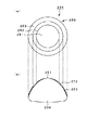
従来、異なるフォーマットとされた3種類の光ディスクに対して、情報信号の記録又は再生を実現する方法として、例えば、図71に示すようなDVD・CD用、及び、高密度記録光ディスク用の2種類の対物レンズと2種類の光学系を設け、それぞれの対物レンズを使用波長毎に切り換える方式のものがある。   Conventionally, as a method for realizing recording or reproduction of information signals on three types of optical discs having different formats, for example, two types for DVD / CD as shown in FIG. 71 and for high-density recording optical discs There are two types of objective lenses and two types of optical systems, and each objective lens is switched for each wavelength used.

図71に示す光ピックアップ430は、2種類の対物レンズ433,434を設けることにより、異なる種類の光ディスクの記録及び/又は再生を実現するものであり、CD等の光ディスクに対して波長785nm程度の光ビームを出射する出射部と、DVD等の光ディスクに対して波長655nm程度の光ビームを出射する出射部とを有するレーザダイオード等の光源部432と、高密度記録光ディスクに対して波長405nm程度の光ビームを出射する出射部を有するレーザダイオード等の光源部431と、DVD、CD等の光ディスク用の対物レンズ434と、高密度記録光ディスク用の対物レンズ433とを備える。また、この光ピックアップは、コリメータレンズ442A,442B、1/4波長板443A,443B、立ち上げミラー444A,444B、ビームスプリッタ437,438、グレーティング439,440、光検出器445、マルチレンズ446等を備える。   The optical pickup 430 shown in FIG. 71 realizes recording and / or reproduction of different types of optical disks by providing two types of objective lenses 433 and 434, and has a wavelength of about 785 nm with respect to an optical disk such as a CD. A light source unit 432 such as a laser diode having an emission part for emitting a light beam and an emission part for emitting a light beam with a wavelength of about 655 nm for an optical disk such as a DVD, and a wavelength of about 405 nm for a high-density recording optical disk A light source unit 431 such as a laser diode having an emission unit for emitting a light beam, an objective lens 434 for an optical disc such as a DVD or a CD, and an objective lens 433 for a high-density recording optical disc are provided. Further, this optical pickup includes collimator lenses 442A and 442B, quarter wavelength plates 443A and 443B, rising mirrors 444A and 444B, beam splitters 437 and 438, gratings 439 and 440, a photodetector 445, a multi lens 446, and the like. Prepare.

光源部432より出射された波長785nm程度の光ビームは、ビームスプリッタ437、ビームスプリッタ438を透過し、対物レンズ434へと入射する。この対物レンズ434によって厚さ1.1mmの保護層(カバー層)を有する光ディスクの信号記録面に集光される。   The light beam having a wavelength of about 785 nm emitted from the light source unit 432 passes through the beam splitter 437 and the beam splitter 438 and enters the objective lens 434. The objective lens 434 is focused on the signal recording surface of an optical disc having a protective layer (cover layer) having a thickness of 1.1 mm.

同様に、光源部432より出射された波長655nm程度の光ビームは、まったく同一の光路によって対物レンズ434へと入射し、厚さ0.6mmの保護層を有する光ディスクの信号記録面に集光される。光ディスクの信号記録面で反射された波長785nm及び波長655nmの戻り光は、ビームスプリッタ438を経て、フォトディテクタ等を有する光検出器445で検出される。   Similarly, a light beam having a wavelength of about 655 nm emitted from the light source unit 432 enters the objective lens 434 through the exact same optical path, and is condensed on the signal recording surface of the optical disk having a protective layer having a thickness of 0.6 mm. The The return light having a wavelength of 785 nm and a wavelength of 655 nm reflected by the signal recording surface of the optical disc passes through the beam splitter 438 and is detected by a photodetector 445 having a photodetector or the like.

光源部431より出射された波長405nm程度の光ビームは、ビームスプリッタ437で反射され、ビームスプリッタ438を経て対物レンズ433へと入射する。この対物レンズ433によって厚さ約0.1mmの保護層を有する光ディスクの信号記録面に集光される。光ディスクの信号記録面で反射された波長405nmの戻り光は、ビームスプリッタ438を経て、光検出器445で検出される。   The light beam having a wavelength of about 405 nm emitted from the light source unit 431 is reflected by the beam splitter 437 and enters the objective lens 433 through the beam splitter 438. The objective lens 433 is focused on the signal recording surface of an optical disc having a protective layer having a thickness of about 0.1 mm. The return light having a wavelength of 405 nm reflected by the signal recording surface of the optical disc is detected by the photodetector 445 through the beam splitter 438.

以上のような図71に示す光ピックアップは、上述のようなDVD/CD用の対物レンズ434と、高密度記録光ディスク用の対物レンズ433との2種類の対物レンズを設けることにより、異なる3種類の光ディスクの記録及び/又は再生を実現し、すなわち、複数種類の光ディスク間の互換を実現する。   The optical pickup shown in FIG. 71 has three different types of objective lenses by providing two types of objective lenses, the DVD / CD objective lens 434 and the high-density recording optical disc objective lens 433 as described above. Recording and / or reproduction of optical discs, that is, compatibility between a plurality of types of optical discs is realized.

しかしながら、上述のような光ピックアップでは、以下のような問題がある。まず、各光ディスク毎に最適となる対物レンズの傾きに相違があり、上述の光ピックアップでは、2個の対物レンズ433,434を用いることによって、それぞれの対物レンズ433,434のアクチュエータのレンズホルダへの取り付け角度が不適切となる場合があり、このことにより光ディスクに対して最適な対物レンズの傾きとすることができない場合がある。この結果、再生信号の品質が低下するといった問題がある。また、上述の光ピックアップでは、2種類の対物レンズ433,434を用いることによって、立ち上げミラー、コリメータレンズ或いは1/4波長板といった2種類の光学系のそれぞれの光路内に挿入する必要のある部品点数が増大することとなる。このため、高コストになり、光ピックアップが大型化してしまうといった問題がある。さらに、上述の光ピックアップでは、2つの対物レンズ433,434を対物レンズ駆動用のアクチュエータに搭載する必要があるため、アクチュエータの重量が増大し、感度が低下するという問題もあった。   However, the optical pickup as described above has the following problems. First, there is a difference in the optimum inclination of the objective lens for each optical disk. In the above optical pickup, by using the two objective lenses 433 and 434, the lens holders of the actuators of the respective objective lenses 433 and 434 are used. The mounting angle of the lens may become inappropriate, which may prevent the objective lens from tilting optimally with respect to the optical disk. As a result, there is a problem that the quality of the reproduced signal is lowered. Further, in the above-described optical pickup, it is necessary to use two types of objective lenses 433 and 434 to be inserted into respective optical paths of two types of optical systems such as a rising mirror, a collimator lens, or a quarter wavelength plate. The number of parts will increase. For this reason, there is a problem that the cost is increased and the optical pickup is increased in size. Further, in the above-described optical pickup, since it is necessary to mount the two objective lenses 433 and 434 on the actuator for driving the objective lens, there is a problem that the weight of the actuator increases and the sensitivity decreases.

これに対し、上述のような問題を解消するとともに、さらに光学部品の簡素化を可能とするため複数種類の光ディスク及び3種類の使用波長に対して共通の単一の対物レンズを備える光ピックアップも検討されている。3波長の光ビームに対応した対物レンズを設ける場合の基本的指針としては、対物レンズに入射する前の光路上に回折光学素子等の回折部を設けることによって、対物レンズに対して拡散・収束光の状態で入射させ、使用波長とメディアの組み合わせによって生じる球面収差を補正するというものである。   On the other hand, there is also an optical pickup provided with a single objective lens common to a plurality of types of optical disks and three types of operating wavelengths in order to solve the above-described problems and further simplify optical components. It is being considered. As a basic guideline when providing an objective lens corresponding to a three-wavelength light beam, a diffractive portion such as a diffractive optical element is provided on the optical path before entering the objective lens, thereby diffusing and converging on the objective lens. It is incident in the state of light and corrects spherical aberration caused by the combination of wavelength used and media.

しかし、従来検討されている光ピックアップでは、回折部が複数面に設けられることにより構成されていたり、対物レンズの球面とは異なる球面形状を回折面に設ける必要があったり、対物レンズの入射前の光路に複雑な構成を有する液晶素子を設けることが必要であったりした。これらの構成は、いずれもレンズ部、回折部、液晶素子等が別々に形成されたのち組み合わされており、これらの位置合わせや複数の回折面の貼り合わせにかなり高い精度が要求されることとなり、製造の煩雑化・複雑化といった問題や、これらの精度が満たされないことによる問題等もあった。   However, optical pickups that have been studied in the past are configured by providing diffractive portions on a plurality of surfaces, or it is necessary to provide a spherical surface different from the spherical surface of the objective lens on the diffractive surface, or before the entrance of the objective lens. It is necessary to provide a liquid crystal element having a complicated configuration in the optical path. All of these configurations are combined after the lens, diffractive part, liquid crystal element, etc. are separately formed, and a fairly high degree of accuracy is required for their alignment and bonding of multiple diffractive surfaces. There are also problems such as complicated and complicated manufacturing, and problems due to failure to satisfy these precisions.

また、例えば、特開2004−265573号公報に記載のように、回折部を一面に設けた光ピックアップも考えられているが、2波長互換の実現に留まっており、3波長互換を実現するためには、別に残りの1波長に対応した対物レンズを設ける必要があり、光学部品の増大及び構成の複雑化といった問題があった。(特許文献1参照)。   Further, for example, as described in Japanese Patent Application Laid-Open No. 2004-265573, an optical pickup having a diffractive portion on one surface is also conceivable. However, the two-wavelength compatibility is only realized, and the three-wavelength compatibility is realized. However, it is necessary to provide an objective lens corresponding to the remaining one wavelength, and there are problems such as an increase in optical components and a complicated configuration. (See Patent Document 1).

特開2004−265573号公報JP 2004-265573 A

本発明の目的は、構成を複雑にすることなく、それぞれ使用波長を異にする3種類の光ディスクに対して、共通の一の対物レンズを用いて光ビームを信号記録面に集光して情報信号の記録及び/又は再生を実現する光ピックアップに用いられる対物レンズ及び集光光学装置並びに光ピックアップ及びこの光ピックアップを用いた光ディスク装置を提供することにある。   An object of the present invention is to collect information by condensing a light beam on a signal recording surface using a common objective lens for three types of optical disks each having a different use wavelength without complicating the configuration. It is an object of the present invention to provide an objective lens and a condensing optical device used for an optical pickup that realizes signal recording and / or reproduction, an optical pickup, and an optical disk device using the optical pickup.

この目的を達成するため、本発明に係る対物レンズは、少なくとも、第1の透過層を有する第1の光ディスクと、上記第1の光ディスクとは異なり上記第1の透過層の厚さより厚い第2の透過層を有する第2の光ディスクと、上記第1及び第2の光ディスクとは異なり上記第2の透過層の厚さより厚い第3の透過層を有する第3の光ディスクとに対して光ビームを照射して情報信号の記録及び/又は再生を行う光ピックアップに用いられ、上記第1の光ディスクに対応した第1の波長の光ビームと、上記第2の光ディスクに対応した上記第1の波長より長い第2の波長の光ビームと、上記第3の光ディスクに対応した上記第2の波長より長い第3の波長の光ビームとを対応する光ディスクの信号記録面上に集光する対物レンズにおいて、入射側の面又は出射側の面に設けられる回折部を備え、上記回折部は、最内周部に設けられ略円形状の第1の回折領域と、上記第1の回折領域の外側に設けられ輪帯状の第2の回折領域と、上記第2の回折領域の外側に設けられ輪帯状の第3の回折領域とを有し、上記第1の回折領域は、通過する上記第1の波長の光ビームの上記対物レンズを介して第1の光ディスクの信号記録面に集光する回折光が最大の回折効率となるように発生させ、その回折光に対して与える球面収差極性が、通過する上記第2の波長の光ビームの上記対物レンズを介して第2の光ディスクの信号記録面に集光する回折光が最大の回折効率となるように発生させ、その回折光に対して与える球面収差極性、及び、通過する上記第3の波長の光ビームの上記対物レンズを介して第3の光ディスクの信号記録面に集光する回折光が最大の回折効率となるように発生させ、その回折光に対して与える球面収差極性に対して、逆極性とされており、上記第2の回折領域は、輪帯状で且つ所定の深さを有し上記第1の回折構造とは異なる構造の第2の回折構造が形成され、通過する上記第1の波長の光ビームの当該対物レンズを介して第1の光ディスクの信号記録面に集光する次数の回折光が最大の回折効率となるように発生させ、通過する上記第2の波長の光ビームの当該対物レンズを介して第2の光ディスクの信号記録面に集光する次数の回折光が最大の回折効率となるように発生させるとともに、通過する上記第3の波長の光ビームの当該対物レンズを介して第3の光ディスクの信号記録面に集光する次数以外の次数の回折光が最大の回折効率となり且つ支配的となるように発生させ、上記第3の回折領域は、輪帯状で且つ所定の深さを有し上記第1及び第2の回折構造とは異なる構造の第3の回折構造が形成され、通過する上記第1の波長の光ビームの当該対物レンズを介して第1の光ディスクの信号記録面に集光する次数の回折光が最大の回折効率となるように発生させるとともに、通過する上記第2の波長の光ビームの当該対物レンズを介して第2の光ディスクの信号記録面に集光する次数以外の次数の回折光が最大の回折効率となり且つ支配的となるように発生させ、通過する上記第3の波長の光ビームの当該対物レンズを介して第3の光ディスクの信号記録面に集光する次数以外の次数の回折光が最大の回折効率となり且つ支配的となるように発生させる。 In order to achieve this object, an objective lens according to the present invention includes at least a first optical disc having a first transmission layer and a second optical disc that is thicker than the first transmission layer, unlike the first optical disc. A light beam is applied to a second optical disc having a transmissive layer and a third optical disc having a third transmissive layer that is thicker than the second transmissive layer, unlike the first and second optical discs. Used for an optical pickup that irradiates and records and / or reproduces an information signal. From a first wavelength light beam corresponding to the first optical disc and the first wavelength corresponding to the second optical disc. In an objective lens that focuses a light beam having a long second wavelength and a light beam having a third wavelength longer than the second wavelength corresponding to the third optical disc on a signal recording surface of the corresponding optical disc, incident A diffractive portion provided on the surface of the light source or on the exit side surface, the diffractive portion provided on the innermost peripheral portion and provided on the outermost side of the substantially circular first diffractive region and on the outer side of the first diffractive region. A band-shaped second diffraction region; and a ring-shaped third diffraction region provided outside the second diffraction region, wherein the first diffraction region passes through the light of the first wavelength. beam said undiffracted light condensed on the signal recording surface of the first optical disc through the objective lens is generated such that the maximum diffraction efficiency, the spherical aberration polarity given to the diffracted light, the passes first A spherical aberration polarity which is generated so that the diffracted light condensed on the signal recording surface of the second optical disc through the objective lens of the light beam having the wavelength of 2 has the maximum diffraction efficiency , And through the objective lens of the light beam of the third wavelength passing through Is generated as diffracted light condensing is the maximum diffraction efficiency in the signal recording surface of the third optical disc Te for spherical aberration polarity given to the diffracted light, which is the opposite polarity, said first The second diffractive region has an annular shape and a predetermined depth, and a second diffractive structure different from the first diffractive structure is formed, and the objective of the light beam having the first wavelength passing therethrough is formed. The diffracted light of the order that is condensed on the signal recording surface of the first optical disk through the lens is generated so as to have the maximum diffraction efficiency, and the second wavelength light beam that passes through the objective lens through the objective lens is generated. The diffracted light of the order condensed on the signal recording surface of the second optical disk is generated so as to have the maximum diffraction efficiency, and the light beam of the third wavelength passing therethrough is passed through the objective lens of the third optical disk. Orders other than the order focused on the signal recording surface The third diffractive light is generated in such a manner that it has the maximum diffraction efficiency and is dominant, and the third diffractive region is annular and has a predetermined depth, which is different from the first and second diffractive structures. A third diffractive structure of the structure is formed, and the diffracted light of the order that is focused on the signal recording surface of the first optical disc through the objective lens of the light beam of the first wavelength passing therethrough has the maximum diffraction efficiency. And the diffracted light of the order other than the order focused on the signal recording surface of the second optical disc through the objective lens of the light beam having the second wavelength that passes through has the maximum diffraction efficiency and The diffraction efficiency of the diffracted light of the order other than the order which is generated so as to be dominant and is condensed on the signal recording surface of the third optical disc through the objective lens of the light beam having the third wavelength passing therethrough is maximized. issued so as to be next to and dominant Make.

また、本発明に係る光ピックアップは、第1の透過層を有する第1の光ディスクに対応した第1の波長の光ビームを出射する第1の出射部と、上記第1の光ディスクとは異なり上記第1の透過層の厚さより厚い第2の透過層を有する第2の光ディスクに対応した上記第1の波長より長い第2の波長の光ビームを出射する第2の出射部と、上記第1及び第2の光ディスクとは異なり上記第2の透過層の厚さより厚い第3の透過層を有する第3の光ディスクに対応した上記第2の波長より長い第3の波長の光ビームを出射する第3の出射部と、上記第1乃至第3の出射部から出射された光ビームを光ディスクの信号記録面上に集光する対物レンズと、上記第1乃至第3の波長の光ビームの光路上に配置される光学素子又は上記対物レンズの一方の面に設けられる回折部とを備え、上記回折部は、最内周部に設けられ略円形状の第1の回折領域と、上記第1の回折領域の外側に設けられ輪帯状の第2の回折領域と、上記第2の回折領域の外側に設けられ輪帯状の第3の回折領域とを有し、上記第1の回折領域は、通過する上記第1の波長の光ビームの上記対物レンズを介して第1の光ディスクの信号記録面に集光する回折光が最大の回折効率となるように発生させ、その回折光に対して与える球面収差極性が、通過する上記第2の波長の光ビームの上記対物レンズを介して第2の光ディスクの信号記録面に集光する回折光が最大の回折効率となるように発生させ、その回折光に対して与える球面収差極性、及び、通過する上記第3の波長の光ビームの上記対物レンズを介して第3の光ディスクの信号記録面に集光する回折光が最大の回折効率となるように発生させ、その回折光に対して与える球面収差極性に対して、逆極性とされており、上記第2の回折領域は、輪帯状で且つ所定の深さを有し上記第1の回折構造とは異なる構造の第2の回折構造が形成され、通過する上記第1の波長の光ビームの上記対物レンズを介して第1の光ディスクの信号記録面に集光する次数の回折光が最大の回折効率となるように発生させ、通過する上記第2の波長の光ビームの上記対物レンズを介して第2の光ディスクの信号記録面に集光する次数の回折光が最大の回折効率となるように発生させるとともに、通過する上記第3の波長の光ビームの上記対物レンズを介して第3の光ディスクの信号記録面に集光する次数以外の次数の回折光が最大の回折効率となり且つ支配的となるように発生させ、上記第3の回折領域は、輪帯状で且つ所定の深さを有し上記第1及び第2の回折構造とは異なる構造の第3の回折構造が形成され、通過する上記第1の波長の光ビームの上記対物レンズを介して第1の光ディスクの信号記録面に集光する次数の回折光が最大の回折効率となるように発生させるとともに、通過する上記第2の波長の光ビームの上記対物レンズを介して第2の光ディスクの信号記録面に集光する次数以外の次数の回折光が最大の回折効率となり且つ支配的となるように発生させ、通過する上記第3の波長の光ビームの上記対物レンズを介して第3の光ディスクの信号記録面に集光する次数以外の次数の回折光が最大の回折効率となり且つ支配的となるように発生させる。 The optical pickup according to the present invention is different from the first optical disc in that the first emission section that emits the light beam having the first wavelength corresponding to the first optical disc having the first transmission layer is different from the first optical disc. A second emitting section for emitting a light beam having a second wavelength longer than the first wavelength corresponding to a second optical disk having a second transmissive layer thicker than the first transmissive layer; Unlike the second optical disc, the second optical disc emits a light beam having a third wavelength longer than the second wavelength corresponding to the third optical disc having a third transmission layer that is thicker than the thickness of the second transmission layer. 3, an objective lens for condensing the light beam emitted from the first to third emission parts on the signal recording surface of the optical disc, and an optical path of the light beam having the first to third wavelengths. One of the optical element or the objective lens arranged in A diffractive part provided on the innermost peripheral part, the diffractive part being provided with a substantially circular first diffractive area, and an annular second diffractive element provided outside the first diffractive area. And an annular third diffraction region provided outside the second diffraction region, the first diffraction region passing through the objective lens of the light beam having the first wavelength passing therethrough through by generating as diffracted light condensing is the maximum diffraction efficiency on the signal recording surface of the first optical disc, spherical aberration polarity given to the diffracted light, the second wavelength passing through the light beam The diffracted light condensed on the signal recording surface of the second optical disc through the objective lens is generated so as to have the maximum diffraction efficiency , and the spherical aberration polarity given to the diffracted light and the passing first A third light beam through the objective lens of the light beam having the third wavelength. Diffracted light converged on the signal recording surface of the click is allowed to occur so that the maximum diffraction efficiency, with respect to spherical aberration polarity given to the diffracted light, which is the opposite polarity, said second diffraction area Is formed in a second diffractive structure having a ring shape and a predetermined depth, which is different from the first diffractive structure, and passes through the objective lens of the light beam having the first wavelength passing therethrough. The diffracted light of the order condensed on the signal recording surface of the first optical disc is generated so as to have the maximum diffraction efficiency, and the second optical disc passes through the objective lens of the light beam having the second wavelength passing therethrough. The diffracted light of the order condensed on the signal recording surface is generated so as to have the maximum diffraction efficiency, and the light beam having the third wavelength passing through the signal recording surface of the third optical disc is passed through the objective lens. Diffracted light of orders other than the order of light collection is the largest The third diffractive region is generated in such a manner as to be diffractive efficiency and dominant, and the third diffractive region has an annular shape and a predetermined depth, and has a structure different from the first and second diffractive structures. A structure is formed, and the diffracted light of the order that is focused on the signal recording surface of the first optical disc through the objective lens of the light beam of the first wavelength that passes through is generated so as to have the maximum diffraction efficiency. The diffracted light of the order other than the order condensed on the signal recording surface of the second optical disc through the objective lens of the light beam having the second wavelength passing therethrough has the maximum diffraction efficiency and becomes dominant. The diffracted light of the order other than the order that is generated and passes through the objective lens of the light beam of the third wavelength passing through the objective lens has the maximum diffraction efficiency and becomes dominant. To generate.

また、本発明に係る光ディスク装置は、少なくとも、第1の透過層を有する第1の光ディスクと、上記第1の光ディスクとは異なり上記第1の透過層の厚さより厚い第2の透過層を有する第2の光ディスクと、上記第1及び第2の光ディスクとは異なり上記第2の透過層の厚さより厚い第3の透過層を有する第3の光ディスクとから任意に選択される光ディスクを保持して回転駆動する駆動手段と、上記駆動手段によって回転駆動される光ディスクに対し波長を異にする複数の光ビームを選択的に照射することにより情報信号の記録及び/又は再生を行う光ピックアップとを有する光ディスク装置であり、この光ディスク装置に用いる光ピックアップとして、上述したようなものを用いたものである。 The optical disk apparatus according to the present invention includes at least a first optical disk having a first transparent layer, the first different Ri said first and optical disk transmission layer transmitting layer thick second than the thickness of the a second optical disk, an optical disk that is arbitrarily selected from the above-described first and third optical disc having the second thicker third than the thickness of the transparent layer of the transmissive layers Unlike second optical disk holding with And an optical pickup that records and / or reproduces an information signal by selectively irradiating a plurality of light beams having different wavelengths to an optical disk that is rotationally driven by the driving means. The above-described optical pickup is used for the optical disk device.

本発明は、光ビームを出射する出射部と光ディスクの信号記録面との間の光路上に配置される光学素子の一面に設けられた回折部により、それぞれ使用波長を異にする3種類の光ディスクに対して、共通の一の対物レンズを用いてそれぞれ対応する光ビームを信号記録面に適切に集光することを可能として、構成を複雑にすることなく、対物レンズを共通とした3波長互換を実現してそれぞれの光ディスクに対して良好な信号の記録及び/又は再生を実現する。
また、本発明は、第1の回折領域において、第1の波長の光ビームに与える球面収差極性と、第2及び第3の波長の光ビームに与える球面収差極性とが逆になるようにすることで、保護層の厚さと対応する光ビームの波長とがそれぞれ異なる各光ディスクの信号記録面に生じる球面収差を効率よく抑え、それぞれの光ディスクに対して良好な信号の記録及び/又は再生を実現することができる。
The present invention provides three types of optical discs each having a different wavelength to be used by a diffractive portion provided on one surface of an optical element disposed on an optical path between an emitting portion for emitting a light beam and a signal recording surface of the optical disc. On the other hand, it is possible to properly collect the corresponding light beams on the signal recording surface using one common objective lens, and it is compatible with three wavelengths without complicating the configuration. To realize good signal recording and / or reproduction for each optical disc.
In the first diffraction region, the spherical aberration polarity given to the light beam of the first wavelength and the spherical aberration polarity given to the light beams of the second and third wavelengths are reversed in the first diffraction region. This effectively suppresses spherical aberration that occurs on the signal recording surface of each optical disc with a different thickness of the protective layer and the corresponding wavelength of the light beam, and realizes good signal recording and / or reproduction on each optical disc. can do.

以下、本発明を適用した光ピックアップを用いた光ディスク装置について、図面を参照して説明する。   Hereinafter, an optical disk apparatus using an optical pickup to which the present invention is applied will be described with reference to the drawings.

<1>光ディスク装置の全体構成(図1)
本発明が適用された光ディスク装置1は、図1に示すように、光ディスク2から情報記録再生を行う光ピックアップ3と、光ディスク2を回転操作する駆動手段としてのスピンドルモータ4と、光ピックアップ3を光ディスク2の径方向に移動させる送りモータ5とを備えている。この光ディスク装置1は、フォーマットの異なる3種類の光ディスク及び記録層が積層化された光ディスクに対して情報の記録及び/又は再生を行うことができる3規格間互換性を実現した光ディスク装置である。ここで、光ディスク装置1を構成する光ピックアップとしては、光ピックアップ3に限られるものではなく、後述の光ピックアップ103,203等を用いるように構成してもよい。
<1> Overall configuration of optical disc apparatus (FIG. 1)
As shown in FIG. 1, an optical disc apparatus 1 to which the present invention is applied includes an optical pickup 3 for recording / reproducing information from / on an optical disc 2, a spindle motor 4 as a driving means for rotating the optical disc 2, and an optical pickup 3. And a feed motor 5 for moving the optical disk 2 in the radial direction. The optical disc apparatus 1 is an optical disc apparatus that realizes compatibility between three standards capable of recording and / or reproducing information on three types of optical discs having different formats and an optical disc in which recording layers are stacked. Here, the optical pickup constituting the optical disc apparatus 1 is not limited to the optical pickup 3, and may be configured to use optical pickups 103 and 203 described later.

ここで用いられる光ディスクは、例えば、発光波長が785nm程度の半導体レーザを用いたCD(Compact Disc)、CD−R(Recordable)、CD−RW(ReWritable)等の光ディスクや、発光波長を655nm程度の半導体レーザを用いたDVD(Digital Versatile Disc)、DVD−R(Recordable)、DVD−RW(ReWritable)、DVD+RW(ReWritable)等の光ディスクや、さらに発光波長が短い405nm程度(青紫色)の半導体レーザを用いた高密度記録が可能なBD(Blu-ray Disc(登録商標))等の高密度記録光ディスクである。   The optical disk used here is, for example, an optical disk such as CD (Compact Disc), CD-R (Recordable), CD-RW (ReWritable) using a semiconductor laser having an emission wavelength of about 785 nm, or an emission wavelength of about 655 nm. Optical discs such as DVD (Digital Versatile Disc), DVD-R (Recordable), DVD-RW (ReWritable), DVD + RW (ReWritable) using semiconductor lasers, and semiconductor lasers with a shorter emission wavelength of about 405 nm (blue-violet) It is a high-density recording optical disk such as a BD (Blu-ray Disc (registered trademark)) that can be used for high-density recording.

特に、以下で光ディスク装置1により情報の再生又は記録を行う3種類の光ディスク2として、0.1mm程度の第1の厚さで形成された保護層を有し波長405nm程度の光ビームを記録再生光として使用する高密度記録が可能な上述したBD等の第1の光ディスク11と、0.6mm程度の第2の厚さで形成された保護層を有し波長655nm程度の光ビームを記録再生光として使用するDVD等の第2の光ディスク12と、1.1mm程度の第3の厚さで形成された保護層を有し波長785nm程度の光ビームを記録再生光として使用するCD等の第3の光ディスク13とを用いるものとして説明する。   In particular, the following three types of optical disks 2 for reproducing or recording information by the optical disk apparatus 1 have a protective layer formed with a first thickness of about 0.1 mm and record and reproduce a light beam with a wavelength of about 405 nm. Recording / reproducing a light beam having a wavelength of about 655 nm having the first optical disk 11 such as the above-described BD capable of high-density recording used as light and a protective layer formed with a second thickness of about 0.6 mm. A second optical disk 12 such as a DVD used as light, and a CD such as a CD that has a protective layer formed with a third thickness of about 1.1 mm and uses a light beam with a wavelength of about 785 nm as recording / reproducing light. 3 is used as an example.

光ディスク装置1において、スピンドルモータ4及び送りモータ5は、ディスク種類判別手段ともなるシステムコントローラ7からの指令に基づいて制御されるサーボ制御部9によりディスク種類に応じて駆動制御されており、例えば、第1の光ディスク11、第2の光ディスク12、第3の光ディスク13に応じて所定の回転数で駆動される。   In the optical disc apparatus 1, the spindle motor 4 and the feed motor 5 are driven and controlled in accordance with the disc type by a servo control unit 9 that is controlled based on a command from a system controller 7 that also serves as a disc type discriminating unit. The first optical disk 11, the second optical disk 12, and the third optical disk 13 are driven at a predetermined number of rotations.

光ピックアップ3は、3波長互換光学系を有する光ピックアップであり、規格の異なる光ディスクの記録層に対して異なる波長の光ビームを保護層側から照射するとともに、この光ビームの記録層における反射光を検出する。光ピックアップ3は、検出した反射光から各光ビームに対応する信号を出力する。   The optical pickup 3 is an optical pickup having a three-wavelength compatible optical system. The optical pickup 3 irradiates a recording layer of an optical disc having a different standard with a light beam having a different wavelength from the protective layer side, and reflects the light beam reflected on the recording layer. Is detected. The optical pickup 3 outputs a signal corresponding to each light beam from the detected reflected light.

光ディスク装置1は、光ピックアップ3から出力された信号に基づいてフォーカスエラー信号、トラッキングエラー信号、RF信号等を生成するプリアンプ14と、プリアンプ14からの信号を復調し又は外部コンピュータ17等からの信号を変調するための信号変復調器及びエラー訂正符号ブロック(以下、信号変復調器&ECCブロックと記す。)15と、インターフェース16と、D/A,A/D変換器18と、オーディオ・ビジュアル処理部19と、オーディオ・ビジュアル信号入出力部20とを備える。   The optical disc device 1 generates a focus error signal, a tracking error signal, an RF signal and the like based on a signal output from the optical pickup 3, and demodulates a signal from the preamplifier 14 or a signal from an external computer 17 or the like. A signal modulator / demodulator and error correction code block (hereinafter referred to as a signal modulator / demodulator & ECC block) 15, an interface 16, a D / A / A / D converter 18, and an audio / visual processing unit 19. And an audio / visual signal input / output unit 20.

このプリアンプ14は、光検出器からの出力に基づいて、非点収差法等によってフォーカスエラー信号を生成し、また、3ビーム法、DPD法、DPP法等によってトラッキングエラー信号を生成し、更にRF信号を生成し、RF信号を、信号変調&ECCブロック15に出力する。また、プリアンプ14は、フォーカスエラー信号とトラッキングエラー信号とをサーボ制御部9に出力する。   The preamplifier 14 generates a focus error signal by an astigmatism method or the like based on an output from the photodetector, generates a tracking error signal by a three beam method, a DPD method, a DPP method, or the like, and further generates an RF signal. A signal is generated, and the RF signal is output to the signal modulation & ECC block 15. Further, the preamplifier 14 outputs a focus error signal and a tracking error signal to the servo control unit 9.

信号変調&ECCブロック15は、第1の光ディスクに対して、データの記録を行うとき、インターフェース16又はD/A,A/D変換器18から入力されたディジタル信号に対して、LDC−ECC及びBIS等のエラー訂正方式によってエラー訂正処理を行い、次いで、1−7PP方式等の変調処理を行う。また、信号変調&ECCブロック15は、第2の光ディスクに対してデータを記録するとき、PC(Product Code)等のエラー訂正方式に従ってエラー訂正処理を行い、次いで、8−16変調等の変調処理を行う。更に、信号変調&ECCブロック15は、第3の光ディスクに対してデータを記録するとき、CIRC等のエラー訂正方式によってエラー訂正処理を行い、次いで、8−14変調処理等の変調処理を行う。そして、信号変調&ECCブロック15は、変調されたデータをレーザ制御部21に出力する。更に、信号変調&ECCブロック15は、各光ディスクの再生を行うとき、プリアンプ14から入力されたRF信号に基づいて復調処理を行い、更に、エラー訂正処理を行って、インタフェース16又はデータをD/A,A/D変換器18に出力する。   The signal modulation & ECC block 15 performs LDC-ECC and BIS on the digital signal input from the interface 16 or the D / A / A / D converter 18 when recording data on the first optical disk. Error correction processing is performed by an error correction method such as 1-7PP, and then modulation processing such as 1-7PP method is performed. The signal modulation & ECC block 15 performs error correction processing according to an error correction method such as PC (Product Code) when recording data on the second optical disc, and then performs modulation processing such as 8-16 modulation. Do. Further, when recording data on the third optical disc, the signal modulation & ECC block 15 performs error correction processing by an error correction method such as CIRC, and then performs modulation processing such as 8-14 modulation processing. Then, the signal modulation & ECC block 15 outputs the modulated data to the laser control unit 21. Further, when reproducing each optical disk, the signal modulation & ECC block 15 performs demodulation processing based on the RF signal input from the preamplifier 14, further performs error correction processing, and converts the interface 16 or data to D / A. , Output to the A / D converter 18.

なお、データ圧縮してデータ記録するときには、圧縮伸長部を信号変調&ECCブロック15とインターフェース16又はD/A,A/D変換器18との間に設けても良い。この場合、データは、MPEG2やMPEG4といった方式でデータが圧縮される。   When data is compressed and recorded, a compression / decompression unit may be provided between the signal modulation & ECC block 15 and the interface 16 or the D / A / A / D converter 18. In this case, the data is compressed by a method such as MPEG2 or MPEG4.

サーボ制御部9は、プリアンプ14からフォーカスエラー信号やトラッキングエラー信号が入力される。サーボ制御部9は、フォーカスエラー信号やトラッキングエラー信号が0となるようなフォーカスサーボ信号やトラッキングサーボ信号を生成し、これらのサーボ信号に基づいて、対物レンズを駆動する2軸アクチュエータ等の対物レンズ駆動部を駆動制御する。また、プリアンプ14からの出力より、同期信号等を検出して、CLV(Constant Linear Velocity)やCAV(Constant Angular Velocity)、更にはこれらの組み合わせの方式等で、スピンドルモータをサーボ制御する。   The servo controller 9 receives a focus error signal and a tracking error signal from the preamplifier 14. The servo control unit 9 generates a focus servo signal and a tracking servo signal so that the focus error signal and the tracking error signal become zero, and an objective lens such as a biaxial actuator that drives the objective lens based on these servo signals. Drive control of the drive unit. Further, a synchronization signal or the like is detected from the output from the preamplifier 14, and the spindle motor is servo-controlled by CLV (Constant Linear Velocity), CAV (Constant Angular Velocity), or a combination of these.

レーザ制御部21は、光ピックアップ3のレーザ光源を制御する。特に、この具体例では、レーザ制御部21は、記録モード時と再生モード時とでレーザ光源の出力パワーを異ならせる制御を行っている。また、光ディスク2の種類に応じてもレーザ光源の出力パワーを異ならせる制御を行っている。レーザ制御部21は、ディスク種類判別部22によって検出された光ディスク2の種類に応じて光ピックアップ3のレーザ光源を切り換えている。   The laser control unit 21 controls the laser light source of the optical pickup 3. In particular, in this specific example, the laser control unit 21 performs control to vary the output power of the laser light source between the recording mode and the reproduction mode. Also, control is performed to vary the output power of the laser light source depending on the type of the optical disc 2. The laser control unit 21 switches the laser light source of the optical pickup 3 in accordance with the type of the optical disc 2 detected by the disc type determination unit 22.

ディスク種類判別部22は、第1〜第3の光ディスク11,12,13の間の表面反射率、形状的及び外形的な違い等から反射光量の変化を検出し光ディスク2の異なるフォーマットを検出することができる。   The disc type discriminating unit 22 detects a change in the amount of reflected light from the surface reflectance, the shape and the external difference between the first to third optical discs 11, 12, and 13 to detect different formats of the optical disc 2. be able to.

光ディスク装置1を構成する各ブロックは、ディスク種類判別部22における検出結果に応じて、装着される光ディスク2の仕様に基づく信号処理ができるように構成されている。   Each block constituting the optical disc apparatus 1 is configured to be able to perform signal processing based on the specification of the optical disc 2 to be mounted, according to the detection result in the disc type discriminating unit 22.

システムコントローラ7は、ディスク種類判別部22で判別された光ディスク2の種類に応じて装置全体を制御する。また、システムコントローラ7は、ユーザからの操作入力に応じて、光ディスク最内周にあるプリマスタードピットやグルーブ等に記録されたアドレス情報や目録情報(Table Of Contents;TOC)に基づいて、記録再生を行う光ディスクの記録位置や再生位置を特定し、特定した位置に基づいて、各部を制御する。   The system controller 7 controls the entire apparatus according to the type of the optical disk 2 determined by the disk type determination unit 22. Further, the system controller 7 performs recording / reproduction based on address information and table information (TOC) recorded in a premastered pit or groove in the innermost periphery of the optical disc in response to an operation input from the user. The recording position and reproduction position of the optical disc to be performed are specified, and each unit is controlled based on the specified position.

以上のように構成された光ディスク装置1は、スピンドルモータ4によって、光ディスク2を回転操作し、サーボ制御部9からの制御信号に応じて送りモータ5を駆動制御し、光ピックアップ3を光ディスク2の所望の記録トラックに対応する位置に移動することで、光ディスク2に対して情報の記録再生を行う。   The optical disc apparatus 1 configured as described above rotates the optical disc 2 by the spindle motor 4, drives and controls the feed motor 5 in accordance with a control signal from the servo control unit 9, and controls the optical pickup 3 on the optical disc 2. Information is recorded on and reproduced from the optical disc 2 by moving to a position corresponding to a desired recording track.

具体的には、光ディスク装置1により記録再生するときには、サーボ制御部9は、CAVやCLVやこれらの組み合わせで光ディスク2を回転する。光ピックアップ3は、光源から光ビームを照射して光検出器により光ディスク2からの戻りの光ビームを検出し、フォーカスエラー信号やトラッキングエラー信号を生成し、これらフォーカスエラー信号やトラッキングエラー信号に基づいて対物レンズ駆動機構により対物レンズを駆動してフォーカスサーボ及びトラッキングサーボを行う。   Specifically, when recording / reproducing is performed by the optical disc apparatus 1, the servo control unit 9 rotates the optical disc 2 by CAV, CLV, or a combination thereof. The optical pickup 3 irradiates a light beam from a light source, detects a returning light beam from the optical disc 2 by a photodetector, generates a focus error signal and a tracking error signal, and based on these focus error signal and tracking error signal Then, the objective lens is driven by the objective lens driving mechanism to perform focus servo and tracking servo.

また、光ディスク装置1により記録する際には、外部コンピュータ17からの信号がインターフェース16を介して信号変復調器&ECCブロック15に入力される。信号変復調器&ECCブロック15は、インターフェース16又はA/D変換器18から入力されたディジタルデータに対して上述したような所定のエラー訂正符号を付加し、更に所定の変調処理を行った後に記録信号を生成する。レーザ制御部21は、信号変復調器&ECCブロック15で生成された記録信号に基づいて、光ピックアップ3のレーザ光源を制御して、所定の光ディスクに記録する。   When recording is performed by the optical disc apparatus 1, a signal from the external computer 17 is input to the signal modulator / demodulator & ECC block 15 through the interface 16. The signal modulator / demodulator & ECC block 15 adds a predetermined error correction code as described above to the digital data input from the interface 16 or the A / D converter 18, and further performs a predetermined modulation process and then a recording signal. Is generated. The laser control unit 21 controls the laser light source of the optical pickup 3 based on the recording signal generated by the signal modulator / demodulator & ECC block 15 and records it on a predetermined optical disk.

また、光ディスク2に記録された情報を光ディスク装置1により再生する際には、光検出器で検出された信号に対して、信号変復調器&ECCブロック15が復調処理を行う。信号変復調器&ECCブロック15により復調された記録信号がコンピュータのデータストレージ用であれば、インターフェース16を介して外部コンピュータ17に出力される。これにより、外部コンピュータ17は、光ディスク2に記録された信号に基づいて動作することができる。また、信号変復調器&ECCブロック15により復調された記録信号がオーディオビジュアル用であれば、D/A変換器18でデジタルアナログ変換され、オーディオ・ビジュアル処理部19に供給される。そしてオーディオ・ビジュアル処理部19でオーディオビジュアル処理が行われ、オーディオ・ビジュアル信号入出力部20を介して、図示しない外部のスピーカやモニターに出力される。   When the information recorded on the optical disc 2 is reproduced by the optical disc apparatus 1, the signal modulator / demodulator & ECC block 15 demodulates the signal detected by the photodetector. If the recording signal demodulated by the signal modulator / demodulator & ECC block 15 is for data storage of a computer, it is output to the external computer 17 via the interface 16. Accordingly, the external computer 17 can operate based on the signal recorded on the optical disc 2. Further, if the recording signal demodulated by the signal modulator / demodulator & ECC block 15 is for audio visual, it is digital-analog converted by the D / A converter 18 and supplied to the audio / visual processing unit 19. Audio visual processing is performed by the audio / visual processing unit 19 and output to an external speaker or monitor (not shown) via the audio / visual signal input / output unit 20.

ここで、上述した光ディスク装置1に用いられる記録再生用光ピックアップ3,103,203等について詳しく説明する。
<2>光ピックアップの第1の実施の形態(図2〜図19)
まず、本発明に係る光ピックアップの第1の実施の形態として、本発明を適用した光ピックアップ3について、図2〜図19を用いて説明する。この光ピックアップ3は、上述したように、保護層の厚さ等のフォーマットが異なる3種類の第1乃至第3の光ディスク11,12,13から任意に選択された光ディスクに対し波長を異にする複数の光ビームを選択的に照射することにより情報信号の記録及び/又は再生を行う光ピックアップである。
Here, the recording / reproducing optical pickups 3, 103, 203 and the like used in the optical disc apparatus 1 will be described in detail.
<2> First embodiment of optical pickup (FIGS. 2 to 19)
First, as a first embodiment of an optical pickup according to the present invention, an optical pickup 3 to which the present invention is applied will be described with reference to FIGS. As described above, the optical pickup 3 has a wavelength different from that of an optical disc arbitrarily selected from the three types of first to third optical discs 11, 12, and 13 having different formats such as the thickness of the protective layer. This is an optical pickup that records and / or reproduces information signals by selectively irradiating a plurality of light beams.

本発明を適用した光ピックアップ3は、図2に示すように、第1の波長の光ビームを出射する第1の出射部を有する第1の光源部31と、第1の波長より長い第2の波長の光ビームを出射する第2の出射部を有する第2の光源部32と、第2の波長より長い第3の波長の光ビームを出射する第3の出射部を有する第3の光源部33と、この第1乃至第3の出射部から出射された光ビームを光ディスク2の信号記録面上に集光する対物レンズ34と、第1乃至第3の出射部と対物レンズ34との間の光路上に設けられる回折光学素子35とを備える。   As shown in FIG. 2, the optical pickup 3 to which the present invention is applied includes a first light source unit 31 having a first emission unit that emits a light beam having a first wavelength, and a second light source that has a second wavelength longer than the first wavelength. A third light source having a second light source part 32 having a second light emission part for emitting a light beam having a third wavelength and a third light emission part for emitting a light beam having a third wavelength longer than the second wavelength. Part 33, an objective lens 34 for condensing the light beam emitted from the first to third emission parts on the signal recording surface of the optical disc 2, and the first to third emission parts and the objective lens 34. And a diffractive optical element 35 provided on the optical path therebetween.

また、光ピックアップ3は、第2及び第3の出射部と回折光学素子35との間に設けられ、第2の出射部から出射された第2の波長の光ビームの光路と第3の出射部から出射された第3の波長の光ビームの光路とを合成する光路合成手段として第1のビームスプリッタ36と、第1のビームスプリッタ36と回折光学素子35との間に設けられ、第1のビームスプリッタ36で光路を合成された第2及び第3の波長の光ビームの光路と、第1の出射部から出射された第1の波長の光ビームの光路とを合成する光路合成手段として第2のビームスプリッタ37と、第2のビームスプリッタ37と回折光学素子35との間に設けられ、第2のビームスプリッタ37で光路を合成された第1乃至第3の波長の光ビームの往路の光路と、光ディスクで反射された第1乃至第3の波長の光ビームの戻り(以下、「復路」ともいう。)の光路とを分離する光路分離手段として第3のビームスプリッタ38とを有する。   The optical pickup 3 is provided between the second and third emission units and the diffractive optical element 35, and the optical path and the third emission of the light beam having the second wavelength emitted from the second emission unit. The first beam splitter 36 is provided between the first beam splitter 36 and the diffractive optical element 35 as optical path synthesis means for synthesizing the optical path of the light beam of the third wavelength emitted from the unit. As optical path combining means for combining the optical paths of the light beams of the second and third wavelengths combined by the beam splitter 36 and the optical path of the light beam of the first wavelength emitted from the first emitting section. The second beam splitter 37, the forward path of the light beams of the first to third wavelengths which are provided between the second beam splitter 37 and the diffractive optical element 35 and whose optical paths are synthesized by the second beam splitter 37 Optical path and optical disc Isa The first to third wavelengths of the light beam returning (hereinafter, also referred to as "backward".) And a third beam splitter 38 as the optical path separating means for separating the optical paths.

さらに、光ピックアップ3は、第1の光源部31の第1の出射部と第2のビームスプリッタ37との間に設けられ、第1の出射部から出射された第1の波長の光ビームをトラッキングエラー信号等の検出のために3ビームに回折する第1のグレーティング39と、第2の光源部32の第2の出射部と第1のビームスプリッタ36との間に設けられ、第2の出射部から出射された第2の波長の光ビームをトラッキングエラー信号等の検出のために3ビームに回折する第2のグレーティング40と、第3の光源部33の第3の出射部と第1のビームスプリッタ36との間に設けられ、第3の出射部から出射された第3の波長の光ビームをトラッキングエラー信号等の検出のために3ビームに回折する第3のグレーティング41とを有する。   Further, the optical pickup 3 is provided between the first emission part of the first light source part 31 and the second beam splitter 37, and receives the light beam having the first wavelength emitted from the first emission part. A first grating 39 that diffracts into three beams for detection of a tracking error signal and the like, a second light emitting portion of the second light source portion 32, and the first beam splitter 36 are provided, A second grating 40 that diffracts the light beam of the second wavelength emitted from the emission unit into three beams for detection of a tracking error signal or the like, the third emission unit of the third light source unit 33, and the first And a third grating 41 that diffracts the light beam of the third wavelength emitted from the third emission unit into three beams for detection of a tracking error signal or the like. .

また、光ピックアップ3は、第3のビームスプリッタ38と回折光学素子35との間に設けられ、第3のビームスプリッタ38で光路を合成された第1乃至第3の波長の光ビームの発散角を変換して略平行光の状態又は略平行光に対して拡散若しくは収束した状態となるように調整して出射させる発散角変換手段としてのコリメータレンズ42と、コリメータレンズ42と回折光学素子35との間に設けられ、コリメータレンズ42に発散角を調整された第1乃至第3の波長の光ビームに1/4波長の位相差を与える1/4波長板43と、回折光学素子35と1/4波長板43との間に設けられ、対物レンズ34及び回折光学素子35の光軸に略直交する平面内で上述した光学部品を経由された光ビームを反射して立ち上げることにより対物レンズ34及び回折光学素子35の光軸方向に光ビームを出射させる立ち上げミラー44とを有する。   The optical pickup 3 is provided between the third beam splitter 38 and the diffractive optical element 35, and the divergence angles of the first to third wavelength light beams synthesized by the third beam splitter 38. , A collimator lens 42 as a divergence angle conversion means for adjusting and emitting so as to be in a substantially parallel light state or a diffused or converged state with respect to the substantially parallel light, a collimator lens 42 and a diffractive optical element 35 A quarter-wave plate 43 that provides a quarter-wave phase difference to the first to third light beams whose divergence angles are adjusted by the collimator lens 42, and the diffractive optical elements 35 and 1 / 4 wavelength plate 43 is provided between the objective lens 34 and the diffractive optical element 35 so as to reflect the light beam that has passed through the above-described optical components in a plane substantially orthogonal to the objective lens 34 and the diffractive optical element 35, thereby raising the objective. And a raising mirror 44 for emitting a light beam in the optical axis direction of the lens 34 and diffractive optical element 35.

さらに、光ピックアップ3は、第3のビームスプリッタ38で往路の第1乃至第3の波長の光ビームの光路から分離された復路の第1乃至第3の波長の光ビームを受光して検出する光検出器45と、第3のビームスプリッタ38と光検出器45との間に設けられ、第3のビームスプリッタ38で分離された復路の第1乃至第3の波長の光ビームを光検出器45のフォトディテクタ等の受光面に集光させるとともにフォーカスエラー信号等の検出のための非点収差を付与するマルチレンズ46とを有する。   Further, the optical pickup 3 receives and detects the light beams having the first to third wavelengths in the return path separated from the optical paths of the light beams having the first to third wavelengths in the forward path by the third beam splitter 38. Provided between the photodetector 45, the third beam splitter 38, and the photodetector 45, the light beams of the first to third wavelengths in the return path separated by the third beam splitter 38 are detected by the photodetector. A multi-lens 46 that focuses light on a light-receiving surface such as a photo detector 45 and applies astigmatism for detecting a focus error signal or the like.

第1の光源部31は、第1の光ディスク11に対して405nm程度の第1の波長の光ビームを出射する第1の出射部を有する。第2の光源部32は、第2の光ディスク12に対して655nm程度の第2の波長の光ビームを出射する第2の出射部を有する。第3の光源部33は、785nm程度の第3の光ディスクに対して第3の波長の光ビームを出射する第3の出射部を有する。尚、ここでは、第1乃至第3の出射部をそれぞれ別々の光源部31,32,33に配置するように構成したが、これに限られるものではなく、第1乃至第3の出射部の内2つの出射部を有する光源部と、残りの1つの出射部を有する光源部とを異なる位置に配置するように構成してもよく、さらに、第1乃至第3の出射部を略同一位置に有する光源部となるように構成してもよい。   The first light source unit 31 includes a first emission unit that emits a light beam having a first wavelength of about 405 nm to the first optical disc 11. The second light source unit 32 includes a second emission unit that emits a light beam having a second wavelength of about 655 nm to the second optical disc 12. The third light source unit 33 includes a third emission unit that emits a light beam having a third wavelength with respect to a third optical disk of about 785 nm. Here, the first to third emission parts are configured to be arranged in the separate light source parts 31, 32, 33, respectively, but the present invention is not limited to this, and the first to third emission parts of the first to third emission parts are arranged. The light source part having two of the emission parts and the light source part having the remaining one emission part may be arranged at different positions, and the first to third emission parts may be arranged at substantially the same position. You may comprise so that it may become a light source part which has.

対物レンズ34は、入射した第1乃至第3の波長の光ビームを光ディスク2の信号記録面上に集光させる。この対物レンズ34は、図示しない2軸アクチュエータ等の対物レンズ駆動機構によって移動自在に保持されている。そして、この対物レンズ34は、光検出器45で検出された光ディスク2からの戻り光のRF信号により生成されたトラッキングエラー信号及びフォーカスエラー信号に基づいて、2軸アクチュエータ等により移動操作されることにより、光ディスク2に近接離間する方向及び光ディスク2の径方向の2軸方向へ移動される。対物レンズ34は、第1乃至第3の出射部から出射される光ビームが光ディスク2の信号記録面上で常に焦点が合うように、この光ビームを集束するとともに、この集束された光ビームを光ディスク2の信号記録面上に形成された記録トラックに追従させる。尚、対物レンズ34が保持される対物レンズ駆動機構のレンズホルダに、この対物レンズ34と一体となるように後述の回折光学素子35を保持するように構成することにより、対物レンズ34のトラッキング方向への移動等の視野振りの際にも回折光学素子35に設けた回折部50の後述の作用効果を適切に発揮することができる。   The objective lens 34 condenses the incident light beams having the first to third wavelengths on the signal recording surface of the optical disc 2. The objective lens 34 is movably held by an objective lens driving mechanism such as a biaxial actuator (not shown). The objective lens 34 is moved and operated by a biaxial actuator or the like based on the tracking error signal and the focus error signal generated from the RF signal of the return light from the optical disc 2 detected by the photodetector 45. As a result, the optical disk 2 is moved in two axial directions, ie, a direction approaching and separating from the optical disk 2 and a radial direction of the optical disk 2. The objective lens 34 focuses the light beam emitted from the first to third emission portions so that the light beam is always focused on the signal recording surface of the optical disc 2 and the focused light beam. The recording track formed on the signal recording surface of the optical disc 2 is followed. The tracking direction of the objective lens 34 is configured by holding a diffractive optical element 35 (described later) so as to be integrated with the objective lens 34 in a lens holder of the objective lens driving mechanism that holds the objective lens 34. Even when the field of view is swung, such as moving to the diffracting optical element 35, the following effects of the diffractive portion 50 provided in the diffractive optical element 35 can be appropriately exhibited.

回折光学素子35は、その一方の面として例えば、入射側の面に複数の回折領域からなる回折部50が設けられており、この回折部50により、複数の回折領域毎に通過する第1乃至第3の波長の光ビームのそれぞれを所定の次数となるように回折して対物レンズ34に入射させ、すなわち、所定の発散角を有する拡散状態又は収束状態の光ビームとして対物レンズ34に入射させることで、この単一の対物レンズ34を用いて第1乃至第3の波長の光ビームをそれぞれに対応する3種類の光ディスクの信号記録面に球面収差を発生しないように適切に集光することを可能とする。かかる回折光学素子35は、対物レンズ34とともに3つの異なる波長の光ビームをそれぞれに対応する光ディスクの信号記録面に球面収差を発生しないように適切に集光する集光光学デバイスとして機能する。   The diffractive optical element 35 includes, for example, a diffractive portion 50 including a plurality of diffractive regions on the incident-side surface as one surface, and the diffractive portion 50 passes through each of the plurality of diffractive regions. Each of the light beams of the third wavelength is diffracted so as to have a predetermined order and is incident on the objective lens 34, that is, is incident on the objective lens 34 as a light beam in a diffusing state or a converging state having a predetermined divergence angle. By using this single objective lens 34, the light beams having the first to third wavelengths are appropriately condensed so as not to generate spherical aberration on the signal recording surfaces of the three types of optical disks corresponding thereto. Is possible. The diffractive optical element 35 functions as a condensing optical device that appropriately collects light beams of three different wavelengths together with the objective lens 34 so as not to generate spherical aberration on the signal recording surface of the corresponding optical disk.

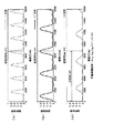
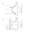
回折部50を有する回折光学素子35は、例えば、図3(a)に示すように、回折部50を通過した第1の波長の光ビームBB0を+1次回折光BB1となるように回折して対物レンズ34に入射させ、すなわち、所定の発散角を有する拡散状態の光ビームとして対物レンズ34に入射させることで、第1の光ディスク11の信号記録面に適切に集光させ、図3(b)に示すように、回折部50を通過した第2の波長の光ビームBD0を−1次回折光BD1となるように回折して対物レンズ34に入射させ、すなわち、所定の発散角を有する収束状態の光ビームとして対物レンズ34に入射させることで、第2の光ディスク12の信号記録面に適切に集光させ、図3(c)に示すように、回折部50を通過した第3の波長の光ビームBC0を−2次回折光BC1となるように回折して対物レンズ34に入射させ、すなわち、所定の発散角を有する収束状態の光ビームとして対物レンズ34に入射させることで、第3の光ディスク13の信号記録面に適切に集光させることにより、単一の対物レンズ34を用いて3種類の光ディスクの信号記録面に球面収差を発生しないように適切に集光することを可能とする。尚、ここでは、回折部50の複数の回折領域において、同じ波長の光ビームを同じ回折次数の回折光とする例について図3を用いて説明したが、本発明を適用した光ピックアップ3を構成する回折部50は、後述のように、各領域毎に各波長に対する回折次数を設定し、より球面収差を低減するように構成することを可能とする。   For example, as shown in FIG. 3A, the diffractive optical element 35 having the diffractive part 50 diffracts the light beam BB0 having the first wavelength that has passed through the diffractive part 50 so as to become the + 1st order diffracted light BB1, and thereby the objective. By making it enter into the lens 34, that is, making it enter into the objective lens 34 as a diffused light beam having a predetermined divergence angle, the light is appropriately condensed on the signal recording surface of the first optical disc 11, and FIG. As shown in FIG. 5, the light beam BD0 having the second wavelength that has passed through the diffraction section 50 is diffracted so as to become the −1st order diffracted light BD1, and is incident on the objective lens 34, that is, in a converged state having a predetermined divergence angle. By making it enter into the objective lens 34 as a light beam, it is appropriately condensed on the signal recording surface of the second optical disk 12, and as shown in FIG. Beam BC0 The signal recording surface of the third optical disc 13 is diffracted so as to be the second-order diffracted light BC1 and incident on the objective lens 34, that is, incident on the objective lens 34 as a converged light beam having a predetermined divergence angle. By appropriately condensing the light, it is possible to appropriately condense using the single objective lens 34 so that spherical aberration does not occur on the signal recording surfaces of the three types of optical disks. Here, an example in which a light beam having the same wavelength is diffracted light having the same diffraction order in a plurality of diffraction regions of the diffraction unit 50 has been described with reference to FIG. 3, but the optical pickup 3 to which the present invention is applied is configured. As will be described later, the diffracting unit 50 can set a diffraction order for each wavelength for each region, and can be configured to further reduce spherical aberration.

具体的に、図4(a)及び図4(b)に示すように、回折光学素子35の入射側の面に設けられた回折部50は、最内周部に設けられ略円形状の第1の回折領域(以下、「内輪帯」ともいう。)51と、第1の回折領域51の外側に設けられ輪帯状の第2の回折領域(以下、「中輪帯」ともいう。)52と、第2の回折領域52の外側に設けられ輪帯状の第3の回折領域(以下、「外輪帯」ともいう。)53とを有する。   Specifically, as shown in FIGS. 4A and 4B, the diffractive portion 50 provided on the incident-side surface of the diffractive optical element 35 is provided on the innermost peripheral portion and has a substantially circular shape. 1 diffraction region (hereinafter also referred to as “inner annular zone”) 51, and a second diffraction region (hereinafter also referred to as “intermediate annular zone”) 52 provided outside the first diffraction region 51. And a ring-shaped third diffraction region (hereinafter also referred to as “outer ring zone”) 53 provided outside the second diffraction region 52.

内輪帯である第1の回折領域51は、輪帯状で且つ所定の深さを有する第1の回折構造が形成され、通過する第1の波長の光ビームの対物レンズ34を介して第1の光ディスクの信号記録面に適切なスポットを形成するよう集光する次数の回折光が支配的となるように、すなわち、他の次数の回折光に対して最大の回折効率となるように発生させる。   The first diffractive region 51 that is the inner annular zone is formed with a first diffractive structure having an annular shape and a predetermined depth, and the first diffractive region 51 passes through the objective lens 34 of the light beam having the first wavelength that passes therethrough. In order to form an appropriate spot on the signal recording surface of the optical disc, the diffracted light of the order that is collected is dominant, that is, generated to have the maximum diffraction efficiency with respect to other orders of diffracted light.

また、第1の回折領域51は、第1の回折構造により、通過する第2の波長の光ビームの対物レンズ34を介して第2の光ディスクの信号記録面に適切なスポットを形成するよう集光する次数の回折光が支配的となるように、すなわち、他の次数の回折光に対して最大の回折効率となるように発生させる。   In addition, the first diffraction region 51 is gathered so as to form an appropriate spot on the signal recording surface of the second optical disc through the objective lens 34 of the light beam having the second wavelength passing therethrough by the first diffraction structure. It is generated so that the diffracted light of the order of light is dominant, that is, has the maximum diffraction efficiency with respect to the diffracted light of other orders.

また、第1の回折領域51は、第1の回折構造により、通過する第3の波長の光ビームの対物レンズ34を介して第3の光ディスクの信号記録面に適切なスポットを形成するよう集光する次数の回折光が支配的となるように、すなわち、他の次数の回折光に対して最大の回折効率となるように発生させる。   In addition, the first diffraction region 51 is gathered so as to form an appropriate spot on the signal recording surface of the third optical disc through the objective lens 34 of the light beam having the third wavelength passing through the first diffraction structure. It is generated so that the diffracted light of the order of light is dominant, that is, has the maximum diffraction efficiency with respect to the diffracted light of other orders.

このように、第1の回折領域51は、上述の各波長の光ビームに対して上述の所定の次数の回折光が支配的となるのに適するような回折構造が形成されているため、第1の回折領域51を通過して所定の次数の回折光とされた各波長の光ビームが対物レンズ34によりそれぞれの光ディスクの信号記録面に集光される際の球面収差を補正して低減することを可能とする。   Thus, the first diffraction region 51 is formed with a diffractive structure that is suitable for the diffracted light of the predetermined order to be dominant with respect to the light beam of each wavelength described above. 1 corrects and reduces spherical aberration when a light beam of each wavelength, which has passed through one diffraction region 51 and is made a diffracted light of a predetermined order, is condensed on the signal recording surface of each optical disk by the objective lens 34. Make it possible.

具体的には、第1の回折領域51は、図4及び図5(a)に示すように、光軸を中心とした輪帯状でこの輪帯の断面形状が、所定の深さ(以下、「溝深さ」ともいう。)dで所定のステップ数S(Sは、正の整数とする。)の階段形状(以下、「マルチステップの階段形状」ともいう。)が半径方向に連続して形成されている。ここで、上述の回折構造における輪帯の断面形状とは、輪帯の半径方向を含む面、すなわち、輪帯の接線方向に直交する面における断面形状を意味する。また、ここで、所定のステップ数Sの階段形状を有する回折構造とは、各段の深さが略同一深さとされた第1乃至第Sの段部を有する階段部が半径方向に連続して形成されている構造であり、さらに、換言すると光軸方向に略同一間隔に形成された第1乃至第(S+1)の回折面を有して形成されている構造である。また、回折構造における所定の深さdは、階段形状の最も表面側(最高段、浅い位置)に位置される第(S+1)の回折面と、階段形状の最も素子側(最低段、深い位置)に位置される第1の回折面との光軸方向の長さを意味する。この点については、後述する図5(b)及び図5(c)についても同様である。尚、図5(a)〜図5(c)においては、階段形状の各階段部内において段部が半径方向の外側に向けて形成、すなわち、段部が半径方向の外側に向かうにつれて表面側に向けて形成されるように構成したが、これに限られるものではなく、内輪帯、中輪帯及び外輪帯の回折構造において階段形状の各階段部内において段部が半径方向の内側に向けて形成されるように構成してもよい。具体的には、各回折構造における支配的となる回折次数及び後述の溝幅を設定することにより、所定の回折角度及び回折効率を得るとともに、回折次数がプラスであるかマイナスであるかに応じて階段形状の形成方向を設定することにより所望の発散角を有した拡散状態又は収束状態を得ることができる。図5(a)〜図5(c)中Rは、輪帯の半径方向外側に向けた方向を示し、すなわち、光軸から離間する方向を示すものである。 Specifically, as shown in FIG. 4 and FIG. 5A, the first diffraction region 51 has an annular shape centered on the optical axis, and the sectional shape of the annular zone has a predetermined depth (hereinafter referred to as the following). (Also referred to as “groove depth”). A stepped shape (hereinafter also referred to as “multistep stepped shape”) having a predetermined number of steps S (S is a positive integer) is continuous in the radial direction. Is formed. Here, the sectional shape of the annular zone in the above-described diffraction structure means a sectional shape on a plane including the radial direction of the annular zone, that is, a plane orthogonal to the tangential direction of the annular zone. Further, here, the diffractive structure having a staircase shape having a predetermined number of steps S means that a staircase portion having first to S-th step portions in which the depth of each step is substantially the same depth is continuous in the radial direction. In other words, it is a structure having first to (S + 1) th diffraction surfaces formed at substantially the same interval in the optical axis direction. The predetermined depth d in the diffractive structure is such that the (S + 1) -th diffractive surface located on the most surface side (highest step, shallow position) of the staircase shape and the most element side (lowest step, deep position) of the staircase shape. ) In the optical axis direction with respect to the first diffractive surface. This also applies to FIGS. 5B and 5C described later. 5A to 5C, the stepped portion is formed outward in the radial direction in each stepped stepped portion, that is, on the surface side as the stepped portion goes outward in the radial direction. However, the present invention is not limited to this, and in the diffraction structure of the inner ring zone, the middle ring zone, and the outer ring zone, the stepped portion is formed toward the radially inner side in each stepped stepped portion. You may comprise. Specifically, by setting the dominant diffraction order and the groove width described later in each diffraction structure, a predetermined diffraction angle and diffraction efficiency are obtained, and depending on whether the diffraction order is positive or negative. By setting the direction of formation of the staircase shape, a diffusion state or a convergence state having a desired divergence angle can be obtained. In FIG. 5 (a) to FIG. 5 (c), R 2 O indicates the direction toward the radially outer side of the annular zone, that is, the direction away from the optical axis.

尚、第1の回折領域51に形成される第1の回折構造並びに後述の第2及び第3の回折構造において、溝深さd及びステップ数Sは、支配的となる回折次数、及び回折効率を考慮して決定されている。また、各段部の溝幅(階段形状の各段部の半径方向の寸法)は、図5(a)〜図5(c)に示すように、一の階段部内において、等しく形成されているとともに、半径方向に連続して形成されている異なる階段部間において、光軸から離間するにつれてその値が小さくなるように形成されている。尚、この溝幅は、光ディスクの信号記録面上で集光されるスポットが最適となるように、この溝幅で形成された回折領域で与える位相差に基づいて決定されている。   In the first diffractive structure formed in the first diffractive region 51 and the second and third diffractive structures described later, the groove depth d and the step number S are the dominant diffraction order and diffraction efficiency. Has been determined in consideration of. Further, the groove width of each step portion (the dimension in the radial direction of each step portion of the staircase shape) is formed equally in one step portion as shown in FIGS. 5 (a) to 5 (c). At the same time, the distance between the different step portions formed continuously in the radial direction is such that the value decreases as the distance from the optical axis increases. The groove width is determined based on the phase difference given by the diffraction region formed with this groove width so that the spot focused on the signal recording surface of the optical disc is optimized.

例えば、第1の回折領域51の回折構造は、図5(a)に示すように、ステップ数が4(S=4)とされた回折構造であり、各段の深さが略同一深さ(d/4)とされた第1乃至第4の段部51s1,51s2,51s3,51s4を有する階段部が半径方向に連続して形成されており、また、光軸方向に間隔が(d/4)で同一間隔に形成された第1乃至第5の回折面51f1,51f2,51f3,51f4,51f5を有して形成されている。   For example, as shown in FIG. 5A, the diffractive structure of the first diffractive region 51 is a diffractive structure in which the number of steps is 4 (S = 4), and the depth of each step is substantially the same depth. Step portions having first to fourth step portions 51 s 1, 51 s 2, 51 s 3, 51 s 4 defined as (d / 4) are continuously formed in the radial direction, and the interval in the optical axis direction is (d / 4), the first to fifth diffractive surfaces 51f1, 51f2, 51f3, 51f4, and 51f5 are formed at the same interval.

また、ここでは、輪帯の断面形状がマルチステップの階段形状となるような回折構造を有する第1の回折領域51が形成されているものとして説明するが、上述のような各波長の光ビームに対して所定の次数の光ビームが支配的となるような回折構造であればよく、例えば、輪帯の断面形状が図6に示すような所定の深さdのブレーズ形状となるような回折構造を有する回折領域51Bが形成されるように構成してもよい。   In addition, here, it is assumed that the first diffraction region 51 having a diffraction structure in which the sectional shape of the annular zone is a multi-step staircase shape is formed. For example, a diffraction structure in which a light beam of a predetermined order is dominant, such as a diffraction pattern in which the cross-sectional shape of the annular zone becomes a blazed shape having a predetermined depth d as shown in FIG. You may comprise so that the diffraction area 51B which has a structure may be formed.

また、第1の回折領域51は、通過する第1の波長の光ビームの次数k1iの回折光が支配的となるよう、すなわち、回折効率が最大となるように発生させ、また、通過する第2の波長の光ビームの次数k2iの回折光が支配的となるよう、すなわち、回折効率が最大となるように発生させ、また、通過する第3の波長の光ビームの次数k3iの回折光が支配的となるように発生させる場合に、k1i、k2i、k3iがいずれも0以外であり、k1iとk2iとが異符号(k1i×k2i<0)で、k2iとk3iとが同符号(k2i×k3i>0)となるようにされている。尚、上述の場合においてk1iとk3iが異符号となるようにされている。   The first diffraction region 51 is generated so that the diffracted light of the order k1i of the light beam having the first wavelength passing therethrough is dominant, that is, the diffraction efficiency is maximized, and the first diffraction region 51 passes through. The diffracted light of order k2i of the light beam of wavelength 2 is dominant, that is, the diffraction efficiency is maximized, and the diffracted light of order k3i of the light beam of the third wavelength passing through is When generated so as to be dominant, k1i, k2i, and k3i are all other than 0, k1i and k2i are different signs (k1i × k2i <0), and k2i and k3i are the same sign (k2i × k3i> 0). In the above case, k1i and k3i have different signs.

ここで、第1の回折領域51は、回折効率が最大となる第1の波長の回折次数k1iが0以外とされていることにより、対物レンズ34によるカップリングを下げることができ、光源戻り光ノイズの問題を防止することができ、従来の光源出射において出力を適度な範囲に抑えなければいけない等の問題を回避できる。また、第1の回折領域51において、回折効率が最大となる第2及び第3の波長の回折次数k2i,k3iを0とした場合の、収差及び効率が最良となる組み合わせが存在しない。換言すると、第1の回折領域51において、k2i,k3iが0以外とされていることにより、収差及び効率を確保し得る組み合わせとすることができる。   Here, in the first diffraction region 51, since the diffraction order k1i of the first wavelength that maximizes the diffraction efficiency is other than 0, the coupling by the objective lens 34 can be lowered, and the light source return light The problem of noise can be prevented, and problems such as the need to suppress the output to an appropriate range in conventional light source emission can be avoided. Further, in the first diffraction region 51, there is no combination that provides the best aberration and efficiency when the diffraction orders k2i and k3i of the second and third wavelengths that maximize the diffraction efficiency are set to zero. In other words, since k2i and k3i are other than 0 in the first diffraction region 51, a combination that can ensure aberration and efficiency can be obtained.

第1の回折領域51は、回折効率が最大となる各波長の回折次数k1i、k2i、k3iの関係がk1iとk2iとが異符号で、k2iとk3iとが同符号となるように構成されていることにより、複数種類の光ディスクに対して各波長の光ビームについて同一の対物レンズ34により集光する場合において、球面収差をより低減させることを可能とする。これは、上述のような第1乃至第3の光ディスクに対して対物レンズ34を設計する場合に、保護層の設計センターを0.1mm〜0.6mmに設定することが多いため、その設計センターに対して第1の波長の光ビームに与える球面収差極性と、第2及び第3の波長の光ビームに与える球面収差極性とが逆になるようにすることで球面収差を抑えることができるという考え方によるものである。 The first diffraction region 51 is configured such that the diffraction orders k1i, k2i, and k3i of the respective wavelengths at which the diffraction efficiency is maximum are such that k1i and k2i have different signs, and k2i and k3i have the same sign. This makes it possible to further reduce the spherical aberration when the light beams having the respective wavelengths are condensed by the same objective lens 34 on a plurality of types of optical disks. This is because when designing the objective lens 34 for the first to third optical disks as described above, the design center of the protective layer is often set to 0.1 mm to 0.6 mm. Spherical aberration can be suppressed by making the spherical aberration polarity given to the light beam of the first wavelength and the spherical aberration polarity given to the light beam of the second and third wavelengths opposite to the design center. It is based on the idea of being able to

さらに、第1の回折領域51は、回折効率が最大となる各波長の回折次数k1i、k2i、k3iが以下で示される関係のいずれかとなるように構成されている。(k1i,k2i,k3i)=(+1,−1,−2)、(−1,+1,+2)、(+1,−2,−3)、(−1、+2、+3)、(+2,−1,−2)、(−2,+1,+2)、(+2,−2,−3)、(−2、+2,+3)。   Furthermore, the first diffraction region 51 is configured such that the diffraction orders k1i, k2i, and k3i of the respective wavelengths that maximize the diffraction efficiency have any of the relationships shown below. (K1i, k2i, k3i) = (+ 1, -1, -2), (-1, + 1, + 2), (+ 1, -2, -3), (-1, +2, +3), (+2,- 1, -2), (-2, +1, +2), (+2, -2, -3), (-2, +2, +3).

以下に、内輪帯である第1の回折領域51の具体的な実施例として、深さd及びステップ数Sについての具体的な数値を挙げ、各波長の光ビームに対して支配的となる次数の回折光の回折次数、及び、その回折次数の回折光の回折効率について表1に示す。尚、表1は、第1の回折領域51の実施例として内輪帯構成例1〜内輪帯構成例4について示すものであり、表1中k1iは、第1の波長の光ビームの回折効率が最大となる回折次数を示し、eff1は、第1の波長の光ビームの回折効率が最大となる回折次数の回折効率を示し、k2iは、第2の波長の光ビームの回折効率が最大となる回折次数を示し、eff2は、第2の波長の光ビームの回折効率が最大となる回折次数の回折効率を示し、k3iは、第3の波長の光ビームの回折効率が最大となる回折次数を示し、eff3は、第3の波長の光ビームの回折効率が最大となる回折次数の回折効率を示し、dは、第1の回折領域51の溝深さ、すなわち階段形状の最低段から最高段までの距離を示し、Sは、第1の回折領域51の階段形状のステップ数を示すものである。   In the following, as specific examples of the first diffraction region 51 that is the inner ring zone, specific numerical values for the depth d and the step number S are given, and the orders that are dominant with respect to the light beam of each wavelength. Table 1 shows the diffraction order of the diffracted light and the diffraction efficiency of the diffracted light of that diffraction order. Table 1 shows an example of the inner annular zone configuration example 1 to the inner annular zone configuration example 4 as examples of the first diffraction region 51. In Table 1, k1i indicates the diffraction efficiency of the light beam of the first wavelength. The maximum diffraction order is shown, eff1 is the diffraction efficiency of the diffraction order that maximizes the diffraction efficiency of the light beam of the first wavelength, and k2i is the maximum diffraction efficiency of the light beam of the second wavelength. Indicates the diffraction order, eff2 indicates the diffraction efficiency of the diffraction order that maximizes the diffraction efficiency of the light beam of the second wavelength, and k3i indicates the diffraction order of maximum diffraction efficiency of the light beam of the third wavelength. Eff3 indicates the diffraction efficiency of the diffraction order that maximizes the diffraction efficiency of the light beam of the third wavelength, and d indicates the groove depth of the first diffraction region 51, that is, the lowest step to the highest step of the step shape. , S is the step shape of the first diffraction region 51 It indicates the number of steps.

Figure 0004586904
Figure 0004586904

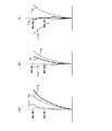
ここで、表1に示す内輪帯構成例1について説明する。内輪帯構成例1においては、表1に示すように、溝深さd=3.8(μm)、ステップ数S=4としたときの、第1の波長の光ビームの回折次数k1i=+1の回折効率eff1=0.81であり、第2の波長の光ビームの回折次数k2i=−1の回折効率eff2=0.62であり、第3の波長の光ビームの回折次数k3i=−2の回折効率eff3=0.57である。次に、この内輪帯構成例1について図7(a)〜図7(c)を用いて、さらに具体的に説明する。図7(a)は、ステップ数S=4の階段形状の溝深さdを変化させた場合の、第1の波長の光ビームの+1次回折光の回折効率の変化を示す図であり、図7(b)は、ステップ数S=4の階段形状の溝深さdを変化させた場合の、第2の波長の光ビームの−1次回折光の回折効率の変化を示す図であり、図7(c)は、ステップ数S=4の階段形状の溝深さdを変化させた場合の、第3の波長の光ビームの−2次回折光の回折効率の変化を示す図である。図7(a)〜図7(c)中において横軸は、溝深さ(nm)を示し、縦軸は、回折効率(光の強度)を示す図である。そして、横軸が3800nmの位置において、図7(a)に示すように、eff1は、0.81であり、図7(b)に示すように、eff2は、0.62であり、図7(c)に示すように、eff3は、0.57である。   Here, an inner ring zone configuration example 1 shown in Table 1 will be described. In the inner ring zone configuration example 1, as shown in Table 1, when the groove depth is d = 3.8 (μm) and the number of steps is S = 4, the diffraction order k1i of the light beam of the first wavelength is +1. The diffraction efficiency eff1 = 0.81 of the second wavelength, the diffraction order k2i of the light beam of the second wavelength k2i = −1, the diffraction efficiency eff2 = 0.62, and the diffraction order of the light beam of the third wavelength k3i = −2. The diffraction efficiency eff3 = 0.57. Next, the inner ring zone configuration example 1 will be described more specifically with reference to FIGS. 7A to 7C. FIG. 7A is a diagram showing a change in the diffraction efficiency of the + 1st order diffracted light of the light beam of the first wavelength when the step-shaped groove depth d having the number of steps S = 4 is changed. FIG. 7B is a diagram illustrating a change in diffraction efficiency of the −1st order diffracted light of the light beam having the second wavelength when the step-shaped groove depth d having the number of steps S = 4 is changed. FIG. 7C is a diagram illustrating a change in diffraction efficiency of the −2nd order diffracted light of the light beam having the third wavelength when the step-shaped groove depth d having the number of steps S = 4 is changed. 7A to 7C, the horizontal axis represents the groove depth (nm), and the vertical axis represents the diffraction efficiency (light intensity). Then, at a position where the horizontal axis is 3800 nm, as shown in FIG. 7A, eff1 is 0.81, and as shown in FIG. 7B, eff2 is 0.62. As shown in (c), eff3 is 0.57.

また、表1に示す内輪帯構成例2についても同様に、d=5.3(μm)、S=6としたときに、表1及び図8(a)〜図8(c)に示すように、各次数k1i,k2i,k3i及び各回折効率eff1,eff2,eff3が得られ、表1に示す内輪帯構成例3についても同様に、d=5.1(μm)、S=5としたときに、表1及び図9(a)〜図9(c)に示すように、各次数k1i,k2i,k3i及び各回折効率eff1,eff2,eff3が得られ、表1に示す内輪帯構成例4についても同様に、d=5.8(μm)、S=6としたときに、表1及び図10(a)〜図10(c)に示すように、各次数k1i,k2i,k3i及び各回折効率eff1,eff2,eff3が得られることとなる。   Similarly, in the inner ring zone configuration example 2 shown in Table 1, when d = 5.3 (μm) and S = 6, as shown in Table 1 and FIGS. 8A to 8C. Further, the respective orders k1i, k2i, k3i and the respective diffraction efficiencies eff1, eff2, eff3 are obtained. Similarly, in the inner ring zone configuration example 3 shown in Table 1, d = 5.1 (μm) and S = 5. Sometimes, as shown in Table 1 and FIGS. 9A to 9C, the orders k1i, k2i, k3i and the diffraction efficiencies eff1, eff2, eff3 are obtained. Similarly, when d = 5.8 (μm) and S = 6, as shown in Table 1 and FIGS. 10 (a) to 10 (c), each order k1i, k2i, k3i and Each diffraction efficiency eff1, eff2, eff3 is obtained.

中輪帯である第2の回折領域52は、輪帯状で且つ所定の深さを有し第1の回折構造とは異なる構造とされた第2の回折構造が形成され、通過する第1の波長の光ビームの対物レンズ34を介して第1の光ディスクの信号記録面に適切なスポットを形成するよう集光する次数の回折光が支配的となるように、すなわち、他の次数の回折光に対して最大の回折効率となるように発生させる。   The second diffractive region 52, which is the middle annular zone, is formed with a second diffractive structure that is annular and has a predetermined depth and is different from the first diffractive structure. The diffracted light of the order that is condensed to form an appropriate spot on the signal recording surface of the first optical disk via the objective lens 34 of the light beam of the wavelength is dominant, that is, the diffracted light of other orders With respect to the maximum diffraction efficiency.

また、第2の回折領域52は、第2の回折構造により、通過する第2の波長の光ビームの対物レンズ34を介して第2の光ディスクの信号記録面に適切なスポットを形成するよう集光する次数の回折光が支配的となるように、すなわち、他の次数の回折光に対して最大の回折効率となるように発生させる。   The second diffractive region 52 is gathered so as to form an appropriate spot on the signal recording surface of the second optical disc through the objective lens 34 of the light beam having the second wavelength that passes through the second diffractive structure. It is generated so that the diffracted light of the order of light is dominant, that is, has the maximum diffraction efficiency with respect to the diffracted light of other orders.

また、第2の回折領域52は、第2の回折構造により、通過する第3の波長の光ビームの対物レンズ34を介して第3の光ディスクの信号記録面に適切なスポットを形成するよう集光する次数以外の次数の回折光が支配的となるように、すなわち、他の次数の回折光に対して最大の回折効率となるように発生させる。尚、第2の回折領域52は、第2の回折構造により、通過する第3の波長の光ビームの対物レンズ34を介して第3の光ディスクの信号記録面に適切なスポットを形成するよう集光する次数の回折光の回折効率を十分に低減することができる。   The second diffractive region 52 is formed by the second diffractive structure so as to form an appropriate spot on the signal recording surface of the third optical disc via the objective lens 34 of the light beam having the third wavelength passing therethrough. It is generated so that the diffracted light of the order other than the order of light is dominant, that is, the diffracted light of the other order has the maximum diffraction efficiency. The second diffractive region 52 is gathered so as to form an appropriate spot on the signal recording surface of the third optical disc through the objective lens 34 of the light beam having the third wavelength passing through the second diffractive structure. The diffraction efficiency of the diffracted light of the order of light can be sufficiently reduced.

このように、第2の回折領域52は、上述の各波長の光ビームに対して上述の所定の次数の回折光が支配的となるのに適するような回折構造が形成されているため、第2の回折領域52を通過して所定の次数の回折光とされた第1及び第2の波長の光ビームが対物レンズ34によりそれぞれの光ディスクの信号記録面に集光される際の球面収差を補正して低減することを可能とする。   Thus, the second diffraction region 52 is formed with a diffraction structure suitable for the diffracted light of the predetermined order to be dominant with respect to the light beams of the respective wavelengths. Spherical aberration when the light beams of the first and second wavelengths that have passed through the two diffraction regions 52 and have been diffracted to a predetermined order are condensed on the signal recording surface of each optical disk by the objective lens 34. It can be corrected and reduced.

また、第2の回折領域52は、第1及び第2の波長の光ビームに対しては上述のように機能するとともに、第3の波長の光ビームについては、この第2の回折領域52を通過して対物レンズ34を介して第3の光ディスクの信号記録面に集光する次数以外の次数の回折光が支配的となるように構成されていることから、この第2の回折領域52を通過した第3の波長の光ビームが対物レンズ34に入射しても第3の光ディスクの信号記録面にはほとんど影響を与えることなく、換言すると、この第2の回折領域52を通過して対物レンズ34により信号記録面に集光される第3の波長の光ビームの光量を大幅に低減して略ゼロとして、第3の波長の光ビームに対して開口制限を行うよう機能することができる。   The second diffractive region 52 functions as described above for the light beams having the first and second wavelengths, and the second diffractive region 52 is used for the light beam having the third wavelength. Since the diffracted light of the order other than the order passing through the objective lens 34 and condensing on the signal recording surface of the third optical disc is dominant, the second diffractive region 52 is formed. Even if the light beam having the third wavelength that has passed is incident on the objective lens 34, the signal recording surface of the third optical disk is hardly affected. In other words, the light beam having the third wavelength passes through the second diffraction region 52 and is objective. The light beam of the third wavelength light beam condensed on the signal recording surface by the lens 34 can be greatly reduced to substantially zero so that the aperture restriction can be performed on the third wavelength light beam. .

ところで、上述した第1の回折領域51は、その領域を通過した第3の波長の光ビームが、NA=0.45程度で開口制限される光ビームと同様の状態で対物レンズ34に入射するような大きさに形成されており、また、この第1の回折領域51の外側に形成される第2の回折領域52は、この領域を通過した第3の波長の光ビームを、対物レンズ34を介して第3の光ディスク上に集光させないため、かかる構成とされた第1及び第2の回折領域51,52を備える回折部50は、第3の波長の光ビームに対して、NA=0.45程度に開口制限を行うように機能することとなる。ここでは、回折部50において、第3の波長の光ビームに対して開口数NAを0.45程度に開口制限を行うように構成したが、上述の構成により制限される開口数はこれに限られるものではない。   By the way, in the first diffraction region 51 described above, the light beam of the third wavelength that has passed through the region is incident on the objective lens 34 in the same state as the light beam whose aperture is limited to about NA = 0.45. The second diffractive region 52 formed outside the first diffractive region 51 has a third wavelength light beam that has passed through this region as the objective lens 34. Therefore, the diffraction unit 50 including the first and second diffraction regions 51 and 52 configured as described above has a NA = It functions to limit the aperture to about 0.45. Here, the diffraction unit 50 is configured to limit the numerical aperture NA to about 0.45 with respect to the light beam of the third wavelength. However, the numerical aperture limited by the above configuration is limited to this. It is not something that can be done.

具体的には、第2の回折領域52は、上述した第1の回折領域51と同様に、図4及び図5(b)に示すように、光軸を中心とした輪帯状でこの輪帯の断面形状が所定の深さdで所定のステップ数Sの階段形状が半径方向に連続して形成されている。尚、ここで、第2の回折領域52は、第1の回折領域51の場合と比べてd及び/又はSの数値が異なっており、すなわち、第1の回折領域51に設けられた第1の回折構造とは異なる第2の回折構造が形成されている。例えば、図5(b)に示す第2の回折領域52の回折構造は、ステップ数が3(S=3)とされた回折構造であり、各段の深さが略同一深さ(d/3)とされた第1乃至第3の段部52s1,52s2,52s3を有する階段部が半径方向に連続して形成されており、また、光軸方向に間隔が(d/3)で同一間隔に形成された第1乃至第4の回折面52f1,52f2,52f3,52f4を有して形成されている。   Specifically, the second diffractive region 52 has an annular shape centered on the optical axis as shown in FIGS. 4 and 5B, as in the first diffractive region 51 described above. A stepped shape having a predetermined depth d and a predetermined step number S is continuously formed in the radial direction. Here, the second diffraction region 52 is different from the first diffraction region 51 in terms of d and / or S, that is, the first diffraction region 51 is provided with the first diffraction region 51. A second diffractive structure different from the diffractive structure is formed. For example, the diffractive structure of the second diffractive region 52 shown in FIG. 5B is a diffractive structure in which the number of steps is 3 (S = 3), and the depth of each step is substantially the same depth (d / 3) Step portions having first to third step portions 52s1, 52s2, and 52s3, which are defined as 3), are continuously formed in the radial direction, and the same interval is provided in the optical axis direction at (d / 3). The first to fourth diffractive surfaces 52f1, 52f2, 52f3 and 52f4 are formed.

また、ここでは、輪帯の断面形状がマルチステップの階段形状となるような回折構造を有する第2の回折領域52が形成されているものとして説明するが、上述した第1の回折領域と同様に、上述のような各波長の光ビームに対して所定の次数の光ビームが支配的となるような回折構造であればよく、例えば、輪帯の断面形状が上述した図6に示すような所定の深さdのブレーズ形状となるような回折構造を有する回折領域52Bが形成されるように構成してもよい。   In addition, here, it is assumed that the second diffraction region 52 having a diffraction structure in which the cross-sectional shape of the annular zone has a multi-step staircase shape is formed, but it is similar to the first diffraction region described above. In addition, a diffraction structure in which a predetermined-order light beam is dominant with respect to the light beams having the respective wavelengths as described above may be used. For example, the sectional shape of the annular zone is as shown in FIG. A diffractive region 52B having a diffractive structure that has a blazed shape with a predetermined depth d may be formed.

また、第2の回折領域52は、通過する第1の波長の光ビームの次数k1mの回折光が支配的となるよう、すなわち、回折効率が最大となるように発生させ、また、通過する第2の波長の光ビームの次数k2mの回折光が支配的となるよう、すなわち、回折効率が最大となるように発生させる場合に、回折次数k1m,k2mが例えば以下で示される関係となるように構成されている。(k1m,k2m)=(+1,−1)、(−1,+1)、(+1,−2)、(−1、+2)、(+2,−1)、(−2,+1)。   The second diffraction region 52 is generated so that the diffracted light of the order k1m of the light beam of the first wavelength passing through is dominant, that is, the diffraction efficiency is maximized, and the second diffraction region 52 passes through. In the case where the diffracted light of the order k2m of the light beam having the wavelength of 2 is dominant, that is, when the diffraction efficiency is maximized, the diffraction orders k1m and k2m have the relationship shown below, for example. It is configured. (K1m, k2m) = (+ 1, −1), (−1, +1), (+1, −2), (−1, +2), (+2, −1), (−2, +1).

以下に、中輪帯である第2の回折領域52の具体的な実施例として、深さd及びステップ数Sについての具体的な数値を挙げ、各波長の光ビームに対して支配的となる次数の回折光の回折次数、及び、その回折次数の回折光の回折効率について表2に示す。尚、表2は、第2の回折領域52の実施例として中輪帯構成例1〜中輪帯構成例3について示すものであり、表2中k1mは、第1の波長の光ビームの回折効率が最大となる回折次数を示し、eff1は、第1の波長の光ビームの回折効率が最大となる回折次数の回折効率を示し、k2mは、第2の波長の光ビームの回折効率が最大となる回折次数を示し、eff2は、第2の波長の光ビームの回折効率が最大となる回折次数の回折効率を示し、k3mは、第3の波長の光ビームの下記のように選択された回折次数を示し、eff3は、第3の波長の光ビームの選択された回折次数の回折効率を示し、dは、第2の回折領域52の溝深さ、すなわち階段形状の最低段から最高段までの距離を示し、Sは、第2の回折領域52の階段形状のステップ数を示すものである。また、表2中「※」は、この構成例の中輪帯を通過する光ビームの対物レンズ34を介して対応する光ディスクの信号記録面に適切にスポットを形成するよう集光する回折次数、換言すると対応する光ディスクの信号記録面において球面収差補正が可能な回折次数を示すものであり、「〜0」は、回折効率が略0の状態を示すものである。   In the following, as specific examples of the second diffraction region 52 that is the middle annular zone, specific numerical values for the depth d and the step number S will be given, which will be dominant over the light beam of each wavelength. Table 2 shows the diffraction order of the diffracted light of the order and the diffraction efficiency of the diffracted light of the diffraction order. Table 2 shows examples of the middle annular zone configuration example 1 to the middle annular zone configuration example 3 as examples of the second diffraction region 52. In Table 2, k1m represents the diffraction of the light beam of the first wavelength. The diffraction order that maximizes the efficiency is shown, eff1 shows the diffraction efficiency of the diffraction order that maximizes the diffraction efficiency of the light beam of the first wavelength, and k2m shows the maximum diffraction efficiency of the light beam of the second wavelength. Where eff2 is the diffraction efficiency of the diffraction order that maximizes the diffraction efficiency of the light beam of the second wavelength, and k3m is selected as follows for the light beam of the third wavelength: Indicates the diffraction order, eff3 indicates the diffraction efficiency of the selected diffraction order of the light beam of the third wavelength, and d indicates the groove depth of the second diffraction region 52, that is, the lowest step to the highest step of the step shape. S is the step of the step shape of the second diffraction region 52. It shows a number of flops. In Table 2, “*” denotes a diffraction order for condensing light so as to appropriately form a spot on the signal recording surface of the corresponding optical disc through the objective lens 34 of the light beam passing through the middle annular zone of this configuration example, In other words, it indicates a diffraction order capable of correcting spherical aberration on the signal recording surface of the corresponding optical disk, and “˜0” indicates a state where the diffraction efficiency is substantially zero.

Figure 0004586904
Figure 0004586904

ここで、表2に示す中輪帯構成例1について説明する。中輪帯構成例1においては、表2に示すように、溝深さd=8.6(μm)、ステップ数S=3としたとき、第1の波長の光ビームの回折次数k1m=−1の回折効率eff1=0.76であり、第2の波長の光ビームの回折次数k2m=+1の回折効率eff2=0.77である。また、この領域を通過する第3の波長の光ビームの対物レンズ34を介して第3の光ディスクの信号記録面にスポットを形成するよう集光する回折次数k3mの回折効率eff3が略0である。   Here, the middle ring zone configuration example 1 shown in Table 2 will be described. In the middle annular zone configuration example 1, as shown in Table 2, when the groove depth is d = 8.6 (μm) and the number of steps is S = 3, the diffraction order k1m of the light beam of the first wavelength = − The diffraction efficiency eff1 of 1 is 0.76, and the diffraction efficiency eff2 = 0.77 of the diffraction order k2m = + 1 of the light beam of the second wavelength. Further, the diffraction efficiency eff3 of the diffraction order k3m that is condensed so as to form a spot on the signal recording surface of the third optical disk via the objective lens 34 of the light beam of the third wavelength that passes through this region is substantially zero. .

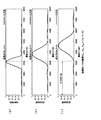
次に、この中輪帯構成例1について図11(a)〜図11(c)を用いて、さらに具体的に説明する。図11(a)は、ステップ数S=3の階段形状の溝深さdを変化させた場合の、第1の波長の光ビームの−1次回折光の回折効率の変化を示す図であり、図11(b)は、ステップ数S=3の階段形状の溝深さdを変化させた場合の、第2の波長の光ビームの+1次回折光の回折効率の変化を示す図であり、図11(c)は、ステップ数S=3の階段形状の溝深さdを変化させた場合の、第3の波長の光ビームの+2次回折光の回折効率の変化を示す図である。図11(a)〜図11(c)中において横軸は、溝深さ(nm)を示し、縦軸は、回折効率(光の強度)を示す図である。そして、横軸が8600nmの位置において、図11(a)に示すように、eff1は、0.76であり、図11(b)に示すように、eff2は、0.77であり、図11(c)に示すように、eff3は、略0である。尚、ここで、上述では「※」で表した第3の波長の光ビームの回折次数k3mは、k3m=+2である。   Next, the middle annular zone configuration example 1 will be described more specifically with reference to FIGS. 11 (a) to 11 (c). FIG. 11A is a diagram showing a change in the diffraction efficiency of the −1st order diffracted light of the light beam having the first wavelength when the step-shaped groove depth d having the number of steps S = 3 is changed. FIG. 11B is a diagram showing a change in the diffraction efficiency of the + 1st order diffracted light of the light beam of the second wavelength when the step-shaped groove depth d having the number of steps S = 3 is changed. 11 (c) is a diagram illustrating a change in the diffraction efficiency of the + 2nd order diffracted light of the light beam having the third wavelength when the step-shaped groove depth d having the number of steps S = 3 is changed. 11A to 11C, the horizontal axis represents the groove depth (nm), and the vertical axis represents the diffraction efficiency (light intensity). Then, at the position where the horizontal axis is 8600 nm, as shown in FIG. 11A, eff1 is 0.76, and as shown in FIG. 11B, eff2 is 0.77. As shown in (c), eff3 is substantially zero. Here, in the above description, the diffraction order k3m of the light beam of the third wavelength represented by “*” is k3m = + 2.

また、表2に示す中輪帯構成例2についても同様に、d=14.8(μm)、S=5としたときに、表2及び図12(a)〜図12(c)に示すように、各次数k1m,k2m,k3m及び各回折効率eff1,eff2,eff3が得られ、表2に示す中輪帯構成例3についても同様に、d=14.1(μm)、S=5としたときに、表2及び図13(a)〜図13(c)に示すように、各次数k1m,k2m,k3m及び各回折効率eff1,eff2,eff3が得られることとなる。   Similarly, in the middle annular zone configuration example 2 shown in Table 2, when d = 14.8 (μm) and S = 5, it is shown in Table 2 and FIGS. 12 (a) to 12 (c). Thus, the respective orders k1m, k2m, k3m and the respective diffraction efficiencies eff1, eff2, eff3 are obtained, and similarly for the middle ring zone configuration example 3 shown in Table 2, d = 14.1 (μm), S = 5 As shown in Table 2 and FIGS. 13A to 13C, the orders k1m, k2m, and k3m and the diffraction efficiencies eff1, eff2, and eff3 are obtained.

外輪帯である第3の回折領域53は、輪帯状で且つ所定の深さを有し第1及び第2の回折構造とは異なる構造とされた第3の回折構造が形成され、通過する第1の波長の光ビームの対物レンズ34を介して第1の光ディスクの信号記録面に適切なスポットを形成するよう集光する次数の回折光が支配的となるように、すなわち、他の次数の回折光に対して最大の回折効率となるように発生させる。   The third diffractive region 53 that is the outer ring zone is formed with a third diffractive structure that is ring-shaped and has a predetermined depth and is different from the first and second diffractive structures. The diffracted light of the order that is condensed to form an appropriate spot on the signal recording surface of the first optical disc through the objective lens 34 of the light beam of one wavelength is dominant, that is, other orders The maximum diffraction efficiency is generated for the diffracted light.

また、第3の回折領域53は、第3の回折構造により、通過する第2の波長の光ビームの対物レンズ34を介して第2の光ディスクの信号記録面に適切なスポットを形成するよう集光する次数以外の次数の回折光が支配的となるように、すなわち、他の次数の回折光に対して最大の回折効率となるように発生させる。尚、第3の回折領域53は、第3の回折構造により、通過する第2の波長の光ビームの対物レンズ34を介して第2の光ディスクの信号記録面に適切なスポットを形成するよう集光する次数の回折光の回折効率を十分に低減することができる。   The third diffractive region 53 is gathered so as to form an appropriate spot on the signal recording surface of the second optical disc through the objective lens 34 of the light beam having the second wavelength passing through the third diffractive structure. It is generated so that the diffracted light of the order other than the order of light is dominant, that is, the diffracted light of the other order has the maximum diffraction efficiency. The third diffractive region 53 is gathered so as to form an appropriate spot on the signal recording surface of the second optical disc through the objective lens 34 of the light beam having the second wavelength passing therethrough by the third diffractive structure. The diffraction efficiency of the diffracted light of the order of light can be sufficiently reduced.

また、第3の回折領域53は、第3の回折構造により、通過する第3の波長の光ビームの対物レンズ34を介して第3の光ディスクの信号記録面に適切なスポットを形成するよう集光する次数以外の次数の回折光が支配的となるように、すなわち、他の次数の回折光に対して最大の回折効率となるように発生させる。尚、第3の回折領域53は、第3の回折構造により、通過する第3の波長の光ビームの対物レンズ34を介して第3の光ディスクの信号記録面に適切なスポットを形成するよう集光する次数の回折光の回折効率を十分に低減することができる。   The third diffractive region 53 is formed by the third diffractive structure so as to form an appropriate spot on the signal recording surface of the third optical disc via the objective lens 34 of the light beam having the third wavelength passing therethrough. It is generated so that the diffracted light of the order other than the order of light is dominant, that is, the diffracted light of the other order has the maximum diffraction efficiency. The third diffractive region 53 is gathered so as to form an appropriate spot on the signal recording surface of the third optical disc through the objective lens 34 of the light beam having the third wavelength passing therethrough by the third diffractive structure. The diffraction efficiency of the diffracted light of the order of light can be sufficiently reduced.

このように、第3の回折領域53は、上述の各波長の光ビームに対して上述の所定の次数の回折光が支配的となるのに適するような回折構造が形成されているため、第3の回折領域53を通過して所定の次数の回折光とされた第1の波長の光ビームが対物レンズ34により光ディスクの信号記録面に集光される際の球面収差を補正して低減することを可能とする。   Thus, the third diffraction region 53 is formed with a diffractive structure that is suitable for the diffracted light of the predetermined order to be dominant with respect to the light beam of each wavelength described above. 3 corrects and reduces the spherical aberration when the light beam of the first wavelength which has passed through the diffraction region 53 of the third light and is made the diffracted light of the predetermined order is condensed on the signal recording surface of the optical disk by the objective lens 34. Make it possible.

また、第3の回折領域53は、第1の波長の光ビームに対しては上述のように機能するとともに、第2及び第3の波長の光ビームについては、この第3の回折領域53を通過して対物レンズ34を介して第2及び第3の光ディスクの信号記録面に集光する次数以外の次数の回折光が支配的となるように構成されていることから、この第3の回折領域53を通過した第2及び第3の波長の光ビームが対物レンズ34に入射しても第2及び第3の光ディスクの信号記録面にはほとんど影響を与えることなく、換言すると、この第3の回折領域53を通過して対物レンズ34により信号記録面に集光される第2及び第3の波長の光ビームの光量を大幅に低減して略ゼロとして、第2の波長の光ビームに対して開口制限を行うよう機能することができる。尚、第3の回折領域53は、第3の波長の光ビームに対しては、上述の第2の回折領域52とともに、開口制限を行うよう機能することができる。   The third diffractive region 53 functions as described above for the light beam having the first wavelength, and the third diffractive region 53 is used for the light beam having the second and third wavelengths. Since the diffracted light of the order other than the order passing through the objective lens 34 and condensing on the signal recording surfaces of the second and third optical discs is dominant, this third diffraction is configured. Even if the light beams of the second and third wavelengths that have passed through the region 53 are incident on the objective lens 34, the signal recording surfaces of the second and third optical disks are hardly affected. The light intensity of the second and third wavelength light beams that pass through the diffraction region 53 and is condensed on the signal recording surface by the objective lens 34 is substantially reduced to substantially zero, so that the second wavelength light beam is converted to the second wavelength light beam. Can function to restrict the opening to . Note that the third diffraction region 53 can function to limit the aperture of the light beam having the third wavelength together with the second diffraction region 52 described above.

ところで、上述した第2の回折領域52は、その領域を通過した第2の波長の光ビームが、NA=0.6程度で開口制限される光ビームと同様の状態で対物レンズ34に入射するような大きさに形成されており、また、この第2の回折領域52の外側に形成される第3の回折領域53は、この領域を通過した第2の波長の光ビームを、対物レンズ34を介して光ディスク上に集光させないため、かかる構成とされた第2及び第3の回折領域52,53を備える回折部50は、第2の波長の光ビームに対して、NA=0.6程度に開口制限を行うように機能することとなる。ここでは、回折部50において、第2の波長の光ビームに対して開口数NAを0.6程度に開口制限を行うように構成したが、上述の構成により制限される開口数はこれに限られるものではない。   By the way, in the second diffraction region 52 described above, the light beam having the second wavelength that has passed through the region is incident on the objective lens 34 in the same state as the light beam whose aperture is limited to about NA = 0.6. The third diffractive region 53 formed outside the second diffractive region 52 has a second wavelength light beam that has passed through this region. Therefore, the diffraction unit 50 including the second and third diffraction regions 52 and 53 configured as described above has a NA = 0.6 with respect to the light beam having the second wavelength. It will function to limit the opening to the extent. Here, the diffraction unit 50 is configured to limit the numerical aperture NA to about 0.6 with respect to the light beam of the second wavelength. However, the numerical aperture limited by the above configuration is limited to this. It is not something that can be done.

また、第3の回折領域53は、その領域を通過した第1の波長の光ビームが、NA=0.85程度で開口制限される光ビームと同様の状態で対物レンズ34に入射するような大きさに形成されており、また、この第3の回折領域53の外側には回折構造が形成されていないため、この領域を透過した第1の波長の光ビームを、対物レンズ34を介して第1の光ディスク上に集光させないため、かかる構成とされた第3の回折領域53を備える回折部50は、第1の波長の光ビームに対して、NA=0.85程度の開口制限を行うように機能することとなる。尚、第3の回折領域53を通過する第1の波長の光ビームは、例えば−1次、+1次、+2次、−2次の回折次数のものが支配的となるようにされているため、第3の回折領域53の外側の領域を透過した0次光は、対物レンズ34を介して第1の光ディスク上に集光しない場合がほとんどであるが、この0次光が、対物レンズ34を介して第1の光ディスク上に集光することになる場合には、第3の回折領域53の外側の領域に、通過する光ビームを遮蔽する遮蔽部又は通過する光ビームを対物レンズ34を介して第1の光ディスク上に集光する次数以外の次数の光ビームが支配的となる回折構造を有する回折領域を設けることにより、開口制限を行うように構成してもよい。ここでは、回折部50において、第1の波長の光ビームに対して開口数NAを0.85程度に開口制限を行うように構成したが、上述の構成により制限される開口数はこれに限られるものではない。   In the third diffraction region 53, the light beam having the first wavelength that has passed through the region is incident on the objective lens 34 in the same state as the light beam whose aperture is limited to about NA = 0.85. Since the diffractive structure is not formed outside the third diffraction region 53, the light beam having the first wavelength transmitted through this region is transmitted through the objective lens 34. In order not to condense on the first optical disc, the diffractive portion 50 including the third diffraction region 53 configured as described above has an aperture limit of about NA = 0.85 with respect to the light beam having the first wavelength. Will function to do. Note that the light beam having the first wavelength that passes through the third diffraction region 53, for example, has a dominant diffraction order of −1st order, + 1st order, + 2nd order, and −2nd order. In most cases, the 0th-order light transmitted through the region outside the third diffraction region 53 is not condensed on the first optical disk via the objective lens 34. When the light is condensed on the first optical disc via the first optical disk, a shielding portion that shields the passing light beam or the passing light beam is passed through the objective lens 34 in a region outside the third diffraction region 53. An aperture restriction may be performed by providing a diffraction region having a diffraction structure in which a light beam of an order other than the order condensed on the first optical disc is dominant. Here, the diffraction unit 50 is configured to limit the numerical aperture NA to about 0.85 with respect to the light beam of the first wavelength, but the numerical aperture limited by the above configuration is limited to this. It is not something that can be done.

具体的には、第3の回折領域53は、上述した第1の回折領域51と同様に、図4及び図5(c)に示すように、光軸を中心とした輪帯状でこの輪帯の断面形状が所定の深さdで所定のステップ数Sの階段形状が半径方向に連続して形成されている。尚、ここで、第3の回折領域53は、第1及び第2の回折領域51,52の場合と比べてd及び/又はSの数値が異なっており、すなわち、第1及び第2の回折領域51,52に設けられた第1及び第2の回折構造とは異なる第3の回折構造が形成されている。例えば、図5(c)に示す第3の回折領域53の回折構造は、ステップ数が2(S=2)とされた回折構造であり、各段の深さが略同一深さ(d/2)とされた第1乃至第2の段部53s1,53s2を有する階段部が半径方向に連続して形成されており、また、光軸方向に間隔が(d/2)で同一間隔に形成された第1乃至第3の回折面53f1,53f2,53f3を有して形成されている。   Specifically, the third diffraction region 53 has an annular shape centered on the optical axis as shown in FIGS. 4 and 5C, as in the first diffraction region 51 described above. A stepped shape having a predetermined depth d and a predetermined step number S is continuously formed in the radial direction. Here, the third diffraction region 53 is different from the first and second diffraction regions 51 and 52 in terms of d and / or S, that is, the first and second diffraction regions. A third diffractive structure different from the first and second diffractive structures provided in the regions 51 and 52 is formed. For example, the diffractive structure of the third diffractive region 53 shown in FIG. 5C is a diffractive structure in which the number of steps is 2 (S = 2), and the depth of each step is substantially the same depth (d / 2) The step portions having the first to second step portions 53s1 and 53s2 are formed continuously in the radial direction, and the intervals in the optical axis direction are (d / 2) and the same intervals. The first to third diffractive surfaces 53f1, 53f2, 53f3 are formed.

また、ここでは、輪帯の断面形状がマルチステップの階段形状となるような回折構造を有する第3の回折領域53が形成されているものとして説明するが、上述した第1及び第2の回折領域と同様に、上述のような各波長の光ビームに対して所定の次数の光ビームが支配的となるような回折構造であればよく、例えば、輪帯の断面形状が上述した図6に示すような所定の深さdのブレーズ形状となるような回折構造を有する回折領域53Bが形成されるように構成してもよい。   In addition, here, it is assumed that the third diffraction region 53 having a diffraction structure in which the cross-sectional shape of the annular zone has a multi-step staircase shape is formed. However, the first and second diffractions described above are described. Similar to the region, any diffractive structure in which the light beam of a predetermined order is dominant with respect to the light beams of the respective wavelengths as described above may be used. For example, the sectional shape of the annular zone is shown in FIG. A diffractive region 53B having a diffractive structure having a blazed shape with a predetermined depth d as shown may be formed.

以下に、外輪帯である第3の回折領域53の具体的な実施例として、深さd及びステップ数Sについての具体的な数値を挙げ、各波長の光ビームに対して支配的となる次数の回折光の回折次数、及び、その回折次数の回折光の回折効率について表3に示す。尚、表3は、第3の回折領域53の実施例として外輪帯構成例1〜外輪帯構成例4について示すものであり、表3k1oは、第1の波長の光ビームの回折効率が最大となる回折次数を示し、eff1は、第1の波長の光ビームの回折効率が最大となる回折次数の回折効率を示し、k2oは、第2の波長の光ビームの下記のように選択された回折次数を示し、eff2は、第2の波長の光ビームの選択された回折次数の回折効率を示し、k3oは、第3の波長の光ビームの下記のように選択された回折次数を示し、eff3は、第3の波長の光ビームの選択された回折次数の回折効率を示し、dは、第3の回折領域53の溝深さ、すなわち階段形状の最低段から最高段までの距離を示し、Sは、第3の回折領域53の階段形状のステップ数を示すものである。また、表3中「※」は、この構成例の外輪帯を通過する光ビームの対物レンズ34を介して対応する光ディスクの信号記録面に適切にスポットを形成するよう集光する回折次数、換言すると対応する光ディスクの信号記録面において球面収差補正が可能な回折次数を示すものであり、「〜0」は、回折効率が略0の状態を示すものである。   In the following, specific examples of the depth d and the step number S are given as specific examples of the third diffraction region 53 that is the outer ring zone, and the orders that are dominant with respect to the light beam of each wavelength. Table 3 shows the diffraction order of the diffracted light and the diffraction efficiency of the diffracted light of that diffraction order. Table 3 shows an example of the outer ring zone configuration example 1 to the outer ring zone configuration example 4 as an example of the third diffraction region 53. Table 3 k1o shows that the diffraction efficiency of the light beam of the first wavelength is the maximum. Eff1 represents the diffraction efficiency of the diffraction order that maximizes the diffraction efficiency of the light beam of the first wavelength, and k2o represents the selected diffraction of the light beam of the second wavelength as follows: Eff2 represents the diffraction efficiency of the selected diffraction order of the light beam of the second wavelength, k3o represents the selected diffraction order of the light beam of the third wavelength as follows, and eff3 Indicates the diffraction efficiency of the selected diffraction order of the light beam of the third wavelength, d indicates the groove depth of the third diffraction region 53, that is, the distance from the lowest step to the highest step of the step shape, S indicates the number of steps in the step shape of the third diffraction region 53. It is intended. Further, in Table 3, “*” denotes a diffraction order that is condensed so as to appropriately form a spot on the signal recording surface of the corresponding optical disc through the objective lens 34 of the light beam passing through the outer ring zone of this configuration example. Then, the diffraction order that can correct the spherical aberration on the signal recording surface of the corresponding optical disk is shown, and “˜0” shows the state where the diffraction efficiency is substantially zero.

Figure 0004586904
Figure 0004586904

ここで、表3に示す外輪帯構成例1について説明する。外輪帯構成例1においては、表3に示すように、溝深さd=4.2(μm)、ステップ数S=2としたとき、第1の波長の光ビームの回折次数k1o=−1の回折効率eff1=0.63である。また、この領域を通過する第2の波長の光ビームの対物レンズ34を介して第2の光ディスクの信号記録面にスポットを形成するよう集光する回折次数k2oの回折効率eff2が略0であり、この領域を通過する第3の波長の光ビームの対物レンズ34を介して第3の光ディスクの信号記録面にスポットを形成するよう集光する回折次数k3oの回折効率eff3が略0である。   Here, the outer ring zone configuration example 1 shown in Table 3 will be described. In the outer ring zone configuration example 1, as shown in Table 3, when the groove depth d = 4.2 (μm) and the step number S = 2, the diffraction order k1o of the light beam of the first wavelength = −1. The diffraction efficiency eff1 is 0.63. Further, the diffraction efficiency eff2 of the diffraction order k2o that is condensed so as to form a spot on the signal recording surface of the second optical disc through the objective lens 34 of the light beam having the second wavelength that passes through this region is substantially zero. The diffraction efficiency eff3 of the diffraction order k3o that is condensed so as to form a spot on the signal recording surface of the third optical disc through the objective lens 34 of the light beam of the third wavelength that passes through this region is substantially zero.

次に、この外輪帯構成例1について図14(a)〜図14(c)を用いて、さらに具体的に説明する。図14(a)は、ステップ数S=2の階段形状の溝深さdを変化させた場合の、第1の波長の光ビームの−1次回折光の回折効率の変化を示す図であり、図14(b)は、ステップ数S=2の階段形状の溝深さdを変化させた場合の、第2の波長の光ビームの+1次回折光の回折効率の変化を示す図であり、図14(c)は、ステップ数S=2の階段形状の溝深さdを変化させた場合の、第3の波長の光ビームの+2次回折光の回折効率の変化を示す図である。図14(a)〜図14(c)中において横軸は、溝深さ(nm)を示し、縦軸は、回折効率(光の強度)を示す図である。そして、横軸が4200nmの位置において、図14(a)に示すように、eff1は、0.63であり、図14(b)に示すように、eff2は、略0であり、図14(c)に示すように、eff3は、略0である。尚、ここで、上述では「※」で表した第2及び第3の波長の光ビームの回折次数k2o,k3oは、それぞれk2o=+1,k3o=+2である。   Next, the outer ring zone configuration example 1 will be described more specifically with reference to FIGS. 14 (a) to 14 (c). FIG. 14A is a diagram showing a change in the diffraction efficiency of the −1st order diffracted light of the light beam having the first wavelength when the step-shaped groove depth d of the number of steps S = 2 is changed. FIG. 14B is a diagram showing a change in the diffraction efficiency of the + 1st order diffracted light of the light beam of the second wavelength when the step-shaped groove depth d having the number of steps S = 2 is changed. FIG. 14C is a diagram showing a change in diffraction efficiency of the + 2nd order diffracted light of the light beam having the third wavelength when the step-shaped groove depth d having the number of steps S = 2 is changed. 14A to 14C, the horizontal axis represents the groove depth (nm), and the vertical axis represents the diffraction efficiency (light intensity). At the position where the horizontal axis is 4200 nm, eff1 is 0.63 as shown in FIG. 14A, and eff2 is substantially 0 as shown in FIG. As shown in c), eff3 is substantially zero. Here, in the above description, the diffraction orders k2o and k3o of the light beams of the second and third wavelengths represented by “*” are k2o = + 1 and k3o = + 2, respectively.

また、表3に示す外輪帯構成例2についても同様に、d=0.5(μm)、S=5としたときに、表3及び図15(a)〜図15(c)に示すように、各次数k1o,k2o,k3o及び各回折効率eff1,eff2,eff3が得られ、表3に示す外輪帯構成例3についても同様に、d=1.2(μm)、S=5としたときに、表3及び図16(a)〜図16(c)に示すように、各次数k1o,k2o,k3o及び各回折効率eff1,eff2,eff3が得られ、表3に示す外輪帯構成例4についても同様に、d=6.4(μm)、S=5としたときに、表3及び図17(a)〜図17(c)に示すように、各次数k1o,k2o,k3o及び各回折効率eff1,eff2,eff3が得られることとなる。   Similarly, in the outer ring zone configuration example 2 shown in Table 3, when d = 0.5 (μm) and S = 5, as shown in Table 3 and FIGS. 15A to 15C. Further, the respective orders k1o, k2o, k3o and the respective diffraction efficiencies eff1, eff2, eff3 are obtained. Similarly, in the outer ring zone configuration example 3 shown in Table 3, d = 1.2 (μm) and S = 5 are set. Sometimes, as shown in Table 3 and FIGS. 16 (a) to 16 (c), the orders k1o, k2o, k3o and the diffraction efficiencies eff1, eff2, eff3 are obtained. Similarly, when d = 6.4 (μm) and S = 5, the orders k1o, k2o, k3o and the like are shown in Table 3 and FIGS. 17 (a) to 17 (c). Each diffraction efficiency eff1, eff2, eff3 is obtained.

以上のような構成とされた第1乃至第3の回折領域51,52,53を有する回折部50は、第1の回折領域51を通過する第1乃至第3の波長の光ビームを、共通の対物レンズ34を介してそれぞれ対応する種類の光ディスクの信号記録面に球面収差が発生しない発散角の状態、すなわち、対物レンズ34を介して球面収差が補正される発散状態又は収束状態で対物レンズ34に入射させて対応する光ディスクの信号記録面に適切なスポットを集光させることができ、第2の回折領域52を通過する第1及び第2の波長の光ビームを、共通の対物レンズ34を介してそれぞれ対応する種類の光ディスクの信号記録面に球面収差が発生しない発散角の状態、すなわち、対物レンズ34を介して球面収差が補正される発散状態又は収束状態で対物レンズ34に入射させて対応する光ディスクの信号記録面に適切なスポットを集光させることができ、第3の回折領域53を通過する第1の波長の光ビームを対物レンズ34を介して対応する種類の光ディスクの信号記録面に球面収差が発生しない発散角の状態、すなわち、対物レンズ34を介して球面収差が補正される発散状態又は収束状態で対物レンズ34に入射させて対応する光ディスクの信号記録面に適切なスポットを集光させることができる。   The diffractive portion 50 having the first to third diffraction regions 51, 52, and 53 configured as described above commonly uses the first to third wavelength light beams that pass through the first diffraction region 51. Objective lens in a divergent angle state in which spherical aberration does not occur on the signal recording surface of the corresponding type of optical disc through the objective lens 34, that is, in a divergent state or convergent state in which spherical aberration is corrected through the objective lens 34 An appropriate spot can be condensed on the signal recording surface of the corresponding optical disc by being incident on the optical disc 34, and the first and second wavelength light beams that pass through the second diffraction region 52 are shared by the common objective lens 34. In a divergent angle state in which spherical aberration does not occur on the signal recording surface of each corresponding type of optical disc, that is, in a divergent state or a converged state in which spherical aberration is corrected via the objective lens 34. An appropriate spot can be focused on the signal recording surface of the corresponding optical disk by being incident on the lens 34, and the first wavelength light beam passing through the third diffraction region 53 is handled via the objective lens 34. A signal of a corresponding optical disc that is incident on the objective lens 34 in a divergent angle state where no spherical aberration occurs on the signal recording surface of the type of optical disc, that is, a divergent state or a convergent state in which the spherical aberration is corrected via the objective lens 34 An appropriate spot can be condensed on the recording surface.

すなわち、光ピックアップ3の光学系における第1乃至第3の出射部と信号記録面との間の光路上に配置される回折光学素子35の一面に設けられた回折部50は、それぞれの領域(第1乃至第3の回折領域51,52,53)を通過するそれぞれの波長の光ビームを信号記録面に発生する球面収差を低減する状態で対物レンズ34に入射させることができるので、光ピックアップ3において第1乃至第3の波長の光ビームを共通の対物レンズ34を用いてそれぞれ対応する光ディスクの信号記録面に集光させたときの信号記録面に発生する球面収差を極限まで低減することができ、すなわち、3種類の光ディスクに対して3種類の波長と共通の対物レンズ34とを用いた光ピックアップの3波長互換を実現してそれぞれの光ディスクに対して適切に情報信号の記録及び/又は再生を可能とする。   That is, the diffractive portion 50 provided on one surface of the diffractive optical element 35 disposed on the optical path between the first to third emitting portions and the signal recording surface in the optical system of the optical pickup 3 has the respective regions ( Since the light beams having the respective wavelengths passing through the first to third diffraction regions 51, 52, and 53) can be incident on the objective lens 34 in a state where the spherical aberration generated on the signal recording surface is reduced, the optical pickup 3, the spherical aberration generated on the signal recording surface when the light beams having the first to third wavelengths are condensed on the signal recording surface of the corresponding optical disk using the common objective lens 34 is reduced to the limit. In other words, the three-wavelength compatibility of the optical pickup using the three types of wavelengths and the common objective lens 34 is realized for the three types of optical discs, and To enable recording and / or reproducing information properly signal.

また、第1乃至第3の回折領域51,52,53を有する回折部50は、第2及び第3の回折領域52,53を通過する第3の波長の光ビームを対物レンズ34を介して対応する種類の光ディスクの信号記録面に適切に集光する回折次数以外の次数が支配的となるようにすることで、第3の波長の光ビームについて、第1の回折領域51を通過した部分の光ビームのみを対物レンズ34を介して光ディスクの信号記録面に集光させるとともに、この第1の回折領域51がこの領域を通過する第3の波長の光ビームを所定のNAとなるような大きさに形成されていることにより、第3の波長の光ビームについて例えば0.45程度のNAとなるように開口制限を行うことを可能とする。   The diffractive portion 50 having the first to third diffractive areas 51, 52, and 53 transmits the light beam having the third wavelength that passes through the second and third diffractive areas 52 and 53 via the objective lens 34. A portion of the light beam having the third wavelength that has passed through the first diffraction region 51 by making the order other than the diffraction order that is appropriately focused on the signal recording surface of the corresponding type of optical disc dominant. The light beam of the third wavelength is condensed on the signal recording surface of the optical disc through the objective lens 34, and the light beam of the third wavelength that passes through this region of the first diffraction region 51 has a predetermined NA. Due to the size, it is possible to limit the aperture of the third wavelength light beam so that the NA is about 0.45, for example.

また、回折部50は、第3の回折領域53を通過する第2の波長の光ビームを対物レンズ34を介して対応する種類の光ディスクの信号記録面に適切に集光する回折次数以外の次数が支配的となるようにすることで、第2の波長の光ビームについて、第1及び第2の回折領域51,52を通過した部分の光ビームのみを対物レンズ34を介して光ディスクの信号記録面に集光させるとともに、この第1及び第2の回折領域51,52がこの領域を通過する第2の波長の光ビームを所定のNAとなるような大きさに形成されていることにより、第2の波長の光ビームについて例えば0.60程度のNAとなるように開口制限を行うことを可能とする。   The diffractive section 50 also orders other than the diffraction orders that appropriately collect the light beam of the second wavelength that passes through the third diffraction region 53 on the signal recording surface of the corresponding type of optical disc via the objective lens 34. As a result, only the light beam of the portion having passed through the first and second diffraction regions 51 and 52 is recorded on the optical disc via the objective lens 34. The first and second diffraction regions 51 and 52 are focused on the surface, and the light beam having the second wavelength passing through this region is formed in a size that has a predetermined NA. It is possible to limit the aperture of the light beam having the second wavelength so that the NA is about 0.60, for example.

また、回折部50は、第3の回折領域53の外側の領域を通過する第1の波長の光ビームを対物レンズ34を介して対応する種類の光ディスクの信号記録面に適切に集光しないような状態又は遮蔽することで、第1の波長の光ビームについて、第1乃至第3の回折領域51,52,53を通過した部分の光ビームのみを対物レンズ34を介して光ディスクの信号記録面に集光させるとともに、この第1乃至第3の回折領域51,52,53がこの領域を通過する第1の波長の光ビームを所定のNAとなるような大きさに形成されていることにより、第1の波長の光ビームについて例えば0.85程度のNAとなるように開口制限を行うことを可能とする。   Further, the diffractive portion 50 does not appropriately collect the light beam having the first wavelength passing through the region outside the third diffraction region 53 on the signal recording surface of the corresponding type of optical disc via the objective lens 34. When the light beam having the first wavelength is passed through the first to third diffraction regions 51, 52, and 53, only the light beam passing through the first to third diffraction regions 51, 52, and 53 is passed through the objective lens 34. And the first to third diffraction regions 51, 52, and 53 are formed to have a size such that the light beam having the first wavelength passing through this region has a predetermined NA. It is possible to limit the aperture of the light beam having the first wavelength so that the NA is about 0.85, for example.

このように、上述のような光路上に配置される回折光学素子35の一面に設けられた回折部50は、3波長互換を実現するのみならず、3種類の光ディスク及び第1乃至第3の波長の光ビームのそれぞれに適応した開口数で開口制限した状態で共通の対物レンズ34に各波長の光ビームを入射させることを可能とする。すなわち、回折部50は、3波長に対応した収差補正の機能を有するのみならず、開口制限手段としての機能も有する。   As described above, the diffractive portion 50 provided on one surface of the diffractive optical element 35 disposed on the optical path as described above not only realizes three-wavelength compatibility, but also three types of optical disks and the first to third types. It is possible to make the light beam of each wavelength incident on the common objective lens 34 in a state where the aperture is limited by the numerical aperture adapted to each of the light beams of the wavelengths. That is, the diffractive portion 50 not only has a function of correcting aberrations corresponding to three wavelengths, but also has a function as aperture limiting means.

尚、上述の各回折領域の実施例を適宜組み合わせて回折部を構成することが可能である。すなわち、各回折領域を通過する各波長の回折次数は、適宜選択可能である。尚、各回折領域を通過する各波長の回折次数を変える場合には、この各領域を通過した各波長の各回折次数に対応した対物レンズ34を用いればよい。   Note that it is possible to configure the diffractive portion by appropriately combining the embodiments of the above-described diffraction regions. That is, the diffraction order of each wavelength passing through each diffraction region can be selected as appropriate. When changing the diffraction order of each wavelength passing through each diffraction region, the objective lens 34 corresponding to each diffraction order of each wavelength passing through each region may be used.

また、ここでは、第1乃至第3の回折領域51,52,53を所定の深さの段差部を有する階段形状とされた所謂マルチステップ形状の回折構造を有するように形成したが、例えば、図6に示すようなブレーズ形状により構成してもよい。尚、特に第3の回折領域等の溝深さdが浅い回折構造が形成される回折領域においては、ブレーズ形状により形成することで製造工程が容易となり、製造の容易化及び低コスト化を可能とする。   In addition, here, the first to third diffraction regions 51, 52, and 53 are formed to have a so-called multi-step shape diffraction structure having a stepped shape having a stepped portion having a predetermined depth. You may comprise by the blaze shape as shown in FIG. In particular, in a diffraction region in which a diffraction structure with a shallow groove depth d such as the third diffraction region is formed, the manufacturing process is facilitated by forming it with a blazed shape, thereby facilitating manufacturing and cost reduction. And

また、上述では、図18(a)に示すように、対物レンズ34とは別体に設けた回折光学素子35の入射側の面に、3つの回折領域51,52,53からなる回折部50を設けるように構成したが、これに限られるものではなく、回折光学素子35の出射側の面に設けても良い。さらに、第1乃至第3の回折領域51,52,53を有する回折部50は、対物レンズ34の入射側又は出射側の面に一体に設けるように構成してもよく、例えば、図18(b)に示すように、その入射側の面に回折部50を有する対物レンズ34Bを設けるように構成してもよい。例えば、対物レンズ34Bの入射側の面に設けられる場合には、対物レンズとしての機能として要求される入射側の面の面形状を基準として、これに上述のような回折構造の面形状を合わせたような面形状が形成されることとなる。このように構成される対物レンズ34Bは、上述した回折光学素子35及び対物レンズ34が2つの素子により集光光学デバイスとして機能していたのに対し、1つの素子のみで、3つの異なる波長の光ビームをそれぞれ対応する光ディスクの信号記録面に球面収差を発生しないように適切に集光する集光光学デバイスとして機能する。回折部50を対物レンズ34Bに一体に設けることにより、さらなる光学部品の削減、及び構成の小型化を可能とする。回折部50と同様の機能を有する回折部を入射側又は出射側の面に一体に設けられた対物レンズ34Bは、光ピックアップに用いられることにより収差等を低減して光ピックアップの3波長互換を実現するとともに、部品点数を削減して、構成の簡素化及び小型化を可能とし、高生産性、低コスト化を実現する。尚、上述した回折部50は、従来困難であった3波長互換のための収差補正用の回折構造を一面に設けるだけで十分であるので、上述のような屈折素子としての対物レンズ34に一体に形成することを可能とし、これによりプラスチックレンズに回折面を直接形成する構成を可能とし、回折部50を一体化した対物レンズ34Bをプラスチック材料により構成することでより高生産性、低コスト化を実現する。   In the above description, as shown in FIG. 18A, the diffractive portion 50 including three diffractive regions 51, 52, and 53 is provided on the incident side surface of the diffractive optical element 35 provided separately from the objective lens 34. However, the present invention is not limited to this, and may be provided on the exit side surface of the diffractive optical element 35. Furthermore, the diffractive portion 50 having the first to third diffractive regions 51, 52, and 53 may be configured to be integrally provided on the incident side or exit side surface of the objective lens 34. For example, FIG. As shown in b), an objective lens 34B having a diffractive portion 50 may be provided on the incident side surface. For example, when provided on the incident side surface of the objective lens 34B, the surface shape of the diffractive structure as described above is matched with the surface shape of the incident side surface required as a function of the objective lens. A surface shape like this will be formed. In the objective lens 34B configured as described above, the diffractive optical element 35 and the objective lens 34 described above function as a condensing optical device by two elements, but only one element has three different wavelengths. It functions as a condensing optical device that appropriately condenses the light beam so that spherical aberration does not occur on the signal recording surface of the corresponding optical disk. By providing the diffractive portion 50 integrally with the objective lens 34B, it is possible to further reduce optical components and reduce the size of the configuration. The objective lens 34B in which the diffractive part having the same function as that of the diffractive part 50 is integrally provided on the incident side or outgoing side surface is used for the optical pickup, thereby reducing aberrations and the like so that the optical pickup can be compatible with the three wavelengths. In addition to realizing this, the number of parts will be reduced, the structure can be simplified and miniaturized, and high productivity and low cost will be realized. The diffractive portion 50 described above is sufficient to provide an aberration correction diffractive structure for three-wavelength compatibility, which has been difficult in the past, so that it is integrated with the objective lens 34 as a refractive element as described above. This makes it possible to form a diffractive surface directly on a plastic lens, and the objective lens 34B integrated with the diffractive portion 50 is made of a plastic material, thereby achieving higher productivity and lower cost. Is realized.

回折光学素子35と第3のビームスプリッタ38との間に設けられたコリメータレンズ42は、第2のビームスプリッタ37で光路を合成され、第3のビームスプリッタ38を透過された、第1乃至第3の波長の光ビームの発散角をそれぞれ変換して、例えば略平行光の状態として、1/4波長板43及び回折光学素子35側に出射させる。尚、コリメータレンズ42が、第1及び第2の波長の光ビームの発散角を、略平行光の状態として上述した回折光学素子35に入射させるとともに、第3の波長の光ビームの発散角を、平行光に対してわずかに拡散若しくは収束した発散角の状態(以下、「有限系の状態」ともいう。)で回折光学素子35に入射させるように構成することにより、第3の波長の光ビームの回折光学素子35及び対物レンズ34を介して第3の光ディスクの信号記録面に集光する際の球面収差をより低減することを可能とする。ここでは、第3の波長の光ビームを出射させる第3の出射部を有する第3の光源部33とコリメータレンズ42との配置関係により、この所定の発散角の状態で回折光学素子35に入射させることを実現したが、例えば、複数の出射部を共通の光源部に配置した場合には、第3の波長の光ビームの発散角のみを変換する素子を設けることや、コリメータレンズ42を駆動する手段を設けること等により所定の発散角の状態で回折光学素子35に入射させることを実現してもよい。また、同様に、第2の波長の光ビーム、又は第2及び第3の波長の光ビームを有限系の状態で回折光学素子35に入射させるように構成して、さらに収差を低減するようにしてもよい。   The collimator lens 42 provided between the diffractive optical element 35 and the third beam splitter 38 combines the optical paths by the second beam splitter 37, and passes through the third beam splitter 38. The divergence angles of the light beams having the three wavelengths are respectively converted, and are emitted to the quarter-wave plate 43 and the diffractive optical element 35 side, for example, in a substantially parallel light state. The collimator lens 42 causes the divergence angles of the first and second wavelength light beams to enter the diffractive optical element 35 described above in a substantially parallel light state, and the divergence angle of the third wavelength light beam. The light having the third wavelength is configured to be incident on the diffractive optical element 35 in a state of a divergence angle slightly diffused or converged with respect to the parallel light (hereinafter also referred to as “finite system state”). It is possible to further reduce spherical aberration when the light is condensed on the signal recording surface of the third optical disk via the beam diffractive optical element 35 and the objective lens. Here, the incident light enters the diffractive optical element 35 in the state of the predetermined divergence angle due to the arrangement relationship between the third light source unit 33 having the third emission unit for emitting the light beam of the third wavelength and the collimator lens 42. For example, when a plurality of emission units are arranged in a common light source unit, an element that converts only the divergence angle of the third wavelength light beam is provided, or the collimator lens 42 is driven. It is also possible to realize the incidence on the diffractive optical element 35 in a state of a predetermined divergence angle by providing a means for performing the above. Similarly, the second wavelength light beam or the second and third wavelength light beams are configured to enter the diffractive optical element 35 in a finite state so as to further reduce aberration. May be.

マルチレンズ46は、例えば、波長選択性のマルチレンズであり、各光ディスクの信号記録面で反射され、対物レンズ34、回折光学素子35、立ち上げミラー44、1/4波長板43、及びコリメータレンズ42を経由して、第3のビームスプリッタ38で反射されて往路の光ビームより分離された戻りの第1乃至第3の波長の光ビームを光検出器45のフォトディテクタ等の受光面に適切に集光する。このとき、マルチレンズ46は、フォーカスエラー信号等の検出のための非点収差を戻りの光ビームに付与する。   The multi-lens 46 is, for example, a wavelength-selective multi-lens, and is reflected by the signal recording surface of each optical disc. The objective lens 34, the diffractive optical element 35, the rising mirror 44, the quarter-wave plate 43, and the collimator lens The return light beams of the first to third wavelengths reflected by the third beam splitter 38 and separated from the forward light beam via the light source 42 are appropriately applied to the light receiving surface of the photodetector 45 such as a photodetector. Condensate. At this time, the multi-lens 46 imparts astigmatism for detecting a focus error signal or the like to the returned light beam.

光検出器45は、マルチレンズ46で集光された戻りの光ビームを受光して、情報信号とともに、フォーカスエラー信号及びトラッキングエラー信号等の各種検出信号を検出する。   The light detector 45 receives the return light beam collected by the multi-lens 46 and detects various detection signals such as a focus error signal and a tracking error signal together with the information signal.

以上のように構成された光ピックアップ3は、光検出器45によって得られたフォーカスエラー信号及びトラッキングエラー信号に基づいて、対物レンズ34を駆動変位させることによって、光ディスク2の信号記録面に対して対物レンズ34が合焦位置に移動されて、光ビームが光ディスク2の信号記録面に合焦されて、光ディスク2に対して情報の記録又は再生が行われる。   The optical pickup 3 configured as described above moves the objective lens 34 on the basis of the focus error signal and tracking error signal obtained by the photodetector 45, thereby moving the optical pickup 2 relative to the signal recording surface of the optical disc 2. The objective lens 34 is moved to the in-focus position, the light beam is focused on the signal recording surface of the optical disc 2, and information is recorded on or reproduced from the optical disc 2.

光ピックアップ3は、回折光学素子35の一方の面に設けられ、第1乃至第3の回折領域51,52,53を有する回折部50により、各波長の光ビームに対して領域毎に最適な回折効率及び回折角を与えることができ、保護層の厚さ等のフォーマットが異なる3種類の第1乃至第3の光ディスク11,12,13の信号記録面における球面収差を十分に低減でき、異なる3波長の光ビームを用いて、複数種類の光ディスク11,12,13に対して信号の読み取り及び書き込みを可能とする。   The optical pickup 3 is provided on one surface of the diffractive optical element 35 and is optimal for each region with respect to the light beam of each wavelength by the diffractive portion 50 having the first to third diffractive regions 51, 52, and 53. Spherical aberration on the signal recording surfaces of the three types of first to third optical discs 11, 12, and 13 that can give diffraction efficiency and diffraction angle and have different formats such as the thickness of the protective layer can be sufficiently reduced and different. Signals can be read from and written to a plurality of types of optical disks 11, 12, and 13 using light beams of three wavelengths.

また、上述の光ピックアップ3の回折部50を有する回折光学素子35及び対物レンズ34は、入射した光ビームを所定の位置に集光させる集光光学装置(集光光学デバイス)として機能することができる。この集光光学装置は、回折光学素子35の一方の面に設けられる回折部50により、異なる3種類の光ディスクに対して光ビームを照射して情報信号の記録及び/又は再生を行う光ピックアップに用いられた場合に、3種類の光ディスクの信号記録面に対応する光ビームを球面収差を十分に低減した状態で適切に集光することを可能とし、すなわち、3波長に対して共通の対物レンズ34を用いる光ピックアップの3波長互換を可能とする。   Further, the diffractive optical element 35 and the objective lens 34 having the diffractive portion 50 of the optical pickup 3 described above can function as a condensing optical device (condensing optical device) that condenses the incident light beam at a predetermined position. it can. This condensing optical device is an optical pickup that records and / or reproduces an information signal by irradiating a light beam to three different types of optical disks by a diffractive portion 50 provided on one surface of a diffractive optical element 35. When used, the light beam corresponding to the signal recording surface of the three types of optical discs can be properly condensed with sufficiently reduced spherical aberration, that is, a common objective lens for three wavelengths. The three-wavelength compatibility of the optical pickup using 34 is made possible.

また、上述では、回折部50が設けられた回折光学素子35及び対物レンズ34を一体となるように、対物レンズ34を駆動する対物レンズ駆動機構等のアクチュエータに設けるように構成したが、このアクチュエータのレンズホルダに組み付ける際の組み付け精度を高めるとともに組付けを容易にするために回折光学素子35及び対物レンズ34をユニット状にして一体としたような集光光学ユニットとして構成してもよい。例えば、回折光学素子35及び対物レンズ34を、スペーサ等を用いて、位置、間隔及び光軸を合わせながらホルダにより固定することで一体化して集光光学ユニットを構成できる。回折光学素子35及び対物レンズ34は、上述のように、対物レンズ駆動機構に一体に組み付けられることにより例えばトラッキング方向へ変位される等の視野振りの際にも第1乃至第3の波長の光ビームの球面収差を低減させた状態で各光ディスクの信号記録面に適切に集光することが可能となる。   In the above description, the diffractive optical element 35 provided with the diffractive portion 50 and the objective lens 34 are provided so as to be integrated with an actuator such as an objective lens driving mechanism that drives the objective lens 34. In order to increase the assembling accuracy when the lens holder is assembled and to facilitate the assembling, the diffractive optical element 35 and the objective lens 34 may be configured as a unitary light collecting optical unit. For example, the condensing optical unit can be configured by integrating the diffractive optical element 35 and the objective lens 34 by using a spacer or the like and fixing the diffractive optical element 35 and the objective lens 34 with a holder while adjusting the position, interval, and optical axis. As described above, the diffractive optical element 35 and the objective lens 34 are integrally assembled with the objective lens driving mechanism, so that light having the first to third wavelengths can be obtained even when the field of view is moved in the tracking direction, for example. It is possible to appropriately focus on the signal recording surface of each optical disc in a state where the spherical aberration of the beam is reduced.

次に、上述のように構成された光ピックアップ3における、第1乃至第3の光源部31,32,33から出射された光ビームの光路について、図2を用いて説明する。まず、第1の光ディスク11に対して第1の波長の光ビームを出射させて情報の読み取り又は書き込みを行うときの光路について説明する。   Next, the optical path of the light beam emitted from the first to third light source parts 31, 32, 33 in the optical pickup 3 configured as described above will be described with reference to FIG. First, an optical path when information is read or written by emitting a light beam having a first wavelength to the first optical disc 11 will be described.

光ディスク2の種類が第1の光ディスク11であることを判別したディスク種類判別部22は、第1の光源部31の第1の出射部から第1の波長の光ビームを出射させる。   The disc type discriminating unit 22 that discriminates that the type of the optical disc 2 is the first optical disc 11 emits a light beam having the first wavelength from the first emitting unit of the first light source unit 31.

第1の出射部から出射された第1の波長の光ビームは、第1のグレーティング39によりトラッキングエラー信号等の検出のため3ビームに分割され、第2のビームスプリッタ37に入射される。第2のビームスプリッタ37に入射された第1の波長の光ビームは、そのミラー面37aで反射され、第3のビームスプリッタ38側に出射される。   The light beam of the first wavelength emitted from the first emission unit is divided into three beams for detection of a tracking error signal or the like by the first grating 39 and is incident on the second beam splitter 37. The light beam having the first wavelength incident on the second beam splitter 37 is reflected by the mirror surface 37a and emitted to the third beam splitter 38 side.

第3のビームスプリッタ38に入射された第1の波長の光ビームは、そのミラー面38aを透過されて、コリメータレンズ42側に出射され、コリメータレンズ42により発散角を変換されて略平行光とされ、1/4波長板43に所定の位相差を付与され、立ち上げミラー44で反射されて回折光学素子35側に出射される。   The light beam of the first wavelength incident on the third beam splitter 38 is transmitted through the mirror surface 38a, is emitted to the collimator lens 42 side, the divergence angle is converted by the collimator lens 42, and substantially parallel light is obtained. Then, a predetermined phase difference is given to the quarter wavelength plate 43, reflected by the rising mirror 44, and emitted to the diffractive optical element 35 side.

回折光学素子35に入射した第1の波長の光ビームは、その入射側の面に設けられた回折部50の第1乃至第3の回折領域51,52,53により、各領域を通過した光ビームがそれぞれ上述のように所定の回折次数が支配的となるようにして出射され、対物レンズ34に入射される。尚、回折光学素子35から出射される第1の波長の光ビームは、所定の発散角の状態とされているのみならず、開口制限された状態とされている。   The light beam having the first wavelength incident on the diffractive optical element 35 is transmitted through each region by the first to third diffraction regions 51, 52, and 53 of the diffractive portion 50 provided on the incident-side surface. As described above, the beams are emitted so that the predetermined diffraction orders are dominant, and are incident on the objective lens 34. The light beam of the first wavelength emitted from the diffractive optical element 35 is not only in a predetermined divergence angle state but also in an aperture limited state.

対物レンズ34に入射した第1の波長の光ビームは、各領域51,52,53を通過した光ビームが球面収差を低減できるような発散角の状態で入射されているので、対物レンズ34により、第1の光ディスク11の信号記録面に適切に集光される。   Since the light beam having the first wavelength incident on the objective lens 34 is incident at a divergence angle such that the light beam that has passed through each of the regions 51, 52, and 53 can reduce spherical aberration, the objective lens 34 The light is appropriately condensed on the signal recording surface of the first optical disc 11.

第1の光ディスク11で集光された光ビームは、信号記録面で反射し、対物レンズ34、回折光学素子35、立ち上げミラー44、1/4波長板43,コリメータレンズ42を経由して、第3のビームスプリッタ38のミラー面38aにより反射されて光検出器45側に出射される。   The light beam collected by the first optical disk 11 is reflected by the signal recording surface, and passes through the objective lens 34, the diffractive optical element 35, the rising mirror 44, the quarter wavelength plate 43, and the collimator lens 42, The light is reflected by the mirror surface 38a of the third beam splitter 38 and emitted to the photodetector 45 side.

第3のビームスプリッタ38により反射された往路の光ビームから光路分岐された光ビームは、マルチレンズ46により光検出器45に受光面に集束されて検出される。   The light beam branched from the forward light beam reflected by the third beam splitter 38 is focused on the light receiving surface by the multi-lens 46 and detected.

次に、第2の光ディスク12に対して第2の波長の光ビームを出射させて情報の読み取り又は書き込みを行うときの光路について説明する。   Next, an optical path when information is read or written by emitting a light beam of the second wavelength to the second optical disc 12 will be described.

光ディスク2の種類が第2の光ディスク12であることを判別したディスク種類判別部22は、第2の光源部32の第2の出射部から第2の波長の光ビームを出射させる。   The disc type discriminating unit 22 that discriminates that the type of the optical disc 2 is the second optical disc 12 emits a light beam having the second wavelength from the second emitting unit of the second light source unit 32.

第2の出射部から出射された第2の波長の光ビームは、第2のグレーティング40によりトラッキングエラー信号等の検出のため3ビームに分割され、第1のビームスプリッタ36に入射される。第1のビームスプリッタ36に入射された第2の波長の光ビームは、そのミラー面36aを透過され、第2のビームスプリッタ37のミラー面37aも透過され、第3のビームスプリッタ38側に出射される。   The light beam of the second wavelength emitted from the second emission unit is divided into three beams for detection of a tracking error signal or the like by the second grating 40 and is incident on the first beam splitter 36. The light beam having the second wavelength incident on the first beam splitter 36 is transmitted through the mirror surface 36a, is also transmitted through the mirror surface 37a of the second beam splitter 37, and is emitted to the third beam splitter 38 side. Is done.

第3のビームスプリッタ38に入射された第2の波長の光ビームは、そのミラー面38aを透過されて、コリメータレンズ42側に出射され、コリメータレンズ42により発散角を変換されて略平行光とされ、1/4波長板43に所定の位相差を付与され、立ち上げミラー44で反射されて回折光学素子35側に出射される。   The light beam of the second wavelength incident on the third beam splitter 38 is transmitted through the mirror surface 38a, is emitted to the collimator lens 42 side, the divergence angle is converted by the collimator lens 42, and substantially parallel light is obtained. Then, a predetermined phase difference is given to the quarter wavelength plate 43, reflected by the rising mirror 44, and emitted to the diffractive optical element 35 side.

回折光学素子35に入射した第2の波長の光ビームは、その入射側の面に設けられた回折部50の第1乃至第3の回折領域51,52,53により、各領域を通過した光ビームがそれぞれ上述のような所定の回折次数が支配的となるようにして出射され、対物レンズ34に入射される。尚、回折光学素子35から出射される第2の波長の光ビームは、所定の発散角の状態とされているのみならず、対物レンズ34に入射することにより開口制限の効果が得られる状態とされている。   The light beam having the second wavelength incident on the diffractive optical element 35 is transmitted through each region by the first to third diffraction regions 51, 52, and 53 of the diffractive portion 50 provided on the incident-side surface. The beams are emitted so that the predetermined diffraction orders are dominant as described above, and are incident on the objective lens 34. The light beam of the second wavelength emitted from the diffractive optical element 35 is not only in a predetermined divergence angle state but also in a state where an aperture limiting effect is obtained by being incident on the objective lens 34. Has been.

対物レンズ34に入射した第2の波長の光ビームは、第1及び第2の回折領域51,52を通過した光ビームが球面収差を低減できるような発散角の状態で入射されているので、対物レンズ34により、第2の光ディスク12の信号記録面に適切に集光される。   Since the light beam having the second wavelength incident on the objective lens 34 is incident at a divergence angle so that the light beam that has passed through the first and second diffraction regions 51 and 52 can reduce spherical aberration, The objective lens 34 is appropriately focused on the signal recording surface of the second optical disk 12.

第2の光ディスク12の信号記録面で反射された光ビームの復路側の光路については、上述した第1の波長の光ビームと同様であるので、省略する。   The optical path on the return path side of the light beam reflected by the signal recording surface of the second optical disc 12 is the same as that of the light beam having the first wavelength described above, and is therefore omitted.

次に、第3の光ディスク13に対して第3の波長の光ビームを出射させて情報の読み取り又は書き込みを行うときの光路について説明する。   Next, an optical path when information is read or written by emitting a light beam of the third wavelength to the third optical disc 13 will be described.

光ディスク2の種類が第3の光ディスク13であることを判別したディスク種類判別部22は、第3の光源部33の第3の出射部から第3の波長の光ビームを出射させる。   The disc type discriminating unit 22 that discriminates that the type of the optical disc 2 is the third optical disc 13 emits a light beam having the third wavelength from the third emitting unit of the third light source unit 33.

第3の出射部から出射された第3の波長の光ビームは、第3のグレーティング41によりトラッキングエラー信号等の検出のため3ビームに分割され、第1のビームスプリッタ36に入射される。第1のビームスプリッタ36に入射された第3の波長の光ビームは、そのミラー面36aで反射され、第2のビームスプリッタ37のミラー面37aを透過され、第3のビームスプリッタ38側に出射される。   The light beam of the third wavelength emitted from the third emission unit is divided into three beams for detection of a tracking error signal or the like by the third grating 41 and is incident on the first beam splitter 36. The light beam of the third wavelength incident on the first beam splitter 36 is reflected by the mirror surface 36a, transmitted through the mirror surface 37a of the second beam splitter 37, and emitted to the third beam splitter 38 side. Is done.

第3のビームスプリッタ38に入射された第3の波長の光ビームは、そのミラー面38aを透過されて、コリメータレンズ42側に出射され、コリメータレンズ42により発散角を変換されて略平行光に対して拡散若しくは収束した状態とされ、1/4波長板43に所定の位相差を付与され、立ち上げミラー44で反射されて回折光学素子35側に出射される。   The light beam of the third wavelength incident on the third beam splitter 38 is transmitted through the mirror surface 38a, is emitted to the collimator lens 42 side, the divergence angle is converted by the collimator lens 42, and becomes substantially parallel light. On the other hand, the light is diffused or converged, given a predetermined phase difference to the quarter-wave plate 43, reflected by the rising mirror 44, and emitted to the diffractive optical element 35 side.

回折光学素子35に入射した第3の波長の光ビームは、その入射側の面に設けられた回折部50の第1乃至第3の回折領域51,52,53により、各領域を通過した光ビームがそれぞれ上述のような所定の回折次数が支配的となるようにして出射され、対物レンズ34に入射される。尚、回折光学素子35から出射される第3の波長の光ビームは、所定の発散角の状態とされているのみならず、対物レンズ34に入射することにより開口制限の効果が得られる状態とされている。   The light beam having the third wavelength incident on the diffractive optical element 35 is transmitted through each region by the first to third diffraction regions 51, 52, and 53 of the diffractive portion 50 provided on the incident side surface. The beams are emitted so that the predetermined diffraction orders are dominant as described above, and are incident on the objective lens 34. The light beam of the third wavelength emitted from the diffractive optical element 35 is not only in a predetermined divergence angle state but also in a state in which an aperture limiting effect is obtained by entering the objective lens 34. Has been.

対物レンズ34に入射した第3の波長の光ビームは、第1の回折領域51を通過した光ビームが球面収差を低減できるような発散角の状態で入射されているので、対物レンズ34により、第3の光ディスク13の信号記録面に適切に集光される。   Since the light beam having the third wavelength incident on the objective lens 34 is incident in a state of a divergence angle so that the light beam that has passed through the first diffraction region 51 can reduce spherical aberration, the objective lens 34 The light is appropriately condensed on the signal recording surface of the third optical disc 13.

第3の光ディスク13の信号記録面で反射された光ビームの復路側の光路については、上述した第1の波長の光ビームと同様であるので、省略する。   Since the optical path on the return path side of the light beam reflected by the signal recording surface of the third optical disc 13 is the same as that of the light beam having the first wavelength described above, a description thereof will be omitted.

尚、ここでは、第3の波長の光ビームは、第3の出射部の配置を調整することで、コリメータレンズ42により発散角を変換され回折光学素子35に入射される光ビームを略平行光の状態に対して拡散若しくは収束した状態となるように構成したが、波長選択性を有して発散角を変換する素子を設けることにより、又はコリメータレンズ42を光軸方向に駆動するような手段を設けることにより、回折光学素子35に入射するように構成してもよい。   Here, the light beam of the third wavelength is converted into a substantially parallel light beam by converting the divergence angle by the collimator lens 42 by adjusting the arrangement of the third emitting portion and entering the diffractive optical element 35. The device is configured to be in a state of being diffused or converged with respect to the above-mentioned state, but means for driving the collimator lens 42 in the optical axis direction by providing an element having wavelength selectivity and converting the divergence angle May be configured so as to be incident on the diffractive optical element 35.

また、ここでは、第1及び第2の波長の光ビームが、略平行光の状態で回折光学素子35に入射されるとともに、第3の波長の光ビームが、発散光又は収束光の状態で回折光学素子35に入射されるように構成したが、これに限られるものではなく、例えば、第1乃至第3の波長の光ビーム全てを平行光の状態で、又は、第1乃至第3の波長の光ビームの内、いずれか又は全部の光ビームを発散光又は集束光の状態で回折光学素子に入射するように構成してもよい。   Further, here, the light beams of the first and second wavelengths are incident on the diffractive optical element 35 in the state of substantially parallel light, and the light beam of the third wavelength is in the state of diverging light or convergent light. Although it is configured so as to be incident on the diffractive optical element 35, the present invention is not limited to this. For example, all the light beams having the first to third wavelengths are in a parallel light state, or the first to third light beams. Any or all of the light beams having the wavelengths may be configured to be incident on the diffractive optical element in the state of diverging light or focused light.

本発明を適用した光ピックアップ3は、第1乃至第3の波長の光ビームを出射する第1乃至第3の出射部と、第1乃至第3の出射部から出射された第1乃至第3の波長の光ビームを光ディスクの信号記録面に集光する対物レンズ34と、第1乃至第3の波長の光ビームの往路の光路上に配置される光学素子の一方の面に設けられる回折部50とを備え、回折部50が、第1乃至第3の回折領域51,52,53を有し、第1乃至第3の回折領域51,52,53が、輪帯状で且つ所定の深さを有するそれぞれ異なる回折構造とされるとともに、各波長の光ビームに対して上述のような所定の回折次数の回折光が支配的となるように発生させる第1乃至第3の回折構造を有するように構成したことにより、それぞれ使用波長を異にする3種類の光ディスクに対して、共通の一の対物レンズ34を用いてそれぞれ対応する光ビームを信号記録面に適切に集光することを可能として、構成を複雑にすることなく、対物レンズ34を共通とした3波長互換を実現してそれぞれの光ディスクに対して良好な情報信号の記録及び/又は再生を実現する。   The optical pickup 3 to which the present invention is applied includes first to third emission units that emit light beams having first to third wavelengths, and first to third rays that are emitted from the first to third emission units. Objective lens 34 for condensing a light beam with a wavelength of 1 on the signal recording surface of the optical disc, and a diffraction section provided on one surface of an optical element disposed on the forward path of the light beam with the first to third wavelengths 50, the diffractive portion 50 has first to third diffraction regions 51, 52, 53, and the first to third diffraction regions 51, 52, 53 are ring-shaped and have a predetermined depth. And having the first to third diffractive structures that are generated so that the diffracted light of the predetermined diffraction order is dominant with respect to the light beam of each wavelength. The three types of different wavelengths used by each It is possible to appropriately collect the corresponding light beams on the signal recording surface by using one common objective lens 34 for the disc, and the objective lens 34 is made common without complicating the configuration. Three-wavelength compatibility is realized, and good information signal recording and / or reproduction is realized for each optical disc.

すなわち、本発明を適用した光ピックアップ3は、第1乃至第3の波長の光ビームの光路内の一面に設けられた回折部50により最適な回折効率及び回折角を得ることで、各光源部31,32,33に設けられた複数の出射部から出射される異なる波長の光ビームを用いて、複数種類の光ディスク11,12,13に対して信号の読み取り及び書き込みを可能とするとともに、対物レンズ34等の光学部品を共通化することができるので、部品点数を削減して、構成の簡素化及び小型化を可能とし、高生産性、低コスト化を実現する。   That is, the optical pickup 3 to which the present invention is applied obtains the optimum diffraction efficiency and diffraction angle by the diffractive part 50 provided on one surface in the optical path of the light beam having the first to third wavelengths. Signals can be read from and written to a plurality of types of optical discs 11, 12, and 13 using light beams of different wavelengths emitted from a plurality of emission units provided in 31, 32, and 33, and the objective Since optical components such as the lens 34 can be shared, the number of components can be reduced, the configuration can be simplified and the size can be reduced, and high productivity and cost reduction can be realized.

また、本発明を適用した光ピックアップ3は、対物レンズ34を3波長に対して共通とすることができるので、アクチュエータにおける可動部の重量が増大することによる感度低下等の問題の発生を防止できる。また、本発明を適用した光ピックアップ3は、3波長互換の際の共通の対物レンズ34を用いた場合に問題となる球面収差を光学素子の一面に設けた回折部50により十分に低減できるので、従来のような球面収差低減用の回折部を複数面に設けた場合の各回折部間の位置合わせや、複数の回折部を設けることによる回折効率の低下等の問題を防止でき、すなわち、組立工程の簡素化及び光の利用効率の向上を実現する。   In addition, since the optical pickup 3 to which the present invention is applied can make the objective lens 34 common to the three wavelengths, it is possible to prevent problems such as a decrease in sensitivity due to an increase in the weight of the movable part in the actuator. . In addition, the optical pickup 3 to which the present invention is applied can sufficiently reduce the spherical aberration, which is a problem when using the common objective lens 34 for three-wavelength compatibility, by the diffractive portion 50 provided on one surface of the optical element. In addition, it is possible to prevent the problems such as the alignment between the diffraction parts when the diffractive parts for reducing spherical aberration are provided on a plurality of surfaces as in the prior art, and the decrease in diffraction efficiency due to the provision of the plurality of diffractive parts, Simplify the assembly process and improve light utilization efficiency.

さらに、本発明を適用した光ピックアップ3は、上述した回折光学素子35の一面に設けられた回折部50により3波長互換を実現するのみならず、3種類の光ディスク及び3種類の波長の光ビームに対応した開口数で開口制限を行うことができ、さらに、構成の簡素化、小型化、及び低コスト化を実現する。   Furthermore, the optical pickup 3 to which the present invention is applied not only realizes three-wavelength compatibility by the diffractive portion 50 provided on one surface of the diffractive optical element 35 described above, but also three types of optical disks and light beams of three types of wavelengths. The aperture can be limited with a numerical aperture corresponding to the above, and the structure can be simplified, downsized, and the cost can be reduced.

また、上述では、光ピックアップ3において、第1の光源部31に第1の出射部を設け、第2の光源部32に第2の出射部を設け、第3の光源部33に第3の出射部を設けるように構成したが、これに限られるものではなく、例えば、第1乃至第3の出射部の内2つの出射部を有する光源部と、残りの1つの出射部を有する光源部とを異なる位置に配置して設けるように構成してもよい。   In the above description, in the optical pickup 3, the first light source unit 31 is provided with the first emission unit, the second light source unit 32 is provided with the second emission unit, and the third light source unit 33 is provided with the third emission unit. However, the present invention is not limited to this. For example, a light source unit having two of the first to third emission units and a light source unit having the remaining one emission unit. May be arranged at different positions.

次に、第1の出射部を有する光源部と、第2及び第3の出射部を有する光源部とを備える図19に示す光ピックアップ60について説明する。尚、以下の説明において、上述した光ピックアップ3と共通する部分については、共通の符号を付して詳細な説明は、省略する。   Next, the optical pickup 60 shown in FIG. 19 provided with the light source part which has a 1st output part and the light source part which has a 2nd and 3rd output part is demonstrated. In the following description, portions common to the optical pickup 3 described above are denoted by common reference numerals, and detailed description thereof is omitted.

本発明を適用した光ピックアップ60は、図19に示すように、第1の波長の光ビームを出射する第1の出射部を有する第1の光源部61と、第2の波長の光ビームを出射する第2の出射部と、第3の波長の光ビームを出射する第3の出射部とを有する第2の光源部62と、この第1乃至第3の出射部から出射された光ビームを光ディスク2の信号記録面上に集光する対物レンズ34と、第1乃至第3の出射部と対物レンズ34との間の光路上に設けられる回折光学素子35とを備える。   As shown in FIG. 19, an optical pickup 60 to which the present invention is applied includes a first light source unit 61 having a first emitting unit that emits a light beam having a first wavelength, and a light beam having a second wavelength. A second light source unit 62 having a second emitting unit for emitting and a third emitting unit for emitting a light beam having a third wavelength, and a light beam emitted from the first to third emitting units. Are provided on the signal recording surface of the optical disc 2 and a diffractive optical element 35 provided on the optical path between the first to third emitting portions and the objective lens 34.

また、光ピックアップ60は、第1の光源部61の第1の出射部から出射された第1の波長の光ビームの光路と、第2の光源部62の第2及び第3の出射部から出射された第2及び第3の波長の光ビームの光路とを合成する光路合成手段としてビームスプリッタ63と、上述の第3のビームスプリッタ38と同様の機能を有するビームスプリッタ64とを有する。   In addition, the optical pickup 60 includes an optical path of the light beam having the first wavelength emitted from the first emission unit of the first light source unit 61 and the second and third emission units of the second light source unit 62. It has a beam splitter 63 as an optical path combining means for combining the optical paths of the emitted light beams of the second and third wavelengths, and a beam splitter 64 having the same function as the third beam splitter 38 described above.

さらに、光ピックアップ60は、第1のグレーティング39と、第2の光源部62とビームスプリッタ63との間に設けられ、第2及び第3の出射部から出射された第2及び第3の波長の光ビームをトラッキングエラー信号等の検出のためにそれぞれ3ビームに回折する波長依存性を有するグレーティング65とを有する。   Further, the optical pickup 60 is provided between the first grating 39, the second light source unit 62, and the beam splitter 63, and the second and third wavelengths emitted from the second and third emission units. And a grating 65 having wavelength dependency for diffracting each of the light beams into three beams for detection of a tracking error signal or the like.

また、光ピックアップ60は、コリメータレンズ42と、1/4波長板43と、立ち上げミラー44と、光検出器45と、マルチレンズ46とを有するとともに、このコリメータレンズ42を光軸方向に駆動するコリメータレンズ駆動手段66とを有する。コリメータレンズ駆動手段66は、コリメータレンズ42を光軸方向に駆動することで、上述したように、コリメータレンズ42を通過した光ビームの発散角を調整することができることにより、球面収差をより低減することを可能とするのみならず、装着された光ディスクが信号記録面を複数有する所謂多層光ディスクであった場合には、そのいずれの信号記録面への記録及び/又は再生をも可能とする。   The optical pickup 60 includes a collimator lens 42, a quarter-wave plate 43, a rising mirror 44, a photodetector 45, and a multi lens 46, and drives the collimator lens 42 in the optical axis direction. And a collimator lens driving means 66. As described above, the collimator lens driving unit 66 can adjust the divergence angle of the light beam that has passed through the collimator lens 42 by driving the collimator lens 42 in the optical axis direction, thereby further reducing spherical aberration. In addition to this, when the mounted optical disc is a so-called multilayer optical disc having a plurality of signal recording surfaces, recording and / or reproduction on any of the signal recording surfaces is possible.

以上のように構成された光ピックアップ60において、各光学部品の機能は、上述したことを除いて光ピックアップ3と同様であり、第1乃至第3の出射部から出射された第1乃至第3の波長の光ビームの光路についても、上述したことを除いて、すなわちビームスプリッタ64で各波長の光ビームの光路が合成された後は光ピックアップ3と同様であるので詳細な説明は省略する。   In the optical pickup 60 configured as described above, the function of each optical component is the same as that of the optical pickup 3 except for the above, and the first to third light emitted from the first to third light emitting portions. Since the optical path of the light beam of the wavelength is the same as that of the optical pickup 3 except for the above, that is, after the optical path of the light beam of each wavelength is synthesized by the beam splitter 64, detailed description thereof is omitted.

本発明を適用した光ピックアップ60は、第1乃至第3の波長の光ビームを出射する第1乃至第3の出射部と、第1乃至第3の出射部から出射された第1乃至第3の波長の光ビームを光ディスクの信号記録面に集光する対物レンズ34と、第1乃至第3の波長の光ビームの往路の光路上に配置される光学素子の一方の面に設けられる回折部50とを備え、回折部50が、第1乃至第3の回折領域51,52,53を有し、第1乃至第3の回折領域51,52,53が、輪帯状で且つ所定の深さを有するそれぞれ異なる回折構造とされるとともに、各波長の光ビームに対して上述のような所定の回折次数の回折光が支配的となるように発生される第1乃至第3の回折構造を有するように構成したことにより、それぞれ使用波長を異にする3種類の光ディスクに対して、共通の一の対物レンズ34を用いてそれぞれ対応する光ビームを信号記録面に適切に集光することを可能として、構成を複雑にすることなく、対物レンズ34を共通とした3波長互換を実現してそれぞれの光ディスクに対して良好な情報信号の記録及び/又は再生を実現する。また、光ピックアップ60は、その他の上述した光ピックアップ3と同様の効果を有している。   An optical pickup 60 to which the present invention is applied includes first to third emission portions that emit light beams having first to third wavelengths, and first to third rays that are emitted from the first to third emission portions. Objective lens 34 for condensing a light beam with a wavelength of 1 on the signal recording surface of the optical disc, and a diffraction section provided on one surface of an optical element disposed on the forward path of the light beam with the first to third wavelengths 50, the diffractive portion 50 has first to third diffraction regions 51, 52, 53, and the first to third diffraction regions 51, 52, 53 are ring-shaped and have a predetermined depth. And the first to third diffractive structures generated so that the diffracted light of the predetermined diffraction order is dominant with respect to the light beam of each wavelength. 3 types with different wavelengths used It is possible to appropriately collect the corresponding light beam on the signal recording surface by using one common objective lens 34 for the optical disc, and the objective lens 34 is made common without complicating the configuration. Three-wavelength compatibility is realized, and good information signal recording and / or reproduction is realized for each optical disc. The optical pickup 60 has the same effects as the other optical pickups 3 described above.

さらに、光ピックアップ60は、第2及び第3の出射部を共通の光源部62に配置するように構成したことから、さらなる構成の簡素化及び小型化を実現する。尚、同様に、本発明を適用した光ピックアップは、第1乃至第3の出射部を略同一位置に有する光源部に配置するように構成してもよく、そのような構成とした場合には、さらなる構成の簡素化及び小型化を実現する。   Furthermore, since the optical pickup 60 is configured such that the second and third emission units are arranged in the common light source unit 62, the configuration can be further simplified and reduced in size. Similarly, the optical pickup to which the present invention is applied may be configured to be disposed in the light source unit having the first to third emission units at substantially the same position. Further, simplification and downsizing of the configuration are realized.

本発明を適用した光ディスク装置1は、第1乃至第3の光ディスクから任意に選択される光ディスクを保持して回転駆動する駆動手段と、この駆動手段によって回転駆動される光ディスクに対し波長を異にする複数の光ビームを選択的に照射することにより情報信号の記録及び/又は再生を行う光ピックアップとを備え、この光ピックアップとして上述した光ピックアップ3,60を用いたことにより、第1乃至第3の波長の光ビームの光路上の光学素子の一面に設けられた回折部により、それぞれ使用波長を異にする3種類の光ディスクに対して、共通の一の対物レンズ34を用いてそれぞれ対応する光ビームを信号記録面に適切に集光することを可能として、構成を複雑にすることなく、対物レンズ34を共通した3波長互換を実現するので、構成の簡素化及び小型化を可能とするとともに良好な記録・再生特性を得ることを実現する。   The optical disc apparatus 1 to which the present invention is applied has a drive unit that holds and rotates an optical disc arbitrarily selected from the first to third optical discs, and a different wavelength for the optical disc that is rotationally driven by the drive unit. And an optical pickup that records and / or reproduces information signals by selectively irradiating a plurality of optical beams, and the optical pickups 3 and 60 described above are used as the optical pickup. The diffraction unit provided on one surface of the optical element on the optical path of the light beam having the wavelength 3 corresponds to each of the three types of optical disks having different operating wavelengths using the common objective lens 34. The light beam can be appropriately focused on the signal recording surface, and the common objective lens 34 is compatible with the three wavelengths without complicating the configuration. In, to realize that to obtain good recording and reproducing characteristics while enabling simplification and downsizing of the configuration.

<3>光ピックアップの第2の実施の形態(図20〜図36)
次に、上述した光ディスク装置1に用いられる本発明に係る光ピックアップの第2の実施の形態として、本発明を適用した光ピックアップ103について、図20〜図36を用いて詳しく説明する。この光ピックアップ103は、上述したように、保護層の厚さ等のフォーマットが異なる3種類の第1乃至第3の光ディスク11,12,13から任意に選択された光ディスクに対し波長を異にする複数の光ビームを選択的に照射することにより情報信号の記録及び/又は再生を行う光ピックアップである。
<3> Second embodiment of optical pickup (FIGS. 20 to 36)
Next, an optical pickup 103 to which the present invention is applied will be described in detail with reference to FIGS. 20 to 36 as a second embodiment of the optical pickup according to the present invention used in the optical disc apparatus 1 described above. As described above, the optical pickup 103 has a wavelength different from that of an optical disc arbitrarily selected from the three types of first to third optical discs 11, 12, and 13 having different formats such as the thickness of the protective layer. This is an optical pickup that records and / or reproduces information signals by selectively irradiating a plurality of light beams.

本発明を適用した光ピックアップ103は、図20に示すように、第1の波長の光ビームを出射する第1の出射部を有する第1の光源部131と、第1の波長より長い第2の波長の光ビームを出射する第2の出射部を有する第2の光源部132と、第2の波長より長い第3の波長の光ビームを出射する第3の出射部を有する第3の光源部133と、この第1乃至第3の出射部から出射された光ビームを光ディスク2の信号記録面上に集光する対物レンズ134と、第1乃至第3の出射部と対物レンズ134との間の光路上に設けられる回折光学素子135とを備える。   As shown in FIG. 20, the optical pickup 103 to which the present invention is applied includes a first light source unit 131 having a first emission unit that emits a light beam having a first wavelength, and a second light source having a second wavelength longer than the first wavelength. A third light source having a second light source part 132 having a second light emitting part for emitting a light beam having a third wavelength and a third light emitting part for emitting a light beam having a third wavelength longer than the second wavelength. Part 133, an objective lens 134 for condensing the light beam emitted from the first to third emission parts on the signal recording surface of the optical disc 2, and the first to third emission parts and the objective lens 134. And a diffractive optical element 135 provided on the optical path therebetween.

また、光ピックアップ103は、第2及び第3の出射部と回折光学素子135との間に設けられ、第2の出射部から出射された第2の波長の光ビームの光路と第3の出射部から出射された第3の波長の光ビームの光路とを合成する光路合成手段として第1のビームスプリッタ136と、第1のビームスプリッタ136と回折光学素子135との間に設けられ、第1のビームスプリッタ136で光路を合成された第2及び第3の波長の光ビームの光路と、第1の出射部から出射された第1の波長の光ビームの光路とを合成する光路合成手段として第2のビームスプリッタ137と、第2のビームスプリッタ137と回折光学素子135との間に設けられ、第2のビームスプリッタ137で光路を合成された第1乃至第3の波長の光ビームの往路の光路と、光ディスクで反射された第1乃至第3の波長の光ビームの戻り(以下、「復路」ともいう。)の光路とを分離する光路分離手段として第3のビームスプリッタ138とを有する。   The optical pickup 103 is provided between the second and third emission units and the diffractive optical element 135, and the optical path and the third emission of the light beam having the second wavelength emitted from the second emission unit. The first beam splitter 136 is provided between the first beam splitter 136 and the diffractive optical element 135 as optical path synthesis means for synthesizing the optical path of the light beam of the third wavelength emitted from the unit. As optical path combining means for combining the optical paths of the second and third wavelength light beams combined by the beam splitter 136 and the optical path of the first wavelength light beam emitted from the first emitting section. The second beam splitter 137, the forward path of the light beams of the first to third wavelengths, which are provided between the second beam splitter 137 and the diffractive optical element 135 and whose optical paths are combined by the second beam splitter 137. Having an optical path, the first to third wavelengths of the light beams of the return reflected by the optical disk (hereinafter, also referred to as "backward".) And the third beam splitter 138 as the optical path separating means for separating the optical paths.

さらに、光ピックアップ103は、第1の光源部131の第1の出射部と第2のビームスプリッタ137との間に設けられ、第1の出射部から出射された第1の波長の光ビームをトラッキングエラー信号等の検出のために3ビームに回折する第1のグレーティング139と、第2の光源部132の第2の出射部と第1のビームスプリッタ136との間に設けられ、第2の出射部から出射された第2の波長の光ビームをトラッキングエラー信号等の検出のために3ビームに回折する第2のグレーティング140と、第3の光源部133の第3の出射部と第1のビームスプリッタ136との間に設けられ、第3の出射部から出射された第3の波長の光ビームをトラッキングエラー信号等の検出のために3ビームに回折する第3のグレーティング141とを有する。   Further, the optical pickup 103 is provided between the first emission unit of the first light source unit 131 and the second beam splitter 137, and receives the light beam having the first wavelength emitted from the first emission unit. A first grating 139 that diffracts into three beams for detection of a tracking error signal and the like, and a second light emitting part of the second light source part 132 and the first beam splitter 136 are provided, A second grating 140 that diffracts the light beam of the second wavelength emitted from the emission unit into three beams for detection of a tracking error signal, the third emission unit of the third light source unit 133, and the first The third grating 1 is provided between the beam splitter 136 and diffracts the light beam of the third wavelength emitted from the third emission unit into three beams for detection of a tracking error signal or the like. Having one and.

また、光ピックアップ103は、第3のビームスプリッタ138と回折光学素子135との間に設けられ、第3のビームスプリッタ138で光路を合成された第1乃至第3の波長の光ビームの発散角を変換して略平行光の状態又は略平行光に対して拡散若しくは収束した状態となるように調整して出射させる発散角変換手段としてのコリメータレンズ142と、コリメータレンズ142と回折光学素子135との間に設けられ、コリメータレンズ142に発散角を調整された第1乃至第3の波長の光ビームに1/4波長の位相差を与える1/4波長板143と、回折光学素子135と1/4波長板143との間に設けられ、対物レンズ134及び回折光学素子135の光軸に略直交する平面内で上述した光学部品を経由された光ビームを反射して立ち上げることにより対物レンズ134及び回折光学素子135の光軸方向に光ビームを出射させる立ち上げミラー144とを有する。   The optical pickup 103 is provided between the third beam splitter 138 and the diffractive optical element 135, and the divergence angles of the first to third wavelength light beams synthesized by the third beam splitter 138. , A collimator lens 142 as a divergence angle conversion means for adjusting and emitting the light so as to be in a substantially parallel light state or a diffused or converged state with respect to the substantially parallel light, a collimator lens 142 and a diffractive optical element 135 A quarter-wave plate 143 that gives a quarter-wave phase difference to the first to third light beams whose divergence angles are adjusted by the collimator lens 142, and the diffractive optical elements 135 and 1 / 4 wavelength plate 143 is reflected between the objective lens 134 and the optical axis of the diffractive optical element 135 and reflects the light beam that has passed through the above-mentioned optical components in a plane. And a raising mirror 144 which emits a light beam in the optical axis direction of the objective lens 134 and the diffractive optical element 135 by launch Te.

さらに、光ピックアップ103は、第3のビームスプリッタ138で往路の第1乃至第3の波長の光ビームの光路から分離された復路の第1乃至第3の波長の光ビームを受光して検出する光検出器145と、第3のビームスプリッタ138と光検出器145との間に設けられ、第3のビームスプリッタ138で分離された復路の第1乃至第3の波長の光ビームを光検出器145のフォトディテクタ等の受光面に集光させるとともにフォーカスエラー信号等の検出のための非点収差を付与するマルチレンズ146とを有する。   Further, the optical pickup 103 receives and detects the light beams of the first to third wavelengths in the return path separated by the third beam splitter 138 from the optical paths of the light beams of the first to third wavelengths in the forward path. Provided between the photodetector 145, the third beam splitter 138, and the photodetector 145, the light beams of the first to third wavelengths in the return path separated by the third beam splitter 138 are detected by the photodetector. And a multi-lens 146 that focuses light on a light receiving surface such as a photo detector 145 and provides astigmatism for detecting a focus error signal or the like.

第1の光源部131は、第1の光ディスク11に対して405nm程度の第1の波長の光ビームを出射する第1の出射部を有する。第2の光源部132は、第2の光ディスク12に対して655nm程度の第2の波長の光ビームを出射する第2の出射部を有する。第3の光源部133は、785nm程度の第3の光ディスクに対して第3の波長の光ビームを出射する第3の出射部を有する。尚、ここでは、第1乃至第3の出射部をそれぞれ別々の光源部131,132,133に配置するように構成したが、これに限られるものではなく、第1乃至第3の出射部の内2つの出射部を有する光源部と、残りの1つの出射部を有する光源部とを異なる位置に配置するように構成してもよく、さらに、第1乃至第3の出射部を略同一位置に有する光源部となるように構成してもよい。   The first light source unit 131 includes a first emission unit that emits a light beam having a first wavelength of about 405 nm to the first optical disc 11. The second light source unit 132 includes a second emission unit that emits a light beam having a second wavelength of about 655 nm to the second optical disc 12. The third light source unit 133 includes a third emission unit that emits a light beam having a third wavelength with respect to a third optical disk having a wavelength of about 785 nm. Note that, here, the first to third emission parts are configured to be disposed in the separate light source parts 131, 132, and 133, respectively, but the present invention is not limited to this, and the first to third emission parts of the first to third emission parts are arranged. The light source part having two of the emission parts and the light source part having the remaining one emission part may be arranged at different positions, and the first to third emission parts are arranged at substantially the same position. You may comprise so that it may become a light source part which has.

対物レンズ134は、入射した第1乃至第3の波長の光ビームを光ディスク2の信号記録面上に集光させる。この対物レンズ134は、図示しない2軸アクチュエータ等の対物レンズ駆動機構によって移動自在に保持されている。そして、この対物レンズ134は、光検出器145で検出された光ディスク2からの戻り光のRF信号により生成されたトラッキングエラー信号及びフォーカスエラー信号に基づいて、2軸アクチュエータ等により移動操作されることにより、光ディスク2に近接離間する方向及び光ディスク2の径方向の2軸方向へ移動される。対物レンズ134は、第1乃至第3の出射部から出射される光ビームが光ディスク2の信号記録面上で常に焦点が合うように、この光ビームを集束するとともに、この集束された光ビームを光ディスク2の信号記録面上に形成された記録トラックに追従させる。尚、ここでは、対物レンズ134が保持される対物レンズ駆動機構のレンズホルダに、この対物レンズ134と一体となるように後述の回折光学素子135を保持するように構成されており、かかる構成により、対物レンズ134のトラッキング方向への移動等の視野振りの際にも回折光学素子135に設けた回折部150の後述の作用効果を適切に発揮することができる。   The objective lens 134 condenses the incident light beams having the first to third wavelengths on the signal recording surface of the optical disc 2. The objective lens 134 is movably held by an objective lens driving mechanism such as a biaxial actuator (not shown). The objective lens 134 is moved and operated by a biaxial actuator or the like based on the tracking error signal and the focus error signal generated from the RF signal of the return light from the optical disc 2 detected by the photodetector 145. As a result, the optical disk 2 is moved in two axial directions, ie, a direction approaching and separating from the optical disk 2 and a radial direction of the optical disk 2. The objective lens 134 focuses the light beam emitted from the first to third emitting portions so that the light beam is always focused on the signal recording surface of the optical disc 2 and the focused light beam. The recording track formed on the signal recording surface of the optical disc 2 is made to follow. Here, the lens holder of the objective lens driving mechanism that holds the objective lens 134 is configured to hold a diffractive optical element 135 to be described later so as to be integrated with the objective lens 134. With this configuration, In addition, the following effects of the diffractive portion 150 provided in the diffractive optical element 135 can be appropriately exhibited even when the field of view such as movement of the objective lens 134 in the tracking direction is performed.

回折光学素子135は、その一方の面として例えば、入射側の面に複数の回折領域からなる回折部150が設けられており、この回折部150により、複数の回折領域毎に通過する第1乃至第3の波長の光ビームのそれぞれを所定の次数となるように回折して対物レンズ134に入射させ、すなわち、所定の発散角を有する拡散状態又は収束状態の光ビームとして対物レンズ134に入射させることで、この単一の対物レンズ134を用いて第1乃至第3の波長の光ビームをそれぞれに対応する3種類の光ディスクの信号記録面に球面収差を発生しないように適切に集光することを可能とする。かかる回折光学素子135は、対物レンズ134とともに3つの異なる波長の光ビームをそれぞれに対応する光ディスクの信号記録面に球面収差を発生しないように適切に集光する集光光学デバイスとして機能する。   The diffractive optical element 135 is provided with a diffractive portion 150 including a plurality of diffractive regions on one surface thereof as one surface, for example, and the diffractive portion 150 passes through each of the plurality of diffractive regions. Each of the light beams having the third wavelength is diffracted so as to have a predetermined order and is incident on the objective lens 134, that is, is incident on the objective lens 134 as a light beam in a diffused state or a converged state having a predetermined divergence angle. Thus, using this single objective lens 134, the light beams having the first to third wavelengths are appropriately condensed so as not to cause spherical aberration on the signal recording surfaces of the three types of optical disks corresponding thereto. Is possible. The diffractive optical element 135 functions together with the objective lens 134 as a condensing optical device that appropriately condenses light beams having three different wavelengths so that spherical aberration does not occur on the signal recording surface of the corresponding optical disk.

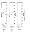
回折部150を有する回折光学素子135は、例えば、図21(a)に示すように、回折部150を通過した第1の波長の光ビームBB0を+1次回折光BB1となるように回折して対物レンズ134に入射させ、すなわち、所定の発散角を有する収束状態の光ビームとして対物レンズ134に入射させることで、第1の光ディスク11の信号記録面に適切に集光させ、図21(b)に示すように、回折部150を通過した第2の波長の光ビームBD0を+1次回折光BD1となるように回折して対物レンズ134に入射させ、すなわち、所定の発散角を有する収束状態の光ビームとして対物レンズ134に入射させることで、第2の光ディスク12の信号記録面に適切に集光させ、図21(c)に示すように、回折部150を通過した第3の波長の光ビームBC0を+1次回折光BC1となるように回折して対物レンズ134に入射させ、すなわち、所定の発散角を有する収束状態の光ビームとして対物レンズ134に入射させることで、第3の光ディスク13の信号記録面に適切に集光させることにより、単一の対物レンズ134を用いて3種類の光ディスクの信号記録面に球面収差を発生しないように適切に集光することを可能とする。尚、ここでは、回折部150の複数の回折領域において、同じ波長の光ビームを同じ回折次数の回折光とする例について図21を用いて説明したが、本発明を適用した光ピックアップ103を構成する回折部150は、後述のように、各領域毎に各波長に対する回折次数を設定し、より球面収差を低減するように構成することを可能とする。   For example, as shown in FIG. 21A, the diffractive optical element 135 having the diffractive portion 150 diffracts the light beam BB0 having the first wavelength that has passed through the diffractive portion 150 so as to become the + 1st order diffracted light BB1. By making it enter the lens 134, that is, by making it enter the objective lens 134 as a convergent light beam having a predetermined divergence angle, the light is appropriately condensed on the signal recording surface of the first optical disc 11, and FIG. As shown in FIG. 5, the light beam BD0 having the second wavelength that has passed through the diffraction unit 150 is diffracted to be + 1st order diffracted light BD1, and is incident on the objective lens 134, that is, convergent light having a predetermined divergence angle. By making it enter into the objective lens 134 as a beam, it is appropriately condensed on the signal recording surface of the second optical disk 12, and as shown in FIG. The light beam BC0 having a wavelength is diffracted so as to be the + 1st order diffracted light BC1 and is incident on the objective lens 134. That is, the light beam BC0 is incident on the objective lens 134 as a converged light beam having a predetermined divergence angle. By appropriately condensing on the signal recording surface of the optical disc 13, it is possible to appropriately condense using the single objective lens 134 so that spherical aberration does not occur on the signal recording surfaces of the three types of optical discs. . Here, an example in which a light beam having the same wavelength is diffracted light having the same diffraction order in a plurality of diffraction regions of the diffraction unit 150 has been described with reference to FIG. 21, but an optical pickup 103 to which the present invention is applied is configured. As will be described later, the diffractive section 150 can set a diffraction order for each wavelength for each region, and can be configured to further reduce spherical aberration.

ここで、上述及び以下の回折次数の記載において、入射した光ビームに対して、進行方向に進むにつれて光軸側に近接する方向に回折する次数を正の次数とする。換言すると、入射した光ビームに対して光軸方向に向かって回折する次数を正の次数とする。すなわち、上述のように第1乃至第3の波長において、支配的となるように選択された+1次回折光が入射した各波長の光ビームに対して比較して収束する方向に向けて回折する。   Here, in the description of the diffraction order described above and below, the order in which the incident light beam is diffracted in the direction closer to the optical axis side as the traveling direction proceeds is defined as a positive order. In other words, the order in which the incident light beam is diffracted in the optical axis direction is a positive order. That is, as described above, the + 1st order diffracted light selected so as to be dominant at the first to third wavelengths is diffracted in the direction of convergence compared to the incident light beam of each wavelength.

具体的に、図22(a)及び図22(b)に示すように、回折光学素子135の入射側の面に設けられた回折部150は、最内周部に設けられ略円形状の第1の回折領域(以下、「内輪帯」ともいう。)151と、第1の回折領域151の外側に設けられ輪帯状の第2の回折領域(以下、「中輪帯」ともいう。)152と、第2の回折領域152の外側に設けられ輪帯状の第3の回折領域(以下、「外輪帯」ともいう。)153とを有する。   Specifically, as shown in FIGS. 22A and 22B, the diffractive portion 150 provided on the incident-side surface of the diffractive optical element 135 is provided on the innermost peripheral portion and has a substantially circular shape. 1 diffraction region (hereinafter also referred to as “inner ring zone”) 151 and a second diffraction region (hereinafter also referred to as “middle ring zone”) 152 provided outside the first diffraction region 151. And an annular third diffraction region (hereinafter also referred to as “outer annular zone”) 153 provided outside the second diffraction region 152.

内輪帯である第1の回折領域151は、輪帯状で且つ所定の深さを有する第1の回折構造が形成され、通過する第1の波長の光ビームの対物レンズ134を介して第1の光ディスクの信号記録面に適切なスポットを形成するよう集光する次数の回折光が支配的となるように、すなわち、他の次数の回折光に対して最大の回折効率となるように発生させる。   The first diffractive region 151 that is the inner annular zone is formed with a first diffractive structure having an annular shape and a predetermined depth, and the first diffractive region 151 passes through the objective lens 134 of the light beam having the first wavelength that passes therethrough. In order to form an appropriate spot on the signal recording surface of the optical disk, the diffracted light of the order that is condensed is dominant, that is, generated so as to have the maximum diffraction efficiency with respect to other orders of diffracted light.

また、第1の回折領域151は、第1の回折構造により、通過する第2の波長の光ビームの対物レンズ134を介して第2の光ディスクの信号記録面に適切なスポットを形成するよう集光する次数の回折光が支配的となるように、すなわち、他の次数の回折光に対して最大の回折効率となるように発生させる。   Further, the first diffraction region 151 is gathered so as to form an appropriate spot on the signal recording surface of the second optical disc through the objective lens 134 of the light beam having the second wavelength that passes through the first diffraction structure 151. It is generated so that the diffracted light of the order of light is dominant, that is, has the maximum diffraction efficiency with respect to the diffracted light of other orders.

また、第1の回折領域151は、第1の回折構造により、通過する第3の波長の光ビームの対物レンズ134を介して第3の光ディスクの信号記録面に適切なスポットを形成するよう集光する次数の回折光が支配的となるように、すなわち、他の次数の回折光に対して最大の回折効率となるように発生させる。   In addition, the first diffraction region 151 is gathered so as to form an appropriate spot on the signal recording surface of the third optical disc through the objective lens 134 of the light beam having the third wavelength passing through the first diffraction structure. It is generated so that the diffracted light of the order of light is dominant, that is, has the maximum diffraction efficiency with respect to the diffracted light of other orders.

このように、第1の回折領域151は、上述の各波長の光ビームに対して上述の所定の次数の回折光が支配的となるのに適するような回折構造が形成されているため、第1の回折領域151を通過して所定の次数の回折光とされた各波長の光ビームが対物レンズ134によりそれぞれの光ディスクの信号記録面に集光される際の球面収差を補正して低減することを可能とする。   As described above, the first diffraction region 151 is formed with a diffractive structure suitable for the diffracted light of the predetermined order to be dominant with respect to the light beam of each wavelength described above. 1 corrects and reduces spherical aberration when a light beam of each wavelength having passed through one diffraction region 151 and having a predetermined order of diffracted light is condensed on the signal recording surface of each optical disk by the objective lens 134. Make it possible.

具体的には、第1の回折領域151は、図22及び図23(a)に示すように、光軸を中心とした輪帯状でこの輪帯の断面形状が、所定の深さ(以下、「溝深さ」ともいう。)dのブレーズ形状となるように形成されている。ここで、上述の回折構造における輪帯の断面形状とは、輪帯の半径方向を含む面、すなわち、輪帯の接線方向に直交する面における断面形状を意味する。尚、図23(a)においては、鋸歯形状の凹凸の斜面が半径方向の内側に向かうにつれて表面側に向けて形成されるように構成したが、これは選択する回折次数をプラスにし、所望の発散角を有した収束状態を得るためである。尚、ここで、収束状態を得るための発散角はマイナスの発散角である。図23(a)〜図23(c)中Rは、輪帯の半径方向外側に向けた方向を示し、すなわち、光軸から離間する方向を示すものである。 Specifically, as shown in FIGS. 22 and 23 (a), the first diffraction region 151 has an annular shape centered on the optical axis, and the sectional shape of the annular zone has a predetermined depth (hereinafter referred to as the following). It is also called “groove depth.”) It is formed to have a blaze shape of d. Here, the sectional shape of the annular zone in the above-described diffraction structure means a sectional shape on a plane including the radial direction of the annular zone, that is, a plane orthogonal to the tangential direction of the annular zone. In FIG. 23A, the sawtooth-shaped uneven slope is formed so as to be formed toward the surface side toward the inner side in the radial direction. However, this increases the selected diffraction order to a desired value. This is to obtain a convergence state having a divergence angle. Here, the divergence angle for obtaining the convergence state is a negative divergence angle. In FIG. 23 (a) to FIG. 23 (c), R 2 O indicates the direction toward the radially outer side of the annular zone, that is, the direction away from the optical axis.

尚、第1の回折領域151に形成される第1の回折構造において、溝幅は、支配的となる回折次数、及び回折効率を考慮して決定されている。また、溝幅は、図23(a)に示すように、光軸から離間するにつれてその値が小さくなるように形成されている。尚、この溝幅は、光ディスクの信号記録面上で集光されるスポットが最適となるように、この溝幅で形成された回折領域で与える位相差に基づいて決定されている。   In the first diffraction structure formed in the first diffraction region 151, the groove width is determined in consideration of the dominant diffraction order and diffraction efficiency. Further, as shown in FIG. 23A, the groove width is formed such that its value decreases as the distance from the optical axis increases. The groove width is determined based on the phase difference given by the diffraction region formed with this groove width so that the spot focused on the signal recording surface of the optical disc is optimized.

また、第1の回折領域151は、通過する第1の波長の光ビームの次数k1iの回折光が支配的となるよう、すなわち、回折効率が最大となるように発生させ、また、通過する第2の波長の光ビームの次数k2iの回折光が支配的となるよう、すなわち、回折効率が最大となるように発生させ、また、通過する第3の波長の光ビームの次数k3iの回折光が支配的となるよう、すなわち、回折効率が最大となるように発生させる場合に、k1i、k2i、k3iが(k1i、k2i、k3i)=(+1,+1,+1)となるようにされている。   Further, the first diffraction region 151 is generated so that the diffracted light of the order k1i of the light beam having the first wavelength passing therethrough is dominant, that is, the diffraction efficiency is maximized, and the first diffraction region 151 passes through. The diffracted light of order k2i of the light beam of wavelength 2 is dominant, that is, generated to maximize the diffraction efficiency, and the diffracted light of order k3i of the light beam of the third wavelength passing through is In the case where the diffraction efficiency is maximized, that is, when the diffraction efficiency is maximized, k1i, k2i, and k3i are set to (k1i, k2i, k3i) = (+ 1, + 1, + 1).

ここで、第1の回折領域151は、第1の観点として、各波長における球面収差を低減する必要があり、第2の観点として、温度球面収差特性を考慮する必要、すなわち温度変化において発生する球面収差を低減する必要があり、第3の観点として、製造上有利な構成とする必要があり、これらのことに鑑みて上述の回折次数k1i,k2i,k3iが最大の回折効率となる回折次数として選択されているが、この点について以下に説明する。   Here, the first diffraction region 151 needs to reduce the spherical aberration at each wavelength as the first viewpoint, and needs to consider the temperature spherical aberration characteristic as the second viewpoint, that is, it occurs in the temperature change. It is necessary to reduce spherical aberration, and as a third aspect, it is necessary to provide a configuration advantageous in manufacturing. In view of these, the diffraction orders at which the above-described diffraction orders k1i, k2i, and k3i have the maximum diffraction efficiency. This point will be described below.

まず、第1の観点について説明する。一般的に、第1の回折領域151のような機能を有する領域において、第1の波長をλ1(nm)とし、第2の波長をλ2(nm)とし、第3の波長をλ3(nm)とし、第1の波長の光ビームの選択される回折次数をk1iとし、第2の波長の光ビームの選択される回折次数をk2iとし、第3の波長の光ビームの選択される回折次数をk3iとし、第1の光ディスクの第1の保護層の厚さをt1(mm)とし、第2の光ディスクの第2の保護層の厚さをt2(mm)とし、第3の光ディスクの第3の保護層の厚さをt3(mm)としたときに、(λ1×k1x−λ2×k2x)/(t1−t2)≒(λ1×k1x−λ3×k3x)/(t1−t3)の条件式(内輪帯においてこの条件式中のk1x,k2x,k3xのxは、x=iとする)を満たすことが各波長の各光ディスクの信号記録面上の球面収差を補正して低減できる条件であることが知られている。上述した内輪帯としての第1の回折領域151においては、λ1=405(nm)、λ2=655(nm)、λ3=785(nm)、t1=0.1(mm)、t2=0.6(mm)、t3=1.1(mm)としたときに、k1i=+1、k2i=+1、k3i=+1であるので、この条件式を満足することとなり、球面収差を低減できることが確認できた。また、このことは、換言すると、図24に示すように横軸に波長×回折次数(nm)により算出される値を、縦軸に保護層厚さ(mm)を設定して各点Pλ1,Pλ2,Pλ3をプロットした際に、一直線上に位置した場合に、各波長の各光ディスクの信号記録面上の球面収差を補正して低減できることを意味するが、実際に、下記の条件で各点Pλ1,Pλ2,Pλ3をプロットした場合にはおよそ一直線の設計直線上に各点が位置し、球面収差が可能であることを示している。そして、具体的に対物レンズ134は、図24に示す直線L11を設計直線として、構成材料や入射側及び出射側の面形状が決定されており、この設計直線の傾きは、例えば、(t1−t2)/(λ1×k1x−λ2×k2x)により算出されるPλ1とPλ2とを結ぶ直線の傾き、若しくは(t1−t3)/(λ1×k1x−λ3×k3x)により算出されるPλ1とPλ3とを結ぶ直線の傾きに略近似され、又はこれらの直線の傾きやその他の設計条件を考慮して決定されている。尚、図24でPλ3が僅かに直線上から乖離しているが、これは対物レンズ134及び回折光学素子135のうち各出射部に近接される側の光学素子としてここでは回折光学素子135への入射光を発散光として入射させることで球面収差を確実に補正することができる。   First, the first viewpoint will be described. In general, in a region having a function such as the first diffraction region 151, the first wavelength is λ1 (nm), the second wavelength is λ2 (nm), and the third wavelength is λ3 (nm). The selected diffraction order of the light beam of the first wavelength is k1i, the selected diffraction order of the light beam of the second wavelength is k2i, and the selected diffraction order of the light beam of the third wavelength is k3i, the thickness of the first protective layer of the first optical disk is t1 (mm), the thickness of the second protective layer of the second optical disk is t2 (mm), and the third optical disk is third. (Λ1 × k1x−λ2 × k2x) / (t1−t2) ≈ (λ1 × k1x−λ3 × k3x) / (t1−t3) where t3 (mm) is the thickness of the protective layer (In the inner ring zone, x in k1x, k2x, k3x in this conditional expression is x = i) It is known that this is a condition that can correct and reduce spherical aberration on the signal recording surface of each optical disk of each wavelength. In the first diffraction region 151 as the inner ring zone described above, λ1 = 405 (nm), λ2 = 655 (nm), λ3 = 785 (nm), t1 = 0.1 (mm), t2 = 0.6 When (mm) and t3 = 1.1 (mm), k1i = + 1, k2i = + 1, and k3i = + 1. Therefore, this conditional expression was satisfied, and it was confirmed that spherical aberration could be reduced. . In other words, as shown in FIG. 24, the value calculated by the wavelength × diffraction order (nm) is set on the horizontal axis, and the protective layer thickness (mm) is set on the vertical axis. When plotting Pλ2 and Pλ3, it means that the spherical aberration on the signal recording surface of each optical disk of each wavelength can be corrected and reduced when positioned on a straight line. When Pλ1, Pλ2, and Pλ3 are plotted, each point is positioned on a substantially straight design line, indicating that spherical aberration is possible. Specifically, the objective lens 134 has the straight line L11 shown in FIG. 24 as a design straight line, and the constituent materials and the surface shapes on the incident side and the outgoing side are determined. The inclination of the design line is, for example, (t1- t2) / (λ1 × k1x−λ2 × k2x) calculated by the inclination of a straight line connecting Pλ1 and Pλ2, or (λ1-x3) / (λ1 × k1x−λ3 × k3x) Is approximately approximated to the slope of a straight line connecting the two, or determined in consideration of the slope of these straight lines and other design conditions. In FIG. 24, Pλ3 is slightly deviated from the straight line, but this is an optical element on the side close to each emitting portion of the objective lens 134 and the diffractive optical element 135, and here the diffractive optical element 135 is connected. By making incident light incident as diverging light, spherical aberration can be reliably corrected.

次に、第2の観点について説明する。第1の回折領域151のような機能を有する領域において、適切な温度球面収差特性、すなわち温度変化によらず球面収差を低減することを実現するために、これらの次数は正でなくてはならない。ここで、正の回折次数とは、上述したように光ビームの進行方向に対して光軸中心方向へ向かって回折される回折次数である。そして、温度上昇によって生じる球面収差は、温度変化に伴う対物レンズ134の構成材料の屈折率変動による影響項ΔWnと、温度変化に伴う入射光ビームの波長変動による影響項ΔWλとの和で表され、すなわち、次の関係式ΔW=ΔWn+ΔWλで得られるΔWで表される。このうち、後者の波長変動による影響項ΔWλの正負は、回折部150による回折方向によって規定されることとなる。対物レンズ134は、正のパワー(屈折力)を与えているので、温度上昇に伴って屈折率が低下することとなり、結果として、正のパワーが弱くなる方向に働き、屈折率変動による影響項Wnは、ΔWn<0となる。この影響項Wnをキャンセルするためには、波長変動による影響項ΔWλが、ΔWλ>0となる必要があり、すなわち、回折部150において温度上昇時に正のパワーが強まるようにしなくてはならない。このように、回折部150における回折次数は、正である方が温度球面収差特性の観点から有利である。   Next, the second viewpoint will be described. In order to realize an appropriate temperature spherical aberration characteristic, that is, to reduce the spherical aberration regardless of the temperature change in a region having a function such as the first diffraction region 151, these orders must be positive. . Here, the positive diffraction order is a diffraction order diffracted toward the optical axis center direction with respect to the traveling direction of the light beam as described above. The spherical aberration caused by the temperature rise is represented by the sum of the influence term ΔWn due to the refractive index fluctuation of the constituent material of the objective lens 134 due to the temperature change and the influence term ΔWλ due to the wavelength fluctuation of the incident light beam due to the temperature change. That is, it is expressed by ΔW obtained by the following relational expression ΔW = ΔWn + ΔWλ. Among these, the sign of the influence term ΔWλ due to the latter wavelength variation is defined by the diffraction direction by the diffraction section 150. Since the objective lens 134 gives positive power (refractive power), the refractive index decreases as the temperature rises. As a result, the positive lens works in a direction in which the positive power becomes weaker, and an influence term due to refractive index fluctuation. Wn is ΔWn <0. In order to cancel the influence term Wn, it is necessary that the influence term ΔWλ due to the wavelength fluctuation is ΔWλ> 0, that is, the positive power must be increased in the diffraction section 150 when the temperature rises. Thus, it is advantageous from the viewpoint of the temperature spherical aberration characteristic that the diffraction order in the diffraction section 150 is positive.

また、ここで、温度上昇によって生じる球面収差を、上述のような構成により打ち消し合うことができることについて、図25に示すような縦収差図を用いてさらに詳細に説明する。そして、図25を用いた説明に先立ち図26を用いて縦収差図について説明する。尚、図26(a)及び図26(b)において、x軸方向は、光軸方向を示し、y軸方向は、像高すなわち光軸に直交する方向に向けた光軸からの高さを示すものである。   Here, it will be described in more detail with reference to a longitudinal aberration diagram as shown in FIG. 25 that the spherical aberration caused by the temperature rise can be canceled out by the above-described configuration. Prior to the description with reference to FIG. 25, the longitudinal aberration diagram will be described with reference to FIG. In FIGS. 26A and 26B, the x-axis direction indicates the optical axis direction, and the y-axis direction indicates the image height, that is, the height from the optical axis in the direction perpendicular to the optical axis. It is shown.

図26(a)に示すように、一般的に収差がないレンズを通過した光ビームは、レンズの光軸に直交する方向における入射位置に関わらず、同一の像面に集光され、すなわち、近軸像点位置A0に一致して集光されている。   As shown in FIG. 26 (a), a light beam that has passed through a lens that is generally free from aberrations is focused on the same image plane regardless of the incident position in the direction orthogonal to the optical axis of the lens, that is, Condensed light coincides with the paraxial image point position A0.

その一方で、例えば図26(b)に示すように、収差があるレンズを通過した光ビームは、レンズの光軸に直交する方向における入射位置に応じて、異なる像面に集光され、すなわち、近軸像点位置B0に対してx軸方向にずれた位置に集光されている。このとき、縦収差の状態を示す線LBは、光ビームの入射位置の光軸からの高さ(像高)をy軸にとり、この光軸からの高さの位置に入射した光線による像面が主光線である光軸と交わる位置をx軸に取った例えば各点B1〜B7を結んだ曲線により示される。具体的には、光軸からの高さ位置y1で入射した光線が位置x1で光軸と交わっていることから、座標(x1,y1)であるB1が得られる。また、光軸からの高さ位置y2で入射した光線が位置x2で光軸と交わっていることから、座標(x2,y2)であるB2が得られる。B3〜B7についても同様に得られるものであるがここでは詳細な説明を省略する。   On the other hand, as shown in FIG. 26B, for example, the light beam that has passed through the lens with aberration is condensed on different image planes according to the incident position in the direction orthogonal to the optical axis of the lens, that is, The light is condensed at a position shifted in the x-axis direction with respect to the paraxial image point position B0. At this time, the line LB indicating the state of longitudinal aberration takes the height (image height) of the incident position of the light beam from the optical axis as the y axis, and the image plane by the light ray incident on the height position from the optical axis. Is shown by a curve connecting the points B1 to B7, for example, with the x-axis taken as the position intersecting the optical axis that is the principal ray. Specifically, since the light ray incident at the height position y1 from the optical axis intersects the optical axis at the position x1, B1 as coordinates (x1, y1) is obtained. Further, since the light beam incident at the height position y2 from the optical axis intersects the optical axis at the position x2, B2 as coordinates (x2, y2) is obtained. Although B3 to B7 can be obtained in the same manner, detailed description is omitted here.

同様に、図26(a)に示すようなレンズにおいて、縦収差の状態を示す線LAは、上述した線LBと同様に、光ビームの入射位置の光軸からの高さをy軸にとり、この光軸からの高さの位置に入射した光線が光軸と交わる位置に取った例えばA1〜A7を結んだ直線により示される。尚、図26(a)の場合には、y軸の位置によらず、光軸と交わるx軸の位置は常に一定であるので縦収差の状態を示す線LAは、y軸に一致する。そして、一般的に縦収差の状態を示す線は、図26(a)に示すようなy軸に一致又は可能な限り近接した状態が収差がない状態又は収差が少ない状態であるといえる。   Similarly, in the lens as shown in FIG. 26A, the line LA indicating the state of longitudinal aberration takes the height from the optical axis of the incident position of the light beam on the y-axis, similarly to the line LB described above. This is indicated by a straight line connecting, for example, A1 to A7, at which the light beam incident on the height position from the optical axis intersects the optical axis. In the case of FIG. 26A, the position of the x-axis that intersects the optical axis is always constant regardless of the position of the y-axis, so the line LA indicating the state of longitudinal aberration coincides with the y-axis. In general, a line indicating the state of longitudinal aberration can be said to be a state where there is no aberration or a state where there is little aberration when the line coincides with the y-axis as shown in FIG.

次に、以上のことに鑑みて、上述の回折次数k1i,k2i,k3iを選択することで、温度上昇によって生じる球面収差を打ち消し合うことができることについて図25を用いて説明する。   Next, in view of the above, it will be described with reference to FIG. 25 that spherical aberrations caused by temperature rise can be canceled by selecting the above-described diffraction orders k1i, k2i, and k3i.

図25(a)及び図25(b)は、温度変化に伴う構成材料の屈折率変動による影響項ΔWn及び温度変化に伴う入射光ビームの波長変動による影響項ΔWλをそれぞれ縦収差として概念的に示した図である。ここで、図25(a)及び図25(b)中、破線Lwnは、屈折率変化による縦収差、すなわち構成材料の屈折率変動による影響項ΔWnを縦収差として示し、一点鎖線Lwλ1は、選択された回折次数がプラスの回折次数、すなわちこの回折部により正の屈折力を与える場合の回折角変化による縦収差、すなわち波長変動による影響項ΔWλを縦収差として示し、一点鎖線Lwλ2は、Lwλ1と比較するために、選択された回折次数がマイナスの回折次数、すなわちこの回折部により負の屈折力を与える場合の波長変動による影響項ΔWλを縦収差として示すものである。そして、図25(a)及び図25(b)において、実線Lw1及び実線Lw2は、図25(a)に示すΔWn及びΔWλを加算することにより得られた温度上昇により生じる球面収差ΔWを縦収差として示したものである。図25(b)中、実線Lw1は、図25(b)で示した破線Lwn及び一点鎖線Lwλ1を足し合わせた図、すなわち、回折次数がプラスの場合の球面収差ΔWを示し、図25(a)中実線Lw2は、図25(a)で示した破線Lwn及び一点鎖線Lwλ2を足し合わせた図、すなわち、回折次数がマイナスの場合の球面収差ΔWを示すものである。   25 (a) and 25 (b) conceptually show, as longitudinal aberrations, the influence term ΔWn due to the refractive index fluctuation of the constituent material accompanying the temperature change and the influence term ΔWλ due to the wavelength fluctuation of the incident light beam accompanying the temperature change, respectively. FIG. Here, in FIG. 25A and FIG. 25B, the broken line Lwn indicates the longitudinal aberration due to the refractive index change, that is, the influence term ΔWn due to the refractive index fluctuation of the constituent material as the vertical aberration, and the alternate long and short dash line Lwλ1 is selected. The diffraction order with a positive diffraction order, that is, longitudinal aberration due to a change in diffraction angle in the case where a positive refractive power is given by this diffraction section, that is, an influence term ΔWλ due to wavelength variation is shown as longitudinal aberration, and a one-dot chain line Lwλ2 is expressed by For comparison, an influence term ΔWλ due to wavelength variation when the selected diffraction order is a negative diffraction order, that is, when negative refractive power is given by this diffraction section, is shown as longitudinal aberration. In FIGS. 25A and 25B, the solid line Lw1 and the solid line Lw2 indicate the spherical aberration ΔW caused by the temperature rise obtained by adding ΔWn and ΔWλ shown in FIG. It is shown as. In FIG. 25B, a solid line Lw1 is a diagram obtained by adding the broken line Lwn and the alternate long and short dash line Lwλ1 shown in FIG. 25B, that is, the spherical aberration ΔW when the diffraction order is positive, and FIG. ) A solid line Lw2 is a diagram in which the broken line Lwn and the alternate long and short dash line Lwλ2 shown in FIG. 25A are added, that is, the spherical aberration ΔW when the diffraction order is negative.

図25(b)に示すように、第1の回折領域151のような機能を有する領域において、上述の回折次数k1i,k2i,k3iを選択することで、すなわち、プラスの回折次数を選択することで、縦収差の状態(Lw1)が図26(a)に示す状態に近くなり収差を抑えた状態とすることができる。これに対して、図25(a)に示すように、マイナスの回折次数を選択した場合には、縦収差の状態(Lw2)が収差が抑えられていない、すなわち、温度球面収差特性の面から問題のある状態となる。以上のように、上述のように回折次数k1i,k2i,k3iを選択することで、温度球面収差特性の観点から有利である。   As shown in FIG. 25 (b), by selecting the above-mentioned diffraction orders k1i, k2i, k3i in a region having a function such as the first diffraction region 151, that is, selecting a positive diffraction order. Thus, the longitudinal aberration state (Lw1) is close to the state shown in FIG. On the other hand, as shown in FIG. 25A, when a negative diffraction order is selected, the state of longitudinal aberration (Lw2) is not suppressed, that is, from the viewpoint of the temperature spherical aberration characteristic. It becomes a problem state. As described above, selecting the diffraction orders k1i, k2i, and k3i as described above is advantageous from the viewpoint of thermal spherical aberration characteristics.

次に、第3の観点について説明する。第1の回折領域151のような機能を有する回折部は、回折光学素子135の一方の面、又は後述のように対物レンズの一方の面にその回折構造が形成されることで構成されるため、選択される回折次数があまりに大きい場合には、形成する回折構造の深さdが深くなる。そして、回折構造の深さdが深くなると形成精度が悪化するおそれがあるのみならず、温度変化による光路長増大効果が大きくなり、温度回折効率特性が劣化してしまうという問題が発生するおそれがある。このような理由から、3〜4次程度までの回折次数を選択するのが妥当であり、一般的である。すなわち、上述した第1の回折領域151は、選択する回折次数k1i,k2i,k3iとして上述のようなものを選択していることから、このような製造上の観点からも、製造容易であるとともに、精度劣化等の問題も発生せず、品質を高めることを可能とし、結果として、良好な回折効率を有する回折光を確実に発生させることができる。   Next, a third aspect will be described. The diffractive portion having a function like the first diffractive region 151 is configured by forming the diffractive structure on one surface of the diffractive optical element 135 or one surface of the objective lens as described later. When the selected diffraction order is too large, the depth d of the diffraction structure to be formed becomes deep. When the depth d of the diffractive structure is deepened, not only the formation accuracy may be deteriorated, but also the effect of increasing the optical path length due to the temperature change is increased, and the problem that the temperature diffraction efficiency characteristic is deteriorated may occur. is there. For these reasons, it is appropriate and general to select diffraction orders up to about 3-4. That is, since the first diffraction region 151 described above is selected as the above-described diffraction orders k1i, k2i, k3i, it is easy to manufacture from such a manufacturing viewpoint. Therefore, it is possible to improve the quality without causing problems such as accuracy degradation, and as a result, it is possible to reliably generate diffracted light having good diffraction efficiency.

このように内輪帯としての第1の回折領域151は、球面収差低減という第1の観点からも、温度球面収差特性という第2の観点からも、製作における形成する回折構造の深さという第3の観点からも優れた、次数を選択したものであり、すなわち、上述のように構成することで、球面収差を低減でき、温度変化の際の収差発生を低減でき、製造上有利な構成とすることができる。   Thus, the first diffractive region 151 as the inner annular zone has a third depth, which is the depth of the diffractive structure to be formed in manufacturing, from both the first viewpoint of reducing spherical aberration and the second viewpoint of thermal spherical aberration characteristics. The order is selected, which is also excellent from the viewpoint of the above. That is, by configuring as described above, it is possible to reduce spherical aberration, to reduce the occurrence of aberration at the time of temperature change, and to make a configuration advantageous in manufacturing. be able to.

中輪帯である第2の回折領域152は、輪帯状で且つ所定の深さを有し第1の回折構造とは異なる構造とされた第2の回折構造が形成され、通過する第1の波長の光ビームの対物レンズ134を介して第1の光ディスクの信号記録面に適切なスポットを形成するよう集光する次数の回折光が支配的となるように、すなわち、他の次数の回折光に対して最大の回折効率となるように発生させる。   The second diffractive region 152, which is the middle annular zone, is formed with a second diffractive structure that is annular and has a predetermined depth and is different from the first diffractive structure. The diffracted light of the order that is focused to form an appropriate spot on the signal recording surface of the first optical disc via the objective lens 134 of the light beam of the wavelength is dominant, that is, the diffracted light of other orders With respect to the maximum diffraction efficiency.

また、第2の回折領域152は、第2の回折構造により、通過する第2の波長の光ビームの対物レンズ134を介して第2の光ディスクの信号記録面に適切なスポットを形成するよう集光する次数の回折光が支配的となるように、すなわち、他の次数の回折光に対して最大の回折効率となるように発生させる。   The second diffractive region 152 is formed so as to form an appropriate spot on the signal recording surface of the second optical disc through the objective lens 134 of the light beam having the second wavelength passing through the second diffractive structure. It is generated so that the diffracted light of the order of light is dominant, that is, has the maximum diffraction efficiency with respect to the diffracted light of other orders.

また、第2の回折領域152は、第2の回折構造により、通過する第3の波長の光ビームの対物レンズ134を介して第3の光ディスクの信号記録面に適切なスポットを形成するよう集光する次数以外の次数の回折光が支配的となるように、すなわち、他の次数の回折光に対して最大の回折効率となるように発生させる。尚、第2の回折領域152は、第2の回折構造により、通過する第3の波長の光ビームの対物レンズ134を介して第3の光ディスクの信号記録面に適切なスポットを形成するよう集光する次数の回折光の回折効率を十分に低減することができる。   The second diffractive region 152 is formed so as to form an appropriate spot on the signal recording surface of the third optical disc through the objective lens 134 of the light beam having the third wavelength that passes through the second diffractive structure. It is generated so that the diffracted light of the order other than the order of light is dominant, that is, the maximum diffraction efficiency is obtained with respect to the diffracted light of other orders. The second diffractive region 152 is formed so as to form an appropriate spot on the signal recording surface of the third optical disc through the objective lens 134 of the light beam having the third wavelength that passes through the second diffractive structure. The diffraction efficiency of the diffracted light of the order of light can be sufficiently reduced.

このように、第2の回折領域152は、上述の各波長の光ビームに対して上述の所定の次数の回折光が支配的となるのに適するような回折構造が形成されているため、第2の回折領域152を通過して所定の次数の回折光とされた第1及び第2の波長の光ビームが対物レンズ134によりそれぞれの光ディスクの信号記録面に集光される際の球面収差を補正して低減することを可能とする。   As described above, the second diffraction region 152 is formed with a diffraction structure suitable for the diffracted light of the predetermined order to be dominant with respect to the light beam of each wavelength described above. Spherical aberration when the light beams of the first and second wavelengths, which have been passed through the second diffraction region 152 and made into diffracted light of a predetermined order, are condensed on the signal recording surface of each optical disk by the objective lens 134. It can be corrected and reduced.

また、第2の回折領域152は、第1及び第2の波長の光ビームに対しては上述のように機能するとともに、第3の波長の光ビームについては、この第2の回折領域152を通過して対物レンズ134を介して第3の光ディスクの信号記録面に集光する次数以外の次数の回折光が支配的となるように構成されていることから、この第2の回折領域152を通過した第3の波長の光ビームが対物レンズ134に入射しても第3の光ディスクの信号記録面にはほとんど影響を与えることなく、換言すると、この第2の回折領域152を通過して対物レンズ134により信号記録面に集光される第3の波長の光ビームの光量を大幅に低減して略ゼロとして、第3の波長の光ビームに対して開口制限を行うよう機能することができる。   The second diffraction region 152 functions as described above for the first and second wavelength light beams, and the second diffraction region 152 is used for the third wavelength light beam. Since the diffracted light of the order other than the order passing through the objective lens 134 and condensing on the signal recording surface of the third optical disc becomes dominant, the second diffractive region 152 is formed. Even if the light beam having the third wavelength that has passed through is incident on the objective lens 134, the signal recording surface of the third optical disk is hardly affected. In other words, the light beam having the third wavelength passes through the second diffraction region 152 and is objective. It is possible to reduce the amount of light of the third wavelength light beam collected on the signal recording surface by the lens 134 to substantially zero, thereby functioning to limit the aperture of the third wavelength light beam. .

ところで、上述した第1の回折領域151は、その領域を通過した第3の波長の光ビームが、NA=0.45程度で開口制限される光ビームと同様の状態で対物レンズ134に入射するような大きさに形成されており、また、この第1の回折領域151の外側に形成される第2の回折領域152は、この領域を通過した第3の波長の光ビームを、対物レンズ134を介して第3の光ディスク上に集光させないため、かかる構成とされた第1及び第2の回折領域151,152を備える回折部150は、第3の波長の光ビームに対して、NA=0.45程度に開口制限を行うように機能することとなる。ここでは、回折部150において、第3の波長の光ビームに対して開口数NAを0.45程度に開口制限を行うように構成したが、上述の構成により制限される開口数はこれに限られるものではない。   By the way, in the first diffraction region 151 described above, the light beam of the third wavelength that has passed through the region is incident on the objective lens 134 in the same state as the light beam whose aperture is limited to about NA = 0.45. The second diffractive region 152 formed outside the first diffractive region 151 has a third wavelength light beam that has passed through this region. Therefore, the diffraction unit 150 including the first and second diffraction regions 151 and 152 configured as described above is configured so that NA = It functions to limit the aperture to about 0.45. Here, the diffraction unit 150 is configured to limit the numerical aperture NA to about 0.45 with respect to the light beam of the third wavelength. However, the numerical aperture limited by the above configuration is limited to this. It is not something that can be done.

具体的には、第2の回折領域152は、上述した第1の回折領域151と同様に、図22及び図23(a)に示すように、光軸を中心とした輪帯状でこの輪帯の断面形状が所定の深さdのブレーズ形状となるように形成されている。   Specifically, the second diffractive region 152 has an annular shape centered on the optical axis as shown in FIGS. 22 and 23A, as in the first diffractive region 151 described above. Are formed so as to have a blazed shape with a predetermined depth d.

また、ここでは、輪帯の断面形状がブレーズ形状となるような回折構造を有する第2の回折領域が形成されているものとして説明するが、上述のような各波長の光ビームに対して所定の次数の光ビームが支配的となるような回折構造であればよく、例えば、輪帯の断面形状が、図23(b)に示すような、光軸を中心とした輪帯状でこの輪帯の断面形状が所定の深さdで所定のステップ数Sの階段形状が半径方向に連続して形成された回折領域152Bが形成されるように構成してもよい。   In addition, here, the second diffractive region having a diffractive structure in which the cross-sectional shape of the zonal zone becomes a blazed shape will be described. For example, the annular zone has a ring-shaped cross section centered on the optical axis as shown in FIG. 23B. Alternatively, a diffraction region 152B may be formed in which the cross-sectional shape is a predetermined depth d and a stepped shape having a predetermined number of steps S is continuously formed in the radial direction.

ここで、所定のステップ数Sの階段形状を有する回折構造とは、各段の深さが略同一深さとされた第1乃至第Sの段部を有する階段部が半径方向に連続して形成されている構造であり、さらに、換言すると光軸方向に略同一間隔に形成された第1乃至第(S+1)の回折面を有して形成されている構造である。また、回折構造における所定の深さdは、階段形状の最も表面側(最高段、浅い位置)に位置される第(S+1)の回折面と、階段形状の最も素子側(最低段、深い位置)に位置される第1の回折面との光軸方向の長さを意味する。この点については、後述する図23(c)についても同様である。尚、図23(b)及び図23(c)においては、階段形状の各階段部内において段部が半径方向の内側に向けて形成、すなわち、段部が半径方向の内側に向かうにつれて表面側に向けて形成されるように構成したが、これは、選択する回折次数をプラスにし、所望の発散角を有した収束状態を得るためである。尚、第2及び後述の第3の回折構造において、階段形状とする場合の溝深さd及びステップ数Sは、支配的となる回折次数、及び回折効率を考慮して決定されている。   Here, a diffractive structure having a staircase shape with a predetermined number of steps S means that a staircase portion having first to S-th step portions in which the depth of each step is substantially the same depth is continuously formed in the radial direction. Further, in other words, it is a structure having first to (S + 1) -th diffraction surfaces formed at substantially the same interval in the optical axis direction. The predetermined depth d in the diffractive structure is such that the (S + 1) -th diffractive surface located on the most surface side (highest step, shallow position) of the staircase shape and the most element side (lowest step, deep position) of the staircase shape. ) In the optical axis direction with respect to the first diffractive surface. The same applies to FIG. 23C described later. In FIG. 23B and FIG. 23C, the stepped portion is formed inward in the radial direction in each stepped stepped portion, that is, on the surface side as the stepped portion goes inward in the radial direction. This is because the selected diffraction order is made positive and a convergence state having a desired divergence angle is obtained. In the second and third diffraction structures to be described later, the groove depth d and the step number S in the case of the stepped shape are determined in consideration of the dominant diffraction order and diffraction efficiency.

また、各段部の溝幅(階段形状の各段部の半径方向の寸法)は、図23(b)〜図23(c)に示すように、一の階段部内において、等しく形成されているとともに、半径方向に連続して形成されている異なる階段部間において、光軸から離間するにつれてその値が大きくなるように形成されている。尚、この溝幅は、光ディスクの信号記録面上で集光されるスポットが最低となるように、この溝幅で形成された回折領域で与える位相差に基づいて決定されている。   Further, the groove width of each step portion (the dimension in the radial direction of each step portion of the staircase shape) is formed equally in one step portion as shown in FIGS. 23 (b) to 23 (c). At the same time, it is formed such that its value increases as the distance from the optical axis increases between different step portions formed continuously in the radial direction. The groove width is determined based on the phase difference given by the diffraction region formed with this groove width so that the spot condensed on the signal recording surface of the optical disk is minimized.

例えば、図23(b)に示す第2の回折領域152Bの回折構造は、ステップ数が3(S=3)とされた回折構造であり、各段の深さが略同一深さ(d/3)とされた第1乃至第3の段部152s1,152s2,152s3を有する階段部が半径方向に連続して形成されており、また、光軸方向に間隔が(d/3)で同一間隔に形成された第1乃至第4の回折面152f1,152f2,152f3,152f4を有して形成されている。   For example, the diffractive structure of the second diffractive region 152B shown in FIG. 23B is a diffractive structure in which the number of steps is 3 (S = 3), and the depth of each step is substantially the same depth (d / 3) Step portions having first to third step portions 152s1, 152s2, and 152s3, which are defined as 3), are continuously formed in the radial direction, and the same interval is provided in the optical axis direction at (d / 3). The first to fourth diffractive surfaces 152f1, 152f2, 152f3, and 152f4 are formed.

また、第2の回折領域152は、通過する第1の波長の光ビームの次数k1mの回折光が支配的となるよう、すなわち、回折効率が最大となるように発生させ、また、通過する第2の波長の光ビームの次数k2mの回折光が支配的となるよう、すなわち、回折効率が最大となるように発生させる場合に、回折次数k1m,k2mが例えば以下で示される関係となるように構成されている。(k1m,k2m)=(+1,+1)、(+3,+2)。   The second diffraction region 152 is generated so that the diffracted light of the order k1m of the light beam having the first wavelength passing therethrough is dominant, that is, the diffraction efficiency is maximized, and the second diffractive region 152 passes through. In the case where the diffracted light of the order k2m of the light beam having the wavelength of 2 is dominant, that is, when the diffraction efficiency is maximized, the diffraction orders k1m and k2m are set to have the relationship shown below, for example. It is configured. (K1m, k2m) = (+ 1, +1), (+3, +2).

ここで、内輪帯としての第2の回折領域152は、上述の第1の回折領域151の説明において示した第1乃至第3の観点からも優れた次数を選択したものであり、すなわち、球面収差を低減でき、温度変化の際の収差発生を低減でき、製造上有利な構成とすることができる。   Here, the second diffraction region 152 serving as the inner ring zone is one in which an order superior from the first to third viewpoints shown in the description of the first diffraction region 151 is selected, that is, a spherical surface. Aberrations can be reduced, the occurrence of aberrations during temperature changes can be reduced, and a manufacturing advantageous configuration can be obtained.

また、ここで、第2の回折領域152は、上述したように、第1及び第2の光ディスクの信号記録面に適切なスポットを形成するよう対物レンズ134を介して集光する第1及び第2の波長の光ビームの回折次数k1m,k2mの回折光の回折効率を高い状態で発生させるとともに、第3の光ディスクの信号記録面に集光する第3の波長の光ビームの回折次数の回折効率を極力抑えて開口制限機能を有するように構成されているが、この第3の波長の光ビームにおけるこの回折次数の光ビームを第3の光ディスクの信号記録面に焦点を結像させた状態からずらして、実質的に第3の光ディスクの信号記録面に集光される光ビームの光量をさらに低減するように構成してもよい。尚、以下では、この所定の波長の光ビームの対物レンズ134を介して結像される位置を対応する光ディスクの信号記録面からずらして、実質的に信号記録面に集光されるこの波長の光ビームの光量を低減させることを、「フレア化」ともいう。   Here, as described above, the second diffractive region 152 condenses through the objective lens 134 so as to form an appropriate spot on the signal recording surfaces of the first and second optical disks. The diffraction order of the light beam of the second wavelength is generated with high diffraction efficiency of the diffraction orders of k1m and k2m, and the diffraction order of the light beam of the third wavelength condensed on the signal recording surface of the third optical disk. Although it is configured to have an aperture limiting function while suppressing efficiency as much as possible, the light beam of this diffraction order in the light beam of the third wavelength is focused on the signal recording surface of the third optical disk. It is also possible to configure so as to further reduce the light amount of the light beam condensed on the signal recording surface of the third optical disk. In the following description, the position where the light beam having the predetermined wavelength is imaged through the objective lens 134 is shifted from the signal recording surface of the corresponding optical disk, and the light beam having this wavelength that is substantially condensed on the signal recording surface. Reducing the amount of light beam is also called “flaring”.

ここで、第2の回折領域152において、フレア化させること、及びその構成について説明する。上述の第1の回折領域151の説明において、条件式(λ1×k1x−λ2×k2x)/(t1−t2)≒(λ1×k1x−λ3×k3x)/(t1−t3)を満たすことが要求されていることについて述べたが、この条件式(中輪帯においてこの条件式中のk1x,k2x,k3xのxは、x=mとする)は、第2の回折領域152においても考慮されるものである。そして、この中輪帯としての第2の回折領域152においては、上述のような第1及び第2の光ディスクの信号記録面に適切なスポットを形成するよう対物レンズ134を介して集光する第1及び第2の波長の光ビームの回折次数k1m,k2mの回折光を回折効率を高い状態で発生させるという機能を考慮すると、プロットされるPλ1とPλ2とを設計直線上に位置させれば良いが、さらに、第3の波長についてフレア化させるために、Pλ3について、故意にこの設計直線上から乖離させるような設計直線を選択するようにすればよい。すなわち、Pλ3について設計直線から乖離させたような設計直線に基づき形成された対物レンズ134を構成することにより、第3の波長の光ビームの当該回折次数の回折光を第3の光ディスクの信号記録面に焦点を結像させた状態からずらすことができ、実質的に第3の光ディスクの信号記録面に集光される第3の波長の光ビームの光量を低減させることができ、これにより、上述のような第3の波長の光ビームに対する開口制限を確実且つ良好に行うことを可能とする。具体的には、後述の図33に示すような(k1m,k2m,k3m)=(+3,+2,+2)とした場合には、Pλ3が設計直線L13から乖離されており、当初から期待されていた第2の回折領域152に形成された回折構造により第3の波長の当該次数の回折光の回折効率を低減させる効果に加え、このフレア化の効果をさらに得て、これらの構成からさらに一層第3の光ディスクに入射してしまう第3の波長の光ビームの光量を抑えることを可能とする。   Here, flaring and the configuration of the second diffraction region 152 will be described. In the description of the first diffraction region 151 described above, it is required to satisfy the conditional expression (λ1 × k1x−λ2 × k2x) / (t1−t2) ≈ (λ1 × k1x−λ3 × k3x) / (t1−t3). However, this conditional expression (in the middle annular zone, x in k1x, k2x, and k3x in this conditional expression is x = m) is also considered in the second diffraction region 152. Is. In the second diffractive region 152 as the middle annular zone, the second diffracting region 152 is focused through the objective lens 134 so as to form an appropriate spot on the signal recording surfaces of the first and second optical discs as described above. Considering the function of generating diffracted light beams of diffraction orders k1m and k2m of the light beams of the first and second wavelengths with high diffraction efficiency, the plotted Pλ1 and Pλ2 may be positioned on the design line. However, in order to make the third wavelength flare, a design line that deliberately deviates from this design line may be selected for Pλ3. That is, by forming the objective lens 134 formed based on a design line that is deviated from the design line with respect to Pλ3, the diffracted light of the diffraction order of the light beam of the third wavelength is recorded on the signal of the third optical disc. The focal point can be shifted from the imaged state on the surface, and the amount of the light beam of the third wavelength condensed on the signal recording surface of the third optical disk can be substantially reduced. It is possible to reliably and satisfactorily perform aperture restriction on the light beam having the third wavelength as described above. Specifically, when (k1m, k2m, k3m) = (+ 3, +2, +2) as shown in FIG. 33 to be described later, Pλ3 is deviated from the design line L13 and is expected from the beginning. In addition to the effect of reducing the diffraction efficiency of the diffracted light of the third wavelength at the third wavelength by the diffractive structure formed in the second diffractive region 152, the effect of flaring can be further obtained, and further from these configurations. It is possible to suppress the amount of the light beam having the third wavelength that enters the third optical disk.

外輪帯である第3の回折領域153は、輪帯状で且つ所定の深さを有し第1及び第2の回折構造とは異なる構造とされた第3の回折構造が形成され、通過する第1の波長の光ビームの対物レンズ134を介して第1の光ディスクの信号記録面に適切なスポットを形成するよう集光する次数の回折光が支配的となるように、すなわち、他の次数の回折光に対して最大の回折効率となるように発生させる。   The third diffractive region 153, which is the outer ring zone, is formed with a third diffractive structure that is annular and has a predetermined depth and is different from the first and second diffractive structures. The diffracted light of the order that is condensed to form an appropriate spot on the signal recording surface of the first optical disc through the objective lens 134 of the light beam of one wavelength is dominant, that is, other orders It is generated so as to have the maximum diffraction efficiency with respect to the diffracted light.

また、第3の回折領域153は、第3の回折構造により、通過する第2の波長の光ビームの対物レンズ134を介して第2の光ディスクの信号記録面に適切なスポットを形成するよう集光する次数以外の次数の回折光が支配的となるように、すなわち、他の次数の回折光に対して最大の回折効率となるように発生させる。尚、第3の回折領域153は、第3の回折構造により、通過する第2の波長の光ビームの対物レンズ134を介して第2の光ディスクの信号記録面に適切なスポットを形成するよう集光する次数の回折光の回折効率を十分に低減することができる。   The third diffractive region 153 is formed by the third diffractive structure so as to form an appropriate spot on the signal recording surface of the second optical disc through the objective lens 134 of the light beam having the second wavelength that passes therethrough. It is generated so that the diffracted light of the order other than the order of light is dominant, that is, the maximum diffraction efficiency is obtained with respect to the diffracted light of other orders. The third diffractive region 153 is formed so as to form an appropriate spot on the signal recording surface of the second optical disc through the objective lens 134 of the light beam having the second wavelength passing therethrough by the third diffractive structure. The diffraction efficiency of the diffracted light of the order of light can be sufficiently reduced.

また、第3の回折領域153は、第3の回折構造により、通過する第3の波長の光ビームの対物レンズ134を介して第3の光ディスクの信号記録面に適切なスポットを形成するよう集光する次数以外の次数の回折光が支配的となるように、すなわち、他の次数の回折光に対して最大の回折効率となるように発生させる。尚、第3の回折領域153は、第3の回折構造により、通過する第3の波長の光ビームの対物レンズ134を介して第3の光ディスクの信号記録面に適切なスポットを形成するよう集光する次数の回折光の回折効率を十分に低減することができる。   The third diffractive region 153 is formed by the third diffractive structure so as to form an appropriate spot on the signal recording surface of the third optical disc via the objective lens 134 of the light beam having the third wavelength passing therethrough. It is generated so that the diffracted light of the order other than the order of light is dominant, that is, the maximum diffraction efficiency is obtained with respect to the diffracted light of other orders. The third diffractive region 153 has a third diffractive structure so as to form an appropriate spot on the signal recording surface of the third optical disc through the objective lens 134 of the light beam having the third wavelength that passes therethrough. The diffraction efficiency of the diffracted light of the order of light can be sufficiently reduced.

このように、第3の回折領域153は、上述の各波長の光ビームに対して上述の所定の次数の回折光が支配的となるのに適するような回折構造が形成されているため、第3の回折領域153を通過して所定の次数の回折光とされた第1の波長の光ビームが対物レンズ134により光ディスクの信号記録面に集光される際の球面収差を補正して低減することを可能とする。   As described above, the third diffraction region 153 is formed with a diffractive structure that is suitable for the diffracted light of the predetermined order to be dominant with respect to the light beam of each wavelength described above. 3 corrects and reduces the spherical aberration when the light beam of the first wavelength that has passed through the third diffraction region 153 and has been diffracted to a predetermined order is focused on the signal recording surface of the optical disk by the objective lens 134. Make it possible.

また、第3の回折領域153は、第1の波長の光ビームに対しては上述のように機能するとともに、第2及び第3の波長の光ビームについては、この第3の回折領域153を通過して対物レンズ134を介して第2及び第3の光ディスクの信号記録面に集光する次数以外の次数の回折光が支配的となるように構成されていることから、この第3の回折領域153を通過した第2及び第3の波長の光ビームが対物レンズ134に入射しても第2及び第3の光ディスクの信号記録面にはほとんど影響を与えることなく、換言すると、この第3の回折領域153を通過して対物レンズ134により信号記録面に集光される第2及び第3の波長の光ビームの光量を大幅に低減して略ゼロとして、第2の波長の光ビームに対して開口制限を行うよう機能することができる。尚、第3の回折領域153は、第3の波長の光ビームに対しては、上述の第2の回折領域152とともに、開口制限を行うよう機能することができる。   The third diffraction region 153 functions as described above for the light beam having the first wavelength, and the third diffraction region 153 is used for the light beams having the second and third wavelengths. Since the diffracted light of the order other than the order passing through the objective lens 134 and condensing on the signal recording surfaces of the second and third optical discs is dominant, the third diffraction is configured. Even if the light beams having the second and third wavelengths that have passed through the region 153 are incident on the objective lens 134, the signal recording surfaces of the second and third optical disks are hardly affected. The light intensity of the second and third wavelength light beams that pass through the diffraction region 153 and are focused on the signal recording surface by the objective lens 134 is substantially reduced to substantially zero, so that the second wavelength light beam Function to limit opening to Rukoto can. Note that the third diffraction region 153 can function to limit the aperture of the light beam having the third wavelength together with the second diffraction region 152 described above.

ところで、上述した第2の回折領域152は、その領域を通過した第2の波長の光ビームが、NA=0.6程度で開口制限される光ビームと同様の状態で対物レンズ134に入射するような大きさに形成されており、また、この第2の回折領域152の外側に形成される第3の回折領域153は、この領域を通過した第2の波長の光ビームを、対物レンズ134を介して光ディスク上に集光させないため、かかる構成とされた第2及び第3の回折領域152,153を備える回折部150は、第2の波長の光ビームに対して、NA=0.6程度に開口制限を行うように機能することとなる。ここでは、回折部150において、第2の波長の光ビームに対して開口数NAを0.6程度に開口制限を行うように構成したが、上述の構成により制限される開口数はこれに限られるものではない。   By the way, in the second diffraction region 152 described above, the light beam having the second wavelength that has passed through the region is incident on the objective lens 134 in the same state as the light beam whose aperture is limited to about NA = 0.6. The third diffractive region 153 formed outside the second diffractive region 152 has a second wavelength light beam that has passed through this region as the objective lens 134. Therefore, the diffraction unit 150 including the second and third diffraction regions 152 and 153 configured as described above has a NA = 0.6 with respect to the light beam having the second wavelength. It will function to limit the opening to the extent. Here, the diffraction unit 150 is configured to limit the numerical aperture NA to about 0.6 with respect to the light beam of the second wavelength. However, the numerical aperture limited by the above configuration is limited to this. It is not something that can be done.

また、第3の回折領域153は、その領域を通過した第1の波長の光ビームが、NA=0.85程度で開口制限される光ビームと同様の状態で対物レンズ134に入射するような大きさに形成されており、また、この第3の回折領域153の外側には回折構造が形成されていないため、この領域を透過した第1の波長の光ビームを、対物レンズ134を介して第1の光ディスク上に集光させないため、かかる構成とされた第3の回折領域153を備える回折部150は、第1の波長の光ビームに対して、NA=0.85程度の開口制限を行うように機能することとなる。尚、第3の回折領域153を通過する第1の波長の光ビームは、例えば+1次、+2次、+3次、+4次、+5次の回折次数のものが支配的となるようにされているため、第3の回折領域153の外側の領域を透過した0次光は、対物レンズ134を介して第1の光ディスク上に集光しない場合がほとんどであるが、この0次光が、対物レンズ134を介して第1の光ディスク上に集光することになる場合には、第3の回折領域153の外側の領域に、通過する光ビームを遮蔽する遮蔽部又は通過する光ビームを対物レンズ134を介して第1の光ディスク上に集光する次数以外の次数の光ビームが支配的となる回折構造を有する回折領域を設けることにより、開口制限を行うように構成してもよい。ここでは、回折部150において、第1の波長の光ビームに対して開口数NAを0.85程度に開口制限を行うように構成したが、上述の構成により制限される開口数はこれに限られるものではない。   The third diffraction region 153 is such that the light beam having the first wavelength that has passed through the region is incident on the objective lens 134 in the same state as the light beam whose aperture is limited to about NA = 0.85. Since the diffractive structure is not formed outside the third diffractive region 153, the light beam having the first wavelength transmitted through this region is passed through the objective lens 134. In order not to condense on the first optical disc, the diffraction unit 150 including the third diffraction region 153 configured as described above has an aperture limit of about NA = 0.85 with respect to the light beam having the first wavelength. Will function to do. The light beam having the first wavelength that passes through the third diffraction region 153 has dominant diffraction orders of, for example, + 1st order, + 2nd order, + 3rd order, + 4th order, and + 5th order. Therefore, in most cases, the 0th-order light transmitted through the region outside the third diffraction region 153 is not condensed on the first optical disk via the objective lens 134. When the light is to be condensed on the first optical disc via 134, a shielding portion that shields the passing light beam or the passing light beam is formed on the objective lens 134 in a region outside the third diffraction region 153. The aperture restriction may be performed by providing a diffraction region having a diffraction structure in which a light beam of an order other than the order condensed on the first optical disc via the first is provided. Here, the diffraction unit 150 is configured to limit the numerical aperture NA to about 0.85 with respect to the light beam of the first wavelength, but the numerical aperture limited by the above configuration is limited to this. It is not something that can be done.

具体的には、第3の回折領域153は、上述した第1の回折領域151と同様に、図22及び図23(a)に示すように、光軸を中心とした輪帯状でこの輪帯の断面形状が所定の深さdのブレーズ形状となるように形成されている。   Specifically, the third diffraction region 153 has an annular shape centered on the optical axis as shown in FIGS. 22 and 23A, as in the first diffraction region 151 described above. The cross-sectional shape is a blazed shape having a predetermined depth d.

また、ここでは、輪帯の断面形状がブレーズ形状となるような回折構造を有する第2の回折領域が形成されているものとして説明するが、上述のような各波長の光ビームに対して所定の次数の光ビームが支配的となるような回折構造であればよく、例えば、輪帯の断面形状が図23(c)に示すような、光軸を中心とした輪帯状でこの輪帯の断面形状が所定の深さdで所定のステップ数Sの階段形状が半径方向に連続して形成された回折領域153Bが形成されるように構成してもよい。   In addition, here, description will be made assuming that the second diffraction region having a diffraction structure in which the cross-sectional shape of the annular zone is a blazed shape is formed. For example, the sectional shape of the annular zone is an annular zone centered on the optical axis as shown in FIG. 23 (c). You may comprise so that the diffraction region 153B in which the cross-sectional shape is the predetermined depth d, and the step shape of the predetermined step number S was formed continuously in the radial direction may be formed.

例えば、図23(c)に示す第3の回折領域153Bの回折構造は、ステップ数が2(S=2)とされた回折構造であり、各段の深さが略同一深さ(d/2)とされた第1乃至第2の段部153s1,153s2を有する階段部が半径方向に連続して形成されており、また、光軸方向に間隔が(d/2)で同一間隔に形成された第1乃至第3の回折面153f1,153f2,153f3を有して形成されている。   For example, the diffraction structure of the third diffraction region 153B shown in FIG. 23C is a diffraction structure in which the number of steps is 2 (S = 2), and the depth of each step is substantially the same depth (d / Steps having first to second step portions 153s1 and 153s2 defined as 2) are continuously formed in the radial direction, and are formed at the same interval of (d / 2) in the optical axis direction. The first to third diffractive surfaces 153f1, 153f2, and 153f3 are formed.

また、第3の回折領域153は、通過する第1の波長の光ビームの次数k1oの回折光が支配的となるよう、すなわち、回折効率が最大となるように発生させる場合に、回折次数k1oが例えば以下で示される関係となるように構成されている。1≦k1o≦5(k1oは、正の整数)。すなわち、k1oは、k1o=+1,+2,+3,+4,+5のいずれかとなるようにされている。   Further, the third diffraction region 153 has a diffraction order k1o when the diffraction light having the order k1o of the light beam having the first wavelength passing therethrough is dominant, that is, when the diffraction efficiency is maximized. Is configured to have the relationship shown below, for example. 1 ≦ k1o ≦ 5 (k1o is a positive integer). That is, k1o is set to any one of k1o = + 1, +2, +3, +4, and +5.

ここで、外輪帯としての第3の回折領域153は、上述の第1の回折領域151の説明において示した第1乃至第3の観点からも優れた次数を選択したものであり、すなわち、球面収差を低減でき、温度変化の際の収差発生を低減でき、製造上有利な構成とすることができる。   Here, the third diffractive region 153 as the outer ring zone is one in which an order superior from the first to third viewpoints shown in the description of the first diffractive region 151 is selected, that is, a spherical surface. Aberration can be reduced, generation of aberration at the time of temperature change can be reduced, and a manufacturing advantageous configuration can be obtained.

また、ここで、第3の回折領域153は、上述したように、第1の光ディスクの信号記録面に適切なスポットを形成するよう対物レンズ134を介して集光する第1の波長の光ビームの回折次数k1oの回折光の回折効率を高い状態で発生させるとともに、第2及び第3の光ディスクの信号記録面にそれぞれ集光する第2、第3の波長の光ビームの回折次数の回折効率を極力抑えて開口制限機能を有するように構成されているが、この第2及び第3の波長の光ビームにおけるそれぞれの回折次数の光ビームを第2、第3の光ディスクの信号記録面に焦点を結像させた状態からずらして、実質的に第2、第3の光ディスクの信号記録面に集光される光ビームの光量をさらに低減、すなわちフレア化するように構成してもよい。   Here, as described above, the third diffraction region 153 is a light beam having the first wavelength that is condensed via the objective lens 134 so as to form an appropriate spot on the signal recording surface of the first optical disc. The diffraction efficiency of the diffracted light of the diffraction order k1o is generated in a high state, and the diffraction efficiency of the light orders of the second and third wavelengths condensed on the signal recording surfaces of the second and third optical disks, respectively. However, the light beams of the respective diffraction orders of the light beams of the second and third wavelengths are focused on the signal recording surfaces of the second and third optical discs. By shifting from the imaged state, the light amount of the light beam condensed on the signal recording surfaces of the second and third optical disks may be further reduced, that is, flared.

ここで、第3の回折領域153において、フレア化させること、及びその構成について説明する。上述の第1の回折領域151の説明において、条件式(λ1×k1x−λ2×k2x)/(t1−t2)≒(λ1×k1x−λ3×k3x)/(t1−t3)を満たすことが要求されていることについて述べたが、この条件式(外輪帯においてこの条件式中のk1x,k2x,k3xのxは、x=oとする)は、第3の回折領域153においても考慮されるものである。そして、この外輪帯としての第3の回折領域153においては、上述のような第1の光ディスクの信号記録面に適切なスポットを形成するよう対物レンズ134を介して集光する第1の波長の光ビームの回折次数k1oの回折光を回折効率を高い状態で発生させるという機能を考慮すると、プロットされるPλ1を設計直線上に位置させれば良いが、さらに第2の波長若しくは第3の波長、又は第2及び第3の波長、についてフレア化させるために、それぞれ対応するPλ2,Pλ3について、故意にこの設計直線上から乖離させるような設計直線を選択するようにすればよい。   Here, flaring and the configuration of the third diffraction region 153 will be described. In the description of the first diffraction region 151 described above, it is required to satisfy the conditional expression (λ1 × k1x−λ2 × k2x) / (t1−t2) ≈ (λ1 × k1x−λ3 × k3x) / (t1−t3). This conditional expression (in the outer ring zone, x in k1x, k2x, and k3x in this conditional expression is x = o) is also considered in the third diffraction region 153. It is. In the third diffraction region 153 as the outer ring zone, the first wavelength focused through the objective lens 134 so as to form an appropriate spot on the signal recording surface of the first optical disc as described above. Considering the function of generating diffracted light of the diffraction order k1o of the light beam with a high diffraction efficiency, the plotted Pλ1 may be positioned on the design straight line, but the second wavelength or the third wavelength Alternatively, in order to flare the second and third wavelengths, design lines that deliberately deviate from the design line may be selected for the corresponding Pλ2 and Pλ3.

すなわち、Pλ2について設計直線から乖離させたような設計直線に基づき形成された対物レンズ134を構成することにより、第2の波長の光ビームの当該回折次数の回折光を第2の光ディスクの信号記録面に焦点を結像させた状態からずらすことができ、実質的に第2の光ディスクの信号記録面に集光される第2の波長の光ビームの光量を低減させることができ、これにより、上述の第2の波長の光ビームに対する開口制限を確実且つ良好に行うことを可能とする。また、Pλ3について設計直線から乖離させたような設計直線に基づき形成された対物レンズ134を構成することにより、第3の波長の光ビームの当該回折次数の回折光を第3の光ディスクの信号記録面に焦点を結像させた状態からずらすことができ、実質的に第3の光ディスクの信号記録面に集光される第3の波長の光ビームの光量を低減させることができ、これにより、上述の第3の波長の光ビームに対する開口制限を確実且つ良好に行うことを可能とする。また、Pλ2及びPλ3の両者について設計直線から乖離させたような設計直線に基づき形成された対物レンズ134を構成することにより、上述した両方の効果、すなわち、対応する光ディスクの信号記録面に集光される第2及び第3の波長の光ビームの光量を低減させることを可能とする。   That is, by configuring the objective lens 134 formed based on the design line that is deviated from the design line with respect to Pλ2, the diffracted light of the diffraction order of the light beam of the second wavelength is recorded on the signal of the second optical disc. The focal point can be shifted from the imaged state on the surface, and the amount of the light beam having the second wavelength condensed on the signal recording surface of the second optical disk can be substantially reduced. It is possible to reliably and satisfactorily perform aperture limitation on the light beam having the second wavelength described above. Further, by configuring the objective lens 134 formed based on the design line that is deviated from the design line with respect to Pλ3, the diffracted light of the diffraction order of the light beam of the third wavelength is recorded on the signal of the third optical disc. The focal point can be shifted from the imaged state on the surface, and the amount of the light beam of the third wavelength condensed on the signal recording surface of the third optical disk can be substantially reduced. It is possible to reliably and satisfactorily perform aperture limitation on the above-described third wavelength light beam. Further, by configuring the objective lens 134 formed based on a design line that is deviated from the design line for both Pλ2 and Pλ3, both the above-described effects, that is, focusing on the signal recording surface of the corresponding optical disc. It is possible to reduce the amount of light beams of the second and third wavelengths.

具体的には、後述の図30に示すような(k1o,k2o,k3o)=(+1,+2,+2)とした場合には、Pλ2が設計直線L12から乖離されており、当初から期待されていた第3の回折領域153に形成された回折構造により第2の波長の当該次数の回折光の回折効率を低減させる効果に加え、このフレア化の効果をさらに得て、これらの構成からさらに一層第2の光ディスクに入射してしまう第2の波長の光ビームの光量を抑えることを可能とする。また、後述の図34に示すような(k1o,k2o,k3o)=(+4,+3,+3)とした場合には、Pλ2及びPλ3の両者が設計直線L14から乖離されており、当初から期待されていた第3の回折領域153に形成された回折構造により第2及び第3の波長の当該次数の回折光の回折効率を低減させる効果に加え、このフレア化の効果をさらに得て、これらの構成からさらに一層第2及び第3の光ディスクにそれぞれ入射してしまう第2及び第3の波長の光ビームの光量を抑えることを可能とする。   Specifically, when (k1o, k2o, k3o) = (+ 1, +2, +2) as shown in FIG. 30 described later, Pλ2 is deviated from the design straight line L12 and is expected from the beginning. In addition to the effect of reducing the diffraction efficiency of the diffracted light of the second wavelength at the second wavelength by the diffractive structure formed in the third diffractive region 153, this flaring effect is further obtained, and these configurations are further improved. It is possible to suppress the amount of the light beam having the second wavelength that enters the second optical disk. Further, when (k1o, k2o, k3o) = (+ 4, +3, +3) as shown in FIG. 34 described later, both Pλ2 and Pλ3 are deviated from the design line L14, which is expected from the beginning. In addition to the effect of reducing the diffraction efficiency of the diffracted light of the second and third wavelengths by the diffractive structure formed in the third diffractive region 153, the effect of flaring is further obtained. It is possible to further suppress the amount of light beams of the second and third wavelengths that are incident on the second and third optical disks, respectively, from the configuration.

以下に、上述した内輪帯である第1の回折領域151と、中輪帯である第2の回折領域152と、外輪帯である第3の回折領域153とを有する回折部150の具体的な実施例として、深さd及びブレーズ形状又は階段形状におけるステップ数Sについての具体的な数値を挙げ、各波長の光ビームに対して支配的となる次数の回折光の回折次数、及び、その回折次数の回折光の回折効率について表4及び後述の表5に示す。尚、表4は、回折部150の実施例1を示すものであり、表5は、回折部150の実施例2を示すものであり、表4及び表5中k1は、各輪帯における第1の波長の光ビームの対物レンズ134を介して第1の光ディスクの信号記録面に適切にスポットを形成するように集光する回折次数(k1i,k1m,k1o)、すなわち、回折効率が最大となる回折次数を示し、eff1は、第1の波長の光ビームの当該回折次数(k1i,k1m,k1o)の回折効率を示し、k2は、第2の波長の光ビームの対物レンズ134を介して第2の光ディスクの信号記録面に適切にスポットを形成するように集光する回折次数(k2i,k2m,k2o)、特に内輪帯及び中輪帯においては回折効率が最大となる回折次数を示し、eff2は、第2の波長の光ビームの当該回折次数(k2i,k2m,k2o)の回折効率を示し、k3は、第3の波長の光ビームの対物レンズ134を介して第3の光ディスクの信号記録面に適切にスポットを形成するように集光する回折次数(k3i,k3m,k3o)、特に内輪帯においては回折効率が最大となる回折次数を示し、eff3は、第3の波長の光ビームの当該回折次数(k3i,k3m,k3o)の回折効率を示し、dは、各回折領域の溝深さを示し、Sは、階段形状の場合におけるステップ数又は「∞」とあるのはブレーズ形状であることを示すものである。また、表4及び表5中「※」は、各実施例の中輪帯又は外輪帯を通過する光ビームの対物レンズ134を介して対応する光ディスクの信号記録面に適切にスポットを形成するよう集光する回折次数、換言すると対応する光ディスクの信号記録面において球面収差が可能な回折次数、又は後述のようにフレア化された状態の回折次数を示すものであり、「〜0」は、回折効率が略0の状態を示すものである。   Hereinafter, a specific example of the diffraction unit 150 including the first diffraction region 151 that is the inner ring zone, the second diffraction region 152 that is the middle ring zone, and the third diffraction region 153 that is the outer ring zone will be described. As an example, specific numerical values for the depth d and the step number S in the blaze shape or the staircase shape are given, and the diffraction order of the diffracted light of the order that is dominant with respect to the light beam of each wavelength, and its diffraction The diffraction efficiency of the diffracted light of the order is shown in Table 4 and Table 5 described later. Table 4 shows Example 1 of the diffractive part 150, Table 5 shows Example 2 of the diffractive part 150, and k1 in Tables 4 and 5 is the first in each annular zone. The diffraction order (k1i, k1m, k1o) for condensing light so as to appropriately form a spot on the signal recording surface of the first optical disc through the objective lens 134 of the light beam of 1 wavelength, that is, the diffraction efficiency is maximum. Eff1 indicates the diffraction efficiency of the diffraction order (k1i, k1m, k1o) of the light beam of the first wavelength, and k2 passes through the objective lens 134 of the light beam of the second wavelength. The diffraction orders (k2i, k2m, k2o) for condensing light so as to appropriately form spots on the signal recording surface of the second optical disc, particularly the diffraction orders that maximize the diffraction efficiency in the inner ring zone and the middle ring zone, eff2 is the second wave Represents the diffraction efficiency of the diffraction order (k2i, k2m, k2o) of the light beam, and k3 appropriately spots a signal recording surface of the third optical disc via the objective lens 134 of the light beam of the third wavelength. Diffraction orders (k3i, k3m, k3o) to be condensed so as to form, in particular, the diffraction orders that maximize the diffraction efficiency in the inner ring zone, and eff3 represents the diffraction orders (k3i, k3m, k3o), d indicates the groove depth of each diffraction region, S indicates the number of steps in the case of a staircase shape, or “∞” indicates a blaze shape. is there. In Tables 4 and 5, “*” indicates that a spot is appropriately formed on the signal recording surface of the corresponding optical disc through the objective lens 134 of the light beam passing through the middle or outer ring of each embodiment. This indicates the diffraction order to be condensed, in other words, the diffraction order in which spherical aberration is possible on the signal recording surface of the corresponding optical disc, or the diffraction order in a flared state as will be described later. This shows a state where the efficiency is substantially zero.

Figure 0004586904
Figure 0004586904

ここで、表4に示す実施例1について説明する。実施例1の内輪帯においては、表4に示すように、溝深さd=0.9(μm)のブレーズ形状(S=∞)としたときの、第1の波長の光ビームの回折次数k1i=+1の回折効率eff1=0.91であり、第2の波長の光ビームの回折次数k2i=+1の回折効率eff2=0.73であり、第3の波長の光ビームの回折次数k3i=+1の回折効率eff3=0.53である。   Here, Example 1 shown in Table 4 will be described. In the inner ring zone of Example 1, as shown in Table 4, the diffraction order of the light beam of the first wavelength when the groove depth is d = 0.9 (μm) and the blazed shape is S = ∞. The diffraction efficiency eff1 = 0.91 of k1i = + 1, the diffraction order eff2 = 0.73 of the light beam of the second wavelength k2i = + 1, and the diffraction order k3i = of the light beam of the third wavelength. The diffraction efficiency eff3 of +1 is 0.53.

次に、この実施例1の内輪帯について図27(a)〜図27(c)を用いて、さらに具体的に説明する。図27(a)は、ステップ数S=∞のブレーズ形状の溝深さdを変化させた場合の、第1の波長の光ビームの+1次回折光の回折効率の変化を示す図であり、図27(b)は、ステップ数S=∞のブレーズ形状の溝深さdを変化させた場合の、第2の波長の光ビームの+1次回折光の回折効率の変化を示す図であり、図27(c)は、ステップ数S=∞のブレーズ形状の溝深さdを変化させた場合の、第3の波長の光ビームの+1次回折光の回折効率の変化を示す図である。図27(a)〜図27(c)中において横軸は、溝深さ(nm)を示し、縦軸は、回折効率(光の強度)を示す図である。そして、横軸が900nmの位置において、図27(a)に示すように、eff1は、0.91であり、図27(b)に示すように、eff2は、0.73であり、図27(c)に示すように、eff3は、0.53である。   Next, the inner ring zone of the first embodiment will be described more specifically with reference to FIGS. 27 (a) to 27 (c). FIG. 27A is a diagram showing a change in the diffraction efficiency of the + 1st order diffracted light of the light beam of the first wavelength when the blazed groove depth d having the number of steps S = ∞ is changed. FIG. 27B is a diagram showing a change in the diffraction efficiency of the + 1st order diffracted light of the light beam of the second wavelength when the blazed groove depth d with the number of steps S = ∞ is changed. (C) is a figure which shows the change of the diffraction efficiency of the + 1st order diffracted light of the light beam of the 3rd wavelength when changing the depth d of the blaze | braze shape of step number S = infinity. 27A to 27C, the horizontal axis represents the groove depth (nm), and the vertical axis represents the diffraction efficiency (light intensity). Then, at the position where the horizontal axis is 900 nm, as shown in FIG. 27A, eff1 is 0.91, and as shown in FIG. 27B, eff2 is 0.73. As shown in (c), eff3 is 0.53.

また、実施例1の中輪帯においては、表4に示すように、溝深さd=5.1(μm)、ステップ数S=3としたとき、第1の波長の光ビームの回折次数k1m=+1の回折効率eff1=0.72であり、第2の波長の光ビームの回折次数k2m=+1の回折効率eff2=0.66である。また、この領域を通過する第3の波長の光ビームの対物レンズ134を介して第3の光ディスクの信号記録面にスポットを形成するよう集光する回折次数k3m(※)の回折効率eff3が略0である。   In the middle ring zone of Example 1, as shown in Table 4, when the groove depth is d = 5.1 (μm) and the number of steps is S = 3, the diffraction order of the light beam of the first wavelength is set. The diffraction efficiency eff1 = 0.72 of k1m = + 1, and the diffraction efficiency eff2 = 0.66 of the diffraction order k2m = + 1 of the light beam of the second wavelength. Further, the diffraction efficiency eff3 of the diffraction order k3m (*) for condensing so as to form a spot on the signal recording surface of the third optical disc through the objective lens 134 of the light beam of the third wavelength passing through this region is approximately. 0.

次に、この実施例1の中輪帯について図28(a)〜図28(c)を用いて、さらに具体的に説明する。図28(a)は、ステップ数S=3の階段形状の溝深さdを変化させた場合の、第1の波長の光ビームの+1次回折光の回折効率の変化を示す図であり、図28(b)は、ステップ数S=3の階段形状の溝深さdを変化させた場合の、第2の波長の光ビームの+1次回折光の回折効率の変化を示す図であり、図28(c)は、ステップ数S=3の階段形状の溝深さdを変化させた場合の、第3の波長の光ビームの+1次回折光の回折効率の変化を示す図である。図28(a)〜図28(c)中において横軸は、溝深さ(nm)を示し、縦軸は、回折効率(光の強度)を示す図である。そして、横軸が5100nmの位置において、図28(a)に示すように、eff1は、0.72であり、図28(b)に示すように、eff2は、0.66であり、図28(c)に示すように、eff3は、略0である。尚、ここで、表4及び上述では「※」で表した第3の波長の光ビームの回折次数は、+1である。   Next, the middle ring zone of the first embodiment will be described more specifically with reference to FIGS. 28 (a) to 28 (c). FIG. 28A is a diagram showing a change in the diffraction efficiency of the + 1st order diffracted light of the light beam of the first wavelength when the step-shaped groove depth d with the number of steps S = 3 is changed. FIG. 28B is a diagram showing a change in the diffraction efficiency of the + 1st order diffracted light of the light beam having the second wavelength when the step-shaped groove depth d having the number of steps S = 3 is changed. (C) is a figure which shows the change of the diffraction efficiency of the + 1st order diffracted light of the light beam of the 3rd wavelength when changing the step-shaped groove depth d of step number S = 3. In FIGS. 28A to 28C, the horizontal axis represents the groove depth (nm), and the vertical axis represents the diffraction efficiency (light intensity). Then, at a position where the horizontal axis is 5100 nm, as shown in FIG. 28A, eff1 is 0.72, and as shown in FIG. 28B, eff2 is 0.66. As shown in (c), eff3 is substantially zero. Here, the diffraction order of the light beam of the third wavelength represented by “*” in Table 4 and above is +1.

また、実施例1の外輪帯においては、表4に示すように、溝深さd=0.65(μm)のブレーズ形状(S=∞)としたときの、第1の波長の光ビームの回折次数k1o=+1の回折効率eff1=0.92である。また、この領域を通過する第2の波長の光ビームの対物レンズ134を介して第2の光ディスクの信号記録面にスポットを形成するよう集光する回折次数k2o(※)の回折効率eff2が略0であり、この領域を通過する第3の波長の光ビームの対物レンズ134を介して第3の光ディスクの信号記録面にスポットを形成するよう集光する回折次数k3o(※)の回折効率eff3が略0である。   In the outer ring zone of Example 1, as shown in Table 4, the light beam of the first wavelength when the groove depth d = 0.65 (μm) and the blazed shape (S = ∞) is used. The diffraction efficiency eff1 = 0.92 for the diffraction order k1o = + 1. Further, the diffraction efficiency eff2 of the diffraction order k2o (*) that is condensed so as to form a spot on the signal recording surface of the second optical disc through the objective lens 134 of the light beam having the second wavelength that passes through this region is approximately. The diffraction efficiency eff3 of the diffraction order k3o (*) that is 0 and is condensed to form a spot on the signal recording surface of the third optical disc through the objective lens 134 of the light beam of the third wavelength that passes through this region. Is substantially zero.

次に、この実施例1の外輪帯について図29(a)〜図29(c)を用いて、さらに具体的に説明する。図29(a)は、ステップ数S=∞のブレーズ形状の溝深さdを変化させた場合の、第1の波長の光ビームの+1次回折光の回折効率の変化を示す図であり、図29(b)は、ステップ数S=∞のブレーズ形状の溝深さdを変化させた場合の、第2の波長の光ビームの+2次回折光の回折効率の変化を示す図であり、図29(c)は、ステップ数S=∞のブレーズ形状の溝深さdを変化させた場合の、第3の波長の光ビームの+2次回折光の回折効率の変化を示す図である。図29(a)〜図29(c)中において横軸は、溝深さ(nm)を示し、縦軸は、回折効率(光の強度)を示す図である。そして、横軸が650nmの位置において、図29(a)に示すように、eff1は、0.92であり、図29(b)に示すように、eff2は、略0であり、図29(c)に示すように、eff3は、略0である。尚、ここで、表4及び上述では「※」で表した第2及び第3の波長の光ビームの回折次数は、それぞれ+2,+2である。   Next, the outer ring zone of the first embodiment will be described more specifically with reference to FIGS. 29 (a) to 29 (c). FIG. 29A is a diagram showing a change in the diffraction efficiency of the + 1st order diffracted light of the light beam of the first wavelength when the blazed groove depth d having the number of steps S = ∞ is changed. 29 (b) is a diagram showing a change in the diffraction efficiency of the + 2nd order diffracted light of the light beam of the second wavelength when the blazed groove depth d having the number of steps S = ∞ is changed. (C) is a figure which shows the change of the diffraction efficiency of the + 2nd order diffracted light of the light beam of the 3rd wavelength when changing the depth d of the blaze | braze shape of step number S = infinity. 29A to 29C, the horizontal axis represents the groove depth (nm), and the vertical axis represents the diffraction efficiency (light intensity). Then, at a position where the horizontal axis is 650 nm, as shown in FIG. 29A, eff1 is 0.92, and as shown in FIG. 29B, eff2 is substantially 0, and FIG. As shown in c), eff3 is substantially zero. Here, the diffraction orders of the light beams of the second and third wavelengths represented by “*” in Table 4 and above are +2 and +2, respectively.

また、上述した実施例1の外輪帯においては、上述した(波長×次数)と、保護層厚さとの関係における設計直線のうち、保護層厚さを示す縦軸をY軸としたときのY切片位置及び傾きを対物レンズの設計によって変動させて第2の波長についてフレア化している。よって、このような設計直線に基づいて適切な対物レンズ設計を行えば、第2の波長の光ビームの光量をさらに抑えてこの第2の波長の光ビームに対して良好な開口制限を行うことができる。具体的には、実施例1の外輪帯は、図30に示すように、各回折次数(k1o,k2o,k3o)=(+1,+2,+2)で各点Pλ1,Pλ2,Pλ3をプロットし、L12に示すような設計直線を設定したものである。図30において、第1の波長の設計点Pλ1と第3の波長の設計点Pλ3とは、設計直線L12上に位置するために、回折次数k1o,k3oの回折光の収差は略0となる。一方、第2の波長におけるプロットされた点Pλ2は、収差ゼロ設計点とはかなりの乖離を有しており、上述したようなフレア化されていることを示している。尚、図30においては、(k2o,k3o)=(2,2)のプロットしか示していないが、第2及び第3の波長においてその他の次数でも同様に設計直線L12から乖離していることとなる。この結果、第2の波長においては収差が取れ残り、すなわち、結果としてこの外輪帯を通過した第2の波長の光ビームは信号記録面で結像しないで、第2の光ディスクに入射してしまう第2の波長の光ビームの光量を抑えることができる。この結果、第2の波長の回折効率にかかわらず、適切な開口制限(NA=0.6)を実現することができる。   Moreover, in the outer ring zone of Example 1 mentioned above, it is Y when the vertical axis | shaft which shows protective layer thickness is made into a Y axis among the design straight lines in the relationship between (wavelength x order) mentioned above and protective layer thickness. The intercept position and the tilt are changed depending on the design of the objective lens, and the flare is made for the second wavelength. Therefore, if an appropriate objective lens is designed based on such a design line, the amount of light of the second wavelength light beam can be further suppressed and good aperture limitation can be performed on the light beam of the second wavelength. Can do. Specifically, as shown in FIG. 30, the outer ring zone of Example 1 plots the points Pλ1, Pλ2, and Pλ3 at each diffraction order (k1o, k2o, k3o) = (+ 1, +2, +2), A design straight line as shown in L12 is set. In FIG. 30, since the design point Pλ1 of the first wavelength and the design point Pλ3 of the third wavelength are located on the design line L12, the aberration of the diffracted light of the diffraction orders k1o and k3o is substantially zero. On the other hand, the plotted point Pλ2 at the second wavelength has a considerable deviation from the zero-aberration design point, indicating that it is flared as described above. In FIG. 30, only the plot of (k2o, k3o) = (2, 2) is shown, but the second and third wavelengths are similarly deviated from the design line L12 in the other orders. Become. As a result, the aberration remains at the second wavelength, that is, as a result, the light beam of the second wavelength that has passed through the outer ring zone enters the second optical disc without being imaged on the signal recording surface. The amount of light of the second wavelength light beam can be suppressed. As a result, an appropriate aperture limit (NA = 0.6) can be realized regardless of the diffraction efficiency of the second wavelength.

以上のように実施例1の外輪帯は、回折面をブレーズ化している構成から、後述のように対物レンズの一方の面にこの回折部を設けるような場合にも、外輪帯という性質上レンズ外周部のレンズ面の傾斜のきつい曲面に対しても比較的容易に回折溝を形成できる。また、実施例1の外輪帯は、第2の波長と同様に開口制限を行いたい第3の波長について+2次を選択することで球面収差が補正された状態となって集光されるものの、図29にも示すように回折効率が略0となっているために開口制限機能を発揮することができる。   As described above, the outer ring zone of Example 1 has a structure in which the diffractive surface is blazed, and therefore, in the case where this diffractive portion is provided on one surface of the objective lens as will be described later, the lens is in the nature of the outer ring zone. A diffraction groove can be formed relatively easily even on a curved surface with a sloping lens surface at the outer peripheral portion. Moreover, although the outer ring zone of Example 1 is condensed in a state in which spherical aberration is corrected by selecting the + second order for the third wavelength for which aperture restriction is to be performed similarly to the second wavelength, As shown in FIG. 29, since the diffraction efficiency is substantially zero, the aperture limiting function can be exhibited.

次に、表5に示す実施例2について説明する。尚、実施例2の内輪帯は、表4及び表5に示すように、上述した実施例1の内輪帯と同じ構成であるので説明は省略する。   Next, Example 2 shown in Table 5 will be described. As shown in Tables 4 and 5, the inner ring zone of the second embodiment has the same configuration as the inner ring zone of the first embodiment described above, and a description thereof will be omitted.

Figure 0004586904
Figure 0004586904

実施例2の中輪帯においては、表5に示すように、溝深さd=2.4(μm)のブレーズ形状(S=∞)としたときの、第1の波長の光ビームの回折次数k1m=+3の回折効率eff1=0.96であり、第2の波長の光ビームの回折次数k2m=+2の回折効率eff2=0.93である。また、この領域を通過する第3の波長の光ビームの対物レンズ134を介して第3の光ディスクの信号記録面にスポットを形成するよう集光する回折次数k3m(※)の回折効率eff3=0.48であるが、後述するようにスポットがフレア化されるため、結像には寄与しない。   In the middle ring zone of Example 2, as shown in Table 5, the diffraction of the light beam having the first wavelength when the groove depth is d = 2.4 (μm) and the blazed shape is S = ∞. The diffraction efficiency eff1 = 0.96 of the order k1m = + 3, and the diffraction efficiency eff2 = 0.93 of the diffraction order k2m = + 2 of the light beam of the second wavelength. In addition, the diffraction efficiency eff3 = 0 of the diffraction order k3m (*) for condensing so as to form a spot on the signal recording surface of the third optical disc through the objective lens 134 of the light beam of the third wavelength passing through this region. .48, but the spot is flared as will be described later, so it does not contribute to image formation.

次に、この実施例2の中輪帯について図31(a)〜図31(c)を用いて、さらに具体的に説明する。図31(a)は、ステップ数S=∞のブレーズ形状の溝深さdを変化させた場合の、第1の波長の光ビームの+3次回折光の回折効率の変化を示す図であり、図31(b)は、ステップ数S=∞のブレーズ形状の溝深さdを変化させた場合の、第2の波長の光ビームの+2次回折光の回折効率の変化を示す図であり、図31(c)は、ステップ数S=∞のブレーズ形状の溝深さdを変化させた場合の、第3の波長の光ビームの+2次回折光の回折効率の変化を示す図である。図31(a)〜図31(c)中において横軸は、溝深さ(nm)を示し、縦軸は、回折効率(光の強度)を示す図である。そして、横軸が2400nmの位置において、図31(a)に示すように、eff1は、0.96であり、図31(b)に示すように、eff2は、0.93であり、図31(c)に示すように、eff3は、0.48であるが、後述するようにスポットがフレア化される。尚、ここで、表5及び上述では「※」で表した第3の波長の光ビームの回折次数は、+2である。   Next, the middle ring zone of the second embodiment will be described more specifically with reference to FIGS. 31 (a) to 31 (c). FIG. 31A is a diagram showing a change in the diffraction efficiency of the + third-order diffracted light of the light beam of the first wavelength when the blazed groove depth d having the number of steps S = ∞ is changed. 31 (b) is a diagram showing a change in the diffraction efficiency of the + 2nd order diffracted light of the light beam of the second wavelength when the blazed groove depth d having the number of steps S = ∞ is changed. (C) is a figure which shows the change of the diffraction efficiency of the + 2nd order diffracted light of the light beam of the 3rd wavelength when changing the depth d of the blaze | braze shape of step number S = infinity. 31A to 31C, the horizontal axis represents the groove depth (nm), and the vertical axis represents the diffraction efficiency (light intensity). Then, at the position where the horizontal axis is 2400 nm, as shown in FIG. 31A, eff1 is 0.96, and as shown in FIG. 31B, eff2 is 0.93. As shown in (c), eff3 is 0.48, but the spot is flared as described later. Here, the diffraction order of the light beam of the third wavelength represented by “*” in Table 5 and above is +2.

また、この実施例2の中輪帯においても、上述した実施例1の外輪帯の場合と同様に、対物レンズの設計直線を変動させて、第3の波長についてフレア化して、良好な開口制限を行うように構成している。具体的には、実施例2の中輪帯は、図33に示すように、各回折次数(k1m,k2m,k3m)=(+3,+2,+2)で各点Pλ1,Pλ2,Pλ3をプロットし、L13に示すような設計直線を設定したものである。図33において、第1の波長の設計点Pλ1と第2の波長の設計点Pλ2とは、設計直線L13上に位置するために、回折次数k1m,k2mの回折光の収差は略0となる。一方、第3の波長におけるプロットされた点Pλ3は、収差ゼロ設計点とはかなりの乖離を有しており、上述したようなフレア化されていることを示している。尚、図33においては、k3m=+2のプロットしか示していないが、第3の波長においてその他の次数でも同様に設計直線L13から乖離していることとなる。この結果、第3の波長においては収差が取れ残り、すなわち、結果としてこの中輪帯を通過した第3の波長の光ビームは信号記録面に結像しないで、第3の光ディスクに入射してしまう第3の波長の光ビームの光量を抑えることができる。この結果、図31に示すように第3の波長の光ビームの回折効率が少し存在しても、これらの光ビームは結像に対して寄与せず、適切な開口制限(NA=0.45)を実現することができる。   Also in the middle annular zone of the second embodiment, as in the case of the outer annular zone of the first embodiment described above, the design straight line of the objective lens is fluctuated, and the third wavelength is flared to provide a favorable aperture limit. Is configured to do. Specifically, as shown in FIG. 33, the middle ring zone of the second embodiment plots the points Pλ1, Pλ2, and Pλ3 at each diffraction order (k1m, k2m, k3m) = (+ 3, +2, +2). A design straight line as shown in L13 is set. In FIG. 33, since the design point Pλ1 of the first wavelength and the design point Pλ2 of the second wavelength are located on the design line L13, the aberration of the diffracted light of diffraction orders k1m and k2m is substantially zero. On the other hand, the plotted point Pλ3 at the third wavelength has a considerable deviation from the zero-aberration design point, indicating that it is flared as described above. In FIG. 33, only a plot of k3m = + 2 is shown. However, other orders are similarly deviated from the design line L13 at the third wavelength. As a result, aberration remains at the third wavelength, that is, as a result, the light beam of the third wavelength that has passed through the middle annular zone does not form an image on the signal recording surface, but enters the third optical disk. Therefore, the amount of the light beam having the third wavelength can be suppressed. As a result, even if there is a little diffraction efficiency of the light beam of the third wavelength as shown in FIG. 31, these light beams do not contribute to the image formation, and appropriate aperture limitation (NA = 0.45). ) Can be realized.

また、以上のような実施例2の中輪帯は、上述した実施例1の中輪帯より第1の波長に対して高い回折効率を有しているため、その意味において優れている。   Moreover, since the middle annular zone of the second embodiment as described above has higher diffraction efficiency for the first wavelength than the middle annular zone of the first embodiment described above, it is superior in that sense.

また、実施例2の外輪帯においては、表5に示すように、溝深さd=3.1(μm)のブレーズ形状(S=∞)としたときの、第1の波長の光ビームの回折次数k1o=+4の回折効率eff1=1.0である。また、この領域を通過する第2の波長の光ビームの対物レンズ134を介して第2の光ディスクの信号記録面にスポットを形成するよう集光する回折次数k2o(※)の回折効率eff2=0.25であるが、後述するようにスポットがフレア化されるため、結像には寄与しない。さらに、この領域を通過する第3の波長の光ビームの対物レンズ134を介して第3の光ディスクの信号記録面にスポットを形成するよう集光する回折次数k3o(※)の回折効率eff3が略0である。   Further, in the outer ring zone of Example 2, as shown in Table 5, the light beam having the first wavelength when the groove depth d = 3.1 (μm) and the blazed shape (S = ∞) is used. The diffraction efficiency eff1 = 1.0 for the diffraction order k1o = + 4. Further, the diffraction efficiency eff2 = 0 of the diffraction order k2o (*) for condensing so as to form a spot on the signal recording surface of the second optical disc through the objective lens 134 of the light beam of the second wavelength passing through this region. However, it does not contribute to image formation because the spot is flared as will be described later. Furthermore, the diffraction efficiency eff3 of the diffraction order k3o (*) that is condensed so as to form a spot on the signal recording surface of the third optical disc via the objective lens 134 of the light beam of the third wavelength that passes through this region is approximately. 0.

次に、この実施例2の外輪帯について図32(a)〜図32(c)を用いて、さらに具体的に説明する。図32(a)は、ステップ数S=∞のブレーズ形状の溝深さdを変化させた場合の、第1の波長の光ビームの+4次回折光の回折効率の変化を示す図であり、図32(b)は、ステップ数S=∞のブレーズ形状の溝深さdを変化させた場合の、第2の波長の光ビームの+3次回折光の回折効率の変化を示す図であり、図32(c)は、ステップ数S=∞のブレーズ形状の溝深さdを変化させた場合の、第3の波長の光ビームの+3次回折光の回折効率の変化を示す図である。図32(a)〜図32(c)中において横軸は、溝深さ(nm)を示し、縦軸は、回折効率(光の強度)を示す図である。そして、横軸が3100nmの位置において、図32(a)に示すように、eff1は、1.0であり、図32(b)に示すように、eff2は、0.25であるが、後述するようにスポットがフレア化される。さらに、図32(c)に示すように、eff3は、略0である。尚、ここで、表5及び上述では「※」で表した第2及び第3の波長の光ビームの回折次数は、それぞれ+3,+3である。   Next, the outer ring zone of the second embodiment will be described more specifically with reference to FIGS. 32 (a) to 32 (c). FIG. 32A is a diagram showing a change in the diffraction efficiency of the + 4th order diffracted light of the light beam of the first wavelength when the blazed groove depth d with the number of steps S = ∞ is changed. 32 (b) is a diagram showing a change in the diffraction efficiency of the + third-order diffracted light of the light beam of the second wavelength when the blazed groove depth d with the number of steps S = ∞ is changed. (C) is a figure which shows the change of the diffraction efficiency of the + 3rd-order diffracted light of the light beam of the 3rd wavelength when changing the depth d of the blaze | braze shape of step number S = infinity. 32A to 32C, the horizontal axis represents the groove depth (nm), and the vertical axis represents the diffraction efficiency (light intensity). At the position where the horizontal axis is 3100 nm, eff1 is 1.0 as shown in FIG. 32 (a), and eff2 is 0.25 as shown in FIG. 32 (b). The spot is flared to do so. Furthermore, as shown in FIG. 32 (c), eff3 is substantially zero. Here, the diffraction orders of the light beams of the second and third wavelengths represented by “*” in Table 5 and above are +3 and +3, respectively.

また、この実施例2の外輪帯においても、上述した実施例1の外輪帯の場合と同様に、対物レンズの設計直線を変動させて、第2及び第3の波長についてフレア化して、良好な開口制限を行うように構成している。具体的には、実施例2の外輪帯は、図34に示すように、各回折次数(k1o,k2o,k3o)=(+4,+3,+3)で各点Pλ1,Pλ2,Pλ3をプロットし、L14に示すような設計直線を設定したものである。図34において、第1の波長の設計点Pλ1は、設計直線L14上に位置するために、回折次数k1oの回折光の収差は略0となる。一方、第2及び第3の波長におけるプロットされた点Pλ2,Pλ3は、収差ゼロ設計点とはかなりの乖離を有しており、上述したようなフレア化されていることを示している。尚、図34においては、(k2o,k3o)=(+3,+3)のプロットしか示していないが、第2及び第3の波長においてその他の次数でも同様に設計直線L14から乖離していることとなる。この結果、第2及び第3の波長においては収差が取れ残り、すなわち、結果としてこの外輪帯を通過した第2及び第3の波長の光ビームは信号記録面に結像しないで、それぞれ第2及び第3の光ディスクに入射してしまう第2及び第3の波長の光ビームの光量を抑えることができる。この結果、図32に示すように第2の波長の光ビームの回折効率が少し存在しても、これらの光ビームは結像に対して寄与せず、適切な開口制限(NA=0.6)を実現することができ、また、第3の波長の光ビームに対しては、さらに適切な開口制限(NA=0.45)を実現することができる。   Also in the outer ring zone of the second embodiment, as in the case of the outer ring zone of the first embodiment described above, the design straight line of the objective lens is fluctuated, and the second and third wavelengths are flared. The opening is limited. Specifically, as shown in FIG. 34, the outer ring zone of Example 2 plots the points Pλ1, Pλ2, and Pλ3 at each diffraction order (k1o, k2o, k3o) = (+ 4, +3, +3), A design straight line as shown in L14 is set. In FIG. 34, since the design point Pλ1 of the first wavelength is located on the design line L14, the aberration of the diffracted light of the diffraction order k1o is substantially zero. On the other hand, the plotted points Pλ2 and Pλ3 at the second and third wavelengths have a considerable divergence from the zero-aberration design point, indicating that they are flared as described above. In FIG. 34, only the plot of (k2o, k3o) = (+ 3, +3) is shown, but the second and third wavelengths are similarly deviated from the design line L14 in the other orders. Become. As a result, the aberration remains at the second and third wavelengths, that is, as a result, the light beams of the second and third wavelengths that have passed through the outer ring zone do not form an image on the signal recording surface. And the light quantity of the light beam of the 2nd and 3rd wavelength which injects into a 3rd optical disk can be suppressed. As a result, even if there is a little diffraction efficiency of the light beam of the second wavelength as shown in FIG. 32, these light beams do not contribute to the image formation, and appropriate aperture restriction (NA = 0.6). ) And a more appropriate aperture limit (NA = 0.45) can be realized for the light beam of the third wavelength.

尚、外輪帯においては実施例1のものが基本的に設計上採用しやすいともいえるが、上述したようにこのような外輪帯を有する回折部において、上述したように温度による収差変化量を低減したいという要求があり、このような観点から実施例2の外輪帯は有利である。このことについて、上述した温度変化に伴う構成材料の屈折率変動による影響項ΔWnと、温度変化に伴う光ビームの波長変動による影響項ΔWλとを用いて説明する。一般的に、|ΔWn|は、|ΔWλ|よりも大きいために、1次程度の回折次数では、ΔW≒0を実現するのが困難である。そして影響項ΔWλは、回折次数に略比例するため、回折次数をなるべく大きいものを採用することによって、回折によって生じる収差変化量ともいえるΔWλを増大し、温度上昇によって生じる球面収差量ΔWを、ΔW≒0とすることを目指すことができる。このような観点における設計例が、図32及び図34を用いて説明した実施例2の外輪帯(k1o=+4)であり、k1o=+1を採用した実施例1の外輪帯よりも温度変化時の発生収差量を低減できるものである。尚、このことを、上述した図25を用いて説明したのと同様に縦収差図を用いて説明すると、例えば、(k1i,k1m,k1o)=(+1,+1,+1)のような場合の温度変化に伴う縦収差図を図25(b)のように得られるとすると、中輪帯及び外輪帯において比較的高次の回折次数を選択して(k1i,k1m,k1o)=(+1,+3,+4)のような場合には、図25(c)のような状態が得られることとなる。図25(c)中において、破線Lwnは、図25(b)の場合と同様であり、一点鎖線Lwλ3は、中輪帯及び外輪帯において比較的高次の回折次数を選択した場合の波長変動による影響項ΔWλを縦収差として示すものである。そして、図25(c)に示す、実線Lw3は、Lwn及びLwλ3により示される影響項ΔWn及び影響項ΔWλを加算した温度変化によって生じる球面収差量ΔWを示すものである。このように、図25(c)によれば、図25(b)に示す実線Lw2で示される縦収差量と比べても、さらに、縦収差(Lw3)の発生が抑えられることが示されている。   Although it can be said that the outer ring zone of Example 1 is basically easy to adopt in design, as described above, the amount of change in aberration due to temperature is reduced in the diffraction section having such an outer ring zone as described above. From this point of view, the outer ring zone of the second embodiment is advantageous. This will be described using the influence term ΔWn due to the refractive index fluctuation of the constituent material accompanying the temperature change and the influence term ΔWλ due to the wavelength fluctuation of the light beam accompanying the temperature change. In general, | ΔWn | is larger than | ΔWλ |, so that it is difficult to realize ΔW≈0 in the first order diffraction order. Since the influence term ΔWλ is substantially proportional to the diffraction order, by adopting a diffraction order that is as large as possible, ΔWλ, which can be said to be an aberration change amount caused by diffraction, is increased, and the spherical aberration amount ΔW caused by temperature rise is It is possible to aim for ≈0. A design example in such a viewpoint is the outer ring zone (k1o = + 4) of the second embodiment described with reference to FIGS. 32 and 34, and when the temperature changes more than the outer ring zone of the first embodiment employing k1o = + 1. The amount of generated aberration can be reduced. Note that this will be described using the longitudinal aberration diagram in the same manner as described above with reference to FIG. 25. For example, in the case of (k1i, k1m, k1o) = (+ 1, +1, +1) If a longitudinal aberration diagram with temperature change is obtained as shown in FIG. 25 (b), relatively high-order diffraction orders are selected in the middle annular zone and the outer annular zone (k1i, k1m, k1o) = (+ 1, In the case of +3, +4), the state shown in FIG. 25C is obtained. In FIG. 25 (c), the broken line Lwn is the same as in FIG. 25 (b), and the alternate long and short dash line Lwλ3 is the wavelength fluctuation when a relatively higher diffraction order is selected in the middle ring zone and the outer ring zone. This shows the influence term ΔWλ due to the vertical aberration. A solid line Lw3 shown in FIG. 25C indicates the spherical aberration amount ΔW generated by the temperature change obtained by adding the influence term ΔWn and the influence term ΔWλ indicated by Lwn and Lwλ3. In this way, according to FIG. 25C, it is shown that the occurrence of longitudinal aberration (Lw3) can be further suppressed compared to the longitudinal aberration amount indicated by the solid line Lw2 shown in FIG. Yes.

以上のような内輪帯、中輪帯及び外輪帯を備える実施例2の回折部では、特に第1の波長に対する回折効率が全ての輪帯に亘って良好であり、3波長互換において特に要求が強く、且つ従来検討されてきた互換レンズでは、困難であった、第1の波長に対する高回折効率を実現するものである。   In the diffractive portion of Example 2 including the inner ring zone, the middle ring zone, and the outer ring zone as described above, the diffraction efficiency with respect to the first wavelength is particularly good over all the ring zones, and there is a particular requirement in the three-wavelength compatibility. A strong and compatible lens that has been studied in the past realizes high diffraction efficiency for the first wavelength, which is difficult.

以上のような構成とされた第1乃至第3の回折領域151,152,153を有する回折部150及び対物レンズ134は、第1の回折領域151を通過する第1乃至第3の波長の光ビームを、共通の対物レンズ134を介してそれぞれ対応する種類の光ディスクの信号記録面に球面収差が発生しない発散角の状態、すなわち、対物レンズ134を介して球面収差が補正される収束状態で対物レンズ134に入射させて対応する光ディスクの信号記録面に適切なスポットを集光させることができ、第2の回折領域152を通過する第1及び第2の波長の光ビームを、共通の対物レンズ134を介してそれぞれ対応する種類の光ディスクの信号記録面に球面収差が発生しない発散角の状態、すなわち、対物レンズ134を介して球面収差が補正される収束状態で対物レンズ134に入射させて対応する光ディスクの信号記録面に適切なスポットを集光させることができ、第3の回折領域153を通過する第1の波長の光ビームを対物レンズ134を介して対応する種類の光ディスクの信号記録面に球面収差が発生しない発散角の状態、すなわち、対物レンズ134を介して球面収差が補正される拡散状態又は収束状態で対物レンズ134に入射させて対応する光ディスクの信号記録面に適切なスポットを集光させることができる。   The diffractive portion 150 and the objective lens 134 having the first to third diffractive regions 151, 152, and 153 configured as described above are light having the first to third wavelengths that pass through the first diffractive region 151. The beam is focused through a common objective lens 134 in a divergent angle state in which no spherical aberration occurs on the signal recording surface of the corresponding type of optical disc, that is, in a convergent state in which spherical aberration is corrected through the objective lens 134. A suitable spot can be focused on the signal recording surface of the corresponding optical disk by being incident on the lens 134, and the first and second wavelength light beams that pass through the second diffraction region 152 are used as a common objective lens. 134 is a divergent angle state in which spherical aberration does not occur on the signal recording surface of each corresponding type of optical disc, that is, spherical aberration is corrected via the objective lens 134. In such a converged state, the light beam is incident on the objective lens 134 to collect an appropriate spot on the signal recording surface of the corresponding optical disk, and the light beam having the first wavelength that passes through the third diffraction region 153 is reflected on the objective lens 134. Through the objective lens 134 in a divergence angle state in which spherical aberration does not occur on the signal recording surface of the corresponding type of optical disc, that is, in a diffuse state or a converged state in which the spherical aberration is corrected through the objective lens 134. An appropriate spot can be condensed on the signal recording surface of the corresponding optical disc.

すなわち、光ピックアップ103の光学系における第1乃至第3の出射部と信号記録面との間の光路上に配置される回折光学素子135の一面に設けられた回折部150は、それぞれの領域(第1乃至第3の回折領域151,152,153)を通過するそれぞれの波長の光ビームを信号記録面に発生する球面収差を低減する状態で対物レンズ134に入射させることができるので、光ピックアップ103において第1乃至第3の波長の光ビームを共通の対物レンズ134を用いてそれぞれ対応する光ディスクの信号記録面に集光させたときの信号記録面に発生する球面収差を極限まで低減することができ、すなわち、3種類の光ディスクに対して3種類の波長と共通の対物レンズ134とを用いた光ピックアップの3波長互換を実現してそれぞれの光ディスクに対して適切に情報信号の記録及び/又は再生を可能とする。   That is, the diffractive portion 150 provided on one surface of the diffractive optical element 135 disposed on the optical path between the first to third emitting portions and the signal recording surface in the optical system of the optical pickup 103 has different regions ( Since the light beams having the respective wavelengths passing through the first to third diffraction regions 151, 152, and 153) can be incident on the objective lens 134 in a state where the spherical aberration generated on the signal recording surface is reduced, the optical pickup In 103, the spherical aberration generated on the signal recording surface when the light beams of the first to third wavelengths are condensed on the signal recording surface of the corresponding optical disk using the common objective lens 134 is reduced to the limit. That is, the three-wavelength compatibility of the optical pickup using the three types of wavelengths and the common objective lens 134 for the three types of optical disks is realized. To enable recording and / or reproducing of information properly signals to respective optical disks.

また、上述したような第1乃至第3の回折領域151,152,153を有する回折部150及び対物レンズ134は、内輪帯としての第1の回折領域151により選択されて対物レンズ134を介して対応する光ディスクの信号記録面に集光される回折次数(k1i,k2i,k3i)が、(+1,+1,+1)となるようにされていることから、3波長に対して球面収差を低減した状態で且つそれぞれの高い回折効率ですなわち光量を十分な状態で各光ディスクの信号記録面に集光させることができ、また、温度変化で発生する球面収差を低減でき、さらに、形成すべき回折構造の溝深さが深くなりすぎることを防止して製造容易であるとともに精度劣化等の問題も防止して製造上有利な構成とすることができる。   The diffractive portion 150 and the objective lens 134 having the first to third diffractive areas 151, 152, and 153 as described above are selected by the first diffractive area 151 as the inner annular zone and are passed through the objective lens 134. Since the diffraction orders (k1i, k2i, k3i) focused on the signal recording surface of the corresponding optical disc are set to (+1, +1, +1), spherical aberration is reduced with respect to three wavelengths. Can be focused on the signal recording surface of each optical disk in a state and with a high diffraction efficiency, that is, with a sufficient amount of light, can reduce spherical aberration caused by temperature changes, and can also form a diffractive structure to be formed Therefore, it is easy to manufacture by preventing the groove depth from becoming too deep, and problems such as deterioration in accuracy can be prevented to provide a structure advantageous in manufacturing.

さらに、回折部150及び対物レンズ134は、中輪帯としての第2の回折領域152により選択されて対物レンズ134を介して対応する光ディスクの信号記録面に集光される回折次数(k1m,k2m)が、(+1,+1)又は(+3,+2)となるように構成されることで、第1及び第2の波長に対して球面収差を低減した状態で且つ光量を十分な状態で各光ディスクの信号記録面に集光させることができ、また、温度変化で発生する球面収差を低減でき、製造上有利な構成とすることができ、さらに、上述したフレア化による効果も得ることができる。   Further, the diffraction unit 150 and the objective lens 134 are selected by the second diffraction region 152 as the middle annular zone, and the diffraction orders (k1m, k2m) condensed on the signal recording surface of the corresponding optical disc via the objective lens 134. ) Is (+1, +1) or (+3, +2), so that each optical disc can have a sufficient amount of light with reduced spherical aberration with respect to the first and second wavelengths. Can be condensed on the signal recording surface, spherical aberration caused by temperature change can be reduced, and a configuration advantageous in manufacturing can be obtained. Further, the above-described effect of flare can be obtained.

さらにまた、回折部150及び対物レンズ134は、外輪帯としての第3の回折領域153により選択されて対物レンズ134を介して対応する光ディスクの信号記録面に集光される回折次数k1oが、+1,+2,+3,+4,+5となるように構成されることで、第1の波長に対して球面収差が低減した状態で且つ光量を十分な状態で各光ディスクの信号記録面に集光させることができ、また、温度変化で発生する球面収差を低減でき、製造上有利な構成とすることができ、さらに、上述したフレア化による効果も得ることができる。   Furthermore, the diffraction order 150 and the objective lens 134 are selected by the third diffraction region 153 as the outer ring zone, and the diffraction order k1o focused on the signal recording surface of the corresponding optical disc via the objective lens 134 is +1. , +2, +3, +4, and +5, so that the spherical aberration is reduced with respect to the first wavelength and the light amount is condensed on the signal recording surface of each optical disc with sufficient light quantity. In addition, spherical aberration that occurs due to temperature changes can be reduced, and a configuration that is advantageous in terms of manufacturing can be obtained. Further, the above-described effect of flare can be obtained.

また、第1乃至第3の回折領域151,152,153を有する回折部150は、従来検討されてきた3波長互換レンズでは解消が困難であった回折効率及び温度変動時の球面収差の問題点も良好に解消することができる。すなわち、従来検討されてきた3波長互換レンズでは、最短波長である第1の波長の設計効率を高めることが困難で、さらに3波長互換のためにレンズ外周部で曲率が大きくなってしまうため、この外周部に形成される回折構造の形状精度が低下した場合に回折効率が低下したときに必要な回折効率が得られないといった問題や、第1乃至第3の波長において異符号とされた回折次数を選択したようなものでは、両者の温度変動時の振る舞いが逆転すること、このような回折部において一般的に温度上昇時の屈折率による球面収差発生量を温度上昇時の波長変動による球面収差発生量で相殺するようにされていること、及び温度上昇時の波長変動による球面収差発生量は回折方向によりその影響の正負が決まること、から第1乃至第3の波長において同符号の回折次数を選択した波長においては収差を抑えることができても、異符号の回折次数を選択した波長においては収差量が増大してしまうことがあるといった問題があったのに対し、上述した第1乃至第3の回折領域151,152,153を有する回折部150は、第1の波長に対する設計効率を100%近くまで高めることができるとともに、温度変動時の球面収差の発生も抑えることができる。   In addition, the diffraction section 150 having the first to third diffraction regions 151, 152, and 153 has a problem of diffraction efficiency and spherical aberration at the time of temperature fluctuation, which has been difficult to solve with the conventional three-wavelength compatible lens. Can be resolved well. That is, in the three-wavelength compatible lens that has been studied in the past, it is difficult to increase the design efficiency of the first wavelength, which is the shortest wavelength, and the curvature increases at the outer periphery of the lens due to the three-wavelength compatibility. When the shape accuracy of the diffractive structure formed on the outer peripheral portion is lowered, a problem that the required diffraction efficiency cannot be obtained when the diffraction efficiency is lowered, or diffraction with different signs at the first to third wavelengths When the order is selected, the behavior of both changes in temperature is reversed, and in such a diffractive section, the amount of spherical aberration generated by the refractive index when the temperature rises is generally The first to third wavelengths are determined based on the fact that they are offset by the amount of aberration generated, and that the amount of spherical aberration due to wavelength fluctuation at the time of temperature rise depends on the diffraction direction. However, even though the aberration can be suppressed at the wavelength selected with the diffraction order of the same sign, the amount of aberration may increase at the wavelength selected with the diffraction order of the different sign. On the other hand, the diffraction unit 150 having the first to third diffraction regions 151, 152, and 153 described above can increase the design efficiency for the first wavelength to nearly 100% and generate spherical aberration when the temperature fluctuates. Can also be suppressed.

さらに、回折部150は、第1の回折領域151において、溝深さの浅いブレーズ形状により形成して3波長互換を実現することで、製造工程が容易となり、製造の容易化及び低コスト化を可能とし、特に、後述のようにこの回折部の対物レンズへの一体化の際には、製造上有利な構成とすることができる。また、回折部150は、第2及び第3の回折領域152,153において、溝深さの浅いブレーズ形状により形成されるように構成した場合には、製造工程が容易となり、製造の容易化及び低コスト化を可能とし、特に、後述のようにこの回折部の対物レンズへの一体化の際には、製造上有利な構成とすることができる。   Furthermore, the diffraction unit 150 is formed in a blazed shape with a shallow groove in the first diffraction region 151 to realize the three-wavelength compatibility, thereby facilitating the manufacturing process, facilitating the manufacturing and reducing the cost. In particular, when the diffractive portion is integrated with the objective lens as will be described later, it is possible to obtain a configuration advantageous in manufacturing. Further, when the diffractive portion 150 is configured to be formed in a blazed shape with a shallow groove depth in the second and third diffractive regions 152 and 153, the manufacturing process becomes easy, and the manufacturing is facilitated. The cost can be reduced, and in particular, when the diffractive portion is integrated into the objective lens as will be described later, a configuration advantageous in manufacturing can be obtained.

また、第1乃至第3の回折領域151,152,153を有する回折部150は、第2及び第3の回折領域152,153を通過する第3の波長の光ビームを対物レンズ134を介して対応する種類の光ディスクの信号記録面に適切に集光する回折次数以外の次数が支配的となるようにすることで、第3の波長の光ビームについて、第1の回折領域151を通過した部分の光ビームのみを対物レンズ134を介して光ディスクの信号記録面に集光させるとともに、この第1の回折領域151がこの領域を通過する第3の波長の光ビームを所定のNAとなるような大きさに形成されていることにより、第3の波長の光ビームについて例えば0.45程度のNAとなるように開口制限を行うことを可能とする。尚、回折部150及び対物レンズ134は、第2及び第3の回折領域152,153の一方又は両方で、上述のような第3の波長に対してフレア化する構成とすることにより、第3の光ディスクの信号記録面に集光する第3の波長の光ビームの光量をさらに抑えてより一層開口制限の機能を発揮することを可能とする。   Further, the diffractive portion 150 having the first to third diffraction regions 151, 152, and 153 transmits the light beam having the third wavelength that passes through the second and third diffraction regions 152 and 153 through the objective lens 134. A portion of the light beam having the third wavelength that has passed through the first diffraction region 151 by making the order other than the diffraction order that is appropriately focused on the signal recording surface of the corresponding type of optical disc dominant. The light beam of the third wavelength is condensed on the signal recording surface of the optical disc via the objective lens 134, and the light beam of the third wavelength that passes through this region of the first diffraction region 151 has a predetermined NA. Due to the size, it is possible to limit the aperture of the third wavelength light beam so that the NA is about 0.45, for example. The diffractive portion 150 and the objective lens 134 are configured to flare with respect to the third wavelength as described above in one or both of the second and third diffractive regions 152 and 153, so that the third It is possible to further suppress the light amount of the light beam of the third wavelength condensed on the signal recording surface of the optical disc and to further exhibit the aperture limiting function.

また、回折部150は、第3の回折領域153を通過する第2の波長の光ビームを対物レンズ134を介して対応する種類の光ディスクの信号記録面に適切に集光する回折次数以外の次数が支配的となるようにすることで、第2の波長の光ビームについて、第1及び第2の回折領域151,152を通過した部分の光ビームのみを対物レンズ134を介して光ディスクの信号記録面に集光させるとともに、この第1及び第2の回折領域151,152がこの領域を通過する第2の波長の光ビームを所定のNAとなるような大きさに形成されていることにより、第2の波長の光ビームについて例えば0.60程度のNAとなるように開口制限を行うことを可能とする。尚、回折部150及び対物レンズ134は、第3の回折領域153で、上述のような第2の波長に対してフレア化する構成とすることにより、第2の光ディスクの信号記録面に集光する第2の波長の光ビームの光量をさらに抑えてより一層開口制限の機能を発揮することを可能とする。   In addition, the diffraction unit 150 appropriately orders the light beam having the second wavelength that passes through the third diffraction region 153 via the objective lens 134 onto the signal recording surface of the corresponding type of optical disk. As a result, only the portion of the light beam that has passed through the first and second diffraction regions 151 and 152 is recorded on the optical disc via the objective lens 134. The first and second diffraction regions 151 and 152 are focused on the surface, and the light beam having the second wavelength that passes through this region is formed to have a predetermined NA. It is possible to limit the aperture of the light beam having the second wavelength so that the NA is about 0.60, for example. The diffractive portion 150 and the objective lens 134 are configured to flare with respect to the second wavelength as described above in the third diffractive region 153, thereby condensing on the signal recording surface of the second optical disc. It is possible to further suppress the light amount of the light beam having the second wavelength to further exhibit the aperture limiting function.

また、回折部150は、第3の回折領域153の外側の領域を通過する第1の波長の光ビームを対物レンズ134を介して対応する種類の光ディスクの信号記録面に適切に集光しないような状態又は遮蔽することで、第1の波長の光ビームについて、第1乃至第3の回折領域151,152,153を通過した部分の光ビームのみを対物レンズ134を介して光ディスクの信号記録面に集光させるとともに、この第1乃至第3の回折領域151,152,153がこの領域を通過する第1の波長の光ビームを所定のNAとなるような大きさに形成されていることにより、第1の波長の光ビームについて例えば0.85程度のNAとなるように開口制限を行うことを可能とする。   In addition, the diffraction unit 150 does not appropriately collect the light beam having the first wavelength that passes through the region outside the third diffraction region 153 on the signal recording surface of the corresponding type of optical disc via the objective lens 134. When the light beam having the first wavelength is passed through the first to third diffraction regions 151, 152, and 153, the signal recording surface of the optical disc is passed through the objective lens 134. And the first to third diffraction regions 151, 152, and 153 are formed to have a size such that the light beam having the first wavelength passing through these regions has a predetermined NA. For the light beam of the first wavelength, it is possible to limit the aperture so that the NA is about 0.85, for example.

このように、上述のような光路上に配置される回折光学素子135の一面に設けられた回折部150は、3波長互換を実現するのみならず、3種類の光ディスク及び第1乃至第3の波長の光ビームのそれぞれに適応した開口数で開口制限した状態で共通の対物レンズ134に各波長の光ビームを入射させることを可能とする。すなわち、回折部150は、3波長に対応した収差補正の機能を有するのみならず、開口制限手段としての機能も有する。   Thus, the diffractive portion 150 provided on one surface of the diffractive optical element 135 disposed on the optical path as described above not only realizes three-wavelength compatibility, but also three types of optical disks and the first to third types. It is possible to make the light beam of each wavelength incident on the common objective lens 134 in a state where the aperture is limited by the numerical aperture adapted to each of the light beams of the wavelengths. That is, the diffractive portion 150 not only has a function of correcting aberrations corresponding to three wavelengths, but also has a function as aperture limiting means.

尚、上述の実施例における各回折領域の構成を適宜組み合わせて回折部を構成することが可能である。すなわち、各回折領域を通過する各波長の回折次数は、適宜選択可能である。尚、各回折領域を通過する各波長の回折次数を変える場合には、この各領域を通過した各波長の各回折次数に対応した対物レンズ134を用いればよい。   It should be noted that the diffraction section can be configured by appropriately combining the configurations of the diffraction regions in the above-described embodiments. That is, the diffraction order of each wavelength passing through each diffraction region can be selected as appropriate. When changing the diffraction order of each wavelength passing through each diffraction region, an objective lens 134 corresponding to each diffraction order of each wavelength passing through each region may be used.

また、上述では、図35(a)に示すように、対物レンズ134とは別体に設けた回折光学素子135の入射側の面に、3つの回折領域151,152,153からなる回折部150を設けるように構成したが、これに限られるものではなく、回折光学素子135の出射側の面に設けてもよい。さらに、第1乃至第3の回折領域151,152,153を有する回折部150は、対物レンズの入射側又は出射側の面に一体に設けるように構成してもよく、例えば図35(b)に示すように、その入射側の面に回折部150を有する対物レンズ134Bを設けるように構成してもよい。例えば、対物レンズ134Bの入射側の面に設けられる場合には、対物レンズとしての機能として要求される入射側の面の面形状を基準として、これに上述のような回折構造の面形状を合わせたような面形状が形成されることとなる。このように構成される対物レンズ134Bは、上述した回折光学素子135及び対物レンズ134が2つの素子により集光光学デバイスとして機能していたのに対して、1つの素子のみで、3つの異なる波長の光ビームをそれぞれに対応する光ディスクの信号記録面に球面収差を発生しないように適切に集光する集光光学デバイスとして機能する。回折部150を対物レンズ134Bに一体に設けることにより、さらなる光学部品の削減、及び構成の小型化を可能とする。回折部150と同様の機能を有する回折部を入射側又は出射側の面に一体に設けられた対物レンズ134Bは、光ピックアップに用いられることにより収差等を低減して光ピックアップの3波長互換を実現するとともに、部品点数を削減して、構成の簡素化及び小型化を可能とし、高生産性、低コスト化を実現する。尚、上述した回折部150は、従来困難であった3波長互換のための収差補正用の回折構造を一面に設けるだけで十分であるので、上述のような屈折素子としての対物レンズ134に一体に形成することを可能とし、これによりプラスチックレンズに回折面を直接形成する構成を可能とし、回折部150を一体化した対物レンズ134Bをプラスチック材料により構成することでより高生産性、低コスト化を実現する。   In the above description, as shown in FIG. 35A, the diffraction unit 150 including three diffraction regions 151, 152, and 153 on the incident side surface of the diffractive optical element 135 provided separately from the objective lens 134. However, the present invention is not limited to this, and may be provided on the exit side surface of the diffractive optical element 135. Furthermore, the diffractive portion 150 having the first to third diffractive regions 151, 152, 153 may be configured to be integrally provided on the entrance side or exit side surface of the objective lens. For example, FIG. As shown, the objective lens 134B having the diffractive portion 150 may be provided on the incident-side surface. For example, when it is provided on the incident side surface of the objective lens 134B, the surface shape of the diffractive structure as described above is matched with the surface shape of the incident side surface required as a function of the objective lens. A surface shape like this will be formed. The objective lens 134B configured as described above has the diffractive optical element 135 and the objective lens 134 described above functioning as a condensing optical device with two elements, whereas only one element has three different wavelengths. Function as a condensing optical device that appropriately condenses the light beams so as not to cause spherical aberration on the signal recording surface of the corresponding optical disk. By providing the diffractive portion 150 integrally with the objective lens 134B, it is possible to further reduce optical components and reduce the size of the configuration. The objective lens 134B in which the diffractive part having the same function as that of the diffractive part 150 is integrally provided on the incident side or outgoing side surface is used for the optical pickup, thereby reducing aberrations and the like, and making the optical pickup compatible with the three wavelengths. In addition to realizing this, the number of parts will be reduced, the structure can be simplified and miniaturized, and high productivity and low cost will be realized. Note that the above-described diffractive portion 150 is sufficient to provide a diffraction structure for correcting aberrations for three-wavelength compatibility, which has been difficult in the past, and is thus integrated with the objective lens 134 as a refractive element as described above. This makes it possible to form a diffractive surface directly on a plastic lens, and the objective lens 134B integrated with the diffractive portion 150 is made of a plastic material, resulting in higher productivity and lower cost. Is realized.

回折光学素子135と第3のビームスプリッタ138との間に設けられたコリメータレンズ142は、第2のビームスプリッタ137で光路を合成され、第3のビームスプリッタ138を透過された、第1乃至第3の波長の光ビームの発散角をそれぞれ変換して、例えば略平行光の状態として、1/4波長板143及び回折光学素子135側に出射させる。具体的に、コリメータレンズ142は、第1及び第2の波長の光ビームの発散角を、略平行光の状態として上述した回折光学素子135に入射させるとともに、第3の波長の光ビームの発散角を、平行光に対してわずかに拡散した発散角の状態(以下、「有限系の状態」ともいう。)で回折光学素子135に入射させるように構成することにより、図24を用いて説明した第3の波長の光ビームの回折光学素子135及び対物レンズ134を介して第3の光ディスクの信号記録面に集光する際に僅かに発生してしまう球面収差を低減してより収差が発生しない3波長互換を実現する。ここでは、第3の波長の光ビームを出射させる第3の出射部を有する第3の光源部133とコリメータレンズ142との配置関係により、この所定の発散角の状態で回折光学素子135に入射させることを実現したが、例えば、複数の出射部を共通の光源部に配置した場合には、第3の波長の光ビームの発散角のみを変換する素子を設けることや、コリメータレンズ142を駆動する手段を設けること等により所定の発散角の状態で回折光学素子135に入射させることを実現してもよい。また、同様に、第2の波長の光ビーム、又は第2及び第3の波長の光ビームを有限系の状態で回折光学素子135に入射させるように構成して、さらに収差を低減するようにしてもよい。また、第2及び第3の波長の光ビームを有限系で且つ拡散状態で入射させることにより、戻り倍率を調整することを実現し、戻り倍率の調整によりフォーカス引き込み範囲等をフォーマットに適合させた所望の状態として、さらに良好な光学系の互換性を達成するようにしてもよい。尚、この場合には、上述した波長×回折次数と、保護層厚さとの関係で第2及び第3の波長についてプロットされる点Pλ2、Pλ3に対して設計直線が所望の距離だけ下方に位置するように設定して対物レンズ134を形成するようにすればよい。   The collimator lens 142 provided between the diffractive optical element 135 and the third beam splitter 138 combines the optical paths by the second beam splitter 137 and is transmitted through the third beam splitter 138. Each of the divergence angles of the light beam having the wavelength 3 is converted and emitted to the quarter-wave plate 143 and the diffractive optical element 135 side, for example, in a substantially parallel light state. Specifically, the collimator lens 142 causes the divergence angles of the first and second wavelength light beams to enter the above-described diffractive optical element 135 in a substantially parallel light state, and diverges the third wavelength light beam. The angle is configured to be incident on the diffractive optical element 135 in a state of a divergence angle slightly diffused with respect to parallel light (hereinafter also referred to as “finite system state”), and will be described with reference to FIG. The spherical aberration that occurs slightly when the third wavelength light beam is condensed on the signal recording surface of the third optical disc via the diffractive optical element 135 and the objective lens 134 is reduced, and more aberration is generated. Realize 3 wavelength compatibility. Here, the incident light enters the diffractive optical element 135 in the state of the predetermined divergence angle depending on the arrangement relationship between the third light source unit 133 having the third emission unit for emitting the light beam of the third wavelength and the collimator lens 142. For example, when a plurality of emission units are arranged in a common light source unit, an element that converts only the divergence angle of the light beam of the third wavelength is provided, or the collimator lens 142 is driven. It is also possible to realize that the light is incident on the diffractive optical element 135 in a state of a predetermined divergence angle by providing a means for performing the above. Similarly, the second wavelength light beam or the second and third wavelength light beams are made incident on the diffractive optical element 135 in a finite state so as to further reduce aberration. May be. In addition, the return magnification can be adjusted by making the light beams of the second and third wavelengths incident in a finite system and in a diffuse state, and the focus pull-in range and the like are adapted to the format by adjusting the return magnification. As desired, even better optical system compatibility may be achieved. In this case, the design straight line is positioned below the points Pλ2 and Pλ3 plotted for the second and third wavelengths by the relationship between the above-mentioned wavelength × diffraction order and protective layer thickness by a desired distance. The objective lens 134 may be formed by setting so as to be.

マルチレンズ146は、例えば、波長選択性のマルチレンズであり、各光ディスクの信号記録面で反射され、対物レンズ134、回折光学素子135、立ち上げミラー144、1/4波長板143、及びコリメータレンズ142を経由して、第3のビームスプリッタ138で反射されて往路の光ビームより分離された戻りの第1乃至第3の波長の光ビームを光検出器145のフォトディテクタ等の受光面に適切に集光する。このとき、マルチレンズ146は、フォーカスエラー信号等の検出のための非点収差を戻りの光ビームに付与する。   The multi-lens 146 is, for example, a wavelength-selective multi-lens, and is reflected by the signal recording surface of each optical disc. The objective lens 134, the diffractive optical element 135, the rising mirror 144, the quarter-wave plate 143, and the collimator lens The return light beams having the first to third wavelengths reflected by the third beam splitter 138 and separated from the forward light beam are appropriately applied to the light receiving surface such as a photodetector of the photodetector 145 via 142. Condensate. At this time, the multi lens 146 imparts astigmatism for detecting a focus error signal or the like to the returning light beam.

光検出器145は、マルチレンズ146で集光された戻りの光ビームを受光して、情報信号とともに、フォーカスエラー信号及びトラッキングエラー信号等の各種検出信号を検出する。   The light detector 145 receives the return light beam collected by the multi-lens 146 and detects various detection signals such as a focus error signal and a tracking error signal together with the information signal.

以上のように構成された光ピックアップ103は、光検出器145によって得られたフォーカスエラー信号及びトラッキングエラー信号に基づいて、対物レンズ134を駆動変位させることによって、光ディスク2の信号記録面に対して対物レンズ134が合焦位置に移動されて、光ビームが光ディスク2の信号記録面に合焦されて、光ディスク2に対して情報の記録又は再生が行われる。   The optical pickup 103 configured as described above moves the objective lens 134 on the basis of the focus error signal and the tracking error signal obtained by the photodetector 145 to thereby move the objective lens 134 relative to the signal recording surface of the optical disc 2. The objective lens 134 is moved to the in-focus position, the light beam is focused on the signal recording surface of the optical disc 2, and information is recorded on or reproduced from the optical disc 2.

光ピックアップ103は、回折光学素子135の一方の面に設けられ、第1乃至第3の回折領域151,152,153を有する回折部150により、各波長の光ビームに対して領域毎に最適な回折効率及び回折角を与えることができ、保護層の厚さ等のフォーマットが異なる3種類の第1乃至第3の光ディスク11,12,13の信号記録面における球面収差を十分に低減でき、異なる3波長の光ビームを用いて、複数種類の光ディスク11,12,13に対して信号の読み取り及び書き込みを可能とする。   The optical pickup 103 is provided on one surface of the diffractive optical element 135 and is optimal for each region with respect to the light beam of each wavelength by the diffractive portion 150 having the first to third diffractive regions 151, 152, and 153. Spherical aberration on the signal recording surfaces of the three types of first to third optical discs 11, 12, and 13 that can give diffraction efficiency and diffraction angle and have different formats such as the thickness of the protective layer can be sufficiently reduced and different Signals can be read from and written to a plurality of types of optical disks 11, 12, and 13 using a light beam of three wavelengths.

また、上述の光ピックアップ103の回折部150を有する回折光学素子135及び対物レンズ134は、入射した光ビームを所定の位置に集光させる集光光学装置として機能することができる。この集光光学装置は、回折光学素子135の一方の面に設けられる回折部150により、異なる3種類の光ディスクに対して光ビームを照射して情報信号の記録及び/又は再生を行う光ピックアップに用いられた場合に、3種類の光ディスクの信号記録面に対応する光ビームを球面収差を十分に低減した状態で適切に集光することを可能とし、すなわち、3波長に対して共通の対物レンズ134を用いる光ピックアップの3波長互換を可能とする。   Further, the diffractive optical element 135 and the objective lens 134 having the diffractive portion 150 of the optical pickup 103 can function as a condensing optical device that condenses the incident light beam at a predetermined position. This condensing optical device is an optical pickup that records and / or reproduces an information signal by irradiating a light beam to three different types of optical disks by a diffractive portion 150 provided on one surface of a diffractive optical element 135. When used, the light beam corresponding to the signal recording surface of the three types of optical discs can be properly condensed with sufficiently reduced spherical aberration, that is, a common objective lens for three wavelengths. The three-wavelength compatibility of the optical pickup using 134 is enabled.

また、上述では、回折部150が設けられた回折光学素子135及び対物レンズ134を一体となるように、対物レンズ134を駆動する対物レンズ駆動機構等のアクチュエータに設けるように構成したが、このアクチュエータのレンズホルダに組み付ける際の組み付け精度を高めるとともに組付けを容易にするために回折光学素子135及び対物レンズ134をユニット状にして一体としたような集光光学ユニットとして構成してもよい。例えば、回折光学素子135及び対物レンズ134を、スペーサ等を用いて、位置、間隔及び光軸を合わせながらホルダにより固定することで一体化して集光光学ユニットを構成できる。回折光学素子135及び対物レンズ134は、上述のように、対物レンズ駆動機構に一体に組み付けられることにより例えばトラッキング方向へ変位される等の視野振りの際にも第1乃至第3の波長の光ビームの球面収差を低減させた状態で各光ディスクの信号記録面に適切に集光することが可能となる。   Further, in the above description, the diffractive optical element 135 provided with the diffractive portion 150 and the objective lens 134 are provided in an actuator such as an objective lens driving mechanism that drives the objective lens 134 so as to be integrated. In order to improve the assembling accuracy when assembling the lens holder and to facilitate the assembling, the diffractive optical element 135 and the objective lens 134 may be configured as a unitary light collecting optical unit. For example, the diffractive optical element 135 and the objective lens 134 can be integrated by fixing them with a holder using a spacer or the like while aligning the position, interval and optical axis. As described above, the diffractive optical element 135 and the objective lens 134 are integrally assembled with the objective lens driving mechanism, so that light having the first to third wavelengths can be obtained even when the field of view is displaced in the tracking direction, for example. It is possible to appropriately focus on the signal recording surface of each optical disc in a state where the spherical aberration of the beam is reduced.

次に、上述のように構成された光ピックアップ103における、第1乃至第3の光源部131,132,133から出射された光ビームの光路について、図20を用いて説明する。まず、第1の光ディスク11に対して第1の波長の光ビームを出射させて情報の読み取り又は書き込みを行うときの光路について説明する。   Next, the optical path of the light beam emitted from the first to third light source units 131, 132, 133 in the optical pickup 103 configured as described above will be described with reference to FIG. First, an optical path when information is read or written by emitting a light beam having a first wavelength to the first optical disc 11 will be described.

光ディスク2の種類が第1の光ディスク11であることを判別したディスク種類判別部22は、第1の光源部131の第1の出射部から第1の波長の光ビームを出射させる。   The disc type discriminating unit 22 that discriminates that the type of the optical disc 2 is the first optical disc 11 emits a light beam having the first wavelength from the first emitting unit of the first light source unit 131.

第1の出射部から出射された第1の波長の光ビームは、第1のグレーティング139によりトラッキングエラー信号等の検出のため3ビームに分割され、第2のビームスプリッタ137に入射される。第2のビームスプリッタ137に入射された第1の波長の光ビームは、そのミラー面137aで反射され、第3のビームスプリッタ138側に出射される。   The light beam having the first wavelength emitted from the first emission unit is divided into three beams for detection of a tracking error signal or the like by the first grating 139 and is incident on the second beam splitter 137. The light beam having the first wavelength incident on the second beam splitter 137 is reflected by the mirror surface 137a and emitted to the third beam splitter 138 side.

第3のビームスプリッタ138に入射された第1の波長の光ビームは、そのミラー面138aを透過されて、コリメータレンズ142側に出射され、コリメータレンズ142により発散角を変換されて略平行光とされ、1/4波長板143に所定の位相差を付与され、立ち上げミラー144で反射されて回折光学素子135側に出射される。   The light beam having the first wavelength incident on the third beam splitter 138 is transmitted through the mirror surface 138a, is emitted to the collimator lens 142 side, the divergence angle is converted by the collimator lens 142, and substantially parallel light is obtained. Then, a predetermined phase difference is given to the quarter wavelength plate 143, reflected by the rising mirror 144, and emitted to the diffractive optical element 135 side.

回折光学素子135に入射した第1の波長の光ビームは、その入射側の面に設けられた回折部150の第1乃至第3の回折領域151,152,153により、各領域を通過した光ビームがそれぞれ上述のように所定の回折次数(k1i,k1m,k1o)が支配的となるようにして出射され、対物レンズ134に入射される。尚、回折光学素子135から出射される第1の波長の光ビームは、所定の発散角の状態とされているのみならず、開口制限された状態とされている。   The light beam having the first wavelength incident on the diffractive optical element 135 is transmitted through each region by the first to third diffraction regions 151, 152, and 153 of the diffractive portion 150 provided on the incident side surface. As described above, the beams are emitted so that the predetermined diffraction orders (k1i, k1m, k1o) are dominant, and are incident on the objective lens 134. The light beam having the first wavelength emitted from the diffractive optical element 135 is not only in a predetermined divergence angle but also in an aperture limited state.

対物レンズ134に入射した第1の波長の光ビームは、各領域151,152,153を通過した光ビームが球面収差を低減できるような発散角の状態(収束状態)で入射されているので、対物レンズ134により、第1の光ディスク11の信号記録面に適切に集光される。   Since the light beam having the first wavelength incident on the objective lens 134 is incident in a divergence angle state (convergence state) such that the light beam that has passed through each of the regions 151, 152, and 153 can reduce spherical aberration, The objective lens 134 is appropriately focused on the signal recording surface of the first optical disc 11.

第1の光ディスク11で集光された光ビームは、信号記録面で反射し、対物レンズ134、回折光学素子135、立ち上げミラー144、1/4波長板143,コリメータレンズ142を経由して、第3のビームスプリッタ138のミラー面138aにより反射されて光検出器145側に出射される。   The light beam collected by the first optical disk 11 is reflected by the signal recording surface, and passes through the objective lens 134, the diffractive optical element 135, the rising mirror 144, the quarter wavelength plate 143, and the collimator lens 142, The light is reflected by the mirror surface 138a of the third beam splitter 138 and emitted to the photodetector 145 side.

第3のビームスプリッタ138により反射された往路の光ビームから光路分岐された光ビームは、マルチレンズ146により光検出器145に受光面に集束されて検出される。   The light beam branched from the forward light beam reflected by the third beam splitter 138 is focused on the light receiving surface by the multi lens 146 and detected.

次に、第2の光ディスク12に対して第2の波長の光ビームを出射させて情報の読み取り又は書き込みを行うときの光路について説明する。   Next, an optical path when information is read or written by emitting a light beam of the second wavelength to the second optical disc 12 will be described.

光ディスク2の種類が第2の光ディスク12であることを判別したディスク種類判別部22は、第2の光源部132の第2の出射部から第2の波長の光ビームを出射させる。   The disc type discriminating unit 22 that discriminates that the type of the optical disc 2 is the second optical disc 12 emits the light beam having the second wavelength from the second emitting unit of the second light source unit 132.

第2の出射部から出射された第2の波長の光ビームは、第2のグレーティング140によりトラッキングエラー信号等の検出のため3ビームに分割され、第1のビームスプリッタ136に入射される。第1のビームスプリッタ136に入射された第2の波長の光ビームは、そのミラー面136aを透過され、第2のビームスプリッタ137のミラー面137aも透過され、第3のビームスプリッタ138側に出射される。   The light beam of the second wavelength emitted from the second emission unit is divided into three beams for detection of a tracking error signal or the like by the second grating 140 and is incident on the first beam splitter 136. The light beam of the second wavelength incident on the first beam splitter 136 is transmitted through the mirror surface 136a, is also transmitted through the mirror surface 137a of the second beam splitter 137, and is emitted to the third beam splitter 138 side. Is done.

第3のビームスプリッタ138に入射された第2の波長の光ビームは、そのミラー面138aを透過されて、コリメータレンズ142側に出射され、コリメータレンズ142により発散角を変換されて略平行光又は拡散光とされ、1/4波長板143に所定の位相差を付与され、立ち上げミラー144で反射されて回折光学素子135側に出射される。   The light beam of the second wavelength incident on the third beam splitter 138 is transmitted through the mirror surface 138a and emitted to the collimator lens 142 side, and the divergence angle is converted by the collimator lens 142 so as to be substantially parallel light or This is diffused light, given a predetermined phase difference to the quarter-wave plate 143, reflected by the rising mirror 144, and emitted to the diffractive optical element 135 side.

回折光学素子135に入射した第2の波長の光ビームは、その入射側の面に設けられた回折部150の第1乃至第3の回折領域151,152,153により、各領域を通過した光ビームがそれぞれ上述のような所定の回折次数が支配的となるようにして出射され、対物レンズ134に入射される。尚、回折光学素子135から出射される第2の波長の光ビームは、所定の発散角の状態とされているのみならず、対物レンズ134に入射することにより開口制限の効果が得られる状態とされている。   The light beam having the second wavelength incident on the diffractive optical element 135 is transmitted through each region by the first to third diffraction regions 151, 152, and 153 of the diffraction unit 150 provided on the incident side surface. The beams are emitted so that the predetermined diffraction orders are dominant as described above, and are incident on the objective lens 134. The light beam of the second wavelength emitted from the diffractive optical element 135 is not only in a predetermined divergence angle state but also in a state where an aperture limiting effect is obtained by entering the objective lens 134. Has been.

対物レンズ134に入射した第2の波長の光ビームは、第1及び第2の回折領域151,152を通過した光ビームが球面収差を低減できるような発散角の状態で入射されているので、対物レンズ134により、第2の光ディスク12の信号記録面に適切に集光される。   Since the light beam having the second wavelength incident on the objective lens 134 is incident at a divergence angle so that the light beams that have passed through the first and second diffraction regions 151 and 152 can reduce spherical aberration, The objective lens 134 is appropriately focused on the signal recording surface of the second optical disk 12.

第2の光ディスク12の信号記録面で反射された光ビームの復路側の光路については、上述した第1の波長の光ビームと同様であるので、省略する。   The optical path on the return path side of the light beam reflected by the signal recording surface of the second optical disc 12 is the same as that of the light beam having the first wavelength described above, and is therefore omitted.

次に、第3の光ディスク13に対して第3の波長の光ビームを出射させて情報の読み取り又は書き込みを行うときの光路について説明する。   Next, an optical path when information is read or written by emitting a light beam of the third wavelength to the third optical disc 13 will be described.

光ディスク2の種類が第3の光ディスク13であることを判別したディスク種類判別部22は、第3の光源部133の第3の出射部から第3の波長の光ビームを出射させる。   The disc type discriminating unit 22 that discriminates that the type of the optical disc 2 is the third optical disc 13 emits a light beam having the third wavelength from the third emitting unit of the third light source unit 133.

第3の出射部から出射された第3の波長の光ビームは、第3のグレーティング141によりトラッキングエラー信号等の検出のため3ビームに分割され、第1のビームスプリッタ136に入射される。第1のビームスプリッタ136に入射された第3の波長の光ビームは、そのミラー面136aで反射され、第2のビームスプリッタ137のミラー面137aを透過され、第3のビームスプリッタ138側に出射される。   The light beam of the third wavelength emitted from the third emission unit is divided into three beams for detection of a tracking error signal or the like by the third grating 141 and is incident on the first beam splitter 136. The light beam of the third wavelength incident on the first beam splitter 136 is reflected by the mirror surface 136a, transmitted through the mirror surface 137a of the second beam splitter 137, and emitted to the third beam splitter 138 side. Is done.

第3のビームスプリッタ138に入射された第3の波長の光ビームは、そのミラー面138aを透過されて、コリメータレンズ142側に出射され、コリメータレンズ142により発散角を変換されて略平行光に対して拡散した状態の拡散光とされ、1/4波長板143に所定の位相差を付与され、立ち上げミラー144で反射されて回折光学素子135側に出射される。   The light beam of the third wavelength incident on the third beam splitter 138 is transmitted through the mirror surface 138a and emitted to the collimator lens 142 side, and the divergence angle is converted by the collimator lens 142 to become substantially parallel light. On the other hand, the diffused light is diffused, given a predetermined phase difference to the quarter-wave plate 143, reflected by the rising mirror 144, and emitted to the diffractive optical element 135 side.

回折光学素子135に入射した第3の波長の光ビームは、その入射側の面に設けられた回折部150の第1乃至第3の回折領域151,152,153により、各領域を通過した光ビームがそれぞれ上述のような所定の回折次数が支配的となるようにして出射され、対物レンズ134に入射される。尚、回折光学素子135から出射される第3の波長の光ビームは、所定の発散角の状態とされているのみならず、対物レンズ134に入射することにより開口制限の効果が得られる状態とされている。   The light beam having the third wavelength incident on the diffractive optical element 135 is transmitted through each region by the first to third diffraction regions 151, 152, and 153 of the diffractive portion 150 provided on the incident side surface. The beams are emitted so that the predetermined diffraction orders are dominant as described above, and are incident on the objective lens 134. The light beam having the third wavelength emitted from the diffractive optical element 135 is not only in a predetermined divergence angle state but also in a state in which an aperture limiting effect is obtained by being incident on the objective lens 134. Has been.

対物レンズ134に入射した第3の波長の光ビームは、第1の回折領域151を通過した光ビームが球面収差を低減できるような発散角の状態で入射されているので、対物レンズ134により、第3の光ディスク13の信号記録面に適切に集光される。   Since the light beam having the third wavelength incident on the objective lens 134 is incident at a divergence angle such that the light beam that has passed through the first diffraction region 151 can reduce spherical aberration, the objective lens 134 The light is appropriately condensed on the signal recording surface of the third optical disc 13.

第3の光ディスク13の信号記録面で反射された光ビームの復路側の光路については、上述した第1の波長の光ビームと同様であるので、省略する。   Since the optical path on the return path side of the light beam reflected by the signal recording surface of the third optical disc 13 is the same as that of the light beam having the first wavelength described above, a description thereof will be omitted.

尚、ここでは、第3の波長の光ビームは、第3の出射部の配置を調整することで、コリメータレンズ142により発散角を変換され回折光学素子135に入射される光ビームを略平行光の状態に対して拡散した状態となるように構成したが、波長選択性を有して発散角を変換する素子を設けることにより、又はコリメータレンズ142を光軸方向に駆動するような手段を設けることにより、回折光学素子135に入射するように構成してもよい。   Here, the light beam of the third wavelength is converted into a substantially parallel light beam by converting the divergence angle by the collimator lens 142 by adjusting the arrangement of the third emitting portion and entering the diffractive optical element 135. However, a device for driving the collimator lens 142 in the direction of the optical axis is provided by providing a device having wavelength selectivity and converting a divergence angle. Thus, the light may enter the diffractive optical element 135.

また、ここでは、第1の波長の光ビームが、略平行光の状態で回折光学素子135に入射され、第2の波長の光ビームが略平行光又は拡散光の状態で回折光学素子135に入射されるとともに、第3の波長の光ビームが、拡散光の状態で回折光学素子135に入射されるように構成したが、これに限られるものではなく、例えば、対物レンズ134の設計直線と回折部150により選択される回折次数を考慮した上で、第1乃至第3の波長の光ビームを、選択的に拡散光、平行光又は収束光の状態で回折光学素子に入射するように構成してもよい。   Further, here, the light beam of the first wavelength is incident on the diffractive optical element 135 in the state of substantially parallel light, and the light beam of the second wavelength is incident on the diffractive optical element 135 in the state of substantially parallel light or diffused light. Although the light beam having the third wavelength is incident on the diffractive optical element 135 in the state of diffused light, the present invention is not limited to this. For example, the design straight line of the objective lens 134 Considering the diffraction order selected by the diffraction unit 150, the light beam having the first to third wavelengths is selectively incident on the diffractive optical element in the state of diffused light, parallel light, or convergent light. May be.

本発明を適用した光ピックアップ103は、第1乃至第3の波長の光ビームを出射する第1乃至第3の出射部と、第1乃至第3の出射部から出射された第1乃至第3の波長の光ビームを光ディスクの信号記録面に集光する対物レンズ134と、第1乃至第3の波長の光ビームの往路の光路上に配置される光学素子の一方の面に設けられる回折部150とを備え、回折部150が、第1乃至第3の回折領域151,152,153を有し、第1乃至第3の回折領域151,152,153が、輪帯状で且つ所定の深さを有するそれぞれ異なる回折構造とされるとともに、各波長の光ビームに対して上述のような所定の回折次数の回折光が支配的となるように発生させる第1乃至第3の回折構造を有するように構成したことにより、それぞれ使用波長を異にする3種類の光ディスクに対して、共通の一の対物レンズ134を用いてそれぞれ対応する光ビームを信号記録面に適切に集光することを可能として、構成を複雑にすることなく、対物レンズ134を共通とした3波長互換を実現してそれぞれの光ディスクに対して良好な情報信号の記録及び/又は再生を実現する。   The optical pickup 103 to which the present invention is applied includes first to third emission units that emit light beams having first to third wavelengths, and first to third rays that are emitted from the first to third emission units. Objective lens 134 for condensing a light beam with a wavelength of 1 on the signal recording surface of the optical disc, and a diffraction section provided on one surface of the optical element disposed on the forward path of the light beam with the first to third wavelengths 150, the diffractive portion 150 has first to third diffraction regions 151, 152, 153, and the first to third diffraction regions 151, 152, 153 are annular and have a predetermined depth. And having the first to third diffractive structures that are generated so that the diffracted light of the predetermined diffraction order is dominant with respect to the light beam of each wavelength. Each configured by For the three types of optical discs having different lengths, it is possible to appropriately collect the corresponding light beams on the signal recording surface using a common objective lens 134 without complicating the configuration. The three-wavelength compatibility with the common objective lens 134 is realized, and good information signal recording and / or reproduction is realized for each optical disc.

すなわち、本発明を適用した光ピックアップ103は、第1乃至第3の波長の光ビームの光路内の一面に設けられた回折部150により最適な回折効率及び回折角を得ることで、各光源部131,132,133に設けられた複数の出射部から出射される異なる波長の光ビームを用いて、複数種類の光ディスク11,12,13に対して信号の読み取り及び書き込みを可能とするとともに、対物レンズ134等の光学部品を共通化することができるので、部品点数を削減して、構成の簡素化及び小型化を可能とし、高生産性、低コスト化を実現する。   In other words, the optical pickup 103 to which the present invention is applied obtains the optimum diffraction efficiency and diffraction angle by the diffraction unit 150 provided on one surface in the optical path of the light beam having the first to third wavelengths, so that each light source unit Signals can be read from and written to a plurality of types of optical discs 11, 12, and 13 using light beams of different wavelengths emitted from a plurality of emission units provided at 131, 132, and 133, and Since optical components such as the lens 134 can be shared, the number of components can be reduced, the configuration can be simplified and miniaturized, and high productivity and cost reduction can be realized.

そして、本発明を適用した光ピックアップ103は、第1の回折領域151により選択される所定の回折次数(k1i,k2i,k3i)を、(+1,+1,+1)として回折部150及び対物レンズ134が構成されていることにより、3波長に対して球面収差を低減した状態で且つ十分に高い光利用効率で各光ディスクの信号記録面に集光させることができるとともに、温度変化時の球面収差特性を良好にすることができ、優れた互換性を実現してそれぞれの光ディスクに対して良好な記録及び/又は再生を実現する。   In the optical pickup 103 to which the present invention is applied, the diffraction unit 150 and the objective lens 134 have a predetermined diffraction order (k1i, k2i, k3i) selected by the first diffraction region 151 as (+1, +1, +1). Can be focused on the signal recording surface of each optical disc with sufficiently high light utilization efficiency with reduced spherical aberration with respect to three wavelengths, and spherical aberration characteristics when temperature changes And good recording and reproduction on each optical disc by realizing excellent compatibility.

また、本発明を適用した光ピックアップ103は、第2及び/又は第3の回折領域152,153により選択されるそれぞれの所定の回折次数(k1m,k2m)が、(+1,+1)又は(+3,+2)であり、k1oが、+1,+2,+3,+4,+5であるように回折部150及び対物レンズ134が構成されていることにより、対応する波長に対して球面収差を低減した状態で且つ十分に高い光利用効率、特に第1の波長の光ビームに対して高い光利用効率で各光ディスクの信号記録面に集光させることができるとともに、温度変化時の球面収差特性をさらに良好にすることができ、さらに優れた互換性を実現してそれぞれの光ディスクに対して良好な記録及び/又は再生を実現する。   Also, in the optical pickup 103 to which the present invention is applied, the predetermined diffraction orders (k1m, k2m) selected by the second and / or third diffraction regions 152, 153 are (+1, +1) or (+3). , +2), and diffractive portion 150 and objective lens 134 are configured such that k1o is +1, +2, +3, +4, +5, so that spherical aberration is reduced with respect to the corresponding wavelength. In addition, it can be focused on the signal recording surface of each optical disc with a sufficiently high light utilization efficiency, in particular, a high light utilization efficiency with respect to the light beam of the first wavelength, and the spherical aberration characteristics when the temperature changes are further improved. Furthermore, excellent compatibility is realized, and good recording and / or reproduction is realized for each optical disc.

また、本発明を適用した光ピックアップ103は、対物レンズ134を3波長に対して共通とすることができるので、アクチュエータにおける可動部の重量が増大することによる感度低下等の問題の発生を防止できる。また、本発明を適用した光ピックアップ103は、3波長互換の際の共通の対物レンズ134を用いた場合に問題となる球面収差を光学素子の一面に設けた回折部150により十分に低減できるので、従来のような球面収差低減用の回折部を複数面に設けた場合の各回折部間の位置合わせや、複数の回折部を設けることによる回折効率の低下等の問題を防止でき、すなわち、組立工程の簡素化及び光の利用効率の向上を実現する。また、本発明を適用した光ピックアップ103は、上述のように回折部150を光学素子の一面に設ける構成を可能とすることにより、対物レンズ134及び回折光学素子135に換えて回折部150を有する対物レンズ134Bを有するように構成することを可能とし、この回折部150を対物レンズに一体とする構成により、さらなる構成の簡素化、アクチュエータの可動部の重量を小さくすること、組立工程の簡素化及び光の利用効率の向上を実現する。   In addition, since the optical pickup 103 to which the present invention is applied can make the objective lens 134 common to the three wavelengths, it is possible to prevent problems such as a decrease in sensitivity due to an increase in the weight of the movable part in the actuator. . In addition, the optical pickup 103 to which the present invention is applied can sufficiently reduce spherical aberration, which is a problem when using a common objective lens 134 for three-wavelength compatibility, by the diffraction unit 150 provided on one surface of the optical element. In addition, it is possible to prevent problems such as the alignment between the diffraction parts when the diffractive parts for reducing spherical aberration are provided on a plurality of surfaces as in the prior art, and the decrease in diffraction efficiency due to the provision of the plurality of diffractive parts, Simplify the assembly process and improve light utilization efficiency. Further, the optical pickup 103 to which the present invention is applied has a diffractive part 150 in place of the objective lens 134 and the diffractive optical element 135 by enabling the configuration in which the diffractive part 150 is provided on one surface of the optical element as described above. The objective lens 134B can be configured so that the diffractive portion 150 is integrated with the objective lens, thereby further simplifying the configuration, reducing the weight of the movable portion of the actuator, and simplifying the assembly process. In addition, the light utilization efficiency is improved.

さらに、本発明を適用した光ピックアップ103は、上述した回折光学素子135の一面に設けられた回折部150により3波長互換を実現するのみならず、3種類の光ディスク及び3種類の波長の光ビームに対応した開口数で開口制限を行うことができ、これにより従来必要であった開口制限フィルター等を設けることや、これを配置させる際の調整を不要とし、さらに、構成の簡素化、小型化、及び低コスト化を実現する。尚、光ピックアップ103は、回折部150及び対物レンズ134において、第2及び第3の回折領域152,153の一方又は両方で、上述したフレア化可能な構成とすることにより、さらに良好な開口制限機能を発揮させることができる。   Further, the optical pickup 103 to which the present invention is applied not only realizes three-wavelength compatibility by the diffraction unit 150 provided on one surface of the diffractive optical element 135 described above, but also three types of optical disks and three types of light beams of wavelengths. The aperture can be limited with a numerical aperture corresponding to the above, which eliminates the need to provide an aperture limiting filter, etc., which has been necessary in the past, and adjustment when arranging it, and simplifies and downsizes the configuration. And cost reduction. In the optical pickup 103, the diffractive portion 150 and the objective lens 134 have the above-described flaring configuration in one or both of the second and third diffraction regions 152 and 153, so that the aperture can be further improved. The function can be demonstrated.

また、上述では、光ピックアップ103において、第1の光源部131に第1の出射部を設け、第2の光源部132に第2の出射部を設け、第3の光源部133に第3の出射部を設けるように構成したが、これに限られるものではなく、例えば、第1乃至第3の出射部の内2つの出射部を有する光源部と、残りの1つの出射部を有する光源部とを異なる位置に配置して設けるように構成してもよい。   Further, in the above description, in the optical pickup 103, the first light source unit 131 is provided with the first emission unit, the second light source unit 132 is provided with the second emission unit, and the third light source unit 133 is provided with the third emission unit. However, the present invention is not limited to this. For example, a light source unit having two of the first to third emission units and a light source unit having the remaining one emission unit. May be arranged at different positions.

次に、第1の出射部を有する光源部と、第2及び第3の出射部を有する光源部とを備える図36に示す光ピックアップ160について説明する。尚、以下の説明において、上述した光ピックアップ103と共通する部分については、共通の符号を付して詳細な説明は、省略する。   Next, the optical pickup 160 shown in FIG. 36 provided with a light source unit having a first emission unit and light source units having second and third emission units will be described. In the following description, portions common to the optical pickup 103 described above are denoted by common reference numerals, and detailed description thereof is omitted.

本発明を適用した光ピックアップ160は、図36に示すように、第1の波長の光ビームを出射する第1の出射部を有する第1の光源部161と、第2の波長の光ビームを出射する第2の出射部と、第3の波長の光ビームを出射する第3の出射部とを有する第2の光源部162と、この第1乃至第3の出射部から出射された光ビームを光ディスク2の信号記録面上に集光する対物レンズ134と、第1乃至第3の出射部と対物レンズ134との間の光路上に設けられる回折光学素子135とを備える。この回折光学素子135には、上述したように回折部150が設けられている。尚、ここで説明する光ピックアップ160においても、対物レンズ134及び回折光学素子135に換えて、例えば上述した対物レンズ134Bのような、入射側又は出射側の一方の面に回折部150を一体化した対物レンズを設けるように構成してもよい。   As shown in FIG. 36, the optical pickup 160 to which the present invention is applied includes a first light source unit 161 having a first emission unit that emits a light beam having a first wavelength, and a light beam having a second wavelength. A second light source 162 having a second emitting part for emitting and a third emitting part for emitting a light beam having a third wavelength, and a light beam emitted from the first to third emitting parts. Is provided on the signal recording surface of the optical disc 2 and a diffractive optical element 135 provided on the optical path between the first to third emitting portions and the objective lens 134. The diffractive optical element 135 is provided with the diffractive portion 150 as described above. In the optical pickup 160 described here, instead of the objective lens 134 and the diffractive optical element 135, the diffractive portion 150 is integrated on one surface on the incident side or the exit side, such as the objective lens 134B described above. The objective lens may be provided.

また、光ピックアップ160は、第1の光源部161の第1の出射部から出射された第1の波長の光ビームの光路と、第2の光源部162の第2及び第3の出射部から出射された第2及び第3の波長の光ビームの光路とを合成する光路合成手段としてビームスプリッタ163と、上述の第3のビームスプリッタ138と同様の機能を有するビームスプリッタ164とを有する。   In addition, the optical pickup 160 includes an optical path of the first wavelength light beam emitted from the first emission unit of the first light source unit 161 and the second and third emission units of the second light source unit 162. It has a beam splitter 163 as an optical path combining unit that combines the optical paths of the emitted light beams of the second and third wavelengths, and a beam splitter 164 having the same function as the third beam splitter 138 described above.

さらに、光ピックアップ160は、第1のグレーティング139と、第2の光源部162とビームスプリッタ163との間に設けられ、第2及び第3の出射部から出射された第2及び第3の波長の光ビームをトラッキングエラー信号等の検出のためにそれぞれ3ビームに回折する波長依存性を有するグレーティング165とを有する。   Further, the optical pickup 160 is provided between the first grating 139, the second light source unit 162, and the beam splitter 163, and the second and third wavelengths emitted from the second and third emission units. And a grating 165 having wavelength dependency for diffracting each light beam into three beams for detecting a tracking error signal or the like.

また、光ピックアップ160は、コリメータレンズ142と、1/4波長板143と、立ち上げミラー144と、光検出器145と、マルチレンズ146とを有するとともに、このコリメータレンズ142を光軸方向に駆動するコリメータレンズ駆動手段166とを有する。コリメータレンズ駆動手段166は、コリメータレンズ142を光軸方向に駆動することで、上述したように、コリメータレンズ142を通過した光ビームの発散角を調整することができることにより、所望の状態で回折光学素子135及び対物レンズ134へ各光ビームを入射させて、球面収差を低減することを可能とするのみならず、装着された光ディスクが信号記録面を複数有する所謂多層光ディスクであった場合には、そのいずれの信号記録面への記録及び/又は再生をも可能とする。   The optical pickup 160 includes a collimator lens 142, a quarter wavelength plate 143, a rising mirror 144, a photodetector 145, and a multi lens 146, and drives the collimator lens 142 in the optical axis direction. And a collimator lens driving means 166. As described above, the collimator lens driving unit 166 can adjust the divergence angle of the light beam that has passed through the collimator lens 142 by driving the collimator lens 142 in the optical axis direction. In addition to allowing each light beam to enter the element 135 and the objective lens 134 to reduce spherical aberration, when the mounted optical disk is a so-called multilayer optical disk having a plurality of signal recording surfaces, Recording and / or reproduction on any of the signal recording surfaces is possible.

以上のように構成された光ピックアップ160において、各光学部品の機能は、上述したことを除いて光ピックアップ103と同様であり、第1乃至第3の出射部から出射された第1乃至第3の波長の光ビームの光路についても、上述したことを除いて、すなわちビームスプリッタ164で各波長の光ビームの光路が合成された後は光ピックアップ103と同様であるので詳細な説明は省略する。   In the optical pickup 160 configured as described above, the function of each optical component is the same as that of the optical pickup 103 except for the above, and the first to third light emitted from the first to third light emitting units. The optical path of the light beam having the wavelength is the same as that of the optical pickup 103 except for what has been described above, that is, after the optical path of the light beam having each wavelength is synthesized by the beam splitter 164, and detailed description thereof will be omitted.

本発明を適用した光ピックアップ160は、第1乃至第3の波長の光ビームを出射する第1乃至第3の出射部と、第1乃至第3の出射部から出射された第1乃至第3の波長の光ビームを光ディスクの信号記録面に集光する対物レンズ134と、第1乃至第3の波長の光ビームの往路の光路上に配置される光学素子の一方の面に設けられる回折部150とを備え、回折部150が、第1乃至第3の回折領域151,152,153を有し、第1乃至第3の回折領域151,152,153が、輪帯状で且つ所定の深さを有するそれぞれ異なる回折構造とされるとともに、各波長の光ビームに対して上述のような所定の回折次数の回折光が支配的となるように発生される第1乃至第3の回折構造を有するように構成したことにより、それぞれ使用波長を異にする3種類の光ディスクに対して、共通の一の対物レンズ134を用いてそれぞれ対応する光ビームを信号記録面に適切に集光することを可能として、構成を複雑にすることなく、対物レンズ134を共通とした3波長互換を実現してそれぞれの光ディスクに対して良好な情報信号の記録及び/又は再生を実現する。また、光ピックアップ160は、その他の上述した光ピックアップ103と同様の効果を有している。   An optical pickup 160 to which the present invention is applied includes first to third emission units that emit light beams having first to third wavelengths, and first to third rays that are emitted from the first to third emission units. Objective lens 134 for condensing a light beam with a wavelength of 1 on the signal recording surface of the optical disc, and a diffraction section provided on one surface of the optical element disposed on the forward path of the light beam with the first to third wavelengths 150, the diffractive portion 150 has first to third diffraction regions 151, 152, 153, and the first to third diffraction regions 151, 152, 153 are annular and have a predetermined depth. And the first to third diffractive structures that are generated so that the diffracted light of the predetermined diffraction order is dominant with respect to the light beam of each wavelength. Each configured by using For the three types of optical discs having different lengths, it is possible to appropriately collect the corresponding light beams on the signal recording surface using a common objective lens 134 without complicating the configuration. The three-wavelength compatibility with the common objective lens 134 is realized, and good information signal recording and / or reproduction is realized for each optical disc. Further, the optical pickup 160 has the same effects as the other optical pickups 103 described above.

さらに、光ピックアップ160は、第2及び第3の出射部を共通の光源部162に配置するように構成したことから、さらなる構成の簡素化及び小型化を実現する。尚、同様に、本発明を適用した光ピックアップは、第1乃至第3の出射部を略同一位置に有する光源部に配置するように構成してもよく、そのような構成とした場合には、さらなる構成の簡素化及び小型化を実現する。   Furthermore, since the optical pickup 160 is configured such that the second and third emission units are disposed in the common light source unit 162, the configuration can be further simplified and reduced in size. Similarly, the optical pickup to which the present invention is applied may be configured to be disposed in the light source unit having the first to third emission units at substantially the same position. Further, simplification and downsizing of the configuration are realized.

本発明を適用した光ディスク装置1は、第1乃至第3の光ディスクから任意に選択される光ディスクを保持して回転駆動する駆動手段と、この駆動手段によって回転駆動される光ディスクに対し波長を異にする複数の光ビームを選択的に照射することにより情報信号の記録及び/又は再生を行う光ピックアップとを備え、この光ピックアップとして上述した光ピックアップ103,160を用いたことにより、第1乃至第3の波長の光ビームの光路上の光学素子の一面に設けられた回折部により、それぞれ使用波長を異にする3種類の光ディスクに対して、共通の一の対物レンズ134を用いてそれぞれ対応する光ビームを信号記録面に適切に集光することを可能として、構成を複雑にすることなく、対物レンズ134を共通した3波長互換を実現するので、構成の簡素化及び小型化を可能とするとともに良好な記録・再生特性を得ることを実現する。   The optical disc apparatus 1 to which the present invention is applied has a drive unit that holds and rotates an optical disc arbitrarily selected from the first to third optical discs, and a different wavelength for the optical disc that is rotationally driven by the drive unit. And an optical pickup that records and / or reproduces information signals by selectively irradiating a plurality of optical beams, and the optical pickups 103 and 160 described above are used as the optical pickups. The diffraction unit provided on one surface of the optical element on the optical path of the light beam having the wavelength of 3 corresponds to each of three types of optical disks having different operating wavelengths using the common objective lens. The light beam can be properly focused on the signal recording surface, and the objective lens 134 is compatible with three wavelengths without complicating the configuration. Since implementing, realizing that to obtain good recording and reproducing characteristics while enabling simplification and downsizing of the configuration.

<4>光ピックアップの第3の実施の形態(図37〜図70)
次に、上述した光ディスク装置1に用いられる本発明に係る光ピックアップの第3の実施の形態として、本発明を適用した光ピックアップ203について、図37〜図70を用いて詳しく説明する。この光ピックアップ203は、上述したように、保護層の厚さ等のフォーマットが異なる3種類の第1乃至第3の光ディスク11,12,13から任意に選択された光ディスクに対し波長を異にする複数の光ビームを選択的に照射することにより情報信号の記録及び/又は再生を行う光ピックアップである。
<4> Third embodiment of optical pickup (FIGS. 37 to 70)
Next, an optical pickup 203 to which the present invention is applied will be described in detail with reference to FIGS. 37 to 70 as a third embodiment of the optical pickup according to the present invention used in the optical disc apparatus 1 described above. As described above, the optical pickup 203 has a wavelength different from that of an optical disc arbitrarily selected from the three types of the first to third optical discs 11, 12, and 13 having different formats such as the thickness of the protective layer. This is an optical pickup that records and / or reproduces information signals by selectively irradiating a plurality of light beams.

尚、ここで説明する第3の実施の形態としての光ピックアップ203は、上述した光ピックアップ3,103と同様の課題を解決するとともに、これに加えてさらに以下の課題を解決するものであり、より有利な効果を得るための構成を備えるものである。まず、第1に、より光利用効率を高めることを実現したいという要請に対応できるとともに、適切な第3の波長の作動距離を保持しつつ、第1の波長に対する焦点距離を短くしたいという課題を解決でき、この点において、上述した光ピックアップ3よりさらに優れている。そして、第2に、より不要光入射を低減させたいという要請に対応できるとともに、第1及び第3の波長の選択する回折次数を変えることにより作動距離と焦点距離をより適切なものにしたいという課題を解決でき、この点において、上述した光ピックアップ103よりさらに優れている。   The optical pickup 203 as the third embodiment described here solves the same problems as the optical pickups 3 and 103 described above, and further solves the following problems. A configuration for obtaining a more advantageous effect is provided. First of all, there is a problem that it is possible to respond to a request to realize higher light utilization efficiency and to shorten the focal length with respect to the first wavelength while maintaining an appropriate working distance of the third wavelength. This can be solved and is superior to the optical pickup 3 described above in this respect. Secondly, it is possible to respond to the request to reduce the incidence of unnecessary light, and to make the working distance and the focal length more appropriate by changing the diffraction orders selected by the first and third wavelengths. The problem can be solved, and this is superior to the optical pickup 103 described above.

本発明を適用した光ピックアップ203は、図37に示すように、第1の波長の光ビームを出射する第1の出射部を有する第1の光源部231と、第1の波長より長い第2の波長の光ビームを出射する第2の出射部を有する第2の光源部232と、第2の波長より長い第3の波長の光ビームを出射する第3の出射部を有する第3の光源部233と、この第1乃至第3の出射部から出射された光ビームを光ディスク2の信号記録面上に集光する集光光学デバイスとして機能する対物レンズ234とを備える。   As shown in FIG. 37, an optical pickup 203 to which the present invention is applied includes a first light source unit 231 having a first emission unit that emits a light beam having a first wavelength, and a second light source longer than the first wavelength. A third light source having a second light source part 232 having a second light emission part for emitting a light beam having a wavelength of 3 and a third light emission part for emitting a light beam having a third wavelength longer than the second wavelength. And an objective lens 234 that functions as a condensing optical device that condenses the light beams emitted from the first to third emission units on the signal recording surface of the optical disc 2.

また、光ピックアップ203は、第2及び第3の出射部と対物レンズ234との間に設けられ、第2の出射部から出射された第2の波長の光ビームの光路と第3の出射部から出射された第3の波長の光ビームの光路とを合成する光路合成手段として第1のビームスプリッタ236と、第1のビームスプリッタ236と対物レンズ234との間に設けられ、第1のビームスプリッタ236で光路を合成された第2及び第3の波長の光ビームの光路と、第1の出射部から出射された第1の波長の光ビームの光路とを合成する光路合成手段として第2のビームスプリッタ237と、第2のビームスプリッタ237と対物レンズ234との間に設けられ、第2のビームスプリッタ237で光路を合成された第1乃至第3の波長の光ビームの往路の光路と、光ディスクで反射された第1乃至第3の波長の光ビームの戻り(以下、「復路」ともいう。)の光路とを分離する光路分離手段として第3のビームスプリッタ238とを有する。   The optical pickup 203 is provided between the second and third emission units and the objective lens 234, and the optical path of the light beam having the second wavelength emitted from the second emission unit and the third emission unit. The first beam splitter 236 is provided between the first beam splitter 236 and the objective lens 234 as optical path combining means for combining the optical paths of the light beams of the third wavelength emitted from the first beam. Second optical path combining means for combining the optical paths of the second and third wavelength light beams combined by the splitter 236 with the optical path of the first wavelength light beam emitted from the first emitting section. The optical path of the first to third wavelength light beams that are provided between the second beam splitter 237, the second beam splitter 237, and the objective lens 234, and whose optical paths are combined by the second beam splitter 237. , First to third wavelength light beams of the return reflected by the optical disk (hereinafter, also referred to as "backward".) And a third beam splitter 238 as the optical path separating means for separating the optical paths.

さらに、光ピックアップ203は、第1の光源部231の第1の出射部と第2のビームスプリッタ237との間に設けられ、第1の出射部から出射された第1の波長の光ビームをトラッキングエラー信号等の検出のために3ビームに回折する第1のグレーティング239と、第2の光源部232の第2の出射部と第1のビームスプリッタ236との間に設けられ、第2の出射部から出射された第2の波長の光ビームをトラッキングエラー信号等の検出のために3ビームに回折する第2のグレーティング240と、第3の光源部233の第3の出射部と第1のビームスプリッタ236との間に設けられ、第3の出射部から出射された第3の波長の光ビームをトラッキングエラー信号等の検出のために3ビームに回折する第3のグレーティング241とを有する。   Further, the optical pickup 203 is provided between the first emission part of the first light source part 231 and the second beam splitter 237, and receives the light beam having the first wavelength emitted from the first emission part. A first grating 239 that diffracts into three beams for detection of a tracking error signal and the like, and a second light emitting section of the second light source section 232 and the first beam splitter 236 are provided, A second grating 240 that diffracts the light beam of the second wavelength emitted from the emission unit into three beams for detection of a tracking error signal and the like, the third emission unit of the third light source unit 233, and the first The third grating 2 is provided between the first and second beam splitters 236 and diffracts the light beam having the third wavelength emitted from the third emission unit into three beams for detection of a tracking error signal or the like. Having one and.

また、光ピックアップ203は、第3のビームスプリッタ238と対物レンズ234との間に設けられ、第3のビームスプリッタ238で光路を合成された第1乃至第3の波長の光ビームの発散角を変換して略平行光の状態又は略平行光に対して拡散若しくは収束した状態となるように調整して出射させる発散角変換手段としてのコリメータレンズ242と、コリメータレンズ242と対物レンズ234との間に設けられ、コリメータレンズ242に発散角を調整された第1乃至第3の波長の光ビームに1/4波長の位相差を与える1/4波長板243と、対物レンズ234と1/4波長板243との間に設けられ、対物レンズ234の光軸に略直交する平面内で上述した光学部品を経由された光ビームを反射して立ち上げることにより対物レンズ234の光軸方向に光ビームを出射させる立ち上げミラー244とを有する。   The optical pickup 203 is provided between the third beam splitter 238 and the objective lens 234, and has a divergence angle of the first to third wavelength light beams synthesized by the third beam splitter 238. Between the collimator lens 242 and the objective lens 234 as a divergence angle conversion means for adjusting and emitting the light so as to be converted into a substantially parallel light state or a diffused or converged state with respect to the substantially parallel light. A quarter-wave plate 243 that gives a quarter-wave phase difference to the first to third light beams whose divergence angles are adjusted by the collimator lens 242; an objective lens 234 and a quarter-wavelength; The objective is obtained by reflecting and raising the light beam that is provided between the plate 243 and passes through the optical component described above in a plane that is substantially orthogonal to the optical axis of the objective lens 234. With the optical axis of the lens 234 and a raising mirror 244 which emits a light beam.

さらに、光ピックアップ203は、第3のビームスプリッタ238で往路の第1乃至第3の波長の光ビームの光路から分離された復路の第1乃至第3の波長の光ビームを受光して検出する光検出器245と、第3のビームスプリッタ238と光検出器245との間に設けられ、第3のビームスプリッタ238で分離された復路の第1乃至第3の波長の光ビームを光検出器245のフォトディテクタ等の受光面に集光させるとともにフォーカスエラー信号等の検出のための非点収差を付与するマルチレンズ246とを有する。   Further, the optical pickup 203 receives and detects the light beams of the first to third wavelengths in the return path separated by the third beam splitter 238 from the optical paths of the light beams of the first to third wavelengths in the forward path. Provided between the photodetector 245, the third beam splitter 238, and the photodetector 245, the light beams of the first to third wavelengths in the return path separated by the third beam splitter 238 are detected by the photodetector. And a multi-lens 246 that collects light on a light receiving surface such as a photo detector 245 and provides astigmatism for detecting a focus error signal or the like.

第1の光源部231は、第1の光ディスク11に対して405nm程度の第1の波長の光ビームを出射する第1の出射部を有する。第2の光源部232は、第2の光ディスク12に対して655nm程度の第2の波長の光ビームを出射する第2の出射部を有する。第3の光源部233は、785nm程度の第3の光ディスクに対して第3の波長の光ビームを出射する第3の出射部を有する。尚、ここでは、第1乃至第3の出射部をそれぞれ別々の光源部231,232,233に配置するように構成したが、これに限られるものではなく、第1乃至第3の出射部の内2つの出射部を有する光源部と、残りの1つの出射部を有する光源部とを異なる位置に配置するように構成してもよく、さらに、第1乃至第3の出射部を略同一位置に有する光源部となるように構成してもよい。   The first light source unit 231 includes a first emission unit that emits a light beam having a first wavelength of about 405 nm to the first optical disc 11. The second light source unit 232 includes a second emission unit that emits a light beam having a second wavelength of about 655 nm to the second optical disc 12. The third light source unit 233 includes a third emission unit that emits a light beam having a third wavelength with respect to a third optical disk of about 785 nm. Here, the first to third emission parts are configured to be arranged in the separate light source parts 231, 232, and 233, respectively, but the present invention is not limited to this, and the first to third emission parts of the first to third emission parts are arranged. The light source part having two of the emission parts and the light source part having the remaining one emission part may be arranged at different positions, and the first to third emission parts are arranged at substantially the same position. You may comprise so that it may become a light source part which has.

対物レンズ234は、入射した第1乃至第3の波長の光ビームを光ディスク2の信号記録面上に集光させる。この対物レンズ234は、図示しない2軸アクチュエータ等の対物レンズ駆動機構によって移動自在に保持されている。そして、この対物レンズ234は、光検出器245で検出された光ディスク2からの戻り光のRF信号により生成されたトラッキングエラー信号及びフォーカスエラー信号に基づいて、2軸アクチュエータ等により移動操作されることにより、光ディスク2に近接離間する方向及び光ディスク2の径方向の2軸方向へ移動される。対物レンズ234は、第1乃至第3の出射部から出射される光ビームが光ディスク2の信号記録面上で常に焦点が合うように、この光ビームを集束するとともに、この集束された光ビームを光ディスク2の信号記録面上に形成された記録トラックに追従させる。尚、後述のように回折部250を対物レンズとは別体の光学素子(回折光学素子235B)に設ける場合(図69参照)には、対物レンズ234Bが保持される対物レンズ駆動機構のレンズホルダに、この対物レンズ234Bと一体となるように後述の回折光学素子235Bを保持するように構成されることになり、かかる構成により、対物レンズ234Bのトラッキング方向への移動等の視野振りの際にも回折光学素子235Bに設けた回折部250の後述の作用効果を適切に発揮することができる。   The objective lens 234 focuses the incident light beams having the first to third wavelengths on the signal recording surface of the optical disc 2. The objective lens 234 is movably held by an objective lens driving mechanism such as a biaxial actuator (not shown). The objective lens 234 is moved and operated by a biaxial actuator or the like based on the tracking error signal and the focus error signal generated from the RF signal of the return light from the optical disc 2 detected by the photodetector 245. As a result, the optical disk 2 is moved in two axial directions, ie, a direction approaching and separating from the optical disk 2 and a radial direction of the optical disk 2. The objective lens 234 focuses the light beam emitted from the first to third emission portions so that the light beam is always in focus on the signal recording surface of the optical disc 2 and the focused light beam. The recording track formed on the signal recording surface of the optical disc 2 is made to follow. As will be described later, when the diffractive portion 250 is provided in an optical element (diffractive optical element 235B) separate from the objective lens (see FIG. 69), the lens holder of the objective lens driving mechanism that holds the objective lens 234B. In addition, a diffractive optical element 235B, which will be described later, is configured to be integrated with the objective lens 234B. With this configuration, the objective lens 234B can be moved in the tracking direction such as in the tracking direction. In addition, the following effects of the diffractive portion 250 provided in the diffractive optical element 235B can be appropriately exhibited.

また、対物レンズ234は、その一方の面として例えば、入射側の面に複数の回折領域からなる回折部250が設けられており、この回折部250により、複数の回折領域毎に通過する第1乃至第3の波長の光ビームのそれぞれを所定の次数となるように回折して、所定の発散角を有する拡散状態又は収束状態の光ビームとして対物レンズ234に入射させるのと同様の状態とすることで、この単一の対物レンズ234を用いて第1乃至第3の波長の光ビームをそれぞれに対応する3種類の光ディスクの信号記録面に球面収差を発生しないように適切に集光することを可能とする。回折部250を有する対物レンズ234は、基準となる屈折力を発生させるレンズ面形状を基準として回折力を発生させる回折構造が形成されていることにより、3つの異なる波長の光ビームをそれぞれに対応する光ディスクの信号記録面に球面収差を発生しないように適切に集光する集光光学デバイスとして機能する。また、このように対物レンズ234は、屈折素子の機能と回折素子の機能を兼ね備えており、すなわち、レンズ曲面による屈折機能と、一方の面に設けられた回折部250による回折機能とを兼ね備えるものである。   In addition, the objective lens 234 is provided with a diffractive portion 250 composed of a plurality of diffractive regions on one surface thereof, for example, on the incident side, and the diffractive portion 250 passes through the first diffractive region. The light beams having the third to third wavelengths are diffracted so as to have a predetermined order, and are made to be in the same state as being incident on the objective lens 234 as a light beam in a diffusion state or a convergence state having a predetermined divergence angle. By using this single objective lens 234, the light beams having the first to third wavelengths are appropriately condensed so as not to cause spherical aberration on the signal recording surfaces of the three types of optical disks corresponding thereto. Is possible. The objective lens 234 having the diffractive section 250 is formed with a diffractive structure that generates a diffractive power based on a lens surface shape that generates a refracting power serving as a reference, thereby corresponding to light beams having three different wavelengths. It functions as a condensing optical device that collects light appropriately so that spherical aberration does not occur on the signal recording surface of the optical disc. In addition, the objective lens 234 has both a function of a refracting element and a function of a diffractive element as described above, that is, a function having both a refracting function by a curved surface of a lens and a diffractive function by a diffractive portion 250 provided on one surface. It is.

ここで、回折部250の回折機能について概念的に説明するために、後述のように、回折部250が屈折力を有する対物レンズ234Bと別体の回折光学素子235Bに設けられていた場合(図69参照)を例に挙げて説明する。後述のように屈折機能のみを有する対物レンズ234Bとともに用いられ、回折部250を有する回折光学素子235Bは、例えば、図38(a)に示すように、回折部250を通過した第1の波長の光ビームBB0を+1次回折光BB1となるように回折して対物レンズ234Bに入射させ、すなわち、所定の発散角を有する拡散状態の光ビームとして対物レンズ234Bに入射させることで、第1の光ディスク11の信号記録面に適切に集光させ、図38(b)に示すように、回折部250を通過した第2の波長の光ビームBD0を−1次回折光BD1となるように回折して対物レンズ234Bに入射させ、すなわち、所定の発散角を有する収束状態の光ビームとして対物レンズ234Bに入射させることで、第2の光ディスク12の信号記録面に適切に集光させ、図38(c)に示すように、回折部250を通過した第3の波長の光ビームBC0を−2次回折光BC1となるように回折して対物レンズ234Bに入射させ、すなわち、所定の発散角を有する収束状態の光ビームとして対物レンズ234Bに入射させることで、第3の光ディスク13の信号記録面に適切に集光させることにより、単一の対物レンズ234Bを用いて3種類の光ディスクの信号記録面に球面収差を発生しないように適切に集光することを可能とする。尚、ここでは、回折部250の複数の回折領域において、同じ波長の光ビームを同じ回折次数の回折光とする例について図38を用いて説明したが、本発明を適用した光ピックアップ3を構成する回折部250は、後述のように、各領域毎に各波長に対する回折次数を設定し、適切な開口制限を行うとともに球面収差を低減するように構成することを可能とする。以上では、説明のため回折部250を対物レンズと別体の光学素子に設けた場合を例に挙げて説明したが、ここで説明する対物レンズ234の一方の面に一体に設けた回折部250もその回折構造に応じた回折力を付与することで同様の機能を有するものであり、回折部250の回折力と、対物レンズ234の基準となるレンズ曲面による屈折力により、各波長の光ビームを対応する光ディスクの信号記録面に球面収差を発生しないように適切に集光することを可能とする。   Here, in order to conceptually explain the diffractive function of the diffractive part 250, as will be described later, the diffractive part 250 is provided in a diffractive optical element 235B separate from the objective lens 234B having refractive power (see FIG. 69) for example. As will be described later, a diffractive optical element 235B that is used together with an objective lens 234B having only a refractive function and has a diffractive portion 250 has, for example, a first wavelength that has passed through the diffractive portion 250 as shown in FIG. The first optical disk 11 is made by diffracting the light beam BB0 to be + 1st order diffracted light BB1 and entering the objective lens 234B, that is, entering the objective lens 234B as a diffused light beam having a predetermined divergence angle. As shown in FIG. 38B, the light beam BD0 having the second wavelength that has passed through the diffraction section 250 is diffracted to become −1st-order diffracted light BD1, as shown in FIG. 234B, that is, by making it enter the objective lens 234B as a converged light beam having a predetermined divergence angle, the signal of the second optical disc 12 is received. As shown in FIG. 38C, the third wavelength light beam BC0 having passed through the diffraction section 250 is diffracted so as to be -second order diffracted light BC1, and is incident on the objective lens 234B. The single objective lens 234B is made to be incident on the objective lens 234B as a converged light beam having a predetermined divergence angle, and is appropriately condensed on the signal recording surface of the third optical disc 13. It is possible to appropriately collect light so that spherical aberration does not occur on the signal recording surfaces of the three types of optical discs. Here, an example in which a light beam having the same wavelength is diffracted light having the same diffraction order in a plurality of diffraction regions of the diffraction unit 250 has been described with reference to FIG. 38, but the optical pickup 3 to which the present invention is applied is configured. As will be described later, the diffractive section 250 can set a diffraction order for each wavelength for each region, and can be configured to appropriately limit the aperture and reduce spherical aberration. In the above description, the case where the diffractive portion 250 is provided in an optical element that is separate from the objective lens has been described as an example, but the diffractive portion 250 provided integrally on one surface of the objective lens 234 described here. 1 has the same function by applying a diffractive power corresponding to the diffractive structure, and the light beam of each wavelength is obtained by the diffractive power of the diffractive portion 250 and the refracting power of the objective lens 234 as a reference lens curved surface. Can be appropriately condensed so as not to cause spherical aberration on the signal recording surface of the corresponding optical disc.

上述及び以下の回折次数の記載において、入射した光ビームに対して、進行方向に進むにつれて光軸側に近接する方向に回折する次数を正の次数とし、進行方向に進むにつれて光軸から離間する方向に回折する次数を負の次数とする。換言すると、入射した光ビームに対して光軸方向に向かって回折する次数を正の次数とする。   In the description of the diffraction order described above and below, the incident light beam is diffracted in the direction closer to the optical axis as it travels in the traveling direction, and the order that is diffracted in the direction closer to the optical axis is positive. The order that diffracts in the direction is the negative order. In other words, the order in which the incident light beam is diffracted in the optical axis direction is a positive order.

具体的に、図39(a)及び図39(b)に示すように、対物レンズ234の入射側の面に設けられた回折部250は、最内周部に設けられ略円形状の第1の回折領域(以下、「内輪帯」ともいう。)251と、第1の回折領域251の外側に設けられ輪帯状の第2の回折領域(以下、「中輪帯」ともいう。)252と、第2の回折領域252の外側に設けられ輪帯状の第3の回折領域(以下、「外輪帯」ともいう。)253とを有する。   Specifically, as shown in FIGS. 39A and 39B, the diffractive portion 250 provided on the incident-side surface of the objective lens 234 is provided on the innermost peripheral portion and has a substantially circular shape. Diffractive region (hereinafter also referred to as “inner ring zone”) 251, and a ring-shaped second diffraction region (hereinafter also referred to as “middle ring zone”) 252 provided outside the first diffraction region 251. And an annular third diffraction region (hereinafter also referred to as “outer annular zone”) 253 provided outside the second diffraction region 252.

内輪帯である第1の回折領域251は、輪帯状で且つ所定の深さを有する第1の回折構造が形成され、通過する第1の波長の光ビームの対物レンズ234を介して第1の光ディスクの信号記録面に適切なスポットを形成するよう集光する次数の回折光が支配的となるように、すなわち、他の次数の回折光に対して最大の回折効率となるように発生させる。   The first diffractive region 251 that is the inner annular zone is formed with a first diffractive structure having an annular shape and a predetermined depth, and the first diffractive region 251 passes through the objective lens 234 of the light beam having the first wavelength that passes therethrough. In order to form an appropriate spot on the signal recording surface of the optical disk, the diffracted light of the order that is condensed is dominant, that is, generated so as to have the maximum diffraction efficiency with respect to other orders of diffracted light.

また、第1の回折領域251は、第1の回折構造により、通過する第2の波長の光ビームの対物レンズ234を介して第2の光ディスクの信号記録面に適切なスポットを形成するよう集光する次数の回折光が支配的となるように、すなわち、他の次数の回折光に対して最大の回折効率となるように発生させる。   In addition, the first diffraction region 251 collects an appropriate spot on the signal recording surface of the second optical disc through the objective lens 234 of the light beam having the second wavelength that passes through the first diffraction structure. It is generated so that the diffracted light of the order of light is dominant, that is, has the maximum diffraction efficiency with respect to the diffracted light of other orders.

また、第1の回折領域251は、第1の回折構造により、通過する第3の波長の光ビームの対物レンズ234を介して第3の光ディスクの信号記録面に適切なスポットを形成するよう集光する次数の回折光が支配的となるように、すなわち、他の次数の回折光に対して最大の回折効率となるように発生させる。   In addition, the first diffraction region 251 is gathered so as to form an appropriate spot on the signal recording surface of the third optical disc via the objective lens 234 of the light beam having the third wavelength passing through the first diffraction structure. It is generated so that the diffracted light of the order of light is dominant, that is, has the maximum diffraction efficiency with respect to the diffracted light of other orders.

このように、第1の回折領域251は、上述の各波長の光ビームに対して上述の所定の次数の回折光が支配的となるのに適するような回折構造が形成されているため、第1の回折領域251を通過して所定の次数の回折光とされた各波長の光ビームが対物レンズ234によりそれぞれの光ディスクの信号記録面に集光される際の球面収差を補正して低減することを可能とする。尚、この第1の回折領域251及び後述で詳細に説明する第2及び第3の回折領域252,253において、各波長の光ビームに対して支配的となるように選択される所定の次数の回折光には、透過光、すなわち、0次光が含まれるものとして、上述及び後述する。   As described above, the first diffraction region 251 is formed with a diffractive structure suitable for the diffracted light of the predetermined order to be dominant with respect to the light beam of each wavelength described above. 1 corrects and reduces spherical aberration when a light beam of each wavelength having passed through one diffraction region 251 and having a predetermined order of diffracted light is condensed on the signal recording surface of each optical disk by the objective lens 234. Make it possible. In the first diffraction region 251 and the second and third diffraction regions 252 and 253, which will be described in detail later, a predetermined order selected so as to be dominant with respect to the light beam of each wavelength. The diffracted light will be described above and below, assuming that transmitted light, that is, zero-order light is included.

具体的には、第1の回折領域251は、図39及び図40(a)に示すように、光軸を中心とした輪帯状で基準面に対してこの輪帯の断面形状が、所定の深さ(以下、「溝深さ」ともいう。)dで所定のステップ数S(Sは、正の整数とする。)の階段形状(以下、「マルチステップの階段形状」ともいう。)が半径方向に連続して形成されている。ここで、上述の回折構造における輪帯の断面形状とは、輪帯の半径方向を含む面、すなわち、輪帯の接線方向に直交する面における断面形状を意味する。   Specifically, as shown in FIGS. 39 and 40 (a), the first diffraction region 251 has an annular shape centering on the optical axis, and the sectional shape of the annular zone with respect to the reference plane is a predetermined value. A step shape (hereinafter also referred to as “multi-step staircase shape”) having a predetermined number of steps S (S is a positive integer) at a depth (hereinafter also referred to as “groove depth”) d. It is formed continuously in the radial direction. Here, the sectional shape of the annular zone in the above-described diffraction structure means a sectional shape on a plane including the radial direction of the annular zone, that is, a plane orthogonal to the tangential direction of the annular zone.

また、この基準面は、対物レンズ234の屈折素子の機能として要求される入射側の面の面形状を意味するものとする。そして、この第1の回折領域251には、実際には図39(a)に示すように、対物レンズ234の屈折素子の機能として要求される入射側の面の面形状を基準面として、この基準面に対して、図40(a)に示すような回折機能を有する回折構造となる輪帯状で階段形状の面形状を合わせたような面形状が形成されているが、図39(a)〜図39(c)及び後述の図47では、説明のためその基準面に対する回折構造の形状のみを示すとともに、以下の説明においても基準面に対する形状について説明するものとする。尚、回折部250を対物レンズと別体の光学素子(後述の回折光学素子235B)に設けた場合には、図39(a)〜図39(c)に示す形状が、当該回折光学素子235Bの断面形状となる。また、この図39等で示した回折構造は、実際には後述のように微小な寸法で形成されており、図39等は拡大断面を示すものである。   In addition, this reference surface means the surface shape of the incident side surface required as a function of the refractive element of the objective lens 234. In the first diffraction region 251, as shown in FIG. 39A, the surface shape of the incident side required as a function of the refractive element of the objective lens 234 is actually used as a reference surface. With respect to the reference surface, a surface shape is formed in which a ring-shaped and stepped surface shape is formed as a diffractive structure having a diffraction function as shown in FIG. 40 (a). In FIG. 39C and FIG. 47 to be described later, only the shape of the diffractive structure with respect to the reference surface is shown for the sake of explanation, and the shape with respect to the reference surface is also described in the following description. When the diffractive portion 250 is provided in an optical element separate from the objective lens (a diffractive optical element 235B described later), the shapes shown in FIGS. The cross-sectional shape is as follows. In addition, the diffraction structure shown in FIG. 39 and the like is actually formed with minute dimensions as will be described later, and FIG. 39 and the like show an enlarged cross section.

また、ここで、所定のステップ数Sの階段形状を有する回折構造とは、各段の深さが略同一深さとされた第1乃至第Sの段部を有する階段部が半径方向に連続して形成されている構造であり、さらに、換言すると光軸方向に略同一間隔に形成された第1乃至第(S+1)の回折面を有して形成されている構造である。また、回折構造における所定の深さdは、階段形状の最も表面側(最高段、浅い位置)に位置される第(S+1)の回折面と、階段形状の最も素子側(最低段、深い位置)に位置される第1の回折面との光軸方向の長さを意味する。尚、図40(a)において、階段形状の各階段部内において段部が半径方向の内側に向けて形成、すなわち、段部が半径方向の内側に向かうにつれて表面側に向けて形成されるように構成したが、この理由は内輪帯において後述するような回折次数が最大回折効率次数として選択されているからである。また、図40(b)、図40(c)及び後述の図47においては、内輪帯と同様に、鋸歯形状の凹凸の斜面又は階段形状の段部の形成方向が半径方向の内側に向かうにつれて表面側に向けて形成されるような例について図示しているが、これに限られるものではなく、選択される回折次数に応じてブレーズ形状又は階段形状の形成方向が設定されることとなる。図40(a)〜図40(c)中Rは、輪帯の半径方向外側に向けた方向を示し、すなわち、光軸から離間する方向を示すものである。 Further, here, the diffractive structure having a staircase shape having a predetermined number of steps S means that a staircase portion having first to S-th step portions in which the depth of each step is substantially the same depth is continuous in the radial direction. In other words, it is a structure having first to (S + 1) th diffraction surfaces formed at substantially the same interval in the optical axis direction. The predetermined depth d in the diffractive structure is such that the (S + 1) -th diffractive surface located on the most surface side (highest step, shallow position) of the staircase shape and the most element side (lowest step, deep position) of the staircase shape. ) In the optical axis direction with respect to the first diffractive surface. In FIG. 40 (a), the stepped portion is formed inward in the radial direction in each stepped portion of the staircase shape, that is, the stepped portion is formed toward the surface side toward the inner side in the radial direction. The reason for this is that the diffraction order as will be described later in the inner ring zone is selected as the maximum diffraction efficiency order. 40 (b), 40 (c), and FIG. 47 (to be described later), as in the case of the inner annular zone, the formation direction of the sawtooth-shaped uneven slope or the stepped stepped portion is directed radially inward. Although an example in which it is formed toward the surface side is illustrated, the present invention is not limited to this, and the formation direction of a blaze shape or a staircase shape is set according to the selected diffraction order. In FIG. 40 (a) to FIG. 40 (c), R 2 O indicates the direction toward the outside in the radial direction of the annular zone, that is, indicates the direction away from the optical axis.

尚、第1の回折領域251に形成される第1の回折構造並びに後述の第2及び第3の回折構造において、溝深さd及びステップ数Sは、支配的となる回折次数、及び回折効率を考慮して決定されている。また、各段部の溝幅(階段形状の各段部の半径方向の寸法)は、図40(a)に示すように、一の階段部内において、等しく形成されているとともに、半径方向に連続して形成されている異なる階段部間において、光軸から離間するにつれてその値が小さくなるように形成されている。尚、ここでは上述のように構成するものとして説明したが、各段部の溝幅が、半径方向に連続して形成されている異なる階段部間において、光軸から離間するにつれてその値が大きくなるように形成される場合もある。この点については、図40(b)及び図40(c)についても同様である。尚、この溝幅は、光ディスクの信号記録面上で集光されるスポットが最適となるように、この溝幅で形成された回折領域で与える位相差に基づいて決定されている。   In the first diffractive structure formed in the first diffractive region 251 and the second and third diffractive structures described later, the groove depth d and the step number S are the dominant diffraction order and diffraction efficiency. Has been determined in consideration of. Further, the groove width of each stepped portion (the dimension in the radial direction of each stepped portion of the staircase shape) is equally formed in one stepped portion and continuous in the radial direction, as shown in FIG. The different step portions are formed so that the value decreases as the distance from the optical axis increases. In addition, although demonstrated as what is comprised here, the value of the groove width of each step part becomes large as it separates from an optical axis between the different step parts currently formed in the radial direction. It may be formed so that it may become. This also applies to FIGS. 40 (b) and 40 (c). The groove width is determined based on the phase difference given by the diffraction region formed with this groove width so that the spot focused on the signal recording surface of the optical disc is optimized.

例えば、第1の回折領域251の回折構造は、図40(a)に示すように、ステップ数が4(S=4)とされた回折構造であり、各段の深さが略同一深さ(d/4)とされた第1乃至第4の段部251s1,251s2,251s3,251s4を有する階段部が半径方向に連続して形成されており、また、光軸方向に間隔が(d/4)で同一間隔に形成された第1乃至第5の回折面251f1,251f2,251f3,251f4,251f5を有して形成されている。   For example, as shown in FIG. 40A, the diffraction structure of the first diffraction region 251 is a diffraction structure in which the number of steps is 4 (S = 4), and the depth of each step is substantially the same depth. Step portions having first to fourth step portions 251s1, 251s2, 251s3, and 251s4, which are defined as (d / 4), are continuously formed in the radial direction, and the interval in the optical axis direction is (d / 4), the first to fifth diffractive surfaces 251f1, 251f2, 251f3, 251f4, and 251f5 formed at the same interval.

また、第1の回折領域251は、通過する第1の波長の光ビームの次数k1iの回折光が支配的となるよう、すなわち、回折効率が最大となるように発生させ、また、通過する第2の波長の光ビームの次数k2iの回折光が支配的となるよう、すなわち、回折効率が最大となるように発生させ、また、通過する第3の波長の光ビームの次数k3iの回折光が支配的となるように発生させる場合に、k1i≧k2i>k3iの関係を有するように構成されている。   The first diffraction region 251 is generated so that the diffracted light of the order k1i of the light beam having the first wavelength passing therethrough is dominant, that is, the diffraction efficiency is maximized, and the first diffraction region 251 passes through. The diffracted light of order k2i of the light beam of wavelength 2 is dominant, that is, the diffraction efficiency is maximized, and the diffracted light of order k3i of the light beam of the third wavelength passing through is When it is generated so as to be dominant, it has a relationship of k1i ≧ k2i> k3i.

このように、第1の回折領域251は、k1i≧k2i>k3iの関係を有するように回折光を発生させる構成により、適切に球面収差を低減できる次数の回折光を支配的にするとともに、作動距離と焦点距離との関係を最適な状態にすることができ、第3の波長λ3を用いる場合の作動距離を確保することにより第1の波長λ1に対する焦点距離が長くなり、これにより対物レンズのレンズ径や光ピックアップ全体として大型化してしまう等の問題を防止するとともに、回折効率を確保しつつ収差を低減させることができる。   Thus, the first diffractive region 251 dominates the diffracted light of the order capable of appropriately reducing the spherical aberration and operates by generating the diffracted light so as to have a relationship of k1i ≧ k2i> k3i. The relationship between the distance and the focal length can be optimized, and by securing the working distance when using the third wavelength λ3, the focal length with respect to the first wavelength λ1 is increased, and thus the objective lens It is possible to prevent problems such as enlargement of the lens diameter and the entire optical pickup, and to reduce aberrations while ensuring diffraction efficiency.

ここで、第1の回折領域251において、k1i≧k2i>k3iの関係を有するように構成する理由を含めた最適な回折次数を選択する手法について以下の第1乃至第4の観点から説明する。換言すると、第1の回折領域251は、第1の観点として、各波長における球面収差を低減する必要があり、第2の観点として、各波長における作動距離及び焦点距離を最適なものにする必要があり、第3及び第4の観点として、製造上有利及び製造可能な構成とする必要があり、これらのことに鑑みて回折次数k1i,k2i,k3iが最大の回折効率となる回折次数として選択されているが、この点について以下に説明する。   Here, a method for selecting an optimal diffraction order including the reason for configuring the first diffraction region 251 to have a relationship of k1i ≧ k2i> k3i will be described from the following first to fourth viewpoints. In other words, the first diffraction region 251 needs to reduce spherical aberration at each wavelength as a first viewpoint, and needs to optimize the working distance and focal length at each wavelength as a second viewpoint. As the third and fourth viewpoints, it is necessary to provide a configuration that is advantageous in manufacture and can be manufactured, and in view of these, the diffraction orders k1i, k2i, and k3i are selected as the diffraction orders that provide the maximum diffraction efficiency. However, this point will be described below.

まず、第1の観点について説明する。第1の観点としては、内輪帯である第1の回折領域251における回折次数は、対物レンズ234による集光時に、対応する各光ディスクの球面収差を補正できる次数とする必要がある。一般的に、第1の回折領域251のような機能を有する領域において、材料分散を無視した場合、第1の波長をλ1(nm)とし、第2の波長をλ2(nm)とし、第3の波長をλ3(nm)とし、第1の波長の光ビームの選択される回折次数をk1iとし、第2の波長の光ビームの選択される回折次数をk2iとし、第3の波長の光ビームの選択される回折次数をk3iとし、第1の光ディスクの第1の保護層の厚さをt1(mm)とし、第2の光ディスクの第2の保護層の厚さをt2(mm)とし、第3の光ディスクの第3の保護層の厚さをt3(mm)としたときに、以下の条件式(1)(内輪帯においてこの条件式中のk1x,k2x,k3xのxは、x=iとする)を満たすことが各波長の各光ディスクの信号記録面上の球面収差を補正して低減できる条件であることが知られている。
(λ1×k1x−λ2×k2x)/(t1−t2)≒(λ1×k1x−λ3×k3x)/(t1−t3) ・・・(1)
First, the first viewpoint will be described. As a first aspect, the diffraction order in the first diffraction region 251 that is the inner annular zone needs to be an order that can correct the spherical aberration of each corresponding optical disk when the light is collected by the objective lens 234. In general, in a region having a function such as the first diffraction region 251, when material dispersion is ignored, the first wavelength is λ1 (nm), the second wavelength is λ2 (nm), and the third wavelength Λ3 (nm), the selected diffraction order of the light beam of the first wavelength is k1i, the selected diffraction order of the light beam of the second wavelength is k2i, and the light beam of the third wavelength K3i, the thickness of the first protective layer of the first optical disc is t1 (mm), the thickness of the second protective layer of the second optical disc is t2 (mm), When the thickness of the third protective layer of the third optical disk is t3 (mm), the following conditional expression (1) (in the inner ring zone, x in k1x, k2x, k3x in the conditional expression is x = i)) satisfies the spherical aberration on the signal recording surface of each optical disc at each wavelength. It is known that is a condition that can be reduced properly.
(Λ1 × k1x−λ2 × k2x) / (t1−t2) ≈ (λ1 × k1x−λ3 × k3x) / (t1−t3) (1)

ここで、内輪帯としての第1の回折領域251においては、λ1=405(nm)、λ2=655(nm)、λ3=785(nm)、t1=0.1(mm)、t2=0.6(mm)、t3=1.1(mm)としたときに、例えば、後述のように最適な組み合わせの一例としてのk1i=+1、k2i=−1、k3i=−2の場合には、この条件式を満足することとなり、球面収差を低減できることが確認できた。また、このことは、換言すると、図41に示すように横軸に波長×回折次数(nm)により算出される値を、縦軸に保護層厚さ(mm)を設定して各点Pλ1,Pλ2,Pλ3をプロットした際に、一直線上に位置した場合に、各波長の各光ディスクの信号記録面上の球面収差を補正して低減できることを意味するが、実際に、下記の条件で各点Pλ1,Pλ2,Pλ3をプロットした場合にはおよそ一直線の設計直線上に各点が位置し、球面収差が可能であることを示している。そして、具体的に対物レンズ234は、図41に示す直線L21を設計直線として、構成材料や入射側及び出射側の面形状が決定されており、この設計直線の傾きは、例えば、(t1−t2)/(λ1×k1i−λ2×k2i)により算出されるPλ1とPλ2とを結ぶ直線の傾き、若しくは(t1−t3)/(λ1×k1i−λ3×k3i)により算出されるPλ1とPλ3とを結ぶ直線の傾きに略近似され、又はこれらの直線の傾きやその他の設計条件を考慮して決定されている。   Here, in the first diffraction region 251 as the inner ring zone, λ1 = 405 (nm), λ2 = 655 (nm), λ3 = 785 (nm), t1 = 0.1 (mm), t2 = 0. When 6 (mm) and t3 = 1.1 (mm), for example, in the case of k1i = + 1, k2i = -1, and k3i = -2 as an example of an optimum combination as described later, The conditional expression was satisfied, and it was confirmed that spherical aberration could be reduced. Further, in other words, as shown in FIG. 41, the value calculated by wavelength × diffraction order (nm) is set on the horizontal axis, and the protective layer thickness (mm) is set on the vertical axis. When plotting Pλ2 and Pλ3, it means that the spherical aberration on the signal recording surface of each optical disk of each wavelength can be corrected and reduced when positioned on a straight line. When Pλ1, Pλ2, and Pλ3 are plotted, each point is positioned on a substantially straight design line, indicating that spherical aberration is possible. Specifically, the objective lens 234 has the straight line L21 shown in FIG. 41 as a design straight line, and the constituent materials and the surface shapes on the incident side and the output side are determined. The inclination of the design straight line is, for example, (t1- t2) / (λ1 × k1i−λ2 × k2i) calculated by the slope of a straight line connecting Pλ1 and Pλ2, or Pλ1 and Pλ3 calculated by (t1−t3) / (λ1 × k1i−λ3 × k3i) Are approximately approximated to the slopes of the straight lines connecting the two, or determined in consideration of the slopes of these straight lines and other design conditions.

尚、図41でPλ3が僅かに直線L21上から乖離しているが、これは回折部250が設けられた対物レンズ234への入射光を発散光として入射させることで球面収差を確実に補正することができる。すなわち、対物レンズ234に対して発散光を入射させることで見かけ上の保護層厚さが厚くなるのと同様な結果を得ることができるからである。尚、後述のように回折部250を対物レンズとは別体の光学素子(回折光学素子235B、図69参照)に設ける場合には、対物レンズ234B及び回折光学素子235Bのうち各出射部に近接される側の光学素子として例えば図69では回折光学素子235Bへの入射光を発散光として入射させることで球面収差を確実に補正することができる。   In FIG. 41, Pλ3 is slightly deviated from the straight line L21. This makes it possible to reliably correct the spherical aberration by causing the incident light to enter the objective lens 234 provided with the diffractive portion 250 as divergent light. be able to. That is, the same result can be obtained that the divergent light is incident on the objective lens 234 to increase the apparent protective layer thickness. As will be described later, when the diffractive portion 250 is provided in an optical element separate from the objective lens (the diffractive optical element 235B, see FIG. 69), the objective lens 234B and the diffractive optical element 235B are close to each emitting portion. For example, in FIG. 69, the incident light to the diffractive optical element 235B is made incident as diverging light as the optical element on the side to be corrected, so that the spherical aberration can be reliably corrected.

この点について、この補正の概念を示す図42を用いて説明する。具体的には、対物レンズ234に、第2及び第3の波長λ2,λ3の光ビームを僅かな発散光として入射させることによって、図42に示すように、第2及び第3の波長を示すプロットPλ2’,Pλ3’は、見かけ上の保護層厚さによって、プロットPλ2,Pλ3に対して上方側へシフトすることとなる。そして、図42に示したように、発散光の倍率を適宜調整することによって、この3点Pλ1、Pλ2’、Pλ3’を直線L21’上に完全に一直線上に位置させて、保護層厚さの違い等に起因する球面収差を十分に補正することができる。この際、プロットPλ1,Pλ2’,Pλ3’が位置する直線L21’が設計直線とされることとなる。   This point will be described with reference to FIG. 42 showing the concept of this correction. Specifically, as shown in FIG. 42, the second and third wavelengths are shown by making the light beams of the second and third wavelengths λ2 and λ3 enter the objective lens 234 as slight divergent light. The plots Pλ2 ′ and Pλ3 ′ are shifted upward with respect to the plots Pλ2 and Pλ3 depending on the apparent protective layer thickness. Then, as shown in FIG. 42, by appropriately adjusting the magnification of the diverging light, these three points Pλ1, Pλ2 ′, Pλ3 ′ are positioned completely on the straight line L21 ′, and the thickness of the protective layer It is possible to sufficiently correct the spherical aberration due to the difference between the two. At this time, the straight line L21 'on which the plots Pλ1, Pλ2', and Pλ3 'are located becomes the design straight line.

尚、ここで、例えば第3の波長λ3の光ビームだけ収束光を入射させて下方側にシフトさせて各プロットを一直線上に位置させて球面収差を補正することも可能であるが、収束光を用いる場合には、作動距離が短くなり望ましくない場合があり、上述のように発散光を用いる方が望ましい。さらに、3波長互換を考慮したとき、第2及び第3の波長において発散光を対物レンズに入射させた方が、適切な戻り倍率を確保できるという観点からも有利であるといえる。   Here, for example, it is possible to correct the spherical aberration by allowing the convergent light to be incident only by the light beam having the third wavelength λ3 and shifting it downward to position each plot on a straight line. In some cases, the working distance is shortened, which is not desirable, and it is desirable to use divergent light as described above. Furthermore, when considering the three-wavelength compatibility, it can be said that it is more advantageous from the viewpoint of ensuring an appropriate return magnification when diverging light is incident on the objective lens at the second and third wavelengths.

また、上述の関係式と密接に関係する図41を用いて説明したプロットPλ1,Pλ2,Pλ3を考慮すると、各次数k1i,k2i,k3iの間には、各次数の絶対値が3次程度の範囲にあるとすれば、次の式(2A)又は式(2B)の関係式を満足させる必要がある。
k1i≦k2i≦k3i ・・・(2A)
k1i≧k2i≧k3i ・・・(2B)
Further, considering the plots Pλ1, Pλ2, and Pλ3 described with reference to FIG. 41 that is closely related to the above relational expression, the absolute value of each order is about the third order between the orders k1i, k2i, and k3i. If it is within the range, it is necessary to satisfy the following relational expression (2A) or (2B).
k1i ≦ k2i ≦ k3i (2A)
k1i ≧ k2i ≧ k3i (2B)

次に、第2の観点について説明する。第2の観点としては、第3の波長λ3を用いる場合の作動距離WD3を大きく保ちつつも、第1の波長λ1に対する焦点距離f1を小さくできる次数とする必要がある。一般的に、作動距離は、焦点距離fを伸ばすことによって伸びる。そして、第1の波長λ1に対する焦点距離f1は、小さくする必要があり、第3の波長λ3に対する焦点距離f3は、大きくする必要がある。ここで、第1の波長λ1に対する焦点距離f1は、2.2mm以下であることが望ましい。また、第3の波長λ3を用いる場合の作動距離(ワーキングディスタンス)は、0.4mm程度以上を確保する必要性がある。そのためには、f1=2.2mmと仮定するとともに、対物レンズ234への入射を無限入射、すなわち平行光入射と仮定した場合に、f3は、2.5mm程度以上とする必要がある。上述のような3波長λ1,λ2,λ3に対応するプラスチック製の対物レンズの材料は、分散が大きいものであるが、ここでは、これを無視して、概略の値を計算するものとする。   Next, the second viewpoint will be described. As a second aspect, it is necessary to set the order that can reduce the focal length f1 with respect to the first wavelength λ1 while keeping the working distance WD3 large when using the third wavelength λ3. In general, the working distance is increased by increasing the focal length f. The focal length f1 with respect to the first wavelength λ1 needs to be reduced, and the focal length f3 with respect to the third wavelength λ3 needs to be increased. Here, the focal length f1 with respect to the first wavelength λ1 is desirably 2.2 mm or less. In addition, the working distance (working distance) when using the third wavelength λ3 needs to be about 0.4 mm or more. For this purpose, f1 is assumed to be 2.2 mm, and when it is assumed that the incident on the objective lens 234 is infinite, that is, parallel light, f3 needs to be about 2.5 mm or more. The plastic objective lens material corresponding to the above-mentioned three wavelengths λ1, λ2, and λ3 has a large dispersion, but here, this is ignored and the approximate value is calculated.

対物レンズ234は、レンズ曲面による屈折力と、一方の面に設けられた回折部250による回折力を有している。この対物レンズ234の回折部250の回折による焦点距離fdifは、以下の式(3)に従い算出できることが知られている。式(3)中において、λ0は、製造波長であり、ここではλ0=λ1とする。また、C1は、位相差関数係数と呼ばれる値であり、回折構造(回折格子)によって与えられる位相差形状を規定する係数であり、λ0の値により異なる値である。また、式(3)中kは、各波長λ1,λ2,λ3において選択される回折次数を示すものであり、具体的には、k1,k2,k3である。 The objective lens 234 has refracting power due to the curved surface of the lens and diffracting power due to the diffractive portion 250 provided on one surface. It is known that the focal length f dif due to diffraction of the diffractive portion 250 of the objective lens 234 can be calculated according to the following equation (3). In equation (3), λ0 is the manufacturing wavelength, and here λ0 = λ1. C1 is a value called a phase difference function coefficient, which is a coefficient that defines the phase difference shape given by the diffraction structure (diffraction grating), and is a value that varies depending on the value of λ0. Further, k in equation (3) indicates the diffraction orders selected at the respective wavelengths λ1, λ2, and λ3, and specifically, k1, k2, and k3.

Figure 0004586904
Figure 0004586904

式(3)において、係数C1は、λ0=λ1としたとき絶対値が1×10⁻²より小さくなければ、ピッチ量が増大してしまい形成不可能となる。また、対物レンズの屈折及び回折全体の焦点距離fallは、レンズ曲面の屈折力による焦点距離をfrとしたとき、上述の回折による焦点距離fdifとこのfrを用いて、式(4)の関係により算出される。 In equation (3), if the absolute value of the coefficient C1 is not smaller than 1 × 10 −2 when λ0 = λ1, the pitch amount increases and cannot be formed. The focal length f all of the refraction and diffraction of the objective lens is expressed by the following equation (4) using the above-mentioned diffraction focal length f dif and fr when the focal length due to the refractive power of the lens curved surface is fr. Calculated by relationship.

Figure 0004586904
Figure 0004586904

このような式(3)及び式(4)に基づいて、k1及びk3を変化させたときの、焦点距離f3の値の変化を図43に示す。図43中横軸は、次数k3を示し、縦軸は、第3の波長λ3に対する焦点距離f3を示し、曲線LM3,LM2,LM1,LP0,LP1,LP2,LP3は、それぞれ次数k1iが−3次、−2次、−1次、0次、1次、2次、3次であった場合のk3iの変化に伴う焦点距離f3の変化をプロットしたものを結んだ曲線を示すものである。尚、図43は、係数C1が最大の1×10⁻²であるものとし、また、第1の波長λ1の式(4)により算出される全体の焦点距離fallを示すfall1が、fall1=2.2(mm)であるものとして算出されたものである。そして、上述で説明した事項における回折次数であるが、実際には内輪帯の部分にしか幾何光学を適用できず、また、焦点距離等の特性は内輪帯の部分で決まるため、上述したk1〜k3は、k1i〜k3iと対応しており、換言すると、上述したk1〜k3の関係は、それぞれk1i〜k3iに置き換えた関係を有していることとなる。そして、図43より、f3を2.5mm以上とするためには、次式(5A)の関係が成立することとなる。よって、上述した式(2B)の関係から、次式(5B)の関係を有することが、適切な焦点距離と作動距離を確保する上で必要となる。
k1i>k3i ・・・(5A)
k1i≧k2i>k3i ・・・(5B)
FIG. 43 shows changes in the value of the focal length f3 when k1 and k3 are changed based on the equations (3) and (4). In FIG. 43, the horizontal axis indicates the order k3, the vertical axis indicates the focal length f3 with respect to the third wavelength λ3, and the curves LM3, LM2, LM1, LP0, LP1, LP2, and LP3 have an order k1i of −3, respectively. A curve obtained by connecting plots of changes in the focal length f3 accompanying changes in k3i in the case of the second, second order, −1st order, 0th order, first order, second order, and third order is shown. In FIG. 43, it is assumed that the coefficient C1 is 1 × 10 −2 at the maximum, and f all1 indicating the total focal length f all calculated by the equation (4) of the first wavelength λ1 is f It is calculated assuming that all1 = 2.2 (mm). And although it is the diffraction order in the matter described above, in practice, geometrical optics can be applied only to the inner annular zone, and the characteristics such as the focal length are determined by the inner annular zone. k3 corresponds to k1i to k3i, in other words, the relationship of k1 to k3 described above has a relationship replaced by k1i to k3i, respectively. And from FIG. 43, in order to make f3 into 2.5 mm or more, the relationship of following Formula (5A) will be materialized. Therefore, in order to secure an appropriate focal length and working distance, it is necessary to have the relationship of the following equation (5B) from the relationship of the above equation (2B).
k1i> k3i (5A)
k1i ≧ k2i> k3i (5B)

さらに、この式(5B)と後述の用いる回折次数は3次程度以下であるという観点から、k1i,k3iがそれぞれ、(k1i,k3i)=(−2,−3)、(−1,−2)、(−1,−3)、(0,−2)、(0,−3)、(1,−2)、(1,−3)、(2,−1)、(2,−2)、(2,−3)、(3,0)、(3,−1)、(3,−2)、(3,−3)の組み合わせが上述の観点から適した組み合わせであるといえる。この際,k2iは、式(5B)を満足するように決定されたものが用いられる。尚、厳密には、f1の値と材料分散とによって、図43の関係が変化し、さらにf1を低下させたり対物レンズへの入射倍率を発散光にしたりすることにより、f3の目標値が低下するものの、回折次数の選択肢は、上述したものが適している。   Further, from the viewpoint that this diffraction formula (5B) and a diffraction order to be described later are about the third order or less, k1i and k3i are (k1i, k3i) = (− 2, −3), (−1, −2), respectively. ), (-1, -3), (0, -2), (0, -3), (1, -2), (1, -3), (2, -1), (2, -2) ), (2, −3), (3, 0), (3, −1), (3, −2), and (3, −3) are suitable combinations from the above viewpoint. At this time, k2i is determined so as to satisfy Expression (5B). Strictly speaking, the relationship shown in FIG. 43 changes depending on the value of f1 and the material dispersion, and the target value of f3 is reduced by further reducing f1 or changing the incident magnification to the objective lens to be divergent light. However, the above-mentioned options are suitable for the choice of the diffraction order.

次に、第3の観点について説明する。第3の観点としては、製造上有利な構成とする必要がある。選択される回折次数があまりに大きい場合には、形成する回折構造の段差・ブレーズの深さが深くなってしまう。そして、回折構造の深さが深くなると形成精度が悪化するおそれがあるほか、温度変化による光路長増大効果が大きくなり、温度回折効率特性が劣化してしまうという問題が発生するおそれがある。また、形成精度の悪化は、回折効率の効率低下を招くという問題もある。このような理由から、3〜4次程度までの回折次数を選択するのが妥当であり、一般的である。よって、上述した第2の観点では、回折次数を3次までとして検討している。   Next, a third aspect will be described. As a third aspect, it is necessary to provide a configuration that is advantageous in manufacturing. If the selected diffraction order is too large, the step and blaze depth of the diffraction structure to be formed will be deep. When the depth of the diffractive structure is increased, the formation accuracy may be deteriorated, and the effect of increasing the optical path length due to the temperature change is increased, which may cause a problem that the temperature diffraction efficiency characteristic is deteriorated. In addition, the deterioration of the formation accuracy also causes a problem that the efficiency of diffraction efficiency is reduced. For these reasons, it is appropriate and general to select diffraction orders up to about 3-4. Therefore, in the second viewpoint described above, the diffraction order is considered to be up to the third order.

次に、第4の観点について説明する。第4の観点としては、第3の観点と似ているが製造可能な構成とする必要がある。後述する「回折構造の深さ及び形状と回折効率の計算」で説明する回折効率計算を行ったときに、深さdが適切な大きさ以下であり形成可能である必要がある。そして、深さdは、少なくとも15μm以下であることが必要である。   Next, a fourth aspect will be described. The fourth aspect is similar to the third aspect but needs to be a manufacturable configuration. When the diffraction efficiency calculation described in “Calculation of Depth and Shape of Diffraction Structure and Diffraction Efficiency” described later is performed, the depth d is not more than an appropriate size and needs to be formed. The depth d needs to be at least 15 μm or less.

以上のような第1乃至第4の観点から、内輪帯である第1の回折領域251は、k1i≧k2i>k3iの関係を有する各回折光を発生させるように構成されている。   From the first to fourth viewpoints as described above, the first diffraction region 251 that is the inner annular zone is configured to generate each diffracted light having a relationship of k1i ≧ k2i> k3i.

さらに、第1の回折領域251は、回折効率が最大となる各波長の回折次数k1i,k2i,k3iのうちk1i、k3iが以下で示される関係のいずれかとなるように構成されている。(k1i,k3i)=(−2,−3)、(−1,−2)、(−1,−3)、(0,−2)、(0,−3)、(1,−2)、(1,−3)、(2,−1)、(2,−2)、(2,−3)、(3,0)、(3,−1)、(3,−2)、(3,−3)。   Further, the first diffraction region 251 is configured such that k1i and k3i out of the diffraction orders k1i, k2i, and k3i of the respective wavelengths that maximize the diffraction efficiency are in any of the relationships shown below. (K1i, k3i) = (− 2, −3), (−1, −2), (−1, −3), (0, −2), (0, −3), (1, −2) , (1, -3), (2, -1), (2, -2), (2, -3), (3,0), (3, -1), (3, -2), ( 3, -3).

また、第1乃至第4の観点から具体的に、後述のように、k1i,k2i,k3iが、(k1i,k2i,k3i)=(1,−1,−2)、(0,−1,−2)、(1,−2,−3)又は(0,−2,−3)である場合が最適な構成の一例である。ここで、以上のように回折次数k1i,k2i,k3iを選択したときの、回折効率等を考慮したときに選ばれるステップ数S及び溝深さdを表6のI1〜I4に示す。また、表6には、併せて上述した図41を用いて説明したプロットPλ1、Pλ2、Pλ3及び設計直線Lの関係における、以下で説明する第3の波長を示すプロットPλ3の設計直線Lからの乖離量Δを表6に示す。すなわち、この乖離量Δは、後述の図48に示すように、上述したプロットPλ1及びPλ2を結ぶ直線(以下、「球面収差補正直線」ともいう。)を設定したときに、プロットPλ3からその球面収差補正直線に向けた縦軸方向(保護層厚さを示す方向)への乖離された距離を示すものである。ここで、乖離量Δ=0である場合には、各点Pλ1,Pλ2,Pλ3が完全に一直線上にあることを示す。また、乖離量Δが正である場合には、プロットPλ3が球面収差補正直線より下側に位置することを示し、乖離量Δが負である場合には、プロットPλ3が球面収差補正直線より上側に位置することを示す。尚、ここでは、内輪帯の実施例1を示す図41においては、内輪帯の性質上この乖離量Δを図示することが困難であることから、中輪帯の実施例1で用いる図48を用いて、この乖離量Δについて説明をしたが、この乖離量Δの定義については内輪帯においても中輪帯においても同様であるものとする。表6に示すように、いずれの例も回折効率が十分に確保されており、また、乖離量Δも十分に小さいことから球面収差補正を考慮しても良好な回折次数であることが確認できる。   Also, specifically from the first to fourth viewpoints, as described later, k1i, k2i, k3i are (k1i, k2i, k3i) = (1, -1, -2), (0, -1, -2), (1, -2, -3) or (0, -2, -3) is an example of the optimum configuration. Here, when the diffraction orders k1i, k2i, and k3i are selected as described above, the step number S and the groove depth d that are selected in consideration of the diffraction efficiency and the like are shown in I1 to I4 of Table 6. Table 6 also shows the relationship between the plots Pλ1, Pλ2, Pλ3 and the design line L described with reference to FIG. 41 described above from the design line L of the plot Pλ3 indicating the third wavelength described below. The deviation amount Δ is shown in Table 6. That is, as shown in FIG. 48 described later, this divergence amount Δ is set from the plot Pλ3 to its spherical surface when a straight line connecting the above-described plots Pλ1 and Pλ2 (hereinafter also referred to as “spherical aberration correction straight line”) is set. It shows the distance separated in the vertical axis direction (direction indicating the thickness of the protective layer) toward the aberration correction straight line. Here, when the deviation amount Δ = 0, it indicates that the points Pλ1, Pλ2, and Pλ3 are completely on a straight line. Further, when the deviation amount Δ is positive, it indicates that the plot Pλ3 is located below the spherical aberration correction line, and when the deviation amount Δ is negative, the plot Pλ3 is above the spherical aberration correction line. It is located at. Here, in FIG. 41 showing the first embodiment of the inner annular zone, it is difficult to show the deviation Δ due to the nature of the inner annular zone, so FIG. 48 used in the first embodiment of the middle annular zone is shown. The divergence amount Δ has been described above, but the definition of the divergence amount Δ is the same in both the inner ring zone and the middle ring zone. As shown in Table 6, the diffraction efficiency of each example is sufficiently secured, and the deviation amount Δ is also sufficiently small, so that it can be confirmed that the diffraction order is good even when spherical aberration correction is taken into consideration. .

Figure 0004586904
Figure 0004586904

次に、第1の回折領域251等における「回折構造の深さ及び形状と回折効率の計算」について具体的な実施例を挙げて説明する。ここでは、上述の各次数の回折光を最大の回折光とするような回折面の設計例を、実施例1の内輪帯として、図44を用いて示すものである。尚、選択した回折次数の回折量(回折効率)は、図44に示すように溝深さによって変動するので、適切な溝深さを設定すれば、各波長における選択された回折次数の回折効率を所望の程度まで大きくすることができる。   Next, “calculation of the depth and shape of the diffraction structure and the diffraction efficiency” in the first diffraction region 251 and the like will be described with specific examples. Here, a design example of a diffractive surface in which the diffracted light of each order described above is the maximum diffracted light is shown as an inner ring zone of Example 1 with reference to FIG. Note that the diffraction amount (diffraction efficiency) of the selected diffraction order varies depending on the groove depth as shown in FIG. 44. Therefore, if an appropriate groove depth is set, the diffraction efficiency of the selected diffraction order at each wavelength. Can be increased to a desired degree.

具体的に、図44は、回折構造をステップ数S=4の階段形状として、(k1i,k2i,k3i)=(+1,−1,−2)としたときの、溝深さdに対する回折効率の変化を示すものである。そして、図44(a)は、第1の波長の光ビームの+1次回折光の回折効率の変化を示す図であり、図44(b)は、第2の波長の光ビームの−1次回折光の回折効率の変化を示すとともに、後述のように不要光となる−2次回折光の回折効率の変化を示す図であり、図44(c)は、第3の波長の光ビームの−2次回折光の回折効率の変化を示すとともに、後述のように不要光となる+3次回折光の回折効率の変化を示す図である。図44(a)〜図44(c)中において横軸は、溝深さ(nm)を示し、縦軸は、回折効率(光の強度)を示す図である。そして、k1iの回折効率をeff1とし、k2iの回折効率をeff2とし、k3iの回折効率をeff3としたときに、横軸に示す溝深さd=3800(nm)の位置で十分な回折効率を有している。具体的に、図44(a)に示すように、eff1=0.81、図44(b)に示すように、eff2=0.62で、図44(c)に示すように、eff3=0.57であり、十分な回折効率を有するものとなっている。図44に示すように、回折効率と溝深さとの関係は、ステップ数によっても変動するので、適切なステップ数を選択する必要性があるが、ここでは、上述のようにステップ数S=4とした。   Specifically, FIG. 44 shows the diffraction efficiency with respect to the groove depth d when the diffractive structure is a stepped shape having a step number S = 4 and (k1i, k2i, k3i) = (+ 1, −1, −2). It shows the change of. 44A is a diagram showing a change in diffraction efficiency of the + 1st order diffracted light of the light beam having the first wavelength, and FIG. 44B is a -1st order diffracted light of the light beam having the second wavelength. FIG. 44C is a diagram showing a change in the diffraction efficiency of −2nd order diffracted light that becomes unnecessary light as described later, and FIG. It is a figure which shows the change of the diffraction efficiency of folding light, and also shows the change of the diffraction efficiency of + 3rd-order diffracted light used as unnecessary light as mentioned later. 44 (a) to 44 (c), the horizontal axis indicates the groove depth (nm), and the vertical axis indicates the diffraction efficiency (light intensity). When the diffraction efficiency of k1i is eff1, the diffraction efficiency of k2i is eff2, and the diffraction efficiency of k3i is eff3, sufficient diffraction efficiency is obtained at the position of the groove depth d = 3800 (nm) shown on the horizontal axis. Have. Specifically, eff1 = 0.81 as shown in FIG. 44 (a), eff2 = 0.62 as shown in FIG. 44 (b), and eff3 = 0 as shown in FIG. 44 (c). .57, which has a sufficient diffraction efficiency. As shown in FIG. 44, since the relationship between the diffraction efficiency and the groove depth varies depending on the number of steps, it is necessary to select an appropriate number of steps. Here, as described above, the number of steps S = 4. It was.

第1の回折領域251では、内輪帯領域をステップ構造(階段形状の回折構造)としているため、この回折領域において発生する不要光の回折効率を、正規光の回折効率eff1,eff2,eff3より乖離させるのに適した構成である。ここで、正規光とは、上述のように選択した回折次数k1i,k2i,k3iの回折光を意味するもの、すなわち、回折効率が最大となる回折次数の回折光を意味するものとし、また、不要光とは、回折効率が2番目に大きくなる回折次数の回折光を意味するものとする。尚、図44並びに後述の図45及び図54中において、LMは、回折効率が最大となる回折次数の回折光の回折効率の変化を示し、LFは、ここで説明した不要光となる回折次数の回折光の回折効率の変化を示す。   In the first diffraction region 251, since the inner ring zone region has a step structure (step-shaped diffraction structure), the diffraction efficiency of unnecessary light generated in this diffraction region is different from the diffraction efficiency eff1, eff2, eff3 of normal light. It is a structure suitable for making it happen. Here, the normal light means the diffracted light of the diffraction orders k1i, k2i, and k3i selected as described above, that is, the diffracted light of the diffraction order that maximizes the diffraction efficiency, and Unnecessary light means diffracted light of the diffraction order that has the second highest diffraction efficiency. In FIG. 44 and FIGS. 45 and 54 to be described later, LM indicates a change in the diffraction efficiency of the diffracted light having the maximum diffraction efficiency, and LF is the diffraction order that is the unnecessary light described here. The change of the diffraction efficiency of the diffracted light is shown.

この第1の回折領域251において、階段形状の回折構造を形成することにより、不要光の影響を低減できることについて説明する。この図44と比較するために、参考例として図45に、この内輪帯をブレーズ形状として形成した場合の回折効率を示す。図45は、回折構造をステップ数S=∞のブレーズ形状として、(k1i,k2i,k3i)=(+1,+1,+1)としたときの、溝深さdに対する回折効率の変化を示すものである。そして、図45(a)は、第1の波長の光ビームの+1次回折光の回折効率の変化を示す図であり、図45(b)は、第2の波長の光ビームの+1次回折光の回折効率の変化を示すとともに、不要光となる0次光の回折効率の変化を示す図であり、図45(c)は、第3の波長の光ビームの+1次回折光の回折効率の変化を示すとともに、不要光となる0次光の回折効率の変化を示す図である。図45(a)〜図45(c)中において横軸は、溝深さ(nm)を示し、縦軸は、回折効率(光の強度)を示す図である。図45に示すようにこの場合には、第2及び第3の波長の場合に0次光が不要光として効率を有することになってしまう。そして、0次光と1次光のような隣接回折次数の各光ビームは、回折角度に違いが少ない。このため、選択された回折次数k2i,k3iのいずれかの光ビームである正規光を対応する光ディスクにフォーカス状態となるように集光させると、不要光もぼやけた状態で集光することとなる。そして、この不要光も光ディスクで反射されて、不要光の反射光が受光部に照射されてしまい、受光部で得られる信号に悪影響を及ぼし、ジッター等が悪化するおそれがある。さらに、この不要光は、デフォーカスが発生した場合にその影響が大きくなるという問題も招来するおそれがある。上述した図44に示すように、階段形状の回折構造を形成することにより、図45に示す場合に比べて不要光の回折効率を低くすることができる。   It will be described that the influence of unnecessary light can be reduced by forming a step-shaped diffraction structure in the first diffraction region 251. For comparison with FIG. 44, FIG. 45 shows a diffraction efficiency when this inner ring zone is formed in a blazed shape as a reference example. FIG. 45 shows a change in diffraction efficiency with respect to the groove depth d when the diffractive structure has a blaze shape with the number of steps S = ∞ and (k1i, k2i, k3i) = (+ 1, + 1, + 1). is there. FIG. 45A is a diagram showing a change in the diffraction efficiency of the + 1st order diffracted light of the light beam of the first wavelength, and FIG. 45B is a diagram of the + 1st order diffracted light of the light beam of the second wavelength. FIG. 45C is a diagram showing a change in diffraction efficiency and a change in diffraction efficiency of zero-order light, which is unnecessary light, and FIG. 45C shows a change in diffraction efficiency of + 1st-order diffracted light of a third wavelength light beam. It is a figure which shows the change of the diffraction efficiency of the 0th-order light used as unnecessary light. 45 (a) to 45 (c), the horizontal axis represents the groove depth (nm), and the vertical axis represents the diffraction efficiency (light intensity). As shown in FIG. 45, in this case, the 0th-order light has efficiency as unnecessary light in the case of the second and third wavelengths. And each light beam of adjacent diffraction orders like 0th-order light and 1st-order light has little difference in a diffraction angle. For this reason, if the regular light, which is one of the selected diffraction orders k2i and k3i, is condensed on the corresponding optical disc so as to be in a focused state, unnecessary light is also collected in a blurred state. . Then, this unnecessary light is also reflected by the optical disk, and the reflected light of the unnecessary light is irradiated onto the light receiving unit, which may adversely affect the signal obtained by the light receiving unit and may deteriorate jitter and the like. Further, the unnecessary light may cause a problem that the influence of the unnecessary light increases when defocusing occurs. As shown in FIG. 44 described above, the diffraction efficiency of unnecessary light can be lowered by forming a staircase-shaped diffraction structure as compared with the case shown in FIG.

すなわち、第1の回折領域251のような内輪帯の部分を階段形状のようにステップ化した場合には、不要光の回折光量を抑えるような構成とすることができる。階段形状の回折構造は、不要光の効率が低くなる溝深さを選択することができるとともに、不要光効率が高い効率となったとしても、正規光となる次数と、不要光となる次数が大きく異なるため、フォーカス時に不要光が集光することを防止することができる。具体的に、図44(b)に示すように、第2の波長における不要光効率が5%程度で寄与しない程度まで抑えることができる。また、図44(c)に示すように、第3の波長における正規光が−2次光であるのに対して、不要光は+3次光となっており、この−2次光と、+3次光とは回折角度が大きく異なるため、正規光がフォーカスしている場合にも不要光が大きくデフォーカスすることとなり、受光部に不要光が入射することによる悪影響はない。換言すると、階段形状のような所謂ステップ構造は、ブレーズ形状等に比べて正規光の回折効率を隣接次数の回折光の回折効率から乖離させるのに適した構成といえるからである。   That is, when the inner ring zone portion such as the first diffraction region 251 is stepped like a staircase shape, the amount of diffracted light of unnecessary light can be suppressed. The step-shaped diffractive structure can select the groove depth at which the efficiency of unnecessary light is low, and even if the unnecessary light efficiency is high, the order of normal light and the order of unnecessary light are Since it is greatly different, it is possible to prevent unnecessary light from being condensed during focusing. Specifically, as shown in FIG. 44B, the unnecessary light efficiency at the second wavelength can be suppressed to a level that does not contribute at about 5%. Also, as shown in FIG. 44 (c), the regular light at the third wavelength is -secondary light, whereas the unnecessary light is + third-order light, and this -secondary light and +3 Since the diffraction angle is significantly different from that of the next light, the unnecessary light is largely defocused even when the regular light is focused, and there is no adverse effect caused by the unnecessary light entering the light receiving unit. In other words, a so-called step structure such as a staircase shape can be said to be a configuration suitable for deviating the diffraction efficiency of normal light from the diffraction efficiency of adjacent-order diffracted light as compared to a blazed shape or the like.

次に、第1の回折領域251等における「ピッチ設計」について説明する。回折構造のピッチ設計において、所定の回折構造を有する回折部(回折面)により与えたい位相をφとすると、その位相は、位相差関数係数Cnを用いて、次式(6)のように表すことができる。尚、式(6)中kは、各波長λ1,λ2,λ3において選択される回折次数を示すものであり、具体的には、k1,k2,k3を示し、rは、半径方向の位置を示し、λ0は、設計波長を示すものである。尚、ピッチ設計に用いるλ0における場合には、k=1として計算が行われるものとする。   Next, “pitch design” in the first diffraction region 251 and the like will be described. In the pitch design of the diffractive structure, if the phase desired to be given by the diffractive portion (diffraction surface) having a predetermined diffractive structure is φ, the phase is expressed as the following equation (6) using the phase difference function coefficient Cn. be able to. In Equation (6), k represents the diffraction orders selected at the respective wavelengths λ1, λ2, and λ3. Specifically, k represents k1, k2, and k3, and r represents the position in the radial direction. Λ0 indicates the design wavelength. In the case of λ0 used for pitch design, the calculation is performed with k = 1.

Figure 0004586904
Figure 0004586904

この式(6)中のφの値は、レンズ設計時に一意に求めることができるものである。その一方で、φは、設計波長λ0における位相を表しているので、φ’=φ−nλ0の関係式により得られるφ’と、このφの与える位相とはその与える影響が全く同一である。上述の関係式により得られるφ’は、換言すると、図46(b)に示すように、例えば図46(a)に示すようなφをλ0により剰算した場合の余り、すなわち所謂剰余演算により得られる値である。このφ’は、実際の回折構造のピッチを決めるための付与すべき位相量ともいえる。実際の回折構造ピッチは、このφ’から決定されるものであり、具体的には、図46(c)に示すように、このφ’の形状に沿うように決定されることとなる。尚、図46(a)〜図46(c)中の横軸は、半径方向の位置を示すものであり、図46(a)中の縦軸は、その位置毎の必要位相量φを示すものであり、図46(b)中の縦軸は、その位置毎に剰余演算により得られる付与位相量φ’を示すものであり、図46(c)中の縦軸は、溝深さdを示すものである。ここで、図46(c)では、ピッチを決定した後に、ブレーズ形状を示しているが、上述で説明した第1の回折領域251等のように、階段形状を採用する場合には、図46(c)に示すブレーズの斜面の部分が所定のステップ数Sの階段形状が形成されることとなる。   The value of φ in this equation (6) can be uniquely determined at the time of lens design. On the other hand, since φ represents a phase at the design wavelength λ0, φ ′ obtained by the relational expression of φ ′ = φ−nλ0 and the phase given by φ have the same influence. In other words, as shown in FIG. 46B, φ ′ obtained by the above relational expression is, for example, the remainder when φ is divided by λ0 as shown in FIG. This is the value obtained. This φ ′ can be said to be a phase amount to be added for determining the pitch of the actual diffractive structure. The actual diffraction structure pitch is determined from this φ ′, and specifically, as shown in FIG. 46C, it is determined so as to follow the shape of this φ ′. Note that the horizontal axis in FIGS. 46A to 46C indicates the position in the radial direction, and the vertical axis in FIG. 46A indicates the necessary phase amount φ for each position. The vertical axis in FIG. 46 (b) indicates the applied phase amount φ ′ obtained by the remainder calculation for each position, and the vertical axis in FIG. 46 (c) indicates the groove depth d. Is shown. Here, in FIG. 46C, the blazed shape is shown after the pitch is determined. However, when the staircase shape is adopted as in the first diffraction region 251 described above, FIG. A stepped shape having a predetermined number of steps S is formed on the sloped portion of the blaze shown in FIG.

尚、上述では、第1の回折領域251に設けられる回折構造は、その半径方向と光軸方向を含む断面形状が、図40(a)に示すように、一の階段部内において略等間隔に設定された所定の高さと所定の幅で形成された複数の階段形状の回折構造が設けられているものとして説明したが、これに限られるものではなく、図46(b)に示すような目標となる獲得目標位相に基づき、基準となる階段形状に対して高さ及び/又は幅を微小調整したような非周期的な段形状を形成してもよい。さらに、所定の波長の光ビームに対して所定の位相差を付与することができるように位相設計により決定された形状に形成されるように構成してもよく、すなわち、断面形状が基準となる平面を示す水平線に対して平行な直線と、垂直線とからのみ形成されるものではなく、この直線に対して傾斜した直線(傾斜面)や、曲線(曲面)等を有した非周期的な形状となるように形成されるように構成してもよい。この点については、後述する第2の回折領域252も同様である。   In the above description, the diffractive structure provided in the first diffractive region 251 has a cross-sectional shape including the radial direction and the optical axis direction at substantially equal intervals in one step portion as shown in FIG. Although it has been described that a plurality of staircase-shaped diffraction structures formed with a predetermined height and a predetermined width are provided, the present invention is not limited to this, and a target as shown in FIG. A non-periodic step shape in which the height and / or width are finely adjusted with respect to the reference step shape may be formed based on the acquired target phase. Furthermore, it may be configured to be formed in a shape determined by phase design so that a predetermined phase difference can be given to a light beam of a predetermined wavelength, that is, the cross-sectional shape is a reference. It is not formed only from a straight line parallel to a horizontal line indicating a plane and a vertical line, but an aperiodic line having a straight line (inclined surface) or a curved line (curved surface) inclined with respect to this straight line. You may comprise so that it may become a shape. This also applies to the second diffraction region 252 described later.

中輪帯である第2の回折領域252は、輪帯状で且つ所定の深さを有し第1の回折構造とは異なる構造とされた第2の回折構造が形成され、通過する第1の波長の光ビームの対物レンズ234を介して第1の光ディスクの信号記録面に適切なスポットを形成するよう集光する次数の回折光が支配的となるように、すなわち、他の次数の回折光に対して最大の回折効率となるように発生させる。   The second diffractive region 252, which is the middle annular zone, is formed with a second diffractive structure that is annular and has a predetermined depth and is different from the first diffractive structure, and passes through the first diffractive structure. The diffracted light of the order that is focused to form an appropriate spot on the signal recording surface of the first optical disc through the objective lens 234 of the light beam of the wavelength is dominant, that is, the diffracted light of other orders With respect to the maximum diffraction efficiency.

また、第2の回折領域252は、第2の回折構造により、通過する第2の波長の光ビームの対物レンズ234を介して第2の光ディスクの信号記録面に適切なスポットを形成するよう集光する次数の回折光が支配的となるように、すなわち、他の次数の回折光に対して最大の回折効率となるように発生させる。   Further, the second diffraction region 252 is gathered so as to form an appropriate spot on the signal recording surface of the second optical disc through the objective lens 234 of the light beam having the second wavelength passing through the second diffraction structure. It is generated so that the diffracted light of the order of light is dominant, that is, has the maximum diffraction efficiency with respect to the diffracted light of other orders.

また、第2の回折領域252は、第2の回折構造により、通過する第3の波長の光ビームの対物レンズ234を介して第3の光ディスクの信号記録面に適切なスポットを形成するよう集光する次数以外の次数の回折光が支配的となるように、すなわち、他の次数の回折光に対して最大の回折効率となるように発生させる。この点について換言すると、第2の回折領域252は、第2の回折構造により、後述のフレア化の作用等を考慮した上で、通過する第3の波長の光ビームの対物レンズ234を介して第3の光ディスクの信号記録面に適切なスポットを形成しないような次数の回折光が支配的となるようにされている。尚、第2の回折領域252は、第2の回折構造により、通過する第3の波長の光ビームの対物レンズ234を介して第3の光ディスクの信号記録面に適切なスポットを形成するよう集光する次数の回折光の回折効率を十分に低減することができる。   In addition, the second diffraction region 252 is gathered so as to form an appropriate spot on the signal recording surface of the third optical disc via the objective lens 234 of the light beam having the third wavelength that passes through the second diffraction structure. It is generated so that the diffracted light of the order other than the order of light is dominant, that is, the maximum diffraction efficiency is obtained with respect to the diffracted light of other orders. In other words, the second diffractive region 252 passes through the objective lens 234 of the light beam having the third wavelength that passes through the second diffractive structure in consideration of the action of flaring described later. The order of diffracted light that does not form an appropriate spot on the signal recording surface of the third optical disk is dominant. The second diffractive region 252 is gathered so as to form an appropriate spot on the signal recording surface of the third optical disc through the objective lens 234 of the light beam of the third wavelength that passes through the second diffractive structure. The diffraction efficiency of the diffracted light of the order of light can be sufficiently reduced.

このように、第2の回折領域252は、上述の各波長の光ビームに対して上述の所定の次数の回折光が支配的となるのに適するような回折構造が形成されているため、第2の回折領域252を通過して所定の次数の回折光とされた第1及び第2の波長の光ビームが対物レンズ234によりそれぞれの光ディスクの信号記録面に集光される際の球面収差を補正して低減することを可能とする。   As described above, the second diffraction region 252 is formed with a diffraction structure suitable for the above-described predetermined-order diffracted light to be dominant with respect to the above-described light beams of the respective wavelengths. Spherical aberration when the light beams of the first and second wavelengths that have passed through the second diffraction region 252 and have been diffracted to a predetermined order are condensed on the signal recording surface of each optical disk by the objective lens 234. It can be corrected and reduced.

また、第2の回折領域252は、第1及び第2の波長の光ビームに対しては上述のように機能するとともに、第3の波長の光ビームについては、フレア化の影響等を考慮して、この第2の回折領域252を通過して対物レンズ234を介して第3の光ディスクの信号記録面に集光しない次数の回折光が支配的となるように構成されていることから、この第2の回折領域252を通過した第3の波長の光ビームが対物レンズ234に入射しても第3の光ディスクの信号記録面にはほとんど影響を与えることなく、換言すると、この第2の回折領域252を通過して対物レンズ234により信号記録面に集光される第3の波長の光ビームの光量を大幅に低減して略ゼロとして、第3の波長の光ビームに対して開口制限を行うよう機能することができる。   In addition, the second diffraction region 252 functions as described above for the light beams having the first and second wavelengths, and for the light beam having the third wavelength, the influence of flaring is taken into consideration. The diffracted light of the order not passing through the second diffraction region 252 and condensing on the signal recording surface of the third optical disk via the objective lens 234 is configured to be dominant. Even if the light beam having the third wavelength that has passed through the second diffraction region 252 is incident on the objective lens 234, the signal recording surface of the third optical disk is hardly affected. In other words, the second diffraction is performed. The amount of light of the third wavelength light beam that passes through the region 252 and is focused on the signal recording surface by the objective lens 234 is substantially reduced to substantially zero, and aperture restriction is applied to the third wavelength light beam. Can function to do That.

ところで、上述した第1の回折領域251は、その領域を通過した第3の波長の光ビームが、NA=0.45程度で開口制限される光ビームと同様の状態で対物レンズ234に入射するような大きさに形成されており、また、この第1の回折領域251の外側に形成される第2の回折領域252は、この領域を通過した第3の波長の光ビームを、対物レンズ234を介して第3の光ディスク上に集光させないため、かかる構成とされた第1及び第2の回折領域251,252を備える回折部250は、第3の波長の光ビームに対して、NA=0.45程度に開口制限を行うように機能することとなる。ここでは、回折部250において、第3の波長の光ビームに対して開口数NAを0.45程度に開口制限を行うように構成したが、上述の構成により制限される開口数はこれに限られるものではない。   By the way, in the first diffraction region 251 described above, the light beam of the third wavelength that has passed through the region is incident on the objective lens 234 in the same state as the light beam whose aperture is limited to about NA = 0.45. The second diffractive region 252 formed outside the first diffractive region 251 has a third wavelength light beam that has passed through this region as the objective lens 234. Therefore, the diffraction unit 250 including the first and second diffraction regions 251 and 252 configured as described above has a NA = It functions to limit the aperture to about 0.45. Here, the diffraction unit 250 is configured to limit the numerical aperture NA to about 0.45 with respect to the light beam of the third wavelength. However, the numerical aperture limited by the above configuration is limited to this. It is not something that can be done.

具体的には、第2の回折領域252は、図39及び図40(b)に示すように、光軸を中心とした輪帯状で基準面に対してこの輪帯の断面形状が所定の深さ(以下、「溝深さ」ともいう。)dのブレーズ形状となるように形成されている。   Specifically, as shown in FIG. 39 and FIG. 40B, the second diffraction region 252 has an annular shape centered on the optical axis, and the sectional shape of the annular zone with respect to the reference plane has a predetermined depth. (Hereinafter, also referred to as “groove depth”).

また、ここでは、輪帯の断面形状がブレーズ形状となるような回折構造を有する第2の回折領域が形成されているものとして説明するが、上述のような各波長の光ビームに対して所定の次数の光ビームが支配的となるような回折構造であればよく、例えば、輪帯の断面形状が、図47に示すような、光軸を中心とした輪帯状で基準面に対してこの輪帯の断面形状が所定の深さdで所定のステップ数Sの階段形状が半径方向に連続して形成された回折領域252Bが形成されるように構成してもよい。   In addition, here, the second diffractive region having a diffractive structure in which the cross-sectional shape of the zonal zone becomes a blazed shape will be described. For example, the cross-sectional shape of the annular zone is an annular zone centered on the optical axis as shown in FIG. A diffraction region 252 </ b> B may be formed in which the annular zone has a predetermined depth d and a stepped shape having a predetermined number of steps S formed continuously in the radial direction.

図47に示すように、中輪帯として階段形状が形成される場合の回折領域252Bは、光軸を中心とした輪帯状でこの輪帯の断面形状が所定の深さdで所定のステップ数Sの階段形状が半径方向に連続して形成されている。尚、ここで、第2の回折領域252Bは、第1の回折領域251の場合と比べてd及び/又はSの数値が異なっており、すなわち、第1の回折領域251に設けられた第1の回折構造とは異なる第2の回折構造が形成されている。例えば、図47に示す第2の回折領域252Bの回折構造は、ステップ数が5(S=5)とされた回折構造であり、各段の深さが略同一深さ(d/3)とされた第1乃至第5の段部252Bs1,252Bs2,252Bs3,252Bs4,252Bs5を有する階段部が半径方向に連続して形成されており、また、光軸方向に間隔が(d/5)で同一間隔に形成された第1乃至第6の回折面252Bf1,252Bf2,252Bf3,252Bf4,252Bf5,252Bf6を有して形成されている。   As shown in FIG. 47, the diffraction region 252B when the staircase shape is formed as the middle annular zone is an annular zone centered on the optical axis, and the sectional shape of this annular zone is a predetermined depth d and a predetermined number of steps. The step shape of S is formed continuously in the radial direction. Here, the second diffractive region 252B is different in numerical value of d and / or S from the case of the first diffractive region 251. That is, the first diffractive region 252B has a first diffractive region 251B. A second diffractive structure different from the diffractive structure is formed. For example, the diffraction structure of the second diffraction region 252B shown in FIG. 47 is a diffraction structure in which the number of steps is 5 (S = 5), and the depth of each step is substantially the same depth (d / 3). The first to fifth step portions 252Bs1, 252Bs2, 252Bs3, 252Bs4, and 252Bs5 are continuously formed in the radial direction, and the distance in the optical axis direction is the same at (d / 5). The first to sixth diffractive surfaces 252Bf1, 252Bf2, 252Bf3, 252Bf4, 252Bf5 and 252Bf6 formed at intervals are formed.

また、第2の回折領域252は、通過する第1の波長の光ビームの次数k1mの回折光が支配的となるよう、すなわち、回折効率が最大となるように発生させ、また、通過する第2の波長の光ビームの次数k2mの回折光が支配的となるよう、すなわち、回折効率が最大となるように発生させ、また、通過する第3の波長の光ビームの次数k3mの回折光が支配的、すなわち、回折効率が最大となるように発生させる場合に、回折次数k1m,k2m,k3mが以下の第1乃至第3の観点から決定された関係となるように構成されている。   Further, the second diffraction region 252 is generated so that the diffracted light of the order k1m of the light beam of the first wavelength passing therethrough is dominant, that is, the diffraction efficiency is maximized, and the second diffraction region 252 passes through. The diffracted light of order k2m of the light beam of wavelength 2 is dominant, that is, the diffraction efficiency is maximized, and the diffracted light of order k3m of the light beam of the third wavelength passing therethrough is In order to generate the dominant diffraction efficiency, that is, the diffraction efficiency is maximized, the diffraction orders k1m, k2m, and k3m are configured to have a relationship determined from the following first to third viewpoints.

まず、第1の観点について説明する。第1の観点としては、最大の回折効率となる回折次数k1m,k2m,k3mが、上述の式(1)の関係式(中輪帯においてこの条件式中のk1x、k2x、k3xのxは、x=mとする)を満たさないことである。これは、中輪帯領域において、k1m,k2m,k3mが式(1)を満たす場合には、第3の波長の次数k3mの回折光が第3の光ディスクの信号記録面に結像されてしまうからである。このような場合には、第3の波長に対する開口制限が実現できなくなってしまう。   First, the first viewpoint will be described. As a first aspect, the diffraction orders k1m, k2m, and k3m that provide the maximum diffraction efficiency are expressed by the relational expression (1) described above (in the middle ring zone, x in k1x, k2x, and k3x in the conditional expression is x = m) is not satisfied. This is because, in the middle ring zone region, when k1m, k2m, and k3m satisfy Expression (1), the diffracted light of the third wavelength of order k3m is imaged on the signal recording surface of the third optical disc. Because. In such a case, aperture limitation for the third wavelength cannot be realized.

換言すると、第2の回折領域252は、第1及び第2の光ディスクの信号記録面に適切なスポットを形成するよう対物レンズ234を介して集光する第1及び第2の波長の光ビームの回折次数k1m,k2mの回折光の回折効率を高い状態で発生させるとともに、第3の光ディスクの信号記録面に集光する第3の波長の光ビームの回折次数の回折効率を極力抑えて開口制限機能を有するように構成してもよいが、この式(1)の関係を満たさないようにすることにより、この第3の波長の光ビームにおけるこの回折次数の光ビームを第3の光ディスクの信号記録面に焦点を結像させた状態からずらして、実質的に第3の光ディスクの信号記録面に集光される光ビームの光量をさらに低減させるものである。以下では、この所定の波長の光ビームの対物レンズ234を介して結像される位置を対応する光ディスクの信号記録面からずらして、実質的に信号記録面に集光されるこの波長の光ビームの光量を低減させることを、「フレア化」といい、詳細は後述する。   In other words, the second diffractive region 252 is the first and second wavelength light beams collected through the objective lens 234 so as to form appropriate spots on the signal recording surfaces of the first and second optical disks. The diffraction efficiency of the diffracted light beams of the diffraction orders k1m and k2m is generated in a high state, and the aperture efficiency is limited by suppressing the diffraction efficiency of the light beam of the third wavelength condensed on the signal recording surface of the third optical disk as much as possible. Although it may be configured to have a function, the light beam of this diffraction order in the light beam of this third wavelength can be converted to the signal of the third optical disk by not satisfying the relationship of the expression (1). By deviating from the state in which the focal point is focused on the recording surface, the light amount of the light beam condensed on the signal recording surface of the third optical disk is further reduced. In the following, the light beam of this wavelength that is focused on the signal recording surface by shifting the position of the light beam of the predetermined wavelength formed through the objective lens 234 from the signal recording surface of the corresponding optical disk. Reducing the amount of light is called “flaring” and will be described in detail later.

尚、第3の波長に関しては、最大の回折効率を有する回折次数k3mのみでなく、所定の回折効率を有する全ての回折次数において、これをk3mに換えて上述の関係式を上述のk1m、k2mとともに満たさないように構成する必要がある。これは、所定の効率を有する回折次数の回折光でも式(1)の関係を満たすと、その回折光が対物レンズにより集光されて、開口制限を適切に行うことができないからである。ここで、所定の回折効率とは、この領域を通過した光ビームが光ディスクに照射され、その光ディスクで反射された光ビームが受光部に入射した場合に、正規の開口範囲内を通過した光ビームの戻り光を受光部で検出する際にノイズとなってしまう程度の効率を意味し、換言すると開口制限を適切に行うことができない程度の大きさの効率を意味するものとする。   Regarding the third wavelength, not only the diffraction order k3m having the maximum diffraction efficiency but also all diffraction orders having a predetermined diffraction efficiency, this is replaced with k3m, and the above relational expression is changed to the above k1m, k2m. It is necessary to configure so as not to satisfy. This is because even if the diffracted light of the diffraction order having a predetermined efficiency satisfies the relationship of the expression (1), the diffracted light is condensed by the objective lens and the aperture restriction cannot be performed appropriately. Here, the predetermined diffraction efficiency refers to a light beam that has passed through a normal aperture range when a light beam that has passed through this region is irradiated onto the optical disc and the light beam that has been reflected by the optical disc enters the light receiving unit. In other words, the efficiency is such that noise is generated when the return light is detected by the light receiving unit, in other words, the efficiency is such that the aperture cannot be properly limited.

その一方で、この第1の観点のように、式(1)の関係式を満たさない回折次数k1m,k2m,k3mを選択することにより、第3の波長に対する開口制限を良好に行うことができる。   On the other hand, as in the first aspect, by selecting the diffraction orders k1m, k2m, and k3m that do not satisfy the relational expression (1), it is possible to satisfactorily limit the aperture with respect to the third wavelength. .

次に、第2の観点について説明する。第2の観点としては、内輪帯で説明したのと同様に、選択する次数があまりに大きい場合には、回折構造の段差、溝深さ及びブレーズ深さが深くなってしまう。回折構造の深さが深くなると形成精度が悪化するおそれがあるほか、温度変化による光路長増大効果が大きくなり、温度回折効率特性が劣化してしまうという問題もある。このような理由から、3〜4次程度までの回折次数を選択するのが妥当であり、一般的である。   Next, the second viewpoint will be described. As a second aspect, as described in the inner annular zone, when the selected order is too large, the step, groove depth, and blaze depth of the diffractive structure become deep. When the depth of the diffractive structure is increased, the formation accuracy may be deteriorated, and the effect of increasing the optical path length due to the temperature change is increased, and the temperature diffraction efficiency characteristic is deteriorated. For these reasons, it is appropriate and general to select diffraction orders up to about 3-4.

次に、第3の観点について説明する。第3の観点としては、内輪帯で説明したのと同様に、後述のような回折効率計算を行ったときに、深さdが適切な大きさ以下であり形成可能である必要がある。そして、深さdは、少なくとも15μm以下であることが必要である。   Next, a third aspect will be described. As a third aspect, as described in the inner ring zone, when the diffraction efficiency calculation as described later is performed, the depth d needs to be less than an appropriate size and can be formed. The depth d needs to be at least 15 μm or less.

以上のような第1乃至第3の観点を満たすように、第2の回折領域252で所定の回折次数k1m,k2mを選択すれば良く、例えば、(k1m,k2m)=(+1,+1)、(−1,−1)、(0,+2)、(0,−2)、(0,+1)、(0,−1)、(+1,0)、(−1,0)の組み合わせ(以下、この組み合わせのことを「中輪帯の回折次数の組み合わせA」という。)の場合、及び、(k1m,k2m)=(+3,+2)、(−3,−2)、(+2,+1)、(−2,−1)の組み合わせ(以下、この組み合わせのことを「中輪帯の回折次数の組み合わせB」という。)の場合が最適な構成の一例である。ここで、この中輪帯の回折次数の組み合わせA,Bを選択したときの、中輪帯の上述の機能とともに、回折効率等を考慮したときに階段形状、ブレーズ形状から選ばれる回折構造の形状、ステップ数S(ここで、ブレーズ形状の場合は、「∞」と示す)及び溝深さdを以下の表7に示す。ここで、表7に示すように、中輪帯の回折次数の組み合わせAでは、所謂ステップ形状である階段形状の回折構造において最適な回折効率が得られる溝深さが存在し、すなわち、この組み合わせは、階段形状の回折構造に適した組み合わせであるといえる。表7中MA1〜MA4は、組み合わせAの各組み合わせの場合を示し、MB1〜MB2は、組み合わせBの各組み合わせの場合を示す。尚、この組み合わせAの場合には、非周期構造においても最適な解が得られる。また、中輪帯の回折次数の組み合わせBでは、ブレーズ形状の回折構造において最適な回折効率が得られる溝深さが存在し、すなわち、この組み合わせは、ブレーズ形状の回折構造に適した組み合わせであるといえる。尚、表7には、上述の回折次数k1m,k2mの組み合わせに適した回折構造において第3の波長の光ビームの回折効率が最大となる回折次数k3mとともに、所謂不要光として2番目に大きな回折効率をを有する回折次数次数を「k3m’」として示している。また、表7には、各波長の次数k1m、k2m、k3mにおける回折効率eff1,eff2,eff3とともに第3の波長の回折次数k3m’における回折効率eff3’も併せて示している。さらに、それぞれの例における、第3の波長のプロットPλ3の球面収差補正直線からの乖離量Δとともに、第3の波長の回折次数k3m’を同様にプロットした場合のこのプロット点の球面収差補正直線からの乖離量を「Δ’」として示している。尚、表7及び後述の表8中の次数k1m、k2m、k3m、k3m’の組み合わせは、複号同順の組み合わせである。また、表7中「※」は、eff3’において、回折効率が低く効率が問題とならないことを示すものである。   A predetermined diffraction order k1m, k2m may be selected in the second diffraction region 252 so as to satisfy the first to third aspects as described above. For example, (k1m, k2m) = (+ 1, +1), A combination of (-1, -1), (0, +2), (0, -2), (0, +1), (0, -1), (+1, 0), (-1, 0) (below) , This combination is referred to as “middle ring zone diffraction order combination A”), and (k1m, k2m) = (+ 3, +2), (−3, −2), (+2, +1) , (-2, -1) combination (hereinafter, this combination is referred to as “middle ring zone diffraction order combination B”) is an example of an optimum configuration. Here, when the combination A and B of the diffraction orders of the middle ring zone is selected, the shape of the diffraction structure selected from the staircase shape and the blaze shape in consideration of the diffraction efficiency and the like together with the above-described functions of the middle ring zone Table 7 below shows the number of steps S (in the case of a blaze shape, indicated as “∞”) and the groove depth d. Here, as shown in Table 7, in the combination A of the diffraction orders of the middle annular zone, there is a groove depth at which an optimum diffraction efficiency can be obtained in a step-shaped diffraction structure which is a so-called step shape. Can be said to be a combination suitable for a staircase-shaped diffraction structure. In Table 7, MA1 to MA4 indicate cases of combinations A, and MB1 to MB2 indicate cases of combinations B. In the case of this combination A, an optimal solution can be obtained even in a non-periodic structure. Further, in the combination B of the diffraction orders of the middle annular zone, there is a groove depth at which an optimum diffraction efficiency can be obtained in the blazed diffractive structure, that is, this combination is suitable for the blazed diffractive structure. It can be said. In Table 7, the diffraction order k3m that maximizes the diffraction efficiency of the light beam of the third wavelength in the diffraction structure suitable for the combination of the above-described diffraction orders k1m and k2m is shown as the second largest diffraction as so-called unnecessary light. The diffraction order having efficiency is shown as “k3m ′”. Table 7 also shows the diffraction efficiencies eff3 'at the diffraction order k3m' of the third wavelength together with the diffraction efficiencies eff1, eff2, eff3 at the orders k1m, k2m, and k3m of the respective wavelengths. Furthermore, the spherical aberration correction straight line at this plot point when the third wavelength diffraction order k3m ′ is similarly plotted together with the deviation Δ from the spherical aberration correction straight line of the third wavelength plot Pλ3 in each example. The amount of deviation from is shown as “Δ ′”. Note that the combinations of orders k1m, k2m, k3m, and k3m ′ in Table 7 and Table 8 described later are combinations in the same order. In Table 7, “*” indicates that in eff3 ′, the diffraction efficiency is low and the efficiency is not a problem.

Figure 0004586904
Figure 0004586904

この表7に示すように、上述の組み合わせA,Bでは、いずれの場合も、回折効率が十分に確保されており、また、第3の波長の回折効率が存在する場合にも、乖離量Δが十分に大きく、すなわちこの第3の波長の光ビームに対して球面収差が大きく付与されており、結像に寄与せず、開口制限の機能を発揮していることを確認できる。このことは、フレア化の効果が得られていることを意味している。尚、この表7においては、組み合わせA,Bにおいて、溝深さdとステップ数Sの解が複数存在するものも当然存在しているが、その代表的な例としてその溝深さd及びステップ数Sの一例を示しているだけである。   As shown in Table 7, in the above combinations A and B, the diffraction efficiency is sufficiently ensured in both cases, and the deviation amount Δ is also present when the diffraction efficiency of the third wavelength exists. Is sufficiently large, that is, a large spherical aberration is imparted to the light beam of the third wavelength, and it can be confirmed that the aperture limiting function is exhibited without contributing to image formation. This means that the effect of flaring is obtained. In Table 7, there are naturally a plurality of solutions of the groove depth d and the step number S in the combinations A and B. As a typical example, the groove depth d and the step are included. Only an example of the number S is shown.

また、第1乃至第3の観点を満たす、第2の回折領域252で選択される回折次数k1m,k2mは上述に限られるものではなく、例えば、(k1m,k2m)=(+1,−1)、(−1,+1)の組み合わせ(以下、この組み合わせのことを「中輪帯の回折次数の組み合わせC」という。)の場合や、(k1m,k2m)=(+1,+1)、(−1,−1)の組み合わせ(以下、この組み合わせのことを「中輪帯の回折次数の組み合わせD」という。)の場合も最適な構成の一例であるといえる。ここで、この中輪帯の回折次数の組み合わせC,Dを選択したときの、中輪帯の上述の機能とともに、回折効率等を考慮したときに選ばれる階段形状、ブレーズ形状から選ばれる回折構造の形状、ステップ数S及び溝深さdを以下の表8のMC1,MD1に示す。ここで、表8に示すように、中輪帯の回折次数の組み合わせCでは、所謂ステップ形状である階段形状の回折構造において最適な回折効率が得られる溝深さが存在し、すなわち、この組み合わせは、階段形状の回折構造に適した組み合わせであるといえる。また、中輪帯の回折次数の組み合わせDでは、ブレーズ形状の回折構造において最適な回折効率が得られる溝深さが存在し、すなわち、この組み合わせは、ブレーズ形状の回折構造に適した組み合わせであるといえる。尚、表8に示した「k1m」、「k2m」、「k3m」、「k3m’」、「eff1」、「eff2」、「eff3」、「eff3’」、「d」、「S」、「Δ」及び「Δ’」については、上述した表7で説明したのと同様である。   In addition, the diffraction orders k1m and k2m selected in the second diffraction region 252 that satisfy the first to third viewpoints are not limited to those described above. For example, (k1m, k2m) = (+ 1, −1) , (−1, + 1) combination (hereinafter, this combination is referred to as “middle ring zone diffraction order combination C”), or (k1m, k2m) = (+ 1, + 1), (−1 , -1) (hereinafter, this combination is referred to as "middle ring zone diffraction order combination D") is an example of an optimum configuration. Here, when the combination C and D of the diffraction orders of the middle annular zone is selected, a diffraction structure selected from a staircase shape and a blazed shape selected in consideration of diffraction efficiency and the like together with the above-described functions of the middle annular zone , The number of steps S and the groove depth d are shown in MC1 and MD1 in Table 8 below. Here, as shown in Table 8, in the combination C of the diffraction orders of the middle annular zone, there is a groove depth at which an optimum diffraction efficiency can be obtained in a step-shaped diffraction structure which is a so-called step shape. Can be said to be a combination suitable for a step-shaped diffraction structure. Further, in the combination D of the diffraction orders of the middle annular zone, there is a groove depth at which an optimum diffraction efficiency can be obtained in the blazed diffractive structure, that is, this combination is suitable for the blazed diffractive structure. It can be said. It should be noted that “k1m”, “k2m”, “k3m”, “k3m ′”, “eff1”, “eff2”, “eff3”, “eff3 ′”, “d”, “S”, “S”, “Δ” and “Δ ′” are the same as those described in Table 7 above.

Figure 0004586904
Figure 0004586904

この表8に示すように、上述の組み合わせC,Dでは、いずれの場合にも、回折効率が十分に確保されている。尚、表8で示した例では、乖離量Δ又は乖離量Δ’が表7で示した例に比べて十分に大きな量とはいえないが、比較的低い回折効率eff3,eff3’で且つある程度の剥離量Δ、Δ’が得られていることから、例えば光学系の戻り倍率を大きく設定する等の手法により開口制限を実現しつつ、不要光の影響を下げることが十分に可能である。   As shown in Table 8, in the above combinations C and D, the diffraction efficiency is sufficiently ensured in any case. In the example shown in Table 8, the divergence amount Δ or the divergence amount Δ ′ is not sufficiently large as compared with the example shown in Table 7, but the diffraction efficiency eff3, eff3 ′ is relatively low and to some extent. Thus, it is possible to sufficiently reduce the influence of unnecessary light while realizing aperture limitation by a method such as setting a large return magnification of the optical system.

以上のように、内輪帯としての第2の回折領域252は、上述したような第1乃至第4の観点から、上述したような内輪帯の回折次数の組み合わせA,B,C,Dを選択することができ、このような回折次数を選択することにより、第1及び第2の波長の光ビームを高い回折効率で対応する光ディスクの信号記録面に球面収差を低減した状態で集光させることができるとともに、第3の波長の光ビームに対しては、回折効率の高い回折次数の回折光を第3の光ディスクの信号記録面に集光させないようにされていることから開口制限を行うように機能することができる。   As described above, the second diffraction region 252 as the inner annular zone selects the above-described combinations A, B, C, and D of the diffraction orders of the inner annular zone from the first to fourth viewpoints as described above. By selecting such diffraction orders, the light beams of the first and second wavelengths can be condensed with high diffraction efficiency on the signal recording surface of the corresponding optical disk with reduced spherical aberration. In addition, for the light beam of the third wavelength, aperture restriction is performed because diffracted light having a diffraction order with high diffraction efficiency is not condensed on the signal recording surface of the third optical disk. Can function.

なお、上述したように、中輪帯においては、ブレーズ形状の第2の回折領域252に換えて、階段形状の第2の回折領域252Bを用いてもよい。これは、上述の内輪帯の説明において説明したように、不要光の影響を低減するためには階段形状(ステップ構造)が有利である一方で、中輪帯は、内輪帯よりも外側に設けられ、レンズ曲面が急峻になっているため、ブレーズ形状(ブレーズ構造)の方が製造面では有利なためである。すなわち、中輪帯においては、この不要光の影響と、製造面の有利さとの微妙なバランスの中で、他の構成との関係をふまえて有利な構成を選ぶようにすればよい。   As described above, in the middle annular zone, the second diffraction region 252B having a step shape may be used instead of the second diffraction region 252 having a blaze shape. As described in the explanation of the inner ring zone, a staircase shape (step structure) is advantageous in order to reduce the influence of unnecessary light, while the middle ring zone is provided outside the inner ring zone. In other words, since the lens curved surface is steep, the blazed shape (blazed structure) is advantageous in terms of manufacturing. That is, in the middle ring zone, an advantageous configuration may be selected in consideration of the relationship with other configurations in a delicate balance between the influence of unnecessary light and the advantages of manufacturing.

ここで、第2の回折領域252において、フレア化させること、及びその構成について説明する。上述の第1の回折領域251の説明において、上述の条件式(λ1×k1x−λ2×k2x)/(t1−t2)≒(λ1×k1x−λ3×k3x)/(t1−t3)を満たすことが要求されていることについて述べたが、この条件式(中輪帯においてこの条件式中のk1x,k2x,k3xのxは、x=mとする)は、第2の回折領域252においても考慮されるものである。そして、この中輪帯としての第2の回折領域252においては、上述のような第1及び第2の光ディスクの信号記録面に適切なスポットを形成するよう対物レンズ234を介して集光する第1及び第2の波長の光ビームの回折次数k1m,k2mの回折光を回折効率を高い状態で発生させるという機能を考慮すると、プロットされるPλ1とPλ2とを設計直線上に位置させれば良いが、さらに、第3の波長についてフレア化させるために、Pλ3について、故意にこの設計直線上から乖離させるような設計直線を選択するようにすればよい。すなわち、Pλ3について設計直線から乖離させたような設計直線に基づき形成された対物レンズ234を構成することにより、第3の波長の光ビームの当該回折次数の回折光を第3の光ディスクの信号記録面に焦点を結像させた状態からずらすことができ、実質的に第3の光ディスクの信号記録面に集光される第3の波長の光ビームの光量を低減させることができ、これにより、上述のような第3の波長の光ビームに対する開口制限を確実且つ良好に行うことを可能とする。具体的には、図48に示すような(k1m,k2m,k3m)=(+3,+2,+2)とした場合には、Pλ3が設計直線L22から乖離されており、当初から期待されていた第2の回折領域252に形成された回折構造により第3の波長の当該次数の回折光の回折効率を低減させる効果に加え、このフレア化の効果をさらに得て、これらの構成からさらに一層第3の光ディスクに入射してしまう第3の波長の光ビームの光量を抑えることを可能とする。   Here, flaring and the configuration of the second diffraction region 252 will be described. In the description of the first diffraction region 251 described above, the above-described conditional expression (λ1 × k1x−λ2 × k2x) / (t1−t2) ≈ (λ1 × k1x−λ3 × k3x) / (t1−t3) is satisfied. However, this conditional expression (x in the conditional expression k1x, k2x, k3x in the middle annular zone is x = m) is also considered in the second diffraction region 252. It is what is done. Then, in the second diffraction region 252 as the middle annular zone, the second diffraction region 252 is condensed through the objective lens 234 so as to form an appropriate spot on the signal recording surfaces of the first and second optical discs as described above. Considering the function of generating diffracted light beams of diffraction orders k1m and k2m of the light beams of the first and second wavelengths with high diffraction efficiency, the plotted Pλ1 and Pλ2 may be positioned on the design line. However, in order to make the third wavelength flare, a design line that deliberately deviates from this design line may be selected for Pλ3. That is, by configuring the objective lens 234 formed based on a design line that is deviated from the design line with respect to Pλ3, the diffracted light of the diffraction order of the light beam of the third wavelength is recorded on the signal of the third optical disc. The focal point can be shifted from the imaged state on the surface, and the amount of the light beam of the third wavelength condensed on the signal recording surface of the third optical disk can be substantially reduced. It is possible to reliably and satisfactorily perform aperture restriction on the light beam having the third wavelength as described above. Specifically, when (k1m, k2m, k3m) = (+ 3, +2, +2) as shown in FIG. 48, Pλ3 is deviated from the design line L22, and the first expected from the beginning. In addition to the effect of reducing the diffraction efficiency of the diffracted light of the third wavelength by the diffractive structure formed in the second diffractive region 252, this flaring effect can be further obtained, and the third structure is further improved. It is possible to suppress the light quantity of the light beam having the third wavelength that enters the optical disk.

外輪帯である第3の回折領域253は、輪帯状で且つ所定の深さを有し第1及び第2の回折構造とは異なる構造とされた第3の回折構造が形成され、通過する第1の波長の光ビームの対物レンズ234を介して第1の光ディスクの信号記録面に適切なスポットを形成するよう集光する次数の回折光が支配的となるように、すなわち、他の次数の回折光に対して最大の回折効率となるように発生させる。   The third diffractive region 253 which is the outer ring zone is formed with a third diffractive structure which is ring-shaped and has a predetermined depth and is different from the first and second diffractive structures. The diffracted light of the order that is condensed to form an appropriate spot on the signal recording surface of the first optical disc through the objective lens 234 of the light beam of one wavelength is dominant, that is, other orders The maximum diffraction efficiency is generated for the diffracted light.

また、第3の回折領域253は、第3の回折構造により、通過する第2の波長の光ビームの対物レンズ234を介して第2の光ディスクの信号記録面に適切なスポットを形成するよう集光する次数以外の次数の回折光が支配的となるように、すなわち、他の次数の回折光に対して最大の回折効率となるように発生させる。この点について換言すると、第3の回折領域253は、第3の回折構造により、後述のフレア化の作用等を考慮した上で、通過する第2の波長の光ビームの対物レンズ234を介して第2の光ディスクの信号記録面に適切なスポットを形成しないような次数の回折光が支配的となるようにされている。
尚、第3の回折領域253は、第3の回折構造により、通過する第2の波長の光ビームの対物レンズ234を介して第2の光ディスクの信号記録面に適切なスポットを形成するよう集光する次数の回折光の回折効率を十分に低減することができる。
In addition, the third diffraction region 253 is formed so as to form an appropriate spot on the signal recording surface of the second optical disc through the objective lens 234 of the light beam having the second wavelength that passes through the third diffraction structure. It is generated so that the diffracted light of the order other than the order of light is dominant, that is, the diffracted light of the other order has the maximum diffraction efficiency. In other words, the third diffractive region 253 is passed through the objective lens 234 of the light beam having the second wavelength that passes through the third diffractive structure in consideration of the action of flaring described later. The order of diffracted light that does not form an appropriate spot on the signal recording surface of the second optical disk is dominant.
The third diffractive region 253 is gathered so as to form an appropriate spot on the signal recording surface of the second optical disc through the objective lens 234 of the light beam having the second wavelength passing through the third diffractive structure. The diffraction efficiency of the diffracted light of the order of light can be sufficiently reduced.

また、第3の回折領域253は、第3の回折構造により、通過する第3の波長の光ビームの対物レンズ234を介して第3の光ディスクの信号記録面に適切なスポットを形成するよう集光する次数以外の次数の回折光が支配的となるように、すなわち、他の次数の回折光に対して最大の回折効率となるように発生させる。この点について換言すると、第3の回折領域253は、第3の回折構造により、後述のフレア化の作用等を考慮した上で、通過する第3の波長の光ビームの対物レンズ234を介して第3の光ディスクの信号記録面に適切なスポットを形成しないような次数の回折光が支配的となるようにされている。尚、第3の回折領域253は、第3の回折構造により、通過する第3の波長の光ビームの対物レンズ234を介して第3の光ディスクの信号記録面に適切なスポットを形成するよう集光する次数の回折光の回折効率を十分に低減することができる。   In addition, the third diffraction region 253 is formed so as to form an appropriate spot on the signal recording surface of the third optical disc through the objective lens 234 of the light beam having the third wavelength passing through the third diffraction structure. It is generated so that the diffracted light of the order other than the order of light is dominant, that is, the maximum diffraction efficiency is obtained with respect to the diffracted light of other orders. In other words, the third diffractive region 253 is passed through the objective lens 234 of the light beam having the third wavelength that passes through the third diffractive structure in consideration of the action of flaring described later. The order of diffracted light that does not form an appropriate spot on the signal recording surface of the third optical disk is dominant. The third diffractive region 253 is formed by the third diffractive structure so as to form an appropriate spot on the signal recording surface of the third optical disc via the objective lens 234 of the light beam having the third wavelength that passes therethrough. The diffraction efficiency of the diffracted light of the order of light can be sufficiently reduced.

このように、第3の回折領域253は、上述の各波長の光ビームに対して上述の所定の次数の回折光が支配的となるのに適するような回折構造が形成されているため、第3の回折領域253を通過して所定の次数の回折光とされた第1の波長の光ビームが対物レンズ234により光ディスクの信号記録面に集光される際の球面収差を補正して低減することを可能とする。   As described above, the third diffraction region 253 is formed with a diffractive structure that is suitable for the diffracted light of the predetermined order to be dominant with respect to the light beam of each wavelength described above. 3 corrects and reduces spherical aberration when the light beam of the first wavelength, which has passed through the diffraction region 253 of 3 and is converted to a predetermined order of diffracted light, is condensed on the signal recording surface of the optical disk by the objective lens 234. Make it possible.

また、第3の回折領域253は、第1の波長の光ビームに対しては上述のように機能するとともに、第2及び第3の波長の光ビームについては、フレア化の影響等を考慮して、この第3の回折領域253を通過して対物レンズ234を介して第2及び第3の光ディスクの信号記録面に集光しない次数の回折光が支配的となるように構成されていることから、この第3の回折領域253を通過した第2及び第3の波長の光ビームが対物レンズ234に入射しても第2及び第3の光ディスクの信号記録面にはほとんど影響を与えることなく、換言すると、この第3の回折領域253を通過して対物レンズ234により信号記録面に集光される第2及び第3の波長の光ビームの光量を大幅に低減して略ゼロとして、第2の波長の光ビームに対して開口制限を行うよう機能することができる。尚、第3の回折領域253は、第3の波長の光ビームに対しては、上述の第2の回折領域252とともに、開口制限を行うよう機能することができる。   The third diffraction region 253 functions as described above for the light beam of the first wavelength, and considers the influence of flaring on the light beams of the second and third wavelengths. The diffracted light of the order not passing through the third diffraction region 253 and condensing on the signal recording surfaces of the second and third optical discs through the objective lens 234 is dominant. Thus, even if the light beams of the second and third wavelengths that have passed through the third diffraction region 253 are incident on the objective lens 234, the signal recording surfaces of the second and third optical disks are hardly affected. In other words, the amount of light beams of the second and third wavelengths that pass through the third diffraction region 253 and are focused on the signal recording surface by the objective lens 234 is substantially reduced to substantially zero, Open for light beams of two wavelengths It can function to perform the restriction. Note that the third diffraction region 253 can function to limit the aperture of the light beam having the third wavelength together with the second diffraction region 252 described above.

ところで、上述した第2の回折領域252は、その領域を通過した第2の波長の光ビームが、NA=0.6程度で開口制限される光ビームと同様の状態で対物レンズ234に入射するような大きさに形成されており、また、この第2の回折領域252の外側に形成される第3の回折領域253は、この領域を通過した第2の波長の光ビームを、対物レンズ234を介して光ディスク上に集光させないため、かかる構成とされた第2及び第3の回折領域252,253を備える回折部250は、第2の波長の光ビームに対して、NA=0.6程度に開口制限を行うように機能することとなる。ここでは、回折部250において、第2の波長の光ビームに対して開口数NAを0.6程度に開口制限を行うように構成したが、上述の構成により制限される開口数はこれに限られるものではない。   By the way, in the second diffraction region 252 described above, the light beam of the second wavelength that has passed through the region is incident on the objective lens 234 in the same state as the light beam whose aperture is limited to about NA = 0.6. The third diffractive region 253 formed outside the second diffractive region 252 has a second wavelength light beam that has passed through this region as the objective lens 234. Therefore, the diffraction unit 250 including the second and third diffraction regions 252 and 253 configured as described above has a NA = 0.6 with respect to the light beam having the second wavelength. It will function to limit the opening to the extent. Here, the diffraction unit 250 is configured to limit the numerical aperture NA to about 0.6 with respect to the light beam of the second wavelength. However, the numerical aperture limited by the above configuration is limited to this. It is not something that can be done.

また、第3の回折領域253は、その領域を通過した第1の波長の光ビームが、NA=0.85程度で開口制限される光ビームと同様の状態で対物レンズ234に入射するような大きさに形成されており、また、この第3の回折領域253の外側には回折構造が形成されていないため、この領域を透過した第1の波長の光ビームを、対物レンズ234を介して第1の光ディスク上に集光させないため、かかる構成とされた第3の回折領域253を備える回折部250は、第1の波長の光ビームに対して、NA=0.85程度の開口制限を行うように機能することとなる。尚、第3の回折領域253を通過する第1の波長の光ビームは、例えば1次、4次の回折次数のものが支配的となるようにされているため、第3の回折領域253の外側の領域を透過した0次光は、対物レンズ234を介して第1の光ディスク上に集光しない場合がほとんどであるが、この0次光が、対物レンズ234を介して第1の光ディスク上に集光することになる場合には、第3の回折領域253の外側の領域に、通過する光ビームを遮蔽する遮蔽部又は通過する光ビームを対物レンズ234を介して第1の光ディスク上に集光する次数以外の次数の光ビームが支配的となる回折構造を有する回折領域を設けることにより、開口制限を行うように構成してもよい。ここでは、回折部250において、第1の波長の光ビームに対して開口数NAを0.85程度に開口制限を行うように構成したが、上述の構成により制限される開口数はこれに限られるものではない。   The third diffraction region 253 is such that the light beam having the first wavelength that has passed through the region is incident on the objective lens 234 in the same state as the light beam whose aperture is limited to about NA = 0.85. Since the diffractive structure is not formed outside the third diffraction region 253, the light beam having the first wavelength transmitted through this region is passed through the objective lens 234. In order not to condense on the first optical disc, the diffraction unit 250 including the third diffraction region 253 configured as described above has an aperture limit of about NA = 0.85 with respect to the light beam having the first wavelength. Will function to do. The light beam having the first wavelength that passes through the third diffraction region 253 is, for example, dominant in the first-order and fourth-order diffraction orders. In most cases, the 0th-order light transmitted through the outer region is not collected on the first optical disk via the objective lens 234. However, this 0th-order light is transmitted on the first optical disk via the objective lens 234. In the case where the light beam is focused on the first optical disk via the objective lens 234, the shielding portion for shielding the light beam passing through the third diffraction region 253 or the light beam passing through the objective lens 234 is provided on the first optical disk. The aperture restriction may be performed by providing a diffraction region having a diffraction structure in which a light beam of an order other than the order of focusing is dominant. Here, the diffraction unit 250 is configured to limit the numerical aperture NA to about 0.85 with respect to the light beam of the first wavelength, but the numerical aperture limited by the above configuration is limited to this. It is not something that can be done.

具体的には、第3の回折領域253は、図39及び図40(c)に示すように、光軸を中心とした輪帯状で基準面に対してこの輪帯の断面形状が所定の深さdのブレーズ形状となるように形成されている。   Specifically, as shown in FIGS. 39 and 40 (c), the third diffraction region 253 has an annular shape centering on the optical axis, and the sectional shape of the annular zone with respect to the reference plane has a predetermined depth. It is formed to have a blaze shape of d.

外輪帯である、第3の回折領域253においては、上述のようにブレーズ構造を採用している。この理由としては、最も外側に設けられる外輪帯は、極めてレンズ曲面が最も急峻な曲率を有しており、ブレーズ以外の構造を設けるのは製造上の観点から不利なためである。また、上述したような不要光や効率等の問題は考慮する必要がないため、ブレーズ構造で十分な性能を得ることができる。以下に選択される各次数について述べる。   In the third diffraction region 253 that is the outer ring zone, the blazed structure is adopted as described above. This is because the outer ring zone provided on the outermost side has a lens surface having the steepest curvature, and providing a structure other than blaze is disadvantageous from the viewpoint of manufacturing. Moreover, since it is not necessary to consider the problems such as unnecessary light and efficiency as described above, a sufficient performance can be obtained with a blazed structure. Each order selected is described below.

第3の回折領域253が、通過する第1の波長の光ビームの次数k1oの回折光が支配的となるよう、すなわち、回折効率が最大となるように発生させ、また、通過する第2の波長の光ビームの次数k2oの回折光が支配的となるよう、すなわち、回折効率が最大となるように発生させ、また、通過する第3の波長の光ビームの次数k3oの回折光が支配的、すなわち、回折効率が最大となるように発生させる場合に、回折次数k1o,k2o,k3oを選択する際に、第1の波長の次数と回折効率だけを考慮すればよい。   The third diffraction region 253 is generated so that the diffracted light of the order k1o of the light beam of the first wavelength passing therethrough is dominant, that is, the diffraction efficiency is maximized, and the second light passing through The diffracted light of the order k2o of the light beam of the wavelength is dominant, that is, the diffraction efficiency is maximized, and the diffracted light of the order k3o of the light beam of the third wavelength passing is dominant. That is, when generating the diffraction efficiency to be maximized, only the first wavelength order and the diffraction efficiency need be considered when selecting the diffraction orders k1o, k2o, and k3o.

これは、所定の回折効率を有してしまう第2及び第3の波長の集光点をフレア化して結像させた状態からずらして、実質的に第2、第3の光ディスクの信号記録面に集光される光ビームの光量を低減することができるため、自由度が高く条件としては緩和されているからである。   This is because the condensing points of the second and third wavelengths that have a predetermined diffraction efficiency are shifted from the state of being formed into a flare and imaged, and the signal recording surfaces of the second and third optical discs substantially. This is because the degree of freedom is high and the condition is relaxed.

以上のような観点から、第3の回折領域253で所定の回折次数k1o,k2o,k3oを選択すれば良く、例えば、その一例として、後述の実施例1のように、(k1o,k2o,k3o)=(+4,+2,+2)の場合には、上述の各観点を満たし、各効率を得ることができるものである。   From the above viewpoint, a predetermined diffraction order k1o, k2o, k3o may be selected in the third diffraction region 253. For example, as in Example 1 described later, (k1o, k2o, k3o) may be used. ) = (+ 4, +2, +2), the above-mentioned viewpoints can be satisfied and each efficiency can be obtained.

ここで、第3の回折領域253において、フレア化させること、及びその構成について説明する。上述の第1の回折領域251の説明において、条件式(λ1×k1x−λ2×k2x)/(t1−t2)≒(λ1×k1x−λ3×k3x)/(t1−t3)を満たすことが要求されていることについて述べたが、この条件式(外輪帯においてこの条件式中のk1x,k2x,k3xのxは、x=oとする)は、第3の回折領域253においても考慮されるものである。そして、この外輪帯としての第3の回折領域253においては、上述のような第1の光ディスクの信号記録面に適切なスポットを形成するよう対物レンズ234を介して集光する第1の波長の光ビームの回折次数koの回折光を回折効率を高い状態で発生させるという機能を考慮すると、プロットされるPλ1を設計直線上に位置させれば良いが、さらに第2の波長若しくは第3の波長、又は第2及び第3の波長、についてフレア化させるために、それぞれ対応するPλ2,Pλ3について、故意にこの設計直線上から乖離させるような設計直線を選択するようにすればよい。   Here, flaring and the configuration of the third diffraction region 253 will be described. In the description of the first diffraction region 251 described above, it is required that the conditional expression (λ1 × k1x−λ2 × k2x) / (t1−t2) ≈ (λ1 × k1x−λ3 × k3x) / (t1−t3) is satisfied. This conditional expression (in the outer ring zone, x in k1x, k2x, and k3x in this conditional expression is x = o) is also considered in the third diffraction region 253. It is. In the third diffraction region 253 as the outer ring zone, the first wavelength of light collected through the objective lens 234 so as to form an appropriate spot on the signal recording surface of the first optical disc as described above. Considering the function of generating diffracted light of the diffraction order ko of the light beam with a high diffraction efficiency, the plotted Pλ1 may be positioned on the design line, but the second wavelength or the third wavelength Alternatively, in order to flare the second and third wavelengths, design lines that deliberately deviate from this design line may be selected for the corresponding Pλ2 and Pλ3.

すなわち、Pλ2について設計直線から乖離させたような設計直線に基づき形成された対物レンズ234を構成することにより、第2の波長の光ビームの当該回折次数の回折光を第2の光ディスクの信号記録面に焦点を結像させた状態からずらすことができ、実質的に第2の光ディスクの信号記録面に集光される第2の波長の光ビームの光量を低減させることができ、これにより、上述の第2の波長の光ビームに対する開口制限を確実且つ良好に行うことを可能とする。また、Pλ3について設計直線から乖離させたような設計直線に基づき形成された対物レンズ234を構成することにより、第3の波長の光ビームの当該回折次数の回折光を第3の光ディスクの信号記録面に焦点を結像させた状態からずらすことができ、実質的に第3の光ディスクの信号記録面に集光される第3の波長の光ビームの光量を低減させることができ、これにより、上述の第3の波長の光ビームに対する開口制限を確実且つ良好に行うことを可能とする。また、Pλ2及びPλ3の両者について設計直線から乖離させたような設計直線に基づき形成された対物レンズ234を構成することにより、上述した両方の効果、すなわち、対応する光ディスクの信号記録面に集光される第2及び第3の波長の光ビームの光量を低減させることを可能とする。   That is, by configuring the objective lens 234 formed based on the design line that is deviated from the design line with respect to Pλ2, the diffracted light of the diffraction order of the light beam of the second wavelength is recorded on the signal of the second optical disc. The focal point can be shifted from the imaged state on the surface, and the amount of the light beam having the second wavelength condensed on the signal recording surface of the second optical disk can be substantially reduced. It is possible to reliably and satisfactorily perform aperture limitation on the light beam having the second wavelength described above. Further, by forming the objective lens 234 formed based on the design line that is deviated from the design line with respect to Pλ3, the diffracted light of the diffraction order of the light beam of the third wavelength is recorded on the signal of the third optical disc. The focal point can be shifted from the imaged state on the surface, and the amount of the light beam having the third wavelength condensed on the signal recording surface of the third optical disk can be substantially reduced. It is possible to reliably and satisfactorily perform aperture limitation on the above-described third wavelength light beam. Further, by configuring the objective lens 234 formed on the basis of a design line that is deviated from the design line for both Pλ2 and Pλ3, both of the above-described effects, that is, focusing on the signal recording surface of the corresponding optical disk. It is possible to reduce the amount of light beams of the second and third wavelengths.

具体的には、図49に示すような(k1o,k2o,k3o)=(+4,+2,+2)とした場合には、Pλ2及びPλ3の両者が設計直線L23から乖離されており、当初から期待されていた第3の回折領域253に形成された回折構造により第2及び第3の波長の当該次数の回折光の回折効率を低減させる効果に加え、このフレア化の効果をさらに得て、これらの構成からさらに一層第2及び第3の光ディスクにそれぞれ入射してしまう第2及び第3の波長の光ビームの光量を抑えることを可能とする。   Specifically, when (k1o, k2o, k3o) = (+ 4, +2, +2) as shown in FIG. 49, both Pλ2 and Pλ3 are deviated from the design line L23, and are expected from the beginning. In addition to the effect of reducing the diffraction efficiency of the diffracted light of the second and third wavelengths by the diffractive structure formed in the third diffraction region 253, the effect of flaring is further obtained. With this configuration, it is possible to further suppress the amount of light beams of the second and third wavelengths that are incident on the second and third optical disks, respectively.

以下に、上述した内輪帯である第1の回折領域251と、中輪帯である第2の回折領域252と、外輪帯である第3の回折領域253とを有する回折部250の具体的な実施例として、深さd及びブレーズ形状又は階段形状におけるステップ数Sについての具体的な数値を挙げ、各波長の光ビームに対して支配的となる次数の回折光の回折次数、及び、その回折次数の回折光の回折効率について表9及び後述の表10に示す。尚、表9は、回折部250の実施例1を示すものであり、表10は、回折部250の実施例2を示すものであり、表9及び表10中k1は、各輪帯における第1の波長の光ビームの回折効率が最大となる回折次数(k1i,k1m,k1o)、すなわち、対物レンズ234を介して第1の光ディスクの信号記録面に適切にスポットを形成するように集光する回折次数を示し、eff1は、第1の波長の光ビームの当該回折次数(k1i,k1m,k1o)の回折効率を示し、k2は、第2の波長の光ビームの回折効率が最大となる回折次数(k2i,k2m,k2o)、特に内輪帯及び中輪帯においては対物レンズ234を介して第2の光ディスクの信号記録面に適切にスポットを形成するように集光する回折次数を示し、eff2は、第2の波長の光ビームの当該回折次数(k2i,k2m,k2o)の回折効率を示し、k3は、第3の波長の光ビームの回折効率が最大となる回折次数(k3i,k3m,k3o)、特に内輪帯においては対物レンズ234を介して第3の光ディスクの信号記録面に適切にスポットを形成するように集光する回折次数を示し、eff3は、第3の波長の光ビームの当該回折次数(k3i,k3m,k3o)の回折効率を示し、dは、各回折領域の溝深さを示し、Sは、階段形状の場合におけるステップ数又は「∞」とあるのはブレーズ形状であることを示すものである。また、表9及び表10中「※」は、上述のフレア化により効率が問題とならない状態を示すものである。   Hereinafter, a specific example of the diffraction unit 250 including the first diffraction region 251 that is the inner ring zone, the second diffraction region 252 that is the middle ring zone, and the third diffraction region 253 that is the outer ring zone will be described. As an example, specific numerical values for the depth d and the step number S in the blaze shape or the staircase shape are given, and the diffraction order of the diffracted light of the order that is dominant with respect to the light beam of each wavelength, and its diffraction The diffraction efficiency of the diffracted light of the order is shown in Table 9 and Table 10 described later. Table 9 shows Example 1 of the diffractive part 250, Table 10 shows Example 2 of the diffractive part 250, and k1 in Tables 9 and 10 is the first in each annular zone. The diffraction order (k1i, k1m, k1o) that maximizes the diffraction efficiency of the light beam of 1 wavelength, that is, the light is condensed via the objective lens 234 so as to appropriately form a spot on the signal recording surface of the first optical disk. Eff1 represents the diffraction efficiency of the light beam of the first wavelength (k1i, k1m, k1o), and k2 represents the maximum diffraction efficiency of the light beam of the second wavelength. Diffraction orders (k2i, k2m, k2o), particularly in the inner ring zone and the middle ring zone, indicate the diffraction orders that are condensed through the objective lens 234 so as to appropriately form spots on the signal recording surface of the second optical disc, eff2 is the second The diffraction efficiency of the diffraction order (k2i, k2m, k2o) of the light beam with the wavelength is shown, and k3 is the diffraction order (k3i, k3m, k3o) that maximizes the diffraction efficiency of the light beam with the third wavelength, especially the inner ring. In the band, a diffraction order that is condensed so as to appropriately form a spot on the signal recording surface of the third optical disk via the objective lens 234 is shown, and eff3 is the diffraction order (k3i) of the light beam of the third wavelength. , K3m, k3o), d indicates the groove depth of each diffraction region, S indicates the number of steps in the case of a staircase shape, or “∞” indicates a blaze shape It is. In Tables 9 and 10, “*” indicates a state in which efficiency does not become a problem due to the above-described flare.

Figure 0004586904
Figure 0004586904

ここで、表9に示す実施例1について説明する。実施例1の内輪帯においては、表9に示すように、溝深さd=3.8(μm)のステップ数S=4の階段形状としたときの、第1の波長の光ビームの回折次数k1i=+1の回折効率eff=0.81であり、第2の波長の光ビームの回折次数k2i=−1の回折効率eff=0.62であり、第3の波長の光ビームの回折次数k3i=−2の回折効率eff=0.57である。この実施例1の内輪帯のさらに具体的な説明については、図44を用いて上述したのでここでは詳細な説明は省略する。 Here, Example 1 shown in Table 9 will be described. In the inner ring zone of the first embodiment, as shown in Table 9, the diffraction of the light beam of the first wavelength when the groove depth is d = 3.8 (μm) and the number of steps is S = 4. The diffraction efficiency eff 1 = 0.81 of the order k1i = + 1, the diffraction efficiency eff 2 = 0.62 of the diffraction order k2i = −1 of the light beam of the second wavelength, and the light beam of the third wavelength The diffraction efficiency eff 3 = 0.57 for the diffraction order k3i = −2. Since the more specific description of the inner ring zone of the first embodiment has been described above with reference to FIG. 44, detailed description thereof is omitted here.

また、実施例1の中輪帯においては、表9に示すように、溝深さd=2.4(μm)のブレーズ形状(S=∞)としたとき、第1の波長の光ビームの回折次数k1m=+3の回折効率eff1=0.96であり、第2の波長の光ビームの回折次数k2m=+2の回折効率eff2=0.93である。また、この領域を通過する第3の波長の光ビームの最大回折効率となる回折次数k3m=+2の回折効率eff3は、0.4程度存在するが、図48を用いて上述したようにスポットがフレア化されるため、結像には寄与しない。   In the middle ring zone of Example 1, as shown in Table 9, when the groove depth d = 2.4 (μm) and the blazed shape (S = ∞), the light beam of the first wavelength The diffraction efficiency eff1 = 0.96 for the diffraction order k1m = + 3, and the diffraction efficiency eff2 = 0.93 for the diffraction order k2m = + 2 of the light beam of the second wavelength. Further, the diffraction efficiency eff3 of the diffraction order k3m = + 2, which is the maximum diffraction efficiency of the light beam of the third wavelength passing through this region, is about 0.4, but as described above with reference to FIG. Since it is flared, it does not contribute to image formation.

次に、この実施例1の中輪帯について図50(a)〜図50(c)を用いて、さらに具体的に説明する。図50(a)は、ステップ数S=∞のブレーズ形状の溝深さdを変化させた場合の、第1の波長の光ビームの+3次回折光の回折効率の変化を示す図であり、図50(b)は、ステップ数S=∞のブレーズ形状の溝深さdを変化させた場合の、第2の波長の光ビームの+2次回折光の回折効率の変化を示す図であり、図50(c)は、ステップ数S=∞のブレーズ形状の溝深さdを変化させた場合の、第3の波長の光ビームの+2次回折光の回折効率の変化を示す図である。図50(a)〜図50(c)中において横軸は、溝深さ(nm)を示し、縦軸は、回折効率(光の強度)を示す図である。そして、横軸が2400nmの位置において、図50(a)に示すように、eff1は、0.96であり、図50(b)に示すように、eff2は、0.93であり、図50(c)に示すように、eff3は、0.4程度であるが、スポットがフレア化される。   Next, the middle ring zone of the first embodiment will be described more specifically with reference to FIGS. 50 (a) to 50 (c). FIG. 50A is a diagram showing a change in diffraction efficiency of the + third-order diffracted light of the light beam of the first wavelength when the blazed groove depth d with the number of steps S = ∞ is changed. 50 (b) is a diagram showing a change in the diffraction efficiency of the + 2nd order diffracted light of the light beam of the second wavelength when the blazed groove depth d with the number of steps S = ∞ is changed. (C) is a figure which shows the change of the diffraction efficiency of the + 2nd order diffracted light of the light beam of the 3rd wavelength when changing the depth d of the blaze | braze shape of step number S = infinity. 50 (a) to 50 (c), the horizontal axis represents the groove depth (nm), and the vertical axis represents the diffraction efficiency (light intensity). Then, at the position where the horizontal axis is 2400 nm, as shown in FIG. 50 (a), eff1 is 0.96, and as shown in FIG. 50 (b), eff2 is 0.93. As shown in (c), eff3 is about 0.4, but the spot is flared.

また、上述した実施例1の中輪帯においては、上述した(波長×次数)と、保護層厚さとの関係における設計直線のうち、保護層厚さを示す縦軸をY軸としたときのY切片位置及び傾きを対物レンズの設計によって変動させて第3の波長についてフレア化している。よって、このような設計直線に基づいて適切な対物レンズ設計を行えば、第3の波長の光ビームの光量をさらに抑えてこの第3の波長の光ビームに対して良好な開口制限を行うことができる。具体的には、実施例1の中輪帯は、図48に示すように、各回折次数(k1m,k2m,k3m)=(+3,+2,+2)で各点Pλ1,Pλ2,Pλ3をプロットし、L22に示すような設計直線を設定したものである。図48において、第1の波長の設計点Pλ1と第2の波長の設計点Pλ2とは、設計直線L22上に位置するために、回折次数k1m,k2mの回折光の収差は略0となる。一方、第3の波長におけるプロットされた点Pλ3は、収差ゼロ設計点とはかなりの乖離を有しており、上述したようなフレア化されていることを示している。尚、図48においては、k3m=+2のプロットしか示していないが、第3の波長においてその他の次数でも同様に設計直線L22から乖離していることとなる。この結果、第3の波長においては収差が取れ残り、すなわち、結果としてこの中輪帯を通過した第3の波長の光ビームは信号記録面に結像しないで、第3の光ディスクに入射してしまう第3の波長の光ビームの光量を抑えることができる。この結果、図50に示すように第3の波長の光ビームの回折効率が存在しても、これらの光ビームは結像に対して寄与せず、適切な開口制限(NA=0.45)を実現することができる。   Moreover, in the middle ring zone of Example 1 mentioned above, when the vertical axis | shaft which shows protective layer thickness is made into the Y-axis among the design straight lines in the relationship between (wavelength x order) mentioned above and protective layer thickness. The Y-intercept position and inclination are changed depending on the design of the objective lens, and the third wavelength is flared. Therefore, if an appropriate objective lens is designed based on such a design line, the amount of the light beam of the third wavelength is further suppressed, and a favorable aperture restriction is performed on the light beam of the third wavelength. Can do. Specifically, as shown in FIG. 48, in the middle annular zone of Example 1, the points Pλ1, Pλ2, and Pλ3 are plotted at the respective diffraction orders (k1m, k2m, k3m) = (+ 3, +2, +2). , A design straight line as shown in L22 is set. In FIG. 48, since the design point Pλ1 of the first wavelength and the design point Pλ2 of the second wavelength are located on the design line L22, the aberration of the diffracted light of the diffraction orders k1m and k2m is substantially zero. On the other hand, the plotted point Pλ3 at the third wavelength has a considerable deviation from the zero-aberration design point, indicating that it is flared as described above. In FIG. 48, only the plot of k3m = + 2 is shown. However, other orders are similarly deviated from the design line L22 at the third wavelength. As a result, aberration remains at the third wavelength, that is, as a result, the light beam of the third wavelength that has passed through the middle annular zone does not form an image on the signal recording surface, but enters the third optical disk. Therefore, the amount of the light beam having the third wavelength can be suppressed. As a result, as shown in FIG. 50, even if the diffraction efficiency of the light beams of the third wavelength exists, these light beams do not contribute to the image formation, and appropriate aperture limitation (NA = 0.45). Can be realized.

また、実施例1の外輪帯においては、表9に示すように、溝深さd=3.1(μm)のブレーズ形状(S=∞)としたときの、第1の波長の光ビームの回折次数k1o=+4の回折効率eff=1.0である。また、この領域を通過する第2の波長の光ビームの最大回折効率となる回折次数k2o=+2の回折効率eff2は、0.6程度存在するが、図49を用いて上述したようにスポットがフレア化されるため、結像には寄与しない。さらに、この領域を通過する第3の波長の光ビームの最大回折効率となる回折次数k3o=+2の回折効率eff3は、1.0程度存在するが、図49を用いて上述したようにスポットがフレア化されるため、結像には寄与しない。 Further, in the outer ring zone of Example 1, as shown in Table 9, the light beam having the first wavelength when the groove depth d = 3.1 (μm) and the blazed shape (S = ∞) is used. The diffraction efficiency eff 1 = 1.0 for the diffraction order k1o = + 4. Further, although the diffraction efficiency eff2 of the diffraction order k2o = + 2 that is the maximum diffraction efficiency of the light beam of the second wavelength that passes through this region is about 0.6, as described above with reference to FIG. Since it is flared, it does not contribute to image formation. Furthermore, although the diffraction efficiency eff3 of the diffraction order k3o = + 2 that is the maximum diffraction efficiency of the light beam of the third wavelength that passes through this region is about 1.0, as described above with reference to FIG. Since it is flared, it does not contribute to image formation.

次に、この実施例1の外輪帯について図51(a)〜図51(c)を用いて、さらに具体的に説明する。図51(a)は、ステップ数S=∞のブレーズ形状の溝深さdを変化させた場合の、第1の波長の光ビームの+4次回折光の回折効率の変化を示す図であり、図51(b)は、ステップ数S=∞のブレーズ形状の溝深さdを変化させた場合の、第2の波長の光ビームの+2次回折光の回折効率の変化を示す図であり、図51(c)は、ステップ数S=∞のブレーズ形状の溝深さdを変化させた場合の、第3の波長の光ビームの+2次回折光の回折効率の変化を示す図である。図51(a)〜図51(c)中において横軸は、溝深さ(nm)を示し、縦軸は、回折効率(光の強度)を示す図である。そして、横軸が3100nmの位置において、図51(a)に示すように、eff1は、1.0であり、図51(b)に示すように、eff2は、0.6程度であるが、スポットがフレア化され、図51(c)に示すように、eff3は、1.0程度であるが、スポットがフレア化される。   Next, the outer ring zone of the first embodiment will be described more specifically with reference to FIGS. 51 (a) to 51 (c). FIG. 51A is a diagram showing a change in the diffraction efficiency of the + 4th order diffracted light of the light beam of the first wavelength when the blazed groove depth d of the number of steps S = ∞ is changed. 51 (b) is a diagram showing a change in the diffraction efficiency of the + 2nd order diffracted light of the light beam of the second wavelength when the blazed groove depth d with the number of steps S = ∞ is changed. (C) is a figure which shows the change of the diffraction efficiency of the + 2nd order diffracted light of the light beam of the 3rd wavelength when changing the depth d of the blaze | braze shape of step number S = infinity. 51A to 51C, the horizontal axis represents the groove depth (nm), and the vertical axis represents the diffraction efficiency (light intensity). Then, at the position where the horizontal axis is 3100 nm, as shown in FIG. 51A, eff1 is 1.0, and as shown in FIG. 51B, eff2 is about 0.6. The spot is flared, and as shown in FIG. 51C, eff3 is about 1.0, but the spot is flared.

また、上述した実施例1の外輪帯においても、上述した実施例1の中輪帯の場合と同様に、対物レンズの設計直線を変動させて、第2及び第3の波長についてフレア化して、良好な開口制限を行うように構成している。具体的には、実施例1の外輪帯は、図49に示すように、各回折次数(k1o,k2o,k3o)=(+4,+2,+2)で各点Pλ1,Pλ2,Pλ3をプロットし、L23に示すような設計直線を設定したものである。図49において、第1の波長の設計点Pλ1は、設計直線L23上に位置するために、回折次数k1oの回折光の収差は略0となる。一方、第2及び第3の波長におけるプロットされた点Pλ2,Pλ3は、収差ゼロ設計点とはかなりの乖離を有しており、上述したようなフレア化されていることを示している。尚、図49においては、(k2o,k3o)=(+2,+2)のプロットしか示していないが、第2及び第3の波長においてその他の次数でも同様に設計直線L23から乖離していることとなる。この結果、第2の波長においては収差が取れ残り、すなわち、結果としてこの外輪帯を通過した第2及び第3の波長の光ビームは信号記録面に結像しないで、それぞれ第2及び第3の光ディスクに入射してしまう第2及び第3の波長の光ビームの光量を抑えることができる。この結果、図51に示すように第2の波長の光ビームの回折効率が存在しても、この光ビームは結像に対して寄与せず、適切な開口制限(NA=0.6)を実現することができ、また、図51に示すように第3の波長の光ビームの回折効率が存在しても、この光ビームは結像に対して寄与せず、適切な開口制限(NA=0.45)を実現することができる。   Also, in the outer ring zone of Example 1 described above, as in the case of the middle ring zone of Example 1 described above, the design straight line of the objective lens is changed, and the second and third wavelengths are flared, It is configured to perform good opening restriction. Specifically, as shown in FIG. 49, the outer ring zone of Example 1 plots the points Pλ1, Pλ2, and Pλ3 at each diffraction order (k1o, k2o, k3o) = (+ 4, +2, +2), A design straight line as shown in L23 is set. In FIG. 49, since the design point Pλ1 of the first wavelength is located on the design line L23, the aberration of the diffracted light of the diffraction order k1o is substantially zero. On the other hand, the plotted points Pλ2 and Pλ3 at the second and third wavelengths have a considerable divergence from the zero-aberration design point, indicating that they are flared as described above. In FIG. 49, only the plot of (k2o, k3o) = (+ 2, +2) is shown, but the second and third wavelengths are similarly deviated from the design line L23 in the other orders. Become. As a result, the aberration remains at the second wavelength, that is, as a result, the light beams of the second and third wavelengths that have passed through the outer ring zone do not form an image on the signal recording surface, and the second and third light beams respectively. It is possible to suppress the amount of light beams of the second and third wavelengths that enter the optical disc. As a result, even if the diffraction efficiency of the light beam having the second wavelength exists as shown in FIG. 51, this light beam does not contribute to the image formation, and appropriate aperture restriction (NA = 0.6) Even if there is a diffraction efficiency of the light beam of the third wavelength as shown in FIG. 51, this light beam does not contribute to the imaging, and appropriate aperture restriction (NA = 0.45) can be realized.

以上のように実施例1及び後述の実施例2の外輪帯は、回折面をブレーズ化している構成から、後述のように対物レンズの一方の面にこの回折部を設けるような場合にも、外輪帯という性質上レンズ外周部のレンズ面の傾斜のきつい曲面に対しても比較的容易に回折溝を形成できる。   As described above, the outer ring zone of Example 1 and Example 2 to be described later has a structure in which the diffractive surface is blazed, and even when this diffraction part is provided on one surface of the objective lens as described later, Due to the nature of the outer ring zone, it is possible to form the diffraction grooves relatively easily even on a curved surface having a slanted lens surface on the outer periphery of the lens.

次に、表10に示す実施例2について説明する。   Next, Example 2 shown in Table 10 will be described.

Figure 0004586904
Figure 0004586904

実施例2の内輪帯においては、表10に示すように、溝深さd=6.9(μm)のステップ数S=3の階段形状としたときの、第1の波長の光ビームの回折次数k1i=0の回折効率eff1=0.98であり、第2の波長の光ビームの回折次数k2i=−1の回折効率eff2=0.78であり、第3の波長の光ビームの回折次数k3i=−2の回折効率eff3=0.39である。   In the inner ring zone of the second embodiment, as shown in Table 10, the diffraction of the light beam of the first wavelength when the groove depth is d = 6.9 (μm) and the number of steps is S = 3. The diffraction efficiency eff1 = 0.98 of the order k1i = 0, the diffraction efficiency eff2 = 0.78 of the light beam of the second wavelength k2i = −1, and the diffraction order of the light beam of the third wavelength. The diffraction efficiency eff3 = 0.39 for k3i = -2.

次に、この実施例2の内輪帯について図52(a)〜図52(c)を用いて、さらに具体的に説明する。図52(a)は、ステップ数S=3の階段形状の溝深さdを変化させた場合の、第1の波長の光ビームの0次光の回折効率の変化を示す図であり、図52(b)は、ステップ数S=3の階段形状の溝深さdを変化させた場合の、第2の波長の光ビームの−1次回折光の回折効率の変化を示す図であり、図52(c)は、ステップ数S=3の階段形状の溝深さdを変化させた場合の、第3の波長の光ビームの−2次回折光の回折効率の変化を示す図である。図52(a)〜図52(c)中において横軸は、溝深さ(nm)を示し、縦軸は、回折効率(光の強度)を示す図である。そして、横軸が6900nmの位置において、図52(a)に示すように、eff1は、0.98であり、図52(b)に示すように、eff2は、0.78であり、図52(c)に示すように、eff3は、0.39である。   Next, the inner ring zone of the second embodiment will be described more specifically with reference to FIGS. 52 (a) to 52 (c). FIG. 52A is a diagram showing a change in the diffraction efficiency of the 0th-order light of the light beam of the first wavelength when the step-shaped groove depth d with the number of steps S = 3 is changed. 52 (b) is a diagram showing a change in the diffraction efficiency of the −1st order diffracted light of the light beam having the second wavelength when the step-shaped groove depth d having the number of steps S = 3 is changed. 52 (c) is a diagram showing a change in the diffraction efficiency of the −2nd order diffracted light of the light beam having the third wavelength when the step-shaped groove depth d having the number of steps S = 3 is changed. 52A to 52C, the horizontal axis represents the groove depth (nm), and the vertical axis represents the diffraction efficiency (light intensity). Then, at the position where the horizontal axis is 6900 nm, as shown in FIG. 52A, eff1 is 0.98, and as shown in FIG. 52B, eff2 is 0.78. As shown in (c), eff3 is 0.39.

尚、この実施例2の内輪帯においても、ここで選択された回折次数(k1i,k2i,k3i)=(0,−1,−2)は、上述の条件式(1)(条件式中のk1x,k2x,k3xのxは、x=iとする)を満たしており、各光ディスクの信号記録面上の球面収差を補正して低減できる回折次数である。さらに具体的には、図55に示すように、各プロットPλ1,Pλ2,Pλ3が略設計直線である直線L24上に一直線に位置することとなる。ここで、厳密には、図42を用いて上述したのと同様に、第2及び第3の波長λ2,λ3を発散光として入射させることで、完全に一直線上に位置させるものとする。   In the inner ring zone of the second embodiment, the diffraction order (k1i, k2i, k3i) = (0, −1, −2) selected here is equal to the above-described conditional expression (1) (in the conditional expression). x of k1x, k2x, and k3x satisfies x = i), and is a diffraction order that can be reduced by correcting spherical aberration on the signal recording surface of each optical disc. More specifically, as shown in FIG. 55, the plots Pλ1, Pλ2, and Pλ3 are positioned on a straight line L24 that is a substantially designed straight line. Strictly speaking, as described above with reference to FIG. 42, the second and third wavelengths λ2 and λ3 are incident as diverging light so as to be perfectly positioned on a straight line.

実施例2の中輪帯においては、表10に示すように、溝深さd=11.65(μm)のステップ数S=5の階段形状としたときの、第1の波長の光ビームの回折次数k1m=0の回折効率eff1=0.96であり、第2の波長の光ビームの回折次数k2m=−1の回折効率eff2=0.81である。また、この領域を通過する第3の波長の光ビームの最大回折効率となる回折次数k3m=−3の回折効率eff3は、0.4程度存在するが、上述したようにスポットがフレア化される(図56参照)ため、結像には寄与しない。   In the middle annular zone of the second embodiment, as shown in Table 10, the light beam of the first wavelength when the step depth S = 5 with the groove depth d = 11.65 (μm) is used. The diffraction efficiency eff1 = 0.96 for the diffraction order k1m = 0, and the diffraction efficiency eff2 = 0.81 for the diffraction order k2m = −1 of the light beam of the second wavelength. Further, the diffraction efficiency eff3 of the diffraction order k3m = −3, which is the maximum diffraction efficiency of the light beam of the third wavelength passing through this region, is about 0.4, but the spot is flared as described above. Therefore, it does not contribute to image formation.

次に、この実施例2の中輪帯について図53(a)〜図53(c)を用いて、さらに具体的に説明する。図53(a)は、ステップ数S=5の階段形状の溝深さdを変化させた場合の、第1の波長の光ビームの0次光の回折効率の変化を示す図であり、図53(b)は、ステップ数S=5の階段形状の溝深さdを変化させた場合の、第2の波長の光ビームの−1次回折光の回折効率の変化を示す図であり、図53(c)は、ステップ数S=5の階段形状の溝深さdを変化させた場合の、第3の波長の光ビームの−3次回折光の回折効率の変化を示す図である。図53(a)〜図53(c)中において横軸は、溝深さ(nm)を示し、縦軸は、回折効率(光の強度)を示す図である。そして、横軸が11650nmの位置において、図53(a)に示すように、eff1は、0.96であり、図53(b)に示すように、eff2は、0.81であり、図53(c)に示すように、eff3は、0.4程度であるが、スポットがフレア化される。   Next, the middle ring zone of the second embodiment will be described more specifically with reference to FIGS. 53 (a) to 53 (c). FIG. 53A is a diagram showing a change in the diffraction efficiency of the 0th-order light of the light beam of the first wavelength when the step-shaped groove depth d with the number of steps S = 5 is changed. 53 (b) is a diagram illustrating a change in the diffraction efficiency of the −1st order diffracted light of the light beam having the second wavelength when the step-shaped groove depth d having the number of steps S = 5 is changed. 53 (c) is a diagram illustrating a change in diffraction efficiency of the third-order diffracted light of the light beam having the third wavelength when the step-shaped groove depth d having the number of steps S = 5 is changed. 53 (a) to 53 (c), the horizontal axis represents the groove depth (nm), and the vertical axis represents the diffraction efficiency (light intensity). Then, at the position where the horizontal axis is 11650 nm, eff1 is 0.96 as shown in FIG. 53 (a), and eff2 is 0.81 as shown in FIG. 53 (b). As shown in (c), eff3 is about 0.4, but the spot is flared.

また、この実施例2の中輪帯においても、上述した実施例1の中輪帯の場合と同様に、対物レンズの設計直線を変動させて、第3の波長についてフレア化して、良好な開口制限を行うように構成している。具体的には、実施例2の中輪帯は、図56に示すように、各回折次数(k1m,k2m,k3m)=(0,−1,−3)で各点Pλ1,Pλ2,Pλ3をプロットし、L25に示すような設計直線を設定したものである。図56において、第1の波長の設計点Pλ1と第2の波長の設計点Pλ2とは、設計直線L25上に位置するために、回折次数k1m,k2mの回折光の収差は略0となる。一方、第3の波長におけるプロットされた点Pλ3は、収差ゼロ設計点とはかなりの乖離を有しており、上述したようなフレア化されていることを示している。尚、図56においては、k3m=−3のプロットしか示していないが、第3の波長においてその他の次数でも同様に設計直線L25から乖離していることとなる。この結果、第3の波長においては収差が取れ残り、すなわち、結果としてこの中輪帯を通過した第3の波長の光ビームは信号記録面に結像しないで、第3の光ディスクに入射してしまう第3の波長の光ビームの光量を抑えることができる。この結果、図53に示すように第3の波長の光ビームの回折効率が少し存在しても、これらの光ビームは結像に対して寄与せず、適切な開口制限(NA=0.45)を実現することができる。   Also in the middle annular zone of the second embodiment, similarly to the middle annular zone of the first embodiment described above, the objective lens design straight line is changed, and the third wavelength is flared to provide a favorable aperture. It is configured to limit. Specifically, as shown in FIG. 56, in the middle annular zone of the second embodiment, the points Pλ1, Pλ2, and Pλ3 are represented by the diffraction orders (k1m, k2m, k3m) = (0, −1, −3). Plotted and a design straight line as shown in L25 is set. In FIG. 56, since the design point Pλ1 of the first wavelength and the design point Pλ2 of the second wavelength are located on the design line L25, the aberration of the diffracted light of the diffraction orders k1m and k2m is substantially zero. On the other hand, the plotted point Pλ3 at the third wavelength has a considerable deviation from the zero-aberration design point, indicating that it is flared as described above. In FIG. 56, only a plot of k3m = −3 is shown, but other orders are similarly deviated from the design line L25 at the third wavelength. As a result, aberration remains at the third wavelength, that is, as a result, the light beam of the third wavelength that has passed through the middle annular zone does not form an image on the signal recording surface, but enters the third optical disk. Therefore, the amount of the light beam having the third wavelength can be suppressed. As a result, as shown in FIG. 53, even if there is a little diffraction efficiency of the light beam of the third wavelength, these light beams do not contribute to the image formation, and appropriate aperture restriction (NA = 0.45). ) Can be realized.

また、実施例2の外輪帯においては、表10に示すように、溝深さd=0.8(μm)のブレーズ形状(S=∞)としたときの、第1の波長の光ビームの回折次数k1o=+1の回折効率eff1=1.0である。また、この領域を通過する第2の波長の光ビームの最大回折効率となる回折次数k2o=+1の回折効率eff2は、0.6程度存在するが、上述したようにスポットがフレア化される(図57参照)ため、結像には寄与しない。さらに、この領域を通過する第3の波長の光ビームの最大回折効率となる回折次数k3o=+1の回折効率eff3は、0.4程度存在するが、上述したようにスポットがフレア化されるため、結像には寄与しない。   Further, in the outer ring zone of Example 2, as shown in Table 10, the light beam of the first wavelength when the groove depth d = 0.8 (μm) and the blazed shape (S = ∞) is used. The diffraction efficiency eff1 = 1.0 for the diffraction order k1o = + 1. In addition, although the diffraction efficiency eff2 of the diffraction order k2o = + 1 that is the maximum diffraction efficiency of the light beam of the second wavelength that passes through this region is about 0.6, the spot is flared as described above ( Therefore, it does not contribute to image formation. Furthermore, although the diffraction efficiency eff3 of the diffraction order k3o = + 1 that is the maximum diffraction efficiency of the light beam of the third wavelength that passes through this region is about 0.4, the spot is flared as described above. Does not contribute to image formation.

次に、この実施例2の外輪帯について図54(a)〜図54(c)を用いて、さらに具体的に説明する。図54(a)は、ステップ数S=∞のブレーズ形状の溝深さdを変化させた場合の、第1の波長の光ビームの+1次回折光の回折効率の変化を示す図であり、図54(b)は、ステップ数S=∞のブレーズ形状の溝深さdを変化させた場合の、第2の波長の光ビームの+1次回折光の回折効率の変化を示すとともに、不要光となる0次光の回折効率の変化を示す図であり、図54(c)は、ステップ数S=∞のブレーズ形状の溝深さdを変化させた場合の、第3の波長の光ビームの+1次回折光の回折効率の変化を示すとともに、不要光となる0次光の回折効率の変化を示す図である。図54(a)〜図54(c)中において横軸は、溝深さ(nm)を示し、縦軸は、回折効率(光の強度)を示す図である。そして、横軸が800nmの位置において、図54(a)に示すように、eff1は、1.0であり、図54(b)に示すように、eff2は、0.6程度であるが、スポットがフレア化され、図54(c)に示すように、eff3は、0.4程度であるが、スポットがフレア化される。   Next, the outer ring zone of the second embodiment will be described more specifically with reference to FIGS. 54 (a) to 54 (c). FIG. 54A is a diagram showing a change in diffraction efficiency of the + 1st order diffracted light of the light beam of the first wavelength when the blazed groove depth d having the number of steps S = ∞ is changed. 54 (b) shows the change in the diffraction efficiency of the + 1st order diffracted light of the light beam of the second wavelength when the blazed groove depth d of the number of steps S = ∞ is changed, and becomes unnecessary light. FIG. 54 (c) is a diagram showing a change in diffraction efficiency of 0th-order light, and FIG. 54 (c) shows the +1 of the light beam of the third wavelength when the blazed groove depth d with the number of steps S = ∞ is changed. It is a figure which shows the change of the diffraction efficiency of the 0th order light used as unnecessary light while showing the change of the diffraction efficiency of a next order diffracted light. 54A to 54C, the horizontal axis represents the groove depth (nm), and the vertical axis represents the diffraction efficiency (light intensity). Then, at a position where the horizontal axis is 800 nm, eff1 is 1.0 as shown in FIG. 54 (a), and eff2 is about 0.6 as shown in FIG. 54 (b). The spot is flared and, as shown in FIG. 54C, eff3 is about 0.4, but the spot is flared.

また、この実施例2の外輪帯においても、上述した実施例1の外輪帯の場合と同様に、対物レンズの設計直線を変動させて、第2及び第3の波長についてフレア化して、良好な開口制限を行うように構成している。具体的には、実施例2の外輪帯は、図57に示すように、各回折次数(k1o,k2o,k3o)=(+1,+1,+1)で各点Pλ1,Pλ2,Pλ3をプロットし、L26に示すような設計直線を設定したものである。図57において、第1の波長の設計点Pλ1は、設計直線L26上に位置するために、回折次数k1oの回折光の収差は略0となる。一方、第2及び第3の波長におけるプロットされた点Pλ2,Pλ3は、収差ゼロ設計点とはかなりの乖離を有しており、上述したようなフレア化されていることを示している。尚、図57においては、(k2o,k3o)=(+1,+1)のプロットしか示していないが、第2及び第3の波長において、例えば0次光のようなその他の次数でも同様に設計直線L26から乖離していることとなる。この結果、第2及び第3の波長においては収差が取れ残り、すなわち、結果としてこの外輪帯を通過した第2及び第3の波長の光ビームは信号記録面に結像しないで、それぞれ第2及び第3の光ディスクに入射してしまう第2及び第3の波長の光ビームの光量を抑えることができる。この結果、図54に示すように第2の波長の光ビームの回折効率が存在しても、これらの光ビームは結像に対して寄与せず、適切な開口制限(NA=0.6)を実現することができ、また、図54に示すように第3の波長の光ビームの回折効率が存在しても、この光ビームは結像に対して寄与せず、適切な開口制限(NA=0.45)を実現することができる。   Also in the outer ring zone of the second embodiment, as in the case of the outer ring zone of the first embodiment described above, the design straight line of the objective lens is fluctuated, and the second and third wavelengths are flared. The opening is limited. Specifically, as shown in FIG. 57, the outer ring zone of Example 2 plots the points Pλ1, Pλ2, and Pλ3 at each diffraction order (k1o, k2o, k3o) = (+ 1, +1, +1), A design straight line as shown in L26 is set. In FIG. 57, since the design point Pλ1 of the first wavelength is located on the design line L26, the aberration of the diffracted light of the diffraction order k1o is substantially zero. On the other hand, the plotted points Pλ2 and Pλ3 at the second and third wavelengths have a considerable divergence from the zero-aberration design point, indicating that they are flared as described above. In FIG. 57, only the plot of (k2o, k3o) = (+ 1, +1) is shown, but the design straight line is similarly applied to other orders such as 0th order light at the second and third wavelengths. It is deviating from L26. As a result, the aberration remains at the second and third wavelengths, that is, as a result, the light beams of the second and third wavelengths that have passed through the outer ring zone do not form an image on the signal recording surface. And the light quantity of the light beam of the 2nd and 3rd wavelength which injects into a 3rd optical disk can be suppressed. As a result, as shown in FIG. 54, even if the diffraction efficiency of the light beams of the second wavelength exists, these light beams do not contribute to the image formation, and appropriate aperture restriction (NA = 0.6). In addition, even if there is a diffraction efficiency of the light beam of the third wavelength as shown in FIG. 54, this light beam does not contribute to the imaging, and an appropriate aperture limit (NA) = 0.45) can be realized.

以上のような内輪帯、中輪帯及び外輪帯を備える実施例1及び実施例2の回折部では、上述した式(5B)の関係を満たすとともに、各波長に対する回折効率が対応する各輪帯に亘って良好であり、十分な効率が得られるとともに、不要光の問題も解消できていることが確認できる。また、上述したように、内輪帯をステップ形状(階段形状)にし、外輪帯をブレーズ形状としていることから、製造上も有利な構成となっている。   In the diffractive portions of the first embodiment and the second embodiment having the inner ring zone, the middle ring zone, and the outer ring zone as described above, each ring zone that satisfies the relationship of the above-described formula (5B) and corresponds to the diffraction efficiency for each wavelength. It is possible to confirm that the problem of unnecessary light can be solved while sufficient efficiency is obtained. In addition, as described above, the inner annular zone has a step shape (step shape), and the outer annular zone has a blaze shape, which is advantageous in manufacturing.

次に、この実施例1及び実施例2について、作動距離及び焦点距離の観点から確認する。以下の表11、表12に、それぞれ表9、表10に示した実施例1,2の各波長及び対応する光ディスクに対する光学特性を示す。尚、表11は、実施例1に対応し、表12は、実施例2に対応するものである。また、表11及び表12には、各波長の光ビーム及び対応する光ディスクに対する、対物レンズの「焦点距離」、「NA」、「有効径」、「倍率」、「作動距離」を示すとともに、光ディスクの「保護層厚さ」及び対物レンズの「軸上厚さ」を示すものとする。   Next, Example 1 and Example 2 will be confirmed from the viewpoint of working distance and focal length. Tables 11 and 12 below show the respective wavelengths of Examples 1 and 2 shown in Tables 9 and 10 and the optical characteristics for the corresponding optical discs. Table 11 corresponds to Example 1, and Table 12 corresponds to Example 2. Tables 11 and 12 show the “focal length”, “NA”, “effective diameter”, “magnification”, and “working distance” of the objective lens with respect to the light beam of each wavelength and the corresponding optical disc, The “protective layer thickness” of the optical disc and the “axial thickness” of the objective lens shall be indicated.

Figure 0004586904
Figure 0004586904

Figure 0004586904
Figure 0004586904

表11,表12に示すように、実施例1及び実施例2の回折部は、上述したように要求される第1の波長に対する「焦点距離」を2.2以下にすることができるとともに、第3の波長の光ビームを用いる場合の「作動距離」を0.40以上とすることができる。   As shown in Tables 11 and 12, the diffractive portions of Example 1 and Example 2 can reduce the “focal length” for the first wavelength required as described above to 2.2 or less, When the light beam having the third wavelength is used, the “working distance” can be set to 0.40 or more.

以上のように、実施例1及び実施例2の回折部は、製造上有利な構成で、且つ不要光の問題も解消でき、各波長に対する対物レンズの焦点距離や作動距離の条件も所望のものにできるとともに、各波長に対して所定の開口制限と所望の回折効率を得ることができる。   As described above, the diffractive portions of the first and second embodiments are advantageous in manufacturing, can solve the problem of unnecessary light, and have the desired objective lens focal length and working distance conditions for each wavelength. In addition, a predetermined aperture limit and desired diffraction efficiency can be obtained for each wavelength.

尚、上述では、内輪帯として複数の段部を有する階段構造が輪帯の半径方向に連続的に形成された階段形状の回折構造が形成された第1の回折領域251と、中輪帯として複数の段部を有する階段構造が輪帯の半径方向に連続的に形成された階段形状又はブレーズ形状の回折構造が形成された第2の回折領域252,252Bと、外輪帯としてブレーズ形状の回折構造が形成された第3の回折領域253とを備えるものとして説明したが、これに限られるものではなく、内輪帯及び中輪帯においては、上述の選択される回折次数の関係を満足すれば非周期構造の回折構造を有して構成してもよい。   In the above description, the first diffraction region 251 in which the staircase-shaped diffraction structure in which the staircase structure having a plurality of steps as the inner annular zone is continuously formed in the radial direction of the annular zone is formed, Second diffraction regions 252 and 252B in which a staircase-shaped or blaze-shaped diffraction structure in which a staircase structure having a plurality of step portions is continuously formed in the radial direction of the annular zone, and a blaze-shaped diffraction as an outer annular zone The third diffraction region 253 having the structure is described as being provided. However, the present invention is not limited to this, and the inner ring zone and the middle ring zone may satisfy the above-described relationship of the selected diffraction orders. A diffractive structure having an aperiodic structure may be used.

例えば、第1の回折領域は、上述したように所望の位相差を付与する非周期構造が輪帯の半径方向に形成された非周期形状の回折構造が形成されるように構成してもよく、また、第2の回折領域は、上述したように所望の位相差を付与する非周期構造が輪帯の半径方向に形成された非周期形状の回折構造が形成されるように構成してもよい。第1及び第2の回折領域に、非周期形状の回折構造を設ける場合には、設計の自由度が広がり、より所望の回折効率を得ることができとともに、回折効率の温度特性の点で有利な構成である。   For example, the first diffraction region may be configured such that a non-periodic diffractive structure in which the non-periodic structure that imparts a desired phase difference is formed in the radial direction of the annular zone as described above is formed. In addition, the second diffraction region may be configured such that a non-periodic diffractive structure in which the non-periodic structure imparting a desired phase difference is formed in the radial direction of the annular zone as described above is formed. Good. When a non-periodic diffractive structure is provided in the first and second diffractive regions, the degree of freedom of design is widened, a more desired diffraction efficiency can be obtained, and the temperature efficiency of the diffraction efficiency is advantageous It is a simple configuration.

また、以上で説明した第1乃至第3の回折領域251,252,253の変形例としては、第3の回折領域を所謂非球面連続面として形成してもよい。すなわち、上述のような第3の回折領域253に換えて、レンズ曲面の屈折力により、第1の波長の光ビームに対しては所定の屈折力を付与して球面収差のない状態で対応する光ディスクに集光させるとともに、第2及び第3の波長の光ビームに対しては適切に開口制限を行うように構成してもよい。換言すると、第3の光ディスクの開口数に対応するような領域に形成され内輪帯として複数の段部を有する階段構造が輪帯の半径方向に連続的に形成された階段形状の回折構造が形成された第1の回折領域251と、第2の光ディスクの開口数に対応するような領域に形成され中輪帯として複数の段部を有する階段構造が輪帯の半径方向に連続的に形成された階段形状又はブレーズ形状の回折構造が形成された第2の回折領域252,252Bと、第1の光ディスクの開口数に対応するような領域に形成され、通過する第1の波長の光ビームを対応する第1の光ディスクの信号記録面に集光させるとともに通過する第2及び第3の波長の光ビームをそれぞれ対応する第2及び第3の光ディスクの信号記録面に集光しないようにさせる領域とを有する回折部として構成してもよい。かかる外輪帯を非球面連続面として構成する例については、図58を用いて後述する。   As a modification of the first to third diffraction regions 251, 252, and 253 described above, the third diffraction region may be formed as a so-called aspheric continuous surface. That is, instead of the third diffraction region 253 as described above, a predetermined refractive power is applied to the light beam of the first wavelength by the refractive power of the lens curved surface to cope with a state without spherical aberration. While condensing on the optical disk, the aperture restriction may be appropriately performed on the light beams of the second and third wavelengths. In other words, a stair-like diffractive structure is formed in which a staircase structure having a plurality of step portions as an inner annular zone is formed continuously in the radial direction of the annular zone, formed in a region corresponding to the numerical aperture of the third optical disk. A staircase structure having a plurality of step portions as the middle annular zone formed continuously in the radial direction of the annular zone is formed in the first diffraction region 251 and the region corresponding to the numerical aperture of the second optical disc. A second diffraction region 252 and 252B in which a staircase-shaped or blaze-shaped diffraction structure is formed, and a light beam having a first wavelength that is formed in a region corresponding to the numerical aperture of the first optical disc. Areas for condensing light beam having the second and third wavelengths passing through the signal recording surface of the corresponding first optical disk and for condensing the light beams of the second and third wavelengths passing through the signal recording surface of the corresponding second and third optical disks, respectively. And It may be configured as a diffractive portion for. An example of configuring such an outer ring zone as an aspheric continuous surface will be described later with reference to FIG.

以上のような構成とされた第1乃至第3の回折領域251,252,253を有する回折部250は、第1の回折領域251を通過する第1乃至第3の波長の光ビームを、3波長に共通の対物レンズ234の屈折力によりそれぞれ対応する種類の光ディスクの信号記録面に球面収差が発生しない発散角の状態となるような回折力で回折させるとともに対物レンズ234の屈折力により対応する光ディスクの信号記録面に適切なスポットを集光させることができ、第2の回折領域252を通過する第1及び第2の波長の光ビームを、共通の対物レンズ234の屈折力によりそれぞれ対応する種類の光ディスクの信号記録面に球面収差が発生しない発散角の状態となるような回折力で回折させるとともに対物レンズ234の屈折力により対応する光ディスクの信号記録面に適切なスポットを集光させることができ、第3の回折領域253を通過する第1の波長の光ビームを対物レンズ234の屈折力により対応する種類の光ディスクの信号記録面に球面収差が発生しない発散角の状態となるような回折力で回折させるとともに対物レンズ234の屈折力により対応する光ディスクの信号記録面に適切なスポットを集光させることができる。ここで、「球面収差が発生しない発散角の状態」には、発散状態、収束状態及び平行光の状態も含み、球面収差がレンズ曲面の屈折力により補正される状態を意味するものとする。   The diffractive portion 250 having the first to third diffraction regions 251, 252, and 253 configured as described above converts the light beams having the first to third wavelengths that pass through the first diffraction region 251 to 3 The diffractive power of the objective lens 234 diffracts the signal recording surface of the corresponding type of optical disc with a diffractive angle that does not cause spherical aberration, and the refracting power of the objective lens 234 corresponds to the wavelength. An appropriate spot can be condensed on the signal recording surface of the optical disc, and the light beams of the first and second wavelengths that pass through the second diffraction region 252 correspond to the refractive power of the common objective lens 234, respectively. It is diffracted by a diffractive force that causes a divergence angle in which no spherical aberration occurs on the signal recording surface of each type of optical disc, and is handled by the refractive power of the objective lens 234. An appropriate spot can be condensed on the signal recording surface of the disk, and the light beam of the first wavelength that passes through the third diffraction region 253 corresponds to the signal recording surface of the optical disk of the type corresponding to the refractive power of the objective lens 234. In addition, it is possible to diffract the light with a diffractive force so that a spherical aberration does not occur, and to collect a suitable spot on the signal recording surface of the corresponding optical disk by the refractive power of the objective lens 234. Here, the “divergence angle state in which no spherical aberration occurs” includes a divergent state, a convergent state, and a parallel light state, and means a state in which the spherical aberration is corrected by the refractive power of the lens curved surface.

すなわち、光ピックアップ203の光学系における第1乃至第3の出射部と信号記録面との間の光路上に配置される対物レンズ234の一面に設けられた回折部250は、それぞれの領域(第1乃至第3の回折領域251,252,253)を通過するそれぞれの波長の光ビームを信号記録面に発生する球面収差を低減する状態となるように回折力を付与することができるので、光ピックアップ203において第1乃至第3の波長の光ビームを共通の対物レンズ234を用いてそれぞれ対応する光ディスクの信号記録面に集光させたときの信号記録面に発生する球面収差を極限まで低減することができ、すなわち、3種類の光ディスクに対して3種類の波長と共通の対物レンズ234とを用いた光ピックアップの3波長互換を実現してそれぞれの光ディスクに対して適切に情報信号の記録及び/又は再生を可能とする。   That is, the diffractive portion 250 provided on one surface of the objective lens 234 disposed on the optical path between the first to third emitting portions and the signal recording surface in the optical system of the optical pickup 203 has different regions (first 1 to 3 diffractive regions 251, 252, 253) can be applied with a diffractive force so as to reduce the spherical aberration generated on the signal recording surface by the light beams having the respective wavelengths. Spherical aberration generated on the signal recording surface when the light beam having the first to third wavelengths is condensed on the signal recording surface of the corresponding optical disk using the common objective lens 234 in the pickup 203 is reduced to the limit. In other words, the three-wavelength compatibility of the optical pickup using the three types of wavelengths and the common objective lens 234 for the three types of optical disks is realized. To enable recording and / or reproducing of information properly signals to the optical disc.

また、上述したような第1乃至第3の回折領域251,252,253からなる回折部250を有する対物レンズ234は、内輪帯としての第1の回折領域251により選択されて支配的とされて対物レンズ234を介して対応する光ディスクの信号記録面に集光される回折次数(k1i,k2i,k3i)が、k1i≧k2i>k3iの関係を有するようにされていることから、適切に球面収差を低減できる次数の回折光を支配的とすることで、各波長の光ビームを対応する光ディスクの信号記録面に適切なスポットを集光させることができるとともに、各波長の光ビームを使用する場合の作動距離と、各波長に対する焦点距離を適切な状態にすることができ、すなわち第3の波長λ3を使用する場合の作動距離を確保するために第1の波長λ1に対する焦点距離が長くなり過ぎることを防止して、対物レンズのレンズ径が大きくなることや光ピックアップ全体の大型化する等の問題を防止できる。よって、この回折部250を有する対物レンズ234は、適切な作動距離と焦点距離を確保して光学部品や光ピックアップの大型化させることなく、各波長の光ビームを高い光利用効率で対応する光ディスクの信号記録面に適切なスポットを集光させることを実現し、すなわち3種類の光ディスクに対して3種類の波長と共通の対物レンズを用いた光ピックアップの3波長互換を実現してそれぞれの光ディスクに対して適切に情報信号の記録及び/又は再生を可能とする。   The objective lens 234 having the diffractive portion 250 composed of the first to third diffractive areas 251, 252, 253 as described above is selected and dominant by the first diffractive area 251 as the inner ring zone. Since the diffraction orders (k1i, k2i, k3i) condensed on the signal recording surface of the corresponding optical disc via the objective lens 234 have a relationship of k1i ≧ k2i> k3i, the spherical aberration is appropriately set. By controlling the diffracted light of the order that can reduce the light, it is possible to focus an appropriate spot on the signal recording surface of the corresponding optical disk and to use the light beam of each wavelength. And the focal length for each wavelength can be in an appropriate state, i.e. the first wave to ensure the working distance when using the third wavelength λ3. It is possible to prevent the focal length too long for .lambda.1, can prevent problems such as increase in the overall size of that and an optical pickup lens diameter of the objective lens becomes large. Therefore, the objective lens 234 having the diffractive portion 250 is an optical disc that can ensure a suitable working distance and focal length and increase the optical components and the optical pickup without increasing the size of optical components and optical pickups with high light utilization efficiency. In this way, it is possible to condense an appropriate spot on the signal recording surface of the optical disc, that is, to realize the three-wavelength compatibility of the optical pickup using the same objective lens with the three types of wavelengths for the three types of optical discs. The information signal can be appropriately recorded and / or reproduced.

また、上述したような回折部250を有する対物レンズ234は、内輪帯としての第1の回折領域251により選択されて対物レンズ234を介して対応する光ディスクの信号記録面に集光される回折次数のうち、k1i,k3iがそれぞれ、(−2,−3)、(−1,−2)、(−1,−3)、(0,−2)、(0,−3)、(1,−2)、(1,−3)、(2,−1)、(2,−2)、(2,−3)、(3,0)、(3,−1)、(3,−2)、又は(3,−3)である構成により、適切に球面収差を低減できる次数の回折光を支配的とすることで、各波長の光ビームを対応する光ディスクの信号記録面に適切なスポットを集光させることができるとともに、各波長の光ビームを使用する場合の作動距離と、各波長に対する焦点距離を適切な状態にすることができ、すなわち第3の波長λ3を使用する場合の作動距離を確保するために第1の波長λ1に対する焦点距離が長くなり過ぎることを防止して、対物レンズのレンズ径が大きくなることや光ピックアップ全体の大型化する等の問題を防止できるのに加えて、上述した内輪帯を構成する際の第3の観点で説明したように、必要となる溝深さが深くなりすぎることを防止する製造上有利な構成であるので、製造工程を簡素化できるとともに、形成精度の悪化を防止することができる。よって、この回折部250を有する対物レンズ234は、適切な作動距離と焦点距離を確保して光学部品や光ピックアップを大型化させることなく、また、製造工程を簡素化するとともに形成精度の悪化を防止して、高い光利用効率で対応する光ディスクの信号記録面に適切なスポットを集光させることを実現する。   Further, the objective lens 234 having the diffractive portion 250 as described above is selected by the first diffraction region 251 as the inner ring zone, and the diffraction order that is focused on the signal recording surface of the corresponding optical disc via the objective lens 234. K1i and k3i are (−2, −3), (−1, −2), (−1, −3), (0, −2), (0, −3), (1, -2), (1, -3), (2, -1), (2, -2), (2, -3), (3,0), (3, -1), (3, -2) ), Or (3, -3), the diffracted light of the order capable of appropriately reducing the spherical aberration is dominant, so that the light beam of each wavelength is an appropriate spot on the signal recording surface of the corresponding optical disk. In addition, the working distance when using a light beam of each wavelength and the focal length for each wavelength are suitable. In other words, the focal length with respect to the first wavelength λ1 is prevented from becoming too long in order to secure the working distance when using the third wavelength λ3, and the lens diameter of the objective lens is reduced. In addition to preventing problems such as an increase in size and an increase in the size of the entire optical pickup, as described in the third aspect of the inner ring zone described above, the required groove depth increases. Since this is an advantageous structure in manufacturing that prevents the excess, it is possible to simplify the manufacturing process and prevent the formation accuracy from deteriorating. Therefore, the objective lens 234 having the diffractive portion 250 can secure an appropriate working distance and focal length without increasing the size of optical components and optical pickups, simplifying the manufacturing process, and reducing the formation accuracy. In this way, it is possible to collect an appropriate spot on the signal recording surface of the corresponding optical disk with high light utilization efficiency.

また、上述したような回折部250を有する対物レンズ234は、第1の回折領域251が、複数の段部を有する階段構造が輪帯の半径方向に連続的に形成された階段形状の回折構造が形成され、第3の回折領域253が、ブレーズ形状の回折構造が形成されている構成とされている。かかる回折部250を有する対物レンズ234は、第1乃至第3の波長に対して所定の状態となるような回折力を付与するとともに高い回折効率とする必要性のある内輪帯をステップ形状で形成した構成により、不要光の回折光量を抑えて、不要光が受光部で受光されてジッター等が悪化するおそれを防止でき、また、不要光の回折光量がある程度発生した場合にもその不要光の回折次数をフォーカス光の隣接回折次数以外の回折角度差の大きい乖離された次数とすることで、フォーカス時に不要光が集光されてジッター等が悪化するおそれを防止できる。また、かかる回折部250を有する対物レンズ234は、対物レンズの一方の面に一体形成されるとともに最も外側に設けられる外輪帯をブレーズ形状で形成した構成により、3波長対応レンズのような極めてレンズ曲面が急峻な曲率を有している部分に回折構造を形成する際に有利な構成であり、製造を容易にし且つ形成精度の悪化を防止することができる。   Further, in the objective lens 234 having the diffractive portion 250 as described above, the first diffractive region 251 has a step-shaped diffractive structure in which a step structure having a plurality of step portions is continuously formed in the radial direction of the annular zone. Are formed, and the third diffraction region 253 has a blazed diffraction structure. The objective lens 234 having the diffractive portion 250 forms an inner annular zone in a step shape that imparts a diffractive force that is in a predetermined state with respect to the first to third wavelengths and requires high diffraction efficiency. With this configuration, the amount of unnecessary light diffracted can be suppressed to prevent the unnecessary light from being received by the light receiving unit, thereby deteriorating the jitter and the like. By setting the diffraction order to a separated order having a large difference in diffraction angle other than the adjacent diffraction orders of the focus light, it is possible to prevent the possibility of unnecessary light being condensed at the time of focusing and deterioration of jitter and the like. In addition, the objective lens 234 having the diffractive portion 250 is an extremely lens such as a three-wavelength compatible lens by being formed integrally with one surface of the objective lens and forming the outer ring zone provided on the outermost side in a blazed shape. This is an advantageous configuration when forming a diffractive structure in a portion where the curved surface has a steep curvature, facilitating manufacturing and preventing deterioration in formation accuracy.

また、上述したような回折部250を有する対物レンズ234は、対物レンズ234の入射側の面に入射する際の、第1の波長の光ビームが無限光学系、すなわち略平行光とされ、第2及び第3の波長の光ビームが有限光学系、すなわち発散光とされて入射される構成により、図41,図42及び図55を用いて説明したように、3波長の選択された回折次数k1i,k2i,k3iに対して所定の回折効率を球面収差補正の可能性を考慮する必要のある内輪帯である第1の回折領域251を通過する光ビームを、高い回折効率且つ球面収差のない状態で対応する光ディスクの信号記録面に適切に集光することができる。さらに、かかる回折部250を有する対物レンズ234は、対物レンズの入射側の面に入射する際の、第1の波長の光ビームが略平行光とされ、第2及び第3の波長の光ビームが発散光とされて入射される構成により、中輪帯や外輪帯で、図48、図49、図56、図57で説明したようなフレア化を行う際の自由度を向上し、自由度を向上させてフレア化の効果を享受することにより、中輪帯や外輪帯の回折構造選択の自由度を向上させて、すなわち、より高効率が得られるとともに、構成自体の簡素化を実現して、さらにはこれによる形成精度の悪化等についても防止できる。このように、かかる回折部250を有する対物レンズ234は、対物レンズ234の入射側の面に入射する際の、第1の波長の光ビームが略平行光とされ、第2及び第3の波長の光ビームが発散光とされて入射される構成により、各波長に対して高い回折効率且つ球面収差のない状態で対応する光ディスクの信号記録面に適切に集光することを、より簡素な構成で実現することを可能とする。   In the objective lens 234 having the diffractive portion 250 as described above, the light beam having the first wavelength when entering the incident-side surface of the objective lens 234 is an infinite optical system, that is, substantially parallel light. As described with reference to FIGS. 41, 42, and 55, the selected diffraction orders of the three wavelengths are obtained by the configuration in which the light beams of the second and third wavelengths are incident as the finite optical system, that is, the divergent light. With respect to k1i, k2i, and k3i, a light beam passing through the first diffraction region 251 that is an inner annular zone that needs to consider the possibility of correcting the spherical aberration with a predetermined diffraction efficiency, has a high diffraction efficiency and no spherical aberration. In this state, the light can be appropriately condensed on the signal recording surface of the corresponding optical disk. Further, in the objective lens 234 having the diffractive portion 250, the light beam having the first wavelength when entering the surface on the incident side of the objective lens is made substantially parallel light, and the light beams having the second and third wavelengths. The configuration in which divergent light is incident and improves the degree of freedom when performing flaring as described in FIGS. 48, 49, 56, and 57 in the middle or outer annular zone. To improve the flexibility of selecting the diffractive structure of the middle or outer ring, that is, higher efficiency can be obtained, and the structure itself can be simplified. In addition, it is possible to prevent deterioration in formation accuracy due to this. As described above, in the objective lens 234 having the diffractive portion 250, the light beam having the first wavelength when entering the surface on the incident side of the objective lens 234 is made substantially parallel light, and the second and third wavelengths. The light beam is divergent and incident, and it is simpler to properly focus on the signal recording surface of the corresponding optical disc with high diffraction efficiency and no spherical aberration for each wavelength. It is possible to realize with.

尚、後述のように回折部250が対物レンズと別体の回折光学素子235B(図69参照)に設けられる場合には、対物レンズ及び回折部が設けられた回折光学素子のうち第1乃至第3の出射部に近接する側に配置される側の素子の入射側の面に入射する際の、第1の波長の光ビームが略平行光とされ、第2及び第3の波長の光ビームが発散光とされて入射されるように構成すれば同様の効果が得られる。   As will be described later, when the diffractive portion 250 is provided in the diffractive optical element 235B (see FIG. 69) separate from the objective lens, the first to the first diffractive optical elements provided with the objective lens and the diffractive portion are provided. The light beam having the first wavelength when entering the incident-side surface of the element disposed on the side close to the light emitting unit 3 is substantially parallel light, and the light beams having the second and third wavelengths. The same effect can be obtained if it is configured such that is incident as divergent light.

さらに、上述したような回折部250を有する対物レンズ234は、内輪帯としての第1の回折領域251により選択されて支配的とされて対物レンズ234を介して対応する光ディスクの信号記録面に集光される回折次数(k1i,k2i,k3i)が、(1,−1,−2)、(0,−1,−2)、(1,−2,−3)又は(0,−2,−3)とされていることにより、内輪帯を構成する際の第1の観点で述べたような各波長における球面収差を低減でき、第2の観点で述べたような各波長における作動距離及び焦点距離を最適なものにでき、第3及び第4の観点で述べたような製造上有利な構成とでき、さらに、各波長のそれぞれ選択された回折次数の回折効率を十分に高く設定でき、且つ、階段形状での構成を可能とすることから不要光の回折効率を抑えるとともに、隣接回折次数の回折効率を低くできることから、不要光の悪影響を極力抑えることを実現できる。よって、この回折部250を有する対物レンズ234は、より具体的な構成を考慮して小型化や構成の有利さ等を考慮した上で、より有利な構成で、高い光利用効率で対応する光ディスクの信号記録面に適切なスポットを集光させることを実現する。   Further, the objective lens 234 having the diffractive portion 250 as described above is selected and dominant by the first diffraction region 251 as the inner ring zone, and is collected on the signal recording surface of the corresponding optical disc via the objective lens 234. The diffraction orders (k1i, k2i, k3i) emitted are (1, -1, -2), (0, -1, -2), (1, -2, -3) or (0, -2, -3), it is possible to reduce the spherical aberration at each wavelength as described in the first viewpoint when configuring the inner annular zone, and the working distance at each wavelength as described in the second viewpoint and The focal length can be optimized, the production advantageous configuration as described in the third and fourth aspects can be achieved, and the diffraction efficiency of each selected diffraction order of each wavelength can be set sufficiently high, And it is unnecessary because it can be configured in a staircase shape. It suppresses the diffraction efficiency of, because it can lower the diffraction efficiency of the adjacent diffraction orders can be realized as much as possible to suppress the adverse effects of unwanted light. Therefore, the objective lens 234 having the diffractive portion 250 is an optical disc that is more advantageous in configuration and more efficient in consideration of downsizing and advantages of configuration in consideration of a more specific configuration. It is possible to collect an appropriate spot on the signal recording surface.

さらに、上述したような回折部250を有する対物レンズ234は、内輪帯としての第1の回折領域251により選択される回折次数(k1i,k2i,k3i)を上述のような次数としたときに、中輪帯としての第2の回折領域252により選択されて支配的とされて対物レンズ234を介して対応する光ディスクの信号記録面に集光される回折次数(k1m,k2m)が、(+1,+1)、(−1,−1)、(0,+2)、(0,−2)、(0,+1)、(0,−1)、(+1,0)又は(−1,0)とされていることにより、例えば階段形状又は非周期形状での回折効率が有利な構成を可能とし、内輪帯及び中輪帯の構成としてそれぞれの機能を十分に発揮することができる。すなわち、このような第2の回折領域252を有する対物レンズ234は、特に中輪帯を構成する際の第2の観点で述べたような内輪帯及び中輪帯における回折機能による像点位置を一致させるのがより容易な構成とされていることにより、中輪帯に入射した第1及び第2の波長の光ビームを、内輪帯により上述のように収差を低減された光ビームとの関係を最適な状態として、且つ球面収差を十分に低減することを実現できる。さらに、かかる第2の回折領域252を有する対物レンズ234は、第1及び第2の波長に対しては球面収差を補正した状態で高い回折効率を得ることができるとともに第3の波長に対しては適切に開口制限を行うことを実現し、また、製造上有利な構成とすることができる。よって、この回折部250を有する対物レンズ234は、構成の有利さ等を考慮した上で、より有利な構成で、高い光利用効率で対応する光ディスクの信号記録面に適切なスポットを集光させることを実現する。   Furthermore, when the objective lens 234 having the diffractive portion 250 as described above has the diffraction orders (k1i, k2i, k3i) selected by the first diffraction region 251 as the inner annular zone as described above, The diffraction orders (k1m, k2m) selected by the second diffraction region 252 as the middle ring zone and made dominant and condensed on the signal recording surface of the corresponding optical disc via the objective lens 234 are (+1, +1), (-1, -1), (0, +2), (0, -2), (0, +1), (0, -1), (+1, 0) or (-1, 0) Thus, for example, a configuration in which diffraction efficiency in a stepped shape or a non-periodic shape is advantageous can be achieved, and the respective functions can be sufficiently exhibited as the configuration of the inner ring zone and the middle ring zone. In other words, the objective lens 234 having such a second diffraction region 252 has an image point position due to the diffraction function in the inner ring zone and the middle ring zone as described in the second viewpoint, particularly when the middle ring zone is formed. By making the configuration easier to match, the relationship between the light beams having the first and second wavelengths incident on the middle annular zone and the light beams whose aberrations have been reduced by the inner annular zone as described above. Can be achieved in an optimal state and spherical aberration can be sufficiently reduced. Furthermore, the objective lens 234 having the second diffraction region 252 can obtain high diffraction efficiency with the spherical aberration corrected for the first and second wavelengths, and for the third wavelength. Can appropriately limit the opening, and can have a structure advantageous in manufacturing. Therefore, the objective lens 234 having the diffractive portion 250 condenses an appropriate spot on the signal recording surface of the corresponding optical disc with high light utilization efficiency with a more advantageous configuration in consideration of the advantages of the configuration. Realize that.

さらに、上述したような回折部250を有する対物レンズ234は、内輪帯としての第1の回折領域251により選択される回折次数(k1i,k2i,k3i)を上述のような次数としたときに、中輪帯としての第2の回折領域252により選択されて支配的とされて対物レンズ234を介して対応する光ディスクの信号記録面に集光される回折次数(k1m,k2m)が、(+3,+2)、(−3,−2)、(+2,+1)又は(−2,−1)とされていることにより、例えばブレーズ形状又は非周期形状での回折効率が有利な構成を可能とし、内輪帯及び中輪帯の構成としてそれぞれの機能を十分に発揮することができる。すなわち、このような第2の回折領域252を有する対物レンズ234は、特に中輪帯を構成する際の第2の観点で述べたような内輪帯及び中輪帯における回折機能による像点位置を一致させるのがより容易な構成とされていることにより、中輪帯に入射した第1及び第2の波長の光ビームを、内輪帯により上述のように収差を低減された光ビームとの関係を最適な状態として、且つ球面収差を十分に低減することを実現できる。さらに、かかる第2の回折領域252を有する対物レンズ234は、第1及び第2の波長に対しては球面収差を補正した状態で高い回折効率を得ることができるとともに第3の波長に対しては適切に開口制限を行うことを実現し、また、製造上有利な構成とすることができる。よって、この回折部250を有する対物レンズ234は、構成の有利さ等を考慮した上で、より有利な構成で、高い光利用効率で対応する光ディスクの信号記録面に適切なスポットを集光させることを実現する。   Furthermore, when the objective lens 234 having the diffractive portion 250 as described above has the diffraction orders (k1i, k2i, k3i) selected by the first diffraction region 251 as the inner annular zone as described above, The diffraction orders (k1m, k2m) selected by the second diffraction region 252 as the middle ring zone and made dominant and condensed on the signal recording surface of the corresponding optical disc via the objective lens 234 are (+3, +2), (−3, −2), (+2, +1), or (−2, −1), for example, enables a configuration in which diffraction efficiency in a blaze shape or an aperiodic shape is advantageous, Each function can be fully exhibited as a structure of an inner ring zone and a middle ring zone. In other words, the objective lens 234 having such a second diffraction region 252 has an image point position due to the diffraction function in the inner ring zone and the middle ring zone as described in the second viewpoint, particularly when the middle ring zone is formed. By making the configuration easier to match, the relationship between the light beams having the first and second wavelengths incident on the middle annular zone and the light beams whose aberrations have been reduced by the inner annular zone as described above. Can be achieved in an optimal state and spherical aberration can be sufficiently reduced. Furthermore, the objective lens 234 having the second diffraction region 252 can obtain high diffraction efficiency with the spherical aberration corrected for the first and second wavelengths, and for the third wavelength. Can appropriately limit the opening, and can have a structure advantageous in manufacturing. Therefore, the objective lens 234 having the diffractive portion 250 condenses an appropriate spot on the signal recording surface of the corresponding optical disc with high light utilization efficiency with a more advantageous configuration in consideration of the advantages of the configuration. Realize that.

さらに、上述したような回折部250を有する対物レンズ234は、内輪帯としての第1の回折領域251により選択される回折次数(k1i,k2i,k3i)を上述のような次数としたときに、中輪帯としての第2の回折領域252により選択されて支配的とされて対物レンズ234を介して対応する光ディスクの信号記録面に集光される回折次数(k1m,k2m)が、(+1,−1)又は(−1,+1)とされていることにより、例えば階段形状又は非周期形状での回折効率が有利な構成を可能とし、また、(k1m,k2m)が、(+1,+1)又は(−1,−1)とされていることにより、例えばブレーズ形状又は非周期形状での回折効率が有利な構成を可能として、内輪帯及び中輪帯の構成としてそれぞれの機能を十分に発揮することができる。すなわち、このような第2の回折領域252を有する対物レンズ234は、光ピックアップの光学系の戻り倍率を大きく設定する等の手法により不要光の影響を低下させる構成と一緒に用いられることにより、特に中輪帯を構成する際の第2の観点で述べたような内輪帯及び中輪帯における回折機能による像点位置を一致させるのがより容易な構成とされていることにより、中輪帯に入射した第1及び第2の波長の光ビームを、内輪帯により上述のように収差を低減された光ビームとの関係を最適な状態として、且つ球面収差を十分に低減することを実現できる。さらに、かかる第2の回折領域252を有する対物レンズ234は、第1及び第2の波長に対しては球面収差を補正した状態で高い回折効率を得ることができるとともに第3の波長に対しては適切に開口制限を行うことを実現し、また、製造上有利な構成とすることができる。よって、この回折部250を有する対物レンズ234は、構成の有利さ等を考慮した上で、より有利な構成で、高い光利用効率で対応する光ディスクの信号記録面に適切なスポットを集光させることを実現する。   Furthermore, when the objective lens 234 having the diffractive portion 250 as described above has the diffraction orders (k1i, k2i, k3i) selected by the first diffraction region 251 as the inner annular zone as described above, The diffraction orders (k1m, k2m) selected by the second diffraction region 252 as the middle ring zone and made dominant and condensed on the signal recording surface of the corresponding optical disc via the objective lens 234 are (+1, −1) or (−1, + 1) enables a configuration in which diffraction efficiency in a stepped shape or a non-periodic shape is advantageous, for example, and (k1m, k2m) is (+ 1, + 1). Or, by being set to (-1, -1), for example, it is possible to achieve a configuration in which the diffraction efficiency in a blaze shape or a non-periodic shape is advantageous, and the respective functions are sufficiently exhibited as the configuration of the inner ring zone and the middle ring zone. Rukoto can. That is, the objective lens 234 having the second diffraction region 252 is used together with a configuration that reduces the influence of unnecessary light by a method such as setting a large return magnification of the optical system of the optical pickup. In particular, it is easier to match the image point positions by the diffraction function in the inner annular zone and the middle annular zone as described in the second viewpoint when constructing the middle annular zone. It is possible to achieve a sufficiently reduced spherical aberration with the light beam having the first and second wavelengths incident on the light beam having the optimum relationship with the light beam whose aberration has been reduced by the inner ring as described above. . Furthermore, the objective lens 234 having the second diffraction region 252 can obtain high diffraction efficiency with the spherical aberration corrected for the first and second wavelengths, and for the third wavelength. Can appropriately limit the opening, and can have a structure advantageous in manufacturing. Therefore, the objective lens 234 having the diffractive portion 250 condenses an appropriate spot on the signal recording surface of the corresponding optical disc with high light utilization efficiency with a more advantageous configuration in consideration of the advantages of the configuration. Realize that.

また、第1乃至第3の回折領域251,252,253を有する回折部250は、第2及び第3の回折領域252,253を第3の波長の光ビームが通過することにより最大の回折効率及び所定の回折効率を有して発生する回折次数の回折光をフレア化して結像位置を信号記録面からずらすことによりその回折次数の回折光の回折効率を低減する構成により、第3の波長の光ビームについて、第1の回折領域251を通過した部分の光ビームのみを対物レンズ234により光ディスクの信号記録面に集光させるとともに、この第1の回折領域251がこの領域を通過する第3の波長の光ビームを所定のNAとなるような大きさに形成されていることにより、第3の波長の光ビームについて例えば0.45程度のNAとなるように開口制限を行うことを可能とする。   In addition, the diffraction section 250 having the first to third diffraction regions 251, 252, and 253 has the maximum diffraction efficiency because the light beam having the third wavelength passes through the second and third diffraction regions 252 and 253. And diffracting the diffracted light of the diffraction order generated with a predetermined diffraction efficiency to reduce the diffraction efficiency of the diffracted light of the diffracted order by shifting the imaging position from the signal recording surface. Only the portion of the light beam that has passed through the first diffraction region 251 is condensed on the signal recording surface of the optical disk by the objective lens 234, and the first diffraction region 251 passes through this region. By limiting the size of the light beam having the predetermined wavelength to the predetermined NA, the aperture restriction is performed so that the light beam having the third wavelength has an NA of about 0.45, for example. Make it possible.

また、回折部250は、第3の回折領域253を第2の波長の光ビームが通過することにより最大の回折効率及び所定の回折効率を有して発生する回折次数の回折光をフレア化することによりその回折次数の回折光の回折効率を低減する構成により、第2の波長の光ビームについて、第1及び第2の回折領域251,252を通過した部分の光ビームのみを対物レンズ234により光ディスクの信号記録面に集光させるとともに、この第1及び第2の回折領域251,252がこの領域を通過する第2の波長の光ビームを所定のNAとなるような大きさに形成されていることにより、第2の波長の光ビームについて例えば0.60程度のNAとなるように開口制限を行うことを可能とする。   In addition, the diffraction unit 250 flares the diffracted light of the diffraction order generated with the maximum diffraction efficiency and the predetermined diffraction efficiency when the light beam of the second wavelength passes through the third diffraction region 253. Thus, by the configuration that reduces the diffraction efficiency of the diffracted light of the diffraction order, only the light beam of the second wavelength that has passed through the first and second diffraction regions 251 and 252 is reflected by the objective lens 234. The first and second diffraction regions 251 and 252 are formed so as to have a predetermined NA so that the light beam having the second wavelength passing through these regions is focused on the signal recording surface of the optical disc. Therefore, it is possible to limit the aperture of the light beam having the second wavelength so that the NA is, for example, about 0.60.

また、回折部250は、第3の回折領域253の外側の領域を通過する第1の波長の光ビームを対物レンズ234により対応する種類の光ディスクの信号記録面に適切に集光しないような状態又は遮蔽することで、第1の波長の光ビームについて、第1乃至第3の回折領域251,252,253を通過した部分の光ビームのみを対物レンズ234により光ディスクの信号記録面に集光させるとともに、この第1乃至第3の回折領域251,252,253がこの領域を通過する第1の波長の光ビームを所定のNAとなるような大きさに形成されていることにより、第1の波長の光ビームについて例えば0.85程度のNAとなるように開口制限を行うことを可能とする。   In addition, the diffractive portion 250 does not properly collect the light beam having the first wavelength that passes through the region outside the third diffraction region 253 onto the signal recording surface of the corresponding type of optical disk by the objective lens 234. Alternatively, by shielding the light beam having the first wavelength, only the portion of the light beam that has passed through the first to third diffraction regions 251, 252, and 253 is condensed on the signal recording surface of the optical disk by the objective lens 234. At the same time, the first to third diffraction regions 251, 252, and 253 are formed to have a size such that the light beam having the first wavelength passing through these regions has a predetermined NA. It is possible to limit the aperture of the light beam having a wavelength so that the NA is about 0.85, for example.

このように、上述のような光路上に配置される対物レンズ234の一面に設けられた回折部250は、3波長互換を実現するのみならず、3種類の光ディスク及び第1乃至第3の波長の光ビームのそれぞれに適応した開口数で開口制限した状態で共通の対物レンズ234に各波長の光ビームを入射させることを可能とする。すなわち、回折部250は、3波長に対応した収差補正の機能を有するのみならず、開口制限手段としての機能も有する。   As described above, the diffractive portion 250 provided on one surface of the objective lens 234 arranged on the optical path as described above not only realizes three-wavelength compatibility, but also three types of optical disks and first to third wavelengths. It is possible to make the light beam of each wavelength incident on the common objective lens 234 in a state where the aperture is limited by the numerical aperture adapted to each of the light beams. That is, the diffraction section 250 not only has an aberration correction function corresponding to three wavelengths, but also has a function as an aperture limiting unit.

尚、上述の各回折領域の実施例を適宜組み合わせて回折部を構成することが可能である。すなわち、各回折領域を通過する各波長の回折次数は、適宜選択可能である。尚、各回折領域を通過する各波長の回折次数を変える場合には、この各領域を通過した各波長の各回折次数に対応したレンズ曲面を有するように対物レンズ234を構成すればよい。   Note that it is possible to configure the diffractive portion by appropriately combining the embodiments of the above-described diffraction regions. That is, the diffraction order of each wavelength passing through each diffraction region can be selected as appropriate. When the diffraction order of each wavelength passing through each diffraction region is changed, the objective lens 234 may be configured to have a lens curved surface corresponding to each diffraction order of each wavelength passing through each region.

ここで、上述した回折部250の第3の回折領域253に換えて外輪帯を非球面連続面として構成する例について図58を用いて説明する。すなわち、図58を用いて、第1、第2の回折領域251,252に加えてかかる第2の回折領域252の外側に非球面連続面として形成された第3の領域273を有する回折部270を用いた例について説明する。尚、回折部270は、上述した回折部250の第3の回折領域253に相当する部分に第3の領域273を有することを除いては、上述した回折部250と同様であるので、共通する部分には同一の符号を付すとともに詳細は省略する。また、かかる回折部270においても、上述したように第2の回折領域252に換えて第2の回折領域252Bを用いるように構成してもよい。   Here, an example in which the outer ring zone is configured as an aspheric continuous surface instead of the third diffraction region 253 of the diffraction section 250 described above will be described with reference to FIG. That is, referring to FIG. 58, in addition to the first and second diffraction regions 251 and 252, a diffraction unit 270 having a third region 273 formed as an aspheric continuous surface outside the second diffraction region 252. An example using this will be described. The diffractive portion 270 is the same as the diffractive portion 250 described above except that the diffractive portion 270 has the third region 273 in a portion corresponding to the third diffractive region 253 of the diffractive portion 250 described above, and thus is common. Parts are denoted by the same reference numerals and details are omitted. Further, the diffraction unit 270 may be configured to use the second diffraction region 252B instead of the second diffraction region 252 as described above.

回折部270を有する対物レンズ234Cは、回折部250を有する場合と同様に、この回折部270により、複数の回折領域251,252毎に通過する第1乃至第3の波長の光ビームのそれぞれを所定の次数となるように回折して、所定の発散角を有する拡散状態又は収束状態の光ビームとして対物レンズ234Cに入射させるのと同様の状態とすること及び後述の第3の領域273により所定の作用を与えることにより、この単一の対物レンズ234Cを用いて第1乃至第3の波長の光ビームをそれぞれに対応する3種類の光ディスクの信号記録面に球面収差を発生しないように適切に集光することを可能とする。回折部270を有する対物レンズ234Cは、基準となる屈折力を発生させるレンズ面形状を基準として回折力を発生させる回折構造が形成されていることにより、3つの異なる波長の光ビームをそれぞれに対応する光ディスクの信号記録面に球面収差を発生しないように適切に集光する集光光学デバイスとして機能する。また、回折部270を有する対物レンズ234Cは、屈折素子の機能と回折素子の機能を兼ね備えており、すなわち、レンズ曲面による屈折機能と、一方の面に設けられた回折部270による回折機能とを兼ね備えるものである。   The objective lens 234 </ b> C having the diffractive portion 270 allows each of the light beams having the first to third wavelengths to pass through the plurality of diffractive regions 251 and 252 by the diffractive portion 270, as in the case of having the diffractive portion 250. Diffraction to have a predetermined order and a state similar to that of entering a light beam in a diffused state or a converged state having a predetermined divergence angle into the objective lens 234C and predetermined by a third region 273 described later. By using this single objective lens 234C, the first to third wavelength light beams are appropriately used so that spherical aberration does not occur on the signal recording surfaces of the three types of optical discs corresponding thereto. It is possible to collect light. The objective lens 234C having the diffractive portion 270 is formed with a diffractive structure that generates a diffractive force based on a lens surface shape that generates a refracting power serving as a reference, thereby corresponding to light beams having three different wavelengths. It functions as a condensing optical device that collects light appropriately so that spherical aberration does not occur on the signal recording surface of the optical disc. The objective lens 234C having the diffractive portion 270 has both the function of a refractive element and the function of a diffractive element. That is, the objective lens 234C has a refractive function by a curved lens surface and a diffractive function by a diffractive unit 270 provided on one surface. It is what you have.

具体的に、図58(a)及び図58(b)に示すように、対物レンズ234Cの入射側の面に設けられた回折部270は、最内周部に設けられ略円形状であり、光ビームを回折する回折作用を有する第1の領域として第1の回折領域(内輪帯)251と、第1の回折領域251の外側に設けられ輪帯状であり、光ビームを回折する回折作用を有する第2の領域として第2の回折領域(中輪帯)252と、第2の回折領域252の外側に設けられ輪帯状の第3の領域(以下、「外輪帯」ともいう。)273とを有する。   Specifically, as shown in FIGS. 58A and 58B, the diffractive portion 270 provided on the incident-side surface of the objective lens 234C is provided in the innermost peripheral portion and has a substantially circular shape. A first diffraction region (inner annular zone) 251 as a first region having a diffraction effect for diffracting a light beam and an annular zone provided outside the first diffraction region 251, and having a diffraction effect for diffracting a light beam. A second diffraction region (middle annular zone) 252 as a second region having a ring-shaped third region (hereinafter also referred to as “outer annular zone”) 273 provided outside the second diffraction region 252. Have

外輪帯である第3の領域273は、輪帯状で所定の屈折作用を有する非球面連続面として形成され、通過する第1の波長の光ビームを第1の光ディスクの信号記録面に適切なスポットを形成するよう集光するように屈折させる。   The third region 273 which is an outer ring zone is formed as an aspherical continuous surface having a ring shape and having a predetermined refractive action, and a light beam having a first wavelength passing therethrough is an appropriate spot on the signal recording surface of the first optical disc. The light is refracted so as to be condensed.

また、第3の領域273は、上述の非球面連続面により、通過する第2の波長の光ビームを第2の光ディスクの信号記録面に適切なスポットを形成しないように屈折させる。すなわち、第3の領域273は、第2の波長の光ビームを第2の光ディスクの信号記録面に集光させない状態とする。換言すると、第3の領域273は、第2の波長の光ビームを第2の光ディスクの信号記録面からデフォーカスすなわち乖離した位置に集光させる状態か、又は、発散させて集光させない状態となるように第2の波長の光ビームに屈折作用を与える。   The third region 273 refracts the light beam having the second wavelength passing therethrough so as not to form an appropriate spot on the signal recording surface of the second optical disk by the above-described aspherical continuous surface. That is, the third region 273 is in a state where the light beam having the second wavelength is not condensed on the signal recording surface of the second optical disc. In other words, the third region 273 is in a state in which the light beam having the second wavelength is condensed at a position defocused, that is, deviated from the signal recording surface of the second optical disk, or in a state in which the light is diverged and not condensed. In this way, the light beam having the second wavelength is refracted.

また、第3の領域273は、上述の非球面連続面により、通過する第3の波長の光ビームを第3の光ディスクの信号記録面に適切なスポットを形成しないように屈折させる。すなわち、第3の領域273は、第3の波長の光ビームを第3の光ディスクの信号記録面に集光させない状態とする。換言すると、第3の領域273は、第3の波長の光ビームを第3の光ディスクの信号記録面からデフォーカスすなわち乖離した位置に集光させる状態か、又は、発散させて集光させない状態となるように第3の波長の光ビームに屈折作用を与える。   The third region 273 refracts the light beam having the third wavelength passing therethrough so as not to form an appropriate spot on the signal recording surface of the third optical disk by the above-described aspherical continuous surface. That is, the third region 273 does not collect the light beam having the third wavelength on the signal recording surface of the third optical disc. In other words, the third region 273 is a state in which the light beam of the third wavelength is condensed at a position defocused, that is, deviated from the signal recording surface of the third optical disk, or is in a state of being diverged and not condensed. In this way, the light beam having the third wavelength is refracted.

このように、第3の領域273は、上述の作用を与える非球面連続面により形成されることにより、第3の領域273を通過した第1の波長の光ビームを第1の光ディスクの信号記録面に集光される際の球面収差を補正して低減することを可能とする。また、第3の領域273は、第2の波長の光ビームについては、対応する光ディスクの信号記録面に集光させず、開口制限機能を発揮することができる。さらに、第3の領域273は、第3の波長の光ビームについても、対応する光ディスクの信号記録面に集光させず、上述の回折領域252とともに、開口制限機能を発揮することができる。ここで、第3の領域273は、上述の第2の波長の光ビームに対して開口数NAを0.6程度に開口制限を行うように構成された第2の回折領域252の外側に形成されている。また、第3の領域273は、その領域を通過した第1の波長の光ビームが、NA=0.85程度で開口制限されるような大きさに形成されている。尚、かかる第3の領域273の外側の領域は、通過する光ビームを遮蔽する遮蔽部を設けることにより、若しくは通過する光ビームを対物レンズ234Cを介して第1の光ディスク上に集光する次数以外の次数の光ビームが支配的となる回折領域を設けることにより、又は通過する第1の波長の光ビームを第1の光ディスクの信号記録面に集光させないような屈折面が形成されることにより、開口制限が行われる。上述の構成により制限される開口数は、これに限られるものではない。   As described above, the third region 273 is formed by the aspherical continuous surface that provides the above-described action, so that the light beam having the first wavelength that has passed through the third region 273 is recorded on the signal of the first optical disc. It is possible to correct and reduce spherical aberration when focused on the surface. The third region 273 can exhibit the aperture limiting function without condensing the light beam of the second wavelength on the signal recording surface of the corresponding optical disc. Further, the third region 273 can exhibit the aperture limiting function together with the above-described diffraction region 252 without condensing the light beam of the third wavelength on the signal recording surface of the corresponding optical disc. Here, the third region 273 is formed outside the second diffraction region 252 configured to limit the numerical aperture NA to about 0.6 with respect to the light beam having the second wavelength described above. Has been. Further, the third region 273 is formed in such a size that the aperture of the light beam having the first wavelength that has passed through the region is restricted at NA = 0.85. The outer region of the third region 273 is an order for condensing the passing light beam on the first optical disc through the objective lens 234C by providing a shielding part that blocks the passing light beam. By providing a diffraction region in which a light beam of an order other than that is dominant, or forming a refracting surface so that the light beam having the first wavelength passing therethrough is not condensed on the signal recording surface of the first optical disc. As a result, the opening is limited. The numerical aperture limited by the above-described configuration is not limited to this.

具体的に、第3の領域273は、次式(7)で示すような非球面形状となるように形成されている。尚、第1及び第2の回折領域251,252についても、回折構造が形成される基準面が、この次式(7)で示される非球面形状となるようにされ、かかる非球面形状の基準面上に上述の回折構造が形成されている。また、上述した回折部250の第3の回折領域253についても、回折構造が形成される基準面が、この次式(7)で示される非球面形状となるようにされ、かかる非球面形状の基準面上に上述の回折構造が形成されている。この式(7)中で、hは、光軸からの高さ、すなわち半径方向の位置を示し、zは、hの位置における光軸に平行するサグ量を示し、すなわち、hの位置における面頂点の接平面からの距離を示す。このzで示すサグ量は、回折構造がない第3の領域273においては、レンズの面形状を示すものである。また、cは、曲率、すなわち曲率半径の逆数を示し、κは、円錐係数(非球面係数)を示し、A4、A6、A8、A10・・・は、非球面係数を示す。   Specifically, the third region 273 is formed to have an aspherical shape as represented by the following formula (7). For the first and second diffraction regions 251 and 252 as well, the reference surface on which the diffractive structure is formed has an aspheric shape represented by the following equation (7). The above-described diffractive structure is formed on the surface. In the third diffraction region 253 of the diffractive portion 250 described above, the reference surface on which the diffractive structure is formed has an aspheric shape represented by the following equation (7). The above-described diffractive structure is formed on the reference surface. In this equation (7), h represents a height from the optical axis, that is, a radial position, and z represents a sag amount parallel to the optical axis at the h position, that is, a surface at the h position. Indicates the distance of the vertex from the tangent plane. The sag amount indicated by z indicates the surface shape of the lens in the third region 273 having no diffractive structure. C represents the curvature, that is, the reciprocal of the radius of curvature, κ represents the conical coefficient (aspheric coefficient), and A4, A6, A8, A10... Represent the aspheric coefficient.

Figure 0004586904
Figure 0004586904

また、式(7)中Δzは、内輪帯の基準面を示す2−1面を基準に取った場合の2−1面からの軸上面間距離を示す。すなわち、内輪帯基準面を2−1面とし、中輪帯基準面を2−2面とし、外輪帯基準面を2−3面としたときに、内輪帯基準面2−1面の頂点位置を原点とし、中輪帯基準面2−2面と、外輪帯基準面2−3面とがこの原点からΔzだけオフセットして面が形成されていることを示す。ここで、「外輪帯基準面」としたが、これは、上述した外輪帯253の場合には、この基準面に回折構造が形成されるが、ここで説明する外輪帯273の場合には、この「外輪帯基準面」自体が外輪帯の面形状となる。例えば、2−2面についての軸上面間距離Δzは、図59のように示されることとなる。尚、図59中、Su2−1は、内輪帯251の基準面である2−1面を示し、Su2−2は、中輪帯252の基準面である2−2面を示す。また、横軸は、光軸方向のサグ量zを示し、hは、半径方向の位置を示し、z(h)は、式(7)中のzである半径方向の位置毎のサグ量を示す。また、図59において、実線部は、Su2−1及びSu2−2により形成される基準面を示し、破線部は、Su2−1,Su2−2を延長した部分を示す。かかる図59において、Δzは、2−1面の頂点と、2−2面の頂点との軸上の距離を示すものである。尚、ここでは、2−1面と2−2面との交点が内輪帯及び中輪帯の領域境界となっているが、これに限られるものではなく、収差や回折効率を考慮して各光ディスクの信号記録面に適切に集光できるような状態になるように形成される。換言すると、内輪帯と中輪帯との2境界の閾値は、半径方向の位置を示すhにより決定されるものである。そして、上述のように2−1面と2−2面とが、hで決定される境界部分で交差しないような場合は、微少の段差を有して内輪帯及び中輪帯の基準面が形成されることとなる。また、上述は内輪帯と中輪帯との関係について説明したが、外輪帯と内輪帯及び中輪帯との関係も上述の場合と同様であり、また、外輪帯におけるΔzも、内輪帯の面頂点との関係で上述と同様に決定されている。   Further, Δz in equation (7) indicates the distance between the shaft upper surfaces from the 2-1 surface when the 2-1 surface indicating the reference surface of the inner ring zone is taken as a reference. That is, when the inner annular zone reference surface is 2-1 surface, the middle annular zone reference surface is 2-2 surface, and the outer annular zone reference surface is 2-3 surface, the vertex position of the inner annular zone reference surface 2-1 surface The surface is formed by offsetting the middle annular zone reference surface 2-2 surface and the outer annular zone reference surface 2-3 surface by Δz from this origin. Here, the “outer ring zone reference surface” is used. In the case of the outer ring zone 253 described above, a diffractive structure is formed on this reference plane. However, in the case of the outer ring zone 273 described here, This “outer ring zone reference surface” itself is the surface shape of the outer ring zone. For example, the distance Δz between the axial upper surfaces with respect to the 2-2 surface is as shown in FIG. In FIG. 59, Su2-1 indicates the 2-1 surface that is the reference surface of the inner annular zone 251 and Su2-2 indicates the 2-2 surface that is the reference surface of the intermediate annular zone 252. The horizontal axis indicates the sag amount z in the optical axis direction, h indicates the radial position, and z (h) indicates the sag amount for each radial position, which is z in Equation (7). Show. In FIG. 59, a solid line portion indicates a reference plane formed by Su2-1 and Su2-2, and a broken line portion indicates a portion obtained by extending Su2-1 and Su2-2. In FIG. 59, Δz indicates the axial distance between the vertex of the 2-1 surface and the vertex of the 2-2 surface. Here, the intersection of the 2-1 surface and the 2-2 surface is the region boundary of the inner annular zone and the middle annular zone, but it is not limited to this, and each of them is considered in consideration of aberration and diffraction efficiency. It is formed so that it can be properly focused on the signal recording surface of the optical disc. In other words, the threshold value of the two boundaries between the inner ring zone and the middle ring zone is determined by h indicating the position in the radial direction. And as mentioned above, when the 2-1 plane and the 2-2 plane do not intersect at the boundary portion determined by h, the reference plane of the inner ring zone and the middle ring zone has a slight step. Will be formed. In addition, the relationship between the inner ring zone and the middle ring zone has been described above. However, the relationship between the outer ring zone, the inner ring zone, and the middle ring zone is the same as in the above case, and Δz in the outer ring zone is also the value of the inner ring zone. It is determined in the same manner as described above in relation to the surface vertex.

さらに、図39及び図58で説明した内輪帯である第1の回折領域251や、中輪帯である第2の回折領域252や、図39で説明した外輪帯である第3の回折領域253において、非球面基準面に対して付与された回折構造による位相差Φは、次式(8)によって表される。式(8)は、位相差関数係数Ciを用いたものであり、式(8)中kは、各波長λ1,λ2,λ3において選択される回折次数を示すものであり、具体的には、k1,k2,k3を示し、hは、半径方向の位置を示し、λ0は、設計波長を示すものである。尚、ここで説明したΦは、非球面レンズ形状上に極めて薄い非常に高屈折率の膜があると仮定し、その際の位相差量を定義したものである。実際のレンズ回折面の形成においては、上述した図46の手順にしたがって形成されることとなるが、そのままレンズ面に回折構造となる凹凸形状を形成すると光軸に対して斜めに進む光路では光路差が変動するため、微少な補正が行われて形成されることとなる。   Further, the first diffraction region 251 that is the inner ring zone described in FIGS. 39 and 58, the second diffraction region 252 that is the middle ring zone, and the third diffraction region 253 that is the outer ring zone described in FIG. The phase difference Φ due to the diffractive structure given to the aspherical reference surface is expressed by the following equation (8). Expression (8) uses the phase difference function coefficient Ci, and k in Expression (8) indicates the diffraction orders selected at the respective wavelengths λ1, λ2, and λ3. Specifically, k1, k2, and k3 are shown, h is a position in the radial direction, and λ0 is a design wavelength. Note that Φ described here assumes that an extremely thin film having a very high refractive index is present on the aspherical lens shape, and defines a phase difference amount at that time. In the actual formation of the lens diffractive surface, the lens surface is formed in accordance with the procedure shown in FIG. 46 described above. Since the difference fluctuates, it is formed with a slight correction.

Figure 0004586904
Figure 0004586904

次に、第1及び第2の回折領域251,252と第3の領域273とを有する回折部270を有する対物レンズについて具体的な数値を挙げた実施例5について説明するが、これと比較するために、第1乃至第3の回折領域251,252,253を有する回折部250の実施例3,4についても併せて説明する。以下、かかる実施例として、表13で示される実施例3、表14で示される実施例4、表15で示される実施例5について説明する。   Next, Example 5 in which specific numerical values are given for an objective lens having a diffractive portion 270 having first and second diffraction regions 251 and 252 and a third region 273 will be described. Therefore, Embodiments 3 and 4 of the diffraction section 250 having the first to third diffraction regions 251, 252, and 253 are also described. Hereinafter, as Example 3, Example 3 shown in Table 13, Example 4 shown in Table 14, and Example 5 shown in Table 15 will be described.

後述で示す表13〜表15においては、メディア種類として、BD等の第1の光ディスク、DVD等の第2の光ディスク、CD等の第3の光ディスクを示した。また、各波長、各保護層厚さ、焦点距離f、NA及び入射倍率を表中に示す。また、面番号は、各面の番号を示すものであり、すなわち、0面は、光源の位置を示すものであり、無限(∞)である場合は、平行光入射であることを示すとともに、無限でない場合は、僅かに斜め方向から入射することを示す。また、1面は、絞り面を示す、この絞り径は、最大開口である第1の光ディスク(BD等)のものであり、φ3.26mm程度である。ここで、第2及び第3の光ディスクに対しては、上述のような中輪帯や外輪帯による開口制限機能による所謂セルフアパーチャとして機能するため、表中の数値程度まで、開口制限機能により制限されることを示している。また、2−1面、2−2面、2−3面は、それぞれ内輪帯、中輪帯、外輪帯を示すものであり、実際のレンズにおいては1面であるが、上述した図59で説明したように構成されている。3面は、対物レンズの出射面を示す。4面は、対物レンズから光ディスク表面までの距離を示し、所謂作動距離(WD,ワーキングディスタンス)を示すものである。また、5面は、光ディスクを示しており、それぞれ波長に応じた屈折率を有するとともに、メディア毎に異なる保護層厚さを有することを示している。各面における屈折率nλ1、nλ2、nλ3は、その面より後方の屈折率を示し、各面における面間隔dλ1、dλ2、dλ3は、その面から次の面までの距離を示している。また、ri(i=2−1,2−2,2−3,3)は、それぞれの面の曲率半径を示している。また、BD等の第1の光ディスクの面間隔dλ1、第1の波長に対する屈折率nλ1、DVD等の第2の光ディスクの面間隔dλ2、第2の波長に対する屈折率nλ2、CD等の第3の光ディスクの面間隔dλ3、第3の波長に対する屈折率nλ3を示す。さらに、表13〜15には、上述したhを領域(mm)として示すとともに、非球面係数k、A4、A6、A8、・・・、回折次数、設計波長(nm)、位相差関数係数Cn、「2−1面との軸上面間距離」を示す。また、回折次数については、例えば、2−1面における「1/−1/−2」は、内輪帯において第1の波長について1次、第2の波長について−1次、第3の波長について−2次が上述のように支配的となるように選択していることを示している。また、2−2面における「0/−1」は、中輪帯において第1の波長について0次、第2の波長について−1次が上述のように支配的となるように選択していることを示している。また、2−3面における「4」は、外輪帯において第1の波長について4次が上述のように支配的となるように選択していることを示している。表15においては、かかる外輪帯の2−3面が上述のように屈折面として構成されるため、空欄としている。2−1面との軸上面間距離は、上述の式(7)におけるΔzを示すものであり、2−1面では、0とするとともに、3面では、レンズの光軸上での厚みを示すものとなっている。また、各実施例において示す縦収差図の説明については、図26を用いて上述したとおりである。   In Tables 13 to 15 described later, as the media type, a first optical disk such as BD, a second optical disk such as DVD, and a third optical disk such as CD are shown. Each wavelength, each protective layer thickness, focal length f, NA and incident magnification are shown in the table. Further, the surface number indicates the number of each surface, that is, the 0 surface indicates the position of the light source, and when it is infinite (∞), it indicates parallel light incidence, If it is not infinite, it indicates that the light is incident slightly from an oblique direction. One surface indicates a diaphragm surface. The diameter of the diaphragm is that of the first optical disk (BD or the like) having the maximum aperture, and is about φ 3.26 mm. Here, the second and third optical discs function as a so-called self-aperture by the aperture limiting function by the middle ring zone and the outer ring zone as described above, and thus are limited by the aperture limiting function to the numerical values in the table. It is shown that. Further, the 2-1 surface, the 2-2 surface, and the 2-3 surface indicate the inner annular zone, the middle annular zone, and the outer annular zone, respectively. Configured as described. Three surfaces indicate the exit surface of the objective lens. The four surfaces indicate the distance from the objective lens to the surface of the optical disk, and the so-called working distance (WD, working distance). Further, surface 5 shows an optical disk, which has a refractive index corresponding to the wavelength and a different protective layer thickness for each medium. Refractive indexes nλ1, nλ2, and nλ3 on each surface indicate refractive indexes behind the surface, and surface intervals dλ1, dλ2, and dλ3 on each surface indicate distances from the surface to the next surface. Also, ri (i = 2-1, 2-2, 2-3, 3) indicates the radius of curvature of each surface. Further, the surface distance dλ1 of the first optical disk such as BD, the refractive index nλ1 with respect to the first wavelength, the surface distance dλ2 of the second optical disk such as DVD, the refractive index nλ2 with respect to the second wavelength, and the third index such as CD. The surface distance dλ3 of the optical disk and the refractive index nλ3 with respect to the third wavelength are shown. Further, Tables 13 to 15 show the above-described h as a region (mm), an aspheric coefficient k, A4, A6, A8,..., Diffraction order, design wavelength (nm), and phase difference function coefficient Cn. , “Distance between axial upper surfaces with 2-1 surface”. As for the diffraction order, for example, “1 / −1 / −2” in the 2-1 plane is the first order for the first wavelength, the −1st order for the second wavelength, and the third wavelength in the inner ring zone. -2nd order is selected to be dominant as described above. Also, “0 / −1” in the 2-2 plane is selected so that the 0th order for the first wavelength and the −1st order for the second wavelength are dominant as described above in the middle ring zone. It is shown that. In addition, “4” on the surface 2-3 indicates that the fourth order is selected to be dominant as described above for the first wavelength in the outer ring zone. In Table 15, the 2-3 surface of the outer ring zone is blank because it is configured as a refracting surface as described above. The distance between the upper surface and the 2-1 surface indicates Δz in the above-described equation (7). The 2-1 surface is 0, and the 3 surface is the thickness on the optical axis of the lens. It is meant to be shown. The explanation of the longitudinal aberration diagram shown in each example is as described above with reference to FIG.

まず、表13で示される実施例3について説明する。かかる実施例3は、第3の回折領域253を有する回折部250に対応するものである。この実施例3に対応する縦収差図を図60〜図62に示す。この図60〜図62並びに後述の図63〜68において縦軸は、NAを示し、横軸は、デフォーカス(「defocus」)(mm)を示す。ここで、NAは、BD等の第1の光ディスクにおける波長、すなわち第1の波長におけるものに換算されている。すなわち、NA×f=NA×f=NA×fの関係を用いて換算したものである。NA、NA、NAは、それぞれ第1乃至第3の光ディスクの開口数NAを示し、f、f、fは、それぞれ、第1乃至第3の光ディスクに対応する第1乃至第3の波長における焦点距離を示す。そして、この関係を用いたとき、DVD等の第2の光ディスクに対する第2の波長における開口数は、第1の波長におけるものに換算すると0.65程度となる。同様に、CD等の第3の光ディスクに対する第3の波長における開口数は、第1の波長のものに換算すると0.5程度となる。 First, Example 3 shown in Table 13 will be described. The third embodiment corresponds to the diffraction unit 250 having the third diffraction region 253. The longitudinal aberration diagrams corresponding to Example 3 are shown in FIGS. In FIGS. 60 to 62 and FIGS. 63 to 68 described later, the vertical axis represents NA, and the horizontal axis represents defocus (mm). Here, NA is converted into the wavelength at the first optical disc such as BD, that is, at the first wavelength. That is obtained by conversion using the relationship NA 1 × f 1 = NA 2 × f 2 = NA 3 × f 3. NA 1 , NA 2 , NA 3 indicate the numerical aperture NA of the first to third optical disks, respectively, and f 1 , f 2 , f 3 respectively indicate the first to third optical disks corresponding to the first to third optical disks. The focal length at the third wavelength is shown. When this relationship is used, the numerical aperture at the second wavelength for a second optical disk such as a DVD is about 0.65 when converted to that at the first wavelength. Similarly, the numerical aperture at the third wavelength for a third optical disk such as a CD is about 0.5 when converted to that of the first wavelength.

Figure 0004586904
Figure 0004586904

実施例3においては、図60に、BD等の第1の光ディスクに対する第1の波長においては、略無収差で結像していることが示されている。また、図61に、DVD等の第2の光ディスクに対する第2の波長においては、NA0.65程度で、無収差でありその外側では結像がぼやけていることが示されている。これは、図61の縦収差図において、±0.05mmほど結像位置がずれていることに起因するものであり、多少の結像が残るものの、第2の波長の回折効率が約60%程度(図51(b)参照)であるため、問題なく結像されないといえる。すなわち、第2の光ディスクに対する第2の波長の開口より外側の部分では適切に開口制限の機能が発揮されていることが示されている。さらに、図62に、CD等の第3の光ディスクに対する第3の波長においては、NA0.5程度より外側では完全に外れた状態であることが示されており、すなわち、適切に開口制限の機能が発揮されていることが示されている。 In Example 3, it is shown in FIG. 60 that an image is formed with substantially no aberration at the first wavelength for the first optical disc such as BD. Further, FIG. 61 shows that at the second wavelength for a second optical disk such as a DVD, NA is about 0.65, no aberration, and the image formation is blurred outside. In the longitudinal aberration diagram of FIG. 61 , this is caused by the fact that the imaging position is shifted by ± 0.05 mm. Although some imaging remains, the diffraction efficiency of the second wavelength is about 60%. It can be said that the image is formed without any problem because of the degree (see FIG. 51B). That is, it is shown that the aperture limiting function is properly exhibited in the portion outside the second wavelength aperture for the second optical disc. Further, FIG. 62 shows that the third wavelength with respect to the third optical disk such as CD is in a state of completely deviating outside NA of about 0.5, that is, the function of appropriately limiting the aperture. Is shown to be demonstrated.

次に、表14で示される実施例4について説明する。この実施例4に対応する縦収差図を図63〜図65に示す。かかる実施例4は、第3の回折領域253を有する回折部250に対応するものである。   Next, Example 4 shown in Table 14 will be described. The longitudinal aberration diagrams corresponding to Example 4 are shown in FIGS. The fourth embodiment corresponds to the diffraction unit 250 having the third diffraction region 253.

Figure 0004586904
Figure 0004586904

実施例4において、図63に、第1の光ディスクに対する第1の波長においては、略無収差で結像していることが示されている。また、図64に、第2の光ディスクに対する第2の波長においては、NA0.65より外側の部分で、結像が外れていることが示されている。この実施例4では、特に、第2の光ディスクに対する第2の波長においては、NA0.65以上の部分である外輪帯の部分における不要光の乖離が大きいことを意味しており、開口制限の機能を非常に良好に発揮しているといえる。さらに、図65に、第3の光ディスクに対する第3の波長においては、NA0.5より外側で完全に外れた状態であることが示されており、すなわち、適切に開口制限機能が発揮されていることが示されている。   In Example 4, FIG. 63 shows that an image is formed with substantially no aberration at the first wavelength with respect to the first optical disk. Also, FIG. 64 shows that the image is out of focus at a portion outside NA 0.65 at the second wavelength for the second optical disc. In the fourth embodiment, particularly in the second wavelength with respect to the second optical disc, it means that the unnecessary light has a large divergence in the outer ring zone portion which is NA 0.65 or more, and the aperture limiting function. It can be said that it is performing very well. Further, FIG. 65 shows that the third wavelength for the third optical disc is in a state of completely deviating outside NA 0.5, that is, the aperture limiting function is appropriately exhibited. It has been shown.

次に、表15で示される実施例5について説明する。この実施例5に対応する縦収差図を図66〜図68に示す。かかる実施例5は、第3の領域273を有する回折部270に対応するものである。   Next, Example 5 shown in Table 15 will be described. Longitudinal aberration diagrams corresponding to Example 5 are shown in FIGS. The fifth embodiment corresponds to the diffraction unit 270 having the third region 273.

Figure 0004586904
Figure 0004586904

実施例5において、図66に、第1の光ディスクに対する第1の波長においては、略無収差で結像していることが示されている。また、図67に、第2の光ディスクに対する第2の波長においては、NA0.65以上の部分で、結像が外れていることが示されている。さらに、図68に、第3の光ディスクに対する第3の波長においては、NA0.5より外側で完全に外れた状態であることが示されており、すなわち、適切に開口制限機能が発揮されていることが示されている。特に、この実施例5では、第3の波長の外輪帯部分が回折機能を有さず100%の効率を有する不要光であるが、軸上方向に約0.2mmにわたって光が分散しているため、十分にフレア化がなされているといえる。これにより、開口制限の機能が十分に発揮されていることが確認できる。   In Example 5, FIG. 66 shows that an image is formed with substantially no aberration at the first wavelength with respect to the first optical disk. Also, FIG. 67 shows that the image is out of focus at a portion of NA 0.65 or more at the second wavelength for the second optical disc. Further, FIG. 68 shows that the third wavelength with respect to the third optical disc is in a state of completely deviating outside NA 0.5, that is, the aperture limiting function is appropriately exhibited. It has been shown. In particular, in Example 5, the outer ring zone portion of the third wavelength is unnecessary light having no diffraction function and 100% efficiency, but the light is dispersed over about 0.2 mm in the axial direction. Therefore, it can be said that it has been sufficiently flared. Thereby, it can confirm that the function of opening restriction | limiting is fully exhibited.

以上のような構成とされた第1、第2の領域として第1及び第2の回折領域251,252と、第3の領域273を有する回折部270は、第1の回折領域251を通過する第1乃至第3の波長の光ビームを、3波長に共通の対物レンズ234Cの屈折力によりそれぞれ対応する種類の光ディスクの信号記録面に球面収差が発生しない発散角の状態となるような回折力で回折させるとともに対物レンズ234Cの屈折力により対応する光ディスクの信号記録面に適切なスポットを集光させることができ、第2の回折領域252を通過する第1及び第2の波長の光ビームを、共通の対物レンズ234Cの屈折力によりそれぞれ対応する種類の光ディスクの信号記録面に球面収差が発生しない発散角の状態となるような回折力で回折させるとともに対物レンズ234Cの屈折力により対応する光ディスクの信号記録面に適切なスポットを集光させることができ、第3の領域273を通過する第1の波長の光ビームをその屈折力により対応する種類の光ディスクの信号記録面に球面収差が発生しない発散角の状態となるように対応する光ディスクの信号記録面に適切なスポットを集光させることができる。   The diffractive portion 270 having the first and second diffraction regions 251 and 252 and the third region 273 as the first and second regions configured as described above passes through the first diffraction region 251. Diffractive power that causes the light beams of the first to third wavelengths to have a divergent angle state in which no spherical aberration occurs on the signal recording surface of the optical disc of the type corresponding to the refractive power of the objective lens 234C common to the three wavelengths. And an appropriate spot can be condensed on the signal recording surface of the corresponding optical disk by the refractive power of the objective lens 234C, and the light beams having the first and second wavelengths passing through the second diffraction region 252 can be collected. In addition, the refractive power of the common objective lens 234C causes the signal recording surface of each corresponding type of optical disc to be diffracted with a diffractive force that produces a divergence angle that does not cause spherical aberration. An appropriate spot can be condensed on the signal recording surface of the corresponding optical disk by the refractive power of the objective lens 234C, and the light beam of the first wavelength passing through the third region 273 is of a kind corresponding to the refractive power. An appropriate spot can be focused on the signal recording surface of the corresponding optical disc so that the signal recording surface of the optical disc has a divergence angle in which no spherical aberration occurs.

すなわち、光ピックアップ203の光学系における第1乃至第3の出射部と信号記録面との間の光路上に配置される対物レンズ234Cの一面に設けられた回折部270は、それぞれの領域(第1、第2の回折領域251,252、第3の領域273)を通過するそれぞれの波長の光ビームを信号記録面に発生する球面収差を低減する状態となるように回折力を付与することができるので、光ピックアップ203において第1乃至第3の波長の光ビームを共通の対物レンズ234Cを用いてそれぞれ対応する光ディスクの信号記録面に集光させたときの信号記録面に発生する球面収差を極限まで低減することができ、すなわち、3種類の光ディスクに対して3種類の波長と共通の対物レンズ234Cとを用いた光ピックアップの3波長互換を実現してそれぞれの光ディスクに対して適切に情報信号の記録及び/又は再生を可能とする。   That is, the diffractive portion 270 provided on one surface of the objective lens 234C disposed on the optical path between the first to third emitting portions and the signal recording surface in the optical system of the optical pickup 203 has respective regions (first (1), (2) diffraction regions (251, 252, and (3) third region 273) can be applied with diffractive power so as to reduce the spherical aberration generated on the signal recording surface by the light beams having the respective wavelengths. Therefore, the spherical aberration generated on the signal recording surface when the light beams of the first to third wavelengths are condensed on the signal recording surface of the corresponding optical disk by using the common objective lens 234C in the optical pickup 203. The optical pickup using three types of wavelengths and a common objective lens 234C for three types of optical disks can be reduced to the limit. To enable recording and / or reproducing of information properly signals to each of the optical disc represents.

また、対物レンズ234Cの一面に設けられた回折部270と、この回折部270を有する対物レンズ234Cとは、第1及び第2の回折領域251,252の機能や、第3の領域273の機能により、上述した回折部250やこれを有する対物レンズ234と同様の機能、効果を有する。すなわち、回折部270及び対物レンズ234Cは、第1及び第2の回折領域251,252で所定の次数の回折光が支配的となるように構成することにより、上述のような、高い光利用効率を得ることや、良好なスポットを集光できることや、所定の開口制限を発揮させること等の機能を有する。   Further, the diffractive portion 270 provided on one surface of the objective lens 234C and the objective lens 234C having the diffractive portion 270 are the functions of the first and second diffracting regions 251 and 252 and the function of the third region 273. Thus, the same function and effect as those of the diffraction unit 250 and the objective lens 234 having the diffraction unit 250 are provided. That is, the diffractive portion 270 and the objective lens 234C are configured such that a predetermined order of diffracted light is dominant in the first and second diffraction regions 251 and 252, so that the high light utilization efficiency as described above. It has functions such as obtaining light, condensing a good spot, and exhibiting a predetermined aperture restriction.

さらに、回折部270を有する対物レンズ234Cは、外輪帯として、第2の回折領域252の外側に設けられ輪帯状の第3の領域273を有し、この第3の領域273が、所定の屈折作用を有する非球面連続面として形成されることにより、上述のような、高い光利用効率を得ることや、良好なスポットを集光できることや、所定の開口制限を発揮させること等の機能を発揮できるとともに、外輪帯における、製造工程の簡素化や、外輪帯における回折構造を有しないことにより高い光利用効率を実現する。   Further, the objective lens 234C having the diffractive portion 270 has an annular third region 273 provided outside the second diffraction region 252 as an outer annular zone, and the third region 273 has a predetermined refraction. By being formed as an aspherical continuous surface that has an action, it exhibits functions such as obtaining high light utilization efficiency as described above, condensing good spots, and exhibiting predetermined aperture restrictions. In addition, high light utilization efficiency is realized by simplifying the manufacturing process in the outer ring zone and not having a diffraction structure in the outer ring zone.

また、上述では、図69(a)に示すように、対物レンズ234の入射側の面に、3つの回折領域251,252,253からなる回折部250等を設けるように構成したが、これに限られるものではなく、対物レンズ234の出射側の面に設けてもよい。さらに、第1乃至第3の回折領域251,252,253を有する回折部250は、対物レンズとは別体に設けた光学素子の入射側又は出射側の面に一体に設けるように構成してもよく、例えば、図69(b)に示すように、上述した対物レンズ234から回折部250を除いたようなレンズ曲面のみを有する対物レンズ234Bと、回折部250の一方の面に設けられ、3波長に共通の光路上に配置される回折光学素子235Bとから集光光学デバイスを構成するようにしてもよい。上述の図69(a)に示す対物レンズ234においては、対物レンズの屈折力の機能として要求される入射側の面の面形状を基準として、これに回折力の機能として要求される回折構造の面形状を合わせたような面形状が形成されていたのに対し、図69(b)に示すような別体の回折光学素子235Bを設ける場合には、対物レンズ234B自体が、屈折力の機能として要求される面形状とされるとともに、回折光学素子235Bの一方の面に回折力の機能として要求される回折構造の面形状が形成されることとなる。図69(b)に示すような対物レンズ234B及び回折光学素子235Bは、集光光学デバイスとして上述した対物レンズ234と同様に機能して、光ピックアップに用いられることにより収差等を低減して光ピックアップの3波長互換を実現するとともに、部品点数を削減して、構成の簡素化及び小型化を可能とし、高生産性、低コスト化を実現するという効果を発揮するものであり、対物レンズ234に一体に設ける場合に比べて回折構造を複雑にすることが可能である。その一方で、上述で述べた図69(a)に示すように1つの素子(対物レンズ234)のみで、3つの異なる波長の光ビームをそれぞれに対応する光ディスクの信号記録面に球面収差を発生しないように適切に集光する集光光学デバイスとして機能し、回折部250を対物レンズ234に一体に設けることにより、さらなる光学部品の削減、及び構成の小型化を可能とする。尚、上述した回折部250は、従来困難であった3波長互換のための収差補正用の回折構造を一面に設けるだけで十分であるので、上述のような屈折素子としての対物レンズ234に一体に形成することを可能とし、これによりプラスチックレンズに回折面を直接形成する構成を可能とし、回折部250を一体化した対物レンズ234をプラスチック材料により構成することでより高生産性、低コスト化を実現する。尚、ここで図69を用いて説明した変形例については、回折部270を有する対物レンズ234Cについても同様である。すなわち、回折部270は、対物レンズ234Cの出射側の面に設けてもよく、また、対物レンズとは別体に設けた光学素子の入射側又は出射側の面に一体に設けるように構成してもよい。この場合、第3の領域273の屈折作用は、対物レンズ側に付与されるとともに、第1及び第2の回折領域251,252に相当する回折作用が当該別体の光学素子に付与されることとなる。すなわち、かかる別体に設けた光学素子は、第1の回折領域251に設けたものに対応する回折構造が設けられた第1の領域と、第2の回折領域252に設けたものに対応する回折構造が設けられた第2の領域と、かかる第2の領域の外側に回折作用を有さずそのまま透過させる第3の領域とを有し、これに対応する対物レンズは、上述した第3の領域273に対応する形状とされた非球面形状が外輪帯部分に形成されることとなる。   In the above description, as shown in FIG. 69A, the diffraction lens 250 including three diffraction regions 251, 252, and 253 is provided on the incident-side surface of the objective lens 234. However, the present invention is not limited to this, and the objective lens 234 may be provided on the exit side surface. Further, the diffractive portion 250 having the first to third diffractive regions 251, 252, and 253 is configured to be integrally provided on the incident side or emission side surface of the optical element provided separately from the objective lens. For example, as shown in FIG. 69 (b), the objective lens 234B having only a curved lens surface obtained by removing the diffractive portion 250 from the objective lens 234 described above is provided on one surface of the diffractive portion 250. You may make it comprise a condensing optical device from the diffractive optical element 235B arrange | positioned on the optical path common to 3 wavelengths. In the objective lens 234 shown in FIG. 69A described above, the surface shape of the incident-side surface required as a function of refractive power of the objective lens is used as a reference, and the diffraction structure required as a function of diffraction power is used as a reference. Where the surface shape is formed by combining the surface shapes, when the separate diffractive optical element 235B as shown in FIG. 69B is provided, the objective lens 234B itself has a function of refractive power. The surface shape of the diffractive structure required as a function of the diffractive force is formed on one surface of the diffractive optical element 235B. The objective lens 234B and the diffractive optical element 235B as shown in FIG. 69B function in the same manner as the objective lens 234 described above as a condensing optical device, and are used for an optical pickup to reduce aberrations and the like. The objective lens 234 achieves the effects of realizing the three-wavelength compatibility of the pickup, reducing the number of parts, enabling the simplification and downsizing of the configuration, and realizing high productivity and low cost. It is possible to make the diffractive structure complicated as compared with a case where the diffractive structure is provided integrally with the diffractive structure. On the other hand, as shown in FIG. 69 (a) described above, only one element (objective lens 234) generates spherical aberration on the signal recording surface of the optical disc corresponding to each of three different wavelength light beams. Therefore, the diffractive portion 250 is provided integrally with the objective lens 234, thereby further reducing optical components and downsizing the configuration. The diffractive portion 250 described above is sufficient to provide a diffraction structure for correcting aberrations for compatibility with three wavelengths, which has been difficult in the past, and is thus integrated with the objective lens 234 as a refractive element as described above. This makes it possible to form a diffractive surface directly on a plastic lens, and the objective lens 234 integrated with the diffractive portion 250 is made of a plastic material, thereby achieving higher productivity and lower cost. To realize. Note that the modification described with reference to FIG. 69 is the same for the objective lens 234 </ b> C having the diffractive portion 270. That is, the diffractive portion 270 may be provided on the exit-side surface of the objective lens 234C, or may be provided integrally on the entrance-side or exit-side surface of the optical element provided separately from the objective lens. May be. In this case, the refractive action of the third region 273 is given to the objective lens side, and the diffractive action corresponding to the first and second diffraction regions 251 and 252 is given to the separate optical element. It becomes. In other words, the optical element provided in such a separate body corresponds to the first region provided with the diffraction structure corresponding to the one provided in the first diffraction region 251 and the one provided in the second diffraction region 252. The second region provided with the diffractive structure and the third region that passes through the second region without being diffracted as it is, and the objective lens corresponding thereto has the third lens described above. An aspheric shape corresponding to the region 273 is formed in the outer ring zone portion.

対物レンズ234と第3のビームスプリッタ238との間に設けられたコリメータレンズ242は、第2のビームスプリッタ237で光路を合成され、第3のビームスプリッタ238を透過された、第1乃至第3の波長の光ビームの発散角をそれぞれ変換して、例えば略平行光の状態として、1/4波長板243及び対物レンズ234側に出射させる。尚、コリメータレンズ242が、第1の波長の光ビームの発散角を、略平行光の状態として上述した対物レンズ234に入射させるとともに、第2及び第3の波長の光ビームの発散角を、平行光に対してわずかに拡散した発散角の状態(以下、この拡散した状態及び収束した状態のことを「有限系の状態」ともいう。)で対物レンズ234に入射させるように構成することにより、第2又は第3の波長の光ビームの対物レンズ234を介して第2、第3の光ディスクの信号記録面に集光する際の球面収差を低減してより収差が発生しない3波長互換を実現する。この点については、図41及び図42を用いて上述した通りである。ここでは、第2の波長の光ビームを出射させる第2の出射部を有する第2の光源部232とコリメータレンズ242との配置関係、及び/又は、第3の波長の光ビームを出射させる第3の出射部を有する第3の光源部233とコリメータレンズ242との配置関係により、この所定の発散角の状態で対物レンズ234に入射させることを実現したが、例えば、複数の出射部を共通の光源部に配置した場合には、第2及び/又は第3の波長の光ビームの発散角のみを変換する素子を設けることや、コリメータレンズ242を駆動する手段を設けること等により所定の発散角の状態で対物レンズ234に入射させることを実現してもよい。また、状況に応じて、第2及び第3の波長の光ビームのうちいずれかを有限系の状態で対物レンズ234に入射させるように構成して、さらに収差を低減するようにしてもよい。また、第2及び第3の波長の光ビームを有限系で且つ拡散状態で入射させることにより、戻り倍率を調整することを実現し、戻り倍率の調整によりフォーカス引き込み範囲等をフォーマットに適合させた所望の状態として、さらに良好な光学系の互換性を達成するという効果も有している。   The collimator lens 242 provided between the objective lens 234 and the third beam splitter 238 combines the optical paths by the second beam splitter 237 and is transmitted through the third beam splitter 238. Each of the divergence angles of the light beam having the wavelength is converted into, for example, a substantially parallel light state, and is emitted toward the quarter-wave plate 243 and the objective lens 234 side. The collimator lens 242 causes the divergence angle of the light beam of the first wavelength to enter the objective lens 234 described above as a substantially parallel light state, and the divergence angles of the light beams of the second and third wavelengths are By being configured to be incident on the objective lens 234 in a state of a divergence angle slightly diffused with respect to parallel light (hereinafter, the diffused state and the converged state are also referred to as “finite state”). The spherical aberration at the time of condensing the light beam of the second or third wavelength on the signal recording surface of the second and third optical discs via the objective lens 234 is reduced, so that the three-wavelength compatibility is achieved so that the aberration does not occur. Realize. This point is as described above with reference to FIGS. 41 and 42. Here, the arrangement relationship between the second light source unit 232 having the second emitting unit for emitting the light beam having the second wavelength and the collimator lens 242 and / or the first light beam for emitting the third wavelength light beam. The arrangement of the third light source unit 233 having three emission units and the collimator lens 242 realizes the incidence to the objective lens 234 in the state of the predetermined divergence angle. For example, a plurality of emission units are shared. When the light source unit is disposed in the light source unit, a predetermined divergence is provided by providing an element that converts only the divergence angle of the light beam having the second and / or third wavelength, or by providing a means for driving the collimator lens 242. You may implement | achieve making it enter into the objective lens 234 in the state of an angle | corner. Further, depending on the situation, any one of the light beams having the second and third wavelengths may be configured to be incident on the objective lens 234 in a finite state, so that the aberration can be further reduced. In addition, the return magnification can be adjusted by making the light beams of the second and third wavelengths incident in a finite system and in a diffuse state, and the focus pull-in range and the like are adapted to the format by adjusting the return magnification. As a desired state, there is also an effect of achieving better optical system compatibility.

マルチレンズ246は、例えば、波長選択性のマルチレンズであり、各光ディスクの信号記録面で反射され、対物レンズ234、立ち上げミラー244、1/4波長板243、及びコリメータレンズ242を経由して、第3のビームスプリッタ238で反射されて往路の光ビームより分離された戻りの第1乃至第3の波長の光ビームを光検出器245のフォトディテクタ等の受光面に適切に集光する。このとき、マルチレンズ246は、フォーカスエラー信号等の検出のための非点収差を戻りの光ビームに付与する。   The multi lens 246 is, for example, a wavelength selective multi lens, is reflected by the signal recording surface of each optical disk, and passes through the objective lens 234, the rising mirror 244, the quarter wavelength plate 243, and the collimator lens 242. Then, the returned first to third wavelength light beams reflected by the third beam splitter 238 and separated from the forward light beam are appropriately condensed on a light receiving surface such as a photodetector of the photodetector 245. At this time, the multi-lens 246 imparts astigmatism for detecting a focus error signal or the like to the returning light beam.

光検出器245は、マルチレンズ246で集光された戻りの光ビームを受光して、情報信号とともに、フォーカスエラー信号及びトラッキングエラー信号等の各種検出信号を検出する。   The light detector 245 receives the return light beam collected by the multi-lens 246 and detects various detection signals such as a focus error signal and a tracking error signal together with the information signal.

以上のように構成された光ピックアップ203は、光検出器245によって得られたフォーカスエラー信号及びトラッキングエラー信号に基づいて、対物レンズ234を駆動変位されることによって、光ディスク2の信号記録面に対して対物レンズ234が合焦位置に移動されて、光ビームが光ディスク2の信号記録面に合焦されて、光ディスク2に対して情報の記録又は再生が行われる。   The optical pickup 203 configured as described above is driven and displaced with respect to the signal recording surface of the optical disc 2 by driving the objective lens 234 based on the focus error signal and tracking error signal obtained by the photodetector 245. Thus, the objective lens 234 is moved to the in-focus position, the light beam is focused on the signal recording surface of the optical disc 2, and information is recorded on or reproduced from the optical disc 2.

光ピックアップ203は、対物レンズ234の一方の面に設けられ、第1乃至第3の回折領域251,252,253を有する回折部250により、各波長の光ビームに対して領域毎に最適な回折効率及び回折角を与えることができ、保護層の厚さ等のフォーマットが異なる3種類の第1乃至第3の光ディスク11,12,13の信号記録面における球面収差を十分に低減でき、異なる3波長の光ビームを用いて、複数種類の光ディスク11,12,13に対して信号の読み取り及び書き込みを可能とする。   The optical pickup 203 is provided on one surface of the objective lens 234, and the diffraction unit 250 having the first to third diffraction regions 251, 252, and 253 performs an optimum diffraction for each light beam of each wavelength. Efficiency and diffraction angle can be given, and spherical aberration on the signal recording surfaces of the three types of first to third optical disks 11, 12, and 13 having different formats such as the thickness of the protective layer can be sufficiently reduced. Signals can be read from and written to a plurality of types of optical disks 11, 12, and 13 using light beams of wavelengths.

また、上述の光ピックアップ203を構成する、図69(a)に示した回折部250を有する対物レンズ234と、図69(b)を用いて説明した回折部250を有する回折光学素子235B及び対物レンズ234Bと、図58を用いて説明した回折部270を有する対物レンズ234Cとは、それぞれ入射した光ビームを所定の位置に集光させる集光光学装置(集光光学デバイス)として機能することができる。この集光光学装置は、対物レンズ234、234C又は回折光学素子235Bの一方の面に設けられる回折部250、270により、異なる3種類の光ディスクに対して光ビームを照射して情報信号の記録及び/又は再生を行う光ピックアップに用いられた場合に、3種類の光ディスクの信号記録面に対応する光ビームを球面収差を十分に低減した状態で適切に集光することを可能とし、すなわち、3波長に対して共通の対物レンズ234、対物レンズ234B又は対物レンズ234Cを用いる光ピックアップの3波長互換を可能とする。   Further, the objective lens 234 having the diffractive portion 250 shown in FIG. 69A and the diffractive optical element 235B having the diffractive portion 250 described with reference to FIG. The lens 234B and the objective lens 234C having the diffraction unit 270 described with reference to FIG. 58 can function as a condensing optical device (condensing optical device) that condenses the incident light beam at a predetermined position. it can. This condensing optical device records and records information signals by irradiating three different types of optical disks with light beams by diffractive portions 250 and 270 provided on one surface of objective lenses 234 and 234C or diffractive optical element 235B. When used for an optical pickup that performs reproduction, it is possible to appropriately collect light beams corresponding to the signal recording surfaces of three types of optical discs with sufficiently reduced spherical aberration. The optical pickup using the common objective lens 234, objective lens 234B, or objective lens 234C with respect to the wavelength can be compatible with three wavelengths.

また、図69(b)を用いて説明した回折部250を有する回折光学素子235B及び対物レンズ234Bは、例えば、回折部250が設けられた回折光学素子235B及び対物レンズ234Bを一体となるように、対物レンズ234Bを駆動する対物レンズ駆動機構等のアクチュエータに設けるように構成してもよいが、このアクチュエータのレンズホルダに組み付ける際の組み付け精度を高めるとともに組付けを容易にするために回折光学素子235B及び対物レンズ234Bをユニット状にして一体としたような集光光学ユニットとして構成してもよい。例えば、回折光学素子235B及び対物レンズ234Bを、スペーサ等を用いて、位置、間隔及び光軸を合わせながらホルダにより固定することで一体化して集光光学ユニットを構成できる。回折光学素子235B及び対物レンズ234Bは、上述のように、対物レンズ駆動機構に一体に組み付けられることにより例えばトラッキング方向へ変位される等の視野振りの際にも第1乃至第3の波長の光ビームの球面収差を低減させた状態で各光ディスクの信号記録面に適切に集光することが可能となる。   In addition, the diffractive optical element 235B and the objective lens 234B having the diffractive portion 250 described with reference to FIG. 69B, for example, so that the diffractive optical element 235B and the objective lens 234B provided with the diffractive portion 250 are integrated. The diffractive optical element may be provided in an actuator such as an objective lens driving mechanism for driving the objective lens 234B. In order to improve the assembling accuracy and facilitate the assembling of the actuator to the lens holder, You may comprise as a condensing optical unit which united 235B and the objective lens 234B in unit shape. For example, the diffractive optical element 235B and the objective lens 234B can be integrated by fixing with a holder using a spacer or the like while aligning the position, interval, and optical axis. As described above, the diffractive optical element 235B and the objective lens 234B are integrated with the objective lens driving mechanism, so that the light having the first to third wavelengths can be used even when the field is swung in the tracking direction, for example. It is possible to appropriately focus on the signal recording surface of each optical disc in a state where the spherical aberration of the beam is reduced.

次に、上述のように構成された光ピックアップ3における、第1乃至第3の光源部231,232,233から出射された光ビームの光路について、図37を用いて説明する。まず、第1の光ディスク11に対して第1の波長の光ビームを出射させて情報の読み取り又は書き込みを行うときの光路について説明する。   Next, the optical path of the light beam emitted from the first to third light source units 231, 232, 233 in the optical pickup 3 configured as described above will be described with reference to FIG. First, an optical path when information is read or written by emitting a light beam having a first wavelength to the first optical disc 11 will be described.

光ディスク2の種類が第1の光ディスク11であることを判別したディスク種類判別部22は、第1の光源部231の第1の出射部から第1の波長の光ビームを出射させる。   The disc type discriminating unit 22 that discriminates that the type of the optical disc 2 is the first optical disc 11 emits a light beam having the first wavelength from the first emitting unit of the first light source unit 231.

第1の出射部から出射された第1の波長の光ビームは、第1のグレーティング239によりトラッキングエラー信号等の検出のため3ビームに分割され、第2のビームスプリッタ237に入射される。第2のビームスプリッタ237に入射された第1の波長の光ビームは、そのミラー面237aで反射され、第3のビームスプリッタ238側に出射される。   The light beam of the first wavelength emitted from the first emission unit is divided into three beams for detection of a tracking error signal or the like by the first grating 239 and is incident on the second beam splitter 237. The light beam having the first wavelength incident on the second beam splitter 237 is reflected by the mirror surface 237a and emitted to the third beam splitter 238 side.

第3のビームスプリッタ238に入射された第1の波長の光ビームは、そのミラー面238aを透過されて、コリメータレンズ242側に出射され、コリメータレンズ242により発散角を変換されて略平行光とされ、1/4波長板243に所定の位相差を付与され、立ち上げミラー244で反射されて対物レンズ234側に出射される。   The light beam of the first wavelength incident on the third beam splitter 238 is transmitted through the mirror surface 238a and emitted to the collimator lens 242 side, and the divergence angle is converted by the collimator lens 242 to obtain substantially parallel light. Then, a predetermined phase difference is given to the quarter-wave plate 243, is reflected by the rising mirror 244, and is emitted to the objective lens 234 side.

対物レンズ234に入射した第1の波長の光ビームは、その入射側の面に設けられた回折部250の第1乃至第3の回折領域251,252,253により、各領域を通過した光ビームがそれぞれ上述のように所定の回折次数が支配的となるように回折されるとともに、対物レンズ234のレンズ曲面の屈折力により、第1の光ディスク11の信号記録面に適切に集光される。このとき、第1の波長の光ビームは、各領域251,252,253を通過した光ビームが球面収差を低減できるような状態となるような回折力が付与されていることにより適切に集光される。尚、対物レンズ234から出射される第1の波長の光ビームは、所定の回折力が付与された状態とされているのみならず、開口制限された状態とされている。   The light beam having the first wavelength incident on the objective lens 234 is transmitted through each region by the first to third diffraction regions 251, 252, and 253 of the diffraction unit 250 provided on the surface on the incident side. Are diffracted so that the predetermined diffraction order becomes dominant as described above, and are appropriately condensed on the signal recording surface of the first optical disk 11 by the refractive power of the curved surface of the objective lens 234. At this time, the light beam having the first wavelength is appropriately condensed by being given a diffractive force so that the light beam that has passed through each of the regions 251, 252, and 253 can reduce the spherical aberration. Is done. The light beam of the first wavelength emitted from the objective lens 234 is not only in a state where a predetermined diffraction force is applied, but also in a state where the aperture is limited.

第1の光ディスク11で集光された光ビームは、信号記録面で反射し、対物レンズ234、立ち上げミラー244、1/4波長板243,コリメータレンズ242を経由して、第3のビームスプリッタ238のミラー面238aにより反射されて光検出器245側に出射される。   The light beam condensed by the first optical disk 11 is reflected by the signal recording surface, and passes through the objective lens 234, the rising mirror 244, the quarter wavelength plate 243, and the collimator lens 242, and the third beam splitter. The light is reflected by the mirror surface 238a of 238 and emitted toward the photodetector 245.

第3のビームスプリッタ238により反射された往路の光ビームから光路分岐された光ビームは、マルチレンズ246により光検出器245に受光面に集束されて検出される。   The light beam branched from the forward light beam reflected by the third beam splitter 238 is focused on the light receiving surface by the multi lens 246 and detected.

次に、第2の光ディスク12に対して第2の波長の光ビームを出射させて情報の読み取り又は書き込みを行うときの光路について説明する。   Next, an optical path when information is read or written by emitting a light beam of the second wavelength to the second optical disc 12 will be described.

光ディスク2の種類が第2の光ディスク12であることを判別したディスク種類判別部22は、第2の光源部232の第2の出射部から第2の波長の光ビームを出射させる。   The disc type discriminating unit 22 that discriminates that the type of the optical disc 2 is the second optical disc 12 emits a light beam having the second wavelength from the second emitting unit of the second light source unit 232.

第2の出射部から出射された第2の波長の光ビームは、第2のグレーティング240によりトラッキングエラー信号等の検出のため3ビームに分割され、第1のビームスプリッタ236に入射される。第1のビームスプリッタ236に入射された第2の波長の光ビームは、そのミラー面236aを透過され、第2のビームスプリッタ237のミラー面237aも透過され、第3のビームスプリッタ238側に出射される。   The light beam having the second wavelength emitted from the second emission unit is divided into three beams for detection of a tracking error signal or the like by the second grating 240 and is incident on the first beam splitter 236. The light beam of the second wavelength incident on the first beam splitter 236 is transmitted through the mirror surface 236a, is also transmitted through the mirror surface 237a of the second beam splitter 237, and is emitted to the third beam splitter 238 side. Is done.

第3のビームスプリッタ238に入射された第2の波長の光ビームは、そのミラー面238aを透過されて、コリメータレンズ242側に出射され、コリメータレンズ242により発散角を変換されて拡散光の状態とされ、1/4波長板243に所定の位相差を付与され、立ち上げミラー244で反射されて対物レンズ234側に出射される。   The light beam of the second wavelength incident on the third beam splitter 238 is transmitted through the mirror surface 238a, emitted to the collimator lens 242 side, the divergence angle is converted by the collimator lens 242, and the state of the diffused light Then, a predetermined phase difference is given to the quarter-wave plate 243, is reflected by the rising mirror 244, and is emitted to the objective lens 234 side.

対物レンズ234に入射した第2の波長の光ビームは、その入射側の面に設けられた回折部250の第1及び第2の回折領域251,252により、各領域を通過した光ビームがそれぞれ上述のような所定の回折次数が支配的となるように回折されるとともに、対物レンズ234のレンズ曲面の屈折力により、第2の光ディスク12の信号記録面に適切に集光される。このとき、第2の波長の光ビームは、第1及び第2の回折領域251,252を通過した光ビームが球面収差を低減できるような状態となるような回折力が付与されていることにより適切に集光される。尚、第2の波長の光ビームが第3の回折領域253を通過することにより発生した回折光は、上述のフレア化の効果により、第2の光ディスク12の信号記録面に集光されない状態とされており、すなわち適切に開口制限の効果が得られる状態とされている。   The light beam having the second wavelength incident on the objective lens 234 is transmitted through each region by the first and second diffraction regions 251 and 252 of the diffractive portion 250 provided on the incident side surface. The light is diffracted so that the predetermined diffraction order as described above is dominant, and is appropriately condensed on the signal recording surface of the second optical disk 12 by the refractive power of the lens curved surface of the objective lens 234. At this time, the light beam having the second wavelength is given a diffractive power that allows the light beam that has passed through the first and second diffraction regions 251 and 252 to reduce the spherical aberration. It is properly condensed. Note that the diffracted light generated when the light beam having the second wavelength passes through the third diffraction region 253 is not condensed on the signal recording surface of the second optical disk 12 due to the effect of the flare described above. That is, it is in a state where an effect of opening limitation can be appropriately obtained.

第2の光ディスク12の信号記録面で反射された光ビームの復路側の光路については、上述した第1の波長の光ビームと同様であるので、省略する。   The optical path on the return path side of the light beam reflected by the signal recording surface of the second optical disc 12 is the same as that of the light beam having the first wavelength described above, and is therefore omitted.

次に、第3の光ディスク13に対して第3の波長の光ビームを出射させて情報の読み取り又は書き込みを行うときの光路について説明する。   Next, an optical path when information is read or written by emitting a light beam of the third wavelength to the third optical disc 13 will be described.

光ディスク2の種類が第3の光ディスク13であることを判別したディスク種類判別部22は、第3の光源部233の第3の出射部から第3の波長の光ビームを出射させる。   The disc type discriminating unit 22 that discriminates that the type of the optical disc 2 is the third optical disc 13 emits a light beam having the third wavelength from the third emitting unit of the third light source unit 233.

第3の出射部から出射された第3の波長の光ビームは、第3のグレーティング241によりトラッキングエラー信号等の検出のため3ビームに分割され、第1のビームスプリッタ236に入射される。第1のビームスプリッタ236に入射された第3の波長の光ビームは、そのミラー面236aで反射され、第2のビームスプリッタ237のミラー面237aを透過され、第3のビームスプリッタ238側に出射される。   The light beam of the third wavelength emitted from the third emission unit is divided into three beams for detection of a tracking error signal or the like by the third grating 241 and is incident on the first beam splitter 236. The light beam of the third wavelength incident on the first beam splitter 236 is reflected by the mirror surface 236a, transmitted through the mirror surface 237a of the second beam splitter 237, and emitted to the third beam splitter 238 side. Is done.

第3のビームスプリッタ238に入射された第3の波長の光ビームは、そのミラー面238aを透過されて、コリメータレンズ242側に出射され、コリメータレンズ242により発散角を変換されて拡散光の状態とされ、1/4波長板243に所定の位相差を付与され、立ち上げミラー244で反射されて対物レンズ234側に出射される。   The light beam of the third wavelength incident on the third beam splitter 238 is transmitted through the mirror surface 238a and emitted to the collimator lens 242 side, and the divergence angle is converted by the collimator lens 242 so that the state of the diffused light Then, a predetermined phase difference is given to the quarter-wave plate 243, is reflected by the rising mirror 244, and is emitted to the objective lens 234 side.

対物レンズ234に入射した第3の波長の光ビームは、その入射側の面に設けられた回折部250の第1の回折領域251により、この領域を通過した光ビームがそれぞれ上述のような所定の回折次数が支配的となるように回折されるとともに、対物レンズ234のレンズ曲面の屈折力により、第3の光ディスク13の信号記録面に適切に集光される。このとき、第3の波長の光ビームは、第1の回折領域251を通過した光ビームが球面収差を低減できるような状態となるような回折力が付与されていることにより適切に集光される。尚、第3の波長の光ビームが第2及び第3の回折領域252,253を通過することにより発生した回折光は、上述のフレア化の効果により、第3の光ディスク13の信号記録面に集光されない状態とされており、すなわち適切に開口制限の効果が得られる状態とされている。   The light beam having the third wavelength incident on the objective lens 234 is transmitted through the first diffraction region 251 of the diffraction unit 250 provided on the incident side surface so that the light beam having passed through this region has a predetermined value as described above. Is diffracted so that the diffraction order becomes dominant, and is appropriately condensed on the signal recording surface of the third optical disk 13 by the refractive power of the curved surface of the objective lens 234. At this time, the light beam of the third wavelength is appropriately condensed by being given a diffractive force that makes it possible to reduce the spherical aberration of the light beam that has passed through the first diffraction region 251. The The diffracted light generated when the light beam having the third wavelength passes through the second and third diffraction regions 252 and 253 is applied to the signal recording surface of the third optical disk 13 due to the effect of flaring. The light is not condensed, that is, a state in which an effect of restricting the aperture is appropriately obtained.

第3の光ディスク13の信号記録面で反射された光ビームの復路側の光路については、上述した第1の波長の光ビームと同様であるので、省略する。   Since the optical path on the return path side of the light beam reflected by the signal recording surface of the third optical disc 13 is the same as that of the light beam having the first wavelength described above, a description thereof will be omitted.

尚、ここでは、第2及び第3の波長の光ビームは、第2及び/又は第3の出射部の配置を調整することで、コリメータレンズ242により発散角を変換され対物レンズ234に入射される光ビームを略平行光の状態に対して拡散した状態となるように構成したが、波長選択性を有して発散角を変換する素子を設けることにより、又はコリメータレンズ242を光軸方向に駆動するような手段を設けることにより、拡散若しくは収束した状態で対物レンズ234に入射するように構成してもよい。   Here, the light beams of the second and third wavelengths are incident on the objective lens 234 after the divergence angle is converted by the collimator lens 242 by adjusting the arrangement of the second and / or third emitting portions. However, the collimator lens 242 is arranged in the optical axis direction by providing an element having wavelength selectivity and converting the divergence angle. By providing means for driving, the light may enter the objective lens 234 in a diffused or converged state.

また、ここでは、第1の波長の光ビームが、略平行光の状態で対物レンズ234に入射されるとともに、第2及び第3の波長の光ビームが、拡散光の状態で対物レンズ234に入射されるように構成したが、これに限られるものではなく、例えば、第1乃至第3の波長の光ビーム全てを平行光の状態で、又は、第1乃至第3の波長の光ビームの内、いずれか又は全部の光ビームを発散光又は集束光の状態で対物レンズ234に入射するように構成してもよい。   Further, here, the light beam of the first wavelength is incident on the objective lens 234 in the state of substantially parallel light, and the light beams of the second and third wavelengths are incident on the objective lens 234 in the state of diffused light. However, the present invention is not limited to this. For example, all the light beams having the first to third wavelengths may be parallel light or the light beams having the first to third wavelengths. Of these, any or all of the light beams may be incident on the objective lens 234 in the form of divergent light or focused light.

本発明を適用した光ピックアップ203は、第1乃至第3の波長の光ビームを出射する第1乃至第3の出射部と、第1乃至第3の出射部から出射された第1乃至第3の波長の光ビームを光ディスクの信号記録面に集光する対物レンズ234と、第1乃至第3の波長の光ビームの往路の光路上に配置される光学素子としての対物レンズ234の一方の面に設けられる回折部250とを備え、回折部250が、第1乃至第3の回折領域251,252,253を有し、第1乃至第3の回折領域251,252,253が、輪帯状で且つ所定の深さを有するそれぞれ異なる回折構造とされるとともに、各波長の光ビームに対して上述のような所定の回折次数の回折光が支配的となるように発生させる第1乃至第3の回折構造を有するように構成したことにより、それぞれ使用波長を異にする3種類の光ディスクに対して、共通の一の対物レンズ234を用いてそれぞれ対応する光ビームを信号記録面に適切に集光することを可能として、構成を複雑にすることなく、対物レンズ234を共通とした3波長互換を実現してそれぞれの光ディスクに対して良好な情報信号の記録及び/又は再生を実現する。   An optical pickup 203 to which the present invention is applied includes first to third emission units that emit light beams having first to third wavelengths, and first to third rays that are emitted from the first to third emission units. Objective lens 234 for condensing a light beam with a wavelength of 1 on the signal recording surface of the optical disc, and one surface of an objective lens 234 as an optical element arranged on the forward path of the light beam with the first to third wavelengths The diffractive portion 250 includes first to third diffractive regions 251, 252, and 253, and the first to third diffractive regions 251, 252, and 253 are ring-shaped. The first to third diffractive structures having predetermined depths are generated so that the diffracted light of the predetermined diffraction order is dominant with respect to the light beam of each wavelength. Configured to have a diffractive structure Thus, for the three types of optical discs having different use wavelengths, it is possible to appropriately collect the corresponding light beams on the signal recording surface by using a common objective lens 234. Without complicating, three-wavelength compatibility using the objective lens 234 in common is realized, and good information signal recording and / or reproduction is realized for each optical disc.

すなわち、本発明を適用した光ピックアップ203は、第1乃至第3の波長の光ビームの光路内の一面に設けられた回折部250により最適な回折効率及び回折角を得ることで、各光源部231,232,233に設けられた複数の出射部から出射される異なる波長の光ビームを用いて、複数種類の光ディスク11,12,13に対して信号の読み取り及び書き込みを可能とするとともに、対物レンズ234等の光学部品を共通化することができるので、部品点数を削減して、構成の簡素化及び小型化を可能とし、高生産性、低コスト化を実現する。   In other words, the optical pickup 203 to which the present invention is applied obtains the optimum diffraction efficiency and diffraction angle by the diffraction unit 250 provided on one surface in the optical path of the light beam having the first to third wavelengths, so that each light source unit It is possible to read and write signals from / to a plurality of types of optical disks 11, 12, and 13 by using light beams having different wavelengths emitted from a plurality of emission units provided at 231, 232 and 233, Since optical components such as the lens 234 can be shared, the number of components can be reduced, the configuration can be simplified and miniaturized, and high productivity and cost reduction can be realized.

そして、本発明を適用した光ピックアップ203は、内輪帯としての第1の回折領域251により選択されて最大回折効率を有するとともに対応する光ディスクの信号記録面に球面収差を低減した状態で集光される所定の回折次数(k1i,k2i,k3i)が、k1i≧k2i>k3iの関係を有するようにされていることから、各波長の光ビームを使用する場合の作動距離と、各波長に対する焦点距離を適切な状態にすることができ、すなわち、第1の波長λ1に対する焦点距離を短くしつつ、第3の波長λ3を使用する場合の作動距離を確保することができ、対物レンズのレンズ径が大きくなることや光ピックアップ全体の大型化する等の問題を防止することを実現する。そして、対物レンズのレンズ径を縮小することにより、アクチュエータの設計を容易とでき、焦点距離を小さくできることにより、収差特性を良好にできる。よって、優れた互換性を実現してそれぞれの光ディスクに対して良好な記録及び/又は再生を実現するとともに、さらなる構成の簡素化及び小型化を可能とし、高生産性、低コスト化を実現する。   The optical pickup 203 to which the present invention is applied is selected by the first diffraction region 251 as the inner annular zone, has the maximum diffraction efficiency, and is condensed on the signal recording surface of the corresponding optical disc with reduced spherical aberration. The predetermined diffraction orders (k1i, k2i, k3i) have a relationship of k1i ≧ k2i> k3i, so that the working distance when using the light beam of each wavelength and the focal length for each wavelength In other words, the working distance when the third wavelength λ3 is used can be secured while the focal length with respect to the first wavelength λ1 is shortened, and the lens diameter of the objective lens is reduced. It is possible to prevent problems such as an increase in size and an increase in the size of the entire optical pickup. Then, by reducing the lens diameter of the objective lens, the actuator can be designed easily, and the focal length can be reduced, so that the aberration characteristics can be improved. Therefore, it achieves excellent compatibility and realizes good recording and / or reproduction for each optical disc, and further simplification and downsizing of the configuration, realizing high productivity and low cost. .

また、本発明を適用した光ピックアップ203は、内輪帯としての第1の回折領域251により選択された回折次数(k1i,k2i,k3i)のうち、k1i,k3iがそれぞれ、(−2,−3)、(−1,−2)、(−1,−3)、(0,−2)、(0,−3)、(1,−2)、(1,−3)、(2,−1)、(2,−2)、(2,−3)、(3,0)、(3,−1)、(3,−2)、又は(3,−3)であるようにされていることから、各波長における作動距離及び焦点距離を適切な状態にして対物レンズのレンズ径の大型化や装置の大型化を防止できるのに加えて、溝深さが深くなりすぎることを防止して、製造を容易にでき、形成精度の悪化を防止することができる。よって、優れた互換性を実現してそれぞれの光ディスクに対して良好な記録及び/又は再生を実現するとともに、構成の簡素化及び小型化を可能とするとともに製造を容易化でき、高生産性、低コスト化を実現する。   In the optical pickup 203 to which the present invention is applied, among the diffraction orders (k1i, k2i, k3i) selected by the first diffraction region 251 as the inner ring zone, k1i, k3i are (−2, −3), respectively. ), (-1, -2), (-1, -3), (0, -2), (0, -3), (1, -2), (1, -3), (2,- 1), (2, -2), (2, -3), (3,0), (3, -1), (3, -2), or (3, -3) Therefore, the working distance and focal length at each wavelength can be set to an appropriate state to prevent the objective lens from increasing its diameter and the size of the device, and in addition to preventing the groove depth from becoming too deep. Thus, manufacturing can be facilitated, and deterioration of formation accuracy can be prevented. Therefore, it realizes excellent compatibility and realizes good recording and / or reproduction with respect to each optical disc, simplifies the configuration and enables miniaturization, and facilitates the production. Realize low cost.

また、本発明を適用した光ピックアップ203は、3波長に対して所定の回折力を付与するとともに高い回折効率を必要とする内輪帯としての第1の回折領域251に、ステップ形状の回折構造が形成されていることにより、不要光の回折光量を抑えて、不要光が受光部で受光されてジッター等が悪化するおそれを防止し、また、不要光の回折光量がある程度発生した場合にもその不要光の回折次数をフォーカス光の隣接回折次数以外の回折角度差の大きい乖離された次数とすることで、フォーカス時に不要光が集光されてジッター等が悪化するおそれを防止することを実現できる。   Further, the optical pickup 203 to which the present invention is applied has a step-shaped diffractive structure in the first diffractive region 251 as an inner annular zone that gives a predetermined diffractive power to three wavelengths and requires high diffraction efficiency. By being formed, the amount of diffracted light of unnecessary light is suppressed, the possibility that unnecessary light is received by the light receiving unit and jitters etc. may be deteriorated, and even when the amount of diffracted light of unnecessary light is generated to some extent, By setting the diffraction order of unnecessary light to a separated order with a large difference in diffraction angle other than the adjacent diffraction order of focus light, it is possible to prevent the possibility of unnecessary light being condensed during focusing and the deterioration of jitter and the like. .

また、本発明を適用した光ピックアップ203は、対物レンズ234の一方の面に一体形成されるとともに最も外側に設けられる外輪帯として第3の回折領域253に、ブレーズ形状の回折構造が形成されていることにより、3波長対応レンズのような極めてレンズ曲面が急峻な曲率を有している部分に回折構造を形成する際に有利な構成であり、製造を容易にし且つ形成精度の悪化を防止することを実現できる。   Further, the optical pickup 203 to which the present invention is applied is formed integrally with one surface of the objective lens 234 and has a blazed diffraction structure formed in the third diffraction region 253 as an outer ring zone provided on the outermost side. This is an advantageous configuration when forming a diffractive structure in a portion where the lens curved surface has a steep curvature, such as a three-wavelength compatible lens, which facilitates manufacturing and prevents deterioration in forming accuracy. Can be realized.

また、本発明を適用した光ピックアップ203は、内輪帯としての第1の回折領域251により選択された回折次数(k1i,k2i,k3i)が(1,−1,−2)、(0,−1,−2)、(1,−2,−3)又は(0,−2,−3)とされ回折構造も階段形状により構成されていることにより、不要光による悪影響を抑えることができ、また、各波長における作動距離及び焦点距離を適切な状態にして対物レンズのレンズ径の大型化や装置の大型化を防止できるのに加えて、溝深さも小さく抑えることができ、製造を容易にでき、形成精度の悪化を防止することができる。よって、優れた互換性を実現してそれぞれの光ディスクに対して良好な記録及び/又は再生を実現するとともに、構成の簡素化及び小型化を可能とするとともに製造を容易化でき、高生産性、低コスト化を実現する。   In the optical pickup 203 to which the present invention is applied, the diffraction orders (k1i, k2i, k3i) selected by the first diffraction region 251 as the inner ring zone are (1, -1, -2), (0,- 1, -2), (1, -2, -3) or (0, -2, -3), and the diffractive structure is also configured in a staircase shape, so that adverse effects due to unnecessary light can be suppressed, In addition to preventing the increase in the lens diameter of the objective lens and the increase in size of the device by appropriately setting the working distance and the focal length at each wavelength, the groove depth can also be suppressed to make the manufacturing easy. And deterioration of formation accuracy can be prevented. Therefore, it realizes excellent compatibility and realizes good recording and / or reproduction with respect to each optical disc, simplifies the configuration and enables miniaturization, and facilitates the production. Realize low cost.

また、本発明を適用した光ピックアップ203は、内輪帯により選択される回折次数に加えて、中輪帯としての第2の回折領域252により選択される回折次数(k1m,k2m)が、(+1,+1)、(−1,−1)、(0,+2)、(0,−2)、(0,+1)、(0,−1)、(+1,0)、(−1,0)、(+1,−1)又は(−1,+1)とされ回折構造も階段形状又は非周期形状により構成されていることにより、内輪帯及び中輪帯の構成としてそれぞれの機能を十分に発揮することができる。よって、優れた互換性を実現してそれぞれの光ディスクに対して良好な記録及び/又は再生を実現するとともに、構成の簡素化及び小型化を可能とするとともに製造を容易化でき、高生産性、低コスト化を実現する。   Further, in the optical pickup 203 to which the present invention is applied, in addition to the diffraction order selected by the inner annular zone, the diffraction orders (k1m, k2m) selected by the second diffraction region 252 as the middle annular zone are (+1). , + 1), (-1, -1), (0, + 2), (0, -2), (0, + 1), (0, -1), (+1,0), (-1,0) , (+1, -1) or (-1, +1), and the diffraction structure is also configured in a stepped shape or a non-periodic shape, so that the respective functions can be sufficiently exhibited as a configuration of the inner ring zone and the middle ring zone. be able to. Therefore, it realizes excellent compatibility and realizes good recording and / or reproduction with respect to each optical disc, simplifies the configuration and enables miniaturization, and facilitates the production. Realize low cost.

また、本発明を適用した光ピックアップ203は、内輪帯により選択される回折次数に加えて、中輪帯としての第2の回折領域252により選択される回折次数(k1m,k2m)が、(+3,+2)、(−3,−2)、(+2,+1)、(−2,−1)、(+1,+1)又は(−1,−1)とされ回折構造もブレーズ形状又は非周期形状により構成されていることにより、内輪帯及び中輪帯の構成としてそれぞれの機能を十分に発揮することができる。よって、優れた互換性を実現してそれぞれの光ディスクに対して良好な記録及び/又は再生を実現するとともに、構成の簡素化及び小型化を可能とするとともに製造を容易化でき、高生産性、低コスト化を実現する。   The optical pickup 203 to which the present invention is applied has a diffraction order (k1m, k2m) selected by the second diffraction region 252 as the middle annular zone in addition to the diffraction order selected by the inner annular zone (+3 , +2), (−3, −2), (+2, +1), (−2, −1), (+1, +1) or (−1, −1), and the diffraction structure is also blazed or non-periodic By being comprised by these, each function can fully be exhibited as a structure of an inner ring zone and a middle ring zone. Therefore, it realizes excellent compatibility and realizes good recording and / or reproduction with respect to each optical disc, simplifies the configuration and enables miniaturization, and facilitates the production. Realize low cost.

また、本発明を適用した光ピックアップ203は、対物レンズ234等の集光光学デバイスの入射側の面に入射する際の、第1の波長の光ビームが略平行光とされ、第2及び第3の波長の光ビームが拡散光とされて入射される構成により、内輪帯としての第1の回折領域251を通過する光ビームを、高い回折効率且つ球面収差のより低減された状態で対応する光ディスクの信号記録面に適切に集光できるとともに、中輪帯及び外輪帯としての第2及び第3の回折領域においては、フレア化の効果を享受でき、所望の波長の光ビームに対しては高効率且つ球面収差を低減でき、集光させたくない波長の光ビームに対しては対応する信号記録面に入射する光量をより低減でき、さらには、回折次数選択の自由度を向上させて構成の簡素化等についても実現する。   Further, in the optical pickup 203 to which the present invention is applied, the light beam having the first wavelength when entering the incident-side surface of the condensing optical device such as the objective lens 234 is substantially parallel light, and the second and second With the configuration in which the light beam having the wavelength of 3 is incident as the diffused light, the light beam passing through the first diffraction region 251 as the inner annular zone can be handled with high diffraction efficiency and reduced spherical aberration. In addition to being able to collect light appropriately on the signal recording surface of the optical disc, in the second and third diffraction regions as the middle and outer annular zones, the effect of flare can be enjoyed. Highly efficient and can reduce spherical aberration, can reduce the amount of light incident on the corresponding signal recording surface for light beams with wavelengths that you do not want to focus, and further improve the degree of freedom of diffraction order selection Simplification Even if realized.

また、本発明を適用した光ピックアップ203は、対物レンズ234を3波長に対して共通とすることができるので、アクチュエータにおける可動部の重量が増大することによる感度低下等の問題や、アクチュエータのレンズホルダへの取り付け角度が不適切となるおそれがある等の問題の発生を防止できる。また、本発明を適用した光ピックアップ203は、3波長互換の際の共通の対物レンズ234を用いた場合に問題となる球面収差を光学素子(対物レンズ234、回折光学素子235B)の一面に設けた回折部250により十分に低減できるので、従来のような球面収差低減用の回折部を複数面に設けた場合の各回折部間の位置合わせや、複数の回折部を設けることによる回折効率の低下等の問題を防止でき、すなわち、組立工程の簡素化及び光の利用効率の向上を実現する。また、本発明を適用した光ピックアップ203は、上述のように回折部250を光学素子の一面に設ける構成を可能とすることにより、回折部250を対物レンズ234に一体とする構成により、さらなる構成の簡素化、アクチュエータの可動部の重量を小さくすること、組立工程の簡素化及び光の利用効率の向上を実現する。   In addition, since the optical pickup 203 to which the present invention is applied can make the objective lens 234 common to the three wavelengths, problems such as a decrease in sensitivity due to an increase in the weight of the movable part in the actuator, and the lens of the actuator It is possible to prevent the occurrence of problems such as the possibility that the mounting angle to the holder becomes inappropriate. In addition, the optical pickup 203 to which the present invention is applied provides spherical aberration, which becomes a problem when the common objective lens 234 is used for three-wavelength compatibility, on one surface of the optical element (objective lens 234, diffractive optical element 235B). Since the diffraction unit 250 can sufficiently reduce the diffraction efficiency, the alignment of each diffraction unit in the case where the conventional diffraction units for reducing spherical aberration are provided on a plurality of surfaces, and the diffraction efficiency by providing the plurality of diffraction units are improved. Problems such as reduction can be prevented, that is, the assembly process can be simplified and the light utilization efficiency can be improved. In addition, the optical pickup 203 to which the present invention is applied can be configured so that the diffractive portion 250 is provided on one surface of the optical element as described above, so that the diffractive portion 250 is integrated with the objective lens 234. , The weight of the movable part of the actuator is reduced, the assembly process is simplified, and the light use efficiency is improved.

さらに、本発明を適用した光ピックアップ203は、上述した図69(a)及び図69(b)に示すように、対物レンズ234又は回折光学素子235Bの一面に設けられた回折部250により3波長互換を実現するのみならず、3種類の光ディスク及び3種類の波長の光ビームに対応した開口数で開口制限を行うことができ、これにより従来必要であった開口制限フィルター等を設けることや、これを配置させる際の調整を不要とし、さらに、構成の簡素化、小型化、及び低コスト化を実現する。   Furthermore, the optical pickup 203 to which the present invention is applied has three wavelengths by the diffractive portion 250 provided on one surface of the objective lens 234 or the diffractive optical element 235B, as shown in FIGS. 69 (a) and 69 (b). In addition to realizing compatibility, it is possible to perform aperture limitation with a numerical aperture corresponding to three types of optical disks and three types of light beams, thereby providing a conventionally required aperture limiting filter, Adjustment is not required when this is arranged, and further simplification of the configuration, size reduction, and cost reduction are realized.

また、本発明を適用した光ピックアップ203は、第1乃至第3の波長の光ビームを出射する第1乃至第3の出射部と、第1乃至第3の出射部から出射された第1乃至第3の波長の光ビームを光ディスクの信号記録面に集光する対物レンズ234Cと、第1乃至第3の波長の光ビームの往路の光路上に配置される光学素子としての対物レンズ234Cの一方の面に設けられる回折部270とを備え、回折部270が、第1、第2の領域としての第1、第2の回折領域251,252と、第3の領域273とを有し、第1及び第2の回折領域251,252が、輪帯状で且つ所定の深さを有するそれぞれ異なる回折構造とされ、各波長の光ビームに対して上述のような所定の回折次数の回折光が支配的となるように発生させる第1及び第2の回折構造を有するように構成されるとともに、第3の領域273が、上述のような各波長の光ビームに対して所定の屈折作用を有する非球面連続面とされたことにより、それぞれ使用波長を異にする3種類の光ディスクに対して、共通の一の対物レンズ234Cを用いてそれぞれ対応する光ビームを信号記録面に適切に集光することを可能として、構成を複雑にすることなく、対物レンズ234Cを共通とした3波長互換を実現してそれぞれの光ディスクに対して良好な情報信号の記録及び/又は再生を実現する。   The optical pickup 203 to which the present invention is applied includes first to third emission units that emit light beams having first to third wavelengths, and first to third rays that are emitted from the first to third emission units. One of an objective lens 234C that condenses the light beam of the third wavelength on the signal recording surface of the optical disc, and one of the objective lens 234C as an optical element arranged on the forward path of the light beams of the first to third wavelengths. A diffractive portion 270 provided on the first surface, and the diffractive portion 270 includes first and second diffractive regions 251 and 252 as first and second regions, and a third region 273. The first and second diffractive regions 251 and 252 have different diffractive structures each having an annular shape and a predetermined depth, and the diffracted light of the predetermined diffraction order as described above dominates the light beam of each wavelength. 1st and 2nd times to generate The third region 273 is configured to have a structure and has an aspherical continuous surface having a predetermined refracting action with respect to the light beam having each wavelength as described above. The three types of optical discs to be used can appropriately collect the corresponding light beams on the signal recording surface using one common objective lens 234C, and without complicating the configuration, Three-wavelength compatibility using 234C in common is realized, and good information signal recording and / or reproduction is realized for each optical disc.

すなわち、本発明を適用した光ピックアップ203は、第1乃至第3の波長の光ビームの光路内の一面に設けられた回折部270により最適な回折効率及び回折角を得ることで、各光源部231,232,233に設けられた複数の出射部から出射される異なる波長の光ビームを用いて、複数種類の光ディスク11,12,13に対して信号の読み取り及び書き込みを可能とするとともに、対物レンズ234C等の光学部品を共通化することができるので、部品点数を削減して、構成の簡素化及び小型化を可能とし、高生産性、低コスト化を実現する。   That is, the optical pickup 203 to which the present invention is applied obtains the optimum diffraction efficiency and diffraction angle by the diffraction unit 270 provided on one surface in the optical path of the light beams of the first to third wavelengths, thereby allowing each light source unit It is possible to read and write signals from / to a plurality of types of optical disks 11, 12, and 13 by using light beams having different wavelengths emitted from a plurality of emission units provided at 231, 232 and 233, Since optical components such as the lens 234C can be shared, the number of components can be reduced, the configuration can be simplified and miniaturized, and high productivity and low cost can be realized.

また、回折部270及び対物レンズ234Cを有する本発明を適用した光ピックアップ203は、対物レンズ234Cの一面に設けられた回折部270と、この回折部270を有する対物レンズ234Cとが、上述したような、第1及び第2の回折領域251,252の機能や、第3の領域273の機能を有することにより、上述した回折部250及び対物レンズ234を有する場合と同様の機能、効果を有する。すなわち、回折部270及び対物レンズ234Cを有する光ピックアップ203は、第1及び第2の回折領域251,252で所定の次数の回折光が支配的となるように構成することにより、上述のような、高い光利用効率を得ることや、良好なスポットを集光できることや、所定の開口制限を発揮させること等の作用や効果を有する。   Further, in the optical pickup 203 to which the present invention having the diffractive portion 270 and the objective lens 234C is applied, the diffractive portion 270 provided on one surface of the objective lens 234C and the objective lens 234C having the diffractive portion 270 are as described above. In addition, by having the functions of the first and second diffraction regions 251 and 252 and the function of the third region 273, the same functions and effects as those in the case of having the diffraction unit 250 and the objective lens 234 described above are obtained. In other words, the optical pickup 203 having the diffractive portion 270 and the objective lens 234C is configured so that diffracted light of a predetermined order is dominant in the first and second diffraction regions 251 and 252 as described above. It has actions and effects such as obtaining high light utilization efficiency, condensing a good spot, and exhibiting a predetermined aperture restriction.

さらに、回折部270及び対物レンズ234Cを有する本発明を適用した光ピックアップ203は、外輪帯として、第2の回折領域252の外側に設けられ輪帯状の第3の領域273を有し、この第3の領域273が、所定の屈折作用を有する非球面連続面として形成されることにより、上述のような、高い光利用効率を得ることや、良好なスポットを集光できることや、所定の開口制限を発揮させること等の機能を発揮できるとともに、外輪帯における、製造工程の簡素化や、外輪帯における回折構造を有しないことにより高い光利用効率を得ることを実現する。   Furthermore, the optical pickup 203 to which the present invention having the diffractive portion 270 and the objective lens 234C is applied has an annular third region 273 provided outside the second diffraction region 252 as an outer annular zone. 3 region 273 is formed as an aspherical continuous surface having a predetermined refractive action, so that high light utilization efficiency as described above can be obtained, a good spot can be collected, and a predetermined aperture limit can be obtained. In addition, it is possible to achieve functions such as exhibiting a high light utilization efficiency by simplifying the manufacturing process in the outer annular zone and not having a diffractive structure in the outer annular zone.

また、上述では、光ピックアップ203において、第1の光源部231に第1の出射部を設け、第2の光源部232に第2の出射部を設け、第3の光源部233に第3の出射部を設けるように構成したが、これに限られるものではなく、例えば、第1乃至第3の出射部の内2つの出射部を有する光源部と、残りの1つの出射部を有する光源部とを異なる位置に配置して設けるように構成してもよい。   Further, in the above description, in the optical pickup 203, the first light source unit 231 is provided with the first emission unit, the second light source unit 232 is provided with the second emission unit, and the third light source unit 233 is provided with the third emission unit. However, the present invention is not limited to this. For example, a light source unit having two of the first to third emission units and a light source unit having the remaining one emission unit. May be arranged at different positions.

次に、第1の出射部を有する光源部と、第2及び第3の出射部を有する光源部とを備える図70に示す光ピックアップ260について説明する。尚、以下の説明において、上述した光ピックアップ3と共通する部分については、共通の符号を付して詳細な説明は、省略する。   Next, the optical pickup 260 shown in FIG. 70 provided with a light source unit having a first emission unit and light source units having second and third emission units will be described. In the following description, portions common to the optical pickup 3 described above are denoted by common reference numerals, and detailed description thereof is omitted.

本発明を適用した光ピックアップ260は、図70に示すように、第1の波長の光ビームを出射する第1の出射部を有する第1の光源部261と、第2の波長の光ビームを出射する第2の出射部と、第3の波長の光ビームを出射する第3の出射部とを有する第2の光源部262と、この第1乃至第3の出射部から出射された光ビームを光ディスク2の信号記録面上に集光する集光光学デバイスとして機能する対物レンズ234とを備える。尚、ここで説明する光ピックアップ260においても、集光光学デバイスとして回折部250を有する対物レンズ234を用いるものとして説明するが、これに換えて図69(b)に示すような対物レンズ234Bと、回折部250を有する回折光学素子235Bとからなる集光光学デバイスや、図58に示すような回折部270を有する対物レンズ234Cからなる集光光学デバイスを設けるように構成してもよい。ここで、図58に示すような回折部270を有する対物レンズ234Cからなる集光光学デバイスを以下で説明する図70に示すような光ピックアップ260に適用した場合には、以下で説明する効果を奏するとともに、上述した対物レンズ234Cの作用効果を有する。   As shown in FIG. 70, an optical pickup 260 to which the present invention is applied includes a first light source unit 261 having a first emission unit that emits a light beam having a first wavelength, and a light beam having a second wavelength. A second light source unit 262 having a second emitting unit for emitting and a third emitting unit for emitting a light beam having a third wavelength, and a light beam emitted from the first to third emitting units. And an objective lens 234 that functions as a condensing optical device that condenses the light onto the signal recording surface of the optical disc 2. In the optical pickup 260 described here, the objective lens 234 having the diffractive portion 250 is used as the condensing optical device. However, instead of this, an objective lens 234B as shown in FIG. Alternatively, a condensing optical device composed of the diffractive optical element 235B having the diffractive portion 250 or a condensing optical device composed of the objective lens 234C having the diffractive portion 270 as shown in FIG. 58 may be provided. Here, when the condensing optical device including the objective lens 234C having the diffractive portion 270 as shown in FIG. 58 is applied to the optical pickup 260 as shown in FIG. 70 described below, the effects described below are obtained. In addition to the effects, the above-described objective lens 234C has the operational effects.

また、光ピックアップ260は、第1の光源部261の第1の出射部から出射された第1の波長の光ビームの光路と、第2の光源部262の第2及び第3の出射部から出射された第2及び第3の波長の光ビームの光路とを合成する光路合成手段としてビームスプリッタ263と、上述の第3のビームスプリッタ238と同様の機能を有するビームスプリッタ264とを有する。   In addition, the optical pickup 260 includes an optical path of the light beam having the first wavelength emitted from the first emission unit of the first light source unit 261 and the second and third emission units of the second light source unit 262. It has a beam splitter 263 as an optical path combining unit that combines the optical paths of the emitted light beams of the second and third wavelengths, and a beam splitter 264 having the same function as the third beam splitter 238 described above.

さらに、光ピックアップ260は、第1のグレーティング239と、第2の光源部262とビームスプリッタ263との間に設けられ、第2及び第3の出射部から出射された第2及び第3の波長の光ビームをトラッキングエラー信号等の検出のためにそれぞれ3ビームに回折する波長依存性を有するグレーティング265とを有する。   Further, the optical pickup 260 is provided between the first grating 239, the second light source unit 262, and the beam splitter 263, and the second and third wavelengths emitted from the second and third emission units. And a grating 265 having wavelength dependency for diffracting each of the light beams into three beams in order to detect a tracking error signal or the like.

また、光ピックアップ260は、コリメータレンズ242と、1/4波長板243と、立ち上げミラー244と、光検出器245と、マルチレンズ246とを有するとともに、このコリメータレンズ242を光軸方向に駆動するコリメータレンズ駆動手段266とを有する。コリメータレンズ駆動手段266は、コリメータレンズ242を光軸方向に駆動することで、上述したように、コリメータレンズ242を通過した光ビームの発散角を調整することができることにより、所望の状態で対物レンズ234へ各光ビームを入射させて、球面収差を低減させたり上述のフレア化を可能とするのみならず、装着された光ディスクが信号記録面を複数有する所謂多層光ディスクであった場合には、そのいずれの信号記録面への記録及び/又は再生をも可能とする。   The optical pickup 260 includes a collimator lens 242, a quarter-wave plate 243, a rising mirror 244, a photodetector 245, and a multi lens 246, and drives the collimator lens 242 in the optical axis direction. And a collimator lens driving means 266. The collimator lens driving means 266 can adjust the divergence angle of the light beam that has passed through the collimator lens 242 as described above by driving the collimator lens 242 in the direction of the optical axis. In addition to reducing the spherical aberration and making the above-mentioned flaring possible by making each light beam enter 234, if the mounted optical disc is a so-called multilayer optical disc having a plurality of signal recording surfaces, Recording and / or reproduction on any signal recording surface is possible.

以上のように構成された光ピックアップ260において、各光学部品の機能は、上述したことを除いて光ピックアップ203と同様であり、第1乃至第3の出射部から出射された第1乃至第3の波長の光ビームの光路についても、上述したことを除いて、すなわちビームスプリッタ264で各波長の光ビームの光路が合成された後は光ピックアップ203と同様であるので詳細な説明は省略する。   In the optical pickup 260 configured as described above, the function of each optical component is the same as that of the optical pickup 203 except for the above, and the first to third light emitted from the first to third light emitting units. The optical path of the light beam having the wavelength is the same as that of the optical pickup 203 except for what has been described above, that is, after the optical path of the light beam having each wavelength is synthesized by the beam splitter 264, and thus detailed description thereof will be omitted.

本発明を適用した光ピックアップ260は、第1乃至第3の波長の光ビームを出射する第1乃至第3の出射部と、第1乃至第3の出射部から出射された第1乃至第3の波長の光ビームを光ディスクの信号記録面に集光する対物レンズ234と、第1乃至第3の波長の光ビームの往路の光路上に配置される光学素子としての対物レンズ234の一方の面に設けられる回折部250とを備え、回折部250が、第1乃至第3の回折領域251,252,253を有し、第1乃至第3の回折領域251,252,253が、輪帯状で且つ所定の深さを有するそれぞれ異なる回折構造とされるとともに、各波長の光ビームに対して上述のような所定の回折次数の回折光が支配的となるように発生される第1乃至第3の回折構造を有するように構成したことにより、それぞれ使用波長を異にする3種類の光ディスクに対して、共通の一の対物レンズ234を用いてそれぞれ対応する光ビームを信号記録面に適切に集光することを可能として、構成を複雑にすることなく、対物レンズ234を共通とした3波長互換を実現してそれぞれの光ディスクに対して良好な情報信号の記録及び/又は再生を実現する。また、光ピックアップ260は、その他の上述した光ピックアップ203と同様の効果を有している。   An optical pickup 260 to which the present invention is applied includes first to third emission units that emit light beams having first to third wavelengths, and first to third rays that are emitted from the first to third emission units. Objective lens 234 for condensing a light beam with a wavelength of 1 on the signal recording surface of the optical disc, and one surface of an objective lens 234 as an optical element arranged on the forward path of the light beam with the first to third wavelengths The diffractive portion 250 includes first to third diffractive regions 251, 252, and 253, and the first to third diffractive regions 251, 252, and 253 are ring-shaped. The first to third diffracted lights having a predetermined depth and different diffractive structures having the predetermined diffraction orders as described above are dominant with respect to the light beams of the respective wavelengths. Configured to have a diffractive structure Thus, for the three types of optical discs having different use wavelengths, it is possible to appropriately collect the corresponding light beams on the signal recording surface by using a common objective lens 234. Without complicating, three-wavelength compatibility using the objective lens 234 in common is realized, and good information signal recording and / or reproduction is realized for each optical disc. The optical pickup 260 has the same effects as the other optical pickups 203 described above.

さらに、光ピックアップ260は、第2及び第3の出射部を共通の光源部262に配置するように構成したことから、さらなる構成の簡素化及び小型化を実現する。尚、同様に、本発明を適用した光ピックアップは、第1乃至第3の出射部を略同一位置に有する光源部に配置するように構成してもよく、そのような構成とした場合には、さらなる構成の簡素化及び小型化を実現する。   Furthermore, since the optical pickup 260 is configured such that the second and third emission units are arranged in the common light source unit 262, the configuration can be further simplified and reduced in size. Similarly, the optical pickup to which the present invention is applied may be configured to be disposed in the light source unit having the first to third emission units at substantially the same position. Further, simplification and downsizing of the configuration are realized.

本発明を適用した光ディスク装置1は、第1乃至第3の光ディスクから任意に選択される光ディスクを保持して回転駆動する駆動手段と、この駆動手段によって回転駆動される光ディスクに対し波長を異にする複数の光ビームを選択的に照射することにより情報信号の記録及び/又は再生を行う光ピックアップとを備え、この光ピックアップとして上述した光ピックアップ203,260を用いたことにより、第1乃至第3の波長の光ビームの光路上の光学素子の一面に設けられた回折部により、それぞれ使用波長を異にする3種類の光ディスクに対して、共通の一の対物レンズ234を用いてそれぞれ対応する光ビームを信号記録面に適切に集光することを可能として、構成を複雑にすることなく、対物レンズ234を共通した3波長互換を実現するので、構成の簡素化及び小型化を可能とするとともに良好な記録・再生特性を得ることを実現する。   The optical disc apparatus 1 to which the present invention is applied has a drive unit that holds and rotates an optical disc arbitrarily selected from the first to third optical discs, and a different wavelength for the optical disc that is rotationally driven by the drive unit. And an optical pickup that records and / or reproduces information signals by selectively irradiating a plurality of optical beams, and the optical pickups 203 and 260 described above are used as the optical pickup. The diffraction unit provided on one surface of the optical element on the optical path of the light beam having the wavelength 3 corresponds to each of three types of optical disks having different operating wavelengths using the common objective lens 234. The light beam can be appropriately focused on the signal recording surface, and the objective lens 234 is compatible with the three wavelengths without complicating the configuration. Since implementing, realizing that to obtain good recording and reproducing characteristics while enabling simplification and downsizing of the configuration.

本発明を適用した光ディスク装置を示すブロック回路図である。1 is a block circuit diagram showing an optical disc apparatus to which the present invention is applied. 第1の実施の形態としての本発明を適用した光ピックアップの光学系を示す光路図である。1 is an optical path diagram showing an optical system of an optical pickup to which the present invention is applied as a first embodiment. 図2に示す光ピックアップを構成する回折光学素子及び対物レンズの機能を説明するための図であり、(a)は、例えば、第1の光ディスクに対して第1の波長の光ビームの+1次回折光を発生させた場合の光ビームを示すための図であり、(b)は、例えば、第2の光ディスクに対して第2の波長の光ビームの−1次回折光を発生させた場合の光ビームを示すための図であり、(c)は、例えば、第3の光ディスクに対して第3の波長の光ビームの−2次回折光を発生させた場合の光ビームを示すための図である。3A and 3B are diagrams for explaining the functions of a diffractive optical element and an objective lens constituting the optical pickup shown in FIG. 2. FIG. 3A is, for example, +1 next time of a light beam having a first wavelength with respect to a first optical disk. It is a figure for showing the light beam at the time of generating folding light, (b) is the light at the time of generating -1st order diffracted light of the light beam of the 2nd wavelength with respect to the 2nd optical disk, for example FIG. 4C is a diagram for illustrating a light beam when, for example, -second order diffracted light of a light beam having a third wavelength is generated on a third optical disc. . 図2に示す光ピックアップを構成する回折光学素子を説明するための図であり、(a)は、回折光学素子の平面図であり、(b)は、回折光学素子の断面図である。3A and 3B are diagrams for explaining a diffractive optical element constituting the optical pickup shown in FIG. 2, wherein FIG. 3A is a plan view of the diffractive optical element, and FIG. 3B is a cross-sectional view of the diffractive optical element. 図4に示す回折光学素子の一面に設けられた回折部の構成を説明するための図であり、(a)は、回折部の内輪帯として設けられた第1の回折領域の例を示す断面図であり、(b)は、回折部の中輪帯として設けられた第2の回折領域の例を示す断面図であり、(c)は、回折部の外輪帯として設けられた第3の回折領域の例を示す断面図である。FIG. 5 is a diagram for explaining a configuration of a diffractive portion provided on one surface of the diffractive optical element shown in FIG. 4, wherein (a) is a cross section showing an example of a first diffractive region provided as an inner ring zone of the diffractive portion. (B) is a cross-sectional view showing an example of a second diffraction region provided as a middle ring zone of the diffraction portion, and (c) is a third view provided as an outer ring zone of the diffraction portion. It is sectional drawing which shows the example of a diffraction area | region. 回折部を構成する内輪帯、中輪帯及び外輪帯の他の例としてブレーズ形状の回折構造が形成された例を示す断面図である。It is sectional drawing which shows the example in which the blaze-shaped diffraction structure was formed as another example of the inner ring zone which comprises a diffraction part, a middle ring zone, and an outer ring zone. 第1の実施の形態の内輪帯構成例1の回折効率を計算するためのグラフであり、S=4、(k1i,k2i,k3i)=(+1,−1,−2)とした場合の溝深さdの変化に対する各波長の光ビームの回折効率の変化を示す図である。It is a graph for calculating the diffraction efficiency of the inner ring zone structural example 1 of 1st Embodiment, and is a groove | channel when S = 4 and (k1i, k2i, k3i) = (+ 1, -1, -2) It is a figure which shows the change of the diffraction efficiency of the light beam of each wavelength with respect to the change of the depth d. 第1の実施の形態の内輪帯構成例2の回折効率を計算するためのグラフであり、S=6、(k1i,k2i,k3i)=(+1,−2,−3)とした場合の溝深さdの変化に対する各波長の光ビームの回折効率の変化を示す図である。It is a graph for calculating the diffraction efficiency of the inner ring zone configuration example 2 of the first embodiment, and grooves when S = 6, (k1i, k2i, k3i) = (+ 1, −2, −3) It is a figure which shows the change of the diffraction efficiency of the light beam of each wavelength with respect to the change of the depth d. 第1の実施の形態の内輪帯構成例3の回折効率を計算するためのグラフであり、S=5、(k1i,k2i,k3i)=(+2,−1,−2)とした場合の溝深さdの変化に対する各波長の光ビームの回折効率の変化を示す図である。It is a graph for calculating the diffraction efficiency of the inner ring zone configuration example 3 of the first embodiment, and grooves when S = 5, (k1i, k2i, k3i) = (+ 2, -1, -2) It is a figure which shows the change of the diffraction efficiency of the light beam of each wavelength with respect to the change of the depth d. 第1の実施の形態の内輪帯構成例4の回折効率を計算するためのグラフであり、S=6、(k1i,k2i,k3i)=(+2,−2,−3)とした場合の溝深さdの変化に対する各波長の光ビームの回折効率の変化を示す図である。It is a graph for calculating diffraction efficiency of inner ring zone composition example 4 of a 1st embodiment, and is a slot in case of S = 6 and (k1i, k2i, k3i) = (+ 2, -2, -3) It is a figure which shows the change of the diffraction efficiency of the light beam of each wavelength with respect to the change of the depth d. 第1の実施の形態の中輪帯構成例1の回折効率を計算するためのグラフであり、S=3、(k1m,k2m,k3m)=(−1,+1,+2)とした場合の溝深さdの変化に対する各波長の光ビームの回折効率の変化を示す図である。It is a graph for calculating the diffraction efficiency of the middle ring zone configuration example 1 of the first embodiment, and the groove when S = 3, (k1m, k2m, k3m) = (-1, +1, +2) It is a figure which shows the change of the diffraction efficiency of the light beam of each wavelength with respect to the change of the depth d. 第1の実施の形態の中輪帯構成例2の回折効率を計算するためのグラフであり、S=5、(k1m,k2m,k3m)=(−1,+2,+3)とした場合の溝深さdの変化に対する各波長の光ビームの回折効率の変化を示す図である。It is a graph for calculating the diffraction efficiency of the middle ring zone configuration example 2 of the first embodiment, and the groove when S = 5, (k1m, k2m, k3m) = (-1, +2, +3) It is a figure which shows the change of the diffraction efficiency of the light beam of each wavelength with respect to the change of the depth d. 第1の実施の形態の中輪帯構成例3の回折効率を計算するためのグラフであり、S=5、(k1m,k2m,k3m)=(−2,+1,+2)とした場合の溝深さdの変化に対する各波長の光ビームの回折効率の変化を示す図である。It is a graph for calculating the diffraction efficiency of the middle ring zone configuration example 3 of the first embodiment, and the groove when S = 5, (k1m, k2m, k3m) = (− 2, + 1, + 2) It is a figure which shows the change of the diffraction efficiency of the light beam of each wavelength with respect to the change of the depth d. 第1の実施の形態の外輪帯構成例1の回折効率を計算するためのグラフであり、S=2、(k1o,k2o,k3o)=(−1,+1,+2)とした場合の溝深さdの変化に対する各波長の光ビームの回折効率の変化を示す図である。It is a graph for calculating the diffraction efficiency of the outer ring zone configuration example 1 of the first embodiment, and the groove depth when S = 2, (k1o, k2o, k3o) = (-1, +1, +2) It is a figure which shows the change of the diffraction efficiency of the light beam of each wavelength with respect to the change of thickness d. 第1の実施の形態の外輪帯構成例2の回折効率を計算するためのグラフであり、S=5、(k1o,k2o,k3o)=(+1,−2,−3)とした場合の溝深さdの変化に対する各波長の光ビームの回折効率の変化を示す図である。It is a graph for calculating diffraction efficiency of outer ring zone composition example 2 of a 1st embodiment, and is a slot at the time of setting S = 5 and (k1o, k2o, k3o) = (+ 1, -2, -3) It is a figure which shows the change of the diffraction efficiency of the light beam of each wavelength with respect to the change of the depth d. 第1の実施の形態の外輪帯構成例3の回折効率を計算するためのグラフであり、S=5、(k1o,k2o,k3o)=(+2,−1,−2)とした場合の溝深さdの変化に対する各波長の光ビームの回折効率の変化を示す図である。It is a graph for calculating diffraction efficiency of outer ring zone composition example 3 of a 1st embodiment, and is a slot at the time of setting S = 5 and (k1o, k2o, k3o) = (+ 2, -1, -2). It is a figure which shows the change of the diffraction efficiency of the light beam of each wavelength with respect to the change of the depth d. 第1の実施の形態の外輪帯構成例4の回折効率を計算するためのグラフであり、S=5、(k1o,k2o,k3o)=(−2,+2,+3)とした場合の溝深さdの変化に対する各波長の光ビームの回折効率の変化を示す図である。It is a graph for calculating the diffraction efficiency of the outer ring zone configuration example 4 of the first embodiment, and the groove depth when S = 5, (k1o, k2o, k3o) = (− 2, +2, +3) It is a figure which shows the change of the diffraction efficiency of the light beam of each wavelength with respect to the change of thickness d. 第1の実施の形態の本発明を適用した光ピックアップを構成する集光光学デバイスの例について説明するための図であり、(a)は、入射側の面に回折部を有する回折光学素子と、対物レンズとにより構成された例の集光光学デバイスを示す側面図であり、(b)は、その入射側の面に回折部が一体に形成された対物レンズにより構成された例の集光光学デバイスを示す側面図である。It is a figure for demonstrating the example of the condensing optical device which comprises the optical pick-up to which this invention of 1st Embodiment is applied, (a) is a diffractive optical element which has a diffraction part in the surface of an incident side, and It is a side view which shows the condensing optical device of the example comprised with the objective lens, (b) is the condensing of the example comprised with the objective lens by which the diffraction part was integrally formed in the surface of the incident side It is a side view which shows an optical device. 第1の実施の形態としての、本発明を適用した光ピックアップの光学系の他の例を示す光路図である。It is an optical path diagram which shows the other example of the optical system of the optical pick-up to which this invention is applied as 1st Embodiment. 第2の実施の形態としての、本発明を適用した光ピックアップの光学系を示す光路図である。FIG. 4 is an optical path diagram showing an optical system of an optical pickup to which the present invention is applied as a second embodiment. 図20に示す光ピックアップを構成する回折光学素子及び対物レンズの機能を説明するための図であり、(a)は、例えば、第1の光ディスクに対して第1の波長の光ビームの+1次回折光を発生させた場合の光ビームを示すための図であり、(b)は、例えば、第2の光ディスクに対して第2の波長の光ビームの+1次回折光を発生させた場合の光ビームを示すための図であり、(c)は、例えば、第3の光ディスクに対して第3の波長の光ビームの+1次回折光を発生させた場合の光ビームを示すための図である。FIG. 21 is a diagram for explaining the functions of a diffractive optical element and an objective lens constituting the optical pickup shown in FIG. 20, and FIG. It is a figure for showing the light beam at the time of generating folding light, (b) is the light beam at the time of generating the + 1st order diffracted light of the light beam of the 2nd wavelength with respect to the 2nd optical disc, for example For example, (c) is a diagram showing a light beam when a + 1st order diffracted light of a light beam having a third wavelength is generated on a third optical disc. 図20に示す光ピックアップを構成する回折光学素子を説明するための図であり、(a)は、回折光学素子の平面図であり、(b)は、回折光学素子の断面図である。FIG. 21 is a diagram for explaining a diffractive optical element constituting the optical pickup shown in FIG. 20, (a) is a plan view of the diffractive optical element, and (b) is a cross-sectional view of the diffractive optical element. 図22に示す回折光学素子の一面に設けられた回折部の構成を説明するための図であり、(a)は、回折部の内輪帯、中輪帯及び外輪帯としてそれぞれ設けられた第1乃至第3の回折領域をブレーズ形状に形成した場合の例を示す断面図であり、(b)は、回折部の中輪帯として設けられた第2の回折領域の他の例としてこの第2の回折領域を階段形状に形成した場合の例を示す断面図であり、(c)は、回折部の外輪帯として設けられた第3の回折領域の他の例としてこの第3の回折領域を階段形状に形成した場合の例を示す断面図である。It is a figure for demonstrating the structure of the diffraction part provided in the one surface of the diffractive optical element shown in FIG. 22, (a) is each provided as an inner ring zone, a middle ring zone, and an outer ring zone of the diffraction part. FIG. 7 is a cross-sectional view illustrating an example in which the third diffraction region is formed in a blazed shape, and FIG. 7B is a diagram illustrating another example of the second diffraction region provided as the middle ring zone of the diffraction portion. FIG. 6C is a cross-sectional view showing an example in which the diffraction region is formed in a staircase shape, and FIG. 6C is a diagram illustrating the third diffraction region as another example of the third diffraction region provided as the outer ring zone of the diffraction portion. It is sectional drawing which shows the example at the time of forming in step shape. 光ピックアップを構成する回折部における3波長を回折して用いる回折領域(内輪帯)において、球面収差補正可能性について説明するための図であり、(k1i,k2i,k3i)=(+1,+1,+1)とした場合の波長×回折次数と保護層厚さとの関係によりプロットされる点、及び対物レンズの設計直線の関係について示す図である。It is a figure for demonstrating a spherical aberration correction possibility in the diffraction area | region (inner ring zone) which diffracts and uses 3 wavelengths in the diffraction part which comprises an optical pick-up, (k1i, k2i, k3i) = (+ 1, + 1, It is a figure shown about the point plotted by the relationship of the wavelength x diffraction order and protective layer thickness at the time of (+1), and the design straight line of the objective lens. 回折部の温度球面収差特性と、この回折部により支配的に発生させる回折光の回折次数との関係について縦収差の状態図を用いて説明するために、温度変化により発生する、構成材料の屈折率変動による影響項ΔWnと、波長変動による影響項ΔWλと、これらの影響項ΔWn,ΔWλの和ΔWと、の縦収差を示す図であり、(a)は、マイナスの回折次数を選択した場合の各縦収差を示す図であり、(b)は、プラスの回折次数を選択した場合の各縦収差を示す図であり、(c)は、プラスの回折次数を選択するとともに中輪帯及び外輪帯において比較的高次の回折次数を選択した場合の各縦収差を示す図である。In order to explain the relationship between the temperature spherical aberration characteristic of the diffractive part and the diffraction order of the diffracted light generated predominantly by the diffractive part, using the state diagram of longitudinal aberration, the refraction of the constituent material caused by the temperature change It is a figure which shows the longitudinal aberration of the influence term (DELTA) Wn by rate fluctuation | variation, the influence term (DELTA) Wlambda by wavelength fluctuation | variation, and the sum (DELTA) W of these influence terms (DELTA) Wn and (DELTA) W (lambda), (a) is a case where the negative diffraction order is selected (B) is a diagram showing longitudinal aberrations when a positive diffraction order is selected, and (c) is a diagram showing selection of a positive diffraction order and the middle annular zone and It is a figure which shows each longitudinal aberration at the time of selecting a comparatively high-order diffraction order in an outer ring zone. 図25で示す縦収差について説明するための図であり、(a)は、収差がないレンズの縦収差の状態を示す図であり、(b)は、収差があるレンズにおける縦収差の状態を示す線LBを説明するための図である。It is a figure for demonstrating the longitudinal aberration shown in FIG. 25, (a) is a figure which shows the state of the longitudinal aberration of a lens without an aberration, (b) is the state of the longitudinal aberration in the lens with an aberration. It is a figure for demonstrating the line LB shown. 第2の実施の形態の実施例1及び実施例2の内輪帯の回折効率を計算するためのグラフであり、S=∞、(k1i,k2i,k3i)=(+1,+1,+1)とした場合の溝深さdの変化に対する各波長の光ビームの回折効率の変化を示す図である。It is a graph for calculating the diffraction efficiency of the inner annular zone of Example 1 and Example 2 of the second embodiment, and S = ∞, (k1i, k2i, k3i) = (+ 1, + 1, + 1) It is a figure which shows the change of the diffraction efficiency of the light beam of each wavelength with respect to the change of the groove depth d in the case. 第2の実施の形態の実施例1の中輪帯の回折効率を計算するためのグラフであり、S=3、(k1m,k2m,k3m)=(+1,+1,+1)とした場合の溝深さdの変化に対する各波長の光ビームの回折効率の変化を示す図である。It is a graph for calculating the diffraction efficiency of the middle annular zone of Example 1 of the second embodiment, and grooves when S = 3, (k1m, k2m, k3m) = (+ 1, + 1, + 1) It is a figure which shows the change of the diffraction efficiency of the light beam of each wavelength with respect to the change of the depth d. 第2の実施の形態の実施例1の外輪帯の回折効率を計算するためのグラフであり、S=∞、(k1o,k2o,k3o)=(+1,+2,+2)とした場合の溝深さdの変化に対する各波長の光ビームの回折効率の変化を示す図である。It is a graph for calculating the diffraction efficiency of the outer ring zone of Example 1 of the second embodiment, and the groove depth when S = ∞ and (k1o, k2o, k3o) = (+ 1, +2, +2) It is a figure which shows the change of the diffraction efficiency of the light beam of each wavelength with respect to the change of thickness d. 第2の実施の形態の実施例1の外輪帯におけるフレア化について説明する図であり、(k1o,k2o,k3o)=(+1,+2,+2)とした場合の波長×回折次数と保護層厚さとの関係によりプロットされる点、及び対物レンズの設計直線の関係について示す図である。It is a figure explaining the flaring in the outer ring zone of Example 1 of the second embodiment, where the wavelength x diffraction order and protective layer thickness when (k1o, k2o, k3o) = (+ 1, +2, +2) It is a figure shown about the point plotted by the relationship with, and the relationship of the design straight line of an objective lens. 第2の実施の形態の実施例2の中輪帯の回折効率を計算するためのグラフであり、S=∞、(k1m,k2m,k3m)=(+3,+2,+2)とした場合の溝深さdの変化に対する各波長の光ビームの回折効率の変化を示す図である。It is a graph for calculating the diffraction efficiency of the middle annular zone of Example 2 of the second embodiment, and grooves when S = ∞ and (k1m, k2m, k3m) = (+ 3, +2, +2) It is a figure which shows the change of the diffraction efficiency of the light beam of each wavelength with respect to the change of the depth d. 第2の実施の形態の実施例2の外輪帯の回折効率を計算するためのグラフであり、S=∞、(k1o,k2o,k3o)=(+4,+3,+3)とした場合の溝深さdの変化に対する各波長の光ビームの回折効率の変化を示す図である。It is a graph for calculating the diffraction efficiency of the outer ring zone of Example 2 of the second embodiment, and the groove depth when S = ∞ and (k1o, k2o, k3o) = (+ 4, +3, +3) It is a figure which shows the change of the diffraction efficiency of the light beam of each wavelength with respect to the change of thickness d. 第2の実施の形態の実施例2の中輪帯におけるフレア化について説明する図であり、(k1m,k2m,k3m)=(+3,+2,+2)とした場合の波長×回折次数と保護層厚さとの関係によりプロットされる点、及び対物レンズの設計直線の関係について示す図である。It is a figure explaining flaring in the middle ring zone of Example 2 of a 2nd mode, and is made into (k1m, k2m, k3m) = (+ 3, +2, +2) wavelength x diffraction order and protective layer It is a figure shown about the point plotted by the relationship with thickness, and the relationship of the design straight line of an objective lens. 第2の実施の形態の実施例2の外輪帯におけるフレア化について説明する図であり、(k1o,k2o,k3o)=(+4,+3,+3)とした場合の波長×回折次数と保護層厚さとの関係によりプロットされる点、及び対物レンズの設計直線の関係について示す図である。It is a figure explaining the flaring in the outer ring zone of Example 2 of the second embodiment, where (k1o, k2o, k3o) = (+ 4, +3, +3) wavelength × diffraction order and protective layer thickness It is a figure shown about the point plotted by the relationship with, and the relationship of the design straight line of an objective lens. 第2の実施の形態の本発明を適用した光ピックアップを構成する集光光学デバイスの例について説明するための図であり、(a)は、入射側の面に回折部を有する回折光学素子と、対物レンズとにより構成された例の集光光学デバイスを示す側面図であり、(b)は、その入射側の面に回折部が一体に形成された対物レンズにより構成された例の集光光学デバイスを示す側面図である。It is a figure for demonstrating the example of the condensing optical device which comprises the optical pick-up to which this invention of 2nd Embodiment is applied, (a) is a diffractive optical element which has a diffraction part in the surface of an incident side, and It is a side view which shows the condensing optical device of the example comprised with the objective lens, (b) is the condensing of the example comprised with the objective lens by which the diffraction part was integrally formed in the surface of the incident side It is a side view which shows an optical device. 第2の実施の形態としての、本発明を適用した光ピックアップの光学系の他の例を示す光路図である。It is an optical path diagram which shows the other example of the optical system of the optical pick-up to which this invention is applied as 2nd Embodiment. 第3の実施の形態としての、本発明を適用した光ピックアップの光学系を示す光路図である。It is an optical path diagram which shows the optical system of the optical pick-up to which this invention is applied as 3rd Embodiment. 図37に示す光ピックアップを構成する回折部の機能を説明するための図であり、且つ回折部が対物レンズとは別体の光学素子に設けられていた場合を例に挙げて回折部が設けられ回折機能を有する回折光学素子及び屈折機能を有する対物レンズの機能を説明するための図であり、(a)は、例えば、第1の光ディスクに対して第1の波長の光ビームの+1次回折光を発生させた場合の光ビームを示すための図であり、(b)は、例えば、第2の光ディスクに対して第2の波長の光ビームの−1次回折光を発生させた場合の光ビームを示すための図であり、(c)は、例えば、第3の光ディスクに対して第3の波長の光ビームの−2次回折光を発生させた場合の光ビームを示すための図である。It is a figure for demonstrating the function of the diffraction part which comprises the optical pick-up shown in FIG. 37, and the diffraction part is provided as an example when the diffraction part is provided in the optical element separate from the objective lens. FIG. 3 is a diagram for explaining the functions of a diffractive optical element having a diffraction function and an objective lens having a refraction function, and FIG. It is a figure for showing the light beam at the time of generating folding light, (b) is the light at the time of generating -1st order diffracted light of the light beam of the 2nd wavelength with respect to the 2nd optical disk, for example FIG. 6C is a diagram for illustrating a light beam when, for example, -second order diffracted light of a light beam having a third wavelength is generated on a third optical disc. . 図37に示す光ピックアップを構成する対物レンズを説明するための図であり、(a)は、対物レンズの平面図であり、(b)は、対物レンズの断面図である。FIG. 38 is a diagram for explaining an objective lens constituting the optical pickup shown in FIG. 37, (a) is a plan view of the objective lens, and (b) is a cross-sectional view of the objective lens. 図39に示す対物レンズの一面に設けられた回折部の構成を説明するための図であり、(a)は、回折部の内輪帯として設けられた第1の回折領域の例として基準面に対する形状を示す断面図であり、(b)は、回折部の中輪帯として設けられた第2の回折領域の例として基準面に対する形状を示す断面図であり、(c)は、回折部の外輪帯として設けられた第3の回折領域の例として基準面に対する形状を示す断面図である。It is a figure for demonstrating the structure of the diffraction part provided in one surface of the objective lens shown in FIG. 39, (a) is with respect to a reference plane as an example of the 1st diffraction area provided as an inner ring zone of a diffraction part. It is sectional drawing which shows a shape, (b) is sectional drawing which shows the shape with respect to a reference plane as an example of the 2nd diffraction area provided as a middle ring zone of a diffraction part, (c) is a diffraction part of a diffraction part. It is sectional drawing which shows the shape with respect to a reference plane as an example of the 3rd diffraction area | region provided as an outer ring zone. 光ピックアップを構成する回折部における3波長を回折して用いる回折領域(内輪帯)において、実施例1の内輪帯を例に挙げて、球面収差補正可能性について説明するための図であり、(k1i,k2i,k3i)=(+1,−1,−2)とした場合の波長×回折次数と保護層厚さとの関係によりプロットされる点、及び対物レンズの設計直線の関係について示す図である。In the diffraction region (inner annular zone) that diffracts and uses three wavelengths in the diffraction section constituting the optical pickup, it is a diagram for explaining the possibility of spherical aberration correction, taking the inner annular zone of Example 1 as an example. It is a figure which shows about the point plotted by the relationship of the wavelength x diffraction order and protective layer thickness at the time of setting k1i, k2i, k3i) = (+ 1, -1, -2), and the design line of the objective lens. . 発散光を用いることにより球面収差補正できることを概念的に示す図であり、図41の状態に比べて、第2及び第3の波長を拡散光の状態で入射させることにより、プロット位置がシフトされて各プロットPλ1,Pλ2’,Pλ3’が一直線上に位置される状態となることを示す図である。FIG. 42 is a diagram conceptually showing that spherical aberration can be corrected by using divergent light. Compared with the state of FIG. 41, the plot position is shifted by making the second and third wavelengths incident in the state of diffused light. FIG. 11 is a diagram showing that the plots Pλ1, Pλ2 ′, Pλ3 ′ are positioned on a straight line. 回折部において第1及び第3の波長における選択される回折次数k1,k3と、第3の波長に対する対物レンズの焦点距離との関係を説明するための図であり、第1の波長の回折次数k1毎に、第3の波長の回折次数k3の変化に伴う第3の波長に対する焦点距離の変化を示す図である。It is a figure for demonstrating the relationship between the diffraction order k1 and k3 selected in the 1st and 3rd wavelength in a diffraction part, and the focal distance of the objective lens with respect to a 3rd wavelength, and is the diffraction order of a 1st wavelength. It is a figure which shows the change of the focal distance with respect to the 3rd wavelength accompanying the change of the diffraction order k3 of the 3rd wavelength for every k1. 第3の実施の形態の実施例1の内輪帯の回折効率を計算するためのグラフであり、S=4、(k1i,k2i,k3i)=(+1,−1,−2)とした場合の溝深さdの変化に対する各波長の光ビームの回折効率の変化を示す図である。It is a graph for calculating the diffraction efficiency of the inner ring zone of Example 1 of the third embodiment, where S = 4, (k1i, k2i, k3i) = (+ 1, −1, −2). It is a figure which shows the change of the diffraction efficiency of the light beam of each wavelength with respect to the change of the groove depth d. 図44に示す実施例1の内輪帯と比較するための参考例の内輪帯の回折効率の変化を示す図であり、ブレーズ形状(S=∞)で、(k1i,k2i,k3i)=(+1,+1,+1)とした場合の溝深さdの変化に対する各波長の光ビームの回折効率の変化を示す図である。It is a figure which shows the change of the diffraction efficiency of the inner ring zone of the reference example for comparing with the inner ring zone of Example 1 shown in FIG. 44, and is a blaze shape (S = ∞), and (k1i, k2i, k3i) = (+ 1 , +1, +1) is a diagram showing a change in diffraction efficiency of a light beam of each wavelength with respect to a change in groove depth d. 回折構造のピッチを決定する手法について説明するための図であり、(a)は、半径方向の位置毎に設計波長λ0に付与を意図する設計位相量φを示す図であり、(b)は、(a)で示したφに基づいて、実際に半径方向の位置毎に与える位相量φ’を示す図であり、(c)は、(b)で示した位相量φ’を付与する回折構造の形状を概念的に示す図である。It is a figure for demonstrating the method of determining the pitch of a diffractive structure, (a) is a figure which shows design phase amount (phi) intended to provide to design wavelength (lambda) 0 for every position of a radial direction, (b) is a figure. FIG. 4B is a diagram showing a phase amount φ ′ that is actually given for each position in the radial direction based on φ shown in (a), and (c) is a diffraction that gives the phase amount φ ′ shown in (b). It is a figure which shows the shape of a structure notionally. 回折部を構成する中輪帯の他の例を示すものであり、階段形状の回折構造が形成された第2の回折領域の例として基準面に対する形状を示す断面図である。FIG. 10 is a cross-sectional view showing another example of the middle annular zone constituting the diffractive portion and showing a shape with respect to a reference plane as an example of a second diffraction region in which a stair-like diffraction structure is formed. 第3の実施の形態の実施例1の中輪帯におけるフレア化について説明する図であり、(k1m,k2m,k3m)=(+3,+2,+2)とした場合の波長×回折次数と保護層厚さとの関係によりプロットされる点、及び対物レンズの設計直線の関係について示す図である。It is a figure explaining the flaring in the middle ring zone of Example 1 of the third embodiment, where (k1m, k2m, k3m) = (+ 3, +2, +2), wavelength × diffraction order and protective layer It is a figure shown about the point plotted by the relationship with thickness, and the relationship of the design straight line of an objective lens. 第3の実施の形態の実施例1の外輪帯におけるフレア化について説明する図であり、(k1o,k2o,k3o)=(+4,+2,+2)とした場合の波長×回折次数と保護層厚さとの関係によりプロットされる点、及び対物レンズの設計直線の関係について示す図である。It is a figure explaining the flaring in the outer ring zone of Example 1 of the third embodiment, where the wavelength x diffraction order and protective layer thickness when (k1o, k2o, k3o) = (+ 4, +2, +2) It is a figure shown about the point plotted by the relationship with, and the relationship of the design straight line of an objective lens. 第3の実施の形態の実施例1の中輪帯の回折効率を計算するためのグラフであり、S=∞、(k1m,k2m,k3m)=(+3,+2,+2)とした場合の溝深さdの変化に対する各波長の光ビームの回折効率の変化を示す図である。It is a graph for calculating the diffraction efficiency of the middle annular zone of Example 1 of the third embodiment, and grooves when S = ∞ and (k1m, k2m, k3m) = (+ 3, +2, +2) It is a figure which shows the change of the diffraction efficiency of the light beam of each wavelength with respect to the change of the depth d. 第3の実施の形態の実施例1の外輪帯の回折効率を計算するためのグラフであり、S=∞、(k1o,k2o,k3o)=(+4,+2,+2)とした場合の溝深さdの変化に対する各波長の光ビームの回折効率の変化を示す図である。It is a graph for calculating the diffraction efficiency of the outer ring zone of Example 1 of the third embodiment, and the groove depth when S = ∞ and (k1o, k2o, k3o) = (+ 4, +2, +2) It is a figure which shows the change of the diffraction efficiency of the light beam of each wavelength with respect to the change of thickness d. 第3の実施の形態の実施例2の内輪帯の回折効率を計算するためのグラフであり、S=3、(k1i,k2i,k3i)=(0,−1,−2)とした場合の溝深さdの変化に対する各波長の光ビームの回折効率の変化を示す図である。It is a graph for calculating the diffraction efficiency of the inner ring zone of Example 2 of the third embodiment, where S = 3, (k1i, k2i, k3i) = (0, -1, -2). It is a figure which shows the change of the diffraction efficiency of the light beam of each wavelength with respect to the change of the groove depth d. 第3の実施の形態の実施例2の中輪帯の回折効率を計算するためのグラフであり、S=∞、(k1m,k2m,k3m)=(0,−1,−3)とした場合の溝深さdの変化に対する各波長の光ビームの回折効率の変化を示す図である。It is a graph for calculating the diffraction efficiency of the middle annular zone of Example 2 of the third embodiment, where S = ∞ and (k1m, k2m, k3m) = (0, −1, −3) It is a figure which shows the change of the diffraction efficiency of the light beam of each wavelength with respect to the change of the groove depth d. 第3の実施の形態の実施例2の外輪帯の回折効率を計算するためのグラフであり、S=∞、(k1o,k2o,k3o)=(+1,+1,+1)とした場合の溝深さdの変化に対する各波長の光ビームの回折効率の変化を示す図である。It is a graph for calculating the diffraction efficiency of the outer ring zone of Example 2 of the third embodiment, and the groove depth when S = ∞ and (k1o, k2o, k3o) = (+ 1, + 1, + 1) It is a figure which shows the change of the diffraction efficiency of the light beam of each wavelength with respect to the change of thickness d. 第3の実施の形態の実施例2の内輪帯において、球面収差補正可能性について説明するための図であり、(k1i,k2i,k3i)=(+0,−1,−2)とした場合の波長×回折次数と保護層厚さとの関係によりプロットされる点、及び対物レンズの設計直線の関係について示す図である。In the inner ring zone of Example 2 of a 3rd embodiment, it is a figure for explaining spherical aberration amendment, and is a case where it is set as (k1i, k2i, k3i) = (+ 0, -1, -2). It is a figure shown about the point plotted by the relationship of a wavelength x diffraction order and protective layer thickness, and the relationship of the design straight line of an objective lens. 第3の実施の形態の実施例2の中輪帯におけるフレア化について説明する図であり、(k1m,k2m,k3m)=(0,−1,−3)とした場合の波長×回折次数と保護層厚さとの関係によりプロットされる点、及び対物レンズの設計直線の関係について示す図である。It is a figure explaining the flaring in the middle ring zone of Example 2 of the third embodiment, where (k1m, k2m, k3m) = (0, -1, -3) It is a figure shown about the point plotted by the relationship with protective layer thickness, and the relationship of the design straight line of an objective lens. 第3の実施の形態の実施例2の外輪帯におけるフレア化について説明する図であり、(k1o,k2o,k3o)=(+1,+1,+1)とした場合の波長×回折次数と保護層厚さとの関係によりプロットされる点、及び対物レンズの設計直線の関係について示す図である。It is a figure explaining the flaring in the outer ring zone of Example 2 of the third embodiment, where (k1o, k2o, k3o) = (+ 1, + 1, + 1), wavelength × diffraction order and protective layer thickness It is a figure shown about the point plotted by the relationship with, and the relationship of the design straight line of an objective lens. 図37に示す光ピックアップを構成する対物レンズの他の例として、外輪帯を非球面連続面として構成する例について説明するための図であり、(a)は、対物レンズの平面図であり、(b)は、対物レンズの断面図である。FIG. 38 is a diagram for explaining an example in which the outer annular zone is configured as an aspheric continuous surface as another example of the objective lens that constitutes the optical pickup shown in FIG. 37, and (a) is a plan view of the objective lens; (B) is sectional drawing of an objective lens. 対物レンズの回折部における内輪帯、中輪帯及び外輪帯の基準となる非球面形状における軸上面間距離について説明するための図である。It is a figure for demonstrating the distance between the shaft upper surfaces in the aspherical surface used as the reference | standard of the inner ring zone, the middle ring zone, and the outer ring zone in the diffraction part of an objective lens. 第3の実施の形態の実施例3について説明する図であり、第1の光ディスクの縦収差図である。It is a figure explaining Example 3 of a 3rd embodiment, and is a longitudinal aberration figure of the 1st optical disk. 第3の実施の形態の実施例3について説明する図であり、第2の光ディスクの縦収差図である。It is a figure explaining Example 3 of a 3rd embodiment, and is a longitudinal aberration figure of the 2nd optical disk. 第3の実施の形態の実施例3について説明する図であり、第3の光ディスクの縦収差図である。It is a figure explaining Example 3 of 3rd Embodiment, and is a longitudinal aberration figure of a 3rd optical disk. 第3の実施の形態の実施例4について説明する図であり、第1の光ディスクの縦収差図である。It is a figure explaining Example 4 of a 3rd embodiment, and is a longitudinal aberration figure of a 1st optical disk. 第3の実施の形態の実施例4について説明する図であり、第2の光ディスクの縦収差図である。It is a figure explaining Example 4 of a 3rd embodiment, and is a longitudinal aberration figure of a 2nd optical disk. 第3の実施の形態の実施例4について説明する図であり、第3の光ディスクの縦収差図である。It is a figure explaining Example 4 of a 3rd embodiment, and is a longitudinal aberration figure of a 3rd optical disk. 第3の実施の形態の実施例5について説明する図であり、第1の光ディスクの縦収差図である。It is a figure explaining Example 5 of a 3rd Embodiment, and is a longitudinal aberration figure of a 1st optical disk. 第3の実施の形態の実施例5について説明する図であり、第2の光ディスクの縦収差図である。It is a figure explaining Example 5 of a 3rd Embodiment, and is a longitudinal aberration figure of a 2nd optical disk. 第3の実施の形態の実施例5について説明する図であり、第3の光ディスクの縦収差図である。It is a figure explaining Example 5 of a 3rd Embodiment, and is a longitudinal aberration figure of a 3rd optical disk. 第3の実施の形態の本発明を適用した光ピックアップを構成する集光光学デバイスの例について説明するための図であり、(a)は、その入射側の面に回折部が一体に形成された対物レンズにより構成された例の集光光学デバイスを示す側面図であり、(b)は、入射側の面に回折部を有する回折光学素子と、対物レンズとにより構成された例の集光光学デバイスを示す側面図である。It is a figure for demonstrating the example of the condensing optical device which comprises the optical pick-up to which this invention of 3rd Embodiment is applied, (a) is that the diffraction part is integrally formed in the surface of the incident side. It is a side view which shows the condensing optical device of the example comprised with the further objective lens, (b) is the condensing of the example comprised by the diffractive optical element which has a diffraction part in the surface of an incident side, and an objective lens It is a side view which shows an optical device. 本発明を適用した光ピックアップの光学系の他の例を示す光路図である。It is an optical path figure which shows the other example of the optical system of the optical pick-up to which this invention is applied. 従来の光ピックアップの光学系の例を示す光路図である。It is an optical path figure which shows the example of the optical system of the conventional optical pick-up.

符号の説明Explanation of symbols

1 光ディスク装置、 2 光ディスク、 3 光ピックアップ、 4 スピンドルモータ、 5 送りモータ、 9 サーボ制御部、 22 ディスク種類判別部、 31 第1の光源部、 32 第2の光源部、 33 第3の光源部、 34 対物レンズ、 35 回折光学素子、 36 第1のビームスプリッタ、 37 第2のビームスプリッタ、 38 第3のビームスプリッタ、 39 第1のグレーティング、 40 第2のグレーティング、 41 第3のグレーティング、 42 コリメータレンズ、 43 1/4波長板、 44 立ち上げミラー、 45 光検出器、 46 マルチレンズ、 50 回折部、 51 第1の回折領域、 52 第2の回折領域、 53 第3の回折領域、 103 光ピックアップ、 131 第1の光源部、 132 第2の光源部、 133 第3の光源部、 134 対物レンズ、 135 回折光学素子、 136 第1のビームスプリッタ、 137 第2のビームスプリッタ、 138 第3のビームスプリッタ、 139 第1のグレーティング、 140 第2のグレーティング、 141 第3のグレーティング、 142 コリメータレンズ、 143 1/4波長板、 144 立ち上げミラー、 145 光検出器、 146 マルチレンズ、 150 回折部、 151 第1の回折領域、 152 第2の回折領域、 153 第3の回折領域、 203 光ピックアップ、 231 第1の光源部、 232 第2の光源部、 233 第3の光源部、 234 対物レンズ、 236 第1のビームスプリッタ、 237 第2のビームスプリッタ、 238 第3のビームスプリッタ、 239 第1のグレーティング、 240 第2のグレーティング、 241 第3のグレーティング、 242 コリメータレンズ、 243 1/4波長板、 244 立ち上げミラー、 245 光検出器、 246 マルチレンズ、 250 回折部、 251 第1の回折領域、 252 第2の回折領域、 253 第3の回折領域   DESCRIPTION OF SYMBOLS 1 Optical disk apparatus, 2 Optical disk, 3 Optical pick-up, 4 Spindle motor, 5 Feed motor, 9 Servo control part, 22 Disk type discrimination | determination part, 31 1st light source part, 32 2nd light source part, 33 3rd light source part , 34 objective lens, 35 diffractive optical element, 36 first beam splitter, 37 second beam splitter, 38 third beam splitter, 39 first grating, 40 second grating, 41 third grating, 42 Collimator lens, 43 1/4 wavelength plate, 44 Rising mirror, 45 Photo detector, 46 Multi lens, 50 Diffraction unit, 51 First diffraction region, 52 Second diffraction region, 53 Third diffraction region, 103 Optical pickup, 131 first light source unit, 132 first 2 light source sections, 133 third light source section, 134 objective lens, 135 diffractive optical element, 136 first beam splitter, 137 second beam splitter, 138 third beam splitter, 139 first grating, 140 th 2nd grating, 141 3rd grating, 142 collimator lens, 143 1/4 wavelength plate, 144 rising mirror, 145 photodetector, 146 multi lens, 150 diffractive section, 151 first diffractive area, 152 second Diffraction region, 153 third diffraction region, 203 optical pickup, 231 first light source unit, 232 second light source unit, 233 third light source unit, 234 objective lens, 236 first beam splitter, 237 second Beam splitter, 238 3rd Beam splitter, 239 first grating, 240 second grating, 241 third grating, 242 collimator lens, 243 1/4 wavelength plate, 244 rising mirror, 245 photodetector, 246 multi lens, 250 diffractive section, 251 First diffraction region, 252 Second diffraction region, 253 Third diffraction region

Claims (28)

第1の透過層を有する第1の光ディスクに対応した第1の波長の光ビームを出射する第1の出射部と、
上記第1の光ディスクとは異なり上記第1の透過層の厚さより厚い第2の透過層を有する第2の光ディスクに対応した上記第1の波長より長い第2の波長の光ビームを出射する第2の出射部と、
上記第1及び第2の光ディスクとは異なり上記第2の透過層の厚さより厚い第3の透過層を有する第3の光ディスクに対応した上記第2の波長より長い第3の波長の光ビームを出射する第3の出射部と、
上記第1乃至第3の出射部から出射された光ビームを光ディスクの信号記録面上に集光する対物レンズと、
上記第1乃至第3の波長の光ビームの光路上に配置される光学素子又は上記対物レンズの一方の面に設けられる回折部とを備え、
上記回折部は、最内周部に設けられ略円形状の第1の回折領域と、上記第1の回折領域の外側に設けられ輪帯状の第2の回折領域と、上記第2の回折領域の外側に設けられ輪帯状の第3の回折領域とを有し、
上記第1の回折領域は、輪帯状で且つ所定の深さを有する第1の回折構造が形成され、通過する上記第1の波長の光ビームの上記対物レンズを介して第1の光ディスクの信号記録面に集光する回折光が最大の回折効率となるように発生させ、その回折光に対して与える球面収差極性が、通過する上記第2の波長の光ビームの上記対物レンズを介して第2の光ディスクの信号記録面に集光する回折光が最大の回折効率となるように発生させ、その回折光に対して与える球面収差極性、及び、通過する上記第3の波長の光ビームの上記対物レンズを介して第3の光ディスクの信号記録面に集光する回折光が最大の回折効率となるように発生させ、その回折光に対して与える球面収差極性に対して、逆極性とされており、
上記第2の回折領域は、輪帯状で且つ所定の深さを有し上記第1の回折構造とは異なる構造の第2の回折構造が形成され、通過する上記第1の波長の光ビームの上記対物レンズを介して第1の光ディスクの信号記録面に集光する次数の回折光が最大の回折効率となるように発生させ、通過する上記第2の波長の光ビームの上記対物レンズを介して第2の光ディスクの信号記録面に集光する次数の回折光が最大の回折効率となるように発生させるとともに、通過する上記第3の波長の光ビームの上記対物レンズを介して第3の光ディスクの信号記録面に集光する次数以外の次数の回折光が最大の回折効率となり且つ支配的となるように発生させ、
上記第3の回折領域は、輪帯状で且つ所定の深さを有し上記第1及び第2の回折構造とは異なる構造の第3の回折構造が形成され、通過する上記第1の波長の光ビームの上記対物レンズを介して第1の光ディスクの信号記録面に集光する次数の回折光が最大の回折効率となるように発生させるとともに、通過する上記第2の波長の光ビームの上記対物レンズを介して第2の光ディスクの信号記録面に集光する次数以外の次数の回折光が最大の回折効率となり且つ支配的となるように発生させ、通過する上記第3の波長の光ビームの上記対物レンズを介して第3の光ディスクの信号記録面に集光する次数以外の次数の回折光が最大の回折効率となり且つ支配的となるように発生させる光ピックアップ。
A first emission part for emitting a light beam of a first wavelength corresponding to a first optical disc having a first transmission layer;
Unlike the first optical disc, the second optical disc emits a light beam having a second wavelength longer than the first wavelength corresponding to a second optical disc having a second transmissive layer thicker than the first transmissive layer. Two emission parts;
Unlike the first and second optical disks, a light beam having a third wavelength longer than the second wavelength corresponding to a third optical disk having a third transmission layer that is thicker than the thickness of the second transmission layer. A third exit portion for exiting;
An objective lens for condensing the light beam emitted from the first to third emission portions on the signal recording surface of the optical disc;
An optical element disposed on the optical path of the light beam having the first to third wavelengths, or a diffraction unit provided on one surface of the objective lens,
The diffractive portion includes a substantially circular first diffractive region provided in the innermost peripheral portion, a ring-shaped second diffractive region provided outside the first diffractive region, and the second diffractive region. And an annular third diffraction region provided outside the
In the first diffraction region, a first diffraction structure having a ring shape and a predetermined depth is formed, and the signal of the first optical disc is transmitted through the objective lens of the light beam having the first wavelength that passes therethrough. The diffracted light condensed on the recording surface is generated so as to have the maximum diffraction efficiency, and the spherical aberration polarity given to the diffracted light is the first through the objective lens of the light beam of the second wavelength passing therethrough. The diffracted light condensed on the signal recording surface of the optical disc 2 is generated so as to have the maximum diffraction efficiency , and the spherical aberration polarity given to the diffracted light and the above-mentioned light beam of the third wavelength passing therethrough The diffracted light condensed on the signal recording surface of the third optical disc through the objective lens is generated so as to have the maximum diffraction efficiency, and is opposite in polarity to the spherical aberration polarity given to the diffracted light . And
The second diffractive region has a ring-like shape and has a predetermined depth, and a second diffractive structure different from the first diffractive structure is formed, and the light beam having the first wavelength passing therethrough is formed. The diffracted light of the order that is condensed on the signal recording surface of the first optical disc through the objective lens is generated so as to have the maximum diffraction efficiency, and the light beam having the second wavelength that passes through the objective lens is passed through the objective lens. Te condensed on the signal recording surface of the second optical disc with light diffracted orders can be generated such that the maximum diffraction efficiency, the third through the third light beam of the objective lens of the wavelength of the passing The diffracted light of the order other than the order condensed on the signal recording surface of the optical disc is generated so as to have the maximum diffraction efficiency and become dominant,
The third diffractive region has a ring-like shape and has a predetermined depth, and a third diffractive structure different from the first and second diffractive structures is formed. The diffracted light of the order that is focused on the signal recording surface of the first optical disc through the objective lens of the light beam is generated so as to have the maximum diffraction efficiency, and the light beam of the second wavelength that passes through is generated. A light beam having the third wavelength that passes through the objective lens is generated so that diffracted light of orders other than the order condensed on the signal recording surface of the second optical disc has the maximum diffraction efficiency and is dominant. An optical pickup that generates diffracted light of an order other than the order condensed on the signal recording surface of the third optical disc through the objective lens so as to have the maximum diffraction efficiency and become dominant.
上記第1の回折領域は、通過する上記第1の波長の光ビームの上記対物レンズを介して第1の光ディスクの信号記録面に集光する次数がk1iの回折光が他の次数の回折光に対して最大の回折効率となるように発生させ、通過する上記第2の波長の光ビームの上記対物レンズを介して第2の光ディスクの信号記録面に集光する次数がk2iの回折光が他の次数の回折光に対して最大の回折効率となるように発生させ、通過する上記第3の波長の光ビームの上記対物レンズを介して第3の光ディスクの信号記録面に集光する次数がk3iの回折光が他の次数の回折光に対して最大の回折効率となるように発生させ、該k1iと該k2iとが異符号とされ、該k2iと該k3iとが同符号とされている請求項1記載の光ピックアップ。   In the first diffraction region, the diffracted light of the order k1i condensed on the signal recording surface of the first optical disc through the objective lens of the light beam having the first wavelength passing therethrough is diffracted light of another order. Diffracted light of order k2i that is generated so as to have the maximum diffraction efficiency and is focused on the signal recording surface of the second optical disc through the objective lens of the light beam of the second wavelength that passes through Orders that are generated so as to have the maximum diffraction efficiency with respect to other orders of diffracted light, and are condensed on the signal recording surface of the third optical disc through the objective lens of the light beam of the third wavelength that passes therethrough. Is generated such that the diffracted light of k3i has the maximum diffraction efficiency with respect to the diffracted light of other orders, the k1i and the k2i are different signs, and the k2i and the k3i are same signs. The optical pickup according to claim 1. 上記第1の回折領域は、入射した光ビームに対して、光軸方向に向かって回折する次数を正の次数としたときに、k1i>k2i>k3iの関係を有するように回折光を発生させる請求項2記載の光ピックアップ。   The first diffraction region generates diffracted light so as to have a relationship of k1i> k2i> k3i when the order of diffraction in the optical axis direction is a positive order with respect to the incident light beam. The optical pickup according to claim 2. 上記第1の透過層の厚さが0.1mm程度であり、
上記第2の透過層の厚さが0.6mm程度であり、
上記第3の透過層の厚さが1.1mm程度であり、
上記第1の波長が、405nm程度であり、
上記第2の波長が、655nm程度であり、
上記第3の波長が、785nm程度であり、
上記k1i,k3iがそれぞれ、(1,−2)、(1,−3)、(2,−1)、(2,−2)、(2,−3)、(3,−1)、(3,−2)、又は(3,−3)である請求項3記載の光ピックアップ。
The thickness of the first transmission layer is about 0.1 mm;
The thickness of the second transmission layer is about 0.6 mm,
The third transmission layer has a thickness of about 1.1 mm;
The first wavelength is about 405 nm;
The second wavelength is about 655 nm,
The third wavelength is about 785 nm;
The k1i and k3i are respectively (1, -2), (1, -3), (2, -1), (2, -2), (2, -3), (3, -1), ( The optical pickup according to claim 3, wherein the optical pickup is (3, -2) or (3, -3).
上記第1の回折領域は、複数の段部を有する階段構造が輪帯の半径方向に連続的に形成された階段形状の回折構造が形成され、
上記第2の回折領域は、複数の段部を有する階段構造が輪帯の半径方向に連続的に形成された階段形状又はブレーズ形状の回折構造が形成され、
上記第3の回折領域は、ブレーズ形状の回折構造が形成されている請求項3記載の光ピックアップ。
In the first diffraction region, a stair-like diffraction structure in which a staircase structure having a plurality of step portions is continuously formed in the radial direction of the annular zone is formed,
In the second diffraction region, a staircase-shaped or blaze-shaped diffraction structure in which a staircase structure having a plurality of step portions is continuously formed in the radial direction of the annular zone is formed,
The optical pickup according to claim 3, wherein the third diffraction region has a blazed diffraction structure.
上記第1の回折領域は、非周期構造が輪帯の半径方向に形成された非周期形状の回折構造が形成され、
上記第2の回折領域は、非周期構造が輪帯の半径方向に形成された非周期形状又はブレーズ形状の回折構造が形成され、
上記第3の回折領域は、ブレーズ形状の回折構造が形成されている請求項3記載の光ピックアップ。
The first diffraction region is formed with a non-periodic diffractive structure in which the non-periodic structure is formed in the radial direction of the annular zone,
In the second diffraction region, a non-periodic structure or a blaze-shaped diffraction structure in which the non-periodic structure is formed in the radial direction of the annular zone is formed.
The optical pickup according to claim 3, wherein the third diffraction region has a blazed diffraction structure.
上記第1の透過層の厚さが0.1mm程度であり、
上記第2の透過層の厚さが0.6mm程度であり、
上記第3の透過層の厚さが1.1mm程度であり、
上記第1の波長が、405nm程度であり、
上記第2の波長が、655nm程度であり、
上記第3の波長が、785nm程度であり、
上記k1i,k2i,k3iがそれぞれ、(1,−1,−2)、又は(1,−2,−3)である請求項3記載の光ピックアップ。
The thickness of the first transmission layer is about 0.1 mm;
The thickness of the second transmission layer is about 0.6 mm,
The third transmission layer has a thickness of about 1.1 mm;
The first wavelength is about 405 nm;
The second wavelength is about 655 nm,
The third wavelength is about 785 nm;
4. The optical pickup according to claim 3, wherein k1i, k2i, and k3i are (1, -1, -2) or (1, -2, -3), respectively.
上記第2の回折領域は、複数の段部を有する階段構造が輪帯の半径方向に連続的に形成された階段形状、又は非周期構造が輪帯の半径方向に形成された非周期形状の回折構造が形成され、
上記第2の回折領域は、通過する上記第1の波長の光ビームの上記対物レンズを介して第1の光ディスクの信号記録面に集光する次数がk1mの回折光が他の次数の回折光に対して最大の回折効率となるように発生させ、通過する上記第2の波長の光ビームの上記対物レンズを介して第2の光ディスクの信号記録面に集光する次数がk2mの回折光が他の次数の回折光に対して最大の回折効率となるように発生させ、
上記k1m,k2mがそれぞれ、(+1,+1)、(−1,−1)、(0,+2)、(0,−2)、(0,+1)、(0,−1)、(+1,0)、(−1,0)、(+1,−1)又は(−1,+1)である請求項7記載の光ピックアップ。
The second diffraction region has a stepped shape in which a step structure having a plurality of step portions is continuously formed in the radial direction of the annular zone, or an aperiodic shape in which the non-periodic structure is formed in the radial direction of the annular zone. A diffractive structure is formed,
In the second diffraction region, the diffracted light of order k1m that is focused on the signal recording surface of the first optical disc through the objective lens of the light beam having the first wavelength that passes through is diffracted light of another order. Diffracted light of order k2m is generated so as to have the maximum diffraction efficiency, and is condensed on the signal recording surface of the second optical disk through the objective lens of the light beam having the second wavelength that passes through. Generate the maximum diffraction efficiency for other orders of diffracted light,
K1m and k2m are respectively (+1, +1), (-1, -1), (0, +2), (0, -2), (0, +1), (0, -1), (+1, 8. The optical pickup according to claim 7, wherein the optical pickup is (0), (-1, 0), (+1, -1) or (-1, +1).
上記第2の回折領域は、ブレーズ形状の回折構造が形成され、
上記第2の回折領域は、通過する上記第1の波長の光ビームの上記対物レンズを介して第1の光ディスクの信号記録面に集光する次数がk1mの回折光が他の次数の回折光に対して最大の回折効率となるように発生させ、通過する上記第2の波長の光ビームの上記対物レンズを介して第2の光ディスクの信号記録面に集光する次数がk2mの回折光が他の次数の回折光に対して最大の回折効率となるように発生させ、
上記k1m,k2mがそれぞれ、(+3,+2)、(−3,−2)、(+2,+1)、(−2,−1)、(+1,+1)又は(−1,−1)である請求項7記載の光ピックアップ。
In the second diffraction region, a blazed diffraction structure is formed,
In the second diffraction region, the diffracted light of order k1m that is focused on the signal recording surface of the first optical disc through the objective lens of the light beam having the first wavelength that passes through is diffracted light of another order. Diffracted light of order k2m is generated so as to have the maximum diffraction efficiency, and is condensed on the signal recording surface of the second optical disk through the objective lens of the light beam having the second wavelength that passes through. Generate the maximum diffraction efficiency for other orders of diffracted light,
The k1m and k2m are (+3, +2), (-3, -2), (+2, +1), (-2, -1), (+1, +1) or (-1, -1), respectively. The optical pickup according to claim 7.
上記対物レンズ又は上記回折部が設けられた光学素子のうち第1乃至第3の出射部に近接する側に配置される側の素子の入射側の面に入射する際の、第1の波長の光ビームが略平行光とされ、第2及び第3の波長の光ビームが拡散光とされて入射される請求項3記載の光ピックアップ。   Of the optical element provided with the objective lens or the diffractive part, the first wavelength when entering the incident side surface of the element disposed on the side close to the first to third emitting parts 4. The optical pickup according to claim 3, wherein the light beam is substantially parallel light, and the light beams having the second and third wavelengths are incident as diffused light. 上記第1乃至第3の回折領域は、通過する上記第1乃至第3の波長の光ビームを0次光以外の次数の回折光が支配的となるように回折光を発生させる請求項1記載の光ピックアップ。   2. The first to third diffraction regions generate diffracted light so that diffracted light of orders other than 0th order is dominant in the passing light beams of the first to third wavelengths. Optical pickup. 上記第1乃至第3の回折領域は、それぞれ、複数の段部を有する階段構造が輪帯の半径方向に連続的に形成された階段形状の回折構造が形成されている請求項1記載の光ピックアップ。   2. The light according to claim 1, wherein each of the first to third diffraction regions is formed with a step-shaped diffraction structure in which a step structure having a plurality of step portions is continuously formed in a radial direction of the annular zone. pick up. 上記第1及び第2の回折領域は、それぞれ、複数の段部を有する階段構造が輪帯の半径方向に連続的に形成された階段形状の回折構造が形成され、
上記第3の回折領域は、ブレーズ形状の回折構造が形成されている請求項1記載の光ピックアップ。
In each of the first and second diffraction regions, a staircase-shaped diffraction structure in which a staircase structure having a plurality of step portions is continuously formed in the radial direction of the annular zone is formed,
The optical pickup according to claim 1, wherein the third diffraction region has a blazed diffraction structure.
さらに、上記第1乃至第3の出射部から出射された光ビームの発散角を変換する発散角変換素子を有し、
上記発散角変換素子は、上記第1乃至第3の波長の光ビームの発散角を変換し、上記対物レンズ又は上記回折部が設けられた光学素子のうち第1乃至第3の出射部に近接する側に配置される側の素子の入射側の面に入射する際の、第1及び第2の波長の光ビームを略平行光とし、第3の波長の光ビームを収束光又は拡散光とする請求項1記載の光ピックアップ。
And a divergence angle conversion element that converts a divergence angle of the light beam emitted from the first to third emission parts.
The divergence angle conversion element converts a divergence angle of the light beam having the first to third wavelengths, and is close to the first to third emission units of the optical element provided with the objective lens or the diffraction unit. The light beams having the first and second wavelengths when entering the incident-side surface of the element disposed on the side to be arranged are substantially parallel light, and the light beam having the third wavelength is converged light or diffused light. The optical pickup according to claim 1.
上記第1の透過層の厚さが0.1mm程度であり、
上記第2の透過層の厚さが0.6mm程度であり、
上記第3の透過層の厚さが1.1mm程度であり、
上記第1の波長が、405nm程度であり、
上記第2の波長が、655nm程度であり、
上記第3の波長が、785nm程度であり、
上記k1i,k2i,k3iがそれぞれ、(+1,−1,−2)、(−1,+1,+2)、(+1,−2,−3)、(−1、+2、+3)、(+2,−1,−2)、(−2,+1,+2)、(+2,−2,−3)又は(−2、+2,+3)である請求項2記載の光ピックアップ。
The thickness of the first transmission layer is about 0.1 mm;
The thickness of the second transmission layer is about 0.6 mm,
The third transmission layer has a thickness of about 1.1 mm;
The first wavelength is about 405 nm;
The second wavelength is about 655 nm,
The third wavelength is about 785 nm;
The k1i, k2i, and k3i are respectively (+1, -1, -2), (-1, +1, +2), (+1, -2, -3), (-1, +2, +3), (+2, The optical pickup according to claim 2, which is (−1, −2), (−2, +1, +2), (+2, −2, −3) or (−2, +2, +3).
上記第1乃至第3の回折領域は、通過する上記第1の波長の光ビームを対応する第1の開口数となるような大きさに形成され、
上記第1及び第2の回折領域は、通過する上記第2の波長の光ビームを対応する第2の開口数となるような大きさに形成され、
上記第1の回折領域は、通過する上記第3の波長の光ビームを対応する第3の開口数となるような大きさに形成されている請求項1記載の光ピックアップ。
The first to third diffraction regions are formed to have a size corresponding to the first numerical aperture corresponding to the light beam having the first wavelength that passes therethrough,
The first and second diffraction regions are formed to have a size such that the light beam having the second wavelength passing therethrough has a corresponding second numerical aperture,
2. The optical pickup according to claim 1, wherein the first diffraction region is formed to have a size corresponding to a third numerical aperture corresponding to the light beam having the third wavelength that passes therethrough.
少なくとも、第1の透過層を有する第1の光ディスクと、上記第1の光ディスクとは異なり上記第1の透過層の厚さより厚い第2の透過層を有する第2の光ディスクと、上記第1及び第2の光ディスクとは異なり上記第2の透過層の厚さより厚い第3の透過層を有する第3の光ディスクとから任意に選択される光ディスクを保持して回転駆動する駆動手段と、
上記駆動手段によって回転駆動される光ディスクに対し波長を異にする複数の光ビームを選択的に照射することにより情報信号の記録及び/又は再生を行う光ピックアップとを有する光ディスク装置において、
上記光ピックアップは、上記第1の光ディスクに対応した第1の波長の光ビームを出射する第1の出射部と、
上記第2の光ディスクに対応した上記第1の波長より長い第2の波長の光ビームを出射する第2の出射部と、
上記第3の光ディスクに対応した上記第2の波長より長い第3の波長の光ビームを出射する第3の出射部と、
上記第1乃至第3の出射部から出射された光ビームを光ディスクの信号記録面上に集光する対物レンズと、
上記第1乃至第3の波長の光ビームの光路上に配置される光学素子又は上記対物レンズの一方の面に設けられる回折部とを備え、
上記回折部は、最内周部に設けられ略円形状の第1の回折領域と、上記第1の回折領域の外側に設けられ輪帯状の第2の回折領域と、上記第2の回折領域の外側に設けられ輪帯状の第3の回折領域とを有し、
上記第1の回折領域は、通過する上記第1の波長の光ビームの上記対物レンズを介して第1の光ディスクの信号記録面に集光する回折光が最大の回折効率となるように発生させ、その回折光に対して与える球面収差極性が、通過する上記第2の波長の光ビームの上記対物レンズを介して第2の光ディスクの信号記録面に集光する回折光が最大の回折効率となるように発生させ、その回折光に対して与える球面収差極性、及び、通過する上記第3の波長の光ビームの上記対物レンズを介して第3の光ディスクの信号記録面に集光する回折光が最大の回折効率となるように発生させ、その回折光に対して与える球面収差極性に対して、逆極性とされており、
上記第2の回折領域は、輪帯状で且つ所定の深さを有し上記第1の回折構造とは異なる構造の第2の回折構造が形成され、通過する上記第1の波長の光ビームの上記対物レンズを介して第1の光ディスクの信号記録面に集光する次数の回折光が最大の回折効率となるように発生させ、通過する上記第2の波長の光ビームの上記対物レンズを介して第2の光ディスクの信号記録面に集光する次数の回折光が最大の回折効率となるように発生させるとともに、通過する上記第3の波長の光ビームの上記対物レンズを介して第3の光ディスクの信号記録面に集光する次数以外の次数の回折光が最大の回折効率となり且つ支配的となるように発生させ、
上記第3の回折領域は、輪帯状で且つ所定の深さを有し上記第1及び第2の回折構造とは異なる構造の第3の回折構造が形成され、通過する上記第1の波長の光ビームの上記対物レンズを介して第1の光ディスクの信号記録面に集光する次数の回折光が最大の回折効率となるように発生させるとともに、通過する上記第2の波長の光ビームの上記対物レンズを介して第2の光ディスクの信号記録面に集光する次数以外の次数の回折光が最大の回折効率となり且つ支配的となるように発生させ、通過する上記第3の波長の光ビームの上記対物レンズを介して第3の光ディスクの信号記録面に集光する次数以外の次数の回折光が最大の回折効率となり且つ支配的となるように発生させる光ディスク装置。
At least a first optical disc having a first transmissive layer; a second optical disc having a second transmissive layer that is thicker than the first transmissive layer, unlike the first optical disc; and Driving means for holding and rotating the optical disk arbitrarily selected from a third optical disk having a third transmission layer that is thicker than the second transmission layer, unlike the second optical disk;
In an optical disc apparatus having an optical pickup that records and / or reproduces an information signal by selectively irradiating a plurality of light beams having different wavelengths to the optical disc rotated and driven by the driving means,
The optical pickup includes a first emission unit that emits a light beam having a first wavelength corresponding to the first optical disc;
A second emitting unit for emitting a light beam having a second wavelength longer than the first wavelength corresponding to the second optical disc;
A third emitting unit for emitting a light beam having a third wavelength longer than the second wavelength corresponding to the third optical disc;
An objective lens for condensing the light beam emitted from the first to third emission portions on the signal recording surface of the optical disc;
An optical element disposed on the optical path of the light beam having the first to third wavelengths, or a diffraction unit provided on one surface of the objective lens,
The diffractive portion includes a substantially circular first diffractive region provided in the innermost peripheral portion, a ring-shaped second diffractive region provided outside the first diffractive region, and the second diffractive region. And an annular third diffraction region provided outside the
The first diffraction region is generated such that the diffracted light condensed on the signal recording surface of the first optical disc through the objective lens of the light beam having the first wavelength passing therethrough has the maximum diffraction efficiency. The spherical aberration polarity given to the diffracted light is such that the diffracted light condensed on the signal recording surface of the second optical disc through the objective lens of the light beam having the second wavelength passing through has the maximum diffraction efficiency. Diffracted light that is generated in such a manner as to be converged on the signal recording surface of the third optical disc through the objective lens of the light beam having the third wavelength that passes through the objective lens and the spherical aberration that is given to the diffracted light. Is generated so as to have the maximum diffraction efficiency, and is opposite in polarity to the spherical aberration polarity given to the diffracted light ,
The second diffractive region has a ring-like shape and has a predetermined depth, and a second diffractive structure different from the first diffractive structure is formed, and the light beam having the first wavelength passing therethrough is formed. The diffracted light of the order that is condensed on the signal recording surface of the first optical disc through the objective lens is generated so as to have the maximum diffraction efficiency, and the light beam having the second wavelength that passes through the objective lens is passed through the objective lens. Te condensed on the signal recording surface of the second optical disc with light diffracted orders can be generated such that the maximum diffraction efficiency, the third through the third light beam of the objective lens of the wavelength of the passing The diffracted light of the order other than the order condensed on the signal recording surface of the optical disc is generated so as to have the maximum diffraction efficiency and become dominant,
The third diffractive region has a ring-like shape and has a predetermined depth, and a third diffractive structure different from the first and second diffractive structures is formed. The diffracted light of the order that is focused on the signal recording surface of the first optical disc through the objective lens of the light beam is generated so as to have the maximum diffraction efficiency, and the light beam of the second wavelength that passes through is generated. A light beam having the third wavelength that passes through the objective lens is generated so that diffracted light of orders other than the order condensed on the signal recording surface of the second optical disc has the maximum diffraction efficiency and is dominant. An optical disc apparatus for generating diffracted light of an order other than the order condensed on the signal recording surface of the third optical disc through the objective lens so as to have the maximum diffraction efficiency and become dominant.
少なくとも、第1の透過層を有する第1の光ディスクと、上記第1の光ディスクとは異なり上記第1の透過層の厚さより厚い第2の透過層を有する第2の光ディスクと、上記第1及び第2の光ディスクとは異なり上記第2の透過層の厚さより厚い第3の透過層を有する第3の光ディスクとに対して光ビームを照射して情報信号の記録及び/又は再生を行う光ピックアップに用いられ、上記第1の光ディスクに対応した第1の波長の光ビームと、上記第2の光ディスクに対応した上記第1の波長より長い第2の波長の光ビームと、上記第3の光ディスクに対応した上記第2の波長より長い第3の波長の光ビームとを対応する光ディスクの信号記録面上に集光する対物レンズにおいて、
入射側の面又は出射側の面に設けられる回折部を備え、
上記回折部は、最内周部に設けられ略円形状の第1の回折領域と、上記第1の回折領域の外側に設けられ輪帯状の第2の回折領域と、上記第2の回折領域の外側に設けられ輪帯状の第3の回折領域とを有し、
上記第1の回折領域は、通過する上記第1の波長の光ビームの上記対物レンズを介して第1の光ディスクの信号記録面に集光する回折光が最大の回折効率となるように発生させ、その回折光に対して与える球面収差極性が、通過する上記第2の波長の光ビームの上記対物レンズを介して第2の光ディスクの信号記録面に集光する回折光が最大の回折効率となるように発生させ、その回折光に対して与える球面収差極性、及び、通過する上記第3の波長の光ビームの上記対物レンズを介して第3の光ディスクの信号記録面に集光する回折光が最大の回折効率となるように発生させ、その回折光に対して与える球面収差極性に対して、逆極性とされており、
上記第2の回折領域は、輪帯状で且つ所定の深さを有し上記第1の回折構造とは異なる構造の第2の回折構造が形成され、通過する上記第1の波長の光ビームの当該対物レンズを介して第1の光ディスクの信号記録面に集光する次数の回折光が最大の回折効率となるように発生させ、通過する上記第2の波長の光ビームの当該対物レンズを介して第2の光ディスクの信号記録面に集光する次数の回折光が最大の回折効率となるように発生させるとともに、通過する上記第3の波長の光ビームの当該対物レンズを介して第3の光ディスクの信号記録面に集光する次数以外の次数の回折光が最大の回折効率となり且つ支配的となるように発生させ、
上記第3の回折領域は、輪帯状で且つ所定の深さを有し上記第1及び第2の回折構造とは異なる構造の第3の回折構造が形成され、通過する上記第1の波長の光ビームの当該対物レンズを介して第1の光ディスクの信号記録面に集光する次数の回折光が最大の回折効率となるように発生させるとともに、通過する上記第2の波長の光ビームの当該対物レンズを介して第2の光ディスクの信号記録面に集光する次数以外の次数の回折光が最大の回折効率となり且つ支配的となるように発生させ、通過する上記第3の波長の光ビームの当該対物レンズを介して第3の光ディスクの信号記録面に集光する次数以外の次数の回折光が最大の回折効率となり且つ支配的となるように発生させる対物レンズ。
At least a first optical disc having a first transmissive layer; a second optical disc having a second transmissive layer that is thicker than the first transmissive layer, unlike the first optical disc; and An optical pickup that records and / or reproduces an information signal by irradiating a light beam to a third optical disc having a third transmission layer that is thicker than the second transmission layer, unlike the second optical disc. A first wavelength light beam corresponding to the first optical disc, a second wavelength light beam longer than the first wavelength corresponding to the second optical disc, and the third optical disc. In the objective lens for condensing the light beam of the third wavelength longer than the second wavelength corresponding to the above on the signal recording surface of the corresponding optical disc,
A diffractive portion provided on the incident side surface or the emission side surface,
The diffractive portion includes a substantially circular first diffractive region provided in the innermost peripheral portion, a ring-shaped second diffractive region provided outside the first diffractive region, and the second diffractive region. And an annular third diffraction region provided outside the
The first diffraction region is generated such that the diffracted light condensed on the signal recording surface of the first optical disc through the objective lens of the light beam having the first wavelength passing therethrough has the maximum diffraction efficiency. The spherical aberration polarity given to the diffracted light is such that the diffracted light condensed on the signal recording surface of the second optical disc through the objective lens of the light beam having the second wavelength passing through has the maximum diffraction efficiency. Diffracted light that is generated in such a manner as to be converged on the signal recording surface of the third optical disc through the objective lens of the light beam having the third wavelength that passes through the objective lens and the spherical aberration that is given to the diffracted light. There is generated such that the maximum diffraction efficiency, with respect to spherical aberration polarity given to the diffracted light, which is the opposite polarity,
The second diffractive region has a ring-like shape and has a predetermined depth, and a second diffractive structure different from the first diffractive structure is formed, and the light beam having the first wavelength passing therethrough is formed. The diffracted light of the order that is condensed on the signal recording surface of the first optical disc through the objective lens is generated so as to have the maximum diffraction efficiency, and the light beam of the second wavelength that passes through the objective lens is passed through the objective lens. Then, the diffracted light of the order condensed on the signal recording surface of the second optical disc is generated so as to have the maximum diffraction efficiency, and the third light beam passing therethrough is passed through the objective lens through the objective lens. The diffracted light of the order other than the order condensed on the signal recording surface of the optical disc is generated so as to have the maximum diffraction efficiency and become dominant,
The third diffractive region has a ring-like shape and has a predetermined depth, and a third diffractive structure different from the first and second diffractive structures is formed. The diffracted light of the order that is focused on the signal recording surface of the first optical disc through the objective lens of the light beam is generated so as to have the maximum diffraction efficiency, and the light beam of the second wavelength that passes through is generated. A light beam having the third wavelength that passes through the objective lens is generated so that diffracted light of orders other than the order condensed on the signal recording surface of the second optical disc has the maximum diffraction efficiency and is dominant. An objective lens that generates diffracted light of an order other than the order condensed on the signal recording surface of the third optical disc through the objective lens so as to have the maximum diffraction efficiency and become dominant.
上記第1の回折領域は、通過する上記第1の波長の光ビームの上記対物レンズを介して第1の光ディスクの信号記録面に集光する次数がk1iの回折光が他の次数の回折光に対して最大の回折効率となるように発生させ、通過する上記第2の波長の光ビームの上記対物レンズを介して第2の光ディスクの信号記録面に集光する次数がk2iの回折光が他の次数の回折光に対して最大の回折効率となるように発生させ、通過する上記第3の波長の光ビームの上記対物レンズを介して第3の光ディスクの信号記録面に集光する次数がk3iの回折光が他の次数の回折光に対して最大の回折効率となるように発生させ、該k1iと該k2iとが異符号とされ、該k2iと該k3iとが同符号とされている請求項18記載の対物レンズ。   In the first diffraction region, the diffracted light of the order k1i condensed on the signal recording surface of the first optical disc through the objective lens of the light beam having the first wavelength passing therethrough is diffracted light of another order. Diffracted light of order k2i that is generated so as to have the maximum diffraction efficiency and is focused on the signal recording surface of the second optical disc through the objective lens of the light beam of the second wavelength that passes through Orders that are generated so as to have the maximum diffraction efficiency with respect to other orders of diffracted light, and are condensed on the signal recording surface of the third optical disc through the objective lens of the light beam of the third wavelength that passes therethrough. Is generated such that the diffracted light of k3i has the maximum diffraction efficiency with respect to the diffracted light of other orders, the k1i and the k2i are different signs, and the k2i and the k3i are same signs. The objective lens according to claim 18. 上記第1の回折領域は、入射した光ビームに対して、光軸方向に向かって回折する次数を正の次数としたときに、k1i>k2i>k3iの関係を有するように回折光を発生させる請求項19記載の対物レンズ。   The first diffraction region generates diffracted light so as to have a relationship of k1i> k2i> k3i when the order of diffraction in the optical axis direction is a positive order with respect to the incident light beam. The objective lens according to claim 19. 上記第1の回折領域は、複数の段部を有する階段構造が輪帯の半径方向に連続的に形成された階段形状の回折構造が形成され、
上記第2の回折領域は、複数の段部を有する階段構造が輪帯の半径方向に連続的に形成された階段形状又はブレーズ形状の回折構造が形成され、
上記第3の回折領域は、ブレーズ形状の回折構造が形成されている請求項20記載の対物レンズ。
In the first diffraction region, a stair-like diffraction structure in which a staircase structure having a plurality of step portions is continuously formed in the radial direction of the annular zone is formed,
In the second diffraction region, a staircase-shaped or blaze-shaped diffraction structure in which a staircase structure having a plurality of step portions is continuously formed in the radial direction of the annular zone is formed,
21. The objective lens according to claim 20, wherein the third diffraction region is formed with a blazed diffraction structure.
上記第1の回折領域は、非周期構造が輪帯の半径方向に形成された非周期形状の回折構造が形成され、
上記第2の回折領域は、非周期構造が輪帯の半径方向に形成された非周期形状又はブレーズ形状の回折構造が形成され、
上記第3の回折領域は、ブレーズ形状の回折構造が形成されている請求項20記載の対物レンズ。
The first diffraction region is formed with a non-periodic diffractive structure in which the non-periodic structure is formed in the radial direction of the annular zone,
In the second diffraction region, a non-periodic structure or a blaze-shaped diffraction structure in which the non-periodic structure is formed in the radial direction of the annular zone is formed.
21. The objective lens according to claim 20, wherein the third diffraction region is formed with a blazed diffraction structure.
上記対物レンズ又は上記回折部が設けられた光学素子のうち第1乃至第3の出射部に近接する側に配置される側の素子の入射側の面に入射する際の、第1の波長の光ビームが略平行光とされ、第2及び第3の波長の光ビームが拡散光とされて入射される請求項20記載の対物レンズ。   Of the optical element provided with the objective lens or the diffractive part, the first wavelength when entering the incident side surface of the element disposed on the side close to the first to third emitting parts 21. The objective lens according to claim 20, wherein the light beam is substantially parallel light, and the light beams having the second and third wavelengths are incident as diffuse light. 上記第1乃至第3の回折領域は、通過する上記第1乃至第3の波長の光ビームを0次光以外の次数の回折光が支配的となるように回折光を発生させる請求項18記載の対物レンズ。   19. The first to third diffraction regions generate diffracted light so that diffracted light of an order other than 0th order is dominant in the passing light beams of the first to third wavelengths. Objective lens. 上記第1乃至第3の回折領域は、それぞれ、複数の段部を有する階段構造が輪帯の半径方向に連続的に形成された階段形状の回折構造が形成されている請求項18記載の対物レンズ。   19. The objective according to claim 18, wherein each of the first to third diffraction regions is formed with a step-shaped diffraction structure in which a step structure having a plurality of step portions is continuously formed in a radial direction of the annular zone. lens. 上記第1及び第2の回折領域は、それぞれ、複数の段部を有する階段構造が輪帯の半径方向に連続的に形成された階段形状の回折構造が形成され、
上記第3の回折領域は、ブレーズ形状の回折構造が形成されている請求項18記載の対物レンズ。
In each of the first and second diffraction regions, a staircase-shaped diffraction structure in which a staircase structure having a plurality of step portions is continuously formed in the radial direction of the annular zone is formed,
The objective lens according to claim 18, wherein the third diffraction region is formed with a blazed diffraction structure.
さらに、上記第1乃至第3の出射部から出射された光ビームの発散角を変換する発散角変換素子を有し、
上記発散角変換素子は、上記第1乃至第3の波長の光ビームの発散角を変換し、上記対物レンズ又は上記回折部が設けられた光学素子のうち第1乃至第3の出射部に近接する側に配置される側の素子の入射側の面に入射する際の、第1及び第2の波長の光ビームを略平行光とし、第3の波長の光ビームを収束光又は拡散光とする請求項18記載の対物レンズ。
And a divergence angle conversion element that converts a divergence angle of the light beam emitted from the first to third emission parts.
The divergence angle conversion element converts a divergence angle of the light beam having the first to third wavelengths, and is close to the first to third emission units of the optical element provided with the objective lens or the diffraction unit. The light beams having the first and second wavelengths when entering the incident-side surface of the element disposed on the side to be arranged are substantially parallel light, and the light beam having the third wavelength is converged light or diffused light. The objective lens according to claim 18.
上記第1乃至第3の回折領域は、通過する上記第1の波長の光ビームを対応する第1の開口数となるような大きさに形成され、
上記第1及び第2の回折領域は、通過する上記第2の波長の光ビームを対応する第2の開口数となるような大きさに形成され、
上記第1の回折領域は、通過する上記第3の波長の光ビームを対応する第3の開口数となるような大きさに形成されている請求項18記載の対物レンズ。
The first to third diffraction regions are formed to have a size corresponding to the first numerical aperture corresponding to the light beam having the first wavelength that passes therethrough,
The first and second diffraction regions are formed to have a size such that the light beam having the second wavelength passing therethrough has a corresponding second numerical aperture,
19. The objective lens according to claim 18, wherein the first diffraction region is formed to have a size corresponding to a third numerical aperture corresponding to the light beam having the third wavelength that passes therethrough.
JP2008196640A 2007-07-30 2008-07-30 Objective lens, optical pickup and optical disk apparatus Active JP4586904B2 (en)

Priority Applications (1)

Application Number Priority Date Filing Date Title
JP2008196640A JP4586904B2 (en) 2007-07-30 2008-07-30 Objective lens, optical pickup and optical disk apparatus

Applications Claiming Priority (4)

Application Number Priority Date Filing Date Title
JP2007197961 2007-07-30
JP2007303610 2007-11-22
JP2008063383 2008-03-12
JP2008196640A JP4586904B2 (en) 2007-07-30 2008-07-30 Objective lens, optical pickup and optical disk apparatus

Related Child Applications (1)

Application Number Title Priority Date Filing Date
JP2010108671A Division JP4711019B2 (en) 2007-07-30 2010-05-10 Objective lens, optical pickup and optical disk apparatus

Publications (2)

Publication Number Publication Date
JP2009245575A JP2009245575A (en) 2009-10-22
JP4586904B2 true JP4586904B2 (en) 2010-11-24

Family

ID=40337994

Family Applications (2)

Application Number Title Priority Date Filing Date
JP2008196640A Active JP4586904B2 (en) 2007-07-30 2008-07-30 Objective lens, optical pickup and optical disk apparatus
JP2010108671A Active JP4711019B2 (en) 2007-07-30 2010-05-10 Objective lens, optical pickup and optical disk apparatus

Family Applications After (1)

Application Number Title Priority Date Filing Date
JP2010108671A Active JP4711019B2 (en) 2007-07-30 2010-05-10 Objective lens, optical pickup and optical disk apparatus

Country Status (5)

Country Link
US (2) US7924684B2 (en)
JP (2) JP4586904B2 (en)
KR (1) KR101464757B1 (en)
CN (1) CN101359489B (en)
TW (1) TWI394152B (en)

Families Citing this family (20)

* Cited by examiner, † Cited by third party
Publication number Priority date Publication date Assignee Title
WO2009016847A1 (en) 2007-08-02 2009-02-05 Panasonic Corporation Composite objective lens, diffraction element, optical head device, optical information device, objective lens driving method and control device
JPWO2009057415A1 (en) * 2007-10-30 2011-03-10 コニカミノルタオプト株式会社 Objective lens and optical pickup device
JPWO2009116385A1 (en) * 2008-03-18 2011-07-21 コニカミノルタオプト株式会社 Objective lens and optical pickup device
JP4502079B2 (en) * 2008-05-27 2010-07-14 コニカミノルタオプト株式会社 Objective lens and optical pickup device
WO2010013616A1 (en) * 2008-07-30 2010-02-04 コニカミノルタオプト株式会社 Objective lens and optical pickup device
JP5169981B2 (en) * 2009-04-27 2013-03-27 ソニー株式会社 Optical pickup, optical disc apparatus, optical pickup manufacturing method, and optical pickup control method
US20100309554A1 (en) * 2009-06-03 2010-12-09 Panasonic Corporation Color separation microlens and color separation grating
JP2011141909A (en) * 2009-06-18 2011-07-21 Sony Corp Objective lens, optical pickup, and optical disc apparatus
WO2011033782A1 (en) * 2009-09-17 2011-03-24 パナソニック株式会社 Optical element and optical pickup device
EP2530674A4 (en) * 2010-01-27 2017-05-10 Panasonic Intellectual Property Management Co., Ltd. Compound objective lens, optical head device, optical information device and information processing device
JPWO2012014423A1 (en) * 2010-07-26 2013-09-12 パナソニック株式会社 Objective lens, optical head, optical disc apparatus and information processing apparatus
US8902506B2 (en) 2010-09-30 2014-12-02 Panasonic Corporation Laser speckle reduction element
WO2012090852A1 (en) * 2010-12-28 2012-07-05 コニカミノルタオプト株式会社 Objective lens for optical pickup device, optical pickup device, and optical information record/play device
JP5658183B2 (en) * 2011-02-15 2015-01-21 パナソニックIpマネジメント株式会社 Objective lens element and optical head device including the same
JP5799686B2 (en) * 2011-09-07 2015-10-28 ソニー株式会社 Objective lens, optical pickup device, and optical disk device
JP5358753B1 (en) 2011-12-26 2013-12-04 パナソニック株式会社 Optical element and optical head device including the same
WO2013099201A1 (en) 2011-12-28 2013-07-04 パナソニック株式会社 Optical element and optical head device provided therewith
JP6065347B2 (en) * 2012-03-28 2017-01-25 コニカミノルタ株式会社 Objective lens and optical pickup device
JP5595568B1 (en) * 2013-08-28 2014-09-24 三菱重工業株式会社 Laser processing equipment
KR102582652B1 (en) * 2016-12-21 2023-09-25 삼성디스플레이 주식회사 Laser polycrystallization apparatus

Citations (8)

* Cited by examiner, † Cited by third party
Publication number Priority date Publication date Assignee Title
JP2003288733A (en) * 2002-03-28 2003-10-10 Asahi Glass Co Ltd Aperture-limiting element and optical head device
JP2004079146A (en) * 2001-10-12 2004-03-11 Konica Minolta Holdings Inc Optical pickup apparatus, objective lens, diffractive optical element, optical element, and recording / reproducing apparatus
JP2004362626A (en) * 2003-06-02 2004-12-24 Pentax Corp Objective lens for optical pickup, and optical pickup device
JP2004362732A (en) * 2003-05-09 2004-12-24 Pioneer Electronic Corp Optical pickup, optical member, and information reproducing apparatus
JP2005032411A (en) * 2003-06-17 2005-02-03 Pentax Corp Objective lens for optical pickup, and optical pickup device
WO2005091280A1 (en) * 2004-03-19 2005-09-29 Pioneer Corporation Optical element, optical pickup, and optical information recording/reproducing device
JP2007294029A (en) * 2006-04-26 2007-11-08 Ricoh Co Ltd Optical pickup and optical information processor
JP2009059407A (en) * 2007-08-31 2009-03-19 Konica Minolta Opto Inc Optical pickup device and objective lens of optical pickup device

Family Cites Families (21)

* Cited by examiner, † Cited by third party
Publication number Priority date Publication date Assignee Title
US6222812B1 (en) * 1996-08-29 2001-04-24 Samsung Electronics Co., Ltd. Optical pickup using an optical phase plate
JP3653923B2 (en) * 1997-03-19 2005-06-02 ソニー株式会社 Recording / reproducing apparatus and method
TW411454B (en) * 1998-10-28 2000-11-11 Ind Tech Res Inst Optical read/write head for dual wavelength
US6834036B1 (en) * 1998-10-28 2004-12-21 Matsushita Electric Industrial Co., Ltd. Optical head for a plurality of types of information recording media
ATE363122T1 (en) * 1999-01-22 2007-06-15 Konica Minolta Opto Inc OPTICAL SCANNING DEVICE FOR INFORMATION RECORDING AND REPRODUCTION
TWI239002B (en) * 2000-03-10 2005-09-01 Sony Corp Optical recording/reproducing apparatus, optical head apparatus, optical disc drive apparatus, tracking control method for use therein, and optical disc
JP2002250809A (en) * 2001-02-26 2002-09-06 Alps Electric Co Ltd Optical member and light pickup using the same
TWI239520B (en) * 2001-10-12 2005-09-11 Konica Corp Objective lens, optical element, optical pick-up apparatus and optical information recording and/or reproducing apparatus equipped therewith
TW561466B (en) * 2001-12-07 2003-11-11 Ind Tech Res Inst Multi-wavelength optical pickup
US7245407B2 (en) * 2002-06-10 2007-07-17 Matsushita Electric Industrial Co., Ltd. Complex objective lens compatible with information media of different thicknesses
JP4433818B2 (en) * 2003-02-14 2010-03-17 コニカミノルタホールディングス株式会社 Objective lens for optical pickup device, optical pickup device and optical information recording / reproducing device
US7408866B2 (en) 2003-02-14 2008-08-05 Konica Minolta Holdings, Inc. Objective lens for optical pickup apparatus, optical pickup apparatus and optical information recording reproducing apparatus
US6952390B2 (en) * 2003-06-30 2005-10-04 Konica Minolta Opto, Inc. Optical pickup apparatus, condensing optical system, and optical element
JP2005115152A (en) * 2003-10-09 2005-04-28 Sankyo Seiki Mfg Co Ltd Lens and optical head device
KR100525229B1 (en) * 2003-10-13 2005-10-28 삼성전기주식회사 Objective lens of optical pick up for the interchange of DVD/CD
JP2005166173A (en) * 2003-12-03 2005-06-23 Konica Minolta Opto Inc Optical pickup device and optical information recording/reproducing device
TWI254293B (en) * 2004-07-02 2006-05-01 Ind Tech Res Inst Optical read-write head
JP4340690B2 (en) 2004-10-08 2009-10-07 パイオニア株式会社 Diffractive optical element, objective lens module, optical pickup and optical information recording / reproducing apparatus
WO2006046465A1 (en) 2004-10-29 2006-05-04 Konica Minolta Opto, Inc. Objective lens, optical pickup, and optical disc drive
US8064314B2 (en) 2005-07-28 2011-11-22 Panasonic Corporation Optical head and optical disc device
WO2008007553A1 (en) 2006-07-14 2008-01-17 Konica Minolta Opto, Inc. Optical pickup device, objective optical element and optical information recorder/reproducer

Patent Citations (8)

* Cited by examiner, † Cited by third party
Publication number Priority date Publication date Assignee Title
JP2004079146A (en) * 2001-10-12 2004-03-11 Konica Minolta Holdings Inc Optical pickup apparatus, objective lens, diffractive optical element, optical element, and recording / reproducing apparatus
JP2003288733A (en) * 2002-03-28 2003-10-10 Asahi Glass Co Ltd Aperture-limiting element and optical head device
JP2004362732A (en) * 2003-05-09 2004-12-24 Pioneer Electronic Corp Optical pickup, optical member, and information reproducing apparatus
JP2004362626A (en) * 2003-06-02 2004-12-24 Pentax Corp Objective lens for optical pickup, and optical pickup device
JP2005032411A (en) * 2003-06-17 2005-02-03 Pentax Corp Objective lens for optical pickup, and optical pickup device
WO2005091280A1 (en) * 2004-03-19 2005-09-29 Pioneer Corporation Optical element, optical pickup, and optical information recording/reproducing device
JP2007294029A (en) * 2006-04-26 2007-11-08 Ricoh Co Ltd Optical pickup and optical information processor
JP2009059407A (en) * 2007-08-31 2009-03-19 Konica Minolta Opto Inc Optical pickup device and objective lens of optical pickup device

Also Published As

Publication number Publication date
KR101464757B1 (en) 2014-11-24
JP2010170694A (en) 2010-08-05
TWI394152B (en) 2013-04-21
CN101359489B (en) 2012-05-02
US20110075543A1 (en) 2011-03-31
US20090034398A1 (en) 2009-02-05
TW200921661A (en) 2009-05-16
US7924684B2 (en) 2011-04-12
CN101359489A (en) 2009-02-04
US8102749B2 (en) 2012-01-24
JP2009245575A (en) 2009-10-22
JP4711019B2 (en) 2011-06-29
KR20090013070A (en) 2009-02-04

Similar Documents

Publication Publication Date Title
JP4586904B2 (en) Objective lens, optical pickup and optical disk apparatus
JP4775422B2 (en) Condensing optical device, optical pickup and optical disc apparatus
JP2011014236A (en) Objective optical system for optical pickup device, optical pickup device, drive device for optical information recording medium, condensing lens, and optical path integration element
JP2011141909A (en) Objective lens, optical pickup, and optical disc apparatus
JP5310386B2 (en) Objective lens, optical pickup and optical disk apparatus
JP4849134B2 (en) Objective lens, optical pickup and optical disk apparatus
JP4315440B2 (en) Objective lens for optical recording medium and optical pickup device using the same
JP4846975B2 (en) Optical element, objective optical system, and optical pickup device
KR20060047694A (en) Optical element, objective optical system, optical pick-up apparatus, and drive apparatus of optical disk
JP5024041B2 (en) Objective optical element for optical pickup device, optical element for optical pickup device, objective optical element unit for optical pickup device, and optical pickup device
JP3948481B2 (en) Optical pickup device
JP4216155B2 (en) Objective optical system for optical recording medium and optical pickup device using the same
JP2009129502A (en) Optical pickup and optical disk drive
JP2005332463A (en) Objective optical system for optical recording medium and optical pickup device using same
JPWO2005088625A1 (en) Objective optical element and optical pickup device
JP2009076163A (en) Optical element, optical pickup, and optical disk drive
JP2010198717A (en) Objective lens, optical pickup and optical disk device
JP4254640B2 (en) Optical pickup device
JP2010061768A (en) Optical pickup and optical disk device
JP2009104774A (en) Optical element, objective optical element and optical pickup device
JP2009176391A (en) Optical pickup and optical disk device
JP2005327375A (en) Phase optical element and optical pickup device
JP2006286186A (en) Optical pickup device
JP2011187119A (en) Objective lens, optical pickup, and optical disk device
JP2005302273A (en) Objective optical element and optical pickup device

Legal Events

Date Code Title Description
A621 Written request for application examination

Free format text: JAPANESE INTERMEDIATE CODE: A621

Effective date: 20100108

A871 Explanation of circumstances concerning accelerated examination

Free format text: JAPANESE INTERMEDIATE CODE: A871

Effective date: 20100108

A975 Report on accelerated examination

Free format text: JAPANESE INTERMEDIATE CODE: A971005

Effective date: 20100125

A131 Notification of reasons for refusal

Free format text: JAPANESE INTERMEDIATE CODE: A131

Effective date: 20100309

A521 Written amendment

Free format text: JAPANESE INTERMEDIATE CODE: A523

Effective date: 20100510

A131 Notification of reasons for refusal

Free format text: JAPANESE INTERMEDIATE CODE: A131

Effective date: 20100608

A521 Written amendment

Free format text: JAPANESE INTERMEDIATE CODE: A523

Effective date: 20100720

TRDD Decision of grant or rejection written
A01 Written decision to grant a patent or to grant a registration (utility model)

Free format text: JAPANESE INTERMEDIATE CODE: A01

Effective date: 20100810

A01 Written decision to grant a patent or to grant a registration (utility model)

Free format text: JAPANESE INTERMEDIATE CODE: A01

A61 First payment of annual fees (during grant procedure)

Free format text: JAPANESE INTERMEDIATE CODE: A61

Effective date: 20100823

R151 Written notification of patent or utility model registration

Ref document number: 4586904

Country of ref document: JP

Free format text: JAPANESE INTERMEDIATE CODE: R151

FPAY Renewal fee payment (event date is renewal date of database)

Free format text: PAYMENT UNTIL: 20130917

Year of fee payment: 3

R250 Receipt of annual fees

Free format text: JAPANESE INTERMEDIATE CODE: R250

R250 Receipt of annual fees

Free format text: JAPANESE INTERMEDIATE CODE: R250

R250 Receipt of annual fees

Free format text: JAPANESE INTERMEDIATE CODE: R250

R250 Receipt of annual fees

Free format text: JAPANESE INTERMEDIATE CODE: R250

R250 Receipt of annual fees

Free format text: JAPANESE INTERMEDIATE CODE: R250

R250 Receipt of annual fees

Free format text: JAPANESE INTERMEDIATE CODE: R250

R250 Receipt of annual fees

Free format text: JAPANESE INTERMEDIATE CODE: R250

R250 Receipt of annual fees

Free format text: JAPANESE INTERMEDIATE CODE: R250