KR101462122B1 - Halved sliding bearing and method for producing same - Google Patents
Halved sliding bearing and method for producing same Download PDFInfo
- Publication number
- KR101462122B1 KR101462122B1 KR1020137001608A KR20137001608A KR101462122B1 KR 101462122 B1 KR101462122 B1 KR 101462122B1 KR 1020137001608 A KR1020137001608 A KR 1020137001608A KR 20137001608 A KR20137001608 A KR 20137001608A KR 101462122 B1 KR101462122 B1 KR 101462122B1
- Authority
- KR
- South Korea
- Prior art keywords
- concave portion
- periphery
- circumferential
- bearing body
- section
- Prior art date
Links
Images


Classifications
-
- F—MECHANICAL ENGINEERING; LIGHTING; HEATING; WEAPONS; BLASTING
- F16—ENGINEERING ELEMENTS AND UNITS; GENERAL MEASURES FOR PRODUCING AND MAINTAINING EFFECTIVE FUNCTIONING OF MACHINES OR INSTALLATIONS; THERMAL INSULATION IN GENERAL
- F16C—SHAFTS; FLEXIBLE SHAFTS; ELEMENTS OR CRANKSHAFT MECHANISMS; ROTARY BODIES OTHER THAN GEARING ELEMENTS; BEARINGS
- F16C35/00—Rigid support of bearing units; Housings, e.g. caps, covers
- F16C35/02—Rigid support of bearing units; Housings, e.g. caps, covers in the case of sliding-contact bearings
-
- F—MECHANICAL ENGINEERING; LIGHTING; HEATING; WEAPONS; BLASTING
- F16—ENGINEERING ELEMENTS AND UNITS; GENERAL MEASURES FOR PRODUCING AND MAINTAINING EFFECTIVE FUNCTIONING OF MACHINES OR INSTALLATIONS; THERMAL INSULATION IN GENERAL
- F16C—SHAFTS; FLEXIBLE SHAFTS; ELEMENTS OR CRANKSHAFT MECHANISMS; ROTARY BODIES OTHER THAN GEARING ELEMENTS; BEARINGS
- F16C17/00—Sliding-contact bearings for exclusively rotary movement
- F16C17/02—Sliding-contact bearings for exclusively rotary movement for radial load only
- F16C17/022—Sliding-contact bearings for exclusively rotary movement for radial load only with a pair of essentially semicircular bearing sleeves
-
- F—MECHANICAL ENGINEERING; LIGHTING; HEATING; WEAPONS; BLASTING
- F16—ENGINEERING ELEMENTS AND UNITS; GENERAL MEASURES FOR PRODUCING AND MAINTAINING EFFECTIVE FUNCTIONING OF MACHINES OR INSTALLATIONS; THERMAL INSULATION IN GENERAL
- F16C—SHAFTS; FLEXIBLE SHAFTS; ELEMENTS OR CRANKSHAFT MECHANISMS; ROTARY BODIES OTHER THAN GEARING ELEMENTS; BEARINGS
- F16C33/00—Parts of bearings; Special methods for making bearings or parts thereof
- F16C33/02—Parts of sliding-contact bearings
-
- F—MECHANICAL ENGINEERING; LIGHTING; HEATING; WEAPONS; BLASTING
- F16—ENGINEERING ELEMENTS AND UNITS; GENERAL MEASURES FOR PRODUCING AND MAINTAINING EFFECTIVE FUNCTIONING OF MACHINES OR INSTALLATIONS; THERMAL INSULATION IN GENERAL
- F16C—SHAFTS; FLEXIBLE SHAFTS; ELEMENTS OR CRANKSHAFT MECHANISMS; ROTARY BODIES OTHER THAN GEARING ELEMENTS; BEARINGS
- F16C17/00—Sliding-contact bearings for exclusively rotary movement
- F16C17/12—Sliding-contact bearings for exclusively rotary movement characterised by features not related to the direction of the load
-
- F—MECHANICAL ENGINEERING; LIGHTING; HEATING; WEAPONS; BLASTING
- F16—ENGINEERING ELEMENTS AND UNITS; GENERAL MEASURES FOR PRODUCING AND MAINTAINING EFFECTIVE FUNCTIONING OF MACHINES OR INSTALLATIONS; THERMAL INSULATION IN GENERAL
- F16C—SHAFTS; FLEXIBLE SHAFTS; ELEMENTS OR CRANKSHAFT MECHANISMS; ROTARY BODIES OTHER THAN GEARING ELEMENTS; BEARINGS
- F16C33/00—Parts of bearings; Special methods for making bearings or parts thereof
- F16C33/02—Parts of sliding-contact bearings
- F16C33/04—Brasses; Bushes; Linings
- F16C33/06—Sliding surface mainly made of metal
- F16C33/08—Attachment of brasses, bushes or linings to the bearing housing
-
- F—MECHANICAL ENGINEERING; LIGHTING; HEATING; WEAPONS; BLASTING
- F16—ENGINEERING ELEMENTS AND UNITS; GENERAL MEASURES FOR PRODUCING AND MAINTAINING EFFECTIVE FUNCTIONING OF MACHINES OR INSTALLATIONS; THERMAL INSULATION IN GENERAL
- F16C—SHAFTS; FLEXIBLE SHAFTS; ELEMENTS OR CRANKSHAFT MECHANISMS; ROTARY BODIES OTHER THAN GEARING ELEMENTS; BEARINGS
- F16C33/00—Parts of bearings; Special methods for making bearings or parts thereof
- F16C33/02—Parts of sliding-contact bearings
- F16C33/04—Brasses; Bushes; Linings
- F16C33/06—Sliding surface mainly made of metal
- F16C33/14—Special methods of manufacture; Running-in
-
- F—MECHANICAL ENGINEERING; LIGHTING; HEATING; WEAPONS; BLASTING
- F16—ENGINEERING ELEMENTS AND UNITS; GENERAL MEASURES FOR PRODUCING AND MAINTAINING EFFECTIVE FUNCTIONING OF MACHINES OR INSTALLATIONS; THERMAL INSULATION IN GENERAL
- F16C—SHAFTS; FLEXIBLE SHAFTS; ELEMENTS OR CRANKSHAFT MECHANISMS; ROTARY BODIES OTHER THAN GEARING ELEMENTS; BEARINGS
- F16C9/00—Bearings for crankshafts or connecting-rods; Attachment of connecting-rods
- F16C9/02—Crankshaft bearings
-
- F—MECHANICAL ENGINEERING; LIGHTING; HEATING; WEAPONS; BLASTING
- F16—ENGINEERING ELEMENTS AND UNITS; GENERAL MEASURES FOR PRODUCING AND MAINTAINING EFFECTIVE FUNCTIONING OF MACHINES OR INSTALLATIONS; THERMAL INSULATION IN GENERAL
- F16C—SHAFTS; FLEXIBLE SHAFTS; ELEMENTS OR CRANKSHAFT MECHANISMS; ROTARY BODIES OTHER THAN GEARING ELEMENTS; BEARINGS
- F16C2220/00—Shaping
- F16C2220/40—Shaping by deformation without removing material
- F16C2220/42—Shaping by deformation without removing material by working of thin walled material such as sheet or tube
-
- F—MECHANICAL ENGINEERING; LIGHTING; HEATING; WEAPONS; BLASTING
- F16—ENGINEERING ELEMENTS AND UNITS; GENERAL MEASURES FOR PRODUCING AND MAINTAINING EFFECTIVE FUNCTIONING OF MACHINES OR INSTALLATIONS; THERMAL INSULATION IN GENERAL
- F16C—SHAFTS; FLEXIBLE SHAFTS; ELEMENTS OR CRANKSHAFT MECHANISMS; ROTARY BODIES OTHER THAN GEARING ELEMENTS; BEARINGS
- F16C2220/00—Shaping
- F16C2220/60—Shaping by removing material, e.g. machining
-
- F—MECHANICAL ENGINEERING; LIGHTING; HEATING; WEAPONS; BLASTING
- F16—ENGINEERING ELEMENTS AND UNITS; GENERAL MEASURES FOR PRODUCING AND MAINTAINING EFFECTIVE FUNCTIONING OF MACHINES OR INSTALLATIONS; THERMAL INSULATION IN GENERAL
- F16C—SHAFTS; FLEXIBLE SHAFTS; ELEMENTS OR CRANKSHAFT MECHANISMS; ROTARY BODIES OTHER THAN GEARING ELEMENTS; BEARINGS
- F16C2220/00—Shaping
- F16C2220/80—Shaping by separating parts, e.g. by severing, cracking
- F16C2220/82—Shaping by separating parts, e.g. by severing, cracking by cutting
-
- F—MECHANICAL ENGINEERING; LIGHTING; HEATING; WEAPONS; BLASTING
- F16—ENGINEERING ELEMENTS AND UNITS; GENERAL MEASURES FOR PRODUCING AND MAINTAINING EFFECTIVE FUNCTIONING OF MACHINES OR INSTALLATIONS; THERMAL INSULATION IN GENERAL
- F16C—SHAFTS; FLEXIBLE SHAFTS; ELEMENTS OR CRANKSHAFT MECHANISMS; ROTARY BODIES OTHER THAN GEARING ELEMENTS; BEARINGS
- F16C2226/00—Joining parts; Fastening; Assembling or mounting parts
- F16C2226/50—Positive connections
-
- F—MECHANICAL ENGINEERING; LIGHTING; HEATING; WEAPONS; BLASTING
- F16—ENGINEERING ELEMENTS AND UNITS; GENERAL MEASURES FOR PRODUCING AND MAINTAINING EFFECTIVE FUNCTIONING OF MACHINES OR INSTALLATIONS; THERMAL INSULATION IN GENERAL
- F16C—SHAFTS; FLEXIBLE SHAFTS; ELEMENTS OR CRANKSHAFT MECHANISMS; ROTARY BODIES OTHER THAN GEARING ELEMENTS; BEARINGS
- F16C2360/00—Engines or pumps
- F16C2360/22—Internal combustion engines
-
- F—MECHANICAL ENGINEERING; LIGHTING; HEATING; WEAPONS; BLASTING
- F16—ENGINEERING ELEMENTS AND UNITS; GENERAL MEASURES FOR PRODUCING AND MAINTAINING EFFECTIVE FUNCTIONING OF MACHINES OR INSTALLATIONS; THERMAL INSULATION IN GENERAL
- F16C—SHAFTS; FLEXIBLE SHAFTS; ELEMENTS OR CRANKSHAFT MECHANISMS; ROTARY BODIES OTHER THAN GEARING ELEMENTS; BEARINGS
- F16C43/00—Assembling bearings
- F16C43/02—Assembling sliding-contact bearings
-
- F—MECHANICAL ENGINEERING; LIGHTING; HEATING; WEAPONS; BLASTING
- F16—ENGINEERING ELEMENTS AND UNITS; GENERAL MEASURES FOR PRODUCING AND MAINTAINING EFFECTIVE FUNCTIONING OF MACHINES OR INSTALLATIONS; THERMAL INSULATION IN GENERAL
- F16C—SHAFTS; FLEXIBLE SHAFTS; ELEMENTS OR CRANKSHAFT MECHANISMS; ROTARY BODIES OTHER THAN GEARING ELEMENTS; BEARINGS
- F16C9/00—Bearings for crankshafts or connecting-rods; Attachment of connecting-rods
- F16C9/04—Connecting-rod bearings; Attachments thereof
-
- Y—GENERAL TAGGING OF NEW TECHNOLOGICAL DEVELOPMENTS; GENERAL TAGGING OF CROSS-SECTIONAL TECHNOLOGIES SPANNING OVER SEVERAL SECTIONS OF THE IPC; TECHNICAL SUBJECTS COVERED BY FORMER USPC CROSS-REFERENCE ART COLLECTIONS [XRACs] AND DIGESTS
- Y10—TECHNICAL SUBJECTS COVERED BY FORMER USPC
- Y10T—TECHNICAL SUBJECTS COVERED BY FORMER US CLASSIFICATION
- Y10T83/00—Cutting
- Y10T83/02—Other than completely through work thickness
- Y10T83/0207—Other than completely through work thickness or through work presented
-
- Y—GENERAL TAGGING OF NEW TECHNOLOGICAL DEVELOPMENTS; GENERAL TAGGING OF CROSS-SECTIONAL TECHNOLOGIES SPANNING OVER SEVERAL SECTIONS OF THE IPC; TECHNICAL SUBJECTS COVERED BY FORMER USPC CROSS-REFERENCE ART COLLECTIONS [XRACs] AND DIGESTS
- Y10—TECHNICAL SUBJECTS COVERED BY FORMER USPC
- Y10T—TECHNICAL SUBJECTS COVERED BY FORMER US CLASSIFICATION
- Y10T83/00—Cutting
- Y10T83/04—Processes
Landscapes
- Engineering & Computer Science (AREA)
- General Engineering & Computer Science (AREA)
- Mechanical Engineering (AREA)
- Sliding-Contact Bearings (AREA)
- Shafts, Cranks, Connecting Bars, And Related Bearings (AREA)
- Mounting Of Bearings Or Others (AREA)
Abstract
반원통형의 베어링 본체(3)의 맞춤면(5)의 외주연으로부터 둘레 방향으로 형성된 오목부(7)를 구비하는 하프 슬라이딩 베어링(1)에 있어서, 당해 맞춤면(5)의 형성 시에 오목부(7)의 내측으로 버가 형성되는 것을 방지한다.
베어링 본체(3)의 전구체로서의 반원통 형상의 부재(23)의 둘레 방향 단면에 개구되는 상기 오목부(7)의 주연에 있어서, 부재(23)의 축 방향과 교차하는 적어도 일방의 가장자리의 전역을 모따기하고, 오목부(7)의 주연에 있어서 모따기가 형성된 가장자리에 가장 먼저 절삭날(31)이 도달하도록, 둘레 방향 단면을 절삭해 맞춤면을 형성하여, 베어링 본체를 제작한다.A half sliding bearing (1) comprising a recessed portion (7) formed in a circumferential direction from an outer periphery of a mating surface (5) of a semicylindrical bearing body (3) So that burrs are prevented from being formed inside the portion (7).
At least one of the edges of at least one of the edges intersecting the axial direction of the member 23 at the periphery of the recess 7 opened in the circumferential directional end face of the semi-cylindrical member 23 as the precursor of the bearing body 3 And the circumferential cross section is cut so that the cutting edge 31 first reaches the edge where the chamfer is formed at the periphery of the concave portion 7 to form the fitting surface to manufacture the bearing main body.
Description
본 발명은 하프 슬라이딩 베어링 및 그 제조 방법에 관한 것이다.The present invention relates to a half-sliding bearing and a method of manufacturing the half-sliding bearing.
하프 슬라이딩 베어링은, 예를 들면, 자동차용 엔진의 커넥팅 로드에 장착되고, 커넥팅 로드에 삽입 통과된 크랭크 샤프트의 크랭크핀을 커넥팅 로드에 대하여 원활하게 회전시키기 위하여 사용된다.The half sliding bearing is used, for example, to mount the connecting rod of an automotive engine and smoothly rotate the crank pin of the crankshaft inserted into the connecting rod to the connecting rod.
이 하프 슬라이딩 베어링은, 반원통형의 베어링 본체를 주요 구성 요소로 하고, 그 맞춤면의 외주 측의 끝 가장자리로부터 둘레 방향으로 오목부가 형성되어 있다(특허문헌 1 참조). 이 오목부는 다이를 가압하여 베어링 본체의 재료를 소성 변형함으로써 형성되고, 그 결과, 오목부의 하측 가장자리에 돌출부가 형성된다. 이 돌출부는 위치 결정 부재로서 사용된다.The half sliding bearing has a semi-cylindrical bearing main body as a main component, and a recess is formed in a circumferential direction from an end edge on the outer peripheral side of the mating surface (see Patent Document 1). This concave portion is formed by pressing the die to plastic deform the material of the bearing body, and as a result, a protruding portion is formed at the lower edge of the concave portion. This projection is used as a positioning member.
또, 맞춤면의 외주 측의 끝 가장자리를 둘레 방향으로 절삭하여 오목부를 형성하는 경우도 있고, 이와 같이 형성된 오목부(돌출부를 구비하지 않는 것)는, 상대측 부재로부터 돌출되는 볼트 등과의 간섭을 방지한다.In addition, there may be a case where the concave portion is formed by cutting the end edge on the outer circumferential side of the fitting surface in the circumferential direction, and the concave portion (without the projection portion) thus formed prevents interference with the bolt or the like protruded from the mating member do.
하프 슬라이딩 베어링은, 그 맞춤면에 있어서 상대측 부재(마찬가지로 반원통형의 부재)에 접하게 되기 때문에, 맞춤면에는 높은 평탄성이 요구된다. 따라서, 최종 공정에 있어서 맞춤면을 절삭하여, 그 평탄성을 확보한다. 바꾸어 말하면, 최종 공정에서 오목부를 형성하면 오목부 형성 시의 변형이 맞춤면에 나타날 우려가 있기 때문에, 맞춤면에 오목부를 형성한 후, 맞춤면을 절삭하여 그 평탄성을 확보하는 것이 바람직하다. Since the half sliding bearing comes into contact with the mating member (similarly, a semi-cylindrical member) on the mating face, the mating face requires high flatness. Therefore, the mating surface is cut in the final step, and the flatness is secured. In other words, if the concave portion is formed in the final step, the deformation during the formation of the concave portion may appear on the fitting surface. Therefore, it is preferable to form the concave portion on the fitting surface and then cut the fitting surface to secure the flatness.
맞춤면에 오목부가 개구되어 있으면, 이 개구부가 공간부가 되어, 맞춤면 절삭 시에 버(burr)가 형성되는 경우가 있다. 즉, 맞춤면에 절삭날을 대고, 이것을 베어링 본체의 축 방향으로 상대 이동함으로써 맞춤면의 평탄화를 행할 때, 절삭날의 이동 방향의 하류 측에 오목부가 공간으로서 존재하기 때문에, 오목부의 상류 측에 위치하는 주연(周緣)에 버가 형성될 우려가 있다.When the concave portion is opened in the fitting surface, the opening portion is formed as a space, and a burr may be formed at the time of cutting the fitting surface. In other words, when the planarization of the mating surface is performed by placing the cutting edge on the mating surface and relatively moving the mating surface in the axial direction of the bearing body, since the concave portion exists on the downstream side in the moving direction of the cutting edge, There is a fear that burrs may form on the circumferential edge to be located.
이 버는, 하프 슬라이딩 베어링의 내주면이나 외주면(하우징 부착부)에 부착되어, 하프 슬라이딩 베어링의 신뢰성을 저하시키는 원인이 될 수밖에 없다.This burr is attached to the inner circumferential surface or the outer circumferential surface (housing attachment portion) of the half sliding bearing, which is a cause of lowering the reliability of the half sliding bearing.
그래서, 이 버를 제거하는 트리밍 작업이 필요하게 되나, 하프 슬라이딩 베어링에 높은 신뢰성을 확보하기 위해서는, 트리밍 작업에 매우 많은 공수(工數)를 필요로 하게 된다. Therefore, a trimming operation for removing the bur is required, but in order to secure high reliability of the half sliding bearing, a very large number of work is required for the trimming work.
추가로 말하면, 애당초 버의 발생이 없으면, 트리밍 작업을 생략할 수 있는 것은 물론, 하프 슬라이딩 베어링의 신뢰성 확보에 있어서 이보다 좋은 것은 없다.In addition, if there is no occurrence of burrs in the beginning, trimming work can be omitted, and there is no better thing in securing the reliability of the half sliding bearing.
본 발명은 상기 과제를 고려하여 이루어진 것으로, 그 제1 국면은 다음과 같이 규정된다. 즉,The present invention has been made in view of the above problems, and its first aspect is defined as follows. In other words,
반원통형의 베어링 본체의 맞춤면의 외주연으로부터 둘레 방향으로 형성된 오목부를 구비하는 하프 슬라이딩 베어링의 제조 방법으로서,And a recess formed in a circumferential direction from an outer circumference of a mating surface of a semi-cylindrical bearing body, the half sliding bearing comprising:
상기 베어링 본체의 전구체(前驅體)로서의 반원통 형상의 부재의 둘레 방향 단면(端面)에 개구되는 상기 오목부의 주연에 있어서, 상기 부재의 축 방향과 교차하는 적어도 일방의 가장자리의 전역이 모따기되어 있는 상기 부재를 준비하는 단계와,The entire circumference of at least one of the edges crossing the axial direction of the member is chamfered at the periphery of the concave portion opened to the circumferential end face of the semicylindrical member as the precursor of the bearing body Preparing the member,
상기 오목부의 주연에 있어서 상기 모따기가 형성된 가장자리로 가장 먼저 절삭날이 도달하도록, 상기 둘레 방향 단면을 절삭해 맞춤면을 형성하여, 베어링 본체를 제작하는 단계를 포함하는 하프 슬라이딩 베어링의 제조 방법.And cutting the circumferential cross section to form a fitting surface so that the cutting edge first reaches the edge where the chamfer is formed at the periphery of the recess, thereby manufacturing the bearing body.
이와 같이 규정되는 제1 국면의 발명에 의하면, 오목부의 주연에 있어서 상류 측의 가장자리(먼저 절삭날이 도달하는 가장자리)가 그 전체 가장자리에 걸쳐 모따기되어 있기 때문에, 맞춤면의 절삭 형성 시, 당해 상류 측의 가장자리의 하류 측에 공간(즉 오목부)이 존재했다고 해도, 버의 발생이 억제된다. 이 모따기에 의해 형성되는 면을 이하, 「모따기면」이라고 하는 경우가 있다.According to the first aspect of the present invention defined above, since the edge on the upstream side (the edge at which the cutting edge reaches first) is chamfered over its entire edge at the periphery of the concave portion, The generation of burrs is suppressed even if a space (i.e., concave portion) is present on the downstream side of the edge of the side surface. The surface formed by this chamfer may hereinafter be referred to as a " chamfer surface ".
본 발명의 제2 국면은 다음과 같이 규정된다. 즉, 제1 국면에 규정하는 제조 방법에 있어서, 상기 부재를 준비하는 단계는,The second aspect of the present invention is defined as follows. That is, in the manufacturing method defined in the first aspect, the step of preparing the member includes:
상기 부재의 둘레 방향 단면의 외주연으로부터 둘레 방향으로 오목부를 형성하는 단계와, Forming a recess in a circumferential direction from an outer periphery of a circumferential section of the member;
상기 오목부의 형성 후에, 상기 둘레 방향 단면에 개구되는 상기 오목부의 주연의 모따기를 행하는 단계를 포함한다.And after the formation of the concave portion, chamfering the periphery of the concave portion opened in the circumferential cross section.
이와 같이 규정되는 제2 국면에 규정하는 제조 방법에 의하면, 모따기의 형성 자유도가 향상되어, 높은 생산성을 확보할 수 있다. 한편, 둘레 방향 단면에 대하여 미리 모따기면을 형성해 두고, 그 모따기면을 형성한 영역으로 오목부를 형성해도, 오목부의 상류 측의 가장자리에 모따기면이 형성되게 되기 때문에, 맞춤면의 절삭 형성 시에 있어서의 버의 발생을 미연에 방지할 수 있으나, 미리 형성한 모따기 영역에 대하여 높은 정밀도로 오목부의 위치 맞춤을 행할 필요가 있다. 또, 이 제2 국면에 규정하는 제조 방법에 의하면, 오목부 형성 시에 있어서의 모따기한 영역의 변형이 없기 때문에, 버의 형성을 유발할 리스크를 현저하게 저감시킬 수 있다. According to the manufacturing method defined in the second aspect defined in this manner, the degree of freedom in forming the chamfer is improved, and high productivity can be ensured. On the other hand, even when the chamfered surface is formed in advance in the circumferential direction and the chamfered surface is formed, the chamfered surface is formed at the edge on the upstream side of the concave portion. Therefore, It is necessary to align the concave portions with high precision with respect to the previously formed chamfer regions. According to the manufacturing method defined in the second aspect, there is no deformation of the chamfered area at the time of forming the recess, so that the risk of causing burr formation can be remarkably reduced.
본 발명의 제3 국면은 다음과 같이 규정된다. 즉, 제2 국면에 규정하는 제조 방법에 있어서, 상기 둘레 방향 단면에 대한 모따기의 각도(이하, 「모따기각」이라고 하는 경우가 있다)를 30∼65도로 한다.The third aspect of the present invention is defined as follows. That is, in the manufacturing method defined in the second aspect, the angle of the chamfer (hereinafter sometimes referred to as "chamfering angle") with respect to the circumferential section is set to 30 to 65 degrees.
버의 발생을 더욱 확실하게 방지하기 위해서는, 모따기각은 제로에 가까울수록 바람직하지만, 다른 한편, 맞춤면에 차지하는 모따기 영역의 면적이 커져, 모따기각이 30도를 넘으면, 맞춤면에 본래적으로 요구되는 기계적 특성에 지장이 생길 우려가 있다.On the other hand, if the chamfered area occupied by the chamfered surface area is large and the chamfered chamfer angle exceeds 30 degrees, it is necessary to originally require the chamfered surface There is a fear that the mechanical characteristics may be deteriorated.
다른 한편, 모따기각이 직각에 근접할수록 버의 발생 확률이 높아지나, 본 발명자들의 검토에 의하면, 모따기각이 65도 이내이면, 버가 거의 발생하지 않았다. On the other hand, as the chamfered angle approaches the right angle, the probability of occurrence of burrs increases. According to the examination by the present inventors, however, if the chamfered angle is less than 65 degrees, burrs hardly occur.
이 모따기면은 평면에 한정되지 않고, 곡면이어도 된다.The chamfered surface is not limited to a plane but may be a curved surface.
여기서, 모따기면이 복수의 면으로 이루어지는 경우, 각각의 면에 있어서의 모따기각이 전부 동일해도 되고, 달라도 된다. 다른 경우, 모따기각을 30∼65도로 한 면과 30∼65도 이외로 한 면이 혼재해도 된다. 적어도, 둘레 방향 단면을 절삭할 때의 절삭날이 이동하는 방향과 교차하는 면으로서 가장 먼저 절삭날이 도달하는 가장자리에 형성된 면인 모따기면과 관련되는 모따기각이, 30∼65도인 것이 바람직하다. Here, when the chamfered surface comprises a plurality of surfaces, the chamfered angle on each surface may be the same or different. In other cases, the chamfered angle may be 30 to 65 degrees and the other surface may be 30 to 65 degrees. It is preferable that the chamfering angle related to the chamfered face which is the face formed at the edge at which the cutting edge first reaches as the face intersecting with the moving direction of the cutting edge when cutting the circumferential section is preferably 30 to 65 degrees.
성형 용이성의 견지에서, 이 모따기는, 절삭 가공에 의해 행하는 것이 바람직하다(제4 국면).From the standpoint of ease of molding, this chamfer is preferably performed by cutting (fourth aspect).
또, 이 모따기면은, 오목부의 전체 주연에 형성하는 것이 바람직하다(제5 국면). 이것에 의해, 모따기를 행할 때에 요구되는 위치 맞춤 정밀도를 낮게 할 수 있기 때문에, 성형성의 향상 나아가서는 생산성의 향상을 도모할 수 있다.It is preferable that the chamfered surface is formed on the entire periphery of the concave portion (the fifth aspect). This makes it possible to lower the alignment accuracy required for chamfering, thereby improving the formability and further improving the productivity.
본 발명의 제6 국면은 다음과 같이 규정된다. 즉,The sixth aspect of the present invention is defined as follows. In other words,
반원통형의 베어링 본체와,A semi-cylindrical bearing body,
당해 베어링 본체의 맞춤면의 외주 측으로부터 둘레 방향으로 형성된 오목부와, A concave portion formed in a circumferential direction from an outer circumferential side of a mating surface of the bearing body,
상기 맞춤면에 개구되는 상기 오목부의 주연에 있어서, 상기 베어링 본체의 축 방향과 교차하는 적어도 일방의 가장자리의 전역이 컷아웃되어 있는, 하프 슬라이딩 베어링. And a whole of at least one of the edges intersecting with the axial direction of the bearing body is cut-out at the periphery of the concave portion opened in the fitting surface.
이와 같이 구성되는 하프 슬라이딩 베어링은, 오목부의 주연에 있어서 버 발생 확률이 높은 부분이 컷아웃되어 있기 때문에, 그곳에서의 버의 발생이 억제되어 있고, 그로 인해, 높은 신뢰성이 있다. In the half sliding bearing thus structured, since the portion with a high probability of occurrence of burrs is cut out at the periphery of the concave portion, generation of burrs therein is suppressed, thereby providing high reliability.
이 컷아웃은 모따기라고 하는 것이 바람직하다(제7 국면).This cut-out is preferably a chamfer (seventh aspect).
본 발명의 제8 국면은 다음과 같이 규정된다. 즉, 제7 국면에 규정하는 하프 슬라이딩 베어링에 있어서, 상기 맞춤면에 개구되는 오목부의 주연의 전체 가장자리가 모따기되어 있다. The eighth aspect of the present invention is defined as follows. That is, in the half sliding bearing defined in the seventh aspect, the entire peripheral edge of the concave portion opened in the fitting surface is chamfered.
이와 같이 규정되는 제8 국면에 규정하는 하프 슬라이딩 베어링은, 이미 서술한 제6 국면에 규정하는 제조 방법을 거친 것으로, 높은 생산성이 확보되어 있기 때문에 저렴하게 제공 가능하게 된다. The half sliding bearing defined in the eighth aspect defined in the manner described above is obtained through the manufacturing method defined in the above-described sixth aspect, and can be provided at low cost because the high productivity is ensured.
본 발명의 제9 국면은 다음과 같이 규정된다. 즉, 제7 국면에 규정하는 하프 슬라이딩 베어링에 있어서, 상기 맞춤면에 대한 모따기면의 각도(모따기각)를 30∼65도로 한다. 모따기각을 이러한 범위로 설정함으로써, 버의 발생 방지가 확실해지고, 또한 맞춤면에도 충분한 기계적 안정성이 확보된다. 따라서, 모따기각을 이러한 범위로 한 하프 슬라이딩 베어링은 신뢰성이 높은 것이 된다. The ninth aspect of the present invention is defined as follows. That is, in the half sliding bearing defined in the seventh aspect, the angle (chamfered angle) of the chamfered surface with respect to the mating surface is set to 30 to 65 degrees. By setting the chamfering angle in this range, it is possible to prevent the generation of burrs and ensure sufficient mechanical stability to the mating face. Therefore, the half sliding bearing having the chamfered angle in this range becomes highly reliable.
여기서, 모따기면이 복수의 면으로 이루어지는 경우, 각각의 면에 있어서의 모따기각이 전부 동일해도 되고, 달라도 된다. 다른 경우, 모따기각을 30∼65도로 한 면과 30∼65도 이외로 한 면이 혼재해도 된다. 맞춤면에 개구되는 오목부의 주연에 있어서의, 베어링 본체의 축 방향과 교차하는 적어도 일방의 가장자리의 모따기각이, 30∼65도인 것이 바람직하다.Here, when the chamfered surface comprises a plurality of surfaces, the chamfered angle on each surface may be the same or different. In other cases, the chamfered angle may be 30 to 65 degrees and the other surface may be 30 to 65 degrees. It is preferable that the chamfering angle of at least one edge intersecting with the axial direction of the bearing body at the periphery of the concave portion opened in the fitting face is 30 to 65 degrees.
본 발명의 제10 국면은 다음과 같이 규정된다. 즉,The tenth aspect of the present invention is defined as follows. In other words,
베어링 본체의 맞춤면의 외주연으로부터 둘레 방향으로 형성된 오목부를 구비하는 반원통형의 하프 슬라이딩 베어링의 제조 방법으로서,And a recess formed in a circumferential direction from an outer circumference of a mating surface of the bearing body, the method comprising the steps of:
상기 베어링 본체의 전구체로서의 반원통 형상의 부재의 둘레 방향 단면의 일단 측에 상기 오목부를 형성하는 단계와,A step of forming the concave portion on one end side of a circumferential section of a semicylindrical member as a precursor of the bearing body,
상기 오목부와 상기 부재의 상기 일단 측의 단부 사이에 존재하는 둘레 방향 단면을 컷아웃하는 단계와,Cutting out the circumferential cross section existing between the concave portion and the end of the one end side of the member;
상기 둘레 방향 단면을 상기 일단 측으로부터 절삭해 맞춤면을 형성하여, 베어링 본체를 제작하는 단계를 포함하는 하프 슬라이딩 베어링의 제조 방법.And cutting the circumferential section from the one end side to form a fitting surface, thereby manufacturing a bearing body.
이와 같이 규정되는 제10 국면에 규정하는 제조 방법에 의하면, 오목부의 상류 측에 맞춤면이 존재하지 않기 때문에, 애당초 버가 발생하지 않게 된다.According to the manufacturing method defined in the tenth aspect defined as described above, burrs do not occur in the beginning because there is no mating surface on the upstream side of the concave portion.
도 1은 본 발명의 실시 형태의 하프 슬라이딩 베어링을 나타내는 사시도이다.
도 2는 마찬가지로 오목부(7)의 확대 평면도이다.
도 3은, 도 2에 있어서의 III-III 화살표 방향에서 본 선 단면이다.
도 4는 하프 슬라이딩 베어링의 제조 방법을 나타내는 모식도이다.
도 5는 마찬가지로 제조 방법을 나타내는 모식도이다.
도 6은 마찬가지로 제조 방법을 나타내는 모식도이다.
도 7은 맞춤면의 절삭 가공을 나타내는 모식도이다.
도 8은 맞춤면과 경사면의 각도 θ1과 버 발생 확률을 나타내는 그래프이다.
도 9는 다른 실시 형태의 하프 슬라이딩 베어링의 주요부를 나타내는 사시도이다.
도 10은 다른 실시 형태의 하프 슬라이딩 베어링의 주요부를 나타내는 사시도이다.
도 11은 다른 실시 형태의 하프 슬라이딩 베어링의 주요부를 나타내는 사시도이다.
도 12는 다른 실시 형태의 하프 슬라이딩 베어링의 주요부를 나타내는 사시도이다.
도 13은 다른 실시 형태의 하프 슬라이딩 베어링의 주요부를 나타내는 사시도이다.
도 14는 도 13에 있어서의 A-A 화살표 방향에서 본 선 단면도이다.1 is a perspective view showing a half sliding bearing according to an embodiment of the present invention.
2 is an enlarged plan view of the
Fig. 3 is a cross-sectional view taken along the line III-III in Fig.
4 is a schematic view showing a manufacturing method of a half sliding bearing.
5 is a schematic diagram showing a manufacturing method in the same manner.
6 is a schematic diagram showing a manufacturing method in the same manner.
Fig. 7 is a schematic diagram showing a cutting process of the mating surface. Fig.
8 is a graph showing an angle? 1 between the alignment surface and the inclined surface and a burr occurrence probability.
9 is a perspective view showing a main part of a half sliding bearing according to another embodiment.
10 is a perspective view showing a main part of a half sliding bearing according to another embodiment.
11 is a perspective view showing a main part of a half sliding bearing according to another embodiment.
12 is a perspective view showing a main part of a half sliding bearing according to another embodiment.
13 is a perspective view showing a main part of a half sliding bearing according to another embodiment.
Fig. 14 is a cross-sectional view taken along line AA in Fig. 13; Fig.
이하, 본 발명을 실시 형태에 의거하여 더욱 상세하게 설명한다.Hereinafter, the present invention will be described in more detail with reference to embodiments.
도 1에 본 발명의 실시 형태의 하프 슬라이딩 베어링(1)의 사시도를 나타낸다. 1 is a perspective view of a
이 하프 슬라이딩 베어링(1)은, 반원통형의 베어링 본체(3)를 주요부로 하고, 이 베어링 본체(3)의 맞춤면(5, 5)[도 1의 상단(上端) 평탄면]에 오목부(7)를 구비한다. 오목부(7)의 하측 가장자리로부터 위치 결정 부재(9)가 돌출되어 있다.This
오목부(7)는, 일방의 맞춤면(5)의 외주연의 중앙 부분으로부터, 당해 맞춤면(5)에 대하여 수직 방향으로, 즉 베어링 본체(3)의 둘레 방향으로 형성되어 있다. 이 오목부(7)의 폭[베어링 본체(3)의 축 방향 길이]이나 깊이[베어링 본체(3)의 둘레 방향의 길이]는, 위치 결정 부재(9)에 요구되는 폭이나 돌출 길이에 따라 임의로 선택할 수 있다. 예를 들면, 오목부(7)의 폭은 맞춤면(5)의 폭[마찬가지로 베어링 본체(3)의 축 방향 길이]의 5∼50%로 할 수 있다.The
오목부(7)의 위치도, 위치 결정 부재(9)를 형성해야 하는 위치에 따라, 임의로 선택할 수 있다. 오목부의 개수도, 용도에 따라 임의로 선택할 수 있다. 또, 둘레 방향 양측의 맞춤면에 오목부를 형성해도 된다. 도 1의 예에서는 맞춤면(5)의 중앙에 오목부(7)를 형성하였으나, 도 13의 예에서는 맞춤면(5)의 일단 측에 오목부가 형성되어 있다. The position of the
도 1의 예에서는, 위치 결정 부재(9)를 팽출(膨出)시키는 다이의 궤적으로서 오목부(7)가 형성되기 때문에[도 4(B) 참조], 이러한 오목부(7)는, 도 2에 나타내는 바와 같이, 맞춤면(5)에 개구되는 형상이 위치 결정 부재(9)까지 유지된다.In the example of Fig. 1, since the
또한, 위치 결정 부재(9)를 수반하지 않는 오목부의 경우에는, 맞춤면(5)의 외주연으로부터 당해 맞춤면에 대하여 수직 방향으로, 예를 들면, 절삭을 실시하여 형성된다. 이 경우의 오목부는 상대측 부재로부터 뚫고 나온 볼트 등과의 간섭을 피하기 위한 것으로, 그 목적에 따라 임의의 형상이 채용된다.In the case of the concave portion not involving the
도 1의 예에서는, 맞춤면(5)에 개구되는 오목부(7)의 전체 주연이 컷아웃되어, 이른바 모따기되어 있다. 더 구체적으로는, 오목부(7)의 개구부 주연의 리드면(11)과, 당해 리드면(11)으로부터 축 방향으로 연속하여 경사면(13, 14)이 형성된다. 이 리드면(11)과 경사면(13, 14)이 모따기면(10)이 된다. In the example shown in Fig. 1, the entire peripheral edge of the
또한, 베어링 본체(3)의 재질이나 그 두께는 그 용도, 목적에 따라 임의로 선택된다. 베어링 본체(3)를 2층 구조(바이메탈 타입)로 하고, 그 내주층(슬라이딩층)을 Al 합금이나 Cu 합금제로 하며, 외주층(오목부가 형성되는 층)을 Fe 합금제로 할 수 있다. The material and thickness of the bearing
베어링 본체(3)의 직경, 길이도 마찬가지로 그 용도, 목적에 따라 임의로 선택된다. The diameter and length of the bearing
다음으로, 도 1의 예의 하프 슬라이딩 베어링(1)의 제조 방법을 설명한다.Next, a manufacturing method of the
먼저, 베어링 본체(3)의 전구체로서 반원통 형상의 부재(23)를 준비하고[도 4(A)], 다이(24)를 그 맞춤면(25)의 외주연에 간섭시켜, 돌출부(9)를 형성한다[도 4(B)].First, a
이때, 다이(25)의 궤적으로서 오목부(7)가 형성된다.At this time, the
또한, 범용적인 제조 방법에서는, 도 4(B)에 나타내는 구조의 워크의 둘레 방향 단면(25)을 절삭하여 맞춤면을 형성하게 된다.Further, in the general-purpose manufacturing method, the
다음으로, 도 5(A)에 나타내는 바와 같이, 부재(23)의 둘레 방향 단면(25)(마무리 전 맞춤면)에 있어서 오목부(7)가 개구되는 부분을 절삭한다.Next, as shown in Fig. 5 (A), the portion of the
이 예에서는, 원추 사다리꼴의 칼날로, 둘레 방향 단면(25)을 그 두께 방향에 대하여 조금 경사지게 하여, 절삭하고 있다. 그 결과, 도 5(B)에 나타내는 바와 같이, 오목부(7)의 주연에 평탄하면서 또한 둘레 방향 단면(25)의 두께 방향에 대하여 경사진 리드면(11)이 형성된다. 이 리드면(11)은 원추 사다리꼴 칼날의 선단부로 형성된다. 리드면(11)의 양 옆에는 경사면(13, 14)이 형성되어 있다. 이 경사면(13)은 원추 사다리꼴의 칼날의 측면으로 형성된다.In this example, the
다음으로, 도 5(B)의 부재(23)의 둘레 방향 단면(25)을, 도 6(A)에 가상 2점 쇄선으로 나타내는 평면을 따르도록, 절삭하여 맞춤면(5)을 형성한다. 이 가상 2점 쇄선은 하프 슬라이딩 베어링(1)을 상대측 부재에 장착하여 이루어지는 어셈블리의 축선을 통과하는 것으로 하는 것이 바람직하다. 또, 모따기면(10)이 내주면에 도달하지 않는 것이 바람직하다. 즉, 상기를 예로 하여 설명하면, 맞춤면(5)이 형성된 시점에서, 리드면(11)이나 경사면(13, 14)이 내주면에 개구된 도 5(B)와 같은 형상이 되어 있지 않은 것이 바람직하다. 모따기면(10)이 내주면에 도달하지 않은[맞춤면(5)이 축 방향 전체 길이에 걸쳐 도중에 끊어지지 않고 1면 형상으로 존재] 형상이면, 하프 베어링(1)에 있어서, 오일 흐름을 흐트러뜨리는 요인을 삭감할 수 있다. 또, 오일 리크나 유압 저하의 리스크를 최대한 저감할 수 있어, 하프 베어링(1)의 사용에 있어서 매우 바람직하다.Next, the
절삭의 결과를 도 6(B)에 나타낸다.The results of the cutting are shown in Fig. 6 (B).
이 도 6(B)의 구조는, 도 2에 나타내는 구조와 실질적으로 동일하기 때문에, 양자에 있어서 동일한 요소에는 동일한 부호를 붙이고 있다.Since the structure of Fig. 6B is substantially the same as the structure shown in Fig. 2, the same elements are denoted by the same reference numerals.
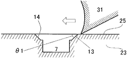
여기에, 도 6(A)에 나타내는 맞춤면의 절삭 가공의 모습을 도 7에 모식적으로 나타낸다. 도 7 중의 부호 31은 절삭날을 나타내고, 반원통 형상의 부재(23)에 대하여 화살표로 나타내는 방향으로 상대 이동된다.Fig. 7 schematically shows the state of the cutting process of the alignment surface shown in Fig. 6 (A).
절삭날(31)은, 둘레 방향 단면(25)에 대하여, 절삭날(31)이 맞닿는 방향(도 7에서는 기울어진 좌측 하방향)으로 힘을 가하여, 둘레 방향 단면(25)의 재료를 벗겨 간다.The
본 발명자들은, 둘레 방향 단면(25)에 대한 경사면(13)의 각도(모따기각) θ1을 변화시켰을 때의, 버의 발생 확률을 검토하였다. 결과를 도 8에 나타낸다. 도 8에 있어서 각 모따기각에 있어서 샘플수는 20이다.The present inventors studied the occurrence probability of burr when the angle (chamfered angle)? 1 of the
도 8의 결과로부터, 모따기각 θ1이 65도를 넘으면, 이 경사면(13)에도 버가 발생할 우려가 있음을 알 수 있다.From the results shown in Fig. 8, it can be seen that if the chamfered angle? 1 exceeds 65 degrees, burrs may occur in the
본 발명자들의 검토에 의하면, 모따기각 θ1이 30도 미만이 되면, 경사면(13), 나아가서는 대면(對面) 측의 경사면(14)의 면적이 커지고, 바꿔 말하면, 맞춤면(5)의 면적이 감소하기 때문에, 맞춤면(5)의 기계적 강도 유지의 관점에서 반드시 바람직하지는 않다. According to the examination by the inventors of the present invention, when the chamfered angle? 1 is less than 30 degrees, the area of the
즉, 둘레 방향 단면(25)에 대한 경사면(13)의 모따기각 θ1의 바람직한 범위는 30∼65도이며, 더욱 바람직한 모따기각은 45도 및 그 전후이다.That is, the preferred range of the chamfered angle? 1 of the
버의 발생 여하의 관점에서 보면, 하류 측의 경사면(14)의 각도는 특별히 문제가 되지 않는다.From the viewpoint of occurrence of burrs, the angle of the
도 9에는, 맞춤면(5)에 개구되는 오목부(7)의 주연에 있어서, 맞춤면의 절삭 가공 형성 시에 상류 측에 위치하는 부분에만 모따기면(40), 즉 리드면(41)과 경사면(43)을 형성한 예를 나타낸다. 리드면(41)은 오목부(7)의 주연에 있어서 내측(베어링 본체의 중심 측) 부분의 일부에도 형성되어 있다.9 shows only the chamfered
도 9에 나타낸 모따기면(40)은, 도 5(A)에 나타내는 절삭 시에, 칼날의 폭을 좁게 하여, 오목부(7)의 주연의 일부에만 가공을 실시함으로써 얻어진다. The chamfered
이러한 구성을 채용함으로써, 맞춤면에 넓은 면적을 확보할 수 있다.By employing such a configuration, it is possible to secure a large area on the mating surface.
도 10의 예에서는, 맞춤면(5)에 개구되는 오목부(7)의 주연에 있어서, 상류 측 및 하류 측의 가장자리에 직접 경사면(53, 54)이 형성되어 있고, 오목부(7)의 주연에 있어서 내측에는 어떠한 모따기도 형성되어 있지 않다. 이러한 구성을 채용함에 의해서도, 맞춤면(5)에 넓은 면적을 확보할 수 있다. 10, the
도 10에 나타낸 모따기면(50)은, 도 5(A)에 나타내는 절삭 시에, 칼날의 측면만이 오목부(7)의 주연에 간섭하도록 하고, 또한, 맞춤면(5)의 두께 방향에 대한 위치 맞춤을 제어하는 것에 의해 얻어진다.The chamfered surface 50 shown in Fig. 10 is formed such that only the side surface of the blade is interfered with the periphery of the
또한, 경사면(53) 또는 경사면(54)을 굳이 생략하는 것이, 맞춤면(5)의 면적 확대의 견지에서, 더욱 바람직하다.It is more preferable to omit the
도 11의 예는, 도 5(A)의 절삭 가공 시에, 엔드밀 등의 막대 형상의 회전 절삭 공구를, 그 회전축을 맞춤면과 평행[베어링 본체(3)의 반경 방향]하게 하여 맞춤면에 수직한 방향으로 이동시켜서 형성한 모따기면(60)을 나타낸다. 이 모따기면(60)은, 오목부(7)의 주연에 있어서, 베어링 본체(3)의 축 방향 상류 측 및 하류 측에 있어서 곡면을 가진다. 당해 부위가 경사면에 상당한다.In the example shown in Fig. 11, the rod-like rotary cutting tool such as the end mill is rotated parallel to the mating surface (radial direction of the bearing body 3) And a
또, 도 12의 예는, 도 5(A)의 절삭 가공 시에, 엔드밀 등의 막대 형상의 회전 절삭 공구를, 그 회전축을 맞춤면과 수직하게 하여 맞춤면에 평행한 방향으로 이동시켜서 형성한 모따기면(70)을 나타낸다. 이 모따기면(70)에서는, 맞춤면(5)에 개구되는 전체 주연을 포함하는 면이 경사면에 상당한다.In the example shown in Fig. 12, a rod-like rotary cutting tool such as an end mill is moved in a direction parallel to the mating surface perpendicular to the mating surface during the cutting process of Fig. 5A, A chamfered
도 11 및 도 12의 예에서 나타낸 형성 방법에 있어서, 예를 들면, 회전 절삭 공구의 크기를 바꾸었다고 해도, 물론, 오목부(7)의 주연에 있어서 적어도 상류 측의 부분이 모따기되어, 버의 발생이 예방되어 있으면 된다.In the forming method shown in the examples of Figs. 11 and 12, for example, even if the size of the rotary cutting tool is changed, of course, at least the portion on the upstream side in the periphery of the
도 13, 14에는, 다른 실시 형태의 하프 슬라이딩 베어링의 예를 나타내었다.13 and 14 show examples of half-sliding bearings according to other embodiments.
이 예에서는, 오목부(7)가 맞춤면(5)의 일단 측에 편재하여 형성되어 있다. 그리고, 베어링 본체(3)의 단부와 오목부(7) 사이에 존재하는 좁은 벽부(85)의 상면이, 도 14로부터 분명한 바와 같이, 맞춤면(5)의 두께 방향에 대하여 경사지게 컷아웃되어 있다.In this example, the
이러한 컷아웃면(80)은, 도 5(A)의 절삭 가공 시에, 좁은 벽부(85)의 상면만을 절삭함으로써 얻어진다. 이러한 절삭 작업에는 높은 위치 맞춤이 요구되지 않기 때문에, 성형성이 우수하다. 이러한 컷아웃면(80)을 형성한 후, 좁은 벽부(85) 측으로부터 둘레 방향 단면(25)을 절삭하여 맞춤면(5)을 형성한다.This
또한, 컷아웃면(80)의 내측[베어링 본체(3)의 반경 방향 중심 측]에는 맞춤면(5)으로서의 평탄면을 잔존시키는 것이 바람직하다.It is preferable that the flat surface as the
이 예에서는, 맞춤면(5)에 개구되는 오목부(7)의 주연에 있어서 상류 측의 부분[즉 좁은 벽부(85)]의 상면이 맞춤면 절삭용의 절삭날에 간섭하지 않도록 컷아웃되어 있다. 따라서, 버를 발생시키는 재료가 존재하지 않기 때문에, 버와 무관하다.In this example, the upper surface of the upstream portion (that is, the narrow wall portion 85) at the periphery of the
본 발명은, 상기 발명의 실시 형태 및 실시예의 설명에 어떠한 한정이 되는 것은 아니다. 특허청구의 범위의 기재를 일탈하지 않고, 당업자가 용이하게 생각해낼 수 있는 범위에서 다양한 변형 양태도 본 발명에 포함된다.The present invention is not limited to the description of the embodiments and the examples of the present invention. Various modifications are also included in the present invention without departing from the scope of the claims, and to the extent that those skilled in the art can easily think of them.
본 명세서 중에서 명시한 논문, 공개 특허 공보, 및 특허 공보 등의 내용은, 그 모든 내용을 원용에 의해 인용하는 것으로 한다.The contents of the papers, the patent publications, and the patent publications specified in the present specification are to be cited by reference.
1 : 하프 슬라이딩 베어링
3 : 베어링 본체
5 : 맞춤면
7 : 오목부
9 : 위치 결정 부재
11, 41 : 리드면
13, 14, 43, 53, 54 : 경사면
10, 40, 50, 60, 70 : 모따기면1: Half sliding bearing
3: Bearing body
5: Fit Face
7:
9: positioning member
11, 41: lead face
13, 14, 43, 53, 54:
10, 40, 50, 60, 70: Chamfer face
Claims (11)
상기 베어링 본체의 전구체로서의 반원통 형상의 부재의 둘레 방향 단면에 개구되는 상기 오목부의 주연에 있어서, 상기 부재의 축 방향과 교차하는 적어도 일방의 가장자리의 전역이 모따기되어 있는 상기 부재를 준비하는 단계와,
상기 오목부의 주연에 있어서, 상기 모따기가 형성된 가장자리에 가장 먼저 절삭날이 도달하도록, 상기 둘레 방향 단면을 절삭해 맞춤면을 형성하여, 베어링 본체를 제작하는 단계를 포함하는 하프 슬라이딩 베어링의 제조 방법.And a recess formed in a circumferential direction from an outer circumference of a mating surface of the bearing body, the method comprising the steps of:
The step of preparing the member having the entire periphery of at least one of the edges intersecting with the axial direction of the member at the periphery of the recess opened in the circumferential cross section of the semicylindrical member as the precursor of the bearing body; ,
And cutting the circumferential section to form a fitting surface so that the cutting edge first reaches the edge where the chamfer is formed, at the periphery of the concave portion, thereby manufacturing the bearing body.
상기 부재를 준비하는 단계는,
상기 부재의 둘레 방향 단면의 외주연으로부터 둘레 방향으로 오목부를 형성하는 단계와,
상기 오목부의 형성 후에, 상기 둘레 방향 단면에 개구되는 상기 오목부의 주연의 모따기를 행하는 단계를 포함하는, 제조 방법.The method according to claim 1,
Wherein preparing the member comprises:
Forming a recess in a circumferential direction from an outer periphery of a circumferential section of the member;
And after the formation of the concave portion, chamfering the periphery of the concave portion opened in the circumferential directional section.
상기 둘레 방향 단면에 대한 모따기의 각도는 30∼65도로 하는, 제조 방법.3. The method of claim 2,
Wherein the angle of the chamfer with respect to the circumferential section is 30 to 65 degrees.
상기 모따기를 형성하는 단계는 절삭에 의하는, 제조 방법.3. The method of claim 2,
Wherein the forming of the chamfer is by cutting.
상기 둘레 방향 단면에 개구되는 상기 오목부의 주연의 전체 둘레에 상기 모따기를 형성하는, 제조 방법.3. The method of claim 2,
And the chamfer is formed around the entire periphery of the concave portion opened in the circumferential directional section.
당해 베어링 본체의 맞춤면의 외주 측으로부터 둘레 방향으로 형성된 오목부를 가지며,
상기 맞춤면에 개구되는 상기 오목부의 주연에 있어서, 상기 베어링 본체의 축 방향과 교차되는 적어도 일방의 가장자리의 전역이 컷아웃됨으로써, 상기 맞춤면 및 상기 오목부의 양방과 다른 면을 구비하는, 하프 슬라이딩 베어링.A semi-cylindrical bearing body,
And a concave portion formed in a circumferential direction from an outer circumferential side of a mating surface of the bearing body,
And a half-sliding portion having a surface different from both of the mating surface and the concave portion by cutting out the entire surface of at least one edge intersecting with the axial direction of the bearing body at the periphery of the recess opened to the mating surface, bearing.
상기 컷아웃에 의해 상기 오목부의 주연이 모따기되어 있는, 하프 슬라이딩 베어링.The method according to claim 6,
And the periphery of the concave portion is chamfered by the cutout.
상기 맞춤면에 개구되는 오목부의 주연의 전체 가장자리가 모따기되어 있는, 하프 슬라이딩 베어링.8. The method of claim 7,
And the entire periphery of the periphery of the concave portion opened in said fitting surface is chamfered.
맞춤면에 개구되는 오목부의 주연의 모따기 각도는 30∼65도인, 하프 슬라이딩 베어링.9. The method of claim 8,
And the chamfer angle of the periphery of the recessed portion opened to the mating face is 30 to 65 degrees.
상기 베어링 본체의 전구체로서의 반원통 형상의 부재의 둘레 방향 단면의 일단 측에 상기 오목부를 형성하는 단계와,
상기 오목부와 상기 부재의 상기 일단 측의 단부 사이에 존재하는 둘레 방향 단면을 컷아웃하는 단계와,
상기 둘레 방향 단면을 상기 일단 측으로부터 절삭해 맞춤면을 형성하여, 베어링 본체를 제작하는 단계를 포함하는 하프 슬라이딩 베어링의 제조 방법.And a recess formed in a circumferential direction from an outer circumference of a mating surface of the bearing body, the method comprising the steps of:
A step of forming the concave portion on one end side of a circumferential section of a semicylindrical member as a precursor of the bearing body,
Cutting out the circumferential cross section existing between the concave portion and the end of the one end side of the member;
And cutting the circumferential section from the one end side to form a fitting surface, thereby manufacturing a bearing body.
당해 베어링 본체의 맞춤면의 외주 측으로부터 둘레 방향으로 형성된 오목부를 가지며,
상기 맞춤면에 개구되는 상기 오목부의 주연에 있어서, 상기 베어링 본체의 축 방향과 교차하는 적어도 일방의 가장자리의 전역이 컷아웃됨으로써, 상기 맞춤면 및 상기 오목부의 양방과 다른 면을 구비하는, 하프 슬라이딩 베어링으로서,
상기 베어링 본체의 전구체로서의 반원통 형상의 부재의 둘레 방향 단면에 개구되는 상기 오목부의 주연에 있어서, 상기 부재의 축 방향과 교차하는 적어도 일방의 가장자리의 전역이 모따기되어 있는 상기 부재를 준비하는 단계와,
상기 오목부의 주연에 있어서, 상기 모따기가 형성된 가장자리에 가장 먼저 절삭날이 도달하도록, 상기 둘레 방향 단면을 절삭해 맞춤면을 형성하여, 베어링 본체를 제작하는 단계를 포함하는 방법에 의해 제조되는, 하프 슬라이딩 베어링.A semi-cylindrical bearing body,
And a concave portion formed in a circumferential direction from an outer circumferential side of a mating surface of the bearing body,
And a half-sliding portion having a surface different from both of the mating surface and the concave portion by cutting out the entire surface of at least one edge intersecting with the axial direction of the bearing body at the periphery of the concave portion opened in the mating surface, As a bearing,
The step of preparing the member having the entire periphery of at least one of the edges intersecting with the axial direction of the member at the periphery of the recess opened in the circumferential cross section of the semicylindrical member as the precursor of the bearing body; ,
And cutting the circumferential cross section to form a fitting surface so that the cutting edge first reaches the edge where the chamfer is formed at the periphery of the concave portion so as to manufacture the bearing body, Sliding bearing.
Applications Claiming Priority (3)
| Application Number | Priority Date | Filing Date | Title |
|---|---|---|---|
| JP2011145860A JP5600083B2 (en) | 2011-06-30 | 2011-06-30 | Half slide bearing and method for manufacturing the same |
| JPJP-P-2011-145860 | 2011-06-30 | ||
| PCT/JP2012/058932 WO2013001881A1 (en) | 2011-06-30 | 2012-04-02 | Halved sliding bearing and method for producing same |
Publications (2)
| Publication Number | Publication Date |
|---|---|
| KR20130031901A KR20130031901A (en) | 2013-03-29 |
| KR101462122B1 true KR101462122B1 (en) | 2014-11-17 |
Family
ID=47423790
Family Applications (1)
| Application Number | Title | Priority Date | Filing Date |
|---|---|---|---|
| KR1020137001608A KR101462122B1 (en) | 2011-06-30 | 2012-04-02 | Halved sliding bearing and method for producing same |
Country Status (5)
| Country | Link |
|---|---|
| US (1) | US8899837B2 (en) |
| EP (1) | EP2728211B1 (en) |
| JP (1) | JP5600083B2 (en) |
| KR (1) | KR101462122B1 (en) |
| WO (1) | WO2013001881A1 (en) |
Families Citing this family (4)
| Publication number | Priority date | Publication date | Assignee | Title |
|---|---|---|---|---|
| US20150059184A1 (en) * | 2013-08-28 | 2015-03-05 | Aktiebolaget Skf | Methods of Fabricating a High Pressure Bushing and Supporting a Shaft |
| WO2017003927A1 (en) | 2015-06-30 | 2017-01-05 | Saint-Gobain Performance Plastics Corporation | Plain bearing |
| CN111360590B (en) * | 2020-04-23 | 2021-03-19 | 桂林福达曲轴有限公司 | Method for removing grinding burrs on crankshaft journal edge and shoulder surface |
| JP2023030707A (en) | 2021-08-24 | 2023-03-08 | 大同メタル工業株式会社 | Half bearing and slide bearing |
Citations (2)
| Publication number | Priority date | Publication date | Assignee | Title |
|---|---|---|---|---|
| JPS5950226A (en) * | 1982-08-18 | 1984-03-23 | グリコ・アクチエンゲゼルシャフト | Slide bearing |
| JPH0740726Y2 (en) * | 1989-10-20 | 1995-09-20 | エヌデーシー株式会社 | Plain bearing |
Family Cites Families (5)
| Publication number | Priority date | Publication date | Assignee | Title |
|---|---|---|---|---|
| US2124060A (en) * | 1935-05-22 | 1938-07-19 | Gen Motors Corp | Method of making bronze faced bearings |
| US3576353A (en) * | 1969-04-25 | 1971-04-27 | Caterpillar Tractor Co | Connecting rod bearing |
| FR2371599A1 (en) * | 1974-05-16 | 1978-06-16 | Rolls Royce Motors Ltd | ENGINE CONNECTING ROD BEARING |
| JP3056998B2 (en) * | 1996-01-31 | 2000-06-26 | 大同メタル工業株式会社 | Half plain bearing |
| DE19631663C2 (en) * | 1996-08-06 | 1998-08-06 | Glyco Metall Werke | Bearing shell with holding cams and process for its manufacture |
-
2011
- 2011-06-30 JP JP2011145860A patent/JP5600083B2/en active Active
-
2012
- 2012-04-02 WO PCT/JP2012/058932 patent/WO2013001881A1/en active Application Filing
- 2012-04-02 KR KR1020137001608A patent/KR101462122B1/en active IP Right Grant
- 2012-04-02 EP EP12804008.6A patent/EP2728211B1/en active Active
- 2012-04-02 US US13/821,839 patent/US8899837B2/en active Active
Patent Citations (3)
| Publication number | Priority date | Publication date | Assignee | Title |
|---|---|---|---|---|
| JPS5950226A (en) * | 1982-08-18 | 1984-03-23 | グリコ・アクチエンゲゼルシャフト | Slide bearing |
| US4775249A (en) * | 1982-08-18 | 1988-10-04 | Glyco-Metall Werke, Daelen & Loos Gmbh | Plain bearing |
| JPH0740726Y2 (en) * | 1989-10-20 | 1995-09-20 | エヌデーシー株式会社 | Plain bearing |
Also Published As
| Publication number | Publication date |
|---|---|
| US8899837B2 (en) | 2014-12-02 |
| WO2013001881A1 (en) | 2013-01-03 |
| EP2728211B1 (en) | 2020-07-15 |
| JP5600083B2 (en) | 2014-10-01 |
| US20130163904A1 (en) | 2013-06-27 |
| EP2728211A1 (en) | 2014-05-07 |
| EP2728211A4 (en) | 2015-09-30 |
| JP2013011333A (en) | 2013-01-17 |
| KR20130031901A (en) | 2013-03-29 |
Similar Documents
| Publication | Publication Date | Title |
|---|---|---|
| EP2520816B1 (en) | Halved sliding bearing manufacturing method and halved sliding bearing | |
| KR101462122B1 (en) | Halved sliding bearing and method for producing same | |
| JP6535584B2 (en) | Method of manufacturing compressor housing | |
| EP2679826A1 (en) | Impeller, rotor comprising same, and impeller manufacturing method | |
| US11482912B2 (en) | Manufacturing method of core for rotary electric machine | |
| JP2004034037A (en) | Inner spline member and its producing method | |
| JP2006508302A (en) | Bearing shell, bearing and manufacturing method of bearing shell | |
| US20170016475A1 (en) | Plain Bearing Shell and Piston For A Radial Piston Engine | |
| WO2014148357A1 (en) | Reclining mechanism ratchet, method for manufacturing reclining mechanism ratchet, and apparatus for manufacturing reclining mechanism ratchet | |
| US9879718B2 (en) | Sliding bearing and method for manufacturing sliding bearing | |
| JP5626499B1 (en) | Camshaft manufacturing method and gear shaft manufacturing method | |
| CN102330728A (en) | Thrust structure of engine cam shaft | |
| JP4881190B2 (en) | Dove groove processing method | |
| EP3067581A1 (en) | Bearing device and method for manufacturing bearing device | |
| EP3647583A1 (en) | Rail for high-pressure direct injection | |
| JP5413739B2 (en) | Sintered metal sprocket with a mark on the side | |
| JP2012031991A (en) | Method of manufacturing halved slide bearing and halved slide bearing | |
| EP2402580A1 (en) | Fabrication method for nozzle vane | |
| JP7327835B2 (en) | gear member | |
| JP6803965B2 (en) | Seal ring | |
| JP2017095752A (en) | Method for producing sintered component with small recess | |
| CN116677689A (en) | Positioning pin mechanism and positioning method thereof | |
| JP2005290523A (en) | Compound sintering machine parts and powder forming apparatus | |
| CN105683574A (en) | Rotating body, rotating body material, and manufacturing method for rotating body | |
| JP6195050B2 (en) | Bush |
Legal Events
| Date | Code | Title | Description |
|---|---|---|---|
| A201 | Request for examination | ||
| E902 | Notification of reason for refusal | ||
| E902 | Notification of reason for refusal | ||
| E701 | Decision to grant or registration of patent right | ||
| GRNT | Written decision to grant | ||
| FPAY | Annual fee payment |
Payment date: 20170907 Year of fee payment: 4 |
|
| FPAY | Annual fee payment |
Payment date: 20180829 Year of fee payment: 5 |
|
| FPAY | Annual fee payment |
Payment date: 20190918 Year of fee payment: 6 |