KR101436947B1 - Integrated sensor system - Google Patents
Integrated sensor system Download PDFInfo
- Publication number
- KR101436947B1 KR101436947B1 KR1020127020227A KR20127020227A KR101436947B1 KR 101436947 B1 KR101436947 B1 KR 101436947B1 KR 1020127020227 A KR1020127020227 A KR 1020127020227A KR 20127020227 A KR20127020227 A KR 20127020227A KR 101436947 B1 KR101436947 B1 KR 101436947B1
- Authority
- KR
- South Korea
- Prior art keywords
- capacitive
- capacitive sensors
- conductive
- capacitive sensor
- electrode
- Prior art date
Links
- 238000005259 measurement Methods 0.000 claims abstract description 69
- 239000010409 thin film Substances 0.000 claims abstract description 35
- 238000001459 lithography Methods 0.000 claims abstract description 29
- 239000010408 film Substances 0.000 claims description 40
- 238000000034 method Methods 0.000 claims description 38
- 230000006870 function Effects 0.000 claims description 18
- 239000000853 adhesive Substances 0.000 claims description 11
- 230000001070 adhesive effect Effects 0.000 claims description 11
- 230000002093 peripheral effect Effects 0.000 claims description 7
- 235000012431 wafers Nutrition 0.000 description 168
- 239000010410 layer Substances 0.000 description 104
- 239000000758 substrate Substances 0.000 description 58
- 238000012545 processing Methods 0.000 description 48
- 239000004020 conductor Substances 0.000 description 32
- 239000000523 sample Substances 0.000 description 23
- 238000010586 diagram Methods 0.000 description 21
- 230000005684 electric field Effects 0.000 description 20
- 238000013461 design Methods 0.000 description 17
- 230000000694 effects Effects 0.000 description 17
- 238000004519 manufacturing process Methods 0.000 description 14
- 239000000463 material Substances 0.000 description 14
- 230000003071 parasitic effect Effects 0.000 description 14
- 230000001360 synchronised effect Effects 0.000 description 14
- XUIMIQQOPSSXEZ-UHFFFAOYSA-N Silicon Chemical compound [Si] XUIMIQQOPSSXEZ-UHFFFAOYSA-N 0.000 description 10
- 239000002245 particle Substances 0.000 description 10
- 230000035945 sensitivity Effects 0.000 description 10
- 229910052710 silicon Inorganic materials 0.000 description 10
- 239000010703 silicon Substances 0.000 description 10
- RZVAJINKPMORJF-UHFFFAOYSA-N Acetaminophen Chemical compound CC(=O)NC1=CC=C(O)C=C1 RZVAJINKPMORJF-UHFFFAOYSA-N 0.000 description 9
- 230000008859 change Effects 0.000 description 9
- 239000005297 pyrex Substances 0.000 description 9
- RYGMFSIKBFXOCR-UHFFFAOYSA-N Copper Chemical compound [Cu] RYGMFSIKBFXOCR-UHFFFAOYSA-N 0.000 description 8
- 229910052802 copper Inorganic materials 0.000 description 8
- 239000010949 copper Substances 0.000 description 8
- 230000010354 integration Effects 0.000 description 7
- 230000003287 optical effect Effects 0.000 description 7
- 230000008569 process Effects 0.000 description 7
- 230000008901 benefit Effects 0.000 description 6
- 230000010363 phase shift Effects 0.000 description 6
- 238000007781 pre-processing Methods 0.000 description 6
- 239000011241 protective layer Substances 0.000 description 6
- 238000004422 calculation algorithm Methods 0.000 description 5
- 239000012528 membrane Substances 0.000 description 5
- 230000001681 protective effect Effects 0.000 description 5
- 238000000926 separation method Methods 0.000 description 5
- 238000012937 correction Methods 0.000 description 4
- 230000008878 coupling Effects 0.000 description 4
- 238000010168 coupling process Methods 0.000 description 4
- 238000005859 coupling reaction Methods 0.000 description 4
- 239000011810 insulating material Substances 0.000 description 4
- 229920001721 polyimide Polymers 0.000 description 4
- 238000007639 printing Methods 0.000 description 4
- 230000002829 reductive effect Effects 0.000 description 4
- 125000006850 spacer group Chemical group 0.000 description 4
- 238000012546 transfer Methods 0.000 description 4
- 238000004364 calculation method Methods 0.000 description 3
- 239000011248 coating agent Substances 0.000 description 3
- 238000000576 coating method Methods 0.000 description 3
- 230000000052 comparative effect Effects 0.000 description 3
- 238000005516 engineering process Methods 0.000 description 3
- 239000011159 matrix material Substances 0.000 description 3
- 238000000691 measurement method Methods 0.000 description 3
- 238000005452 bending Methods 0.000 description 2
- 239000003990 capacitor Substances 0.000 description 2
- 230000003111 delayed effect Effects 0.000 description 2
- 238000010894 electron beam technology Methods 0.000 description 2
- 238000000609 electron-beam lithography Methods 0.000 description 2
- 238000005530 etching Methods 0.000 description 2
- 239000000976 ink Substances 0.000 description 2
- 239000012212 insulator Substances 0.000 description 2
- 238000012423 maintenance Methods 0.000 description 2
- 239000002184 metal Substances 0.000 description 2
- 229910052751 metal Inorganic materials 0.000 description 2
- 238000000059 patterning Methods 0.000 description 2
- 238000004026 adhesive bonding Methods 0.000 description 1
- 230000002411 adverse Effects 0.000 description 1
- 238000003491 array Methods 0.000 description 1
- 230000015572 biosynthetic process Effects 0.000 description 1
- 230000003750 conditioning effect Effects 0.000 description 1
- 239000000356 contaminant Substances 0.000 description 1
- 238000011109 contamination Methods 0.000 description 1
- 230000008602 contraction Effects 0.000 description 1
- 230000008021 deposition Effects 0.000 description 1
- 238000001514 detection method Methods 0.000 description 1
- 238000011161 development Methods 0.000 description 1
- 239000003989 dielectric material Substances 0.000 description 1
- 238000006073 displacement reaction Methods 0.000 description 1
- 238000002474 experimental method Methods 0.000 description 1
- 238000005562 fading Methods 0.000 description 1
- 239000011521 glass Substances 0.000 description 1
- 230000017525 heat dissipation Effects 0.000 description 1
- 239000012535 impurity Substances 0.000 description 1
- 238000011065 in-situ storage Methods 0.000 description 1
- 238000007689 inspection Methods 0.000 description 1
- 230000003993 interaction Effects 0.000 description 1
- 238000010030 laminating Methods 0.000 description 1
- 230000000670 limiting effect Effects 0.000 description 1
- 238000013507 mapping Methods 0.000 description 1
- 238000012986 modification Methods 0.000 description 1
- 230000004048 modification Effects 0.000 description 1
- 238000005192 partition Methods 0.000 description 1
- 238000000206 photolithography Methods 0.000 description 1
- 229920000642 polymer Polymers 0.000 description 1
- 230000009467 reduction Effects 0.000 description 1
- 230000002441 reversible effect Effects 0.000 description 1
- 239000004065 semiconductor Substances 0.000 description 1
- 230000003068 static effect Effects 0.000 description 1
- 229920001169 thermoplastic Polymers 0.000 description 1
Images


Classifications
-
- G—PHYSICS
- G01—MEASURING; TESTING
- G01B—MEASURING LENGTH, THICKNESS OR SIMILAR LINEAR DIMENSIONS; MEASURING ANGLES; MEASURING AREAS; MEASURING IRREGULARITIES OF SURFACES OR CONTOURS
- G01B7/00—Measuring arrangements characterised by the use of electric or magnetic techniques
- G01B7/02—Measuring arrangements characterised by the use of electric or magnetic techniques for measuring length, width or thickness
- G01B7/023—Measuring arrangements characterised by the use of electric or magnetic techniques for measuring length, width or thickness for measuring distance between sensor and object
-
- G—PHYSICS
- G01—MEASURING; TESTING
- G01D—MEASURING NOT SPECIALLY ADAPTED FOR A SPECIFIC VARIABLE; ARRANGEMENTS FOR MEASURING TWO OR MORE VARIABLES NOT COVERED IN A SINGLE OTHER SUBCLASS; TARIFF METERING APPARATUS; MEASURING OR TESTING NOT OTHERWISE PROVIDED FOR
- G01D3/00—Indicating or recording apparatus with provision for the special purposes referred to in the subgroups
- G01D3/028—Indicating or recording apparatus with provision for the special purposes referred to in the subgroups mitigating undesired influences, e.g. temperature, pressure
- G01D3/036—Indicating or recording apparatus with provision for the special purposes referred to in the subgroups mitigating undesired influences, e.g. temperature, pressure on measuring arrangements themselves
-
- G—PHYSICS
- G01—MEASURING; TESTING
- G01D—MEASURING NOT SPECIALLY ADAPTED FOR A SPECIFIC VARIABLE; ARRANGEMENTS FOR MEASURING TWO OR MORE VARIABLES NOT COVERED IN A SINGLE OTHER SUBCLASS; TARIFF METERING APPARATUS; MEASURING OR TESTING NOT OTHERWISE PROVIDED FOR
- G01D5/00—Mechanical means for transferring the output of a sensing member; Means for converting the output of a sensing member to another variable where the form or nature of the sensing member does not constrain the means for converting; Transducers not specially adapted for a specific variable
- G01D5/12—Mechanical means for transferring the output of a sensing member; Means for converting the output of a sensing member to another variable where the form or nature of the sensing member does not constrain the means for converting; Transducers not specially adapted for a specific variable using electric or magnetic means
- G01D5/14—Mechanical means for transferring the output of a sensing member; Means for converting the output of a sensing member to another variable where the form or nature of the sensing member does not constrain the means for converting; Transducers not specially adapted for a specific variable using electric or magnetic means influencing the magnitude of a current or voltage
- G01D5/24—Mechanical means for transferring the output of a sensing member; Means for converting the output of a sensing member to another variable where the form or nature of the sensing member does not constrain the means for converting; Transducers not specially adapted for a specific variable using electric or magnetic means influencing the magnitude of a current or voltage by varying capacitance
- G01D5/241—Mechanical means for transferring the output of a sensing member; Means for converting the output of a sensing member to another variable where the form or nature of the sensing member does not constrain the means for converting; Transducers not specially adapted for a specific variable using electric or magnetic means influencing the magnitude of a current or voltage by varying capacitance by relative movement of capacitor electrodes
- G01D5/2417—Mechanical means for transferring the output of a sensing member; Means for converting the output of a sensing member to another variable where the form or nature of the sensing member does not constrain the means for converting; Transducers not specially adapted for a specific variable using electric or magnetic means influencing the magnitude of a current or voltage by varying capacitance by relative movement of capacitor electrodes by varying separation
-
- G—PHYSICS
- G03—PHOTOGRAPHY; CINEMATOGRAPHY; ANALOGOUS TECHNIQUES USING WAVES OTHER THAN OPTICAL WAVES; ELECTROGRAPHY; HOLOGRAPHY
- G03F—PHOTOMECHANICAL PRODUCTION OF TEXTURED OR PATTERNED SURFACES, e.g. FOR PRINTING, FOR PROCESSING OF SEMICONDUCTOR DEVICES; MATERIALS THEREFOR; ORIGINALS THEREFOR; APPARATUS SPECIALLY ADAPTED THEREFOR
- G03F9/00—Registration or positioning of originals, masks, frames, photographic sheets or textured or patterned surfaces, e.g. automatically
- G03F9/70—Registration or positioning of originals, masks, frames, photographic sheets or textured or patterned surfaces, e.g. automatically for microlithography
- G03F9/7003—Alignment type or strategy, e.g. leveling, global alignment
- G03F9/7023—Aligning or positioning in direction perpendicular to substrate surface
- G03F9/7026—Focusing
-
- G—PHYSICS
- G03—PHOTOGRAPHY; CINEMATOGRAPHY; ANALOGOUS TECHNIQUES USING WAVES OTHER THAN OPTICAL WAVES; ELECTROGRAPHY; HOLOGRAPHY
- G03F—PHOTOMECHANICAL PRODUCTION OF TEXTURED OR PATTERNED SURFACES, e.g. FOR PRINTING, FOR PROCESSING OF SEMICONDUCTOR DEVICES; MATERIALS THEREFOR; ORIGINALS THEREFOR; APPARATUS SPECIALLY ADAPTED THEREFOR
- G03F9/00—Registration or positioning of originals, masks, frames, photographic sheets or textured or patterned surfaces, e.g. automatically
- G03F9/70—Registration or positioning of originals, masks, frames, photographic sheets or textured or patterned surfaces, e.g. automatically for microlithography
- G03F9/7049—Technique, e.g. interferometric
- G03F9/7053—Non-optical, e.g. mechanical, capacitive, using an electron beam, acoustic or thermal waves
Abstract
리소그래피 기계(lithography machine)를 위한 통합 센서 시스템(integrated sensor system)이 개시되고, 상기 시스템은 하나 이상의 노출 빔들을 타겟 상에 포커싱하기 위한 투사 렌즈 시스템(132), 타겟(9)을 운반하기 위한 이동 가능한 테이블(134), 투사 렌즈 시스템(104)의 최종 포커싱 엘리먼트 및 타겟(9)의 표면 사이의 거리에 관련된 측정을 하기 위한 용량성 센싱 시스템(capacitive sensing system)(300), 및 용량성 센싱 시스템으로부터의 신호에 적어도 부분적으로 기초하여 타겟(9)의 위치를 조절하기 위해 이동 가능한 테이블(134)의 이동을 제어하기 위한 제어 유닛(400)을 포함한다. 용량성 센싱 시스템(300)은 복수의 용량성 센서들(30)을 포함하고, 용량성 센서들 각각은 박막 구조를 포함한다. 용량성 센서들 및 상기 투사 렌즈 시스템의 최종 포커싱 엘리먼트(104)는 공통 베이스(112)에 직접적으로 장착되고, 센서들은 투사 렌즈 시스템의 최종 포커싱 엘리먼트의 에지에 근접하게 위치된다.An integrated sensor system for a lithography machine is disclosed that includes a projection lens system 132 for focusing one or more exposure beams onto a target, A capacitive sensing system 300 for making measurements related to the possible table 134, the distance between the final focusing element of the projection lens system 104 and the surface of the target 9, And a control unit (400) for controlling the movement of the movable table (134) to adjust the position of the target (9) based at least in part on the signal from the target (9). The capacitive sensing system 300 includes a plurality of capacitive sensors 30, each of which includes a thin film structure. The capacitive sensors and the final focusing element 104 of the projection lens system are mounted directly on the common base 112 and the sensors are positioned close to the edge of the final focusing element of the projection lens system.
Description
본 발명은 거리를 측정하기 위한 용량성 센서, 특히, 리소그래피 장치에서 타겟에 대한 거리를 측정하기 위한 용량성 센서에 관한 것이다.The present invention relates to a capacitive sensor for measuring distance, and more particularly to a capacitive sensor for measuring the distance to a target in a lithographic apparatus.
대전 입자 및 광학 리소그래피 기계들 및 검사 기계들은, 통상적으로 반도체 디바이스 제조 프로세스의 부분으로서 웨이퍼들 상의 패턴들 및 다른 타겟들을 노출시키는데 사용된다. 리소그래피 시스템에서, 웨이퍼는 리소그래피 기계에 의해 생성된 광학 또는 입자 노출 빔들에 의해 다수의 위치들에서 항상 노출된다. 웨이퍼는 항상 웨이퍼 테이블 상에 위치되고, 정적 전자/ 광학 컬럼에 관련하여 웨이퍼 테이블의 제어된 변위에 의해 다수의 노출들이 통상적으로 성취된다. 노출들은 통상적으로 웨이퍼 표면 상에서 연속적으로 수행된다. Charged particles and optical lithography machines and inspection machines are typically used to expose patterns and other targets on wafers as part of a semiconductor device manufacturing process. In a lithographic system, a wafer is always exposed at multiple locations by optical or particle exposure beams produced by a lithographic machine. The wafer is always located on the wafer table, and multiple exposures are typically accomplished by controlled displacement of the wafer table relative to the static electronic / optical column. Exposures are typically performed continuously on the wafer surface.
노출될 웨이퍼 표면은 거의 완전하게 평평하지는 않다. 통상적인 웨이퍼는 웨이퍼 테이블에 대한 클램핑 없이 그 안에 50 ㎛ 까지의 보(bow)를 가질 수 있다. 웨이퍼 보 이외에, 웨이퍼 표면은 그의 표면에 걸쳐 다른 불균일성들을 가질 수 있다. 웨이퍼 보 및 다른 불균일성들은 웨이퍼 표면에서 높이 변동들을 야기한다. 현대 리소그래피 기계들에서 요구되는 극히 고정밀성을 성취하기 위해, 광학 또는 입자 노출 빔들을 웨이퍼로 포커싱하는데 사용되는 투사 렌즈의 포커스 평면에서 노출되는 웨이퍼 표면을 유지하도록 이러한 높이 변동을 정정할 필요가 있다. The wafer surface to be exposed is not nearly perfectly flat. Conventional wafers can have up to 50 탆 of bow in it without clamping to the wafer table. In addition to the wafer beam, the wafer surface may have other non-uniformities across its surface. Wafer beams and other non-uniformities cause height variations at the wafer surface. In order to achieve the extremely high precision required in modern lithography machines, it is necessary to correct this height variation to maintain the exposed wafer surface in the focus plane of the projection lens used to focus the optical or particle exposure beams onto the wafer.
웨이퍼를 유지하는 웨이퍼 테이블은 웨이퍼 표면의 높이에서의 이러한 변동들을 보상하도록 조절될 수 있다. 웨이퍼 테이블의 높이는 노출될 웨이퍼 표면을 투사 렌즈의 포커스 평면으로 유도하도록 조절될 수 있다. 웨이퍼 테이블 높이의 제어는, 웨이퍼 표면의 높이, 예를 들면, 투사 렌즈와 웨이퍼 표면 간의 거리를 측정하는 센서들로부터 전송된 신호들을 사용하여 성취될 수 있다. 고감도 센서들은 현대 리소그래피 기계들에서 요구되는 극도의 정밀도로 웨이퍼 위치의 정확한 제어를 보장하도록 요구된다. 다양한 형태들의 센서들은 용량성 프로브들을 포함하는 이러한 형태의 애플리케이션에서 사용되어 왔다. 그러나, 기존의 용량성 프로브들 및 연관된 측정 및 제어 시스템들은 몇몇의 단점들로 고통받고 있다. The wafer table holding the wafer can be adjusted to compensate for these variations in height of the wafer surface. The height of the wafer table can be adjusted to guide the wafer surface to be exposed to the focus plane of the projection lens. Control of the wafer table height can be accomplished using signals transmitted from sensors that measure the height of the wafer surface, e.g., the distance between the projection lens and the wafer surface. High sensitivity sensors are required to ensure accurate control of the wafer position with the extreme precision required in modern lithography machines. Various types of sensors have been used in this type of application, including capacitive probes. However, existing capacitive probes and associated measurement and control systems suffer from several drawbacks.
기존의 용량성 센서들은 높이 및 센서 면적 양자에 있어서 통상적으로 크다. 도 1a 및 도 1b는 종래 기술의 용량성 센서의 구조를 도시한다. 도 1a는 단면도를 도시하고, 도 1b는 용량성 센서 프로브의 단부도를 도시한다. 도전성 센싱 전극(2)은 도전성 가드 전극(3)에 의해 둘러싸이게 된다. 절연층(4)은 2 개의 전극들을 분리하고, 또 다른 절연층(5)은 하우징(6)으로부터 가드 전극(3)을 분리하는데 사용될 수 있다. 전기 케이블(7) 및 접속기(8)는 원하는 최종 측정 신호를 유도하기 위해 신호 프로세싱 시스템에 용량성 센서를 접속시킨다. 용량성 센서의 동작 범위는 센싱 전극(2) 하에서 센싱 영역에 의존한다. 가드 전극(3)은 센싱 전극(2)과 타겟(9) 사이에 비교적 일정한 전기장을 생성하도록 센싱 영역 내의 전기장을 국한시키기 위해 센싱 전극과 동일한 전위로 설정된다. 이러한 형태의 구조는 비교적 큰 용량성 센서, 일반적으로 높이에서 약 20 mm, 및 비교적 대형 센싱 전극을 야기한다.Conventional capacitive sensors are typically large in both height and sensor area. Figures 1a and 1b show the structure of a capacitive sensor of the prior art. Fig. 1A shows a sectional view, and Fig. 1B shows an end view of a capacitive sensor probe. The
용량성 센서들의 비교적 큰 높이 및 폭은 용량성 센서들이 투사 렌즈로부터 비교적으로 멀리 배치될 필요가 있어서, 제조 허용 오차들 및 열 팽창으로 인한 용량성 센서들 및 투사 렌즈의 상대적인 위치 선정에서의 변동으로 인한 에러들을 도입한다. 비교적 큰 크기의 기존의 용량성 프로브들은 또한 다중-센서 구조들의 개별적인 용량성 센서들이 비교적 멀리 이격되는 것을 요구하여, 센싱 시스템의 공간 분해능을 감소시켜서, 웨이퍼 표면의 작은 영역에 걸쳐 발생하는 웨이퍼 표면 내의 불균일성들이 검출될 수 없다. 비교적 넓은 이격은 또한 더 느린 측정 프로세스를 야기하여, 이러한 시스템들을 사용하는 리소그래피 기계의 처리량을 감소시킨다. The relatively large height and width of the capacitive sensors require that the capacitive sensors be located relatively far from the projection lens so that variations in the relative positioning of the capacitive sensors and projection lens due to manufacturing tolerances and thermal expansion Introduced errors. Conventional capacitive probes of relatively large size also require that individual capacitive sensors of the multi-sensor structures be relatively far apart, thereby reducing the spatial resolution of the sensing system, thereby reducing the spatial resolution of the sensing surface within the wafer surface Non-uniformities can not be detected. Relatively wide spacing also results in a slower measurement process, which reduces the throughput of the lithographic machine using these systems.
영국 특허 제 2,131,176 호는, 하나의 시트의 구리 코팅된 면이 다른 시트의 코딩되지 않은 면에 결합되도록, 하나의 측면 상에 증착된 구리 코팅을 갖는 2 개의 열가소성 폴리머 막들을 함께 접착 결합시킴으로써 제조되는 커패시턴스 거리 측정 프로브를 기재하고 있다. 하나의 시트 상의 노출된 구리 코팅은 센싱 전극을 구성하는 제 1 영역 및 센싱 전극을 적어도 부분적으로 둘러싸는 제 2 영역으로 분할되고, 센싱 전극에 대한 가드 전극을 규정하기 위해 다른 시트 상의 구리 코팅과 전기적으로 상호 접속된다. 이러한 구조는 감지 전극을 둘러싸는 가드 전극을 제공함으로써 도 1에 도시된 구조처럼 보이고, 가드 전극 양자는 동일한 표면 상에서 및 적층 디바이스의 동일한 레벨에서 형성된 센싱 전극을 둘러싸고 있다. 이것은 상이한 도전층들 사이에 전기 접속을 요구하고 따라서 더 복잡하고 비용이 드는 제조 프로세스를 요구하는 구조를 야기한다. British Patent 2,131,176 is made by adhesive bonding together two thermoplastic polymer membranes having a copper coating deposited on one side so that the copper coated side of one sheet is bonded to the uncured side of the other sheet And a capacitance distance measuring probe. The exposed copper coating on one sheet is divided into a first region constituting a sensing electrode and a second region at least partially surrounding the sensing electrode and electrically connected to a copper coating on another sheet and a second region electrically Respectively. This structure looks like the structure shown in Fig. 1 by providing a guard electrode surrounding the sensing electrode, and both guard electrodes surround sensing electrodes formed on the same surface and at the same level of the laminating device. This results in a structure that requires electrical connections between different conductive layers and thus requires more complex and costly manufacturing processes.
또한, 이러한 용량성 센서들에 대한 배선 접속들은 제조하기 어렵고, 배선은 용량성 센서의 판독에 영향을 주는 커패시턴스들을 도입하고, 고려될 필요가 있고, 항상 조합된 용량성 센서 및 배선 설비를 조정할 필요가 있다. 용량성 센서 배선과 조합하여 기존의 용량성 센서들을 조정하기 위한 요건은, 용량성 센서가 대체될 때마다 재조정을 요구하여, 대체를 복잡하고 시간-소모하고, 비용이 들게 한다. Also, the wiring connections for these capacitive sensors are difficult to manufacture, the wiring introduces capacitances that affect the readout of the capacitive sensor, needs to be considered, and always needs to adjust the combined capacitive sensor and wiring facilities . The requirement to tune existing capacitive sensors in combination with capacitive sensor wiring requires readjustment each time a capacitive sensor is replaced, complicating the replacement, time-consuming, and costly.
미국 특허 제 4,538,069 호는 레티클들을 노출시키기 위한 단일의 전자 빔 리소그래피 기계에 대한 커패시턴스 높이 게이지를 조정하는 방법을 기재하고 있다. 높이 게이지는 먼저 레이저 간섭계를 사용하여 조정 고정 장치(calibration fixture)에서 조정되고, 그후 상기 기계는 레티클을 노출시키기 위해 리소그래피 스테이션에 재위치되고, 커패시턴스 게이지를 사용하여 레티클에 대한 거리가 측정된다. 커패시턴스 게이지들은 전자 빔 광학 하우징의 하부에 고정되는 기판 상에 형성된다. 레티클 타겟이 접지되고, 커패시턴스 게이지는 180°위상차를 갖는 신호들(out-of-phase signals)에 의해 구동되고, 각각의 게이트로부터의 출력 신호는 4 개의 높이 측정 신호들을 생성하도록 개별적으로 프로세싱된다. U.S. Patent No. 4,538,069 describes a method of adjusting the capacitance height gauge for a single electron beam lithography machine to expose reticles. The height gauge is first adjusted in a calibration fixture using a laser interferometer, which is then relocated to the lithography station to expose the reticle and the distance to the reticle is measured using a capacitance gauge. Capacitance gauges are formed on a substrate fixed to the bottom of the electron beam optical housing. The reticle target is grounded, the capacitance gage is driven by out-of-phase signals with 180 degrees of phase, and the output signal from each gate is individually processed to produce four height measurement signals.
본 발명은 리소그래피 기계를 위한 개선된 통합 센서 시스템을 제공하기 위해 위의 단점들을 해소 또는 감소시려고 하며, 상기 시스템은 하나 이상의 노출 빔들을 타겟으로 포커싱하기 위한 투사 렌즈 시스템, 타겟을 운반하기 위한 이동 가능한 테이블, 투사 렌즈 시스템의 최종 포커싱 엘리먼트와 타겟의 표면 사이의 거리에 관련된 측정을 하기 위한 용량성 센싱 시스템, 및 용량성 센싱 시스템으로부터의 신호에 적어도 부분적으로 기초하여 타겟의 위치를 조절하기 위해 이동 가능한 테이블의 이동을 제어하기 위한 제어 유닛을 포함한다. 용량성 센싱 시스템은 복수의 용량성 센서들을 포함하고, 각각의 용량성 센서는 박막 구조를 포함한다. 용량성 센서들 및 투사 렌즈 시스템의 최종 포커싱 엘리먼트는 공통 베이스에 직접적으로 장착되고, 용량성 센서들은 투사 렌즈 시스템의 최종 포커싱 엘리먼트의 에지에 가깝게 근접하여 위치된다. SUMMARY OF THE INVENTION The present invention seeks to solve or mitigate the above disadvantages to provide an improved integrated sensor system for a lithographic machine, the system comprising a projection lens system for focusing one or more exposure beams onto a target, A capacitive sensing system for making measurements related to the distance between the table, the final focusing element of the projection lens system and the surface of the target, and a movable sensing system for adjusting the position of the target based at least in part on the signal from the capacitive sensing system. And a control unit for controlling movement of the table. The capacitive sensing system includes a plurality of capacitive sensors, each capacitive sensor comprising a thin film structure. The final focusing elements of the capacitive sensors and the projection lens system are mounted directly on the common base and the capacitive sensors are positioned close to the edge of the final focusing element of the projection lens system.
용량성 센서들 중 적어도 일부는, 타겟을 향해 대면하는 용량성 센서의 센싱 전극의 하부 표면이 타겟의 표면에 대해 수직인 z-축 방향으로 투사 렌즈 시스템의 최종 포커싱 엘리먼트의 하부 표면과 실질적으로 동일한 높이이도록 위치될 수 있다. 용량성 센서들 중 적어도 일부는, 타겟의 표면에 수직인 z-축 방향으로 투사 렌즈 시스템의 최종 포커싱 엘리먼트의 하부 표면의 50 미크론 내에 위치된 타겟을 향해 대면하는 용량성 센서의 센싱 전극의 하부 표면을 갖도록 배열될 수 있다. 용량성 센서들 중 적어도 일부는 용량성 센서의 후방 표면으로부터 타겟을 향해 대면하는 용량성 센서의 센싱 전극의 전방 표면으로 50-150 미크론, 바람직하게는 약 100 미크론의 두께를 가질 수 있다. 투사 렌즈 시스템의 최종 포커싱 엘리먼트는 100-150 미크론 두께일 수 있다. At least some of the capacitive sensors are configured so that the lower surface of the sensing electrode of the capacitive sensor facing towards the target is substantially coincident with the lower surface of the final focusing element of the projection lens system in the z- As shown in FIG. At least a portion of the capacitive sensors are disposed on a lower surface of a sensing electrode of a capacitive sensor facing a target positioned within 50 microns of a lower surface of a final focusing element of the projection lens system in a z- . ≪ / RTI > At least some of the capacitive sensors may have a thickness of 50-150 microns, preferably about 100 microns, on the front surface of the sensing electrode of the capacitive sensor facing the target from the rear surface of the capacitive sensor. The final focusing element of the projection lens system may be 100-150 microns thick.
용량성 센서들은 최종 포커싱 엘리먼트에 가깝게 위치되고, 최종 포커싱 엘리먼트의 에지에 대해 리소그래피 기계의 필드 크기의 폭 또는 길이 내에 위치될 수 있다. 최종 포커싱 엘리먼트는 투사 렌즈 시스템의 하부 엘리먼트일 수 있다. 용량성 센서들 및 투사 렌즈 시스템의 최종 포커싱 엘리먼트는 직접적으로 함께 접속된다. The capacitive sensors may be located close to the final focusing element and positioned within the width or length of the field size of the lithographic apparatus relative to the edge of the final focusing element. The final focusing element may be the lower element of the projection lens system. The capacitive sensors and the final focusing elements of the projection lens system are directly connected together.
용량성 센서들은 각각 박막 구조를 포함할 수 있고, 여기서 박막 구조는 제 1 절연층의 제 1 표면 상에 형성된 센싱 전극을 포함하는 제 1 도전막 및 제 1 절연막, 제 1 절연층의 제 2 표면 및 제 2 절연층의 제 1 표면 상에 배치된 후방 가드 전극을 포함하는 제 2 도전막을 포함하고, 후방 가드 전극의 주변부는 후방 가드 전극에 통합된 측면 가드 전극을 형성하기 위해 센싱 전극을 넘어 연장되고 이를 둘러싼다. 용량성 센서들의 박막 구조는 제 2 절연층의 제 2 표면 상에 배치된 차폐 전극을 포함하는 제 3 도전막을 더 포함할 수 있다. 박막 구조는 가요성일 수 있다.The capacitive sensors may each comprise a thin film structure wherein the thin film structure comprises a first conductive film and a first insulating film comprising a sensing electrode formed on a first surface of the first insulating layer, And a second conductive layer disposed on the first surface of the second insulating layer, wherein a peripheral portion of the rear guard electrode extends beyond the sensing electrode to form a side-guard electrode incorporated in the rear guard electrode And surround it. The thin film structure of the capacitive sensors may further comprise a third conductive film comprising a shielding electrode disposed on a second surface of the second insulating layer. The thin film structure may be flexible.
용량성 센싱 시스템은 센싱 전극들로부터 원격으로 위치된 능동 전자 컴포넌트들을 포함할 수 있고, 어떠한 능동 전자 컴포넌트들도 용량성 센서들과 배치되지 않는다. 각각의 용량성 센서는 도전성 트랙들이 인쇄 또는 부착되는 가요성 멤브레인을 포함하는 가늘고 긴 접속 부재를 더 포함할 수 있고, 도전성 트랙들은 하나의 단부에서 용량성 센서의 후방 가드 전극 및 센싱 전극에 전기적으로 접속되고, 다른 단부에서 접속기에 전기적으로 접속된다. 도전성 트랙들은 제 1 절연층 상에 형성될 수 있고, 제 1 절연층은 센싱 전극 및 후방 가드 전극이 위치되는 제 1 영역 및 도전성 트랙들이 형성되는 제 2 가늘고 긴 영역을 포함할 수 있다.The capacitive sensing system may include active electronic components remotely located from the sensing electrodes, and no active electronic components are placed with the capacitive sensors. Each capacitive sensor may further comprise an elongate connecting member comprising a flexible membrane onto which conductive tracks are printed or attached, wherein the conductive tracks are electrically connected to the rear guard electrode and the sensing electrode of the capacitive sensor at one end And is electrically connected to the connector at the other end. The conductive tracks may be formed on the first insulating layer, and the first insulating layer may include a first region where the sensing electrode and the rear guard electrode are located and a second thin region where the conductive tracks are formed.
용량성 센서들은 박막 절연 기저층 상에 형성된 복수의 쌍들의 용량성 센서들을 포함할 수 있고, 박막 절연 기저층은 공통 베이스에 직접적으로 장착된다. 상기 시스템은 한 쌍의 용량성 센서들 중 제 2 용량성 센서에 대한 전류 또는 전압에 대해 180 도 위상차를 갖는 교류 전류 또는 전압으로 한 쌍의 용량성 센서들 중 제 1 용량성 센서에 동력을 공급하도록 배열된 하나 이상의 AC 전력원들을 더 포함할 수 있다. The capacitive sensors may comprise a plurality of pairs of capacitive sensors formed on a thin insulating base layer and the thin insulating base layer is mounted directly on a common base. The system powers a first one of the pair of capacitive sensors with an alternating current or voltage having a 180 degree phase difference relative to the current or voltage for the second one of the pair of capacitive sensors Lt; RTI ID = 0.0 > AC < / RTI >
본 발명의 다양한 양상들은 도면들에 도시된 실시예들을 참조하여 추가로 설명될 것이다. The various aspects of the invention will be further described with reference to the embodiments shown in the drawings.
도 1a는 용량성 센서의 단면도.
도 1b는 도 1a의 용량성 센서의 단부도.
도 2는 병렬판 전극 어레인지먼트의 간략화된 개략도.
도 3은 용량성 센서 프로브 및 접지된 도전성 타겟의 도면.
도 4는 접지된 도전성 타겟을 갖는 차동 측정 어레인지먼트의 2 개의 용량성 센서 프로브들의 도면.
도 5는 박막 구조를 포함하는 용량성 센서의 단면도.
도 6a, 도 6b, 도 6c 및 도 6d는 박막 센서의 다양한 실시예들의 단면도들.
도 6e는 도 6a 및 도 6b의 센서의 상면도.
도 6f는 도 6d의 센서의 상면도.
도 7a는 정사각형 센싱 전극을 갖는 박막 센서의 상면도.
도 7b는 도 8a의 센서의 단면도.
도 8a는 원형 센싱 전극을 갖는 박막 센서의 상면도.
도 8b는 도 8a의 센서의 단면도.
도 9a, 도 9b 및 도 9c는 통합 차동 박막 센서의 다양한 실시예들의 단면도들.
도 9d는 통합 차동 박막 센서의 상면도.
도 10a 내지 도 10d는 박막 용량성 센서들의 단면도들
도 11은 접속 라인들 및 접촉 패드들을 갖는 센서의 상면도.
도 12a 및 도 12b는 접촉 패드 구조들의 단면도들.
도 13a 내지 도 13d는 공통 기판 상에 형성된 센서들, 접속 라인들 및 접촉 패드들의 도면들.
도 14는 리소그래피 기계 상에 장착된 센서들의 측면도.
도 15a 및 도 15b는 플렉스(flex) 인쇄 접속기의 도면들.
도 16a 및 도 16b는 대전 입자 리소그래피 기계의 투사 렌즈 스택의 단면도들.
도 17a 내지 도 17d는 다수의 센서들 및 통합 플렉스 인쇄 접속기들을 갖는 가요성(flexible) 인쇄 회로 구조의 도면들.
도 18은 리소그래피 기계 상의 센서들의 또 다른 접속 어레인지먼트를 도시한 도면.
도 19a 및 도 19b는 리소그래피 기계 상에 통합 가요성 인쇄 회로 구조를 장착하기 위한 어레인지먼트의 도면들.
도 20a 및 도 20b는 장착판 상의 용량성 센서들의 구조들의 도면들.
도 20c 및 도 20d는 대각선 구조를 배열된 용량성 센서들의 도면들.
도 21a 및 도 21b는 박막 구조 상에 형성된 다수의 용량성 센서들을 갖는 박막 구조의 도면들.
도 21c는 다수의 센서들 및 통합 플렉스 인쇄 접속기들을 갖는 가요성 인쇄 회로 구조의 도면.
도 21d는 통합 플렉스 인쇄 접속기의 단면도.
도 22는 센서 시스템 및 신호 프로세싱 시스템의 간략도.
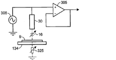
도 23a는 전류원을 갖는 고임피던스 증폭기 회로의 간략화된 회로도.
도 23b는 전류원을 갖는 차동 센서 어레인지먼트의 간략화된 회로도.
도 24a는 전압원을 갖는 휘스톤 브릿지 어레인지먼트의 간략화된 회로도.
도 24b는 전압원을 갖는 차동 센서 어레인지먼트의 간략화된 회로도.
도 25는 차동 센서 회로 어레인지먼트의 간략화된 회로도.
도 26은 동기식 검출기 회로의 간략화된 회로도.
도 27은 센서 시스템 내의 커패시턴스들을 도시하는 간략도.
도 28a 및 도 28b는 센서를 신호 프로세싱 회로에 접속하는 케이블을 갖는 어레인지먼트의 간략화된 회로도들.
도 29는 동기식 회로의 또 다른 실시예의 간략화된 회로도.
도 30은 한 쌍의 차동 센서들로부터의 신호들을 프로세싱하기 위한 어레인지먼트의 간략화된 회로도.
도 31은 리소그래피 기계에 대해 웨이퍼의 위치 선정을 위한 제어 시스템의 간략도.
도 32a 및 도 32b는 도 31의 제어 시스템에서 사용하기 위한 센서 어레인지먼트들의 도면들.
도 32c는 투사 렌즈와 웨이퍼의 표면 사이의 거리 및 웨이퍼의 표면에 걸친 기울기 값들을 결정하기 위한 측정 방법을 예시한 도면.1A is a cross-sectional view of a capacitive sensor;
1B is an end view of the capacitive sensor of FIG.
2 is a simplified schematic diagram of a parallel plate electrode arrangement.
Figure 3 is a diagram of a capacitive sensor probe and a grounded conductive target.
4 is a diagram of two capacitive sensor probes of a differential measurement arrangement having a grounded conductive target;
5 is a cross-sectional view of a capacitive sensor including a thin film structure;
Figures 6A, 6B, 6C and 6D are cross-sectional views of various embodiments of thin film sensors.
6E is a top view of the sensor of Figs. 6A and 6B. Fig.
Figure 6f is a top view of the sensor of Figure 6d.
7A is a top view of a thin film sensor having a square sensing electrode.
Figure 7b is a cross-sectional view of the sensor of Figure 8a.
8A is a top view of a thin film sensor having a circular sensing electrode.
Figure 8b is a cross-sectional view of the sensor of Figure 8a.
Figures 9a, 9b and 9c are cross-sectional views of various embodiments of an integrated differential thin film sensor.
9D is a top view of an integrated differential thin film sensor.
Figures 10a-10d show cross-sectional views of thin film capacitive sensors
11 is a top view of a sensor having contact lines and contact pads.
12A and 12B are cross-sectional views of contact pad structures.
13A-13D are views of sensors, contact lines and contact pads formed on a common substrate.
Figure 14 is a side view of sensors mounted on a lithographic machine.
15A and 15B are views of a flex print connector.
16A and 16B are cross-sectional views of a projection lens stack of a charged particle lithography machine.
Figures 17a-d are illustrations of a flexible printed circuit structure with multiple sensors and integrated flex print connectors.
18 shows another connection arrangement of sensors on a lithographic machine.
Figures 19a and 19b are drawings of an arrangement for mounting an integrated flexible printed circuit structure on a lithographic machine.
Figures 20a and 20b are views of structures of capacitive sensors on a mounting plate.
Figures 20c and 20d are views of capacitive sensors arranged in a diagonal configuration.
Figures 21a and 21b are illustrations of a thin film structure having a plurality of capacitive sensors formed on a thin film structure.
Figure 21c is a diagram of a flexible printed circuit structure with multiple sensors and integrated flex print connectors.
21D is a cross-sectional view of an integrated flex print connector.
Figure 22 is a simplified diagram of a sensor system and a signal processing system.
23A is a simplified circuit diagram of a high impedance amplifier circuit having a current source.
23B is a simplified circuit diagram of a differential sensor arrangement with a current source.
24A is a simplified circuit diagram of a Wheatstone bridge arrangement having a voltage source.
24B is a simplified circuit diagram of a differential sensor arrangement with a voltage source.
25 is a simplified circuit diagram of a differential sensor circuit arrangement.
26 is a simplified circuit diagram of a synchronous detector circuit;
Figure 27 is a simplified diagram illustrating the capacitances in the sensor system;
28A and 28B are simplified circuit diagrams of an arrangement having a cable connecting a sensor to a signal processing circuit.
29 is a simplified circuit diagram of another embodiment of a synchronous circuit;
30 is a simplified circuit diagram of an arrangement for processing signals from a pair of differential sensors;
Figure 31 is a simplified diagram of a control system for positioning a wafer relative to a lithographic machine.
32A and 32B are diagrams of sensor arrangements for use in the control system of FIG.
Figure 32c illustrates a measurement method for determining the distance between the projection lens and the surface of the wafer and the tilt values across the surface of the wafer.
다음은 도면들을 참조하여 단지 예로서 주어지는 본 발명의 다양한 실시예들의 설명이다.The following is a description of various embodiments of the invention given by way of example only with reference to the drawings.
용량성Capacitive 센서들의 이론 Theory of sensors
용량성 센서는 2 개의 도전성 표면들 사이에서 설정된 균질 전기장을 사용한다. 단거리들에 걸쳐, 인가된 전압은 표면들 사이의 거리에 비례한다. 단일판 센서들은 단일 센서판과 전기적으로 도전성 타겟 표면 사이의 거리를 측정한다. The capacitive sensor uses a homogenous electric field established between two conductive surfaces. Over short distances, the applied voltage is proportional to the distance between the surfaces. Single plate sensors measure the distance between a single sensor plate and the electrically conductive target surface.
도 2는 병렬판 전극 어레인지먼트를 도시한다. 2 개의 전극들(11, 12) 사이의 커패시턴스는, 수학식 1에 표현된 바와 같이, 2 개의 전극들 사이의 전위 차로 인해 전극들 중 하나에서 유도된 전하에 의해 주어지고, 전위 차로 제산된다.Figure 2 shows a parallel plate electrode arrangement. The capacitance between the two

2 개의 병렬 전극들은 거리 d만큼 분리된다. 2 개의 전극들 사이의 커패시턴스는 필드 벤딩의 효과들 및 유전체의 비균질성(non-homogeneity)을 무시하여 수학식 2에 의해 주어지고, The two parallel electrodes are separated by a distance d. The capacitance between the two electrodes is given by equation (2), neglecting the effects of field bending and non-homogeneity of the dielectric,
![]()
![]()
여기서, C는 2 개의 전극들 사이의 커패시턴스(F)이고, A는 2 개의 전극들의 중첩 면적(m2)이고, ε0은 자유 공간의 유전율(8.85 x 10¹² F/m)이고, εr은 전극들 사이의 매체의 비유전율이고, d는 전극들 사이의 거리(m)이다.Here, C is a capacitance (F) between the two electrodes, A is the overlap area (m 2) of the two electrodes, ε 0 is the dielectric constant (8.85 x 10 12 F / m ) of free space, ε r Is the relative dielectric constant of the medium between the electrodes, and d is the distance (m) between the electrodes.
교류 전류원(13)이 병렬판 커패시터를 대전하는데 사용될 때, 전압 전위는 전극들의 임피던스에 의존하여 전극들 사이에서 상승한다. 병렬판 커패시턴스의 임피던스는 수학식 3에 의해 주어지고,When the alternating
![]()
![]()
여기서, Z는 임피던스(Ω)이고, f는 주파수(Hz)이고, C는 커패시턴스(F)이다. Where Z is the impedance (?), F is the frequency (Hz), and C is the capacitance (F).
수학식 3으로부터, 용량성 임피던스가 커패시턴스의 값 및 커패시터에 인가된 신호의 주파수에 반비례한다는 것을 알 수 있다. 용량성 센서의 경우에, 용량성 센서의 임피던스의 변화에 대응하는 전기 파라미터(전압 또는 전류)의 변화가 측정된다. 용량성 센서에 인가된 신호의 주파수가 일정하게 유지될 때, 임피던스는 커패시턴스의 변화에 반비례하게 될 수 있다. 수학식 2는 커패시턴스가 용량성 센서 전극들의 중첩 면적에 직접적으로 비례하고, 전극들 사이의 거리에서의 변화에 반비례한다는 것을 보여준다. 수학식 2 및 수학식 3을 조합하는 것은 수학식 4를 산출하고,From Equation (3), it can be seen that the capacitive impedance is inversely proportional to the value of the capacitance and the frequency of the signal applied to the capacitor. In the case of a capacitive sensor, a change in electrical parameter (voltage or current) corresponding to a change in the impedance of the capacitive sensor is measured. When the frequency of the signal applied to the capacitive sensor is kept constant, the impedance can be inversely proportional to the change in capacitance.

여기서, i = 전류이다. Where i = current.
전극 중첩 면적 및 용량성 센서에 인가된 전기 신호(전류)의 주파수를 일정하게 유지함으로써, 전극들 사이의 거리에서의 변화는 용량성 센서의 임피던스의 변화를 야기한다. 용량성 센서에 걸친 전압은 임피던스에 비례하고, 용량성 센서 전극들 사이의 거리(d)에 비례할 것이며, 이는 거리의 정확한 측정을 가능하게 한다. 다양한 측정 개념들이 후술되는 바와 같이 사용될 수 있다. By maintaining the electrode overlap area and the frequency of the electrical signal (current) applied to the capacitive sensor constant, a change in the distance between the electrodes causes a change in the impedance of the capacitive sensor. The voltage across the capacitive sensor will be proportional to the impedance and proportional to the distance d between the capacitive sensor electrodes, which allows an accurate measurement of the distance. Various measurement concepts may be used as described below.
용량성Capacitive 센서에 대한 측정 원리 Measuring principle for sensors
도 3은 접지된 도전성 타겟(9)에 대한 분리 거리를 측정하는 단일 용량성 센서 프로브(1)를 도시한다. AC 전류가 공급될 때, 전류는 센서-타겟 커패시턴스(16)를 통해 용량성 센서로부터 타겟으로, 및 타겟-접지 임피던스(17)를 통해 타겟으로부터 접지로의 경로(15)를 따라 흐를 것이다. 거리 측정에 영향을 주는 외부 영향들 또는 변동들로부터의 외란들은 전압(19)으로서 도면에 표현된다. 용량성 센서로부터 타겟으로의 거리 측정의 정확성은 용량성 센서가 센서-타겟 커패시턴스(16)를 얼마나 정확하게 측정할 수 있는지에 의존한다. 타겟-접지 임피던스(17)의 커패시턴스는 센서-타겟 커패시턴스(16)를 종종 크게 초과할 것이고, 타겟이 잘 접지되지 않을 때보다 100 배를 초과할 수 있다. 이러한 높은 커패시턴스는 낮은 임피던스(17)를 야기하여, 용량성 센서에 대한 그의 효과가 작다. 그러나, 임피던스(17)의 변동들은 거리 측정에 영향을 줄 것이고, 이것은 이러한 효과를 최소화하는데 바람직하다. Fig. 3 shows a single
도 4는 타겟(9)에 대한 분리 거리의 차동 측정을 위한 2 개의 용량성 센서 프로브들(1a 및 1b)의 어레인지먼트를 도시한다. 용량성 센서들에는 180도만큼 오프셋된 AC 전류가 공급되어, 전류를 센서-타겟 커패시턴스(16a)를 통해 하나의 용량성 센서로부터 타겟으로, 및 다른 센서-타겟 커패시턴스(16b)를 통해 타겟으로부터 다른 용량성 센서로의 경로(18)를 따라 흐를 수 있다. 위상차를 갖는 신호들로 2 개의 용량성 센서들을 구동시키기 위한 이러한 어레인지먼트는 타겟을 통한 접지로의 전류의 흐름을 회피하는데 유효하고, 접지 임피던스(17)에 대한 타겟의 효과를 최소화한다. 이것이 접지된 복귀 경로를 필요로 하지 않고 하나의 용량성 센서로부터 다른 용량성 센서로 전류가 흐르도록 허용하기 때문에, 이것은 또한 비접지된 타켓에 대해 유용하다. 위상차를 갖는 신호들로 용량성 센서들을 여기하는 이러한 어레인지먼트는, 한 쌍의 용량성 센서들 중 각각의 용량성 센서로부터 별도 및 독립적인 커패시턴스(및 거리) 측정을 유도하는 종래의 측정 시스템에서 사용될 수 있다. 각각의 용량성 센서는 타겟에 대한 거리를 개별적으로 측정한다. 외란(19)은 2 개의 외란 전압들(19a 및 19b)에 의해 도 4에 표현되고, 전압(19)의 절반값 각각은 각각의 용량성 센서에 동일하게 영향을 주는 공통 모드 외란(disturbance)에 대한 것이다. Fig. 4 shows the arrangement of two capacitive sensor probes Ia and Ib for differential measurement of the separation distance to the
차동 측정 어레인지먼트는 또한 용량성 센서들에 공급되는 위상차를 갖는 신호들과 관련하여 사용될 수 있다. 이러한 어레인지먼트에서, 2 개의 용량성 센서들로부터의 출력들은, 용량성 센서(1a)의 센서-타겟 커패시턴스(16a)가 그의 양의 절반 주기 동안에 용량성 센서(1a)의 구동 전압에 의해, 또한 그의 양의 절반 주기 동안에 용량성 센서(1b)의 구동 전압에 의해 대전되고, 한편 용량성 센서(1b)의 센서-타겟 커패시턴스(16b)는 그의 음의 절반 주기 동안에 용량성 센서(1b)의 구동 전압에 의해 및 또한 그의 음의 절반 주기 동안에 용량성 센서(1a)의 구동 저압에 의해 대전되는 그런 방식으로 결합된다. 따라서, 각각의 용량성 센서로부터의 출력 신호는 2 개의 용량성 센서들 및 타겟 사이의 평균 거리에 대응한다. The differential measurement arrangement can also be used in conjunction with signals having a phase difference supplied to the capacitive sensors. In such an arrangement, the outputs from the two capacitive sensors are such that the sensor-
용량성 센서들에는 일정한 슬로프 및 진폭을 갖는 삼각 전압 파형으로 동력이 공급되어, 용량성 센서의 커패시턴스로의 대략적으로 구형파 전류 흐름, 즉, 절반 주기에서 대략적으로 일정한 양의 전류 흐름 및 다른 절반 주기에서 대략적으로 일정한 음의 전류 흐름을 야기한다. 실제로, 전류는 각각의 절반 주기 동안에 실질적으로 정상 상태로 상승하여, 정상-상태 전류 흐름이 도달될 때 각각의 절반 주기의 후반부 동안에 측정들이 바람직하게 이루어진다. The capacitive sensors are powered by a triangular voltage waveform having a constant slope and amplitude to produce a roughly square-wave current flow to the capacitance of the capacitive sensor, i.e., a substantially constant amount of current flow in a half period and Resulting in an approximately constant negative current flow. In practice, the current rises to a substantially steady state during each half-cycle, and measurements are preferably made during the latter half of each half-cycle when steady-state current flow is reached.
용량성 센서를 통한 전류 및 연관된 용량성 센서 커패시턴스가 측정되고, 부가적인 프로세싱을 위해 전압으로 변환될 수 있다. 차동 쌍의 각각의 용량성 센서에 대한 결과적인 값들은 공통 모드 외란들을 감소시키거나 제거하도록 조합될 수 있다. 예를 들면, 양의 전류 흐름 주기 동안에 용량성 센서(1a)를 통한 정상-상태 전류 및 양의 전류 흐름 주기 동안에 용량성 센서(1b)를 통한 정상-상태 전류가 합산될 수 있고, 마찬가지로, 음의 전류 흐름 주기 동안에 용량성 센서(1a)를 통한 정상-상태 전류 및 음의 전류 흐름 주기 동안에 용량성 센서(1b)를 통한 정상-상태 전류가 합산될 수 있다. 합산된 음의 주기 값으로부터 합산된 양의 주기 값을 감산하는 것은 차동 센서 신호, 즉, Vdiff=(V1pos + V2pos)-(V1neg + V2neg)를 산출한다. The current through the capacitive sensor and the associated capacitive sensor capacitance can be measured and converted to voltage for additional processing. The resulting values for each capacitive sensor of the differential pair may be combined to reduce or eliminate common mode disturbances. For example, the steady-state current through the
한 쌍의 용량성 센서들의 근접도 및 위상차를 갖는 구동으로 인해, 용량성 센서 전류는 용량성 센서 쌍 하에서 센서-타겟 커패시턴스들(16a 및 16b) 양자를 충전 및 방전시켜서, 각각의 측정 값은 타겟에 대한 각각의 용량성 센서의 거리 간의 평균이다. 이것은 용량성 센서 쌍 간의 거리 및 2 개의 용량성 센서 간의 타겟 중간 상의 지점으로서 간주될 수 있다. 각각의 측정 값은 임의의 외란들, 예를 들면, 도 4에 도시된 외란들(19a 및 19b)에 의해 영향을 받을 것이다. 이러한 외란들은 양의 주기 값들 및 음의 주기 값들 양자에서 존재하지만, 차동 센서 신호를 제공하기 위해 양의 값 및 음의 값을 감산함으로써 측정으로 근본적으로 제거된다. 이러한 어레인지먼트의 이점은, 개별적인 용량성 센서들 상의 공통 모드 외란들이 측정 동안에 상쇄된다는 것이다. 측정 동안에 일정하게 유지되는 2 개의 용량성 센서들 내의 임의의 차이들은 정확한 측정을 야기하기 위해 상쇄될 수 있다. 차동 측정 어레인지먼트는 타겟-접지 커패시턴스의 영향을 크게 감소시키고, 센싱 시스템의 감도를 증가시킨다. Due to the drive with proximity and phase difference of the pair of capacitive sensors, the capacitive sensor current charges and discharges both of the sensor-
센서들의 구조Structure of sensors
도 5는 박막 구조를 포함하는 용량성 센서의 단면도를 도시한다. 도전성 센싱 전극(31) 및 도전성 측면 가드 전극(32)은 절연막(34) 상에 형성되거나 절연막(34)에 부착된다. 도전성 후방 가드 전극(35)은 절연막(34)의 후방측 상에 배치된다. 센싱 전극 및 가드 전극 사이의 갭(39)은 좁고, 통상적으로 마이크로미터들의 수십분의 일이고, 에어 갭일 수 있거나, 절연 재료로 충전된다. Figure 5 shows a cross-sectional view of a capacitive sensor comprising a thin film structure. The
센싱 전극 및 타겟 사이에 생성된 전기장은 센싱 전극의 에지들 근처에서 굴절된다. 센싱 전극의 에지 근처의 도전체의 존재는 전기장 및 따라서 용량성 센서의 측정에 대해 크고 예측 불가한 효과를 가질 수 있다. 이러한 상황을 회피하기 위해(및 전기장이 분석적으로 계산될 수 있도록 모델에 대해 용량성 센서 측정을 더 예측 가능하고 더 용이하게 하기 위해), 센싱 전극은 센싱 전극과 동일한 전위에 의해 동력이 공급되는 가드 전극에 의해 둘러싸인다. 가드 전극은 외부 간섭에 대해 차폐로서 기능하고, 또한 센싱 전극 아래의 센싱 영역 외부의 전기장 굴절 효과들을 이동시켜서, 기생 커패시턴스를 감소시킨다. 전기장은 센싱 전극 및 타겟 사이의 전기장의 한 측면 상에서 가드 전극과 타겟 사이에서 생성된다. 센싱 전극과 가드 전극이 동일한 전위에 있기 때문에, 센싱 전극과 가드 전극 사이에 어떠한 전기장도 생성되지 않는다. 이것은, 필드 벤딩이 가드 전극들의 외부 에지들에서 발생하는 동안에 센싱 전극 아래의 영역에서 실질적으로 균질 전기장을 발생시킨다.The electric field generated between the sensing electrode and the target is refracted near the edges of the sensing electrode. The presence of conductors near the edge of the sensing electrode may have a large and unpredictable effect on the electric field and thus the measurement of the capacitive sensor. In order to avoid this situation (and to make the capacitive sensor measurement more predictable and easier for the model so that the electric field can be calculated analytically), the sensing electrode is a guard that is powered by the same potential as the sensing electrode Surrounded by electrodes. The guard electrode functions as a shield against external interference, and also moves the electric field refraction effects outside the sensing area below the sensing electrode, thereby reducing the parasitic capacitance. An electric field is generated between the guard electrode and the target on one side of the electric field between the sensing electrode and the target. Since the sensing electrode and the guard electrode are at the same potential, no electric field is generated between the sensing electrode and the guard electrode. This results in a substantially homogeneous electric field in the area beneath the sensing electrode while the field bending occurs at the outer edges of the guard electrodes.
센싱 전극(31)의 영역은 타겟으로부터 센싱 전극을 분리시키는 거리와 비교하여 커야 한다. 또한, 센싱 전극(31)과 측면 가드 전극(32) 사이의 갭(39)은 센싱 전극과 타겟 사이의 거리와 비교하여 작아야 하고, 측면 가드 전극(32)의 폭은 센싱 전극과 타겟 사이의 거리와 비교하여 커야 한다. 일 실시예에서, 센싱 전극의 폭은 센싱 전극과 타겟 사이의 거리의 적어도 5 배이고, 센싱 전극과 가드 전극 사이의 갭은 센싱 전극과 타겟 사이의 거리의 1/5 이하이고, 가드 전극의 폭은 센싱 전극과 타겟 사이의 거리의 적어도 5 배이다. 다음의 이러한 비교 설계 규칙들은 용량성 센서 설계 규칙들의 실시예에 높은 예측 가능한 커패시턴스, 예를 들면, 1 ppm의 커패시턴스의 예측 가능성을 제공한다. 예측 가능성은 본원에서, 위의 수학식 2의 이상적인 판-거리 커패시턴스 공식이 무한 전극 차원들 대신에 유한 전극 차원들에 대한 커패시턴스를 계산하는데 사용되는 경우에 발생되는 상대적인 에러로서 규정된다. The area of the
측정되는 센싱 전극과 타겟 사이의 센싱 커패시턴스(C1) 이외에, 용량성 센서는 구조의 개별적인 엘리먼트들 각각의 사이에서 진성 기생 커패시턴스들(C2 및 C3)을 갖는다. 기생 커패시턴스들(C2 및 C3)은 측정되는 커패시턴스(C1)와 비교하여 작다. 도 5의 실시예에서, 기생 커패시턴스는 센싱 전극과 측면 가드 전극들 사이의 커패시턴스(C2) 및 센싱 전극과 후방 가드 전극 사이의 커패시턴스(C3)를 포함한다.The sensing capacitance (C 1 ) between the sensing electrode and the target, In addition, capacitive sensors have intrinsic parasitic capacitances (C 2 and C 3 ) between each of the individual elements of the structure. The parasitic capacitances C 2 and C 3 are small compared to the capacitance C 1 being measured. In the embodiment of FIG. 5, the parasitic capacitance includes a capacitance (C 2 ) between the sensing electrode and the side guard electrodes and a capacitance (C 3 ) between the sensing electrode and the back guard electrode.
용량성 센서의 일 실시예에서, 센싱 전극과 타겟 사이의 센싱 커패시턴스(C1)는 0.1 pF 내지 1 pF이고, 반면에, 센싱 전극과 측면 가드 전극 사이의 기생 커패시턴스(C2)는 100 내지 1000배만큼 더 작고, 통상적으로 약 0.001 pF(즉, 10-15F)의 인수이다. 센싱 전극과 후방 전극 사이의 기생 커패시턴스(C3)는 통상적으로 더 크고, 통상적으로 약 1 내지 1000 pF(즉, 10-12F 내지 10-9F)이 우세하다. 이러한 기생 커패시턴스들의 효과는 센싱 전극과 동일한 전위로 가드 전극에 동력을 공급함으로써 감소된다. 이것은 측면 가드 및 센싱 전극들을 전기적으로 접속함으로써, 또는 아래에 더 상세히 논의되는 능동 가딩의 사용에 의해 성취될 수 있다. 능동 가딩은 또한 후방 가드 전극에서 사용될 수 있다. In one embodiment of the capacitive sensor, the sensing capacitance (C 1 ) between the sensing electrode and the target is between 0.1 pF and 1 pF, while the parasitic capacitance (C 2 ) between the sensing electrode and the side guard electrode is between 100 and 1000 Fold, and is typically an argument of about 0.001 pF (i.e., 10 -15 F). The parasitic capacitance (C 3 ) between the sensing electrode and the back electrode is typically larger, typically about 1 to 1000 pF (i.e., 10 -12 F to 10 -9 F). The effect of these parasitic capacitances is reduced by powering the guard electrode to the same potential as the sensing electrode. This can be accomplished by electrically connecting the side guard and sensing electrodes, or by the use of active guarding, discussed in more detail below. Active guarding can also be used at the rear guard electrode.
진공 챔버 내의 청정 환경에서 동작하는 리소그래피 기계들을 사용한 애플리케이션들에 대해, 용량성 센서들은 진공 환경 내에 있을 때 매우 낮은 레벨들의 오염들을 발산하도록 구성되는 것이 바람직하다. 보호층은, 특히 진공 환경을 오염시킬 수 있는 재료들이 사용되는 경우에 캡톤 폴리이미드 막 또는 유사한 보호막과 같이 이러한 형태의 애플리케이션에서 사용되는 용량성 센서들을 위한 도전체들 위에 형성될 수 있다. 도 6a 내지 도 6d는 보호층들(37 및 38)을 포함하는 박막 용량성 센서의 다양한 실시예들의 단면도들을 도시하고, 도 6e는 도 6a 및 도 6b의 센서의 상면도를 도시하고, 도 6f는 도 6d의 센서의 상면도를 도시한다. For applications using lithography machines operating in a clean environment in a vacuum chamber, the capacitive sensors are preferably configured to emit very low levels of contamination when in a vacuum environment. The protective layer may be formed on conductors for capacitive sensors used in this type of application, such as a capton polyimide film or similar protective film, especially when materials that can contaminate the vacuum environment are used. 6a-6d show cross-sectional views of various embodiments of thin-film capacitive sensors including
도 6a는 절연막(34)의 하나의 표면 상에 형성되거나 이에 부착되는 측면 가드 전극(32) 및 센싱 전극(31), 및 막(34)의 다른 표면 상의 후방 가드 전극(35)을 갖는 실시예의 단면도를 도시한다. 용량성 센서는, 통상적으로, 거리 측정을 요구하는 장비의 구조의 일부분인 판(40)에 부착되거나, 상기 구조의 부분, 예를 들면, 용량성 센서가 렌즈 아래의 웨이퍼 및 투사 렌즈 사이의 거리를 측정하는 경우에 리소그래피 기계의 투사 렌즈 주변에 장착판 또는 스페이서 판에 부착될 수 있다. 판(40)은 도전성일 수 있고, 따라서, 또한 용량성 센서에 대한 차폐 전극으로서 역할을 한다. 6A shows an embodiment of an embodiment having a
도 6b는 용량성 센서의 구조의 일부분으로서 제 2 절연막(43) 상에 형성되거나 이에 부착되는 도전성 차폐 전극(44)을 갖는 대안적인 실시예를 도시한다. 이러한 구조는 용량성 센서가 비도전성 표면에 장착되는 것을 가능하게 한다. 도전성 표면에 장착될지라도, 이것은 어느 정도 일관성 및 차폐 전극의 기능을 보장한다. 용량성 센서 구조의 일부분으로서 차폐 전극(44)의 포함은 또한, 그렇지 않다면 지지 표면으로부터 획득될 수 있는 독립적인 접지 전위를 제공한다. 예를 들면, 용량성 센서가 전자 빔 리소그래피 시스템 상에서 사용될 때, 기계로부터의 접지 전위는 투사 렌즈로부터의 전기적 잡음에 의해 영향을 받을 수 있다. 이것은 또한 용량성 센서 차폐 전극이 측정 회로 및 용량성 센서를 측정 회로에 접속하는 케이블들과 동일한 접지를 갖는 것을 가능하게 한다. 6B shows an alternative embodiment with a
이것은 용량성 센서 차폐 전극을 접속 케이블로 차폐 도전체에 접속함으로써 성취될 수 있고, 접속 케이블은 그후 측정 회로들에 의해 사용되는 접지점에 접속된다. 이것은 용량성 센서 및 측정 전자 기기에 대한 개별적인 접지들을 갖는 것을 회피시킨다. 3 개의 도전체 케이블, 예를 들면, 삼축 케이블에 접속될 때, 이러한 구조는 또한 삼축 케이블의 차폐 도전체에 대한 차폐 전극의 접속을 포함하여, 차폐 전극을 포함하는 용량성 센서의 3 개의 도전층들 각각과 삼축 케이블의 대응하는 도전체 사이의 접속을 위해 배열되는 접속점들이 독립적인 접지 전위를 회로로부터의 용량성 센서에 제공하는 것을 가능하게 한다. This can be achieved by connecting the capacitive sensor shielding electrode to the shielding conductor with a connecting cable, which is then connected to the grounding point used by the measuring circuits. This avoids having separate grounds for the capacitive sensor and the measuring electronics. When connected to three conductor cables, for example, a triax cable, this structure also includes the connection of the shielded electrode to the shielding conductor of the triaxial cable, so that the three conductive layers of the capacitive sensor, And the corresponding conductors of the triaxial cable to provide independent ground potentials to the capacitive sensor from the circuit.
도 6c는 차폐 전극(44)에 전기적으로 접속된 외부 측면 가드 전극(33)을 포함하는 또 다른 실시예를 예시한다. 이러한 접속은 각각의 레벨 상에서 도전층들의 부분들 사이의 전기적 접속을 허용하기 위해, 예를 들면, 레이저에 의해 절연층들(34 및 43)에 구멍들 또는 비아들을 형성함으로써 이루어질 수 있다. 6C illustrates another embodiment that includes an outer
도 6d는 센싱 전극과 동일한 레벨 또는 표면 상에 측면 가드 전극들이 없는 또 다른 실시예를 도시한다. 측면 가드 전극들은, 비교적 균일한 전기장이 센싱 전극과 타겟 사이에서 생성되고 용량성 센서 근처에 위치된 도전체들의 용량성 센서에 대한 효과를 감소시키도록 센싱 영역 내의 센싱 전극에 의해 생성되는 전기장을 국한시키기 위해 상술된 바와 같은 종래의 설계들에서 필요한 것으로 항상 고려되고 있다. 용량성 센서 전극을 둘러싸기 위해 용량성 센서 전극과 동일한 평면을 향해 아래로 연장되는 가드 전극은, 예를 들면, 도 1a에 도시된 바와 같은 비교적으로 키가 크고 대형인 종래의 구조들에서 요구되었다. 측면 가드 전극들은 마찬가지로 가드 전극을 용량성 센서 전극과 동일한 레벨로 배치하기 위해 박막 설계들에서 필수적인 것으로 고려되었다. 측면 가드 전극들은 후방 가드 전극에 전기적으로 접속되는 것이 바람직하지만, 이러한 어레인지먼트는 난관들이 있는 이러한 2 개의 전극들 사이의 전기적 접속을 하는 것을 요구한다. 도 6a 내지 도 6c에 도시된 설계들에서, 이러한 접속은 절연층(34)을 통해 이루어진다. 작은 크기의 용량성 센서 및 얇은 절연층(34)으로 인해, 절연층에서 올바른 크기 및 위치의 구멍들을 정확히 제조하는 것이 어렵다. 레이저는 이러한 목적을 위해 사용될 수 있지만, 제조 프로세스는 더 복잡하고 비용이 많이 들게 된다. Figure 6d shows another embodiment where there are no side guard electrodes on the same level or surface as the sensing electrode. The side guard electrodes are configured to confine the electric field generated by the sensing electrode in the sensing region to reduce the effect of a relatively uniform electric field between the sensing electrode and the target and capacitive sensors of conductors located near the capacitive sensor Which is required in the conventional designs as described above in order to make it possible. A guard electrode extending downward in the same plane as the capacitive sensor electrode to surround the capacitive sensor electrode is required in conventional structures, for example, as shown in Figure 1A, which are relatively tall and large . The side guard electrodes are likewise considered essential in thin film designs to place the guard electrode at the same level as the capacitive sensor electrode. While it is preferred that the side-guard electrodes are electrically connected to the back-guard electrode, such arrangement requires an electrical connection between these two electrodes with tubing. In the designs shown in Figs. 6A-6C, this connection is made through an insulating
그러나, 박막 센서의 막들이 충분히 얇기 때문에, 센싱 전극과 동일한 레벨의 측면 가드 전극들이 필요로 되지 않는다는 것이 알려져 있다. 후방 가드 전극(35)보다 작은 센싱 전극(31)을 갖는 용량성 센서를 설계함으로써 동일한 효과가 성취될 수 있어서, 후방 가드 전극의 주변부는 센싱 전극 넘어 측면으로 연장되고, 센싱 전극을 둘러싼다. 그후, 후방 가드 전극의 이러한 주변부는 측면 가드 전극으로서 수행한다. 후방 가드 전극(35)의 주변부로부터 발산되는 전기장은 절연층(34)을 통해 연장되고, 센싱 영역 내의 센싱 전극에 의해 생성된 전기장을 국한시키도록 동작하여, 비교적 균일한 전기장이 센싱 전극과 타겟 사이에서 생성된다. 용량성 센서 근처에 배치된 도전체에 의해 야기되는 전기장 굴절은 센싱 전극보다는 후방 가드 전극의 주변부의 외부 에지들에서 발생한다. 결과는, 제조하기에 덜 복잡하고, 그래서 생산하기에 더 저렴하지만, 용량성 센서 근처에 위치된 도전체에 의해 발생되는 외란들에 대한 감소된 감도로 센싱 전극 아래의 영역에서 실질적으로 균질 전기장을 생성할 수 있는 더 간단한 설계이다. However, it is known that since the films of the thin film sensor are sufficiently thin, the side guard electrodes at the same level as the sensing electrode are not required. The same effect can be achieved by designing a capacitive sensor having a sensing
도 6a 및 도 6b의 실시예의 상면도가 도 6e에 도시되고, 여기서 센싱 전극(31)은 원형 형상으로 형성되고, "C" 형상의 측면 가드 전극(32)은 센싱 전극을 거의 완전히 둘러싸고, 센싱 전극(31)의 주변 둘레의 2 개의 전극들 사이에 좁은 갭을 남긴다. 이러한 실시예에서, 측면 가드 전극(32) 및 후방 전극(35)은, 가드 및 후방 전극들이 전기적으로 접촉하도록 허용하는 절연막(34) 내의 개구(37)에 의해 선택적으로 전기적으로 접속된다. 다른 형상들이 사용될 수 있거나 및/또는 다수의 개구들이 사용될 수 있지만, 본 실시예에서 단일의 "C" 형상의 개구가 사용된다. 가드 및 후방 전극들을 접속하는 것은 그들 사이에 임의의 커패시턴스의 효과를 제거하기 위해 양자의 전극들을 동일한 전위에 놓고, 능동 가딩을 사용함으로써, 가드 및 후방 전극들과 센싱 전극 사이의 임의의 커패시턴스의 효과가 또한 제거될 수 있다. A top view of the embodiment of Figures 6A and 6B is shown in Figure 6E where the
도 6e의 실시예에서, 내부 센싱 전극(31)은 센싱 전극으로부터 외부 신호 프로세싱 회로들로의 전기적 접속을 하기 위한 접속 라인들(41)을 형성하는 하나 이상의 연장부들을 갖고, 측면 가드 전극(32)은 마찬가지로 전기적 접속들을 하기 위한 접속 라인들(42)을 형성하는 하나 이상의 연장부들을 갖는다. 센싱 전극(31), 측면 가드 전극(32), 접속 라인들(41 및 42)은 박막들로부터 형성된다. 도시된 실시예에서, 전극들(31 및 32) 및 접속 라인들(41 및 42)은 모두 동일한 평면 내에 있고, 레이저를 사용하여 막 제거 부분들을 증착 또는 형성함으로써, 에칭 또는 다른 적절한 제거 기술들에 의해 동일한 박막으로부터 형성될 수 있다. 측면 가드 전극(32)은 센싱 전극과 신호 프로세싱 회로들 사이에 전기적 접속을 제공하기 위해 센싱 전극으로부터 외부로 연장되도록 접속 라인들(41)을 위한 작은 갭을 남겨두고 실질적으로 센싱 전극(31)을 둘러싼다. 접속 라인들은 또한 용량성 센서의 설계에서 고려되어야 하는 기생 커패시턴스를 부가한다. 6E, the
도 6d의 실시예의 상면도가 도 6f에 도시된다(후방 가드 전극(35)이 보일 수 있도록 절연층(34)이 도시되지 않음). 이것은 센싱 전극과 동일한 레벨에서의 측면 가드 전극들의 부재를 제외하고 도 6e의 실시예와 유사하다. 이러한 관점에서, 후방 가드 전극(35)의 주변 영역(35a)은 측면 가드 전극으로서 기능하다. 용량성 센서는 상술된 도 6e의 실시예와 동일한 방식으로 구성될 수 있고, 접속 라인들(41 및 42)은 상술된 바와 같은 전기적 접속들을 제공하기 위해 센싱 및 후방 가드 전극들로부터 외부로 연장된다. A top view of the embodiment of Fig. 6d is shown in Fig. 6f (the insulating
이러한 실시예들에서, 전극들(31 및 35), 및 이들이 포함되는 전극들(32 및 44)은 약 18 미크론 두께로 도전층들로부터 형성될 수 있고, 절연막들(34 및 43)은 약 25 미크론 두께일 수 있고, 보호층들(37, 38)은 약 50 미크론 두께일 수 있다. 박막 센서는 약 100-200 미크론의 총 두께, 및 50-150 미크론, 바람직하게는 약 100 미크론의 용량성 센서 구조의 후방 표면과 센싱 전극의 전방 표면(즉, 거리 측정이 이루어지는 방향을 대면하는 표면) 사이의 두께로 구성될 수 있다. 박막 구조, 작은 영역, 및 용량성 센서의 매우 작은 높이(두께)는, 이용 가능한 공간이 매우 적고(xmrgl, 이용 가능한 높이가 제한되고), 용량성 센서들 사이 또는 용량성 센서들과 다른 장비 사이의 가까운 간격이 요구되는 애플리케이션들에 용량성 센서들을 적용하는 것을 가능하게 한다. In these embodiments, the
도 6a 내지 도 6f에 도시된 작은 크기의 박막 센서(및 후술되는 다른 실시예들에 또한 도시됨)는 많은 이점들을 제공한다. 박막 구조는 최소의 높이를 발생시키고, 용량성 센서의 폭 또는 면적이 또한 매우 작을 수 있다. 이것은 거리 측정이 요구되는 지점에 근접하게 용량성 센서가 장착되는 것을 가능하게 한다. 투사 렌즈 및 노출되는 타겟 사이의 거리를 측정하기 위한 리소그래피 기계에서 사용될 때, 용량성 센서들은 투사 렌즈 옆에 및 동일한 장착 구조 상에 장착될 수 있어서, 용량성 센서들 및 투사 렌즈 양자가 동일한 기준점에 고정된다. 이것은 용량성 센서들과 투사 렌즈 사이의 상대적인 이동으로 인한 에러들을 크게 감소시키고, 용량성 센서 장착 변동에 대한 정정에 대한 필요성을 제거하고, 조정에 대한 요건들을 감소시킨다. 작은 크기의 용량성 센서는 또한 용량성 센서 자체에 대한 평탄 요건들을 감소시킨다. The small-sized thin film sensors shown in Figures 6A-6F (and also shown in other embodiments described below) provide many advantages. The thin film structure produces a minimum height, and the width or area of the capacitive sensor may also be very small. This enables the capacitive sensor to be mounted close to the point where distance measurement is desired. When used in a lithographic machine for measuring the distance between a projection lens and an exposed target, capacitive sensors can be mounted next to the projection lens and on the same mounting structure such that both capacitive sensors and the projection lens . This greatly reduces errors due to relative movement between the capacitive sensors and the projection lens, eliminates the need for correction for capacitive sensor mounting variations, and reduces the requirements for adjustment. Small-sized capacitive sensors also reduce the flatness requirements for the capacitive sensor itself.
도 7 및 도 8은 센싱 전극(31)과 후방 전극 사이에만 절연층(34)이 형성되어 측면 가드 전극(32) 및 후방 전극(35)이 서로에 직접적으로 접속할 수 있는 박막 센서의 부가적인 실시예들을 도시한다. 7 and 8 show an additional implementation of the thin film sensor in which the insulating
도 7a는 정사각형 센싱 전극을 갖는 용량성 센서의 상면도를 도시하고, 도 7b는 상기 용량성 센서의 단면도를 도시한다. 일 실시예에서, 정사각형 용량성 센서는 용량성 센서와 타겟 사이에 100 미크론의 공칭 거리에서 1 pF의 공칭 센서 커패시턴스(센싱 전극과 타겟 사이의 커패시턴스 C1)를 갖도록 설계된다. 센싱 전극은 3.5 mm(+/- 0.01 mm)의 폭 및 12.25 mm2의 면적을 갖는다. 가드 전극은 1.5 mm(+/- 0.01 mm)의 폭을 갖고, 센싱 전극과 가드 전극 사이의 갭은 0.015 mm(+/- 0.001 mm)이다. 또 다른 실시예에서, 용량성 센서는 용량성 센서와 타겟 사이에 100 미크론의 공칭 거리에서 10 pF의 공칭 센서 커패시턴스를 갖도록 설계된다. 센싱 전극은 11 mm(+/- 0.01 mm)의 폭 및 121 mm2의 면적을 갖는다. 가드 전극 폭 및 갭은 각각 1.5 mm(+/- 0.01 mm) 및 0.015 mm(+/- 0.001 mm)에서 불변한다. Figure 7a shows a top view of a capacitive sensor having a square sensing electrode, and Figure 7b shows a cross-sectional view of the capacitive sensor. In one embodiment, the square capacitive sensor is designed to have a nominal sensor capacitance (capacitance C 1 between the sensing electrode and the target) of 1 pF at a nominal distance of 100 microns between the capacitive sensor and the target. The sensing electrode has a width of 3.5 mm (+/- 0.01 mm) and an area of 12.25 mm < 2 >. The guard electrode has a width of 1.5 mm (+/- 0.01 mm), and the gap between the sensing electrode and the guard electrode is 0.015 mm (+/- 0.001 mm). In yet another embodiment, the capacitive sensor is designed to have a nominal sensor capacitance of 10 pF at a nominal distance of 100 microns between the capacitive sensor and the target. The sensing electrode has a width of 11 mm (+/- 0.01 mm) and an area of 121 mm 2 . The guard electrode width and gap are unchanged at 1.5 mm (+/- 0.01 mm) and 0.015 mm (+/- 0.001 mm), respectively.
도 8a는 원형 센싱 전극을 갖는 용량성 센서의 상면도를 도시하고, 도 8b는 상기 용량성 센서의 단면도를 도시한다. 하나의 실시예에서, 원형 센서는 용량성 센서와 타겟 사이의 100 미크론의 공칭 거리에서 1 pF의 공칭 센서 커패시턴스를 갖도록 설계된다. 센싱 전극은 4 mm(+/- 0.001 mm)의 지름 및 12.25 mm2의 면적을 갖는다. 가드 전극은 4.015 mm(+/- 0.001 mm)의 내부 지름 및 8 mm(+/- 0.001 mm)의 외부 지름을 갖는다. 또 다른 실시예에서, 원형 센서는 센서와 타겟 사이의 100 미크론의 공칭 거리에서 10 pF의 공칭 센서 커패시턴스를 갖도록 설계된다. 센싱 전극은 6.2 mm(+/- 0.001 mm)의 지름 및 121 mm2의 면적을 갖는다. 가드 전극은 6.215 mm(+/- 0.001 mm)의 내부 지름 및 12.4 mm(+/- 0.001 mm)의 외부 지름을 갖는다.Figure 8a shows a top view of a capacitive sensor having a circular sensing electrode, and Figure 8b shows a cross-sectional view of the capacitive sensor. In one embodiment, the circular sensor is designed to have a nominal sensor capacitance of 1 pF at a nominal distance of 100 microns between the capacitive sensor and the target. The sensing electrode has a diameter of 4 mm (+/- 0.001 mm) and an area of 12.25 mm 2 . The guard electrode has an inner diameter of 4.015 mm (+/- 0.001 mm) and an outer diameter of 8 mm (+/- 0.001 mm). In another embodiment, the circular sensor is designed to have a nominal sensor capacitance of 10 pF at a nominal distance of 100 microns between the sensor and the target. The sensing electrode has a diameter of 6.2 mm (+/- 0.001 mm) and an area of 121 mm 2 . The guard electrode has an inner diameter of 6.215 mm (+/- 0.001 mm) and an outer diameter of 12.4 mm (+/- 0.001 mm).
도 5 내지 도 8의 실시예들은 용량성 센서와 타겟 사이에 80 - 180 미크론의 측정 범위(센싱 전극 표면에 수직인 z 축에서)를 갖도록 구성될 수 있다. 용량성 센서들의 치수들은 당업자에 의해 인지될 바와 같이 상이한 측정 범위를 수용하도록 변경될 수 있다. The embodiments of FIGS. 5-8 may be configured to have a measurement range of 80-180 microns (in the z-axis perpendicular to the sensing electrode surface) between the capacitive sensor and the target. The dimensions of the capacitive sensors may be varied to accommodate different measurement ranges as will be appreciated by those skilled in the art.
도 5 내지 도 8의 실시예들은 또한 재료의 훨씬 더 얇은 층들, 예를 들면, 100 nm(+/- 10 nm)의 두께를 갖는 센싱 전극(31), 두께 150 nm(+/- 10 nm)의 측면 가드 전극(32)(포함되는 경우) 및 후방 전극(35), 및 두께 50 nm(+/- 10 nm)의 절연층(34)을 성취하기 위해 리소그래픽 기술들을 사용하여 제조될 수 있다. 이러한 실시예들에서 센싱 전극은 용량성 센서의 전체 치수들을 최소화하면서 용량성 센서의 감도를 최대화하기 위한 대형 센싱 영역을 제공하는 정사각형 또는 원형이다. 그러나, 용량성 센서는 이러한 형상들로부터 이탈할 수 있고, 센싱 전극(및 유사하게 가드 전극들)은 센싱 영역을 최대화하기 위해 직사각형, 타원형 또는 다른 형상의 형태를 취한다. The embodiments of FIGS. 5-8 also include
도 5 내지 도 8의 실시예들은 전극들(31, 32)에 대한 도전층이 절연층(35) 상에 증착되거나 접착제 또는 결합층을 사용하여 절연층에 부착되도록 구성될 수 있다. 센싱 전극 및 가드 전극 사이의 갭(39)은 센싱 전극 및 가드 전극 양자에 대한 단일의 도전층을 형성하고, 레이저를 사용하여 재료를 제거하거나 갭을 생성하기 위해 에칭함으로써 형성될 수 있다. 레이저는 매우 작은 갭 폭들을 제조하는데 바람직하고, 작은 편차로 25 미크론 폭의 갭을 제조하는데 사용될 수 있고, 한편 에칭은 일반적으로 덜 정밀하다. 5 to 8 may be configured such that a conductive layer for the
용량성 센서들은, 다양한 기술들을 사용하여, 예를 들면, 리소그래픽 기술들, MEMS(Micro Electro Mechanical Systems) 기술, 또는 가요성 인쇄 회로 기술을 사용하여 제조될 수 있다. 가요성 인쇄 회로 기술을 사용하여, 절연층(34)은, 캡톤 폴리이미드 막 또는 유사한 가요성 절연막과 같이 적절한 재료의 가요성 시트 또는 테이프로서 제공될 수 있다. 도전성 전극들(31, 32 및 35)은 구리 또는 다른 적절한 도전성 재료의 박층으로 형성되고, 접착제를 사용하여 절연층(34)에 고정되고, 예를 들면, 직접 금속화 프로세스를 사용하는 것과 같이 무접착제 적층판(adhesiveless laminate)으로서 형성되거나, 도전성 잉크들 또는 다른 적절한 인쇄 기술들을 사용하여 절연층 상에 인쇄될 수 있다. 보호 절연막들(37 및 38)은 층(34)과 동일한 형태들의 재료들로 형성될 수 있다. Capacitive sensors can be fabricated using a variety of techniques, for example, lithographic techniques, Micro Electro Mechanical Systems (MEMS) technology, or flexible printed circuit technology. Using a flexible printed circuit technology, the insulating
가요성 인쇄 박막 센서는 제조하기에 용이하고, 신속하게 제조되어 제조를 위해 짧은 리드 시간을 초래한다. 용량성 센서는 용량성 센서로부터 신호 프로세싱 회로로의 강인한 접속들로 제조될 수 있다. 작은 크기는 거리가 측정되는 지점에서 또는 그 지점 매우 근처에서 배치에 대한 더 많은 유연성을 제공한다. 용량성 센서들은 센싱 시스템을 신속하고 간단하게 조립하기 위해 개별적인 센서 엘리먼트들로서 적소에서 접착될 수 있다. 개별적인 용량성 센서들의 평탄도 및 기울기는 용량성 센서들이 적소에서 접착되고 측정 절차에서 조정된 후에 점검될 수 있다. 절연층들에 대해 재료의 가요성 시트가 사용될 때, 전체 용량성 센서는 유연하게 구성될 수 있다. Flexible printed thin film sensors are easy to manufacture and are quickly manufactured, resulting in short lead times for fabrication. A capacitive sensor may be fabricated with robust connections from a capacitive sensor to a signal processing circuit. The small size provides more flexibility for placement at or near the point where the distance is measured. Capacitive sensors can be glued in place as individual sensor elements to quickly and simply assemble the sensing system. The flatness and slope of individual capacitive sensors can be checked after capacitive sensors are glued in place and adjusted in the measurement procedure. When a flexible sheet of material is used for the insulating layers, the entire capacitive sensor can be configured flexibly.
위의 실시예들 중 일부에서 센싱 전극 및 측면 가드 전극 사이의 갭 폭은 상술된 비교 설계 규칙들을 충족하지 않고, 예를 들면, 센싱 전극과 가드 전극 사이의 갭이 센싱 전극과 타겟 사이의 거리의 1/5을 초과한다. 그러나, 박막 구조의 이점들은 용량성 센서들의 많은 애플리케이션들에 대해 이것을 능가한다. In some of the above embodiments, the gap width between the sensing electrode and the side guard electrode does not satisfy the above-described comparative design rules, and the gap between the sensing electrode and the guard electrode is smaller than the gap between the sensing electrode and the
도 9a 내지 도 9c는 단일 통합 유닛으로서 구성된 용량성 센서 쌍의 다양한 실시예들을 도시한다. 이러한 실시예들에서, 통합 유닛은 2 개의 용량성 센서들(30a 및 30b)을 포함하고, 각각의 용량성 센서는 그 자신의 센싱 전극(31a, 31b) 및 후방 가드 전극(35a, 35b)을 갖는다. 도 9a의 용량성 센서는 차폐 전극으로서 도전판(40)을 사용하고, 도 9b 및 도 9c의 용량성 센서들은 용량성 센서 쌍과 통합된 단일 차폐 전극(44)을 공유한다. 도 9c의 실시예에서, 용량성 센서는 차폐 전극(44)과 판(40) 사이의 접착점들 또는 라인들(56)을 사용하여 판(40)에 고정된다. 판(40)이 도전성일 때, 도전성 접착제는 차폐 전극을 더 효과적으로 접지하기 위해 판(40) 및 차폐 전극(44)을 전기적으로 접속하는데 사용될 수 있다. 2 개의 용량성 센서들(30a, 30b)은 상술된 바와 같은 차동 쌍으로서 동작되는 것이 바람직하고, 여기서 각각의 용량성 센서는 용량성 센서 쌍 중 다른 용량성 센서로부터 위상차, 바람직하게는 180 도 위상차를 갖는 전압 또는 전류에 의해 구동되고, 공통 모드 에러들을 상쇄하기 위해 차동 측정이 이루어진다. Figures 9A-9C illustrate various embodiments of a capacitive sensor pair configured as a single integrated unit. In such embodiments, the integrated unit includes two
도 9d는 차동 센서 쌍의 상면도를 도시한다. 후방 가드 및 센싱 전극들은, 예를 들면, 도 20d 및 도 21b에 도시된 영역들(115) 내에 맞춰지도록 설계된 둥근 사각형 형상으로 형성된다. 이러한 형상은 최고의 분해능 측정들을 생성하기 위한 영역(115)의 범위 내의 센싱 전극들에 대한 최대 영역을 발생시킨다. 전극들은 또한 최대 영역 센싱 전극들을 생성하기 위해 영역(115) 내에 또한 단단히 맞춰지는 원형 형상들로 형성될 수 있다. 9D shows a top view of the differential sensor pair. The rear guard and sensing electrodes are formed in a rounded rectangular shape designed to fit within, for example, the
도 10a 내지 도 10d는 용량성 센서 기판에 대해 상이한 재료들을 사용하는 박막 용량성 센서에 대한 다양한 구성들을 도시한다. 이러한 실시예들은, 매우 작은 갭 크기들을 갖는 매우 정밀하게 형상화된 전극들의 제조를 허용하는 리소그래픽 기술들을 사용하여 구조에 대해 적절하다. 이것은 용량성 센서가 상술된 비교 설계 규칙들을 만족시키도록 구성되도록 하여, 매우 작은 피쳐들 및 매우 작은 거리들을 측정하기 위한 매우 높은 분해능을 갖는다. 리소그래픽 프로세스들은 또한 접속 라인들 및 접촉/결합 패드들이 매우 작은 트랙 폭들 및 정밀한 치수들로 제조되도록 한다. 또한, 리소그래픽 프로세스들은 당업자에게 잘 알려져 있고, 일단 프로세스 흐름이 개발되면, 더 높은 분해능을 갖는 용량성 센서들의 제조에 용이하게 적용될 수 있다. 그러나, 프로세스의 초기 개발은 더 긴 제조 리드 시간을 초래하고, 상이한 프로세스 단계들을 검증하기 위해 짧은 루프 실험들을 요구할 것이다. 도 10a 내지 도 10d는 층들의 어레인지먼트들만을 도시하고, 측면 가드 전극을 도시하지 않지만, 포함되면, 측면 가드 전극은 센싱 전극과 동일한 층 상에 형성될 것이고, 도 10a 내지 도 10d는 측면 가드 전극 및 후방 가드 전극의 선택적인 접속을 도시하지 않는다.Figures 10A-10D show various configurations for a thin film capacitive sensor using different materials for the capacitive sensor substrate. These embodiments are suitable for structures using lithographic techniques that allow the fabrication of highly precisely shaped electrodes with very small gap sizes. This allows the capacitive sensor to be configured to meet the comparative design rules described above, with very high resolution for measuring very small features and very small distances. Lithographic processes also allow the contact lines and contact / bond pads to be fabricated with very small track widths and precise dimensions. Lithographic processes are also well known to those skilled in the art and once the process flow is developed, they can be readily applied to the fabrication of capacitive sensors with higher resolution. However, the initial development of the process will result in longer manufacturing lead times and will require short loop experiments to verify different process steps. 10A to 10D show only the arrangements of the layers and do not show the side guard electrodes, but if included, the side guard electrodes will be formed on the same layer as the sensing electrodes, and Figs. 10A to 10D show side- The selective connection of the rear guard electrode is not shown.
하나 이상의 용량성 센서들이 리소그래피 기계와 같은 기계 상에 장착되는 애플리케이션들에 대해, 이러한 실시예들에서의 기판은 2 개 이상의 용량성 센서에 대해 공통일 수 있어서, 용량성 센서들의 세트가 하나의 유닛으로 구성된다. 이러한 형태의 어레인지먼트의 예는 도 13a 내지 도 13d에 도시되고, 후술된다. 그후, 기판은 장착판에 접속될 수 있거나, 기판은 용량성 센서들을 기계에 장착하기 위한 장착판으로서 사용될 수 있다. For applications in which one or more capacitive sensors are mounted on a machine, such as a lithographic machine, the substrate in such embodiments may be common to two or more capacitive sensors such that a set of capacitive sensors . Examples of this type of arrangement are shown in Figs. 13A to 13D and described below. The substrate can then be connected to the mounting plate, or the substrate can be used as a mounting plate for mounting the capacitive sensors on the machine.
도 10a의 실시예는 양자의 측면들 상에 형성된 절연층들(47a, 47b)을 갖는 실리콘 기판(45)을 갖는다. 센싱 전극(31)은 절연층들 중 하나의 표면 상에 형성되고, 후방 가드 전극(35)은 다른 절연층의 표면 상에 형성된다. 이러한 실시예는 효과적으로 기능하기 위해 가드 전극의 능동 바이어싱을 요구할 수 있고, 이는 용량성 센서가 고정된 판의 패터닝을 요구할 수 있다. 또한, 투사 렌즈와 용량성 센서들 사이의 용량성 결합이 문제가 될 수 있다. The embodiment of FIG. 10A has a
도 10b의 실시예는 제 1 절연층(47a), 제 1 절연층 상에 형성된 센싱 전극(31), 제 2 절연층(47b), 및 제 2 절연층 상에 형성된 후방 가드 전극(35)을 포함하여 하나의 측면 상에 형성된 다수의 층들을 갖는 실리콘 기판(45)을 갖는다. 이러한 실시예는 용량성 센서가 고정되는 장착판을 패터닝할 필요성을 회피하고, 또한 투사 렌즈와 용량성 센서들 사이의 용량성 결합을 회피한다. 그러나, 도 10a의 실시예와 비교하여, 부가적인 절연층이 요구된다. The embodiment of FIG. 10B includes a first insulating
실리콘 기판은 양호한 절연체가 아니어서, 절연층들이 이러한 실시예들에 포함된다. 실리콘 기판의 부가적인 단점은, 실리콘 내의 불순물들로 인해 실리콘에서 기생 전류들이 생성될 수 있고 이러한 전류들이 용량성 센서의 커패시턴스 측정을 방해할 수 있다는 것이다. The silicon substrate is not a good insulator, so insulating layers are included in these embodiments. An additional disadvantage of the silicon substrate is that parasitic currents can be generated in the silicon due to impurities in the silicon and such currents can interfere with the capacitance measurement of the capacitive sensor.
도 10c의 실시예는 하나의 표면 상에 형성된 센싱 전극(31) 및 다른 표면 상에 형성된 후방 전극(35)을 갖는 파이렉스 기판(46)을 갖는다. 능동 가딩이 용량성 센서에서 감도의 감소 및 적은 양의 비선형성의 부가로 인해 생략될 수 있지만, 이러한 실시예는 또한 가드 전극들의 능동 바이어싱이 구현되는 경우 용량성 센서가 고정되는 판의 패터닝을 요구한다. 100 ㎛의 기판 두께 및 16 ㎛의 센싱 전극과 측면 가드 전극 사이의 갭을 갖는 이러한 구조를 갖는 실시예는, 150 kHz에서 50 ㎂의 전류로 동력이 공급될 때, 용량성 센서와 타겟 사이의 0.8 ㎛의 거리에서 약 11.5 V의 유효 출력 전압, 및 용량성 센서와 타겟 사이의 1.8 ㎛의 거리에서 약 13.5 V의 유효 출력 전압을 생성할 수 있다.The embodiment of Figure 10c has a
도 10d의 실시예는 가드 전극(49), 가드 전극 상에 형성된 절연층(47), 및 절연층 상에 형성된 센싱 전극(48)을 포함하여 하나의 측면 상에 형성된 다수의 층들을 갖는 파이렉스 기판(46)을 갖는다. 용량성 센서가 고정되는 판의 패터닝은 이러한 어레인지먼트에 대해 요구되지 않고, 투사 렌즈 및 용량성 센서들 사이의 용량성 결합은 100 ㎛ 파이렉스 층으로 인해 감소된다. 파이렉스는 양호한 절연체이고, 실리콘 실시예들에서 사용되는 절연층들은 파이렉스 기판을 사용하는 실시예들에 대해 생략될 수 있다. The embodiment of FIG. 10D is a pyrex substrate having a plurality of layers formed on one side, including a guard electrode 49, an insulating layer 47 formed on the guard electrode, and a sensing electrode 48 formed on the insulating layer. (46). The patterning of the plate to which the capacitive sensor is fixed is not required for such an arrangement and the capacitive coupling between the projection lens and the capacitive sensors is reduced due to the 100 탆 pyrex layer. Pyrex is a good insulator and the insulating layers used in the silicon embodiments can be omitted for embodiments using Pyrex substrates.
용량성 센서 전극들(센싱, 측면 가드 및 후방 가드 전극들)과 신호 프로세싱 시스템 사이에 전기적 접속들을 만드는 것은 작은 용량성 센서 엘리먼트들에 대한 강인한 저임피던스 접속을 만드는 것을 요구한다. 상기 접속은 용량성 센서 어레인지먼트에서 부가적인 기생 커패시턴스들의 도입을 회피하면서 예상되는 기계적인 스트레스들을 견딜 수 있어야 한다. 리소그래픽 기계들을 사용한 용량성 센서 애플리케이션들에 대해, 접속들은 또한 진공 환경에 대한 오염물들을 발생시킬 재료들의 사용을 회피해야 한다. Making electrical connections between the capacitive sensor electrodes (sensing, side guard, and back guard electrodes) and the signal processing system requires creating a robust low impedance connection to the small capacitive sensor elements. The connection should be able to withstand the expected mechanical stresses while avoiding the introduction of additional parasitic capacitances in the capacitive sensor arrangement. For capacitive sensor applications using lithographic machines, connections should also avoid the use of materials that will generate contaminants for the vacuum environment.
도 11은 용량성 센서로부터 신호 프로세싱 회로들로의 외부 접속들을 만들기 위한 접속 라인들(41 및 42)의 단부들에 형성되는 접촉 패드들(50a, 50b)을 갖는 용량성 센서를 도시한다. 도 12a 및 도 12b는 용량성 센서 전극들에 대한 전기적 접촉을 만들기 위한 접촉 패드들의 구조의 단면도들을 도시한다. 이들은 특히 실리콘, 파이렉스 및 유사한 재료들의 기판들을 사용하는 실시예들에 대해 적합하다. 이러한 실시예들은 기판의 전방 측면 상에서 용량성 센서 전극들을 전기적으로 접속하기 위해 기판의 후방 측면 상에 접촉 패드를 제공한다. 도 12a는 기판(55)을 통한 비아 구멍을 갖는 실시예를 도시한다. 도전성 접촉 패드(50)는 실리콘 기판의 후방 측면 상에 형성되고, 도전성 접속(51)은 기판의 전방 측면 상의 도전층(52)과 접속하기 위해 비아 구멍을 통해 형성된다. 도 12b는 기판(55)의 에지에 걸쳐 이루어진 전기적 접속을 갖는 실시예를 도시한다. 도전성 접촉 패드(50)는 기판의 후방 측면 상에 형성되고, 도전성 접속(51)은 기판의 전방 측면 상의 도전층(52)과 접속하기 위한 기판의 에지에서 형성된다. Figure 11 shows a capacitive sensor having
실리콘 또는 다른 비유전체 기판을 사용하는 실시예들에 대해, 절연층(53)은 기판으로부터 도전층(52)을 분리하고, 작은 절연층(54)은 기판으로부터 접촉 패드(50)를 분리한다. 비아 구멍은 또한 도 12a의 절연층으로 코팅되고, 도전성 접속(51) 하에서 기판의 에지는 도 12b의 절연층으로 코팅된다. 접촉 패드에서 요구되는 부가적인 절연층은 부가적인 작은 기생 커패시턴스가 생기게 한다. 파이렉스와 같은 유전체 기판을 사용하는 실시예에 대해, 부가적인 절연층들은 선택적이고, 부가적인 기생 커패시턴스들이 감소된다. For embodiments using silicon or other non-rigid substrate, the insulating layer 53 separates the
도 13a 내지 도 13d는 리소그래피 기계의 투사 렌즈(104)를 둘러싸는 단일 기판(102) 상에 구성된 다수의 용량성 센서들을 갖는 센싱 시스템의 실시예를 도시한다. 도 13a는 기판의 전방 측면, 즉, 노출될 웨이퍼를 향해 및 하향하여 대면하는 측면을 도시한다. 8 개의 용량성 센서들(4 개의 용량성 센서 쌍들을 포함)은 투사 렌즈 주변의 쌍들에서 이격된 기판 상에 형성된다. 이러한 실시예에서, 도전성 센싱 전극(31)은 각각의 용량성 센서에 대한 기판의 전방 측면 상에 형성된다. 측면 가드 전극(32)은 각각의 센싱 전극 사이에 형성된 작은 갭을 갖고 각각의 센싱 전극을 둘러싼다. 접속 라인들(105)은 각각의 센싱 및 가드 전극과 기판의 에지 사이에 전기적 접속들을 만든다. 이러한 실시예에서, 기판은 파이렉스 또는 캡톤과 같은 유전체 재료로 구성되고, 전극들과 기판 사이에 어떠한 부가적인 절연층도 사용되지 않는다. 얇은 보호 절연층은 또한 기판의 전방 측면 상의 용량성 센서 전극들 위에 형성될 수 있다. 13A-13D illustrate an embodiment of a sensing system having a plurality of capacitive sensors configured on a
도 13b는 기판의 후방 측면, 즉 노출될 웨이퍼로부터 떨어져 상향으로 대면하는 측면을 도시한다. 도전성 후방 가드 전극(35)은 각각의 용량성 센서에 대한 기판의 후방 측면 상에 형성된다. 각각의 용량성 센서에 대해, 후방 전극은 기판의 전방 측면 상의 센싱 및 측면 가드 전극들과 정렬된다. 원형 전극들을 갖는 이러한 실시예에서, 모든 전극들의 중심들은 각각의 용량성 센서에 대해 정렬된다. 후방 전극(35)은 센싱 전극(31)보다 더 큰 지름을 갖고, 전방 측면 상의 측면 가드 전극(32)의 지름보다 크거나 동일할 수 있다. 접속 라인들(106)은 후방 가드 전극들 및 기판의 에지 사이에 전기적 접속들을 만든다.Figure 13B shows the back side of the substrate, i.e., the side facing upwardly away from the wafer to be exposed. A conductive
기판의 전방 측면 상의 접속 라인들(105) 및 후방 측면 상의 접속 라인들(106)은, 예를 들면, 도 11, 도 12a 또는 도 12b에 도시된 구조를 사용하여 에지에서 기판의 후방 측면 상에 접촉 패드들(50a 및 50b)을 형성하도록 배열될 수 있고, 여기서 접촉 패드들(50a)은 센싱 전극들(31)에 전기적으로 접속되고, 접촉 패드들(50b)은 측면 가드 전극들(32) 및 후방 가드 전극들(35)에 접속된다. 이러한 실시예에서, 접촉 패드 영역들은 교번하고, 센싱 전극으로부터의 각각의 접촉 패드(50a)는 어느 한 측면 상에서 대응하는 측면 가드 및 후방 가드 전극으로부터의 접촉 패드(50b)를 갖는다. 부가적인 접촉 패드(50c)는 또한 차폐 전극에 접속하도록 기판의 에지에 형성되며, 차폐 전극은 측정 시스템에 용량성 센서들을 접속하는 케이블에 대한 차폐부에 접속될 수 있다. 접촉 패드 영역들은 함께 기판 상의 용량성 센서 쌍 어레인지먼트에 대응하는 개별적인 영역에 배열되는 접촉 패드들(50)을 형성한다. The connection lines 105 on the front side of the substrate and the connection lines 106 on the back side may be formed on the back side of the substrate at the edge using, for example, the structure shown in Figures 11, 12A or 12B Wherein the
도 13c는 절연층(110)이 기판 위에 형성되어, 기판의 에지 주변에 갭을 남기고, 접촉 패드들(50)이 접속들을 만들기 위해 노출되는 기판의 후방 측면을 도시한다. 도 13d는 스페이서/장착판(112)에 장착되는 기판(102)을 도시한다. 장착판(112)은 도전성일 수 있고, 차폐 전극으로서 기능할 수 있고, 접지될 수 있고, 또는 대안적으로 차폐 전극으로서 기능하는 도전성 차폐판은 개별적인 컴포넌트로서 제공될 수 있다. 접촉 패드(50c)는 차폐 전극에 대한 전기적 접속들을 만들기 위한, 예를 들면, 용량성 센서 차폐에 접속하기 위한 접속 영역으로서 기능한다. 절연층(110)은 장착판/차폐 전극으로부터 가드 전극들을 전기적으로 분리한다. 이러한 실시예에서, 장착판은 전기적 접속들을 만들도록 노출되는 접촉 패드들(50)을 남기기 위해 그의 에지 주변에 차단기들(cut-outs)을 갖는다.Figure 13C illustrates the back side of the substrate where an insulating
일 실시예에서, 도 13a 내지 도 13d의 어레인지먼트는 투사 렌즈를 수용하기 위해 정사각형 구멍, 예를 들면, 19 x 19 mm 또는 26 x 26 mm을 갖는 50 mm 지름의 파이렉스 기판을 포함할 수 있다. 센싱 전극들은 3.8 mm의 지름 및 센싱 전극과 가드 전극 사이의 16 ㎛의 갭을 갖고, 가드 전극들은 1 mm의 폭을 갖고, 후방 전극들은 6 mm의 지름을 갖는다. 접속 라인들(105)은 0.05 mm의 폭 및 16 ㎛의 분리를 갖고, 접속 라인들(106)은 0.5 mm의 폭 및 0.5 mm의 분리를 갖고, 접촉 패드들은 0.5 mm의 폭 및 1.4 mm의 길이일 수 있고, 패드들은 서로로부터 0.5 mm 갭만큼 분리된다. 용량성 센서에는 200 kHz에서 10 ㎂의 전류가 공급될 수 있다. In one embodiment, the arrangement of FIGS. 13A-13D may include a 50 mm diameter Pyrex substrate having a square hole, for example, 19 x 19 mm or 26 x 26 mm, to accommodate the projection lens. The sensing electrodes have a diameter of 3.8 mm and a gap of 16 占 퐉 between the sensing electrode and the guard electrode. The guard electrodes have a width of 1 mm and the rear electrodes have a diameter of 6 mm. The connection lines 105 have a width of 0.05 mm and a separation of 16 m, the connection lines 106 have a width of 0.5 mm and a separation of 0.5 mm, the contact pads have a width of 0.5 mm and a length of 1.4 mm And the pads are separated from each other by a gap of 0.5 mm. The capacitive sensor can be supplied with a current of 10 ㎂ at 200 kHz.
도 13a 내지 도 13d에 도시된 실시예들의 용량성 센서들, 또는 본원에 설명된 다른 용량성 센서 어레인지먼트들 중 임의의 용량성 센서 어레인지먼트의 용량성 센서는, 예를 들면, 도 6a 내지 도 6f, 도 7a 및 도 7b, 도 8a 및 도 8b, 도 9a 내지 도 9c, 도 10a 내지 도 10d, 도 11 또는 도 12a 및 도 12b에 설명된 실시예들 중 임의의 실시예에 따라 구성될 수 있고, 쌍 내의 각각의 용량성 센서가 쌍의 다른 용량성 센서로부터 위상차를 갖는 전압 또는 전류에 의해 구동되는 차동 쌍들로 배열될 수 있다. 예를 들면, 쌍 중 제 1 용량성 센서는 쌍의 다른 용량성 센서로부터 180 도 위상차를 갖는 전류에 의해 구동될 수 있다. 다수의 차동 쌍들의 용량성 센서들이 함께 사용될 수 있도록 용량성 센서들의 쌍을 사이에 결합을 감소시키기 위해, 각각의 용량성 센서 쌍은 인접한 용량성 센서 쌍으로부터 위상 오프셋된 전압 또는 전류에 의해 구동될 수 있다. 예를 들면, 인접한 쌍들의 용량성 센서들은 서로로부터 90 도 위상차를 갖는 전류에 의해 유도될 수 있다. 예를 들면, 도 13a의 상부에서 용량성 센서들의 쌍은 위상 0 및 180 도들에서 전류에 의해 동력이 공급될 수 있고, 한편 우측 상의 용량성 센서들의 쌍 및 좌측 상의 용량성 센서들의 쌍은 각각 위상 90 및 270 도들에서 동력이 공급되고, 하부에서 용량성 센서들의 쌍은 위상 0 및 180 도들에서 동력이 공급된다. 이러한 방식에서, 인접한 용량성 센서 쌍들을 분리하고 이들 간의 간섭을 감소시키기 위해 인접한 용량성 센서 쌍들의 직교 바이어싱을 통해 위상 분할 기술이 사용된다. 주파수 분할 또는 시 분할과 같은 다른 기술들은 대안적으로 또는 부가적으로 용량성 센서 쌍들 사이의 간섭을 감소시키는데 사용될 수 있다. The capacitive sensors of the embodiments shown in Figs. 13A-13D, or capacitive sensors of any of the other capacitive sensor arrangements described herein, can be used, for example, as shown in Figs. 6A- May be constructed in accordance with any of the embodiments described in Figures 7A and 7B, 8A and 8B, 9A through 9C, 10A through 10D, 11 or 12A and 12B, Each capacitive sensor in the pair can be arranged in differential pairs driven by a voltage or current having a phase difference from the other capacitive sensor of the pair. For example, the first of the pair of capacitive sensors may be driven by a current having a 180 degree phase difference from the other capacitive sensor of the pair. In order to reduce the coupling between the pair of capacitive sensors so that the capacitive sensors of multiple differential pairs can be used together, each capacitive sensor pair is driven by a voltage or current phase offset from the adjacent capacitive sensor pair . For example, adjacent pairs of capacitive sensors may be induced by currents having a 90 degree phase difference from each other. For example, a pair of capacitive sensors at the top of FIG. 13A may be powered by current at phase 0 and 180 degrees, while a pair of capacitive sensors on the right side and a pair of capacitive sensors on the left side Phase 90 and 270 degrees, and the bottom pair of capacitive sensors are powered at phase 0 and 180 degrees. In this manner, phase division techniques are used through orthogonal biasing of adjacent capacitive sensor pairs to separate adjacent capacitive sensor pairs and reduce interference therebetween. Other techniques such as frequency division or time division may alternatively or additionally be used to reduce interference between the capacitive sensor pairs.
용량성 센서 프로브들로부터 신호 프로세싱 시스템으로의 전기적 접속은 용량성 센서의 전기적 신호들을 전송하고, 원(raw) 용량성 센서 신호들을 이용 가능한 포맷으로 변환하기 위해 전기적 신호들을 전송하는데 필요로 된다. 도 14는 리소그래피 기계 투사 렌즈(104) 주변에 기판(102)의 전방 측면 상에 장착되는 용량성 센서들(30)을 갖는 용량성 센서 어레인지먼트의 측면도를 도시한다. 기판(102)은 또한 거리 측정이 이루어지는 장비, 예를 들면, 리소그래피 기계의 투사 렌즈에 용량성 센서들을 장착하기 위한 장착판(112)으로서 기능할 수 있다. 접촉 패드들(50)은 기판의 후방 측면 상에 형성되고, 금속 접촉 스프링의 형태의 접속 배선들(60)은 신호 프로세싱 시스템에 접속하기 위해 패드들과 전기적 접촉을 만든다. The electrical connection from the capacitive sensor probes to the signal processing system is required to transmit the electrical signals of the capacitive sensor and to transmit the electrical signals to convert the raw capacitive sensor signals into the usable format. 14 shows a side view of a capacitive sensor arrangement having
도 15a 및 도 15b는, 도전성 트랙들(114a, 114b, 114c)이 인쇄 또는 부착되는 가요성 멤브레인(111)을 포함하여 가요성 인쇄 회로 접속 부재(110)를 사용하는 대안적인 접속 어레인지먼트를 도시한다. 보호 절연층은 도전성 트랙들 위에 형성될 수 있다. 플렉스 인쇄 접속기(110)의 하나의 단부는 접촉 패드들(50) 또는 용량성 센서 전극들의 접속 영역들에 결합되어, 도전성 트랙들은 용량성 센서 전극들에 대한 전기적 접속을 만든다. 도시된 실시예에서, 도전성 트랙(114a)은 센싱 전극에 대한 접촉 패드에 접속하고, 도전성 트랙들(114b 및 114c)은 측면 가드 전극 및/또는 후방 전극에 대한 접촉 패드들에 접속한다. 차폐 전극이 용량성 센서 구조에 포함되는 경우에, 부가적인 도전성 트랙들은 용량성 센서 및 용량성 센서를 지지하는 구조로부터 원격인 접지 전위에 차폐 전위를 접속하기 위한 플렉스 인쇄 접속기 상에 형성될 수 있다. 접속기 플러그 또는 소켓(116)은, 용량성 센서 신호들을 신호 프로세싱 시스템으로 전송하기 위한 배선들 또는 접속 핀들(120)과 전기적인 접촉을 만들기 위한 접촉 단자들(117)을 갖는 플렉스 인쇄 접속기(110)의 다른 단부에 부착된다. 도 15a는 도전성 트랙들이 접속할 접촉 패드들(50)의 세트의 상부도와 나란히 도전성 트랙들(114a-114c)을 도시하는 플렉스 인쇄 접속기(110)의 실시예의 밑면을 도시한다. 도 15b는 접촉 패드들에 접속될 때 플렉스 인쇄 접속기(110)의 측면도를 도시한다. 플렉스 인쇄 접속기는 가요성이고, 본원에 설명된 용량성 센서 실시예들 중 임의의 실시예에서 사용될 수 있다. 플렉스 인쇄 접속기의 최대 굴절 반경은 특히 매우 작은 도전성 트랙 폭들에 대해 고려되어야 하고, 조립 동안에 플렉스 인쇄 접속기와 용량성 센서 접촉 패드들 사이의 정렬이 중요하다. 15A and 15B illustrate alternative connection arrangements using a flexible printed
절연층(34)이 폴리머 절연막 또는 유사한 것과 같은 적합한 재료로 구성될 때, 가요성 멤브레인(111)은 동일한 재료로 형성되고, 그의 확장으로서 절연층(34)에 통합될 수 있다. 이러한 실시예에서, 도전성 트랙들(114a-c)은 유사하게 동일한 재료로 구성되고, 전극들의 확장으로서 센싱 전극(31) 및 측면 가드 전극(32) 및/또는 후방 전극(35)에 통합될 수 있다. 이러한 구성에서, 전극들과 도전성 트랙들 사이의 접촉 패드들이 불필요할 것이지만, 접촉 패드들은 도전성 트랙들의 단부들에서 사용될 수 있다. 또 다른 실시예에서, 도전성 트랙들은, 예를 들면, 후방 가드 전극에 접속된 도전성 트랙이 감지 전극에 접속된 도전성 트랙 위에 형성되는 절연층 위에 형성되도록 용량성 센서의 전극들과 동일한 방식으로 적층될 수 있다. 이러한 구조는 또한, 예를 들면, 도 21d에 도시된 바와 같이, 후방 가드 전극에 접속된 도전성 트랙 위에 형성되는 절연층 위에 형성된 차폐 전극에 접속된 도전성 트랙을 포함하도록 확장될 수 있다. When the insulating
도 16a는 대전 입자 리소그래피 기계의 투사 렌즈 및 디플렉터(deflector) 스택(132)을 통한 단면도를 도시한다. 스택(132)은 통상적으로 수직으로 적층된 투사 렌즈 엘리먼트들 및 리소그래피 기계에 의해 생성된 대전 입자 빔릿들(beamlets)을 웨이퍼의 표면으로 포커싱하고 스캐닝 패턴으로 웨이퍼의 표면에 걸쳐 빔릿들의 방향을 바꾸기 위한 빔릿 디플렉터 엘리먼트들을 포함한다. 각각의 수직으로 적층된 투사 렌즈 엘리먼트는 사실상 대다수의 빔릿들을 웨이퍼 표면으로 동시에 포커싱하기 위한 투사 렌즈들의 어레이를 포함할 수 있고, 각각의 빔릿은 웨이퍼의 상이한 부분을 노출시키고, 각각의 디플렉터 엘리먼트는 유사하게 디플렉터들의 어레이를 포함할 수 있다. 16A shows a cross-sectional view through a projection lens and a
렌즈 스택(132)은 하우징 프레임 부재(130) 내에 장착된다. 렌즈 스택의 2 개의 정전기 렌즈 사이의 스페이서로서 또한 기능할 수 있는 장착판(112)은 프레임 부재(130) 아래에 위치되고, 프레임 부재(130)에 부착되고, 대전 입자 빔이 중앙에 위치된 구멍을 통해 투사된다. 판/스페이서(112)는 렌즈 스택(132) 및 하부 렌즈(104), 웨이퍼, 용량성 센서들, 및 인근의 다른 컴포넌트들에 존재하는 고전압들 사이에 절연층을 제공하기 위해 유리 또는 다른 적절한 절연 재료로 구성될 수 있다. 일반적으로 원통형으로 형상화된 프레임 부재(130) 및 상부 장착판(133)과 함께 판(112)은 투사 렌즈 및 디플렉터 스택(132)을 위한 하우징 구조를 형성한다.The
판(112)은 대안적으로 도전성이거나, 용량성 센서들을 위한 차폐 전극으로서 기능하는 도전층을 포함할 수 있다. 판(112)은 또한 용량성 센서들이 형성될 수 있는 기판(102)일 수 있다. 도시된 실시예에서, 투사 렌즈 스택(132)은 주로 판(112) 위에 위치된, 수직 스택으로 배열된 일련의 투사 렌즈 엘리먼트들을 포함하지만, 스택의 최종 포커싱 렌즈 엘리먼트(104)는 판(112)의 하부 표면 상의 판 아래에 위치된다.
도 16b는 투사 렌즈 스택의 하부 투사 렌즈(104) 및 이동 가능한 웨이퍼 테이블(134) 상에 받쳐있는 웨이퍼(9) 사이의 거리에 관련된 거리를 측정하기 위한 용량성 센서들의 어레인지먼트를 도시한다. 웨이퍼 및 테이블이 편의상 간략하게 도시되고, 그의 폭은 실제로 렌즈 스택 하우징의 폭보다 훨씬 더 큰다는 것을 유의하라. 통상적으로, 웨이퍼는 지름이 200 또는 300 mm이고 대조적으로 렌즈 스택 하우징에 대해서는 50-70 mm이다. 용량성 센서들(30)은 하부 투사 렌즈(104)와 동일한 판(112) 상에, 및 렌즈(104)에 근접하게 장착된다. 용량성 센서들은 리소그래피 기계의 필드의 크기보다 더 작은 것이 바람직하고, 용량성 센서들 중 일부 또는 모두는 필드 크기의 길이 또는 폭과 동일한 거리보다 투사 렌즈의 에지에 더 가깝게 위치될 수 있다. 16B shows the arrangement of capacitive sensors for measuring the distance related to the distance between the
이러한 어레인지먼트에서, 용량성 센서들은 투사 렌즈에 대한 고정 관계로 장착되어, 하부 투사 렌즈(104)와 웨이퍼(9) 사이의 거리가 용량성 센서들과 웨이퍼 사이의 측정된 거리로부터 결정될 수 있다. 본원에 기재된 매우 작은 크기의 용량성 센서들은 투사 렌즈에 근접하게 용량성 센서들을 장착하는 것을 가능하게 하고, 용량성 센서들이 투사 렌즈의 최종 포커싱 엘리먼트와 동일한 지지 엘리먼트 상에 장착되도록 허용하여, 용량성 센서들 양자가 동일한 기준점에 고정된다. 용량성 센서들이 단일 구조에 대해 하부 투사 렌즈와 통합되기 때문에, 이것은, 예를 들면, 하부 투사 렌즈가 장착되는 지지 엘리먼트와 용량성 센서들이 장착되는 지지 엘리먼트 사이의 이동, 열 팽창 및 수축에 의해 발생되는 용량성 센서들 및 투사 렌즈들의 상대적인 위치들에서의 변화들로 인한 에러들, 및 용량성 센서들 및 하부 투사 렌즈 각각에 대한 상이한 베이스 구조들의 장착 부정확성으로 인한 에러들을 크게 감소시킨다. 이것은 x 및 y 축(즉, 웨이퍼의 표면에 평행) 및 z 축(즉, 웨이퍼의 표면에 수직)에서의 변동에 대한 용량성 센서 시스템의 조정에 대한 필요성을 제거하거나, 그러한 조정에 대한 필요성을 적어도 감소시키게 한다. 종래의 용량성 센서들은 판(112) 상에 장착하기에 너무 크고 넓고, 예를 들면, 프레임 부재(131) 상의 투사 렌즈(104)로부터 더 떨어져 장착되어야 할 것이다. In such an arrangement, the capacitive sensors are mounted in a fixed relationship to the projection lens such that the distance between the
포커싱 효과는 원칙적으로 최종(하부) 투사 렌즈(104)에 의해 결정된다. 상술된 통합 설계 특징들에서, 용량성 높이 센서들은 투사 렌즈와 통합되어, 용량성 높이 센서들과 최종 투사 렌즈 엘리먼트의 포커스 생성 영역 사이에 어떠한 다른 엘리먼트들도 존재하지 않는다. 통합 시스템에서 단지 중요한 변동은 매우 얇은 엘리먼트(통상적으로 200 ㎛ 이하)인 단일의 투사 렌즈 전극(104)의 허용 오차이다. 용량성 센서와 투사 렌즈 사이의 관계는 최종 엘리먼트(104)의 허용 오차에 의해서만 방해된다. 용량성 센서들의 절대 측정치는, 포커싱 엘리먼트(투사 렌즈의 최종 엘리먼트)의 두께 허용 오차를 제외하고, 포커싱 엘리먼트로부터 웨이퍼의 표면, 즉, 빔들이 포커싱되는 평면/위치로의 거리와 근본적으로 매칭할 것이다. 포커싱 엘리먼트의 이러한 두께 불확실성은 단지 요구된 측정의 작은 부분 및 용량성 센서들의 동작 범위이고, 따라서 용량성 센서들의 나머지 커패시턴스를 결정하기 위해, 무한대 측정을 제외하고, 용량성 센서의 어떠한 부가적인 조정을 요구하지 않는다. 이것은 무한대로 간단히 측정함으로써, 즉, 적소에 웨이퍼가 없이 결정될 수 있다. 용량성 센서들 및 투사 렌즈를 가깝게 통합하는 것은 시스템의 총 허용 오차를 최소화하여, 용량성 센서들의 판독이 부가적인 조정 없이 리소그래피 기계에서 사용되기에 충분히 정확하다. 부가적인 이점은 최소의 설계가 노출 빔들에 가까운 타겟(웨이퍼)에 대한 거리의 측정을 가능하게 하고, 부가적으로 측정 에러를 최소화하는 것이다. The focusing effect is in principle determined by the final (lower)
용량성 센서들은 투사 렌즈(104)의 하부에 인접한 판(112) 상에 배치된다. 예를 들면, 도 5 내지 도 9에 도시된 형태의 박막 구조에 따라 개별적으로 구성된 용량성 센서들에 대해, 개별적인 용량성 센서들은, 예를 들면, 접착제를 사용하여 장착판(112)에 직접적으로 고정될 수 있다. 예를 들면, 도 13a 내지 도 13d에 도시된 형태의 공통 기판 상에 형성된 용량성 센서들에 대해, 용량성 센서 기판은 또한 접착제 또는 다른 접착 수단을 사용하여 장착판(112)에 고정될 수 있다. 또한 공통 용량성 센서 기판이 또한 장착판(112)으로서 기능하는 것이 가능하다. The capacitive sensors are disposed on the
투사 렌즈(104)의 하부는 실질적으로 용량성 센서들(30)의 센싱 전극들의 하부 표면과 동일한 높이에 있을 수 있거나, 약간 더 낮을 수 있다. 측정되길 바라는 거리가 실제로 측정된 거리(즉, 센싱 전극들의 하부 표면과 타겟 사이의 거리가 측정됨)와 거의 동일하도록 시스템을 설계함으로써, 시스템의 감도가 증가된다. 일 실시예에서, 리소그래피 기계에서 사용될 때, 투사 렌즈(104)의 하부는 용량성 센서들(30)의 센싱 전극들의 하부 표면 아래로 50 ㎛ 연장된다. 투사의 포커스 평면은 투사 렌즈의 하부 아래로 50 ㎛이고, 센싱 전극들 아래로 100 ㎛이다. 웨이퍼 테이블은 100 nm의 위치 선정 정확도로 센싱 전극들의 하부 표면 아래로 80-180 ㎛ 범위의 z-축(수직) 이동을 갖고, 이러한 범위의 최고치(top)는 센싱 전극들의 80 ㎛ 내에 웨이퍼를 유도하고, 이러한 범위의 최저치(bottom)는 센싱 전극들 아래로 180 ㎛로 웨이퍼를 이동시킨다.The lower portion of the
도 17a 내지 도 17d는 다수의 용량성 센서들(30) 및 통합 플렉스 인쇄 접속기(110)를 갖는 가요성 인쇄 회로 구조(120)를 도시한다. 구조(120)는 캡톤 폴리이미드 막 또는 유사한 가요성 절연막과 같은 절연 재료의 가요성 베이스를 포함한다. 용량성 센서들을 위한 도전성 전극들 및 접속 라인을 만들기 위한 도전성 트랙들은 구리 또는 다른 적절한 도전성 재료의 박층으로 형성되고, 접착제를 사용하여 절연 기저층에 고정되고, 예를 들면, 직접 금속화 프로세스를 사용하여 무접착제 적층판으로서 형성되거나, 도전성 잉크들 또는 다른 적절한 인쇄 기술들을 사용하여 절연층 상에 인쇄된다. 그후, 보호 절연막은 도전층들 위에 형성될 수 있다. 17A-17D illustrate a flexible printed
도 17b에 도시된 실시예에서, 8 개의 쌍들의 용량성 센서들은 하부 투사 렌즈(104)를 수용하는 정사각형 차단기(121) 주변에 정사각형 어레이로 배열된다. 단일 용량성 센서들은 또한, 용량성 센서 쌍들 대신에 사용될 수 있고, 용량성 센서들 또는 용량성 센서 쌍들의 상이한 공간 어레인지먼트들이 또한 사용될 수 있다. 가요성 기저층은 용량성 센서들과 신호 프로세싱 시스템 사이에 전기적 접속들을 만들기 위한, 상술된 바와 같이 구성된 플렉스 인쇄 접속기들(110)로서 기능하는 확장된 부분들을 포함할 수 있다. 플렉스 인쇄 접속기들(110)은 접속기들(116)에 접속하고, 접속기들(116)은 원격 신호 프로세싱 시스템에 접속하기 위한 삼축 케이블들(210)에 스트레스 제거(stress relief) 및 인터페이스를 제공한다. In the embodiment shown in FIG. 17B, eight pairs of capacitive sensors are arranged in a square array around a square circuit breaker 121 that houses a
더 크고 더 강인한 접속이 이루어질 수 있는 경우에, 용량성 센서로부터 신호들을 용량성 센서로부터 멀리 떨어진 위치로 전송하기 위해 필요한 용량성 센서 및 접속들 및 배선의 통합은 몇몇의 문제점들을 해소한다. 극히 작은 크기의 용량성 센서는 배선 및 접속기 하드웨어의 크기 제한들로 인해 전기적 접속들을 어렵게 만든다. 배선에 의해 도입된 커패시턴스들은, 그들이 용량성 센서 시스템을 지배하지 않도록 제어되어야 한다. 배선의 임의의 작은 이동 또는 진동은 손상 또는 용량성 센서를 재조정할 필요성을 발생시킬 수 있다. 단일의 유연한 인쇄 가요성 기저층 상에 용량성 센서 및 용량성 센서 배선들 양자의 통합은 매우 작은 치수들을 갖는 용량성 센서에서 접속을 가능하게 하고, 배선에 의해 도입된 커패시턴스들은 시스템의 설계 동안에 제어될 수 있고, 단일의 기저층으로의 통합은 기계적으로 강인한 설계를 생성하여 배선의 움직임에 의한 문제점들을 크게 감소시킨다. The integration of capacitive sensors and connections and wiring necessary to transfer signals from the capacitive sensor to a location remote from the capacitive sensor, in the case where a larger, more robust connection can be made, addresses some of the problems. Very small capacitive sensors make electrical connections difficult due to size limitations in wiring and connector hardware. The capacitances introduced by the wiring must be controlled such that they do not dominate the capacitive sensor system. Any small movement or vibration of the wiring can cause a need to readjust the damaged or capacitive sensor. The integration of both capacitive sensors and capacitive sensor wires on a single flexible printed flexible base layer allows connection in capacitive sensors with very small dimensions and the capacitances introduced by the wires are controlled during the design of the system And integration into a single base layer creates a mechanically robust design, greatly reducing problems caused by wiring movement.
단일의 기저층으로의 다수의 용량성 센서들 및 그들의 연관된 배선의 통합은 부가적인 이점들을 제공한다. 단일 베이스 상에 용량성 센서들의 어레이를 형성함으로써, 제조될 때 용량성 센서들의 공간 어레인지먼트가 고정되고, 더 큰 통합 구조는 장비, 예를 들면, 리소그래피 기계의 취급 및 이에 대한 부착을 용이하게 한다. The integration of multiple capacitive sensors and their associated wiring into a single base layer provides additional benefits. By forming an array of capacitive sensors on a single base, the spatial arrangement of the capacitive sensors is fixed when manufactured, and a larger integrated structure facilitates handling and attachment of equipment, e.g., a lithographic machine.
신호 프리프로세싱 회로들(200)은, 회로들을 가요성 기저층 상에 인쇄 또는 그렇지 않다면 형성함으로써 플렉스 인쇄 접속기 상에 통합될 수 있다. 신호 프리프로세싱 회로들(200)은 용량성 센서 가드 전극들의 능동 바이어싱(후술됨)에서 사용되는 버퍼/증폭기를 포함할 수 있고, 부가적인 회로를 포함할 수 있거나, 투사 렌즈 및 모든 능동 컴포넌트들에 대해 로컬인 접속 하드웨어만이 원격으로 위치되도록 생략될 수 있다. 리소그래피 기계가 진공 환경에서 동작하기 때문에, 진공에서 능동 컴포넌트들을 용량성 센서들에 가깝게 배치하는 것은 진공에서 열 전달의 부재로 인해 능동 컴포넌트들로부터 열을 소멸시키는 문제점들을 초래할 수 있다. 그러나, 능동 가딩에 대해 필요로 되는 컴포넌트들을 가드 전극들에 가깝게 위치시키는 것은 시스템의 성능을 증가시킨다. 도시된 실시예에서, 신호 프리프로세싱 회로들(200)은 접속기들(116) 옆에 위치되어, 회로들에 의해 생성된 열이 접속기들(116)을 통해 케이블들(210)로 및 용량성 센서 어레인지먼트로부터 멀리 더 효과적으로 전도될 수 있다.The
도 18은 대안적인 접속 어레인지먼트를 도시한다. 플렉스 인쇄 접속기(110)는 접속 배선들 또는 핀들(201)을 통해 장착판(112) 상의 하나의 단부에서 용량성 센서(30)에 접속하고 다른 단부에서 신호 프리프로세싱 회로(200)에 접속한다. 신호 프리프로세싱 유닛(200)은 프레임 부재(131) 상에, 바람직하게는 리세스 또는 칸막이 내에 장착될 수 있다. 신호 프리프로세싱 회로들(200)의 출력은 배선들 또는 핀들(202), 접속기들(204), 및 삼축 케이블(210)을 통해 제어 시스템으로 전송된다.Figure 18 shows an alternative connection arrangement. The
도 19a 및 도 19b는 리소그래피 기계에서 통합 가요성 인쇄 회로 구조(120)(도 17a 내지 도 17d에 도시됨)를 장착하기 위한 어레인지먼트를 도시한다. 도 19a는 가시성을 개선하기 위해 제거된 투사 렌즈 스택, 및 프레임 부재(136) 내의 우물(well)에 위치된 가요성 인쇄 회로 구조(120)를 갖는, 위로부터의 어레인지먼트를 도시한다. 접속기들(116)은, 결국 원격 신호 프로세싱 시스템에 접속하기 위한 케이블들(214)에 접속하는 케이블링 번들(212)에 삼축 케이블들(210)을 통해 접속한다. 도 19b는 가요성 인쇄 회로 구조(120) 및 웨이퍼를 향해 대면하는 용량성 센서들(30)을 도시하는 하부도를 도시한다. Figs. 19A and 19B show an arrangement for mounting an integrated flexible printed circuit structure 120 (shown in Figs. 17A-17D) in a lithographic machine. 19A shows an arrangement from above with a projection lens stack removed to improve visibility and a flexible printed
가요성 인쇄 회로 구조(120)는, 접착제 또는 다른 적절한 부착 방법을 사용하여 장착판, 예를 들면, 도 16a 및 도 16b에 도시된 장착판(112)의 하부 표면에 고정될 수 있다. 이것은 단일 구조로 장착판(112)과 연관된 배선 및 하부 투사 렌즈(104)와 용량성 센서 어레이 모두의 통합을 발생시킨다. 이로써 용량성 센서들은 투사 렌즈에 근접하게 및 투사 렌즈에 고정 관계로 장착되어, 도 16a 및 도 16b의 실시예에 대해 설명된 바와 같은 이점들을 발생시킨다. The flexible printed
도 20a, 도 20b 및 도 20d는 리소그래피 기계 투사 렌즈(104)를 둘러싸는 장착판(112) 상의 용량성 센서들의 다양한 구성들을 도시한다. 도 20a에서, 4 개의 용량성 센서 쌍들은 장착판(112)의 4 개의 사분면들에 분산되고, 용량성 센서들은 차동 센싱을 위해 쌍들로 배열된다. 장착판의 하부 측면 상에서, 각각의 용량성 센서는 센싱 전극(31)을 포함하고, 또한 측면 가드 전극(32)을 포함할 수 있다. 이러한 어레인지먼트는 웨이퍼의 높이 및 기울기의 측정에 특히 적합하다. 도 20b는 정사각형 매트릭스에서 쌍들로 배열된 16 개의 용량성 센서들의 어레인지먼트를 도시하고, 투사 렌즈(104)가 위치되는 정사각형의 중간은 어떠한 용량성 센서들도 갖지 않는다. 상술된 구성들 모두에 대해, 후방 가드 전극들은 용량성 센서 기판의 후방 측면 상에 포함되는 것이 바람직하고, 차폐 전극들은 또한 상술된 바와 같이 포함되는 것이 바람직하다. 도 20c는 장착판(112) 및 용량성 센서들에 관련하여 다양한 위치들의 웨이퍼들(9a, 9b, 9c, 9d)을 도시하고, 장착판(112) 상의 4 개의 영역들(115)을 형성하는 4 개의 웨이퍼 위치들 사이의 중첩 영역들은 투사 렌즈(104)의 4 개의 코너들로부터 연장된다. 도 20d는 이러한 4 개의 영역들(115)에 배열된 4 개의 용량성 센서 (차동) 쌍들을 도시한다. 20A, 20B, and 20D illustrate various configurations of capacitive sensors on a mounting
영역들(115)의 이러한 어레인지먼트는 적어도 하나의 용량성 센서 또는 용량성 센서 쌍을 사용하여 웨이퍼 표면에 대한 거리를 측정하기 위한 가능성을 최대화하기 위해 용량성 센서들을 분산시킨다. 단지 하나의 용량성 센서/쌍이 웨이퍼 위에 위치되도록 웨이퍼가 위치되면, 그후 웨이퍼 표면에 대한 거리 측정은 이러한 용량성 센서/쌍에 홀로 기초한다. 또 다른 용량성 센서/쌍이 웨이퍼 위에 위치되자마자, 또한 이러한 용량성 센서/쌍으로부터 측정이 이루어질 것이고, 평균 거리 값이 웨이퍼 위의 2 개의 용량성 센서들/쌍들로부터 계산될 수 있다. 마찬가지로, 제 3 및 제 4 용량성 센서/쌍이 웨이퍼 위에 위치되게 될 때, 제 3 및 제 4 용량성 센서/쌍이 고려될 것이다. 부가적인 용량성 센서들/쌍들의 포함은, 최종 측정된 거리 값에서 갑작스러운 스텝들을 회피하기 위해 페이딩 인(fading in)함으로써, 예를 들면, 부가적인 용량성 센서들/쌍들의 기여를 서서히 포함시킴으로써 평균 거리의 계산에 포함되는 것이 바람직하다. This arrangement of
장착판(112)의 크기는 통상적으로 약 60 mm인 최소 타겟 크기를 결정한다. 300 mm 웨이퍼들에 대해, 웨이퍼 위치들(9a-9d) 사이의 4 개의 중첩 영역들(115)은 용량성 센서들에 대한 적절한 배치 영역들을 나타낸다. 그러나, 용량성 센서들은 리소그래피 기계의 광 또는 전자 빔의 실제 투사 영역에 가능한 가깝게 장착되는 것이 바람직하다. 영역들(115)을 규정하는 원형 섹션들이 직선들을 향하는 경향이 있기 때문에, 450 mm과 같은 더 큰 웨이퍼 크기들은 영역들(115)을 확대하는 경향이 있다. The size of the mounting
도 21a 및 도 21b는 4 개의 차동 용량성 센서 쌍들(30a, 30b)을 갖는 가요성 인쇄 회로 구조(120)의 실시예를 도시한다. 구조(120)는 도 17a 내지 도 17d의 실시예와 유사하게 캡톤 폴리이미드 막 또는 유사한 가요성 절연막과 같은 절연 재료의 가요성 베이스로 형성될 수 있고, 또한 하나 이상의 통합 플렉스 인쇄 접속기들(110)을 포함할 수 있다. 도시된 실시예에서, 센싱 전극들을 대면하는 아래로부터 볼 때(및 센싱 전극들이 보일 수 있도록 용량성 센서들 위의 임의의 절연 보호층을 생략함), 4 개의 용량성 센서 쌍들이 하부 투사 렌즈(104) 주변에 도 20d의 영역들(115)에 위치하도록 배열된다. 단일 용량성 센서들은 또한 용량성 센서 쌍들 대신에 사용될 수 있다. 용량성 센서들 및 배선 접속들의 통합은 매우 작은 용량성 센서들에 대해 간단하고 강인한 접속들 및 배선에 의해 도입되는 커패시턴스들의 제어를 가능하게 한다. 도 21a는 원형 용량성 센서들을 갖는 실시예를 예시한다. 도 21b는 영역(115)의 사용을 최대화하기 위한 사각형으로 형상화된 용량성 센서들을 갖는 실시예를 예시한다(예를 들면, 도 19d에 도시된 바와 같이 둥근 코너들이 바람직하지만, 용량성 센서들은 간략히 하기 위해 날카로운 코너들로 도시됨).21A and 21B illustrate an embodiment of a flexible printed
도 21c는 용량성 센서들 뒤로부터 각도에서 가요성 인쇄 회로 구조(120)를 도시한다. 4 개의 통합 유연한 접속기들(110)이 접히고, 기저층(120)으로부터 위로 연장된다. 도전성 트랙들은 유연한 접속기들(110)을 따라 각각의 용량성 센서의 용량성 센서 전극들로부터 및 원격 회로에 접속하기 위한 케이블들에 대한 접속을 위해 가요성 멤브레인들(122 및 123) 주변에서 연장된다. 기저층이 위로부터 보여지고, 용량성 센서들의 후방 가드 전극들(35a, 35b)이 유연한 접속기들(110)의 내부 측면(110b) 상에 형성된 도전성 트랙들(114b)을 갖는 것으로 도시된다(후방 가드 전극들이 보일 수 있도록 절연층들 및 임의의 차폐 전극들이 생략됨). 도전성 트랙들은 또한 유연한 접속기들(110)의 외부 측면(110a) 상에 형성된다. 도 17a 내지 도 17d의 실시예에서와 같이, 도전성 트랙들은 구리 또는 다른 적절한 도전성 재료의 박층으로 형성되고, 접착제를 사용하여 절연층에 고정되고, 무접착제 적층판으로서 형성되거나, 절연층 상에 인쇄될 수 있다. Fig. 21C shows the flexible printed
도 21d는 용량성 센서(30) 및 연관된 유연한 접속기(110)의 단면도이다. 도전성 트랙들(114a-114e)은 용량성 센서를 원격 회로에 접속하기 위한 유연한 접속기(110)를 따라 용량성 센서 전극들로부터 연장된다. 이러한 실시예에서, 도전성 트랙들(114a-114e)은 동일한 재료로 형성되고, 전극들의 확장으로서 용량성 센서 전극들에 통합된다. 도전성 트랙들은 용량성 센서의 전극들과 동일한 방식으로 층들로 배열된다. 절연층(34)은 유연한 접속기(110)에 대한 연장된 부분을 포함한다. 도전성 트랙(114a)은 센싱 전극(31)으로부터 연장되고, 이들 양자는 절연층(34) 상에 형성된다. 도전성 트랙(114b)은 후방 가드 전극(35)으로부터 연장되고, 이들 양자는 절연층들(34 및 43) 사이에 형성되고, 도전성 트랙(114b)은 도전성 트랙(114a)보다 더 넓어서, 도전성 트랙(114b)은 도전성 트랙(114a)에 대한 측면 가드 전극으로서 기능하는 주변부를 갖는다. 도전성 트랙(114a)은 센싱 전극으로부터 신호를 전달하고, 주변 환경에서 도전체들에 대해 특정 커패시턴스를 가질 것이다. 도전성 트랙(114a) 근처의 도전체들은 그들이 용량성 센서의 센싱 전극에 영향을 주는 것과 동일한 방식으로 이러한 커패시턴스에 영향을 줄 것이다. 따라서, 도전성 트랙(114b)은 인근의 도체들로 인한 외란들을 감소시키기 위해 측면 가드 전극으로서 역할을 하도록 설계된다. 21D is a cross-sectional view of
용량성 센서가 차폐 전극을 포함하는 경우에, 도전성 트랙(114d)은 차폐 전극(44)으로부터 연장되고, 이들 양자는 절연층들(43 및 38) 사이에 형성된다. 이러한 어레인지먼트는, 거리 측정 및 외부 영향들에 대한 외란들을 감소시키기 위해 센싱 전극으로부터 측정 신호를 전달하는 도전성 트랙(114a)의 길이에 걸쳐 차폐 전극의 효과를 연장시킨다. In the case where the capacitive sensor includes a shield electrode, the
도 21c의 실시예에서, 도전성 트랙들(114b 및 114d) 및 개재 절연층들은 유연한 접속기들의 내부 표면(110b) 상에서 내부로 연장된다. 유사한 어레인지먼트는 유연한 접속기들의 외부 표면(110a)에 대해 복제될 수 있다. 절연 보호층(37)이 형성되고 도전성 트랙(114a) 위에서 유연한 접속기(110)를 따라 연장될 수 있고, 도전성 트랙(114c)은 도전성 트랙(114a) 위의 유연한 접속기를 따라 연장되고, 주변부들은 도전성 트랙(114a)의 어느 한 측면 상에서 연장된다. 그후, 도전성 트랙(114c)은 후방 가드 전극에 접속된 도전성 트랙(114b)에 전기적으로 접속되고, 따라서 도전성 트랙(114c)을 후방 가드 전극과 동일한 전위로 유도한다. 도전성 트랙(114c)은 또한 후방 가드 전극에 직접적으로 접속되거나 몇몇의 다른 수단에 의해 전기적으로 접속될 수 있다. In the embodiment of Figure 21C, the
마찬가지로, 또 다른 절연층(43a)은 도전성 트랙(114c) 위에서 유연한 접속기를 따라 연장하여 형성될 수 있고, 또 다른 도전성 트랙(114e)은 도전성 트랙(114c) 위에서 유연한 접속기를 따라 연장된다. 도전성 트랙(114e)은 도전성 트랙(114d), 또는 접지 전위에 대한 접속을 위해 케이블 도전체, 바람직하게는 용량성 센서로부터 원격의 접지에 전기적으로 접속될 수 있다. 마지막으로, 보호층(38a)은 상부 위에 형성될 수 있다. Likewise, another insulating
이러한 2-측면 어레인지먼트를 통해, 센싱 전극으로부터 신호를 전달하는 도전성 트랙(114a)은 후방 가드 전극의 연장부들 사이에 효과적으로 샌드위치되고, 이러한 조합된 구조는 차폐 전극의 연장부들 사이에 샌드위치되고, 따라서 거리 측정 및 외부 영향들에 대한 외란들을 크게 감소시킨다.Through this two-sided arrangement, the
도전성 트랙들(114a-114e)은 용량성 센서들로부터의 원격의 단부들에서 용량성 센서 신호들을 원격 회로에 전송하기 위한 케이블에 접속될 수 있다. 삼축 케이블이 사용될 수 있고, 중심 케이블 도전체는 도전성 트랙(114a)에 접속되고, 중간 케이블 도전체는 도전성 트랙들(114b 및 114c)에 접속되고, 외부 케이블 도전체는 도전성 트랙들(114d 및 114e)에 접속된다. 이러한 접속들은 위에 놓인 절연층들 내의 구멍들을 통해 각각의 도전성 트랙의 금속의 접촉 패드들을 노출시킴으로써 이루어질 수 있다. The
도 21c에 도시된 용량성 센서 및 접속기 구조는 리소그래피 기계의 투사 렌즈에 대한 용량성 센서들의 어레이의 접속 및 장착을 위해 적합하다. 이러한 어레인지먼트는, 최종 투사 렌즈 엘리먼트가 장착되는 동일한 장착판에 직접적으로 및 투사 렌즈의 포커스 점에 근접하게 매우 작은 박막 용량성 센서들을 장착하기 위한 가요성 기저층을 제공하여 몇몇의 목표들을 성취한다. 이러한 장착 방법은 센싱 엘리먼트들 및 투사 렌즈 사이의 높이에서의 변동들로 인해 용량성 센서 시스템을 조정할 필요성을 제거한다. 용량성 센서 전극들로부터 연장되는 통합 접속기들은 시스템의 커패시턴스의 최소 변동들을 도입하는 용량성 센서에 대한 강인한 전기적 접속들을 생성하여, 용량성 센서에 대한 접속에서의 변동들로 인한 조정에 대한 필요성을 제거한다. The capacitive sensor and connector structure shown in Figure 21C is suitable for connection and mounting of arrays of capacitive sensors to the projection lens of a lithographic machine. Such an arrangement achieves several goals by providing a flexible base layer for mounting very thin film capacitive sensors directly on the same mounting plate on which the final projection lens element is mounted and close to the focus point of the projection lens. This mounting method eliminates the need to adjust the capacitive sensor system due to variations in the height between the sensing elements and the projection lens. Integrated connectors extending from the capacitive sensor electrodes create robust electrical connections to the capacitive sensor introducing minimal variations in the capacitance of the system to eliminate the need for adjustment due to variations in the connection to the capacitive sensor do.
이것은 인-시츄 조정을 요구하지 않는 매우 간단한 시스템을 발생시킨다. 용량성 센서들의 나머지 커패시턴스가 결정되고(이것은 무한대로 측정함으로써, 즉, 용량성 센서의 전방의 웨이퍼 없이, 간단히 수행될 수 있음), 후속으로 오프셋될 수 있다. 용량성 센서들의 나머지 커패시턴스가 근본적으로 고정되기 때문에, 용량성 센서들의 부가적인 조정이 요구되지 않는다. 접속들의 이동 또는 진동이 고정된 접속 구조 및 삼축 케이블에 의해 크게 제거되기 때문에, 기생 커패시턴스들(예를 들면, 배선의 작은 이동들로 인한 것임)은 쉽게 낮게 유지된다. 결과적인 구조는 리소그래피 기계에 용이하게 부착되고, 길이 재조정 없이 용량성 센서들 또는 조합된 투사 렌즈 및 용량성 센서의 합 구조의 제거 및 대체를 용이하게 한다. This results in a very simple system that does not require in-situ tuning. The remaining capacitances of the capacitive sensors are determined (this can be done simply by measuring infinitely, i.e., without a wafer in front of the capacitive sensor), and subsequently offset. Since the remaining capacitances of the capacitive sensors are essentially fixed, no further adjustment of the capacitive sensors is required. Parasitic capacitances (due to small movements of the wiring, for example) are easily kept low because the movement or vibrations of the connections are largely eliminated by the fixed connection structure and the triax cable. The resulting structure is easily attached to the lithographic machine and facilitates removal and replacement of the summed structure of the capacitive sensors or combined projection lens and capacitive sensor without length recalibration.
전자 회로들Electronic circuits
도 22는 하나 이상의 용량성 센서 프로브들(30), 신호 프로세싱 시스템(301), 및 용량성 센서 프로브들로부터 신호 프로세싱 시스템으로 신호들을 전달하기 위한 접속 시스템(302)을 포함하는 용량성 센서 시스템(300)을 도시한다. 신호 프로세싱 시스템(301)은 용량성 센서 프로브들을 구동시키기 위한 전류원 또는 전압원 회로, 원 용량성 센서 신호를 증폭하기 위한 증폭기/버퍼 회로, 용량성 센서 가드 전극들 및 접속 케이블 도전체들을 바이어싱하기 위한 회로, 프로브들로부터 수신된 신호들을 프로세싱하고, 프로세싱된 신호들을 측정 데이터로서 출력하기 위한 신호 프로세싱 회로, 및 시스템을 조정하기 위한 회로를 포함할 수 있다. 접속 시스템(302)은 용량성 센서들을 신호 프로세싱 시스템에 접속하기 위한 케이블들을 포함할 수 있다. 22 shows a capacitive sensor system (not shown) including one or more capacitive sensor probes 30, a
시스템의 각각의 부분은 다양한 형태들의 측정 에러들 및 감도를 감소시키는 요인들에 대한 소스일 수 있다. 에러들은, 용량성 센서 전극들 및 다른 컴포넌트들의 기하학적 구조에서의 불규칙성들 및 부정확성을 발생시키는 제조 프로세스의 제한들 및 프로브들의 유한 기하학적 구조로 인해 용량성 센서 프로브들에 의해 도입된다. 용량성 센서 프로브의 구조로 인한 진성/기생 커패시턴스들, 및 프로브들 근처의 다른 컴포넌트들과의 상호 작용은 용량성 센서들의 감도를 감소시킬 수 있다. Each portion of the system may be a source for various types of measurement errors and factors that reduce sensitivity. Errors are introduced by capacitive sensor probes due to irregularities in the geometry of the capacitive sensor electrodes and other components and due to the limitations of the manufacturing process and the finite geometry of the probes, which creates inaccuracies. The intrinsic / parasitic capacitances due to the structure of the capacitive sensor probe and interaction with other components near the probes can reduce the sensitivity of the capacitive sensors.
에러들은, 장착 표면 또는 프로브들의 비평탄성 또는 기울기의 결과로서 프로브들의 장착, 및 위치에서의 허용 오차들 및 장착에 관련된 다른 요인들에 의해 도입될 수 있다. 에러들은 신호 프로세싱 에러들, 컴포넌트 허용 오차들, 외부 또는 내부 간섭, 및 다른 요인들로 인해 신호 프로세싱 시스템에 의해 도입될 수 있다. 에러들은 또한 접속 라인들, 접촉 패드들, 접속 배선들 및 케이블링과 같은 접속 컴포넌트들에 의해 도입되는 부가적인 커패시턴스들과 같이 접속 시스템에 의해 도입될 수 있다. Errors can be introduced by the mounting of the probes as a result of the non-planarity or tilt of the mounting surface or probes, tolerances in position and other factors related to mounting. Errors can be introduced by the signal processing system due to signal processing errors, component tolerances, external or internal interference, and other factors. Errors can also be introduced by the connection system, such as additional capacitances introduced by connection components, such as contact lines, contact pads, connection wires and cabling.
용량성 센서와 타겟 사이의 거리를 나타내는 용량성 센서들의 커패시턴스에서의 변화를 검출하기 위해, 다양한 증폭기 구성들이 사용될 수 있다. 도 23a는 기본적인 고임피던스 증폭기 회로의 간략화된 회로도이다. 고입력 임피던스 증폭기는 단위 이득 비반전 구성의 증폭기(305)를 사용한다. AC 전류원(306)은 증폭기의 입력으로서 용량성 센서 프로브(30)와 병렬로 접속된다. 상기 회로는, 용량성 센서 프로브(30)와 타겟(9) 사이의 거리에 따라 변동하는 커패시턴스의 변화에 비례하는 선형 출력(309)을 생성한다. Various amplifier configurations can be used to detect changes in the capacitance of the capacitive sensors that represent the distance between the capacitive sensor and the target. 23A is a simplified circuit diagram of a basic high impedance amplifier circuit. The high input impedance amplifier uses an
용량성 센서(30)는 증폭기의 입력 및 접지 또는 가상 접지 사이에 접속되고, 즉, 측정되는 커패시턴스의 하나의 전극은 접지에 접속된다. 그러나, 웨이퍼에 대한 거리 측정들에 대해, 용량성 센서의 센싱 전극은 측정된 커패시턴스의 하나의 전극을 형성하고, 한편 웨이퍼 내의 도전층은 다른 전극을 형성한다. 웨이퍼(9)의 도전층은 통상적으로 웨이퍼 테이블(134)을 통해 접지 및 다른 리소그래피 기계 컴포넌트들에 용량성으로 결합된다. 웨이퍼 및 접지 사이의 커패시턴스는 통상적으로 6 pF 내지 70 nf에서 변동하고, 용량성 센서 커패시턴스의 공칭값은 통상적으로 약 0.1 pF 내지 1 pF이다. 용량성 센서(30)와 웨이퍼(9) 사이의 거리에서의 작은 변화들을 정확히 측정하기 위해, 용량성 센서의 공칭 커패시턴스보다 적어도 1000 배의 접지 커패시턴스에 대한 웨이퍼를 가질 필요가 있다. 접지 커패시턴스에 대한 웨이퍼의 변동 범위가 상당히 크기 때문에, 이러한 커패시턴스에서의 작은 변화들은 거리 측정에 영향을 줄 수 있다. 접지 커패시턴스에 대한 웨이퍼가 용량성 센서의 공칭 커패시턴스보다 적어도 1000 배가 아닌 경우, 접지 커패시턴스에 대한 웨이퍼의 작은 변화들은 측정된 커패시턴스에서의 변화들 및 거리 측정에서의 원하지 않는 변화들을 발생시킬 것이다.The
차동 측정 원리에서, 차동 쌍의 2 개의 용량성 센서들(30a, 30b)은 도 23b에 도시된 바와 같이 180 도 위상차를 갖는 전류원들(306a, 306b)에 의해 구동된다. 하나의 프로브를 통한 전류는 타겟 내의 도전층을 통한 경로를 발견한다. 가상 접지, 즉, 전류 경로 내의 최저 전위 또는 일정한 전위가 전류 경로의 중심에서 생성된다. 고임피던스 증폭기들(305a, 305b)은 용량성 센서들 및 타겟 내의 도전층 사이의 거리에서의 변화에 대응하는 전압 신호들을 측정하는데 사용된다. 차동 측정 원리는 거리 측정이 접지 임피던스에 대한 웨이퍼의 변동에 대해 독립적이도록 한다. In the differential measurement principle, the two
도 24a는 전압원을 사용하여 용량성 센서(30)를 바이어싱하기 위한 대안적인 회로를 도시한다. 2 개의 고정 임피던스들(71 및 72), 가변 커패시턴스(73), 및 용량성 센서(30)(가변 커패시턴스로서 도시됨)는 전압원(306)에 의해 동력이 공급되는 휘스톤 브릿지 어레인지먼트로 배열된다. 상기 브릿지는 병렬 회로로 배열된 2 개의 레그들, 제 1 노드에서 함께 접속되고 하나의 레그를 형성하는 임피던스(71) 및 가변 커패시턴스(73), 및 제 2 노드에서 접속되고 다른 레그를 형성하는 임피던스(72) 및 용량성 센서(30)를 갖는다. 고정 임피던스들(71 및 72)은 동일한 임피던스 값들을 갖고, 가변 커패시턴스(73)는 용량성 센서(30)의 공칭 커패시턴스와 매칭하도록 조절된다. 브릿지의 각각의 레그의 중간 지점에서 2 개의 노드들은 차동 증폭기(75)의 2 개의 입력들에 접속되고, 차동 증폭기(75)는 노드들에 걸쳐, 즉, 가변 커패시턴스(73) 및 용량성 센서(30)에 걸친 전압에서의 차이를 측정한다. 가변 커패시턴스는 차동 증폭기의 널(null) 값을 조절하도록 동조되고, 자동화된 조정 알고리즘에 의해 조절될 수 있다. 24A shows an alternative circuit for biasing the
브릿지 컴포넌트들 및 차동 증폭기는 용량성 센서에 위치될 수 있다. 도 17a 내지 도 17d에 도시된 바와 같은 유연한 인쇄 구조와 연관하여 사용될 때, 고정 임피던스들(71, 72)은 용량성 센서와 동일한 가요성 기저층 상에 형성될 수 있다. 가변 커패시턴스(73)는 가변 커패시턴스 다이오드(배리캡(varicap)) 또는 다른 적절한 컴포넌트를 사용하여 형성될 수 있다. 가변 커패시턴스(73)는 또한 기저층 상에 장착 또는 형성된 컴포넌트로서 가요성 기저층 상에 통합되거나, 구리 및 절연층들을 사용하여 가요성 구조 자체에 통합될 수 있다. 차동 증폭기는 기저층 상에 형성될 수 있지만, 앞서 논의된 진공 환경에서 능동 컴포넌트들에 관한 고려 사항들이 또한 적용된다. 차동 증폭기가 원격에 위치되고 용량성 센서 및 가변 커패시턴스에 대한 접속을 위해 동일한 케이블 길이가 사용될 때, 케이블 커패시턴스의 효과가 제거될 수 있고, 공통 모드 외란들이 상쇄될 수 있다. The bridge components and the differential amplifier may be located in a capacitive sensor. When used in connection with a flexible printing structure as shown in Figs. 17A-17D, the fixed
도 24b는 차동 용량성 센서 쌍에 대해 구현된 도 24a의 회로를 도시한다. 차동 용량성 센서 쌍 중 각각의 용량성 센서(30a, 30b)는 고정 임피던스(71, 72)에 접속되고, 전압원(306a, 306b)에 의해 바이어싱된다. 휘스톤 브릿지 어레인지먼트는, 타겟 위에 받쳐진 도전성 웨이퍼를 통해 접속되는 용량성 센서 쌍(30a 및 30b) 및 고정 커패시턴스들(71 및 72)에 의해 이제 형성된다. Figure 24B shows the circuit of Figure 24A implemented for a differential capacitive sensor pair. Each of the
도 25는 고임피던스 증폭기 회로들을 통한 차동 측정을 사용하는 실시예를 도시한다. 2 개의 용량성 센서들(30a, 30b)은 차동 쌍으로 배열된다. 용량성 센서(30a)의 센싱 전극(31a)은 AC 전류원(306a)에 의해 구동되고, 용량성 센서(30b)의 센싱 전극(31b)은 AC 전류원(306b)에 의해 구동된다. 2 개의 전류원들(306a, 306b)은 서로에 대해 180 도 위상차를 갖는다. 하나의 절반 주기 동안에, 전류(307)는 용량성 센서(30a) 및 용량성 센서-타겟 커패시턴스(16a)를 통해, 타겟(9)의 도전층을 통해, 및 용량성 센서-타겟 커패시턴스(16b)를 통해 및 용량성 센서(30b)를 통해 하나의 방향으로 흐른다. 다음 절반 주기 동안에, 전류는 역방향으로 흐른다.Figure 25 illustrates an embodiment using differential measurements with high impedance amplifier circuits. The two
증폭기/버퍼(305a)는 부가적인 프로세싱을 위한 출력 신호(309a)를 생성하기 위해 용량성 센서(30a)의 원 출력 전압을 증폭한다. 출력(309a)은 또한 용량성 센서(30a)의 측면 가드 전극(32a) 및/또는 후방 가드 전극(35a)에 피드백될 수 있다. 이것은, 센싱 전극에 존재하는 동일한 전압으로 가드 전극들에 동력을 공급함으로써 능동 가딩을 구현하여, 센싱 전극과 가드 전극 사이에 형성되는 전기장이 존재하지 않고, 센싱 전극과 타겟 사이의 전기장이 가능한 균일하다. 마찬가지로, 증폭기/버퍼(305b)는 출력 신호(309b)를 생성하고 용량성 센서(30b)의 가드 전극들에 대한 능동 바이어싱 신호를 제공하기 위해 용량성 센서(30b)의 원 출력 전압을 증폭한다. 출력 신호들(309a, 309b)은 각각 동기식 검출기 회로들(330a, 330b)에 입력될 수 있다. The amplifier /
증폭기들(305a, 305b)은, 용량성 센서로부터 신호 프로세싱이 발생하는 원격 위치로 케이블링함으로써 도입되는 부가적인 커패시턴스들에 의해 야기되는 에러들의 도입을 방지하기 위해, 특히 가드 전극들의 능동 바이어싱이 구현될 때 용량성 센서들(30a, 30b)에 가깝게 위치되는 것이 바람직하다. 진공에서 동작하는 리소그래피 기계에 대한 용량성 센서 애플리케이션들에 대해, 능동 컴포넌트들을 용량성 센서들에 가깝게 배치하는 것은 이러한 컴포넌트들을 진공 챔버 내에 놓는 것을 항상 요구하고, 이것은 진공에서의 방사에 의한 열 전달의 부재로 인해 열 소멸 문제점들을 발생시킬 수 있다(전도에 의한 열 전달이 진공에서 여전히 발생하지만). 이러한 이유로, 전류원들(306a, 306b) 및 동기식 검출기들(330a, 330b)과 같은 부가적인 신호 프로세싱 회로들은 진공 챔버 외부에 용량성 센서들로부터 원격으로 위치될 수 있다. 그러나, 능동 컴포넌트들로부터 멀리 열의 전도를 허용하는 구성에서, 더 낮은 측정 에러를 성취하기 위해 증폭기들(305a, 305b)은 용량성 센서들에 가까운 진공 챔버 내에 위치되는 것이 바람직하다.The
도 26은 동기식 검출기 회로(330)의 일 실시예를 도시한다. 기준 발진기(331)는, 용량성 센서를 구동시키기 위한 교류 전류(332)를 생성하기 위해 전류원(306)에 의해 사용되고, 기준 주파수에 관련하여 위상 시프트를 갖는 기준 신호(334)를 (또한 주파수(f1)에서) 생성하기 위해 위상 시프터(333)에 의해 사용되는 기준 주파수(f1)를 생성한다. 기준 신호(334)의 위상 시프트는, 동기식 검출기 회로(330)와 용량성 센서 사이의 케이블링에서 및 센싱 어레인지먼트 내에서 발생하는 위상 시프트를 확인하기 위해 기준 주파수와 용량성 센서로부터의 신호(309) 사이의 위상 시프트와 동일하도록 동조된다. FIG. 26 illustrates one embodiment of
주파수(f2)에서 용량성 센서로부터의 출력(309)은 입력 버퍼(335)에 대한 입력이다. 곱셈기(337)는 주파수(f2)에서 버퍼링되거나 증폭된 입력 신호(336) 및 주파수(f1)에서 기준 신호(334)를 수신한다. 곱셈기(337)로부터의 출력은 2 개의 입력 주파수들의 합산(f1+f2) 및 2 개의 입력 주파수들 간의 차이(f1-f2)의 컴포넌트들을 포함할 것이다. 곱셈기(337)로부터의 출력은 2 개의 입력 주파수들 간의 차이(f1-f2)를 나타내는 저주파수 컴포넌트를 남겨두기 위해 더 높은 주파수들을 필터링(filter out)하도록 저대역 통과 필터(338)를 통해 통과된다. 이러한 신호는 측정 신호(340)를 생성하기 위해 증폭기(339)에 의해 증폭된다. 이러한 측정 신호(340)는 용량성 센서에 의해 측정되는 임피던스에서의 변화를 나타내고, 이는 용량성 센서와 타겟 사이의 거리에서의 변화에 의존한다. At frequency f2, the
위에서 유의된 바와 같이, 용량성 센서들 및 신호 프로세싱 회로들을 구동시키기 위한 전류원은 용량성 센서들로부터 원격으로 위치될 수 있다. 그러나, 용량성 센서들을 원격 회로들에 접속하기 위해 사용되는 케이블링 접속은 시스템에서 부가적인 원하지 않는 커패시턴스들을 도입할 것이다. 도 27은 용량성 센서 시스템에서 커패시턴스들을 도시하는 도면이다. 커패시턴스(Cin)는 전류원(306)의 출력 커패시턴스 및 케이블 커패시턴스의 합을 나타내고, 커패시턴스(Cs)는 용량성 센서 및 용량성 센서 접속 라인들의 진성(기생) 커패시턴스와 측정된 용량성 센서-타겟 커패시턴스의 합을 나타내고, 커패시턴스(Cout)는 버퍼(305)의 입력 커패시턴스와 케이블 커패시턴스의 합을 나타낸다. 큰 표유 커패시턴스들(stray capacitances)이 용량성 센서의 감도를 감소시킬 것이기 때문에, 표유 커패시턴스들(Cin 및 Cout)은 Cs 및 측정되는 용량성 센서-타겟 커패시턴스와 비교하여 작아야 한다. As noted above, the capacitive sensors and the current source for driving the signal processing circuits may be remotely located from the capacitive sensors. However, the cabling connection used to connect the capacitive sensors to the remote circuits will introduce additional unwanted capacitances in the system. 27 is a diagram illustrating the capacitances in a capacitive sensor system. Capacitance Cs represents the sum of the output capacitance of the
용량성 센서들을 신호 프로세싱 회로들에 접속하는 케이블의 커패시턴스는 클 수 있고, 용량성 센서의 감도에 대해 악영향을 가질 수 있다. 능동 가딩은 이러한 문제점을 감소시키거나 제거하기 위해 케이블 도전체들에서 사용될 수 있다. 도 28a는 용량성 센서(30)를 신호 프로세싱 회로(330)에 접속하는 케이블(350)을 갖는 어레인지먼트를 도시한다. 도시된 어레인지먼트에서, 증폭기/버퍼(305)는 용량성 센서(30)에 로컬적으로(수직 점선의 좌측에) 위치되고, 전류원(306)은 용량성 센서로부터 원격으로(수직 점선의 우측에) 위치된다. 전류원(306)은 케이블의 중심 도전체(351)를 통해 전류를 용량성 센서(30)로 전송한다. 버퍼(305)는 용량성 센서의 센싱 전극들 상에 존재하는 것과 동일한 전압으로 동축 도전체(352)에 동력을 공급한다. 중심 도전체(351) 및 동축 도전체(352)가 그들 상에서 동일한 전압을 갖기 때문에, 도전체들 사이의 임의의 표유 커패시턴스의 효과가 효과적으로 무효화된다.The capacitance of the cables connecting the capacitive sensors to the signal processing circuits can be large and can have an adverse effect on the sensitivity of the capacitive sensor. Active guarding can be used in cable conductors to reduce or eliminate this problem. 28A shows an arrangement having a
도 28b는 케이블(350)의 도전체들 및 용량성 센서(30)의 도전성 전극들 사이의 접속들을 도시한다. 중앙 도전체(351)는 센싱 전극(31)에 접속되고, 내부 동축 도전체(352)는 후방 가드 전극(35)에 접속되고, 외부 동축 도전체(353)는 차폐 전극(44)에 접속된다. 28B shows connections between the conductors of the
이러한 실시예에서 케이블은, 차폐로서 기능하고 접지되는 제 3 동축 도전체(353)를 갖는 삼축 케이블이다. 차폐는 케이블의 원격 단부, 예를 들면, 회로(330)에서 개별적인 접지에 접속되는 것이 바람직하다. 이러한 접지는 단지 차폐 접지이고, 용량성 센서에서 임의의 접지에 접속되지 않는 것이 바람직하다.In this embodiment, the cable is a triaxial cable having a third
이러한 어레인지먼트에 대한 많은 대안들이 가능하다. 예를 들면, 비동축 케이블이 또한 사용될 수 있고, 버퍼(305)는, 케이블(350)의 원단(far end)으로부터 로컬적으로 신호 프로세싱 회로들(330)로 도전체(352)에 동력을 공급하기 위해 용량성 센서로부터 원격으로 위치될 수 있다. Many alternatives to such an arrangement are possible. For example, a non-coaxial cable could also be used, and the
용량성 센서 및 신호 프로세싱 회로의 물리적 분리는 종래의 설계들에서 회피되어 왔고, 종래의 설계들에서, 용량성 센서들 및 회로가 하나의 제조자에 의해 함께 공급되고, 전자 회로들을 용량성 센서와 매칭시키고 비선형성들을 회피하기 위한 설정으로서 공장에서 함께 조정되었다. 본원에 기재된 시스템에서, 예를 들면, 웨이퍼 테이블을 알려진 위치들로 이동시키고, 용량성 센서들로부터 측정들을 수행함으로써 센싱 시스템을 신속하게 조정하기 위해 웨이퍼 테이블 제어 시스템과 연관하여 자동화된 스크립트(script)가 사용될 수 있다. 이것은 용량성 센서 및 신호 프로세싱 회로를 매칭된 쌍으로서 처리할 필요성을 제거하고, 또한 신호 프로세싱 회로를 대체하지 않고 용량성 센서의 대체를 허용하여, 유지 보수를 크게 간략화하고, 리소그래피 기계에 대한 비생산 시간을 감소시키고, 따라서 처리량을 증가시킨다. Physical separation of capacitive sensors and signal processing circuits has been avoided in prior designs and in conventional designs capacitive sensors and circuits are supplied together by a single manufacturer and electronic circuits are matched with capacitive sensors And adjusted together in the factory as a setting to avoid nonlinearities. In the system described herein, for example, an automated script is associated with the wafer table control system to quickly adjust the sensing system by moving the wafer table to known locations and performing measurements from the capacitive sensors, Can be used. This eliminates the need to treat the capacitive sensor and signal processing circuitry as a matched pair, and also permits replacement of the capacitive sensor without replacing the signal processing circuitry, greatly simplifying maintenance, Thus reducing the time, and thus increasing the throughput.
도 29는 동기식 회로(360)의 또 다른 실시예를 도시한다. 디지털 기준 발진기(376)는 기준 주파수(f1)를 생성하고, 기준 주파수는 혼합기(372)에 입력되는 기준 신호를 형성하고, 또한 위상 지연을 도입시키기 위해 디지털 위상 시프터(377)에 제공된다. 위상 지연된 기준 주파수는 디지털-아날로그 변환기(378)에 의해 아날로그 신호로 변환되고, 아날로그 위상 지연된 신호는 용량성 센서(30)에 동력을 공급하는 전류원(306)을 구동시킨다. 위상 지연은, 동기식 검출기 회로에 대한 입력에서의 용량성 센서 시스템 출력 신호(361)와 기준 주파수(f1) 사이의 위상 차이와 같은, 센싱 시스템과 케이블(350)에서 발생하는 위상 시프트와 같게 동조된다. 위상 지연은 최대 출력이 혼합기(372)로부터 획득될 때까지 위상 시프터(377)를 조절함으로써 설정될 수 있다. 센싱 시스템 및 케이블 내의 위상 시프트는 용량성 센서의 커패시턴스가 변할 때조차 일정하게 유지되어야 한다는 것을 유의하라.Fig. 29 shows another embodiment of the
입력 버퍼(362)는 용량성 센서 신호(361)를 수신하고, 버퍼링된 신호는 신호로부터 잡음 및 간섭을 필터링하기 위해 대역 통과 필터(363)에 입력된다. 필터링된 신호는 아날로그-디지털 변환기(364)에 의해 디지털 신호로 변환된다. 그후, 디지털 프로세싱이 사용되고, 따라서 회로(360)는 아날로그 및 디지털 양자의 최상의 특징들을 사용하기 위해 신호들의 아날로그 및 디지털 프로세싱을 조합한다. 그후, 디지털 필터링된 용량성 센서 신호는 2 개의 차동 출력들을 갖는 단일-입력 차동-출력, 차동 증폭기(또는 위상 분할기)(371)에 입력되고, 하나의 출력은 입력 신호와 동위상이고, 다른 출력은 입력 신호와 180 도 위상차를 갖는다. 혼합기(372)는 차동 출력들(주파수(f2)에서) 및 기준 신호(주파수(f1)에서)를 수신한다. 입력 주파수(f1)(기준 주파수) 및 입력 주파수(f2)(용량성 센서 신호(361)의 주파수)는 혼합기(372)에서 제거되고, 혼합기 출력은 입력 주파수들의 합산 및 차이(즉, f1+f2 및 f1-f2)의 주파수들을 갖는 컴포넌트들을 포함한다. 저대역 통과 필터(373)는 주파수들의 합산을 필터링하여 기준 주파수 및 용량성 센서 신호 주파수 사이의 차이(f1-f2)를 나타내는 저주파수 컴포넌트를 남겨 둔다. 주파수들(f1 및 f2)이 동일하고 동위상일 때, 혼합기는 용량성 센서 신호(361)의 진폭에 비례하는 DC 값을 출력하고, DC 값은 용량성 센서 커패시턴스에 비례하고, 용량성 센서와 타겟 사이의 거리에 비례한다. 증폭기(374)는 저대역 통과 필터로부터의 출력을 증폭하고, 그후 이것은 제어 시스템에 입력될 수 있다. The
조정 알고리즘은 용량성 센서 시스템에 대해 동기식 검출기 회로를 자동적으로 조정하는데 사용될 수 있다. 상기 알고리즘은 위상 지연을 증가 또는 감소시키기 위한 단계들에서 디지털 위상 시프터(377)를 조절하고, 혼합기(372)의 출력을 모니터링한다. 위상-시프터는, 기준 신호와 용량성 센서 신호가 동위상이라는 것을 나타내는 최대값이 혼합기(372)의 출력에서 성취될 때까지 조절된다. The calibration algorithm can be used to automatically adjust the synchronous detector circuit for the capacitive sensor system. The algorithm adjusts the
동기식 검출 회로의 디지털 프로세싱은 필드 프로그래밍 가능 게이트 어레이(FPGA)를 사용하여 구현될 수 있고, 조정 알고리즘은 또한 FPGA로 또는 FPGA와 연관하여 작동하는 소프트웨어로 구현될 수 있다. Digital processing of the synchronous detection circuit can be implemented using a field programmable gate array (FPGA), and the coordination algorithm can also be implemented in software operating in conjunction with or in conjunction with the FPGA.
자동화된 조정을 갖는 이러한 설계는, 용량성 센서 또는 용량성 센서들로부터의 측정 신호들을 프로세싱하는 신호 프로세싱 회로를 또한 대체 또는 재조정할 필요성 없이 용량성 센서 또는 용량성 센서들의 어레이를 대체하는 것을 허용한다. 종래의 용량성 센서 시스템 설계들은 매칭된 설정으로서 공장에서 함께 조정되는 용량성 센서들 및 신호 프로세싱 회로를 수반하여, 용량성 센서를 대체하는 것이 신호 프로세싱 회로를 대체하는 것을 또한 요구하였다. 자동화된 조정 알고리즘은 용량성 센서들이 신호 프로세싱 회로들과 독립적으로 대체되도록 하고, 새로운 용량성 센서들과 기존의 신호 프로세싱 회로들의 신속한 조정을 가능하게 하여, 유지 보수를 크게 간략화하고, 리소그래피 기계에 대한 비생산 시간을 감소시킨다. 이것은 더 적은 다운시간 및 결과적으로 리소그래피 기계의 더 높은 처리량을 가능하게 한다. This design with automated adjustment allows to replace the capacitive sensor or the array of capacitive sensors without the need to also replace or readjust the signal processing circuitry that processes the measurement signals from the capacitive sensor or capacitive sensors . Conventional capacitive sensor system designs have accompanied capacitive sensors and signal processing circuitry that are coordinated together at the factory as matched settings, thus requiring replacement of the capacitive sensor to replace the signal processing circuitry. Automated calibration algorithms allow capacitive sensors to be independently replaced with signal processing circuits, enable rapid adjustment of new capacitive sensors and existing signal processing circuits, greatly simplifying maintenance, Reduces non-production time. This enables less downtime and consequently higher throughput of the lithographic machine.
도 30은 차동 쌍의 용량성 센서들(30a, 30b)에 대한 프로세싱 회로의 간략화된 도면이다. 용량성 센서들은 180 도 위상차로 동작하는 전류(또는 전압)원들(306a, 306b)에 의해 바이어싱된다. 각각의 용량성 센서(30a, 30b)의 출력은 각각 동기식 검출기 회로들(360a, 360b)에 제공되고, 동기식 검출기 회로들의 출력들은 감산 함수를 구현하는 회로(380)에 입력된다. 동기식 검출기 회로의 출력들은 180 도 위상차를 갖고, 그래서 감산은 용량성 센서 신호들을 유지하면서 2 개의 동기식 검출기 회로 출력들로부터 공통 모드 간섭을 제거하도록 연산된다. 30 is a simplified diagram of the processing circuitry for the differential pair of
용량성 센서들은 리소그래피 기계에 대한 웨이퍼의 위치 선정의 제어를 위해 사용될 수 있다. 도 31은 그러한 제어 시스템의 간략도이다. 용량성 센서들(30)은 리소그래피 기계의 투사 렌즈(104) 및 이동 가능한 웨이퍼 테이블(134) 상에 받쳐있는 웨이퍼(9) 사이의 거리에 관련된 거리를 측정한다. 이러한 어레인지먼트에서, 용량성 센서들은 고정된 관계로 투사 렌즈에 장착되어, 투사 렌즈 및 웨이퍼 사이의 거리가 용량성 센서들 및 웨이퍼 사이에 측정된 거리로부터 결정될 수 있다. 용량성 센서 신호들은 신호 프로세싱 유닛(301)으로 전송되고, 신호 프로세싱 유닛에 의해 출력된 측정된 데이터는 제어 유닛(400)으로 전송된다. 제어 유닛(400)은 리소그래피 기계의 투사 렌즈의 포커스 평면에 웨이퍼를 유지하기 위해 웨이퍼 테이블의 z-축(수직) 이동을 제어하는데 사용될 수 있어서, 웨이퍼가 x 및 y 축으로 이동함에 따라 상기 기계에 의해 생성된 대전 입자 빔릿들이 웨이퍼의 표면 상에 여전히 포커싱된다. Capacitive sensors can be used to control the positioning of the wafer relative to the lithographic machine. Figure 31 is a simplified diagram of such a control system. The
제어 시스템과 연관하여 용량성 센서 시스템은, 웨이퍼가 이동됨에 따라 다양한 지점들에서 투사 렌즈와 웨이퍼 사이의 거리를 정확히 결정하는데 사용될 수 있다. 이것은 상기 시스템이 웨이퍼의 표면의 토폴로지를 결정하게 하여, 웨이퍼 내의 기울기 또는 보(bow)의 존재 및 웨이퍼의 표면 내의 다른 불규칙성들을 검출한다. 웨이퍼 표면은 결코 거의 완전히 평평하지는 않다. 통상적인 웨이퍼는 클램핑 없이 웨이퍼 내에 50 ㎛까지의 보를 가질 수 있다. 웨이퍼 보 이외에, 웨이퍼 표면은 그의 표면에 걸쳐 다른 불균일성들을 가질 수 있다. 웨이퍼 보 및 다른 불균일성들은 웨이퍼 표면에서 높이 변동들을 야기하고, 이것은 웨이퍼 표면이 투사 렌즈의 포커스 평면 내에 있지 않게 한다. 제어 시스템은, 광학 또는 입자 노출 빔들을 웨이퍼로 포커싱하는데 사용되는 투사 렌즈의 포커스 평면에 웨이퍼 표면을 유지하기 위해 이러한 높이 변동을 정정하는데 사용될 수 있다. 웨이퍼 테이블의 수직 위치는 용량성 센서들로부터 전송된 신호들을 사용하여 웨이퍼 표면의 높이에서의 이러한 변동들을 보상하도록 조절될 수 있다. The capacitive sensor system in conjunction with the control system can be used to accurately determine the distance between the projection lens and the wafer at various points as the wafer is moved. This allows the system to determine the topology of the surface of the wafer, detecting the presence of tilt or bow in the wafer and other irregularities in the surface of the wafer. The wafer surface is never nearly perfectly flat. Conventional wafers can have up to 50 탆 of beam in the wafer without clamping. In addition to the wafer beam, the wafer surface may have other non-uniformities across its surface. Wafer beams and other non-uniformities cause height variations in the wafer surface, which makes the wafer surface not in the focus plane of the projection lens. The control system may be used to correct for such height variations to maintain the wafer surface in the focus plane of the projection lens used to focus the optical or particle exposure beams onto the wafer. The vertical position of the wafer table can be adjusted to compensate for these variations in height of the wafer surface using signals transmitted from the capacitive sensors.
상기 시스템은, 미래에 측정들을 행하는 것보다는 웨이퍼를 프로세싱(예를 들면, 노출)하면서 웨이퍼 표면의 토폴로지를 측정하도록 설계된다. 이것은 전체 웨이퍼 프로세싱 시간을 감소시키고, 처리량을 증가시킨다. The system is designed to measure the topology of the wafer surface while processing (e.g., exposing) the wafer, rather than making measurements in the future. This reduces overall wafer processing time and increases throughput.
일 실시예에서, 도 32a에 도시된 바와 같이, 투사 렌즈 주변에 정사각형 매트릭스의 8 개의 용량성 센서들의 어레인지먼트가 사용된다. 이러한 어레인지먼트는 웨이퍼 기울기, 웨이퍼 보 및 다른 불규칙성들의 측정 및 웨이퍼의 노출이 웨이퍼의 단일 스캔으로 이루어지도록 허용한다. 통상적인 어레인지먼트에서, 웨이퍼는 기계적인 스캔 방향으로 이동되고, 한편 리소그래피 기계의 광학 또는 대전 입자 빔들은 노출 패턴에 따라 웨이퍼를 노출시키기 위해 웨이퍼의 표면에 걸쳐 스캐닝된다.In one embodiment, the arrangement of eight capacitive sensors of a square matrix around the projection lens is used, as shown in Figure 32A. Such an arrangement allows measurement of wafer slope, wafer beam and other irregularities, and exposure of the wafer to be done with a single scan of the wafer. In a typical arrangement, the wafer is moved in a mechanical scan direction, while the optical or charged particle beams of the lithographic machine are scanned across the surface of the wafer to expose the wafer in accordance with the exposure pattern.
도 32a의 실시예에서, 웨이퍼가 기계적인 스캔 방향(405)으로 이동됨에 따라, 제 1 로우(row)의 용량성 센서들(A-C)은 용량성 센서들(A, B 및 C)에 대응하여 웨이퍼의 표면 상의 라인 내의 3 개의 지점들에서 웨이퍼 표면에 대한 거리를 측정한다. 웨이퍼 위치에서의 기울기, 웨이퍼 내의 보, 또는 다른 표면 불규칙성들의 존재 및 크기는, 용량성 센서(B)로부터의 측정과 용량성 센서들(A 및 C)로부터의 측정들을 비교함으로써 계산될 수 있다. 라인을 따라 웨이퍼 기울기, 보 또는 불규칙성의 계산된 값은 제어 시스템 내의 메모리에 저장된다. 웨이퍼가 방향(405)으로 진행됨에 따라, 용량성 센서들(A-C)에 의해 이전에 측정된 라인은 투사 렌즈(104) 아래로 떨어지고, 노출될 준비를 한다. 투사 렌즈의 어느 한 측면 상의 용량성 센서들(D 및 E)은 용량성 센서들(A 및 C)에 의해 이전에 측정된 라인 상의 지점들에 대한 거리를 측정한다. 투사 렌즈 아래의 지점에서 웨이퍼의 높이는 이제 용량성 센서들(D 및 E)로부터 전류 측정들 및 저장된 값에 기초하여 계산될 수 있다. 제어 시스템은, 웨이퍼의 표면이 투사 렌즈의 포커스 평면 내에 머물도록 보장하기 위해 웨이퍼 테이블의 높이를 조정하도록 투사 렌즈 아래의 지점에서 웨이퍼의 높이의 이러한 계산을 사용할 수 있다. 이것은 웨이퍼의 단일 스캔에서 측정 및 정정될 웨이퍼의 표면 내의 기울기, 보 또는 다른 불규칙성에 대한 보상을 가능하게 한다. 32A, as the wafer is moved in the
즉, 웨이퍼가 방향(405) 또는 반대 방향으로 이동할 때, 상술된 동일한 프로세스가 양자의 기계적 스캔 방향들에서 사용되도록 하는 제 3 로우의 용량성 센서들(F-H)이 제공된다. 도 32a는 8 개의 용량성 센서들의 매트릭스를 예시하지만, 상술된 방법은 상이한 수의 용량성 센서들로 구현될 수 있다. 또한, 도 32a에 도시된 각각의 용량성 센서는 차동 쌍의 용량성 센서들일 수 있어서, 각각의 지점(A-H)에서 차동 측정을 한다. That is, third row capacitive sensors F-H are provided that allow the same process as described above to be used in both mechanical scan directions when the wafer moves in
투사 렌즈(104)의 4 개의 코너들에서 차동 쌍들의 8 개의 용량성 센서들의 어레인지먼트를 갖는 또 다른 실시예가 도 32b에 도시된다. 이러한 어레인지먼트는, 예를 들면, 수용 가능한 값으로 웨이퍼 보를 감소시키기 위한 노출 동안에 웨이퍼가 충분히 잘 클램핑되는 리소그래피 시스템들에서 적합하다. 그러나, 매우 평평한 웨이퍼 테이블 표면 및 웨이퍼 테이블에 대해 평평한 웨이퍼를 지지하는 양호한 클램프를 갖더라도, 웨이퍼에서의 변동들 및 그의 표면 상의 저항층으로 인해 웨이퍼 표면에서 변동이 여전히 존재할 것이다. 이러한 실시예에서, 웨이퍼가 기계적인 스캔 방향(405)으로 이동됨에 따라, 용량성 센서 쌍들(A 및 B)을 포함하는 제 1 로우는 위치들(A 및 B)에 대응하는 웨이퍼의 표면 상의 라인 내의 2 개의 지점들에서 웨이퍼 표면에 대한 거리를 측정한다. 측정들은 또한 위치들(C 및 D)에서 용량성 센서 쌍들(C 및 D)에 의해 이루어질 수 있다. Another embodiment having an arrangement of eight capacitive sensors of the differential pairs at four corners of the
지점들(A, B, C 및 D)에서의 웨이퍼에 대한 거리, 웨이퍼에 대한 평균 거리, 및 웨이퍼 내의 기울기(예를 들면, 스캔의 방향 및 다른 방향들의 웨이퍼 기울기)의 존재 및 크기가 계산되고, 제어 시스템 내의 메모리에 저장될 수 있다. 이러한 측정들로부터, 투사 렌즈(104)의 중심 및 웨이퍼의 표면 사이의 거리가 계산될 수 있다. The presence and size of the distance to the wafer at points A, B, C, and D, the average distance to the wafer, and the slope in the wafer (e.g., the direction of the scan and the slope of the wafer in the other directions) , And stored in a memory in the control system. From these measurements, the distance between the center of the
도 32c는 투사 렌즈 및 웨이퍼의 표면 사이의 거리, 및 웨이퍼의 표면 위의 기울기 값을 결정하기 위한 측정 방법을 예시한다. 노출 전에, 몇몇의 미리 결정된 위치들에서, 예를 들면, 도 32c에 도시된 바와 같이, 웨이퍼에 대한 주변 둘레의 중심 및 4 개의 등거리 위치들에서 웨이퍼의 로컬 경사도들(gradients)이 측정된다. 웨이퍼 테이블은 x-방향에서 웨이퍼 테이블의 기울기(Rx) 및 y-방향에서 웨이퍼 테이블의 기울기(Ry)를 조절하도록 제어 가능하다. 측정들 동안에, 웨이퍼 테이블의 기울기(Rx 및 Ry)는 일정한 값으로 유지된다. Figure 32c illustrates a measurement method for determining the distance between the projection lens and the surface of the wafer, and the tilt value on the surface of the wafer. Prior to exposure, the local gradients of the wafer are measured at several predetermined locations, e.g., at the center of the perimeter about the wafer and at four equidistant positions, as shown in Figure 32C. The wafer table is controllable to adjust the slope (Rx) of the wafer table in the x-direction and the slope (Ry) of the wafer table in the y-direction. During measurements, the slopes Rx and Ry of the wafer table are maintained at constant values.
측정 결과들을 사용하여, 프로세싱 유닛에 의해 노출될 웨이퍼의 완전한 영역의 높이 맵이 계산된다. 높이 맵으로부터, 기울기 정정 값들(Rx(x,y) 및 Ry(x,y))은 웨이퍼 테이블을 기울이도록 노출 동안에 웨이퍼 테이블을 작동시키는데 있어서 웨이퍼의 표면에 걸친 높인 변동들을 정정하기 위해 계산된다. x- 및 y-방향들에 대해 전체 노출에서 일정한 기울기 정정이 계산될 수 있고, 즉, Rx(x,y)는 일정한 값이고, Ry(x,y)는 노출 동안 (어쩌면 상이한) 일정한 값이다. 웨이퍼의 상이한 영역들에서 다수의 기울기 정정 값들(Rx 및 Ry)이 계산되고, 각각의 영역이 노출될 때 웨이퍼 테이블이 이에 따라 조절되는 경우에, 더 복잡한 계산이 또한 이루어질 수 있다. Using the measurement results, a height map of the complete area of the wafer to be exposed by the processing unit is calculated. From the height map, the slope correction values Rx (x, y) and Ry (x, y) are computed to correct elevated variations over the surface of the wafer in operating the wafer table during exposure to tilt the wafer table. (x, y) is a constant value, and Ry (x, y) is a constant value (possibly different) during exposure . More complex calculations can also be made if a plurality of tilt correction values Rx and Ry are calculated in different areas of the wafer and the wafer table is adjusted accordingly when each area is exposed.
노출 동안에, x- 및 y-방향들에서 웨이퍼 테이블의 기울기는 계산된 기울기 정정 값들(Rx 및 Ry)에 따라 제어된다. 이것은, 예를 들면, 웨이퍼 테이블 위치 및 기울기의 피드백에 대한 간섭계(interferometer) 신호들을 사용하여 성취될 수 있다. 그후, 레벨 용량성 센서들은 단지 z-방향 데이터, 즉, 투사 렌즈와 웨이퍼 표면 사이의 거리를 생성하는데 사용될 수 있다. During exposure, the slope of the wafer table in the x- and y-directions is controlled according to the calculated tilt correction values (Rx and Ry). This can be accomplished, for example, using interferometer signals for wafer table position and slope feedback. The level capacitive sensors can then be used only to generate z-directional data, i.e. the distance between the projection lens and the wafer surface.
이러한 절차는 상술된 인-라인 측정 방법, 및 웨이퍼에 대한 z-방향 거리가 다양한 위치들에서 측정되는 진보된 웨이퍼 맵핑 방법에서 변동하며, 이로부터 x- 및 y- 방향들의 웨이퍼 표면의 전체 기울기가 계산된다. 그후, 웨이퍼 테이블은 프로젝터 헤드에 대해 명목상으로 평행하는 웨이퍼 표면을 제공하기 위해, 노출 전에 임의의 그러한 기울기를 최적으로 정정하고, 웨이퍼의 스캐닝 동안에 리소그래피 컬럼(column)의 광학 축으로 횡단하도록 조절된다. 스캐닝 동안에, 웨이퍼 표면의 계산된 높이 맵은 z-방향에서의 변동, 즉, 투사 렌즈 및 웨이퍼 표면 사이의 거리에서의 변동에 적응하는데 사용될 수 있다. z-방향 값들은 측정된 값들 사이에 보간을 사용함으로써 또는 이전에 결정된 높이 맵으로부터 직접적으로 알 수 있다. This procedure varies in the in-line measurement method described above and in the advanced wafer mapping method in which the z-directional distance to the wafer is measured at various locations, from which the overall slope of the wafer surface in x- and y- . The wafer table is then adjusted to optimally correct for any such slope prior to exposure to traverse the optical axis of the lithographic column during scanning of the wafer and to provide a nominally parallel wafer surface to the projector head. During scanning, the calculated height map of the wafer surface may be used to accommodate variations in the z-direction, i.e., variations in the distance between the projection lens and the wafer surface. The z-direction values can be known directly from the previously determined height map or by using interpolation between the measured values.
본 발명은 상술된 특정 실시예들을 참조하여 설명되었다. 다양한 구조들 및 대안들이 설명되었고, 당업자에 의해 인지될 바와 같이, 다양한 구조들 및 대안들이 본원에 기재된 실시예들 중 임의의 실시예에서 사용될 수 있다는 것이 유의되어야 한다. 또한, 이러한 실시예들이 본 발명의 사상 및 범위에서 벗어나지 않고 당업자에게 잘 알려진 다양한 수정들 및 대안적인 형태들에 영향을 받기 쉽다는 것이 인지될 것이다. 따라서, 특정 실시예들이 설명되었지만, 이것은 단지 예들이고, 본 발명의 범위를 제한하지 않고, 본 발명의 범위는 첨부된 청구항들에 규정된다.The invention has been described with reference to the specific embodiments described above. It should be noted that various structures and alternatives have been described and that various structures and alternatives may be used in any of the embodiments described herein, as will be appreciated by those skilled in the art. It will also be appreciated that these embodiments are susceptible to various modifications and alternative forms well known to those skilled in the art without departing from the spirit and scope of the invention. Thus, although specific embodiments have been described, these are merely examples and without limiting the scope of the invention, the scope of the invention is set forth in the appended claims.
Claims (16)
하나 또는 그 초과의 노출 빔들을 타겟 상에 포커싱하기 위한 투사 렌즈 시스템(132);
타겟(9)을 운반하기 위한 이동 가능한 테이블(134);
상기 투사 렌즈 시스템의 최종 포커싱 엘리먼트(104)와 상기 타겟(9)의 표면 사이의 거리에 관련된 측정을 하기 위한 용량성 센싱 시스템(capacitive sensing system)(300); 및
상기 용량성 센싱 시스템으로부터의 신호에 적어도 부분적으로 기초하여 상기 타겟(9)의 위치를 조절하도록 상기 이동 가능한 테이블(134)의 이동을 제어하기 위한 제어 유닛(400)
을 포함하며, 상기 용량성 센싱 시스템(300)은 복수의 용량성 센서들(30)을 포함하고, 상기 복수의 용량성 센서들 각각은 센싱 전극 및 후방 가드 전극을 포함하는 박막 구조를 포함하고, 상기 박막 구조는 가요성(flexible)이며,
상기 복수의 용량성 센서들 및 상기 투사 렌즈 시스템의 최종 포커싱 엘리먼트(104)는 공통 베이스(112)에 직접(directly) 장착되고,
상기 복수의 용량성 센서들은 상기 투사 렌즈 시스템의 최종 포커싱 엘리먼트의 에지에 근접하게 위치되는,
리소그래피 기계.As a lithography machine,
A projection lens system 132 for focusing one or more of the exposure beams onto the target;
A movable table (134) for carrying the target (9);
A capacitive sensing system 300 for making measurements related to the distance between the final focusing element 104 of the projection lens system and the surface of the target 9; And
A control unit (400) for controlling movement of the movable table (134) to adjust the position of the target (9) based at least in part on a signal from the capacitive sensing system
, Wherein the capacitive sensing system (300) includes a plurality of capacitive sensors (30), each of the plurality of capacitive sensors including a thin film structure including a sensing electrode and a back guard electrode, The thin film structure is flexible,
The plurality of capacitive sensors and the final focusing element 104 of the projection lens system are mounted directly to the common base 112,
The plurality of capacitive sensors being positioned proximate an edge of a final focusing element of the projection lens system,
Lithography machine.
상기 복수의 용량성 센서들(30) 중 적어도 일부는, 상기 타겟(9)의 표면에 수직인 z-축 방향으로 상기 투사 렌즈 시스템의 최종 포커싱 엘리먼트(104)의 하부 표면의 50 미크론 내에 위치되는 상기 타겟을 향해 대면하는 용량성 센서의 센싱 전극(31)의 하부 표면을 갖는,
리소그래피 기계.The method according to claim 1,
At least some of the plurality of capacitive sensors 30 are positioned within 50 microns of the bottom surface of the final focusing element 104 of the projection lens system in a z-axis direction perpendicular to the surface of the target 9 Having a lower surface of a sensing electrode (31) of a capacitive sensor facing towards the target,
Lithography machine.
상기 복수의 용량성 센서들 중 적어도 일부는, 상기 센서의 후방 표면으로부터 상기 타겟을 향해 대면하는 상기 센서의 센싱 전극의 전방 표면까지 50-150 미크론의 두께를 갖는,
리소그래피 기계.The method according to claim 1,
Wherein at least some of the plurality of capacitive sensors have a thickness of 50-150 microns from the rear surface of the sensor to the front surface of the sensing electrode of the sensor,
Lithography machine.
상기 투사 렌즈 시스템의 최종 포커싱 엘리먼트(104)는 100-150 미크론의 두께인,
리소그래피 기계.The method according to claim 1,
The final focusing element 104 of the projection lens system has a thickness of 100-150 microns,
Lithography machine.
상기 복수의 용량성 센서들은 상기 최종 포커싱 엘리먼트의 에지에 대해 상기 리소그래피 기계의 필드 크기의 폭 또는 길이 내에서 위치되는,
리소그래피 기계.The method according to claim 1,
Wherein the plurality of capacitive sensors are located within a width or length of a field size of the lithographic apparatus with respect to an edge of the final focusing element,
Lithography machine.
상기 복수의 용량성 센서들 및 상기 투사 렌즈 시스템의 최종 포커싱 엘리먼트(104)는, 상기 투사 렌즈 시스템의 최종 포커싱 엘리먼트와 동일한 지지 엘리먼트 상에 상기 복수의 용량성 센서들을 장착함으로써 직접 접속되는,
리소그래피 기계.The method according to claim 1,
Wherein the plurality of capacitive sensors and the final focusing element (104) of the projection lens system are directly connected by mounting the plurality of capacitive sensors on the same support element as the last focusing element of the projection lens system,
Lithography machine.
상기 용량성 센싱 시스템(300)은 상기 센싱 전극들로부터 멀리 떨어져(remotely) 위치된 능동 전자 컴포넌트들을 포함하고, 상기 복수의 용량성 센서들에 어떠한 능동 전자 컴포넌트들도 위치되지 않는,
리소그래피 기계.The method according to claim 1,
The capacitive sensing system 300 includes active electronic components remotely located from the sensing electrodes and wherein no active electronic components are located in the plurality of capacitive sensors,
Lithography machine.
상기 복수의 용량성 센서들은 박막 절연 베이스 층 상에 복수의 쌍들의 용량성 센서들을 포함하며, 상기 박막 절연 베이스 층은 상기 공통 베이스에 직접(directly) 장착되는,
리소그래피 기계.The method according to claim 1,
The plurality of capacitive sensors comprising a plurality of pairs of capacitive sensors on a thin insulating base layer, the thin insulating base layer being directly mounted to the common base,
Lithography machine.
상기 복수의 용량성 센서들은 박막 절연 베이스 층 상에 형성된 복수의 쌍들의 용량성 센서들을 포함하며,
상기 기계는, 상기 복수의 쌍들의 용량성 센서들의 한 쌍의 용량성 센서들 중 제 1 용량성 센서를, 상기 복수의 쌍들의 용량성 센서들의 상기한 쌍의 용량성 센서들 중 제 2 용량성 센서에 대한 전류 또는 전압에 대해 180 도 위상차(out of phase)를 갖는 교류 전류 또는 전압으로 동력을 공급하도록 배열된 하나 또는 그 초과의 AC 전력원들을 더 포함하는,
리소그래피 기계.The method according to claim 1,
The plurality of capacitive sensors comprising a plurality of pairs of capacitive sensors formed on a thin insulating base layer,
Wherein the machine is configured to detect a first one of a pair of capacitive sensors of the plurality of pairs of capacitive sensors from a second one of the pair of capacitive sensors of the plurality of pairs of capacitive sensors Further comprising one or more AC power sources arranged to power an alternating current or voltage having a 180 degrees out of phase with respect to the current or voltage to the sensor,
Lithography machine.
상기 복수의 용량성 센서들은, 가요성 인쇄 회로 구조에 통합되며, 상기 가요성 인쇄 회로 구조는 가요성 절연 베이스 층을 포함하는,
리소그래피 기계.The method according to claim 1,
Wherein the plurality of capacitive sensors are integrated into a flexible printed circuit structure, the flexible printed circuit structure including a flexible insulating base layer,
Lithography machine.
상기 복수의 용량성 센서들의 후방 가드 전극들 및 상기 센싱 전극들은, 접착제(adhesive)를 사용하여 상기 가요성 절연 베이스 층에 고정(fix)되거나, 또는 무접착제 적층판(adhesiveless laminate)으로서 형성되거나, 또는 상기 가요성 절연 베이스 층 상에 인쇄되며,
상기 가요성 절연 베이스 층은 상기 가요성 인쇄 회로 구조를 접속기에 접속하기 위한 세장형 접속 부재들로서 기능하는 확장된 부분들을 포함하며, 그리고
도전성 트랙들이 상기 접속 부재들 상에 인쇄되거나 부착되며(affixed), 상기 도전성 트랙들은, 일 단부에서는 상기 복수의 센서들의 센싱 전극들 및 후방 가드 전극들에 그리고 다른 단부에서는 상기 접속기에 전기적으로 접속되는,
리소그래피 기계.11. The method of claim 10,
The rear guard electrodes and the sensing electrodes of the plurality of capacitive sensors may be fixed to the flexible insulating base layer using an adhesive or formed as an adhesive laminates, Wherein the flexible insulating base layer is printed on the flexible insulating base layer,
Wherein the flexible insulating base layer comprises extended portions that function as elongate connection members for connecting the flexible printed circuit structure to the connector,
Conductive tracks are printed or affixed on the connecting members and the conductive tracks are electrically connected to the sensing electrodes and the back guard electrodes of the plurality of sensors at one end and to the connector at the other end ,
Lithography machine.
상기 후방 가드 전극의 주변부는 상기 센싱 전극 너머로 연장되고 이를 둘러싸 상기 후방 가드 전극에 통합된 측면 가드 전극을 형성하는,
리소그래피 기계.The method according to claim 1,
Wherein a peripheral portion of the rear guard electrode extends beyond the sensing electrode and surrounds the sensing electrode to form a side guard electrode integrated with the rear guard electrode.
Lithography machine.
상기 박막 구조는,
도전성 트랙들 중 제 1 도전성 트랙 및 상기 센싱 전극을 포함하는 제 1 도전성 막;
상기 도전성 트랙들 중 제 2 도전성 트랙 및 상기 후방 가드 전극을 포함하는 제 2 도전성 막;
상기 도전성 트랙들 중 제 3 도전성 트랙을 포함하는 제 3 도전성 막
을 포함하며,
상기 제 1 도전성 막은 상기 제 2 도전성 막과 상기 제 3 도전성 막 사이에 배열되며, 상기 도전성 막들은 절연층들에 의해 분리되는,
리소그래피 기계.The method according to claim 1,
In the thin film structure,
A first conductive film comprising a first conductive track of the conductive tracks and the sensing electrode;
A second conductive film comprising the second conductive track and the rear guard electrode of the conductive tracks;
A third conductive film comprising a third conductive track of the conductive tracks,
/ RTI >
Wherein the first conductive film is arranged between the second conductive film and the third conductive film and the conductive films are separated by insulating layers,
Lithography machine.
상기 도전성 트랙들 중 제 2 도전성 트랙 및 상기 도전성 트랙들 중 제 3 도전성 트랙의 주변부는 상기 도전성 트랙들 중 제 1 도전성 트랙보다 넓어, 상기 도전성 트랙들 중 제 2 도전성 트랙 및 상기 도전성 트랙들 중 제 3 도전성 트랙이 상기 도전성 트랙들 중 제 1 도전성 트랙에 대한 측면 가드 전극들로서 기능하는 주변부를 갖게 되는,
리소그래피 기계.14. The method of claim 13,
The second conductive track of the conductive tracks and the peripheral portion of the third conductive track of the conductive tracks are wider than the first conductive track of the conductive tracks and the second conductive track of the conductive tracks, 3 conductive track has a peripheral portion that functions as the side guard electrodes for the first conductive track of the conductive tracks.
Lithography machine.
상기 박막 구조는,
상기 도전성 트랙들 중 제 4 도전성 트랙 및 차폐 전극을 포함하는 제 4 도전성 막; 및
상기 도전성 트랙들 중 제 5 도전성 트랙을 포함하는 제 5 도전성 막
을 더 포함하며, 상기 제 5 도전성 막은 상기 제 4 도전성 막에 전기적으로 접속되며, 상기 제 2 도전성 막은 상기 제 4 도전성 막과 상기 제 1 도전성 막 사이에 배열되며, 상기 제 3 도전성 막은 상기 제 5 도전성 막과 상기 제 1 도전성 막 사이에 배열되며, 상기 도전성 막들은 절연층들에 의해 분리되는,
리소그래피 기계.14. The method of claim 13,
In the thin film structure,
A fourth conductive film comprising a fourth conductive track and a shielding electrode of the conductive tracks; And
A fifth conductive film comprising a fifth conductive track of the conductive tracks,
Wherein the fifth conductive film is electrically connected to the fourth conductive film, the second conductive film is arranged between the fourth conductive film and the first conductive film, and the third conductive film is arranged between the fifth conductive film and the fourth conductive film, Wherein the conductive films are arranged between the conductive film and the first conductive film,
Lithography machine.
상기 가요성 절연 베이스 층은 상기 가요성 인쇄 회로 구조를 접속기에 접속하기 위한 세장형 접속 부재로서 기능하는 확장된 부분을 포함하며, 상기 세장형 접속 부재는 상기 가요성 인쇄 회로 구조로부터 접혀져 상향 연장되는,
리소그래피 기계. 11. The method of claim 10,
Wherein the flexible insulating base layer comprises an expanded portion that functions as a elongate connecting member for connecting the flexible printed circuit structure to the connector, the elongated connecting member being folded upwardly from the flexible printed circuit structure ,
Lithography machine.
Applications Claiming Priority (3)
| Application Number | Priority Date | Filing Date | Title |
|---|---|---|---|
| US29141109P | 2009-12-31 | 2009-12-31 | |
| US61/291,411 | 2009-12-31 | ||
| PCT/EP2010/070890 WO2011080310A1 (en) | 2009-12-31 | 2010-12-29 | Integrated sensor system |
Publications (2)
| Publication Number | Publication Date |
|---|---|
| KR20120102802A KR20120102802A (en) | 2012-09-18 |
| KR101436947B1 true KR101436947B1 (en) | 2014-09-02 |
Family
ID=43640437
Family Applications (5)
| Application Number | Title | Priority Date | Filing Date |
|---|---|---|---|
| KR1020127019998A KR101454727B1 (en) | 2009-12-31 | 2010-12-29 | Capacitive sensing system with differential pairs |
| KR1020127020224A KR20120102148A (en) | 2009-12-31 | 2010-12-29 | Exposure method |
| KR1020147032749A KR101577717B1 (en) | 2009-12-31 | 2010-12-29 | Capacitive sensing system |
| KR1020127020000A KR101676831B1 (en) | 2009-12-31 | 2010-12-29 | Capacitive sensing system |
| KR1020127020227A KR101436947B1 (en) | 2009-12-31 | 2010-12-29 | Integrated sensor system |
Family Applications Before (4)
| Application Number | Title | Priority Date | Filing Date |
|---|---|---|---|
| KR1020127019998A KR101454727B1 (en) | 2009-12-31 | 2010-12-29 | Capacitive sensing system with differential pairs |
| KR1020127020224A KR20120102148A (en) | 2009-12-31 | 2010-12-29 | Exposure method |
| KR1020147032749A KR101577717B1 (en) | 2009-12-31 | 2010-12-29 | Capacitive sensing system |
| KR1020127020000A KR101676831B1 (en) | 2009-12-31 | 2010-12-29 | Capacitive sensing system |
Country Status (8)
| Country | Link |
|---|---|
| US (5) | US20110261344A1 (en) |
| EP (4) | EP2519858A1 (en) |
| JP (5) | JP5781541B2 (en) |
| KR (5) | KR101454727B1 (en) |
| CN (6) | CN105716630B (en) |
| RU (4) | RU2532575C2 (en) |
| TW (5) | TWI453549B (en) |
| WO (4) | WO2011080308A1 (en) |
Families Citing this family (88)
| Publication number | Priority date | Publication date | Assignee | Title |
|---|---|---|---|---|
| US8151995B2 (en) * | 2008-02-04 | 2012-04-10 | Texas Instruments Incorporated | Methods and apparatus to prevent mold compound feeder jams in systems to package integrated circuits |
| US20110261344A1 (en) * | 2009-12-31 | 2011-10-27 | Mapper Lithography Ip B.V. | Exposure method |
| US8688393B2 (en) * | 2010-07-29 | 2014-04-01 | Medtronic, Inc. | Techniques for approximating a difference between two capacitances |
| GB201016556D0 (en) * | 2010-10-01 | 2010-11-17 | Senergy Technology Ltd | Methods for providing for correcting data and associated apparatus |
| JP5353991B2 (en) * | 2010-11-30 | 2013-11-27 | 株式会社日本自動車部品総合研究所 | Capacitive occupant detection device |
| KR20120080923A (en) * | 2011-01-10 | 2012-07-18 | 삼성전자주식회사 | Semiconductor package and method of forming the same |
| US9395636B2 (en) * | 2011-04-22 | 2016-07-19 | Mapper Lithography Ip B.V. | Lithography system for processing a target, such as a wafer, and a method for operating a lithography system for processing a target, such as a wafer |
| CN103649688B (en) | 2011-06-30 | 2017-02-22 | 迈普尔平版印刷Ip有限公司 | Active shield for capacitive measurement system |
| US8933712B2 (en) | 2012-01-31 | 2015-01-13 | Medtronic, Inc. | Servo techniques for approximation of differential capacitance of a sensor |
| JP5909822B2 (en) * | 2012-02-27 | 2016-04-27 | アルプス・グリーンデバイス株式会社 | Current sensor and manufacturing method thereof |
| US8961228B2 (en) * | 2012-02-29 | 2015-02-24 | Tyco Electronics Corporation | Electrical connector having shielded differential pairs |
| JP6219320B2 (en) | 2012-03-08 | 2017-10-25 | マッパー・リソグラフィー・アイピー・ビー.ブイ. | Lithographic system and method for processing a target such as a wafer |
| CN104272427B (en) | 2012-03-08 | 2017-05-17 | 迈普尔平版印刷Ip有限公司 | Charged particle lithography system with alignment sensor and beam measurement sensor |
| JP5934546B2 (en) * | 2012-03-29 | 2016-06-15 | 株式会社Screenホールディングス | Drawing apparatus and drawing method |
| DE102012205122A1 (en) * | 2012-03-29 | 2013-10-02 | Robert Bosch Gmbh | Capacitive locating device |
| JP5981270B2 (en) * | 2012-08-28 | 2016-08-31 | 日置電機株式会社 | Voltage measuring sensor and voltage measuring device |
| JP5981271B2 (en) * | 2012-08-28 | 2016-08-31 | 日置電機株式会社 | Voltage measuring sensor and voltage measuring device |
| US9692875B2 (en) * | 2012-08-31 | 2017-06-27 | Analog Devices, Inc. | Grip detection and capacitive gesture system for mobile devices |
| TWI464371B (en) * | 2012-10-22 | 2014-12-11 | Pixart Imaging Inc | Micro-electro-mechanical device and method for making the same |
| WO2014150785A2 (en) * | 2013-03-15 | 2014-09-25 | Ilium Technology, Inc. | Apparatus and method for measuring electrical properties of matter |
| TW201504631A (en) * | 2013-07-23 | 2015-02-01 | Mpi Corp | High frequency probe card for probing photoelectric device |
| WO2015032955A1 (en) * | 2013-09-07 | 2015-03-12 | Mapper Lithography Ip B.V. | Target processing unit |
| US9739816B2 (en) * | 2013-11-27 | 2017-08-22 | Analog Devices, Inc. | Capacitive sensor with differential shield |
| WO2015123614A2 (en) * | 2014-02-14 | 2015-08-20 | Witricity Corporation | Object detection for wireless energy transfer systems |
| JP6452140B2 (en) * | 2014-02-19 | 2019-01-16 | 本田技研工業株式会社 | Distance sensor and measuring method |
| KR102224824B1 (en) * | 2014-05-30 | 2021-03-08 | 삼성전자 주식회사 | Electronic device having ito electrode pattern and method for manufacturing the same |
| US10139869B2 (en) | 2014-07-23 | 2018-11-27 | Analog Devices, Inc. | Capacitive sensors for grip sensing and finger tracking |
| US9811218B2 (en) | 2014-08-16 | 2017-11-07 | Synaptics Incorporated | Location based object classification |
| WO2016073144A1 (en) * | 2014-11-03 | 2016-05-12 | Illinois Tool Works Inc. | Transmissive front-face heater for vehicle sensor system |
| UA114724C2 (en) * | 2014-12-23 | 2017-07-25 | Микола Іванович Єпіфанов | AUTONOMOUS MODULAR DEVICE FOR IMPROVING THE SAFETY OF A VEHICLE AND A CLUSTER DEVICE FOR ITS IMPLEMENTATION |
| US10132651B2 (en) * | 2015-03-23 | 2018-11-20 | Iee International Electronics & Engineering S.A. | Capacitive sensing system with hardware diagnostics concept for detection of sensor interruption |
| KR101679204B1 (en) * | 2015-04-22 | 2016-11-25 | 에이디반도체(주) | Apparatus for Transmission of Sensing Signal and Capacitive Sensor Apparatus Using The Same |
| CN105185283B (en) * | 2015-10-23 | 2017-12-08 | 京东方科技集团股份有限公司 | Detection means, frame substrate, the method for detection frame substrate upper substrate position |
| DE102016202456B4 (en) * | 2016-02-17 | 2017-10-26 | Olympus Winter & Ibe Gmbh | Surgery device with functional device |
| JP6650325B2 (en) * | 2016-04-01 | 2020-02-19 | アルプスアルパイン株式会社 | Input device |
| US9852833B1 (en) * | 2016-06-28 | 2017-12-26 | Alcatel-Lucent Usa Inc. | Magnetization alignment in a thin-film device |
| US9725302B1 (en) * | 2016-08-25 | 2017-08-08 | Applied Materials, Inc. | Wafer processing equipment having exposable sensing layers |
| JP6775800B2 (en) * | 2016-10-25 | 2020-10-28 | 島根県 | Capacitive sensor |
| CN108007327A (en) * | 2016-10-31 | 2018-05-08 | 深圳指瑞威科技有限公司 | Capacitive distance sensor |
| FR3060733B1 (en) * | 2016-12-16 | 2019-01-25 | Fogale Nanotech | APPARATUS AND METHOD FOR DETECTING THE APPROACH AND / OR CONTACT AND SUPPORT OF AN OBJECT IN RELATION TO A DETECTION SURFACE |
| FR3062205B1 (en) * | 2017-01-23 | 2020-01-31 | Fogale Nanotech | CAPACITIVE DEVICE FOR DETECTING AN ELECTRICALLY FLOATING OBJECT |
| EP3379204B1 (en) * | 2017-03-22 | 2021-02-17 | Knowles Electronics, LLC | Arrangement to calibrate a capacitive sensor interface |
| TWI613578B (en) * | 2017-04-10 | 2018-02-01 | 友達光電股份有限公司 | Touch electrode array and touch display apparatus |
| WO2018194682A1 (en) * | 2017-04-21 | 2018-10-25 | Hewlett-Packard Development Company, L.P. | Sensors calibration |
| CN107204325B (en) * | 2017-05-25 | 2023-06-02 | 成都线易科技有限责任公司 | Capacitor array and method of manufacture |
| JP6718622B2 (en) | 2017-05-26 | 2020-07-08 | 株式会社京岡 | Gap sensor and gap measuring method |
| JP7094513B2 (en) * | 2017-06-19 | 2022-07-04 | ユニパルス株式会社 | Thickness measuring device |
| KR101879285B1 (en) * | 2017-08-01 | 2018-07-17 | 송청담 | Capacitive sensor circuit for high sensitive detection |
| GB2566053A (en) * | 2017-08-31 | 2019-03-06 | Weston Aerospace Ltd | Sensor and method of manufacturing same |
| JP7058409B2 (en) * | 2017-09-06 | 2022-04-22 | 島根県 | Capacitance type sensor with high degree of freedom of installation |
| JP7048043B2 (en) * | 2017-12-26 | 2022-04-05 | 島根県 | Non-contact measurement system |
| KR102394081B1 (en) * | 2018-02-27 | 2022-05-04 | 삼성전자주식회사 | Method for changing operation mode based on bending information using the sensing circuit, electronic device and storage medium |
| RU2688734C1 (en) * | 2018-04-06 | 2019-05-22 | Общество с ограниченной ответственностью "СБ "Марит" (ООО "СБ "Марит") | Capacitive detection means |
| US11953388B2 (en) * | 2018-05-16 | 2024-04-09 | Alleima Tube Ab | Metallic tube structure with a sensor arrangement |
| CN108562216B (en) * | 2018-05-30 | 2020-07-10 | 华中科技大学 | Capacitance displacement sensing device based on primary long-distance transmission of transformer |
| CN108413856B (en) * | 2018-05-30 | 2020-07-10 | 华中科技大学 | Capacitance displacement sensing device based on double-transformer remote isolation transmission |
| EP3594639B1 (en) * | 2018-07-13 | 2022-09-28 | Tecan Trading Ag | Device and method for capacitative fill level measurement in liquid containers |
| EP3608624B1 (en) * | 2018-08-06 | 2022-06-29 | Hexagon Technology Center GmbH | Capacitive distance sensor |
| US10847393B2 (en) | 2018-09-04 | 2020-11-24 | Applied Materials, Inc. | Method and apparatus for measuring process kit centering |
| US11342210B2 (en) | 2018-09-04 | 2022-05-24 | Applied Materials, Inc. | Method and apparatus for measuring wafer movement and placement using vibration data |
| US11521872B2 (en) | 2018-09-04 | 2022-12-06 | Applied Materials, Inc. | Method and apparatus for measuring erosion and calibrating position for a moving process kit |
| US11404296B2 (en) | 2018-09-04 | 2022-08-02 | Applied Materials, Inc. | Method and apparatus for measuring placement of a substrate on a heater pedestal |
| US10794681B2 (en) * | 2018-09-04 | 2020-10-06 | Applied Materials, Inc. | Long range capacitive gap measurement in a wafer form sensor system |
| CN113039633B (en) * | 2018-11-15 | 2022-08-16 | 科磊股份有限公司 | Multi-sensor tiled camera with flexible electronics for wafer inspection |
| US10724964B1 (en) | 2019-04-10 | 2020-07-28 | Kla-Tencor Corporation | Multi-sensor tiled camera with flexible electronics for wafer inspection |
| EP3654532B1 (en) * | 2018-11-16 | 2022-05-18 | Bently Nevada, LLC | Proximity sensing system with component compatibility testing |
| CN109581511B (en) * | 2018-11-23 | 2020-06-16 | 辽宁大学 | Non-contact coal rock charged monitoring sensor calibration system and method based on induction principle |
| US11688617B2 (en) * | 2018-12-11 | 2023-06-27 | Rorze Corporation | Electrostatic capacitance sensor |
| US10809048B2 (en) * | 2019-01-08 | 2020-10-20 | Formfactor Beaverton, Inc. | Probe systems and methods for calibrating capacitive height sensing measurements |
| US10837803B2 (en) | 2019-04-12 | 2020-11-17 | Kla Corporation | Inspection system with grounded capacitive sample proximity sensor |
| CN110044253A (en) * | 2019-05-27 | 2019-07-23 | 中国工程物理研究院电子工程研究所 | A kind of micro motor and embedded angle measurement unit |
| RU2722167C1 (en) * | 2019-08-11 | 2020-05-27 | Сергей Викторович Тюрин | Method for non-contact measurement of displacement of live conductor from geometrical centre of cable core |
| RU2717904C1 (en) * | 2019-09-13 | 2020-03-26 | Общество С Ограниченной Ответственностью "Конструкторское Бюро "Дорс" (Ооо "Кб "Дорс") | Method of measuring using differential sensor |
| CN110631465B (en) * | 2019-09-16 | 2021-04-16 | 太原理工大学 | Ash deposition and slagging on-line monitoring device and method based on capacitance principle differential measurement |
| CN110779965B (en) * | 2019-10-22 | 2022-08-02 | 电子科技大学 | Flexible detection device of large tracts of land surface damage |
| CN112744779B (en) * | 2019-10-30 | 2024-02-23 | 台湾积体电路制造股份有限公司 | Microelectromechanical system and method of manufacturing the same |
| US11274037B2 (en) * | 2019-10-30 | 2022-03-15 | Taiwan Semiconductor Manufacturing Co., Ltd. | Dual micro-electro mechanical system and manufacturing method thereof |
| RU197920U1 (en) * | 2020-01-28 | 2020-06-05 | Акционерное общество "ПК Альматек" | PRINTED DEVICE FOR ELECTRIC PULSES UNDER TRANSLINGUAL NEUROSTIMULATION |
| US11646707B2 (en) * | 2020-05-21 | 2023-05-09 | Novatek Microelectronics Corp. | Analog front end with pulse width modulation current compensation |
| US11574530B2 (en) * | 2020-06-04 | 2023-02-07 | Ecolink Intelligent Technology, Inc. | Electronic sensor with flexible sensing device |
| CN112325980B (en) * | 2020-10-30 | 2024-03-01 | 中国航空工业集团公司西安航空计算技术研究所 | Self-balancing alternating current bridge type capacitive oil mass sensor acquisition device and method |
| US11275312B1 (en) * | 2020-11-30 | 2022-03-15 | Waymo Llc | Systems and methods for verifying photomask cleanliness |
| JP2023554388A (en) * | 2020-12-16 | 2023-12-27 | サノフイ | Electrode systems, electronic systems, drug delivery devices, and methods of manufacturing electronic systems |
| TWI790857B (en) | 2021-12-15 | 2023-01-21 | 財團法人工業技術研究院 | Differential capacitor device and differential capacitor calibration method |
| CN114526144B (en) * | 2022-02-25 | 2023-03-21 | 潍柴动力股份有限公司 | NOx sensor installation position identification method and device, vehicle and medium |
| EP4258320A1 (en) * | 2022-04-08 | 2023-10-11 | ASML Netherlands B.V. | Sensor substrate, apparatus, and method |
| EP4310885A1 (en) | 2022-07-21 | 2024-01-24 | ASML Netherlands B.V. | Electron-optical apparatus and method of obtaining topographical information about a sample surface |
| TWI822621B (en) * | 2023-03-30 | 2023-11-11 | 力晶積成電子製造股份有限公司 | Detecting device |
Citations (3)
| Publication number | Priority date | Publication date | Assignee | Title |
|---|---|---|---|---|
| US6249130B1 (en) | 1998-12-21 | 2001-06-19 | Agrichem, Inc. | Shielded flat-plate proximity/dielectric properties sensor |
| JP2005175173A (en) | 2003-12-10 | 2005-06-30 | Nikon Corp | Exposure method and aligner, and method for manufacturing device |
| JP2007519238A (en) | 2004-01-20 | 2007-07-12 | カール・ツアイス・エスエムテイ・アーゲー | Microlithographic projection exposure apparatus and measuring apparatus for projection lens |
Family Cites Families (72)
| Publication number | Priority date | Publication date | Assignee | Title |
|---|---|---|---|---|
| US3522528A (en) * | 1968-02-27 | 1970-08-04 | Trw Inc | Noncontacting capacitance distance gauge having a servosystem and a position sensor |
| SU932208A1 (en) * | 1978-07-17 | 1982-05-30 | Ордена Трудового Красного Знамени Предприятие П/Я А-1742 | Device for measuring distance to conductive surface |
| GB2131176B (en) | 1982-10-07 | 1986-02-19 | Rolls Royce | Method of manufacturing a capacitance distance measuring probe |
| US4539835A (en) | 1983-10-28 | 1985-09-10 | Control Data Corporation | Calibration apparatus for capacitance height gauges |
| US4538069A (en) * | 1983-10-28 | 1985-08-27 | Control Data Corporation | Capacitance height gage applied in reticle position detection system for electron beam lithography apparatus |
| JPS615317A (en) * | 1984-06-18 | 1986-01-11 | Omron Tateisi Electronics Co | Automatic focusing device |
| SU1195182A1 (en) * | 1984-07-26 | 1985-11-30 | Институт Электродинамики Ан Усср | Capacitance displacement meter |
| US4766368A (en) * | 1986-09-30 | 1988-08-23 | Cox Harold A | Capacitive sensor |
| JP2518301B2 (en) * | 1987-09-11 | 1996-07-24 | 株式会社ニコン | Interval measuring device |
| AT393040B (en) | 1988-03-03 | 1991-07-25 | Setec Messgeraete Gmbh | CAPACITIVE CLOSER |
| JPH01285801A (en) * | 1988-05-12 | 1989-11-16 | Koko Res Kk | Proximity distance sensor and discriminating apparatus of shape |
| JP2807827B2 (en) * | 1989-07-03 | 1998-10-08 | 直之 大纒 | Capacitance type distance meter |
| US5337353A (en) * | 1992-04-01 | 1994-08-09 | At&T Bell Laboratories | Capacitive proximity sensors |
| JP2516666Y2 (en) * | 1992-10-23 | 1996-11-06 | 株式会社ミツトヨ | Capacitance displacement measuring device |
| JPH0682506U (en) * | 1993-04-28 | 1994-11-25 | 兼子興産株式会社 | Non-contact thickness gauge |
| US5539323A (en) * | 1993-05-07 | 1996-07-23 | Brooks Automation, Inc. | Sensor for articles such as wafers on end effector |
| JP3520881B2 (en) * | 1995-07-03 | 2004-04-19 | 株式会社ニコン | Exposure equipment |
| JP3328710B2 (en) | 1995-08-23 | 2002-09-30 | オムロン株式会社 | Semiconductor capacitance type sensor |
| AU5128996A (en) | 1996-02-09 | 1997-08-28 | Scandmec Ab | Device for sensing presence of an electrically conducting object |
| JPH09280806A (en) * | 1996-04-09 | 1997-10-31 | Nissan Motor Co Ltd | Electrostatic capacitance type displacement meter |
| US5844486A (en) | 1997-01-02 | 1998-12-01 | Advanced Safety Concepts, Inc. | Integral capacitive sensor array |
| US6075375A (en) * | 1997-06-11 | 2000-06-13 | Applied Materials, Inc. | Apparatus for wafer detection |
| JP3356043B2 (en) * | 1997-12-26 | 2002-12-09 | 三菱電機株式会社 | Distance detector for laser processing equipment |
| US5990473A (en) * | 1998-02-04 | 1999-11-23 | Sandia Corporation | Apparatus and method for sensing motion in a microelectro-mechanical system |
| DE19812626A1 (en) * | 1998-03-23 | 1999-09-30 | Bayerische Motoren Werke Ag | Capacitive object detection method for vehicles |
| JP3246726B2 (en) * | 1998-11-13 | 2002-01-15 | 株式会社ミツトヨ | Capacitive displacement detector and measuring device |
| AU3604900A (en) * | 1999-02-24 | 2000-09-14 | Advanced Safety Concepts, Inc. | Capacitive sensors for vehicular environments |
| JP4872989B2 (en) * | 1999-07-22 | 2012-02-08 | 東京エレクトロン株式会社 | Capacitance type sensor component, object mounting body, semiconductor manufacturing apparatus, and liquid crystal display element manufacturing apparatus |
| JP2001091205A (en) * | 1999-07-22 | 2001-04-06 | Sumitomo Metal Ind Ltd | Object-loading apparatus |
| GB0000619D0 (en) * | 2000-01-13 | 2000-03-01 | British Aerospace | Accelerometer |
| US6633050B1 (en) | 2000-08-15 | 2003-10-14 | Asml Holding Nv. | Virtual gauging system for use in lithographic processing |
| US7561270B2 (en) * | 2000-08-24 | 2009-07-14 | Asml Netherlands B.V. | Lithographic apparatus, device manufacturing method and device manufactured thereby |
| EP1231515B1 (en) * | 2001-02-08 | 2008-11-05 | ASML Netherlands B.V. | Lithographic apparatus and device manufacturing method |
| US6859260B2 (en) | 2001-04-25 | 2005-02-22 | Asml Holding N.V. | Method and system for improving focus accuracy in a lithography system |
| JP3980387B2 (en) * | 2002-03-20 | 2007-09-26 | 富士通株式会社 | Capacitance detection type sensor and manufacturing method thereof |
| US20040207395A1 (en) * | 2002-04-08 | 2004-10-21 | Moshe Sarfaty | Eddy current-capacitance sensor for conducting film characterization |
| US7109493B2 (en) | 2002-06-15 | 2006-09-19 | Anthony Derek Eastham | Particle beam generator |
| KR20050083833A (en) * | 2002-10-31 | 2005-08-26 | 해럴드 필립 | Charge transfer capacitive position sensor |
| FI115109B (en) * | 2003-01-22 | 2005-02-28 | Nokia Corp | An authentication arrangement and a mobile station comprising an authentication arrangement |
| JP4067053B2 (en) * | 2003-03-13 | 2008-03-26 | キヤノン株式会社 | Capacitance sensor type measuring device |
| JP4054693B2 (en) * | 2003-02-27 | 2008-02-27 | 株式会社ミツトヨ | Capacitive displacement measuring instrument |
| US7114399B2 (en) | 2003-03-19 | 2006-10-03 | Ade Corporation | Shaped non-contact capacitive displacement sensors for measuring shaped targets |
| JP4029770B2 (en) * | 2003-05-15 | 2008-01-09 | オムロン株式会社 | Thickness detection sensor |
| JP4042973B2 (en) * | 2003-11-07 | 2008-02-06 | 株式会社日本自動車部品総合研究所 | Non-contact type vehicle approaching object detection device |
| JP2005156492A (en) | 2003-11-28 | 2005-06-16 | Agilent Technol Inc | Movable apparatus, measuring device, electrostatic capacity typed range finder and positioning device |
| US20050134865A1 (en) * | 2003-12-17 | 2005-06-23 | Asml Netherlands B.V. | Method for determining a map, device manufacturing method, and lithographic apparatus |
| JP2005183744A (en) * | 2003-12-22 | 2005-07-07 | Nikon Corp | Aligner and method for manufacturing device |
| JPWO2005088686A1 (en) * | 2004-03-16 | 2008-01-31 | 株式会社ニコン | Level difference measuring method and apparatus, and exposure method and apparatus |
| US6989679B2 (en) * | 2004-06-03 | 2006-01-24 | General Electric Company | Non-contact capacitive sensor and cable with dual layer active shield |
| JP4356570B2 (en) * | 2004-09-16 | 2009-11-04 | 沖電気工業株式会社 | Capacitance type distance sensor |
| JP4720747B2 (en) * | 2004-12-02 | 2011-07-13 | 株式会社ニコン | Exposure apparatus, exposure method, and device manufacturing method |
| KR20060082223A (en) * | 2005-01-11 | 2006-07-18 | 삼성전자주식회사 | Image sensor semiconductor module |
| US7342641B2 (en) * | 2005-02-22 | 2008-03-11 | Nikon Corporation | Autofocus methods and devices for lithography |
| US7395717B2 (en) * | 2006-02-10 | 2008-07-08 | Milliken & Company | Flexible capacitive sensor |
| US7208960B1 (en) * | 2006-02-10 | 2007-04-24 | Milliken & Company | Printed capacitive sensor |
| KR101259218B1 (en) * | 2006-02-21 | 2013-04-29 | 싸이버옵틱스 쎄미콘덕터 인코퍼레이티드 | Capacitive distance sensing in semiconductor processing tools |
| EP1989537B1 (en) * | 2006-02-27 | 2017-02-22 | Edwards Lifesciences Corporation | Method and apparatus for using flex circuit technology to create a reference electrode channel |
| KR101356142B1 (en) * | 2006-03-13 | 2014-01-24 | 마이크로칩 테크놀로지 저머니 Ⅱ 게엠베하 운트 콤파니 카게 | Arrangement for producing an electric field and sensor device comprising the same |
| JP4828316B2 (en) * | 2006-06-13 | 2011-11-30 | 三菱電機株式会社 | GAP DETECTING DEVICE, LASER PROCESSING SYSTEM, AND GAP DETECTING METHOD FOR LASER MACHINE |
| RU2338997C2 (en) * | 2006-07-13 | 2008-11-20 | Федеральное государственное унитарное предприятие "Центральный научно-исследовательский институт "Электроприбор" | Method for measurement of clearance between electrodes and moving mass of micromechanical device and device for its realisation |
| RU2318183C1 (en) * | 2006-08-09 | 2008-02-27 | Общество С Ограниченной Ответственностью "Диамех 2000" | Device for measuring air space |
| US20080079920A1 (en) * | 2006-09-29 | 2008-04-03 | Heiko Hommen | Wafer exposure device and method |
| JP4609731B2 (en) * | 2006-10-31 | 2011-01-12 | 株式会社デンソー | Capacitive occupant detection sensor |
| JP2008111758A (en) * | 2006-10-31 | 2008-05-15 | Yamatake Corp | Electromagnetic flowmeter of capacitive type |
| NL1036009A1 (en) * | 2007-10-05 | 2009-04-07 | Asml Netherlands Bv | An Immersion Lithography Apparatus. |
| JP2009109208A (en) * | 2007-10-26 | 2009-05-21 | Ono Sokki Co Ltd | Measurement apparatus and measurement method |
| NL1036069A1 (en) * | 2007-10-30 | 2009-05-07 | Asml Netherlands Bv | An Immersion Lithography Apparatus. |
| NL1036547A1 (en) * | 2008-02-20 | 2009-08-24 | Asml Holding Nv | Gas gauge compatible with vacuum environments. |
| NL1036516A1 (en) * | 2008-03-05 | 2009-09-08 | Asml Netherlands Bv | Lithographic apparatus and method. |
| NL1036709A1 (en) * | 2008-04-24 | 2009-10-27 | Asml Netherlands Bv | Lithographic apparatus and a method of operating the apparatus. |
| US8872771B2 (en) * | 2009-07-07 | 2014-10-28 | Apple Inc. | Touch sensing device having conductive nodes |
| US20110261344A1 (en) * | 2009-12-31 | 2011-10-27 | Mapper Lithography Ip B.V. | Exposure method |
-
2010
- 2010-12-23 US US12/977,346 patent/US20110261344A1/en not_active Abandoned
- 2010-12-23 US US12/977,404 patent/US8513959B2/en active Active
- 2010-12-23 US US12/977,288 patent/US8638109B2/en active Active
- 2010-12-23 US US12/977,240 patent/US8570055B2/en active Active
- 2010-12-29 KR KR1020127019998A patent/KR101454727B1/en active IP Right Grant
- 2010-12-29 WO PCT/EP2010/070888 patent/WO2011080308A1/en active Application Filing
- 2010-12-29 JP JP2012546449A patent/JP5781541B2/en active Active
- 2010-12-29 CN CN201610064253.4A patent/CN105716630B/en active Active
- 2010-12-29 EP EP10803098A patent/EP2519858A1/en not_active Withdrawn
- 2010-12-29 WO PCT/EP2010/070889 patent/WO2011080309A1/en active Application Filing
- 2010-12-29 JP JP2012546447A patent/JP5599899B2/en active Active
- 2010-12-29 CN CN201080063434.6A patent/CN102753931B/en active Active
- 2010-12-29 RU RU2012132633/28A patent/RU2532575C2/en active
- 2010-12-29 KR KR1020127020224A patent/KR20120102148A/en not_active Application Discontinuation
- 2010-12-29 WO PCT/EP2010/070891 patent/WO2011080311A1/en active Application Filing
- 2010-12-29 CN CN2010800650601A patent/CN102782585A/en active Pending
- 2010-12-29 JP JP2012546448A patent/JP5559359B2/en not_active Expired - Fee Related
- 2010-12-29 RU RU2012132634/28A patent/RU2012132634A/en not_active Application Discontinuation
- 2010-12-29 EP EP10798144.1A patent/EP2519800B1/en active Active
- 2010-12-29 EP EP10807329.7A patent/EP2519859B1/en active Active
- 2010-12-29 CN CN2010800650584A patent/CN102782584A/en active Pending
- 2010-12-29 RU RU2012132637/28A patent/RU2573447C2/en active
- 2010-12-29 JP JP2012546446A patent/JP5784630B2/en active Active
- 2010-12-29 CN CN201511036369.9A patent/CN108151773A/en not_active Withdrawn
- 2010-12-29 RU RU2012132638/28A patent/RU2559993C2/en active
- 2010-12-29 EP EP10798361.1A patent/EP2519801B1/en active Active
- 2010-12-29 CN CN201080065050.8A patent/CN102782444B/en active Active
- 2010-12-29 KR KR1020147032749A patent/KR101577717B1/en active IP Right Grant
- 2010-12-29 WO PCT/EP2010/070890 patent/WO2011080310A1/en active Application Filing
- 2010-12-29 KR KR1020127020000A patent/KR101676831B1/en active IP Right Grant
- 2010-12-29 KR KR1020127020227A patent/KR101436947B1/en active IP Right Grant
- 2010-12-30 TW TW099146838A patent/TWI453549B/en active
- 2010-12-30 TW TW099146839A patent/TWI512265B/en active
- 2010-12-30 TW TW099146837A patent/TWI460398B/en active
- 2010-12-30 TW TW099146840A patent/TW201142242A/en unknown
- 2010-12-30 TW TW103134728A patent/TW201508243A/en unknown
-
2013
- 2013-10-28 US US14/064,255 patent/US8841920B2/en active Active
-
2014
- 2014-12-01 JP JP2014243368A patent/JP5917665B2/en active Active
Patent Citations (3)
| Publication number | Priority date | Publication date | Assignee | Title |
|---|---|---|---|---|
| US6249130B1 (en) | 1998-12-21 | 2001-06-19 | Agrichem, Inc. | Shielded flat-plate proximity/dielectric properties sensor |
| JP2005175173A (en) | 2003-12-10 | 2005-06-30 | Nikon Corp | Exposure method and aligner, and method for manufacturing device |
| JP2007519238A (en) | 2004-01-20 | 2007-07-12 | カール・ツアイス・エスエムテイ・アーゲー | Microlithographic projection exposure apparatus and measuring apparatus for projection lens |
Also Published As
Similar Documents
| Publication | Publication Date | Title |
|---|---|---|
| KR101436947B1 (en) | Integrated sensor system | |
| NL2004055C2 (en) | Method for measuring target surface topology and lithography system. | |
| NL2004051C2 (en) | Capacitive sensor. | |
| NL2004054C2 (en) | Lithography system with capacitive sensing system. | |
| NL2004052C2 (en) | Capacitive sensing system. |
Legal Events
| Date | Code | Title | Description |
|---|---|---|---|
| A201 | Request for examination | ||
| A302 | Request for accelerated examination | ||
| E902 | Notification of reason for refusal | ||
| E701 | Decision to grant or registration of patent right | ||
| GRNT | Written decision to grant | ||
| FPAY | Annual fee payment |
Payment date: 20170811 Year of fee payment: 4 |
|
| FPAY | Annual fee payment |
Payment date: 20180810 Year of fee payment: 5 |