KR101395615B1 - Organic compound, charge-transporting material, composition for charge-transporting material and organic electroluminescent device - Google Patents
Organic compound, charge-transporting material, composition for charge-transporting material and organic electroluminescent device Download PDFInfo
- Publication number
- KR101395615B1 KR101395615B1 KR1020087009361A KR20087009361A KR101395615B1 KR 101395615 B1 KR101395615 B1 KR 101395615B1 KR 1020087009361 A KR1020087009361 A KR 1020087009361A KR 20087009361 A KR20087009361 A KR 20087009361A KR 101395615 B1 KR101395615 B1 KR 101395615B1
- Authority
- KR
- South Korea
- Prior art keywords
- group
- ring
- substituent
- derived
- compound
- Prior art date
Links
- 0 *=C(N(c1ccccc11)c(cc2)ccc2-[n]2c(cccc3)c3c3ccccc23)N1c(cc1)ccc1N(c1ccccc1N1c(cc2)ccc2-c(cc2)ccc2N(c2ccccc2N2c(cc3)ccc3N(c3ccccc3N3c(cc4)ccc4-[n]4c5ccccc5c5c4cccc5)C3=O)C2=O)C1=O Chemical compound *=C(N(c1ccccc11)c(cc2)ccc2-[n]2c(cccc3)c3c3ccccc23)N1c(cc1)ccc1N(c1ccccc1N1c(cc2)ccc2-c(cc2)ccc2N(c2ccccc2N2c(cc3)ccc3N(c3ccccc3N3c(cc4)ccc4-[n]4c5ccccc5c5c4cccc5)C3=O)C2=O)C1=O 0.000 description 4
- FMXGBUISJLXQBT-UHFFFAOYSA-N O=C(N(c1ccccc11)c(cc2)ccc2N(c2ccccc2)c(cc2)ccc2-c2ccccc2)N1c(cc1)ccc1N(c1ccccc1)c(cc1)ccc1-c1ccccc1 Chemical compound O=C(N(c1ccccc11)c(cc2)ccc2N(c2ccccc2)c(cc2)ccc2-c2ccccc2)N1c(cc1)ccc1N(c1ccccc1)c(cc1)ccc1-c1ccccc1 FMXGBUISJLXQBT-UHFFFAOYSA-N 0.000 description 2
- WZAJJFSKAYHLDR-UHFFFAOYSA-N Brc1cccc(-[n]2c(cccc3)c3c3c2cccc3)n1 Chemical compound Brc1cccc(-[n]2c(cccc3)c3c3c2cccc3)n1 WZAJJFSKAYHLDR-UHFFFAOYSA-N 0.000 description 1
- ZKGHGKNHPPZALY-UHFFFAOYSA-N Brc1cccc(-[n]2c(cccc3)c3c3ccccc23)c1 Chemical compound Brc1cccc(-[n]2c(cccc3)c3c3ccccc23)c1 ZKGHGKNHPPZALY-UHFFFAOYSA-N 0.000 description 1
- MTLDXHHBNZZSEX-UHFFFAOYSA-N C=C(N(C1=CCCC=C1)c(cccc1)c1N)O Chemical compound C=C(N(C1=CCCC=C1)c(cccc1)c1N)O MTLDXHHBNZZSEX-UHFFFAOYSA-N 0.000 description 1
- JOGOURDUBXUROS-UHFFFAOYSA-N CC(N(C1=O)c2cc(-c(cc3)ccc3-[n]3c(cccc4)c4c4c3cccc4)ccc2)=C(CI)N1c1cc(-c(cc2)ccc2-[n]2c(cccc3)c3c3c2cccc3)ccc1 Chemical compound CC(N(C1=O)c2cc(-c(cc3)ccc3-[n]3c(cccc4)c4c4c3cccc4)ccc2)=C(CI)N1c1cc(-c(cc2)ccc2-[n]2c(cccc3)c3c3c2cccc3)ccc1 JOGOURDUBXUROS-UHFFFAOYSA-N 0.000 description 1
- FDTRDFXOYPHTKS-UHFFFAOYSA-N CC12c3ccccc3NC1C=CCC2 Chemical compound CC12c3ccccc3NC1C=CCC2 FDTRDFXOYPHTKS-UHFFFAOYSA-N 0.000 description 1
- OYYCPHHDGKZQGK-QRXDBQBNSA-N CC[C@@H](c1cc(N(c2ccccc2)c2ccccc2)cc(N(c(cccc2)c2N2c3cc(N(c4ccccc4)c4ccccc4)cc(N(c4ccccc4)c4ccccc4)c3)C2=O)c1)C1=CCCC=C1 Chemical compound CC[C@@H](c1cc(N(c2ccccc2)c2ccccc2)cc(N(c(cccc2)c2N2c3cc(N(c4ccccc4)c4ccccc4)cc(N(c4ccccc4)c4ccccc4)c3)C2=O)c1)C1=CCCC=C1 OYYCPHHDGKZQGK-QRXDBQBNSA-N 0.000 description 1
- DFRYLCNHOHRAPG-UHFFFAOYSA-N Cc(cc1)ccc1N(C(CC(c1ccccc1)=C1)C=C1N(c1ccccc1N1c2cc(N(c3ccc(C)cc3)c3ccc(C=[IH])cc3)cc(-c3ccccc3)c2)C1=O)c1ccc(C=[IH])cc1 Chemical compound Cc(cc1)ccc1N(C(CC(c1ccccc1)=C1)C=C1N(c1ccccc1N1c2cc(N(c3ccc(C)cc3)c3ccc(C=[IH])cc3)cc(-c3ccccc3)c2)C1=O)c1ccc(C=[IH])cc1 DFRYLCNHOHRAPG-UHFFFAOYSA-N 0.000 description 1
- JHTWZCBAASSQSF-UHFFFAOYSA-N Cc(cc1)ccc1N(c1ccc(C)cc1)c(cc1)ccc1N(c(cccc1)c1N1c(cc2)ccc2N(c2ccc(C)cc2)c2ccc(C)cc2)C1=O Chemical compound Cc(cc1)ccc1N(c1ccc(C)cc1)c(cc1)ccc1N(c(cccc1)c1N1c(cc2)ccc2N(c2ccc(C)cc2)c2ccc(C)cc2)C1=O JHTWZCBAASSQSF-UHFFFAOYSA-N 0.000 description 1
- NETBHBOQCJGDLM-UHFFFAOYSA-N O=C(N(C(c1ccccc1)=C1c2ccccc2)c(cc2)ccc2-c(cc2)ccc2N(C(c2ccccc2)=C(c2ccccc2)N2c(cc3)ccc3-[n]3c(cccc4)c4c4c3cccc4)C2=O)N1c(cc1)ccc1-[n]1c(cccc2)c2c2c1cccc2 Chemical compound O=C(N(C(c1ccccc1)=C1c2ccccc2)c(cc2)ccc2-c(cc2)ccc2N(C(c2ccccc2)=C(c2ccccc2)N2c(cc3)ccc3-[n]3c(cccc4)c4c4c3cccc4)C2=O)N1c(cc1)ccc1-[n]1c(cccc2)c2c2c1cccc2 NETBHBOQCJGDLM-UHFFFAOYSA-N 0.000 description 1
- CPASGKWVDYROSO-UHFFFAOYSA-N O=C(N(C=C1)c2cccc(-c3cc(-[n]4c5ccccc5c5c4cccc5)cc(-[n]4c5ccccc5c5c4cccc5)c3)c2)N1c1cc(-c2cc(-[n]3c(C=CCC4)c4c4c3cccc4)cc(-[n]3c(cccc4)c4c4c3cccc4)c2)ccc1 Chemical compound O=C(N(C=C1)c2cccc(-c3cc(-[n]4c5ccccc5c5c4cccc5)cc(-[n]4c5ccccc5c5c4cccc5)c3)c2)N1c1cc(-c2cc(-[n]3c(C=CCC4)c4c4c3cccc4)cc(-[n]3c(cccc4)c4c4c3cccc4)c2)ccc1 CPASGKWVDYROSO-UHFFFAOYSA-N 0.000 description 1
- WRVLKCXEGAROOU-UHFFFAOYSA-N O=C(N(c1c2cccc1)c(cc1)ccc1-c1cc(-[n]3c4ccccc4c4c3cccc4)cc(-[n]3c4ccccc4c4c3cccc4)c1)N2c1cccc(-c2ccccc2)c1 Chemical compound O=C(N(c1c2cccc1)c(cc1)ccc1-c1cc(-[n]3c4ccccc4c4c3cccc4)cc(-[n]3c4ccccc4c4c3cccc4)c1)N2c1cccc(-c2ccccc2)c1 WRVLKCXEGAROOU-UHFFFAOYSA-N 0.000 description 1
- SRIMBSKPUSYNCP-UHFFFAOYSA-N O=C(N(c1c2cccc1)c(cc1)ccc1N(c1ccccc1)c1ccccc1)N2c(cc1)ccc1N(c1ccccc1)c1ccccc1 Chemical compound O=C(N(c1c2cccc1)c(cc1)ccc1N(c1ccccc1)c1ccccc1)N2c(cc1)ccc1N(c1ccccc1)c1ccccc1 SRIMBSKPUSYNCP-UHFFFAOYSA-N 0.000 description 1
- KBBOECRNKPTMFE-UHFFFAOYSA-N O=C(N(c1c2cccc1)c1cc(-[n](c(ccc(-c3ccccc3)c3)c3c3c4)c3ccc4-c3ccccc3)ccc1)N2c1cc(-[n]2c(ccc(-c3ccccc3)c3)c3c3c2ccc(-c2ccccc2)c3)ccc1 Chemical compound O=C(N(c1c2cccc1)c1cc(-[n](c(ccc(-c3ccccc3)c3)c3c3c4)c3ccc4-c3ccccc3)ccc1)N2c1cc(-[n]2c(ccc(-c3ccccc3)c3)c3c3c2ccc(-c2ccccc2)c3)ccc1 KBBOECRNKPTMFE-UHFFFAOYSA-N 0.000 description 1
- RWKLAOCASMEOBC-UHFFFAOYSA-N O=C(N(c1c2cccc1)c1cccc(-c(cc3)ccc3N(c3ccccc3)c(cc3)ccc3-c3ccccc3)c1)N2c1cc(-c(cc2)ccc2N(c2ccccc2)c(cc2)ccc2-c2ccccc2)ccc1 Chemical compound O=C(N(c1c2cccc1)c1cccc(-c(cc3)ccc3N(c3ccccc3)c(cc3)ccc3-c3ccccc3)c1)N2c1cc(-c(cc2)ccc2N(c2ccccc2)c(cc2)ccc2-c2ccccc2)ccc1 RWKLAOCASMEOBC-UHFFFAOYSA-N 0.000 description 1
- ARTRVGXLNHTOGL-UHFFFAOYSA-N O=C(N(c1c2cccc1)c1ccccc1)N2c(cc1)ccc1N(c1ccccc1)c(cc1)ccc1N(c1ccccc1N1c2ccccc2)C1=O Chemical compound O=C(N(c1c2cccc1)c1ccccc1)N2c(cc1)ccc1N(c1ccccc1)c(cc1)ccc1N(c1ccccc1N1c2ccccc2)C1=O ARTRVGXLNHTOGL-UHFFFAOYSA-N 0.000 description 1
- WBSSFODIPAWHHI-UHFFFAOYSA-N O=C(N(c1c2cccc1)c1ccccc1)N2c1cccc(-c2cccc(-c3cccc(-[n]4c(cccc5)c5c5c4cccc5)c3)c2)c1 Chemical compound O=C(N(c1c2cccc1)c1ccccc1)N2c1cccc(-c2cccc(-c3cccc(-[n]4c(cccc5)c5c5c4cccc5)c3)c2)c1 WBSSFODIPAWHHI-UHFFFAOYSA-N 0.000 description 1
- SAWAIUSRFVPBCM-UHFFFAOYSA-N O=C(N(c1ccccc11)c(cc2)ccc2-c(cc(cc2)-[n]3c4ccccc4c4c3cccc4)c2-[n]2c3ccccc3c3ccccc23)N1c(cc1)ccc1N(c1ccccc1N1c(cc2)ccc2-c2cc(-[n]3c4ccccc4c4c3cccc4)ccc2-[n]2c3ccccc3c3c2cccc3)C1=O Chemical compound O=C(N(c1ccccc11)c(cc2)ccc2-c(cc(cc2)-[n]3c4ccccc4c4c3cccc4)c2-[n]2c3ccccc3c3ccccc23)N1c(cc1)ccc1N(c1ccccc1N1c(cc2)ccc2-c2cc(-[n]3c4ccccc4c4c3cccc4)ccc2-[n]2c3ccccc3c3c2cccc3)C1=O SAWAIUSRFVPBCM-UHFFFAOYSA-N 0.000 description 1
- RUQNRBHOQNNGPF-UHFFFAOYSA-N O=C(N(c1ccccc11)c(cc2)ccc2N(c(cccc2)c2N2c3cc(-c4cccc(-[n]5c6ccccc6c6c5cccc6)c4)ccc3)C2=O)N1c(cc1)ccc1N(c1ccccc1N1c2cc(-c3cc(-[n]4c5ccccc5c5c4cccc5)ccc3)ccc2)C1=O Chemical compound O=C(N(c1ccccc11)c(cc2)ccc2N(c(cccc2)c2N2c3cc(-c4cccc(-[n]5c6ccccc6c6c5cccc6)c4)ccc3)C2=O)N1c(cc1)ccc1N(c1ccccc1N1c2cc(-c3cc(-[n]4c5ccccc5c5c4cccc5)ccc3)ccc2)C1=O RUQNRBHOQNNGPF-UHFFFAOYSA-N 0.000 description 1
- BYULFMIDVZBTQV-UHFFFAOYSA-N O=C(N(c1ccccc11)c2cc(-c3cccc(CCC(c4ccccc4)c4ccccc4)c3)ccc2)N1c1cccc(-c2cc(N(c3ccccc3)c3ccccc3)ccc2)c1 Chemical compound O=C(N(c1ccccc11)c2cc(-c3cccc(CCC(c4ccccc4)c4ccccc4)c3)ccc2)N1c1cccc(-c2cc(N(c3ccccc3)c3ccccc3)ccc2)c1 BYULFMIDVZBTQV-UHFFFAOYSA-N 0.000 description 1
- GWOGGZPGFCGIEX-UHFFFAOYSA-N O=C(N(c1ccccc11)c2ccc(C3C=CC(N(C(CC4)=CC=C4c4ccccc4)c4ccccc4)=CC3)cc2)N1c(cc1)ccc1-c(cc1)ccc1N(c1ccccc1)c(cc1)ccc1C1=CC=CCC1 Chemical compound O=C(N(c1ccccc11)c2ccc(C3C=CC(N(C(CC4)=CC=C4c4ccccc4)c4ccccc4)=CC3)cc2)N1c(cc1)ccc1-c(cc1)ccc1N(c1ccccc1)c(cc1)ccc1C1=CC=CCC1 GWOGGZPGFCGIEX-UHFFFAOYSA-N 0.000 description 1
- SILNNFMWIMZVEQ-UHFFFAOYSA-N Oc1nc(cccc2)c2[nH]1 Chemical compound Oc1nc(cccc2)c2[nH]1 SILNNFMWIMZVEQ-UHFFFAOYSA-N 0.000 description 1
- PGDIPOWQYRAOSK-UHFFFAOYSA-N Oc1nc(nccc2)c2[nH]1 Chemical compound Oc1nc(nccc2)c2[nH]1 PGDIPOWQYRAOSK-UHFFFAOYSA-N 0.000 description 1
Images


Classifications
-
- C—CHEMISTRY; METALLURGY
- C07—ORGANIC CHEMISTRY
- C07D—HETEROCYCLIC COMPOUNDS
- C07D209/00—Heterocyclic compounds containing five-membered rings, condensed with other rings, with one nitrogen atom as the only ring hetero atom
- C07D209/56—Ring systems containing three or more rings
- C07D209/80—[b, c]- or [b, d]-condensed
- C07D209/82—Carbazoles; Hydrogenated carbazoles
- C07D209/86—Carbazoles; Hydrogenated carbazoles with only hydrogen atoms, hydrocarbon or substituted hydrocarbon radicals, directly attached to carbon atoms of the ring system
-
- C—CHEMISTRY; METALLURGY
- C07—ORGANIC CHEMISTRY
- C07D—HETEROCYCLIC COMPOUNDS
- C07D235/00—Heterocyclic compounds containing 1,3-diazole or hydrogenated 1,3-diazole rings, condensed with other rings
- C07D235/02—Heterocyclic compounds containing 1,3-diazole or hydrogenated 1,3-diazole rings, condensed with other rings condensed with carbocyclic rings or ring systems
- C07D235/04—Benzimidazoles; Hydrogenated benzimidazoles
- C07D235/24—Benzimidazoles; Hydrogenated benzimidazoles with hetero atoms or with carbon atoms having three bonds to hetero atoms with at the most one bond to halogen, e.g. ester or nitrile radicals, directly attached in position 2
- C07D235/26—Oxygen atoms
-
- C—CHEMISTRY; METALLURGY
- C07—ORGANIC CHEMISTRY
- C07D—HETEROCYCLIC COMPOUNDS
- C07D401/00—Heterocyclic compounds containing two or more hetero rings, having nitrogen atoms as the only ring hetero atoms, at least one ring being a six-membered ring with only one nitrogen atom
- C07D401/14—Heterocyclic compounds containing two or more hetero rings, having nitrogen atoms as the only ring hetero atoms, at least one ring being a six-membered ring with only one nitrogen atom containing three or more hetero rings
-
- C—CHEMISTRY; METALLURGY
- C07—ORGANIC CHEMISTRY
- C07D—HETEROCYCLIC COMPOUNDS
- C07D403/00—Heterocyclic compounds containing two or more hetero rings, having nitrogen atoms as the only ring hetero atoms, not provided for by group C07D401/00
- C07D403/02—Heterocyclic compounds containing two or more hetero rings, having nitrogen atoms as the only ring hetero atoms, not provided for by group C07D401/00 containing two hetero rings
- C07D403/12—Heterocyclic compounds containing two or more hetero rings, having nitrogen atoms as the only ring hetero atoms, not provided for by group C07D401/00 containing two hetero rings linked by a chain containing hetero atoms as chain links
-
- C—CHEMISTRY; METALLURGY
- C07—ORGANIC CHEMISTRY
- C07D—HETEROCYCLIC COMPOUNDS
- C07D403/00—Heterocyclic compounds containing two or more hetero rings, having nitrogen atoms as the only ring hetero atoms, not provided for by group C07D401/00
- C07D403/14—Heterocyclic compounds containing two or more hetero rings, having nitrogen atoms as the only ring hetero atoms, not provided for by group C07D401/00 containing three or more hetero rings
-
- C—CHEMISTRY; METALLURGY
- C07—ORGANIC CHEMISTRY
- C07D—HETEROCYCLIC COMPOUNDS
- C07D471/00—Heterocyclic compounds containing nitrogen atoms as the only ring hetero atoms in the condensed system, at least one ring being a six-membered ring with one nitrogen atom, not provided for by groups C07D451/00 - C07D463/00
- C07D471/02—Heterocyclic compounds containing nitrogen atoms as the only ring hetero atoms in the condensed system, at least one ring being a six-membered ring with one nitrogen atom, not provided for by groups C07D451/00 - C07D463/00 in which the condensed system contains two hetero rings
- C07D471/04—Ortho-condensed systems
-
- C—CHEMISTRY; METALLURGY
- C07—ORGANIC CHEMISTRY
- C07D—HETEROCYCLIC COMPOUNDS
- C07D519/00—Heterocyclic compounds containing more than one system of two or more relevant hetero rings condensed among themselves or condensed with a common carbocyclic ring system not provided for in groups C07D453/00 or C07D455/00
-
- C—CHEMISTRY; METALLURGY
- C09—DYES; PAINTS; POLISHES; NATURAL RESINS; ADHESIVES; COMPOSITIONS NOT OTHERWISE PROVIDED FOR; APPLICATIONS OF MATERIALS NOT OTHERWISE PROVIDED FOR
- C09K—MATERIALS FOR MISCELLANEOUS APPLICATIONS, NOT PROVIDED FOR ELSEWHERE
- C09K11/00—Luminescent, e.g. electroluminescent, chemiluminescent materials
- C09K11/06—Luminescent, e.g. electroluminescent, chemiluminescent materials containing organic luminescent materials
-
- H—ELECTRICITY
- H10—SEMICONDUCTOR DEVICES; ELECTRIC SOLID-STATE DEVICES NOT OTHERWISE PROVIDED FOR
- H10K—ORGANIC ELECTRIC SOLID-STATE DEVICES
- H10K50/00—Organic light-emitting devices
- H10K50/10—OLEDs or polymer light-emitting diodes [PLED]
- H10K50/11—OLEDs or polymer light-emitting diodes [PLED] characterised by the electroluminescent [EL] layers
-
- H—ELECTRICITY
- H10—SEMICONDUCTOR DEVICES; ELECTRIC SOLID-STATE DEVICES NOT OTHERWISE PROVIDED FOR
- H10K—ORGANIC ELECTRIC SOLID-STATE DEVICES
- H10K85/00—Organic materials used in the body or electrodes of devices covered by this subclass
- H10K85/30—Coordination compounds
- H10K85/321—Metal complexes comprising a group IIIA element, e.g. Tris (8-hydroxyquinoline) gallium [Gaq3]
- H10K85/324—Metal complexes comprising a group IIIA element, e.g. Tris (8-hydroxyquinoline) gallium [Gaq3] comprising aluminium, e.g. Alq3
-
- H—ELECTRICITY
- H10—SEMICONDUCTOR DEVICES; ELECTRIC SOLID-STATE DEVICES NOT OTHERWISE PROVIDED FOR
- H10K—ORGANIC ELECTRIC SOLID-STATE DEVICES
- H10K85/00—Organic materials used in the body or electrodes of devices covered by this subclass
- H10K85/30—Coordination compounds
- H10K85/341—Transition metal complexes, e.g. Ru(II)polypyridine complexes
- H10K85/342—Transition metal complexes, e.g. Ru(II)polypyridine complexes comprising iridium
-
- H—ELECTRICITY
- H10—SEMICONDUCTOR DEVICES; ELECTRIC SOLID-STATE DEVICES NOT OTHERWISE PROVIDED FOR
- H10K—ORGANIC ELECTRIC SOLID-STATE DEVICES
- H10K85/00—Organic materials used in the body or electrodes of devices covered by this subclass
- H10K85/40—Organosilicon compounds, e.g. TIPS pentacene
-
- H—ELECTRICITY
- H10—SEMICONDUCTOR DEVICES; ELECTRIC SOLID-STATE DEVICES NOT OTHERWISE PROVIDED FOR
- H10K—ORGANIC ELECTRIC SOLID-STATE DEVICES
- H10K85/00—Organic materials used in the body or electrodes of devices covered by this subclass
- H10K85/60—Organic compounds having low molecular weight
- H10K85/631—Amine compounds having at least two aryl rest on at least one amine-nitrogen atom, e.g. triphenylamine
- H10K85/636—Amine compounds having at least two aryl rest on at least one amine-nitrogen atom, e.g. triphenylamine comprising heteroaromatic hydrocarbons as substituents on the nitrogen atom
-
- H—ELECTRICITY
- H10—SEMICONDUCTOR DEVICES; ELECTRIC SOLID-STATE DEVICES NOT OTHERWISE PROVIDED FOR
- H10K—ORGANIC ELECTRIC SOLID-STATE DEVICES
- H10K85/00—Organic materials used in the body or electrodes of devices covered by this subclass
- H10K85/60—Organic compounds having low molecular weight
- H10K85/649—Aromatic compounds comprising a hetero atom
- H10K85/654—Aromatic compounds comprising a hetero atom comprising only nitrogen as heteroatom
-
- H—ELECTRICITY
- H10—SEMICONDUCTOR DEVICES; ELECTRIC SOLID-STATE DEVICES NOT OTHERWISE PROVIDED FOR
- H10K—ORGANIC ELECTRIC SOLID-STATE DEVICES
- H10K85/00—Organic materials used in the body or electrodes of devices covered by this subclass
- H10K85/60—Organic compounds having low molecular weight
- H10K85/649—Aromatic compounds comprising a hetero atom
- H10K85/657—Polycyclic condensed heteroaromatic hydrocarbons
- H10K85/6572—Polycyclic condensed heteroaromatic hydrocarbons comprising only nitrogen in the heteroaromatic polycondensed ring system, e.g. phenanthroline or carbazole
-
- C—CHEMISTRY; METALLURGY
- C09—DYES; PAINTS; POLISHES; NATURAL RESINS; ADHESIVES; COMPOSITIONS NOT OTHERWISE PROVIDED FOR; APPLICATIONS OF MATERIALS NOT OTHERWISE PROVIDED FOR
- C09K—MATERIALS FOR MISCELLANEOUS APPLICATIONS, NOT PROVIDED FOR ELSEWHERE
- C09K2211/00—Chemical nature of organic luminescent or tenebrescent compounds
- C09K2211/10—Non-macromolecular compounds
- C09K2211/1003—Carbocyclic compounds
- C09K2211/1007—Non-condensed systems
-
- C—CHEMISTRY; METALLURGY
- C09—DYES; PAINTS; POLISHES; NATURAL RESINS; ADHESIVES; COMPOSITIONS NOT OTHERWISE PROVIDED FOR; APPLICATIONS OF MATERIALS NOT OTHERWISE PROVIDED FOR
- C09K—MATERIALS FOR MISCELLANEOUS APPLICATIONS, NOT PROVIDED FOR ELSEWHERE
- C09K2211/00—Chemical nature of organic luminescent or tenebrescent compounds
- C09K2211/10—Non-macromolecular compounds
- C09K2211/1003—Carbocyclic compounds
- C09K2211/1011—Condensed systems
-
- C—CHEMISTRY; METALLURGY
- C09—DYES; PAINTS; POLISHES; NATURAL RESINS; ADHESIVES; COMPOSITIONS NOT OTHERWISE PROVIDED FOR; APPLICATIONS OF MATERIALS NOT OTHERWISE PROVIDED FOR
- C09K—MATERIALS FOR MISCELLANEOUS APPLICATIONS, NOT PROVIDED FOR ELSEWHERE
- C09K2211/00—Chemical nature of organic luminescent or tenebrescent compounds
- C09K2211/10—Non-macromolecular compounds
- C09K2211/1018—Heterocyclic compounds
- C09K2211/1025—Heterocyclic compounds characterised by ligands
- C09K2211/1029—Heterocyclic compounds characterised by ligands containing one nitrogen atom as the heteroatom
-
- C—CHEMISTRY; METALLURGY
- C09—DYES; PAINTS; POLISHES; NATURAL RESINS; ADHESIVES; COMPOSITIONS NOT OTHERWISE PROVIDED FOR; APPLICATIONS OF MATERIALS NOT OTHERWISE PROVIDED FOR
- C09K—MATERIALS FOR MISCELLANEOUS APPLICATIONS, NOT PROVIDED FOR ELSEWHERE
- C09K2211/00—Chemical nature of organic luminescent or tenebrescent compounds
- C09K2211/10—Non-macromolecular compounds
- C09K2211/1018—Heterocyclic compounds
- C09K2211/1025—Heterocyclic compounds characterised by ligands
- C09K2211/1044—Heterocyclic compounds characterised by ligands containing two nitrogen atoms as heteroatoms
-
- C—CHEMISTRY; METALLURGY
- C09—DYES; PAINTS; POLISHES; NATURAL RESINS; ADHESIVES; COMPOSITIONS NOT OTHERWISE PROVIDED FOR; APPLICATIONS OF MATERIALS NOT OTHERWISE PROVIDED FOR
- C09K—MATERIALS FOR MISCELLANEOUS APPLICATIONS, NOT PROVIDED FOR ELSEWHERE
- C09K2211/00—Chemical nature of organic luminescent or tenebrescent compounds
- C09K2211/10—Non-macromolecular compounds
- C09K2211/1018—Heterocyclic compounds
- C09K2211/1025—Heterocyclic compounds characterised by ligands
- C09K2211/1088—Heterocyclic compounds characterised by ligands containing oxygen as the only heteroatom
-
- H—ELECTRICITY
- H10—SEMICONDUCTOR DEVICES; ELECTRIC SOLID-STATE DEVICES NOT OTHERWISE PROVIDED FOR
- H10K—ORGANIC ELECTRIC SOLID-STATE DEVICES
- H10K2101/00—Properties of the organic materials covered by group H10K85/00
- H10K2101/10—Triplet emission
Landscapes
- Chemical & Material Sciences (AREA)
- Organic Chemistry (AREA)
- Engineering & Computer Science (AREA)
- Materials Engineering (AREA)
- Physics & Mathematics (AREA)
- Spectroscopy & Molecular Physics (AREA)
- Inorganic Chemistry (AREA)
- Crystallography & Structural Chemistry (AREA)
- Optics & Photonics (AREA)
- Electroluminescent Light Sources (AREA)
- Heterocyclic Carbon Compounds Containing A Hetero Ring Having Nitrogen And Oxygen As The Only Ring Hetero Atoms (AREA)
Abstract
내열성, 비정질성 및 전하 수송능이 우수하고, 또한 높은 일중항 및 삼중항 여기 준위를 가지며, 유기 용매에 대한 용해성도 우수한 유기 화합물은, 하기 식 (Ⅰ) 로 표시되는 유기 화합물.The organic compound represented by the following formula (I) is an organic compound having excellent heat resistance, amorphousness and charge transporting ability, high singlet and triplet excitation levels, and excellent solubility in an organic solvent.

Ar1 은 치환기를 갖고 있어도 되는 방향족 탄화수소기, 방향족 복소환기, 또는 알킬기 ; Ar2 는 치환기를 갖고 있어도 되는 방향족 탄화수소기, 또는 방향족 복소환기 ; R1, R2 는 수소 원자 또는 치환기. R1 과 R2 는 서로 결합하여 고리를 형성하고 있어도 된다. Q 는 하기 식 (Ⅰ-1) 또는 (Ⅰ-2) 로 표시된다.Ar 1 represents an aromatic hydrocarbon group, an aromatic heterocyclic group, or an alkyl group which may have a substituent; Ar 2 represents an aromatic hydrocarbon group which may have a substituent, or an aromatic heterocyclic group; R 1 and R 2 are each a hydrogen atom or a substituent. R 1 and R 2 may be bonded to each other to form a ring. Q is represented by the following formula (I-1) or (I-2).

Ar3∼Ar5 는 치환기를 갖고 있어도 되는 방향족 탄화수소기, 또는 방향족 복소환기. Ar3 과 Ar4 는 서로 결합하여 고리를 형성하고 있어도 된다.Ar 3 to Ar 5 are an aromatic hydrocarbon group which may have a substituent, or an aromatic heterocyclic group. Ar 3 and Ar 4 may combine with each other to form a ring.
Description
본 발명은 신규 유기 화합물, 이 유기 화합물로 이루어지는 전하 수송 재료와, 이 전하 수송 재료를 함유하는 전하 수송 재료용 조성물에 관한 것이다.The present invention relates to a novel organic compound, a charge transporting material comprising the organic compound, and a composition for a charge transporting material containing the charge transporting material.
본 발명은 또, 이 신규 유기 화합물로 이루어지는 전하 수송 재료를 사용한 고휘도, 고효율 또한 긴 수명의 유기 전계 발광 소자에 관한 것이다.The present invention also relates to an organic electroluminescent device having a high luminance, a high efficiency and a long lifetime using a charge transporting material composed of the novel organic compound.
유기 박막을 사용한 전계 발광 소자의 개발이 실시되고 있다. 유기 박막을 사용한 전계 발광 소자, 즉 유기 전계 발광 소자는, 통상 기판 상에, 양극, 음극, 및 이들 양극 사이에 형성된 적어도 발광층을 포함하는 유기층을 갖는다. 유기층으로는, 발광층 이외에도, 정공 주입층, 정공 수송층, 정공 저지층, 전자 수송층, 전자 주입층 등이 사용된다. 통상, 이들 층을 적층함으로써, 유기 전계 발광 소자로서 사용되고 있다. 종래, 유기 전계 발광 소자는, 형광 발광을 이용해 왔는데, 소자의 발광 효율을 높이는 시도에서, 형광이 아니라 인광 발광을 사용하는 것이 검토되고 있다. 그러나, 인광 발광을 사용했다고 해도, 아직 충분한 발광 효율, 휘도 및 수명은 얻어지지 않고 있다.Development of an electroluminescent device using an organic thin film has been carried out. An electroluminescent device using an organic thin film, that is, an organic electroluminescent device, usually has on its substrate an anode, a cathode, and an organic layer including at least a light-emitting layer formed between these anodes. As the organic layer, in addition to the light emitting layer, a hole injecting layer, a hole transporting layer, a hole blocking layer, an electron transporting layer, an electron injecting layer and the like are used. Usually, these layers are laminated to be used as an organic electroluminescent device. Conventionally, an organic electroluminescent device has used fluorescence emission. However, in an attempt to increase the luminous efficiency of a device, it has been investigated to use phosphorescence instead of fluorescence. However, even when phosphorescent emission is used, sufficient luminous efficiency, luminance and lifetime can not be obtained yet.
하기 비특허 문헌 1 에는, 도전성 고분자인 폴리아닐린의 용해성을 향상시킬 목적으로, 하기 고분자 화합물 (C-1) 이 제안되어 있다.The following
[화학식 1][Chemical Formula 1]

그러나, 상기 화합물 (C-1) 과 같은, 고분자 재료에는 이하와 같은 문제가 있다.However, a polymer material such as the compound (C-1) has the following problems.
고분자 재료는 중합도나 분자량 분포를 제어하는 것이 곤란하다.It is difficult to control the degree of polymerization or the molecular weight distribution of the polymer material.
연속 구동시에 말단 잔기에 의한 열화가 일어난다.Deterioration due to terminal residues occurs at the time of continuous operation.
재료 자체의 고순도화가 곤란하여 불순물을 함유한다.It is difficult to make the material itself highly pure and contains impurities.
또한, 화합물 (C-1) 에 전하 수송성을 유기 (誘起) 하기 위해서는, 산화된 후, 프로톤산을 도프할 필요가 있고, 도프한 프로톤산 및 카운터 음이온이 확산될 우려가 있으므로, 화합물 (C-1) 은 유기 전계 발광 소자의 전하 수송 재료로서 문제가 있는 것으로 추측된다.Further, in order to induce charge transportability of the compound (C-1), it is necessary to dope the protonic acid after oxidation, and the doped protonic acid and the counter anion may be diffused. 1) has a problem as a charge transporting material of an organic electroluminescent device.
비특허 문헌 1 에는, 화합물 (C-1) 의 모델 화합물로서, 하기 화합물 (C-2) 가 개시되어 있다.
[화학식 2](2)

그러나, 상기 화합물 (C-2) 는 2급 아민 부위를 갖기 때문에, 내열성 및 비정질성이 부족하고, 화합물 (C-2) 를 함유하는 유기 박막은, 결정화나 응집 등에 의해 용이하게 열화된다는 과제를 갖는다. 또한, 2급 아민 부위에 HOMO 가 국재화되어 있으므로, 화합물 (C-2) 는 전하 수송성이 부족하다는 과제도 갖는다.However, since the compound (C-2) has a secondary amine moiety and is insufficient in heat resistance and amorphousness, the organic thin film containing the compound (C-2) is easily deteriorated by crystallization or aggregation . Further, since the HOMO is localized at the secondary amine site, the compound (C-2) also has a problem of insufficient charge transportability.
하기 특허 문헌 1 에는, 하기 화합물 (C-3) 을 전자 사진 감광체의 전하 수송 재료로서 사용하는 것이 제안되어 있다.In the following
[화학식 3](3)

그러나, 상기 화합물 (C-3) 과 같은 화합물은, 1,3-디히드로이미다졸-2-온 고리의 질소 원자에 결합하는 기에, 방향족 고리가 1 개밖에 없기 때문에, 내열성이 낮고, 유기 전계 발광 소자의 전하 수송 재료로서 문제가 있는 경우가 있다.However, since a compound such as the above-described compound (C-3) has only one aromatic ring in the group bonding to the nitrogen atom of the 1,3-dihydroimidazol-2-one ring, the heat resistance is low, There may be a problem as a charge transporting material of the light emitting element.
이러한 점에서, 내열성 및 비정질성이 우수함과 함께, 전하 수송능이 우수한 재료가 요구되고 있었다.From this viewpoint, there has been a demand for a material excellent in heat resistance and amorphous properties and excellent in charge transportability.
특허 문헌 1 : 일본 공개특허공보 평10-246973호Patent Document 1: JP-A-10-246973
비특허 문헌 1 : Macromolecules 2003 년, 36, 4368-4373 페이지Non-Patent Document 1: Macromolecules 2003, 36, 4368-4373
발명의 개요Summary of the Invention
본 발명은 내열성 및 비정질성이 우수하고, 전하 수송능이 우수한 전하 수송 재료의 제공, 또한 고휘도, 고효율 또한 긴 수명의 유기 전계 발광 소자를 형성하기 위한 조성물, 및 그것을 사용한 유기 전계 발광 소자를 제공하는 것을 목적으로 한다.The present invention relates to a composition for forming an organic electroluminescent device having excellent heat resistance and amorphousness and having excellent charge transporting ability, a high luminance, a high efficiency and a long lifetime, and an organic electroluminescent device using the composition The purpose.
본 발명에 의하면, 하기 식 (Ⅰ) 로 표시되는 유기 화합물, 그 화합물로 이루어지는 전하 수송 재료, 하기 식 (Ⅱ-2) 로 표시되는 유기 전계 발광 소자용 전하 수송 재료, 그 재료를 함유하는 전하 수송 재료용 조성물이 제공된다.According to the present invention, there is provided an organic compound represented by the following formula (I), a charge transporting material comprising the compound, a charge transporting material for an organic electroluminescence device represented by the following formula (II-2) A composition for a material is provided.
본 발명에 의하면, 기판 상에, 양극, 음극, 및 이들 양극 사이에 형성된 발광층을 갖는 유기 전계 발광 소자에 있어서, 이 전하 수송 재료를 함유하여 이루어지는 층을 갖는 유기 전계 발광 소자가 제공된다.According to the present invention, there is provided an organic electroluminescent device having an anode, a cathode, and a light emitting layer formed between these anodes on a substrate, wherein the organic electroluminescent device has a layer containing this charge transporting material.
[화학식 4][Chemical Formula 4]

Ar1 은 치환기를 갖고 있어도 되는 방향족 탄화수소기, 치환기를 갖고 있어도 되는 방향족 복소환기, 또는 치환기를 갖고 있어도 되는 알킬기를 나타낸다.Ar 1 represents an aromatic hydrocarbon group which may have a substituent, an aromatic heterocyclic group which may have a substituent, or an alkyl group which may have a substituent.
Ar2 는 치환기를 갖고 있어도 되는 방향족 탄화수소기, 또는 치환기를 갖고 있어도 되는 방향족 복소환기를 나타낸다.Ar 2 represents an aromatic hydrocarbon group which may have a substituent or an aromatic heterocyclic group which may have a substituent.
R1, R2 는 각각 독립적으로 수소 원자 또는 치환기를 나타낸다. R1 과 R2 는 서로 결합하여 고리를 형성하고 있어도 된다.R 1 and R 2 each independently represent a hydrogen atom or a substituent. R 1 and R 2 may be bonded to each other to form a ring.
Q 는 하기 식 (Ⅰ-1) 또는 (Ⅰ-2) 로 표시된다.Q is represented by the following formula (I-1) or (I-2).
[화학식 5][Chemical Formula 5]

Ar3∼Ar5 는 각각 독립적으로 치환기를 갖고 있어도 되는 방향족 탄화수소기, 또는 치환기를 갖고 있어도 되는 방향족 복소환기를 나타낸다. Ar3 과 Ar4 는 서로 결합하여 고리를 형성하고 있어도 된다.Ar 3 to Ar 5 each independently represent an aromatic hydrocarbon group which may have a substituent or an aromatic heterocyclic group which may have a substituent. Ar 3 and Ar 4 may combine with each other to form a ring.
[화학식 6][Chemical Formula 6]

고리 A1 은, 치환기를 갖고 있어도 되는 벤젠 고리, 또는 치환기를 갖고 있어도 되는 질소 함유 방향족 6 원자 고리를 나타낸다.Ring A 1 represents a benzene ring which may have a substituent or a nitrogen-containing aromatic 6-membered ring which may have a substituent.
Ar1, Ar9 는 각각 독립적으로 치환기를 갖고 있어도 되는 방향족 탄화수소기, 또는 치환기를 갖고 있어도 되는 방향족 복소환기를 나타낸다.Ar 1 and Ar 9 each independently represent an aromatic hydrocarbon group which may have a substituent or an aromatic heterocyclic group which may have a substituent.
도 1 은 본 발명의 유기 전계 발광 소자의 일례를 나타낸 모식적 단면도이다.1 is a schematic cross-sectional view showing an example of an organic electroluminescent device of the present invention.
도 2 는 본 발명의 유기 전계 발광 소자의 다른 예를 나타낸 모식적 단면도이다.2 is a schematic cross-sectional view showing another example of the organic electroluminescent device of the present invention.
도 3 은 본 발명의 유기 전계 발광 소자의 다른 예를 나타낸 모식적 단면도이다.3 is a schematic cross-sectional view showing another example of the organic electroluminescent device of the present invention.
도 4 는 본 발명의 유기 전계 발광 소자의 다른 예를 나타낸 모식적 단면도이다.4 is a schematic cross-sectional view showing another example of the organic electroluminescent device of the present invention.
도 5 는 본 발명의 유기 전계 발광 소자의 다른 예를 나타낸 모식적 단면도이다.5 is a schematic cross-sectional view showing another example of the organic electroluminescent device of the present invention.
도 6 은 본 발명의 유기 전계 발광 소자의 다른 예를 나타낸 모식적 단면도이다.6 is a schematic cross-sectional view showing another example of the organic electroluminescent device of the present invention.
도 7 은 본 발명의 유기 전계 발광 소자의 다른 예를 나타낸 모식적 단면도이다.7 is a schematic cross-sectional view showing another example of the organic electroluminescent device of the present invention.
도 8 은 본 발명의 유기 전계 발광 소자의 다른 예를 나타낸 모식적 단면도 이다.8 is a schematic cross-sectional view showing another example of the organic electroluminescent device of the present invention.
상세한 설명details
본 발명자들은 예의 검토한 결과, 상기 구조의 유기 화합물을 찾아냈다. 이 유기 화합물은, 내열성, 비정질성 및 전하 수송능이 우수하고, 또한 높은 일중항 및 삼중항 여기 (勵起) 준위를 가지며, 또한, 유기 용매에 대한 용해성도 우수하다.As a result of intensive studies, the present inventors have found an organic compound having the above structure. These organic compounds are excellent in heat resistance, amorphousness and charge transporting ability, have high singlet and triplet excitation levels, and are also excellent in solubility in an organic solvent.
이 때문에, 이 유기 화합물로 이루어지는 전하 수송 재료, 및 이 유기 화합물로 이루어지는 전하 수송 재료를 함유하는 전하 수송 재료용 조성물을 사용한 유기 전계 발광 소자에 의하면, 고휘도, 고효율 또한 긴 수명의 유기 전계 발광 소자가 제공된다.Therefore, according to the organic electroluminescent device using the charge transporting material comprising the organic compound and the charge transporting material containing the charge transporting material composed of the organic compound, the organic electroluminescent device having high luminance, high efficiency, / RTI >
본 발명의 유기 화합물, 그 화합물로 이루어지는 전하 수송 재료, 그 재료를 함유하는 전하 수송 재료용 조성물에 의하면, 전하 수송능이 높은 재료를 함유하는 균일한 유기 박막을 습식 막 제조법에 의해 형성하는 것이 가능하고, 유기 전계 발광 소자의 대면적화가 용이해진다. 또한, 본 발명의 전하 수송 재료, 그 재료를 함유하는 전하 수송 재료용 조성물을 사용한 유기 전계 발광 소자에 의하면, 낮은 전압, 또한 높은 효율로 발광시키는 것이 가능해진다.According to the organic compound of the present invention, the charge transporting material comprising the compound, and the composition for a charge transporting material containing the material, it is possible to form a uniform organic thin film containing a material having a high charge transporting ability by a wet film production method , It becomes easy to increase the area of the organic electroluminescent device. Further, according to the organic electroluminescent device using the charge transporting material of the present invention and the composition for a charge transporting material containing the material, it becomes possible to emit light at a low voltage and at a high efficiency.
또, 본 발명의 전하 수송 재료는, 우수한 막 제조성, 전하 수송성, 발광 특성, 내열성 면에서, 진공 증착법에도 습식 막 제조법에도 적용 가능하다.Further, the charge transporting material of the present invention can be applied to a vacuum evaporation method and a wet film production method in terms of excellent film forming property, charge transporting property, light emitting property, and heat resistance.
또한, 본 발명의 전하 수송 재료, 그 재료를 함유하는 전하 수송 재료용 조성물은, 우수한 막 제조성, 전하 수송성, 발광 특성, 내열성에서, 소자의 층 구성 에 맞춰, 정공 주입 재료, 정공 수송 재료, 발광 재료, 호스트 재료, 전자 주입 재료, 전자 수송 재료 등으로도 적용 가능하다.The charge transporting material of the present invention and the composition for a charge transporting material containing the same can be suitably used for a hole injecting material, a hole transporting material, an electron transporting material, a hole transporting material, A light emitting material, a host material, an electron injecting material, an electron transporting material, and the like.
따라서, 본 발명의 전하 수송 재료, 그 재료를 함유하는 전하 수송 재료용 조성물을 사용한 본 발명의 유기 전계 발광 소자는 플랫 패널·디스플레이 (예를 들어 OA 컴퓨터용이나 벽걸이 텔레비전), 차재 표시 소자, 휴대전화 표시나 면발광체로서의 특징을 살린 광원 (예를 들어, 복사기의 광원, 액정 디스플레이나 계기류의 백라이트 광원), 표시판, 표지등에 대한 응용을 생각할 수 있어 그 기술적 가치는 큰 것이다.Therefore, the organic electroluminescent device of the present invention using the charge transport material of the present invention and a composition for a charge transport material containing the same can be applied to flat panel displays (for example, OA computers or wall-mounted televisions) (For example, a light source of a copying machine, a backlight light source of a liquid crystal display or a meter), a display panel, a cover, etc., taking advantage of the characteristics of a telephone display or a light emitting body.
본 발명의 전하 수송 재료, 그 재료를 함유하는 전하 수송 재료용 조성물은, 본질적으로 우수한 산화 환원 안정성을 가지므로, 유기 전계 발광 소자에 한정되지 않고, 그 밖에 전자 사진 감광체, 광전 변환 소자, 유기 태양 전지, 유기 정류 소자 등에도 유효하게 이용할 수 있다.The charge transporting material of the present invention and the composition for a charge transporting material containing the material are not limited to the organic electroluminescent device because they have inherently excellent redox stability and can be used for electrophotographic photoreceptors, Batteries, organic rectifying devices, and the like.
이하에 본 발명의 실시형태를 상세히 설명하는데, 이하에 기재하는 구성 요건의 설명은, 본 발명의 실시양태의 일례 (대표예) 이고, 본 발명은 그 요지를 벗어나지 않는 한, 이들 내용에 특정되지 않는다.Hereinafter, the embodiments of the present invention will be described in detail. The following description of the constituent elements described below is an example (representative example) of the embodiment of the present invention, and the present invention is not limited thereto Do not.
[유기 화합물][Organic compounds]
본 발명의 유기 화합물은 하기 식 (Ⅰ) 로 표시된다.The organic compound of the present invention is represented by the following formula (I).
[화학식 7](7)

Ar1 은 치환기를 갖고 있어도 되는 방향족 탄화수소기, 치환기를 갖고 있어도 되는 방향족 복소환기, 또는 치환기를 갖고 있어도 되는 알킬기를 나타낸다.Ar 1 represents an aromatic hydrocarbon group which may have a substituent, an aromatic heterocyclic group which may have a substituent, or an alkyl group which may have a substituent.
Ar2 는 치환기를 갖고 있어도 되는 방향족 탄화수소기, 또는 치환기를 갖고 있어도 되는 방향족 복소환기를 나타낸다.Ar 2 represents an aromatic hydrocarbon group which may have a substituent or an aromatic heterocyclic group which may have a substituent.
R1, R2 는 각각 독립적으로 수소 원자 또는 치환기를 나타낸다. R1 과 R2 는 서로 결합하여 고리를 형성하고 있어도 된다.R 1 and R 2 each independently represent a hydrogen atom or a substituent. R 1 and R 2 may be bonded to each other to form a ring.
Q 는 하기 식 (Ⅰ-1) 또는 (Ⅰ-2) 로 표시된다.Q is represented by the following formula (I-1) or (I-2).
[화학식 8][Chemical Formula 8]

Ar3∼Ar5 는 각각 독립적으로 치환기를 갖고 있어도 되는 방향족 탄화수소기, 또는 치환기를 갖고 있어도 되는 방향족 복소환기를 나타낸다. Ar3 과 Ar4 는 서로 결합하여 고리를 형성하고 있어도 된다.Ar 3 to Ar 5 each independently represent an aromatic hydrocarbon group which may have a substituent or an aromatic heterocyclic group which may have a substituent. Ar 3 and Ar 4 may combine with each other to form a ring.
[1] 구조 상의 특징[1] Structural features
본 발명의 유기 화합물은, 우레아 결합 (-NR-CO-NR'-) 을 포함하는 5 원자 고리 (1,3-디히드로이미다졸-2-온) 구조를 갖기 때문에, 적절한 극성을 가지며, 비정질성이 높고, 내열성이 높다. 이 때문에, 여러 가지의 유기 용매에 가용이고, 용이하게는 결정화되지 않는 비정질의 유기 박막을 형성하는 것이 가능하다. 또, 그 구조는, 엄격한 평면 구조이기 때문에, 본 발명의 유기 화합물은 높은 일중항 및 삼중항 여기 준위를 갖는다. 또한, 본 발명의 유기 화합물은, 그 구조 외에, 3급 아민 부위 (-Ar2-N(Ar3)-Ar4) 또는 직접 결합된 2 개의 방향족기 (-Ar2-Ar5) 를 가지므로, 전하 수송성, 내열성이 더욱 향상되어 있다.Since the organic compound of the present invention has a five-membered ring (1,3-dihydroimidazol-2-one) structure containing a urea bond (-NR-CO-NR'-), it has an appropriate polarity, High heat resistance and high heat resistance. Therefore, it is possible to form an amorphous organic thin film soluble in various organic solvents and not easily crystallized. In addition, since the structure is a strict planar structure, the organic compound of the present invention has high singlet and triplet excitation states. In addition to the structure, the organic compound of the present invention has a tertiary amine moiety (-Ar 2 -N (Ar 3 ) -Ar 4 ) or two aromatic groups (-Ar 2 -Ar 5 ) directly bonded , Charge transportability and heat resistance are further improved.
[2] 분자량 범위[2] Molecular weight range
본 발명의 유기 화합물의 분자량은 통상 5000 이하, 바람직하게는 3000 이하, 보다 바람직하게는 2000 이하이고, 또한 통상 300 이상, 바람직하게는 500 이상, 보다 바람직하게는 600 이상이다.The molecular weight of the organic compound of the present invention is usually 5000 or less, preferably 3000 or less, more preferably 2000 or less, and usually 300 or more, preferably 500 or more, and more preferably 600 or more.
분자량이 상기 상한값을 초과하면, 불순물의 고분자량화에 의해 정제가 곤란해지는 경우가 있고, 또한 분자량이 상기 하한값을 밑돌면, 유리 전이 온도 및 융점, 기화 온도 등이 저하되기 때문에, 내열성이 현저히 저해될 우려가 있다.If the molecular weight exceeds the upper limit value, purification may be difficult due to the increase in the molecular weight of the impurities. If the molecular weight is lower than the lower limit value, the glass transition temperature, melting point, vaporization temperature and the like are lowered, There is a concern.
[3] 물성[3] Properties
본 발명의 유기 화합물은 통상 40℃ 이상의 유리 전이 온도를 갖는데, 내열성의 관점에서, 80℃ 이상인 것이 바람직하고, 110℃ 이상인 것이 더욱 바람직하 다.The organic compound of the present invention usually has a glass transition temperature of 40 DEG C or higher, and from the viewpoint of heat resistance, it is preferably 80 DEG C or higher, more preferably 110 DEG C or higher.
본 발명의 유기 화합물은 통상 300℃ 이상, 800℃ 이하의 기화 온도를 갖는다.The organic compound of the present invention usually has a vaporization temperature of 300 DEG C or higher and 800 DEG C or lower.
본 발명의 유기 화합물은, 통상 2.0eV 이상 4.0eV 이하의 여기 삼중항 상태와 기저 상태의 에너지차를 갖는데, 인광 발광을 사용한 유기 전계 발광 소자의 효율을 향상시키는 관점에서, 여기 삼중항 상태와 기저 상태의 에너지차가 2.3eV 이상인 것이 바람직하고, 2.6eV 이상인 것이 보다 바람직하고, 2.9eV 이상인 것이 더욱 바람직하다.The organic compound of the present invention has an excited triplet state and an energy difference of the base state of usually 2.0 eV or more and 4.0 eV or less. From the viewpoint of improving the efficiency of an organic electroluminescent device using phosphorescent luminescence, State is preferably 2.3 eV or more, more preferably 2.6 eV or more, and further preferably 2.9 eV or more.
이 여기 삼중항 상태와 기저 상태의 에너지차 (최저 삼중항 여기 에너지) 를 구하는 방법은, 예를 들어 이하와 같다.The method of obtaining the energy difference (triplet excitation energy) between the excitation triplet state and the ground state is as follows, for example.
최저 삼중항 여기 에너지에는, 시료 화합물을 분광용으로 정제된 용매 (예를 들어, 2-메틸테트라히드로푸란) 에 녹인 용액을 통형상 석영 셀에 넣고, 액체 질소를 사용하여 77K 로 냉각시켜 포토루미네선스를 측정하고, 그 최대 에너지의 인광 발광 (0, 0 천이 피크 형상) 으로부터 구한다. 인광 발광과 형광 발광의 분별은, 여기광 입사 후, 포토루미네선스 관측 개시 시간을 늦춤으로써 실시한다. 포토루미네선스의 측정은, 재료의 흡수에 맞춰 N2 레이저 광원 (파장 337㎚) 을 사용하고, 이것을 여기광으로 하여 시료 화합물에 쬐여 실시한다.For the lowest triplet excitation energy, a solution obtained by dissolving a sample compound in a solvent for spectroscopic analysis (for example, 2-methyltetrahydrofuran) was placed in a tubular quartz cell, cooled to 77K using liquid nitrogen, The ness is measured, and the maximum energy is obtained from phosphorescence emission (0, 0 transition peak shape). The separation of phosphorescent emission and fluorescence emission is performed by delaying the photoluminescence observation start time after the excitation light is incident. The measurement of the photoluminescence is performed by using an N 2 laser light source (wavelength: 337 nm) in accordance with the absorption of the material and irradiating it with the sample compound as the excitation light.
[4] R1, R2 [4] R 1 , R 2
본 발명의 유기 화합물에 있어서의 R1, R2 는 각각 독립적으로 수소 원자 또 는 임의의 치환기를 나타내고, R1, R2 는 서로 결합하여 고리를 형성하고 있어도 된다.In the organic compound of the present invention, R 1 and R 2 each independently represent a hydrogen atom or an arbitrary substituent, and R 1 and R 2 may be bonded to each other to form a ring.
임의의 치환기로는, 이하에 예시하는 유기기 등을 들 수 있고, 바람직하게는 분자량 500 이하의 기를 들 수 있다. 구체적으로는, 다음과 같은 것을 들 수 있다.Examples of optional substituents include the following organic groups and the like, preferably those having a molecular weight of 500 or less. Specifically, the following can be mentioned.
치환기를 갖고 있어도 되는 알킬기 (바람직하게는 탄소수 1∼8 의 직사슬 또는 분기의 알킬기이고, 예를 들어 메틸, 에틸, n-프로필, 2-프로필, n-부틸, 이소부틸, tert-부틸기 등을 들 수 있다),An alkyl group which may have a substituent (preferably a linear or branched alkyl group having 1 to 8 carbon atoms, such as methyl, ethyl, n-propyl, 2-propyl, n-butyl, isobutyl, , ≪ / RTI >
치환기를 갖고 있어도 되는 알케닐기 (바람직하게는, 탄소수 2∼9 의 알케닐기이고, 예를 들어 비닐, 알릴, 1-부테닐기 등을 들 수 있다),An alkenyl group which may have a substituent (preferably an alkenyl group having 2 to 9 carbon atoms, for example, vinyl, allyl, 1-butenyl group, etc.)
치환기를 갖고 있어도 되는 알키닐기 (바람직하게는, 탄소수 2∼9 의 알키닐기이고, 예를 들어 에티닐, 프로파르길기 등을 들 수 있다),An alkynyl group which may have a substituent (preferably an alkynyl group having 2 to 9 carbon atoms, for example, ethynyl, propargyl, etc.)
치환기를 갖고 있어도 되는 아르알킬기 (바람직하게는, 탄소수 7∼15 의 아르알킬기이고, 예를 들어 벤질기 등을 들 수 있다),An aralkyl group which may have a substituent (preferably an aralkyl group having 7 to 15 carbon atoms, for example, a benzyl group)
치환기를 갖고 있어도 되는 아미노기 [바람직하게는, 치환기를 갖고 있어도 되는 탄소수 1∼8 의 알킬기를 1 개 이상 갖는 알킬아미노기 (예를 들어 메틸아미노, 디메틸아미노, 디에틸아미노, 디벤질아미노기 등을 들 수 있다),An amino group optionally having a substituent [preferably an alkylamino group having at least one alkyl group having 1 to 8 carbon atoms which may have a substituent (e.g., methylamino, dimethylamino, diethylamino, dibenzylamino group and the like have),
치환기를 갖고 있어도 되는 탄소수 6∼12 의 방향족 탄화수소기를 갖는 아릴아미노기 (예를 들어 페닐아미노, 디페닐아미노, 디톨릴아미노기 등을 들 수 있다 ),An arylamino group having an aromatic hydrocarbon group having 6 to 12 carbon atoms which may have a substituent (for example, phenylamino, diphenylamino, ditolylamino group and the like)
치환기를 갖고 있어도 되는 5 또는 6 원자 고리의 방향족 복소환을 갖는 헤테로아릴아미노기 (예를 들어 피리딜아미노, 티에닐아미노, 디티에닐아미노기 등을 들 수 있다),A heteroarylamino group having an aromatic heterocycle having 5 or 6 ring atoms which may have a substituent (for example, pyridylamino, thienylamino, dithienylamino group and the like)
치환기를 갖고 있어도 되는 탄소수 2∼10 의 아실기를 갖는 아실아미노기 (예를 들어 아세틸아미노, 벤조일아미노기 등을 들 수 있다)],An acylamino group having an acyl group having 2 to 10 carbon atoms which may have a substituent (for example, acetylamino or benzoylamino group)],
치환기를 갖고 있어도 되는 알콕시기 (바람직하게는 치환기를 갖고 있어도 되는 탄소수 1∼8 의 알콕시기이고, 예를 들어 메톡시, 에톡시, 부톡시기 등을 들 수 있다),An alkoxy group which may have a substituent (preferably an alkoxy group having 1 to 8 carbon atoms which may have a substituent, examples of which include methoxy, ethoxy and butoxy groups)
치환기를 갖고 있어도 되는 아릴옥시기 (바람직하게는 탄소수 6∼12 의 방향족 탄화수소기를 갖는 것이고, 예를 들어 페닐옥시, 1-나프틸옥시, 2-나프틸옥시기 등을 들 수 있다),An aryloxy group which may have a substituent (preferably an aromatic hydrocarbon group having 6 to 12 carbon atoms, such as phenyloxy, 1-naphthyloxy and 2-naphthyloxy)
치환기를 갖고 있어도 되는 헤테로아릴옥시기 (바람직하게는 5 또는 6 원자 고리의 방향족 복소환기를 갖는 것이고, 예를 들어 피리딜옥시, 티에닐옥시기 등을 들 수 있다),A heteroaryloxy group which may have a substituent (preferably having an aromatic heterocyclic group having 5 or 6 ring atoms, such as pyridyloxy and thienyloxy group),
치환기를 갖고 있어도 되는 아실기 (바람직하게는, 치환기를 갖고 있어도 되는 탄소수 2∼10 의 아실기이고, 예를 들어 포르밀, 아세틸, 벤조일기 등을 들 수 있다),An acyl group which may have a substituent (preferably an acyl group having 2 to 10 carbon atoms which may have a substituent, for example, formyl, acetyl, benzoyl group, etc.)
치환기를 갖고 있어도 되는 알콕시카르보닐기 (바람직하게는 치환기를 갖고 있어도 되는 탄소수 2∼10 의 알콕시카르보닐기이고, 예를 들어 메톡시카르보닐, 에톡시카르보닐기 등을 들 수 있다),An alkoxycarbonyl group which may have a substituent (preferably an alkoxycarbonyl group having 2 to 10 carbon atoms which may have a substituent, for example, methoxycarbonyl, ethoxycarbonyl, etc.)
치환기를 갖고 있어도 되는 아릴옥시카르보닐기 (바람직하게는 치환기를 갖고 있어도 되는 탄소수 7∼13 의 아릴옥시카르보닐기이고, 예를 들어 페녹시카르보닐기 등을 들 수 있다),An aryloxycarbonyl group which may have a substituent (preferably an aryloxycarbonyl group having 7 to 13 carbon atoms which may have a substituent, for example, a phenoxycarbonyl group and the like)
치환기를 갖고 있어도 되는 알킬카르보닐옥시기 (바람직하게는 치환기를 갖고 있어도 되는 탄소수 2∼10 의 알킬카르보닐옥시기이고, 예를 들어 아세톡시기 등을 들 수 있다),An alkylcarbonyloxy group which may have a substituent (preferably an alkylcarbonyloxy group having 2 to 10 carbon atoms which may have a substituent, examples of which include an acetoxy group and the like)
할로겐 원자 (특히, 불소 원자 또는 염소 원자),A halogen atom (particularly, a fluorine atom or a chlorine atom),
카르복실기,A carboxyl group,
시아노기,Cyano group,
수산기,Hydroxyl group,
메르캅토기,Mercapto group,
치환기를 갖고 있어도 되는 알킬티오기 (바람직하게는 탄소수 1∼8 의 알킬티오기이고, 예를 들어 메틸티오기, 에틸티오기 등을 들 수 있다),An alkylthio group which may have a substituent (preferably an alkylthio group having 1 to 8 carbon atoms, such as a methylthio group and an ethylthio group)
치환기를 갖고 있어도 되는 아릴티오기 (바람직하게는 탄소수 6∼12 의 아릴티오기이고, 예를 들어 페닐티오기, 1-나프틸티오기 등을 들 수 있다),An arylthio group which may have a substituent (preferably an arylthio group having 6 to 12 carbon atoms, such as phenylthio group and 1-naphthylthio group),
치환기를 갖고 있어도 되는 술포닐기 (예를 들어, 메실기, 토실기 등을 들 수 있다),A sulfonyl group which may have a substituent (for example, a mesyl group or a tosyl group)
치환기를 갖고 있어도 되는 실릴기 (예를 들어, 트리메틸실릴기, 트리페닐실릴기 등을 들 수 있다),A silyl group which may have a substituent (for example, a trimethylsilyl group, a triphenylsilyl group, etc.),
치환기를 갖고 있어도 되는 보릴기 (예를 들어, 디메시틸보릴기 등을 들 수 있다),A boryl group which may have a substituent (for example, a dimethyl tilobyl group and the like),
치환기를 갖고 있어도 되는 포스피노기 (예를 들어, 디페닐포스피노기 등을 들 수 있다),A phosphino group which may have a substituent (for example, diphenylphosphino group and the like),
치환기를 갖고 있어도 되는 방향족 탄화수소기 (예를 들어, 벤젠 고리, 나프탈렌 고리, 안트라센 고리, 페난트렌 고리, 페릴렌 고리, 테트라센 고리, 피렌 고리, 벤즈피렌 고리, 크리센 고리, 트리페닐렌 고리, 플루오란텐 고리 등의, 5 또는 6 원자 고리의 단고리 또는 2∼5 축합 고리 유래의 1 가의 기를 들 수 있다)An aromatic hydrocarbon group which may have a substituent (for example, a benzene ring, a naphthalene ring, an anthracene ring, a phenanthrene ring, a perylene ring, a tetracene ring, a pyrene ring, a benzpyrene ring, A monocyclic group of 5 or 6 atomic rings such as a fluoranthene ring or a monovalent group derived from 2 to 5 condensed rings)
치환기를 갖고 있어도 되는 복소환기 (예를 들어, 푸란 고리, 벤조푸란 고리, 티오펜 고리, 벤조티오펜 고리, 피롤 고리, 피라졸 고리, 이미다졸 고리, 옥사디아졸 고리, 인돌 고리, 카르바졸 고리, 피롤로이미다졸 고리, 피롤로피라졸 고리, 피롤로피롤 고리, 티에노피롤 고리, 티에노티오펜 고리, 푸로피롤 고리, 푸로푸란 고리, 티에노푸란 고리, 벤조이소옥사졸 고리, 벤조이소티아졸 고리, 벤조이미다졸 고리, 피리딘 고리, 피라진 고리, 피리다진 고리, 피리미딘 고리, 트리아진 고리, 퀴놀린 고리, 이소퀴놀린 고리, 시놀린 고리, 퀴녹살린 고리, 벤조이미다졸 고리, 페리미딘 고리, 퀴나졸린 고리, 이미다졸리논 고리, 벤조이미다졸리논 고리 등의, 5 또는 6 원자 고리의 단고리 또는 2∼4 축합 고리 유래의 1 가의 기를 들 수 있다)A heterocyclic group which may have a substituent (for example, a furan ring, a benzofuran ring, a thiophene ring, a benzothiophene ring, a pyrrole ring, a pyrazole ring, an imidazole ring, an oxadiazole ring, , Pyrroloimidazole ring, pyrrolopyrazole ring, pyrrolopyrrole ring, thienopyrrole ring, thienothiophene ring, furopyrrole ring, furofuran ring, thienofuran ring, benzoisothiazole ring, benzoisothiazole ring, A pyrimidine ring, a pyrimidine ring, a pyrimidine ring, a triazine ring, a quinoline ring, an isoquinoline ring, a cycloline ring, a quinoxaline ring, a benzimidazole ring, a perimidine ring, a quinine ring There can be mentioned a monovalent group of 5 or 6 atomic rings or a monovalent group derived from 2 to 4 condensed rings such as a zolinocyclic ring, imidazolidinone ring, benzimidazolinone ring and the like)
또한, 상기 치환기가 추가로 치환기를 갖는 경우, 그 치환기로는, 상기 예시 치환기를 들 수 있다.When the substituent further has a substituent, examples of the substituent include the above exemplified substituent.
R1, R2 로는, 전기 화학적 내구성을 향상시키는 관점 및 내열성을 향상시키는 관점에서, 치환기를 갖고 있어도 되는 방향족 탄화수소기가 바람직하고, 치환기를 갖고 있어도 되는 페닐기가 보다 바람직하고, 비치환의 페닐기, 또는 1 또는 2 치환의 페닐기가 더욱 바람직하다.R 1 and R 2 are preferably an aromatic hydrocarbon group which may have a substituent, more preferably a phenyl group which may have a substituent, and an unsubstituted phenyl group, or 1 Or a substituted or unsubstituted phenyl group is more preferable.
R1, R2 로는, 용해성 및 비정질성을 더욱 향상시키는 관점에서, 치환기를 갖고 있어도 되는 알킬기가 바람직하고, 메틸기, 에틸기, n-프로필기, 2-프로필기, n-부틸기, 이소부틸기, tert-부틸기 등의 탄소수 1∼4 의 알킬기가 보다 바람직하고, 메틸기, 에틸기, n-프로필기가 더욱 바람직하다.As R 1 and R 2 , an alkyl group which may have a substituent is preferable from the viewpoint of further improving solubility and amorphousness, and a methyl group, an ethyl group, an n-propyl group, a 2-propyl group, , a tert-butyl group and the like are more preferable, and a methyl group, an ethyl group and an n-propyl group are more preferable.
또한, R1, R2 로는, 삼중항 여기 준위의 저하를 방지하는 관점에서, 수소 원자가 바람직하다.As R < 1 > and R < 2 & gt ;, a hydrogen atom is preferable from the viewpoint of preventing the lowering of the triplet excitation level.
내열성을 더욱 향상시키는 관점에서, R1, R2 는 서로 결합하여 고리를 형성하고 있는 것이 바람직하다. R1, R2 가 서로 결합하여 고리를 형성한 경우의 식 (Ⅰ) 로 표시되는 유기 화합물의 예를 하기에 나타내는데, 본 발명은 이들에 한정되는 것은 아니다. 또, 이하에 있어서, R 로는, R1, R2 로서 예시한 치환기 또는 수소 원자를 들 수 있다.From the viewpoint of further improving the heat resistance, it is preferable that R 1 and R 2 combine with each other to form a ring. Examples of the organic compound represented by the formula (I) when R 1 and R 2 are bonded to each other to form a ring are shown below, but the present invention is not limited thereto. In the following, examples of R include substituents or hydrogen atoms exemplified as R 1 and R 2 .
[화학식 9][Chemical Formula 9]

전기 화학적 내구성을 향상시키는 관점, 삼중항 여기 준위의 저하를 방지하는 관점에서, R1, R2 는 서로 결합하여 벤젠 고리 또는 질소 함유 방향족 6 원자 고리를 형성하는 것이 바람직하다. 즉, 본 발명의 유기 화합물은 하기 식 (Ⅱ) 로 표시되는 것이 바람직하다.From the standpoint of improving the electrochemical durability and preventing the lowering of the triplet excitation level, it is preferable that R 1 and R 2 are bonded to each other to form a benzene ring or a nitrogen-containing aromatic six-membered ring. That is, the organic compound of the present invention is preferably represented by the following formula (II).
[화학식 10][Chemical formula 10]

Ar1, Ar2, Q 는, 상기 식 (Ⅰ) 에 있어서와 동일한 의미이다.Ar 1 , Ar 2 and Q have the same meanings as in the formula (I).
고리 A1 은 치환기를 갖고 있어도 되는 벤젠 고리, 또는 치환기를 갖고 있어도 되는 질소 함유 방향족 6 원자 고리를 나타낸다.Ring A 1 represents a benzene ring which may have a substituent or a nitrogen-containing aromatic six-membered ring which may have a substituent.
고리 A1 의 질소 함유 방향족 6 원자 고리로는, 피리딘 고리, 피라진 고리, 피리미딘 고리, 피리다진 고리, 트리아진 고리를 들 수 있고, 특히 피리딘 고리가 바람직하다.Examples of the nitrogen-containing aromatic six-membered ring of ring A 1 include a pyridine ring, a pyrazine ring, a pyrimidine ring, a pyridazine ring and a triazine ring, and a pyridine ring is particularly preferable.
고리 A1 의 치환기의 예로는, R1, R2 로서 예시한 치환기를 들 수 있고, 바람직한 치환기는 R1, R2 로서 바람직한 치환기와 동일하다.Examples of the substituent of the ring A 1 is, R 1, R may be a substituent exemplified as a second, preferred substituents are the same as the preferred substituents as R 1, R 2.
[5] Ar1, Ar2 [5] Ar 1 , Ar 2
본 발명의 유기 화합물에 있어서의 Ar1 은, 임의의 치환기를 갖고 있어도 되는 방향족 탄화수소기, 임의의 치환기를 갖고 있어도 되는 방향족 복소환기, 또는 임의의 치환기를 갖고 있어도 되는 알킬기를 나타내고, Ar2 는, 임의의 치환기를 갖 고 있어도 되는 방향족 탄화수소기, 또는 임의의 치환기를 갖고 있어도 되는 방향족 복소환기를 나타낸다.Ar 1 in the organic compounds of the present invention, an alkyl group which may have an aromatic hydrocarbon group which may have any substituent, an aromatic heterocyclic group which may have any substituent, or an arbitrary substituent, Ar 2 is, An aromatic hydrocarbon group which may have an arbitrary substituent or an aromatic heterocyclic group which may have an arbitrary substituent.
Ar1, Ar2 가 갖고 있어도 되는 치환기의 예는, R1, R2 로서 예시한 치환기를 들 수 있다. Ar1 및 Ar2 의 치환기는, R1 및 R2 로서 예시한 치환기를 복수 연결하여 이루어지는 것이어도 된다. 또한, 그들 치환기는 인접하는 기와 결합하여 고리를 형성하고 있어도 된다. Ar1 은 그 치환기도 포함시켜, 바람직하게는 분자량 3000 이하, 더욱 바람직하게는 1000 이하이다. Ar2-Q 는, 그 치환기도 포함시켜, 바람직하게는 분자량 3000 이하, 바람직하게는 1000 이하이다.Examples of the substituent which Ar 1 and Ar 2 may have include the substituents exemplified as R 1 and R 2 . The substituent for Ar 1 and Ar 2 may be a group formed by connecting a plurality of substituents exemplified as R 1 and R 2 . These substituents may be bonded to adjacent groups to form a ring. Ar 1 preferably includes a substituent, and preferably has a molecular weight of 3,000 or less, more preferably 1,000 or less. Ar 2 -Q includes a substituent, and preferably has a molecular weight of 3,000 or less, preferably 1,000 or less.
Ar1, Ar2 가 갖고 있어도 되는 치환기로는, 내열성을 향상시키는 관점에서, 치환기를 갖고 있어도 되는 방향족 탄화수소기가 바람직하고, 보다 바람직하게는 치환기를 갖고 있어도 되는 페닐기이고, 더욱 바람직하게는 비치환의 페닐기, 1 또는 2 치환의 페닐기이다.The substituent which Ar 1 and Ar 2 may have is preferably an aromatic hydrocarbon group which may have a substituent, more preferably a phenyl group which may have a substituent, more preferably an unsubstituted phenyl group , Or a substituted or unsubstituted phenyl group.
Ar1, Ar2 가 갖고 있어도 되는 치환기로는, 용해성 및 비정질성을 더욱 향상시키는 관점에서, 치환기를 갖고 있어도 되는 알킬기가 바람직하고, 보다 바람직하게는 메틸기, 에틸기, n-프로필기, 2-프로필기, n-부틸기, 이소부틸기, sec-부틸기, tert-부틸기 등의 탄소수 1∼4 의 알킬기, 더욱 바람직하게는 메틸기, 에틸기이다.The substituent which Ar 1 and Ar 2 may have is preferably an alkyl group which may have a substituent, more preferably a methyl group, ethyl group, n-propyl group, 2-propyl group, An alkyl group having 1 to 4 carbon atoms such as an n-butyl group, an isobutyl group, a sec-butyl group and a tert-butyl group, more preferably a methyl group or an ethyl group.
Ar1, Ar2 가 갖고 있어도 되는 치환기로는, 일중항 및 삼중항 여기 준위의 저하를 방지하면서, 더욱 내열성 및 전하 수송능을 향상시키는 점에서, 1,3-디히드로이미다졸-2-온 고리 유래의 기가 바람직하다.As the substituent that Ar 1 and Ar 2 may have, 1,3-dihydroimidazol-2-one can be used as the substituent for improving the heat resistance and charge transporting ability while preventing lowering of singlet and triplet excited states A ring-derived group is preferable.
Ar1, Ar2 에 적용 가능한 방향족 탄화수소기를 예시하면, 벤젠 고리, 나프탈렌 고리, 안트라센 고리, 페난트렌 고리, 페릴렌 고리, 테트라센 고리, 피렌 고리, 벤즈피렌 고리, 크리센 고리, 트리페닐렌 고리, 아세나프텐 고리, 플루오란텐 고리 등의, 6 원자 고리의 단고리 또는 2∼5 축합 고리 유래의 기를 들 수 있다.Examples of the aromatic hydrocarbon group applicable to Ar 1 and Ar 2 include benzene ring, naphthalene ring, anthracene ring, phenanthrene ring, perylene ring, tetracene ring, pyrene ring, benzpyrene ring, , An acenaphthene ring, a fluoranthene ring or the like, or a group derived from a monocyclic or bicyclic condensed ring of a six-membered ring.
Ar1, Ar2 에 적용 가능한 방향족 복소환기를 예시하면, 푸란 고리, 벤조푸란 고리, 티오펜 고리, 벤조티오펜 고리, 피롤 고리, 피라졸 고리, 이미다졸 고리, 옥사디아졸 고리, 인돌 고리, 카르바졸 고리, 피롤로이미다졸 고리, 피롤로피라졸 고리, 피롤로피롤 고리, 티에노피롤 고리, 티에노티오펜 고리, 푸로피롤 고리, 푸로푸란 고리, 티에노푸란 고리, 벤조이소옥사졸 고리, 벤조이소티아졸 고리, 벤조이미다졸 고리, 피리딘 고리, 피라진 고리, 피리다진 고리, 피리미딘 고리, 트리아진 고리, 퀴놀린 고리, 이소퀴놀린 고리, 시놀린 고리, 퀴녹살린 고리, 페난트리딘 고리, 벤조이미다졸 고리, 페리미딘 고리, 퀴나졸린 고리, 퀴나졸리논 고리, 아줄렌 고리 등의, 5 또는 6 원자 고리의 단고리 또는 2∼4 축합 고리 유래의 기를 들 수 있다.Examples of aromatic heterocyclic groups which can be applied to Ar 1 and Ar 2 include furan ring, benzofuran ring, thiophene ring, benzothiophene ring, pyrrole ring, pyrazole ring, imidazole ring, oxadiazole ring, A thiophenol ring, a thiophenol ring, a furfuran ring, a thienofuran ring, a benzoisooxazole ring, a benzoisooxazole ring, a benzoisooxazole ring, a benzoisooxazole ring, A pyrimidine ring, a pyridazine ring, a pyrimidine ring, a triazine ring, a quinoline ring, an isoquinoline ring, a cyclolin ring, a quinoxaline ring, a phenanthridine ring, a benzoimidazole ring, There may be mentioned a group derived from a monocyclic or bicyclic or tricyclic condensed ring of 5 or 6-membered rings such as a dodecyl ring, a perimidinediyl ring, a quinazoline ring, a quinazolinone ring and an azulene ring.
Ar1 에 적용 가능한 알킬기를 예시하면, 메틸, 에틸, n-프로필, 2-프로필, n-부틸, 이소부틸, sec-부틸기, tert-부틸기 등의 탄소수 1∼4 의 알킬기를 들 수 있다.Examples of the alkyl group applicable to Ar 1 include alkyl groups having 1 to 4 carbon atoms such as methyl, ethyl, n-propyl, 2-propyl, n-butyl, isobutyl, sec- .
Ar1 은, 삼중항 여기 준위의 저하를 방지하는 점에서, 치환기를 갖고 있어도 되는 벤젠 고리 유래의 기, 치환기를 갖고 있어도 되는 피리딘 고리 유래의 기, 치환기를 갖고 있어도 되는 벤젠 고리 또는 치환기를 갖고 있어도 되는 피리딘 고리가 복수 (예를 들어 2∼10 개) 연결된 기 (예를 들어, 비페닐기, 터페닐기, 페닐피리딜기, 비피리딜기, 터피리딜기 등) 가 바람직하다.Ar 1 represents a group derived from a benzene ring which may have a substituent, a group derived from a pyridine ring which may have a substituent, a benzene ring which may have a substituent or a substituent (For example, a biphenyl group, a terphenyl group, a phenylpyridyl group, a bipyridyl group, a terpyridyl group and the like) linked to a plurality of (for example, 2 to 10) pyridine rings.
Ar1 은, 합성이 용이한 점, 삼중항 여기 준위가 높아지는 경향이 있는 점에서, -Ar2-Q 와 동일한 것이 바람직하다.Ar 1 is preferably the same as -Ar 2 -Q in that it is easy to synthesize and that the triplet excitation level tends to be high.
Ar1 은, 용해성이 향상되는 점에서, -Ar2-Q 와는 다른 기인 것이 바람직하다.Ar 1 is preferably a group different from -Ar 2 -Q in that solubility is improved.
Ar2 는, 삼중항 여기 준위의 저하를 방지하는 점에서, 치환기를 갖고 있어도 되는 벤젠 고리 유래의 기, 치환기를 갖고 있어도 되는 피리딘 고리 유래의 기, 치환기를 갖고 있어도 되는 벤젠 고리 또는 치환기를 갖고 있어도 되는 피리딘 고리가 복수 (예를 들어 2∼10 개) 연결된 2 가의 기 (예를 들어, 비페닐, 터페닐, 비피리딜, 터피리딜, 페닐피리딘, 디페닐피리딘, 디피리딜벤젠 유래의 2 가의 기 등) 가 바람직하다.Ar 2 preferably has a benzene ring-derived group which may have a substituent, a pyridine ring-derived group which may have a substituent, a benzene ring which may have a substituent or a substituent (E.g., biphenyl, terphenyl, bipyridyl, terpyridyl, phenylpyridine, diphenylpyridine, dipyridylbenzene) derived from a plurality (for example, 2 to 10) A divalent group or the like).
또, Ar2 는, 전기 화학적 내구성을 더욱 향상시키는 점에서, p-페닐렌기, 4,4'-비페닐렌기, 4,3'-비페닐렌기, 3,4'-비페닐렌기인 것이 더욱 바람직하다.In addition, Ar 2 Is preferably a p-phenylene group, a 4,4'-biphenylene group, a 4,3'-biphenylene group, or a 3,4'-biphenylene group in view of further improving electrochemical durability.
또한, Ar2 는, 용해성을 더욱 향상시키는 점에서, m-페닐렌기, 3,3'-비페닐렌기인 것이 더욱 바람직하다.Further, Ar 2 is more preferably an m-phenylene group or a 3,3'-biphenylene group in order to further improve the solubility.
또, Ar2 는, 전하 (전자) 수송성을 더욱 향상시키는 점에서, 피리딘 고리를 포함하는 것이 바람직하고, 피리딘디일기, 또는 비피리딜, 터피리딜, 페닐피리딘, 디페닐피리딘, 디피리딜벤젠 유래의 2 가의 기인 것이 더욱 바람직하다.In addition, Ar 2 preferably includes a pyridine ring in view of further improving charge (electron) transportability, and a pyridinediyl group, or a pyridyldiaryl group, or a bipyridyl group, a terpyridyl group, a phenylpyridine group, a diphenylpyridine group, More preferably a divalent group derived from benzene.
Ar1 과 Ar2 가 모두 벤젠 고리 유래의 기인 것이, 용해성 및 내열성의 점에서, 삼중항 여기 준위의 저하를 방지하는 점에서 바람직하다.It is preferable that Ar 1 and Ar 2 are both groups derived from a benzene ring in terms of solubility and heat resistance in view of prevention of lowering of the triplet excitation level.
즉, 본 발명의 유기 화합물은, 하기 식 (Ⅲ) 으로 표시되는 것이 바람직하다.That is, the organic compound of the present invention is preferably represented by the following formula (III).
[화학식 11](11)

R1, R2, Q 는, 상기 식 (Ⅰ) 에 있어서와 동일한 의미이다.R 1 , R 2 and Q have the same meanings as in the formula (I).
고리 B1 은 치환기를 갖고 있어도 되는 벤젠 고리를 나타내고, 고리 C1 은 Q 이외에 치환기를 갖고 있어도 되는 벤젠 고리를 나타낸다.Ring B 1 represents a benzene ring which may have a substituent, and ring C 1 represents a benzene ring which may have a substituent in addition to Q.
고리 B1, 고리 C1 이 갖고 있어도 되는 치환기의 예 및 그 바람직한 예는, 각각 상기 Ar1, Ar2 가 갖고 있어도 되는 치환기와 동일하다.Examples of the substituent which the ring B 1 and the ring C 1 may have and the preferable example thereof are the same as the substituent which each of Ar 1 and Ar 2 may have.
또한, Ar1 과 Ar2 가 모두 피리딘 고리 유래의 기인 것이, 전하 수송성 및 내열성의 점에서, 삼중항 여기 준위의 저하를 방지하는 점에서 바람직하다.In addition, Ar 1 And Ar 2 are both a group derived from a pyridine ring from the viewpoint of preventing charge transportability and heat resistance from lowering the triplet excitation level.
즉, 본 발명의 유기 화합물은, 하기 식 (Ⅲ-2) 로 표시되는 것이 바람직하다.That is, the organic compound of the present invention is preferably represented by the following formula (III-2).
[화학식 12][Chemical Formula 12]

R1, R2, Q 는, 상기 식 (Ⅰ) 에 있어서와 동일한 의미이다.R 1 , R 2 and Q have the same meanings as in the formula (I).
고리 D1 은 치환기를 갖고 있어도 되는 피리딘 고리를 나타내고, 고리 E1 은 Q 이외에 치환기를 갖고 있어도 되는 피리딘 고리를 나타낸다.Ring D 1 represents a pyridine ring which may have a substituent, and ring E 1 represents a pyridine ring which may have a substituent in addition to Q.
고리 D1, 고리 E1 이 갖고 있어도 되는 치환기의 예 및 그 바람직한 예는, 각각 상기 Ar1, Ar2 가 갖고 있어도 되는 치환기와 동일하다.Examples of the substituent which rings D 1 and E 1 may have and the preferred examples thereof are the same as the substituent which Ar 1 and Ar 2 respectively may have.
[6] Q[6] Q
본 발명의 유기 화합물에 있어서의 Q 는, 하기 식 (Ⅰ-1) 또는 (Ⅰ-2) 에서 선택되는 기를 나타낸다.Q in the organic compound of the present invention represents a group selected from the following formulas (I-1) and (I-2).
[화학식 13][Chemical Formula 13]

Ar3∼Ar5 는 각각 독립적으로 치환기를 갖고 있어도 되는 방향족 탄화수소기, 또는 치환기를 갖고 있어도 되는 방향족 복소환기를 나타낸다. Ar3 과 Ar4 는 서로 결합하여 고리를 형성하고 있어도 된다.Ar 3 to Ar 5 each independently represent an aromatic hydrocarbon group which may have a substituent or an aromatic heterocyclic group which may have a substituent. Ar 3 and Ar 4 may combine with each other to form a ring.
Ar3∼Ar5 가 갖고 있어도 되는 치환기의 예는, R1, R2 로서 예시한 치환기를 들 수 있다.Examples of the substituent which Ar 3 to Ar 5 may have include the substituents exemplified as R 1 and R 2 .
Ar3∼Ar5 가 갖고 있어도 되는 치환기로서 바람직한 예는 Ar1, Ar2 가 갖고 있어도 되는 치환기의 바람직한 예와 동일하다.Preferable examples of the substituent which Ar 3 to Ar 5 may have are the same as the preferred examples of the substituent which Ar 1 and Ar 2 may have.
Ar3∼Ar5 에 적용 가능한 방향족 탄화수소기, 방향족 복소환기의 예는 Ar1, Ar2 에 적용 가능한 방향족 탄화수소기, 방향족 복소환기의 예와 동일하다.Examples of the aromatic hydrocarbon group and aromatic heterocyclic group applicable to Ar 3 to Ar 5 are the same as the examples of the aromatic hydrocarbon group and aromatic heterocyclic group applicable to Ar 1 and Ar 2 .
Ar3, Ar4 는, 전기 화학적 내구성을 향상시키는 관점 및 내열성을 향상시키는 관점에서, 치환기를 갖고 있어도 되는 방향족 탄화수소기가 바람직하고, 보다 바람직하게는 치환기를 갖고 있어도 되는 페닐기이고, 더욱 바람직하게는 비치환의 페닐기, 1 또는 2 치환의 페닐기이다.Ar 3 and Ar 4 are preferably an aromatic hydrocarbon group which may have a substituent, more preferably a phenyl group which may have a substituent, from the viewpoint of improving the electrochemical durability and from the viewpoint of improving the heat resistance, A phenyl group in the ring, or a substituted or unsubstituted phenyl group.
전하 수송능을 더욱 향상시키는 점에서, Q 는 식 (Ⅰ-1) 로 표시되는 것이 바람직하다.Q is preferably represented by the formula (I-1) in that it further improves the charge transport ability.
식 (Ⅰ-1) 에 있어서, Ar3 과 Ar4 는 서로 결합하여, 치환기를 갖고 있어도 되는 고리를 형성하고 있어도 된다. Ar3 과 Ar4 는 서로 결합하여 고리를 형성한 경우의, Ar3Ar4N- 의 바람직한 예를 하기에 나타낸다. 이들 중, 높은 삼중항 여기 준위를 갖는 점에서, N-카르바졸릴기가 보다 바람직하다.In the formula (I-1), Ar 3 and Ar 4 may combine with each other to form a ring which may have a substituent. A preferable example of Ar 3 Ar 4 N- when Ar 3 and Ar 4 are bonded to each other to form a ring is shown below. Among them, an N-carbazolyl group is more preferable in that it has a high triplet excitation level.
[화학식 14][Chemical Formula 14]

내열성을 향상시키는 점에서, Q 는 식 (Ⅰ-2) 로 표시되는 것이 바람직하다.From the viewpoint of improving the heat resistance, Q is preferably represented by the formula (I-2).
식 (Ⅰ-2) 에 있어서, Ar5 는, 삼중항 여기 준위의 저하를 방지하는 점에서, 치환기를 갖고 있어도 되는 벤젠 고리 유래의 기, 벤젠 고리가 복수 (예를 들어 2∼10 개) 연결된 기 (예를 들어, 비페닐렌기, 터페닐렌기 등) 가 바람직하다.In the formula (I-2), Ar 5 is a group derived from a benzene ring which may have a substituent, and a plurality (for example, 2 to 10) of benzene rings are linked Group (for example, biphenylene group, terphenylene group, etc.).
[7] 바람직한 구조[7] Preferred structure
본 발명의 유기 화합물은, 높은 전하 수송능, 높은 전기 화학적 안정성, 높은 삼중항 여기 준위의 모두를 갖는 점에서, 하기 식 (Ⅳ) 로 표시되는 것이 바람직하다.The organic compound of the present invention is preferably represented by the following formula (IV) in that it has both high charge transport ability, high electrochemical stability, and high triplet excitation level.
[화학식 15][Chemical Formula 15]

Ar2∼Ar4, R1, R2 는, 상기 식 (Ⅰ) 및 식 (Ⅰ-1) 에 있어서와 동일한 의미이다.Ar 2 to Ar 4 , and R 1 and R 2 have the same meanings as in the formulas (I) and (I-1).
Ar6∼Ar8 은 각각 독립적으로 치환기를 갖고 있어도 되는 방향족 탄화수소기, 또는 치환기를 갖고 있어도 되는 방향족 복소환기를 나타낸다. Ar7 과 Ar8 은 서로 결합하여 고리를 형성하고 있어도 된다.Ar 6 to Ar 8 each independently represent an aromatic hydrocarbon group which may have a substituent or an aromatic heterocyclic group which may have a substituent. Ar 7 and Ar 8 may combine with each other to form a ring.
Ar6 의 예 및 바람직한 예는, 각각 Ar2 와 동일하다. Ar7 및 Ar8 의 예 및 바람직한 예는, 각각 Ar3 또는 Ar4 와 동일하다.Examples and preferable examples of Ar 6 are the same as Ar 2 , respectively. Examples and preferable examples of Ar 7 and Ar 8 are the same as Ar 3 or Ar 4 , respectively.
또한, 높은 삼중항 여기 준위를 유지하면서, 내열성을 더욱 향상시키는 관점에서, 본 발명의 유기 화합물에 Ar1 의 부위, Ar2-Q 의 부위, R1 또는 R2 의 부위에, 하기 식 (Ⅰ-3) 으로 표시되는 N-카르바졸릴기를 1 개 이상, 바람직하게는 1∼6 개, 더욱 바람직하게는 2∼4 개 갖는 것이 바람직하다. 그 카르바졸릴기는, 치환기를 갖고 있어도 되는데, 비치환인 것이 바람직하다.From the viewpoint of further improving the heat resistance while maintaining a high triplet excitation level, it is preferable to add a compound represented by the following formula (I) to the site of Ar 1, the site of Ar 2 -Q and the site of R 1 or R 2 in the organic compound of the present invention -3), preferably 1 to 6, more preferably 2 to 4 N-carbazolyl groups. The carbazolyl group may have a substituent, and is preferably unsubstituted.
[화학식 16][Chemical Formula 16]

[8] 예시[8] Example
이하에, 본 발명의 유기 화합물로서 바람직한 구체적인 예를 나타내는데, 본 발명은 이들에 한정되는 것은 아니다.Specific preferred examples of the organic compound of the present invention are shown below, but the present invention is not limited thereto.
[화학식 17][Chemical Formula 17]

[화학식 18][Chemical Formula 18]

[화학식 19][Chemical Formula 19]

[화학식 20][Chemical Formula 20]

[화학식 21][Chemical Formula 21]

[화학식 22][Chemical Formula 22]

[화학식 23](23)

[화학식 24]≪ EMI ID =

[화학식 25](25)

[화학식 26](26)

[화학식 27](27)

[화학식 28](28)

[화학식 29][Chemical Formula 29]

[화학식 30](30)

[화학식 31](31)

[화학식 32](32)

[9] 합성법[9] Synthesis method
본 발명의 유기 화합물은, 목적으로 하는 화합물의 구조에 따라 원료를 선택하고, 공지된 수법을 사용하여 합성할 수 있다.The organic compound of the present invention can be synthesized by selecting a raw material according to the structure of the target compound and using a known technique.
예를 들어, 다음과 같은 순서로 합성할 수 있다.For example, they can be synthesized in the following order.
먼저, 식 (i) 로 표시되는 2-히드록시이미다졸 유도체와 할로겐화물 (Ar1-X1) 을, 구리 분말, 할로겐화 구리 (Ⅰ), 산화 구리 (Ⅰ), 팔라듐 착물 등의 천이 금속 촉매 (할로겐화물 (Ar1-X1) 의 할로겐 원자에 대하여 0.001∼5 당량 정도), 및 탄산 칼륨, 탄산 칼슘, 인산 칼륨, 탄산 세슘, tert-부톡시나트륨, 트리에틸아민 등의 염기성 물질 (할로겐화물 (Ar1-X1) 의 할로겐 원자에 대하여 1∼10 당량 정도) 의 존재하, 불활성 가스 기류하, 무용매 또는 방향족 용매, 에테르계 용매 등의 용매 중, 20∼300℃ 에서, 1∼60 시간 교반 혼합함으로써, 하기 식 (ii) 로 표시되는 화합물이 얻어진다. 다음으로, 하기 식 (ii) 로 표시되는 화합물과 할로겐화물 (X2-Ar2-Q) 을, 구리 분말, 할로겐화 구리 (Ⅰ), 산화 구리 (Ⅰ), 팔라듐 착물 등의 천이 금속 촉매 (할로겐화물 (X2-Ar2-Q) 의 할로겐 원자에 대하여 0.001∼5 당량 정도), 및 탄산 칼륨, 탄산 칼슘, 인산 칼륨, 탄산 세슘, tert-부톡시나트륨, 트리에틸아민 등의 염기성 물질 (할로겐화물 (X2-Ar2-Q) 의 할로겐 원자에 대하여 1∼10 당량 정도) 의 존재하, 불활성 가스 기류하, 무용매 또는 방향족 용매, 에테르계 용매 등의 용매 중, 20∼300℃ 에서, 1∼60 시간 교반 혼합함으로써, 하기 식 (Ⅰ) 로 표시되는 본 발명의 유기 화합물이 얻어진다. 또, 이하에 있어서, Ar1∼Ar5, R1, R2, Q 는 상기 식 (Ⅰ) 에 있어서와 동일한 의미이다. X1, X2 는 할로겐 원자를 나타낸다.First, the 2-hydroxyimidazole derivative represented by the formula (i) and the halide (Ar 1 -X 1 ) are reacted with a transition metal catalyst such as copper powder, copper halide (I), copper oxide (I) (About 0.001 to about 5 equivalents based on the halogen atom of the halide (Ar 1 -X 1 )), and a basic substance such as potassium carbonate, calcium carbonate, potassium phosphate, cesium carbonate, tert-butoxysodium, triethylamine cargo, 20~300 ℃ in a solvent such as the presence of an inert gas stream of, a solvent or an aromatic solvent, an ether solvent of 1 to 10 equivalents or so) with respect to the halogen atom of (Ar 1 -
[화학식 33](33)

상기 식 (ii) 로 표시되는 화합물의 합성법으로는, Tetrahedron 1999 년, 55, 475-484 페이지, Tetrahedron Letters 2000 년, 41, 6387-6391 페이지, Tetrahedron 1990 년, 46, 1331-1342 페이지, European Journal of Organic Chemistry 1998 년, 183-187, The Journal of 0rganic Chemistry, 2004 년, 69, 7752-7754 페이지에 기재된 우레아 결합을 포함하는 5 원자 고리 (1,3-디히드로이 미다졸-2-온) 을 형성하는 방법도 적용할 수 있다.As a synthesis method of the compound represented by the above formula (ii), it is possible to synthesize the compound represented by the formula (ii) by the method described in Tetrahedron 1999, 55, 475-484, Tetrahedron Letters 2000, 41, 6387-6391, Tetrahedron 1990, 46, 1331-1342, (1,3-dihydroimidazol-2-one) containing a urea bond as described in the Journal of Organic Chemistry, 1998, 183-187, The Journal of 0rganic Chemistry, 2004, 69, 7752-7754 May also be applied.
Q=Ar5 의 경우, 할로겐화물 (X2-Ar2-Ar5) 은, 공지된 커플링 반응을 사용하여 합성하는 것이 가능하다. 공지된 커플링 수법으로는, 구체적으로는, 「Palladium in Heterocyclic Chemistry : A guide for the Synthetic Chemist」 (제 2 판, 2002, Jie Jack Li and Gordon W. Gribble, Pergamon 사), 「천이 금속이 만드는 유기 합성 그 다채로운 반응 형식과 최신의 성과」 (1997 년, 쯔지지로, 화학 동인사), 「볼하르트·쇼어 현대 유기 화학 하」 (2004 년, K.P.C.Vollhardt, 화학 동인사) 등에 기재 또는 인용되어 있는, 할로겐화 아릴과 아릴보레이트의 커플링 반응 등의, 고리끼리의 결합 (커플링) 반응을 사용할 수 있다.In the case of Q = Ar 5 , the halide (X 2 -Ar 2 -Ar 5 ) can be synthesized using a known coupling reaction. Specific examples of the known coupling method include "Palladium in Heterocyclic Chemistry: A guide for the Synthetic Chemist" (2nd edition, 2002, Jie Jack Li and Gordon W. Gribble, Pergamon), " Organic Synthesis of Various Reaction Forms and Recent Achievements "(1997, Tsuyajiro, Chemistry)," Volhard Shore Modern Organic Chemistry "(2004, KPCVollhardt, Chemistry) , A coupling reaction of an aryl halide and an aryl borate, or the like, may be used.
Q=NAr3Ar4 의 경우, 할로겐화물 (X2-Ar2-NAr3Ar4) 은, 하기 식과 같이, 2급 아민 화합물 (Ar3Ar4NH) 과 디할로겐화물 (X2-Ar2-X3 (X2, X3=F, Cl, Br, I)) 로 합성된다. 사용 가능한 시약 등은, 상기 식 (i) 로 표시되는 화합물에서, 식 (ii) 로 표시되는 화합물을 합성하는 공정과 동일하다.In the case of Q = NAr 3 Ar 4 , the halide (X 2 -Ar 2 -NAr 3 Ar 4 ) can be reacted with a secondary amine compound (Ar 3 Ar 4 NH) and a dihalide (X 2 -Ar 2 -X 3 Is synthesized as (X 2, X 3 = F , Cl, Br, I)). The usable reagents and the like are the same as the process for synthesizing the compound represented by the formula (ii) in the compound represented by the formula (i).
[화학식 34](34)

합성된 화합물의 정제 방법으로는, 「분리 정제 기술 핸드북」 (1993 년, (재) 일본 화학회 편), 「화학 변환법에 의한 미량 성분 및 난정제 물질의 고도 분 리」 (1988 년, (주) IPC 발행), 또는 「실험 화학 강좌 (제 4 판) 1」 (1990 년, (재) 일본 화학회 편) 의 「분리와 정제」 의 항에 기재된 방법을 비롯하여, 공지된 기술을 이용할 수 있다.As a method for purifying the synthesized compound, there is a method of "Separation Purification Technology Handbook" (1993, edited by the Japanese Chemical Society, 1993), "Separation of Trace Components and Refractory Substances by Chemical Transformation Method" Known techniques can be used, including those described in the section on "Separation and purification" of the Journal of the Experimental Chemistry (4th Edition) 1 (published by the IPC) or "Experimental Chemistry Lecture (4th Edition) .
구체적으로는, 추출 (현탁 세정, 자비 (煮沸) 세정, 초음파 세정, 산염기 세정을 포함한다), 흡착, 흡장, 융해, 정석 (용매로부터의 재결정, 재침전을 포함한다), 증류 (상압 증류, 감압 증류), 증발, 승화 (상압 승화, 감압 승화), 이온 교환, 투석, 여과, 한외 여과, 역침투, 압침투, 대역 용해, 전기 영동, 원심 분리, 부상 분리, 침강 분리, 자기 분리, 각종 크로마토그래피 (형상 분류 : 칼럼, 페이퍼, 박층, 캐필러리. 이동상 분류 : 가스, 액체, 미셀, 초임계 유체. 분리 기구 : 흡착, 분배, 이온 교환, 분자 체, 킬레이트, 겔 여과, 배제, 어피니티) 등을 들 수 있다.Specific examples of the solvent include extraction (including suspension cleaning, boiling cleaning, ultrasonic cleaning, acid base cleaning), adsorption, storage, melting, crystallization (including recrystallization from a solvent, reprecipitation), distillation , Vacuum distillation), evaporation, sublimation (atmospheric pressure sublimation, decompression sublimation), ion exchange, dialysis, filtration, ultrafiltration, reverse osmosis, pressure infiltration, band melting, electrophoresis, centrifugation, Separation mechanism: adsorption, distribution, ion exchange, molecular sieve, chelate, gel filtration, exclusion, adsorption, adsorption, Affinity).
생성물의 확인이나 순도의 분석 방법으로는, 가스 크로마토그래프 (GC), 고속 액체 크로마토그래프 (HPLC), 고속 아미노산 분석계 (AAA), 캐필러리 전기 영동 측정 (CE), 사이즈 배제 크로마토그래프 (SEC), 겔 침투 크로마토그래프 (GPC), 교차 분별 크로마토그래프 (CFC) 질량 분석 (MS, LC/MS, GC/MS, MS/MS), 핵자기 공명 장치 (NMR (1HNMR, 13CNMR)), 푸리에 변환 적외 분광 고도계 (FT-IR), 자외 가시 근적외 분광 고도계 (UV. VIS, NIR), 전자 스핀 공명 장치 (ESR), 투과형 전자 현미경 (TEM-EDX) 전자선 마이크로 애널라이저 (EPMA), 금속 원소 분석 (이온 크로마토그래프, 유도 결합 플라즈마-발광 분광 (ICP-AES) 원자 흡광 분석 (AAS) 형광 X 선 분석 장치 (XRF)), 비금속 원소 분석, 미량 성분 분석 (ICP-MS, GF-AAS, GD-MS) 등을 필요에 따라 적용할 수 있다.(GC), high performance liquid chromatography (HPLC), high-speed amino acid analysis (AAA), capillary electrophoresis (CE), size exclusion chromatography (SEC) , gel permeation chromatography (GPC), cross fractionation chromatograph (CFC) mass spectrometry (MS, LC / MS, GC / MS, MS / MS), nuclear magnetic resonance apparatus (NMR (1 HNMR, 13 CNMR )), a Fourier VIS, NIR), Electron Spin Resonator (ESR), Transmission Electron Microscope (TEM-EDX) Electron Beam Microanalyzer (EPMA), Metal Element Analysis (ICP-MS, GF-AAS, GD-AAS), ion-exchange chromatography (ion chromatography, inductively coupled plasma-emission spectroscopy (AAS) MS) can be applied as needed.
[10] 유기 화합물의 용도[10] Use of organic compounds
본 발명의 유기 화합물은, 높은 전하 수송성을 갖기 때문에, 전하 수송 재료로서 전자 사진 감광체, 유기 전계 발광 소자, 광전 변환 소자, 유기 태양 전지, 유기 정류 소자 등에 바람직하게 사용할 수 있다.The organic compound of the present invention has a high charge transporting property and can be preferably used as an electrophotographic photoconductor, an organic electroluminescent device, a photoelectric conversion device, an organic solar cell, and an organic rectifying device as a charge transporting material.
또한, 높은 삼중항 여기 준위를 가지므로, 본 발명의 유기 화합물로 이루어지는 본 발명의 전하 수송 재료를 사용함으로써, 내열성이 우수하고, 장기간 안정적으로 구동 (발광) 하는 유기 전계 발광 소자가 얻어지기 때문에, 본 발명의 유기 화합물 및 전하 수송 재료는 유기 전계 발광 소자 재료로서 특히 바람직하다.Further, since the charge transporting material of the present invention comprising the organic compound of the present invention is used because it has a high triplet excitation level, an organic electroluminescent device which is excellent in heat resistance and can be stably driven (emitted) for a long period of time can be obtained, The organic compound and the charge transporting material of the present invention are particularly preferable as an organic electroluminescence device material.
[전하 수송 재료][Charge transporting material]
본 발명의 전하 수송 재료는, 본 발명의 유기 화합물로 이루어지는 것, 또는 하기 식 (Ⅱ-2) 로 표시되는 것이고, 바람직하게는, 톨루엔에 대하여 2.0 중량% 이상, 보다 바람직하게는 5.0 중량% 이상 용해된다.The charge-transporting material of the present invention is composed of the organic compound of the present invention or represented by the following formula (II-2), preferably 2.0% by weight or more, more preferably 5.0% by weight or more, Lt; / RTI >
[화학식 35](35)

고리 A1 은, 치환기를 갖고 있어도 되는 벤젠 고리, 또는 치환기를 갖고 있 어도 되는 질소 함유 방향족 6 원자 고리를 나타낸다.Ring A 1 represents a benzene ring which may have a substituent or a nitrogen-containing aromatic six-membered ring which may have a substituent.
Ar1, Ar9 는 각각 독립적으로 치환기를 갖고 있어도 되는 방향족 탄화수소기, 또는 치환기를 갖고 있어도 되는 방향족 복소환기를 나타낸다.Ar 1 and Ar 9 each independently represent an aromatic hydrocarbon group which may have a substituent or an aromatic heterocyclic group which may have a substituent.
상기 식 (Ⅱ-2) 에 있어서, 고리 A1, Ar1 은 상기 식 (Ⅱ) 에 있어서의 A1, Ar1 과 동일한 의미이고, 그 치환기, 그 바람직한 예도 동일하다. Ar9 로는 Ar1 과 동일한 것을 들 수 있고, Ar9 가 갖고 있어도 되는 치환기에 대해서도 Ar1 이 갖고 있어도 되는 치환기와 동일하다.In the formula (Ⅱ-2), and the ring A 1, Ar 1 has the same meaning as A 1, Ar 1 in the formula (Ⅱ), the substituent, the same examples that preferred. Ar 9 is the same as Ar 1, and the substituent which Ar 9 may have is the same as the substituent which Ar 1 may have.
상기 식 (Ⅱ-2) 로 표시되는 본 발명의 전하 수송 재료의 분자량은, 통상 5000 이하, 바람직하게는 3000 이하, 보다 바람직하게는 2000 이하이고, 또한 통상 300 이상, 바람직하게는 500 이상, 보다 바람직하게는 600 이상이다.The molecular weight of the charge transporting material of the present invention represented by the above formula (II-2) is generally 5000 or less, preferably 3000 or less, more preferably 2000 or less, and usually 300 or more, preferably 500 or more Preferably 600 or more.
분자량이 상기 상한값을 초과하면, 불순물의 고분자량화에 의해 정제가 곤란해지는 경우가 있고, 또한 분자량이 상기 하한값을 밑돌면, 유리 전이 온도 및 융점, 기화 온도 등이 저하되므로, 내열성이 현저히 저해될 우려가 있다.If the molecular weight exceeds the upper limit value, purification may be difficult due to the high molecular weight of the impurities. If the molecular weight is lower than the lower limit value described above, the glass transition temperature, melting point, vaporization temperature and the like are lowered, .
본 발명의 전하 수송 재료는, 통상 40℃ 이상의 유리 전이 온도를 갖는데, 내열성의 관점에서, 80℃ 이상인 것이 바람직하고, 110℃ 이상인 것이 더욱 바람직하다.The charge transporting material of the present invention usually has a glass transition temperature of 40 DEG C or higher, and is preferably 80 DEG C or higher, more preferably 110 DEG C or higher, from the viewpoint of heat resistance.
본 발명의 전하 수송 재료는, 통상 300℃ 이상, 800℃ 이하의 기화 온도를 갖는다.The charge transporting material of the present invention usually has a vaporization temperature of 300 DEG C or higher and 800 DEG C or lower.
본 발명의 전하 수송 재료는, 통상 2.0eV 이상 4.0eV 이하의 여기 삼중항 상태와 기저 상태의 에너지차를 갖는데, 인광 발광을 사용한 유기 전계 발광 소자의 효율을 향상시키는 관점에서, 여기 삼중항 상태와 기저 상태의 에너지차가 2.3eV 이상인 것이 바람직하고, 2.6eV 이상인 것이 보다 바람직하고, 2.9eV 이상인 것이 더욱 바람직하다.The charge transporting material of the present invention has an energy difference between the excited triplet state and the ground state of usually 2.0 eV or more and 4.0 eV or less. From the viewpoint of improving the efficiency of the organic electroluminescent device using phosphorescent light emission, The energy difference in the base state is preferably 2.3 eV or more, more preferably 2.6 eV or more, and further preferably 2.9 eV or more.
후술하는 바와 같이, 전하 수송 재료용 조성물에 함유되는 용제로는 방향족 탄화수소가 바람직하다. 톨루엔은, 방향족 탄화수소의 대표예로서 예시되어 있고, 본 발명에 있어서는, 유기 화합물 (전하 수송 재료) 의 용해성을 나타내는 지표로 하고 있다.As described later, an aromatic hydrocarbon is preferable as a solvent contained in the composition for a charge transporting material. Toluene is exemplified as a representative example of an aromatic hydrocarbon, and in the present invention, it is an index showing the solubility of the organic compound (charge transporting material).
본 발명의 전하 수송 재료의 톨루엔에 대한 용해도가 2.0 중량% 이상인 것에 의해, 습식 막 제조법에 의해 유기 전계 발광 소자를 구성하는 층을 용이하게 형성할 수 있어 바람직하다. 이 용해도의 상한에는 특별히 제한은 없지만, 통상 50 중량% 정도이다.When the solubility of the charge transporting material of the present invention in toluene is 2.0 wt% or more, a layer constituting the organic electroluminescence device can be easily formed by a wet film production method, which is preferable. The upper limit of the solubility is not particularly limited, but is usually about 50% by weight.
[전하 수송 재료용 조성물][Composition for charge transporting material]
본 발명의 전하 수송 재료용 조성물은, 상기 서술한 본 발명의 전하 수송 재료를 함유하는 것이고, 통상 본 발명의 전하 수송 재료와 용제를 함유하고, 더욱 바람직하게는 인광 발광 재료를 함유하는 것이고, 바람직하게는, 유기 전계 발광 소자용으로 사용된다.The composition for a charge-transporting material of the present invention contains the above-described charge-transporting material of the present invention and usually contains a charge-transporting material and a solvent of the present invention, more preferably a phosphorescent light-emitting material, Is used for an organic electroluminescent device.
[1] 용제[1] Solvent
본 발명의 전하 수송 재료용 조성물에 함유되는 용제로는, 용질인 본 발명의 전하 수송 재료 등이 양호하게 용해되는 용제이면 특별히 한정되지 않는다.The solvent contained in the composition for a charge-transporting material of the present invention is not particularly limited as long as it is a solvent in which the charge-transporting material of the present invention, which is a solute, is dissolved satisfactorily.
본 발명의 전하 수송 재료는 용해성이 높으므로, 여러 가지 용제를 적용할 수 있다. 예를 들어, 톨루엔, 자일렌, 메시틸렌, 시클로헥실벤젠, 테트랄린 등의 방향족 탄화수소 ; 클로로벤젠, 디클로로벤젠, 트리클로로벤젠 등의 할로겐화 방향족 탄화수소 ; 1,2-디메톡시벤젠, 1,3-디메톡시벤젠, 아니솔, 페네톨, 2-메톡시톨루엔, 3-메톡시톨루엔, 4-메톡시톨루엔, 2,3-디메틸아니솔, 2,4-디메틸아니솔 등의 방향족 에테르 ; 아세트산 페닐, 프로피온산 페닐, 벤조산 메틸, 벤조산 에틸, 벤조산 프로필, 벤조산 n-부틸 등의 방향족 에스테르 ; 시클로헥사논, 시클로옥타논 등의 지환을 갖는 케톤 ; 메틸에틸케톤, 디부틸케톤 등의 지방족 케톤 ; 메틸에틸케톤, 시클로헥산올, 시클로옥탄올 등의 지환을 갖는 알코올 ; 부탄올, 헥산올 등의 지방족 알코올 ; 에틸렌글리콜디메틸에테르, 에틸렌글리콜디에틸에테르, 프로필렌글리콜-1-모노메틸에테르아세테이트 (PGMEA) 등의 지방족 에테르 ; 아세트산 에틸, 아세트산 n-부틸, 락트산 에틸, 락트산 n-부틸 등의 지방족 에스테르 등을 이용할 수 있다. 이들 중, 물의 용해도가 낮은 점, 용이하게는 변질되지 않는 점에서, 톨루엔, 자일렌, 메티실렌, 시클로헥실벤젠, 테트랄린 등의 방향족 탄화수소가 바람직하다.Since the charge transporting material of the present invention has high solubility, various solvents can be used. For example, aromatic hydrocarbons such as toluene, xylene, mesitylene, cyclohexylbenzene, tetralin and the like; Halogenated aromatic hydrocarbons such as chlorobenzene, dichlorobenzene and trichlorobenzene; 2-methoxybenzene, 1,2-dimethoxybenzene, 1,3-dimethoxybenzene, anisole, phenetol, 2- methoxytoluene, 3- methoxytoluene, 4- methoxytoluene, Aromatic ethers such as 4-dimethyl anisole; Aromatic esters such as phenyl acetate, phenyl propionate, methyl benzoate, ethyl benzoate, propyl benzoate and n-butyl benzoate; Ketones having an alicyclic ring such as cyclohexanone and cyclooctanone; Aliphatic ketones such as methyl ethyl ketone and dibutyl ketone; Alcohols having an alicyclic ring such as methyl ethyl ketone, cyclohexanol, and cyclooctanol; Aliphatic alcohols such as butanol and hexanol; Aliphatic ethers such as ethylene glycol dimethyl ether, ethylene glycol diethyl ether and propylene glycol-1-monomethyl ether acetate (PGMEA); Aliphatic esters such as ethyl acetate, n-butyl acetate, ethyl lactate, and n-butyl lactate, and the like can be used. Of these, aromatic hydrocarbons such as toluene, xylene, methysylene, cyclohexylbenzene, tetralin and the like are preferable in that the solubility of water is low and easily deteriorated.
유기 전계 발광 소자에는, 음극 등의 수분에 의해 현저히 열화되는 재료가 많이 사용되고 있기 때문에, 조성물 중의 수분의 존재는, 건조 후의 막 중에 수분이 잔류하여, 소자의 특성을 저하시킬 가능성이 있어 바람직하지 않다.Since the organic electroluminescent element is largely deteriorated by moisture such as a negative electrode, the presence of moisture in the composition is undesirable because moisture may remain in the dried film and degrade the characteristics of the element .
조성물 중의 수분량을 저감시키는 방법으로는, 예를 들어 질소 가스 시일, 건조제의 사용, 용제를 미리 탈수하는 것, 물의 용해도가 낮은 용제를 사용하는 것 등을 들 수 있다. 그 중에서도, 물의 용해도가 낮은 용제를 사용하는 경우에는, 습식 막 제조 공정 중에, 용액막이 대기 중의 수분을 흡수하여 백화되는 현상을 방지할 수 있기 때문에 바람직하다. 이러한 관점에서는, 본 실시형태가 적용되는 전하 수송 재료용 조성물은, 예를 들어 25℃ 에서의 물의 용해도가 1 중량% 이하, 바람직하게는 0.1 중량% 이하인 용제를, 조성물 중 10 중량% 이상 함유하는 것이 바람직하다.Examples of the method for reducing the water content in the composition include a nitrogen gas seal, use of a drying agent, dehydration of a solvent in advance, and use of a solvent having a low water solubility. Among them, when a solvent having a low solubility in water is used, it is preferable because the solvent film can prevent the phenomenon that water is absorbed and whitened in the atmosphere during the wet film production process. From this point of view, the composition for a charge-transporting material to which the present embodiment is applied is a composition containing, for example, a solvent in which the solubility of water at 25 캜 is 1% by weight or less, preferably 0.1% by weight or less, .
또한, 습식 막 제조시에 있어서의 조성물로부터의 용제 증발에 의한, 막 제조 안정성의 저하를 저감시키기 위해서는, 전하 수송 재료용 조성물의 용제로서, 비점이 100℃ 이상, 바람직하게는 비점이 150℃ 이상, 보다 바람직하게는 비점이 200℃ 이상인 용제를 사용하는 것이 효과적이다. 또한, 보다 균일한 막을 얻기 위해서는, 막 제조 직후의 액막으로부터 용제가 적당한 속도로 증발하는 것이 필요하고, 이를 위해서는 통상 비점 80℃ 이상, 바람직하게는 비점 100℃ 이상, 보다 바람직하게는 비점 120℃ 이상이고, 통상 비점 270℃ 미만, 바람직하게는 비점 250℃ 미만, 보다 바람직하게는 비점 230℃ 미만의 용제를 사용하는 것이 효과적이다.In order to reduce the deterioration of the film production stability due to solvent evaporation from the composition during the production of the wet film, it is preferable that the solvent of the composition for the charge transport material has a boiling point of 100 占 폚 or higher, preferably 150 占 폚 or higher , And more preferably a solvent having a boiling point of 200 ° C or higher. In order to obtain a more uniform film, it is necessary for the solvent to evaporate at a suitable rate from the liquid film immediately after the film production. For this purpose, it is usually required to have a boiling point of 80 캜 or higher, preferably 100 캜 or higher, , And it is effective to use a solvent having a boiling point of usually less than 270 ° C, preferably less than 250 ° C, more preferably less than 230 ° C.
상기 서술한 조건, 즉 용질의 용해성, 증발 속도, 물의 용해도의 조건을 만족하는 용제를 단독으로 사용해도 되는데, 2 종류 이상의 용제를 혼합하여 사용할 수도 있다.Solvents satisfying the conditions described above, that is, solubility of solute, evaporation rate, and solubility of water may be used alone, or two or more kinds of solvents may be mixed and used.
[2] 발광 재료[2] luminescent material
본 발명의 전하 수송 재료용 조성물, 특히 전하 수송 재료용 조성물로서 사 용되는 전하 수송 재료용 조성물은, 발광 재료를 함유하는 것이 바람직하다.The composition for a charge-transporting material of the present invention, particularly the composition for a charge-transporting material used as a composition for a charge-transporting material, preferably contains a light-emitting material.
발광 재료란, 본 발명의 전하 수송 재료용 조성물에 있어서, 주로 발광되는 성분을 가리키고, 유기 전계 발광 디바이스에 있어서의 도펀트 성분에 해당한다. 즉, 전하 수송 재료용 조성물로부터 발생되는 광량 (단위 : cd/㎡) 중, 통상 10∼100%, 바람직하게는 20∼100%, 보다 바람직하게는 50∼100%, 가장 바람직하게는 80∼100% 가, 어떤 성분 재료로부터의 발광과 동정되는 경우, 그것을 발광 재료로 정의한다.The luminescent material refers to a component that mainly emits light in the composition for a charge-transporting material of the present invention, and corresponds to a dopant component in an organic electroluminescent device. That is, it is generally 10 to 100%, preferably 20 to 100%, more preferably 50 to 100%, and most preferably 80 to 100% of the light amount (unit: cd / m 2) generated from the composition for a charge- When% is identified as light emission from a certain component material, it is defined as a light emitting material.
발광 재료로는, 공지 재료를 적용할 수 있고, 형광 발광 재료 또는 인광 발광 재료를 단독 또는 복수를 혼합하여 사용할 수 있는데, 내부 양자 효율의 관점에서, 바람직하게는 인광 발광 재료이다.As the luminescent material, a known material can be used, and a fluorescent luminescent material or a phosphorescent luminescent material can be used singly or in a mixture of plural luminescent materials, and from the viewpoint of internal quantum efficiency, it is preferably a phosphorescent luminescent material.
본 발명의 전하 수송 재료용 조성물에 사용하는 경우, 이 발광 재료의 최대 발광 피크 파장은 390∼490㎚ 의 범위에 있는 것이 바람직하다.When used in the composition for a charge-transporting material of the present invention, the maximum luminescence peak wavelength of the luminescent material is preferably in the range of 390 to 490 nm.
또, 용제에 대한 용해성을 향상시킬 목적으로, 발광 재료 분자의 대칭성이나 강성을 저하시키거나, 또는 알킬기 등의 친유성 치환기를 도입하는 것도 중요하다.For the purpose of improving the solubility in a solvent, it is also important to lower the symmetry or stiffness of the light emitting material molecule or introduce a lipophilic substituent such as an alkyl group.
청색 발광을 부여하는 형광 색소로는, 페릴렌, 피렌, 안트라센, 쿠마린, p-비스(2-페닐에테닐)벤젠 및 그들의 유도체 등을 들 수 있다. 녹색 형광 색소로는, 퀴나크리돈 유도체, 쿠마린 유도체 등을 들 수 있다. 황색 형광 색소로는, 루브렌, 페리미돈 유도체 등을 들 수 있다. 적색 형광 색소로는, DCM 계 화합물, 벤조피란 유도체, 로다민 유도체, 벤조티오크산텐 유도체, 아자벤조티오크산텐 등을 들 수 있다.Examples of the fluorescent dye giving blue light emission include perylene, pyrene, anthracene, coumarin, p-bis (2-phenylethenyl) benzene and derivatives thereof. Examples of the green fluorescent dye include quinacridone derivatives and coumarin derivatives. Examples of the yellow fluorescent dye include rubrene, ferrimidone derivatives and the like. Examples of the red fluorescent dye include DCM-based compounds, benzopyran derivatives, rhodamine derivatives, benzothioxanthone derivatives, and azabenzothioxanthone.
인광 발광 재료로는, 예를 들어 주기표 7 내지 11 족에서 선택되는 금속을 함유하는 유기 금속 착물을 들 수 있다.Examples of the phosphorescent material include organometallic complexes containing a metal selected from
주기표 7 내지 11 족에서 선택되는 금속을 함유하는 인광성 유기 금속 착물에 있어서의 금속으로서 바람직하게는, 루테늄, 로듐, 팔라듐, 은, 레늄, 오스뮴, 이리듐, 백금, 금 등을 들 수 있다. 이들 유기 금속 착물로서, 바람직하게는 하기 일반식 (Ⅴ) 또는 식 (Ⅵ) 으로 표시되는 화합물을 들 수 있다.Rhodium, rhodium, palladium, silver, rhenium, osmium, iridium, platinum, gold and the like are preferably used as the metal in the phosphorescent organometallic complex containing a metal selected from
ML(q-j)L'j (Ⅴ)ML (qj) L ' j (V)
일반식 (Ⅴ) 중, M 은 금속을 나타내고, q 는 상기 금속의 가수를 나타낸다. 또한, L 및 L' 는 2 좌 배위자를 나타낸다. j 는 0, 1 또는 2 를 나타낸다)In the general formula (V), M represents a metal, and q represents a valence of the metal. L and L 'represent a two-coordinate ligand. j represents 0, 1 or 2)
[화학식 36](36)

일반식 (Ⅵ) 중, Md 는 금속을 나타내고, T 는 탄소 또는 질소를 나타낸다. R92∼R95 는, 각각 독립적으로 치환기를 나타낸다. 단, T 가 질소인 경우에는, R94 및 R95 는 없다.In the general formula (VI), M d represents a metal and T represents carbon or nitrogen. R 92 to R 95 each independently represent a substituent. Provided that when T is nitrogen, R 94 and R 95 are absent.
이하, 먼저, 일반식 (Ⅴ) 로 표시되는 화합물에 대하여 설명한다.First, the compound represented by the general formula (V) will be explained.
일반식 (Ⅴ) 중, M 은 임의의 금속을 나타내고, 바람직한 것의 구체예로는, 주기표 7 내지 11 족에서 선택되는 금속으로서 상기 서술한 금속을 들 수 있다.In the general formula (V), M represents an arbitrary metal, and specific examples of preferred metals include the metals described above as the metals selected from
또한, 일반식 (Ⅴ) 중의 2 좌 배위자 L 및 L' 는, 각각 이하의 부분 구조를 갖는 배위자를 나타낸다.The two-coordinate ligands L and L 'in the general formula (V) represent ligands having the following partial structures, respectively.
[화학식 37](37)

[화학식 38](38)

L' 로서, 착물의 안정성의 관점에서, 특히 바람직하게는 하기의 것을 들 수 있다.As L ', particularly preferable from the viewpoint of the stability of the complex are the following.
[화학식 39][Chemical Formula 39]

상기 L, L' 의 부분 구조에 있어서, 고리 A1 은, 방향족 탄화수소기 또는 방향족 복소환기를 나타내고, 이들은 치환기를 갖고 있어도 된다. 또, 고리 A2 는, 질소 함유 방향족 복소환기를 나타내고, 이들은 치환기를 갖고 있어도 된다.In the partial structures of L and L ', ring A1 represents an aromatic hydrocarbon group or an aromatic heterocyclic group, and they may have a substituent. The ring A2 represents a nitrogen-containing aromatic heterocyclic group, which may have a substituent.
고리 A1, A2 가 치환기를 갖는 경우, 바람직한 치환기로는, 불소 원자 등의 할로겐 원자 ; 메틸기, 에틸기 등의 알킬기 ; 비닐기 등의 알케닐기 ; 메톡시카르보닐기, 에톡시카르보닐기 등의 알콕시카르보닐기 ; 메톡시기, 에톡시기 등의 알콕시기 ; 페녹시기, 벤질옥시기 등의 아릴옥시기 ; 디메틸아미노기, 디에틸아미노기 등의 디알킬아미노기 ; 디페닐아미노기 등의 디아릴아미노기 ; 카르바졸릴기 ; 아세틸기 등의 아실기 ; 트리플루오로메틸기 등의 할로알킬기 ; 시아노기 ; 페닐기, 나프틸기, 페난틸기 등의 방향족 탄화수소기 등을 들 수 있다.When the rings A1 and A2 have substituents, preferred substituents include halogen atoms such as a fluorine atom; Alkyl groups such as methyl group and ethyl group; An alkenyl group such as a vinyl group; An alkoxycarbonyl group such as a methoxycarbonyl group or an ethoxycarbonyl group; An alkoxy group such as a methoxy group or an ethoxy group; An aryloxy group such as a phenoxy group or a benzyloxy group; Dialkylamino groups such as dimethylamino group and diethylamino group; A diarylamino group such as a diphenylamino group; A carbazolyl group; An acyl group such as an acetyl group; A haloalkyl group such as a trifluoromethyl group; Cyano; And aromatic hydrocarbon groups such as a phenyl group, a naphthyl group and a phenanthyl group.
일반식 (Ⅴ) 로 표시되는 화합물로서, 더욱 바람직하게는, 하기 일반식 (Ⅴa), (Ⅴb), (Ⅴc) 로 표시되는 화합물을 들 수 있다.The compound represented by the general formula (V) is more preferably a compound represented by the following general formulas (Va), (Vb) and (Vc).
[화학식 40](40)

일반식 (Ⅴa) 중, Ma 는 M 과 동일한 금속을 나타내고, w 는 상기 금속의 가수를 나타낸다. 또한, 고리 A1 은 치환기를 갖고 있어도 되는 방향족 탄화수소 기를 나타내고, 고리 A2 는 치환기를 갖고 있어도 되는 질소 함유 방향족 복소환기를 나타낸다.In the general formula (Va), M a represents the same metal as M and w represents the valence of the metal. The ring A1 represents an aromatic hydrocarbon group which may have a substituent, and the ring A2 represents a nitrogen-containing aromatic heterocyclic group which may have a substituent.
[화학식 41](41)

일반식 (Ⅴb) 중, Mb 는 M 과 동일한 금속을 나타내고, w 는 상기 금속의 가수를 나타낸다. 또한, 고리 A1 은 치환기를 갖고 있어도 되는 방향족 탄화수소기 또는 치환기를 갖고 있어도 되는 방향족 복소환기를 나타내고, 고리 A2 는 치환기를 갖고 있어도 되는 질소 함유 방향족 복소환기를 나타낸다.In the general formula (Ⅴb), M b represents the same metal as M, w represents the valence of the metal. The ring A1 represents an aromatic hydrocarbon group which may have a substituent or an aromatic heterocyclic group which may have a substituent, and a ring A2 represents a nitrogen-containing aromatic heterocyclic group which may have a substituent.
[화학식 42](42)

일반식 (Ⅴc) 중, Mc 는 M 과 동일한 금속을 나타내고, w 는 상기 금속의 가수를 나타낸다. 또한, j 는 0, 1 또는 2 를 나타낸다. 또한, 고리 A1 및 고리 A1' 는, 각각 독립적으로 치환기를 갖고 있어도 되는 방향족 탄화수소기 또는 치환기를 갖고 있어도 되는 방향족 복소환기를 나타낸다. 또한, 고리 A2 및 고리 A2' 는, 각각 독립적으로 치환기를 갖고 있어도 되는 질소 함유 방향족 복소환기를 나타낸다.In the general formula (Vc), M c represents the same metal as M and w represents the valence of the metal. Further, j represents 0, 1 or 2. Ring A1 and ring A1 'each independently represent an aromatic hydrocarbon group which may have a substituent or an aromatic heterocyclic group which may have a substituent. The rings A2 and A2 'each represent a nitrogen-containing aromatic heterocyclic group which may have a substituent independently of each other.
상기 일반식 (Ⅴa), (Ⅴb), (Ⅴc) 에 있어서, 고리 A1 및 고리 A1' 의 기로는, 바람직하게는, 예를 들어 페닐기, 비페닐기, 나프틸기, 안트릴기, 티에닐기, 푸릴기, 벤조티에닐기, 벤조푸릴기, 피리딜기, 퀴놀릴기, 이소퀴놀릴기, 카르바졸릴기 등을 들 수 있다.In the general formulas (Va), (Vb) and (Vc), the group of the ring A1 and the ring A1 'is preferably a phenyl group, a biphenyl group, a naphthyl group, an anthryl group, a thienyl group, A benzothienyl group, a benzofuryl group, a pyridyl group, a quinolyl group, an isoquinolyl group, and a carbazolyl group.
또한, 고리 A2, 고리 A2' 의 기로는, 바람직하게는, 예를 들어 피리딜기, 피리미딜기, 피라질기, 트리아질기, 벤조티아졸기, 벤조옥사졸기, 벤조이미다졸기, 퀴놀릴기, 이소퀴놀릴기, 퀴녹살릴기, 페난트리딜기 등을 들 수 있다.The groups of the rings A2 and A2 'are preferably, for example, pyridyl, pyrimidyl, pyrazyl, triazolyl, benzothiazole, benzoimazole, Quinolyl group, quinoxalyl group, and phenanthridyl group.
또한, 일반식 (Ⅴa), (Ⅴb), (Ⅴc) 로 표시되는 화합물이 갖고 있어도 되는 치환기로는, 불소 원자 등의 할로겐 원자 ; 메틸기, 에틸기 등의 알킬기 ; 비닐기 등의 알케닐기 ; 메톡시카르보닐기, 에톡시카르보닐기 등의 알콕시카르보닐기 ; 메톡시기, 에톡시기 등의 알콕시기 ; 페녹시기, 벤질옥시기 등의 아릴옥시기 ; 디메틸아미노기, 디에틸아미노기 등의 디알킬아미노기 ; 디페닐아미노기 등의 디아릴아미노기 ; 카르바졸릴기 ; 아세틸기 등의 아실기 ; 트리플루오로메틸기 등의 할로알킬기 ; 시아노기 등을 들 수 있다.Examples of the substituent which the compound represented by the general formula (Va), (Vb) or (Vc) may have include a halogen atom such as a fluorine atom; Alkyl groups such as methyl group and ethyl group; An alkenyl group such as a vinyl group; An alkoxycarbonyl group such as a methoxycarbonyl group or an ethoxycarbonyl group; An alkoxy group such as a methoxy group or an ethoxy group; An aryloxy group such as a phenoxy group or a benzyloxy group; Dialkylamino groups such as dimethylamino group and diethylamino group; A diarylamino group such as a diphenylamino group; A carbazolyl group; An acyl group such as an acetyl group; A haloalkyl group such as a trifluoromethyl group; And cyano group.
상기 치환기가 알킬기인 경우에는, 그 탄소수는 통상 1 이상 6 이하이다. 또한, 치환기가 알케닐기인 경우에는, 그 탄소수는 통상 2 이상 6 이하이다. 또, 치환기가 알콕시카르보닐기인 경우에는, 그 탄소수는 통상 2 이상 6 이하이다. 또한, 치환기가 알콕시기인 경우에는, 그 탄소수는 통상 1 이상 6 이하이다. 또, 치환기가 아릴옥시기인 경우에는, 그 탄소수는 통상 6 이상 14 이하이다. 또한, 치환기가 디알킬아미노기인 경우에는, 그 탄소수는 통상 2 이상 24 이하이다. 또, 치환기가 디아릴아미노기인 경우에는, 그 탄소수는 통상 12 이상 28 이하이다. 또한, 치환기가 아실기인 경우에는, 그 탄소수는 통상 1 이상 14 이하이다. 또, 치환기가 할로알킬기인 경우에는, 그 탄소수는 통상 1 이상 12 이하이다.When the substituent is an alkyl group, the carbon number thereof is usually 1 or more and 6 or less. When the substituent is an alkenyl group, the carbon number thereof is usually 2 or more and 6 or less. When the substituent is an alkoxycarbonyl group, the carbon number thereof is usually 2 or more and 6 or less. When the substituent is an alkoxy group, the number of carbon atoms thereof is usually 1 or more and 6 or less. When the substituent is an aryloxy group, the carbon number thereof is usually 6 or more and 14 or less. When the substituent is a dialkylamino group, the carbon number thereof is usually 2 or more and 24 or less. When the substituent is a diarylamino group, the carbon number thereof is usually 12 or more and 28 or less. When the substituent is an acyl group, the carbon number thereof is usually 1 or more and 14 or less. When the substituent is a haloalkyl group, the carbon number thereof is usually 1 or more and 12 or less.
또, 이들 치환기는 서로 연결하여 고리를 형성해도 된다. 구체예로는, 고리 A1 이 갖는 치환기와 고리 A2 가 갖는 치환기가 결합하거나, 또는 고리 A1' 가 갖는 치환기와 고리 A2' 가 갖는 치환기가 결합하거나 하여, 하나의 축합 고리를 형성해도 된다. 이러한 축합 고리기로는, 7,8-벤조퀴놀린기 등을 들 수 있다.These substituents may be connected to each other to form a ring. As a specific example, the substituent of the ring A1 may be bonded to the substituent of the ring A2, or the substituent of the ring A1 'may be combined with the substituent of the ring A2' to form a single condensed ring. Examples of such a condensed ring group include a 7,8-benzoquinoline group and the like.
그 중에서도, 고리 A1, 고리 A1', 고리 A2 및 고리 A2' 의 치환기로서, 보다 바람직하게는 알킬기, 알콕시기, 방향족 탄화수소기, 시아노기, 할로겐 원자, 할로알킬기, 디아릴아미노기, 카르바졸릴기를 들 수 있다.Among them, an alkyl group, an alkoxy group, an aromatic hydrocarbon group, a cyano group, a halogen atom, a haloalkyl group, a diarylamino group and a carbazolyl group are more preferable as the substituent of the ring A1, the ring A1 ', the ring A2 and the ring A2' .
또한, 일반식 (Ⅴa), (Ⅴb), (Ⅴc) 에 있어서의 Ma, Mb, Mc 로서 바람직하게는, 루테늄, 로듐, 팔라듐, 은, 레늄, 오스뮴, 이리듐, 백금 또는 금을 들 수 있다.As M a , M b and M c in the general formulas (Va), (Vb) and (Vc), ruthenium, rhodium, palladium, silver, rhenium, osmium, iridium, .
상기 일반식 (Ⅴ), (Ⅴa), (Ⅴb) 또는 (Ⅴc) 로 나타내는 유기 금속 착물의 구체예를 이하에 나타내는데, 하기의 화합물에 한정되는 것은 아니다 (이하에 있어서, Ph 는 페닐기를 나타낸다).Specific examples of the organometallic complex represented by the general formula (V), (Va), (Vb) or (Vc) are shown below, but the present invention is not limited to the following compounds (Ph in the following represents a phenyl group) .
[화학식 43](43)

[화학식 44](44)

상기 일반식 (Ⅴ), (Ⅴa), (Ⅴb), (Ⅴc) 로 표시되는 유기 금속 착물 중에서도, 특히 배위자 L 및/또는 L' 로서 2-아릴피리딘계 배위자, 즉 2-아릴피리딘, 이것에 임의의 치환기가 결합된 것, 및 이것에 임의의 기가 축합하여 이루어지는 것 을 갖는 화합물이 바람직하다.Among the organometallic complexes represented by the general formulas (V), (Va), (Vb) and (Vc), a 2-arylpyridine-based ligand such as 2-arylpyridine as ligands L and / A compound having an arbitrary substituent bonded thereto and a compound having an arbitrary group condensed thereon are preferable.
또한, WO2005/019373호에 기재된 화합물도 사용할 수 있다.The compounds described in WO2005 / 019373 may also be used.
다음으로, 상기 일반식 (Ⅵ) 으로 표시되는 화합물에 대해서 설명한다.Next, the compound represented by the above general formula (VI) will be explained.
일반식 (Ⅵ) 중, Md 는 금속을 나타내고, 구체예로는, 주기표 7 내지 11 족에서 선택되는 금속으로서 상기 서술한 금속을 들 수 있다. 그 중에서도 바람직하게는, 루테늄, 로듐, 팔라듐, 은, 레늄, 오스뮴, 이리듐, 백금 또는 금을 들 수 있고, 특히 바람직하게는, 백금, 팔라듐 등의 2 가의 금속을 들 수 있다.In the general formula (VI), M d represents a metal, and specific examples thereof include the metals described above as the metals selected from
또한, 일반식 (Ⅵ) 에 있어서, R92 및 R93 은, 각각 독립적으로 수소 원자, 할로겐 원자, 알킬기, 아르알킬기, 알케닐기, 시아노기, 아미노기, 아실기, 알콕시카르보닐기, 카르복실기, 알콕시기, 알킬아미노기, 아르알킬아미노기, 할로알킬기, 수산기, 아릴옥시기, 방향족 탄화수소기 또는 방향족 복소환기를 나타낸다.R 92 and R 93 each independently represent a hydrogen atom, a halogen atom, an alkyl group, an aralkyl group, an alkenyl group, a cyano group, an amino group, an acyl group, an alkoxycarbonyl group, a carboxyl group, an alkoxy group, An alkylamino group, an aralkylamino group, a haloalkyl group, a hydroxyl group, an aryloxy group, an aromatic hydrocarbon group or an aromatic heterocyclic group.
또한, T 가 탄소인 경우, R94 및 R95 는, 각각 독립적으로 R92 및 R93 과 동일한 예시물로 표시되는 치환기를 나타낸다. 또한, 상기 서술한 바와 같이, T 가 질소인 경우에는 R94 및 R95 는 없다.When T is carbon, R 94 and R 95 each independently represent a substituent represented by the same example as R 92 and R 93 . As described above, when T is nitrogen, R 94 and R 95 are absent.
또, R92∼R95 는 추가로 치환기를 갖고 있어도 된다. 이 경우의 추가로 갖고 있어도 되는 치환기에는 특별히 제한은 없고, 임의의 기를 치환기로 할 수 있다.R 92 to R 95 may further have a substituent. The substituent which may be further included in this case is not particularly limited and any group may be substituted.
또한, R92∼R95 는 서로 연결하여 고리를 형성해도 되고, 이 고리가 추가로 임의의 치환기를 갖고 있어도 된다.R 92 to R 95 may be connected to each other to form a ring, and the ring may further have an arbitrary substituent.
일반식 (Ⅵ) 으로 표시되는 유기 금속 착물의 구체예 (T-1, T-10∼T-15) 를 이하에 나타내는데, 하기의 예시 화합물에 한정되는 것은 아니다. 또, 이하에 있어서, Me 는 메틸기를 나타내고, Et 는 에틸기를 나타낸다.Specific examples (T-1, T-10 to T-15) of the organometallic complex represented by the general formula (VI) are shown below and are not limited to the following exemplary compounds. In the following description, Me represents a methyl group, and Et represents an ethyl group.
[화학식 45][Chemical Formula 45]

[3] 그 밖의 성분[3] Other components
본 발명의 전하 수송 재료용 조성물, 특히 전하 수송 재료용 조성물로서 사 용되는 전하 수송 재료용 조성물 중에는, 상기 서술한 용제 및 발광 재료 이외에도, 필요에 따라, 각종의 다른 용제를 함유하고 있어도 된다. 이러한 다른 용제로는, 예를 들어 N,N-디메틸포름아미드, N,N-디메틸아세트아미드 등의 아미드류, 디메틸술폭시드 등을 들 수 있다.The composition for a charge-transporting material of the present invention, particularly the composition for a charge-transporting material used as a composition for a charge-transporting material, may contain various other solvents, if necessary, in addition to the above- Examples of such another solvent include amides such as N, N-dimethylformamide and N, N-dimethylacetamide, dimethylsulfoxide and the like.
또한, 레벨링제나 소포제 등의 각종 첨가제를 함유하고 있어도 된다.In addition, various additives such as leveling agents and defoaming agents may be contained.
또, 2 층 이상의 층을 습식 막 제조법에 의해 적층할 때, 이들 층이 상용되는 것을 방지하기 위해, 막 제조 후에 경화시켜 불용화시킬 목적으로 광경화성 수지나, 열경화성 수지를 함유시켜 둘 수도 있다.When two or more layers are laminated by a wet film production method, a photocurable resin or a thermosetting resin may be contained for the purpose of curing and insolubilization after the film is formed in order to prevent these layers from being used.
[4] 전하 수송 재료용 조성물 중의 재료 농도와 배합비[4] Material concentration and mixing ratio in the composition for charge transporting material
전하 수송 재료용 조성물, 특히 전하 수송 재료용 조성물 중의 전하 수송 재료, 발광 재료 및 필요에 따라 첨가 가능한 성분 (레벨링제 등) 등의 고형분 농도는, 통상 0.01 중량% 이상, 바람직하게는 0.05 중량% 이상, 보다 바람직하게는 0.1 중량% 이상, 더욱 바람직하게는 0.5 중량% 이상, 가장 바람직하게는 1 중량% 이상이고, 통상 80 중량% 이하, 바람직하게는 50 중량% 이하, 보다 바람직하게는 40 중량% 이하, 더욱 바람직하게는 30 중량% 이하, 가장 바람직하게는 20 중량% 이하이다. 이 농도가 하한을 밑돌면, 박막을 형성하는 경우, 후막을 형성하는 것이 곤란해지고, 상한을 초과하면, 박막을 형성하는 것이 곤란해질 우려가 있다.The solid concentration of the charge transporting material, particularly the charge transporting material, the light emitting material and optionally added components (leveling agent, etc.) in the composition for the charge transporting material is usually 0.01% by weight or more, preferably 0.05% by weight or more , More preferably not less than 0.1 wt%, more preferably not less than 0.5 wt%, most preferably not less than 1 wt%, usually not more than 80 wt%, preferably not more than 50 wt%, more preferably not more than 40 wt% Or less, more preferably 30 wt% or less, and most preferably 20 wt% or less. When the concentration is lower than the lower limit, it is difficult to form a thick film when a thin film is formed, and when it exceeds the upper limit, it may be difficult to form a thin film.
또, 본 발명의 전하 수송 재료용 조성물, 특히 전하 수송 재료용 조성물에 있어서, 발광 재료/전하 수송 재료의 중량 혼합비는, 통상 0.1/99.9 이상이고, 보다 바람직하게는 0.5/99.5 이상이고, 더욱 바람직하게는 1/99 이상이고, 가장 바람 직하게는 2/98 이상이고, 통상 50/50 이하이고, 보다 바람직하게는 40/60 이하이고, 더욱 바람직하게는 30/70 이하이고, 가장 바람직하게는 20/80 이하이다. 이 비가 하한을 밑돌거나, 상한을 초과하면, 현저히 발광 효율이 저하될 우려가 있다.In the composition for a charge-transporting material of the present invention, particularly the composition for a charge-transporting material, the weight mixing ratio of the light-emitting material / charge-transporting material is usually 0.1 / 99.9 or more, more preferably 0.5 / 99.5 or more, Preferably not less than 1/99, most preferably not less than 2/98, usually not more than 50/50, more preferably not more than 40/60, more preferably not more than 30/70, and most preferably, 20/80 or less. If the ratio is lower than the lower limit or exceeds the upper limit, there is a possibility that the luminous efficiency is remarkably lowered.
[5] 전하 수송 재료용 조성물의 조제 방법[5] A method for preparing a composition for a charge transporting material
본 발명의 전하 수송 재료용 조성물, 특히 전하 수송 재료용 조성물은, 전하 수송 재료, 발광 재료, 및 필요에 따라 첨가 가능한 레벨링제나 소포제 등의 각종 첨가제로 이루어지는 용질을, 적당한 용제에 용해시킴으로써 조제된다. 용해 공정에 요하는 시간을 단축하기 위해, 및 조성물 중의 용질 농도를 균일하게 유지하기 위해, 통상 액을 교반하면서 용질을 용해시킨다. 용해 공정은 상온에서 실시해도 되는데, 용해 속도가 느린 경우에는 가열하여 용해시킬 수도 있다. 용해 공정 종료 후, 필요에 따라, 필터링 등의 여과 공정을 경유해도 된다.The composition for a charge-transporting material of the present invention, particularly a composition for a charge-transporting material, is prepared by dissolving a solute comprising a charge-transporting material, a light-emitting material, and various additives such as leveling agents and defoaming agents which can be added as needed in a suitable solvent. In order to shorten the time required for the dissolving process, and to maintain the solute concentration uniformly in the composition, the solute is usually dissolved while stirring the solution. The dissolution step may be carried out at room temperature, and if the dissolution rate is low, it may be dissolved by heating. After completion of the dissolution step, a filtration step such as filtration may be carried out if necessary.
[6] 전하 수송 재료용 조성물의 성상, 물성 등[6] Properties, physical properties, etc. of a composition for a charge transporting material
[수분 농도][Moisture concentration]
유기 전계 발광 소자를, 본 발명의 전하 수송 재료용 조성물 (전하 수송 재료용 조성물) 을 사용한 습식 막 제조법에 의해 층 형성하여 제조하는 경우, 사용하는 전하 수송 재료용 조성물에 수분이 존재하면, 형성된 막에 수분이 혼입되어 막의 균일성이 저해되므로, 본 발명의 전하 수송 재료용 조성물, 특히 전하 수송 재료용 조성물 중의 수분 함유량은 가능한 한 적은 것이 바람직하다. 또한 일반적으로, 유기 전계 발광 소자는, 음극 등의 수분에 의해 현저히 열화되는 재료가 많이 사용되고 있기 때문에, 전하 수송 재료용 조성물 중에 수분이 존재한 경우, 건조 후의 막 중에 수분이 잔류하여 소자의 특성을 저하시킬 가능성이 있어 바람직하지 않다.In the case where the organic electroluminescent device is produced by forming a layer by a wet film production method using the composition for a charge transport material of the present invention (composition for a charge transport material), if moisture is present in the composition for a charge transport material to be used, It is preferable that the water content in the composition for a charge transport material of the present invention, particularly the composition for a charge transport material, is as small as possible. Further, in general, the organic electroluminescent device is widely used as a material which significantly deteriorates due to moisture such as a cathode. Therefore, when moisture is present in the composition for a charge transporting material, moisture remains in the film after drying, It is undesirable because there is a possibility of degradation.
구체적으로는, 본 발명의 전하 수송 재료용 조성물, 특히 전하 수송 재료용 조성물 중에 함유되는 수분량은, 통상 1 중량% 이하, 바람직하게는 0.1 중량% 이하, 보다 바람직하게는 0.01 중량% 이하이다.Specifically, the amount of water contained in the composition for a charge transport material of the present invention, particularly the composition for a charge transport material, is usually 1% by weight or less, preferably 0.1% by weight or less, more preferably 0.01% by weight or less.
전하 수송 재료용 조성물 중의 수분 농도의 측정 방법으로는, 일본 공업 규격 「화학 제품의 수분 측정법」 (JIS K0068 : 2001) 에 기재된 방법이 바람직하고, 예를 들어 칼피셔 시약법 (JIS K0211-1348) 등에 의해 분석할 수 있다.As the method for measuring the water concentration in the composition for a charge transporting material, the method described in Japanese Industrial Standard "Moisture Measurement Method of Chemical Product" (JIS K0068: 2001) is preferable. For example, the Karl Fischer reagent method (JIS K0211-1348) And the like.
[균일성][Uniformity]
본 발명의 전하 수송 재료용 조성물, 특히 전하 수송 재료용 조성물은, 습식 막 제조 프로세스에서의 안정성, 예를 들어 잉크젯 막 제조법에 있어서의 노즐로부터의 토출 안정성을 높이기 위해서는, 상온에서 균일한 액상인 것이 바람직하다. 상온에서 균일한 액상이란, 조성물이 균일상으로 이루어지는 액체이고, 또한 조성물 중에 입경 0.1㎛ 이상의 입자 성분을 함유하지 않는 것을 말한다.The composition for a charge-transporting material of the present invention, particularly, a composition for a charge-transporting material is preferably a liquid in a uniform liquid state at room temperature in order to improve stability in a wet film production process, for example, discharge stability from a nozzle in an ink- desirable. A homogeneous liquid phase at room temperature means a liquid in which the composition is homogeneous and does not contain a particle component having a particle size of 0.1 mu m or more in the composition.
[물성][Properties]
본 발명의 전하 수송 재료용 조성물, 특히 전하 수송 재료용 조성물의 점도에 대해서는, 극단적으로 저점도인 경우에는, 예를 들어 막 제조 공정에서의 과도한 액막 유동에 의한 도포면 불균일, 잉크젯 막 제조에 있어서의 노즐 토출 불량 등이 일어나기 쉬워지고, 극단적으로 고점도인 경우에는, 잉크젯 막 제조에 있어서 의 노즐 막힘 등이 일어나기 쉬워진다. 이 때문에, 본 발명의 조성물의 25℃ 에서의 점도는, 통상 2mPa·s 이상, 바람직하게는 3mPa·s 이상, 보다 바람직하게는 5mPa·s 이상이고, 통상 1000mPa·s 이하, 바람직하게는 100mPa·s 이하, 보다 바람직하게는 50mPa·s 이하이다.With respect to the viscosity of the composition for a charge-transporting material of the present invention, particularly the composition for a charge-transporting material, in the case of an extremely low viscosity, for example, unevenness of a coating surface due to excessive liquid film flow in a film- Nozzle ejection defects and the like are apt to occur. When the viscosity is extremely high, clogging of the nozzle or the like in the production of the ink-jet film tends to occur. Therefore, the viscosity of the composition of the present invention at 25 ° C is usually 2 mPa · s or more, preferably 3 mPa · s or more, more preferably 5 mPa · s or more, and usually 1000 mPa · s or less, s or less, and more preferably 50 mPa · s or less.
또, 본 발명의 전하 수송 재료용 조성물, 특히 전하 수송 재료용 조성물의 표면 장력이 높은 경우에는, 기판에 대한 막 제조용 액의 젖음성이 저하되고, 액막의 레벨링성이 나쁘고, 건조시의 막 제조면의 불균일이 일어나기 쉬워지는 등의 문제가 발생하는 경우가 있기 때문에, 본 발명의 조성물의 20℃ 에서의 표면 장력은, 통상 50mN/m 미만, 바람직하게는 40mN/m 미만이다.In addition, when the composition for a charge transport material of the present invention, particularly the composition for a charge transport material, has a high surface tension, the wettability of the film-forming liquid to the substrate is lowered and the leveling property of the liquid film is poor, The surface tension at 20 캜 of the composition of the present invention is usually less than 50 mN / m, preferably less than 40 mN / m.
또한, 본 발명의 전하 수송 재료용 조성물, 특히 전하 수송 재료용 조성물의 증기압이 높은 경우에는, 용제의 증발에 의한 용질 농도의 변화 등의 문제가 쉽게 일어나게 되는 경우가 있다. 이 때문에, 본 발명의 조성물의 25℃ 에서의 증기압은, 통상 50mmHg 이하, 바람직하게는 10mmHg 이하, 보다 바람직하게는 1mmHg 이하이다.In addition, when the composition for a charge transport material of the present invention, particularly the composition for a charge transport material, has a high vapor pressure, a problem such as a change in solute concentration due to evaporation of a solvent may easily occur. Therefore, the vapor pressure of the composition of the present invention at 25 ° C is usually 50 mmHg or lower, preferably 10 mmHg or lower, more preferably 1 mmHg or lower.
[7] 전하 수송 재료용 조성물의 보존 방법[7] Method of preserving composition for charge transport material
본 발명의 전하 수송 재료용 조성물은, 자외선의 투과를 막을 수 있는 용기, 예를 들어 갈색 유리병 등에 충전하고, 마개로 밀봉하여 보관하는 것이 바람직하다. 보관 온도는, 통상 -30℃ 이상, 바람직하게는 0℃ 이상이고, 통상 35℃ 이하, 바람직하게는 25℃ 이하이다.The composition for a charge-transporting material of the present invention is preferably packed in a container that can prevent the transmission of ultraviolet rays, for example, a brown glass bottle, sealed and sealed with a stopper. The storage temperature is usually -30 ° C or higher, preferably 0 ° C or higher, and usually 35 ° C or lower, preferably 25 ° C or lower.
[유기 전계 발광 소자][Organic electroluminescent device]
본 발명의 유기 전계 발광 소자는, 기판 상에 양극, 음극, 및 이들 양극 사이에 형성된 발광층을 갖는 것으로서, 본 발명의 전하 수송 재료를 함유하는 층을 갖는 것을 특징으로 한다. 그 전하 수송 재료를 함유하는 층은, 본 발명의 전하 수송 재료용 조성물을 사용하여 형성되는 것이 바람직하다. 그 전하 수송 재료를 함유하는 층은, 그 발광층인 것이 바람직하다. 또, 그 전하 수송 재료를 함유하는 층에, 유기 금속 착물이 도프되어 있는 것이 바람직하다. 이 유기 금속 착물로는, 상기 발광 재료로서 예시한 것을 사용할 수 있다.The organic electroluminescent device of the present invention is characterized by having a layer containing a charge transporting material of the present invention having a positive electrode, a negative electrode, and a light emitting layer formed between these positive electrodes on a substrate. The layer containing the charge transporting material is preferably formed using the composition for a charge transporting material of the present invention. The layer containing the charge transporting material is preferably a light emitting layer thereof. It is preferable that the layer containing the charge transporting material is doped with an organic metal complex. As the organometallic complex, those exemplified as the above-mentioned light emitting material can be used.
도 1∼8 은 본 발명의 유기 전계 발광 소자에 바람직한 구조예를 나타내는 단면의 모식도이고, 도 1 에 있어서, 1 은 기판, 2 는 양극, 3 은 정공 주입층, 4 는 발광층, 5 는 전자 주입층, 6 은 음극을 각각 나타낸다.1 to 8 are schematic diagrams showing a structural example preferable for the organic electroluminescent device of the present invention. In Fig. 1,
[1] 기판[1] Substrate
기판 (1) 은 유기 전계 발광 소자의 지지체가 되는 것이고, 석영이나 유리의 판, 금속판이나 금속박, 플라스틱 필름이나 시트 등이 사용된다. 특히 유리판이나, 폴리에스테르, 폴리메타크릴레이트, 폴리카보네이트, 폴리술폰 등의 투명한 합성 수지의 판이 바람직하다. 합성 수지 기판을 사용하는 경우에는 가스 배리어성에 유의할 필요가 있다. 기판의 가스 배리어성이 너무 작으면, 기판을 통과한 외기에 의해 유기 전계 발광 소자가 열화되는 경우가 있기 때문에 바람직하지 않다. 이 때문에, 합성 수지 기판의 적어도 편면에 치밀한 실리콘 산화막 등을 형성하여 가스 배리어성을 확보하는 방법도 바람직한 방법의 하나이다.The
[2] 양극[2] The anode
기판 (1) 상에는 양극 (2) 이 형성된다. 양극 (2) 은 발광층측의 층 (정공 주입층 (3) 또는 발광층 (4) 등) 에 대한 정공 주입 역할을 하는 것이다.On the
이 양극 (2) 은, 통상 알루미늄, 금, 은, 니켈, 팔라듐, 백금 등의 금속, 인듐 및/또는 주석의 산화물 등의 금속 산화물, 요오드화 구리 등의 할로겐화 금속, 카본 블랙, 또는 폴리(3-메틸티오펜), 폴리피롤, 폴리아닐린 등의 도전성 고분자 등에 의해 구성된다.The
양극 (2) 의 형성은 통상 스퍼터링법, 진공 증착법 등에 의해 실시되는 경우가 많다. 또한, 은 등의 금속 미립자, 요오드화 구리 등의 미립자, 카본 블랙, 도전성 금속 산화물 미립자, 도전성 고분자 미분말 등을 사용하여 양극을 형성하는 경우에는, 적당한 바인더 수지 용액에 분산시켜, 기판 (1) 상에 도포함으로써 양극 (2) 을 형성할 수도 있다. 또한, 도전성 고분자의 경우에는, 전해 중합에 의해 직접 기판 (1) 상에 박막을 형성하거나, 기판 (1) 상에 도전성 고분자를 도포하여 양극 (2) 을 형성할 수도 있다 (Appl. Phys. Lett., 60 권, 2711 페이지, 1992 년).The
양극 (2) 은 통상은 단층 구조인데, 원하는 바에 따라 복수의 재료로 이루어지는 적층 구조로 하는 것도 가능하다.The
양극 (2) 의 두께는, 필요로 하는 투명성에 따라 다르다. 투명성이 필요하게 되는 경우에는, 가시광의 투과율을 통상 60% 이상, 바람직하게는 80% 이상으로 하는 것이 바람직하다. 이 경우, 양극의 두께는 통상 5㎚ 이상, 바람직하게는 10㎚ 이상이고, 또한 통상 1000㎚ 이하, 바람직하게는 500㎚ 이하 정도이다. 불투명해도 되는 경우에는 양극 (2) 의 두께는 임의이고, 양극 (2) 은 기판 (1) 과 동일해도 된다. 또한, 나아가서는 상기 양극 (2) 상에 다른 도전 재료를 적층하는 것도 가능하다.The thickness of the
양극에 부착된 불순물을 제거하고, 이온화 포텐셜을 조정하여 정공 주입성을 향상시키는 것을 목적으로, 양극 표면을 자외선 (UV)/오존 처리하거나, 산소 플라즈마, 아르곤 플라즈마 처리하는 것은 바람직하다.It is preferable to treat the surface of the anode with ultraviolet (UV) / ozone treatment, oxygen plasma or argon plasma treatment for the purpose of removing impurities adhered to the anode and adjusting the ionization potential to improve the hole injection property.
[3] 정공 주입층[3] Hole injection layer
정공 주입층 (3) 은 양극 (2) 으로부터 발광층 (4) 에 정공을 수송하는 층이므로, 정공 주입층 (3) 에는 정공 수송성 화합물을 함유하는 것이 바람직하다.Since the
정공 주입층 (3) 에서는, 전기적으로 중성인 화합물로부터 전자가 하나 제거된 양이온 라디칼이, 근방의 전기적으로 중성인 화합물로부터 1 전자를 수용함으로써 정공이 이동한다. 소자 비(非)통전시의 정공 주입층 (3) 에 양이온 라디칼 화합물이 함유되지 않은 경우에는, 통전시에, 정공 수송성 화합물이 양극 (2) 에 전자를 부여함으로써 정공 수송성 화합물의 양이온 라디칼이 생성되고, 이 양이온 라디칼과 전기적으로 중성인 정공 수송성 화합물 사이에서 전자의 수수(授受)가 실시됨으로써 정공을 수송한다.In the
정공 주입층 (3) 에 양이온 라디칼 화합물이 함유되면, 양극 (2) 에 의한 산화에 의해 생성되는 이상의 농도로 정공 수송에 필요한 양이온 라디칼이 존재하게 되고, 정공 수송 성능이 향상되기 때문에, 정공 주입층 (3) 에 양이온 라디칼 화합물을 함유하는 것이 바람직하다. 양이온 라디칼 화합물의 근방에 전기적으로 중성인 정공 수송성 화합물이 존재하면, 전자의 주고 받음이 순조롭게 실시되므로, 정공 주입층 (3) 에 양이온 라디칼 화합물과 정공 수송성 화합물을 함유하는 것이 더욱 바람직하다.When a positive radical compound is contained in the
여기에서, 양이온 라디칼 화합물이란, 정공 수송성 화합물로부터 1 전자 제거한 화학종인 양이온 라디칼과, 카운터 음이온으로 이루어지는 이온 화합물이고, 이동하기 쉬운 정공 (프리캐리어) 을 이미 갖고 있다.Here, the cation radical compound is a cation radical, which is a chemical species that is one electron removed from the hole-transporting compound, and an ionic compound composed of a counter anion, and already has a hole (free carrier) that is easy to move.
또한, 정공 수송성 화합물에 전자 수용성 화합물을 혼합함으로써, 정공 수송성 화합물로부터 전자 수용성 화합물로의 1 전자 이동이 일어나고, 상기 서술한 양이온 라디칼 화합물이 생성된다. 이 때문에, 정공 주입층 (3) 에 정공 수송성 화합물과 전자 수용성 화합물을 함유하는 것이 바람직하다.Further, by mixing the hole-transporting compound with the electron-accepting compound, one electron transfer from the hole-transporting compound to the electron-accepting compound occurs, and the above-described cationic radical compound is produced. For this reason, it is preferable that the hole-injecting layer (3) contains a hole-transporting compound and an electron-accepting compound.
이상의 바람직한 재료에 대해서 정리하면, 정공 주입층 (3) 에 정공 수송성 화합물을 함유하는 것이 바람직하고, 정공 수송성 화합물과 전자 수용성 화합물을 함유하는 것이 더욱 바람직하다. 또, 정공 주입층 (3) 에 양이온 라디칼 화합물을 함유하는 것이 바람직하고, 양이온 라디칼 화합물과 정공 수송성 화합물을 함유하는 것이 더욱 바람직하다.In terms of the above preferable materials, it is preferable that the hole injecting layer (3) contains a hole transporting compound, more preferably a hole transporting compound and an electron accepting compound. Further, the positive hole injection layer (3) preferably contains a cation radical compound, and more preferably contains a cation radical compound and a hole transporting compound.
또한, 필요에 따라, 정공 주입층 (3) 에는 전하의 트랩이 되기 어려운 바인더 수지나, 도포성 개량제를 함유하고 있어도 된다.Further, if necessary, the
단, 정공 주입층 (3) 으로서, 전자 수용성 화합물만, 또는 전자 수용성 화합물과 정공 수송성 화합물을 사용하여 습식 막 제조법에 의해 양극 (2) 상에 막 제조하고, 그 위에서 직접, 본 발명의 전하 수송 재료용 조성물을 도포, 또는 증착에 의해 적층하는 것도 가능하다. 이 경우, 본 발명의 전하 수송 재료용 조성물의 일부 또는 전부가 전자 수용성 화합물과 상호 작용함으로써, 도 7, 8 에 나타내는 바와 같이, 정공 주입성이 우수한 정공 수송층 (10) 이 형성된다.It is to be noted that a film is formed on the
[정공 수송성 화합물][Hole transporting compound]
정공 수송성 화합물로는, 4.5eV∼6.0eV 의 이온화 포텐셜을 갖는 화합물이 바람직하다.As the hole-transporting compound, a compound having an ionization potential of 4.5 eV to 6.0 eV is preferable.
정공 수송성 화합물의 예로는, 본 발명의 전하 수송 재료 외에, 방향족 아민 화합물, 프탈로시아닌 유도체, 포르피린 유도체, 올리고티오펜 유도체, 폴리티오펜 유도체 등을 들 수 있다. 그 중에서도 비정질성, 가시광의 투과율 면에서, 방향족 아민 화합물이 바람직하다.Examples of the hole-transporting compound include an aromatic amine compound, a phthalocyanine derivative, a porphyrin derivative, an oligothiophene derivative and a polythiophene derivative in addition to the charge transporting material of the present invention. Among them, an aromatic amine compound is preferable in terms of the amorphous property and the transmittance of visible light.
방향족 아민 화합물 중에서도, 특히 본 발명의 전하 수송 재료 등의 방향족 3급 아민 화합물이 바람직하다. 여기에서, 방향족 3급 아민 화합물이란, 방향족 3급 아민 구조를 갖는 화합물로서, 방향족 3급 아민 유래의 기를 갖는 화합물도 포함한다.Of the aromatic amine compounds, aromatic tertiary amine compounds such as the charge transporting material of the present invention are particularly preferred. Here, the aromatic tertiary amine compound is a compound having an aromatic tertiary amine structure and also includes a compound having a group derived from an aromatic tertiary amine.
방향족 3급 아민 화합물의 종류는 특별히 제한되지 않지만, 표면 평활화 효과 면에서, 중량 평균 분자량이 1000 이상, 1000000 이하의 고분자 화합물 (반복 단위가 연속되는 중합형 유기 화합물) 이 더욱 바람직하다.The kind of the aromatic tertiary amine compound is not particularly limited, but from the viewpoint of the surface smoothing effect, a polymer compound having a weight average molecular weight of 1,000 or more and 1,000,000 or less (a polymerizable organic compound in which repeating units are continuous) is more preferable.
방향족 3급 아민 고분자 화합물의 바람직한 예로서, 하기 일반식 (Ⅶ) 로 표시되는 반복 단위를 갖는 고분자 화합물을 들 수 있다.As a preferable example of the aromatic tertiary amine polymer compound, there can be mentioned a polymer compound having a repeating unit represented by the following general formula (VII).
[화학식 46](46)

일반식 (Ⅶ) 중, Ar21, Ar22 는 각각 독립적으로 치환기를 갖고 있어도 되는 방향족 탄화수소기, 또는 치환기를 갖고 있어도 되는 방향족 복소환기를 나타낸다. Ar23∼Ar25 는, 각각 독립적으로 치환기를 갖고 있어도 되는 2 가의 방향족 탄화수소기, 또는 치환기를 갖고 있어도 되는 2 가의 방향족 복소환기를 나타낸다. Y 는, 하기의 연결기군 중에서 선택되는 연결기를 나타낸다. 또, Ar21∼Ar25 중, 동일한 N 원자에 결합되는 2 개의 기는 서로 결합하여 고리를 형성해도 된다.In the general formula (VII), Ar 21 and Ar 22 each independently represent an aromatic hydrocarbon group which may have a substituent or an aromatic heterocyclic group which may have a substituent. Ar 23 to Ar 25 Each independently represent a divalent aromatic hydrocarbon group which may have a substituent or a divalent aromatic heterocyclic group which may have a substituent. Y represents a linking group selected from the following linking group groups. Of the groups Ar 21 to Ar 25 , two groups bonded to the same N atom may be bonded to each other to form a ring.
[화학식 47](47)

상기 각 식 중, Ar31∼Ar41 은, 각각 독립적으로 치환기를 갖고 있어도 되는 방향족 탄화수소 고리, 또는 치환기를 갖고 있어도 되는 방향족 복소환 유래의 1 가 또는 2 가의 기를 나타낸다. R101 및 R102 는, 각각 독립적으로 수소 원자 또는 임의의 치환기를 나타낸다.In the above formulas, Ar 31 to Ar 41 each independently represent an aromatic hydrocarbon ring which may have a substituent or a monovalent or divalent group derived from an aromatic heterocycle which may have a substituent. R 101 and R 102 each independently represent a hydrogen atom or an arbitrary substituent.
Ar21∼Ar25 및 Ar31∼Ar41 로는, 임의의 방향족 탄화수소 고리 또는 방향족 복소환 유래의, 1 가 또는 2 가의 기를 적용할 수 있다. 이들은 각각 동일해도, 서로 상이해도 된다. 또한, 임의의 치환기를 갖고 있어도 된다.As Ar 21 to Ar 25 and Ar 31 to Ar 41 , a monovalent or divalent group derived from any aromatic hydrocarbon ring or aromatic heterocyclic ring may be used. These may be the same or different from each other. And may have an arbitrary substituent.
그 방향족 탄화수소 고리로는, 5 또는 6 원자 고리의 단고리 또는 2∼5 축합 고리를 들 수 있다. 구체예로는, 벤젠 고리, 나프탈렌 고리, 안트라센 고리, 페난트렌 고리, 페릴렌 고리, 테트라센 고리, 피렌 고리, 벤즈피렌 고리, 크리센 고리, 트리페닐렌 고리, 아세나프텐 고리, 플루오란텐 고리, 플루오렌 고리 등을 들 수 있다.The aromatic hydrocarbon ring may be a 5- or 6-membered ring or a 2- to 5-condensed ring. Specific examples include benzene ring, naphthalene ring, anthracene ring, phenanthrene ring, perylene ring, tetracene ring, pyrene ring, benzpyrene ring, chrysene ring, triphenylene ring, Fluorene ring and the like.
또한, 그 방향족 복소환으로는, 5 또는 6 원자 고리의 단고리 또는 2∼4 축합 고리를 들 수 있다. 구체예로는, 푸란 고리, 벤조푸란 고리, 티오펜 고리, 벤조티오펜 고리, 피롤 고리, 피라졸 고리, 이미다졸 고리, 옥사디아졸 고리, 인돌 고리, 카르바졸 고리, 피롤로이미다졸 고리, 피롤로피라졸 고리, 피롤로피롤 고리, 티에노피롤 고리, 티에노티오펜 고리, 푸로피롤 고리, 푸로푸란 고리, 티에노푸란 고리, 벤조이소옥사졸 고리, 벤조이소티아졸 고리, 벤조이미다졸 고리, 피리딘 고리, 피라진 고리, 피리다진 고리, 피리미딘 고리, 트리아진 고리, 퀴놀린 고리, 이 소퀴놀린 고리, 시놀린 고리, 퀴녹살린 고리, 페난트리딘 고리, 벤조이미다졸 고리, 피리미딘 고리, 퀴나졸린 고리, 퀴나졸리논 고리, 아줄렌 고리 등을 들 수 있다.The aromatic heterocycle includes monocyclic or bicyclic to tricyclic condensed rings of 5 or 6 atomic rings. Specific examples include furan ring, benzofuran ring, thiophene ring, benzothiophene ring, pyrrole ring, pyrazole ring, imidazole ring, oxadiazole ring, indole ring, carbazole ring, pyrroloimidazole ring, Wherein the ring is selected from the group consisting of a pyrrolopyrrole ring, a pyrrolopyrrole ring, a pyrrolopyrrole ring, a thienopyrrole ring, a thienothiophene ring, a furopyrrole ring, a furofuran ring, a thienofuran ring, a benzoisothiazole ring, a benzoisothiazole ring, A pyrimidine ring, a pyridazine ring, a pyridazine ring, a pyrimidine ring, a triazine ring, a quinoline ring, an isoquinoline ring, a cyinoline ring, a quinoxaline ring, a phenanthridine ring, a benzimidazole ring, a pyrimidine ring, A ring, a quinazolinone ring, an azulene ring, and the like.
또한, Ar23∼Ar25, Ar31∼Ar35, Ar37∼Ar40 으로는, 상기에 예시한 1 종류 또는 2 종류 이상의 방향족 탄화수소 고리 및/또는 방향족 복소환 유래의 2 가의 기를 2 개 이상 연결하여 사용할 수도 있다.As the groups Ar 23 to Ar 25 , Ar 31 to Ar 35 and Ar 37 to Ar 40 , two or more of the above-described one kind or two or more kinds of aromatic hydrocarbon rings and / or aromatic heterocyclic-derived divalent groups may be connected .
Ar21∼Ar41 의 방향족 탄화수소 고리 및/또는 방향족 복소환 유래의 기는, 추가로 치환기를 갖고 있어도 된다. 치환기의 분자량으로는, 통상 400 이하, 그 중에서도 250 이하 정도가 바람직하다. 치환기의 종류는 특별히 제한되지 않지만, 예로는, 다음의 치환기군 D 에서 선택되는 1 종 또는 2 종 이상을 들 수 있다.The aromatic hydrocarbon ring of Ar 21 to Ar 41 and / or the aromatic heterocyclic ring-derived group may further have a substituent. The molecular weight of the substituent is usually 400 or less, preferably 250 or less. The kind of the substituent is not particularly limited, but examples thereof include one or two or more selected from the following Substituent Group D. [
[치환기군 D][Substituent group D]
메틸기, 에틸기 등의, 탄소수가 통상 1 이상, 통상 10 이하, 바람직하게는 8 이하의 알킬기 ; 비닐기 등의, 탄소수가 통상 2 이상, 통상 11 이하, 바람직하게는 5 이하의 알케닐기 ; 에티닐기 등의, 탄소수가 통상 2 이상, 통상 11 이하, 바람직하게는 5 이하의 알키닐기 ; 메톡시기, 에톡시기 등의, 탄소수가 통상 1 이상, 통상 10 이하, 바람직하게는 6 이하의 알콕시기 ; 페녹시기, 나프톡시기, 피리딜옥시기 등의, 탄소수가 통상 4 이상, 바람직하게는 5 이상, 통상 25 이하, 바람직하게는 14 이하의 아릴옥시기 ; 메톡시카르보닐기, 에톡시카르보닐기 등의, 탄소수가 통상 2 이상, 통상 11 이하, 바람직하게는 7 이하의 알콕시카르보닐기 ; 디메틸아 미노기, 디에틸아미노기 등의, 탄소수가 통상 2 이상, 통상 20 이하, 바람직하게는 12 이하의 디알킬아미노기 ; 디페닐아미노기, 디톨릴아미노기, N-카르바졸릴기 등의, 탄소수가 통상 10 이상, 바람직하게는 12 이상, 통상 30 이하, 바람직하게는 22 이하의 디아릴아미노기 ; 페닐메틸아미노기 등의, 탄소수가 통상 6 이상, 바람직하게는 7 이상, 통상 25 이하, 바람직하게는 17 이하의 아릴알킬아미노기 ; 아세틸기, 벤조일기 등의, 탄소수가 통상 2 이상, 통상 10 이하, 바람직하게는 7 이하의 아실기 ; 불소 원자, 염소 원자 등의 할로겐 원자 ; 트리플루오로메틸기 등의, 탄소수가 통상 1 이상, 통상 8 이하, 바람직하게는 4 이하의 할로알킬기 ; 메틸티오기, 에틸티오기 등의, 탄소수가 통상 1 이상, 통상 10 이하, 바람직하게는 6 이하의 알킬티오기 ; 페닐티오기, 나프틸티오기, 피리딜티오기 등의, 탄소수가 통상 4 이상, 바람직하게는 5 이상, 통상 25 이하, 바람직하게는 14 이하의 아릴티오기 ; 트리메틸실릴기, 트리페닐실릴기 등의, 탄소수가 통상 2 이상, 바람직하게는 3 이상, 통상 33 이하, 바람직하게는 26 이하의 실릴기 ; 트리메틸실록시기, 트리페닐실록시기 등의, 탄소수가 통상 2 이상, 바람직하게는 3 이상, 통상 33 이하, 바람직하게는 26 이하의 실록시기 ; 시아노기 ; 페닐기, 나프틸기 등의, 탄소수가 통상 6 이상, 통상 30 이하, 바람직하게는 18 이하의 방향족 탄화수소 고리기 ; 티에닐기, 피리딜기 등의, 탄소수가 통상 3 이상, 바람직하게는 4 이상, 통상 28 이하, 바람직하게는 17 이하의 방향족 복소환기.An alkyl group having usually 1 or more, usually 10 or less, preferably 8 or less carbon atoms, such as a methyl group and an ethyl group; An alkenyl group having a carbon number of usually 2 or more, usually 11 or less, preferably 5 or less, such as a vinyl group; An alkynyl group such as an ethynyl group usually having 2 or more, usually 11 or less, preferably 5 or less carbon atoms; An alkoxy group having usually 1 or more, usually 10 or less, preferably 6 or less carbon atoms, such as methoxy group and ethoxy group; An aryloxy group having usually 4 or more, preferably 5 or more, and usually 25 or less, preferably 14 or less carbon atoms, such as a phenoxy group, a naphthoxy group, and a pyridyloxy group; An alkoxycarbonyl group having usually 2 or more, usually 11 or less, preferably 7 or less carbon atoms, such as methoxycarbonyl group and ethoxycarbonyl group; A dialkylamino group having usually 2 or more, usually 20 or less, preferably 12 or less carbon atoms, such as a dimethylamino group and a diethylamino group; A diarylamino group having a carbon number of usually 10 or more, preferably 12 or more, usually 30 or less, preferably 22 or less, such as a diphenylamino group, a ditolylamino group or an N-carbazolyl group; An arylalkylamino group having a carbon number of usually 6 or more, preferably 7 or more, usually 25 or less, preferably 17 or less, such as phenylmethylamino group; An acyl group having usually 2 or more, usually 10 or less, preferably 7 or less carbon atoms, such as an acetyl group and a benzoyl group; A halogen atom such as a fluorine atom or a chlorine atom; A haloalkyl group having usually 1 or more, usually 8 or less, preferably 4 or less carbon atoms, such as trifluoromethyl group; An alkylthio group having usually 1 or more, usually 10 or less, preferably 6 or less carbon atoms, such as a methylthio group or an ethylthio group; An arylthio group having usually 4 or more, preferably 5 or more, and usually 25 or less, preferably 14 or less carbon atoms, such as a phenylthio group, a naphthylthio group or a pyridylthio group; A silyl group having usually 2 or more, preferably 3 or more, and usually 33 or less, preferably 26 or less carbon atoms, such as trimethylsilyl group and triphenylsilyl group; A silyl group having usually 2 or more, preferably 3 or more, and usually 33 or less, preferably 26 or less carbon atoms, such as a trimethylsiloxy group, a triphenylsiloxy group and the like; Cyano; An aromatic hydrocarbon ring group having a carbon number of usually 6 or more, usually 30 or less, preferably 18 or less, such as a phenyl group or a naphthyl group; An aromatic heterocyclic group having a carbon number of usually 3 or more, preferably 4 or more, usually 28 or less, preferably 17 or less, such as a thienyl group or a pyridyl group.
Ar21, Ar22 로는, 고분자 화합물의 용해성, 내열성, 정공 주입·수송성 면에 서, 벤젠 고리, 나프탈렌 고리, 페난트렌 고리, 티오펜 고리, 피리딘 고리 유래의 1 가의 기가 바람직하고, 페닐기, 나프틸기가 더욱 바람직하다.Ar 21 and Ar 22 are preferably monovalent groups derived from a benzene ring, a naphthalene ring, a phenanthrene ring, a thiophene ring or a pyridine ring in view of the solubility, heat resistance and hole injection and transportability of the polymer compound, Is more preferable.
또, Ar23∼Ar25 로는, 내열성, 산화 환원 전위를 포함시킨 정공 주입·수송성 면에서, 벤젠 고리, 나프탈렌 고리, 안트라센 고리, 페난트렌 고리 유래의 2 가의 기가 바람직하고, 페닐렌기, 비페닐렌기, 나프틸렌기가 더욱 바람직하다.Ar 23 to Ar 25 are preferably a divalent group derived from a benzene ring, a naphthalene ring, an anthracene ring, or a phenanthrene ring in terms of hole injection and transportation including heat resistance and redox potential, and a phenylene group, a biphenylene group , And a naphthylene group is more preferable.
R101, R102 로는, 수소 원자 또는 임의의 치환기를 적용할 수 있다. 이들은 서로 동일해도 되고, 상이해도 된다. 치환기의 종류는, 특별히 제한되지 않지만, 적용 가능한 치환기를 예시하면, 알킬기, 알케닐기, 알키닐기, 알콕시기, 실릴기, 실록시기, 방향족 탄화수소기, 방향족 복소환기, 할로겐 원자를 들 수 있다. 이들의 구체예로는, 상기 치환기군 D 에서 예시한 각 기를 들 수 있다.As R 101 and R 102 , a hydrogen atom or an arbitrary substituent can be applied. These may be the same or different. Examples of the substituent include, but not limited to, alkyl, alkenyl, alkynyl, alkoxy, silyl, siloxy, aromatic hydrocarbon, aromatic heterocyclic, Specific examples thereof include each of the groups exemplified in Substituent Group D above.
일반식 (Ⅶ) 로 표시되는 반복 단위를 갖는 방향족 3급 아민 고분자 화합물의 구체예로는, WO2005/089024호에 기재된 것을 들 수 있고, 그 바람직한 예도 동일하고, 예를 들어 하기 구조식으로 표시되는 화합물 (PB-1) 을 들 수 있는데, 조금도 그것들에 한정되는 것은 아니다.Specific examples of the aromatic tertiary amine polymer compound having a repeating unit represented by the general formula (VII) include those described in WO2005 / 089024, and preferred examples thereof are the same. For example, a compound represented by the following structural formula (PB-1), but the present invention is not limited to them.
[화학식 48](48)

다른 방향족 3급 아민 고분자 화합물의 바람직한 예로서, 하기 일반식 (Ⅷ) 및/또는 일반식 (Ⅸ) 로 표시되는 반복 단위를 포함하는 고분자 화합물을 들 수 있다.Preferable examples of other aromatic tertiary amine polymer compounds include polymer compounds containing a repeating unit represented by the following general formula (VIII) and / or general formula (IX).
[화학식 49](49)

일반식 (Ⅷ), (Ⅸ) 중, Ar45, Ar47 및 Ar48 은 각각 독립적으로 치환기를 갖고 있어도 되는 방향족 탄화수소기, 또는 치환기를 갖고 있어도 되는 방향족 복소환기를 나타낸다. Ar44 및 Ar46 은 각각 독립적으로 치환기를 갖고 있어도 되는 2 가의 방향족 탄화수소기, 또는 치환기를 갖고 있어도 되는 2 가의 방향족 복소환기를 나타낸다. 또한, Ar45∼Ar48 중, 동일한 N 원자에 결합되는 2 개의 기는 서로 결합하여 고리를 형성해도 된다. R111∼R113 은 각각 독립적으로 수소 원자 또는 임의의 치환기를 나타낸다.In formulas (VIII) and (IX), Ar 45 , Ar 47 and Ar 48 each independently represent an aromatic hydrocarbon group which may have a substituent or an aromatic heterocyclic group which may have a substituent. Ar 44 and Ar 46 each independently represent a divalent aromatic hydrocarbon group which may have a substituent or a divalent aromatic heterocyclic group which may have a substituent. Of the groups Ar 45 to Ar 48 , two groups bonded to the same N atom may be bonded to each other to form a ring. Each of R 111 to R 113 independently represents a hydrogen atom or an arbitrary substituent.
Ar45, Ar47, Ar48 및 Ar44, Ar46 의 구체예, 바람직한 예, 갖고 있어도 되는 치 환기의 예 및 바람직한 치환기의 예는, 각각 Ar21, Ar22 및 Ar23∼Ar25 와 동일하다. R111∼R113 은 바람직하게는 수소 원자 또는 [치환기군 D] 에 기재되어 있는 치환기이고, 더욱 바람직하게는, 수소 원자, 알킬기, 알콕시기, 아미노기, 방향족 탄화수소기, 방향족 탄화수소기이다.Specific examples of Ar 45 , Ar 47 , Ar 48 and Ar 44 , Ar 46 , preferred examples thereof, examples of preferred polycyclic groups and preferred examples of the substituent include Ar 21 , Ar 22 and Ar 23 to Ar 25 . R 111 to R 113 Is preferably a hydrogen atom or a substituent described in [substituent group D], and more preferably a hydrogen atom, an alkyl group, an alkoxy group, an amino group, an aromatic hydrocarbon group or an aromatic hydrocarbon group.
일반식 (Ⅷ) 및/또는 (Ⅸ) 로 표시되는 반복 단위를 포함하는 방향족 3급 아민 고분자 화합물의 구체예로는, WO2005/089024호에 기재된 것을 들 수 있고, 그 바람직한 예도 동일한데, 조금도 그것들에 한정되는 것은 아니다.Specific examples of the aromatic tertiary amine polymer compound containing the repeating unit represented by the general formula (VIII) and / or (IX) include those described in WO2005 / 089024, and the preferred examples thereof are the same, .
또, 습식 막 제조법에 의해 정공 주입층을 형성하는 경우에는, 여러 가지의 용제에 용해되기 쉬운 정공 수송성 화합물이 바람직하다. 방향족 3급 아민 화합물로는, 예를 들어 비나프틸계 화합물 (일본 공개특허공보 2004-014187호) 및 비대칭 1,4-페닐렌디아민 화합물 (일본 공개특허공보 2004-026732호) 이 바람직하다.When a hole injecting layer is formed by a wet film production method, a hole transporting compound which is soluble in various solvents is preferable. As the aromatic tertiary amine compound, for example, a binaphthyl-based compound (JP-A-2004-014187) and an asymmetric 1,4-phenylenediamine compound (JP-A-2004-026732) are preferable.
또한, 종래, 유기 전계 발광 소자에 있어서의 정공 주입·수송성의 박막 정제 재료로서 이용되어 온 방향족 아민 화합물 중에서, 여러 가지의 용제에 용해되기 쉬운 화합물을 적절히 선택해도 된다. 정공 주입층의 정공 수송성 화합물에 적용 가능한 방향족 아민 화합물로는, 예를 들어 유기 전계 발광 소자에 있어서의 정공 주입·수송성의 층 형성 재료로서 이용되어 온, 종래 공지된 화합물을 들 수 있다. 예를 들어, 1,1-비스(4-디-p-톨릴아미노페닐)시클로헥산 등의 3급 방향족 아민 유닛을 연결한 방향족 디아민 화합물 (일본 공개특허공보 소59-194393호) ; 4,4'-비스[N-(1-나프틸)-N-페닐아미노]비페닐로 대표되는 2 개 이상의 3급 아민을 함유하고, 2 개 이상의 축합 방향족 고리가 질소 원자에 치환된 방향족 아민 화합물 (일본 공개특허공보 평5-234681호) ; 트리페닐벤젠의 유도체로 스타버스트 구조를 갖는 방향족 트리아민 화합물 (미국 특허 제4,923,774호) ; N,N'-디페닐-N,N'-비스(3-메틸페닐)비페닐-4,4'-디아민 등의 방향족 디아민 화합물 (미국 특허 제4,764,625호) ; α,α,α',α'-테트라메틸-α,α'-비스(4-디(p-톨릴)아미노페닐)-p-자일렌 (일본 공개특허공보 평3-269084호) ; 분자 전체로서 입체적으로 비대칭인 트리페닐아민 유도체 (일본 공개특허공보 평4-129271호) ; 피레닐기에 방향족 디아미노기가 복수개 치환된 화합물 (일본 공개특허공보 평4-175395호) ; 에틸렌기로 3급 방향족 아민 유닛을 연결한 방향족 디아민 화합물 (일본 공개특허공보 평4-264189호) ; 스티릴 구조를 갖는 방향족 디아민 (일본 공개특허공보 평4-290851호) ; 티오펜기로 방향족 3급 아민 유닛을 연결한 화합물 (일본 공개특허공보 평4-304466호) ; 스타버스트형 방향족 트리아민 화합물 (일본 공개특허공보 평4-308688호) ; 벤질페닐 화합물 (일본 공개특허공보 평4-364153호) ; 플루오렌기로 3급 아민을 연결한 화합물 (일본 공개특허공보 평5-25473호) ; 트리아민 화합물 (일본 공개특허공보 평5-239455호) ; 비스디피리딜아미노비페닐 (일본 공개특허공보 평5-320634호) ; N,N,N-트리페닐아민 유도체 (일본 공개특허공보 평6-1972호) ; 페녹사진 구조를 갖는 방향족 디아민 (일본 공개특허공보 평7-138562호) ; 디아미노페닐페난트리딘 유도체 (일본 공개특허공보 평7-252474호) ; 히드라존 화합물 (일본 공개특허공보 평2-311591호) ; 실라잔 화합물 (미국 특허 제4,950,950호) ; 시라나민 유도체 (일본 공개특허공보 평6-49079호) ; 포스파민 유도체 (일본 공개특허공보 평6-25659호) ; 퀴나크리돈 화합물 등을 들 수 있다. 이들 방향족 아민 화합물은, 필요에 따라 2 종 이상을 혼합하여 사용해도 된다.Further, among the aromatic amine compounds conventionally used as the thin film refining material for hole injection and transport in the organic electroluminescent device, a compound easily soluble in various solvents may be appropriately selected. Examples of the aromatic amine compound applicable to the hole-transporting compound in the hole-injecting layer include conventionally known compounds which have been used as a hole-injecting and transporting layer-forming material in an organic electroluminescent device. For example, an aromatic diamine compound in which tertiary aromatic amine units such as 1,1-bis (4-di-p-tolylaminophenyl) cyclohexane are connected (JP-A-59-194393); An aromatic amine containing two or more tertiary amines represented by 4,4'-bis [N- (1-naphthyl) -N-phenylamino] biphenyl and at least two condensed aromatic rings substituted with a nitrogen atom Compounds (JP-A-5-234681); Aromatic triamine compounds having a starburst structure as a derivative of triphenylbenzene (U.S. Patent No. 4,923,774); Aromatic diamine compounds such as N, N'-diphenyl-N, N'-bis (3-methylphenyl) biphenyl-4,4'-diamine (U.S. Patent No. 4,764,625); (4-di (p-tolyl) aminophenyl) -p-xylene (JP-A-3-269084); A triphenylamine derivative which is asymmetric in three dimensions as a whole molecule (JP-A-4-129271); A compound in which a plurality of aromatic diamino groups are substituted in a pyrenyl group (JP-A-4-175395); An aromatic diamine compound in which a tertiary aromatic amine unit is linked with an ethylene group (JP-A-4-264189); Aromatic diamines having a styryl structure (JP-A-4-290851); A compound in which an aromatic tertiary amine unit is linked with a thiophene group (JP-A-4-304466); Star burst type aromatic triamine compounds (JP-A-4-308688); Benzyl phenyl compounds (JP-A-4-364153); A compound in which a tertiary amine is linked with a fluorene group (JP-A-5-25473); Triamine compounds (JP-A-5-239455); Bisdipyridyl aminobiphenyl (JP-A-5-320634); N, N, N-triphenylamine derivatives (JP-A-6-1972); Aromatic diamines having a phenoxazine structure (JP-A-7-138562); Diaminophenylphenanthridine derivatives (JP-A-7-252474); Hydrazone compounds (JP-A-2-311591); Silazane compounds (U.S. Patent No. 4,950,950); Silanamine derivatives (Japanese Patent Application Laid-Open No. 6-49079); Phosphamine derivatives (JP-A-6-25659); Quinacridone compounds, and the like. These aromatic amine compounds may be used in admixture of two or more as necessary.
또한, 정공 주입층의 정공 수송성 화합물에 적용 가능한 프탈로시아닌 유도체 또는 포르피린 유도체의 바람직한 구체예로는, 포르피린, 5,10,15,20-테트라페닐-21H,23H-포르피린, 5,10,15,20-테트라페닐-21H,23H-포르피린 코발트 (Ⅱ), 5,10,15,20-테트라페닐-21H,23H-포르피린 구리 (Ⅱ), 5,10,15,20-테트라페닐-21H,23H-포르피린 아연 (Ⅱ), 5,10,15,20-테트라페닐-21H,23H-포르피린 바나듐 (Ⅳ) 옥사이드, 5,10,15,20-테트라(4-피리딜)-21H,23H-포르피린, 29H,31H-프탈로시아닌 구리 (Ⅱ), 프탈로시아닌 아연 (Ⅱ), 프탈로시아닌 티탄, 프탈로시아닌 옥사이드마그네슘, 프탈로시아닌 납, 프탈로시아닌 구리 (Ⅱ), 4,4',4'',4'''-테트라아자-29H,31H-프탈로시아닌 등을 들 수 있다.Specific examples of the phthalocyanine derivatives or porphyrin derivatives applicable to the hole-transporting compound in the hole injection layer include porphyrin, 5,10,15,20-tetraphenyl-21H, 23H-porphyrin, 5,10,15,20 -Tetraphenyl-21H, 23H-porphyrin cobalt (II), 5,10,15,20-tetraphenyl-21H, 23H-porphyrin copper (II), 5,10,15,20- (II), 5,10,15,20-tetraphenyl-21H, 23H-porphyrin vanadium (IV) oxide, 5,10,15,20-tetra (4-pyridyl) -21H, 23H-porphyrin, 29H, 31H-phthalocyanine copper (II), phthalocyanine zinc (II), phthalocyanine titanium, phthalocyanine magnesium, phthalocyanine lead, phthalocyanine copper (II), 4,4 ', 4 " , 31H-phthalocyanine, and the like.
또, 정공 주입층의 정공 수송성 화합물로서 적용 가능한 올리고티오펜 유도체의 바람직한 구체예로는, α-터티오펜과 그 유도체, α-섹시티오펜과 그 유도체, 나프탈렌 고리를 함유하는 올리고티오펜 유도체 (일본 공개특허공보 평6-256341호) 등을 들 수 있다.Specific preferred examples of the oligothiophene derivatives applicable as the hole-transporting compound in the hole-injecting layer include α-thiothiophene and its derivatives, α-sexy thiophene and its derivatives, and oligothiophene derivatives containing a naphthalene ring Japanese Unexamined Patent Application Publication No. 6-256341).
또한, 본 발명에 있어서의 정공 수송성 화합물로서 적용 가능한 폴리티오펜 유도체의 바람직한 구체예로는, 폴리(3,4-에틸렌디옥시티오펜) (PEDOT), 폴리(3-헥실티오펜) 등을 들 수 있다.Specific examples of the polythiophene derivatives applicable as the hole-transporting compound in the present invention include poly (3,4-ethylenedioxythiophene) (PEDOT), poly (3-hexylthiophene) .
또, 이들 정공 수송성 화합물의 분자량은, 고분자 화합물 (반복 단위가 연속되는 중합성 화합물) 의 경우를 제외하고, 통상 9000 이하, 바람직하게는 5000 이 하, 또한, 통상 200 이상, 바람직하게는 400 이상의 범위이다. 정공 수송성 화합물의 분자량이 너무 높으면 합성 및 정제가 곤란하여 바람직하지 않은 반면, 분자량이 너무 낮으면 내열성이 낮아질 우려가 있어 역시 바람직하지 않다.The molecular weight of these hole-transporting compounds is generally 9000 or less, preferably 5000 or less, and usually 200 or more, preferably 400 or more, in the case of a polymer compound (a polymerizable compound in which repeating units are continuous) Range. When the molecular weight of the hole-transporting compound is too high, it is not preferable because synthesis and purification are difficult, whereas when the molecular weight is too low, heat resistance tends to be lowered.
정공 주입층의 재료로서 사용되는 정공 수송성 화합물은, 이러한 화합물 중 어느 1 종을 단독으로 함유하고 있어도 되고, 2 종 이상을 함유하고 있어도 된다. 2 종 이상의 정공 수송성 화합물을 함유하는 경우, 그 조합은 임의인데, 방향족 3급 아민 고분자 화합물 1 종 또는 2 종 이상과, 그 밖의 정공 수송성 화합물 1 종 또는 2 종 이상을 병용하는 것이 바람직하다.The hole-transporting compound used as the material of the hole-injecting layer may contain either one of these compounds singly or two or more kinds thereof. When two or more kinds of hole-transporting compounds are contained, the combination thereof is optional, and it is preferable to use one or more aromatic tertiary amine polymer compounds and one or more other hole-transporting compounds in combination.
[전자 수용성 화합물][Electron-Soluble Compound]
전자 수용성 화합물이란, 산화력을 가지며, 상기 서술한 정공 수송성 화합물로부터 1 전자 수용하는 능력을 갖는 화합물이 바람직하고, 구체적으로는, 전자 친화력이 4eV 이상인 화합물이 바람직하고, 5eV 이상인 화합물이 더욱 바람직하다.The electron-accepting compound is preferably a compound having an oxidizing power and capable of accepting one electron from the above-described hole-transporting compound. Specifically, a compound having an electron affinity of 4 eV or more is preferable, and a compound having 5 eV or more is more preferable.
예로는, 4-이소프로필-4'-메틸디페닐요오드늄테트라키스(펜타플루오로페닐)보레이트 등의 유기기가 치환된 오늄염, 염화 철 (Ⅲ) (일본 공개특허공보 평11-251067호), 퍼옥소 2황산 암모늄 등의 고(高)원자가의 무기 화합물, 테트라시아노에틸렌 등의 시아노 화합물, 트리스(펜타플루오로페닐)보란 (일본 공개특허공보 2003-31365호) 등의 방향족 붕소 화합물, 풀러렌 유도체, 요오드 등을 들 수 있다.Examples include an onium salt substituted with an organic group such as 4-isopropyl-4'-methyldiphenyliodonium tetrakis (pentafluorophenyl) borate, iron chloride (III) (JP-A No. 11-251067) , High-valency inorganic compounds such as peroxodisulfuric acid ammonium, cyanate compounds such as tetracyanoethylene, and aromatic boron compounds such as tris (pentafluorophenyl) borane (JP-A No. 2003-31365) , Fullerene derivatives, and iodine.
상기 화합물 중, 강한 산화력을 갖는 점에서 유기기가 치환된 오늄염, 고원자가의 무기 화합물이 바람직하고, 여러 가지의 용제에 가용이며 습식 도포에 적용 가능한 점에서 유기기가 치환된 오늄염, 시아노 화합물, 방향족 붕소 화합물이 바 람직하다.Among these compounds, an onium salt or a high-order inorganic compound substituted with an organic group in view of strong oxidizing power is preferable, and an onium salt substituted with an organic group in view of applicability to various kinds of solvents and a wet coating, a cyano compound , An aromatic boron compound is preferable.
전자 수용성 화합물로서 바람직한 유기기가 치환된 오늄염, 시아노 화합물, 방향족 붕소 화합물의 구체예로는, WO2005/089024호에 기재된 것을 들 수 있고, 그 바람직한 예도 동일하고, 예를 들어 하기 구조식으로 표시되는 화합물 (A-2) 를 들 수 있는데, 조금도 그것들에 한정되는 것은 아니다.Specific examples of the organic group-substituted onium salt, cyano compound and aromatic boron compound which are preferable as the electron-accepting compound include those described in WO2005 / 089024, and the preferred examples thereof are the same. For example, The compound (A-2) can be exemplified, but is not limited to them.
[화학식 50](50)

[양이온 라디칼 화합물][Cationic Radical Compound]
양이온 라디칼 화합물이란, 정공 수송성 화합물로부터 1 전자 제거한 화학종인 양이온 라디칼과, 카운터 음이온으로 이루어지는 이온 화합물이다. 단, 양이온 라디칼이 정공 수송성의 고분자 화합물 유래인 경우, 양이온 라디칼은 고분자 화합물의 반복 단위로부터 1 전자 제거한 구조가 된다.The cation radical compound is an ionic compound comprising a cation radical, which is a chemical species that is one electron removed from the hole-transporting compound, and a counter anion. However, when the cation radical is derived from a polymer compound having a hole-transporting property, the cation radical has a structure in which one electron is removed from the repeating unit of the polymer compound.
양이온 라디칼은, 정공 수송성 화합물에 상기 서술한 화합물로부터 1 전자 제거한 화학종인 것이 바람직하고, 정공 수송성 화합물로서 더욱 바람직한 화합물로부터 1 전자 제거한 화학종인 것이 비정질성, 가시광의 투과율, 내열성, 용해성 등의 면에서 더욱 바람직하다.The cation radical is preferably a chemical species that is one electron removed from the above-described compound in the hole-transporting compound, and a chemical species in which one electron is removed from a more preferable compound as the hole-transporting compound is preferably a compound having an electron-transporting property such as amorphous, visible light transmittance, heat resistance, More preferable.
양이온 라디칼 화합물은, 상기 서술한 정공 수송성 화합물과 전자 수용성 화합물을 혼합함으로써 생성시킬 수 있다. 즉, 상기 서술한 정공 수송성 화합물과 전자 수용성 화합물을 혼합함으로써, 정공 수송성 화합물로부터 전자 수용성 화합물로 전자 이동이 일어나고, 정공 수송성 화합물의 양이온 라디칼과 카운터 음이온으로 이루어지는 양이온 이온 화합물이 생성된다.The cation radical compound can be produced by mixing the above-described hole-transporting compound with an electron-accepting compound. That is, by mixing the above-described hole-transporting compound and the electron-accepting compound, electron transfer from the hole-transporting compound to the electron-accepting compound occurs, and a cationic ionic compound comprising the cation radical of the hole-transporting compound and the counter anion is produced.
PEDOT/PSS (Adv. Mater., 2000 년, 12 권, 481 페이지) 나 에메랄딘 염산염 (J. Phys. Chem., 1990 년, 94 권, 7716 페이지) 등의 고분자 화합물 유래의 양이온 라디칼 화합물은, 산화 중합 (탈수소 중합), 즉, 모노머를 산성 용액 중에서, 퍼옥소 2황산염 등을 사용하여 화학적으로, 또는 전기 화학적으로 산화함으로써도 생성된다. 이 산화 중합 (탈수소 중합) 의 경우, 모노머가 산화됨으로써 고분자화됨과 함께, 산성 용액 유래의 음이온을 카운터 음이온으로 하는, 고분자의 반복 단위로부터 1 전자 제거된 양이온 라디칼이 생성된다.Cationic radical compounds derived from macromolecules such as PEDOT / PSS (Adv. Mater. 2000, 12, 481 pages) or emeraldine hydrochloride (J. Phys. Chem., 1990, vol. 94, page 7716) Oxidation polymerization (dehydrogenation polymerization), that is, by chemically or electrochemically oxidizing monomers in an acidic solution using peroxo-2-sulfate or the like. In the case of the oxidation polymerization (dehydrogenation polymerization), the monomers are oxidized to polymerize, and a cation radical removed from the repeating unit of the polymer, which is anion derived from the acidic solution, is made into a counter anion.
정공 주입층 (3) 은, 습식 막 제조법 또는 진공 증착법에 의해 양극 (2) 상에 형성된다.The
양극 (2) 으로서 일반적으로 사용되는 ITO (인듐·주석 산화물) 는, 그 표면 거침도가 10㎚ 정도의 거침도 (Ra) 를 갖는 것에 추가하여, 국소적으로 돌기를 갖는 것이 많아, 단락 결함을 발생시키기 쉽다는 문제가 있었다. 양극 (2) 상에 형성되는 정공 주입층 (3) 은 습식 막 제조법에 의해 형성하는 것은, 진공 증착법으로 형성하는 경우와 비교하여, 이들 양극 표면의 요철에서 기인되는 소자의 결함 의 발생을 저감시키는 이점을 갖는다.ITO (indium tin oxide), which is generally used as the
습식 막 제조법에 의한 층 형성의 경우에는, 상기 서술한 각 재료 (정공 수송성 화합물, 전자 수용성 화합물, 양이온 라디칼 화합물) 의 1 종 또는 2 종 이상의 소정량을, 필요에 따라 전하의 트랩이 되지 않는 바인더 수지나 도포성 개량제를 첨가하여, 용제에 용해시켜 도포 용액을 조제하고, 스핀코트, 스프레이코트, 딥코트, 다이코트, 플렉소 인쇄, 스크린 인쇄, 잉크젯법 등의 습식 막 제조법에 의해 양극 상에 도포하고, 건조시켜 정공 주입층 (3) 을 형성시킨다.In the case of the layer formation by the wet film production method, a predetermined amount of one or more of the aforementioned materials (the hole-transporting compound, the electron-accepting compound, and the cationic radical compound) is added to the binder The coating solution is prepared by dissolving the resin or coating improver in a solvent and dissolving the coating solution on the positive electrode by a wet film production method such as spin coating, spray coating, dip coating, die coating, flexographic printing, screen printing, And then dried to form the
습식 막 제조법에 의한 층 형성을 위해 사용되는 용제로는, 상기 서술한 각 재료 (정공 수송성 화합물, 전자 수용성 화합물, 양이온 라디칼 화합물) 를 용해하는 것이 가능한 용제이면, 그 종류는 특별히 한정되지 않지만, 정공 주입층에 사용되는 각 재료 (정공 수송성 화합물, 전자 수용성 화합물, 양이온 라디칼 화합물) 를 실활 (失活) 시킬 우려가 있는, 실활 물질 또는 실활 물질을 발생시키는 것을 포함하지 않는 것이 바람직하다.The type of the solvent used for forming the layer by the wet film production method is not particularly limited as long as it is a solvent capable of dissolving the respective materials (hole-transporting compound, electron-accepting compound, cationic radical compound) It is preferable that the material does not include a material which generates a deactivating substance or a deactivating material which may cause deactivation of each material (hole-transporting compound, electron-accepting compound, cationic radical compound) used in the injection layer.
이들 조건을 만족하는 바람직한 용제로는, 예를 들어 에테르계 용제 및 에스테르계 용제를 들 수 있다. 구체적으로는, 에테르계 용제로는, 예를 들어 에틸렌글리콜디메틸에테르, 에틸렌글리콜디에틸에테르, 프로필렌글리콜-1-모노메틸에테르아세테이트 (PGMEA) 등의 지방족 에테르 ; 1,2-디메톡시벤젠, 1,3-디메톡시벤젠, 아니솔, 페네톨, 2-메톡시톨루엔, 3-메톡시톨루엔, 4-메톡시톨루엔, 2,3-디메틸아니솔, 2,4-디메틸아니솔 등의 방향족 에테르 등을 들 수 있다. 에스테르계 용제로는, 예를 들어 아세트산 에틸, 아세트산 n-부틸, 락트산 에틸, 락트산 n-부틸 등의 지방족 에스테르 ; 아세트산 페닐, 프로피온산 페닐, 벤조산 메틸, 벤조산 에틸, 벤조산 프로필, 벤조산 n-부틸 등의 방향족 에스테르 등을 들 수 있다. 이들은 어느 1 종을 단독으로 사용해도 되고, 2 종 이상을 임의의 조합 및 비율로 사용해도 된다.As preferable solvents satisfying these conditions, for example, ether solvents and ester solvents can be mentioned. Specifically, examples of the ether-based solvent include aliphatic ethers such as ethylene glycol dimethyl ether, ethylene glycol diethyl ether and propylene glycol-1-monomethyl ether acetate (PGMEA); 2-methoxybenzene, 1,2-dimethoxybenzene, 1,3-dimethoxybenzene, anisole, phenetol, 2- methoxytoluene, 3- methoxytoluene, 4- methoxytoluene, And aromatic ethers such as 4-dimethyl anisole. Examples of the ester-based solvent include aliphatic esters such as ethyl acetate, n-butyl acetate, ethyl lactate, and n-butyl lactate; And aromatic esters such as phenyl acetate, phenyl propionate, methyl benzoate, ethyl benzoate, propyl benzoate and n-butyl benzoate. Any one of them may be used alone, or two or more kinds may be used in any combination and ratio.
상기 서술한 에테르계 용제 및 에스테르계 용제 이외에 사용 가능한 용제로는, 예를 들어 벤젠, 톨루엔, 자일렌 등의 방향족 탄화수소계 용제, N,N-디메틸포름아미드, N,N-디메틸아세트아미드 등의 아미드계 용제, 디메틸술폭시드 등을 들 수 있다. 이들은 어느 1 종을 단독으로 사용해도 되고, 2 종 이상을 임의의 조합 및 비율로 사용해도 된다. 또, 이들 용제 중 1 종 또는 2 종 이상을, 상기 서술한 에테르계 용제 및 에스테르계 용제 중 1 종 또는 2 종 이상과 조합하여 사용해도 된다. 특히, 벤젠, 톨루엔, 자일렌 등의 방향족 탄화수소계 용제는, 전자 수용성 화합물 및 양이온 라디칼 화합물을 용해하는 능력이 낮으므로, 에테르계 용제 및 에스테르계 용제와 혼합하여 사용하는 것이 바람직하다.Examples of usable solvents in addition to the above-mentioned ether solvents and ester solvents include aromatic hydrocarbon solvents such as benzene, toluene and xylene, solvents such as N, N-dimethylformamide and N, N-dimethylacetamide Amide solvents, dimethyl sulfoxide and the like. Any one of them may be used alone, or two or more kinds may be used in any combination and ratio. One or two or more of these solvents may be used in combination with one or more of the above-mentioned ether solvents and ester solvents. Particularly, since aromatic hydrocarbon solvents such as benzene, toluene and xylene have a low ability to dissolve the electron-accepting compound and the cationic radical compound, they are preferably used in combination with an ether solvent and an ester solvent.
도포 용액 중에 있어서의 용제의 농도는, 통상 10 중량% 이상, 바람직하게는 30 중량% 이상, 보다 바람직하게는 50 중량% 이상, 또한, 통상 99.999 중량% 이하, 바람직하게는 99.99 중량% 이하, 더욱 바람직하게는 99.9 중량% 이하의 범위이다. 또, 2 종 이상의 용제를 혼합하여 사용하는 경우에는, 이들 용제의 합계가 이 범위를 만족하도록 한다.The concentration of the solvent in the coating solution is usually 10% by weight or more, preferably 30% by weight or more, more preferably 50% by weight or more, usually 99.999% by weight or less, preferably 99.99% And preferably not more than 99.9% by weight. When two or more kinds of solvents are mixed and used, the total of these solvents should satisfy this range.
진공 증착법에 의한 층 형성의 경우에는, 상기 서술한 각 재료 (정공 수송성 화합물, 전자 수용성 화합물, 양이온 라디칼 화합물) 의 1 종 또는 2 종 이상을 진 공 용기 내에 설치된 도가니에 넣고 (2 종 이상 재료를 사용하는 경우에는 각각의 도가니에 넣고), 진공 용기 내를 적당한 진공 펌프로 10-4Pa 정도까지 배기한 후, 도가니를 가열하고 (2 종 이상 재료를 사용하는 경우에는 각각의 도가니를 가열하고), 증발량을 제어하여 증발시키고 (2 종 이상 재료를 사용하는 경우에는 각각 독립적으로 증발량을 제어하여 증발시키고), 도가니와 마주 보고 놓여진 기판의 양극 상에 정공 주입층을 형성시킨다. 또, 2 종 이상의 재료를 사용하는 경우에는, 그들의 혼합물을 도가니에 넣고, 가열하고 증발시켜 정공 주입층 형성에 사용할 수도 있다.In the case of forming a layer by the vacuum vapor deposition method, one or two or more of the above-described materials (hole-transporting compound, electron-accepting compound, cation radical compound) are put in a crucible provided in a vacuum container The crucible is heated (when two or more kinds of materials are used, the respective crucibles are heated), and the crucible is heated to a temperature of about 10 < -4 > Pa by means of a suitable vacuum pump. (When two or more kinds of materials are used, the evaporation amount is independently controlled to evaporate), and a hole injection layer is formed on the anode of the substrate facing the crucible. When two or more kinds of materials are used, the mixture may be placed in a crucible, heated and evaporated to form a hole injection layer.
이렇게 하여 형성되는 양호한 정공 주입층 (3) 의 막두께는, 통상 5㎚ 이상, 바람직하게는 10㎚ 이상, 또한, 통상 1000㎚ 이하, 바람직하게는 500㎚ 이하의 범위이다.The film thickness of the good
또, 정공 주입층 (3) 은, 도 6 에 나타내는 바와 같이, 이것을 생략해도 된다.In addition, as shown in Fig. 6, the
[4] 발광층[4] Light emitting layer
정공 주입층 (3) 상에는 통상 발광층 (4) 이 형성된다. 발광층 (4) 은 발광 재료를 함유하는 층이고, 전계가 부여된 전극 사이에서, 양극 (2) 으로부터 정공 주입층 (3) 을 통하여 주입된 정공과, 음극 (6) 으로부터 전자 수송층 (5) 을 통하여 주입된 전자의 재결합에 의해 여기되어 주된 발광원이 되는 층이다. 발광층 (4) 은 발광 재료 (도펀트) 와 1 종 또는 2 종 이상의 호스트 재료를 함유하 는 것이 바람직하고, 발광층 (4) 은 본 발명의 전하 수송 재료를 호스트 재료로서 포함하는 것이 더욱 바람직하고, 진공 증착법으로 형성하고 있어도 되는데, 본 발명의 전하 수송 재료용 조성물을 사용하고, 습식 막 제조법에 의해 제조된 층인 것이 특히 바람직하다.On the
여기에서, 습식 막 제조법이란, 상기 용제를 함유하는 본 발명의 전하 수송 재료용 조성물을, 스핀코트, 스프레이코트, 딥코트, 다이코트, 플렉소 인쇄, 스크린 인쇄, 잉크젯법에 의해 도포하여 막 형성하는 것이다.Here, the wet film production method is a method in which the composition for a charge-transporting material of the present invention containing the above-mentioned solvent is applied by spin coating, spray coating, dip coating, die coating, flexographic printing, screen printing, .
또, 발광층 (4) 은, 본 발명의 성능을 저해하지 않는 범위에서, 다른 재료, 성분을 함유하고 있어도 된다.The light-emitting
일반적으로 유기 전계 발광 소자에 있어서, 동일한 재료를 사용한 경우, 전극간의 막두께가 얇은 것이 실효 전계가 커지기 때문에, 주입되는 전류가 많아지므로, 구동 전압은 저하된다. 그 때문에, 전극간의 총 막두께는 얇은 것이 유기 전계 발광 소자의 구동 전압은 저하되는데, 너무 얇으면, ITO 등의 전극에서 기인되는 돌기에 의해 단락이 발생하기 때문에, 어느 정도의 막두께가 필요하게 된다.In general, in the organic electroluminescent device, when the same material is used, the effective electric field becomes larger when the film thickness between the electrodes becomes larger, so that the injected current increases, and the driving voltage decreases. For this reason, the driving voltage of the organic electroluminescent device is reduced because the total film thickness between the electrodes is too small. When the thickness is too small, a short circuit occurs due to the protrusion caused by the electrode such as ITO. do.
본 발명에 있어서는, 발광층 (4) 이외에, 정공 주입층 (3) 및 후술하는 전자 수송층 (5) 등의 유기층을 갖는 경우, 발광층 (4) 과 정공 주입층 (3) 이나 전자 수송층 (5) 등의 다른 유기층을 합친 총 막두께는 통상 30㎚ 이상, 바람직하게는 50㎚ 이상이고, 더욱 바람직하게는 100㎚ 이상이고, 통상 1000㎚ 이하, 바람직하게는 500㎚ 이하이고, 더욱 바람직하게는 300㎚ 이하이다. 또한, 발광층 (4) 이외의 정공 주입층 (3) 이나 후술하는 전자 주입층 (5) 의 도전성이 높은 경우, 발 광층 (4) 에 주입되는 전하량이 증가하기 때문에, 예를 들어 정공 주입층 (3) 의 막두께를 두껍게 하여 발광층 (4) 의 막두께를 얇게 하고, 총 막두께를 어느 정도의 막두께를 유지한 채 구동 전압을 낮추는 것도 가능하다.In the present invention, when the organic layer such as the
따라서, 발광층 (4) 의 막두께는, 통상 10㎚ 이상, 바람직하게는 20㎚ 이상이고, 통상 300㎚ 이하, 바람직하게는 200㎚ 이하이다. 또, 본 발명의 소자가, 양극 및 음극의 양극 사이에, 발광층 (4) 만을 갖는 경우의 발광층 (4) 의 막두께는, 통상 30㎚ 이상, 바람직하게는 50㎚ 이상, 통상 500㎚ 이하, 바람직하게는 300㎚ 이하이다.Therefore, the thickness of the light-emitting
[5] 전자 주입층[5] Electron injection layer
전자 주입층 (5) 은 음극 (6) 으로부터 주입된 전자를 효율적으로 발광층 (4) 에 주입하는 역할을 한다. 전자 주입을 효율적으로 실시하기 위해서는, 전자 주입층 (5) 을 형성하는 재료는, 일함수가 낮은 금속이 바람직하고, 나트륨이나 세슘 등의 알칼리 금속, 바륨이나 칼슘 등의 알칼리 토금속이 사용된다.The
전자 주입층 (5) 의 막두께는 0.1∼5㎚ 가 바람직하다.The thickness of the
또한, 음극 (6) 과 발광층 (4) 또는 후술하는 전자 수송층 (8) 의 계면에 LiF, MgF2, Li2O, CsCO3 등의 극박 절연막 (0.1∼5㎚) 을 삽입하는 것도, 소자의 효율을 향상시키는 유효한 방법이다 (Appl. Phys. Lett., 70 권, 152 페이지, 1997 년 ; 일본 공개특허공보 평10-74586호 ; IEEETrans. Electron. Devices, 44 권, 1245 페이지, 1997 년 ; SID 04 Digest, 154 페이지).It is also to insert the
또한, 후술하는 바소페난트롤린 등의 질소 함유 복소환 화합물이나 8-히드록시퀴놀린의 알루미늄 착물 등의 금속 착물로 대표되는 유기 전자 수송 재료에, 나트륨, 칼륨, 세슘, 리튬, 루비듐 등의 알칼리 금속을 도프하는 (일본 공개특허공보 평10-270171호, 일본 공개특허공보 2002-100478호, 일본 공개특허공보 2002-100482호 등에 기재) 것에 의해, 전자 주입·수송성이 향상되어 우수한 막질을 양립시키는 것이 가능해지기 때문에 바람직하다. 이 경우의 막두께는 통상 5㎚ 이상, 바람직하게는 10㎚ 이상이고, 통상 200㎚ 이하, 바람직하게는 100㎚ 이하이다.Further, an alkali metal such as sodium, potassium, cesium, lithium, or rubidium is added to an organic electron transporting material represented by a metal complex such as a nitrogen-containing heterocyclic compound such as a bazophenanthroline described below or an aluminum complex of 8-hydroxyquinoline (Japanese Unexamined Patent Application, First Publication No. Hei 10-270171, Japanese Unexamined Patent Application, First Publication No. 2002-100478, and Japanese Unexamined Patent Application, First Publication No. 2002-100482), it is possible to improve the electron injecting and transporting property, Is preferable. In this case, the film thickness is usually 5 nm or more, preferably 10 nm or more, and usually 200 nm or less, preferably 100 nm or less.
전자 주입층 (5) 은, 발광층 (4) 과 동일하게 하여 습식 막 제조법, 또는 진공 증착법에 의해 발광층 (4) 상에 적층함으로써 형성된다. 진공 증착법의 경우에는, 진공 용기 내에 설치된 도가니 또는 금속 보트에 증착원을 넣고, 진공 용기 내를 적당한 진공 펌프로 10-4Pa 정도까지 배기한 후, 도가니 또는 금속 보트를 가열하여 증발시키고, 도가니 또는 금속 보트와 마주 보고 놓여진 기판 상에 전자 주입층을 형성한다.The
알칼리 금속의 증착은, 크롬산 알칼리 금속과 환원제를 니크롬에 충전한 알칼리 금속 디스펜서를 사용하여 실시한다. 이 디스펜서를 진공 용기 내에서 가열함으로써, 크롬산 알칼리 금속이 환원되어 알칼리 금속이 증발된다. 유기 전자 수송 재료와 알칼리 금속을 공 (共) 증착하는 경우에는, 유기 전자 수송 재료를 진공 용기 내에 설치된 도가니에 넣고, 진공 용기 내를 적당한 진공 펌프로 10-4Pa 정도까지 배기한 후, 각각의 도가니 및 디스펜서를 동시에 가열하여 증발시키고, 도가니 및 디스펜서와 마주 보고 놓여진 기판 상에 전자 주입층을 형성한다.The deposition of the alkali metal is carried out using an alkali metal chromium oxide and an alkali metal dispenser filled with a reducing agent in nichrome. By heating the dispenser in a vacuum container, the alkali metal chromate is reduced to evaporate the alkali metal. In the case of co-depositing an organic electron transporting material and an alkali metal, the organic electron transporting material is placed in a crucible provided in a vacuum container, the vacuum container is evacuated to about 10 -4 Pa by a suitable vacuum pump, The crucible and the dispenser are simultaneously heated to evaporate, and an electron injection layer is formed on the substrate placed opposite to the crucible and the dispenser.
이 때, 전자 주입층 (5) 의 막두께 방향에서 균일하게 공증착되는데, 막두께 방향에서 농도 분포가 있어도 된다.At this time, co-deposition is uniformly performed in the film thickness direction of the
또, 전자 주입층 (5) 은, 도 5, 6, 7, 8 에 나타내는 바와 같이, 이것을 생략해도 된다.5, 6, 7, and 8, the
[6] 음극[6] cathode
음극 (6) 은, 발광층측의 층 (전자 주입층 (5) 또는 발광층 (4) 등) 에 전자를 주입하는 역할을 한다. 음극 (6) 으로서 사용되는 재료는, 상기 양극 (2) 에 사용되는 재료를 사용하는 것이 가능한데, 효율적으로 전자 주입을 실시하기 위해서는, 일함수가 낮은 금속이 바람직하고, 주석, 마그네슘, 인듐, 칼슘, 알루미늄, 은 등의 적당한 금속 또는 그들의 합금이 사용된다. 구체예로는, 마그네슘-은 합금, 마그네슘-인듐 합금, 알루미늄-리튬 합금 등의 저 (低) 일함수 합금 전극을 들 수 있다.The
음극 (6) 의 막두께는 통상 양극 (2) 과 동일하다. 저일함수 금속으로 이루어지는 음극을 보호할 목적으로, 이 위에 추가로 일함수가 높고 대기에 대하여 안정된 금속층을 적층하는 것은 소자의 안정성을 증가시킨다. 이 목적을 위해, 알루미늄, 은, 구리, 니켈, 크롬, 금, 백금 등의 금속이 사용된다.The film thickness of the
[7] 그 밖의 구성층[7] Other constituent layers
이상, 도 1 에 나타내는 층 구성의 소자를 중심으로 설명해 왔지만, 본 발명의 유기 전계 발광 소자에 있어서의 양극 (2) 및 음극 (6) 과 발광층 (4) 의 사이 에는, 그 성능을 저해하지 않는 한, 상기 설명에 있는 층 외에도, 임의의 층을 갖고 있어도 되고, 또한 발광층 (4) 이외의 임의의 층을 생략해도 된다.Although the description has been made with reference to the element having the layer structure shown in Fig. 1 as above, the
갖고 있어도 되는 층으로는, 예를 들어 전자 수송층 (7) 을 들 수 있다. 전자 수송층 (7) 은 소자의 발광 효율을 더욱 향상시키는 것을 목적으로, 도 2 에 나타내는 바와 같이, 발광층 (4) 과 전자 주입층 (5) 사이에 형성된다.As the layer which may be contained, for example, the
전자 수송층 (7) 은, 전계가 부여된 전극 사이에서 음극 (6) 으로부터 주입된 전자를 효율적으로 발광층 (4) 의 방향으로 수송할 수 있는 화합물로 형성된다. 전자 수송층 (7) 에 사용되는 전자 수송성 화합물로는, 음극 (6) 또는 전자 주입층 (5) 으로부터의 전자 주입 효율이 높고, 또한 높은 전자 이동도를 가지며 주입된 전자를 효율적으로 수송할 수 있는 화합물인 것이 필요하다.The
이러한 조건을 만족하는 재료로는, 8-히드록시퀴놀린의 알루미늄 착물 등의 금속 착물 (일본 공개특허공보 소59-194393호), 10-히드록시벤조[h]퀴놀린의 금속 착물, 옥사디아졸 유도체, 디스티릴비페닐 유도체, 실롤 유도체, 3- 또는 5-히드록시플라본 금속 착물, 벤즈옥사졸 금속 착물, 벤조티아졸 금속 착물, 트리스벤즈이미다졸릴벤젠 (미국 특허 제5,645,948호), 퀴녹살린 화합물 (일본 공개특허공보 평6-207169호), 페난트롤린 유도체 (일본 공개특허공보 평5-331459호), 2-t-부틸-9,10-N,N'-디시아노안트라퀴논디이민, n 형 수소화 비정질 탄화 실리콘, n 형 황화 아연, n 형 셀렌화 아연 등을 들 수 있다.Examples of the material satisfying these conditions include metal complexes such as aluminum complexes of 8-hydroxyquinoline (Japanese Patent Laid-Open No. 59-194393), metal complexes of 10-hydroxybenzo [h] quinoline, oxadiazole derivatives , Distyrylbiphenyl derivatives, silole derivatives, 3- or 5-hydroxyflavone metal complexes, benzoxazole metal complexes, benzothiazole metal complexes, trisbenzimidazolylbenzene (US Pat. No. 5,645,948), quinoxaline compounds 6-207169), phenanthroline derivatives (JP-A-5-331459), 2-t-butyl-9,10-N, N'-dicyanoanthraquinone diimine, n Type hydrogenated amorphous silicon carbide, n-type zinc sulfide, and n-type zinc selenide.
전자 수송층 (7) 의 막두께는, 통상 하한은 1㎚, 바람직하게는 5㎚ 정도이고, 상한은 통상 300㎚, 바람직하게는 100㎚ 정도이다.The thickness of the
전자 수송층 (7) 은, 정공 주입층 (3) 과 동일하게 하여 습식 막 제조법, 또는 진공 증착법에 의해 발광층 (4) 상에 적층함으로써 형성된다. 통상은, 진공 증착법이 사용된다.The
또, 정공 수송층 (10) 을 갖는 것이 본 발명에서 바람직하고, 정공 수송층 (10) 에는, 본 발명의 전하 수송 재료를 함유하는 것이 바람직하다. 또한, 상기 정공 주입층의 정공 수송성 화합물로서 예시한 화합물을 사용할 수도 있다. 또한, 폴리비닐카르바졸, 폴리비닐트리페닐아민, 테트라페닐벤지딘을 함유하는 폴리아릴렌에테르술폰 등의 고분자 재료를 사용해도 된다. 정공 수송층 (10) 은, 이들 재료를 습식 막 제조법 또는 진공 증착법에 의해 정공 주입층 상에 적층함으로써 형성된다. 이렇게 하여 형성되는 정공 수송층 (10) 의 막두께는, 통상 10㎚ 이상, 바람직하게는 30㎚ 이상이다. 단, 통상 300㎚ 이하, 바람직하게는 100㎚ 이하이다.It is preferable in the present invention to have the
또한, 특히, 발광 물질로서 인광 재료를 사용하거나, 청색 발광 재료를 사용하는 경우, 도 3 에 나타내는 바와 같이, 정공 저지층 (8) 을 형성하는 것도 효과적이다. 정공 저지층 (8) 은 정공과 전자를 발광층 (4) 내에 가둬 발광 효율을 향상시키는 기능을 갖는다. 즉, 정공 저지층 (8) 은, 발광층 (4) 으로부터 이동되어 오는 정공이 전자 수송층 (7) 에 도달하는 것을 저지함으로써, 발광층 (4) 내에서 전자와의 재결합 확률을 늘리고, 생성된 여기자 (勵起子) 를 발광층 (4) 내에 가두는 역할과, 전자 수송층 (8) 으로부터 주입된 전자를 효율적으로 발광층 (4) 의 방향으로 수송하는 역할이 있다.In particular, when a phosphorescent material is used as the luminescent material or a blue luminescent material is used, it is also effective to form the
정공 저지층 (8) 은, 양극 (2) 으로부터 이동되어 오는 정공을 음극 (6) 에 도달하는 것을 저지하는 역할과, 음극 (6) 으로부터 주입된 전자를 효율적으로 발광층 (4) 의 방향으로 수송할 수 있는 화합물에 의해, 발광층 (4) 상에 발광층 (4) 의 음극 (6) 측의 계면에 접하도록 적층 형성된다.The
정공 저지층 (8) 을 구성하는 재료에 요구되는 물성으로는, 전자 이동도가 높고 정공 이동도가 낮은 것, 에너지 갭 (HOMO, LUMO 의 차이) 이 큰 것, 여기 삼중항 준위 (T1) 가 높은 것을 들 수 있다.Examples of physical properties required for the material constituting the
이러한 조건을 만족하는 정공 저지층 재료로는, 비스(2-메틸-8-퀴놀리놀라토)(페놀라토)알루미늄, 비스(2-메틸-8-퀴놀리놀라토)(트리페닐실라놀라토)알루미늄 등의 혼합 배위자 착물, 비스(2-메틸-8-퀴놀라토)알루미늄-μ-옥소-비스-(2-메틸-8-퀴놀리라토)알루미늄 2 핵 금속 착물 등의 금속 착물, 디스티릴비페닐 유도체 등의 스티릴 화합물 (일본 공개특허공보 평11-242996호), 3-(4-비페닐일)-4-페닐-5(4-tert-부틸페닐)-1,2,4-트리아졸 등의 트리아졸 유도체 (일본 공개특허공보 평7-41759호), 바소큐프로인 등의 페난트롤린 유도체 (일본 공개특허공보 평10-79297호) 를 들 수 있다.Examples of the hole blocking layer material satisfying these conditions include bis (2-methyl-8-quinolinolato) (phenolato) aluminum, bis (2-methyl-8- quinolinolato) Metal complexes such as bis (2-methyl-8-quinolato) aluminum-? -Oxo-bis- (2-methyl-8- quinolylato)
또한, WO2005/022962호에 기재된 2,4,6 위치가 치환된 피리딘 고리를 적어도 1 개 갖는 화합물도 정공 저지 재료로서 바람직하다.A compound having at least one pyridine ring substituted with 2,4,6-position described in WO2005 / 022962 is also preferable as the hole blocking material.
정공 저지층 (8) 의 막두께는, 통상 0.3㎚ 이상, 바람직하게는 0.5㎚ 이상이고, 통상 100㎚ 이하, 바람직하게는 50㎚ 이하이다.The film thickness of the
정공 저지층 (8) 도 정공 주입층 (3) 과 동일한 방법으로 형성할 수 있는데, 통상은 진공 증착법이 사용된다.The
전자 수송층 (7) 및 정공 저지층 (8) 은 필요에 따라 적절히 형성하면 되고, 1) 전자 수송층만, 2) 정공 저지층만, 3) 정공 저지층/전자 수송층의 적층, 4) 사용하지 않는다 등, 용법이 있다. 또한, 도 7 에 나타내는 바와 같이, 전자 주입층 (5) 을 생략하고 정공 저지층 (8) 과 전자 수송층 (7) 을 적층해도 되고, 또한, 도 8 에 나타내는 바와 같이, 전자 수송층 (7) 만이어도 된다.The
정공 저지층 (8) 과 동일한 목적으로, 도 4 에 나타내는 바와 같이, 정공 주입층 (3) 과 발광층 (4) 사이에 전자 저지층 (9) 을 형성하는 것도 효과적이다. 전자 저지층 (9) 은, 발광층 (4) 으로부터 이동되어 오는 전자가 정공 주입층 (3) 에 도달하는 것을 저지함으로써, 발광층 (4) 내에서 정공과의 재결합 확률을 늘리고, 생성된 여기자를 발광층 (4) 내에 가두는 역할과, 정공 주입층 (3) 으로부터 주입된 정공을 효율적으로 발광층 (4) 의 방향으로 수송하는 역할이 있다.It is also effective to form the
전자 저지층 (9) 에 요구되는 특성으로는, 정공 수송성이 높고, 에너지 갭 (HOMO, LUMO 의 차이) 이 큰 것, 여기 삼중항 준위 (T1) 가 높은 것을 들 수 있다. 또한, 발광층 (4) 을 습식 막 제조법으로 형성하는 경우, 전자 저지층 (9) 도 습식 막 제조법으로 형성하는 것이 소자 제조가 용이해지므로 바람직하다.Examples of characteristics required for the
이 때문에, 전자 저지층 (9) 도 습식 막 제조 적합성을 갖는 것이 바람직하고, 이러한 전자 저지층 (9) 에 사용되는 재료로는, F8-TFB 로 대표되는 디옥틸플루오렌과 트리페닐아민의 공중합체 (WO2004/084260호 기재) 등을 들 수 있다.For this reason, it is preferable that the
또, 도 1 과는 반대의 구조, 즉, 기판 (1) 상에 음극 (6), 전자 주입층 (5), 발광층 (4), 정공 주입층 (3), 양극 (2) 의 순서로 적층하는 것도 가능하고, 이미 서술한 바와 같이, 적어도 일방이 투명성이 높은 2 장의 기판 사이에 본 발명의 유기 전계 발광 소자를 형성하는 것도 가능하다. 마찬가지로, 도 2 ∼ 도 8 에 나타낸 상기 각 층 구성과는 반대의 구조에 적층하는 것도 가능하다.1, the
또한, 도 1 에 나타내는 층 구성을 복수단 겹친 구조 (발광 유닛을 복수 적층시킨 구조) 로 하는 것도 가능하다. 그 때에는 단 사이 (발광 유닛 사이) 의 계면층 (양극이 ITO, 음극이 Al 인 경우에는 그 2 층) 대신에, 예를 들어 V2O5 등을 전하 발생층 (CGL) 으로서 사용하면 단 사이의 장벽이 적어지고, 발광 효율·구동 전압의 관점에서 보다 바람직하다.It is also possible to make the layer structure shown in Fig. 1 a plurality of stacked layers (a structure in which a plurality of light emitting units are stacked). At this time, if V 2 O 5 or the like is used as the charge generation layer (CGL) in place of the interfacial layer (between the light emitting units) (the anode is ITO and the cathode is Al) And thus it is more preferable from the viewpoint of luminous efficiency and driving voltage.
본 발명은, 유기 전계 발광 소자가 단일의 소자, 어레이상으로 배치된 구조로 이루어지는 소자, 양극과 음극이 X-Y 매트릭스상으로 배치된 구조의 어느 것에도 적용할 수 있다.The present invention can be applied to any structure in which the organic electroluminescent device is composed of a single element, a structure in which the structure is arranged over an array, and a structure in which an anode and a cathode are arranged in an X-Y matrix.
다음으로, 본 발명을 실시예에 의해 더욱 구체적으로 설명하는데, 본 발명은 그 요지를 벗어나지 않는 한, 이하의 실시예의 기재에 한정되는 것은 아니다.EXAMPLES Next, the present invention will be described more specifically with reference to examples, but the present invention is not limited to the description of the following examples unless they depart from the gist thereof.
[본 발명의 유기 화합물의 합성예][Example of synthesis of organic compound of the present invention]
이하에 본 발명의 유기 화합물을 합성하는 실시예를 나타낸다.Examples of synthesizing the organic compound of the present invention are shown below.
또, 이하의 실시예에 있어서, 유리 전이 온도는 DSC 측정에 의해, 기화 온도는 TG-DTA 측정에 의해, 융점은 DSC 측정 또는 TG-DTA 측정에 의해 각각 구하였다.In the following examples, the glass transition temperature was determined by DSC measurement, the vaporization temperature by TG-DTA measurement, and the melting point by DSC measurement or TG-DTA measurement, respectively.
[실시예 1 : 목적물 1, 2][Example 1:
[화학식 51](51)
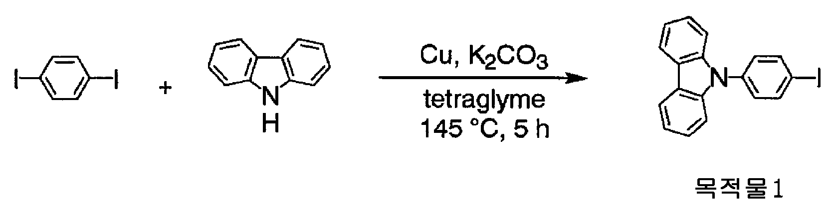
질소 기류 중, 카르바졸 (12.7g), p-디요오드벤젠 (25.0g), 구리 분말 (4.82g), 탄산 칼륨 (21.0g), 테트라글라임 (45㎖) 을, 145℃ 로 가열하, 5 시간 교반하고, 실온까지 방랭시켰다. 반응 혼합물에 클로로포름을 첨가하고, 불용물을 여과 분리하였다. 여과액에 함유되는 클로로포름을 감압 증류 제거하고, 실리카겔 칼럼 크로마토그래피 (n-헥산/톨루엔=4/1) 로 정제함으로써 목적물 1 (11.2g) 을 얻었다.Carbazole (25.7 g), p-diiodobenzene (25.0 g), copper powder (4.82 g), potassium carbonate (21.0 g) and tetraglyme (45 ml) The mixture was stirred for 5 hours and allowed to cool to room temperature. Chloroform was added to the reaction mixture, and the insoluble matter was separated by filtration. The chloroform contained in the filtrate was distilled off under reduced pressure, and the residue was purified by silica gel column chromatography (n-hexane / toluene = 4/1) to obtain target compound 1 (11.2 g).
[화학식 52](52)

질소 기류 중, 목적물 1 (8.01g), 2-히드록시벤즈이미다졸 (1.04g), 구리 분말 (1.38g), 탄산 칼륨 (6.44g), 테트라글라임 (20㎖) 을, 200℃ 에서 8 시간 교반한 후, 방랭시키고, 구리 분말 (1.39g) 을 첨가하고, 200℃ 에서 6 시간 교반하였다. 방랭 후, 반응 혼합물에 클로로포름, 활성 백토를 첨가하고, 교반하고, 불 용물을 여과 분리하고, 메탄올 (200㎖) 에 첨가하고, 교반한 후, 침전을 여과 채취하였다. 얻어진 고형분을 실리카겔 칼럼 크로마토그래피 (톨루엔) 로 정제하고, 아세트산 에틸 및 클로로포름/메탄올 혼합액으로 세정함으로써 목적물 2 (1.33g) 를 얻었다.(8.01 g), 2-hydroxybenzimidazole (1.04 g), copper powder (1.38 g), potassium carbonate (6.44 g) and tetraglyme (20 ml) After stirring for a time, the mixture was cooled, copper powder (1.39 g) was added, and the mixture was stirred at 200 占 폚 for 6 hours. After cooling, chloroform and active white clay were added to the reaction mixture, and the mixture was stirred. The insoluble matter was separated by filtration, added to methanol (200 ml), stirred, and the precipitate was collected by filtration. The resulting solid was purified by silica gel column chromatography (toluene), and washed with a mixture of ethyl acetate and chloroform / methanol to obtain the target compound 2 (1.33 g).
DEI-MS m/z=616(M+)DEI-MS m / z = 616 (M < + & gt ; ).
이것의 유리 전이 온도는 146℃, 융점은 355℃, 기화 온도는 507℃ 이었다.Its glass transition temperature was 146 占 폚, its melting point was 355 占 폚, and its vaporization temperature was 507 占 폚.
이것의 여기 삼중항 상태와 기저 상태의 에너지차는 3.04eV 이었다.The energy difference between the excited triplet state and the ground state of this was 3.04 eV.
[실시예 2 : 목적물 3, 4][Example 2:
[화학식 53](53)

질소 기류 중, 2-히드록시벤즈이미다졸 (5.41g), m-디브로모벤젠 (28.6g), 요오드화 구리 (Ⅰ) (15.3g), 탄산 칼륨 (22.3g), N,N-디메틸포름아미드 (130㎖) 를, 150℃ 로 가열하, 6.5 시간 교반하고, 실온까지 방랭시켰다. 반응 혼합물에 물을 첨가하고, 아세트산 에틸로 추출, 유기층을 황산 마그네슘으로 건조, 농축시켰다. 농축 잔류물에 톨루엔, 활성 백토를 첨가하고, 교반하고, 불용물을 여과 분리하였다. 여과액에 함유되는 클로로포름을 감압 증류 제거한 후, 메탄올을 첨가하고, 교반하고, 얻어진 석출물을 메탄올로 재결정함으로써 목적물 3 (4.36g) 을 얻었다.(5.41 g), m-dibromobenzene (28.6 g), copper iodide (15.3 g), potassium carbonate (22.3 g), N, N-dimethylform Amide (130 ml) was stirred for 6.5 hours under heating at 150 占 폚, and then cooled to room temperature. Water was added to the reaction mixture, extracted with ethyl acetate, and the organic layer was dried over magnesium sulfate and concentrated. Toluene and activated clay were added to the concentrated residue, stirred, and the insoluble matter was separated by filtration. After the chloroform contained in the filtrate was distilled off under reduced pressure, methanol was added and stirred, and the resulting precipitate was recrystallized from methanol to obtain the desired product 3 (4.36 g).
[화학식 54](54)

질소 기류 중, 목적물 3 (4.36g), 카르바졸 (5.76g), 구리 분말 (1.88g), 탄산 칼륨 (8.15g), 테트라글라임 (20㎖) 을, 210℃ 에서 7.5 시간 교반하였다. 방랭 후, 반응 혼합물에 클로로포름을 첨가하고, 교반하고, 불용물을 여과 분리하고, 메탄올 (200㎖) 에 첨가하고, 교반한 후, 침전을 여과 채취하였다. 얻어진 고형분을 실리카겔 칼럼 크로마토그래피 (톨루엔) 로 정제하고, 디클로로메탄/메탄올 혼합액으로 세정함으로써 목적물 4 (2.29g) 를 얻었다.(4.36 g), carbazole (5.76 g), copper powder (1.88 g), potassium carbonate (8.15 g) and tetraglyme (20 ml) were stirred at 210 ° C for 7.5 hours in a stream of nitrogen. After cooling, chloroform was added to the reaction mixture, and the mixture was stirred. Insoluble matter was separated by filtration, added to methanol (200 ml), stirred, and the precipitate was collected by filtration. The resulting solid was purified by silica gel column chromatography (toluene) and washed with a dichloromethane / methanol mixture to obtain the objective product 4 (2.29 g).
DEI-MS m/z=616(M+)DEI-MS m / z = 616 (M < + & gt ; ).
이것의 유리 전이 온도는 125℃, 융점은 227℃, 기화 온도는 489℃ 이었다.Its glass transition temperature was 125 占 폚, its melting point was 227 占 폚, and its vaporization temperature was 489 占 폚.
이것은 톨루엔에 대하여, 3 중량% 이상 용해되었다.This was dissolved in toluene in an amount of 3 wt% or more.
이것의 여기 삼중항 상태와 기저 상태의 에너지차는 2.99eV 이었다.Its energy difference between the excited triplet state and ground state was 2.99 eV.
[실시예 3 : 목적물 5][Example 3: Object 5]
[화학식 55](55)

질소 기류 중, 1,3-비스(4-브로모페닐)-1,3-디히드로벤즈이미다졸-2-온 (2.60g), N-(4-비페닐)아닐린 (4.31g), tert-부톡시나트륨 (2.25g), 및 톨루엔 (35㎖) 의 용액에, 트리스(디벤질리덴아세톤)디팔라듐 (0) 클로로포름 착물 (0.12g), 트리-tert-부틸포스핀 (0.209g), 및 톨루엔 (5㎖) 을 질소 분위기하, 60℃ 에서 5 분간 교반하여 조제한 용액을 첨가하고, 가열 환류하, 9.5 시간 교반하였다. 방랭 후, 활성 백토 및 클로로포름을 첨가하고, 교반하였다. 불용물을 여과 분리하고, 메탄올 (200㎖) 에 첨가하고, 교반한 후, 침전을 여과 채취하였다. 얻어진 고형분을 실리카겔 칼럼 크로마토그래피 (톨루엔) 로 정제하고, 디클로로메탄/메탄올 혼합액으로 세정함으로써 목적물 5 (2.55g) 를 얻었다.(2.60 g), N- (4-biphenyl) aniline (4.31 g) and tert-butyl (tert-butyldimethylsilyl) (Dibenzylideneacetone) dipalladium (0) chloroform complex (0.12 g), tri-tert-butylphosphine (0.209 g), and triethylamine were added to a solution of 2- And toluene (5 ml) in a nitrogen atmosphere at 60 占 폚 for 5 minutes, and the mixture was stirred under reflux for 9.5 hours. After cooling, the active clay and chloroform were added and stirred. The insoluble matter was separated by filtration, added to methanol (200 ml), stirred, and the precipitate was collected by filtration. The resulting solid was purified by silica gel column chromatography (toluene) and washed with a dichloromethane / methanol mixture to obtain the target compound 5 (2.55 g).
DEI-MS m/z=772(M+)DEI-MS m / z = 772 (M < + & gt ; ).
이것의 유리 전이 온도는 124℃, 융점은 관측되지 않고, 기화 온도는 527℃ 이었다. 이것은, 톨루엔에 대하여 5.0 중량% 이상 용해되었다.Its glass transition temperature was 124 占 폚, its melting point was not observed, and its vaporization temperature was 527 占 폚. This was dissolved in 5.0 wt% or more with respect to toluene.
[실시예 4 : 목적물 6][Example 4: Object 6]
[화학식 56](56)

질소 기류 중, 2-히드록시벤즈이미다졸 (1.03g), 3-브로모비페닐 (5.00g), 요오드화 구리 (Ⅰ) (2.92g), 탄산 칼륨 (4.23g), N,N-디메틸포름아미드 (10㎖) 를, 가열 환류하 8 시간 교반한 후, 방랭시켰다. 반응 혼합물에 클로로포름을 첨가하고, 교반하고, 불용물을 여과 분리하고, 여과액을 농축한 후, 실리카겔 칼럼 크로마토그래피로 정제하고, 메탄올로 현탁 세정함으로써 목적물 6 (2.68g) 을 얻었다.A mixture of 2-hydroxybenzimidazole (1.03 g), 3-bromobiphenyl (5.00 g), copper iodide (2.92 g), potassium carbonate (4.23 g) and N, N-dimethylformamide (10 ml) were stirred under reflux for 8 hours and then cooled. Chloroform was added to the reaction mixture and stirred. The insoluble material was separated by filtration, and the filtrate was concentrated. The residue was purified by silica gel column chromatography and washed with methanol to obtain the objective compound 6 (2.68 g).
EI-MS m/z=438(M+)EI-MS m / z = 438 (M < + & gt ; ).
이것의 유리 전이 온도는 56℃, 융점은 150℃, 기화 온도는 391℃ 이었다. 이것은 톨루엔에 대하여 5.0 중량% 이상 용해되었다.Its glass transition temperature was 56 占 폚, its melting point was 150 占 폚, and its vaporization temperature was 391 占 폚. This was dissolved in 5.0 wt% or more with respect to toluene.
[실시예 5 : 목적물 7∼9][Example 5:
[화학식 57](57)

질소 기류 중, 2-히드록시벤즈이미다졸 (6.53g), 요오드벤젠 (9.93g), 구리 분말 (3.11g), 탄산 칼륨 (13.5g), 및 테트라글라임 (15㎖) 을, 170℃ 에서 4 시간 교반한 후, 방랭시켰다. 반응 혼합물에 아세트산 에틸 및 물을 첨가하여 교반하고, 유기층을 황산 마그네슘으로 건조 후, 농축시키고, 실리카겔 칼럼 크로마토그래피 (n-헥산/아세트산 에틸 혼합액∼아세트산 에틸) 로 정제하고, n-헥산으로 현탁 세정함으로써 목적물 7 (3.87g) 을 얻었다.2-hydroxybenzimidazole (6.53 g), iodobenzene (9.93 g), copper powder (3.11 g), potassium carbonate (13.5 g) and tetraglyme (15 ml) After stirring for 4 hours, the mixture was cooled. Ethyl acetate and water were added to the reaction mixture, and the mixture was stirred. The organic layer was dried over magnesium sulfate, concentrated and purified by silica gel column chromatography (n-hexane / ethyl acetate mixture solution to ethyl acetate), washed with n-hexane To obtain objective compound 7 (3.87 g).
[화학식 58](58)

질소 기류 중, 2-히드록시벤즈이미다졸 (7.58g), p-디브로모벤젠 (40.0g), 구리 분말 (10.8g), 탄산 칼륨 (46.9g), 및 테트라글라임 (40㎖) 을, 200℃ 에서 12 시간 교반한 후, 방랭시켰다. 반응 혼합물에 아세트산 에틸을 첨가하고, 가열 환류하, 30 분 교반하고, 방랭 후, 불용물을 여과 분리하고, 여과액을 농축시키고, 석출물을 에탄올로 현탁 세정하고, 실리카겔 칼럼 크로마토그래피 (n-헥산/톨루엔 혼합액∼톨루엔) 로 정제하고, 메탄올로 현탁 세정함으로써 목적물 8 (3.87g) 을 얻었다.(7.58 g), p-dibromobenzene (40.0 g), copper powder (10.8 g), potassium carbonate (46.9 g) and tetraglyme (40 ml) , Stirred at 200 DEG C for 12 hours, and then cooled. Ethyl acetate was added to the reaction mixture and the mixture was stirred for 30 minutes while heating and refluxing. After cooling, the insoluble matter was separated by filtration, and the filtrate was concentrated. The precipitate was washed with ethanol and subjected to silica gel column chromatography (n-hexane / Toluene mixed solution to toluene), and the mixture was suspended in methanol to obtain objective product 8 (3.87 g).
[화학식 59][Chemical Formula 59]

질소 기류 중, 목적물 8 (0.860g), 목적물 7 (1.22g), 구리 분말 (0.492g), 탄산 칼륨 (2.14g), 및 테트라글라임 (6㎖) 을, 200℃ 에서 14 시간 교반한 후, 방랭시켰다. 반응 혼합물에 클로로포름을 첨가하고, 30 분 교반하고, 불용물을 여과 분리하고, 여과액을 농축시키고, 석출물을 에탄올로 현탁 세정하고, 실리카겔 칼럼 크로마토그래피 (n-헥산/아세트산 에틸 혼합액) 로 정제하고, 아세트산 에틸/에탄올 혼합액으로 현탁 세정함으로써 목적물 9 (0.465g) 를 얻었다.(0.860 g), target substance 7 (1.22 g), copper powder (0.492 g), potassium carbonate (2.14 g) and tetraglyme (6 ml) were stirred at 200 占 폚 for 14 hours , ≪ / RTI > Chloroform was added to the reaction mixture and stirred for 30 minutes. The insoluble material was separated by filtration, and the filtrate was concentrated. The precipitate was washed with ethanol and purified by silica gel column chromatography (n-hexane / ethyl acetate mixture) , And the mixture was suspended and washed with an ethyl acetate / ethanol mixed solution to obtain the objective product 9 (0.465 g).
DEI-MS m/z=702(M+)DEI-MS m / z = 702 (M < + & gt ; ).
이것의 유리 전이 온도는 150℃, 융점은 328℃, 기화 온도는 527℃ 이었다.Its glass transition temperature was 150 占 폚, its melting point was 328 占 폚, and its gasification temperature was 527 占 폚.
이것의 여기 삼중항 상태와 기저 상태의 에너지차는 3.2eV 이상이었다.Its energy difference between the excited triplet state and ground state was 3.2 eV or more.
[실시예 6 : 목적물 10, 11][Example 6:
[화학식 60](60)

질소 기류 중, 카르바졸 (18.8g), 2,6-디브로모피리딘 (80.0g), 구리 분말 (14.4g), 탄산 칼륨 (31.2g), 및 테트라글라임 (80㎖) 을, 170℃ 로 가열하, 7 시간 교반하고, 실온까지 방랭시켰다. 반응 혼합물에 클로로포름을 첨가하고, 불용물을 여과 분리하였다. 여과액에 함유되는 클로로포름을 감압 증류 제거하고, 에탄올/물 (40/1) 혼합액을 첨가하고, 석출물을 여과 분리하였다. 여과액에 물을 첨가하고, 석출물을 여과 채취하고, 에탄올로 세정 후, 실리카겔 칼럼 크로마토그래피 (n-헥산/염화 메틸렌 혼합액) 로 정제함으로써 목적물 10 (17.7g) 을 얻었다.(18.8 g), 2,6-dibromopyridine (80.0 g), copper powder (14.4 g), potassium carbonate (31.2 g) and tetraglyme (80 ml) , Stirred for 7 hours, and cooled to room temperature. Chloroform was added to the reaction mixture, and the insoluble matter was separated by filtration. The chloroform contained in the filtrate was distilled off under reduced pressure, and an ethanol / water (40/1) mixed solution was added, and the precipitate was separated by filtration. Water was added to the filtrate, and the precipitate was collected by filtration, washed with ethanol, and then purified by silica gel column chromatography (n-hexane / methylene chloride mixed solution) to obtain objective compound 10 (17.7 g).
[화학식 61](61)

질소 기류 중, 2-히드록시벤즈이미다졸 (0.724g), 목적물 10 (7.50g), 요오드화 구리 (Ⅰ) (2.06g), 탄산 칼륨 (2.99g), 및 N,N-디메틸포름아미드 (17㎖) 를, 가열 환류하, 10 시간 교반한 후, 방랭시켰다. 반응 혼합물에 염화 메틸렌, 활성 백토를 첨가하여 교반하고, 불용물을 여과 분리하고, 여과액을 농축한 후, 석출물을 메탄올로 현탁 세정하였다. 또한, 클로로포름/메탄올 혼합액 및 클로로포름으로 현탁 세정함으로써 목적물 11 (2.27g) 을 얻었다.A mixture of 2-hydroxybenzimidazole (0.724 g), target substance 10 (7.50 g), copper iodide (2.06 g), potassium carbonate (2.99 g) and N, N-dimethylformamide Ml) was stirred under reflux for 10 hours, and then cooled. Methylene chloride and active white clay were added to the reaction mixture and stirred. The insoluble matter was separated by filtration. The filtrate was concentrated, and the precipitate was washed with methanol. Further, the mixture was suspended and washed with a mixture of chloroform / methanol and chloroform to obtain the target compound 11 (2.27 g).
DEI-MS m/z=618(M+)DEI-MS m / z = 618 (M < + & gt ; ).
이것의 유리 전이 온도는 123℃, 융점은 317℃, 기화 온도는 500℃ 이었다.Its glass transition temperature was 123 占 폚, its melting point was 317 占 폚, and its vaporization temperature was 500 占 폚.
이것의 여기 삼중항 상태와 기저 상태의 에너지차는 3.00eV 이었다.Its energetic difference between the excited triplet state and the ground state was 3.00 eV.
[실시예 7 : 목적물 12][Example 7: Object 12]
[화학식 62](62)

질소 기류 중, 9H-피리도[3,4-b]인돌 (2.8g), 목적물 3 (2.47g), 구리 분말 (1.06g), 탄산 칼륨 (4.6g), 및 테트라글라임 (8㎖) 을 가열하, 180℃ 에서 8 시간 반응 교반하였다.(2.47 g), copper powder (1.06 g), potassium carbonate (4.6 g), and tetraglyme (8 ml) were added to a solution of 9H-pyrido [3,4- And the reaction was stirred at 180 ° C for 8 hours.
반응 종료 후, 반응 혼합물에 클로로포름을 첨가하고, 불용물을 여과 분리하였다. 여과액을 농축시킨 후, 석출물을 메탄올로 현탁 세정하고, 실리카겔 칼럼 크로마토그래피 (아세트산 에틸/염화 메틸렌 혼합액→에탄올/염화 메틸렌 혼합액) 로 정제함으로써 목적물 12 (1.27g) 를 얻었다.After completion of the reaction, chloroform was added to the reaction mixture, and the insoluble matter was separated by filtration. After the filtrate was concentrated, the precipitate was suspended in methanol, and the residue was purified by silica gel column chromatography (ethyl acetate / methylene chloride mixture → ethanol / methylene chloride mixture) to obtain the target product 12 (1.27 g).
DEI-MS m/z=617(M-H)+ DEI-MS m / z = 617 (MH) < + & gt ;
DCI-MS m/z=619(M+H)+ DCI-MS m / z = 619 (M + H) < + &
이것의 유리 전이 온도는 135℃, 융점은 221℃, 기화 온도는 499℃ 이었다.Its glass transition temperature was 135 占 폚, its melting point was 221 占 폚, and its vaporization temperature was 499 占 폚.
이것은 톨루엔에 대하여 3 중량% 이상 용해되었다.This was dissolved in toluene in an amount of 3 wt% or more.
이것의 여기 삼중항 상태와 기저 상태의 에너지차는 2.96eV 이었다.Its energy difference between the excited triplet state and the ground state was 2.96 eV.
[실시예 8 : 목적물 13, 14][Example 8: Object 13, 14]
[화학식 63](63)

대기 중, 4-아미노-3-니트로벤젠트리플루오라이드 (20.06g), 및 에탄올 (400㎖) 의 현탁 용액에, 농염산 수용액 (120㎖) 을 첨가하고, 교반하면서 80℃ 로 승온시켰다. 여기에 환원 철 (27.09g) 을 15 분에 걸쳐서 서서히 투입한 후, 가열 환류하, 1 시간 교반하였다. 빙랭 후, 얻어진 용액을 수산화 암모늄 수용액으로 중화하고 나서, 디클로로메탄으로 추출하였다. 추출액을 수세 후, 농축시키고, 이것을 실리카겔 칼럼 크로마토그래피로 정제하고, 3,4-디아미노벤젠트리플루오라이드 (12.495g) 를 얻었다.To a suspension of 4-amino-3-nitrobenzenetrifluoride (20.06 g) and ethanol (400 ml) in the air, concentrated aqueous hydrochloric acid (120 ml) was added and the temperature was raised to 80 ° C with stirring. Reduction iron (27.09 g) was slowly added thereto over 15 minutes, and the mixture was stirred under reflux for 1 hour. After ice-cooling, the resulting solution was neutralized with aqueous ammonium hydroxide solution and then extracted with dichloromethane. The extract was washed with water, concentrated, and purified by silica gel column chromatography to obtain 3,4-diaminobenzenetrifluoride (12.495 g).
질소 기류 중, 빙랭하, 3,4-디아미노벤젠트리플루오라이드 (3.0g) 와 탈수 테트라히드로푸란 (100㎖) 의 용액에, 1,1'-카르보닐디이미다졸 (3.314g) 을 첨가하고, 실온에서 10.7 시간 교반하였다. 얻어진 용액을 농축 후, 메탄올을 첨가하여 초음파를 조사하고 나서 농축시키고, 석출된 침전물을 여과 채취하였다. 이것을 에탄올/헥산 혼합 용매 중에서의 현탁 세정, 아세트산 에틸로부터의 재결정에 의해 정제하여 목적물 13 (1.203g) 을 얻었다.1,1'-carbonyldiimidazole (3.314 g) was added to a solution of 3,4-diaminobenzenetrifluoride (3.0 g) and dehydrated tetrahydrofuran (100 ml) in a nitrogen stream under ice- And the mixture was stirred at room temperature for 10.7 hours. After the obtained solution was concentrated, methanol was added thereto, and the mixture was irradiated with ultrasonic waves, followed by concentration, and the deposited precipitate was filtered. This was purified by suspension washing in an ethanol / hexane mixed solvent and recrystallization from ethyl acetate to obtain the target substance 13 (1.203 g).
DEI-MS m/z=202(M+)DEI-MS m / z = 202 (M < + & gt ; ).
[화학식 64]≪ EMI ID =

질소 기류 중, 목적물 13 (1.188g), 목적물 10 (5.125g), CuI (2.26g), 탄산 칼륨 (3.28g), 및 무수 N,N-디메틸포름아미드 (19㎖) 의 혼합 용액을, 가열 환류하, 6.2 시간 교반하였다. 이것에 추가로 목적물 10 (1.41g), CuI (1.15g), 및 탄산 칼륨 (1.8g) 을 추가 투입하고, 가열 환류하, 4.5 시간 교반하였다. 얻어진 용액에 메탄올 (30㎖) 과 물 (30㎖) 을 첨가한 후, 여과하고, 잔류물을 150㎖ 의 클로로포름에 투입하여 교반하였다. 이 용액에 활성 백토를 첨가하여 교반한 후, 여과하고, 여과액을 농축 후, 중성 구상 실리카겔의 칼럼 크로마토그래피 (전개 용매 : 헥산/염화 메틸렌) 로 정제하고, 그 후 메탄올 중에서의 현탁 세정, 아세트산 에틸과 에탄올의 혼합 용매 중에서의 열현세 (熱懸洗) 로 정제하여 목적물 14 (2.164g) 를 얻었다.A mixed solution of the objective product 13 (1.188 g), the target product 10 (5.125 g), CuI (2.26 g), potassium carbonate (3.28 g) and anhydrous N, N- dimethylformamide (19 ml) The mixture was stirred under reflux for 6.2 hours. Further, Objective 10 (1.41 g), CuI (1.15 g) and potassium carbonate (1.8 g) were further added thereto, and the mixture was stirred under reflux for 4.5 hours. Methanol (30 ml) and water (30 ml) were added to the resulting solution, followed by filtration, and the residue was added to 150 ml of chloroform and stirred. The active white clay was added to the solution and stirred, followed by filtration. The filtrate was concentrated, and then purified by column chromatography (developing solvent: hexane / methylene chloride) of neutral spherical silica gel, and then washed in methanol, The residue was purified by a heat mobile washing in a mixed solvent of ethyl and ethanol to obtain objective compound 14 (2.164 g).
DEI-MS m/z=686(M+)DEI-MS m / z = 686 (M < + & gt ; ).
이것의 유리 전이 온도는 126℃, 융점은 282℃, 기화 온도는 399℃ 이었다.Its glass transition temperature was 126 占 폚, its melting point was 282 占 폚, and its vaporization temperature was 399 占 폚.
이것의 여기 삼중항 상태와 기저 상태의 에너지차는 2.97eV 이었다.Its energy difference between the excited triplet state and the ground state was 2.97 eV.
[실시예 9 : 목적물 15, 16][Example 9: Objectives 15, 16]
[화학식 65](65)

질소 기류 중, 빙랭하, 2,3-디아미노피리딘 (8.7g) 과 탈수 테트라히드로푸란 (500㎖) 의 용액에, 1,1'-카르보닐디이미다졸 (15.5g) 을 첨가하고, 실온에서 14 시간 교반하였다. 얻어진 용액을 농축 후, 메탄올을 첨가하여 가열 현세 (懸洗) 처리를 실시하고, 석출된 침전물을 여과 채취한 결과, 목적물 15 (4.9g) 를 얻었다.1,1'-carbonyldiimidazole (15.5 g) was added to a solution of 2,3-diaminopyridine (8.7 g) and dehydrated tetrahydrofuran (500 ml) in a nitrogen stream under ice-cooling, Lt; / RTI > for 14 hours. The resulting solution was concentrated, and then methanol was added thereto to carry out heating suspension treatment. The deposited precipitate was collected by filtration to obtain the objective product 15 (4.9 g).
DEI-MS m/z=135(M+)DEI-MS m / z = 135 (M < + & gt ; ).
[화학식 66](66)

질소 기류 중, 목적물 15 (1.0g), N-(3-브로모페닐)카르바졸 (6.8g), CuI (2.8g), 탄산 칼륨 (4.2g), 및 무수 N,N-디메틸포름아미드 (10㎖) 의 혼합 용액을, 가열 환류하, 6.2 시간 교반하였다. 이것에 추가로 목적물 10 (1.4g), CuI (1.15g), 및 탄산 칼륨 (1.8g) 을 추가 투입하고, 가열 환류하, 15 시간 교반하였다. 반응액을 디클로로메탄으로 희석 후 여과하고, 브라인, 1N 의 염산으로 세 정하여 황산 나트륨으로 건조시켰다. 감압 농축에 의해 갈색 오일상이 된 것을, 실리카겔의 칼럼 크로마토그래피 (전개 용매 : 톨루엔) 로 정제하고, 그 후 메탄올 중에서의 현탁 세정으로 정제하여 목적물 16 (1.1g) 을 얻었다.(1.0 g), N- (3-bromophenyl) carbazole (6.8 g), CuI (2.8 g), potassium carbonate (4.2 g) and anhydrous N, N-
DEI-MS m/z=617(M+)DEI-MS m / z = 617 (M < + & gt ; ).
이것의 유리 전이 온도는 125℃, 융점은 226℃, 기화 온도는 490℃ 이었다. 이것은 톨루엔에 대하여 3 중량% 이상 용해되었다.Its glass transition temperature was 125 占 폚, its melting point was 226 占 폚, and its vaporization temperature was 490 占 폚. This was dissolved in toluene in an amount of 3 wt% or more.
이것의 여기 삼중항 상태와 기저 상태의 에너지차는 2.99eV 이었다.Its energy difference between the excited triplet state and ground state was 2.99 eV.
[실시예 10 : 목적물 17][Example 10: Target 17]
[화학식 67](67)

질소 기류 중, 목적물 7 (1.6g), 6,6''-디브로모-2,2':6',2''-터피리딘 (1.0g), 구리 분말 (0.35g), 탄산 칼륨 (1.4g), 및 테트라글라임 (5㎖) 을 100mL 4 구 플라스크에 첨가하고, 170℃ 의 오일배스에 담궈 13 시간 가열 교반하였다. 디클로로메탄으로 희석하여 여과 후, 감압 증류 제거하여 얻어진 황백색 고체를 테트라히드로푸란으로 가열 현세함으로써, 백색 분말상의 목적물 17 (0.9g) 을 얻었다.(1.6 g), 6,6 "-dibromo-2,2 ': 6', 2" -terpyridine (1.0 g), copper powder (0.35 g) and potassium carbonate 1.4 g) and tetraglyme (5 ml) were added to a 100 ml four-necked flask, and the mixture was immersed in an oil bath at 170 캜 and heated and stirred for 13 hours. The mixture was diluted with dichloromethane, filtered, and then distilled off under reduced pressure. The resulting yellowish white solid was heated in tetrahydrofuran to obtain the objective product 17 (0.9 g) in the form of a white powder.
DEI-MS m/z=649(M+)DEI-MS m / z = 649 (M < + & gt ; ).
이것의 유리 전이 온도는 118℃, 융점은 276℃, 기화 온도는 451℃ 이었다.Its glass transition temperature was 118 占 폚, its melting point was 276 占 폚, and its vaporization temperature was 451 占 폚.
이것의 여기 삼중항 상태와 기저 상태의 에너지차는 2.98eV 이었다.The energy difference between the excited triplet state and the ground state of this was 2.98 eV.
[본 발명의 유기 전계 발광 소자의 제조예][Production Example of Organic Electroluminescent Device of the Present Invention]
이하에 본 발명의 유기 전계 발광 소자를 제조하는 실시예를 나타낸다.Hereinafter, embodiments of producing the organic electroluminescent device of the present invention will be described.
[실시예 11][Example 11]
도 7 에 나타내는 구조를 갖는 유기 전계 발광 소자를 이하의 방법으로 제조하였다.An organic electroluminescent device having the structure shown in Fig. 7 was manufactured by the following method.
유리 기판 (1) 상에 인듐·주석 산화물 (ITO) 투명 도전막 (2) 을 150㎚ 퇴적한 것 (스퍼터 막 형성품 ; 시트 저항 15Ω) 을 통상의 포토리소그래피 기술과 염산 에칭을 사용하여 2㎜ 폭의 스트라이프로 패터닝하여 양극 (2) 을 형성하였다. 패턴 형성한 ITO 기판을, 아세톤에 의한 초음파 세정, 순수에 의한 수세, 이소프로필알코올에 의한 초음파 세정의 순서로 세정 후, 질소 블로우로 건조시키고, 마지막에 자외선 오존 세정을 실시하였다.(Sputter film formation: sheet resistance: 15 OMEGA) deposited with a thickness of 150 nm of indium tin oxide (ITO) transparent
정공 주입층 (3) 의 재료로서, 하기에 나타내는 구조식의 방향족 아미노기를 갖는 비공액계 고분자 화합물 (PB-2) 를 하기에 나타내는 구조식의 전자 수용성 화합물 (A-2) 와 함께 이하의 조건에서 스핀코트하였다.A non-conjugated polymer compound (PB-2) having an aromatic amino group represented by the following structural formula was used as a material for the
[화학식 68](68)

스핀코트 조건Spin coat condition
용매 아니솔Solvent anisole
PB-2 의 농도 2[wt%]Concentration of PB-2 2 [wt%]
PB-2 : A-2 10:2(중량비)PB-2: A-2 10: 2 (weight ratio)
스피너 회전수 2000[rpm]Spinner speed 2000 [rpm]
스피너 회전 시간 30[초]Spinner Rotation Time 30 [sec]
건조 조건 230[℃] 15[분]Drying conditions 230 [占 폚] 15 [min]
상기 스핀코트에 의해 막두께 30㎚ 의 균일한 박막이 형성되었다.A uniform thin film having a film thickness of 30 nm was formed by the spin-coating.
다음으로 정공 주입층 (3) 을 막 형성한 기판을 진공 증착 장치 내에 설치하 였다. 상기 장치의 조 (粗) 배기를 오일 회전 펌프에 의해 실시한 후, 장치 내의 진공도가 9.8×10⁻⁵Pa (약 7.5×10⁻⁷Torr) 이하가 될 때까지 크라이오 펌프를 사용하여 배기하였다. 상기 장치 내에 배치된 세라믹 도가니에 넣은, 하기에 나타내는 구조식의 아릴아민 화합물 (H-1) 을 도가니 주위의 탄탈선 히터로 가열하여 증착을 실시하였다. 이 때의 도가니의 온도는, 300∼314℃ 의 범위에서 제어하였다. 증착시의 진공도 9.0×10⁻⁵Pa (약 6.9×10⁻⁷Torr), 증착 속도는 0.1㎚/초로 막두께 40㎚ 의 정공 수송층 (10) 을 형성하였다.Next, a substrate having a
[화학식 69](69)

이어서, 발광층 (4) 의 주성분 (호스트 재료) 으로서 실시예 2 에서 합성한 목적물 4 : 본 발명의 유기 화합물 (EM-1) 을, 부성분 (도펀트) 으로서 하기에 나타내는 구조식의 유기 이리듐 착물 (D-1) 을 별개의 세라믹 도가니에 설치하고, 2 원 동시 증착법에 의해 막 형성하였다.Subsequently, the organic compound (EM-1) of the present invention synthesized in Example 2 as the main component (host material) of the light-emitting
[화학식 70](70)

본 발명의 유기 화합물 (EM-1) 의 도가니 온도는 270∼284℃, 증착 속도는 0.1㎚/초로, 유기 이리듐 착물 (D-1) 의 도가니 온도는 230∼237℃ 로 각각 제어하고, 막두께 30㎚ 로 유기 이리듐 착물 (D-1) 이 약 12.5 중량% 함유된 발광층 (4) 을 정공 수송층 (10) 상에 적층하였다. 증착시의 진공도는 7.4×10⁻⁵Pa (약 5.7×10⁻⁷Torr) 이었다.The crucible temperature of the organic compound (EM-1) of the present invention is controlled to 270 to 284 占 폚, the deposition rate to 0.1 nm / second and the crucible temperature of the organic iridium complex (D-1) to 230 to 237 占 폚, Emitting
또한, 정공 저지층 (8) 으로서, 하기에 나타내는 구조식의 트리아릴벤젠 유도체 (HB-2) 를 도가니 온도를 343∼350℃ 로 하여, 증착 속도 0.09㎚/초로 10㎚ 의 막두께로 적층하였다. 증착시의 진공도는 7.1×10⁻⁵Pa (약 5.5×10⁻⁷Torr) 이었다.As the
[화학식 71](71)

이어서, 정공 저지층 (8) 상에, 전자 수송층 (7) 으로서, 하기에 나타내는 구조식의 바소큐프로인 (ET-2) 를 동일하게 하여 증착하였다. 이 때의 바소큐프로인 (ET-2) 의 도가니 온도는 160∼172℃ 의 범위에서 제어하고, 증착시의 진공도는 6.6×10⁻⁵Pa (약 5.1×10⁻⁷Torr), 증착 속도는 0.1㎚/초이고 막두께는 30㎚ 로 하였다.Subsequently, on the
[화학식 72](72)

상기 정공 수송층 (10), 발광층 (4), 정공 저지층 (8) 및 전자 수송층 (7) 을 진공 증착할 때의 기판 온도는 실온으로 유지하였다.The substrate temperature at the time of vacuum deposition of the
여기에서, 전자 수송층 (7) 까지의 증착을 실시한 소자를 1 번 상기 진공 증착 장치 내로부터 대기 중으로 꺼내고, 음극 증착용 마스크로서 2㎜ 폭의 스트라이프상 섀도우마스크를, 양극 (2) 의 ITO 스트라이프와는 직교하도록 소자에 밀착시 키고, 별도의 진공 증착 장치 내에 설치하여 유기층과 동일하게 하여 장치 내의 진공도가 2.8×10⁻⁶Torr (약 3.6×10⁻⁴Pa) 이하가 될 때까지 배기하였다. 음극 (6) 으로서, 먼저, 불화 리튬 (LiF) 을 몰리브덴 보트를 사용하여, 증착 속도 0.03㎚/초, 진공도 2.8×10⁻⁶Torr (약 3.7×10⁻⁴Pa) 로, 0.5㎚ 의 막두께로 전자 수송층 (7) 상에 막 형성하였다. 다음으로, 알루미늄을 동일하게 몰리브덴 보트에 의해 가열하고, 증착 속도 0.2㎚/초, 진공도 9.8×10⁻⁶Torr (약 1.3×10⁻³Pa) 로 막두께 80㎚ 의 알루미늄층을 형성하여 음극 (6) 을 완성시켰다. 이상의 2 층형 음극 (6) 의 증착시의 기판 온도는 실온으로 유지하였다.Here, the device subjected to vapor deposition up to the
이상과 같이 하여, 2㎜×2㎜ 사이즈의 발광 면적 부분을 갖는 유기 전계 발광 소자가 얻어졌다. 이 소자의 발광 특성을 표 1, 2 에 나타낸다.Thus, an organic electroluminescent device having a light emitting area portion of 2 mm x 2 mm size was obtained. The luminescent characteristics of this device are shown in Tables 1 and 2.
이 소자의 전계 발광은, 극대 파장 473㎚, 반치폭 (full width at half maximum(FWHM)) 은 67㎚ 의 청녹색 발광이고, 유기 이리듐 착물 (D-1) 로부터의 것과 동정되었다. 색도는 CIE(x,y)=(0.18, 0.38) 이었다.The electroluminescence of this device was a blue-green light emission having a maximum wavelength of 473 nm and a full width at half maximum (FWHM) of 67 nm and was identified from the organic iridium complex (D-1). The chromaticity was CIE (x, y) = (0.18, 0.38).

[실시예 12][Example 12]
발광층 (4) 을 이하에 기재하는 방법으로 막 형성한 것 이외에는 실시예 11 에 나타내는 방법과 동일하게 하여, 도 7 에 나타내는 구조를 갖는 유기 전계 발광 소자를 이하의 방법으로 제조하였다.An organic electroluminescent device having the structure shown in Fig. 7 was produced by the following method in the same manner as in Example 11, except that the
발광층 (4) 의 주성분 (호스트 재료) 으로서 실시예 9 에서 합성한 목적물 16 : 본 발명의 유기 화합물 (EM-3) 을, 부성분 (도펀트) 으로서 실시예 11 에서 사용한 유기 이리듐 착물 (D-1) 을 별개의 세라믹 도가니에 설치하고, 2 원 동시 증착법에 의해 막 형성하였다.The organic compound (EM-3) of the present invention synthesized in Example 9 and the organic iridium complex (D-1) used in Example 11 as the subcomponent (dopant) were used as the main component (host material) Were provided in separate ceramic crucibles, and a film was formed by a two-source co-deposition method.
[화학식 73](73)

본 발명의 유기 화합물 (EM-3) 의 도가니 온도는 400∼407℃, 증착 속도는 0.1㎚/초로, 유기 이리듐 착물 (D-1) 의 도가니 온도는 201∼207℃ 로 각각 제어하고, 막두께 30㎚ 로 유기 이리듐 착물 (D-1) 이 약 10.4 중량% 함유된 발광층 (4) 을 정공 수송층 (10) 상에 적층하였다. 증착시의 진공도는 4.6×10⁻⁵Pa (약 3.5×10⁻⁷Torr) 이었다.The crucible temperature of the organic compound (EM-3) of the present invention is controlled to be 400 to 407 캜, the deposition rate to 0.1 nm / second and the crucible temperature of the organic iridium complex (D-1) to 201 to 207 캜, Emitting
이 소자의 발광 특성을 표 2 에 나타낸다.Table 2 shows the luminescence characteristics of this device.
이 소자의 전계 발광은, 극대 파장 471㎚, 반치폭은 53㎚ 의 청녹색 발광이고, 유기 이리듐 착물 (D-1) 로부터의 것과 동정되었다. 색도는 CIE(x,y)=(0.14, 0.31) 이었다.The electroluminescence of this device was blue-green light emission having a maximum wavelength of 471 nm and a full width at half maximum of 53 nm and was identified from the organic iridium complex (D-1). The chromaticity was CIE (x, y) = (0.14, 0.31).
[실시예 13][Example 13]
발광층 (4) 을 이하에 기재하는 방법으로 막 형성한 것 이외에는 실시예 11 에 나타내는 방법과 동일하게 하여, 도 7 에 나타내는 구조를 갖는 유기 전계 발광 소자를 이하의 방법으로 제조하였다.An organic electroluminescent device having the structure shown in Fig. 7 was produced by the following method in the same manner as in Example 11, except that the
발광층 (4) 의 주성분 (호스트 재료) 으로서 실시예 7 에서 합성한 목적물 12 : 본 발명의 유기 화합물 (EM-4) 를, 부성분 (도펀트) 으로서 실시예 11 에서 사용한 유기 이리듐 착물 (D-1) 을 별개의 세라믹 도가니에 설치하고, 2 원 동시 증착법에 의해 막 형성하였다.The organic compound (D-1) used in Example 11 was used as the main component (host material) of the light-emitting
[화학식 74]≪ EMI ID =

본 발명의 유기 화합물 (EM-4) 의 도가니 온도는 217∼242℃, 증착 속도는 0.09㎚/초로, 유기 이리듐 착물 (D-1) 의 도가니 온도는 213∼216℃ 로 각각 제어하고, 막두께 30㎚ 로 유기 이리듐 착물 (D-1) 이 약 13.1 중량% 함유된 발광층 (4) 을 정공 수송층 (10) 상에 적층하였다. 증착시의 진공도는 5.0×10⁻⁵Pa (약 4.0×10⁻⁷Torr) 이었다.The crucible temperature of the organic compound (EM-4) of the present invention is controlled to 217 to 242 占 폚, the deposition rate to 0.09 nm / second and the crucible temperature of the organic iridium complex (D-1) to 213 to 216 占 폚, Emitting
이 소자의 발광 특성을 표 2 에 나타낸다.Table 2 shows the luminescence characteristics of this device.
이 소자의 전계 발광은, 극대 파장 472㎚, 반치폭은 53㎚ 의 청녹색 발광이고, 유기 이리듐 착물 (D-1) 로부터의 것과 동정되었다. 색도는 CIE(x,y)=(0.15, 0.32) 이었다.The electroluminescence of this device was blue-green light emission having a maximum wavelength of 472 nm and a full width at half maximum of 53 nm, and was identified from the organic iridium complex (D-1). The chromaticity was CIE (x, y) = (0.15, 0.32).
[비교예 1][Comparative Example 1]
발광층 (4) 을 이하에 기재하는 방법으로 막 형성한 것 이외에는 실시예 11 에 나타내는 방법과 동일하게 하여, 도 7 에 나타내는 구조를 갖는 유기 전계 발광 소자를 이하의 방법으로 제조하였다.An organic electroluminescent device having the structure shown in Fig. 7 was produced by the following method in the same manner as in Example 11, except that the
발광층 (4) 의 주성분 (호스트 재료) 으로서 하기 구조식에 나타내는 카르바졸 유도체 (CBP) 를, 부성분 (도펀트) 으로서 실시예 11 에서 사용한 유기 이리듐 착물 (D-1) 을 별개의 세라믹 도가니에 설치하고, 2 원 동시 증착법에 의해 막 형성하였다.A carbazole derivative (CBP) shown in the following structural formula was used as a main component (host material) of the
[화학식 75](75)

카르바졸 유도체 (CBP) 의 도가니 온도는 406∼411℃, 증착 속도는 0.08㎚/초로, 유기 이리듐 착물 (D-1) 의 도가니 온도는 204∼209℃ 로 각각 제어하고, 막두께 30㎚ 로 유기 이리듐 착물 (D-1) 이 약 13.1 중량% 함유된 발광층 (4) 을 정공 수송층 (10) 상에 적층하였다. 증착시의 진공도는 3.8×10⁻⁵Pa (약 2.9×10⁻⁷Torr) 이었다.The crucible temperature of the carbazole derivative (CBP) was controlled at 406 to 411 占 폚, the deposition rate was 0.08 nm / second, the crucible temperature of the organic iridium complex (D-1) was controlled at 204 to 209 占 폚, The
이 소자의 발광 특성을 표 1 과 표 2 에 나타낸다.The luminescent characteristics of this device are shown in Tables 1 and 2.
이 소자의 전계 발광은, 극대 파장 490㎚, 반치폭은 59㎚ 의 청녹색 발광이고, 유기 이리듐 착물 (D-1) 로부터의 발광 이외에, 다른 재료 유래의 발광도 관측되었다. 색도는 CIE(x,y)=(0.19, 0.54) 이었다.The electroluminescence of this device was a blue-green light emission having a maximum wavelength of 490 nm and a half-width of 59 nm, and light emission from other materials was observed in addition to light emission from the organic iridium complex (D-1). The chromaticity was CIE (x, y) = (0.19, 0.54).

[실시예 14][Example 14]
도 7 에 나타내는 구조를 갖는 유기 전계 발광 소자를 이하의 방법으로 제조하였다.An organic electroluminescent device having the structure shown in Fig. 7 was manufactured by the following method.
유리 기판 (1) 상에 인듐·주석 산화물 (ITO) 투명 도전막 (2) 을 150㎚ 퇴적한 것 (스퍼터 막 형성품 ; 시트 저항 15Ω) 을 통상의 포토리소그래피 기술과 염산 에칭을 사용하여 2㎜ 폭의 스트라이프로 패터닝하여 양극 (2) 을 형성하였다. 패턴 형성한 ITO 기판을, 아세톤에 의한 초음파 세정, 순수에 의한 수세, 이소프로필알코올에 의한 초음파 세정의 순서로 세정 후, 질소 블로우로 건조시키고, 마지막에 자외선 오존 세정을 실시하였다.(Sputter film formation: sheet resistance: 15 OMEGA) deposited with a thickness of 150 nm of indium tin oxide (ITO) transparent
정공 주입층 (3) 의 재료로서, 하기에 나타내는 구조식의 방향족 아미노기를 갖는 비공액계 고분자 화합물 (PB-1) (중량 평균 분자량 : 29400, 수평균 분자량 : 12600) 을 실시예 11 에서 사용한 전자 수용성 화합물 (A-2) 와 함께 이하의 조건에서 스핀코트하였다.(PB-1) (weight average molecular weight: 29400, number average molecular weight: 12600) having an aromatic amino group of the following structural formula was used as the material of the
[화학식 76][Formula 76]

스핀코트 조건Spin coat condition
용매 벤조산 에틸Solvent ethyl benzoate
PB-1 의 농도 2[wt%]Concentration of PB-1 2 [wt%]
PB-1 : A-2 10:2(중량비)PB-1: A-2 10: 2 (weight ratio)
스피너 회전수 1500[rpm]Spinner speed 1500 [rpm]
스피너 회전 시간 30[초]Spinner Rotation Time 30 [sec]
건조 조건 230[℃] 15[분]Drying conditions 230 [占 폚] 15 [min]
상기 스핀코트에 의해 막두께 30㎚ 의 균일한 박막이 형성되었다.A uniform thin film having a film thickness of 30 nm was formed by the spin-coating.
다음으로 정공 주입층 (3) 을 막 형성한 기판을 진공 증착 장치 내에 설치하였다. 상기 장치의 조 (粗) 배기를 오일 회전 펌프에 의해 실시한 후, 장치 내의 진공도가 9.0×10⁻⁵Pa (약 6.8×10⁻⁷Torr) 이하가 될 때까지 크라이오 펌프를 사용하여 배기하였다. 상기 장치 내에 배치된 세라믹 도가니에 넣은, 실시예 11 에서 사용한 아릴아민 화합물 (H-1) 을 도가니 주위의 탄탈선 히터로 가열하여 증착을 실시하였다. 이 때의 도가니의 온도는, 300∼314℃ 의 범위에서 제어하였다. 증착시의 진공도 9.3×10⁻⁵Pa (약 7.0×10⁻⁷Torr), 증착 속도는 0.1㎚/초로 막두께 40㎚ 의 정공 수송층 (10) 을 형성하였다.Next, a substrate having a
이어서, 발광층 (4) 의 주성분 (호스트 재료) 으로서 실시예 2 에서 합성한 목적물 4 : 본 발명의 유기 화합물 (EM-1) 을, 부성분 (도펀트) 으로서 하기에 나타내는 구조식의 유기 이리듐 착물 (D-2) 를 별개의 세라믹 도가니에 설치하고, 2 원 동시 증착법에 의해 막 형성하였다.Subsequently, the organic compound (EM-1) of the present invention synthesized in Example 2 as the main component (host material) of the light-emitting
[화학식 77][Formula 77]

본 발명의 유기 화합물 (EM-1) 의 도가니 온도는 270∼284℃, 증착 속도는 0.1㎚/초로, 유기 이리듐 착물 (D-2) 의 도가니 온도는 245∼246℃ 로 각각 제어하고, 막두께 30㎚ 로 유기 이리듐 착물 (D-2) 가 약 5.9 중량% 함유된 발광층 (4) 을 정공 수송층 (10) 상에 적층하였다. 증착시의 진공도는 7.8×10⁻⁵Pa (약 5.9×10⁻⁷Torr) 이었다.The crucible temperature of the organic compound (EM-1) of the present invention was controlled at 270 to 284 占 폚, the deposition rate was 0.1 nm / second and the crucible temperature of the organic iridium complex (D-2) was controlled at 245 to 246 占 폚, Emitting
또한, 정공 저지층 (8) 으로서, 하기에 나타내는 구조식의 페닐피리딘 유도체 (HB-1) 을 도가니 온도를 343∼350℃ 로 하여, 증착 속도 0.09㎚/초로 10㎚ 의 막두께로 적층하였다. 증착시의 진공도는 7.1×10⁻⁵Pa (약 5.5×10⁻⁷Torr) 이었다.As the
[화학식 78](78)

이어서, 정공 저지층 (8) 상에, 전자 수송층 (7) 으로서, 하기에 나타내는 구조식의 트리스(8-히드록시퀴놀리나토)알루미늄 (Alq3) 을 동일하게 하여 증착하였다. 이 때의 트리스(8-히드록시퀴놀리나토)알루미늄 (Alq3) 의 도가니 온도는 296∼300℃ 의 범위에서 제어하고, 증착시의 진공도는 6.6×10⁻⁵Pa (약 5.1×10⁻⁷Torr), 증착 속도는 0.15㎚/초이고 막두께는 30㎚ 로 하였다.Subsequently, tris (8-hydroxyquinolinato) aluminum (Alq3) having the following structural formula was vapor-deposited as the
[화학식 79](79)

상기 정공 수송층 (10), 발광층 (4), 정공 저지층 (8) 및 전자 수송층 (7) 을 진공 증착할 때의 기판 온도는 실온으로 유지하였다.The substrate temperature at the time of vacuum deposition of the
그 후, 실시예 11 과 동일하게 하여 2 층형 음극 (6) 을 증착하였다.Thereafter, the two-layer type
이 소자의 발광 특성을 표 3 에 나타낸다.Table 3 shows the luminescence characteristics of this device.
이 소자의 전계 발광은, 극대 파장 514㎚, 반치폭은 70㎚ 의 녹색 발광이고, 유기 이리듐 착물 (D-2) 로부터의 것과 동정되었다. 색도는 CIE(x,y)=(0.31,0.62) 이었다.The electroluminescence of this device was a green light emission having a maximum wavelength of 514 nm and a half width of 70 nm, and was identified from the organic iridium complex (D-2). The chromaticity was CIE (x, y) = (0.31, 0.62).
[실시예 15][Example 15]
발광층 (4) 을 이하에 기재하는 방법으로 막 형성한 것 이외에는 실시예 14 에 나타내는 방법과 동일하게 하여, 도 7 에 나타내는 구조를 갖는 유기 전계 발광 소자를 이하의 방법으로 제조하였다.An organic electroluminescent device having the structure shown in Fig. 7 was produced in the following manner, in the same manner as in Example 14, except that the
발광층 (4) 의 주성분 (호스트 재료) 으로서 실시예 6 에서 합성한 목적물 11 : 본 발명의 유기 화합물 (EM-5) 를, 부성분 (도펀트) 으로서 실시예 14 에서 사용한 유기 이리듐 착물 (D-2) 를 별개의 세라믹 도가니에 설치하고, 2 원 동시 증착법에 의해 막 형성하였다.The organic compound (EM-5) of the present invention synthesized in Example 6 and the organic iridium complex (D-2) used in Example 14 were used as the main component (host material) Were provided in separate ceramic crucibles, and a film was formed by a two-source co-deposition method.
[화학식 80](80)
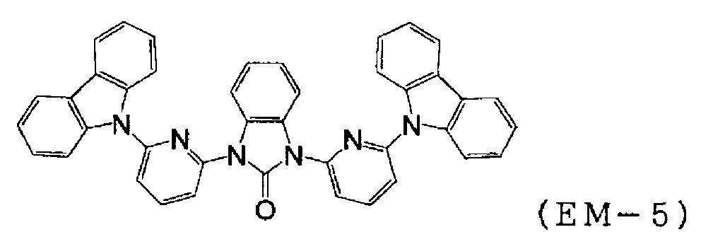
본 발명의 유기 화합물 (EM-5) 의 증착 속도는 0.1㎚/초로, 유기 이리듐 착물 (D-2) 의 도가니 온도는 255∼257℃ 로 각각 제어하고, 막두께 32㎚ 로 유기 이리듐 착물 (D-2) 가 약 6.2 중량% 함유된 발광층 (4) 을 정공 수송층 (10) 상에 적층하였다. 증착시의 진공도는 1.5×10⁻⁴Pa 이었다.The deposition rate of the organic compound (EM-5) of the present invention was controlled to 0.1 nm / sec and the crucible temperature of the organic iridium complex (D-2) was controlled to 255 to 257 ° C. -2) in an amount of about 6.2% by weight was laminated on the
이 소자의 발광 특성을 표 3 에 나타낸다.Table 3 shows the luminescence characteristics of this device.
이 소자의 전계 발광은, 극대 파장 513㎚, 반치폭은 68㎚ 의 녹색 발광이고, 유기 이리듐 착물 (D-2) 로부터의 것과 동정되었다. 색도는 CIE(x,y)=(0.30, 0.62) 이었다.The electroluminescence of this device was a green light emission having a maximum wavelength of 513 nm and a half width of 68 nm, and was identified from the organic iridium complex (D-2). The chromaticity was CIE (x, y) = (0.30, 0.62).
[실시예 16][Example 16]
정공 수송층 (10) 및 발광층 (4) 을 이하에 기재하는 방법으로 막 형성한 것 이외에는 실시예 14 에 나타내는 방법과 동일하게 하여, 도 7 에 나타내는 구조를 갖는 유기 전계 발광 소자를 이하의 방법으로 제조하였다.An organic electroluminescent device having the structure shown in FIG. 7 was manufactured in the following manner in the same manner as in Example 14 except that the
정공 주입층 (3) 을 막 형성한 기판을 진공 증착 장치 내에 설치하였다. 상기 장치의 조 (粗) 배기를 오일 회전 펌프에 의해 실시한 후, 장치 내의 진공도가 5.3×10⁻⁵Pa (약 4.0×10⁻⁷Torr) 이하가 될 때까지 크라이오 펌프를 사용하여 배기하였다. 상기 장치 내에 배치된 세라믹 도가니에 넣은, 하기에 나타내는 구조식의 아릴아민 화합물 (PPD) 을 도가니 주위의 탄탈선 히터로 가열하여 증착하였다. 이 때의 도가니의 온도는 260∼272℃ 의 범위에서 제어하였다. 증착시의 진공도 6.0×10⁻⁵Pa (약 4.9×10⁻⁷Torr), 증착 속도는 0.1㎚/초로 막두께 40㎚ 의 정공 수송층 (10) 을 형성하였다.A substrate on which the
[화학식 81][Formula 81]

이어서, 발광층 (4) 의 주성분 (호스트 재료) 으로서 실시예 1 에서 합성한 목적물 2 : 본 발명의 유기 화합물 (EM-6) 을, 부성분 (도펀트) 으로서 실시예 14 에서 사용한 유기 이리듐 착물 (D-2) 를 별개의 세라믹 도가니에 설치하고, 2 원 동시 증착법에 의해 막 형성하였다.Subsequently, the organic compound (EM-6) of the present invention synthesized in Example 1 and the organic iridium complex (D-2) used in Example 14 were used as the main component (host material) 2) were provided in separate ceramic crucibles and formed by a two-source co-evaporation method.
[화학식 82](82)

본 발명의 유기 화합물 (EM-6) 의 증착 속도는 0.1㎚/초로, 유기 이리듐 착물 (D-2) 의 도가니 온도는 268∼270℃ 로 각각 제어하고, 막두께 30㎚ 로 유기 이리듐 착물 (D-2) 가 약 6.1 중량% 함유된 발광층 (4) 을 정공 수송층 (10) 상에 적층하였다. 증착시의 진공도는 6.3×10⁻⁵Pa (약 4.7×10⁻⁷Torr) 이었다.The deposition rate of the organic compound (EM-6) of the present invention was controlled to 0.1 nm / sec and the crucible temperature of the organic iridium complex (D-2) was controlled to 268 to 270 캜, -2) in an amount of about 6.1% by weight was laminated on the
이 소자의 발광 특성을 표 3 에 나타낸다.Table 3 shows the luminescence characteristics of this device.
이 소자의 전계 발광은, 극대 파장 513㎚, 반치폭은 69㎚ 의 녹색 발광이고, 유기 이리듐 착물 (D-2) 로부터의 것과 동정되었다. 색도는 CIE(x,y)=(0.30, 0.58) 이었다.The electroluminescence of this device was a green light emission having a maximum wavelength of 513 nm and a half width of 69 nm, and was identified from the organic iridium complex (D-2). The chromaticity was CIE (x, y) = (0.30, 0.58).
[비교예 2][Comparative Example 2]
발광층 (4) 을 이하에 기재하는 방법으로 막 형성한 것 이외에는 실시예 14 에 나타내는 방법과 동일하게 하여, 도 7 에 나타내는 구조를 갖는 유기 전계 발광 소자를 이하의 방법으로 제조하였다.An organic electroluminescent device having the structure shown in Fig. 7 was produced in the following manner, in the same manner as in Example 14, except that the
발광층 (4) 의 주성분 (호스트 재료) 으로서 하기 구조식에 나타내는 카르바졸 유도체 (SiMCP) 를, 부성분 (도펀트) 으로서 실시예 14 에서 사용한 유기 이리듐 착물 (D-2) 를 별개의 세라믹 도가니에 설치하고, 2 원 동시 증착법에 의해 막 형성하였다.A carbazole derivative (SiMCP) shown in the following structural formula as a main component (host material) of the
[화학식 83](83)

카르바졸 유도체 (SiMCP) 의 증착 속도는 0.1㎚/초로, 유기 이리듐 착물 (D-2) 의 도가니 온도는 268∼270℃ 로 각각 제어하고, 막두께 30㎚ 로 유기 이리듐 착물 (D-2) 가 약 5.9 중량% 함유된 발광층 (4) 을 정공 수송층 (10) 상에 적층하였다. 증착시의 진공도는 6.3×10⁻⁵Pa (약 4.7×10⁻⁷Torr) 이었다.The deposition rate of the carbazole derivative (SiMCP) was controlled to 0.1 nm / second and the crucible temperature of the organic iridium complex (D-2) was controlled to 268 to 270 占 폚, and the organic iridium complex (D-2) The
이 소자의 발광 특성을 표 3 에 나타낸다.Table 3 shows the luminescence characteristics of this device.
이 소자의 전계 발광은, 극대 파장 513㎚, 반치폭은 70㎚ 의 녹색 발광이고, 유기 이리듐 착물 (D-2) 로부터의 것과 동정되었다. 색도는 CIE(x,y)=(0.31,0.68) 이었다.The electroluminescence of this device was a green light emission having a maximum wavelength of 513 nm and a half width of 70 nm, and was identified from the organic iridium complex (D-2). The chromaticity was CIE (x, y) = (0.31, 0.68).

[실시예 17 및 비교예 3][Example 17 and Comparative Example 3]
실시예 14∼16 및 비교예 2 에서 제조한 소자에, 전류 밀도 250mA/㎠ 에 상당하는 직류를 통전했을 때의 휘도 변화를 관찰하였다. 통전 40 초 후의 휘도, 통전 직후의 휘도, 및 통전 40 초 후의 휘도값을 통전 직후의 휘도값으로 나눈 값을 표 4 에 나타낸다.The devices produced in Examples 14 to 16 and Comparative Example 2 were observed for luminance changes when a direct current corresponding to a current density of 250 mA /

이 결과로부터, 본 발명의 화합물 (EM-1), (EM-5) 및 (EM-6) 을 발광층의 주성분에 사용한 소자는, 카르바졸 유도체 (SiMCP) 를 발광층의 주성분에 사용한 소자보다, 통전시의 휘도 저하가 적은 것이 분명해졌다.These results indicate that the device using the compounds (EM-1), (EM-5) and (EM-6) of the present invention as the main component of the light emitting layer is superior to the device using the carbazole derivative (SiMCP) It became clear that the decrease in luminance of the exhibition was small.
[실시예 18][Example 18]
정공 수송층 (10) 및 발광층 (4) 을 이하에 기재하는 방법으로 막 형성한 것 이외에는 실시예 14 에 나타내는 방법과 동일하게 하여, 도 7 에 나타내는 구조를 갖는 유기 전계 발광 소자를 이하의 방법으로 제조하였다.An organic electroluminescent device having the structure shown in FIG. 7 was manufactured in the following manner in the same manner as in Example 14 except that the
정공 주입층 (3) 을 막 형성한 기판을 진공 증착 장치 내에 설치하였다. 상기 장치의 조 배기를 오일 회전 펌프에 의해 실시한 후, 장치 내의 진공도가 7.5×10⁻⁵Pa (약 5.6×10⁻⁷Torr) 이하가 될 때까지 크라이오 펌프를 사용하여 배기하였다. 상기 장치 내에 배치된 세라믹 도가니에 넣은, 하기에 나타내는 실시예 3 에서 합성한 목적물 5 : 본 발명의 유기 화합물 (EM-7) 을 도가니 주위의 탄탈선 히터로 가열하여 증착하였다. 증착시의 진공도 7.0×10⁻⁵Pa, 증착 속도는 0.1㎚/초로 막두께 40㎚ 의 정공 수송층 (10) 을 얻었다.A substrate on which the
[화학식 84](84)

이어서, 발광층 (4) 의 주성분 (호스트 재료) 으로서 하기에 나타내는 카르바졸 유도체 (E-1) 을, 부성분 (도펀트) 으로서 실시예 14 에서 사용한 유기 이리듐 착물 (D-2) 를, 별개의 세라믹 도가니에 설치하고, 2 원 동시 증착법에 의해 막 형성하였다.Subsequently, a carbazole derivative (E-1) shown below as a main component (host material) of the
[화학식 85](85)

카르바졸 유도체 (E-1) 의 도가니 온도는 300∼304℃, 증착 속도는 0.08㎚/초로, 유기 이리듐 착물 (D-2) 의 도가니 온도는 239∼242℃ 로 각각 제어하고, 막두께 30㎚ 로 유기 이리듐 착물 (D-2) 가 6.4 중량% 함유된 발광층 (4) 을 정공 수송층 (10) 상에 적층하였다. 증착시의 진공도는 6.6×10⁻⁵Pa 이었다.The crucible temperature of the carbazole derivative (E-1) was controlled to 300 to 304 占 폚, the deposition rate was 0.08 nm / sec, and the crucible temperature of the organic iridium complex (D-2) was controlled to 239 to 242 占 폚, Emitting
이 소자의 발광 특성을 표 5 에 나타낸다.Table 5 shows the luminescence characteristics of this device.
이 소자의 전계 발광은, 극대 파장 513㎚, 반치폭은 69㎚ 의 녹색 발광이고, 유기 이리듐 착물 (D-2) 로부터의 것과 동정되었다. 색도는 CIE(x,y)=(0.31, 0.62) 이었다.The electroluminescence of this device was a green light emission having a maximum wavelength of 513 nm and a half width of 69 nm, and was identified from the organic iridium complex (D-2). The chromaticity was CIE (x, y) = (0.31, 0.62).
[비교예 4][Comparative Example 4]
정공 수송층 (10) 을 이하에 기재하는 방법으로 막 형성한 것 이외에는 실시예 18 에 나타내는 방법과 동일하게 하여, 도 7 에 나타내는 구조를 갖는 유기 전계 발광 소자를 이하의 방법으로 제조하였다.An organic electroluminescent device having the structure shown in Fig. 7 was produced in the following manner in the same manner as in Example 18 except that the
하기에 나타내는 구조식의 아릴아민 화합물 (PPD) 을 세라믹 도가니에 넣고, 도가니 주위의 탄탈선 히터로 가열하여 증착을 실시하였다. 증착시의 진공도는 6.0×10⁻⁵Pa, 증착 속도는 0.08∼0.13㎚/초로 제어하고, 막두께 40㎚ 의 정공 수송층 (10) 을 얻었다.An arylamine compound (PPD) having a structural formula shown below was placed in a ceramic crucible and heated by a tantalum line heater around the crucible to perform vapor deposition. The degree of vacuum at the time of deposition was controlled to 6.0 10 -5 Pa and the deposition rate was controlled at 0.08 to 0.13 nm / sec to obtain a
[화학식 86]≪ EMI ID =

이 소자의 발광 특성을 표 5 에 나타낸다.Table 5 shows the luminescence characteristics of this device.
이 소자의 전계 발광은, 극대 파장 513㎚, 반치폭은 67㎚ 의 녹색 발광이고, 유기 이리듐 착물 (D-2) 로부터의 것과 동정되었다. 색도는 CIE(x,y)=(0.30,0.61) 이었다.The electroluminescence of this device was a green light emission having a maximum wavelength of 513 nm and a full width at half maximum of 67 nm and was identified from the organic iridium complex (D-2). The chromaticity was CIE (x, y) = (0.30, 0.61).

[실시예 19][Example 19]
도 7 에 나타내는 구조를 갖는 유기 전계 발광 소자를 이하의 방법으로 제조하였다.An organic electroluminescent device having the structure shown in Fig. 7 was manufactured by the following method.
실시예 14 에 나타내는 방법과 동일하게 하여, 정공 주입층 (3) 과 정공 수송층 (10) 을 막 형성한 후, 발광층 (4) 의 주성분 (호스트 재료) 으로서 실시예 2 에서 합성한 목적물 4 : 본 발명의 유기 화합물 (EM-1) 을, 부성분 (도펀트) 으로서 하기에 나타내는 구조식의 유기 이리듐 착물 (Facial 체 : D-3. Me 는 메틸기) 을 별개의 세라믹 도가니에 설치하고, 2 원 동시 증착법에 의해 막 형성하였다.The
[화학식 87][Chemical Formula 87]

본 발명의 유기 화합물 (EM-1) 의 도가니 온도는 277∼283℃, 증착 속도는 0.07㎚/초로, 유기 이리듐 착물 (D-3) 의 도가니 온도는 279∼281℃ 로 각각 제어하고, 막두께 30㎚ 로 유기 이리듐 착물 (D-3) 이 약 5.8 중량% 함유된 발광층 (4) 을 정공 수송층 (10) 상에 적층하였다. 증착시의 진공도는 5.0×10⁻⁵Pa (약 3.8×10⁻⁷Torr) 이었다.The crucible temperature of the organic compound (EM-1) of the present invention was controlled to 277 to 283 ° C, the deposition rate to 0.07 nm / second and the crucible temperature of the organic iridium complex (D-3) to 279 to 281 ° C, Emitting
또한, 정공 저지층 (8) 으로서, 본 발명의 유기 화합물 (EM-1) 만을, 도가니 온도를 283∼297℃ 로 하여, 증착 속도 0.09㎚/초로 10㎚ 의 막두께로 적층하였다. 증착시의 진공도는 4.5×10⁻⁵Pa (약 3.4×10⁻⁷Torr) 이었다.As the
이어서, 정공 저지층 (8) 상에, 전자 수송층 (7) 으로서, 실시예 11 에서 사용한 바소큐프로인 (ET-2) 를 동일하게 하여 증착하였다. 이 때의 바소큐프로인 (ET-2) 의 도가니 온도는 162∼183℃ 의 범위에서 제어하고, 증착시의 진공도는 4.4×10⁻⁵Pa (약 3.3×10⁻⁷Torr), 증착 속도는 0.09㎚/초이고 막두께는 30㎚ 로 하였다.Subsequently, on the
상기 정공 수송층 (10), 발광층 (4), 정공 저지층 (8) 및 전자 수송층 (7) 을 진공 증착할 때의 기판 온도는 실온으로 유지하였다.The substrate temperature at the time of vacuum deposition of the
그 후, 실시예 11 과 동일하게 하여 2 층형 음극 (6) 을 증착하였다.Thereafter, the two-layer type
이 소자의 발광 특성을 표 6 에 나타낸다.Table 6 shows the luminescence characteristics of this device.
이 소자의 전계 발광은, 극대 파장 403㎚ 의 청색 발광이고, 유기 이리듐 착물 (D-3) 으로부터의 것과 동정되었다. 색도는 CIE(x,y)=(0.18,0.10) 이었다.The electroluminescence of this device was blue light emission with a maximum wavelength of 403 nm and was identified from the organic iridium complex (D-3). The chromaticity was CIE (x, y) = (0.18, 0.10).

[실시예 20][Example 20]
도 7 에 나타내는 구조를 갖는 유기 전계 발광 소자를 이하의 방법으로 제조하였다.An organic electroluminescent device having the structure shown in Fig. 7 was manufactured by the following method.
실시예 14 에 나타내는 방법과 동일하게 하여, 정공 주입층 (3) 과 정공 수송층 (10) 을 막 형성한 후, 발광층 (4) 의 주성분 (호스트 재료) 으로서 실시예 6 에서 합성한 목적물 11 : 본 발명의 유기 화합물 (EM-5) 를, 부성분 (도펀트) 으로서 실시예 11 에서 사용한 유기 이리듐 착물 (D-1) 을 별개의 세라믹 도가니에 설치하고, 2 원 동시 증착법에 의해 막 형성하였다.The
본 발명의 유기 화합물 (EM-5) 의 증착 속도는 0.1㎚/초로, 유기 이리듐 착물 (D-1) 의 도가니 온도는 252∼260℃ 로 각각 제어하고, 막두께 33㎚ 로 유기 이리듐 착물 (D-1) 이 약 7.6 중량% 함유된 발광층 (4) 을 정공 수송층 (10) 상에 적층하였다. 증착시의 진공도는 4.2×10⁻⁵Pa 이었다.The deposition rate of the organic compound (EM-5) of the present invention was controlled to 0.1 nm / second and the crucible temperature of the organic iridium complex (D-1) was controlled to 252 to 260 캜, -1) of about 7.6 wt% was laminated on the
또한, 정공 저지층 (8) 으로서, 실시예 14 에서 사용한 페닐피리딘 유도체 (HB-1) 을 도가니 온도 340∼341℃ 로 하여, 증착 속도 0.08∼0.09㎚/초로 5㎚ 의 막두께로 적층하였다. 증착시의 진공도는 4.6×10⁻⁵Pa 이었다.As the
이어서, 정공 저지층 (8) 상에, 전자 수송층 (7) 으로서, 하기에 나타내는 구조식의 비스(2-메틸8-히드록시퀴놀리나토)(p-페닐페놀레이트)알루미늄 (BAlq) 을 동일하게 하여 증착하였다. 이 때의 비스(2-메틸8-히드록시퀴놀리나토)(p-페닐페놀레이트)알루미늄 (BAlq) 의 도가니 온도는 190∼191℃ 의 범위에서 제어하고, 증착시의 진공도는 5.1×10⁻⁵Pa, 증착 속도는 0.08∼0.24m/초로 제어하고, 막두께는 30㎚ 로 하였다.Then, bis (2-methyl 8-hydroxyquinolinato) (p-phenylphenolate) aluminum (BAlq) having the following structural formula was formed on the
[화학식 88][Formula 88]

상기 정공 수송층 (10), 발광층 (4), 정공 저지층 (8) 및 전자 수송층 (7) 을 진공 증착할 때의 기판 온도는 실온으로 유지하였다.The substrate temperature at the time of vacuum deposition of the
그 후, 실시예 11 과 동일하게 하여 2 층형 음극 (6) 을 증착하였다.Thereafter, the two-layer type
이 소자의 발광 특성을 표 7 에 나타낸다.Table 7 shows the luminescence characteristics of this device.
이 소자의 전계 발광은, 극대 파장 471㎚, 반치폭은 66㎚ 의 청녹색 발광이고, 유기 이리듐 착물 (D-1) 로부터의 것과 동정되었다. 색도는 CIE(x,y)=(0.17,0.36) 이었다.The electroluminescence of this device was a blue-green light emission having a maximum wavelength of 471 nm and a full width at half maximum of 66 nm and was identified from the organic iridium complex (D-1). The chromaticity was CIE (x, y) = (0.17, 0.36).

[실시예 21][Example 21]
도 3 에 나타내는 구조 (단, 전자 주입층은 갖지 않는다) 를 갖는 유기 전계 발광 소자를, 이하의 방법에 의해 제조하였다.An organic electroluminescent device having the structure shown in Fig. 3 (however, no electron injecting layer is provided) was produced by the following method.
유리 기판 (1) 상에 인듐·주석 산화물 (ITO) 투명 도전막 (2) 을 150㎚ 퇴적한 것 (스퍼터 막 형성품 ; 시트 저항 15Ω) 을 통상의 포토리소그래피 기술과 염산 에칭을 사용하여 2㎜ 폭의 스트라이프로 패터닝하여 양극 (2) 을 형성하였다. 패턴 형성한 ITO 기판을, 아세톤에 의한 초음파 세정, 순수에 의한 수세, 이소프로필알코올에 의한 초음파 세정의 순서로 세정 후, 질소 블로우로 건조시키고, 마지막에 자외선 오존 세정을 실시하였다.(Sputter film formation: sheet resistance: 15 OMEGA) deposited with a thickness of 150 nm of indium tin oxide (ITO) transparent
다음으로, 정공 주입층 (3) 을, 스핀코트시의 건조 조건을 230℃, 180 분으로 한 것 이외에는 실시예 11 과 동일하게 하여 형성하였다.Next, the
이어서, 정공 주입층 (3) 상에 발광층 (4) 을 이하와 같이 습식 막 제조법에 의해 형성하였다. 발광층 (4) 의 재료로서, 실시예 2 에서 합성한 목적물 4 : 본 발명의 유기 화합물 (EM-1) 및 실시예 11 에서 사용한 유기 이리듐 착물 (D-1) 을 사용하고, 이들을 용매로 하여 톨루엔에 용해시켜 유기 전계 발광 소자용 조성물을 조제하고, 이 유기 전계 발광 소자용 조성물을 사용하여 하기의 조건에서 스핀코트하였다.Subsequently, a
스핀코트 조건Spin coat condition
용매 톨루엔Solvent toluene
EM-1 의 농도 2[wt%]Concentration of EM-1 2 [wt%]
EM-1 : D-1 10:1(중량비)EM-1: D-1 10: 1 (weight ratio)
스피너 회전수 1500[rpm]Spinner speed 1500 [rpm]
스피너 회전 시간 60[초]Spinner Rotation Time 60 [sec]
건조 조건 100[℃], 60[분] (감압하)Drying conditions 100 [占 폚], 60 [minutes] (under reduced pressure)
상기 스핀코트에 의해 막두께 65㎚ 의 균일한 박막이 형성되었다.A uniform thin film having a thickness of 65 nm was formed by the spin coating.
다음으로, 정공 저지층 (8), 전자 수송층 (7), 음극 (6) 을 실시예 11 과 동일하게 하여 형성하였다.Next, the
이상과 같이 하여, 2㎜×2㎜ 사이즈의 발광 면적 부분을 갖는 유기 전계 발광 소자가 얻어졌다. 이 소자의 발광 특성을 표 8 에 나타낸다.Thus, an organic electroluminescent device having a light emitting area portion of 2 mm x 2 mm size was obtained. Table 8 shows the luminescence characteristics of this device.
이 소자의 전계 발광은, 극대 파장 471㎚, 반치폭은 67㎚ 의 청녹 발광이고, 유기 이리듐 착물 (D-1) 로부터의 것과 동정되었다. 색도는 CIE(x,y)=(0.18,0.36) 이었다.The electroluminescence of this device was blue light emission with a maximum wavelength of 471 nm and a full width at half maximum of 67 nm and was identified from the organic iridium complex (D-1). The chromaticity was CIE (x, y) = (0.18, 0.36).

본 발명을 특정한 양태를 사용하여 상세히 설명했는데, 본 발명의 의도와 범위를 벗어나지 않고 여러 가지 변경이 가능한 것은 당업자에게 분명하다.While the invention has been described in detail with reference to specific embodiments thereof, it is evident to those skilled in the art that various changes may be made therein without departing from the spirit and scope of the invention.
또, 본 출원은, 2005 년 11 월 30 일자로 출원된 일본 특허출원 (일본국 특허출원 2005-346164호) 에 기초하고 있으며, 그 전체가 인용에 의해 원용된다.The present application is based on Japanese Patent Application (Japanese Patent Application No. 2005-346164) filed on November 30, 2005, which is incorporated by reference in its entirety.
Claims (18)


Applications Claiming Priority (3)
| Application Number | Priority Date | Filing Date | Title |
|---|---|---|---|
| JP2005346164 | 2005-11-30 | ||
| JPJP-P-2005-00346164 | 2005-11-30 | ||
| PCT/JP2006/323330 WO2007063760A1 (en) | 2005-11-30 | 2006-11-22 | Organic compound, charge-transporting material, composition for charge-transporting material and organic electroluminescent device |
Publications (2)
| Publication Number | Publication Date |
|---|---|
| KR20080074103A KR20080074103A (en) | 2008-08-12 |
| KR101395615B1 true KR101395615B1 (en) | 2014-05-16 |
Family
ID=38092095
Family Applications (1)
| Application Number | Title | Priority Date | Filing Date |
|---|---|---|---|
| KR1020087009361A KR101395615B1 (en) | 2005-11-30 | 2006-11-22 | Organic compound, charge-transporting material, composition for charge-transporting material and organic electroluminescent device |
Country Status (6)
| Country | Link |
|---|---|
| US (1) | US8022617B2 (en) |
| EP (1) | EP1956008B1 (en) |
| KR (1) | KR101395615B1 (en) |
| CN (1) | CN101287713A (en) |
| TW (1) | TWI388549B (en) |
| WO (1) | WO2007063760A1 (en) |
Families Citing this family (29)
| Publication number | Priority date | Publication date | Assignee | Title |
|---|---|---|---|---|
| ITMI20051085A1 (en) * | 2005-06-10 | 2006-12-11 | Acs Dobfar Spa | METHOD OF PURIFICATION OF CEFOTETAN |
| WO2008153088A1 (en) * | 2007-06-13 | 2008-12-18 | Ube Industries, Ltd. | Organic electroluminescent element and material for the element |
| GB2462410B (en) * | 2008-07-21 | 2011-04-27 | Cambridge Display Tech Ltd | Compositions and methods for manufacturing light-emissive devices |
| JP5540600B2 (en) * | 2008-08-13 | 2014-07-02 | 三菱化学株式会社 | Electronic device, organic electroluminescent element, organic EL display device, and organic EL lighting |
| JP2012504847A (en) * | 2008-10-01 | 2012-02-23 | エルジー・ケム・リミテッド | ORGANIC LIGHT EMITTING ELEMENT AND MANUFACTURING METHOD THEREOF |
| WO2010062643A1 (en) * | 2008-10-28 | 2010-06-03 | The Regents Of The University Of Michigan | Stacked white oled having separate red, green and blue sub-elements |
| US8980443B2 (en) * | 2009-04-14 | 2015-03-17 | Konica Minolta Holdings, Inc. | Organic electroluminescent element |
| JP4599469B1 (en) * | 2009-08-31 | 2010-12-15 | 富士フイルム株式会社 | Organic electroluminescent element material and organic electroluminescent element |
| JP4579343B1 (en) * | 2010-04-23 | 2010-11-10 | 富士フイルム株式会社 | Organic electroluminescent element material and organic electroluminescent element |
| WO2011137922A1 (en) | 2010-05-03 | 2011-11-10 | Merck Patent Gmbh | Formulations and electronic devices |
| US9067919B2 (en) | 2010-07-08 | 2015-06-30 | Basf Se | Use of dibenzofurans and dibenzothiophenes substituted by nitrogen-bonded five-membered heterocyclic rings in organic electronics |
| EP2590967B1 (en) * | 2010-07-08 | 2019-05-15 | UDC Ireland Limited | Use of dibenzofurans and dibenzothiophenes substituted by nitrogen-bonded five-membered heterocyclic rings in organic electronics |
| US9159930B2 (en) | 2010-11-26 | 2015-10-13 | Merck Patent Gmbh | Formulations and electronic devices |
| EP2672540A4 (en) * | 2011-02-02 | 2015-06-24 | Idemitsu Kosan Co | Nitrogenated heterocyclic derivative, electron-transporting material for organic electroluminescent elements, and organic electroluminescent element using same |
| JP5206907B2 (en) | 2011-04-07 | 2013-06-12 | 三菱化学株式会社 | Organic compound, charge transport material, composition containing the compound, organic electroluminescent element, display device and lighting device |
| JP6215211B2 (en) * | 2011-10-18 | 2017-10-18 | エンパイア テクノロジー ディベロップメント エルエルシー | Barriers and films |
| CN103855309A (en) * | 2012-11-30 | 2014-06-11 | 海洋王照明科技股份有限公司 | Organic electroluminescence device and preparation method thereof |
| CN105431442B (en) | 2013-07-31 | 2018-08-07 | Udc 爱尔兰有限责任公司 | Luminous diaza benzo imidazole carbene metal complex |
| CN103626405B (en) * | 2013-11-28 | 2016-04-06 | 中国工程物理研究院化工材料研究所 | Single fluorescent conjugated polymer film and preparation method thereof |
| US9666822B2 (en) | 2013-12-17 | 2017-05-30 | The Regents Of The University Of Michigan | Extended OLED operational lifetime through phosphorescent dopant profile management |
| US20180108845A1 (en) | 2015-06-30 | 2018-04-19 | Dow Global Technologies Llc | Cyclic urea compounds for electronic devices |
| KR102471110B1 (en) | 2015-08-11 | 2022-11-28 | 삼성디스플레이 주식회사 | An organic light emitting device |
| TWI582081B (en) * | 2016-03-25 | 2017-05-11 | 昱鐳光電科技股份有限公司 | Compound for organic electroluminescent device and organic electroluminescent devices using the same |
| KR102603865B1 (en) | 2016-04-21 | 2023-11-21 | 삼성디스플레이 주식회사 | Organic light emitting device |
| CN107759527B (en) * | 2016-08-17 | 2022-03-04 | 北京鼎材科技有限公司 | Compound, application thereof and organic electroluminescent device |
| CN107759572B (en) * | 2016-08-17 | 2020-11-03 | 北京鼎材科技有限公司 | Compound, application thereof and organic electroluminescent device |
| US11069856B2 (en) * | 2016-09-07 | 2021-07-20 | Joled Inc. | Solution for organic EL, method of producing organic EL device and organic EL device |
| JP2018194639A (en) * | 2017-05-16 | 2018-12-06 | 京セラドキュメントソリューションズ株式会社 | Electrophotographic photoreceptor |
| CN114014742B (en) * | 2021-11-01 | 2024-05-10 | 上海八亿时空先进材料有限公司 | Triarylbenzene derivative, luminescent material, luminescent element and consumer product |
Citations (4)
| Publication number | Priority date | Publication date | Assignee | Title |
|---|---|---|---|---|
| US5276049A (en) * | 1991-03-12 | 1994-01-04 | Dr. Karl Thomae Gmbh | Cyclic urea derivatives, pharmaceutical compositions containing these compounds and methods of using the same |
| JPH09183769A (en) * | 1995-02-17 | 1997-07-15 | Takeda Chem Ind Ltd | Azole compound and its use |
| US5861420A (en) * | 1991-04-05 | 1999-01-19 | G. D. Searle & Co. | N-arylheteroarylalkyl imidazol-2-one compounds for treatment of circulatory disorders |
| WO2004011438A1 (en) * | 2002-07-25 | 2004-02-05 | Aventis Pharma Deutschland Gmbh | Diaryl-substituted cyclic urea derivatives having an mch-modulatory effect |
Family Cites Families (12)
| Publication number | Priority date | Publication date | Assignee | Title |
|---|---|---|---|---|
| DE4123245A1 (en) | 1991-07-13 | 1993-01-14 | Basf Ag | New polyimide polymers contg. cyclic urea units - prepd. by reacting aromatic di:amine contg. cyclic urea gp. with aromatic or hetero-aromatic tetra:carboxylic acid di:anhydride |
| JP3039182B2 (en) | 1993-03-08 | 2000-05-08 | 富士電機株式会社 | Oligothiophene derivative and method for producing the same |
| TW318841B (en) | 1995-02-17 | 1997-11-01 | Takeda Pharm Industry Co Ltd | |
| JPH10246973A (en) | 1997-03-05 | 1998-09-14 | Mita Ind Co Ltd | Electrophotographic photoreceptor |
| GB0211649D0 (en) | 2002-05-21 | 2002-07-03 | Novartis Ag | Organic compounds |
| CN100493286C (en) * | 2003-01-24 | 2009-05-27 | 出光兴产株式会社 | organic electroluminescent element |
| KR100994083B1 (en) * | 2003-07-31 | 2010-11-12 | 미쓰비시 가가꾸 가부시키가이샤 | Compound, charge transport material and organic electroluminescent device |
| JP2005123164A (en) * | 2003-09-24 | 2005-05-12 | Fuji Photo Film Co Ltd | Light emitting device |
| US7175922B2 (en) * | 2003-10-22 | 2007-02-13 | Eastman Kodak Company | Aggregate organic light emitting diode devices with improved operational stability |
| US20060004197A1 (en) | 2004-07-02 | 2006-01-05 | Thomas Thrash | Sulfonamide-based compounds as protein tyrosine kinase inhibitors |
| GB0510390D0 (en) * | 2005-05-20 | 2005-06-29 | Novartis Ag | Organic compounds |
| WO2006136553A1 (en) * | 2005-06-23 | 2006-12-28 | Janssen Pharmaceutica N.V. | Imidazolinone and hydantoine derivatives as novel inhibitors of histone deacetylase |
-
2006
- 2006-11-22 KR KR1020087009361A patent/KR101395615B1/en active IP Right Grant
- 2006-11-22 US US12/095,024 patent/US8022617B2/en active Active
- 2006-11-22 CN CNA2006800380112A patent/CN101287713A/en active Pending
- 2006-11-22 EP EP06833152A patent/EP1956008B1/en active Active
- 2006-11-22 WO PCT/JP2006/323330 patent/WO2007063760A1/en active Application Filing
- 2006-11-30 TW TW095144358A patent/TWI388549B/en active
Patent Citations (4)
| Publication number | Priority date | Publication date | Assignee | Title |
|---|---|---|---|---|
| US5276049A (en) * | 1991-03-12 | 1994-01-04 | Dr. Karl Thomae Gmbh | Cyclic urea derivatives, pharmaceutical compositions containing these compounds and methods of using the same |
| US5861420A (en) * | 1991-04-05 | 1999-01-19 | G. D. Searle & Co. | N-arylheteroarylalkyl imidazol-2-one compounds for treatment of circulatory disorders |
| JPH09183769A (en) * | 1995-02-17 | 1997-07-15 | Takeda Chem Ind Ltd | Azole compound and its use |
| WO2004011438A1 (en) * | 2002-07-25 | 2004-02-05 | Aventis Pharma Deutschland Gmbh | Diaryl-substituted cyclic urea derivatives having an mch-modulatory effect |
Also Published As
| Publication number | Publication date |
|---|---|
| EP1956008B1 (en) | 2012-03-28 |
| CN101287713A (en) | 2008-10-15 |
| WO2007063760A1 (en) | 2007-06-07 |
| US20090284134A1 (en) | 2009-11-19 |
| KR20080074103A (en) | 2008-08-12 |
| EP1956008A1 (en) | 2008-08-13 |
| EP1956008A4 (en) | 2010-12-01 |
| TWI388549B (en) | 2013-03-11 |
| TW200736230A (en) | 2007-10-01 |
| US8022617B2 (en) | 2011-09-20 |
Similar Documents
| Publication | Publication Date | Title |
|---|---|---|
| KR101395615B1 (en) | Organic compound, charge-transporting material, composition for charge-transporting material and organic electroluminescent device | |
| KR101693138B1 (en) | Composition for organic device, polymer membrane and organic electroluminescent device | |
| US9705091B2 (en) | Aromatic heterocycle derivative and organic electroluminescent element using same | |
| JP5168840B2 (en) | Charge transport material, composition for organic electroluminescence device, and organic electroluminescence device | |
| JP5499487B2 (en) | Quinoline compounds, materials for organic electroluminescent elements, compositions for organic electroluminescent elements, organic electroluminescent elements, organic EL displays, and organic EL lighting | |
| KR101309502B1 (en) | Hydrocarbons, charge transfer materials, charge transfer material compositions, and organic electroluminescent devices | |
| CN112789273A (en) | Novel compound and organic light emitting device comprising same | |
| KR102055545B1 (en) | Monoamine compound, charge-transporting material, composition for charge-transporting film, organic electroluminescent element, organic el display device and organic el lighting | |
| JP5664128B2 (en) | Pyrimidine compound, material for organic electroluminescence device, composition for organic electroluminescence device, organic electroluminescence device, lighting device and display device | |
| JPWO2014024889A1 (en) | Iridium complex compound, composition containing the compound, organic electroluminescent element, display device and lighting device | |
| CN114375506A (en) | Organic thin film, method for producing organic thin film, organic electroluminescent element, display device, lighting device, organic thin film solar cell, photoelectric conversion element, thin film transistor, coating composition, and material for organic electroluminescent element | |
| CN107257787B (en) | Heterocyclic compound and organic light-emitting element comprising same | |
| CN114503297A (en) | First and second organic semiconductor layers and organic electronic device including the same | |
| US11404652B2 (en) | Iridium complex compound, composition containing the compound and solvent, organic electroluminescent element containing the compound, display device, and illumination device | |
| JP5028934B2 (en) | Hydrocarbon compound, charge transport material, charge transport material composition, and organic electroluminescent device | |
| CN113874366A (en) | Heterocyclic compound and organic light emitting device including the same | |
| JP2008115131A (en) | Organic compound, charge-transporting material, composition for charge-transporting material, and organic electroluminescent element | |
| JP2008031068A (en) | Organic compound, electric charge-transporting material, electric charge-transporting material composition and orgnic electric field light-emitting element | |
| JP5685882B2 (en) | Charge transport material, composition for charge transport film, organic electroluminescence device, organic electroluminescence device display device, and organic electroluminescence device illumination device | |
| WO2022250044A1 (en) | Iridium complex compound, composition containing iridium complex compound, organic electroluminescent element and method for producing same | |
| JP5250967B2 (en) | Organic compound, charge transport material, composition for charge transport material, and organic electroluminescent device | |
| JP7206611B2 (en) | Composition for luminescent layer of organic electroluminescent device, organic electroluminescent device, display device and lighting | |
| CN112771036A (en) | Novel compound and organic light emitting device comprising same | |
| CN111699178A (en) | Compound and organic light emitting device including the same | |
| JP2021127325A (en) | Aromatic diamine derivative |
Legal Events
| Date | Code | Title | Description |
|---|---|---|---|
| A201 | Request for examination | ||
| E902 | Notification of reason for refusal | ||
| E902 | Notification of reason for refusal | ||
| E701 | Decision to grant or registration of patent right | ||
| GRNT | Written decision to grant | ||
| FPAY | Annual fee payment |
Payment date: 20170420 Year of fee payment: 4 |
|
| FPAY | Annual fee payment |
Payment date: 20180417 Year of fee payment: 5 |
|
| FPAY | Annual fee payment |
Payment date: 20190417 Year of fee payment: 6 |