KR101348062B1 - Scribing wheel - Google Patents
Scribing wheel Download PDFInfo
- Publication number
- KR101348062B1 KR101348062B1 KR1020120081618A KR20120081618A KR101348062B1 KR 101348062 B1 KR101348062 B1 KR 101348062B1 KR 1020120081618 A KR1020120081618 A KR 1020120081618A KR 20120081618 A KR20120081618 A KR 20120081618A KR 101348062 B1 KR101348062 B1 KR 101348062B1
- Authority
- KR
- South Korea
- Prior art keywords
- blade
- scribing wheel
- inclined surface
- tip
- scribing
- Prior art date
Links
Images


Classifications
-
- C—CHEMISTRY; METALLURGY
- C03—GLASS; MINERAL OR SLAG WOOL
- C03B—MANUFACTURE, SHAPING, OR SUPPLEMENTARY PROCESSES
- C03B33/00—Severing cooled glass
- C03B33/10—Glass-cutting tools, e.g. scoring tools
- C03B33/105—Details of cutting or scoring means, e.g. tips
- C03B33/107—Wheel design, e.g. materials, construction, shape
-
- C—CHEMISTRY; METALLURGY
- C03—GLASS; MINERAL OR SLAG WOOL
- C03B—MANUFACTURE, SHAPING, OR SUPPLEMENTARY PROCESSES
- C03B33/00—Severing cooled glass
- C03B33/02—Cutting or splitting sheet glass or ribbons; Apparatus or machines therefor
- C03B33/023—Cutting or splitting sheet glass or ribbons; Apparatus or machines therefor the sheet or ribbon being in a horizontal position
- C03B33/033—Apparatus for opening score lines in glass sheets
-
- B—PERFORMING OPERATIONS; TRANSPORTING
- B26—HAND CUTTING TOOLS; CUTTING; SEVERING
- B26D—CUTTING; DETAILS COMMON TO MACHINES FOR PERFORATING, PUNCHING, CUTTING-OUT, STAMPING-OUT OR SEVERING
- B26D3/00—Cutting work characterised by the nature of the cut made; Apparatus therefor
- B26D3/08—Making a superficial cut in the surface of the work without removal of material, e.g. scoring, incising
- B26D3/085—On sheet material
-
- B—PERFORMING OPERATIONS; TRANSPORTING
- B28—WORKING CEMENT, CLAY, OR STONE
- B28D—WORKING STONE OR STONE-LIKE MATERIALS
- B28D5/00—Fine working of gems, jewels, crystals, e.g. of semiconductor material; apparatus or devices therefor
-
- Y—GENERAL TAGGING OF NEW TECHNOLOGICAL DEVELOPMENTS; GENERAL TAGGING OF CROSS-SECTIONAL TECHNOLOGIES SPANNING OVER SEVERAL SECTIONS OF THE IPC; TECHNICAL SUBJECTS COVERED BY FORMER USPC CROSS-REFERENCE ART COLLECTIONS [XRACs] AND DIGESTS
- Y02—TECHNOLOGIES OR APPLICATIONS FOR MITIGATION OR ADAPTATION AGAINST CLIMATE CHANGE
- Y02P—CLIMATE CHANGE MITIGATION TECHNOLOGIES IN THE PRODUCTION OR PROCESSING OF GOODS
- Y02P40/00—Technologies relating to the processing of minerals
- Y02P40/50—Glass production, e.g. reusing waste heat during processing or shaping
- Y02P40/57—Improving the yield, e-g- reduction of reject rates
Landscapes
- Chemical & Material Sciences (AREA)
- Engineering & Computer Science (AREA)
- Materials Engineering (AREA)
- Organic Chemistry (AREA)
- Re-Forming, After-Treatment, Cutting And Transporting Of Glass Products (AREA)
- Processing Of Stones Or Stones Resemblance Materials (AREA)
- Liquid Crystal (AREA)
Abstract
날 끝과 취성 기판 사이의 그립성이 양호하며, 스크라이브한 취성 기판의 단부면 강도를 향상시킬 수 있는 스크라이빙 휠을 제공한다. 본 발명의 스크라이빙 휠(10)은, 디스크 형상 휠의 원주부를 따라서 V자형의 날의 능선부가 연속되는 날 끝(12a)이 되도록 형성되고, 또한, V자형의 날의 경사면(12)에 날 끝(12a)으로부터 소정 거리 이격된 위치로부터 절결 오목부(13)가 형성되고, V자형의 날의 선단 부분에 박육부(12b)와 후육부(12c)가 교대로 형성되고, 절결 오목부(13)는 날 끝(12a)의 각도를 θ1, 절결 오목부(13)를 형성하는 면의 날 끝측 부분과 날의 경사면(12) 사이의 각도를 θ2로 하였을 때, 180°>θ2>180°-(θ1)/2로 되도록 형성되어 있다.Provided is a scribing wheel having a good grip between a blade tip and a brittle substrate and capable of improving the end face strength of the scribed brittle substrate. The scribing wheel 10 of this invention is formed so that it may become the blade edge | tip 12a which continues the ridge part of a V-shaped blade along the circumference of a disk-shaped wheel, and also inclines the surface 12 of a V-shaped blade. The notch recess 13 is formed from the position spaced apart from the edge 12a by predetermined distance, the thin part 12b and the thick part 12c are alternately formed in the tip part of a V-shaped blade, and the notch recess The portion 13 is 180 °> θ2 when the angle of the blade tip 12a is θ1, and the angle between the blade end side of the surface forming the cutout recess 13 and the inclined surface 12 of the blade is θ2. It is formed so that it may become 180 degrees ((theta) 1) / 2.
Description
본 발명은, 스크라이빙 휠에 관한 것으로, 특히 날 끝과 취성 기판 사이의 그립성이 양호하며, 스크라이브한 취성 기판의 단부면 강도를 향상시킬 수 있는 스크라이빙 휠에 관한 것이다.BACKGROUND OF THE INVENTION 1. Field of the Invention The present invention relates to a scribing wheel, and more particularly, to a scribing wheel which has a good grip between a blade tip and a brittle substrate, and which can improve the end face strength of the scribed brittle substrate.
종래, 액정 표시 패널이나 유기 일렉트로 루미네센스(EL) 패널 등의 플랫 디스플레이 패널, 태양 전지 등의 제조 공정에서는, 머더 글래스 기판 등의 취성 재료 기판의 분단 공정이 설치되어 있다. 이들의 분단 공정에서는, 스크라이빙 휠에 취성 기판의 재질이나 두께 등의 여러 조건에 상응한 하중을 부하하면서, 스크라이빙 휠을 취성 기판의 표면 위를 구름 이동시켜 스크라이브 라인을 형성하고, 취성 기판에 소정의 힘을 부하함으로써 취성 기판을 스크라이브 라인을 따라서 분단하고, 개개의 패널이나 글래스 기판을 제조하고 있다.Conventionally, in a manufacturing process of a flat display panel such as a liquid crystal display panel or an organic electroluminescence (EL) panel, a solar cell, or the like, a step of dividing a brittle material substrate such as a mother glass substrate is provided. In these division processes, the scribing wheel is rolled over the surface of the brittle substrate to form a scribe line while the scribing wheel is loaded with loads corresponding to various conditions such as the material and thickness of the brittle substrate. By loading a predetermined force on the substrate, the brittle substrate is divided along the scribe line to manufacture individual panels and glass substrates.
이들의 스크라이빙 휠로서, 일반적으로 디스크 형상 휠의 원주부를 따라서 V자형의 날을 형성한 것(하기 특허 문헌 1 참조)이 사용되어 있다. 이 종래예의 스크라이빙 휠을 사용하여 글래스 기판에 스크라이브 라인을 형성할 때에는, 스크라이빙 휠의 날 끝에 하중이 작용됨으로써 날 끝이 접촉되어 있는 글래스 기판의 표면에 탄성 변형이 발생하고, 계속해서, 날 끝 하중의 증대에 수반하여 스크라이빙 휠의 접촉 개소에 소성 변형이 발생하고, 또한 날 끝 하중이 증대되면, 소성 변형의 한계점을 초과하여 취성 파괴가 발생하고, 글래스 기판의 두께 방향으로 수직 크랙이 성장한다.As these scribing wheels, generally, a V-shaped blade is formed along the circumference of the disc-shaped wheel (see Patent Document 1 below). When a scribe line is formed on a glass substrate using this conventional scribing wheel, a load is applied to the edge of the blade of the scribing wheel, so that elastic deformation occurs on the surface of the glass substrate in which the edge of the blade is in contact. When plastic deformation occurs at the contact point of the scribing wheel with the increase of the blade tip load, and the blade tip load increases, brittle fracture occurs beyond the limit point of the plastic deformation, and in the thickness direction of the glass substrate. Vertical cracks grow
이때, 날 끝 하중을 크게 함으로써, 날 끝이 글래스 기판의 표면에 파고 들어가는 깊이가 커져, 수직 크랙을 발생시키기 위한 에너지가 커지므로, 수직 크랙의 길이도 길어진다. 그러나, 날 끝 하중이 일정한 크기를 초과하면, 긴 수직 크랙을 형성시킬 수 있지만, 글래스 기판의 표면의 스크라이브 라인을 따른 소성 변형 영역의 내부 변형이 포화 상태로 되고, 수평 크랙이 발생하여 바람직하지 않은 절삭 칩(컬릿)이 발생하여 버린다.At this time, by increasing the blade tip load, the depth at which the blade tip penetrates into the surface of the glass substrate increases, and the energy for generating vertical cracks increases, so that the length of the vertical cracks also increases. However, if the blade tip load exceeds a certain size, long vertical cracks can be formed, but internal deformation of the plastic deformation region along the scribe line of the surface of the glass substrate becomes saturated, and horizontal cracks occur, which is undesirable. Cutting chips (colllets) are generated and discarded.
그로 인해, 긴 수직 크랙이 형성되면서 수평 크랙의 발생이 적은 스크라이빙 휠로서, 디스크 형상 휠의 원주부를 따라서 V자형의 날을 형성하는 동시에, 이 날 끝에 일정 피치로 일정 높이의 돌기 또는 일정 깊이의 홈을 형성한 것(하기 특허 문헌 2 참조)이 알려져 있다. 이 스크라이빙 휠에 따르면, 돌기 부분이 글래스 기판에 접촉될 때에 타점 충격을 부여할 수 있기 때문에, 돌기에 의한 점접촉이 중심이 되고, 스크라이브 시에 글래스 기판의 표면 방향으로 발생하는 응력이 종래의 것과 비교하여 적기 때문에, 불필요한 수평 크랙이 발생하지 않고, 글래스 기판에 판 두께를 관통할 정도의 매우 긴 수직 크랙을 발생시키면서, 글래스 기판을 연속적으로 스크라이브할 수 있게 된다.As a result, a scribing wheel having long vertical cracks and less horizontal cracks formed, forming a V-shaped blade along the circumference of the disc-shaped wheel, and at the same time, a protrusion or a constant height at a constant pitch at the end of the blade. It is known to form the groove of depth (refer patent document 2). According to this scribing wheel, since the spot impact can be given when the projection portion is in contact with the glass substrate, the point contact caused by the projection is the center, and the stress generated in the surface direction of the glass substrate during scribing is conventionally Since it is small compared with the thing, unnecessary horizontal crack does not generate | occur | produce, and it becomes possible to scribe a glass substrate continuously, generating very long vertical cracks which penetrate a plate | board thickness to a glass substrate.
마찬가지로, 디스크 형상 휠의 원주부를 따라서 V자형의 날의 능선부가 연속되는 날 끝이 되도록 형성되고, 또한, 글래스 기판에 스크라이브 라인을 형성할 때, 스크라이브 라인의 깊이 방향에 면하는 절결 오목부를 날 끝의 바로 아래의 날의 경사면에 형성함으로써, V자형의 날의 선단 부분에 박육부와 후육부가 교대로 형성되도록 한 것(하기 특허 문헌 3 참조)도 알려져 있다.Similarly, the ridges of the V-shaped blades are formed along the circumference of the disk-shaped wheel so that the edges of the blades are continuous, and when the scribe lines are formed on the glass substrate, the notched recesses facing the depth direction of the scribe lines are formed. It is also known that the thin portion and the thick portion are alternately formed in the tip portion of the V-shaped blade by forming on the inclined surface of the blade just below the tip (see Patent Document 3 below).
여기서, 하기 특허 문헌 3에 개시되어 있는 스크라이빙 휠을, 도 5 및 도 6을 사용하여 설명한다. 또한, 도 5a는 하기 특허 문헌 3에 개시되어 있는 스크라이빙 휠의 측면도이고, 도 5b는 단면도이고, 도 5c는 정면도이고, 도 5d는 글래스 기판에 스크라이브 라인을 형성하고 있을 때의 확대 단면도이다. 또한, 도 6a는 도 5에 도시한 스크라이빙 휠의 박육부의 작용을 설명하는 도면이고, 도 6b는 후육부의 작용을 설명하는 도면이다.Here, the scribing wheel disclosed by following patent document 3 is demonstrated using FIG. 5 and FIG. 5A is a side view of the scribing wheel disclosed in Patent Document 3 below, FIG. 5B is a sectional view, FIG. 5C is a front view, and FIG. 5D is an enlarged sectional view when a scribe line is formed on a glass substrate. . 6A is a figure explaining the action of the thin part of the scribing wheel shown in FIG. 5, and FIG. 6B is a figure explaining the action of the thick part.
이 스크라이빙 휠(50)은, 디스크 형상의 스크라이빙 휠(50)의 외주연부를 따라서 V자 형상의 날의 경사면(51)에 의해 능선부가 되는 날 끝(51a)이 짧게 끊어지는 일 없이 연속해서 형성되어 있다. 또한, 스크라이빙 휠(50)의 중앙부에는 관통 구멍(52)이 형성되어 있고, 이 관통 구멍(52)에 회전축이 되는 휠 핀(도시 생략)이 삽입 관통되고, 이 휠 핀에 축 지지되어 스크라이빙 휠(50)이 구름 이동하도록 이루어져 있다.In the
날 끝(51a)의 바로 아래의 날의 경사면(51)에는, 스크라이빙 휠(50)이 글래스 기판(54)(도 5d 참조)에 스크라이브 라인을 형성할 때, 이 스크라이브 라인 S의 깊이 방향에 면하는 복수의 절결 오목부(53)가 방전 가공 등의 적절한 수단에 의해 형성되어 있다. 또한, 이 스크라이빙 휠(50)에서는, 절결 오목부(53)를 형성하는 면의 날 끝측 부분(53a)은 능선부를 형성하는 날 끝(51a)과 평행한 상태로 되도록 형성되어 있다.Depth direction of this scribe line S when the
이 절결 오목부(53)는, 도 5d에 도시한 바와 같이, 글래스 기판(54)에 형성되는 스크라이브 라인 S의 통상의 깊이, 즉, 글래스 기판(54)의 표면으로부터 날 끝(51a)까지의 깊이가 d1(약 10㎛ 이하, 통상 5㎛ 이하)인 경우, 날의 경사면(51)에 있어서, 날 끝(51a)으로부터 후퇴한 위치 d2로부터 글래스 기판(54)의 표면으로부터 후퇴한 위치 d3을 오목하게 함몰되는 범위로 정하여 형성되어 있다. 또한, 절결 오목부(53)를 형성하는 면의 날 끝측 부분(53a)은, 글래스 기판(54)의 표면과 실질적으로 수직인 배치 관계로 된다. 이와 같이 날의 경사면(51)의 날 끝(51a)측에 절결 오목부(53)가 형성되어 있음으로써, 절결 오목부(53)가 형성된 부분은 박육부(51b)가 되고, 절결 오목부(53)가 형성되어 있지 않은 부분은 후육부(51c)가 되고, 박육부(51b)와 후육부(51c)가 교대로 형성되어 있는 동시에 날 끝(51a)이 연속해서 형성된 상태로 된다.As shown in FIG. 5D, the
이 스크라이빙 휠(50)을 사용하여 글래스 기판(54)에 스크라이브 라인을 형성할 때, 스크라이빙 휠(50)의 날 끝(51a)이 글래스 기판(54)의 두께 방향의 최하점에 이르기까지는, 날의 선단측에 형성된 박육부(51b)와 후육부(51c)에 의한 스크라이브가 교대로 반복되고, 날 끝(51a)의 파고 들어감의 깊이를 서서히 크게 하면서 스크라이브 처리가 진행되게 된다.When forming a scribe line on the
날의 선단측에 형성된 박육부(51b)가 스크라이브 처리를 행하고 있는 상태에서는, 도 6a에 도시하는 바와 같이, 절결 오목부(53)가 릴리프 오목부가 되어 스크라이브 라인 S의 홈의 경사면 Sa와 접촉되지 않으므로, 날 끝(51a)의 선단부만으로 하중의 전부가 집중되는 상태로 되고, 박육부(51b)에 의한 스크라이브가 효과적으로 진행된다. 이 박육부(51b)에 의한 스크라이브 처리에서는, 스크라이브 라인 S를 따르는 소성 변형 영역에 날 끝(51a)이 접촉되지 않으므로, 내부 변형의 발생을 낮게 억제할 수 있고, 수평 크랙의 발생을 방지할 수 있어, 스크라이브 라인 S의 저부에 얕은 수직 크랙 Sb가 형성된다. 이때, 후육부(51c)는 스크라이브 라인 S에 진입되기 직전의 상태로 되어 있다.In the state where the
날의 선단측에 형성된 박육부(51b)가 통과하고, 이 스크라이브 라인 S에 후육부(51c)가 진입되면, 이 후육부(51c)의 선단의 양측부가 스크라이브 라인 S의 홈의 경사면 Sa에 접촉되고, 날 끝 하중의 전부가 이 홈의 경사면 Sa에 가해진다. 또한 후육부(51c)가 진입됨에 따라서, 도 6b에 도시하는 바와 같이, 홈의 경사면 Sa가 압박되어 소성 변형되어 평탄화된다. 이때, 스크라이브 라인 S는 좌우로 확대되는 상태로 되므로, 수직 크랙 Sb가 더 크게 형성되게 된다. 또한, 날의 선단측에 형성된 박육부(51b)에 의해 형성된 스크라이브 라인 S에 후육부(51c)가 진입될 때, 이 후육부(51c)가 스크라이브 라인 S의 홈의 경사면 Sa에 접촉되는 형태가 되므로 타점 충격을 부여하는 상태로 되고, 수직 크랙 Sb의 형성이 조장되게 된다.When the
이와 같이 하여, 날의 선단측에 형성된 박육부(51b)와 후육부(51c)의 스크라이브가 교대로 반복됨으로써, 순차적으로 글래스 기판(54)에의 파고 들어감이 깊어지므로, 종래와 동등하거나 혹은 그 이하의 날 끝 하중에 의해 종래보다도 깊은 수직 크랙 Sb의 형성이 가능해진다. 그 결과, 스크라이브 시에 글래스 기판(54)에 가해지는 하중을 작게 할 수 있으므로, 잔류 응력이 글래스 기판(54)에 발생하는 일이 거의 없으므로, 수평 크랙의 발생을 억제할 수 있다고 하는 효과를 발휘하게 된다.In this manner, the scribes of the
상기 특허 문헌 3에 개시되어 있는 스크라이빙 휠(50)에 따르면, 날 끝(51a)과 글래스 기판(54) 사이의 그립성이 양호하며, 스크라이브 라인의 소성 변형 영역에 수평 크랙의 발생을 억제하면서 수직 크랙이 효과적으로 형성되기 때문에, 분단 처리를 행하였을 때에는 단부면에 요철이 발생하지 않는 높은 성형 품질의 글래스 기판이 얻어진다고 하는 우수한 효과를 발휘한다. 그러나, 본 발명자의 검토 결과에 따르면, 상기 특허 문헌 3에 개시되어 있는 스크라이빙 휠(50)을 사용하여 글래스 기판(54)을 스크라이브하면, 얻어진 글래스 기판의 단부면 강도가 저하된다고 하는 과제가 발견되었다.According to the
본 발명자는, 상기 특허 문헌 3에 개시되어 있는 스크라이빙 휠(50)의 과제의 생성 원인을 찾기 위해 여러 가지 실험을 반복한 결과, 절결 오목부(53)를 형성하는 면의 날 끝측 부분(53a)이 글래스 기판(54)의 표면과 실질적으로 수직인 배치 관계가 이루어져 있기 때문에, 후육부(51c)에 의한 타점 충격이 지나치게 큰 것에 의한 것인 것을 지견하였다. 따라서, 본 발명자들은 더욱 검토를 거듭하고, 이 타점 충격이 전혀 존재하지 않는 것은 아니지만 상기 특허 문헌 3에 개시되어 있는 것보다도 작아지도록 하기 때문에, 디스크 형상의 스크라이빙 휠의 외주연부를 따라서 형성된 V자 형상의 날의 경사면에 형성하는 절결 오목부의 형상을 다시 봄으로써, 날 끝과 취성 기판 사이의 그립성이 양호하면서, 스크라이브한 글래스 기판 등의 취성 기판의 단부면 강도를 향상시킬 수 있는 것을 발견하고, 본 발명을 완성하는 것에 이른 것이다.MEANS TO SOLVE THE PROBLEM As a result of repeating various experiments in order to find out the generation | occurrence | production cause of the subject of the scribing
즉, 본 발명은, 날 끝과 취성 기판 사이의 그립성이 양호하며, 스크라이브한 취성 기판의 단부면 강도를 향상시킬 수 있는 스크라이빙 휠을 제공하는 것을 목적으로 한다.That is, an object of the present invention is to provide a scribing wheel which has a good grip between the edge of a blade and a brittle substrate and can improve the end surface strength of the scribed brittle substrate.
상기 목적을 달성하기 위해, 본 발명의 스크라이빙 휠은, 디스크 형상 휠의 원주부를 따라서 V자형의 날의 능선부가 연속되는 날 끝이 되도록 형성되고, 또한, 상기 V자형의 날의 경사면에 상기 날 끝으로부터 소정 거리 이격된 위치로부터 절결 오목부가 형성되고, 상기 V자형의 날의 선단 부분에 박육부와 후육부가 교대로 형성된 스크라이빙 휠에 있어서,In order to achieve the above object, the scribing wheel of the present invention is formed such that the ridge portion of the V-shaped blade is a continuous blade end along the circumference of the disk-shaped wheel, and on the inclined surface of the V-shaped blade. In the scribing wheel is formed from the position spaced apart from the end of the blade by a predetermined distance, the thin portion and the thick portion alternately in the tip portion of the V-shaped blade,
상기 절결 오목부는, 상기 날 끝의 각도를 θ1(단, θ1>90°), 상기 절결 오목부를 형성하는 면의 상기 날 끝측 부분과 상기 날의 경사면 사이의 각도를 θ2로 하였을 때,When the notch concave portion is set at an angle of the edge of the blade at θ1 (wherein θ1> 90 °) and the angle between the blade end side of the surface forming the notch concave portion and the inclined surface of the blade is θ2,
180°>θ2>180°-(θ1)/2180 °> θ2> 180 °-(θ1) / 2
가 되도록 형성되어 있는 것을 특징으로 한다.It is characterized in that it is formed to be.
또한, 본 발명에 있어서의 「θ2」는, 「절결 오목부를 형성하는 면」이 곡면의 경우도 포함하고, 「절결 오목부를 형성하는 면」이 날 끝측 부분에 있어서 날의 경사면과 교차하는 위치에서의, 「절결 오목부를 형성하는 면」의 접촉면과 「날의 경사면」의 접촉면 사이에 형성되는 각도를 의미한다. 또한, θ1은 둔각(θ>90°)이고, 바람직하게는, 165°≥θ1>90°의 범위이다.In addition, "(theta) 2" in this invention includes the case where "the surface which forms a notch recessed part" is a curved surface, and "the surface which forms the notch recessed part" is the position which intersects the inclined surface of a blade in blade edge side part. Means the angle formed between the contact surface of "the surface which forms a notch recessed part" and the contact surface of the "inclined surface of a blade." Further, θ1 is an obtuse angle (θ> 90 °), preferably in a range of 165 ° ≧ θ1> 90 °.
그리고, θ2=180°인 경우에는, 절결 오목부가 형성되어 있지 않은 상태이고, 상기 특허 문헌 1에 개시되어 있는 바와 같은 디스크 형상 휠의 원주부를 따라서 V자형의 날을 형성한 스크라이빙 휠에 대응한다. 또한, θ2=180°-(θ1)/2인 경우는, 절결 오목부를 형성하는 면의 날 끝측 부분이 능선부를 형성하는 날 끝과 평행한 상태이고, 실질적으로 상기 특허 문헌 3에 대응한다. 즉, 본 발명의 스크라이빙 휠은, V자형의 날의 경사면에 날 끝으로부터 소정 거리 이격된 위치로부터 절결 오목부가 형성되어 있고, 이 절결 오목부를 형성하는 면의 날 끝측 부분과 날의 경사면 사이의 각도가 상기 특허 문헌 3에 개시되어 있는 스크라이빙 휠의 경우보다도 커지고 있는 것이다.And when (theta) 2 = 180 degrees, the notch recessed part is not formed and it is provided in the scribing wheel which provided the V-shaped blade | wing along the circumference of the disk-shaped wheel as disclosed in the said patent document 1. Corresponds. In addition, when (theta) 2 = 180 degrees ((theta) 1) / 2, the blade edge side part of the surface which forms a notch recess part is a state parallel to the blade edge which forms a ridge line part, and corresponds substantially to the said patent document 3. That is, in the scribing wheel of the present invention, a cutout recess is formed on the inclined surface of the V-shaped blade from a position spaced a predetermined distance from the edge of the blade. The angle of is larger than that of the scribing wheel disclosed in Patent Document 3.
이에 의해, 상기 특허 문헌 1에 개시되어 있는 스크라이빙 휠보다도 수평 크랙이 발생하기 어려워지지만, 상기 특허 문헌 3에 개시되어 있는 스크라이빙 휠보다도 수직 크랙이 얕아진다. 그로 인해, 본 발명의 스크라이빙 휠에 따르면, 날 끝과 취성 기판 사이의 그립성이 양호하며, 스크라이브한 취성 기판의 단부면 강도를 향상시킬 수 있게 된다. 덧붙여, 다른 스크라이브 라인과 교차하는 일이 있어도, 교차부에 절결이 발생하기 어려워진다.As a result, horizontal cracks are less likely to occur than scribing wheels disclosed in Patent Document 1, but vertical cracks are shallower than scribing wheels disclosed in Patent Document 3. Therefore, according to the scribing wheel of the present invention, the grip between the blade tip and the brittle substrate is good, and the end face strength of the scribed brittle substrate can be improved. In addition, even if it intersects with another scribe line, a cutout is unlikely to occur at the intersection.
또한, 본 발명의 스크라이빙 휠은 초경 합금제, 소결 다이아몬드제, 혹은 강이나 초경 합금의 표면에, 단결정 다이아몬드, 다결정 다이아몬드, CBN 등을 물리적 기상 성장법 또는 화학적 기상 성장법에 의해 코팅한 부재를 적절하게 선택하여 사용할 수 있다. 또한, 절결 오목부는, 그 사이즈가 작기 때문에, 고정밀도로 가공하기 위해서는 레이저 가공에 의해 형성하는 것이 바람직하다. 또한, 본 발명의 스크라이빙 휠에 있어서는, 절결 오목부는 양측의 V자형의 날의 경사면에 형성되어 있는 것이 바람직하지만, 용도에 따라서는 한쪽측의 날의 경사면에만 형성되어 있는 것도 채용할 수 있다.In addition, the scribing wheel of the present invention is a member in which a single crystal diamond, polycrystalline diamond, CBN, or the like is coated on the surface of a cemented carbide, a sintered diamond, or a steel or a cemented carbide by physical vapor deposition or chemical vapor deposition. Can be selected and used appropriately. In addition, since the size of a notch recess is small, it is preferable to form by laser processing in order to process with high precision. In the scribing wheel of the present invention, the cutout recess is preferably formed on the inclined surfaces of the V-shaped blades on both sides, but it is also possible to employ ones formed only on the inclined surfaces of the one blade, depending on the application. .
본 발명의 스크라이빙 휠에 있어서는, 상기 θ2는, 175°≥θ2≥180°-(θ1)/2+5°로 이루어져 있는 것이 바람직하고, 나아가서는 175°≥θ2≥180-(θ1)/2+45°로 이루어져 있는 것이 보다 바람직하다.In the scribing wheel of the present invention, it is preferable that θ2 is made of 175 ° ≥θ2≥180 °-(θ1) / 2 + 5 °, furthermore, 175 ° ≥θ2≥180- (θ1) / More preferably, it consists of 2 + 45 degrees.
θ2가 180°>θ2>175°의 조건으로 되어 있는 경우, 절결 오목부를 형성한 것에 의한 효과가 작고, 상기 특허 문헌 1에 개시되어 있는 스크라이빙 휠과의 사이에 발생하는 효과의 차이도 작아진다. 또한, θ2가 180°-(θ1)/2+5°>θ2≥180°-(θ1)/2의 조건으로 되어 있는 경우, 상기 특허 문헌 3에 개시되어 있는 스크라이빙 휠과의 사이에 발생하는 효과의 차이가 작아진다. θ2가 175°≥θ2≥180°-(θ1)/2+45°의 조건으로 되어 있는 경우, 보다 스크라이브한 취성 기판의 단부면 강도를 향상시킬 수 있게 된다.When θ2 is set to a condition of 180 °> θ2> 175 °, the effect of forming a cutout recess is small, and the difference in the effect that occurs between the scribing wheel disclosed in Patent Document 1 is small. Lose. Further, when θ2 is set to a condition of 180 °-(θ1) / 2 + 5 °> θ2 ≧ 180 °-(θ1) / 2, it occurs between the scribing wheel disclosed in Patent Document 3 above. The difference in the effect becomes small. When θ2 is a condition of 175 ° ≧ θ2 ≧ 180 ° − (θ1) / 2 + 45 °, the end face strength of the scribed brittle substrate can be improved.
본 발명의 스크라이빙 휠에 있어서는, 상기 절결 오목부는, 동일 형상의 것이 복수개, 동일 원주 상에 등간격으로 형성되어 있는 것으로 하는 것이 바람직하다.In the scribing wheel of this invention, it is preferable that the said notch recessed parts are formed in the same shape on the same circumference, in multiple numbers of the same shape.
본 발명의 스크라이빙 휠에 있어서는, 절결 오목부로서, 각각 다른 형상의 것이 단일 또는 복수개, 동일 원주 상에 부등 간격 또는 어긋나게 형성되어 있어도 그 나름대로의 효과가 발휘된다. 그러나, 절결 오목부로서, 동일 형상의 것이 복수개, 동일 원주 상에 등간격으로 형성되어 있으면, 전체 길이에 걸쳐서 균질한 스크라이브 라인을 형성할 수 있는 동시에, 단부에 있어서 취성 기판에 당접하는 스크라이빙 휠의 접촉 상태가 실질적으로 균일하게 되므로, 스크라이브한 취성 기판의 단부면 강도를 보다 향상시킬 수 있게 된다. 또한, 다른 스크라이브 라인과 교차하는 일이 있어도, 보다 교차부에 절결이 발생하기 어려워진다.In the scribing wheel according to the present invention, even when a single or a plurality of different shapes are formed on the same circumference or are unevenly spaced or shifted apart as cutout concave portions, their respective effects are exerted. However, as a notch recessed part, when several pieces of the same shape are formed at equal intervals on the same circumference, the uniform scribe line can be formed over the whole length, and the scribing which abuts on a brittle board | substrate at the edge part. Since the contact state of the wheel becomes substantially uniform, the end face strength of the scribed brittle substrate can be further improved. Moreover, even if it intersects with another scribe line, a cutout becomes less likely to occur at an intersection part more.
본 발명의 스크라이빙 휠에 있어서는, 상기 절결 오목부는, 상기 날의 경사면의 연장 방향을 따른 길이 a와 상기 날의 경사면과 직교하는 방향을 따른 길이 b의 비 b/a가,In the scribing wheel of the present invention, the notch concave portion has a ratio b / a of the length a along the extending direction of the inclined surface of the blade and the length b along the direction orthogonal to the inclined surface of the blade,
b/a<1b / a <1
이 되도록 형성되어 있는 것으로 하는 것이 바람직하다.It is preferable to form so that it may become.
절결 오목부가 b/a<1의 조건을 충족하도록 하면, 절결 오목부는 타원 형상이 되고, 날의 경사면의 연장 방향으로 정렬되어 배열된 상태로 된다. 그로 인해, 본 발명의 스크라이빙 휠에 따르면, 날의 경사면에 많은 절결 오목부를 형성할 수 있으므로, 스크라이브한 취성 기판의 단부면 형상이 보다 균질하게 되어, 단부면 강도를 보다 향상시킬 수 있게 된다.When the notch concave portion satisfies the condition of b / a < 1, the notch concave portion becomes an oval shape, and is arranged in alignment with the extending direction of the inclined surface of the blade. Therefore, according to the scribing wheel of this invention, since many notch recessed parts can be formed in the inclined surface of a blade, the shape of the end surface of the scribed brittle substrate becomes more homogeneous, and the end surface strength can be improved more. .
도 1은 실시 형태의 스크라이빙 휠의 측면도이다.
도 2는 도 1의 스크라이빙 휠의 정면도이다.
도 3은 도 1의 Ⅲ-Ⅲ선을 따른 확대 단면도이다.
도 4a는 실시 형태의 스크라이빙 휠의 박육부의 작용을 설명하는 도면이고, 도 4b는 후육부의 작용을 설명하는 도면이다.
도 5a는 종래예의 스크라이빙 휠의 측면도이고, 도 5b는 단면도이고, 도 5c는 정면도이고, 도 5d는 글래스 기판에 스크라이브 라인을 형성하고 있을 때의 확대 단면도이다.
도 6a는 도 5에 도시한 스크라이빙 휠의 박육부의 작용을 설명하는 도면이고, 도 6b는 후육부의 작용을 설명하는 도면이다.1 is a side view of a scribing wheel of an embodiment.
FIG. 2 is a front view of the scribing wheel of FIG. 1. FIG.
3 is an enlarged cross-sectional view taken along line III-III of FIG. 1.
4A is a view for explaining the action of the thin part of the scribing wheel of the embodiment, and FIG. 4B is a view for explaining the action of the thick part.
FIG. 5A is a side view of a scribing wheel of a conventional example, FIG. 5B is a sectional view, FIG. 5C is a front view, and FIG. 5D is an enlarged sectional view when a scribe line is formed on a glass substrate.
FIG. 6A is a view for explaining the action of the thin part of the scribing wheel shown in FIG. 5, and FIG. 6B is a view for explaining the action of the thick part.
이하, 본 발명의 실시 형태를 도면을 사용하여 설명한다. 단, 이하에 도시하는 실시 형태는, 본 발명의 기술 사상을 구체화하기 위한 스크라이빙 휠의 일례를 나타내는 것이며, 본 발명을 이 스크라이빙 휠에 특정하는 것을 의도하는 것이 아니라, 특허 청구의 범위에 포함되는 그 밖의 실시 형태의 것에도 동등하게 적용할 수 있는 것이다. 또한, 이하에 도시하는 도면에 있어서는, 각 구성을 이해하기 쉽게 시인할 수 있도록 하기 때문에, 각 구성 부분마다 적절하게 축척을 다르게 하고, 반드시 실제의 치수 내지 각도와 같이 도시되어 있는 것은 아니다.DESCRIPTION OF THE PREFERRED EMBODIMENTS Hereinafter, embodiments of the present invention will be described with reference to the drawings. However, embodiment shown below shows an example of the scribing wheel for incorporating the technical idea of this invention, and does not intend to specify this invention to this scribing wheel, but is a claim It is applicable equally to the thing of the other embodiment contained in. In addition, in the drawing shown below, since each structure can be visually recognized easily, it is not necessarily shown like a real dimension or an angle, scale | stretching suitably for each component part.
최초에 실시 형태의 스크라이빙 휠에 대해서, 도 1 내지 도 3을 참조하여 설명한다. 또한, 도 1은 실시 형태의 스크라이빙 휠의 측면도이다. 도 2는 도 1의 스크라이빙 휠의 정면도이다. 도 3은 도 1의 Ⅲ-Ⅲ선을 따른 확대 단면도이다.First, the scribing wheel of embodiment is demonstrated with reference to FIGS. 1 is a side view of the scribing wheel of the embodiment. FIG. 2 is a front view of the scribing wheel of FIG. 1. FIG. 3 is an enlarged cross-sectional view taken along line III-III of FIG. 1.
도 1 내지 도 3에 도시하는 바와 같이, 실시 형태의 스크라이빙 휠(10)은, 디스크 형상 휠의 원주부를 따른 전체 둘레에 걸쳐 V자형의 날이 형성된 형상을 구비하고 있다. 보다 상세하게는, 하측 저면이 상측 저면보다 면적이 큰 2개의 원추대의 하측 저면끼리가 서로 대향하도록 배치된 형상을 구비하고 있고, 주판알 형상을 갖고 있고, 본체부(11)와, 날의 경사면(12)과, 날의 경사면에 의해서 형성되는 능선부인 날 끝(12a)을 갖고 있다.As shown in FIGS. 1-3, the
또한, 이 스크라이빙 휠(10)은 초경 합금제, 소결 다이아몬드제, 혹은 강이나 초경 합금의 표면에, 단결정 다이아몬드, 다결정 다이아몬드, CBN 등을 물리적 기상 성장법 또는 화학적 기상 성장법에 의해 코팅한 부재를 적절하게 선택하여 사용할 수 있다.In addition, the
본체부(11)는, 도 1 및 도 2에 도시하는 바와 같이, 디스크 형상으로 되어 있고, 본체부(11)의 중심 부근에는 회전축(10b)을 따라서 본체부(11)를 관통하는 관통 구멍(10a)이 형성되어 있다. 또한, 본체부(11)의 외주에는, 원환상으로 날의 경사면(12)이 설치되어 있다.1 and 2, the
날의 경사면(12)은, 도 1에 도시하는 바와 같이, 회전축(10b)을 중심으로 한 동심원 형상의 내주 및 외주에 의해 형성되는 원환상체이다. 또한, 날의 경사면(12)은, 도 2에 도시하는 바와 같이, 정면시 V자 형상으로 되어 있다. 회전축(10b)을 따른 날의 경사면(12)의 두께는, 회전축(10b)측으로부터 날 끝(12a)을 향함에 따라서 서서히 작게 되어 있다. 날 끝(12a)은 날의 경사면(12)의 최외주부를 따라서 설치되어 있다. 또한, 날의 경사면(12)은, 종래예의 경우와 마찬가지로, 베벨 연삭법(지석의 면을 사용하여 연삭하고, 경사면을 형성하는 방법)에 의해 형성할 수 있다.As shown in FIG. 1, the
그리고, 본 실시 형태의 스크라이빙 휠(10)에서는, 날의 경사면(12)에 복수의 동일 형상의 절결 오목부(13)가 동심원 형상으로, 등간격으로, 형성되어 있다. 또한, 도 1 및 도 2에서는, 도면 제작의 사정상, 절결 오목부(13)로서 각각 몇 개만 도시하고 있다. 이 절결 오목부(13)는, 그 사이즈가 작기 때문에, 고정밀도로 가공하기 위해, 레이저 가공법에 의해 형성하면 된다. 또한, 절결 오목부(13)는, 모두가 동일 형상이 아니어도 되고, 등간격이 아니어도 되고, 나아가서는 날의 경사면의 양면에서 각각 다른 위치에 있어도 된다.And in the
또한, 절결 오목부(13)는 절결 오목부(13)를 형성하는 면(13a)(도 3 참조)이 곡면의 경우도 포함하므로, 절결 오목부를 형성하는 면(13a)의 날 끝측 부분과 날의 경사면(12) 사이의 각도 θ2는, 절결 오목부를 형성하는 면(13a)이 날 끝측 부분에 있어서 날의 경사면(12)과 교차하는 위치에서의, 절결 오목부를 형성하는 면의 접촉면 L과 날의 경사면(12)의 접촉면 사이에 형성되는 각도로서 정의된다.In addition, since the notch recessed
개개의 절결 오목부(13)는, 날의 경사면(12)의 연장 방향을 따른 길이 a와 날의 경사면(12)과 직교하는 방향을 따른 길이 b의 비 b/a가 b/a<1이 되도록 타원 형상으로 형성되어 있고, 도 1 및 도 2에 있어서는, b/a<0.5 이하의 긴 타원 형상으로 한 예를 나타내고 있다. 이 복수의 절결 오목부(13)는, 상기 특허 문헌 3에 개시된 것과 마찬가지로, 글래스 기판(14)(도 4 참조)에 형성되는 스크라이브 라인 S의 통상의 깊이, 즉, 글래스 기판(14)의 표면으로부터 날 끝(12a)까지의 깊이가 d1(약 5㎛ 이하)인 경우, 날의 경사면(12)에 있어서, 날 끝(12a)으로부터 후퇴한 위치 d2로부터 글래스 기판(14)의 표면으로부터 후퇴한 위치 d3을 오목하게 함몰되는 범위로 정하여 형성되어 있다.Each notch recessed
또한, 절결 오목부(13)는, V자형의 날의 경사면(12)에 날 끝(12a)으로부터 소정 거리 이격된 위치로부터 형성되고, 날의 경사면(12)의 날 끝(12a)측에 절결 오목부(13)가 형성되어 있음으로써, 절결 오목부(13)가 형성된 부분은 박육부(12b)가 되고, 절결 오목부(13)가 형성되어 있지 않은 부분은 후육부(12c)가 되고, V자형의 날의 선단 부분에 박육부(12b)와 후육부(12c)가 교대로 형성되어 있는 동시에 날 끝(12a)이 연속해서 형성된 상태로 된다.The
그리고, 본 실시 형태의 스크라이빙 휠에서는, 상기 특허 문헌 3에 개시된 것과는 달리, 도 3에 도시한 바와 같이, 절결 오목부(13)로서, 날 끝(12a)의 각도를 θ1, 절결 오목부(13)를 형성하는 면의 날 끝측 부분과 날의 경사면(12) 사이의 각도를 θ2로 하였을 때, 180°>θ2>180°-(θ1)/2로 되도록 형성되어 있다.And in the scribing wheel of this embodiment, unlike what was disclosed in the said patent document 3, as shown in FIG. 3, as the
이 θ2는 이하와 같이 하여 정해진 것이다. 즉, θ2=180°인 경우, 절결 오목부가 형성되어 있지 않은 상태이며, 상기 특허 문헌 1에 개시되어 있는 바와 같은 디스크 형상 휠의 원주부를 따라서 V자형의 날을 형성한 스크라이빙 휠과 동일 형상이 된다. 이 경우는 날 끝 하중을 크게 함으로써, 날 끝(12a)이 글래스 기판(14)의 표면에 파고 들어가는 심도가 커져, 수직 크랙을 발생시키기 위한 에너지가 커지므로, 수직 크랙의 심도도 커지지만, 날 끝 하중이 일정한 크기를 초과하면, 수평 크랙이 발생하여 바람직하지 않은 컬릿이 많이 발생하여 버리게 된다.This θ2 is determined as follows. That is, when (theta) 2 = 180 degree, the notch recessed part is not formed and is the same as the scribing wheel in which the V-shaped blade was formed along the circumference of the disc-shaped wheel as disclosed in the said patent document 1 It becomes a shape. In this case, by increasing the blade tip load, the depth at which the
한편, θ2=180°-(θ1)/2인 경우, 상기 특허 문헌 3에 개시되어 있는 바와 같은 절결 오목부(13)를 형성하는 면의 날 끝측 부분이 능선부를 형성하는 날 끝(12a)과 평행한 상태와 동일 형상이 된다. 즉, 절결 오목부(13)를 형성하는 면의 날 끝측 부분은, 글래스 기판(14)의 표면과 실질적으로 수직인 배치 관계가 된다. 이 경우는, 날의 선단측에 형성된 박육부(12b)에 의해 형성된 스크라이브 라인에 후육부(12c)가 진입될 때에 타점 충격을 부여하는 상태로 되므로, 수직 크랙의 형성이 조장되게 된다.On the other hand, in the case of θ2 = 180 °-(θ1) / 2, the
그 결과, 스크라이브 시에 글래스 기판(14)에 가해지는 하중을 작게 할 수 있으므로, 잔류 응력이 글래스 기판(14)에 발생하는 일이 거의 없어지고, 수평 크랙의 발생을 억제할 수 있으므로, 분단 처리를 행하였을 때, 단부면에 요철이 발생하지 않는 높은 성형 품질의 글래스 기판이 얻어진다. 그 반면, 날의 선단측에 형성된 박육부(12b)에 의해 형성된 스크라이브 라인에 후육부(12c)가 진입될 때의 타점 충격이 크기 때문에, 단부면 강도가 저하되어 버린다.As a result, since the load applied to the
따라서, 본 실시 형태에서는, 절결 오목부(13)가 형성되어 있는 상태로 하기 위해, 180°>θ2라고 하는 조건을 채용하고, 또한, 날의 선단측에 형성된 박육부(12b)에 의해 형성된 스크라이브 라인에 후육부(12c)가 진입될 때의 타점 충격이 지나치게 커지지 않도록 하기 위해, θ2>180°-(θ1)/2라고 하는 조건을 채용한 것이다.Therefore, in this embodiment, in order to make the notch
이 실시 형태의 스크라이빙 휠(10)을 사용하여 글래스 기판(14)에 스크라이브 라인 S를 형성할 때의 작용을 도 4를 사용하여 설명한다. 또한, 도 4a는 실시 형태의 스크라이빙 휠의 박육부의 작용을 설명하는 도면이고, 도 4b는 후육부의 작용을 설명하는 도면이다.The action at the time of forming the scribe line S on the
실시 형태의 스크라이빙 휠(10)의 날 끝(12a)이 글래스 기판(14)의 두께 방향으로 설정된 파고 들어감의 심도에 이르기까지는, 도 6에 도시한 상기 특허 문헌 3에 개시되어 있는 스크라이빙 휠의 경우와 마찬가지로, 날의 선단측에 형성된 박육부(12b)와 후육부(12c)에 의한 스크라이브가 교대로 반복된다.The scribing disclosed in the patent document 3 shown in FIG. 6 until the
그리고, 날의 선단측에 형성된 박육부(12b)가 스크라이브 처리를 행하고 있는 상태에서는, 도 4a에 도시하는 바와 같이, 절결 오목부(13)가 스크라이브 라인 S의 홈의 경사면 Sa와 접촉되지만, 날 끝(12a)의 선단부만에 하중의 전부가 집중되는 상태로 되고, 박육부(12b)에 의한 스크라이브가 효과적으로 진행된다. 이 박육부(12b)에 의한 스크라이브 처리에서는, 스크라이브 라인 S를 따르는 소성 변형 영역에 날 끝(12a)이 접촉되어도, 내부 변형의 발생을 낮게 억제할 수 있고, 수평 크랙의 발생을 방지할 수 있어, 스크라이브 라인 S의 저부에 얕은 수직 크랙 Sc가 형성된다. 이때, 후육부(12c)는 스크라이브 라인 S에 진입되기 직전의 상태로 되어 있다.And in the state where the
날의 선단측에 형성된 박육부(12b)가 통과하고, 이 스크라이브 라인 S에 후육부(12c)가 진입되면, 이 후육부(12c)의 선단의 양측부가 스크라이브 라인 S의 홈의 경사면 Sa에 접촉되고, 날 끝 하중의 전부가 이 홈의 경사면 Sa에 가해진다. 또한 후육부(12c)가 진입됨에 따라, 도 4b에 도시하는 바와 같이, 홈의 경사면 Sa가 압박되어 소성 변형되어 평탄화된다. 이때, 스크라이브 라인 S는 좌우로 확대되는 상태로 되므로, 수직 크랙 Sc가 더 크게 형성되게 되고, 게다가, 이 후육부(12c)가 스크라이브 라인 S의 홈의 경사면 Sa에 접촉되는 형태가 되므로, 수직 크랙 Sc의 형성이 조장되게 된다.When the
이와 같이 하여, 날의 선단측에 형성된 박육부(12b)와 후육부(12c)의 스크라이브가 교대로 반복됨으로써, 종래와 동등하거나 혹은 그 이하의 날 끝 하중에 의해 수직 크랙 Sc의 형성이 가능해진다. 그 결과, 스크라이브 시에 글래스 기판(14)에 가해지는 하중을 작게 할 수 있으므로, 잔류 응력이 글래스 기판(14)에 발생하는 일이 거의 없으므로, 수평 크랙의 발생을 억제할 수 있다.In this way, the scribes of the
덧붙여, 본 실시 형태의 스크라이빙 휠(10)에서는, 날 각도 θ1과, 절결 오목부(13)를 형성하는 면의 날 끝측 부분과 날의 경사면(12) 사이의 각도 θ2와의 사이에, θ2>180°-(θ1)/2라고 하는 조건을 충족하도록 되어 있으므로, 날의 선단측에 형성된 후육부(12c)에 의한 타점 충격은 θ2=180°-(θ1)/2로 되어 있는 상기 특허 문헌 3에 개시되어 있는 스크라이빙 휠의 경우보다도 작아진다.In addition, in the
그로 인해, 본 실시 형태의 스크라이빙 휠(10)에 따르면, 상기 특허 문헌 1에 개시되어 있는 스크라이빙 휠보다도 수평 크랙이 발생하기 어려워지지만, 상기 특허 문헌 3에 개시되어 있는 스크라이빙 휠보다도 수직 크랙이 얕아지는 동시에, 상기 특허 문헌 3에 개시되어 있는 스크라이빙 휠과 마찬가지로 날 끝과 글래스 기판 등의 취성 기판 사이의 그립성이 양호해진다. 게다가, 수직 크랙이 얕아짐으로써, 스크라이브한 취성 기판의 단부면 강도를 향상시킬 수 있게 되는 동시에, 다른 스크라이브 라인과 교차하는 일이 있어도, 교차부에 절결이 발생하기 어려워진다.Therefore, according to the
또한, 본 실시 형태의 스크라이빙 휠(10)에서는, 날 각도 θ1과, 절결 오목부(13)를 형성하는 면의 날 끝측 부분과 날의 경사면(12) 사이의 각도 θ2와의 사이에, 175°≥θ2≥180°-(θ1)/2+5°로 이루어져 있는 것이 바람직하고, 나아가서는 175°≥θ2≥180°-(θ1)/2+45°로 이루어져 있는 것이 보다 바람직하다.In addition, in the
θ2가 180°>θ2>175°의 조건으로 되어 있는 경우, 절결 오목부(13)를 형성한 것에 의한 효과가 작고, 실질적으로 상기 특허 문헌 1에 개시되어 있는 스크라이빙 휠과의 사이에 효과의 차이가 발생하지 않게 된다. 또한, θ2가 180°-(θ1)/2+5°>θ2≥180°-(θ1)/2의 조건으로 되어 있는 경우, 실질적으로 상기 특허 문헌 3에 개시되어 있는 스크라이빙 휠과의 사이에 효과의 차이가 발생하지 않게 된다. θ2가 175°≥θ2≥180°-(θ1)/2+45°의 조건으로 되어 있는 경우, 수직 크랙이 지나치게 깊게 되지 않으므로, 보다 스크라이브한 취성 기판의 단부면 강도를 향상시킬 수 있게 된다.When θ2 is set to a condition of 180 °> θ2> 175 °, the effect of forming the
또한, 스크라이빙 휠(10)의 외경 D(도 2 참조)는, 바람직하게는 1 내지 5㎜의 범위이다. 스크라이빙 휠(10)의 외경 D가 1㎜보다 작은 경우에는, 스크라이빙 휠(10)의 취급성 및 내구성이 저하되는 동시에, 공업적인 생산도 곤란해진다. 한편, 스크라이빙 휠(10)의 외경 D가 5㎜보다 큰 경우에는, 스크라이브 시의 적정 하중 범위가 고하중 측으로 시프트하고, 낮은 하중에서는 스크라이브 라인이 형성되기 어려워지는 경향이 있다.Moreover, the outer diameter D (refer FIG. 2) of the
또한, 스크라이빙 휠(10)의 두께 T는, 바람직하게는 0.5 내지 1.2㎜의 범위이다. 스크라이빙 휠(10)의 두께 T가 0.5㎜보다 작은 경우에는 가공성 및 취급성이 저하되는 경우가 있다. 한편, 스크라이빙 휠(10)의 두께 T가 1.2㎜보다 큰 경우에는 스크라이빙 휠(10)의 제조를 위한 비용이 높아진다In addition, the thickness T of the
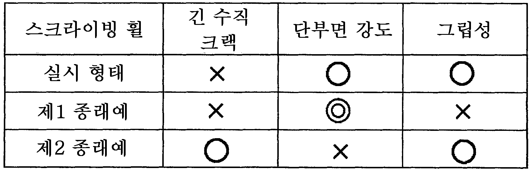
또한, 날 끝(12a)의 날 각도 θ1은, 통상 둔각이고, 바람직하게는, 165°≥θ>90°의 범위이다. 또한, 날 각도 θ1의 구체적 각도는, 절단하는 취성 재료 기판의 재질이나 두께 등으로부터 적절하게 설정된다. 또한, 이 절결 오목부(13)의 최적인 형성 위치는, 취성 재료 기판의 재질 및 두께, 스크라이빙 휠의 날 각도 θ1 및 두께를 고려하는 면에서, 스크라이브 시의 취성 기판의 표면으로부터 날 끝(12a)까지의 깊이보다도 작은 범위, 즉 1 내지 5㎛ 정도의 범위에서 실험적으로 적절하게 설정하면 된다. 또한, 인접하는 절결 오목부(13)의 사이의 피치는, 임계적 한계는 존재하지 않지만, 20 내지 200㎛의 범위에서 적절하게 선택하면 된다. 또한, 상기 실시 형태의 스크라이빙 휠과, 상기 특허 문헌 1에 개시되어 있는 스크라이빙 휠(제1 종래예)과, 상기 특허 문헌 3에 개시되어 있는 스크라이빙 휠(제2 종래예)의 특성의 차이를 정리하면, 하기 표 1에 기재한 바와 같게 된다.In addition, the blade angle θ1 of the
또한, 상기 실시 형태의 스크라이빙 휠(10)에 있어서는, 절결 오목부(13)로서 동일 형상의 것이 복수개, 동일 원주 상에 등간격 형성된 예를 나타냈지만, 본 발명에 있어서는, 절결 오목부(13)로서 각각 다른 형상의 것이 단일 또는 복수개, 동일 원주 상에 부등 간격 또는 어긋나게 형성되어 있어도 그 나름대로의 효과가 발휘된다. 그러나, 절결 오목부(13)로서, 동일 형상의 것이 복수개, 동일 원주 상에 등간격으로 형성되어 있으면, 전체 길이에 걸쳐서 균질한 스크라이브 라인을 형성할 수 있는 동시에, 단부에 있어서 글래스 기판 등의 취성 기판에 접촉되는 스크라이빙 휠의 접촉 상태가 실질적으로 균일하게 되므로, 스크라이브한 취성 기판의 단부면 강도를 보다 향상시킬 수 있게 되는 동시에, 다른 스크라이브 라인과 교차하는 일이 있어도, 보다 교차부에 절결이 발생하기 어려워진다.In addition, in the
상기 실시 형태의 스크라이빙 휠(10)에 있어서는, 절결 오목부(13)로서, 날의 경사면(12)의 연장 방향을 따른 길이 a와 날의 경사면(12)과 직교하는 방향을 따른 길이 b의 비 b/a가 b/a<0.5의 긴 타원 형상의 예를 나타냈다. 그러나, 본 발명에 있어서는, 절결 오목부(13)로서는, b/a≥1의 조건이라도, 그 나름대로의 효과를 발휘할 수 있지만, 적어도, b/a<1의 조건을 충족하고 있으면, 절결 오목부(13)의 형상이 타원 형상이 되고, 날의 경사면(12)과 직교하는 방향으로 정렬되어 배열된 상태로 되므로, 날의 경사면(12)에 많은 절결 오목부(13)를 형성할 수 있고, 스크라이브한 취성 기판의 단부면 형상이 보다 균질하게 되어, 단부면 강도를 보다 향상시킬 수 있게 된다.In the
10 : 스크라이빙 휠
10a : 관통 구멍
10b : 회전축
11 : 본체부
12 : 날의 경사면
12a : 날 끝
12b : 박육부
12c : 후육부
13 : 절결 오목부
14 : 글래스 기판
S : 스크라이브 라인
Sa : 홈의 경사면
Sc : 수직 크랙10: scribing wheel
10a: through hole
10b: axis of rotation
11: main body
12: slope of the blade
12a: end of day
12b: thinning
12c: thick portion
13: notch recess
14: glass substrate
S: scribe line
Sa: slope of the groove
Sc: Vertical Crack
Claims (7)
상기 절결 오목부는, 상기 날 끝의 각도를 θ1(단, θ1>90°), 상기 절결 오목부를 형성하는 면의 상기 날 끝측 부분과 상기 날의 경사면 사이의 각도를 θ2로 하였을 때,
180°>θ2>180°-(θ1)/2
가 되도록 형성되어 있는 것을 특징으로 하는, 스크라이빙 휠.It is formed along the circumference of the disk-shaped wheel so that the ridge portion of the V-shaped blade is a continuous blade end, and a cutout recess is formed on the inclined surface of the V-shaped blade from a position spaced a predetermined distance from the blade end, In the scribing wheel in which a thin portion and a thick portion are alternately formed at the tip portion of the V-shaped blade,
When the notch concave portion is set at an angle of the edge of the blade at θ1 (wherein θ1> 90 °) and the angle between the blade end side of the surface forming the notch concave portion and the inclined surface of the blade is θ2,
180 °>θ2> 180 °-(θ1) / 2
Scribing wheel, characterized in that is formed to be.
상기 θ2는,
175°≥θ2≥180°-(θ1)/2+5°
로 이루어져 있는 것을 특징으로 하는, 스크라이빙 휠.The method of claim 1,
Θ2 is
175 ° ≥θ2≥180 °-(θ1) / 2 + 5 °
Scribing wheel, characterized in that consisting of.
상기 θ2는,
175°≥θ2≥180°-(θ1)/2+45°
로 이루어져 있는 것을 특징으로 하는, 스크라이빙 휠.3. The method of claim 2,
Θ2 is
175 ° ≥θ2≥180 °-(θ1) / 2 + 45 °
Scribing wheel, characterized in that consisting of.
상기 절결 오목부는, 동일 형상의 것이 복수개, 동일 원주 상에 등간격으로 형성되어 있는 것을 특징으로 하는, 스크라이빙 휠.The method of claim 1,
The scribing wheel according to claim 1, wherein the notched recesses are formed in plural, having the same shape on the same circumference at equal intervals.
상기 절결 오목부는, 동일 형상의 것이 복수개, 동일 원주 상에 등간격으로 형성되어 있는 것을 특징으로 하는, 스크라이빙 휠.3. The method of claim 2,
The scribing wheel according to claim 1, wherein the notched recesses are formed in plural, having the same shape on the same circumference at equal intervals.
상기 절결 오목부는, 동일 형상의 것이 복수개, 동일 원주 상에 등간격으로 형성되어 있는 것을 특징으로 하는, 스크라이빙 휠.The method of claim 3,
The scribing wheel according to claim 1, wherein the notched recesses are formed in plural, having the same shape on the same circumference at equal intervals.
상기 절결 오목부는, 상기 날의 경사면의 연장 방향을 따른 길이 a와 상기 날의 경사면과 직교하는 방향을 따른 길이 b의 비 b/a가,
b/a<1
이 되도록 형성되어 있는 것을 특징으로 하는, 스크라이빙 휠.7. The method according to any one of claims 1 to 6,
The notch concave portion has a ratio b / a of the length a along the extending direction of the inclined surface of the blade and the length b along the direction orthogonal to the inclined surface of the blade,
b / a <1
A scribing wheel, characterized in that formed so as to be.
Applications Claiming Priority (2)
| Application Number | Priority Date | Filing Date | Title |
|---|---|---|---|
| JP2011187990A JP5409726B2 (en) | 2011-08-30 | 2011-08-30 | Scribing wheel |
| JPJP-P-2011-187990 | 2011-08-30 |
Publications (2)
| Publication Number | Publication Date |
|---|---|
| KR20130024749A KR20130024749A (en) | 2013-03-08 |
| KR101348062B1 true KR101348062B1 (en) | 2014-01-03 |
Family
ID=47794531
Family Applications (1)
| Application Number | Title | Priority Date | Filing Date |
|---|---|---|---|
| KR1020120081618A KR101348062B1 (en) | 2011-08-30 | 2012-07-26 | Scribing wheel |
Country Status (4)
| Country | Link |
|---|---|
| JP (1) | JP5409726B2 (en) |
| KR (1) | KR101348062B1 (en) |
| CN (1) | CN102964060B (en) |
| TW (1) | TWI483910B (en) |
Families Citing this family (13)
| Publication number | Priority date | Publication date | Assignee | Title |
|---|---|---|---|---|
| JP6077799B2 (en) * | 2012-08-31 | 2017-02-08 | 三星ダイヤモンド工業株式会社 | Cutter wheel and manufacturing method thereof |
| CN104175406B (en) * | 2013-05-24 | 2017-09-15 | 三星钻石工业股份有限公司 | Break bar and its manufacture method |
| JP2015003513A (en) * | 2013-05-24 | 2015-01-08 | 三星ダイヤモンド工業株式会社 | Cutter wheel and manufacturing method thereof |
| JP6332618B2 (en) * | 2014-04-24 | 2018-05-30 | 三星ダイヤモンド工業株式会社 | Scribing cutter wheel and scribing device |
| JP6572660B2 (en) * | 2015-07-31 | 2019-09-11 | 三星ダイヤモンド工業株式会社 | Scribing wheel |
| JP6648448B2 (en) * | 2015-08-17 | 2020-02-14 | 三星ダイヤモンド工業株式会社 | Method for forming vertical crack in brittle material substrate and method for cutting brittle material substrate |
| JP6547556B2 (en) * | 2015-09-29 | 2019-07-24 | 三星ダイヤモンド工業株式会社 | Method of dividing brittle substrate |
| CN107140820B (en) * | 2017-06-20 | 2023-10-27 | 嘉兴沃尔德金刚石工具有限公司 | Cutter wheel with chip removal hole array |
| JP7032787B2 (en) * | 2017-11-30 | 2022-03-09 | 三星ダイヤモンド工業株式会社 | Scribing wheel |
| DE102018131179A1 (en) | 2018-12-06 | 2020-06-10 | Schott Ag | Glass element with cut edge and process for its production |
| CN109574488B (en) * | 2019-01-28 | 2024-03-01 | 嘉兴沃尔德金刚石工具有限公司 | Knife flywheel |
| JP2021006374A (en) * | 2019-06-28 | 2021-01-21 | 三星ダイヤモンド工業株式会社 | Scribing wheel |
| JP2022038435A (en) * | 2020-08-26 | 2022-03-10 | ファインテック株式会社 | Scribing wheel for brittle material substrate and method for producing the same |
Citations (4)
| Publication number | Priority date | Publication date | Assignee | Title |
|---|---|---|---|---|
| KR19990006850A (en) * | 1997-06-10 | 1999-01-25 | 무라따 미치히로 | Electronic component and manufacturing method thereof |
| US20090235802A1 (en) | 2007-09-22 | 2009-09-24 | Bohle Ag | Small glass cutting wheel |
| JP2010126382A (en) | 2008-11-26 | 2010-06-10 | Joyo Kogaku Kk | Cutter wheel for cutting glass |
| JP2010126387A (en) | 2008-11-26 | 2010-06-10 | Japan Steel Works Ltd:The | Cutter wheel |
Family Cites Families (6)
| Publication number | Priority date | Publication date | Assignee | Title |
|---|---|---|---|---|
| JP4649555B2 (en) * | 2001-03-30 | 2011-03-09 | Uht株式会社 | Cutting device |
| TWI249460B (en) * | 2004-05-28 | 2006-02-21 | Tzujan Technology Inst | A cutting wheel structure |
| JP4582774B2 (en) * | 2004-10-07 | 2010-11-17 | 常陽工学株式会社 | Cutter wheel for glass cutting |
| TWI409232B (en) * | 2005-07-06 | 2013-09-21 | Mitsuboshi Diamond Ind Co Ltd | Method for manufacturing scratches for brittle materials |
| JP4219945B2 (en) * | 2006-08-10 | 2009-02-04 | トーヨー産業株式会社 | Cutter foil for glass cutting |
| KR20090058806A (en) * | 2007-12-05 | 2009-06-10 | 주식회사 탑 엔지니어링 | Scribe apparatus |
-
2011
- 2011-08-30 JP JP2011187990A patent/JP5409726B2/en not_active Expired - Fee Related
-
2012
- 2012-07-26 KR KR1020120081618A patent/KR101348062B1/en active IP Right Grant
- 2012-07-27 CN CN201210263027.0A patent/CN102964060B/en not_active Expired - Fee Related
- 2012-07-30 TW TW101127503A patent/TWI483910B/en not_active IP Right Cessation
Patent Citations (4)
| Publication number | Priority date | Publication date | Assignee | Title |
|---|---|---|---|---|
| KR19990006850A (en) * | 1997-06-10 | 1999-01-25 | 무라따 미치히로 | Electronic component and manufacturing method thereof |
| US20090235802A1 (en) | 2007-09-22 | 2009-09-24 | Bohle Ag | Small glass cutting wheel |
| JP2010126382A (en) | 2008-11-26 | 2010-06-10 | Joyo Kogaku Kk | Cutter wheel for cutting glass |
| JP2010126387A (en) | 2008-11-26 | 2010-06-10 | Japan Steel Works Ltd:The | Cutter wheel |
Also Published As
| Publication number | Publication date |
|---|---|
| KR20130024749A (en) | 2013-03-08 |
| TWI483910B (en) | 2015-05-11 |
| JP5409726B2 (en) | 2014-02-05 |
| CN102964060B (en) | 2015-09-16 |
| TW201313637A (en) | 2013-04-01 |
| JP2013049597A (en) | 2013-03-14 |
| CN102964060A (en) | 2013-03-13 |
Similar Documents
| Publication | Publication Date | Title |
|---|---|---|
| KR101348062B1 (en) | Scribing wheel | |
| KR101201263B1 (en) | Cutter wheel and method for scribing brittle material substrate | |
| EP2385026A1 (en) | Cutter and method for cutting brittle material substrate using same | |
| KR102551257B1 (en) | Scribing wheel | |
| TW200808670A (en) | Cutter wheel for cutting glass | |
| KR101737581B1 (en) | Double-edged scribing wheel for cutting coated glass | |
| KR101347994B1 (en) | Scribing wheel | |
| KR20170015242A (en) | Scribing wheel | |
| KR102453526B1 (en) | Cutter wheel | |
| CN109849197B (en) | Scribing wheel | |
| TWI752133B (en) | cutter wheel | |
| CN114102882A (en) | Scribing wheel for brittle material substrate and manufacturing method thereof | |
| KR20180077055A (en) | Scribing wheel | |
| TW200538260A (en) | Cutting tool for glass or wafer | |
| KR101824529B1 (en) | Scribing wheel | |
| TWI457300B (en) | Scribe wheel | |
| JP2022099809A (en) | Scribing wheel and scribing method | |
| KR20110129050A (en) | Scribing wheel and method for manufacturing the same |
Legal Events
| Date | Code | Title | Description |
|---|---|---|---|
| A201 | Request for examination | ||
| E701 | Decision to grant or registration of patent right | ||
| GRNT | Written decision to grant | ||
| FPAY | Annual fee payment |
Payment date: 20161129 Year of fee payment: 4 |
|
| FPAY | Annual fee payment |
Payment date: 20181129 Year of fee payment: 6 |