KR101135757B1 - Stereoscopic display system - Google Patents
Stereoscopic display system Download PDFInfo
- Publication number
- KR101135757B1 KR101135757B1 KR1020067016666A KR20067016666A KR101135757B1 KR 101135757 B1 KR101135757 B1 KR 101135757B1 KR 1020067016666 A KR1020067016666 A KR 1020067016666A KR 20067016666 A KR20067016666 A KR 20067016666A KR 101135757 B1 KR101135757 B1 KR 101135757B1
- Authority
- KR
- South Korea
- Prior art keywords
- matrix display
- polarization
- pixel
- image
- display
- Prior art date
Links
Images


Classifications
-
- G—PHYSICS
- G06—COMPUTING; CALCULATING OR COUNTING
- G06F—ELECTRIC DIGITAL DATA PROCESSING
- G06F21/00—Security arrangements for protecting computers, components thereof, programs or data against unauthorised activity
- G06F21/70—Protecting specific internal or peripheral components, in which the protection of a component leads to protection of the entire computer
- G06F21/82—Protecting input, output or interconnection devices
- G06F21/84—Protecting input, output or interconnection devices output devices, e.g. displays or monitors
-
- G—PHYSICS
- G02—OPTICS
- G02B—OPTICAL ELEMENTS, SYSTEMS OR APPARATUS
- G02B30/00—Optical systems or apparatus for producing three-dimensional [3D] effects, e.g. stereoscopic images
- G02B30/20—Optical systems or apparatus for producing three-dimensional [3D] effects, e.g. stereoscopic images by providing first and second parallax images to an observer's left and right eyes
- G02B30/22—Optical systems or apparatus for producing three-dimensional [3D] effects, e.g. stereoscopic images by providing first and second parallax images to an observer's left and right eyes of the stereoscopic type
- G02B30/25—Optical systems or apparatus for producing three-dimensional [3D] effects, e.g. stereoscopic images by providing first and second parallax images to an observer's left and right eyes of the stereoscopic type using polarisation techniques
-
- G—PHYSICS
- G06—COMPUTING; CALCULATING OR COUNTING
- G06F—ELECTRIC DIGITAL DATA PROCESSING
- G06F21/00—Security arrangements for protecting computers, components thereof, programs or data against unauthorised activity
-
- H—ELECTRICITY
- H04—ELECTRIC COMMUNICATION TECHNIQUE
- H04N—PICTORIAL COMMUNICATION, e.g. TELEVISION
- H04N13/00—Stereoscopic video systems; Multi-view video systems; Details thereof
- H04N13/30—Image reproducers
- H04N13/332—Displays for viewing with the aid of special glasses or head-mounted displays [HMD]
- H04N13/337—Displays for viewing with the aid of special glasses or head-mounted displays [HMD] using polarisation multiplexing
-
- G—PHYSICS
- G02—OPTICS
- G02F—OPTICAL DEVICES OR ARRANGEMENTS FOR THE CONTROL OF LIGHT BY MODIFICATION OF THE OPTICAL PROPERTIES OF THE MEDIA OF THE ELEMENTS INVOLVED THEREIN; NON-LINEAR OPTICS; FREQUENCY-CHANGING OF LIGHT; OPTICAL LOGIC ELEMENTS; OPTICAL ANALOGUE/DIGITAL CONVERTERS
- G02F1/00—Devices or arrangements for the control of the intensity, colour, phase, polarisation or direction of light arriving from an independent light source, e.g. switching, gating or modulating; Non-linear optics
- G02F1/01—Devices or arrangements for the control of the intensity, colour, phase, polarisation or direction of light arriving from an independent light source, e.g. switching, gating or modulating; Non-linear optics for the control of the intensity, phase, polarisation or colour
- G02F1/13—Devices or arrangements for the control of the intensity, colour, phase, polarisation or direction of light arriving from an independent light source, e.g. switching, gating or modulating; Non-linear optics for the control of the intensity, phase, polarisation or colour based on liquid crystals, e.g. single liquid crystal display cells
- G02F1/133—Constructional arrangements; Operation of liquid crystal cells; Circuit arrangements
- G02F1/1333—Constructional arrangements; Manufacturing methods
- G02F1/1335—Structural association of cells with optical devices, e.g. polarisers or reflectors
- G02F1/133526—Lenses, e.g. microlenses or Fresnel lenses
Landscapes
- Engineering & Computer Science (AREA)
- Physics & Mathematics (AREA)
- Theoretical Computer Science (AREA)
- Computer Hardware Design (AREA)
- General Physics & Mathematics (AREA)
- Computer Security & Cryptography (AREA)
- Software Systems (AREA)
- General Engineering & Computer Science (AREA)
- Multimedia (AREA)
- Signal Processing (AREA)
- Optics & Photonics (AREA)
- Testing, Inspecting, Measuring Of Stereoscopic Televisions And Televisions (AREA)
- Liquid Crystal (AREA)
- Liquid Crystal Display Device Control (AREA)
- Control Of Indicators Other Than Cathode Ray Tubes (AREA)
Abstract
전면을 갖는 세기 변조 매트릭스 디스플레이; 및 세기 변조 매트릭스 디스플레이의 전면에 겹쳐지며, 각 픽셀은 세기 변조 매트릭스 디스플레이의 대응 픽셀과 광학적으로 작용하는 편광 매트릭스 디스플레이 패널을 포함하되, 상기 편광 디스플레이는, 편광 매트릭스 디스플레이 패널의 각 픽셀을 제어 가능하고, 발생된 편광의 회전이 90° 및 그 이하를 포함하는 범위에 걸쳐 변화하는 선형 편광 디스플레이; 및 편광 매트릭스 디스플레이 패널의 각 픽셀을 제어 가능하고, 상기 세기 변조 매트릭스 디스플레이의 대응 픽셀로부터 오는 편광의 속축(fast axis)과 지축(slow axis) 사이의 위상을 180°및 그 이하를 포함하는 범위 내에서 제어하는 타원형 편광 디스플레이 중의 하나인 것을 특징으로 하는 입체 디스플레이 시스템을 개시한다.An intensity modulation matrix display having a front surface; And a polarization matrix display panel superimposed on the front of the intensity modulation matrix display, each pixel optically acting with a corresponding pixel of the intensity modulation matrix display, wherein the polarization display is capable of controlling each pixel of the polarization matrix display panel; A linearly polarized display in which the rotation of the generated polarization varies over a range including 90 ° and less; And control the respective pixels of the polarization matrix display panel, wherein the phase between the fast axis and the slow axis of the polarization coming from the corresponding pixel of the intensity modulation matrix display is 180 ° and below. Disclosed is a stereoscopic display system, characterized in that it is one of an elliptical polarizing display controlled by.
입체, 디스플레이, 시스템, 편광, 픽셀 Stereoscopic, display, system, polarized, pixel
Description
본 발명은 입체 디스플레이 시스템에 관한 것으로서, 특히 고화질 평면 패널(high quality flat panel) 입체 디스플레이 시스템에 관한 것이다. TECHNICAL FIELD The present invention relates to a stereoscopic display system, and more particularly to a high quality flat panel stereoscopic display system.
입체 기술은 시청자(viewer)가 실제 생활에서 목표물을 바라보는 것과 거의 동일한 방법으로 시청자의 눈을 통해 나타냄으로써, 목표물에 깊이를 제공하는 현실감을 주는 게임 또는 장면을 만들어내게 된다. 편광 기술에 따르면, 타원형 편광로 언급된, 직선 편광 및 원형 편광 및 그 조합이 사용되었다. Stereoscopic technology creates a realistic game or scene that provides depth to the target by presenting it through the viewer's eyes in much the same way that the viewer sees the target in real life. According to the polarization technique, linear and circular polarization and combinations thereof, referred to as elliptical polarization, were used.
일반적인 입체 디스플레이 시스템은 서로에 대해 90°를 이루는 2개의 필터를 포함하는 수동 편광 입체 글래스를 사용하며, 서로에 대해 90°로 편광된 2개의 이미지를 생성한다. 도 1은 이러한 시스템을 도시하며, 도 1에서 "L.I."는 좌측 눈에 의해서만 보여지도록 의도된 좌측 이미지이고, "R.I."는 우측 눈에 의해서만 보여지도록 의도된 우측 이미지이다. 또한, "L.F."는 좌측 이미지만을 통과시키는 좌측 편광 필터이고, "R.F."는 우측 이미지만을 통과시키는 우측 편광 필터이다. A typical stereoscopic display system uses passively polarized stereoscopic glasses that include two filters that are at 90 ° to each other and produce two images that are polarized at 90 ° to each other. FIG. 1 illustrates such a system, in which "L.I." is a left image intended to be seen only by the left eye, and "R.I." is a right image intended to be seen only by the right eye. In addition, "L.F." is a left polarization filter which passes only the left image, and "R.F." is a right polarization filter which passes only the right image.
액정 디스플레이(LCD) 기술에서, 3가지 형태의 능동 매트릭스 박막 트랜지스터(TFT) LCD가 사용되었다: Twist Nematic(TN), In-Plane Switching(IPS), Multi-domain Vertical Alignment(MVA). LCD 디스플레이는 내부에 실링된 액정 물질에 의해 분리된, 일반적으로 투명인 2개의 글래스 시트로 구성된다. 전방 및 후방 전극 코팅부 사이에 인가되는 전압은 가시적인 특성을 형성하기에 충분하도록 액정을 어둡게 하는 액정 분자의 규칙적인 배열을 붕괴시킨다.In liquid crystal display (LCD) technology, three types of active matrix thin film transistor (TFT) LCDs have been used: Twist Nematic (TN), In-Plane Switching (IPS), and Multi-domain Vertical Alignment (MVA). LCD displays consist of two generally transparent glass sheets separated by a liquid crystal material sealed therein. The voltage applied between the front and back electrode coatings disrupts the regular arrangement of liquid crystal molecules that darkens the liquid crystal to be sufficient to form visible properties.
본 출원인이 특허권자인 미국특허 제5,629,798호에서는, 상당한 3D 지각력은 시청자의 눈에 대응하는 서로 다른 시각 포인트로부터 2개의 이미지를 나타냄으로써 달성되며, 이 입체 디스플레이 시스템은 제시간에 이미지를 다중 송신하지 않거나, 대부분의 다른 입체 기술에서의 일반적인 경우에서와 같이 공간에 2개의 이미지를 디스플레이하는 유일한 장점을 갖는다. 상기 방법은 각각의 이미지 요소를 통해, 좌측과 우측 이미지 내에 2개의 대응하는 픽셀 세기 값의 광 세기를 조정하여 구성하고, 각각의 이미지 요소를 통해, 좌측 및 우측 이미지에 대한 2개의 대응하는 픽셀값에 의존하는 각도로 편광시켜 구성한다. 상기 결과적인 디스플레이는 종래의 LCD 모니터와 동일하나, 그것은 2개의 LCD 패널을 포함한다. 상기 디스플레이는 후방에서 전방으로, 백라이트 패널, 제1 편광 필터, 제1 LCD 패널(Mod LCD), 제2 편광 필터, 그리고 제2 LCD 패널(Angle LCD)을 포함하는 일련의 층을 포함한다. 상기 제1 LCD 패널은 양쪽 눈을 위한 픽셀 세기를 제어하는 반면에, 제2 LCD 패널은 한쪽 눈 또는 다른 눈으로의 분산을 제어한다. 입체 이미지를 발생시키기 위하여, 다음 관계식을 이용하여 좌측 및 우측 이미지는 모듈로(Modulo; 제 1 LCD 구동) 및 각도 이미지(angular images; 제2 LCD를 구동)로 변환된다.In U.S. Patent No. 5,629,798, the applicant's patentee, significant 3D perception is achieved by displaying two images from different viewing points corresponding to the viewer's eyes, and this stereoscopic display system does not multiplex images in time or This has the only advantage of displaying two images in space, as is the general case in most other stereoscopic techniques. The method is configured by adjusting the light intensity of two corresponding pixel intensity values in the left and right images, through each image element, and by means of each image element, two corresponding pixel values for the left and right images, respectively. It is configured to be polarized at an angle depending on. The resulting display is the same as a conventional LCD monitor, but it includes two LCD panels. The display comprises a series of layers comprising a backlight panel, a first polarizing filter, a first LCD panel (Mod LCD), a second polarizing filter, and a second LCD panel (Angle LCD) from rear to front. The first LCD panel controls the pixel intensity for both eyes, while the second LCD panel controls the dispersion to one or the other eye. To generate a stereoscopic image, the left and right images are converted into Modulo (first LCD drive) and angular images (drive second LCD) using the following relationship.

상기 수동 글래스(passive glass)의 직교 편광 필터는 좌측 눈 및 우측 눈을 위한 좌측 이미지 및 우측 이미지를 재생한다. 이는 편광 필터들이 다음과 같은 코사인 및 사인 삼각함수와 같은 기능을 하기 때문이다. The orthogonal polarization filter of the passive glass reproduces the left and right images for the left and right eyes. This is because polarization filters function like cosine and sine trigonometric functions as follows.

본 분야의 개발에도 불구하고, 고화질 평면 패널 입체 디스플레이 분야에서 추가적인 개발의 여지가 있다. Despite the development in the field, there is room for further development in the field of high-definition flat panel stereoscopic display.
본 발명에 따르면, 전면을 갖는 세기 변조 매트릭스 디스플레이; 세기 변조 매트릭스 디스플레이의 전방에 위치하며 전면을 갖는 편광 매트릭스 디스플레이 패널을 포함하되, 상기 편광 매트릭스 디스플레이 패널의 디스플레이는 각 픽셀이 제어 가능하며, 발생된 편광의 회전을 90° 및 그 이하를 포함하는 범위를 통하여 변경시키는 선형 편광 디스플레이와; 각 픽셀이 제어 가능하며, 180°및 그 이하를 포함하는 범위 내에서 세기 변조 매트릭스 디스플레이의 대응 픽셀로부터 오는 편광의 속축과 지축 사이의 위상을 제어하는 타원형 편광 디스플레이 중의 하나인 편광 디스플레이를 제공하는데 있다. According to the present invention, there is provided a display device comprising: an intensity modulation matrix display having a front surface; A polarization matrix display panel positioned in front of the intensity modulation matrix display and having a front surface, wherein the display of the polarization matrix display panel has a range in which each pixel is controllable and includes a rotation of the generated polarization of 90 ° and below. A linear polarized display for changing through; To provide a polarization display which is one of an elliptical polarization display in which each pixel is controllable and controls a phase between the axis and the axis of polarization coming from the corresponding pixel of the intensity modulation matrix display within a range including 180 ° and below. .
본 발명에 따른 목적, 효과 및 특징은 그 실시예의 한정되지 않는 설명에 따라 더욱 자명하게 될 것이며, 첨부도면을 참조하여 오직 예시로서만 주어진다. The objects, effects and features according to the present invention will become more apparent according to the non-limiting description of the embodiments, given by way of example only with reference to the accompanying drawings.
"종래 기술"이 표기된 도 1은 종래의 입체 디스플레이 시스템을 나타내는 도면.
도 2는 본 발명의 제1 태양의 실시예에 따른 비직교 편광 입체 디스플레이를 나타낸 도면.
도 3은 도 2의 비직교 편광 입체 디스플레이를 나타내는 도면.
도 4는 직교계에서 경사계으로의 변환을 나타내는 도면.
도 5는 도 2의 극좌표에서 비직교 편광 입체 디스플레이를 나타낸 도면.
도 6은 도 5의 극좌표에서 본 발명의 실시예에 따른 비직교 편광 입체 디스플레이를 나타내는 도면.
도 7은 본 발명의 실시예에 따른 디스플레이의 전방의 λ/2 파장 리타더(retarder)와 λ/4 파장 리타더 시트를 갖는 시스템을 도시한 도면.
도 8은 도 7의 리타더 시트(retarder sheet)에 따른 광학 축의 방향의 효과를 나타내는 도면.
도 9는 도 7 및 도 8의 시스템의 대안적인 시스템을 도시한 도면.
도 10은 도 7 내지 도 9의 시스템의 응용예를 도시한 도면.
도 11은 게임에서의 2인을 위한 도 7 내지 도 10의 시스템의 응용예를 도시한 도면.
도 12는 좌우 분할 매트릭스 (가는선)와 모듈로-각도 분할 매트릭스(점선)의 일부를 나타내는 도면.
도 13은 LCD의 오버드라이빙의 효과를 나타내는 도면.
도 14는 좌우 눈 사이에서의 크로스-토크 효과를 도시한 도면.
도 15는 각도 신호 지연의 효과를 나타내는 도면.
도 16은 도 15의 경우에서 LCD 픽셀의 대응 응답을 나타내는 도면.
도 17은 도 15의 경우에서 좌우 편광 필터 뒤에서의, 관찰자의 눈에서의 최종 픽셀 세기를 나타내는 도면.
도 18은 본 발명의 실시예에 따른, 전방 디퓨저 및 투사 백 라이트를 사용한 LCD 디스플레이의 예를 도시한 도면.
도 19는 본 발명의 실시예에 따른, 다양한 컬러의 서브-픽셀 내의 광을 시준(collimate)하기 위하여 마이크로 렌즈 어레이를 사용하는 LCD 디스플레이의 예를 도시한 도면.
도 20은 1280×1024 해상도의 LCD를 위하여 픽셀 피치를 매칭시키는 렌즈 어레이를 나타낸 도면.
도 21은 LCD 픽셀 피치를 매칭시키는 렌즈 어레이를 나타낸 도면.
도 22는 본 발명의 다른 실시예에 따른 디스플레이를 나타낸 도면.
도 23은 본 발명의 다른 실시예에 따른 탈편광이 없는 광을 더 확산시키기 위하여 사용될 수 있는 블랙 마스크를 사용한 마이크로-볼 어레이(micro-ball array)를 이용한 디스플레이를 나타낸 도면.
도 24는 본 발명의 다른 실시예에 따른 마이크로-프리즘을 이용한 디스플레이를 나타낸 도면.
도 25는 본 발명의 태양의 실시예에 따른 마이크로-렌즈 어레이를 이용한 디스플레이를 나타낸 도면.
도 26은 본 발명의 태양의 실시예에 따른 홀로그래픽 광학 요소 시트를 이용한 디스플레이를 나타낸 도면.
도 27은 본 발명의 다른 실시예에 따른 통합 LCD를 이용한 디스플레이를 나타내는 도면. 1 is a diagram illustrating a conventional stereoscopic display system.
2 shows a non-orthogonal polarized stereoscopic display according to an embodiment of the first aspect of the invention.
3 illustrates the non-orthogonal polarized stereoscopic display of FIG. 2.
4 is a diagram showing a transformation from an orthogonal system to an inclinometer.
5 shows a non-orthogonal polarized stereoscopic display in polar coordinates of FIG. 2.
6 shows a non-orthogonal polarized stereoscopic display according to an embodiment of the invention in polar coordinates of FIG. 5.
FIG. 7 illustrates a system having a lambda / 2 wavelength retarder and a lambda / 4 wavelength retarder sheet in front of a display according to an embodiment of the present invention. FIG.
8 shows the effect of the direction of the optical axis according to the retarder sheet of FIG. 7.
9 shows an alternative system of the system of FIGS. 7 and 8.
10 shows an application example of the system of FIGS. 7 to 9.
FIG. 11 illustrates an application of the system of FIGS. 7 to 10 for two people in a game.
12 shows part of the left and right dividing matrix (the thin line) and the modulo-angle dividing matrix (the dashed line).
13 illustrates the effect of overdriving of an LCD.
Fig. 14 shows the cross-talk effect between the left and right eyes.
15 shows the effect of angular signal delay.
FIG. 16 shows a corresponding response of an LCD pixel in the case of FIG. 15; FIG.
FIG. 17 shows the final pixel intensity in the observer's eye after the left and right polarization filter in the case of FIG. 15; FIG.
18 shows an example of an LCD display using a front diffuser and projection backlight, in accordance with an embodiment of the invention.
19 illustrates an example of an LCD display using a micro lens array to collimate light in sub-pixels of various colors, in accordance with an embodiment of the invention.
Fig. 20 shows a lens array for matching pixel pitches for LCDs with 1280 × 1024 resolution.
21 illustrates a lens array for matching LCD pixel pitches.
22 illustrates a display according to another embodiment of the present invention.
FIG. 23 illustrates a display using a micro-ball array using a black mask that can be used to further diffuse light without depolarization in accordance with another embodiment of the present invention. FIG.
24 illustrates a display using a micro-prism according to another embodiment of the present invention.
25 shows a display using a micro-lens array in accordance with an embodiment of the aspect of the invention.
FIG. 26 illustrates a display using a holographic optical element sheet in accordance with an embodiment of the aspect of the present disclosure. FIG.
27 illustrates a display using an integrated LCD in accordance with another embodiment of the present invention.
삭제delete
삭제delete
삭제delete
삭제delete
삭제delete
삭제delete
삭제delete
삭제delete
삭제delete
삭제delete
삭제delete
삭제delete
삭제delete
삭제delete
삭제delete
삭제delete
삭제delete
삭제delete
삭제delete
삭제delete
삭제delete
삭제delete
삭제delete
삭제delete
삭제delete
삭제delete
삭제delete
일반적으로, 2개의 편광 필터를 포함하고 2개의 편광 이미지를 발생시키는 편광 입체 시스템이 제공되며, 여기서 종래의 입체 시스템(도 1)과 달리, ⅰ) 2개의 편광 필터는 90°로 위치할 필요가 없으며, ⅱ)편광 이미지의 각도는 대응하는 편광 필터와 같지 않으며 (즉 좌측 필터는 좌측 이미지 각도의 각으로 있지 않고, 우측 이미지는 우측 필터와 비교하여 같은 각도에 있지 않다), ⅲ) 크로스-토크(cross-talk), 즉 우측 이미지으로부터 좌측 이미지 또는 그 반대로의 누설을 취소하는 방법으로 각도 시스템이 선택된다. Generally, a polarized stereoscopic system is provided that includes two polarizing filters and generates two polarized images, where, unlike conventional stereoscopic systems (FIG. 1), i) two polarizing filters need to be positioned at 90 °. Ii) the angle of the polarized image is not equal to the corresponding polarization filter (ie the left filter is not at the angle of the left image angle and the right image is not at the same angle as compared to the right filter), i) cross-talk The angle system is chosen in such a way as to cancel cross-talk, ie leakage of the left image from the right image or vice versa.
도 2 및 도 3은 각도의 데카르트 좌표계에 있어 본 발명의 실시예에 따른 비직교 편광 입체 디스플레이 시스템을 나타낸다. 본 발명은 우측 이미지(R.I.)의 선형 편광각(β)로부터 90°의 각도 "A"에 있는 좌측 선형 편광 필터(L.F.) 및 좌측 이미지(L.I.)의 선형 편광각(α)로부터 90°의 각도 "B"에 있는 우측 선형 편광 필터(R. F.)를 구비한 수동 편광 입체 글래스(도 3 참조)를 포함한다. 본 발명은 서로로부터 각도 ω에서 편광된 2개의 이미지를 생성한다(여기서, ω = α+β). 2 and 3 show a non-orthogonal polarized stereoscopic display system according to an embodiment of the invention in an Cartesian coordinate system of angles. The present invention provides an angle of 90 ° from the left linear polarization filter LF at an angle “A” of 90 ° from the linear polarization angle β of the right image RI and the linear polarization angle α of the left image LI. A passive polarized stereoscopic glass (see FIG. 3) with a right linear polarization filter (RF) at " B ". The present invention produces two images polarized at an angle ω from each other, where ω = α + β.
이러한 시스템에서, 설계에 의하여 각(α+B)는 90°이고, cos 90°는 "0"이기 때문에, 좌측 필터(L.F.)를 통과한 후의 좌측 이미지(L.I.)의 세기는 좌측 필터(L.F.)와 좌측 이미지(L.I.) 사이의 각도의 코사인의 인수(factor), 즉 cos(A-α)에 의해 감소되는 반면에, 우측 필터(R.F.)를 통과한 후의 좌측 이미지(L.I.)의 세기는 없다. 유사하게, 설계에 의하여 각(β+A)는 90°이고, cos 90°는 "0"이기 때문에, 우측 필터(R.F.)를 통과한 후의 우측 이미지(R.I.)의 세기는 우측 필터(R.F.)와 우측 이미지(R.I.) 사이의 각도의 코사인의 인수(factor), 즉 cos(β+A)에 의해 감소되는 반면에, 좌측 필터(L.F.)를 통과한 후의 우측 이미지(R.I.)의 세기는 없다. In this system, by design the angle α + B is 90 ° and cos 90 ° is “0”, so the intensity of the left image LI after passing the left filter LF is left filter LF. While the intensity of the angle between the and left image LI is reduced by the factor of cosine, ie cos (A-α), there is no intensity of the left image LI after passing through the right filter RF. Similarly, by design, the angle β + A is 90 ° and cos 90 ° is “0”, so the intensity of the right image RI after passing through the right filter RF is equal to the right filter RF. While it is reduced by the factor of cosine of the angle between the right image RI, ie cos (β + A), there is no intensity of the right image RI after passing through the left filter LF.
위에서 설명된, 본 출원인의 특허에 개시된 폴라 입체 디스플레이 시스템(polar stereoscopic display system)에서와 같이, 픽셀은 각 픽셀의 적색, 녹색 및 청색 세기를 제어하는 3개의 서브-픽셀로 세분화되고, 좌측과 우측의 각 대응 서브-픽셀은 롤라 입체 디스플레이의 제1 및 제2 LCD를 구동하기 위하여 사용된 모듈러 값과 각도 값으로 변환되며, 위에서 언급된 관계식 (1) 및 (2)이 계속된다. 여기서, "left"는 우측 이미지 상의 동일 서브-픽셀에 대응하는 좌측 이미지의 서브-픽셀 값이고, "right"는 좌측 이미지 상의 동일 서브-픽셀에 대응하는 우측 이미지의 서브-픽셀 값이다. As in the polar stereoscopic display system disclosed in the Applicant's patent described above, the pixels are subdivided into three sub-pixels that control the red, green and blue intensity of each pixel, left and right Each corresponding sub-pixel of is converted into a modular value and an angular value used to drive the first and second LCDs of the roll stereoscopic display, followed by relations (1) and (2) mentioned above. Here, "left" is a sub-pixel value of the left image corresponding to the same sub-pixel on the right image, and "right" is a sub-pixel value of the right image corresponding to the same sub-pixel on the left image.
따라서, 본 발명에 따른 시스템은 비직교이기 때문에, 좌측 값 및 우측 값이 도 4에 도시된 바와 같이 데카르트 좌표계로부터 각도 ω의 경사계(경사 좌표계)로 변환된다. 여기서, "L"은 이 우측 이미지 상의 동일한 서브-픽셀에 대응하는 좌측 이미지의 서브-픽셀 값을 언급하며, "R"은 좌측 이미지 상의 동일한 서브-픽셀에 대응하는 우측 이미지의 서브-픽셀 값이다. 또한, "x"는 변환된 "L"값, "y"는 변환된 "R" 값이고, "ω=α+β"는 2개의 이미지 사이의 편광각이며, 그리고 "θ=A-α"는 좌측 필터와 좌측 이미지 사이의 편광각이다. Thus, since the system according to the invention is non-orthogonal, the left and right values are converted from the Cartesian coordinate system to the tilt system (tilt coordinate system) of the angle ω as shown in FIG. Here, "L" refers to the sub-pixel value of the left image corresponding to the same sub-pixel on this right image, and "R" is the sub-pixel value of the right image corresponding to the same sub-pixel on the left image. . Further, "x" is the converted "L" value, "y" is the converted "R" value, "ω = α + β" is the polarization angle between two images, and "θ = A-α" Is the polarization angle between the left filter and the left image.
상기 x 및 y는 다음 관계식을 이용하여 계산될 수 있다.The x and y can be calculated using the following relationship.

그리고, 관계식 (1) 및 (2)는 하기와 같이 된다. The relational expressions (1) and (2) are as follows.

관계식 (7) 및 (8)을 이용하여 관계식 (9) 및 (10)이 얻어진다. Relations (9) and (10) are obtained using relations (7) and (8).

"Modulo'" 및 "Angular'" 변환을 적용함으로서 도 5에 도시된 바와 같은 (α에서 β까지)ω의 범위를 갖는 편광각을 산출한다. Applying the "Modulo '" and "Angular'" transformations yields a polarization angle with a range of ω (from α to β) as shown in FIG.
"L.O."는 대응하는 좌측 서브-픽셀 값과 비교하여 우측 서브-픽셀 값이 "0"이거나 무시할 정도일 때의 서브-픽셀의 좌측 방향의 각도 값이며, 이는 최소 발생 각도 값이다. "R.O."는 대응하는 우측 서브-픽셀 값과 비교하여 좌측 서브-픽셀 값이 "0"이거나 무시할 정도일 때의 서브-픽셀의 우측 방향의 각도 값이다. 이는 발생 각도 최대값이다. "L.O." is an angle value in the left direction of the sub-pixel when the right sub-pixel value is "0" or negligible compared to the corresponding left sub-pixel value, which is the minimum occurrence angle value. "R.O." is the angle value in the right direction of the sub-pixel when the left sub-pixel value is "0" or negligible compared to the corresponding right sub-pixel value. This is the maximum angle of occurrence.
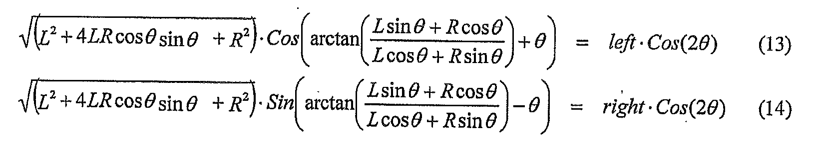
비직교 편광 수동 글래스(non-orthogonal polarized passive glasses)의 각도 A 및 B에서의 필터와 함께 "Modulo'" 및 "Angular'"로부터의 L 및 R의 회복은 다음과 같이, 좌측 눈 및 우측 눈을 위한 좌측 이미지 및 우측 이미지를 재생성한다.Recovery of L and R from "Modulo '" and "Angular'" with a filter at angles A and B of non-orthogonal polarized passive glasses is as follows. Regenerate the left image and the right image.
도 6은 비직교 편광 폴라 입체 디스플레이 시스템에 대한 결과를 나타낸다.6 shows the results for a non-orthogonal polarized polar stereoscopic display system.
흥미롭게도, 이러한 비직교 선형 편광 시스템의 원리는 원형 편광 입체 시스템에 적용된다. 종래의 원형 편광 입체 디스플레이 시스템은 좌측 이미지와 우측 이미지를 분리하기 위하여 좌회전 및 우회전 원형 편광 필터를 사용한다. 선형 편광 시스템으로부터 원형 편광 시스템으로의 변환 및 그 역의 변환이 1/4 파장의 리타더 필름에 의하여 수행되며, 여기서, 좌측 및 우측 선형 편광각 사이의 중심각에 위치하는 리타더 필름의 속축(fast axis)이 선형 편광을 원형 편광으로 변환시킨다. 비직교 원형 편광 입체 디스플레이 시스템에서, 원형 편광 필터 대신에 적당한 타원형 편광 필터를 사용함으로써 상기 선형 편광은 타원형 편광으로 변환된다.Interestingly, the principle of this non-orthogonal linear polarization system applies to circularly polarized stereoscopic systems. Conventional circularly polarized stereoscopic display systems use left and right circularly polarized filters to separate left and right images. The conversion from the linear polarization system to the circular polarization system and vice versa is performed by a retarder film of quarter wavelengths, where the fast axis of the retarder film is located at the center angle between the left and right linear polarization angles. axis) converts linearly polarized light into circularly polarized light. In non-orthogonal circularly polarized stereoscopic display systems, the linearly polarized light is converted to elliptical polarization by using a suitable elliptical polarization filter instead of a circularly polarized filter.
당업자는 본 발명이 상업적으로 이용 가능한 LCD 패널의 저각도 범위에 적합하다는 것을 이해할 것이다. 실제로, 이러한 상업적인 AM-LCD 패널은 거의 65°의 저각도로부터 85°사이에서, TN, IPS, 또는 MVA와 같은 기술, 제조 업체 그리고 LCD 채널 증폭기 바이어스에 따라 변경되는 적어도 90°의 범위를 갖는 광을 변환하지 않는다. 더욱이, 이러한 범위는 각각의 원색 사이에서 변화된다. 예를 들어, 테스트가 완료된 패널은 45°로부터 -25°까지 변화하는 적색을 갖고 있는 반면에, 청색은 45°로부터 -40°까지 변화한다. 본 발명에 따른 상기 비직교 편광 입체 시스템은 동일한 보통의 편광 글래스에 기초하여 각각의 색을 위하여 적합하게 될 수 있다. Those skilled in the art will appreciate that the present invention is suitable for the low angle range of commercially available LCD panels. Indeed, these commercial AM-LCD panels range from a low angle of nearly 65 ° to 85 °, with a range of at least 90 ° that varies with technology, manufacturers and LCD channel amplifier biases such as TN, IPS, or MVA. Does not convert. Moreover, this range varies between each primary color. For example, the tested panel has a red color that varies from 45 ° to -25 ° while blue changes from 45 ° to -40 °. The non-orthogonal polarized stereoscopic system according to the invention can be adapted for each color based on the same common polarized glass.
당업자는 본 발명의 태양이 CRT-LC 패널 입체 디스플레이 시스템에서의 고속(faster) 스위치, 보다 빠른 응답을 위한 각도 선회의 양극단에서 LCD를 오버드라이브(overdrive)하기 위한 용량 뿐만 아니라, 폴라 입체 디스플레이 시스템에서의 제로 크로스-토크(zero cross-talk)를 가능하게 하는 것을 이해할 것이다. 더욱이, 이는 90°이외의 각도로 편광된 2개의 독립된 이미지를 디스플레이하도록 한다. Those skilled in the art will appreciate that aspects of the present invention may be used in polar stereoscopic display systems, as well as in faster switches in CRT-LC panel stereoscopic display systems, as well as capacity to overdrive the LCD at both ends of angular turning for faster response. It will be appreciated that it is possible to enable zero cross-talk. Moreover, this allows to display two independent images polarized at an angle other than 90 °.
도 7에 도시된 바와 같이, 디스플레이 전방에 1/2 파장 리타더(retarder) 및 1/4 파장 리타더를 도입함으로써, 타원형 편광 입체 디스플레이 시스템이 제공된다. 도 8은 리타더 시트(retarder sheet)의 광학축으 방향이 편광 입체의 양식(paradigm)에 어떻게 영향을 주는지를 도시한다. 더욱이, 1/2 파장 리타더 시트는 선형 및 원형 편광 시스템의 추가 배열(permutation)을 야기하는 광의 선형 편광부의 방향 범위를 변경할 수 있다. As shown in FIG. 7, by introducing a half-wave retarder and a quarter-wave retarder in front of the display, an elliptical polarized stereoscopic display system is provided. 8 shows how the direction of the optical axis of the retarder sheet affects the paradigm of the polarization solid. Moreover, the half-wave retarder sheet can change the direction range of the linear polarizer of light, resulting in further permutation of the linear and circular polarization systems.
따라서, 리타더 시트의 이용은 비직교 입체 디스플레이 시스템에 있어서 재배열의 수를 늘릴 수 있다. 이러한 재배열의 일부는 글래스가 서로의 앞에 위치할 때, 글래스를 착용한 첫번째 사용자가 유사한 글래스를 착용한 두번째 사용자를 편안하게 볼 수 있도록 하는 방법으로, 광이 통과하는 좌측 및 우측 타원형 편광 필터가 동일한 광량을 갖는 입체 글래스의 선택을 가능하게 한다. 더욱이, 필터에 재배열은 글래스를 착용한 사용자가 다른 LCD 모니터를 편안하게 보는 것을 허용한다. Thus, the use of retarder sheets can increase the number of rearrangements in non-orthogonal stereoscopic display systems. Part of this rearrangement is such that when the glasses are positioned in front of each other, the first user wearing the glasses can comfortably see the second user wearing the similar glasses, so that the left and right elliptical polarization filters through which the light passes are the same. It is possible to select a three-dimensional glass having a quantity of light. Moreover, rearrangement in the filter allows the user wearing the glass to comfortably view another LCD monitor.
당업자는 본 발명의 태양이 다른 입체 편광 글래스에서 직면하는 불편함을 감소시킨다는 것을 이해할 것이다. 여기서, 불쾌감이란, 정상적인 LCD 모니터를 볼 때 하나의 눈은 상기 모니터 상의 이미지를 보지만, 다른 눈은 블랙 이미지를 보는 것이며, 유사한 글라스를 착용한 다른 사람을 볼 때, 한 눈이 단지 제1 사용자의 제1 눈을 보고, 다른 눈은 제1 사용자의 제2 눈을 본다는 것이며, 이는 뇌에 있어서 상당한 혼란을 야기한다. Those skilled in the art will appreciate that aspects of the present invention reduce the discomfort encountered in other stereoscopic polarizing glasses. Here, discomfort means that when looking at a normal LCD monitor, one eye sees an image on the monitor, while the other eye sees a black image; Seeing the first eye, seeing the other eye the second eye of the first user, which causes considerable confusion in the brain.
본 발명은 이하에서 설명될, 라이브 비디오(live video)의 변환을 위하여, 직교 좌표계(rectangular)에서 폴라 좌표계로의 변환 시스템(conversion system)을 위한 록-업 테이블(lock-up table)을 제공하며, 이는 실시간으로 모듈로 및 각도 이미지 내의 좌측 및 우측 이미지를 변환하기 위하여 요구되는 높은 처리 능력을 해결하는 것을 가능하게 하며, 또한 개별적으로 조합된 값(좌측 및 우측 컬러 값)에 의한 크로스-토크를 감소시키는 것을 가능하게 한다. The present invention provides a lock-up table for a conversion system from a rectangular coordinate system to a polar coordinate system for conversion of live video, which will be described below. This makes it possible to solve the high processing power required to convert left and right images in modulo and angular images in real time, and also allows cross-talk by individually combined values (left and right color values). Makes it possible to reduce.
상술한 바와 같이, 입체 이미지를 발생시키기 위하여, 상기 좌측 및 우측 이미지는 다음의 도면에서 보이는 바와 같이, 모든 서브-픽셀에 대한 모듈러 값 및 각도값으로 변환된다.As described above, in order to generate a stereoscopic image, the left and right images are converted into modular and angular values for all sub-pixels, as shown in the following figure.

일반 LCD 모니터 픽셀의 광 세기는 신호 입력의 전압 또는 값에 대하여, 감마 보정의 유무와 관계 없이, 선형 응답을 갖고 있다. 폴라 시스템(Polar system)의 모듈로(modulo) 신호에 대하여, 선형 LCD 픽셀 M'을 얻기 위하여 모듈 입력에 감마 보정이 도입되고, 하기와 같이, LCD 광 세기 선형 응답을 보상하기 위하여 사인 변환(Sinus transformation)이 사용되어 각도 신호는 선형 각도 응답 A'를 생성한다. 발생시킨다. The light intensity of a general LCD monitor pixel has a linear response with respect to the voltage or value of the signal input, with or without gamma correction. For modulo signals of the Polar system, gamma correction is introduced at the module input to obtain a linear LCD pixel M 'and sinusoidal to compensate for the LCD light intensity linear response as follows. transformation is used to produce a linear angle response A '. Generate.

다음과 같이, 편광 필터 및 전자 회로에 기인하는 LCD 패널의 완전하지 못한 응답을 보상하기 위하여 보정이 더 도입될 수 있다. As follows, correction may be further introduced to compensate for the incomplete response of the LCD panel due to the polarization filter and the electronic circuit.

이러한 신호의 처리는 다음과 같이, 록-업 테이블로 이용된 메모리에 통합, 저장될 수 있다.The processing of these signals can be integrated and stored in the memory used as the lock-up table as follows.

각각 픽셀 컬러가 다른 파라미터를 가질 수 있기 때문에, 하기에 도시된 바와 같이, 대응하는 개수를 갖는 LUT(록-업 테이블)이 각각의 컬러을 위하여 사용된다.
Since each pixel color may have a different parameter, as shown below, a LUT (lock-up table) with a corresponding number is used for each color.
삭제delete

아래에 예시된 바와 같이, LUT는 SRAM (static random access memory) 내에서 실장될 수 있다.As illustrated below, the LUT may be mounted in static random access memory (SRAM).

당업자는 상기 LUT (록-업 테이블)가 480 Hz에서 클락된 변환 처리를 요구하는 85 HZ 재생율로 1280×1024의 서브-픽셀 주파수를 달성하기 위하여 유일한 그리고 비용면에서 유리한 툴(tool)임을 인정할 것이다. 더욱이, 상기 LUT는 어떠한 원하는 조정을 도입하는 것을 보다 용이하게 한다. Those skilled in the art will recognize that the LUT (lock-up table) is the only and cost-effective tool to achieve a sub-pixel frequency of 1280 × 1024 with 85 HZ refresh rate requiring a conversion process clocked at 480 Hz. . Moreover, the LUT makes it easier to introduce any desired adjustments.
본 발명은 명암 및 컬러 해상도를 더욱 향상되도록 하며, 그로 인하여 이용 가능한 많은 세기 레벨을 증가시키기 위하여 제2 광 밸브와 같은 전방의 LCD를 이용하면서 2개의 LCD 결합을 제어함으로써, 일반 모드(2D)에서의 폴라(polar) 디스플레이의 품질은 현재 사용 가능한 LCD 디스플레이를 능가한다. 또한, 2개의 LCD를 이용하여 광을 더 차단함에 따라 블랙커 블랙(blacker black) 픽셀의 세기를 얻을 수 있다. The present invention allows for further enhancement of contrast and color resolution, thereby controlling the two LCD combinations while using the front LCD, such as the second light valve, to increase the many levels of intensity available. The quality of its polar displays exceeds that of currently available LCD displays. In addition, by using two LCDs to further block light, the intensity of blacker black pixels can be obtained.
다른 형태의 편광 글래스(3D가 아닌, 즉 양 눈이 동일한 각도를 가짐)를 간단히 착용하거나 디스플레이의 최상점으로 제거 가능한 필터 시트를 올려놓는 것은 도 9에 도시된 바와 같이, 입체 모드에서의 광 트위스터(light twister)로서 대신에, 명암비의 2배 이상의 10비트/컬러 선명도를 가져오는 광 밸브와 같은 제2 LCD를 활성화한다. Simply wearing another type of polarized glass (not 3D, i.e. both eyes have the same angle) or placing a removable filter sheet at the top of the display is shown in FIG. 9, the optical twister in stereo mode. Instead, as a (light twister), it activates a second LCD, such as a light valve, which brings 10 bits / color clarity more than twice the contrast ratio.
이러한 특징은 제1 LCD 상에 완전한 백색 이미지를 디스플레이하는 동안에 제2 LCD 상에 이미지를 보여줌으로써 다른 사람이 단지 백색 스크린을 보는 반면에 (향상된 콘트라스트를 위한 것과 동일한) 편광 글라스를 착용한 사람만이 스크린을 볼 수 있다(도 10 참조)는 것을 특징으로 하는 개인적인 디스플레이를 가능하게 한다. This feature shows that by displaying an image on the second LCD while displaying a complete white image on the first LCD, only the person wearing polarized glass (same as for enhanced contrast), while others see only the white screen A screen can be seen (see FIG. 10) which enables a personal display.
더구나, 개인 디스플레이의 제1 LCD 상에 백색 이미지를 보여주는 대신에, 글래스를 착용한 사용자가 실제로 다른 이미지를 보는 반면에, 편광 글래스를 쓰지 않은 사용자에게 정상적인 디스플레이의 오해를 주는 위조의 이미지를 보여주는 것이 가능하다. 제2 LCD 상에 나타날 개인 이미지는 편광 글래스를 착용한 사용자를 위한 제1 이미지를 제거하도록 처리된다. 제1 LCD상의 이미지는 모든 픽셀에서의 충분한 밝기를 갖도록 선택되거나 변환되며, 따라서 제 2 LCD의 각 픽셀은 개인 이미지를 디스플레이하기 위한 충분한 광을 갖는다.Moreover, instead of showing a white image on the first LCD of the personal display, it is more convenient to show a fake image that misleads a normal display to a user without polarized glass, while a user wearing glass actually sees a different image. It is possible. The personal image to be displayed on the second LCD is processed to remove the first image for the user wearing the polarized glass. The image on the first LCD is selected or converted to have sufficient brightness at every pixel, so each pixel of the second LCD has enough light to display a personal image.
한 게임에서 2명의 플레이어가 있는 경우, 각 플레이어는 동일 디스플레이 상에서 다른 이미지를 볼 수 있다. 제1 플레이어는 양 눈이 제1 편광 방향에 있는 글래스를 쓰고, 제2 플레이어는 제2 편광 방향에 있는 글래스를 착용한다. 위에서 설명한 바와 같이 두 방향은 직교 또는 비직교된다(도 11 참조).If there are two players in a game, each player can see different images on the same display. The first player wears glasses in which both eyes are in the first polarization direction, and the second player wears glasses in the second polarization direction. As described above, the two directions are orthogonal or non-orthogonal (see FIG. 11).
따라서, 동일 디스플레이는 통상적인 2D 스크린, 입체 스크린(수동 3D 글래스 착용에 의하여), 향상된 2D 스크린(디스플레이 표면 상에서의 필름 추가에 의하여), 보안 디스플레이 스크린(security display screen; 특별한 글래스를 착용한 사용자만이 이미지를 보는 경우), 그리고 2명의 플레이어-2개의 디스플레이-단일 스크린-풀 스크린 디스플레이 스크린 사이에서, 예를 들어 버튼의 누름에 따라 전환할 수 있다. Thus, the same display can only be used with conventional 2D screens, stereoscopic screens (by manual 3D glass wearing), enhanced 2D screens (by adding film on the display surface), security display screens (users wearing special glasses). Viewing this image), and between two player-2 display-single-screen-full-screen display screens, for example by pressing a button.
크로스-토크와 같은, 다른 문제점이 본 발명 내에서 해결될 수 있으며, 이는 대안적인 디스플레이 영역의 2D 매트릭스 평균을 사용하는 것에 의하여 줄어들 수 있다. 사실, 모듈러 신호 및 각도 신호의 (신호를 불연속 레벨, 예를 들어 256 레벨로 전환하기 위한) 디지털화는 크로스-토크를 야기할 수 있는 양자화 오차(quantization error)를 가져온다. 극 전환에 대한 데카르트 좌표계가 오류를 일으키지 않을지라도, 모듈러 값 및 각도 값의 라운딩(rounding)에 의하여 오류는 여저히 발생될 수 있으며, 이는 본래의 좌측 값과 우측 값 간의 차이 및 디스플레이 세기 간의 차이를 차례로 발생시킨다. Other problems, such as cross-talk, can be solved within the present invention, which can be reduced by using 2D matrix averages of alternative display areas. In fact, the digitization of the modular and angular signals (to convert the signal to discrete levels, for example 256 levels) leads to quantization errors that can cause cross-talk. Even if the Cartesian coordinate system for the pole shift does not cause an error, errors can still occur due to the rounding of the modular and angular values, which indicates the difference between the original left and right values and the difference between the display intensities. Generate them in turn.
도 12는 좌측-우측 불연속 매트릭스(가는 선) 및 모듈로-각도(점선) 불연속 매트릭스의 일부를 나타낸다. 가장 가까운 모듈러와 각도의 불연속 값은 좌측 값과 우측 값을 표현하기 위하여 사용되지만, 도면에 도시된 바와 같이, 일부 값들을 결합하기 위하여, 상기 오차는 상당히 커질 수 있고 그 결과 양자화 오차 및 크로스-토크를 발생시킬 수 있다. 그러한 오차를 줄이기 위하여, 2개의 모듈로-각도(molulo-angular) 불연속 값 사이에서 모든 비디오 프레임에서 또는 관찰자에 의하여 인지될 어떠한 깜빡임(flicker)을 방지하기에 충분히 빠른 다른 속도(different rate)로 전환(toggle)시키는 것이 고려되며, 따라서 좌측-우측 값(실선)에 근접한 평균 값을 얻는다.12 shows a portion of the left-right discontinuous matrix (thin line) and the modulo-angle (dashed line) discontinuous matrix. The discontinuous values of the closest modular and angular are used to represent the left and right values, but as shown in the figure, in order to combine some values, the error can be quite large and as a result quantization error and cross-talk Can be generated. To reduce such errors, switch between different modulo-angular discontinuity values at different rates that are fast enough to prevent any flicker to be perceived by the observer or in every video frame. Toggle is considered, thus obtaining an average value close to the left-right value (solid line).
이후에 설명될 바와 같이, 크로스-토크는 LCD 오버드라이브 기술 및 선-각도(pre-angular) 조정을 이용하여 빠르게 움직이는 이미지를 위하여 더욱 줄어들 수 있다. As will be explained later, cross-talk can be further reduced for fast moving images using LCD overdrive technology and pre-angular adjustment.
예를 들어, 단일의 비디오 프레임 사이와 같은 짧은 시간 동안 LCD에 신호를 오버드라이빙(overdriving)하는 것은 LC 액정의 방향의 변화를 가속화하고, 최종 값을 빠르게 산출한다(도 13 참조). 이러한 시스템은 높은 픽셀 값으로부터 낮은 픽셀 값으로의 변화와 함께 작동할 수 있다. 그러나, 보다 높은 또는 보다 낮은 값을 구동하기 위한 여지가 부족함로 인하여 오버드라이빙은 픽셀 세기의 극값, 즉 0및 8비트/컬러 픽셀을 위한 255에서 제한될 수 있다. 본 발명의 비직교 입체 디스플레이는 각도 범위를 줄임으로써 오버드라이빙을 위한 여지를 추가할 수 있으며, 이로 인하여 모든 값에서 보다 빠른 디스플레이 응답의 각도 LCD를 허용하며, 이는 크로스-토크 감소를 가져온다. 상술한 바와 같이, LCD 오버드라이브의 사용은 각도가 하나의 프레임에서 다음 프레임으로 변화할 때에 중간 각도에 의해 발생하는 크로스-토크를 줄일 수 있고 빠르게 움직이는 이미지의 번짐(smearing)을 줄이게 된다. For example, overdriving the signal to the LCD for a short time, such as between single video frames, accelerates the change in the direction of the LC liquid crystal and quickly yields the final value (see FIG. 13). Such a system can work with a change from a high pixel value to a low pixel value. However, due to the lack of room for driving higher or lower values, overdriving may be limited at extremes of pixel intensity, ie 255 for 0 and 8 bit / color pixels. The non-orthogonal stereoscopic display of the present invention can add room for overdriving by reducing the angular range, thereby allowing an angular LCD of faster display response at all values, resulting in cross-talk reduction. As mentioned above, the use of LCD overdrive can reduce cross-talk caused by the intermediate angle when the angle changes from one frame to the next and reduce smearing of fast moving images.
선-각도 조정을 이용하여 빠르게 움직이는 이미지를 위한 크로스-토크 감소에 대하여 설명하면, 제1 눈에서의 세기 변화는 제2 눈에서의 의사(擬似) 광을 야기할 수 있다는 것에 주목해야 한다. 예를 들어, 좌측 눈 이미지의 대응 픽셀이 어두운 반면에 우측 눈 이미지의 픽셀은 밝음에서 어두움으로 변화된다(도 14 참조).Referring to cross-talk reduction for fast moving images using line-angle adjustments, it should be noted that intensity changes in the first eye can cause pseudo light in the second eye. For example, while the corresponding pixel of the left eye image is dark, the pixel of the right eye image changes from light to dark (see FIG. 14).
도 15의 상부 도면은 통상의 시스템을 도시하고, 하부 도면은 각도 신호가, 예를 들어 하나의 비디오 프레임의 어느 시간만큼 지연되는 시스템을 나타낸다. LCD 픽셀의 대응 응답이 도 16에 도시되어 있다. 좌측 및 우측 편광 필터 후의 시청자의 눈에서의 결과적인 픽셀의 세기가 도 17에 도시되어 있다.The top view of FIG. 15 shows a conventional system, and the bottom view shows a system in which the angular signal is delayed by, for example, some time in one video frame. The corresponding response of the LCD pixels is shown in FIG. The resulting pixel intensity in the viewer's eye after the left and right polarization filters is shown in FIG. 17.
LCD의 늦은 응답은 광이 좌측 눈의 필터를 통과하는 동안 일시적인 갭(gap)을 만들며, 각도 신호가 지연될 때 이러한 갭은 일어나지 않는다는 것을 알 수 있다. 유사하게, 상기 다른 이미지가 어두운 반면에 한 이미지의 픽셀 세기가 어두어짐에서 밝음으로 변화할 때 광 충돌(light bump)은 모듈로(Modulo) 신호를 지연시킴으로서 방지될 수 있다는 것이 입증될 수 있다. 지연을 적용하기 위한 기본적인 규칙은 하기와 같이 설명될 수 있다. It can be seen that the late response of the LCD creates a temporary gap while light passes through the filter of the left eye, and this gap does not occur when the angular signal is delayed. Similarly, it can be demonstrated that light bumps can be prevented by delaying the Modulo signal when the other image is dark while the pixel intensity of one image changes from dark to bright. The basic rule for applying the delay can be described as follows.
- 좌측 또는 우측의 서브 픽셀이 어두움에서 밝음으로 변하는 반면에, 우측 또는 좌측의 다른 대응 픽셀이 어두울 때, 그후 각도 신호에 대하여 모듈로 신호는 지연됨. 그리고, - 좌측 또는 우측의 서브 픽셀이 밝음에서 어두움으로 변하는 반면에, 우측 또는 좌측의 다른 대응 픽셀이 어두울 때, 그후 모듈로 신호에 대하여 각도 신호는 지연됨. The left or right subpixel changes from dark to bright while the other corresponding pixel on the right or left is dark, then the modulo signal is delayed with respect to the angular signal. And when the left or right subpixel changes from light to dark, while the other corresponding pixel on the right or left is dark, then the angle signal is delayed with respect to the modulo signal.
오버드라이브 기술은 신호의 지연 대신에 신호를 진행하기 위하여 사용될 수 있다. 오버드라이브 및 지연 기술은 함께 이용될 수 있다.Overdrive techniques can be used to advance the signal instead of the delay of the signal. Overdrive and delay techniques can be used together.
또 다른 문제점이 본 발명에 의하여 처리된다. 예를 들어, 2개의 LCD 셀과 같은 2개의 패턴 구조의 중첩은 2개의 구조의 간섭으로 인해 모아레(Moire) 패턴을 야기한다는 것이 잘 알려져 있다. 본 발명에 따른 LCD에 의하여, 하나의 입사 광선만이 동일한 픽셀 및 동일한 컬러 필터를 통과하는 반면에, 다른 2개의 광선이 컬러 필터에 의해 차단된다.
상기 2개의 LCD 패널의 대응 픽셀은 함께 작용하여 주어진 각도에서 모듈로 픽셀과 각도 픽셀의 불일치를 가져 오며, 그 결과 좌측 이미지와 우측 이미지 간의 시차 크로스-토크 및 이미지 해상도의 열화를 가져온다. 2개의 LCD 패널의 픽셀 구조 사이의 간섭은 낮은 디스플레이 밝기를 야기하며, 광이 2개의 눈 사이에서 분할되기 때문에 이러한 현상은 입체 시스템에 내재되어 있는 낮은 밝기에 부가된다. Another problem is addressed by the present invention. For example, it is well known that superposition of two pattern structures, such as two LCD cells, results in a Moire pattern due to interference of the two structures. With the LCD according to the invention, only one incident ray passes through the same pixel and the same color filter, while the other two rays are blocked by the color filter.
Corresponding pixels of the two LCD panels work together to produce inconsistencies of modulo and angular pixels at a given angle, resulting in parallax cross-talk between the left and right images and degradation of the image resolution. Interference between the pixel structures of the two LCD panels results in low display brightness, and this phenomenon is added to the low brightness inherent in stereoscopic systems because light is split between the two eyes.
본 발명은 적층된 LCD 패널의 간섭 문제를 해결하고 2개의 LCD 패널의 앞, 사이, 및/또는 후에 위치한 하나 또는 그 이상의 마이크로-렌즈 어레이층을 이용한 광의 평행화를 허용함으로써 넓은 시야각(wide view angle)에서의 명암(contrast)을 향상시킨다. 명암이 감소하고 컬러이 시야각에 따라 이동하는 표준 LCD와 달리, 도 18 및 도 19에서 설명된 예는 광이 고정 각도로 픽셀을 통과하기 때문에 매우 넓은 시야각을 허용한다. The present invention solves the interference problem of stacked LCD panels and allows for parallelization of light using one or more micro-lens array layers positioned in front of, between, and / or after the two LCD panels, thereby providing a wide viewing angle. To improve contrast. Unlike standard LCDs where the contrast is reduced and the color moves with the viewing angle, the example described in FIGS. 18 and 19 allows a very wide viewing angle because light passes through the pixels at a fixed angle.
도 18은 전방 디퓨저 및 투사 백라이트를 이용한 실시예를 도시한다. 도 19는 모든 컬럭 서브-픽셀 내의 광을 평행하게 하기 위한 마이크로-렌즈 어레이를 갖는 실시예를 설명한다.18 illustrates an embodiment using a front diffuser and a projection backlight. 19 illustrates an embodiment with a micro-lens array for paralleling light in all color sub-pixels.
마이크로-렌즈 어레이의 피치는 LCD 픽셀 피치 또는 서브-픽셀 피치와 일치한다. 도 20은 1280×1024 LCD용 픽셀 피치와 일치하는 렌즈 어레이를 도시한다. 백라이트로부터 방사된 광은 제1 LCD의 픽셀 개구 및 제2 LCD의 대응 픽셀 개구를 통하여 촛점이 맞추어진다. 그 후, 제2 LCD의 개구 밖으로 나온 광은 마이크로-렌즈 또는 광 디퓨저 층에 의하여 또는 마이크로-렌즈와 광 디퓨저 층에 의하여 확산될 수 있다. 마이크로-렌즈 어레이는 또한 그라디언트 인덱스(radian Index:GRIN) 렌즈 타입일 수 있다. The pitch of the micro-lens array matches the LCD pixel pitch or sub-pixel pitch. 20 shows a lens array that matches the pixel pitch for a 1280 × 1024 LCD. Light emitted from the backlight is focused through the pixel aperture of the first LCD and the corresponding pixel aperture of the second LCD. The light exiting the aperture of the second LCD can then be diffused by the micro-lens or light diffuser layer or by the micro-lens and light diffuser layer. The micro-lens array can also be a gradient index (GRIN) lens type.
하기의 마이크로-렌즈 기반 예를 위하여, 렌즈 어레이는 도 21에 도시된 바와 같이 LCD 픽셀 피치와 일치한다. For the following micro-lens based example, the lens array matches the LCD pixel pitch as shown in FIG.
대안적으로, LCD 패널의 컬러 필터는 평행 베리어(barrier)를 만들고 적색 및 청색 광선을 각도 LCD의 좌측 및 우측 근접 픽셀 컬럼으로 유도하기 위하여 사용될 수 있다. 만일, LCD 패널 컬러 매트릭스가 RGB 대신에 BGR라면, 적색을 진행시키고 하나의 픽셀을 통한 녹색 채널을 지연시키거나, 이와 반대로 함으로써 LCD를 구동하는 전자 장치는 시프트(shift)를 보상할 수 있다(도 22 참조). 또한, 본 발명에 따른 디스플레이 내에서의 광의 고정된 각도는 콜레스테릭 컬러 및 편광 필터의 사용을 허용하며, 이는 최고 600%의 휘도 이득(brightness gain)을 가능하게하고, 그로 인하여 위에서 설명한 낮은 휘도를 보상한다. Alternatively, color filters in the LCD panel can be used to create parallel barriers and direct red and blue light rays to the left and right adjacent pixel columns of the angled LCD. If the LCD panel color matrix is BGR instead of RGB, the electronic device driving the LCD can compensate for the shift by advancing red and delaying the green channel through one pixel, or vice versa (Fig. 22). In addition, the fixed angle of the light in the display according to the invention allows the use of cholesteric color and polarization filters, which allows for brightness gains of up to 600% and thereby the low luminance described above To compensate.
본 발명에 따른 디스플레이의 휘도를 증대시키는 다른 방법은 그것을 필터링하는 대신에 컬러를 분리하기 위한 격자 광학 요소를 사용하게 하며, 마이크로 렌즈 어레이와의 조합에서, 이는 300%까지 휘도의 증가를 가져올 수 있다. 도 23에 도시된 바와 같이, 광을 비편광화하지 않고 광을 확산시키기 위하여 블랙 마스크를 Another method of increasing the brightness of a display according to the invention allows the use of grating optical elements to separate colors instead of filtering them, in combination with a micro lens array, which can lead to an increase in brightness by 300%. . As shown in FIG. 23, a black mask is used to diffuse light without depolarizing the light.
삭제delete
더구나, 적색 및 청색 광선을 벗어나도록 하기 위하여 마이크로-프리즘이 추가될 수 있으며, 따라서 도 24에 도시된 바와 같이, 위의 광선은 녹색과 같이 평면에 수직이다.Moreover, micro-prisms can be added to deviate from the red and blue rays, so that the above rays are perpendicular to the plane, such as green, as shown in FIG. 24.
마이크로-렌즈 어레이 또는 GRINS 렌즈 어레이의 위와 같은 이용은 특정 각도에서 광선이 (동일 좌표에서의) 대응하는 각도 LCD 픽셀에 근접한 모듈로 LCD 픽셀을 통과하는 것을 방지시킴으로서 도 7과 관련하여 위에서 설명된 LCD 셀과 같은 2개의 패턴 구조의 중첩과 관련한 문제를 해결하며, 그렇지 않으면 좌측 이미지와 우측 이미지 간의 시차 크로스-토크 및 해상도 저하가 발생하게 된다. 따라서, 광이 고정된 각도에서 픽셀을 통과하기 때문에, 많은 광이 픽셀의 개구를 통과하는 것을 허용함에 따라 휘도가 증가되고 매우 넓은 시야각이 얻어진다. Such use of a micro-lens array or GRINS lens array prevents light rays from passing through the LCD pixel into a module close to the corresponding angle LCD pixel (at the same coordinate) at a particular angle, thereby preventing the LCD described above with respect to FIG. 7. It solves the problem of superposition of two pattern structures such as cells, otherwise parallax cross-talk and resolution degradation between the left and right images occur. Thus, since light passes through the pixel at a fixed angle, the luminance is increased and a very wide viewing angle is obtained as it allows a lot of light to pass through the aperture of the pixel.
미니-렌즈 어레이 또는 GRINS 렌즈 어레이 또한 제1 및 제2 LCD 이미지 복제를 수행하기 위하여 사용될 수 있다(도 25 참조). 하나 또는 그 이상의 미니-렌즈 어레이층은 입체 디스플레이 내의 2개의 LCD 사이에 위치한다. 이 미니-렌즈 어레이는 비-반전된 1:1 이미지 프로젝션(non-inverted 1:1 image projection)을 형성하기 위하여 선택되며, 따라서 제1 LCD의 서브-픽셀을 통과하는 광은 대응하는 제2 LCD의 서브-픽셀을 통과한다. 미니-렌즈 어레이의 피치는 LCD 픽셀 피치와 일치하지 않아도 좋다. 미니-렌즈 어레이는 또한 그라디언트 인덱스(gradient Index: GRIN) 렌즈 타입일 수 있다. Mini-lens arrays or GRINS lens arrays may also be used to perform the first and second LCD image replication (see FIG. 25). One or more mini-lens array layers are located between the two LCDs in the stereoscopic display. This mini-lens array is chosen to form a non-inverted 1: 1 image projection, so that light passing through the sub-pixels of the first LCD is corresponding to the corresponding second LCD. Passes through the sub-pixels of The pitch of the mini-lens array does not have to match the LCD pixel pitch. The mini-lens array can also be a gradient index (GRIN) lens type.
광을 제1 LCD와 제2 LCD의 대응 픽셀로 굴절시키기 위하여 홀로그램 광학 요소 시트를 사용하는 디스플레이가 도 26에 도시되어 있다.A display using a holographic optical element sheet for refracting light into corresponding pixels of a first LCD and a second LCD is shown in FIG. 26.
제1 및 제2 LCD의 복제는 위에서 설명한 2개의 패턴 구조의 중첩에 관련한 문제점을 해결한다.Duplicating the first and second LCDs solves the problem associated with the overlap of the two pattern structures described above.
본 발명에 따른 LCD는 도 27에 도시된 바와 같이 일체화될 수 있으며, 여기서 2개의 LCD 패널은 하나의 LCD 패널로 일체화된다. 모듈로 및 각도 LCD 구조가 서로 근접하기 때문에 백라이트로부터의 광은 넓은 각도로 양쪽의 대응 픽셀을 통하여 나아간다. 일반적인 LCD 패널은 통상 0.7mm 두께로 이루어진 2개의 글래스 기판으로 제조되며, 제1 글래스 기판은 LCD의 활성부를 포함하고, 글래스 기판은 흑색 매트릭스, 컬러 필터를 포함하며, 특정 경우에서, IPO 도전층이 양극 또는 음극으로 작용한다. 액정은 이러한 2개의 기판 사이에 위치하게 된다. 본 발명에 따른 일체화된 LCD에 있어서, 두께가 0.7mm인 2개의 활성 기판이 사용될 수 있으며, 여기서 한 기판은 모듈러 신호에 의하여 제어되고, 다른 하나의 기판은 각도 신호에 의하여 제어된다. IPO 도전층 및 컬러 필터를 포함하며 0.2mm 이하의 두께를 갖고 글래스 또는 다른 물질로 만들어진 매우 얇은 시트는 2개의 활성 글래스 기판 사이에 위치하며, 중간 위치의 얇은 시트는 액정이다. 2개의 활성 기판 및 컬러 필터는 일렬로 배열된다. 제2 활성 기판은 흑색 매트릭스 층을 가질 수 있다. 이러한 구조는 상술한 2개의 패턴 구조의 중첩에 관련한 문제점을 해결한다.The LCD according to the present invention can be integrated as shown in FIG. 27, where two LCD panels are integrated into one LCD panel. Because the modulo and angular LCD structures are close to each other, the light from the backlight goes through both corresponding pixels at a wide angle. A typical LCD panel is usually made of two glass substrates, usually 0.7 mm thick, the first glass substrate comprising the active portion of the LCD, the glass substrate comprising a black matrix, color filters, and in certain cases the IPO conductive layer is It acts as an anode or a cathode. The liquid crystal is placed between these two substrates. In the integrated LCD according to the invention, two active substrates having a thickness of 0.7 mm can be used, where one substrate is controlled by a modular signal and the other substrate is controlled by an angle signal. A very thin sheet containing an IPO conductive layer and a color filter and having a thickness of 0.2 mm or less and made of glass or other material is placed between two active glass substrates, and the thin sheet in the middle position is liquid crystal. The two active substrates and the color filters are arranged in a line. The second active substrate may have a black matrix layer. This structure solves the problems associated with the overlap of the two pattern structures described above.
Claims (31)


Applications Claiming Priority (3)
| Application Number | Priority Date | Filing Date | Title |
|---|---|---|---|
| US53701604P | 2004-01-20 | 2004-01-20 | |
| US60/537,016 | 2004-01-20 | ||
| PCT/CA2005/000065 WO2005069269A1 (en) | 2004-01-20 | 2005-01-20 | Stereoscopic display system |
Publications (2)
| Publication Number | Publication Date |
|---|---|
| KR20060134070A KR20060134070A (en) | 2006-12-27 |
| KR101135757B1 true KR101135757B1 (en) | 2012-04-24 |
Family
ID=34794435
Family Applications (1)
| Application Number | Title | Priority Date | Filing Date |
|---|---|---|---|
| KR1020067016666A KR101135757B1 (en) | 2004-01-20 | 2005-01-20 | Stereoscopic display system |
Country Status (6)
| Country | Link |
|---|---|
| US (1) | US7705935B2 (en) |
| EP (1) | EP1709623B1 (en) |
| JP (1) | JP2007519042A (en) |
| KR (1) | KR101135757B1 (en) |
| CN (1) | CN1930605B (en) |
| WO (1) | WO2005069269A1 (en) |
Families Citing this family (55)
| Publication number | Priority date | Publication date | Assignee | Title |
|---|---|---|---|---|
| EP1825691A1 (en) * | 2004-12-06 | 2007-08-29 | Koninklijke Philips Electronics N.V. | A stereoscopic display apparatus |
| EP1908304A2 (en) * | 2005-07-11 | 2008-04-09 | Neurok Optics LLC | Two-panel liquid crystal system with circular polarization and polarizer glasses suitable for three dimensional imaging |
| CN101263417B (en) * | 2005-09-30 | 2011-07-27 | 夏普株式会社 | Liquid crystal display and television receiver |
| EP1982317B1 (en) | 2006-02-10 | 2017-08-09 | RealD Inc. | Multi-functional active matrix liquid crystal displays |
| US20090284518A1 (en) * | 2006-08-02 | 2009-11-19 | Daiichi Sawabe | Liquid crystal display device, liquid crystal display method, and television receiver |
| KR100852758B1 (en) * | 2006-09-14 | 2008-08-18 | 한국과학기술연구원 | Image display system |
| EP2092389A4 (en) * | 2006-11-06 | 2009-11-11 | Master Image Co Ltd | Stereoscopic image projecting system using circularly polarized filter module |
| GB0709411D0 (en) * | 2007-05-16 | 2007-06-27 | Barco Nv | Methods and systems for stereoscopic imaging |
| US9088792B2 (en) * | 2007-06-08 | 2015-07-21 | Reald Inc. | Stereoscopic flat panel display with synchronized backlight, polarization control panel, and liquid crystal display |
| US8115698B2 (en) * | 2007-08-28 | 2012-02-14 | Dell Products, L.P. | Methods and systems for image processing and display |
| US8506085B2 (en) | 2007-08-28 | 2013-08-13 | Dell Products, L.P. | Methods and systems for projecting images |
| US8462949B2 (en) * | 2007-11-29 | 2013-06-11 | Oculis Labs, Inc. | Method and apparatus for secure display of visual content |
| GB2457692A (en) * | 2008-02-21 | 2009-08-26 | Sharp Kk | A display device with a plurality of viewing modes |
| TW201011414A (en) * | 2008-09-12 | 2010-03-16 | Chunghwa Picture Tubes Ltd | Three-dimensional display device |
| JP5321009B2 (en) * | 2008-11-21 | 2013-10-23 | ソニー株式会社 | Image signal processing apparatus, image signal processing method, and image projection apparatus |
| US8587639B2 (en) * | 2008-12-11 | 2013-11-19 | Alcatel Lucent | Method of improved three dimensional display technique |
| US8581969B2 (en) | 2008-12-11 | 2013-11-12 | Nvidia Corporation | Single display system and method for displaying stereoscopic content |
| JP5603042B2 (en) * | 2009-09-14 | 2014-10-08 | 株式会社有沢製作所 | Stereoscopic image display device |
| TWI419144B (en) * | 2009-10-08 | 2013-12-11 | Acer Inc | Display brightness control method and display device thereof |
| KR101040701B1 (en) * | 2009-12-22 | 2011-06-13 | 주식회사 엘지화학 | Polarized glasses and stereoscopic display device comprising the same |
| TWI417866B (en) * | 2010-04-22 | 2013-12-01 | Chunghwa Picture Tubes Ltd | Stereoscopic image displaying method and stereoscopic display device thereof |
| KR101303456B1 (en) * | 2010-06-22 | 2013-09-10 | 엘지디스플레이 주식회사 | 3 dimensional data modulation method and liquid crystal display device using the same |
| TWI387315B (en) | 2010-06-29 | 2013-02-21 | Acer Inc | Three dimensional liquid crystal shutter glasses |
| WO2012021835A2 (en) * | 2010-08-12 | 2012-02-16 | 3D Digital, Llc | Apparatus, method and article for generating a three dimensional effect using active glasses |
| TW201209479A (en) * | 2010-08-18 | 2012-03-01 | Chunghwa Picture Tubes Ltd | 3D image display device and signal controlling method therefor |
| JP2012053165A (en) * | 2010-08-31 | 2012-03-15 | Sony Corp | Information processing device, program, and information processing method |
| KR20120035825A (en) * | 2010-10-06 | 2012-04-16 | 삼성전자주식회사 | 3d display panel, 3d display apparatus for using it, and driving methods thereof |
| JP5631235B2 (en) * | 2011-02-18 | 2014-11-26 | 三菱電機株式会社 | Transmitted light selection device, stereoscopic image display device, and stereoscopic image display method |
| US9955145B2 (en) * | 2011-04-08 | 2018-04-24 | Dolby Laboratories Licensing Corporation | Method and apparatus for flicker reduction and contrast enhancement in 3D displays |
| US20120299805A1 (en) * | 2011-05-26 | 2012-11-29 | Sanyo Electric., Ltd. | Projection display apparatus |
| US8941801B2 (en) * | 2011-06-14 | 2015-01-27 | Reald Inc. | In-plane switched active retarder for stereoscopic display systems |
| CN102419494B (en) * | 2011-06-21 | 2014-07-16 | 深圳市华星光电技术有限公司 | Display panel and display device applied thereto |
| TW201306562A (en) * | 2011-07-19 | 2013-02-01 | Acer Inc | Method for improving three-dimensional display qualities |
| US20130021226A1 (en) * | 2011-07-21 | 2013-01-24 | Jonathan Arnold Bell | Wearable display devices |
| CN102917229A (en) * | 2011-08-03 | 2013-02-06 | 宏碁股份有限公司 | Method for improving three-dimensional display quality |
| TWI449956B (en) * | 2011-08-23 | 2014-08-21 | Acer Inc | Three-dimensional display apparatus using active polarization |
| CN102981283B (en) * | 2011-09-07 | 2015-04-08 | 宏碁股份有限公司 | Active polarized light three-dimensional display device |
| US9414049B2 (en) | 2011-09-19 | 2016-08-09 | Écrans Polaires Inc./Polar Screens Inc. | Method and display for showing a stereoscopic image |
| KR20130039066A (en) * | 2011-10-11 | 2013-04-19 | 삼성디스플레이 주식회사 | Display apparatus, display system having the same and method of manufacturing the display apparatus |
| KR101299184B1 (en) * | 2012-02-28 | 2013-08-21 | 엘지디스플레이 주식회사 | 3 dimensional stereography image displayable system |
| KR20130125664A (en) * | 2012-05-09 | 2013-11-19 | 삼성전자주식회사 | Display panel and display apparatus having the same |
| CN103235441B (en) * | 2013-04-22 | 2015-10-14 | 京东方科技集团股份有限公司 | A kind of liquid crystal indicator, special eyeglasses and display device |
| KR102156408B1 (en) | 2013-11-19 | 2020-09-16 | 삼성전자주식회사 | Display device and image generating method for layered display scheme |
| JP6384092B2 (en) * | 2014-04-01 | 2018-09-05 | セイコーエプソン株式会社 | Liquid crystal device and electronic device |
| KR102310106B1 (en) | 2014-04-04 | 2021-10-08 | 삼성전자주식회사 | Electronic device and method for displaying a service display |
| US9176328B1 (en) | 2015-02-09 | 2015-11-03 | Nanografix Corporation | Generic optical matrices having pixels corresponding to color and sub-pixels corresponding to non-color effects, and associated methods |
| US9188954B1 (en) | 2015-02-09 | 2015-11-17 | Nanografix Corporation | Systems and methods for generating negatives of variable digital optical images based on desired images and generic optical matrices |
| US10831155B2 (en) | 2015-02-09 | 2020-11-10 | Nanografix Corporation | Systems and methods for fabricating variable digital optical images using generic optical matrices |
| US9176473B1 (en) | 2015-02-09 | 2015-11-03 | Nanografix Corporation | Systems and methods for fabricating variable digital optical images using generic optical matrices |
| CN106647212B (en) * | 2015-11-03 | 2019-06-04 | 北京理工大学 | A kind of hologram three-dimensional display methods and system |
| CN111093552A (en) * | 2017-08-16 | 2020-05-01 | 柯惠有限合伙公司 | Optimizing perception of stereoscopic content |
| CN108051928A (en) * | 2018-01-22 | 2018-05-18 | 成都工业学院 | A kind of virtual reality glasses and 3D display system |
| US11449004B2 (en) | 2020-05-21 | 2022-09-20 | Looking Glass Factory, Inc. | System and method for holographic image display |
| WO2021262860A1 (en) | 2020-06-23 | 2021-12-30 | Looking Glass Factory, Inc. | System and method for holographic communication |
| WO2022119940A1 (en) | 2020-12-01 | 2022-06-09 | Looking Glass Factory, Inc. | System and method for processing three dimensional images |
Citations (1)
| Publication number | Priority date | Publication date | Assignee | Title |
|---|---|---|---|---|
| US6529250B1 (en) | 1997-05-22 | 2003-03-04 | Seiko Epson Corporation | Projector |
Family Cites Families (15)
| Publication number | Priority date | Publication date | Assignee | Title |
|---|---|---|---|---|
| JPS6271394A (en) * | 1985-09-25 | 1987-04-02 | Yazaki Corp | Steroscopic video display device |
| JPS63182991A (en) * | 1987-01-26 | 1988-07-28 | Hitachi Ltd | Stereoscopic television receiver |
| US5903388A (en) * | 1992-06-11 | 1999-05-11 | Sedlmayr Steven R | High efficiency electromagnetic beam projector and systems and method for implementation thereof |
| JPH06110076A (en) * | 1992-09-25 | 1994-04-22 | Sony Corp | Liquid crystal display device |
| EP0796542B1 (en) * | 1994-12-09 | 1999-04-07 | Jean-Etienne Gaudreau | Stereoscopic displaying method and device |
| DE19510671A1 (en) * | 1995-03-27 | 1996-10-02 | Charalampos Avgoustinos | Three=dimensional image display with LCD screen |
| US5999240A (en) * | 1995-05-23 | 1999-12-07 | Colorlink, Inc. | Optical retarder stack pair for transforming input light into polarization states having saturated color spectra |
| US6570629B1 (en) * | 1995-10-14 | 2003-05-27 | Semiconductor Energy Laboratory Co., Ltd. | Display unit including first and second active matrix regions that is provided completely outside each other |
| CN1132136C (en) * | 1995-12-22 | 2003-12-24 | 皇家菲利浦电子有限公司 | Picture display device with two microlens arrays |
| JP3631318B2 (en) * | 1996-03-12 | 2005-03-23 | オリンパス株式会社 | Liquid crystal display device and head mounted video display device |
| GB2317524A (en) * | 1996-09-19 | 1998-03-25 | Sharp Kk | Three dimensional stereoscopic projection display |
| EP0941616A1 (en) * | 1996-12-06 | 1999-09-15 | The Rowland Institute For Science | Electronic stereoscopic display |
| JP3822361B2 (en) * | 1998-07-10 | 2006-09-20 | 株式会社日立製作所 | Light distribution control element and display device including the same |
| CN2422659Y (en) * | 2000-01-29 | 2001-03-07 | 杨克立 | Laminated liquid crystal three-dimensional image display screen |
| GB0119176D0 (en) * | 2001-08-06 | 2001-09-26 | Ocuity Ltd | Optical switching apparatus |
-
2005
- 2005-01-20 JP JP2006549807A patent/JP2007519042A/en active Pending
- 2005-01-20 CN CN2005800072808A patent/CN1930605B/en not_active Expired - Fee Related
- 2005-01-20 US US10/586,108 patent/US7705935B2/en not_active Expired - Fee Related
- 2005-01-20 EP EP05726212A patent/EP1709623B1/en not_active Not-in-force
- 2005-01-20 KR KR1020067016666A patent/KR101135757B1/en not_active IP Right Cessation
- 2005-01-20 WO PCT/CA2005/000065 patent/WO2005069269A1/en active Application Filing
Patent Citations (1)
| Publication number | Priority date | Publication date | Assignee | Title |
|---|---|---|---|---|
| US6529250B1 (en) | 1997-05-22 | 2003-03-04 | Seiko Epson Corporation | Projector |
Also Published As
| Publication number | Publication date |
|---|---|
| KR20060134070A (en) | 2006-12-27 |
| CN1930605B (en) | 2010-05-05 |
| JP2007519042A (en) | 2007-07-12 |
| EP1709623A4 (en) | 2010-11-03 |
| WO2005069269A1 (en) | 2005-07-28 |
| US7705935B2 (en) | 2010-04-27 |
| CN1930605A (en) | 2007-03-14 |
| EP1709623B1 (en) | 2012-07-11 |
| US20080246897A1 (en) | 2008-10-09 |
| EP1709623A1 (en) | 2006-10-11 |
Similar Documents
| Publication | Publication Date | Title |
|---|---|---|
| KR101135757B1 (en) | Stereoscopic display system | |
| US8345088B2 (en) | Autostereoscopic display apparatus | |
| JP4654183B2 (en) | Lens array structure | |
| JP4944235B2 (en) | Switchable birefringent lens array and display device having the same | |
| KR100742052B1 (en) | Display | |
| US8917441B2 (en) | Observe tracking autostereoscopic display | |
| US8692871B2 (en) | Autostereoscopic display apparatus | |
| EP2699009B1 (en) | Stereoscopic display device with subpixel structures | |
| JP3452470B2 (en) | display | |
| KR100880819B1 (en) | Pixel arrangement for an autostereoscopic display apparatus | |
| US7986283B2 (en) | Multi-dimensional image selectable display device | |
| KR101963905B1 (en) | Display device | |
| GB2296099A (en) | Spatial light modulator | |
| US20130063332A1 (en) | Display device, display method, and electronic apparatus | |
| KR20150004028A (en) | 3 dimensional stereography image displayable device | |
| KR20130114376A (en) | 3 dimensional stereography image displayable device | |
| JP4894314B2 (en) | Image display device |
Legal Events
| Date | Code | Title | Description |
|---|---|---|---|
| A201 | Request for examination | ||
| E902 | Notification of reason for refusal | ||
| E701 | Decision to grant or registration of patent right | ||
| GRNT | Written decision to grant | ||
| LAPS | Lapse due to unpaid annual fee |