KR101024781B1 - Vacuum switch - Google Patents
Vacuum switch Download PDFInfo
- Publication number
- KR101024781B1 KR101024781B1 KR1020090073307A KR20090073307A KR101024781B1 KR 101024781 B1 KR101024781 B1 KR 101024781B1 KR 1020090073307 A KR1020090073307 A KR 1020090073307A KR 20090073307 A KR20090073307 A KR 20090073307A KR 101024781 B1 KR101024781 B1 KR 101024781B1
- Authority
- KR
- South Korea
- Prior art keywords
- fuse
- face plate
- power
- vacuum
- vacuum switch
- Prior art date
Links
Images


Classifications
-
- H—ELECTRICITY
- H01—ELECTRIC ELEMENTS
- H01H—ELECTRIC SWITCHES; RELAYS; SELECTORS; EMERGENCY PROTECTIVE DEVICES
- H01H33/00—High-tension or heavy-current switches with arc-extinguishing or arc-preventing means
- H01H33/02—Details
- H01H33/53—Cases; Reservoirs, tanks, piping or valves, for arc-extinguishing fluid; Accessories therefor, e.g. safety arrangements, pressure relief devices
-
- H—ELECTRICITY
- H01—ELECTRIC ELEMENTS
- H01H—ELECTRIC SWITCHES; RELAYS; SELECTORS; EMERGENCY PROTECTIVE DEVICES
- H01H33/00—High-tension or heavy-current switches with arc-extinguishing or arc-preventing means
- H01H33/60—Switches wherein the means for extinguishing or preventing the arc do not include separate means for obtaining or increasing flow of arc-extinguishing fluid
- H01H33/66—Vacuum switches
- H01H33/666—Operating arrangements
-
- H—ELECTRICITY
- H01—ELECTRIC ELEMENTS
- H01H—ELECTRIC SWITCHES; RELAYS; SELECTORS; EMERGENCY PROTECTIVE DEVICES
- H01H85/00—Protective devices in which the current flows through a part of fusible material and this current is interrupted by displacement of the fusible material when this current becomes excessive
- H01H85/02—Details
- H01H85/0241—Structural association of a fuse and another component or apparatus
-
- H—ELECTRICITY
- H02—GENERATION; CONVERSION OR DISTRIBUTION OF ELECTRIC POWER
- H02B—BOARDS, SUBSTATIONS OR SWITCHING ARRANGEMENTS FOR THE SUPPLY OR DISTRIBUTION OF ELECTRIC POWER
- H02B13/00—Arrangement of switchgear in which switches are enclosed in, or structurally associated with, a casing, e.g. cubicle
- H02B13/02—Arrangement of switchgear in which switches are enclosed in, or structurally associated with, a casing, e.g. cubicle with metal casing
- H02B13/035—Gas-insulated switchgear
- H02B13/0354—Gas-insulated switchgear comprising a vacuum switch
-
- H—ELECTRICITY
- H01—ELECTRIC ELEMENTS
- H01H—ELECTRIC SWITCHES; RELAYS; SELECTORS; EMERGENCY PROTECTIVE DEVICES
- H01H9/00—Details of switching devices, not covered by groups H01H1/00 - H01H7/00
- H01H9/02—Bases, casings, or covers
- H01H2009/0292—Transparent window or opening, e.g. for allowing visual inspection of contact position or contact condition
Landscapes
- Engineering & Computer Science (AREA)
- Power Engineering (AREA)
- Trip Switchboards (AREA)
- Fuses (AREA)
Abstract
<과제> 전력퓨즈의 전방부(前方部)와 페이스 플레이트(face plate) 사이의 거리를 축소할 수 있는 진공개폐기를 얻는다.<Problem> The vacuum switch which can reduce the distance between the front part of a power fuse and a face plate is obtained.
<해결수단> 진공 인터럽터(vacuum interrupter)(3)를 가지고, 전력퓨즈(18)를 구비해 전면부에 보호용 페이스 플레이트(25)가 설치된 진공개폐기에 있어서, 각 상(相)에 대응하여 설치된 복수 개의 전력퓨즈(18)를 길이방향을 진공개폐기의 전후방향을 향하고, 또한, 전면 측에서 보아 가로방향으로 일렬로 늘어 놓아 진공 인터럽터(3)의 위쪽에 배치하며, 각 전력퓨즈(18)의 전방부와 대향하는 페이스 플레이트(25)의 위치에 늘어 놓인 전력퓨즈(18)의 최대 폭보다도 큰 가로 폭과 전력퓨즈(18)의 최대 직경보다도 큰 세로 폭의 직사각형 모양의 창(25a)을 형성하고, 창을 폐색하는 절연판(27)을 페이스 플레이트의 이면(裏面)에 체결부재(28)로 장착했다.<Solution> In a vacuum switch having a vacuum interrupter 3 and provided with a power fuse 18 and provided with a protective face plate 25 on its front surface, a plurality of valves are provided corresponding to each phase. Two power fuses 18 are arranged in the longitudinal direction toward the front and rear direction of the vacuum switch, and are arranged in a row in the transverse direction as viewed from the front side, and placed above the vacuum interrupter 3, and in front of each power fuse 18. A rectangular window 25a having a horizontal width larger than the maximum width of the power fuse 18 and a vertical width larger than the maximum diameter of the power fuse 18 arranged at the position of the face plate 25 facing the negative portion is formed. The insulating plate 27 which closes the window was attached to the rear face of the face plate with the fastening member 28.
Description
본 발명은 전력퓨즈가 부착된 진공개폐기에 관한 것이고, 특히, 진공개폐기의 전면(前面)을 보호하는 페이스 플레이트(face plate)에 관한 것이다.BACKGROUND OF THE
전면에 보호커버가 설치된 종래의 전력퓨즈가 부착된 진공개폐기로서, 도 4에 나타내는 바와 같은 고압진공전자(高壓眞空電磁) 접촉기가 알려져 있다. 도면과 같이, 차륜(車輪)을 가지는 프레임체(31)에 절연프레임(32)이 장착되어 있고, 그 내측에 3상(相)의 진공 인터럽터(vacuum interrupter)(33)가 배치되며, 진공 인터럽터(33)의 아래쪽에는 구동용 전자석과 가동철심을 구비한 전자조작기구(도시생략)가 배치되어 있다. 또 진공 인터럽터(33)의 위쪽에는 고장전류차단용 전력퓨즈(34)가 각 상에 대응시켜서 배치되어 있다.As a vacuum switch with a conventional power fuse provided with a protective cover on its front surface, a high-pressure vacuum electron contactor as shown in Fig. 4 is known. As shown in the drawing, the
고전압의 충전부가 노출되는 전력퓨즈(34)와 진공 인터럽터(33)의 전면에는 보호커버(35)(본원발명의 페이스 플레이트에 상당)가 설치되어 있다. 이 보호커버(35)는 한쪽의 측부를 절연프레임(32)에 돌출 형성한 걸어맞춤핀(36)에 걸어맞춤시키고, 다른 쪽의 단부를 프레임체(31)에 지지된 커넥터 패널(37)에 2개의 나사(38)로 체결하여 고정되어 있다(예를 들면, 특허문헌 1 참조)A protective cover 35 (corresponding to the face plate of the present invention) is provided on the front of the
<선행기술문헌><Preceding technical literature>
<특허문헌><Patent Documents>
[특허문헌 1] 일본국 실개소63-69331호 공보(제4 페이지, 제1 도)[Patent Document 1] Japanese Patent Application Laid-Open No. 63-69331 (4 pages, FIG. 1)
<발명이 해결하고자 하는 과제>Problems to be Solved by the Invention
진공개폐기의 전면을 보호하는 보호커버(이하, 페이스 플레이트(face plate)로 칭함)는 그 목적상, 어느 정도의 강도가 필요하고, 이 때문에, 통상은 금속판이 사용되고 있다. 특허문헌 1에 나타내는 바와 같은 종래의 고압전자접촉기에서는 전면(全面)이 금속판으로 이루어지는 페이스 플레이트로 덮여 있으므로, 전력퓨즈 전방부와 페이스 플레이트와의 절연거리를 확보하고자 하면, 최소 절연거리 이상의 이격(離隔)치수가 필요하며, 결과적으로, 진공개폐기가 커져 버린다고 하는 문제점이 있었다.A protective cover (hereinafter referred to as a face plate) that protects the entire surface of the vacuum breaker requires a certain degree of strength for the purpose, and for this reason, a metal plate is usually used. In the conventional high voltage electromagnetic contactor as shown in
본 발명은 상기와 같은 문제점을 해소하기 위해서 이루어진 것으로, 전력퓨즈의 전방부와 페이스 플레이트 사이의 거리를 축소할 수 있는 진공개폐기를 얻는 것을 목적으로 한다.The present invention has been made to solve the above problems, and an object of the present invention is to obtain a vacuum switch that can reduce the distance between the front portion of the power fuse and the face plate.
본 발명에 관한 진공개폐기는 고정접점과 가동접점을 내장한 진공 인터럽터(vacuum interrupter)를 가지고, 진공 인터럽터의 각 상의 고정접점 측에 도전(導電)접속된 복수 개의 전력퓨즈를 구비하며, 전면부에 보호용 페이스 플레이트가 설치된 진공개폐기에 있어서, 각 전력퓨즈는 길이방향을 진공개폐기의 전후방향을 향하고, 또한, 전면 측에서 보아 가로방향으로 일렬로 늘어 놓고 진공 인터럽터의 위쪽에 배치되며, 페이스 플레이트는 전력퓨즈의 전방부와 대향하는 위치에 가로방 향으로 늘어 놓인 전력퓨즈의 최대 폭보다도 큰 가로 폭과 전력퓨즈의 직경보다도 큰 세로 폭의 직사각형 모양의 창을 가지고 있고, 페이스 플레이트의 이면에 창을 폐색하는 절연판이 장착되어 있는 것이다.The vacuum switch according to the present invention has a vacuum interrupter having a fixed contact point and a movable contact point, and has a plurality of power fuses electrically connected to the fixed contact point of each phase of the vacuum interrupter. In a vacuum breaker provided with a protective face plate, each power fuse is disposed above the vacuum interrupter in a longitudinal direction in the front and rear direction of the vacuum breaker, and arranged in a line in the horizontal direction when viewed from the front side. It has a rectangular window with a width larger than the maximum width of the power fuse and a width larger than the diameter of the power fuse arranged in the horizontal direction at a position opposite to the front part of the fuse, and closing the window on the back of the face plate. Insulation plate is attached.
본 발명의 진공개폐기에 의하면, 각 상에 대응하여 설치된 복수 개의 전력퓨즈를 길이방향을 진공개폐기의 전후방향을 향하고, 또한, 전면 측에서 보아 가로방향으로 일렬로 늘어 놓고 진공 인터럽터의 위쪽에 배치하며, 각 전력퓨즈의 전방부와 대향하는 페이스 플레이트의 위치에 가로방향으로 늘어 놓인 전력퓨즈의 최대 폭보다도 큰 가로 폭과 전력퓨즈의 직경보다도 큰 세로 폭의 직사각형 모양의 창을 가지고, 페이스 플레이트의 이면에 창을 폐색하는 절연판을 장착함으로써, 전력퓨즈의 전방부와 페이스 플레이트와의 내(耐)전압 성능을 향상시킬 수 있어, 실질적으로 전력과 퓨즈와 페이스 플레이트와의 이격거리를 짧게 할 수 있으므로, 진공개폐기의 소형화를 도모할 수 있다.According to the vacuum switch of the present invention, a plurality of power fuses installed corresponding to the respective phases are arranged in the longitudinal direction in the front and rear directions of the vacuum switch, and arranged in a row in the horizontal direction as viewed from the front side, and arranged above the vacuum interrupter. The rear face of the face plate has a rectangular window having a width larger than the maximum width of the power fuse and a length larger than the diameter of the power fuse, which are arranged in the transverse direction at the position of the face plate facing the front of each power fuse. By attaching an insulating plate that closes the window, the withstand voltage performance between the front portion of the power fuse and the face plate can be improved, and the separation distance between the power and the fuse and the face plate can be substantially shortened. The vacuum switch can be miniaturized.
<발명을 실시하기 위한 형태><Mode for carrying out the invention>
실시형태 1.
이하, 실시형태 1에 따른 진공개폐기를 도 1 및 도 2에 근거하여 설명한다.Hereinafter, the vacuum switch which concerns on
대차(臺車)(1)에 탑재된 절연프레임(2) 내에 진공개폐기의 주회로 접점을 구성하는 진공 인터럽터(3)가 3상분(分) 늘어 놓아 배치되어 있다. 진공 인터럽터(3)는, 도 2에 나타내는 바와 같이, 진공용기 내에 고정접점(4)과 가동접점(5)이 내장 되고, 고정접점(4)으로부터 고정로드(rod)(6)가 외부에 도출(導出)되며, 가동접점(5)으로부터 가동로드(7)가 외부로 도출되어 있다. 고정로드(6)의 선단 측은 절연프레임(2)에 고정된 고정 측 단자(8)에 접속되고, 가동로드(7)의 선단 측은 절연로드(9)를 통하여 자동축(10)에 일단이 고착(固着)된 레버(11)에 연결되어 있다. 또, 진공용기로부터 도출된 가동로드(7)의 중간부는 가요(可撓)도체를 통하여 절연프레임(2)에 고정된 가동 측 단자(12)에 접속되어 있다. 이 가동 측 단자(12)는 다시 가동 측 주회로 도체(13)와 접속되어 있고, 그 선단부에는 부하 측 도체와 접속되는 접촉자(14)가 설치되어 있다. 가동 측 주회로 도체(13)는 대차(1)에 고정된 지지부재(15)에 지지되어 있다.In the insulating
진공 인터럽터(3)의 아래쪽에는 가동철심(16)과 전자석(17)을 가지는 전자조작기구가 배치되어 있다. 전자석(17)에 의해서 가동철심(16)이 흡인(吸引)되면 회동축(10)이 회동하고, 연동하여 레버(11)가 구동되며, 이 구동력이 절연로드(9), 가동로드(7), 가동접점(5)에 전달되어 양(兩)접점(4, 5)이 접리하도록 되어 있다.Under the
진공 인터럽터(3)의 위쪽에는 소정 이상의 전류가 흘렀을 때에 전기회로를 차단하기 위한 전력퓨즈(18)가 3상의 진공 인터럽터(3)의 각 상에 대응하여 배치되어 있다. 각 전력퓨즈(18)의 배치방향은 3개를 서로 병행시켜, 그 길이방향을 진공개폐기의 전후방향으로 수평을 향하고, 또한, 전면 측에서 보아 3개의 전력퓨즈(18)가, 도 1에 나타내는 바와 같이, 가로방향으로 일렬로 늘어 놓아서 배치되어 있다.Above the
전력퓨즈(18)에는 전면 측의 퓨즈의 축심부에 퓨즈 스트라이커(fuse striker)(18a)를 구비하고 있다. 퓨즈 스트라이커(18a)는, 도 2 중에 점선으로 나타내는 바와 같이, 퓨즈가 동작하여 용단(溶斷)했을 때에 스프링에 의해 축방향으로 돌출하고, 용단을 표시하는 용단표시장치이다. 퓨즈 스트라이커(18a)의 전방에 용단검출장치(도시생략)를 설치해 두고, 돌출을 검출하면, 예를 들면, 보조 릴레이(relay)를 통하여 진공개폐기로 당겨 빼냄 지령을 주도록 이용되지만, 본 발명의 주요부는 아니기 때문에 상세한 설명은 생략한다.The
전력퓨즈(18)는 그 양단부에 설치된 퓨즈 캡(fuse cap)(18b)(단자부)을 퓨즈 홀더(fuse holder)(19)에 장착하고, 퓨즈 홀더(19)를 통전부에 고정하는 것으로 도전접속되어 있다. 도 2에 나타내는 바와 같이, 전면 측의 퓨즈 홀더(19)는 절연프레임(2) 측에 고정된 접속도체(20)를 통하여 고정 측 단자(8)에 접속되어 있다. 배면 측의 퓨즈 홀더(19)는 접속도체(21)를 통하여 고정 측 주회로 도체(22)에 접속되어 있다. 고정 측 주회로 도체(22)는 지지부재(15)에 지지되어 있고, 그 선단부에는 전원 측 도체와 접속되는 접촉자(23)가 설치되어 있다.The
또, 각 상의 전력퓨즈(18)의 상간(相間)에는 절연 베어리어(barrier)(24)가 설치되어 있다.In addition, an
진공개폐기의 전면부, 즉 절연프레임(2)의 전면부에 진공개폐기의 전면을 보호하는 페이스 플레이트(25)가 대차(1)와 절연프레임(2)에 볼트 등의 체결부재(26)로 나사고정되어 착탈가능하게 설치되어 있다. 페이스 플레이트(25)는 얇은 강판(鋼板)으로 이루어지고, 고전압의 충전부가 노출되는 전력퓨즈(18)나 진공 인터럽터(3) 및 전자조작기구 등의 조작부나 제어기기가 노출되는 부분을 덮어, 그들을 보호함과 동시에 조작자의 안전을 확보하기 위한 것이다.The
페이스 플레이트(25)는 각 전력퓨즈(18)의 전방부와 대향하는 위치에, 도 1에 나타내는 바와 같이, 가로방향으로 늘어 놓인 3상의 전력퓨즈(18)의 최대 폭보다도 큰 가로 폭을 가지고, 전력퓨즈(18)의 직경(퓨즈 캡(18b)부가 최대 직경이 됨)보다도 큰 세로 폭을 가지는 직사각형 모양의 창(25a)이 형성되어 있다.The
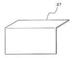
그리고, 페이스 플레이트(25)의 이면에 페이스 플레이트(25)의 창부(25a)를 폐색하고, 전력퓨즈(18)의 상면의 일부를 덮도록 절연판(27)이 볼트 또는 피스 등의 체결부재(28)에 의해서 나사잠금되어 있다. 절연판(27)은, 도 3에 나타내는 바와 같이, 투명 또는 반투명의 절연판재(예를 들면, 아크릴판)를 이용하여 단면이 'L'자 모양으로 굽혀져 형성되어 있다. 'L'자 모양으로 형성된 상부 측은 전력퓨즈(18) 상면의 일부를 덮는 부분이지만, 더욱이, 양측면도 이와 같이 'L'자 모양으로 접곡되어 전력퓨즈(18)의 측면의 일부를 덮도록 해도 된다.Then, the
또한, 지금까지 설명한 진공개폐기의 구성(특히, 전자조작기구부의 구성)은 일례를 나타내는 것으로, 도면에 한정되는 것은 아니다. 중앙부에 진공 인터럽터(3)를 가지고, 진공 인터럽터(3)의 아래쪽에 조작기구가 배치되고, 위쪽에 전력퓨즈(18)를 구비하며, 전면 측에 페이스 플레이트(25)가 설치된 진공개폐기이면 된다.In addition, the structure (especially the structure of an electronic control mechanism part) of the vacuum switch demonstrated so far is an example, Comprising: It is not limited to drawing. The
이상과 같이 구성된 페이스 플레이트(25)와 절연판(27)의 작용에 대해서 설명한다.The operation of the
전력퓨즈(18)의 퓨즈 캡(18b)은 노출된 고압충전부이다. 한편, 금속제의 페 이스 플레이트(25)는 접지부이다. 따라서, 전력퓨즈(18)의 전면 측의 퓨즈 캡(18b)과 페이스 플레이트(25) 사이는 내전압의 관점에서는 최약점부가 되기 때문에, 필요한 내전압 성능을 얻기 위해서 소정의 절연거리를 확보해 둘 필요가 있다.The
그래서, 본 출원의 실시형태 1의 진공개폐기에서는 전력퓨즈(18)의 전방부에 대향하는 페이스 플레이트(25)의 위치에 창(25a)을 개구시켜, 양자 사이의 절연거리를 실질적으로 길게 하고, 또한 절연판(27)으로 개구부를 폐색한 것이다. 이것에 의해, 내전압 성능을 향상시킬 수 있다. 바꾸어 말하면, 창(25a)이 없는 경우와 동일한 내전압 성능으로 좋다면, 전력퓨즈(18)와 페이스 플레이트(25)의 이격(離隔)거리를 짧게 할 수 있게 된다.Therefore, in the vacuum switch of
도 2에 의해 더욱 자세하게 설명한다. 퓨즈 캡(18b)의 단부로부터 창(25a)의 개구연까지의 거리를 D로 하고, 퓨즈 캡(18b)의 전면으로부터 페이스 플레이트(25)까지의 최소 거리(축 방향 거리)를 d로 한다. 창(25a)이 없는 경우는, d치수를 필요한 절연거리로서 확보할 필요가 있었지만, 창(25a)이 있는 경우는, D치수를 필요한 절연거리로 하면 된다. 즉, 창(25a)을 형성한 것에 의해, 퓨즈 캡(18b)과 페이스 플레이트(25)와의 이격거리를 (D - d)만큼 축소할 수 있다. 이 결과, 진공개폐기를 소형화하는 것이 가능하게 된다.It demonstrates in more detail by FIG. The distance from the end of the
또, 절연판을 투명 또는 반투명으로 함으로써, 퓨즈 스트라이커(18a)가 부착된 전력퓨즈(18)의 경우, 퓨즈가 용단하여 퓨즈 스트라이커(18a)가 돌출된 동작을 창(25a)을 통해서 눈으로 확인하는 것이 가능하게 된다. 따라서, 퓨즈의 동작검출수단을 마련하지 않아도 퓨즈의 용단을 용이하게 알 수 있다.In addition, in the case of the
또한, 퓨즈 스트라이커가 부착된 전력퓨즈가 아닌 경우는 절연판(27)을 투명 또는 반투명으로 할 필요는 없고, 불투명의 절연판(27)으로 해도 된다.In addition, when it is not the electric power fuse with a fuse striker, it is not necessary to make the insulating
이상과 같이, 실시형태 1의 진공개폐기에 의하면, 각 상에 대응해서 설치된 복수 개의 전력퓨즈를 길이방향을 진공개폐기의 전후방향을 향하고, 또한, 전면 측에서 보아 가로방향으로 일렬로 늘어 놓아 진공 인터럽터의 위쪽에 배치하며, 각 전력퓨즈의 전방부와 대향하는 페이스 플레이트의 위치에 가로방향으로 늘어 놓인 전력퓨즈의 최대 폭보다도 큰 가로 폭과 전력퓨즈의 직경보다도 큰 세로 폭의 직사각형 모양의 창을 형성하고, 페이스 플레이트의 이면에 창을 폐색하는 절연판을 장착함으로써, 전력퓨즈의 전방부와 페이스 플레이트와의 내전압 성능을 향상시킬 수 있어, 실질적으로 전력퓨즈와 페이스 플레이트와의 이격거리를 짧게 할 수 있으므로, 진공개폐기의 소형화를 도모할 수 있다.As described above, according to the vacuum switch of the first embodiment, a plurality of power fuses provided corresponding to each phase are arranged in a line in the transverse direction as viewed from the front side in the longitudinal direction of the vacuum switch, and the vacuum interrupter. A rectangular window having a width greater than the maximum width of the power fuses and a width greater than the diameter of the power fuses arranged in a horizontal direction at a position of the face plate facing the front of each power fuse. In addition, by installing an insulating plate that closes the window on the back surface of the face plate, the breakdown voltage performance between the front portion of the power fuse and the face plate can be improved, and the separation distance between the power fuse and the face plate can be substantially shortened. Therefore, the vacuum switch can be miniaturized.
또, 진력퓨즈는 용단을 표시하는 퓨즈 스트라이커를 가지고, 절연판은 투명 또는 반투명으로 함으로써, 퓨즈 스트라이커가 부착된 전력퓨즈를 구비한 진공개폐기의 경우, 상기의 효과에 더하여, 퓨즈가 용단하여 퓨즈 스트라이커가 돌출한 동작을 창을 통해 눈으로 확인하는 것이 가능하게 되어, 전력퓨즈의 동작확인이 용이하게 된다.In addition, in the case of a vacuum breaker having a power fuse with a fuse striker, the fuse has a fuse blown, and the fuse blower has a fuse striker indicating the blowdown, and the insulating plate is transparent or translucent. It is possible to visually check the protruding operation through the window, so that it is easy to confirm the operation of the power fuse.
도 1은 본 발명의 실시형태 1에 의한 진공개폐기의 정면도이다.1 is a front view of a vacuum switch according to
도 2는 도 1의 진공개폐기의 측면도이다.FIG. 2 is a side view of the vacuum switch of FIG. 1. FIG.
도 3은 도 1의 진공개폐기의 페이스 플레이트에 장착되는 절연판이다.3 is an insulating plate mounted to the face plate of the vacuum switch of FIG.
도 4는 종래의 페이스 플레이트를 구비한 진공전자 접촉기이다.4 is a vacuum electronic contactor with a conventional face plate.
<부호의 설명><Code description>
1 대차 2 절연프레임1
3 진공 인터럽터 4 고정접점3
5 가동접점 6 고정로드5
7 가동로드 8 고정 측 단자7
9 절연로드 10 회동축9 insulated
11 레버 12 가동 측 단자11
13 가동 측 주회로 도체 14, 23 접촉자13 Movable side
15 지지부재 16 가동철심15
17 전자석 18 전력퓨즈17 Electromagnet 18 Power Fuse
18a 퓨즈 스트라이커 18b 퓨즈 캡
19 퓨즈 홀더 20, 21 접속도체19
22 고정 측 주회로 도체 24 절연 베어리어22 Fixed Side
25 페이스 플레이트 25a 창25
26, 28 체결부재 27 절연판.26, 28
Claims (2)
Applications Claiming Priority (2)
| Application Number | Priority Date | Filing Date | Title |
|---|---|---|---|
| JP2009114613A JP2010263747A (en) | 2009-05-11 | 2009-05-11 | Vacuum switch |
| JPJP-P-2009-114613 | 2009-05-11 |
Publications (2)
| Publication Number | Publication Date |
|---|---|
| KR20100122040A KR20100122040A (en) | 2010-11-19 |
| KR101024781B1 true KR101024781B1 (en) | 2011-03-24 |
Family
ID=43073677
Family Applications (1)
| Application Number | Title | Priority Date | Filing Date |
|---|---|---|---|
| KR1020090073307A KR101024781B1 (en) | 2009-05-11 | 2009-08-10 | Vacuum switch |
Country Status (4)
| Country | Link |
|---|---|
| JP (1) | JP2010263747A (en) |
| KR (1) | KR101024781B1 (en) |
| CN (1) | CN101887819B (en) |
| TW (1) | TWI404100B (en) |
Cited By (1)
| Publication number | Priority date | Publication date | Assignee | Title |
|---|---|---|---|---|
| KR20220045493A (en) * | 2020-10-05 | 2022-04-12 | 신성산전주식회사 | Driving apparatus for load breaker switch |
Families Citing this family (6)
| Publication number | Priority date | Publication date | Assignee | Title |
|---|---|---|---|---|
| US8791362B2 (en) * | 2012-05-24 | 2014-07-29 | General Electric Company | Shutter door assembly for an electrical panel |
| KR200484887Y1 (en) * | 2013-09-16 | 2017-11-03 | 엘에스산전 주식회사 | A combination type vaacuum contactor |
| CN103730287A (en) * | 2013-12-20 | 2014-04-16 | 吴江市东泰电力特种开关有限公司 | Vacuum power switch |
| CN105845492A (en) * | 2016-06-06 | 2016-08-10 | 广西南宁德通网络有限公司 | Vacuum circuit-breaking equipment |
| KR200487085Y1 (en) * | 2016-12-29 | 2018-08-29 | 엘에스산전 주식회사 | Fuse case for vacuum contactor |
| WO2021090420A1 (en) * | 2019-11-07 | 2021-05-14 | 三菱電機株式会社 | Vacuum switching device and switchgear |
Citations (3)
| Publication number | Priority date | Publication date | Assignee | Title |
|---|---|---|---|---|
| JPH06208821A (en) * | 1993-01-11 | 1994-07-26 | Mitsubishi Electric Corp | Vacuum circuit breaker |
| KR100324801B1 (en) | 1997-07-24 | 2002-08-24 | 미쓰비시덴키 가부시키가이샤 | Switchgear |
| KR100857439B1 (en) | 2008-02-29 | 2008-09-08 | 한빛전기감리(주) | A power supplying apparatus |
Family Cites Families (13)
| Publication number | Priority date | Publication date | Assignee | Title |
|---|---|---|---|---|
| JPS5718810U (en) * | 1980-07-04 | 1982-01-30 | ||
| JPS58190206A (en) * | 1982-04-27 | 1983-11-07 | 神鋼電機株式会社 | Drawer type high voltage electromagnetic contactor |
| JPS59129324U (en) * | 1983-02-10 | 1984-08-30 | 株式会社東芝 | closed switchboard |
| JPS6012205U (en) * | 1983-07-04 | 1985-01-28 | 三菱電機株式会社 | Disconnect type unit |
| JPS61237321A (en) * | 1985-04-12 | 1986-10-22 | 株式会社東芝 | Insulation case |
| JPS6369331U (en) * | 1986-10-23 | 1988-05-10 | ||
| JP3039032B2 (en) * | 1991-09-10 | 2000-05-08 | 富士電機株式会社 | Vacuum electromagnetic contactor |
| JPH0946830A (en) * | 1995-07-24 | 1997-02-14 | Nissin Electric Co Ltd | Switchgear |
| JP3744688B2 (en) * | 1998-05-22 | 2006-02-15 | 三菱電機株式会社 | Unit trolley |
| JP3600781B2 (en) * | 2000-06-06 | 2004-12-15 | 株式会社日立製作所 | Protection device for hermetic electric compressor, hermetic electric compressor and cooling system using the same |
| US20070012894A1 (en) * | 2005-07-18 | 2007-01-18 | G-Light Display Corp. | Vacuum gate valve |
| JP4955354B2 (en) * | 2006-04-28 | 2012-06-20 | 富士電機株式会社 | Drawer type equipment and switchboard |
| US7576957B2 (en) * | 2006-05-01 | 2009-08-18 | Eaton Corporation | Circuit interrupter including point-on-wave controller and voltage sensors |
-
2009
- 2009-05-11 JP JP2009114613A patent/JP2010263747A/en active Pending
- 2009-07-28 CN CN2009101605640A patent/CN101887819B/en active Active
- 2009-08-10 KR KR1020090073307A patent/KR101024781B1/en active IP Right Grant
- 2009-10-19 TW TW098135225A patent/TWI404100B/en active
Patent Citations (3)
| Publication number | Priority date | Publication date | Assignee | Title |
|---|---|---|---|---|
| JPH06208821A (en) * | 1993-01-11 | 1994-07-26 | Mitsubishi Electric Corp | Vacuum circuit breaker |
| KR100324801B1 (en) | 1997-07-24 | 2002-08-24 | 미쓰비시덴키 가부시키가이샤 | Switchgear |
| KR100857439B1 (en) | 2008-02-29 | 2008-09-08 | 한빛전기감리(주) | A power supplying apparatus |
Cited By (2)
| Publication number | Priority date | Publication date | Assignee | Title |
|---|---|---|---|---|
| KR20220045493A (en) * | 2020-10-05 | 2022-04-12 | 신성산전주식회사 | Driving apparatus for load breaker switch |
| KR102457966B1 (en) * | 2020-10-05 | 2022-10-26 | 신성산전주식회사 | Driving apparatus for load breaker switch |
Also Published As
| Publication number | Publication date |
|---|---|
| CN101887819A (en) | 2010-11-17 |
| JP2010263747A (en) | 2010-11-18 |
| TWI404100B (en) | 2013-08-01 |
| CN101887819B (en) | 2013-01-16 |
| TW201041003A (en) | 2010-11-16 |
| KR20100122040A (en) | 2010-11-19 |
Similar Documents
| Publication | Publication Date | Title |
|---|---|---|
| KR101024781B1 (en) | Vacuum switch | |
| US9208978B2 (en) | Electromagnetic operating device | |
| EP2178097A2 (en) | Switchgear | |
| US8173916B2 (en) | Move-out type interlock apparatus for circuit breaker | |
| US8411418B2 (en) | Vacuum insulated switchgear | |
| KR101704807B1 (en) | operation device using electromagnetic repulsion force for circuit breaker | |
| RU2396627C2 (en) | Electromechanical circuit breaker and current breaking method | |
| US7075027B1 (en) | Spring-charged mechanism assembly employing two trunnion members moveable in different planes and circuit interrupter employing the same | |
| KR20140036111A (en) | Arc extinguishing mechanism of direct current switch and direct current switch and direct current circuit breaker having arc extinguishing mechanism | |
| CN112543985A (en) | Switching device and method for operating a switching device | |
| US4973805A (en) | Arc runner, containment support assembly | |
| US20140361858A1 (en) | Actuator for contactor | |
| KR100844274B1 (en) | Three Position Switch structure of Magnetic Contactor | |
| JP5123894B2 (en) | Vacuum insulated switchgear | |
| KR100987585B1 (en) | A cell switch operating rod for cubicle | |
| KR101883574B1 (en) | Position detector for vacuum circuit breaker | |
| JP2005038630A (en) | Vacuum interrupting device | |
| JP5152899B2 (en) | Power fuse fusing display device | |
| CN108987194A (en) | The safety device unit of circuit-breaker and circuit-breaker | |
| US11955301B2 (en) | Switching device | |
| KR101198508B1 (en) | an earthing switch of Gas Insulated Switchgear | |
| KR101252409B1 (en) | Base assembly having a heater combination portion and circuit breaker for electric wiring having the same | |
| CN115148556A (en) | Integrated protection module and circuit breaker | |
| KR101026579B1 (en) | Circuit breaker | |
| CN202307604U (en) | Novel grounding interlocking |
Legal Events
| Date | Code | Title | Description |
|---|---|---|---|
| A201 | Request for examination | ||
| E701 | Decision to grant or registration of patent right | ||
| GRNT | Written decision to grant | ||
| FPAY | Annual fee payment |
Payment date: 20140220 Year of fee payment: 4 |
|
| FPAY | Annual fee payment |
Payment date: 20150224 Year of fee payment: 5 |
|
| FPAY | Annual fee payment |
Payment date: 20160219 Year of fee payment: 6 |
|
| FPAY | Annual fee payment |
Payment date: 20170221 Year of fee payment: 7 |
|
| FPAY | Annual fee payment |
Payment date: 20180220 Year of fee payment: 8 |
|
| FPAY | Annual fee payment |
Payment date: 20190219 Year of fee payment: 9 |
|
| FPAY | Annual fee payment |
Payment date: 20200303 Year of fee payment: 10 |