KR100939039B1 - Vehicle control device - Google Patents
Vehicle control device Download PDFInfo
- Publication number
- KR100939039B1 KR100939039B1 KR1020077027343A KR20077027343A KR100939039B1 KR 100939039 B1 KR100939039 B1 KR 100939039B1 KR 1020077027343 A KR1020077027343 A KR 1020077027343A KR 20077027343 A KR20077027343 A KR 20077027343A KR 100939039 B1 KR100939039 B1 KR 100939039B1
- Authority
- KR
- South Korea
- Prior art keywords
- future
- vehicle behavior
- time
- operation command
- determined
- Prior art date
Links
- 238000011156 evaluation Methods 0.000 claims abstract description 194
- 230000033001 locomotion Effects 0.000 claims abstract description 185
- 238000006243 chemical reaction Methods 0.000 claims abstract description 54
- 238000001514 detection method Methods 0.000 claims abstract description 27
- 230000006399 behavior Effects 0.000 claims description 1069
- 238000000034 method Methods 0.000 claims description 390
- 230000008569 process Effects 0.000 claims description 304
- 238000012545 processing Methods 0.000 claims description 280
- 238000012937 correction Methods 0.000 claims description 119
- 238000006557 surface reaction Methods 0.000 claims description 78
- 238000004364 calculation method Methods 0.000 claims description 59
- 238000013459 approach Methods 0.000 claims description 22
- 230000002194 synthesizing effect Effects 0.000 claims description 13
- 239000002131 composite material Substances 0.000 claims description 7
- 238000012986 modification Methods 0.000 claims description 3
- 230000004048 modification Effects 0.000 claims description 3
- 238000011002 quantification Methods 0.000 claims description 2
- 239000008280 blood Substances 0.000 claims 1
- 210000004369 blood Anatomy 0.000 claims 1
- 230000008859 change Effects 0.000 description 80
- 239000000725 suspension Substances 0.000 description 57
- IHGVZTXLHUWVIA-UHFFFAOYSA-N 4-chloro-n-hydroxy-1-benzothiophene-2-carboxamide Chemical compound C1=CC=C2SC(C(=O)NO)=CC2=C1Cl IHGVZTXLHUWVIA-UHFFFAOYSA-N 0.000 description 43
- 230000006870 function Effects 0.000 description 37
- 238000011161 development Methods 0.000 description 32
- 238000002360 preparation method Methods 0.000 description 31
- 230000002123 temporal effect Effects 0.000 description 27
- 239000013598 vector Substances 0.000 description 22
- 238000009826 distribution Methods 0.000 description 20
- 230000002265 prevention Effects 0.000 description 19
- 238000010586 diagram Methods 0.000 description 17
- 230000001133 acceleration Effects 0.000 description 15
- 230000014509 gene expression Effects 0.000 description 14
- 101150048593 Mdmd gene Proteins 0.000 description 12
- 230000004044 response Effects 0.000 description 11
- 238000005096 rolling process Methods 0.000 description 11
- 230000000694 effects Effects 0.000 description 10
- 230000005540 biological transmission Effects 0.000 description 9
- 230000003252 repetitive effect Effects 0.000 description 8
- 230000003466 anti-cipated effect Effects 0.000 description 7
- 239000000446 fuel Substances 0.000 description 6
- 238000002347 injection Methods 0.000 description 6
- 239000007924 injection Substances 0.000 description 6
- 230000002159 abnormal effect Effects 0.000 description 5
- 238000006073 displacement reaction Methods 0.000 description 5
- 230000001953 sensory effect Effects 0.000 description 5
- 239000000243 solution Substances 0.000 description 5
- 230000003449 preventive effect Effects 0.000 description 4
- 230000000007 visual effect Effects 0.000 description 4
- 238000005242 forging Methods 0.000 description 3
- 230000007246 mechanism Effects 0.000 description 3
- 238000011084 recovery Methods 0.000 description 3
- 230000009471 action Effects 0.000 description 2
- 239000000470 constituent Substances 0.000 description 2
- 238000013016 damping Methods 0.000 description 2
- 230000007423 decrease Effects 0.000 description 2
- 238000011022 operating instruction Methods 0.000 description 2
- 238000002485 combustion reaction Methods 0.000 description 1
- 238000005516 engineering process Methods 0.000 description 1
- 230000007613 environmental effect Effects 0.000 description 1
- 238000012854 evaluation process Methods 0.000 description 1
- 238000002474 experimental method Methods 0.000 description 1
- 238000001914 filtration Methods 0.000 description 1
- 230000000977 initiatory effect Effects 0.000 description 1
- 230000010354 integration Effects 0.000 description 1
- 238000012804 iterative process Methods 0.000 description 1
- 230000000069 prophylactic effect Effects 0.000 description 1
- 229920006395 saturated elastomer Polymers 0.000 description 1
- 239000007787 solid Substances 0.000 description 1
- 238000009987 spinning Methods 0.000 description 1
- 238000013519 translation Methods 0.000 description 1
Images
Classifications
-
- B—PERFORMING OPERATIONS; TRANSPORTING
- B62—LAND VEHICLES FOR TRAVELLING OTHERWISE THAN ON RAILS
- B62D—MOTOR VEHICLES; TRAILERS
- B62D6/00—Arrangements for automatically controlling steering depending on driving conditions sensed and responded to, e.g. control circuits
- B62D6/002—Arrangements for automatically controlling steering depending on driving conditions sensed and responded to, e.g. control circuits computing target steering angles for front or rear wheels
- B62D6/003—Arrangements for automatically controlling steering depending on driving conditions sensed and responded to, e.g. control circuits computing target steering angles for front or rear wheels in order to control vehicle yaw movement, i.e. around a vertical axis
-
- B—PERFORMING OPERATIONS; TRANSPORTING
- B60—VEHICLES IN GENERAL
- B60W—CONJOINT CONTROL OF VEHICLE SUB-UNITS OF DIFFERENT TYPE OR DIFFERENT FUNCTION; CONTROL SYSTEMS SPECIALLY ADAPTED FOR HYBRID VEHICLES; ROAD VEHICLE DRIVE CONTROL SYSTEMS FOR PURPOSES NOT RELATED TO THE CONTROL OF A PARTICULAR SUB-UNIT
- B60W30/00—Purposes of road vehicle drive control systems not related to the control of a particular sub-unit, e.g. of systems using conjoint control of vehicle sub-units
- B60W30/02—Control of vehicle driving stability
-
- B—PERFORMING OPERATIONS; TRANSPORTING
- B60—VEHICLES IN GENERAL
- B60T—VEHICLE BRAKE CONTROL SYSTEMS OR PARTS THEREOF; BRAKE CONTROL SYSTEMS OR PARTS THEREOF, IN GENERAL; ARRANGEMENT OF BRAKING ELEMENTS ON VEHICLES IN GENERAL; PORTABLE DEVICES FOR PREVENTING UNWANTED MOVEMENT OF VEHICLES; VEHICLE MODIFICATIONS TO FACILITATE COOLING OF BRAKES
- B60T8/00—Arrangements for adjusting wheel-braking force to meet varying vehicular or ground-surface conditions, e.g. limiting or varying distribution of braking force
- B60T8/17—Using electrical or electronic regulation means to control braking
- B60T8/1755—Brake regulation specially adapted to control the stability of the vehicle, e.g. taking into account yaw rate or transverse acceleration in a curve
- B60T8/17551—Brake regulation specially adapted to control the stability of the vehicle, e.g. taking into account yaw rate or transverse acceleration in a curve determining control parameters related to vehicle stability used in the regulation, e.g. by calculations involving measured or detected parameters
-
- B—PERFORMING OPERATIONS; TRANSPORTING
- B60—VEHICLES IN GENERAL
- B60W—CONJOINT CONTROL OF VEHICLE SUB-UNITS OF DIFFERENT TYPE OR DIFFERENT FUNCTION; CONTROL SYSTEMS SPECIALLY ADAPTED FOR HYBRID VEHICLES; ROAD VEHICLE DRIVE CONTROL SYSTEMS FOR PURPOSES NOT RELATED TO THE CONTROL OF A PARTICULAR SUB-UNIT
- B60W40/00—Estimation or calculation of non-directly measurable driving parameters for road vehicle drive control systems not related to the control of a particular sub unit, e.g. by using mathematical models
- B60W40/02—Estimation or calculation of non-directly measurable driving parameters for road vehicle drive control systems not related to the control of a particular sub unit, e.g. by using mathematical models related to ambient conditions
- B60W40/06—Road conditions
- B60W40/068—Road friction coefficient
-
- B—PERFORMING OPERATIONS; TRANSPORTING
- B60—VEHICLES IN GENERAL
- B60W—CONJOINT CONTROL OF VEHICLE SUB-UNITS OF DIFFERENT TYPE OR DIFFERENT FUNCTION; CONTROL SYSTEMS SPECIALLY ADAPTED FOR HYBRID VEHICLES; ROAD VEHICLE DRIVE CONTROL SYSTEMS FOR PURPOSES NOT RELATED TO THE CONTROL OF A PARTICULAR SUB-UNIT
- B60W40/00—Estimation or calculation of non-directly measurable driving parameters for road vehicle drive control systems not related to the control of a particular sub unit, e.g. by using mathematical models
- B60W40/08—Estimation or calculation of non-directly measurable driving parameters for road vehicle drive control systems not related to the control of a particular sub unit, e.g. by using mathematical models related to drivers or passengers
-
- B—PERFORMING OPERATIONS; TRANSPORTING
- B60—VEHICLES IN GENERAL
- B60W—CONJOINT CONTROL OF VEHICLE SUB-UNITS OF DIFFERENT TYPE OR DIFFERENT FUNCTION; CONTROL SYSTEMS SPECIALLY ADAPTED FOR HYBRID VEHICLES; ROAD VEHICLE DRIVE CONTROL SYSTEMS FOR PURPOSES NOT RELATED TO THE CONTROL OF A PARTICULAR SUB-UNIT
- B60W40/00—Estimation or calculation of non-directly measurable driving parameters for road vehicle drive control systems not related to the control of a particular sub unit, e.g. by using mathematical models
- B60W40/10—Estimation or calculation of non-directly measurable driving parameters for road vehicle drive control systems not related to the control of a particular sub unit, e.g. by using mathematical models related to vehicle motion
- B60W40/101—Side slip angle of tyre
-
- B—PERFORMING OPERATIONS; TRANSPORTING
- B60—VEHICLES IN GENERAL
- B60W—CONJOINT CONTROL OF VEHICLE SUB-UNITS OF DIFFERENT TYPE OR DIFFERENT FUNCTION; CONTROL SYSTEMS SPECIALLY ADAPTED FOR HYBRID VEHICLES; ROAD VEHICLE DRIVE CONTROL SYSTEMS FOR PURPOSES NOT RELATED TO THE CONTROL OF A PARTICULAR SUB-UNIT
- B60W50/00—Details of control systems for road vehicle drive control not related to the control of a particular sub-unit, e.g. process diagnostic or vehicle driver interfaces
- B60W50/0097—Predicting future conditions
-
- B—PERFORMING OPERATIONS; TRANSPORTING
- B62—LAND VEHICLES FOR TRAVELLING OTHERWISE THAN ON RAILS
- B62D—MOTOR VEHICLES; TRAILERS
- B62D6/00—Arrangements for automatically controlling steering depending on driving conditions sensed and responded to, e.g. control circuits
-
- B—PERFORMING OPERATIONS; TRANSPORTING
- B60—VEHICLES IN GENERAL
- B60T—VEHICLE BRAKE CONTROL SYSTEMS OR PARTS THEREOF; BRAKE CONTROL SYSTEMS OR PARTS THEREOF, IN GENERAL; ARRANGEMENT OF BRAKING ELEMENTS ON VEHICLES IN GENERAL; PORTABLE DEVICES FOR PREVENTING UNWANTED MOVEMENT OF VEHICLES; VEHICLE MODIFICATIONS TO FACILITATE COOLING OF BRAKES
- B60T2230/00—Monitoring, detecting special vehicle behaviour; Counteracting thereof
- B60T2230/02—Side slip angle, attitude angle, floating angle, drift angle
-
- B—PERFORMING OPERATIONS; TRANSPORTING
- B60—VEHICLES IN GENERAL
- B60T—VEHICLE BRAKE CONTROL SYSTEMS OR PARTS THEREOF; BRAKE CONTROL SYSTEMS OR PARTS THEREOF, IN GENERAL; ARRANGEMENT OF BRAKING ELEMENTS ON VEHICLES IN GENERAL; PORTABLE DEVICES FOR PREVENTING UNWANTED MOVEMENT OF VEHICLES; VEHICLE MODIFICATIONS TO FACILITATE COOLING OF BRAKES
- B60T2270/00—Further aspects of brake control systems not otherwise provided for
- B60T2270/86—Optimizing braking by using ESP vehicle or tire model
-
- B—PERFORMING OPERATIONS; TRANSPORTING
- B60—VEHICLES IN GENERAL
- B60W—CONJOINT CONTROL OF VEHICLE SUB-UNITS OF DIFFERENT TYPE OR DIFFERENT FUNCTION; CONTROL SYSTEMS SPECIALLY ADAPTED FOR HYBRID VEHICLES; ROAD VEHICLE DRIVE CONTROL SYSTEMS FOR PURPOSES NOT RELATED TO THE CONTROL OF A PARTICULAR SUB-UNIT
- B60W10/00—Conjoint control of vehicle sub-units of different type or different function
- B60W10/18—Conjoint control of vehicle sub-units of different type or different function including control of braking systems
- B60W10/184—Conjoint control of vehicle sub-units of different type or different function including control of braking systems with wheel brakes
-
- B—PERFORMING OPERATIONS; TRANSPORTING
- B60—VEHICLES IN GENERAL
- B60W—CONJOINT CONTROL OF VEHICLE SUB-UNITS OF DIFFERENT TYPE OR DIFFERENT FUNCTION; CONTROL SYSTEMS SPECIALLY ADAPTED FOR HYBRID VEHICLES; ROAD VEHICLE DRIVE CONTROL SYSTEMS FOR PURPOSES NOT RELATED TO THE CONTROL OF A PARTICULAR SUB-UNIT
- B60W10/00—Conjoint control of vehicle sub-units of different type or different function
- B60W10/20—Conjoint control of vehicle sub-units of different type or different function including control of steering systems
-
- B—PERFORMING OPERATIONS; TRANSPORTING
- B60—VEHICLES IN GENERAL
- B60W—CONJOINT CONTROL OF VEHICLE SUB-UNITS OF DIFFERENT TYPE OR DIFFERENT FUNCTION; CONTROL SYSTEMS SPECIALLY ADAPTED FOR HYBRID VEHICLES; ROAD VEHICLE DRIVE CONTROL SYSTEMS FOR PURPOSES NOT RELATED TO THE CONTROL OF A PARTICULAR SUB-UNIT
- B60W10/00—Conjoint control of vehicle sub-units of different type or different function
- B60W10/22—Conjoint control of vehicle sub-units of different type or different function including control of suspension systems
-
- B—PERFORMING OPERATIONS; TRANSPORTING
- B60—VEHICLES IN GENERAL
- B60W—CONJOINT CONTROL OF VEHICLE SUB-UNITS OF DIFFERENT TYPE OR DIFFERENT FUNCTION; CONTROL SYSTEMS SPECIALLY ADAPTED FOR HYBRID VEHICLES; ROAD VEHICLE DRIVE CONTROL SYSTEMS FOR PURPOSES NOT RELATED TO THE CONTROL OF A PARTICULAR SUB-UNIT
- B60W50/00—Details of control systems for road vehicle drive control not related to the control of a particular sub-unit, e.g. process diagnostic or vehicle driver interfaces
- B60W2050/0001—Details of the control system
- B60W2050/0019—Control system elements or transfer functions
- B60W2050/0028—Mathematical models, e.g. for simulation
- B60W2050/0031—Mathematical model of the vehicle
Landscapes
- Engineering & Computer Science (AREA)
- Transportation (AREA)
- Mechanical Engineering (AREA)
- Automation & Control Theory (AREA)
- Physics & Mathematics (AREA)
- Mathematical Physics (AREA)
- Chemical & Material Sciences (AREA)
- Combustion & Propulsion (AREA)
- Human Computer Interaction (AREA)
- Steering Control In Accordance With Driving Conditions (AREA)
- Control Of Driving Devices And Active Controlling Of Vehicle (AREA)
- Regulating Braking Force (AREA)
Abstract
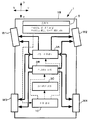
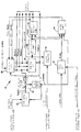
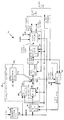
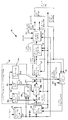
차량(1)의 액추에이터 장치(3A, 3B, 3C)의 동작을 제어하는 제어수단(10)은 차량 모델(41)을 사용하여 차량(1)의 장래 거동의 시계열을 작성한다. 이 때, 차량 모델(41)의 상태량은 실제의 차량(1)의 상태량에 기초하여 초기화되고, 그 초기 상태량을 기점으로 하여 장래 거동이 작성된다. 그 장래 거동은, 현재시각에 있어서의 차량 모델(41)에서의 액추에이터 장치의 동작지령을, 차량(1)의 스티어링 휠 등의 조작기(5)의 조작에 따른 기본값에 일치시키거나, 또는 근접되게 하여 작성된다. 작성한 장래 거동에서의 차량의 운동, 노면 반력 및 차륜의 미끄러짐 등의 평가대상이 소정의 제약조건을 충족시키고 있는지 아닌지를 평가하고, 그 평가결과에 기초하여 액추에이터 장치(3A, 3B, 3C)의 동작지령을 차례차례 결정한다. 이것에 의해, 차량의 장래의 거동을 적절하게 예측하면서, 차량의 적합한 주행을 행하는 것을 가능하게 한다. The control means 10 for controlling the operation of the actuator devices 3A, 3B, 3C of the vehicle 1 creates the time series of the future behavior of the vehicle 1 using the vehicle model 41. At this time, the state quantity of the vehicle model 41 is initialized based on the actual state quantity of the vehicle 1, and future behavior is created based on the initial state quantity. The future behavior is to match the operation command of the actuator device in the vehicle model 41 at the present time with or close to the default value according to the operation of the manipulator 5 such as the steering wheel of the vehicle 1. Is written. Evaluate whether or not the evaluation targets such as the movement of the vehicle, the road reaction force, and the sliding of the wheel meet the predetermined constraints in the future behavior, and operate the actuator devices 3A, 3B, and 3C based on the evaluation result. Decide on orders one after another. This makes it possible to appropriately run the vehicle while properly predicting the future behavior of the vehicle.
조작기, 운전조작량 검출수단, 액추에이터 장치, 액추에이터 장치 제어수단, 실상태량 파악수단, 차량의 제어장치, 동역학 모델, 차량 모델, 차량 모델 초기화 수단, 장래 운전조작량 결정수단, 차량거동 결정수단, 평가수단. Manipulator, driving amount detection means, actuator device, actuator device control means, actual state amount detecting means, vehicle control device, dynamics model, vehicle model, vehicle model initialization means, future operation amount determination means, vehicle behavior determination means, evaluation means.
Description
본 발명은 자동차(엔진 자동차), 하이브리드차, 전기자동차, 자동 2륜차 등, 복수의 차륜을 갖는 차량의 제어장치에 관한 것이다. The present invention relates to a control device for a vehicle having a plurality of wheels, such as an automobile (engine vehicle), a hybrid vehicle, an electric vehicle, an automatic two-wheeled vehicle, and the like.
자동차 등의 차량에서는, 여러 액추에이터를 탑재하고, 스티어링 휠, 가속 페달, 브레이크 페달, 시프트 레버 등의 인위적인 조작기의 조작에 따라 수동적으로(운전자에 의한 조작기의 조작대로) 차량의 거동을 제어할 뿐만 아니라, 차량의 여러 다양한 상태량이나 외부환경의 상태에 따라, 여러 액추에이터를 통하여 능동적으로 차량의 거동을 제어하도록 한 것이 알려져 있다. In vehicles such as automobiles, various actuators are mounted and not only control the behavior of the vehicle manually (in accordance with the operation of the manipulator) by manipulating manipulators such as steering wheel, accelerator pedal, brake pedal, shift lever, etc. In addition, it is known to actively control the behavior of the vehicle through various actuators according to various state quantities of the vehicle or the state of the external environment.
예를 들면 일본 특개 2000-302055호 공보(이하, 특허문헌 1이라고 함)에는, 액추에이터에 의해 조타 가능한 차량을 목표 코스에 추종시키도록 차량의 조타 제어를 행하는 기술이 본원 출원인에 의해 제안되어 있다. 이 기술에서는, CCD 카메라 등에 의해 얻은 정보를 기초로 결정한 목표 코스에 대한 차량의 장래의 횡방향 변위가 예측된다. 또한, 그 횡방향 변위와 조타각의 시간적 변화량을 가능한 한 작게 하도록 차량의 조타 제어용의 제어 입력이 결정된다. 그리고, 그 제어 입력에 의해 차량의 조타를 액추에이터를 통하여 행하도록 하고 있다. For example, Japanese Patent Application Laid-Open No. 2000-302055 (hereinafter referred to as Patent Document 1) proposes a technique for performing steering control of a vehicle so that a vehicle steerable by an actuator can follow a target course. In this technique, the future lateral displacement of the vehicle with respect to the target course determined based on the information obtained by the CCD camera or the like is predicted. Further, the control input for steering control of the vehicle is determined so that the amount of temporal change in the lateral displacement and the steering angle is as small as possible. Then, the control input allows steering of the vehicle through the actuator.
또, 예를 들면 「자동차 기술 핸드북 기초·이론편(제 1분책)/사단법인 자동 차기술회 발행(1992년 6월 15일 발행)」(이하, 비특허문헌 1이라고 함)의 제 225쪽의 도 6-99(a)에는, 모델 팔로잉(Model-following) 방식이라고 하는 제어 수법이 개시되어 있다. 이 제어 수법은 운전자에 의한 조타륜의 조타각을 조타 응답특성을 미리 설정한 규범 모델에 입력하고, 이 규범 모델의 출력에 차량 모델의 출력을 추종시키도록 차량 모델의 제어 입력을 결정한다. 그리고, 이 차량 모델의 제어 입력을 실제의 차량에 입력함으로써, 실제의 차량을 규범 모델에 추종시키도록 하고 있다. Also, for example, the diagram on page 225 of the `` Basic Technology Handbook Basics and Theory '' (first part) / The Society of Automotive Engineers (June 15, 1992) (hereinafter referred to as Non-Patent Document 1). 6-99 (a) discloses a control method called a model-following method. This control method inputs the steering angle of the steering wheel by the driver to the norm model in which the steering response characteristics are set in advance, and determines the control input of the vehicle model to follow the output of the vehicle model to the output of the norm model. And the control input of this vehicle model is input to an actual vehicle, and the actual vehicle follows the norm model.
(발명의 개시)(Initiation of invention)
그러나, 상기 특허문헌 1에 개시되는 기술은, 차륜의 마찰특성의 비선형성(마찰력의 포화특성)이 고려되어 있지 않아, 선형적인 예측처리에 의해, 차량의 조타 제어를 행하도록 하고 있다. 이 때문에, 노면 상태에 따라서는(마찰력이 포화된 경우에는), 제어계의 발산이 발생하여, 실제로는, 차량을 목표 코스에 추종시키는 것이 곤란하게 되는 경우가 있다. However, the technique disclosed in
또, 상기 비특허문헌 1에 개시되는 기술에서는, 차량 모델의 제어 입력, 나아가서는 실제의 차량에 대한 입력을 결정할 때, 그 순간에 있어서의 차량 모델의 출력과 규범 모델의 출력과의 차에 따라 이 차량 모델의 제어 입력을 결정하는 것에 지나지 않는다. 이 때문에, 장래에 있어서의 차량의 거동이 고려되어 있지 않아, 차량의 적합한 주행을 계속적으로 행하는 것이 곤란하게 되는 경우가 많이 있다. 또한, 규범 모델 또는 차량 모델상에서 상정되어 있지 않은 외란(예를 들면 노면의 마찰계수의 예기치 않은 변화) 등이 발생했을 때에, 이 모델의 거동이 실제의 차량의 거동에 대하여 괴리되어 버리는 사태가 발생한다. 그리고, 이러한 경우에는, 차량의 거동을 적절하게 제어하는 것이 곤란하게 된다. Moreover, in the technique disclosed in the said
본 발명은, 이러한 배경을 감안하여 이루어진 것으로서, 차량의 장래의 거동을 적절하게 예측하면서, 차량이 적합한 주행을 행하는 것을 가능하게 하고, 또한 제어계의 발산을 적절하게 방지하여 차량의 제어의 로버스트성을 향상시킬 수 있는 차량의 제어장치를 제공하는 것을 목적으로 한다. SUMMARY OF THE INVENTION The present invention has been made in view of such a background, and it is possible to properly drive a vehicle while properly predicting future behavior of the vehicle, and to prevent the divergence of the control system appropriately, thereby providing robustness of control of the vehicle. It is an object of the present invention to provide a control device of a vehicle that can improve.
이러한 목적을 달성하기 위하여, 본 발명(제 1 발명)은 복수의 차륜을 갖는 차량의 조종자가 이 차량을 조종하기 위해 조작하는 조작기와,In order to achieve this object, the present invention (first invention) is a manipulator that a manipulator of a vehicle having a plurality of wheels manipulates to steer the vehicle;
이 조종자에 의한 이 조작기의 조작상태를 나타내는 운전조작량을 검출하는 운전조작량 검출수단과,Driving operation amount detection means for detecting an operation operation amount indicating an operation state of the manipulator by the manipulator;
소정의 동작지령에 따라 상기 차량의 소정의 운동을 조작 가능하게 이 차량에 설치된 액추에이터 장치와,An actuator device provided in the vehicle so as to be able to operate the predetermined movement of the vehicle according to a predetermined operation command;
적어도 상기 운전조작량에 따라, 상기 액추에이터 장치에 대한 상기 동작지령을 차례차례(逐次) 결정하면서, 그 결정한 동작지령에 의해 이 액추에이터 장치의 동작을 제어하는 액추에이터 장치 제어수단과,Actuator device control means for controlling the operation of the actuator device by the determined operation command while sequentially determining the operation command for the actuator device in accordance with at least the operation amount;
상기 차량의 실제의 운동에 관계되는 소정의 제 1 상태량인 실상태량을 검출 또는 추정하는 실상태량 파악수단을 구비한 차량의 제어장치에 있어서,In the control apparatus of a vehicle provided with the real-state quantity grasping means which detects or estimates the real-state quantity which is a predetermined 1st state quantity which concerns on the actual movement of the said vehicle,
상기 액추에이터 장치 제어수단은,The actuator device control means,
상기 차륜의 미끄러짐과 이 차륜에 작용하는 노면 반력과의 관계를 나타내는 마찰 모델, 상기 차량의 운동과 상기 노면 반력과의 관계를 나타내는 동역학 모델, 및 상기 액추에이터 장치의 동작 특성을 나타내는 모델을 적어도 포함하는 차량 모델과,At least a friction model indicating a relationship between the sliding of the wheel and a road reaction force acting on the wheel, a dynamics model indicating a relationship between the movement of the vehicle and the road reaction force, and a model indicating an operation characteristic of the actuator device. Vehicle model,
적어도 상기 차량 모델상에서의 차량의 운동에 관계되는 상기 제 1 상태량을 초기화 대상 상태량으로 하고, 현재시각 또는 그 근방의 소정 시각(예를 들면 현재시각의 1제어처리 주기 전의 시각)에 있어서의 상기 초기화 대상 상태량의 값을 적어도 현재시각 이전의 상기 실상태량에 기초하여 결정한 값으로 초기화하는 차량 모델 초기화 수단과,Initializing at least the first state amount related to the movement of the vehicle on the vehicle model as an initialization target state amount, and at the present time or a predetermined time (for example, a time before one control processing cycle of the present time). Vehicle model initialization means for initializing a value of a target state quantity to a value determined based at least on the actual state quantity before a current time;
적어도 현재시각 이전의 상기 운전조작량을 기초로, 현재시각 이후의 장래의 운전조작량의 시계열(時系列)을 결정하는 장래 운전조작량 결정수단과,Future operation amount determination means for determining a time series of a future operation amount after the current time, based at least on the operation amount before the current time;
상기 차량 모델의 액추에이터 장치에 대한 상기 동작지령과 이 동작지령을 내린 상기 차량 모델상에서 발생하는 차량의 운동과 노면 반력과 차륜의 미끄러짐과의 조의 현재시각 이후의 장래의 시계열인 장래 차량거동을, 소정의 제 1 제어칙에 따라서, 적어도 상기 결정된 장래의 운전조작량의 시계열과 상기 초기화 대상 상태량의 값을 초기화한 상기 차량 모델인 초기화된 차량 모델을 사용하여 결정하는 제 1 장래 차량거동 결정수단과,The future vehicle behavior, which is a future time series after the present time of pairing of the movement command of the vehicle and the road reaction force and the sliding of the wheel occurring on the vehicle model which issued the operation command with the actuator command of the vehicle model, is determined. First future vehicle behavior determining means for determining using at least an initialized vehicle model which is the vehicle model in which at least the determined time series of the future driving manipulation quantity and the value of the initialization target state quantity are initialized, according to the first control rule of;
상기 장래 차량거동 중의 차량의 운동과 노면 반력과 차륜의 미끄러짐 중 적어도 어느 하나를 평가대상으로 하고, 그 평가대상이 소정의 제약조건을 충족시키고 있는지 아닌지를 평가하는 평가수단을 구비하고, And evaluating means for evaluating whether at least one of the movement of the vehicle and the road surface reaction force and the sliding of the wheel during the future vehicle behavior is evaluated, and whether the evaluation target satisfies a predetermined constraint,
상기 동작지령을 새롭게 결정할 때, 상기 차량 모델 초기화 수단, 장래 운전조작량 결정수단, 및 제 1 장래 차량거동 결정수단의 처리를 실행하여 상기 장래 차량거동을 결정함과 아울러 그 결정한 장래 차량거동의 상기 평가대상에 대하여 상기 평가수단의 처리를 실행하고, 적어도 이 평가수단의 평가결과에 기초하여 상기 액추에이터 장치의 새로운 동작지령을 결정하는 것을 특징으로 한다. When the operation command is newly determined, the vehicle model initializing means, the future driving operation amount determining means, and the first future vehicle behavior determining means are executed to determine the future vehicle behavior and to evaluate the determined future vehicle behavior. The processing of the said evaluation means is performed with respect to an object, and the new operation command of the said actuator apparatus is determined based on the evaluation result of this evaluation means at least.
또한, 본 발명에서, 현재시각 이후의 시각은 현재시각을 포함하는 미래의 시각을 의미한다. 또, 현재시각 이전의 시각은 현재시각을 포함하는 과거의 시각 또는 현재시각을 포함하지 않는 과거의 시각을 의미한다. In addition, in the present invention, the time after the current time means a future time including the current time. In addition, the time before the present time means a past time including the present time or a past time not including the present time.
이러한 제 1 발명에 의하면, 상기 제 1 장래 차량거동 결정수단에 의해 상기 장래 차량거동이 결정된다. 이 때, 이 장래 차량거동을 결정하기 위하여 사용되는 차량 모델은 상기 초기화된 차량 모델이다. 이 때문에, 현재시각까지의 실제의 차량의 거동에 준거한 장래 차량거동을 결정할 수 있다. 또, 차량 모델에는, 상기 마찰 모델과 동역학 모델이 포함되므로, 차량의 차륜의 노면과의 사이의 마찰특성 등의 비선형성을 고려한 신뢰성이 높은 장래 차량거동을 결정할 수 있다. 그리고, 제 1 발명에서는, 이 장래 차량거동 중의 차량의 운동과 노면 반력과 차륜의 미끄러짐 중 적어도 어느 하나를 평가대상으로 하고, 그 평가대상이 소정의 제약조건을 충족시키고 있는지 아닌지를 상기 평가수단에 의해 평가한다. 또한, 이 평가결과에 기초하여 상기 액추에이터 장치에 대한 새로운 동작지령이 차례차례 결정된다. According to this first invention, the future vehicle behavior is determined by the first future vehicle behavior determining means. At this time, the vehicle model used to determine this future vehicle behavior is the initialized vehicle model. Therefore, the future vehicle behavior based on the actual vehicle behavior up to the present time can be determined. In addition, since the friction model and the dynamics model are included in the vehicle model, it is possible to determine a reliable future vehicle behavior in consideration of nonlinearity such as friction characteristics between the road surface of the wheel of the vehicle. In the first aspect of the present invention, the evaluation means determines whether at least one of the movement of the vehicle during the future vehicle behavior, the road surface reaction force, and the sliding of the wheel is evaluated, and whether the evaluation target satisfies a predetermined constraint. Evaluate by Further, based on this evaluation result, a new operation command for the actuator device is determined in turn.
이것에 의해, 실제의 차량의 상기 평가대상이 가능한 한 상기 소정의 제약조건을 충족시키도록 하면서, 상기 액추에이터 장치를 통하여 차량의 거동을 제어하는 것이 가능하게 된다. Thereby, it becomes possible to control the behavior of the vehicle through the actuator device, while allowing the evaluation target of the actual vehicle to satisfy the predetermined constraint as much as possible.
따라서, 제 1 발명에 의하면, 차량의 장래의 거동을 적절하게 예측하면서, 차량의 적합한 주행을 행하는 것을 가능하게 하고, 또, 제어계의 발산을 적절하게 방지하여 차량의 제어의 로버스트성을 높일 수 있다. Therefore, according to the first invention, it is possible to appropriately drive the vehicle while properly predicting the future behavior of the vehicle, and it is possible to prevent the divergence of the control system appropriately and to improve the robustness of the control of the vehicle. have.
또한, 상기 제 1 상태량으로서는, 차량의 위치, 주행 속도, 차량의 방향(방위각), 이 방위각(요잉축, 피칭축, 롤링 축 등의 축 주위의 각도)의 변화속도(각속도) 등을 들 수 있다. 또, 상기 평가대상으로서는, 차량의 운동에 관해서는, 차량의 요잉 레이트나 위치, 그 위치의 공간적인 궤적(주행경로) 등을 들 수 있다. 또, 차량의 노면 반력에 관한 평가대상으로서는, 이 노면 반력 중의 수평방향의 노면 반력(구동·제동력이나 횡력) 등을 들 수 있다. 이 경우, 노면 반력의 임의의 1축방향,또는 2축방향의 성분이어도 된다. 또, 차륜의 미끄러짐에 관한 평가대상으로서는, 횡방향 미끄러짐각, 슬립비 등을 들 수 있다. As the first state quantity, the position of the vehicle, the traveling speed, the direction of the vehicle (azimuth angle), the speed of change (angular velocity) of the azimuth angle (an angle around an axis such as a yaw axis, a pitching axis, a rolling axis), and the like can be given. have. Moreover, as said evaluation object, the yaw rate and position of a vehicle, the spatial trajectory (driving path) of the position, etc. are mentioned regarding the movement of a vehicle. Moreover, as an evaluation object regarding the road surface reaction force of a vehicle, the road surface reaction force (driving, braking force, lateral force) etc. of the horizontal direction in this road reaction force are mentioned. In this case, the component of arbitrary 1 axis direction or 2 axis direction of road surface reaction force may be sufficient. Moreover, as an evaluation object regarding slip of a wheel, a lateral slip angle, a slip ratio, etc. are mentioned.
상기 제 1 발명에서는, 상기 액추에이터 장치 제어수단은, 예를 들면 상기 동작지령을 새롭게 결정할 때, 상기 제 1 장래 차량거동 결정수단에 의해 결정한 상기 장래 차량거동의 평가대상이 상기 소정의 제약조건을 충족시키고 있는 경우에는, 이 장래 차량거동 중의 현재시각에 있어서의 동작지령을 상기 새로운 동작지령으로서 결정하고, 이 장래 차량거동의 평가대상이 상기 소정의 제약조건을 충족시키고 있지 않는 경우에는, 이 장래 차량거동 중의 현재시각에 있어서의 동작지령을 소정의 수정규칙에 따라 수정하여 이루어지는 동작지령을 상기 새로운 동작지령으로서 결정한다(제 2 발명). In the first invention, the actuator device control means, for example, when the operation command is newly determined, the evaluation target of the future vehicle behavior determined by the first future vehicle behavior determining means satisfies the predetermined constraint. In this case, the operation command at the present time in the future vehicle behavior is determined as the new operation command, and when the evaluation target of the future vehicle behavior does not satisfy the predetermined constraint, the future vehicle The operation command formed by modifying the operation command at the current time in motion according to a predetermined correction rule is determined as the new operation command (second invention).
이 제 2 발명에 의하면, 상기 장래 차량거동의 평가대상이 상기 소정의 제약조건을 충족시키는 경우에는 물론, 충족시키지 않는 경우에도, 상기 소정의 수정규칙을 적절하게 정해놓음으로써 실제의 차량의 순시 순시의 상기 평가대상이 가능한 한 상기 소정의 제약조건을 충족시키도록 적절한 동작지령을 차례차례 결정하는 것이 가능하게 된다. According to the second aspect of the present invention, the instantaneous instantaneous instantaneous actuality of the actual vehicle can be achieved by appropriately setting the predetermined correction rule even when the evaluation target of the future vehicle behavior satisfies the predetermined constraint, as well as not. It is possible, in turn, to determine appropriate operating instructions such that the evaluation target of satisfies the predetermined constraint as much as possible.
또, 제 1 발명에서는, 상기 액추에이터 장치 제어수단은, 예를 들면 상기 제 1 장래 차량거동 결정수단에 의해 결정한 상기 장래 차량거동을 제 1 장래 차량거동으로 하고, 이 제 1 장래 차량거동의 평가대상이 상기 소정의 제약조건을 충족시키고 있지 않은 경우에, 이 제 1 장래 차량거동 중의 동작지령의 시계열과 상이한 패턴의 동작지령의 시계열을 갖는 제 2 장래 차량거동을, 소정의 제 2 제어칙에 따라, 적어도 상기 초기화된 차량 모델을 사용하여 결정하는 제 2 장래 차량거동 결정수단을 구비하고, 상기 동작지령을 새롭게 결정할 때, 상기 제 1 장래 차량거동의 평가대상이 상기 소정의 제약조건을 충족시키고 있는 경우에는, 이 제 1 장래 차량거동 중의 현재시각에 있어서의 동작지령을 상기 새로운 동작지령으로서 결정하고, 이 제 1 장래 차량거동의 평가대상이 상기 소정의 제약조건을 충족시키고 있지 않은 경우에는, 상기 제 2 장래 차량거동 결정수단에 의해 결정한 제 2 장래 차량거동의 상기 평가대상에 대하여 상기 평가수단의 처리를 실행하고, 적어도 이 제 2 장래 차량거동의 평가대상의 평가결과에 기초하여 상기 새로운 동작지령을 결정하도록 해도 된다(제 3 발명). In the first aspect of the present invention, the actuator device control means uses, for example, the future vehicle behavior determined by the first future vehicle behavior determining means as the first future vehicle behavior, and the evaluation target of the first future vehicle behavior. When the predetermined constraint is not satisfied, the second future vehicle behavior having the time series of the operation command having a pattern different from the time series of the operation command during the first future vehicle behavior is subjected to the predetermined second control rule. And a second future vehicle behavior determining means for determining using at least the initialized vehicle model, wherein when the operation command is newly determined, the evaluation target of the first future vehicle behavior satisfies the predetermined constraint. In this case, the operation command at the present time in the first future vehicle behavior is determined as the new operation command, and the first future vehicle behavior is determined. If the evaluation target of does not satisfy the predetermined constraint, the processing of the evaluation means is executed on the evaluation target of the second future vehicle behavior determined by the second future vehicle behavior determining means. The new operation command may be determined based on the evaluation result of the evaluation target of the second future vehicle behavior (third invention).
이 제 3 발명에 의하면, 제 1 장래 차량거동의 평가대상이 상기 소정의 제약조건을 충족시키고 있지 않은 경우에, 이 제 1 장래 차량거동 중의 동작지령의 시계열과 상이한 패턴의 동작지령의 시계열을 갖는 제 2 장래 차량거동이 제 2 장래 차량거동 결정수단에 의해 결정된다. 그리고, 이 제 2 장래 차량거동의 평가대상에 대한 상기 평가수단에 의한 평가결과에 기초하여 새로운 동작지령이 결정된다. 이 때문에, 상기 제 2 제어칙을 적절하게 설정해 놓음으로써, 장래적인 차량의 거동을 전망하면서, 실제의 차량의 평가대상이 상기 소정의 제약조건을 가능한 한 충족시키도록 하는 점에서, 적합한 동작지령을 차례차례 결정할 수 있다. According to the third aspect of the present invention, when the evaluation target of the first future vehicle behavior does not satisfy the predetermined constraint, it has a time series of operation instructions having a pattern different from that of the operation instructions during the first future vehicle behavior. The second future vehicle behavior is determined by the second future vehicle behavior determining means. Then, a new operation command is determined based on the evaluation result by the evaluation means for the evaluation target of the second future vehicle behavior. For this reason, by appropriately setting the second control law, the operation target of the actual vehicle satisfies the predetermined constraint as much as possible while predicting the future behavior of the vehicle. You can decide in turn.
또는, 보다 바람직하게는, 상기 제 1 발명에서는, 상기 액추에이터 장치 제어수단은 상기 제 1 장래 차량거동 결정수단에 의해 결정한 상기 장래 차량거동을 제 1 장래 차량거동으로 하고, 이 제 1 장래 차량거동의 평가대상이 상기 소정의 제약조건을 충족시키고 있지 않은 경우에, 이 제 1 장래 차량거동 중의 동작지령의 시계열과 상이한 패턴의 동작지령의 시계열을 갖는 제 2 장래 차량거동을 결정하기 위한 제 2 제어칙을, 미리 정해진 복수 종류의 제어칙 중에서 상기 제 1 장래 차량거동의 평가대상의 상기 제약조건으로부터의 일탈 상태에 따라 선택하는 제어칙 선택수단과, 그 선택된 제 2 제어칙에 따라, 적어도 상기 초기화된 차량 모델을 사용하여 상기 제 2 장래 차량거동을 결정하는 제 2 장래 차량거동 결정수단을 구비하고, 상기 동작지령을 새롭게 결정할 때, 상기 제 1 장래 차량거동의 평가대상이 상기 소정의 제약조건을 충족시키고 있는 경우에는, 이 제 1 장래 차량거동 중의 현재시각에 있어서의 동작지령을 상기 새로운 동작지령으로서 결정하고, 이 제 1 장래 차량거동의 평가대상이 상기 소정의 제약조건을 충족시키고 있지 않은 경우에는, 상기 제 2 장래 차량거동 결정수단에 의해 결정한 제 2 장래 차량거동의 평가대상에 대하여 상기 평가수단의 처리를 실행하고, 적어도 상기 결정한 이 제 2 장래 차량거동의 평가대상의 평가결과에 기초하여 상기 새로운 동작지령을 결정하도록 해도 된다(제 4 발명). Or, more preferably, in the first invention, the actuator device control means makes the future vehicle behavior determined by the first future vehicle behavior determining means the first future vehicle behavior, and the first future vehicle behavior is determined. A second control rule for determining a second future vehicle behavior having a time series of operation commands having a pattern different from that of the operation command during the first future vehicle behavior when the evaluation target does not satisfy the predetermined constraint; Control rule selection means for selecting from among a plurality of predetermined control rules according to a deviation state from the constraint condition of the evaluation target of the first future vehicle behavior and at least the initialized according to the selected second control rule. A second future vehicle behavior determining means for determining the second future vehicle behavior by using the vehicle model, In the case where the first target vehicle behavior evaluation target satisfies the predetermined constraint, the operation command at the present time in the first future vehicle behavior is determined as the new operation command. If the evaluation target of the first future vehicle behavior does not satisfy the predetermined constraint, the processing of the evaluation means is performed on the evaluation target of the second future vehicle behavior determined by the second future vehicle behavior determining means. The new operation command may be determined based at least on the evaluation result of the evaluation target of the second future vehicle behavior determined above (fourth invention).
이 제 4 발명에 의하면, 상기 제 1 장래 차량거동의 평가대상이 상기 소정의 제약조건을 충족시키고 있지 않은 경우에, 이 평가대상의 제약조건으로부터의 일탈 상태에 따라 상기 제 2 장래 차량거동을 결정하기 위한 상기 제 2 제어칙이 결정된다. 따라서, 제 1 장래 차량거동의 평가대상의 상기 소정의 제약조건으로부터의 일탈 상태의 해소에 적합한 제 2 장래 차량거동을 결정할 수 있다. 이 결과, 제 4 발명에 의하면, 장래적인 차량의 거동을 전망하면서, 실제의 차량의 평가대상이, 상기 소정의 제약조건을 가능한 한 충족시키도록 하는 점에서, 보다 적합한 동작지령을 차례차례 결정할 수 있다. According to the fourth aspect of the present invention, when the evaluation target of the first future vehicle behavior does not satisfy the predetermined constraint, the second future vehicle behavior is determined according to the deviation state from the constraint of the evaluation target. The second control rule for determining is determined. Therefore, it is possible to determine the second future vehicle behavior suitable for eliminating the deviation state from the predetermined constraint of the first future vehicle behavior to be evaluated. As a result, according to the fourth aspect of the present invention, in view of the future behavior of the vehicle, a more suitable operation command can be determined in turn so that the evaluation target of the actual vehicle satisfies the predetermined constraint as much as possible. have.
상기 제 1 발명에서는, 보다 일반적으로는, 상기 액추에이터 장치 제어수단은 상기 제 1 장래 차량거동 결정수단에 의해 결정한 상기 장래 차량거동을 제 1 장래 차량거동으로 하고, M을 미리 정한 2 이상의 정수값으로 했을 때, 제 m-1(m: 2≤m≤M으로 되는 임의의 정수)의 장래 차량거동의 상기 평가대상이 상기 소정의 제약조건을 충족시키고 있지 않은 경우에, 제 1∼제 m-1 장래 차량거동의 각각의 동작지령의 시계열과 상이한 패턴의 동작지령의 시계열을 갖는 제 m 장래 차량거동을, 소정의 제 m 제어칙에 따라, 적어도 상기 초기화된 차량 모델을 사용하여 결정하는 제 m 장래 차량거동 결정수단을 구비하고, 상기 동작지령을 새롭게 결정할 때, 상기 제 m-1 장래 차량거동의 평가대상이 상기 소정의 제약조건을 충족시키고 있는 경우에는, 이 제 m-1 장래 차량거동 중의 현재시각에 있어서의 동작지령을 상기 새로운 동작지령으로서 결정하고, 이 제 m-1 장래 차량거동의 평가대상이 상기 소정의 제약조건을 충족시키고 있지 않은 경우에는, 상기 제 m 장래 차량거동 결정수단에 의해 상기 제 m 장래 차량거동을 결정한다고 하는 처리를 m=2부터 차례대로 실행하고, 제 m 장래 차량거동을 결정했을 때에는, 적어도 제 m 장래 차량거동의 상기 평가대상에 대한 상기 평가수단의 평가결과에 기초하여 상기 새로운 동작지령을 결정하도록 해도 된다(제 5 발명). In the first invention, more generally, the actuator device control means makes the future vehicle behavior determined by the first future vehicle behavior determining means the first future vehicle behavior, and M is an integer value of two or more predetermined. 1 to m-1 when the evaluation target of the future vehicle behavior of m-1 (m: any integer equal to 2 ≦ m ≦ M) does not satisfy the predetermined constraint. M-th future which determines the m-th future vehicle behavior which has the time series of the operation command of a pattern different from each operation command of future vehicle behavior using at least the said initialized vehicle model according to predetermined m control rule. And a vehicle behavior determination means, and when the operation command is newly determined, when the evaluation target of the m-1th future vehicle behavior satisfies the predetermined constraint, the m-1 future vehicle The operation command at the present time during the operation is determined as the new operation command, and when the evaluation target of the m-th future vehicle behavior does not satisfy the predetermined constraint, the m-th future vehicle behavior is determined. Means for determining the m-th future vehicle behavior in order from m = 2, and when the m-th future vehicle behavior is determined, at least the evaluation means for the evaluation target of the m-th future vehicle behavior. The new operation command may be determined based on the evaluation result (fifth invention).
이 제 5 발명에 의하면, 제 1부터 제 m-1 장래 차량거동의 평가대상이 상기 소정의 제약조건을 충족시키고 있지 않은 경우에, 이 제 1∼제 m-1 장래 차량거동 중의 동작지령의 시계열과 상이한 패턴의 동작지령의 시계열을 갖는 제 m 장래 차량거동이 제 m 장래 차량거동 결정수단에 의해 결정된다. 또, 제 m-1 장래 차량거동의 평가대상이 상기 소정의 제약조건을 충족시키고 있는 경우에는, 제 m-1 장래 차량거동 중의 현재시각에 있어서의 동작지령이 새로운 동작지령으로서 결정된다. 그리고, 이러한 처리에 의해, 제 m 장래 차량거동을 결정했을 때에는, 이 제 m 장래 차량거동의 평가대상에 대한 상기 평가수단에 의한 평가결과에 기초하여 새로운 동작지령이 결정된다. According to the fifth aspect of the present invention, when the evaluation targets of the first to m-1 future vehicle behaviors do not satisfy the predetermined constraints, the time series of the operation commands during the first to m-1 future vehicle behaviors. The m-th future vehicle behavior having the time series of the operation command of the pattern different from is determined by the m-th future vehicle behavior determining means. In addition, when the evaluation target of the m-1 future vehicle behavior satisfies the predetermined constraint, the operation command at the present time in the m-1 future vehicle behavior is determined as a new operation command. When the m-th future vehicle behavior is determined by this processing, a new operation command is determined based on the evaluation result by the evaluation means for the evaluation target of the m-th future vehicle behavior.
이것에 의해, 상기 평가대상이 소정의 제약조건을 충족시킬 수 있는 장래 차량거동을 찾아낼 가능성을 높이는 것이 가능하게 된다. 이 때문에, 장래적인 차량의 거동을 전망하면서, 실제의 차량의 평가대상이 상기 소정의 제약조건을 가능한 한 충족시키도록 하는 점에서, 보다 적합한 동작지령을 차례차례 결정할 수 있다. Thereby, it becomes possible to raise the possibility that the said evaluation target will find out the future vehicle behavior which can satisfy | fill predetermined | prescribed constraint conditions. For this reason, in view of the future behavior of the vehicle, more suitable operating instructions can be determined in turn, in that the target of evaluation of the actual vehicle satisfies the predetermined constraints as much as possible.
이 제 5 발명에서는, 상기 제 2∼제 m 제어칙의 조가 미리 복수조 준비되어 있고, 상기 제 2∼제 m 장래 차량거동 결정수단은, 상기 결정한 제 1 장래 차량거동의 평가대상의 상기 소정의 제약조건으로부터의 일탈 상태에 따라 상기 제 2∼제 m 제어칙의 조를 상기 복수조 중에서 선택하고, 이 제 2∼제 m 장래 차량거동 결정수단 중의 임의의 제 m 장래 차량거동 결정수단은, 상기 선택한 조의 제 2∼제 m 제어칙 중 제 m 제어칙에 따라, 상기 제 m 장래 차량거동을 결정하는 것이 바람직하다(제 6 발명). In this fifth invention, a plurality of sets of the second to m-th control rules are prepared in advance, and the second to m-th future vehicle behavior determining means includes the predetermined predetermined target of evaluation of the determined first future vehicle behavior. According to the deviation condition from the constraint condition, the set of the second to m-th control rules is selected from the plurality of sets, and the m-th future vehicle behavior determining means of the second to m-th future vehicle behavior determining means is the above-mentioned. It is preferable to determine the m-th future vehicle behavior according to the m-th control rule of the selected second to m-th control rules (sixth invention).
이 제 6 발명에 의하면, 상기 제 1 장래 차량거동의 평가대상이 상기 소정의 제약조건을 충족시키고 있지 않은 경우에, 이 평가대상의 제약조건으로부터의 일탈 상태에 따라 상기 제 2∼제 m 제어칙의 조가 선택된다. 따라서, 제 1 장래 차량거동의 평가대상의 상기 소정의 제약조건으로부터의 일탈 상태의 해소에 적합한 제 m 장래 차량거동(m= 2, 3, ……, M)을 결정할 수 있다. 이 결과, 제 6 발명에 의하면, 실제의 차량의 평가대상이 상기 소정의 제약조건을 가능한 한 충족시키도록 하는 점에서, 보다 적합한 동작지령을 차례차례 결정할 수 있다. According to the sixth aspect of the present invention, when the evaluation target of the first future vehicle behavior does not satisfy the predetermined constraint, the second to m-th control rules according to the deviation state from the constraint of the evaluation target. Is selected. Therefore, it is possible to determine the m-th future vehicle behavior (m = 2, 3, ..., M) suitable for eliminating the deviation from the predetermined constraint condition of the evaluation target of the first future vehicle behavior. As a result, according to the sixth invention, more suitable operation commands can be determined one by one in order to make the actual evaluation target of the vehicle satisfy the predetermined constraint as much as possible.
상기 제 1 발명 또는 제 2 발명에서는, 상기 제 1 장래 차량거동 결정수단은, 적어도 상기 결정된 장래의 운전조작량의 시계열을 기초로, 현재시각 이후의 장래의 상기 동작지령의 기본값의 시계열인 장래 기본동작 지령을 결정하는 수단을 구비하고, 이 제 1 장래 차량거동 결정수단이 상기 장래 차량거동을 결정하기 위한 상기 제 1 제어칙은 적어도 상기 장래 차량거동 중의 현재시각에 있어서의 동작지령과, 상기 결정한 장래 기본 동작지령 중의 현재시각에 있어서의 상기 기본값과의 차가 0에 근접하거나, 또는 0에 일치하도록 상기 장래 차량거동을 결정하는 제어칙인 것이 바람직하다(제 7 발명). In the first invention or the second invention, the first future vehicle behavior determining means is a future basic operation that is a time series of a default value of the future operation command after a current time, based at least on the time series of the determined future driving operation amount. Means for determining a command, wherein the first control principle for the first future vehicle behavior determining means to determine the future vehicle behavior includes at least an operation command at a present time in the future vehicle behavior and the determined future; It is preferable that it is a control rule for determining the future vehicle behavior so that the difference from the default value at the present time in the basic operation command is close to or coincides with zero (seventh invention).
이 제 7 발명에서는, 상기 동작지령의 기본값은 상기 운전조작량이 표시하는나타내는 차량 운전자의 요구에 따른 차량의 거동을 나타내는 액추에이터 장치의 동작지령을 의미한다. 그리고, 제 1 장래 차량거동 결정수단이 결정한 장래 차량거동의 평가대상이 상기 소정의 제약조건을 충족시키는 경우에는, 상기 장래 기본 동작지령에 근접하거나, 또는, 일치하는 것과 같은 동작지령이 차례차례 결정되게 된다. 이 때문에, 실제의 차량의 평가대상이, 장래적으로 상기 소정의 제약조건을 충족시킬 것이 예측되는 상황에서는, 운전자의 요구에 따른 차량의 운전을 행할 수 있다. In this seventh invention, the default value of the operation command means an operation command of the actuator device indicating the behavior of the vehicle according to the request of the vehicle driver, which is indicated by the driving operation amount. When the evaluation target of the future vehicle behavior determined by the first future vehicle behavior determining means satisfies the predetermined constraint, an operation command that is close to or coincides with the future basic operation command is sequentially determined. Will be. For this reason, in the situation where it is predicted that the evaluation target of the actual vehicle will satisfy the predetermined constraint in the future, the vehicle can be driven in accordance with the driver's request.
상기 제 2 발명에서는, 상기 제 1 장래 차량거동 결정수단은, 적어도 상기 결정된 장래의 운전조작량의 시계열을 기초로, 현재시각 이후의 장래의 상기 동작지령의 기본값의 시계열인 장래 기본 동작지령을 결정하는 수단을 구비하고, 이 제 1 장래 차량거동 결정수단이 상기 장래 차량거동을 결정하기 위한 상기 제 1 제어칙은 적어도 상기 장래 차량거동 중의 현재시각에 있어서의 동작지령과, 상기 결정한 장래 기본 동작지령 중의 현재시각에 있어서의 상기 기본값과의 차가 0에 근접하거나, 또는 0에 일치하도록 상기 장래 차량거동을 결정하는 제어칙이며, 그 결정한 장래 차량거동의 상기 평가대상이 상기 소정의 제약조건을 충족시키고 있지 않은 경우에, 이 장래 차량거동 중의 현재시각에 있어서의 동작지령을 수정하기 위한 상기 수정규칙은, 이 장래 차량거동 중의 현재시각에 있어서의 동작지령을 수정하여 이루어지는 동작지령과, 상기 결정한 장래 기본 동작지령 중의 현재시각에 있어서의 상기 기본값과의 차가, 이 장래 차량거동 중의 현재시각에 있어서의 수정 전의 동작지령과 상기 결정한 장래 기본 동작지령 중의 현재시각에 있어서의 상기 기본값과의 차보다도 0으로부터 멀어지도록 이 장래 차량거동 중의 현재시각에 있어서의 동작지령의 값을 수정하는 규칙인 것이 바람직하다(제 8 발명). In the second invention, the first future vehicle behavior determining means determines, based on at least the time series of the determined future driving operation amount, a future basic operation command which is a time series of the default value of the future operation command after the current time. Means for determining, by the first future vehicle behavior determination means, the first control rule for determining the future vehicle behavior, at least among the operation command at the present time in the future vehicle behavior and the determined future basic operation command. Is a control rule for determining the future vehicle behavior such that the difference from the default value at present time approaches zero or coincides with zero, and the evaluation target of the determined future vehicle behavior does not satisfy the predetermined constraint. If not, the correction rule for correcting the operation command at the present time during future vehicle behavior is: The difference between the operation command which correct | amends the operation command in the present time during a vehicle movement, and the said default value in the present time of the determined future basic operation command is the operation before correction in the present time during this future vehicle behavior. It is preferable that the rule corrects the value of the operation command at the current time in the future vehicle behavior so as to be farther from 0 than the difference between the command and the present default time at the determined basic operation command. ).
이 제 8 발명에 의하면, 상기 제 1 장래 차량거동 결정수단이 결정한 장래 차량거동의 평가대상이 상기 소정의 제약조건을 충족시키는 경우에는, 상기 제 7 발명과 동일한 작용효과를 얻을 수 있다. 한편, 제 1 장래 차량거동 결정수단이 결정한 장래 차량거동의 평가대상이 상기 소정의 제약조건을 충족시키고 있지 않은 경우에는, 이 장래 차량거동 중의 현재시각에 있어서의 동작지령을 수정하여 이루어지는 동작지령과, 상기 장래 기본 동작지령 중의 현재시각에 있어서의 상기 기본값과의 차가, 이 장래 차량거동 중의 현재시각에 있어서의 수정 전의 동작지령과 상기 장래 기본 동작지령 중의 현재시각에 있어서의 상기 기본값과의 차보다도 0으로부터 멀어지도록 이 장래 차량거동 중의 현재시각에 있어서의 동작지령의 값이 수정된다. 이 때문에, 운전자의 요구에 따라 액추에이터 장치를 동작시킨 경우에, 장래적으로 차량의 평가대상이 상기 소정의 제약조건을 충족시키지 않게 되는 것이 예측되는 상황에서는, 그 상황의 발생을 방지하기 위하여 적절한 액추에이터 장치의 동작지령을 결정할 수 있다. According to this eighth invention, when the evaluation target of the future vehicle behavior determined by the first future vehicle behavior determining means satisfies the predetermined constraint, the same effects as those of the seventh invention can be obtained. On the other hand, when the evaluation target of the future vehicle behavior determined by the first future vehicle behavior determining means does not satisfy the predetermined constraint, the operation instruction made by modifying the operation command at the present time in the future vehicle behavior; The difference between the default value in the current time in the future basic operation command is greater than the difference between the operation command before correction in the current time in the future vehicle behavior and the default value in the current time in the future basic operation command. The value of the operation command at the present time during the future vehicle behavior is corrected so as to move away from zero. For this reason, when the actuator device is operated in accordance with the driver's request, in a situation where it is predicted that the evaluation target of the vehicle will not satisfy the predetermined constraint in the future, an appropriate actuator will be used to prevent the occurrence of the situation. The operation command of the device can be determined.
또, 상기 제 3 발명 또는 제 4 발명에서는, 상기 제 1 장래 차량거동 결정수단은 적어도 상기 결정된 장래의 운전조작량의 시계열을 기초로, 현재시각 이후의 장래의 상기 동작지령의 기본값의 시계열인 장래 기본 동작지령을 결정하는 수단을 구비하고, 이 제 1 장래 차량거동 결정수단이 상기 제 1 장래 차량거동을 결정하기 위한 상기 제 1 제어칙은 적어도 상기 제 1 장래 차량거동 중의 현재시각에 있어서의 동작지령과, 상기 결정한 장래 기본 동작지령 중의 현재시각에 있어서의 상기 기본값과의 차가 0에 근접하거나, 또는 0에 일치하도록 상기 제 1 장래 차량거동을 결정하는 제어칙이며, 상기 제 2 장래 차량거동 결정수단이 상기 제 2 장래 차량거동을 결정하기 위한 상기 제 2 제어칙은, 상기 제 2 장래 차량거동 중의 현재시각에 있어서의 동작지령과 상기 결정한 장래 기본 동작지령 중의 현재시각에 있어서의 상기 기본값과의 차를 Δ2(1)로 하고, 상기 제 2 장래 차량거동 중의 현재시각의 다음 시각에 있어서의 동작지령과 상기 결정한 장래 기본 동작지령 중의 현재시각의 다음 시각에 있어서의 상기 기본값과의 차를 Δ2(2)로 하고, 상기 제 1 장래 차량거동 중의 현재시각에 있어서의 동작지령과 상기 결정한 장래 기본 동작지령 중의 현재시각에 있어서의 상기 기본값과의 차를 Δ1(1)로 하고, 상기 제 1 장래 차량거동 중의 현재시각의 다음 시각에 있어서의 동작지령과 상기 결정한 장래 기본 동작지령 중의 현재시각의 다음 시각에 있어서의 상기 기본값과의 차를 Δ1(2)로 했을 때, 적어도 Δ2(1)이 Δ1(1)보다도 0으로부터 멀어지거나, 또는, Δ2(2)가 Δ1(2)보다도 0으로부터 멀어지도록 상기 제 2 장래 차량거동을 결정하는 제어칙인 것이 바람직하다(제 9 발명). Further, in the third invention or the fourth invention, the first future vehicle behavior determining means is based on at least the time series of the determined future driving operation amount, which is the basic time of the future which is the time series of the default value of the future operation command after the current time. Means for determining an operation command, wherein the first control rule for the first future vehicle behavior determining means for determining the first future vehicle behavior is at least an operation command at a current time in the first future vehicle behavior; And a control rule for determining the first future vehicle behavior so that the difference between the default value at the present time of the determined basic operation command is close to or equal to zero, and the second future vehicle behavior determining means. The second control rule for determining the second future vehicle behavior includes an operation command at a current time during the second future vehicle behavior. The difference between the default value in the present time of the determined future basic operation command is Δ2 (1), and the operation command at the next time of the present time in the second future vehicle behavior and the determined future basic operation command. The difference between the default value at the next time of the present time is Δ2 (2), and the default value at the present time in the current command during the determined current basic operation command and the current command during the first future vehicle behavior. Is set to? 1 (1), and the difference between the operation command at the next time of the present time in the first future vehicle behavior and the default value at the next time of the present time of the determined basic operation command is determined. In the case of Δ1 (2), at least Δ2 (1) is farther from 0 than Δ1 (1) or Δ2 (2) is farther from 0 than Δ1 (2). It is preferably a control law for determining (ninth invention) a.
이 제 9 발명에 의하면, 상기 제 1 장래 차량거동의 평가대상이 상기 소정의 제약조건을 충족시키는 경우에는, 상기 제 7 발명 또는 제 8 발명과 동일한 작용효과를 얻을 수 있다. 한편, 제 1 장래 차량거동의 평가대상이 상기 소정의 제약조건을 충족시키고 있지 않은 경우에는, 적어도 상기 Δ2(1)이 Δ1(1)보다도 0으로부터 멀어지거나, 또는, 상기 Δ2(2)가 Δ1(2)보다도 0으로부터 멀어지도록 상기 제 2 장래 차량거동이 결정된다. 이 때문에, 운전자의 요구에 따라 액추에이터 장치를 동작시킨 경우에, 장래적으로 차량의 평가대상이 상기 소정의 제약조건을 충족시키지 않게 되는 것이 예측되는 상황에서는, 그 상황의 발생을 현재시각으로부터, 또는 그 다음 시각으로부터 방지할 수 있도록 상기 제 2 장래 차량거동을 결정할 수 있다. 따라서, 이 제 2 장래 차량거동의 평가대상에 대한 상기 평가수단의 평가에 기초하여, 액추에이터 장치의 현재시각의 동작지령을 결정함으로써, 상기의 상황의 발생을 방지하기 위하여 적절한 액추에이터 장치의 동작지령을 결정할 수 있다. According to the ninth invention, when the evaluation target of the first future vehicle behavior satisfies the predetermined constraint, the same effects as those of the seventh or eighth invention can be obtained. On the other hand, when the evaluation target of the first future vehicle behavior does not satisfy the predetermined constraint, at least Δ2 (1) is farther from 0 than Δ1 (1), or Δ2 (2) is Δ1. The second future vehicle behavior is determined to be farther from zero than in (2). For this reason, when the actuator device is operated in response to a driver's request, in the situation where it is predicted that the evaluation target of the vehicle will not satisfy the predetermined constraint in the future, the occurrence of the situation is determined from the present time, or The second future vehicle behavior can then be determined so as to prevent it from time. Therefore, based on the evaluation of the evaluation means for the evaluation target of the second future vehicle behavior, the operation command of the actuator device suitable for preventing occurrence of the above situation is determined by determining the operation command of the present time of the actuator device. You can decide.
이 제 9 발명에서는, 상기 제 2 장래 차량거동 결정수단이 상기 제 2 장래 차량거동을 결정하기 위한 상기 제 2 제어칙은, 이 제 2 장래 차량거동의 임의의 시각 k에 있어서의 동작지령과, 상기 결정한 장래 기본 동작지령 중의 이 시각 k에 있어서의 상기 기본값과의 차를, 이 시각 k의 진행에 따라 서서히 0으로부터 멀어지도록 상기 제 2 장래 차량거동을 결정하는 제어칙인 것이 바람직하다(제 10 발명). In the ninth aspect of the present invention, the second control principle for the second future vehicle behavior determining means for determining the second future vehicle behavior includes: an operation command at any time k of the second future vehicle behavior; It is preferable that it is a control rule which determines the said 2nd future vehicle behavior so that the difference with the said default value at this time k of the determined future basic operation command may gradually move away from 0 with progress of this time k (10th) invent).
이 제 10 발명에 의하면, 운전자의 요구에 따라 액추에이터 장치를 동작시킨 경우에, 장래적으로 차량의 평가대상이 상기 소정의 제약조건을 충족시키지 않게 되는 것이 예측되는 상황에서, 액추에이터의 동작지령을, 운전자의 요구에 따른 동작지령(상기 기본값)으로부터 서서히 멀어지도록 결정하는 것이 가능하게 된다. 즉, 액추에이터 장치의 동작지령이 급격하게 변화되는 것을 방지할 수 있다. According to the tenth aspect of the present invention, when the actuator device is operated in response to a driver's request, the operation command of the actuator is given in a situation where it is predicted that the evaluation target of the vehicle will not satisfy the predetermined constraint in the future. It is possible to determine to gradually move away from the operation command (the above default value) according to the driver's request. That is, it is possible to prevent the operation command of the actuator device from changing abruptly.
상기 제 9 발명과 마찬가지로, 상기 제 5 발명 또는 제 6 발명에서는, 상기 제 1 장래 차량거동 결정수단은 적어도 상기 결정된 장래의 운전조작량의 시계열을 기초로, 현재시각 이후의 장래의 상기 동작지령의 기본값의 시계열인 장래 기본 동작지령을 결정하는 수단을 구비하고, 이 제 1 장래 차량거동 결정수단이 상기 제 1 장래 차량거동을 결정하기 위한 상기 제 1 제어칙은 적어도 상기 제 1 장래 차량거동 중의 현재시각에 있어서의 동작지령과, 상기 결정한 장래 기본 동작지령 중의 현재시각에 있어서의 상기 기본값과의 차가 0에 근접하거나, 또는 0에 일치하도록 상기 제 1 장래 차량거동을 결정하는 제어칙이며, 상기 제 m 장래 차량거동 결정수단이 상기 제 m 장래 차량거동을 결정하기 위한 상기 제 m 제어칙은, 상기 제 m 장래 차량거동 중의 현재시각에 있어서의 동작지령과 상기 결정한 장래 기본 동작지령 중의 현재시각에 있어서의 상기 기본값과의 차를 Δm(1)로 하고, 상기 제 m 장래 차량거동 중의 현재시각의 다음 시각에 있어서의 동작지령과 상기 결정한 장래 기본 동작지령 중의 현재시각의 다음 시각에 있어서의 상기 기본값과의 차를 Δm(2)로 하고, 상기 제 m-1 장래 차량거동 중의 현재시각에 있어서의 동작지령과 상기 결정한 장래 기본 동작지령 중의 현재시각에 있어서의 상기 기본값과의 차를 Δm-1(1)로 하고, 상기 제 m-1 장래 차량거동 중의 현재시각의 다음 시각에 있어서의 동작지령과 상기 결정한 장래 기본 동작지령 중의 현재시각의 다음 시각에 있어서의 상기 기본값과의 차를 Δm-1(2)로 했을 때, 적어도 Δm(1)이 Δm-1(1)보다도 0으로부터 멀어지거나, 또는, Δm(2)가 Δm-1(2)보다도 0으로부터 멀어지도록 상기 제 m 장래 차량거동을 결정하는 제어칙인 것이 바람직하다(제 11 발명). Similarly to the ninth invention, in the fifth or sixth invention, the first future vehicle behavior determining means is based on at least the time series of the determined future driving operation amount, and defaults to the future operation command after the current time. Means for determining a future basic operation command which is a time series of?, Wherein the first control rule for determining, by the first future vehicle behavior determining means, the first future vehicle behavior is at least a current time in the first future vehicle behavior; M is a control rule for determining the first future vehicle behavior such that a difference between the operation command in s and the default value at the present time in the determined basic operation command is close to or equal to zero, The m-th control rule for determining the m-th future vehicle behavior by the future vehicle behavior determining means is the current time in the m-th future vehicle behavior. The difference between the operation command at and the default value at the present time in the determined future basic operation command is Δm (1), and the operation command at the next time of the present time in the mth future vehicle behavior and the The difference between the default value at the next time of the present time of the determined future basic operation command is Δm (2), and the operation command at the present time of the m-1 future vehicle behavior and the determined future basic action command. Is the difference between the default value in the present time and? M-1 (1), and the current time in the operation command at the next time after the current time in the m-1 future vehicle behavior and the determined basic operation command in the future. When Δm-1 (2) is set as the difference from the default value at the next time of, at least Δm (1) is farther from 0 than Δm-1 (1), or Δm (2) is Δm-1 From 0 than (2) It is preferable that it is a control rule for determining the m-th future vehicle behavior so as to move away (eleventh invention).
이 제 11 발명에 의하면, 상기 제 1 장래 차량거동의 평가대상이 상기 소정의 제약조건을 충족시키는 경우에는, 상기 제 7 발명 또는 제 8 발명과 동일한 작용효과를 얻을 수 있다. 한편, 제 1부터 제 m-1 장래 차량거동의 평가대상이 상기 소정의 제약조건을 충족시키고 있지 않은 경우에는, 적어도 상기 Δm(1)이 Δm-1(1)보다도 0으로부터 멀어지거나, 또는, 상기 Δm(2)가 Δm-1(2)보다도 0으로부터 멀어지도록 상기 제 m 장래 차량거동이 결정된다. 이 때문에, 제 m-1 장래 차량거동의 동작지령으로 액추에이터 장치를 동작시킨 경우에, 장래적으로 평가대상이 상기 소정의 제약조건을 충족시키지 않게 되는 것이 예측되는 상황에서는, 그 상황의 발생을 현재시각부터, 또는 그 다음 시각부터 방지할 수 있도록 상기 제 m 장래 차량거동을 결정할 수 있다. 따라서, 실제의 차량의 평가대상이 상기 소정의 제약조건을 충족시키지 않게 되는 상황의 발생을 방지하기 위하여 적절한 액추에이터 장치의 동작지령을 결정할 수 있다. According to the eleventh invention, when the evaluation target of the first future vehicle behavior satisfies the predetermined constraint, the same effects as those of the seventh or eighth invention can be obtained. On the other hand, when the evaluation target of the first to m-1 future vehicle behaviors does not satisfy the predetermined constraint, at least Δm (1) is farther from 0 than Δm-1 (1), or The m-th future vehicle behavior is determined such that Δm (2) is farther from 0 than Δm-1 (2). For this reason, when the actuator device is operated by the operation command of the m-1 future vehicle behavior, the occurrence of the situation is present in the situation where it is predicted that the evaluation target will not satisfy the predetermined constraint in the future. The m-th future vehicle behavior can be determined so as to prevent from the time or the next time. Therefore, in order to prevent the occurrence of the situation in which the evaluation target of the actual vehicle does not satisfy the predetermined constraint, it is possible to determine the operation command of the appropriate actuator device.
이 제 11 발명에서는, 상기 제 10 발명과 동일하게, 상기 제 m 장래 차량거동 결정수단이 상기 제 m 장래 차량거동을 결정하기 위한 상기 제 m 제어칙은, 이 제 m 장래 차량거동의 임의의 시각 k에 있어서의 동작지령과, 상기 결정한 장래 기본 동작지령 중의 이 시각 k에 있어서의 상기 기본값과의 차를, 이 시각 k의 진행에 따라 서서히 0으로부터 멀어지도록 상기 제 m 장래 차량거동을 결정하는 제어칙인 것이 바람직하다(제 12 발명). In this eleventh invention, as in the tenth invention, the m-th control rule for determining the m-th future vehicle behavior by the m-th future vehicle behavior determining means is any time of the m-th future vehicle behavior. a control for determining the m-th future vehicle behavior so that the difference between the operation command at k and the default value at this time k in the determined future basic operation command gradually moves away from zero as the time k progresses. It is preferable that it is a chick (12th invention).
이 제 12 발명에 의하면, 운전자의 요구에 따라 액추에이터 장치를 동작시킨 경우에, 장래적으로 차량의 평가대상이 상기 소정의 제약조건을 충족시키지 않게 되는 것이 예측되는 상황에서, 액추에이터의 동작지령을, 운전자의 요구에 따른 동작지령(상기 기본값)으로부터 서서히 멀어지도록 결정하는 것이 가능하게 된다. According to the twelfth invention, when the actuator device is operated in response to a driver's request, the operation command of the actuator is given in a situation where it is predicted that the evaluation target of the vehicle will not satisfy the predetermined constraint in the future. It is possible to determine to gradually move away from the operation command (the above default value) according to the driver's request.
상기 제 1 발명 또는 제 2 발명에서는, 상기 제 1 장래 차량거동 결정수단이 상기 장래 차량거동을 결정하기 위한 상기 제 1 제어칙은 이 장래 차량거동 중의 동작지령의 시계열의 각 값을 현재시각측으로부터 시계열적으로 상기 초기화된 차량 모델에 입력하여 이 초기화된 차량 모델의 연산처리를 실행한 경우에 이 연산처리에 의해 결정되는 상기 노면 반력 및 차륜의 미끄러짐 중 적어도 어느 한쪽이 소정의 허용범위에 들어가도록, 이 장래 차량거동 중의 동작지령의 시계열의 각 값을 제한하는 처리를 포함하는 것이 바람직하다(제 13 발명). In the first invention or the second invention, the first control rule for the first future vehicle behavior determining means to determine the future vehicle behavior is that each value of the time series of the operation command during the future vehicle behavior is determined from the present time side. When the calculation process of the initialized vehicle model is executed by inputting to the initialized vehicle model in time series, at least one of the road reaction force and the sliding of the wheel determined by the calculation process falls within a predetermined allowable range. It is preferable to include a process of limiting each value of the time series of the operation command during the future vehicle behavior (Thirteenth invention).
보다 구체적으로는, 상기 제 1 발명 또는 제 2 발명에서는, 상기 제 1 장래 차량거동 결정수단이 상기 장래 차량거동을 결정하기 위한 상기 제 1 제어칙은 적어도 상기 결정된 장래의 운전조작량의 시계열을 기초로, 소정의 제 1a 규칙에 의해 상기 장래 차량거동 중의 동작지령의 시계열의 각 임시값을 결정하는 처리와, 적어도 상기 결정한 동작지령의 각 임시값을 현재시각측으로부터 시계열적으로 상기 초기화된 차량 모델에 입력하여 이 초기화된 차량 모델의 연산처리를 실행함으로써, 이 동작지령의 시계열의 각 임시값과 조를 이루는 상기 노면 반력 및 차륜의 미끄러짐 중 적어도 어느 한쪽을 제한대상으로서 구하는 처리와, 그 구한 제한대상이 소정의 허용범위를 일탈했는지 아닌지를 판단하는 처리와, 상기 각 임시값에 대하여, 이 임시값과 조를 이루는 상기 제한대상이 상기 소정의 허용범위를 일탈하지 않은 경우에는, 이 임시값을 상기 장래 차량거동 중의 동작지령의 시계열을 구성하는 값으로서 결정하고, 이 임시값과 조를 이루는 상기 제한대상이 상기 소정의 허용범위를 일탈한 경우에는, 소정의 제 1b 규칙에 의해, 그 일탈한 제한대상이 상기 소정의 허용범위에 들어가도록, 또는 들어가는 상태에 근접하도록 이 임시값을 수정하여 이루어지는 값을, 상기 장래 차량거동 중의 동작지령의 시계열을 구성하는 값으로서 결정하는 처리를 포함하는 것이 바람직하다(제 14 발명).More specifically, in the first invention or the second invention, the first control rule for the first future vehicle behavior determining means to determine the future vehicle behavior is based on at least the time series of the determined future driving operation amount. Processing for determining each temporary value of the time series of the operation command during the future vehicle behavior according to a predetermined first a rule; and at least each temporary value of the determined operation command is transferred to the initialized vehicle model from the present time side. Inputting and executing the arithmetic processing of the initialized vehicle model to obtain, as a limiting object, at least one of the road surface reaction force and the sliding of the wheel forming the pair with each temporary value of the time series of the operation command; A process for determining whether or not the predetermined allowable range has been deviated, and for each of the temporary values, When the limiting object to be achieved does not deviate from the predetermined allowable range, the temporary value is determined as a value constituting a time series of the operation command during the future vehicle behavior, and the limiting object that forms the pair with the temporary value is determined. In the case of a deviation from the predetermined allowable range, the value obtained by modifying the temporary value so that the deviation restriction object falls within the predetermined allowable range or approaches the entering state is determined by the predetermined 1b rule. It is preferable to include the process of determining as a value which comprises the time series of the operation command in future vehicle behavior (14th invention).
이들 제 13 발명 및 제 14 발명에 의하면, 장래 차량거동에 있어서, 상기 제한대상(노면 반력 및 차륜의 미끄러짐 중 적어도 어느 한쪽)이 과대하게 되는 등, 부적절한 것으로 되지 않도록 이 장래 차량거동을 결정할 수 있다. 나아가서는, 실제의 차량의 평가대상이 상기 제약조건을 가능한 한 충족시키는 것과 같은 동작지령을 적절하게 결정할 수 있다. 특히, 제 14 발명에서는, 상기 동작지령의 임시값을 기초로, 상기 차량 모델을 사용하여 노면 반력이나 차륜의 미끄러짐(제한대상)을 구하므로, 그 제한대상이 허용범위로부터 일탈하는 것을 최대한 방지할 수 있는 것과 같은 장래 차량거동의 동작지령을 결정할 수 있다. According to these thirteenth inventions and fourteenth inventions, the future vehicle behavior can be determined so as not to become unsuitable in the future vehicle behavior, such that the restriction object (at least one of the road reaction force and the wheel slippage) becomes excessive. . Furthermore, it is possible to appropriately determine an operation command such that an actual vehicle evaluation target satisfies the above constraints as much as possible. Particularly, in the fourteenth aspect of the invention, road surface reaction force or wheel slip (restriction object) are calculated using the vehicle model based on the temporary value of the operation command, so that the restricted object is prevented from deviating from the allowable range as much as possible. The operation command of the future vehicle behavior such as can be determined.
또, 상기 제 13 발명 또는 제 14 발명과 동일한 생각에 의해, 상기 제 3 발명 또는 제 4 발명에서는, 상기 제 1 장래 차량거동 결정수단이 상기 제 1 장래 차량거동을 결정하기 위한 상기 제 1 제어칙은 이 제 1 장래 차량거동 중의 동작지령의 시계열의 각 값을 현재시각측으로부터 시계열적으로 상기 초기화된 차량 모델에 입력하여 이 초기화된 차량 모델의 연산처리를 실행한 경우에, 이 연산처리에 의해 결정되는 상기 노면 반력 및 차륜의 미끄러짐 중 적어도 어느 한쪽이 소정의 허용범위에 들어가도록, 이 제 1 장래 차량거동 중의 동작지령의 시계열의 각 값을 제한하는 처리를 포함하고, 상기 제 2 장래 차량거동 결정수단이 상기 제 2 장래 차량거동을 결정하기 위한 상기 제 2 제어칙은, 이 제 2 장래 차량거동 중의 동작지령의 시계열의 각 값을 현재시각측으로부터 시계열적으로 상기 초기화된 차량 모델에 입력하여 이 초기화된 차량 모델의 연산처리를 실행한 경우에, 이 연산처리에 의해 결정되는 상기 노면 반력 및 차륜의 미끄러짐 중 적어도 어느 한쪽이 상기 소정의 허용범위에 들어가도록, 이 제 2 장래 차량거동 중의 동작지령의 시계열의 각 값을 제한하는 처리를 포함하는 것이 바람직하다(제 15 발명). Further, according to the same idea as the thirteenth invention or the fourteenth invention, in the third invention or the fourth invention, the first control principle for the first future vehicle behavior determining means for determining the first future vehicle behavior. In this case, when each value of the time series of the operation command during the first future vehicle behavior is input to the initialized vehicle model in time series from the current time side and the arithmetic processing of the initialized vehicle model is executed, A process of limiting each value of the time series of the operation command during the first future vehicle behavior so that at least one of the determined road reaction force and the sliding of the wheel falls within a predetermined allowable range, the second future vehicle behavior The second control rule for determining means for determining the second future vehicle behavior is to present each value of the time series of the operation command during the second future vehicle behavior. When the calculation process of this initialized vehicle model is executed by inputting to the initialized vehicle model in time series from the side, at least one of the road surface reaction force and the slippage of the wheel determined by this calculation process is the predetermined allowance. It is preferable to include the process of limiting each value of the time series of the operation command during the second future vehicle behavior so as to fall within the range (fifteenth invention).
보다 구체적으로는, 상기 제 3 발명 또는 제 4 발명에서는, 상기 제 1 장래 차량거동 결정수단이 상기 제 1 장래 차량거동을 결정하기 위한 제 1 제어칙은 적어도 상기 결정된 장래의 운전조작량의 시계열을 기초로, 소정의 제 1a 규칙에 의해 상기 제 1 장래 차량거동 중의 동작지령의 시계열의 각 임시값을 결정하는 처리와, 이 제 1 장래 차량거동 중 상기 결정한 동작지령의 각 임시값을 현재시각측으로부터 시계열적으로 상기 초기화된 차량 모델에 입력하여 이 초기화된 차량 모델의 연산처리를 실행함으로써, 이 동작지령의 시계열의 각 임시값과 조를 이루는 상기 노면 반력 및 차륜의 미끄러짐 중 적어도 어느 한쪽을 제한대상으로서 구하는 처리와, 그 구한 제한대상이 소정의 허용범위를 일탈했는지 아닌지를 판단하는 처리와, 상기 제 1 장래 차량거동 중의 동작지령의 시계열의 각 임시값에 대하여, 이 임시값과 조를 이루는 상기 제한대상이 상기 소정의 허용범위를 일탈하지 않은 경우에는, 이 임시값을 상기 제 1 장래 차량거동 중의 동작지령의 시계열을 구성하는 값으로서 결정하고, 이 임시값과 조를 이루는 상기 제한대상이 상기 소정의 허용범위를 일탈한 경우에는, 소정의 제 1b 규칙에 의해, 그 일탈한 제한대상이 상기 소정의 허용범위에 들어가도록, 또는 들어가는 상태에 근접하도록 이 임시값을 수정하여 이루어지는 값을, 상기 제 1 장래 차량거동 중의 동작지령의 시계열을 구성하는 값으로서 결정하는 처리를 포함하고, 상기 제 2 장래 차량거동 결정수단이 상기 제 2 장래 차량거동을 결정하기 위한 상기 제 2 제어칙은, 소정의 제 2a 규칙에 의해, 상기 제 2 장래 차량거동 중의 동작지령의 시계열의 각 임시값을 결정하는 처리와, 적어도 이 제 2 장래 차량거동 중 상기 결정한 동작지령의 각 임시값을 현재시각측으로부터 시계열적으로 상기 초기화된 차량 모델에 입력하여 이 초기화된 차량 모델의 연산처리를 실행함으로써, 이 제 2 장래 차량거동 중의 동작지령의 시계열의 각 임시값과 조를 이루는 상기 노면 반력 및 차륜의 미끄러짐 중 적어도 어느 한쪽을 제한대상으로서 구하는 처리와, 그 구한 제한대상이 소정의 허용범위를 일탈했는지 아닌지를 판단하는 처리와, 상기 제 2 장래 차량거동 중의 동작지령의 시계열의 각 임시값에 대하여, 이 임시값과 조를 이루는 상기 제한대상이 상기 소정의 허용범위를 일탈하지 않은 경우에는, 이 임시값을 상기 제 2 장래 차량거동 중의 동작지령의 시계열을 구성하는 값으로서 결정하고, 이 임시값과 조를 이루는 상기 제한대상이 상기 소정의 허용범위를 일탈한 경우에는, 소정의 제 2b 규칙에 의해, 그 일탈한 제한대상이 상기 소정의 허용범위에 들어가도록, 또는 들어가는 상태에 근접하도록 이 임시값을 수정하여 이루어지는 값을, 상기 제 2 장래 차량거동 중의 동작지령의 시계열을 구성하는 값으로서 결정하는 처리를 구비하는 것이 바람직하다(제 16 발명). More specifically, in the third invention or the fourth invention, the first control rule for the first future vehicle behavior determining means to determine the first future vehicle behavior is based at least on the determined time series of the future driving operation amount. The process of determining each temporary value of the time series of the operation command during the first future vehicle behavior according to the predetermined first a rule, and the respective temporary values of the determined operation command during the first future vehicle behavior from the present time side. By inputting to the initialized vehicle model in time series and executing the arithmetic processing of the initialized vehicle model, at least one of the road surface reaction force and the sliding of the wheel, which are paired with each temporary value of the time series of the operation command, is subject to restriction. Processing to determine whether or not the determined restriction target has deviated from a predetermined allowable range, and the first future vehicle For each temporary value in the time series of the operation command during the same time, when the restriction target constituting the temporary value does not deviate from the predetermined allowable range, the temporary value is set to the operation command during the first future vehicle behavior. If it is determined as a value constituting a time series, and the limiting object constituting the temporal value deviates from the predetermined allowable range, then the prescribed limiting object is deviated by the predetermined 1b rule. A process of determining a value obtained by modifying the temporary value so as to enter or close to the entering state as a value constituting a time series of operation commands during the first future vehicle behavior, wherein the second future vehicle behavior determination is performed. The second control rule for the means for determining the second future vehicle behavior is an operation command during the second future vehicle behavior according to a predetermined second a rule. Processing for determining each temporary value of the time series, and inputting each temporary value of the determined operation command of at least the second future vehicle behavior to the initialized vehicle model in time series from the current time side to calculate the initialized vehicle model; By executing the processing, the processing for obtaining at least one of the road surface reaction force and the sliding of the wheel, which constitutes a pair with the temporary values of the time series of the operation command during the second future vehicle behavior, as the limiting object, and the obtained limiting object is determined. The process of determining whether or not the deviation is within the allowable range, and for each temporary value of the time series of the operation command during the second future vehicle behavior, the restriction target constituting the temporary value does not deviate from the predetermined allowable range. In this case, the temporary value is determined as a value constituting a time series of the operation command during the second future vehicle behavior. In the case where the limiting object constituting the value deviates from the predetermined allowable range, the predetermined limiting rule allows the deviated restrictive object to enter the predetermined allowable range or approximates the entering condition. It is preferable to include a process of determining a value obtained by correcting the temporary value as a value constituting a time series of the operation command during the second future vehicle behavior (16th invention).
이들 제 15 발명 및 제 16 발명에 의하면, 제 1 장래 차량거동 뿐만 아니라, 제 2 장래 차량거동도, 그 제한대상(노면 반력 및 차륜의 미끄러짐 중 적어도 어느 한쪽)이 과대해지는 등, 부적절한 것으로 되지 않도록 이 제 2 장래 차량거동을 결정할 수 있다. 나아가서는, 실제의 차량의 평가대상이 상기 제약조건을 가능한 한 충족시키는 것과 같은 동작지령을 적절하게 결정할 수 있다. 특히, 제 16 발명에서는, 상기 동작지령의 임시값을 기초로, 상기 차량 모델을 사용하여 노면 반력이나 차륜의 미끄러짐(제한대상)을 구하므로, 그 제한대상이 허용범위로부터 일탈하는 것을 최대한 방지할 수 있는 제 1 및 제 2 장래 차량거동의 동작지령을 결정할 수 있다. According to these fifteenth and sixteenth inventions, not only the first future vehicle behavior but also the second future vehicle behavior and the object to be restricted (at least one of the road reaction force and the sliding of the wheel) are not improper, such as being excessive. This second future vehicle behavior can be determined. Furthermore, it is possible to appropriately determine an operation command such that an actual vehicle evaluation target satisfies the above constraints as much as possible. Particularly, in the sixteenth aspect of the present invention, road surface reaction force and wheel slip (restriction object) are calculated using the vehicle model based on the temporary value of the operation command, so that the restricted object is prevented from deviating from the allowable range as much as possible. It is possible to determine the operation command of the first and second future vehicle behavior.
마찬가지로, 상기 제 5 발명 또는 제 6 발명에서는, 상기 제 1 장래 차량거동 결정수단이 상기 제 1 장래 차량거동을 결정하기 위한 상기 제 1 제어칙은 이 제 1 장래 차량거동 중의 동작지령의 시계열의 각 값을 현재시각측으로부터 시계열적으로 상기 초기화된 차량 모델에 입력하여 이 초기화된 차량 모델의 연산처리를 실행한 경우에, 이 연산처리에 의해 결정되는 상기 노면 반력 및 차륜의 미끄러짐 중 적어도 어느 한쪽이 소정의 허용범위에 들어가도록, 이 제 1 장래 차량거동 중의 동작지령의 시계열의 각 값을 제한하는 처리를 포함하고, 상기 제 m 장래 차량거동 결정수단이 상기 제 m 장래 차량거동을 결정하기 위한 상기 제 m 제어칙은, 이 제 m 장래 차량거동 중의 동작지령의 시계열의 각 값을 현재시각측으로부터 시계열적으로 상기 초기화된 차량 모델에 입력하여 이 초기화된 차량 모델의 연산처리를 실행한 경우에, 이 연산처리에 의해 결정되는 상기 노면 반력 및 차륜의 미끄러짐 중 적어도 어느 한쪽이 상기 소정의 허용범위에 들어가도록, 이 제 m 장래 차량거동 중의 동작지령의 시계열의 각 값을 제한하는 처리를 포함하는 것이 바람직하다(제 17 발명). Similarly, in the fifth invention or the sixth invention, the first control rule for the first future vehicle behavior determining means to determine the first future vehicle behavior is that the angle of the time series of the operation command during the first future vehicle behavior is determined. When a value is input to the initialized vehicle model in time series from the present time side and the calculation process of the initialized vehicle model is executed, at least one of the road surface reaction force and the sliding of the wheel determined by the calculation process Processing for limiting each value of the time series of the operation command during the first future vehicle behavior so as to fall within a predetermined allowable range, wherein the mth future vehicle behavior determining means determines the mth future vehicle behavior; The m-th control rule is the difference in which the respective values of the time series of the operation command during the mth future vehicle behavior are initialized in time series from the present time side. In the case of performing the arithmetic processing of the initialized vehicle model by inputting to the model, at least one of the road reaction force and the slippage of the wheel determined by this arithmetic processing falls within the predetermined allowable range. It is preferable to include a process for limiting each value of the time series of the operation command during vehicle behavior (17th invention).
보다 구체적으로는, 상기 상기 제 5 발명 또는 제 6 발명에서는, 상기 제 1 장래 차량거동 결정수단이 상기 제 1 장래 차량거동을 결정하기 위한 제 1 제어칙은 적어도 상기 결정된 장래의 운전조작량의 시계열을 기초로, 소정의 제 1a 규칙에 의해 상기 제 1 장래 차량거동 중의 동작지령의 시계열의 각 임시값을 결정하는 처리와, 이 제 1 장래 차량거동 중 상기 결정한 동작지령의 각 임시값을 현재시각측으로부터 시계열적으로 상기 초기화된 차량 모델에 입력하여 이 초기화된 차량 모델의 연산처리를 실행함으로써, 이 동작지령의 시계열의 각 임시값과 조를 이루는 상기 노면 반력 및 차륜의 미끄러짐 중 적어도 어느 한쪽을 제한대상으로서 구하는 처리와, 그 구한 제한대상이 소정의 허용범위를 일탈했는지 아닌지를 판단하는 처리와, 상기 제 1 장래 차량거동 중의 동작지령의 시계열의 각 임시값에 대하여, 이 임시값과 조를 이루는 상기 제한대상이 상기 소정의 허용범위를 일탈하지 않은 경우에는, 이 임시값을 상기 제 1 장래 차량거동 중의 동작지령의 시계열을 구성하는 값으로서 결정하고, 이 임시값과 조를 이루는 상기 제한대상이 상기 소정의 허용범위를 일탈한 경우에는, 소정의 제 1b 규칙에 의해, 그 일탈한 제한대상이 상기 소정의 허용범위에 들어가도록, 또는 들어가는 상태에 근접하도록 이 임시값을 수정하여 이루어지는 값을, 상기 제 1 장래 차량거동 중의 동작지령의 시계열을 구성하는 값으로서 결정하는 처리를 포함하고, 상기 제 m 장래 차량거동 결정수단이 상기 제 m 장래 차량거동을 결정하기 위한 상기 제 m 제어칙은, 소정의 제 ma 규칙에 의해, 상기 제 m 장래 차량거동 중의 동작지령의 시계열의 각 임시값을 결정하는 처리와, 적어도 이 제 m 장래 차량거동 중 상기 결정한 동작지령의 각 임시값을 현재시각측으로부터 시계열적으로 상기 초기화된 차량 모델에 입력하여 이 초기화된 차량 모델의 연산처리를 실행함으로써, 이 제 m 장래 차량거동 중의 동작지령의 시계열의 각 임시값과 조를 이루는 상기 노면 반력 및 차륜의 미끄러짐 중 적어도 어느 한쪽을 제한대상으로서 구하는 처리와, 그 구한 제한대상이 소정의 허용범위를 일탈했는지 아닌지를 판단하는 처리와, 상기 제 m 장래 차량거동 중의 동작지령의 시계열의 각 임시값에 대하여, 이 임시값과 조를 이루는 상기 제한대상이 상기 소정의 허용범위를 일탈하지 않은 경우에는, 이 임시값을 상기 제 m 장래 차량거동 중의 동작지령의 시계열을 구성하는 값으로서 결정하고, 이 임시값과 조를 이루는 상기 제한대상이 상기 소정의 허용범위를 일탈한 경우에는, 소정의 제 mb 규칙에 의해, 그 일탈한 제한대상이 상기 소정의 허용범위에 들어가도록, 또는 들어가는 상태에 근접하도록 이 임시값을 수정하여 이루어지는 값을, 상기 제 2 장래 차량거동 중의 동작지령의 시계열을 구성하는 값으로서 결정하는 처리를 구비하는 것이 바람직하다(제 18 발명). More specifically, in the fifth or sixth invention, the first control rule for the first future vehicle behavior determining means to determine the first future vehicle behavior includes at least the time series of the determined future operation amount. On the basis of this, processing for determining each temporary value of the time series of the operation command during the first future vehicle behavior according to the predetermined first a rule, and each temporary value of the determined operation command during the first future vehicle behavior is measured at the present time. Inputting the vehicle model to the initialized vehicle model in time series and executing the arithmetic processing of the initialized vehicle model, thereby limiting at least one of the road surface reaction force and the sliding of the wheel, which are paired with each temporary value of the time series of the operation command. A process for obtaining as an object, a process for determining whether or not the obtained restricted object deviated from a predetermined allowable range, and the first future For each temporary value in the time series of the operation command during the vehicle behavior, if the restriction target constituting the temporary value does not deviate from the predetermined allowable range, the temporary value is set to the operation command during the first future vehicle behavior. Is determined as a value constituting the time series of, and when the restriction target constituting the temporal value deviates from the predetermined allowable range, the predetermined restriction rule deviates from the predetermined permission by the first rule 1b. And a process of determining a value obtained by modifying the temporary value so as to enter a range or close to an entering state as a value constituting a time series of an operation command during the first future vehicle behavior, wherein the mth future vehicle behavior is included. The m-th control rule for determining means for determining the m-th future vehicle behavior is an operation during the m-th future vehicle behavior according to a predetermined ma rule. A process of determining each temporary value of the time series of the command, and inputting each temporary value of the determined operation command among at least the m-th future vehicle behavior into the initialized vehicle model in time series from the current time side; By executing the arithmetic processing, the processing for obtaining at least one of the road surface reaction force and the sliding of the wheel, which form a pair with each temporary value of the time series of the operation command during the m-th future vehicle behavior, as the limiting object, The process of judging whether or not the predetermined allowable range has been deviated, and for each temporary value of the time series of the operation command during the m-th future vehicle behavior, the restriction target constituting the temporary value deviates from the predetermined allowable range. If not, this temporary value is determined as a value constituting a time series of the operation command during the mth future vehicle behavior, In the case where the restricted object constituting a temporary value deviates from the predetermined allowable range, the deviated restricted object enters into the predetermined allowable range or approaches the entering state according to the predetermined mb rule. It is preferable to include a process of determining a value obtained by correcting this temporary value as a value constituting a time series of an operation command during the second future vehicle behavior (18th invention).
이들 제 17 발명 및 제 18 발명에 의하면, 제 1 장래 차량거동 뿐만 아니라, 제 m 장래 차량거동도, 그 제한대상(노면 반력 및 차륜의 미끄러짐 중 적어도 어느 한쪽)이 과대하게 되는 등, 부적절한 것으로 되지 않도록 이 제 m 장래 차량거동을 결정할 수 있다. 나아가서는, 실제의 차량의 평가대상이 상기 제약조건을 가능한 한 충족시키는 것과 같은 동작지령을 적절하게 결정할 수 있다. 특히, 제 18 발명에서는, 상기 동작지령의 임시값을 기초로, 상기 차량 모델을 사용하여 노면 반력이나 차륜의 미끄러짐(제한대상)을 구하므로, 그 제한대상이 허용범위로부터 일탈하는 것을 최대한 방지할 수 있는 것과 같은 제 1 및 제 m 장래 차량거동의 동작지령을 결정할 수 있다. According to these seventeenth inventions and eighteenth inventions, not only the first future vehicle behavior but also the m-th future vehicle behavior and the limiting object (at least one of the road reaction force and the sliding of the wheel) become inadequate. M future vehicle behavior can be determined. Furthermore, it is possible to appropriately determine an operation command such that an actual vehicle evaluation target satisfies the above constraints as much as possible. Particularly, in the eighteenth aspect of the present invention, road surface reaction force and wheel slip (restriction object) are calculated using the vehicle model based on the temporary value of the operation command, so that the restricted object is prevented from deviating from the allowable range as much as possible. It is possible to determine the operation command of the first and m-th future vehicle behavior as can be.
상기 제 14 발명에서는, 상기 제 7 발명과 마찬가지로, 상기 제 1 장래 차량거동 결정수단은, 적어도 상기 결정된 장래의 운전조작량의 시계열을 기초로, 현재시각 이후의 장래의 상기 동작지령의 기본값의 시계열인 장래 기본 동작지령을 결정하는 수단을 구비하고, 이 제 1 장래 차량거동 결정수단이 상기 장래 차량거동 중의 동작지령의 각 임시값을 결정하기 위한 상기 제 1a 규칙은 적어도 상기 장래 차량거동 중의 현재시각에 있어서의동작지령과, 상기 결정한 장래 기본 동작지령 중의 현재시각에 있어서의 상기 기본값과의 차가 0에 근접하거나, 또는 0에 일치하도록 상기 장래 차량거동을 결정하는 규칙인 것이 바람직하다(제 19 발명). In the fourteenth invention, as in the seventh invention, the first future vehicle behavior determining means is a time series of a default value of the future operation command after the current time, based at least on the time series of the determined future driving operation amount. Means for determining a future basic operation command, wherein said first rule for determining each temporary value of an operation command during said future vehicle behavior by said first future vehicle behavior determining means is at least at a current time in said future vehicle behavior; It is preferable that the rule determines the future vehicle behavior so that the difference between the operation command in the command and the default value at the present time in the determined basic operation command is close to or equal to zero (19th invention). .
또, 상기 제 16 발명에서는, 상기 제 9 발명과 마찬가지로, 상기 제 1 장래 차량거동 결정수단은 적어도 상기 결정된 장래의 운전조작량의 시계열을 기초로, 현재시각 이후의 장래의 상기 동작지령의 기본값의 시계열인 장래 기본 동작지령을 결정하는 수단을 구비하고,Further, in the sixteenth invention, as in the ninth invention, the first future vehicle behavior determining means is based on at least the time series of the determined future driving operation amount, the time series of the default value of the future operation command after the current time. Means for determining a basic future operation command
이 제 1 장래 차량거동 결정수단이 상기 제 1 장래 차량거동 중의 동작지령의 시계열의 각 임시값을 결정하기 위한 상기 제 1a 규칙은 적어도 상기 제 1 장래 차량거동 중의 현재시각에 있어서의 동작지령과, 상기 결정한 장래 기본 동작지령 중의 현재시각에 있어서의 상기 기본값과의 차가 0에 근접하거나, 또는 0에 일치하도록 상기 제 1 장래 차량거동 중의 동작지령의 시계열의 각 임시값을 결정하는 규칙이며,The first a rule for the first future vehicle behavior determining means to determine each temporary value of the time series of the operation command during the first future vehicle behavior includes at least an operation command at a current time in the first future vehicle behavior; A rule for determining each temporary value of the time series of the operation command during the first future vehicle behavior so that the difference from the default value at the present time in the determined future basic operation command is close to or coincides with zero,
상기 제 2 장래 차량거동 결정수단이 상기 제 2 장래 차량거동 중의 동작지령의 시계열의 각 임시값을 결정하기 위한 상기 제 2a 규칙은, 상기 제 2 장래 차량거동 중의 현재시각에 있어서의 동작지령과 상기 결정한 장래 기본 동작지령 중의 현재시각에 있어서의 상기 기본값과의 차를 Δ2(1)로 하고, 상기 제 2 장래 차량거동 중의 현재시각의 다음 시각에 있어서의 동작지령과 상기 결정한 장래 기본 동작지령 중의 현재시각의 다음 시각에 있어서의 상기 기본값과의 차를 Δ2(2)로 하고, 상기 제 1 장래 차량거동 중의 현재시각에 있어서의 동작지령과 상기 결정한 장래 기본 동작지령 중의 현재시각에 있어서의 상기 기본값과의 차를 Δ1(1)로 하고, 상기 제 1 장래 차량거동 중의 현재시각의 다음 시각에 있어서의 동작지령과 상기 결정한 장래 기본 동작지령 중의 현재시각의 다음 시각에 있어서의 상기 기본값과의 차를 Δ1(2)로 했을 때, 적어도 Δ2(1)이 Δ1(1)보다도 0으로부터 멀어지거나, 또는, Δ2(2)가 Δ1(2)보다도 0으로부터 멀어지도록 상기 제 2 장래 차량거동 중의 동작지령의 시계열의 각 임시값을 결정하는 규칙인 것이 바람직하다(제 20 발명). The second a rule for the second future vehicle behavior determining means to determine respective temporary values of the time series of the operation command during the second future vehicle behavior includes the operation command at the current time during the second future vehicle behavior and the The difference between the default value in the present time of the determined future basic operation command is Δ2 (1), and the operation command at the next time of the present time of the second future vehicle behavior and the present present time of the determined future basic operation command. The difference between the default value at the next time of the time is Δ2 (2), and the operation command at the present time in the first future vehicle behavior and the default value at the present time in the determined future basic operation command. Is set to Δ1 (1), and the operation command at the next time after the present time in the first future vehicle behavior and the determined basic operation command are determined. When the difference from the default value at the next time of the current time is Δ1 (2), at least Δ2 (1) is farther from 0 than Δ1 (1), or Δ2 (2) is Δ1 (2). More preferably, it is a rule for determining each temporary value of the time series of the operation command during the second future vehicle behavior so as to be far from zero (20th invention).
그리고, 이 제 20 발명에서는, 상기 제 10 발명과 마찬가지로, 상기 제 2 장래 차량거동 결정수단이 상기 제 2 장래 차량거동 중의 동작지령의 시계열의 각 임시값을 결정하기 위한 상기 제 2a 규칙은 이 제 2 장래 차량거동의 임의의 시각 k에 있어서의 동작지령과, 상기 결정한 장래 기본 동작지령 중의 이 시각 k에 있어서의 상기 기본값과의 차를, 이 시각 k의 진행에 따라 서서히 0으로부터 멀어지도록 상기 제 2 장래 차량거동 중의 동작지령의 시계열의 각 임시값을 결정하는 규칙인 것이 바람직하다(제 21 발명). In this twentieth invention, as in the tenth invention, the second arule for the second future vehicle behavior determining means to determine each temporary value of the time series of the operation command during the second future vehicle behavior is as follows. The first difference between the operation command at any time k of the future vehicle behavior and the default value at this time k in the determined future basic operation command gradually moves away from zero as the time k progresses. It is preferable that it is a rule which determines each temporary value of the time series of the operation command in future vehicle behavior (21st invention).
또, 상기 제 18 발명에서는, 상기 제 11 발명과 마찬가지로, 상기 제 1 장래 차량거동 결정수단은, 적어도 상기 결정된 장래의 운전조작량의 시계열을 기초로, 현재시각 이후의 장래의 상기 동작지령의 기본값의 시계열인 장래 기본 동작지령을 결정하는 수단을 구비하고,Further, in the eighteenth invention, as in the eleventh invention, the first future vehicle behavior determining means is based on at least the default value of the future operation command after the current time, based on at least the time series of the determined future driving operation amount. Means for determining a future basic operation command which is a time series;
이 제 1 장래 차량거동 결정수단이 상기 제 1 장래 차량거동 중의 동작지령의 시계열의 각 임시값을 결정하기 위한 상기 제 1a 규칙은, 적어도 상기 제 1 장래 차량거동 중의 현재시각에 있어서의 동작지령과, 상기 결정한 장래 기본 동작지령 중의 현재시각에 있어서의 상기 기본값과의 차가 0에 근접하거나, 또는 0에 일치하도록 상기 제 1 장래 차량거동 중의 동작지령의 시계열의 각 임시값을 결정하는 규칙이며,The first a rule for the first future vehicle behavior determining means to determine each temporary value of the time series of the operation command during the first future vehicle behavior includes at least an operation command at a current time in the first future vehicle behavior. Is a rule for determining each temporary value of the time series of the operation command during the first future vehicle behavior so that the difference from the default value at the current time in the determined future basic operation command is close to or coincides with zero,
상기 제 m 장래 차량거동 결정수단이 상기 제 m 장래 차량거동 중의 동작지령의 시계열의 각 임시값을 결정하기 위한 상기 제 ma 규칙은, 상기 제 m 장래 차량거동 중의 현재시각에 있어서의 동작지령과 상기 결정한 장래 기본 동작지령 중의 현재시각에 있어서의 상기 기본값과의 차를 Δm(1)로 하고, 상기 제 m 장래 차량거동 중의 현재시각의 다음 시각에 있어서의 동작지령과 상기 결정한 장래 기본 동작지령 중의 현재시각의 다음 시각에 있어서의 상기 기본값과의 차를 Δm(2)로 하고, 상기 제 m-1 장래 차량거동 중의 현재시각에 있어서의 동작지령과 상기 결정한 장래 기본 동작지령 중의 현재시각에 있어서의 상기 기본값과의 차를 Δm-1(1)로 하고, 상기 제 m-1 장래 차량거동 중의 현재시각의 다음 시각에 있어서의 동작지령과 상기 결정한 장래 기본 동작지령 중의 현재시각의 다음 시각에 있어서의 상기 기본값과의 차를 Δm-1(2)로 했을 때, 적어도 Δm(1)이 Δm-1(1)보다도 0으로부터 멀어지거나, 또는, Δm(2)가 Δm-1(2)보다도 0으로부터 멀어지도록 상기 제 m 장래 차량거동 중의 동작지령의 시계열의 각 임시값을 결정하는 규칙인 것이 바람직하다(제 22 발명).The ma-th rule for the m-th future vehicle behavior determining means to determine respective temporary values of the time series of the operation command during the m-th future vehicle behavior includes the operation command at the current time in the m-th future vehicle behavior and the The difference between the default value in the present time of the determined future basic operation command is Δm (1), and the operation command at the next time of the present time in the m-th future vehicle behavior and the present current in the determined future basic operation command. The difference with the said default value in the next time of time is (DELTA) m (2), The said operation command in the present time in the said m-1 future vehicle behavior, and the said present time in the determined future basic operation command The difference from the default value is Δm-1 (1), and the operation command at the next time of the present time in the m-1 future vehicle behavior and the determined future basic operation When the difference with the said default value in the next time of the present time in an order is (DELTA) m-1 (2), at least (DELTA) m (1) is further from 0 than (DELTA) m-1 (1), or (DELTA) m (2) It is preferable that the rule determines the respective temporary values of the time series of the operation command during the mth future vehicle behavior so that is farther from 0 than Δm-1 (2) (22nd invention).
그리고, 이 제 22 발명에서는, 상기 제 12 발명과 마찬가지로, 상기 제 m 장래 차량거동 결정수단이 상기 제 m 장래 차량거동 중의 동작지령의 시계열의 각 임시값을 결정하기 위한 상기 제 ma 규칙은, 이 제 m 장래 차량거동의 임의의 시각 k에 있어서의 동작지령과, 상기 결정한 장래 기본 동작지령 중의 이 시각 k에 있어서의 상기 기본값과의 차를, 이 시각 k의 진행에 따라 서서히 0으로부터 멀어지도록 상기 제 m 장래 차량거동 중의 동작지령의 시계열의 각 임시값을 결정하는 규칙인 것이 바람직하다(제 23 발명).In the twenty-second invention, as in the twelfth invention, the ma-th rule for determining the respective temporary values of the time series of the operation command during the m-th future vehicle behavior is determined by the m-th future vehicle behavior determining means. The difference between the operation command at an arbitrary time k of the mth future vehicle behavior and the default value at this time k in the determined future basic operation command is gradually moved away from zero with the progress of this time k. It is preferable that it is a rule which determines each temporary value of the time series of the operation command in the mth future vehicle behavior (23rd invention).
이들 제 19 발명∼제 23 발명에 의하면, 각각, 상기 제 7 발명, 제 9 발명, 제 10 발명, 제 11 발명, 제 12 발명과 동일한 작용 효과를 얻을 수 있다. According to these 19th invention-23rd invention, the effect similar to the said 7th invention, 9th invention, 10th invention, 11th invention, and 12th invention can be acquired, respectively.
또, 상기 제 1 발명에서는, 상기 액추에이터 장치 제어수단은, 현재시각 이후의 장래의 차량의 운동에 관계되는 소정의 제 2 상태량에 대한 규범상태인 장래 규범상태를 적어도 상기 결정된 장래의 운전조작량의 시계열에 기초하여 결정하는 규범상태 결정수단과, 그 결정된 규범상태에 따라 상기 장래의 차량의 운동에 관계되는 제 2 상태량의 허용범위를 설정하는 허용범위 설정수단을 구비하고, 상기 평가수단의 처리에 있어서의 상기 평가대상은 상기 제 2 상태량을 포함하고, 상기 제약조건은 이 제 2 상태량이 상기 결정된 허용범위 내에 들어간다고 하는 조건을 포함하도록 해도 된다(제 24 발명). Further, in the first invention, the actuator device control means includes at least the time-series of the determined future driving operation amount, which is a normative state that is a normative state for a predetermined second state amount related to the movement of a future vehicle after a current time. And an allowable range setting means for setting the allowable range of the second state amount related to the movement of the future vehicle in accordance with the determined norm state, and the allowable range setting means for determining based on the determined norm state. The evaluation target of may include the second state amount, and the constraint may include a condition that the second state amount falls within the determined allowable range (a twenty-fourth invention).
이 제 24 발명에 의하면, 차량의 운동에 관계되는 제 2 상태량이 상기 장래 규범상태(이것은 제 2 상태량에 관한 장래의 이상적인 상태를 의미함)로부터 과대하게 벗어나지 않도록(제 2 상태량이 상기 허용범위에 들어가도록) 액추에이터 장치의 동작지령을 결정하는 것이 가능하게 된다. According to the twenty-fourth invention, the second state amount related to the movement of the vehicle does not deviate excessively from the future norm state (this means the future ideal state with respect to the second state amount) (the second state amount is within the allowable range. It is possible to determine the operation command of the actuator device.
또한, 제 2 상태량은 상기 제 1 상태량과 상이한 상태량이어도 되는 것은 물론이지만, 이 제 1 상태량과 동일하거나, 혹은, 이 제 1 상태량의 일부의 상태량이어도 된다. In addition, of course, although the 2nd state amount may differ from the said 1st state amount, the state amount may be the same as this 1st state amount, or may be the state amount of a part of this 1st state amount.
또, 상기 제 1 발명 또는 제 2 발명에서는, 상기 액추에이터 장치 제어수단은 적어도 현재시각 이전에 상기 운전조작량 검출수단이 검출한 상기 운전조작량에 기초하여 상기 차량의 운동에 관계되는 소정의 제 2 상태량에 대한 현재시각까지의 규범상태인 현재시각 이전 규범상태를 차례차례 결정하는 제 1 규범상태 결정수단과, 적어도 상기 결정된 장래의 운전조작량의 시계열과 상기 결정된 현재시각 이전 규범상태에 기초하여, 상기 제 2 상태량에 대한 현재시각 이후의 장래의 규범상태인 장래 규범상태를 결정하는 제 2 규범상태 결정수단을 구비하고,Further, in the first invention or the second invention, the actuator device control means is adapted to a predetermined second state amount related to the movement of the vehicle based on the driving operation amount detected by the driving operation amount detection means at least before the present time. A first norm state determining means for sequentially determining a norm state prior to the current time, which is the norm state up to the present time, and based on at least the time series of the determined future operation amount and the determined state before norm, And a second normative state determining means for determining a future normative state which is a future normative state after the current time with respect to the state quantity,
상기 제 1 장래 차량거동 결정수단이 상기 장래 차량거동을 결정하기 위한 상기 제 1 제어칙은, 이 장래 차량거동 중의 동작지령의 시계열의 각 값을 현재시각측으로부터 시계열적으로 상기 초기화된 차량 모델에 입력하여 이 초기화된 차량 모델의 연산처리를 실행한 경우에 이 연산처리에 의해 결정되는 상기 차량의 운동에 관계되는 상기 제 2 상태량이 상기 결정된 장래 규범상태에 근접하도록, 상기 장래 차량거동을 결정하는 제어칙이어도 된다(제 25 발명). The first control rule for the first future vehicle behavior determining means to determine the future vehicle behavior is to assign each value of the time series of the operation command during the future vehicle behavior to the initialized vehicle model in time series from the present time side. Determining the future vehicle behavior so that when the input and execution of this initialized vehicle model are executed, the amount of the second state related to the movement of the vehicle determined by the calculation processing is close to the determined future norm. It may be a control rule (25th invention).
이 제 25 발명에 의하면, 제 2 상태량에 관한 장래의 이상적인 상태를 의미하는 상기 장래 규범상태는 상기 장래의 운전조작량과 상기 현재시각 이전 규범 상태량에 기초하여 결정되므로, 현재시각 이전 규범상태에 이어지는 장래 규범상태를 적절하게 결정할 수 있다. 그리고, 상기 장래 차량거동은 그것에 있어서의 제 2 상태량이 상기 장래 규범상태에 근접하도록 상기 초기화된 차량 모델을 사용하여 결정되므로, 적어도 상기 장래 차량거동의 평가대상이 상기 소정의 제약조건을 충족시키는 한, 실제의 차량의 운동에 관계되는 제 2 상태량이 이상적인 상태에 근접하도록 액추에이터 장치의 동작지령을 차례차례 결정할 수 있다. According to the twenty-fifth aspect of the present invention, the future norm state, which means an ideal state in the future with respect to the second state quantity, is determined based on the future operation amount and the norm state state before the present time, and thus the future state that precedes the norm state before the present time. The norm can be determined appropriately. And the future vehicle behavior is determined using the initialized vehicle model such that the second state quantity therein is close to the future norm state, so long as at least the object of evaluation of the future vehicle behavior satisfies the predetermined constraint. The operation command of the actuator device can be determined in turn so that the second state amount related to the actual movement of the vehicle approaches the ideal state.
이 제 25 발명에서는, 보다 구체적으로는, 예를 들면, 상기 제 1 장래 차량거동 결정수단이 결정하는 상기 장래 차량거동 중의 임의의 시각 k에 있어서의 동작지령은 피드포워드 성분과 피드백 성분과의 합성값이며, 상기 제 1 장래 차량거동 결정수단이 상기 장래 차량거동을 결정하기 위한 상기 제 1 제어칙은 이 장래 차량거동 중의 시각 k에 있어서의 동작지령의 상기 피드포워드 성분을, 적어도 상기 결정된 장래의 운전조작량의 시계열 중의 시각 k 또는 시각 k-1에 있어서의 운전조작량의 값에 기초하여 소정의 제 1 피드포워드 제어측에 의해 결정하는 처리와, 이 장래 차량거동 중의 시각 k에 있어서의 동작지령의 상기 피드백 성분을, 상기 초기화된 차량 모델상의 차량의 운동에 관계되는 제 2 상태량 중의 시각 k-1에 있어서의 값과 상기 결정된 장래 규범상태의 시각 k 또는 시각 k-1의 값과의 차에 따라 이 차를 0에 근접시키도록 소정의 제 1 피드백 제어칙에 의해 결정하는 처리와, 이 장래 차량거동 중의 시각 k에 있어서의 상기 피드포워드 성분과 상기 피드백 성분을 합성하여 이 시각 k에 있어서의 동작지령을 결정하는 처리를 포함하는 제어칙이다(제 26 발명). In the twenty-fifth aspect of the present invention, more specifically, for example, the operation command at any time k in the future vehicle behavior determined by the first future vehicle behavior determining means is a combination of a feedforward component and a feedback component. Value, wherein the first control rule for the first future vehicle behavior determining means to determine the future vehicle behavior includes the feedforward component of the operation command at time k during the future vehicle behavior, at least in the determined future. The process of determining by the predetermined first feedforward control side based on the value of the driving operation amount at time k or time k-1 in the time series of the driving operation amount and the operation command at time k during this future vehicle behavior. The feedback component is determined by the value at time k-1 in the second state quantity related to the motion of the vehicle on the initialized vehicle model and the determined future. A process of determining by a predetermined first feedback control rule to bring this difference close to 0 in accordance with the difference from the value of time k or the time k-1 of the general state; and at the time k during this future vehicle behavior. It is a control rule including a process of combining the feedforward component and the feedback component to determine an operation command at this time k (26th invention).
이 제 26 발명에 의하면, 상기 장래의 운전조작량에 기초하는 피드포워드 성분을 기본으로 하면서, 상기 피드백 성분에 의해, 상기 장래 차량거동의 제 2 상태량을 상기 장래 규범상태에 근접시키도록 이 장래 차량거동의 동작지령을 결정할 수 있다. According to the twenty-sixth aspect of the present invention, the future vehicle behavior is set such that, based on the feedforward component based on the future driving operation amount, the second component of the future vehicle behavior is brought closer to the future norm state by the feedback component. The operation command of can be determined.
또, 상기 제 3 발명 또는 제 4 발명에서는, 상기 액추에이터 장치 제어수단은 적어도 현재시각 이전에 상기 운전조작량 검출수단이 검출한 상기 운전조작량에 기초하여 상기 차량의 운동에 관계되는 소정의 제 2 상태량에 대한 현재시각까지의 규범상태인 현재시각 이전 규범상태를 차례차례 결정하는 제 1 규범상태 결정수단과, 적어도 상기 결정된 장래의 운전조작량의 시계열과 상기 결정된 현재시각 이전 규범상태에 기초하여, 상기 제 2 상태량에 대한 현재시각 이후의 장래의 규범상태인 장래 규범상태를 결정하는 제 2 규범상태 결정수단을 구비하고,Further, in the third invention or the fourth invention, the actuator device control means is adapted to a predetermined second state amount related to the movement of the vehicle based on the driving operation amount detected by the driving operation amount detection means at least before the present time. A first norm state determining means for sequentially determining a norm state prior to the current time, which is the norm state up to the present time, and based on at least the time series of the determined future operation amount and the determined state before norm, And a second normative state determining means for determining a future normative state which is a future normative state after the current time with respect to the state quantity,
상기 제 1 장래 차량거동 결정수단이 상기 제 1 장래 차량거동을 결정하기 위한 상기 제 1 제어칙은, 이 제 1 장래 차량거동 중의 동작지령의 시계열의 각 값을 현재시각측으로부터 시계열적으로 상기 초기화된 차량 모델에 입력하여 이 초기화된 차량 모델의 연산처리를 실행한 경우에 이 연산처리에 의해 결정되는 상기 차량의 운동에 관계되는 상기 제 2 상태량이 상기 결정된 장래 규범상태에 근접하도록, 상기 제 1 장래 차량거동을 결정하는 제어칙이며,The first control rule for the first future vehicle behavior determining means to determine the first future vehicle behavior is to initialize each value of the time series of the operation command during the first future vehicle behavior in time series from the present time side. The first state so that the second state amount related to the movement of the vehicle determined by this calculation process is close to the determined future norm state when inputting to the corrected vehicle model and executing the arithmetic processing of this initialized vehicle model; Are the control rules that determine future vehicle behavior,
상기 제 2 장래 차량거동 결정수단이 상기 제 2 장래 차량거동을 결정하기 위한 상기 제 2 제어칙은, 이 제 2 장래 차량거동 중의 동작지령의 시계열의 각 값을 현재시각측으로부터 시계열적으로 상기 초기화된 차량 모델에 입력하여 이 초기화된 차량 모델의 연산처리를 실행한 경우에 이 연산처리에 의해 결정되는 상기 차량의 운동에 관계되는 상기 제 2 상태량이 상기 결정된 장래 규범상태에 근접하도록, 상기 제 2 장래 차량거동을 결정하는 제어칙이도록 해도 된다(제 27 발명). The second control rule for the second future vehicle behavior determining means for determining the second future vehicle behavior is to initialize each value of the time series of the operation command during the second future vehicle behavior in time series from the present time side. The second state amount related to the movement of the vehicle determined by the calculation process when the calculation process of the initialized vehicle model is executed by inputting to the vehicle model that has been initialized, so as to approach the determined future norm state; It may be a control rule for determining future vehicle behavior (27th invention).
이 제 27 발명에 의하면, 제 2 상태량에 관한 장래의 이상적인 상태를 의미하는 상기 장래 규범상태는, 상기 제 25 발명과 마찬가지로, 상기 장래의 운전조작량과 상기 현재시각 이전 규범 상태량에 기초하여 결정되므로, 현재시각 이전 규범상태에 이어지는 장래 규범상태를 적절하게 결정할 수 있다. 그리고, 상기 제 1 장래 차량거동 및 제 2 장래 차량거동은, 각각에 있어서의 제 2 상태량이 상기 장래 규범상태에 근접하도록 상기 초기화된 차량 모델을 사용하여 결정되므로, 적어도 상기 제 1 장래 차량거동 또는 제 2 장래 차량거동의 평가대상이 상기 소정의 제약조건을 충족시키는 한, 실제의 차량의 운동에 관계되는 제 2 상태량이 이상적인 상태에 가능한 한 근접하도록 액추에이터 장치의 동작지령을 차례차례 결정할 수 있다. According to the twenty-seventh invention, the future normative state, which means a future ideal state with respect to the second state quantity, is determined on the basis of the future operation operation amount and the pre-current time normative state amount, as in the twenty-fifth invention. It is possible to appropriately determine the future norm that follows the norm before the present time. And the first future vehicle behavior and the second future vehicle behavior are determined using the initialized vehicle model such that the second state amount in each is close to the future norm state, so that at least the first future vehicle behavior or As long as the evaluation target of the second future vehicle behavior satisfies the predetermined constraint, the operation command of the actuator device can be determined in turn so that the second state amount related to the actual vehicle movement is as close as possible to the ideal state.
이 제 27 발명에서는, 보다 구체적으로는, 예를 들면 상기 제 1 장래 차량거동 결정수단이 결정하는 상기 제 1 장래 차량거동 중의 임의의 시각 k에 있어서의 동작지령은 제 1 피드포워드 성분과 제 1 피드백 성분과의 합성값이며, 상기 제 1 장래 차량거동 결정수단이 상기 제 1 장래 차량거동을 결정하기 위한 상기 제 1 제어칙은, 이 제 1 장래 차량거동 중의 시각 k에 있어서의 동작지령의 제 1 피드포워드 성분을, 적어도 상기 결정된 장래의 운전조작량의 시계열 중의 시각 k 또는 시각 k-1에 있어서의 운전조작량의 값에 기초하여 소정의 제 1 피드포워드 제어칙에 의해 결정하는 처리와, 이 제 1 장래 차량거동 중의 시각 k에 있어서의 동작지령의 제 1 피드백 성분을, 상기 초기화된 차량 모델상의 차량의 운동에 관계되는 제 2 상태량 중의 시각 k-1에 있어서의 값과 상기 결정된 장래 규범상태의 시각 k 또는 시각 k-1의 값과의 차에 따라 이 차를 0에 근접시키도록 소정의 제 1 피드백 제어칙에 의해 결정하는 처리와, 이 제 1 장래 차량거동 중의 시각 k에 있어서의 상기 제 1 피드포워드 성분과 상기 제 1 피드백 성분을 합성하여 이 시각 k에 있어서의 동작지령을 결정하는 처리를 포함하는 제어칙이며,More specifically, in the twenty-seventh invention, for example, the operation command at any time k in the first future vehicle behavior determined by the first future vehicle behavior determining means includes the first feedforward component and the first. The first control rule for determining the first future vehicle behavior by the first future vehicle behavior determining means is a composite value with a feedback component, and the first control rule is based on the operation command at time k during the first future vehicle behavior. A process of determining one feedforward component by a predetermined first feedforward control rule based on at least the value of the operation amount at time k or time k-1 in the time series of the determined future operation amount, and The first feedback component of the operation command at time k during the future vehicle behavior is determined at time k-1 in the second state quantity related to the motion of the vehicle on the initialized vehicle model. A process of determining by a predetermined first feedback control rule to bring this difference close to zero according to the difference between the value and the value of time k or time k-1 of the determined future norm; and the first future vehicle behavior. Is a control rule including a process of synthesizing the first feedforward component and the first feedback component at time k during the operation to determine an operation command at this time k,
상기 제 2 장래 차량거동 결정수단이 결정하는 상기 제 2 장래 차량거동 중의 임의의 시각 k에 있어서의 동작지령은 제 2 피드포워드 성분과 제 2 피드백 성분과의 합성값이며, 상기 제 2 장래 차량거동 결정수단이 상기 제 2 장래 차량거동을 결정하기 위한 상기 제 2 제어칙은, 이 제 2 장래 차량거동 중의 시각 k에 있어서의 동작지령의 제 2 피드포워드 성분을 소정의 제 2 피드포워드 제어칙에 의해 결정하는 처리와, 이 제 2 장래 차량거동 중의 시각 k에 있어서의 동작지령의 제 2 피드백 성분을, 상기 초기화된 차량 모델상의 차량의 운동에 관계되는 제 2 상태량 중의 시각 k-1에 있어서의 값과 상기 결정된 장래 규범상태의 시각 k 또는 시각 k-1의 값과의 차에 따라 이 차를 0에 근접시키도록 소정의 제 2 피드백 제어칙에 의해 결정하는 처리와, 이 제 2 장래 차량거동 중의 시각 k에 있어서의 상기 제 2 피드포워드 성분과 상기 제 2 피드백 성분을 합성하여 이 시각 k에 있어서의 동작지령을 결정하는 처리를 포함하는 제어칙이다(제 28 발명). The operation command at any time k in the second future vehicle behavior determined by the second future vehicle behavior determining means is a composite value of the second feedforward component and the second feedback component, and the second future vehicle behavior. The second control rule for determining means for determining the second future vehicle behavior includes the second feedforward component of the operation command at time k during the second future vehicle behavior as a predetermined second feedforward control rule. Processing to determine the second feedback component of the operation command at time k during the second future vehicle behavior at time k-1 in the second state quantity related to the movement of the vehicle on the initialized vehicle model. A process of determining by a predetermined second feedback control rule to bring this difference close to 0 according to the difference between the value and the value of time k or time k-1 of the determined future norm; and the second future It is a control rule including a process of synthesizing the second feedforward component and the second feedback component at time k during vehicle operation to determine an operation command at this time k (28th invention).
이 제 28 발명에 의하면, 상기 장래의 운전조작량에 기초하는 제 1 피드포워드 성분을 기본으로 하면서, 상기 제 1 피드백 성분에 의해, 상기 제 1 장래 차량거동의 제 2 상태량을 상기 장래 규범상태에 근접시키도록 이 제 1 장래 차량거동의 동작지령을 결정할 수 있다. 마찬가지로, 제 2 피드포워드 성분을 기본로 하면서, 상기 제 2 피드백 성분에 의해, 상기 제 2 장래 차량거동의 제 2 상태량을 상기 장래 규범상태에 근접시키도록 이 제 2 장래 차량거동의 동작지령을 결정할 수 있다. According to the twenty-eighth aspect of the present invention, based on the first feedforward component based on the future driving operation amount, the first feedback component makes the second state amount of the first future vehicle behavior close to the future normative state. The operation command of this first future vehicle behavior can be determined. Similarly, based on the second feedforward component, the second feedback component determines an operation command of the second future vehicle behavior to bring the second state quantity of the second future vehicle behavior closer to the future norm. Can be.
또한, 제 28 발명에서는, 상기 제 1 피드백 제어칙과 제 2 피드백 제어칙은 서로 상이한 피드백 제어칙이어도 되지만, 동일한 피드백 제어칙이어도 된다. In the twenty-eighth aspect of the invention, the first feedback control rule and the second feedback control rule may be different from each other, or may be the same feedback control rule.
또, 상기 제 5 발명 또는 제 6 발명에서는, 상기 액추에이터 장치 제어수단은, 적어도 현재시각 이전에 상기 운전조작량 검출수단이 검출한 상기 운전조작량에 기초하여 상기 차량의 운동에 관계되는 소정의 제 2 상태량에 대한 현재시각까지의 규범상태인 현재시각 이전 규범상태를 차례차례 결정하는 제 1 규범상태 결정수단과, 적어도 상기 결정된 장래의 운전조작량의 시계열과 상기 결정된 현재시각 이전 규범상태에 기초하여, 상기 제 2 상태량에 대한 현재시각 이후의 장래의 규범상태인 장래 규범상태를 결정하는 제 2 규범상태 결정수단을 구비하고,Further, in the fifth or sixth invention, the actuator device control means includes a predetermined second state amount related to the movement of the vehicle based on the driving operation amount detected by the driving operation amount detection means at least before the present time. First normative state determining means for sequentially determining a normative state prior to the current time, which is the normative state up to the current time, and based on at least the time series of the determined future operation amounts and the determined normative state before the current time; 2nd normative state determining means for determining a future normative state which is a future normative state after the current time with respect to the state quantity;
상기 제 1 장래 차량거동 결정수단이 상기 제 1 장래 차량거동을 결정하기 위한 상기 제 1 제어칙은 이 제 1 장래 차량거동 중의 동작지령의 시계열의 각 값을 현재시각측으로부터 시계열적으로 상기 초기화된 차량 모델에 입력하여 이 초기화된 차량 모델의 연산처리를 실행한 경우에 이 연산처리에 의해 결정되는 상기 차량의 운동에 관계되는 상기 제 2 상태량이 상기 결정된 장래 규범상태에 근접하도록, 상기 제 1 장래 차량거동을 결정하는 제어칙이며,The first control rule for the first future vehicle behavior determining means for determining the first future vehicle behavior is to initialize each value of the time series of the operation command during the first future vehicle behavior in time series from the present time side. When the calculation process of the initialized vehicle model is executed by inputting to the vehicle model, the first future is made such that the second state amount related to the movement of the vehicle determined by the calculation process is close to the determined future norm state. Is a control rule that determines vehicle behavior,
상기 제 m 장래 차량거동 결정수단이 상기 제 m 장래 차량거동을 결정하기 위한 상기 제 m 제어칙은 이 제 m 장래 차량거동 중의 동작지령의 시계열의 각 값을 현재시각측으로부터 시계열적으로 상기 초기화된 차량 모델에 입력하여 이 초기화된 차량 모델의 연산처리를 실행한 경우에 이 연산처리에 의해 결정되는 상기 차량의 운동에 관계되는 상기 제 2 상태량이 상기 결정된 장래 규범상태에 근접하도록, 상기 제 m 장래 차량거동을 결정하는 제어칙이도록 해도 된다(제 29 발명). The m-th control rule for the m-th future vehicle behavior determining means to determine the m-th future vehicle behavior is to initialize each value of the time series of the operation command during the m-th future vehicle behavior from the present time side. The mth future, so that when the calculation process of the initialized vehicle model is executed by inputting to the vehicle model, the second state amount related to the movement of the vehicle determined by the calculation process is close to the determined future norm state. It may be a control rule for determining vehicle behavior (Twenty-ninth invention).
이 제 29 발명에 의하면, 제 2 상태량에 관한 장래의 이상적인 상태를 의미하는 상기 장래 규범상태는, 상기 제 25 발명과 마찬가지로, 상기 장래의 운전조작량과 상기 현재시각 이전 규범 상태량에 기초하여 결정되므로, 현재시각 이전 규범상태에 이어지는 장래 규범상태를 적절하게 결정할 수 있다. 그리고, 상기 제 1 장래 차량거동 및 제 m 장래 차량거동은, 각각에 있어서의 제 2 상태량이 상기 장래 규범상태에 근접하도록 상기 초기화된 차량 모델을 사용하여 결정되므로, 적어도 상기 제 1 장래 차량거동 또는 제 m 장래 차량거동의 평가대상이 상기 소정의 제약조건을 충족시키는 한, 실제의 차량의 운동에 관계되는 제 2 상태량이, 이상적인 상태에 가능한 한 근접하도록 액추에이터 장치의 동작지령을 차례차례 결정할 수 있다. According to the twenty-ninth invention, the future normative state, which means a future ideal state with respect to the second state quantity, is determined on the basis of the future operation operation amount and the current time normative state amount, as in the twenty-fifth invention, It is possible to appropriately determine the future norm that follows the norm before the present time. And the first future vehicle behavior and the mth future vehicle behavior are determined using the initialized vehicle model such that the second state amount in each is close to the future norm state, so that at least the first future vehicle behavior or As long as the evaluation target of the m-th future vehicle behavior satisfies the predetermined constraint, the operation command of the actuator device can be determined in order so that the second state amount related to the actual movement of the vehicle is as close as possible to the ideal state. .
그리고, 이 제 29 발명에서는, 보다 구체적으로는, 예를 들면 상기 제 1 장래 차량거동 결정수단이 결정하는 상기 제 1 장래 차량거동 중의 임의의 시각 k에 있어서의 동작지령은 제 1 피드포워드 성분과 제 1 피드백 성분과의 합성값이며, 상기 제 1 장래 차량거동 결정수단이 상기 제 1 장래 차량거동을 결정하기 위한 상기 제 1 제어칙은, 이 제 1 장래 차량거동 중의 시각 k에 있어서의 동작지령의 제 1 피드포워드 성분을, 적어도 상기 결정된 장래의 운전조작량의 시계열 중의 시각 k 또는 시각 k-1에서의 운전조작량의 값에 기초하여 소정의 제 1 피드포워드 제어칙에 의해 결정하는 처리와, 이 제 1 장래 차량거동 중의 시각 k에 있어서의 동작지령의 제 1 피드백 성분을, 상기 초기화된 차량 모델상의 차량의 운동에 관계되는 제 2 상태량 중의 시각 k-1에 있어서의 값과 상기 결정된 장래 규범상태의 시각 k 또는 시각 k-1의 값과의 차에 따라 이 차를 0에 근접시키도록 소정의 제 1 피드백 제어칙에 의해 결정하는 처리와, 이 제 1 장래 차량거동 중의 시각 k에 있어서의 상기 제 1 피드포워드 성분과 상기 제 1 피드백 성분을 합성하여 이 시각 k에 있어서의 동작지령을 결정하는 처리를 포함하는 제어칙이며,In the twenty-ninth aspect of the present invention, more specifically, for example, the operation command at any time k of the first future vehicle behavior determined by the first future vehicle behavior determining means is determined by the first feedforward component. The first control rule for combining the first feedback component with the first future vehicle behavior determining means for determining the first future vehicle behavior is an operation command at time k during the first future vehicle behavior. A process for determining the first feedforward component of the second predetermined feedforward component based on a predetermined first feedforward control rule based on at least the value of the operation amount at time k or time k-1 in the time series of the determined future operation amount; The first feedback component of the operation command at time k during the first future vehicle behavior is the time k-1 in the second state quantity related to the motion of the vehicle on the initialized vehicle model. A process of determining by a predetermined first feedback control rule to bring this difference close to 0 according to the difference between the value of and the value of time k or time k-1 of the determined future norm; and the first future vehicle. A control rule including a process of synthesizing the first feedforward component and the first feedback component at time k during motion to determine an operation command at this time k,
상기 제 m 장래 차량거동 결정수단이 결정하는 상기 제 m 장래 차량거동 중의 임의의 시각 k에 있어서의 동작지령은 제 m 피드포워드 성분과 제 m 피드백 성분과의 합성값이며, 상기 제 m 장래 차량거동 결정수단이 상기 제 m 장래 차량거동을 결정하기 위한 상기 제 m 제어칙은, 이 제 m 장래 차량거동 중의 시각 k에 있어서의 동작지령의 제 m 피드포워드 성분을 소정의 제 m 피드포워드 제어칙에 의해 결정하는 처리와, 이 제 m 장래 차량거동 중의 시각 k에 있어서의 동작지령의 제 m 피드백 성분을, 상기 초기화된 차량 모델상의 차량의 운동에 관계되는 제 2 상태량 중의 시각 k-1에 있어서의 값과 상기 결정된 장래 규범상태의 시각 k 또는 시각 k-1의 값과의 차에 따라 이 차를 0에 근접시키도록 소정의 제 m 피드백 제어칙에 의해 결정하는 처리와, 이 제 m 장래 차량거동 중의 시각 k에 있어서의 상기 제 m 피드포워드 성분과 상기 제 m 피드백 성분을 합성하여 이 시각 k에 있어서의 동작지령을 결정하는 처리를 포함하는 제어칙이다(제 30 발명). The operation command at any time k of the mth future vehicle behavior determined by the mth future vehicle behavior determining means is a composite value of the mth feedforward component and the mth feedback component, and the mth future vehicle behavior The m-th control rule for determining means for determining the m-th future vehicle behavior includes the m-th feedforward component of the operation command at time k during the m-th future vehicle behavior to the predetermined m-th feedforward control rule. The m-th feedback component of the operation command at the time k during the mth future vehicle behavior and the process determined by the step, at the time k-1 in the second state quantity related to the motion of the vehicle on the initialized vehicle model. A process of determining by a predetermined m-th feedback control rule to bring this difference close to 0 according to the difference between the value and the value of time k or time k-1 of the determined future norm; The control law includes a process of synthesizing the m-th feedforward component and the m-th feedback component at time k during vehicle operation to determine an operation command at this time k (30th invention).
이 제 30 발명에 의하면, 상기 장래의 운전조작량에 기초하는 제 1 피드포워드 성분을 기본으로 하면서, 상기 제 1 피드백 성분에 의해, 상기 제 1 장래 차량거동의 제 2 상태량을 상기 장래 규범상태에 근접시키도록 이 제 1 장래 차량거동의 동작지령을 결정할 수 있다. 마찬가지로, 제 m 피드포워드 성분을 기본으로 하면서, 상기 제 m 피드백 성분에 의해, 상기 제 m 장래 차량거동의 제 2 상태량을 상기 장래 규범상태에 근접시키도록 이 제 m 장래 차량거동의 동작지령을 결정할 수 있다. According to the thirtieth invention, the first feedback component makes the second state amount of the first future vehicle behavior close to the future norm state, based on the first feedforward component based on the future driving operation amount. The operation command of this first future vehicle behavior can be determined. Similarly, based on the mth feed forward component, the mth feedback component determines an operation command of the mth future vehicle behavior to bring the second state amount of the mth future vehicle behavior closer to the future norm. Can be.
또한, 제 30 발명에서는, 상기 제 1 피드백 제어칙과 제 m(m=2, 3, …, M)의 피드백 제어칙과는 서로 다른 피드백 제어칙이어도 되지만, 동일한 피드백 제어칙이어도 된다. In the thirtieth invention, a feedback control rule different from the feedback control rule of the first feedback control rule and the mth (m = 2, 3, ..., M) may be used, or the same feedback control rule may be used.
상기 제 26 발명에서는, 더욱 구체적으로는, 상기 제 1 장래 차량거동 결정수단이 결정하는 상기 장래 차량거동 중의 임의의 시각 k에 있어서의 동작지령의 상기 피드포워드 성분은 기본 피드포워드 성분과 제 1 보조 피드포워드 성분으로 구성되고, 이 제 1 장래 차량거동 결정수단의 상기 제 1 피드포워드 제어칙은 상기 장래 차량거동 중의 임의의 시각 k에 있어서의 동작지령의 상기 기본 피드포워드 성분을 적어도 상기 결정된 장래의 운전조작량의 시계열 중의 시각 k 또는 시각 k-1에 있어서의 운전조작량의 값에 기초하여 결정하는 처리와, 적어도 상기 장래 차량거동 중의 현재시각에 있어서의 상기 제 1 보조 피드포워드 성분이, 상기 액추에이터 장치 제어수단이 새로운 동작지령을 결정하고자 하는 현재시각의 하나 전의 시각에 있어서의 제 1 보조 피드포워드 성분의 값보다도 0에 근접하거나, 또는 0에 일치하는 것과 같은 소정의 패턴으로 상기 장래 차량거동의 각 시각에 있어서의 동작지령의 상기 제 1 보조 피드포워드 성분을 결정하는 처리를 포함하는 제어칙인 것이 바람직하다(제 31 발명). In the twenty-sixth aspect of the present invention, more specifically, the feedforward component of the operation command at any time k of the future vehicle behavior determined by the first future vehicle behavior determining means is a basic feedforward component and a first auxiliary. And the first feedforward control rule of the first future vehicle behavior determining means comprises at least the basic feedforward component of the operation command at any time k during the future vehicle behavior. The processing for determining based on the value of the driving operation amount at time k or the time k-1 in the time series of the driving operation amount, and at least the first auxiliary feedforward component at the present time in the future vehicle behavior is the actuator device. First aid at a time before the current time at which the control means wishes to determine a new operation command A control including a process of determining the first auxiliary feedforward component of the operation command at each time point of the future vehicle behavior in a predetermined pattern that is closer to or equal to zero than the value of the feedforward component; It is preferable that it is a chick (31st invention).
이 제 31 발명에 의하면, 상기 기본 피드포워드 성분은 상기 운전조작량이 표시하는 차량의 운전자의 요구에 따른 차량의 거동을 나타내는 액추에이터 장치의 동작지령을 의미한다. 그리고, 제 1 장래 차량거동 결정수단이 결정한 장래 차량거동의 평가대상이 상기 소정의 제약조건을 충족시키는 경우에는, 상기 기본 피드포워드 성분에 근접하거나, 또는 일치하는 것과 같은 피드포워드 성분을 갖는 동작지령이 차례차례 결정되게 된다. 이 때문에, 실제의 차량의 평가대상이 장래적으로 상기 소정의 제약조건을 충족시키는 것이 예측되는 상황에서는, 실제의 차량의 운동에 관계되는 제 2 상태량을 규범상태(이상적인 상태)에 근접시키면서, 가능한 한 운전자의 요구에 따른 차량의 운전을 행할 수 있다. According to the thirty-first aspect of the present invention, the basic feedforward component means an operation command of an actuator device indicating the behavior of the vehicle in response to a request of the driver of the vehicle indicated by the driving amount of operation. And when the evaluation target of the future vehicle behavior determined by the first future vehicle behavior determining means satisfies the predetermined constraint, an operation command having a feedforward component that is close to or coincides with the basic feedforward component. This will be determined in turn. For this reason, in a situation where it is predicted that the evaluation target of the actual vehicle will meet the predetermined constraints in the future, it is possible to bring the second state quantity related to the movement of the actual vehicle closer to the normative state (ideal state). The vehicle can be driven according to the needs of one driver.
또한, 이 제 31 발명에서의 기본 피드포워드 성분은 상기 제 7 발명에서의 기본값에 상당한다. In addition, the basic feedforward component in this thirty-first invention corresponds to the default value in the seventh invention.
또, 상기 제 28 발명에서는, 상기 제 1 장래 차량거동 결정수단이 결정하는 상기 제 1 장래 차량거동 중의 임의의 시각 k에 있어서의 동작지령의 상기 제 1 피드포워드 성분은 기본 피드포워드 성분과 제 1 보조 피드포워드 성분으로 구성되고, 이 제 1 장래 차량거동 결정수단의 상기 제 1 피드포워드 제어칙은, 상기 제 1 장래 차량거동 중의 임의의 시각 k에 있어서의 동작지령의 상기 기본 피드포워드 성분을, 적어도 상기 결정된 장래의 운전조작량의 시계열 중의 시각 k 또는 시각 k-1에 있어서의 운전조작량의 값에 기초하여 결정하는 처리와, 적어도 상기 제 1 장래 차량거동 중의 현재시각에 있어서의 상기 제 1 보조 피드포워드 성분이, 상기 액추에이터 장치 제어수단이 새로운 동작지령을 결정하고자 하는 현재시각의 하나 전의 시각에 있어서의 제 1 보조 피드포워드 성분의 값보다도 0에 근접하거나, 또는 0에 일치하는 것과 같은 소정의 패턴으로 상기 제 1 장래 차량거동의 각 시각에 있어서의 동작지령의 상기 제 1 보조 피드포워드 성분을 결정하는 처리를 포함하는 제어칙이며, In the twenty-eighth aspect of the present invention, the first feedforward component of the operation command at an arbitrary time k of the first future vehicle behavior determined by the first future vehicle behavior determining means includes a basic feedforward component and a first feedforward component. The first feedforward control rule of the first future vehicle behavior determining means includes the basic feedforward component of the operation command at any time k in the first future vehicle behavior. Processing for determining based on at least the value of the driving operation amount at time k or time k-1 in the time series of the determined future driving operation amount, and at least the first auxiliary feed at the present time in the first future vehicle behavior. The forward component is the first report at a time before the present time at which the actuator device control means wishes to determine a new operation command. A process of determining the first auxiliary feedforward component of the operation command at each time point of the first future vehicle behavior in a predetermined pattern that is closer to or equal to zero than the value of the first feedforward component; Is a control rule
상기 제 2 장래 차량거동 결정수단이 결정하는 상기 제 2 장래 차량거동 중의 임의의 시각 k에 있어서의 동작지령의 상기 제 2 피드포워드 성분은 상기 기본 피드포워드 성분과 제 2 보조 피드포워드 성분으로 구성되고, 이 제 2 장래 차량거동 결정수단의 상기 제 2 피드포워드 제어칙은 상기 제 2 장래 차량거동 중의 현재시각 및 그 다음 시각에 있어서의 상기 제 2 보조 피드포워드 성분을 각각 FF2_2(1), FF2_2(2)로 하고, 상기 제 1 장래 차량거동 중의 현재시각 및 그 다음 시각에 있어서의 상기 제 1 보조 피드포워드 성분을 각각 FF2_1(1), FF2_1(2)로 했을 때, 적어도 FF2_2(1)이 FF2_1(1)보다도 0으로부터 멀어지거나, 또는, FF2_2(2)가 FF2_1(2)보다도 0으로부터 멀어지는 것과 같은 소정의 패턴으로 상기 제 2 장래 차량거동의 각 시각에 있어서의 동작지령의 제 2 보조 피드포워드 성분을 결정하는 처리를 포함하는 제어칙인 것이 바람직하다(제 32 발명). The second feedforward component of the operation command at any time k in the second future vehicle behavior determined by the second future vehicle behavior determining means comprises the basic feedforward component and the second auxiliary feedforward component; The second feedforward control rule of the second future vehicle behavior determining means sets the second auxiliary feedforward components at the current time and the next time during the second future vehicle behavior, respectively. FF2_2 (1) and FF2_2 ( 2), and when the first auxiliary feedforward component at the current time and the next time in the first future vehicle behavior is FF2_1 (1) and FF2_1 (2), respectively, at least FF2_2 (1) is FF2_1. The second auxiliary feed of the operation command at each time of the second future vehicle behavior in a predetermined pattern such that it is further from 0 than (1) or FF2_2 (2) is further from 0 than FF2_1 (2). It is preferably a control law which includes processing for determining a word-component (invention 32).
이 제 32 발명에 의하면, 상기 제 1 장래 차량거동의 평가대상이 상기 소정의 제약조건을 충족시키는 경우에는, 상기 제 31 발명과 동일한 작용효과를 얻을 수 있다. 한편, 제 1 장래 차량거동의 평가대상이 상기 소정의 제약조건을 충족시키고 있지 않은 경우에는, 적어도 상기 FF2_2(1)이 FF2_1(1)보다도 0으로부터 멀어지거나, 또는, 상기 FF2_2(2)가 FF2_1(2)보다도 0으로부터 멀어지는 것과 같은 소정의 패턴으로 상기 제 2 장래 차량거동의 각 시각에 있어서의 동작지령의 제 2 보조 피드포워드 성분이 결정된다. 이 때문에, 실제의 차량의 운동에 관계되는 제 2 상태량을 규범상태(이상적인 상태)에 근접시키면서, 운전자의 요구에 따라 액추에이터 장치를 동작시킨 경우에, 장래적으로 차량의 평가대상이 상기 소정의 제약조건을 충족시키지 않게 되는 것이 예측되는 상황에서는, 그 상황의 발생을 현재시각으로부터, 또는 그 다음 시각으로부터 방지할 수 있도록 상기 제 2 장래 차량거동을 결정할 수 있다. 따라서, 이 제 2 장래 차량거동의 평가대상에 대한 상기 평가수단의 평가에 기초하여 액추에이터 장치의 현재시각의 동작지령을 결정함으로써 상기의 상황의 발생을 방지하기 위하여 적절한 액추에이터 장치의 동작지령을 결정할 수 있다. According to the thirty-second aspect of the present invention, when the evaluation target of the first future vehicle behavior satisfies the predetermined constraint, the same effect as that of the thirty-first invention can be obtained. On the other hand, when the evaluation target of the first future vehicle behavior does not satisfy the predetermined constraint, at least the FF2_2 (1) is farther from 0 than the FF2_1 (1), or the FF2_2 (2) is FF2_1 The second auxiliary feedforward component of the operation command at each time point of the second future vehicle behavior is determined in a predetermined pattern that is farther from zero than in (2). For this reason, when the actuator device is operated in accordance with the driver's request while bringing the second state quantity related to the actual movement of the vehicle into the normative state (ideal state), the evaluation target of the vehicle is determined by the predetermined constraint in the future. In a situation where it is anticipated that the condition will not be satisfied, the second future vehicle behavior can be determined so as to prevent the occurrence of the situation from the present time or from the next time. Therefore, the operation command of the appropriate actuator device can be determined to prevent the occurrence of the above situation by determining the operation command of the present time of the actuator device based on the evaluation of the evaluation means for the evaluation target of the second future vehicle behavior. have.
또한, 이 제 32 발명에 있어서의 기본 피드포워드 성분은 상기 제 9 발명에 있어서의 기본값에 상당한다. In addition, the basic feedforward component in this thirty-second invention corresponds to the default value in the ninth invention.
그리고, 이 제 32 발명에서는, 상기 제 2 장래 차량거동 결정수단의 상기 제 2 피드포워드 제어칙은 상기 제 2 장래 차량거동의 임의의 시각 k에 있어서의 동작지령의 상기 제 2 보조 피드포워드 성분을 이 시각 k의 진행에 따라 서서히 0으로부터 멀어지도록 결정하는 제어칙인 것이 바람직하다(제 33 발명). In the thirty-second aspect of the present invention, the second feedforward control rule of the second future vehicle behavior determining means includes the second auxiliary feedforward component of the operation command at an arbitrary time k of the second future vehicle behavior. It is preferable that it is a control rule which decides to gradually move away from 0 with progress of this time k (33rd invention).
이 제 33 발명에 의하면, 실제의 차량의 제 2 상태량을 규범상태(이상적인 상태)에 근접시키면서, 운전자의 요구에 따라 액추에이터 장치를 동작시킨 경우에, 장래적으로 차량의 평가대상이 상기 소정의 제약조건을 충족시키지 않게 되는 것이 예측되는 상황에서, 액추에이터의 동작지령의 피드포워드 성분을 운전자의 요구에 따른 동작지령의 성분으로서의 기본 피드포워드 성분으로부터 서서히 멀어지도록 결정하는 것이 가능하게 된다. According to the thirty-third aspect of the present invention, in the case where the actuator device is operated in accordance with the driver's request while bringing the actual second state amount of the vehicle closer to the normative state (ideal state), the evaluation target of the vehicle is determined by the predetermined restriction in the future. In a situation where it is anticipated that the condition will not be satisfied, it is possible to determine that the feedforward component of the actuator's operation command gradually moves away from the basic feedforward component as the component of the operation command according to the driver's request.
상기 제 32 발명과 마찬가지로, 상기 제 30 발명에서는, 상기 제 1 장래 차량거동 결정수단이 결정하는 상기 제 1 장래 차량거동 중의 임의의 시각 k에 있어서의 동작지령의 상기 제 1 피드포워드 성분은 기본 피드포워드 성분과 제 1 보조 피드포워드 성분으로 구성되고, 이 제 1 장래 차량거동 결정수단의 상기 제 1 피드포워드 제어칙은 상기 제 1 장래 차량거동 중의 임의의 시각 k에 있어서의 동작지령의 상기 기본 피드포워드 성분을 적어도 상기 결정된 장래의 운전조작량의 시계열 중의 시각 k 또는 시각 k-1에 있어서의 운전조작량의 값에 기초하여 결정하는 처리와, 적어도 상기 제 1 장래 차량거동 중의 현재시각에 있어서의 상기 제 1 보조 피드포워드 성분이, 상기 액추에이터 장치 제어수단이 새로운 동작지령을 결정하고자 하는 현재시각의 하나 전의 시각에 있어서의 제 1 보조 피드포워드 성분의 값보다도 0에 근접하거나, 또는 0에 일치하는 것과 같은 소정의 패턴으로 상기 제 1 장래 차량거동의 각 시각에 있어서의 동작지령의 상기 제 1 보조 피드포워드 성분을 결정하는 처리를 포함하는 제어칙이며,Similar to the thirtieth invention, in the thirtieth invention, the first feedforward component of the operation command at any time k of the first future vehicle behavior determined by the first future vehicle behavior determining means is a basic feed. The first feedforward control rule of the first future vehicle behavior determining means comprises the forward component and the first auxiliary feedforward component, wherein the basic feed of the operation command at any time k in the first future vehicle behavior. A process of determining a forward component based at least on the value of the driving operation amount at time k or time k-1 in the time series of the determined future driving operation amount, and at least the first time at the present time in the first future vehicle behavior; 1 The auxiliary feedforward component is one of the current time at which the actuator device control means wants to determine a new operation command. The first auxiliary feedforward of the operation command at each time of the first future vehicle behavior in a predetermined pattern that is closer to or equal to zero than the value of the first auxiliary feedforward component at the time. Is a control rule that includes processing to determine the components,
상기 제 m 장래 차량거동 결정수단이 결정하는 상기 제 m 장래 차량거동 중의 임의의 시각 k에 있어서의 동작지령의 상기 제 m 피드포워드 성분은 상기 기본 피드포워드 성분과 제 m 보조 피드포워드 성분으로 구성되고, 이 제 m 장래 차량거동 결정수단의 상기 제 m 피드포워드 제어칙은, 상기 제 m 장래 차량거동 중의 현재시각 및 그 다음 시각에 있어서의 상기 제 m 보조 피드포워드 성분을 각각 FF2m(1), FF2m(2)로 하고, 상기 제 m-1 장래 차량거동 중의 현재시각 및 그 다음 시각에 있어서의 상기 제 m-1 보조 피드포워드 성분을 각각 FF2m-1(1), FF2m-1(2)로 했을 때, 적어도 FF2m(1)이 FF2m-1(1)보다도 0으로부터 멀어지거나, 또는, FF2m(2)가 FF2m-1(2)보다도 0으로부터 멀어지는 것과 같은 소정의 패턴으로 상기 제 m 장래 차량거동의 각 시각에 있어서의 동작지령의 제 m 보조 피드포워드 성분을 결정하는 처리를 포함하는 제어칙인 것이 바람직하다(제 34 발명). The mth feedforward component of the operation command at any time k of the mth future vehicle behavior determined by the mth future vehicle behavior determining means is constituted of the basic feedforward component and the mth auxiliary feedforward component; The mth feedforward control rule of the mth future vehicle behavior determining means sets the mth auxiliary feedforward component at the current time and the next time in the mth future vehicle behavior, respectively, FF2m (1) and FF2m. (2), and the m-th auxiliary feedforward component at the present time and the next time in the m-th future vehicle behavior is set to FF2m-1 (1) and FF2m-1 (2), respectively. At least FF2m (1) moves away from zero than FF2m-1 (1), or FF2m (2) moves away from zero than FF2m-1 (2) in a predetermined pattern of the m-th future vehicle behavior. M-th assistance of the operation command at each time It is preferably a control law which includes processing for determining the de-forward component (34th invention).
이 제 34 발명에 의하면, 상기 제 1 장래 차량거동의 평가대상이 상기 소정의 제약조건을 충족시키는 경우에는, 상기 제 31 발명과 동일한 작용효과를 얻을 수 있다. 한편, 제 1부터 제 m-1 장래 차량거동의 평가대상이 상기 소정의 제약조건을 충족시키고 있지 않은 경우에는, 적어도 상기 FF2m(1)이 FF2m-1(1)보다도 0으로부터 멀어지거나, 또는, 상기 FF2m(2)가 FF2m-1(2)보다도 0으로부터 멀어지는 것과 같은 소정의 패턴으로 상기 제 m 장래 차량거동의 각 시각에 있어서의 동작지령의 제 m 보조 피드포워드 성분이 결정된다. 이 때문에, 제 m-1 장래 차량거동의 동작지령으로 액추에이터 장치를 동작시킨 경우에, 장래적으로 평가대상이 상기 소정의 제약조건을 충족시키지 않게 되는 것이 예측되는 상황에서는, 그 상황의 발생을 현재시각으로부터, 또는 그 다음 시각으로부터 방지할 수 있도록 상기 제 m 장래 차량거동을 결정할 수 있다. 따라서, 실제의 차량의 평가대상이 상기 소정의 제약조건을 충족시키지 않게 되는 상황의 발생을 방지하기 위하여 적절한 액추에이터 장치의 동작지령을 결정할 수 있다. According to the thirty-fourth invention, when the evaluation target of the first future vehicle behavior satisfies the predetermined constraint, the same effects as those of the thirty-first invention can be obtained. On the other hand, when the evaluation target of the first to m-1 future vehicle behaviors does not satisfy the predetermined constraint, at least the FF2m (1) is farther from 0 than FF2m-1 (1), or The mth auxiliary feedforward component of the operation command at each time point of the mth future vehicle behavior is determined in a predetermined pattern such that the FF2m (2) is farther from 0 than the FF2m-1 (2). For this reason, when the actuator device is operated by the operation command of the m-1 future vehicle behavior, the occurrence of the situation is present in the situation where it is predicted that the evaluation target will not satisfy the predetermined constraint in the future. The m-th future vehicle behavior can be determined to prevent from time or from the next time. Therefore, in order to prevent the occurrence of the situation in which the evaluation target of the actual vehicle does not satisfy the predetermined constraint, it is possible to determine the operation command of the appropriate actuator device.
또한, 이 제 34 발명에 있어서의 기본 피드포워드 성분은 상기 제 11 발명에 있어서의 기본값에 상당한다. In addition, the basic feedforward component in this thirty-fourth invention corresponds to the default value in the eleventh invention.
그리고, 이 제 34 발명에서는, 상기 제 m 장래 차량거동 결정수단의 상기 제 m 피드포워드 제어칙은, 상기 제 m 장래 차량거동의 임의의 시각 k에 있어서의 동작지령의 상기 제 m 보조 피드포워드 성분을 이 시각 k의 진행에 따라 서서히 0으로부터 멀어지도록 결정하는 제어칙인 것이 바람직하다(제 35 발명). In the thirty-fourth aspect of the present invention, the m-th feedforward control rule of the m-th future vehicle behavior determining means is the m-th auxiliary feedforward component of the operation command at an arbitrary time k of the m-th future vehicle behavior. It is preferable that the control rule be determined to gradually move away from zero as the time k progresses (35th invention).
이 제 35 발명에 의하면, 실제의 차량의 제 2 상태량을 규범상태(이상적인 상태)에 근접시키면서, 운전자의 요구에 따라 액추에이터 장치를 동작시킨 경우에, 장래적으로 차량의 평가대상이 상기 소정의 제약조건을 충족시키지 않게 되는 것이 예측되는 상황에서, 액추에이터의 동작지령의 피드포워드 성분을, 운전자의 요구에 따른 동작지령의 성분으로서의 기본 피드포워드 성분으로부터 서서히 멀어지도록 결정하는 것이 가능하게 된다. According to the thirty-fifth aspect of the present invention, when the actuator device is operated in response to a driver's request while bringing the actual second state amount of the vehicle closer to the normative state (ideal state), the evaluation target of the vehicle is determined by the predetermined restriction in the future. In a situation where the condition is not expected to be satisfied, it is possible to determine that the feedforward component of the operation command of the actuator is gradually separated from the basic feedforward component as the component of the operation command according to the driver's request.
상기 제 26 발명에서는, 한층 더 구체적으로는, 상기 제 1 장래 차량거동 결정수단은, 적어도 상기 장래 차량거동 중의 현재시각에 있어서의 상기 제 1 피드백 제어칙의 피드백 게인이, 상기 액추에이터 장치 제어수단이 새로운 동작지령을 결정하고자 하는 현재시각의 하나 전의 시각에 있어서의 피드백 게인의 값보다도 소정의 기준 게인에 근접하거나, 또는 이 기준 게인에 일치하는 것과 같은 소정의 패턴으로 상기 장래 차량거동의 각 시각에 있어서의 상기 제 1 피드백 제어칙의 피드백 게인을 설정하는 수단을 구비하도록 해도 된다(제 36 발명). In the twenty-sixth aspect of the present invention, more specifically, the first future vehicle behavior determining means includes at least a feedback gain of the first feedback control rule at a current time during the future vehicle behavior. At each time of the future vehicle behavior in a predetermined pattern that is closer to, or equal to, the predetermined reference gain than the value of the feedback gain at the time before the current time for which the new operation command is to be determined. You may provide the means for setting the feedback gain of the said 1st feedback control rule in (36th invention).
이 제 36 발명에 의하면, 제 1 장래 차량거동 결정수단이 결정한 장래 차량거동의 평가대상이 상기 소정의 제약조건을 충족시키는 경우에는, 상기 제 1 피드백 제어칙의 피드백 게인이 기준 게인에 근접하거나, 또는 일치하는 것과 같은 소정의 패턴으로 차례차례 결정된다. 이 때문에, 실제의 차량의 평가대상이 장래적으로 상기 소정의 제약조건을 충족시키는 것이 예측되는 상황에서는, 실제의 차량의 운동에 관계되는 제 2 상태량을 규범상태(이상적인 상태)에 적절하게 근접시킬 수 있다. According to the thirty-sixth aspect of the present invention, if the evaluation target of the future vehicle behavior determined by the first future vehicle behavior determining means satisfies the predetermined constraint, the feedback gain of the first feedback control rule is close to the reference gain, Or in turn, determined in a predetermined pattern, such as a match. For this reason, in a situation where it is predicted that the subject of evaluation of the actual vehicle will meet the predetermined constraints in the future, the second state quantity related to the movement of the actual vehicle is appropriately brought close to the norm state (ideal state). Can be.
또, 상기 제 28 발명에서는, 상기 제 1 장래 차량거동 결정수단은, 적어도 상기 장래 차량거동 중의 현재시각에 있어서의 상기 제 1 피드백 제어칙의 피드백 게인이, 상기 액추에이터 장치 제어수단이 새로운 동작지령을 결정하고자 하는 현재시각의 하나 전의 시각에 있어서의 피드백 게인의 값보다도 소정의 기준 게인에 근접하거나, 또는 이 기준 게인에 일치하는 것과 같은 소정의 패턴으로 상기 장래 차량거동의 각 시각에 있어서의 상기 제 1 피드백 제어칙의 피드백 게인을 설정하는 수단을 구비하고, In the twenty-eighth aspect of the present invention, in the first future vehicle behavior determining means, at least the feedback gain of the first feedback control rule at the present time in the future vehicle behavior is such that the actuator device control means receives a new operation command. The first at each time of the future vehicle behavior in a predetermined pattern that is closer to, or coincident with, the predetermined reference gain than the value of the feedback gain at the time before the current time to be determined. Means for setting a feedback gain of one feedback control rule,
상기 제 2 장래 차량거동 결정수단은 상기 제 2 장래 차량거동에서의 현재시각 및 그 다음 시각에 있어서의 상기 제 2 피드백 제어칙의 피드백 게인을 각각 Kfb_2(1), Kfb_2(2)로 하고, 상기 제 1 장래 차량거동에서의 현재시각 및 그 다음 시각에 있어서의 상기 제 1 피드백 제어칙의 피드백 게인을 각각 Kfb_1(1), Kfb_1(2)로 했을 때, 적어도 Kfb_2(1)이 Kfb_1(1)보다도 상기 기준 게인으로부터 멀어지거나, 또는, Kfb_2(2)가 Kfb_1(2)보다도 상기 기준 게인으로부터 멀어지는 것과 같은 소정의 패턴으로 상기 제 2 장래 차량거동의 각 시각에 있어서의 상기 제 2 피드백 제어칙의 피드백 게인을 설정하는 수단을 구비하도록 해도 된다(제 37 발명). The second future vehicle behavior determining means sets Kfb_2 (1) and Kfb_2 (2) feedback gains of the second feedback control rule at the current time and the next time in the second future vehicle behavior, respectively. When Kfb_1 (1) and Kfb_1 (2), respectively, the feedback gains of the first feedback control principle at the present time and the next time in the first future vehicle behavior, at least Kfb_2 (1) is equal to Kfb_1 (1). The second feedback control rule at each time point of the second future vehicle behavior in a predetermined pattern such that it is further away from the reference gain or Kfb_2 (2) is further away from the reference gain than Kfb_1 (2). You may be provided with a means for setting a feedback gain (37th invention).
이 제 37 발명에 의하면, 상기 제 1 장래 차량거동의 평가대상이 상기 소정의 제약조건을 충족시키는 경우에는, 상기 제 36 발명과 동일한 작용효과를 얻을 수 있다. 한편, 제 1 장래 차량거동의 평가대상이 상기 소정의 제약조건을 충족시키고 있지 않은 경우에는, 적어도 상기 Kfb_2(1)이 Kfb_1(1)보다도 상기 기준 게인으로부터 멀어지거나, 또는, Kfb_2(2)가 Kfb_1(2)보다도 상기 기준 게인으로부터 멀어지는 것과 같은 소정의 패턴으로 상기 제 2 장래 차량거동의 각 시각에 있어서의 상기 제 2 피드백 제어칙의 피드백 게인이 설정된다. 이 때문에, 실제의 차량의 운동에 관계되는 제 2 상태량을 규범상태(이상적인 상태)에 근접시키면서, 운전자의 요구에 따라 액추에이터 장치를 동작시킨 경우에, 장래적으로 차량의 평가대상이 상기 소정의 제약조건을 충족시키지 않게 되는 것이 예측되는 상황에서는, 그 상황의 발생을 현재시각으로부터, 또는 그 다음 시각으로부터 방지할 수 있도록 상기 제 2 장래 차량거동의 피드백 성분을 결정할 수 있다. 따라서, 이 제 2 장래 차량거동의 평가대상에 대한 상기 평가수단의 평가에 기초하여 액추에이터 장치의 현재시각의 동작지령을 결정함으로써 상기의 상황의 발생을 방지하기 위하여 적절한 액추에이터 장치의 동작지령을 결정할 수 있다. According to the thirty-seventh invention, when the evaluation target of the first future vehicle behavior satisfies the predetermined constraint, the same effects as those of the thirty-sixth invention can be obtained. On the other hand, when the evaluation target of the first future vehicle behavior does not satisfy the predetermined constraint, at least the Kfb_2 (1) is farther from the reference gain than Kfb_1 (1), or Kfb_2 (2) is The feedback gain of the second feedback control rule at each time point of the second future vehicle behavior is set in a predetermined pattern that is farther from Kfb_1 (2) than the reference gain. For this reason, when the actuator device is operated in accordance with the driver's request while bringing the second state quantity related to the actual movement of the vehicle into the normative state (ideal state), the evaluation target of the vehicle is determined by the predetermined constraint in the future. In a situation where it is anticipated that the condition will not be satisfied, the feedback component of the second future vehicle behavior can be determined so as to prevent the occurrence of the situation from the present time or from the next time. Therefore, the operation command of the appropriate actuator device can be determined to prevent the occurrence of the above situation by determining the operation command of the present time of the actuator device based on the evaluation of the evaluation means for the evaluation target of the second future vehicle behavior. have.
그리고, 이 제 37 발명에서는, 상기 제 2 피드백 제어칙의 피드백 게인을 설정하는 수단은, 상기 제 2 장래 차량거동의 임의의 시각 k에 있어서의 제 2 피드백 제어칙의 피드백 게인을 이 시각 k의 진행에 따라 서서히 상기 기준 게인으로부터 멀어지도록 설정하는 것이 바람직하다(제 38 발명). According to the thirty-seventh aspect of the present invention, the means for setting the feedback gain of the second feedback control rule includes the feedback gain of the second feedback control rule at an arbitrary time k of the second future vehicle behavior. It is preferable to set so that it may gradually move away from the said reference gain with progress (38th invention).
이 제 38 발명에 의하면, 실제의 차량의 제 2 상태량을 규범상태(이상적인 상태)에 근접시키면서, 운전자의 요구에 따라 액추에이터 장치를 동작시킨 경우에, 장래적으로 차량의 평가대상이 상기 소정의 제약조건을 충족시키지 않게 되는 것이 예측되는 상황에서, 상기 제 2 피드백 제어칙의 피드백 게인을 기준 게인으로부터 서서히 멀어지도록 결정하는 것이 가능하게 된다. According to the thirty-eighth aspect of the present invention, when the actuator device is operated in response to a driver's request while bringing the actual second state quantity of the vehicle closer to the normative state (ideal state), the evaluation target of the vehicle is determined by the predetermined restriction in the future. In a situation where it is anticipated that the condition will not be satisfied, it is possible to determine that the feedback gain of the second feedback control rule is gradually away from the reference gain.
상기 제 37 발명과 마찬가지로, 상기 제 30 발명에서는, 상기 제 1 장래 차량거동 결정수단은, 적어도 상기 장래 차량거동 중의 현재시각에 있어서의 상기 제 1 피드백 제어칙의 피드백 게인이, 상기 액추에이터 장치 제어수단이 새로운 동작지령을 결정하고자 하는 현재시각의 하나 전의 시각에 있어서의 피드백 게인의 값보다도 소정의 기준 게인에 근접하거나, 또는 이 기준 게인에 일치하는 것과 같은 소정의 패턴으로 상기 장래 차량거동의 각 시각에 있어서의 상기 제 1 피드백 제어칙의 피드백 게인을 설정하는 수단을 구비하고,As in the thirtieth invention, in the thirtieth invention, the first future vehicle behavior determining means includes at least a feedback gain of the first feedback control rule at a current time during the future vehicle behavior. Each time of the future vehicle behavior in a predetermined pattern that is closer to, or coincident with, the predetermined reference gain than the value of the feedback gain at the time before the current time to which this new operation command is to be determined. Means for setting a feedback gain of said first feedback control rule in
상기 제 m 장래 차량거동 결정수단은 상기 제 m 장래 차량거동에서의 현재시각 및 그 다음 시각에 있어서의 상기 제 m 피드백 제어칙의 피드백 게인을 각각 Kfbm(1), Kfbm(2)로 하고, 상기 제 m-1 장래 차량거동에서의 현재시각 및 그 다음 시각에 있어서의 상기 제 m-1 피드백 제어칙의 피드백 게인을 각각 Kfbm-1(1), Kfbm-1(2)로 했을 때, 적어도 Kfbm(1)이 Kfbm-1(1)보다도 상기 기준 게인으로부터 멀어지거나, 또는, Kfbm(2)가 Kfbm-1(2)보다도 상기 기준 게인으로부터 멀어지는 것과 같은 소정의 패턴으로 상기 제 m 장래 차량거동의 각 시각에 있어서의 상기 제 m 피드백 제어칙의 피드백 게인을 설정하는 수단을 구비하도록 해도 된다(제 39 발명). The m-th future vehicle behavior determining means sets the feedback gains of the m-th feedback control rule at the current time and the next time in the m-th future vehicle behavior to be Kfbm (1) and Kfbm (2), respectively. At least Kfbm when the feedback gain of the m-1 feedback control rule at the present time and the next time in the m-1 future vehicle behavior is set to Kfbm-1 (1) and Kfbm-1 (2), respectively. In the m-th future vehicle behavior in a predetermined pattern such that (1) is farther from the reference gain than Kfbm-1 (1), or Kfbm (2) is farther from the reference gain than Kfbm-1 (2). You may provide means for setting the feedback gain of the said mth feedback control rule in each time (39th invention).
이 제 39 발명에 의하면, 상기 제 1 장래 차량거동의 평가대상이 상기 소정의 제약조건을 충족시키는 경우에는, 상기 제 36 발명과 동일한 작용효과를 얻을 수 있다. 한편, 제 1부터 제 m-1 장래 차량거동의 평가대상이 상기 소정의 제약조건을 충족시키고 있지 않은 경우에는, 적어도 Kfbm(1)이 Kfbm-1(1)보다도 상기 기준 게인으로부터 멀어지거나, 또는, Kfbm(2)가 Kfbm-1(2)보다도 상기 기준 게인으로부터 멀어지는 것과 같은 소정의 패턴으로 상기 제 m 장래 차량거동의 각 시각에 있어서의 상기 제 m 피드백 제어칙의 피드백 게인이 설정된다. 이 때문에, 제 m-1 장래 차량거동의 동작지령으로 액추에이터 장치를 동작시킨 경우에, 장래적으로 평가대상이 상기 소정의 제약조건을 충족시키지 않게 되는 것이 예측되는 상황에서는, 그 상황의 발생을 현재시각으로부터, 또는 그 다음 시각으로부터 방지할 수 있도록 상기 제 m 장래 차량거동의 피드백 성분을 결정할 수 있다. 따라서, 실제의 차량의 평가대상이 상기 소정의 제약조건을 충족시키지 않게 되는 상황의 발생을 방지하기 위하여 적절한 액추에이터 장치의 동작지령을 결정할 수 있다. According to the thirty-ninth invention, when the evaluation target of the first future vehicle behavior satisfies the predetermined constraint, the same effects as those of the thirty-sixth invention can be obtained. On the other hand, when the evaluation target of the first to m-1 future vehicle behaviors does not satisfy the predetermined constraint, at least Kfbm (1) is farther from the reference gain than Kfbm-1 (1), or The feedback gain of the mth feedback control rule at each time of the mth future vehicle behavior is set in a predetermined pattern such that Kfbm (2) is farther from Kfbm-1 (2) than the reference gain. For this reason, when the actuator device is operated by the operation command of the m-1 future vehicle behavior, the occurrence of the situation is present in the situation where it is predicted that the evaluation target will not satisfy the predetermined constraint in the future. It is possible to determine the feedback component of the m-th future vehicle behavior so as to prevent from the time or from the next time. Therefore, in order to prevent the occurrence of the situation in which the evaluation target of the actual vehicle does not satisfy the predetermined constraint, it is possible to determine the operation command of the appropriate actuator device.
그리고, 이 제 39 발명에서는, 상기 제 m 피드백 제어칙의 피드백 게인을 설정하는 수단은 상기 제 m 장래 차량거동의 임의의 시각 k에서의 제 m 피드백 제어칙의 피드백 게인을 이 시각 k의 진행에 따라 서서히 상기 기준 게인으로부터 멀어지도록 설정하는 것이 바람직하다(제 40 발명). In this thirty-ninth invention, the means for setting the feedback gain of the m-th feedback control rule comprises the feedback gain of the m-th feedback control rule at an arbitrary time k of the m-th future vehicle behavior to the progression of this time k. Therefore, it is preferable to set so that it may gradually move away from the said reference gain (40th invention).
이 제 40 발명에 의하면, 실제의 차량의 제 2 상태량을 규범상태(이상적인 상태)에 근접시키면서, 운전자의 요구에 따라 액추에이터 장치를 동작시킨 경우에, 장래적으로 차량의 평가대상이 상기 소정의 제약조건을 충족시키지 않게 되는 것이 예측되는 상황에서, 상기 제 m 피드백 제어칙의 피드백 게인을 기준 게인으로부터 서서히 멀어지도록 결정하는 것이 가능하게 된다. According to the forty-first aspect of the present invention, when the actuator device is operated in response to a driver's request while bringing the actual second state amount of the vehicle closer to the normative state (ideal state), the evaluation target of the vehicle is determined by the predetermined restriction in the future. In a situation where it is predicted not to satisfy the condition, it is possible to determine the feedback gain of the m-th feedback control rule to be gradually away from the reference gain.
또, 상기 제 26 발명에서는, 상기 제 2 규범상태 결정수단은 적어도 상기 결정된 장래의 운전조작량의 시계열과 상기 결정된 현재시각 이전 규범상태에 기초하여, 상기 제 2 상태량에 대한 현재시각 이후의 장래의 기본 규범상태를 결정하는 수단과, 이 기본 규범상태를 수정하기 위한 규범 수정량을 결정하는 수단과, 상기 결정된 기본 규범상태를 이 규범 수정량에 의해 수정함으로써 상기 장래 규범상태를 결정하는 수단으로 구성되고,Further, in the twenty-sixth aspect of the present invention, the second norm state determining means is based on at least the time series of the determined future operation amount and the determined norm state before the present time, and the basic basis for the future after the current time with respect to the second state amount. Means for determining a normative state, means for determining an amount of normative correction for correcting the basic normative state, and means for determining the future normative state by modifying the determined basic normative state with this normative correction amount; ,
상기 규범 수정량을 결정하는 수단은, 상기 제 1 장래 차량거동 수단에 의해 상기 장래 차량거동의 시계열을 결정할 때, 적어도 이 장래 차량거동 중의 현재시각에 있어서의 상기 규범 수정량이 상기 액추에이터 장치 제어수단이 새로운 동작지령을 결정하고자 하는 현재시각의 하나 전의 시각에 있어서의 규범 수정량의 값보다도 0에 근접하거나, 또는 0에 일치하는 것과 같은 소정의 패턴으로 상기 장래 차량거동의 각 시각에 있어서의 상기 규범 수정량을 결정하도록 해도 된다(제 41 발명). The means for determining the norm correcting amount is such that, when the time series of the future vehicle behavior is determined by the first future vehicle behavior means, at least the norm correction amount at the present time in the future vehicle behavior is determined by the actuator device control means. The norm at each time of the future vehicle behavior in a predetermined pattern that is closer to or equal to zero than the value of the norm correction amount at a time before the current time at which the new operation command is to be determined. The correction amount may be determined (41st invention).
이 제 41 발명에 의하면, 제 1 장래 차량거동 결정수단이 결정한 장래 차량거동의 평가대상이 상기 소정의 제약조건을 충족시키는 경우에는, 상기 규범 수정량이 0에 근접하거나, 또는 일치하는 것과 같은 소정의 패턴으로 차례차례 결정된다. 이 때문에, 실제의 차량의 평가대상이, 장래적으로 상기 소정의 제약조건을 충족시키는 것이 예측되는 상황에서는, 실제의 차량의 운동에 관계되는 제 2 상태량을 규범상태(이상적인 상태)에 적절하게 근접시킬 수 있다. According to the forty-first aspect of the present invention, when the evaluation target of the future vehicle behavior determined by the first future vehicle behavior determining means satisfies the predetermined constraint, the predetermined correction amount is determined to be close to or coincident with zero. The pattern is determined in turn. For this reason, in a situation where the subject of evaluation of the actual vehicle is expected to meet the predetermined constraints in the future, the second state quantity related to the movement of the actual vehicle is appropriately close to the norm state (ideal state). You can.
또, 상기 제 28 발명에서는, 상기 제 2 규범상태 결정수단은, 적어도 상기 결정된 장래의 운전조작량의 시계열과 상기 결정된 현재시각 이전 규범상태에 기초하고, 상기 제 2 상태량에 대한 현재시각 이후의 장래의 기본 규범상태를 결정하는 수단과, 이 기본 규범상태를 수정하기 위한 규범 수정량을 결정하는 수단과, 상기 결정된 기본 규범상태를 이 규범 수정량에 의해 수정함으로써 상기 장래 규범상태를 결정하는 수단으로 구성되고,Further, in the twenty-eighth aspect of the present invention, the second norm state determining means is based on at least the time series of the determined future operation amount and the determined norm state before the present time, and the future state after the present time with respect to the second state amount. Means for determining a basic normative state, means for determining an amount of normative correction for correcting the basic normative state, and means for determining the future normative state by modifying the determined basic normative state with this normative correction amount. Become,
상기 규범 수정량을 결정하는 수단은 상기 제 1 장래 차량거동 결정수단에 의해 상기 제 1 장래 차량거동을 결정할 때, 적어도 이 제 1 장래 차량거동 중의 현재시각에 있어서의 상기 규범 수정량이 상기 액추에이터 장치 제어수단이 새로운 동작지령을 결정하고자 하는 현재시각의 하나 전의 시각에 있어서의 규범 수정량의 값보다도 0에 근접하거나, 또는 0에 일치하는 것과 같은 소정의 패턴으로 상기 장래 차량거동의 각 시각에 있어서의 상기 규범 수정량을 결정함과 아울러, 상기 제 2 장래 차량거동 결정수단에 의해 상기 제 2 장래 차량거동을 결정할 때, 이 제 2 장래 차량거동에서의 현재시각 및 그 다음 시각에 있어서의 상기 규범 수정량을 각각 C2(1), C2(2)로 하고, 상기 제 1 장래 차량거동에서의 현재시각 및 그 다음 시각에 있어서의 상기 규범 수정량을 각각 C1(1), C1(2)로 했을 때, 적어도 C2(1)이 C1(1)보다도 0으로부터 멀어지거나, 또는, C2(2)가 C1(2)보다도 0으로부터 멀어지는 것과 같은 소정의 패턴으로 상기 제 2 장래 차량거동의 각 시각에 있어서의 상기 규범 수정량을 결정하도록 해도 된다(제 42 발명). The means for determining the norm correction amount controls the actuator device at least when the first future vehicle behavior is determined by the first future vehicle behavior determining means, at least in the current time of the first future vehicle behavior. Means at each time of the future vehicle behavior in a predetermined pattern which is closer to or equal to zero than the value of the norm corrected amount at the time before the current time at which the means is to determine a new operation command. The number of norms at the present time and the next time in the second future vehicle behavior when determining the second future vehicle behavior by the second future vehicle behavior determining means as well as determining the standard correction amount. The quantity is set to C2 (1) and C2 (2), respectively, and the number of the norms at the present time and the next time in the first future vehicle behavior. When the amounts are set to C1 (1) and C1 (2), respectively, at least C2 (1) moves away from zero than C1 (1), or C2 (2) moves away from zero than C1 (2). The norm correction amount at each time point of the second future vehicle behavior may be determined in a pattern of (42nd invention).
이 제 42 발명에 의하면, 상기 제 1 장래 차량거동의 평가대상이 상기 소정의 제약조건을 충족시키는 경우에는, 상기 제 41 발명과 동일한 작용효과를 얻을 수 있다. 한편, 제 1 장래 차량거동의 평가대상이 상기 소정의 제약조건을 충족시키고 있지 않은 경우에는, 적어도 상기 C2(1)이 C1(1)보다도 0으로부터 멀어지거나, 또는, C2(2)가 C1(2)보다도 0으로부터 멀어지는 것과 같은 소정의 패턴으로 상기 제 2 장래 차량거동의 각 시각에 있어서의 상기 규범 수정량이 결정된다. 이 때문에, 실제의 차량의 운동에 관계되는 제 2 상태량을 규범상태(이상적인 상태)에 근접시키면서, 운전자의 요구에 따라 액추에이터 장치를 동작시킨 경우에, 장래적으로 차량의 평가대상이 상기 소정의 제약조건을 충족시키지 않게 되는 것이 예측되는 상황에서는, 그 상황의 발생을 현재시각으로부터, 또는 그 다음 시각으로부터 방지할 수 있도록 상기 제 2 장래 차량거동의 피드백 성분을 결정할 수 있다. 따라서, 이 제 2 장래 차량거동의 평가대상에 대한 상기 평가수단의 평가에 기초하여 액추에이터 장치의 현재시각의 동작지령을 결정함으로써 상기의 상황의 발생을 방지하기 위하여 적절한 액추에이터 장치의 동작지령을 결정할 수 있다. According to the forty-second aspect of the present invention, when the evaluation target of the first future vehicle behavior satisfies the predetermined constraint, the same effects as those of the forty-first aspect can be obtained. On the other hand, when the evaluation target of the first future vehicle behavior does not satisfy the predetermined constraint, at least C2 (1) is farther from 0 than C1 (1), or C2 (2) is C1 ( The norm correction amount at each time point of the second future vehicle behavior is determined in a predetermined pattern that is farther from zero than 2). For this reason, when the actuator device is operated in accordance with the driver's request while bringing the second state quantity related to the actual movement of the vehicle into the normative state (ideal state), the evaluation target of the vehicle is determined by the predetermined constraint in the future. In a situation where it is anticipated that the condition will not be satisfied, the feedback component of the second future vehicle behavior can be determined so as to prevent the occurrence of the situation from the present time or from the next time. Therefore, the operation command of the appropriate actuator device can be determined to prevent the occurrence of the above situation by determining the operation command of the present time of the actuator device based on the evaluation of the evaluation means for the evaluation target of the second future vehicle behavior. have.
그리고, 이 제 42 발명에서는, 상기 규범 수정량을 결정하는 수단은 상기 제 2 장래 차량거동의 임의의 시각 k에 있어서의 규범 수정량을 이 시각 k의 진행에 따라 서서히 0으로부터 멀어지도록 결정하는 것이 바람직하다(제 43 발명). In the forty-second aspect of the present invention, the means for determining the norm correction amount determines that the norm correction amount at any time k of the second future vehicle behavior gradually moves away from zero with the progress of this time k. It is preferable (43th invention).
이 제 43 발명에 의하면, 실제의 차량의 제 2 상태량을 규범상태(이상적인 상태)에 근접시키면서, 운전자의 요구에 따라 액추에이터 장치를 동작시킨 경우에, 장래적으로 차량의 평가대상이 상기 소정의 제약조건을 충족시키지 않게 되는 것이 예측되는 상황에서, 상기 장래 규범상태를 기본 규범상태로부터 서서히 멀어지도록 결정하는 것이 가능하게 된다. According to the forty-third aspect of the present invention, when the actuator device is operated in response to a driver's request while bringing the actual second state amount of the vehicle closer to the normative state (ideal state), the evaluation target of the vehicle is determined by the predetermined constraint in the future. In situations where it is anticipated that the condition will not be satisfied, it will be possible to determine that the normative state will gradually deviate from the basic norm state.
상기 제 42 발명과 마찬가지로, 상기 제 30 발명에서는, 상기 제 2 규범상태 결정수단은, 적어도 상기 결정된 장래의 운전조작량의 시계열과 상기 결정된 현재시각 이전 규범상태에 기초하여, 상기 제 2 상태량에 대한 현재시각 이후의 장래의 기본 규범상태를 결정하는 수단과, 이 기본 규범상태를 수정하기 위한 규범 수정량을 결정하는 수단과, 상기 결정된 기본 규범상태를 이 규범 수정량에 의해 수정함으로써 상기 장래 규범상태를 결정하는 수단으로 구성되고, Similar to the forty-second aspect of the present invention, in the thirtieth aspect of the present invention, the second norm state determining means is based on at least a time series of the determined future operation amount and the determined nominal state before the current time, Means for determining a future basic normative state after time, means for determining an amount of normative correction for correcting this basic normative state, and modifying the determined basic normative state with this normative correction amount Means for determining,
상기 규범 수정량을 결정하는 수단은, 상기 제 1 장래 차량거동 결정수단에 의해 상기 제 1 장래 차량거동을 결정할 때, 적어도 이 제 1 장래 차량거동 중의 현재시각에 있어서의 상기 규범 수정량이 상기 액추에이터 장치 제어수단이 새로운 동작지령을 결정하고자 하는 현재시각의 하나 전의 시각에 있어서의 규범 수정량의 값보다도 0에 근접하거나, 또는 0에 일치하는 것과 같은 소정의 패턴으로 상기 장래 차량거동의 각 시각에 있어서의 상기 규범 수정량을 결정함과 아울러, 상기 제 m 장래 차량거동 결정수단에 의해 상기 제 m 장래 차량거동을 결정할 때, 이 제 m 장래 차량거동에서의 현재시각 및 그 다음 시각에 있어서의 상기 규범 수정량을 각각 Cm(1), Cm(2)로 하고, 상기 제 m-1 장래 차량거동에서의 현재시각 및 그 다음 시각에 있어서의 상기 규범 수정량을 각각 Cm-1(1), Cm-1(2)로 했을 때, 적어도 Cm(1)이 Cm-1(1)보다도 0으로부터 멀어지거나, 또는, Cm(2)가 Cm-1(2)보다도 0으로부터 멀어지는 것과 같은 소정의 패턴으로 상기 제 m 장래 차량거동의 각 시각에 있어서의 상기 규범 수정량을 결정하도록 해도 된다(제 44 발명). The means for determining the norm correction amount is such that, when the first future vehicle behavior is determined by the first future vehicle behavior determining means, at least the standard correction amount at the present time in the first future vehicle behavior is determined by the actuator device. At each time of the future vehicle behavior in a predetermined pattern such that the control means is closer to or equal to zero than the value of the norm corrected amount at a time before the current time at which the new operation command is to be determined. The norm at the present time and the next time in the m-th future vehicle behavior when determining the m-th future vehicle behavior by the m-th future vehicle behavior determining means as well as determining the corrected amount of the norm The correction amount is Cm (1) and Cm (2), respectively, and the above norm at present time and next time in the m-1th future vehicle behavior. When the quantification is set to Cm-1 (1) and Cm-1 (2), at least Cm (1) is farther from 0 than Cm-1 (1), or Cm (2) is Cm-1 (2). The standard correction amount at each time point of the m-th future vehicle behavior may be determined in a predetermined pattern that is farther away from 0 (the 44th invention).
이 제 44 발명에 의하면, 상기 제 1 장래 차량거동의 평가대상이 상기 소정의 제약조건을 충족시키는 경우에는, 상기 제 41 발명과 동일한 작용효과를 얻을 수 있다. 한편, 제 1부터 제 m-1 장래 차량거동의 평가대상이 상기 소정의 제약조건을 충족시키고 있지 않은 경우에는, 적어도 Cm(1)이 Cm-1(1)보다도 0으로부터 멀어지거나, 또는, Cm(2)가 Cm-1(2)보다도 0으로부터 멀어지는 것과 같은 소정의 패턴으로 상기 제 m 장래 차량거동의 각 시각에 있어서의 상기 규범 수정량이 결정된다. 이 때문에, 제 m-1 장래 차량거동의 동작지령으로 액추에이터 장치를 동작시킨 경우에, 장래적으로 평가대상이 상기 소정의 제약조건을 충족시키지 않게 되는 것이 예측되는 상황에서는, 그 상황의 발생을 현재시각으로부터, 또는 그 다음 시각으로부터 방지할 수 있도록 상기 제 m 장래 차량거동의 피드백 성분을 결정할 수 있다. 따라서, 실제의 차량의 평가대상이 상기 소정의 제약조건을 충족시키지 않게 되는 상황의 발생을 방지하기 위하여 적절한 액추에이터 장치의 동작지령을 결정할 수 있다. According to the forty-fourth invention, when the evaluation target of the first future vehicle behavior satisfies the predetermined constraint, the same effects as those of the forty-first invention can be obtained. On the other hand, when the evaluation target of the first to m-1 future vehicle behaviors does not satisfy the predetermined constraint, at least Cm (1) is farther from 0 than Cm-1 (1), or Cm In the predetermined pattern such that (2) is farther from 0 than Cm-1 (2), the above-mentioned standard correction amount at each time of the mth future vehicle behavior is determined. For this reason, when the actuator device is operated by the operation command of the m-1 future vehicle behavior, the occurrence of the situation is present in the situation where it is predicted that the evaluation target will not satisfy the predetermined constraint in the future. It is possible to determine the feedback component of the m-th future vehicle behavior so as to prevent from the time or from the next time. Therefore, in order to prevent the occurrence of the situation in which the evaluation target of the actual vehicle does not satisfy the predetermined constraint, it is possible to determine the operation command of the appropriate actuator device.
그리고, 이 제 39 발명에서는, 상기 규범 수정량을 결정하는 수단은 상기 제 m 장래 차량거동의 임의의 시각 k에 있어서의 규범 수정량을 이 시각 k의 진행에 따라 서서히 0으로부터 멀어지도록 결정하는 것이 바람직하다(제 45 발명). In the thirty-ninth invention, the means for determining the norm correction amount determines that the norm correction amount at any time k of the m-th future vehicle behavior gradually moves away from zero as the time k progresses. It is preferable (45th invention).
이 제 45 발명에 의하면, 실제의 차량의 제 2 상태량을 규범상태(이상적인 상태)에 근접시키면서, 운전자의 요구에 따라 액추에이터 장치를 동작시킨 경우에, 장래적으로 차량의 평가대상이 상기 소정의 제약조건을 충족시키지 않게 되는 것이 예측되는 상황에서, 제 m 장래 차량거동에 관한 상기 장래 규범상태를 기본 규범상태로부터 서서히 멀어지도록 결정하는 것이 가능하게 된다. According to the forty-fifth aspect of the present invention, when the actuator device is operated in accordance with the driver's request while bringing the actual second state amount of the vehicle closer to the normative state (ideal state), the evaluation target of the vehicle is determined by the predetermined restriction in the future. In a situation where it is anticipated that the condition will not be satisfied, it is possible to determine the future norm for the m-th future vehicle behavior to gradually move away from the basic norm.
보충하면, 상기 제 31 발명, 제 36 발명, 제 41 발명 중 2개 이상의 발명을 서로 병용해도 된다. 또, 상기 제 32 발명, 제 37 발명, 제 42 발명 중 2개 이상의 발명을 서로 병용해도 된다. 또, 제 34 발명, 제 39 발명, 제 44 발명 중 2개 이상의 발명을 서로 병용해도 된다. Supplementally, two or more of the thirty-first, thirty-sixth, and forty-first inventions may be used in combination. Moreover, you may use together 2 or more invention of the said 32nd invention, 37th invention, and 42nd invention. Moreover, you may use together 2 or more invention of a 34th invention, a 39th invention, and a 44th invention.
또, 상기 제 31 발명에서는, 상기 제 1 장래 차량거동 결정수단의 상기 제 1 제어칙은 상기 장래 차량거동 중의 시각 k에 있어서의 상기 피드포워드 성분과 상기 피드백 성분을 합성하여 이루어지는 동작지령의 시계열의 각 값을 임시값으로 하여, 이 임시값을 현재시각측으로부터 시계열적으로 상기 초기화된 차량 모델에 입력하여 이 초기화된 차량 모델의 연산처리를 실행함으로써, 이 동작지령의 시계열의 각 값과 조를 이루는 상기 노면 반력 및 차륜의 미끄러짐 중 적어도 어느 한쪽을 제한대상으로서 구하는 처리와, 그 구한 제한대상이 소정의 허용범위를 일탈했는지 아닌지를 판단하는 처리와, 상기 각 임시값에 대하여, 이 임시값과 조를 이루는 상기 제한대상이 상기 소정의 허용범위를 일탈하지 않은 경우에는, 이 임시값을 상기 장래 차량거동 중의 동작지령의 시계열을 구성하는 값으로서 결정하고, 이 임시값과 조를 이루는 상기 제한대상이 상기 소정의 허용범위를 일탈한 경우에는, 소정의 규칙에 의해, 그 일탈한 제한대상이 상기 소정의 허용범위에 들어가도록, 또는 들어가는 상태에 근접하도록 이 임시값 중 상기 제 1 보조 피드포워드 성분을 수정함으로써 상기 장래 차량거동 중의 동작지령의 각 값을 결정하는 처리를 더 포함하는 것이 바람직하다(제 46 발명). In the thirty-first aspect of the present invention, the first control rule of the first future vehicle behavior determining means is a time series of an operation command formed by synthesizing the feedforward component and the feedback component at time k during the future vehicle behavior. By setting each value as a temporary value, this temporary value is inputted to the initialized vehicle model in time series from the current time side, and the calculation process of the initialized vehicle model is executed to set each value and pair in the time series of this operation command. A process for obtaining at least one of the road surface reaction force and the sliding of the wheel as a limiting object; a process for determining whether the obtained limiting object deviates from a predetermined allowable range; and for each of the temporary values, When the restriction subject to the group does not deviate from the predetermined allowable range, the temporary value is used to determine the future vehicle behavior. Is determined as a value constituting a time series of an operation command, and when the restriction target constituting the temporary value deviates from the predetermined allowable range, the predetermined restriction object deviates by the predetermined rule. It is preferable to further include a process of determining each value of the operation command during the future vehicle behavior by modifying the first auxiliary feedforward component of the temporary value so as to fall within the allowable range or close to the entering state. invent).
이 제 46 발명에 의하면, 장래 차량거동에 있어서, 상기 제한대상(노면 반력 및 차륜의 미끄러짐 중 적어도 어느 한쪽)이 과대하게 되는 등, 부적절한 것으로 되지 않도록 제 1 보조 피드포워드 성분을 조정하고, 이 장래 차량거동을 결정할 수 있다. 나아가서는, 실제의 차량의 평가대상이 상기 제약조건을 가능한 한 충족시키는 것과 같은 동작지령을 적절하게 결정할 수 있다. 또, 상기 동작지령의 임시값을 기초로, 상기 차량 모델을 사용하여 노면 반력이나 차륜의 미끄러짐(제한대상)을 구하므로, 그 제한대상이 허용범위로부터 일탈하는 것을 최대한 방지할 수 있는 것과 같은 장래 차량거동의 동작지령을 결정할 수 있다. According to the forty-sixth aspect of the present invention, in the future vehicle behavior, the first auxiliary feedforward component is adjusted so as not to become inadequate, such as an excessive restriction of the target object (at least one of the road reaction force and the sliding of the wheel). Vehicle behavior can be determined. Furthermore, it is possible to appropriately determine an operation command such that an actual vehicle evaluation target satisfies the above constraints as much as possible. Also, based on the temporary value of the operation command, the vehicle model is used to determine road surface reaction force and wheel slip (limit object), so that the limited object can be prevented from deviating from the allowable range as much as possible in the future. The operation command of the vehicle behavior can be determined.
또한, 이 제 46 발명에 있어서의 상기 소정의 규칙은 상기 제 14 발명에 있어서의 소정의 제 1b 규칙에 상당한다. In addition, the said predetermined rule in this 46th invention is corresponded to the predetermined 1b rule in the said 14th invention.
또, 상기 제 46 발명과 동일한 생각에 의해, 상기 제 32 발명 또는 제 33 발명에서는, 상기 제 1 장래 차량거동 결정수단의 상기 제 1 제어칙은 상기 제 1 장래 차량거동 중의 시각 k에 있어서의 상기 제 1 피드포워드 성분과 상기 제 1 피드백 성분을 합성하여 이루어지는 동작지령의 시계열의 각 값을 임시값으로 하여, 이 임시값을 현재시각측으로부터 시계열적으로 상기 초기화된 차량 모델에 입력하여 이 초기화된 차량 모델의 연산처리를 실행함으로써, 이 동작지령의 시계열의 각 값과 조를 이루는 상기 노면 반력 및 차륜의 미끄러짐 중 적어도 어느 한쪽을 제한대상으로서 구하는 처리와, 그 구한 제한대상이 소정의 허용범위를 일탈했는지 아닌지를 판단하는 처리와, 상기 제 1 장래 차량거동 중의 동작지령의 시계열의 각 임시값에 대하여, 이 임시값과 조를 이루는 상기 제한대상이 상기 소정의 허용범위를 일탈하지 않은 경우에는, 이 임시값을 상기 장래 차량거동 중의 동작지령의 시계열을 구성하는 값으로서 결정하고, 이 임시값과 조를 이루는 상기 제한대상이 상기 소정의 허용범위를 일탈한 경우에는, 소정의 규칙에 의해, 그 일탈한 제한대상이 상기 소정의 허용범위에 들어가도록, 또는 들어가는 상태에 근접하도록 이 임시값 중 상기 제 1 보조 피드포워드 성분을 수정함으로써 상기 장래 차량거동 중의 동작지령의 각 값을 결정하는 처리를 더 포함하고, In the thirty-second or thirty-third aspect of the present invention, in the thirty-second or thirty-third aspect of the present invention, the first control rule of the first future vehicle behavior determining means is the time at time k during the first future vehicle behavior. The temporary values are inputted to the initialized vehicle model in time series from the present time side, with each value in the time series of the operation command formed by combining the first feedforward component and the first feedback component as a temporary value. By executing the arithmetic processing of the vehicle model, a process of obtaining at least one of the road surface reaction force and the slippage of the wheel, which form a pair with each value of the time series of the operation command, as a limiting object, and the obtained limiting object sets a predetermined allowable range. Processing for determining whether or not a deviation has occurred, and for each temporary value of the time series of the operation command during the first future vehicle behavior, In the case where the restricting object constituting the group does not deviate from the predetermined allowable range, the temporary value is determined as a value constituting a time series of the operation command during the future vehicle behavior, and the limit object constituting the group with the temporary value is determined. The first auxiliary feedforward component of the temporary value is set so that the deviation restriction object falls within the predetermined allowable range or is close to the entering state when the deviation is outside the predetermined allowable range. Further comprising a process of determining each value of the operation command during the future vehicle behavior by modifying
상기 제 2 장래 차량거동 결정수단의 상기 제 2 제어칙은 상기 제 2 장래 차량거동 중의 시각 k에 있어서의 상기 제 2 피드포워드 성분과 상기 제 2 피드백 성분을 합성하여 이루어지는 동작지령의 시계열의 각 값을 임시값으로 하여, 이 임시값을 현재시각측으로부터 시계열적으로 상기 초기화된 차량 모델에 입력하여 이 초기화된 차량 모델의 연산처리를 실행함으로써, 이 동작지령의 시계열의 각 값과 조를 이루는 상기 노면 반력 및 차륜의 미끄러짐 중 적어도 어느 한쪽을 제한대상으로서 구하는 처리와, 그 구한 제한대상이 소정의 허용범위를 일탈했는지 아닌지를 판단하는 처리와, 상기 제 2 장래 차량거동의 동작지령의 시계열의 각 임시값에 대하여, 이 임시값과 조를 이루는 상기 제한대상이 상기 소정의 허용범위를 일탈하지 않은 경우에는, 이 임시값을 상기 장래 차량거동 중의 동작지령의 시계열을 구성하는 값으로서 결정하고, 이 임시값과 조를 이루는 상기 제한대상이 상기 소정의 허용범위를 일탈한 경우에는, 소정의 규칙에 의해, 그 일탈한 제한대상이 상기 소정의 허용범위에 들어가도록, 또는 들어가는 상태에 근접하도록 이 임시값 중 상기 제 2 보조 피드포워드 성분을 수정함으로써 상기 장래 차량거동 중의 동작지령의 각 값을 결정하는 처리를 더 포함하는 것이 바람직하다(제 47 발명). The second control rule of the second future vehicle behavior determining means is a value of each time series of an operation command formed by synthesizing the second feedforward component and the second feedback component at time k during the second future vehicle behavior. Is a temporary value, and the temporary value is inputted to the initialized vehicle model in time series from the current time side, and the arithmetic processing of the initialized vehicle model is executed to form a pair with each value of the time series of the operation command. A process for obtaining at least one of road surface reaction force and slippage of the wheel as a limiting object, a process for determining whether the obtained limiting object deviates from a predetermined allowable range, and a time series of operation commands of the second future vehicle behavior With respect to the temporary value, when the restriction target constituting the temporary value does not deviate from the predetermined allowable range, The time value is determined as a value constituting a time series of an operation command during the future vehicle behavior, and when the restriction target constituting the temporary value deviates from the predetermined allowable range, the deviation is made according to a predetermined rule. Further comprising a process of determining each value of an operation command during the future vehicle behavior by modifying the second auxiliary feedforward component of the temporary value such that the restriction target is within the predetermined allowable range or is close to the entering state. It is preferable (47th invention).
이 제 47 발명에 의하면, 제 1 장래 차량거동 뿐만 아니라, 제 2 장래 차량거동도, 그 제한대상(노면 반력 및 차륜의 미끄러짐 중 적어도 어느 한쪽)이 과대하게 되는 등, 부적절한 것으로 되지 않도록 제 2 보조 피드포워드 성분을 조정하여, 이 제 2 장래 차량거동을 결정할 수 있다. 나아가서는, 실제의 차량의 평가대상이 상기 제약조건을 가능한 한 충족시키는 것과 같은 동작지령을 적절하게 결정할 수 있다. 또, 상기 동작지령의 임시값을 기초로, 상기 차량 모델을 사용하여 노면 반력이나 차륜의 미끄러짐(제한대상)을 구하므로, 그 제한대상이 허용범위로부터 일탈하는 것을 최대한 방지할 수 있는 것과 같은 제 1 및 제 2 장래 차량거동의 동작지령을 결정할 수 있다. According to the forty-seventh invention, not only the first future vehicle behavior but also the second future vehicle behavior and the second assisted vehicle are prevented from becoming unsuitable, such as excessive restrictions on the object (at least one of the road reaction force and the sliding of the wheel). By adjusting the feedforward component, this second future vehicle behavior can be determined. Furthermore, it is possible to appropriately determine an operation command such that an actual vehicle evaluation target satisfies the above constraints as much as possible. Also, based on the temporary value of the operation command, the vehicle model is used to determine road surface reaction force and wheel slip (limit object), so that the limited object can be prevented from deviating from the allowable range as much as possible. Operation commands for the first and second future vehicle behaviors can be determined.
마찬가지로, 상기 제 34 발명 또는 제 35 발명에서는, 상기 제 1 장래 차량거동 결정수단의 상기 제 1 제어칙은 상기 제 1 장래 차량거동 중의 시각 k에 있어서의 상기 제 1 피드포워드 성분과 상기 제 1 피드백 성분을 합성하여 이루어지는 동작지령의 시계열의 각 값을 임시값으로 하여, 이 임시값을 현재시각측으로부터 시계열적으로 상기 초기화된 차량 모델에 입력하여 이 초기화된 차량 모델의 연산처리를 실행함으로써, 이 동작지령의 시계열의 각 값과 조를 이루는 상기 노면 반력 및 차륜의 미끄러짐 중 적어도 어느 한쪽을 제한대상으로서 구하는 처리와, 그 구한 제한대상이 소정의 허용범위를 일탈했는지 아닌지를 판단하는 처리와, 상기 제 1 장래 차량거동 중의 동작지령의 시계열의 각 임시값에 대하여, 이 임시값과 조를 이루는 상기 제한대상이 상기 소정의 허용범위를 일탈하지 않은 경우에는, 이 임시값을 상기 장래 차량거동 중의 동작지령의 시계열을 구성하는 값으로서 결정하고, 이 임시값과 조를 이루는 상기 제한대상이 상기 소정의 허용범위를 일탈한 경우에는, 소정의 규칙에 의해, 그 일탈한 제한대상이 상기 소정의 허용범위에 들어가도록, 또는 들어가는 상태에 근접하도록 이 임시값 중 상기 제 1 보조 피드포워드 성분을 수정함으로써 상기 장래 차량거동 중의 동작지령의 각 값을 결정하는 처리를 더 포함하고, Similarly, in the thirty-fourth invention or the thirty-fifth invention, the first control rule of the first future vehicle behavior determining means is that the first feedforward component and the first feedback at time k during the first future vehicle behavior. By inputting the temporary value to the initialized vehicle model in time series from the present time side by making each value of the time series of the operation command formed by synthesizing the components into a temporary value, this operation is performed. A process of obtaining at least one of the road surface reaction force and the sliding of the wheel forming the pair as the respective values of the time series of the operation command; and a process of determining whether the obtained limited object deviates from a predetermined allowable range; For each temporary value of the time series of the operation command during the first future vehicle behavior, the above-mentioned restriction subject forming a pair with this temporary value In the case where the predetermined allowable range is not deviated, the temporary value is determined as a value constituting a time series of an operation command during the future vehicle behavior, and the limiting object which is paired with this temporary value sets the predetermined allowable range. In the event of deviation, the future vehicle behavior is corrected by modifying the first auxiliary feedforward component of the temporary value such that the deviation restriction object falls within the predetermined allowable range or approaches the entering state according to a predetermined rule. Further comprising a process of determining each value of an operation command during
상기 제 m 장래 차량거동 결정수단의 상기 제 m 제어칙은 상기 제 m 장래 차량거동 중의 시각 k에 있어서의 상기 제 m 피드포워드 성분과 상기 제 m 피드백 성분을 합성하여 이루어지는 동작지령의 시계열의 각 값을 임시값으로 하여, 이 임시값을 현재시각측으로부터 시계열적으로 상기 초기화된 차량 모델에 입력하여 이 초기화된 차량 모델의 연산처리를 실행함으로써, 이 동작지령의 시계열의 각 값과 조를 이루는 상기 노면 반력 및 차륜의 미끄러짐 중 적어도 어느 한쪽을 제한대상으로서 구하는 처리와, 그 구한 제한대상이 소정의 허용범위를 일탈했는지 아닌지를 판단하는 처리와, 상기 제 m 장래 차량거동의 동작지령의 시계열의 각 임시값에 대하여, 이 임시값과 조를 이루는 상기 제한대상이 상기 소정의 허용범위를 일탈하지 않은 경우에는, 이 임시값을 상기 장래 차량거동 중의 동작지령의 시계열을 구성하는 값으로서 결정하고, 이 임시값과 조를 이루는 상기 제한대상이 상기 소정의 허용범위를 일탈한 경우에는, 소정의 규칙에 의해, 그 일탈한 제한대상이 상기 소정의 허용범위에 들어가도록, 또는 들어가는 상태에 근접하도록 이 임시값 중 상기 제 m 보조 피드포워드 성분을 수정함으로써 상기 장래 차량거동 중의 동작지령의 각 값을 결정하는 처리를 더 포함하는 것이 바람직하다(제 48 발명). The mth control rule of the mth future vehicle behavior determining means is a value of a time series of an operation command formed by synthesizing the mth feedforward component and the mth feedback component at time k during the mth future vehicle behavior. Is a temporary value, and the temporary value is inputted to the initialized vehicle model in time series from the current time side, and the arithmetic processing of the initialized vehicle model is executed to form a pair with each value of the time series of the operation command. A process for obtaining at least one of road surface reaction force and slippage of the wheel as a limiting object, a process for determining whether the obtained limiting object deviates from a predetermined allowable range, and the time series of the operation command of the m-th future vehicle behavior With respect to the temporary value, when the restriction target constituting the temporary value does not deviate from the predetermined allowable range, The time value is determined as a value constituting a time series of an operation command during the future vehicle behavior, and when the restriction target constituting the temporary value deviates from the predetermined allowable range, the deviation is made according to a predetermined rule. Further comprising a process of determining each value of an operation command during the future vehicle behavior by modifying the m th auxiliary feedforward component of the temporary value such that the restriction target is within the predetermined allowable range or is close to the entering state. It is preferable (48th invention).
이 제 48 발명에 의하면, 제 1 장래 차량거동 뿐만 아니라, 제 m 장래 차량거동도, 그 제한대상(노면 반력 및 차륜의 미끄러짐 중 적어도 어느 한쪽)이 과대해지는 등, 부적절한 것으로 되지 않도록 제 m 보조 피드포워드 성분을 조정하여, 이 제 m 장래 차량거동을 결정할 수 있다. 나아가서는, 실제의 차량의 평가대상이 상기 제약조건을 가능한 한 충족시키는 것과 같은 동작지령을 적절하게 결정할 수 있다. 또, 상기 동작지령의 임시값을 기초로, 상기 차량 모델을 사용하여 노면 반력이나 차륜의 미끄러짐(제한대상)을 구하므로, 그 제한대상이 허용범위로부터 일탈하는 것을 최대한 방지할 수 있는 것과 같은 제 1 및 제 m 장래 차량거동의 동작지령을 결정할 수 있다. According to the forty-eighth invention, not only the first future vehicle behavior, but also the m-th future vehicle behavior and the m-th auxiliary feed so that the restriction object (at least one of the road reaction force and the slippage of the wheel) become excessive, such that it is not inappropriate. By adjusting the forward component, this m-th future vehicle behavior can be determined. Furthermore, it is possible to appropriately determine an operation command such that an actual vehicle evaluation target satisfies the above constraints as much as possible. Also, based on the temporary value of the operation command, the vehicle model is used to determine road surface reaction force and wheel slip (limit object), so that the limited object can be prevented from deviating from the allowable range as much as possible. The operation command of the first and mth future vehicle behaviors can be determined.
상기 제 1 규범상태 결정수단을 구비한 상기 제 25∼제 48 발명에서는, 상기 실상태량 파악 수단은 상기 차량의 실제의 운동에 관계되는 상기 제 2 상태량을 검출 또는 추정하는 수단을 포함하고, In the twenty-fifth to forty-eighth inventions provided with the first normative state determining means, the real state quantity identifying means includes means for detecting or estimating the second state quantity related to the actual movement of the vehicle,
상기 제 1 규범상태 결정수단은, 상기 현재시각 이전 규범상태를 새롭게 결정할 때, 적어도 상기 운전조작량 검출수단이 검출한 상기 운전조작량과, 이 현재시각 이전 규범상태의 과거값과 상기 검출 또는 추정된 상기 제 2 상태량과의 차에 따라 이 차를 0에 근접시키도록 결정한 가상 외력에 기초하여 새로운 현재시각 이전 규범상태를 결정하는 것이 바람직하다(제 49 발명). The first norm state determining means includes, when newly determining the norm state before the current time, at least the operation maneuver detected by the operation maneuver amount detecting means, the past value of the norm state before the current time and the detected or estimated It is preferable to determine a new pre-current time normative state based on the virtual external force determined to bring this difference close to zero in accordance with the difference from the second state quantity (49th invention).
이 제 49 발명에 의하면, 상기 현재시각 이전 규범상태가 그 과거값과 상기 검출 또는 추정된 제 2 상태량과의 차를 0에 근접시키도록 결정한 가상 외력을 사용하여 결정되므로, 현재시각 이전 규범상태가 실제의 차량의 제 2 상태량의 상태로부터 크게 괴리되는 것을 방지할 수 있다. 나아가서는, 상기 장래 규범 상태량도 현재시각까지의 차량의 제 2 상태량과 괴리가 적은 것으로 결정할 수 있다. 그 결과, 각 장래 차량거동에 있어서, 제 2 상태량이 장래 규범 상태량에 근접하도록 결정되는 동작지령이 과대하게 되는 것을 방지하여, 실제의 차량의 거동을 적절하게 제어할 수 있는 동작지령을 차례차례 결정하는 것이 가능하게 된다. According to the forty-ninth aspect of the present invention, the norm before present time is determined using a virtual external force determined to bring the difference between the past value and the detected or estimated second state quantity close to zero. Large deviation from the state of the second state quantity of the actual vehicle can be prevented. Furthermore, it can be determined that the future normative state quantity also has a small deviation from the second state quantity of the vehicle up to the present time. As a result, in each future vehicle behavior, the operation instruction which determines that the second state amount is close to the future norm state amount is prevented from being excessive, and the operation command which can appropriately control the actual vehicle behavior is sequentially determined. It becomes possible.
상기 제 49 발명과 다른 형태로서, 예를 들면 상기 제 46 발명에서는, 상기 제 1 장래 차량거동 결정수단이 결정한 상기 장래 차량거동의 현재시각에 있어서의 동작지령을 상기 새로운 동작지령으로서 결정한 경우에서의 이 동작지령의 현재시각에 있어서의 상기 임시값과, 새로운 동작지령과의 차를 가상 외력 결정용 편차로 했을 때, 상기 제 1 규범상태 결정수단은, 상기 현재시각 이전 규범상태를 새롭게 결정할 때, 적어도 상기 운전조작량 검출수단이 검출한 상기 운전조작량과, 상기 가상 외력 결정용 편차에 따라 이 편차를 0에 근접시키도록 결정한 가상 외력에 기초하여 새로운 현재시각 이전 규범상태를 결정하도록 해도 된다(제 52 발명). In a form different from the forty-ninth invention, for example, in the forty-seventh invention, the operation command at the present time of the future vehicle behavior determined by the first future vehicle behavior determining means is determined as the new operation command. When the difference between the temporary value at the present time of this operation command and the new operation command is a deviation for determining the virtual external force, the first norm state determining means newly determines the norm state before the current time, The new norm prior to the current time may be determined based on at least the driving operation amount detected by the driving operation amount detection means and the virtual external force determined to bring this deviation close to zero in accordance with the deviation for determining the virtual external force. invent).
마찬가지로, 상기 제 47 발명에서는, 상기 제 1 장래 차량거동 결정수단이 결정한 상기 제 1 장래 차량거동의 현재시각에 있어서의 동작지령을 상기 새로운 동작지령으로서 결정한 경우에서의 이 제 1 장래 차량거동의 동작지령의 현재시각에 있어서의 상기 임시값과, 상기 제 2 장래 차량거동 결정수단이 결정한 상기 제 2 장래 차량거동의 현재시각에 있어서의 동작지령을 상기 새로운 동작지령으로서 결정한 경우에서의 이 제 2 장래 차량거동의 동작지령의 현재시각에 있어서의 상기 임시값과 중 어느 하나와, 새로운 동작지령과의 차를 가상 외력 결정용 편차로 했을 때, 상기 제 1 규범상태 결정수단은, 상기 현재시각 이전 규범상태를 새롭게 결정할 때, 적어도 상기 운전조작량 검출수단이 검출한 상기 운전조작량과, 상기 가상 외력 결정용 편차에 따라 이 편차를 0에 근접시키도록 결정한 가상 외력에 기초하여 새로운 현재시각 이전 규범상태를 결정하도록 해도 된다(제 53 발명). Similarly, in the forty-seventh invention, the operation of the first future vehicle behavior when the operation instruction at the present time of the first future vehicle behavior determined by the first future vehicle behavior determination means is determined as the new operation instruction. The second future when the temporary value at the present time of the command and the operation command at the present time of the second future vehicle behavior determined by the second future vehicle behavior determining means are determined as the new operation command. When the difference between any one of the temporary value in the current time of the operation command of the vehicle behavior and the new operation command is a deviation for determining the virtual external force, the first norm state determining means is the norm before the current time. When the state is newly determined, at least according to the operation amount detected by the operation amount detection means and the deviation for determining the virtual external force. It is also possible to determine the new pre-time normative state based on the virtual external force determined to bring the deviation close to zero (53th invention).
마찬가지로, 상기 제 48 발명에서는, 상기 제 1 장래 차량거동 결정수단이 결정한 상기 제 1 장래 차량거동의 현재시각에 있어서의 동작지령을 상기 새로운 동작지령으로서 결정한 경우에서의 이 제 1 장래 차량거동의 동작지령의 현재시각에 있어서의 상기 임시값과, 상기 제 m 장래 차량거동 결정수단이 결정한 상기 제 m 장래 차량거동의 현재시각에 있어서의 동작지령을 상기 새로운 동작지령으로서 결정한 경우에서의 이 제 m 장래 차량거동의 동작지령의 현재시각에 있어서의 상기 임시값 중 어느 하나와, 새로운 동작지령과의 차를 가상 외력 결정용 편차로 했을 때, 상기 제 1 규범상태 결정수단은, 상기 현재시각 이전 규범상태를 새롭게 결정할 때, 적어도 상기 운전조작량 검출수단이 검출한 상기 운전조작량과, 상기 가상 외력 결정용 편차에 따라 이 편차를 0에 근접시키도록 결정한 가상 외력에 기초하여 새로운 현재시각 이전 규범상태를 결정하도록 해도 된다(제 54 발명). Similarly, in the forty-eighth aspect of the present invention, the operation of the first future vehicle behavior when the operation command at the present time of the first future vehicle behavior determined by the first future vehicle behavior determination means is determined as the new operation command. The m-th future when the temporary value at the present time of the command and the operation command at the present time of the m-th future vehicle behavior determined by the m-th future vehicle behavior determining means are determined as the new operation command. When the difference between any one of the temporary values in the current time of the operation command of the vehicle behavior and the new operation command is a deviation for determining the virtual external force, the first norm state determining means is configured to determine the norm before the current time. Is determined in accordance with at least the operation amount detected by the operation amount detection means and the deviation for determining the virtual external force. The new norm before the current time may be determined based on the virtual external force determined to bring this deviation close to zero (54th invention).
이들 제 52 발명∼제 54 발명에 의하면, 현재시각 이전 규범상태가 상기 가상 외력 결정용 편차에 따라 이 편차를 0에 근접시키도록 결정한 가상 외력을 사용하여 결정되므로, 상기 제 39 발명과 마찬가지로, 현재시각 이전 규범상태가, 실제의 차량의 제 2 상태량의 상태로부터 크게 괴리되는 것을 방지할 수 있다. 나아가서는, 각 장래 차량거동에 있어서, 제 2 상태량이 장래 규범 상태량에 근접하도록 결정되는 동작지령이 과대하게 되는 것을 방지하여, 실제의 차량의 거동을 적절하게 제어할 수 있는 동작지령을 차례차례 결정하는 것이 가능하게 된다. According to the fifty-second invention to the fifty-fourth invention, the norm state before the current time is determined using the virtual external force determined to bring this deviation close to zero in accordance with the deviation for determining the virtual external force. The norm before the time can be prevented from large deviation from the state of the second state quantity of the actual vehicle. Furthermore, in each future vehicle behavior, the operation instruction which determines that the 2nd state amount approaches the normative state amount is prevented from becoming excessive, and the operation command which can control the actual vehicle behavior appropriately is determined one by one. It becomes possible.
도 1은 본 발명의 실시형태에서의 차량의 개략적인 구성을 도시하는 블럭도, 1 is a block diagram showing a schematic configuration of a vehicle in an embodiment of the present invention;
도 2는 본 발명의 제 1 실시형태에서의 제어장치의 전체의 기능적 구성을 도시하는 블럭도, 2 is a block diagram showing the overall functional configuration of a control device according to the first embodiment of the present invention;
도 3은 제 1 실시형태에서의 규범 동특성 모델을 설명하기 위한 도면, 3 is a diagram for explaining a normative dynamic model in the first embodiment;
도 4는 제 1 실시형태에서의 규범 동특성 모델의 다른 예를 설명하기 위한 도면, 4 is a diagram for explaining another example of the normative dynamic model in the first embodiment;
도 5는 제 1 실시형태에서의 시나리오 차량 모델의 기능적 구성을 도시하는 블럭도, 5 is a block diagram showing the functional configuration of a scenario vehicle model in the first embodiment;
도 6은 도 5의 시나리오 차량 모델의 처리를 나타내는 플로우차트, 6 is a flowchart illustrating processing of the scenario vehicle model of FIG. 5;
도 7은 제 1 실시형태에서의 시나리오 작성부의 기능적 구성을 도시하는 블럭도, 7 is a block diagram showing the functional configuration of a scenario creating unit according to the first embodiment;
도 8은 제 1 실시형태에서의 시나리오 작성부 및 규범 동특성 모델의 처리를 도시하는 플로우차트, 8 is a flowchart showing processing of a scenario preparation unit and a normative dynamic model in the first embodiment;
도 9은 도 8의 S116, S126 및 S138의 서브루틴 처리를 나타내는 플로우차트, 9 is a flowchart showing the subroutine processing of S116, S126, and S138 of FIG. 8;
도 10은 도 9의 S218의 서브루틴 처리를 나타내는 플로우차트, 10 is a flowchart showing the subroutine processing of S218 in FIG. 9;
도 11은 도 10의 S312 및 S316의 서브루틴 처리를 나타내는 플로우차트, FIG. 11 is a flowchart showing the subroutine processing of S312 and S316 of FIG. 10;
도 12는 제 1 실시형태에서의 장래 운전조작 입력(스티어링 각(θs))의 작성예를 도시하는 그래프, 12 is a graph showing an example of creating a future operation operation input (steering angle θs) in the first embodiment;
도 13(a)∼(d)는 제 1 실시형태에서의 제 2 피드포워드량(FF2)의 결정의 방법을 설명하기 위한 그래프, 13A to 13D are graphs for explaining the method of determining the second feedforward amount FF2 in the first embodiment;
도 14는 제 1 실시형태에서의 시나리오 현상 용인 조작량을 결정하기 위한 처리를 도시하는 블럭도, 14 is a block diagram showing a process for determining an operation amount for scenario development in the first embodiment;
도 15는 제 1 실시형태에서의 시나리오 운동상태량의 작성예를 도시하는 그래프, 15 is a graph showing an example of preparation of a scenario exercise state amount in a first embodiment;
도 16은 제 1 실시형태에서의 코스 벗어남을 설명하기 위한 도면, FIG. 16 is a view for explaining out of course in the first embodiment; FIG.
도 17은 본 발명의 제 2 실시형태에서의 시나리오 작성부의 기능적 구성을 도시하는 블럭도, 17 is a block diagram showing the functional configuration of a scenario creating unit in the second embodiment of the present invention;
도 18은 도 18(a)∼(c)는 차량의 코스 이탈이 발생한 경우에, 제 2 실시형태에서의 피드백칙의 게인(Kfby)의 설정 방법을 설명하기 위한 그래프, 18A to 18C are graphs for explaining a method of setting the gain Kfby of the feedback rule in the second embodiment when the vehicle is out of course;
도 19(a)∼(c)는 차량의 코스 이탈이 발생한 경우에, 제 2 실시형태에서의 피드백칙의 게인(Kfbc)의 설정 방법을 설명하기 위한 그래프, 19 (a) to 19 (c) are graphs for explaining a method of setting the gain Kfbc of the feedback rule in the second embodiment when the vehicle is out of course;
도 20(a)∼(c)는 차량의 스핀이 발생한 경우에, 제 2 실시형태에서의 피드백칙의 게인(Kfby)의 설정 방법을 설명하기 위한 그래프, 20 (a) to 20 (c) are graphs for explaining a method of setting the gain Kfby of the feedback rule in the second embodiment when a vehicle spin occurs;
도 21(a)∼(c)는 차량의 스핀이 발생한 경우에, 제 2 실시형태에서의 피드백칙의 게인(Kfbc)의 설정 방법을 설명하기 위한 그래프, 21 (a) to 21 (c) are graphs for explaining a method for setting the gain Kfbc of the feedback rule in the second embodiment when the spin of the vehicle occurs;
도 22(a)∼(c)는 제 2 실시형태에서의 규범 코스의 수정 방법을 설명하기 위한 그래프, 22 (a) to 22 (c) are graphs for explaining a method of correcting a normative course in the second embodiment;
도 23은 제 2 실시형태에서의 규범 코스의 수정예를 도시하는 도면, FIG. 23 is a diagram showing a modification of the normative course in the second embodiment;
도 24는 본 발명의 제 3 실시형태에서의 현상 용인 조작량의 결정처리를 나타내는 플로우차트, 24 is a flowchart showing the determination processing of the development tolerance amount in the third embodiment of the present invention;
도 25는 본 발명의 제 4 실시형태에서의 시나리오 작성부 및 규범 동특성 모델의 처리를 나타내는 플로우차트, 25 is a flowchart showing processing of a scenario preparation unit and a normative dynamic model in the fourth embodiment of the present invention;
도 26은 도 25의 S524의 서브루틴 처리를 나타내는 플로우차트, FIG. 26 is a flowchart showing the subroutine processing of S524 in FIG. 25;
도 27은 도 26의 S616의 처리를 설명하기 위한 그래프, 27 is a graph for explaining the process of S616 in FIG. 26;
도 28(a)∼(e)는 도 26의 S632∼S678의 처리를 설명하기 위한 그래프이다. 28A to 28E are graphs for explaining the processing of S632 to S678 in FIG.
(발명을 실시하기 위한 최량의 형태)(The best form to carry out invention)
본 발명의 차량의 제어장치의 실시형태를 이하에 설명한다. Embodiment of the control apparatus of the vehicle of this invention is described below.
먼저, 본 명세서의 실시형태에 있어서의 차량의 개요를 설명한다. 본 명세서의 실시형태에서 예시하는 차량은 4개의 차륜(차량의 전후에 2개씩의 차륜)을 구비하는 자동차이다. 그 자동차의 구조 자체는 공지의 것이어도 되므로 본 명세서에서의 상세한 도시 및 설명은 생략하지만, 그 개요는 다음과 같다. 도 1은 그 차량의 개략적인 구성을 도시하는 블럭도이다. First, the outline | summary of the vehicle in embodiment of this specification is demonstrated. The vehicle illustrated in the embodiment of the present specification is an automobile having four wheels (two wheels before and after the vehicle). Since the structure itself of the vehicle may be a known one, detailed illustration and description in the present specification are omitted, but the outline thereof is as follows. 1 is a block diagram showing a schematic configuration of the vehicle.
도 1에 도시하는 바와 같이, 차량(1)(자동차)은, 공지의 통상의 자동차와 마찬가지로, 4개의 차륜(W1, W2, W3, W4) 중 구동륜에 회전구동력(차량의 추진력이 되는 회전력)을 부여하거나, 또는 각 차륜(W1∼W4)에 제동력을 부여하는 구동·제동장치(3A)(구동·제동계)와, 4개의 차륜(W1∼W4) 중 조타륜(통상은 전륜(W1, W2))을 조타하는 스티어링 장치(3B)(스티어링계)와, 4개의 차륜(W1∼W4)에 차체(1B)를 탄력적으로 지지하는 서스펜션 장치(3C)(서스펜션계)를 구비하고 있다. As shown in FIG. 1, the vehicle 1 (car) has a rotational driving force (rotational force that becomes a driving force of the vehicle) on a driving wheel among four wheels W1, W2, W3, and W4, similarly to a known vehicle. The driving / braking device 3A (driving / braking system) for giving a braking force to each of the wheels W1 to W4, and the steering wheel (usually the front wheels W1, W4 to W4). A
이들 장치 3A, 3B, 3C는 차량(1)의 운동을 조작하는 기능을 갖는다. 예를 들면 구동·제동장치(3A)는 주로 차량(1)의 진행방향의 위치, 속도, 가속도를 조작하는 기능을 갖고, 스티어링 장치(3B)는 주로 차량(1)의 요잉 방향의 자세를 조작하는 기능을 갖고, 서스펜션 장치(3C)는 주로 차량(1)의 차체(1B)의 피칭 방향 및 롤링 방향의 자세, 또는 차체(1B)의 노면으로부터의 높이(차륜(W1∼W4)에 대한 차체(1B)의 상하방향의 위치)를 조작하는 기능을 갖는다. 또한, 본 명세서에서는, 「자세」는 공간적인 방향을 의미한다. These
구동·제동장치(3A)는, 도시는 생략하지만, 보다 상세하게는 차량(1)의 동력 발생원(차량(1)의 추진력 발생원)으로서의 엔진(내연기관)과, 이 엔진의 출력(회전구동력)을 차륜(W1∼W4) 중 구동륜에 전달하는 동력전달계와, 각 차륜(W1∼W4)에 제동력을 부여하는 브레이크 장치를 구비하고 있다. 동력전달계에는 변속장치, 차동기어장치 등이 포함된다. 구동륜은 2개의 전륜(W1, W2), 또는, 2개의 후륜(W3, W4), 또는, 전륜(W1, W2) 및 후륜(W3, W4)의 양자(4개의 차륜(W1∼W4)) 중 어느 것이어도 된다. Although the illustration of the drive / braking device 3A is omitted, in more detail, the engine (internal combustion engine) as a power source (the driving force generating source of the vehicle 1) of the
또한, 실시형태에서 설명하는 차량(1)은 동력 발생원으로서 엔진을 구비하는 것이지만, 엔진과 전동모터를 동력 발생원으로서 구비한 차량(소위 패러렐형의 하이브리드 차량)이나 전동모터를 동력 발생원으로서 구비한 차량(소위 전기자동차, 또는 시리즈형의 하이브리드 차량)이어도 된다. The
또, 차량(1)(자동차)을 운전자가 조종하기 위해서 조작하는 조작기(5)(인위 적 조작기)로서, 스티어링 휠(핸들), 가속 페달, 브레이크 페달, 시프트 레버 등이 차량(1)의 차실 내에 구비되어 있다. Moreover, as the manipulator 5 (manual manipulator) which the driver operates to control the vehicle 1 (car), the steering wheel, the steering pedal, the accelerator pedal, the brake pedal, the shift lever, etc. are the vehicle interior of the
조작기(5) 중 스티어링 휠은 상기 스티어링 장치(3B)의 동작에 관련되어 있고, 이 스티어링 휠을 회전조작함으로써 이것에 따라 스티어링 장치(3B)에 의해 차륜(W1∼W4) 중 조타륜(통상은 2개의 전륜(W1, W2))이 조타된다. The steering wheel of the
조작기(5) 중 가속 페달, 브레이크 페달 및 시프트 레버는 상기 구동·제동장치(3A)의 동작에 관련되는 것이다. 즉, 가속 페달의 조작량(밟아넣기량)에 따라 엔진에 구비된 스로틀 밸브의 개방도가 변화되어, 엔진의 흡입공기량 및 연료분사량(나아가서는 엔진의 출력)이 조정된다. 또, 브레이크 페달의 조작량(밟아넣기량)에 따라 브레이크 장치가 작동하고, 브레이크 페달의 조작량에 따른 제동력이 각 차륜(W1∼W4)에 부여된다. 또, 시프트 레버를 조작함으로써 변속장치의 변속비 등, 이 변속장치의 동작 상태가 변화되어, 엔진으로부터 구동륜에 전달되는 토크의 조정 등이 행해진다. The accelerator pedal, the brake pedal, and the shift lever of the
또한, 운전자(차량(1)의 조종자)에 의한 스티어링 휠 등의 각 조작기(5)의 운전조작 상태는 도시를 생략하는 적절한 센서에 의해 검출된다. 이후, 이 운전조작 상태의 검출값(센서의 검출 출력)을 운전조작 입력이라고 부른다. 이 운전조작 입력에는, 구체적으로는, 스티어링 휠의 회전각인 스티어링 각, 가속 페달의 조작량인 가속 페달 조작량, 브레이크 페달의 조작량인 브레이크 페달 조작량, 시프트 레버의 조작위치인 시프트 레버 위치가 포함된다. 이 운전조작 입력은 본 발명에서의 운전조작량에 상당하는 것이며, 이 운전조작 입력을 검출하는 센서가 본 발명 에서의 운전조작량 검출수단에 상당한다. In addition, the driving operation state of each
본 명세서의 실시형태에서는 상기 구동·제동장치(3A), 스티어링 장치(3B) 및 서스펜션 장치(3C)는 그 동작 (나아가서는 차량(1)의 운동)을 상기 운전조작 입력 이외의 차량(1)의 상태량(차속, 요잉레이트 등)에 따라 능동적으로 제어가능한 것으로 되어 있다. In the embodiment of the present specification, the driving / braking device 3A, the
즉, 구동·제동장치(3A)는, 예를 들면 차량(1)의 주행시에 엔진으로부터 각 구동륜에 전달하는 회전구동력의 배분이나, 차량(1)의 감속시에 각 차륜(W1∼W4)에 부여하는 제동력의 배분을 유압 액추에이터, 전동모터, 전자제어 밸브 등의 액추에이터를 통하여 원하는 동력배분으로 제어할 수 있는 것으로 되어 있다. 이하, 이러한 동력배분의 제어기능을 갖는 구동·제동장치(3A)를, 동력배분 제어 기능 부착 구동·제동장치(3A)라고 한다. 또한, 이 동력배분 제어 기능 부착 구동·제동장치(3A)에는, 동력배분을 제어하기 위한 액추에이터 이외에, 엔진의 스로틀 벨브를 구동하는 액추에이터, 연료분사 밸브를 구동하는 액추에이터, 변속장치의 변속구동을 행하는 액추에이터, 브레이크 장치의 액추에이터 등도 포함된다. That is, the driving / braking device 3A is configured to distribute the rotational driving force transmitted from the engine to the respective driving wheels when the
또, 스티어링 장치(3B)는 전륜(W1, W2)뿐만 아니라, 후륜(W3, W4)의 조타기구도 구비하고 있어, 스티어링 휠의 회전조작에 따라, 전륜(W1, W2)을 조타함과 아울러, 필요에 따라서 적당하게, 유압펌프, 전동모터, 전자제어 밸브 등의 액추에이터를 통하여 후륜(W3, W4)의 조타를 행하는 것(소위 4WS)으로 되어 있다. 이 경우, 스티어링 장치(3B)는 전륜(W1, W2)의 조타각도 후륜(W3, W4)과 마찬가지로 전동모터 등의 액추에이터에 의해 원하는 조타각으로 제어가능한 것으로 되어 있다. Moreover, the
단, 스티어링 장치(3B)는 전륜(W1, W2)을 스티어링 휠의 회전조작에 따라 래크·앤드·피니언 등의 조타기구를 통하여 기계적으로 조타하는 것(전륜 조타용의 액추에이터를 구비하지 않은 것), 또는, 그 기계적인 조타에 더불어 필요에 따라서 전동모터 등의 액추에이터에 의해 전륜(W1, W2)의 조타를 보조하도록 한 것이어도 된다. 또는, 스티어링 장치(3B)는 후륜(W3, W4)의 조타기능을 가지지 않고, 전륜(W1, W2)의 조타각만을 전동모터 등의 액추에이터에 의해 원하는 조타각으로 제어가능한 것이어도 된다. 이하, 이와 같이 전륜(W1, W2)의 조타각, 또는 (후륜 W3, W4)의 조타각, 또는, 전륜(W1, W2) 및 후륜(W3, W4)의 양자의 조타각을 액추에이터에 의해 제어가능한 스티어링 장치(3B)를 액티브 스티어링 장치(3B)라고 한다. However, the
또한, 전륜(W1, W2) 등의 조타륜을 스티어링 휠의 회전조작에 따라 기계적으로 조타하는 것에 더하여, 보조적으로 액추에이터에 의해 조타륜을 조타하도록 한 액티브 스티어링 장치에서는, 스티어링 휠의 회전조작에 의해 기계적으로 결정되는 조타륜의 조타각과, 액추에이터의 동작에 의한 조타각(조타각의 보정량)과의 합성 각도가 조타륜의 조타각이 된다. 또, 조타륜의 조타를 액추에이터의 구동력만으로 행하도록 한 액티브 스티어링 장치에서는, 적어도 스티어링 각의 검출값에 따라 조타륜의 조타각의 목표값이 결정되고, 조타륜의 실제의 조타각이 그 목표값이 되도록 액추에이터가 제어된다. Further, in addition to mechanically steering steering wheels such as the front wheels W1 and W2 in accordance with the rotation operation of the steering wheel, in an active steering device in which the steering wheel is assisted by the actuator, the steering wheel is rotated by the rotation operation. The steering angle of the steering wheel which is mechanically determined and the steering angle (correction amount of the steering angle) by the operation of the actuator become the steering angle of the steering wheel. In an active steering apparatus in which steering of the steering wheel is performed only by the driving force of the actuator, the target value of the steering wheel's steering angle is determined at least according to the detected value of the steering angle, and the actual steering angle of the steering wheel is the target value. The actuator is controlled to be this.
또, 서스펜션 장치(3C)는, 예를 들면 차체(1B)와 차륜(W1∼W4) 사이에 개재하는 댐퍼의 감쇠력이나 단단함 등을 전자제어 밸브나 전동모터 등의 액추에이터를 통하여 가변적으로 제어가능한 것, 또는 유압실린더 또는 공압실린더에 의해 서스펜션(서스펜션 장치(3C)의 스프링 등의 기구부분)의 스트록(차체(1B)와 각 차륜(W1∼W4) 사이의 상하방향의 변위량), 또는 차체(1B)와 차륜(W1∼W4) 사이에서 발생하는 서스펜션의 상하방향의 신축력을 직접적으로 제어가능한 것(소위 전자제어 서스펜션)으로 되어 있다. 이하, 이것들의 제어기능을 갖는 서스펜션 장치(3C)를 액티브 서스펜션 장치(3C)라고 한다. 이 액티브 서스펜션 장치(3C)에서는 댐퍼의 감쇠력 등을 액추에이터를 통하여 제어함으로써 각 차륜(W1∼W4)과 차체(1B) 사이의 작용력이 조작되고, 그것에 의하여 각 차륜(W1∼W4)의 접지하중(각 차륜(W1∼W4)에 작용하는 노면 반력 중 병진력의 연직성분 혹은 노면에 수직한 성분)이 조작된다. 또는, 서스펜션의 스트록(나아가서는 차륜(W1∼W4)에 대한 차체(1B)의 상하방향의 위치)이 액추에이터를 통하여 조작된다. The suspension device 3C is capable of variably controlling, for example, damping force or rigidity of a damper interposed between the
이후, 이들 동력배분 제어 기능 부착 구동·제동장치(3A), 액티브 스티어링 장치(3B) 및 액티브 서스펜션 장치(3C)를, 그 동작을 적당한 액추에이터를 통하여 능동적으로 제어할 수 있는 것이라고 하는 의미에서, 종종 총칭적으로 액추에이터 장치(3)라고 한다. 본 명세서의 실시형태에서의 차량(1)에서는, 액추에이터 장치(3)로서, 상기 동력배분 제어 기능 부착 구동·제동장치(3A), 액티브 스티어링 장치(3B), 및 액티브 서스펜션 장치(3C)가 구비되어 있다. Thereafter, in the sense that these driving / braking devices 3A,
또한, 이들 액추에이터 장치(3)의 모두를 구비할 필요는 없고, 이들 액추에이터 장치(3) 중 어느 1개 또는 2개만이 구비되어 있어도 된다. 또, 이것들 이외의 액추에이터 장치가 구비되어 있어도 된다. 액추에이터 장치(3)는 그 동작을 운 전조작 입력 또는 차량(1)의 상태량(차속, 요잉레이트 등) 등에 따라 능동적으로 제어가능하며, 그 제어에 의해 차량(1)의 어떤 운동을 능동적으로 조작할 수 있는 것이면 된다. In addition, it is not necessary to provide all of these
또, 차량(1)에는 상기 각 액추에이터 장치(3)에 구비하는 액추에이터의 조작량(액추에이터에 대한 제어 입력. 이하, 액추에이터 조작량이라고 함)을 상기 운전조작 입력 등에 따라 결정하고, 그 액추에이터 조작량에 의해 각 액추에이터 장치(3)의 동작을 제어하는 제어장치(10)가 구비되어 있다. 이 제어장치(10)는 마이크로컴퓨터 등을 포함하는 전자회로 유닛으로 구성되고, 그 연산처리 기능에 의해 본 발명에서의 각 수단을 실현하고 있다. 또한, 제어장치(10)에는, 조작기(5)의 센서로부터 상기 운전조작 입력이 입력되는 것 이외에, 도시하지 않은 여러 센서로부터 차량(1)의 차속, 요잉레이트 등의 차량(1)의 상태량의 검출값이 입력된다. In addition, the
이상이, 본 명세서의 실시형태에서의 차량(1)(자동차)의 개요이다. 이상에서 설명한 차량(1)의 개요를 전제로 하여, 실시형태에서의 차량(1)의 제어장치(10)를 이하에 상세하게 설명한다. 또한, 이후, 실제의 차량(1)을 종종 실차(1)라고 한다. The above is the outline | summary of the vehicle 1 (car) in embodiment of this specification. Assuming the outline of the
도 2는 상기 제어장치(10)의 전체적인 제어처리 기능의 개략을 도시하는 블럭도이다. 도 2 중의 실차(1)를 제외한 부분(보다 정확하게는, 실차(1)와, 후술의 센서·옵저버(20)에 포함되는 센서를 제외한 부분)이 제어장치(10)의 중심인 제어처리기능이다. 도 2 중의 실차(1)는 상기한 액추에이터 장치(3)(동력배분 제어 기능 부착 구동·제동장치(3A), 액티브 스티어링 장치(3B), 액티브 서스펜션 장 치(3C))를 구비하고 있다. 2 is a block diagram showing an outline of the overall control processing function of the control device 10. The part except the
제어장치(10)는 규범 동특성 모델(12), 시나리오 작성부(14), 액추에이터 구동제어 장치(16), μ 추정기(18), 센서·옵저버(20), 및 감각 피드백칙(22)을 구비하고 있다. 이하, 이 제어장치(10)의 처리의 개요를 도 2의 각 부의 처리기능과 함께 설명한다. 제어장치(10)의 처리는 소정의 제어처리 주기(그 값을 이하, ΔT라고 함)로 차례차례 실행된다. 또한, 이후, 제어장치(10)의 각 제어처리 주기에서 결정되는 변수의 값에 관한 것으로, 현재의(최신의) 제어처리 주기의 처리에서 최종적으로 얻어지는 값을 금회값, 전회의 제어처리 주기의 처리에서 최종적으로 얻어진 값을 전회값, 과거의 제어처리 주기의 처리에서 최종적으로 얻어진 값을 과거값(전회값을 포함함)이라고 한다. The control device 10 includes a normative
제어장치(10)의 각 제어처리 주기에 있어서, 먼저, 센서·옵저버(20)에 의해, 실차(1)의 실제의 상태량인 실상태량의 금회값이 검출 또는 추정된다. 센서·옵저버(20)는 실차(1)의 가속도를 검출하는 가속도 센서, 실차(1)의 각속도(요잉레이트)를 검출하는 레이트 센서, 실차(1)의 차속(대지 속도)을 검출하는 차속 센서, 각 차륜(W1∼W4)의 회전속도를 검출하는 회전속도 센서, 서스펜션의 스트록(상하방향의 변위량)을 검출하는 서스펜션 스트록 센서, 차체(1B)의 높이(노면에 대한 상하방향의 위치)를 검출하는 차고 센서, 각 차륜(W1∼W4)의 접지하중(노면 반력) 또는 노면 사이의 마찰력을 검출하는 힘 센서, 각 차륜(W1∼W4)의 구동 토크를 검출하는 토크 센서, 실차(1)의 주위(전방 등)의 존재물을 검출하는 시각 센서 혹은 레이더, 실차(1)의 위치를 검출하는 GPS 혹은 관성항법장치 등의 여러 센서를 구비하 고 있고, 이들 센서의 출력에 의해, 실차(1)의 실상태량 및 장해물 등의 실차(1)의 주위상황을 검출한다. In each control processing cycle of the control apparatus 10, the
또, 센서·옵저버(20)는 센서에 의해 직접적으로 검출할 수 없는 실차(1)의 실상태량(예를 들면 횡방향 미끄러짐 각)에 관해서는, 예를 들면 상기 운전조작 입력과 액추에이터 장치(3)의 액추에이터 조작량과 센서의 검출값을 기초로, 옵저버에 의해 실차(1)의 실상태량을 추정한다. 이렇게 센서에 의해 직접적으로 검출되거나, 또는, 옵저버에 의해 추정되는 실차(1)의 실제의 상태량이 실상태량이다. 본 명세서의 실시형태에서는 검출 또는 추정하는 실상태량(차량(1)의 실제의 운동에 관계되는 제 1 상태량)에는, 실차(1)의 위치 (공간적인 위치), 그 위치의 변화속도, 실차(1)의 차체(1B)의 자세(요잉 방향, 피칭 방향, 롤링 방향의 방위각), 그 자세의 변화속도(요잉 방향, 피칭 방향, 롤링 방향의 각속도), 차속, 각 차륜(W1∼W4)의 회전속도, 횡방향 미끄러짐 각, 엔진의 회전속도 등이 포함된다. 또한, 도 2의 센서·옵저버(20)에는 상기 조작기(5)의 센서는 포함되어 있지 않다. 이후, 개개의 실상태량의 검출값 또는 추정값에 종종 「실」을 붙인다. 예를 들면 실제의 차속의 검출값 또는 추정값을 실차속, 실제의 요잉레이트(요잉 방향의 각속도)의 검출값 또는 추정값을 실요잉레이트라고 한다. Further, the
보충하면, 센서·옵저버(20)는 본 발명에서의 실상태량 파악 수단에 상당한다. Supplementally, the
이어서, μ 추정기(18)에 의해, 차륜(W1∼W4)과 노면 사이의 마찰계수의 추정값인 추정 마찰계수(μestm)(금회값)이 산출된다. 이 μ 추정기(18)에는, 예를 들면 센서·옵저버(20)에서 검출 또는 추정된 실차(1)의 실상태량(예를 들면 실차(1)의 전후, 좌우 방향의 가속도, 각 차륜(W1∼W4)의 회전속도, 실차(1)의 요잉레이트 등)과, 상세를 후술하는 액추에이터 구동제어 장치(16)가 결정한 액추에이터 조작량 중 조타륜(W1∼W4)의 조타각을 규정하는 액추에이터 조작량(전회값 등의 과거값) 및 구동·제동력을 규정하는 액추에이터 조작량(전회값 등의 과거값)이 입력되고, 이것들의 입력으로부터 추정 마찰계수(μestm)가 산출된다. 이 경우, 마찰계수를 추정하는 수법은 여러 다양한 수법이 공지되어 있고, 그 공지의 수법에 의해 μestm을 결정하도록 하면 된다. 예를 들면 차체(1B)의 가속도의 피크값을 기초로 마찰계수를 추정하는 것이 가능하다. Subsequently, the
또한, 추정 마찰계수(μestm)는 각 차륜(W1∼W4)마다 각각 별도로 요구하는 것이 바람직하지만, 예를 들면 모든 차륜(W1∼W4)의 조에 대한 대표적인 추정값, 또는, 전륜(W1, W2)의 조와 후륜(W3, W4)의 조의 각각의 조의 대표적인 추정값, 또는, 좌측의 차륜(W1, W3)의 조와 우측의 차륜(W2, W4)의 조의 각각의 조의 대표적인 추정값이어도 된다. 또, 추정 마찰계수(μestm)는, 그 값이 빈번하게 변동하는 것을 피하기 위하여, 제어장치(10)의 제어처리 주기보다도 긴 일정한 시간간격으로 갱신하도록 하거나, 또는, 각 제어처리 주기에서의 마찰계수의 순시 추정값으로부터 로 패스 필터 등의 필터를 통하여 추정 마찰계수(μestm)를 얻도록 해도 된다. The estimated coefficient of friction µestm is preferably required separately for each of the wheels W1 to W4, but for example, a representative estimated value for the pair of all the wheels W1 to W4, or the front wheels W1 and W2. Representative estimated values of the respective groups of the pair of the jaws and the rear wheels W3 and W4, or representative estimates of the respective groups of the pair of the left wheels W1 and W3 and the pair of the right wheels W2 and W4 may be used. In addition, the estimated friction coefficient µestm is updated at a constant time interval longer than the control processing cycle of the control device 10 in order to avoid the fluctuation of the value frequently, or the friction coefficient in each control processing cycle. The estimated friction coefficient (μestm) may be obtained from the instantaneous estimated value of through a filter such as a low pass filter.
이어서, 상기 조작기(5)의 스티어링 각, 가속 페달 조작량, 브레이크 페달 조작량, 시프트 레버 위치를 포함하는 운전조작 입력 중 스티어링 각(금회값)과, 상기 센서·옵저버(20)에 의해 검출 또는 추정된 실상태량 중 차속(금회값)과, 현 상 용인 조작량이 규범 동특성 모델(12)에 입력된다. 이 규범 동특성 모델(12)은, 실차(1)의 운전 개시시(보다 정확하게는 제어장치(10)의 기동시)부터, 차량(1)의 운동에 관계되는 상태량(제 2 상태량)의 규범값으로서의 규범 상태량을 제어처리 주기마다 차례차례 작성하는 수단이다. 이 규범 상태량의 시계열은 현재의 제어처리 주기까지의(현재시각까지의) 운전조작 입력에 따른 이상적인 차량(1)의 상태량(예를 들면 이상적인 건조 노면 상에서 조작기(5)의 조작에 의해 운전자가 기대한 실차(1)의 운동에 관계되는 상태량)의 시계열을 의미한다. 본 명세서의 실시형태에서는 이 규범 상태량의 시계열은, 예를 들면 차량(1)의 요잉레이트의 시계열과 차량(1)의 위치의 시계열의 공간적인 궤적으로서의 차량(1)의 주행경로로 구성된다. 이하, 규범 동특성 모델(12)이 작성하는 요잉레이트를 규범 요잉레이트, 차량(1)의 주행경로를 규범 코스라고 한다. 또한, 규범 상태량은 규범 요잉레이트 및 규범 코스의 어느 한쪽뿐 등, 단일 종류의 상태량만이어도 되거나, 또는, 그 밖의 종류의 상태량이 포함되어 있어도 된다. 즉, 실차(1)의 운동에 관계되는 여러 다양한 상태량 중, 액추에이터 장치(3)에 의해 조작가능하고, 또한 제어하려는 종류의 상태량을 적당하게, 선택하고, 그 선택한 종류의 상태량의 규범값을 규범 상태량으로서 구하도록 하면 된다. 본 명세서의 실시형태에서는 차량(1)의 요잉축 주위의 운동과 주행경로를 적절하게 제어하기 위하여, 규범 요잉레이트와 규범 코스를 규범 상태량으로서 구하도록 했다. Subsequently, the steering angle (current value) and the
또, 규범 동특성 모델(12)에 입력되는 현상 용인 조작량은, 규범 동특성 모델(12)이 작성하는 규범 상태량을 실차(1)의 실상태량에 근접시키(규범 상태량이 실차(1)의 실상태량으로부터 멀리 떨어지는 것을 억제한다) 위해 규범 동특성 모델(12)에 입력하는 가상적인 외력에 상당하는 것이다. 이 현상 용인 조작량은, 상세를 후술하는 시나리오 작성부(14)에서 제어처리 주기마다 차례차례 결정된다. 그리고, 규범 동특성 모델(12)이 각 제어처리 주기에서, 규범 상태량의 금회값을 산출할 때에는, 현상 용인 조작량의 전회값이 입력된다. In addition, the phenomenon tolerance operation amount input into the normative
상기 규범 동특성 모델(12)의 구체적인 처리를 설명한다. 본 실시형태에서는 규범 상태량으로서의 규범 요잉레이트 및 규범 코스는, 예를 들면 상기 비특허문헌 1의 도 6-63, 또는, 「자동차의 운동과 제어(제 2 판)」 (저자: 아베 마사토, 발행소:주식회사 산카이도, 2004년 7월 23일 발행)의 도 3.5에 도시되는 2 자유도 모델(2륜차 모델)에 기초하여, 규범 요잉레이트 및 규범 코스를 결정한다. 2 자유도 모델은, 도 3에 도시하는 바와 같이, 실차(1)의 거동을 단일의 전륜(Wf)과 단일인 후륜(Wr)을 갖는 차량(즉 2륜차)의 거동으로 근사표현하는 모델이다. Specific processing of the normative
이 경우, 본 실시형태의 규범 동특성 모델(12)은 다음 식 01a, 01b의 동역학 방정식으로 기술된다. In this case, the normative

……식 01a… … Equation 01a

……식 01b… … Formula 01b
여기에서, m, I, V, β, γ, δf는 각각 차량(1)의 질량, 차량(1)의 요잉축 주위의 관성 모멘트, 주행속도(차속), 차량(1)의 중심점의 횡방향 미끄러짐 각, 차량(1)의 요잉레이트, 전륜(W1, W2)(도 3의 전륜(Wf))의 조타각이다. 또, Lf는 차량(1)의 중심점과 전방 차축 사이의 거리, Lr은 차량(1)의 중심점과 후방 차축 사이의 거리, Kf는 차량(1)의 전륜(W1, W2)의 1륜당의 코너링 파워(도 3의 전륜(Wf)의 코너링 파워), Kr은 차량(1)의 후륜(W3, W4)의 1륜당의 코너링 파워(도 3의 후륜(Wr)의 코너링 파워)이다. 또, Fvirt, Mvirt는 각각 상기 현상 용인 조작량의 병진력 성분, 모멘트 성분이다. 단, 본 실시형태에서는 Fvirt=0으로 한다. Here, m, I, V, β, γ, δf are the mass of the
규범 동특성 모델(12)에는, 제어처리 주기마다, 차량(1)의 실상태량 중 차속(V)(금회값)과, 운전조작 입력 중 스티어링 각(금회값)과, 상기 현상 용인 조작량(본 실시형태에서는 Mvirt)이 입력된다. 그리고, 입력된 스티어링 각을 기초로, 조타각(δf)(금회값)이 구해지고, 이 조타각(δf)과 입력된 차속(V)을 사용하여, 상기 식 01a, 01b를 충족시키는 횡방향 미끄러짐 각(β) 및 요잉레이트(γ)의 금회값이 산출된다. 이 경우, 식 01a, 01b에서의 m, Lf, Lr, Kf, Kr의 값으로서는, 미리 설정된 값이 사용된다. 이렇게 하여 산출된 횡방향 미끄러짐 각(β) 및 요잉레이트(γ) 중 요잉레이트(γ)가 규범 요잉레이트로서 얻어진다. In the standard
그리고, 상기의 바와 같이 산출된 요잉레이트(γ)(규범 요잉레이트)를 제어처리 주기마다 적분함으로써 차량(1)의 방위각(요잉축 주위의 각도)이 구해진다. 또한, 이 방위각과, 상기한 바와 같이 산출한 차량(1)의 중심점의 횡방향 미끄러짐 각(β)과, 실차속(V)을 기초로, 차량(1)의 위치(보다 상세하게는 차량(1)의 중심점의 평면 내 위치)가 시계열적으로 산출된다. 이렇게 하여 얻어지는 차량(1)의 중심점의 위치의 시계열의 공간적인 궤적(평면상에서의 궤적)이 규범 코스로서 얻어진다. Then, the azimuth angle (angle around the yaw axis) of the
상기한 바와 같이, 규범 동특성 모델(12)에서는, 각 제어처리 주기에서, 그 시각까지의(현재시각까지의) 규범 상태량이 차례차례 결정된다. 이와 같이, 결정되는 규범 상태량의 금회값은 후술하는 시나리오 규범 상태량의 시계열의 초기값으로서 사용되는 것이다. 즉, 규범 동특성 모델(12)은, 바꾸어 말하면, 후술하는 시나리오 규범 상태량의 초기값을 차례차례 결정하는 것이다. As described above, in the normative
또한, 본 실시형태에서는 규범 요잉레이트와 규범 코스를 규범 상태량으로 했지만, 규범 요잉레이트만을 규범 상태량으로서 결정할 경우에는, 예를 들면 다음과 같이 규범 요잉레이트를 결정하도록 해도 된다. 이 예를 도 4를 참조하여 이하에 설명한다. 도 4는 규범 요잉레이트를 산출하는 처리기능을 도시하는 블럭도이다. 도시하는 바와 같이, 규범 동특성 모델(12)은 규범 요잉레이트의 시계열을 작성하기 위한 처리기능으로서, 정정(整定) 목표값 결정부(12a), 플라이휠 추종 제어칙(12b), 가산처리부(12c), 및 플라이휠 모델(12d)을 구비한다. In addition, although the normative yaw rate and the normative course were made into the normative state amount in this embodiment, when determining only the normative yaw rate as a normative state amount, you may make it determine, for example as follows. This example is explained below with reference to FIG. Fig. 4 is a block diagram showing a processing function of calculating the normative yaw rate. As shown, the
각 제어처리 주기에 있어서, 운전조작 입력 중 스티어링 각과 실차(1)의 실상태량 중의 차속이 정정 목표값 결정부(12a)에 입력된다. 입력되는 스티어링 각 및 차속은 금회값이다. 이 정정 목표값 결정부(12a)는 입력된 스티어링 각과 차속으로부터, 미리 주행실험에 기초하여 작성된 맵 또는 연산식 등에 의해, 정상상태 (스티어링 각과 차속이 각각 금회값으로 일정하게 유지된 상태)에서의 차량(1)의 요잉레이트의 목표값인 정정 목표 요잉레이트(금회값)을 결정한다. In each control processing cycle, the steering angle of the driving operation input and the vehicle speed in the actual state amount of the
그리고, 정정 목표값 결정부(12a)에서 결정된 정정 목표 요잉레이트(금회값)과, 규범 동특성 모델(12)이 전회의 제어처리 주기에서 산출한 규범 요잉레이트(규범 요잉레이트의 전회값)가 플라이휠 추종 제어칙(12b)에 입력된다. 이 플라이휠 추종 제어칙(12b)은 입력된 정정 목표 요잉레이트와 규범 요잉레이트와의 편차에 따라, 이 편차를 0에 근접시키기(수렴시키기) 위한 조작량(이 예에서는 모멘트의 차원의 조작량)으로서의 플라이휠용 FB 모멘트를 PD 제어칙 등의 피드백 제어칙에 의해 산출한다. 이 플라이휠용 FB 모멘트는 규범 요잉레이트를 정정 목표 요잉레이트에 근접시키는 각가속도(요잉축 주위의 각가속도)를 발생시키기 위한, 차량(1)의 중심 주위의 모멘트(요잉축 주위 모멘트)의 요구값에 상당한다. Then, the correction target yaw rate (current time value) determined by the correction target
이어서, 이 플라이휠용 FB 모멘트(금회값)에 현상 용인 조작량의 전회값이 가산처리부(12c)에서 더해지고, 이 가산 결과가 플라이휠 모델(12d)에 입력된다. 플라이휠 모델(12d)은 차량(1)의 요잉축 주위의 운동을 관성 모멘트가 차량(1)의 요잉축 주위의 실제의 관성 모멘트와 거의 동일한 플라이휠의 운동에 의해 근사표현하는 모델이다. 또한, 플라이휠용 FB 모멘트에 더해지는 현상 용인 조작량은 차량(1)에 작용시키는 가상적인 외력 모멘트(요잉축 주위의 외력 모멘트)에 상당하는 것인, 상기 식 01b에 나타내는 Mvirt와 동일해도 된다. Subsequently, the previous value of the manipulation allowance for development is added to this flywheel FB moment (current time value) by the
이 플라이휠 모델(12d)에서는 플라이휠용 FB 모멘트(금회값)에 현상 용인 조작량(전회값)을 더한 것을, 미리 정해진 플라이휠의 관성 모멘트(I)(차량(1)의 요 잉축 주위의 관성 모멘트)로 제산하고, 이 제산결과의 값을 제어처리 주기마다 적분함으로써 규범 요잉레이트를 산출한다. 구체적으로는, 플라이휠용 FB 모멘트의 금회값에 현상 용인 조작량의 전회값을 더한 것을 플라이휠의 관성 모멘트(I)로 제산하여 이루어지는 값(이것은 플라이휠의 각가속도를 의미함)에 제어처리 주기(ΔT)를 곱하고, 그 승산결과의 값을 규범 요잉레이트의 전회값에 가산함으로써, 규범 요잉레이트의 금회값이 산출된다. In this
보충하면, 이상에서 설명한 규범 동특성 모델(12)의 처리에서는, 노면의 마찰계수가 이상적인 건조 노면의 마찰계수(일정값)에 유지되고 있는 것으로 하고 있다. 단, 노면의 마찰계수를 일정값으로 하지 않아도 되고, 실제의 마찰계수의 변화를 고려하여, 규범 상태량을 결정하도록 해도 된다. 이 경우, 상기 식 01a, 01b를 사용하여 규범 상태량을 결정할 때에는, 상기 μ 추정기(18)에서 결정한 추정 마찰계수(μestm)(금회값)에 따라, 동 식 중의 Kf, Kr을 가변적으로 설정한다. 또, 도 4의 처리에서 규범 상태량(규범 요잉레이트)을 결정할 때에는, 예를 들면 도 4에 파선으로 나타내는 바와 같이, 상기 μ 추정기(18)에서 결정한 추정 마찰계수(μestm)(금회값)를 정정 목표값 결정부(12a)와 플라이휠 추종 제어칙(12b)에 입력한다. 그리고, 정정 목표값 결정부(12a)에서는 입력된 추정 마찰계수(μestm)와 운전조작 입력과 차속(실차속)으로부터 맵 등에 의해 정정 목표 요잉레이트를 구한다. 또, 플라이휠 추종 제어칙(12b)에서는 입력된 추정 마찰계수(μestm)에 따라 피드백 제어칙의 게인(비례 게인 등)을 가변적으로 조정한다. 또한, 규범 동특성 모델(12)에서 사용하는 마찰계수의 값은, 빈번한 변동을 발생하지 않는 것이 바람 직하다. 또, 각 차륜(W1∼W4)마다 노면의 마찰계수를 추정 혹은 설정하는 것과 같은 경우에는, 좌측의 차륜(W1, W3)과 우측의 차륜(W2, W4)으로 노면의 마찰계수의 값이 서로 동일, 혹은 거의 동일한 것이 바람직하다. 또한, 전륜(W1, W2)의 노면의 마찰계수와 후륜(W3, W4)의 노면의 마찰계수와의 차가 급격하게 변화되지 않는 것이 바람직하다. In addition, in the processing of the normative
또, 규범 상태량 중 규범 요잉레이트는, 예를 들면 상기 정정 목표값 결정부(12a)에서 결정한 정정 목표 요잉레이트를 예를 들면 1차 지연의 필터에 통과시키킴으로써 결정하도록 해도 된다. 이 경우의 규범 요잉레이트의 시계열은 정정 목표 요잉레이트에 일차 지연을 수반하고 추종하는 것과 같은 요잉레이트의 시계열이 된다. The norm yaw rate in the normative state amount may be determined by, for example, passing the correction target yaw rate determined by the correction target
또, 규범 상태량 중 규범 코스 대신에, 차량(1)의 선회 곡률 혹은 곡률 반경의 규범값(규범 코스의 각 부의 곡률 혹은 곡률 반경)을 구하도록 해도 된다. Moreover, instead of the normative course of the normative state quantities, the norm value (curvature or curvature radius of each part of the normative course) of the turning curvature or curvature radius of the
보충하면, 규범 동특성 모델(12)의 처리는 본 발명에서의 제 1 규범상태 결정수단에 상당한다. 이 처리에 의해 결정되는 규범 요잉레이트 또는, 이 규범 요잉레이트 및 규범 코스는 현재시각 이전 규범상태에 상당한다. Supplementally, the processing of the
도 2로 되돌아와, 상기한 바와 같이 규범 동특성 모델(12)에 의해 규범 상태량(금회값)을 구한 후, 스티어링 각, 가속 페달 조작량, 브레이크 페달 조작량 및 시프트 레버 위치를 포함하는 운전조작 입력(금회값)과, 센서·옵저버(20)에 의해 검출 또는 추정된 실차(1)의 실상태량(실차(1)의 위치, 그 위치의 변화속도, 자세(방위각), 그 자세의 변화속도(각속도), 차속이나 엔진의 회전속도 등의 금회값) 과, 규범 동특성 모델(12)이 결정한 규범 상태량(규범 요잉레이트 및 규범 코스의 금회값)과, μ 추정기(18)가 결정한 추정 마찰계수(μestm)(전회값)가 시나리오 작성부(14)에 입력된다. 이 시나리오 작성부(14)는, 상세한 것은 후술하지만, 이것들의 입력을 기초로, 각 액추에이터 장치(3)의 동작을 규정하는 동작지령으로서의 액추에이터 동작 목표값(액추에이터 구동제어 장치(16)에 대한 입력값)의 금회값을 결정한다. Returning to Fig. 2, after obtaining the normative state amount (current value) by the normative
여기에서, 시나리오 작성부(14)에서 결정하는 액추에이터 동작 목표값은 본 발명에서의 동작지령에 상당하는 것이다. 이 액추에이터 동작 목표값은 본 명세서의 실시형태에서는 예를 들면 동력배분 제어 기능 부착 구동·제동장치(3A)에 대한 각 차륜(W1∼W4)의 동력배분의 목표값(보다 상세하게는 각 차륜(W1∼W4)의 구동 토크의 목표값과 제동 토크의 목표값과의 조)으로서의 목표 구동·제동력과, 액티브 스티어링 장치(3B)에 대한 각 조타륜의 조타각의 목표값으로서의 목표 조타각과, 액티브 서스펜션 장치(3C)에 대한 각 차륜(W1∼W4)의 접지하중(각 차륜(W1∼W4)에 작용하는 노면 반력 중, 연직방향 또는 노면에 수직한 방향의 병진력 성분)의 목표값으로서의 목표 접지하중과, 이 액티브 서스펜션 장치(3C)에 대한 서스펜션의 스트록의 목표값으로서의 목표 서스펜션 스트록을 구성요소로 하는 벡터량이다. Here, the actuator operation target value determined by the
이어서, 액추에이터 동작 목표값(금회값)과 실차(1)의 실상태량(차속이나 엔진의 회전속도 등의 금회값)이 액추에이터 구동제어 장치(16)에 입력된다. 이 액추에이터 구동제어 장치(16)는 입력된 액추에이터 동작 목표값 및 실상태량을 기초로, 실차(1)의 각 액추에이터 장치(3)(동력배분 제어 기능 부착 구동·제동장 치(3A), 액티브 스티어링 장치(3B), 액티브 서스펜션 장치(3C))의 액추에이터 조작량을 결정하고, 그 액추에이터 조작량에 의해 각 액추에이터 장치(3)를 제어한다. Subsequently, the actuator operation target value (current time value) and the actual state amount (current time value such as the vehicle speed or the rotational speed of the engine) of the
즉, 액추에이터 구동제어 장치(16)는 실제의 동력배분 제어 기능 부착 구동·제동장치(3A)(엔진, 변속 장치, 브레이크 장치 등)가 발생하는 각 차륜(W1∼W4)의 구동·제동력이 각각의 목표 구동·제동력에 일치 또는 수렴하도록, 실제의 동력배분 제어 기능 부착 구동·제동장치(3A)에 액추에이터 조작량을 출력한다. 또, 액추에이터 구동제어 장치(16)는 실제의 액티브 스티어링 장치(3B)에 의한 각 조타륜의 조타각이 각각의 목표 조타각에 일치 또는 수렴 또는 추종하도록 실제의 액티브 스티어링 장치(3B)에 액추에이터 조작량을 출력한다. 또, 액추에이터 구동제어 장치(16)는 실제의 액티브 서스펜션 장치(3C)에 의해 각 차륜(W1∼W4)에 발생하는 접지하중과 이 액티브 서스펜션 장치(3C)의 서스펜션 스트록이 각각 목표 접지하중, 목표 서스펜션 스트록에 일치 또는 수렴하도록 액추에이터 조작량을 출력한다. That is, the actuator
또한, 각 차륜(W1∼W4)의 목표 접지하중과 목표 서스펜션 스트록을 엄밀하게 동시에 성립시키는 것은 불가능하므로, 목표 접지하중과 목표 서스펜션 스트록을 타협적으로 만족하도록, 액티브 서스펜션 장치(3C)의 제어에는 컴플라이언스 특성을 갖게 한다. In addition, since it is impossible to establish the target ground load and the target suspension stroke of each of the wheels W1 to W4 at the same time, it is impossible to control the active suspension device 3C so as to compromise the target ground load and the target suspension stroke in a compromise manner. To have characteristics.
또, 액추에이터 동작 목표값에 관하여, 각 차륜(W1∼W4)의 목표 구동·제동력 대신에, 동력배분 제어 기능 부착 구동·제동장치(3A)를 구성하는 각 요소에 대한 목표값, 즉, 엔진의 스로틀 벨브의 목표 개도 및 목표 연료분사율, 변속 장치의 목표 변속비, 브레이크 장치의 목표 브레이크압을 사용해도 된다. 또는, 목표 구 동·제동력 대신에, 각 차륜(W1∼W4)의 목표 구동력과 목표 브레이크압을 사용해도 된다. 또, 목표 접지하중 대신에 각 차륜(W1∼W4)의 슬립비의 목표값으로서의 목표 슬립비와 횡방향 미끄러짐 각의 목표값으로서의 목표 횡방향 미끄러짐 각을 사용하도록 해도 된다. In addition, with respect to the actuator operation target value, instead of the target driving and braking force of each of the wheels W1 to W4, a target value for each element constituting the drive / braking device 3A with the power distribution control function, that is, the engine's The target opening degree and target fuel injection rate of the throttle valve, the target speed ratio of the transmission device, and the target brake pressure of the brake device may be used. Alternatively, instead of the target driving and braking force, the target driving force and the target brake pressure of each of the wheels W1 to W4 may be used. Instead of the target ground load, the target slip ratio as a target value of the slip ratios of the wheels W1 to W4 and the target lateral slip angle as a target value of the lateral slip angle may be used.
보충하면, 상기 시나리오 작성부(14) 및 액추에이터 구동제어 장치(16)의 처리는 본 발명에서의 액추에이터 제어수단에 상당한다. In addition, the processes of the
또, 감각 피드백 제어칙(22)에는, 시나리오 작성부(14)에서 후술하는 바와 같이 실행되는 판단처리의 결과가 입력된다. 그리고, 감각 피드백 제어칙(22)은, 상세한 것은 후술하지만, 입력된 판단 결과에 따라, 적당하게, 차량(1)의 운전자에게 필요한 통지를 행한다. In addition, the sensory
이상이, 제어장치(10)의 전체적 처리의 개요이다. 이 개요는, 본 명세서의 어느 실시형태에서도 동일하다. The above is the outline | summary of the whole process of the control apparatus 10. FIG. This summary is the same in any embodiment of the present specification.
다음에 본 발명의 제 1 실시형태에 있어서의 시나리오 작성부(14)의 처리를 구체적으로 설명한다. Next, the process of the
시나리오 작성부(14)는, 그것을 개략적으로 설명하면, 제어장치(10)의 각 제어처리 주기에 있어서, 상기 운전조작 입력 등에 따라, 현재시각으로부터 소정 시간(Te) 후의 시각(현재시각 + Te의 시각)까지의 차량(1)의 장래의 규범 상태량의 시계열(이하, 시나리오 규범 상태량의 시계열이라고 함)을 작성함과 아울러, 현재시각으로부터 소정 시간(Te) 후의 시각까지의 액추에이터 동작 목표값과, 차량(1)의 운동에 관계되는 상태량과, 각 차륜(W1∼W4)에 작용하는 노면 반력과, 각 차 륜(W1∼W4)의 미끄러짐(횡방향 미끄러짐 각 및 슬립비)과의 조 (이하, 이 조를 시나리오 차량거동이라고 함)의 시계열을 작성한다. 이 때, 기본적으로는, 시나리오 차량거동에서의 각 차륜(W1∼W4)의 미끄러짐(횡방향 미끄러짐 각 및 슬립비) 혹은 각 차륜(W1∼W4)의 노면 반력이 소정의 허용범위에 들어가고, 또한, 시나리오 차량거동의 운동에 관계되는 상태량과 시나리오 규범 상태량과의 차가 소정의 허용범위에 들어가도록 시나리오 차량거동의 시계열이 작성된다. 그리고, 이와 같이 작성한 시나리오 차량거동의 시계열 중, 현재시각(이 시계열의 초기시각)에 있어서의 액추에이터 동작 목표값이 현재의(금회의) 제어처리 주기에서 실제의 액추에이터 구동제어 장치(16)에 출력해야 할 액추에이터 동작 목표값, 즉, 액추에이터 동작 목표값의 금회값으로서 출력된다.
또한, 시나리오 차량거동의 시계열은 소정의 일정 간격의 시간(Δt)의 시간 간격의 시계열이다. 그 일정 간격의 시간(Δt)은 예를 들면 상기 제어장치(10)의 제어처리 주기(ΔT)와 동일하게 된다. 단, 반드시 Δt=ΔT일 필요는 없고, 시나리오 차량거동의 시계열의 작성 시간을 단축하기 위하여, Δt>ΔT로 해도 된다. 또는, 시나리오 차량거동의 시계열의 정밀도를 높이기 위하여, Δt<ΔT로 해도 된다. Further, the time series of scenario vehicle behavior is a time series of time intervals of a predetermined time interval? T. The time Δt at the predetermined interval becomes, for example, the same as the control processing period ΔT of the control device 10. However, it is not necessary that Δt = ΔT and Δt> ΔT in order to shorten the preparation time of the time series of scenario vehicle behavior. Alternatively, Δt <ΔT may be used to increase the accuracy of the time series of scenario vehicle behavior.
이후, 시나리오 작성부(14)가 작성하는 상태량 등의 변수명의 선두에 종종 「시나리오」라고 하는 명칭을 붙인다. 예를 들면 시나리오 차량거동 중, 차량(1)의 운동에 관계되는 상태량을 시나리오 운동상태량, 노면 반력을 시나리오 노면 반력이라고 한다. 또, 시나리오 차량거동 중 액추에이터 동작 목표값을 시나리오 액추에이터 동작 목표값이라고 한다. Subsequently, a "scenario" is often attached to the head of the variable name such as the state quantity created by the
또, 시나리오 차량거동의 시계열에 있어서의 임의의 시각을 정수값 「k」로 나타내고, 그 다음 시각을 k+1, 1개 전의 시각을 k-1로 나타낸다. 시각 k와 시각 k+1 또는 시각 k-1과의 시간차는 상기 일정 간격의 시간(Δt)이다. 또, 시각 k=1은 시나리오 차량거동의 초기시각을 의미하고, 그 초기시각은 시나리오 차량거동의 시계열을 새롭게 작성하려고 하고 있는 제어처리 주기의 시각(즉 현재시각)에 일치하는 것으로 한다. Moreover, arbitrary time in the time series of scenario vehicle behavior is represented by the integer value "k", the next time is k + 1 and the time before one is k-1. The time difference between the time k and the time k + 1 or the time k-1 is the time Δt at the predetermined interval. In addition, time k = 1 means the initial time of scenario vehicle behavior, and the initial time shall correspond with the time (namely, current time) of the control process period which is trying to produce the time series of scenario vehicle behavior newly.
보충하면, 상기 시나리오 차량거동은 본 발명에 있어서의 장래 차량거동(제 1 장래 차량거동, 제 2 장래 차량거동, 제 m 장래 차량거동)에 상당한다. 또, 상기 시나리오 규범 상태량은 본 발명에 있어서의 장래 규범상태에 상당한다. In addition, the scenario vehicle behavior corresponds to future vehicle behavior (first future vehicle behavior, second future vehicle behavior, mth future vehicle behavior) in the present invention. The scenario normative state amount corresponds to a future normative state in the present invention.
여기에서, 시나리오 작성부(14)의 처리에서 사용하는 시나리오 차량 모델(41)(도 7을 참조)에 대하여 설명해 둔다. Here, the scenario vehicle model 41 (refer to FIG. 7) used by the process of the
이 시나리오 차량 모델(41)은 차량(1)의 거동을 표현하는 모델이며, 차륜(W1∼W4)의 미끄러짐과 이 차륜(W1∼W4)에 작용하는 노면 반력과의 관계를 나타내는 마찰 모델과, 차량(1)의 운동과 차륜(W1∼W4)의 미끄러짐과의 관계를 나타내는 운동학 모델과, 차량(1)의 운동과 노면 반력(보다 일반적으로는 차량(1)에 작용하는 외력(노면 반력을 포함함))과의 관계를 나타내는 동역학 모델과, 상기 각 액추에이터 장치(3)의 동작 특성(운전조작 입력이나 액추에이터 조작량, 또는 외력에 대한 각 액추에이터 장치(3)의 동작 특성)을 의미하는 모델을 포함하는 것이다. 이 시나리오 차량 모델(41)은 본 발명에 있어서의 차량 모델에 상당하는 것이다. This
도 5는 이 시나리오 차량 모델(41)의 기능적 구성을 도시하는 블럭도이다. 또한, 이후의 설명에서, 차륜(W1∼W4)의 각각 대응하는 변수를 명시적으로 구별할 필요가 있는 경우에, 이 변수에 이 차륜(W1∼W4)과 동일한 수의 첨자(i)(i=1, 2, 3, 4)를 붙인다. 차륜(W1∼W4)은 각각 상기 도 1에 도시한 바와 같이 차량(1)의 좌측 전방의 차륜, 우측 전방의 차륜, 좌측 후방의 차륜, 우측 후방의 차륜이다. 또, 이후의 시나리오 차량 모델(41)의 설명에서는, 각 차륜(W1∼W4)이 그 외주부(노면과 직접적으로 접촉하여 마찰력을 받는 부분)에 구비하는 타이어를 차륜과 동일시하고, 차륜(W1∼W4)을 종종 타이어(W1∼W4)라고 칭한다. 또, 차체(1B)의 전후방향 또는 진행방향을 X축, 연직방향을 Z축, X축 및 Z축과 직교하는 축을 Y축으로 하고, 벡터량의 각 좌표축 성분에는, 각각 첨자 x, y, z를 붙인다. 5 is a block diagram showing the functional configuration of this
도 5에 도시한 시나리오 차량 모델(41)은 타이어 마찰 모델(50), 구동·제동계 모델(52), 서스펜션 동특성 모델(54), 차체운동 모델(56), 타이어 회전운동 모델(58), 조타계 모델(60), 횡방향 미끄러짐 각 산출부(62), 슬립비 산출부(64), 및 타이어 진행속도 벡터 산출부(66)를 구비하고 있다. 또한, 이 시나리오 차량 모델(41)의 설명에서는, 「금회값」은, 시나리오 차량거동의 시계열에 있어서의 시각 k에서의 값의 의미로 사용하고, 「전회값」은 시각 k-1에서의 값의 의미로 사용한다. The
타이어 마찰 모델(50)은, 차륜(W1∼W4)의 미끄러짐과 이 차륜(W1∼W4)에 작용하는 노면 반력과의 관계를 나타내는 마찰 모델에 상당하는 것이며, 시나리오 차량 모델(41)상에서의 각 타이어(Wi)(i=1, 2, 3, 4)와 노면 사이의 상대운동에 따라 각 타이어(Wi)에 발생하는(노면으로부터 각 타이어(Wi)에 작용한다) 노면 반력 중 구동·제동력(Fmdl_x_i)과 횡력(Fmdl_y_i)과 셀프 얼라이닝 토크(Mmdl_z_i)를 산출하여 출력하는 것이다. 이들 Fmdl_x_i, Fmdl_y_i 및 Mmdl_z_i는, 예를 들면 상기 비특허문헌 1에 기재되어 있는 바와 같이 공지의 연산처리에 의해 산출된다. The
구체적으로는, 각 타이어(Wi)의 구동·제동력(Fmdl_x_i)은, 예를 들면 상기 비특허문헌 1의 제183쪽의 식(26), (27)에 나타내어지는 바와 같이, 각 타이어(W1∼W4)의 슬립비(Smdl_i)에 따라 다음 식 02a, 02b에 의해 결정된다. 또한, 식 02a, 02b는 어느 타이어(W1∼W4)에 대해서도 동일한 형태의 식이므로, 첨자(i)(i=1, 2, 3, 4)는 생략하고 있다. Specifically, the driving / braking force Fmdl_x_i of each tire Wi is, for example, as shown in equations (26) and (27) on page 183 of the
Smdl≤3·μs·Fmdl_z/Kx일 때When Smdl≤3μsFmdl_z / Kx
Fmdl_x=Kx·(Lh/L)2·Smdl+μd·(1+2·Lh/L)·(1-Lh/L)2·Fmdl_zFmdl_x = Kx · (Lh / L ) 2 · Smdl + μd · (1 + 2 · Lh / L) · (1-Lh / L) 2 · Fmdl_z
+6·Fmdl_z·(μs-μd)·[{(L·ε·Smdl)-2+2·(L·ε·Smdl)-3}+ 6 · Fmdl_z · (μs−μd) · [{(L · ε · Smdl) −2 + 2 · (L · ε · Smdl) −3 }
exp{-ε·(L-Lh)·Smdl}+(L·ε·Smdl)-1·(1-Lh/L)·(Lh/L)exp {-ε · (L-Lh) · Smdl} + (L · ε · Smdl) −1 · (1-Lh / L) · (Lh / L)
-(L·ε·Smdl)-2·(1-2·Lh/L)-2·(L·ε·Smdl)-3]-(L · ε · Smdl) -2 · (1-2 · Lh / L) -2 · (L · ε · Smdl) -3 ]
…… 식 02a… … Equation 02a
1≥|Smdl|≥3·μs·Fmdl_z/Kx일 때1≥ | Smdl | ≥3 · μs · Fmdl_z / Kx
Fmdl_x=μd·Fmdl_z+6·Fmdl_z·(μs-μd)·[{(L·ε·Smdl)-2 Fmdl_x = μdFmdl_z + 6Fmdl_z (μs-μd) [{(LεεSmdl) -2
+2·(L·ε·Smdl)-3}·exp(-L·ε·Smdl)+ 2 · (L · ε · Smdl) −3 } · exp (-L · ε · Smdl)
+(L·ε·Smdl)-2-2·(L·ε·Smdl)-3]+ (L · ε · Smdl) -2 -2 · (L · ε · Smdl) -3 ]
…… 식 02b… … Equation 02b
이들 식 02a, 02b에 있어서, Kx는 드라이빙 스티프티스(타이어(Wi)의 구동시) 또는 브레이킹 스티프티스(타이어(Wi)의 제동시)라고 불리는 비례정수, L은 각 타이어(Wi)의 접지길이, μs는 최대 마찰계수, μd는 미끄러짐 마찰계수, Lh는 각 타이어(Wi)의 미끄러짐 초기의 접지길이, ε은 마찰계수가 μs로부터 μd로 변화될 때의 변화정도, exp()는 자연대수의 밑 e의 지수함수, Smdl은 시나리오 차량 모델(41)상에서의 각 타이어(Wi)의 슬립비, Fmdl_z는 시나리오 차량 모델(41)상에서의 각 타이어(Wi)의 접지하중(연직방향의 노면 반력)이다. 각 타이어(Wi)의 슬립비(Smdl)는 후술하는 슬립비 산출부(64)에서 구해지고, 접지하중(Fmdl_z)은 후술하는 서스펜션 동특성 모델(54)에서 구해지고, μs, μd는 상기 μ 추정부(18)에서 구해지는 추정 마찰계수(μestm) 등을 기초로 결정된다. Kx, L, Lh, ε은 예를 들면 미리 정한 소정값으로 설정된다. 또는, ε 등도 마찰계수와 마찬가지로 공지의 방법에 의해 추정해도 된다. 또한, 상기 비특허문헌 1의 제183쪽의 도 6-17에 도시되는 바와 같이, 각 타이어(Wi)의 슬립비와 Fmdl_x와의 관계를 미리 맵이나 데이터 테이블에서 설정해 두고, 그것을 사용하여 Fmdl_x를 결정하도록 해도 된다. In these equations 02a and 02b, Kx is a proportional constant called driving stiffness (when driving the tire Wi) or braking stiffness (when braking the tire Wi), and L is the ground length of each tire Wi. , μs is the maximum coefficient of friction, μd is the coefficient of slip friction, Lh is the grounding length of the initial slip of each tire (Wi), ε is the degree of change when the coefficient of friction changes from μs to μd, and exp () The exponential function of base e, Smdl is the slip ratio of each tire Wi on the
각 타이어(Wi)의 셀프 얼라이닝 토크(Mmdl_z_i)는, 예를 들면 상기 비특허문헌 1의 제180쪽의 식(4), (5)에 나타내어지는 바와 같이, 각 타이어(Wi)의 횡방향 미끄러짐 각(αmdl_i)에 따라 다음 식 03a, 03b에 의해 결정된다. 또한, 식 03a, 03b는 어느 타이어(W1∼W4)에 대해서도 동일한 형태의 식이므로, 첨자(i)(i=1, 2, 3, 4)는 생략하고 있다. The self-aligning torque Mmdl_z_i of each tire Wi is, for example, as shown in equations (4) and (5) on page 180 of the
M_z*=Mmdl_z/(L·μ·Fmdl_z)M_z * = Mmdl_z / (Lμm Fmdl_z)
=(1/6)·φ-(1/6)φ2+(1/18)·φ3-(1/162)·φ4……식 03a= (1/6)?-(1/6)? 2 + (1/18)? 3- (1/162)? 4 . … Equation 03a
φ=(Ky/(μ·Fmdl_z))·tanαmdl ……식 03b? = (Ky / (μFmdl_z)) tan? mdl... … Equation 03b
이들 식 03a, 03b에 있어서, Ky는 코너링 스티프니스라고 불리는 비례정수, L은 각 타이어(W1∼W4)의 접지길이, μ은 마찰계수이다. 각 타이어의 접지하중(Fmdl_z)은 후술하는 서스펜션 동특성 모델(54)에서 구해지고, μ은 상기 μ 추정부(18)에서 구해지는 추정 마찰계수(μestm)를 기초로 결정된다. Ky, L은 예를 들면 미리 정한 소정값으로 설정되거나, 또는 공지의 방법에 의해 추정된다. 또, 횡방향 미끄러짐 각(αmdl)은 후술하는 횡방향 미끄러짐 각 산출부(62)에서 구해진다. In these equations 03a and 03b, Ky is a proportional constant called cornering stiffness, L is a ground length of each tire W1 to W4, and µ is a friction coefficient. The ground load Fmdl_z of each tire is obtained from the
또한, 상기 비특허문헌 1의 제180쪽의 도 6-10에 나타내어지는 바와 같이, 각 타이어(Wi)의 φ와 M_z*의 관계를 미리 맵이나 데이터 테이블에서 설정해 두고, 그것을 사용하여 Mmdl_z_i를 결정하도록 해도 된다. In addition, as shown in FIG. 6-10 of the 180th
각 타이어(Wi)의 횡력(Fmdl_y_i)은 상기 비특허문헌 1의 제180쪽의 식(3)에 나타내어지는 바와 같이, 횡방향 미끄러짐 각(αmdl_i)에 따라 다음 식 04에 의해 결정된다. 또한, 식 04는 어느 타이어(W1∼W4)에 대해서도 동일한 형태의 식이므로, 첨자(i)(i=1, 2, 3, 4)는 생략하고 있다. The lateral force Fmdl_y_i of each tire Wi is determined by the following equation 04 according to the lateral slip angle αmdl_i, as shown in equation (3) on page 180 of the
F_y*=Fmdl_y/(μ·Fmdl_z)F_y * = Fmdl_y / (μFmdl_z)
=φ-(1/3)φ2+(1/27)·φ3 ……식 04=?-(1/3)? 2 + (1/27)? 3 ? … Equation 04
이 식의 φ는 상기 식 03b에 의해 횡방향 미끄러짐 각(αmdl_i)에 따라 정의되는 값이다. 각 타이어(Wi)의 접지하중(Fmdl_z)은 후술하는 서스펜션 동특성 모델(54)에서 구해지고, μ는 상기 μ 추정부(18)에서 구해지는 추정 마찰계수(μestm)를 기초로 결정된다. Φ of this equation is a value defined according to the lateral slip angle αmdl_i by Expression 03b. The ground load Fmdl_z of each tire Wi is obtained from the
또한, 상기 비특허문헌 1의 제180쪽의 도 6-10에 도시되는 바와 같이, φ와 F_y*와의 관계를 미리 맵이나 데이터 테이블에서 설정해 두고, 그것을 사용하여 Fmdl_y_i를 결정하도록 해도 된다. 또, 각 타이어(Wi)의 횡력(Fmdl_y_i)은 슬립비(Smdl_i)에 따라 보정해도 된다. 즉, 상기 비특허문헌 1의 제184쪽의 도 6-20에 도시되는 바와 같은 횡력과 슬립비와의 관계를 미리 맵이나 데이터 테이블에서 설정해 두고, 그것을 사용하여 식 04에 의해 결정한 횡력(Fmdl_y_i)을 보정하도록 해도 된다. 또는, 횡방향 미끄러짐 각(αmdl_i)과 슬립비(Smdl_i)로부터 맵을 사용하여 횡력(Fmdl_y_i)을 직접적으로 결정하도록 해도 된다. 게다가, 타이어(Wi)의 이너셔(관성 모멘트)를 무시할 수 있는 경우에는, 상기 비특허문헌 1의 제184쪽의 도 6-21에 도시되는 관계를 이용하여, 슬립비(Smdl_i)에 따라 횡력(Fmdl_y_i)을 보정하는 대신, 각 타이어(Wi)에 작용하는 구동·제동력(Fmdl_x_i)에 따라 횡력(Fmdl_y_i)을 보정하도록 해도 된다. In addition, as shown in FIG. 6-10 of the 180th
이상과 같이 구동·제동력(Fmdl_x_i)과 횡력(Fmdl_y_i)과 셀프 얼라이닝 토 크(Mmdl_z_i)를 산출하기 위하여, 도 5의 시나리오 차량 모델(41)에서는, 각 타이어의 슬립비(Smdl_i), 횡방향 미끄러짐 각(αmdl_i), 접지하중(Fmdl_z_i), 및 추정 마찰계수(μestm)를 타이어 마찰 모델(50)에 입력하고, 이들 입력값을 기초로, Fmdl_x_i, Fmdl_y_i 및 Mmdl_z_i를 결정하여 출력하도록 했다. As described above, in order to calculate the driving / braking force (Fmdl_x_i), the lateral force (Fmdl_y_i) and the self-aligning torque (Mmdl_z_i), in the
보충하면, 상기 식 02a, 식 02b에서 구해지는 구동·제동력(Fmdl_x_i)은 차륜(Wi)의 중심면(차륜(Wi)의 회전축과 직교하는 면)과 노면과의 교선방향의 힘이며, 식 04를 기초로 구해지는 횡력(Fmdl_y_i)은 차륜(Wi)의 회전축을 포함하여 노면에 수직한 면과 노면과의 교선방향의 힘이다. 따라서, 그들 교선방향이 X축(차체의 전후 방향), Y축(차체의 차폭방향)의 방향에 일치하고 있지 않은 경우(차량(1)의 선회시 등)에는, 후술하는 각 차륜(Wi)의 조타각(δmdl_i) 등을 기초로, 좌표변화를 행함으로써 Fmdl_x_i와 Fmdl_y_i가 구해진다. 또한, 상기 교선방향이 X축, Y축과 일치하고 있지 않은 경우에는, X축방향의 힘(Fmdl_x_i)은 코너링 드래그, Y축방향의 힘(Fmdl_y_i)은 코너링 포스라고 불린다. In addition, the driving / braking force Fmdl_x_i obtained by the above expressions 02a and 02b is the force in the intersection direction between the center plane of the wheel Wi (the plane orthogonal to the axis of rotation of the wheel Wi) and the road surface, and Equation 04 The lateral force Fmdl_y_i obtained on the basis of is a force in the intersection direction between the surface perpendicular to the road surface, including the axis of rotation of the wheel Wi. Therefore, when their intersection directions do not coincide with the directions of the X-axis (front and rear direction of the vehicle body) and the Y-axis (vehicle width direction of the vehicle body) (when turning the
구동·제동계 모델(52)은 상기한 바와 같이 엔진, 동력전달계 및 브레이크 장치로 구성되는 상기 동력배분 제어 기능 부착 구동·제동장치(3A)의 모델(이 구동·제동장치(3A)의 동작 특성을 나타내는 모델)이며, 적어도 이 구동·제동장치(3A)에 구비하는 액추에이터의 조작량인 구동·제동계 액추에이터 조작량(엔진의 스로틀 벨브의 구동, 연료분사 장치의 구동, 변속 장치의 변속동작, 브레이크 장치의 구동을 행하는 액추에이터의 조작량)을 기초로, 각 타이어(Wi)에 부여하는 구동·제동 토크(Tqmdl_i)(각 타이어(Wi)에 부여하는 구동 토크와 제동 토크와의 조)를 산출하는 것이다. 구동·제동계 액추에이터 조작량은 상기 액추에이터 구동제어 장치(16)의 모델인 후술의 시나리오 액추에이터 구동제어 장치 모델(39)로부터 입력된다. 이후, 이 구동·제동계 액추에이터 조작량을 구동·제동계 모델 액추에이터 조작량이라고 하기도 한다. 이 경우, 동력배분 제어 기능 부착 구동·제동장치(3A)가 각 타이어(Wi)에 부여하는 구동·제동 토크(Tqmdl_i)는 각 타이어(Wi)의 회전속도(ωwmdl_i)에 따라 변화되므로, 각 타이어(Wi)의 회전속도(ωwmdl_i)도 구동·제동계 모델(52)에 입력된다. 또, 본 명세서의 실시형태에서의 실제의 액추에이터 구동제어 장치(16)에 입력되는 상기 액추에이터 동작 목표값에는, 상기한 바와 같이, 동력배분 제어 기능 부착 구동·제동장치(3A)에 대한 각 차륜(Wi)의 목표 구동·제동력(각 차륜(Wi)의 구동 토크의 목표값과 제동 토크의 목표값과의 조)이 포함된다. 그리고, 실제의 액추에이터 구동제어 장치(16)가 동력배분 제어 기능 부착 구동·제동장치(3A)에 출력하는 액추에이터 조작량은 실제의 동력배분 제어 기능 부착 구동·제동장치(3A)가 발생하는 각 차륜(W1∼W4)의 구동력 또는 제동력이 각각의 목표값에 일치 또는 수렴 또는 추종하도록 생성된다. 이 때문에, 상기 액추에이터 구동제어 장치(16)의 모델인 후술의 시나리오 액추에이터 구동제어 장치 모델(39)에의 입력에도, 각 타이어(Wi)에 작용하는 구동·제동력의 목표값이 포함된다. 그리고, 상기 구동·제동계 모델(52)에서는, 그 목표값에 따르도록 각 타이어(Wi)에 부여하는 구동·제동 토크(Tqmdl_i)가 산출된다. The drive /
서스펜션 동특성 모델(54)은 상기 액티브 서스펜션 장치(3C)의 동작 특성을 나타내는 모델이다. 이 서스펜션 동특성 모델(54)에는, 상세를 후술하는 차체운동 모델(56)로부터, 차량 모델상에서의 차체(1B)의 운동에 관계되는 상태량(차체(1B)의 자세의 방위각 및 그 각속도, 차체(1B)의 위치 및 속도)의 전회값이 입력됨과 아울러, 후술하는 시나리오 액추에이터 구동제어 장치 모델(39)로부터 액티브 서스펜션 장치(3C)에 구비하는 액추에이터의 조작량인 서스펜션계 액추에이터 조작량(이후, 이것을 서스펜션계 모델 액추에이터 조작량이라고 하기도 함)이 입력된다. The
그리고, 서스펜션 동특성 모델(54)은 입력된 서스펜션계 모델 액추에이터 조작량과 시나리오 차량 모델(41)상에서의 차체(1B)의 운동에 관계되는 상태량의 전회값으로 상정 또는 추정되는 노면 형상을 기초로, 시나리오 차량 모델(41)상에서 각 타이어(Wi)에 작용하는 접지하중(Fmdl_z_i)을 산출한다. The suspension dynamic
또한, 서스펜션 장치(3C)가, 능동적인 액추에이터를 구비하지 않은 수동적인 서스펜션 장치인 경우에는, 서스펜션 동특성 모델(54)은 서스펜션이나 각 타이어(Wi)의 스프링·매스·댐퍼 특성을 나타내는 것이어도 된다. 이 경우에는, 서스펜션 동특성 모델(54)은 시나리오 차량 모델(41)상에서의 차체(1B)의 운동에 관계되는 상태량(차체(1B)의 자세의 방위각 및 그 각속도, 차체(1B)의 위치 및 속도)의 전회값으로 상정 또는 추정되는 노면 형상을 기초로 각 타이어(W1∼W4)에 작용하는 접지하중(Fmdl_z_i)을 산출하면 좋다. In addition, when 3 C of suspension apparatuses are a passive suspension apparatus which does not have an active actuator, the
차체운동 모델(56)은 차량(1)에 작용하는 힘(노면 반력 등)과 차체(1B)의 운동과의 관계를 나타내는 동역학 모델이며, 상기와 같이 타이어 마찰 모델(50) 및 서스펜션 동특성 모델(54)에 의해 구해진 각 타이어(Wi)의 노면 반력(횡력(Fmdl_y_i), 구동·제동력(Fmdl_x_i), 접지하중(Fmdl_z_i), 셀프 얼라이닝 토 크(Mmdl_z_i) 등)이 입력된다. 그리고, 차체운동 모델(56)은 이것들의 입력과, 차체(1B)의 운동에 관계되는 상태량(차체(1B)의 자세의 방위각 및 그 각속도, 차체(1B)의 위치 및 속도)의 전회값을 기초로, 차체(1B)의 운동에 관계되는 상태량의 금회값을 산출한다. 또한, 차체운동 모델(56)상에서의 차체(1B)의 운동의 상태량을, 이후, 시나리오 운동상태량이라고 한다. The
이 차체운동 모델(56)은, 구체적으로는, 예를 들면 상기 비특허문헌 1의 제211쪽의 식(122)∼(127)에 의해 기술된다. 즉, 차체(1B)의 병진 운동(X, Y, Z축의 각 좌표축방향의 병진운동)에 관한 동역학은 다음 식 05a∼05c로 기술되고, 차체(1B)의 회전운동(롤링 방향(X축 주의), 피칭 방향(Y축 주의), 요잉 방향(Z축 주의)의 회전운동)에 관한 동역학은 다음 식 06a∼06c로 기술된다. 또한, 여기에서는, 차량(1)에 작용하는 공기력의 영향은 무시한다. Specifically, the


…… 식 06a… … Equation 06a

…… 식 06b… … Equation 06b

…… 식 06c… … (06c)
여기에서, 이들 식의 변수의 의미는 비특허문헌 1의 제210쪽의 표 6-7에 정의되어 있는 바와 같다. 즉, u, v, w는 각각 차량(1)의 스프링 상측부분(차체(1B))의 전후, 좌우, 상하방향의 속도성분, p, q, r은 각각 스프링 상측부분의 롤링 방향, 피칭 방향, 요잉 방향의 각속도, Ix, Iy는 각각 스프링 상측부분의 X축, Y축 주위의 관성 모멘트, Iz는 차량(1)의 Z축 주위의 관성 모멘트, Ixz는 스프링 상측부분의 X축 및 Z축에 관한 관성 상승 모멘트, hf, hr은 각각 차량(1)의 전방축, 후방축의 롤링 센터 높이, hs는 스프링 상측부분의 중심으로부터 롤링 축에 내린 수선의 길이(롤링 암), hRC은 스프링 상측부분의 중심위치에서의 롤링 축의 높이, Lf, Lr은 각각 전방축, 후방축과 스프링 상측부분의 중심 사이의 거리, bf, br은 각각 전륜 트레드, 후륜 트레드, m, ms는 각각 차량의 질량, 스프링 상측부분의 질량, g는 중력 가속도, ax ,ay는 각각 차량(1)의 전후방향, 횡방향(차폭방향)의 가속도이다. Here, the meanings of the variables of these formulas are as defined in Table 6-7 on page 210 of
차체운동 모델(56)의 구체적인 연산 수순에서는, 상기 식 05a∼05c 및 06a∼06c의 모델 식에 의해, 차체(1B)의 X, Y, Z축방향의 속도(식 05a∼05c에서의 u, v, w)와, 롤링 방향, 피칭 방향, 요잉 방향의 각속도(식 06a∼06c에서의 p, q, r)가 구해지고, 이어서, 그 구한 차체(1B)의 속도, 각속도를 적분함으로써, 차체(1B)의 위치와, 자세각(롤링 방향, 피칭 방향, 요잉 방향의 각도)이 구해진다. In the specific calculation procedure of the vehicle
또한, 상기한 차체운동 모델(56)의 식에서는, 타이어(Wi)의 상하 변위는 일정(또는 노면에서의 높이 일정)하다고 가정되지만, 일정하지 않아도 된다. In addition, although the vertical displacement of the tire Wi is assumed to be constant (or the height constant on the road surface) in the above-described equation of the
또, 이상의 모델에서는, 각 타이어(Wi)에 작용하는 수평축 주위의 모멘트 Mmdl_x_i, Mmdl_y_i는 무시하고 있지만, 이것들을 고려해도 된다. 또, 롤링 센터를 사용하지 않는 표현으로 모델을 기술해도 된다. In the above model, the moments Mmdl_x_i and Mmdl_y_i around the horizontal axis acting on the respective tires Wi are ignored, but these may be considered. Moreover, you may describe a model by the expression which does not use a rolling center.
상기 타이어 회전운동 모델(58)은, 각 타이어(Wi)의 구동·제동력(Fmdl_x_i)과 각 타이어(Wi)의 구동·제동 토크(Tqmdl_i)를 입력으로 하여, 각 타이어(Wi)의 회전속도(ωwmdl_i)를 출력하는 모델이다. Fmdl_x_i, Tqmdl_i는 각각 상기 타이어 마찰 모델(50), 구동·제동계 모델(52)로부터 입력된다. The tire
구체적으로는, 타이어 회전운동 모델(58)에서는, 먼저, 각 타이어(Wi)의 구동·제동력(Fmd_x_i)에 타이어의 유효반경(rw)를 곱한 값을, 각 타이어(Wi)의 구동·제동 토크(Tqmdl_i)로부터 뺌으로써, 각 타이어(Wi)의 회전 가속 토크가 구해진 다. 그리고, 이 회전 가속 토크를 각 타이어(Wi)의 회전 이너셔(관성 모멘트)(Iw)로 나눈 값을 적분함으로써, 각 타이어(Wi)의 회전속도(ωwmdl_i)가 구해진다. Specifically, in the tire
또한, 일정 간격의 시간이 Δt인 이산계에서는, 적분에 의해 각 타이어(Wi)의 회전속도(ωwmdl_i)를 구하기 위해서는, 각 타이어(Wi)의 회전 가속 토크를 이 타이어(Wi)의 회전 이너셔(Iw)로 나누고 Δt를 곱한 값을 타이어(Wi)의 회전속도의 전회값에 더함으로써, 타이어(Wi)의 회전속도(ωwmdl_i)의 금회값을 구하면 된다. In addition, in a discrete system in which the time interval is Δt, in order to obtain the rotational speed ωwmdl_i of each tire Wi by integration, the rotational acceleration torque of each tire Wi is rotated and inertia of the tire Wi. The current value of the rotational speed ωwmdl_i of the tire Wi may be obtained by adding the value obtained by dividing by Iw and multiplied by? T to the previous value of the rotational speed of the tire Wi.
조타계 모델(60)은 상기 운전조작 입력의 요소인 스티어링 각(θs) 등을 입력하고, 각 타이어(Wi)의 조타각(δmdl_i)을 산출하는 모델(스티어링 장치(3B)의 동작 특성을 나타내는 모델)이다. 실시형태에서의 스티어링 장치(3B)인 액티브 스티어링 장치(3B)에서는 조타계 모델(60)에는, 스티어링 각(θs)에 더하여, 액티브 스티어링 장치(3B)가 구비하는 액추에이터의 조작량인 스티어링 액추에이터 조작량(δa_i)(이후, 조타계 모델 액추에이터 조작량이라고 하기도 함)이 입력된다. 액티브 스티어링 장치(3B)가 후륜(W3, W4)의 조타각만을 액추에이터에 의해 제어할 수 있는 장치인 경우에는, 조타계 모델 액추에이터 조작량(δa_i)은 각 조타륜의 액추에이터에 의한 조타각을 규정하는 조작량이다. 그리고, 조타계 모델(60)은, 이것들의 입력을 기초로, 각 타이어(W1∼W4)의 조타각(δmdl_i)을 산출한다. The
또한, 액티브 스티어링 장치(3B)가 모든 차륜(W1∼W4)의 조타를 액추에이터에 의해 행하는 장치인 경우에는, 각 차륜(Wi)의 조타계 모델 액추에이터 조작량(δa_i)에 의해, 각 차륜(Wi)의 조타각이 정해지므로, 조타계 모델(60)에의 스티어링 각(θs)의 입력을 생략해도 된다. In addition, when the
또, 액티브 스티어링 장치(3B)가 후륜(W3, W4)을 조타하지 않는 것인 경우에는, 후륜(W3, W4)의 조타각은 스티어링 각(θs)에 관계없이 항상 0(차체(1B)의 전후 방향에 대한 각도가 0)으로 된다. 또, 스티어링 장치(3B)가 능동적인 액추에이터를 구비하지 않는 경우에는, 조타계 모델(60)은, 스티어링 장치(3B)의 기구적인 특성을 기초로, 스티어링 각(θs)으로부터 각 조타륜(각 전륜(W1, W2))의 조타각(δmdl_i)을 산출하도록 하면 된다. 또한, 서스펜션의 스트록 변화나 하중 변화에 의한 기하학적 변화를 고려해도 된다. In addition, when the
상기 슬립비 산출부(64)는 각 타이어(Wi)의 진행속도 벡터(Vmdl_i)와 각 타이어(Wi)의 조타각(δmdl_i)과 각 타이어(Wi)의 회전속도(ωwmdl_i)가 입력되고, 이것들의 입력으로부터, 예를 들면 상기 비특허문헌 1의 제182쪽의 식(17) 및 (18)에 따라, 각 타이어(Wi)의 슬립비(Smdl_i)를 산출하는 것이다. 진행속도 벡터(Vmdl_i)는 상세를 후술하는 타이어 진행속도 벡터 산출부(66)로부터 입력되고, 조타각(δmdl_i)은 상기 조타계 모델(60)로부터 입력되고, 회전속도(ωwmdl_i)는 상기 타이어 회전운동 모델(58)로부터 입력된다. The slip
구체적으로는, 각 타이어(Wi)의 슬립비(Smdl_i)는, 그 타이어(Wi)의 구동시에는, 다음 식 07a에 의해 산출되고, 이 타이어(Wi)의 제동시에는, 다음 식 07b에 의해 산출된다. 단, 이들 식 07a, 07b에 있어서의 V는 차체(1B)의 방향을 기준으로 한 진행속도 벡터(Vmdl_i) 중, 타이어(Wi)의 중심면과 노면의 교선방향의 성분이다. 이 성분은 조타각(δmdl_i)을 사용하여 구해진다. 또한, 식 07a, 07b에 있어서, rw는 각 타이어(Wi)의 유효반경이다. 또한, 식 07a, 07b는, 어느 타이어(W1 ∼W4)에 대해서도 동일한 형태의 식이므로, 첨자(i)(i=1, 2, 3, 4)는 생략하고 있다. Specifically, the slip ratio Smdl_i of each tire Wi is calculated by the following equation 07a at the time of driving the tire Wi, and at the time of braking of the tire Wi, by the following equation 07b. Is calculated. However, V in these equations 07a and 07b is a component of the intersection direction of the center surface of the tire Wi and the road surface among the traveling speed vectors Vmdl_i based on the direction of the
구동시: When driving:
Smdl= (V-rw·ωwmdl)/(rw·ωwmdl) ……식 07aSmdl = (V-rwωwmdl) / (rwωwmdl)... … Formula 07a
제동시: When braking:
Smdl=(V-rw·ωwmdl)/V ……식 07bSmdl = (V-rw? Wmwmdl) / V... … Formula 07b
상기 횡방향 미끄러짐 각 산출부(62)는 각 타이어(Wi)의 진행속도 벡터(Vmdl_i)와 각 타이어(Wi)의 조타각(δmdl_i)이 입력되고, 이들 입력을 기초로, 예를 들면 상기 비특허문헌 1의 제181쪽의 도 6-13에 도시되는 바와 같이, 각 타이어(Wi)의 조타각(X축방향에 대한 각도)과 각 타이어(Wi)의 진행속도 벡터(Vmdl_i)의 방향(X축방향에 대한 각도)과의 차를 구함으로써 횡방향 미끄러짐 각(αmdl_i)을 구하는 것이다. 진행속도 벡터(Vmdl_i)와 조타각(δmdl_i)은 상세를 후술하는 타이어 진행속도 벡터 산출부(66), 상기 조타계 모델(60)로부터 각각 입력된다. In the lateral slip
타이어 진행속도 벡터 산출부(66)는 상기 차체운동 모델(56)로부터 입력되는 차체(1B)의 운동에 관계되는 상태량을 기초로, 키네마틱스 연산에 의해 각 타이어(Wi)의 진행속도 벡터(각 타이어(Wi)의 진행방향과 속도)(Vmdl_i)를 산출하는 것이다. The tire traveling speed
이상에서 설명한 시나리오 차량 모델(41)의 연산처리를 도 6의 플로우차트를 참조하여 이하에 설명한다. 이 연산처리는 상기 시나리오 차량거동의 시계열의 각 시각 k에서 실행되는 처리이다. 또한, 이후의 설명에서는, 첨자 [k]는 시각 k에서 의 값인 것을 의미하고, 첨자 [k-1]은 시각 k-1에서의 값인 것을 의미하는 것으로 한다. The calculation processing of the
먼저, S010에서, 구동·제동계 모델 액추에이터 조작량 [k]를 구동·제동계 모델(52)에 입력함으로써, 각 타이어(Wi)의 구동·제동 토크(Tqmdl_i)[k](각 타이어(Wi)의 구동 토크 및 제동 토크의 조)를 산출한다. First, in S010, the driving / braking system model actuator operation amount [k] is input to the driving /
이어서, S012로 진행되고, 각 타이어(Wi)의 구동·제동 토크(Tqmdl_i)[k]와, 시각 k-1에서의 각 타이어(Wi)의 구동·제동력(Fmdl_x_i)[k-1]을 타이어 회전운동 모델(58)에 입력함으로써, 상기와 같이 각 타이어(Wi)의 회전속도(ωwmdl_i)[k]를 산출한다. Subsequently, the procedure proceeds to S012, in which the driving / braking torque Tqmdl_i [k] of each tire Wi and the driving / braking force Fmdl_x_i [k-1] of each tire Wi at time k-1 are tires. By inputting to the
이어서 S014로 진행되고, 운전조작 입력 중 스티어링 각(θs)[k]과 조타계 모델 액추에이터 조작량(δa_i)[k]을 조타계 모델(60)에 입력함으로써, 각 타이어(Wi)의 조타각(δmdl_i)[k]을 구한다. Subsequently, the procedure proceeds to S014 and the steering angle (θs) [k] and the steering system model actuator operation amount δa_i [k] of the driving operation input are inputted to the
이어서 S016으로 진행되고, 서스펜션계 모델 액추에이터 조작량[k]과 시각 k-1에서의 시나리오 운동상태량[k-1](차체(1B)의 자세각 [k-1] 및 그 각속도[k-1], 차체(1B)의 위치[k-1] 및 속도[k-1])을 서스펜션 동특성 모델(54)에 입력함으로써, 각 타이어(Wi)에 작용하는 접지하중(Fmdl_z_i)[k]을 산출한다. 이 경우, 상정 또는 추정되는 노면 형상을 서스펜션 동특성 모델(54)에 입력해도 되지만, 본 실시형태에서는, 그 노면 형상은 평탄하게 한다. Subsequently, the procedure proceeds to S016 where the suspension system model actuator operation amount [k] and the scenario motion state amount [k-1] at time k-1 (Attitude angle [k-1] of the
이어서 S018로 진행되고, 시각 k-1의 시나리오 운동상태량(차체(1B)의 속도[k-1]와 자세각[k-1] 및 각속도[k-1])을 타이어 진행속도 벡터 산출부(66)에 입 력 함으로써, 각 타이어(Wi)의 진행속도 벡터(Vmdl_i)[k](진행방향과 속도)를 산출한다. Subsequently, the procedure proceeds to S018, in which the scenario motion state quantity (speed [k-1] and posture angle [k-1] and angular velocity [k-1] of the
이어서 S020으로 진행되고, 각 타이어(Wi)의 조타각(δmdl_i)[k]과 각 타이어(Wi)의 회전속도(ωwmdl_i)[k]와 각 타이어(Wi)의 진행속도 벡터(Vmdl_i)[k]를 슬립비 산출부(64)에 입력함으로써, 상기와 같이 각 타이어(Wi)의 슬립비(Smdl_i)[k]를 산출한다. Subsequently, the procedure proceeds to S020 where the steering angle δmdl_i [k] of each tire Wi, the rotational speed ωwmdl_i [k] of each tire Wi and the traveling speed vector Vmdl_i [k] of each tire Wi ] Is input to the slip
이어서 S022로 진행되고, 각 타이어(Wi)의 조타각(δmdl_i)[k]과 각 타이어(Wi)의 진행속도 벡터(Vmdl_i)[k]를 횡방향 미끄러짐 각 산출부(62)에 입력함으로써, 횡방향 미끄러짐 각(αmdl_i)[k]을 구한다. Subsequently, the procedure proceeds to S022 by inputting the steering angle δmdl_i [k] of each tire Wi and the traveling speed vector Vmdl_i [k] of each tire Wi to the lateral slip
이어서 S024로 진행되고, 각 타이어(Wi)의 횡방향 미끄러짐 각(αmdl_i)[k]과 슬립비(Smdl_i)[k]와 접지하중(Fmdl_z_i)[k]을 타이어 마찰 모델(50)에 입력함으로써, 각 타이어(Wi)의 구동·제동력(Fmdl_x_i)[k]과 횡력(Fmdl_y_i)[k]과 셀프 얼라이닝 토크(Mmdl_z_i)[k]를 결정한다. Subsequently, the process proceeds to S024, by inputting the lateral slip angle αmdl_i [k], the slip ratio Smdl_i [k] and the ground load Fmdl_z_i [k] of each tire Wi to the
최후에 S126으로 진행되고, 상기와 같이 구한 노면 반력(횡력(Fmdl_y_i)[k], 구동·제동력(Fmdl_x_i)[k], 접지하중(Fmdl_z_i)[k], 셀프 얼라이닝 토크(Mmdl_z_i)[k])를 전술의 차체운동 모델(56)에 입력함으로써, 시나리오 운동상태량[k]을 산출한다. 이 때, 차체운동 모델(56)에서는, 상기의 입력과, 시각 k-1에서의 시나리오 운동상태량(차체(1B)의 자세각[k-1] 및 그 각속도[k-1], 차체(1B)의 위치[k-1] 및 속도[k-1])을 기초로, 시나리오 운동상태량[k]을 산출한다. The road surface reaction force (lateral force (Fmdl_y_i) [k], driving / braking force (Fmdl_x_i) [k], ground load (Fmdl_z_i) [k], self-aligning torque (Mmdl_z_i) [k last obtained as described above. ]) Is input to the above-described
이상이 시나리오 차량 모델(41)의 연산처리의 상세하다. 이후, 이상과 같이 시나리오 차량 모델(41)의 연산처리에 의해 산출되는 시나리오 운동상태량과, 각 차륜(Wi)의 노면 반력(시나리오 노면 반력), 횡방향 미끄러짐 각(시나리오 횡방향 미끄러짐 각) 및 슬립비(시나리오 슬립비)를 총칭적으로 시나리오 차량상태량이라고 하기도 한다. 또한, 시나리오 차량 모델(41)의 연산처리는 그 순서를 적당하게 변경해도 된다. 예를 들면 S012과 S014의 연산처리의 순서를 역으로 해도 된다. 보충하면, 이상에서 설명한 시나리오 차량 모델(41) 및 그 연산처리는 본 명세서의 각 실시형태에서 공통이다. The above is the detailed processing of the
[제 1 실시형태][First embodiment]
다음에 제 1 실시형태에서의 시나리오 작성부(14)의 처리의 상세를 설명한다. Next, the detail of the process of the
도 7은 제 1 실시형태에서의 시나리오 작성부(14)의 처리기능의 개략을 도시하는 블럭도이다. 동 도면에 도시하는 바와 같이, 시나리오 작성부(14)는, 주 처리기능으로서, 장래 운전조작 입력 시계열 결정부(31), 시나리오 규범 동특성 모델(33), 시나리오 액추에이터 동작 목표 임시값 결정부(35), 횡방향 미끄러짐 각·슬립비 리미터(37), 시나리오 액추에이터 구동제어 장치 모델(39), 상기 시나리오 차량 모델(41), 및 현상 용인 조작량 결정부(43)를 구비한다. FIG. 7 is a block diagram showing an outline of a processing function of the
상기 조작기(5)의 센서로부터 시나리오 작성부(14)에 입력되는 운전조작 입력은 장래 운전조작 입력 시계열 결정부(31)에 주어진다. 이 장래 운전조작 입력 시계열 결정부(31)는 입력된 운전조작 입력의 시계열(금회값 및 과거값)을 기초로, 시각 k=1(현재시각)으로부터 소정 시간(Te) 후의 시각 k=Te/Δt(이후, Te/Δt≡Ke 라고 함)까지의 장래의 운전조작 입력인 장래 운전조작 입력(op)의 시계열 op[k](k=1, 2, ……, Ke)를 작성한다. The driving operation input input to the
또한, 장래 운전조작 입력 시계열 결정부(31)의 처리는 본 발명에서의 장래 운전조작량 결정수단에 상당한다. In addition, the process of the future operation operation input time
각 시각 k의 장래 운전조작 입력(op)[k]은 시나리오 규범 동특성 모델(33)과, 시나리오 액추에이터 동작 목표 임시값 결정부(35)에 입력된다. 시나리오 규범 동특성 모델(33)은 장래 운전조작 입력(op)[k]과 시나리오 현상 용인 조작량[k-1]과 시나리오 운동상태량[k-1]을 기초로, 시나리오 차량거동의 각 시각 k에 있어서의 차량(1)의 운동에 관계되는 규범 상태량인 시나리오 규범 상태량[k]을 작성한다. 이 시나리오 규범 상태량[k]은 상기 규범 동특성 모델(12)에 의해 작성하는 규범 상태량과 마찬가지로, 규범 요잉레이트와 규범 코스로 구성된다. 이후, 시나리오 규범 상태량 중 규범 요잉레이트를 시나리오 규범 요잉레이트, 규범 코스를 시나리오 규범 코스라고 한다. 작성된 시나리오 규범 상태량[k]은 시나리오 액추에이터 동작 목표 임시값 결정부(35)에 입력된다. 또한, 시나리오 규범 상태량을 작성하기 위하여, 시나리오 규범 동특성 모델(33)에 입력되는 상기 시나리오 현상 용인 조작량[k-1]과 시나리오 운동상태량[k-1]은, 각각, 시각 k-1에 있어서 현상 용인 조작량 결정부(43), 시나리오 차량 모델(41)에 의해 구해지는 것이다. The future operation operation input op [k] of each time k is input to the scenario norm dynamic
보충하면, 상기 시나리오 규범 상태량은 본 발명에서의 장래 규범상태에 상당하므로, 시나리오 규범 동특성 모델(33)의 처리는 본 발명에서의 규범상태 결정수단(보다 상세하게는 상기 제 24 발명에 있어서의 규범상태 결정수단, 또는, 상기 제 25 발명, 제 27 발명, 제 29 발명에 있어서의 제 2 규범상태 결정수단)에 상당한다. Supplementally, since the scenario normative state amount corresponds to the future normative state in the present invention, the processing of the scenario norm dynamic
시나리오 액추에이터 동작 목표 임시값 결정부(35)는, 각 시각 k에 있어서의 액추에이터 동작 목표값의 임시값으로서의 시나리오 액추에이터 동작 목표 임시값[k]을 결정한다. 여기에서, 시나리오 액추에이터 동작 목표 임시값[k]은 제 1 피드포워드량(FF1)[k]과, 제 2 피드포워드량(FF2)[k]과, 피드백량 FB[k]으로 구성되고, 각각 통상 피드포워드칙(35a), 예약형 피드포워드량 결정부(35c), 피드백칙(35b)에 의해 결정된다. 그리고, 이들 FF1[k], FF2[k], FB[k]를 가산처리부(35d)에서 가산함으로써, 시나리오 액추에이터 동작 목표 임시값[k](=FF1[k]+FF2[k]+FB[k])이 결정된다. 결정된 시나리오 액추에이터 동작 목표 임시값[k]은 횡방향 미끄러짐 각·슬립비 리미터(37)에 입력된다. The scenario actuator operation target temporary
여기에서, 제 1 피드포워드량(FF1)은 운전조작 입력 및 차량(1)의 운동의 상태량으로부터 통상적인 피드포워드칙(미리 설정된 맵, 연산식 등)에 의해 결정되는 피드포워드 조작량(액추에이터 동작 목표값의 기본값)이다. 예를 들면, 종래부터 알려져 있는 엔진의 운전제어와 같이, 스로틀 벨브의 개방도 혹은 가속 페달 조작량 혹은 흡기관 내압과 엔진의 회전속도로부터 맵 등에 의해 결정되는 연료분사량(기본 연료분사량)은 제 1 피드포워드량(FF1)에 상당하는 것이다. 본 명세서의 실시형태에서는 액추에이터 동작 목표값은, 상기한 바와 같이, 각 차륜(Wi)의 목표 구동·제동력, 목표 조타각, 목표 접지하중, 및 목표 서스펜션 스트록를 구성요소로 하는 벡터량이므로, 이들 목표값의 기본값(표준값)을 구성요소로 하는 벡터량이 제 1 피드포워드량(FF1)으로서 결정된다. 이 경우, FF1은, 통상 피드포워드칙(35a)에 의해, 운전조작 입력(op)[k]과 시나리오 운동상태량[k-1]을 기초로 결정된다. 즉, FF1은 미래정보를 사용하지 않고 결정된다. 구체적으로는, FF1[k]을 결정할 때, op[k'](k'>k)와 시나리오 운동상태량[k''](k''>k-1)은 사용되지 않는다. Here, the first feedforward amount FF1 is a feedforward manipulation amount (actuator operation target) determined by a normal feedforward rule (preset map, calculation formula, etc.) from the driving operation input and the state quantity of the movement of the
또, 제 2 피드포워드량(FF2)은 시나리오 차량거동에서의 차량(1)의 스핀이나 코스 이탈을 방지하기 위한 예약형의 피드포워드 조작량이다. 이 FF2는 차량(1)의 스핀이나 코스 이탈을 방지하기 위하여, 제 1 피드포워드량(FF1)의 구성요소(각 차륜(Wi)의 목표 구동·제동력, 목표 조타각, 목표 접지하중, 및 목표 서스펜션 스트록의 기본값)를 수정하는 보정량으로서의 기능을 갖고, FF1의 각 구성요소의 보정량으로 구성되는 벡터량이다. 이 FF2는 예약형 피드포워드량 결정부(35c)에 의해, 후술하는 시나리오 타입(SC)에 따라 결정되는 것이며, 기본적으로는, 시나리오 차량거동에서의 차량(1)의 스핀이나 코스 이탈이 발생할 우려가 있을 경우에, FF2의 크기(보다 상세하게는, FF2의 특정 구성요소의 크기(절대값))가 서서히 증가된다. 그리고, 시나리오 차량거동에서의 차량(1)의 스핀이나 코스 이탈이 발생하지 않는 것과 같은 상황에서는, FF2의 각 구성요소는 0에 유지되거나, 혹은 0으로 서서히 되돌려진다. The second feedforward amount FF2 is a reserved feedforward manipulated amount for preventing spin or course deviation of the
또, 피드백량 FB은 시나리오 차량거동에서의 차량(1)의 운동의 상태량(시나리오 운동상태량)을 시나리오 규범 상태량에 근접시키도록(수렴 또는 추종시키도록) 결정되는 피드백 조작량이다. 이 FB는, 시나리오 운동상태량을 시나리오 규범 상태량에 근접시키기 위하여, 제 1 피드포워드 조작량(FF1)의 각 구성요소(각 차륜(Wi)의 목표 구동·제동력, 목표 조타각, 목표 접지하중, 및 목표 서스펜션 스트록의 기본값)를 수정하는 보정량으로서의 기능을 갖고, FF1의 각 구성요소의 보정량으로 구성되는 벡터량이며, 피드백 제어칙(35b)에 의해, 시나리오 규범 상태량k과 시나리오 운동상태량[k-1]과의 차를 기초로 결정된다. In addition, the feedback amount FB is a feedback operation amount determined to bring the state amount (scenario exercise state amount) of the movement of the
횡방향 미끄러짐 각·슬립비 리미터(37)는 시나리오 차량 모델(41)상에서의 횡방향 미끄러짐 각[k](시나리오 횡방향 미끄러짐 각[k])과 슬립비[k](시나리오 슬립비[k])이 소정의 허용범위에 들어가도록, 상기 시나리오 액추에이터 동작 목표 임시값[k]을 적당하게 수정하고, 시각 ke까지의 시나리오 액추에이터 동작 목표값[k]의 시계열을 결정한다. The lateral slip angle and slip
시나리오 액추에이터 구동제어 장치 모델(39)은 시나리오 액추에이터 동작 목표값[k]과 시나리오 차량상태량[k-1]을 기초로, 실차(1)의 액추에이터 구동제어 장치(16)와 동일한 처리에 의해 시나리오 차량거동에 관계되는 액추에이터 조작량인 시나리오 액추에이터 조작량[k]의 시계열을 결정한다. The scenario actuator drive
시나리오 차량 모델(41)은, 상기한 바와 같이, 시나리오 액추에이터 조작량[k] 등을 기초로, 시나리오 차량거동 중 시나리오 차량상태량[k](시나리오 노면 반력[k], 시나리오 슬립비[k], 시나리오 횡방향 미끄러짐 각[k] 및 시나리오 운동상태량[k])을 산출한다. As described above, the
현상 용인 조작량 결정부(43)는 상기 시나리오 액추에이터 동작 목표 임시값과 시나리오 액추에이터 동작 목표값을 기초로, 시나리오 현상 용인 조작량을 결정 한다. 이 시나리오 현상 용인 조작량은 시나리오 규범 상태량을 시나리오 차량 모델(41)에서 작성되는 시나리오 운동상태량에 근접시키기 위한 조작량이며, 본 실시형태에서는 상기 규범 동특성 모델(12)에 입력하는 현상 용인 조작량과 마찬가지로, 모멘트의 차원의 조작량이다. The development tolerance amount determining unit 43 determines the scenario development tolerance amount based on the scenario actuator operation target temporary value and the scenario actuator operation target value. This scenario phenomenon tolerance amount is an operation amount for bringing the scenario norm state amount into a scenario motion state amount created in the
또한, 제어장치(10)의 각 제어처리 주기에 있어서, 횡방향 미끄러짐 각·슬립비 리미터(37)로 최종적으로 결정되는 시나리오 액추에이터 동작 목표값[k]의 시계열 중의 시각 k=1에 있어서의 값이, 현재의(금회의) 제어처리 주기에 있어서의 액추에이터 동작 목표값으로서, 시나리오 작성부(14)로부터 상기 액추에이터 구동제어 장치(16)에 출력된다. 또, 현상 용인 조작량 결정부(43)에서 결정되는 시나리오 현상 용인 조작량[k]의 시계열 중의 시각 k=1에 있어서의 값이, 현재의 제어처리 주기의 다음 제어처리 주기에서 상기 규범 동특성 모델(12)의 연산에 사용하는 현상 용인 조작량으로서 시나리오 작성부(14)로부터 출력된다. In addition, in each control processing cycle of the control apparatus 10, the value at time k = 1 in the time series of the scenario actuator operation | movement target value [k] finally determined by the lateral slip angle-
도 8∼도 11의 플로우차트 등을 참조하여, 이하에 시나리오 작성부(14)의 처리의 상세를 설명한다. With reference to the flowchart of FIG. 8-11, the detail of the process of the
도 8은 시나리오 작성부(14)의 메인루틴 처리를 나타내는 플로우차트이다. 또한, 이 플로우차트는, 설명의 편의상, 상기 규범 동특성 모델(12)의 처리도 포함하고 있다. 8 is a flowchart showing the main routine processing of the
먼저 S110의 처리가 실행된다. 이 S110의 처리는 상기 장래 운전조작 입력 시계열 결정부(31)의 처리이다. 이 S110에서는, 현재시각까지의 운전조작 입력의 시계열(운전조작 입력의 금회값 및 과거값으로 이루어지는 시계열)을 기초로, 현재 시각 k=1로부터 장래의 시각 k=Ke까지의 각 시각 k에 있어서의 운전조작 입력인 장래 운전조작 입력(op)[k](k=1, 2, ……, Ke)의 시계열이 결정된다. 결정된 장래 운전조작 입력(op)[k]의 시계열은 도시하지 않은 메모리에 기억 유지된다. First, the process of S110 is executed. The processing of S110 is the processing of the future driving operation input time
이 장래 운전조작 입력(op)[k]의 시계열은 구체적으로는 다음과 같이 작성된다. 즉, 운전조작 입력 중 스티어링 각(θs)을 예로 들어 설명하면, 예를 들면 도 12에 도시하는 바와 같이, 현재시각까지의 스티어링 각(θs)의 시계열이 동 도면의 파선의 그래프로 나타내는 것과 같은 것일 때, 장래 운전조작 입력(op)[k]의 시계열 중 스티어링 각(θs)[k]의 시계열은 동 도면의 실선의 그래프로 나타내어지는 바와 같이 결정된다. 이 경우, 환경(실차(1)의 주행환경)을 인식할 수 없는 경우에는, 현재시각 k=1로부터 약간의 시간이 경과한 시각부터 스티어링 각(θs)[k]이 일정하게 되도록, 스티어링 각(θs)[k]의 시계열을 결정하면 된다. 보다 구체적으로는, θs[k]는 현재시각의 스티어링 각(θs)의 값(금회값)과, 이 스티어링 각(θs)의 각속도의 값(금회값)으로부터, 예를 들면 1차 지연계의 거동을 나타내도록 결정된다. 즉, 현재시각 k=1에서의 스티어링 각(θs)[1]의 값을 θs1, 각속도의 값을 dθs1/dt라고 했을 때, θs[k]는, 소정의 완화시간 Ts로, θs1+Ts·dθs1/dt로 정정하는 1차 지연파형이 되도록 결정된다. 이 경우, θs1은 현재시각에 있어서의스티어링 각(θs)의 검출값, 즉, θs의 금회값에 일치시킨다. 또한, 각속도(dθs1/dt)는 스티어링 각(θs)의 검출값의 금회값과 전회값의 차를 제어처리 주기(ΔT)로 제산함으로써 구해도 되지만, 노이즈를 제거하기 위하여, 스티어링 각(θs)의 검출값의 금회값 및 복수의 과거값의 시계열을 기초로, FIR 필터 혹은 IIR 필터에 의해 구하도록 해도 된다. The time series of this future operation operation input op [k] is specifically created as follows. In other words, when the steering angle θs of the driving operation input is described as an example, as shown in FIG. 12, for example, a time series of the steering angle θs up to the current time is represented by a broken line graph in the drawing. In this case, the time series of the steering angle θs [k] among the time series of the future driving operation input op [k] is determined as shown by the graph of the solid line in the figure. In this case, when the environment (the driving environment of the actual vehicle 1) cannot be recognized, the steering angle (θs) [k] becomes constant from the time when a little time elapses from the present time k = 1. What is necessary is to determine the time series of (theta) s [k]. More specifically, θ s [k] is, for example, from the value of the steering angle θ s of the present time (current value) and the value of the angular velocity of the steering angle θ s (current time value), for example, of the primary delay system. It is determined to exhibit behavior. That is, when the value of the steering angle θs [1] at the present time k = 1 is θs1 and the value of the angular velocity is dθs1 / dt, θs [k] is θs1 + Ts · with a predetermined relaxation time Ts. It is determined to be the first order delay waveform corrected by dθs1 / dt. In this case, θs1 corresponds to the detected value of the steering angle θs at the present time, that is, the current value of θs. The angular velocity dθs1 / dt may be obtained by dividing the difference between the current value and the previous value of the detected value of the steering angle θs by the control processing period ΔT, but in order to remove noise, the steering angle θs The FIR filter or the IIR filter may be obtained based on the current value of the detected value and the time series of the plurality of past values.
장래 운동조작 입력(op)[k] 중, 스티어링 각(θs) 이외의 다른 운전조작 입력(가속 페달 조작량, 브레이크 페달 조작량)의 시계열도 스티어링 각(θs)의 시계열 θs[k]와 마찬가지로 결정된다. 또한, 장래 운동조작 입력(op)[k] 중, 시프트 레버 위치의 시계열은, 예를 들면 현재시각에 있어서의시프트 레버 위치(금회값)에 유지하도록 결정된다. Of the future motion operation inputs op [k], the time series of other driving operation inputs (acceleration pedal operation amount and brake pedal operation amount) other than the steering angle θs is also determined in the same manner as the time series θs [k] of the steering angle θs. . In addition, in the future motion operation input op [k], the time series of the shift lever position is determined to be maintained at the shift lever position (current value) at the present time, for example.
보충하면, 시각 센서, 레이더, GPS, 관성항법장치, 지도 데이터 등에 의해, 실차(1)의 주행환경을 인식할 수 있는 경우에는, 환경정보에 따라 장래 운전조작 입력(op)[k]의 시계열을 작성하는 것이 바람직하다. 예를 들면, 실차(1)가 고속도로를 주행하고 있는 경우에 있어서, 운전자가 급격하게 스티어링 휠을 조작했을 때에는, 장해물 등을 회피하기 위하여 차선변경을 행하려고 하고 있다고 해석하여, 장래 운전조작 입력(op)[k]의 시계열을 작성하면 된다. 장래 운전조작 입력(op)[k]의 시계열은 기본적으로는 운전자가 의도하는 장래의 실차(1)의 거동에 가까운 차량(1)의 거동이 얻어지는 것과 같은 운전조작 입력인 것이 바람직하다. In addition, when the driving environment of the
이상에서 설명한 S110의 처리(장래 운전조작 입력 시계열 결정부(31)의 처리)가 본 발명에서의 장래 운전조작량 결정수단에 상당한다. The process of S110 (the process of the future operation operation input time series determination unit 31) described above corresponds to the future operation operation amount determining means in the present invention.
이어서, S112로 진행되고, 현상 용인 조작량의 전회값(최신값)과, 운전조작 입력의 금회값(=op[1]. 운전조작 입력의 최신값)과, 실차(1)의 실상태량(상세하게 차속)의 금회값(최신값)을 상기 규범 동특성 모델(12)에 입력함으로써, 상기한 바와 같이, 규범 상태량(규범 요잉레이트 및 규범 코스)의 금회값이 구해진다. 이 경우, 상기 식 01b의 Mvirt로서 현상 용인 조작량의 전회값이 사용된다. 이 S112의 처리(규범 동특성 모델(12)의 처리)에 의해, 본 발명에서의 제 1 규범상태 결정수단이 구성된다. Subsequently, the procedure proceeds to S112 where the previous value (latest value) of the allowable operation amount, the current value (= op [1], the latest value of the operation operation input) of the operation operation input, and the actual state amount of the actual vehicle 1 (details). By inputting the current value (latest value) of the vehicle speed into the standard dynamic
이어서 S114로 진행되고, 시나리오 타입(SC)으로서, 복귀 시나리오가 설정된다. 여기에서, 시나리오 타입(SC)은 시나리오 차량거동에서의 상기 제 2 피드포워드량(FF2)[k](k=1, 2, ……, Ke)의 변화 패턴의 종별을 규정하는 것이다. 본 실시형태에서는 시나리오 차량거동의 시계열을 작성할 때, 각 시각 k마다, FF2[k], FF1[k], FB[k]를 임시 결정하고, 그것들의 총 합을 액추에이터 동작 목표 임시값[k]으로서 결정한다. 이 액추에이터 동작 목표 임시값[k] 중 제 2 피드포워드량(FF2)[k]의 변화 패턴(FF2[k]의 시계열의 설정의 규칙)을 규정하는 것이 시나리오 타입(SC)이다. 또한, 본 실시형태에서는 시나리오 타입(SC)은, 대별하면, 복귀 시나리오를 포함하여 4종류의 시나리오 타입이 준비되어 있다. Subsequently, the procedure proceeds to S114 where a return scenario is set as the scenario type SC. Here, the scenario type SC defines the type of the change pattern of the second feedforward amount FF2 [k] (k = 1, 2, ..., Ke) in the scenario vehicle behavior. In the present embodiment, when creating a time series of scenario vehicle behavior, FF2 [k], FF1 [k], and FB [k] are temporarily determined for each time k, and the total of these is the actuator operation target temporary value [k]. Decide as The scenario type SC defines the change pattern (rules for setting the time series of FF2 [k]) of the second feedforward amount FF2 [k] among the actuator operation target temporary values [k]. In the present embodiment, the scenario type SC is roughly divided into four types of scenario types including the return scenario.
이어서, S116으로 진행되고, 현재 설정되어 있는 시나리오 타입(SC)(=복귀 시나리오)에 따라 시나리오 차량거동이 작성된다. 이 S116의 처리가 본 발명에 있어서의 제 1 장래 차량거동 결정수단에 상당하는 것이다. 따라서, 이 처리에 의해 작성되는 시나리오 차량거동이 상기 제 1 발명에 있어서의 장래 차량거동, 또는, 제 3 발명, 제 5 발명에 있어서의 제 1 장래 차량거동에 상당한다. 이 S116의 처리는, 도 9의 플로우차트에서 나타내는 서브루틴 처리에 의해 실행된다. 또한, 이후의 설명에서는, 금회의(현재의) 제어처리 주기에서 구한 값과, 전회의 제어처리 주기에서 구한 값을 구별하기 위하여, 각각의 값에 적당하게, 첨자 n, n-1을 붙이 기도 한다. Subsequently, the procedure proceeds to S116 where a scenario vehicle behavior is created according to the scenario type SC (= return scenario) currently set. This processing in S116 corresponds to the first future vehicle behavior determining means in the present invention. Therefore, the scenario vehicle behavior created by this process corresponds to the future vehicle behavior in the first invention or the first future vehicle behavior in the third and fifth inventions. This processing of S116 is executed by the subroutine processing shown in the flowchart of FIG. In the following description, in order to distinguish between the value obtained in the current (current) control processing cycle and the value obtained in the previous control processing cycle, the subscripts n and n-1 may be appropriately added to each value. do.
이하, 설명하면 먼저, S210에서, 제 2 피드포워드량(FF2)의 시각 0(현재시각-Δt의 시각)의 값 FF[0]n에, 전회의 제어처리 주기에서 최종적으로 결정한 제 2 피드포워드량(FF2)[k]n-1(k= 1, 2, ……, Ke)의 시계열 중의 시각 k=1에서의 값 FF2[1]n-1이 대입된다. 즉 FF2[0]n=FF2[1]n-1로 한다. In the following description, first, in S210, the second feedforward finally determined at the value FF [0] n of the time 0 (time of the current time-Δt) of the second feedforward amount FF2 in the last control processing period. The value FF2 [1] n-1 at time k = 1 in the time series of the quantity FF2 [k] n-1 (k = 1, 2, ..., Ke) is substituted. That is, let FF2 [0] n = FF2 [1] n-1.
이어서 S212로 진행되고, 시나리오 차량 모델(41)의 초기 상태(시각 k=0에서의 시나리오 운동상태)를 실차(1)의 실상태의 금회값(실차(1)의 최신의 상태)에 일치시킨다. 즉, 시나리오 차량 모델(41)상의 차량의 위치, 그 위치의 변화속도, 자세각(방위각), 그 자세각의 변화속도 등의 상태량(초기화 대상 상태량)의 시각=0에서의 값이 각각 실차(1)의 실상태량의 금회값에 일치시켜진다. 이 S212의 처리에 의해, 본 발명에서의 차량 모델 초기화 수단이 구성된다. 또한, 예를 들면 실상태량에 필터링 처리를 실시하여 이루어지는 값으로, 시나리오 차량 모델(41)의 초기화 대상 상태량을 초기화해도 된다. 또, 예를 들면 실차(1)의 실상태량의 전회값(1제어처리 주기 전의 시각(이것은 현재시각의 근방 시각을 의미함)에서의 값)에 의해, 시나리오 차량 모델(41)의 상태량을 초기화해도 된다. Subsequently, the procedure proceeds to S212 where the initial state of the scenario vehicle model 41 (the scenario movement state at the time k = 0) is matched to the current value of the actual state of the actual vehicle 1 (the latest state of the actual vehicle 1). . That is, the values at the time = 0 of the state amount (initial subject amount) such as the position of the vehicle on the
이어서, S214로 진행되고, 시각 k의 값을 시나리오 차량거동의 초기시각 「1」로 한 후, S216∼S242의 루프 처리가 각 시각 k(k= 1, 2, ……, Ke)에 대하여 실행된다. S216의 처리는 상기 시나리오 규범 동특성 모델(33)에서 실행되는 처리이다. 이 S216에서는, 시나리오 현상 용인 조작량[k-1]과, 장래 운전조작 입력(op)[k]과, 시나리오 운동상태량[k-1](상세하게는 시나리오 운동상태량[k-1] 중 차속)을 시나리오 규범 동특성 모델(33)에 입력함으로써, 시나리오 규범 상태량[k](시나리오 규범 요잉레이트[k] 및 시나리오 규범 코스[k])을 구한다. 단, k=1의 경우에는, 상기 규범 동특성 모델(12)에 의해 구한 규범 상태량의 금회값(도 8의 S112에서 구한 규범 상태량의 최신값)을 그대로 시나리오 규범 상태량[1]에 대입한다. k≠1일 때의 시나리오 규범 상태량[k]은 상기 규범 동특성 모델(12)과 동일한 처리에 의해 구해진다. 이 경우, 시각 k(≥2)의 시나리오 규범 상태량을 산출할 때에는, 시나리오 규범 동특성 모델(33)에는, 장래 운전조작 입력(op)[k] 중 스티어링 각(θs)[k]과, 시나리오 운동상태량[k-1] 중 차속[k-1]과, 시각 k-1에 대응하여 후술의 S238의 처리에서 먼저 구해진 시나리오 현상 용인 조작량[k-1]이 입력된다. 그리고, 이들 입력값으로부터 상기 규범 동특성 모델(12)과 같은 처리(상기 식 01a, 01b에 기초하는 연산처리)에 의해, 시나리오 규범 상태량이 산출된다. Subsequently, the procedure proceeds to S214 where the value of time k is set to the initial time "1" of scenario vehicle behavior, and then the loop processing of S216 to S242 is executed for each time k (k = 1, 2, ..., Ke). do. The processing in S216 is the processing executed in the scenario normative
또한, 시나리오 규범 상태량으로서, 시나리오 규범 요잉레이트만을 결정하도록 하는 경우에는, 상기 도 4에 도시한 것과 동일한 처리에 의해, 시나리오 규범 요잉레이트를 결정하도록 해도 된다. In addition, when only the scenario norm yaw rate is to be determined as the scenario norm amount, the scenario norm yaw rate may be determined by the same processing as that shown in FIG. 4.
이어서, S218로 진행되고, 현재 설정되어 있는 시나리오 타입(SC)에 따라, 제 2 피드포워드량(FF2)[k]이 결정된다. 이 처리는, 상기 액추에이터 동작 목표 임시값 결정부(35)의 예약형 피드포워드량 결정부(35c)에 의해 실행되는 처리이다. Subsequently, the procedure proceeds to S218 where the second feedforward amount FF2 [k] is determined according to the scenario type SC currently set. This process is a process performed by the reserved feedforward
여기에서, FF2[k](k= 1, 2, ……, Ke)의 변화 패턴을 규정하는 시나리오 타입(SC)의 종류는, 본 실시형태에서는 대별하면, 상기 복귀 시나리오를 포함하여 4종류 있다. 단, 복귀 시나리오 이외의 3종류의 시나리오 타입(SC)은 시나리오 차 량거동 중 시나리오 횡방향 미끄러짐 각 및 시나리오 슬립비(혹은 시나리오 노면 반력)가 각각 소정의 허용범위를 일탈한 경우, 또는, 시나리오 운동상태량과 시나리오 규범 상태량과의 차가 소정의 허용범위를 일탈한 경우에, 그 일탈의 결과로서 발생할 것이 예상되는 차량(1)의 거동의 종류에 따라 더욱 나누어진다. 예를 들면 차량(1)의 전방을 향하여 좌측으로 코스 이탈할 것과 같은 상황, 좌로(반시계방향으로) 차량(1)이 스핀할 것과 같은 상황, 우측으로 코스 이탈할 것과 같은 상황, 우로(시계방향으로) 차량(1)이 스핀할 것과 같은 상황 등에 따라, 복귀 시나리오 이외의 3종류의 시나리오 타입(SC)은 더 나누어진다. 이후, 이들 상황을 총칭적으로 예방대상 상황이라고 한다. 따라서, 복귀 시나리오 이외의 3종류의 시나리오 타입은 예방대상 상황의 종류마다 정해져 있다. Here, there are four types of scenario types SC that define the change pattern of FF2 [k] (k = 1, 2, ..., Ke), in this embodiment, including the above-mentioned return scenario. . However, the three types of scenarios (SC) other than the return scenario are for scenario lateral slip angles and scenario slip ratios (or scenario road reaction forces) that deviate from a predetermined allowable range during scenario vehicle behavior, or scenario movements. When the difference between the state amount and the scenario norm state amount deviates from a predetermined allowable range, the difference is further divided according to the kind of behavior of the
이후, 각 종류의 예방대상 상황의 종류를 영어의 소문자(a, b, ……)로 구별하고, 각 종류의 예방대상 상황마다의 3종류의 시나리오 타입(SC)을 1∼3의 정수값으로 구별하여 표현한다. 예를 들면, 예방대상 상황의 종류가 차량(1)의 좌측으로의 코스 이탈인 경우에서의 3종류의 시나리오 타입(SC)을 a1, a2, a3로 하도록 표기하고, 예방대상 상황의 종류가 차량(1)의 좌로의(반시계방향의) 스핀인 경우에는, 시나리오 타입(SC)을 b1, b2, b3로 하도록 표기한다. 이들 시나리오 타입(SC)에 있어서, 시나리오 타입(SC)의 표기의 정수값의 부분이 동일한 값인 시나리오 타입은 그것에 의해 규정되는 제 2 피드포워드량(FF2)의 변화 패턴이 동일한 종류의 시나리오 타입인(FF2의 시계열의 결정 규칙이 동종인) 것을 의미한다. 예를 들면, a1, b1, ……은 각각 FF2의 변화 패턴이 동일한 종류의 시나리오 타입이다. 시나 리오 타입(SC)의 표기의 정수값의 부분이 동일한 값이고, 영어의 소문자 부분이 상이한(예방대상 상황의 종류가 상이한) 임의의 2개의 시나리오 타입은, 일반적으로, 제 2 피드포워드량(FF2) 중, 변화시키는 구성요소가 상위한 한편, 그 변화시키는 구성요소의 경시적인 변화 패턴이 동일한 종류의 변화 패턴으로 된다. 즉, 예방대상 상황의 종류마다, 제 2 피드포워드량(FF2) 중 변화시키는 구성요소가 정해져 있고, 그 구성요소의 변화 패턴이 3종류 있다. 그리고, 복귀 시나리오는 각 종류의 예방대상 상황에 대응하여 변화시킨 FF2의 구성요소를 서서히 0으로 되돌리는 시나리오 타입이다. 또한, 복귀 시나리오에서는, FF2의 모든 구성요소가 0으로 되어 있는 상태에서는, 그 상태가 유지된다. Subsequently, the types of prevented situations of each kind are distinguished by lowercase letters (a, b, ..., ...) of English, and three kinds of scenario types (SC) for each type of prevented situations are converted into integer values of 1 to 3. Express distinctly. For example, the three types of scenario types SC when the type of the prevented situation is a course deviation to the left of the
S218의 처리는 도 10의 플로우차트에서 나타내는 서브루틴 처리에 의해 실행된다. 또한, 도 10에서는, 예방 대상 상황에서 변화시키는 FF2(벡터량)의 구성요소(시나리오 타입마다의 특정한 구성요소) 중 1개의 구성요소를 대표적으로 FF2x로서 기재하고 있다. 실제로는, 도 10의 처리는, FF2(벡터량) 중, 예방대상 상황의 종류에 대응하여(시나리오 타입에 대응하여) 변화시키는 구성요소의 각각에 대하여 실행된다. 후술하는 도 11, 도 13, 도 27에서도, 이들 도면 중에서의 「FF2x」는 상기 와 마찬가지로, 대표적인 1개의 구성요소를 의미하고 있다. The processing in S218 is executed by the subroutine processing shown in the flowchart of FIG. In addition, in FIG. 10, one component of the component (specific component for every scenario type) of FF2 (vector amount) changed in the prevention object situation is described as FF2x typically. In practice, the processing in FIG. 10 is performed for each of the components that change in response to the type of the prevented situation (corresponding to the scenario type) in the FF2 (vector amount). In FIG. 11, FIG. 13, and FIG. 27 mentioned later, "FF2x" in these figures means one typical component similarly to the above.
도 10을 참조하여, 먼저, S310에서, 현재 설정되어 있는 시나리오 타입(SC)이 판단된다. SC=복귀 시나리오인 경우에는, S312에서, 제 2 피드포워드량(FF2)의 각 구성요소를 서서히 0으로 되돌리거나, 혹은 0에 유지하는 처리인 복귀처리가 행해진다. 이 복귀처리는 도 11의 플로우차트에서 나타내는 서브루틴 처리에 의해 실행된다. Referring to FIG. 10, first, in S310, a scenario type SC currently set is determined. In the case of SC = return scenario, in S312, a return process, which is a process of slowly returning each component of the second feedforward amount FF2 or keeping it at zero, is performed. This return process is executed by the subroutine process shown in the flowchart of FIG.
먼저, S410에서, FF2x[k-1]의 값이 판단된다. FF2x[k-1]이 0인 경우에는, S412로 진행되고, FF2x[k]가 0으로 되고, 도 11의 서브루틴 처리가 종료된다. 즉, FF2x의 값을 0에 유지하고, 도 11의 서브루틴 처리가 종료된다. First, in S410, the value of FF2x [k-1] is determined. If FF2x [k-1] is 0, the process proceeds to S412, FF2x [k] becomes 0, and the subroutine processing in FIG. 11 ends. That is, the value of FF2x is kept at 0, and the subroutine processing in FIG. 11 ends.
또, S410의 판단에 있어서, FF2x[k-1]이 0보다도 클 경우에는, S414로 진행되고, FF2x[k-1]로부터 소정량 ΔFF2x_rec(>0)을 뺀 것을 FF2x[k]로 한다. 여기에서, ΔFF2x_rec는 FF2x를 서서히 0에 근접시켜 갈 때에 있어서의, 일정 간격의 시간(Δt)당의 FF2x의 변화량(시간적 변화량)을 규정하는 것이다. 또한, ΔFF2x_rec는 제 2 피드포워드량(FF2)의 구성요소마다 미리 정해져 있다. If FF2x [k-1] is greater than 0 in the determination of S410, the process proceeds to S414, and FF2x [k] is obtained by subtracting the predetermined amount ΔFF2x_rec (> 0) from FF2x [k-1]. Here, ΔFF2x_rec defines the amount of change (temporal change amount) of FF2x per time Δt at a fixed interval when FF2x gradually approaches zero. ΔFF2x_rec is predetermined for each component of the second feedforward amount FF2.
이어서, S416으로 진행되고, FF2x[k]의 값이 판단된다. 이 때, FF2x[k]가 0보다도 작을 경우에는, S418로 진행되고, 상기 S412와 마찬가지로 FF2x[k]를 0으로 하고, 도 11의 서브루틴 처리가 종료된다. S416의 판단에서, FF2x[k]가 0보다도 작지 않을 경우에는, 그대로, 도 11의 서브루틴 처리가 종료된다. Subsequently, the procedure proceeds to S416 where the value of FF2x [k] is determined. At this time, if FF2x [k] is smaller than 0, the process proceeds to S418. Similarly to S412, FF2x [k] is set to 0, and the subroutine processing of FIG. 11 ends. In the judgment at S416, when FF2x [k] is not smaller than zero, the subroutine processing in Fig. 11 is terminated as it is.
또, S410의 판단에 있어서 FF2x[k-1]<0일 때에는, S420으로 진행되고, FF2x[k-1]에 소정량 ΔFF2x_rec를 가산한 것을 FF2x[k]로 한다. 이어서, S422로 진행되고, FF2x[k]의 값이 판단된다. 이 때, FF2x[k]가 0보다도 클 경우에는, S424로 진행되고, FF2x[k]를 0으로 하고 도 11의 서브루틴 처리가 종료된다. S422의 판단에서, FF2x[k]가 0보다도 크지 않을 경우에는, 그대로, 도 11의 서브루틴 처리가 종료된다. When FF2x [k-1] <0 in the determination of S410, the flow proceeds to S420, and FF2x [k] is obtained by adding the predetermined amount ΔFF2x_rec to FF2x [k-1]. Subsequently, the procedure proceeds to S422 where the value of FF2x [k] is determined. At this time, if FF2x [k] is greater than zero, the process proceeds to S424, where FF2x [k] is set to zero and the subroutine processing in FIG. 11 ends. In the determination at S422, when FF2x [k] is not larger than zero, the subroutine processing in Fig. 11 is terminated as it is.
보충하면, 제 2 피드포워드량(FF2)의 구성요소에는, 시나리오 타입에 따라 0 이상의 값에서 변화되는 구성요소 FF2x[k]와, 0 이하의 값에서 변화되는 구성요소 FF2x[k]가 있고, 0이상의 값에서 변화되는 FF2x[k]에 관해서는, 실제로는, S420∼S424의 처리는 실행되지 않는다. S420∼S424의 처리는 0 이하의 값에서 변화되는 FF2x[k]에 관하여 실행되는 처리이다. 그리고, 0 이하의 값에서 변화되는 FF2x[k]에 관해서는 S414∼S418의 처리는 실행되지 않는다. Supplementally, the component of the second feedforward amount FF2 includes a component FF2x [k] that changes from a value of 0 or more and a component FF2x [k] that varies from a value of 0 or less, depending on the scenario type. Regarding FF2x [k] that is changed from a value of zero or more, the processing of S420 to S424 is not executed in practice. The processing in S420 to S424 is the processing executed for FF2x [k] that is changed from a value of 0 or less. The processing of S414 to S418 is not executed with respect to FF2x [k] that is changed from a value of 0 or less.
이상이 도 10의 S312의 처리이다. The above is the process of S312 of FIG.
이후의 도 10의 설명에서는, 0 이상의 값에서 변화되는 구성요소 FF2x[k]에 관하여, 대표적으로 설명한다. In the following description of FIG. 10, the component FF2x [k] that is changed from a value of 0 or more will be representatively described.
도 10의 설명으로 되돌아와, S310의 판단에서, 시나리오 타입(SC)이 a1인 경우에는, S314로 진행되고, k=1인지 아닌지가 판단된다. k=1인 경우에는, S316으로 진행되고, 상기 S312와 동일한 처리(FF2x의 복귀처리)가 실행된다. 또, S314에서 k≠1인 경우에는, S318로 진행되고, FF2x[k-1]에 소정량(ΔFF2x_emg_a)(>0)를 더한 것을 FF2x[k]로 한다. ΔFF2x_emg_a는 예방대상 상황의 종류 a에 따른 FF2x의 일정 간격의 시간(Δt)당의 변화량(시간적 변화량)을 규정하는 것이다(여기에서는, FF2x≥0이므로, ΔFF2x_emg_a는 일정 간격의 시간(Δt)당의 FF2 증가량(시간적 증가율)을 규정하는 것이다).Returning to the description of FIG. 10, when the scenario type SC is a1 in the determination of S310, the flow proceeds to S314, and it is determined whether k = 1. If k = 1, the process proceeds to S316 where the same processing (return processing of FF2x) as that in S312 is performed. In the case of k ≠ 1 in S314, the process proceeds to S318, and FF2x [k] is obtained by adding a predetermined amount (ΔFF2x_emg_a) (> 0) to FF2x [k-1]. ΔFF2x_emg_a defines the amount of change (temporal change) per time Δt of FF2x according to the kind of prevented situation a (interval Δt). (Temporal growth rate).
이어서, S320으로 진행되고, FF2x[k]가 미리 정한 상한값(FF2xmax)(>0)보다도 큰지 아닌지가 판단된다. 이 S320의 판단 결과가 YES인 경우에는, S322로 진행되고, FF2x[k]의 값을 강제적으로 FF2xmax에 제한하고, 도 10의 서브루틴 처리가 종료된다. 또, S320의 판단결과가 NO인 경우에는, 그대로 도 10의 서브루틴 처리 가 종료된다. Subsequently, the procedure proceeds to S320 where it is determined whether or not FF2x [k] is larger than a predetermined upper limit value FF2xmax (> 0). If the determination result of S320 is YES, the process proceeds to S322 where the value of FF2x [k] is forcibly limited to FF2xmax, and the subroutine processing in FIG. 10 ends. If the determination result in S320 is NO, the subroutine processing in Fig. 10 is terminated as it is.
S310의 판단에서, 시나리오 타입(SC)이 a2인 경우에는, S324로 진행되고, k=1인지 아닌지가 판단된다. k=1인 경우에는, S326으로 진행되고, FF2x[k]에 FF2x[k-1]이 대입되고, 도 10의 서브루틴 처리가 종료된다. 또, S324에서 k≠1인 경우에는, S328로 진행되고, 상기 S318과 동일한 처리가 실행된다. 이어서, S330, S332에서, 각각 상기 S320, S322와 동일한 처리가 실행된다. In the judgment of S310, if the scenario type SC is a2, the flow proceeds to S324, and it is determined whether k = 1. If k = 1, the flow advances to S326, FF2x [k-1] is substituted into FF2x [k], and the subroutine processing in FIG. 10 ends. If k? 1 in S324, the flow proceeds to S328, where the same processing as in S318 is performed. Subsequently, in S330 and S332, the same processing as in S320 and S322 is performed, respectively.
S310의 판단에서, 시나리오 타입(SC)이 a3인 경우에는, S334로 진행되고, 상기 S318과 동일한 처리가 실행된다. 이어서, S336, S338에서, 각각 상기 S320, S322와 동일한 처리가 실행된다. If the scenario type SC is a3 in the judgment of S310, the flow advances to S334, and the same processing as in S318 is executed. Next, in S336 and S338, the same processing as in S320 and S322 is performed, respectively.
또한, 시나리오 타입(SC)이 b1, b2, b3 등인 경우에도 시나리오 타입(SC)이 a1, a2, a3인 경우와 동일한 처리에 의해, FF2x[k]가 결정된다. 예를 들면, SC=b1일 때에는, S314∼S322와 동일한 처리에 의해, FF2x[k]가 설정되고, SC=b2일 때에는, S324∼S332와 동일한 처리에 의해, FF2x[k]가 설정되고, SC=b3일 때에는, S334∼S338와 동일한 처리에 의해, FF2x[k]가 설정된다. 단, ΔFF2x_emg는 예방대상 상황의 종류 및 그 종류에 대응하는 FF2의 특정한 구성요소마다 설정되어 있다. Further, even when the scenario type SC is b1, b2, b3, or the like, FF2x [k] is determined by the same processing as that in the scenario type SC is a1, a2, a3. For example, when SC = b1, FF2x [k] is set by the same processing as S314 to S322, and when SC = b2, FF2x [k] is set by the same processing as S324 to S332. When SC = b3, FF2x [k] is set by the same process as S334-S338. However, ΔFF2x_emg is set for each specific component of FF2 corresponding to the kind of prevented situation and the kind.
또한, 0 이하의 값에서 변화되는 FF2x에 관해서는, S318, S328, S334의 처리 대신에, FF2x[k-1]로부터, ΔFF2x_emg를 뺀 것이 FF2x[k]에 대입된다. 그리고, S320, S330, S336의 판단처리 대신에, FF2x[k]가 소정의 하한값(FF2xmin)(<0)과 비교되고, FF2x[k]<FF2xmin일 때에, S322, S332, S338 대신에, FF2x[k]의 값이 강제적으로 FF2xmin에 설정된다. 이것 이외는, 0 이상의 값에서 변화되는 FF2x에 관한 도 10의 처리와 동일하다. Regarding FF2x that is changed to a value of 0 or less, instead of the processing of S318, S328, and S334, FF2x [k-1] is obtained by subtracting ΔFF2x_emg from FF2x [k]. Instead of the judgment processing of S320, S330, S336, FF2x [k] is compared with a predetermined lower limit value FF2xmin (<0), and when FF2x [k] <FF2xmin, instead of S322, S332, S338, FF2x The value of [k] is forcibly set to FF2xmin. Other than this, it is the same as the process of FIG. 10 regarding FF2x which changes in the value of 0 or more.
보충하면, 예방대상 상황의 종류가 a인 경우에 ΔFF2_emg_a에 의해 변화시키는 FF2의 구성요소는 예를 들면 각 차륜(Wi)의 목표 제동력의 보정량, 또는, 목표 조타각의 보정량, 또는, 그 양자이다. In addition, when the type of the prevented situation is a, the component of FF2 changed by ΔFF2_emg_a is, for example, the amount of correction of the target braking force of each wheel Wi, or the amount of correction of the target steering angle, or both. .
이상이, 도 9의 S218의 처리이다. 이 처리에 의해, 각 시각 k의 FF2의 소정의 구성요소(예방대상 상황의 종류마다 정해진 구성요소)는 설정되어 있는 시나리오 타입(SC)에 따라, 도 13(a)∼(d)에 도시하는 바와 같이 변화되게 된다. 또한, 여기에서는, 예방대상 상황의 종류가 a인 경우에 대하여 대표적으로 설명한다. The above is the process of S218 of FIG. 9. By this process, the predetermined component (component determined for each type of prevention target situation) of FF2 at each time k is shown in Figs. 13A to 13D according to the set scenario type SC. As will be changed. In addition, here, the case where the kind of prevention object situation is a is demonstrated typically.
도 13(a)∼(d)는 각각 시나리오 타입(SC)으로서 복귀 시나리오, a1 시나리오, a2 시나리오, a3 시나리오가 설정되어 있는 경우의 FF2[k] 중 특정한 구성요소 FF2x[k]의 변화 패턴의 예를 도시하고 있다. 이 경우, 도 13(a)∼(d)에서는 0 이상의 값에서 변화되는 FF2x에 관해서는, 종축의 상방향을 정의 방향으로 함과 아울러, 0 이하의 값에서 변화되는 FF2x에 관해서는, 종축의 상방향을 부의 방향으로 한다. 또, 도 13의 설명에서는, 0 이상의 값으로 변화되는 FF2x에 관한 설명과, 0 이하의 값으로 변화되는 FF2x에 관한 설명을 구별할 필요가 있을 때는, 후자에 관한 설명에 중괄호 {}를 붙인다. 13 (a) to 13 (d) are scenario types SC, respectively, of change patterns of specific components FF2x [k] among FF2 [k] when a return scenario, a1 scenario, a2 scenario, and a3 scenario are set. An example is shown. In this case, in Figs. 13 (a) to 13 (d), the FF2x changes from a value of 0 or more, while the upper direction of the vertical axis is in the positive direction, and the FF2x changes from a value of 0 or less, The upper direction is taken as the negative direction. In the description of FIG. 13, when it is necessary to distinguish between the description of FF2x that changes to a value of 0 or more and the description of FF2x that changes to a value of 0 or less, braces {} are added to the description of the latter.
어느 시나리오 타입에서도, 시각 k=0에서의 FF2[k](=FF2[0])는 전회의 제어처리 주기에 있어서의 시각 k=1에서의 FF2x의 값인 FF2[1]n-1의 값과 동일하게 설정된다. In either scenario type, FF2 [k] (= FF2 [0]) at time k = 0 is equal to the value of FF2 [1] n-1, which is the value of FF2x at time k = 1 in the previous control processing period. The same is set.
그리고, 복귀 시나리오에서는, 도 13(a)에 도시하는 바와 같이, FF2x[k]는 시각 k=1부터, 일정 간격의 시간(Δt)마다, 소정량 ΔFF2x_rec씩, 0을 향하여 변화되어, 최종적으로 0에 유지된다. In the return scenario, as shown in Fig. 13A, FF2x [k] is changed toward 0 by a predetermined amount ΔFF2x_rec for each time Δt at a fixed interval from time k = 1, and finally, Stays at zero
또, a1 시나리오에서는, 도 13(b)에 도시하는 바와 같이, FF2x[k]는 시각 k=1에서, FF2x[0]부터 0을 향하여 소정량 ΔFF2x_rec만큼 변화되고(단, FF2x[0]=0일 때는, FF2x[k]=0로 함), 시각 k=2 이후는, 일정 간격의 시간(Δt)마다, 상한값(FF2xmax){하한값(FF2xmin)}에 도달할 때까지, 소정량(ΔFF2x_emg_a)씩 변화된다. 그리고, FF2x[k]는 상한치(FF2xmax){하한값(FF2xmin)}에 도달한 후는, 그 상한값{하한값}에 유지된다. 이와 같이, a1 시나리오(보다 일반적으로는, 시나리오 타입(SC)의 종별을 나타내는 정수값이 「1」인 시나리오 타입)은 시각 k=1일 때만, FF2[k]의 소정의 구성요소 FF2x[k]를 FF2x[0]으로부터 0에 근접시키거나(FF2x[0]≠0의 경우), 혹은, FF2x[k]를 FF2x[0](FF2x[0]=0의 경우)에 유지하고, 그 후에 FF2x[k]를 상한값(FF2xmax){하한값(FF2xmin)}까지 변화(단조 변화)시켜 가도록 FF2x[k]를 변화시키는 시나리오 타입이다. In the a1 scenario, as shown in Fig. 13B, FF2x [k] is changed by a predetermined amount ΔFF2x_rec from FF2x [0] to 0 at time k = 1 (where FF2x [0] =). If it is 0, FF2x [k] = 0), and after time k = 2, the predetermined amount (ΔFF2x_emg_a) until the upper limit value FF2xmax (lower limit value FF2xmin) is reached for each time Δt at a fixed interval. Change by). After FF2x [k] reaches the upper limit value FF2xmax (lower limit value FF2xmin), it is held at the upper limit value (lower limit value). Thus, the scenario a1 (more generally, the scenario type whose integer value indicating the type of the scenario type SC is "1") is a predetermined component FF2x [k of FF2 [k] only when the time k = 1. ] Is approached from FF2x [0] to 0 (for FF2x [0] ≠ 0) or FF2x [k] is held for FF2x [0] (for FF2x [0] = 0), then It is a scenario type in which FF2x [k] is changed so that FF2x [k] is changed (forged change) to an upper limit value (FF2xmax) (lower limit value FF2xmin).
또, a2 시나리오에서는, 도 13(c)에 도시하는 바와 같이, FF2x[k]는 시각 k=1에 있어서, FF2x[0]과 동일한 값에 유지되고, 시각 k=2 이후는, 일정 간격의 시간(Δt)마다, 상한값(FF2xmax){하한값(FF2xmin)}에 도달할 때까지, 소정량(ΔFF2x_emg_a)씩 변화된다. 그리고, FF2[k]는 상한값(FF2xmax){하한값(FF2xmin)}에 도달한 후는, 그 상한값{하한값}에 유지된다. 이와 같이 a2 시나리오(보다 일반적으로는, 시나리오 타입(SC)의 종별을 나타내는 정수값이 「2」인 시나리오 타입)은 시각 k=1일 때만, FF2x[k]를 FF2x[0]와 동일하게 유지하고, 그 후에 FF2x[k]를 상 한값(FF2xmax){하한값(FF2xmin)}까지 변화(단조 변화)시켜 가도록 FF2x[k]를 변화시키는 시나리오 타입이다. In the scenario a2, as shown in Fig. 13C, FF2x [k] is held at the same value as FF2x [0] at time k = 1, and after time k = 2, Every time (DELTA) t, it changes by predetermined amount (DELTA) FF2x_emg_a until it reaches the upper limit (FF2xmax) (lower limit (FF2xmin)). After FF2 [k] reaches the upper limit value FF2xmax (lower limit value FF2xmin), it is held at the upper limit value (lower limit value). Thus, the scenario a2 (more generally, the scenario type in which the integer value indicating the type of the scenario type SC is "2") keeps FF2x [k] equal to FF2x [0] only when time k = 1. Then, after that, it is a scenario type in which FF2x [k] is changed to change (forging change) to FF2x [k] to an upper limit value FF2xmax (lower limit value FF2xmin).
또, a3 시나리오에서는, 도 13(d)에 도시하는 바와 같이 FF2x[k]는 시각 k=1로부터, 일정 간격의 시간(Δt)마다, 상한값(FF2xmax){하한값(FF2xmin)}에 도달할 때까지, 소정량(ΔFF2x_emg_a)씩 변화된다. 그리고, FF2x[k]는 상한값(FF2xmax){하한값(FF2xmin)}에 도달한 후는, 그 상한값{하한값}에 유지된다. 이와 같이 a3 시나리오(보다 일반적으로는, 시나리오 타입(SC)의 종별을 나타내는 정수값이 「3」인 시나리오 타입)은 시각 k=1로부터, FF2x[k]를 상한값(FF2xmax){하한값(FF2xmin)}까지 변화(단조 변화)시켜 가도록 FF2x[k]를 변화시키는 시나리오 타입이다. In the a3 scenario, as shown in Fig. 13D, when FF2x [k] reaches the upper limit value FF2xmax (lower limit value FF2xmin) for each time Δt at a fixed interval from time k = 1. Until a predetermined amount ΔFF2x_emg_a. After FF2x [k] reaches the upper limit value FF2xmax (lower limit value FF2xmin), it is held at the upper limit value (lower limit value). Thus, in the a3 scenario (more generally, the scenario type in which the integer value indicating the type of the scenario type SC is "3"), the upper limit value (FF2xmax) (lower limit value (FF2xmin)) is determined from time k = 1 to FF2x [k]. } Is a scenario type in which FF2x [k] is changed to change (forging).
도 9의 설명으로 되돌아와, S218의 처리 후, S220으로 진행되고, 장래 운전조작 입력(op)[k]과 차량 모델(41)의 시나리오 운동상태량[k-1]에 기초하여 상기 통상 피드포워드칙(35a)에 의해 제 1 피드포워드량(FF1)[k]을 구함과 아울러, 시나리오 운동상태량[k-1]과 시나리오 규범 상태량[k]의 차에 기초하여 상기 피드백칙(35b)에 의해 피드백량 FB[k]을 구한다. Returning to the description of Fig. 9, after the processing in S218, the flow proceeds to S220, based on the future driving operation input (op) [k] and the scenario motion state amount [k-1] of the
이 경우, 제 1 피드포워드량(FF1)[k]의 각 구성요소(목표 구동·제동력의 기본값 등)는 장래 운전조작 입력(op)[k] 중 이 구성요소에 대응하는 운전조작 입력(가속 페달 조작량 등)과, 시나리오 운동상태량[k-1] 중 이 구성요소에 대응하는 상태량(차속 등)으로부터, 소정의 맵이나 연산식에 의해 구해진다. 또한, FF1[k]를 구할 때에, 시나리오 타입(SC)을 고려해도 된다. 예를 들면, 시나리오 타 입(SC)에 따라 미리 준비한 맵 또는 연산식에 의해, FF1[k]를 적당하게 결정해도 된다. In this case, each component of the first feedforward amount FF1 [k] (the default value of the target driving / braking force, etc.) is a driving operation input (acceleration) corresponding to this component among the future driving operation inputs op [k]. Pedal operation amount, etc.) and the state amount (vehicle speed, etc.) corresponding to this component among the scenario exercise state amount [k-1] by a predetermined map or calculation formula. In addition, when calculating FF1 [k], you may consider scenario type SC. For example, FF1 [k] may be appropriately determined by a map or arithmetic formula prepared in advance according to the scenario type SC.
또, 피드백량 FB[k]은 시나리오 운동상태량[k-1] 중 차량(1)의 위치(이하, 시나리오 차량위치라고 하기도 함)와, 시나리오 규범 상태량[k] 중 시나리오 규범 코스와의 차(시나리오 차량 위치[k-1]와 규범 코스와의 거리. 이하, 코스 벗어남이라고 하기도 함), 및, 시나리오 운동상태량[k-1] 중 요잉레이트와, 시나리오 규범 상태량[k] 중 시나리오 규범 요잉레이트와의 차(이하, 요잉레이트 편차라고 하기도 함)로부터 피드백칙에 의해 구해진다. The feedback amount FB [k] is the difference between the position of the vehicle 1 (hereinafter also referred to as the scenario vehicle position) among the scenario exercise state amount [k-1] and the scenario norm course among the scenario norm state amount [k] ( Distance between the scenario vehicle position [k-1] and the normative course, hereinafter also referred to as off course), and the yaw rate of the scenario exercise state amount [k-1] and the scenario norm yawing rate of the scenario norm state amount [k] It is calculated | required by the feedback rule from difference with (it may be called yaw rate deviation hereafter).
예를 들면, 다음 식 08에 의해 FB[k]가 산출된다. For example, FB [k] is calculated by the following equation 08.
FB[k]=Kfby·요잉레이트 편차+Kfbc·코스 벗어남 ……식 08FB [k] = Kfby, yaw rate deviation + Kfbc course off. … Equation 08
이 식 08의 Kfby, Kfbc는 소정의 피드백 게인이다. 또한, 코스 벗어남 대신에, 시각 k-1까지의 시나리오 차량위치의 궤적에 의해 정해지는, 시나리오 차량 모델(41)상에서의 차량(1)의 주행경로의 곡률[k-1]과, 시각 k에서의 시나리오 규범 코스의 곡률[k]과의 차를 사용하여 FB[k]를 구하도록 해도 된다. Kfby and Kfbc of this expression 08 are predetermined feedback gains. In addition, at the time k and the curvature [k-1] of the traveling route of the
또, 식 08 대신에, 다음 식 08'을 사용해도 된다. In addition, instead of Expression 08, the following Expression 08 'may be used.
FB[k]=Kfby·요잉레이트 편차+Kfbc·코스 벗어남FB [k] = Kfby, yaw rate deviation + Kfbc, off course
+Kfbc'·코스 벗어남 변화율 ……식 08'+ Kfbc 'course off-change rate. … Equation 08 '
이 식 08'을 사용함으로써, 더한층, 규범 코스에의 추종성을 향상시킬 수 있다. By using this expression 08 ', the followability to a norm course can be improved further.
이어서, S222로 진행되고, 상기와 같이 구한 FF1[k], FF2[k], FB[k]를 상기 가산처리부(35d)에서 더해 합침으로써, 시나리오 액추에이터 동작 목표 임시값[k]이 구해진다. Subsequently, the procedure proceeds to S222 where the FF1 [k], FF2 [k] and FB [k] obtained as described above are added together in the
이어서, S224로 진행되고, 장래 운전조작 입력(op)[k]과, 시나리오 액추에이터 동작 목표 임시값[k]과, 시나리오 차량상태량[k-1](시나리오 운동상태량[k-1], 시나리오 노면 반력[k-1], 시나리오 횡방향 미끄러짐 각[k-1], 시나리오 슬립비[k-1])과, 추정 마찰계수(μestm)를 기초로, 시나리오 차량 모델(41)을 사용하여 시나리오 횡방향 미끄러짐 각[k] 및 슬립비[k]를 산출한다. 이 S224의 처리는 상기 횡방향 미끄러짐 각·슬립비 리미터(37), 시나리오 액추에이터 구동제어 장치 모델(39) 및 시나리오 차량 모델(41)에 의해 실행되는 처리이다. Subsequently, the procedure proceeds to S224, where the future driving operation input (op) [k], the scenario actuator operation target temporary value [k], the scenario vehicle state quantity [k-1] (the scenario movement state quantity [k-1], the scenario road surface). Based on the reaction force [k-1], the scenario lateral slip angle [k-1], the scenario slip ratio [k-1]), and the estimated friction coefficient (μestm), the
구체적으로는, 횡방향 미끄러짐 각·슬립비 리미터(37)는 시나리오 액추에이터 동작 목표 임시값[k]을 그대로, 시나리오 액추에이터 구동제어 장치 모델(39)에 출력한다. 이 때, 시나리오 액추에이터 구동제어 장치 모델(39)은, 시나리오 액추에이터 동작 목표 임시값[k]의 각 목표값을 만족하도록 각 액추에이터 장치(3)에 대한 시나리오 액추에이터 조작량[k]을 결정하고, 그것을 시나리오 차량 모델(41)에 입력한다. 그리고, 시나리오 차량 모델(41)은, 입력된 시나리오 액추에이터 조작량[k]과 장래 운전조작 입력(op)[k]과 상기 μ 추정기(18)에 의해 얻어진 추정 마찰계수(μestm)(금회값)를 기초로, 상기한 바와 같이 연산처리를 행하여, 시나리오 횡방향 미끄러짐 각[k] 및 시나리오 슬립비[k]를 산출한다. 이들 시나리오 횡방향 미끄러짐 각[k] 및 시나리오 슬립비[k]는 각각 도 5의 횡방향 미끄러짐 각 산출부(62), 슬립 산출부(64)로부터 얻어진다. Specifically, the lateral slip angle /
이어서, S226으로 진행되고, 시나리오 횡방향 미끄러짐 각[k] 및 시나리오 슬립비[k]가 각각 소정의 허용범위를 만족하고 있는지 아닌지(허용범위 내에 들어가 있는지 아닌지)가 판단된다. 이 S226의 판단처리와, 후술의 S228, S230, S232의 처리는 횡방향 미끄러짐 각·슬립비 리미터(37)로 행해지는 처리이다. Subsequently, the procedure proceeds to S226 where it is determined whether the scenario lateral slip angle [k] and the scenario slip ratio [k] satisfy a predetermined allowable range, respectively (whether within the allowable range). The determination process of S226 and the processes of S228, S230, and S232 described later are processes performed by the lateral slip angle /
여기에서, 시나리오 횡방향 미끄러짐 각[k] 및 시나리오 슬립비[k] 양자가 각각 대응하는 소정의 허용범위를 만족하고 있는 경우에는, 시나리오 차량 모델(41)상에서, 차량(1)의 스핀이나 코스 이탈 등의 상기 예방대상 상황이 발생하지 않는 것을 의미한다. 그래서, 이 경우에는, S232로 진행되고, 시나리오 액추에이터 동작 목표 임시값[k](S222에서 결정한 것)을 시나리오 액추에이터 동작 목표값[k]으로서 결정한다. Here, when both the scenario lateral slip angle [k] and the scenario slip ratio [k] satisfy the predetermined allowable ranges, respectively, on the
한편, 시나리오 횡방향 미끄러짐 각[k] 및 시나리오 슬립비[k] 중 어느 하나가 허용범위를 만족하고 있지 않은 경우(허용범위로부터 일탈한 경우)에는, 시나리오 차량 모델(41)상에서, 차량(1)의 스핀이나 코스 이탈 등의 상기 예방대상 상황이 발생할 우려가 있다. 그래서, 이 경우에는, S228로 진행되고, 시나리오 횡방향 미끄러짐 각[k] 및 시나리오 슬립비[k]의 양자가 각각 대응하는 상기 허용범위를 만족하는 방향으로, 제 2 피드포워드량(FF2)[k]을 수정한다. 예를 들면, 시나리오 차량 모델(41) 상에서 차량(1)의 스핀이나 코스 이탈이 발생할 우려가 있는 상황에서는, FF2[k]의 구성요소 중 목표 제동력에 관계되는 구성요소, 또는, 목표 조타각에 관계되는 구성요소를 수정한다. 보다 구체적으로는, 예를 들면 시나리오 슬립비[k]가 그것에 대한 허용범위로부터 일탈한 경우에는, FF2[k]의 구성요소 중 목표 제동력을 임시값으로부터 소정량 혹은 소정 비율만큼 약화시킨다. 또, 예를 들면 시나리오 횡방향 미끄러짐 각[k]이 그것에 대한 허용범위로부터 일탈한 경우에는, FF2[k]의 구성요소 중 목표 조타각을, 횡방향 미끄어짐 각이 감소하는 방향으로, 임시값으로부터 소정량 혹은 소정 비율만큼 변화시킨다. On the other hand, when either of the scenario lateral slip angle [k] and the scenario slip ratio [k] does not satisfy the allowable range (deviation from the allowable range), the
이어서 S230으로 진행되고, 수정 후의 FF2[k]와 S220에서 구한 FF1[k], FB[k]를 더해 합침으로써, 시나리오 액추에이터 동작 목표값[k]을 결정한다. Subsequently, the procedure proceeds to S230, in which the modified actuator FF2 [k] and FF1 [k] and FB [k] obtained in S220 are added and combined to determine the scenario actuator operation target value [k].
S230 또는 S232의 처리 후, S234로 진행되고, 장래 운전조작 입력(op)[k]과, S230 또는 S232에서 결정한 시나리오 액추에이터 동작 목표값[k]과, 시나리오 차량상태량[k-1](시나리오 운동상태량[k-1], 시나리오 노면 반력[k-1], 시나리오 횡방향 미끄러짐 각[k-1], 시나리오 슬립비[k-1])과, 추정 마찰계수(μestm)(금회값)를 기초로, 시나리오 차량 모델(41)을 사용하여, 시나리오 차량상태량[k](시나리오 횡방향 미끄러짐 각[k], 시나리오 슬립비[k], 시나리오 노면 반력[k], 및 시나리오 운동상태량[k])을 산출한다. 이 S234의 처리는 상기 시나리오 액추에이터 구동제어 장치 모델(39) 및 시나리오 차량 모델(41)에 의해 실행되는 처리이다. After the processing of S230 or S232, the flow advances to S234, the future driving operation input (op) [k], the scenario actuator operation target value [k] determined in S230 or S232, and the scenario vehicle state quantity [k-1] (scenario movement Based on state quantity [k-1], scenario road surface reaction force [k-1], scenario lateral slip angle [k-1], scenario slip ratio [k-1]), and estimated friction coefficient (μestm) (current value) By using the
구체적으로는, 시나리오 액추에이터 구동제어 장치 모델(39)은 S230 또는 S232에서 결정한 시나리오 액추에이터 동작 목표값[k]의 각 목표값을 만족하도록 각 액추에이터 장치(3)에 대한 시나리오 액추에이터 조작량[k]을 결정하고, 그것을 시나리오 차량 모델(41)에 입력한다. 그리고, 시나리오 차량 모델(41)은 입력된 시나리오 액추에이터 조작량[k]과 장래 운전조작 입력(op)[k]과 상기 μ 추정기(18)에 의해 얻어진 추정 마찰계수(μestm)(금회값)를 기초로, 상기한 바와 같이 연산처리를 행하여, 시나리오 차량상태량[k](시나리오 노면 반력[k], 시나리오 횡방향 미끄러짐 각[k], 시나리오 슬립비[k], 및 시나리오 운동상태량[k])을 산출한다. Specifically, the scenario actuator drive
이어서, S236으로 진행되고, 시나리오 액추에이터 동작 목표값[k]과, 시나리오 액추에이터 동작 목표 임시값[k]과의 차에 대응하는 노면 반력(상세하게는 당해 차에 대응하는 노면 반력에 의한 차량(1)의 중심 주위의 모멘트의 요잉축 주위 성분)에 소정의 계수(Kmdl)[k]를 곱함으로써 시나리오 현상 용인 조작량[k]으로서 구한다. 이 처리는 상기 현상 용인 조작량 결정부(43)에서 실행되는 처리이다. 이 S236의 처리를 도 14를 참조하여 설명한다. 도 14는 S236의 처리의 흐름을 나타내는 데이터 흐름도이다. Subsequently, the procedure proceeds to S236 where the road surface reaction force corresponding to the difference between the scenario actuator operation target value [k] and the scenario actuator operation target temporary value [k] (in detail, the vehicle by the road surface reaction force corresponding to the vehicle (1). By multiplying a predetermined coefficient Kmdl [k] by the component around the yaw axis of the moment around the center of the center), it is calculated | required as operation amount [k] for scenario development. This process is a process performed by the above-mentioned development allowance operation amount determining unit 43. This processing of S236 will be described with reference to FIG. 14 is a data flow diagram showing the flow of processing in S236.
S236a에서, 시나리오 액추에이터 동작 목표 임시값[k](도 9의 S222에서 구한 것)과, 장래 운전조작 입력(op)[k]과, 시나리오 차량상태량[k-1]과, 미리 정해진 이상 마찰계수(μideal)를 기초로, 시나리오 노면 반력의 임시값으로서의 시나리오 임시 노면 반력을 산출한다. 보다 구체적으로는, 시나리오 액추에이터 동작 목표 임시값[k]과 시나리오 차량상태량[k-1]을 기초로, 상기 시나리오 액추에이터 구동제어 장치 모델(39)과 동일한 처리를 실행함으로써 각 액추에이터 장치(3)에 대한 액추에이터 조작량이 구해진다. 그리고, 이 액추에이터 조작량과, 시나리오 차량상태량[k-1]과, 이상 마찰계수(μideal)를 기초로, 상기 시나리오 차량 모델(41)의 연산(구체적으로는, 도 5의 타이어 마찰 모델(50) 및 서스펜션 동특성 모델(54)의 연산)을 행함으로써 시나리오 임시 노면 반력[k]이 구해진다. 이 경우, 도 5의 타 이어 마찰 모델(50)에서는, 추정 마찰계수(μestm) 대신에, 이상 마찰계수(μideal)가 사용된다. 이 이상 마찰계수(μideal)는 이상적인 건조 노면의 마찰계수의 설정값이다. 또한, 시나리오 임시 노면 반력[k]을 구할 때에 필요한 변수값은 액추에이터 장치(3)의 구성에 따라서는, 액추에이터 조작량, 시나리오 차량상태량[k-1], 및 이상 마찰계수(μideal)에 더하여 장래 운전조작 입력(op)[k] 중 일부의 구성요소가 필요하게 되는 경우도 있다. 예를 들면 스티어링 장치(3B)가 조타륜의 조타를 스티어링 휠의 조작에 따라 기구적으로 행하는 것인 경우(스티어링·바이·와이어가 아닐 경우)에는, 운전조작 입력(op) 중 스티어링 각(θs)도 필요하다. In S236a, the scenario actuator operation target temporary value [k] (obtained in S222 of FIG. 9), the future driving operation input (op) [k], the scenario vehicle state amount [k-1], and the predetermined abnormal friction coefficient Based on (μideal), the scenario temporary road reaction force as a temporary value of the scenario road reaction force is calculated. More specifically, on the basis of the scenario actuator operation target temporary value [k] and the scenario vehicle state amount [k-1], each
이렇게 하여 구해지는 시나리오 임시 노면 반력[k]는 가령, 시나리오 액추에이터 동작 목표 임시값[k]에 따라, 각 액추에이터 장치(3)를 제어했을 때에, 각 차륜(Wi)이 미끄러지지 않고 차량(1)의 운동이 행해졌다고 한 경우에 발생하는 노면 반력을 의미한다. The scenario temporary road surface reaction force [k] obtained in this way is, for example, when each
이어서, S236b에서, 각 차륜(Wi)의 시나리오 임시 노면 반력[k]의 합력(보다 상세하게는, 각 차륜(Wi)의 시나리오 가노면 반력이 차량(1)의 중심 주위에 발생하는 모멘트의 요잉축 주위의 성분. 이하, 이것을 시나리오 임시 합력이라고 함)을 계산한다. Subsequently, in S236b, the force of the scenario temporary road surface reaction force k of each wheel Wi (more specifically, the scenario road surface reaction force of each wheel Wi causes yawing of a moment occurring around the center of the vehicle 1). Component around the axis, hereinafter referred to as scenario temporary force).
또, S236c에서, 시나리오 액추에이터 동작 목표값[k](도 9의 S230 또는 S232에서 구한 것)과, 장래 운전조작 입력(op)[k]과, 시나리오 차량상태량[k-1]과, 추정 마찰계수(μestm)(금회값)를 기초로, S236a와 동일한 연산처리에 의해, 시나리 오 노면 반력[k]이 구해진다. 또한, 이 S236c에서 구해지는 시나리오 노면 반력[k]은 상기 S234에서 구해지는 시나리오 차량상태량[k] 중 시나리오 노면 반력[k]과 동일하게 되므로, S236b의 처리는 생략해도 된다. In S236c, the scenario actuator operation target value [k] (obtained from S230 or S232 in FIG. 9), the future driving operation input (op) [k], the scenario vehicle state amount [k-1], and the estimated friction Based on the coefficient µest (current time value), the scenario road surface reaction force [k] is obtained by the same calculation processing as in S236a. In addition, since the scenario road surface reaction force [k] calculated by this S236c becomes the same as the scenario road surface reaction force [k] of the scenario vehicle state quantity [k] calculated by said S234, the process of S236b may be abbreviate | omitted.
그리고, S236d에서, S236b와 동일하게, S236c(또는 S234)에서 구해진 각 차륜(Wi)의 시나리오 노면 반력[k]의 합력(보다 상세하게는, 각 차륜(Wi)의 시나리오 노면 반력[k]이 차량(1)의 중심 주위에 발생하는 모멘트의 요잉축 주위의 성분. 이하, 이것을 시나리오 합력이라고 함)을 계산한다. And in S236d, similar to S236b, the sum of the scenario road surface reaction force k of each wheel Wi obtained in S236c (or S234) (more specifically, the scenario road surface reaction force k of each wheel Wi is The component around the yaw axis of the moment occurring around the center of the
이어서, S236e에서, 상기 시나리오 합력(요잉축 주위의 모멘트)으로부터, 상기 시나리오 임시 합력(요잉축 주위의 모멘트)이 감산된다(양 합력의 차가 산출됨). 그리고, 이 S236e의 연산결과(시나리오 합력-시나리오 임시 합력)에, S236f에서 소정의 계수(Kmdl)[k]를 곱함으로써, 시나리오 현상 용인 조작량[k]이 산출된다. Subsequently, in S236e, from the scenario force (moment around the yaw axis), the scenario temporary force (moment around the yaw axis) is subtracted (the difference between both forces is calculated). Then, the operation amount [k] for scenario development is calculated by multiplying the calculation result (scenario force-scenario temporary force) of S236e by the predetermined coefficient Kmdl [k] in S236f.
이상이, 도 9의 S236의 처리이다. 이 경우, 본 실시형태에서는 시각 k=1에 있어서의 시나리오 현상 용인 조작량[1]을 상기 규범 동특성 모델(12)의 연산에서 현상 용인 조작량으로서 사용하므로, 상기 계수(Kmdl)[k]는, 적어도 k=1일 때는, Kmdl[1]>0(예를 들면 Kmdl[1]=1)인 것이 바람직하다. 그리고, k≥2일 때는, 예를 들면 Kmdl[k]=Kmdl[1]로 하면 되지만, 반드시 Kmdl[k]>0로 할 필요는 없고, Kmdl[k]=0으로 해도 된다. 본 실시형태에서는 Kmdl[1]=1, Kmdl[k]=0(k=2, 3, ……, Ke)으로 하고 있다. The above is the process of S236 of FIG. 9. In this case, in the present embodiment, the operation amount [1] for scenario development at time k = 1 is used as the operation amount for development in the calculation of the normative
도 9의 설명으로 되돌아와, 상기한 바와 같이 S236의 처리를 실행한 후, S238로 진행되고, 시나리오 규범 상태량[k]과, 시나리오 차량거동[k](시나리오 액추에이터 동작 목표값[k], 시나리오 횡방향 미끄러짐 각[k], 시나리오 슬립비[k], 시나리오 노면 반력[k], 시나리오 운동상태량[k])과, 시나리오 현상 용인 조작량[k]이 도시하지 않은 메모리에 기억 유지된다. Returning to the description of FIG. 9, after executing the processing of S236 as described above, the flow proceeds to S238 where the scenario norm amount [k], the scenario vehicle behavior [k] (the scenario actuator operation target value [k], the scenario) are performed. The lateral slip angle [k], the scenario slip ratio [k], the scenario road surface reaction force [k], the scenario motion state amount [k], and the operation amount [k] for scenario phenomenon are stored and stored in a memory not shown.
이어서, S240로 진행되어 시각 k의 값을 1만큼 증가시킨 후, S242에서, k>Ke인지 아닌지가 판단된다. 그리고, 이 판단 결과가 NO일 때에는, S216으로부터의 처리가 반복되고, YES일 때에는, 도 9의 처리가 종료된다. Subsequently, the procedure proceeds to S240 where the value of time k is increased by 1, and then in S242, it is determined whether k> Ke. When this determination result is NO, the process from S216 is repeated, and when YES, the process of FIG. 9 ends.
이상에 의해, 시각 k=1부터 k=Ke까지의 시나리오 차량거동[k], 시나리오 규범 상태량[k], 시나리오 현상 용인 조작량[k]의 시계열이 작성된다. 이 경우, 각 제어처리 주기에서, 시나리오 차량 모델(41)의 초기 상태(시각 k=0의 시나리오 운동상태량)은 실차(1)의 실상태에 일치시키므로, 각 제어처리 주기에서 새롭게 작성되는 시나리오 차량거동[k](상세하게는 시나리오 운동상태량[k])은, 도 15에 도시하는 바와 같이, 과거의 제어처리 주기에서 작성된 시나리오 차량거동에 의존하지 않고, 시각 k=0에서의 실차(1)의 실상태를 초기값으로 하여 작성된다. 따라서, 실차(1)의 실상태에 따른 시나리오 차량거동[k]의 시계열, 즉, 실차(1)의 장래의 거동을 나타내는 것으로서 정확도가 높은 시나리오 차량거동[k]의 시계열을 작성할 수 있다. As described above, the time series of the scenario vehicle behavior [k], the scenario norm amount [k], and the operation amount [k] for scenario development from time k = 1 to k = Ke is created. In this case, in each control processing cycle, the initial state of the scenario vehicle model 41 (the amount of scenario movement state at the time k = 0) matches the actual state of the
또, S216에서는, 시각 k=1일 때에, 시나리오 규범 상태량[1]을 현상 용인 조작량(전회값)을 고려하여 상기 규범 동특성 모델(12)에 의해 산출한 규범 상태량에 일치시키므로, 시나리오 규범 상태량이 실차(1)의 상태량으로부터 멀리 떨어지는 것을 방지할 수 있다. 그 결과, 시나리오 액추에이터 동작 목표값 중 피드백량 FB이 과대하게 되고, 나아가서는, 시나리오 액추에이터 동작 목표값(혹은 시나리오 액추에이터 동작 목표 임시값)이, 조정 여유가 없는 과대한 값으로 되는 것을 방지할 수 있다. In addition, in S216, when the time k = 1, the scenario norm state amount [1] is made to match the norm state amount calculated by the norm dynamic
또한, S226에서는, 시나리오 횡방향 미끄러짐 각[k]과 시나리오 슬립비[k]가 각각 소정의 허용범위를 만족하고 있는지 아닌지를 판단했지만, S224에서 시나리오 노면 반력[k]을 구하도록 하고, S226에서, 그 시나리오 노면 반력[k]이 소정의 허용범위를 만족하는지 아닌지를 판단하도록 해도 된다. Further, in S226, it is determined whether the scenario lateral slip angle [k] and the scenario slip ratio [k] satisfy the predetermined allowable range, respectively, but the scenario road surface reaction force [k] is determined in S224, and in S226 It is also possible to determine whether or not the scenario road surface reaction force [k] satisfies a predetermined allowable range.
또, S216에서는, 시나리오 현상 용인 조작량을 항상 0으로 하고, 시나리오 규범 상태량[k]을 산출하도록 해도 된다. In addition, in S216, the operation amount for scenario development may be always 0, and the scenario norm amount [k] may be calculated.
이상이, 도 8의 S116의 처리의 상세하다. The above is the detail of the process of S116 of FIG.
보충하면, 이상에서 설명한 S116의 처리는 상기한 바와 같이 본 발명에 있어서의 제 1 장래 차량거동 결정수단에 상당한다. 이 경우, SC=복귀 시나리오인 것에 의존하여 정해지는 규칙(시나리오 차량거동을 결정하기 위한 규칙)이 본 발명에서의 제 1 제어칙에 상당한다. 또, S116의 처리 중에서 실행되는 상기 S218∼S222의 반복처리가, 본 발명에서의 제 1a 규칙에 의해, 장래 차량거동(제 1 장래 차량거동) 중 동작지령의 시계열의 각 임시값을 결정하는 처리에 상당한다. 또, S116의 처리 중에서 실행되는 상기 S228의 반복처리가, 본 발명에서의 제 1b 규칙에 의한 동작지령의 임시값의 수정처리에 상당한다. 또, S116의 처리 중에서 실행되는 S220의 반복처리(통상 피드포워드칙(35a)의 처리의 반복)에 의해 결정되는 제 1 피 드포워드량(FF1)[k]은 본 발명에서의 동작지령의 기본값, 또는, 기본 피드포워드 성분에 상당한다. 또한, S116의 처리 중의 S220의 반복처리(예약형 피드포워드량 결정부(35c)의 처리의 반복)에 의해 결정되는 제 2 피드포워드량(FF2)[k]은 본 발명에서의 제 1 보조 피드포워드 성분에 상당한다. 또, S116의 처리 중의 S220의 처리는 FF1, FF2의 양자를 결정하므로, 본 발명에서의 제 1 피드포워드 제어칙(통상 피드포워드칙(35a)의 제어칙과 예약형 피드포워드량 결정부(35c)의 제어칙으로 이루어지는 제어칙)에 의해, FF1, FF2로 이루어지는 제 1 피드포워드 성분을 결정하는 처리라고 할 수 있다. In addition, the process of S116 demonstrated above is corresponded to the 1st future vehicle behavior determination means in this invention as mentioned above. In this case, a rule (rule for determining scenario vehicle behavior) determined depending on SC = return scenario corresponds to the first control rule in the present invention. Further, the repetitive processing of S218 to S222 executed in the processing of S116 is a process of determining each temporary value of the time series of the operation command in the future vehicle behavior (first future vehicle behavior) according to the first rule in the present invention. Corresponds to In addition, the repetition process of said S228 performed in the process of S116 is corresponded to the correction process of the temporary value of the operation command by a 1st rule in this invention. The first feed forward amount FF1 [k], which is determined by the repetition processing of S220 (normally, the repetition of the processing of the
또, S224의 처리에서 구해지는 시나리오 횡방향 미끄러짐 각 및 시나리오 슬립비(또는 시나리오 노면 반력)는 본 발명에서의 제한대상에 상당한다. 또, 상기 S236의 처리에 있어서의 도 14의 S236e에서 구해지는 시나리오 합력과 시나리오 임시 합력과의 차가 본 발명에서의 가상 외력 결정용 편차에 상당한다. 이들 제한대상, 가상 외력 결정용 편차에 대해서는, 후술하는 S126, S132, S138의 처리에서도 동일하다. In addition, the scenario lateral slip angle and the scenario slip ratio (or scenario road surface reaction force) determined by the processing of S224 correspond to the restrictions in the present invention. In addition, the difference between the scenario force and the scenario temporary force obtained in S236e of FIG. 14 in the process of S236 corresponds to the deviation for determining the virtual external force in the present invention. These limitations and deviations for determining the virtual external force are also the same in the processes of S126, S132, and S138 described later.
또한, 제 1 피드포워드량(FF1)[k]을 S220에서 결정할 때, 시각 k에 있어서의 장래 운전조작 입력(op)[k] 대신에, 시각 k-1에 있어서의 장래 운전조작 입력(op)[k-1]을 사용해도 된다. 이것은 후술하는 S126, S132, S138의 처리에서도 동일하다. Further, when determining the first feedforward amount FF1 [k] in S220, instead of the future operation operation input op [k] at time k, the future operation operation input op at time k-1 (op). ) [k-1] may be used. The same applies to the processing of S126, S132, and S138 described later.
도 8의 설명으로 되돌아와, S116의 처리의 실행 후, S118로 진행되고, S116의 처리에서 작성한 시나리오 차량거동의 소정의 구성요소의 시계열이 소정의 허용 범위를 만족하고 있는지 아닌지가 판단된다. 구체적으로는, 시나리오 차량거동 중 시나리오 횡방향 미끄러짐 각 및 시나리오 슬립비가 각 시각 k(k=1, 2,……, Ke)에 있어서 각각 허용범위를 만족하고 있는지 아닌지가 판단된다. 또는, 시나리오 차량거동의 시나리오 운동상태량(시나리오 요잉레이트 및 시나리오 차량위치)이, 각 시각 k에 있어서 시나리오 규범 상태량에 따라 설정되는 소정의 허용범위를 만족하고 있는지 아닌지(또는, 시나리오 운동상태량과 시나리오 규범 상태량과의 차(상기 요잉레이트 편차, 및, 코스 벗어남)가 소정의 허용범위를 만족하고 있는지 아닌지)가 판단된다. 또한, 시나리오 차량위치(코스 벗어남)에 관한 허용범위는, 예를 들면 도 16에 예시하는 바와 같이, 시나리오 규범 코스를 중심으로 하는 공간적인 범위로서, 시나리오 규범 코스에 따라 설정된다. 또, 시나리오 요잉레이트에 관한 허용범위는, 예를 들면 각 시각 k에 있어서의 시나리오 규범 요잉레이트를 중심으로 하는 소정 폭의 범위로서, 이 시나리오 규범 요잉레이트에 따라 설정된다. Returning to the description of Fig. 8, after execution of the processing in S116, the flow proceeds to S118, and it is determined whether or not the time series of the predetermined component of the scenario vehicle behavior created in the processing of S116 satisfies the predetermined allowable range. Specifically, it is determined whether the scenario lateral slip angle and the scenario slip ratio during the scenario vehicle behavior satisfy the allowable range at each time k (k = 1, 2, ..., Ke), respectively. Alternatively, whether or not the scenario exercise state quantity (scenario yawing rate and scenario vehicle position) of the scenario vehicle behavior satisfies a predetermined allowable range set according to the scenario norm state quantity at each time k (or the scenario exercise state quantity and the scenario norm). It is determined whether the difference (the yaw rate deviation and the course deviation) from the state quantity satisfies a predetermined allowable range. In addition, the allowable range regarding a scenario vehicle position (out of course) is set according to the scenario norm course as a spatial range centering on the scenario norm course, for example, as illustrated in FIG. 16. The allowable range for the scenario yaw rate is a range of a predetermined width centered on the scenario norm yaw rate at each time k, for example, and is set according to the scenario norm yaw rate.
여기에서, 시나리오 횡방향 미끄러짐 각 혹은 시나리오 슬립비가 소정의 허용범위를 일탈하거나, 또는, 시나리오 운동상태량과 시나리오 규범 상태량과의 차가 소정의 허용범위를 일탈한다고 하는 상황은 상기 예방대상 상황(코스 이탈, 스핀 등)이 발할는 우려가 있는 상황을 의미한다. 또한, 시나리오 횡방향 미끄러짐 각 및 시나리오 슬립비가 각각 소정의 허용범위를 만족하는지 아닌지를 판단하는 대신에, 시나리오 노면 반력이 소정의 허용범위를 만족할 것인가 아닌지 판단하도록 해도 된다. Here, the situation in which the scenario lateral slip angle or the scenario slip ratio deviates from the predetermined allowable range, or the difference between the scenario exercise state amount and the scenario normative state amount deviates from the predetermined allowable range, may be the above-mentioned prevention target situation (course deviation, Spin, etc.) means a situation that may be a concern. In addition, instead of determining whether the scenario lateral slip angle and the scenario slip ratio satisfy a predetermined allowable range, respectively, the scenario road surface reaction force may be determined whether or not the predetermined allowable range is satisfied.
보충하면, S118의 판단처리와 후술하는 S128, S134, S140의 판단처리가 본 발명에서의 평가수단에 상당한다. 상기한 바와 같이, 본 실시형태에서는 평가대상으로서, 시나리오 횡방향 미끄러짐 각 및 시나리오 슬립비(또는 시나리오 노면 반력)나, 시나리오 차량 위치, 시나리오 요잉레이트를 사용할 수 있다. 또, S118에서, 상기한 바와 같이 시나리오 규범 상태량에 따라 시나리오 운동상태량의 허용범위를 설정하는 처리가 본 발명에서의 허용범위 설정수단에 상당한다. 이 허용범위의 설정은, S116의 처리 중에서 행하도록 해도 된다. In addition, the judgment process of S118 and the judgment process of S128, S134, S140 mentioned later correspond to the evaluation means in this invention. As described above, in the present embodiment, the scenario lateral slip angle and scenario slip ratio (or scenario road surface reaction force), the scenario vehicle position, and the scenario yaw rate can be used. In S118, as described above, the processing for setting the allowable range of the scenario exercise state amount corresponds to the allowable range setting means in the present invention. This allowable range may be set in the process of S116.
S118의 판단 결과가 긍정적인 경우(시나리오 차량거동의 소정의 구성요소의 시계열이 소정의 허용범위를 만족하고 있는 경우)에는, S120로 진행되고, 시각 k=1에서의 시나리오 액추에이터 동작 목표값[1]을 액추에이터 동작 목표값의 금회값으로 하여, 실제의 액추에이터 구동제어 장치(16)에 출력한다. If the result of the determination in S118 is affirmative (when the time series of the predetermined component of the scenario vehicle behavior satisfies the predetermined allowable range), the process proceeds to S120 and the scenario actuator operation target value [1] at time k = 1. ] Is set as the current value of the actuator operation target value, and is output to the actual actuator
보충하면, S118의 판단결과가 긍정적이라는 것은, 본 발명에서의 제 1 장래 차량거동(제 1 장래 차량거동 결정수단에 의해 결정되는 장래 차량거동)의 평가대상이 소정의 제약조건(평가대상이 허용범위를 만족한다고 하는 조건)을 충족시키는 것을 의미한다. Supplementally, the positive determination result of S118 means that the evaluation target of the first future vehicle behavior (the future vehicle behavior determined by the first future vehicle behavior determining means) in the present invention is determined by a predetermined constraint (the evaluation target allows). Means to satisfy the range).
이어서, S122로 진행되고, 시각 k=1에서의 시나리오 현상 용인 조작량[1]을 현상 용인 조작량의 금회값으로서 규범 동특성 모델(12)에 출력한다. 이 현상 용인 조작량의 금회값은 다음회의 제어처리 주기에서 규범 동특성 모델(12)에서의 처리에 사용된다. Subsequently, the procedure proceeds to S122 and the scenario development tolerance operation amount [1] at time k = 1 is output to the standard dynamic
한편, S118의 판단 결과가 부정적인 경우에는, 발생할 우려가 있는 예방대상 상황의 종류마다의 처리가 실행된다. 바꾸어 말하면, S118에서 허용범위를 만족하 는지 아닌지를 판단하는 평가대상의 이 허용범위로부터의 일탈 상황에 따라, 시나리오 타입의 조((a1, a2, a3)의 조, (b1, b2, b3)의 조 등)가 선택되고, 그 선택된 조에 대응하는 처리가 실행된다. 또한, 여기에서의 선택처리는 본 발명에서의 제어칙 선택수단에 상당한다. On the other hand, when the determination result of S118 is negative, the process for every kind of prevention object situation which might arise may be performed. In other words, the pair of scenario types ((a1, a2, a3), (b1, b2, b3) according to the deviation from this allowable range of the evaluation target to judge whether or not the acceptable range is satisfied in S118. J), etc.) is selected, and a process corresponding to the selected jaw is executed. In addition, the selection process here corresponds to the control rule selection means in the present invention.
여기에서는, 예를 들면 발생할 우려가 있는 예방대상 상황이 차량(1)의 좌측으로의 코스 이탈인 경우((a1, a2, a3)로 조가 선택되는 경우)를 예로 들어 대표적으로 설명한다. Here, the case where the prevention object situation which may arise, for example, is a course deviation to the left side of the vehicle 1 (when a group is selected by (a1, a2, a3)) is demonstrated as an example.
이 경우에는, 먼저, S124에서, 시나리오 타입(SC)이 a1 시나리오로 설정된다. 이것은 a1 시나리오의 제어칙에 따라, 시나리오 차량거동의 시계열을 결정하고자 하는 것을 의미한다. In this case, first, in S124, the scenario type SC is set to the a1 scenario. This means that the time series of scenario vehicle behavior is to be determined according to the control rule of the a1 scenario.
이어서, S126으로 진행되고, 상기 S116과 동일한 처리에 의해, 시나리오 차량거동의 시계열이 작성된다. 또한, 이 경우에는, SC=a1이므로, 도 9의 S218의 서브루틴 처리에 있어서, 도 10의 S314∼S322의 처리에 의해, 제 2 피드포워드량(FF2)[k]이 결정되게 된다. 이 때문에, 예를 들면 FF2[k]의 구성요소 중 목표 제동력(혹은 브레이크 압)의 보정량이 도 13(b)에 도시하는 변화 패턴으로 설정된다. 단, FF2[k]의 시간적 변화율은 차량(1)의 좌측의 차륜(W1, W3)의 제동력과, 우측의 차륜(W2, W4)의 제동력에서 상위하여, 차량(1)의 좌측으로의 코스 이탈을 방지하도록 FF2[k]의 각 차륜(Wi)의 목표 제동력의 보정량이 결정된다. Subsequently, the procedure proceeds to S126 where a time series of scenario vehicle behavior is generated by the same processing as that in S116 described above. In this case, since SC = a1, the second feedforward amount FF2 [k] is determined by the processing of S314 to S322 in FIG. 10 in the subroutine processing of S218 in FIG. 9. For this reason, for example, the correction amount of the target braking force (or brake pressure) among the components of FF2 [k] is set to the change pattern shown in Fig. 13B. However, the temporal change rate of FF2 [k] differs from the braking force of the wheels W1 and W3 on the left side of the
이 때, FF2[k]는 S116과 상이한 패턴으로 결정되므로, S116에서 결정되는 시나리오 차량거동의 액추에이터 동작 목표값의 시계열과 상이한 패턴의 액추에이터 동작 목표값의 시계열을 갖는 시나리오 차량거동이 S126에서 결정되게 된다. At this time, since FF2 [k] is determined in a different pattern from S116, the scenario vehicle behavior having the time series of the actuator operation target value of the scenario vehicle behavior determined in S116 and the time series of the actuator operation target value different from the pattern is determined in S126. do.
보충하면, S126의 처리는 본 발명에서의 제 2 장래 차량거동 결정수단에 상당한다. 따라서, S126의 처리에서 결정되는 시나리오 차량거동이 본 발명에서의 제 2 장래 차량거동에 상당한다. 이 경우, SC=a1(또는, b1, c1 등)인 것에 의존하여 정해지는 규칙(시나리오 차량거동을 결정하기 위한 규칙)이, 본 발명에서의 제 2 제어칙에 상당한다. 또, S126의 처리 중에서 실행되는 상기 S218∼S222의 반복처리가, 본 발명에서의 제 2a 규칙에 의해, 제 2 장래 차량거동 중의 동작지령의 시계열의 각 임시값을 결정하는 처리에 상당한다. 또, S126의 처리 중에서 실행되는 상기 S228의 반복처리가 본 발명에서의 제 2b 규칙에 의한 동작지령의 임시값의 수정처리에 상당한다. 또, S126의 처리 중에서 실행되는 S220의 반복처리에 의해 결정되는 제 1 피드포워드량(FF1)[k]은 본 발명에서의 동작지령의 기본값, 또는, 기본 피드포워드 성분에 상당한다. 또한, S126의 처리 중의 S218의 반복처리에 의해 결정되는 제 2 피드포워드량(FF2)[k]은 본 발명에서의 제 2 보조 피드포워드 성분에 상당한다. 또, S126의 처리 중의 S218 및 S220을 합친 처리는 FF1, FF2의 양자를 결정하므로, 본 발명에서의 제 2 피드포워드 제어칙에 의해, FF1, FF2로 이루어지는 제 2 피드포워드 성분을 결정하는 처리라고 할 수 있다. Supplementally, the process of S126 corresponds to the second future vehicle behavior determining means in the present invention. Therefore, the scenario vehicle behavior determined in the process of S126 corresponds to the second future vehicle behavior in the present invention. In this case, the rule (rule for determining scenario vehicle behavior) determined depending on SC = a1 (or b1, c1, etc.) corresponds to the second control rule in the present invention. The repetitive processing of S218 to S222 executed in the processing of S126 corresponds to the processing for determining each temporary value of the time series of the operation command during the second future vehicle behavior according to the second rule in the present invention. In addition, the repetition process of S228 performed in the process of S126 is corresponded to the correction process of the temporary value of the operation command by a 2nd rule in this invention. The first feedforward amount FF1 [k] determined by the repetitive process of S220 executed in the process of S126 corresponds to the default value of the operation command or the basic feedforward component of the present invention. In addition, the 2nd feed forward amount FF2 [k] determined by the repetition process of S218 during the process of S126 is corresponded to the 2nd auxiliary feedforward component in this invention. In addition, since the process which combined S218 and S220 in the process of S126 determines both FF1 and FF2, it is the process which determines the 2nd feedforward component which consists of FF1 and FF2 according to the 2nd feedforward control rule in this invention. can do.
이어서, S128로 진행되고, 상기 S118과 동일한 판단처리가 실행된다. 이 때, S128의 판단 결과가 긍정적인 경우(S126에서 작성한 시나리오 차량거동의 소정의 구성요소의 시계열이 소정의 허용범위를 만족하고 있는 경우)에는, 상기 S120 및 S122의 처리가 실행되어, 액추에이터 동작 목표값의 금회값과, 현상 용인 조작 량의 금회값이 결정·출력된다. 또한, S128의 판단처리에서의 허용범위는 S118의 판단처리에서의 허용범위와 상이하게 해도 된다. Subsequently, the procedure proceeds to S128 where the same determination processing as that in S118 is executed. At this time, when the determination result of S128 is affirmative (when the time series of the predetermined component of the scenario vehicle behavior created in S126 satisfies the predetermined allowable range), the processes of S120 and S122 are executed to operate the actuator. The present value of the target value and the present value of the manipulation allowance for development are determined and output. In addition, the allowable range in the determination processing in S128 may be different from the allowable range in the determination processing in S118.
또, S128의 판단 결과가 부정적인 경우에는, S130으로 진행되고, 시나리오 타입(SC)이 a2 시나리오로 설정된다. 이것은, a2 시나리오의 제어칙에 따라, 시나리오 차량거동의 시계열을 결정하고자 하는 것을 의미한다. 이어서, S132로 진행되고, 상기 S116과 동일한 처리에 의해, 시나리오 차량거동의 시계열이 작성된다. 또한, 이 경우에는, SC=a2이므로, 도 9의 S218의 서브루틴 처리에서, 도 10의 S324∼S332의 처리에 의해, 제 2 피드포워드량(FF2)[k]이 결정되게 된다. 이 때문에, 예를 들면 FF2[k]의 구성요소 중 목표 제동력의 보정량이 도 13(c)에 도시하는 변화 패턴으로 설정된다. 단, FF2[k]의 시간적 변화율은 차량(1)의 좌측의 차륜(W1, W3)의 제동력과, 우측의 차륜(W2, W4)의 제동력에서 상위하여, 차량(1)의 좌측으로의 코스 이탈을 방지하도록 FF2[k]의 각 차륜(Wi)의 목표 제동력의 보정량이 결정된다. If the determination result in S128 is negative, the flow advances to S130, and the scenario type SC is set to the a2 scenario. This means that the time series of scenario vehicle behavior is to be determined according to the control rule of the a2 scenario. Subsequently, the procedure proceeds to S132 where a time series of scenario vehicle behavior is generated by the same processing as that in S116 described above. In this case, since SC = a2, the second feedforward amount FF2 [k] is determined by the processing of S324 to S332 of FIG. 10 in the subroutine processing of S218 in FIG. 9. For this reason, for example, the correction amount of the target braking force among the components of FF2 [k] is set to the change pattern shown in Fig. 13C. However, the temporal change rate of FF2 [k] differs from the braking force of the wheels W1 and W3 on the left side of the
이 때, FF2[k]는 S116 및 S126과 상이한 패턴으로 결정되므로, S116 및 S126에서 각각 결정되는 시나리오 차량거동의 액추에이터 동작 목표값의 시계열과 상이한 패턴의 액추에이터 동작 목표값의 시계열을 갖는 시나리오 차량거동이 S132에서 결정되게 된다. At this time, since FF2 [k] is determined in a different pattern from S116 and S126, a scenario vehicle behavior having a time series of actuator operating target values of a pattern vehicle different from the time series of actuator operating target values determined in S116 and S126, respectively. This is determined in S132.
보충하면, S132의 처리는 본 발명에서의 제 3 장래 차량거동 결정수단에 상당한다. 따라서, S132의 처리에서 결정되는 시나리오 차량거동이 본 발명에서의 제 3 장래 차량거동(m=3일 때의 제 m 장래 차량거동)에 상당한다. 이 경우, SC=a2(또는, b2, c2 등)인 것에 의존하여 정해지는 규칙(시나리오 차량거동을 결정하기 위한 규칙)이 본 발명에서의 제 3 제어칙에 상당한다. 또, S132의 처리 중에서 실행되는 상기 S218∼S222의 반복처리가, 본 발명에서의 제 3a 규칙에 의해, 제 3 장래 차량거동 중의 동작지령의 시계열의 각 임시값을 결정하는 처리에 상당한다. 또, S132의 처리 중에서 실행되는 상기 S228의 반복처리가, 본 발명에서의 제 3b 규칙에 의한, 동작지령의 임시값의 수정처리에 상당한다. 또, S132의 처리 중에서 실행되는 S220의 반복처리에 의해 결정되는 제 1 피드포워드량(FF1)[k]은 본 발명에서의 동작지령의 기본값, 또는, 기본 피드포워드 성분에 상당한다. 또한, S132의 처리 중의 S218의 반복처리에 의해 결정되는 제 2 피드포워드량(FF2)[k]은 본 발명에서의 제 3 보조 피드포워드 성분에 상당한다. 또, S132의 처리 중의 S218 및 S220을 합친 처리는, FF1, FF2의 양자를 결정하므로, 본 발명에서의 제 3 피드포워드 제어칙에 의해, FF1, FF2로 이루어지는 제 3 피드포워드 성분을 결정하는 처리라고 할 수 있다. Supplementally, the process of S132 corresponds to the third future vehicle behavior determining means in the present invention. Therefore, the scenario vehicle behavior determined in the process of S132 corresponds to the third future vehicle behavior (mth future vehicle behavior when m = 3) in the present invention. In this case, a rule (rule for determining scenario vehicle behavior) determined depending on SC = a2 (or b2, c2, etc.) corresponds to the third control rule in the present invention. The repetitive processing of S218 to S222 executed in the processing of S132 corresponds to the processing for determining each temporary value of the time series of the operation command during the third future vehicle behavior according to the third rule in the present invention. In addition, the repetition process of said S228 performed in the process of S132 is corresponded to the correction process of the temporary value of an operation command by the 3rd rule of this invention. The first feedforward amount FF1 [k] determined by the repetitive processing of S220 executed in the processing of S132 corresponds to the default value of the operation command or the basic feedforward component of the present invention. In addition, the 2nd feedforward amount FF2 [k] determined by the repetition process of S218 during the process of S132 is corresponded to the 3rd auxiliary feedforward component in this invention. In addition, since the process which combined S218 and S220 in the process of S132 determines both FF1 and FF2, the process which determines the 3rd feedforward component which consists of FF1 and FF2 according to the 3rd feedforward control rule in this invention. It can be said.
이어서, S134로 진행되고, 상기 S118과 동일한 판단처리가 실행된다. 이 때, S134의 판단 결과가 긍정적인 경우(S132에서 작성한 시나리오 차량거동의 소정의 구성요소의 시계열이 소정의 허용범위를 만족하고 있는 경우)에는, 상기 S120 및 S122의 처리가 실행되고, 액추에이터 동작 목표값의 금회값과, 현상 용인 조작량의 금회값이 결정·출력된다. 또한, S134의 판단처리에서의 허용범위는 S118의 판단처리 또는 S128의 판단처리에서의 허용범위와 상이하게 해도 된다. Subsequently, the procedure proceeds to S134 where the same judgment processing as in S118 is executed. At this time, when the determination result of S134 is affirmative (when the time series of the predetermined component of the scenario vehicle behavior created in S132 satisfies the predetermined allowable range), the processing of S120 and S122 is executed, and the actuator operation is performed. The present value of the target value and the present value of the operation allowance for development are determined and output. The allowable range in the determination processing of S134 may be different from the allowable range in the determination processing of S118 or the determination processing of S128.
또, S134의 판단 결과가 부정적인 경우(차량(1)의 좌측으로 코스 이탈이 발 생할 우려가 있는 경우)에는, S136으로 진행되고, 시나리오 타입(SC)이 a3 시나리오로 설정된다. 이것은, a3 시나리오의 제어칙에 따라, 시나리오 차량거동의 시계열을 결정하고자 하는 것을 의미한다. 이어서, S138로 진행되고, 상기 S116과 동일한 처리에 의해, 시나리오 차량거동의 시계열이 작성된다. 또한, 이 경우에는, SC=a3이므로, 도 9의 S218의 서브루틴 처리에서, 도 10의 S334∼S338의 처리에 의해, 제 2 피드포워드량(FF2)[k]이 결정되게 된다. 이 때문에, 예를 들면 FF2[k]의 구성요소 중 목표 제동력의 보정량이 도 13(d)에 도시하는 변화 패턴으로 설정된다. 단, FF2[k]의 시간적 변화율은 차량(1)의 좌측의 차륜(W1, W3)의 제동력과, 우측의 차륜(W2, W4)의 제동력에서 상위하여, 차량(1)의 좌측으로의 코스 이탈을 방지하도록 FF2[k]의 각 차륜(Wi)의 목표 제동력의 보정량이 결정된다. In addition, when the determination result of S134 is negative (when there is a possibility that the course deviation may occur to the left side of the vehicle 1), the process proceeds to S136, and the scenario type SC is set to the a3 scenario. This means that the time series of scenario vehicle behavior is to be determined according to the control rule of the a3 scenario. Subsequently, the procedure proceeds to S138 where a time series of scenario vehicle behavior is generated by the same processing as that in S116 described above. In this case, since SC = a3, the second feedforward amount FF2 [k] is determined by the processing of S334 to S338 in FIG. 10 in the subroutine processing of S218 in FIG. 9. For this reason, for example, the correction amount of the target braking force among the components of FF2 [k] is set to the change pattern shown in Fig. 13D. However, the temporal change rate of FF2 [k] differs from the braking force of the wheels W1 and W3 on the left side of the
이 때, FF2[k]는 S116, S126, 및 S132와 상이한 패턴으로 결정되므로, S116, S126 및 S132에서 각각 결정되는 시나리오 차량거동의 액추에이터 동작 목표값의 시계열과 상이한 패턴의 액추에이터 동작 목표값의 시계열을 갖는 시나리오 차량거동이 S138에서 결정되게 된다. At this time, since FF2 [k] is determined in a different pattern from S116, S126, and S132, the time series of the actuator operation target value of the pattern different from the time series of the actuator operation target value of the scenario vehicle behavior determined in S116, S126, and S132, respectively. Scenario vehicle behavior with a is determined in S138.
보충하면, S138의 처리는 본 발명에서의 제 4 장래 차량거동 결정수단에 상당한다. 따라서, S138의 처리에서 결정되는 시나리오 차량거동이 본 발명에서의 제 4 장래 차량거동(m=4일 때의 제 m 장래 차량거동)에 상당한다. 이 경우, SC=a3(또는, b3, c3 등)인 것에 의존하여 정해지는 규칙(시나리오 차량거동을 결정하기 위한 규칙)이 본 발명에서의 제 4 제어칙에 상당한다. 또, S138의 처리 중에서 실행되는 상기 S218∼S222의 반복처리가, 본 발명에서의 제 4a 규칙에 의해, 제 4 장래 차량거동 중의 동작지령의 시계열의 각 임시값을 결정하는 처리에 상당한다. 또, S138의 처리 중에서 실행되는 상기 S228의 반복처리가 본 발명에서의 제 4b 규칙에 의한 동작지령의 임시값의 수정처리에 상당한다. 또, S138의 처리 중에서 실행되는 S220의 반복처리에 의해 결정되는 제 1 피드포워드량(FF1)[k]은 본 발명에서의 동작지령의 기본값,또는, 기본 피드포워드 성분에 상당한다. 또한, S138의 처리 중의 S218의 반복처리에 의해 결정되는 제 2 피드포워드량(FF2)[k]은 본 발명에서의 제 4 보조 피드포워드 성분에 상당한다. 또, S138의 처리 중의 S218 및 S220을 합친 처리는 FF1, FF2의 양자를 결정하므로, 본 발명에서의 제 4 피드포워드 제어칙에 의해, FF1, FF2로 이루어지는 제 4 피드포워드 성분을 결정하는 처리라고 할 수 있다. Supplementally, the process of S138 corresponds to the fourth future vehicle behavior determining means in the present invention. Therefore, the scenario vehicle behavior determined in the processing of S138 corresponds to the fourth future vehicle behavior (mth future vehicle behavior when m = 4) in the present invention. In this case, a rule (rule for determining scenario vehicle behavior) determined depending on SC = a3 (or b3, c3, etc.) corresponds to the fourth control rule in the present invention. In addition, the repetition process of said S218-S222 performed in the process of S138 is corresponded to the process which determines each temporary value of the time series of the operation command in a 4th future vehicle behavior by the 4th rule in this invention. In addition, the repetition process of said S228 performed in the process of S138 is corresponded to the correction process of the temporary value of the operation command by a 4th rule of this invention. The first feedforward amount FF1 [k] determined by the repetitive process of S220 executed in the process of S138 corresponds to the default value of the operation command or the basic feedforward component of the present invention. In addition, the 2nd feedforward amount FF2 [k] determined by the repetitive process of S218 during the process of S138 is corresponded to the 4th auxiliary feedforward component in this invention. In addition, since the process which combined S218 and S220 in the process of S138 determines both FF1 and FF2, it is the process which determines the 4th feedforward component which consists of FF1 and FF2 by the 4th feedforward control rule in this invention. can do.
이어서, S140으로 진행되고, 상기 S118과 동일한 판단처리가 실행된다. 이 때, S140의 판단 결과가 긍정적인 경우(S138에서 작성한 시나리오 차량거동의 소정의 구성요소의 시계열이 소정의 허용범위를 만족하고 있을 경우)에는, 상기 S120 및 S122의 처리가 실행되어, 액추에이터 동작 목표값의 금회값과, 현상 용인 조작량의 금회값이 결정·출력된다. 또한, S140의 판단처리에서의 허용범위는 S118의 판단처리, S128의 판단처리 또는 S134의 판단처리에서의 허용범위와 상이하게 해도 된다. Subsequently, the procedure proceeds to S140 where the same judgment processing as in S118 is executed. At this time, when the determination result of S140 is affirmative (when the time series of the predetermined component of the scenario vehicle behavior created in S138 satisfies the predetermined allowable range), the processing of S120 and S122 is executed to operate the actuator. The present value of the target value and the present value of the operation allowance for development are determined and output. The allowable range in the determination processing of S140 may be different from the allowable range in the determination processing of S118, the determination processing of S128, or the determination processing of S134.
또, S140의 판단 결과가 부정적인 경우, 즉, a1∼a3 중 어느 시나리오에서도, 차량(1)의 좌측으로 코스 이탈이 발생할 우려가 있을 경우에는, S142로 진행되고, 비상정지 제어칙에 의해 액추에이터 동작 목표값(금회값)이 결정된다. 구체적 으로는, 도 9와 동일한 처리에 의해, 시나리오 차량거동의 시계열이 작성되고, 그 작성한 시나리오 차량거동의 시계열 중의 시각 k=1에 시나리오 액추에이터 동작 목표값[1]이 액추에이터 동작 목표값으로서 결정된다. 단, 이 경우에는, 도 9의 S218에서는, 제 2 피드포워드량(FF2)[k]은 모든 차륜(W1∼W4)의 목표 제동력을 소정의 변화율로 상한값(이상적인 건조 노면에서의 최대 제동력)까지 증가시키도록 결정된다. 또, S226의 판단처리에서는, 시나리오 횡방향 미끄러짐 각의 허용범위는 시나리오 타입(SC)이 복귀 시나리오, a1 시나리오, a2 시나리오, a3 시나리오인 경우보다도 큰 범위로 설정되고, 시나리오 슬립비의 허용범위는 시나리오 타입(SC)이 복귀 시나리오, a1 시나리오, a2 시나리오, a3 시나리오인 경우보다도 큰 범위로 설정된다. 이와 같이 시나리오 횡방향 미끄러짐 각 및 시나리오 슬립비의 허용범위를 설정하는 것은, 각 차륜(Wi)의 횡방향 미끄러짐을 방지하는 것보다도, 차량(1)의 제동력을 우선적으로 확보하기 위해서이다. If the determination result of S140 is negative, i.e., if there is a risk of course deviation to the left side of the
또한, S142에서는, 현재시각의 액추에이터 동작 목표값만을 복귀 시나리오, a1 시나리오, a2 시나리오, a3 시나리오의 각 시나리오 타입에서의 시나리오 차량거동의 현재시각에 있어서의 액추에이터 동작 목표값과 상이한 액추에이터 동작 목표값으로 결정하도록 해도 된다. Further, in S142, only the actuator operation target value of the current time is set to an actuator operation target value different from the actuator operation target value at the present time of the scenario vehicle behavior in each scenario type of the return scenario, the a1 scenario, the a2 scenario, and the a3 scenario. You may make a decision.
이어서, S144로 진행되고, 현상 용인 조작량(금회값)을 0으로 한다. 따라서, 비상정지 제어칙에 의해 액추에이터 동작 목표값의 금회값을 결정하는 것과 같은 상황에서는, 현상 용인 조작량의 금회값은 0으로 하고, 규범 상태량을 실차(1)의 상태량에 근접시키는 것을 중지한다. Subsequently, the procedure proceeds to S144 where the manipulated operation amount (current value) is zero. Therefore, in such a situation that the current value of the actuator operation target value is determined by the emergency stop control rule, the current value of the development allowable operation amount is set to 0, and the normal state amount is stopped from the state amount of the
S118의 판단 결과에서, 차량(1)의 좌측으로의 코스 이탈 이외의 예방대상 상황(차량(1)의 스핀 등)이 발생할 우려가 있을 경우에도, 각 종류의 예방대상 상황마다, 상기와 같이 액추에이터 동작 목표값(금회값)과 현상 용인 조작량(금회값)이 결정된다. According to the determination result of S118, even if there exists a possibility that the prevention target situation (spinning of the
이상이, 제 1 실시형태에서의 시나리오 작성부(14)의 처리의 상세이다. The above is the detail of the process of the
또한, 시나리오 작성부(14)는 도 8의 S118, S128, S134, S140의 판단 결과를 상기 감각 피드백칙(22)에 출력한다. 그리고, 이 감각 피드백칙(22)에서는, 그 판단 결과에 따라, 적당하게, 시각적 또는 청각적인 통지수단 등에 의해, 차량(1)의 상태가 어떤 상태에 있는지를 운전자에게 통지한다. 예를 들면, 예방대상 상황이 발생할 우려가 있는 상황에서는, 어떤 종류의 예방대상 상황이 발생할 우려가 있는지가 적당한 통지수단에 의해 운전자에게 통지된다. In addition, the
보충하면, 본 실시형태에서는 S118의 판단 결과(평가 결과)가 부정적인 경우에는, 달리 말하면, a1 시나리오, a2 시나리오, a3 시나리오, 및 비상정지 제어칙을 포함하는 수정규칙에 의해, 복귀 시나리오에서의 시나리오 차량거동의 현재시각(k=1)에 있어서의 시나리오 액추에이터 동작 목표값[1]을 수정하여 이루어지는 시나리오 액추에이터 동작 목표값[1]을 실제의 액추에이터 동작 목표값의 금회값으로서 결정하도록 하고 있다고 할 수 있다. In addition, in this embodiment, when the determination result (evaluation result) of S118 is negative, in other words, the scenario in a return scenario by the correction rule containing a1 scenario, a2 scenario, a3 scenario, and an emergency stop control rule. It can be said that the scenario actuator operation target value [1] obtained by modifying the scenario actuator operation target value [1] at the current time (k = 1) of the vehicle behavior is determined as the current value of the actual actuator operation target value. have.
또, 본 실시형태에서는 각 예방대상 상황마다, 3종류의 시나리오 타입(SC)을 설정했지만, 예를 들면 a2 시나리오(보다 일반적으로는, 수치부분이 「2」인 시나리오 타입)을 생략해도 된다. 이 경우에는, 도 8의 S130∼S134의 처리를 생략하면 된다. In addition, in this embodiment, although three types of scenario types SC were set for each prevention object situation, you may abbreviate | omit a2 scenario (more generally, the scenario type whose numerical part is "2"). In this case, the process of S130 to S134 of FIG. 8 may be abbreviate | omitted.
또, 복귀 시나리오를 생략하고, a1 시나리오(혹은 이것과 동종의(수치부분이 「1」인) 시나리오 타입)와 a3 시나리오(혹은 이것과 동종의(수치부분이 「3」인) 시나리오 타입)만을 사용하도록 해도 된다. 즉, a1 시나리오는, 시각 k=1에 있어서, 제 2 피드포워드량(FF2)[k]을 0에 근접시키거나, 혹은 0에 유지하는 패턴이므로, 예방대상 상황이 발생할 우려가 없는 상황에서 a1 시나리오를 설정함으로써 각 제어처리 주기에서 액추에이터 구동제어 장치(16)에 출력하는 액추에이터 동작 목표값[1] 중 FF2[1]를 0에 근접시키거나, 또는 0에 유지할 수 있다. a1 시나리오(혹은 이것과 동종의 시나리오 타입)와 a3 시나리오(혹은 이것과 동종의 시나리오 타입)만을 사용하는 경우에는, 예를 들면 도 8의 S114에서 SC=a1로 하여, S116에서 시나리오 차량거동의 시계열을 작성한다. 그리고, S118의 판단 결과가 부정적인 경우에서의 각 예방대상 상황마다의 S124∼S134의 처리를 생략하면 된다. 이렇게 한 경우에는, a1 시나리오로 최초에 작성되는 시나리오 차량거동이 본 발명에서의 제 1 장래 차량거동에 상당하는 것으로 된다. 또, a1 시나리오에서 작성된 시나리오 차량거동의 시계열이 상기 S118의 판단처리에서의 허용범위를 충족시키지 않을 경우에, a3 시나리오(혹은 이것과 동종의 시나리오 타입)에서 작성되는 시나리오 차량거동이 본 발명에서의 제 2 장래 차량거동에 상당하는 것이 된다. In addition, the return scenario is omitted, and only the a1 scenario (or a scenario type equivalent to this (the numerical value is "1") and the a3 scenario (or a scenario type equivalent to this (the numerical value is "3")) You may use it. That is, the scenario a1 is a pattern in which the second feedforward amount FF2 [k] is close to zero or maintained at zero at time k = 1, so that the situation a1 is prevented from occurring. By setting the scenario, FF2 [1] of the actuator operation target values [1] output to the actuator
또, 비상정지 제어칙을 생략하고, S134의 판단처리가 부정적인 경우에, a3 시나리오에서 작성한 시나리오 차량거동(S138에서 작성한 시나리오 차량거동)의 현재시각(k=1)에서의 시나리오 액추에이터 동작 목표값을 실제의 액추에이터 동작 목 표값의 금회값으로서 결정하도록 해도 된다. 그리고, 이 경우에 있어서도, 상기한 바와 같이 복귀 시나리오를 생략하고, a1 시나리오에서, 제 1 장래 차량거동(제 1 장래 차량거동 결정수단에 의해 결정되는 장래 차량거동)에 상당하는 시나리오 차량거동의 시계열을 결정하도록 해도 된다. 그리고, 이 a1 시나리오에 의한 시나리오 차량거동의 시계열에 대하여 상기 S118과 동일한 판단처리에서의 허용범위를 충족시키지 않을 경우에, 상기 a3 시나리오(혹은 이것과 동종의 시나리오 타입)에 의한 시나리오 차량거동의 현재시각에 있어서의 시나리오 액추에이터 동작 목표값을 실제의 액추에이터 동작 목표값의 금회값으로서 결정한다. 이렇게 한 경우에는, a3 시나리오에 의한 시나리오 차량거동의 현재시각에 있어서의 시나리오 액추에이터 동작 목표값(실제의 액추에이터 동작 목표값)은 액추에이터 동작 목표값의 기본값으로서의 제 1 피드포워드량(FF1)[1]과의 차가 a1 시나리오에 의한 시나리오 차량거동의 현재시각에 있어서의 시나리오 액추에이터 동작 목표값과 FF[1]과의 차보다도 0으로부터 멀어지도록, a1 시나리오에 의한 시나리오 차량거동의 현재시각에 있어서의 시나리오 액추에이터 동작 목표값을 수정한 것이라고 할 수 있다. If the emergency stop control rule is omitted and the determination process in S134 is negative, the scenario actuator operation target value at the current time (k = 1) of the scenario vehicle behavior (the scenario vehicle behavior created in S138) created in scenario a3 is determined. It may be determined as the current value of the actual actuator operation target value. Also in this case, the return scenario is omitted as described above, and in the scenario a1, the time series of scenario vehicle behavior corresponding to the first future vehicle behavior (the future vehicle behavior determined by the first future vehicle behavior determining means) May be determined. When the time series of scenario vehicle behavior according to this scenario a1 is not satisfied in the same determination process as in S118, the current scenario scenario behavior according to the scenario a3 (or a scenario type similar to this) is performed. The scenario actuator operation target value at time is determined as the current value of the actual actuator operation target value. In this case, the scenario actuator operation target value (actual actuator operation target value) at the current time of scenario vehicle behavior according to the a3 scenario is the first feedforward amount FF1 as the default value of the actuator operation target value [1]. The scenario actuator at the current time of the scenario vehicle behavior according to the scenario a1 so that the difference between the difference and the distance from the scenario actuator operation target value at the current time of the scenario vehicle behavior according to the scenario a1 and the difference between FF [1] is zero. It can be said that the operation target value is modified.
[제 2 실시형태]Second Embodiment
다음에 본 발명의 제 2 실시형태를 도 17∼도 23을 참조하여 설명한다. 또한, 본 실시형태는, 시나리오 작성부의 처리의 일부만이 제 1 실시형태와 상위하므로, 제 1 실시형태와 동일 구성부분 혹은 동일 기능부분에 대해서는, 제 1 실시형태와 동일한 참조부호 및 도면을 사용하고, 설명을 생략한다. Next, a second embodiment of the present invention will be described with reference to FIGS. 17 to 23. In addition, in this embodiment, since only a part of the process of the scenario preparation unit differs from the first embodiment, the same reference numerals and drawings as those in the first embodiment are used for the same constituent parts or the same functional parts as the first embodiment. , Description is omitted.
상기 제 1 실시형태에서는 시나리오 차량거동에 있어서, 예방대상 상황이 발 생할 우려가 있는 경우에, 그 예방대상 상황의 종류에 따라(시나리오 타입(SC)에 따라) 제 2 피드포워드량(FF2)을 조작함으로써, 예방대상 상황의 발생을 방지하도록 액추에이터 동작 목표값을 조정하도록 했다. 이에 반해, 제 2 실시형태에서는 그것을 개략적으로 설명하면 제 2 피드포워드량(FF2) 뿐만 아니라, 피드백칙(35b)에 입력하는 시나리오 규범 상태량과 이 피드백칙(35b)의 상기 피드백 게인(Kfby, Kfbc)(상기 식 08을 참조)을 조작함으로써, 피드백량 FB을 조정하고, 그것에 의하여, 예방대상 상황의 발생을 방지하도록 액추에이터 동작 목표값을 조정한다. In the first embodiment, in the scenario vehicle behavior, when there is a possibility that a situation to be prevented may occur, the second feedforward amount FF2 is set according to the type of the situation to be prevented (according to the scenario type SC). By operating, the actuator operation target value was adjusted to prevent the occurrence of the prevented situation. On the other hand, in the second embodiment, when it is outlined, not only the second feedforward amount FF2 but also the scenario norm state amount input to the
도 17은 본 실시형태의 시나리오 작성부(14)의 처리기능을 도시하는 블럭도이다. 도시하는 바와 같이, 시나리오 액추에이터 동작 목표 임시값 결정부(35)에는, 상기 제 1 실시형태의 시나리오 작성부의 기능적 구성에 더하여, 더욱, 시나리오 규범 상태량을 수정하기 위한 규범 수정량을 결정하는 규범 수정량 결정부(35e)와, 피드백칙(35b)의 피드백 게인(Kfby, Kfbc)을 결정하는 FB 게인 결정부(35f)와, 규범 수정량을 시나리오 규범 상태량에 더함으로써 이 시나리오 규범 상태량을 수정하는 가산처리부(35g)가 구비되어 있다. 그리고, 가산처리부(35g)의 출력(수정 후의 시나리오 규범 상태량)이 피드백 제어칙(35b)에 입력됨과 동시에, 시나리오 타입(SC)이 규범 수정량 결정부(35e)와 FB 게인 결정부(35f)에 입력되게 되어 있다. 이것 이외의 시나리오 작성부(14)의 처리기능은 제 1 실시형태의 것과 동일하다. 17 is a block diagram showing processing functions of the
FB 게인 결정부(35e)는 시나리오 타입(SC)에 따른 소정의 패턴으로 각 시각 k의 피드백 게인(Kfby)[k], Kfbc[k]을 변화시킨다. 구체적으로는, 먼저, 전회의 제어처리 주기에서 최종적으로 결정한 시각 k=1에서의 액추에이터 동작 목표값[1]n-1의 피드백량 FB[1]n-1을 구했을 때에 사용한 Kfby[1]n-1, Kfbc[1]n-1을, 각각 금회의 제어처리 주기에서의 시각 k=0에서의 Kfby의 초기값 Kfby[0]n, Kfbc의 초기값 Kfbc[0]n으로 한다. 그리고, 시나리오 타입(SC)이 복귀 시나리오일 때에는, 금회의 제어처리 주기에서의 Kfby[k](k=1, 2, ……, Ke)를, Kfby[0]으로부터 서서히(소정의 시간적 변화율로), 소정의 기준값(표준값)에 근접시켜가, 최종적으로 이 기준값에 유지한다. 이 경우, Kfby[0]가 이미 기준값으로 되어 있을 때에는, Kfby[k](k=1, 2, ……, Ke)는 이 기준값에 유지된다. 피드백 게인(Kfbc)[k]에 대해서도 마찬가지로, 소정의 기준값(표준값)에 서서히 근접시켜지거나, 또는, 이 기준값에 유지된다. 또한, 기준값은 Kfby와 Kfbc에서 일반적으로는 상이하다. The
시나리오 타입(SC)이 복귀 시나리오 이외의 시나리오일 때에는, 발생할 우려가 있는 예방대상 상황에 따른 패턴으로, 피드백 게인(Kfby)[k], Kfbc[k]를 각각 Kfby[0], Kfbc[0]로부터 변화시킨다. 이 변화 패턴의 예를 도 18∼도 21에 도시한다. When the scenario type SC is a scenario other than the return scenario, the feedback gains Kfby [k] and Kfbc [k] are respectively Kfby [0] and Kfbc [0] in a pattern according to the prevented situation that may occur. Change from. Examples of this change pattern are shown in FIGS. 18 to 21.
도 18(a)∼(c)는 각각, 예방대상 상황이 코스 이탈인 경우에 있어서, 시나리오 타입(SC)이 a1 시나리오, a2 시나리오, a3 시나리오인 경우에서의 피드백 게인(Kfby)의 변화 패턴을 예시하고 있다. 또, 도 19(a)∼(c)는 각각, 예방대상 상황이 코스 이탈인 경우에 있어서, 시나리오 타입(SC)이 a1 시나리오, a2 시나리오, a3 시나리오인 경우에서의 피드백 게인(Kfbc)의 변화 패턴을 예시하고 있다. 또, 도 20(a)∼(c)는 각각, 예방대상 상황이 차량(1)의 스핀인 경우에 있어서, 시나리 오 타입(SC)이 b1 시나리오, b2 시나리오, b3 시나리오인 경우에서의 피드백 게인(Kfby)의 변화 패턴을 예시하고 있다. 또, 도 21(a)∼(c)는 각각, 예방대상 상황이 차량(1)의 스핀인 경우에 있어서, 시나리오 타입(SC)이 b1 시나리오, b2 시나리오, b3 시나리오인 경우에서의 피드백 게인(Kfbc)의 변화 패턴을 예시하고 있다. 18 (a) to 18 (c) respectively show patterns of change in feedback gain Kfby when the scenario type SC is a1 scenario, a2 scenario, and a3 scenario when the situation to be prevented is out of course. To illustrate. 19A to 19C show changes in feedback gain Kfbc when the scenario type SC is a1 scenario, a2 scenario, and a3 scenario, respectively, when the situation to be prevented is out of course. The pattern is illustrated. 20 (a) to 20 (c) show feedback when the scenario type SC is the b1 scenario, the b2 scenario, and the b3 scenario, respectively, when the situation to be prevented is the spin of the
예방대상 상황이 코스 이탈인 경우에 있어서, 시나리오 타입(SC)이 a1 시나리오일 때에는, 도 18(a)에 도시하는 바와 같이, 요잉레이트에 관한 피드백 게인(Kfby)[k](k=1, 2, ……, Ke)은 시각 k=1에서는 Kfby[0](=Kfby[1]n-1)로부터 소정량만큼 소정의 표준값(Kfby_s)에 근접시켜지고, 시각 k=2 이후는 Kfby[1]로부터 소정의 하한값(Kfby_a)까지, 서서히(소정의 시간적 변화율로) 표준값으로부터 멀어지는 것과 같은 패턴으로 결정된다. 또한, Kfby[k]는 하한값(Kfby_a)에 도달한 후는 이 하한값(Kfby_a)에 유지된다. 또, Kfby[0]=Kfby_s일 때에는 Kfby[1]은 Kfby_s에 유지된다. When the preventive situation is off course, when the scenario type SC is a1 scenario, as shown in Fig. 18A, the feedback gain Kfby [k] [k] (k = 1, 2, ..., Ke) approaches the predetermined standard value Kfby_s by a predetermined amount from Kfby [0] (= Kfby [1] n-1) at time k = 1, and Kfby [after time k = 2. 1] to a predetermined lower limit value Kfby_a, which is determined in a pattern such as gradually away from the standard value (at a predetermined temporal rate of change). Kfby [k] is held at this lower limit Kfby_a after reaching the lower limit Kfby_a. When Kfby [0] = Kfby_s, Kfby [1] is held in Kfby_s.
동시에, 도 19(a)에 도시하는 바와 같이, 주행 코스에 관한 피드백 게인(Kfbc)[k](k=1, 2, ……, Ke)은, 시각 k=1에서는, Kfbc[0](=Kfbc[1]n-1)로부터 소정량만큼 소정의 표준값(Kfbc_s)에 근접시켜지고, 시각 k=2 이후는 Kfbc[1]로부터 소정의 상한값(Kfbc_a)까지, 서서히(소정의 시간적 변화율로), 표준값으로부터 멀어지는 것과 같은 패턴으로 결정된다. 또한, Kfbc[k]는 상한값(Kfbc_a)에 도달한 후는 이 상한값(Kfbc_a)에 유지된다. 또, Kfbc[0]=Kfbc_s일 때에는, Kfbc[1]은 Kfbc_s에 유지된다. At the same time, as shown in Fig. 19A, the feedback gain Kfbc [k] (k = 1, 2, ..., Ke) relating to the traveling course is Kfbc [0] ( = Kfbc [1] n-1) is approached by a predetermined amount to the predetermined standard value Kfbc_s, and after time k = 2, it gradually increases from Kfbc [1] to a predetermined upper limit value Kfbc_a (at a predetermined temporal rate of change). ), The same pattern as the deviation from the standard value. Kfbc [k] is held at this upper limit value Kfbc_a after reaching the upper limit value Kfbc_a. When Kfbc [0] = Kfbc_s, Kfbc [1] is held in Kfbc_s.
또, 예방대상 상황이 코스 이탈인 경우에 있어서, 시나리오 타입(SC)이 a2 시나리오일 때에는, 도 18(b)에 도시하는 바와 같이, 요잉레이트에 관한 피드백 게인(Kfby)[k](k=1, 2, ……, Ke)은 시각 k=1에서는 Kfby[0](=Kfby[1]n-1)과 동일한 값에 유지되고, 시각 k=2 이후는, Kfby[1](=Kfby[0])로부터 상기 하한값(Kfby_a)(이 경우에는 하한값)까지, 서서히(소정의 시간적 변화율로), 상기 표준값(Kfby_s)으로부터 멀어지는 것과 같은 패턴으로 결정된다. 또한, Kfby[k]는 하한값(Kfby_a)에 도달한 후는 이 하한값(Kfby_a)에 유지된다. 또, Kfby[0]=Kfby_a일 때에는, Kfby[k]는 시각 k=1부터 Kfby_a에 유지된다. In the case where the situation to be prevented is out of course, when the scenario type SC is a2 scenario, as shown in Fig. 18B, the feedback gain Kfby [k] (k =) regarding yawing rate is shown. 1, 2, ..., Ke) are kept at the same value as Kfby [0] (= Kfby [1] n-1) at time k = 1, and after time k = 2, Kfby [1] (= Kfby). [0]) to the lower limit value Kfby_a (in this case, the lower limit value), gradually (at a predetermined temporal rate of change), and in the same pattern as the distance from the standard value Kfby_s. Kfby [k] is held at this lower limit Kfby_a after reaching the lower limit Kfby_a. When Kfby [0] = Kfby_a, Kfby [k] is held at Kfby_a from time k = 1.
동시에, 도 19(b)에 도시하는 바와 같이, 주행 코스에 관한 피드백 게인(Kfbc)[k](k=1, 2, ……, Ke)은, 시각 k=1에서는, Kfbc[0](=Kfbc[1]n-1)와 동일한 값에 유지되고, 시각 k=2 이후는, Kfbc[1](=Kfbc[0])로부터 상기 상한값(Kfbc_a)까지, 서서히(소정의 시간적 변화율로), 상기 표준값(Kfbc_s)으로부터 멀어지는 것과 같은 패턴으로 결정된다. 또한, Kfbc[k]는 상한값(Kfbc_a)에 도달한 후는 이 상한값(Kfbc_a)에 유지된다. 또, Kfbc[0]=Kfbc_a일 때에는, Kfbc[k]는 시각 k=1부터 Kfbc_a에 유지된다. At the same time, as shown in Fig. 19B, the feedback gain Kfbc [k] (k = 1, 2, ..., Ke) related to the traveling course is Kfbc [0] ( It is kept at the same value as = Kfbc [1] n-1), and after time k = 2, it is gradually (at a predetermined temporal rate of change) from Kfbc [1] (= Kfbc [0]) to the upper limit value Kfbc_a. It is determined in the same pattern as the distance from the standard value Kfbc_s. Kfbc [k] is held at this upper limit value Kfbc_a after reaching the upper limit value Kfbc_a. When Kfbc [0] = Kfbc_a, Kfbc [k] is held at Kfbc_a from time k = 1.
또, 예방대상 상황이 코스 이탈인 경우에 있어서, 시나리오 타입(SC)이 a3 시나리오일 때에는, 도 18(c)에 도시하는 바와 같이, 요잉레이트에 관한 피드백 게인(Kfby)[k](k=1, 2, ……, Ke)은, Kfby[0](=Kfby[1]n-1)로부터 상기 하한값(Kfby_a)까지, 서서히(소정의 시간적 변화율로), 상기 표준값(Kfby_s)으로부터 멀어지는 것과 같은 패턴으로 결정된다. 또한, Kfby[k]는 하한값(Kfby_a)에 도달한 후에는, 이 하한값(Kfby_a)에 유지된다. 또, Kfby[0]=Kfby_a일 때에는, Kfby[k]는 시각 k=1부터 Kfby_a에 유지된다. In the case where the prevention target situation is out of course, when the scenario type SC is an a3 scenario, as shown in Fig. 18C, the feedback gain Kfby [k] (k =) regarding the yawing rate is shown. 1, 2, ..., Ke) are gradually separated from the standard value Kfby_s from Kfby [0] (= Kfby [1] n-1) to the lower limit value Kfby_a (at a predetermined temporal rate of change). It is determined by the same pattern. In addition, Kfby [k] is maintained at this lower limit value Kfby_a after reaching the lower limit value Kfby_a. When Kfby [0] = Kfby_a, Kfby [k] is held at Kfby_a from time k = 1.
동시에, 도 19(c)에 도시하는 바와 같이, 주행 코스에 관한 피드백 게인(Kfbc)[k](k=1, 2, ……, Ke)은 Kfbc[0](=Kfbc[1]n-1)로부터 상기 상한값(Kfbc_a)까지, 서서히(소정의 시간적 변화율로), 상기 표준값(Kfbc_s)으로부터 멀어지는 것과 같은 패턴으로 결정된다. 또한, Kfbc[k]는 상한값(Kfbc_a)에 도달한 후는, 이 상한값(Kfbc_a)에 유지된다. 또, Kfbc[0]=Kfbc_a일 때에는, Kfbc[k]는 시각 k=1부터 Kfbc_a에 유지된다. At the same time, as shown in Fig. 19C, the feedback gain Kfbc [k] (k = 1, 2, ..., Ke) relating to the driving course is Kfbc [0] (= Kfbc [1] n- From 1) to the upper limit value Kfbc_a, it is determined in a pattern such as gradually away from the standard value Kfbc_s (at a predetermined temporal rate of change). Kfbc [k] is held at this upper limit value Kfbc_a after reaching the upper limit value Kfbc_a. When Kfbc [0] = Kfbc_a, Kfbc [k] is held at Kfbc_a from time k = 1.
또, 예방대상 상황이 스핀인 경우에 있어서, 시나리오 타입(SC)이 b1 시나리오일 때에는, 도 20(a)에 도시하는 바와 같이, 요잉레이트에 관한 피드백 게인(Kfby)[k](k=1, 2, ……, Ke)은, 시각 k=1에서는, Kfby[0](=Kfby[1]n-1)로부터 소정량만큼, 상기 표준값(Kfby_s)에 근접시켜지고, 시각 k=2 이후는 Kfby[1]로부터 소정의 상한값(Kfby_b)까지, 서서히(소정의 시간적 변화율로), 표준값(Kfby_s)으로부터 멀어지는 것과 같은 패턴으로 결정된다. 또한, Kfby[k]는 상한값(Kfby_b)에 도달한 후에는 이 상한값(Kfby_b)에 유지된다. 또, Kfby[0]=Kfby_s일 때에는, Kfby[1]은 Kfby_s에 유지된다. In the case where the prevention target situation is spin, when the scenario type SC is the b1 scenario, as shown in Fig. 20A, the feedback gain Kfby [k] (k = 1) regarding the yawing rate is shown. , 2, ..., Ke) approaches the standard value Kfby_s by a predetermined amount from Kfby [0] (= Kfby [1] n-1) at time k = 1 and after time k = 2. Is determined in a pattern such as gradually away from the standard value Kfby_s, from Kfby [1] to a predetermined upper limit value Kfby_b, gradually (at a predetermined temporal rate of change). Further, Kfby [k] is held at this upper limit value Kfby_b after reaching the upper limit value Kfby_b. When Kfby [0] = Kfby_s, Kfby [1] is held in Kfby_s.
동시에, 도 21(a)에 도시하는 바와 같이, 주행 코스에 관한 피드백 게인(Kfbc)[k](k=1, 2, ……, Ke)은, 시각 k=1에서는, Kfbc[0](=Kfbc[1]n-1)로부터 소정량만큼, 상기 표준값(Kfbc_s)에 근접시켜지고, 시각 k=2 이후에는, Kfbc[1]로부터 소정의 하한값(Kfbc_b)까지, 서서히(소정의 시간적 변화율로), 표준값(Kfbc_s)으로부터 멀어지는 것과 같은 패턴으로 결정된다. 또한, Kfbc[k]는 하 한값(Kfbc_b)에 도달한 후에는 이 하한값(Kfbc_b)에 유지된다. 또, Kfbc[0]=Kfbc_s일 때에는, Kfbc[1]은 Kfbc_s에 유지된다. At the same time, as shown in Fig. 21A, the feedback gain Kfbc [k] (k = 1, 2, ..., Ke) relating to the traveling course is Kfbc [0] ( From Kfbc [1] n-1), the predetermined value is brought close to the standard value Kfbc_s, and after time k = 2, gradually from Kfbc [1] to the predetermined lower limit value Kfbc_b (a predetermined temporal rate of change). ), And is determined in the same pattern as moving away from the standard value Kfbc_s. Further, Kfbc [k] is held at this lower limit value Kfbc_b after reaching the lower limit value Kfbc_b. When Kfbc [0] = Kfbc_s, Kfbc [1] is held in Kfbc_s.
또, 예방대상 상황이 스핀인 경우에 있어서, 시나리오 타입(SC)이 b2 시나리오일 때에는, 도 20(b)에 도시하는 바와 같이, 요잉레이트에 관한 피드백 게인(Kfby)[k](k=1, 2, ……, Ke)은, 시각 k=1에서는, Kfby[0](=Kfby[1]n-1)와 동일한 값에 유지되고, 시각 k=2 이후는, Kfby[1](=Kfby[0])로부터 상기 상한값(Kfby_b)까지, 서서히(소정의 시간적 변화율로), 상기 표준값(Kfby_s)으로부터 멀어지는 것과 같은 패턴으로 결정된다. 또한, Kfby[k]는 상한값(Kfby_b)에 도달한 후는 이 상한값(Kfby_b)에 유지된다. 또, Kfby[0]=Kfby_b일 때에는, Kfby[k]는 시각 k=1로부터 Kfby_b에 유지된다. In the case where the prevention target situation is spin, when the scenario type SC is the b2 scenario, as shown in Fig. 20B, the feedback gain Kfby [k] [k] (k = 1) regarding the yaw rate , 2, ..., Ke) are kept at the same value as Kfby [0] (= Kfby [1] n-1) at time k = 1, and Kfby [1] (= after time k = 2. From Kfby [0]) to the upper limit value Kfby_b, it is determined in a pattern such as gradually away from the standard value Kfby_s (at a predetermined temporal rate of change). Further, Kfby [k] is held at this upper limit value Kfby_b after reaching the upper limit value Kfby_b. When Kfby [0] = Kfby_b, Kfby [k] is held at Kfby_b from time k = 1.
동시에, 도 21(b)에 도시하는 바와 같이, 주행 코스에 관한 피드백 게인(Kfbc)[k](k=1, 2, ……, Ke)은 시각 k=1에서는, Kfbc[0](=Kfbc[1]n-1)과 동일한 값에 유지되고, 시각 k=2 이후는, Kfbc[1](=Kfbc[0])부터 상기 하한값(Kfbc_b)까지, 서서히(소정의 시간적 변화율로), 상기 표준값(Kfbc_s)으로부터 멀어지는 것과 같은 패턴으로 결정된다. 또, Kfbc[k]는 하한값(Kfbc_b)에 도달한 후에는, 이 하한값(Kfbc_b)에 유지된다. 또, Kfbc[0]=Kfbc_b일 때에는, Kfbc[k]는 시각 k=1부터 Kfbc_b에 유지된다. At the same time, as shown in Fig. 21B, the feedback gain Kfbc [k] (k = 1, 2, ..., Ke) relating to the traveling course is Kfbc [0] (= at time k = 1. It is kept at the same value as Kfbc [1] n-1), and after time k = 2, it gradually (at a predetermined temporal rate of change) from Kfbc [1] (= Kfbc [0]) to the lower limit Kfbc_b, It is determined in the same pattern as the distance from the standard value Kfbc_s. Kfbc [k] is held at this lower limit value Kfbc_b after reaching the lower limit value Kfbc_b. When Kfbc [0] = Kfbc_b, Kfbc [k] is held at Kfbc_b from time k = 1.
또, 예방대상 상황이 스핀인 경우에 있어서, 시나리오 타입(SC)이 b3 시나리오일 때에는, 도 20(c)에 도시하는 바와 같이, 요잉레이트에 관한 피드백 게인(Kfby)[k](k=1, 2, ……, Ke)은 Kfby[0](=Kfby[1]n-1)부터 상기 상한값(Kfby_b) 까지, 서서히(소정의 시간적 변화율로), 상기 표준값(Kfby_s)으로부터 멀어지는 것과 같은 패턴으로 결정된다. 또한, Kfby[k]는 상한값(Kfby_b)에 도달한 후는, 이 상한값(Kfby_b)에 유지된다. 또, Kfby[0]=Kfby_b일 때에는, Kfby[k]는 시각 k=1부터 Kfby_b에 유지된다. In the case where the prevention target situation is the spin, when the scenario type SC is the b3 scenario, as shown in Fig. 20C, the feedback gain Kfby [k] [k] (k = 1) regarding the yawing rate is shown. , 2, ..., Ke) is the same pattern as Kfby [0] (= Kfby [1] n-1) to the upper limit Kfby_b, gradually (at a predetermined temporal rate of change), and away from the standard value Kfby_s. Is determined. Kfby [k] is maintained at this upper limit value Kfby_b after reaching the upper limit value Kfby_b. When Kfby [0] = Kfby_b, Kfby [k] is held at Kfby_b from time k = 1.
동시에, 도 21(c)에 도시하는 바와 같이, 주행 코스에 관한 피드백 게인(Kfbc)[k](k=1, 2, ……, Ke)은 Kfbc[0](=Kfbc[1]n-1)로부터 상기 하한값(Kfbc_b)까지, 서서히(소정의 시간적 변화율로), 상기 표준값(Kfby_s)으로부터 멀어지는 것과 같은 패턴으로 결정된다. 또한, Kfbc[k]는 하한값(Kfbc_b)에 도달한 후에는, 이 하한값(Kfbc_b)에 유지된다. 또, Kfbc[0]=Kfbc_b일 때에는, Kfbc[k]는 시각 k=1부터 Kfbc_b에 유지된다. At the same time, as shown in Fig. 21C, the feedback gain Kfbc [k] (k = 1, 2, ..., Ke) relating to the driving course is Kfbc [0] (= Kfbc [1] n- From 1) to the lower limit Kfbc_b, it is determined in a pattern such as gradually away from the standard value Kfby_s (at a predetermined temporal rate of change). Kfbc [k] is held at this lower limit value Kfbc_b after reaching the lower limit value Kfbc_b. When Kfbc [0] = Kfbc_b, Kfbc [k] is held at Kfbc_b from time k = 1.
이상과 같이, 피드백 게인 Kfby[k], Kfbc[k]가 시나리오 타입(SC)에 따라 결정된다. 또한, Kfby[k], Kfbc[k](k>1)를 각각 표준값 Kfby_s, Kfbc_s로부터 상한측, 하한측의 어느 측으로 멀어지게 할지는, 예방대상 상황의 종류(시나리오 타입(SC)의 영문자 부분에 대응하는 종류)에 따라 정해진다. As described above, feedback gains Kfby [k] and Kfbc [k] are determined according to the scenario type SC. In addition, whether the Kfby [k] and Kfbc [k] (k> 1) are moved from the standard values Kfby_s and Kfbc_s to the upper and lower limits, respectively, depends on the type of the prevented situation (the English letter portion of the scenario type (SC)). Corresponding types).
이상과 같이 하여 설정된 피드백 게인(Kfby, Kfbc)이, 상기 도 9의 S220에서 FB[k]를 상기 식 08에 의해 산출할 때에 사용된다. The feedback gains Kfby and Kfbc set as described above are used when calculating FB [k] by Equation 08 in S220 of FIG.
보충하면, 상기와 같이 설정한 피드백 게인(Kfby, Kfbc)을, 다음 식 09a, 09b로 표시하는 바와 같이, 시나리오 운동상태량 중 차속(시나리오 차속)(V)에 따라 보정하고, 그 보정 후의 피드백 게인(Kfby', Kfbc')을 사용하여, 식 08의 연산에 의해 피드백량 FB를 결정하도록 하는 것이 바람직하다. Supplementally, the feedback gains (Kfby, Kfbc) set as described above are corrected according to the vehicle speed (scenario vehicle speed) V in the scenario exercise state amount as shown by the following equations 09a and 09b, and the feedback gain after the correction. Using (Kfby ', Kfbc'), it is preferable to determine the feedback amount FB by the calculation of equation 08.
Kfby'=f(V)·Kfby ……식 09aKfby '= f (V) Kfby... … Equation 09a
Kfbc'=f(V)·Kfbc ……식 09bKfbc '= f (V) Kfbc... … Equation 09b
또한, f(V)는 시나리오 차속(V)의 함수이다. In addition, f (V) is a function of the scenario vehicle speed V.
규범 수정량 결정부(35e)는 시나리오 타입(SC)에 따른 소정의 패턴으로 각 시각 k의 규범 수정량을 변화시킨다. 구체적으로는, 예를 들면, 예방대상 상황이 코스 이탈인 경우에 있어서, 규범 코스 수정량(보다 상세하게는, 규범 코스의 곡률의 수정량)을 시나리오 타입(SC)에 따른 변화 패턴으로 결정한다. The norm correction
도 22(a)는 시나리오 규범 동특성 모델(33)에서 작성되는 규범 코스의 곡률의 예를 게시하고 있고, 도 22(b)는, 예방대상 상황이 코스 이탈(차량(1)의 좌측으로의 코스 이탈)에서, 시나리오 타입(SC)이 a1 시나리오인 경우에서의 규범 코스 수정량(규범 코스의 곡률의 수정량)의 변화 패턴을 예시하고 있다. 또, 도 22(c)는 도 22(b)의 규범 코스 수정량에 의한 수정 후의 규범 코스의 곡률을 예시하고 있다. 또한, 도 22(b)에 도시하는 예에서는, 전회의 제어처리 주기에서 최종적으로 액추에이터 동작 목표값을 결정했을 때에 규범 수정량 결정부(35e)가 결정한 시각 k=1에서의 규범 코스 수정량[k]n-1(곡률의 수정량[k]n-1)은 0이라고 하고 있다. Fig. 22A shows an example of the curvature of the normative course created by the scenario norm
이 경우, 도 22(b)에 도시하는 바와 같이, 금회의 제어처리 주기에 있어서, 시각 k=1에서의 규범 코스 수정량[1]은 0에 유지된다. 또한, 시각 k=0에서의 규범 코스 수정량[0]n(=규범 코스 수정량[1]n-1)이 0이 아닐 때에는, 규범 코스 수정량[1]은 규범 코스 수정량[0]으로부터 소정량만큼 0에 근접시켜진다. 그리고, 시각 k=2 이후는, 규범 코스 수정량[k]은 규범 코스의 곡률을 서서히(소정의 시간적 변화율로) 작게 하기 위해서, 소정값(<0)까지, 서서히 변화(단조변화)되어, 이 소정값에 도달한 후에는, 이 소정값에 유지된다. In this case, as shown in Fig. 22B, in the current control processing cycle, the normative course correction amount [1] at time k = 1 is held at zero. Moreover, when the normative course correction amount [0] n (= normative course correction amount [1] n-1) at time k = 0 is not 0, the normative course correction amount [1] is the normative course correction amount [0] To 0 by a predetermined amount. After the time k = 2, the normative course correction amount [k] is gradually changed (forged change) to a predetermined value (<0) so as to gradually reduce the curvature of the normative course (at a predetermined temporal rate of change). After reaching this predetermined value, it is held at this predetermined value.
보충하면, 시나리오 타입(SC)이 복귀 시나리오일 때에는, 규범 코스 수정량[k]은 시각 k=0에서의 값(=규범 코스 수정량[1]n-1)으로부터, 소정의 시간적 변화율로 0으로 되돌려지거나(규범 코스 수정량[0]≠0인 경우), 또는, 0에 유지된다(규범 코스 수정량[0]=0인 경우). 또, 시나리오 타입(SC)이 a2 시나리오일 때에는, 규범 코스 수정량[k]은 시각 k=1에서는, 규범 코스 수정량[0]에 유지되고, 시각 k=2 이후는 상기 소정값까지, 소정의 시간적 변화율로 변화(단조변화)된다. 또, 시나리오 타입(SC)이 a3 시나리오일 때에는, 규범 코스 수정량[k]은 규범 코스 수정량[0]으로부터 상기 소정값까지, 소정의 시간적 변화율로 변화(단조변화)된다. 또한, 규범 코스 수정량[k](k>1)이 증가측, 감소측의 어느 측으로 변화될지는 예방대상 상황의 종류에 따라 정해진다. Supplementally, when the scenario type SC is a return scenario, the normative course correction amount [k] is 0 at a predetermined temporal rate of change from the value at time k = 0 (= normative course correction amount [1] n-1). Is returned (when the normative course correction amount [0] ≠ 0) or is maintained at 0 (when the normative course correction amount [0] = 0). When the scenario type SC is the a2 scenario, the normative course correction amount [k] is held at the normative course correction amount [0] at time k = 1, and after time k = 2, the predetermined value is determined until the predetermined value. It is changed at the rate of change of time (forging change). When the scenario type SC is the a3 scenario, the normative course correction amount [k] is changed (forged change) from the normative course correction amount [0] to the predetermined value at a predetermined temporal rate of change. In addition, which side of the normative course correction amount [k] (k> 1) is changed to the increase side and the decrease side is determined according to the kind of prevention object situation.
이와 같이 규범 수정량 결정부(35e)에서 결정된 규범 코스 수정량[k](k=1, 2, ……, Ke)이 상기 가산처리부(35g)에서 시나리오 규범 상태량의 규범 코스의 곡률[k]에 더해져서 이 시나리오 규범 상태량이 수정되고, 그 수정 후의 시나리오 규범 상태량이 피드백칙(35b)에 입력된다. In this way, the normative course correction amount [k] (k = 1, 2, ..., Ke) determined by the norm correction
도 22의 예에서는, 수정 후의 시나리오 규범 상태량의 규범 코스의 곡률[k]은 도 22(c)에 실선으로 나타내게 된다. 또한, 도 22(c)의 파선은 수정 전의 규범 코스의 곡률[k]을 나타내고 있다. 또, 이 경우의 수정 후의 시나리오 규범 상태량의 규범 코스와, 수정 전의 규범 코스와의 관계는 도 23에 도시하는 바와 같이 된 다. In the example of FIG. 22, the curvature [k] of the normative course of the scenario normative state quantity after correction is shown by the solid line in FIG. 22 (c). Moreover, the broken line of FIG. 22C has shown the curvature [k] of the normative course before correction. In addition, the relationship between the normative course of the scenario normative state amount after the correction and the normative course before the correction in this case is as shown in FIG.
그리고, 피드백 제어칙(35b)에서는 다음 식 10에 의해, 피드백량 FB[k]을 산출한다. In the
FB[k]=Kfby[k]·Δ요잉레이트'+Kfbc[k]·Δ코스 곡률 ……식 10FB [k] = Kfby [k] · Δ Yaw rate '+ Kfbc [k] · ΔCourse curvature. … Equation 10
여기에서, Δ요잉레이트'은 시나리오 운동상태량[k-1] 중 시나리오 요잉레이트[k-1]와, 수정 후의 시나리오 규범 상태량[k]의 규범 요잉레이트[k](본 실시형태에서는 이것은 시나리오 규범 상태량[k]의 규범 요잉레이트[k]와 동일함)와의 차이며, Δ코스 곡률은 시각 k-1까지의 시나리오 차량위치의 시계열에 의해 정해지는 차량(1)의 주행경로의 곡률[k-1]과 수정 후의 시나리오 규범 상태량의 규범 코스의 곡률[k]과의 차이다. 또한, 피드백 게인 Kfby[k], Kfbc[k]는 상기 식 09a, 09b에 나타내는 바와 같이, 시나리오 운동상태량 중 차속(V)에 따라 보정해도 된다. Here, Δ yaw rate 'is the scenario yaw rate [k-1] of the scenario exercise state amount [k-1] and the norm yaw rate [k] of the modified scenario norm state amount [k] (in this embodiment, this is the scenario norm). Δ course curvature is the curvature of the traveling path of the
이상에서 설명한 것 이외의 제어장치(10)의 처리는 상기 제 1 실시형태와 동일하다. Processing of the control apparatus 10 other than what was demonstrated above is the same as that of the said 1st Embodiment.
이상에서 설명한 제 2 실시형태에서는 시나리오 타입(SC)에 따라, 제 2 피드포워드량(FF2) 뿐만 아니라, 피드백칙(35b)의 피드백 게인(Kfby, Kfbc)과, 시나리오 규범 상태량을 FF2와 동일한 시간변화 패턴으로 조정하므로, 예방대상 상황의 발생을 방지할 수 있는 시나리오 액추에이터 동작 목표값을 보다 적절하게 생성할 수 있다. In the second embodiment described above, according to the scenario type SC, not only the second feedforward amount FF2 but also the feedback gains Kfby and Kfbc of the
보충하면, 본 실시형태에서는 시나리오 규범 동특성 모델(33), 규범 수정량 결정부(35e), 및 가산처리부(35g)의 처리가, 본 발명에서의 제 2 규범 상태량 결정 수단에 상당한다. 이 경우, 규범 동특성 모델(33)에서 결정되는 시나리오 규범 상태량은 본 발명에서의 기본 규범상태에 상당한다. 또, 피드백 게인에 관한 상기 표준값은 본 발명에서의 기준 게인에 상당한다. In addition, in this embodiment, the process of the scenario norm dynamic
또한, 제 2 실시형태에서는 시나리오 타입(SC)에 따라, 제 2 피드포워드량(FF2)과, 피드백칙(35b)의 피드백 게인(Kfby, Kfbc)과, 시나리오 규범 상태량을 조정하도록 했지만, 이들 중 어느 하나 하나, 또는, 2개를 조정하도록 해도 된다. In the second embodiment, the second feedforward amount FF2, the feedback gains Kfby and Kfbc of the
[제 3 실시형태][Third Embodiment]
다음에 본 발명의 제 3 실시형태를 도 24를 참조하여 설명한다. 또한, 본 실시형태는 시나리오 작성부의 처리의 일부만이 제 1 실시형태와 상위한 것이므로, 제 1 실시형태와 동일구성 부분 혹은 동일기능 부분에 대해서는, 제 1 실시형태와 동일한 참조부호 및 도면을 사용하고, 설명을 생략한다. Next, a third embodiment of the present invention will be described with reference to FIG. In addition, since only a part of the process of the scenario preparation unit differs from the first embodiment in the present embodiment, the same reference numerals and drawings as in the first embodiment are used for the same constituent parts or the same functional parts as the first embodiment. , Description is omitted.
제 3 실시형태에서는 상기 도 8의 S122의 처리 대신에, 도 24의 플로우차트에서 나타내는 서브루틴 처리를 실행함으로써, 현상 용인 조작량(상기 규범 동특성 모델(12)에서 사용하는 현상 용인 조작량)을 결정한다. 이외는, 제 1 실시형태와 동일하다. In the third embodiment, instead of the processing in S122 in FIG. 8, the subroutine processing shown in the flowchart in FIG. 24 is executed to determine the developing tolerance amount (the developing tolerance amount used in the standard dynamic characteristic model 12). . Other than that is the same as that of 1st Embodiment.
이하, 도 24의 처리를 설명하면, 먼저, S430에서, 규범 동특성 모델(12)의 상태와 상기 센서·옵저버(20)에 의해 검출 또는 추정되는 실차(1)의 실상태와의 차에 따라, 그 차를 축소하기 위하여 차량(1)(시나리오 차량 모델(41) 상의 차량(1))에 작용시켜야 할 가상 외력의 요구값(Mdmd)을 산출한다. 구체적으로는, 규범 동특성 모델(12)의 상태와 실차(1)의 실상태와의 차는 규범 요잉레이트의 금회 값과 실차(1)의 실요잉레이트의 금회값과의 차와, 규범 코스의 금회값과 실차(1)의 위치(실위치)의 금회값과의 거리(실차(1)의 규범 코스로부터의 코스 벗어남)로 구성된다. 그리고, 이들 차 및 거리(코스 벗어남)에 각각 소정의 게인을 곱하고 더해 합침으로써 요구값(Mdmd)이 산출된다. 즉, 요잉레이트의 차와 코스 벗어남을 0에 근접시키도록 요구값(Mdmd)이 산출된다. 또한, 요구값(Mdmd)은 모멘트(상세하게는 요잉축 주위의 모멘트)의 차원의 가상 외력이다. Hereinafter, the process of FIG. 24 will be described. First, in S430, depending on the difference between the state of the normative
이어서, S432로 진행되고, Mdmd가 소정의 불감대(不感帶)의 상한값(Mdmd_max)보다도 큰지 아닌지가 판단되고, Mdmd>Mdmd_max일 때에는, S440으로 진행되고, 현상 용인 조작량(금회값)을 Mdmd_max-Mdmd로 한다. 또, S432의 판단에서, Mdmd≤Mdmd_max일 때에는, S434로 진행되고, Mdmd가 상기 불감대의 하한값(Mdmd_min)보다도 작은지 아닌지가 판단된다. 이 때, Mdmd<Mdmd_min일 때에는, S436으로 진행되고, 현상 용인 조작량(금회값)을 Mdmd_min-Mdmd로 한다. 또, Mdmd≥Mdmd_min일 때에는, 현상 용인 조작량(금회값)을 0으로 한다. Subsequently, the procedure proceeds to S432, and it is judged whether or not Mdmd is larger than the upper limit value Mdmd_max of the predetermined dead zone, and when Mdmd> Mdmd_max, the process proceeds to S440 and the operation allowance amount (current value) for development is Mdmd_max-. We do it with Mdmd. Further, in the determination of S432, when Mdmd≤Mdmd_max, the process proceeds to S434, and it is determined whether or not Mdmd is smaller than the lower limit value Mdmd_min of the dead band. At this time, when Mdmd < Mdmd_min, the process proceeds to S436, and the manipulation allowable manipulated value (current value) is set to Mdmd_min-Mdmd. In addition, when Mdmd≥Mdmd_min, the manipulation allowable manipulated value (current value) is set to zero.
이상에 의해, 현상 용인 조작량의 금회값이 결정된다. 따라서, 이 제 3 실시형태에서는 규범 상태량과 실차(1)의 실상태와의 차가 비교적 커진 경우(Mdmd가 상기불감대를 일탈한 경우)에만, 규범 상태량을 실차(1)의 실상태량에 근접시키도록 규범 동특성 모델(12)에서 규범 상태량이 결정되게 된다. 이 경우, 규범 동특성 모델(12)에서는, 상기 식 01b의 Mvirt로서, 상기한 바와 같이 결정된 현상 용인 조작량이 사용된다. 또한, 식 01a의 Fvirt는 본 실시형태에서는 상기 제 1 실시형태와 동일하게 0으로 한다. By the above, this time value of the operation tolerance for image development is determined. Therefore, in the third embodiment, the normative state amount is brought close to the actual state amount of the
또한, 이상에서 설명한 제 3 실시형태에서는 상기 제 2 실시형태와 동일하게, 시나리오 타입(SC)에 따라 피드백칙(35b)의 피드백 게인을 가변화하거나, 또는, 시나리오 규범 상태량을 수정하도록 해도 된다. In addition, in the third embodiment described above, similarly to the second embodiment, the feedback gain of the
[제 4 실시형태]Fourth Embodiment
다음에 본 발명의 제 4 실시형태를 도 25∼도 28을 참조하여 설명한다. 또한, 본 실시형태는 시나리오 작성부의 처리만이 제 1 실시형태와 상위한 것이므로, 제 1 실시형태와 동일구성 부분 혹은 동일기능 부분에 대해서는, 제 1 실시형태와 동일한 참조부호 및 도면을 사용하고, 설명을 생략한다. Next, a fourth embodiment of the present invention will be described with reference to FIGS. 25 to 28. In addition, in this embodiment, since only the process of the scenario preparation part differs from 1st Embodiment, about the same structural part or same functional part as 1st Embodiment, the same code | symbol and drawing as 1st Embodiment are used, Omit the description.
제 4 실시형태에서는 시나리오 작성부(14)는 시나리오 차량거동에 있어서, 예방대상 상황이 발생할 우려가 있는 경우에, 그 예방대상 상황을 가능한 한 방지할 수 있는 시나리오 차량거동을 탐색적으로 결정한다. In the fourth embodiment, in scenario vehicle behavior, when there is a possibility that a situation to be prevented occurs, the
도 25는 시나리오 작성부(14)의 메인루틴 처리를 나타내는 플로우차트이다. 이하, 설명하면 먼저, S510부터 S518까지, 상기 도 8의 S110부터 S118까지와 동일한 처리를 실행한다. 즉, S510에서 장래 운전조작 입력(op)[k]의 시계열을 작성함과 아울러, S512에서 규범 동특성 모델(12)에 의해 규범 상태량의 금회값(=시나리오 규범 상태량[1])을 구한 후, S514에서 시나리오 타입을 복귀 시나리오로 설정하고, S516에서 시나리오 차량거동의 시계열을 작성한다. 그리고, S518에서 시나리오 차량거동 중 소정의 구성요소의 시계열이 각 시각 k(k=1, 2, ……, Ke)에 있어서, 소정의 허용범위를 만족하고 있는지 아닌지를 판단한다(예방대상 상황이 발생할 우려가 있는지 아닌지를 판단함). 25 is a flowchart showing the main routine processing of the
보충하면, S510의 처리는 본 발명에 있어서의 장래 운전조작량 결정수단에 상당하고, S512의 처리는 본 발명에 있어서의 제 1 규범상태 결정수단에 상당한다. 또, S516의 처리가 본 발명에서의 제 1 장래 차량거동 결정수단에 상당한다. 또한, S518의 판단처리와 후술하는 S526의 판단처리에 의하여, 본 발명에서의 평가수단이 구성된다. 이것들은 상기 제 1 실시형태와 동일하다. Supplementally, the process of S510 corresponds to the future operation amount determining means in the present invention, and the process of S512 corresponds to the first norm state determining means in the present invention. The processing in S516 corresponds to the first future vehicle behavior determining means in the present invention. In addition, the evaluation process in this invention is comprised by the judgment process of S518, and the judgment process of S526 mentioned later. These are the same as the above first embodiment.
S518의 판단 결과가 긍정적일 때(예방대상 상황이 발생할 우려가 없을 때)에는, S520으로 진행되고, 상기 도 8의 S120과 동일한 처리를 실행하고, 액추에이터 동작 목표값의 금회값을 결정하여 출력한다. When the determination result in S518 is affirmative (when there is no fear of occurrence of the prevention target situation), the process proceeds to S520, the same processing as in S120 of FIG. 8 is executed, and the current value of the actuator operation target value is determined and output.
또한 S522에서, 상기 도 8의 S122와 동일한 처리를 실행하고, 현상 용인 조작량의 금회값을 결정하여 출력한다. In S522, the same processing as that in S122 in Fig. 8 is executed to determine and output the current value of the manipulation allowance for development.
한편, S518의 판단 결과가 부정적일 때(예방대상 상황이 발생할 우려가 있을 때)에는, 발생할 우려가 있는 예방대상 상황에 따라, 그 예방대상 상황을 방지할 수 있는 시나리오 차량거동을 탐색적으로 결정한다(S524, S532,……). 도시된 예에서는, 발생할 우려가 있는 예방대상 상황이 차량(1)의 좌측으로의 코스 이탈인 경우에는, S524로 진행되고, 차량(1)의 좌측으로의 스핀(반시계방향의 스핀)인 경우에는, S532로 진행되게 되어 있다. 이 분기처리가 본 발명에서의 제어칙 선택수단에 상당한다. On the other hand, when the judgment result of S518 is negative (when a situation to be prevented may occur), the scenario vehicle behavior that can prevent the situation to be prevented is exploratively determined in accordance with the situation to be prevented. (S524, S532, ...). In the example shown, when the prophylactic situation that may occur is a course out of the left side of the
이하, 발생할 우려가 있는 예방대상 상황이 좌측으로의 코스 이탈인 경우를 대표예로서 설명한다. Hereinafter, the case where the preventive situation which is likely to arise is a course deviation to the left side is demonstrated as a representative example.
도 26은 S524의 서브루틴 처리를 나타내는 플로우차트이다. 이하, 설명하 면, 먼저, S610에서, 시나리오 타입(SC)에 a를 설정한다. 「a」는 시나리오 타입(SC)이 좌측으로의 코스 이탈을 방지하기 위한 시나리오 타입인 것을 의미한다. 본 실시형태에서는, 이 시나리오 타입(SC)에 의해, 예방대상 상황을 방지하기 위하여 조정해야 할 제 2 피드포워드량(FF2)[k]의 구성요소 및 그 시간적 변화 패턴과, 시나리오 차량거동의 탐색 처리의 알고리즘이 정해진다. Fig. 26 is a flowchart showing the subroutine processing in S524. In the following description, first, in S610, a is set to the scenario type SC. "A" means that the scenario type SC is a scenario type for preventing course deviation to the left. In this embodiment, according to this scenario type SC, the components of the second feedforward amount FF2 [k] to be adjusted in order to prevent the situation to be prevented, the temporal change pattern, and the scenario vehicle behavior search The algorithm for processing is determined.
이어서, S612로 진행되고, 시나리오 슬립비의 허용범위의 상한값이 작은 쪽 후보값(SL0)과, 큰 쪽 후보값(SL2)(<SL0)에 각각, 미리 정해진 소정값(SLmin, SLmax)을 대입한다. Subsequently, the procedure proceeds to S612 where the upper limit value of the allowable range of the scenario slip ratio is substituted with predetermined values SLmin and SLmax, respectively, to the smaller candidate value SL0 and the larger candidate value SL2 (<SL0), respectively. do.
이어서, S614로 진행되고, 시나리오 슬립비의 허용범위의 상한값의 설정값인 슬립비 상한 설정값(SL)에 작은 쪽 후보값(SL0)을 대입한다. 또한, 시나리오 슬립비의 허용범위의 하한값은 0이다. 또, 이 S614에서는, SL0=SLmin이므로, SL은 SLmin으로 설정되게 된다. Subsequently, the procedure proceeds to S614 where the smaller candidate value SL0 is substituted into the slip ratio upper limit set value SL which is the set value of the upper limit of the allowable range of the scenario slip ratio. In addition, the lower limit of the allowable range of the scenario slip ratio is zero. In addition, in this S614, since SL0 = SLmin, SL is set to SLmin.
이어서, S616으로 진행되고, 지금 현재 설정되어 있는 시나리오 타입(SC)(여기에서는 a 시나리오)와, 슬립비 상한 설정값(SL)(여기에서는 SLmin)에 따라 시나리오 차량거동의 시계열(시각 k=1부터 시각 k=Ke까지의 시계열)을 작성한다. 이 처리는 제 1 실시형태에서 설명한 도 9의 처리와 동일하게 행해진다. 단, 도 9의 S218의 처리에서는, 제 2 피드포워드량(FF2)[k]의 소정의 구성요소(FF2x)[k](목표 제동력 등, 시나리오 타입마다의 특정한 구성요소)는, 예를 들면 도 27에 도시하는 바와 같이, 상기 도면 13(d)의 a3 시나리오와 동일한 변화 패턴으로 결정된다. 즉, FF2x[k]는 그 소정의 구성요소가 시각 k=0의 값(=FF2x[1]n-1)으로부터, 소정의 시간적 변화율로, 소정의 상한값(FF2xmax)까지(FF2x를 0 이상으로 변화시키는 경우), 또는, 소정의 하한값(FF2xmin)까지(FF2x를 0 이하로 변화시키는 경우), 서서히 단조 변화해 가도록 결정된다. 그리고, S226의 판단처리는 슬립비[k]의 허용범위의 상한값을 슬립비 상한 설정값(SL)으로서(하한값은 0으로 함) 실행된다. 또한, 이 때, S226의 판단 결과가 NO인 경우에는, FF2[k]는 도 27에 파선(FF2x')으로 나타내는 바와 같이 수정된다. 이것 이외는 도 9의 처리와 동일하다. Subsequently, the procedure proceeds to S616, in which the time series (time k = 1) of the scenario vehicle behavior is set according to the scenario type SC (here, a scenario) and the slip ratio upper limit set value SL (here, SLmin). To time k = Ke). This process is performed similarly to the process of FIG. 9 described in the first embodiment. However, in the processing of S218 in FIG. 9, the predetermined components FF2x [k] (specific components for each scenario type such as target braking force) of the second feedforward amount FF2 [k] are, for example. As shown in FIG. 27, it determines with the same change pattern as the a3 scenario of the said FIG. 13 (d). That is, FF2x [k] is a predetermined component whose value is at time k = 0 (= FF2x [1] n-1) to a predetermined temporal rate of change, up to a predetermined upper limit value (FF2xmax) (FF2x is greater than or equal to zero). In the case of a change), or until a predetermined lower limit value (FF2xmin) (in the case of changing FF2x to 0 or less), it is determined to gradually change monotonously. The determination processing of S226 is executed as the upper limit value of the allowable range of the slip ratio [k] as the slip ratio upper limit set value SL (the lower limit is set to 0). At this time, when the determination result of S226 is NO, FF2 [k] is corrected as shown by broken line FF2x 'in FIG. Other than this is the same as the process of FIG.
이어서, S618로 진행되고, S616에서 작성한 시나리오 차량거동의 시계열로부터, 최대 코스 벗어남을 구하고, 그것을 E0에 대입한다. E0는 슬립비 상한 설정값(SL)이 작은 쪽 후보값(SL0)에 대응하여 얻어진 최대 코스 벗어남이다. 여기에서, 최대 코스 벗어남은 시나리오 차량거동에서의 각 시각 k의 시나리오 차량위치[k]와 시나리오 규범 코스와의 거리(시나리오 차량위치[k]의 시나리오 규범 코스로부터의 벗어남량) 중 최대값이다. 즉, 시나리오 차량거동의 시계열에 있어서, 시나리오 차량위치가 시나리오 규범 코스로부터 가장 벗어나 있는 시각에 있어서의 그 벗어남량이 최대 코스 벗어남이다. Subsequently, the procedure proceeds to S618 where a maximum course deviation is obtained from the time series of the scenario vehicle behavior created in S616, and substituted into E0. E0 is the maximum course deviation obtained corresponding to the smaller candidate value SL0 in which the slip ratio upper limit set value SL is smaller. Here, the maximum course deviation is the maximum value of the distance between the scenario vehicle position [k] and the scenario norm course of each time k in the scenario vehicle behavior (the amount of deviation from the scenario norm course of the scenario vehicle position [k]). That is, in the time series of scenario vehicle behavior, the deviation amount at the time when the scenario vehicle position is far from the scenario norm course is the maximum course deviation.
이어서, S620으로 진행되고, 슬립비 상한 설정값(SL)에 큰 쪽 후보값(SL2)(여기에서는 SLmax)을 대입한 후, S622로 진행되고, 상기 S616과 동일한 처리를 실행하고, 시나리오 차량거동의 시계열을 작성한다. 단, 이 경우에는, 슬립비 상한 설정값(SL)은 S616의 처리의 경우와 상위하고, SL=SL2이다. Subsequently, the procedure proceeds to S620 where the larger candidate value SL2 (here, SLmax) is substituted for the slip ratio upper limit set value SL, and then the procedure proceeds to S622 where the same processing as that in S616 is executed, and the scenario vehicle behavior is performed. Create a time series of. In this case, however, the slip ratio upper limit set value SL is different from the case of the processing of S616, and SL = SL2.
이어서, S624로 진행되고, S622에서 작성한 시나리오 차량거동에서의 최대 코스 벗어남을 상기 S618과 동일하게 구하고, 그것을 E2에 대입한다. E2는 슬립비 상한 설정값(SL)의 큰 쪽 후보값(SL2)에 대응하여 얻어진 최대 코스 벗어남이다. Subsequently, the procedure proceeds to S624 where the maximum course deviation in the scenario vehicle behavior created in S622 is obtained in the same manner as in S618, and substituted into E2. E2 is the maximum course deviation obtained corresponding to the larger candidate value SL2 of the slip ratio upper limit set value SL.
이어서, S626으로 진행되고, 슬립비 상한 설정값(SL)의 중간 후보값(SL2)을, 지금 현재의 작은 쪽 후보값(SL0)(여기에서는 SLmin)과 큰 쪽 후보값(SL2)(여기에서는 SLmax)과의 평균값으로 하여 구하고, 그것을 슬립비 상한 설정값(SL)에 대입한다. Subsequently, the procedure proceeds to S626 where the intermediate candidate value SL2 of the slip ratio upper limit set value SL is changed to the current small candidate value SL0 (here SLmin) and the larger candidate value SL2 (here It is calculated | required as average value with SLmax), and is substituted into slip ratio upper limit set value SL.
이어서, S628로 진행되고, 상기 S616과 동일한 처리를 실행하여, 시나리오 차량거동의 시계열을 작성한다. 단, 이 경우에는 슬립비 상한 설정값(SL)은 S616의 처리의 경우와 상위하고, SL=SL1이다. Subsequently, the procedure proceeds to S628 where the same processing as in S616 described above is executed to create a time series of scenario vehicle behavior. However, in this case, the slip ratio upper limit set value SL is different from the case of the process of S616, and SL = SL1.
이어서, S630으로 진행되고, S628에서 작성한 시나리오 차량거동에서의 최대 코스 벗어남을 상기 S618과 동일하게 구하고, 그것을 E1에 대입한다. E1은 슬립비 상한 설정값(SL)의 중간 후보값(SL1)에 대응하여 얻어진 최대 코스 벗어남이다. Subsequently, the procedure proceeds to S630 where the maximum course deviation in the scenario vehicle behavior created in S628 is obtained in the same manner as in S618, and substituted into E1. E1 is the maximum course deviation obtained corresponding to the intermediate candidate value SL1 of the slip ratio upper limit set value SL.
이상의 S610∼S630의 처리에 의해, 슬립비 상한 설정값(SL)의 3종류의 값(SL0, SL1, SL2)(SL0<SL1<SL2)의 각각 대응하는 최대 코스 벗어남(E0, E1, E2)의 값이 구해진다. By the above processes of S610 to S630, the corresponding maximum course deviations (E0, E1, E2) of the three kinds of values SL0, SL1, SL2 (SL0 <SL1 <SL2) of the slip ratio upper limit set value SL, respectively. Is obtained.
여기에서, 상기 S616, S622, S628은, 상기한 바와 같이 도 9의 처리와 동일한 처리에 의해, 시나리오 차량거동의 시계열을 작성하기 때문에, 그 시계열은 슬립비 상한 설정값(SL)의 값에 따른 것으로 된다. 따라서, 작성되는 시나리오 차량거동에서의 최대 코스 벗어남은 슬립비 상한 설정값(SL)의 함수가 된다. 이 함수의 패턴의 예를 도 28(a)∼(e)에 나타낸다. 이들 도 28(a)∼(e)에 각각 실선의 곡선으로 예시하는 바와 같이, 슬립비 상한 설정값(SL)에 대한 최대 코스 벗어남의 함수는 슬립비 상한 설정값(SL)이 어떤 값일 때에, 최대 코스 벗어남이 극소값으로 되는 아래로 볼록한 패턴으로 된다. 또한, 도 28(a)∼(e)에서는 이하에 설명하는 S632 또는 S636의 판단처리의 시점에서의 E0, E1, E2, SL0, SL1, SL2의 값을 각각 첨자 m을 붙여, E0_m, E1_m, E2_m, SL0_m, SL1_m, SL2_m에 의해 나타내고 있다. Here, S616, S622, and S628 generate the time series of the scenario vehicle behavior by the same processing as that of Fig. 9 as described above, so that the time series depends on the value of the slip ratio upper limit set value SL. It becomes. Therefore, the maximum course deviation in the generated scenario vehicle behavior becomes a function of the slip ratio upper limit set value SL. Examples of patterns of this function are shown in Figs. 28 (a) to (e). As illustrated by the solid curves in Figs. 28A to 28E, the function of the maximum course deviation with respect to the slip ratio upper limit set value SL is obtained when the slip ratio upper limit set value SL is a certain value. There is a downwardly convex pattern where the maximum course deviation is a minimum. 28 (a) to 28 (e), subscripts m are assigned to the values of E0, E1, E2, SL0, SL1, and SL2 at the time of the judgment processing of S632 or S636, which will be described below, and E0_m, E1_m, It is represented by E2_m, SL0_m, SL1_m, and SL2_m.
상기와 같은 슬립비 상한 설정값(SL)과 최대 코스 벗어남과의 관계를 고려하여, 도 26의 처리(도 25의 S524의 서브루틴 처리)에서는, 코스 이탈을 가능한 한 방지할 수 있는 시나리오 차량거동의 시계열을 작성하기 위해서, 이하에 설명하는 처리에 의해, 최대 코스 벗어남이 극소값 혹은 그것에 가까운 값이 되는 시나리오 차량거동의 시계열을 탐색적으로 작성하도록 했다. 또한, 상기 SLmin 및 SLmax의 값은 최대 코스 벗어남의 극소값이 반드시 SLmin과 SLmax 사이에 존재하도록 설정되어 있다. In consideration of the relationship between the slip ratio upper limit set value SL and the maximum course deviation as described above, in the process of FIG. 26 (the subroutine process of S524 in FIG. 25), the scenario vehicle behavior can be prevented as far as possible. In order to create a time series of, a process described below was made to exploratoryly create a time series of scenario vehicle behavior in which the maximum course deviation is a minimum value or a value close thereto. In addition, the values of SLmin and SLmax are set such that the minimum value of the maximum course deviation always exists between SLmin and SLmax.
즉, S630의 처리 후, S632로 진행되고, 지금 현재의 최대 코스 벗어남(E0)의 값이 지금 현재의 최대 코스 벗어남(E1)의 값보다도 작은지 아닌지(E0<E1인지 아닌지)를 판단한다. 이 판단 결과가 YES일 때(E0<E1인 경우)에는, SL=SL0일 때의 최대 코스 벗어남(E0)과, SL=SL1일 때의 최대 코스 벗어남(E1)과, SL=SL2일 때의 최대 코스 벗어남(E2)과의 관계는, 도 28(a)에 도시하는 바와 같은 관계로 되어 있다(E0_m, E1_m, E2_m 중, E0_m이 가장 극소값에 가까움). 이러한 상황에서는, 최대 코스 벗어남이 극소값으로 되는 슬립비 상한 설정값(SL)의 값은 SL0(SL0_m)과 SL1(SL1_m) 사이의 범위(도면의 해답 존재영역)에 존재할 것이다. 그래서, 이 경우에는, S634로 진행되고, 슬립비 상한 설정값(SL)이 큰 쪽 후보값(SL2)에 지금 현 재의 중간 후보값(SL1)을 새롭게 대입하고(SL2를 갱신함), 또, E2에 지금 현재의 E1의 값을 새롭게 대입한다(E2를 갱신함). 또한, 이 경우에는, 작은 쪽 후보값(SL0)은 지금 현재의 값에 유지된다. 즉, S632의 판단 결과가 YES일 때에는, 그때의 SL0의 값(SL0_m)과, SL1의 값(SL1_m)이 각각 새롭게 작은 쪽 후보값(SL0), 큰 쪽 후보값(SL2)으로서 설정된다. That is, after the process of S630, it progresses to S632 and it is judged whether the value of the current maximum course deviation E0 is less than the value of the current maximum course deviation E1 (E0 <E1 or not). When the determination result is YES (when E0 <E1), the maximum course deviation (E0) when SL = SL0, the maximum course deviation (E1) when SL = SL1, and when SL = SL2 The relationship with the maximum course deviation E2 is as shown in Fig. 28A (E0_m is closest to the minimum value among E0_m, E1_m, and E2_m). In such a situation, the value of the slip ratio upper limit set value SL at which the maximum course deviation becomes the minimum value will exist in the range (solution present area in the figure) between SL0 (SL0_m) and SL1 (SL1_m). Therefore, in this case, the process proceeds to S634 where the current candidate candidate value SL1 is newly substituted (the SL2 is updated) to the candidate value SL2 having the larger slip ratio upper limit set value SL, and Replace E2 with the current value of E1 now (update E2). In this case, the smaller candidate value SL0 is now held at the current value. That is, when the determination result of S632 is YES, the value SL0_m of SL0 and the value SL1_m of SL1 at that time are set as the new small candidate value SL0 and the large candidate value SL2, respectively.
또, S632의 판단 결과가 NO일 때(E0≥E1인 경우)에는, S636으로 진행되고, 지금 현재의 최대 코스 벗어남(E2)의 값이 지금 현재의 최대 코스 벗어남(E1)의 값보다도 작은지 아닌지(E1>E2인지의 여부)를 판단한다. 이 판단 결과가 YES일 때(E1>E2인 경우)에는, SL=SL0일 때의 최대 코스 벗어남(E0)과, SL=SL1일 때의 최대 코스 벗어남(E1)과, SL=SL2일 때의 최대 코스 벗어남(E2)과의 관계는, 도 28(b)에 도시하는 관계로 되어 있다(E0_m, E1_m, E2_m 중, E2_m이 가장 극소값에 가까움). 이러한 상황에서는, 최대 코스 벗어남이 극소값으로 되는 슬립비 상한 설정값(SL)의 값은 SL1(SL1_m)과 SL2(SL2_m) 사이의 범위(도면 중 해답 존재영역)에 존재하는 것이다. 그래서, 이 경우에는, S638로 진행되고, 슬립비 상한 설정값(SL)이 작은 쪽 후보값(SL0)에 지금 현재의 중간 후보값(SL1)을 새롭게 대입하고(SL0을 갱신함), 또한 E0에 지금 현재의 E1의 값을 새롭게 대입한다(E0을 갱신함). 또한, 이 경우에는, 큰 쪽 후보값(SL2)은 지금 현재의 값에 유지된다. 즉, S636의 판단 결과가 YES일 때에는, 그때의 SL1의 값(SL1_m)과, SL2의 값(SL2_m)이, 각각 새롭게, 작은 쪽 후보값(SL0), 큰 쪽 후보값(SL2)로서 설정된다. When the determination result of S632 is NO (E0 ≥ E1), the flow proceeds to S636, and is the value of the current maximum course deviation (E2) smaller than the value of the current maximum course deviation (E1)? It is determined whether or not (E1> E2). When this determination result is YES (when E1> E2), the maximum course deviation (E0) when SL = SL0, the maximum course deviation (E1) when SL = SL1, and when SL = SL2 The relationship with the maximum course deviation E2 is shown in FIG. 28B (E2_m is closest to the minimum value among E0_m, E1_m, and E2_m). In such a situation, the value of the slip ratio upper limit set value SL at which the maximum course deviation is a minimum value exists in the range (the solution presence area in the figure) between SL1 (SL1_m) and SL2 (SL2_m). In this case, the process proceeds to S638 where the current candidate candidate value SL1 is newly substituted (the SL0 is updated) to the smaller candidate value SL0 with the lower slip ratio upper limit set value SL, and E0. The current value of E1 is now substituted into E (update E0). In this case, the larger candidate value SL2 is now held at the current value. That is, when the determination result of S636 is YES, the value SL1_m of SL1 and the value SL2_m of SL2 at that time are newly set as the small candidate value SL0 and the large candidate value SL2, respectively. .
상기와 같이 S634 또는 S638의 처리가 실행된 후, S640으로 진행되고, 지금 현재의 작은 쪽 후보값(SL0)(SL0_m 또는 SL1_m)과 지금 현재의 큰 쪽 후보값(SL2)(SL1_m 또는 SL2_m)의 평균값을 새롭게 중간 후보값(SL1)으로 하고, 그것을 슬립비 상한 설정값(SL)에 새롭게 대입한다. 예를 들면 도 28(a)의 경우에는, SL0_m과 SL1_m의 평균값이 새로운 중간 후보값(SL1_m+1)이 되고, 그것이 슬립비 상한 설정값(SL)에 대입된다. 또, 도 28(b)의 경우에는, SL1_m과 SL2_m의 평균값이 새로운 중간 후보값(SL1_m+1)으로 되고, 그것이 슬립비 상한 설정값(SL)에 대입된다. After the processing of S634 or S638 is executed as described above, the process proceeds to S640, where the current small candidate value SL0 (SL0_m or SL1_m) and the current large candidate value SL2 (SL1_m or SL2_m) are executed. The average value is newly set as the intermediate candidate value SL1, and the value is substituted into the slip ratio upper limit set value SL. For example, in the case of Fig. 28A, the average value of SL0_m and SL1_m becomes a new intermediate candidate
이어서, S642로 진행되고, 상기 S616과 동일한 처리를 실행하고, 시나리오 차량거동의 시계열을 작성한다. 단, 이 경우에는, 슬립비 상한 설정값(SL)은 S640에서 결정된 중간 후보값(SL1)이다. Subsequently, the procedure proceeds to S642 where the same processing as that in S616 described above is executed to create a time series of scenario vehicle behavior. However, in this case, the slip ratio upper limit set value SL is the intermediate candidate value SL1 determined in S640.
이어서, S644로 진행되고, S642에서 작성한 시나리오 차량거동에서의 최대 코스 벗어남을 상기 S618과 동일하게 구하고, 그것을 E1에 대입한다. E1은 S640에서 설정한 슬립비 상한 설정값(SL)(=S640에서 구한 중간 후보값(SL1))에 대응하여 얻어진 최대 코스 벗어남이다. 이렇게 하여 S644에서 구해지는 최대 코스 벗어남(E1)의 예를 도 28(a), (b)에 각각 E1_m+1에 의해 나타낸다. Subsequently, the procedure proceeds to S644 where the maximum course deviation in the scenario vehicle behavior created in S642 is obtained in the same manner as in S618, and substituted into E1. E1 is the maximum course deviation obtained corresponding to the slip ratio upper limit set value SL set in S640 (= intermediate candidate value SL1 obtained in S640). In this way, an example of the maximum course deviation E1 obtained in S644 is shown by E1_m + 1 in Figs. 28A and 28B, respectively.
이어서, S646으로 진행되고, 회수 카운터(cnt)의 값을 1만큼 증가시킨다. 이회수 카운터(cnt)는 S630의 처리 후, 최대 코스 벗어남이 극소값 혹은 그것에 가까운 값이 되는 시나리오 차량거동의 작성을 실행한 회수(시나리오 차량거동의 탐색 실행 회수)을 계수하는 카운터이며, 도 26의 처리의 개시 시에 0으로 초기화 되어 있다. Subsequently, the procedure proceeds to S646 where the value of the recovery counter cnt is increased by one. This recovery counter cnt is a counter that counts the number of times the scenario vehicle behavior has been created (the number of executions of the scenario vehicle behavior) in which the maximum course deviation becomes the minimum value or the value close to the process after S630. It is initialized to 0 at the start of the process.
이어서 S648로 진행되고, 회수 카운터(cnt)의 값이 소정의 상한값(cnt_max)에 도달했는지 아닌지가 판단된다. 이 판단처리는 구해진 최대 코스 벗어남(E1)이 극소값에 충분히 수렴되었는지 아닌지를 판단하는 처리이다. 이 때, S648의 판단 결과가 NO일 때(cnt<cnt_max인 경우)에는, S632의 판단처리로 되돌아간다. 또, S648의 판단 결과가 YES일 때에는, 지금 현재의 최대 코스 벗어남(E1)이 충분히 극소값에 가까운 값으로 된 것으로 가정하여, S678로 진행되고, 지금 현재의 최대 코스 벗어남(E1)을 최종적으로 작성한 시나리오 차량거동에서의 시나리오 차량위치의 규범 코스로부터의 벗어남량(코스 벗어남)으로서 결정한다. Subsequently, the procedure proceeds to S648 where it is determined whether or not the value of the retrieval counter cnt has reached a predetermined upper limit value cnt_max. This judgment process is a process of judging whether the obtained maximum course deviation E1 converged enough to the minimum value. At this time, when the determination result of S648 is NO (when cnt <cnt_max), it returns to the determination process of S632. When the determination result of S648 is YES, it is assumed that the current maximum course deviation (E1) is sufficiently close to the minimum value, and the procedure proceeds to S678, where the current maximum course deviation (E1) is finally created. It is determined as the amount of deviation (course off) from the normative course of the scenario vehicle position in scenario vehicle behavior.
한편, 상기 S636의 판단 결과가 NO인 경우(E0≥E1 또한 E2≥E1인 경우)에는, SL=SL0일 때의 최대 코스 벗어남(E0)과, SL=SL1일 때의 최대 코스 벗어남(E1)과, SL=SL2일 때의 최대 코스 벗어남(E2)과의 관계는, 도 28(c) 또는 도 28(d) 또는 도 28(e)에 나타내는 바와 같은 관계로 되어 있다(E0_m, E1_m, E2_m 중, E1_m이 가장 극소값에 가까움). 이러한 경우에는, 최대 코스 벗어남이 극소값으로 되는 슬립비 상한 설정값(SL)의 값은, SL0(SL0_m)와 SL1(SL1_m) 사이의 범위, 및, SL1(SL1_m)과 SL2(SL2_m) 사이의 범위의 어느 하나의 범위에 존재할 것이며, 이 시점에서는, 어느 범위에 존재하는지는 불분명하다. On the other hand, when the determination result of S636 is NO (E0 ≥ E1 and E2 ≥ E1), the maximum course deviation (E0) when SL = SL0 and the maximum course deviation (E1) when SL = SL1 And the relationship with the maximum course deviation E2 when SL = SL2 are as shown in Fig. 28 (c) or Fig. 28 (d) or Fig. 28 (e) (E0_m, E1_m, and E2_m). Where E1_m is closest to the minimum). In such a case, the value of the slip ratio upper limit set value SL at which the maximum course deviation becomes a minimum value is a range between SL0 (SL0_m) and SL1 (SL1_m), and a range between SL1 (SL1_m) and SL2 (SL2_m). It will be in any one of the ranges, and at this point it is unclear which range is present.
이 때문에, 본 실시형태에서는 S636의 판단 결과가 NO인 경우에는, S650으로 진행되고, 지금 현재의 큰 쪽 후보값(SL2)의 값(SL2_m)과 이것에 대응하는 최대 코스 벗어남(E2)의 값(E2_m과)을 각각 백업 패러미터(SL2bk, E2bk)의 값으로서 기억 유지함과 아울러, 지금 현재의 중간 후보값(SL1)의 값(SL1_m)과 이것에 대응하는 최대 코스 벗어남(E1)의 값(E1_m)을 각각 백업 패러미터(SL1bk, E1bk)의 값으로서 기억 유지한다. For this reason, in this embodiment, when the determination result of S636 is NO, it progresses to S650 and the value SL2_m of the present large candidate value SL2, and the value of the maximum course deviation E2 corresponding to this are now. (E2_m and) are stored as the values of the backup parameters SL2bk and E2bk, respectively, and the value SL1_m of the current intermediate candidate value SL1 and the maximum course deviation E1 corresponding thereto (E1_m). Is stored as the values of the backup parameters SL1bk and E1bk, respectively.
이어서, S652로 진행되고, 큰 쪽 후보값(SL2)에 지금 현재의 중간 후보값(SL1)의 값(SL1_m)을 새롭게 대입하고(SL2를 갱신함), 또한 E2에 지금 현재의 E1의 값(E1_m)을 새롭게 대입한다(E2를 갱신함). 또한, 이 경우에는, 작은 쪽 후보값(SL0)은 지금 현재의 값(SL0_m)에 유지된다. 즉, S636의 판단 결과가 NO일 때에는, 그때의 SL0의 값(SL0_m)과, SL1의 값(SL1_m)이 각각 새롭게 작은 쪽 후보값(SL0), 큰 쪽 후보값(SL2)으로서 설정된다. Subsequently, the procedure proceeds to S652 where the value SL1_m of the current intermediate candidate value SL1 is substituted into the larger candidate value SL2 (update SL2), and the value of E1 now ( E1_m) is newly substituted (E2 is updated). In this case, the smaller candidate value SL0 is now held at the current value SL0_m. That is, when the determination result of S636 is NO, the value SL0_m of SL0 and the value SL1_m of SL1 at that time are set as new small candidate value SL0 and large candidate value SL2, respectively.
이어서, S654로 진행되고, 지금 현재의 작은 쪽 후보값(SL0)(=SL0_m)과 지금 현재의 큰 쪽 후보값(SL2)(=SL1_m)의 평균값을 새롭게 중간 후보값(SL1)으로 하고, 그것을 슬립비 상한 설정값(SL)에 새롭게 대입한다. 도 28(c)∼(e)의 예에서는, 도면 중의 SL1_m+1이 새로운 중간 후보값(SL1)으로 되고, 그것이 슬립비 상한 설정값(SL)에 새롭게 대입된다. Subsequently, the procedure proceeds to S654 where the average value of the current small candidate value SL0 (= SL0_m) and the current large candidate value SL2 (= SL1_m) is newly set as an intermediate candidate value SL1, It is newly substituted into the slip ratio upper limit set value SL. In the example of Figs. 28 (c) to (e), SL1_m + 1 in the figure becomes a new intermediate candidate value SL1, which is newly substituted into the slip ratio upper limit set value SL.
이어서, S656으로 진행되고, 상기 S616과 동일한 처리를 실행하고, 시나리오 차량거동의 시계열을 작성한다. 단, 이 경우에는, 슬립비 상한 설정값(SL)은 S654에서 결정된 중간 후보값(SL1)이다. Subsequently, the procedure proceeds to S656 where the same processing as that in S616 described above is executed to create a time series of scenario vehicle behavior. In this case, however, the slip ratio upper limit set value SL is the intermediate candidate value SL1 determined in S654.
이어서, S658로 진행되고, S656에서 작성한 시나리오 차량거동에서의 최대 코스 벗어남을 상기 S618과 마찬가지로 구하고, 그것을 E1에 대입한다. E1은 S654에서 설정한 슬립비 상한 설정값(SL)(=도 28(c)∼도 28(e)의 SL1_m+1)에 대응하여 얻어진 최대 코스 벗어남이다. 이렇게 하여 S658에서 구해지는 E1의 예를 도 28(c)∼도 28(e)에 E1_m+1에 의해 나타낸다. Subsequently, the procedure proceeds to S658 where the maximum course deviation in the scenario vehicle behavior created in S656 is obtained in the same manner as in S618, and substituted into E1. E1 is the maximum course deviation obtained corresponding to the slip ratio upper limit set value SL (= SL1_m + 1 in Figs. 28 (c) to 28 (e)) set in S654. An example of E1 obtained in this way is shown by E1_m + 1 in Figs. 28 (c) to 28 (e).
이어서, S660으로 진행되고, 지금 현재의 E1의 값(=E1_m+1)이 지금 현재의 E2의 값(=E1_m)보다도 작은지 아닌지(E1<E2인지의 여부)를 판단한다. 이 판단 결과가 YES로 되는 경우에는, 도 28(c)에 예시하는 것과 같은 상황이며, 최대 코스 벗어남의 극소값으로 되는 슬립비 상한 설정값(SL)은 지금 현재의 작은 쪽 후보값(SL0)(=SL0_m)과, 지금 현재의 큰 쪽 후보값(SL2)(=SL1_m) 사이의 범위(도 28(c)의 해답 존재영역)에 존재한다. 그래서, 이 경우에는, 작은 쪽 후보값(SL0)과, 큰 쪽 후보값(SL2)을 각각 지금 현재의 값에 유지한 채 상기 S646으로 진행된다. Subsequently, the procedure proceeds to S660 where it is determined whether the current value of E1 (= E1_m + 1) is smaller than the current value of E2 (= E1_m) or not (E1 <E2). When this determination result is YES, it is the same situation as illustrated in FIG. 28 (c), and the slip ratio upper limit set value SL, which is the minimum value of the maximum course deviation, is now the smaller candidate value SL0 ( It exists in the range (the solution presence area of FIG. 28 (c)) between = SL0_m) and the present larger candidate value SL2 (= SL1_m). In this case, therefore, the process proceeds to S646 while the small candidate value SL0 and the large candidate value SL2 are now maintained at the current values.
또, S660의 판단 결과가 NO인 경우에는, 도 28(d) 또는 도 28(e)에 예시하는 것과 같은 상황이다. 이 경우에는, S662로 진행되고, S650에서 기억 유지한 SL1bk의 값(=SL1_m), E1bk의 값(=E1_m), SL2bk의 값(=SL2_m), E2bk의 값(=E2_m)을 각각 SL0, E0, SL2, E2에 대입하고, 또한 지금 현재의 SL1의 값(=SL1_m+1), 지금 현재의 E1의 값(=E1_m+1)을 각각, 백업 패러미터(SL1bk, E1bk)의 값으로서 기억 유지한다. In addition, when the determination result of S660 is NO, it is a situation as illustrated in FIG. 28 (d) or FIG. 28 (e). In this case, the process proceeds to S662 where SL1bk value (= SL1_m), E1bk value (= E1_m), SL2bk value (= SL2_m), and E2bk value (= E2_m) stored in S650 are respectively SL0 and E0. , SL2 and E2 are assigned, and the current SL1 value (= SL1_m + 1) and the current E1 value (= E1_m + 1) are stored as backup parameter SL1bk and E1bk, respectively. .
이어서, S664로 진행되고, 지금 현재의 작은 쪽 후보값(SL0)(=SL1_m)과 지금 현재의 큰 쪽 후보값(SL2)(=SL2_m)과의 평균값을 새롭게 중간 후보값(SL1)으로 하고, 그것을 슬립비 상한 설정값(SL)에 새롭게 대입한다. 도 28(d), (e)의 예에서는, 도면 중의 SL1_m+2가 새로운 중간 후보값(SL1)으로 되고, 그것이 슬립비 상한 설정값(SL)에 새롭게 대입된다. Subsequently, the procedure proceeds to S664 where the average value of the current smallest candidate value SL0 (= SL1_m) and the current large candidate value SL2 (= SL2_m) is newly set as an intermediate candidate value SL1. It is newly substituted into the slip ratio upper limit set value SL. In the example of Figs. 28 (d) and (e), SL1_m + 2 in the figure becomes a new intermediate candidate value SL1, and it is newly substituted into the slip ratio upper limit set value SL.
이어서, S666으로 진행되고, 상기 S616과 동일한 처리를 실행하고, 시나리오 차량거동의 시계열을 작성한다. 단, 이 경우에는, 슬립비 상한 설정값(SL)은 S664 에서 결정된 중간 후보값(SL1)이다. Subsequently, the procedure proceeds to S666 where the same processing as that in S616 described above is executed to prepare a time series of scenario vehicle behavior. However, in this case, the slip ratio upper limit set value SL is the intermediate candidate value SL1 determined in S664.
이어서, S668로 진행되고, S666에서 작성한 시나리오 차량거동에서의 최대 코스 벗어남을 상기 S618과 동일하게 구하고, 그것을 E1에 대입한다. E1은 S664에서 설정한 슬립비 상한 설정값(SL)(=도 28(d), (e)의 SL1_m+2)에 대응하여 얻어진 최대 코스 벗어남이다. 이렇게 하여 S668에서 구해지는 E1의 예를 도 28(d), (e)에 E1_m+2에 의해 나타낸다. Subsequently, the procedure proceeds to S668 where the maximum course deviation in the scenario vehicle behavior created in S666 is obtained in the same manner as in S618, and substituted into E1. E1 is the maximum course deviation obtained corresponding to the slip ratio upper limit set value SL (= SL1_m + 2 in Fig. 28 (d), (e)) set in S664. An example of E1 obtained in this way is shown by E1_m + 2 in Figs. 28 (d) and (e).
이어서, S670으로 진행되고, 지금 현재의 E1(=E1_m+2)이 지금 현재의 E0(=E1_m)보다도 작은지 아닌지(E1<E0인지 아닌지)가 판단된다. 이 판단 결과가 YES로 되는 경우에는, 도 28(d)에 예시하는 것과 같은 상황이며, 최대 코스 벗어남의 극소값이 되는 슬립비 상한 설정값(SL)은 지금 현재의 작은 쪽 후보값(SL0)(=SL1_m)과, 지금 현재의 큰 쪽 후보값(SL2)(=SL2_m) 사이의 범위(도 28(d)의 해답 존재영역)에 존재한다. 그래서, 이 경우에는, 작은 쪽 후보값(SL0)과, 큰 쪽 후보값(SL2)을 각각 지금 현재의 값에 유지한 채 상기 S646으로 진행된다. Subsequently, the procedure proceeds to S670 where it is determined whether the current E1 (= E1_m + 2) is smaller than the current E0 (= E1_m) (E1 <E0 or not). When this determination result is YES, it is the same situation as illustrated in FIG. 28 (d), and the slip ratio upper limit set value SL, which is the minimum value of the maximum course deviation, is now smaller candidate value SL0 ( It exists in the range (the solution presence area of FIG. 28 (d)) between = SL1_m) and the present large candidate value SL2 (= SL2_m). In this case, therefore, the process proceeds to S646 while the small candidate value SL0 and the large candidate value SL2 are now maintained at the current values.
또, S670의 판단 결과가 NO인 경우에는, 도 28(e)에 예시하는 것과 같은 상황이며, 최대 코스 벗어남의 극소값이 되는 슬립비 상한 설정값(SL)은, S660의 판단처리의 시점에서의 중간 후보값(SL1)(=SL1_m+1)과, 지금 현재의 중간 후보값(SL1)(=SL1_m+2) 사이 범위(도 28(e)의 해답 존재영역)에 존재한다. 그래서, 이 경우에는, S672로 진행되고, 지금 현재의 SL0의 값(=SL1_m), E0의 값(=E1_m), SL1의 값(=SL1_m+2), E2의 값(=E1_m+2)을 각각 SL1, E1, SL2, E2에 새롭게 대입하고, 또한 S662에서 기억 유지한 백업 패러미터(SL1bk)의 값(=SL1_m+1), E1bk의 값(=E1_m+1)을 각각 SL0, E0에 새롭게 대입한다. 즉, 작은 쪽 후보값(SL0), 중간 후보값(SL1), 큰 쪽 후보값(SL2)에 각각 SL1_m+1, SL1_m, SL1_m+2을 대입한다. In addition, when the determination result of S670 is NO, it is the same situation as illustrated in FIG. 28 (e), and the slip ratio upper limit set value SL, which is the minimum value of the maximum course deviation, is at the time of the determination process of S660. It exists in the range between the intermediate candidate value SL1 (= SL1_m + 1) and the current intermediate candidate value SL1 (= SL1_m + 2) (the solution presence area in Fig. 28 (e)). Thus, in this case, the process proceeds to S672 where the current value of SL0 (= SL1_m), the value of E0 (= E1_m), the value of SL1 (= SL1_m + 2), and the value of E2 (= E1_m + 2) The values of the backup parameters SL1bk (= SL1_m + 1) and the values of E1bk (= E1_m + 1) are newly assigned to SL0 and E0, respectively, and are newly assigned to SL1, E1, SL2, and E2. do. That is, SL1_m + 1, SL1_m, and SL1_m + 2 are substituted into the small candidate value SL0, the intermediate candidate value SL1, and the large candidate value SL2, respectively.
이어서, S674로 진행되고, 상기 S646과 동일한 처리를 실행하여, 회수 카운터(cnt)의 값을 1만큼 증가시킨 후, S676으로 진행되고, 상기 S648과 동일한 판단처리를 실행한다. 그리고, 이 S676의 판단 결과가 NO일 때에는, 상기 S650으로부터의 처리로 되돌아가고, YES일 때에는, 상기 S678의 처리를 실행하고, 도 26의 처리를 종료한다. Subsequently, the procedure proceeds to S674 where the same processing as that in S646 is performed to increase the value of the recovery counter cnt by one, and then the procedure proceeds to S676 where the same determination processing as in S648 is executed. When the determination result of S676 is NO, the processing returns to the processing from S650. If YES, the processing of S678 is executed, and the processing of Fig. 26 ends.
이상의 처리에 의해, 최종적으로 작성된 시나리오 차량거동이 코스 이탈을 가능한 한 방지할 수 있는 최적의 시나리오 차량거동으로서 얻어진다. 그리고, 그 시나리오 차량거동에서의 최대 코스 벗어남이 시나리오 차량위치의 규범 코스로부터의 벗어남량(코스 벗어남)으로서 결정된다. By the above process, the scenario vehicle behavior finally produced is obtained as the optimal scenario vehicle behavior which can prevent the course deviation from the course as much as possible. The maximum course deviation in the scenario vehicle behavior is determined as the deviation amount (course deviation) from the normative course of the scenario vehicle position.
이상이 도 25의 S524의 서브루틴 처리의 상세이다. 예방대상 상황이 우측으로의 코스 이탈인 경우에도, S524와 동일한 처리에 의해, 최대 코스 벗어남이 극소값 혹은 그것에 가까운 값이 되는 시나리오 차량거동의 시계열을 탐색하도록 하면 된다. 또, 상세한 설명은 생략하지만, 예방대상 거동이 스핀인 경우에는, 예를 들면 시나리오 차량거동의 시계열에 있어서의 횡방향 미끄러짐 각의 절대값의 최대값이 극소값 혹은 그것에 가까운 값이 되는 시나리오 차량거동의 시계열을 탐색하도록 하면 된다. 또한, 도 26의 처리에서의 시나리오 차량거동의 시계열의 작성 처리(S616, S622, S628, S642, S656, S666의 처리)는 상기 도 9의 처리와 동일하므로, 시나리오 차량거동의 시계열과 함께, 시나리오 규범 상태량 및 시나리오 현상 용인 조작량의 시계열도 작성된다. The above is the detail of the subroutine process of S524 of FIG. Even when the situation to be prevented is off course to the right, the time series of scenario vehicle behavior may be searched by the same processing as in S524 that the maximum course deviation becomes a minimum value or a value close thereto. In addition, although the detailed description is abbreviate | omitted, when the behavior to be prevented is a spin, for example, the maximum value of the absolute value of the lateral slip angle in the time series of the scenario vehicle behavior becomes the minimum value or the value close to that of the scenario vehicle behavior. This is done by searching the time series. In addition, since the process of creating the time series of the scenario vehicle behavior in the process of Fig. 26 (the processes of S616, S622, S628, S642, S656, and S666) is the same as the process of Fig. 9, the scenario is performed together with the time series of the scenario vehicle behavior. A time series of manipulated quantities for normative state quantities and scenario phenomenon are also created.
보충하면, S524의 처리는, 본 발명에서의 제 2 장래 차량거동 결정수단에 상당한다. 이 경우, S524의 처리 중에서 실행되는 S616, S622, S628, S642, S656, S666의 처리에 있어서의 도 9의 S212의 처리가 본 발명에서의 차량 모델 초기화 수단에 상당한다. 또, 도 9의 S216의 반복처리가 본 발명에서의 제 2 규범상태 결정수단에 상당한다. Supplementally, the process of S524 corresponds to the second future vehicle behavior determining means in the present invention. In this case, the process of S212 of FIG. 9 in the process of S616, S622, S628, S642, S656, and S666 performed in the process of S524 corresponds to the vehicle model initialization means in the present invention. In addition, the iterative process of S216 of FIG. 9 corresponds to the 2nd norm state determination means in this invention.
도 25의 설명으로 되돌아와, S524의 처리 후, S526으로 진행되고, S524의 처리에서 작성한 시나리오 차량거동의 소정의 구성요소의 시계열이 소정의 허용범위를 만족하고 있는지 아닌지가 상기 도 8의 S118과 동일하게 판단된다. 또한, 이 경우, 시나리오 차량위치와 시나리오 규범 코스와의 차(거리)가 소정의 허용범위를 만족하고 있는지 아닌지의 판단은, S524의 처리에서 최종적으로 구한 최대 코스 벗어남(E1)이 소정의 허용범위를 만족하고 있는지 아닌지를 판단하는 것으로 행해진다. 이 때, 최대 코스 벗어남(E1)의 판단에 더하여, 횡방향 미끄러짐 각(시나리오 횡방향 미끄러짐 각)이 소정의 허용범위를 만족하고 있는지 아닌지를 판단하도록 해도 된다. Returning to the description of FIG. 25, the process proceeds to S526 after the process of S524, and whether or not the time series of the predetermined component of the scenario vehicle behavior created in the process of S524 satisfies the predetermined allowable range. It is judged the same. In this case, whether or not the difference (distance) between the scenario vehicle position and the scenario norm course satisfies the predetermined allowable range is determined by the maximum course deviation E1 finally obtained in the process of S524. Is judged whether or not is satisfied. At this time, in addition to the determination of the maximum course deviation E1, it may be judged whether or not the lateral slip angle (scenario lateral slip angle) satisfies a predetermined allowable range.
이 S526의 판단 결과가 YES일 때에는, S520과 S522에서, 각각 상기 도 8의 S120, S122와 동일한 처리가 실행되고, 액추에이터 동작 목표값의 금회값과, 현상 용인 조작량의 금회값이 결정·출력된다. When the determination result of S526 is YES, the same processing as that of S120 and S122 in Fig. 8 is executed in S520 and S522, respectively, and the current value of the actuator operation target value and the current value of the development tolerance are determined and output. .
또, S526의 판단 결과가 NO인 경우에는, S528과 S530에서, 각각 상기 도 8의 S142, S144와 동일한 처리가 실행되고, 비상정지 제어칙에 의해 액추에이터 동작 목표값의 금회값이 결정됨과 아울러, 현상 용인 조작량의 금회값이 0으로 된다. When the determination result in S526 is NO, the same processing as in S142 and S144 in Fig. 8 is executed in S528 and S530, respectively, and the current value of the actuator operation target value is determined by the emergency stop control rule. The present value of the development tolerance is zero.
또한, 예방대상 상황이 좌측으로의 코스 이탈 이외의 경우(좌로의 스핀, 우측으로의 코스 이탈, 우로의 스핀 등)에 있어서도, S526과 동일한 판단처리가 실행되고, 그 판단 결과에 따라, 액추에이터 동작 목표값의 금회값과 현상 용인 조작량의 금회값이 결정된다. In addition, in the case where the prevention target situation is other than the departure from the course to the left (the spin to the left, the course to the right, the spin to the right, etc.), the same judgment processing as in S526 is executed, and the actuator operation is performed according to the determination result. The present value of the target value and the present value of the manipulation allowance for developing are determined.
이상이, 제 4 실시형태이다. 또한, 제 4 실시형태에서는 제 2 실시형태와 동일하게, 피드백칙(35b)의 피드백 게인을 시나리오 타입(SC)에 따라 변화시키거나, 또는 시나리오 규범 상태량을 시나리오 타입(SC)에 따라 수정하도록 해도 된다. 또, 현상 용인 조작량은 상기 제 3 실시형태와 동일하게 결정해도 된다. The above is 4th Embodiment. In addition, in the fourth embodiment, similarly to the second embodiment, the feedback gain of the
또, 이상에서 설명한 제 1∼제 4 실시형태에서는 현상 용인 조작량을 외력 모멘트에 의해 나타냈지만, 규범 상태량을 실차(1)의 상태량에 근접시키기 위해, 외력 모멘트와 병진 외력을 병용해도 되고, 또는, 외력 모멘트 대신 병진 외력을 사용하도록 해도 된다. Moreover, in the 1st-4th embodiment demonstrated above, the operation allowance of developing image was shown by the external force moment, In order to make the normative state quantity approach the state quantity of the
또, 타이어 마찰 모델은 서스펜션계 및 조타계의 특성에 기인하는 기하학적 변화에 의한 영향을 포함시킨 등가적인 특성으로 설정해 두는 것이 바람직하다. Moreover, it is preferable to set the tire friction model to the equivalent characteristic which included the influence by the geometric change resulting from the characteristic of a suspension system and a steering system.
또, 시나리오 차량 모델(41) 등의 연산처리에서는, 처리의 수순을 적당하게 변경하도록 해도 된다. In addition, in the arithmetic processing of the
또, 상기 실시형태에서는 시나리오 차량거동의 시계열을 작성할 때, 시나리오 규범 동특성 모델(33)에서 결정한 시나리오 규범 상태량에, 시나리오 운동상태량을 피드백 제어칙에 의해 근접시키도록 했지만, 그것을 생략해도 된다. 이 경우 에는, 상기 제 1 실시형태 또는 제 2 실시형태 또는 제 4 실시형태에서, FB[k]=0(k=1, 2, ……, Ke)으로 하여, 시나리오 차량거동의 시계열을 작성하도록 하면 된다. 그리고, 이 경우에는, 규범 동특성 모델(12), 시나리오 규범 동특성 모델(33), 피드백칙, 현상 용인 조작량 결정부(43)의 처리는 불필요하다. Moreover, in the said embodiment, when creating the time series of scenario vehicle behavior, although the scenario exercise state amount was made to approximate the scenario exercise state amount determined by the scenario norm dynamic
이상과 같이, 본 발명은 자동차, 하이브리드 차, 전동차량 등의 차량의 거동을 높은 로버스트성을 확보하면서 적절하게 제어할 수 있는 것으로서 유용하다. As mentioned above, this invention is useful as it can control suitably the behavior of vehicles, such as an automobile, a hybrid vehicle, and an electric vehicle, ensuring high robustness.
Claims (54)
Applications Claiming Priority (2)
| Application Number | Priority Date | Filing Date | Title |
|---|---|---|---|
| JP2005228292 | 2005-08-05 | ||
| JPJP-P-2005-00228292 | 2005-08-05 |
Publications (2)
| Publication Number | Publication Date |
|---|---|
| KR20080009134A KR20080009134A (en) | 2008-01-24 |
| KR100939039B1 true KR100939039B1 (en) | 2010-01-27 |
Family
ID=37727371
Family Applications (1)
| Application Number | Title | Priority Date | Filing Date |
|---|---|---|---|
| KR1020077027343A KR100939039B1 (en) | 2005-08-05 | 2006-08-07 | Vehicle control device |
Country Status (8)
| Country | Link |
|---|---|
| US (1) | US8271175B2 (en) |
| EP (1) | EP1873033B1 (en) |
| JP (1) | JP4699465B2 (en) |
| KR (1) | KR100939039B1 (en) |
| CN (1) | CN101171163B (en) |
| CA (1) | CA2607002C (en) |
| DE (1) | DE602006017530D1 (en) |
| WO (1) | WO2007018188A1 (en) |
Families Citing this family (79)
| Publication number | Priority date | Publication date | Assignee | Title |
|---|---|---|---|---|
| US7753313B1 (en) | 2006-09-19 | 2010-07-13 | The Boeing Company | Composite wing slat for aircraft |
| US8160816B2 (en) * | 2007-08-27 | 2012-04-17 | Honda Motor Co., Ltd. | Vehicular behavior determination device and vehicular behavior determination method |
| US8078291B2 (en) | 2008-04-04 | 2011-12-13 | Honeywell International Inc. | Methods and systems for the design and implementation of optimal multivariable model predictive controllers for fast-sampling constrained dynamic systems |
| JP5123143B2 (en) * | 2008-11-21 | 2013-01-16 | 本田技研工業株式会社 | Electric power steering device for vehicle |
| JP5185854B2 (en) * | 2009-02-16 | 2013-04-17 | 本田技研工業株式会社 | Road friction coefficient estimation device |
| JP5267215B2 (en) * | 2009-03-03 | 2013-08-21 | 日産自動車株式会社 | Vehicle driving support device and vehicle driving support method |
| US8855885B2 (en) | 2009-03-30 | 2014-10-07 | Honda Motor Co., Ltd. | Device for estimating state quantity of skid motion of vehicle |
| JP5172764B2 (en) * | 2009-03-30 | 2013-03-27 | 本田技研工業株式会社 | Road friction coefficient estimation device |
| IT1394715B1 (en) * | 2009-06-09 | 2012-07-13 | Milano Politecnico | SYSTEM AND METHOD OF TRACTION CONTROL IN A TWO-WHEEL VEHICLE |
| IN2012DN01360A (en) * | 2009-08-18 | 2015-06-05 | Toyota Motor Co Ltd | |
| JP5211002B2 (en) * | 2009-09-15 | 2013-06-12 | 日立オートモティブシステムズ株式会社 | Drive control device |
| US8849474B2 (en) * | 2009-12-25 | 2014-09-30 | Yamaha Hatsudoki Kabushiki Kaisha | Rider characteristic determining apparatus, and a saddle riding type vehicle having the same |
| DE102010004113B4 (en) * | 2010-01-07 | 2014-11-20 | Continental Automotive Gmbh | Method and device for determining a maximum coefficient of friction μmax between a tire and a substrate |
| FR2959836B1 (en) * | 2010-05-07 | 2012-06-01 | Messier Bugatti | METHOD FOR MANAGING A LACET MOVEMENT OF A GROUNDING AIRCRAFT. |
| JP5671887B2 (en) * | 2010-08-30 | 2015-02-18 | トヨタ自動車株式会社 | Vehicle control device |
| JP5573530B2 (en) * | 2010-09-15 | 2014-08-20 | トヨタ自動車株式会社 | Vehicle control device |
| DE102010046317A1 (en) * | 2010-09-23 | 2012-03-29 | Audi Ag | Method for adjusting the spatial position of the roll axis of a motor vehicle |
| CN102616101B (en) * | 2011-01-28 | 2014-12-17 | 日产自动车株式会社 | Vehicle running state control device |
| US9550480B2 (en) * | 2011-10-21 | 2017-01-24 | Autoliv Nissin Brake Systems Japan Co., Ltd. | Vehicle brake hydraulic pressure control apparatus and road surface friction coefficient estimating device |
| CA2890996C (en) | 2012-11-07 | 2023-03-21 | Polaris Industries Inc. | Vehicle having suspension with continuous damping control |
| US9205717B2 (en) | 2012-11-07 | 2015-12-08 | Polaris Industries Inc. | Vehicle having suspension with continuous damping control |
| US9256576B2 (en) * | 2012-11-08 | 2016-02-09 | Ford Global Technologies, Llc | Assisted direct start and active suspension integration control |
| FR3000542B1 (en) * | 2012-12-27 | 2015-03-13 | Alstom Transport Sa | METHOD FOR EVALUATING THE SPEED OF A RAILWAY VEHICLE |
| GB2511827B (en) * | 2013-03-14 | 2015-08-12 | Jaguar Land Rover Ltd | Control unit for a vehicle suspension |
| DE102014204519A1 (en) | 2013-04-08 | 2014-10-09 | Ford Global Technologies, Llc | Apparatus and method for proactively controlling a vibration damping system of a vehicle |
| JP6108974B2 (en) * | 2013-06-14 | 2017-04-05 | 日立オートモティブシステムズ株式会社 | Vehicle control system |
| KR101480652B1 (en) * | 2013-12-11 | 2015-01-09 | 현대자동차주식회사 | Lane change control apparatus and control method of the same |
| JP6119634B2 (en) * | 2014-02-21 | 2017-04-26 | トヨタ自動車株式会社 | Vehicle automatic operation control method |
| DE102015205369B4 (en) * | 2014-04-04 | 2019-08-22 | Ford Global Technologies, Llc | Method for operating a suspension system |
| FR3019794B1 (en) * | 2014-04-10 | 2017-12-08 | Jtekt Europe Sas | ESTIMATING THE AGING OF AN ASSISTED DIRECTION |
| JP6060938B2 (en) * | 2014-06-11 | 2017-01-18 | トヨタ自動車株式会社 | Engine control device |
| US9482169B2 (en) * | 2014-07-23 | 2016-11-01 | Cummins Inc. | Optimization-based controls for diesel engine air-handling systems |
| CN107406094B (en) | 2014-10-31 | 2020-04-14 | 北极星工业有限公司 | System and method for controlling vehicle |
| US10530290B2 (en) * | 2014-12-02 | 2020-01-07 | Electronic Power Design, Inc. | System and method for hybrid power generation |
| US9573600B2 (en) * | 2014-12-19 | 2017-02-21 | Toyota Motor Engineering & Manufacturing North America, Inc. | Method and apparatus for generating and using driver specific vehicle controls |
| JP6225927B2 (en) * | 2015-02-02 | 2017-11-08 | トヨタ自動車株式会社 | Vehicle state prediction system |
| AU2016265556B2 (en) | 2015-05-15 | 2019-05-02 | Polaris Industries Inc. | Utility vehicle |
| US9718404B2 (en) * | 2015-10-01 | 2017-08-01 | Ford Global Technologies, LLCS | Parking obstruction locator and height estimator |
| US10160447B2 (en) | 2015-10-20 | 2018-12-25 | Ford Global Technologies, Llc | Systems and methods for abrupt road change assist and active suspension control |
| US10241215B2 (en) * | 2015-11-19 | 2019-03-26 | Agjunction Llc | Sensor alignment calibration |
| JP6622129B2 (en) * | 2016-03-28 | 2019-12-18 | 株式会社ショーワ | Vehicle height adjustment device |
| US9791279B1 (en) * | 2016-06-30 | 2017-10-17 | U-Blox Ag | System for and method of determining angular position of a vehicle |
| JP6293827B2 (en) * | 2016-07-27 | 2018-03-14 | 本田技研工業株式会社 | Vehicle control device |
| US10019008B2 (en) * | 2016-09-28 | 2018-07-10 | Baidu Usa Llc | Sideslip compensated control method for autonomous vehicles |
| WO2018094212A2 (en) | 2016-11-18 | 2018-05-24 | Polaris Industries Inc. | Vehicle having adjustable suspension |
| US10012158B2 (en) | 2016-11-29 | 2018-07-03 | Cummins Inc. | Optimization-based controls for an air handling system using an online reference governor |
| US20180154777A1 (en) * | 2016-12-02 | 2018-06-07 | Faraday&Future Inc. | Braking torque blending system and method for automatic emergency braking |
| US11333085B2 (en) * | 2017-01-25 | 2022-05-17 | Electronic Power Design, Inc. | System and method for energy management using linear programming |
| WO2018149501A1 (en) * | 2017-02-17 | 2018-08-23 | Thyssenkrupp Presta Ag | Vehicle lateral motion control |
| DE102017205564B4 (en) | 2017-03-31 | 2019-10-17 | Ford Global Technologies, Llc | A steering assistance system and method for determining a presumably occurring steering angle amplitude of a steering wheel of a vehicle during a lane change |
| JP6286091B1 (en) | 2017-05-30 | 2018-02-28 | 株式会社ショーワ | Vehicle state estimation device, control device, suspension control device, and suspension device. |
| JP6286092B1 (en) * | 2017-05-30 | 2018-02-28 | 株式会社ショーワ | Suspension control device and suspension device. |
| US10474157B2 (en) * | 2017-06-06 | 2019-11-12 | Baidu Usa Llc | Data-based control error detection and parameter compensation system |
| US10406884B2 (en) | 2017-06-09 | 2019-09-10 | Polaris Industries Inc. | Adjustable vehicle suspension system |
| JP6426794B1 (en) * | 2017-06-16 | 2018-11-21 | 本田技研工業株式会社 | Electromagnetic suspension device |
| CN110799402B (en) * | 2017-06-27 | 2022-12-16 | 本田技研工业株式会社 | Vehicle control device |
| KR102202752B1 (en) * | 2017-06-30 | 2021-01-14 | 현대모비스 주식회사 | Method for controlling rear wheel steering in vehicle and apparatus thereof |
| JP7081117B2 (en) * | 2017-11-06 | 2022-06-07 | いすゞ自動車株式会社 | Steering control device and steering control method |
| US10960941B2 (en) | 2018-01-10 | 2021-03-30 | Polaris Industries Inc. | Vehicle |
| US10946736B2 (en) | 2018-06-05 | 2021-03-16 | Polaris Industries Inc. | All-terrain vehicle |
| JP7046740B2 (en) * | 2018-07-02 | 2022-04-04 | 日立Astemo株式会社 | Predictive controller |
| DE102018213298A1 (en) * | 2018-08-08 | 2020-02-13 | Robert Bosch Gmbh | Motorcycle and method and control device for controlling an active steering control system of a motorcycle |
| CN110920605B (en) * | 2018-08-31 | 2021-05-14 | 华为技术有限公司 | Vehicle control method and device |
| US10987987B2 (en) | 2018-11-21 | 2021-04-27 | Polaris Industries Inc. | Vehicle having adjustable compression and rebound damping |
| CN110410494A (en) * | 2019-06-05 | 2019-11-05 | 浙江鸿吉智能控制有限公司 | A kind of intelligent integrated formula line traffic control shifting system and control method |
| US20220081091A1 (en) * | 2019-07-01 | 2022-03-17 | Electronic Power Design, Inc. | Hybrid power generation plant system and method |
| US11260803B2 (en) | 2019-07-26 | 2022-03-01 | Polaris Industries Inc. | Audio system for a utility vehicle |
| CN112406889B (en) * | 2019-08-22 | 2022-05-27 | 魔门塔(苏州)科技有限公司 | Vehicle prediction control method based on kinematics and processor |
| CN112406890B (en) * | 2019-08-22 | 2022-04-01 | 魔门塔(苏州)科技有限公司 | Dynamics-based vehicle prediction control method and processor |
| US11686836B2 (en) * | 2020-01-13 | 2023-06-27 | Pony Ai Inc. | Real-time and dynamic localization using active doppler sensing systems for vehicles |
| WO2021149149A1 (en) * | 2020-01-21 | 2021-07-29 | 日立Astemo株式会社 | Steering control device and steering device |
| JP7354916B2 (en) * | 2020-04-28 | 2023-10-03 | トヨタ自動車株式会社 | Vehicle vibration damping control device, vibration damping control system, vibration damping control method, and data providing device. |
| MX2022015902A (en) | 2020-07-17 | 2023-01-24 | Polaris Inc | Adjustable suspensions and vehicle operation for off-road recreational vehicles. |
| JP7314904B2 (en) * | 2020-10-30 | 2023-07-26 | トヨタ自動車株式会社 | Vibration control device |
| JP2024517072A (en) * | 2021-04-07 | 2024-04-19 | ボルボトラックコーポレーション | Tire rolling resistance estimation based on dynamic tire model |
| US11724739B2 (en) * | 2021-07-22 | 2023-08-15 | GM Global Technology Operations LLC | Vehicle actuation commands to affect transient handling |
| JP2023048674A (en) * | 2021-09-28 | 2023-04-07 | 株式会社J-QuAD DYNAMICS | Control device for movable body |
| US11999380B1 (en) * | 2021-12-17 | 2024-06-04 | Zoox, Inc. | Autonomous vehicle trajectory generation and optimization |
| WO2024008307A1 (en) | 2022-07-08 | 2024-01-11 | Volvo Truck Corporation | Understeer protection in a vehicle |
Citations (4)
| Publication number | Priority date | Publication date | Assignee | Title |
|---|---|---|---|---|
| JPH1199848A (en) | 1997-09-30 | 1999-04-13 | Nissan Motor Co Ltd | Vehicle action estimating device |
| US6453226B1 (en) | 2001-01-25 | 2002-09-17 | Delphi Technologies, Inc. | Integrated control of active tire steer and brakes |
| JP2003312319A (en) * | 2002-04-23 | 2003-11-06 | Aisin Seiki Co Ltd | Conjoint control device of vehicle |
| US6891937B1 (en) | 1999-12-08 | 2005-05-10 | Tsr, Inc. | Method and apparatus for administration of circuit inventories in telecommunication networks |
Family Cites Families (20)
| Publication number | Priority date | Publication date | Assignee | Title |
|---|---|---|---|---|
| DE4201146C2 (en) | 1991-01-18 | 2003-01-30 | Hitachi Ltd | Device for controlling motor vehicle behavior |
| JP3516986B2 (en) | 1993-06-02 | 2004-04-05 | 本田技研工業株式会社 | Driving skill estimation device |
| US5701248A (en) * | 1994-11-25 | 1997-12-23 | Itt Automotive Europe Gmbh | Process for controlling the driving stability with the king pin inclination difference as the controlled variable |
| US5671143A (en) * | 1994-11-25 | 1997-09-23 | Itt Automotive Europe Gmbh | Driving stability controller with coefficient of friction dependent limitation of the reference yaw rate |
| JP3565938B2 (en) * | 1995-03-14 | 2004-09-15 | トヨタ自動車株式会社 | Vehicle braking force control device |
| JPH10254505A (en) | 1997-03-14 | 1998-09-25 | Toyota Motor Corp | Automatic controller |
| JP3769938B2 (en) * | 1998-03-10 | 2006-04-26 | 日産自動車株式会社 | Lane keeping system |
| JP2000302055A (en) | 1999-04-20 | 2000-10-31 | Honda Motor Co Ltd | Traffic lane followup control device |
| US6508102B1 (en) * | 1999-08-26 | 2003-01-21 | Aisin Seiki Co., Ltd. | Near real-time friction estimation for pre-emptive vehicle control |
| JP2001250176A (en) | 2000-03-02 | 2001-09-14 | Hitachi Ltd | Drive information providing device |
| JP2002019485A (en) * | 2000-07-07 | 2002-01-23 | Hitachi Ltd | Drive supporting device |
| JP3601487B2 (en) * | 2000-11-20 | 2004-12-15 | トヨタ自動車株式会社 | Vehicle braking / driving force control device |
| DE10137292A1 (en) | 2001-08-01 | 2003-03-06 | Continental Teves Ag & Co Ohg | Driver assistance system and method for its operation |
| EP1332910B1 (en) * | 2002-02-01 | 2009-11-04 | Nissan Motor Co., Ltd. | Method and system for vehicle operator assistance improvement |
| US6556908B1 (en) * | 2002-03-04 | 2003-04-29 | Ford Global Technologies, Inc. | Attitude sensing system for an automotive vehicle relative to the road |
| US20040034460A1 (en) * | 2002-08-13 | 2004-02-19 | Folkerts Charles Henry | Powertrain control system |
| JP3870911B2 (en) * | 2003-02-10 | 2007-01-24 | 日産自動車株式会社 | Lane departure prevention device |
| EP1601561B1 (en) * | 2003-02-20 | 2011-07-13 | Continental Teves AG & Co. oHG | Method and system for controlling the driving stability of a vehicle and use of said system |
| US7137673B2 (en) * | 2003-06-27 | 2006-11-21 | Visteon Global Technologies, Inc. | Vehicle yaw stability system and method |
| US7212901B2 (en) * | 2003-10-29 | 2007-05-01 | Nissan Motor Co., Ltd. | Lane departure prevention apparatus |
-
2006
- 2006-08-07 US US11/912,957 patent/US8271175B2/en active Active
- 2006-08-07 KR KR1020077027343A patent/KR100939039B1/en active IP Right Grant
- 2006-08-07 CN CN2006800148820A patent/CN101171163B/en not_active Expired - Fee Related
- 2006-08-07 JP JP2007529580A patent/JP4699465B2/en not_active Expired - Fee Related
- 2006-08-07 WO PCT/JP2006/315615 patent/WO2007018188A1/en active Application Filing
- 2006-08-07 DE DE602006017530T patent/DE602006017530D1/en active Active
- 2006-08-07 CA CA2607002A patent/CA2607002C/en not_active Expired - Fee Related
- 2006-08-07 EP EP06782457A patent/EP1873033B1/en not_active Expired - Fee Related
Patent Citations (4)
| Publication number | Priority date | Publication date | Assignee | Title |
|---|---|---|---|---|
| JPH1199848A (en) | 1997-09-30 | 1999-04-13 | Nissan Motor Co Ltd | Vehicle action estimating device |
| US6891937B1 (en) | 1999-12-08 | 2005-05-10 | Tsr, Inc. | Method and apparatus for administration of circuit inventories in telecommunication networks |
| US6453226B1 (en) | 2001-01-25 | 2002-09-17 | Delphi Technologies, Inc. | Integrated control of active tire steer and brakes |
| JP2003312319A (en) * | 2002-04-23 | 2003-11-06 | Aisin Seiki Co Ltd | Conjoint control device of vehicle |
Also Published As
| Publication number | Publication date |
|---|---|
| CA2607002A1 (en) | 2007-02-15 |
| US20090088918A1 (en) | 2009-04-02 |
| JPWO2007018188A1 (en) | 2009-02-19 |
| EP1873033A1 (en) | 2008-01-02 |
| CA2607002C (en) | 2011-07-26 |
| US8271175B2 (en) | 2012-09-18 |
| CN101171163B (en) | 2011-12-07 |
| KR20080009134A (en) | 2008-01-24 |
| DE602006017530D1 (en) | 2010-11-25 |
| CN101171163A (en) | 2008-04-30 |
| EP1873033A4 (en) | 2008-07-16 |
| JP4699465B2 (en) | 2011-06-08 |
| WO2007018188A1 (en) | 2007-02-15 |
| EP1873033B1 (en) | 2010-10-13 |
Similar Documents
| Publication | Publication Date | Title |
|---|---|---|
| KR100939039B1 (en) | Vehicle control device | |
| JP4143104B2 (en) | Vehicle control device | |
| US9090285B2 (en) | Method for providing a lanekeeping assistance based on modifying mechanical sources of steering torques | |
| JP6127560B2 (en) | Road shape prediction device | |
| CN110036353A (en) | For the self-adaptation control method and system in the surface car of trace, especially in automatic Pilot scene | |
| EP2712780B1 (en) | Method and apparatus for performing driving assistance | |
| US20100312434A1 (en) | Vehicle driving assistance | |
| JP2007022169A (en) | Vehicle controller and cant state deciding method | |
| JP2019055644A (en) | Vehicle control apparatus, vehicle control method, and vehicle control system | |
| CN109017805B (en) | Method for controlling stability of running system vehicle with uncertainty | |
| CN115214616A (en) | Travel control system and travel control method | |
| JP6577850B2 (en) | Vehicle control apparatus and vehicle control method | |
| Kapania et al. | An autonomous lanekeeping system for vehicle path tracking and stability at the limits of handling | |
| CN115675481A (en) | GPS-enhanced friction estimation | |
| JP5180610B2 (en) | Vehicle driving force control device | |
| Kojima et al. | Environment-on-board predictive braking control functions for autonomous driving during sudden changes in the road friction coefficient on sharp curves | |
| Ting et al. | A robust fuzzy neural control approach for vehicle lateral dynamics | |
| JP5916559B2 (en) | Vehicle steering control device | |
| Xin et al. | A multi-tiered robust steering controller based on yaw rate and side slip estimation | |
| JP7173893B2 (en) | VEHICLE CONTROL DEVICE, VEHICLE CONTROL METHOD AND VEHICLE CONTROL SYSTEM | |
| CN115782897A (en) | Vehicle steering angle determination method and device, vehicle control unit and storage medium | |
| WO2024110049A1 (en) | Vehicle control system | |
| CN117734668A (en) | Intelligent vehicle stability control method considering pretightening angle and time lag compensation |
Legal Events
| Date | Code | Title | Description |
|---|---|---|---|
| A201 | Request for examination | ||
| E902 | Notification of reason for refusal | ||
| E90F | Notification of reason for final refusal | ||
| E701 | Decision to grant or registration of patent right | ||
| GRNT | Written decision to grant | ||
| FPAY | Annual fee payment |
Payment date: 20121220 Year of fee payment: 4 |
|
| FPAY | Annual fee payment |
Payment date: 20131219 Year of fee payment: 5 |
|
| FPAY | Annual fee payment |
Payment date: 20141230 Year of fee payment: 6 |
|
| FPAY | Annual fee payment |
Payment date: 20151217 Year of fee payment: 7 |
|
| FPAY | Annual fee payment |
Payment date: 20161221 Year of fee payment: 8 |
|
| FPAY | Annual fee payment |
Payment date: 20180104 Year of fee payment: 9 |
|
| FPAY | Annual fee payment |
Payment date: 20200107 Year of fee payment: 11 |