KR100692940B1 - Liquid crystal panel and liquid crystal display apparatus - Google Patents
Liquid crystal panel and liquid crystal display apparatus Download PDFInfo
- Publication number
- KR100692940B1 KR100692940B1 KR1020050119223A KR20050119223A KR100692940B1 KR 100692940 B1 KR100692940 B1 KR 100692940B1 KR 1020050119223 A KR1020050119223 A KR 1020050119223A KR 20050119223 A KR20050119223 A KR 20050119223A KR 100692940 B1 KR100692940 B1 KR 100692940B1
- Authority
- KR
- South Korea
- Prior art keywords
- liquid crystal
- positive
- plate
- polarizer
- crystal cell
- Prior art date
Links
Images


Classifications
-
- G—PHYSICS
- G02—OPTICS
- G02B—OPTICAL ELEMENTS, SYSTEMS OR APPARATUS
- G02B5/00—Optical elements other than lenses
- G02B5/30—Polarising elements
- G02B5/3016—Polarising elements involving passive liquid crystal elements
-
- G—PHYSICS
- G02—OPTICS
- G02F—OPTICAL DEVICES OR ARRANGEMENTS FOR THE CONTROL OF LIGHT BY MODIFICATION OF THE OPTICAL PROPERTIES OF THE MEDIA OF THE ELEMENTS INVOLVED THEREIN; NON-LINEAR OPTICS; FREQUENCY-CHANGING OF LIGHT; OPTICAL LOGIC ELEMENTS; OPTICAL ANALOGUE/DIGITAL CONVERTERS
- G02F1/00—Devices or arrangements for the control of the intensity, colour, phase, polarisation or direction of light arriving from an independent light source, e.g. switching, gating or modulating; Non-linear optics
- G02F1/01—Devices or arrangements for the control of the intensity, colour, phase, polarisation or direction of light arriving from an independent light source, e.g. switching, gating or modulating; Non-linear optics for the control of the intensity, phase, polarisation or colour
- G02F1/13—Devices or arrangements for the control of the intensity, colour, phase, polarisation or direction of light arriving from an independent light source, e.g. switching, gating or modulating; Non-linear optics for the control of the intensity, phase, polarisation or colour based on liquid crystals, e.g. single liquid crystal display cells
- G02F1/133—Constructional arrangements; Operation of liquid crystal cells; Circuit arrangements
- G02F1/1333—Constructional arrangements; Manufacturing methods
- G02F1/1335—Structural association of cells with optical devices, e.g. polarisers or reflectors
- G02F1/13363—Birefringent elements, e.g. for optical compensation
-
- G—PHYSICS
- G02—OPTICS
- G02F—OPTICAL DEVICES OR ARRANGEMENTS FOR THE CONTROL OF LIGHT BY MODIFICATION OF THE OPTICAL PROPERTIES OF THE MEDIA OF THE ELEMENTS INVOLVED THEREIN; NON-LINEAR OPTICS; FREQUENCY-CHANGING OF LIGHT; OPTICAL LOGIC ELEMENTS; OPTICAL ANALOGUE/DIGITAL CONVERTERS
- G02F1/00—Devices or arrangements for the control of the intensity, colour, phase, polarisation or direction of light arriving from an independent light source, e.g. switching, gating or modulating; Non-linear optics
- G02F1/01—Devices or arrangements for the control of the intensity, colour, phase, polarisation or direction of light arriving from an independent light source, e.g. switching, gating or modulating; Non-linear optics for the control of the intensity, phase, polarisation or colour
- G02F1/13—Devices or arrangements for the control of the intensity, colour, phase, polarisation or direction of light arriving from an independent light source, e.g. switching, gating or modulating; Non-linear optics for the control of the intensity, phase, polarisation or colour based on liquid crystals, e.g. single liquid crystal display cells
- G02F1/133—Constructional arrangements; Operation of liquid crystal cells; Circuit arrangements
- G02F1/1333—Constructional arrangements; Manufacturing methods
- G02F1/1335—Structural association of cells with optical devices, e.g. polarisers or reflectors
- G02F1/133528—Polarisers
- G02F1/133531—Polarisers characterised by the arrangement of polariser or analyser axes
-
- G—PHYSICS
- G02—OPTICS
- G02F—OPTICAL DEVICES OR ARRANGEMENTS FOR THE CONTROL OF LIGHT BY MODIFICATION OF THE OPTICAL PROPERTIES OF THE MEDIA OF THE ELEMENTS INVOLVED THEREIN; NON-LINEAR OPTICS; FREQUENCY-CHANGING OF LIGHT; OPTICAL LOGIC ELEMENTS; OPTICAL ANALOGUE/DIGITAL CONVERTERS
- G02F1/00—Devices or arrangements for the control of the intensity, colour, phase, polarisation or direction of light arriving from an independent light source, e.g. switching, gating or modulating; Non-linear optics
- G02F1/01—Devices or arrangements for the control of the intensity, colour, phase, polarisation or direction of light arriving from an independent light source, e.g. switching, gating or modulating; Non-linear optics for the control of the intensity, phase, polarisation or colour
- G02F1/13—Devices or arrangements for the control of the intensity, colour, phase, polarisation or direction of light arriving from an independent light source, e.g. switching, gating or modulating; Non-linear optics for the control of the intensity, phase, polarisation or colour based on liquid crystals, e.g. single liquid crystal display cells
- G02F1/133—Constructional arrangements; Operation of liquid crystal cells; Circuit arrangements
- G02F1/1333—Constructional arrangements; Manufacturing methods
- G02F1/1335—Structural association of cells with optical devices, e.g. polarisers or reflectors
- G02F1/13363—Birefringent elements, e.g. for optical compensation
- G02F1/133634—Birefringent elements, e.g. for optical compensation the refractive index Nz perpendicular to the element surface being different from in-plane refractive indices Nx and Ny, e.g. biaxial or with normal optical axis
-
- G—PHYSICS
- G02—OPTICS
- G02F—OPTICAL DEVICES OR ARRANGEMENTS FOR THE CONTROL OF LIGHT BY MODIFICATION OF THE OPTICAL PROPERTIES OF THE MEDIA OF THE ELEMENTS INVOLVED THEREIN; NON-LINEAR OPTICS; FREQUENCY-CHANGING OF LIGHT; OPTICAL LOGIC ELEMENTS; OPTICAL ANALOGUE/DIGITAL CONVERTERS
- G02F1/00—Devices or arrangements for the control of the intensity, colour, phase, polarisation or direction of light arriving from an independent light source, e.g. switching, gating or modulating; Non-linear optics
- G02F1/01—Devices or arrangements for the control of the intensity, colour, phase, polarisation or direction of light arriving from an independent light source, e.g. switching, gating or modulating; Non-linear optics for the control of the intensity, phase, polarisation or colour
- G02F1/13—Devices or arrangements for the control of the intensity, colour, phase, polarisation or direction of light arriving from an independent light source, e.g. switching, gating or modulating; Non-linear optics for the control of the intensity, phase, polarisation or colour based on liquid crystals, e.g. single liquid crystal display cells
- G02F1/133—Constructional arrangements; Operation of liquid crystal cells; Circuit arrangements
- G02F1/1333—Constructional arrangements; Manufacturing methods
- G02F1/1343—Electrodes
- G02F1/134309—Electrodes characterised by their geometrical arrangement
- G02F1/134363—Electrodes characterised by their geometrical arrangement for applying an electric field parallel to the substrate, i.e. in-plane switching [IPS]
-
- G—PHYSICS
- G02—OPTICS
- G02F—OPTICAL DEVICES OR ARRANGEMENTS FOR THE CONTROL OF LIGHT BY MODIFICATION OF THE OPTICAL PROPERTIES OF THE MEDIA OF THE ELEMENTS INVOLVED THEREIN; NON-LINEAR OPTICS; FREQUENCY-CHANGING OF LIGHT; OPTICAL LOGIC ELEMENTS; OPTICAL ANALOGUE/DIGITAL CONVERTERS
- G02F1/00—Devices or arrangements for the control of the intensity, colour, phase, polarisation or direction of light arriving from an independent light source, e.g. switching, gating or modulating; Non-linear optics
- G02F1/01—Devices or arrangements for the control of the intensity, colour, phase, polarisation or direction of light arriving from an independent light source, e.g. switching, gating or modulating; Non-linear optics for the control of the intensity, phase, polarisation or colour
- G02F1/13—Devices or arrangements for the control of the intensity, colour, phase, polarisation or direction of light arriving from an independent light source, e.g. switching, gating or modulating; Non-linear optics for the control of the intensity, phase, polarisation or colour based on liquid crystals, e.g. single liquid crystal display cells
- G02F1/137—Devices or arrangements for the control of the intensity, colour, phase, polarisation or direction of light arriving from an independent light source, e.g. switching, gating or modulating; Non-linear optics for the control of the intensity, phase, polarisation or colour based on liquid crystals, e.g. single liquid crystal display cells characterised by the electro-optical or magneto-optical effect, e.g. field-induced phase transition, orientation effect, guest-host interaction or dynamic scattering
- G02F1/139—Devices or arrangements for the control of the intensity, colour, phase, polarisation or direction of light arriving from an independent light source, e.g. switching, gating or modulating; Non-linear optics for the control of the intensity, phase, polarisation or colour based on liquid crystals, e.g. single liquid crystal display cells characterised by the electro-optical or magneto-optical effect, e.g. field-induced phase transition, orientation effect, guest-host interaction or dynamic scattering based on orientation effects in which the liquid crystal remains transparent
- G02F1/141—Devices or arrangements for the control of the intensity, colour, phase, polarisation or direction of light arriving from an independent light source, e.g. switching, gating or modulating; Non-linear optics for the control of the intensity, phase, polarisation or colour based on liquid crystals, e.g. single liquid crystal display cells characterised by the electro-optical or magneto-optical effect, e.g. field-induced phase transition, orientation effect, guest-host interaction or dynamic scattering based on orientation effects in which the liquid crystal remains transparent using ferroelectric liquid crystals
-
- G—PHYSICS
- G02—OPTICS
- G02F—OPTICAL DEVICES OR ARRANGEMENTS FOR THE CONTROL OF LIGHT BY MODIFICATION OF THE OPTICAL PROPERTIES OF THE MEDIA OF THE ELEMENTS INVOLVED THEREIN; NON-LINEAR OPTICS; FREQUENCY-CHANGING OF LIGHT; OPTICAL LOGIC ELEMENTS; OPTICAL ANALOGUE/DIGITAL CONVERTERS
- G02F2201/00—Constructional arrangements not provided for in groups G02F1/00 - G02F7/00
- G02F2201/50—Protective arrangements
-
- G—PHYSICS
- G02—OPTICS
- G02F—OPTICAL DEVICES OR ARRANGEMENTS FOR THE CONTROL OF LIGHT BY MODIFICATION OF THE OPTICAL PROPERTIES OF THE MEDIA OF THE ELEMENTS INVOLVED THEREIN; NON-LINEAR OPTICS; FREQUENCY-CHANGING OF LIGHT; OPTICAL LOGIC ELEMENTS; OPTICAL ANALOGUE/DIGITAL CONVERTERS
- G02F2413/00—Indexing scheme related to G02F1/13363, i.e. to birefringent elements, e.g. for optical compensation, characterised by the number, position, orientation or value of the compensation plates
- G02F2413/02—Number of plates being 2
-
- G—PHYSICS
- G02—OPTICS
- G02F—OPTICAL DEVICES OR ARRANGEMENTS FOR THE CONTROL OF LIGHT BY MODIFICATION OF THE OPTICAL PROPERTIES OF THE MEDIA OF THE ELEMENTS INVOLVED THEREIN; NON-LINEAR OPTICS; FREQUENCY-CHANGING OF LIGHT; OPTICAL LOGIC ELEMENTS; OPTICAL ANALOGUE/DIGITAL CONVERTERS
- G02F2413/00—Indexing scheme related to G02F1/13363, i.e. to birefringent elements, e.g. for optical compensation, characterised by the number, position, orientation or value of the compensation plates
- G02F2413/07—All plates on one side of the LC cell
-
- G—PHYSICS
- G02—OPTICS
- G02F—OPTICAL DEVICES OR ARRANGEMENTS FOR THE CONTROL OF LIGHT BY MODIFICATION OF THE OPTICAL PROPERTIES OF THE MEDIA OF THE ELEMENTS INVOLVED THEREIN; NON-LINEAR OPTICS; FREQUENCY-CHANGING OF LIGHT; OPTICAL LOGIC ELEMENTS; OPTICAL ANALOGUE/DIGITAL CONVERTERS
- G02F2413/00—Indexing scheme related to G02F1/13363, i.e. to birefringent elements, e.g. for optical compensation, characterised by the number, position, orientation or value of the compensation plates
- G02F2413/13—Positive birefingence
Landscapes
- Physics & Mathematics (AREA)
- Nonlinear Science (AREA)
- Chemical & Material Sciences (AREA)
- Crystallography & Structural Chemistry (AREA)
- General Physics & Mathematics (AREA)
- Optics & Photonics (AREA)
- Mathematical Physics (AREA)
- Liquid Crystal (AREA)
- Polarising Elements (AREA)
Abstract
본 발명의 실시형태에 따른 액정 패널은, 액정셀; 액정셀의 하나의 단부 상에 배열된 제 1 편광자; 액정셀의 다른 단부 상에 배열된 제 2 편광자; 액정셀과 제 1 편광자 사이에 배열된 포지티브 A 플레이트 및 포지티브 C 플레이트; 및 액정셀과 제 2 편광자 사이에 배열된 등방성 광학 소자를 포함하고, 포지티브 A 플레이트는 제 1 편광자와 포지티브 C 플레이트 사이에 배열된다.Liquid crystal panel according to an embodiment of the present invention, the liquid crystal cell; A first polarizer arranged on one end of the liquid crystal cell; A second polarizer arranged on the other end of the liquid crystal cell; A positive A plate and a positive C plate arranged between the liquid crystal cell and the first polarizer; And an isotropic optical element arranged between the liquid crystal cell and the second polarizer, wherein the positive A plate is arranged between the first polarizer and the positive C plate.
액정 패널, 액정 표시 장치 Liquid crystal panel, liquid crystal display
Description
도 1 은 본 발명의 바람직한 실시형태에 따른 액정 패널의 개략적인 단면도.1 is a schematic cross-sectional view of a liquid crystal panel according to a preferred embodiment of the present invention.
도 2a 는 O-모드를 이용하는 본 발명의 액정 패널의 개략적인 단면도이며, 도 2b 는 E-모드를 이용하는 본 발명의 액정 패널의 개략적인 단면도.Fig. 2A is a schematic cross sectional view of a liquid crystal panel of the present invention using an O-mode, and Fig. 2B is a schematic cross sectional view of a liquid crystal panel of the present invention using an E-mode.
도 3 은 본 발명의 바람직한 실시형태에 따른 액정 표시 장치의 개략적인 단면도.3 is a schematic cross-sectional view of a liquid crystal display device according to a preferred embodiment of the present invention.
* 도면의 주요 부분에 대한 부호의 설명 *Explanation of symbols on the main parts of the drawings
100 : 액정 패널100: liquid crystal panel
10 : 액정셀10: liquid crystal cell
20 : 제 1 편광자20: first polarizer
20' : 제 2 편광자20 ': second polarizer
30 : 포지티브 A 플레이트30: positive A plate
40 : 포지티브 C 플레이트40: positive C plate
50 : 등방성 광학 소자50: isotropic optical element
본 출원은 2004 년 12 월 8 일자 출원된 일본특허출원 제 2004-355590 호 및 2005 년 8 월 23 일자 출원된 일본특허출원 제 2005-240588 호를 우선권주장하며, 여기에 참조로서 포함된다.This application claims priority to Japanese Patent Application No. 2004-355590, filed December 8, 2004, and Japanese Patent Application No. 2005-240588, filed August 23, 2005, which is incorporated herein by reference.
본 발명은 액정셀, 편광자 및 광학 소자를 갖는 액정 패널에 관한 것이다. 또한, 본 발명은 이 액정 패널을 사용하는 액정 텔레비전 및 액정표시장치에 관한 것이다.The present invention relates to a liquid crystal panel having a liquid crystal cell, a polarizer and an optical element. The present invention also relates to a liquid crystal television and a liquid crystal display device using the liquid crystal panel.
IPS 모드의 액정셀이 제공된 액정 표시 장치는, 전계의 미인가 상태에서 실질적으로 횡방향으로 배향되는 액정 분자 상에, 전계를 횡방향으로 인가함으로써, 액정분자를 약 45°회전시켜서 광투과성 (백색 표시) 및 광차단성 (흑색 표시) 을 제어하는 것을 포함한다. IPS 모드의 액정셀이 제공되는 통상의 액정 표시 장치는, 편광판의 흡수축에 대하여 45° 각도 (45°, 135°, 225°, 또는 315° 의 방위각) 의 경사방향으로 화면을 볼 때 콘트라스트 비가 감소하며, 화면을 보는 각도에 따라 표시 색상이 변화하는 현상 (또한, 컬러 시프트라 함) 을 증가시킨다는 문제점을 갖는다. 즉, 액정셀의 일 단부 상에 복수의 위상차 필름을 배열함으로써 컬러 시프트를 개선하는 방법이 개시된다 (예를 들면, 일본 11-133408 참조). 그러나, 이 기술은 컬러 시프트를 개선시키지만, 경사방향에서의 콘트라스트 비를 효과적으로 개선시키지는 못한다.In the liquid crystal display device provided with the liquid crystal cell of the IPS mode, the liquid crystal molecules are rotated approximately 45 degrees by applying an electric field in the transverse direction on the liquid crystal molecules which are substantially oriented in the transverse direction in the unapplied state of the electric field. ) And light blocking properties (black display). A conventional liquid crystal display device in which an IPS mode liquid crystal cell is provided has a contrast ratio when viewing the screen in an inclination direction of a 45 ° angle (45 °, 135 °, 225 °, or 315 °) with respect to the absorption axis of the polarizing plate. There is a problem in that it decreases and increases the phenomenon that the display color changes according to the viewing angle (also called a color shift). That is, a method of improving color shift by arranging a plurality of retardation films on one end of a liquid crystal cell is disclosed (see, for example, Japanese 11-133408). However, this technique improves the color shift but does not effectively improve the contrast ratio in the oblique direction.
본 발명의 목적은 경사 방향에서의 콘트라스트 비가 증가하고 컬러 시프트가 감소되는 액정 패널, 액정 텔레비전 및 액정 표시 장치를 제공하는데 있다.An object of the present invention is to provide a liquid crystal panel, a liquid crystal television and a liquid crystal display device in which the contrast ratio in the oblique direction increases and the color shift is reduced.
본 발명의 실시형태에 따른 액정 패널은: 액정셀; 액정셀의 하나의 단부 상에 배열된 제 1 편광자; 액정셀의 다른 단부 상에 배열된 제 2 편광자; 액정셀과 제 1 편광자 사이에 배열된 포지티브 A 플레이트 및 포지티브 C 플레이트; 및 액정셀과 제 2 편광자 사이에 배열된 등방성 광학 소자를 포함한다. 여기서, 포지티브 A 플레이트는 제 1 편광자와 포지티브 C 플레이트 사이에 배열된다.A liquid crystal panel according to an embodiment of the present invention includes: a liquid crystal cell; A first polarizer arranged on one end of the liquid crystal cell; A second polarizer arranged on the other end of the liquid crystal cell; A positive A plate and a positive C plate arranged between the liquid crystal cell and the first polarizer; And an isotropic optical element arranged between the liquid crystal cell and the second polarizer. Here, the positive A plate is arranged between the first polarizer and the positive C plate.
본 발명의 일 실시형태에서, 액정셀은 액정셀은 전계의 미인가 시 균일하게 배향된 액정 분자를 함유하는 액정층을 포함한다.In one embodiment of the present invention, the liquid crystal cell comprises a liquid crystal layer containing liquid crystal molecules uniformly oriented upon unapplied electric field.
본 발명의 다른 실시형태에서, 액정층은 nx>ny=nz 의 굴절율 프로파일을 갖는다.In another embodiment of the present invention, the liquid crystal layer has a refractive index profile of nx> ny = nz.
본 발명의 또 다른 실시형태에서, 액정셀은 IPS 모드, FFS 모드, 및 FLC 모드 중 하나를 포함한다.In another embodiment of the present invention, the liquid crystal cell includes one of the IPS mode, the FFS mode, and the FLC mode.
본 발명의 또 다른 실시형태에서, 액정셀의 초기 배향 방향은 제 2 편광자의 흡수축의 방향에 실질적으로 평행하다.In another embodiment of the present invention, the initial alignment direction of the liquid crystal cell is substantially parallel to the direction of the absorption axis of the second polarizer.
본 발명의 또 다른 실시형태에서, 액정셀의 초기 배향 방향은 상기 액정셀의 백라이트측 상에 배열된 편광자의 흡수축의 방향에 실질적으로 평행하다. 다른 방법으로, 액정셀의 초기 배향 방향은 액정셀의 백라이트측 상에 배열된 편광자의 흡수축의 방향에 실질적으로 수직하다.In another embodiment of the present invention, the initial alignment direction of the liquid crystal cell is substantially parallel to the direction of the absorption axis of the polarizer arranged on the backlight side of the liquid crystal cell. Alternatively, the initial alignment direction of the liquid crystal cell is substantially perpendicular to the direction of the absorption axis of the polarizer arranged on the backlight side of the liquid crystal cell.
본 발명의 또 다른 실시형태에서, 포지티브 A 플레이트의 지상축 (slow axis) 은 제 1 편광자의 흡수축과 실질적으로 수직하다.In another embodiment of the present invention, the slow axis of the positive A plate is substantially perpendicular to the absorption axis of the first polarizer.
본 발명의 또 다른 실시형태에서, 포지티브 A 플레이트는 23 ℃ 에서 590 nm 의 파장광을 이용하여 측정한 결과 70 내지 200 nm 의 면내 위상차값 (Re[590]) 을 갖는다.In another embodiment of the present invention, the positive A plate has an in-plane retardation value (Re [590]) of 70 to 200 nm as measured using wavelength light of 590 nm at 23 ° C.
본 발명의 또 다른 실시형태에서, 포지티브 A 플레이트는 Re[590] 과 Rth[590] 사이의 차이의 절대값, 즉, |Rth[590]-Re[590]|이 0 내지 5 nm 이다.In another embodiment of the invention, the positive A plate has an absolute value of the difference between Re [590] and Rth [590], ie, | Rth [590] -Re [590] |, from 0 to 5 nm.
본 발명의 또 다른 실시형태에서, 포지티브 A 플레이트는 0.8 내지 1.2 의 Re[480]/Re[590] 을 갖는다.In another embodiment of the present invention, the positive A plate has a Re [480] / Re [590] of 0.8 to 1.2.
본 발명의 또 다른 실시형태에서, 포지티브 A 플레이트는 주성분으로서 폴리노르보르넨과 폴리카보네이트 중 하나를 함유하는 폴리머 필름의 연신 필름을 포함한다.In another embodiment of the present invention, the positive A plate comprises a stretched film of a polymer film containing one of polynorbornene and polycarbonate as a main component.
본 발명의 또 다른 실시형태에서, 폴리머 필름은 2.0×10⁻¹³ 내지 1.0×10⁻¹⁰ 의 광탄성 계수 C[590](m2/N) 의 절대값을 갖는다.In another embodiment of the invention, the polymer film has an absolute value of photoelastic coefficient C [590] (m 2 / N) of 2.0 × 10 −13 to 1.0 × 10 −10 .
본 발명의 또 다른 실시형태에서, 포지티브 C 플레이트는 23 ℃ 에서 590 nm 의 파장의 광을 이용하여 측정한 결과 -200 내지 -30 nm 의 두께 방향 위상차값 (Rth[590]) 을 갖는다.In still another embodiment of the present invention, the positive C plate has a thickness direction retardation value (Rth [590]) of -200 to -30 nm as measured using light at a wavelength of 590 nm at 23 ° C.
본 발명의 또 다른 실시형태에서, 포지티브 C 플레이트는 0 내지 5 nm 의 Re[590] 을 갖는다.In another embodiment of the invention, the positive C plate has a Re [590] of 0-5 nm.
본 발명의 또 다른 실시형태에서, 포지티브 C 플레이트는 수직 배향된 액정 성 조성물의 경화층 (hardened layer) 및 큐어링층 (cured layer) 중 하나를 포함한다.In another embodiment of the invention, the positive C plate comprises one of a hardened layer and a cured layer of the vertically oriented liquid crystalline composition.
본 발명의 또 다른 실시형태에서, 등방성 광학 소자는 폴리노르보르넨, 셀룰로오스 에스테르, 이소부틸렌/N-메틸말레이미드 코폴리머, 및 아크릴오니트릴/스티렌 코폴리머로 이루어지는 그룹에서 선택된 하나 이상의 수지를 주성분으로서 함유하는 폴리머 필름을 포함한다.In another embodiment of the invention, the isotropic optical element comprises at least one resin selected from the group consisting of polynorbornene, cellulose esters, isobutylene / N-methylmaleimide copolymers, and acrylonitrile / styrene copolymers. The polymer film containing as a main component is included.
본 발명의 또 다른 실시형태에서, 폴리머 필름은 2.0×10⁻¹³ 내지 1.0×10⁻¹⁰ 의 광탄성계수 C[590](m2/N) 의 절대값을 갖는다.In another embodiment of the present invention, the polymer film has an absolute value of photoelastic coefficient C [590] (m 2 / N) of 2.0 × 10 −13 to 1.0 × 10 −10 .
본 발명의 다른 태양에 따르면, 액정 텔레비전이 제공된다. 이 액정 텔레비전은 전술한 액정 패널을 포함한다.According to another aspect of the present invention, a liquid crystal television is provided. This liquid crystal television includes the liquid crystal panel described above.
본 발명의 또 다른 태양에 따르면, 액정 표시 장치가 제공된다. 이 액정 표시 장치는 전술한 액정 패널을 포함한다.According to another aspect of the present invention, a liquid crystal display device is provided. This liquid crystal display device includes the liquid crystal panel described above.
본 발명의 액정 패널에서, 포지티브 A 플레이트 및 포지티브 C 플레이트는 액정셀의 하나의 단부 상에 배열되는 제 1 편광자와 액정셀 사이에 배열된다. 또한, 포지티브 A 플레이트는 제 1 편광자와 포지티브 C 플레이트 사이에 배열되며, 등방성 광학 소자는 액정셀의 다른 단부 상에 배열되는 제 2 편광자와 액정셀 사이에 배열됨으로써, 액정 표시 장치의 경사 방향에서의 콘트라스트 비가 증가하고 액정 표시 장치의 경사 방향에서의 컬러 시프트가 감소된다.In the liquid crystal panel of the present invention, the positive A plate and the positive C plate are arranged between the first polarizer and the liquid crystal cell arranged on one end of the liquid crystal cell. In addition, the positive A plate is arranged between the first polarizer and the positive C plate, and the isotropic optical element is arranged between the second polarizer and the liquid crystal cell arranged on the other end of the liquid crystal cell, thereby inclining the liquid crystal display device in the oblique direction. The contrast ratio is increased and the color shift in the oblique direction of the liquid crystal display is reduced.
A. 액정 패널 전체의 개요A. Overview of the entire liquid crystal panel
도 1 은 본 발명의 바람직한 실시형태에 따른 액정 패널의 개략적인 단면도이다. 도 2a 는 O-모드를 이용하는 액정 패널의 개략적인 사시도이며, 도 2b 는 E-모드를 이용하는 액정 패널의 개략적인 사시도이다. 도 1, 도 2a 및 도 2b 에 도시된 각각의 부재의 길이, 폭 및 두께의 비율은 명확성을 위하여 실제 부재와 상이하다. 예를 들어, 액정 패널이 O-모드를 이용하는 경우 (도 2a), 액정 패널 (100) 에는, 액정셀 (10); 액정셀 (10) 의 일 단부 (도 2a 에서는 시인측) 상에 배열되는 제 1 편광자 (20); 액정셀 (10) 의 다른 단부 (도 2a 의 백라이트측) 상에 배열되는 제 2 편광자 (20'); 제 1 편광자 (20) 와 액정셀 (10) 사이에 배열되는 포지티브 C 플레이트 (40) 와 포지티브 A 플레이트 (30); 및 제 2 편광자 (20') 와 액정셀 (10) 사이에 배열되는 등방성 광학 소자 (50) 이 제공된다. 포지티브 A 플레이트 (30) 은, 포지티브 A 플레이트 (30) 의 지상축과 제 1 편광자 (20) 의 흡수축이 서로 수직하도록, 제 1 편광자 (20) 와 포지티브 C 플레이트 (40) 사이에 배열된다. 포지티브 C 플레이트 (40) 은 포지티브 A 플레이트 (30) 와 액정셀 (10) 사이에 배열된다. 편광자 (20, 20') 는 각각의 흡수축들이 서로에 대하여 수직하도록 배열된다. 실제 이용 시, 임의의 적절한 보호층 (미도시) 은 편광자 (20, 20') 의 외측 상에 배열될 수도 있다. 본 발명의 다른 실시형태에서, 다른 부재 (바람직하게는 등방성 광학 소자) 는 도 1 에 나타낸 부재들 사이에 배열될 수도 있다.1 is a schematic cross-sectional view of a liquid crystal panel according to a preferred embodiment of the present invention. 2A is a schematic perspective view of a liquid crystal panel using an O-mode, and FIG. 2B is a schematic perspective view of a liquid crystal panel using an E-mode. The ratios of the length, width and thickness of each member shown in FIGS. 1, 2A and 2B differ from the actual members for clarity. For example, when the liquid crystal panel uses the O-mode (FIG. 2A), the
제 2 편광자 (20', 즉, 등방성 광학 소자 (50) 가 배열되는 단부 상의 편광 자) 는 그 흡수축이 액정셀 (10) 의 초기 배향 방향으로 실질적으로 평행하도록 배열되는 것이 바람직하다. 제 1 편광자 (20) 는 그 흡수축이 액정셀 (10) 의 초기 배향 방향으로 실질적으로 수직하도록 배열된다.The second polarizer 20 ', that is, the polarizer on the end where the isotropic
본 발명의 액정 패널은 소위 O-모드 또는 E-모드가 될 수도 있다. 용어 "O-모드의 액정 패널" 은 액정셀의 백라이트측 상에 배열되는 편광자의 흡수축과 액정셀의 초기 배향 방향이 서로 평행한 액정 패널을 말한다. 용어 "E-모드의 액정 패널" 은 액정셀의 백라이트측 상에 배열되는 편광자의 흡수축과 액정셀의 초기 배향 방향이 서로 수직한 액정 패널을 말한다. 도 2a 에 나타낸 O-모드의 액정 패널에서, 제 1 편광자 (20), 포지티브 A 플레이트 (30) 및 포지티브 C 플레이트 (40) 가 액정셀 (10) 의 시인측 상에 바람직하게 배열되며, 등방성 광학 소자 (50) 와 제 2 편광자 (20') 가 액정셀 (10) 의 백라이트 측 상에 바람직하게 배열된다. 도 2b 에 나타낸 바와 같은 E-모드의 액정 패널에서, 제 1 편광자 (20), 포지티브 A 플레이트 (30), 및 포지티브 C 플레이트 (40) 가 액정셀 (10) 의 백라이트측 상에 바람직하게 배열되며, 등방성 광학 소자 (50) 와 제 2 편광자 (20') 가 액정셀 (10) 의 시인측 상에 바람직하게 배열된다. 본 발명에서, 도 2a 에 나타낸 바와 같은 O-모드의 액정 패널은 O-모드의 배열이 보다 나은 광학 보상을 구현할 수 있기 때문에 바람직하다. 구체적으로는, O-모드의 배열에서, 포지티브 A 플레이트 및 포지티브 C 플레이트는 백라이트로부터 멀리 있는 단부 상에 배열되므로, 백라이트의 열로 인한 역효과가 거의 미치지 못하므로, 위상차값의 변화 또는 불균일을 감소시킨다.The liquid crystal panel of the present invention may be so-called O-mode or E-mode. The term "liquid crystal panel in O-mode" refers to a liquid crystal panel in which the absorption axis of the polarizer arranged on the backlight side of the liquid crystal cell and the initial alignment direction of the liquid crystal cell are parallel to each other. The term "liquid crystal panel in E-mode" refers to a liquid crystal panel in which the absorption axis of the polarizer arranged on the backlight side of the liquid crystal cell and the initial alignment direction of the liquid crystal cell are perpendicular to each other. In the O-mode liquid crystal panel shown in FIG. 2A, the
B. 액정셀B. Liquid Crystal Cell
도 1 을 참조하면, 본 발명의 액정 패널에 이용되는 액정셀 (10) 에는, 한 쌍의 기판 (11, 11'); 및 기판 (11, 11') 사이에 고정되는 표시 매체인 액정층 (12) 이 제공된다. 기판 (11, 컬러 필터 기판) 에는 컬러 필터 및 블랙 매트릭스 (둘 다 미도시) 가 제공된다. 다른 기판 (11', 액티브 매트릭스 기판) 에는, 액정의 전기광학 특성을 제어하기 위한 스위칭 소자 (통상, TFT, 미도시); 소오스 신호를 제공하기 위하여 스위칭 소자와 신호선 (미도시) 에 게이트 신호를 제공하기 위한 주사선 (미도시); 및 화소 전극 및 카운터 전극 (둘 다 미도시) 이 제공된다. 컬러 필터는 액티브 매트릭스 기판 (11') 에 제공될 수도 있다. 기판 (11, 11') 사이의 거리 (셀 갭) 는 스페이스 (미도시) 에 의해 제어된다. 예를 들어, 폴리이미드로 형성되는 배향 필름 (미도시) 은 액정층 (12) 과 접촉하는 기판 (11, 11') 각각의 단부 상에 제공된다.Referring to Fig. 1, a
액정층 (12) 은 전계 미인가 시에 균일하게 배향되는 액정 분자를 함유하는 것이 바람직하다. 일반적으로, 액정층 (결국, 액정셀) 은 nx>ny=nz (여기서, nx, ny, nz 는 각각 액정층의 지상축, 진상축 및 두께 방향에서의 굴절율을 나타냄) 의 굴절율 프로파일을 나타낸다. 본 발명의 명세서에서, ny=nz 는 ny 및 nz 가 정확하게 동일한 경우를 포함할 뿐 아니라, ny 및 nz 가 실질적으로 동일한 경우를 포함한다. 또한, 용어 "액정셀의 초기 배향 방향" 은 전계의 미인가 시 액정층의 액정 분자의 배향에 의해 액정층의 최대 면내 굴절율을 제공하는 방향을 말한다. 이러한 굴절율 프로파일을 나타내는 액정층을 이용한 구동 모드의 통상의 예는 면내 스위칭 (IPS) 모드; 프린지 필드 스위칭 (FFS) 모드; 및 강유전체 액정 (FLC) 모드를 포함한다. 구동 모드에 이용되는 액정의 구체적인 예는 네마틱 액정 및 스멕틱 액정을 포함한다. 예를 들면, 네마틱 액정은 IPS 모드 및 FFS 모드에 이용되며, 스멕틱 액정은 FLC 모드에 이용된다.It is preferable that the
IPS 모드에서, 전계 미인가 시 균일하게 배향되는 액정 분자는, 예를 들어, 전기적 제어 복굴절 (ECB) 효과를 이용하여, 각각 금속으로 형성되는 카운터 전극과 화소 전극 사이에 생성되는 기판에 평행한 전계 (횡전계라 함) 에 응답한다. 구체적으로는, "Monthly Display July" (83 내지 88 페이지, 1997 년 Techno Times Co., Ltd. 발행) 또는 "Ekisho vol. 2, No. 4" (303 내지 316 페이지, 1998 년 Japanese Liquid Crystal Society 발행) 에 개시된 바와 같이, 노멀리 블랙 모드는, 전계 미인가시 하나의 편광자의 흡수축 방향으로 액정셀의 배향 방향을 조절하고 서로에 대하여 수직하게 액정셀 상부 및 하부에 편광판을 배열함으로써, 전계 미인가 시 완전한 흑색 표시를 제공한다. 전계 인가 시, 액정 분자는 회전하면서 기판에 평행하게 존재함으로써, 회전 각도에 따른 투과율을 획득하게 된다. IPS 모드는 각각 V-형 전극, 지그재그 전극 등을 이용하는 S-IPS 모드 및 AS-IPS 모드를 포함한다. IPS 모드의 시중에서 입수가능한 액정 표시 장치의 예는 : 20 인치 폭의 액정 텔레비젼 "Wooo" (제품명, Hitachi, Ltd. 제조); 19 인치 액정 디스플레이 "ProLite E481S-1" (제품명, Iiyama Corporation 제조); 및 17 인치 TFT 액정 디스플레이 "FlexScan L565" (제품명, Eizo Nanao Corporation 제조) 를 포함한다.In the IPS mode, the liquid crystal molecules that are uniformly oriented when no electric field is applied, for example, use an electrically controlled birefringence (ECB) effect to produce an electric field parallel to the substrate generated between the counter electrode and the pixel electrode, each formed of metal. The transverse electric field). Specifically, "Monthly Display July" (p. 83 to 88, issued by Techno Times Co., Ltd. in 1997) or "Ekisho vol. 2, No. 4" (p. 303 to 316, published in 1998 Japanese Liquid Crystal Society) As disclosed in), in the normally black mode, when the electric field is not applied, the polarizing plates are arranged on the upper and lower parts of the liquid crystal cell perpendicularly to each other by adjusting the alignment direction of the liquid crystal cells in the absorption axis direction of one polarizer. Provides a complete black mark. When the electric field is applied, the liquid crystal molecules exist in parallel to the substrate while rotating, thereby obtaining transmittance according to the rotation angle. IPS modes include S-IPS mode and AS-IPS mode using V-type electrodes, zigzag electrodes and the like, respectively. Examples of commercially available liquid crystal displays in IPS mode include: 20 inch wide liquid crystal television "Wooo" (product name, manufactured by Hitachi, Ltd.); 19 inch liquid crystal display "ProLite E481S-1" (product name, manufactured by Iiyama Corporation); And a 17 inch TFT liquid crystal display "FlexScan L565" (product name, manufactured by Eizo Nanao Corporation).
FFS 모드에서, 전계 미인가 시 균일하게 배향된 액정 분자는, 예를 들어, ECB 효과를 이용하여, 각각이 투명 도전체로 형성되는 카운터 전극과 화소 전극 사이에 생성되는 기판에 평행한 전계 (횡전계라 함) 에 응답한다. FFS 모드에서의 횡전계는 프린지 전계라고도 하며, 각각이 셀갭보다 좁은 투명 도전체로 형성되는 카운터 전극 및 화소 전극 사이의 거리를 설정함으로써 생성될 수 있다. 구체적으로는, "Society for Information Display (SID) 2001 Digest" 또는 JP 2002-031812 A 에 개시된 바와 같이, 노멀리 블랙 모드는, 하나의 편광자의 흡수축 방향으로 전계 미인가 시 액정셀의 배향 방향을 조절하고, 서로 수직하게 액정셀 상하부에 편광판을 배열함으로써, 전계 미인가시 완전한 흑색 표시를 제공한다. 전계 인가 하에서, 액정 분자는 회전하면서 기판에 평행하게 유지하여, 회전각에 따른 투과율을 획득하게 된다. FFS 모드는 각각이 V-형 전극, 지그재그 전극 등을 이용하는 A-FFS 모드 및 U-FFS 모드를 포함한다. 시중에서 입수가능한 FFS 모드의 액정 표시 장치의 예는 테블릿 PC "M1400" (제품명, Motion Computing, Inc. 제조) 을 포함한다.In the FFS mode, liquid crystal molecules that are uniformly oriented when no electric field is applied, for example, use an ECB effect to produce an electric field parallel to the substrate, which is formed between the counter electrode and the pixel electrode, each of which is formed of a transparent conductor. Answer the question. The transverse electric field in the FFS mode, also called a fringe electric field, can be generated by setting the distance between the counter electrode and the pixel electrode, each of which is formed of a transparent conductor narrower than the cell gap. Specifically, as disclosed in "Society for Information Display (SID) 2001 Digest" or JP 2002-031812 A, normally black mode adjusts the orientation direction of the liquid crystal cell when no electric field is applied in the absorption axis direction of one polarizer. The polarizing plates are arranged above and below the liquid crystal cell perpendicularly to each other, thereby providing a complete black display when no electric field is applied. Under electric field application, the liquid crystal molecules remain parallel to the substrate while rotating, thereby obtaining transmittance according to the rotation angle. The FFS mode includes an A-FFS mode and a U-FFS mode, each using a V-type electrode, a zigzag electrode, and the like. Examples of commercially available liquid crystal display devices in FFS mode include tablet PC "M1400" (product name, manufactured by Motion Computing, Inc.).
FLC 모드는 각각 약 1 내지 2 ㎛ 의 두께를 갖는 전극 기판 사이에 매입된 강자성 키랄 스멕틱 액정의 특성을 이용함으로써, 예를 들면, 분자 배향의 2 가지 안정적인 상태를 나타낸다. 구체적으로는, 강자성 키랄 스멕틱 액정 분자는 기판에 평행한 면 내에서 회전하고, 전압 인가에 의해 응답한다. FLC 모드는 IPS 모드 또는 FFS 모드와 동일한 이론에 기초하여 흑백 표시를 제공할 수 있다. FLC 모드는 응답 속도가 다른 구동 모드에 비하여 높다는 특징을 갖는다. 본 발명의 명세서에서, FLC 모드는 SS-FLC (surface stabilized ferroelectric liquid crystal) 모드, AFLC (antiferroelectric liquid crystal) 모드, PS-FLC (polymer stabilized ferroelectric liquid crystal) 모드, 및 V-FLC (V-shape switching ferroelectric liquid crystal) 모드를 포함한다.The FLC mode exhibits two stable states of molecular orientation, for example, by utilizing the properties of ferromagnetic chiral smectic liquid crystals embedded between electrode substrates each having a thickness of about 1 to 2 μm. Specifically, the ferromagnetic chiral smectic liquid crystal molecules rotate in a plane parallel to the substrate and respond by voltage application. FLC mode can provide black and white display based on the same theory as IPS mode or FFS mode. The FLC mode is characterized by a higher response speed than other driving modes. In the context of the present invention, FLC mode is SS-FLC (surface stabilized ferroelectric liquid crystal) mode, AFLC (antiferroelectric liquid crystal) mode, PS-FLC (polymer stabilized ferroelectric liquid crystal) mode, and V-FLC (V-FLape switching) ferroelectric liquid crystal) mode.
균일하게 배향되는 액정 분자는 배향 처리에 투입된 기판과 액정 분자 사이의 상호작용의 결과로서 획득되며, 액정 분자의 배향 벡터는 기판면에 평행하고 균일하게 배향된다. 본 발명의 명세서에서, 균일한 배향은 배향 벡터가 기판면에 대하여 약간의 경사를 갖는 경우, 즉, 액정 분자가 프리틸트 (pretilt) 되는 경우를 포함한다. 액정 분자가 프리틸트되는 경우, 프리틸트 각도는 큰 콘트라스트 비를 유지하고 바람직한 표시 특성을 획득하기 위하여 20° 이하인 것이 바람직하다.Liquid crystal molecules that are uniformly aligned are obtained as a result of the interaction between the liquid crystal molecules and the substrate put into the alignment treatment, and the alignment vectors of the liquid crystal molecules are aligned parallel and uniformly to the substrate surface. In the context of the present invention, uniform orientation includes the case where the orientation vector has a slight inclination with respect to the substrate surface, i.e., the liquid crystal molecules are pretilted. When the liquid crystal molecules are pretilted, the pretilt angle is preferably 20 ° or less in order to maintain a large contrast ratio and obtain desirable display characteristics.
목적에 따라 네마틱 액정으로서 임의의 적절한 네마틱 액정을 이용할 수도 있다. 예를 들면, 네마틱 액정은 포지티브 유전 이방성 또는 네거티브 유전 이방성을 가질 수도 있다. 포지티브 유전 이방성을 갖는 네마틱 액정의 구체적인 예는 "ZLI-4535" (제품명, 일본 Merck Ltd. 제조) 를 포함한다. 네거티브 유전 이방성을 갖는 네마틱 액정의 구체적인 예는 "ZLI-2806" (제품명, 일본 Merck Ltd. 제조) 를 포함한다. 정상적인 비율 (no) 과 비정상적인 비율 (ne) 사이의 차이, 즉, 복굴절율 (ΔnLC) 은 액정의 응답 속도, 투과율 등에 따라 적절하게 선택될 수 있다. 그러나, 복굴절율은 일반적으로 0.05 내지 0.30 이 바람직하다.Depending on the purpose, any suitable nematic liquid crystal may be used as the nematic liquid crystal. For example, the nematic liquid crystal may have positive dielectric anisotropy or negative dielectric anisotropy. Specific examples of nematic liquid crystals having positive dielectric anisotropy include "ZLI-4535" (product name, manufactured by Merck Ltd., Japan). Specific examples of nematic liquid crystals having negative dielectric anisotropy include "ZLI-2806" (product name, manufactured by Merck Ltd., Japan). The difference between the normal ratio no and the abnormal ratio ne, that is, the birefringence Δn LC , may be appropriately selected according to the response speed, transmittance, and the like of the liquid crystal. However, the birefringence is generally preferably 0.05 to 0.30.
목적에 따라 스멕틱 액정으로서 임의의 적절한 스멕틱 액정을 이용할 수도 있다. 바람직하게 이용되는 스멕틱 액정은 분자 구조의 일부분의 비대칭 탄소 원자를 가지며, 강유전 특성을 나타낸다 (또한, 강유전 액정이라 함). 강유전 특성을 나타내는 스멕틱 액정의 구체적인 예는: p-디사일록시벤질리딘-p'-아미노-2-메틸부틸신나메이트; p-헥실록시벤질리딘-p'-아미노-2-사이클로프로필신나메이트; 및 4-o-(2-메틸)부틸레소르실리딘-4'-옥틸아닐린을 포함한다. 시중에서 입수 가능한 강유전 액정의 예는 : ZLI-5014-000 (제품명, 2.88 nF 의 용량, -2.8 C/cm2 의 자발편광, 일본 Merck Ltd. 제조); ZLI-5014-100 (제품명, 3.19 nF 의 용량, -20.0 C/cm2 의 자발편광, 일본 Merck Ltd. 제조); 및 FELIX-008 (제품명, 2.26 nF 의 용량, -9.6 C/cm2 의 자발편광, Hoechst Aktiengesellschaft 제조) 을 포함한다.According to the purpose, any suitable smectic liquid crystal may be used as the smectic liquid crystal. Smectic liquid crystals which are preferably used have asymmetric carbon atoms of a part of the molecular structure and exhibit ferroelectric properties (also called ferroelectric liquid crystals). Specific examples of smectic liquid crystals exhibiting ferroelectric properties include: p-disiloxybenzylidine-p'-amino-2-methylbutylcinnamate;p-hexyloxybenzylidine-p'-amino-2-cyclopropylcinnamate; And 4-o- (2-methyl) butylresorcilidine-4'-octylaniline. Examples of commercially available ferroelectric liquid crystals are: ZLI-5014-000 (product name, capacity of 2.88 nF, spontaneous polarization of -2.8 C / cm 2 , manufactured by Merck Ltd., Japan); ZLI-5014-100 (product name, capacity of 3.19 nF, spontaneous polarization of -20.0 C / cm 2 , manufactured by Merck Ltd., Japan); And FELIX-008 (product name, capacity of 2.26 nF, spontaneous polarization of -9.6 C / cm 2 , manufactured by Hoechst Aktiengesellschaft).
목적에 따라 액정셀의 셀갭 (기판간의 거리) 으로서 임의의 적절한 셀갭을 이용할 수도 있다. 그러나, 셀갭은 바람직하게는 1.0 내지 7.0 ㎛ 이다. 전술한 범위의 셀갭은 응답 시간을 감소시키고 바람직한 표시 특성을 제공할 수 있다.Depending on the purpose, any suitable cell gap may be used as the cell gap (distance between substrates) of the liquid crystal cell. However, the cell gap is preferably 1.0 to 7.0 mu m. Cell gaps in the aforementioned range can reduce response time and provide desirable display characteristics.
C. 편광자C. Polarizer
본 발명의 명세서에서, 용어 "편광자" 는 자연광 또는 편광된 광을 적절한 편광된 광으로 변환할 수 있는 필름을 말한다. 임의의 적절한 편광자를 본 발 명에 이용되는 편광자로서 이용할 수도 있다. 바람직하게는, 자연광 또는 편광된 광을 직선 편광된 광으로 변환할 수 있는 편광자를 이용한다.In the context of the present invention, the term "polarizer" refers to a film capable of converting natural or polarized light into appropriate polarized light. Any suitable polarizer may be used as the polarizer used in the present invention. Preferably, polarizers are used that can convert natural or polarized light into linearly polarized light.
편광자는 임의의 적절한 두께를 가질 수도 있다. 편광자의 두께는 일반적으로는 5 내지 80 ㎛ 이며, 바람직하게는 10 내지 50 ㎛ 이고, 보다 바람직하게는 20 내지 40 ㎛ 이다. 전술한 범위 내의 편광자의 두께는 우수한 광학 특성 및 기계적 강도를 제공할 수 있다.The polarizer may have any suitable thickness. The thickness of a polarizer is generally 5-80 micrometers, Preferably it is 10-50 micrometers, More preferably, it is 20-40 micrometers. The thickness of the polarizer within the aforementioned range can provide excellent optical properties and mechanical strength.
편광자의 광 투과율 (또한, 일축 투과율이라 함) 은 23 ℃ 에서 440 nm 파장의 광을 이용하여 측정한 값이 바람직하게는 41 % 이상이고, 보다 바람직하게는 43 % 이상이다. 일축 투과율의 이론적 상한은 50 % 이다. 편광도는 바람직하게는 99.8 내지 100 % 이며, 보다 바람직하게는 99.9 내지 100 % 이다. 전술한 범위의 일축 투과율 및 편광도는 편광자를 이용하는 액정 표시 장치의 법선 방향의 콘트라스트 비를 더욱 증가시킬 수 있다.The light transmittance of the polarizer (also referred to as uniaxial transmittance) is preferably 41% or more, more preferably 43% or more, measured using light having a wavelength of 440 nm at 23 ° C. The theoretical upper limit of uniaxial transmittance is 50%. The degree of polarization is preferably 99.8 to 100%, more preferably 99.9 to 100%. Uniaxial transmittance and polarization degree in the above-described range can further increase the contrast ratio in the normal direction of the liquid crystal display using the polarizer.
일축 투과율 및 편광도는 스펙트로포토미터 "DOT-3" (제품명, Murakami Color Research Laboratory 제조) 를 이용하여 결정될 수 있다. 편광도는, 편광자의 평행광 투과율 (H0) 및 수직광 투과율 (H90) 을 측정하고, 다음의 식을 이용함으로써 결정될 수 있다. 편광도 (%) = {(H0-H90)/(H0+H90)}1/2×100 평행광 투과율 (H0) 는 각각의 흡수축이 서로에 대하여 수직하도록 2 개의 동일한 편광자를 쌓아 제조된 평행한 적층 편광자의 투과율을 말한다. 수직 광 투과율 (H90) 은 각각의 흡수축이 서로에 대하여 평행하도록 2 개의 동일한 편광자를 쌓아 제조된 수직한 적층 편광자의 투과율을 말한다. 광 투과율은 JIS Z8701-1982 에 따른 2 도의 시야 (C 소오스) 에 의한 컬러 보정을 통하여 획득되는 Y 값을 말한다.Uniaxial transmittance and polarization degree can be determined using a spectrophotometer "DOT-3" (product name, manufactured by Murakami Color Research Laboratory). The degree of polarization can be determined by measuring the parallel light transmittance (H 0 ) and the vertical light transmittance (H 90 ) of the polarizer and using the following equation. Polarization degree (%) = {(H 0 -H 90 ) / (H 0 + H 90 )} 1/2 × 100 parallel light transmittance (H 0 ) is two identical polarizers so that each absorption axis is perpendicular to each other. It refers to the transmittance of the parallel laminated polarizer produced by stacking. Vertical light transmittance (H 90 ) refers to the transmittance of a vertically stacked polarizer produced by stacking two identical polarizers such that each absorption axis is parallel to each other. Light transmittance refers to a Y value obtained through color correction by a 2 degree field of view (C source) according to JIS Z8701-1982.
목적에 따라 본 발명에 이용되는 편광자로서 임의의 적절한 편광자를 이용할 수도 있다. 그 예는 : 폴리비닐 알코올계 필름, 부분 포르말화 폴리비닐 알코올계 필름 또는 부분 감화된 에틸렌/비닐 아세테이트 코폴리머계 필름과 같은 친수성 폴리머 필름 상에 요오드와 같은 이색성 물질 또는 이색성 염료를 흡수시키고 이 필름을 일축 연신하여 제조되는 필름; 및 폴리비닐 알코올계 필름의 탈수물 또는 폴리비닐 염화물계 필름의 탈염소물과 같은 폴리엔계 배향 필름을 포함한다. 이 중에서, 폴리비닐 알코올계 필름 상에 요오드와 같은 이색성 물질을 흡수시키고 이 필름을 일축 연신하여 준비되는 편광자는, 높은 편광 이색성으로 인하여 특히 바람직하다.Any suitable polarizer can also be used as a polarizer used for this invention according to the objective. Examples include: absorbing a dichroic material such as iodine or a dichroic dye on a hydrophilic polymer film such as a polyvinyl alcohol based film, a partially formalized polyvinyl alcohol based film or a partially sensitized ethylene / vinyl acetate copolymer based film. A film produced by uniaxial stretching of the film; And polyene-based alignment films such as dehydration of polyvinyl alcohol-based films or dechlorination of polyvinyl chloride-based films. Among these, the polarizer prepared by absorbing a dichroic substance such as iodine on a polyvinyl alcohol-based film and uniaxially stretching the film is particularly preferable because of its high polarization dichroism.
폴리비닐 알코올계 필름 상에 요오드를 흡수시키고, 이 필름을 일축 연신하여 제조되는 편광자는, 예를 들어, 착색용 요오드 수용액에 폴리비닐 알코올계 필름을 함침하고; 이 필름을 원래 길이의 3 내지 7 배 길이로 연신하여 제조될 수도 있다. 수용액은 필요에 따라 붕산, 황화 아연, 염화 아연 등을 함유할 수 있으며, 폴리비닐 알코올계 필름을 요오드화 칼륨 수용액 등에 함침할 수도 있다. 또한, 폴리비닐 알코올계 필름을 함침하고, 필요에 따라 착색 이전에 물에서 세정할 수도 있다.A polarizer produced by absorbing iodine on a polyvinyl alcohol-based film and uniaxially stretching the film, for example, impregnates a polyvinyl alcohol-based film in a coloring aqueous solution of iodine; The film may be prepared by stretching the film 3 to 7 times its original length. The aqueous solution may contain boric acid, zinc sulfide, zinc chloride, or the like as necessary, and the polyvinyl alcohol-based film may be impregnated with an aqueous potassium iodide solution or the like. In addition, the polyvinyl alcohol-based film may be impregnated and, if necessary, washed with water before coloring.
폴리비닐 알코올계 필름의 물세정은 필름 표면 상의 오염물을 제거시키고 안 티블록제 (antiblocking agent) 를 세정시키도록 할 뿐 아니라, 폴리비닐 알코올계 필름의 팽창에 의한 불균일한 착색과 같은 불균일을 방지할 수 있는 효과를 제공한다. 이 필름의 연신은 필름의 요오드 착색 이후 수행되거나, 필름의 착색 시 수행되거나, 또는, 필름의 요오드 착색 이후에 수행될 수 있다. 이 연신은 붕산 또는 요오드화 칼륨 수용액, 또는 수조에서 수행될 수 있다.Water cleaning of the polyvinyl alcohol-based film not only removes contaminants on the film surface and cleans the antiblocking agent, but also prevents non-uniformity such as uneven coloring due to expansion of the polyvinyl alcohol-based film. It can be effective. Stretching of this film can be carried out after iodine coloring of the film, at the time of coloring of the film, or after iodine coloring of the film. This stretching can be carried out in an aqueous solution of boric acid or potassium iodide, or in a water bath.
전술한 편광자 이외에도, 본 발명에 이용되는 편광자의 다른 예는 : 요오드 또는 이색성 염료와 같은 이색성 물질을 함유하는 폴리머 필름을 연신하여 준비되는 편광자; 액정 화합물 및 이색성 물질을 함유하는 액정성 조성물을 특정 방향으로 배향하여 준비되는 게스트/호스트 타입의 O-형 편광자 (US 5,523,863); 및 특정 방향으로 리오트로픽 (lyotropic) 액정을 배향하여 준비되는 E-형 편광자 (US 6,049,428) 을 포함한다.In addition to the polarizers described above, other examples of polarizers used in the present invention include: polarizers prepared by stretching a polymer film containing a dichroic substance such as iodine or a dichroic dye; A guest / host type O-type polarizer (US 5,523,863) prepared by orienting a liquid crystalline composition containing a liquid crystal compound and a dichroic substance in a specific direction; And an E-type polarizer (US 6,049,428) prepared by orienting a lyotropic liquid crystal in a specific direction.
본 발명의 액정 패널에서, 액정셀의 양면 상에 배열되는 편광자는 서로 동일하거나 상이할 수도 있다.In the liquid crystal panel of the present invention, the polarizers arranged on both sides of the liquid crystal cell may be the same or different from each other.
도 2a 및 도 2b 를 참조하면, 목적에 따라 제 1 편광자 (20) 와 제 2 편광자 (20') 를 배열하는 방법으로서 임의의 적절한 방법을 이용할 수도 있다. 바람직하게는, 제 1 편광자 (20) 및 제 2 편광자 (20') 각각은 접착제층 또는 감압성 접착제층 (pressure sensitive adhesive layer)(미도시) 를 통하여 액정셀과 반대의 표면 상에 제공된다. 다음으로, 제 1 편광자 (20) 는 포지티브 A 플레이트 (30) 의 표면에 접착되고, 제 2 편광자 (20') 는 등방성 광학 소자 (50) 의 표면에 접착된다. 이 방법에서, 편광자를 이용하는 액정 표시 장치의 콘트라스트가 증 가될 수 있다.2A and 2B, any suitable method may be used as a method of arranging the
접착제층 또는 감압성 접착제층의 두께는 용도, 접착 강도 등에 따라 적절하게 결정될 수 있다. 이 접착제층은 일반적으로 0.1 내지 50 ㎛ 의 두께를 가지며, 바람직하게는 0.1 내지 20 ㎛ 의 두께를 가지며, 특히 바람직하게는 0.1 내지 10 ㎛ 의 두께를 갖는다. 감압성 접착제층은 일반적으로 1 내지 100 ㎛ 의 두께를 가지며, 바람직하게는 5 내지 80 ㎛ 의 두께를 가지며, 특히 바람직하게는 10 내지 50 ㎛ 의 두께를 갖는다.The thickness of the adhesive layer or the pressure-sensitive adhesive layer can be appropriately determined depending on the use, adhesive strength, and the like. This adhesive layer generally has a thickness of 0.1 to 50 mu m, preferably a thickness of 0.1 to 20 mu m, and particularly preferably a thickness of 0.1 to 10 mu m. The pressure-sensitive adhesive layer generally has a thickness of 1 to 100 µm, preferably a thickness of 5 to 80 µm, and particularly preferably a thickness of 10 to 50 µm.
피접착물의 종류에 따라 접착제층 또는 감압성 접착제층을 형성하기 위하여, 임의의 적절한 접착제 또는 감압성 접착제를 이용할 수도 있다. 특히, 폴리비닐 알코올계 필름을 편광자로 이용하는 경우, 접착제로서 수용성 접착제가 바람직하다. 주성분으로서 폴리비닐 알코올계 수지를 함유하는 접착제가 보다 바람직하게 이용된다. 그 구체적인 예는 아세토아세틸기를 갖는 개질 폴리비닐 알코올을 주성분으로서 함유하는 접착제인 "GOHSEFIMER Z200" (제품명, Nippon Synthetic Chemical Industry Co., Ltd. 제조) 를 포함한다. 베이스 폴리머로서 아크릴 폴리머를 함유하는 아크릴 감압성 접착제는, 우수한 광학 투명성, 젖음 특성, 응집 특성 및 접착성과 같은 적절한 감압성 접착 특성, 및 우수한 내후성과 내열성의 관점에서 감압성 접착제로 이용되는 것이 보다 바람직하다. 그 구체적인 예에는 감압성 접착제층으로서 아크릴 감압성 접착제를 함유하는 양면 광학 테이프 "SK-2057" (제품명, Soken Chemical & Engineering Co., Ltd. 제조) 를 포함한다.In order to form an adhesive bond layer or a pressure sensitive adhesive layer according to the kind of to-be-adhered body, you may use any suitable adhesive agent or pressure sensitive adhesive agent. In particular, when using a polyvinyl alcohol-type film as a polarizer, a water-soluble adhesive is preferable as an adhesive agent. As the main component, an adhesive containing polyvinyl alcohol-based resin is more preferably used. Specific examples thereof include "GOHSEFIMER Z200" (product name, manufactured by Nippon Synthetic Chemical Industry Co., Ltd.), an adhesive containing as a main component a modified polyvinyl alcohol having an acetoacetyl group. The acrylic pressure sensitive adhesive containing an acrylic polymer as the base polymer is more preferably used as a pressure sensitive adhesive in view of excellent optical transparency, wettability, cohesive properties, and suitable pressure sensitive adhesive properties such as adhesion and excellent weather resistance and heat resistance. Do. Specific examples thereof include a double-sided optical tape "SK-2057" (product name, manufactured by Soken Chemical & Engineering Co., Ltd.) containing an acrylic pressure-sensitive adhesive as the pressure-sensitive adhesive layer.
제 1 편광자 (20) 는 그 흡수축이 대향하는 제 2 편광자 (20') 의 흡수축에 실질적으로 수직하도록 배열되는 것이 바람직하다. 본 발명의 명세서에서, 용어 "실질적으로 수직한" 은 제 1 편광자 (20) 의 흡수축과 제 2 편광자 (20') 의 흡수축이 90°±2.0°의 각도를, 바람직하게는 90°±1.0°의 각도를, 보다 바람직하게는 90°±0.5°의 각도를 형성하는 경우를 포함한다. 전술한 범위로부터 크게 벗어나는 각도는, 제 1 편광자 (20) 와 제 2 편광자 (20') 를 이용하는 액정 표시 장치의 콘트라스트 감소를 유발한다.The
D. 포지티브 A 플레이트D. Positive A Plate
본 발명의 명세서에서, 용어 "포지티브 A 플레이트" 는 nx>ny=nz 의 굴절율 프로파일을 충족시키는 포지티브 일축성 광학 소자를 말한다 (여기서, nx 및 ny 는 각각 지상축과 진상축의 주요 면내 굴절율을 나타내며, nz 는 두께 방향 굴절율을 나타낸다). 본 발명의 명세서에서, ny=nz 는 ny 와 nz 는 정확하게 동일할 뿐 아니라, ny 와 nz 가 실질적으로 동일한 경우를 포함한다. 여기서 사용되는 용어 "ny 와 nz 가 실질적으로 동일한 경우" 는 면내 위상차값 (Re[590]) 과 두께 방향 위상차값 )Rth[590]) 사이의 차이의 절대값, 즉 |Rth[590]-Re[590]|이 10 nm 이하인 경우를 포함한다. Re[590] 및 Rth[590] 을 후술한다.In the context of the present invention, the term “positive A plate” refers to a positive uniaxial optical element that satisfies the refractive index profile of nx> ny = nz (where nx and ny represent the major in-plane refractive indices of the slow axis and the fast axis, respectively, nz represents the thickness direction refractive index). In the specification of the present invention, ny = nz includes not only ny and nz exactly the same, but also ny and nz are substantially the same. As used herein, the term "ny and nz are substantially equal" means the absolute value of the difference between the in-plane retardation value Re [590] and the thickness direction retardation value Rth [590]), that is, | Rth [590] -Re [590] | includes 10 nm or less. Re [590] and Rth [590] will be described later.
도 1, 2a 및 2b 를 참조하면, 포지티브 A 플레이트 (30) 는 제 1 편광자 (20) 와 포지티브 C 플레이트 (40) 사이에 배열된다.1, 2A and 2B, the
D-1. 포지티브 A 플레이트의 광학 특성D-1. Optical Properties of Positive A Plates
본 발명의 명세서에서, Re[590] 은 23 ℃ 에서 590 nm 의 파장의 광을 이용하여 결정되는 면내 위상차값을 말한다. Re[590] 는 식 Re[590]=(nx-ny)×d 로부터 결정될 수도 있다 (여기서, nx 및 ny 각각은 590 nm 파장에서의 지상축 방향과 진상축 방향에서의 광학 소자 (또는 위상차 필름) 의 굴절율을 나타내며, d (nm) 는 광학 소자 (또는 위상차 필름) 의 두께를 나타낸다). 지상축은 최대 면내 굴절율을 제공하는 방향을 말한다.In the specification of the present invention, Re [590] refers to an in-plane retardation value determined using light having a wavelength of 590 nm at 23 ° C. Re [590] may be determined from the formula Re [590] = (nx−ny) × d (where each of nx and ny is an optical element (or a retardation film in the slow axis direction and the fast axis direction at 590 nm wavelength). ), D (nm) represents the thickness of the optical element (or retardation film). The slow axis is the direction that provides the maximum in-plane refractive index.
본 발명에 이용되는 포지티브 A 플레이트는 바람직하게는 70 내지 200 nm 의 Re[590], 보다 바람직하게는 100 내지 180 nm 의 Re[590], 가장 바람직하게는 120 내지 170 nm 의 Re[590], 가장 바람직하게는 130 내지 150 nm 의 Re[590] 을 갖는다. 전술한 범위에서의 Re[590] 는 액정 표시 장치의 경사방향에서의 콘트라스트 비를 증가시킬 수 있다.The positive A plate used in the present invention is preferably Re [590] of 70 to 200 nm, more preferably Re [590] of 100 to 180 nm, most preferably Re [590] of 120 to 170 nm, Most preferably have a Re [590] of 130 to 150 nm. Re [590] in the above range can increase the contrast ratio in the inclination direction of the liquid crystal display.
본 발명의 명세서에서, Rth[590] 는 23 ℃ 에서 590 nm 의 파장의 광을 이용하여 결정되는 필름 두께 방향 위상차 값을 말한다. Rth[590] 는 식 Rth[590]=(nx-nz)×d 로부터 결정될 수 있다 (여기서, nx 및 nz 각각은 590 nm 파장에서의 지상축 방향과 진상축 방향에서의 광학 소자 (또는 위상차 필름) 의 굴절율을 각각 나타내며, d (nm) 는 광학 소자 (또는 위상차 필름) 의 두께를 나타낸다). 지상축은 최대 면내 굴절율을 제공하는 방향을 말한다.In the specification of the present invention, Rth [590] refers to a film thickness direction retardation value determined using light having a wavelength of 590 nm at 23 ° C. Rth [590] can be determined from the formula Rth [590] = (nx−nz) × d (where each of nx and nz is an optical element (or a retardation film in the slow axis direction and the fast axis direction at 590 nm wavelength). ), And d (nm) represents the thickness of the optical element (or retardation film). The slow axis is the direction that provides the maximum in-plane refractive index.
본 발명에 이용되는 포지티브 A 플레이트는 Re[590] 과 Rth[590] 사이의 차이의 절대값, 즉 바람직하게는 0 내지 5 nm, 보다 바람직하게는 0 내지 2 nm 의 | Rth[590]-Re[590]| 를 갖는다. 전술한 범위의 |Rth[590]-Re[590]| 는 액정표시장치의 경사 방향에서의 콘트라스트 비를 증가시킬 수 있다.The positive A plate used in the present invention has an absolute value of the difference between Re [590] and Rth [590], that is, 0 Rth [590] -Re of preferably 0 to 5 nm, more preferably 0 to 2 nm. [590] | | Rth [590] -Re [590] | in the aforementioned range can increase the contrast ratio in the inclination direction of the liquid crystal display.
Re[590] 및 Rth[590] 는 "KOBRA-21ADH" (제품명, Oji Scientific Instruments 제조) 를 이용하여 결정될 수도 있다. 굴절율 (nx, ny, nz) 은 23 ℃ 에서 590 nm 파장에서 결정되는 면내 위상차값 (Re), 40°틸트각으로 지상축을 경사지게 함으로써 결정되는 위상차값 (R40), 위상차 필름의 두께 (d), 및 위상차 필름의 평균 굴절율 (n0) 을 이용하고, 컴퓨터 수치 계산을 위한 다음의 식 (i) 내지 (iii) 을 이용하여 결정될 수 있다. 그 후, Rth 은 다음의 식 (iv) 으로부터 계산될 수 있다. 여기서, Φ 및 ny' 는 다음의 각각의 식 (v) 및 (vi) 으로 나타낸다.Re [590] and Rth [590] may be determined using “KOBRA-21ADH” (trade name, manufactured by Oji Scientific Instruments). The refractive indices (nx, ny, nz) are in-plane retardation values (Re) determined at 590 nm wavelength at 23 ° C, retardation values (R40) determined by tilting the slow axis at a 40 ° tilt angle, thickness (d) of retardation film, And the average refractive index (n0) of the retardation film, and can be determined using the following equations (i) to (iii) for computer numerical calculation. Then, Rth can be calculated from the following equation (iv). Here, Φ and ny 'are represented by the following formulas (v) and (vi), respectively.
Re=(nx-ny)×d (i)Re = (nx-ny) × d (i)
R40=(nx-ny')×d /cos(Φ) (ii)R40 = (nx-ny ') × d / cos (Φ) (ii)
(nx+ny+nz)/3=n0 (iii)(nx + ny + nz) / 3 = n0 (iii)
Rth=(nx-nz)×d (iv)Rth = (nx-nz) × d (iv)
Φ=sin-1[sin(40°)/no] (V)Φ = sin -1 [sin (40 °) / no] (V)
ny'=ny×nz[ny2×sin2(Φ)+nz2×cos2(Φ)]1/2 (vi)ny '= ny × nz [ny 2 × sin 2 (Φ) + nz 2 × cos 2 (Φ)] 1/2 (vi)
일반적으로, 위상차 필름의 위상차값은 파장에 따라 변화할 수도 있다. 이 현상을 위상차 필름의 파장 분산 특성이라 한다. 본 발명의 명세서에서, 파장 분산 특성은 23 ℃ 에서 480 nm 의 파장의 광 및 590 nm 의 파장의 광을 이용하 여 결정되는 면내 위상차값의 비 Re[480]/Re[590] 에 따라 결정될 수 있다.In general, the retardation value of the retardation film may change depending on the wavelength. This phenomenon is called wavelength dispersion characteristic of retardation film. In the specification of the present invention, the wavelength dispersion characteristic may be determined according to the ratio Re [480] / Re [590] of the in-plane retardation value determined using light of 480 nm wavelength and light of 590 nm wavelength at 23 ° C. .
포지티브 A 플레이트는 바람직하게는 0.8 내지 1.2, 보다 바람직하게는 0.8 내지 1.1, 특히 바람직하게는 0.8 내지 1.0 의 Re[480]/Rth[590] 을 갖는다. 전술한 범위 내에서 Re[480]/Rth[590] 이 작을수록 넓은 가시광 범위에서의 균일한 위상차값을 제공한다. 그 결과, 포지티브 A 플레이트를 이용하는 액정 표시 장치에서, 특정 파장의 광이 거의 누설되지 않으며, 경사방향에서의 컬러 시프트가 액정 표시 장치의 흑색 표시에서 더욱 감소될 수 있다.The positive A plate preferably has a Re [480] / Rth [590] of 0.8 to 1.2, more preferably 0.8 to 1.1, particularly preferably 0.8 to 1.0. Smaller Re [480] / Rth [590] within the aforementioned range provides a uniform retardation value over a wide visible light range. As a result, in the liquid crystal display device using the positive A plate, light of a specific wavelength hardly leaks, and the color shift in the oblique direction can be further reduced in the black display of the liquid crystal display device.
D-2. 포지티브 A 플레이트를 배열하기 위한 수단D-2. Means for arranging positive A plates
도 1, 2a 및 2b 를 참조하면, 포지티브 A 플레이트 (30) 가 제 1 편광자 (20) 와 포지티브 C 플레이트 (40) 사이에 배열된다. 목적에 따라 임의의 적절한 방법을 제 1 편광자 (20) 와 포지티브 C 플레이트 (40) 사이에 포지티브 A 플레이트 (30) 를 배열하는 방법으로서 이용할 수도 있다. 포지티브 A 플레이트 (30) 는 포지티브 A 플레이트 (30) 의 각각의 면 상에 접착제층 또는 감압성 접착제층 (미도시) 를 제공하여 제 1 편광자 (20) 및 포지티브 C 플레이트 (40) 에 접착되는 것이 바람직하다. 이 방법에서, 포지티브 A 플레이트 (30) 를 이용하는 액정 표시 장치의 콘트라스트가 증가될 수 있다.1, 2A and 2B, a
접착제층 또는 감압성 접착제층의 두께는 사용 용도, 접착 강도 등에 따라 적절하게 결정될 수도 있다. 접착제층은 일반적으로 0.1 내지 50 ㎛, 바람직하게는 0.1 내지 20 ㎛, 특히 바람직하게는 0.1 내지 10 ㎛ 의 적절한 두께를 갖는 다. 감압성 접착제층은 일반적으로 1 내지 100 ㎛, 바람직하게는 5 내지 80 ㎛, 특히 바람직하게는 10 내지 50 ㎛ 의 적절한 두께를 갖는다.The thickness of the adhesive layer or the pressure-sensitive adhesive layer may be appropriately determined depending on the intended use, adhesive strength, and the like. The adhesive layer generally has a suitable thickness of 0.1 to 50 μm, preferably 0.1 to 20 μm, particularly preferably 0.1 to 10 μm. The pressure sensitive adhesive layer generally has a suitable thickness of 1 to 100 μm, preferably 5 to 80 μm, particularly preferably 10 to 50 μm.
접착제층 또는 감압성 접착제층을 형성하기 위하여, 임의의 적절한 접착제 또는 감압성 접착제를 이용할 수도 있다. 그 예는 아크릴 폴리머, 실리콘계 폴리머, 폴리에스테르, 폴리우레탄, 폴리아미드, 폴리비닐 에테르, 비닐 아세테이트/비닐 클로라이드 코폴리머, 개질 폴리올레핀, 에폭시계 폴리머, 불소계 폴리머, 또는 고무계 폴리머 (천연 고무계 폴리머 또는 합성 고무계 폴리머 등) 와 같은 폴리머를 베이스 폴리머로서 함유하는 것을 포함하며, 이들을 적절하게 선택하여 이용할 수 있다. 특히, 피접착물이 폴리비닐 알코올계 필름 상에 요오드와 같은 이색성 물질을 흡수시키고 이 필름을 일축 연신하여 준비되는 편광자인 경우, 수용성 접착제는 접착제로서 바람직하게 이용된다. 폴리비닐 알코올계 수지를 주성분으로서 함유하는 접착제를 특히 바람직하게 이용한다. 구체적인 예는 아세토아세틸기를 갖는 개질 폴리비닐 알코올을 주성분으로서 함유하는 접착제 "GOHSEFIMER Z200" (제품명, Nippon Synthetic Chemical Industry Co., Ltd. 제조) 을 포함한다. 감압성 접착제로서는, 우수한 광학 투명성과, 젖음성, 응집성 및 접착성과 같은 적절한 감압성 접착성과, 그리고 우수한 내후성 및 내열성의 관점에서, 아크릴 폴리머를 함유하는 아크릴 감압성 접착제가 베이스 폴리머로서 이용되는 것이 바람직하다. 그 구체적인 예는 감압성 접착제층으로서 아크릴 감압성 접착제를 함유하는 양면 광학 테이프 "SK-2057" (제품명, Soken Chemical & Engineering co., Ltd. 제조) 을 포함한다.In order to form the adhesive layer or the pressure-sensitive adhesive layer, any suitable adhesive or pressure-sensitive adhesive may be used. Examples include acrylic polymers, silicone polymers, polyesters, polyurethanes, polyamides, polyvinyl ethers, vinyl acetate / vinyl chloride copolymers, modified polyolefins, epoxy polymers, fluorine polymers, or rubber polymers (natural rubber polymers or synthetic rubbers). And polymers such as polymers) as base polymers, and these may be appropriately selected and used. In particular, when the adherend is a polarizer prepared by absorbing a dichroic substance such as iodine on a polyvinyl alcohol-based film and uniaxially stretching the film, a water-soluble adhesive is preferably used as an adhesive. Adhesives containing polyvinyl alcohol-based resins as main components are particularly preferably used. Specific examples include adhesive "GOHSEFIMER Z200" (product name, manufactured by Nippon Synthetic Chemical Industry Co., Ltd.) containing, as a main component, a modified polyvinyl alcohol having an acetoacetyl group. As the pressure-sensitive adhesive, it is preferable that an acrylic pressure-sensitive adhesive containing an acrylic polymer is used as the base polymer from the viewpoint of excellent optical transparency, proper pressure-sensitive adhesiveness such as wettability, cohesion and adhesion, and excellent weather resistance and heat resistance. . Specific examples thereof include the double-sided optical tape "SK-2057" (product name, manufactured by Soken Chemical & Engineering co., Ltd.) containing an acrylic pressure-sensitive adhesive as the pressure-sensitive adhesive layer.
포지티브 A 플레이트 (30) 는 그 지상축이 근접하는 제 1 편광자 (20) 의 흡수축에 실질적으로 수직하도록 배열되는 것이 바람직하다. 본 발명의 명세서에서, 용어 "실질적으로 수직한" 은 포지티브 A 플레이트 (30) 의 지상축과 제 1 편광자 (20) 의 흡수축이 90°±2.0°의 각도를 형성하고, 바람직하게는 90°±1.0°의 각도를 형성하며, 보다 바람직하게는 90°±0.5°의 각도를 형성하는 경우를 포함한다. 전술한 범위를 크게 벗어난 각도는 포지티브 A 플레이트 (30) 를 이용하는 액정 표시 장치의 콘트라스트 감소를 유발시킨다. The
D-3. 포지티브 A 플레이트의 구조D-3. Structure of Positive A Plate
포지티브 A 플레이트의 구조 (적층 구조) 는 전술한 D-1 부분에서 설명한 광학 특성을 충족시킨다면 특별하게 한정하지 않는다. 구체적으로는, 포지티브 A 플레이트는 단일 위상차 필름, 또는 2 이상의 위상차 필름의 적층이 될 수도 있다. 포지티브 A 플레이트는 백라이트의 열 또는 편광자의 열수축으로 인한 위상차값의 시프트 또는 분균일을 감소시키고, 액정 패널의 두께를 감소시키기 위하여, 단일 위상차 필름인 것이 바람직하다. 적층체인 포지티브 A 플레이트는 2 이상의 위상차 필름을 접착하기 위하여 접착제층 또는 감압 접착제층 등을 포함할 수도 있다. 적층체인 포지티브 A 플레이트가 2 이상의 위상차 필름을 포함하는 경우, 위상차 필름은 서로 동일하거나 상이할 수도 있다. 이하 위상차 필름에 대하여 상세하게 설명한다.The structure of the positive A plate (lamination structure) is not particularly limited as long as it satisfies the optical properties described in the above-mentioned part D-1. Specifically, the positive A plate may be a single retardation film or a stack of two or more retardation films. The positive A plate is preferably a single retardation film in order to reduce the shift or unevenness of the retardation value due to the heat of the backlight or the heat shrink of the polarizer, and to reduce the thickness of the liquid crystal panel. The positive A plate, which is a laminate, may include an adhesive layer, a pressure-sensitive adhesive layer, or the like in order to adhere two or more retardation films. When the positive A plate which is a laminate includes two or more retardation films, the retardation films may be the same or different from each other. Hereinafter, the retardation film will be described in detail.
포지티브 A 플레이트에 이용되는 위상차 필름의 Re[590] 은 이용되는 위상차 필름의 개수에 따라 적절하게 선택될 수 있다. 예를 들면, 포지티브 A 플레이트가 단일 위상차 필름으로 형성되는 경우, 위상차 필름의 Re[590] 은 포지티브 A 플레이트의 Re[590] 과 동일한 것이 바람직하다. 따라서, 편광자 또는 포지티브 C 플레이트 상에 포지티브 A 플레이트를 적층하기 위해 이용되는 감압성 접착제층, 접착제층 등의 위상차는 가능하면 작은 것이 바람직하다. 또한, 포지티브 A 플레이트가 2 이상의 위상차 필름을 포함하는 적층체인 경우, 예를 들어, 적층체는 위상차 필름의 총 Re[590] 이 포지티브 A 플레이트의 Re[590] 과 동일하도록 설계되는 것이 바람직하다. 구체적으로는, 140 nm 의 Re[590] 을 갖는 포지티브 A 플레이트는, 각각의 지상축이 서로 수직하도록 70 nm 의 Re[590] 을 각각 갖는 2 개의 위상차 필름을 적층하여 획득될 수 있다. 본 명세서는 간략성을 위하여 2 이하의 위상차 필름을 이용하는 경우를 설명하지만, 본 발명을 3 이상의 위상차 필름을 포함하는 적층체에 적용할 수 있음은 자명하다.Re [590] of the retardation film used for the positive A plate may be appropriately selected depending on the number of retardation films used. For example, when the positive A plate is formed of a single retardation film, it is preferable that Re [590] of the retardation film is the same as Re [590] of the positive A plate. Therefore, it is preferable that the phase difference of the pressure-sensitive adhesive layer, adhesive layer, etc. used for laminating | stacking a positive A plate on a polarizer or a positive C plate is as small as possible. In addition, when the positive A plate is a laminate including two or more retardation films, for example, the laminate is preferably designed such that the total Re [590] of the retardation film is the same as Re [590] of the positive A plate. Specifically, a positive A plate having a Re [590] of 140 nm can be obtained by stacking two retardation films each having a Re [590] of 70 nm so that each slow axis is perpendicular to each other. Although this specification demonstrates the case where two or less retardation films are used for the sake of simplicity, it is apparent that the present invention can be applied to a laminate including three or more retardation films.
포지티브 A 플레이트의 전체 두께는 바람직하게는 10 내지 500 ㎛ 이며, 보다 바람직하게는 20 내지 400 ㎛ 이며, 가장 바람직하게는 30 내지 300 ㎛ 이다. 전술한 범위내의 두께를 갖는 포지티브 A 플레이트는 우수한 광학 균일성을 갖는 액정 표시 장치를 제공할 수 있다.The total thickness of the positive A plate is preferably 10 to 500 µm, more preferably 20 to 400 µm, and most preferably 30 to 300 µm. A positive A plate having a thickness within the above range can provide a liquid crystal display device having excellent optical uniformity.
D-4. 포지티브 A 플레이트에 이용되는 위상차 필름D-4. Retardation film used for positive A plate
포지티브 A 플레이트에 이용되는 위상차 필름은 우수한 투명성, 기계적 강도, 열 안정성, 수분 차단성 등을 가지며, 비틀림으로 인한 광학 불균일성을 거의 발생시키지 않는 위상차 필름인 것이 바람직하다. 열가소성 수지를 주성분으로서 함유하는 폴리머 필름으로 이루어지는 연신된 필름은 위상차 필름으로서 이용되는 것이 바람직하다. 본 발명의 명세서에서, 용어 "연신된 필름" 은, 적절한 온도에서 연신되지 않은 필름에 텐션을 인가하거나, 미리 연신된 필름에 추가 텐션을 인가함으로써, 특정 방향으로 분자 배향이 개선된 플라스틱 필름을 말한다.The retardation film used for the positive A plate is preferably a retardation film having excellent transparency, mechanical strength, thermal stability, moisture barrier property, and the like, and hardly generating optical nonuniformity due to torsion. It is preferable that the stretched film which consists of a polymer film containing a thermoplastic resin as a main component is used as retardation film. In the context of the present invention, the term "stretched film" refers to a plastic film having improved molecular orientation in a particular direction by applying tension to an unstretched film at an appropriate temperature, or applying additional tension to a prestretched film. .
위상차 필름은 23 ℃ 에서 590 nm 의 파장의 광을 이용하여 바람직하게는 80 % 이상이며, 보다 바람직하게는 85 % 이상이며, 특히 바람직하게는 90 % 이상으로 측정된 광투과율을 갖는다. 이론적인 열 투과율의 상한은 100 % 이며, 그 적합한 하한은 94 % 가 될 수도 있다. 포지티브 A 플레이트는 전체적으로 유사한 광 투과율을 갖는 것이 바람직하다.The retardation film is preferably 80% or more, more preferably 85% or more, and particularly preferably 90% or more, using light having a wavelength of 590 nm at 23 ° C. The upper limit of the theoretical heat transmittance is 100%, and the suitable lower limit may be 94%. It is preferable that the positive A plate has similar light transmittance overall.
위상차 필름의 광탄성 계수 C[590](m2/N) 의 절대값은 바람직하게는 2.0×10⁻¹³ 내지 1.0×10- 10 이며, 보다 바람직하게는 1.0×10⁻¹² 내지 1.0×10- 10 이고, 특히 바람직하게는 1.0×10⁻¹² 내지 3.0×10- 11 이다. 전술한 범위내에서의 광탄성 계수의 절대값은 우수한 표시 균일성을 갖는 액정 표시 장치를 제공할 수 있다.The absolute value of the photoelastic coefficient of the retardation film C [590] (m 2 / N) is preferably 2.0 × 10 -13 to 1.0 × 10 - 10, and more preferably 1.0 × 10 -12 to 1.0 × 10 - 10 It is 11 -, and particularly preferably 1.0 × 10 -12 to 3.0 × 10. The absolute value of the photoelastic coefficient within the above range can provide a liquid crystal display device having excellent display uniformity.
위상차 필름은 포지티브 A 플레이트의 적층 구조물 또는 목적에 따라 임의의 적절한 두께를 가질 수도 있다. 포지티브 A 플레이트가 단일 위상차 필름으로 형성되는 경우, 위상차 필름은 포지티브 A 플레이트의 전체 두께와 동일한 두께를 갖는다. 또한, 포지티브 A 플레이트가 적층 구조를 갖는 경우, 위상차 필름 각각의 두께는 위상차 필름의 두께 전체가 포지티브 A 플레이트의 바람직한 전체 두 께와 동일하도록 설정될 수도 있다. 위상차 필름은 동일한 두께 또는 상이한 두께를 각각 가질 수도 있다. 구체적으로는, 위상차 필름의 두께는 바람직하게는 10 내지 250 ㎛ 이며, 보다 바람직하게는 20 내지 200 ㎛ 이고, 특히 바람직하게는 30 내지 150 ㎛ 이다. 전술한 범위에서의 위상차 필름의 두께는 우수한 기계적 강도 및 표시 균일성을 갖는 위상차 필름을 제공할 수 있다.The retardation film may have any suitable thickness depending on the laminate structure or purpose of the positive A plate. When the positive A plate is formed of a single retardation film, the retardation film has a thickness equal to the overall thickness of the positive A plate. In addition, when the positive A plate has a laminated structure, the thickness of each of the retardation films may be set such that the entire thickness of the retardation film is the same as the desired overall thickness of the positive A plate. The retardation film may have the same thickness or different thickness, respectively. Specifically, the thickness of the retardation film is preferably 10 to 250 µm, more preferably 20 to 200 µm, and particularly preferably 30 to 150 µm. The thickness of the retardation film in the above range can provide a retardation film having excellent mechanical strength and display uniformity.
열가소성 수지를 주성분으로서 함유하는 폴리머 필름을 획득하는 방법으로서, 임의의 적절한 형성 방법을 이용할 수도 있다. 압축 몰딩, 트랜스퍼 몰딩, 인젝션 몰딩, 압출, 블로우 몰딩, 파우더 몰딩, FRP 몰딩, 용매 캐스팅 등으로부터 임의의 적절한 방법을 선택할 수도 있다. 이 중에서, 바람직한 광학 균일성을 갖는 매우 평탄한 위상차 필름을 획득할 수 있기 때문에, 압출 및 용매 캐스팅이 바람직하다. 구체적으로는, 압출은, 주성분으로서 열가소성 수지를 함유하는 수지 조성물, 가소제, 첨가제 등 가열 용융하고, T-다이 등을 이용하여 이 용융된 수지 조성물을 캐스팅 롤러의 표면 상에 박막으로 압출하며, 전체적으로 냉각하여 필름을 제조하는 공정을 포함한다. 또한, 용매 캐스팅 방법은, 주성분으로서 열가소성 수지, 가소제, 첨가제 등을 함유하는 수지 조성물을 용매에 용해하여 제조된 리치 용액 (도프) 를 기포 제거하고, 엔들리스 (endless) 스테인레스 스틸 벨트 또는 회전 드럼의 표면 상에 기포가 제거된 용액을 박막으로 균일하게 캐스팅하며, 용매를 증발시켜 필름을 제조하는 공정을 포함한다. 형성 조건은 이용되는 수지의 종류 또는 조성물, 형성 방법 등에 따라 적절하게 선택될 수도 있다.Arbitrary appropriate formation methods can also be used as a method of obtaining the polymer film containing a thermoplastic resin as a main component. Any suitable method may be selected from compression molding, transfer molding, injection molding, extrusion, blow molding, powder molding, FRP molding, solvent casting, and the like. Among them, extrusion and solvent casting are preferred because a very flat retardation film having desirable optical uniformity can be obtained. Specifically, extrusion is performed by heating and melting a resin composition containing a thermoplastic resin as a main component, a plasticizer, an additive, and the like, and extruding the molten resin composition into a thin film on the surface of a casting roller using a T-die or the like, and as a whole Cooling to produce a film. In addition, the solvent casting method is used to remove bubbles of a rich solution (dope) prepared by dissolving a resin composition containing a thermoplastic resin, a plasticizer, an additive, and the like as a main component in a solvent, thereby removing an endless stainless steel belt or a rotating drum. Uniformly casting the solution free of bubbles on the surface, and evaporating the solvent to produce a film. Formation conditions may be suitably selected according to the kind or composition of resin used, formation method, etc.
전술한 폴리머 필름의 글라스 전이 온도 (Tg) 는 특별하게 한정되지 않지만, 바람직하게는 110 내지 185 ℃ 이며, 보다 바람직하게는 120 내지 180 ℃ 이며, 특히 바람직하게는 125 내지 175 ℃ 이다. 110 ℃ 이상의 Tg 는 열안정성이 우수한 필름의 형성을 촉진하고, 185 ℃ 이하의 Tg 는 연신을 통한 필름의 면내 및 두께 방향 위상차값의 제어를 용이하게 한다. 글라스 전이 온도 (Tg) 는 JIS K7121 에 따른 DSC 를 통해 결정될 수 있다.Although the glass transition temperature (Tg) of the above-mentioned polymer film is not specifically limited, Preferably it is 110-185 degreeC, More preferably, it is 120-180 degreeC, Especially preferably, it is 125-175 degreeC. Tg of 110 ° C. or higher promotes formation of a film excellent in thermal stability, and Tg of 185 ° C. or less facilitates control of in-plane and thickness direction retardation values of the film through stretching. The glass transition temperature Tg can be determined via DSC according to JIS K7121.
열가소성 수지를 형성하는 재료의 예는, 폴리에틸렌, 폴리프로필렌, 폴리노르보르넨, 폴리비닐 클로라이드, 셀룰로오스 에스테르, 폴리스티렌, ABS 수지, AS 수지, 폴리메틸메타크릴레이트, 폴리비닐 아세테이트 및 폴리비닐리덴 클로라이드와 같은 일반적인 용도의 플라스틱; 폴리아미드, 폴리아세탈, 폴리카보네이트, 개질 폴리페닐렌 에테르, 폴리부틸렌 테레프탈레이트 및 폴리에틸렌 테레프탈레이트와 같은 일반적인 목적의 엔지니어링 플라스틱; 및 폴리페닐렌 술파이드, 폴리술폰, 폴리에테르술폰, 폴리에테르에테르케톤, 폴리아릴레이트, 액정 폴리머, 폴리아미드이미드, 폴리이미드 및 폴리테트라플루오로에틸렌과 같은 수퍼 엔지니어링 플라스틱을 포함한다. 열가소성 수지는 적절한 폴리머 개질 후 이용될 수도 있다. 폴리머 개질의 예는 코폴리머리제이션, 브랜칭, 가교결합, 및 분자 말단 및 입체적 규칙성 (stereoregularity) 의 개질을 포함한다. 2 종류 이상의 열가소성 수지를 혼합하여 이용할 수도 있다.Examples of the material for forming the thermoplastic resin include polyethylene, polypropylene, polynorbornene, polyvinyl chloride, cellulose ester, polystyrene, ABS resin, AS resin, polymethylmethacrylate, polyvinyl acetate and polyvinylidene chloride General purpose plastics such as; General purpose engineering plastics such as polyamide, polyacetal, polycarbonate, modified polyphenylene ether, polybutylene terephthalate and polyethylene terephthalate; And super engineering plastics such as polyphenylene sulfide, polysulfone, polyethersulfone, polyetheretherketone, polyarylate, liquid crystal polymer, polyamideimide, polyimide and polytetrafluoroethylene. Thermoplastic resins may be used after appropriate polymer modification. Examples of polymer modifications include copolymerization, branching, crosslinking, and modification of molecular termini and stereoregularity. You may mix and use two or more types of thermoplastic resins.
주성분으로서 열가소성 수지를 함유하는 폴리머 필름은 필요에 따라 임의의 적절한 첨가제를 더 함유할 수도 있다. 구체적인 첨가제의 예는 가소제, 열안정제, 광안정제, 윤활제, 산화방지제, UV 흡수제, 화염 지연제, 착색제, 대전방지 제, 호환제, 가교결합제, 및 농후제를 포함한다. 이용되는 첨가제의 종류 및 양은 목적에 따라 적절하게 설정할 수도 있다. 첨가제의 이용량은 폴리머 필름의 고체 총 함량을 100 으로 하였을 때 일반적으로 0.1 내지 10 이하 (중량비) 이다.The polymer film containing a thermoplastic resin as a main component may further contain arbitrary appropriate additives as needed. Examples of specific additives include plasticizers, heat stabilizers, light stabilizers, lubricants, antioxidants, UV absorbers, flame retardants, colorants, antistatic agents, compatibilizers, crosslinkers, and thickeners. The kind and quantity of the additive used may be suitably set according to the objective. The amount of the additive used is generally 0.1 to 10 or less (weight ratio) when the total solid content of the polymer film is 100.
본 발명의 포지티브 A 플레이트에 이용되는 위상차 필름은, 투명성, 기계적 강도, 열 안정성 및 수분 차단성이 우수하고, 위상차값의 개선가능성, 위상차값의 제어 용이성, 편광자와의 접착성 등으로 인하여, 폴리노르보르넨 또는 폴리카보네이트를 주성분으로서 함유하는 폴리머 필름의 연신된 필름이 바람직하다.The retardation film used for the positive A plate of the present invention is excellent in transparency, mechanical strength, thermal stability, and moisture barrier property, and due to the possibility of improvement of the retardation value, controllability of the retardation value, adhesion to the polarizer, and the like, Preference is given to stretched films of polymer films containing norbornene or polycarbonate as the main component.
폴리노르보르넨은 노르보르넨 고리를 부분 또는 전체 시작 재료 (모노머) 로서 갖는 노르보르넨계 모노머를 이용하여 획득한 (코)폴리머를 말한다. 폴리노르보르넨은 (노르보르넨 고리에 이중 결합을 갖는) 노르보르넨 고리를 갖는 노르보르넨계 모노머를 시작 재료로서 이용하여 획득된다. 그러나, (코)폴리머는 반복 단위에 노르보르넨 고리를 갖거나 갖지 않을 수도 있다. 노르보르넨 고리를 갖지 않은 (코)폴리머로서 폴리노르보르넨은 고리 개구를 통하여 5 각형 고리를 형성하는 모노머로부터 획득되는 것으로, 모노머의 일반적인 예는 노르보르넨, 디사이클로펜타디엔, 5-페닐노르보르넨, 및 그 유도체를 포함한다. 폴리노르보르넨이 코폴리머인 경우, 반복 단위의 배열은 특별하게 한정되지 않는다. 폴리노르보르넨은 랜덤 코폴리머, 블록 코폴리머, 또는 그래프트 코폴리머일 수도 있다.Polynorbornene refers to a (co) polymer obtained using a norbornene-based monomer having a norbornene ring as part or all starting material (monomer). Polynorbornene is obtained using a norbornene-based monomer having a norbornene ring (having a double bond in the norbornene ring) as a starting material. However, the (co) polymer may or may not have a norbornene ring in the repeating unit. Polynorbornene as a (co) polymer having no norbornene ring is obtained from a monomer which forms a pentagonal ring through the ring opening, and typical examples of the monomer are norbornene, dicyclopentadiene, 5-phenyl Norbornene, and derivatives thereof. When the polynorbornene is a copolymer, the arrangement of the repeating units is not particularly limited. The polynorbornene may be a random copolymer, a block copolymer, or a graft copolymer.
폴리노르보르넨의 예는 (A) 노르보르넨계 모노머의 개환형 (코)폴리머의 수소첨가를 통하여 획득된 수지, 및 (B) 노르보르넨계 모노머의 첨가 (코)폴리머리제 이션을 통해 획득된 수지를 포함한다. 노르보르넨계 모노머의 개환형 (코)폴리머는 하나 이상의 노르보르넨계 모노머, 및 ![]()
![]()
![]()
![]()
보다 바람직하게는, 본 발명에 이용된 위상차 필름은 다음의 일반식 (1), (2) 및/또는 (3) 으로 표현되는 반복 단위를 적어도 함유하며, 노르보르넨계 모노머의 개환형 (코)폴리머의 수소첨가를 통하여 획득된 수지를 포함한다.More preferably, the retardation film used in the present invention contains at least a repeating unit represented by the following general formulas (1), (2) and / or (3), and is a ring-opening (co) of norbornene-based monomer Resins obtained through hydrogenation of polymers.


일반식 (1), (2) 및 (3) 에서, R1 내지 R14 은 각각 수소, 할로겐, 1 내지 5 탄소 원자를 갖는 할로겐화 알킬기, 1 내지 5 탄소 원자를 갖는 알킬기, 1 내지 5 탄소 원자를 갖는 알킬리덴기, 1 내지 5 탄소 원자를 갖는 알케닐기, 1 내지 5 탄소 원자를 갖는 알콕시카르보닐기, 4 내지 10 탄소 원자를 갖는 사이클로알킬기, 아릴기, 아랄킬기, 아랄킬록시기, 하이드록시알킬기, 시아노기, 또는 아실록시기와, 또는 그 치환 유도체를 독립적으로 나타내며, n 은 1 이상의 정수를 나타낸다.In formulas (1), (2) and (3), R1 to R14 each represent hydrogen, halogen, a halogenated alkyl group having 1 to 5 carbon atoms, an alkyl group having 1 to 5 carbon atoms, and having 1 to 5 carbon atoms Alkylidene group, alkenyl group having 1 to 5 carbon atoms, alkoxycarbonyl group having 1 to 5 carbon atoms, cycloalkyl group having 4 to 10 carbon atoms, aryl group, aralkyl group, aralkyloxy group, hydroxyalkyl group, cyano group , Or an acyloxy group or a substituted derivative thereof is independently represented, and n represents an integer of 1 or more.
특히, 일반식 (1) 에서, R1 내지 R4 각각은 수소, 할로겐, 1 내지 5 탄소 원자를 갖는 할로겐화 알킬기, 1 내지 5 탄소 원자를 갖는 알킬기, 1 내지 5 탄소 원자를 갖는 알킬리덴기, 1 내지 5 탄소 원자를 갖는 알케닐기, 1 내지 5 탄소 원자를 갖는 알콕시카르보닐기, 4 내지 10 탄소 원자를 갖는 사이클로알킬기, 아릴기, 아랄킬기, 아랄킬록시기, 또는 아실록시기를 독립적으로 나타내며, n 은 1 이상의 정수를 나타낸다. 또한, 일반식 (2) 에서, R5 와 R6 각각은 수소, 할로겐, 1 내지 5 탄소 원자를 갖는 할로겐화 알킬기, 1 내지 5 탄소 원자를 갖는 알킬기, 1 내지 5 탄소 원자를 갖는 알킬리덴기, 1 내지 5 탄소 원자를 갖는 알케닐기, 1 내지 5 탄소 원자를 갖는 알콕시카르보닐기를 독립적으로 나타내며, n 은 1 이상의 정수를 나타낸다. 또한, 일반식 (3) 에서, R9 내지 R14 는 각각 1 내지 5 탄소 원자를 갖는 알킬기 또는 수소를 독립적으로 나타내며, n 은 1 이상의 정수를 나타낸다.In particular, in general formula (1), each of R1 to R4 is hydrogen, halogen, halogenated alkyl group having 1 to 5 carbon atoms, alkyl group having 1 to 5 carbon atoms, alkylidene group having 1 to 5 carbon atoms, 1 to 1 Independently represent alkenyl groups having 5 carbon atoms, alkoxycarbonyl groups having 1 to 5 carbon atoms, cycloalkyl groups having 4 to 10 carbon atoms, aryl groups, aralkyl groups, aralkyloxy groups, or acyloxy groups, n is 1 The above integer is shown. Further, in general formula (2), each of R5 and R6 is hydrogen, halogen, halogenated alkyl group having 1 to 5 carbon atoms, alkyl group having 1 to 5 carbon atoms, alkylidene group having 1 to 5 carbon atoms, 1 to 1 Alkenyl groups having 5 carbon atoms and alkoxycarbonyl groups having 1 to 5 carbon atoms are independently represented, and n represents an integer of 1 or more. In General Formula (3), R 9 to R 14 each independently represent an alkyl group having 1 to 5 carbon atoms or hydrogen, and n represents an integer of 1 or more.
가장 바람직하게는, 일반식 (1) 에서, R1 및 R2 각각은 수소, 트리플루오로메틸기, 메틸기, 에틸기, 메틸리덴기, 에틸리덴기, 비닐기, 프로페닐기, 메톡시카르보닐기, 에톡시카르보닐기, 페닐기, 에틸 페닐기, 벤조일록시기, 사이클로펜틸기 또는 사이클로헥실기를 독립적으로 나타내며, R3 및 R4 는 각각 수소를 나타내며, n 은 1 이상의 정수를 나타낸다. 또한, 일반식 (2) 에서, R5 및 R6 각각은 수소, 트리플루오로메틸기, 메틸기, 에틸기, 메틸리덴기, 에틸리덴기, 비닐기, 프로페닐기, 메톡시카브로닐기, 또는 에톡시카르보닐기를 독립적으로 표현하며, R7 및 R8 은 각각 수소를 나타내고, n 은 1 이상의 정수를 나타낸다. 또한, 일반식 (3) 에서, R9 내지 R12 는 각각 수소 또는 메틸기를 독립적으로 나타내고, R13 및 R14 는 각각 수소를 나타내며, n 은 1 이상의 정수를 나타낸다.Most preferably, in general formula (1), each of R1 and R2 is hydrogen, trifluoromethyl group, methyl group, ethyl group, methylidene group, ethylidene group, vinyl group, propenyl group, methoxycarbonyl group, ethoxycarbonyl group, A phenyl group, an ethyl phenyl group, a benzoyloxy group, a cyclopentyl group or a cyclohexyl group are independently represented, R3 and R4 each represent hydrogen, and n represents an integer of 1 or more. In General Formula (2), each of R5 and R6 represents a hydrogen, trifluoromethyl group, methyl group, ethyl group, methylidene group, ethylidene group, vinyl group, propenyl group, methoxycarbynyl group, or ethoxycarbonyl group Expressed independently, R7 and R8 each represent hydrogen and n represents an integer of 1 or more. In General Formula (3), R9 to R12 each independently represent hydrogen or a methyl group, R13 and R14 each represent hydrogen, and n represents an integer of 1 or more.
임의의 적절한 모노머를 노르보르넨계 모노머로서 선택한다. 예를 들면, 비사이클로[2.2.1]헵트-2-엔 (공통명 : 노르보르넨) 및 그 유도체를 이용할 수 있다. 그 구체적인 예는 5-메틸-비사이클로[2.2.1]-헵트-2-엔, 5,5-디메틸-비사이클로[2.2.1]-헵트-2-엔, 5-에틸-비사이클로[2.2.1]-헵트-2-엔, 5-프로필-비사이클로[2.2.1]-헵트-2-엔, 5-부틸-비사이클로[2.2.1]-헵트-2-엔, 5-메틸리덴-비사이클로[2.2.1]-헵트-2-엔, 5-에틸리덴-비사이클로[2.2.1]-헵트-2-엔, 5-비닐-비사이클로[2.2.1]-헵트-2-엔, 5-프로페닐-비사이클로[2.2.1]-헵트-2-엔, 5-메톡시카르보 닐-비사이클로[2.2.1]-헵트-2-엔, 5-에톡시카르보닐-비사이클로[2.2.1]-헵트-2-엔, 5-메틸-5-메톡시카르보닐-비사이클로[2.2.1]-헵트-2-엔, 5-메틸-5-에톡시카르보닐-비사이클로[2.2.1]-헵트-2-엔, 5-페닐-비사이클로[2.2.1]-헵트-2-엔, 5-사이클로펜틸-비사이클로[2.2.1]-헵트-2-엔, 5-사이클로헥실-비사이클로[2.2.1]-헵트-2-엔, 5-벤조일록시-5-메틸비사이클로[2.2.1]-헵트-2-엔, 5-트리플루오로메틸-비사이클로[2.2.1]-헵트-2-엔, 5,6-비스(트리플루오로메틸)-비사이클로[2.2.1]-헵트-2-엔, 5-벤질-비사이클로[2.2.1]-헵트-2-엔, 5-톨릴-비사이클로[2.2.1]-헵트-2-엔, 5-(에틸페닐)-비사이클로[2.2.1]-헵트-2-엔, 5-(이소프로필페닐)-비사이클로[2.2.1]-헵트-2-엔, 5-시아노-비사이클로[2.2.1]-헵트-2-엔, 비사이클로[2.2.1]-헵트-5-에닐-2-프로피오네이트, 비사이클로[2.2.1]-헵트-5-에닐-2-메틸옥타노에이트, 비사이클로[2.2.1]-헵트-5-엔-5,6-디카르복실릭 무수물 및 5-하이드록시메틸-비사이클로[2.2.1]-헵트-5-엔, 및 이들의 극성기 (할로겐 등) 치환 생성물을 포함한다.Any suitable monomer is selected as the norbornene-based monomer. For example, bicyclo [2.2.1] hept-2-ene (common name: norbornene) and its derivatives can be used. Specific examples thereof are 5-methyl-bicyclo [2.2.1] -hept-2-ene, 5,5-dimethyl-bicyclo [2.2.1] -hept-2-ene, 5-ethyl-bicyclo [2.2 .1] -hept-2-ene, 5-propyl-bicyclo [2.2.1] -hept-2-ene, 5-butyl-bicyclo [2.2.1] -hept-2-ene, 5-methylidene -Bicyclo [2.2.1] -hept-2-ene, 5-ethylidene-bicyclo [2.2.1] -hept-2-ene, 5-vinyl-bicyclo [2.2.1] -hept-2- N, 5-propenyl-bicyclo [2.2.1] -hept-2-ene, 5-methoxycarbonyl-bicyclo [2.2.1] -hept-2-ene, 5-ethoxycarbonyl- Bicyclo [2.2.1] -hept-2-ene, 5-methyl-5-methoxycarbonyl-bicyclo [2.2.1] -hept-2-ene, 5-methyl-5-ethoxycarbonyl- Bicyclo [2.2.1] -hept-2-ene, 5-phenyl-bicyclo [2.2.1] -hept-2-ene, 5-cyclopentyl-bicyclo [2.2.1] -hept-2-ene , 5-cyclohexyl-bicyclo [2.2.1] -hept-2-ene, 5-benzoyloxy-5-methylbicyclo [2.2.1] -hept-2-ene, 5-trifluoromethyl-ratio Cyclo [2.2.1] ] -Hept-2-ene, 5,6-bis (trifluoromethyl) -bicyclo [2.2.1] -hept-2-ene, 5-benzyl-bicyclo [2.2.1] -hept-2- N, 5-tolyl-bicyclo [2.2.1] -hept-2-ene, 5- (ethylphenyl) -bicyclo [2.2.1] -hept-2-ene, 5- (isopropylphenyl) -ratio Cyclo [2.2.1] -hept-2-ene, 5-cyano-bicyclo [2.2.1] -hept-2-ene, bicyclo [2.2.1] -hept-5-enyl-2-propio Nate, Bicyclo [2.2.1] -hept-5-enyl-2-methyloctanoate, Bicyclo [2.2.1] -hept-5-ene-5,6-dicarboxylic anhydride and 5-Hyde Oxymethyl-bicyclo [2.2.1] -hept-5-ene, and their polar group (halogen, etc.) substitution products.
트리사이클로[4.3.12,5.01,6]-데카-3,7-디엔 (공통명 : 디사이클로펜타디엔) 및 그 유도체를 이용할 수 있다. 구체적인 예는 2,3-디하이드로-트리사이클로[4.3.12,5.01,6]-데카-3,7-디엔, 트리사이클로[4.3.12,5.01,6]-데카-3-엔, 2-메틸-트리사이클로[4.3.12,5.01,6]-데카-3-엔, 및 5-메틸-트리사이클로[4.3.12,5.01,6]-데카-3-엔, 및 이들의 극성기 (할로겐 등) 치환 생성물을 포함한다. Tricyclo [4.3.1 2,5.0 1,6 ] -deca-3,7-diene (common name: dicyclopentadiene) and derivatives thereof can be used. Specific examples are 2,3-dihydro-tricyclo [4.3.1 2,5 .0 1,6 ] -deca-3,7-diene, tricyclo [4.3.1 2,5 .0 1,6 ]- Deca-3-ene, 2-methyl-tricyclo [4.3.1 2,5 .0 1,6 ] -deca-3-ene, and 5-methyl-tricyclo [4.3.1 2,5 .0 1, 6 ] -deca-3-ene, and their polar group (halogen, etc.) substitution products.
트리사이클로[4.4.12,5.01,6]-언데카-3,7-디엔, 트리사이클로[4.4.12,5.01,6]-언 데카-3,8-디엔, 트리사이클로[4.4.12,5.01,6]-언데카-3-엔, 및 그 유도체 (극성기 (할로겐)-치환 생성물 등) 을 이용할 수 있다. Tricyclo [4.4.1 2,5 .0 1,6 ] -undeca-3,7-diene, tricyclo [4.4.1 2,5 .0 1,6 ] -an deca-3,8-diene, Tricyclo [4.4.1 2,5 .0 1,6 ] -undeca-3-ene, and derivatives thereof (such as polar groups (halogen) -substituted products) can be used.
테트라사이클로[4.4.12,5.17,10.0]-도데카-3-엔 (공통명 : 테트라사이클로도데신) 및 그 유도체를 이용할 수 있다. 그 구체적인 예는 8-메틸-테트라사이클로[4.4.12,5.17,10.0]-도데카-3-엔, 8-에틸-테트라사이클로[4.4.12,5.17,10.0]-도데카-3-엔, 8-메틸리덴-테트라사이클로[4.4.12,5.17,10.0]-도데카-3-엔, 8-에틸리딘-테트라사이클로[4.4.12,5.17,10.0]-도데카-3, 8-비닐-테트라사이클로[4.4.12,5.17,10.0]-도데카-3-엔, 8-프로페닐-테트라사이클로[4.4.12,5.17,10.0]-도데카-3-엔, 8-메톡시카르보닐-테트라사이클로[4.4.12,5.17,10.0]-도데카-3-엔, 8-에톡시카르보닐-테트라사이클로[4.4.12,5.17,10.0]-도데카-3-엔, 8-n-프로폭시카르보닐-테트라사이클로[4.4.12,5.17,10.0]-도데카-3-엔, 8-부톡시카르보닐-테트라사이클로[4.4.12,5.17,10.0]-도데카-3-엔, 8-페녹시카르보닐-테트라사이클로[4.4.12,5.17,10.0]-도데카-3-엔, 8-트리플루오로메틸-테트라사이클로[4.4.12,5.17,10.0]-도데카-3-엔, 8-메틸-8-트리플루오로메틸-테트라사이클로[4.4.12,5.17,10.0]-도데카-3-엔, 8-메틸-8-메톡시카르보닐-테트라사이클로[4.4.12,5.17,10.0]-도데카-3-엔, 8-메틸-8-에톡시카르보닐-테트라사이클 로[4.4.12,5.17,10.0]-도데카-3-엔, 8-메틸-8-n-프로폭시카르보닐-테트라사이클로[4.4.12,5.17,10.0]-도데카-3-엔, 8-메틸-8-부톡시카르보닐-테트라사이클로[4.4.12,5.17,10.0]-도데카-3-엔, 및 8-메틸-8-페녹시카르노닐-테트라사이클로[4.4.12,5.17,10.0]-도데카-3-엔, 및 그 극성기 (할로겐 등) 치환 생성물을 포함한다. 노르보르넨계 모노머는 단독으로 또는 조합하여 이용할 수도 있다. 노르보르넨계 모노머는 임의의 적절한 변형으로 투입한 후 이용될 수도 있다.Tetracyclo [4.4.1 2,5 .1 7,10 .0] -dodeca-3-ene (common name: tetracyclododecine) and its derivatives can be used. Specific examples thereof are 8-methyl-tetracyclo [4.4.1 2,5 .1 7,10 .0] -dodeca-3-ene, 8-ethyl-tetracyclo [4.4.1 2,5 .1 7, 10 0.0] dodeca-3-ene, 8-methylidene-tetracyclo [4.4.1 2,5 .1 7,10 .0] - dodeca-3-ene, 8-naphthyridin-ethyl-tetracyclo [ 4.4.1 2,5 .1 7,10 .0] -dodeca-3,8 -vinyl-tetracyclo [4.4.1 2,5 .1 7,10 .0] -dodeca-3-ene, 8 -Propenyl -tetracyclo [4.4.1 2,5 .1 7,10 .0] -dodeca-3-ene, 8-methoxycarbonyl-tetracyclo [4.4.1 2,5 .1 7,10 .0] -dodeca-3-ene, 8-ethoxycarbonyl-tetracyclo [4.4.1 2,5 .1 7,10 .0] -dodeca-3-ene, 8-n-propoxycar Carbonyl-tetracyclo [4.4.1 2,5 .1 7,10 .0] -dodeca-3-ene, 8-butoxycarbonyl-tetracyclo [4.4.1 2,5 .1 7,10 .0 ] -Dodeca-3-ene, 8-phenoxycarbonyl-tetracyclo [4.4.1 2,5 .1 7,10 .0] -dodeca-3-ene, 8-trifluoromethyl-tetracyclo [4.4.1 2,5 .1 7,10 .0] - dodeca-3-ene, 8-methyl-8-triple base Romero butyl-tetracyclo [4.4.1 2,5 .1 7,10 .0] - dodeca-3-ene, 8-methyl-8-methoxycarbonyl-tetracyclo [4.4.1 2,5 .1 7,10 .0] -dodeca-3-ene, 8-methyl-8-ethoxycarbonyl-tetracyclo [4.4.1 2,5 .1 7,10 .0] -dodeca-3-ene , 8-methyl-8-n-propoxycarbonyl-tetracyclo [4.4.1 2,5 .1 7,10 .0] -dodeca-3-ene, 8-methyl-8-butoxycarbonyl- Tetracyclo [4.4.1 2,5 .1 7,10 .0] -dodeca-3-ene, and 8-methyl-8-phenoxycarnonyl-tetracyclo [4.4.1 2,5 .1 7, 10 0.0] dodeca-3-ene, and the polar group include (such as halogen) substituted product. Norbornene-based monomers may be used alone or in combination. Norbornene-based monomers may be used after being charged with any suitable modification.
또한, 옥타하이드로나프탈렌 및 그 유도체를 이용할 수 있다. 그 구체적인 예는 1,4:5,8-디메타노-1,4,4a,5,6,7,8a-옥타하이드로나프탈렌 및 6-메틸-1,4:5,8-디메타노-1,4,4a,5,6,7,8a-옥타하이드로나프탈렌을 포함한다.Octahydronaphthalene and its derivatives can also be used. Specific examples thereof include 1,4: 5,8-dimethano-1,4,4a, 5,6,7,8a-octahydronaphthalene and 6-methyl-1,4: 5,8-dimethano- 1,4,4a, 5,6,7,8a-octahydronaphthalene.
노르보르넨계 모노머는 바람직하게는 5-메틸-비사이클로[2.2.1]-헵트-2-엔, 5-에틸-비사이클로[2.2.1]-헵트-2-엔, 5,5-디메틸-비사이클로[2.2.1]-헵트-2-엔, 5-에틸리덴-비사이클로[2.2.1]-헵트-2-엔, 5-메톡시카르보닐-비사이클로[2.2.1]-헵트-2-엔, 5-메틸-5-메톡시카르보닐-비사이클로[2.2.1]-헵트-2-엔, 5-페닐-비사이클로[2.2.1]-헵트-2-엔, 트리사이클로[4.3.12,5.01,6]-데카-3,7-디엔, 2,3-디하이드로-트리사이클로[4.3.12,5.01,6]-데카-3,7-디엔, 트리사이클로[4.3.12,5.01,6]-데카-3-엔, 테트라사이클로[4.4.12,5.17,10.0]-도데카-3-엔, 8-메틸-테트라사이클로[4.4.12,5.17,10.0]-도데카-3-엔, 8-메톡시카르보닐-테트라사이클로[4.4.12,5.17,10.0]- 도데카-3-엔, 8-메틸-8-메톡시카르보닐-테트라사이클로[4.4.12,5.17,10.0]-도데카-3-엔, 1,4:5,8-디메타노-1,4,4a,5,6,7,8a-옥타하이드로나프탈렌 또는 6-메틸-1,4:5,8-디메타노-1,4,4a,5,6,7,8a-옥타하이드로나프탈렌, 또는 그 조합물을 포함한다.The norbornene-based monomer is preferably 5-methyl-bicyclo [2.2.1] -hept-2-ene, 5-ethyl-bicyclo [2.2.1] -hept-2-ene, 5,5-dimethyl- Bicyclo [2.2.1] -hept-2-ene, 5-ethylidene-bicyclo [2.2.1] -hept-2-ene, 5-methoxycarbonyl-bicyclo [2.2.1] -hept- 2-ene, 5-methyl-5-methoxycarbonyl-bicyclo [2.2.1] -hept-2-ene, 5-phenyl-bicyclo [2.2.1] -hept-2-ene, tricyclo [ 4.3.1 2,5 .0 1,6 ] -deca-3,7-diene, 2,3-dihydro-tricyclo [4.3.1 2,5 .0 1,6 ] -deca-3,7- Diene, tricyclo [4.3.1 2,5 .0 1,6 ] -deca-3-ene, tetracyclo [4.4.1 2,5 .1 7,10 .0] -dodeca-3-ene, 8 -Methyl-tetracyclo [4.4.1 2,5 .1 7,10 .0] -dodeca-3-ene, 8-methoxycarbonyl-tetracyclo [4.4.1 2,5 .1 7,10 . 0] -dodeca-3-ene, 8-methyl-8-methoxycarbonyl-tetracyclo [4.4.1 2,5 .1 7,10 .0] -dodeca-3-ene, 1,4: 5,8-dimethano-1,4,4a, 5,6,7,8a-octahydronaphthalene or 6-meth Til-1,4: 5,8-dimethano-1,4,4a, 5,6,7,8a-octahydronaphthalene, or combinations thereof.
![]()
![]()
![]()
![]()
![]()
![]()
![]()
![]()
사이클로알켄의 예는 사이클로부텐, 사이클로펜텐, 사이클로헥센, 3-메틸-사이클로헥센, 3,4-디메틸-사이클로헥센, 2-(2-메틸부틸)-1-사이클로헥센, 사이클로헵텐, 사이클로옥텐, 6-브로모-3-클로로-4-메틸사이클로헥센, 3a,5,6,7a-테트라하이드로-4,7-메타노-1H-인덴, 및 5,6-디하이드로디사이클로펜타디엔을 포함한다. 이러한 사이클로알켄은 단독으로 또는 조합하여 이용할 수도 있다. 이러한 사이클로알켄은 본 발명의 효과를 저하시키지 않는다면 필요에 따라 다른 비닐계 모노머와 공중합할 수도 있다.Examples of cycloalkenes include cyclobutene, cyclopentene, cyclohexene, 3-methyl-cyclohexene, 3,4-dimethyl-cyclohexene, 2- (2-methylbutyl) -1-cyclohexene, cycloheptene, cyclooctene, 6-bromo-3-chloro-4-methylcyclohexene, 3a, 5,6,7a-tetrahydro-4,7-methano-1H-indene, and 5,6-dihydrodicyclopentadiene do. These cycloalkenes may be used alone or in combination. Such cycloalkenes may be copolymerized with other vinyl monomers as necessary, provided that the effects of the present invention are not impaired.
공액 디엔의 예는 1,4-헥사디엔, 4-메틸-1,4-헥사디엔, 5-메틸-1,4-헥사디엔, 및 1,7-옥타디엔을 포함한다. 이러한 공액 디엔은 단독으로 또는 조합하여 이용될 수도 있다. 이러한 공액 디엔은 본 발명의 효과를 저하시키지 않는다면 필요에 따라 다른 비닐계 모노머와 공중합할 수도 있다.Examples of conjugated dienes include 1,4-hexadiene, 4-methyl-1,4-hexadiene, 5-methyl-1,4-hexadiene, and 1,7-octadiene. Such conjugated dienes may be used alone or in combination. Such conjugated dienes may be copolymerized with other vinyl monomers as necessary, provided that the effects of the present invention are not impaired.
노르보르넨계 모노머의 개환형 (코)폴리머의 수소첨가를 통하여 획득한 수지는, 개환형 (코)폴리머를 획득하기 위한 메타합성 반응에 노르보르넨계 모노머 등을 투입하는 단계; 및 개환형 (코)폴리머를 수소첨가에 투입하는 단계에 의해 획득된다. 이 수지는 예를 들어 2003 년 NTS Inc. 발행 "Development and applied techniques of optical polymer materials" 103 내지 111 페이지에 개시된 방법; JP11-116780A 의 단락 [0059] 내지 [0060] 에 개시된 방법; JP2001-350017A 의 단락 [0035] 내지 [0037] 에 개시된 방법; 및 JP2005-008698A 의 단락 [0053] 에 개시된 방법을 포함하며, 이들은 참조로서 포함된다.The resin obtained through hydrogenation of the ring-opening (co) polymer of the norbornene monomer may include the steps of adding a norbornene-based monomer to a meta-synthesis reaction for obtaining the ring-opening (co) polymer; And a ring-opening (co) polymer is added to the hydrogenation. This resin is for example NTS Inc. in 2003. The method disclosed in the publication "Development and applied techniques of optical polymer materials" on pages 103-111; The method disclosed in paragraphs [0059] to [0060] of JP11-116780A; The method disclosed in paragraphs [0035] to [0037] of JP2001-350017A; And the method disclosed in paragraph [0053] of JP2005-008698A, which are incorporated by reference.
메타합성 반응에 이용되는 개환형 중합용 촉매의 예는; 루테늄, 로듐, 팔라듐, 오스뮴, 이리듐, 또는 백금과 같은 금속의 할라이드; 니트레이트 또는 아세틸아세톤 화합물과 환원제로 구성된 중합 촉매; 및 티타늄, 바나듐, 지르코늄, 텅스텐 또는 몰리브덴과 같은 금속의 할라이드 또는 아세틸아세톤 화합물과 유기 알루미늄 화합물로 구성된 중합 촉매를 포함한다. 중합 온도 및 중합 압력과 같은 반응 조건은 노르보르넨계 모노머, 의도된 분자량 등의 타입에 따라 적절하게 선택될 수도 있다. 본 발명의 일 실시형태에서, 중합 온도는 -50 ℃ 내지 100 ℃ 이며, 중합 압력은 바람직하게는 0 내지 50 kgf/㎠ 이다.Examples of the ring-opening polymerization catalyst used in the metasynthesis reaction include; Halides of metals such as ruthenium, rhodium, palladium, osmium, iridium, or platinum; A polymerization catalyst composed of a nitrate or acetylacetone compound and a reducing agent; And a polymerization catalyst composed of a halide or acetylacetone compound of a metal such as titanium, vanadium, zirconium, tungsten or molybdenum and an organoaluminum compound. Reaction conditions such as polymerization temperature and polymerization pressure may be appropriately selected depending on the type of norbornene-based monomer, intended molecular weight, and the like. In one embodiment of the invention, the polymerization temperature is from -50 ° C to 100 ° C and the polymerization pressure is preferably from 0 to 50 kgf / cm 2.
임의의 적절한 수소첨가 촉매의 존재 하에 수소를 불어넣어 수행되는 수소첨가 반응을 통해 노르보르넨계 모노머의 개환형 (코)폴리머를 수소첨가하여 획득한 수지 각각을 획득할 수 있다. 수소첨가 촉매의 구체적인 예는 코발트 아세테이트/트리에틸 알루미늄, 니켈 아세틸아세토네이트/트리이소부틸 알루미늄, 티타노센 디클로라이드/n-부틸리튬, 지르코노센 디클로라이드/sec-부틸리튬, 또는 테트라부톡시 티타네이트/디메틸 마그네슘과 같은 전이 금속 화합물/알킬 금속 화합물로 구성된 균질 촉매; 니켈, 팔라듐, 또는 백금과 같은 이종 금속 촉매; 및 니켈/실리카, 니켈/규조토, 니켈/알루미나, 팔라듐/탄소, 팔라듐/실리카, 팔라듐/규조토, 또는 팔라듐/알루미나와 같이 캐리어 상에서 금속 촉매가 수송되는 이종 고체 수송 촉매를 포함한다.Each of the resins obtained by hydrogenating a ring-opening (co) polymer of a norbornene-based monomer can be obtained through a hydrogenation reaction carried out by blowing hydrogen in the presence of any suitable hydrogenation catalyst. Specific examples of hydrogenation catalysts include cobalt acetate / triethyl aluminum, nickel acetylacetonate / triisobutyl aluminum, titanocene dichloride / n-butyllithium, zirconocene dichloride / sec-butyllithium, or tetrabutoxy tita Homogeneous catalysts composed of transition metal compounds / alkyl metal compounds such as nate / dimethyl magnesium; Dissimilar metal catalysts such as nickel, palladium, or platinum; And heterogeneous solid transport catalysts in which a metal catalyst is transported on a carrier such as nickel / silica, nickel / diatomaceous earth, nickel / alumina, palladium / carbon, palladium / silica, palladium / diatomaceous earth, or palladium / alumina.
노르보르넨계 모노머의 추가 (코)폴리머리제이션을 통해 획득되는 수지는 JP61-292601A 의 실시예 1 에 개시된 방법을 통해여 획득될 수 있으며, 여기에 참조로서 포함된다.The resin obtained through further (co) polymerization of the norbornene-based monomer can be obtained by the method disclosed in Example 1 of JP61-292601A, which is incorporated herein by reference.
본 발명에 이용되는 폴리노르보르넨은, 톨루엔 용매를 이용한 GPC 법을 통하여 측정한 결과, 중량 평균 분자량 (Mw) 으로서 20000 내지 400000, 보다 바람직하게는 30000 내지 300000, 특히 바람직하게는 40000 내지 200000 이다. 전술한 범위 내의 중량 평균 분자량을 갖는 폴리노르보르넨은 우수한 기계적 강도, 및 바람직한 용해도, 가공성 및 성형 시 작업성을 갖는다.As a weight average molecular weight (Mw), the polynorbornene used for this invention is 20000-400000, More preferably, it is 30000-30000, Especially preferably, it is 40000-200000 as measured by GPC method using a toluene solvent. . Polynorbornene having a weight average molecular weight within the aforementioned range has excellent mechanical strength and desirable solubility, processability and workability in molding.
노르보르넨계 모노머의 개환형 (코)폴리머의 수소첨가를 통해 폴리노르보르넨을 획득한 경우, 수소첨가율은 바람직하게는 90 % 이상, 보다 바람직하게는 95 % 이상, 가장 바람직하게는 99 % 이상이다. 전술한 범위 내의 수소첨가율로 획득된 폴리노르보르넨은 우수한 내열성 및 우수한 내광성을 갖는다. 수소첨가율은 폴리노르보르넨을 1H-NMR (500 MHz) 측정에 투입하고, 올레핀계 수소 원자에 대한 파라핀계 수소의 적분된 강도비로부터 수소첨가율을 결정하여, 획득될 수 있다.When polynorbornene is obtained through hydrogenation of a ring-opening (co) polymer of a norbornene-based monomer, the hydrogenation rate is preferably at least 90%, more preferably at least 95%, most preferably at least 99% to be. Polynorbornene obtained with the hydrogenation rate within the above-mentioned range has excellent heat resistance and excellent light resistance. The hydrogenation rate can be obtained by introducing polynorbornene into 1 H-NMR (500 MHz) measurement and determining the hydrogenation rate from the integrated intensity ratio of paraffinic hydrogen to olefinic hydrogen atoms.
포지티브 A 플레이트에 이용되는 위상차 필름은 2 종류 이상의 폴리노르보르넨을 포함할 수도 있다. 위상차 필름은 폴리노르보르넨이외에도 다른 열가소성 수지를 포함할 수도 있다. 다른 열가소성 수지의 함량 (중량비) 은 위상차 필름의 총 고체 함유량을 100 으로 한 경우 0 보다 크고 50 이하인 것이 바람직하고, 0 보다 크고 40 이하인 것이 보다 바람직하다. 전술한 범위 내의 다른 열가소성 수지의 함량은 작은 광탄성 계수를 가지며, 바람직한 파장 분산 특성, 및 우수한 내구성, 기계적 강도 및 투명성을 갖는 위상차 필름을 제공할 수 있다.The retardation film used for the positive A plate may include two or more kinds of polynorbornene. The retardation film may contain other thermoplastic resins in addition to polynorbornene. The content (weight ratio) of the other thermoplastic resin is preferably greater than 0 and less than or equal to 50 and more preferably greater than 0 and less than or equal to 40 when the total solid content of the retardation film is 100. The content of other thermoplastic resins within the above-mentioned ranges can provide a retardation film having a small photoelastic coefficient, desirable wavelength dispersion characteristics, and excellent durability, mechanical strength and transparency.
목적에 따라 임의의 적절한 수지를 열가소성 수지로서 선택할 수 있다. 그 구체적인 예는 폴리올레핀 수지, 폴리비닐 클로라이드계 수지, 셀룰로오스계 수지, 스티렌계 수지, 아크릴오니트릴/부타디엔/스티렌계 수지, 아크릴오니트릴/스티렌계 수지, 폴리메틸 메타크릴레이트, 폴리비닐 아세테이트, 및 폴리비닐리덴 클로라이드계 수지와 같은 일반 목적의 플라스틱; 폴리아미드계 수지, 폴리아세탈계 수지, 폴리카보네이트계 수지, 개질 폴리페닐렌 에테르계 수지, 폴리부틸렌 테레프탈레이트계 수지 및 폴리에틸렌 테레프탈레이트계 수지와 같은 일반 목적의 엔지니어링 플라스틱; 및 폴리페닐렌 술파이드계 수지, 폴리술폰계 수지, 폴리에테르 술폰 계 수지, 폴리에테르 에테르 케톤계 수지, 폴리아릴레이트계 수지, 액정성 수지, 폴리아미드-이미드계 수지, 폴리이미드계 수지 및 폴리테트라플루오로에틸렌계 수지와 같은 수퍼 엔지니어링 플라스틱을 포함한다. 이러한 열가소성 수지는 단독으로 또는 조합하여 이용할 수도 있다. 이러한 열가소성 수지는 임의의 적절한 폴리머 개질에 투입된 후 이용될 수도 있다. 폴리머 개질의 예는 코폴리머리제이션, 가교결합, 분자 말단 개질 및 입체규칙성 개질을 포함한다.Arbitrary suitable resin can be selected as a thermoplastic resin according to the objective. Specific examples thereof include polyolefin resin, polyvinyl chloride resin, cellulose resin, styrene resin, acrylonitrile / butadiene / styrene resin, acrylonitrile / styrene resin, polymethyl methacrylate, polyvinyl acetate, and General purpose plastics such as polyvinylidene chloride resins; General purpose engineering plastics such as polyamide resin, polyacetal resin, polycarbonate resin, modified polyphenylene ether resin, polybutylene terephthalate resin and polyethylene terephthalate resin; And polyphenylene sulfide resin, polysulfone resin, polyether sulfone resin, polyether ether ketone resin, polyarylate resin, liquid crystalline resin, polyamide-imide resin, polyimide resin and polytetra Super engineering plastics such as fluoroethylene-based resins. These thermoplastic resins may be used alone or in combination. Such thermoplastic resins may be used after they have been subjected to any suitable polymer modification. Examples of polymer modifications include copolymerization, crosslinking, molecular end modifications, and stereoregular modifications.
포지티브 A 플레이트에 이용되는 위상차 필름이 폴리노르보르넨 및 다른 열가소성 수지를 함유하는 연신된 폴리머 필름인 경우, 다른 열가소성 수지는 스티렌계 수지인 것이 바람직하다. 스티렌계 수지는 위상차 필름의 파장 분산 특성 또는 광탄성 계수를 조절하기 위하여 이용된다. 본 발명의 명세서에서, 용어 "스티렌계 수지" 는 스티렌계 모노머를 중합하여 획득한 폴리머를 말한다. 스티렌계 모노머의 예는 스티렌, ![]()
![]()
스티렌계 수지는 스티렌계 모노머와 다른 모노머와의 반응을 통하여 획득된 코폴리머가 될 수도 있다. 코폴리머의 구체적인 예는 스티렌/말레이미드 코폴리머, 스티렌/말레익 무수 코폴리머, 및 스티렌/메틸 메타크릴레이트 코폴리머를 포함한다. 스티렌계 수지가 스티렌계 모노머와 다른 모노머의 반응을 통해 획득되는 코폴리머인 경우, 스티렌계 모노머의 함량은 바람직하게는 50 몰% 이상 100 % 미만이며, 보다 바람직하게는 60 몰% 이상 100 몰% 미만이며, 가장 바람직하게는 70 몰% 이상 100 몰% 미만이다. 전술한 범위의 스티렌계 모노머의 함량은 작은 광탄성 계수를 가지며 우수한 파장 분산 특성을 갖는 위상차 필름을 제공할 수 있다.The styrene resin may be a copolymer obtained through the reaction of a styrene monomer with another monomer. Specific examples of copolymers include styrene / maleimide copolymers, styrene / maleic anhydride copolymers, and styrene / methyl methacrylate copolymers. When the styrene resin is a copolymer obtained through the reaction of the styrene monomer with another monomer, the content of the styrene monomer is preferably 50 mol% or more and less than 100%, and more preferably 60 mol% or more and 100 mol%. Less than 70 mol% and most preferably less than 100 mol%. The content of the styrene-based monomer in the above-described range can provide a retardation film having a small photoelastic coefficient and excellent wavelength dispersion characteristics.
스티렌계 수지는 테트라하이드로퓨란 용매를 이용하는 GPC (gel permeation chromatograph) 방법을 통해 측정한 결과, 바람직하게는 1000 내지 400000, 보다 바람직하게는 2000 내지 300000 의 중량 평균 분자량 (Mw) 을 갖는다. 전술한 범위 내에서 중량 평균 분자량을 갖는 스티렌계 수지는 바람직한 용해도 및 가공성을 갖는다. The styrene resin is measured by a gel permeation chromatograph (GPC) method using a tetrahydrofuran solvent, and preferably has a weight average molecular weight (Mw) of 1000 to 400000, more preferably 2000 to 300000. Styrene-based resins having a weight average molecular weight within the above ranges have preferred solubility and processability.
방향족 디하이드릭 페놀 성분과 카보네이트 성분으로 구성된 방향족 폴리카보네이트는 본 발명에 이용되는 폴리카보네이트계 수지로서 이용되는 것이 바람직하다. 방향족 폴리카보네이트는 일반적으로 방향족 디하이드릭 페놀 화합물 및 카보네이트 전구체 사이의 반응을 통해 획득된다. 즉, 방향족 폴리카보네이트는, 부식성 알칼리 및 용매 존재하에서 포스겐을 방향족 디하이드릭 페놀 화합물로 불어넣는 포스겐 방법; 또는 방향족 디하이드릭 페놀 화합물과 비스아릴 카보네이트를 촉매 존재 하에서 에스테르 교환에 투입하는 에스테르 교환 방법을 통하여 획득될 수 있다.It is preferable that the aromatic polycarbonate composed of the aromatic dihydric phenol component and the carbonate component is used as the polycarbonate resin used in the present invention. Aromatic polycarbonates are generally obtained through reactions between aromatic dihydric phenolic compounds and carbonate precursors. That is, the aromatic polycarbonate is a phosgene method of blowing phosgene into an aromatic dihydric phenol compound in the presence of a corrosive alkali and a solvent; Or through a transesterification process in which an aromatic dihydric phenol compound and a bisaryl carbonate are introduced into the transesterification in the presence of a catalyst.
방향족 디하이드릭 페놀 화합물의 구체적인 예는 : 2,2-비스(4-하이드록시페닐)프로판; 9,9-비스(4-하이드록시페닐)플루오렌; 4,4'-비페놀; 4'4'-디하이드록시비페닐 에테르; 2,2-비스(3-메틸-4-하이드록시페닐)프로판; 2,2-비스(3-브로모-4-하이드록시페닐)프로판; 2,2-비스(4-하이드록시-3,5-디메틸페닐)프로판; 비스(4-하 이드록시페닐)메탄; 1,1-비스(4-하이드록시페닐)에탄; 2,2-비스(4-하이드록시페닐)부탄; 2,2-비스(4-하이드록시-3,5-디메틸페닐)부탄; 2,2-비스(4-하이드록시-3,5-디프로필페닐)프로판; 1,1-비스(4-하이드록시페닐)사이클로헥산; 및 1,1-비스(4-하이드록시페닐)-3,3,5-트리메틸사이클로헥산을 포함한다. 방향족 디하이드릭 페놀 화합물을 단독으로 또는 조합하여 이용할 수도 있다.Specific examples of the aromatic dihydric phenol compounds include: 2,2-bis (4-hydroxyphenyl) propane; 9,9-bis (4-hydroxyphenyl) fluorene; 4,4'-biphenol; 4'4'-dihydroxybiphenyl ether; 2,2-bis (3-methyl-4-hydroxyphenyl) propane; 2,2-bis (3-bromo-4-hydroxyphenyl) propane; 2,2-bis (4-hydroxy-3,5-dimethylphenyl) propane; Bis (4-hydroxyphenyl) methane; 1,1-bis (4-hydroxyphenyl) ethane; 2,2-bis (4-hydroxyphenyl) butane; 2,2-bis (4-hydroxy-3,5-dimethylphenyl) butane; 2,2-bis (4-hydroxy-3,5-dipropylphenyl) propane; 1,1-bis (4-hydroxyphenyl) cyclohexane; And 1,1-bis (4-hydroxyphenyl) -3,3,5-trimethylcyclohexane. Aromatic dihydric phenol compounds may be used alone or in combination.
카보네이트 전구체의 예는 포스겐, 전술한 디하이드릭 페놀의 비스클로로포르메이트, 디페닐 카보네이트, 디-p-톨릴카보네이트, 페닐-p-톨릴카보네이트, 디-p-클로로페닐 카보네이트, 및 디나프틸 카보네이트를 포함한다. 이 중, 포스겐 및 디페닐 카보네이트가 바람직하다.Examples of carbonate precursors include phosgene, bischloroformates of the dihydric phenols described above, diphenyl carbonate, di-p-tolylcarbonate, phenyl-p-tolylcarbonate, di-p-chlorophenyl carbonate, and dinaphthyl carbonate It includes. Of these, phosgene and diphenyl carbonate are preferred.
폴리카보네이트는 테트라하이드로퓨란 용매를 이용하여 GPC 법을 통해 측정한 결과 바람직하게는 25000 내지 250000, 보다 바람직하게는 30000 내지 200000, 특히 바람직하게는 40000 내지 100000 의 중량 평균 분자량 (Mw) 을 갖는다. 전술한 범위 내에서 중량 평균 분자량을 갖는 폴리카보네이트는 기계적 강도, 용해도, 형성 특성 및 성형 작업성이 우수한 폴리머 필름을 제공할 수 있다.The polycarbonate has a weight average molecular weight (Mw) of preferably 25000 to 250000, more preferably 30000 to 200000, and particularly preferably 40000 to 100000 as measured by the GPC method using a tetrahydrofuran solvent. Polycarbonate having a weight average molecular weight within the above range can provide a polymer film excellent in mechanical strength, solubility, forming properties and molding workability.
이 중, 다음의 일반식 (4) 으로 표현되는 반복 단위 (C) 및 다음의 일반식 (5) 로 표현되는 반복 단위 (D) 를 함유하고, 플루오렌 구조를 갖는 폴리카보네이트는, 파장 분산 특성이 우수하고 위상차값의 개선이 용이하다는 점에서, 포지티브 A 플레이트에 바람직하게 이용된다.Among these, a polycarbonate containing a repeating unit (C) represented by the following General Formula (4) and a repeating unit (D) represented by the following General Formula (5), and having a fluorene structure, has a wavelength dispersion characteristic. Since it is excellent and the improvement of retardation value is easy, it is used preferably for positive A plate.


식에서, R1 및 R2 는 수소, 할로겐, 각각 1 내지 5 개의 탄소 원자를 갖는 할로겐화 알킬기, 1 내지 5 개의 탄소 원자를 갖는 알킬기, 1 내지 5 개의 탄소 원자를 갖는 알콕시기, 1 내지 5 개의 탄소 원자를 갖는 알콕시카르보닐기, 1 내지 5 개의 탄소 원자를 갖는 알킬카르보닐기, 및 그 치환 유도체를 독립적으로 나타낸다. 이 식에서, n 및 m 은 각각 1 이상의 정수를 나타내며, R1 및 R2 는 보다 바람직하게는 각각 1 내지 5 개의 탄소 원자를 갖는 알킬기를, 특히 바람직하게는 메틸기를 나타낸다.Wherein R1 and R2 represent hydrogen, halogen, a halogenated alkyl group having 1 to 5 carbon atoms each, an alkyl group having 1 to 5 carbon atoms, an alkoxy group having 1 to 5 carbon atoms, 1 to 5 carbon atoms The alkoxycarbonyl group which has, the alkylcarbonyl group which has 1-5 carbon atoms, and its substituted derivative are shown independently. In this formula, n and m each represent an integer of 1 or more, and R1 and R2 more preferably each represent an alkyl group having 1 to 5 carbon atoms, particularly preferably a methyl group.
일반식 (4) 로 표현된 반복 단위 (C) 및 일반식 (5) 로 표현된 반복 단위 (D) 를 함유하는 폴리카보네이트에서, 반복 단위 (D) 에 대한 반복 단위 (C) 의 비율 (C : D) 은 바람직하게는 2 : 8 내지 4 : 6 이다. 전술한 범위의 비율 (C : D) 을 갖는 폴리카보네이트는 넓은 가시광 영역에서 균일한 위상차값을 갖는 위상 차 필름으로 형성된다. 그 결과, 경사 방향에서의 컬러 시프트는 액정 표시 장치의 흑색 표시에서 감소될 수도 있다. 비율은 이용되는 모노머의 비율에 의해 적절하게 조절될 수도 있다 (예를 들면, 방향족 디하이드릭 페놀 성분).In the polycarbonate containing the repeating unit (C) represented by the general formula (4) and the repeating unit (D) represented by the general formula (5), the ratio of the repeating unit (C) to the repeating unit (D) (C : D) is preferably 2: 8 to 4: 6. Polycarbonates having a ratio (C: D) in the above-described range are formed of a retardation film having a uniform retardation value in a wide visible light region. As a result, the color shift in the oblique direction may be reduced in the black display of the liquid crystal display device. The ratio may be appropriately adjusted by the ratio of the monomers used (for example, aromatic dihydric phenol component).
전술한 폴리머 필름이외에도, 포지티브 A 플레이트에 이용되는 위상차 필름으로서 시중에서 입수가능한 광학 필름을 이용할 수도 있다. 시중에서 입수가능한 광학 필름은 이용 전 연신 처리 및/또는 완화 처리와 같은 공정에 투입될 수 있다. 시중에서 입수가능한 폴리노르보르넨 필름의 구체적인 예는; "ZEONEX 시리즈" (480, 480R 등, 제품명, Zeon Corporation 제조); "ZEONOR 시리즈" (ZF14, ZF16 등, 제품명, Zeon Corporation 제조); 및 "ARTON 시리즈" (ARTON G, ARTON F 등, 제품명, JSR Corporation 제조) 를 포함한다. 시중에서 입수가능한 폴리카보네이트 필름의 구체적인 예는 "Pureace 시리즈" (제품명, Teijin Ltd. 제조); "Elmech 시리즈" (R140, R435 등, 제품명, Kaneka Corporation 제조); 및 "Illuminex 시리즈" (제품명, GE Plastics Japan, Ltd. 제조) 를 포함한다.In addition to the polymer film described above, a commercially available optical film can also be used as the retardation film used for the positive A plate. Commercially available optical films can be subjected to processes such as stretching treatment and / or relaxation treatment before use. Specific examples of commercially available polynorbornene films include; "ZEONEX series" (480, 480R, etc., product name, manufactured by Zeon Corporation); "ZEONOR series" (ZF14, ZF16, etc., product name, manufactured by Zeon Corporation); And "ARTON series" (ARTON G, ARTON F et al., Product name, manufactured by JSR Corporation). Specific examples of commercially available polycarbonate films include the "Pureace series" (trade name, manufactured by Teijin Ltd.); "Elmech series" (R140, R435 et al., Product name, manufactured by Kaneka Corporation); And "Illuminex series" (product name, manufactured by GE Plastics Japan, Ltd.).
열가소성 수지를 주성분으로서 함유하는 폴리머 필름의 연신된 필름을 형성하는 방법으로서 임의의 적절한 연신 방법을 이용할 수 있다. 연신 방법의 구체적인 예는 : 횡방향 일축 연신 방법; 종방향 일축 연신 방법; 종횡방향 동시 이축 연신 방법; 및 종횡방향 연속 이축 연신 방법을 포함한다. 롤 연신 기기, 텐터 연신 기기 또는 이축성 연신 기기와 같은 임의의 적절한 연신 기기를 연신 수단으로서 이용할 수도 있다. 가열 연신을 수행하는 경우, 연신 온도를 연속적으로 변경하거나 단계별로 변경할 수도 있다. 연신은 2 이상의 단계로 수행될 수도 있다. 종방향 일축 연신 방법 또는 횡방향 일축 연신 방법은 필름 폭 방향의 지상축이 작게 변동하는 위상차 필름을 획득할 수 있기 때문에 바람직하게 이용할 수 있다. 종방향 일축 연신 방법은 분자의 일축 특성을 개선시키기 위하여 (분자의 배향 방향을 특정 방향으로 쉽게 배향시킴) 적절하게 이용되며, 위상차값을 거의 생성하지 않는 재료임에도 불구하고 큰 위상차값을 획득할 수 있는 특징을 갖는다. 횡방향 일축 연신 방법은, 위상차 필름의 지상축과 편광자의 흡수축이 서로 수직하도록, 위상차 필름과 편광자를 접착시킨 적층체의 롤러 제조를 허용함으로써, 생산성이 현저하게 개선될 수도 있다는 특징을 갖는다.Arbitrary appropriate extending | stretching methods can be used as a method of forming the stretched film of the polymer film containing a thermoplastic resin as a main component. Specific examples of the stretching method include: the transverse uniaxial stretching method; Longitudinal uniaxial stretching method; Longitudinal and simultaneous biaxial stretching methods; And a longitudinal transverse biaxial stretching method. Any suitable stretching device such as a roll stretching machine, tenter stretching machine or biaxial stretching machine may be used as the stretching means. When carrying out the heat stretching, the stretching temperature may be changed continuously or may be changed step by step. Stretching may be performed in two or more steps. The longitudinal uniaxial stretching method or the transverse uniaxial stretching method can be preferably used since the retardation film in which the slow axis in the film width direction fluctuates small can be obtained. The longitudinal uniaxial stretching method is suitably used to improve the uniaxial property of the molecule (orients the orientation of the molecule in a specific direction easily), and it is possible to obtain a large retardation value even though it is a material that generates little retardation value. Has the characteristics. The transverse uniaxial stretching method has a feature that productivity may be remarkably improved by allowing roller production of a laminate to which the retardation film and the polarizer are bonded so that the slow axis of the retardation film and the absorption axis of the polarizer are perpendicular to each other.
폴리머 필름의 연신 동안 연신 오븐의 온도 (연신 온도라 함) 는, 위상차값이 폭 방향으로 쉽게 나타나고 필름이 거의 결정화되지 않으므로 (흐려지므로), 폴리머 필름의 글라스 전이 온도 (Tg) 이상인 것이 바람직하다. 위상차 온도는 바람직하게는 Tg+1℃ 내지 Tg+30℃ 이다. 보다 상세하게는, 연신 온도는 일반적으로 110 내지 200 ℃ 이며, 보다 바람직하게는 120 내지 180 ℃ 이다. 글라스 전이 온도는 DSC 에 의해 JIS K7121-1987 에 따른 방법을 통해 결정될 수 있다.The temperature of the stretching oven (called the stretching temperature) during the stretching of the polymer film is preferably equal to or higher than the glass transition temperature (Tg) of the polymer film since the retardation value easily appears in the width direction and the film hardly crystallizes (blurrs). The phase difference temperature is preferably Tg + 1 ° C to Tg + 30 ° C. More specifically, stretching temperature is generally 110-200 degreeC, More preferably, it is 120-180 degreeC. The glass transition temperature can be determined via DSC according to the method according to JIS K7121-1987.
연신 오븐 내에서 온도를 제어하기 위한 구체적인 방법을 특별하게 한정하지 않으며, 뜨거운 공기 또는 차가운 공기를 순환시키는 공기순환식 온도조절 오븐; 마이크로웨이브, 적외선 등을 이용한 히터; 온도 조절용 가열 롤러; 가열 파이프 롤러; 및 가열 금속 벨트를 이용하는, 가열 방법 또는 온도 조절 방법으로부터 적절하게 선택될 수 있다.Air circulation thermostat ovens that specifically circulate hot or cold air, without particularly limiting a specific method for controlling temperature in the stretching oven; Heaters using microwaves, infrared rays, or the like; Heating roller for temperature control; Heating pipe rollers; And a heating method or a temperature control method using a heating metal belt.
폴리머 필름의 연신 동안의 연신율을 특별하게 한정하지 않으며, 폴리머 필 름의 조성, 휘발성 성분 등의 종류, 휘발성 성분 등의 잔류량, 설정된 위상차값 등에 따라 적절하게 결정될 수도 있다. 구체적으로는, 연신비율은 1.05 배 내지 2.00 배인 것이 바람직하다. 연신 동안의 전달 속도를 특별하게 한정하지 않지만, 연신 기기의 기기 정확성, 안정성 등을 고려할 때 바람직하게는 0.5 내지 20 m/min 이 바람직하다.The elongation during the stretching of the polymer film is not particularly limited, and may be appropriately determined according to the composition of the polymer film, the kind of volatile components and the like, the residual amount of the volatile components and the like, the set phase difference value and the like. Specifically, the draw ratio is preferably 1.05 times to 2.00 times. Although the delivery speed during the stretching is not particularly limited, 0.5-20 m / min is preferable in consideration of the accuracy, stability and the like of the stretching apparatus.
E. 포지티브 C 플레이트E. Positive C Plate
본 발명의 명세서에서, 포지티브 C 플레이트는, nz>nx=ny 의 굴절율 프로파일을 충족시키는 포지티브 일축 위상차 광학 소자를 말한다 (여기서, nx 및 ny 는 각각 지상축과 진상축 방향으로의 주요 면내 굴절율을 나타내며, nz 는 두께 방향 굴절율을 나타낸다). 포지티브 일축 위상차 광학 소자는 필름의 법선 방향에서의 광학축을 갖는 것이 이상적이다. 본 발명의 명세서에서, nx=ny 는 nx 및 ny 가 정확하게 동일한 경우 뿐아니라 nx 및 ny 가 실질적으로 동일한 경우를 포함한다. 여기서 이용되는 용어 "nx 및 ny 가 실질적으로 동일한 경우" 는 면내 위상차값 (Re[590]) 이 10 nm 이하인 경우를 포함한다.In the context of the present invention, positive C plate refers to a positive uniaxial retardation optical element that satisfies the refractive index profile of nz> nx = ny (where nx and ny represent the major in-plane refractive indices in the slow and fast axis directions, respectively) , nz represents the thickness direction refractive index). It is ideal that the positive uniaxial retardation optical element has an optical axis in the normal direction of the film. In the context of the present invention, nx = ny includes the case where nx and ny are exactly the same as well as the case where nx and ny are substantially the same. As used herein, the term "nx and ny are substantially the same" includes the case where the in-plane retardation value Re [590] is 10 nm or less.
E-1. 포지티브 C 플레이트의 광학 특성E-1. Optical Properties of Positive C Plates
본 발명에 이용되는 포지티브 C 플레이트는 바람직하게는 0 내지 5 nm, 보다 바람직하게는 0 내지 2 nm 의 Re[590] 을 갖는다. 전술한 범위 내의 Re[590] 은 액정 표시 장치의 경사방향으로의 콘트라스트 비를 증가시킬 수 있다.The positive C plate used in the present invention preferably has a Re [590] of 0 to 5 nm, more preferably 0 to 2 nm. Re [590] within the above range can increase the contrast ratio in the inclination direction of the liquid crystal display.
본 발명에 이용되는 포지티브 C 플레이트는 바람직하게는 -200 내지 -30 nm, 보다 바람직하게는 -180 내지 -40 nm, 특히 바람직하게는 -160 내지 -50 nm, 가장 바람직하게는 -130 내지 -70 nm 의 Rth[590] 를 갖는다. 전술한 범위의 Rth[590] 는 액정 표시 장치의 경사방향에서의 콘트라스트 비를 증가시킬 수 있다.The positive C plate used in the present invention is preferably -200 to -30 nm, more preferably -180 to -40 nm, particularly preferably -160 to -50 nm, most preferably -130 to -70 Rth [590] in nm. Rth [590] in the above-described range can increase the contrast ratio in the inclination direction of the liquid crystal display.
E-2. 포지티브 C 플레이트를 배열하기 위한 수단E-2. Means for arranging positive C plates
도 1, 2a, 및 2b 를 참조하면, 포지티브 C 플레이트 (40) 는 포지티브 A 플레이트 (30) 와 액정셀 (10) 사이에 배열된다. 목적에 따라, 포지티브 A 플레이트 (30) 와 액정셀 (10) 사이에 포지티브 C 플레이트 (40) 를 배열하기 위한 방법으로서, 임의의 적절한 방법을 이용할 수도 있다. 포지티브 C 플레이트 (40) 는 포지티브 C 플레이트 (40) 의 각각의 단부 상에 접착제층 또는 감압성 접착제층 (미도시) 을 제공하여 포지티브 A 플레이트 (30) 와 액정셀 (10) 에 접착되는 것이 바람직하다. 이 방법으로, 포지티브 C 플레이트 (40) 를 이용하는 액정 표시 장치의 콘트라스트가 증가될 수 있다.1, 2A, and 2B, the
감압성 접착제층 또는 접착제층의 두께는 용도, 접착 강도 등에 따라 적절하게 결정될 수도 있다. 접착제층은 일반적으로 0.1 내지 50 ㎛, 바람직하게는 0.1 내지 20 ㎛, 특히 바람직하게는 0.1 내지 10 ㎛ 의 두께를 갖는다. 감압성 접착제층은 일반적으로 1 내지 100 ㎛, 바람직하게는 5 내지 80 ㎛, 특히 바람직하게는 10 내지 50 ㎛ 의 두께를 갖는다. The thickness of the pressure-sensitive adhesive layer or the adhesive layer may be appropriately determined depending on the use, adhesive strength, and the like. The adhesive layer generally has a thickness of 0.1 to 50 μm, preferably 0.1 to 20 μm, particularly preferably 0.1 to 10 μm. The pressure-sensitive adhesive layer generally has a thickness of 1 to 100 μm, preferably 5 to 80 μm, particularly preferably 10 to 50 μm.
접착제층 또는 감압성 접착제층을 형성하기 위하여 임의의 적절한 접착제 또 는 감압성 접착제를 이용할 수도 있다. 그 예는, 각각 베이스 폴리머로서, 아크릴 폴리머, 실리콘계 폴리머, 폴리에스테르, 폴리우레탄, 폴리아미드, 폴리비닐 에테르, 비닐 아세테이트/비닐 클로라이드 코폴리머, 개질 폴리올레핀, 에폭시계 폴리머, 불소계 폴리머 또는 고무계 폴리머 (천연 고무 폴리머 또는 합성 고무 폴리머 등) 와 같은 폴리머를 함유하며, 적절하게 선택하여 이용할 수 있다는 것을 포함한다. 특히, 하나의 피접착물이 액정셀에 이용되는 기판인 경우 (통상, 글라스 기판), 편광자의 접착 동안 축 이동이 발생하면 편광자를 박리하여 액정셀을 재생시키기 때문에 (또는 재가공), 감압성 접착제를 바람직하게 이용한다. 베이스 폴리머로서 아크릴 폴리머를 함유하는 아크릴 감압성 접착제는, 우수한 광학 투과성, 젖음 특성, 응집 특성 및 접착성과 같은 적절한 감압성 접착 특성, 및 우수한 내후성과 내열성으로 인하여, 액정셀 (10) 의 표면에 포지티브 C 플레이트 (40) 를 접착하기 위해 이용되는 감압성 접착제로서 바람직하게 이용된다. 구체적인 예는 감압성 접착제층으로서 아크릴 감압성 접착제를 함유하는 양면 광학 테이프 "SK-2057" (제품명, Soken Chemical & Engineering Co., Ltd. 제조) 을 포함한다.Any suitable adhesive or pressure sensitive adhesive may be used to form the adhesive layer or the pressure sensitive adhesive layer. Examples are, as base polymers, acrylic polymers, silicone polymers, polyesters, polyurethanes, polyamides, polyvinyl ethers, vinyl acetate / vinyl chloride copolymers, modified polyolefins, epoxy polymers, fluorine polymers or rubber polymers (natural And polymers such as rubber polymers or synthetic rubber polymers). In particular, when one adherend is a substrate used for a liquid crystal cell (usually a glass substrate), if an axial shift occurs during adhesion of the polarizer, the polarizer is peeled off to regenerate the liquid crystal cell (or reworked). It is preferably used. The acrylic pressure-sensitive adhesive containing acrylic polymer as the base polymer is positive on the surface of the
포지티브 C 플레이트 (40) 의 nx 및 ny 가 정확하게 동일한 경우, 포지티브 C 플레이트 (40) 는 면내 복굴절율을 나타내지 않으며, 그 지상축이 검출되지 않는다. 즉, 포지티브 C 플레이트 (40) 는 제 1 편광자 (20) 의 흡수축, 포지티브 A 플레이트 (30) 의 지상축, 및 액정셀 (10) 내의 액정 분자의 배향 방향과 독립적으로 배열될 수 있다. 포지티브 C 플레이트 (40) 의 nx 및 ny 가 실질적으로 동일하지만 다소 상이한 경우, 그 지상축을 검출할 수도 있다. 이 경우, 포지티브 C 플레이트 (40) 는 그 지상축이 제 1 편광자 (20) 의 흡수축과 실질적으로 평행하거나 수직하도록 배열되는 것이 바람직하다. 본 발명의 명세서에서, 용어 "실질적으로 평행한" 은 제 1 편광자 (20) 의 흡수축과 포지티브 C 플레이트 (40) 의 지상축이 0°±2.0°, 바람직하게는 0°±1.0°, 보다 바람직하게는 0°±0.5°의 각도를 형성하는 경우를 포함한다. 용어 "실질적으로 수직한" 은 제 1 편광자 (20) 의 흡수축과 포지티브 C 플레이트 (40) 의 지상축이 90°±2.0°, 바람직하게는 90°±1.0°, 보다 바람직하게는 90°±0.5°의 각도를 형성하는 경우를 포함한다. 전술한 범위로부터 크게 벗어난 각도는 포지티브 C 플레이트 (40) 를 이용하는 액정 표시 장치의 콘트라스트 감소를 유발한다.When nx and ny of the
E-3. 포지티브 C 플레이트의 구조E-3. Structure of Positive C Plate
상기 E-1 에서 설명한 바와 같은 광학 특성을 충족시킨다면 포지티브 C 플레이트의 구조 (적층 구조) 를 특별하게 한정하지 않는다. 구체적으로는, 포지티브 C 플레이트는 단일 위상차 필름이나 2 이상의 위상차 필름의 적층체가 될 수도 있다. 포지티브 C 플레이트는, 액정 패널의 두께를 감소시키고, 편광자의 수축 응력 또는 백라이트의 열로 인한 위상차값의 불균일 또는 변화를 감소시키기 위하여, 단일 위상차 필름인 것이 바람직하다. 적층체인 포지티브 C 플레이트 (40) 는 2 이상의 위상차 필름을 접착시키기 위한 접착제층, 감압성 접착제층 등을 포함할 수도 있다. 적층체인 포지티브 C 플레이트가 2 이상의 위상차 필름을 포함 하는 경우, 위상차 필름은 서로 동일하거나 상이하다. 위상차 필름의 상세한 설명은 다음에 설명한다.If the optical properties as described in the above E-1 are satisfied, the structure (lamination structure) of the positive C plate is not particularly limited. Specifically, the positive C plate may be a single retardation film or a laminate of two or more retardation films. The positive C plate is preferably a single retardation film in order to reduce the thickness of the liquid crystal panel and to reduce unevenness or change in retardation value due to shrinkage stress of the polarizer or heat of the backlight. The
포지티브 C 플레이트에 이용되는 위상차 필름의 Rth[590] 는 이용되는 위상차 필름의 개수에 따라 적절하게 선택될 수 있다. 예를 들면, 포지티브 C 플레이트가 단일 위상차 필름으로 형성되는 경우, 위상차 필름의 Rth[590] 은 포지티브 C 플레이트의 Rth[590] 와 동일한 것이 바람직하다. 즉, 포지티브 A 플레이트 또는 액정셀 상에 포지티브 C 플레이트를 적층시키기 위하여 이용되는 감압성 접착제층, 접착제층 등의 위상차는 가능한한 작은 것이 바람직하다. 또한, 포지티브 C 플레이트가 2 이상의 위상차 필름을 포함하는 적층제인 경우, 예를 들면, 적층체는 위상차 필름의 전체 Rth[590] 이 포지티브 C 플레이트의 Rth[590] 과 동일하도록 설계되는 것이 바람직하다. 구체적으로는, -100 nm 의 Rth[590] 을 갖는 포지티브 C 플레이트는 예를 들어, 각각 -50 nm 의 Rth[590] 을 갖는 2 개의 위상차 필름을 적층하거나, -150 nm 의 Rth[590] 을 갖는 위상차 필름과 -50 nm 의 Rth[590] 을 갖는 위상차 필름을 적층하여 획득할 수 있다. 이러한 경우, 2 개의 위상차 필름은 각각의 지상축이 서로 수직하도록 적층되어, 포지티브 C 플레이트의 면내 위상차값이 감소될 수 있도록 한다. 본 명세서에서는 간략성을 위하여 2 이하의 위상차 필름을 이용하는 경우를 설명하였지만, 3 이상의 위상차 필름을 포함하는 적층체에 본 발명을 적용할 수 있음은 자명하다.The Rth [590] of the retardation film used for the positive C plate may be appropriately selected depending on the number of retardation films used. For example, when the positive C plate is formed of a single retardation film, Rth [590] of the retardation film is preferably the same as Rth [590] of the positive C plate. That is, it is preferable that the phase difference of a pressure-sensitive adhesive layer, an adhesive bond layer, etc. used for laminating | stacking a positive C plate on a positive A plate or a liquid crystal cell is as small as possible. In addition, when the positive C plate is a lamination agent comprising two or more retardation films, for example, the laminate is preferably designed such that the total Rth [590] of the retardation film is equal to the Rth [590] of the positive C plate. Specifically, a positive C plate having a Rth [590] of -100 nm is, for example, laminated two retardation films each having a Rth [590] of -50 nm, or a Rth [590] of -150 nm. It can obtain by laminating | stacking the retardation film which has, and the retardation film which has Rth [590] of -50 nm. In this case, the two retardation films are laminated so that each slow axis is perpendicular to each other, so that the in-plane retardation value of the positive C plate can be reduced. In the present specification, the case of using two or less retardation films for the sake of simplicity has been described, but it is obvious that the present invention can be applied to a laminate including three or more retardation films.
포지티브 C 플레이트가 단일 위상차 필름으로 형성되는 경우, 포지티브 C 플레이트의 총두께는 바람직하게는 0.1 내지 3 ㎛ 이고, 보다 바람직하게는 0.3 내지 2 ㎛ 이며, 특히 바람직하게는 0.5 내지 2 ㎛ 이다. 포지티브 C 플레이트가 2 이상의 위상차 필름으로 형성되는 경우, 포지티브 C 플레이트의 총 두께는 바람직하게는 10 내지 200 ㎛ 이고, 보다 바람직하게는 20 내지 150 ㎛ 이며, 특히 바람직하게는 30 내지 120 ㎛ 이다.When the positive C plate is formed of a single retardation film, the total thickness of the positive C plate is preferably 0.1 to 3 mu m, more preferably 0.3 to 2 mu m, and particularly preferably 0.5 to 2 mu m. When the positive C plate is formed of two or more retardation films, the total thickness of the positive C plate is preferably 10 to 200 mu m, more preferably 20 to 150 mu m, and particularly preferably 30 to 120 mu m.
E-4. 포지티브 C 플레이트에 이용되는 위상차 필름E-4. Retardation film used for positive C plate
포지티브 C 플레이트에 이용되는 위상차 필름은 우수한 투과성, 기계적 강도, 열 안정성, 수분 차단성 등을 가지며 뒤틀림으로 인한 광학 불균일을 거의 발생시키지 않는 위상차 필름인 것이 바람직하다. 위상차 필름은 수직하게 배향된 액정성 조성물의 경화 (hardened) 층 또는 큐어링 (cured) 층인 것이 바람직하다.The retardation film used for the positive C plate is preferably a retardation film having excellent transmittance, mechanical strength, thermal stability, moisture barrier property, and the like, and hardly generating optical nonuniformity due to distortion. The retardation film is preferably a hardened layer or cured layer of the vertically oriented liquid crystalline composition.
본 발명의 명세서에서, 용어 "수직하게 배향된" 은 필름의 법선 방향에 균일하게 평행하게 배향된 액정성 조성물의 액정 화합물 상태를 말한다. 용어 "경화층" 은 연화, 용융, 또는 용액 상태의 액정성 조성물을 냉각 및 경화시켜 획득한 층을 말한다. 용어 "큐어링층" 은 불용해성 및 불용성 또는 거의 용해되지 않고 거의 용융되지 않은 안정적인 상태에서 방사선, 열, 촉매 및/또는 광을 통해 액정성 조성물을 가교결합시킴으로써 획득되는 층을 말한다. "큐어링 층" 은 액정성 조성물의 경화층으로부터 획득되는 큐어링된 층을 포함한다.In the context of the present invention, the term "vertically oriented" refers to the liquid crystal compound state of the liquid crystal composition oriented uniformly parallel to the normal direction of the film. The term "cured layer" refers to a layer obtained by cooling and curing a liquid crystalline composition in softening, melting, or in solution. The term "cure layer" refers to a layer obtained by crosslinking a liquid crystalline composition through radiation, heat, a catalyst and / or light in a stable state that is insoluble and insoluble or hardly dissolved and hardly melted. "Cure layer" includes a cured layer obtained from a cured layer of a liquid crystalline composition.
본 발명의 명세서에서, 용어 "액정성 조성물" 은 액정상을 가지며 액정 결정성을 나타내는 조성을 말한다. 액정상의 예는 네마틱 액정상, 스멕틱 액정상, 및 콜레스테릭 액정상을 포함한다. 본 발명에 이용되는 액정성 조성물은 네마틱 액정상을 가짐으로써, 매우 투명한 위상차 필름을 획득하는 것이 바람직하다. 액정상은 사이클릭 유닛 등을 함유하는 메소겐기를 분자 구조에 갖는 액정 화합물로부터 전개된다.In the context of the present invention, the term "liquid crystal composition" refers to a composition having a liquid crystal phase and exhibiting liquid crystal crystallinity. Examples of the liquid crystal phase include a nematic liquid crystal phase, a smectic liquid crystal phase, and a cholesteric liquid crystal phase. It is preferable that the liquid crystalline composition used for this invention has a nematic liquid crystal phase, and acquires a very transparent retardation film. The liquid crystal phase is developed from a liquid crystal compound having a mesogenic group containing a cyclic unit or the like in its molecular structure.
액정성 조성물 중 액정 화합물의 함량은 총 고체 함량을 100 으로 했을 때 바람직하게는 40 내지 100 (중량비) 이며, 보다 바람직하게는 50 내지 99 (중량비) 이고, 특히 바람직하게는 70 내지 98 (중량비) 이다. 액정성 조성물은 본 발명의 목적을 방해하지 않는 평활제 (leveling agent), 중합 개시제, 배향제, 열안정제, 윤활제, 가소제, 및 대전방지제와 같은 다양한 첨가제를 함유할 수도 있다.The content of the liquid crystal compound in the liquid crystal composition is preferably 40 to 100 (weight ratio) when the total solid content is 100, more preferably 50 to 99 (weight ratio), and particularly preferably 70 to 98 (weight ratio) to be. The liquid crystalline composition may contain various additives such as leveling agents, polymerization initiators, alignment agents, thermal stabilizers, lubricants, plasticizers, and antistatic agents that do not interfere with the object of the present invention.
액정 화합물의 사이클릭 유닛 등을 함유하는 메소겐기의 예는 비페닐기, 페닐벤조에이트기, 페닐사이클로헥산기, 아족시벤젠기, 아조메틴기, 아조벤젠기, 페닐 피리미딘기, 디페닐아세틸렌기, 디페닐벤조에이트기, 비사이클로헥산기, 사이클로헥실벤젠기 및 테르페닐기를 포함한다. 사이클릭 유닛의 말단은 시아노기, 알킬기, 알콕시기, 또는 할로겐기와 같은 치환물을 가질 수도 있다. 이 중, 사이클릭 유닛 등을 함유하는 메소겐기는 비페닐기 또는 페닐벤조에이트기를 갖는 것이 바람직하다.Examples of the mesogenic group containing a cyclic unit or the like of the liquid crystal compound include a biphenyl group, a phenylbenzoate group, a phenylcyclohexane group, an azobenzene group, an azomethine group, an azobenzene group, a phenyl pyrimidine group, a diphenylacetylene group, Diphenyl benzoate group, bicyclohexane group, cyclohexylbenzene group and terphenyl group. The terminal of the cyclic unit may have a substituent such as a cyano group, an alkyl group, an alkoxy group, or a halogen group. Among these, it is preferable that the mesogenic group containing a cyclic unit etc. has a biphenyl group or a phenylbenzoate group.
이용되는 액정 화합물은 분자의 일부분에 하나 이상의 중합성 기능기를 갖는 것이 바람직하다. 중합성 기능기의 예는 아크릴로일기, 메타크릴로일기, 에폭시기, 및 비닐 에테르기를 포함한다. 이 중, 아크릴로일기 또는 메타크릴로일기를 이용하는 것이 바람직하다. 또한, 액정 화합물은 분자의 일부분에 2 이상의 중합성 기능기를 가짐으로써, 중합 반응을 통하여 형성되는 가교결합 구조에 의해 내구성이 향상되는 것이 바람직하다. 분자의 일부에서 2 이상의 중합성 기능기를 갖는 액정 화합물의 구체적인 예는 "Paliocolor LC242" (제품명, BASF Aktiengesellschaft 제조) 를 포함한다.The liquid crystal compound used preferably has one or more polymerizable functional groups in a part of the molecule. Examples of the polymerizable functional group include acryloyl group, methacryloyl group, epoxy group, and vinyl ether group. Among these, it is preferable to use acryloyl group or methacryloyl group. In addition, since the liquid crystal compound has two or more polymerizable functional groups in a part of the molecule, durability is improved by a crosslinking structure formed through a polymerization reaction. Specific examples of liquid crystal compounds having two or more polymerizable functional groups in a part of the molecule include "Paliocolor LC242" (trade name, manufactured by BASF Aktiengesellschaft).
포지티브 C 플레이트에 이용되는 위상차 필름은 JP 2002-174725 A 에 개시된 액정성 화합물을 함유하는 액정성 조성물을 포함하고, 이 액정성 조성물을 수직하게 배향함으로써 획득되는 경화층 또는 큐어링층인 것이 보다 바람직하다. 포지티브 C 플레이트에 이용되는 위상차 필름은 특히 바람직하게는 다음의 식 (6) 에 의해 표현되는 액정 폴리머를 함유하는 액정성 조성물을 포함하며, 액정성 조성물을 수직 배향하여 획득되는 경화층 또는 큐어링층이다. 포지티브 C 플레이트에 이용되는 위상차 필름은 다음의 일반식 (6) 으로 표현되는 액정 폴리머를 함유하는 액정성 조성물, 및 분자 일부에 하나 이상의 중합성 기능기를 갖는 액정 화합물을 포함하고, 액정성 조성물을 수직 배향하여 획득되는 경화층 또는 큐어링층인 것이 가장 바람직하다. 이러한 액정성 조성물은 우수한 광학 균일성을 갖는 고 투명성의 위상차 필름을 제공할 수 있다.It is more preferable that the retardation film used for the positive C plate contains a liquid crystal composition containing the liquid crystal compound disclosed in JP 2002-174725 A, and is a cured layer or curing layer obtained by orienting the liquid crystal composition vertically. . The retardation film used for the positive C plate particularly preferably comprises a liquid crystal composition containing a liquid crystal polymer represented by the following formula (6), and is a cured layer or curing layer obtained by vertically aligning the liquid crystal composition. . The retardation film used for the positive C plate contains a liquid crystal composition containing a liquid crystal polymer represented by the following general formula (6), and a liquid crystal compound having at least one polymerizable functional group in a molecule thereof, and the liquid crystal composition is perpendicular to the liquid crystal composition. It is most preferable that it is a cured layer or curing layer obtained by orientation. Such a liquid crystalline composition can provide a highly transparent retardation film having excellent optical uniformity.

일반식 (6) 에서, h 는 14 내지 20 의 정수를 나타낸다. m 및 n 의 합이 100 일 때, m 은 50 내지 70 이며, n 은 30 내지 50 이다.In General formula (6), h shows the integer of 14-20. When the sum of m and n is 100, m is 50 to 70 and n is 30 to 50.
수직 배향된 액정성 조성물을 획득하는 방법의 예는 액정성 조성물의 용액 또는 용융된 생성물을 배향 처리에 투입된 기판 상에 도포하는 단계를 포함하는 방법이다. 바람직한 예는 액정성 조성물을 용액에 용해하여 준비되는 용액 (도포 용액이라 함) 을 배향 처리에 투입된 기판 상에 도포하는 단계를 포함한다. 이러한 방법은 액정성 조성물의 배향 결함 (디스클리네이션 (disclination) 이라 함) 이 거의 없는 위상차 필름을 제공할 수 있다.An example of a method of obtaining a vertically oriented liquid crystalline composition is a method comprising applying a solution or a molten product of the liquid crystalline composition onto a substrate subjected to an alignment treatment. Preferred examples include applying a solution (called a coating solution) prepared by dissolving the liquid crystalline composition in a solution onto a substrate subjected to the alignment treatment. Such a method can provide a retardation film that is almost free of orientation defects (called disclination) of the liquid crystal composition.
도포 용액은 시중에서 입수할 수 있는 액정성 조성물의 용액을 이용하거나, 시중에서 입수할 수 있는 액정성 조성물을 함유하는 용액에 용매를 추가하여 준비될 수도 있다. 다른 방법으로, 도포 용액은: 다양한 용매에 액정성 조성물의 고체함량을 용해시키는 단계; 또는 필요에 따라 액정 화합물에 다양한 첨가제를 첨가하고 용매를 첨가하여 첨가제를 용해하는 단계에 의해 준비될 수도 있다.The coating solution may be prepared by using a solution of a commercially available liquid crystal composition or by adding a solvent to a solution containing a commercially available liquid crystal composition. Alternatively, the coating solution may comprise: dissolving the solids content of the liquid crystalline composition in various solvents; Alternatively, the present invention may be prepared by adding various additives to the liquid crystal compound and adding a solvent to dissolve the additives as necessary.
도포 용액의 총 고체 함량은 용해도, 도포 점도, 기판에 대한 젖음 특성, 도포 후 두께 등에 따라 변화한다. 그러나, 고체 함량은 용매를 100 으로 했을 때 일반적으로 2 내지 100 (중량비) 이며, 보다 바람직하게는 10 내지 50 (중량비) 이며, 특히 바람직하게는 20 내지 40 (중량비) 이다. 전술한 범위 내의 고체 함량은 높은 표면 균일성을 갖는 위상차 필름을 제공할 수 있다.The total solids content of the coating solution varies with solubility, coating viscosity, wettability to the substrate, thickness after application, and the like. However, the solids content is generally 2 to 100 (weight ratio) when the solvent is 100, more preferably 10 to 50 (weight ratio), and particularly preferably 20 to 40 (weight ratio). The solids content in the above ranges can provide a retardation film with high surface uniformity.
액정성 조성물을 균일하게 용해하여 용액을 준비할 수 있는 액상 물질을 용매로서 이용할 수도 있다. 용매의 예는, 벤젠 또는 헥산과 같은 무극성 용매; 및 물 또는 알코올과 같은 극성 용매를 포함한다. 용매의 다른 예는 물과 같은 무기 용매; 및 알코올, 케톤, 에테르, 에스테르, 지방족 및 방향족 하이드로카본, 할로겐화 하이드로카본, 아미드, 및 셀로솔브와 같은 유기 용매를 포함한다. 용매는 바람직하게는 사이클로펜타논, 사이클로헥사논, 메틸 이소부틸 케톤, 메틸 에틸 케톤, 톨루엔, 에틸 아세테이트, 및 테트라하이드로퓨란 중 선택되는 하나 이상의 용매이다. 이러한 용매는 실제 이용 시 기판 상에 부식과 같은 역효과를 미치지 않으며, 액정성 조성물을 충분히 용해시킬 수 있다.The liquid substance which can melt | dissolve a liquid crystalline composition uniformly and prepare a solution can also be used as a solvent. Examples of the solvent include nonpolar solvents such as benzene or hexane; And polar solvents such as water or alcohols. Other examples of the solvent include inorganic solvents such as water; And organic solvents such as alcohols, ketones, ethers, esters, aliphatic and aromatic hydrocarbons, halogenated hydrocarbons, amides, and cellosolves. The solvent is preferably at least one solvent selected from cyclopentanone, cyclohexanone, methyl isobutyl ketone, methyl ethyl ketone, toluene, ethyl acetate, and tetrahydrofuran. Such solvents do not have adverse effects such as corrosion on the substrate in actual use, and can sufficiently dissolve the liquid crystalline composition.
기판을 특별하게 한정하지 않지만, 이용할 수 있는 예는, 글라스 시트 또는 석영 기판과 같은 글라스 기판; 플라스틱 필름 또는 플라스틱 기판과 같은 폴리머 기판; 알루미늄 기판 또는 철 기판과 같은 금속 기판; 세라믹 기판과 같은 무기 기판; 및 실리콘 웨이퍼와 같은 반도체 기판을 포함한다. 폴리머 기판은 기판 표면의 평탄성 및 액정성 조성물과의 젖음 특성이 우수하기 때문에 특히 바람직하며, 롤러를 이용한 연속적인 제조가 가능하도록 함으로써 생산성을 크게 개선시킨다.Although the substrate is not particularly limited, examples that can be used include: a glass substrate such as a glass sheet or a quartz substrate; Polymer substrates such as plastic films or plastic substrates; Metal substrates such as aluminum substrates or iron substrates; Inorganic substrates such as ceramic substrates; And semiconductor substrates such as silicon wafers. Polymer substrates are particularly preferred because of excellent flatness of the substrate surface and wettability with the liquid crystalline composition, and greatly improve productivity by enabling continuous production using a roller.
폴리머 기판을 형성하는 재료의 예는 열경화성 수지, UV 경화성 수지, 열가소성 수지, 열가소성 탄성체 및 생물분해성 플라스틱을 포함한다. 이 중, 열가소성 수지가 바람직하게 이용된다. 열가소성 수지는 비결정성 폴리머 또는 결정성 폴리머가 될 수도 있다. 비결정성 폴리머는 우수한 투과성을 가지므로, 위상차 필름을 기판에서 박리하지 않고 액정 패널 등에 이용될 수 있는 이점을 갖는다. 반대로, 결정성 폴리머는 우수한 강성, 강도 및 내화학성을 가지며, 따라 서, 위상차 필름 (포지티브 C 플레이트) 을 안정적으로 제조할 수 있는 이점을 갖는다. 폴리에틸렌 테레프탈레이트는 우수한 표면 균일성, 강도, 내화학성 및 제조 안정성으로 인하여 폴리머 기판에 이용되는 것이 가장 바람직하다. 폴리에틸렌 테레프탈레이트 기판은 일반적으로 수직 배향된 액정성 조성물을 경화 또는 큐어링한 후 박리된다.Examples of materials for forming the polymer substrate include thermosetting resins, UV curable resins, thermoplastic resins, thermoplastic elastomers and biodegradable plastics. Among these, thermoplastic resins are preferably used. The thermoplastic resin may be an amorphous polymer or a crystalline polymer. Since the amorphous polymer has excellent permeability, it has the advantage that it can be used in liquid crystal panels and the like without peeling the retardation film from the substrate. In contrast, crystalline polymers have excellent stiffness, strength and chemical resistance, and therefore have the advantage of stably producing a retardation film (positive C plate). Polyethylene terephthalate is most preferred for use in polymer substrates because of its excellent surface uniformity, strength, chemical resistance and manufacturing stability. The polyethylene terephthalate substrate is generally peeled after curing or curing the vertically oriented liquid crystalline composition.
액정 화합물의 종류, 기판 재료 등에 따라 임의의 적절한 배향 처리를 선택할 수 있다. 구체적인 예는 기판 표면 지향 (direct) 배향 처리 (A); 기판 표면 비지향 (indirect) 배향 처리 (B); 및 기판 표면 변형 배향 처리 (C) 를 포함한다. 본 발명의 명세서에서, 용어 "기판 표면 지향 배향 처리 (A)" 는: 용액 도포 (습식 처리), 또는 플라즈마 중합 또는 스퍼터링 (건조 처리) 와 같은 방법을 통해 기판 표면 상에 배향제의 박막층을 형성하는 단계; 및 사이의 배향제와 액정 화합물 간의 상호 작용을 이용하여 액정 화합물의 배향 방향을 특정 방향으로 조절하는 단계를 포함한다. 용어 "기판 표면 비지향 배향 처리 (B)" 는 기판 표면 상에 향후 용해될 배향제를 갖는 액정성 조성물을 도포하는 단계; 및 액정성 조성물으로부터 침투하고 기판 표면 상에서 흡수하는 배향제의 현상을 이용하여 배향제와 액정 화합물 사이의 상호 작용을 이용함으로써 특정 방향의 액정 화합물의 배향 방향을 조절하는 단계를 포함한다. 용어 "기판 표면 변형 배향 처리 (C)" 은 거친 표면을 형성하기 위하여 기판 표면을 변형하는 단계; 및 거친 표면과 액정 화합물 사이의 상호작용을 이용하여 특정 방향으로 액정 화합물의 배향 방향을 조절하는 단계를 포함한다. 이 중, 기판 표면 지향 배향 처리 (A) 는 이 처리가 액 정 화합물의 배향성이 우수하므로 우수한 광학 균일성을 갖는 고 투과성의 위상차 필름을 제공할 수 있기 때문에 본 발명에서 바람직하다.Arbitrary appropriate orientation treatment can be selected according to the kind of liquid crystal compound, a board | substrate material, etc. Specific examples include substrate surface direct alignment treatment (A); Substrate surface indirect orientation treatment (B); And substrate surface deformation alignment treatment (C). In the context of the present invention, the term "substrate surface-oriented orientation treatment (A)" refers to: forming a thin film layer of an alignment agent on the surface of a substrate through a method such as solution application (wet treatment), or plasma polymerization or sputtering (dry treatment). Making; And adjusting the alignment direction of the liquid crystal compound in a specific direction by using the interaction between the alignment agent and the liquid crystal compound therebetween. The term “substrate surface non-oriented orientation treatment (B)” includes the steps of applying a liquid crystalline composition having an alignment agent to be dissolved on the substrate surface in the future; And adjusting the alignment direction of the liquid crystal compound in a specific direction by utilizing the interaction between the alignment agent and the liquid crystal compound using the phenomenon of the alignment agent penetrating from the liquid crystal composition and absorbing on the substrate surface. The term “substrate surface modification orientation treatment (C)” includes the steps of modifying a substrate surface to form a rough surface; And adjusting the alignment direction of the liquid crystal compound in a specific direction by using the interaction between the rough surface and the liquid crystal compound. Among them, the substrate surface-oriented orientation treatment (A) is preferable in the present invention because this treatment can provide a highly transmissive retardation film having excellent optical uniformity because the treatment is excellent in the orientation of the liquid crystal compound.
기판 표면 상의 용액 도포에 투입되는 배향제의 구체적인 예는 스테릭산, 헥사데실트리메틸암모늄 브로마이드, 옥타데실아민 하이드로클로라이드, 모노베이직 크롬 카르복실레이트 복합체 (예를 들어 크롬 미리스테이트 복합체 또는 크로뮴 퍼플루오로논아노에이트 복합체), 및 유기 실란 (예를 들어 실란 결합제 또는 실록산) 을 포함한다. 기판 표면 상의 플라즈마 중합에 투입되는 배향제의 구체적인 예는 퍼플루오로디메틸사이클로헥산 및 테트라플루오로에틸렌을 포함한다. 기판 표면 상의 스퍼터링에 투입되는 배향제의 구체적인 예는 폴리테트라플루오로에틸렌이다. 이 중, 유기 실란은 우수한 작업성, 제품 품질 및 액정 화합물의 배향성으로 인하여 배향제로서 이용되는 것이 특히 바람직하다. 배향제로서의 유기 실란의 구체적인 예는 테트라에톡시실란을 주성분으로서 함유하는 "에틸 실리케이트" (제품명, COLCOAT Co., LTd. 제조) 이다.Specific examples of the aligning agent to be applied for solution application on the substrate surface include steric acid, hexadecyltrimethylammonium bromide, octadecylamine hydrochloride, monobasic chromium carboxylate complexes (e.g. chromium myristate complexes or chromium perfluoronons). Anoate complexes), and organic silanes (eg silane binders or siloxanes). Specific examples of the aligning agent introduced into the plasma polymerization on the substrate surface include perfluorodimethylcyclohexane and tetrafluoroethylene. A specific example of the aligning agent introduced to sputtering on the substrate surface is polytetrafluoroethylene. Among these, organic silane is particularly preferably used as an aligning agent because of its excellent workability, product quality and orientation of the liquid crystal compound. A specific example of the organic silane as an aligning agent is "ethyl silicate" (product name, manufactured by COLCOAT Co., LTd.) Containing tetraethoxysilane as a main component.
전술한 방법이외에도, 배향제는, 시중에서 입수가능한 배향제, 또는 시중에서 입수가능한 배향제를 함유한 용액 또는 분산을 이용하는 단계; 시중에서 입수가능한 배향제, 또는 시중에서 입수가능한 배향제를 함유한 용액 또는 분산에 용매를 첨가하는 단계; 또는 다양한 용매에 배향제의 고체 함유량을 분산 또는 용해하는 단계에 의해, 준비될 수도 있다.In addition to the methods described above, the alignment agent may be prepared by using a commercially available alignment agent, or a solution or dispersion containing a commercially available alignment agent; Adding a solvent to a commercially available alignment agent or a solution or dispersion containing commercially available alignment agent; Or by dispersing or dissolving the solid content of the alignment agent in various solvents.
기판 표면 상에 도포 용액을 도포하는 방법을 특별하게 한정하지 않는다. 예를 들면, 임의의 적절한 코터를 이용한 도포 방법을 이용할 수도 있다. 코터 의 구체적인 예는 리버스 (reverse) 롤 코터, 포지티브 회전 롤 코터, 그라비어 코터, 나이프 코터, 로드 코터, 슬롯 개구 코터, 커튼 코터, 분수 (fountain) 형 코터, 에어 닥터 코터, 키스 코터, 딥 코터, 비즈 코터, 블레이드 코터, 캐스트 코터, 스프레이 코터, 스핀 코터, 압출 코터, 및 핫 멜트 코터를 포함한다. 이 중, 본 발명에 이용되는 코터의 바람직한 예는 리버스 롤 코터, 포지티브 회전 롤 코터, 그라비어 코터, 로드 코터, 슬롯 개구 코터, 커튼 코터, 분수형 코터, 및 스핀 코터를 포함한다. 전술한 코터를 이용한 도포 방법은 우수한 표면 균일성 및 광학 균일성을 갖는 매우 얇은 위상차 필름을 제공할 수 있다.The method of applying the coating solution on the substrate surface is not particularly limited. For example, the coating method using any suitable coater can also be used. Specific examples of coaters include reverse roll coaters, positive rotary roll coaters, gravure coaters, knife coaters, rod coaters, slot opening coaters, curtain coaters, fountain coaters, air doctor coaters, kiss coaters, dip coaters, Beads coater, blade coater, cast coater, spray coater, spin coater, extrusion coater, and hot melt coater. Among these, preferred examples of the coater used in the present invention include a reverse roll coater, a positive rotary roll coater, a gravure coater, a rod coater, a slot opening coater, a curtain coater, a fractional coater, and a spin coater. The coating method using the above-described coater can provide a very thin retardation film having excellent surface uniformity and optical uniformity.
액정성 조성물의 경화 및/또는 큐어링 방법은 이용되는 액정성 화합물의 종류에 따라 수직 배향된 액정성 조성물을 고정하는 방법으로서 이용된다. 예를 들면, 액정성 조성물은 액정 폴리머를 액정 화합물로서 함유하는 경우, 액정 폴리머를 함유하는 용융 생성물 또는 용액을 경화시킴으로써, 실제 이용 시 충분한 기계적 강도를 제공하게 된다. 그 반면, 액정성 조성물이 액정 모노머를 액정 화합물로서 함유하는 경우, 액정 모노머 용액의 경화는 충분한 기계적 강도를 제공할 수 없다. 이 경우, 분자 일부분에 하나 이상의 중합성 기능기를 갖는 중합성 액정 모노머를 이용하고, UV 광으로 조사하며, 경화함으로써, 실제 이용 시 충분한 기계적 강도를 제공하게 된다.The hardening and / or curing method of a liquid crystalline composition is used as a method of fixing the liquid crystalline composition vertically oriented according to the kind of liquid crystalline compound used. For example, when the liquid crystalline composition contains a liquid crystal polymer as a liquid crystal compound, the molten product or solution containing the liquid crystal polymer is cured to provide sufficient mechanical strength in actual use. On the other hand, when the liquid crystalline composition contains a liquid crystal monomer as the liquid crystal compound, curing of the liquid crystal monomer solution cannot provide sufficient mechanical strength. In this case, by using a polymerizable liquid crystal monomer having at least one polymerizable functional group in a part of the molecule, irradiating with UV light, and curing, sufficient mechanical strength is provided in actual use.
UV 광의 조사에 이용되는 광원은 초고압 수은 램프, 플래시 UV 램프, 고압 수은 램프, 저압 수은 램프, 딥 UV 램프, 크세논 램프, 크세논 플래시 램프, 및 금속 할라이드 램프를 포함한다. 광원으로부터 방출되는 UV 광은 비편광된 광 또 는 편광된 광이 될 수도 있다.Light sources used for irradiation of UV light include ultra high pressure mercury lamps, flash UV lamps, high pressure mercury lamps, low pressure mercury lamps, dip UV lamps, xenon lamps, xenon flash lamps, and metal halide lamps. The UV light emitted from the light source may be unpolarized light or polarized light.
UV 조사에 이용되는 광원의 파장은 본 발명에 이용되는 액정 화합물의 중합성 기능기의 광 흡수 파장 범위에 따라 결정될 수도 있지만, 일반적으로 210 내지 380 nm 이며, 바람직하게는 250 내지 380 nm 이다. 광원의 100 내지 200 nm 의 진공 UV 영역은 액정 화합물의 광분해성 반응을 억제하기 위하여 필터 등을 통하여 절단되는 것이 바람직하다. 전술한 범위의 파장은 가교결합 반응을 통한 액정성 조성물의 충분한 큐어링 및 액정성 조성물의 배향 고정을 허용한다.Although the wavelength of the light source used for UV irradiation may be determined according to the light absorption wavelength range of the polymerizable functional group of the liquid crystal compound used for this invention, it is generally 210-380 nm, Preferably it is 250-380 nm. It is preferable that the vacuum UV region of 100-200 nm of a light source is cut | disconnected through a filter etc. in order to suppress the photodegradable reaction of a liquid crystal compound. Wavelengths in the aforementioned ranges allow for sufficient curing of the liquid crystalline composition and orientation fixation of the liquid crystalline composition through a crosslinking reaction.
UV 조사량은 바람직하게는 100 내지 1500 mJ/cm2 이며, 보다 바람직하게는 100 내지 800 mJ/cm2 이다. 전술한 범위 내의 UV 조사량은 가교결합 반응을 통한 액정성 조성물의 충분한 큐어링 및 기판 상의 액정성 조성물의 배향 고정을 허용한다.The UV irradiation amount is preferably 100 to 1500 mJ / cm 2 , more preferably 100 to 800 mJ / cm 2 . The amount of UV radiation within the above-mentioned range allows sufficient curing of the liquid crystal composition through crosslinking reaction and fixation of the orientation of the liquid crystal composition on the substrate.
전술한 UV 조사량에서의 조사 장치 내의 온도 (조사 온도라 함) 를 특별하게 한정하지 않지만, 본 발명에 이용되는 액정성 조성물의 액정상-등방성상 전이 온도 (Ti) 이하로 온도를 유지하면서 조사를 수행하는 것이 바람직하다. 조사 온도는 바람직하게는 Ti-5 ℃ 이하이며, 보다 바람직하게는 Ti-10 ℃ 이하이다. 구체적으로는 조사 온도는 바람직하게는 15 내지 90 ℃ 이며, 보다 바람직하게는 15 내지 60 ℃ 이다. 전술한 범위 내에서의 조사 온도는 매우 균일한 위상차 필름의 형성을 가능하게 한다.Although the temperature (called irradiation temperature) in the irradiation apparatus at the above-mentioned UV irradiation amount is not particularly limited, irradiation is carried out while maintaining the temperature below the liquid crystal phase-isotropic phase transition temperature (Ti) of the liquid crystal composition used in the present invention. It is preferable to carry out. Irradiation temperature becomes like this. Preferably it is Ti-5 degrees C or less, More preferably, it is Ti-10 degrees C or less. Specifically, irradiation temperature becomes like this. Preferably it is 15-90 degreeC, More preferably, it is 15-60 degreeC. Irradiation temperature within the above-mentioned range enables formation of a very uniform retardation film.
액정상-등방성상 전이 온도 (Ti) 는 2 개의 글라스 슬라이드 사이에 본 발명 에 이용되는 액정성 조성물을 고정하는 단계; 온도 조절기 "LK-600PM" (제품명, Japan Hightech Corpoation 제조) 상에 전체적으로 배열하는 단계; 2 개의 편광자를 크로스 니콜 배열로 위키시키고 편광 현미경으로 가열하여 전체적으로 관찰하는 단계; 및 광 필드 대신 다크 필드를 나타내는 온도를 측정하는 단계에 의해 측정될 수 있다.The liquid crystal phase-isotropic phase transition temperature (Ti) is obtained by fixing the liquid crystalline composition used in the present invention between two glass slides; Totally arranging on the temperature controller "LK-600PM" (product name, manufactured by Japan Hightech Corpoation); Wikiing the two polarizers in a cross nicol array and heating them with a polarizing microscope to observe the whole; And measuring the temperature representing the dark field instead of the light field.
조사 온도를 일정하게 유지하는 구체적인 방법을 특별하게 한정하지 않지만, 뜨거운 공기와 차가운 공기를 순환시키는 공기순환식 온도조절 오븐을 이용하는 가열 방법 또는 온도 조절 방법; 마이크로파 또는 원적외선 등을 이용한 히터; 온도 조절을 위한 가열 롤러; 가열 파이프 롤러; 및 가열된 금속 벨트로부터 적절하게 선택할 수도 있다.Although a specific method of keeping the irradiation temperature constant is not particularly limited, a heating method or a temperature control method using an air-circulating thermostat oven for circulating hot air and cold air; A heater using microwaves or far infrared rays; Heating rollers for temperature control; Heating pipe rollers; And a heated metal belt.
본 발명에서, 그 상부에 도포 용액이 도포된 기판을 UV 조사 전 및/또는 후에 건조 처리에 투입할 수도 있다. 건조 처리 온도 (건조 온도) 를 특별하게 한정하지 않지만, 액정성 조성물이 액정상을 갖는 온도 범위 내인 것이 바람직하다. 또한, 건조 온도는 기판의 글라스 전이 온도 (Tg) 이하인 것이 바람직하다. 건조 온도는 바람직하게는 50 내지 130 ℃ 이며, 보다 바람직하게는 80 내지 100 ℃ 이다. 전술한 범위 내의 온도는 매우 균일한 위상차 필름의 형성을 허용한다.In this invention, the board | substrate with which the coating solution was apply | coated on the top may also be put into a drying process before and / or after UV irradiation. Although drying processing temperature (drying temperature) is not specifically limited, It is preferable that a liquid crystalline composition exists in the temperature range which has a liquid crystal phase. Moreover, it is preferable that a drying temperature is below the glass transition temperature (Tg) of a board | substrate. Drying temperature becomes like this. Preferably it is 50-130 degreeC, More preferably, it is 80-100 degreeC. Temperatures within the aforementioned ranges allow for the formation of a very uniform retardation film.
건조 처리용 시간 주기 (건조 시간) 를 특별하게 한정하지 않지만, 바람직한 광학 균일성을 갖는 위상차 필름을 획득하기 위하여 바람직하게는 1 내지 20 분이며, 보다 바람직하게는 1 내지 15 분이며, 가장 바람직하게는 2 내지 10 분이다. Although the time period for drying treatment (drying time) is not particularly limited, in order to obtain a retardation film having desirable optical uniformity, it is preferably 1 to 20 minutes, more preferably 1 to 15 minutes, most preferably Is 2 to 10 minutes.
포지티브 C 플레이트에 이용되는 위상차 필름은, 23 ℃ 에서 590 nm 의 파장의 광을 이용하여 측정한 결과, 바람직하게는 80 % 이상, 보다 바람직하게는 85 % 이상, 특히 바람직하게는 90 % 이상의 광투과율을 갖는다. 포지티브 C 플레이트는 바람직하게는 유사한 광 투과율을 갖는다.The retardation film used for the positive C plate is measured using light having a wavelength of 590 nm at 23 ° C, and preferably 80% or more, more preferably 85% or more, particularly preferably 90% or more. Has Positive C plates preferably have similar light transmittance.
포지티브 C 플레이트에 이용되는 위상차 필름은, 23 ℃ 에서 589 nm 의 파장의 광을 이용하여 측정한 결과, 바람직하게는 -0.20 내지 -0.03, 보다 바람직하게는 -0.15 내지 -0.05, 특히 바람직하게는 -0.12 내지 -0.05 의 두께방향 복굴절율 (nx-nz) 을 갖는다. 전술한 범위의 두께 방향 복굴절율은 면내 위상차값이 거의 불균일하지 않은 얇은 위상차 필름을 제공할 수 있다.The retardation film used for the positive C plate is measured using light having a wavelength of 589 nm at 23 ° C, and preferably -0.20 to -0.03, more preferably -0.15 to -0.05, particularly preferably- It has a thickness direction birefringence (nx-nz) of 0.12 to -0.05. The thickness direction birefringence of the above-mentioned range can provide a thin retardation film whose in-plane retardation value is hardly nonuniform.
포지티브 C 플레이트에 이용되는 위상차 필름은 포지티브 C 플레이트의 적층 구조 또는 목적에 따라 임의의 적절한 두께를 가질 수도 있다. 포지티브 C 플레이트가 단일 위상차 필름으로 형성되는 경우, 위상차 필름은 포지티브 C 플레이트의 총 두께와 동일한 두께를 갖는다. 또한, 포지티브 C 플레이트가 적층 구조를 갖는 경우, 각각의 위상차 필름의 두께는 위상차 필름의 총 두께가 포지티브 C 플레이트의 바람직한 총 두께와 동일하게 된다. 위상차 필름은 각각 동일한 두께 또는 상이한 두께를 가질 수도 있다. 구체적으로는, 위상차 필름의 두께는 바람직하게는 0.1 내지 100 ㎛ 이고, 보다 바람직하게는 0.1 내지 80 ㎛ 이며, 특히 바람직하게는 0.1 내지 50 ㎛ 이다. 전술한 범위의 위상차 필름의 두께는 우수한 기계적 강도 및 표시 균일성을 갖는 위상차 필름을 제공할 수 있다.The retardation film used for the positive C plate may have any suitable thickness depending on the laminated structure or purpose of the positive C plate. When the positive C plate is formed of a single retardation film, the retardation film has a thickness equal to the total thickness of the positive C plate. In addition, when the positive C plate has a laminated structure, the thickness of each retardation film is such that the total thickness of the retardation film is equal to the desired total thickness of the positive C plate. The retardation films may each have the same thickness or different thicknesses. Specifically, the thickness of the retardation film is preferably 0.1 to 100 m, more preferably 0.1 to 80 m, and particularly preferably 0.1 to 50 m. The thickness of the retardation film in the above-described range can provide a retardation film having excellent mechanical strength and display uniformity.
F. 등방성 광학 소자F. Isotropic Optical Element
도 1, 2a, 2b 를 참조하면, 등방성 광학 소자 (50) 는 액정셀 (10) 과 제 2 편광자 (20') 사이에 배열된다. 이 방법으로, 등방성 광학 소자는 편광자의 액정셀 단부 상에 보호층으로서 제공되며, 편광자의 열화를 방지함으로써, 장기간 동안 액정 패널의 높은 표시 특성을 유지하게 된다.1, 2A and 2B, an isotropic
본 발명의 명세서에서, 용어 "등방성 광학 소자" 는 nx=ny=nz 의 굴절율 프로파일을 충족하는 광학 소자를 말한다 (여기서, nx 및 ny 는 주요 면내 굴절율을 나타내며, nz 는 두께 방향 굴절율을 나타낸다). 본 발명의 명세서에서는 nx, ny 및 nz 가 정확하게 동일한 경우뿐 아니라, nx, ny 및 nz 가 실질적으로 동일한 경우를 포함한다. 용어 "nx, ny 및 nz 가 실질적으로 동일한" 은 예를 들어 면내 위상차값 (Re[590]) 이 10 nm 이하이며 두께 방향 위상차값 (Rth[590]) 이 10 nm 이하인 경우를 포함한다.In the context of the present invention, the term “isotropic optical element” refers to an optical element that satisfies the refractive index profile of nx = ny = nz, where nx and ny represent the main in-plane refractive index and nz represents the thickness direction refractive index. In the present specification, not only the case where nx, ny and nz are exactly the same, but also the case where nx, ny and nz are substantially the same. The term "nx, ny and nz are substantially the same" includes, for example, the case where the in-plane retardation value Re [590] is 10 nm or less and the thickness direction retardation value Rth [590] is 10 nm or less.
F-1. 등방성 광학 소자의 광학 특성F-1. Optical Properties of Isotropic Optical Devices
본 발명에 이용되는 등방성 광학 소자의 Re[590] 는 액정 표시 장치의 법선 방향과 경사방향에서의 콘트라스트 비를 증가시키기 위하여 가능한한 작은 것이 바람직하다. Re[590] 는 5 nm 이하인 것이 바람직하며, 3 nm 이하인 것이 가장 바람직하다.Re [590] of the isotropic optical element used in the present invention is preferably as small as possible in order to increase the contrast ratio in the normal direction and the oblique direction of the liquid crystal display. Re [590] is preferably 5 nm or less, most preferably 3 nm or less.
등방성 광학 소자의 Rth[590] 는 액정 표시 장치의 경사방향의 콘트라스트 비를 증가시키기 위하여 가능한한 작은 것이 바람직하다. Rth[590] 은 바람직 하게는 7 nm 이하이며 가장 바람직하게는 5 nm 이하이다. 전술한 범위 내의 Rth[590] 은 액정 표시 장치의 표시 특성 상의 Rth 의 역효과를 제거할 수 있다.The Rth [590] of the isotropic optical element is preferably as small as possible in order to increase the contrast ratio in the oblique direction of the liquid crystal display. Rth [590] is preferably at most 7 nm and most preferably at most 5 nm. Rth [590] within the above range can eliminate the adverse effect of Rth on the display characteristics of the liquid crystal display.
F-2. 등방성 광학 소자를 배열하기 위한 수단F-2. Means for arranging isotropic optical elements
도 2a 및 도 2b 를 참조하면, 임의의 적절한 방법을 목적에 따라 액정셀 (10) 과 제 2 편광자 (20') 사이에 등방성 광학 소자 (50) 를 배열하기 위한 방법으로서 이용할 수도 있다. 등방성 광학 소자 (50) 는 액정셀 (10) 과 제 2 편광자 (20') 에 접착됨으로써, 접착제층 또는 감압성 접착제층 (미도시) 를 등방성 광학 소자 (50) 의 각각의 단부 상에 제공하는 것이 바람직하다. 이 방법으로, 등방성 광학 소자 (50) 를 이용하는 액정 표시 장치의 콘트라스트를 증가시킬 수 있다.2A and 2B, any suitable method may be used as a method for arranging the isotropic
접착제층 또는 감압성 접착제층의 두께는 용도, 접착 강도 등에 따라 적절하게 결정될 수 있으며, 일반적으로는 1 내지 500 ㎛ 이고, 바람직하게는 5 내지 200 ㎛ 이며, 특히 바람직하게는 10 내지 100 ㎛ 이다.The thickness of the adhesive layer or the pressure-sensitive adhesive layer can be appropriately determined according to the use, adhesive strength, and the like, and is generally 1 to 500 µm, preferably 5 to 200 µm, and particularly preferably 10 to 100 µm.
접착제층 또는 감압성 접착제층을 형성하기 위하여 임의의 적절한 접착제 또는 감압성 접착제를 이용할 수도 있다. 그 예는 아크릴 폴리머, 실리콘계 폴리머, 폴리에스테르, 폴리우레탄, 폴리아미드, 폴리비닐 에테르, 비닐 아세테이트/비닐 클로라이드 코폴리머, 개질 폴리올레핀, 에폭시계 폴리머, 불소계 폴리머, 또는 고무계 폴리머 (천연 고무계 폴리머 또는 합성 고무계 폴리머 등) 와 같은 폴리머를 베이스 폴리머로서 함유하는 것을 포함하며, 적절하게 선택하여 이용할 수 있 다. 특히, 피접착물이 액정셀에 이용되는 기판인 경우 (통상, 글라스 기판), 편광자를 접착하는 동안 축 이동이 발생하는 경우 액정셀을 재생시키기 위하여 편광자를 박리시킬 수도 있기 때문에 (재가공이라 함), 감압성 접착제가 바람직하게 이용된다. 베이스 폴리머로서 아크릴 폴리머를 함유하는 아크릴 감압성 접착제는, 광학 투명성, 젖음 특성, 응집 특성 및 접착성과 같은 적절한 감압성 접착제 특성, 및 우수한 내후성 및 내열성의 관점에서, 등방성 광학 소자 (50) 를 액정셀 (10) 의 표면에 접착하기 위하여 이용되는 감압성 접착제로서 이용되는 것이 바람직하다. 그 구체적인 예는 아크릴 감압성 접착제를 감압성 접착제층으로서 함유하는 양면 광학 테이프 "SK-2057" (제품명, Soken Chemical & Engineering Co., Ltd. 제조) 를 포함한다.Any suitable adhesive or pressure sensitive adhesive may be used to form the adhesive layer or the pressure sensitive adhesive layer. Examples include acrylic polymers, silicone polymers, polyesters, polyurethanes, polyamides, polyvinyl ethers, vinyl acetate / vinyl chloride copolymers, modified polyolefins, epoxy polymers, fluorine polymers, or rubber polymers (natural rubber polymers or synthetic rubbers). And polymers such as polymers) as base polymers, and may be appropriately selected and used. In particular, in the case where the adherend is a substrate used for the liquid crystal cell (usually a glass substrate), when the axial movement occurs while adhering the polarizer, the polarizer may be peeled off to regenerate the liquid crystal cell (referred to as reprocessing). Pressure sensitive adhesives are preferably used. The acrylic pressure sensitive adhesive containing an acrylic polymer as the base polymer is a liquid crystal cell containing an isotropic
등방성 광학 소자 (50) 의 nx 및 ny 가 정확하게 동일한 경우, 등방성 광학 소자 (50) 는 면내 복굴절을 나타내지 않으며 그 지상축이 검출되지 않는다. 즉, 등방성 광학 소자 (50) 는 제 2 편광자 (20') 의 흡수축으로부터 독립적으로 배열될 수도 있다. 등방성 광학 소자 (50) 의 nx 및 ny 가 실질적으로 동일하지만 다소 차이를 갖는 경우, 그 지상축이 검출될 수도 있다. 이 경우, 등방성 광학 소자 (50) 는 그 지상축이 제 2 편광자 (20') 의 흡수축과 실질적으로 평행하거나 수직하도록 배열되는 것이 바람직하다. 본 발명의 명세서에서, 용어 "실질적으로 평행한" 은 제 2 편광자 (20') 의 흡수축과 등방성 광학 소자 (50) 의 지상축이 0°±2.0°의 각도, 바람직하게는 0°±1.0° 의 각도, 및 보다 바람직하게는 0°±0.5°의 각도를 형성하는 경우를 포함한다. 용어 "실질적으로 수직한" 은 제 2 편광자 (20') 의 흡수축과 등방성 광학 소자 (50) 의 지상축이 90°±2.0°의 각도, 바람직하게는 90°±1.0° 의 각도, 및 보다 바람직하게는 90°±0.5°의 각도를 형성하는 경우를 포함한다. 전술한 각도로부터 크게 벗어나는 각도는 등방성 광학 소자 (50) 를 이용하는 액정 표시 장치에 대한 감소를 발생시킨다.When nx and ny of the isotropic
F-3. 등방성 광학 소자의 구조F-3. Structure of Isotropic Optical Devices
등방성 광학 소자의 구조 (적층 구조) 는 전술한 F-1 에서 설명한 광학 특성을 충족시킨다면 특별하게 한정하지 않는다. 구체적으로는, 등방성 광학 소자는 단일 광학 필름, 또는 2 이상의 광학 필름의 적층체가 될 수도 있다. 적층체인 등방성 광학 소자는 광학 필름을 접착하기 위한 접착제층 또는 감압성 접착제층을 포함할 수 있다. 광학 필름은 등방성 광학 소자가 실질적으로 광학 등방성을 갖도록 하는 등방성 필름 또는 위상차 필름이 될 수도 있다. 적층제인 등방성 광학 소자가 2 개의 위상차 필름을 포함하는 경우, 위상차 필름은 각각의 지상축이 서로에 수직하도록 배열되어 면내 위상차값을 감소시키도록 하는 것이 바람직하다. 또한, 두께방향 위상차값이 반대 표시를 갖는 위상차 필름들을 적층하여, 두께 방향 위상차값을 감소시키는 것이 바람직하다.The structure (lamination structure) of the isotropic optical element is not particularly limited as long as it satisfies the optical properties described in F-1 described above. Specifically, the isotropic optical element may be a single optical film or a laminate of two or more optical films. The isotropic optical element, which is a laminate, may include an adhesive layer or a pressure-sensitive adhesive layer for adhering the optical film. The optical film may be an isotropic film or retardation film such that the isotropic optical element has substantially optical isotropy. When the isotropic optical element that is the laminating agent includes two retardation films, the retardation films are preferably arranged such that each slow axis is perpendicular to each other so as to reduce the in-plane retardation value. In addition, it is preferable to reduce the thickness direction retardation value by laminating retardation films having opposite indications in the thickness direction retardation value.
등방성 광학 소자의 총 두께는 바람직하게는 10 내지 200 ㎛, 보다 바람직하게는 15 내지 150 ㎛, 특히 바람직하게는 20 내지 100 ㎛ 이다. 전술한 범위 내의 두께는 우수한 광학 균일성을 갖는 등방성 광학 소자를 제공할 수 있다.The total thickness of the isotropic optical element is preferably 10 to 200 μm, more preferably 15 to 150 μm, particularly preferably 20 to 100 μm. The thickness within the above range can provide an isotropic optical element having excellent optical uniformity.
F-4. 등방성 광학 소자에 이용되는 광학 필름F-4. Optical film used for isotropic optical element
등방성 광학 소자에 이용되는 광학 필름은 바람직하게는 등방성 필름이다. 본 발명의 명세서에서, 용어 "등방성 필름" 은 3 차원 방향에서의 광학 특성이 작은 차이를 가지며, 복굴절율과 같은 이방성 광학 특성을 실질적으로 갖지 않는 필름을 말한다. 용어 "이방성 광학 특성을 실질적으로 갖지 않는" 은 등방성이 약간의 복굴절율이 실제 이용 시 액정 표시 장치의 표시 특성에 역효과를 제공하지 않는 경우를 포함하는 것을 나타낸다.The optical film used for the isotropic optical element is preferably an isotropic film. In the specification of the present invention, the term "isotropic film" refers to a film having a small difference in optical properties in the three-dimensional direction and substantially free of anisotropic optical properties such as birefringence. The term "substantially free of anisotropic optical properties" denotes that the isotropy includes the case where some birefringence does not provide an adverse effect on the display characteristics of the liquid crystal display in actual use.
등방성 필름을 획득하는 방법으로서 임의의 적절한 방법을 이용할 수도 있다. 구체적인 예는 압출, 용매 캐스팅, 및 인플레이션 (inflation) 을 포함한다. 등방성 필름을 형성하기 위해서는 압출이 바람직하다.Arbitrary suitable methods may be used as a method of obtaining an isotropic film. Specific examples include extrusion, solvent casting, and inflation. Extrusion is preferable in order to form an isotropic film.
무기 필름을 형성하는 재료의 예는 : 폴리에틸렌, 폴리프로필렌, 폴리노르보르넨, 폴리비닐 클로라이드, 셀룰로오스 에스테르, 폴리스티렌, ABS 수지, AS 수지, 폴리메틸메타크릴레이트, 폴리비닐 아세테이트, 및 폴리비닐리덴 클로라이드와 같은 일반적인 용도의 플라스틱; 폴리아미드, 폴리아세탈, 폴리카보네이트, 개질 폴리페닐렌 에테르, 폴리부틸렌 테레프탈레이트 및 폴리에틸렌 테레프탈레이트와 같은 일반적인 용도의 엔지니어링 플라스틱; 및 폴리페닐렌 술파이드, 폴리술폰, 폴리에테르술폰, 폴리에테르에테르케톤, 폴리아릴레이트, 액정 폴리머, 폴리아미드이미드, 폴리이미드 및 폴리에테르플루오로에틸렌과 같은 수퍼 엔지니어링 플라스틱을 포함한다. 등방성 필름을 적절한 폴리머 개질 후 이용할 수도 있다. 폴리머 개질의 예는 공중합, 브랜칭, 가교결합, 및 분자 말단과 입체적 규칙성의 개질을 포함한다. 2 종류 이상의 등방성 필름을 결합하여 이용할 수도 있다. Examples of materials forming the inorganic film are: polyethylene, polypropylene, polynorbornene, polyvinyl chloride, cellulose esters, polystyrene, ABS resins, AS resins, polymethylmethacrylate, polyvinyl acetate, and polyvinylidene chloride General purpose plastics such as; General purpose engineering plastics such as polyamides, polyacetals, polycarbonates, modified polyphenylene ethers, polybutylene terephthalates and polyethylene terephthalates; And super engineering plastics such as polyphenylene sulfide, polysulfone, polyethersulfone, polyetheretherketone, polyarylate, liquid crystal polymer, polyamideimide, polyimide and polyetherfluoroethylene. Isotropic films can also be used after appropriate polymer modification. Examples of polymer modifications include copolymerization, branching, crosslinking, and modification of molecular terminus and steric regularity. You may use combining 2 or more types of isotropic films.
이용되는 등방성 필름을 형성하기 위한 재료는, 우수한 투명성, 기계적 강도, 열안정성 및 수분 차단 특성, 작은 광탄성 계수 절대값, 및 편광자와의 우수한 접착성의 관점에서, 폴리노르보르넨, 셀룰로오스 에스테르, 이소부틸렌/N-메틸말레이미드 코폴리머, 및 아크릴오니트릴/스티렌 코폴리머로부터 선택되는 하나 이상의 수지를 주성분으로서 함유하는 폴리머 필름이 바람직하다.The materials for forming the isotropic film used include polynorbornene, cellulose ester and isobutyl from the viewpoint of excellent transparency, mechanical strength, thermal stability and moisture barrier properties, small photoelastic coefficient absolute value, and excellent adhesion with polarizers. Preference is given to polymer films containing, as main component, at least one resin selected from ethylene / N-methylmaleimide copolymers and acrylonitrile / styrene copolymers.
광탄성 계수의 작은 절대값과 위상차값을 거의 전개시키지 않는다는 점에서, 에틸렌과 노르보르넨계 모노머의 추가 공중합을 통하여 획득되는 폴리노르보르넨이 특히 바람직하다. D-4 에 개시된 폴리노르보르넨을 이용하는 것이 바람직하며, 다음의 일반식 (7) 으로 표현되는 반복 단위를 함유하는 폴리노르보르넨이 가장 바람직하게 이용된다.Particularly preferred is polynorbornene obtained through further copolymerization of ethylene and norbornene-based monomers in that the small absolute value and retardation value of the photoelastic coefficient hardly develop. It is preferable to use the polynorbornene disclosed in D-4, and the polynorbornene containing the repeating unit represented by following General formula (7) is used most preferably.

일반식 (7) 에서, R1 내지 R4 는 독립적으로 수소, 할로겐, 1 내지 5 탄소 원자를 갖는 할로겐화 알킬기, 1 내지 5 탄소 원자를 갖는 알킬기, 1 내지 5 탄소 원자를 갖는 알콕시기, 1 내지 5 탄소 원자를 갖는 알콕시카르보닐기, 1 내지 5 탄소 원자를 갖는 알킬카르보닐록시기, 및 그 치환 유도체로부터 선택되는 그룹을 나 타내며, n 은 1 이상의 정수를 나타낸다. 가장 바람직하게는 R1 내지 R4 는 각각 수소 원자를 나타낸다.In formula (7), R1 to R4 are independently hydrogen, halogen, halogenated alkyl group having 1 to 5 carbon atoms, alkyl group having 1 to 5 carbon atoms, alkoxy group having 1 to 5 carbon atoms, 1 to 5 carbon Alkoxycarbonyl group having an atom, alkylcarbonyloxy group having 1 to 5 carbon atoms, and substituted derivatives thereof, and n represents an integer of 1 or more. Most preferably R1 to R4 each represent a hydrogen atom.
등방성 광학 소자에 이용되는 등방성 필름은 23 ℃ 에서 590 nm 의 파장의 광을 이용하여 측정할 때 바람직하게는 80 % 이상, 보다 바람직하게는 85 % 이상, 특히 바람직하게는 90 % 이상의 광 투과율을 갖는다. 등방성 광학 소자는 바람직하게는 유사한 광 투과율을 갖는다.The isotropic film used for the isotropic optical element preferably has a light transmittance of 80% or more, more preferably 85% or more, particularly preferably 90% or more when measured using light having a wavelength of 590 nm at 23 ° C. . Isotropic optical elements preferably have similar light transmittance.
등방성 필름의 광탄성 계수 C[590](m2/N) 의 절대값은 바람직하게는 2.0×10⁻¹³ 내지 1.0×10⁻¹⁰, 보다 바람직하게는 1.0×10⁻¹² 내지 1.0×10⁻¹⁰, 및 특히 바람직하게는 1.0×10⁻¹² 내지 1.0×10- 11 이다. 전술한 범위의 광탄성 계수의 절대값은 우수한 표시 균일성을 갖는 액정 표시 장치를 제공할 수 있다.The absolute value of the photoelastic coefficient C [590] (m 2 / N) of the isotropic film is preferably 2.0 × 10 -13 to 1.0 × 10 -10 , more preferably 1.0 × 10 -12 to 1.0 × 10 -10 , and particularly preferably 1.0 × 10 -12 to 1.0 × 10 - 11 a. The absolute value of the photoelastic coefficient of the above-mentioned range can provide the liquid crystal display device which has the outstanding display uniformity.
등방성 필름은 등방성 광학 소자의 적층체 구조 또는 목적에 따라 임의의 적절한 두께를 가질 수도 있다. 등방성 광학 소자가 단일 등방성 필름으로 형성되는 경우, 등방성 필름은 등방성 광학 소자의 총 두께와 동일한 두께를 갖는다. 또한, 등방성 필름이 적층 구조를 갖는 경우, 등방성 필름의 각각의 두께가 등방성 광학 소자의 바람직한 총 두께와 동일하게 설정된다. 등방성 필름은 동일한 두께 또는 상이한 두께를 각각 가질 수도 있다. 구체적으로는 등방성 필름의 두께는 바람직하게는 10 내지 100 ㎛ 이며, 보다 바람직하게는 10 내지 80 ㎛ 이고, 특히 바람직하게는 10 내지 50 ㎛ 이다. 전술한 범위의 두께는 우수한 기계적 강도 및 표시 균일성을 갖는 등방성 필름을 제공할 수 있다.The isotropic film may have any suitable thickness depending on the laminate structure or purpose of the isotropic optical element. When the isotropic optical element is formed of a single isotropic film, the isotropic film has a thickness equal to the total thickness of the isotropic optical element. In addition, when an isotropic film has a laminated structure, each thickness of the isotropic film is set equal to the preferred total thickness of the isotropic optical element. Isotropic films may each have the same thickness or different thicknesses. Specifically, the thickness of the isotropic film is preferably 10 to 100 µm, more preferably 10 to 80 µm, and particularly preferably 10 to 50 µm. The thickness in the above-described range can provide an isotropic film having excellent mechanical strength and display uniformity.
G. 액정 표시 장치G. Liquid Crystal Display
본 발명의 액정 패널은: PC, 액정 텔레비전, 휴대폰, 또는 PDA 와 같은 액정 표시 장치; 또는 유기 EL, 프로젝터, 프로젝션 TV, 또는 플라즈마 텔레비전과 같은 이미지 표시 장치에 이용될 수도 있다. 특히, 본 발명의 액정 패널은 액정 표시 장치에 이용되는 것이 바람직하며, 액정 텔레비전에 이용되는 것이 특히 바람직하다.The liquid crystal panel of the present invention comprises: a liquid crystal display device such as a PC, a liquid crystal television, a mobile phone, or a PDA; Or an image display device such as an organic EL, a projector, a projection TV, or a plasma television. In particular, the liquid crystal panel of the present invention is preferably used in a liquid crystal display device, and particularly preferably used in a liquid crystal television.
도 3 은 본 발명의 바람직한 실시형태에 따른 액정 표시 장치의 개략적인 단면도이다. 액정 표시 장치 (200) 에는, 액정 패널 (100); 액정 패널의 양 면 상에 배열되는 보호층 (60, 60'); 보호층 (60, 60') 의 외부 단부 상에 배열되는 표면 처리층 (70, 70'); 표면 처리층 (70') 의 외부 단부 (백라이트측) 상에 배열되는 배열되는 휘도 개선 필름 (80); 프리즘 시트 (110); 도광판 (120) 및 백라이트 (130) 이 제공된다. 하드 코트 처리, 반사방지 처리, 점착 방지 처리, 확산 처리 (눈부심 방지 처리라 함) 등에 투입되어 처리된 층을 표면 처리층 (70, 70') 으로서 이용한다. 편광 선택층 "D-BEF 시리즈" (제품명, Sumitomo 3M Limited, 예시임) 을 갖는 편광 분리 필름 등을 휘도 개선층으로서 이용한다. 전술한 광학 부재를 이용함으로써, 표시 품질이 보다 우수한 표시 장치를 획득할 수 있다. 다른 실시형태에 따르면, 도 3 에 나타낸 광학 부재는 본 발명의 효과를 획득할 수 있다면, 이용되는 액정셀의 구동 모드 또는 적용에 따라 생략하거나 다른 부재와 부분적으로 대체할 수 있다.3 is a schematic cross-sectional view of a liquid crystal display device according to a preferred embodiment of the present invention. The liquid
본 발명의 액정 패널이 제공된 액정 표시 장치는 45° 의 방위각과 60° 의 극각에서, 바람직하게는 10 내지 200, 보다 바람직하게는 15 내지 200, 및 특히 바람직하게는 40 내지 200 의 콘트라스트비 (YW/YB) 를 갖는다.The liquid crystal display device provided with the liquid crystal panel of the present invention has a contrast ratio (YW) of preferably 10 to 200, more preferably 15 to 200, and particularly preferably 40 to 200 at an azimuth angle of 45 ° and a polar angle of 60 °. / YB)
본 발명의 액정 패널이 제공된 액정 표시 장치는 45° 의 방위각과 60° 의 극각에서, 바람직하게는 0.05 내지 1.3, 보다 바람직하게는 0.05 내지 0.9, 및 특히 바람직하게는 0.05 내지 0.6 의 컬러 시프트 (Δab 값) 를 갖는다.The liquid crystal display device provided with the liquid crystal panel of the present invention has a color shift (Δab) of preferably 0.05 to 1.3, more preferably 0.05 to 0.9, and particularly preferably 0.05 to 0.6 at an azimuth angle of 45 ° and a polar angle of 60 °. Value).
H. 본 발명의 액정 패널의 애플리케이션H. Application of Liquid Crystal Panel of the Present Invention
본 발명의 액정 표시 장치 및 액정 패널의 애플리케이션을 특별하게 한정하지 않지만, 본 발명의 액정 패널 및 액정 표시 장치는 : PC 모니터, 랩탑 PC, 및 복사 기기와 같은 OA 장치; 휴대폰, 시계, 디지털 카메라, PDA 및 휴대용 게임 기기와 같은 휴대용 장치; 비디오 카메라, 액정 텔레비전, 마이크로웨이브와 같은 가전; 후방 모니터, 자동차 네비게이션 시스템 모니터, 및 자동차 오디오와 같은 차량 내부 장치; 상업 정보 모니터와 같은 표시 장치; 감시 모니터와 같은 보안 장치; 및 간호용 모니터 및 의료용 모니터와 같은 간호 보조/의료 장치와 같은 다양한 애플리케이션에 이용될 수도 있다.Although the application of the liquid crystal display and the liquid crystal panel of the present invention is not particularly limited, the liquid crystal panel and the liquid crystal display of the present invention include: OA devices such as PC monitors, laptop PCs, and copying machines; Portable devices such as mobile phones, watches, digital cameras, PDAs, and portable gaming devices; Household appliances such as video cameras, liquid crystal televisions, and microwaves; In-vehicle devices such as rear monitors, car navigation system monitors, and car audio; Display devices such as commercial information monitors; Security devices such as surveillance monitors; And nursing assistant / medical devices such as nursing monitors and medical monitors.
특히, 본 발명의 액정 패널 및 액정 표시 장치는 대형 액정 텔레비젼에 바람직하게 이용된다. 본 발명의 액정 패널 및 액정 표시 장치를 이용하는 액정 텔레비전은 바람직하게는 17 인치 (373mm×224mm) 이상, 보다 바람직하게는 23 인치 (499mm×300mm) 이상, 특히 바람직하게는 26 인치 (566mm×339mm) 이상, 가장 바람 직하게는 32 인치 (687mm×412mm) 이상의 화면 사이즈를 갖는다.In particular, the liquid crystal panel and the liquid crystal display device of the present invention are preferably used for large liquid crystal televisions. The liquid crystal television using the liquid crystal panel and liquid crystal display of the present invention is preferably 17 inches (373 mm x 224 mm) or more, more preferably 23 inches (499 mm x 300 mm) or more, particularly preferably 26 inches (566 mm x 339 mm). Most preferably, it has a screen size of 32 inches (687 mm x 412 mm) or more.
다음의 실시예 및 비교예를 이용하여 본 발명을 보다 상세하게 설명한다. 그러나, 본 발명을 이 예들로서 한정하는 것은 아니다. 이들 예에서의 분석 방법을 후술한다.The present invention will be described in more detail with reference to the following examples and comparative examples. However, the present invention is not limited to these examples. The analysis method in these examples is mentioned later.
(1) 편광도 및 일축 투과율을 결정하는 방법(1) Method of determining polarization degree and uniaxial transmittance
스펙트로포토미터 "DOT-3" (제품명, Murakami Color Research Laboratory 제조) 를 이용하여 23 ℃ 에서 일축 투과율 및 편광도를 결정한다.Uniaxial transmittance and polarization degree were determined at 23 ° C using a spectrophotometer "DOT-3" (product name, manufactured by Murakami Color Research Laboratory).
(2) 분자량을 결정하는 방법(2) Method of determining molecular weight
표준 샘플로서 폴리스티렌을 이용하여 GPC 를 통해 분자량을 계산하였다. 구체적으로는, 분자량은 다음의 측정 조건 하에서 다음의 장치 및 기구를 이용하여 결정하였다.Molecular weights were calculated via GPC using polystyrene as standard sample. Specifically, the molecular weight was determined using the following apparatus and apparatus under the following measurement conditions.
· 분석기 : Tosoh Corporation 제조, "HLC-8120GPC"Analyzer: manufactured by Tosoh Corporation, "HLC-8120GPC"
· 컬럼 : TSKgel SuperHM-H/H4000/H3000/H2000Column: TSKgel SuperHM-H / H4000 / H3000 / H2000
· 컬럼 사이즈 : 6.0 mm I.D.×150 mmColumn size: 6.0 mm I.D. × 150 mm
· 용리제 : 테트라하이드로퓨란Eluent: tetrahydrofuran
· 유량 : 0.6 ml/minFlow rate: 0.6 ml / min
· 검출기 : RIDetector: RI
· 컬럼 온도 : 40 ℃Column temperature: 40 ℃
· 주입량 : 20 ㎕Injection volume: 20 μl
(3) 두께를 측정하는 방법(3) how to measure thickness
10 ㎛ 미만의 두께는 박막 두께 스펙트로포토미터 "Multichannel photodetector MCPD-2000" (제품명, Otsuka Electronics Co., Ltd. 제조) 를 이용하여 측정하였다. 10 ㎛ 이상의 두께는 디지털 마이크로미터 "KC-351C-type" (제품명, Anritsu Corporation 제조) 를 이용하여 측정하였다.The thickness of less than 10 μm was measured using a thin film thickness spectrophotometer "Multichannel photodetector MCPD-2000" (product name, manufactured by Otsuka Electronics Co., Ltd.). The thickness of 10 micrometers or more was measured using the digital micrometer "KC-351C-type" (product name, Anritsu Corporation).
(4) 위상차값 (Re, Rth) 을 결정하는 방법(4) How to determine phase difference value (Re, Rth)
23 ℃ 에서 590 nm 의 파장광을 이용하여 평행 니콜 회전 방법에 기초하여 자동 복굴절 분석기 "KOBRA-21ADH" (제품명, Oji Scientific Instruments) 를 이용하여 위상차값을 결정하였다. 또한, 480 nm 의 파장광을 파장 분산 측정에 이용하였다.The phase difference value was determined using the automatic birefringence analyzer "KOBRA-21ADH" (product name, Oji Scientific Instruments) based on the parallel Nicole rotation method using a wavelength light of 590 nm at 23 ° C. In addition, 480 nm wavelength light was used for wavelength dispersion measurement.
(5) 필름의 굴절율을 측정하는 방법(5) How to measure the refractive index of the film
23 ℃ 에서 589 nm 의 파장광을 이용하여 Abbe 굴절율측정기 "DR-M4" (제품명, Atago Co., Ltd. 제조) 를 이용하여 필름의 굴절율을 결정하였다.The refractive index of the film was determined using an Abbe refractive index meter "DR-M4" (product name, manufactured by Atago Co., Ltd.) using a wavelength of 589 nm at 23 ° C.
(6) 투과율을 측정하는 방법(6) Method of measuring transmittance
23 ℃ 에서 590 nm 의 파장광을 이용하여 UV-vis 스펙트로포토미터 "V-560" (제품명, JASCO Corporation 제조) 를 이용하여 투과율을 측정하였다.The transmittance | permeability was measured using the UV-vis spectrophotometer "V-560" (product name, the JASCO Corporation make) using the wavelength light of 590 nm at 23 degreeC.
(7) 광탄성 계수를 결정하는 방법(7) How to determine the photoelastic coefficient
스펙트로스코픽 엘립소미터 "M-220" (제품명, JASCO Corporation 제조) 를 이용하여, 샘플의 양단을 고정하여 응력 (5 N 내지 15 N) 하에서 2cm×10cm 의 사이즈를 갖는 샘플 중심에서의 위상차값 (23 ℃/590 nm 파장) 을 결정하고, 응력 및 위상차값의 함수의 기울기로부터 광탄성계수를 계산하였다.Using a spectroscopic ellipsometer "M-220" (product name, manufactured by JASCO Corporation), the phase difference value at the center of the sample having a size of 2 cm x 10 cm under stress (5 N to 15 N) by fixing both ends of the sample ( 23 ° C./590 nm wavelength) was determined and the photoelastic coefficient was calculated from the slope of the function of stress and retardation value.
(8) 액정 표시 장치의 콘트라스트비를 결정하는 방법(8) Method of Determining Contrast Ratio of Liquid Crystal Display
다음의 방법, 액정셀 및 측정 장치를 이용하여 23 ℃ 의 암실에서 측정을 수행하였다. 액정 표시 장치 상에 백색 이미지와 흑색 이미지를 표시하였으며, "EZ Contrast 160D" (제품명, ELDIM SA 제조) 를 이용하여 45°방위각 및 60°극각에서 XYZ 표시화면의 Y 값을 측정하였다. 경사방향에서의 콘트라스트비 "YW/YB" 를 백색 이미지의 Y 값 (YW) 와 흑색 이미지의 Y 값 (TB) 로부터 계산하였다. 45° 의 방위각은 0° 에서 패널의 보다 긴 단부에 대해 시계 반대 방향으로 45° 로 회전하는 방향을 말한다. 60° 의 극각은 0° 에서 표시 화면의 법선 방향에 대해 60° 로 경사진 방향을 말한다.The measurement was performed in the dark room at 23 degreeC using the following method, a liquid crystal cell, and a measuring apparatus. A white image and a black image were displayed on the liquid crystal display, and the Y value of the XYZ display screen was measured at 45 ° azimuth and 60 ° polar angle using "EZ Contrast 160D" (product name, manufactured by ELDIM SA). The contrast ratio "YW / YB" in the oblique direction was calculated from the Y value (YW) of the white image and the Y value (TB) of the black image. The azimuth angle of 45 ° refers to the direction of rotation 45 ° counterclockwise with respect to the longer end of the panel at 0 °. The polar angle of 60 ° refers to the direction inclined at 0 ° from 60 ° to the normal direction of the display screen.
· 액정셀 : "KLV-17HR2" 에 설치되는 액정셀 (제품명, Sony Corporation 제조)Liquid crystal cell: Liquid crystal cell installed in "KLV-17HR2" (product name, manufactured by Sony Corporation)
· 패널 사이즈 : 375 mm × 230 mmPanel size: 375 mm × 230 mm
(9) 액정 표시 장치의 컬러 시프트를 결정하는 방법(9) A method of determining the color shift of the liquid crystal display device
액정 표시 장치 상에 흑색 이미지를 표시하였으며, "EZ Constrast 160D" (제품명, ELDIM SA 제조) 를 이용하여, 60°의 극각에서의 모든 방위각 방향에서의 컬러톤 (a 값 및 b 값) 을 측정하였다. 60°의 극각에서의 모든 방위각 방향 (0° 내지 360°) 에서의 a 값 및 b 값의 평균값은 각각 aave . 및 bave . 값으로 나타내며, 45°방위각 및 60°극각에서의 a 값 및 b 값은 각각 a45 ° 값 및 b45 ° 값으로 나타낸다. 경사방향에서의 컬러 시프트 (Δab) 는 다음의 식 : {(a45°-aave.)2+(b45 °-bave.)2}1/ 2 로 계산되었다. 45°의 방위각은 0°의 패널의 보다 긴 단부에 대해 시계 반대 방향으로 45°회전되는 방향을 말한다. 60°의 극각은 0°의 패널의 법선 방향에 대해 60°에서 보이는 방향을 말한다. The black image was displayed on the liquid crystal display, and color tone (a value and b value) in all azimuth directions at a polar angle of 60 ° was measured using "EZ Constrast 160D" (product name, manufactured by ELDIM SA). . The mean values of a and b values in all azimuth directions (0 ° to 360 °) at a polar angle of 60 ° are respectively a ave . And b ave . Values are expressed as values a and b at 45 ° azimuth and 60 ° polar angle, respectively, as a 45 ° and b 45 ° values. Color shift in an oblique direction (Δab) has the following formula: {(. A 45 ° -a ave) 2 + (. B 45 ° -b ave) 2} 1 was calculated as a / 2. The azimuth angle of 45 ° refers to the direction rotated 45 ° counterclockwise relative to the longer end of the 0 ° panel. The polar angle of 60 ° refers to the direction seen at 60 ° relative to the normal direction of the 0 ° panel.
포지티브 A 플레이트의 제조Preparation of Positive A Plates
[참고예 1]Reference Example 1
주성분으로서 노르보르넨을 함유하는 시중에서 입수가능한 폴리머 필름 "ARTON G" (제품명, 100 ㎛ 의 두께, 170 ℃ 의 글라스 전이 온도, 130000 의 중량 평균 분자량, JSR Corporation 제조) 을, 175 ℃ (필름의 배면으로부터 3 cm 거리에서 측정한 온도, ±1℃ 의 온도 오차 범위) 의 공기순환식 온도조절 오븐에서, 필름의 종방향을 고정하면서 롤 연신 기기를 이용하여, 종방향으로 1.30 배 일축 연신함으로써, 위상차 필름 A 를 제조하였다. 표 1 은 획득된 위상차 필름 A 의 특성을 나타낸다. 폴리머 필름 (연신전) 은 3 nm 의 Re[590] 및 7 nm 의 Rth[590] 을 가졌다.A commercially available polymer film “ARTON G” containing norbornene as a main component (product name, thickness of 100 μm, glass transition temperature of 170 ° C., weight average molecular weight of 130000, manufactured by JSR Corporation), 175 ° C. (of film In the air circulating temperature control oven having a temperature measured at a distance of 3 cm from the back side, a temperature error range of ± 1 ° C.), by uniaxially stretching in the longitudinal direction by 1.30 times using a roll stretching machine while fixing the longitudinal direction of the film, Retardation film A was produced. Table 1 shows the characteristics of the retardation film A obtained. The polymer film (before stretching) had a Re [590] of 3 nm and a Rth [590] of 7 nm.
[참고예 2]Reference Example 2
주성분으로서 폴리카보네이트를 함유하고 분자 구조에 플루오렌 구조를 갖는 시중에서 입수가능한 폴리머 필름 "Pureace WR" (제품명, 78 ㎛ 의 두께, Teijin Ltd. 제조) 을 위상차 필름 B 으로서 이용하였다. 표 1 은 위상차 필름 B 의 특성을 나타낸다.A commercially available polymer film "Pureace WR" (product name, 78 µm thick, manufactured by Teijin Ltd.) containing polycarbonate as a main component and having a fluorene structure in its molecular structure was used as the retardation film B. Table 1 shows the characteristics of the retardation film B.
[참고예 3]Reference Example 3
연신 비율을 1.30 배에서 1.38 배로 변경시켰다는 점을 제외하고, 참고예 1 과 동일한 방법으로 위상차 필름 C 을 제조하였다. 표 1 은 획득된 위상차 필름 C 의 특성을 나타낸다.Retardation film C was prepared in the same manner as in Reference Example 1, except that the stretching ratio was changed from 1.30 times to 1.38 times. Table 1 shows the characteristics of the obtained retardation film C.
포지티브 C 플레이트의 제조Preparation of Positive C Plates
[참고예 4]Reference Example 4
에틸 실리케이트 용액 (2 wt% 의 에틸 아세테이트 및 이소프로필 알코올의 혼합액, COLCOAT Co., Ltd. 제조) 를, 그라비아 코터를 이용하여, 시중에서 입수가능한 폴리에틸렌 테레프탈레이트 필름 "S-27E" (제품명, 75 ㎛ 의 두께, Toray Industries, Inc. 제조) 상에 도포하고, 그 전체를 공기순환식 온도조절 오븐에서 130 ℃ (±1℃ 의 온도 오차 범위) 에서 1 분 동안 건조함으로써, 글라스 폴리머 필름을 갖는 폴리에틸렌 테레프탈레이트 필름 (0.1 ㎛ 두께) 을 제조하였다.Ethyl silicate solution (mixture of 2 wt% ethyl acetate and isopropyl alcohol, manufactured by COLCOAT Co., Ltd.) was commercially available polyethylene terephthalate film "S-27E" using a gravure coater (product name, 75 A polyethylene having a glass polymer film by applying onto a thickness of 탆, manufactured by Toray Industries, Inc., and drying the entirety at 130 ° C. (temperature error range of ± 1 ° C.) for 1 minute in an air circulating oven. A terephthalate film (0.1 μm thick) was prepared.
다음의 식 (8) 으로 나타낸 5 중량부의 액정 폴리머 (5000 의 중량 평균 분자량), 메소겐기로서 페닐벤조에이트기를 가지며 분자 구조에 2 개의 중합성 기능기를 갖는 시중에서 입수가능한 액정 화합물 "Paliocolor LC242" (제품명, BASF Aktiengesellschaft) 의 20 중량부, 및 광중합성 개시제 "IRGACURE907" (제품명, Ciba Specialty Chemicals 제조) 의 1.25 중량부를 혼합하여, 액정성 조성물을 준비하였다. 액정성 조성물을 75 중량부의 사이클로헥사논에 용해하여, 도포 용액을 준비하였다. 로드 코터를 이용하여 폴리에틸렌 테레프탈레이트 필름의 글라스 폴리머 필름 상에 도포 용액을 도포하고, 전체를 공기냉각식 온도조절 오븐에서 80 ℃ (±1℃ 의 온도 오차 범위) 에서 2 분 동안 건조한 다음, 실온 (23 ℃) 으로 냉각함으로써, 기판 상에 수직 배향된 액정성 조성물의 경화층을 형성하였다. 이와 같이 형성된 층을 그 상부에 피복된 도포액을 갖는 단부 상에서부터 대기 분위기에서 400 mJ/cm2 의 UV 광 (광원으로서 금속 할라이드 램프를 갖는 조사 장치를 이용, 365 nm 의 파장에서 측정) 으로 조사함으로써, 기판 상에 수직 배향된 액정성 조성물의 큐어링층을 형성하였다. 기판을 박리하여, 위상차 필름 (D) 을 제조하였다. 표 1 은 위상차 필름 (D) 의 특성을 나타낸다.5 parts by weight of the liquid crystal polymer represented by the following formula (8) (weight average molecular weight of 5000), a commercially available liquid crystal compound "Paliocolor LC242" having a phenylbenzoate group as a mesogen group and having two polymerizable functional groups in its molecular structure ( A product name, 20 parts by weight of BASF Aktiengesellschaft) and 1.25 parts by weight of the photopolymerization initiator "IRGACURE907" (product name, manufactured by Ciba Specialty Chemicals) were mixed to prepare a liquid crystalline composition. The liquid crystalline composition was dissolved in 75 parts by weight of cyclohexanone to prepare a coating solution. Using a rod coater, the coating solution is applied onto the glass polymer film of the polyethylene terephthalate film, and the whole is dried in an air-cooled thermostat oven at 80 ° C. (± 1 ° C. temperature error range) for 2 minutes, and then at room temperature ( 23 degreeC), the hardened layer of the liquid crystalline composition orientated vertically was formed on the board | substrate. The layer thus formed was irradiated with UV light of 400 mJ / cm 2 (measured at a wavelength of 365 nm using an irradiation apparatus having a metal halide lamp as a light source) in an air atmosphere from an end having a coating liquid coated thereon. Thereby, the curing layer of the liquid crystal composition oriented vertically on the substrate was formed. The substrate was peeled off to prepare a retardation film (D). Table 1 shows the characteristic of retardation film (D).

[참고예 5]Reference Example 5
위상차 필름 (E) 은 도포 용액의 도포 두께를 변경시켰다는 점을 제외하고 참고예 4 에서와 동일한 방법으로 제조되었다. 표 1 은 위상차 필름 (E) 의 특성을 나타낸다.The retardation film (E) was produced in the same manner as in Reference Example 4 except that the coating thickness of the coating solution was changed. Table 1 shows the characteristic of retardation film (E).
[참고예 6]Reference Example 6
위상차 필름 (F) 은 도포 용액의 도포 두께를 변경시켰다는 점을 제외하고 참고예 4 에서와 동일한 방법으로 제조되었다. 표 1 은 위상차 필름 (F) 의 특 성을 나타낸다.The retardation film (F) was produced in the same manner as in Reference Example 4 except that the coating thickness of the coating solution was changed. Table 1 shows the characteristic of retardation film (F).

등방성 광학 소자의 제조Fabrication of Isotropic Optical Devices
[참고예 7]Reference Example 7
에틸렌 및 노르보르넨의 추가 공중합을 통해 획득된 폴리노르보르넨 "TOPAS" (제품명, 140 ℃ 의 글라스 전이 온도, 90000 의 중량 평균 분자량, Ticona 제조) 의 펠릿을 100 ℃ 에서 5 시간 동안 건조하였다. 다음으로, 이 결과물을 40 nmΦ 의 단일 스크류 압출기 및 400 mm 폭의 T-다이를 이용하여, 270 ℃ 에서 압출하고, 시트형 용융 수지를 냉각 드럼을 이용하여 냉각함으로써, 약 600 mm 의 폭 및 40 ㎛ 의 두께를 갖는 폴리머 필름 (A) 을 제조하였다. 표 2 는 폴리머 필름 (A) 의 특성을 나타낸다.Pellets of the polynorbornene “TOPAS” (product name, glass transition temperature of 140 ° C., weight average molecular weight of 90000, manufactured by Ticona) obtained through further copolymerization of ethylene and norbornene were dried at 100 ° C. for 5 hours. Next, the resultant was extruded at 270 ° C. using a single screw extruder of 40 nmΦ and a 400 mm wide T-die, and the sheet-shaped molten resin was cooled using a cooling drum, thereby width of about 600 mm and 40 μm. A polymer film (A) having a thickness of was prepared. Table 2 shows the characteristics of the polymer film (A).
[참고예 8]Reference Example 8
20 중량부의 폴리노르보르넨 "ARTON G" (제품명, JSR Corporation 제조) 을 80 중량부의 사이클로펜타논 (용매) 에 용해하여, 용액을 준비하였다. 이 용액을 시중에서 입수가능한 셀룰로오스 에스테르 필름 "UZ-TAC" (제품명, Fuji Photo Film Co., Ltd. 제조, 두께 40 ㎛) 상에 150 ㎛ 의 도포 두께로 도포하여, 셀룰로오스 에스테르 필름을 팽창시켰다. 이 결과물을 공기순환식 온도조절 오븐에서 3 분 동안 140 ℃ (±1℃ 의 온도 오차) 에서 건조하여 용매를 증발시킴으로써, 셀룰로오스 에스테르 필름의 표면 상에 폴리노르보르넨층을 형성하였다. 폴리노르보르넨층을 박리하여, 폴리머 필름 (B) 로서 투명한 셀룰로오스 에스테르 필름을 획득하였다. 표 2 는 폴리머 필름 (B) 의 특성을 나타낸다. 팽창 전의 셀룰로오스 에스테르 필름은 2.2 nm 의 Re[590] 및 39.8 nm 의 Rth[590] 을 가졌다.20 parts by weight of polynorbornene "ARTON G" (product name, manufactured by JSR Corporation) was dissolved in 80 parts by weight of cyclopentanone (solvent) to prepare a solution. This solution was applied to a commercially available cellulose ester film "UZ-TAC" (product name, manufactured by Fuji Photo Film Co., Ltd., 40 µm thick) at an application thickness of 150 µm to expand the cellulose ester film. The resultant was dried at 140 ° C. (temperature error of ± 1 ° C.) for 3 minutes in an air circulation oven to evaporate the solvent, thereby forming a polynorbornene layer on the surface of the cellulose ester film. The polynorbornene layer was peeled off to obtain a transparent cellulose ester film as the polymer film (B). Table 2 shows the characteristics of the polymer film (B). The cellulose ester film before expansion had a Re [590] of 2.2 nm and a Rth [590] of 39.8 nm.
[참고예 9]Reference Example 9
N-메틸말레이미드 (50 몰% 의 N-말레이티드 함량 및 157 ℃ 의 글라스 전이 온도) 와 이소부틸렌의 교호 코폴리머 65 중량부, 아크릴오니트릴/스티렌 코폴리머 (27 mol% 의 아크릴오니트릴 함량) 의 35 중량부, 및 2-[4,6-디페닐-1,3,5-트리아진-2-일]-5-[(헥실)옥시]-페놀 (UV 흡수제) 1 중량부를 압출기를 이용하여 펠릿에 형성하였다. 다음으로, 이 결과물을 100 ℃ 에서 5 시간 동안 건조하여 270 ℃ 에서 40 nmΦ 의 단일 스크류 압출기 및 400 mm 폭의 T-다이에 의해 압출하고, 시트형의 용융된 수지를 냉각 드럼을 이용하여 냉각하여, 약 600 mm 의 폭 및 40 ㎛ 의 두께를 갖는 폴리머 필름 C 를 제조하였다. 표 2 는 폴리머 필름 C 의 특성을 나타낸다.65 parts by weight of N-methylmaleimide (N-maleated content of 50 mol% and glass transition temperature of 157 ° C.) and isobutylene, acrylonitrile / styrene copolymer (27 mol% of acrylonitrile Content), and 1 part by weight of 2- [4,6-diphenyl-1,3,5-triazin-2-yl] -5-[(hexyl) oxy] -phenol (UV absorbent) It was formed in the pellet using. Next, the resultant was dried at 100 ° C. for 5 hours and extruded at 270 ° C. by a single screw extruder of 40 nmΦ and a 400 mm width T-die, and the sheet-shaped molten resin was cooled using a cooling drum, Polymer film C was prepared having a width of about 600 mm and a thickness of 40 μm. Table 2 shows the properties of the polymer film C.
[참고예 10]Reference Example 10
시중에서 입수가능한 셀룰로오스 에스테르 필름 "UZ-TAC" (제품명, 80 ㎛ 의 두께, Fuji Photo Film Co., Ltd. 제조) 을 폴리머 필름 D 로 이용하였다. 표 2 는 폴리머 필름 D 를 나타낸다.A commercially available cellulose ester film "UZ-TAC" (product name, 80 µm thick, manufactured by Fuji Photo Film Co., Ltd.) was used as the polymer film D. Table 2 shows the polymer film D.

편광자의 제조Manufacture of polarizer
[참고예 11]Reference Example 11
폴리비닐 알코올을 주성분으로서 함유하는 폴리머 필름 "9P75R" (제품명, 75 ㎛ 의 두께, 2400 의 평균 중합도, 99.9 몰% 의 감화도, Kuraray Co., Ltd. 제조) 을, 폴리머 필름을 요오드와 요오드화칼륨을 함유하고 30℃±3℃ 로 유지되는 착색조에서 착색시키면서, 롤 연신 장치를 이용하여 2.5 배 일축 연신하였다. 다음으로, 폴리머 필름을 붕산과 요오드화 칼륨을 함유하고 60℃±3℃ 로 유지되는 수용액에서 가교결합을 수행하면서 폴리비닐 알코올 필름의 원래의 6 배의 길이로 일축 연신하였다. 획득된 필름을 공기순환식 온도조절 오븐에서 50℃±1℃ 에서 30 분 동안 건조하여, 각각이 26 % 의 수분 함유량, 28 ㎛ 의 두께, 99.9 % 의 편광도, 및 43.5 % 의 일축 투과율을 갖는 편광자 P1 및 P2 를 획득하였다.The polymer film "9P75R" (product name, thickness of 75 micrometers, average degree of polymerization of 2400, the degree of influence of 99.9 mol%, the Kuraray Co., Ltd. product) containing polyvinyl alcohol as a main component was made into the polymer film with iodine and potassium iodide 2.5 times uniaxially stretched using the roll extending apparatus, coloring in the coloring tank containing and holding at 30 degreeC +/- 3 degreeC. Next, the polymer film was uniaxially stretched to the original six times the length of the polyvinyl alcohol film while performing crosslinking in an aqueous solution containing boric acid and potassium iodide and maintained at 60 ° C ± 3 ° C. The obtained films were dried in an air-circulating thermostat oven at 50 ° C. ± 1 ° C. for 30 minutes, each having a moisture content of 26%, a thickness of 28 μm, a degree of polarization of 99.9%, and a uniaxial transmittance of 43.5%. Polarizers P1 and P2 were obtained.
[실시예 1]Example 1
IPS 모드의 액정셀이 제공되는 시중에서 입수가능한 액정 표시 장치 "KLV-17HR2" (Sony Corporation 제조) 에서 액정 패널을 제거하였다. 액정셀의 상부 및 하부에 배열된 편광판을 제거하고, 액정셀의 글라스 표면 (전면 및 배면) 을 세정하였다. 다음으로, 참고예 5 에서 포지티브 C 플레이트로서 제조된 위상차 필름 E 을, 아크릴 감압성 접착제층 (20 ㎛ 의 두께) 을 이용하여 위상차 필름 E 의 지상축이 액정셀의 보다 긴 단부에 평행하도록 (0°±0.2°) 액정셀의 시인측 상의 표면에 접착하였다. 다음으로, 참고예 2 에서 포지티브 A 플레이트로서 제조된 위상차 필름 B 을, 아크릴 감압성 접착제층 (10 ㎛ 의 두께) 을 이용하여 위상차 필름 B 의 지상축이 액정셀의 보다 긴 단부에 수직하도록 (90°±0.2°) 위상차 필름 E 의 표면에 접착하였다. 또한, 참고예 11 에서 제 1 편광자로서 제조된 편광자 (P1) 을, 아크릴 감압성 접착제층 (10 ㎛ 의 두께) 을 이용하여 편광자 (P1) 의 흡수축이 액정셀의 보다 긴 단부에 평행하도록 (0°±0.2°) 위상차 필름 B 의 표면에 접착하였다. 이 경우, 위상차 필름 B 의 지상축과 편광자 (P1) 의 흡수축은 서로에 대하여 수직하였다 (90°±0.4°).The liquid crystal panel was removed from the commercially available liquid crystal display device "KLV-17HR2" (manufactured by Sony Corporation) provided with a liquid crystal cell of IPS mode. The polarizing plates arranged above and below the liquid crystal cell were removed, and the glass surfaces (front and back) of the liquid crystal cell were washed. Next, the retardation film E prepared as the positive C plate in Reference Example 5 was used so that the slow axis of the retardation film E was parallel to the longer end of the liquid crystal cell using an acrylic pressure-sensitive adhesive layer (thickness of 20 μm). ° ± 0.2 °) It adhered to the surface on the visual side of the liquid crystal cell. Next, the retardation film B prepared as the positive A plate in Reference Example 2 was used so that the slow axis of the retardation film B was perpendicular to the longer end of the liquid crystal cell using an acrylic pressure-sensitive adhesive layer (thickness of 10 µm). ° ± 0.2 °) was adhered to the surface of retardation film E. Further, the polarizer P1 produced as the first polarizer in Reference Example 11 was used so that the absorption axis of the polarizer P1 was parallel to the longer end of the liquid crystal cell using an acrylic pressure-sensitive adhesive layer (thickness of 10 μm) ( 0 ° ± 0.2 °) to the surface of retardation film B. In this case, the slow axis of the retardation film B and the absorption axis of the polarizer P1 were perpendicular to each other (90 ° ± 0.4 °).
다음으로, 등방성 광학 소자로서 참고예 7 에서 제조된 폴리머 필름 A 을, 아크릴 감압성 접착제층 (10 ㎛ 의 두께) 을 이용하여, 폴리머 필름 A 의 지상축이 액정셀의 보다 짧은 단부에 평행하도록 (0°±0.2°), 액정셀의 백라이트측 상의 표면에 접착하였다. 다음으로, 참고예 11 에서 제 2 편광자로서 제조된 편광자 (P2) 를, 아크릴 감압성 접착제층 (10 ㎛ 의 두께) 을 이용하여, 편광자 (P2) 의 흡수축이 액정셀의 보다 짧은 단부에 평행하도록 (0°±0.2°), 폴리머 필름 A 의 표면에 접착하였다. 이 경우, 편광자 (P1) 의 흡수축과 편광자 (P2) 의 흡수축이 서로 수직하였다 (90°±0.4°). Next, using the polymer film A prepared in Reference Example 7 as the isotropic optical element, using the acrylic pressure-sensitive adhesive layer (thickness of 10 μm), the slow axis of the polymer film A was parallel to the shorter end of the liquid crystal cell ( 0 ° ± 0.2 °) and adhered to the surface on the backlight side of the liquid crystal cell. Next, using the polarizer P2 manufactured as the second polarizer in Reference Example 11, using an acrylic pressure-sensitive adhesive layer (thickness of 10 μm), the absorption axis of the polarizer P2 was parallel to the shorter end of the liquid crystal cell. (0 ° ± 0.2 °) so as to adhere to the surface of polymer film A. In this case, the absorption axis of the polarizer P1 and the absorption axis of the polarizer P2 were perpendicular to each other (90 ° ± 0.4 °).
이와 같이 제조된 액정 패널이 도 2a 의 구조와 유사한 구조를 갖는 O-모드의 액정 패널이다. 본래의 액정 표시 장치에 액정 패널을 포함시키고, 백라이트를 10 분 동안 턴 온 (turn on) 하여, 경사방향에서의 콘트라스트 비 및 경사방향에서의 컬러 시프트를 측정하였다. 표 3 은 획득된 특성을 나타낸다.The liquid crystal panel thus manufactured is an O-mode liquid crystal panel having a structure similar to that of FIG. 2A. The liquid crystal panel was included in the original liquid crystal display, the backlight was turned on for 10 minutes, and the contrast ratio in the oblique direction and the color shift in the oblique direction were measured. Table 3 shows the characteristics obtained.
[실시예 2]Example 2
위상차 필름 A 를 위상차 필름 B 대신 포지티브 A 플레이트로서 이용한다는 점을 제외하고 실시예 1 과 동일한 방법으로 액정 패널을 제조하여, 경사방향에서의 콘트라스트 비 및 경사방향에서의 컬러 시프트를 측정하였다. 표 3 은 획득된 결과를 나타낸다.A liquid crystal panel was produced in the same manner as in Example 1 except that the retardation film A was used as the positive A plate instead of the retardation film B, and the contrast ratio in the oblique direction and the color shift in the oblique direction were measured. Table 3 shows the results obtained.
[실시예 3]Example 3
위상차 필름 C 을 위상차 필름 B 대신 포지티브 A 플레이트로서 이용한다는 점을 제외하고 실시예 1 과 동일한 방법으로 액정 패널을 제조하여, 경사방향에서의 콘트라스트 비 및 경사방향에서의 컬러 시프트를 측정하였다. 표 3 은 획득된 결과를 나타낸다.A liquid crystal panel was produced in the same manner as in Example 1 except that the retardation film C was used as the positive A plate instead of the retardation film B, and the contrast ratio in the oblique direction and the color shift in the oblique direction were measured. Table 3 shows the results obtained.
[실시예 4]Example 4
위상차 필름 D 을 위상차 필름 E 대신 포지티브 C 플레이트로서 이용한다는 점을 제외하고 실시예 1 과 동일한 방법으로 액정 패널을 제조하여, 경사방향에서의 콘트라스트 비 및 경사방향에서의 컬러 시프트를 측정하였다. 표 3 은 획득된 결과를 나타낸다.A liquid crystal panel was produced in the same manner as in Example 1 except that the retardation film D was used as the positive C plate instead of the retardation film E, and the contrast ratio in the oblique direction and the color shift in the oblique direction were measured. Table 3 shows the results obtained.
[실시예 5]Example 5
위상차 필름 F 을 위상차 필름 E 대신 포지티브 C 플레이트로서 이용한다는 점을 제외하고 실시예 1 과 동일한 방법으로 액정 패널을 제조하여, 경사방향에서의 콘트라스트 비 및 경사방향에서의 컬러 시프트를 측정하였다. 표 3 은 획득된 결과를 나타낸다.A liquid crystal panel was produced in the same manner as in Example 1 except that the retardation film F was used as the positive C plate instead of the retardation film E, and the contrast ratio in the oblique direction and the color shift in the oblique direction were measured. Table 3 shows the results obtained.
[실시예 6]Example 6
폴리머 필름 C 를 폴리머 필름 A 대신 등방성 광학 소자로서 이용한다는 점을 제외하고 실시예 1 과 동일한 방법으로 액정 패널을 제조하여, 경사방향에서의 콘트라스트 비 및 경사방향에서의 컬러 시프트를 측정하였다. 표 3 은 획득된 결과를 나타낸다.A liquid crystal panel was produced in the same manner as in Example 1 except that the polymer film C was used as an isotropic optical element instead of the polymer film A, and the contrast ratio in the oblique direction and the color shift in the oblique direction were measured. Table 3 shows the results obtained.
[비교예 1]Comparative Example 1
참고예 10 에서 제조된 폴리머 필름 D 를 폴리머 필름 A 대신 등방성 광학 소자로서 이용한다는 점을 제외하고 실시예 1 과 동일한 방법으로 액정 패널을 제조하여, 경사방향에서의 콘트라스트 비 및 경사방향에서의 컬러 시프트를 측정하였다. 표 3 은 획득된 결과를 나타낸다.A liquid crystal panel was manufactured in the same manner as in Example 1 except that the polymer film D prepared in Reference Example 10 was used as an isotropic optical element instead of the polymer film A, and the contrast ratio in the oblique direction and the color shift in the oblique direction were obtained. Was measured. Table 3 shows the results obtained.
[비교예 2]Comparative Example 2
실시예 1 에서와 동일한 방식으로 IPS 모드의 액정셀이 제공되는 시중에서 입수가능한 액정 표시 장치 "KLV-17HR2" (Sony Corporation 제조) 에서 액정 패널을 제거하였다. 액정셀의 상부 및 하부에 배열된 편광판을 제거하고, 액정셀의 글라스 표면 (전면 및 배면) 을 세정하였다. 다음으로, 참고예 11 에서 제 1 편광자로서 제조된 편광자 (P1) 을, 아크릴 감압성 접착제층 (10 ㎛ 의 두께) 을 이용하여 편광자 (P1) 의 흡수축이 액정셀의 보다 긴 단부에 평행하도록 (0°±0.2°) 액정셀의 시인측 상의 표면에 접착하였다. 즉, 포지티브 A 플레이트 또는 포지티브 C 플레이트를 이용하지 않았다.In the same manner as in Example 1, the liquid crystal panel was removed from a commercially available liquid crystal display device "KLV-17HR2" (manufactured by Sony Corporation) provided with a liquid crystal cell in IPS mode. The polarizing plates arranged above and below the liquid crystal cell were removed, and the glass surfaces (front and back) of the liquid crystal cell were washed. Next, the polarizer P1 manufactured as the first polarizer in Reference Example 11 was used so that the absorption axis of the polarizer P1 was parallel to the longer end of the liquid crystal cell using an acrylic pressure-sensitive adhesive layer (thickness of 10 μm). (0 ° ± 0.2 °) Adhesion was made to the surface on the visual side of the liquid crystal cell. That is, no positive A plate or positive C plate was used.
다음으로, 등방성 광학 소자로서 참고예 7 에서 제조된 폴리머 필름 A 을 액정셀의 백라이트측 상의 표면에 접착하여, 아크릴 감압성 접착제층 (10 ㎛ 의 두께) 을 이용하여, 폴리머 필름 A 의 지상축이 액정셀의 보다 짧은 단부에 평행하도록 (0°±0.2°), 액정셀의 백라이트측 상의 표면에 접착하였다. 다음으로, 참고예 11 에서 제 2 편광자로서 제조된 편광자 (P2) 를, 아크릴 감압성 접착제층 (10 ㎛ 의 두께) 을 이용하여, 편광자 (P2) 의 흡수축이 액정셀의 보다 짧은 단부에 평행하도록 (0°±0.2°), 폴리머 필름 A 의 표면에 접착하였다. 이 경우, 편광자 (P1) 의 흡수축과 편광자 (P2) 의 흡수축이 서로 수직하였다 (90°±0.4°). Next, as the isotropic optical element, the polymer film A prepared in Reference Example 7 was bonded to the surface on the backlight side of the liquid crystal cell, and the slow axis of the polymer film A It adhere | attached on the surface on the backlight side of a liquid crystal cell so that it might be parallel to a shorter end of a liquid crystal cell (0 degrees +/- 0.2 degrees). Next, using the polarizer P2 manufactured as the second polarizer in Reference Example 11, using an acrylic pressure-sensitive adhesive layer (thickness of 10 μm), the absorption axis of the polarizer P2 was parallel to the shorter end of the liquid crystal cell. (0 ° ± 0.2 °) so as to adhere to the surface of polymer film A. In this case, the absorption axis of the polarizer P1 and the absorption axis of the polarizer P2 were perpendicular to each other (90 ° ± 0.4 °).
이와 같이 획득된 액정 패널이 제공된 액정 표시 장치의 경사방향에서의 콘트라스트 비 및 경사방향에서의 컬러 시프트를 실시예 1 과 동일한 방법으로 측정하였다. 표 3 은 획득된 특성을 나타낸다.The contrast ratio in the inclination direction and the color shift in the inclination direction of the liquid crystal display device provided with the liquid crystal panel thus obtained were measured in the same manner as in Example 1. Table 3 shows the characteristics obtained.
[비교예 3]Comparative Example 3
실시예 1 의 액정셀의 시인측 상의 표면에 위상차 필름 E 및 위상차 필름 B 를 접착하는 순서를 역으로 한다는 점을 제외하고 (즉, 위상차 필름 B 를 액정셀과 위상차 필름 E 사이에 배열한다), 실시예 1 과 동일한 방법으로 액정 패널을 제조하여, 경사방향에서의 콘트라스트 비 및 경사방향에서의 컬러 시프트를 측정하였다. 표 3 은 획득된 결과를 나타낸다.Except that the order of adhering the retardation film E and the retardation film B to the surface on the viewing side of the liquid crystal cell of Example 1 is reversed (that is, the retardation film B is arranged between the liquid crystal cell and the retardation film E), A liquid crystal panel was produced in the same manner as in Example 1, and the contrast ratio in the oblique direction and the color shift in the oblique direction were measured. Table 3 shows the results obtained.
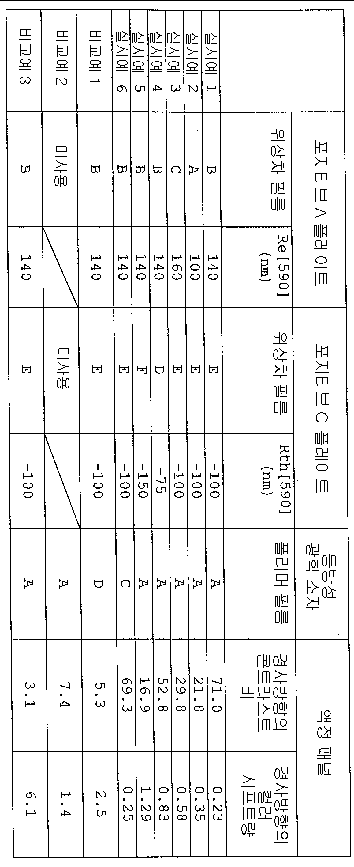
[평가][evaluation]
실시예 1 내지 6 각각에 나타낸 바와 같이, 도 2a 및 도 2b 에 나타낸 바와 같이 배열된 포지티브 A 플레이트, 포지티브 C 플레이트, 및 등방성 광학 소자를 갖는 액정 패널은 경사방향으로의 콘트라스트 비가 크고 경사방향으로의 컬러 시프트가 작은 액정 표시 장치를 제공하였다. 실시예 1 내지 3 의 결과는 포지티브 A 플레이트가 약 140 nm 의 Re[590] 을 갖는 것이 가장 바람직하다는 것을 나타낸다. 또한, 실시예 1, 4 및 5 의 결과물은 포지티브 C 플레이트가 약 -100 nm 의 Re[590] 을 갖는 것이 가장 바람직하다는 것을 나타낸다. 그 반면, 비교예 1 은 폴리머 필름 A 대신에, 편광자의 보호층으로서 이용된 폴리머 필름 D 를, 등방성 광학 소자로 이용하는 액정 패널을 제공하였다. 이 액정 패널에는 경사 방향으로 콘트라스트 비가 작고 경사 방향으로 컬러 시프트가 큰 액정 표시 장치만이 제공되었다. 유사하게, 포지티브 A 플레이트를 이용하지 않고 포지티브 C 플레이트를 이용하지 않은 비교예 2 의 액정 패널에는 경사 방향으로의 콘트라스트 비가 작고 경사 방향으로의 컬러 시프트가 큰 액정 표시 장치만이 제공되었다. 비교예 3 의 액정 패널은 실시예 1 의 액정 패널과 반대의 순서로 배열된 포지티브 A 플레이트 및 포지티브 C 플레이트를 가졌으며, 경사 방향으로 콘트라스트 비가 작고 경사 방향으로 컬러 시프트가 큰 액정 표시 장치만이 제공되었다.As shown in each of Examples 1 to 6, a liquid crystal panel having a positive A plate, a positive C plate, and an isotropic optical element arranged as shown in Figs. 2A and 2B has a large contrast ratio in the oblique direction and a diagonal direction. The liquid crystal display device with small color shift was provided. The results of Examples 1-3 show that it is most preferred that the positive A plate has a Re [590] of about 140 nm. In addition, the results of Examples 1, 4, and 5 indicate that it is most desirable for the positive C plate to have a Re [590] of about -100 nm. On the other hand, Comparative Example 1 provided a liquid crystal panel using, instead of polymer film A, polymer film D used as a protective layer of polarizer as an isotropic optical element. This liquid crystal panel was provided only with a liquid crystal display device having a small contrast ratio in the oblique direction and a large color shift in the oblique direction. Similarly, the liquid crystal panel of Comparative Example 2, which did not use a positive A plate and did not use a positive C plate, was provided with only a liquid crystal display device having a small contrast ratio in the oblique direction and a large color shift in the oblique direction. The liquid crystal panel of Comparative Example 3 had a positive A plate and a positive C plate arranged in the reverse order of the liquid crystal panel of Example 1, and provided only a liquid crystal display device having a small contrast ratio in the oblique direction and a large color shift in the oblique direction. It became.
본 발명의 범위 및 정신으로부터 벗어나지 않는다면, 당업자는 다른 변형을 용이하게 가할 수 있다. 첨부된 특허청구범위의 범위는 상세한 설명으로 제한되지 않고 보다 넓게 해석되어야 함은 자명하다.Other variations may be readily made by those skilled in the art without departing from the scope and spirit of the invention. It is obvious that the scope of the appended claims should not be limited to the detailed description but should be interpreted broadly.
전술한 바와 같이, 본 발명의 액정 패널은 경사 방향으로의 콘트라스트 비를 증가시킬 수 있고, 경사 방향으로의 컬러 시프트를 감소시킬 수 있으므로, 따라서, 액정 표시 장치의 표시 특성을 개선하는데 매우 유용하다. 따라서, 본 발명의 액정 패널은 액정 장치 또는 액정 텔레비전에 적절하게 이용될 수도 있다.As described above, the liquid crystal panel of the present invention can increase the contrast ratio in the oblique direction and can reduce the color shift in the oblique direction, and therefore is very useful for improving the display characteristics of the liquid crystal display device. Therefore, the liquid crystal panel of the present invention may be suitably used for a liquid crystal device or a liquid crystal television.
Claims (20)
Applications Claiming Priority (4)
| Application Number | Priority Date | Filing Date | Title |
|---|---|---|---|
| JPJP-P-2004-00355590 | 2004-12-08 | ||
| JP2004355590 | 2004-12-08 | ||
| JP2005240588A JP2006189781A (en) | 2004-12-08 | 2005-08-23 | Liquid crystal panel and liquid crystal display device |
| JPJP-P-2005-00240588 | 2005-08-23 |
Publications (2)
| Publication Number | Publication Date |
|---|---|
| KR20060064547A KR20060064547A (en) | 2006-06-13 |
| KR100692940B1 true KR100692940B1 (en) | 2007-03-12 |
Family
ID=36573752
Family Applications (1)
| Application Number | Title | Priority Date | Filing Date |
|---|---|---|---|
| KR1020050119223A KR100692940B1 (en) | 2004-12-08 | 2005-12-08 | Liquid crystal panel and liquid crystal display apparatus |
Country Status (4)
| Country | Link |
|---|---|
| US (1) | US7408603B2 (en) |
| JP (1) | JP2006189781A (en) |
| KR (1) | KR100692940B1 (en) |
| TW (1) | TWI263807B (en) |
Cited By (2)
| Publication number | Priority date | Publication date | Assignee | Title |
|---|---|---|---|---|
| KR20200105215A (en) * | 2019-02-28 | 2020-09-07 | 주식회사 엘지화학 | Polarizing Plate |
| WO2022220442A1 (en) * | 2021-04-12 | 2022-10-20 | 동우 화인켐 주식회사 | Liquid crystal display device |
Families Citing this family (26)
| Publication number | Priority date | Publication date | Assignee | Title |
|---|---|---|---|---|
| KR101043338B1 (en) * | 2004-04-19 | 2011-06-21 | 삼성전자주식회사 | Polarizer, display apparatus having the same, method of manufacturing the same and apparatus of manufacturing the same |
| KR101298456B1 (en) * | 2006-06-29 | 2013-08-23 | 엘지디스플레이 주식회사 | Liquid Crystal Display Device |
| JP2008158310A (en) * | 2006-12-25 | 2008-07-10 | Nitto Denko Corp | Layered product, liquid crystal panel, and liquid crystal display device |
| JP2008181091A (en) * | 2006-12-26 | 2008-08-07 | Nitto Denko Corp | Optical laminate and liquid crystal panel using the same |
| JP2008181090A (en) * | 2006-12-26 | 2008-08-07 | Nitto Denko Corp | Optical laminate and liquid crystal panel using the same |
| JP5068146B2 (en) * | 2007-05-01 | 2012-11-07 | 日東電工株式会社 | Liquid crystal panel and liquid crystal display device |
| US7898628B2 (en) * | 2007-08-29 | 2011-03-01 | Mitsubishi Electric Corporation | Liquid crystal display device |
| JP2009092847A (en) * | 2007-10-05 | 2009-04-30 | Nitto Denko Corp | Liquid crystal panel and liquid crystal display device |
| JP4855493B2 (en) | 2008-04-14 | 2012-01-18 | 日東電工株式会社 | Optical display device manufacturing system and optical display device manufacturing method |
| WO2010074543A2 (en) * | 2008-12-26 | 2010-07-01 | 주식회사 엘지화학 | Polarising plate for a planar-switch mode lcd, and a planar-switch mode lcd comprising the same |
| KR101314480B1 (en) * | 2008-12-26 | 2013-10-07 | 주식회사 엘지화학 | Polarizer for ips mode lcd and ips mode lcd comprising the same |
| KR101236244B1 (en) * | 2009-12-11 | 2013-02-22 | 엘지디스플레이 주식회사 | Liquid crystal display device |
| JP5592695B2 (en) * | 2010-05-21 | 2014-09-17 | 株式会社日本触媒 | Retardation film, method for producing the same, and image display device |
| CN102402064A (en) * | 2011-11-22 | 2012-04-04 | 深圳市华星光电技术有限公司 | Display panel |
| KR101525998B1 (en) * | 2011-12-12 | 2015-06-04 | 제일모직주식회사 | Polarized film for organic light emitting diodes and display device comprising the same |
| KR101974107B1 (en) * | 2012-02-02 | 2019-05-02 | 삼성디스플레이 주식회사 | Display apparatus |
| KR20130106633A (en) * | 2012-03-20 | 2013-09-30 | 동우 화인켐 주식회사 | Polarizing plate and image display device comprising the same |
| TWI492203B (en) * | 2012-12-04 | 2015-07-11 | Au Optronics Corp | Method of manufacturing display panel and laminated structure |
| KR102078021B1 (en) * | 2012-12-31 | 2020-02-17 | 엘지디스플레이 주식회사 | polarizer, manufacturing method thereof, and liquid crystal display including the same |
| JP2016065895A (en) * | 2014-09-22 | 2016-04-28 | 大日本印刷株式会社 | Dimmer, installation method, and partition member |
| KR102266646B1 (en) * | 2014-10-23 | 2021-06-17 | 엘지디스플레이 주식회사 | Liquid crystal display device having optical compensation film and method of fabricating the same |
| JP7171283B2 (en) * | 2018-07-18 | 2022-11-15 | スタンレー電気株式会社 | vehicle lamp |
| JP7177617B2 (en) * | 2018-07-24 | 2022-11-24 | スタンレー電気株式会社 | Lamp units, vehicle lighting systems |
| JP2020020996A (en) * | 2018-08-02 | 2020-02-06 | 住友化学株式会社 | Polarizing plate and liquid crystal display device |
| JP2022513832A (en) * | 2018-12-13 | 2022-02-09 | メルク・パテント・ゲゼルシヤフト・ミツト・ベシユレンクテル・ハフツング | Switchable window member |
| KR102590987B1 (en) * | 2019-07-11 | 2023-10-18 | 주식회사 엘지화학 | Polarizing Plate |
Family Cites Families (26)
| Publication number | Priority date | Publication date | Assignee | Title |
|---|---|---|---|---|
| JP2888382B2 (en) | 1991-05-15 | 1999-05-10 | インターナショナル・ビジネス・マシーンズ・コーポレイション | Liquid crystal display device, driving method and driving device thereof |
| GB2321529A (en) | 1997-01-24 | 1998-07-29 | Sharp Kk | Broadband cholesteric optical device |
| KR100223601B1 (en) | 1997-05-29 | 1999-10-15 | 윤종용 | Lcd device |
| JP3204182B2 (en) | 1997-10-24 | 2001-09-04 | 日本電気株式会社 | In-plane switching LCD |
| JP3342417B2 (en) | 1998-08-25 | 2002-11-11 | シャープ株式会社 | Liquid crystal display |
| US6650386B1 (en) | 1998-06-29 | 2003-11-18 | Sharp Kabushiki Kaisha | Nematic liquid crystal display device with multi-domain pixels and compensation with nc>na>nb |
| JP3114723B2 (en) | 1998-08-03 | 2000-12-04 | 日本電気株式会社 | Liquid crystal display device and method of manufacturing the same |
| US6468609B2 (en) | 1999-12-01 | 2002-10-22 | Agfa-Gevaert | UV-absorbing film and its use as protective sheet |
| KR100595295B1 (en) | 2000-06-27 | 2006-07-03 | 엘지.필립스 엘시디 주식회사 | Multi domain liquide crystal display device and method for fabricating the same |
| JP2002072215A (en) | 2000-08-31 | 2002-03-12 | Sharp Corp | Liquid crystal display device |
| US6995816B2 (en) | 2002-04-12 | 2006-02-07 | Eastman Kodak Company | Optical devices comprising high performance polarizer package |
| TWI284230B (en) | 2002-05-17 | 2007-07-21 | Merck Patent Gmbh | Compensator comprising a positive and a negative birefringent retardation film and use thereof |
| KR100839402B1 (en) | 2002-07-23 | 2008-06-20 | 닛토덴코 가부시키가이샤 | Optical film and liquid crystal display device using the same |
| US7046443B2 (en) | 2002-07-24 | 2006-05-16 | Nitto Denko Corporation | Anisotropic light scattering element, anisotropic light scattering polarizing plate using the same, and image display device using the same |
| KR20060002961A (en) | 2003-04-08 | 2006-01-09 | 메르크 파텐트 게엠베하 | Compensated lcd of the ips mode |
| EP1611188B1 (en) | 2003-04-08 | 2008-08-13 | MERCK PATENT GmbH | Optical film inside a liquid crystal display |
| JP2004325468A (en) | 2003-04-21 | 2004-11-18 | Nitto Denko Corp | Polarizing plate, its manufacturing method, optical film and picture display device |
| JP4564795B2 (en) | 2003-09-30 | 2010-10-20 | 株式会社日立製作所 | Liquid crystal display |
| KR100677050B1 (en) * | 2003-10-22 | 2007-01-31 | 주식회사 엘지화학 | In-plane switching liquid crystal display comprising compensation film for angular field of view using +a-plate and +c-plate |
| US7622166B2 (en) | 2003-11-28 | 2009-11-24 | Dai Nippon Printing Co., Ltd. | Optical element, process for producing the same, substrate for liquid crystal alignment, liquid crystal display device, and birefringent material |
| JP4386718B2 (en) | 2003-11-28 | 2009-12-16 | 大日本印刷株式会社 | OPTICAL ELEMENT AND ITS MANUFACTURING METHOD, AND LIQUID CRYSTAL ORIENTATION SUBSTRATE AND LIQUID CRYSTAL DISPLAY |
| KR100601920B1 (en) | 2004-01-09 | 2006-07-14 | 주식회사 엘지화학 | In-plane switching liquid crystal display comprising compensation film for angular field of view using negative biaxial retardation film and + c-plate |
| JP4383903B2 (en) | 2004-01-23 | 2009-12-16 | 株式会社 日立ディスプレイズ | Polarizing plate and liquid crystal display device using the same |
| JP4328243B2 (en) | 2004-03-16 | 2009-09-09 | 富士フイルム株式会社 | Liquid crystal display |
| JP2005321528A (en) | 2004-05-07 | 2005-11-17 | Fuji Photo Film Co Ltd | Liquid crystal display |
| TWI249625B (en) | 2004-10-08 | 2006-02-21 | Optimax Tech Corp | Structure of polarizer |
-
2005
- 2005-08-23 JP JP2005240588A patent/JP2006189781A/en active Pending
- 2005-11-07 TW TW094138942A patent/TWI263807B/en not_active IP Right Cessation
- 2005-12-02 US US11/292,351 patent/US7408603B2/en active Active
- 2005-12-08 KR KR1020050119223A patent/KR100692940B1/en not_active IP Right Cessation
Cited By (3)
| Publication number | Priority date | Publication date | Assignee | Title |
|---|---|---|---|---|
| KR20200105215A (en) * | 2019-02-28 | 2020-09-07 | 주식회사 엘지화학 | Polarizing Plate |
| KR102634252B1 (en) * | 2019-02-28 | 2024-02-07 | 주식회사 엘지화학 | Polarizing Plate |
| WO2022220442A1 (en) * | 2021-04-12 | 2022-10-20 | 동우 화인켐 주식회사 | Liquid crystal display device |
Also Published As
| Publication number | Publication date |
|---|---|
| KR20060064547A (en) | 2006-06-13 |
| TW200619701A (en) | 2006-06-16 |
| JP2006189781A (en) | 2006-07-20 |
| US20060119775A1 (en) | 2006-06-08 |
| US7408603B2 (en) | 2008-08-05 |
| TWI263807B (en) | 2006-10-11 |
Similar Documents
| Publication | Publication Date | Title |
|---|---|---|
| KR100692940B1 (en) | Liquid crystal panel and liquid crystal display apparatus | |
| KR100692939B1 (en) | Liquid crystal panel and liquid crystal display apparatus | |
| JP3985969B2 (en) | Liquid crystal panel and liquid crystal display device | |
| US7782429B2 (en) | Liquid crystal panel and liquid crystal display apparatus | |
| KR100698004B1 (en) | Liquid crystal panel and liquid crystal display apparatus | |
| JP3851919B2 (en) | Liquid crystal panel and liquid crystal display device | |
| KR100831919B1 (en) | Liquid crystal panel, liquid crystal television, and liquid crystal display device | |
| KR100831918B1 (en) | Liquid crystal panel, liquid crystal television, and liquid crystal display device | |
| JP2006126777A5 (en) | ||
| KR100835156B1 (en) | Liquid crystal panel, liquid crystal television, and liquid crystal display apparatus | |
| WO2006090617A1 (en) | Polarizing element, liquid crystal panel, liquid crystal television and liquid crystal display device | |
| JP2006268018A (en) | Polarizing element, liquid crystal panel, liquid crystal television, and liquid crystal display device | |
| JP2008158310A (en) | Layered product, liquid crystal panel, and liquid crystal display device | |
| JP2007148099A (en) | Method of manufacturing positive c-plate, positive c-plate, liquid crystal panel using its positive c-plate and liquid crystal display device | |
| JP4853920B2 (en) | Liquid crystal panel and liquid crystal display device | |
| CN100432785C (en) | Liquid crystal panel and liquid crystal display apparatus | |
| JP2007264586A (en) | Liquid crystal panel and liquid crystal display device | |
| JP2007264585A (en) | Liquid crystal panel and liquid crystal display device | |
| JP2007256902A (en) | Liquid crystal panel and liquid crystal display device | |
| JP2007193365A (en) | Liquid crystal panel, liquid crystal television, and liquid crystal display device |
Legal Events
| Date | Code | Title | Description |
|---|---|---|---|
| A201 | Request for examination | ||
| E701 | Decision to grant or registration of patent right | ||
| GRNT | Written decision to grant | ||
| FPAY | Annual fee payment |
Payment date: 20120223 Year of fee payment: 6 |
|
| LAPS | Lapse due to unpaid annual fee |