KR100228253B1 - Apparatus for charging raw sinter mixture to sintering machine - Google Patents
Apparatus for charging raw sinter mixture to sintering machine Download PDFInfo
- Publication number
- KR100228253B1 KR100228253B1 KR1019970002792A KR19970002792A KR100228253B1 KR 100228253 B1 KR100228253 B1 KR 100228253B1 KR 1019970002792 A KR1019970002792 A KR 1019970002792A KR 19970002792 A KR19970002792 A KR 19970002792A KR 100228253 B1 KR100228253 B1 KR 100228253B1
- Authority
- KR
- South Korea
- Prior art keywords
- sieve
- members
- groups
- drive
- adjacent
- Prior art date
Links
- PZXFVZOTXJPECK-UHFFFAOYSA-N CC/C=[I-](\C)/[NH+](C)C Chemical compound CC/C=[I-](\C)/[NH+](C)C PZXFVZOTXJPECK-UHFFFAOYSA-N 0.000 description 1
Images


Classifications
-
- F—MECHANICAL ENGINEERING; LIGHTING; HEATING; WEAPONS; BLASTING
- F27—FURNACES; KILNS; OVENS; RETORTS
- F27B—FURNACES, KILNS, OVENS, OR RETORTS IN GENERAL; OPEN SINTERING OR LIKE APPARATUS
- F27B21/00—Open or uncovered sintering apparatus; Other heat-treatment apparatus of like construction
-
- F—MECHANICAL ENGINEERING; LIGHTING; HEATING; WEAPONS; BLASTING
- F27—FURNACES; KILNS; OVENS; RETORTS
- F27B—FURNACES, KILNS, OVENS, OR RETORTS IN GENERAL; OPEN SINTERING OR LIKE APPARATUS
- F27B19/00—Combinations of furnaces of kinds not covered by a single preceding main group
-
- C—CHEMISTRY; METALLURGY
- C22—METALLURGY; FERROUS OR NON-FERROUS ALLOYS; TREATMENT OF ALLOYS OR NON-FERROUS METALS
- C22B—PRODUCTION AND REFINING OF METALS; PRETREATMENT OF RAW MATERIALS
- C22B1/00—Preliminary treatment of ores or scrap
- C22B1/14—Agglomerating; Briquetting; Binding; Granulating
- C22B1/16—Sintering; Agglomerating
- C22B1/20—Sintering; Agglomerating in sintering machines with movable grates
-
- F—MECHANICAL ENGINEERING; LIGHTING; HEATING; WEAPONS; BLASTING
- F27—FURNACES; KILNS; OVENS; RETORTS
- F27D—DETAILS OR ACCESSORIES OF FURNACES, KILNS, OVENS, OR RETORTS, IN SO FAR AS THEY ARE OF KINDS OCCURRING IN MORE THAN ONE KIND OF FURNACE
- F27D3/00—Charging; Discharging; Manipulation of charge
- F27D3/0033—Charging; Discharging; Manipulation of charge charging of particulate material
Abstract
원료소결혼합물을 팔레트에 공급하기 위한 공급기구와: 공급수단으로부터 공급된 원료 소결혼합물을 팔레트에 장입하기 위한 체형상 슈트와, 상기 체형상 슈트는: 복수개의 체 구성 부재 군(체를 구성하는 부재들의 군)과, 체 구성부재를 안내하기 위한 복수개의 안내부재를 포함하며; 두 인접한 체 구성 부재군을 체 구성 부재의 종방향으로 이동시키기 위한 이동기구를 포함하는 원료 소결혼합물을 소결기에 장입하기 위한 장치.A supply mechanism for supplying the raw material sintered mixture to the pallet: a body chute for charging the raw material sintered mixture supplied from the supply means to the pallet, and the body chute comprises: a plurality of sieve structural member groups (members constituting a sieve) Group of grasses), and a plurality of guide members for guiding the sieve member; 12. An apparatus for charging a raw material sintered mixture into a sintering apparatus comprising a moving mechanism for moving two groups of adjacent sieve component members in the longitudinal direction of the sieve member.
Description
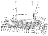
제1도는 본 발명에 의한 원료소결혼합물을 장입하기 위한 장치의 제1 구체예를 보여주는 사시도이고,1 is a perspective view showing a first embodiment of the apparatus for charging the raw sintered mixture according to the present invention,
제2도는 제1도에 표시된 구체예에 있어 유니트(단위)를 구성하는 한쌍의 체 구성 부재군(체를 구성하는 부재들의 군) 및 그 구동기구를 보여주는 사시도이고,FIG. 2 is a perspective view showing a pair of sieve constituent members (group of members constituting a sieve) constituting a unit and a driving mechanism thereof in the embodiment shown in FIG.
제3도는 제1도 및 제2도에 표시된 구체예에 적용되는, 구동 스프로켓 휘일에 대한 체인 쇄정기구를 보여주는 정면도이고,3 is a front view showing the chain locking mechanism for the drive sprocket wheel, which is applied to the embodiment shown in FIGS. 1 and 2,
제4도는 제1도 및 제2도에 표시된 구체예에 적용되는, 구동 스프로켓 휘일에 대한 다른 체인 쇄정기구를 보여주는 정면도이고,4 is a front view showing another chain locking mechanism for the drive sprocket wheel, applied to the embodiment shown in FIGS. 1 and 2,
제5도는 본 발명에 의한 원료 소결혼합물을 장입하기 위한 장치에 있어 안내부재를 보여주는 부분사시도이고,5 is a partial perspective view showing a guide member in the apparatus for charging the raw material sintered mixture according to the present invention,
제6도는 본 발명에 의한 원료 소결혼합물을 장입하기 위한 장치에 설치된 파단 감지 기구를 보여주는 정면도이고,6 is a front view showing a fracture detection mechanism installed in the apparatus for charging the raw material sintered mixture according to the present invention,
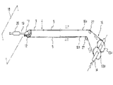
제7도는 본 발명에 따라 한 유니트를 구성하는 한쌍의 체 구성 부재 및 그 구동기구를 보여주는 사시도이고,7 is a perspective view showing a pair of sieve constituting members constituting a unit and a driving mechanism thereof according to the present invention,
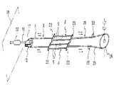
제8도는 본 발명에 따라, 유니트를 구성하는 체 구성 부재군과 체 구성부재, 그리고 그 구동기구를 보여주는 사시도이고,8 is a perspective view showing a sieve constituent group and sieve constituent members constituting a unit, and a driving mechanism thereof, according to the present invention;
제9도는 본 발명에 따라, 유니트를 구성하는 한쌍의 체 구성 부재군 및 그 구동기구를 보여주는 사시도이고,9 is a perspective view showing a pair of sieve component members constituting a unit and a driving mechanism thereof according to the present invention;
제10도는 본 발명에 따라 유니트를 구성하는 한쌍의 체 구성 부재군 및 그 구동 기구를 부분적으로 보여주는 사시도이고,10 is a perspective view partially showing a pair of sieve component members constituting a unit and a drive mechanism thereof according to the present invention;
제11도는 본 발명에 따라 유니트를 구성하는 한쌍의 체 구성 부재군 및 그 구동 기구를 부분적으로 보여주는 사시도이고,11 is a perspective view partially showing a pair of sieve component members constituting a unit and its driving mechanism according to the present invention;
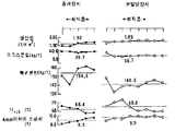
제12도는 소결체의 생산성, 코크스 분립의 단위 소모량, 복귀 분탄의 단위 소모량, TI 및 크기 4![]()
![]()
제13도는 실시예 2에 있는 본 발명의 장치를 사용하는 원료소결혼합물을 장입할 때, 층의 두께방향에 있어 입자 크기의 분포를 보여주는 그래프이고,13 is a graph showing the distribution of particle sizes in the thickness direction of the layer when charging the raw material sintered mixture using the apparatus of the present invention in Example 2,
제14도는 실시예 2에 있는 종래의 장치를 사용하여 원료소결혼합물을 장입할 때, 층의 두께방향에 있어 입자 크기의 분포를 보여주는 그래프이고,14 is a graph showing the distribution of particle size in the thickness direction of the layer when charging the raw material sintered mixture using the conventional apparatus in Example 2,
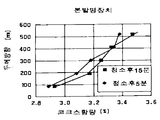
제15도는 실시예 2에 있는 본 발명의 장치를 사용하는 원료소결혼합물을 장입할 때, 층의 두께방향에 있어 코크스 함량의 분포를 보여주는 그래프이고,15 is a graph showing the distribution of coke content in the thickness direction of the layer when charging the raw sintered mixture using the apparatus of the present invention in Example 2,
제16도는 실시예 2에 있는 종래 장치를 사용하여 원료소결혼합물을 장입할 때, 층의 두께방향에 있어 코크스 함량의 분포를 보여주는 그래프이고,16 is a graph showing the distribution of coke content in the thickness direction of the layer when charging the raw material sintered mixture using the conventional apparatus in Example 2,
제17(a)도 및 제17(b)도는 실시예 3의 소결작업에 있어 소결기의 화격자 하부의 팔레트의 폭방향으로의 온도 분포를 보여주는 그래프이고,17 (a) and 17 (b) are graphs showing the temperature distribution in the width direction of the pallet under the grate of the sintering machine in the sintering operation of Example 3,
제18도는 체 형상의 슈트가 장착된 원료소결혼합체물 장입장치에 의해 실행된 입자크기별 분리장입 원리의 설명도이다.FIG. 18 is an explanatory view of the principle of separation charging by particle size performed by the raw material sintered mixture charging device equipped with a sieve chute.
[발명의 목적][Purpose of invention]
[발명이 속하는 기술분야 및 그 분야의 종래기술][Technical field to which the invention belongs and the prior art in that field]
본발명은 용광로 재료로 사용될 소결광을 제조하기 위해 소결기의 이동 팔레트 위에 원료소결혼합물을 장입하기 위한 장치에 관한 것이다.The present invention relates to an apparatus for charging a raw sintered mixture on a moving pallet of a sintering machine to produce a sintered ore to be used as a furnace material.
소결기는, 철광 분립을, 코크스 분립, 석회석 분립 등과 혼합하여 제조된 원료소결혼합물을 층(베드)을 형성하도록 팔레트에 장입하여 팔레트가 이동되는 동안 층내의 코크스 분립을 연소시켜 철광분립이 소결되게 하는 방식으로 소결광을 제조한다. 원료소결혼합물은, 원료소결혼합물의 입자 크기가 층의 두께 방향으로 적당히 분리된 상태로, 즉 원료혼합물이 소결될 때 가스 투과성 및 코크스 분립의 연소성을 확보하기 위해 미세물이 층의 상층쪽에 퇴적되어 있는 상태로, 팔레트위에 장입되어야 한다.The sintering machine charges the raw material sintered mixture prepared by mixing the iron ore powder, coke powder, limestone powder and the like into a pallet to form a layer (bed), and burns the coke powder in the layer while the pallet is moved so that the iron ore powder is sintered. To produce a sintered ore. In the raw sintered mixture, the particle size of the raw sintered mixture is properly separated in the thickness direction of the layer, that is, fines are deposited on the upper layer of the layer to ensure gas permeability and combustibility of coke powder when the raw material mixture is sintered. As it is, it must be loaded onto the pallet.
원료소결혼합물의 입자 크기별 분리 장입이 가능하게하는 장치로서는, 일본 공개 특허공보 평5-1335에 개시된 공지된 장입장치가 있다. 이 장치에는, 롤 피이더와 같은 공급기구 하부에, 팔레트 이동방향의 반대방향으로 하향 경사된 체 형상의 슈트가 배치되어 있다. 체 형성 부재는, 로드들 사이의 간격이 슈트의 상부측으로 감에 따라 더 좁아지는 가운데, 다수의 로드가 팔레트의 폭방향으로 이격 배치된 그런 구조를 갖고 있다.As a device that enables separate charging by particle size of the raw material sintered mixture, there is a known charging device disclosed in Japanese Patent Laid-Open No. 5-1335. In this apparatus, a sieve chute inclined downward in the direction opposite to the pallet movement direction is disposed below a supply mechanism such as a roll feeder. The body forming member has such a structure that a plurality of rods are spaced apart in the width direction of the pallet while the gap between the rods becomes narrower as the gap between the rods goes toward the upper side of the chute.
제18도는, 원료소결혼합물이 어떻게 상기 장입장치에 의해 장입되는가를 보여주는데, 여기서는, 공급기구(40)로부터 미끄러지면서 체형상 슈트(41)위로 낙하하는 원료소결혼합물은 로드(rods)들(42) 사이의 간격을 통해 팔레트(43)위에 낙하할 때 그 입자 크기별로 체 분리 되는데, 그 이유는 체형상 슈트를 구성하는 로드들(42)사이의 간격이 슈트의 상부측을 향해 점차 좁아지기 때문이며, 따라서 큰 입자 크기의 물질은 팔레트의 개시부 측에 장입된다. 그 결과, 물질이 장입된 후 형성되는 층은 미세한 입자 크기의 물질이 층의 상부에 분포하게되는 입자 크기별 분리를 갖게 된다.FIG. 18 shows how the raw sintered mixture is charged by the charging device, where the raw sintered mixture that slides from the
그러나, 상기한 것과 같은 체형상 슈트(41)를 가진 장입장치는 체형상 슈트(41)의 로드(42)에 부착되는 석회석 분립이나 코크스 분립으로 로드들(42) 사이의 공간이 폐색되는 문제점을 안고 있다.However, the charging device having the
상기 문제를 해결하기 위한 장입장치로서, 일본 공개 특허 공보 평7-229684는, 체형상 슈트의 로드 대신에 와이어 로프를 사용하고, 한 세트(조) 또는 다수세트의 무단 와이어 로프의 방향을 풀리를 통해 순차 변경시켜 팔레트의 폭방향에 평행하는 다수의 와이어로프부를 형성하고, 또한 와이어를 지지하고 부착물을 긁어제거하기도하는 안내부재를 수개 위치에서 서로 평행 배치된 와이어 로프부의 중간 위치에 배치하며 와이어 로프부를 안내부재의 안내구멍을 통해 삽입하여 형성된 구조의 장치를 제외하고 있다. 각 무단 와이어는 구동 유니트인 쌍의 구동 풀리사이에 구속되거나 또는 구동드럼 주위에 수회 권취되어 무단 와이어 로프는 구동드럼의 구동력에 의해 순환 또는 왕복이동된다.As a charging device for solving the above problem, Japanese Laid-Open Patent Publication No. Hei 7-229684 uses a wire rope instead of a rod of a body-shaped chute to loosen the direction of one or more sets of endless wire ropes. Through a plurality of wire rope portions arranged parallel to the width direction of the pallet, and guiding members for supporting the wires and scraping off the attachments are arranged in the intermediate position of the wire rope portions arranged parallel to each other in several positions. The apparatus of the structure formed by inserting the part through the guide hole of the guide member is excluded. Each endless wire is constrained between a pair of drive pulleys that are drive units or wound several times around the drive drum so that the endless wire rope is circulated or reciprocated by the drive force of the drive drum.
상기 물질 장입장치에 있어 원료소결혼합물이 슈트 표면을 구성하는 와이어 로프 부분에 부착될 때에는, 각 무단 와이어 로프를 구동 유니트로 구성하여 와이어 로프가 안내부재의 안내구멍을 통과할 때 부착된 원료소결혼합물이 긁혀제거되게 한다.When the raw material sintered mixture is attached to the wire rope portion constituting the chute surface in the material charging device, the raw material sintered mixture attached when the wire rope passes through the guide hole of the guide member by configuring each endless wire rope as a driving unit. Allow this to be scratched off.
그러나 상기 종래 장치는 하기 문제점들을 안고 있다.However, the conventional apparatus suffers from the following problems.
(1) 무단 와이어 로프는 구동풀리 또는 구동드럼상에서 슬립(미끄럼)하기 쉽기 때문에, 와이어 로프는 원활하고 정확하게 움직이지 않을 수 있다. 특히, 무단 와이어 로프가 예정된 행정(두 안내부재 사이의 간격보다 긴 행정)으로 왕복 이동될 때에는, 무단 와이어 로프는 슬립되기 쉽고 그리하여 와이어 로프 이동거리에 오차가 일어날 수 있다. 그래서, 와이어 로프의 이동거리가 미리 설정된 행정보다 짧아져 와이어 로프 부분의 일부가 안내부재의 안내구멍에 도달하지 못하기 때문에 부착물 제거기능이 충분히 달성되지 못할 수 있다.(1) Since the endless wire rope is easy to slip on the driving pulley or the driving drum, the wire rope may not move smoothly and accurately. In particular, when the endless wire rope is reciprocated in a predetermined stroke (stroke longer than the distance between the two guide members), the endless wire rope is liable to slip and thus errors in the wire rope movement distance may occur. Thus, since the moving distance of the wire rope is shorter than the predetermined stroke, a part of the wire rope portion does not reach the guide hole of the guide member, so that the deposit removing function may not be sufficiently achieved.
(2) 또한, 슈트 표면을 구성하는 와이어 로프부분이 이완되어 상기와 같이 와이어 로프들 사이의 간격이 와이어 로프의 슬립으로 인해 대단히 불규칙해지고 이에 따라 장치에 고유한 입자 크기별 분리 장입 기능이 손상되기 쉽다.(2) In addition, the part of the wire rope constituting the chute surface is relaxed, so that the spacing between the wire ropes is very irregular due to the slipping of the wire rope as described above, and the separation charging function according to the particle size inherent to the device is likely to be impaired. .
(3) 와이어 로프는 구동 풀리 또는 구동 드럼상에서 슬립되기 때문에 와이어 로프는 단시간에 마모되어 파단(절단)되기 쉽다.(3) Since the wire rope slips on the driving pulley or the driving drum, the wire rope is worn out in a short time and is likely to break (cut).
(4) 방식에 있어서, 긴 무단 와이어 로프가, 이것과 구동풀리나 구동드럼사이의 마찰력에 의해 구속됨으로써 한 방향으로 강제 신장되도록 이동하기 때문에, 와이어 로프는 장기간 사용되는 동안 신장되고, 그리하여 슈트 표면을 구성하는 와이어 로프 부분이 이완되고 와이어 로프들 사이의 간격이 상기 (2)항에서와 같이 크게 불규칙해지며, 그에 따라 이 장치에 고유한 입자 크기별 분리장입기능이 상기 (2)항의 경우와 같이 손상되기 쉽다.(4) In the system, since the long endless wire rope is moved to be forced in one direction by being restrained by the friction force between it and the driving pulley or the driving drum, the wire rope is elongated for a long time, and thus the chute surface is extended. The constituent wire rope part is relaxed and the spacing between the wire ropes becomes largely irregular as in (2) above, so that the separation loading function according to the particle size inherent to this device is damaged as in the case of (2) above. Easy to be
또한, 신장된 와이어 로프 측에 큰 부하가 인가되고 또한 와이어 로프의 꼬임이 장기 사용으로 인해 풀어지기 쉽기 때문에, 와이어 로프 자체가 파단되기 쉽다.In addition, since a large load is applied to the stretched wire rope side and the twisting of the wire rope is easy to be released due to long-term use, the wire rope itself is likely to break.
(5) 구동 드럼 주위에 와이어로프가 감겨 이동되는 방식에 있어서는, 와이어 로프가 드럼 주위에 감길 때 와이어 로프가 신장이나 꼬임으로 인해 구동드럼상에서 잘못 위치이동되거나 또는 꼬이기 때문에, 와이어 로프의 이동거리에 오차가 생기기 쉽다. 그리하여, 무단 와이어 로프가 예정행정으로 왕복 이동될 때, 와이어 로프 부분의 일부가 상기 (1)항에서와 같이 안내부재의 안내구멍에 도달할 수 없어 부착물 제거 기능이 충분히 달성되지 못할 수 있다.(5) In the manner in which the wire rope is wound and moved around the drive drum, when the wire rope is wound around the drum, the wire rope is misplaced or twisted on the drive drum due to elongation or twisting, so that It is easy to produce an error. Thus, when the endless wire rope is reciprocated in a predetermined stroke, a part of the wire rope portion cannot reach the guide hole of the guide member as in the above (1), and the deposit removal function may not be sufficiently achieved.
[발명의 목적][Purpose of invention]
체 구성 부재의 외면에 부착된 원료소결혼합물이 확실하게 제거될 수 있고 체 구성 부재의 파단이 일어나기 어려운 원료소결혼합물 장입 장치를 제공하는 것이 본 발명의 목적이다.It is an object of the present invention to provide a raw material sintered mixture charging device in which the raw material sintered mixture adhering to the outer surface of the sieve constituent member can be reliably removed and breakage of the sieve constituent member hardly occurs.
이 목적을 달성하기 위해, 본 발명은 원료소결혼합물을 팔레트에 공급하기 위한 공급수단과; 공급수단으로부터 공급된 원료소결혼합물을 팔레트에 장입하기 위한 체형상 슈트와, 체형상 슈트는 공급수단 하부에 배열되고 팔레트 이동방향에 반대되는 방향으로 하향 경사되어 있으며; 두 인접하는 체 구성 부재군을 체 구성 부재의 종방향으로 이동시키기 위한 이동수단을 포함하는, 원료 소결 혼합물을 소결기에 장입하기 위한 장치를 제공한다.In order to achieve this object, the present invention includes a supply means for supplying the raw sintered mixture to the pallet; A body chute for charging the raw material sintered mixture supplied from the supply means to the pallet, and the body chute is arranged below the supply means and inclined downward in a direction opposite to the pallet moving direction; Provided is an apparatus for charging a raw material sintering mixture into a sinter comprising moving means for moving two adjacent groups of sieve members in the longitudinal direction of the sieve member.
체 형상 슈트는 복수개의 체 구성 부재군과 체 구성 부재를 안내하기 위한 복수개의 안내부재로 되어 있다. 복수개의 체 구성 부재군은 팔레트의 종방향으로 서로 평행으로 이격배치되어 있다. 복수개의 안내부재는 팔레트의 폭방향으로 이격 배치되어 있다. 체 구성 부재군은 적어도 하나의 체 구성 부재를 포함한다. 체 구성 부재의 외면은 바람직하게는 수지로 피복된다. 체 구성 부재는 와이어 또는 로드이다. 안내부재는, 체 구성 부재를 통과시킬 안내구멍을 갖고 있다. 플라스틱 부시가 안내구멍의 내면에 배치되는 것이 바람직하다.The sieve chute consists of a plurality of sieve member groups and a plurality of guide members for guiding the sieve member. The plurality of sieve member groups are spaced apart in parallel to each other in the longitudinal direction of the pallet. The plurality of guide members are arranged to be spaced apart in the width direction of the pallet. The sieve member group includes at least one sieve member. The outer surface of the sieve structural member is preferably covered with resin. The sieve member is a wire or rod. The guide member has a guide hole for passing the sieve member. Preferably, the plastic bush is disposed on the inner surface of the guide hole.
이동장치는: 두 인접하는 체 구성 부재군의 각 일단을 연결하기 위한 연결부재; 두 인접하는 체 구성 부재군의 이동방향을 서로 변경시키기 위한 회전가능한 종동 스프로켓 휘일; 및 두 인접하는 체 구성 부재군을 서로 반대방향으로 이동시키기 위한 구동수단으로 되어 있다. 연결부재의 적어도 한부분 이상은 그 종방향으로 체인(사슬)으로 구성되어 있다. 체인은 회전가능한 종동 스프로켓 휘일 주위에 맞물려 있다.The moving device comprises: a connecting member for connecting each end of two adjacent sieve member groups; A rotatable driven sprocket wheel for changing the direction of movement of two adjacent sieve member groups; And drive means for moving two adjacent sieve member groups in opposite directions to each other. At least one part of the connecting member is composed of a chain (chain) in its longitudinal direction. The chain is engaged around the rotatable driven sprocket wheel.
두 인접하는 체 구성 부재군을 이동시키기 위한 구동수단은 바람직하게는 체인-스프로켓 휘일 기계장치, 랙-피니언 기계장치, 또는 실린더 기계장치이다.The drive means for moving the two adjacent sieve member groups is preferably a chain-sprocket wheel mechanism, a rack-pinion mechanism, or a cylinder mechanism.
체인-스프로켓 휘일 기계장치에 있어서는, 상기 구동수단은 두 인접하는 체 구성 부재군의 타단을 연결하기 위한 연결수단을 포함하고; 상기 연결수단은 구동 스프로켓 휘일과 맞물리는 체인수단을 포함한다.In a chain-sprocket wheel mechanism, the drive means includes connecting means for connecting the other ends of two adjacent groups of sieve members; The connecting means comprises a chain means for engaging the drive sprocket wheel.
구동수단은: 동일축으로 배치되어 있는 쌍의 구동 스프로켓 휘일; 및 서로 반대 방향으로 쌍의 구동 스프로켓 휘일 주위로 맞물려있는 쌍의 체인으로 되어 있을 수 있다. 쌍의 체인의 단부는 두 인접하는 체 구성 부재군의 타단에 연결되어 있다.The drive means comprises: a pair of drive sprocket wheels arranged coaxially; And a pair of chains engaged around the pair of drive sprocket wheels in opposite directions. The ends of the pair of chains are connected to the other ends of two adjacent sieve member groups.
구동수단은: 구동 스프로켓 휘일; 및 구동 스프로켓 휘일 주위에 맞물려 있는 체인으로 되어 있을 수 있다. 체인의 단부는 두 인접하는 체 구성 부재군의 타단에 연결된다.The drive means includes: a drive sprocket wheel; And a chain engaged around the drive sprocket wheel. The end of the chain is connected to the other end of two adjacent groups of sieve members.
바람직하게는, 구동수단은: 임의의 시간간격으로 구동 스프로켓 휘일을 구동하기 위한 타이머; 및 구동 스프로켓 휘일의 회전방향을 변경하기 위한 수단을 추가로 포함한다.Preferably, the drive means comprises: a timer for driving the drive sprocket wheel at any time interval; And means for changing the rotational direction of the drive sprocket wheel.
본 발명의 장입장치에 있어서, 체 구성 부재군은 한 체 구성 부재 또는 적어도 두 개 이상의 체 구성 부재이다. 두 인접하는 체 구성 부재군은 서로 반대방향으로 이동한다. 두 개의 인접하는 체 구성 부재군은, 한 체 구성 부재로 구성된 한 체 구성 부재군과 적어도 둘이상의 체 구성 부재로 구성된 한 체 구성 부재군일 수 있다.In the charging apparatus of the present invention, the sieve structural member group is one sieve structural member or at least two sieve structural members. Two adjacent sieve member groups move in opposite directions. The two adjacent sieve member groups may be one sieve member group composed of one sieve member and one sieve member group composed of at least two sieve member members.
[구체예의 설명][Description of Specific Example]
제1도 및 제2도는 본 발명의 원료소결혼합물 장입장치의 구체예를 표시한다.1 and 2 show specific examples of the raw material sintered mixture charging device of the present invention.
원료소결혼합물 장입장치는 원료소결혼합물을 팔레트에 공급하기위한 공급기구(1)와 원료공급기구(1)의 하부에 배치된 체형상 슈트(2)를 포함한다.The raw material sintered mixture charging device includes a
공급기구(1)는 원료소결혼합물 호퍼(3), 롤 피이더(4), 및 원료소결혼합물을 호퍼 하단에 있는 개구로부터 피이드(공급)하기 위한 드럼슈트(4'를 포함하고 있다. 그러나 공급기구(1)의 구성은 상기 구체예에 한정되지 않고, 예컨대 호퍼(3), 롤 피이더(4) 및 드럼 슈트(4') 대신에 벨트 콘베이어를 설치하여 원료소결혼합물이 밸트 콘베이어의 단부로부터 직접 체 형상 슈트(2)위에 직접 공급되도록 구성해도 좋을 것이다.The
원료의 입자 크기가 층의 두께방향으로 분리된 상태에서 원료소결혼합물을 공급기구(1)로부터 팔레트(도시않음) 위로 장입하는데 사용되는 체형상 슈트(2)는, 슈트가 팔레트 이동방향의 반대방향으로 하향경사지고 그 상단은 공급기구(1)의 피이드 유니트(구체예에서 롤 피이더(4))의 대략 바로 아래에 위치되도록 배치된다.The body chute 2 used to charge the raw material sintered mixture from the
체 형상 슈트(2)는, 와이어상 부재(예컨대 로프등) 또는 봉상 부재(예컨대 중실 또는 중공 로드등)로 구성되고 대략 팔레트의 폭 방향에 팽행으로 배치되어 있는 복수개의 체구성부재(5), 및 체구성부재(5)를 그 중간 부분에서 지지하고 체구성부재의 외면에 부착된 원료소결혼합물을 긁어 없애는 기능을 수행하는 안내부재(6)를 포함하고 있다.The body chute 2 is composed of a wire-like member (for example, a rope or the like) or a rod-like member (for example, a solid or hollow rod, etc.) and a plurality of body-constituting
복수개의 체 구성부재들(5)은 팔레트의 폭방향으로 안내부재(6)에 대해 이동 가능하고 팔레트의 종방향(이동방향)으로 적당한 간격으로 서로 평행하게 배치되어 있다. 이들 체구성부재들(5)은 체모양 슈트의 슈트포면을 구성하고, 인접하는 체구성부재들(5) 사이의 간격은 그 상부쪽을 향해감에 따라 점차 좁아지도록 배치되어 있어 원료소결혼합물은 입자크기별 분리상태로 장입될 수 있다. 체구성부재들(5) 사이의 간격이 슈트의 최상부측에서 Wn이고 최하부측에서 W1이라고 가정하면, 간격들의 크기는 예컨대 간격 W1으로부터 간격 Wn까지 간격마다 연속적으로 변화될 수 있거나 또는 간격 W1 - W4, 간격 W5 - W8 … 처럼 수개의 간격당 단계적으로 변화될 수 있고, 그리하여 간격들의 크기는 임의로 설정될 수 있다. 결과적으로, 인접하는 체구성부재들 사이의 간격을 슈트의 상부측을 향해 점점 더 좁게 하는 본 발명의 구성은 상기한 여러 양태를 포함한다.The plurality of
체구성부재들(5)은 팔레트의 길이방향으로 직선상, 요곡상(하향 만곡 형상)등 중의 어느하나로 배치될 수 있지만, 원료의 미끄럼 하강속도를 감소함으로써 체에 의한 원료소결혼합물 체분리를 확실히 하기 위해, 체구성부재 전체를 요곡상으로 또는 제18도에 표시된 것으로 슈트의 상측부분만을 직선상 그리고 그 부분 이후의 부분은 요곡상으로 배치하는 것이 특히 바람직하다.The
또한 체구성부재(5)는 상기와 같이 와이어 로프, 로드(중공 로드를 포함함)등으로 구성될 수 있지만, 비용, 강도, 취급 등의 견지에서 와이어 로프가 특히 바람직하고 따라서 본 구체예의 체구성부재(5)도 와이어 로프로 구성된다. 체구성부재(5)의 단면형상은 임의로 형성될 수 있음을 유의하라.In addition, although the
복수개의 안내부재(6)는 팔레트의 폭방향으로 적당한 간격으로 배치되어 있고 도시되지 않은 프레임 등과 같은 지지부재에 의해 지지 고정되어 있다. 각각의 안내부재(6)는 체구성부재(5)를 통과시킬 수 있도록 그 종방향으로 이격하여 형성된 복수개의 안내홀(7)을 갖고 있고, 체구성부재(5)는 이들 안내홀(7)을 미끄럼 통과한다. 안내부재(6)는 긴 체구성부재(5)를 그 중간부분에서 지지하여 체구성부재들 사이의 간격을 유지하고, 또한 체구성부재가 안내홀(7)을 이동 통과할 때 체구성부재(5)의 외면에 부착된 원료소결혼합물을 긁어 제거하는 기능을 수행한다. 그리하여, 인접하는 안내부재들(6) 사이의 간격은 상기 기능을 고려하여 선택되지만, 통상 이들은 약 800-1300![]()
![]()
구조예에 있어서는, 체구성부재 군(A) 세트는, 체구성부재들(5,5)의 양단부들을 결합부재(23)에 의해 연결함으로써 슈트면을 구성하는 복수개의 체구성부재(5) 중 각각의 두 인접 체구성부재(5,5)로 구성되어 있으며, 그리하여 구조예는 총계 8 세트의 체구성부재군(A1-A8)를 포함하고 있다. 그러면, 이들 체구성부재군(A)중 각 2세트의 인접 체구성부재군(A, A)(즉, A1- A2, A3- A4, A5- A6, A7- A8)가 한 유니트로서 배열되고 그 유니트를 통해 체구성부재(5)는 동기 이동동작을 수행한다. 이 목적을 위해, 한 유니트를 구성하는 두 세트의 인접 체구성부재군(A, A)의 각 일단은 그 중간 부분에 체인(9)을 가진 연결부재(8)에 의해 연결되어 있고 그 타단들은 하기할 구동 유니트(16)의 구동부(체인(10a, 10b))에 연결되어 있다.In the structural example, the set of body composition members A includes a plurality of
체형상 슈트(2)는, 그 주위로 상기 각 유니트에 해당하는 연결부재(8)의 체인(9)이 팔레트의 폭방향으로 유니트의 단부에 배치되어 있는 복수개의 종동 스프로켓 휘일(12), 그리고 각 유니트에 해당하는 복수개의 쌍의 구동 스프로켓 휘일(13a, 13b) 및 유니트의 타단에 배치된 구동 스프로켓 휘일주위로 감겨지는 체인(10a, 10b)으로 구성된 구동유니트(16)를 포함하고 있다. 구동유니트(16)를 구성하는 각 한쌍의 구동 스프로켓 휘일(13a, 13b)은 도시되지 않은 모터 등에 의해 회전되는 구동축(14)에 공축으로 배치되어 있다. 그리고, 체인들(10a, 10b)은 서로 반대방향으로 구동 스프로켓 휘일(13a, 13b) 주위로 감긴다.The body chute 2 includes a plurality of driven
그러면, 각 유니트에 있어서, 체구성부재군(A, A)의 일단들을 연결하기 위한 연결부재(8)의 체인(9)은 종동 스프로켓 휘일(12) 주위로 감겨지는 한편, 구동유니트(16)의 체인(10a, 10b)은 연결부재(11)을 통해 체구성부재군(A, A)의 타단에 연결된다.Then, in each unit, the
따라서, 상기와 같이 배열된 제1도 및 제2도의 장치에 있어서는, 구동 스프로켓 휘일(13a, 13b)이 임의의 방향으로 회전될 때, 두 세트의 체구성부재군(A, A)중의 어느 하나는 전진운동을 하고 그중 다른 것은 복귀운동을 한다.Therefore, in the apparatus of FIGS. 1 and 2 arranged as above, when the
구동유니트(16)를 구성하는 체인들(10a, 10b)은 적당한 잉여 권취부를 가지고 구동 스프로켓 휘일(13a, 13b)주위로 감겨지며, 스프로켓 휘일로부터 분리낙하하지 않도록 적당한 수단에 의해 쇄정(고정)된다. 제3도 및 제4도는 이 목적을 위한 구조예를 표시한다. 제3도는 체인(10)의 일단(100)이 구동 스프로켓 휘일(13)에 고정된 구조예를 표시하고, 제4도는 구동 스프로켓(13)의 외주의 일부 주위에서 체인을 구속하기 위해 안내부재(15)가 배치된 구조예를 보여준다. 구동 스프로켓(13a, 13b)은 "체인의 잉여 권취부" 더하기 "체구성부재의 이동량" 길이를 가진 체인부분이 휘일의 외주부 주위에 감길 수 있게 하기에 충분한 외경을 가져야 한다.The
제1도 및 제2도의 구체예에서는, 체구성부재(5)는 와이어 로프로 구성되어 있기 때문에 거기에 장력이 가해져야 한다. 이 목적을 위해서, 체구성부재군(A)을 구성하는 체구성부재들(5)에 장력이 가해지고 장력이 임의로 조정될 수 있도록, 종동 스프로켓 휘일(12)의 위치가 팔레트의 폭방향으로 고정측 구동 스프로켓 휘일(13a, 13b)에 대해 조정가능하게 한다. 보다 상세하게는, 종동 스프로켓 휘일(12)을 회전 가능하게 유지시키기 위한 브래켓(17)은, 각각 길이 조정기구(20)(예컨대 턴 버클 또는 긴 구멍을 이용하는 공지의 수단)가 구비된 지지부재(19)를 통해 고정 기저부(18)에 의해 지지되어 있기 때문에, 종동 스프로켓 휘일(12)의 위치는 지지부재(19)의 길이를 조정함으로써 팔레트의 폭방향으로 조정될 수 있다.In the embodiment of Figs. 1 and 2, since the
다른 도면들에서, 번호 27은 체인(10a, 10b)을 안내하기 위한 안내 스프로켓 휘일을 표시한다.In other figures, the
원료소결혼합물의 부착성을 억제하고 와이어 로프의 외면에 부착된 원료소결혼합물을 긁어 없애는 효과를 향상시키기 위해 체구성부재(5)를 형성하는 와이어 로프의 외면에 우레탄 수지 등의 수지피복물을 오포하는 것이 바람직하다.In order to suppress the adhesion of the raw material sintered mixture and to improve the effect of scraping off the raw material sintered mixture attached to the outer surface of the wire rope, a resin coating such as urethane resin is formed on the outer surface of the wire rope forming the
또한, 안내부재(6)의 각 안내구멍(7)의 내면에 수지(예컨대 우레탄수지)로 구성된 부시(34)를 설치하는 것이 바람직하며, 그리하여 제5도에 표시한 것과 같이 안내구멍내로 미끄럼 이동하는 체구성부재(5)의 마모를 방지하도록 한다.In addition, it is preferable to provide a
또한, 제6도는 체구성부재(5)가 파단되는 경우 즉시 그 파단을 감지하도록 파단센서(21)가 배치되어 있는 구체예를 표시한다. 이 구체예에 있어서, 종동 스프로켓 휘일(12)의 지지부재(19)의 일단은 고정 기저부(18)에 대해 하측방향으로 경사질 수 있도록 장착되어 있고, 파단센서(21)를 구성하는 리미트 스위치의 스위치 레버(22)는 지지부재(19)의 하부에 배치되어 있으며, 그리하여 체구성부재(5)가 파단(절단)될 때 하향 경사되는 지지부재(19)에 의해 스위치 레버(22)가 작동되고 그것에 의해 체구성부재(5)의 파단이 즉각 감지된다.6 shows a specific example in which the breaking
파단센서(21)의 구조는 제6도에 표시된 것에 한정되지 않고, 어떤 적당한 구성, 예컨대, 지지부재(19)의 중간부분, 또는 지지부재(19)가 고정기저부(18)에 장착되어 있는 부분에 배치된 장력센서등도 이용될 수 있다는 것을 유의하라.The structure of the
제1도 및 제2도에 표시된 구체예에서, 각 체구성부재군(A)은 적어도 두 개의 임의 개수의 체구성부재(5)로 구성되고, 또한 한 유니트를 구성하는 체구성부재군 두 세트에 있어 그 군에 따라 체구성부재(5)의 수가 상이할 수 있다는 것을 유의하라.In the embodiment shown in Figs. 1 and 2, each body member group A is composed of at least two arbitrary numbers of
제1도 및 제2도에 도시된 구체예는 두 세트의 체구성부재군(A, A)이 한 유니트로 이동하도록 구성되어 있지만, 예컨대 제7도에 도시된 것처럼 각각의 두 개의 인접하는 체구성부재(5)가 한 유니트로 이동될 수 있다. 즉, 이 경우, 두 인접 체구성부재(5, 5)의 각 일단은 체인(9)을 가진 연결부재(8)에 의해 연결되고, 각 타단은 직접 또는 적당한 연결부재를 거쳐 구동유니트(16)를 구성하는 체인(10a, 10b)에 연결된다.Although the embodiments shown in FIGS. 1 and 2 are configured so that two sets of body member groups A and A move in one unit, for example, two adjacent sieves each as shown in FIG. The
제7도에 도시된 장치에 있어서는, 구동 스프로켓 휘일(13a, 13b)이 임의의 방향으로 회전될 때, 한 유니트를 구성하는 두 체구성부재(5, 5)중의 어떤 하나는 전진운동을 하고 다른 하나는 복귀운동을 한다.In the apparatus shown in FIG. 7, when the
기타의 구성들은 제1도 및 제2도에 도시된 것과 같기 때문에, 그것들을 표시하는 데는 같은 번호를 사용하고 그 상세한 설명은 생략한다.Since the other configurations are the same as those shown in FIGS. 1 and 2, the same numbers are used to denote them and the detailed description thereof is omitted.
그위에, 제8도에 표시된 것처럼, 한 세트의 체구성부재군(A)과 그것에 인접한 하나의 체구성부재(5)가 한 유니트로 이동될 수 있다. 즉, 이 경우 체구성부재군(A)은 적어도 두 인접 체구성부재(5)의 양단을 결합부재(23)에 의해 연결함으로써 구성되고 체구성부재군(A)의 각 일단과 그것에 인접한 체구성부재(5)는 체(9)를 가진 연결부재(8)에 의해 연결되고 체구성부재군(A)의 각 타단과 체구성부재(5)는 직접으로 또는 연결부재(11)를 통하여 구동유니트(16)를 구성하는 체인(10a, 10b)에 연결된다. 체구성부재군(A)은 이 경우에도 적어도 두 개의, 임의의 개수의 체구성부재(5)로 구성될 수 있다.On top of that, as shown in Fig. 8, a set of body member group A and one
제8도의 장치에 있어서는, 구동 스프로켓 휘일(13a, 13b)이 임의의 방향으로 회전될 때, 한 유니트를 구성하는 체구성부재군(A)과 체구성부재(5) 중의 어느 하나는 전진운동을 하고 다른 것은 복귀운동을 한다.In the apparatus of FIG. 8, when the
기타의 구성들은 제1도 및 제2도에 도시된 것과 같기 때문에, 그것들을 표시하는 데는 같은 번호를 사용하고 그 상세한 설명은 생략한다는 것을 유의하여야 한다.It is to be noted that since the other configurations are the same as those shown in Figs. 1 and 2, the same numbers are used to denote them and the detailed description thereof is omitted.
제9도는 체인/스프로켓 휘일로된 구동유니트(16a)를 사용하는 다른 구체예를 표시한다. 이 구체예에 있어서, 한 유니트를 구성하는 두 세트의 체구성부재군(A)의 타단(구동측)도 일단(종동측)과 같이 그 중간부에 체인(25)을 가진 연결부재(24)에 의해 연결되어 있고 체인(25)은 수평형 구동 스프로켓 휘일(26) 주위로 감긴다. 상기와 같이 배열된 구체예에 있어서는, 한 유니트를 구성하는 두 세트의 체구성부재군(A)에 단지 하나의 구동 스프로켓 휘일(26)을 설치하면 충분하다. 제9도에 도시된 구동유니트(16)도 제7도, 제8도 등에 적용될 수 있다.9 shows another embodiment using a drive unit 16a with a chain / sprocket wheel. In this embodiment, the other end (drive side) of the two sets of body member groups A constituting one unit also has a connection member 24 having a
제9도의 장치에 있어서는, 구동 스프로켓 휘일(26)이 임의의 방향으로 회전될 때, 한 유니트를 구성하는 두 세트의 체구성부재군(A) 중의 어느 하나는 전진운동을 하고 그 중의 다른 것은 복귀운동을 한다.In the apparatus of FIG. 9, when the drive sprocket wheel 26 is rotated in an arbitrary direction, one of the two sets of body members A constituting one unit moves forward while the other returns. work out.
도면에 있어, 33은 체인(25)을 안내하기 위한 안내 스프로켓 휘일을 표시함을 유의하라. 기타의 구성들은 제1도 및 제2도에 도시된 것과 같기 때문에, 그것들을 표시하는데는 같은 번호를 사용하고 그 상세한 설명은 생략한다.In the figure, note that 33 represents a guide sprocket wheel for guiding the
제10도 및 제11도는 체인 스프로켓 휘일 기계장치 이외의 다른 구동 유니트를 사용하는 다른 구체예를 표시한다. 제10도는 랙/피니언 기계장치의 구동유니트(16)를 사용하는 구체예를 표시하고 제11도는 공기 실린더 등을 채용하는 실린더 기계장치의 구동유니트(16)를 사용하는 구체예를 표시한다.10 and 11 show another embodiment using a drive unit other than the chain sprocket wheel mechanism. FIG. 10 shows an embodiment using the
제10도에 도시된 구조는, 쌍의 평행 랙 부재(28a, 28b)가 그 랙부분이 서로 대향하는 안내(29)를 따라 팔레트의 폭방향으로 이동할 수 있도록 한 유니트를 구성하는 두세트의 체구성부재군(A)의 타단에 배치되며, 양 랙부분(280)과 맞물릴 피니언(30)은 양 랙부재(28a, 28b)사이에 삽착되어 있으며, 각 랙부재(28a, 28b)는 연결부재(31)를 통해 체구성부재군(A)의 각 타단에 연결되도록, 구성되어 있다.The structure shown in FIG. 10 comprises two sets of sieves that constitute a unit such that the pair of
제10도의 장치에 있어서는, 피니언(30)이 임의의 방향으로 회전될 때, 랙부재(28a, 28b) 중의 어느 하나는 전진운동을 하고 그중 다른 것은 복귀운동을 하고, 랙부재(28a, 28b)가 이동할 때 체구성부재군(A)도 역시 전진운동과 복귀운동을 한다.In the apparatus of FIG. 10, when the
또한, 제11도에 도시된 구조는, 쌍의 실린더 유니트(32a, 32b)(공기 실린더, 유압 실린더등)가 한 유니트를 구성하는 두세트의 체구성부재군(A, A)의 타단에 배치되고 쌍의 실린더 유니트(32a, 32b)의 각 작동봉(320)은 연결부재(31)를 통해 체구성부재군(A, A)의 각 타단에 연결되도록 구성되어 있다.In addition, the structure shown in FIG. 11 is arrange | positioned at the other end of two sets of body member groups A and A which a pair of
제11도에 표시된 장치에 있어서, 쌍의 실린더 유니트(32a, 32b)의 어느 한 작동봉(320)이 전진하고 다른 것은 동시에 후퇴할 때, 체구성부재군(A, A)도 역시 작동봉(320)의 진퇴에 따라 전진동작과 복귀동작을 한다.In the apparatus shown in FIG. 11, when one of the operating
제10도 및 제11도에 표시된 구동 유니트(16)도 제1도, 제2도 및 제9도에 표시된 어느 한 구체예의 구동 유니트로 사용될 수 있다.The
본 발명의 장치에서는, 드럼 슈트(4) 대신에, 체형상 슈트(2) 상부에 시이트상 슈트가 설치될 수 있는 것으로, 즉, 시이트상 슈트는 원료배출부의 대략 바로 아래에 배치될 수 있고 체형상 슈트(2)는 시이트상 슈트의 연장선상 하부에 배치될 수 있다. 또한 장치는 드럼 슈트(4')와 사이트상 슈트를 설치하지 않은 구조를 채용할 수도 있다.In the apparatus of the present invention, instead of the drum chute 4, a sheet chute can be installed above the body chute 2, i.e., the sheet chute can be disposed approximately immediately below the raw material discharge part and body shape. The upper chute 2 may be disposed below the extension line of the sheet-shaped chute. The apparatus may also adopt a structure in which the drum chute 4 'and the site chute are not provided.
다음에는, 본 발명의 원료소결혼합물을 장입하기 위한 장치의 사용예와 작동으 제1도 및 제2도에 도시된 구체예에 관해 설명하겠다.Next, an example of use and operation of the apparatus for charging the raw sintered mixture of the present invention will be described with reference to the embodiments shown in FIGS. 1 and 2.
본 발명의 장치를 구성하는 체형상 슈트에 의해 달성되는 기본적인 입자 크기별 분리 장입 기능은, 제18도에 도시된 통상적 장치와 유사하다.The basic particle size separation charging function achieved by the body chute constituting the apparatus of the present invention is similar to the conventional apparatus shown in FIG.
한편, 본 발명의 장치에 있어서는, 구동 유니트(16)는 장치가 운전되는 동안 예정된 시간간격으로 구동되며, 구동 스프로켓 휘일(13a, 13b)은 구동유니트(16)가 구동될 때마다 반대방향으로 교대로 회전되어, 각 유니트를 구성하는 쌍의 체구성부재군(A, A)이 팔레트의 폭방향으로 전진 및 복귀 운동을 하게 한다. 체구성부재(5)의 전진 및 복귀 운동의 이동행정은 인접하는 두 안내부재(6) 사이의 간격보다 길게 설정된다.On the other hand, in the device of the present invention, the
예컨대, 인접하는 안내부재들(6)이 900![]()
![]()
![]()
![]()
체구성부재(5)의 외면에 부착된 원료소결혼합물은 체구성부재가 안내부재(6)의 안내구멍(7)을 통과할 때 긁어 없어지지만, 체구성부재(5)의 이동거리(행정)는 두 안내부재 사이의 간격보다 길기 때문에, 체구성부재(5)가 통과(전진 또는 복귀 운동) 할 때 마다 체구성부재(5)의 전체길이가 안내부재(6)의 안내구멍(7)을 통과하며, 따라서 체구성부재의 외면에 부착된 원료소결혼합물은 적당한 정도로 제거될 수 있다. 그러면, 체구성부재(5)는 적당한 시간간격으로 이동되기 때문에, 체구성부재(5)의 외면에 원료소결혼합물이 부착 및 퇴적하는 것이 효과적으로 억제될 수 있다.The raw material sintered mixture attached to the outer surface of the
상기한 작동은 제7도-9, 제10도 및 제11도에 도시된 구체예에 의해서도 마찬가지로 얻어질 수 있다. 체구성부재군들(A, A)은, 예컨대 제9도의 구체예의 경우에는 예정된 시간간격으로 구동 스프로켓 휘일(26)을 전방향 및 후방향으로 회전하여, 제10도의 구체예의 경우에는 예정 시간간격으로 피니언(30)을 전후로 회전시켜, 또한 제11도의 구조예의 경우에는 예정 시간간격으로 서로 반대방향으로 쌍의 실린더 유니트(32a, 32b)의 작동봉(320)을 전진 및 후퇴시켜, 각각 예정 행정으로 전진 및 복귀동작을 할 수 있다.The above operation can likewise be obtained by the embodiment shown in FIGS. 7-9, 10 and 11. The body member groups A and A rotate the drive sprocket wheel 26 forward and backward at a predetermined time interval in the case of the embodiment of FIG. 9, for example, and in the case of the embodiment of FIG. The
체구성부재의 구동조건 및 사용양태는 본 발명의 장치에서는 임의로 선택될 수 있는 것으로 상기 양태에 한정되지 않는다.The driving conditions and the mode of use of the body member can be arbitrarily selected in the apparatus of the present invention and are not limited to the above embodiments.
[발명의 효과][Effects of the Invention]
본 발명의 장치는, 쌍의 체구성부재(5, 5) 또는 체구성부재군(A, A)이 한 유니트로 배치되어 있으며, 그 일단은 체인(9)에 의해 결합되고 그 체인(9)은 종동 스프로켓 휘일(12) 주위에 감겨있으며, 체인/스프로켓 휘일 기계장치, 랙-피니언 기계장치 등의 구동 유니트(16)는 체구성부재들(5) 또는 체구성부재군(A)의 타단에 연결되어 있기 때문에, 구동 드럼 또는 구동 풀리를 사용하는 종래 장치에서 생기는 문제들이 완전히 제거될 수 있으며, 그리하여 체구성부재(5)는 설정된 행정 량 만큼 정확하게 이동될 수 있고 장치에 고유한 입자크기별 분리 기능은 장기간 안정되게 유지될 수 있다. 즉, 와이어 로프가 체구성부재로 사용되지만, 종동측 및 구동측 기계장치를 구성하는 체인/스프로켓 휘일, 랙/피니언등과 같은 기계적 수단은 본질적으로 슬립(미끄럼), 연신 등의 문제를 일으키지 않고 또한 와이어 로프가 구동 드럼 주위에 감길 때 일어날 수 있는 권취변위, 꼬임, 마찰 등의 여지가 없기 때문에, 상기한 종래 장치에 있어서의 문제점(1)-(5)이 일어날 수 없다.In the apparatus of the present invention, a pair of
[실시예 1]Example 1
제1도 및 제2도에 도시된 본 발명의 원료소결혼합물 장입장치를 소결기에 배치하고 원료소결혼합물 장입장치를 사용하여 소결조작을 했다. 이 조작에서는, 공급할 원료소결혼합물(철광 분립, 석회석 분립, 코크스 분립 및 복귀 분탄)을 980톤/시간으로 설정했다.The raw material sintered mixture charging apparatus of the present invention shown in FIG. 1 and FIG. In this operation, the raw material sintered mixture to be supplied (iron ore powder, limestone powder, coke powder and return coal) was set at 980 tons / hour.
본 발명의 원료소결혼합물 장입장치는, 체형상 슈트(2)를 구성하는 체구성부재(5)가 와이어 로프로 구성되고 그 수는 22개로 설정되도록 구성했다. 인접하는 체구성부재들(5) 사이의 간격은 그 최상부측에서는 20![]()
![]()
![]()
![]()
외경 4![]()
![]()
![]()
![]()
![]()
![]()
체구성부재(5)의 구동 조건으로서는, 이동 거리: 1100![]()
![]()
24시간의 작동중 원료가 체형상 슈트(2)에 어떻게 부착하는가를 관찰한 결과, 극소량의 원료소결혼합물이 체형상 슈트(2)에 접착하고 안내부재(6)의 측부에 부착된 원료물질은 체구성부재(5)가 이동함에 따라 박리되는 것을 확인할 수 있었다. 체구성부재의 이동기구가 설치되지 않은 종래의 장치에서는, 운전자가 두 시간 마다 체구성부재와 브래켓에 부착된 원료소결혼합물을 수동으로 제거했지만, 본 발명의 원료소결혼합물의 장입장치에서는 상기한 전체 작동 기간중 그와 같은 제거 작업이 전혀 필요하지 않았다. 추가하여, 작동중 와이어 로프의 절단은 없었다.As a result of observing how the raw materials adhere to the body chute 2 during 24 hours of operation, the raw material adhering to the body chute 2 with a very small amount of raw material sintered mixture is attached to the side of the
제12도는 체구성부재의 이동기구가 없는 종래 장치에 대비한, 본 발명의 원료소결혼합물의 장입장치를 사용하는 소결조작의 변천을 보여주는 그래프이다. 본 발명의 장입장치를 사용하는 소결조작에서는 적당한 입자 크기별 분리 장입이 행해졌기 때문에, 종래 장치를 사용하는 경우에 비하여 팔레트의 폭방향으로의 소결상태의 균일성이 크게 개선되었다. 그 결과, 복귀분탄의 단위 소모량은 종래 장치에 비하여 약 14![]()
![]()
![]()
![]()
[실시예 2]Example 2
실시예 1과 같은 작동 조건하에서 실시예 1과 유사한 장치를 사용하여 소결조작을 행하고, 작동중 장입부위 근방에서 층(층 높이: 약 580![]()
![]()
제13도(본 발명의 장치) 및 제14도(종래 장치)는 층 두께방향의 평균 입자 크기를 보여주고, 제15도(본 발명의 장치) 및 제16도(종래 장치)는 층두께 방향에 있어 물질 내 코크스(탄소)함량을 보여준다.13 (the apparatus of the present invention) and 14 (the conventional apparatus) show the average particle size in the layer thickness direction, and FIG. 15 (the apparatus of the present invention) and 16 (the conventional apparatus) show the layer thickness direction. Shows the coke (carbon) content in the material.
제13도 및 제15도에 표시된 본 발명의 장치의 경우에는, 체구성부재(5)는 약 15분의 시간간격으로 이동되었으므로, 체구성부재(5)가 한번 이동된 후 5분의 시점에서(도면에서 평균입자크기 및 코크스 함량이 (A)로 표시됨), 그리고 체구성부재(5)가 다음번에 이동하기 직전인 15분에 약간 미달하는 시점에서(도면에서 평균입자크기 및 코크스 함량이 (B)로 표시됨) 샘플링한 결과가 표시되어 있다. 한편, 제14도 및 제16도에 표시된 종래 장치의 경우에는, 체형상 슈트를 수동으로 청소한 후(부착된 소결물의 청소 및 제거) 5분 및 120분의 시점에서 샘플링한 결과가 표시되어 있다.In the case of the device of the present invention shown in FIGS. 13 and 15, the
먼저, 층의 두께방향의 입자크기 분포에 대해서는, 제13도에 표시된 본 발명의 장치의 경우에는, 체구성부재(5)의 이동 후 5분 및 15분 약간 전에 있어 분포에 변화가 거의 없었고, 그리하여 입자크기가 상층을 향해 미세하도록된, 적절히 분리된 입자 상태가 얻어졌다. 장치내에 있어 체구성부재는 매 15분의 간격으로 이동되었기 때문에, 분리 장입 상태는 사실상 제13도에 표시된 (B)의 상태 이상으로 악화되지는 않았다. 한편, 제14도에 표시된 바와 같이 체구성부재의 이동장치가 없는 종래 장치의 경우에는, 원료소결혼합물이 점차적으로 체구성부재의 외면에 부착, 퇴적하여 구성부재들 사이의 공간이 폐색하기 때문에, 청소후 120분이 경과했을 때 입자 크기의 분포는 평균화되었고, 그리하여 적절한 입자 크기 분리 장입 상태는 얻어질 수 없었다.First, about the particle size distribution in the thickness direction of the layer, in the case of the apparatus of the present invention shown in FIG. 13, there was little change in the distribution just five minutes and fifteen minutes after the movement of the
또한, 층 두께방향의 코크스 함량 분포에 대해서는, 제15도에 표시된 본 발명의 장치의 경우에는 체구성부재의 이동 후 5분이 되었을 때 및 15분이 약간 못 되었을 때 분포에 거의 큰 변화는 없었고, 그리하여 코크스 함량이 상층을 향해감에 따라 높은, 적절히 분리된 장입상태가 얻어졌다. 상기한 장치에 있어서는, 체구성부재(5)가 매 15분의 간격으로 이동했기 때문에, 제15도에 표시된, 15분 약간 이하가 경과한 후 상태보다 그다지 악화되지 않았다. 한편, 제16도에 도시된 것처럼, 체구성부재(5)의 이동 장치가 없는 종래 장치의 경우에는, 원료소결혼합물이 점차적으로 체구성부재의 외면에 부착, 퇴적하여 구성부재들 사이의 공간이 폐색하기 때문에, 청소후 120분이 경과했을 때, 코크스 함량은 평균화되었고, 그리하여 코크스 함량이 상층을 향해감에 따라 높은, 적절한 입자 크기 분리 장입 상태는 얻어질 수 없었다.In addition, for the coke content distribution in the layer thickness direction, in the case of the apparatus of the present invention shown in FIG. 15, there was almost no change in the distribution at 5 minutes and less than 15 minutes after the movement of the body composition member. As the coke content was directed towards the upper layer, a high, properly separated charge state was obtained. In the above-described apparatus, since the
[실시예 3]Example 3
실시예 1에서와 같은 작동 조건하에서 실시예 1에서와 유사한 장치를 사용하여 소결조작을 행하고 작동중 18번 WB(윈드 박스; 풍함) - 23번 WB(윈드 박스)사이에 있어 소결기의 화격자 하부 팔레트의 폭방향의 온도 분포를 조사했다. 제17도는, 체구성부재의 이동 장치가 없는 종래 장치를 사용한 경우에 대비한 조사결과를 보여준다. 제17(a)도에 표시된 종래 장치의 경우, 체형상 슈트를 청소한 후 약100-110분에 장입한 물질층이 통과할 때의 온도 분포가 표시되어 있는 한편, 제17(b)도에 표시된 본 발명의 장치의 경우, 체구성부재가 일단 이동한 후 약 5분-15분 약간 미만에 장입한 물질층이 통과했을 때의 온도 분포가 표시되어 있다.Perform the sintering operation using a similar device as in Example 1 under the same operating conditions as in Example 1 and during operation the grate lower part of the grate of the sintering machine between WB No. 18 (wind box; wind)-No. 23 WB (wind box) The temperature distribution of the width direction of the pallet was investigated. 17 shows the results of the investigation in the case of using the conventional apparatus without the moving device of the body member. In the conventional apparatus shown in Fig. 17 (a), the temperature distribution when the material layer charged in about 100-110 minutes after cleaning the body chute is shown, while in Fig. 17 (b), In the case of the device of the present invention shown, the temperature distribution is shown when the material layer, which is charged in a little less than about 5 to 15 minutes after the body member has moved once.
제17(a)도에 도시된 종래 장치의 경우에는, 팔레트의 폭방향으로 큰 온도 차가 있기 때문에, 소결상태가 팔레트의 폭방향으로 크게 분산되어 있는 것이 분명하며, 그에 의해 원료소결혼합물의 장입장치의 체 형상 슈트에 물질이 부착 및 퇴적하여, 분리 장입이 적당히 행해지지 못할 정도로 입자 크기별 분리 장입 기능을 손상시키는 것이 나타났다. 한편, 제17(b)도에 표시된 본 발명의 장치의 경우에는, 팔레트의 폭방향의 온도차가 현저히 제거되어, 원료 물질의 분리 장입이 본발명의 장치 사용에 의해 안정적으로 유지될 수 있는 것이 들어났다.In the case of the conventional apparatus shown in FIG. 17 (a), since there is a large temperature difference in the width direction of the pallet, it is clear that the sintered state is widely dispersed in the width direction of the pallet, whereby the charging device of the raw material sintered mixture It has been shown that the substance adheres and deposits on the sieve-shaped chute, thereby impairing the separation charging function by particle size such that the separation charging is not performed properly. On the other hand, in the case of the apparatus of the present invention shown in FIG. 17 (b), the temperature difference in the width direction of the pallet is remarkably removed, so that the separate charging of the raw material can be stably maintained by using the apparatus of the present invention. I got it.
상기한 바와 같은 본 발명의 원료소결혼입장치에 의하면, 체 형상 슈트를 구성하는 와이어로프 등과 같은 체구성부재는, 와이어로프 등의 신장, 꼬임, 마모, 파단등의 문제를 일으키지 않고 장기간 동안 원활하고 정확하게 이동될 수 있기 때문에, 체구성부재의 외면에 부착된 원료소결혼합물의 제거 기능 및 장치에 고유한 입자 크기별 분리 장입 기능이 장기간 안정적으로 유지될 수 있다.According to the raw material sintering mixing apparatus of the present invention as described above, a body member such as a wire rope constituting the body-shaped chute is smooth for a long time without causing problems such as stretching, twisting, abrasion, breakage, etc. of the wire rope, etc. Since it can be moved accurately, the function of removing the raw sintered mixture adhering to the outer surface of the body constituent member and the separating charging function by particle size inherent to the apparatus can be stably maintained for a long time.
Claims (16)
Applications Claiming Priority (2)
| Application Number | Priority Date | Filing Date | Title |
|---|---|---|---|
| JP03744096A JP3336848B2 (en) | 1996-01-31 | 1996-01-31 | Equipment for charging sintering raw materials |
| JP96-37440 | 1996-01-31 |
Publications (2)
| Publication Number | Publication Date |
|---|---|
| KR970059702A KR970059702A (en) | 1997-08-12 |
| KR100228253B1 true KR100228253B1 (en) | 1999-11-01 |
Family
ID=12497582
Family Applications (1)
| Application Number | Title | Priority Date | Filing Date |
|---|---|---|---|
| KR1019970002792A KR100228253B1 (en) | 1996-01-31 | 1997-01-30 | Apparatus for charging raw sinter mixture to sintering machine |
Country Status (8)
| Country | Link |
|---|---|
| EP (1) | EP0787809B1 (en) |
| JP (1) | JP3336848B2 (en) |
| KR (1) | KR100228253B1 (en) |
| AU (1) | AU693730B2 (en) |
| BR (1) | BR9700827A (en) |
| DE (1) | DE69700535T2 (en) |
| IN (1) | IN191111B (en) |
| TW (1) | TW347465B (en) |
Families Citing this family (5)
| Publication number | Priority date | Publication date | Assignee | Title |
|---|---|---|---|---|
| CN1040047C (en) * | 1993-03-27 | 1998-09-30 | 华南理工大学 | Read/write device for data on magnetic card |
| KR20020053270A (en) * | 2000-12-27 | 2002-07-05 | 이구택 | A slit chute with removing device for material attached to slit bar |
| CN102032790B (en) * | 2009-09-30 | 2013-01-02 | 中冶长天国际工程有限责任公司 | Supporting plate clean chute segregation distributor and segregation distributing device |
| JP6003508B2 (en) * | 2012-10-09 | 2016-10-05 | 新日鐵住金株式会社 | Sintering raw material charging equipment |
| EP3489371A1 (en) * | 2017-11-24 | 2019-05-29 | Tata Steel IJmuiden B.V. | Scraper device |
Family Cites Families (8)
| Publication number | Priority date | Publication date | Assignee | Title |
|---|---|---|---|---|
| DE259282C (en) * | ||||
| JPS5949512B2 (en) * | 1977-08-02 | 1984-12-03 | 住友金属工業株式会社 | Charging method of sintering raw materials |
| AT369890B (en) * | 1981-07-27 | 1983-02-10 | Voest Alpine Ag | DEVICE FOR LOADING WALKING GRIDS WITH GREEN PELLETS |
| DE3521781C1 (en) * | 1985-06-19 | 1986-06-19 | Elino Industrie-Ofenbau Carl Hanf GmbH + Co, 5160 Düren | Charging device |
| JPS63206436A (en) * | 1987-02-23 | 1988-08-25 | Nippon Steel Corp | Method and apparatus for charging sintering raw material |
| JPH0816250B2 (en) * | 1987-02-23 | 1996-02-21 | 新日本製鐵株式会社 | Sintering raw material charging method and charging device |
| AU603879B2 (en) * | 1987-04-06 | 1990-11-29 | Nippon Steel Corporation | Apparatus and method for feeding sintering raw mix |
| JP2947052B2 (en) * | 1993-12-24 | 1999-09-13 | 日本鋼管株式会社 | Equipment for charging sintering raw materials |
-
1996
- 1996-01-31 JP JP03744096A patent/JP3336848B2/en not_active Expired - Fee Related
-
1997
- 1997-01-16 AU AU10197/97A patent/AU693730B2/en not_active Expired
- 1997-01-21 IN IN113CA1997 patent/IN191111B/en unknown
- 1997-01-23 TW TW086100710A patent/TW347465B/en not_active IP Right Cessation
- 1997-01-29 EP EP97101346A patent/EP0787809B1/en not_active Expired - Lifetime
- 1997-01-29 DE DE69700535T patent/DE69700535T2/en not_active Expired - Fee Related
- 1997-01-30 KR KR1019970002792A patent/KR100228253B1/en active IP Right Grant
- 1997-01-30 BR BR9700827A patent/BR9700827A/en not_active IP Right Cessation
Also Published As
| Publication number | Publication date |
|---|---|
| AU693730B2 (en) | 1998-07-02 |
| DE69700535D1 (en) | 1999-10-28 |
| JPH09210566A (en) | 1997-08-12 |
| IN191111B (en) | 2003-09-20 |
| EP0787809B1 (en) | 1999-09-22 |
| DE69700535T2 (en) | 2000-02-03 |
| JP3336848B2 (en) | 2002-10-21 |
| BR9700827A (en) | 1998-07-07 |
| KR970059702A (en) | 1997-08-12 |
| TW347465B (en) | 1998-12-11 |
| AU1019797A (en) | 1997-11-13 |
| EP0787809A1 (en) | 1997-08-06 |
Similar Documents
| Publication | Publication Date | Title |
|---|---|---|
| FI89082B (en) | MASKIN OCH FOERFARANDE FOER SORTERING AV TRAEFLISMATERIAL | |
| CN1093741C (en) | Grading machine and equipment | |
| DE2731281C2 (en) | Conveyor device with a variable amount of material to be conveyed | |
| CN101992427A (en) | Continuous conveyor type peen vulcanizing device and method | |
| JPS5990683A (en) | Device and method for sorting slender article | |
| KR100228253B1 (en) | Apparatus for charging raw sinter mixture to sintering machine | |
| US4100651A (en) | Apparatus and method for removing and blending fibers from a plurality of fiber bales | |
| US3672334A (en) | Apparatus for distributing animal feed | |
| US3997216A (en) | Apparatus for continuous mining | |
| US20070289846A1 (en) | Gripping intake system for dual belt conveyor | |
| WO2012149595A1 (en) | A conveyor belt | |
| US1232052A (en) | Grading or screening apparatus. | |
| CN114586861A (en) | Tea processing device | |
| US4919273A (en) | Apparatus for sorting metal bars by length | |
| US4378887A (en) | Spherical fruit assorting instrument | |
| US2150717A (en) | Apparatus for screening and loading coal | |
| JPH0551124A (en) | Feeder for sorting device | |
| DE2137770C3 (en) | Dough piece processing device | |
| WO2011041869A1 (en) | Apparatus for disentangling and separating tendons from a tendon bundle | |
| DE2908155C2 (en) | ||
| JPH1137661A (en) | Preparation of sintered ore | |
| EP0026993B1 (en) | Elevator | |
| US5237725A (en) | Method and apparatus for opening fiber bales | |
| SU1572936A1 (en) | Transporting device | |
| DE3540160A1 (en) | BELT CONVEYOR |
Legal Events
| Date | Code | Title | Description |
|---|---|---|---|
| A201 | Request for examination | ||
| E902 | Notification of reason for refusal | ||
| E701 | Decision to grant or registration of patent right | ||
| GRNT | Written decision to grant | ||
| FPAY | Annual fee payment |
Payment date: 20120724 Year of fee payment: 14 |
|
| FPAY | Annual fee payment |
Payment date: 20130719 Year of fee payment: 15 |
|
| FPAY | Annual fee payment |
Payment date: 20140721 Year of fee payment: 16 |
|
| FPAY | Annual fee payment |
Payment date: 20150716 Year of fee payment: 17 |
|
| FPAY | Annual fee payment |
Payment date: 20160720 Year of fee payment: 18 |