KR0175922B1 - Method and device for the deflection of a beam - Google Patents
Method and device for the deflection of a beam Download PDFInfo
- Publication number
- KR0175922B1 KR0175922B1 KR1019900014017A KR900014017A KR0175922B1 KR 0175922 B1 KR0175922 B1 KR 0175922B1 KR 1019900014017 A KR1019900014017 A KR 1019900014017A KR 900014017 A KR900014017 A KR 900014017A KR 0175922 B1 KR0175922 B1 KR 0175922B1
- Authority
- KR
- South Korea
- Prior art keywords
- magnetic field
- pole
- deflection
- poles
- dense
- Prior art date
Links
Images


Classifications
-
- H—ELECTRICITY
- H01—ELECTRIC ELEMENTS
- H01J—ELECTRIC DISCHARGE TUBES OR DISCHARGE LAMPS
- H01J37/00—Discharge tubes with provision for introducing objects or material to be exposed to the discharge, e.g. for the purpose of examination or processing thereof
- H01J37/30—Electron-beam or ion-beam tubes for localised treatment of objects
- H01J37/305—Electron-beam or ion-beam tubes for localised treatment of objects for casting, melting, evaporating or etching
-
- H—ELECTRICITY
- H01—ELECTRIC ELEMENTS
- H01J—ELECTRIC DISCHARGE TUBES OR DISCHARGE LAMPS
- H01J37/00—Discharge tubes with provision for introducing objects or material to be exposed to the discharge, e.g. for the purpose of examination or processing thereof
- H01J37/02—Details
- H01J37/04—Arrangements of electrodes and associated parts for generating or controlling the discharge, e.g. electron-optical arrangement, ion-optical arrangement
- H01J37/147—Arrangements for directing or deflecting the discharge along a desired path
-
- H—ELECTRICITY
- H01—ELECTRIC ELEMENTS
- H01J—ELECTRIC DISCHARGE TUBES OR DISCHARGE LAMPS
- H01J37/00—Discharge tubes with provision for introducing objects or material to be exposed to the discharge, e.g. for the purpose of examination or processing thereof
- H01J37/30—Electron-beam or ion-beam tubes for localised treatment of objects
- H01J37/305—Electron-beam or ion-beam tubes for localised treatment of objects for casting, melting, evaporating or etching
- H01J37/3053—Electron-beam or ion-beam tubes for localised treatment of objects for casting, melting, evaporating or etching for evaporating or etching
Abstract
Description
제1도는 2개의 자극이 도시되어 있는 종래의 편향자계의 계략도.1 is a schematic diagram of a conventional deflection field in which two magnetic poles are shown.
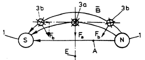
제2도는 항상 일정한 횡방향 힘을 받는 전자비임을 도시한 종래 편향자계의 개략도.2 is a schematic diagram of a conventional deflection magnetic field showing an electron beam that is always subjected to a constant lateral force.
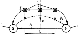
제3도는 본 발명에 따른 비임용 편향자계의 개략도.3 is a schematic diagram of a non-bearing deflection magnetic field according to the present invention.
제4도는 본 발명에 따른 장치의 양호한 실시예에 의해 선형화된 편향자계를 발생시키는 양호한 수단의 개략도.4 is a schematic representation of a preferred means of generating a linearized deflection magnetic field by a preferred embodiment of the device according to the invention.
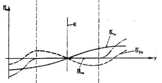
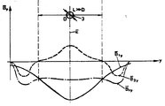
제5a도 내지 제5c도는 제4도에 따른 비임용 여러경로를 도시한 것으로 제5a도는 자계합, 제5b도는 자계백터의 수직성분, 제5c도는 자계벡터의 수평성분을 나타낸 도면.5a to 5c show several paths for non-fertilization according to FIG. 4, FIG. 5a shows a magnetic sum, FIG. 5b shows a vertical component of a magnetic field vector, and FIG. 5c shows a horizontal component of a magnetic field vector.
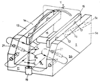
제6도는 본 발명에 따른 장치의 양호한 실시예의 개략도.6 is a schematic representation of a preferred embodiment of the device according to the invention.
제7도는 제6도에 따른 장치의 또다른 실시예의 개략도.7 is a schematic representation of another embodiment of the device according to FIG. 6.
제8도는 제7도에 따른 장치의 또다른 실시예로써 집속 제어장치를 갖는 본 발명에 따른 또다른 실시예의 개략도.8 is a schematic view of another embodiment according to the invention with a focus control device as another embodiment of the device according to FIG.
제9a도 내지 제9c도는 편향자계용 극면을 갖는 본 발명에 따른 장치의 개략측면도.9a to 9c show schematic side views of a device according to the invention with a polar surface for deflection magnetic field;
* 도면의 주요부분에 대한 부호의 설명* Explanation of symbols for main parts of the drawings
1a : 자극 3 : 입자비임1a: stimulus 3: particle beam
5 : 극편 7 : 자석5: pole piece 7: magnet
9 : 보상자석 10 : 극9: reward magnet 10: pole
A : 다이포울축 F : 편향력A: die pole axis F: deflection force
![]()
![]()
![]()
![]()
19 : 비임발생기 21 : 편향자석19: beam generator 21: deflection magnet
L1, L2: 권선 25 : 대상물L 1 , L 2 : Winding 25: Object
본 발명은 비임의 전파방향에 수직한 제1방향에 상기 제1방향과 비임전파방향에 수직한 제2방향으로 비임을 편향시키기 위해 자속밀도가 제공되게되는 단극대전되는 입자 특히 전자의 비임을 편향시키기위한 방법에 관한 것이다.The present invention is directed to deflecting monopolar charged particles, especially electron beams, in which a magnetic flux density is provided to deflect the beam in a first direction perpendicular to the beam propagation direction and in a second direction perpendicular to the non-propagation direction. It is about how to let.
이와 같은 종류의 방법은 미합중국 특허 제 4 064 352호에 공지되어 있다. 여기서 비임발생기로부터 대상물을 증발하기위한 전자비임총의 전자비임은 180℃이상 편향되며 비임곡선의 양측에 자극을 갖는 극편이 배치되어 이극편 사이에서 편향자계가 발생된다. 전자비임은 극편의 전면 상부로 부분적으로 통과되어 그에의해 만곡된 자계구역이 생긴다.A method of this kind is known from US Pat. No. 4 064 352. Here, the electron beam of the electron beam gun for evaporating an object from the beam generator is deflected by more than 180 ° C., and pole pieces having magnetic poles are arranged on both sides of the beam curve to generate a deflection magnetic field between the two pole pieces. The electron beam partially passes through the top of the pole piece, resulting in a curved magnetic field.
제1도에 의해 상세히 설명되는 바와 같은 상기 편향방법은 단점을 갖고 있다. 제1도를 보면 하나의 자성 다이포울(dipole)을 형성하는 2개의 자극(1)이 개략도시되어 있다. 다이포울축(A) 부근에서 자극(1) 사이로 직선으로 뻗어있는 정상적으로 도시된 자속밀도(![]()
![]()
다이포울축(A)의 방향에 있는 비임의 위치와 이축(A)에 경사져있는 편향위치 사이에 커플링이 있다. 비임 횡단면은 소정의 자속밀도와 점선으로 도시된 바와 같은 비임위치가 다이포울(A) 방향으로의 이동시 영향을 받는데 비임횡단면의 여러구역에는 여러 가지 다른 힘들이 작용하게 된다.There is a coupling between the position of the beam in the direction of the die pole axis A and the deflection position inclined to the bi axis A. FIG. The beam cross section is affected by the predetermined magnetic flux density and the beam position as shown by the dashed line in the direction of the die pole A. Various different forces act on the various sections of the beam cross section.
비임은 선속(Feldlinien)을 따라 이동되지않아 자계벡터의 합이 일정하기 때문에 비임이 축(A)에 평행하게 위치이동되면 합성력(F)의 절대치 합이 변화되는 단점이 있다.Since the beam does not move along the line speed (Feldlinien) and the sum of the magnetic field vectors is constant, the absolute value of the combined force (F) is changed when the beam is moved in parallel to the axis (A).
미합중국 특허 제 3 420 977에도 종래의 단점을 갖지 않거나 약간 갖는 방법이 기재되어있다. 여기서 자성극편에 의해 편향자속밀도가 발생되고 대전된 입자 즉 전자의 비임을 상기 극편사이로 통과된다. 연장된 자성극편으로인해 이극편사이에 약간 만곡된 선속을 갖는 자계가 발생된다. 따라서 제2도에 도시된 바와 같이 전자비임(3)은 다이포울 (A)을 따라 변위되어 축(A)에 대해 항상 일정한 횡방향 힘이 합성된다.U.S. Patent No. 3 420 977 also describes a method with or without a prior disadvantage. Here, the deflection magnetic flux density is generated by the magnetic pole pieces, and the beams of charged particles, that is, electrons, are passed between the pole pieces. The extended magnetic pole pieces generate a magnetic field with a slightly curved line flux between the two pole pieces. Thus, as shown in FIG. 2, the
이같은 구성에서 비임을 180℃와 그이상 예를들면 270℃의 큰 각으로 편향시킬 때 자석배열이 큰 공간을 차지하는데 이는 극편은 그 긴부분 사이에 비임을 수용하여야 하기 때문이다. 상기 극편은 대상물에 특히 물질을 증발시키도록 비임을 작용시킴으로써 위험이 증대되게된다. 극편에 경사진, 증발된 도가니와 같은 대상물상의 비임의 크기는 극편의 간격과 길이에 따라 변화될 수 있다.In such a configuration, the magnet array occupies a large space when deflecting the beam at a large angle of 180 ° C. and above 270 ° C., because the pole piece must accommodate the beam between its long portions. The pole pieces are at increased risk by acting on the beam to specifically evaporate the material. The size of the beam on an object, such as an evaporated crucible inclined to the pole piece, can vary depending on the spacing and length of the pole piece.
종래의 기술에서는 만곡된 선속과 비균일한 자계구역을 갖는 편향자속밀도계의 구역은 비임을 안내하기에는 적당하지 않는 단점이 있는데, 제1도를 근거로 설명된 단점을 갖고 비임이 안내된다.In the prior art, a zone of a deflection flux density meter having a curved line flux and a non-uniform magnetic field zone has disadvantages that are not suitable for guiding a beam, with the disadvantage described with reference to FIG. 1 and the beam is guided.
따라서 본 발명의 목적은 종래기술의 단점(제1도 참조)이 없이도 비임을 안내하는데 이용될 수 있으며 편향자계를 발생하는 극편과 같은 부분의 구성에 대해 유연성이 높은 이질의 만곡된 편향자계구역을 제공하는 것이다.Therefore, the object of the present invention can be used to guide the beam without the disadvantages of the prior art (see FIG. 1) and to create a heterogeneous curved deflection magnetic field zone that is highly flexible with respect to the configuration of the pole-like part that generates the deflection magnetic field. To provide.
상기 본 발명의 목적은 특허 청구범위 제1항의 특징부에 따라 달성된다.The object of the present invention is achieved according to the features of
특허 청구 범위 제2항의 기재에 따라 본 발명의 장점이 제공된다.The advantages of the present invention are provided according to the description of
본 발명에 따른 방법을 특히 피복장치에서 물질을 증발시키기위해 전자총의 비임과 같은 전자비임에 이용할 때 비임은 제1방향 즉, 청구범위 제3항의 기재에 따른 편향자계의 방향인 측방으로 편향이 제어된다. 본 발명에 따라 선형화된 편향자계구역의 내부에서 상기 편향으로 인해 편향변화가 거의없고 측방편향이 변화되지 않고도 편향이 변화될 수 있게된다. 비임이 먼저 본 발명에 따른 방법에 의해 균일화된 편향구역 특히 극편배열의 외부로 안내 될 수 있기 때문에 비임의 극편구역에 직접 놓이지 않고도 편향상승이 증가될 수 있게된다.When the method according to the invention is used for an electron beam, such as a beam of an electron gun, in particular for vaporizing a material in a coating device, the beam is deflected in the first direction, lateral to the deflection magnetic field according to the description of
청구범위 제4항의 기재에 따라 비임전파방향의 제2방향 즉, 편향방향에 있는 제어가능한 편자속도밀도계에 의해 편향의 양호하게 이루어진다.The deflection is preferably made by means of a controllable horseshoe densitometer in the second non-propagation direction, ie the deflection direction, according to the description of claim 4.
또한 청구범위 제5항에 따르면 본 발명에 따른 방법을 전술한 전자총에 적용할 때 횡단면에 대해 비임을 제어 할 수 있으며 편향에 의해 경우에 따라서는 전술한 측방편향에 의해 감결합(Entkoppelen)된다. 후자의 경우 서로 진행된 비임의 3개의 감결합된 제어크기가 주어지므로 대상물상의 충돌면(Aufftreffflache)의 위치는 2개의 좌표로 변화될 수 있으며 또한 상기 충돌면과 에너지밀도의 크기가 변화될 수 있다.In addition, according to
특허청구범위 제6항에 따르면 비임은 그 횡단면에 대해 집속자속밀도계에 의해 제어되므로 비임의 양측의 각 대응극에 따라 제2방향으로 제공되거나 관련된 비임횡단면의 내부의 비임양측에서 대응극에 의한 인장력 및 압축력에 의해 비임횡단면이 보상되거나 팽창될 수 있다.According to
미합중국 특허 제4 064 352호에 기재된 바와 같이 편향자속밀도계를 발생하기 위해 비임의 양측에서 상기 극편형태의 연장된 한쌍의 자석배열이 구비될 수 있다. 이 자계는 전자비임으로부터 비임발생기와 대상물 사이의 모든 관통구역위로 뻗어있게된다. 그로인해 비임은 완전한 편향자계비율로 통과된다.As described in US Pat. No. 4 064 352, an extended pair of magnet arrays in the form of pole pieces may be provided on both sides of the beam to generate a deflection flux density meter. This magnetic field extends from the electron beam onto all of the penetration zones between the beam generator and the object. As a result, the beam is passed at full deflection field ratio.
따라서, 종래기술을 고려하여 본 발명의 목적은 가능한 작으며 외부구역에서도 비임의 경로가 영향을 받게되는 비임을 평향시키는 극배열을 제공하는 것이다.Accordingly, it is an object of the present invention, in view of the prior art, to provide a polar arrangement that is as small as possible and to flatten the beam in which the path of the beam is affected even in the outer zone.
단극의 대전된 입자 특히 전자의 비임의 비임경로를 형성하기위한 종래의 방법 즉, 자속밀도계는 비임전파방향에 수직한 제1방향에 수직한 제2방향과 비임전파방향으로 편향시키기위해 상기 제1방향으로 발생되고 편향면 양측에 구비된 연장된 극배열에 의해 비임용자계가 발생되며 상기 비임은 극배열 사이의 만곡된 자계구역으로 관통안내되는 전술한 미합중국 특허 제4 064 352호로부터 상기 본 발명의 목적은 특허 청구범위 7항의 특징부에 따라, 만곡된 자계를 한정하는 극배열의 경계면을 비임이 그 경로를 따라 여러 가지로 다르게 지향하여 배치되는 편향력을 받아 소정의 경로로 안내되도록 편향면에 평행한 면에 지향되게 형성함으로써 달성된다.Conventional methods for forming beam paths of monopolar charged particles, in particular beams of electrons, ie magnetic flux densitometers, are characterized in that the second direction perpendicular to the first direction perpendicular to the non-electromagnetic propagation direction and the non-electromagnetic propagation direction are deflected for deflection. From the above-mentioned U.S. Patent No. 4 064 352, the non-magnetic field is generated by an extended pole array which is generated in one direction and provided on both sides of the deflection surface, and the beam is guided through the curved magnetic field zone between the pole arrays. The purpose of the claim is to, according to the features of claim 7, the deflection plane such that the beam is guided in a predetermined path by means of a deflection force arranged differently along the path of the polar array boundary that defines the curved magnetic field. It is achieved by forming it oriented in a plane parallel to the.
극배열의 경계면을 이와 같이 지향되게 형성함으로써 비임은 그 전파를 따라 원하는 방향으로 지향된 힘을 받을 수 있으며 극배열 즉 극편외에 전파방향으로 다른 소정의 만곡부를 갖도록 비임경로가 설계될 수 있다.By forming the polar array boundary surface in this manner, the beam can receive a force directed in a desired direction along its propagation, and the beam path can be designed to have other predetermined curved portions in the propagation direction besides the pole array.
따라서 청구범위 제8항의 기재에 따르면 감소된 만곡부를 갖도록 편향의 지향방향이 형성될 수 있어서 경계면은 비임지향방향으로 만곡되고 그에의해 주어진 극편은 지향방향을 고려하여 대체로 더욱 짧게 형성될 수 있으며 비임은 극편사이구역을 지난후에 극편외부에 배치된 지향면상으로 항상 더 작은 만곡된 경로로 지향될 수 있으며 극편은 비임의 지향면상의 작용으로부터 보호되고 비교적 큰 지향면이 이용될 수 있는데 이는 비임의 충돌면이 대상물상에서 많이 이동될 수 있으며 극편간격이 줄어들 수 있기 때문이다.Thus, according to the description of claim 8, the deflection direction can be formed to have a reduced bend so that the interface is curved in the non-direction and the pole piece given thereby can be formed generally shorter in consideration of the direction of the direction. After passing through the interpolar zone, it can always be directed to a smaller curved path on the direction plane located outside the pole plane, and the pole piece is protected from the action of the beam orientation plane and a relatively large orientation plane can be used, which is the collision plane of the beam. This is because it can be moved a lot on this object and the polar gap can be reduced.
청구범위 제7항 또는 제8항에 관련되어 있는 방법은 제9항에 따라 이질의 편향자계구역에 단점없이 이용될 수 있는 전술한 것과 조합될수 있다.The method in accordance with claims 7 or 8 can be combined with the above, which can be used without disadvantages in heterogeneous deflection magnetic fields according to claim 9.
단극대전된 입자 특히 전자의 비임을 편향시키는 장치에서 비임경로용 구역이 제공되며 극에서 극까지 비임경로용 구역에서 한방향에 대체로 수직한 방향으로 만곡된 편향자속밀도계를 발생하는 자성편향극편은 상기 목적을 달성하기위해 제10항의 기재에 따라 제공된다.In a device for deflecting monopolar charged particles, in particular electron beams, a non-pathing zone is provided and a magnetic deflection pole piece which generates a deflected magnetic flux density meter that is curved in a direction substantially perpendicular to one direction in the non-pathway zone from pole to pole. It is provided in accordance with the description of
청구범위 제11항에 따라 보상하기위한 장치가 간단한 기술과 방법으로 설계된다.The device for compensating according to
청구범위 제12항 내지 제23항에는 본 발명에 따른 장치의 또다른 양호한 실시예가 기재되어 있다.Claims 12 to 23 describe another preferred embodiment of the device according to the invention.
본 발명에 따라 또 청구범위 제24항에 따라 단극대전된 입자특허 전자의 비임을 편향시키기위한 장치가 제공되는데 이 장치에서 비임용 구역이 구비되며 비임용의 대상물을 설치하기위한 설치장비와 비임경로용 구역의 측면으로 뻗어있는 극편형태의 자성극배열이 구비되어 이 극편 전면사이에 비임경로용 구역의 적어도 일부에서 편향하게 되는 자속밀도계가 발생된다.In accordance with the present invention and in accordance with claim 24, there is provided an apparatus for deflecting a beam of monopolar charged particle patent electrons, in which a beaming zone is provided and installation equipment and beampaths for installing the objects for the beaming. A magnetic pole array in the form of a pole piece extending to the side of the dragon zone is provided to generate a magnetic flux density meter that deflects at least a portion of the beampath zone between the pole piece fronts.
상기 목적의 범위내에서 극편은 가능한 작게되고 주어진 대상물 구역까지는 설치되지 않을 수 있으며 청구범위 제24항의 특징부에 따라 제공된다. 이러한 극배열 (즉 극편)의 양호한 실시예가 청구범위 제25항에 상술되어 있다.Within the scope of this object, the pole piece is as small as possible and may not be installed to a given object zone and is provided according to the features of claim 24. Preferred embodiments of such pole arrays (ie pole pieces) are detailed in
이하, 본 발명은 첨부된 도면을 참조로한 실시예를 통해 설명함으로써 또다른 장점등이 명확해질 것이다.Hereinafter, other advantages and the like will be clarified by explaining the embodiments with reference to the accompanying drawings.
제3도에는 제1도 및 제2도와 대조되는 본 발명에 따른 수단이 도시되어 있다. 양자극(1) 사이에는 자속밀도계(![]()
![]()
다이포울축(A)의 방향으로의 힘성분이 합성력(F)에 발생되지 않고도 입자비임(3)의 위치가 이동될수 있음이 도시되어있다. 상기 방향으로의 위치이동에 관계없이 인가된 편향력(F)이 일정하게 유지된다. 비임(3)의 횡단면의 모든 대전체가 다이포울축(A)의 방향으로 위치이동할 때 일정한 힘을 받기 때문에 비임이 극(1) 부근의 상부 및 외부로 뻗을지라도 이동시에는 비임의 횡단면의 변화가 없게된다.It is shown that the position of the
제4도에는 제3도에 따른 자계강도지도의 양호한 실예가 개략도시되어 있고 이를위한 본 발명에 따른 장치도 개략도시되어 있다.Fig. 4 schematically shows a preferred example of the magnetic field strength map according to Fig. 3 and also shows a device according to the invention for this purpose.
2개의 자극(la) 사이, 예를들면 극편(5)을 통해 형성된 자석(7)의 양측에는 만곡된 자계밀도 (![]()
![]()
자극(la) 부근과 그에따른 직선(g)의 동일한 방향으로 보상자석(9)는 한편에 극(10)울 구비하는데 다른극은 상기극 (la)을 통해 직접 형성될 수 있다. 이 자석(9)에 의해 점선으로 표시한 바와같은 보상자계밀도(![]()
![]()
제 5도a를 보면 제4도에 도시된 방향(y)인 직선(g)상에 있을 때 극(la)사이에 발생된 자계 (![]()
![]()
![]()
![]()
제 5b도를 보면 전술한 바와같이 자속밀도의 제4도에 따른 x 방향의 수직성분이 직선(g)상에 있을때가 도시되어있다. 합성된 자계를 평가하기위해 양자계부분의 수직성분들이 직접 합해질 수 있다. 제5b도에 점선으로 도시된 바와같이 디자인에 따라 크거나 작게될수도 있지만 대개의 경우 입자비임(3)의 직경보다 큰 구역(l)에서 합성된자계(![]()
![]()
![]()
![]()
y-방향의 수평성분에 대한 도면이 제5c도에 도시되어있다. 여기서 합성자속밀도 (![]()
![]()
![]()
![]()
제5에는 정성적으로만 도시되어 있어서 제4도에 따라 구비된 보상자계(![]()
![]()
제4도 및 제5도를 고려해보면 초기편향자속밀도(![]()
![]()
제6도를 보면 본 발명에 따른 장치의 양호한 실시예가 개략도시되어 있다. 정지기부(11)에 의해 U자형으로 결합되는 극편(5)사이에는 극편전면(13)을 갖는 자극 (la)이 형성되어있다. 극편(5) 사이에 자석(15)이 구비되어있다.With reference to FIG. 6 a preferred embodiment of the device according to the invention is shown schematically. Between the
상기 자석(15)은 전자석, 영구자석 또는 전자석과 영구자석의 조합이 이용될수 있다. 자극(la)의 전면(13)부근에는 극편(16)이 있는데 이 극편은 자석(17)에 의해 극편(5)와 연결된다. 상기 자석(17)도 전자석, 영구자석 또는 전자석과 영구자석의 조합이 이용될 수 있다.The
도시되어있는 자석배열에 의한 정성적으로 합성된 자계(![]()
![]()
![]()
![]()
![]()
![]()
![]()
![]()
![]()
![]()
제7도를 보면 제6도에 따른 장치의 또다른 실시예가 도시되어 있는데, 이 장치는 특히 피복장치에서 물질을 증발시키기위한 전자비임총에서 전자비임을 제어하는데 이용된다. 제6도에 대응되는 부분은 제6도에서 이미 이용된 도면번호로 표시된다.7 shows another embodiment of the device according to FIG. 6, which is used in particular to control the electron beam in an electron beam gun for evaporating material in the coating device. The part corresponding to FIG. 6 is indicated by the reference numeral already used in FIG.
제3,4 및 5도의 실시예에 따라 비임(3),특히 전자비임을 측방 즉, 제4도의 y방향으로 이동시키기위해 비임(3)의 양측에 동일하게 극화되고 한편으로는 관련구역에서 비임(3)의 전파 방향에 수직하고 다른 한편으로 편향자계(![]()
![]()
![]()
![]()
![]()
![]()
편향자계(![]()
![]()
제8도에는 제7도에 따른 장치의 또다른 양호한 실시예가 도시되어있다. 극편부품(5b)에는 편향자석(21)과 달리 자속밀도(![]()
![]()
![]()
![]()
따라서 상기 자석 및 그 일부분은 이녹스의 특성을 갖는 전기 불량도체를 함유하므로 와전류에 의한 상호 인덕턴스의 발생이 방지된다. 자속밀도의 전환변화시 시정수(time constant)가 상당히 작으므로 극도로 소형의 구조에도 불구하고 자계는 차단주파수를 갖고 수 KHz 까지도 전이될 수 있다. 따라서 10kw의 전력에서 전자비임은 다른것없이 증발면에 1KHz로 위치하여 집속될수 있다.Therefore, since the magnet and a part thereof contain an electrical defective conductor having the characteristics of inox, mutual occurrence of inductance due to eddy current is prevented. Since the time constant is very small when the change of magnetic flux density is changed, the magnetic field has a cutoff frequency and can be transferred up to several KHz despite the extremely small structure. Thus, at 10 kW of power, the electron beam can be focused at 1 KHz on the evaporation plane without any other.
제4도에 점선으로 도시된 바와같이 필요한 경우 비임의 편향을 제어할 때 보상자계(![]()
![]()
![]()
![]()
![]()
![]()
제9도에 의해 본 발명의 또 다른 양태가 설명된다. 제9도는 본 발명에 따른 장치의 측면도를 개략표시한다.9 illustrates another aspect of the present invention. 9 schematically shows a side view of a device according to the invention.
제9a도 및 제9b도에 따르면 자석배열에 대해 극편(5)과 고정배치되는 비임발생기(19)에 의해 발생된 비임(3)을 원하는 통로로 제공하기위해 극편(5)은 극을 형성하는 그 전면 (1)이 만곡되어 있다. 편향자계의 곡선이![]()
![]()
제8도에(5c)에 점선으로 표시된 극편(5)의 레이싱부(lacing)는 극을 형성하는 전면(13)의 제9c도에 의해 개략도시한 경사부와 일치한다. 자계를 균질화하기 위한 본 발명에 따른 방법에 의해 비임을 안내하기위한 자극부분외에 자계부분이 이용될수 있다. 자계곡선은 간단한 기술과 방법으로 극편전면을 형성함으로써 영향받을 수 있다. 본 발명에 따른 장치의 구성 유연성은 극도로 높다. 대상물이 극편외부에만 놓일 수 있기 때문에 비임을 조절하기위한 더큰 측방상승이 가능하다. 예를들면 제9c도를 보면 극편사이에 비임의 작은 측방편향으로 대상물에서 비임의 더큰 편향이 있게된다.The lacing of the
제8도에 개략도시한 바와같은 구성에 의해 특히 전자총의 전자비임용의 최고로 소형의 제어장치가 제공되는데 이 장치에서 서로 무관한 비임집속, 측방비임편향 및 비임편향이 제어될 수 있다.The configuration as outlined in FIG. 8 provides a particularly compact control device for the electron beam of the electron gun, in which the beam focusing, lateral beam deflection and beam deflection independent of each other can be controlled.
Claims (28)
Applications Claiming Priority (2)
| Application Number | Priority Date | Filing Date | Title |
|---|---|---|---|
| DE3929475A DE3929475A1 (en) | 1989-09-05 | 1989-09-05 | METHOD AND DEVICE FOR DEFLECTING A RAY |
| DE39294757 | 1989-09-05 |
Publications (2)
| Publication Number | Publication Date |
|---|---|
| KR910007063A KR910007063A (en) | 1991-04-30 |
| KR0175922B1 true KR0175922B1 (en) | 1999-03-20 |
Family
ID=6388674
Family Applications (1)
| Application Number | Title | Priority Date | Filing Date |
|---|---|---|---|
| KR1019900014017A KR0175922B1 (en) | 1989-09-05 | 1990-09-05 | Method and device for the deflection of a beam |
Country Status (6)
| Country | Link |
|---|---|
| US (1) | US5038044A (en) |
| EP (1) | EP0416414B1 (en) |
| JP (1) | JP3075411B2 (en) |
| KR (1) | KR0175922B1 (en) |
| AT (1) | ATE128576T1 (en) |
| DE (2) | DE3929475A1 (en) |
Families Citing this family (3)
| Publication number | Priority date | Publication date | Assignee | Title |
|---|---|---|---|---|
| DE19645053C2 (en) * | 1996-10-31 | 1999-11-11 | Siemens Ag | X-ray tube |
| US20050043870A1 (en) * | 2003-08-22 | 2005-02-24 | General Electric Company | Method and apparatus for recording and retrieving maintenance, operating and repair data for turbine engine components |
| KR101717249B1 (en) * | 2015-06-01 | 2017-03-17 | 곽영철 | Health Pillow |
Family Cites Families (10)
| Publication number | Priority date | Publication date | Assignee | Title |
|---|---|---|---|---|
| US3420977A (en) * | 1965-06-18 | 1969-01-07 | Air Reduction | Electron beam apparatus |
| US3609378A (en) * | 1966-10-31 | 1971-09-28 | Air Reduction | Monitoring of vapor density in vapor deposition furnance by emission spectroscopy |
| US3475542A (en) * | 1967-09-13 | 1969-10-28 | Air Reduction | Apparatus for heating a target in an electron beam furnace |
| US3655902A (en) * | 1970-10-19 | 1972-04-11 | Air Reduction | Heating system for electron beam furnace |
| US3924210A (en) * | 1974-11-01 | 1975-12-02 | Raytheon Co | Field shaping magnet structure |
| US4064352A (en) * | 1976-02-17 | 1977-12-20 | Varian Associates, Inc. | Electron beam evaporator having beam spot control |
| FR2453492A1 (en) * | 1979-04-03 | 1980-10-31 | Cgr Mev | DEVICE FOR ACHROMATIC MAGNETIC DEVIATION OF A BEAM OF CHARGED PARTICLES AND IRRADIATION APPARATUS USING SUCH A DEVICE |
| AU8124082A (en) * | 1981-03-09 | 1982-09-16 | Unisearch Limited | Charged particle beam focussing device |
| DE3639683A1 (en) * | 1986-11-20 | 1988-05-26 | Leybold Ag | EVAPORATOR ARRANGEMENT WITH A RECTANGULAR EVAPORATOR AND MULTIPLE ELECTRON CANNON |
| US4804852A (en) * | 1987-01-29 | 1989-02-14 | Eaton Corporation | Treating work pieces with electro-magnetically scanned ion beams |
-
1989
- 1989-09-05 DE DE3929475A patent/DE3929475A1/en active Granted
-
1990
- 1990-08-27 EP EP90116363A patent/EP0416414B1/en not_active Expired - Lifetime
- 1990-08-27 DE DE59009711T patent/DE59009711D1/en not_active Expired - Fee Related
- 1990-08-27 AT AT90116363T patent/ATE128576T1/en not_active IP Right Cessation
- 1990-09-04 US US07/577,467 patent/US5038044A/en not_active Expired - Lifetime
- 1990-09-04 JP JP02232605A patent/JP3075411B2/en not_active Expired - Fee Related
- 1990-09-05 KR KR1019900014017A patent/KR0175922B1/en not_active IP Right Cessation
Also Published As
| Publication number | Publication date |
|---|---|
| DE59009711D1 (en) | 1995-11-02 |
| JP3075411B2 (en) | 2000-08-14 |
| EP0416414A2 (en) | 1991-03-13 |
| JPH03170099A (en) | 1991-07-23 |
| KR910007063A (en) | 1991-04-30 |
| EP0416414B1 (en) | 1995-09-27 |
| US5038044A (en) | 1991-08-06 |
| DE3929475A1 (en) | 1991-03-14 |
| ATE128576T1 (en) | 1995-10-15 |
| EP0416414A3 (en) | 1991-09-18 |
| DE3929475C2 (en) | 1992-12-10 |
Similar Documents
| Publication | Publication Date | Title |
|---|---|---|
| US5132544A (en) | System for irradiating a surface with atomic and molecular ions using two dimensional magnetic scanning | |
| US6365894B2 (en) | Electromagnet and magnetic field generating apparatus | |
| US4710722A (en) | Apparatus generating a magnetic field for a particle accelerator | |
| US5117212A (en) | Electromagnet for charged-particle apparatus | |
| US6633039B2 (en) | Electromagnets for and method of deflecting and splitting a particle beam | |
| KR101169963B1 (en) | Irradiation system with ion beam/charged particle beam | |
| TW445490B (en) | Ion beam implantation using conical magnetic scanning | |
| KR20060135908A (en) | Method and fine-control collimator for accurate collimation and precise parallel alignment of scanned ion beams | |
| JP6460038B2 (en) | Magnetic deflection system, ion implantation system, and method of scanning an ion beam | |
| US10332718B1 (en) | Compact deflecting magnet | |
| JP2007280966A (en) | Electrooptic lens system | |
| US6495826B2 (en) | Monochrometer for electron beam | |
| KR0175922B1 (en) | Method and device for the deflection of a beam | |
| JP2008047491A (en) | Bending magnet, and ion implantation device equipped therewith | |
| US4395691A (en) | Beam deflection system | |
| JP2644958B2 (en) | Ion source device and ion implantation device provided with the ion source device | |
| KR100213462B1 (en) | Device and process for controlling the focusing of a monopolar charged particle beam | |
| US11114270B2 (en) | Scanning magnet design with enhanced efficiency | |
| JP2813386B2 (en) | Electromagnet of charged particle device | |
| JP2004206995A (en) | Deflection electromagnet, electrically-charged particles transportation path and circular accelerator | |
| JPH0878200A (en) | Method and device for controlling magnetic field made by eddy current | |
| JPH02270308A (en) | Superconducting deflection electromagnet and excitation method thereof | |
| CN111741590A (en) | Deflection magnet and deflection device with same | |
| JPH0521197A (en) | Bipolar electromagnet | |
| JPH04292844A (en) | Mass spectro meter |
Legal Events
| Date | Code | Title | Description |
|---|---|---|---|
| A201 | Request for examination | ||
| E701 | Decision to grant or registration of patent right | ||
| GRNT | Written decision to grant | ||
| FPAY | Annual fee payment |
Payment date: 20021106 Year of fee payment: 5 |
|
| LAPS | Lapse due to unpaid annual fee |