KR0155152B1 - Cleaning equipment - Google Patents
Cleaning equipment Download PDFInfo
- Publication number
- KR0155152B1 KR0155152B1 KR1019890012290A KR890012290A KR0155152B1 KR 0155152 B1 KR0155152 B1 KR 0155152B1 KR 1019890012290 A KR1019890012290 A KR 1019890012290A KR 890012290 A KR890012290 A KR 890012290A KR 0155152 B1 KR0155152 B1 KR 0155152B1
- Authority
- KR
- South Korea
- Prior art keywords
- nozzle flow
- flow passage
- cleaning material
- passage
- cleaning
- Prior art date
- Legal status (The legal status is an assumption and is not a legal conclusion. Google has not performed a legal analysis and makes no representation as to the accuracy of the status listed.)
- Expired - Fee Related
Links
Images


Classifications
-
- B—PERFORMING OPERATIONS; TRANSPORTING
- B24—GRINDING; POLISHING
- B24C—ABRASIVE OR RELATED BLASTING WITH PARTICULATE MATERIAL
- B24C3/00—Abrasive blasting machines or devices; Plants
- B24C3/02—Abrasive blasting machines or devices; Plants characterised by the arrangement of the component assemblies with respect to each other
- B24C3/06—Abrasive blasting machines or devices; Plants characterised by the arrangement of the component assemblies with respect to each other movable; portable
- B24C3/062—Abrasive blasting machines or devices; Plants characterised by the arrangement of the component assemblies with respect to each other movable; portable for vertical surfaces
-
- B—PERFORMING OPERATIONS; TRANSPORTING
- B24—GRINDING; POLISHING
- B24C—ABRASIVE OR RELATED BLASTING WITH PARTICULATE MATERIAL
- B24C3/00—Abrasive blasting machines or devices; Plants
- B24C3/02—Abrasive blasting machines or devices; Plants characterised by the arrangement of the component assemblies with respect to each other
- B24C3/06—Abrasive blasting machines or devices; Plants characterised by the arrangement of the component assemblies with respect to each other movable; portable
- B24C3/065—Abrasive blasting machines or devices; Plants characterised by the arrangement of the component assemblies with respect to each other movable; portable with suction means for the abrasive and the waste material
Landscapes
- Engineering & Computer Science (AREA)
- Mechanical Engineering (AREA)
- Environmental & Geological Engineering (AREA)
- Cleaning In General (AREA)
- Cleaning By Liquid Or Steam (AREA)
Abstract
본 발명은 세척될 표면에 세척 재료를 충돌시키기 위한 장치에 관한 것이다. 상기 장치는 세척된 표면의 반대 방향에 위치하는 제1 노즐 유동 통로와, 제1노즐 유동 통로의 상류측에서 이격된 제2노즐 유동 통로와, 재충돌된 세척 재료의 유입 통로, 및 배출 통로를 갖는 세척 헤드를 구비한다. 또한 상기 장치는 세척 재료를 포함하는 가압 유체 흐름을 제2 노즐 유동 통로로 공급하기 위한 수단과, 배출 통로에서 유체를 흡입하기 위한 수단과, 상기 표면에 충돌된 세척 재료를 제1노즐 유동 통로에서 재충돌된 세척 재료의 유입 통로로 되돌리기 위한 수단을 구비한다.The present invention relates to an apparatus for impinging a cleaning material on a surface to be cleaned. The apparatus comprises a first nozzle flow passage located in an opposite direction of the cleaned surface, a second nozzle flow passage spaced upstream of the first nozzle flow passage, an inlet passage of re-impacted cleaning material, and an outlet passage. Having a washing head. The apparatus also includes means for supplying a pressurized fluid stream comprising cleaning material to the second nozzle flow passage, means for sucking fluid in the discharge passage, and cleaning material impinging the surface in the first nozzle flow passage. And means for returning to the inlet passage of the re-collided cleaning material.
Description
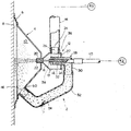
제1도는 본 발명의 세척 장치의 주요 부분을 도시하는 단면도.1 is a cross-sectional view showing the main part of the cleaning apparatus of the present invention.
제2도는 제1도의 세척 장치에 의해 세척될 표면에 충돌되는 세척 재료의 양의 변화를 도시하는 도표.FIG. 2 is a diagram showing a change in the amount of cleaning material impinged on the surface to be cleaned by the cleaning apparatus of FIG.
제3도는 제1도의 세척 장치 내에 있는 세척 헤드의 변형 실시예를 도시한 단면도.3 is a cross-sectional view of a variant embodiment of the cleaning head in the cleaning device of FIG.
* 도면의 주요부분에 대한 부호의 설명* Explanation of symbols for main parts of the drawings
2 : 세척 장치 4 : 폐쇄 부재2: cleaning device 4: closing member
6 : 격벽 8 : 표면6: bulkhead 8: surface
12 : 세척 헤드 18 : 하우징12 cleaning head 18 housing
22 : 제1노즐 유동 통로 38 : 제2 노즐 유동 통로22: first nozzle flow passage 38: second nozzle flow passage
40 : 가요성 호스 42 : 공급수단40: flexible hose 42: supply means
[발명의 분야 ]Field of Invention
본 발명은 가압 유체 흐름 내에 금속 입자, 세라믹 입자 또는 모래와 같은 세척 재료를 부유 운반하여 세척시킬 표면에 충동시키는 형태의 세척 장치에 관한 것이다.The present invention relates to a type of cleaning apparatus in which a cleaning material, such as metal particles, ceramic particles or sand, is suspended in a pressurized fluid stream and impinged on the surface to be cleaned.
종래기술의 설명Description of the Prior Art
금속입자, 세라믹 입자 또는 모래와 같은 세척 재료를 포함하는 가압 유체흐름을, 세척 헤드 내에 배치된 노즐 유동 통로를 통해서 세척될 표면에 충돌시키는 형태의 세척 장치는 오일 저장 탱크, 고층 건물 및 선박과 같은 대형 구조물의 표면을 세척하는 데 널리 사용된다. 보통 상기 형태의 세척 장치는 세척될 표면과 함께 압력 감소 공간을 한정하는 폐쇄 부재를 포함한다. 세척 헤드는 폐쇄 부재 상에 장착되고, 노즐 유동 통로의 끝 부분은 압력 감소 공간 내에 위치한다. 흡입 수단이 제공되어 압력 감소 공간으로부터 배출 통로를 통해 유체를 끌어낸다. 흡닙 수단의 작용에 의해 압력 감소 공간은 압력이 감소된 상태로 유지되고, 세척 헤드가 장착된 폐쇄 부재는 세척될 표면에 진공 부착된다. 노즐 유동 통로에서 표면에 충돌되는 세척 재료는 압력 감소 공간에서 배출 통로를 통해서 빨려든 유체 흐름내에서 부유 운반되고, 압력 감소 공간에서 회수된다. 미국 특허 제4,095,378호(일본 특허 공고 제85-26752호)를 종래의 세척 장치를 나타내는 공지 기술의 통상적인 예로서 인용한다.Cleaning devices in the form of impinging a pressurized fluid stream comprising cleaning material, such as metal particles, ceramic particles or sand, onto the surface to be cleaned via a nozzle flow passage disposed within the cleaning head are suitable for use in oil storage tanks, tall buildings and ships. Widely used to clean the surface of large structures. Usually a cleaning device of this type comprises a closing member defining a pressure reducing space with the surface to be cleaned. The cleaning head is mounted on the closing member and the end of the nozzle flow passage is located in the pressure reducing space. Suction means are provided to draw fluid from the pressure reducing space through the discharge passage. By the action of the suction means, the pressure reducing space is kept in a reduced pressure, and the closing member equipped with the cleaning head is vacuum attached to the surface to be cleaned. The cleaning material impinging on the surface in the nozzle flow passage is suspended in the fluid flow sucked through the discharge passage in the pressure reducing space and recovered in the pressure reducing space. U.S. Patent No. 4,095,378 (Japanese Patent Publication No. 85-26752) is cited as a common example of the known art showing a conventional washing apparatus.
상기 형태의 세척 장치의 세척 효율은 노즐 유동 통로를 통해 세척될 표면에 충돌되는 세척 재료의 단위 시간당 양에 좌우된다. 따라서, 세척 효율을 증가시키기 위해서는 노즐 유동 통로로 공급되는 세척 재료를 포함하는 가압 유체 흐름의 단위 시간당 양을 증가시키는 것이 바람직하며, 따라서 세척될 표면에 충돌되는 세척 재료의 양이 증가된다. 그러나, 가압 유체 흐름의 양을 증가시키기 위해서는 가압 펌프 등으로 구성되는 가압 유체 공급원의 크기를 증가시킬 필요가 있으며, 이에 따라 장치 및 작동 비용이 상당히 증가하게 된다. 세척 재료를 부유 운반하기 위해 가압 유체 흐름의 양을 증가시키지 않고도 세척 재료 양 만을 증가시킬 수 있는 것으로 보인다. 그러나, 만약 가압 유체 흐름의 양에 대해서 세척 재료의 양이 초과된다면, 세척 재료는 세척 재료의 공급원에서 노즐 유동 통로로 연장되는 공급통로(가요성 호스로 제조될 수 있음)를 부드럽게 통과하여 이동할 수 없다. 따라서, 세척 효율이 역으로 감소하며, 세척 재료가 공급 통로를 차단할 수도 있다.The cleaning efficiency of this type of cleaning device depends on the amount of cleaning material per unit time impinging on the surface to be cleaned through the nozzle flow passage. Thus, in order to increase the cleaning efficiency, it is desirable to increase the amount per unit time of pressurized fluid flow including the cleaning material supplied to the nozzle flow passage, thus increasing the amount of cleaning material impinging on the surface to be cleaned. However, in order to increase the amount of pressurized fluid flow, it is necessary to increase the size of the pressurized fluid source consisting of a pressurized pump or the like, which greatly increases the apparatus and operating costs. It appears that it is possible to increase only the amount of cleaning material without increasing the amount of pressurized fluid flow to float convey the cleaning material. However, if the amount of cleaning material is exceeded with respect to the amount of pressurized fluid flow, the cleaning material may move smoothly through a supply passage (which may be made of a flexible hose) extending from the source of cleaning material to the nozzle flow passage. none. Thus, the cleaning efficiency is reversed, and the cleaning material may block the feed passage.
[발명의 요약][Summary of invention]
본 발명의 주목적은 노즐 유동 통로로 공급되는 가압 유체 흐름의 단위 시간당 양을 증가시키지 않고도 세척될 표면에 충돌되는 세척 재료의 단위 시간당의 양을 증가시켜 세척 효율을 증가시키고, 따라서 장비 및 작동 비용의 증가를 피하는 것이다.The primary object of the present invention is to increase the cleaning efficiency by increasing the amount of cleaning material impinging on the surface to be cleaned, without increasing the amount of pressurized fluid flow to the nozzle flow passage, thereby increasing the cleaning efficiency and thus reducing the equipment and operating costs. To avoid the increase.
본 발명의 주목적을 성취하기 위한 필수적인 특징은,(가)세척 재료를 포함하는 가압 유체 흐름이 공금되는 상류측 노즐 유동 통로에 추가하여, 상류측 노즐 유동 통로보다 충분히 큰 단면적을 가지며 세척될 표면의 반대쪽에 위치하는 하류측 노즐이 하류측 방향에서 상류측 노즐 유동 통로와 이격되어 위치시켜 상류측 노즐 유동 통로로 공급되는 세척 재료를 포함하는 가압 유체 흐름이 하류측 노즐 유동 통로를 통해서 세척될 표면에 충돌되도록 하는 것과,(나)하류측 노즐 유동 통로와 관련하여, 재충돌된 세척 재료의 유입 통로와 세척될 표면에 충돌되는 세척재료를 재충돌된 세척 재료의 유입 통로로 되돌리는 세척 재료 되돌림 수단이 제공되고, 재충돌된 세척 재료의 유입 통로로 되돌려진 세척 재료의 일부는 상류측 노즐 유동 통로 내의 세척 재료를 포함하는 가압 유체 흐름을 하류측 노즐 유동 통로쪽으로 전진시켜서 생성된 흡입 작용에 의해 하류측 노즐 유동 통로로 흡입되며, 세척될 표면에 재충돌하게 되는 것이다.An essential feature for achieving the main object of the present invention is that (a) in addition to the upstream nozzle flow passages in which pressurized fluid flows comprising wash material are deposited, they have a cross-sectional area sufficiently larger than the upstream nozzle flow passages and The downstream nozzle located opposite is positioned away from the upstream nozzle flow passage in the downstream direction so that a pressurized fluid flow comprising cleaning material supplied to the upstream nozzle flow passage is applied to the surface to be cleaned through the downstream nozzle flow passage. And (b) cleaning material return means for returning the cleaning material impinging on the surface to be cleaned and the inflow passage of the re-collided cleaning material with respect to the collision of the downstream nozzle flow path. A portion of the cleaning material returned to the inlet passage of the provided, re-collided cleaning material is the cleaning material in the upstream nozzle flow passage. The pressurized fluid flow comprising the material is adsorbed into the downstream nozzle flow passage by the suction action generated by advancing toward the downstream nozzle flow passage and re-collision to the surface to be cleaned.
본 발명에 따르면, 세척될 표면의 반대 방향에 위치하는 제1노즐 유동 통로와,제1노즐 유동 통로의 상류측에 이격되어 있는 제2노즐 유동 통로와, 재충돌된 세척 재료의 유입 통로 및 배출 통로를 갖는 세척 헤드와, 세척 재료를 포함하는 가압 유체 흐름을 제2노즐 유동 통로로 공급하기 위한 수단과, 배출 통로에서 유체를 흡입하기 위한 흡입 수단과, 상기 표면에 충돌된 세척 재료를 제1노즐 유동 통로에서 재충돌된 세척 재료의 유입 통로로 되돌리기 위한 수단을 구비하며, 여기에서 제1노즐 유동통로의 단면적은 제2노즐 유동 통로의 단면적보다 충분히 크며; 상기 세척 재료 공급 수단으로부터 제2노즐 유통 통로로 공급된 세척 재료를 포함하는 가압 유체 흐름은 제2노즐 유동 통로를 통해서 통과하여, 제1노즐 유동 통로 내로 전진하고, 제1노즐 유동 통로로부터 상기 표면에 충돌하게 되고; 세척 재표를 포함하는 가압 유체 흐름의 흐름은 제1노즐 유동 통로 내에 흡입 작용을 생성하며, 재충돌된 세척 재료의 유입 통로로 되돌려진 세척 재료의 일부는 흡입 작용에 의해 제1노즐 유동 통로 내로 흡입되며, 제1노즐 유동통로로부터 상기 표면에 재충돌되는 한편 재충돌된 세척 재료의 유입 통로로 되돌려진 세척 재료의 나머지의 일부는 배출 통로로부터 흡입된 유체에 의하여 부유 운반되는 세척 장치가 제공된다.According to the present invention, there is provided a first nozzle flow passage located in an opposite direction of the surface to be cleaned, a second nozzle flow passage spaced upstream of the first nozzle flow passage, and an inflow passage and discharge of re-collided cleaning material. A first cleaning head having a passage, a means for supplying a pressurized fluid flow comprising cleaning material to the second nozzle flow passage, a suction means for sucking fluid in the discharge passage, and a cleaning material impinging on the surface; Means for returning from the nozzle flow passage to the inlet passage of re-collided cleaning material, wherein the cross-sectional area of the first nozzle flow passage is sufficiently greater than that of the second nozzle flow passage; The pressurized fluid flow comprising the cleaning material supplied from the cleaning material supply means to the second nozzle flow passage passes through the second nozzle flow passage, advances into the first nozzle flow passage, and the surface from the first nozzle flow passage. To collide with; The flow of pressurized fluid flow comprising the cleaning table creates a suction action in the first nozzle flow passage, and a portion of the cleaning material returned to the inlet passage of the re-collided cleaning material is sucked into the first nozzle flow passage by the suction action. And a portion of the remainder of the cleaning material that has been re-collided to the surface from the first nozzle flow passage and returned to the inlet passage of the re-collisioned cleaning material is provided in a floating manner by fluid sucked from the discharge passage.
본 발명의 세척 장치에서, 세척될 표면에 충돌되는 재료의 단위 시간당 양은 재충돌된 세척 재료의 유입 통로로부터 제1노즐 유동 통로(하류측 상의 노즐 통로)에서 흡입된 재충돌된 세척 재료의 양에 의해서 증가된다. 이것은 제2노즐 유동 통로(상류측 상의 노즐 유동 통로)로 공급되는 가압 유체 흐름의 단위 시간당 양을 증가시키지 않고도 성취된다. 제1노즐 통로 내로 흡입된 재충돌된 세척 재료가 제2노즐 유동 통로로 공급되지 않고 제2노즐 유동 통로의 제1 노즐 유동 통로 하류측으로 인도되기 때문에, 재충돌된 세척 재료의 유동은 제2노즐 유동 통로 내로의 가압 유체 흐름의 공급을 방해하지 않는다.In the cleaning apparatus of the present invention, the amount of material per unit time impinging on the surface to be cleaned is equal to the amount of re-impacted cleaning material sucked in the first nozzle flow passage (nozzle passage on the downstream side) from the inflow passage of the re-collided cleaning material. Is increased by. This is accomplished without increasing the amount of pressurized fluid flow to the second nozzle flow passage (nozzle flow passage on the upstream side). Since the re-collided cleaning material sucked into the first nozzle passage is not supplied to the second nozzle flow passage and is led to the downstream side of the first nozzle flow passage of the second nozzle flow passage, the flow of the re-collided cleaning material is controlled by the second nozzle. It does not interfere with the supply of pressurized fluid flow into the flow passages.
본 발며의 세척 장치의 양호한 실시예를 첨부된 도면을 참고로하여 더욱 자세하게 설명하기로 한다.Preferred embodiments of the cleaning device of the present invention will be described in more detail with reference to the accompanying drawings.
제1도를 참조하면, 도면 부호2로 표시된 세척 장치는 거의 절두 원추형태의 폐쇄 부재(4)를 포함한다. 폐쇄 부재(4)는 강철판과 같은 강성(剛性)재료로 형성된다. 격벽(6)은 폐쇄 부재(4)의 환형 자유 단부 부분 내에 배치된고 전방으로 연장되는 한편 바깥으로 향해 방사상으로 경사져 있다. 격벽(6)은 천연 또는 합성고무와 같은 가요성 재료로 구성된다. 제1도에 명백하게 도시되어 있듯이, 격벽(6)을 가지는 폐쇄 부재(4)는 표면(8)과 함께 격벽(6)의 자유 단부 부분과 접촉하여 세척될 표면(8)의 반대쪽에 위치되고, 표면(8)과 협력하여 압력 감소 공간(10)을 형성한다. 후술하는 바와 같이, 압력 감소 공간(10)은 압력이 감소된 상태로 유지하도록 공기를 빼낸다. 따라서 폐쇄 부재(4)는 표면(8)에 흡입 부착된다. 또한 표면(8)과 밀접하게 접촉하는 다수의 휠(wheel)과 휠을 구동시킬 구도원(도시하지않음)이 폐쇄 부재(4)상에 장착된다. 따라서, 폐쇄 부재(4)는 표면(8)에 흡입 부착되고, 동시에 이를 따라서 이동하게 된다. 폐쇄 부재(4)의 흡입 부착과 이동에 대해서는 종래 기술로써 본원에서 인용된 미국 특허 제4,095,378호를 참조하라.Referring to FIG. 1, the cleaning device, indicated by reference numeral 2, comprises a closing member 4 in the form of a nearly truncated cone. The closing member 4 is formed of a rigid material such as a steel sheet. The partition 6 is disposed in the annular free end portion of the closure member 4 and extends forward while inclined radially outward. The partition 6 is made of a flexible material such as natural or synthetic rubber. As clearly shown in FIG. 1, the closing member 4 having the partition 6 is located opposite the surface 8 to be cleaned in contact with the free end portion of the partition 6 together with the surface 8, Cooperate with surface 8 to form
세척 헤드(12)는 폐쇄 부개(4)의 후측(제1도에서 오른쪽)으로 중심부에 고정된다. 세척 헤드(12)는, 예를 들어 적절한 소성 가공 또는 주조 등으로 형성되며, 원통형 후방부(14)와 절두 원추형 전방부(16)로 구성된 하우징(18)을 포함한다. 전방으로 돌출하는 원통형 부재(20)는 하우징(18)의 전방 단부에 배치되고, 제1노즐 유동 통로(22)를 한정한다. 노즐 유동 통로(22)를 한정하는 원통형 부재(20)는 폐쇄 부재(4)를 통해서 연장되며, 노즐 유동 통로(22)의 끝 부분은 압력 감소 공간(10)내에 위치한다. 하우징(18)의 원통형 후방부(14)의 상부면에 개구가 형성된다. 배출 통로(26)를 한정하는 원통형 부재(24)가 이 개구에서 상향으로 연장되어 배치되어 있다. 부재(28)는 이것의 후방벽(27)을 통해 연장되는 하우징(18)내에 배치된다. 부재(28)는 L자형으로 연장되며, 이것의 유입 단부에서 상향으로 연장되는 상류측부(30)와, 상류측부(30)에서 후방벽(27)을 통해 전방으로 연장되는 하류측부(32)를 갖는다. 부재(28)는 단면이 원형일 수 있으며, 재충돌된 세척 재료의 유입 통로(34)를 한정한다. 비교적 작은 직경의 원통형 부재(36)가 세척 헤드(12)내에 또한 설치될 수 있다. 원통형 부재(36)는 부재(28)의 곡선부 (상류측부(30)와하류측부(32)사이의 경계 지역)의 휴방에서, 하류측부(32)를 통해서 연장된다. 원통형 부재(36)는 원통형 부재(20)와 동일 방향으로 직선적으로 연장된다. 원통형 부재(36)는 제2노즐 유동 통로(38)를 형성한다. 따라서, 설명된 실시예에서, 제1 노즐 유동 통로(22)와 제2노즐 유동 통로(38)는 서로에 대해 동일 방향으로 직선적으로 연장된다. 재충돌된 세척 재료의 유입 통로(34)의 하류측부(32)는 제2노즐 유동 통로(38)와 외부로 동일 방향으로 연장된다. 제1노즐 유동 통로(22)의 단면적(Sa)은 제2노즐 유동 통로(38)의 단면적(Sb)보다 충분히 커야 한다. 양호하게는, Sa=2 X Sb 내지 Sa = 8 X Sb이다.The
제2노즐 유동 통로(38)를 한정하는 원통형 부재(36)의 유입 단부(상류측단부)는 가요성 호스(40)를 통해 세척 재료 공급 수단(42)에 연결된다. 세척 재료공급 수단(42)은 공지된 형태 중의 하나라도 좋으며, 압축 펌프와 세척 재료 공급원을 포함한다. 세척 재료 공급 수단은 세척 재료를 포함하는 가압 유체 흐름(예를들어, 압축 공기 흐름과 같은 것일 수 있다)을 가요성 호스(40)를 통해 제2노즐 유동 통로(38)로 공급한다. 필요하다면, 가압 가스 흐름 대신에 세척 재료를 물과 같은 액체에 포함시켜서 세척 재료를 공급할 수도 있다. 배출 통로(26)를 한정하는 원통형 부재(24)의 유입 단부(상류측 단부)는 가요성 호스(44)를 통하여 진공 펌프일 수도 있는 흡입 수단(46)에 연결된다. 흡입 수단(46)은 가요성 호스(44)를 통하여 배출 통로(26)로부터 가스(또는 액체)를 흡입한다. 표면(8)과 협동하는 압력 감소 공간(10)을 한정하는 폐쇄 부재(4) 내에 배출 개구(48)가 현성되다. 원통형 개구(50)는 배출 개구(48)에서 후방으로 돌출하여 배치된다. 원통형 부재(50)는 파이프(52:합성 수지 또는 고무로 제조될 수 있다)에 의해 부재(28)의 유입 단부(상류측 단부)에 연결된다. 파이프(52)와 원통형 부재(50)는 표면(8)에 충돌된 세척 재료를 부재(28)에 의해 한정된 재충돌된 세척 재료의 유입 통로(34)로 되돌리기 위한 재충돌된 세척 재료의 되돌림 통로(54:되돌림 수단)를 구성한다.The inlet end (upstream end) of the
상술한 세척 장치(2)의 작동과 장점을 설명한다. 표면(8)을 세척하기 위하여, 세척 재료를 포함하는 가압 유체 흐름은 가요성 호스(40)를 통하여 세척 재료 공급 수단(42)으로부터 제2노즐 유동 통로(38)로 공급된다. 세척 재료를 포함하는 가압 유체 흐름은 제2노즐 유동 통로(38)를 통하여 통과하여, 제1노즐 유동 통로(22)내로 전진하고, 제1노즐 유동 통로(22)에서 표면(8)에 충돌한다. 그사이에, 가요성 호스(44)를 통하여 배출 통로(26)와 연통되는 흡입 수단(46)은 재충돌된 세척 재료의 귀환 통로(54)와, 재충돌된 세척 재료의 유입통로(34)와,하우징(18)내의 공간과, 배출 통로(26)를 통해 압력 감소 공간(10)에서 유체를 흡입한다. 그 결과, 공간(10)내의 압력은 감소된다. 세척 재료를 포함하는 가압 유체 흐름이 제2노즐 유동 통로(38)로부터 제1노즐 유동 통로(22)내로 들어오고 제1노즐 유동 통로(22)를 통하여 흐를 때, 제1노즐 유동 통로(22)는 제1노즐 유동 통로(22)의 유입부(상류측부)에서 흡입 작용을 증가시키기 위하여 배출시에 혼합실로서 작용한다. 따라서, 압력 감소 공간(10)내의 유체는 제1노즐 유동 통로(22)를 통해 하우징(18)내로 흡입되지 않는다. 표면(8)에 충돌되고 세척 작용을 수행한 세척 재료는 재충돌된 세척 재료의 되돌림 통로(54)를 통해서 유동되는 한편 공간(10)에서 흡입된 액체 흐름 내에서 부유 운반되고, 재충돌된 세척 재료의 유입 통로(34)로 되돌려진다. 유입 통로(34)를 통하여 흐르는 되돌려진 세척 재료는 하우징(18)내의 공간으로 흘러가고, 이것의 일부는 자테의 흐름 관성과 제1노즐 유동 통로(22)의 유입뷰에서 생성된 흡입 작용에 의해 제1노즐 유동 통로(22)내부로 전진하고, 표면(8)에 다시 충돌된다. 재충돌된 세척 재료의 유입 통로(34)애소 하우진(18)내의 공간으로 되돌려진 세척 재료의 나머지의 일부는 배출통로(26)와 가요성 호스(44)를 통하여 흡입된 유체 흐름에 의해 부유 운반되고 유체화(fluidize)된다. 일반적으로, 세척 재료는 표면(8)또는 다른 것과 충돌하여 파열된다. 파열된 세척 재료가 자체의 무게에 비해 비교적 큰 표면적을 가지고 자체 관성에 의해 많이 유동하지 않기 때문에, 파열된 세척 재료는 흡입된 유체 흐름내에서 부유 운반되는 경향이 있고 제1노즐 유동 통로(22)에 들어감이 없이 배출통로(26)와 가요성 호스(44)를 통하여 배출된다. 한편, 파열되지 않고도 양호한 세척 특성을 계속 유지하고 있는 세척 재료는 그 중량에 비해 작은 표면적을 가지며 자체 관성에 의해 양호하게 흐르게 된다. 따라서, 세척 재료는 제1노즐 유동 통로(22)로 쉽게 들러가게 된다. 표면(8)에서 벗겨지든가 다른 방법으로 제거되는 이물질, 페인트, 녹 등은 압력 감소 공간(10)에서 흡입된 유체 흐름 내에 부유 운반되고 재충돌된 세척 재료의 도돌림 통로(54),재충돌된 세척 재료의 유입 통로(34)와 배출 통로(26)를 통해 배출된다. 배출 통로(26)에 연결된 가요성 호스(44)는 공지의 혼합물 분리 장치(도시하지 않음)를 통하여 흡입 수단(46)과 연통되어 혼합물 분리 장치 내에서 세척 재료, 이물질, 페인트, 녹 등을 흡입 유체 흐름에서 분리한다. 폐쇄 부재(4)내에 배치된 격벽(6)은 가볍게 또는 밀접하게 접촉할 수 있으나, 격벽(6)과 표면(8)사이의 공간은 결코 견고하게 밀봉되어 있지는 않다. 압력 감소공간(10)의 내부가 감소된 압력으로 유지될 때, 약간의 유체가 격벽(6)과 표면(8)사이에서 압력 감소 공간(10)내로 흘러 들어온다.The operation and advantages of the cleaning device 2 described above will be described. To clean the surface 8, a pressurized fluid stream comprising cleaning material is supplied from the cleaning material supply means 42 to the second
따라서, 본 발명의 세척 장치(2)에서, 세척 재료 공급 수단(42)에서 제2노즐 유동 통로(38)내로 공급되는 가압 유채 흐름 내에 원래부터 포함되어 있는 세척 재료 뿐만 아니라 재충돌된 세척 재료의 되돌림 통로(54)를 통하여 재충돌된 세척 재료의 유입 통로로 되돌려진 세척 재료도 제1노즐 유동 통로(22)에서 표면(8)에 충돌된다. 따라서, 세척 재료가 표면(8)에 재충돌 하지 않는 종래의 세척 장치와 비교하면, 표면(8)에 충돌되는 세척 재료의 양은 증가되고 따라서 세척 효율이 향상된다.Thus, in the cleaning device 2 of the present invention, the cleaning material originally contained in the pressurized rapeseed stream supplied from the cleaning material supply means 42 into the second
세척 재료 공급 수단(42)에서 제2노즐 유동 통로(38)로 공급되는 세척 재료의 양이 M ㎏/분이고, 세척 재료의 재충돌 양이 R%이고, 세척 재료의 재충돌 횟수를 n이라고 하면, 분당 충돌된 세척 재료의 양은 다음과 같다.When the amount of cleaning material supplied from the cleaning material supply means 42 to the second
F(n) = F(n -1) x R / 100+MF (n) = F (n -1) x R / 100 + M
제2도는 각각 컴퓨터로 계산된 M=35이고 R=50,60,70 및 80에 대한 충돌된 세척 재료의 양의 변화를 도시한 다이어그램이다. 제2도에서, 세로 좌표축은 충돌된 세척 재료의 양(㎏/분 SDD)을 나타내고, 가로 좌표축은 재충돌 횟수를 나타낸다. 제2도에 도시된 바와 같이, R이 일정할 때, 충돌된 세척 재료의 양은 소정의 시간 주기가 경과한다면 특정 범위 내에서 안정화된다. 제1도를 참조하여 상술한 세척장치(2)에서, 세척 재료의 재충돌 비율은 예를 들어, 흡입 수단(46)에 의해 배출 통로(26)로부터 흡입되는 유체 흐름의 양과, 세척 재료 공급 수단(42)으로부터 제2노즐 유동 통로(38)로 공급될 유체 흐름의 양, 또는 제1노즐 유동 통로(22)와 제2노즐 유동통로(38)사이의 거리를 변화시킴으로서 적절하게 조절될수 있다.2 is a diagram showing the change in the amount of impingement cleaning material for M = 35 and R = 50, 60, 70 and 80, respectively, calculated by computer. In FIG. 2, the ordinate represents the amount of impacted washing material (kg / min SDD), and the abscissa represents the number of collisions. As shown in FIG. 2, when R is constant, the amount of impingement washing material is stabilized within a certain range if a predetermined time period elapses. In the washing apparatus 2 described above with reference to FIG. 1, the re-collision rate of the washing material is, for example, the amount of fluid flow sucked from the
제3도는 세척 헤드의 변형 실시예를 도시한다. 제3도에 도시된 세척 헤드(112)에서, 제1도에 도시된 실시예에서와 같이, 제1노즐 유동 통로(122)를 한정하는 원통형 부재(120)와 제2노즐 유동 통로(138)를 한정하는 원통형 부재(136)는 제3도의 좌,우 방향 사이에서 거리를 두고 서로에 대해 동일 방향으로 직선적으로 연장되어있다. 한편, 배출 통로(126)를 한정하는 원통형 부재(124)는 제1노즐 유동 통로(122)의 상류측 단부와 제2노즐 유동 통로(138)의 하류측 단부 사이에서 후방으로 및 상향으로 경사져서 연장된다. 재충돌된 세척 재료의 유입통로(134)는 원통형 부재(128)에 의해 한정된다. 원통형 부재(128)는 제1노즐 유동 통로(122)의 상류측 단부와 제2노즐 유동 통로(138)의 하류측 단부 사이로부터 후방으로 및 하향으로 연장된다. 제3도에 도시된 세척 헤드(112)의 다른 구조는 제1도에 도시된 세척 헤드(12)의 구조와 실질적으로 동일하며, 따라서 다른 구조에 대한 설명은 여기에서 생략하기로 한다.3 shows a variant embodiment of the cleaning head. In the
제3도에 도시된 세척 헤드(112)를 사용하는 경우에 있어서도, 제1노즐 유동 통로(122)에서 표면에 충돌된 세척 재료는 재충돌된 세척 재료의 유입 통로(134)로 되돌려진다. 그러므로, 되돌려진 세척 재료의 일부분은 다시 제1노즐 유동 통로(122)로 들어가고, 제1노즐 유동 통로(122)에서 표면에 다시한번 충돌된다. 되돌려진 세척 재료의 다른 부분이 배출되는 동안에 배출 통로(126)를 통하여 흡입된 유체 흐름 내에 부유 운반된다.Even in the case of using the
양호한 실시예와 첨부된 도면에 도시된 변형 실시예를 참조하며 본 발명의 세척 장치를 상세히 설명하였으나, 본 발명이 양호한 실시예 및 변형 실시예에만 국한되는 것은 아니며, 본원에서 설명되고 청구된 본 발명의 범위에서 이탈하지 않고도 여러 가지의 변경 및 수정이 가능한 것은 당연하다.Although the cleaning apparatus of the present invention has been described in detail with reference to the preferred embodiments and the modified embodiments shown in the accompanying drawings, the invention is not limited to the preferred and modified embodiments, but is described and claimed herein. Naturally, various changes and modifications can be made without departing from the scope of the present invention.
Claims (5)
Applications Claiming Priority (3)
| Application Number | Priority Date | Filing Date | Title |
|---|---|---|---|
| JP214536 | 1988-08-29 | ||
| JP63-214536 | 1988-08-29 | ||
| JP21453688 | 1988-08-29 |
Publications (2)
| Publication Number | Publication Date |
|---|---|
| KR900002898A KR900002898A (en) | 1990-03-23 |
| KR0155152B1 true KR0155152B1 (en) | 1999-01-15 |
Family
ID=16657358
Family Applications (1)
| Application Number | Title | Priority Date | Filing Date |
|---|---|---|---|
| KR1019890012290A Expired - Fee Related KR0155152B1 (en) | 1988-08-29 | 1989-08-29 | Cleaning equipment |
Country Status (6)
| Country | Link |
|---|---|
| US (1) | US4984396A (en) |
| EP (1) | EP0359000B1 (en) |
| KR (1) | KR0155152B1 (en) |
| CA (1) | CA1325954C (en) |
| DE (1) | DE68905728T2 (en) |
| ES (1) | ES2039779T3 (en) |
Families Citing this family (27)
| Publication number | Priority date | Publication date | Assignee | Title |
|---|---|---|---|---|
| GB8908843D0 (en) * | 1989-04-19 | 1989-06-07 | Vapormatt Ltd | Improvements in or relating to the treatment of surfaces |
| US5551909A (en) * | 1990-12-28 | 1996-09-03 | Bailey; Donald C. | Method and apparatus for cleaning with high pressure liquid at low flow rates |
| US5138800A (en) * | 1991-04-30 | 1992-08-18 | Compustrip Systems Ltd. | Positioning apparatus for supporting and guiding a tool |
| JP3028148B2 (en) * | 1991-05-24 | 2000-04-04 | 不可止 浦上 | Centrifugal projection device |
| ES2103400T3 (en) * | 1992-06-19 | 1997-09-16 | Ivan Markocic | ABRASIVE INSTALLATION. |
| US5545074A (en) * | 1994-12-28 | 1996-08-13 | Jacobs; Patrick T. | Abrasive blasting system with waste water recycling |
| DE19520551A1 (en) * | 1995-06-06 | 1996-12-12 | Roland Man Druckmasch | Method and device for cleaning a cylinder of a rotary printing press |
| US5921846A (en) * | 1997-03-21 | 1999-07-13 | The Johns Hopkins University | Lubricated high speed fluid cutting jet |
| US6066032A (en) * | 1997-05-02 | 2000-05-23 | Eco Snow Systems, Inc. | Wafer cleaning using a laser and carbon dioxide snow |
| RU2129949C1 (en) * | 1997-05-27 | 1999-05-10 | Казаков Владимир Михайлович | Apparatus for shot blasting of surfaces |
| US5957761A (en) * | 1997-11-12 | 1999-09-28 | Northrop Grumman Corporation | Closed circuit media capture and recovery head for the portable wheat starch media blast system |
| DE19802308C2 (en) * | 1998-01-22 | 2001-05-31 | Horst Laug | Suction device for sandblasting and liquid pressure nozzles |
| EP1038674A1 (en) * | 1999-02-26 | 2000-09-27 | Alfred M. Petersen | Blast cleaning apparatus for printing machines |
| KR20030015089A (en) * | 2001-08-14 | 2003-02-20 | 엘지.필립스디스플레이(주) | A damper spring for flat type color ray tube |
| GB2410710A (en) * | 2003-12-12 | 2005-08-10 | Pentagon Glass Tech Ltd | Pneumatic etching device |
| NL1027172C2 (en) * | 2004-10-05 | 2006-04-06 | Hoek Loos Nv | Spray pistol is for dry ice or grit, has feed connection (2) for dry ice or grit accommodated in a primary air flow, and a feed-out channel (3) connected to the feed connection with a spray mouthpiece (4) |
| RU2314188C2 (en) * | 2005-11-21 | 2008-01-10 | Рязанский военный автомобильный институт имени генерала армии В.П. ДУБЫНИНА | Abrasive-jet apparatus |
| RU2310554C2 (en) * | 2005-11-28 | 2007-11-20 | Виктор Петрович Крючков | Apparatus for abrasive-jet treatment of surfaces |
| RU2314907C1 (en) * | 2006-04-13 | 2008-01-20 | Олег Иванович Гречишкин | Tool for abrasive-jet working at removing waste working fluid |
| WO2009042767A1 (en) * | 2007-09-26 | 2009-04-02 | Mount Sinai School Of Medicine | Azacytidine analogues and uses thereof |
| TWI531446B (en) * | 2008-08-07 | 2016-05-01 | 不二製作所股份有限公司 | Sand blasting method and equipment with abrasive material recovery system, processing method of thin film solar panel and thin film solar panel processed by the same |
| US8801499B2 (en) * | 2009-04-21 | 2014-08-12 | Sharp Kabushiki Kaisha | Blasting apparatus and method for blast processing |
| JP5746901B2 (en) * | 2011-04-14 | 2015-07-08 | 株式会社不二製作所 | Polishing method and nozzle structure of blast processing apparatus |
| US20140373303A1 (en) * | 2013-06-24 | 2014-12-25 | Phuong Taylor Nguyen | Padeye or Tie-Down Cleaning System |
| JP6128101B2 (en) * | 2014-11-21 | 2017-05-17 | トヨタ自動車株式会社 | Laser cladding equipment |
| DE102017220032A1 (en) * | 2017-11-10 | 2019-05-16 | Premium Aerotec Gmbh | METHOD FOR TREATING A SURFACE OF A FIBER COMPOSITE COMPONENT |
| RU202626U1 (en) * | 2020-10-23 | 2021-03-01 | Акционерное общество "Национальный центр вертолетостроения им. М.Л. Миля и Н.И. Камова" (АО "НЦВ Миль и Камов") | DEVICE FOR STRENGTHENING OF PARTS WITH HOLES |
Family Cites Families (8)
| Publication number | Priority date | Publication date | Assignee | Title |
|---|---|---|---|---|
| DE268568C (en) * | ||||
| US818776A (en) * | 1905-05-05 | 1906-04-24 | John D Murray | Sand-blast apparatus. |
| US3212217A (en) * | 1963-05-28 | 1965-10-19 | Tex Tube Inc | Cleaning device |
| US3925935A (en) * | 1974-03-20 | 1975-12-16 | Robert U Ricklefs | Abrading system |
| US4095378A (en) * | 1975-12-18 | 1978-06-20 | Uragami Fukashi | Device capable of suction-adhering to a wall surface and moving therealong |
| JPS5281792A (en) * | 1975-12-29 | 1977-07-08 | Atsuji Tekko Kk | Wall face grinding and cleaning machine |
| JPS5969262A (en) * | 1982-10-11 | 1984-04-19 | Fukashi Uragami | Injection-type blast device |
| JPS63196379A (en) * | 1987-02-10 | 1988-08-15 | Osaka Gas Co Ltd | Grinding/cleaning material scattering preventive method and device |
-
1989
- 1989-08-22 US US07/396,967 patent/US4984396A/en not_active Expired - Fee Related
- 1989-08-24 DE DE89115634T patent/DE68905728T2/en not_active Expired - Fee Related
- 1989-08-24 ES ES198989115634T patent/ES2039779T3/en not_active Expired - Lifetime
- 1989-08-24 EP EP89115634A patent/EP0359000B1/en not_active Expired - Lifetime
- 1989-08-28 CA CA000609525A patent/CA1325954C/en not_active Expired - Fee Related
- 1989-08-29 KR KR1019890012290A patent/KR0155152B1/en not_active Expired - Fee Related
Also Published As
| Publication number | Publication date |
|---|---|
| EP0359000B1 (en) | 1993-03-31 |
| ES2039779T3 (en) | 1993-10-01 |
| CA1325954C (en) | 1994-01-11 |
| DE68905728T2 (en) | 1993-10-07 |
| US4984396A (en) | 1991-01-15 |
| DE68905728D1 (en) | 1993-05-06 |
| KR900002898A (en) | 1990-03-23 |
| EP0359000A1 (en) | 1990-03-21 |
Similar Documents
| Publication | Publication Date | Title |
|---|---|---|
| KR0155152B1 (en) | Cleaning equipment | |
| JPH0258065B2 (en) | ||
| US7891954B2 (en) | Method and apparatus for conveying material and ejector apparatus | |
| US5664992A (en) | Apparatus and method for cleaning tubular members | |
| EP0543387B1 (en) | Improvements in automatic pool cleaners | |
| JPH01270960A (en) | Centrifugal separation type apparatus for purifying paint mist-containing air | |
| US4734943A (en) | Waste disposal system | |
| US5107632A (en) | Device for separating blasting dust from blasting agent | |
| US4475447A (en) | Spray booth apparatus | |
| EP1058046B1 (en) | Surge suppression apparatus | |
| JP2720208B2 (en) | Cleaning equipment | |
| CN111957639B (en) | Cleaning head for cleaning object surface | |
| US5846303A (en) | Scrubber for cleaning exhaust air contaminated with paint particles | |
| US5656047A (en) | Wet gas scrubber | |
| SU1500791A1 (en) | EJECTOR | |
| SU797739A1 (en) | Jet-type gas washer | |
| JP4348823B2 (en) | Wet blast nozzle and wet blast method | |
| SU1219113A1 (en) | Foam breaker | |
| SU1758243A1 (en) | Device for drawoff and suppression of dust during operation of mining machines | |
| SU1118439A1 (en) | Arrangement for cleaning pipelines | |
| JPH0258064B2 (en) | ||
| HK1117120B (en) | Method and apparatus for conveying material and ejector apparatus |
Legal Events
| Date | Code | Title | Description |
|---|---|---|---|
| PA0109 | Patent application |
St.27 status event code: A-0-1-A10-A12-nap-PA0109 |
|
| R17-X000 | Change to representative recorded |
St.27 status event code: A-3-3-R10-R17-oth-X000 |
|
| PG1501 | Laying open of application |
St.27 status event code: A-1-1-Q10-Q12-nap-PG1501 |
|
| A201 | Request for examination | ||
| P11-X000 | Amendment of application requested |
St.27 status event code: A-2-2-P10-P11-nap-X000 |
|
| P13-X000 | Application amended |
St.27 status event code: A-2-2-P10-P13-nap-X000 |
|
| PA0201 | Request for examination |
St.27 status event code: A-1-2-D10-D11-exm-PA0201 |
|
| E902 | Notification of reason for refusal | ||
| PE0902 | Notice of grounds for rejection |
St.27 status event code: A-1-2-D10-D21-exm-PE0902 |
|
| T11-X000 | Administrative time limit extension requested |
St.27 status event code: U-3-3-T10-T11-oth-X000 |
|
| P11-X000 | Amendment of application requested |
St.27 status event code: A-2-2-P10-P11-nap-X000 |
|
| P13-X000 | Application amended |
St.27 status event code: A-2-2-P10-P13-nap-X000 |
|
| E701 | Decision to grant or registration of patent right | ||
| PE0701 | Decision of registration |
St.27 status event code: A-1-2-D10-D22-exm-PE0701 |
|
| GRNT | Written decision to grant | ||
| PR0701 | Registration of establishment |
St.27 status event code: A-2-4-F10-F11-exm-PR0701 |
|
| PR1002 | Payment of registration fee |
St.27 status event code: A-2-2-U10-U11-oth-PR1002 Fee payment year number: 1 |
|
| PG1601 | Publication of registration |
St.27 status event code: A-4-4-Q10-Q13-nap-PG1601 |
|
| LAPS | Lapse due to unpaid annual fee | ||
| PC1903 | Unpaid annual fee |
St.27 status event code: A-4-4-U10-U13-oth-PC1903 Not in force date: 20010715 Payment event data comment text: Termination Category : DEFAULT_OF_REGISTRATION_FEE |
|
| PC1903 | Unpaid annual fee |
St.27 status event code: N-4-6-H10-H13-oth-PC1903 Ip right cessation event data comment text: Termination Category : DEFAULT_OF_REGISTRATION_FEE Not in force date: 20010715 |