JPWO2013183106A1 - Power receiving device, power transmitting device and vehicle - Google Patents
Power receiving device, power transmitting device and vehicle Download PDFInfo
- Publication number
- JPWO2013183106A1 JPWO2013183106A1 JP2014519715A JP2014519715A JPWO2013183106A1 JP WO2013183106 A1 JPWO2013183106 A1 JP WO2013183106A1 JP 2014519715 A JP2014519715 A JP 2014519715A JP 2014519715 A JP2014519715 A JP 2014519715A JP WO2013183106 A1 JPWO2013183106 A1 JP WO2013183106A1
- Authority
- JP
- Japan
- Prior art keywords
- coil
- magnetic pole
- shaft
- power
- power transmission
- Prior art date
- Legal status (The legal status is an assumption and is not a legal conclusion. Google has not performed a legal analysis and makes no representation as to the accuracy of the status listed.)
- Pending
Links
Images


Classifications
-
- H—ELECTRICITY
- H02—GENERATION; CONVERSION OR DISTRIBUTION OF ELECTRIC POWER
- H02J—CIRCUIT ARRANGEMENTS OR SYSTEMS FOR SUPPLYING OR DISTRIBUTING ELECTRIC POWER; SYSTEMS FOR STORING ELECTRIC ENERGY
- H02J50/00—Circuit arrangements or systems for wireless supply or distribution of electric power
- H02J50/10—Circuit arrangements or systems for wireless supply or distribution of electric power using inductive coupling
- H02J50/12—Circuit arrangements or systems for wireless supply or distribution of electric power using inductive coupling of the resonant type
-
- H—ELECTRICITY
- H01—ELECTRIC ELEMENTS
- H01F—MAGNETS; INDUCTANCES; TRANSFORMERS; SELECTION OF MATERIALS FOR THEIR MAGNETIC PROPERTIES
- H01F27/00—Details of transformers or inductances, in general
- H01F27/24—Magnetic cores
-
- B—PERFORMING OPERATIONS; TRANSPORTING
- B60—VEHICLES IN GENERAL
- B60L—PROPULSION OF ELECTRICALLY-PROPELLED VEHICLES; SUPPLYING ELECTRIC POWER FOR AUXILIARY EQUIPMENT OF ELECTRICALLY-PROPELLED VEHICLES; ELECTRODYNAMIC BRAKE SYSTEMS FOR VEHICLES IN GENERAL; MAGNETIC SUSPENSION OR LEVITATION FOR VEHICLES; MONITORING OPERATING VARIABLES OF ELECTRICALLY-PROPELLED VEHICLES; ELECTRIC SAFETY DEVICES FOR ELECTRICALLY-PROPELLED VEHICLES
- B60L53/00—Methods of charging batteries, specially adapted for electric vehicles; Charging stations or on-board charging equipment therefor; Exchange of energy storage elements in electric vehicles
- B60L53/10—Methods of charging batteries, specially adapted for electric vehicles; Charging stations or on-board charging equipment therefor; Exchange of energy storage elements in electric vehicles characterised by the energy transfer between the charging station and the vehicle
- B60L53/12—Inductive energy transfer
- B60L53/122—Circuits or methods for driving the primary coil, e.g. supplying electric power to the coil
-
- B—PERFORMING OPERATIONS; TRANSPORTING
- B60—VEHICLES IN GENERAL
- B60L—PROPULSION OF ELECTRICALLY-PROPELLED VEHICLES; SUPPLYING ELECTRIC POWER FOR AUXILIARY EQUIPMENT OF ELECTRICALLY-PROPELLED VEHICLES; ELECTRODYNAMIC BRAKE SYSTEMS FOR VEHICLES IN GENERAL; MAGNETIC SUSPENSION OR LEVITATION FOR VEHICLES; MONITORING OPERATING VARIABLES OF ELECTRICALLY-PROPELLED VEHICLES; ELECTRIC SAFETY DEVICES FOR ELECTRICALLY-PROPELLED VEHICLES
- B60L53/00—Methods of charging batteries, specially adapted for electric vehicles; Charging stations or on-board charging equipment therefor; Exchange of energy storage elements in electric vehicles
- B60L53/10—Methods of charging batteries, specially adapted for electric vehicles; Charging stations or on-board charging equipment therefor; Exchange of energy storage elements in electric vehicles characterised by the energy transfer between the charging station and the vehicle
- B60L53/12—Inductive energy transfer
- B60L53/124—Detection or removal of foreign bodies
-
- B—PERFORMING OPERATIONS; TRANSPORTING
- B60—VEHICLES IN GENERAL
- B60L—PROPULSION OF ELECTRICALLY-PROPELLED VEHICLES; SUPPLYING ELECTRIC POWER FOR AUXILIARY EQUIPMENT OF ELECTRICALLY-PROPELLED VEHICLES; ELECTRODYNAMIC BRAKE SYSTEMS FOR VEHICLES IN GENERAL; MAGNETIC SUSPENSION OR LEVITATION FOR VEHICLES; MONITORING OPERATING VARIABLES OF ELECTRICALLY-PROPELLED VEHICLES; ELECTRIC SAFETY DEVICES FOR ELECTRICALLY-PROPELLED VEHICLES
- B60L53/00—Methods of charging batteries, specially adapted for electric vehicles; Charging stations or on-board charging equipment therefor; Exchange of energy storage elements in electric vehicles
- B60L53/10—Methods of charging batteries, specially adapted for electric vehicles; Charging stations or on-board charging equipment therefor; Exchange of energy storage elements in electric vehicles characterised by the energy transfer between the charging station and the vehicle
- B60L53/12—Inductive energy transfer
- B60L53/126—Methods for pairing a vehicle and a charging station, e.g. establishing a one-to-one relation between a wireless power transmitter and a wireless power receiver
-
- H—ELECTRICITY
- H01—ELECTRIC ELEMENTS
- H01F—MAGNETS; INDUCTANCES; TRANSFORMERS; SELECTION OF MATERIALS FOR THEIR MAGNETIC PROPERTIES
- H01F38/00—Adaptations of transformers or inductances for specific applications or functions
- H01F38/14—Inductive couplings
-
- H—ELECTRICITY
- H02—GENERATION; CONVERSION OR DISTRIBUTION OF ELECTRIC POWER
- H02J—CIRCUIT ARRANGEMENTS OR SYSTEMS FOR SUPPLYING OR DISTRIBUTING ELECTRIC POWER; SYSTEMS FOR STORING ELECTRIC ENERGY
- H02J50/00—Circuit arrangements or systems for wireless supply or distribution of electric power
- H02J50/005—Mechanical details of housing or structure aiming to accommodate the power transfer means, e.g. mechanical integration of coils, antennas or transducers into emitting or receiving devices
-
- H—ELECTRICITY
- H02—GENERATION; CONVERSION OR DISTRIBUTION OF ELECTRIC POWER
- H02J—CIRCUIT ARRANGEMENTS OR SYSTEMS FOR SUPPLYING OR DISTRIBUTING ELECTRIC POWER; SYSTEMS FOR STORING ELECTRIC ENERGY
- H02J50/00—Circuit arrangements or systems for wireless supply or distribution of electric power
- H02J50/10—Circuit arrangements or systems for wireless supply or distribution of electric power using inductive coupling
-
- H—ELECTRICITY
- H02—GENERATION; CONVERSION OR DISTRIBUTION OF ELECTRIC POWER
- H02J—CIRCUIT ARRANGEMENTS OR SYSTEMS FOR SUPPLYING OR DISTRIBUTING ELECTRIC POWER; SYSTEMS FOR STORING ELECTRIC ENERGY
- H02J50/00—Circuit arrangements or systems for wireless supply or distribution of electric power
- H02J50/70—Circuit arrangements or systems for wireless supply or distribution of electric power involving the reduction of electric, magnetic or electromagnetic leakage fields
-
- H—ELECTRICITY
- H01—ELECTRIC ELEMENTS
- H01F—MAGNETS; INDUCTANCES; TRANSFORMERS; SELECTION OF MATERIALS FOR THEIR MAGNETIC PROPERTIES
- H01F38/00—Adaptations of transformers or inductances for specific applications or functions
- H01F38/14—Inductive couplings
- H01F2038/143—Inductive couplings for signals
-
- H—ELECTRICITY
- H01—ELECTRIC ELEMENTS
- H01F—MAGNETS; INDUCTANCES; TRANSFORMERS; SELECTION OF MATERIALS FOR THEIR MAGNETIC PROPERTIES
- H01F27/00—Details of transformers or inductances, in general
- H01F27/28—Coils; Windings; Conductive connections
- H01F27/29—Terminals; Tapping arrangements for signal inductances
-
- H—ELECTRICITY
- H02—GENERATION; CONVERSION OR DISTRIBUTION OF ELECTRIC POWER
- H02J—CIRCUIT ARRANGEMENTS OR SYSTEMS FOR SUPPLYING OR DISTRIBUTING ELECTRIC POWER; SYSTEMS FOR STORING ELECTRIC ENERGY
- H02J2310/00—The network for supplying or distributing electric power characterised by its spatial reach or by the load
- H02J2310/40—The network being an on-board power network, i.e. within a vehicle
- H02J2310/48—The network being an on-board power network, i.e. within a vehicle for electric vehicles [EV] or hybrid vehicles [HEV]
-
- Y—GENERAL TAGGING OF NEW TECHNOLOGICAL DEVELOPMENTS; GENERAL TAGGING OF CROSS-SECTIONAL TECHNOLOGIES SPANNING OVER SEVERAL SECTIONS OF THE IPC; TECHNICAL SUBJECTS COVERED BY FORMER USPC CROSS-REFERENCE ART COLLECTIONS [XRACs] AND DIGESTS
- Y02—TECHNOLOGIES OR APPLICATIONS FOR MITIGATION OR ADAPTATION AGAINST CLIMATE CHANGE
- Y02T—CLIMATE CHANGE MITIGATION TECHNOLOGIES RELATED TO TRANSPORTATION
- Y02T10/00—Road transport of goods or passengers
- Y02T10/60—Other road transportation technologies with climate change mitigation effect
- Y02T10/70—Energy storage systems for electromobility, e.g. batteries
-
- Y—GENERAL TAGGING OF NEW TECHNOLOGICAL DEVELOPMENTS; GENERAL TAGGING OF CROSS-SECTIONAL TECHNOLOGIES SPANNING OVER SEVERAL SECTIONS OF THE IPC; TECHNICAL SUBJECTS COVERED BY FORMER USPC CROSS-REFERENCE ART COLLECTIONS [XRACs] AND DIGESTS
- Y02—TECHNOLOGIES OR APPLICATIONS FOR MITIGATION OR ADAPTATION AGAINST CLIMATE CHANGE
- Y02T—CLIMATE CHANGE MITIGATION TECHNOLOGIES RELATED TO TRANSPORTATION
- Y02T10/00—Road transport of goods or passengers
- Y02T10/60—Other road transportation technologies with climate change mitigation effect
- Y02T10/7072—Electromobility specific charging systems or methods for batteries, ultracapacitors, supercapacitors or double-layer capacitors
-
- Y—GENERAL TAGGING OF NEW TECHNOLOGICAL DEVELOPMENTS; GENERAL TAGGING OF CROSS-SECTIONAL TECHNOLOGIES SPANNING OVER SEVERAL SECTIONS OF THE IPC; TECHNICAL SUBJECTS COVERED BY FORMER USPC CROSS-REFERENCE ART COLLECTIONS [XRACs] AND DIGESTS
- Y02—TECHNOLOGIES OR APPLICATIONS FOR MITIGATION OR ADAPTATION AGAINST CLIMATE CHANGE
- Y02T—CLIMATE CHANGE MITIGATION TECHNOLOGIES RELATED TO TRANSPORTATION
- Y02T90/00—Enabling technologies or technologies with a potential or indirect contribution to GHG emissions mitigation
- Y02T90/10—Technologies relating to charging of electric vehicles
- Y02T90/12—Electric charging stations
-
- Y—GENERAL TAGGING OF NEW TECHNOLOGICAL DEVELOPMENTS; GENERAL TAGGING OF CROSS-SECTIONAL TECHNOLOGIES SPANNING OVER SEVERAL SECTIONS OF THE IPC; TECHNICAL SUBJECTS COVERED BY FORMER USPC CROSS-REFERENCE ART COLLECTIONS [XRACs] AND DIGESTS
- Y02—TECHNOLOGIES OR APPLICATIONS FOR MITIGATION OR ADAPTATION AGAINST CLIMATE CHANGE
- Y02T—CLIMATE CHANGE MITIGATION TECHNOLOGIES RELATED TO TRANSPORTATION
- Y02T90/00—Enabling technologies or technologies with a potential or indirect contribution to GHG emissions mitigation
- Y02T90/10—Technologies relating to charging of electric vehicles
- Y02T90/14—Plug-in electric vehicles
Abstract
受電装置は、コイル(22)と、コイル(22)が巻回されたコア(21)と、を備えた受電装置であって、コア(21)は、巻回軸(O1)の延びる方向に延びると共に、コイル(22)が巻回される軸部(33)と、軸部(33)の少なくとも一方の端部に形成され、巻回軸(O1)の延びる方向と交差する交差方向に延びる磁極部(34a,34b)を含み、交差方向における軸部(33)の幅は、交差方向における磁極部(34a,34b)の長さよりも短く、交差方向における磁極部(34a,34b)の中央に位置する第1中央部と、交差方向における軸部(33)の中央に位置する第2中央部とは互いに交差方向にずれるように形成される。The power receiving device is a power receiving device including a coil (22) and a core (21) around which the coil (22) is wound, and the core (21) extends in a direction in which the winding shaft (O1) extends. The shaft portion (33) around which the coil (22) is wound, and at least one end portion of the shaft portion (33), and extends in a crossing direction intersecting with the direction in which the winding shaft (O1) extends. The width of the shaft portion (33) in the cross direction including the magnetic pole portions (34a, 34b) is shorter than the length of the magnetic pole portion (34a, 34b) in the cross direction, and the center of the magnetic pole portions (34a, 34b) in the cross direction The first central portion located at the center and the second central portion located at the center of the shaft portion (33) in the intersecting direction are formed so as to be shifted from each other in the intersecting direction.
Description
本発明は、受電装置、送電装置および車両に関する。 The present invention relates to a power reception device, a power transmission device, and a vehicle.
近年、環境への配慮からバッテリなどの電力を用いて駆動輪を駆動させるハイブリッド車両や電気自動車などが着目されている。 In recent years, attention has been focused on hybrid vehicles, electric vehicles, and the like that drive wheels using electric power such as a battery in consideration of the environment.
特に近年は、上記のようなバッテリを搭載した電動車両において、プラグなどを用いずに非接触でバッテリを充電可能なワイヤレス充電が着目されている。 Particularly in recent years, attention has been focused on wireless charging capable of charging a battery in a non-contact manner without using a plug or the like in an electric vehicle equipped with the battery as described above.
たとえば、特開2011−50127号公報に記載された非接触電力給電装置は、受電部および送電部を備え、送電部および受電部は、いずれも、H形状のコアと、このコアに装着されたコイルとを含む。 For example, a non-contact power feeding apparatus described in Japanese Patent Application Laid-Open No. 2011-50127 includes a power receiving unit and a power transmitting unit, and each of the power transmitting unit and the power receiving unit is mounted on an H-shaped core and the core. Including a coil.
コアは、2つの磁極部と、この2つの磁極部間に形成され、コイルが巻回された細幅被コイル部とを含む。 The core includes two magnetic pole portions and a narrow coiled portion formed between the two magnetic pole portions and wound with a coil.
上記2つの磁極部は、細幅被コイル部の中心を通り、2つの磁極部に垂直に交わる対称軸に対して線対称となるように形成されており、コアは、上記対称軸に対称なH字形状となるように形成されている。 The two magnetic pole portions are formed so as to be line symmetric with respect to a symmetry axis passing through the center of the narrow coiled portion and perpendicular to the two magnetic pole portions, and the core is symmetric with respect to the symmetry axis. It is formed to have an H shape.
上記のように、コアをH字形状に形成した場合には、細幅被コイル部と磁極部とによって2つの凹部が形成される。一般的に、受電装置は電力伝送の際に機能する各種の搭載機器を有する。 As described above, when the core is formed in an H shape, two concave portions are formed by the narrow coiled portion and the magnetic pole portion. Generally, a power receiving apparatus has various on-board devices that function during power transmission.
しかし、各凹部によって形成されるスペースは小さくなりやすく、搭載機器を収容する収容スペースとして利用することが困難であった。 However, the space formed by each recess is likely to be small, and it has been difficult to use it as a storage space for storing a mounted device.
その結果、上記搭載機器をコアから離した状態で配置することになり、受電装置が大型化し易いという問題があった。 As a result, the on-board equipment is disposed in a state of being separated from the core, and there is a problem that the power receiving device is easily increased in size.
仮に、各凹部内に機器を配置すると、機器同士を接続する配線長さが長くなる。その結果、電力伝送時において、コイルの周囲に形成される電磁界によって配線内を流れる電流に大きな外乱が加えられることになる。 If a device is arranged in each recess, the wiring length for connecting the devices increases. As a result, during power transmission, a large disturbance is applied to the current flowing in the wiring due to the electromagnetic field formed around the coil.
なお、送電装置においても、受電装置と同様の課題を有し、送電装置が大型化し易いなどの問題があった。 Note that the power transmission device also has the same problem as the power reception device, and has a problem that the power transmission device is easily increased in size.
本発明は、上記のような課題に鑑みてなされたものであって、その目的は、小型化が図られた受電装置と、当該受電装置を備えた車両を提供することである。また、小型化が図られた送電装置を提供することである。 The present invention has been made in view of the above-described problems, and an object thereof is to provide a power receiving device that is downsized and a vehicle including the power receiving device. Another object of the present invention is to provide a power transmission device that is miniaturized.
受電装置は、外部に設けられた送電部から非接触で電力を受電すると共に、巻回軸の周囲を取り囲むように形成されたコイルと、コイルが巻回されたコアと、を備えた受電装置である。上記コアは、巻回軸の延びる方向に延びると共に、コイルが巻回される軸部と、軸部の少なくとも一方の端部に形成され、巻回軸の延びる方向と交差する交差方向に延びる磁極部を含む。上記交差方向における軸部の幅は、交差方向における磁極部の長さよりも短い。上記交差方向における磁極部の中央に位置する第1中央部と、交差方向における軸部の中央に位置する第2中央部とは互いに交差方向にずれるように形成される。 A power receiving device receives power from a power transmission unit provided outside in a non-contact manner, and includes a coil formed so as to surround a winding shaft, and a core around which the coil is wound. It is. The core extends in a direction in which the winding shaft extends, and is formed at a shaft portion around which the coil is wound, and at least one end of the shaft portion, and extends in a cross direction that intersects with the direction in which the winding shaft extends. Part. The width of the shaft portion in the intersecting direction is shorter than the length of the magnetic pole portion in the intersecting direction. The first central portion located at the center of the magnetic pole portion in the intersecting direction and the second central portion located at the center of the shaft portion in the intersecting direction are formed so as to be shifted from each other in the intersecting direction.
好ましくは、上記コイルに接続された機器をさらに備える。上記磁極部は、交差方向に配列する第1端部および第2端部を含む。上記軸部と第1端部との間の距離は、軸部と第2端部との間のよりも長い。上記機器は、軸部と隣り合うと共に、第1端部側に配置される。 Preferably, the apparatus further includes a device connected to the coil. The magnetic pole part includes a first end part and a second end part arranged in the intersecting direction. The distance between the shaft portion and the first end portion is longer than that between the shaft portion and the second end portion. The said apparatus is arrange | positioned at the 1st edge part side while adjoining a axial part.
好ましくは、上記機器は、コイルに接続されたキャパシタである。好ましくは、上記機器は、整流器である。 Preferably, the device is a capacitor connected to a coil. Preferably, the device is a rectifier.
好ましくは、上記機器は、コイルに接続されたキャパシタと、キャパシタに接続された整流器とを含む。上記キャパシタは、軸部と隣り合うと共に、整流器は、キャパシタに対して軸部と反対側に配置される。 Preferably, the device includes a capacitor connected to the coil and a rectifier connected to the capacitor. The capacitor is adjacent to the shaft portion, and the rectifier is disposed on the opposite side of the shaft portion with respect to the capacitor.
好ましくは、上記軸部は、巻回軸の延びる方向に配列する第3端部および第4端部を含む。上記磁極部は、第3端部に接続された第1磁極部と、第4端部に接続された第2磁極部とを含む。上記交差方向における第1磁極部の中央部と、交差方向における第2磁極部の中央部とは、第2中央部に対して交差方向の一方側にずれる。 Preferably, the shaft portion includes a third end portion and a fourth end portion arranged in a direction in which the winding shaft extends. The magnetic pole part includes a first magnetic pole part connected to the third end part and a second magnetic pole part connected to the fourth end part. The central portion of the first magnetic pole portion in the intersecting direction and the central portion of the second magnetic pole portion in the intersecting direction are shifted to one side in the intersecting direction with respect to the second central portion.
好ましくは、コイルを含む受電部をさらに備える。上記送電部の固有周波数と受電部の固有周波数との差は、受電部の固有周波数の10%以下である。好ましくは、上記コイルを含む受電部をさらに備える。上記受電部と送電部との結合係数は、0.1以下である。好ましくは、上記コイルを含む受電部をさらに備える。上記受電部は、受電部と送電部の間に形成され、かつ特定の周波数で振動する磁界と、受電部と送電部の間に形成され、かつ特定の周波数で振動する電界との少なくとも一方を通じて送電部から電力を受電する。本発明に係る受電装置は、外部に設けられた送電部から非接触で電力を受電すると共に、巻回軸の周囲を取り囲むように形成されたコイルと、コイルが巻回されたコアとを備える。上記コアは、コイルが巻回される軸部と、軸部の少なくとも一方の端部に形成され、巻回軸の延びる方向と交差する交差方向に延びる磁極部を含む。上記交差方向における軸部の長さは、交差方向における磁極部の長さよりも短く、磁極部は、巻回軸を通る仮想平面に対して非対称である。 Preferably, a power receiving unit including a coil is further provided. The difference between the natural frequency of the power transmission unit and the natural frequency of the power reception unit is 10% or less of the natural frequency of the power reception unit. Preferably, a power receiving unit including the coil is further provided. The coupling coefficient between the power reception unit and the power transmission unit is 0.1 or less. Preferably, a power receiving unit including the coil is further provided. The power reception unit is formed between at least one of a magnetic field formed between the power reception unit and the power transmission unit and oscillating at a specific frequency, and an electric field formed between the power reception unit and the power transmission unit and oscillating at a specific frequency. Receives power from the power transmission unit. A power receiving device according to the present invention includes a coil formed so as to surround the periphery of a winding shaft and a core around which the coil is wound while receiving power in a non-contact manner from a power transmission unit provided outside. . The core includes a shaft portion around which the coil is wound, and a magnetic pole portion that is formed at at least one end of the shaft portion and extends in an intersecting direction that intersects with the direction in which the winding shaft extends. The length of the shaft portion in the cross direction is shorter than the length of the magnetic pole portion in the cross direction, and the magnetic pole portion is asymmetric with respect to a virtual plane passing through the winding axis.
本発明に係る車両は、外部に設けられた送電部から非接触で電力を受電すると共に、巻回軸の周囲を取り囲むように形成されたコイルと、コイルが巻回されたコアと、整流器を含み、コイルに接続され機器とを有する受電装置を備えた車両である。上記コアは、巻回軸の延びる方向に延びると共に、コイルが巻回される軸部と、軸部の端部に形成され、巻回軸の延びる方向と交差する交差方向に延びる磁極部を含む。上記交差方向における軸部の長さは、交差方向における磁極部の長さよりも短い。上記交差方向における磁極部の中央に位置する第1中央部と、交差方向における軸部の中央に位置する第2中央部とは互いに交差方向にずれるように形成される。上記磁極部は、交差方向に配列する第1端部および第2端部を含む。上記軸部と第1端部との間の距離は、軸部と第2端部との間のよりも長い。上記整流器は、軸部に対して交差方向に隣り合うと共に、第2端部よりも第1端部側に配置される。上記整流器は、車両の幅方向の中央に配置される。 A vehicle according to the present invention receives electric power in a non-contact manner from a power transmission unit provided outside, and includes a coil formed so as to surround the winding shaft, a core around which the coil is wound, and a rectifier. A vehicle including a power receiving device including a device connected to a coil. The core includes a shaft portion around which the coil is wound and a magnetic pole portion formed at an end portion of the shaft portion and extending in an intersecting direction intersecting the direction in which the winding shaft extends. . The length of the shaft part in the intersecting direction is shorter than the length of the magnetic pole part in the intersecting direction. The first central portion located at the center of the magnetic pole portion in the intersecting direction and the second central portion located at the center of the shaft portion in the intersecting direction are formed so as to be shifted from each other in the intersecting direction. The magnetic pole part includes a first end part and a second end part arranged in the intersecting direction. The distance between the shaft portion and the first end portion is longer than that between the shaft portion and the second end portion. The rectifier is adjacent to the shaft portion in the crossing direction and is disposed closer to the first end than the second end. The rectifier is disposed at the center in the width direction of the vehicle.
本発明に係る車両は、外部に設けられた送電部から非接触で電力を受電すると共に、巻回軸の周囲を取り囲むように形成されたコイルと、コイルが巻回されたコアとを有する受電装置を備えた車両である。上記コアは、巻回軸の延びる方向に延びると共に、コイルが巻回される軸部と、軸部の端部に形成され、巻回軸の延びる方向と交差する交差方向に延びる磁極部を含む。上記交差方向における軸部の長さは、交差方向における磁極部の長さよりも短い。上記交差方向における磁極部の中央に位置する第1中央部と、交差方向における軸部の中央に位置する第2中央部とは互いに交差方向にずれるように形成される。上記巻回軸が車両の幅方向に向くようにコイルが配置される。 A vehicle according to the present invention receives power from a power transmission unit provided outside in a non-contact manner, and has a coil formed so as to surround the winding shaft and a core around which the coil is wound. A vehicle provided with the device. The core includes a shaft portion around which the coil is wound and a magnetic pole portion formed at an end portion of the shaft portion and extending in an intersecting direction intersecting the direction in which the winding shaft extends. . The length of the shaft part in the intersecting direction is shorter than the length of the magnetic pole part in the intersecting direction. The first central portion located at the center of the magnetic pole portion in the intersecting direction and the second central portion located at the center of the shaft portion in the intersecting direction are formed so as to be shifted from each other in the intersecting direction. The coil is arranged so that the winding axis faces the width direction of the vehicle.
好ましくは、上記車両の前後方向の中央を通り、車両の幅方向に延びる仮想線を第1仮想線とし、車両の上方からコイルをみると、第1仮想線とコイルとが重なる。 Preferably, when a virtual line passing through the center of the vehicle in the front-rear direction and extending in the width direction of the vehicle is a first virtual line, and the coil is viewed from above the vehicle, the first virtual line and the coil overlap each other.
本発明に係る車両は、外部に設けられた送電部から非接触で電力を受電すると共に、巻回軸の周囲を取り囲むように形成されたコイルと、コイルが巻回されたコアとを有する受電装置を備えた車両である。上記コアは、巻回軸の延びる方向に延びると共に、コイルが巻回される軸部と、軸部の端部に形成され、巻回軸の延びる方向と交差する交差方向に延びる磁極部を含む。上記交差方向における軸部の長さは、交差方向における磁極部の長さよりも短い。上記交差方向における磁極部の中央に位置する第1中央部と、交差方向における軸部の中央に位置する第2中央部とは互いに交差方向にずれるように形成される。上記巻回軸が車両の前後方向に延びるように、コイルが配置される。 A vehicle according to the present invention receives power from a power transmission unit provided outside in a non-contact manner, and has a coil formed so as to surround the winding shaft and a core around which the coil is wound. A vehicle provided with the device. The core includes a shaft portion around which the coil is wound and a magnetic pole portion formed at an end portion of the shaft portion and extending in an intersecting direction intersecting the direction in which the winding shaft extends. . The length of the shaft part in the intersecting direction is shorter than the length of the magnetic pole part in the intersecting direction. The first central portion located at the center of the magnetic pole portion in the intersecting direction and the second central portion located at the center of the shaft portion in the intersecting direction are formed so as to be shifted from each other in the intersecting direction. A coil is arrange | positioned so that the said winding axis may extend in the front-back direction of a vehicle.
好ましくは、車両の幅方向の中央をとおり、車両の前後方向に延びる仮想線を第2仮想線とし、車両の上方からコイルをみると、コイルと第2仮想線とが重なる。 Preferably, when a virtual line passing through the center in the width direction of the vehicle and extending in the front-rear direction of the vehicle is a second virtual line and the coil is viewed from above the vehicle, the coil and the second virtual line overlap.
本発明に係る送電装置は、車両に設けられた受電部に非接触で電力を送電すると共に、巻回軸の周囲を取り囲むように形成されたコイルと、コイルが巻回されたコアと、を備える。上記コアは、巻回軸の延びる方向に延びると共に、コイルが巻回される軸部と、軸部の少なくとも一方の端部に形成され、巻回軸の延びる方向と交差する交差方向に延びる磁極部を含む。上記交差方向における軸部の幅は、交差方向における磁極部の長さよりも短い。上記交差方向における磁極部の中央に位置する第3中央部と、交差方向における軸部の中央に位置する第4中央部とは互いに交差方向にずれるように形成される。 A power transmission device according to the present invention transmits power in a non-contact manner to a power receiving unit provided in a vehicle, and includes a coil formed so as to surround a winding shaft, and a core around which the coil is wound. Prepare. The core extends in a direction in which the winding shaft extends, and is formed at a shaft portion around which the coil is wound, and at least one end of the shaft portion, and extends in a cross direction that intersects with the direction in which the winding shaft extends. Part. The width of the shaft portion in the intersecting direction is shorter than the length of the magnetic pole portion in the intersecting direction. The third central portion located at the center of the magnetic pole portion in the intersecting direction and the fourth central portion located at the center of the shaft portion in the intersecting direction are formed so as to be shifted from each other in the intersecting direction.
好ましくは、上記コイルに接続された機器をさらに備える。上記磁極部は、交差方向に配列する第5端部および第6端部を含む。上記軸部と第5端部との間の距離は、軸部と第6端部との間の距離より長い。上記機器は、軸部と隣り合うと共に、第5端部側に配置される。好ましくは、上記機器は、コイルに接続されたキャパシタである。 Preferably, the apparatus further includes a device connected to the coil. The magnetic pole part includes a fifth end part and a sixth end part arranged in the intersecting direction. The distance between the shaft portion and the fifth end portion is longer than the distance between the shaft portion and the sixth end portion. The device is adjacent to the shaft portion and disposed on the fifth end side. Preferably, the device is a capacitor connected to a coil.
好ましくは、上記軸部は、巻回軸の延びる方向に配列する第7端部および第8端部を含む。上記磁極部は、第7端部に接続された第3磁極部と、第8端部に接続された第4磁極部とを含む。上記交差方向における第3磁極部の中央部と、交差方向における第4磁極部の中央部とは、第4中央部に対して交差方向の一方側にずれる。本発明に係る送電装置は、車両に設けられた受電部に非接触で電力を送電すると共に、巻回軸の周囲を取り囲むように形成されたコイルと、コイルが巻回されたコアとを備える。上記コアは、巻回軸の延びる方向に延びると共に、コイルが巻回される軸部と、軸部の少なくとも一方の端部に形成され、巻回軸の延びる方向と交差する交差方向に延びる磁極部を含む。上記交差方向における軸部の長さは、交差方向における磁極部の長さよりも短く、磁極部は、巻回軸を通る仮想平面に対して非対称である。 Preferably, the shaft portion includes a seventh end portion and an eighth end portion arranged in a direction in which the winding shaft extends. The magnetic pole part includes a third magnetic pole part connected to the seventh end part and a fourth magnetic pole part connected to the eighth end part. The central portion of the third magnetic pole portion in the crossing direction and the central portion of the fourth magnetic pole portion in the crossing direction are shifted to one side in the crossing direction with respect to the fourth central portion. A power transmission device according to the present invention includes a coil formed so as to surround a winding shaft and a core around which a coil is wound, while transmitting power to a power receiving unit provided in a vehicle in a non-contact manner. . The core extends in a direction in which the winding shaft extends, and is formed at a shaft portion around which the coil is wound, and at least one end of the shaft portion, and extends in a cross direction that intersects with the direction in which the winding shaft extends. Part. The length of the shaft portion in the cross direction is shorter than the length of the magnetic pole portion in the cross direction, and the magnetic pole portion is asymmetric with respect to a virtual plane passing through the winding axis.
本発明に係る受電装置および車両によれば、受電装置の小型化を図ることができる。本発明に係る送電装置によれば、小型化を図ることができる。 According to the power receiving device and the vehicle according to the present invention, the power receiving device can be downsized. The power transmission device according to the present invention can be downsized.
(実施の形態1)
図1は、本実施の形態に係る受電装置と、送電装置と、電力伝送システムとを模式的に示す模式図である。(Embodiment 1)
FIG. 1 is a schematic diagram schematically showing a power reception device, a power transmission device, and a power transmission system according to the present embodiment.
本実施の形態1に係る電力伝送システムは、受電装置11を含む電動車両10と、送電装置50を含む外部給電装置51とを有する。電動車両10の受電装置11は、送電装置50が設けられた駐車スペース52の所定位置に停車して、主に、送電装置50から電力を受電する。
The power transmission system according to the first embodiment includes an
駐車スペース52には、電動車両10を所定の位置に停車させるように、輪止や駐車位置および駐車範囲を示すラインが設けられている。
The
外部給電装置51は、交流電源53に接続された高周波電力ドライバ54と、高周波電力ドライバ54などの駆動を制御する制御部55と、この高周波電力ドライバ54に接続された送電装置50とを含む。送電装置50は、送電部56を含み、送電部56は、フェライトコア57と、フェライトコア57に巻きつけられたコイル(共鳴コイル)58と、この1次コイル58に接続されたキャパシタ59とを含む。なお、キャパシタ59は、必須の構成ではない。1次コイル58は、高周波電力ドライバ54に接続されている。
The external
送電部56は、1次コイル58のインダクタンスと、1次コイル58の浮遊容量およびキャパシタ59のキャパシタンスとから形成された電気回路を含む。
The
図1において、電動車両10は、受電装置11と、受電装置11に接続された整流器13と、この整流器13に接続されたDC/DCコンバータ14と、このDC/DCコンバータ14に接続されたバッテリ15と、パワーコントロールユニット(PCU(Power Control Unit))16と、このパワーコントロールユニット16に接続されたモータユニット17と、DC/DCコンバータ14やパワーコントロールユニット16などの駆動を制御する車両ECU(Electronic Control Unit)12とを備える。なお、本実施の形態に係る電動車両10は、図示しないエンジンを備えたハイブリッド車両であるが、モータにより駆動される車両であれば、燃料電池車両も含む。また、ハイブリッド車両に限定されず、電気自動車であってもよい。
In FIG. 1, an
整流器13は、受電装置11に接続されており、受電装置11から供給される交流電流を直流電流に変換して、DC/DCコンバータ14に供給する。
The
DC/DCコンバータ14は、整流器13から供給された直流電流の電圧を調整して、バッテリ15に供給する。なお、DC/DCコンバータ14は必須の構成ではなく省略してもよい。この場合には、外部給電装置51にインピーダンスを整合するための整合器を送電装置50と高周波電力ドライバ54との間に設けることで、DC/DCコンバータ14の代用をすることができる。
The DC /
パワーコントロールユニット16は、バッテリ15に接続されたコンバータと、このコンバータに接続されたインバータとを含み、コンバータは、バッテリ15から供給される直流電流を調整(昇圧)して、インバータに供給する。インバータは、コンバータから供給される直流電流を交流電流に変換して、モータユニット17に供給する。
The
モータユニット17は、たとえば、三相交流モータなどが採用されており、パワーコントロールユニット16のインバータから供給される交流電流によって駆動する。
The
なお、電動車両10は、エンジンまたは燃料電池をさらに備える。モータユニット17は、発電機として主に機能するモータジェネレータと、電動機として主に機能するモータジェネレータとを含む。
The
受電装置11は、受電部20を含む。受電部20は、フェライトコア21と、このフェライトコア21の外周面に巻きつけられた2次コイル22と、2次コイル22に接続されたキャパシタ23とを含む。なお、受電部20においても、キャパシタ23は、必須の構成ではない。2次コイル22は、整流器13に接続されている。2次コイル22は浮遊容量を有する。このため、受電部20は、2次コイル22のインダクタンスと、2次コイル22およびキャパシタ23のキャパシタンスとによって形成された電気回路を有する。なお、キャパシタ23は、必須の構成ではなく、省略することができる。
The
図2は、電動車両10の左側の側面を示す側面図である。図3は、電動車両10の底面図である。
FIG. 2 is a side view showing the left side surface of the
図2において、電動車両10は、車両本体70と、車両本体70に設けられた車輪とを含む。車両本体70内には、モータユニット17やエンジンなどが収容される駆動室80と、駆動室80より電動車両10の進行方向後方側に配置され、乗員が乗降可能な乗員収容室81と、この乗員収容室81よりも進行方向後方側に配置された荷物室68とが形成されている。
In FIG. 2, electrically
電動車両10の左側面71には、乗員収容室81に連通する乗降用開口部82Lが形成されている。車両本体70は、乗降用開口部82Lを開閉するドア83Lと、乗降用開口部82Lよりも進行方向前方側に配置されたフロントフェンダ84Lと、フロントフェンダ84よりも進行方向前方側に配置されたフロントバンパ86とを含む。
On the
車両本体70は、乗降用開口部82Lよりも進行方向後方側に配置されたリヤフェンダ85Lと、リヤフェンダ85Lよりも進行方向後方側に配置されたリヤバンパ87とを含む。
The
図3において、電動車両10の底面76とは、電動車両10の車輪(タイヤ)が地面と接地された状態において、地面に対して鉛直方向下方に離れた位置から電動車両10を見たときに、見える領域である。この図3に示すように、電動車両10は、車両の幅方向に配列する前輪18Rおよび前輪18Lと、車両の幅方向に配列する後輪19Rおよび後輪19Lとを含む。なお、前輪18R,18Lは、後輪19R,19Lよりも車両前方側に配置されている。受電部20は、後輪19R,19Lの間に配置されている。
In FIG. 3, the
電動車両10は、車両内部と車両外部とを区画するフロアパネル49と、フロアパネル49の下面に配置されたサイドメンバ47と、フロアパネル49の下面に配置されたクロスメンバとを含む。
図4は、受電装置11を示す断面図であり、図5は、受電装置11の分解斜視図である。この図4および図5に示すように、受電装置11は、受電部20と、受電部20に接続された整流器13と、受電部20および整流器13を収容する筐体24を含む。
FIG. 4 is a cross-sectional view showing the
筐体24は、下方に向けて開口するように形成されたシールド25と、シールド25の開口部を閉塞するように設けられた蓋部26とを含む。なお、「下方」とは、受電部20から受電部20と対向する送電部56側に向かう方向を含む。シールド25と蓋部26とによって、受電部20および整流器13を収容する収容室が形成されている。なお、本実施の形態1においては、収容室は密閉されている。
The
シールド25は、天板部25aと、天板部25aの周縁部から下方に向けて垂れ下がるように形成された周壁部25bとを含む。周壁部25bは、複数の壁部25c〜25fを含み、これら複数の壁部25c〜25fが互いに接続されて、環状の周壁部25bが形成されている。壁部25cおよび壁部25eは、2次コイル22の巻回軸O1の延びる方向に配列し、壁部25dおよび壁部25fは、2次コイル22の巻回軸O1に垂直な方向に配列している。なお、シールド25の形状としては、このような形状に限られず、多角刑形状、円形液状、長円形形状など各種形状を採用することができる。
The
周壁部25bの下端部によって開口部が形成されており、蓋部26はこの開口部を閉塞する。
An opening is formed by the lower end of the
受電部20は、板状に形成されたフェライトコア21と、このフェライトコア21を上下面から挟み込む固定部材27と、この固定部材27に巻回された2次コイル22と、この2次コイル22に接続されたキャパシタ23とを含む。
The
図6は、固定部材27およびフェライトコア21を模式的に示す分解斜視図である。フェライトコア21は、固定部材27内に配置されている。図7は、図4に示すVII−VII線における断面図である。この図6および図7に示すように、フェライトコア21は固定部材27内に収容されている。2次コイル22は、固定部材27を介してフェライトコア21に巻きわされており、2次コイル22は巻回軸O1の周囲を取り囲むように形成されている。2次コイル22は、一方の端部から他方の端部に向かうにつれて、巻回軸O1の延びる方向に変位するように形成されている。
FIG. 6 is an exploded perspective view schematically showing the fixing
フェライトコア21は、板状に形成されている。このフェライトコア21は、巻回軸O1が延びる方向に延びる軸部33と、軸部33の一方の端部に形成された磁極部34aと、軸部33の他方の端部に形成された磁極部34bとを含む。2次コイル22は、軸部33の周囲を取り囲むように設けられている。
The
磁極部34aと磁極部34bとは、巻回軸O1と交差する方向に延びる。本実施の形態においては、磁極部34a,34bは、巻回軸O1と直交する方向に長くなるように形成されている。巻回軸O1に対して垂直な方向における軸部33の幅を幅W1とし、巻回軸O1に対して垂直な方向における磁極部34aおよび磁極部34bの幅を幅W2とすると、幅W2は、幅W1よりも大きい。
The
磁極部34aは、軸部33の端部から巻回軸O1の延びる方向に延び出るように形成された延出部35aと、延出部35aの一端から突出する突出部35bと、延出部35aの他端から突出するように形成された突出部35cとを含む。
The
巻回軸O1に対して垂直な方向における延出部35aの幅は、軸部33の幅W1と同じである。突出部35bは、延出部35aから巻回軸O1と交差する方向に突出する。なお、図7に示す例においては、突出部35bは、延出部35aの端部から巻回軸O1に垂直な方向に突出する。突出部35cは、延出部35aに対して、突出部35bと反対側に形成されており、延出部35aから巻回軸O1に交差する方向に突出している。
The width of the extending portion 35a in the direction perpendicular to the winding axis O1 is the same as the width W1 of the
軸部33(延出部35a)から突出部35bが突出する長さを長さL1とする。また、軸部33(延出部35a)から突出部35cが突出する長さを長さL2とすると、長さL1は、長さL2よりも大きい。磁極部34aは、磁極部34aの延びる方向に配列する端部35dおよび端部35fを含む。なお、磁極部34aの延びる方向とは、巻回軸O1と交差する方向である。巻回軸O1と交差する方向とは、本実施の形態においては、巻回軸O1と直交する方向であるが、磁極部34aの延びる方向は、各種の方向に設定することができることはいうまでもない。
Let the length which the protrusion part 35b protrudes from the axial part 33 (extension part 35a) be length L1. Further, when the length that the protruding
磁極部34bは、磁極部34aと同様に形成されている。磁極部34bは、軸部33の端部から巻回軸O1に延びる方向に延び出るように形成された延出部36aと、この延出部36aの一端から突出する突出部35bと、延出部36aの他端から突出する突出部36cとを含む。巻回軸O1に対して垂直な方向における延出部36aの幅は、軸部33の幅W1と同じである。突出部36bは、延出部36aから巻回軸O1と交差する方向に突出する。なお、図7に示す例においては、突出部36bは巻回軸O1と直交する方向に突出する。突出部36cは、延出部36aの端部から巻回軸O1と直交する方向に突出する。ここで、突出部36bが軸部33(延出部36a)から突出する長さは、突出部36cが軸部33(延出部36a)から突出する長さよりも長い。
The
磁極部34bは、磁極部34bの延びる方向に配列する端部36dおよび端部36fを含む。
The
突出部35bと突出部36bとは、巻回軸O1の延びる方向に互いに間隔をあけて対向しており、突出部35cと突出部36cとは、巻回軸O1の延びる方向に互いに間隔をあけて対向している。突出部35bの端部35dと、突出部36bの端部36dとは、巻回軸O1の延びる方向に対向している。突出部35cの端部35fと、突出部36cの端部36fとは、巻回軸O1の延びる方向に対向している。
The protruding portion 35b and the protruding portion 36b are opposed to each other in the extending direction of the winding axis O1, and the protruding
磁極部34aの延びる方向(巻回軸O1に直交する方向)における磁極部34aの中央部を中央部P1とし、磁極部34bの延びる方向(巻回軸O1と直交する方向)における磁極部34bの中央部を中央部P2とする。また、中央部P1および中央部P2を通る仮想直線を仮想線O3とし、巻回軸O1に垂直な方向における軸部33の中央部を中央部P3とする。
The central part P1 is the central part of the
図7からも明らかなように、中央部P1と中央部P3とは、互いに巻回軸O1と直交する方向の一方側にずれている。同様に中央部P2と中央部P3とは、互いに巻回軸O1と直交(交差)する方向の一方側にずれている。具体的には、中央部P1および中央部P2とは、中央部P3に対して、端部35d,36d側にずれている。ここで、「巻回軸O1と直交(交差)する方向の一方側」について説明する。ここで、巻回軸O1と直交する方向には、中央部P1,P2から端部35d、36dに向かう第1方向(巻回軸O1に対して反時計回りに90度の方向)と、中央部P1,P2から端部35f、36fに向かう第2方向(巻回軸O1に対して反時計回りに270度の方向)とがある。そして、「巻回軸O1と直交(交差)する方向の一方」とは、上記第1方向と第2方向のいずれか一方を意味する。なお、本実施の形態においては、中央部P1,P2は、中央部P3から端部35d、36dに向かう第1方向側に位置している。このように、磁極部34a,34bは、巻回軸O1を通る仮想平面に対して非対称となるように形成されている。
As is apparent from FIG. 7, the central portion P1 and the central portion P3 are shifted to one side in the direction orthogonal to the winding axis O1. Similarly, the central portion P2 and the central portion P3 are shifted to one side in a direction orthogonal (crossing) to the winding axis O1. Specifically, the central portion P1 and the central portion P2 are shifted to the
このため、突出部35bと、軸部33と、突出部36bとによって規定される凹部は、突出部35cと軸部33と突出部36cとによって規定される凹部よりも大きい。
For this reason, the recessed part prescribed | regulated by the protrusion part 35b, the
固定部材27は、図6に示すように、フェライトコア21の上面に配置された絶縁片30と、フェライトコア21の下面に配置された絶縁片31とを含み、図4および図5に示すように、絶縁片30と絶縁片31とは、ボルトなどの固定部材28によって、一体化され、シールド25の天板部25aに固定されている。
As shown in FIG. 6, the fixing
固定部材27は、図7に示すように、フェライトコア21の軸部33を覆うコイル巻回部37と、コイル巻回部37の一端部に形成され、磁極部34aを覆うように形成された幅広部38aと、コイル巻回部37の他端部に形成され、磁極部34bを覆うように形成された幅広部38bとを含む。そして、2次コイル22がコイル巻回部37の外周面に巻き回されている。
As shown in FIG. 7, the fixing
そして、コイル巻回部37と、幅広部38aと、幅広部38bとによって、凹み部39が形成される。整流器13と、キャパシタ23とは、上記凹み部39内に配置され、整流器13とキャパシタ23との間には絶縁部材46が配置されている。
And the recessed
キャパシタ23は、軸部33と隣り合うように配置されており、キャパシタ23は、端部35d,36d側に配置されている。キャパシタ23と2次コイル22とは、バスバー29によって接続されている。
The
キャパシタ23と2次コイル22とは、隣り合うため、バスバー29の長さは短い。このため、電力伝送時に2次コイル22の周囲に形成される電磁界によって、バスバー29内を流れる電流に外乱が入り込むことを抑制することができる。
Since the
キャパシタ23は、ケース23cと、このケース23c内に配置された基板23bと、この基板23bの主表面上に実装された素子23aとを含む。素子23aは、たとえば、セラミックスコンデンサである。
整流器13は、キャパシタ23に対して軸部33と反対側に配置されている。整流器13とキャパシタ23とはバスバー32によって接続されている。整流器13は、ケース13cと、このケース13c内に配置された基板13bと、この基板13bの主表面上に実装された素子13aとを含む。素子13aは、たとえば、トランジスタやダイオードである。
The
絶縁部材46は、キャパシタ23のケース23cと、整流器13のケース13cとの間に配置されている。絶縁部材46には、穴部が形成されており、バスバー32は、絶縁部材46に形成された穴部に挿入されている。
The insulating
キャパシタ23と整流器13とが絶縁部材46を挟み込むことで、キャパシタ23と整流器13との間の絶縁が確保されている。その一方で、キャパシタ23と整流器13とが絶縁部材46を挟み込むことで、整流器13とキャパシタ23との間の距離が短くなっている。これに伴い、整流器13とキャパシタ23とを接続するバスバー32の長さを短くすることができる。バスバー32の長さを短くすることで、バスバー32内を流れる電流が2次コイル22の周囲に形成される電磁界から大きな影響を受けることを抑制することができる。
Since the
図8は、図7におけるVIII−VIII線における断面図である。この図8に示すように、受電装置11は、絶縁部材40を備え、絶縁部材40は、シールド25と受電部20との間の絶縁性を確保する受電部用絶縁部材41と、整流器13とシールド25との間の絶縁性を確保する機器用絶縁部材42とを含む。
8 is a cross-sectional view taken along line VIII-VIII in FIG. As shown in FIG. 8, the
受電部用絶縁部材41は、2次コイル22と天板部25aとの間に配置されたコイル用絶縁部材43と、キャパシタ23と天板部25aとの間に配置されたキャパシタ用絶縁部材44とを含む。
The power receiving
このように形成された受電装置11は、図3に示すように、電動車両10の底面76側に設けられている。受電装置11の固定方法は、各種の方法を採用することができる。たとえば、受電装置11をサイドメンバ47やクロスメンバから懸架するようにしてもよい。または、受電装置11をこのフロアパネル49に固定するようにしてもよい。
The
図9は、受電部20と送電部56とを対向配置させた状態を示す斜視図である。なお、図9において、受電装置11に設けられた蓋部26は図示されていない。
FIG. 9 is a perspective view showing a state in which the
この図9に示すように、電力伝送時には、受電部20と、送電部56とは互いにエアギャップをあけて対向するように配置される。
As shown in FIG. 9, at the time of power transmission, the
送電部56は、送電部56と内部に送電部56を収容する筐体60とを備える。送電部56は、筐体60内に収容された固定部材61と、固定部材61内に収容されたフェライトコア57と、固定部材61の外周面に装着された1次コイル58と、筐体60内に収容されたキャパシタ59とを含む。
The
筐体60は、銅などの金属材料によって形成されたシールド62と、シールド62に設けられた樹脂性の蓋部材63とを含む。
The
図10は、図9に示す送電装置50の断面図である。この図10および図9に示すように、シールド62は、底面部62aと、この底面部62aの外周縁部から上方に向けて立ち上げるように環状に形成された周壁部62bとを含み、周壁部62bの環状に延びる上端部によって上方に向けて開口する開口部が形成されている。「上方」とは、送電部56から送電部56と対向する受電部20に向かう方向を含む。蓋部材63は、シールド62の周壁部の上端部によって形成された開口部を閉塞するように形成されている。
10 is a cross-sectional view of
そして、蓋部材63およびシールド62が送電部56を収容する収容室を形成している。この収容室は、蓋部材63およびシールド62によって密閉されている。このため、外部の雨水などが送電装置50内に入り込むことが抑制されている。
The
1次コイル58は、固定部材61に巻き回されており、フェライトコア57は、固定部材61内に収容されている。固定部材61は、図9に示すように、フェライトコア57の上面側に配置された絶縁片61aと、フェライトコア57の下面側に配置された絶縁片61bとを含む。
The
図10において、1次コイル58は、巻回軸O2の周囲を取り囲むように形成されると共に、一端から他端に向かうにつれて、巻回軸O2の延びる方向に変位するように形成されている。
In FIG. 10, the
フェライトコア57は、板状に形成されている。フェライトコア57は、1次コイル58が巻き回される軸部65と、この軸部65の一端に形成された磁極部66と、軸部65の他端に形成された磁極部67とを含む。
The
巻回軸O2に垂直な方向における軸部65の幅は、巻回軸O2に垂直な方向における磁極部67の幅と、巻回軸O2に垂直な方向における磁極部66の幅よりも大きい。
The width of the
磁極部67は、軸部65から連続して軸部65から延びると共に、軸部65から巻回軸O2の延びる方向に突出する延出部67aと、延出部67aの一端部から巻回軸O2と交差する方向(たとえば、垂直な方向)に突出する突出部67bと、延出部67aの他端部から巻回軸O2と交差する方向(たとえば、垂直な方向)に突出する突出部67cとを含む。この磁極部67は、巻回軸O2に直交する方向に配列する端部67dおよび端部67eを含む。
The
巻回軸O2に対して垂直な方向における延出部67aの幅は、巻回軸O2に対して垂直な方向における軸部65の幅と実質的に同じである。延出部67aまたは軸部65から突出部67bが突出する突出長さは、突出部67cが延出部67aまたは軸部65から突出する突出長さよりも長い。
The width of the extending
ここで、磁極部67の延びる方向(巻回軸O2に対して垂直な方向)における磁極部67の中央部を中央部P4とし、巻回軸O2に垂直な方向における軸部65の中央部を中央部P5とすると、中央部P4と、中央部P5とは、巻回軸O2に垂直な方向にずれている。
Here, the central part of the
磁極部66は、磁極部67と同様に形成されている。磁極部66は、軸部65から連続して、軸部65から延び出ると共に、巻回軸O2の延びる方向に突出する延出部66aと、延出部66aの一方端から巻回軸O2と交差する方向(たとえば、巻回軸O2と直交する方向)に突出する突出部66bと、延出部66aの他方端から巻回軸O2と交差する方向(たとえば、巻回軸O2と直交する方向)に突出する突出部66cとを含む。磁極部66は、巻回軸Oと交差する方向に配列する端部66dおよび端部66eとを含む。
The
巻回軸O2に対して垂直な方向における延出部66aの幅は、巻回軸O2に垂直な方向における軸部65の幅と実質的に同じである。
The width of the extending
延出部66aまたは軸部65から突出部66bが突出する突出長さは、突出部66cが延出部66aまたは軸部65から突出する突出長さよりも長い。突出部66bと、突出部67bとは、巻回軸O2の延びる方向に互いに対向し、突出部66cと、突出部67cとは、巻回軸O2の延びる方向に互いに対向する。そして、磁極部67の端部67dと、磁極部66の端部66dとは、互いに巻回軸O2の延びる方向に配列する。また、端部67eと、端部66eとは、互いに巻回軸O2の延びる方向に配列する。
The protruding length that the protruding
ここで、巻回軸O2に垂直な方向における磁極部66の中央部を中央部P6とすると、中央部P6と中央部P5とは、巻回軸O2に垂直な方向にずれている。具体的には、中央部P4,P6は、中央部P5から端部67d,66d側にずれている。このように、磁極部67,66は、巻回軸O2を通る仮想平面に対して非対称となるように形成されている。
Here, if the central part of the
図9において、固定部材61は、フェライトコア57の上面に配置された絶縁片61aと、フェライトコア57の下面に配置された絶縁片61bとを含む。
In FIG. 9, the fixing
絶縁片61aおよび絶縁片61bがフェライトコア57を挟み込むことで、フェライトコア57が保護される。
The
図10において、固定部材61は、軸部65を覆うコイル巻回部69aと、磁極部67を覆う幅広部69bと、磁極部66を覆う幅広部69cとを含む。
In FIG. 10, the fixing
幅広部69bは、コイル巻回部69aの一端部に形成されると共に、巻回軸O2と交差する方向に突出する。幅広部69cは、他端部に形成されると共に、巻回軸O2と交差する方向に突出する。
The
そして、コイル巻回部69aと、幅広部69bと、幅広部69cとによって、凹み部73が形成されている。この凹み部73は、固定部材61の外周を突出部66bと、軸部65と、突出部66bとの外周に沿わせることで形成されている。
And the recessed
キャパシタ59は、凹み部73内に配置されている。このように、キャパシタ59は、軸部65と隣り合うように配置され、キャパシタ59は、端部67d,66d側に配置されている。このように、突出部67b、軸部65および突出部66bによって、凹み部73を形成し、この凹み部73に機器を配置することで、デッドスペースの有効利用が図られている。これにより、送電装置50の小型化が図られている。
The
キャパシタ59は、ケース59cと、このケース59c内に収容され、底面部62aに固定された基板59bと、基板59bの主表面上に実装された素子59aとを含む。そして、キャパシタ59と1次コイル58とは、バスバー64によって接続されている。
キャパシタ59は、軸部65と隣り合うように配置されているため、バスバー64の長さを短くすることができ、バスバー64内を流れる電流に外乱が入り込むことを抑制することができる。
Since the
図1において、本実施の形態に係る電力伝送システムにおいては、送電部56の固有周波数と、受電部20の固有周波数との差は、受電部20または送電部56の固有周波数の10%以下である。このような範囲に各送電部56および受電部20の固有周波数を設定することで、電力伝送効率を高めることができる。その一方で、固有周波数の差が受電部20または送電部56の固有周波数の10%よりも大きくなると、電力伝送効率が10%より小さくなり、バッテリ15の充電時間が長くなるなどの弊害が生じる。
In FIG. 1, in the power transmission system according to the present embodiment, the difference between the natural frequency of
ここで、送電部56の固有周波数とは、キャパシタ59が設けられていない場合には、1次コイル58のインダクタンスと、1次コイル58のキャパシタンスとから形成された電気回路が自由振動する場合の振動周波数を意味する。キャパシタ59が設けられた場合には、送電部56の固有周波数とは、1次コイル58およびキャパシタ59のキャパシタンスと、1次コイル58のインダクタンスとによって形成された電気回路が自由振動する場合の振動周波数を意味する。上記電気回路において、制動力および電気抵抗をゼロもしくは実質的にゼロとしたときの固有周波数は、送電部56の共振周波数とも呼ばれる。
Here, the natural frequency of the
同様に、受電部20の固有周波数とは、キャパシタ23が設けられていない場合には、2次コイル22のインダクタンスと、2次コイル22のキャパシタンスとから形成された電気回路が自由振動する場合の振動周波数を意味する。キャパシタ23が設けられた場合には、受電部20の固有周波数とは、2次コイル22およびキャパシタ23のキャパシタンスと、2次コイル22のインダクタンスとによって形成された電気回路が自由振動する場合の振動周波数を意味する。上記電気回路において、制動力および電気抵抗をゼロもしくは実質的にゼロとしたときの固有周波数は、受電部20の共振周波数とも呼ばれる。
Similarly, the natural frequency of the
図11および図12を用いて、固有周波数の差と電力伝送効率との関係とを解析したシミュレーション結果について説明する。図11は、電力伝送システムのシミュレーションモデルを示す。電力伝送システムは、送電装置90と、受電装置91とを備え、送電装置90は、コイル92(電磁誘導コイル)と、送電部93とを含む。送電部93は、1次コイル94(共鳴コイル)と、1次コイル94に設けられたキャパシタ95とを含む。
A simulation result obtained by analyzing the relationship between the natural frequency difference and the power transmission efficiency will be described with reference to FIGS. 11 and 12. FIG. 11 shows a simulation model of the power transmission system. The power transmission system includes a
受電装置91は、受電部96と、コイル97(電磁誘導コイル)とを備える。受電部96は、2次コイル99とこの2次コイル99(共鳴コイル)に接続されたキャパシタ98とを含む。
The
1次コイル94のインダクタンスをインダクタンスLtとし、キャパシタ95のキャパシタンスをキャパシタンスC1とする。2次コイル99のインダクタンスをインダクタンスLrとし、キャパシタ98のキャパシタンスをキャパシタンスC2とする。このように各パラメータを設定すると、送電部93の固有周波数f1は、下記の式(1)によって示され、受電部96の固有周波数f2は、下記の式(2)によって示される。
The inductance of the
f1=1/{2π(Lt×C1)1/2}・・・(1)
f2=1/{2π(Lr×C2)1/2}・・・(2)
ここで、インダクタンスLrおよびキャパシタンスC1,C2を固定して、インダクタンスLtのみを変化させた場合において、送電部93および受電部96の固有周波数のズレと、電力伝送効率との関係を図12に示す。なお、このシミュレーションにおいては、1次コイル94および2次コイル99の相対的な位置関係は固定した状態であって、さらに、送電部93に供給される電流の周波数は一定である。f1 = 1 / {2π (Lt × C1) 1/2 } (1)
f2 = 1 / {2π (Lr × C2) 1/2 } (2)
Here, when the inductance Lr and the capacitances C1 and C2 are fixed and only the inductance Lt is changed, the relationship between the deviation of the natural frequency of the
図12に示すグラフのうち、横軸は、固有周波数のズレ(%)を示し、縦軸は、一定周波数での伝送効率(%)を示す。固有周波数のズレ(%)は、下記式(3)によって示される。 In the graph shown in FIG. 12, the horizontal axis indicates the deviation (%) of the natural frequency, and the vertical axis indicates the transmission efficiency (%) at a constant frequency. The deviation (%) in the natural frequency is expressed by the following equation (3).
(固有周波数のズレ)={(f1−f2)/f2}×100(%)・・・(3)
図12からも明らかなように、固有周波数のズレ(%)が±0%の場合には、電力伝送効率は、100%近くとなる。固有周波数のズレ(%)が±5%の場合には、電力伝送効率は、40%となる。固有周波数のズレ(%)が±10%の場合には、電力伝送効率は、10%となる。固有周波数のズレ(%)が±15%の場合には、電力伝送効率は、5%となる。すなわち、固有周波数のズレ(%)の絶対値(固有周波数の差)が、受電部96の固有周波数の10%以下の範囲となるように各送電部および受電部の固有周波数を設定することで電力伝送効率を高めることができることがわかる。さらに、固有周波数のズレ(%)の絶対値が受電部96の固有周波数の5%以下となるように、各送電部および受電部の固有周波数を設定することで電力伝送効率をより高めることができることがわかる。なお、シミュレーションソフトしては、電磁界解析ソフトウェア(JMAG(登録商標):株式会社JSOL製)を採用している。(Deviation of natural frequency) = {(f1-f2) / f2} × 100 (%) (3)
As is clear from FIG. 12, when the deviation (%) in natural frequency is ± 0%, the power transmission efficiency is close to 100%. When the deviation (%) in natural frequency is ± 5%, the power transmission efficiency is 40%. When the deviation (%) of the natural frequency is ± 10%, the power transmission efficiency is 10%. When the deviation (%) in natural frequency is ± 15%, the power transmission efficiency is 5%. That is, by setting the natural frequency of each power transmitting unit and the power receiving unit such that the absolute value (difference in natural frequency) of the deviation (%) of the natural frequency falls within the range of 10% or less of the natural frequency of the
次に、本実施の形態に係る電力伝送システムの動作について説明する。
図1において、1次コイル58には、高周波電力ドライバ54から交流電力が供給される。この際、1次コイル58を流れる交流電流の周波数が特定の周波数となるように電力が供給されている。Next, the operation of the power transmission system according to the present embodiment will be described.
In FIG. 1, AC power is supplied to the
1次コイル58に特定の周波数の電流が流れると、1次コイル58の周囲には特定の周波数で振動する電磁界が形成される。
When a current having a specific frequency flows through the
2次コイル22は、1次コイル58から所定範囲内に配置されており、2次コイル22は1次コイル58の周囲に形成された電磁界から電力を受け取る。
The
本実施の形態においては、2次コイル22および1次コイル58は、所謂、ヘリカルコイルが採用されている。このため、1次コイル58の周囲には、特定の周波数で振動する磁界および電界が形成され、2次コイル22は主に当該磁界から電力を受け取る。
In the present embodiment, so-called helical coils are employed for the
ここで、1次コイル58の周囲に形成される特定の周波数の磁界について説明する。「特定の周波数の磁界」は、典型的には、電力伝送効率と1次コイル58に供給される電流の周波数と関連性を有する。そこで、まず、電力伝送効率と、1次コイル58に供給される電流の周波数との関係について説明する。1次コイル58から2次コイル22に電力を伝送するときの電力伝送効率は、1次コイル58および2次コイル22の間の距離などの様々な要因よって変化する。たとえば、送電部56および受電部20の固有周波数(共振周波数)を固有周波数f0とし、1次コイル58に供給される電流の周波数を周波数f3とし、2次コイル22および1次コイル58の間のエアギャップをエアギャップAGとする。
Here, a magnetic field having a specific frequency formed around the
図13は、固有周波数f0を固定した状態で、エアギャップAGを変化させたときの電力伝送効率と、1次コイル58に供給される電流の周波数f3との関係を示すグラフである。
FIG. 13 is a graph showing the relationship between the power transmission efficiency and the frequency f3 of the current supplied to the
図13に示すグラフにおいて、横軸は、1次コイル58に供給する電流の周波数f3を示し、縦軸は、電力伝送効率(%)を示す。効率曲線L1は、エアギャップAGが小さいときの電力伝送効率と、1次コイル58に供給する電流の周波数f3との関係を模式的に示す。この効率曲線L1に示すように、エアギャップAGが小さい場合には、電力伝送効率のピークは周波数f4,f5(f4<f5)において生じる。エアギャップAGを大きくすると、電力伝送効率が高くなるときの2つのピークは、互いに近づくように変化する。そして、効率曲線L2に示すように、エアギャップAGを所定距離よりも大きくすると、電力伝送効率のピークは1つとなり、1次コイル58に供給する電流の周波数が周波数f6のときに電力伝送効率がピークとなる。エアギャップAGを効率曲線L2の状態よりもさらに大きくすると、効率曲線L3に示すように電力伝送効率のピークが小さくなる。
In the graph shown in FIG. 13, the horizontal axis indicates the frequency f3 of the current supplied to the
たとえば、電力伝送効率の向上を図るため手法として次のような第1の手法が考えられる。第1の手法としては、図1に示す1次コイル58に供給する電流の周波数を一定として、エアギャップAGにあわせて、キャパシタ59やキャパシタ23のキャパシタンスを変化させることで、送電部56と受電部20との間での電力伝送効率の特性を変化させる手法が挙げられる。具体的には、1次コイル58に供給される電流の周波数を一定とした状態で、電力伝送効率がピークとなるように、キャパシタ59およびキャパシタ23のキャパシタンスを調整する。この手法では、エアギャップAGの大きさに関係なく、1次コイル58および2次コイル22に流れる電流の周波数は一定である。なお、電力伝送効率の特性を変化させる手法としては、送電装置50と高周波電力ドライバ54との間に設けられた整合器を利用する手法や、コンバータ14を利用する手法などを採用することもできる。
For example, the following first method can be considered as a method for improving the power transmission efficiency. As a first method, the frequency of the current supplied to the
また、第2の手法としては、エアギャップAGの大きさに基づいて、1次コイル58に供給する電流の周波数を調整する手法である。たとえば、図17において、電力伝送特性が効率曲線L1となる場合には、1次コイル58には周波数が周波数f4または周波数f5の電流を1次コイル58に供給する。そして、周波数特性が効率曲線L2,L3となる場合には、周波数が周波数f6の電流を1次コイル58に供給する。この場合では、エアギャップAGの大きさに合わせて1次コイル58および2次コイル22に流れる電流の周波数を変化させることになる。
The second method is a method of adjusting the frequency of the current supplied to the
第1の手法では、1次コイル58を流れる電流の周波数は、固定された一定の周波数となり、第2の手法では、1次コイル58を流れる周波数は、エアギャップAGによって適宜変化する周波数となる。第1の手法や第2の手法などによって、電力伝送効率が高くなるように設定された特定の周波数の電流が1次コイル58に供給される。1次コイル58に特定の周波数の電流が流れることで、1次コイル58の周囲には、特定の周波数で振動する磁界(電磁界)が形成される。受電部20は、受電部20と送電部56の間に形成され、かつ特定の周波数で振動する磁界を通じて送電部56から電力を受電している。したがって、「特定の周波数で振動する磁界」とは、必ずしも固定された周波数の磁界とは限らない。なお、上記の例では、エアギャップAGに着目して、1次コイル58に供給する電流の周波数を設定するようにしているが、電力伝送効率は、1次コイル58および2次コイル22の水平方向のずれ等のように他の要因によっても変化するものであり、当該他の要因に基づいて、1次コイル58に供給する電流の周波数を調整する場合がある。
In the first method, the frequency of the current flowing through the
なお共鳴コイルとしてヘリカルコイルを採用した例について説明したが、共鳴コイルとして、メアンダラインなどのアンテナなどを採用した場合には、1次コイル58に特定の周波数の電流が流れることで、特定の周波数の電界が1次コイル58の周囲に形成される。そして、この電界をとおして、送電部56と受電部20との間で電力伝送が行われる。
In addition, although the example which employ | adopted the helical coil as a resonance coil was demonstrated, when antennas, such as a meander line, are employ | adopted as a resonance coil, the electric current of a specific frequency flows into the
本実施の形態に係る電力伝送システムにおいては、電磁界の「静電磁界」が支配的な近接場(エバネッセント場)を利用することで、送電および受電効率の向上が図られている。図14は、電流源または磁流源からの距離と電磁界の強度との関係を示した図である。図14を参照して、電磁界は3つの成分から成る。曲線k1は、波源からの距離に反比例した成分であり、「輻射電磁界」と称される。曲線k2は、波源からの距離の2乗に反比例した成分であり、「誘導電磁界」と称される。また、曲線k3は、波源からの距離の3乗に反比例した成分であり、「静電磁界」と称される。なお、電磁界の波長を「λ」とすると、「輻射電磁界」と「誘導電磁界」と「静電磁界」との強さが略等しくなる距離は、λ/2πとあらわすことができる。 In the power transmission system according to the present embodiment, the efficiency of power transmission and power reception is improved by using a near field (evanescent field) in which the “electrostatic magnetic field” of the electromagnetic field is dominant. FIG. 14 is a diagram showing the relationship between the distance from the current source or magnetic current source and the strength of the electromagnetic field. Referring to FIG. 14, the electromagnetic field is composed of three components. The curve k1 is a component that is inversely proportional to the distance from the wave source, and is referred to as a “radiated electromagnetic field”. A curve k2 is a component inversely proportional to the square of the distance from the wave source, and is referred to as an “induction electromagnetic field”. The curve k3 is a component inversely proportional to the cube of the distance from the wave source, and is referred to as an “electrostatic magnetic field”. When the wavelength of the electromagnetic field is “λ”, the distance at which the strengths of the “radiant electromagnetic field”, the “induction electromagnetic field”, and the “electrostatic magnetic field” are approximately equal can be expressed as λ / 2π.
「静電磁界」は、波源からの距離とともに急激に電磁波の強度が減少する領域であり、本実施の形態に係る電力伝送システムでは、この「静電磁界」が支配的な近接場(エバネッセント場)を利用してエネルギー(電力)の伝送が行なわれる。すなわち、「静電磁界」が支配的な近接場において、近接する固有周波数を有する送電部56および受電部20(たとえば一対のLC共振コイル)を共鳴させることにより、送電部56から他方の受電部20へエネルギー(電力)を伝送する。この「静電磁界」は遠方にエネルギーを伝播しないので、遠方までエネルギーを伝播する「輻射電磁界」によってエネルギー(電力)を伝送する電磁波に比べて、共鳴法は、より少ないエネルギー損失で送電することができる。
The “electrostatic magnetic field” is a region where the intensity of electromagnetic waves suddenly decreases with the distance from the wave source. In the power transmission system according to the present embodiment, this “electrostatic magnetic field” is a dominant near field (evanescent field). ) Is used to transmit energy (electric power). That is, in the near field where the “electrostatic magnetic field” is dominant, by resonating the
このように、この電力伝送システムにおいては、送電部と受電部とを電磁界によって共振(共鳴)させることで送電部と受電部との間で非接触で電力が送電される。このような受電部と送電部との間に形成される電磁場は、たとえば、近接場共振(共鳴)結合場という場合がある。そして、送電部と受電部との間の結合係数κは、たとえば、0.3以下程度であり、好ましくは、0.1以下である。当然のことながら、結合係数κを0.1〜0.3程度の範囲も採用することができる。結合係数κは、このような値に限定されるものでなく、電力伝送が良好となる種々の値をとり得る。 Thus, in this power transmission system, power is transmitted in a non-contact manner between the power transmission unit and the power reception unit by causing the power transmission unit and the power reception unit to resonate (resonate) with each other by an electromagnetic field. Such an electromagnetic field formed between the power reception unit and the power transmission unit may be referred to as a near-field resonance (resonance) coupling field, for example. And coupling coefficient (kappa) between a power transmission part and a power receiving part is about 0.3 or less, for example, Preferably, it is 0.1 or less. Naturally, a range of about 0.1 to 0.3 for the coupling coefficient κ can also be employed. The coupling coefficient κ is not limited to such a value, and may take various values that improve power transmission.
本実施の形態の電力伝送における送電部56と受電部20との結合を、たとえば、「磁気共鳴結合」、「磁界(磁場)共鳴結合」、「磁場共振(共鳴)結合」、「近接場共振(共鳴)結合」、「電磁界(電磁場)共振結合」または「電界(電場)共振結合」という。
For example, “magnetic resonance coupling”, “magnetic field (magnetic field) resonance coupling”, “magnetic field resonance (resonance) coupling”, “near-field resonance” may be used as the coupling between the
「電磁界(電磁場)共振結合」は、「磁気共鳴結合」、「磁界(磁場)共鳴結合」、「電界(電場)共振結合」のいずれも含む結合を意味する。 The “electromagnetic field (electromagnetic field) resonance coupling” means a coupling including any of “magnetic resonance coupling”, “magnetic field (magnetic field) resonance coupling”, and “electric field (electric field) resonance coupling”.
本明細書中で説明した送電部56の1次コイル58と受電部20の2次コイル22とは、コイル形状のアンテナが採用されているため、送電部56と受電部20とは主に、磁界によって結合しており、送電部56と受電部20とは、「磁気共鳴結合」または「磁界(磁場)共鳴結合」している。
Since the coil-shaped antenna is employed for the
なお、1次コイル58,22として、たとえば、メアンダラインなどのアンテナを採用することも可能であり、この場合には、送電部56と受電部20とは主に、電界によって結合している。このときには、送電部56と受電部20とは、「電界(電場)共振結合」している。
For example, an antenna such as a meander line may be employed as the
図9において、受電部20と、送電部56との間で電力伝送する際には、1次コイル58に所定の周波数の交流電流が供給される。
In FIG. 9, when electric power is transmitted between the
1次コイル58に所定の交流電流が供給されることで、1次コイル58の周囲に所定の周波数で振動する電磁界が形成される。そして、2次コイル22が当該電磁界から電力を受電する。また、受電部20と送電部56との間に磁路が形成される。
By supplying a predetermined alternating current to the
磁路は、磁極部34bと、軸部33と、磁極部34aと、エアギャップと、磁極部66と、軸部65と、磁極部67と、エアギャップとを通る。
The magnetic path passes through the
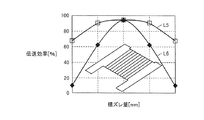
図15は、受電部20と送電部56との間の横ずれ量と、電力伝送効率との関係を示すグラフである。ここで、図9に示す巻回軸O1の延びる方向をY軸方向とする。巻回軸O1に垂直な方向における方向をX軸方向とする。そして、受電部20と送電部56とが互いに鉛直方向に離れる方向をZ軸方向とする。
FIG. 15 is a graph showing the relationship between the amount of lateral deviation between the
図15において、曲線L5は、X軸方向における受電部20と送電部56との位置ずれ量と、電力伝送効率との間の関係を示す。曲線L6は、Y軸方向における受電部20と送電部56との位置ずれ量と、電力伝送効率との間の関係を示す。
In FIG. 15, a curve L5 indicates the relationship between the amount of positional deviation between the
図16は、比較例としての受電部20および送電部56との間の位置ずれ量と、電力伝送効率との関係を示すグラフである。
FIG. 16 is a graph showing the relationship between the amount of positional deviation between the
この図16の比較例に係る受電部20は、フェライトコア21がH字形状に形成されている。具体的には、図7において、突出部35b,36bが突出する長さL1と、突出部35c,36cが突出する長さL2とが等しくなるように、軸部33が磁極部34aと磁極部34bとの間に配置されている。なお、送電部56も同様にフェライトコアがH字形状に形成されている。
In the
図16において、曲線L7は、X軸方向の位置ずれ量と電力伝送効率との関係を示す。さらに、曲線L8は、Y軸方向における位置ずれ量と電力伝送効率とのの関係を示す。 In FIG. 16, a curve L7 shows the relationship between the amount of positional deviation in the X-axis direction and power transmission efficiency. Furthermore, a curve L8 shows the relationship between the amount of misalignment in the Y-axis direction and the power transmission efficiency.
そして、図16および図15に示すように、本実施の形態に係る電力伝送システムの電力伝送特性と、比較例に係る電力伝送システムの電力伝送特性とは、近似している。 As shown in FIGS. 16 and 15, the power transmission characteristics of the power transmission system according to the present embodiment and the power transmission characteristics of the power transmission system according to the comparative example are approximate.
これは、受電部20と送電部56とのいずれにも、磁極部が形成されているため、受電部20と送電部56とが相対的に位置ずれしても、受電部20と送電部56との間で磁路が形成されるためである。
This is because the magnetic pole portion is formed in both the
このように、本実施の形態に係る受電装置11によれば、デッドスペースの有効活用を図ることができると共に、位置ずれしても高い電力伝送効率を確保することができる。
Thus, according to the
(実施の形態2)
図17および図18と、適宜上記図1から図16を用いて、本実施の形態2に係る電動車両10について説明する。なお、図17に示す構成のうち、上記図1から図16に示す構成と同一または相当する構成については、同一の符号を付してその説明を省略する場合がある。(Embodiment 2)
なお、本実施の形態2に係る電動車両10に搭載された受電部20は、上記実施の形態1で説明した受電部20と同様の構成とされている。
The
図17は、受電部20の搭載位置を模式的に示す平面図である。この図17に示すように、2次コイル22は、巻回軸O1が電動車両10の前後方向に向くように配置されている。なお、図17において、電動車両10の幅方向の中央を通り、電動車両10の前後方向に延びる仮想線を中心線O4とする。
FIG. 17 is a plan view schematically showing the mounting position of the
これにより、磁極部34a,34bは、軸部33から電動車両10の幅方向に突出する。ここで、仮に、電力伝送時に、受電部20と送電部56とが電動車両10の幅方向に位置ずれしたとする。
Accordingly, the
この場合、図9において、受電部20と送電部56とがX方向にずれることになる。図15において、X方向に位置ずれしたときの電力伝送効率の特性は、曲線L5によって示される。この曲線L5に示すように、受電部20と送電部56とがX方向に位置ずれしたとしても、電力伝送効率は、殆ど変化せずに、高い効率が維持される。
In this case, in FIG. 9, the
このため、図17に示すように、巻回軸O1が電動車両10の前後方向に向くように受電部20を配置することで、送電部56と受電部20とが電動車両10の幅方向にずれたとしても、高い電力伝送効率を確保することができる。
For this reason, as shown in FIG. 17, by arranging the
特に、駐車スペース52に輪留めを配置することで、受電部20と送電部56との前後方向の位置ずれは抑制することができる。その一方で、受電部20と送電部56との幅方向の位置ずれは、運転手の運転技量に大きく影響を受ける。
In particular, by arranging a ring stop in the
このため、電力伝送時に、受電部20と送電部56とが、電動車両10の幅方向に大きくずれる場合ある。このような場合においても、本実施の形態に係る電動車両10によれば、高い電力伝送効率を実現することができる。
For this reason, the
なお、図16においては、図9に示すように、受電部20と送電部56とのいずれもが、非対称形状のコアを採用した場合についての効率を示す。
In FIG. 16, as shown in FIG. 9, both the
その一方で、たとえば、図9に示す送電部56に替えて、図18に示す送電部56を採用したとしても、図17に示す特性と同様の特性を示す。
On the other hand, for example, even if the
なお、図18に示す送電部56は、磁極部67と、端部66dとは、いずれも、巻回軸O2に対して対称となるように形成されている。このため、突出部67b,66bが軸部65から突出する長さと、突出部67c,66cが軸部65から突出する長さとは、実質的に同じである。
In the
そして、図17に示すように、送電部56は、巻回軸O2が駐車スペースに適切に駐車された電動車両10の幅方向の中央部を通るように配置される。
And as shown in FIG. 17, the
図17において、電動車両10の上方から2次コイル22をみると、中心線O4が2次コイル22を通るように配置されている。なお、この実施の形態においては、中心線O4と巻回軸O1とが一致している。
In FIG. 17, when the
なお、巻回軸O1と中心線O4とが一致するとは、完全に一致する場合と、巻回軸O1と中心線O4とが実質的に一致する場合とを含む。 Note that the winding axis O1 and the center line O4 coincide with each other completely includes the case where the winding axis O1 and the center line O4 substantially coincide with each other.
なお、巻回軸O1と中心線O4とが実質的に一致するとは、たとえば、巻回軸O1と中心線O4とが互いに平行に延び、巻回軸O1と中心線O4とが電動車両10の幅方向に間隔があいている場合には、巻回軸O1と中心線O4との間の距離が、たとえば、突出部35bの突出する長さL1よりも小さい場合を意味する。
The winding axis O1 and the center line O4 substantially coincide with each other. For example, the winding axis O1 and the center line O4 extend in parallel with each other, and the winding axis O1 and the center line O4 are connected to the
また、巻回軸O1と中心線O4とが実質的に一致するとは、たとえば、巻回軸O1と中心線O4とが互いに交差する場合には、巻回軸O1と中心線O4との交差角度が、たとえば、10度以下であることを意味する。 Further, the winding axis O1 and the center line O4 substantially coincide with each other, for example, when the winding axis O1 and the center line O4 intersect each other, the intersection angle between the winding axis O1 and the center line O4. Means, for example, 10 degrees or less.
ここで、受電部20と送電部56との間で電力伝送を行うと、受電部20の周囲に電磁界が形成される。その一方で、受電部20が電動車両10の幅方向の中央部に位置しているので、受電部20の周囲に形成される電磁界が電動車両10の側面側から周囲に漏れることが抑制される。
Here, when power is transmitted between the
特に、この図17に示す例においては、2次コイル22は、後輪19Rおよび後輪19Lの間に配置されている。後輪19Rおよび後輪19Lは、電磁界が電動車両10の周囲に漏れることを抑制する。
In particular, in the example shown in FIG. 17, the
これにより、電動車両10の周囲に位置する電子機器が電磁界から影響を受けることを抑制することができる。
Thereby, it can suppress that the electronic device located around the
図19は、本実施の形態2に係る電動車両10の第1変形例を模式的に示す平面図である。この図19において、中心線O5は、電動車両10の前後方向の中央部に位置し、電動車両10の幅方向に延びる仮想線である。
FIG. 19 is a plan view schematically showing a first modification of electrically powered
この図19に示す例においては、2次コイル22は、巻回軸O1が電動車両10の前後方向に向くように配置されると共に、2次コイル22は、電動車両10の前後方向の中央に配置されている。
In the example shown in FIG. 19, the
ここで、2次コイル22が電動車両10の前後方向の中央部に位置するとは、電動車両10の上方から2次コイル22みると、中心線O5が2次コイル22を通る位置に2次コイル22が設けられていることを意味する。なお、この図19に示す例においては、電動車両の上方から2次コイル22を視ると、中心線O5が2次コイル22の中央部(巻回軸O1の延びる方向における中央部)を通るように配置されているが、中心線O5が通る位置はこの位置に限られない。たとえば、中心線O5が2次コイル22の端部側を通るように、2次コイル22を配置してもよい。
Here, the
2次コイル22を電動車両10の前後方向の中央に配置することで、2次コイル22の周囲に形成される強度の高い電磁界が外部に漏れることを抑制することができる。
By disposing the
図19において領域R1は、電力伝送時に2次コイル22の周囲に形成される電磁界のうち、強度の高い領域を示す。領域R1は、巻回軸O1に直交する方向よりも巻回軸O1の延びる方向に広く分布する。
In FIG. 19, a region R <b> 1 indicates a region having a high strength in the electromagnetic field formed around the
2次コイル22は、巻回軸O1が電動車両10の前後方向に向くように配置されると共に、電動車両10の前後方向の中央に配置されているため、強度の高い電磁界が電動車両10の前後方向から漏れることが抑制される。
The
これにより、電動車両10の周囲に位置する電子機器が電磁界から影響を受けることを抑制することができる。
Thereby, it can suppress that the electronic device located around the
(実施の形態3)
図20および図21と、適宜上記図1から図16を用いて、本実施の形態3に係る電動車両10について説明する。なお、図20および図21に示す構成のうち、上記図1から図19に示す構成と同一または相当する構成については、同一の符号を付してその説明を省略する場合がある。(Embodiment 3)
この図20に示す例おいても、2次コイル22は、巻回軸O1が電動車両10の前後方向に向くように配置されている。
Also in the example shown in FIG. 20, the
そして、受電部20は、整流器13が電動車両10の幅方向の中央に位置するように配置されている。なお、整流器13が電動車両10の幅方向の中央に位置するとは、電動車両10の上方から2次コイル22を視ると、電動車両10の中心線O4が整流器13を通ることを意味する。
And the
整流器13は、複数のダイオードなどの素子を含み、電流を整流する際に、周囲に高調波の電磁波を発生させる場合がある。高調波の電磁界は、電子機器に大きな影響を与える場合がある。
The
本実施の形態3に係る電動車両10においては、整流器13を電動車両10の幅方向の中央に配置することで、整流器13から発せられる高調波の電磁波が電動車両10の周囲に漏れることを抑制することができる。
In the
図21は、本実施の形態2に係る電動車両10の変形例を模式的に示す平面図である。この図21に示す例においては、受電部20は、整流器13が電動車両10の前後方向の中央部に位置するように配置されている。
FIG. 21 is a plan view schematically showing a modification of electrically powered
なお、整流器13が電動車両10の前後方向の中央に位置するとは、電動車両10の上方から整流器13をみると、中心線O5が整流器13を通ることを意味する。
Note that the fact that the
このように、整流器13を配置することで、電動車両10の前後方向から高調波の電磁波が周囲に漏れることを抑制することができる。
Thus, by arranging the
(実施の形態4)
図22および図23と、適宜図1から図16を用いて、本実施の形態4に係る電動車両10について説明する。なお、図22および図23に示す構成のうち、上記図1から図22に示す構成と同一または相当する構成については、同一の符号を付してその説明を省略する場合がある。(Embodiment 4)
図22は、本実施の形態3に係る電動車両10を模式的に示す平面図である。この図22に示すように、2次コイル22は、電動車両10の幅方向に向くように配置されている。
FIG. 22 is a plan view schematically showing electrically
そして、巻回軸O1は、後輪19Rおよび後輪19Lを通るように配置されている。磁極部34bおよび磁極部34aは、軸部33から電動車両10の前方または後方に向けて突出する。なお、この図22に示す例においては、磁極部34aおよび磁極部34bは、電動車両10の前方に向けて突出する。
The winding shaft O1 is disposed so as to pass through the
このように受電部20を配置した状態において、受電部20と送電部56との電動車両10の前後方向における電力伝送の特性は、図15において、曲線L5によって示される。曲線L5に示すように、受電部20と送電部56とが電動車両10の前後方向に位置ずれしたとしても、電力伝送効率は高い状態が維持されることが分かる。
In the state where the
特に、駐車スペース52に輪止めがない場合には、受電部20と送電部56とが電動車両10の前後方向に大きくずれる可能性が高い。このような場合においても、本実施の形態に係る電動車両10によれば、高い電力伝送効率を維持することができる。
In particular, when the
2次コイル22は、電動車両10の幅方向の中央に配置されている。ここで、2次コイル22が電動車両10の幅方向の中央に配置されているとは、電動車両10の上方から2次コイル22をみたときに、中心線O4が2次コイル22を通るような位置に2次コイル22が配置されることを意味する。
送電部56は、電力伝送時に、1次コイル58が停車した電動車両10の幅方向中央に位置するように予め地面に配置される。そのため、2次コイル22を電動車両10の幅方向の中央に配置することで、電動車両10が停車した際に、受電部20と送電部56とを鉛直方向に対向させやすくなる。これにより、高い電力伝送効率を得ることができる。
The
また、2次コイル22を電動車両10の幅方向の中央に配置することで、2次コイル22の周囲に形成される電磁界が電動車両10の周囲に漏れることを抑制することができる。
Further, by disposing the
特に、2次コイル22は、後輪19Rと後輪19Lとの間に配置されている。このため、後輪19Rおよび後輪19Lによって強度の高い電磁界が電動車両10の周囲に漏れることを抑制することができる。
In particular, the
また、2次コイル22を電動車両10の幅方向の中央に配置することで、整流器13も電動車両10の幅方向の中央に位置する。これにより、整流器13から発せられる高調波の電磁波が電動車両10の周囲に漏れることが抑制される。
In addition, by arranging the
図23は、本実施の形態3に係る電動車両10の変形例を模式的に示す平面図である。この図23に示すように、2次コイル22は、巻回軸O1が電動車両10の幅方向に向くように配置されると共に、2次コイル22は、電動車両10の前後方向の中央に配置されている。
FIG. 23 is a plan view schematically showing a modification of electrically powered
このため、整流器13から発せられる高調波の電磁波が電動車両10の前後方向および幅方向から外部に漏れることが抑制されている。
For this reason, it is suppressed that the electromagnetic wave of the harmonic emitted from the
本発明は、受電装置、送電装置、および車両に適用することができる。 The present invention can be applied to a power reception device, a power transmission device, and a vehicle.
10 電動車両、11 受電装置、13 整流器、13b,23a,59b 基板、13c,23c,59c ケース、14 コンバータ、15 バッテリ、16 パワーコントロールユニット、17 モータユニット、18L,18R 前輪、19L,19R 後輪、20,96 受電部、21,57 フェライトコア、22,58,94,99 次コイル、23,59,95,98 キャパシタ、23b,59a 素子、24,60 筐体、25,62 シールド、25a 天板部、25b,62b 周壁部、25c〜25f 壁部、26 蓋部、27,28,61 固定部材、29,32,64 バスバー、30,31,61a,61b 絶縁片、33,65 軸部、34a,34a,34b,34b,66,67 磁極部、35a,36a,66a,67a 延出部、35b,35c,36b,36c,66b,66c,67b,67c 突出部、35d,35f,36d,36f,66d,66e,67d,67e 端部、37,69a コイル巻回部、39,73 凹み部、40,46 絶縁部材、41 受電部用絶縁部材、42 機器用絶縁部材、43 コイル用絶縁部材、44 キャパシタ用絶縁部材、47 サイドメンバ、49 フロアパネル、50,90 送電装置、51 外部給電装置、W1,W2 幅。 DESCRIPTION OF SYMBOLS 10 Electric vehicle, 11 Power receiving device, 13 Rectifier, 13b, 23a, 59b Substrate, 13c, 23c, 59c Case, 14 Converter, 15 Battery, 16 Power control unit, 17 Motor unit, 18L, 18R Front wheel, 19L, 19R Rear wheel , 20, 96 Power receiving unit, 21, 57 Ferrite core, 22, 58, 94, 99 Primary coil, 23, 59, 95, 98 Capacitor, 23b, 59a Element, 24, 60 Housing, 25, 62 Shield, 25a Ceiling Plate part, 25b, 62b peripheral wall part, 25c-25f wall part, 26 lid part, 27, 28, 61 fixing member, 29, 32, 64 bus bar, 30, 31, 61a, 61b insulating piece, 33, 65 shaft part, 34a, 34a, 34b, 34b, 66, 67 Magnetic pole portion, 35a, 36a, 66a, 6 a Extension part, 35b, 35c, 36b, 36c, 66b, 66c, 67b, 67c Projection part, 35d, 35f, 36d, 36f, 66d, 66e, 67d, 67e End part, 37, 69a Coil winding part, 39 73, 40, 46 Insulating member, 41 Insulating member for power receiving unit, 42 Insulating member for device, 43 Insulating member for coil, 44 Insulating member for capacitor, 47 Side member, 49 Floor panel, 50, 90 Power transmission device, 51 External power supply, W1, W2 width.
Claims (20)
前記コイル(22)が巻回されたコア(21)と、
を備えた受電装置であって、
前記コア(21)は、前記巻回軸(O1)の延びる方向に延びると共に、前記コイル(22)が巻回される軸部(33)と、
前記軸部(33)の少なくとも一方の端部に形成され、前記巻回軸(O1)の延びる方向と交差する交差方向に延びる磁極部(34a,34b)を含み、
前記交差方向における前記軸部(33)の幅は、前記交差方向における前記磁極部(34a,34b)の長さよりも短く、
前記交差方向における前記磁極部(34a,34b)の中央に位置する第1中央部と、前記交差方向における前記軸部(33)の中央に位置する第2中央部とは互いに前記交差方向にずれるように形成された、受電装置。A coil (22) formed so as to receive electric power in a non-contact manner from a power transmission unit provided outside and to surround the winding shaft (O1);
A core (21) around which the coil (22) is wound;
A power receiving device comprising:
The core (21) extends in a direction in which the winding shaft (O1) extends, and a shaft portion (33) around which the coil (22) is wound,
A magnetic pole portion (34a, 34b) formed in at least one end of the shaft portion (33) and extending in an intersecting direction intersecting with the extending direction of the winding shaft (O1);
The width of the shaft portion (33) in the intersecting direction is shorter than the length of the magnetic pole portions (34a, 34b) in the intersecting direction,
The first center portion located in the center of the magnetic pole portions (34a, 34b) in the intersecting direction and the second center portion located in the center of the shaft portion (33) in the intersecting direction are shifted from each other in the intersecting direction. A power receiving device formed as described above.
前記磁極部(34a,34b)は、前記交差方向に配列する第1端部および第2端部を含み、
前記軸部(33)と前記第1端部との間の距離は、前記軸部(33)と前記第2端部との間のよりも長く、
前記機器は、前記軸部(33)と隣り合うと共に、前記第1端部側に配置された、請求項1に記載の受電装置。Further comprising a device connected to the coil (22);
The magnetic pole portions (34a, 34b) include a first end portion and a second end portion arranged in the intersecting direction,
The distance between the shaft (33) and the first end is longer than between the shaft (33) and the second end,
The power receiving device according to claim 1, wherein the device is adjacent to the shaft portion (33) and disposed on the first end portion side.
前記キャパシタ(23)は、前記軸部(33)と隣り合うと共に、前記整流器は、前記キャパシタ(23)に対して前記軸部(33)と反対側に配置された、請求項2に記載の受電装置。The device includes a capacitor (23) connected to the coil (22), and a rectifier connected to the capacitor (23),
The capacitor (23) is adjacent to the shaft (33), and the rectifier is disposed on the opposite side of the shaft (33) with respect to the capacitor (23). Power receiving device.
前記磁極部(34a,34b)は、前記第3端部に接続された第1磁極部と、前記第4端部に接続された第2磁極部とを含み、
前記交差方向における前記第1磁極部の中央部と、前記交差方向における前記第2磁極部の中央部とは、前記第2中央部に対して前記交差方向の一方側にずれた、請求項1に記載の受電装置。The shaft portion (33) includes a third end portion and a fourth end portion arranged in a direction in which the winding shaft (O1) extends,
The magnetic pole parts (34a, 34b) include a first magnetic pole part connected to the third end part and a second magnetic pole part connected to the fourth end part,
The central part of the first magnetic pole part in the intersecting direction and the central part of the second magnetic pole part in the intersecting direction are shifted to one side of the intersecting direction with respect to the second central part. The power receiving device described in 1.
前記送電部の固有周波数と前記受電部(20)の固有周波数との差は、前記受電部(20)の固有周波数の10%以下である、請求項1に記載の受電装置。A power receiving unit including the coil;
The power receiving device according to claim 1, wherein a difference between the natural frequency of the power transmission unit and the natural frequency of the power reception unit (20) is 10% or less of the natural frequency of the power reception unit (20).
前記受電部(20)と前記送電部との結合係数は、0.1以下である、請求項1に記載の受電装置。A power receiving unit including the coil;
The power reception device according to claim 1, wherein a coupling coefficient between the power reception unit (20) and the power transmission unit is 0.1 or less.
前記受電部(20)は、前記受電部(20)と前記送電部の間に形成され、かつ特定の周波数で振動する磁界と、前記受電部(20)と前記送電部の間に形成され、かつ特定の周波数で振動する電界との少なくとも一方を通じて前記送電部から電力を受電する、請求項1に記載の受電装置。A power receiving unit including the coil;
The power reception unit (20) is formed between the power reception unit (20) and the power transmission unit, and is formed between the power reception unit (20) and the power transmission unit, and a magnetic field that vibrates at a specific frequency. The power receiving device according to claim 1, wherein power is received from the power transmission unit through at least one of an electric field that vibrates at a specific frequency.
前記コイル(22)が巻回されたコア(21)と、
を備えた受電装置であって、
前記コア(21)は、前記コイル(22)が巻回される軸部(33)と、
前記軸部(33)の少なくとも一方の端部に形成され、前記巻回軸(O1)の延びる方向と交差する交差方向に延びる磁極部(34a,34b)を含み、
前記交差方向における前記軸部の長さは、前記交差方向における前記磁極部の長さよりも短く、前記磁極部は、前記巻回軸を通る仮想平面に対して非対称である、受電装置。A coil (22) formed so as to receive electric power in a non-contact manner from a power transmission unit provided outside and to surround the winding shaft (O1);
A core (21) around which the coil (22) is wound;
A power receiving device comprising:
The core (21) includes a shaft (33) around which the coil (22) is wound,
A magnetic pole portion (34a, 34b) formed in at least one end of the shaft portion (33) and extending in an intersecting direction intersecting with the extending direction of the winding shaft (O1);
The length of the shaft portion in the intersecting direction is shorter than the length of the magnetic pole portion in the intersecting direction, and the magnetic pole portion is asymmetric with respect to a virtual plane passing through the winding axis.
前記コア(21)は、前記巻回軸(O1)の延びる方向に延びると共に、前記コイル(22)が巻回される軸部(33)と、
前記軸部(33)の端部に形成され、前記巻回軸(O1)の延びる方向と交差する交差方向に延びる磁極部(34a,34b)を含み、
前記交差方向における前記軸部(33)の長さは、前記交差方向における前記磁極部(34a,34b)の長さよりも短く、
前記交差方向における前記磁極部(34a,34b)の中央に位置する第1中央部と、前記交差方向における前記軸部(33)の中央に位置する第2中央部とは互いに前記交差方向にずれるように形成され、
前記磁極部(34a,34b)は、前記交差方向に配列する第1端部および第2端部を含み、
前記軸部(33)と前記第1端部との間の距離は、前記軸部(33)と前記第2端部との間のよりも長く、
前記整流器は、前記軸部(33)に対して前記交差方向に隣り合うと共に、前記第2端部よりも前記第1端部側に配置され、
前記整流器は、前記車両の幅方向の中央に配置された、車両。The coil (22) formed so as to surround the winding shaft (O1) and the core (22) wound around the winding shaft (O1) while receiving electric power in a non-contact manner from a power transmission unit provided outside. 21), a vehicle including a rectifier and having a power receiving device connected to the coil (22) and having a device,
The core (21) extends in a direction in which the winding shaft (O1) extends, and a shaft portion (33) around which the coil (22) is wound,
A magnetic pole portion (34a, 34b) formed at an end portion of the shaft portion (33) and extending in a crossing direction intersecting a direction in which the winding shaft (O1) extends;
The length of the shaft portion (33) in the intersecting direction is shorter than the length of the magnetic pole portions (34a, 34b) in the intersecting direction,
The first center portion located in the center of the magnetic pole portions (34a, 34b) in the intersecting direction and the second center portion located in the center of the shaft portion (33) in the intersecting direction are shifted from each other in the intersecting direction. Formed as
The magnetic pole portions (34a, 34b) include a first end portion and a second end portion arranged in the intersecting direction,
The distance between the shaft (33) and the first end is longer than between the shaft (33) and the second end,
The rectifier is adjacent to the shaft portion (33) in the intersecting direction, and is disposed closer to the first end portion than the second end portion,
The rectifier is a vehicle disposed in the center in the width direction of the vehicle.
前記コア(21)は、前記巻回軸(O1)の延びる方向に延びると共に、前記コイル(22)が巻回される軸部(33)と、
前記軸部(33)の端部に形成され、前記巻回軸(O1)の延びる方向と交差する交差方向に延びる磁極部(34a,34b)を含み、
前記交差方向における前記軸部(33)の長さは、前記交差方向における前記磁極部(34a,34b)の長さよりも短く、
前記交差方向における前記磁極部(34a,34b)の中央に位置する第1中央部と、前記交差方向における前記軸部(33)の中央に位置する第2中央部とは互いに前記交差方向にずれるように形成され、
前記巻回軸(O1)が前記車両の幅方向に向くように前記コイル(22)が配置された、車両。The coil (22) formed so as to surround the winding shaft (O1) and the core (22) wound around the winding shaft (O1) while receiving electric power in a non-contact manner from a power transmission unit provided outside. 21) a vehicle including a power receiving device,
The core (21) extends in a direction in which the winding shaft (O1) extends, and a shaft portion (33) around which the coil (22) is wound,
A magnetic pole portion (34a, 34b) formed at an end portion of the shaft portion (33) and extending in a crossing direction intersecting a direction in which the winding shaft (O1) extends;
The length of the shaft portion (33) in the intersecting direction is shorter than the length of the magnetic pole portions (34a, 34b) in the intersecting direction,
The first center portion located in the center of the magnetic pole portions (34a, 34b) in the intersecting direction and the second center portion located in the center of the shaft portion (33) in the intersecting direction are shifted from each other in the intersecting direction. Formed as
A vehicle in which the coil (22) is arranged so that the winding shaft (O1) faces the width direction of the vehicle.
前記コア(21)は、前記巻回軸(O1)の延びる方向に延びると共に、前記コイル(22)が巻回される軸部(33)と、
前記軸部(33)の端部に形成され、前記巻回軸(O1)の延びる方向と交差する交差方向に延びる磁極部(34a,34b)を含み、
前記交差方向における前記軸部(33)の長さは、前記交差方向における前記磁極部(34a,34b)の長さよりも短く、
前記交差方向における前記磁極部(34a,34b)の中央に位置する第1中央部と、前記交差方向における前記軸部(33)の中央に位置する第2中央部とは互いに前記交差方向にずれるように形成され、
前記巻回軸(O1)が前記車両の前後方向に延びるように、前記コイル(22)が配置された、車両。The coil (22) formed so as to surround the winding shaft (O1) and the core (22) wound around the winding shaft (O1) while receiving electric power in a non-contact manner from a power transmission unit provided outside. 21) a vehicle including a power receiving device,
The core (21) extends in a direction in which the winding shaft (O1) extends, and a shaft portion (33) around which the coil (22) is wound,
A magnetic pole portion (34a, 34b) formed at an end portion of the shaft portion (33) and extending in a crossing direction intersecting a direction in which the winding shaft (O1) extends;
The length of the shaft portion (33) in the intersecting direction is shorter than the length of the magnetic pole portions (34a, 34b) in the intersecting direction,
The first center portion located in the center of the magnetic pole portions (34a, 34b) in the intersecting direction and the second center portion located in the center of the shaft portion (33) in the intersecting direction are shifted from each other in the intersecting direction. Formed as
A vehicle in which the coil (22) is arranged so that the winding shaft (O1) extends in the front-rear direction of the vehicle.
前記コイル(58)が巻回されたコア(57)と、
を備えた送電装置であって、
前記コア(57)は、前記巻回軸(O2)の延びる方向に延びると共に、前記コイル(58)が巻回される軸部(65)と、
前記軸部(65)の少なくとも一方の端部に形成され、前記巻回軸(O2)の延びる方向と交差する交差方向に延びる磁極部(66,67)を含み、
前記交差方向における前記軸部(65)の幅は、前記交差方向における前記磁極部(66,67)の長さよりも短く、
前記交差方向における前記磁極部(66,67)の中央に位置する第3中央部と、前記交差方向における前記軸部(65)の中央に位置する第4中央部とは互いに前記交差方向にずれるように形成された、送電装置。A coil (58) formed so as to transmit power in a non-contact manner to a power receiving unit provided in the vehicle and surround the winding shaft (O2);
A core (57) around which the coil (58) is wound;
A power transmission device comprising:
The core (57) extends in a direction in which the winding shaft (O2) extends, and a shaft portion (65) around which the coil (58) is wound,
A magnetic pole portion (66, 67) formed in at least one end of the shaft portion (65) and extending in a crossing direction intersecting a direction in which the winding shaft (O2) extends;
The width of the shaft portion (65) in the intersecting direction is shorter than the length of the magnetic pole portion (66, 67) in the intersecting direction,
The third central portion located at the center of the magnetic pole portion (66, 67) in the intersecting direction and the fourth central portion located at the center of the shaft portion (65) in the intersecting direction are shifted from each other in the intersecting direction. A power transmission device formed as follows.
前記磁極部(66,67)は、前記交差方向に配列する第5端部および第6端部を含み、
前記軸部(65)と前記第5端部との間の距離は、前記軸部(65)と前記第6端部との間の距離より長く、
前記機器は、前記軸部(65)と隣り合うと共に、前記第5端部側に配置された、請求項16に記載の送電装置。Further comprising a device connected to the coil (58);
The magnetic pole portions (66, 67) include a fifth end portion and a sixth end portion arranged in the intersecting direction,
The distance between the shaft (65) and the fifth end is longer than the distance between the shaft (65) and the sixth end,
The power transmission device according to claim 16, wherein the device is adjacent to the shaft portion (65) and disposed on the fifth end side.
前記磁極部(66,67)は、前記第7端部に接続された第3磁極部と、前記第8端部に接続された第4磁極部とを含み、
前記交差方向における前記第3磁極部の中央部と、前記交差方向における前記第4磁極部の中央部とは、前記第4中央部に対して前記交差方向の一方側にずれた、請求項16に記載の送電装置。The shaft portion (65) includes a seventh end portion and an eighth end portion arranged in a direction in which the winding shaft (O2) extends,
The magnetic pole portions (66, 67) include a third magnetic pole portion connected to the seventh end portion and a fourth magnetic pole portion connected to the eighth end portion,
The central part of the third magnetic pole part in the intersecting direction and the central part of the fourth magnetic pole part in the intersecting direction are shifted to one side of the intersecting direction with respect to the fourth central part. The power transmission device described in 1.
前記コイル(58)が巻回されたコア(57)と、
を備えた送電装置であって、
前記コア(57)は、前記コイル(58)が巻回される軸部(65)と、
前記軸部(65)の少なくとも一方の端部に形成され、前記巻回軸(O2)の延びる方向と交差する交差方向に延びる磁極部(66,67)を含み、
前記交差方向における前記軸部の長さは、前記交差方向における前記磁極部の長さよりも短く、前記磁極部は、前記巻回軸を通る仮想平面に対して非対称である、送電装置。A coil (58) formed so as to transmit power in a non-contact manner to a power receiving unit provided in the vehicle and surround the winding shaft (O2);
A core (57) around which the coil (58) is wound;
A power transmission device comprising:
The core (57) includes a shaft (65) around which the coil (58) is wound,
A magnetic pole portion (66, 67) formed in at least one end of the shaft portion (65) and extending in a crossing direction intersecting a direction in which the winding shaft (O2) extends;
The length of the shaft portion in the intersecting direction is shorter than the length of the magnetic pole portion in the intersecting direction, and the magnetic pole portion is asymmetric with respect to a virtual plane passing through the winding axis.
Applications Claiming Priority (1)
| Application Number | Priority Date | Filing Date | Title |
|---|---|---|---|
| PCT/JP2012/064389 WO2013183106A1 (en) | 2012-06-04 | 2012-06-04 | Power reception device, power transmission device, and vehicle |
Publications (1)
| Publication Number | Publication Date |
|---|---|
| JPWO2013183106A1 true JPWO2013183106A1 (en) | 2016-01-21 |
Family
ID=49711527
Family Applications (1)
| Application Number | Title | Priority Date | Filing Date |
|---|---|---|---|
| JP2014519715A Pending JPWO2013183106A1 (en) | 2012-06-04 | 2012-06-04 | Power receiving device, power transmitting device and vehicle |
Country Status (7)
| Country | Link |
|---|---|
| US (1) | US20150137590A1 (en) |
| EP (1) | EP2858078A4 (en) |
| JP (1) | JPWO2013183106A1 (en) |
| KR (1) | KR20150003894A (en) |
| CN (1) | CN104335302A (en) |
| IN (1) | IN2014DN09625A (en) |
| WO (1) | WO2013183106A1 (en) |
Families Citing this family (19)
| Publication number | Priority date | Publication date | Assignee | Title |
|---|---|---|---|---|
| JP5979227B2 (en) | 2012-05-09 | 2016-08-24 | トヨタ自動車株式会社 | vehicle |
| JP5839120B2 (en) | 2012-06-04 | 2016-01-06 | トヨタ自動車株式会社 | Power receiving device and power transmitting device |
| JP6043462B2 (en) * | 2012-09-27 | 2016-12-14 | Ihi運搬機械株式会社 | Vehicle power supply device |
| JP6063719B2 (en) * | 2012-11-19 | 2017-01-18 | 株式会社東芝 | Wireless power transmission device |
| US9472339B2 (en) * | 2013-05-01 | 2016-10-18 | Delphi Technologies, Inc. | Wireless power transfer system transducers having interchangeable source resonator and capture resonator |
| JP2015012656A (en) * | 2013-06-27 | 2015-01-19 | Tdk株式会社 | Wireless power transmission device |
| JP6217435B2 (en) * | 2014-02-13 | 2017-10-25 | トヨタ自動車株式会社 | Power receiving device |
| JP2015176898A (en) * | 2014-03-13 | 2015-10-05 | 矢崎総業株式会社 | Coil unit and non-contact power supply device |
| JP6299362B2 (en) * | 2014-04-16 | 2018-03-28 | トヨタ自動車株式会社 | Vehicle and contactless power transmission system |
| JP6337610B2 (en) | 2014-05-22 | 2018-06-06 | 株式会社Ihi | Coil device |
| JP6417713B2 (en) | 2014-05-22 | 2018-11-07 | 株式会社Ihi | Coil device |
| KR101589609B1 (en) * | 2014-08-21 | 2016-01-29 | 한국과학기술원 | Wireless Electric Power Supply Apparatus |
| JP6405903B2 (en) * | 2014-11-05 | 2018-10-17 | トヨタ自動車株式会社 | Coil unit |
| JP6339524B2 (en) * | 2015-05-08 | 2018-06-06 | トヨタ自動車株式会社 | Power transmission equipment |
| CN109311404B (en) * | 2016-05-25 | 2019-09-06 | 日产自动车株式会社 | Non-contact power receiving device |
| DE102016223534A1 (en) | 2016-11-28 | 2018-05-30 | SUMIDA Components & Modules GmbH | Inductive component and Sekundärresonatoreinrichtung for mounting on an electric motor vehicle |
| EP3438996B1 (en) * | 2017-08-02 | 2021-09-22 | Ningbo Geely Automobile Research & Development Co., Ltd. | A device for a wireless power transfer system for a vehicle |
| JP7225674B2 (en) * | 2018-10-23 | 2023-02-21 | トヨタ自動車株式会社 | coil unit |
| CN111409705A (en) * | 2020-03-06 | 2020-07-14 | 浙江零跑科技有限公司 | Scheme for arranging charging port of electric vehicle in front fender area of vehicle body |
Citations (5)
| Publication number | Priority date | Publication date | Assignee | Title |
|---|---|---|---|---|
| JPH10108373A (en) * | 1996-08-07 | 1998-04-24 | Sumitomo Wiring Syst Ltd | Electric vehicle charging magnetic coupling device |
| JP2003047101A (en) * | 2001-07-30 | 2003-02-14 | Tsubakimoto Chain Co | Noncontact power feeder, mobile body and mobile body system |
| JP2011050127A (en) * | 2009-08-25 | 2011-03-10 | Saitama Univ | Non-contact power feeder |
| JP2012023913A (en) * | 2010-07-16 | 2012-02-02 | Shigeo Hamaguchi | Non-contact power feeding device |
| WO2013176151A1 (en) * | 2012-05-21 | 2013-11-28 | 株式会社 テクノバ | Non-contact power supply transformer |
Family Cites Families (9)
| Publication number | Priority date | Publication date | Assignee | Title |
|---|---|---|---|---|
| DE19545220A1 (en) * | 1995-12-05 | 1997-06-12 | Bosch Gmbh Robert | Arrangement for the contactless transmission of signals between mutually linearly movable vehicle parts |
| DE10103280B4 (en) * | 2001-01-25 | 2005-07-07 | Robert Bosch Gmbh | Arrangement for contactless transmission of electrical energy between mutually linearly movable vehicle parts |
| DE10104020B4 (en) * | 2001-01-31 | 2005-07-14 | Robert Bosch Gmbh | Arrangement for contactless transmission of electrical energy |
| JP2004152947A (en) * | 2002-10-30 | 2004-05-27 | Matsushita Electric Ind Co Ltd | Electronic component apparatus |
| US8294419B2 (en) * | 2008-11-21 | 2012-10-23 | Toyota Jidosha Kabushiki Kaisha | Electrical powered vehicle |
| JP5359544B2 (en) * | 2009-05-18 | 2013-12-04 | トヨタ自動車株式会社 | Non-contact power transmission device, vehicle and non-contact power transmission system |
| CN102005784A (en) * | 2009-09-02 | 2011-04-06 | 北京华旗资讯数码科技有限公司 | Wireless charging system |
| JP5462019B2 (en) * | 2010-02-14 | 2014-04-02 | 国立大学法人埼玉大学 | Non-contact power feeding device |
| US20110309689A1 (en) * | 2010-06-17 | 2011-12-22 | Semiconductor Energy Laboratory Co., Ltd. | Electric power transmitting device, electric power receiving device, and power supply method using electric power transmitting and receiving devices |
-
2012
- 2012-06-04 IN IN9625DEN2014 patent/IN2014DN09625A/en unknown
- 2012-06-04 WO PCT/JP2012/064389 patent/WO2013183106A1/en active Application Filing
- 2012-06-04 US US14/398,653 patent/US20150137590A1/en not_active Abandoned
- 2012-06-04 KR KR1020147033385A patent/KR20150003894A/en active IP Right Grant
- 2012-06-04 CN CN201280073682.8A patent/CN104335302A/en active Pending
- 2012-06-04 EP EP12878270.3A patent/EP2858078A4/en not_active Withdrawn
- 2012-06-04 JP JP2014519715A patent/JPWO2013183106A1/en active Pending
Patent Citations (5)
| Publication number | Priority date | Publication date | Assignee | Title |
|---|---|---|---|---|
| JPH10108373A (en) * | 1996-08-07 | 1998-04-24 | Sumitomo Wiring Syst Ltd | Electric vehicle charging magnetic coupling device |
| JP2003047101A (en) * | 2001-07-30 | 2003-02-14 | Tsubakimoto Chain Co | Noncontact power feeder, mobile body and mobile body system |
| JP2011050127A (en) * | 2009-08-25 | 2011-03-10 | Saitama Univ | Non-contact power feeder |
| JP2012023913A (en) * | 2010-07-16 | 2012-02-02 | Shigeo Hamaguchi | Non-contact power feeding device |
| WO2013176151A1 (en) * | 2012-05-21 | 2013-11-28 | 株式会社 テクノバ | Non-contact power supply transformer |
Also Published As
| Publication number | Publication date |
|---|---|
| EP2858078A1 (en) | 2015-04-08 |
| KR20150003894A (en) | 2015-01-09 |
| WO2013183106A1 (en) | 2013-12-12 |
| US20150137590A1 (en) | 2015-05-21 |
| IN2014DN09625A (en) | 2015-07-31 |
| EP2858078A4 (en) | 2015-12-02 |
| CN104335302A (en) | 2015-02-04 |
Similar Documents
| Publication | Publication Date | Title |
|---|---|---|
| WO2013183106A1 (en) | Power reception device, power transmission device, and vehicle | |
| JP6213611B2 (en) | vehicle | |
| JP5839120B2 (en) | Power receiving device and power transmitting device | |
| JP5846302B2 (en) | vehicle | |
| WO2013168241A1 (en) | Vehicle | |
| JP5810944B2 (en) | Vehicle and power transmission system | |
| WO2013168239A1 (en) | Vehicle capable of contact-free power reception | |
| JP5682712B2 (en) | Power receiving device, power transmitting device, and power transmission system | |
| JP2013219861A (en) | Vehicle | |
| JP6508272B2 (en) | vehicle |
Legal Events
| Date | Code | Title | Description |
|---|---|---|---|
| A131 | Notification of reasons for refusal |
Free format text: JAPANESE INTERMEDIATE CODE: A131 Effective date: 20160119 |
|
| A521 | Request for written amendment filed |
Free format text: JAPANESE INTERMEDIATE CODE: A523 Effective date: 20160309 |
|
| A02 | Decision of refusal |
Free format text: JAPANESE INTERMEDIATE CODE: A02 Effective date: 20160531 |