JPWO2006040841A1 - Non-invasive measuring device for blood glucose level - Google Patents
Non-invasive measuring device for blood glucose level Download PDFInfo
- Publication number
- JPWO2006040841A1 JPWO2006040841A1 JP2006540819A JP2006540819A JPWO2006040841A1 JP WO2006040841 A1 JPWO2006040841 A1 JP WO2006040841A1 JP 2006540819 A JP2006540819 A JP 2006540819A JP 2006540819 A JP2006540819 A JP 2006540819A JP WO2006040841 A1 JPWO2006040841 A1 JP WO2006040841A1
- Authority
- JP
- Japan
- Prior art keywords
- blood glucose
- lambda
- glucose level
- light
- transmitted light
- Prior art date
- Legal status (The legal status is an assumption and is not a legal conclusion. Google has not performed a legal analysis and makes no representation as to the accuracy of the status listed.)
- Pending
Links
Images


Classifications
-
- A—HUMAN NECESSITIES
- A61—MEDICAL OR VETERINARY SCIENCE; HYGIENE
- A61B—DIAGNOSIS; SURGERY; IDENTIFICATION
- A61B5/00—Measuring for diagnostic purposes; Identification of persons
- A61B5/145—Measuring characteristics of blood in vivo, e.g. gas concentration, pH value; Measuring characteristics of body fluids or tissues, e.g. interstitial fluid, cerebral tissue
- A61B5/1455—Measuring characteristics of blood in vivo, e.g. gas concentration, pH value; Measuring characteristics of body fluids or tissues, e.g. interstitial fluid, cerebral tissue using optical sensors, e.g. spectral photometrical oximeters
-
- A—HUMAN NECESSITIES
- A61—MEDICAL OR VETERINARY SCIENCE; HYGIENE
- A61B—DIAGNOSIS; SURGERY; IDENTIFICATION
- A61B5/00—Measuring for diagnostic purposes; Identification of persons
- A61B5/145—Measuring characteristics of blood in vivo, e.g. gas concentration, pH value; Measuring characteristics of body fluids or tissues, e.g. interstitial fluid, cerebral tissue
- A61B5/14532—Measuring characteristics of blood in vivo, e.g. gas concentration, pH value; Measuring characteristics of body fluids or tissues, e.g. interstitial fluid, cerebral tissue for measuring glucose, e.g. by tissue impedance measurement
-
- A—HUMAN NECESSITIES
- A61—MEDICAL OR VETERINARY SCIENCE; HYGIENE
- A61B—DIAGNOSIS; SURGERY; IDENTIFICATION
- A61B2562/00—Details of sensors; Constructional details of sensor housings or probes; Accessories for sensors
- A61B2562/02—Details of sensors specially adapted for in-vivo measurements
- A61B2562/0233—Special features of optical sensors or probes classified in A61B5/00
- A61B2562/0238—Optical sensor arrangements for performing transmission measurements on body tissue
Landscapes
- Health & Medical Sciences (AREA)
- Life Sciences & Earth Sciences (AREA)
- Physics & Mathematics (AREA)
- Biomedical Technology (AREA)
- Medical Informatics (AREA)
- Biophysics (AREA)
- Pathology (AREA)
- Engineering & Computer Science (AREA)
- Veterinary Medicine (AREA)
- Heart & Thoracic Surgery (AREA)
- Optics & Photonics (AREA)
- Molecular Biology (AREA)
- Surgery (AREA)
- Animal Behavior & Ethology (AREA)
- General Health & Medical Sciences (AREA)
- Public Health (AREA)
- Emergency Medicine (AREA)
- Spectroscopy & Molecular Physics (AREA)
- Measurement Of The Respiration, Hearing Ability, Form, And Blood Characteristics Of Living Organisms (AREA)
Abstract
指(1)の測定部位に2つの異なる近赤外波長領域の照射光(11,12)を照射する光源制御部(220)を設け、照射光(11,12)が指(1)の側定部位を透過した透過光(12,22)及び(13,23)を異なる距離をおいた2箇所で受光してその透過光量を検出する光検出器(51,61)を設け、検出した2箇所での同波長の透過光量の比である相対透過度を各波長毎に算出し、同各波長の相対透過度を用いて血糖値を算定するようにし、人体の血糖値を非侵襲的に誤差なく測定できる小型で携帯容易な血糖値の非侵襲測定をする。A light source controller (220) that irradiates irradiation light (11, 12) in two different near-infrared wavelength regions is provided on the measurement site of the finger (1), and the irradiation light (11, 12) is on the finger (1) side. Light detectors (51, 61) that detect transmitted light (12, 22) and (13, 23) transmitted through a fixed portion at two different distances and detect the amount of transmitted light are detected and detected 2 The relative transmittance, which is the ratio of the amount of transmitted light at the same wavelength at each location, is calculated for each wavelength, and the blood glucose level is calculated using the relative transmittance at the same wavelength, and the blood glucose level of the human body is noninvasively calculated. A non-invasive measurement of blood sugar level that is small and easy to carry without error.
Description
本発明は、人体の血糖値を非侵襲的に測定する装置に関し、詳しくは特定波長の光を人体に照射して得られる人体からの透過光から人体の血糖値を非侵襲的に誤差なく測定する技術に関する。 The present invention relates to an apparatus for noninvasively measuring a blood glucose level of a human body, and more specifically, noninvasively measures a blood glucose level of a human body from transmitted light from the human body obtained by irradiating the human body with light of a specific wavelength. Related to technology.
糖尿病では、肝臓から分泌されるインスリンの不足、あるいは体の細胞がインスリンに反応しなくなることで筋肉や肝臓への糖の蓄積が行われなくなり、血液中のグルコース濃度、つまり血糖値が高くなり、これにより網膜症・神経障害・腎症等様々な合併症が引き起こされる。糖尿病患者は国内に690万人、その予備軍を含め1300万人以上にもなるといわれ、深刻な国民病となっている。現状、糖尿病治療では完全な治療方法がなく、血糖値測定を行いながらインスリンの投与、あるいは食事療法によって血糖値を適正なレベルに維持させている。
現状の血糖値測定は、採血した血液を用いて血液に対するグルコース酸化酵素の反応を電気化学的に定量し、血糖値に換算するグルコースセンサー法を用いた測定器により行われており、糖尿病患者の日常での血糖値管理に用いる携帯型血糖値測定器などはすでに市販化されている。こうした血糖値検査では、1日数回の採血に伴う苦痛や採血針による感染等の問題があり、採血が不要で且つ血糖値の日内変動をリアルタイムで測定できる非侵襲の血糖値測定装置が望まれている。
そこで、近赤外領域の波長の光を人体に照射し、その人体からの拡散反射光又は透過光を分光器を用いて測定し、その拡散反射光又は透過光のスペクトルから人体の血糖値を算出しようとする技術が開示されている(例えば非特許文献1,非特許文献2,特許文献1参照)。非特許文献1では近赤外領域の波長の光を前腕皮膚と標準反射板に交互に照射し、その各拡散反射光から分光器等を用いて各拡散反射光のスペクトルを測定し、前腕皮膚と標準反射板の拡散反射光のスペクトル比から算定される拡散反射率スペクトルから多変量解析により血糖値を測定する方法を提案している。特許文献1では近赤外領域の波長の光を指等に照射し、その透過光を検出して特定波長944nmと964nmでの吸光度を求め、その値から血糖値を測定する方法を提案している。
ところで、非特許文献1の方法によれば、近赤外領域の波長の光を前腕皮膚に照射し、その拡散反射光の連続したスペクトルを測定する為に回折格子等から構成される複雑な分光器を必要としている。これは、血糖値を算出する為には連続した波長の光の反射率データを必要とし、このためにはこうした領域の波長の光を有する白色光源からの光を人体に照射し、その反射スペクトルを得る為には前記した分光器が必要となる。また、標準反射板と人体からの各拡散反射光を交互に計測するため、光源の変動が計測誤差の原因になる。こうした白色光源や分光器をベースとした血糖値の測定方法では、糖尿病患者が日常の血糖値管理を行う為に持ち運びが容易な血糖値測定装置の小型・携帯化が難しいものであった。
一方、特許文献1では特定の2波長の光を用い、その透過光により血糖値を測定する装置を提案している。この技術を図9に基づいて説明する。図9に示す測定装置は、近赤外光を発する光源100とその光から所定の単色光のみを指1に照射する為の回折格子340,反射ミラー360を備え、また分光された単色光101の一部を検出する為のサンプリング用プリズム370,NDフィルター390,光検出器380を備えている。さらに人の指1からの透過光102を検出するためのレンズ50,光検出器51を、また光検出器51,380からの検出信号を増幅してデジタル化する信号処理部230、及び中央制御部200を備えている。中央制御部200は信号処理部230で増幅・デジタル化された光検出器51,380からの検出信号をもとに指1の透過率Tを下記式で算出する。
T=I1/I0・・・(1.1)
ここで、I0は照射光101の照射光量で、光検出器380で検出された検出信号に一定数を乗じて算出される。またI1は透過光102の光量で検出器51で検出された検出信号に一定数を乗じて算出される。ここでは照射光101の波長として2つの944nm,964nmを選択し、その各波長に対する前記透過率をそれぞれT1,T2として下記式により血糖値Cを算出する。
C=k0+k1*ABS1/ABS2・・・(1.2)
ここで、ABS1=−ln(T1),ABS2=−ln(T2)をそれぞれ表す。またk0,k1は実測した血糖値を用いて最小2乗法で決定された係数を示す。なお、ここでは光源に白色光源を用いたが、前記波長の異なる2つの波長に944nm,964nmの半導体レーザー等を用いることができれば、回折格子等から構成される複雑な分光器を必要としない血糖値の非侵襲測定装置が実現できる。
しかしながら、この先願発明では、照射光101の照射位置P0と透過光102の検出位置P1との直線距離r1が指1の大きさに依存してわずかに変化する。そのわずかな変化量に対して、前記式による血糖値Cの算出において無視できない測定誤差が生じる問題があった。また、指の大きさに影響されないように、例えば照射位置Poを直線距離r1隔てて検出位置P1と同じ側に配置したとしても、心拍数に対応して変化する血管の膨張・収縮により式(1.1)で表される透過率が変化し、前記式(1.2)による血糖値Cの算出において無視できない測定誤差が生じてしまう問題があった。
The current blood glucose level measurement is performed using a glucose sensor method that electrochemically quantifies the reaction of glucose oxidase to blood using the collected blood and converts it into a blood glucose level. Portable blood glucose level measuring devices used for daily blood glucose level management are already on the market. Such a blood glucose level test has problems such as pain caused by blood sampling several times a day and infection by a blood sampling needle, and a non-invasive blood glucose level measuring device that does not require blood sampling and can measure daily fluctuations in blood glucose level in real time is desired. ing.
Therefore, the human body is irradiated with light having a wavelength in the near-infrared region, the diffuse reflected light or transmitted light from the human body is measured using a spectroscope, and the blood glucose level of the human body is determined from the spectrum of the diffuse reflected light or transmitted light. A technique to be calculated is disclosed (for example, see
By the way, according to the method of Non-Patent
On the other hand,
T = I 1 / I 0 (1.1)
Here, I 0 is the irradiation light quantity of the
C = k 0 + k 1 * ABS 1 / ABS 2 (1.2)
Here, ABS 1 = −ln (T 1 ) and ABS 2 = −ln (T 2 ), respectively. K 0 and k 1 indicate coefficients determined by the least square method using the actually measured blood glucose level. Here, although a white light source is used as the light source, if a 944 nm or 964 nm semiconductor laser or the like can be used for two different wavelengths, a blood glucose that does not require a complicated spectroscope composed of a diffraction grating or the like is required. A non-invasive measuring device of values can be realized.
However, in this prior application, the linear distance r 1 between the irradiation position P 0 of the
本発明が解決しようとする目的は、従来のこれらの問題点を解消し、人体の血糖値を非侵襲的に誤差なく測定できる小型で携帯容易な血糖値の非侵襲測定装置を提供することにある。
かかる課題を解決した本発明の構成は以下の通りである。
1) 人体の測定部位に複数の異なる波長からなる光を照射する照射手段を設け、同照射手段の光が人体の測定部位を透過した透過光を異なる距離をおいた2箇所で受光してその透過光量を検出する透過光量検出手段を設け、同透過光量検出手段で検出した2箇所での同波長の透過光量の比である相対透過度を各波長毎に算出し、同各波長の相対透過度を用いて人体の血糖値を算定する演算手段を設けた血糖値の非侵襲測定装置。
2) 照射手段が、2つの異なる波長の光を照射するもので、演算手段が、2箇所で検出した各透過光量のうち透過距離が短い方をI1.λ1,I1.λ2とし、透過距離が長い方をI2.λ1,I2.λ2とし、2つの異なる波長の相対透過度Rλ1,Rλ2を式Rλ1=I2.λ1/I1.λ1,Rλ2=I2.λ2/I1.λ2とし、予め実測した血糖値と相対透過度Rλ1,Rλ2を用いて次式の係数k0,k1を求め、血糖値Cを式C=k0+k1*ln(Rλ1)/ln(Rλ2)に従って算定するようにしたものである前記1)記載の血糖値の非侵襲測定装置。
3) 照射手段が、2つの異なる波長の光を照射するもので、演算手段が、2箇所で検出した各透過光量のうち透過距離が短い方をI1.λ1,I1.λ2とし、透過距離が長い方をI2.λ1,I2.λ2とし、2つの異なる波長の相対透過度Rλ1,Rλ2を式Rλ1=I2.λ1/I1.λ1,Rλ2=I2.λ2/I1.λ2とし、同各相対透過度Rλ1,Rλ2に基づいて2つの異なる波長の吸光度A1,A2を式A1=−1n(Rλ1),A2=−1n(Rλ2)とし、予め実測した血糖値と吸光度A1,A2を用いて次式の係数k0,k1を求め、血糖値Cを式C=k0+k1*A1/A2に従って算定するようにしたものである前記1)記載の血糖値の非侵襲測定装置。
4) 照射手段が照射する2つの異なる波長の光が、900〜1100nmの範囲から選ばれたものである前記2)又は3)記載の血糖値の非侵襲測定装置。
5) 照射手段が、3つの異なる波長の光を照射するもので、演算手段が、2箇所で検出した各透過光量のうち透過距離が短い方をI1.λ1,I1.λ2,I1.λ3とし、透過距離が長い方をI2.λ1,I2.λ2,I2.λ3とし、3つの波長の相対透過度Rλ1,Rλ2,Rλ3を式Rλ1=I2.λ1/I1.λ1,Rλ2=I2.λ2/I1.λ2,Rλ3=I2.λ3/I1.λ3とし、予め実測した血糖値と相対透過度Rλ1,Rλ2,Rλ3を用いて次式の係数k0,k1を求め、血糖値Cを式C=k0+k1*ln(Rλ1/Rλ3)/ln(Rλ2/Rλ3)に従って算定するようにしたものである前記1)記載の血糖値の非侵襲測定装置。
6) 照射手段が、3つの異なる波長の光を照射するもので、演算手段が、2箇所で検出した各透過光量のうち透過距離が短い方をI1.λ1,I1.λ2,I1.λ3とし、透過距離が長い方をI2.λ1,I2.λ2,I2.λ3とし、3つの波長の相対透過度Rλ1,Rλ2,Rλ3を式Rλ1=I2.λ1/I1.λ1,Rλ2=I2.λ2/I1.λ2,Rλ3=I2.λ3/I1.λ3とし、同各相対透過度Rλ1,Rλ2,Rλ3に基づいて3つの異なる波長の吸光度A1,A2,A3を式A1=−1n(Rλ1),A2=−1n(Rλ2),A3=−1n(Rλ3)とし、予め実測した血糖値と吸光度A1,A2,A3を用いて次式の係数k0,k1を求め、血糖値Cを式C=k0+k1*(A1−A3)/(A2−A3)に従って算定するようにしたものである前記1)記載の血糖値の非侵襲測定装置。
7) 照射手段が照射する3つの異なる波長の光が、その内2つが900〜1100nmの範囲から選ばれたもので、残りの1つが900〜930nm又は1000〜1030nmの範囲から選ばれたものである前記5)又は6)記載の血糖値の非侵襲測定装置。An object of the present invention is to solve these conventional problems and to provide a small and easy-to-carry blood glucose level non-invasive measuring device that can measure blood glucose level of a human body non-invasively without error. is there.
The configuration of the present invention that solves this problem is as follows.
1) An irradiating means for irradiating light having a plurality of different wavelengths is provided on the measurement site of the human body, and the transmitted light transmitted through the measurement site of the human body is received at two different distances. A transmitted light amount detecting unit for detecting the transmitted light amount is provided, and a relative transmittance, which is a ratio of transmitted light amounts of the same wavelength at two locations detected by the transmitted light amount detecting unit, is calculated for each wavelength, and the relative transmission of the same wavelength is performed. A blood glucose level non-invasive measurement apparatus provided with a calculation means for calculating a blood glucose level of a human body using a degree.
2) The irradiating means irradiates light of two different wavelengths, and the calculating means has the shorter transmission distance among the transmitted light amounts detected at two locations . λ1 , I1 . The longer transmission distance is I2 . λ1 , I2 . and .lambda.2, relative permeability of two different wavelengths R .lambda.1, the R .lambda.2 formula R λ1 = I 2. λ1 / I1 . λ1 , R λ2 = I2 . λ2 / I1 . and .lambda.2, blood sugar level and the relative transmittance R .lambda.1 which measuring beforehand, determine the coefficients k 0, k 1 of the following equation using the R .lambda.2, the blood sugar level C wherein C = k 0 + k 1 * ln (R λ1) / The non-invasive measurement apparatus for blood glucose level according to 1), which is calculated according to ln (R λ2 ).
3) The irradiating means irradiates light of two different wavelengths, and the calculating means has the shorter transmission distance among the transmitted light amounts detected at two locations . λ1 , I1 . The longer transmission distance is I2 . λ1 , I2 . and .lambda.2, relative permeability of two different wavelengths R .lambda.1, the R .lambda.2 formula R λ1 = I 2. λ1 / I1 . λ1 , R λ2 = I2 . λ2 / I1 . and .lambda.2, and the respective relative transmittance R .lambda.1, absorbance A 1 of the two different wavelengths based on the R .lambda.2, A 2 Formula A 1 = -1n (R λ1) ,
4) The noninvasive measurement apparatus for blood glucose level according to 2) or 3) above, wherein the light of two different wavelengths irradiated by the irradiation means is selected from the range of 900 to 1100 nm.
5) The irradiating means irradiates light of three different wavelengths, and the calculation means has the shorter transmission distance among the transmitted light amounts detected at two locations . λ1 , I1 . λ2 , I1 . The longer transmission distance is I2 . λ1 , I2 . λ2 , I2 . and [lambda] 3, relative permeability of the three wavelengths R λ1, R λ2, the R [lambda] 3 wherein R λ1 = I 2. λ1 / I1 . λ1 , R λ2 = I2 . λ2 / I1 . λ2 , R λ3 = I2 . λ3 / I 1. and [lambda] 3, the blood sugar value and the relative transmittance R .lambda.1 which measuring beforehand, R .lambda.2, obtains the coefficients k 0, k 1 of the following equation using the R [lambda] 3, the blood sugar level C wherein C = k 0 + k 1 * ln (R The non-invasive measuring apparatus of blood glucose level according to 1), which is calculated according to λ1 / Rλ3 ) / ln ( Rλ2 / Rλ3 ).
6) The irradiating means irradiates light of three different wavelengths, and the computing means has the shorter transmission distance among the transmitted light amounts detected at two locations . λ1 , I1 . λ2 , I1 . The longer transmission distance is I2 . λ1 , I2 . λ2 , I2 . and [lambda] 3, relative permeability of the three wavelengths R λ1, R λ2, the R [lambda] 3 wherein R λ1 = I 2. λ1 / I1 . λ1 , R λ2 = I2 . λ2 / I1 . λ2 , R λ3 = I2 . λ3 / I 1. It is assumed that λ3, and the absorbances A 1 , A 2 , A 3 of three different wavelengths based on the respective relative transmittances R λ1 , R λ2 , R λ3 are expressed by the formulas A 1 = −1n (R λ1 ), A 2 = −1n (R λ2 ), A 3 = −1n (R λ3 ), using the blood glucose level measured in advance and the absorbances A 1 , A 2 , A 3 , determine the coefficients k 0 , k 1 of the following equation, The blood glucose level non-invasive measurement apparatus according to 1), which is calculated according to the formula C = k 0 + k 1 * (A 1 -A 3 ) / (A 2 -A 3 ).
7) Three different wavelengths of light emitted by the irradiating means, two of which are selected from the range of 900 to 1100 nm, and the other one is selected from the range of 900 to 930 nm or 1000 to 1030 nm. The non-invasive measurement apparatus for blood glucose level according to 5) or 6) above.
図1は、実施例1の血糖値の非侵襲測定装置の説明図である。
図2は、実施例1の他の例の光ファイバーを用いた血糖値の非侵襲測定装置の説明図である。
図3は、実施例1の他の例の光ファイバーを用いた血糖値の非侵襲測定装置の説明図である。
図4は、実施例2の血糖値の非侵襲測定装置の説明図である。
図5は、実施例2の血糖値の非侵襲測定装置の説明図である。
図6は、実施例3の血糖値の非侵襲測定装置の説明図である。
図7は、人体を模した散乱体での最適波長の組み合わせ領域を示す図である。
図8は、検出距離r1の変化量と血糖値測定誤差との関係を示す図である。
図9は、従来の血糖値の非侵襲測定装置の説明図である。FIG. 1 is an explanatory diagram of a blood glucose level noninvasive measurement apparatus according to the first embodiment.
FIG. 2 is an explanatory diagram of a blood glucose level non-invasive measurement apparatus using an optical fiber according to another example of the first embodiment.
FIG. 3 is an explanatory diagram of a blood glucose level non-invasive measurement apparatus using an optical fiber according to another example of the first embodiment.
FIG. 4 is an explanatory diagram of a blood glucose level non-invasive measurement apparatus according to the second embodiment.
FIG. 5 is an explanatory diagram of a non-invasive blood glucose level measuring apparatus according to the second embodiment.
FIG. 6 is an explanatory diagram of the blood glucose level non-invasive measurement apparatus according to the third embodiment.
FIG. 7 is a diagram illustrating a combination region of optimum wavelengths in a scatterer simulating a human body.
FIG. 8 is a diagram showing the relationship between the amount of change in the detection distance r1 and the blood sugar level measurement error.
FIG. 9 is an explanatory diagram of a conventional blood glucose level non-invasive measurement apparatus.
添付図面中、各符号は以下の意味を有する。
1 指
10,20,30 光源
11,21,31 照射光
12,13 透過光
22,23 透過光
32,33 透過光
41 レンズ
50,60 レンズ
40 プリズム
51,61 光検出器
100 白色光源
101 照射光
102,103 透過光
110 白色光源用電源
120 レンズ
200 中央制御部
210 表示部
220 光源制御部
230 信号処理部
300,301 分光器
310,320 レンズ
311,321 シャッター
330 プリズム
340 回転格子
350 多チャンネル検出器
360 ミラー
370 サンプル用プリズム
380 光検出器
390 NDフィルター
410,420,430 レンズ
700,701,702 光ファイバー
710,720,730 光ファイバーIn the accompanying drawings, the respective symbols have the following meanings.
1
以下、必要に応じて図面を参照しつつ、本発明を詳細に説明する。
(照射手段)
最良の照射手段としては、3ヶの異なる波長からなる光をほぼ同一の照射位置に照射する手段が好ましい。
(照射光の波長)
最良の照射光の波長は、異なる3ヶの波長のうち、2ヶの波長が900〜1100nmの範囲から、また1ヶの波長が900〜930nm又は1000〜1030nmの範囲からそれぞれ選ばれることが好ましい。
(透過光量検出手段)
最良の透過光量検出手段としては、照射手段による光の照射位置から異なる距離をおいた2ヵ所で透過光を検出する手段が好ましい。
(演算手段)
最良の演算手段は、検出した2つの透過光からその比である相対透過度を異なる3ヶの波長毎に算出し、3ヶの相対透過度から式(1.8)で血糖値を求めるのがよい。
(透過光)
最良の透過光は、照射手段により人体に照射される照射位置と同じ側で透過光量検出手段により検出される透過光が好ましい。
本発明において、光源から波長の異なる複数の光を発生し、照射手段により人体の測定部位(例えば指等)にその光を照射する。照射された光は人体内部で散乱と吸収を受け、人体外に放射されて透過光となる。この透過光を透過光量検出手段で光の照射位置から異なる距離をおいた2ヵ所で検出する。検出した2つの透過光からその比である相対透過度を波長毎に算出し、同相対透過度から人体の血糖値を算定する。検出された透過光には人体内部の血糖値情報が含まれており、非侵襲による人体の血糖値測定が可能となる。
また、2つ又は3つの波長の異なる光源を用いることで、白色光源を用いた従来の血糖値測定装置のように透過又は反射光スペクトルを検出するための複雑な分光器を必要としない装置が実現できる。また、測定部位である指の大きさに依存して単色光の照射位置と透過光の検出位置との直線距離が変化しても、血糖値の測定誤差への影響を少なくした血糖値の非侵襲測定装置が実現できる。さらに、心拍数に対応して変化する血管の膨張・収縮により透過光量が変化しても血糖値の測定誤差への影響を少なくした血糖値の非侵襲測定装置が実現できる。
なお、本発明で用いている透過光量I1.λ1,I2.λ1、及び相対透過度Rλ1の各記号において、I1,I2の数字は検出位置を示し、λ1,λ2,λ3は波長の種類を示しているものである。
以下、本発明の各実施例を図面に基づいて具体的に説明する。Hereinafter, the present invention will be described in detail with reference to the drawings as necessary.
(Irradiation means)
As the best irradiation means, means for irradiating light having three different wavelengths to substantially the same irradiation position is preferable.
(Wavelength of irradiated light)
The wavelength of the best irradiation light is preferably selected from a range of 900 to 1100 nm, and two wavelengths of 900 to 930 nm or 1000 to 1030 nm among three different wavelengths. .
(Transmission light amount detection means)
As the best transmitted light amount detecting means, means for detecting the transmitted light at two positions with different distances from the light irradiation position by the irradiating means is preferable.
(Calculation means)
The best computing means calculates the relative transmittance, which is the ratio, from the two detected transmitted lights for each of the three different wavelengths, and obtains the blood glucose level using the equation (1.8) from the three relative transmittances. Is good.
(Transmitted light)
The best transmitted light is preferably transmitted light detected by the transmitted light amount detecting means on the same side as the irradiation position irradiated on the human body by the irradiation means.
In the present invention, a plurality of lights having different wavelengths are generated from a light source, and the light is irradiated to a measurement site (for example, a finger) of a human body by an irradiation unit. The irradiated light is scattered and absorbed inside the human body and emitted outside the human body to become transmitted light. The transmitted light is detected at two locations at different distances from the light irradiation position by the transmitted light amount detection means. The relative transmittance, which is the ratio of the detected two transmitted lights, is calculated for each wavelength, and the blood glucose level of the human body is calculated from the relative transmittance. The detected transmitted light includes blood glucose level information inside the human body, and blood glucose level measurement of the human body can be performed non-invasively.
In addition, by using two or three light sources having different wavelengths, there is an apparatus that does not require a complicated spectroscope for detecting a transmitted or reflected light spectrum, such as a conventional blood glucose level measuring apparatus using a white light source. realizable. In addition, even if the linear distance between the irradiation position of the monochromatic light and the detection position of the transmitted light changes depending on the size of the finger that is the measurement site, the blood glucose level is not affected by less influence on the measurement error of the blood glucose level. An invasive measurement device can be realized. Furthermore, it is possible to realize a blood glucose level non-invasive measurement apparatus that reduces the influence on blood glucose level measurement errors even if the amount of transmitted light changes due to the expansion and contraction of blood vessels that change according to the heart rate.
The transmitted light amount I used in the present invention is as follows . λ1 , I2 . In each symbol of λ1 and relative transmittance Rλ1 , the numbers I 1 and I 2 indicate detection positions, and λ 1 , λ 2 , and λ 3 indicate the types of wavelengths.
Embodiments of the present invention will be specifically described below with reference to the drawings.
図1は、実施例1の血糖値の非侵襲測定装置の説明図である。
図2は、実施例1の他の例の光ファイバーを用いた血糖値の非侵襲測定装置の説明図である。
図3は、実施例1の他の例の光ファイバーを用いた血糖値の非侵襲測定装置の説明図である。
1は指、10,20,30は光源、11,21,31は照射光、12,13は透過光、22,23は透過光、32,33は透過光、41はレンズ、50,60はレンズ、40はプリズム、51,61は光検出器、100は白色光源、101は照射光、102,103は透過光、110は白色光源用電源、120はレンズ、200は中央制御部、210は表示部、220は光源制御部、230は信号処理部、300,301は分光器、310,320はレンズ、311,321はシャッター、330はプリズム、340は回転格子、350は多チャンネル検出器、360はミラー、370はサンプル用プリズム、380は光検出器、390はNDフィルター、410,420,430はレンズ、700,701,702は光ファイバー、710,720,730は光ファイバーである。
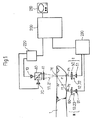
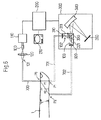
実施例1(図1,2参照):図1に示す実施例1の血糖値測定装置は、照射光11,21を指1に照射するための光源10,20と、反射プリズム40,レンズ41を備える。また指1からの透過光12,22を検出するためのレンズ50と光検出器51から構成される透過光量検出手段1と、透過光13,23を検出するためのレンズ60と光検出器61から構成される透過光量検出手段11を備え、さらに信号処理部230,中央制御部200,表示部210,光源制御部220を備えている。
中央制御部200は、信号処理部230でデジタル化された光検出器51,61からの検出信号をもとに、後述する算定式で人体の血糖値を算出して表示部210で表示する。光源制御部220は、光源10,20に電流を供給するための図示しない電源部を有している。中央制御部200からの指令に従って光源10(光源20)に直流又は変調された電流が供給される。
以上の構成を有する血糖値の非侵襲測定装置の動作を説明する。
光源10から発した照射光11はプリズム40を透過してレンズ41により指1上に照射され、照射光11は指1内部で散乱・吸収を受けて指1外のあらゆる方向に放射されて透過光となる。その後、照射光11の照射位置P0から直線距離r1離れた指1上の位置P1からの透過光12はレンズ50で光検出器51の受光面に集められ、また照射光11の照射位置P0から直線距離r2離れた指1上の位置P2からの透過光13はレンズ60で光検出器61の受光面に集められる。なお、図1ではr1<r2とし、また光検出器51,61にはフォトダイオードを用いている。
光検出器51,61からはそれぞれ透過光12,13の光強度に比例した検出信号が出力されて、信号処理部230でデジタル化処理され、その検出信号を基にコンピュータを用いた中央制御部200で後述する算定式で相対透過度Rλ1が算出される。
続いて、前述した照射光11による相対透過度Rλ1の算出手順と同様に、照射光21による相対透過度Rλ2の算出が実行される。照射光21による相対透過度Rλ2の算出演算が終了すると光源10,20は共にOFF(消灯)して指1の血糖値計測作業が終了する。中央制御部200では、算出した相対透過度Rλ1,Rλ2から指1の血糖値を後述する算定式で算出し、その結果を表示部210に表示する。
次に、中央制御部200で行われる相対透過度Rλ1,Rλ2の算出方法のソフトについて説明する。波長毎の照射光11,透過光12,13の光量をそれぞれI0.λ1,I1.λ1,I2.λ1とする。照射光11に対する指1の相対透過度Rλ1は下記式で表される。
Rλ1=I2.λ1/I1.λ1・・・(1.3)
光検出器51,61における光量−電圧変換係数をそれぞれβ51,β61とすると、光検出器51,61で検出される検出信号(電圧)V51,V61は下記式で表される。
V51=β51*I1.λ1・・・(1.4)
V61=β61*I2.λ1・・・(1.5)
前記各式より、指1の相対透過度Rλ1は下記式で算出され、照射光11の光量I0.λ1に依存しない形で表される。
Rλ1=(β51/β61)*V61/V51・・・(1.6)
ここで、( )内の値は血糖値測定装置固有の定数で、光量が分かった光源を用いて簡単に校正することができる。照射光21に対する指1の相対透過度Rλ2の算出も前記照射光11に対する指1の相対透過度Rλ1と同様にして求めることができる。指1の血糖値Cは、算出した相対透過度Rλ1,Rλ2を用いて下記式で算出する。
C=k0+k1*ln(Rλ1)/ln(Rλ2)・・・(1.7)
ここでk0,k1は実測血糖値を用いて最小2乗法で決定された係数を示す。また、血糖値推定を行うための異なる2つの波長として、実施例1では900〜1100nmの範囲の中からそれぞれ選ばれた波長としている。
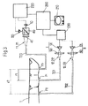
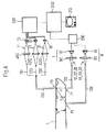
なお、前記した波長範囲にある照射光11,21を発する光源10,20としてレーザーを用いることができる。このレーザーに半導体レーザーを用いれば、小型の血糖値測定装置が実現できる。また、発光ダイオード等の発光素子を光源10,20に用いることも可能である。また、近赤外領域の波長の光を連続的に発する白色光源を光源10,20に用いる場合、光源10,20からの光を前述した波長のみを透過させる光学フィルターを用いることで実現しても良い。さらに、図2に示すように光源10,20からの照射光11,21を光ファイバー700を用いて指1に照射し、さらに指1上の検出点P1,P2からの透過光12,13(22,23)を光ファイバー701,702を用いて前記透過光量検出手段I,IIに導光してもよい。また、図2に示した光ファイバー700を図3に示すように検出側に配置して測定しても良い。FIG. 1 is an explanatory diagram of a blood glucose level noninvasive measurement apparatus according to the first embodiment.
FIG. 2 is an explanatory diagram of a blood glucose level non-invasive measurement apparatus using an optical fiber according to another example of the first embodiment.
FIG. 3 is an explanatory diagram of a blood glucose level non-invasive measurement apparatus using an optical fiber according to another example of the first embodiment.
1 is a finger, 10, 20 and 30 are light sources, 11 and 21 and 31 are irradiation light, 12 and 13 are transmitted light, 22 and 23 are transmitted light, 32 and 33 are transmitted light, 41 is a lens, and 50 and 60 are Lens, 40 is a prism, 51 and 61 are photodetectors, 100 is a white light source, 101 is irradiation light, 102 and 103 are transmitted light, 110 is a power source for white light source, 120 is a lens, 200 is a central control unit, and 210 is Display unit, 220 light source control unit, 230 signal processing unit, 300 and 301 spectroscope, 310 and 320 lenses, 311 and 321 shutters, 330 prisms, 340 rotating grating, 350 multi-channel detector, 360, mirror, 370, sample prism, 380, photodetector, 390, ND filter, 410, 420, 430, lens, 700, 701, 702, optical fiber, 710 720, 730 is an optical fiber.
Example 1 (see FIGS. 1 and 2): The blood glucose level measuring apparatus of Example 1 shown in FIG. 1 includes
The
The operation of the blood glucose level non-invasive measurement apparatus having the above configuration will be described.
Detection signals proportional to the light intensities of the transmitted lights 12 and 13 are output from the
Subsequently, similar to the procedure for calculating the relative transmittance R λ1 by the
Next, software for calculating the relative transmittances R λ1 and R λ2 performed by the
R λ1 = I2 . λ1 / I1 . λ1 (1.3)
If the light quantity-voltage conversion coefficients in the
V 51 = β 51 * I 1 . λ1 (1.4)
V 61 = β 61 * I2 . λ1 (1.5)
From the above formulas, the relative transmittance R λ1 of the
R λ1 = (β 51 / β 61 ) * V 61 / V 51 (1.6)
Here, the values in parentheses are constants specific to the blood glucose level measuring apparatus and can be easily calibrated using a light source whose light quantity is known. The relative transmittance R λ2 of the
C = k 0 + k 1 * ln (R λ1 ) / ln (R λ2 ) (1.7)
Here, k 0 and k 1 indicate coefficients determined by the least square method using the actually measured blood glucose level. Also, as two different wavelengths for performing blood sugar level estimation, in the first embodiment, wavelengths are selected from the range of 900 to 1100 nm.
In addition, a laser can be used as the
図4は、実施例2の血糖値の非侵襲測定装置の説明図である。
図5は、実施例2の血糖値の非侵襲測定装置の説明図である。
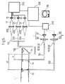
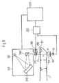
図4に示す実施例2は3つの波長を用いた血糖値の非侵襲測定装置の例である。図4に示す実施例2の血糖値測定装置は、照射光11,21,31を指1に照射するための光源10,20,30と、レンズ410,420,430と、光ファイバー710,720,730及び同各光ファイバー710,720,730を束ねて指1に照射光11,21,31を照射する光ファイバー700を備える。また、指1からの透過光12,22,32を検出するための光ファイバー701,レンズ50,光検出器51から構成される透過光量検出手段1と、透過光13,23,33を検出するための光ファイバー702,レンズ60,光検出器61から構成される透過光量検出手段11を備え、さらに信号処理部230,中央制御部200,表示部210,光源制御部220を備えている。
中央制御部200は、信号処理部230でデジタル化された光検出器51,61からの検出信号をもとに後述する算定式で人体の血糖値を算出し、表示部210で表示する。光源制御部220は、光源10,20,30に電流を供給するための図示しない電源部を有している。中央制御部200からの指令に従って、光源10(光源20,光源30)に直流、又は変調された電流が供給される。各照射光11,21,31に対応した指1の相対透過度Rλ1,Rλ2,Rλ3は実施例1と同様の手順で算出することができる。指1の血糖値Cは、算出した相対透過度Rλ1,Rλ2,Rλ3を用いて下記式で算出する。
C=k0+k1*ln(Rλ1/Rλ3)/ln(Rλ2/Rλ3)・・・(1.8)
ここで、k0,k1は実測血糖値を用いて最小2乗法で決定された係数を示す。前記式(1.8)を用いて血糖値測定を行うための異なる3つの波長として、実施例2では照射光11,21が900〜1100nmの範囲の中からそれぞれ選ばれたものであり、また残りの照射光31が900〜930nm又は1000〜1030nmの範囲の中から選ばれた波長としている。図3で光ファイバー700を指1の検出側とは反対に配置しているが、図5に示すように検出側に配置しても良い。FIG. 4 is an explanatory diagram of a blood glucose level non-invasive measurement apparatus according to the second embodiment.
FIG. 5 is an explanatory diagram of a non-invasive blood glucose level measuring apparatus according to the second embodiment.
Example 2 shown in FIG. 4 is an example of a blood glucose level non-invasive measurement apparatus using three wavelengths. The blood glucose level measuring apparatus of Example 2 shown in FIG. 4 includes
The
C = k 0 + k 1 * ln (R λ 1 / R λ 3 ) / ln (R λ 2 / R λ 3 ) (1.8)
Here, k 0 and k 1 indicate coefficients determined by the least square method using the actually measured blood glucose level. As three different wavelengths for performing blood glucose level measurement using the formula (1.8), the irradiation lights 11 and 21 are each selected from the range of 900 to 1100 nm in Example 2, and The remaining
図6は、実施例3の血糖値の非侵襲測定装置の説明図である。
図7は、人体を模した散乱体での最適波長の組み合わせ領域を示す図である。
図8は、検出距離r1の変化量と血糖値測定誤差との関係を示す図である。
実施例1,2では人体に照射する光を波長の異なる2つ又は3つの光に限定して説明した。これにより、白色光源を用いた従来の血糖値測定装置のように透過又は反射光スペクトルを検出するための複雑な分光器を必要としない装置が実現できる。また、指等の測定部位の大きさに依存して照射光の照射位置と透過光の検出位置との直線距離が変化しても、血糖値の測定誤差への影響を少なくした血糖値の非侵襲測定装置が実現できる。さらに、心拍数に対応して変化する血管の膨張・収縮により透過光量が変化しても血糖値の測定誤差への影響を少なくした血糖値の非侵襲測定装置ができる。
一方、従来の白色光源と分光器を用いた血糖値の非侵襲測定装置においても、指等の測定部位の大きさに依存して光の照射位置と透過光の検出位置との直線距離が変化しても、血糖値の測定誤差への影響を少なくすることができる。また、心拍数に対応して変化する血管の膨張・収縮により透過光量が変化しても血糖値の測定誤差への影響を少なくすることができる。さらに、非特許文献1に記載されたような標準反射板を用いる必要がなくなる。
従来の白色光源と分光器を用いた血糖値の非侵襲測定装置に適用した例を図6に基づいて説明する。
図6に示す血糖値の非侵襲測定装置では、近赤外領域の波長の光を含むハロゲンランプ等の白色光源100とその電源110を備え、光源100からの光101をレンズ120と光ファイバー700を介して指1に照射する。指1に照射された光101は指1内部で散乱・吸収を受けて指1外のあらゆる方向に放射されて透過光となる。光ファイバー700による光101の指1上の照射位置P0から直線距離r1,r2にある指1上の位置P1,P2からの透過光102,103を光ファイバー701,702により分光器300まで導光する。
分光器300は、レンズ310,320と、シャッター311,321と、プリズム330,回折格子340,多チャンネル検出器350から構成される。多チャンネル検出器350にはCCD等のリニアアレイセンサーが用いられる。位置P1から放射された透過光102の透過スペクトルを計測する場合、シャッター311が開き、多チャンネル検出器350上に透過光102の透過スペクトルS1が得られる。この場合、シャッター321は閉まっている。同様にして位置P2から放射された透過光103の透過スペクトルS2を測定する場合、シャッター321が開き、多チャンネル検出器350上に透過光103の透過スペクトルS2が得られる。この場合、シャッター311は閉まっている。以上のようにして測定した前記透過スペクトルS1,S2から相対透過率スペクトルT=S2/S1を算出する。得られた相対透過率スペクトルから吸光度、又は吸光度の1階(あるいは2階)微分値を算出し前記各式、又は非特許文献1で記載されている多変量解析により血糖値Cを算出することができる。
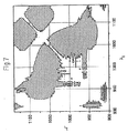
各実施例の非侵襲血糖値測定方法について検討した結果を図7,8に示す。図7は人体を模した散乱体に対して、相対透過度R(λi=1,2,3)を用いて下記式(1.9)により表される指標γとグルコース濃度の相関について図5で示した非侵襲測定装置で測定した場合について理論解析し、その相関係数の自乗値R2>0.995となる波長の組み合わせ領域を斜線で示している。理論解析は文献「A.Ishimaru:Wave Propagation and Scattering in Random Media,Academic Press,NewYork(1978)」を参考に行った。ここでの理論計算では図7中、直線距離r1,r2をそれぞれ10mm,20mmに設定した。また等価散乱係数はグルコース濃度・波長によらず一定とし、ここでは人体の一般値1.0mm−1(参考:機論、59,561B(1993)、PP.338−340)を用いた。また波長・グルコース濃度に依存した吸収係数はグルコース水溶液を用いて実測した結果を用いた。また波長λ3=900nmに設定した。
γ=ln(R(λ1)/R(λ3))/ln(R(λ2)/R(λ3))・・・(1.9)
図7より900〜1100nmの波長範囲に前記指標γでグルコース濃度を推定する為の最適な波長λ1,λ2の組み合わせがあることがわかる。
次に、実施例1,2記載の血糖値測定装置において、図3、及び図5中、距離r1,r2を変化させた場合の血糖値の測定誤差について解析した結果を図8に示す。ここでは透過光検出位置P1,P2間の距離を10mmで一定とした。従来技術の場合も照射位置P0が検出位置P1と同じ側にある場合を想定した。照射位置と検出位置が同じ側にある場合、指の厚みの影響はほとんど無視できるが、心拍数に対応して変化する血管の膨張・収縮により透過光量が変化する。この透過光量の変化は見かけ上、距離r1,r2の変化に起因したものと見なすことができる。実施例1では、従来技術に比べ血糖値の測定誤差が約1/2に、また実施例2では従来技術に比べ血糖値の測定誤差が約1/40にそれぞれ低減していることがわかる。つまり、心拍数に対応して変化する血管の膨張・収縮は指の厚みの変化と同様に透過光量を変化させるが、実施例1,2により血糖値の測定誤差をそれぞれ従来技術に比べて低減することができる。FIG. 6 is an explanatory diagram of the blood glucose level non-invasive measurement apparatus according to the third embodiment.
FIG. 7 is a diagram illustrating a combination region of optimum wavelengths in a scatterer simulating a human body.
FIG. 8 is a diagram showing the relationship between the amount of change in the detection distance r1 and the blood sugar level measurement error.
In the first and second embodiments, the light irradiated on the human body is limited to two or three lights having different wavelengths. Thereby, the apparatus which does not require the complicated spectroscope for detecting a transmitted or reflected light spectrum like the conventional blood glucose level measuring apparatus using a white light source is realizable. In addition, even if the linear distance between the irradiation position of the irradiation light and the detection position of the transmitted light changes depending on the size of the measurement site such as a finger, the blood glucose level is reduced without affecting the measurement error of the blood glucose level. An invasive measurement device can be realized. In addition, a blood glucose level non-invasive measurement apparatus can be obtained in which the influence on blood glucose level measurement errors is reduced even if the amount of transmitted light changes due to the expansion and contraction of blood vessels that change according to the heart rate.
On the other hand, even in a conventional non-invasive blood glucose level measurement device using a white light source and a spectroscope, the linear distance between the light irradiation position and the transmitted light detection position varies depending on the size of the measurement site such as a finger. Even so, the influence on the measurement error of the blood sugar level can be reduced. Moreover, even if the amount of transmitted light changes due to the expansion and contraction of blood vessels that change according to the heart rate, the influence on the measurement error of the blood glucose level can be reduced. Furthermore, it is not necessary to use a standard reflector as described in
An example applied to a conventional blood glucose non-invasive measuring apparatus using a white light source and a spectroscope will be described with reference to FIG.
The blood glucose level non-invasive measurement apparatus shown in FIG. 6 includes a
The
The result of having examined about the noninvasive blood glucose level measuring method of each Example is shown to FIG. FIG. 7 is a graph showing the correlation between the index γ expressed by the following formula (1.9) and the glucose concentration using the relative transmittance R (λ i = 1,2,3 ) with respect to the scatterer imitating the human body. A theoretical analysis is performed on the case of measurement with the non-invasive measuring apparatus shown in FIG. 5, and the wavelength combination region where the square value R 2 > 0.995 of the correlation coefficient is indicated by hatching. The theoretical analysis was performed with reference to the document “A. Ishimaru: Wave Propagation and Scattering in Random Media, Academic Press, New York (1978)”. In the theoretical calculation here, in FIG. 7, the linear distances r 1 and r 2 were set to 10 mm and 20 mm, respectively. In addition, the equivalent scattering coefficient is constant regardless of the glucose concentration / wavelength, and here, the general value of human body 1.0 mm −1 (reference: theory, 59, 561B (1993), PP. 338-340) was used. The absorption coefficient depending on the wavelength and glucose concentration was measured using an aqueous glucose solution. The wavelength λ 3 was set to 900 nm.
γ = ln (R (λ 1 ) / R (λ 3 )) / ln (R (λ 2 ) / R (λ 3 )) (1.9)
FIG. 7 shows that there is an optimum combination of wavelengths λ 1 and λ 2 for estimating the glucose concentration with the index γ in the wavelength range of 900 to 1100 nm.
Next, in the blood sugar level measuring apparatus described in the first and second embodiments, FIG. 8 shows the result of analyzing the blood sugar level measurement error when the distances r 1 and r 2 are changed in FIG. 3 and FIG. . Here, the distance between the transmitted light detection positions P 1 and P 2 is constant at 10 mm. In the case of the prior art, it is assumed that the irradiation position P 0 is on the same side as the detection position P 1 . When the irradiation position and the detection position are on the same side, the influence of the finger thickness is almost negligible, but the amount of transmitted light changes due to the expansion and contraction of the blood vessel that changes according to the heart rate. This change in the amount of transmitted light can be considered to be caused by the change in the distances r 1 and r 2 . In Example 1, the measurement error of the blood sugar level is reduced to about ½ compared to the conventional technique, and in Example 2, the measurement error of the blood sugar level is reduced to about 1/40 compared to the conventional technique. In other words, blood vessel dilation / contraction that changes according to the heart rate changes the amount of transmitted light in the same way as the change in the thickness of the finger. can do.
以上説明したように、本発明によれば複数の異なる波長の光を人体に照射し、その透過光を前記光の照射位置から異なる距離をおいた2ヵ所でそれぞれ検出する。検出された透過光には人体内部の血糖値情報が含まれており、人体の血糖値測定が可能となる。また、白色光源を用いた従来の血糖値測定装置のように透過又は反射光スペクトルを検出するための複雑な分光器を必要としない装置が実現でき、また光源に小型の半導体レーザー等を用いることができるため、小型・軽量の血糖値測定装置が実現できる。さらに、指等の測定部位の大きさの変化、あるいは血管の膨張・収縮に依存して透過光量が変化しても血糖値の測定誤差への影響を少なくした血糖値の非侵襲測定装置が実現できる。 As described above, according to the present invention, a human body is irradiated with a plurality of light beams having different wavelengths, and the transmitted light is detected at two locations at different distances from the light irradiation position. The detected transmitted light includes blood glucose level information inside the human body, and blood glucose level measurement of the human body is possible. In addition, a device that does not require a complicated spectroscope for detecting a transmitted or reflected light spectrum, such as a conventional blood glucose level measuring device using a white light source, can be realized, and a small semiconductor laser or the like is used as the light source. Therefore, a small and lightweight blood glucose level measuring device can be realized. Furthermore, a blood glucose level non-invasive measurement device that reduces the effect on blood glucose level measurement errors even if the amount of transmitted light changes depending on changes in the size of the measurement site such as a finger or the expansion / contraction of blood vessels is realized. it can.
Claims (7)
Applications Claiming Priority (1)
| Application Number | Priority Date | Filing Date | Title |
|---|---|---|---|
| PCT/JP2004/015676 WO2006040841A1 (en) | 2004-10-15 | 2004-10-15 | Instrument for noninvasively measuring blood sugar level |
Publications (1)
| Publication Number | Publication Date |
|---|---|
| JPWO2006040841A1 true JPWO2006040841A1 (en) | 2008-05-15 |
Family
ID=36148143
Family Applications (1)
| Application Number | Title | Priority Date | Filing Date |
|---|---|---|---|
| JP2006540819A Pending JPWO2006040841A1 (en) | 2004-10-15 | 2004-10-15 | Non-invasive measuring device for blood glucose level |
Country Status (5)
| Country | Link |
|---|---|
| US (1) | US7613487B2 (en) |
| JP (1) | JPWO2006040841A1 (en) |
| CN (1) | CN100522059C (en) |
| DE (1) | DE112004002988B4 (en) |
| WO (1) | WO2006040841A1 (en) |
Families Citing this family (35)
| Publication number | Priority date | Publication date | Assignee | Title |
|---|---|---|---|---|
| US9622694B2 (en) * | 2007-06-20 | 2017-04-18 | Vioptix, Inc. | Measuring cerebral oxygen saturation |
| WO2011093912A1 (en) * | 2010-01-29 | 2011-08-04 | Medtronic, Inc. | Optical sensor for medical device |
| SG186961A1 (en) * | 2010-07-08 | 2013-02-28 | Glucostats System Pte Ltd | Apparatus and method for predicting a parameter in the blood stream of a subject |
| EP2628446A4 (en) * | 2010-10-14 | 2017-01-04 | Hitachi, Ltd. | Equipment for in vivo data acquisition and analysis |
| CN102641127A (en) * | 2012-05-07 | 2012-08-22 | 天津恒基晟达科技有限公司 | Human blood composition non-invasive monitoring device based on time gate |
| CN102727215A (en) * | 2012-06-08 | 2012-10-17 | 林建中 | Blood collection-free blood sugar measurement instrument and testing method |
| BR112015019505B1 (en) * | 2013-02-13 | 2022-02-08 | Leman Micro Devices Sa | PERSONAL PORTABLE MONITOR FOR NON-INVASIVE BLOOD ANALYSIS |
| DE102013010611A1 (en) * | 2013-06-25 | 2015-01-08 | Sms Swiss Medical Sensor Ag | Measuring device and measuring method for measuring raw data for determining a blood parameter, in particular for noninvasive determination of the D-glucose concentration |
| JP6600635B2 (en) * | 2014-01-10 | 2019-10-30 | グルコビスタ・インコーポレイテッド | Non-invasive system and method for measuring substance concentration |
| JP6364792B2 (en) * | 2014-01-31 | 2018-08-01 | セイコーエプソン株式会社 | Biological information processing method, biological information processing apparatus, computer system, and wearable device |
| US11229383B2 (en) | 2014-08-25 | 2022-01-25 | California Institute Of Technology | Methods and systems for non-invasive measurement of blood glucose concentration by transmission of millimeter waves through human skin |
| CN104236862B (en) * | 2014-09-28 | 2017-01-11 | 广州视源电子科技股份有限公司 | Optical performance test method |
| CN104490403B (en) * | 2014-12-06 | 2016-08-17 | 深圳市贝沃德克生物技术研究院有限公司 | Invasive blood sugar measuring system based on spectral technique and measuring method thereof |
| US10736580B2 (en) | 2016-09-24 | 2020-08-11 | Sanmina Corporation | System and method of a biosensor for detection of microvascular responses |
| US9788767B1 (en) | 2015-09-25 | 2017-10-17 | Sanmina Corporation | System and method for monitoring nitric oxide levels using a non-invasive, multi-band biosensor |
| US10194871B2 (en) | 2015-09-25 | 2019-02-05 | Sanmina Corporation | Vehicular health monitoring system and method |
| US10750981B2 (en) | 2015-09-25 | 2020-08-25 | Sanmina Corporation | System and method for health monitoring including a remote device |
| US10952682B2 (en) | 2015-07-19 | 2021-03-23 | Sanmina Corporation | System and method of a biosensor for detection of health parameters |
| US10888280B2 (en) | 2016-09-24 | 2021-01-12 | Sanmina Corporation | System and method for obtaining health data using a neural network |
| US10744261B2 (en) | 2015-09-25 | 2020-08-18 | Sanmina Corporation | System and method of a biosensor for detection of vasodilation |
| US9636457B2 (en) | 2015-07-19 | 2017-05-02 | Sanmina Corporation | System and method for a drug delivery and biosensor patch |
| US10321860B2 (en) * | 2015-07-19 | 2019-06-18 | Sanmina Corporation | System and method for glucose monitoring |
| US10932727B2 (en) | 2015-09-25 | 2021-03-02 | Sanmina Corporation | System and method for health monitoring including a user device and biosensor |
| US10973470B2 (en) | 2015-07-19 | 2021-04-13 | Sanmina Corporation | System and method for screening and prediction of severity of infection |
| US10945676B2 (en) | 2015-09-25 | 2021-03-16 | Sanmina Corporation | System and method for blood typing using PPG technology |
| US10362994B2 (en) * | 2016-02-29 | 2019-07-30 | Texas Instruments Incorporated | Bio-sensing device with ambient light cancellation |
| KR102497849B1 (en) | 2016-05-09 | 2023-02-07 | 삼성전자주식회사 | Method and apparatus for predicting analyte concentration |
| CN107684431A (en) * | 2016-08-04 | 2018-02-13 | 中国计量大学 | A kind of noninvasive portable glucose meter based on array CCD |
| CN106264555B (en) * | 2016-10-17 | 2020-06-12 | 南方科技大学 | Blood sugar detector |
| EP3624679B1 (en) | 2017-05-19 | 2023-09-13 | GlucoVista Inc. | Glucose concentration nir monitoring apparatuses and methods |
| WO2018217765A1 (en) * | 2017-05-22 | 2018-11-29 | Gupta Rijul | Method and apparatus for light-weight, non-invasive, point of care diabetes screening device |
| US10466783B2 (en) | 2018-03-15 | 2019-11-05 | Sanmina Corporation | System and method for motion detection using a PPG sensor |
| US11280745B2 (en) | 2018-07-05 | 2022-03-22 | Mezent Corporation | Resonant sensing device |
| CN111012308B (en) * | 2019-12-02 | 2021-06-01 | 清华大学 | Method, device and system for measuring dynamic multispectral absorption characteristic parameters of body surface |
| JP7469799B2 (en) | 2020-07-08 | 2024-04-17 | 東京都公立大学法人 | Measuring device and measuring method |
Citations (2)
| Publication number | Priority date | Publication date | Assignee | Title |
|---|---|---|---|---|
| JPH1078437A (en) * | 1996-09-03 | 1998-03-24 | Matsushita Electric Ind Co Ltd | Blood sugar meter |
| JP2000237195A (en) * | 1998-12-24 | 2000-09-05 | Matsushita Electric Ind Co Ltd | Living body information measuring device, living body information measuring method, body fat measuring device, body fat measuring method and program recording medium |
Family Cites Families (12)
| Publication number | Priority date | Publication date | Assignee | Title |
|---|---|---|---|---|
| JPH06103257B2 (en) * | 1988-12-19 | 1994-12-14 | 大塚電子株式会社 | Method and apparatus for measuring absorption coefficient of substance using light scattering |
| US5028787A (en) * | 1989-01-19 | 1991-07-02 | Futrex, Inc. | Non-invasive measurement of blood glucose |
| JP3093871B2 (en) | 1991-05-22 | 2000-10-03 | 三井金属鉱業株式会社 | Optical blood glucose non-destructive measuring device |
| IL107396A (en) * | 1992-11-09 | 1997-02-18 | Boehringer Mannheim Gmbh | Method and apparatus for analytical determination of glucose in a biological matrix |
| US5492118A (en) * | 1993-12-16 | 1996-02-20 | Board Of Trustees Of The University Of Illinois | Determining material concentrations in tissues |
| JPH09182740A (en) * | 1995-12-30 | 1997-07-15 | Shimadzu Corp | Biological photomeasuring device |
| JP3617576B2 (en) * | 1996-05-31 | 2005-02-09 | 倉敷紡績株式会社 | Optical measuring device for light scatterers |
| US5910109A (en) * | 1997-02-20 | 1999-06-08 | Emerging Technology Systems, Llc | Non-invasive glucose measuring device and method for measuring blood glucose |
| GB2328279B (en) * | 1997-08-12 | 2001-10-10 | Abbott Lab | Optical glucose detector |
| DE19807939C1 (en) * | 1998-02-25 | 1999-09-30 | Siemens Ag | Non-invasive blood glucose concentration determination in vivo |
| US6411373B1 (en) * | 1999-10-08 | 2002-06-25 | Instrumentation Metrics, Inc. | Fiber optic illumination and detection patterns, shapes, and locations for use in spectroscopic analysis |
| MXPA03006726A (en) | 2001-01-26 | 2004-10-15 | Sensys Medical Inc | Noninvasive measurement of glucose through the optical properties of tissue. |
-
2004
- 2004-10-15 DE DE112004002988T patent/DE112004002988B4/en active Active
- 2004-10-15 CN CNB2004800443305A patent/CN100522059C/en active Active
- 2004-10-15 WO PCT/JP2004/015676 patent/WO2006040841A1/en active Application Filing
- 2004-10-15 JP JP2006540819A patent/JPWO2006040841A1/en active Pending
-
2007
- 2007-04-11 US US11/734,122 patent/US7613487B2/en active Active
Patent Citations (2)
| Publication number | Priority date | Publication date | Assignee | Title |
|---|---|---|---|---|
| JPH1078437A (en) * | 1996-09-03 | 1998-03-24 | Matsushita Electric Ind Co Ltd | Blood sugar meter |
| JP2000237195A (en) * | 1998-12-24 | 2000-09-05 | Matsushita Electric Ind Co Ltd | Living body information measuring device, living body information measuring method, body fat measuring device, body fat measuring method and program recording medium |
Also Published As
| Publication number | Publication date |
|---|---|
| CN100522059C (en) | 2009-08-05 |
| US20070203405A1 (en) | 2007-08-30 |
| CN101052349A (en) | 2007-10-10 |
| WO2006040841A1 (en) | 2006-04-20 |
| DE112004002988T5 (en) | 2007-09-20 |
| US7613487B2 (en) | 2009-11-03 |
| DE112004002988B4 (en) | 2013-06-06 |
Similar Documents
| Publication | Publication Date | Title |
|---|---|---|
| JPWO2006040841A1 (en) | Non-invasive measuring device for blood glucose level | |
| US5360004A (en) | Non-invasive determination of analyte concentration using non-continuous radiation | |
| US5137023A (en) | Method and apparatus for monitoring blood analytes noninvasively by pulsatile photoplethysmography | |
| TWI324686B (en) | Noninvasive measurement of glucose through the optical properties of tissue | |
| JP5982364B2 (en) | Apparatus and method for identifying and monitoring components or characteristics of a measurement medium, in particular physiological blood values | |
| JP5175179B2 (en) | Improved blood oxygenation monitoring method by spectrophotometry | |
| JP3875798B2 (en) | Method of operating a bloodless measuring device for blood component concentration and bloodless measuring device | |
| JP4872536B2 (en) | Biological component concentration measurement method | |
| CN110123339B (en) | Noninvasive blood glucose measuring device and method | |
| JPS60236631A (en) | Method and apparatus for light measuring detection of glucose | |
| WO2013073270A1 (en) | Measurement device, measurement method, program, and recording medium | |
| JP2008203234A (en) | Blood component concentration analysis method and device | |
| Tenhunen et al. | Non-invasive glucose measurement based on selective near infrared absorption; requirements on instrumentation and spectral range | |
| JP2005013273A (en) | Blood sugar level measuring device | |
| JP2000506048A (en) | Calibration for subsequent monitoring of biological compounds | |
| JP2007532183A (en) | A compact instrument for non-invasive measurement of glucose by near infrared spectroscopy | |
| TW200404156A (en) | Compact apparatus for noninvasive measurement of glucose through near-infrared spectroscopy | |
| US7809416B2 (en) | Method of preparing calibration curve for quantitative analysis of in-vivo component, and quantitative analyzer using the calibration curve | |
| JP4361822B2 (en) | Method and apparatus for measuring component concentration of target object | |
| JP2007083028A (en) | Noninvasive inspecting apparatus | |
| JP2014018478A (en) | Method and device for blood sugar level measurement | |
| US20060211926A1 (en) | Non-invasive Raman measurement apparatus with broadband spectral correction | |
| CN112137624A (en) | Method for measuring blood oxygen saturation | |
| JP4052461B2 (en) | Non-invasive measuring device for blood glucose level | |
| JP2007020890A (en) | Optical measurement system of biological information and coupling layer used for measurement of optical information |
Legal Events
| Date | Code | Title | Description |
|---|---|---|---|
| A131 | Notification of reasons for refusal |
Free format text: JAPANESE INTERMEDIATE CODE: A131 Effective date: 20100105 |
|
| A02 | Decision of refusal |
Free format text: JAPANESE INTERMEDIATE CODE: A02 Effective date: 20110308 |