JPWO2004032425A1 - COMMUNICATION ADAPTER DEVICE, COMMUNICATION ADAPTER, METHOD FOR WRITE TO NONVOLATILE MEMORY, ELECTRIC APPARATUS AND ROM WRITER - Google Patents
COMMUNICATION ADAPTER DEVICE, COMMUNICATION ADAPTER, METHOD FOR WRITE TO NONVOLATILE MEMORY, ELECTRIC APPARATUS AND ROM WRITER Download PDFInfo
- Publication number
- JPWO2004032425A1 JPWO2004032425A1 JP2005500091A JP2005500091A JPWO2004032425A1 JP WO2004032425 A1 JPWO2004032425 A1 JP WO2004032425A1 JP 2005500091 A JP2005500091 A JP 2005500091A JP 2005500091 A JP2005500091 A JP 2005500091A JP WO2004032425 A1 JPWO2004032425 A1 JP WO2004032425A1
- Authority
- JP
- Japan
- Prior art keywords
- communication
- network
- interface
- unit
- communication adapter
- Prior art date
- Legal status (The legal status is an assumption and is not a legal conclusion. Google has not performed a legal analysis and makes no representation as to the accuracy of the status listed.)
- Granted
Links
- 238000004891 communication Methods 0.000 title claims abstract description 410
- 238000000034 method Methods 0.000 title claims abstract description 140
- 230000006870 function Effects 0.000 claims abstract description 30
- 230000005540 biological transmission Effects 0.000 claims abstract description 22
- 230000005856 abnormality Effects 0.000 claims description 34
- 230000008859 change Effects 0.000 claims description 29
- 238000009434 installation Methods 0.000 claims description 15
- 235000014676 Phragmites communis Nutrition 0.000 claims description 12
- 238000012545 processing Methods 0.000 claims description 12
- 230000001360 synchronised effect Effects 0.000 claims description 12
- 230000004044 response Effects 0.000 claims description 9
- 230000007246 mechanism Effects 0.000 claims description 5
- 230000005389 magnetism Effects 0.000 claims description 4
- 239000002131 composite material Substances 0.000 claims description 3
- 230000000737 periodic effect Effects 0.000 claims description 2
- 230000002194 synthesizing effect Effects 0.000 claims description 2
- 230000008033 biological extinction Effects 0.000 claims 1
- 238000010438 heat treatment Methods 0.000 claims 1
- 238000010276 construction Methods 0.000 abstract description 6
- 238000007726 management method Methods 0.000 description 127
- 238000010586 diagram Methods 0.000 description 39
- 230000000694 effects Effects 0.000 description 9
- 238000012546 transfer Methods 0.000 description 5
- 230000002159 abnormal effect Effects 0.000 description 4
- 238000012544 monitoring process Methods 0.000 description 4
- 230000000630 rising effect Effects 0.000 description 4
- 230000004913 activation Effects 0.000 description 3
- 238000012423 maintenance Methods 0.000 description 3
- 238000012795 verification Methods 0.000 description 3
- 238000006243 chemical reaction Methods 0.000 description 2
- 230000007274 generation of a signal involved in cell-cell signaling Effects 0.000 description 2
- 230000001629 suppression Effects 0.000 description 2
- 230000007704 transition Effects 0.000 description 2
- 230000008878 coupling Effects 0.000 description 1
- 238000010168 coupling process Methods 0.000 description 1
- 238000005859 coupling reaction Methods 0.000 description 1
- 230000002950 deficient Effects 0.000 description 1
- 238000012217 deletion Methods 0.000 description 1
- 230000037430 deletion Effects 0.000 description 1
- 238000001514 detection method Methods 0.000 description 1
- 230000008034 disappearance Effects 0.000 description 1
- 239000000284 extract Substances 0.000 description 1
- 230000007257 malfunction Effects 0.000 description 1
- 230000008569 process Effects 0.000 description 1
- 238000011084 recovery Methods 0.000 description 1
- 230000002441 reversible effect Effects 0.000 description 1
- 238000000926 separation method Methods 0.000 description 1
- 238000005476 soldering Methods 0.000 description 1
- 230000033772 system development Effects 0.000 description 1
Images


Classifications
-
- H—ELECTRICITY
- H04—ELECTRIC COMMUNICATION TECHNIQUE
- H04L—TRANSMISSION OF DIGITAL INFORMATION, e.g. TELEGRAPHIC COMMUNICATION
- H04L12/00—Data switching networks
- H04L12/28—Data switching networks characterised by path configuration, e.g. LAN [Local Area Networks] or WAN [Wide Area Networks]
- H04L12/2803—Home automation networks
- H04L12/2816—Controlling appliance services of a home automation network by calling their functionalities
- H04L12/282—Controlling appliance services of a home automation network by calling their functionalities based on user interaction within the home
-
- G—PHYSICS
- G11—INFORMATION STORAGE
- G11C—STATIC STORES
- G11C16/00—Erasable programmable read-only memories
- G11C16/02—Erasable programmable read-only memories electrically programmable
- G11C16/06—Auxiliary circuits, e.g. for writing into memory
- G11C16/10—Programming or data input circuits
- G11C16/102—External programming circuits, e.g. EPROM programmers; In-circuit programming or reprogramming; EPROM emulators
-
- H—ELECTRICITY
- H04—ELECTRIC COMMUNICATION TECHNIQUE
- H04L—TRANSMISSION OF DIGITAL INFORMATION, e.g. TELEGRAPHIC COMMUNICATION
- H04L12/00—Data switching networks
- H04L12/28—Data switching networks characterised by path configuration, e.g. LAN [Local Area Networks] or WAN [Wide Area Networks]
- H04L12/2803—Home automation networks
- H04L12/2823—Reporting information sensed by appliance or service execution status of appliance services in a home automation network
- H04L12/2825—Reporting to a device located outside the home and the home network
-
- H—ELECTRICITY
- H04—ELECTRIC COMMUNICATION TECHNIQUE
- H04L—TRANSMISSION OF DIGITAL INFORMATION, e.g. TELEGRAPHIC COMMUNICATION
- H04L12/00—Data switching networks
- H04L12/28—Data switching networks characterised by path configuration, e.g. LAN [Local Area Networks] or WAN [Wide Area Networks]
- H04L12/2803—Home automation networks
- H04L12/2823—Reporting information sensed by appliance or service execution status of appliance services in a home automation network
- H04L12/2827—Reporting to a device within the home network; wherein the reception of the information reported automatically triggers the execution of a home appliance functionality
-
- H—ELECTRICITY
- H04—ELECTRIC COMMUNICATION TECHNIQUE
- H04L—TRANSMISSION OF DIGITAL INFORMATION, e.g. TELEGRAPHIC COMMUNICATION
- H04L12/00—Data switching networks
- H04L12/28—Data switching networks characterised by path configuration, e.g. LAN [Local Area Networks] or WAN [Wide Area Networks]
- H04L12/2803—Home automation networks
- H04L2012/2847—Home automation networks characterised by the type of home appliance used
- H04L2012/285—Generic home appliances, e.g. refrigerators
Abstract
本発明は、家電機器やセンサ、その他の機器をネットワークに接続する通信アダプタ装置に関するもので、施工時の設定の容易化、施工工事の容易化、電力消費の低減、システム設定の容易化が可能な通信アダプタ装置を得るために、機器の機能に基づいた情報並びに操作可能な制御項目からなる機器オブジェクトをそれぞれ有する複数の接続対象機器のいずれか一つと、接続対象機器を遠隔操作するコントローラが接続されたネットワークとを接続させる通信アダプタにおいて、ネットワークに対するデータの送受信を制御する通信制御手段と、機器オブジェクトを複製保存すると共に、通信制御手段の通信サービスに関する手順を保存し、これらの保存データを用いて、接続対象機器をネットワークから利用可能とする機器通信管理手段と、複数の接続対象機器の全てを接続可能とすべく、全機器に共通する規格で規定された機器インターフェース手段とから構成する。The present invention relates to a communication adapter device for connecting home appliances, sensors, and other devices to a network, and facilitates setting during construction, ease of construction, reduction of power consumption, and ease of system setting. In order to obtain a simple communication adapter device, one of a plurality of connection target devices each having a device object consisting of information based on device functions and control items that can be operated is connected to a controller that remotely operates the connection target device. In the communication adapter for connecting to the network, the communication control means for controlling transmission / reception of data to / from the network, the device object is duplicated and stored, the procedure regarding the communication service of the communication control means is stored, and the stored data is used Device communication management means to make the connection target device available from the network , In order to enable connection to all of the plurality of connected device is composed of a device interface means defined by standards common to all devices.
Description
この発明は、本発明は、家電機器やセンサ、その他の機器をネットワークに接続する通信アダプタ装置、電気的に書換え可能な不揮発性メモリを内蔵した電気機器と、この不揮発性メモリにデータの書込みを行うROMライタと、これらを用いた書込み方法に関するものである。 The present invention relates to a communication adapter device for connecting home appliances, sensors, and other devices to a network, an electric device incorporating an electrically rewritable nonvolatile memory, and writing data to the nonvolatile memory. The present invention relates to a ROM writer to be executed and a writing method using them.
従来の通信アダプタ装置は、特開2002−44745号公報(5頁段落番号0050、第1図)やECHONETコンソーシアム発行ECHONET規格書Ver1.10(第7部3−1頁)記載のように、遠隔操作の制御信号を通信する通信部のみで構成されており、制御信号の解釈、システム情報の管理機能は家電機器内の家電制御部に搭載されていた。
また、従来の通信アダプタ装置は、ECHONETコンソーシアム発行ECHONET規格書Ver1.10(第1部4−4頁、図4−1、形態4)記載のように、機器毎に仕様の異なる既存の通信インタフェースへの変換機能を内蔵して、遠隔制御を実現していた。
また、従来の家庭内制御システムでは、特開平01−228395号公報(第3頁、第2図)記載のように、エアコン、照明などの負荷に関する属性情報(機種名、消費電力など)を通信アダプタに設定する場合、あるいはシステムの拡張などにより通信アダプタに設定された属性情報を変更する場合、その都度DIPコードスイッチを用いて負荷のコード番号を設定しなければならなかった。また、このようなDIPコードスイッチを用いた設定は煩雑な作業であるため、特開平06−68097号公報(第1図)記載のように、バーコードとバーコードリーダーを用いて、通信アダプタにコード番号を設定する家庭内制御システムが提案されていた。
また、不揮発性メモリへのデータ書込み方法は、特開平2−130799号公報(第1図)記載のように、ROMライタが接続手段を介して端末装置に接続されると、端末装置内のMPUのSTBY端子がROMライタ内の接地端子に接続されるようになっていた。そして、これにより端末装置はスタンバイの状態となってプログラムの書き込みが可能となり、EEPROMに対するプログラムの更新を半田付け作業なしで出来るようになっていた。
しかしながら、従来の通信アダプタ装置は通信制御手段に対し、共通的なインタフェース手段を持たないため、ネットワークの種類に応じて通信制御手段の変更ができないという課題があった。
また、機器内の制御装置に、遠隔操作のための通信管理、制御プログラムを内蔵する必要があり、マイコン等のリソースへの負担やコストが増加するという課題があった。
また、通信アダプタは機器と一体となって機能する必要があり、施工時、すべての機器が稼働状態にならないと種々のシステム設定ができないという課題があった。
また、通信設定情報をアダプタ自身で保持しているため、故障などでアダプタを交換した場合、システムの再設定に伴うアダプタの再設定という煩雑な作業が必要であるという課題があった。
また、システムの異常が発生した際、機器内に制御機能を内蔵しているため、アダプタが異常であるのか、機器が故障であるのかの判断が困難であるという課題があった。
また、施工簡易化のため、家電機器から電源の供給を受けようとした場合、電源管理の機能並びに情報の提供、制御手段が無く、且つ各部の機能を制限する手段がないため、通信アダプタを構成する各部への電源の供給が必須となり、家電機器の電源回路のコストが増大するという課題があった。
また、接続された家電機器の機種名、消費電力などの属性情報の設定や、システムの拡張に伴う設定の変更には、バーコードとバーコードリーダが必要であり、またこれらを用いた手間のかかる作業が必要であった。
また、従来のROMライタと電気機器とこれらを用いた書込み方法は、ROMライタには接地端子しか配設されておらず、接地レベルにプルダウンした時に書込みモードとなるマイコンを内蔵した装置には適用できるが、所定電圧までプルアップした時に書込みモードとなるマイコンを内蔵した装置には適用できなかった。この結果、書込みにおいて、装置に内蔵されているマイコンの仕様に合わせてROMライタを用意する必要があった。
この発明は係る課題を解決するためになされたもので、通信制御手段に対し、共通的なインタフェース手段を持たせ、ネットワークの種類に応じて通信制御手段の変更が可能な通信アダプタ装置を提供することを目的としている。
また、家電機器のマイコン等のリソースへの負担、コストの増加が少なく、ネットワークへ接続可能な家電機器の通信アダプタ装置を提供することを目的とする。
また、施工の容易化であり、稼働状態の家電機器を接続しなくとも種々のシステム設定が可能な通信アダプタ装置を提供することを目的とする。
また、、通信アダプタ装置の交換時にシステム再設定など煩雑な作業を必要とせず、容易に交換可能な通信アダプタ装置を提供することである。
また、システム異常が発生した際、アダプタ異常であるのか、家電品の故障であるのかの判断を可能にする通信アダプタ装置を提供することを目的とする。
また、省電力かつ、接続する家電機器の電源コストを増やすこと無く家電機器をネットワーク接続するための通信アダプタ装置を提供することを目的とする。
また、バーコードやバーコードリーダを用いずに家電機器の属性情報を自動的に設定でき、また変更が生じた場合もバーコードやバーコードリーダを用いずに簡単に変更できる通信アダプタを提供することを目的とする。
また、マイコンの仕様に関係なく使うことのできる汎用性の高いROMライタと電気機器とこれらを用いた書込み方法を提供することを目的とする。Conventional communication adapter devices are disclosed in Japanese Patent Laid-Open No. 2002-44745 (
In addition, the conventional communication adapter device is an existing communication interface having different specifications for each device as described in the ECHONET Consortium-issued ECHONET Standard Ver. 1.10 (
Further, in a conventional home control system, as described in Japanese Patent Laid-Open No. 01-228395 (
Further, as described in Japanese Patent Laid-Open No. 2-130799 (FIG. 1), when a ROM writer is connected to a terminal device via a connecting means, a method for writing data to a nonvolatile memory is described. The STBY terminal is connected to the ground terminal in the ROM writer. As a result, the terminal device is in a standby state and the program can be written, and the program can be updated to the EEPROM without soldering.
However, since the conventional communication adapter device does not have a common interface unit for the communication control unit, there is a problem that the communication control unit cannot be changed according to the type of network.
In addition, it is necessary to incorporate a communication management and control program for remote operation in the control device in the device, and there is a problem that a burden on resources such as a microcomputer and a cost increase.
In addition, the communication adapter needs to function integrally with the device, and there is a problem that various system settings cannot be made unless all devices are in an operating state at the time of construction.
Further, since the communication setting information is held by the adapter itself, there is a problem that when the adapter is replaced due to a failure or the like, a complicated operation of resetting the adapter accompanying the resetting of the system is required.
In addition, when a system abnormality occurs, there is a problem that it is difficult to determine whether the adapter is abnormal or the device is faulty because the control function is built in the device.
In addition, for simplification of construction, when trying to receive power supply from home appliances, there is no power management function, information provision, control means, and no means to limit the functions of each part. The supply of power to each component that constitutes is essential, and there is a problem that the cost of the power supply circuit of the home appliance increases.
In addition, barcodes and barcode readers are required to set attribute information such as the model name and power consumption of connected home appliances, and to change settings associated with system expansion. Such work was necessary.
In addition, the conventional ROM writer, electrical equipment, and the writing method using these are applied to the device with a built-in microcomputer that becomes a write mode when the ROM writer has only a ground terminal and is pulled down to the ground level. However, it could not be applied to a device with a built-in microcomputer that becomes a write mode when pulled up to a predetermined voltage. As a result, in writing, it is necessary to prepare a ROM writer according to the specifications of the microcomputer built in the apparatus.
The present invention has been made to solve the above-described problems, and provides a communication adapter device in which a common interface unit is provided for the communication control unit and the communication control unit can be changed according to the type of network. The purpose is that.
It is another object of the present invention to provide a communication adapter device for home appliances that can be connected to a network with less burden on resources such as microcomputers of home appliances and an increase in cost.
It is another object of the present invention to provide a communication adapter device that facilitates construction and enables various system settings without connecting home appliances in an operating state.
Another object of the present invention is to provide a communication adapter device that can be easily replaced without requiring complicated work such as system resetting when the communication adapter device is replaced.
It is another object of the present invention to provide a communication adapter device that makes it possible to determine whether an adapter abnormality or a home appliance failure occurs when a system abnormality occurs.
It is another object of the present invention to provide a communication adapter device for power-saving and connecting home appliances to a network without increasing the power supply cost of the connected home appliances.
In addition, a communication adapter that can automatically set home appliance attribute information without using a bar code or bar code reader, and can easily change it without using a bar code or bar code reader even if a change occurs is provided. For the purpose.
It is another object of the present invention to provide a highly versatile ROM writer and electric device that can be used regardless of the specifications of the microcomputer, and a writing method using them.
本発明に係る通信アダプタ装置は、機器の機能に基づいた情報並びに操作可能な制御項目からなる機器オブジェクトをそれぞれ有する複数の接続対象機器のいずれか一つと、前記接続対象機器を遠隔操作するコントローラが接続されたネットワークとを接続させる通信アダプタにおいて、前記ネットワークに対するデータの送受信を制御する通信制御手段と、前記機器オブジェクトを複製保存すると共に、前記通信制御手段の通信サービスに関する手順を保存し、これらの保存データを用いて、前記接続対象機器を前記ネットワークから利用可能とする機器通信管理手段と、前記複数の接続対象機器の全てを接続可能とすべく、全機器に共通する規格で規定された機器インターフェース手段とを備えるものである。
また、本発明に係る通信アダプタ装置は、アダプタ内部の充電量を管理する電源管理手段を更に備え、前記通信制御手段は、前記電源管理手段の管理状況に応じて、通信の制限を行うものである。
また、本発明に係る通信アダプタ装置は、アダプタ内部の充電量を管理する電源管理手段を更に備え、前記機器通信管理手段は、前記電源管理手段の管理状況に応じて、前記機器オブジェクトのアクセス制限を行うものである。
また、本発明に係る通信アダプタ装置は、前記機器通信管理手段は、前記接続対象機器に共通な手続きで利用可能な機器インタフェースアクセス部と、前記通信制御手段から共通な手続きで利用可能な機器制御アクセス部とを備えると共に、前記通信制御手段から前記機器インタフェースアクセス部のアクセスを許可或いは禁止する許可/禁止手段と、前記機器インタフェース手段から前記機器制御アクセス部のアクセスを許可或いは禁止する許可/禁止手段との少なくとも一つを備えるものである。
また、本発明に係る通信アダプタ装置は、前記機器通信管理手段は、前記接続対象機器に共通な手続きで利用可能な機器インタフェースアクセス部と、前記通信制御手段から共通な手続きで利用可能な機器制御アクセス部とを備えると共に、前記機器インタフェースアクセス部と前記機器制御アクセス部とのそれぞれは、前記機器オブジェクトのインスタンスやクラスの生成、消滅、追加などの管理を行うオブジェクト管理手段と、前記接続対象機器の保有する設定値、状態の取得手続き、状態変化、定期通知などを設定する状態取得手続設定手段と、前記接続対象機器の設置または配置に関する情報を設定提供する設置情報管理手段と、前記ネットワークに関する属性情報を設定提供するネットワーク属性管理手段と、前記ネットワークの通信帯域に係わる情報を設定提供するネットワーク帯域管理手段との少なくとも一つの手段を備えるものである。
また、本発明に係る通信アダプタ装置は、前記機器通信管理手段は、前記接続対象機器が未接続な場合に、前記ネットワークを介して送信を受け付けた設定コマンドに基づいて、仮想的機器オブジェクトを生成し、前記機器オブジェクトの代わりに保存するものである。
また、本発明に係る通信アダプタ装置は、前記機器通信管理手段は、前記接続対象機器に共通な手続きで利用可能な機器インタフェースアクセス部と、前記通信制御手段から共通な手続きで利用可能な機器制御アクセス部とを備えると共に、前記ネットワークを介して送信を受け付けた設定コマンドに基づいて、前記機器制御アクセス部に仮想的な機器を設け、この仮想的な機器の操作や設定と、これに伴う状態の取得を行うと共に、前記機器インタフェースアクセス部により前記機器オブジェクトの稼働や停止の設定と、これに伴う状態の取得を行うように構成されるものである。
また、本発明に係る通信アダプタ装置は、前記機器通信管理手段は、前記接続対象機器に共通な手続きで利用可能な機器インタフェースアクセス部と、前記通信制御手段から共通な手続きで利用可能な機器制御アクセス部と、前記機器オブジェクトなどの設定情報を保有するデータベースとを備えると共に、前記機器インタフェースアクセス部と前記機器制御アクセス部のそれぞれは、前記データベースが保有する設定情報を、前記接続対象機器に対して書込み及び読出しを行う書込み/読出し手段を備えるものである。
また、本発明に係る通信アダプタ装置は、前記接続対象機器に共通な手続きで利用可能な機器インタフェースアクセス部と、前記通信制御手段から共通な手続きで利用可能な機器制御アクセス部とを備えると共に、前記機器インタフェースアクセス部と前記機器制御アクセス部のそれぞれは、前記機器インタフェース、前記通信制御手段、前記ネットワークインタフェース手段、前記機器オブジェクト内のいずれに生じた異常であるかを検出し、この検出された異常情報を前記ネットワークもしくは前記接続対象機器へ提供する異常通知手段を備えるものである。
また、本発明に係る通信アダプタ装置は、前記ネットワーク経由のデータ送信が可能な場合には、前記ネットワークに前記異常情報を提供し、前記ネットワーク経由のデータ送信が不可能な場合には、前記接続対象機器に前記異常情報を提供するものである。
また、本発明に係る通信アダプタ装置は、前記機器通信管理手段は、前記接続対象機器に共通な手続きで利用可能な機器インタフェースアクセス部と、前記通信制御手段から共通な手続きで利用可能な機器制御アクセス部とを備えると共に、前記電源管理手段の状態に応じて、前記機器インタフェースアクセス部と前記機器制御アクセス部との少なくとも一つを用いて、前記通信制御手段に対して通信を制限するものである。
また、本発明に係る通信アダプタは、家電機器に接続される入出力インタフェースと、ネットワークに接続されるネットワークインタフェースと、これらインタフェースに接続され、データのやり取りと処理を行うCPUと、これらデータを保存する記憶装置とを備えた通信アダプタにおいて、該記憶装置は、入出力方式毎に、前記入出力インタフェースのハードウェアを制御する、複数のドライバソフトウェアを保有すると共に、前記入出力インタフェースが前記家電機器に接続された際、前記CPUが、前記入出力インタフェースの特定端子を介して前記家電機器から供給される電圧情報に基づき、前記家電機器の入出力方式を判別し、この入出力方式に対応したドライバソフトウェアを選択するように構成されたものである。
また、本発明に係る通信アダプタは、家電機器に接続される入出力インタフェースと、ネットワークに接続されるネットワークインタフェースと、これらインタフェースに接続され、データのやり取りと処理を行うCPUと、これらデータを保存する記憶装置とを備えた通信アダプタにおいて、該記憶装置は、入出力方式毎に、前記入出力インタフェースのハードウェアを制御する、複数のドライバソフトウェアを保有すると共に、前記入出力インタフェースは、前記通信アダプタから前記家電機器へクロック信号を供給する第2の特定端子を備えると共に、前記CPUが、該クロック信号の供給/非供給に連動させてクロック同期型/非同期型のシリアル入出力方式のドライバソフトウェアを起動させ、この時に前記家電機器から返信された応答に基づいて、クロック同期型/非同期型のいずれかのシリアル入出力方式のドライバソフトウェアを選択するように構成されたものである。
また、本発明に係る通信アダプタは、家電機器に接続される入出力インタフェースと、ネットワークに接続されるネットワークインタフェースと、これらインタフェースに接続され、データのやり取りと処理を行うCPUと、これらデータを保存する記憶装置とを備えた通信アダプタにおいて、該記憶装置は、入出力方式毎に、前記入出力インタフェースのハードウェアを制御する、複数のドライバソフトウェアを保有すると共に、前記通信アダプタが、前記ネットワークに接続された電気機器から送信された通信フレームに基づいて、前記記憶装置が保有するドライバソフトウェアを選択するように構成されたものである。
また、本発明に係る通信アダプタは、家電機器に接続される入出力インタフェースと、ネットワークに接続されるネットワークインタフェースと、これらインタフェースに接続され、データのやり取りと処理を行うCPUと、これらデータを保存する記憶装置とを備えた通信アダプタにおいて、該記憶装置は、入出力方式毎に、前記入出力インタフェースのハードウェアを制御する、複数のドライバソフトウェアを保有すると共に、前記記憶装置は、複数の家電機器の各々に対して、前記ネットワークから監視、制御、設定ができる項目や機種名、消費電力などから成る属性情報を保有し、前記通信アダプタが、前記入出力インタフェースから前記家電機器へ送信された通信フレームに対する前記家電機器からの応答フレームに基づき、前記入出力インタフェースに対して前記属性情報の一つを選択するように構成されたものである。
また、本発明に係る通信アダプタは、家電機器に接続される入出力インタフェースと、ネットワークに接続されるネットワークインタフェースと、これらインタフェースに接続され、データのやり取りと処理を行うCPUと、これらデータを保存する記憶装置とを備えた通信アダプタにおいて、該記憶装置は、入出力方式毎に、前記入出力インタフェースのハードウェアを制御する、複数のドライバソフトウェアを保有すると共に、前記記憶装置は、複数の家電機器の各々に対して、前記ネットワークから監視、制御、設定ができる項目や機種名、消費電力などから成る属性情報を保有し、前記通信アダプタが、前記ネットワークに接続された電気機器から送信された通信フレームに基づき、前記属性情報の一つを選択するように構成されたものである。
また、本発明に係る不揮発性メモリへの書込み方法は、書込み制御端子が所定電圧にプルダウン若しくはプルアップされた時にデータの書換えが可能となる不揮発性メモリを内蔵した電気機器と、この不揮発性メモリにデータの書込みを行うROMライタとからなる書き込み方法であって、前記電気機器は、前記所定電圧を発生する発生回路を備えると共に、前記ROMライタは、前記発生回路による所定電圧を前記書込み制御端子に繋げる手段を備えたものである。
また、本発明に係る不揮発性メモリへの書込み方法を構成する電気機器は、前記書込み制御端子と、前記発生回路による所定電圧を出力する電圧端子と、を備えたインタフェースを有するものである。
また、本発明に係る不揮発性メモリへの書込み方法を構成する電気機器電気機器と接続されるROMライタは、前記インタフェースと接続でき、接続した時に前記書込み制御端子と前記電圧端子を短絡する手段を備えたインタフェースを有するものである。
また、本発明に係る不揮発性メモリへの書込み方法は、書込み制御端子が所定電圧にプルダウン若しくはプルアップされた時にデータの書換えが可能となる不揮発性メモリを内蔵した電気機器と、この不揮発性メモリにデータの書込みを行うROMライタとからなる書き込み方法であって、前記電気機器は、前記書込み制御端子とこれを前記所定電圧に設定する設定回路を備えたインタフェースを有すると共に、前記ROMライタは、前記インタフェースと接続でき、接続した時に前記設定回路をONするトリガー手段を備えたインタフェースを有するものである。
また、本発明に係る不揮発性メモリへの書込み方法を構成する電気機器は、前記設定回路が、所定強度を越える特定波長光を受光するか否かにより前記書込み制御端子を前記所定電圧に設定する動作のON/OFFを行う受光素子からなる回路ユニットである。
また、本発明に係る不揮発性メモリへの書込み方法を構成する電気機器電気機器と接続されるROMライタは、前記トリガー部が、前記受光素子を特定波長光で照射する発光素子からなる回路ユニットである。
また、本発明に係る不揮発性メモリへの書込み方法を構成する電気機器は、前記設定回路が、コイル制御線に特定電流を与えるか否かにより前記書込み制御端子を前記所定電圧に設定する動作のON/OFFを行うリレーからなる回路ユニットである。
また、本発明に係る不揮発性メモリへの書込み方法を構成する電気機器電気機器と接続されるROMライタは、前記トリガー部が、前記コイル制御線に特定電流を与える電圧端子を含む回路ユニットである。
また、本発明に係る不揮発性メモリへの書込み方法を構成する電気機器は、前記設定回路が、押し込まれるか否かにより前記書込み制御端子を前記所定電圧に設定する動作のON/OFFを行う機構スイッチからなる回路ユニットである。
また、本発明に係る不揮発性メモリへの書込み方法を構成する電気機器電気機器と接続されるROMライタは、前記トリガー部が、前記機構スイッチを押し込むための凸部である。
また、本発明に係る不揮発性メモリへの書込み方法を構成する電気機器は、前記設定回路が、加熱されるか否かにより前記書込み制御端子を前記所定電圧に設定する動作のON/OFFを行う感温リードスイッチからなる回路ユニットである。
また、本発明に係る不揮発性メモリへの書込み方法を構成する電気機器電気機器と接続されるROMライタは、前記トリガー部が、前記感温リードスイッチを加熱するためのヒータである。
また、本発明に係る不揮発性メモリへの書込み方法を構成する電気機器は、前記設定回路が、磁気を加えられるか否かにより前記書込み制御端子を前記所定電圧に設定する動作のON/OFFを行う磁気リードスイッチからなる回路ユニットである。
また、本発明に係る不揮発性メモリへの書込み方法を構成する電気機器電気機器と接続されるROMライタは、前記トリガー部が、前記磁気リードスイッチに磁気を加えるための磁石または電磁石である。
また、本発明に係る不揮発性メモリへの書込み方法は、書送み制御端子が所定電圧にプルダウン若しくはプルアップされた時にデータの書換えが可能となる不揮発性メモリを内蔵した電気機器と、この不揮発性メモリにデータの書換えを行うROMライタとからなる書込み方法であって、前記電気機器は、前記書込み制御端子と、これを前記所定電圧に切換える切換手段と、信号端子と、これに入力された信号を書込み用のデータ信号と該切替手段を制御するためのトリガー信号とに分離する分離手段と、をインタフェースに備えると共に、前記ROMライタは、前記インタフェースと接続でき、接続した時に前記信号端子に対し、書込み用のデータ信号と前記切替手段を制御するためのトリガー信号を合成した合成データ信号を出力する手段を設けたインタフェースを備えたものである。
また、本発明に係る不揮発性メモリへの書込み方法を構成する電気機器は、前記分離手段が、ローパスフィルタから構成されると共に、
前記切換手段が、フリップフロップから構成されるものである。
また、本発明に係る不揮発性メモリへの書込み方法を構成する電気機器電気機器と接続されるROMライタは、前記合成データ信号が、書込み用のデータ信号とクロック信号の論理積である。
また、本発明に係る不揮発性メモリへの書込み方法を構成する電気機器電気機器と接続されるROMライタは、前記合成データ信号が、スタートビット信号と書込み用のデータ信号をこの順番で並べたものである。The communication adapter device according to the present invention includes: one of a plurality of connection target devices each having a device object including information based on the function of the device and operable control items; and a controller that remotely operates the connection target device. In a communication adapter for connecting to a connected network, a communication control means for controlling transmission / reception of data to / from the network, a copy object of the device object, and a procedure relating to a communication service of the communication control means, Device communication management means for making the connection target device available from the network using stored data, and a device defined by a standard common to all devices so that all of the plurality of connection target devices can be connected Interface means.
The communication adapter device according to the present invention further includes power management means for managing the charge amount inside the adapter, and the communication control means limits communication according to the management status of the power management means. is there.
The communication adapter device according to the present invention further includes power management means for managing a charge amount inside the adapter, wherein the equipment communication management means limits access to the equipment object according to a management status of the power management means. Is to do.
In the communication adapter device according to the present invention, the device communication management unit includes a device interface access unit that can be used in a procedure common to the connection target device, and a device control that can be used in a procedure common to the communication control unit. An access unit, permission / prohibition means for permitting or prohibiting access of the device interface access unit from the communication control unit, and permission / prohibition of permitting or prohibiting access of the device control access unit from the device interface unit. And at least one means.
In the communication adapter device according to the present invention, the device communication management unit includes a device interface access unit that can be used in a procedure common to the connection target device, and a device control that can be used in a procedure common to the communication control unit. Each of the device interface access unit and the device control access unit includes an object management unit that manages creation, deletion, and addition of an instance and a class of the device object, and the connection target device. Status acquisition procedure setting means for setting setting values, status acquisition procedures, status changes, periodic notifications, etc., installation information management means for setting and providing information related to the installation or arrangement of the connection target devices, and the network Network attribute management means for setting and providing attribute information; and Those comprising at least one means of the network bandwidth management means for providing setting information related to signal bandwidth.
In the communication adapter device according to the present invention, the device communication management unit generates a virtual device object based on a setting command received via the network when the connection target device is not connected. However, it is stored instead of the device object.
In the communication adapter device according to the present invention, the device communication management unit includes a device interface access unit that can be used in a procedure common to the connection target device, and a device control that can be used in a procedure common to the communication control unit. An access unit, and a virtual device is provided in the device control access unit on the basis of a setting command received via the network, and operations and settings of the virtual device and a state associated therewith Is acquired, and the device interface access unit is configured to perform setting of operation and stop of the device object and acquisition of a state associated therewith.
In the communication adapter device according to the present invention, the device communication management unit includes a device interface access unit that can be used in a procedure common to the connection target device, and a device control that can be used in a procedure common to the communication control unit. An access unit and a database that holds setting information such as the device object, and each of the device interface access unit and the device control access unit stores the setting information held by the database with respect to the connection target device. And writing / reading means for writing and reading.
The communication adapter device according to the present invention includes a device interface access unit that can be used in a procedure common to the connection target devices, and a device control access unit that can be used in a common procedure from the communication control unit, Each of the device interface access unit and the device control access unit detects whether an abnormality occurred in the device interface, the communication control unit, the network interface unit, or the device object. An abnormality notification means for providing abnormality information to the network or the connection target device is provided.
The communication adapter device according to the present invention provides the abnormality information to the network when data transmission via the network is possible, and the connection when data transmission via the network is impossible. The abnormality information is provided to the target device.
In the communication adapter device according to the present invention, the device communication management unit includes a device interface access unit that can be used in a procedure common to the connection target device, and a device control that can be used in a procedure common to the communication control unit. An access unit, and restricts communication to the communication control unit using at least one of the device interface access unit and the device control access unit according to the state of the power management unit. is there.
In addition, the communication adapter according to the present invention includes an input / output interface connected to the home appliance, a network interface connected to the network, a CPU connected to these interfaces for data exchange and processing, and storing these data In the communication adapter including the storage device, the storage device has a plurality of driver software for controlling the hardware of the input / output interface for each input / output method, and the input / output interface is the home appliance. When connected to the CPU, the CPU determines the input / output method of the home appliance based on the voltage information supplied from the home appliance via the specific terminal of the input / output interface, and corresponds to this input / output method. It is configured to select driver software.
In addition, the communication adapter according to the present invention includes an input / output interface connected to the home appliance, a network interface connected to the network, a CPU connected to these interfaces for data exchange and processing, and storing these data In the communication adapter including the storage device, the storage device has a plurality of driver software for controlling the hardware of the input / output interface for each input / output method, and the input / output interface includes the communication device. The second specific terminal for supplying a clock signal from the adapter to the home appliance, and the CPU is a driver software of a clock synchronous type / asynchronous type serial input / output system in conjunction with the supply / non-supply of the clock signal. Will be replied from the home appliance at this time Based on the response, but that is configured to select the driver software of any of the serial input-output system clock synchronous / asynchronous.
In addition, the communication adapter according to the present invention includes an input / output interface connected to the home appliance, a network interface connected to the network, a CPU connected to these interfaces for data exchange and processing, and storing these data A storage device that stores a plurality of driver software for controlling the hardware of the input / output interface for each input / output method, and the communication adapter is connected to the network. Based on the communication frame transmitted from the connected electrical device, the driver software held by the storage device is selected.
In addition, the communication adapter according to the present invention includes an input / output interface connected to the home appliance, a network interface connected to the network, a CPU connected to these interfaces for data exchange and processing, and storing these data A storage adapter that stores a plurality of driver software for controlling the hardware of the input / output interface for each input / output method, and the storage device includes a plurality of home appliances. Each device has attribute information including items, model names, power consumption, etc. that can be monitored, controlled and set from the network, and the communication adapter is transmitted from the input / output interface to the home appliance. Based on the response frame from the home appliance to the communication frame, It is one that is configured to select one of the attribute information to the output interface.
In addition, the communication adapter according to the present invention includes an input / output interface connected to the home appliance, a network interface connected to the network, a CPU connected to these interfaces for data exchange and processing, and storing these data A storage adapter that stores a plurality of driver software for controlling the hardware of the input / output interface for each input / output method, and the storage device includes a plurality of home appliances. Each device has attribute information including items, model names, power consumption, etc. that can be monitored, controlled, and set from the network, and the communication adapter is transmitted from an electric device connected to the network. Based on the communication frame, configured to select one of the attribute information Than it is.
In addition, the writing method to the nonvolatile memory according to the present invention includes an electric device including a nonvolatile memory capable of rewriting data when the write control terminal is pulled down or pulled up to a predetermined voltage, and the nonvolatile memory. A writing method comprising a ROM writer for writing data to the electronic device, wherein the electrical device includes a generation circuit for generating the predetermined voltage, and the ROM writer supplies the predetermined voltage by the generation circuit to the write control terminal. It has a means to connect to.
In addition, an electric device constituting the writing method to the nonvolatile memory according to the present invention has an interface including the write control terminal and a voltage terminal for outputting a predetermined voltage by the generation circuit.
In addition, the ROM writer connected to the electrical equipment constituting the writing method to the nonvolatile memory according to the present invention can be connected to the interface, and means for short-circuiting the write control terminal and the voltage terminal when connected. It has a provided interface.
In addition, the writing method to the nonvolatile memory according to the present invention includes an electric device including a nonvolatile memory capable of rewriting data when the write control terminal is pulled down or pulled up to a predetermined voltage, and the nonvolatile memory. And a ROM writer that writes data to the electrical device, wherein the electrical device has an interface including the write control terminal and a setting circuit for setting the write control terminal to the predetermined voltage, and the ROM writer It has an interface that can be connected to the interface and includes trigger means for turning on the setting circuit when connected.
In addition, in the electric equipment constituting the writing method to the nonvolatile memory according to the present invention, the setting circuit sets the write control terminal to the predetermined voltage depending on whether or not the setting circuit receives light having a specific wavelength exceeding a predetermined intensity. It is a circuit unit composed of a light receiving element that performs ON / OFF operation.
In addition, the ROM writer connected to the electric device / electric device constituting the writing method to the nonvolatile memory according to the present invention is a circuit unit in which the trigger unit is a light emitting element that irradiates the light receiving element with a specific wavelength light. is there.
Further, in the electric equipment constituting the writing method to the nonvolatile memory according to the present invention, the setting circuit sets the write control terminal to the predetermined voltage depending on whether or not the coil control line is supplied with the specific current. It is a circuit unit composed of relays that perform ON / OFF.
In addition, the ROM writer connected to the electrical equipment constituting the nonvolatile memory writing method according to the present invention is a circuit unit in which the trigger portion includes a voltage terminal that applies a specific current to the coil control line. .
Further, the electric device constituting the method for writing to the nonvolatile memory according to the present invention is a mechanism for turning ON / OFF the operation of setting the write control terminal to the predetermined voltage depending on whether the setting circuit is pushed. A circuit unit composed of switches.
Further, in the ROM writer connected to the electrical equipment constituting the writing method to the nonvolatile memory according to the present invention, the trigger portion is a convex portion for pushing the mechanism switch.
In addition, in the electric device constituting the writing method to the nonvolatile memory according to the present invention, the operation of setting the write control terminal to the predetermined voltage is turned ON / OFF depending on whether the setting circuit is heated. This is a circuit unit consisting of a temperature-sensitive reed switch.
Moreover, the ROM writer connected with the electric equipment electric equipment which comprises the writing method to the non-volatile memory which concerns on this invention is a heater for the said trigger part to heat the said thermosensitive reed switch.
In addition, in the electric equipment constituting the writing method to the nonvolatile memory according to the present invention, the setting circuit can turn on / off the operation of setting the write control terminal to the predetermined voltage depending on whether or not magnetism is applied. This is a circuit unit composed of magnetic reed switches.
Further, in the ROM writer connected to the electric equipment constituting the writing method to the nonvolatile memory according to the present invention, the trigger unit is a magnet or an electromagnet for applying magnetism to the magnetic reed switch.
In addition, the writing method to the nonvolatile memory according to the present invention includes an electric device including a nonvolatile memory capable of rewriting data when the write control terminal is pulled down or pulled up to a predetermined voltage, and the nonvolatile memory. A writing method comprising a ROM writer for rewriting data in a volatile memory, wherein the electrical device has the write control terminal, switching means for switching it to the predetermined voltage, a signal terminal, and an input to the write control terminal Separating means for separating a signal into a data signal for writing and a trigger signal for controlling the switching means are provided in the interface, and the ROM writer can be connected to the interface, and when connected, the signal terminal is connected to the signal terminal. On the other hand, a method of outputting a synthesized data signal obtained by synthesizing a data signal for writing and a trigger signal for controlling the switching means. Those having an interface provided with.
Moreover, in the electric equipment constituting the writing method to the nonvolatile memory according to the present invention, the separation means is constituted by a low-pass filter,
The switching means is composed of a flip-flop.
Further, in the ROM writer connected to the electrical equipment constituting the writing method to the nonvolatile memory according to the present invention, the composite data signal is a logical product of the data signal for writing and the clock signal.
In addition, the ROM writer connected to the electrical equipment and electrical equipment constituting the writing method to the nonvolatile memory according to the present invention has the composite data signal in which the start bit signal and the data signal for writing are arranged in this order. It is.
図1は本発明の実施の形態1に係る通信アダプタ装置のブロック図である。
図2は本発明の実施の形態2に係る通信アダプタ装置のブロック図である。
図3は本発明の実施の形態3に係る通信アダプタ装置のブロック図である。
図4は本発明の実施の形態4に係る通信アダプタ装置のブロック図である。
図5は本発明の実施の形態5に係る通信アダプタ装置のブロック図である。
図6は本発明の実施の形態6に係る通信アダプタ装置のブロック図である。
図7は本発明の実施の形態7に係る通信アダプタ装置のブロック図である。
図8は本発明の実施の形態8に係る通信アダプタ装置のブロック図である。
図9は本発明の実施の形態4に係るコントローラ含めたシステムの構成を示す図である。
図10は本発明の実施の形態9に係る通信アダプタと家電機器とネットワークの関係を示すシステム構成図である。
図11は本発明の実施の形態9に係る通信アダプタに入出力形式の異なる家電機器を2台接続した様子を示した図である。
図12は本発明の実施の形態10に係る通信アダプタにクロック同期型の入出力インタフェースの家電機器を接続した図である。
図13は本発明の実施の形態11に係る通信アダプタに接続された家電機器をネットワークから参照するための手順を示した図である。
図14は本発明の実施の形態12に係る電気機器(通信アダプタ)を介し、家電機器が外部ネットワークに接続されている様子を示す図である。
図15は本発明の実施の形態12に係る電気機器の不揮発性メモリに対するプログラムの書込み動作を説明するための図である。
図16は本発明の実施の形態12に係る他の電気機器の不揮発性メモリに対するプログラムの書込み動作を説明するための説明図である。
図17は本発明の実施の形態13に係る電気機器の不揮発性メモリに対するプログラムの書込み動作を説明するための図である。
図18は本発明の実施の形態13に係る電気機器とROMライタの接続部分の構造を示す図である。
図19は本発明の実施の形態14に係る電気機器の不揮発性メモリに対するプログラムの書込み動作を説明するための図である。
図20は本発明の実施の形態15に係る電気機器の不揮発性メモリに対するプログラムの書込み動作を説明するための図である。
図21は本発明の実施の形態16に係る電気機器の不揮発性メモリに対するプログラムの書込み動作を説明するための図である。
図22は本発明の実施の形態17に係る電気機器の不揮発性メモリに対するプログラムの書込み動作を説明するための図である。
図23は本発明の実施の形態18に係る電気機器の不揮発性メモリに対するプログラムの書込み動作を説明するための図である。
図24は本発明の実施の形態19に係るROMライタの信号生成を説明する図である。
図25は本発明の実施の形態19に係る電気機器の不揮発性メモリに対するプログラムの書込み動作を説明するための図である。
図26は本発明の実施の形態19に係るROMライタの他の信号例を示した図である。FIG. 1 is a block diagram of a communication adapter apparatus according to
FIG. 2 is a block diagram of a communication adapter apparatus according to
FIG. 3 is a block diagram of a communication adapter apparatus according to
FIG. 4 is a block diagram of a communication adapter apparatus according to
FIG. 5 is a block diagram of a communication adapter apparatus according to
FIG. 6 is a block diagram of a communication adapter apparatus according to
FIG. 7 is a block diagram of a communication adapter apparatus according to
FIG. 8 is a block diagram of a communication adapter apparatus according to
FIG. 9 is a diagram showing a configuration of a system including a controller according to
FIG. 10 is a system configuration diagram showing the relationship between the communication adapter, home appliance, and network according to
FIG. 11 is a diagram showing a state where two home appliances having different input / output formats are connected to the communication adapter according to
FIG. 12 is a diagram showing a clock synchronous input / output interface household appliance connected to the communication adapter according to the tenth embodiment of the present invention.
FIG. 13 is a diagram showing a procedure for referring to the home appliance connected to the communication adapter according to
FIG. 14 is a diagram illustrating a state in which the home appliance is connected to the external network via the electric device (communication adapter) according to
FIG. 15 is a diagram for explaining a program write operation to the nonvolatile memory of the electric apparatus according to the twelfth embodiment of the present invention.
FIG. 16 is an explanatory diagram for explaining a program write operation to a nonvolatile memory of another electrical apparatus according to
FIG. 17 is a diagram for explaining a program write operation to the nonvolatile memory of the electric apparatus according to the thirteenth embodiment of the present invention.
FIG. 18 is a diagram showing a structure of a connection portion between an electrical device and a ROM writer according to
FIG. 19 is a diagram for explaining a program write operation to the nonvolatile memory of the electric device according to the fourteenth embodiment of the present invention.
FIG. 20 is a diagram for explaining a program write operation to the nonvolatile memory of the electric device according to the fifteenth embodiment of the present invention.
FIG. 21 is a diagram for explaining a program write operation to the nonvolatile memory of the electric apparatus according to the sixteenth embodiment of the present invention.
FIG. 22 is a diagram for explaining a program write operation to the nonvolatile memory of the electric apparatus according to the seventeenth embodiment of the present invention.
FIG. 23 is a diagram for explaining a program write operation to the nonvolatile memory of the electric apparatus according to the eighteenth embodiment of the present invention.
FIG. 24 is a diagram for explaining the signal generation of the ROM writer according to the nineteenth embodiment of the present invention.
FIG. 25 is a diagram for explaining a program write operation to the nonvolatile memory of the electric apparatus according to the nineteenth embodiment of the present invention.
FIG. 26 is a diagram showing another signal example of the ROM writer according to the nineteenth embodiment of the present invention.
実施の形態1.
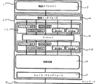
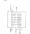
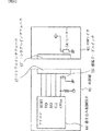
図1は本発明の実施の形態1に係わる通信アダプタ装置の内部構成を示すブロック図である。
図において機器1は家電機器やセンサ装置などであり、機器固有の情報や操作可能な制御項目からなる機器オブジェクト2を保有している。
また、通信アダプタ装置3は、機器1に共通に規定されている機器インタフェース手段4を介し、機器1内の機器オブジェクト2を利用することができる。
機器通信管理手段5は、機器1が保有する機器オブジェクト2の設定や操作、その他の管理機能を有しており、所定の利用手続きによって通信制御手段6と接続される。
通信制御手段6は、ネットワークインタフェース手段7とネットワーク8を経由して他のネットワークに接続された機器との間でデータの授受を行うための通信に関する制御機能を有している。
次に動作について説明する。
ネットワークに接続された他の機器から、通信アダプタ装置3によってネットワーク8に接続された機器1へ、操作コマンドが送信された場合について説明する。
ネットワークインタフェース手段7はネットワーク8から操作コマンドを受信し、通信制御手段6にそれを受け渡す。通信制御手段6は受信に関する種々の手続きをネットワークインタフェース7と連携して実施する。そして取得した操作コマンドを機器通信管理手段5に受け渡すために所定の書式に変換し、所定の手続きを行い、機器通信管理手段5に操作コマンドを受け渡す。機器通信管理手段5は操作コマンドを解析し、機器オブジェクト2の該当する制御項目を設定するために機器インタフェース4を用いて機器1内の機器オブジェクト2の制御項目に関する設定変更を行う。
機器1は機器オブジェクト2の制御項目の設定が変更されたことを検出し、該当する操作を機器1で実施した後、操作により変更された情報項目を変更し、操作コマンドによる一連の動作が完了する。
次に、機器1の機器オブジェクト2の情報項目が変更されたことを他のネットワーク接続された機器に報知する場合の動作について説明する。機器通信管理手段5は、機器インタフェース手段4を用いて定期的に機器オブジェクト2の情報項目の監視を行っており、情報項目の変化を検出した場合には、当該情報項目の変化通報コマンドを生成し、これを所定の書式で作成し、通信制御手段6と所定の手続きを実行し、変化通報コマンドを渡す。
通信制御手段6はネットワークインタフェース手段7と連携し、ネットワーク8に該コマンドを送信するための手続きを行い、変化通報コマンドを他のネットワーク接続された機器に送信完了する。
以上のように、機器通信管理手段5は、機器1に搭載している機器オブジェクト2の管理機能を有しているため、機器1が有するマイコンなどの制御手段で実現する処理機能が軽減され、マイコンリソースに負担をかけずに通信アダプタ装置3を付加することでネットワークから遠隔操作可能な機器を得ることができる。また、機器通信管理手段5は、通信制御手段6との接続手段を所定の書式ならびに手続きで規定しているため、例えば通信プロトコルの変更などが発生した場合でも、規定されたインタフェースに則り、通信制御部を作成することで容易にプロトコル変更が可能な汎用性の高い通信アダプタ装置を得られる効果もある。
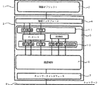
実施の形態2.
図2は、本発明の実施の形態2に係わる通信アダプタ装置の内部構成を示すブロック図である。図1と同一もしくは相当部分には同じ符号を付け、異なる部分について説明する。図において電源管理手段9は、通信アダプタ装置3内の電源の状態、例えば使用可能な電力残量などを管理する機能を有し、その管理状況に応じて通信制御手段6やネットワークインタフェース手段7に所定の制限を加えるよう作用する。
次に動作について説明する。
操作コマンドの受信による動作や、情報変化の通報方式については同様であるため説明を省略する。主に、電源管理に関する動作を説明する。
電源管理手段9が、例えば通信アダプタ装置で使用できる電力残量が残り僅かであることを検出している場合には、電源管理手段9はネットワークインタフェース手段7に自身の電力消費を抑えるモード、例えばスタンバイモードへの移行を指示すると共に、通信制御手段6には通信頻度の抑制を指示し、ネットワークインタフェース手段7がスタンバイモードになった旨の通知を伝える。さらに、電源管理手段9は機器通信管理手段5にも電力残量などの情報を所定の手続きにより与える。
この状態でネットワークに接続された他の機器が、ネットワーク8に該通信アダプタ装置3が接続された機器1宛の操作コマンドを送信した場合、ネットワークインタフェース手段7はネットワーク8上の操作コマンドを、例えばネットワーク8上の信号変化などにより検知し、スタンバイモードから通常の受信動作状態に復旧して受信し、通信制御手段6にそれを受け渡す。通信制御手段6は受信に関する種々の手続きをネットワークインタフェース7と連携した後、取得した操作コマンドを機器通信管理手段5に受け渡すための所定の書式に変換した後、所定の手続きを行い、機器通信管理手段5に操作コマンドを受け渡す。コマンドを受け渡した後、ネットワークインタフェース手段7はスタンバイモードに移行する。機器通信管理手段5は操作コマンドを解析し、機器オブジェクト2の該当する制御項目を設定するために機器インタフェース手段4を用いて機器1内の機器オブジェクト2の制御項目に関する設定変更を行う。
機器1は機器オブジェクト2の制御項目の設定が変更されたことを検出し、該当する操作を機器1で実施した後、操作により変更された情報項目を変更し、操作コマンドによる一連の動作が完了する。
次に、機器1の機器オブジェクト2の情報項目が変更されたことを他のネットワークに接続された機器へ報知する場合の動作について説明する。
機器通信管理手段5は、機器インタフェース手段4を用いて定期的に機器オブジェクト2の情報項目の監視を行うが、電源管理手段9より得た、電源情報に応じて監視する時間間隔を伸ばすなど機器オブジェクト2へのアクセス制限をして、通信アダプタ装置3内でのイベント発生の頻度を抑制する。機器通信管理手段が情報項目の変化を検出した場合には、当該情報項目の変化通報コマンドを生成し、これを所定の書式で作成し、通信制御手段6と所定の手続きを実行し、変化通報コマンドを渡す。
通信制御手段6はネットワークインタフェース手段7を通常動作モードに復旧させた後に連携し、ネットワーク8にコマンドを送信するための手続きを行い、変化通報コマンドを他のネットワーク接続された機器に送信完了する。送信完了後、ネットワークインタフェース手段7は再度スタンバイモードに移行する。
なお、通信制御手段6がネットワークインタフェース手段7にコマンドを渡し、送信させる際、電源管理手段9の検出内容に応じて通信スピードを遅くするなど、更なる消費電力制限の手段を講じても良い。
以上のように、通信アダプタ装置3は電源管理手段9を設け、管理状態に応じた内部の消費電力削減を行うため、例えばセンサ機器など電池駆動である必要のものや機器1から電源の供給を受ける場合など、電源に制約がある場合に制限内での運転確保が可能になるため、機器への電源コスト増加の抑制や電池寿命の延長などの効果が得られる通信アダプタ装置を得ることができる。
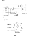
実施の形態3.
図3は、本発明の実施の形態3に係わる機器通信管理手段5の内部構成を詳細化した通信アダプタ装置3のブロック図である。図1、2と同一もしくは相当部分には同じ符号を付け、異なる部分について説明する。図において機器制御アクセス部10は、機器通信管理手段5内に設けられた通信制御手段6と所定の書式ならびに手続きでインタフェースするように構成されている。また、機器インタフェース手段4から機器制御アクセス部10を許可したり禁止したりできるように、許可手段14と禁止手段15が設けられている。
機器インタフェースアクセス部11は、機器通信管理手段5内に設けられた機器インタフェース手段4と所定の書式ならびに手続きでインタフェースするように構成されている。また、通信制御手段6から機器インタフェースアクセス部11を許可したり禁止したりできるように、許可手段12と禁止手段13が設けられている。
次に動作について説明する。
機器1が初期化途中などの状態でネットワークからの操作を受け付けられない場合やメンテナンス中などでネットワークから遠隔操作された場合に危険である場面において、機器オブジェクト2は機器インタフェース4を介して機器制御アクセス部10に対し、禁止手段15を有効にするよう操作し、機器制御アクセス部10が通信制御手段6からアクセス禁止とする。禁止することによりネットワーク8からの不用意な機器オブジェクト2の操作を抑制できる。また、初期化やメンテナンス等が終了し機器オブジェクト2の操作を許可する場合には、機器オブジェクト2は機器インタフェース手段4を介して機器制御アクセス部10に対し、許可手段14を有効にするように操作し、機器制御アクセス部10が通信制御手段6からアクセス許可とする。なお、この許可手段14と禁止手段15は排他的に制御され、一方が有効の場合には、他方が無効となるように動作する。
次に、機器オブジェクト2から機器通信管理手段5へのアクセスを制限する場合について説明する。通信アダプタ装置3の通信設定が未完了である場合には、不用意にネットワークへコマンドを発行したり、コマンド受信による機器オブジェクト2の操作はシステムの誤動作や危険防止のため禁止すべきである。
このような場合には通信制御手段6は機器インタフェースアクセス部11に対し、禁止手段13を有効にするよう操作し、機器インタフェースアクセス部11をアクセス禁止とする。禁止することにより通信手段6が設定途中に誤って受信したコマンドは機器インタフェース手段4へ到達せず、機器オブジェクト2を操作することはできない。また、機器オブジェクト2が機器通信管理手段をアクセスできなくなるため、通信制御手段6へのデータ授受は遮断される。なお、アクセス許可にするには許可手段12を有効に操作することで実現できる。
また、上記説明では不正アクセスの抑制に用いる場合について説明したが、例えば機器通信管理手段5を機器オブジェクト2から機器インタフェース手段4を介して初期化や変更を行っている時、通信手段6からの多重アクセスを禁止する場合に機器制御アクセス部10をアクセス禁止としたり、逆に通信制御手段6から機器通信管理手段5を初期化や変更を行っている時に、機器インタフェースアクセス部11を禁止として、機器通信管理手段5の初期化や変更を安全に行うなどの用途にも使用できる。
以上のように、通信アダプタ装置3の機器通信管理手段5に機器制御アクセス部10と機器インタフェースアクセス部11を設け、おのおの許可と禁止を設定可能としているため、機器1や通信アダプタ装置3の初期化やメンテナンスの際に、安全かつ確実に設定や、メンテナンスの作業が行える、通信アダプタ装置3を得ることができる。
実施の形態4.
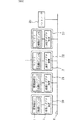
図4は本発明の実施の形態1または2に係わる機器通信管理手段の機能を詳細に記したブロック図である。図1〜3と同一もしくは相当部分には同じ符号を付け、異なる部分について説明する。図には、機器制御アクセス部10ならびに機器インタフェースアクセス部11の内部の具体的な項目が示されている。
機器制御アクセス部10は、通信制御手段6との規定に基づいて規定される機器オブジェクト2のインスタンスやクラス生成、消滅、追加の管理を行うオブジェクト管理部と、機器1の機器オブジェクト2の状態を取得するための方法を設定するための状態取得手続設定手段と、機器1や通信アダプタ装置3が設置されている場所情報などを管理するための設置情報管理手段と、ネットワークの種類などネットワークの属性を管理するネットワーク属性管理手段と、ネットワークの通信帯域(通信容量)などを管理するネットワーク帯域管理手段を有している。
また、機器インタフェースアクセス部11にも機器制御アクセス部10と同様に機器インタフェース4に基づいて規定された同一機能の手段が備わっている。
また、図9は本発明に係わる通信アダプタ装置3と機器1とで構成される通信ノード20または21やセンサ装置と通信アダプタ装置3とで構成されたネットワークセンサ22、23とコントローラ30がネットワーク8をネットワークとして接続されたシステムの構成例を示したものである。
以下、このシステム図に基づいて、初期設定における前記説明した種々の手段の動作について説明する。
通信アダプタ装置3は機器1と接続された際に、例えばコントローラ30の通信ノードとしての種々の情報を開示する必要がある。
機器1内の機器オブジェクト2の情報を取得するには、機器通信管理手段5は機器インタフェースアクセス部11のオブジェクト管理手段を用い、機器インタフェース手段4を介し機器オブジェクト2の情報を逐次取得する。初期化が完了し、機器1が起動した場合には、機器オブジェクト2内のインスタンス変化(起動)を検知するため、機器通信管理手段5はこれをネットワーク8に通報するため、機器制御アクセス部10のオブジェクト管理手段を用い、通信制御手段6にインスタンス変化通報コマンドを送信する。当該コマンドを受け取った通信制御手段6はネットワークインタフェース手段7と連携し、コマンドをネットワーク8に送信する。コントローラ30はこのコマンドを受け、機器1が起動したことを検知する。次にコントローラ30は機器オブジェクト2の種々の状態に対する取得手段の設定を行う。状態の取得方法は、機器1でイベントが発生したときに通報を受ける、あるいは定期的に通信アダプタ装置3が機器1をアクセスし取得した状態を通報する、あるいは、コントローラ30が必要なときにモニタコマンドを発行し、応答から得るなど種々の方法により実現することができる。
そして、コントローラ30は上記説明した方法などから取得方法を決定し、設定コマンドを生成し、ネットワークに送信する。通信アダプタ装置3のネットワークインタフェース手段7はコマンドを受信し、通信制御手段6へコマンドを渡す、通信制御手段6は機器通信管理手段5内の機器制御アクセス部10に設けられた状態取得手続設定手段を所定の手続きにより利用し、コントローラ30から指示された取得方法を機器通信管理手段5に設定する。機器通信管理手段5は機器インタフェースアクセス部11の状態取得手続設定手段を用い、機器インタフェース手段4を介して機器オブジェクト2に同様の設定内容を伝える。ここで機器オブジェクト2に設定内容を伝えることにより、通信アダプタ装置3との間で不整合を生じないようにする。
次に、機器1の設置情報の設定を行う。設置情報の設定は種々の方法が考えられるが、ここではコントローラ30から与える方法について説明する。
コントローラ30はユーザなどから機器1の設置位置が入力されると位置の設定コマンドを生成し、ネットワークに送信する。通信アダプタ装置3のネットワークインタフェース手段7はコマンドを受信し、通信制御手段6へコマンドを渡す、通信制御手段6は機器通信管理手段5内の機器制御アクセス部10に設けられた設置情報管理手段を所定の手続きにより利用し、コントローラ30から指示された設置情報を機器通信管理手段5に設定する。また、機器通信管理手段5は機器インタフェースアクセス部11の設置位置管理手段を用い、機器インタフェース手段4を介して機器オブジェクト2に同様の設定内容を必要に応じ伝えることも可能である。
また、設置位置情報が機器1から入力された場合には上記と逆の経路により、コントローラ30に機器の設置情報を提供することが可能である。
次に、通信アダプタ装置3が保有するネットワーク属性をコントローラ30や機器1へ報知する方法について説明する。
ネットワーク属性(ネットワークの種別や物理アドレス)などネットワークインタフェース手段7に関連する項目については、個体識別や、媒体による応答時間などの差異を、各々の制御プログラムにおいて補正するためにコントローラ30、通信アダプタ装置3は共有する必要がある。この情報は、機器通信管理手段5が機器制御アクセス部10のネットワーク属性管理手段を用いて、通信制御手段6とネットワークインタフェース手段7から取得できる。この情報をコントローラ30に報知するには、機器通信管理手段5が機器制御アクセス部のネットワーク属性管理手段を用いて、通信制御手段6に属性情報を受け渡し、通信制御手段6は該当するコマンドをネットワークインタフェース手段7に発行し、ネットワーク8にコマンドを送信する。このコマンドをコントローラ30が受信し、ネットワーク属性に関する情報を取得する。また、この情報を元に機器通信管理手段5は、機器インタフェース手段4を経由して機器オブジェクト2をアクセスする間隔などを設定する。
次に、ネットワーク帯域の設定方法を説明する。
ネットワーク帯域については、システムで必要とされる帯域の設定や、通信アダプタ装置3の制約から規定される設定値の報知、あるいは機器1が要求する帯域の設定など、設定には種々の目的、用法がある。これら種々の用法、目的に対応するため、ネットワーク帯域管理手段は通信制御手段6側すなわちネットワーク経由でコントローラ30などから設定する経路として、機器制御アクセス部10に設けたネットワーク帯域管理部を設け、また、機器1側からの要求に応じて設定が行えるように、機器インタフェースアクセス部11にもネットワーク帯域管理部を設けている。これら手段を設けることにより、ネットワーク経由の設定、通信制御手段6やネットワークインタフェース手段7内部での制約、機器1からの設定に対応可能となっている。これら部位から機器通信管理手段5への設定方法については前述の属性等と同様に行える。また、これら設定値を各部位で利用するためのアクセス方法も前述のネットワーク属性と同様な方法であるため説明を省略する。
以上のように、オブジェクト管理手段、状態取得手続設定手段、設置情報管理手段、ネットワーク属性管理手段、ネットワーク帯域管理手段を設け自在にアクセス可能に構成しているためシステム設定などコントローラとの情報共有が容易に行うことが可能で、かつ、情報は通信アダプタ装置3内の機器通信管理手段5が管理するため、機器1に負担をかけることなく、機器をネットワーク対応のノードにすることを可能にする通信アダプタ装置3を得ることができる。
実施の形態5.
図5は、本発明の実施の形態1または2に係わる機器通信管理手段の機能を詳細に記したブロック図であり、主に設置調整時などに用いる機能を説明したものである。
機器制御アクセス部10ならびに機器インタフェースアクセス部11には、機器通信管理手段5が管理する機器オブジェクト2の稼動開始および停止の設定、ならびに前記機器オブジェクト2の稼働、停止状態の取得手段を有し、機器インタフェースアクセス部11から通信制御部6の稼働ないし停止を設定及び状態の取得手段を設け、また、機器通信管理手段5で管理する機器オブジェクト2の仮想的に操作設定する手段と仮想的に機器を設定する手段を設けている。
次に動作について説明する。
機器1が未接続の状態の場合、通信アダプタ装置3のみでシステムの設定、ならびに試運転を行う手順に基づいて説明を行う。
図9に示したコントローラ30は通信アダプタ装置3に接続機器の設定コマンドを送信する。このコマンドは、ネットワークインタフェース手段7を経由し、通信制御手段6により解釈され、機器制御アクセス部10の接続機器設定手段に情報を与える。機器通信管理手段5内にはこの情報を元に仮想的な機器が生成される。以降、コントローラ30は通信アダプタ装置3に生成された仮想的な機器を機器制御アクセス部10に設けている仮想的に操作設定する手段を用いてシステムの試運転や設定を行うことが可能となる。
また、システムの検証などを実施する際に、特定の機器オブジェクトを故意にシステムから離脱させたり、再接続させたりする動作が必要な場合が発生する。このような用途のために、機器通信管理手段5には管理している機器オブジェクト2の稼動開始、停止の設定やその状態の取得が行える手段を設けている。機器オブジェクト2を停止する際には、機器通信管理手段5の機器制御アクセス部に設けた停止手段を所定の手続きでアクセスし、機器通信管理手段5にその指示を伝える。機器通信管理手段5は機器インタフェースアクセス部11の停止手段を用い機器インタフェース4を介して、機器オブジェクト2の停止を行う。また逆に、稼動開始とするには、上記停止手段の代わりに起動手段を用い同様な方法で機器オブジェクト2を稼動状態にすることが可能である。
以上のように、機器オブジェクト2の起動、停止を自在に制御可能に構成し、かつ通信アダプタ装置3単独で仮想機器による動作検証が行えるように通信アダプタ装置3を構成したので、施工時に機器が稼動状態でない場合でのシステム設定が容易に実施でき、かつシステム開発時の検証作業が効率的に行える、通信アダプタ装置を得ることができる。
実施の形態6.
図6は本発明の実施の形態1または2に係わる機器通信管理手段5の機能を詳細に記したブロック図であり、主に通信アダプタ装置3の交換などでの便宜を図るための機能についてあらわしている。
機器通信管理手段5内の機器制御アクセス部10ならびに機器インタフェースアクセス部11には、機器1内の機器オブジェクト2内に設けている不揮発性のメモリにアクセスするための手段として、メモリ書込制御手段ならびにメモリ読出手段が設定されている。
以下に動作について説明する。
通信アダプタ装置3はネットワーク通信で必要となるアドレスなどの情報や実施の様態3で示した種々の設定値を保有し、機器1と一体となり通信ノードを構成している。
通信アダプタ装置が何らかの要因により故障した場合には通信アダプタ装置3の交換作業が必要になる。本発明の通信アダプタ装置3は前記の設定内容を機器オブジェクト2のメモリに以下の手順で記憶する。
設定情報はすべて機器通信管理手段5が保有しており、設定完了時に機器インタフェースアクセス部11のメモリ書込制御手段により機器インタフェース4を経由し設定情報を機器オブジェクト2内のメモリに記憶させる。
次に、通信アダプタ装置3が交換された場合、機器通信管理手段5は機器インタフェースアクセス部11のメモリ読出制御手段を用い、機器オブジェクト2のメモリをアクセスし設定情報を取得する。機器通信管理手段5は取得した設定内容をデータベース5保持すると共に、通信制御手段6やネットワークインタフェース手段7に必要な情報の提供を行う。提供の方法は、機器制御アクセス部10内のメモリ読出制御手段を用い、通信制御手段6経由で設定内容を通知する。このようにして通信アダプタ装置3単独で設定値の復元を行うことが可能である。
また、機器通信管理手段5が管理していない情報について、例えば通信制御手段内部の情報などを機器オブジェクト2に記憶するためには機器制御アクセス部10内のメモリ書込制御手段を用い機器通信管理手段5経由で書き込みを行う。
以上のように、通信アダプタ装置3内の情報を、機器1内の機器オブジェクトに一時記憶させることが可能に構成したため、通信アダプタ装置3の交換などで従来必要であったシステムの再設定などを行う必要がなく、容易に交換可能な通信アダプタ装置3を得ることができる。
実施の形態7.
図7は、本発明の実施の形態1または2に係わる機器通信管理手段5の機能を詳細に記したブロック図であり、主に通信アダプタ装置3が検出する各種異常状態において、異常部位の特定が容易に可能なように、機器通信管理手段5に異常内容を提供する手段を設けている。
ネットワーク8に関する異常を提供するネットワークインタフェース異常手段、通信制御手段6の異常を提供するための通信制御異常手段、機器インタフェース手段4に関する異常を提供するための機器インタフエース異常手段、機器の異常を提供するための機器異常手段がそれぞれ設けてある。
次に動作について説明する。
機器通信管理手段5はネットワークインタフェース手段7、通信制御手段6、機器インタフェース4、機器1(機器オブジェクト2)からなる各構成部位で検出した異常情報を機器制御アクセス部10ならびに機器インタフェースアクセス部11を経由して収集し、逐次情報を更新しながら一元管理している。例えば図9に示した通信ノード20の機器1で発生している異常をコントローラ30がネットワーク経由で調査する場合には、機器通信管理手段5の機器異常手段をアクセスするためのコマンドを発行することで、ネットワークインタフェース手段7と通信制御手段6を介して、機器異常の取得コマンドが実行され、機器通信管理手段5の管理する、機器異常のデータが通信制御手段6とネットワークインタフェース手段7、ネットワーク8を経由しコントローラ30に提供される。機器インタフェース手段4の異常の取得についてもアクセス先を機器インタフェース異常手段に変更し、同様な手順で情報の取得が可能である。
また、ネットワーク8に関連した異常に関しては、ネットワーク経由での情報の提供が不可能である場合があるため、ここでは機器オブジェクト2に表示の機能が備わっているものとして説明を行う。機器オブジエクト2は機器インタフェース手段4を利用し、機器インタフェースアクセス部11のネットワーク異常手段あるいは通信制御異常手段をアクセスし、機器通信管理手段5から通信制御手段6あるいはネットワークインタフェース手段7の異常情報を取得する。何らかの異常を検知した場合には異常内容に応じた表示などを実施する。
以上のように、通信アダプタ装置3内部で検出可能な異常状態を区分してネットワーク8あるいは機器1に報知する手段を有しているため、システムの不具合が生じたときの障害が機器の故障に起因するのか、通信アダプタ装置3の故障に起因するのか、通信アダプタ装置3の異常については機器インタフェース手段4の故障に起因するものなのか、通信制御手段6の異常なのかなどが容易に判別可能なため、不具合箇所の特定が効率的に実施可能であり迅速なシステム復旧が可能な通信アダプタ装置を得ることができる。
実施の形態8.
図8は、本発明の実施の形態2に係わる機器インタフェース手段4を経由して機器1から給電され、動作する場合のブロック構成図である。図1〜7と同一もしくは相当部分には同じ符号を付ける。
機器制御アクセス部10ならびに機器インタフェースアクセス部11には、機器オブジェクト2を利用する手段のほかに、電源管理手段9の種々の状態を提供する状態提供手段、ならびに電源管理手段9を制御するための電源制御手段、電源供給能力などを取得するための電源能力取得手段が設けられており、
また、これらの情報により通信制御手段に制限を制御するための通信制限制御手段が設けてある。
ネットワークインタフェース手段7は、ネットワーク8へのインタフェース機能と、自身の電力消費を制限可能な機能、例えばスタンバイモードへの移行や復帰、伝送スピードの変更、などの機能を有している。(また、一般的にネットワークインタフェース手段は送信動作時に電力消費が大きくなることが既知となっている。)
電源管理手段9は、充放電制御部と制御部を有し、機器インタフェース手段4から電源の供給を受け、この電力を充電する機能ならびに必要に応じて各部への電源を供給する機能ならびに、現在の充電量に基づいた供給可能電力容量の提供する機能を有している。
次に動作について説明する。
通信アダプタ装置3は立ち上がり時に機器1の機器オブジェクト2を機器インタフェース手段4経由で機器インタフェースアクセス部11の電源能力取得手段を用いてアクセスし、機器1から供給可能な電源の容量を機器通信管理手段5内に取得する。また、機器制御アクセス部10の電源容量取得手段を用いて通信制御手段6やネットワークインタフェース手段7の動作に必要な電源容量データを取得保持する。
電源管理手段6は取得した供給される電源容量の情報と動作に必要な電源容量を機器制御アクセス手段10内の電源容量取得手段をアクセスし取得し、充放電のデューティや通信制御手段の省電力制御の方式を設定する。
例えば、供給可能な電力が1の期間で動作に必要な電力が3の場合、充電を3行った後に1の期間、通信制御手段6やネットワークインタフェース手段7の動作を許可するなどの制御を、機器制御アクセス手段を用いて実施し、供給される電力の範囲内で通信アダプタ装置3の動作を制御する。
アプリケーションによりこのような間欠動作が許されない場合には、通信制御手段6は電源管理手段9の管理する充放電制御部の状態を、機器制御アクセス部10を介して機器通信管理手段5から取得し、通信制御手段6がデータの送信要求のイベントがある毎に、前記電源管理手段9の情報を監視し、送信動作が可能な充電状態に達しているかを判断し、ネットワークインタフェース手段7のモードを制御する。送信可能な状態にない場合は、機器通信管理手段5は送信イベントの発行元に送信待機中である旨の情報を、通信制限手段を通じて提供可能としている。また、受信動作に関しては、ネットワークインタフェース手段7をスタンバイモードに制御し、ネットワーク8の例えば信号変化などにより、通常モードに制御するなどして受信動作を起動するよう作動する。ただし、この受信の場合でも電源管理手段9、充放電制御部の充電状況が受信動作に不十分である場合には通常モードへの移行も通信制限手段を介して行うことができる。
また、機器通信管理手段5は電源管理手段の電源状態を機器インタフェースアクセス部11に設けた状態提供手段により機器オブジェクト2に電源の状況を提供することにより、機器オブジェクト2が自発的に送信イベントを発生する機能を有する場合にはこれを制限し、送信の電力を抑制することも可能である。
また、機器通信管理手段5が機器オブジェクト2へのアクセスを管理する場合には、把握している電源状態に応じて、機器インタフェースアクセス部11の通信制限手段を用い、機器インタフェース4を介して機器オブジェクト2をアクセスする頻度や時間間隔を調整し、送信イベント発生の頻度を電力容量に応じて調整可能となる。
以上のように、機器1から限られた電源供給しか受けられない場合にも、通信アダプタ装置3に設けた電源管理手段9と機器通信管理手段5内に設けた、種々の情報の提供手段や通信制限制御手段により、供給可能な電力の範囲で通信アダプタ装置3の運転が可能となり、家電機器をネットワーク接続するために通信アダプタ装置を付加する際に、電源工事が不要であり、施工が容易に可能な通信アダプタ装置を得ることができる。
実施の形態9.
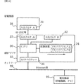
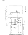
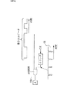
図10は、本発明の実施の形態9に係る通信アダプタを用いたシステムの構成図である。
図において家電機器38には接続コネクタA31が配設され、これを介して通信アダプタ32と属性情報のやり取りを行う。以下、この接続コネクタを入出力インタフェース(入出力I/F)と呼称する。
また、通信アダプタ32は、家電機器38と属性情報のやり取りを行うための入出力インタフェースA37及びB33と、Ethernet(登録商標)などのネットワーク39を介して他の家電機器やパーソナルコンピュータなどの電気機器40と情報のやり取りを行うためのネットワークインタフェース35と、入出力インタフェースA37及びB33とネットワークインタフェース35の間で情報のやり取りを行うと共に、この情報を処理するCPU36と、入出力インタフェースA37やB33に繋がる家電機器に使用されている入出力方式に対応し、入出力インタフェースのハードウェアを制御するドライバソフトウェアA、Bが格納されている記憶装置34から構成されている。
入出力インタフェースA、Bは、全て同じ型の接続コネクタであって、これに繋がる家電機器の入出力方式に対応した形式が選択される。ここでは、簡単のためシリアル入出力と接点入出力のいずれかの形式が選択される場合について説明する。
図11は、通信アダプタ32に、入出力方式の異なる二つの家電機器38、38’が接続されている様子を示したものである。図において家電機器38、38’の入出力インタフェースはそれぞれシリアル入出力形式、接点入出力形式に対応している。
またシリアル入出力形式のインタフェースを備えている家電機器38には、インタフェース用の電源が用意されており、入出力インタフェースの特定の端子(以下、これを特定端子と呼称する)に対して電源電圧信号を供給する。
次に図10、11を参照しながら通信アダプタ32の動作について説明する。
CPU36は、複数の入出力インタフェースのそれぞれ(図11のケースでは二つの入出力インタフェースA37、B33)に対し、特定端子に電源電圧信号が供給されてないかどうかをチェックする。そして入出力インタフェースに家電機器が接続され、チェックしている特定端子から電源電圧信号が検出された場合には、CPU36は、接続されている家電機器38の入出力形式はシリアル入出力形式であると判定し、記憶装置34に格納されているシリアル入出力形式のインタフェースのハードウェアを制御するドライバソフトウェアAを起動する。このドライバソフトウェアAの起動により、接続されている家電機器38との間で通信が行われ、家電機器38から属性情報を読み出す。この属性情報は、CPU36を介して記憶装置34に格納される。そして格納された属性情報は、家電機器38をアクセスして様々な情報を入手したり、制御したりするために活用される。
一方、入出力インタフェースに家電機器が接続されて、チェックしている特定端子から電源電圧信号が検出されなかった場合には、CPU36は、接続されている家電機器38’の入出力形式は接点入出力形式であると判定する。そしてCPU36は接続されている入出力インタフェースに対し、記憶装置34に格納されている接点入出力形式のインタフェースハードウェアを制御するドライバソフトウェアBを起動させる。このドライバソフトウェアBの起動により接続されている家電機器38’との間で通信が行われ、家電機器38’から機器種別、消費電力などの属性情報を読み出す。この属性情報は、CPU36を介して記憶装置34に格納される。そして格納された属性情報は、家電機器38’をアクセスして様々な情報を入手したり、制御したりするために活用される。
このような構成により、通信アダプタ32に接続された家電機器に対応する入出力インタフェースの形式が判定され、これに対応したインタフェースハードウェアを制御するドライバソフトウェアが起動される。
そしてこのドライバソフトウェアの起動により接続された家電機器に関する属性情報は、CPU36を介して記憶装置34に格納されるようになる。このようにしてバーコードやバーコードリーダを用いずに、属性情報を通信アダプタ32に自動的に設定することができる。
なお図では、通信アダプタ32に二つの入出力インタフェースA37、B33が設けてある場合について説明したが、これ以上設けてある場合も同様である。また、シリアル入出力形式、接点入出力形式以外の入出力形式がある場合も同様な方法によって判定できる。
実施の形態10.
実施の形態9では、接続された家電機器の入出力形式が、シリアル入出力/接点入出力のいずれかであるかを判定し、家電機器の属性情報を取得する場合について説明した。
本実施の形態では、接続された家電機器の入出力インタフェースがシリアル入出力形式の場合に限り、クロック同期型/クロック非同期型のいずれかであるかを判定し、家電機器の属性情報を取得する場合について説明する。
図12は、クロック同期型のシリアル入出力インタフェースを備える家電機器38と通信アダプタ32が接続している様子を示したものである。図においてVCC、TX、RX、GND、CLKは、それぞれ電源電圧信号端子、送信信号端子、受信信号端子、グランド端子、クロック信号端子を表している。
ここでシリアル入出力形式の家電機器において、クロック同期型のものは、通信アダプタ32からクロック信号を供給されないとシリアル通信ができないが、クロック非同期型のものは、通信アダプタ32からクロック信号を供給されなくてもシリアル通信が可能である。このため、図12に示すように入出力インタフェースには、クロック同期型のシリアル入出力インタフェースが接続された場合でも、通信シーケンスが成立するように、クロック信号を供給する特定のCLK端子が設定されている。
次に、通信アダプタ32の動作について説明する。
CPU36は、実施の形態9で示したような方法で、家電機器のシリアル入出力形式を判定した後、クロック信号なしで家電機器と通信できるクロック非同期型のドライバソフトウェアを起動させると共に、CLK端子にクロック信号を供給せずに、家電機器との通信を試行する。
この結果、通常の通信シーケンスが実現できることが確認されれば、クロック非同期型であると判定され、このままドライバソフトウェアを替えずに通信を続ける。
一方、通信できない場合には、通信アダプタ側はクロック同期型のドライバソフトウェアに変更し、家電機器に対し、CLK端子を介してクロック信号を供給して通信を試行する。このようにして、通信アダプタ32は、シリアル入出力形式のクロック同期型/クロック非同期型を判定し、自動的に切り換える。
クロック同期型/クロック非同期型が切り換えられた後は、通信アダプタ32に接続されている家電機器38’との間で通信を行い、機種名、消費電力などの属性情報を読み出す。この属性情報は、CPU36を介して記憶装置34に格納される。そして格納された属性情報は、家電機器38’をアクセスして様々な情報を入手したり、制御したりするために活用される。このようにしてバーコードやバーコードリーダを用いずに、属性情報を通信アダプタ32に自動的に設定できる。
なお図では、通信アダプタ32に対して二つの入出力インタフェースA37、B33が設けてある場合について説明したが、これ以上設けてある場合も同様である。
実施の形態11.
実施の形態9、10では、通信アダプタ32が、接続された家電機器の入出力形式、あるいはクロック同期/クロック非同期を判定した後、家電機器の属性情報を取得する場合について説明した。
本実施の形態では属性情報を取得した後、システムの拡張などにより属性情報の変更が必要となったり、監視、制御を行うことが必要となった場合について説明する。
これは、バーコードやバーコードリーダーを用いずに、パソコンなどの電気機器からネットワーク39を介して属性情報を変更するというものである。即ち、図10に示す接続形態において、ネットワーク39に接続された電気機器40から、家電機器38に対する属性情報やドライバソフトウェアを変更したり、監視、制御を行ったりするというものである。以下、動作について説明する。
まず、ネットワークに接続された電気機器からみて、記憶装置34に格納されている属性情報やドライバソフトウェアが既知である場合の変更について説明する。
この場合、ネットワークに接続された電気機器から、通信アダプタ32に向けて、変更する属性情報やドライバソフトウェアが記載された送信フレーム(電文)を送信するだけで十分である。
この電文を受け取ったCPU36は、例えば、使用中のドライバソフトウェアを直ちに終了させると共に、記憶装置34に格納されているドライバソフトウェア群の中から指定されたドライバソフトウェアを読出し、起動させる。
このように記憶装置34に格納されている属性情報やドライバソフトウェアが既知であれば、バーコードやバーコードリーダなどを用いずに、ネットワークに接続された電気機器から電文を送信するだけで、簡単に変更できる。
次に、ネットワークに接続された電気機器からみて、記憶装置34に格納されている属性情報やドライバソフトウェアが未知である場合の変更について説明する。
この場合、電気機器40が家電機器38に対する属性情報の変更や監視、制御を行うことができるように、通信アダプタ32は、ネットワーク39に対して、通信アダプタ32に接続されている家電機器38が何であるか、どのような情報を受信したり、どのような監視、制御ができるのかを調べて開示する必要がある。
図13は、接続されている家電機器38の属性情報をネットワーク39に対して開示する手順を示したものである。
以下、通信アダプタ32の記憶装置34内には、各種家電機器の制御プログラムが格納されているものとして、手順を説明する。
まず家電機器38が通信アダプタ32に接続された後、入出力インタフェースA37を介して、家電機器38の情報を取得するための要求からなる要求フレーム1(家電機器情報取得要求1)を生成して家電機器38へ送信し、この要求フレーム1に対する家電機器38からの応答を待つ(ステップS1)。
家電槻器38は要求フレーム1を受けると、通信アダプタ32に対して、自身(家電機器38)の名称(コード番号)を返信する。通信アダプタは、返信された家電機器からコード番号を受け取り(ステップS2)、このコード番号に基づいて、記憶装置34に格納されている制御プログラム群のうち、該当する家電機器の制御プログラムを抽出して設定する。
このステップを経て、通信アダプタ32は、入出力インタフェースA37に接続されている家電機器38が何であるかを知り、また家電機器38に関する属性情報や監視・制御可能な情報を設定することができる。
そして、このようなステップは、通信アダプタの全ての入出力インタフェースに対して併行して行われ、通信アダプタは、自身に接続されている全ての家電機器に対する属性情報や監視・制御可能な情報を設定することができる。
次に、このようにして情報が設定された通信アダプタ32に対し、ネットワーク39に接続された電気機器40から、通信アダプタ32に接続されている家電機器の属性情報を変更したり、監視、制御したりすることを考える。
この場合、電気機器40は、まず通信アダプタに接続された家電機器に対する情報を取得するための要求からなる要求フレーム2(家電機器情報取得要求2)を生成し、通信アダプタ32に送信する。
通信アダプタ32は、要求フレーム32(家電機器情報取得要求)に対する応答として、接続されている全ての家電機器の属性情報や監視・制御可能な情報をもとに、応答フレーム(家電機器属性情報応答)を生成し、返信する。この通信アダプタからの応答フレームによって、電気機器40は、ネットワーク39にどのような家電機器38が接続されているかが判断でき、これに関する属性情報や監視・制御可能な情報を取得することができる(ステップS3)。そして、取得された情報をもとに家電機器の属性情報や監視・制御を変更するのは、前述の既知の場合と同様、変更内容を記載した電文を送信するだけで十分である。
このようにしてバーコードやバーコードリーダを用いずに、取得した情報をもとに、ネットワーク39に接続された電気機器40から、通信アダプタに接続されている家電機器の属性情報を変更したり、監視・制御したりすることができるようになる。
なお、ここでは、通信アダプタ32の記憶装置34内には、各種家電機器に対する制御プログラム群が格納されており、通信アダプタと家電機器間の入出力インタフェースを介して、通信アダプタが接続されている家電機器を判定する場合について説明したが、ネットワーク39に接続されたパソコンなどの電気機器から、通信アダプタ32に向けて、通信アダプタの入出力インタフェースに接続されている家電機器を設定するフレームを送信するようにしても良い。このようにすれば、送信されてきたフレームに基づいて、該当する家電機器の制御プログラムを設定したり、変更したり、応答フレームを構築したりすることが出来る。
実施の形態12.
電気機器として、家電機器を外部ネットワークに接続するための通信アダプタを例に取り上げて説明する。
図14は、本実施の形態に係る電気機器(通信アダプタ)41を介して家電機器46が外部ネットワークに接続されている様子を示したものである。
図において電気機器(通信アダプタ)41は、Ethernet(登録商標)などの外部ネットワークと接続される外部ネットワークインタフェースと、不揮発性メモリを内蔵したマイコンと、家電機器46に接続されるシリアルインタフェース47とから構成されている。また家電機器46には電気機器(通信アダプタ)41と接続するためのシリアルインタフェース47が配設されている。
このような構成のもと電気機器(通信アダプタ)41は、外部ネットワークインタフェースからの制御信号に応じて自身に繋がる家電機器46を操作したり、家電機器46の状態をモニタしてこの情報を外部ネットワークに接続された他の電気機器へ通知したりする。
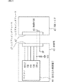
図15は、電気機器41に内蔵された不揮発性メモリに対するプログラムの書込み動作を説明するためのものである。図において電気機器41のシリアルインタフェース47には、家電機器46の替わりに、不揮発性メモリにプログラムを書込むためのROMライタ42が接続されている。
また電気機器41には、書込み制御端子CNVss44が配設されており、これが低電位レベル“L”にプルダウンされた時、書込みモードに切換るマイコンが搭載されているものとする。
以下、図に基づいて不揮発性メモリに対するプログラムの書込みについて説明する。
電気機器41の書込み制御端子CNVss44は、通常、電圧VCCでプルアップされている。そしてこのプルアップされた書込み制御端子CNVss44と接地端子(以下、「GND端子」という)はシリアルインタフェース47に出力されている。
一方、ROMライタ42のシリアルインタフェース47´には、電気機器41とROMライタ42が接続された時、書込み制御端子CNVss44とGND端子が短絡される短絡回路45が配設されている。
したがって電気機器41とROMライタ42を接続することにより書込み制御端子CNVss44は短絡されて低電位レベル“L”となり、マイコンは書込みモードとなり、シリアルインタフェース47に配設されたTXD(Transmitted Dataの略)端子やRXD(Received Dataの略)端子を介し、不揮発性メモリに対して新しいプログラムを書込むことができる。
また本実施の形態では、書込み制御端子CNVss44を低電位レベル“L”にプルダウンすることで、書込みモードとなるマイコンについて説明したが、書込み制御端子CNVss44をマイコンの動作電圧(5V)や回路基板上の共用電源ライン(12V)などの所定電圧にプルアップすることで、書込みモードに切換るマイコンの場合も同じである。
即ちこの場合、図16に示すように、書込み制御端子CNVss44は、通常接地されている。そして電気機器41側のシリアルインタフェース47には、書込み制御端子CNVss44と共に、所定電圧が出力されている端子が配設されている。一方、ROMライタ42側のシリアルインタフェース47´には、電気機器41とROMライタ42が接続された時、所定電圧の端子と書込み制御端子CNVss44が短絡される短絡回路が設けてある。このような構成により上記と同じROMライタ42を用いて、書込みモードに切換えることができる。
このように本発明に係る不揮発性メモリを内蔵した電気機器41は、書込み制御端子CNVss44と、これを切換えるための所定電圧が出力された電圧端子を、シリアルインタフェース47に配設するように構成した。そしてROMライタ42のシリアルインタフェース47´は、電気機器41と接続された時、書込み制御端子CNVss44と当該電圧端子が、短絡するように構成した。
この結果、シリアルインタフェース47と47´を接続すると、マイコンの仕様(プルダウン、プルアップ)とは関係なく、必ず書込みモードへと切換り、TXD端子やRXD端子を介して新しいプログラムを書込むことができる状態に移行する。このようにして、汎用性の高い、ROMライタ42と、電気機器と、これらを用いた書込み方法を提供することができる。
また本実施の形態では、電気機器として通信アダプタを取り上げて説明したが、これに限るものでない。例えば電気機器がエアコンや電子レンジなどの家電機器であり、この家電機器に内蔵されたマイコンの不揮発メモリに新しいプログラムを書き込むため、家電機器に配設されたシリアルインタフェース47に、ROMライタ42を接続してプログラムを書き込む場合も同様である。
また本実施の形態では、書込み制御端子CNVss44が一つの場合について説明したが、複数ある場合も同様である。それぞれに対してGND端子と書込み制御端子を短絡する回路をROMライタ42側に設けるようにすれば良い。
なお本実施の形態では、書込み制御端子CNVss44とGND端子を直接短絡する回路を設けた場合について説明したが、電気機器41とROMライタ42が接続された時、電気機器41の書込み制御端子CNVss44と低電位レベル“L”が短絡されるのであれば、どのような構成であっても構わないことは言うまでもない。
以下の実施の形態では、接続された時に書込み制御端子CNVss44が短絡される様々なケースについて述べている。
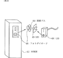
実施の形態13.
実施の形態12では、短絡回路45を介して、書込み制御端子CNVss44とGND端子を短絡し、マイコンを書込みモードに設定したが、図17に示すように、書込み制御端子CNVss44にフォトダイオード48を接続し、ROMライタ42にLED49を搭載し、ROMライタ42を電気機器41のシリアルインタフェース47に接続し、新しい制御プログラムを書込むときに、LED49を点灯させ、フォトダイオード48に光電流を流れさせ、書込み制御端子CNVss44を低電位レベル“L”にするようにしても良い。
またROMライタ42と電気機器41のシリアルインタフェース47における接続部分の構造としては、例えば、図18に示すように通常使用時、外光等により書込みモードにならないように、遮蔽ゴム50などで覆い、ROMライタ42による書込み時に、ROMライタ42側のLED49で遮蔽ゴムを押し抜くことでLED49の光がフォトダイオード48によって受光される構造にすれば良い。
以上のように本実施の形態に係る電気機器は、マイコンを書込みモードへ切換えるための低電位レベル“L”を用意し、フォトダイオードが受光した時に低電位レベル“L”となるように構成したので、実施の形態12と同様、ROMライタ42はLEDなどの発光素子を有するだけで良いことになり、ROMライタ42を電気機器41のマイコンの仕様に合わせて変更する必要がなくなり、汎用性の高い、ROMライタ42と、電気機器と、これらを用いた書込み方法を提供することができる。
実施の形態14.
実施の形態13では、フォトダイオード48を用いた光による結合構造を説明したが、図19に示すように、受光素子として、フォトトランジスタ51を用いても良い。LED49を点灯させ、フォトダイオード48の替わりにフォトトランジスタ51に光電流を流れさせることにより書込み制御端子CNVss44をGNDレベルにするものである。この場合の効果も実施の形態12で説明したものと同じである。
実施の形態15.
実施の形態1では、短絡回路45を介して、書込み制御端子CNVss44を短絡し、書込み制御端子CNVss44を書込みモードの電圧レベルに設定したが、図20に示すように、書込み制御端子CNVss44に押し込まれた時にONとなる機構スイッチ52を接続し、これをシリアルインタフェース47から露出しておく、ROMライタ42には、スイッチを押し込むことができるような凸部を設け、ROMライタ42を本体部のシリアルインタフェースに接続した時に、ROMライタ42側に設けた凸部によりスイッチをONすることができるようにしても良い。この場合の効果は実施の形態12で説明したものと同じであり、説明を省略する。
実施の形態16.
実施の形態12では、短絡回路45を介して、書込み制御端子CNVss44を短絡し、書込み制御端子CNVss44を書込みモードの電圧レベルに設定したが、図8に示すように、書込み制御端子CNVss44に、リレー53の通常時オープンの接点を接続し、リレーのコイル制御線を、シリアルインタフェース47側に端子として出力し、ROMライタ42を電気機器41のシリアルインタフェース47に接続した時に、このコイル制御線に、リレーが動作する電圧が印加されるようにすることにより、リレーをON制御し、書込み制御端子CNVss44をGNDレベルにするようにしてもよい。この場合の効果も実施の形態12で説明したものと同じである。
実施の形態17.
実施の形態12では、短絡回路45を介して、書込み制御端子CNVss44を短絡し、書込み制御端子CNVss44を書込みモードの電圧レベルに設定したが、図22に示すように、書込み制御端子CNVss44に、室温ではオープンになるような感温リードスイッチ55を接続し、ROMライタ42側にヒータ54を設け、ROMライタ42を電気機器41のシリアルインタフェース47に接続する時に、ヒータをONし、接続時にヒータの熱により、感温リードスイッチ55を短絡モードにすることにより、書込み制御端子CNVss44をGNDに接地し、電気機器41のマイコンを書込みモードに設定しても良い。この場合の効果も実施の形態12で説明したものと同じである。
実施の形態18.
実施の形態17では、感温リードスイッチ55により、図23に示すように、書込み制御端子CNVss44を制御したが、磁気リードスイッチ56で制御しても良い。ROMライタ42側は、永久磁石または電磁石57を用意し、ROMライタ42を電気機器41のシリアルインタフェース47に接続した時に、永久磁石57により、短絡モードにすることにより、電気機器41のマイコンを書込みモードに設定しい。
また、ROMライタ42側が、永久磁石ではなく、電磁石の場合には、ROMライタ42を電気機器41のシリアルインタフェース47に接続する時に、コイルに通電することで磁力を発生させ、磁気リードスイッチを短絡させても良い。この場合の効果も実施の形態12で説明したものと同じである。
実施の形態19.
実施の形態12〜18では直接短絡する方法について説明してきたが、本実施の形態では、ROMライタ42からTXD端子へ送信するデータ信号に、書込み制御端子CNVss44をGNDレベルに短絡させる制御信号を重畳させ、電気機器41内にてこの制御信号を分離・抽出することによって短絡する方法について説明する。
最初に本実施の形態におけるROMライタ42の構成と働きについて説明する。
図24はROMライタ42における信号の生成を説明するための図である。
図においてTXD端子へ送信されるデータの転送速度よりも十分に大きな速度のクロック源に基づいてカウンタ回路から信号61が生成される(例えば、TXD端子へ送信されるデータの転送速度が1bit/104usに対し、クロック源の速度が1bit/1us であるなど)。そして信号61とTXD端子へ送信されるデータ信号はAND回路に入力され、二つの信号の論理積(AND信号)が作られる。
次に本実施の形態における電気機器41の構成と働きについて説明する。
図25は、電気機器41に追加された構成要素とその働き(ROMライタ2から送信されてきた信号をデータ信号と制御信号に分離し、書込み制御端子CNVss44を短絡する)について説明する図である。
図14と比べると電気機器41には、新たにローパスフィルタ(以下、「LPF」という)と、イネーブル(ENA)付きのDフリップフロップ(以下、「DFF」という)が追加されている。
以下、信号の流れに沿って動作を説明する。
上記のようにしてROMライタ42によって作られたAND信号(信号58)は、二つに分岐され、一つはLPFに入力される。LPFに入力された信号58は、ここで高周波成分である幅の小さいパルスなどが除かれる。この結果、LPFから出力された信号は、信号59に示すように、立上りと立下りで多少なまるもののAND回路に入力される前の元の信号を再現する。そしてこの信号59は、TXD端子へ入力される。
一方、LPFを通過した後に分岐された信号は、さらに分岐され、それぞれDFFのENA(ENABLEの略)端子とデータ入力端子(D端子)に入力される。またLPFを通過する前に分岐された信号は、そのままCLK端子に入力される。
ここで、DFFでは、ENA端子の入力が高電位レベル“H”の間、CLK端子から入力される波形の最初の立ち上がりを捉えて、D端子の入力をラッチする。即ち、この時のD端子へ入力された高電位レベル“H”が、そのまま出力端子(Q端子:図示せず)の出力として出力される。したがって反転出力端子(Qn端子)からの出力は、信号60に示すように、この高電位レベル“H”を反転させた低電位レベル“L”となる。このことは、CLK端子から入力される波形の最初の立ち上がりを捉えて、Qn端子の出力が高電位レベル“H”から低電位レベル“L”へ切換わることを意味し、書込み制御端子CNVss44をQn端子と接続しておけば、書込みモードに切換わることになる。
そして一旦変化すると、リセットするまで、DFFの反転出力(Qn端子からの出力)は低電位レベル“L”のままであるため、書込み終了後、DFFをリセットする。
このようにしてフリップフロップを用いて書込み制御端子CNVss44を接地レベル(低電位レベル“L”)に短絡させ、電気機器41のマイコンを書込みモードに設定するように構成しても良い。
また、図25のA端子に入力する波形を生成する別の方法としては、図26に示すように、ROMライタ42からの書込み開始時の最初に、シリアルインタフェースの転送速度を115Kbpsとし、「スタートビット+8bitDATA」のUART(Universal Asynchronous Receiver/Transmitterの略)出力フォーマットの構成で、初回のスタートビットのみ検出されるようにDATAをすべて”1”にして、初回データの部分を生成し、それ以降に、プログラム書込み用のデータを、シリアルインタフェースの転送速度を9.6Kbpsに切り換えて通信することで、上記のような電気機器41へ送信するROMライタ42からのデータを作成しても良い。この場合、スタートビットの最初の立ち上がりが、D端子をラッチするために使われる。なお、転送速度の比率(115Kbps:9.6Kbps)は、LPFの性能にしたがって適切に変更される。
以上のように構成されているので、実施の形態12と同様、マイコンを書込みモードに切換えるための低電位レベル“L”を電気機器41から得ると共に、ROMライタ42のデータ信号よりフリップフロップ回路DFFからなる短絡回路を動作させる制御信号を分離・抽出するようにしたので、ROMライタ42を電気機器41のマイコンの仕様に合わせて変更する必要がなくなり、汎用性の高い、ROMライタ42と、電気機器と、これらを用いた書込み方法を提供することができる。
FIG. 1 is a block diagram showing an internal configuration of a communication adapter apparatus according to
In the figure, a
Further, the
The device communication management means 5 has settings and operations for the
The communication control means 6 has a control function related to communication for exchanging data between the network interface means 7 and a device connected to another network via the
Next, the operation will be described.
A case will be described where an operation command is transmitted from another device connected to the network to the
The network interface means 7 receives an operation command from the
The
Next, an operation when notifying other network-connected devices that the information item of the
The
As described above, since the device
FIG. 2 is a block diagram showing the internal configuration of the communication adapter apparatus according to
Next, the operation will be described.
Since the operation by receiving the operation command and the information change notification method are the same, the description is omitted. The operation related to power management will be mainly described.
For example, when the
In this state, when another device connected to the network transmits an operation command addressed to the
The
Next, an operation for notifying a device connected to another network that the information item of the
The device
The
Note that when the communication control means 6 passes a command to the network interface means 7 for transmission, further means for limiting power consumption may be taken, such as reducing the communication speed according to the detection contents of the power management means 9.
As described above, the
FIG. 3 is a block diagram of the
The device
Next, the operation will be described.
The
Next, a case where access from the
In such a case, the
Further, in the above description, the case where it is used for suppressing unauthorized access has been described. For example, when the device communication management means 5 is initialized or changed from the
As described above, since the device
FIG. 4 is a block diagram showing in detail the functions of the device communication management means according to the first or second embodiment of the present invention. The same or corresponding parts as in FIGS. 1 to 3 are denoted by the same reference numerals, and different parts will be described. In the figure, specific items inside the device
The device
Similarly to the device
9 shows a
The operation of the various means described above in the initial setting will be described below based on this system diagram.
When the
In order to acquire information on the
Then, the
Next, installation information of the
When the installation position of the
Further, when installation position information is input from the
Next, a method for notifying the
For items related to the network interface means 7 such as network attributes (network type and physical address), the
Next, a network bandwidth setting method will be described.
The network bandwidth is set for various purposes and usages such as a bandwidth setting required by the system, a notification of a setting value defined by restrictions of the
As described above, the object management means, status acquisition procedure setting means, installation information management means, network attribute management means, and network bandwidth management means are configured to be freely accessible, so that information sharing with the controller such as system settings is possible. Since the information can be easily managed and the information is managed by the device communication management means 5 in the
FIG. 5 is a block diagram illustrating in detail the functions of the device communication management unit according to the first or second embodiment of the present invention, and mainly describes the functions used during installation adjustment.
The device
Next, the operation will be described.
In the case where the
The
Further, when system verification or the like is performed, there may be a case where an operation for intentionally removing a specific device object from the system or reconnecting the device object is necessary. For this purpose, the device communication management means 5 is provided with means for setting the operation start and stop of the managed
As described above, the
FIG. 6 is a block diagram showing in detail the functions of the device communication management means 5 according to the first or second embodiment of the present invention, and mainly shows the functions for convenience in replacement of the
The device
The operation will be described below.
The
When the communication adapter device fails for some reason, the
All the setting information is held by the device communication management means 5, and when the setting is completed, the setting information is stored in the memory in the
Next, when the
For information that is not managed by the device communication management means 5, for example, information stored in the communication control means is stored in the
As described above, since the information in the
FIG. 7 is a block diagram showing in detail the functions of the device communication management means 5 according to the first or second embodiment of the present invention. In various abnormal states detected mainly by the
Network interface abnormality means for providing an abnormality relating to the
Next, the operation will be described.
The equipment communication management means 5 uses the equipment
In addition, regarding an abnormality related to the
As described above, since there is a means for classifying abnormal states that can be detected inside the
FIG. 8 is a block configuration diagram in the case where power is supplied from the
The device
Further, communication restriction control means for controlling restriction on the communication control means based on such information is provided.
The network interface means 7 has an interface function to the
The
Next, the operation will be described.
When the
The power management means 6 obtains the acquired power supply capacity information and the power supply capacity necessary for the operation by accessing the power supply capacity obtaining means in the device control access means 10 to save the charge / discharge duty and the communication control means. Set the control method.
For example, when the power that can be supplied is 3 and the power required for the operation is 3, the control of permitting the operation of the communication control means 6 and the network interface means 7 for the period of 1 after performing the charging 3 is performed. It implements using an apparatus control access means, and controls operation | movement of the
If such an intermittent operation is not permitted by the application, the
Further, the device communication management means 5 provides the power status of the power management means to the
Also, when the device communication management means 5 manages access to the
As described above, when only a limited power supply can be received from the
FIG. 10 is a configuration diagram of a system using the communication adapter according to the ninth embodiment of the present invention.
In the drawing, the
The
The input / output interfaces A and B are all the same type of connector, and a format corresponding to the input / output method of the home appliance connected to the input / output interface A and B is selected. Here, for simplicity, a case will be described in which one of serial input / output and contact input / output is selected.
FIG. 11 shows a state where two
The
Next, the operation of the
The
On the other hand, when a home appliance is connected to the input / output interface and no power supply voltage signal is detected from the specific terminal being checked, the
With such a configuration, the format of the input / output interface corresponding to the home appliance connected to the
And the attribute information regarding the household appliances connected by starting of this driver software comes to be stored in the memory |
In the figure, the case where the
In the ninth embodiment, a case has been described in which it is determined whether the input / output format of the connected home appliance is serial input / output or contact input / output, and the attribute information of the home appliance is acquired.
In this embodiment, only when the input / output interface of the connected home appliance is in the serial input / output format, it is determined whether it is the clock synchronous type or the clock asynchronous type, and the home appliance attribute information is acquired. The case will be described.
FIG. 12 shows a state where the
Here, in the serial input / output home appliances, the clock synchronous type cannot perform serial communication unless the clock signal is supplied from the
Next, the operation of the
After determining the serial input / output format of the home appliance by the method shown in the ninth embodiment, the
As a result, if it is confirmed that a normal communication sequence can be realized, it is determined to be a clock asynchronous type, and communication is continued without changing the driver software.
On the other hand, if communication is not possible, the communication adapter changes to clock-synchronized driver software, and attempts to communicate with the home appliance by supplying a clock signal via the CLK terminal. In this manner, the
After the clock synchronous type / clock asynchronous type is switched, communication is performed with the home appliance 38 'connected to the
In the figure, the case where two input / output interfaces A37 and B33 are provided for the
In the ninth and tenth embodiments, the case where the
In the present embodiment, a case will be described in which, after acquiring attribute information, it is necessary to change the attribute information due to system expansion or the like, or to perform monitoring or control.
This is to change the attribute information via the network 39 from an electric device such as a personal computer without using a bar code or bar code reader. That is, in the connection form shown in FIG. 10, the attribute information and driver software for the
First, a description will be given of a change in a case where attribute information and driver software stored in the
In this case, it is sufficient to transmit a transmission frame (telegram) in which the attribute information to be changed and the driver software are written from the electrical device connected to the network to the
For example, the
If the attribute information and driver software stored in the
Next, a description will be given of a change when attribute information and driver software stored in the
In this case, the
FIG. 13 shows a procedure for disclosing attribute information of the
Hereinafter, the procedure will be described on the assumption that control programs for various home appliances are stored in the
First, after the
Upon receiving the
Through this step, the
Such a step is performed in parallel for all the input / output interfaces of the communication adapter, and the communication adapter displays attribute information and information that can be monitored and controlled for all home appliances connected to the communication adapter. Can be set.
Next, for the
In this case, the
The
In this way, the attribute information of the home appliance connected to the communication adapter is changed from the
Here, a control program group for various home appliances is stored in the
As an electric device, a communication adapter for connecting a home appliance to an external network will be described as an example.
FIG. 14 shows a state in which the home appliance 46 is connected to an external network via the electric device (communication adapter) 41 according to the present embodiment.
In the figure, an electric device (communication adapter) 41 includes an external network interface connected to an external network such as Ethernet (registered trademark), a microcomputer incorporating a nonvolatile memory, and a
Under such a configuration, the electric device (communication adapter) 41 operates the home electric appliance 46 connected to itself according to a control signal from the external network interface or monitors the state of the electric home appliance 46 to obtain this information externally. Notify other electrical devices connected to the network.
FIG. 15 is a diagram for explaining a program write operation to the nonvolatile memory built in the electric device 41. In the figure, a
In addition, it is assumed that a write control terminal CNVss44 is provided in the electric device 41, and a microcomputer that switches to the write mode when it is pulled down to the low potential level “L” is mounted.
Hereinafter, program writing to the nonvolatile memory will be described with reference to the drawings.
The write control terminal CNVss 44 of the electric device 41 is normally pulled up with the voltage VCC. The pulled-up write control terminal CNVss 44 and the ground terminal (hereinafter referred to as “GND terminal”) are output to the
On the other hand, the
Therefore, by connecting the electrical device 41 and the
In the present embodiment, the microcomputer is described as being in the write mode by pulling down the write control terminal CNVss44 to the low potential level “L”. However, the write control terminal CNVss44 is connected to the microcomputer operating voltage (5V) or on the circuit board. The same applies to a microcomputer that switches to a write mode by pulling up to a predetermined voltage such as a common power supply line (12V).
That is, in this case, as shown in FIG. 16, the write control terminal CNVss 44 is normally grounded. The
As described above, the electric device 41 incorporating the nonvolatile memory according to the present invention is configured such that the write control terminal CNVss 44 and a voltage terminal to which a predetermined voltage for switching the write control terminal CNVs 44 is output are arranged in the
As a result, when the
In the present embodiment, the communication adapter is described as an electric device, but the present invention is not limited to this. For example, the electrical device is a home appliance such as an air conditioner or a microwave oven, and the
In the present embodiment, the case where there is one write control terminal CNVss44 has been described. A circuit for short-circuiting the GND terminal and the write control terminal may be provided on the
In this embodiment, the case where a circuit that directly short-circuits the write control terminal CNVss44 and the GND terminal has been described. However, when the electrical device 41 and the
The following embodiments describe various cases in which the write control terminal CNVss 44 is short-circuited when connected.
In the twelfth embodiment, the write control terminal CNVss44 and the GND terminal are short-circuited via the short circuit 45 and the microcomputer is set to the write mode. However, as shown in FIG. 17, the photodiode 48 is connected to the write control terminal CNVss44. Then, the
Further, as a structure of a connection portion in the
As described above, the electric apparatus according to the present embodiment is configured to prepare the low potential level “L” for switching the microcomputer to the write mode, and to have the low potential level “L” when the photodiode receives light. Therefore, as in the twelfth embodiment, the
In the thirteenth embodiment, the light coupling structure using the photodiode 48 is described. However, as shown in FIG. 19, a phototransistor 51 may be used as the light receiving element. The write control terminal CNVss 44 is set to the GND level by turning on the
In the first embodiment, the write control terminal CNVss 44 is short-circuited via the short circuit 45 and the write control terminal CNVss 44 is set to the voltage level of the write mode. However, as shown in FIG. 20, the write control terminal CNVss 44 is pushed into the write control terminal CNVss 44. The
Embodiment 16 FIG.
In the twelfth embodiment, the write control terminal CNVss 44 is short-circuited via the short circuit 45 and the write control terminal CNVss 44 is set to the voltage level of the write mode. However, as shown in FIG. 53, the normally open contact is connected, the coil control line of the relay is output as a terminal to the
Embodiment 17. FIG.
In the twelfth embodiment, the write control terminal CNVss44 is short-circuited via the short circuit 45 and the write control terminal CNVss44 is set to the voltage level of the write mode. However, as shown in FIG. Then, a temperature-sensitive reed switch 55 that is open is connected, a heater 54 is provided on the
In the seventeenth embodiment, the write control terminal CNVss 44 is controlled by the temperature sensitive reed switch 55 as shown in FIG. 23, but may be controlled by the magnetic reed switch 56. On the
When the
Embodiment 19. FIG.
In
First, the configuration and operation of the
FIG. 24 is a diagram for explaining signal generation in the
In the figure, a
Next, the configuration and operation of the electric device 41 in the present embodiment will be described.
FIG. 25 is a diagram for explaining the components added to the electric device 41 and their functions (separate the signal transmitted from the
Compared to FIG. 14, a low-pass filter (hereinafter referred to as “LPF”) and a D flip-flop (hereinafter referred to as “DFF”) with an enable (ENA) are newly added to the electrical device 41.
Hereinafter, the operation will be described along the flow of signals.
The AND signal (signal 58) generated by the
On the other hand, the signal branched after passing through the LPF is further branched and input to the ENA (ENABLE) terminal and the data input terminal (D terminal) of the DFF, respectively. The signal branched before passing through the LPF is input to the CLK terminal as it is.
Here, in the DFF, while the input of the ENA terminal is at the high potential level “H”, the first rising of the waveform input from the CLK terminal is captured and the input of the D terminal is latched. That is, the high potential level “H” input to the D terminal at this time is output as it is as an output of the output terminal (Q terminal: not shown). Therefore, the output from the inverting output terminal (Qn terminal) becomes a low potential level “L” obtained by inverting the high potential level “H” as indicated by a
Once changed, since the inverted output of DFF (output from the Qn terminal) remains at the low potential level “L” until reset, the DFF is reset after the writing is completed.
In this way, the write control terminal CNVss 44 may be short-circuited to the ground level (low potential level “L”) using the flip-flop, and the microcomputer of the electric device 41 may be set to the write mode.
As another method for generating a waveform to be input to the terminal A in FIG. 25, as shown in FIG. 26, at the beginning of writing from the
Since it is configured as described above, the low potential level “L” for switching the microcomputer to the write mode is obtained from the electric device 41 and the flip-flop circuit DFF is obtained from the data signal of the
この発明に係る通信アダプタ装置は、機器通信管理手段手段が機器に搭載している機器オブジェクトの管理機能を有しているため、機器が有するマイコンなどの制御手段で実現する処理機能が軽減され、マイコンリソースに負担をかけずに通信アダプタ装置を付加することでネットワークから遠隔操作可能な機器を得ることができる。また、機器通信管理手段は、通信制御手段との接続手段を所定の書式ならびに手続きで規定しているため、たとえば通信プロトコルの変更などが発生した場合でも、規定されたインタフェースに則り、通信制御部を作成することで容易にプロトコル変更が可能な汎用性の高い通信アダプタ装置を得る効果も得られる。さらに、通信アダプタ装置は電源管理手段を設け、管理状態に応じた内部の消費電力削減を行うため、たとえば、センサ機器など電池駆動である必要のものや機器から電源の供給を受ける場合など、電源に制約がある場合に制限内での運転確保が可能になるため、機器への電源コスト増加の抑制や電池寿命の延長などの効果が得られる通信アダプタ装置を得ることができる。
また、通信アダプタにおいて、通信アダプタの入出力インタフェースと家電機器の入出力インタフェースを接続した際に、通信アダプタのCPUが、入出力インタフェースの特定端子を介して家電機器から供給される電源電圧情報をもとに、記憶装置に格納されているインタフェースハードウェアを制御するドライバソフトウェアを設定するようにしたので、バーコードやバーコードリーダを用いずに、属性情報を自動的に設定することができるようになる。
また、書込み制御端子が所定電圧にプルダウン若しくはプルアップされた時にデータの書換えが可能となる不揮発性メモリを内蔵した電気機器と、この不揮発性メモリにデータの書込みを行うROMライタとからなる書き込み方法において、電気機器は、所定電圧を発生する発生回路を備えると共に、ROMライタは、発生回路による所定電圧を書込み制御端子に繋げる手段を備えたように構成したので、ROMライタ側を電気機器のマイコンの仕様に合わせて変更する必要がなく、汎用性の高い、ROMライタと、電気機器と、これらを用いた書込み方法を提供することができる。In the communication adapter device according to the present invention, the device communication management means means has the management function of the device object mounted on the device, so the processing function realized by the control means such as a microcomputer of the device is reduced, By adding a communication adapter device without placing a burden on microcomputer resources, a device that can be remotely operated from a network can be obtained. In addition, since the device communication management means defines the connection means with the communication control means in a predetermined format and procedure, for example, even when a change in the communication protocol occurs, the communication control unit conforms to the specified interface. By creating the above, it is possible to obtain an effect of obtaining a highly versatile communication adapter device that can easily change the protocol. In addition, the communication adapter device is provided with power management means to reduce internal power consumption according to the management status. When there is a restriction, it is possible to ensure operation within the restriction, so that it is possible to obtain a communication adapter device that can obtain effects such as suppression of increase in power supply cost to the device and extension of battery life.
In the communication adapter, when the input / output interface of the communication adapter and the input / output interface of the home appliance are connected, the CPU of the communication adapter displays the power supply voltage information supplied from the home appliance via the specific terminal of the input / output interface. Originally, the driver software that controls the interface hardware stored in the storage device is set, so that attribute information can be set automatically without using a bar code or bar code reader. become.
Also, a writing method comprising an electric device having a built-in nonvolatile memory capable of rewriting data when the write control terminal is pulled down or pulled up to a predetermined voltage, and a ROM writer for writing data to the nonvolatile memory In this embodiment, the electrical device includes a generation circuit that generates a predetermined voltage, and the ROM writer is configured to include means for connecting the predetermined voltage generated by the generation circuit to the write control terminal. Therefore, it is possible to provide a versatile ROM writer, electrical equipment, and a writing method using these.
Claims (34)
前記切換手段が、フリップフロップから構成されることを特徴する電気機器。The electric device constituting the writing method according to claim 31, wherein the separating means is composed of a low-pass filter,
The electrical device characterized in that the switching means comprises a flip-flop.
Applications Claiming Priority (7)
| Application Number | Priority Date | Filing Date | Title |
|---|---|---|---|
| JP2002289469 | 2002-10-02 | ||
| JP2002289469 | 2002-10-02 | ||
| JP2002290868 | 2002-10-03 | ||
| JP2002290868 | 2002-10-03 | ||
| JP2003064423 | 2003-03-11 | ||
| JP2003064423 | 2003-03-11 | ||
| PCT/JP2003/012600 WO2004032425A1 (en) | 2002-10-02 | 2003-10-01 | Communication adapter device, communication adapter, method for write in nonvolatile memory, electric apparatus used for the same, and rom writer |
Related Child Applications (1)
| Application Number | Title | Priority Date | Filing Date |
|---|---|---|---|
| JP2008035962A Division JP2008192290A (en) | 2002-10-02 | 2008-02-18 | Method for writing in nonvolatile memory, electric apparatus used for the same, and rom writer |
Publications (2)
| Publication Number | Publication Date |
|---|---|
| JPWO2004032425A1 true JPWO2004032425A1 (en) | 2006-02-02 |
| JP4179322B2 JP4179322B2 (en) | 2008-11-12 |
Family
ID=32074146
Family Applications (3)
| Application Number | Title | Priority Date | Filing Date |
|---|---|---|---|
| JP2005500091A Expired - Lifetime JP4179322B2 (en) | 2002-10-02 | 2003-10-01 | Communication adapter device and communication adapter |
| JP2008035962A Pending JP2008192290A (en) | 2002-10-02 | 2008-02-18 | Method for writing in nonvolatile memory, electric apparatus used for the same, and rom writer |
| JP2010233144A Pending JP2011028844A (en) | 2002-10-02 | 2010-10-15 | Electric apparatus, rom writer, and method for write in nonvolatile memory |
Family Applications After (2)
| Application Number | Title | Priority Date | Filing Date |
|---|---|---|---|
| JP2008035962A Pending JP2008192290A (en) | 2002-10-02 | 2008-02-18 | Method for writing in nonvolatile memory, electric apparatus used for the same, and rom writer |
| JP2010233144A Pending JP2011028844A (en) | 2002-10-02 | 2010-10-15 | Electric apparatus, rom writer, and method for write in nonvolatile memory |
Country Status (6)
| Country | Link |
|---|---|
| US (1) | US8230083B2 (en) |
| EP (4) | EP2242207B1 (en) |
| JP (3) | JP4179322B2 (en) |
| HK (2) | HK1082350A1 (en) |
| TW (1) | TWI236853B (en) |
| WO (1) | WO2004032425A1 (en) |
Families Citing this family (39)
| Publication number | Priority date | Publication date | Assignee | Title |
|---|---|---|---|---|
| US8250163B2 (en) * | 2005-06-09 | 2012-08-21 | Whirlpool Corporation | Smart coupling device |
| US20080109093A1 (en) * | 2006-02-27 | 2008-05-08 | Yasutaka Maeda | Control Device, Device Control System, Device Control Program, Computer-Readable Recording Medium Containing the Device Control Program, and Setting Check Data Creation Method |
| JP4838096B2 (en) * | 2006-10-30 | 2011-12-14 | シャープ株式会社 | Home appliance communication control system |
| JP2008152343A (en) * | 2006-12-14 | 2008-07-03 | Toshiba Corp | Home electric appliance controller and home electric appliance control method |
| JP4345029B2 (en) | 2007-03-28 | 2009-10-14 | ブラザー工業株式会社 | Image processing program |
| EP3249893A1 (en) * | 2008-06-03 | 2017-11-29 | Whirlpool Corporation | Appliance development toolkit |
| JP2010056835A (en) * | 2008-08-28 | 2010-03-11 | Yamaha Corp | Method for operation setting of relay device, relay device, and program |
| KR101450920B1 (en) * | 2009-12-17 | 2014-10-23 | 엘지디스플레이 주식회사 | Liquid crystal display and method of updating software |
| US20110148651A1 (en) * | 2009-12-21 | 2011-06-23 | Whirlpool Corporation | Substance Communicating Device with Sensor Enabled Connector |
| US8439178B2 (en) * | 2009-12-21 | 2013-05-14 | Whirlpool Corporation | Proximity sensor enabled mechanical power coupling system |
| US8700809B2 (en) * | 2009-12-21 | 2014-04-15 | Whirlpool Corporation | Substance communicating device with activatable connector and cycle structure |
| US8745203B2 (en) * | 2009-12-21 | 2014-06-03 | Whirlpool Corporation | Mechanical proximity sensor enabled eService connector system |
| US8430221B2 (en) * | 2009-12-21 | 2013-04-30 | Whirlpool Corporation | Mechanically energized mechanical power coupling system |
| US8517337B2 (en) * | 2009-12-21 | 2013-08-27 | Whirlpool Corporation | Proximity sensor enabled substance communication coupling system |
| US8342480B2 (en) * | 2009-12-21 | 2013-01-01 | Whirlpool Corporation | Substance communicating device with mechanically energized connector |
| US8405253B2 (en) * | 2009-12-21 | 2013-03-26 | Whirlpool Corporation | Mechanically energized eService connector system |
| US8008586B2 (en) * | 2009-12-21 | 2011-08-30 | Whirpool Corporation | Mechanically energized mechanical power communication coupling system |
| US20110148650A1 (en) * | 2009-12-21 | 2011-06-23 | Whirlpool Corporation | Mechanical Proximity Sensor Enabled Electromagnetic Service Connector System |
| US8151016B2 (en) * | 2009-12-21 | 2012-04-03 | Whirlpool Corporation | Mechanically energized electromagnetic service connector system |
| US8382065B2 (en) * | 2009-12-21 | 2013-02-26 | Whirlpool Corporation | Substance communicating device with mechanically energized connector system |
| US8387948B2 (en) * | 2009-12-21 | 2013-03-05 | Whirlpool Corporation | Mechanically energized substance communication coupling system |
| US8212430B2 (en) * | 2009-12-21 | 2012-07-03 | Whirlpool Corporation | Apparatus and system for communicating electromagnetic service |
| US20110148649A1 (en) * | 2009-12-21 | 2011-06-23 | Whirlpool Corporation | Proximity Sensor Enabled Electromagnetic Service Connector System |
| US20110153739A1 (en) * | 2009-12-21 | 2011-06-23 | Whirlpool Corporation | Proximity Sensor Enabled eService Connector System |
| US8830660B2 (en) * | 2009-12-21 | 2014-09-09 | Whirlpool Corporation | Mechanical power service communicating device and system |
| US9103578B2 (en) * | 2009-12-21 | 2015-08-11 | Whirlpool Corporation | Substance communicating device for coupling to a host |
| US8528610B2 (en) * | 2009-12-21 | 2013-09-10 | Whirlpool Corporation | Mechanically energized substance communication coupling system |
| DE102010005658A1 (en) * | 2010-01-19 | 2011-07-21 | THALES Defence Deutschland GmbH, 75175 | Connection module for connecting at least one sensor, actuator or effector to a Service Oriented Architecture (SOA) network |
| GB2510283B (en) | 2011-10-21 | 2019-09-11 | Mitsubishi Electric Corp | Household appliance and communication control method |
| TWI444794B (en) | 2011-12-23 | 2014-07-11 | Ind Tech Res Inst | Load control system and load control method |
| JP5749211B2 (en) * | 2012-04-17 | 2015-07-15 | コーセル株式会社 | Switching power supply device and switching power supply program writing system |
| EP2950013B1 (en) | 2013-01-25 | 2018-05-23 | Mitsubishi Electric Corporation | Air-conditioning system |
| JP6147355B2 (en) * | 2013-11-13 | 2017-06-14 | 三菱電機株式会社 | Monitoring system, communication adapter, monitoring method, and program |
| WO2016084234A1 (en) * | 2014-11-28 | 2016-06-02 | 三菱電機株式会社 | Communication device, communication adaptor, communication system, communication parameter response method, and program |
| KR102334077B1 (en) * | 2014-12-01 | 2021-12-03 | 삼성전자주식회사 | Attachment device and Method for controlling electronic apparatus thereof |
| CN104394352B (en) * | 2014-12-15 | 2018-01-09 | 国家电网公司 | The adaptation method of video conferencing isomery operational system based on internet |
| KR102412896B1 (en) * | 2014-12-18 | 2022-06-24 | 삼성전자 주식회사 | Method and apparatus for supporting facility control of terminal |
| EP3396549A1 (en) * | 2017-04-28 | 2018-10-31 | dSPACE digital signal processing and control engineering GmbH | Adapter for the connection of an embedded system with a control computer and method of adapting an adapter |
| JP7383183B2 (en) | 2021-02-10 | 2023-11-17 | 三菱電機株式会社 | Communication adapter, communication control method and program |
Family Cites Families (60)
| Publication number | Priority date | Publication date | Assignee | Title |
|---|---|---|---|---|
| JPS61139998A (en) * | 1984-12-12 | 1986-06-27 | Tokyo Electric Co Ltd | Data writing device for writable rom |
| JPS63106090A (en) * | 1986-10-23 | 1988-05-11 | Asahi Glass Co Ltd | Memory card device |
| JP2627890B2 (en) * | 1987-03-09 | 1997-07-09 | 三菱電線工業株式会社 | Decoding circuit |
| JPH0785596B2 (en) | 1988-03-09 | 1995-09-13 | 三菱電機株式会社 | Remote monitoring control system |
| JPH01252049A (en) * | 1988-03-31 | 1989-10-06 | Toshiba Corp | Asynchronous data transmitting system |
| JPH02130799A (en) | 1988-11-09 | 1990-05-18 | Hitachi Elevator Eng & Service Co Ltd | Data writing device for eeprom |
| WO1990015394A1 (en) * | 1989-06-02 | 1990-12-13 | Aisi Research Corporation | Appliance interface for exchanging data |
| JPH03229955A (en) * | 1990-02-01 | 1991-10-11 | Hitachi Ltd | Microcomputer control device |
| JPH03278288A (en) * | 1990-03-28 | 1991-12-09 | Mitsubishi Electric Corp | Integrated circuit device |
| US5544036A (en) * | 1992-03-25 | 1996-08-06 | Brown, Jr.; Robert J. | Energy management and home automation system |
| JPH05327582A (en) * | 1992-05-19 | 1993-12-10 | Fujitsu Ltd | Program memory rewrite system for portable telephone set |
| JPH0668097A (en) | 1992-08-14 | 1994-03-11 | Mitsubishi Electric Corp | Household control system |
| JPH0728772A (en) * | 1993-06-25 | 1995-01-31 | Hitachi Ltd | Microcomputer |
| JPH08204783A (en) | 1995-01-31 | 1996-08-09 | Canon Inc | Communication controller |
| JPH08315591A (en) * | 1995-05-15 | 1996-11-29 | Hitachi Ltd | Rewriting unit for data in rom |
| JP3513984B2 (en) | 1995-06-29 | 2004-03-31 | 松下電器産業株式会社 | Device control adapter |
| JP3491419B2 (en) | 1995-12-04 | 2004-01-26 | 株式会社デンソー | Electronic control unit |
| JPH1027498A (en) * | 1996-07-11 | 1998-01-27 | Oki Electric Ind Co Ltd | Self test circuit for rom and test method for rom |
| JPH10145400A (en) | 1996-11-06 | 1998-05-29 | Chino Corp | Data transmission device |
| JPH10222619A (en) * | 1997-02-05 | 1998-08-21 | Hitachi Maxell Ltd | Electromagnetic connection-type semi-conductor card system |
| US6347338B1 (en) * | 1997-11-26 | 2002-02-12 | International Business Machines Corporation | Precomputed and distributed security system for a communication network |
| JP2000057786A (en) * | 1998-08-07 | 2000-02-25 | Anritsu Corp | Method for writing data to rom, memory board and adapter for rom writer |
| JP2000172509A (en) | 1998-09-30 | 2000-06-23 | Matsushita Electric Ind Co Ltd | Program collaborative execution device |
| JP4371516B2 (en) * | 1999-02-08 | 2009-11-25 | キヤノン株式会社 | Management server device, print processing method, information processing device, print control method, and computer-readable storage medium |
| JP2000244981A (en) | 1999-02-24 | 2000-09-08 | Victor Co Of Japan Ltd | Device controller using network |
| JP2000253001A (en) | 1999-02-25 | 2000-09-14 | Canon Inc | Connecting device between network and equipment and its method |
| DE19914004B4 (en) * | 1999-03-29 | 2005-04-14 | Robert Bosch Gmbh | Identifiable electrical component with methods of identification and evaluation |
| JP2000298585A (en) | 1999-04-13 | 2000-10-24 | Seiko Epson Corp | System and method for rewriting rom |
| US6526581B1 (en) * | 1999-08-03 | 2003-02-25 | Ucentric Holdings, Llc | Multi-service in-home network with an open interface |
| JP3318289B2 (en) | 1999-08-10 | 2002-08-26 | 松下電送システム株式会社 | Home network gateway equipment |
| US6539423B1 (en) * | 1999-09-24 | 2003-03-25 | Sap Aktiengesellschaft | Methods and systems for generating interactive information formatted for a device |
| AU2001231294A1 (en) * | 2000-02-04 | 2001-08-14 | Becomm Corporation | Media routing |
| US6731201B1 (en) * | 2000-02-23 | 2004-05-04 | Robert Shaw Controls Company | Communications module and system |
| WO2001069380A2 (en) * | 2000-03-14 | 2001-09-20 | Edapta, Inc. | A system and method for enabling dynamically adaptable user interfaces for electronic devices |
| JP2001357023A (en) * | 2000-06-14 | 2001-12-26 | Seiko Epson Corp | Semiconductor integrated circuit and method for writing into nonvolatile memory built therein |
| JP2002004474A (en) | 2000-06-22 | 2002-01-09 | Shimizu Corp | Beam structure |
| JP2002017058A (en) * | 2000-06-30 | 2002-01-18 | Mitsubishi Electric Corp | Cordless power carrying system, power carrying terminal and electrical apparatus |
| JP2002044745A (en) | 2000-07-24 | 2002-02-08 | Sharp Corp | Communication apparatus and remote control system |
| JP2002063071A (en) | 2000-08-21 | 2002-02-28 | Ricoh Microelectronics Co Ltd | Data writing device and computer-readable storage medium |
| JP2002095071A (en) | 2000-09-13 | 2002-03-29 | Sanyo Electric Co Ltd | Network system and control method of apparatus |
| JP2002100195A (en) * | 2000-09-26 | 2002-04-05 | Funai Electric Co Ltd | Setting device for electronic equipment, electronic equipment, and setting method for electronic equipment |
| US6728804B1 (en) * | 2000-10-27 | 2004-04-27 | Emware, Inc. | Remotely reprogrammable communications adapter for providing access to an electronic device |
| US6906617B1 (en) * | 2000-11-17 | 2005-06-14 | Koninklijke Philips Electronics N.V. | Intelligent appliance home network |
| WO2002044925A1 (en) * | 2000-11-28 | 2002-06-06 | P & S Datacom Corporation | Microprocessor-interface communication protocol |
| JP2002197051A (en) * | 2000-12-11 | 2002-07-12 | Internatl Business Mach Corp <Ibm> | Selection method for communication adapter for determining communication destination, setting method for communication adapter, computer system, portable information device, and storage medium |
| JP3737360B2 (en) * | 2000-12-15 | 2006-01-18 | 松下電器産業株式会社 | On-board rewriting device |
| US7170405B2 (en) * | 2000-12-26 | 2007-01-30 | General Electric Company | Method and apparatus for interfacing a power line carrier and an appliance |
| US20020196158A1 (en) * | 2001-06-26 | 2002-12-26 | Chung-Wang Lee | Electric home appliance control system adapted to control an electric home appliance through an internet remote-controller |
| US6880076B2 (en) * | 2001-06-29 | 2005-04-12 | Intel Corporation | System and method for communicating device information between a device and a controller |
| DE60229940D1 (en) * | 2001-07-04 | 2009-01-02 | Lg Electronics Inc | SERVICE SYSTEM FOR ELECTRIC HOUSEHOLD APPLIANCES AND METHOD THEREFOR |
| US20030088796A1 (en) * | 2001-11-06 | 2003-05-08 | Soubhi Abdulkarim | Communication adapter |
| KR100407051B1 (en) * | 2001-11-16 | 2003-11-28 | 삼성전자주식회사 | Home network system |
| DE60230479D1 (en) * | 2001-11-29 | 2009-02-05 | Panasonic Corp | System and method for controlling a household appliance, comprising a communication mobile terminal and a transition unit for a home |
| US6759946B2 (en) * | 2001-12-06 | 2004-07-06 | Mitsubishi Electric Research Laboratories, Inc. | Home appliances network |
| KR100437042B1 (en) * | 2002-03-20 | 2004-06-23 | 엘지전자 주식회사 | Home Appliance Network System and Controlling Method for the Same |
| US7564810B2 (en) * | 2002-05-08 | 2009-07-21 | Microsoft Corporation | Method and system for managing power consumption of a network interface module in a wireless computing device |
| US7561977B2 (en) * | 2002-06-13 | 2009-07-14 | Whirlpool Corporation | Total home energy management system |
| US7865744B2 (en) * | 2002-09-04 | 2011-01-04 | Broadcom Corporation | System and method for optimizing power consumption in a mobile environment |
| US20050005167A1 (en) * | 2003-07-02 | 2005-01-06 | Kelly Thomas J. | Systems and methods for providing security operations in a work machine |
| US7181293B2 (en) * | 2004-12-27 | 2007-02-20 | Intel Corporation | System and method for enabling home power management |
-
2003
- 2003-09-30 TW TW092126961A patent/TWI236853B/en not_active IP Right Cessation
- 2003-10-01 EP EP10001906.6A patent/EP2242207B1/en not_active Expired - Lifetime
- 2003-10-01 JP JP2005500091A patent/JP4179322B2/en not_active Expired - Lifetime
- 2003-10-01 EP EP03748654.5A patent/EP1548983B1/en not_active Expired - Lifetime
- 2003-10-01 EP EP10001908.2A patent/EP2242209B1/en not_active Expired - Lifetime
- 2003-10-01 EP EP10001907.4A patent/EP2242208B1/en not_active Expired - Lifetime
- 2003-10-01 WO PCT/JP2003/012600 patent/WO2004032425A1/en active Application Filing
- 2003-10-01 US US10/529,869 patent/US8230083B2/en not_active Expired - Fee Related
-
2006
- 2006-04-11 HK HK06104362.6A patent/HK1082350A1/en not_active IP Right Cessation
-
2008
- 2008-02-18 JP JP2008035962A patent/JP2008192290A/en active Pending
- 2008-05-02 HK HK08104869.2A patent/HK1114972A1/en not_active IP Right Cessation
-
2010
- 2010-10-15 JP JP2010233144A patent/JP2011028844A/en active Pending
Also Published As
| Publication number | Publication date |
|---|---|
| TW200417265A (en) | 2004-09-01 |
| EP2242207A2 (en) | 2010-10-20 |
| HK1114972A1 (en) | 2008-11-14 |
| TWI236853B (en) | 2005-07-21 |
| EP2242209A2 (en) | 2010-10-20 |
| EP2242209B1 (en) | 2017-09-13 |
| EP2242208B1 (en) | 2019-06-26 |
| HK1082350A1 (en) | 2006-06-02 |
| JP2011028844A (en) | 2011-02-10 |
| EP1548983B1 (en) | 2016-04-06 |
| EP2242208A3 (en) | 2012-10-03 |
| EP1548983A4 (en) | 2009-06-10 |
| EP2242209A3 (en) | 2013-02-27 |
| EP2242208A2 (en) | 2010-10-20 |
| EP1548983A1 (en) | 2005-06-29 |
| EP2242207A3 (en) | 2012-10-03 |
| US8230083B2 (en) | 2012-07-24 |
| JP2008192290A (en) | 2008-08-21 |
| EP2242207B1 (en) | 2019-06-19 |
| WO2004032425A1 (en) | 2004-04-15 |
| JP4179322B2 (en) | 2008-11-12 |
| US20060168236A1 (en) | 2006-07-27 |
Similar Documents
| Publication | Publication Date | Title |
|---|---|---|
| JP4179322B2 (en) | Communication adapter device and communication adapter | |
| US10859982B2 (en) | Networked, channelized power distribution, monitor and control for security and life safety applications | |
| CN104149717B (en) | A kind of long-range noiseless renewal system and method for car load control | |
| RU2392719C2 (en) | Systems and methods for selective control of electric sockets with application of power profile detection | |
| EP1598949A2 (en) | Electronic security system | |
| US20060050465A1 (en) | Uninterruptible power supply apparatus controllable by monitoring apparatus via network | |
| EP1899789A2 (en) | Method and system for controlling and monitoring an array of point-of-load regulators | |
| CN105225317A (en) | A kind of network access control system of multichannel centralized management | |
| CN108874628A (en) | A kind of computer motherboard health and fitness information intelligent management apapratus | |
| CN100504831C (en) | Method and apparatus for recovering I2C bus locked by slave device | |
| CN101163039B (en) | Apparatus for restoring network information for home network system and method thereof | |
| CN204965407U (en) | Car ECU programming and diagnostic equipment based on cell -phone terminal operations platform | |
| CN110245048A (en) | A kind of cabinet intelligent management system and management method | |
| CN105657232A (en) | Restoring method and device for default setting of video camera | |
| CN101123560B (en) | Communication adapter device | |
| CN103914900A (en) | Terminal extensible door control system based on CAN and network communication | |
| CN112578890B (en) | Server device capable of remotely controlling node power supply | |
| TWI759714B (en) | Data storage device which can be controlled remotely and remote control system | |
| CN2924665Y (en) | Smoke-heat composite fire detector | |
| KR20160034687A (en) | Device for blocking standby power, device for supplying power and system for minitoring power socket | |
| CN116231835A (en) | Dual-power supply control device and method | |
| Gaur et al. | Design and implementation of home monitoring system using rf technology | |
| BR102016021199A2 (en) | ELECTRONIC DEVICE FOR REDUCING ELECTRICITY WASTE AND USE THEREOF | |
| CN105739455A (en) | Data communication method between power device control system and calculating device | |
| JP2006140552A (en) | Appliance adaptor, household electric appliance, and home network system |
Legal Events
| Date | Code | Title | Description |
|---|---|---|---|
| A131 | Notification of reasons for refusal |
Free format text: JAPANESE INTERMEDIATE CODE: A131 Effective date: 20071218 |
|
| A521 | Request for written amendment filed |
Free format text: JAPANESE INTERMEDIATE CODE: A523 Effective date: 20080218 |
|
| TRDD | Decision of grant or rejection written | ||
| A01 | Written decision to grant a patent or to grant a registration (utility model) |
Free format text: JAPANESE INTERMEDIATE CODE: A01 Effective date: 20080805 |
|
| A01 | Written decision to grant a patent or to grant a registration (utility model) |
Free format text: JAPANESE INTERMEDIATE CODE: A01 |
|
| A61 | First payment of annual fees (during grant procedure) |
Free format text: JAPANESE INTERMEDIATE CODE: A61 Effective date: 20080818 |
|
| R151 | Written notification of patent or utility model registration |
Ref document number: 4179322 Country of ref document: JP Free format text: JAPANESE INTERMEDIATE CODE: R151 |
|
| FPAY | Renewal fee payment (event date is renewal date of database) |
Free format text: PAYMENT UNTIL: 20110905 Year of fee payment: 3 |
|
| FPAY | Renewal fee payment (event date is renewal date of database) |
Free format text: PAYMENT UNTIL: 20110905 Year of fee payment: 3 |
|
| FPAY | Renewal fee payment (event date is renewal date of database) |
Free format text: PAYMENT UNTIL: 20120905 Year of fee payment: 4 |
|
| FPAY | Renewal fee payment (event date is renewal date of database) |
Free format text: PAYMENT UNTIL: 20130905 Year of fee payment: 5 |
|
| R250 | Receipt of annual fees |
Free format text: JAPANESE INTERMEDIATE CODE: R250 |
|
| R250 | Receipt of annual fees |
Free format text: JAPANESE INTERMEDIATE CODE: R250 |
|
| R250 | Receipt of annual fees |
Free format text: JAPANESE INTERMEDIATE CODE: R250 |
|
| R250 | Receipt of annual fees |
Free format text: JAPANESE INTERMEDIATE CODE: R250 |
|
| R250 | Receipt of annual fees |
Free format text: JAPANESE INTERMEDIATE CODE: R250 |
|
| R250 | Receipt of annual fees |
Free format text: JAPANESE INTERMEDIATE CODE: R250 |
|
| R250 | Receipt of annual fees |
Free format text: JAPANESE INTERMEDIATE CODE: R250 |
|
| R250 | Receipt of annual fees |
Free format text: JAPANESE INTERMEDIATE CODE: R250 |
|
| R250 | Receipt of annual fees |
Free format text: JAPANESE INTERMEDIATE CODE: R250 |
|
| EXPY | Cancellation because of completion of term |