JP7706397B2 - Toll collection system and toll collection method - Google Patents
Toll collection system and toll collection method Download PDFInfo
- Publication number
- JP7706397B2 JP7706397B2 JP2022027478A JP2022027478A JP7706397B2 JP 7706397 B2 JP7706397 B2 JP 7706397B2 JP 2022027478 A JP2022027478 A JP 2022027478A JP 2022027478 A JP2022027478 A JP 2022027478A JP 7706397 B2 JP7706397 B2 JP 7706397B2
- Authority
- JP
- Japan
- Prior art keywords
- toll
- information
- vehicle
- roadside device
- ticket
- Prior art date
- Legal status (The legal status is an assumption and is not a legal conclusion. Google has not performed a legal analysis and makes no representation as to the accuracy of the status listed.)
- Active
Links
Images


Landscapes
- Devices For Checking Fares Or Tickets At Control Points (AREA)
- Management, Administration, Business Operations System, And Electronic Commerce (AREA)
Description
本開示は、例えば、料金収受システム及び料金収受方法に関連し得る。 The present disclosure may relate, for example, to toll collection systems and toll collection methods.
以下の開示は例示である。本願ならびに本発明の範囲は以下の開示によって制限もしくは限定されるものではないことが理解されるべきである。 The following disclosure is illustrative. It should be understood that the scope of the present application and the present invention is not limited or restricted by the following disclosure.
有料道路では、電子式料金収受システム(ETC:Electronic Toll Collection System(登録商標)、「自動料金収受システム」ともいう。)により、車載器を搭載した車両(以下、「ETC車両」とも記載する。)から通行料金を自動的に収受する仕組みが用いられている(例えば、特許文献1を参照)。 On toll roads, an electronic toll collection system (ETC: Electronic Toll Collection System (registered trademark), also known as an "automatic toll collection system") is used to automatically collect tolls from vehicles equipped with onboard units (hereinafter also referred to as "ETC vehicles") (see, for example, Patent Document 1).
一方で、車載器を搭載していない車両(以下、「非ETC車両」とも記載する。)については、料金所車線の路側に設けられた有人ブースに駐在する収受員が非ETC車両に搭乗する利用者と対面応対をして、通行券、現金、クレジットカード等の受け渡しを直接行うことにより通行料金を収受する場合がある。 On the other hand, for vehicles that are not equipped with an onboard unit (hereinafter referred to as "non-ETC vehicles"), toll collectors stationed at manned booths set up on the roadside of the toll gate lane may collect tolls by directly handling toll tickets, cash, credit cards, etc., with users of non-ETC vehicles.
また、近年、非ETC車両の利用者に対しては、収受員が、利用者の公的証明書(運転免許証、マイナンバーカード等)の券面情報を控えて、後日、本人宛に料金を徴収(請求)する収受方法(以下、事後徴収ともいう。)が検討されている。事後徴収の手続きにおいても、収受員は、利用者との間で公的証明書の受け渡しを行う必要があるため、利用者との対面応対を要する。 In addition, in recent years, a collection method has been considered for non-ETC vehicle users, in which a toll collector takes note of the information on the face of the user's official identification (driver's license, My Number card, etc.) and collects (bills) the toll from the user at a later date (hereinafter referred to as ex post collection). Even in the ex post collection procedure, the toll collector needs to hand over the official identification to the user, so it requires face-to-face interaction with the user.
以下の開示は例示である。本願ならびに本発明の範囲は以下の開示によって制限もしくは限定されるものではないことが理解されるべきである。 The following disclosure is illustrative. It should be understood that the scope of the present application and the present invention is not limited or restricted by the following disclosure.
近年では、非ETC車両について、収受員が利用者に対面応対することなく、遠隔地から事後徴収の手続きを行う仕組みが望まれている。 In recent years, there has been a demand for a system for non-ETC vehicles where toll collectors can process tolls remotely without having to meet with users face-to-face.
また、近年、「料金所のキャッシュレス化・タッチレス化」の推進のため、上記の特許文献1のETCシステムによる料金収受を原則とする「ETC専用化」を軸とした料金所運用方法の見直しが検討されている。
In addition, in recent years, in order to promote "cashless and touchless toll booths," there have been discussions about revising the operation methods of toll booths, focusing on "ETC exclusive use," which would basically require toll collection by the ETC system described in
更に、非ETC車に対しては、収受員と利用者との間の接触機会削減のため、料金精算機の活用や料金所で確認する公的証明書やナンバープレートの情報から本人宛に料金を徴収(請求)する方法が検討されている。 Furthermore, for non-ETC vehicles, in order to reduce opportunities for contact between toll collectors and users, methods are being considered for collecting (billing) tolls directly from the user based on official certificates and license plate information checked at toll booths, as well as the use of toll payment machines.
また、上記の特許文献2によれば、国内高速道路の大部分を占める対距離料金区間への適用を目的として、距離により通行料金を変動させるために、通行券や乗継券を用いた入口料金所情報の取得処理が開示されている。
In addition, the above-mentioned
従って従来、例えば、収受員が利用者に対面応対することなく、遠隔地から通行料金の事後徴収の手続きを行うことができる料金収受システム及び料金収受方法が所望されていた。ただし、これは例示である。本願ならびに本発明の範囲はこれによって制限もしくは限定されるものではないことが理解されるべきである。 Therefore, there has been a demand for a toll collection system and method that allows a toll collector to carry out procedures for post-collection of tolls from a remote location without having to meet with users face-to-face. However, this is merely an example. It should be understood that the scope of the present application and the present invention is not limited or restricted thereby.
以下の開示は例示である。本願ならびに本発明の範囲は以下の開示によって制限もしくは限定されるものではないことが理解されるべきである。 The following disclosure is illustrative. It should be understood that the scope of the present application and the present invention is not limited or restricted by the following disclosure.
本開示の一態様は、少なくとも1つの入口料金所に設置される第1の路側装置と、少なくとも1つの出口料金所に設置される第2の路側装置とを備える料金収受システムであって、第1の路側装置が、車両が進入してきたときに、当該入口料金所を示す情報を備える通行券を発行し、第2の路側装置が、車両が進入してきたときに、通行券の入口料金所を示す情報を参照して料金を計算し、車両の利用者の公的証明書を撮像して公的証明書の情報を得て、料金と、公的証明書の情報とから、通知書を発行する、料金収受システムである。 One aspect of the present disclosure is a toll collection system that includes a first roadside device installed at at least one entrance toll gate and a second roadside device installed at at least one exit toll gate, in which the first roadside device issues a toll ticket containing information indicating the entrance toll gate when a vehicle enters, and the second roadside device calculates the toll by referring to the information indicating the entrance toll gate on the toll ticket when the vehicle enters, captures an official certificate of the vehicle user to obtain information on the official certificate, and issues a notice based on the toll fee and the information on the official certificate.
本開示の一態様によれば、上記の料金収受システムにおいて、公的証明書の情報が、公的証明書の静止画像データと、公的証明書の静止画像データのOCRデータと、を含むものである。 According to one aspect of the present disclosure, in the toll collection system described above, the information on the official certificate includes still image data of the official certificate and OCR data of the still image data of the official certificate.
本開示の一態様によれば、上記の料金収受システムにおいて、通行券が、磁気記録された情報を備えるものである。 According to one aspect of the present disclosure, in the toll collection system described above, the ticket has magnetically recorded information.
本開示の一態様によれば、上記の料金収受システムにおいて、第2の路側装置が、車両が進入してきたときに、通行券を参照する際に通行券の磁気記録された情報を読み出すものである。 According to one aspect of the present disclosure, in the toll collection system described above, when a vehicle enters, the second roadside device reads out the magnetically recorded information on the toll ticket when referring to the toll ticket.
本開示の一態様によれば、上記の料金収受システムにおいて、第2の路側装置が、車両が進入してきたときに、通行券の磁気記録された情報を読み出す際にエラーを検知した場合に、通行券の静止画像を取得するものである。 According to one aspect of the present disclosure, in the toll collection system described above, if the second roadside device detects an error when reading the magnetically recorded information on the toll ticket when a vehicle enters, it acquires a still image of the toll ticket.
本開示の一態様によれば、上記の料金収受システムにおいて、通知書には、車両が進入した少なくとも1つの入口料金所の名称、車両が進入した少なくとも1つの出口料金所の名称、通行料金、支払期限、および支払方法が記載されているものである。 According to one aspect of the present disclosure, in the toll collection system described above, the notice includes the name of at least one entrance toll gate through which the vehicle entered, the name of at least one exit toll gate through which the vehicle entered, the toll, the payment deadline, and the payment method.
本開示の一態様は、少なくとも1つの入口料金所に設置される第1の路側装置と、少なくとも1つの出口料金所に設置される第2の路側装置とを備える料金収受システムにおける料金収受方法であって、第1の路側装置において、車両が進入してきたときに、当該入口料金所を示す情報を備える通行券を発行するステップと、第2の路側装置において、車両が進入してきたときに、通行券の入口料金所を示す情報を参照して料金を計算し、車両の利用者の公的証明書を撮像して公的証明書の情報を得て、料金と、公的証明書の情報とから、通知書を発行するステップと、を有する料金収受方法である。 One aspect of the present disclosure is a toll collection method in a toll collection system that includes a first roadside device installed at at least one entrance toll gate and a second roadside device installed at at least one exit toll gate, the toll collection method including the steps of: issuing a toll ticket with information indicating the entrance toll gate in the first roadside device when a vehicle enters; and calculating the toll by referring to the information indicating the entrance toll gate on the toll ticket when the vehicle enters, photographing an official certificate of the vehicle user to obtain information on the official certificate, and issuing a notice from the toll fee and the information on the official certificate in the second roadside device when the vehicle enters.
本開示に係る料金収受システム及び料金収受方法によれば、例えば、収受員が利用者に対面応対することなく、遠隔地から通行料金の事後徴収の手続きを行うことができ得る。ただし、これは例示である。本願ならびに本発明の範囲はこれによって制限もしくは限定されるものではないことが理解されるべきである。 According to the toll collection system and toll collection method disclosed herein, for example, a toll collector may be able to carry out the procedure for post-collection of tolls from a remote location without having to meet with a user face-to-face. However, this is merely an example. It should be understood that the scope of the present application and the present invention is not limited or restricted thereby.
以下の開示は例示である。本願ならびに本発明の範囲は以下の開示によって制限もしくは限定されるものではないことが理解されるべきである。
<第1の実施形態>
以下、本開示の第1の実施形態に係る料金収受システム1について、図1~図7を参照しながら説明する。
The following disclosure is illustrative and should not be construed as limiting or restricting the scope of the present application and the present invention.
First Embodiment
Hereinafter, a
(全体構成)
図1は、本開示の第1の実施形態に係る料金収受システムの全体構成を示す図である。
本実施形態に係る料金収受システム1は、有料道路の料金所(入口料金所又は出口料金所)に設けられ、有料道路と一般道路とを接続する車線Lを走行する車両Aから通行料金を収受する。車両Aは、車載器を搭載するETC車両と、車載器を搭載していない非ETC車両とを含む。本実施形態に係る車線Lは、電子式料金収受システム(ETC設備2)が設けられたETC専用車線である。なお、他の実施形態では、車線Lは、非ETC車両用に設けられた車線であってもよい。
(Overall composition)
FIG. 1 is a diagram showing an overall configuration of a fee collection system according to a first embodiment of the present disclosure.
The
なお、本実施形態では、料金収受システム1が出口料金所に設けられている例について説明する。以下、車線Lの延びる方向(±X方向)を「車線方向」と記載する。また、車線方向の有料道路側(-X側)を「上流側」、一般道路側(+X側)を「下流側」とも記載する。更に、車線Lの幅方向(±Y方向)を「車線幅方向」と記載する。
In this embodiment, an example will be described in which the
また、図1には、料金所に一つの車線Lのみが設けられている例が示されているが、これに限られることはない。他の実施形態では、料金所に複数の車線Lが設けられていてもよい。 In addition, while FIG. 1 shows an example in which only one lane L is provided at the toll gate, this is not limited to this example. In other embodiments, multiple lanes L may be provided at the toll gate.
図1に示すように、料金収受システム1は、ETC設備2と、路側装置3と、監視装置4と、を備えている。
本実施形態に係る料金収受システム1は、ETC車両については、ETC設備2を介して、ETC車両が車線Lを走行している間に料金収受処理を行う。一方、料金収受システム1は、非ETC車両については、車線Lでは通行料金の徴収を行わず、非ETC車両の利用者が後で通行料金の支払いを行う事後徴収を行う。料金収受システム1は、車線Lに設置された路側装置3と、車線Lの遠隔地(例えば、料金所事務所)に設置された監視装置4とを用いて、非ETC車両の利用者を特定し、事後徴収用のデータを作成する。
As shown in FIG. 1, the
For ETC vehicles, the
(ETC設備の構成)
ETC設備2は、車載器を搭載するETC車両から無線通信を介して通行料金を自動的に収受する処理を実行するための装置群である。具体的には、ETC設備2は、図1に示すように、進入側車両検知器21と、路側アンテナ22と、通信用車両検知器23と、車線サーバ24と、発進制御機25と、退出側車両検知器26と、を備えている。
(ETC equipment configuration)
The
進入側車両検知器21は、例えば図1に示すように透過型の車両検知器であり、進入検出位置X1における車両Aの存在の有無を区別可能な検出信号を出力する。
The approaching
路側アンテナ22は、進入側車両検知器21により、車線Lに車両Aが進入したことが検出されると、車線L上の所定の通信領域に向けて無線通信用の電波を放射する。また、路側アンテナ22は、車両Aに搭載された車載器(不図示)と所定の手順で無線通信を行って、車載器から車載器情報を取得するとともに、車載器へ通行料金の通知処理を行う。
When the approaching
通信用車両検知器23は、車両の通信終了位置X2の通過を検出する。通信用車両検知器23は、進入側車両検知器21と同様の機器構成を有している。通信用車両検知器23により車両Aが通信終了位置X2を通過したことが検出されると、路側アンテナ22は電波の放射を停止する。
The
車線サーバ24は、ETC車両から通行料金を収受する処理を実行する。車線サーバ24による料金収受処理は、通常の電子式料金収受システムによる処理と同様であるため、説明は省略する。
The
発進制御機25は、車線サーバ24又は路側装置3の開閉指令に従って開閉バーを上げ下げすることにより、車線Lの開放(車両Aの車線Lからの退出許可)及び閉塞(車両Aの車線Lからの退出規制)を行う。
The
退出側車両検知器26は、車両Aの退出検出位置X3の通過(車線Lからの退出)を検出する。退出側車両検知器26は、進入側車両検知器21と同様の機器構成を有している。
The exiting
(路側装置の機能構成)
路側装置3は、非ETC車両が有料道路から退出した後に通行料金を徴収する事後徴収を行えるように、非ETC車両の利用者を特定して事後徴収用のデータを作成する。
(Functional configuration of roadside device)
The
図1に示すように、路側装置3は、車線方向において、通信用車両検知器23よりも下流側(+X側)、且つ発進制御機25よりも上流側(-X側)のアイランドI上に設置される。例えば、路側装置3は、発進制御機25の開閉バーが閉じているときに、発進制御機25の手前(-X側)に停車する車両の運転席の位置と一致するように配置される。
As shown in FIG. 1, the
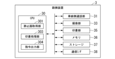
図2は、本開示の第1の実施形態に係る路側装置の機能構成を示す図である。
図2に示すように、路側装置3は、CPU30と、車線側通話部31と、撮像部33と、印書部35と、メモリ36と、ストレージ37と、通信I/F(Interface)38とを有している。また、図1に示すように、車線側通話部31、撮像部33、及び印書部35は、非ETC車両に搭乗した利用者が利用可能となるように、路側装置3の車線L側を向く面(図1の+Y側の面)に設けられている。
FIG. 2 is a diagram illustrating a functional configuration of a roadside device according to the first embodiment of the present disclosure.
As shown in Fig. 2, the
CPU30は、路側装置3の動作全体を司るプロセッサである。CPU30の機能の詳細については後述する。
The
車線側通話部31は、利用者と、料金所事務所に駐在する収受員との間で通話を行うためのインターホンである。
The lane
撮像部33は、利用者が所持する公的証明書を撮影する。公的証明書は、例えば、利用者の運転免許証、マイナンバーカード、パスポート等の官公庁やその他関連団体により発行された個人に関連する証明書であり、利用者を特定可能な利用者情報(券面情報)が表記されているものである。利用者情報には、例えば、公的証明書の識別番号(免許証番号、マイナンバー、旅券番号等)、利用者の氏名、住所等が含まれる。撮像部33が撮影した公的証明書の映像は、後述の通信I/F38を介して監視装置4に逐次、送信される。
The
印書部35は、事後徴収に関する通知書の印刷を行うプリンタである。
The
メモリ36は、いわゆる主記憶装置であって、CPU30の動作に必要な記憶領域を有する。
ストレージ37は、いわゆる補助記憶装置であって、HDD(Hard Disk Drive)やSSD(Solid State Drive)などの大容量記憶デバイスである。
通信I/F38は、ネットワークを介して監視装置4との間でデータの送受信を行う。
The communication I/
次に、図2を参照しながら、CPU30の機能について説明する。CPU30は、所定のプログラムに従って動作することにより、静止画取得部301、印書処理部303、指令出力部304としての機能を発揮する。
Next, the functions of the
静止画取得部301は、撮像部33が撮影した映像から、公的証明書を含む静止画を取得する。静止画取得部301が取得した静止画は、通信I/F38を介して監視装置4に送信される。
The still
印書処理部303は、監視装置4から受信した情報に基づいて、事後徴収に関する通知書の印書データを作成し、印書部35に印書を指示する。
The
指令出力部304は、事後徴収用データの作成が終了した後に、発進制御機25に開指令を出力する。本実施形態では、指令出力部304は、後述の監視装置4が作成した事後徴収用データを受信したときに、開指令を出力する。
After the creation of the post-collection data is completed, the
(監視装置の機能構成)
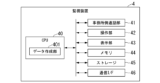
図3は、本開示の第1の実施形態に係る監視装置の機能構成を示す図である。
監視装置4は、料金所事務所に駐在する収受員が車線Lの監視を行う際に用いる装置である。図3に示すように、監視装置4は、CPU40と、事務所側通話部41と、操作部42と、表示部43、メモリ44と、ストレージ45と、通信I/F(Interface)46とを有している。
(Functional configuration of monitoring device)
FIG. 3 is a diagram illustrating a functional configuration of the monitoring device according to the first embodiment of the present disclosure.
The
CPU40は、監視装置4の動作全体を司るプロセッサである。CPU40の機能の詳細については後述する。
The
事務所側通話部41は、収受員と、非ETC車両に搭乗する利用者との間で通話を行うためのインターホンである。
The office
操作部42は、収受員の操作を受け付けるための入力装置(キーボード、マウス等)である。
The
表示部43は、非ETC車両の通行料金の事後徴収に関連する各種情報を表示するための表示装置(液晶ディスプレイ等)である。なお、操作部42及び表示部43は、タッチパネルにより一体に構成されていてもよい。
The
メモリ44は、いわゆる主記憶装置であって、CPU40の動作に必要な記憶領域を有する。
ストレージ45は、いわゆる補助記憶装置であって、HDD(Hard Disk Drive)やSSD(Solid State Drive)などの大容量記憶デバイスである。
通信I/F46は、ネットワークを介して路側装置3との間でデータの送受信を行う。
The communication I/
次に、図3を参照しながら、CPU40の機能について説明する。CPU40は、所定のプログラムに従って動作することにより、データ作成部401としての機能を発揮する。
Next, the function of the
データ作成部401は、路側装置3の撮像部33が撮影した公的証明書に表記されている利用者情報に基づいて、利用者の通行料金の事後徴収用データを作成する。本実施形態では、収受員が映像を目視確認して公的証明書に表記された利用者情報を読み取り、操作部42を介して監視装置4に入力する。作成した事後徴収用データは、ストレージ45に蓄積される。また、ストレージ45に蓄積された事後徴収用データは、所定タイミング毎(例えば1日毎)に上位装置(不図示)に集約され、利用者による支払いの有無等の管理に用いられる。
The
(料金収受システムの処理フロー)
図4は、本開示の第1の実施形態に係る料金収受システムの処理の一例を示すフローチャートである。
以下、図4を参照しながら、本実施形態に係る料金収受システム1が非ETC車両の事後徴収用データを作成する処理の一例について説明する。
(Processing flow of the toll collection system)
FIG. 4 is a flowchart showing an example of processing of the fee collection system according to the first embodiment of the present disclosure.
Hereinafter, an example of a process in which the
非ETC車両が車線Lに進入した場合、ETC設備2では料金収受処理が行われず、発進制御機25は開閉バーを閉じたままの状態となっている。非ETC車両は発進制御機25の手前で停車する。このとき、非ETC車両に搭乗する利用者は、路側装置3の車線側通話部31を介して、料金所事務所の収受員と通話を行う。
When a non-ETC vehicle enters lane L, the
そうすると、収受員は、監視装置4の事務所側通話部41を介して、利用者に対し、公的証明書を撮像部33にかざすように要求する(ステップS101)。
The collector then requests the user to hold the official certificate over the
路側装置3の撮像部33は、利用者がかざした公的証明書を撮影する(ステップS102)。路側装置3の撮像部33が撮影した映像は、逐次、監視装置4に送信される(ステップS103)。
The
路側装置3から送信された映像は、監視装置4の表示部43に表示される。収受員は、表示部43に表示された映像を目視確認して、利用者の公的証明書に表記された利用者情報を読み取る。なお、利用者の手の動きにより公的証明書の視認が難しい場合、収受員は、監視装置4の操作部42を介して、静止画を取得する操作を行う。そうすると、監視装置4のデータ作成部401は、路側装置3に静止画の取得を要求する(ステップS104)。
The image transmitted from the
路側装置3の静止画取得部301は、監視装置4からの要求を受け付けると、撮像部33が撮影した映像から公的証明書を含む静止画を取得して(ステップS105)、監視装置4に送信する(ステップS106)。なお、収受員は、映像が十分に鮮明であり、静止画がなくても公的証明書を読み取り可能である場合には、ステップS104~S106の処理を省略してもよい。
When the still
路側装置3から送信された静止画は、監視装置4の表示部43に表示される。収受員は、表示部43に表示された静止画を目視確認して、利用者の公的証明書に表記された利用者情報を読み取る。そして、収受員は、監視装置4の操作部42(キーボード)を介して、読み取った利用者情報を入力する(ステップS108)。
The still image transmitted from the
なお、公的証明書のうら面にも利用者情報(例えば、住所)が記載されている場合、うら面に記載された利用者情報を取得するために、ステップS101~S108の処理を再度、行うようにしてもよい。このとき、監視装置4の表示部43は、先に取得済みの公的証明書のおもて面の静止画と、新たに取得した公的証明書のうら面の静止画とを並べて表示する。また、表示部43は、収受員の操作にしたがって、おもて面の静止画と、うら面の静止画との一方を切り替え表示するようにしてもよい。
If user information (e.g., address) is also written on the back of the official certificate, steps S101 to S108 may be performed again to obtain the user information written on the back. At this time, the
次に、監視装置4のデータ作成部401は、収受員により入力された利用者情報に基づいて、事後徴収用データを作成する(ステップS109)。作成した事後徴収用データは、ストレージ45に蓄積される。
Next, the
図5は、本開示の第1の実施形態に係る事後徴収用データの一例を示す図である。
図5に示すように、事後徴収用データD1は、処理番号と、通行料金情報と、路側装置3から受信した利用者情報とを含む。
FIG. 5 is a diagram illustrating an example of post-collection data according to the first embodiment of the present disclosure.
As shown in FIG. 5, the post-collection data D1 includes a processing number, toll information, and user information received from the
処理番号は、事後徴収用データD1を管理するための通し番号である。 The processing number is a serial number used to manage the post-collection data D1.
通行料金情報は、料金所IDと、車線IDと、日時と、車種と、通行料金とを含む。料金所ID及び車線IDは、路側装置3が設置された料金所及び車線を特定可能な情報であり、路側装置3から映像又は静止画とともに受信した情報である。日時は、例えばデータ作成部401が事後徴収用データD1を作成した日時である。車種及び通行料金は、収受員が操作部42を介して入力したものであってもよいし、料金所に設置された車種判別装置(不図示)により特定されたものであってもよい。
The toll information includes a toll gate ID, a lane ID, a date and time, a vehicle type, and a toll. The toll gate ID and lane ID are information that can identify the toll gate and lane where the
利用者情報は、収受員が公的証明書を目視確認して入力した情報であり、利用者の氏名と、住所と、公的証明書の識別情報(免許証番号、マイナンバー、旅券番号等)とを含む。 The user information is information entered by the collector after visually checking the official certificate, and includes the user's name, address, and identification information of the official certificate (driver's license number, My Number, passport number, etc.).
次に、監視装置4のデータ作成部401は、作成した事後徴収用データD1を路側装置3に送信する(ステップS110)。
Next, the
路側装置3の指令出力部304は、監視装置4から事後徴収用データD1を受信すると、発進制御機25に開指令を出力する(ステップS111)。そうすると、発進制御機25は開閉バーを上げて、非ETC車両の車線Lからの退出を許可する。
When the
また、路側装置3の印書処理部303は、受信した事後徴収用データD1に基づいて、印書データを作成する(ステップS112)。
The
図6は、本開示の第1の実施形態に係る印書データの一例を示す図である。
図6に示すように、印書データD2は、処理番号と、料金所IDと、車線IDと、日時と、通行料金と、利用者特定情報と、支払期限と、支払方法とを含む。
FIG. 6 is a diagram showing an example of print data according to the first embodiment of the present disclosure.
As shown in FIG. 6, the print data D2 includes a processing number, a toll gate ID, a lane ID, a date and time, a toll, user identification information, a payment deadline, and a payment method.
処理番号、料金所ID、車線ID、日時、及び通行料金は、事後徴収用データD1の内容と同じである。 The processing number, toll gate ID, lane ID, date and time, and toll fee are the same as those in the post-collection data D1.
利用者特定情報は、公的証明書の識別情報である。他の実施形態では、利用者特定情報は、利用者の氏名であってもよい。 The user-identifying information is the identification information of the official certificate. In other embodiments, the user-identifying information may be the user's name.
支払期限は、利用者による通行料金の支払期限であり、例えば、事後徴収用データD1の作成日から所定期間後の日にちが自動的に入力される。また、支払期限は収受員が操作部42を介して入力してもよい。
The payment deadline is the deadline for the user to pay the toll, and is automatically input, for example, as a date a predetermined period after the creation date of the post-collection data D1. The payment deadline may also be input by the toll collector via the
支払方法は、利用者が通行料金を支払うための方法を示す情報であり、例えば通行料金の振り込み先となる銀行口座番号等である。 The payment method is information that indicates the method by which the user will pay the toll, such as a bank account number to which the toll will be transferred.
次に、路側装置3の印書部35は、印書処理部303が作成した印書データを含む通知書を印書する(ステップS113)。
Next, the
図7は、本開示の第1の実施形態に係る通知書の一例を示す図である。
図7に示すように、通知書D3は、印書データD2と同様に、処理番号と、料金所IDと、車線IDと、日時と、通行料金と、利用者特定情報(公的証明書の識別情報)と、支払期限と、支払方法とを含む。なお、印書部35は、図7の例のように、公的証明書の識別情報の一部(例えば、下4桁以外)を伏せ字にして印書する。これにより、通知書D3を利用者以外の他者に見られることがあったとしても、利用者の公的証明書の識別情報を他者に知られてしまうことを防止できる。
FIG. 7 is a diagram showing an example of a notice according to the first embodiment of the present disclosure.
As shown in Fig. 7, the notice D3 includes, like the print data D2, a processing number, a toll gate ID, a lane ID, a date and time, a toll, user identification information (identification information of an official certificate), a payment deadline, and a payment method. Note that the
また、収受員は、監視装置4の事務所側通話部41を介して、印書部35により印書された通知書D3にしたがい通行料金を支払うように利用者に説明する(ステップS114)。
The toll collector also instructs the user via the office
利用者は、印書された通知書D3を受け取った後、非ETC車両を発進させて車線Lから退出する。退出側車両検知器26が非ETC車両の車線Lからの退出を検出すると、発進制御機25は開閉バーを下ろして、後続車両の車線Lからの退出を規制する。
After receiving the printed notice D3, the user starts the non-ETC vehicle and exits lane L. When the exiting
料金収受システム1は、車線Lに非ETC車両が進入する度に、上記した一連の処理を実行する。
The
なお、図4には、路側装置3の指令出力部304が、監視装置4から事後徴収用データD1を受信したタイミングで、発進制御機25に開指令を出力する例が示されているが、これに限られることはない。他の実施形態では、指令出力部304は、利用者が印書部35から通知書D3を受け取った(抜き取った)ことを検出したときに、発進制御機25に開指令を出力してもよい。これにより、利用者が通知書D3を受け取らずに退出してしまうことを抑制することができる。
Note that FIG. 4 shows an example in which the
(作用効果)
以上のように、本実施形態に係る料金収受システム1は、利用者が所持する公的証明書を撮影する撮像部33と、撮像部33が撮影した公的証明書に表記されている利用者情報に基づいて、利用者の通行料金の事後徴収用データD1を作成するデータ作成部401と、を備える。
(Action and Effect)
As described above, the
このようにすることで、料金収受システム1は、収受員と利用者との間で公的証明書の受け渡しを行わずに、公的証明書から利用者情報を取得することができる。これにより、収受員が利用者に対面応対することなく、遠隔地から通行料金の事後徴収の手続きを行うことができる。
In this way, the
また、料金収受システム1は、通行料金の事後徴収に関する通知書D3を印書する印書部35を更に備える。
The
このようにすることで、料金収受システム1は、通行料金を事後徴収することを、通知書D3を介して利用者に通知することができる。
In this way, the
また、料金収受システム1は、撮像部33が撮影した映像から、公的証明書を含む静止画を取得する静止画取得部301を更に備える。
The
このようにすることで、料金収受システム1は、利用者の手の動き等に影響されることなく、公的証明書を視認しやすい静止画を収受員に提示することができる。
In this way, the
また、料金収受システム1は、車線の開放及び閉塞を行う発進制御機と、事後徴収用データD1の作成が終了した後に、発進制御機25に開指令を出力する指令出力部304と、を更に備える。
The
このようにすることで、料金収受システム1は、事後徴収用データD1の作成が終了したときに速やかに車線を開放して、非ETC車両を車線Lから退出させることができる。また、料金収受システム1は、事後徴収用データD1の作成が終了するまでは車線を閉塞することにより、利用者情報を取得する前に非ETC車両が車線Lから退出してしまうことを抑制することができる。
In this way, the
<第2の実施形態>
次に、本開示の第2の実施形態に係る料金収受システム1について、図8~図10を参照しながら説明する。
第1の実施形態と共通の構成要素には同一の符号を付して詳細説明を省略する。
Second Embodiment
Next, a
Components common to the first embodiment are denoted by the same reference numerals and detailed description thereof will be omitted.
(路側装置の機能構成)
図8は、本開示の第2の実施形態に係る路側装置の機能構成を示す図である。
図8に示すように、本実施形態に係る路側装置3において、CPU30は、読取部305としての機能を更に発揮する。
(Functional configuration of roadside device)
FIG. 8 is a diagram illustrating a functional configuration of a roadside device according to the second embodiment of the present disclosure.
As shown in FIG. 8, in the
読取部305は、静止画取得部301が取得した静止画から、公的証明書に表記された文字情報である利用者情報を読み取る。
The
(料金収受システムの処理フロー)
図9は、本開示の第2の実施形態に係る料金収受システムの処理の一例を示すフローチャートである。
以下、図9を参照しながら、本実施形態に係る料金収受システム1が非ETC車両の事後徴収用データを作成する処理の一例について説明する。なお、図9のステップS201~S205は、第1の実施形態(図4のステップS101~S105)と同じであるため、説明を省略する。
(Processing flow of the toll collection system)
FIG. 9 is a flowchart showing an example of processing of the fee collection system according to the second embodiment of the present disclosure.
Hereinafter, an example of a process in which the
本実施形態に係る路側装置3の読取部305は、OCR(Optical Character Recognition;光学文字認識)の技術を用いて、静止画取得部301が取得した静止画から、公的証明書に表記された利用者情報を読み取る(ステップS206)。読取部305が読み取った利用者情報は、静止画とともに監視装置4に送信される(ステップS207)。
The
図10は、本開示の第2の実施形態に係る監視装置の機能を説明するための図である。
図10に示すように、監視装置4の表示部43には、路側装置3から受信した静止画431と、OCRで読み取られた利用者情報432とが同時に並べて表示される。このとき、利用者情報432は、静止画431に含まれる公的証明書との比較が容易となるように、公的証明書のレイアウト、文字の大きさ等と略一致するように調整されて表示される。また、表示部43には、事後徴収用データD1を構成する処理番号及び通行料金情報が更に表示されてもよい。
FIG. 10 is a diagram for explaining functions of the monitoring device according to the second embodiment of the present disclosure.
10, a
収受員は、静止画431及び利用者情報432を比較して、路側装置3の読取部305による読み取り結果が正しいか確認し、必要に応じて情報の訂正を行う(ステップS208)。
The collector compares the
利用者情報432が公的証明書の表記内容と一致する(読み取り結果が正しい)場合、収受員は、操作部42の確定ボタン421を押下する。そうすると、監視装置4のデータ作成部401は、利用者情報に基づいて事後徴収用データD1を作成する(ステップS209)。データ作成部401は、作成した事後徴収用データD1を監視装置4のストレージ45に記憶するとともに、路側装置3に送信する(ステップS210)。以降の処理(ステップS211~S214)は、第1の実施形態(図4のステップS111~S114)と同様であるため、説明を省略する。
If the
一方、利用者情報432が公的証明書の表記内容と一致しない(誤認識、読み取れなかった情報がある等)場合、収受員は、操作部42の訂正ボタン422を押下する。このとき、収受員は、操作部42(キーボード)を介して、正しい利用者情報を入力する(ステップS208)。また、収受員は、通行料金情報の入力、訂正をあわせて行ってもよい。そうすると、監視装置4のデータ作成部401は、収受員が入力した利用者情報に基づいて事後徴収用データD1を作成する(ステップS209)。また、データ作成部401は、修正した事後徴収用データD1をストレージ45に記憶するとともに、路側装置3に送信する(ステップS210)。以降の処理(ステップS211~S214)は、第1の実施形態(図4のステップS111~S114)と同様であるため、説明を省略する。
On the other hand, if the
(作用効果)
以上のように、本実施形態に係る料金収受システム1において、路側装置3は、静止画から、公的証明書に表記された利用者情報を読み取る読取部305を更に備える。
(Action and Effect)
As described above, in the
このようにすることで、料金収受システム1は、収受員が利用者情報を一文字ずつ手入力する手間を省くことができる。これにより、料金収受システム1は、非ETC車両の処理に係るサービスタイムを大きく短縮することができる。
In this way, the
また、本実施形態に係る料金収受システム1において、監視装置4の表示部43は、路側装置3から受信した静止画及び利用者情報を並べて表示する。
In addition, in the
このようにすることで、収受員が静止画と利用者情報とを同時に参照して、利用者情報の読み取りの正誤を容易に確認することが可能となる。 This allows the collector to simultaneously view the still image and the user information, making it easy to check whether the user information has been read correctly.
<第3の実施形態>
次に、本開示の第3の実施形態に係る料金収受システム1について、図11を参照しながら説明する。
第1及び第2の実施形態と共通の構成要素には同一の符号を付して詳細説明を省略する。
本実施形態では、監視装置4のデータ作成部401が収受員の入力操作を介さずに、自動的に事後徴収用データD1を作成する点において、第2の実施形態と異なっている。
Third Embodiment
Next, a
Components common to the first and second embodiments are given the same reference numerals and detailed description thereof will be omitted.
This embodiment differs from the second embodiment in that the
(料金収受システムの処理フロー)
図11は、本開示の第3の実施形態に係る料金収受システムの処理の一例を示すフローチャートである。
以下、図11を参照しながら、本実施形態に係る料金収受システム1が非ETC車両の事後徴収用データを作成する処理の一例について説明する。なお、図11のステップS301~S307は、第2の実施形態(図9のステップS201~S207)と同じであるため、説明を省略する。
(Processing flow of the toll collection system)
FIG. 11 is a flowchart showing an example of processing of the fee collection system according to the third embodiment of the present disclosure.
Hereinafter, an example of a process in which the
監視装置4のデータ作成部401は、路側装置3から受信した利用者情報に基づいて、事後徴収用データD1を自動的に作成する(ステップS308)。データ作成部401は、作成した事後徴収用データD1と、路側装置3から受信した静止画とを関連付けて、ストレージ45に記憶する。また、データ作成部401は、作成した事後徴収用データD1を路側装置3に送信する(ステップS309)。以降の処理(ステップS310~S313)は、第2の実施形態(図9のステップS211~S214)と同様であるため、説明を省略する。
The
(作用効果)
以上のように、本実施形態に係る料金収受システム1において、監視装置4のデータ作成部401は、路側装置3の読取部305が読み取った利用者情報に基づいて、事後徴収用データD1を自動的に作成する。
(Action and Effect)
As described above, in the
このようにすることで、料金収受システム1は、事後徴収用データD1の作成について、収受員による操作を不要とすることができる。これにより、料金収受システム1は、非ETC車両の処理に係るサービスタイムを更に短縮することができる。
In this way, the
また、本実施形態に係る料金収受システム1において、監視装置4のデータ作成部401は、作成した事後徴収用データD1と、静止画とを関連付けてストレージ45に記憶する。
In addition, in the
このようにすることで、収受員は、利用者が少ない時間帯等に、自動作成された事後徴収用データD1と静止画とを照合して、利用者情報の誤認識があれば訂正することができる。 In this way, the collector can compare the automatically created post-collection data D1 with the still image during times when there are few users, and correct any misrecognition of user information.
以上のとおり、本発明に係るいくつかの実施形態を説明したが、これら全ての実施形態は、例として提示したものであり、発明の範囲を限定することを意図していない。これらの実施形態は、その他の様々な形態で実施されることが可能であり、発明の要旨を逸脱しない範囲で種々の省略、置き換え、変更を行うことができる。これらの実施形態及びその変形は、発明の範囲や要旨に含まれると同様に、特許請求の範囲に記載された発明とその均等の範囲に含まれる。 As described above, several embodiments of the present invention have been described, but all of these embodiments are presented as examples and are not intended to limit the scope of the invention. These embodiments can be implemented in various other forms, and various omissions, substitutions, and modifications can be made without departing from the gist of the invention. These embodiments and their modifications are included in the scope of the invention and its equivalents as described in the claims, as well as in the scope and gist of the invention.
上述の実施形態において、路側装置3が静止画取得部301及び読取部305を有する態様について説明したが、これに限られることはない。他の実施形態では、監視装置4が静止画取得部及び読取部を有する態様であってもよい。
In the above embodiment, the
また、上述の実施形態において、路側装置3の印書処理部303が印書データD2を作成し、印書部35が通知書D3を印書する態様について説明したが、これに限られることはない。他の実施形態では、印書処理部303及び印書部35を省略してもよい。この場合、例えば路側装置3の付近に支払方法を記載した説明書を予め用意しておき、必要に応じて利用者がこの説明書を持ち帰るようにしてもよい。
In the above embodiment, the
<付記1>
上述の実施形態に記載の料金収受システム及び料金収受方法は、例えば以下のように把握される。
<
The toll collection system and the toll collection method described in the above-mentioned embodiment can be understood, for example, as follows.
(1)本開示の第1の態様によれば、料金収受システム(1)は、料金所の車線に設けられ、有料道路の利用者が所持する公的証明書を撮影する撮像部(33)と、撮像部(33)が撮影した公的証明書に表記されている情報であって、利用者を特定可能な利用者情報に基づいて、利用者の通行料金の事後徴収用データ(D1)を作成するデータ作成部(401)と、を備える。 (1) According to a first aspect of the present disclosure, a toll collection system (1) is provided in a lane of a toll gate and includes an imaging unit (33) that captures an image of an official certificate held by a toll road user, and a data creation unit (401) that creates data (D1) for subsequent collection of a user's toll based on information written on the official certificate captured by the imaging unit (33) and user information that can identify the user.
このようにすることで、料金収受システムは、収受員と利用者との間で公的証明書の受け渡しを行わずに、公的証明書から利用者情報を取得することができる。これにより、収受員が利用者に対面応対することなく、遠隔地から通行料金の事後徴収の手続きを行うことができる。 In this way, the toll collection system can obtain user information from the official certificate without the need to exchange the official certificate between the toll collector and the user. This allows the toll collector to carry out the procedure for subsequent collection of tolls from a remote location without having to meet with the user in person.
(2)本開示の第2の態様によれば、第1の態様に係る料金収受システム(1)は、通行料金の事後徴収に関する通知書(D3)を印書する印書部(35)を更に備える。 (2) According to a second aspect of the present disclosure, the toll collection system (1) according to the first aspect further includes a printing unit (35) that prints a notice (D3) regarding the subsequent collection of the toll.
このようにすることで、料金収受システムは、通行料金を事後徴収することを、通知書を介して利用者に通知することができる。 In this way, the toll collection system can notify users via a notice that tolls will be collected later.
(3)本開示の第3の態様によれば、第1又は第2の態様に係る料金収受システム(1)は、撮像部(33)が撮影した映像から、公的証明書を含む静止画を取得する静止画取得部(301)を更に備える。 (3) According to a third aspect of the present disclosure, the toll collection system (1) according to the first or second aspect further includes a still image acquisition unit (301) that acquires a still image including an official certificate from the video captured by the imaging unit (33).
このようにすることで、料金収受システムは、利用者の手の動き等に影響されることなく、公的証明書を視認しやすい静止画を収受員に提示することができる。 In this way, the toll collection system can present the toll collector with a still image of the official certificate that is easily visible, without being affected by the user's hand movements, etc.
(4)本開示の第4の態様によれば、第3の態様に係る料金収受システム(1)は、静止画から、公的証明書に表記された文字情報である利用者情報を読み取る読取部(305)を更に備える。 (4) According to a fourth aspect of the present disclosure, the toll collection system (1) according to the third aspect further includes a reading unit (305) that reads user information, which is text information written on an official certificate, from a still image.
このようにすることで、料金収受システムは、収受員が利用者情報を一文字ずつ手入力する手間を省くことができる。これにより、料金収受システムは、事後徴収処理におけるサービスタイムを大きく短縮することができる。 In this way, the toll collection system can save toll collectors the trouble of manually inputting user information character by character. This allows the toll collection system to significantly reduce service time in post-collection processing.
(5)本開示の第5の態様によれば、第4の態様に係る料金収受システム(1)において、データ作成部(401)は、読取部(305)が読み取った利用者情報から事後徴収用データ(D1)を自動的に作成する。 (5) According to a fifth aspect of the present disclosure, in the toll collection system (1) relating to the fourth aspect, the data creation unit (401) automatically creates post-collection data (D1) from the user information read by the reading unit (305).
このようにすることで、料金収受システムは、事後徴収用データの作成について、収受員による操作を不要とすることができる。これにより、料金収受システムは、事後徴収処理におけるサービスタイムを更に短縮することができる。 In this way, the toll collection system can eliminate the need for a toll collector to create data for subsequent collection. This allows the toll collection system to further shorten the service time for subsequent collection processing.
(6)本開示の第6の態様によれば、第1から第5の何れか一の態様に係る料金収受システム(1)は、車線の開放及び閉塞を行う発進制御機(25)と、事後徴収用データ(D1)の作成が終了した後に、発進制御機(25)に開指令を出力する指令出力部(304)と、を更に備える。 (6) According to a sixth aspect of the present disclosure, the toll collection system (1) relating to any one of the first to fifth aspects further includes a starting control device (25) that opens and closes lanes, and a command output unit (304) that outputs an opening command to the starting control device (25) after the creation of the post-collection data (D1) is completed.
このようにすることで、料金収受システムは、事後徴収用データの作成が終了したときに速やかに車線を開放して、非ETC車両を車線から退出させることができる。また、料金収受システムは、事後徴収用データの作成が終了するまでは車線を閉塞することにより、利用者情報を取得する前に非ETC車両が車線から退出してしまうことを抑制することができる。 In this way, the toll collection system can promptly open the lane when the creation of the post-collection data is completed, allowing non-ETC vehicles to exit the lane. In addition, the toll collection system can prevent non-ETC vehicles from exiting the lane before acquiring user information by closing the lane until the creation of the post-collection data is completed.
(7)本開示の第7の態様によれば、料金収受方法は、料金所の車線に設けられた撮像部(33)により、有料道路の利用者が所持する公的証明書を撮影するステップと、撮像部(33)が撮影した公的証明書に表記されている利用者を特定可能な利用者情報に基づいて、利用者の通行料金の事後徴収用データ(D1)を作成するステップと、を有する。 (7) According to a seventh aspect of the present disclosure, the toll collection method includes the steps of photographing an official certificate held by a user of a toll road by an imaging unit (33) installed in a lane of a toll gate, and creating data (D1) for subsequent collection of the user's toll based on user information that can identify the user and is written on the official certificate photographed by the imaging unit (33).
<第4の実施形態>
次に、本開示の第4の実施形態に係る料金収受システムについて、図12等を参照しながら説明する。本実施形態の料金収受システムは、入口料金所における入口監視システム5と、出口料金所における出口監視システム6から構成される。
Fourth Embodiment
Next, a toll collection system according to a fourth embodiment of the present disclosure will be described with reference to Fig. 12 etc. The toll collection system of this embodiment is composed of an
(入口監視システムの構成)
図12は、本実施形態に係る入口監視システム5の構成を示す図である。入口監視システム5は、1つまたは複数の通行券発行装置520を含む有料道路の入口料金所R1を備える。説明を簡単なものとするため、図12においては、入口料金所R1が非ETC車両専用の入り口であると仮定する。従って、車両Aは非ETC車両であると仮定する。ただし、入口料金所R1は、図1のように、ETCシステムも含むものであってもよい。また、入口料金所R1は、図1のように、発進制御機25を備えていてもよい。
(Configuration of the entrance monitoring system)
Fig. 12 is a diagram showing the configuration of the
車線Lに進入した車両Aの搭乗者は、入口料金所R1を通過するときに車両Aを一時停車させる。車両Aの搭乗者は、通行券発行装置520の発券口5220から発行された通行券を取得する。この通行券には、入口料金所R1を示す情報や車両Aの車種を示す情報が記録され得る。車両Aの搭乗者は、有料道路の出口料金所でこの通行券を提出する。
The passenger of vehicle A that has entered lane L temporarily stops vehicle A when passing through entrance toll gate R1. The passenger of vehicle A obtains a pass issued from
図12に示すように、入口監視システム5は、通行券発行装置520を備える。図12においては図示を省略しているが、入口料金所R1には複数の車線Lがあってもよく、各々の車線Lに通行券発行装置520が設置され得る。
As shown in FIG. 12, the
通行券発行装置520は、有料道路の料金所に設置される料金機械の一態様であって、車線Lに進入した車両Aの搭乗者に対し通行券を発行する。図12に示すように、通行券発行装置520は、車線Lの路側(アイランド)に設置される。
The
図13は、通行券発行装置520が発行する通行券のフォーマットの一例を示す。通行券発行装置520が発行する通行券には、「入口」で示されるエリアがあり、このエリアは入口車線で印字されるエリアであり、入口料金所R1等に関する情報が印字される。印字される情報は、例えば、車両Aの車種、路線IC番号、通行券を発行した月/日/時/分、収受員番号、一連番号である。印字される情報は、これらのいずれか少なくとも1つが省略されてもよく、かつ/あるいは、他の情報を含んでもよい。
Figure 13 shows an example of the format of a pass issued by the
図13の通行券発行装置520が発行する通行券において、「車種」は車両Aの車種である。「車種」は例えば、「軽/二輪」、「普通車」、「中型車」、「大型車」、「特大車」等を表す情報を示す数字やアルファベット等であり得る。このような「車種」に関する車種区分は、利用者から収受すべき料金に対応して規定され得る。「車種」の情報を取得する方法の例は後述する。
In the toll ticket issued by the toll
路線IC番号は、料金所を表す情報を示す数字やアルファベット等であり得る。路線IC番号に関し、例えば、料金所が東名高速道路の東京料金所であれば、通行券発行装置520は「01101」を、料金所を表す情報として印字してもよい。
The route IC number may be a number or an alphabet indicating information representing the toll gate. For example, if the toll gate is the Tokyo toll gate on the Tomei Expressway, the
通行券を発行した月/日/時/分は、秒を含んでもよい。収受員番号は、通行券発行装置520の識別番号であってもよい。また、入口料金所R1に収受員が配置され、この収受員が通行券発行装置520の発行する通行券を車両Aの搭乗者に渡す場合には、収受員番号は収受員の識別番号であってもよい。一連番号は、通行券発行装置520ごとに通行券に付与される連番であってもよい。
The month/day/hour/minute when the toll ticket was issued may include seconds. The toll collector number may be the identification number of the toll
図13の通行券発行装置520が発行する通行券において、「出口」のエリアは空白となっている。あるいは、「出口」の欄は省略してもよい。この通行券には、例えば、「高速道路通行券」などの文字を予め印字しておいてもよい。この通行券には、例えば、「車種」表す数字やアルファベット等について、「1=普通車」などの説明を通行券に予め記載しておいてもよい。更に、この通行券には、入口料金所の情報を印字してもよい。入口料金所の情報としては、上記のような「東京料金所」といった文字の情報、及び/もしくは、「01101」といった路線IC番号と同じ東京料金所を表す数字やアルファベットであってもよい。
In the toll ticket issued by the toll
図13に示す通行券は、磁気記録部を備える。この磁気記録部には、例えば、上記の入口料金所R1等に関する情報、車種の情報、発券日時、一連番号が磁気記録されていてもよい。磁気記録部に記録される情報は、これらのいずれか少なくとも1つが省略されてもよく、かつ/あるいは、他の情報を含んでもよい。例えば、車両Aのナンバープレートの情報が含まれてもよい。磁気記録部は、例えば、図13に示されるような通行券の一部に、磁気インキを塗布することによって構成されてもよい。あるいは、通行券自体が磁気記録紙であり、図13に示されるような通行券の一部分に情報を記録し、この部分を磁気記録部として使用してもよい。 The toll ticket shown in FIG. 13 has a magnetic recording section. For example, information about the entrance toll booth R1, vehicle type information, ticket issuance date and time, and serial number may be magnetically recorded in this magnetic recording section. The information recorded in the magnetic recording section may omit at least one of these and/or may include other information. For example, the license plate information of vehicle A may be included. The magnetic recording section may be constructed, for example, by applying magnetic ink to a portion of the toll ticket as shown in FIG. 13. Alternatively, the toll ticket itself may be magnetic recording paper, and information may be recorded in a portion of the toll ticket as shown in FIG. 13, and this portion may be used as the magnetic recording section.
以下の説明では再び図12を参照する。図12に示すように、通行券発行装置520の上流側、すなわち、車両Aの進行方向手前側には、車種判別装置521が設置されている。車種判別装置521は、車線Lに進入した車両Aの車種区分を判別し、判別結果を通行券発行装置520に送信し得る。通行券発行装置520は、車種判別装置521から受信した車種判別結果(車両Aの車種区分)を通行券に印字し得る。
The following description will refer to FIG. 12 again. As shown in FIG. 12, a vehicle
車種判別装置521は、車線Lに進入した車両Aの車両情報を取得し、この車両情報に基づいて車両Aの車種区分を判別し得る。本実施形態において、「車両情報」とは、具体的には、車両Aの車軸数、ナンバープレートに関する情報(分類番号、プレートの色、大きさ)などであり得る。
The vehicle
演算装置5210は、特定された車両情報の組み合わせに応じて、車両Aの車種区分を一意に判別し得る。なお、本実施形態に係る演算装置5210は、車両検知器5211の筐体内部に組み込まれているものとして図示されている。しかし、演算装置5210はこの態様に限定されない。例えば、他の実施形態に係る演算装置5210は、独立した筐体で路側に設置されている態様であってもよい。あるいは、演算装置5210は、異なる場所に配置された監視用や管理用のコンピュータを用いて実装されてもよい。
The
また、他の実施形態に係る演算装置5210は、車両情報として、更に、車両Aの車長、車高、オーバーハング長などを特定するものであってもよい。この場合、車種判別装置521は、これらの車両情報を特定するためのセンサ機器を更に具備する態様であってもよい。センサ機器としては、例えば、赤外線センサ、レーザーセンサ、などが用いられ得る。
In addition, the
車両検知器5211は、車線Lの最も上流側に設けられ、車線Lの設置位置における車両の存在を検知可能に構成され得る。本実施形態に係る車両検知器5211は、例えば、車線Lを幅方向に挟んで対向するように設置される投光塔及び受光塔を有してなる透過型の車両検知器でありえる。車両検知器5211は車両Aの存在を検知した場合に、車両Aの存在示す検知信号を生成してナンバープレート読取機5213に出力するよう、構成され得る。
The
踏板5212は、車両Aのタイヤによる押圧を検知可能に構成され得る。踏板5212は、車線L上における車両検知器5211と同じ位置に設置されてもよい。あるいは、踏板5212は、車線L上における車両検知器5211よりも通行券発行装置520寄りに設置されてもよい。上述の演算装置5210は、車両検知器5211が車両Aの存在を検知している間に踏板5212が踏みつけられた回数を計数し、これを車両Aの車軸数として取得し得る。また、踏板5212の内部には、車線方向に複数の押圧センサが配列されてもよい。演算装置5210は、これらの複数の押圧センサが踏みつけられた順番を検知することで、踏板5212の上を通過している車両が前進しているか、後進しているかを判別することができる。演算装置5210は、これらの複数の押圧センサが同時に踏みつけられた位置を検知することで、車両Aが例えば二輪車である場合にも、これを検知し得る。
The
入口監視システム5は、ナンバープレート読取機5213を有する。ナンバープレート読取機5213は、例えば、動画像/静止画像を撮影可能なカメラと、撮影された動画像/静止画像からナンバープレートの情報を読み取るコンピュータと、を備えてもよい。ナンバープレートの情報を読み取る処理は、パターン認識、形状や文字の認識などにより実装されてもよい。ナンバープレート読取機5213のコンピュータは、演算装置5210であってもよい。ナンバープレート読取機5213は、例えば、車両検知器5211と、通行券発行装置520との間の位置に配置されてもよい。ナンバープレート読取機5213は、通行券発行装置520よりも更に上流の位置に配置されてもよい。あるいは、ナンバープレート読取機5213は、通行券発行装置520に組み込まれてもよい。ナンバープレート読取機5213は、車両検知器5211から車両Aの存在を示す検知信号を受信したときに車両Aの動画像/静止画像を撮影し、当該車両Aのナンバープレートを含む動画像/静止画像を取得する。更に、ナンバープレート読取機5213は、取得した動画像/静止画像から車両AのNP(ナンバープレート)情報を抽出し、車種判別装置521の演算装置5210に送信する。NP情報としては、例えば、ナンバープレートに記載の一連指定番号/地名/分類番号/ひらがな/ナンバープレートの色等が含まれ得る。
The
車種判別装置521の演算装置5210は、ナンバープレート読取機5213からNP情報を受信し、このNP情報に基づいて車両情報を特定し得る。
The
(通行券発行装置の機能構成)
図14は、本実施形態に係る通行券発行装置520の機能構成の例を示す図である。
図14に示すように、通行券発行装置520は、例えば、CPU5200と、メモリ5201と、通信インタフェース5202と、複数の処理ユニット5203と、を備え得る。
(Functional configuration of the ticket issuing device)
FIG. 14 is a diagram showing an example of the functional configuration of a passing
As shown in FIG. 14 , the
CPU5200は、通行券発行装置520の動作全体を司るプロセッサであって、所定のプログラムに従って動作することで種々の機能を実装する。
The
メモリ5201は、いわゆる主記憶装置であって、CPU5200がプログラムに従って動作するための記憶領域となる。
通信インタフェース5202は、広域通信網への有線接続又は無線接続を介して、通行券発行装置520を監視する監視端末との双方向通信を確立する通信モジュールである。1つもしくは複数の通行券発行装置520を監視し得る監視端末は、図示されない装置である。
The
複数の処理ユニット5203は、通行券発行装置としての機能を実現するための処理ユニットであって、例えば、発券口から通行券を発行する発券ユニットや、収受員や監視員等を呼び出すための呼び出しボタン等である。
The
次に、CPU5200の具体的な機能について説明する。CPU5200は、所定のプログラムに従って動作することで、送信部52000、受信部52001、処理部52002、及び、状態特定部52003としての機能を実装する。
Next, the specific functions of the
送信部52000及び受信部52001は、例えば、監視端末との間で種々の情報の送受信処理を行う。
The transmitting
処理部52002は、通行券発行装置としての通常の処理を行う。例えば、処理部52002は、車両Aが車線Lに到来した場合に、新たな通行券に必要な情報(料金所識別情報、発券の月/日/時/分、車両Aの車種区分等)を印字し、磁気記録部に情報を書き込み、その通行券を発行する発券処理等を行う。また、処理部52002は、磁気記録部にCRC(cyclic redundancy check)などのエラー検出のための情報を含めてもよい。
The
状態特定部52003は、通行券発行装置520の種々の状態を特定する。例えば、状態特定部52003は、処理ユニット5203の異常(故障、券詰まり等)の有無や、券切れの発生の有無を一定周期で、あるいは問題が発生したときに検出する。また、状態特定部52003は、通行券発行装置520の状態として、通行券発行装置520における通行券発行枚数、車両進入台数、不渡し枚数(抜き取られなかった通行券の枚数)等を逐次特定する。通行券発行装置520は、これらの情報を、図示しない外部の監視端末や監視サーバへ送信してもよい。例えば、通行券発行装置520は、通行券の発行時に券詰まりを検知した場合には、図示しない監視端末にトラブルの発生を知らせる信号を送信してもよい。図示しない監視端末はこの信号を受信し、画面表示や警告音の出力によって収受員もしくは監視員にトラブルの発生を報知してもよい。
The
(出口監視システムの構成)
図15は、本実施形態に係る出口監視システム6の機能構成を示す図である。出口監視システム6の構成は、図1の料金収受システム1と類似するものであり、同様の構成要素については同じ名称と符号番号を付する。また、以下の説明において、図15の構成要素が、図1の構成要素と類似である場合、その構成要素についての説明は省略され得る。
(Exit monitoring system configuration)
Fig. 15 is a diagram showing the functional configuration of the
本実施形態に係る出口監視システム6は、有料道路の出口料金所に設けられ得る。出口監視システム6は、有料道路と一般道路とを接続する車線Lを走行する車両Aの搭乗者から通行券を受け取り、通行料金を収受するための通知書を発行する。
The
車両Aは、車載器を搭載するETC車両、もしくは、車載器を搭載していない非ETC車両であり得る。以下の説明では、車両Aが非ETC車両であると仮定する。また、以下の説明では、車両Aの搭乗者が上述の入口監視システム5において受け取った通行券を所持していると仮定する。
Vehicle A may be an ETC vehicle equipped with an on-board unit, or a non-ETC vehicle not equipped with an on-board unit. In the following description, it is assumed that vehicle A is a non-ETC vehicle. In the following description, it is also assumed that the occupant of vehicle A is in possession of a pass received by the
本実施形態に係る車線Lは、電子式料金収受システムであるETC設備2が設けられたETC専用車線であってもよい。あるいは、車線Lは、ETC設備2が設けられていない、非ETC車両用に設けられた車線であってもよい。
The lane L in this embodiment may be an ETC-only lane equipped with an
(路側装置の機能構成)
路側装置3は、非ETC車両が有料道路から退出した後に通行料金を徴収する事後徴収を行えるように、非ETC車両の利用者を特定して事後徴収用のデータを作成し、通行料金を収受するための通知書を発行する。
(Functional configuration of roadside device)
The
図16は、本実施形態に係る路側装置3の機能構成を示す図である。図16に開示される構成は、図2に開示される構成と類似し得るものであり、このため、図16の構成要素の中で図2の構成要素と類似の構成要素には同じ名称と符号番号を付与する。また、以下の説明において、図16の構成要素が、図2の構成要素と類似である場合、その構成要素についての説明は省略され得る。
Figure 16 is a diagram showing the functional configuration of the
図16に示すように、路側装置3は、CPU30と、車線側通話部31と、撮像部33と、印書部35と、メモリ36と、ストレージ37と、通信I/F(Interface)38と、通行券受取り/読み取り部39と、を有している。CPU30は、所定のプログラムに従って動作することにより、静止画取得部301、印書処理部303、指令出力部304、OCR処理部302としての機能を実装し得る。また、図16に示すように、車線側通話部31、撮像部33、印書部35、および、通行券受取り/読み取り部39は、非ETC車両に搭乗した利用者が利用可能となるように、路側装置3の車線L側を向く面(図1の+Y側の面)に設けられている。
As shown in FIG. 16, the
通行券受取り/読み取り部39は、車両Aの搭乗者から通行券を受け取り、この通行券の磁気記録部に記録された情報を読み取る、磁気記録情報の読み取り装置である。
The pass receiving/
OCR処理部302は、例えば、静止画取得部301の取得した静止画像から文字、数字、記号などを識別し、識別された文字の情報を含むOCRデータを生成する。
The
本実施形態では、通行券受取り/読み取り部39が読み取った情報と、撮像部33が撮影した公的証明書の映像をOCR処理して得られた利用者データから事後徴収用データを作成する。事後徴収用データは、ストレージ37に蓄積される。また、ストレージ37に蓄積された事後徴収用データは、所定タイミング毎(例えば1日毎)に上位装置(不図示)に集約され、利用者による支払いの有無等の管理に用いられてもよい。事後徴収用データは、監視装置により作成されてもよい。
In this embodiment, post-collection data is created from user data obtained by OCR processing of the information read by the pass receiving/
(監視装置の機能構成)
図17は、本実施形態に係る監視装置の機能構成を示す図である。図17に開示される構成は、図3に開示される構成と類似し得るものであり、このため、図17の構成要素の中で図3の構成要素と類似の構成要素には同じ名称と符号番号を付与する。また、以下の説明において、図17の構成要素が、図3の構成要素と類似である場合、その構成要素についての説明は省略され得る。
(Functional configuration of monitoring device)
Fig. 17 is a diagram showing the functional configuration of a monitoring device according to this embodiment. The configuration disclosed in Fig. 17 may be similar to the configuration disclosed in Fig. 3, and therefore, among the components in Fig. 17, components similar to those in Fig. 3 are given the same names and reference numbers. In the following description, if a component in Fig. 17 is similar to a component in Fig. 3, the description of that component may be omitted.
データ作成部401は、路側装置3が作成したOCRデータの修正などを行う。
The
(出口監視システムの処理フロー)
図18は、本実施形態に係る出口監視システム6の処理の一例を示すフローチャートである。以下、図18を参照しながら、本実施形態に係る出口監視システム6が非ETC車両の事後徴収用データを作成し、通行料金を収受するための通知書を発行する処理の一例について説明する。
(Processing flow of the exit monitoring system)
Fig. 18 is a flowchart showing an example of the process of the
非ETC車両が車線Lに進入した場合、ETC設備2では料金収受処理が行われず、発進制御機25は開閉バーが閉じたままの状態となっている。非ETC車両は発進制御機25の手前で停車する。このとき、料金所事務所の収受員は、非ETC車両に搭乗する利用者と、路側装置3の車線側通話部31と、監視装置4の事務所側通話部41とを介して通話を行う。収受員は利用者に対し、通行料金の後払いの方法について説明を行う(ステップS401)。また、収受員は、監視装置4の事務所側通話部41と路側装置3の車線側通話部31とを介して利用者に通行券を路側装置3の通行券受取り/読み取り部39へ投入するよう求める(ステップS402)。
When a non-ETC vehicle enters lane L, the
収受員による説明に代えて、路側装置3は、予め路側装置3もしくは監視装置4のストレージ(37/45)やメモリ(36/44)に格納された音声を再生してもよい。例えば、路側装置3がタッチパネルなどの表示装置を更に備え、表示装置に「支払を開始」などのボタンを表示させてもよい。非ETC車両に搭乗する利用者が「支払を開始」と表示されたボタンをタッチしたときに、予めメモリに格納された音声を再生してもよい。更に、音声の再生後に、路側装置3は、予め路側装置3もしくは監視装置4のストレージ(37/45)やメモリ(36/44)に格納された「通行券を投入してください」といったメッセージを表示装置に表示させてもよい。
Instead of an explanation by the collector, the
非ETC車両に搭乗する利用者は、収受員の説明に従い、通行券を路側装置3の通行券受取り/読み取り部39に投入する。路側装置3の通行券受取り/読み取り部39は、非ETC車両に搭乗する利用者が投入した通行券を受け取る(ステップS403)。路側装置3の通行券受取り/読み取り部39は、通行券の磁気記録部から情報を読み取る(ステップS404)。
A user in a non-ETC vehicle follows the instructions of the collector and inserts the toll ticket into the toll ticket receiving/
路側装置3の通行券受取り/読み取り部39は、通行券の磁気記録部から情報を正常に読み取ることができたか否かを判断する(ステップS405)。路側装置3の通行券受取り/読み取り部39は、通行券の磁気記録部から情報を正常に読み取ることができたか否かを判断する際に(ステップS405)、CRCなどを利用したエラーチェック処理を行ってもよい。
The toll ticket receiving/
路側装置3の通行券受取り/読み取り部39は、通行券の磁気記録部から情報を正常に読み取ることができたと判断する場合、後続の処理(ステップS416)へ進む(ステップS406)。
If the ticket receiving/
路側装置3の通行券受取り/読み取り部39は、通行券の磁気記録部から情報を正常に読み取ることができなかったと判断する場合に、エラーが発生したと判断する(ステップS407)。このエラーの原因は、例えば、通行券が破損された、汚された、通行券への情報書き込み時に書き込みエラーが発生した、あるいは通行券が強い磁気にさらされた、などの場合があり得る。通行券受取り/読み取り部39が、通行券の磁気記録部から情報を正常に読み取ることができなかったと判断する場合(ステップS407)、路側装置3は通信I/F38を介してエラー信号を監視装置4へ送信する。
If the toll ticket receiving/
監視装置4は、通信I/F46を介して、路側装置3からエラー信号を受信する(ステップS407)。監視装置4は、例えば、エラーメッセージを表示部43に表示する、警告音を出力するなどの方法で収受員に通行券の読み取りエラーを報知する。料金所事務所の収受員は、路側装置3の車線側通話部31と監視装置4の事務所側通話部41とを介して、非ETC車両に搭乗する利用者と通話を行う。収受員は利用者に対し、通行券を路側装置3の撮像部33にかざすよう、求める(ステップS408)。この処理は、例えば、利用者に対し、通行券を路側装置3の撮像部33にかざすよう求める音声データを路側装置3もしくは監視装置4のストレージ37もしくは45、あるいはメモリ36もしくは44に予め格納しておき、収受員が監視装置4に対してこの音声データを再生するよう指示するものとしてもよい。
The
非ETC車両に搭乗する利用者は、通行券を路側装置3の撮像部33にかざし、通行券を収受員に呈示する。路側装置3の撮像部33は、非ETC車両に搭乗する利用者が呈示した通行券の映像を撮像し、路側装置3の通信I/F38を介して、監視装置4へ送信する(ステップS409)。なお、非ETC車両に搭乗する利用者が通行券を呈示した場合に限らず、路側装置3の撮像部33は、撮像した映像を、監視装置4へ常時あるいは断続的/間欠的に送信し続けてもよい。
A user in a non-ETC vehicle holds the toll ticket over the
監視装置4は通信I/F46を介して、非ETC車両に搭乗する利用者の通行券の映像を、路側装置3から受信し、例えば、監視装置4の表示部43に表示する。なお、非ETC車両に搭乗する利用者が通行券を呈示した場合に限らず、監視装置4は通信I/F46を介して、路側装置3の撮像部33が撮像した映像を常時あるいは断続的/間欠的に受信し続け、監視装置4の表示部43に表示し続けてもよい。
The
料金所事務所の収受員は、非ETC車両に搭乗する利用者が呈示した通行券を確認し、監視装置4に通行券の静止画像の撮像を指示する。この指示は、例えば、監視装置4の表示部43に撮像ボタンなどを予め表示しておき、これを料金所事務所の収受員がタッチすることにより、監視装置4に入力されてもよい。監視装置4は通信I/F46を介して、路側装置3へ通行券の静止画像の撮像を要求する信号を送信する(ステップS410)。
The toll collector at the toll booth office checks the toll ticket presented by the user in the non-ETC vehicle and instructs the
路側装置3は通信I/F38を介して、監視装置4から通行券の静止画像の撮像を要求する信号を受信する。路側装置3において、受信した信号に従い、CPU30の静止画取得部301は、撮像部33によって撮像される静止画像から静止画像データを取得する(ステップS411)。路側装置3のCPU30は、通信I/F38を介して、静止画像データを撮像結果として監視装置4へ送信する(ステップS412)。
The
監視装置4は通信I/F46を介して、路側装置3から静止画像データを撮像結果として受信する。監視装置4のCPU40は、受信した撮像結果を表示部43に表示する。収受員は、監視装置4の表示部43に表示された撮像結果から、入口料金所R1等に関する情報、車種の情報、発券日時、一連番号などの情報を目視で確認する(ステップS413)。
The
収受員は、監視装置4に対し、例えばマウスやキーボードを用いて入口料金所R1等に関する情報、車種の情報などについて数字や文字を入力する(ステップS414)。収受員は、入口料金所R1等に関する情報、車種の情報などを確定し、路側装置3へこれらの情報を含む入口・車種情報確定要求の信号を送信するよう、監視装置4に指示する。この指示は、例えば、監視装置4の表示部43に「確定」ボタンなどを予め表示しておき、これを料金所事務所の収受員がタッチすることにより、監視装置4に入力されてもよい。監視装置4のCPU40は、収受員の指示を受け、入口・車種情報確定要求を含む信号を生成し、通信I/F46を介して路側装置3へ送信する(ステップS415)。
The toll collector inputs numbers and letters for information about the entrance toll booth R1, etc., vehicle type information, etc., into the
路側装置3のCPU30は、通信I/F38を介して、入口・車種情報確定要求の信号を受信する。路側装置3のCPU30は、監視装置4から受信した入口・車種情報確定要求の信号に含まれる情報を参照して、通行料金を計算する(ステップS416)。この通行料金の計算において、路側装置3のCPU30は、例えば、メモリ36もしくはストレージ37に格納された料金テーブル情報を参照してもよい。料金テーブル情報は、例えば、入口料金所と、車種との組み合わせに応じた通行料金が格納されたテーブルであってもよい。
The
路側装置3のCPU30は、車両Aの搭乗者である利用者に、通行料金を通知する(ステップS417)。例えば、路側装置3がディスプレイパネルなどの表示部を更に備え、この表示部に通行料金を表示してもよい。あるいは、路側装置3のCPU30は通行料金の音声データを生成し、もしくは予めメモリ36やストレージ37に格納された通行料金に対応する音声データを選択し、車線側通話部31を用いてこの音声データを再生/出力することにより、車両Aの搭乗者である利用者に、通行料金を通知してもよい。あるいは、路側装置3のCPU30は通行料金を示す信号を監視装置4へ送信して監視装置4の表示部43に表示させてもよい。収受員が、表示部43に表示された通行料金を確認し、監視装置4の事務所側通話部41と、路側装置3の車線側通話部31とを介して、車両Aの搭乗者である利用者に通行料金を通知してもよい。また、このステップは、オプションの処理として省略されてもよい。
The
ここで、車両Aの搭乗者である利用者が身体障がい者であり、通行料金の割引を受けることができる場合もあり得る。路側装置3のCPU30は、車両Aの搭乗者である利用者に、障がい者割引の申請を行うか否かを問い合わせてもよい。例えば、路側装置3がディスプレイパネルなどの表示部を更に備え、この表示部に「割引申請を行う(障がい者割引など)」、「割引申請を行わず次へ進む」のボタンを表示してもよい。車両Aの搭乗者である利用者が「割引申請を行う(障がい者割引など)」のボタンをタッチした場合、路側装置3のCPU30は、割引適用申告があった旨を示す信号を生成し、通信I/F38を介して、監視装置4へ信号を送信する(ステップS418)。監視装置4のCPU40は通信I/F46を介して、割引適用申告があった旨を示す信号を受信し、非ETC車両に搭乗する利用者から割引適用申告があった旨を示すメッセージダイアログボックスを表示部43に表示させる。
Here, the user who is a passenger of vehicle A may be physically disabled and may be able to receive a discount on the toll. The
収受員は、監視装置4の表示部43に表示された非ETC車両に搭乗する利用者から割引適用申告があった旨を示すメッセージダイアログボックスを確認する。収受員は事務所側通話部41と、路側装置3の車線側通話部31とを介して、割引適用に関する書類の提示を非ETC車両に搭乗する利用者に求める。非ETC車両に搭乗する利用者は、例えば、障がい者手帳などの割引適用に関する書類を路側装置3の撮像部33にかざす。路側装置3の撮像部33は、割引適用に関する書類の映像を通信I/F38を介して、監視装置4へ送信する。監視装置4の表示部43は、通信I/F46を介して受信した割引適用に関する書類の映像を、表示する。収受員は、路側装置3から受信した割引適用に関する書類の映像を確認し、非ETC車両に搭乗する利用者が割引適用の対象者であると判断した場合、監視装置4に割引適用を指示する。この処理について、監視装置4は予め、例えば、割引適用申告があった旨を示すメッセージダイアログボックスに「割引適用」と「割引なし」のボタンを含めておいてもよい。収受員が「割引適用」のボタンにタッチした場合、監視装置4のCPU40は更に、割引適用の種別を選択するプルダウンメニューを表示し、「障がい者割引」、「大口・多頻度割引」などの項目を表示してもよい。収受員はこれらの項目の中から適切なものを選択し得る。監視装置4のCPU40は、収受員の選択した、例えば、「障がい者割引」を示す割引適用要求を含む信号を、通信I/F46を介して、路側装置3に送信する(ステップS419)。路側装置3のCPU30は通信I/F38を介して、「障がい者割引」を示す割引適用要求を含む信号を監視装置4から受信する。路側装置3のCPU30は通行料金の割引の計算を行う(ステップS420)。例えば、路側装置3のCPU30は、メモリ36もしくはストレージ37に格納された割引料金テーブル情報を参照してもよい。割引料金テーブル情報は、例えば、入口料金所と、車種と、割引の種別との組み合わせに応じた通行料金が格納されたテーブルであってもよい。
The toll collector checks the message dialog box displayed on the
路側装置3のCPU30は、車両Aの搭乗者である利用者に、割引後の通行料金を通知する(ステップS421)。例えば、路側装置3がディスプレイパネルなどの表示部を更に備え、この表示部に割引後の通行料金を表示してもよい。あるいは、路側装置3のCPU30は割引後の通行料金の音声データを生成し、もしくは予めメモリ36やストレージ37に格納された割引後の通行料金に対応する音声データを選択し、車線側通話部31を用いてこの音声データを再生/出力することにより、車両Aの搭乗者である利用者に、割引後の通行料金を通知してもよい。あるいは、路側装置3のCPU30は割引後の通行料金を示す信号を監視装置4へ送信して監視装置4の表示部43に表示させてもよい。収受員が、表示部43に表示された割引後の通行料金を確認し、監視装置4の事務所側通話部41と、路側装置3の車線側通話部31とを介して、車両Aの搭乗者である利用者に割引後の通行料金を通知してもよい。また、このステップは、オプションの処理として省略されてもよい。
The
あるいは、収受員は、路側装置3から受信した割引適用に関する書類の映像を確認し、非ETC車両に搭乗する利用者が割引適用の対象者でないと判断した場合、監視装置4に割引なしを指示する。この処理について、監視装置4は予め、例えば、割引適用申告があった旨を示すメッセージダイアログボックスに「割引適用」と「割引なし」のボタンを含めておいてもよい。収受員が「割引なし」のボタンにタッチした場合、監視装置4のCPU40は、「割引なし」を示す割引不適用要求を含む信号を、通信I/F46を介して、路側装置3に送信する。路側装置3のCPU30は通信I/F38を介して、割引不適用要求を含む信号を監視装置4から受信する。路側装置3のCPU30は、車両Aの搭乗者である利用者に、割引の不適用を通知してもよい。例えば、路側装置3がディスプレイパネルなどの表示部を更に備え、この表示部に割引の不適用のメッセージを表示してもよい。この通知は、音声などで行われてもよい。
Alternatively, the collector checks the video of the document regarding the discount application received from the
また、車両Aの搭乗者である利用者が身体障がい者でない場合、利用者は、例えば、「割引申請を行わず次へ進む」のボタンをタッチする。路側装置3のCPU30は、割引適用申告がなかった旨を示す信号を生成し、通信I/F38を介して、監視装置4へ信号を送信し得る。監視装置4のCPU40は通信I/F46を介して、割引適用申告がなかった旨を示す信号を受信し、非ETC車両に搭乗する利用者から割引適用申告がなかった旨を示すメッセージダイアログボックスを表示部43に表示させてもよい。
Also, if the user who is a passenger in vehicle A is not physically disabled, the user touches, for example, a button that reads "Proceed to next step without applying for discount." The
あるいは、身体障がい者などの割引の要否に関する問い合わせを、収受員が、監視装置4の事務所側通話部41を介して、路側装置3の車線側通話部31から、車両Aの搭乗者である利用者に対し、音声で行ってもよい。車両Aの搭乗者である利用者が、身体障がい者などの割引の適用を音声で求めた場合に、路側装置3が、上述と同様に割引後の通行料の計算を行ってもよい。なお、割引後の通行料の計算は、監視装置4が行ってもよい。
Alternatively, the toll collector may make an inquiry regarding the need for a discount for physically disabled persons, etc., by voice from the lane
次に、収受員は、監視装置4の事務所側通話部41を介して、路側装置3の車線側通話部31から音声を出力することにより、車両Aの搭乗者である利用者に対し、公的証明書を撮像部33にかざすように要求する(ステップS422)。
Next, the collector requests the user, who is a passenger in vehicle A, to hold an official certificate over the
路側装置3の撮像部33は、利用者がかざした公的証明書を撮影する(ステップS423)。路側装置3の撮像部33が撮影した公的証明書の映像は、逐次に監視装置4に送信される。
The
路側装置3から送信された映像は、監視装置4の表示部43に表示される。収受員は、表示部43に表示された映像を目視確認し、監視装置4の操作部42を介して、監視装置4へ静止画を取得とOCR処理を行うよう指示を入力する。監視装置4は、収受員の指示を受け、監視装置4のデータ作成部401が通信I/F46を介して、静止画の取得とOCR処理を行うよう要求する信号を路側装置3へ送信する(ステップS423)。路側装置3は通信I/F38を介して、監視装置4から、信号を受信する。
The video transmitted from the
路側装置3の静止画取得部301は、撮像部33が撮影した映像から公的証明書を含む静止画を取得する。路側装置3のOCR処理部302は、静止画取得部301が取得した公的証明書を含む静止画に対してOCR処理を行い、OCRデータを生成する(ステップS424)。路側装置3は、公的証明書を含む静止画のデータと、OCRデータとを撮像・OCR結果として、通信I/F38を介して、監視装置4へ送信する(ステップS425)。OCR処理は監視装置4が行うよう構成してもよい。
The still
監視装置4は通信I/F46を介して、路側装置3から送信された撮像・OCR結果を受信する。監視装置4は、撮像・OCR結果に含まれる静止画のデータとOCRデータを表示部43に表示する。収受員は、表示部43に表示された静止画とOCR処理の結果を目視確認して、OCRデータ中に住所や氏名、生年月日、運転免許証の番号などの情報に誤りがないか、目視で確認する(ステップS426)。
The
収受員は、OCRデータ中に誤りを見つけた場合には、監視装置4の操作部42からOCRデータの修正を指示する。例えば、監視装置4のCPU40は、静止画のデータとOCRデータを表示部43に表示する際に、「修正」及び「確定」の2つのボタンを表示部43に表示させてもよい。収受員は、OCRデータ中に誤って認識された数字や文字を発見した場合、「修正」のボタンをタッチしてもよい。収受員は、OCRデータ中の誤って認識された数字や文字を、例えばマウスやキーボードを用いて削除し、住所や氏名等に関する情報などについての正しい数字や文字を入力する(ステップS426)。収受員は、OCRデータ中に誤りを見つけない場合には、OCRデータの修正の指示を監視装置4に入力することはしない。これらの処理により、正しい内容のOCRデータが得られる。収受員は、例えば、「確定」のボタンをタッチすることにより、正しい内容のOCRデータを確定し、路側装置3へ利用者情報確定要求の信号を送信するよう、監視装置4に指示する。監視装置4のCPU40は、収受員の指示を受け、正しい内容のOCRデータを含む利用者情報確定要求の信号を生成し、通信I/F46を介して路側装置3へ送信する(ステップS427)。
If the collector finds an error in the OCR data, he/she issues an instruction to correct the OCR data from the
なお、公的証明書のうら面にも利用者情報(例えば、住所)が記載されている場合、うら面に記載された利用者情報を取得するために、ステップS422~S427の処理を再度、行うようにしてもよい。このとき、監視装置4の表示部43は、先に取得済みの公的証明書のおもて面の静止画/OCRデータと、新たに取得した公的証明書のうら面の静止画/OCRデータとを並べて表示する。また、表示部43は、収受員の操作にしたがって、おもて面の静止画/OCRデータと、うら面の静止画/OCRデータとの一方を切り替え表示するようにしてもよい。
If user information (e.g., address) is also written on the back of the official certificate, steps S422 to S427 may be performed again to obtain the user information written on the back. At this time, the
路側装置3のCPU30は、通信I/F38を介して、利用者情報確定要求の信号を受信する。路側装置3のCPU30は、正しい内容のOCRデータを含む利用者情報確定要求の信号に基づいて、後払い用データを作成する(ステップS428)。後払い用データは、例えば、通行料金情報、利用者情報、エビデンス情報のうちの少なくとも1つを含み得る。通行料金情報は、例えば、出口料金所/車線、入口料金所/車線、通行券の発券の月/日/時/分、車両Aの車種区分、NP情報、出口料金所の現在の月/日/時/分、通行料金、通行料金の割引の有無、のうちの少なくとも一つを含み得る。利用者情報は、例えば、車両Aの搭乗者である利用者の氏名、住所、生年月日のうちの少なくとも1つを含み得る。エビデンス情報は、例えば、公的証明書の静止画、公的証明書の正しい内容のOCRデータのうちの少なくとも1つを含み得る。
The
路側装置3のCPU30は、後払い用データを、上位装置であるコンピュータに送信してもよい(ステップS429)。上位装置であるコンピュータは、通行料金が後日正しく支払われたか否かをチェックする、また、支払われない場合は督促するためのコンピュータであり得る。
The
路側装置3の印書処理部303は、後払い用データに基づいて、印書データを作成する。印書データは、例えば、入口料金所の名称、出口料金所の名称、通行券の発券の月/日/時/分、車両Aの車種区分、ナンバープレートに記載の一連指定番号/地名/分類番号/ひらがな、出口料金所の現在の月/日/時/分、通行料金、通行料金の割引の有無、支払期限と、利用者の氏名/住所/生年月日と、支払方法とを含んでもよい。印書データは、これらの項目の全てを含む必要はなく、また、他の情報を含んでもよい。更に、利用者の氏名、住所、生年月日、ナンバープレート等については、一部を「*」のような伏字としてもよい。
The
支払期限は、利用者による通行料金の支払期限であり、例えば、後払い用データの作成日から所定期間後の日にちが自動的に入力され得る。また、支払期限は収受員が操作部42を介して入力してもよい。
The payment deadline is the deadline for the user to pay the toll, and may be automatically entered as a date that is a specified period after the date of creation of the postpaid data, for example. The payment deadline may also be entered by the collector via the
支払方法は、利用者が通行料金を支払うための方法を示す情報であり、例えば通行料金の振り込み先となる銀行口座番号等である。また、支払方法は、コンビニエンスストアでの支払いのためのバーコードあるいは二次元コードなどを含んでもよい。 The payment method is information indicating the method by which the user pays the toll, such as a bank account number to which the toll is to be transferred. The payment method may also include a barcode or two-dimensional code for payment at a convenience store.
路側装置3の印書部35は、印書処理部303が作成した印書データを含む通知書を印書する。指令出力部304は、車両Aの搭乗者である利用者が印書部35から通知書を受け取った(抜き取った)ことを検出したときに、発進制御機25に開指令を出力する(ステップS430)。
The
(作用効果)
以上のように、本実施形態に係る入口料金所R1において、通行券発行装置520は、磁気記録された情報を含む通行券を発行する。また、出口監視システム6の路側装置3は、通行券に磁気記録された情報と公的証明書の静止画像やOCRデータから、通知書を発行する。
(Action and Effect)
As described above, at the entrance toll booth R1 according to this embodiment, the toll
このようにすることで、本実施形態に係る料金収受システムにより、例えば、収受員が車両Aの搭乗者である利用者と直接対面応対することなく、遠隔地から通行料金の事後徴収の手続きを行うことを可能にし得る。 In this way, the toll collection system according to this embodiment may enable, for example, a toll collector to carry out procedures for the subsequent collection of tolls from a remote location without having to meet face-to-face with the user, who is the passenger of vehicle A.
また、本実施形態に係る出口監視システム6の路側装置3では、通行券に磁気記録された情報の読み取りの際にエラーを検知すると、通行券の静止画像を取得し、通行券の静止画像からOCRデータを生成、収受員による目視の確認と訂正を行う。
In addition, when the
このようにすることで、出口で通知書を作成するのに必要となる通行券の情報を確実に取得することを可能にし得る。 In this way, it is possible to reliably obtain the pass information required to create a notification at the exit.
<付記2>
上述の実施形態に記載の料金収受システム及び料金収受方法は、例えば以下のように把握される。
<
The toll collection system and the toll collection method described in the above-mentioned embodiment can be understood, for example, as follows.
(1)本実施形態の一態様は、少なくとも1つの入口料金所に設置される第1の路側装置と、少なくとも1つの出口料金所に設置される第2の路側装置とを備える料金収受システムであって、第1の路側装置が、車両が進入してきたときに、当該入口料金所を示す情報を備える通行券を発行し、第2の路側装置が、車両が進入してきたときに、通行券の入口料金所を示す情報を参照して料金を計算し、車両の利用者の公的証明書を撮像して公的証明書の情報を得て、料金と、公的証明書の情報とから、通知書を発行する、料金収受システムである。 (1) One aspect of this embodiment is a toll collection system that includes a first roadside device installed at at least one entrance toll gate and a second roadside device installed at at least one exit toll gate, in which the first roadside device issues a pass including information indicating the entrance toll gate when a vehicle enters, and the second roadside device calculates the toll by referring to the information indicating the entrance toll gate on the pass when the vehicle enters, captures an official certificate of the vehicle user to obtain information on the official certificate, and issues a notice based on the toll fee and the information on the official certificate.
このようにすることで、本実施形態に係る料金収受システムにより、例えば、収受員が車両の搭乗者である利用者と直接対面応対することなく、遠隔地から通行料金の事後徴収の手続きを行うことを可能にし得る。 In this way, the toll collection system according to this embodiment may, for example, enable a toll collector to carry out procedures for the subsequent collection of tolls from a remote location without having to meet face-to-face with the vehicle occupant, i.e., the user.
(2)本実施形態の追加的な一態様によれば、上記の料金収受システムにおいて、公的証明書の情報が、公的証明書の静止画像データと、公的証明書の静止画像データのOCRデータと、を含むものである。 (2) According to an additional aspect of this embodiment, in the toll collection system described above, the information on the official certificate includes still image data of the official certificate and OCR data of the still image data of the official certificate.
このようにすることで、本実施形態に係る料金収受システムにより、例えば、車両の利用者に関する情報を得ることができ、事後徴収の手続きを確実に行うことを可能にし得る。 In this way, the toll collection system according to this embodiment can obtain information about the vehicle user, for example, and can ensure that post-collection procedures can be carried out reliably.
(3)本実施形態の追加的な一態様によれば、上記の料金収受システムにおいて、通行券が、磁気記録された情報を備えるものである。 (3) According to an additional aspect of this embodiment, in the toll collection system, the toll ticket has magnetically recorded information.
このようにすることで、本実施形態に係る料金収受システムにより、通行券に記載の情報を機械で読み取ることが容易となり、例えば、収受員が車両の搭乗者である利用者と直接対面応対することなく、遠隔地から通行料金の事後徴収の手続きを行うことを可能にし得る。 In this way, the toll collection system according to this embodiment makes it easy to read the information written on the toll ticket mechanically, which may enable, for example, a toll collector to process the subsequent collection of tolls from a remote location without having to meet face-to-face with the vehicle occupant.
(4)本実施形態の追加的な一態様によれば、上記の料金収受システムにおいて、第2の路側装置が、車両が進入してきたときに、通行券を参照する際に通行券の磁気記録された情報を読み出すものである。 (4) According to an additional aspect of this embodiment, in the toll collection system described above, when a vehicle enters, the second roadside device reads out the magnetically recorded information on the toll ticket when referring to the toll ticket.
このようにすることで、本実施形態に係る料金収受システムにより、通行券に記載の情報を機械で読み取ることが容易となり、例えば、収受員が車両の搭乗者である利用者と直接対面応対することなく、遠隔地から通行料金の事後徴収の手続きを行うことを可能にし得る。 In this way, the toll collection system according to this embodiment makes it easy to read the information written on the toll ticket mechanically, which may enable, for example, a toll collector to process the subsequent collection of tolls from a remote location without having to meet face-to-face with the vehicle occupant.
(5)本実施形態の追加的な一態様によれば、上記の料金収受システムにおいて、第2の路側装置が、車両が進入してきたときに、通行券の磁気記録された情報を読み出す際にエラーを検知した場合に、通行券の静止画像を取得するものである。 (5) According to an additional aspect of this embodiment, in the toll collection system described above, if the second roadside device detects an error when reading the magnetically recorded information on the toll ticket when a vehicle enters, it acquires a still image of the toll ticket.
このようにすることで、本実施形態に係る料金収受システムにより、出口で通知書を作成するのに必要となる通行券の情報を確実に取得することを可能にし得る。 In this way, the toll collection system according to this embodiment can reliably obtain the pass information required to create a notice at the exit.
(6)本実施形態の追加的な一態様によれば、上記の料金収受システムにおいて、通知書には、車両が進入した少なくとも1つの入口料金所の名称、車両が進入した少なくとも1つの出口料金所の名称、通行料金、支払期限、および支払方法が記載されているものである。 (6) According to an additional aspect of this embodiment, in the toll collection system described above, the notice includes the name of at least one entrance toll gate through which the vehicle entered, the name of at least one exit toll gate through which the vehicle entered, the toll, the payment deadline, and the payment method.
このようにすることで、本実施形態に係る料金収受システムにより、車両の利用者が通行料を支払うことを円滑なものとし得る。 In this way, the toll collection system according to this embodiment can make it easier for vehicle users to pay tolls.
(7)本実施形態の一態様は、少なくとも1つの入口料金所に設置される第1の路側装置と、少なくとも1つの出口料金所に設置される第2の路側装置とを備える料金収受システムにおける料金収受方法であって、第1の路側装置において、車両が進入してきたときに、当該入口料金所を示す情報を備える通行券を発行するステップと、第2の路側装置において、車両が進入してきたときに、通行券の入口料金所を示す情報を参照して料金を計算し、車両の利用者の公的証明書を撮像して公的証明書の情報を得て、料金と、公的証明書の情報とから、通知書を発行するステップと、を有する料金収受方法である。 (7) One aspect of this embodiment is a toll collection method in a toll collection system that includes a first roadside device installed at at least one entrance toll gate and a second roadside device installed at at least one exit toll gate, the toll collection method including the steps of: issuing a toll ticket with information indicating the entrance toll gate in the first roadside device when a vehicle enters; and calculating the toll by referring to the information indicating the entrance toll gate on the toll ticket in the second roadside device when the vehicle enters, capturing an image of the vehicle user's official certificate to obtain information on the official certificate, and issuing a notice from the toll fee and the information on the official certificate.
このようにすることで、本実施形態に係る料金収受システムにより、例えば、収受員が車両の搭乗者である利用者と直接対面応対することなく、遠隔地から通行料金の事後徴収の手続きを行うことを可能にし得る。 In this way, the toll collection system according to this embodiment may, for example, enable a toll collector to carry out procedures for the subsequent collection of tolls from a remote location without having to meet face-to-face with the vehicle occupant, i.e., the user.
なお、以上の開示は例示である。本願ならびに本発明の範囲は上記の開示によって制限もしくは限定されるものではないことが理解されるべきである。 It should be noted that the above disclosure is illustrative. It should be understood that the scope of the present application and the present invention is not limited or restricted by the above disclosure.
1 料金収受システム
2 ETC設備
21 進入側車両検知器
22 路側アンテナ
23 通信用車両検知器
24 車線サーバ
25 発進制御機
26 退出側車両検知器
3 路側装置
30 CPU
301 静止画取得部
302 OCR処理部
303 印書処理部
304 指令出力部
305 読取部
31 車線側通話部
33 撮像部
35 印書部
36 メモリ
37 ストレージ
38 通信I/F
4 監視装置
40 CPU
401 データ作成部
41 事務所側通話部
42 操作部
43 表示部
44 メモリ
45 ストレージ
46 通信I/F
5 入口監視システム
520 通行券発行装置
521 車種判別装置
5200 CPU
5201 メモリ
5202 通信インタフェース
5203 処理ユニット
5210 演算装置
5211 車両検知器
5212 踏板
5213 ナンバープレート読取機
5220 発券口
52000 送信部
52001 受信部
52002 処理部
52003 状態特定部
6 出口監視システム
A 車両
R1 入口料金所
REFERENCE SIGNS
301 Still
4 Monitoring
401
5
5201
Claims (8)
前記第1の路側装置が、車両が進入してきたときに、当該入口料金所を示す情報を備える通行券を発行し、
前記第2の路側装置が、前記車両が進入してきたときに、前記通行券の前記入口料金所を示す情報を参照して料金を計算し、前記車両の利用者の公的証明書を撮像して前記公的証明書の情報を得て、前記料金と、前記公的証明書の情報とから、通知書を発行し、
前記公的証明書の情報が、前記公的証明書の静止画像データと、前記公的証明書の静止画像データのOCRデータと、を含む、
料金収受システム。 A toll collection system comprising a first roadside device installed at at least one entrance toll booth and a second roadside device installed at at least one exit toll booth,
the first roadside device issues a toll ticket including information indicating the entrance toll gate when the vehicle enters the toll gate;
the second roadside device, when the vehicle enters, calculates a toll by referring to information on the toll ticket that indicates the entrance toll gate, captures an image of an official certificate of the user of the vehicle to obtain information on the official certificate, and issues a notice based on the toll and the information on the official certificate ;
The information on the official certificate includes still image data of the official certificate and OCR data of the still image data of the official certificate.
Toll collection system.
請求項2に記載の料金収受システム。 the second roadside device reads out magnetically recorded information on the toll ticket when the vehicle enters the road and refers to the toll ticket;
The toll collection system according to claim 2 .
請求項3に記載の料金収受システム。 When the second roadside device detects an error in reading out the magnetically recorded information of the toll ticket when the vehicle enters the road, the second roadside device acquires a still image of the toll ticket.
The toll collection system according to claim 3 .
請求項1から4の何れか一項に記載の料金収受システム。 the notification includes a name of the at least one entrance toll booth where the vehicle has entered, a name of the at least one exit toll booth where the vehicle has entered, a toll fare, a payment deadline, and a payment method;
A fee collection system according to any one of claims 1 to 4 .
前記第1の路側装置において、車両が進入してきたときに、当該入口料金所を示す情報を備える通行券を発行するステップと、
前記第2の路側装置において、前記車両が進入してきたときに、前記通行券の入口料金所を示す情報を参照して料金を計算し、前記車両の利用者の公的証明書を撮像して前記公的証明書の情報を得て、前記料金と、前記公的証明書の情報とから、通知書を発行するステップと、
を有し、
前記公的証明書の情報が、前記公的証明書の静止画像データと、前記公的証明書の静止画像データのOCRデータと、を含む、
料金収受方法。 A toll collection method in a toll collection system including a first roadside device installed at at least one entrance toll booth and a second roadside device installed at at least one exit toll booth, comprising:
issuing, in the first roadside device, a toll ticket including information indicating the entrance toll gate when the vehicle enters the toll gate;
in the second roadside device, when the vehicle enters, calculating a toll by referring to information on the toll ticket indicating an entrance toll booth, capturing an image of an official certificate of the user of the vehicle to obtain information on the official certificate, and issuing a notice based on the toll and the information on the official certificate;
having
The information on the official certificate includes still image data of the official certificate and OCR data of the still image data of the official certificate.
Fee collection method.
前記第1の路側装置が、車両が進入してきたときに、当該入口料金所を示す情報を備える通行券を発行し、the first roadside device issues a toll ticket including information indicating the entrance toll gate when the vehicle enters the toll gate;
前記第2の路側装置が、前記車両が進入してきたときに、前記通行券の前記入口料金所を示す情報を参照して料金を計算し、前記車両の利用者の公的証明書を撮像して前記公的証明書の情報を得て、前記料金と、前記公的証明書の情報とから、通知書を発行し、the second roadside device, when the vehicle enters, calculates a toll by referring to information on the toll ticket that indicates the entrance toll gate, captures an image of an official certificate of the user of the vehicle to obtain information on the official certificate, and issues a notice based on the toll and the information on the official certificate;
前記通行券が、磁気記録された情報を備え、the ticket has magnetically recorded information;
前記第2の路側装置が、前記車両が進入してきたときに、前記通行券を参照する際に前記通行券の磁気記録された情報を読み出し、the second roadside device reads out the magnetically recorded information of the pass ticket when referring to the pass ticket when the vehicle enters the road;
前記通行券の磁気記録された情報を読み出す際にエラーを検知した場合に、前記通行券の静止画像を取得する、acquiring a still image of the pass when an error is detected when reading out the magnetically recorded information of the pass;
料金収受システム。Toll collection system.
前記第1の路側装置が、車両が進入してきたときに、当該入口料金所を示す情報を備える通行券を発行し、the first roadside device issues a toll ticket including information indicating the entrance toll gate when the vehicle enters the toll gate;
前記第2の路側装置が、前記車両が進入してきたときに、前記通行券の前記入口料金所を示す情報を参照して料金を計算し、前記車両の利用者の公的証明書を撮像して前記公的証明書の情報を得て、前記料金と、前記公的証明書の情報とから、通知書を発行し、the second roadside device, when the vehicle enters, calculates a toll by referring to information on the toll ticket that indicates the entrance toll gate, captures an image of an official certificate of the user of the vehicle to obtain information on the official certificate, and issues a notice based on the toll and the information on the official certificate;
前記通知書には、前記車両が進入した前記少なくとも1つの入口料金所の名称、前記車両が進入した前記少なくとも1つの出口料金所の名称、通行料金、支払期限、および支払方法が記載されている、the notification includes a name of the at least one entrance toll booth where the vehicle has entered, a name of the at least one exit toll booth where the vehicle has entered, a toll fare, a payment deadline, and a payment method;
料金収受システム。Toll collection system.
Priority Applications (1)
| Application Number | Priority Date | Filing Date | Title |
|---|---|---|---|
| JP2022027478A JP7706397B2 (en) | 2022-02-25 | 2022-02-25 | Toll collection system and toll collection method |
Applications Claiming Priority (1)
| Application Number | Priority Date | Filing Date | Title |
|---|---|---|---|
| JP2022027478A JP7706397B2 (en) | 2022-02-25 | 2022-02-25 | Toll collection system and toll collection method |
Publications (2)
| Publication Number | Publication Date |
|---|---|
| JP2023123965A JP2023123965A (en) | 2023-09-06 |
| JP7706397B2 true JP7706397B2 (en) | 2025-07-11 |
Family
ID=87886290
Family Applications (1)
| Application Number | Title | Priority Date | Filing Date |
|---|---|---|---|
| JP2022027478A Active JP7706397B2 (en) | 2022-02-25 | 2022-02-25 | Toll collection system and toll collection method |
Country Status (1)
| Country | Link |
|---|---|
| JP (1) | JP7706397B2 (en) |
Citations (1)
| Publication number | Priority date | Publication date | Assignee | Title |
|---|---|---|---|---|
| JP2003187279A (en) | 2001-12-17 | 2003-07-04 | Mitsubishi Heavy Ind Ltd | Charge collection system of toll road |
-
2022
- 2022-02-25 JP JP2022027478A patent/JP7706397B2/en active Active
Patent Citations (1)
| Publication number | Priority date | Publication date | Assignee | Title |
|---|---|---|---|---|
| JP2003187279A (en) | 2001-12-17 | 2003-07-04 | Mitsubishi Heavy Ind Ltd | Charge collection system of toll road |
Also Published As
| Publication number | Publication date |
|---|---|
| JP2023123965A (en) | 2023-09-06 |
Similar Documents
| Publication | Publication Date | Title |
|---|---|---|
| CN110264578B (en) | Passenger service system for urban rail transit | |
| JP4813987B2 (en) | Automatic toll collection system that does not require a vehicle type identification device | |
| JPH01319898A (en) | Toll collecting device | |
| JP2023143129A (en) | Toll collection system and toll collection method | |
| CN210166825U (en) | Passenger service system of urban rail transit | |
| JP7706397B2 (en) | Toll collection system and toll collection method | |
| EP1081658A2 (en) | Toll collection system | |
| KR20060114825A (en) | Parking lot management method using license plate recognition system | |
| JP2009064052A (en) | Toll collection system and toll collection method | |
| JP6313570B2 (en) | Receipt certificate issuing machine, automatic toll collection machine, and automatic toll collection system | |
| JP7064360B2 (en) | Terminal equipment, toll machines, toll collection systems, toll collection methods, and programs | |
| JP7676272B2 (en) | Toll collection system and toll collection method | |
| JP2001067501A (en) | Toll collection system, entrance / exit processing method and IC card processing device | |
| JP2002334360A (en) | Contactless token and ticket examination processing system using the same | |
| JP7676273B2 (en) | Toll collection system and toll collection method | |
| JP2018032326A (en) | Ticketing system and ticketing device | |
| JP7692768B2 (en) | Toll collection system, toll collection method and program | |
| JP7710387B2 (en) | Exit information generating device, fee collection system, exit information generating method, and program | |
| JP5132118B2 (en) | Toll collection system, toll collection method | |
| JP6871019B2 (en) | Charge collection system, automatic charge collection machine, charge collection method, and program | |
| JP7676274B2 (en) | Toll collection system and toll collection method | |
| JP3602595B2 (en) | Toll collection system on toll roads | |
| KR200239253Y1 (en) | Parking Management System for Storing License Plate Images of Cars | |
| JP2025014352A (en) | Roadside device, post-event collection system, post-event collection method, and program | |
| JP2025014345A (en) | Post-collection system and post-collection method |
Legal Events
| Date | Code | Title | Description |
|---|---|---|---|
| A625 | Written request for application examination (by other person) |
Free format text: JAPANESE INTERMEDIATE CODE: A625 Effective date: 20240809 |
|
| A977 | Report on retrieval |
Free format text: JAPANESE INTERMEDIATE CODE: A971007 Effective date: 20250326 |
|
| A131 | Notification of reasons for refusal |
Free format text: JAPANESE INTERMEDIATE CODE: A131 Effective date: 20250401 |
|
| A521 | Request for written amendment filed |
Free format text: JAPANESE INTERMEDIATE CODE: A523 Effective date: 20250519 |
|
| TRDD | Decision of grant or rejection written | ||
| A01 | Written decision to grant a patent or to grant a registration (utility model) |
Free format text: JAPANESE INTERMEDIATE CODE: A01 Effective date: 20250603 |
|
| A61 | First payment of annual fees (during grant procedure) |
Free format text: JAPANESE INTERMEDIATE CODE: A61 Effective date: 20250701 |
|
| R150 | Certificate of patent or registration of utility model |
Ref document number: 7706397 Country of ref document: JP Free format text: JAPANESE INTERMEDIATE CODE: R150 |