JP7698564B2 - Horizontal multi-flow plate reactor for large-scale DMO reactions - Google Patents
Horizontal multi-flow plate reactor for large-scale DMO reactions Download PDFInfo
- Publication number
- JP7698564B2 JP7698564B2 JP2021189967A JP2021189967A JP7698564B2 JP 7698564 B2 JP7698564 B2 JP 7698564B2 JP 2021189967 A JP2021189967 A JP 2021189967A JP 2021189967 A JP2021189967 A JP 2021189967A JP 7698564 B2 JP7698564 B2 JP 7698564B2
- Authority
- JP
- Japan
- Prior art keywords
- flow
- reactor
- horizontal multi
- dmo
- horizontal
- Prior art date
- Legal status (The legal status is an assumption and is not a legal conclusion. Google has not performed a legal analysis and makes no representation as to the accuracy of the status listed.)
- Active
Links
Classifications
-
- B—PERFORMING OPERATIONS; TRANSPORTING
- B01—PHYSICAL OR CHEMICAL PROCESSES OR APPARATUS IN GENERAL
- B01J—CHEMICAL OR PHYSICAL PROCESSES, e.g. CATALYSIS OR COLLOID CHEMISTRY; THEIR RELEVANT APPARATUS
- B01J8/00—Chemical or physical processes in general, conducted in the presence of fluids and solid particles; Apparatus for such processes
- B01J8/02—Chemical or physical processes in general, conducted in the presence of fluids and solid particles; Apparatus for such processes with stationary particles, e.g. in fixed beds
- B01J8/0285—Heating or cooling the reactor
-
- C—CHEMISTRY; METALLURGY
- C07—ORGANIC CHEMISTRY
- C07C—ACYCLIC OR CARBOCYCLIC COMPOUNDS
- C07C67/00—Preparation of carboxylic acid esters
- C07C67/36—Preparation of carboxylic acid esters by reaction with carbon monoxide or formates
-
- Y—GENERAL TAGGING OF NEW TECHNOLOGICAL DEVELOPMENTS; GENERAL TAGGING OF CROSS-SECTIONAL TECHNOLOGIES SPANNING OVER SEVERAL SECTIONS OF THE IPC; TECHNICAL SUBJECTS COVERED BY FORMER USPC CROSS-REFERENCE ART COLLECTIONS [XRACs] AND DIGESTS
- Y02—TECHNOLOGIES OR APPLICATIONS FOR MITIGATION OR ADAPTATION AGAINST CLIMATE CHANGE
- Y02P—CLIMATE CHANGE MITIGATION TECHNOLOGIES IN THE PRODUCTION OR PROCESSING OF GOODS
- Y02P20/00—Technologies relating to chemical industry
- Y02P20/50—Improvements relating to the production of bulk chemicals
- Y02P20/52—Improvements relating to the production of bulk chemicals using catalysts, e.g. selective catalysts
Landscapes
- Chemical & Material Sciences (AREA)
- Organic Chemistry (AREA)
- Chemical Kinetics & Catalysis (AREA)
- Devices And Processes Conducted In The Presence Of Fluids And Solid Particles (AREA)
- Organic Low-Molecular-Weight Compounds And Preparation Thereof (AREA)
- Catalysts (AREA)
Description
本発明は、DMO反応装置に関し、特に、大規模DMO反応に用いられる横型マルチフロープレート式反応装置に関する。 The present invention relates to a DMO reactor, and in particular to a horizontal multi-flow plate reactor used for large-scale DMO reactions.
現在中国国内のエチレングリコールプロジェクトは、急速に発展し、主に炭素合成経路中のシュウ酸ジメチルの触媒水素化でエチレングリコールを製造することに重きを置く。このため、シュウ酸ジメチルをエチレングリコール調製の主要原料とし、その調製も非常に重要な研究分野である。反応温度が予想温度より低い場合、DMOシュウ酸ジメチルが触媒の表面で凝縮してしまう。凝縮液は触媒の細孔を満たし、触媒の活性を低下させる可能性があり、同時に反応物である亜硝酸メチル(MN)は、自己分解性を持っているため、反応装置において、高温条件下でのMNの急速な分解反応を避けるため、温度を一定範囲内に制御するよう注意しなければならない。したがって、この反応にとって、反応器の触媒層の温度分布を制御することが特に重要である。 At present, China's domestic ethylene glycol project is developing rapidly, mainly focusing on the production of ethylene glycol through catalytic hydrogenation of dimethyl oxalate in the carbon synthesis route. Therefore, dimethyl oxalate is the main raw material for the preparation of ethylene glycol, and its preparation is also a very important research field. If the reaction temperature is lower than the expected temperature, DMO dimethyl oxalate will condense on the surface of the catalyst. The condensate may fill the pores of the catalyst and reduce the activity of the catalyst. At the same time, the reactant methyl nitrite (MN) has self-decomposition properties, so in the reactor, care must be taken to control the temperature within a certain range to avoid the rapid decomposition reaction of MN under high temperature conditions. Therefore, it is particularly important for this reaction to control the temperature distribution of the catalyst layer in the reactor.
下流の製品であるエチレングリコールの需要の増加に伴い、石炭由来のエチレングリコールプロジェクトの生産能力はそれに応じて拡大され、製造コスト及び運転エネルギー消費を考慮すると、石炭由来エチレングリコールの各プロセスの反応器のスケールアップが不可欠である。現在、ほとんどのDMO合成反応器は、多管式等温反応器であり、その生産能力の規模が主に5~20万トンDMO/年の範囲であり、反応装置のスケールアップの傾向に多くの制限がある。1つ目は、多管式等温反応器の直径の増加により、管板のコストが大幅に増加し、反応装置の建設に多額の投資が発生する。2つ目は、カルボニル化反応システムの運転圧力が低いため、カルボニル化ガス循環機が石炭由来エチレングリコールの主なエネルギー消費装置になり、多管式等温反応器の高さの増加は、触媒層の圧力降下の増大につながり、ガス循環機の運転エネルギー消費が大幅に増加し、反応器のスケールアップを著しく制限する。3つ目は、多管式等温反応器の管径の増加は触媒層の温度分布の不均一につながり、熱交換管の中心で過温度現象が発生しやすく、運転の安全性に影響を及ぼす。4つ目は、多管式等温反応器の直径の増加により、冷却水側の不均一に流れるという現象が顕著に増加し、触媒層温度の不均一性を悪化させる。5つ目は、多管式等温反応器の直径が道路輸送の限界を超え、製造現場で設備の加工と溶接を実施しなくてはならないため、反応器の製造難易度が増える。したがって、多管式等温反応器は、反応装置のスケールアップ(生産能力が20~40万トンDMO/年)の設計要件を満たすことができず、現在中国の化学工業における「大規模、低エネルギー消費、高効率、低汚染」の発展傾向に合っていない。 With the increasing demand for the downstream product ethylene glycol, the production capacity of the coal-derived ethylene glycol project is expanded accordingly. Considering the production cost and operating energy consumption, it is essential to scale up the reactor of each process of coal-derived ethylene glycol. At present, most DMO synthesis reactors are multi-tubular isothermal reactors, the scale of their production capacity is mainly in the range of 50,000 to 200,000 tons DMO / year, and there are many limitations on the trend of reactor scale-up. First, the increase in the diameter of the multi-tubular isothermal reactor will significantly increase the cost of the tube plate, which will generate a large investment in the construction of the reactor. Second, due to the low operating pressure of the carbonylation reaction system, the carbonylation gas circulator becomes the main energy consumption device of coal-derived ethylene glycol, and the increase in the height of the multi-tubular isothermal reactor will lead to an increase in the pressure drop of the catalyst layer, which will significantly increase the operating energy consumption of the gas circulator, significantly restricting the scale-up of the reactor. Third, the increase in the tube diameter of the multi-tubular isothermal reactor leads to uneven temperature distribution in the catalyst layer, which is likely to cause overheating in the center of the heat exchange tube, affecting the safety of operation. Fourth, the increase in the diameter of the multi-tubular isothermal reactor significantly increases the phenomenon of uneven flow on the cooling water side, which worsens the uneven temperature of the catalyst layer. Fifth, the diameter of the multi-tubular isothermal reactor exceeds the limit of road transportation, and the equipment must be processed and welded at the manufacturing site, which increases the difficulty of manufacturing the reactor. Therefore, the multi-tubular isothermal reactor cannot meet the design requirements for the scale-up of the reactor (production capacity of 200,000 to 400,000 tons DMO/year), and does not meet the current development trend of "large scale, low energy consumption, high efficiency, and low pollution" in China's chemical industry.
従来の固定床横型反応器は、ほとんどが断熱型反応器であり、特許文献1に触媒層に伝熱装置がなく、反応器の入口と出口の熱交換器を介して予め昇温、降温する横型反応器が開示されている。ただし、DMO反応は発熱速度が速く、発熱量が大きいため、この種の反応器では反応の熱交換要件を満たすことができない。従来の固定床横型反応器は、圧力降下と投資をさまざまな程度に減らすことができるが、それでも触媒の充填・取り出しが困難及び反応器内のガス分布が不均一であるという問題が存在する。特に急速な発熱反応について、触媒層は、効率的な伝熱デバイスによって反応熱を除去する必要があり、同時に反応器内部の複雑な構造を配慮する必要があり、既存の横型反応器では満たすことができない。 Most of the conventional fixed-bed horizontal reactors are adiabatic reactors. Patent Document 1 discloses a horizontal reactor in which the catalyst layer does not have a heat transfer device, and the temperature is increased or decreased in advance through heat exchangers at the inlet and outlet of the reactor. However, since the DMO reaction has a high heat generation rate and a large heat generation amount, this type of reactor cannot meet the heat exchange requirements of the reaction. Although the conventional fixed-bed horizontal reactor can reduce the pressure drop and investment to various degrees, it still has problems such as difficulty in loading and unloading the catalyst and uneven gas distribution in the reactor. Especially for rapid exothermic reactions, the catalyst layer needs to remove the reaction heat through an efficient heat transfer device, and at the same time, the complex structure inside the reactor needs to be taken into consideration, which cannot be met by the existing horizontal reactor.
本発明は、従来技術における上述の問題点の克服を意図しており、熱伝達係数が高い大規模DMO反応に用いられる横型マルチフロープレート式反応装置を提供することを目的とする。 The present invention is intended to overcome the above-mentioned problems in the conventional technology, and aims to provide a horizontal multi-flow plate reactor for use in large-scale DMO reactions with a high heat transfer coefficient.
DMO合成装置の生産能力拡大における多管式等温反応器の様々な制限に着目し、本発明のマルチフロープレート式反応装置は、同じサイズで熱伝達係数が高く、触媒の充填率が大きく、生産能力拡大を実現できる。本発明の横型マルチフロープレート式反応器は、熱伝達係数が高く、必要な熱交換面積が小さく、高価な管板を必要とせず、反応装置の製造コストを削減するのに有利である。比較的小さい触媒層圧力損失及びシステムの運転圧力降下は、ガス循環機のエネルギー消費及び生産の運転コストを削減することに有利である。水側の温度と流量を段階的に調整し、各段階の触媒層温度の均一性を制御し、DMO収率と運転の安全性を向上させることができる。反応器の直径は触媒充填量によって制限されず、道路輸送の要件を満たし、反応器全体の輸送を容易にし、製造の難易度を低下する。さらに、この反応器全体は、独立したモジュール化の設計を採用し、モジュールの特性は横型ペアプレートの設計パラメーターによって決定される。複数セットの横型ペアプレートが独立したモジュールを形成し、複数セットのモジュールが直列及び並列に接続されて、大型の反応器として統合する。多管式等温反応器のスケールアップ効果と比較して、この反応器の各モジュールの伝熱性能は偏差なしで均一であり、工業スケールアップのリスクが大幅に軽減される。 Focusing on the various limitations of the multi-tube isothermal reactor in expanding the production capacity of the DMO synthesis apparatus, the multi-flow plate reactor of the present invention has a high heat transfer coefficient and a large catalyst loading rate with the same size, which can realize the expansion of production capacity. The horizontal multi-flow plate reactor of the present invention has a high heat transfer coefficient, a small heat exchange area required, and does not require expensive tube plates, which is advantageous for reducing the manufacturing cost of the reactor. The relatively small catalyst bed pressure loss and the operating pressure drop of the system are advantageous for reducing the energy consumption of the gas circulator and the operating cost of production. The temperature and flow rate of the water side can be adjusted in stages to control the uniformity of the catalyst bed temperature of each stage, and the DMO yield and the safety of operation can be improved. The diameter of the reactor is not limited by the catalyst loading, which meets the requirements of road transportation, facilitates the transportation of the entire reactor, and reduces the difficulty of manufacturing. In addition, the entire reactor adopts an independent modular design, and the characteristics of the modules are determined by the design parameters of the horizontal pair plates. Multiple sets of horizontal pair plates form independent modules, and multiple sets of modules are connected in series and parallel to integrate into a large reactor. Compared with the scale-up effect of multi-tube isothermal reactors, the heat transfer performance of each module of this reactor is uniform without deviation, which greatly reduces the risk of industrial scale-up.
本発明では、上記目的を達成するために、次の技術的手段を講じた。
横型マルチノズルシェルを含み、前記シェル上に複数組の原料ガス出入り口及び伝熱側の出入り口が設けられ、前記シェル内に触媒層(3)が設けられる大規模DMO反応に用いられる横型マルチフロープレート式反応装置であって、前記触媒層は、少なくとも2段階のフローを含み、各フローが触媒を充填した複数のプレート式温度制御モジュール(2)で構成され、同じフロー段階の各プレート式温度制御モジュール(2)内に充填した触媒の高さが同じであることを特徴とする。
In order to achieve the above object, the present invention provides the following technical solutions.
The horizontal multi-flow plate reactor used for large-scale DMO reactions includes a horizontal multi-nozzle shell, on which multiple sets of raw material gas inlets and inlets and heat transfer side inlets are provided, and a catalyst layer (3) is provided within the shell, the catalyst layer including at least two flow stages, each flow being composed of multiple plate-type temperature control modules (2) filled with catalyst, and the height of the catalyst filled within each plate-type temperature control module (2) in the same flow stage is the same.
各段階フロー内における流体の流動方式は、順流方式又は逆流方式であり、各段階フローが軸方向に複数組の同じモジュールを並列に接続することで、反応器の生産能力拡大を満たし、反応器の直径の増加により道路輸送が制限されることを避ける。 The fluid flow pattern within each stage flow is either forward flow or reverse flow, and each stage flow connects multiple sets of identical modules in parallel in the axial direction to meet the expansion of reactor production capacity and avoid road transportation restrictions due to the increase in reactor diameter.
各段階フローは、軸方向に複数組のプレート式温度制御モジュール(2)を並列に接続する。 Each stage flow connects multiple sets of plate-type temperature control modules (2) in parallel in the axial direction.
前記プレート式温度制御モジュール(2)は、数枚の同じ熱交換用波形ペアプレート(11)を含み、各熱交換用波形ペアプレート(11)の底部に設けられた取り外し可能なグリッド上の隣り合う熱交換用波形ペアプレート(11)の間に触媒を充填する。前記プレート式温度制御モジュールユニットは、数枚の同じ熱交換用波形ペアプレート(11)を一定距離隔てて、4枚の厚板を最外部の熱交換用波形ペアプレートに各々溶接し、周囲を全周溶接し封止し、流体の流動のための上下開口部のみを残しておく。 The plate-type temperature control module (2) includes several identical heat exchange corrugated pair plates (11), and a catalyst is filled between adjacent heat exchange corrugated pair plates (11) on a removable grid provided at the bottom of each heat exchange corrugated pair plate (11). The plate-type temperature control module unit has several identical heat exchange corrugated pair plates (11) spaced at a certain distance from each other, four thick plates welded to the outermost heat exchange corrugated pair plates, and the periphery is welded and sealed all around, leaving only upper and lower openings for the flow of fluid.
カルボニル化反応の特徴によれば、前記熱交換用波形ペアプレート(11)は、横型熱交換ペアプレート(11)であり、隣り合う熱交換用波形ペアプレートの間の距離が10mm~100mmの範囲である。 According to the characteristics of the carbonylation reaction, the heat exchange corrugated pair plate (11) is a horizontal heat exchange pair plate (11), and the distance between adjacent heat exchange corrugated pair plates is in the range of 10 mm to 100 mm.
前記横型マルチノズルシェルは、直径3~6メートル、長さ8メートル以上の円筒体(5)を含み、両端に鏡板(4)及び複数組の原料ガス出入り口と伝熱側の出入り口が設けられ、前記伝熱側の出入り口の数又は断面積が少なくとも原料ガス出入り口の数又は断面積の2倍であり、各伝熱側の出入り口に少なくとも1個のスチームドラムが接続され、伝熱側の各ブランチに緊急用ベント弁が配置されている。 The horizontal multi-nozzle shell includes a cylinder (5) with a diameter of 3 to 6 meters and a length of 8 meters or more, with end plates (4) at both ends and multiple sets of raw gas inlets and outlets and heat transfer side inlets and outlets, the number or cross-sectional area of the heat transfer side inlets and outlets is at least twice the number or cross-sectional area of the raw gas inlets and outlets, at least one steam drum is connected to each heat transfer side inlet and outlet, and an emergency vent valve is arranged on each branch on the heat transfer side.
前記横型マルチノズルシェルの片側の水平方向に少なくとも2個の等間隔かつ平行な原料ガス入口a(6)が配置され、その対向側に対応する生成物出口a(7)が配置され、原料ガスは、反応器右上の原料ガス入口a(6)から流入し、U字形フローを経由し、さらに反応器左上の生成物出口a(7)から流出させることができる。
又は、前記横型マルチノズルシェルの上方に少なくとも2個の等間隔かつ平行な原料ガス入口b(8)が配置され、その底部に対応する生成物出口b(9)が配置され、原料ガスは、反応器上側の原料ガス入口b(8)から流入し、少なくとも2段階の異なる触媒層を経由して反応器下側生成物出口b(9)から流出させることができる。
At least two equally spaced and parallel raw material gas inlets a(6) are arranged horizontally on one side of the horizontal multi-nozzle shell, and a corresponding product outlet a(7) is arranged on the opposite side. The raw material gas flows into the raw material gas inlet a(6) at the upper right of the reactor, passes through a U-shaped flow, and then flows out of the product outlet a(7) at the upper left of the reactor.
Alternatively, at least two equally spaced and parallel raw material gas inlets b (8) are arranged above the horizontal multi-nozzle shell, and a corresponding product outlet b (9) is arranged at the bottom thereof, and the raw material gas can flow in from the raw material gas inlet b (8) on the upper side of the reactor, pass through at least two different catalyst layers, and flow out from the product outlet b (9) on the lower side of the reactor.
前記横型マルチノズルシェル内の軸方向に配置された少なくとも1枚の流れを仕切る垂直バッフル(12)は、反応器を半径方向に少なくとも左右2つのフローに分割し、前記流れを仕切る垂直バッフル(12)の上側が穿孔の無いバッフルであり、下側が均一に穿孔された穿孔板であり、穿孔の無いバッフルと穿孔板の比率は、10~2:1で、穿孔板の穿孔率が15%~65%の範囲であり、100%にすることもできる。 At least one vertical baffle (12) separating the flow, arranged in the axial direction within the horizontal multi-nozzle shell, divides the reactor in the radial direction into at least two flows, left and right, and the upper side of the vertical baffle (12) separating the flow is a baffle without perforations and the lower side is a perforated plate with uniform perforations. The ratio of the baffle without perforations to the perforated plate is 10 to 2:1, and the perforation rate of the perforated plate is in the range of 15% to 65%, and can be 100%.
前記横型マルチノズルシェル内の半径方向に配置されたガス分散用水平バッフル(13)は、反応器を軸方向に少なくとも上下2つのフローに分割し、前記ガス分散用水平バッフル(13)が均一に穿孔され、穿孔率が30%~70%の範囲であり、100%にすることもできる。 The horizontal gas dispersion baffles (13) arranged radially within the horizontal multi-nozzle shell divide the reactor into at least two flows, upper and lower, in the axial direction, and the horizontal gas dispersion baffles (13) are uniformly perforated, with a perforation rate ranging from 30% to 70%, and can be as high as 100%.
触媒層は、少なくとも2段階のフローで構成され、前記2段階以上のフローが少なくとも2セットの異なるプレート式温度制御モジュールで構成される。同じ段階のフロー内にあるプレート式温度制御モジュールセットの各パラメーターは、一致し、触媒充填の高さがいずれも同じである。原料ガス入口に近く、同じフロー段階にあるプレート式温度制御モジュール(2)のペアプレートの間隔D1は、10mm~60mmの範囲であり、より好ましくは15mm~45mmの範囲であり、触媒充填の高さh1が1.5m~4.3mの範囲であり、原料ガス出口に近く、同じフロー段階にあるプレート式温度制御モジュール(2)のペアプレートの間隔D2は、20mm~100mmの範囲であり、より好ましくは20mm~60mm範囲であり、触媒充填の高h2が0.3m~4.0mの範囲である。ここで、D1<D2、h1>h2となる。 The catalyst layer is composed of at least two flow stages, and the two or more flow stages are composed of at least two sets of different plate-type temperature control modules. The parameters of the plate-type temperature control module sets in the same flow stage are consistent, and the catalyst filling height is the same. The plate-type temperature control module (2) pair plate spacing D1, which is close to the raw gas inlet and in the same flow stage, is in the range of 10 mm to 60 mm, more preferably in the range of 15 mm to 45 mm, the catalyst filling height h1 is in the range of 1.5 m to 4.3 m, the plate-type temperature control module (2) pair plate spacing D2, which is close to the raw gas outlet and in the same flow stage, is in the range of 20 mm to 100 mm, more preferably in the range of 20 mm to 60 mm, and the catalyst filling height h2 is in the range of 0.3 m to 4.0 m. Here, D1<D2, h1>h2.
DMO合成反応は、激しい発熱反応であり、その反応物である亜硝酸メチル(MN)が高温条件下で急速な分解反応を起こすため、反応温度が急激に上昇し、熱暴走反応による爆発現象が発生し、生産の安全性に著しく影響を与える。DMO反応速度は、温度及び反応物の濃度に依存する。反応器の入口部は反応物濃度が高く、反応性が良好であり、反応器の出口側ほど反応物濃度が低く、反応性が低下するため、触媒層前半の反応量が高く、触媒層後半に比べてより高い除熱能力を必要とする。したがって、触媒層前半では、高い熱伝導効率を確保する条件下で、MN分解を抑えて収率をアップする必要がある。
同時に、生成物であるDMOの沸点は、他の成分の沸点よりも高くなり、反応器の温度がその下限よりも低い場合、触媒の表面にDMOの凝縮が生じ、その凝縮液が触媒の細孔に浸透して、触媒の活性が低下する可能性がある。したがって、反応工程全体において、反応温度の精密な制御が特に重要であり、反応工程全体は、好ましくは50~200℃の範囲、より好ましくは80~150℃範囲の温度で行われる。反応圧力は、大気圧以上が好ましいが、10kg/cm2G(約1MPaG)以下、より好ましくは5kg/cm2G(約0.5MPaG)以下である。さらに、この反応の特徴によれば、触媒層前半では、反応器の伝熱能力を高め、高温条件下でのMNの急速な分解反応を避けるため、温度を一定の範囲内に制御する必要があり、触媒層後半では、反応器の伝熱能力を弱め、反応出口温度を80℃以上に制御する必要がある。
The DMO synthesis reaction is an intense exothermic reaction, and the reactant methyl nitrite (MN) undergoes rapid decomposition under high temperature conditions, so the reaction temperature rises rapidly, causing an explosion phenomenon due to thermal runaway reaction, which significantly affects the safety of production. The DMO reaction rate depends on the temperature and the concentration of the reactants. The inlet of the reactor has a high reactant concentration and good reactivity, while the outlet side of the reactor has a low reactant concentration and low reactivity, so the reaction amount in the first half of the catalyst layer is high and requires a higher heat removal capacity than the second half of the catalyst layer. Therefore, in the first half of the catalyst layer, it is necessary to suppress MN decomposition and increase the yield under conditions that ensure high heat transfer efficiency.
At the same time, the boiling point of the product DMO is higher than that of the other components, and if the temperature of the reactor is lower than its lower limit, condensation of DMO occurs on the surface of the catalyst, and the condensate may penetrate into the pores of the catalyst, reducing the activity of the catalyst. Therefore, precise control of the reaction temperature is particularly important in the entire reaction process, and the entire reaction process is preferably carried out at a temperature in the range of 50 to 200°C, more preferably in the range of 80 to 150°C. The reaction pressure is preferably above atmospheric pressure, but is not more than 10 kg/ cm2G (about 1 MPaG), more preferably not more than 5 kg/ cm2G (about 0.5 MPaG). Furthermore, according to the characteristics of this reaction, in the first half of the catalyst layer, the temperature needs to be controlled within a certain range to enhance the heat transfer capacity of the reactor and avoid the rapid decomposition reaction of MN under high temperature conditions, and in the second half of the catalyst layer, the heat transfer capacity of the reactor needs to be weakened and the reaction outlet temperature needs to be controlled to be not less than 80°C.
したがって、反応結果及び安全性を考慮すると、反応器の触媒層の温度分布を厳密に制御しなければならないため、異なる熱交換能力を持つプレート式温度制御モジュールを内蔵し、並列・直列接続構造の配置を通じてマルチフローの内部構造を形成し、反応温度を多段化制御する多段マルチフロー反応器を発明した。DMO合成反応の触媒層前半では発熱が激しいため、高い熱交換能力が必要で、触媒層後半では温度の均一性を制御して収率をアップする特性について、異なるプレート間隔の少なくとも2つのフローを設計し、前段階のフローのプレート間隔が比較的小さく、熱交換能力を高め、後段階フローのプレート間隔が比較的大きく、反応温度を安定するように制御し、出口温度が低くなりすぎるのを防ぐ。 Therefore, considering the reaction results and safety, the temperature distribution of the reactor's catalyst layer must be strictly controlled, so a multi-stage multi-flow reactor was invented that incorporates plate-type temperature control modules with different heat exchange capabilities, forms a multi-flow internal structure through a parallel-series connection structure arrangement, and controls the reaction temperature in multiple stages. In the first half of the catalyst layer for the DMO synthesis reaction, heat is generated intensely, so high heat exchange capabilities are required, and in the second half of the catalyst layer, the temperature uniformity is controlled to increase the yield, so at least two flows with different plate spacing are designed, with the plate spacing of the first stage flow being relatively small to increase the heat exchange capabilities, and the plate spacing of the second stage flow being relatively large to control the reaction temperature stably and prevent the outlet temperature from becoming too low.
また、石炭由来エチレングリコールプロジェクトの生産能力が徐々に拡大するにつれ、DMO合成反応では、触媒層の抵抗力を可能な限り低減し、触媒層の圧力降下を減少し、循環ガス圧縮機の電力を減らして運転エネルギー消費の節約が要求される。横型反応器の触媒層の高さが低く、プレート式モジュラーデザインの組み合わせにより、生産能力を拡大する時にやはり低い圧力降下を確保でき、かつ触媒の充填は、より簡単で均一性が保たれ、各チャネルの供給ガスと触媒の接触時間を0.2~10秒に制御させ、反応の安全性を確保し、省エネ・排出量削減を実現する。 In addition, as the production capacity of the coal-based ethylene glycol project gradually expands, the DMO synthesis reaction requires reducing the resistance of the catalyst layer as much as possible, reducing the pressure drop of the catalyst layer, and reducing the power of the circulating gas compressor to save operating energy consumption. The low height of the catalyst layer in the horizontal reactor combined with the plate-type modular design can ensure low pressure drop when expanding production capacity, and the catalyst loading is simpler and more uniform. The contact time between the supply gas and catalyst in each channel can be controlled to 0.2-10 seconds, ensuring the safety of the reaction and realizing energy saving and emission reduction.
横型多段階温度制御プレート式反応器は、複数のユニットモジュールをつなぎ合わせて形成され、複数組の伝熱側の出入り口と緊急用ベント弁と協働し、各ユニットモジュールのスチームドラム(温度・流量)を個別に調整することができる。触媒層の温度制御は、より便利であり、したがって安全で安定な生産を実現するのにより役立つ。 The horizontal multi-stage temperature-controlled plate reactor is formed by connecting multiple unit modules together, and cooperates with multiple sets of heat transfer side inlets and emergency vent valves to adjust the steam drum (temperature and flow rate) of each unit module individually. The temperature control of the catalyst layer is more convenient, and therefore more conducive to realizing safe and stable production.
従来技術と比較して、本発明は、次の利点を有する。
1.横型多段階温度制御プレート式反応器の内部温度制御プレートユニットは、モジュール構造で構成され、生産能力の要求に応じて軸方向に複数組のモジュールを並列することで、反応器の直径を大きくせず、道路輸送の制限範囲内とする。したがって、横型反応器の各構成要素は、工場で加工や組立を終えることができ、管板製造の要求がなく、製造精度を向上させるだけでなく、製造コストも削減する。
Compared with the prior art, the present invention has the following advantages:
1. The internal temperature control plate unit of the horizontal multi-stage temperature control plate reactor is constructed with a modular structure, and multiple sets of modules are arranged in parallel in the axial direction according to the requirements of production capacity, so that the diameter of the reactor is not large and it is within the limit of road transportation. Therefore, each component of the horizontal reactor can be processed and assembled in the factory, and there is no need to manufacture tube sheets, which not only improves the manufacturing precision but also reduces the manufacturing cost.
2.横型多段階温度制御プレート式反応器の触媒層の高さは、生産能力の拡大の影響を受けず、例えば20万トン/年のDMOの生産能力を一定の空間速度の運転条件下に制御すると、横型反応器の触媒層の圧力降下はわずか25kPaになり、多管式反応器の170kPaよりはるかに低い。空間速度が増加しても、横型反応器はわずか35kPaであり、その多段階フローの触媒層全高が5mを超えず、触媒層の圧力降下が顕著に減少し、15kPa~50kPaの範囲に制御することができる。したがって、横型反応器は、システム運転の圧力降下を大幅に減少し、圧縮機の電力を大幅に減らすことで、運転コストを節約する。 2. The height of the catalyst bed of the horizontal multi-stage temperature-controlled plate reactor is not affected by the expansion of production capacity. For example, when the production capacity of 200,000 tons/year of DMO is controlled under the operating conditions of a constant space velocity, the pressure drop of the catalyst bed of the horizontal reactor is only 25 kPa, which is much lower than the 170 kPa of the multi-tube reactor. Even if the space velocity increases, the horizontal reactor is only 35 kPa, and the total height of the catalyst bed of its multi-stage flow does not exceed 5 m, and the pressure drop of the catalyst bed is significantly reduced and can be controlled in the range of 15 kPa to 50 kPa. Therefore, the horizontal reactor greatly reduces the pressure drop of the system operation and greatly reduces the compressor power, thereby saving operation costs.
3.横型多段階温度制御プレート式反応器のマルチフロー及びモジュラーデザインは、各フロー及びモジュールの冷却水流量と温度を個別に調整するのに役立ち、触媒層の温度制御の利便性及び精度を顕著に向上し、同時に多段階フローの制御により、全体的な反応温度が均一になり、明らかなホットスポット部がなく、触媒層温度の調整、熱暴走回避及びにDMO収率のアップに役立つ。 3. The multi-flow and modular design of the horizontal multi-stage temperature-controlled plate reactor helps to adjust the cooling water flow rate and temperature of each flow and module separately, which significantly improves the convenience and accuracy of catalyst bed temperature control; at the same time, the multi-stage flow control makes the overall reaction temperature uniform and there are no obvious hot spots, which helps to adjust the catalyst bed temperature, avoid thermal runaway and increase the DMO yield.
4.横型多段階温度制御プレート式反応器は、優れた熱伝導性、均一な冷却水側の流動分布及び触媒充填の便利・均一性及びモジュラーデザインを備え、各チャネルの触媒層の温度分布を均一にさせ、局所高温部がないため、横型多段階温度制御プレート式反応器はDMO収率のアップにさらに役立ち、より優れた生産の安全・安定性を有する。 4. The horizontal multi-stage temperature-controlled plate reactor has excellent thermal conductivity, uniform flow distribution on the cooling water side, convenient and uniform catalyst loading, and modular design, which makes the temperature distribution of the catalyst layer in each channel uniform and has no local high temperature areas, which is more helpful in increasing the DMO yield and has better production safety and stability.
5、本発明の装置は、「安定、省エネ、安全、高効率」などの特性を有し、現在化学工学生産のスケールアップ発展傾向に合うことで、石炭由来エチレングリコール分野において最も潜在能力を有する反応器の1つである。 5. The device of the present invention has characteristics such as "stability, energy saving, safety, and high efficiency", and is in line with the current trend of scale-up development in chemical engineering production, making it one of the reactors with the most potential in the field of coal-derived ethylene glycol.
以下、具体的実施例を参照しつつ本発明を詳細に説明する。下記の実施例は、当業者が本発明をさらに理解するのを助けるが、本発明をいかなる形態にも限定しない。当業者であれば本発明の技術思想を逸脱しない範囲で、多様な変更及び修正が可能であることが指摘されるべきである。 The present invention will be described in detail below with reference to specific examples. The following examples will help those skilled in the art to further understand the present invention, but do not limit the present invention in any form. It should be noted that those skilled in the art can make various changes and modifications without departing from the technical concept of the present invention.
本発明の横型マルチフロー温度制御プレート式反応器は、ニーズに応じて反応器を様々な形態で配置することができる。 The horizontal multi-flow temperature-controlled plate reactor of the present invention allows the reactor to be arranged in various configurations according to needs.
第1の形態
図1、図2を参照すると、亜硝酸メチルとCOの反応を起こしてシュウ酸ジメチル(DMO)を得る製造方法中の大規模カルボニル化反応に用いられる横型マルチフロー温度制御プレート式反応器は、横型マルチノズルシェルを含み、シェルが横置きの横型シェルであり、両端に鏡板4が設けられ、円筒体5を含み、シェル直径が3~4.5メートルである。シェル内部は、少なくとも2段階以上の熱交換能力が異なる多段フローを含み、筒体右側の水平方向に少なくとも2個の等間隔かつ平行な原料ガス入口a6が配置され、その左側に対応する生成物出口a7が配置され、シェル内の軸方向に配置された少なくとも1枚の流れを仕切る垂直バッフル12が反応器を少なくとも左右2つのフロー(前記流れを仕切る垂直バッフル(12)の上側は、穿孔の無いバッフルであり、下側が均一に穿孔された穿孔板であり、穿孔の無いバッフルと穿孔板の比率は、10~2:1で、穿孔板の穿孔率が15%~65%の範囲であり、100%にすることもできる)に分割し、原料ガスの一酸化炭素と亜硝酸メチルは反応器右上の原料ガス入口a6から右側の白金族金属触媒層に流れ込んで反応を起こし、さらに流れを仕切る垂直バッフル12を経由して左側の触媒層に入り、U字形フローとなり、さらに反応器左上の生成物出口a7から流出して生成物を得る。右側フロー内には、2~20個の並列に接続されたプレート式温度制御モジュール2を含み、各プレート式温度制御モジュール2は数枚の同じ熱交換用波形ペアプレート11を15mm~45mm離間して配置しており、左側フロー内は、2~20個のプレート式温度制御モジュール2を含み、その中の熱交換用波形ペアプレート11が20mm~80mm離間して配置され、触媒を熱交換用波形ペアプレート間に充填し、熱交換用波形ペアプレート11上に循環水出入り口が設けられ、ペアプレート内部の循環水により熱量を除去し、反応原料ガスがペアプレートの触媒上で反応を起こす。循環水出入り口は、伝熱側の出入り口(図2内の伝熱側入口10、伝熱側出口10’)であり、循環水出入り口が少なくとも1つのスチームドラムに接続され、伝熱側の各ブランチに緊急用ベント弁が配置されて反応温度を調節し、反応を安全に進められるよう確保する。
First embodiment Referring to Figures 1 and 2, a horizontal multi-flow temperature-controlled plate reactor used for a large-scale carbonylation reaction in a production process for obtaining dimethyl oxalate (DMO) by reacting methyl nitrite with CO includes a horizontal multi-nozzle shell, which is a horizontal shell placed horizontally, is provided with end plates 4 at both ends, includes a cylinder 5, and has a shell diameter of 3 to 4.5 meters. The inside of the shell includes a multi-stage flow having at least two or more stages of different heat exchange capabilities, at least two equally spaced and parallel raw gas inlets a6 are arranged in the horizontal direction on the right side of the cylinder, and a corresponding product outlet a7 is arranged on the left side thereof, and at least one vertical baffle 12 for separating the flow arranged in the axial direction inside the shell divides the reactor into at least two left and right flows (the upper side of the vertical baffle (12) for separating the flow is a baffle without perforations, and the lower side is a perforated plate with uniform perforations, the ratio of the baffle without perforations to the perforated plate is 10 to 2: 1, and the perforation rate of the perforated plate is in the range of 15% to 65%, and can also be 100%), and carbon monoxide and methyl nitrite of the raw gas flow from the raw gas inlet a6 at the upper right of the reactor into the platinum group metal catalyst layer on the right side to cause a reaction, and then enter the catalyst layer on the left side via the vertical baffle 12 for separating the flow, becoming a U-shaped flow, and then flowing out from the product outlet a7 at the upper left of the reactor to obtain a product. The right flow contains 2-20 parallel-connected plate-type temperature control modules 2, each of which has several identical heat exchange corrugated pair plates 11 spaced 15-45 mm apart, and the left flow contains 2-20 plate-type temperature control modules 2, among which the heat exchange corrugated pair plates 11 are spaced 20-80 mm apart, and a catalyst is filled between the heat exchange corrugated pair plates. A circulating water inlet/outlet is provided on the heat exchange corrugated pair plates 11, and the circulating water in the pair plates is used to remove heat, and the reactant gas reacts on the catalyst of the pair plates. The circulating water inlet/outlet is the heat transfer side inlet/outlet (heat transfer side inlet 10, heat transfer side outlet 10' in FIG. 2), and the circulating water inlet/outlet is connected to at least one steam drum, and an emergency vent valve is provided on each branch on the heat transfer side to adjust the reaction temperature and ensure the reaction proceeds safely.
第2の形態
図1、図3を参照すると、大規模カルボニル化反応に用いられる別の横型マルチフロー温度制御プレート式反応器は、横型マルチノズルシェルを含み、シェルが横置きの横型シェルであり、両端に鏡板4が設けられ、円筒体5を含み、シェル直径が4~6メートルである。シェル内部は、少なくとも2段階以上の熱交換能力が異なる多段フローを含み、筒体上側の水平方向に少なくとも2個の等間隔かつ平行な原料ガス入口8が配置され、その底部に対応する生成物出口9が配置され、反応器シェル内の半径方向に配置されたガス分散用水平バッフル13は、反応器を軸方向に少なくとも上下2つのフロー(前記ガス分散用水平バッフル13が均一に穿孔され、穿孔率が30%~70%の範囲であり、100の範囲とすることもできる)に分割し、原料ガスの一酸化炭素と亜硝酸メチルは反応器上方の入口8から白金族金属触媒層に流れ込んで反応を起こし、さらにガス分散用水平バッフル13を経由して下側の触媒層に入り、最後に生成物出口9から流出する。上側フロー内には、2~20個のプレート式温度制御モジュール2を含み、各プレート式温度制御モジュール2は数枚の同じ熱交換用波形ペアプレート11を10mm~40mm離間して配置しており、下側フロー内は、2~20個のプレート式温度制御モジュール2を含み、熱交換用波形ペアプレート11が15mm~60mm離間して配置され、触媒を熱交換用波形ペアプレート間に充填し、熱交換用波形ペアプレート内部の循環水により熱量を除去する。循環水出入り口は、伝熱側の出入り口(図3内の伝熱側入口10、伝熱側出口10’)であり、少なくとも1つのスチームドラムに接続され、伝熱側の各ブランチに緊急用ベント弁が配置されて反応温度を調節し、反応を安全に進められるよう確保する。
2. Second embodiment Referring to Figures 1 and 3, another horizontal multi-flow temperature-controlled plate reactor for large-scale carbonylation reaction includes a horizontal multi-nozzle shell, which is a horizontal shell with a horizontal arrangement, end plates 4 at both ends, a cylinder 5, and a shell diameter of 4 to 6 meters. The inside of the shell includes at least two or more stages of multi-stage flows with different heat exchange capacities, at least two equally spaced and parallel raw gas inlets 8 are arranged in the horizontal direction on the upper side of the cylinder, and a corresponding product outlet 9 is arranged at the bottom thereof, and horizontal gas dispersion baffles 13 arranged in the radial direction in the reactor shell divide the reactor into at least two upper and lower flows in the axial direction (the horizontal gas dispersion baffles 13 are uniformly perforated, and the perforation rate is in the range of 30% to 70%, and can also be in the range of 100). Carbon monoxide and methyl nitrite in the raw gas flow from the inlet 8 at the top of the reactor into the platinum group metal catalyst layer to react, then pass through the horizontal gas dispersion baffles 13 into the lower catalyst layer, and finally flow out from the product outlet 9. The upper flow contains 2-20 plate-type temperature control modules 2, each plate-type temperature control module 2 has several identical heat exchange corrugated pair plates 11 arranged at intervals of 10mm-40mm, the lower flow contains 2-20 plate-type temperature control modules 2, the heat exchange corrugated pair plates 11 are arranged at intervals of 15mm-60mm, the catalyst is filled between the heat exchange corrugated pair plates, and the heat is removed by the circulating water inside the heat exchange corrugated pair plates. The circulating water inlet and outlet are the heat transfer side inlet and outlet (heat transfer side inlet 10, heat transfer side outlet 10' in FIG. 3), which are connected to at least one steam drum, and an emergency vent valve is arranged in each branch on the heat transfer side to adjust the reaction temperature and ensure the reaction proceeds safely.
循環水の出入り口(10,10’)の順序を変更することにより、フローを順流方式又は逆流方式に制御できる。ここで、各段階フローの触媒充填の高さは、同じであり、各段階フローが軸方向に複数組の同じモジュールを並列することで、反応器の生産能力拡大を満たし、反応器の直径の増加により道路輸送が制限されることを避ける。 By changing the order of the circulating water inlets and outlets (10, 10'), the flow can be controlled to be in forward flow or reverse flow. Here, the catalyst filling height of each stage flow is the same, and each stage flow has multiple sets of the same modules in parallel in the axial direction to meet the expansion of the reactor production capacity and avoid the restriction of road transportation due to the increase in the reactor diameter.
大規模亜硝酸アルキルエステルカルボニル化反応では、第1の形態の横型マルチフロー式温度制御プレート式反応器を用い、反応器の内径が4mである。反応器の上方で、ガス圧縮機(図示せず)により、COと再生塔からのガス(亜硝酸メチル)を混合した後の混合ガス(体積濃度1~35%の一酸化炭素、体積濃度3~15%の亜硝酸メチルを含有し、同時に窒素または二酸化炭素ガスなどの非反応性ガス、少量の一酸化窒素とアルキルアルコール蒸気も含む)を予熱器(図示せず)に輸送し加熱後触媒層に供給し、反応器の温度制御プレートを介して全体的な反応温度を80~150℃に制御し、一酸化炭素と亜硝酸メチルを反応させる。横型反応器の2段階フロー触媒層の全高は、4.5mであり、触媒が均一に充填され、反応器の運転が安定し、同じ運転条件下の多管式反応器と比較して、触媒層の圧力降下がより小さく、わずか45kPaであり、熱伝達効果は顕著であり、横型マルチフロー式温度制御プレート式反応器の熱交換係数は多管式反応器の1.5~2倍になり、同じホットスポット温度条件下で、DMO収率が15~20%程度向上する。 In the large-scale alkyl nitrite carbonylation reaction, a horizontal multi-flow temperature-controlled plate reactor of the first type is used, with an inner diameter of the reactor of 4 m. Above the reactor, a gas compressor (not shown) mixes CO with the gas from the regeneration tower (methyl nitrite) and the resulting mixed gas (containing 1-35% carbon monoxide by volume, 3-15% methyl nitrite by volume, and also containing non-reactive gases such as nitrogen or carbon dioxide gas, and small amounts of nitric oxide and alkyl alcohol vapor) is transported to a preheater (not shown) and heated, after which it is supplied to the catalyst layer, and the overall reaction temperature is controlled to 80-150°C via the temperature control plate of the reactor to react carbon monoxide with methyl nitrite. The total height of the two-stage flow catalyst layer of the horizontal reactor is 4.5 m, the catalyst is uniformly packed, the operation of the reactor is stable, and compared with the multi-tubular reactor under the same operating conditions, the pressure drop of the catalyst layer is smaller, only 45 kPa, and the heat transfer effect is significant. The heat exchange coefficient of the horizontal multi-flow temperature-controlled plate reactor is 1.5 to 2 times that of the multi-tubular reactor, and under the same hot spot temperature conditions, the DMO yield is improved by about 15 to 20%.
大規模亜硝酸アルキルエステルカルボニル化反応では、実施例1と同じ反応条件で、第2の形態の横型マルチフロー式温度制御プレート式反応器を用い、反応器内径が4.8mであり、全体的な反応温度を80~150℃の範囲に制御して反応し、横型反応器の2段階フロー触媒層の全高は、2.5mであり、反応器の運転が安定し、同じ運転条件下の多管式反応器と比較して、触媒層の圧力降下が顕著に減少し、わずか25kPaであり、循環圧縮機の消費電力を大幅に節約し、システムの運転エネルギー消費を低下する。熱伝達効果は顕著であり、触媒層の温度分布は均一で、同じホットスポット温度条件下で多管式反応器と比較して、DMO収率が5~10%向上する。 In the large-scale alkyl nitrite carbonylation reaction, under the same reaction conditions as in Example 1, a horizontal multi-flow temperature-controlled plate reactor of the second type is used, the reactor inner diameter is 4.8 m, and the overall reaction temperature is controlled in the range of 80 to 150 ° C. The total height of the two-stage flow catalyst layer of the horizontal reactor is 2.5 m, the operation of the reactor is stable, and compared with the multi-tube reactor under the same operating conditions, the pressure drop of the catalyst layer is significantly reduced to only 25 kPa, which greatly saves the power consumption of the circulation compressor and reduces the operating energy consumption of the system. The heat transfer effect is significant, the temperature distribution of the catalyst layer is uniform, and compared with the multi-tube reactor under the same hot spot temperature conditions, the DMO yield is improved by 5 to 10%.
上記実施例における反応器は、大規模なDMO反応に用いられ、性能を下表に示される。
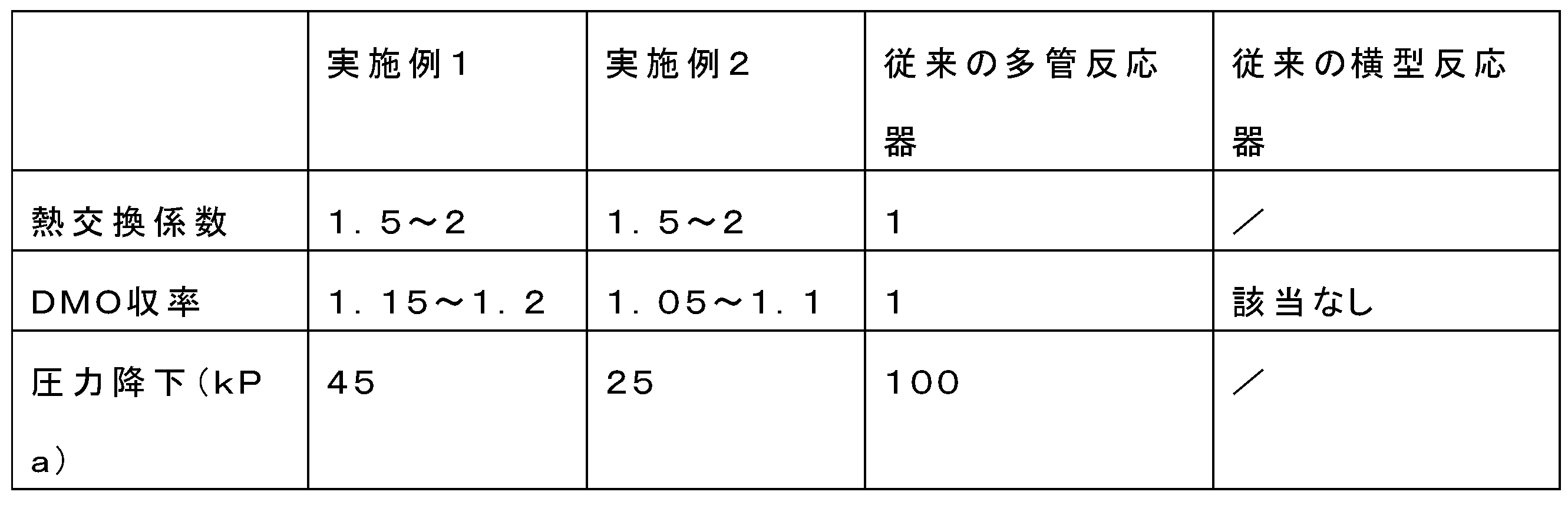
DMO収率とは、1時間あたり1立方メートルあたりに生成されるDMO粗生成物の量を意味し、ここで、通常の管式反応器との比較結果に基づいて、熱交換係数とDMO収率は相対値である。 DMO yield refers to the amount of crude DMO produced per cubic meter per hour, where the heat exchange coefficient and DMO yield are relative values based on comparison with a conventional tubular reactor.
上表から分かるように、実施例1に記載の反応器の熱伝達効果は顕著であり、熱交換係数は多管式反応器の1.5~2倍であり、DMO収率が15~20%程度向上する。
実施例2における反応器の熱伝達効果は顕著であり、熱交換係数が多管式反応器の1.5~2倍であり、DMO収率が5~10%程度向上する。
As can be seen from the above table, the heat transfer effect of the reactor described in Example 1 is significant, the heat exchange coefficient is 1.5 to 2 times that of the multi-tube reactor, and the DMO yield is improved by about 15 to 20%.
The heat transfer effect of the reactor in Example 2 is remarkable, with the heat exchange coefficient being 1.5 to 2 times that of the multi-tube reactor, and the DMO yield being improved by about 5 to 10%.
最後に、上記の好ましい実施例は、本発明の技術的手段を例示するためにのみ使用され、これらにより本発明が限定されるものではないことに留意されたい。本発明の技術的思想から逸脱しない限り様々な置換、変形及び変更が可能であることは当業者にとって明らかであり、当業者により置換、変形及び変更される場合も本発明の特許請求の範囲で限定される範囲に含まれる。 Finally, please note that the above preferred embodiments are used only to illustrate the technical means of the present invention, and the present invention is not limited by these. It is clear to those skilled in the art that various substitutions, modifications and changes are possible without departing from the technical idea of the present invention, and the substitutions, modifications and changes made by those skilled in the art are also included in the scope limited by the claims of the present invention.
Claims (9)
または、前記横型マルチノズルシェルの上方に少なくとも2個の等間隔かつ平行な原料ガス入口b(8)が配置され、その底部に対応する生成物出口b(9)が配置される、
ことを特徴とする、請求項6に記載の大規模DMO反応に用いられる横型マルチフロープレート式反応装置。 At least two equally spaced and parallel raw gas inlets a (6) are arranged in the horizontal direction on one side of the horizontal multi-nozzle shell, and corresponding product outlets a (7) are arranged on the opposite side;
Alternatively, at least two equally spaced and parallel raw gas inlets b (8) are arranged at the top of the horizontal multi-nozzle shell, and a corresponding product outlet b (9) is arranged at the bottom thereof.
The horizontal multi-flow plate reactor for use in the large-scale DMO reaction according to claim 6.
Applications Claiming Priority (2)
| Application Number | Priority Date | Filing Date | Title |
|---|---|---|---|
| CN202011364698.7 | 2020-11-27 | ||
| CN202011364698.7A CN112588206B (en) | 2020-11-27 | 2020-11-27 | Horizontal multi-process plate type reaction equipment for large-scale DMO reaction |
Publications (2)
| Publication Number | Publication Date |
|---|---|
| JP2022085877A JP2022085877A (en) | 2022-06-08 |
| JP7698564B2 true JP7698564B2 (en) | 2025-06-25 |
Family
ID=75187206
Family Applications (1)
| Application Number | Title | Priority Date | Filing Date |
|---|---|---|---|
| JP2021189967A Active JP7698564B2 (en) | 2020-11-27 | 2021-11-24 | Horizontal multi-flow plate reactor for large-scale DMO reactions |
Country Status (2)
| Country | Link |
|---|---|
| JP (1) | JP7698564B2 (en) |
| CN (1) | CN112588206B (en) |
Citations (5)
| Publication number | Priority date | Publication date | Assignee | Title |
|---|---|---|---|---|
| JP2004202430A (en) | 2002-12-26 | 2004-07-22 | Mitsubishi Chemical Engineering Corp | Plate type catalytic reactor |
| JP2010042339A (en) | 2008-08-11 | 2010-02-25 | Mitsubishi Chemicals Corp | Plate-type reactor |
| CN202876772U (en) | 2012-10-23 | 2013-04-17 | 上海戊正工程技术有限公司 | Industrialized plate type reactor for synthesizing ester by carbonylation coupling |
| JP5835420B2 (en) | 2008-03-31 | 2015-12-24 | 三菱化学株式会社 | Plate reactor and reaction product production method |
| CN207102556U (en) | 2017-07-05 | 2018-03-16 | 中国石化工程建设有限公司 | Horizontal reactor |
Family Cites Families (5)
| Publication number | Priority date | Publication date | Assignee | Title |
|---|---|---|---|---|
| FR2573996B1 (en) * | 1984-12-03 | 1987-01-30 | Azote & Prod Chim | REACTOR FOR EXOTHERMIC CATALYTIC SYNTHESIS, IN GAS PHASE UNDER PRESSURE, AND METHOD IMPLEMENTED |
| JPH06218269A (en) * | 1993-01-26 | 1994-08-09 | Mitsubishi Gas Chem Co Inc | Horizontal type fluidized bed catalyst reactor |
| EP2965807A1 (en) * | 2014-07-10 | 2016-01-13 | Casale SA | Horizontal catalytic reactor |
| CN106766401B (en) * | 2016-12-27 | 2022-09-09 | 天津商业大学 | Double-water-path horizontal direct contact condensation heat exchanger |
| CN107243298A (en) * | 2017-07-26 | 2017-10-13 | 德艾柯工程技术(上海)有限公司 | A kind of temperature control gas-solid horizontal reactor for having special distributor |
-
2020
- 2020-11-27 CN CN202011364698.7A patent/CN112588206B/en active Active
-
2021
- 2021-11-24 JP JP2021189967A patent/JP7698564B2/en active Active
Patent Citations (5)
| Publication number | Priority date | Publication date | Assignee | Title |
|---|---|---|---|---|
| JP2004202430A (en) | 2002-12-26 | 2004-07-22 | Mitsubishi Chemical Engineering Corp | Plate type catalytic reactor |
| JP5835420B2 (en) | 2008-03-31 | 2015-12-24 | 三菱化学株式会社 | Plate reactor and reaction product production method |
| JP2010042339A (en) | 2008-08-11 | 2010-02-25 | Mitsubishi Chemicals Corp | Plate-type reactor |
| CN202876772U (en) | 2012-10-23 | 2013-04-17 | 上海戊正工程技术有限公司 | Industrialized plate type reactor for synthesizing ester by carbonylation coupling |
| CN207102556U (en) | 2017-07-05 | 2018-03-16 | 中国石化工程建设有限公司 | Horizontal reactor |
Also Published As
| Publication number | Publication date |
|---|---|
| JP2022085877A (en) | 2022-06-08 |
| CN112588206A (en) | 2021-04-02 |
| CN112588206B (en) | 2022-12-06 |
Similar Documents
| Publication | Publication Date | Title |
|---|---|---|
| CN207102558U (en) | A kind of modularization temperature control reactor | |
| US4594227A (en) | Reaction method and reactor therefor | |
| EP1839735B1 (en) | A transverse tubular heat exchange reactor and a process for catalytic synthesis therein | |
| RU2398733C2 (en) | Converter system with maximum reaction speed for exothermic reactions | |
| CN105032305B (en) | A kind of new radial direction plate-type reactor | |
| RU2435639C2 (en) | Isothermal reactor | |
| CN102850183B (en) | Methanol synthesis system and method | |
| CN102836676A (en) | Gas-solid phase catalytic reactor | |
| JP2012529626A (en) | Multi-stage, multi-tube shell-and-tube reactor | |
| CN104801240B (en) | A kind of plate-type heat-exchange reactor | |
| CN103240036B (en) | A kind of heat transfer reactor of Anti-temperature difference stress and combinations thereof device and application | |
| EA038258B1 (en) | Oxidative dehydrogenation (odh) of ethane | |
| CN108114672B (en) | A kind of uniform heating spiral plate fixed bed reactor for gas-solid catalytic reaction | |
| RU2719441C1 (en) | Reactor for large-scale synthesis of ethylene glycol | |
| CN101254442A (en) | A method and reactor for exothermic pressurized catalytic reaction | |
| CN101927142A (en) | A tubular fixed bed reactor system | |
| CN214051563U (en) | Methyl acetate hydrogenation reactor and heat exchange system of multistage cold hydrogen feeding | |
| CN112169710A (en) | Methyl acetate hydrogenation reactor and heat exchange system of multistage cold hydrogen feeding | |
| WO2018205943A1 (en) | Modularized temperature control reactor | |
| JP7698564B2 (en) | Horizontal multi-flow plate reactor for large-scale DMO reactions | |
| CN112110788A (en) | Acetylene method chloroethylene synthesis reaction process | |
| CN209378963U (en) | A kind of plate-type reactor for the catalysis reaction of enlarged ester through hydrogenation | |
| CN202808648U (en) | Methanol synthetic system | |
| CN105413592A (en) | Combined type fixed bed reactor and device formed thereby | |
| CN205235936U (en) | Modular fixed bed reactor reaches device by its formation |
Legal Events
| Date | Code | Title | Description |
|---|---|---|---|
| A621 | Written request for application examination |
Free format text: JAPANESE INTERMEDIATE CODE: A621 Effective date: 20240719 |
|
| A977 | Report on retrieval |
Free format text: JAPANESE INTERMEDIATE CODE: A971007 Effective date: 20250227 |
|
| A131 | Notification of reasons for refusal |
Free format text: JAPANESE INTERMEDIATE CODE: A131 Effective date: 20250318 |
|
| A521 | Request for written amendment filed |
Free format text: JAPANESE INTERMEDIATE CODE: A523 Effective date: 20250328 |
|
| TRDD | Decision of grant or rejection written | ||
| A01 | Written decision to grant a patent or to grant a registration (utility model) |
Free format text: JAPANESE INTERMEDIATE CODE: A01 Effective date: 20250603 |
|
| A61 | First payment of annual fees (during grant procedure) |
Free format text: JAPANESE INTERMEDIATE CODE: A61 Effective date: 20250613 |
|
| R150 | Certificate of patent or registration of utility model |
Ref document number: 7698564 Country of ref document: JP Free format text: JAPANESE INTERMEDIATE CODE: R150 |