JP7698552B2 - Bulk item fall prevention device - Google Patents
Bulk item fall prevention device Download PDFInfo
- Publication number
- JP7698552B2 JP7698552B2 JP2021171086A JP2021171086A JP7698552B2 JP 7698552 B2 JP7698552 B2 JP 7698552B2 JP 2021171086 A JP2021171086 A JP 2021171086A JP 2021171086 A JP2021171086 A JP 2021171086A JP 7698552 B2 JP7698552 B2 JP 7698552B2
- Authority
- JP
- Japan
- Prior art keywords
- belt
- skirt
- width direction
- rubber
- bulk
- Prior art date
- Legal status (The legal status is an assumption and is not a legal conclusion. Google has not performed a legal analysis and makes no representation as to the accuracy of the status listed.)
- Active
Links
Images


Landscapes
- Framework For Endless Conveyors (AREA)
- Ship Loading And Unloading (AREA)
- Structure Of Belt Conveyors (AREA)
Description
本発明は、二重ベルトコンベヤの挟み込み部でのばら物落下防止装置に関する。 The present invention relates to a device for preventing bulk items from falling at the pinching section of a double belt conveyor.
船舶で運搬された石炭又は石灰石などのばら物は、港において、船艙から陸へと荷揚げされる。このばら物の荷揚げには、例えば、特許文献1に記載の二重ベルトコンベヤ(サンドウィッチベルトコンベヤ)を備えたアンローダが用いられる。特許文献1に記載のアンローダは、互いに対向する主ベルトと従ベルトとが合わされて、その合わせ部でばら物を挟んで搬送する。船艙内に位置する主ベルトと従ベルトとの先端部分は、互いに離れる方向に広がったスカート状となっている。このスカート状の部分(スカート部)にパドルフィーダ又は振動フィーダ等でばら物が送り出される。そして、主ベルトと従ベルトとは、スカート部に送り込まれたばら物を、挟み込んで搬送している。 Bulk materials such as coal or limestone transported by ships are unloaded from the ship's hold to land at the port. For example, an unloader equipped with a double belt conveyor (sandwich belt conveyor) as described in Patent Document 1 is used to unload the bulk materials. In the unloader described in Patent Document 1, opposing main and secondary belts are joined together to sandwich and transport the bulk materials at the joint. The tip portions of the main and secondary belts located inside the ship's hold are skirt-shaped, spreading out in the direction away from each other. Bulk materials are sent to this skirt-shaped portion (skirt portion) by a paddle feeder or vibrating feeder. The main and secondary belts then sandwich and transport the bulk materials sent to the skirt portion.
特許文献1に記載のアンローダにおいて、ばら物の入口であるスカート部の幅方向における両側面は、開放している。このため、主ベルトと従ベルトとでばら物を挟み込む際、バラ物がスカート部の両側面からこぼれ落ちるおそれがある。このような場合、アンローダによるばら物の搬送を効率よく行えない。 In the unloader described in Patent Document 1, both sides in the width direction of the skirt portion, which is the entrance for the bulk materials, are open. Therefore, when the bulk materials are sandwiched between the main belt and the secondary belt, there is a risk that the bulk materials may spill out from both sides of the skirt portion. In such a case, the unloader cannot efficiently transport the bulk materials.
そこで、本発明の目的の一例は、二重ベルトコンベヤでばら物を搬送する際に、ばら物のこぼれ落ちを防止する、ばら物落下防止装置を提供することである。 Therefore, one example of the object of the present invention is to provide a bulk material fall prevention device that prevents bulk materials from falling when transporting them on a double belt conveyor.
上記目的を達成するために、本発明の一側面におけるばら物落下防止装置は、
互いに重なり合い、重なり合う部分から徐々に離隔する第1ベルトと第2ベルトとを備え、被搬送物を前記重なり合う部分で保持した状態で、前記第1ベルトと前記第2ベルトとを連動させて回転させることで、前記被搬送物を搬送する二重ベルトコンベヤに用いられる、ばら物落下防止装置であって、
前記重なり合う部分から徐々に離隔する前記第1ベルトと前記第2ベルトとの間に配置される、第1スカート、及び、第2スカート、を備え、
前記第1スカートは、
ベルト延伸方向に延び、ベルト幅方向における中心から外れた位置に設置され、前記ベルト幅方向の外側へ向かう被搬送物を受け、
前記第2スカートは、
前記ベルト延伸方向に延び、前記ベルト幅方向において、前記第1スカートより外側に配置され、前記ベルト幅方向の外側へ向かう被搬送物を受ける。
In order to achieve the above object, a bulk object fall prevention device according to one aspect of the present invention comprises:
A bulk object drop prevention device for use in a double belt conveyor that includes a first belt and a second belt that overlap each other and gradually move away from the overlapping portion, and that conveys the conveyed object by rotating the first belt and the second belt in conjunction with each other while holding the conveyed object at the overlapping portion,
a first skirt and a second skirt disposed between the first belt and the second belt and spaced apart from the overlapping portion;
The first skirt is
the conveyor extends in a belt extension direction, is disposed at a position offset from the center in the belt width direction, and receives conveyed objects moving toward the outside in the belt width direction;
The second skirt is
The skirt extends in the belt extension direction, is positioned outside the first skirt in the belt width direction, and receives conveyed objects moving toward the outside in the belt width direction.
本発明の構成によると、二重ベルトコンベヤでばら物を搬送する際に、ばら物のこぼれ落ちを防止することができる。 The configuration of the present invention makes it possible to prevent loose objects from spilling out when transporting them on a double belt conveyor.
以下、図面を参照しつつ、二重ベルトコンベヤについて説明する。二重ベルトコンベヤは、2つのベルトで被搬送物を挟み込んで搬送するベルトコンベヤである。以下の説明では、被搬送物は、石炭、石灰石又は鉄鉱石等のばら物として説明する。 The double belt conveyor will be described below with reference to the drawings. The double belt conveyor is a belt conveyor that sandwiches the transported object between two belts and transports it. In the following explanation, the transported object will be described as loose material such as coal, limestone, or iron ore.
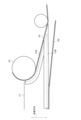
図1は、本実施形態のばら物落下防止を用いる、二重ベルトコンベヤ100を説明するための図である。
Figure 1 is a diagram illustrating a
二重ベルトコンベヤ100は、例えば船底に設けられた船艙200内のばら物を、陸上げするためのアンローダの一部である。図1では、図面上へ向かう方向が船上方向であり、図面下へ向かう方向が船底方向となっている。つまり、図面上下方向は、鉛直方向となる。二重ベルトコンベヤ100は、その下部が船艙200内に位置し、上部が船外(例えば、甲板上方)に位置するように設けられている。このように設けられた二重ベルトコンベヤ100は、その下部で取り込んだ船艙200内のばら物を船上へと搬送する。
The
なお、二重ベルトコンベヤ100で船上へと搬送されたばら物は、二重ベルトコンベヤ100の上端部近傍に配置された、不図示の水平方向に延びる別のベルトコンベヤに受け渡される。その後、ばら物は、別のベルトコンベヤによって、船上から陸へと搬送されるようになっている。
The bulk materials transported onto the ship by the
二重ベルトコンベヤ100は、第1ベルト101と、第2ベルト102とを有している。なお、第1ベルト101、及び、第2ベルト102は、複数のローラで支持されているが、図1では、一部のローラのみを図示している。
The
第1ベルト101及び第2ベルト102それぞれは無端状のベルトであり、複数のローラに架け渡されてループを形成している。第1ベルト101と、第2ベルト102とは、その一部が互いに向かい合って重なり合うように設けられている。二重ベルトコンベヤ100は、その間にばら物を挟み込んで、船艙200から船上へと搬送する。
The
以下、ループ状の第1ベルト101及び第2ベルト102において、ばら物を搬送する側はキャリア側と言い、ばら物を船上まで搬送し終えたベルトが、船艙200内の搬送入口へと戻る側は、リターン側と言う。
Hereinafter, in the loop-shaped
第1ベルト101は、船艙200内に配置された第1ローラ151と、船上に配置された第2ローラ152とに架け渡されて支持されている。また、第1ベルト101のキャリア側は、下方(船艙200)から上方(船上)に向かって、ループ外側に円弧状に突出するように、複数のローラ(不図示)で支持されている。
The
なお、第1ベルト101のリターン側でのローラによる支持構成は、特に限定されない。また、図示しないが、ベルトにかかる張力を調整する張力調整装置によって、第1ベルト101には、常に一定の張力が付与されるようになっている。
The support structure of the rollers on the return side of the
第2ベルト102は、船艙200の内外に配置された複数のローラに架け渡されて支持されている。第2ベルト102のキャリア側は、船艙200内で水平に延びた後、ループ内側に円弧状に突出するように船艙200内から船上に向かって延びている。
The
第1ベルト101と、第2ベルト102とは、円弧状となっている部分で向き合っている。ばら物がないとき、第1ベルト101と、第2ベルト102とは、円弧部分で密着している。ばら物は、この密着している部分で、第1ベルト101と、第2ベルト102とで保持されて搬送される。ばら物を搬送する際、第1ベルト101と、第2ベルト102との間には、ばら物が充填された搬送領域が形成される。
The
図2は、図1のII-II線における断面図である。第1ベルト101と第2ベルト102との間にばら物が挟み込まれると、第2ベルト102は、幅方向における中央部が第1ベルト101とは反対側へ凸状に湾曲し、幅方向における両側部が第1ベルト101の両側部に密着するようになる。これにより、第1ベルト101と第2ベルト102との間に、ばら物を保持する搬送領域120が形成される。図2では、搬送領域120内のばら物の図示は省略している。
Figure 2 is a cross-sectional view taken along line II-II in Figure 1. When loose objects are sandwiched between the
なお、第2ベルト102のリターン側でのローラによる支持構成は、特に限定されない。また、図示しないが、ベルトにかかる張力を調整する張力調整装置によって、第2ベルト102には、常に一定の張力が付与されるようになっている。
The support structure of the rollers on the return side of the
第2ベルト102は、第1ベルト101と重なり合う部分から、徐々に第1ベルト101から離隔するよう保持されている。以下、重なり合う部分から徐々に離隔している、第1ベルト101と第2ベルト102との間の領域を、搬送領域入口という。
The
上記のように構成された二重ベルトコンベヤ100は、船艙200内で水平に延びる第2ベルト102の水平部分にばら物が載置されると、そのばら物を搬送領域入口へ向けて搬送する。そして、二重ベルトコンベヤ100は、第1ベルト101と第2ベルト102とでばら物を挟み込みつつ保持して、船艙200から船上へと、鉛直上向きに搬送する。
When bulk goods are placed on the horizontal portion of the
上記したように、搬送領域入口では、重なり合っている第1ベルト101と第2ベルト102とは、重なり部分から離れるに従い(図1でいう左側に進むに従い)、徐々に離隔している。この搬送領域入口において、ばら物がベルト側部からこぼれ落ちるおそれがある。
As described above, at the entrance to the conveying area, the overlapping
そこで、搬送領域入口でのばら物の落下を防止するために、搬送領域入口には、ばら物落下防止装置10が設けられている。
Therefore, in order to prevent loose items from falling at the entrance to the conveying area, a loose item
図3は、図1のIII-III線における断面図である。なお、図3においても、図2と同様、ばら物の図示は省略している。 Figure 3 is a cross-sectional view taken along line III-III in Figure 1. Note that, like Figure 2, loose objects are not shown in Figure 3 either.
図2に示す、ベルト延伸方向から視た搬送領域120の断面形状は、搬送領域入口に近づくに従い、幅方向における中央側から徐々に離隔して、図3に示すように、第1ベルト101と第2ベルト102との両端部同士のみが密着した形状となる。この図3に示す搬送領域120の断面形状において、幅方向の中央部から両端に向かうに従い第1ベルト101と第2ベルト102との間隔が狭くなる領域は、端部領域120A及び端部領域120Bと言う。
The cross-sectional shape of the conveying
ばら物落下防止装置10は、図3に示すように、一対の第1スカート11と、一対の第2スカート12と、を有している。
As shown in FIG. 3, the bulk object
一対の第1スカート11は、ベルト延伸方向に沿って延びており、先端部が、密着する第1ベルト101と第2ベルト102との間に入り込むように設けられている。つまり、ばら物の搬送時、一対の第1スカート11は、その先端部が搬送領域120内に位置するようになっている。また、一対の第1スカート11それぞれは、ベルトの幅方向における中心から外れた位置に設けられている。詳しくは、一対の第1スカート11は、図3に示すように、ベルト延伸方向から視て、幅方向の中心よりも端部領域120A、120Bに近くなるように設けられている。
The pair of
この一対の第1スカート11は、向かい合っている第1ベルト101と第2ベルト102のうち、上側となる第1ベルト101に密着し、下側となる第2ベルト102から隔離するように設けられている。
The pair of
図4は、一対の第1スカート11の一方を、幅方向の中央から幅方向に沿って見た図である。一対の第1スカート11の他方は、一方と同様の構成なので、その説明は省略する。
Figure 4 shows one of the pair of
第1スカート11は、スカート本体111と、スカート本体111に取り付けられた上部スカートゴム112A及び下部スカートゴム112Bと、を有している。上部スカートゴム112A及び下部スカートゴム112Bは、幅方向の中心側に位置するように、スカート本体111に取り付けられている。そして、図4では、スカートゴム112A、112Bで隠れて見えないスカート本体111の一部を破線で示している。
The
スカート本体111は、例えば鋼板プレートである。図4の破線で示すように、スカート本体111の先端部の下面部は直線状であって、その上面部は、先端に向かうに従い下面部に徐々に近づくように傾斜している。
The
下部スカートゴム112Bは、ほぼ直線に延びる板状のゴムである。下部スカートゴム112Bは、スカート本体111の下面部側に、その下面部よりも突出するように取り付けられている。下部スカートゴム112Bは、例えば、ボルトなどでスカート本体111に取り付けられている。下部スカートゴム112Bの先端部は、スカート本体111の先端部と同様に、その上面が先端に向かうに従い下面に近づくように傾斜している。
The
上部スカートゴム112Aは、下部スカートゴム112Bと同様、板状のゴムである。上部スカートゴム112Aは、スカート本体111の先端部上面部側に、その上面部よりも突出するように取り付けられている。上部スカートゴム112Aは、例えば、ボルトなどで、下部スカートゴム112Bに密着させて取り付けられている。
The
上部スカートゴム112Aは、下部スカートゴム112Bと密着し、その上面が、密着する下部スカートゴム112Bの先端部の傾斜面と直線状となるような形状を有している。なお、上部スカートゴム112Aの上面の一部は、第1ローラ151と同じ曲率の曲面を有しており、第1スカート11を配置する際に、その曲面を第1ローラ151に隙間なく配置することができるようになっている。
The
上部スカートゴム112A及び下部スカートゴム112Bは、密着させてスカート本体111に取り付けられることで、一つのスカートゴムを形成する。そして、そのスカートゴムは、幅方向から見ると、先端に向かって徐々に細くなる形状となる。このような構成の第1スカート11は、上記したように、スカートゴムの先端部が搬送領域120内に位置し、かつ、幅方向における中心から外れた位置に、第1ベルト101と密着させつつ設けられる。
The
一対の第2スカート12のそれぞれは、第1スカート11と同様、ベルト延伸方向に沿って延びており、先端部が、密着する第1ベルト101と第2ベルト102との間に入り込むように設けられている。つまり、ばら物の搬送時、一対の第2スカート12は、その先端部が搬送領域120内に位置するようになっている。なお、後述するが、一対の第2スカート12は、ベルト延伸方向に沿って、搬送領域入口から離れる方向へ移動可能となっている。
Each of the pair of
一対の第2スカート12は、幅方向において、第1スカート11よりも外側に位置するように設けられている。
The pair of
この一対の第2スカート12は、向かい合っている第1ベルト101と第2ベルト102の上側となる第1ベルト101及び下側となる第2ベルト102それぞれに対して密着するように設けられている。
The pair of
図5は、一対の第2スカート12の一方を、幅方向の中央から幅方向に沿って見た図である。一対の第2スカート12の他方は、一方と同様の構成なので、その説明は省略する。
Figure 5 shows one of the pair of
第2スカート12は、スカート本体121と、スカート本体121に取り付けられた上部スカートゴム122A及び下部スカートゴム122Bと、を有している。上部スカートゴム122A及び下部スカートゴム122Bは、幅方向の中心側に位置するように、スカート本体121に取り付けられている。そして、図5では、スカートゴム122A、122Bで隠れて見えないスカート本体121の一部を破線で示している。
The
スカート本体121は、例えば鋼板プレートである。図5の破線で示すように、スカート本体121の先端部の下面部は直線状であって、その上面部は、先端に向かうに従い下面部に徐々に近づくように傾斜している。
The
スカート本体121は移動部13に支持されている。後に詳述するが、スカート本体121は、移動部13によって、ベルト延伸方向に沿って移動するようになっている。
The
下部スカートゴム122Bは、ほぼ直線に延びる板状のゴムである。下部スカートゴム122Bは、スカート本体121の下面部側に、その下面部よりも突出するように取り付けられている。下部スカートゴム122Bは、例えば、ボルトなどでスカート本体121に取り付けられている。下部スカートゴム122Bの先端部は、スカート本体121の先端部と同様に、その上面が先端に向かうに従い下面に近づくように傾斜している。
The
上部スカートゴム122Aは、下部スカートゴム122Bと同様、板状のゴムである。上部スカートゴム122Aは、スカート本体121の先端部上面部側に、その上面部よりも突出するように取り付けられている。上部スカートゴム122Aは、例えば、ボルトなどで、下部スカートゴム122Bと密着させて取り付けられている。
The
上部スカートゴム122Aは、下部スカートゴム122Bと密着し、その上面が、密着する下部スカートゴム122Bの先端部の傾斜面と直線状となるような形状を有している。
The
上部スカートゴム122A及び下部スカートゴム122Bは、密着させてスカート本体121に取り付けられることで、一つのスカートゴムを形成する。そして、そのスカートゴムは、幅方向から見ると、先端に向かって徐々に細くなる形状となる。このような構成の第2スカート12は、上記したように、スカートゴムの先端部が搬送領域120内に位置し、かつ、幅方向におけるベルト外側端部と第1スカート11との間の位置に、第1ベルト101及び第2ベルト102と密着させつつ設けられる。
The
なお、図3に示すように、第2スカート12の上部スカートゴム122A及び下部スカートゴム122Bの厚みは、第1スカート11の上部スカートゴム112A及び下部スカートゴム112Bの厚みよりも薄い。
As shown in FIG. 3, the thickness of the
このように、第1スカート11及び第2スカート12は、幅方向におけるベルト両端部近傍に配置されている。このため、第1スカート11及び第2スカート12は、ベルト側部へ向かうばら物を受けるようになっている。これにより、搬送領域入口において、ばら物がベルト側部からこぼれ落ちることを防止できるようになっている。
In this way, the
また、幅方向の内側に配置される一対の第1スカート11は、図3及び図4に示すように、第2ベルト102と接触せず、間に間隙が形成されている。これにより、第1スカート11は、第2ベルト102上に積載されるばら物のうち、上部のばら物だけを受けることとなる。そして、第2スカート12は、第1スカート11が受けられなかったばら物を受けることとなる。つまり、2つのスカート(第1スカート11及び第2スカート12)を設けることで、1つのスカートだけを設けた場合と比べて、それぞれのスカートが受けるばら物の量を少なくすることができる。この結果、第1スカート11及び第2スカート12の寿命をより長くすることができ、メンテナンス回数を減らすことができる。
As shown in Figs. 3 and 4, the pair of
また、ばら物を受ける量、及び、ばら物から受ける押圧力は、第2スカート12よりも、幅方向の中央に近い第1スカート11の方が大きい。このため、第2スカート12の上部スカートゴム122A及び下部スカートゴム122Bの厚さを、第1スカート11のよりも薄くすることができる。その結果、コストダウンを図ることができる。
In addition, the amount of loose material received and the pressing force received from the loose material are greater in the
さらに、第1スカート11及び第2スカート12において、第1ベルト101及び第2ベルト102それぞれと密着する部分がゴムであることにより、第1ベルト101及び第2ベルト102に傷などがつき、破損するおそれを回避することができる。
Furthermore, since the parts of the
上記したように、第2スカート12は移動部13に支持され、図6に示すように、ベルト延伸方向に沿って移動可能となっている。図6は、第2スカート12を搬送領域入口から遠ざけるように移動させた状態を示す図である。
As described above, the
移動部13は、本体部131と、移動レール132と、一対のローラ133と、カウンターウェイト134と、を有している。
The moving
移動レール132は、第2ベルト102の水平部の上方に配置されている。移動レール132は、図1に示すように、第2ベルト102の水平部に対してほぼ平行に延びている。第2スカート12は、この移動レール132に沿って移動するようになっている。
The moving
本体部131は、第2スカート12のスカート本体121を支持している。本体部131は、一対のローラ133を回転可能に支持している。一対のローラ133は、移動レール132を間に保持している。一対のローラ133は、手動、又は、不図示の制御装置により回転する。本体部131は、一対のローラ133が回転することで、移動レール132に沿って移動するようになっている。本体部131には、第2スカート12の姿勢を安定させるためのカウンターウェイト134が設けられている。
The
第2スカート12がベルト延伸方向に沿って移動可能となることで、第2スカート12を、搬送領域入口から遠ざかる方向へ移動させることができる。これにより、メンテナンスを行う作業者は、第2スカート12よりも幅方向の内側に位置する第1スカート11に対して、ベルト側方からアクセスすることができる。その結果、作業者は、第1スカート11を目視でき、また、そのメンテナンス、例えば、ボルト-ナットを取り外して上部スカートゴム112A及び下部スカートゴム112Bの交換など、を行うことができる。
By allowing the
10 :ばら物落下防止装置
11 :第1スカート
12 :第2スカート
13 :移動部
100 :二重ベルトコンベヤ
101 :第1ベルト
102 :第2ベルト
111 :スカート本体
112A :上部スカートゴム
112B :下部スカートゴム
120 :搬送領域
120A :端部領域
120B :端部領域
121 :スカート本体
122A :上部スカートゴム
122B :下部スカートゴム
131 :本体部
132 :移動レール
133 :ローラ
134 :カウンターウェイト
151 :第1ローラ
152 :第2ローラ
200 :船艙
10: Bulk object fall prevention device 11: First skirt 12: Second skirt 13: Moving part 100: Double belt conveyor 101: First belt 102: Second belt 111:
Claims (3)
前記重なり合う部分から徐々に離隔する前記第1ベルトと前記第2ベルトとの間に配置される、第1スカート、及び、第2スカート、を備え、
前記第1スカートは、
ベルト延伸方向に延び、ベルト幅方向における中心から外れた位置に設置され、前記ベルト幅方向の外側へ向かう被搬送物を受け、
前記第2スカートは、
前記ベルト延伸方向に延び、前記ベルト幅方向において、前記第1スカートより外側に配置され、前記ベルト幅方向の外側へ向かう被搬送物を受け、
前記被搬送物が前記重なり合う部分で保持された状態では、前記ベルト延伸方向から視た、前記第1ベルト及び前記第2ベルトの断面形状は、前記ベルト幅方向における前記第1ベルトの両端と前記第2ベルトの両端とが互いに押し付けられ、前記ベルト幅方向の両端に向かうに従い前記第1ベルトと前記第2ベルトとの間隔が狭くなる形状となり、
前記第2スカートは、前記間隔が狭くなる領域に設置されている、
ばら物落下防止装置。 A bulk object drop prevention device for use in a double belt conveyor that includes a first belt and a second belt that overlap each other and gradually move away from the overlapping portion, and that conveys the conveyed object by rotating the first belt and the second belt in conjunction with each other while holding the conveyed object at the overlapping portion,
a first skirt and a second skirt disposed between the first belt and the second belt and spaced apart from the overlapping portion;
The first skirt is
the conveyor extends in a belt extension direction, is disposed at a position offset from the center in the belt width direction, and receives conveyed objects moving toward the outside in the belt width direction;
The second skirt is
a first skirt extending in the belt extension direction, disposed outside the first skirt in the belt width direction, and receiving an object moving toward the outside in the belt width direction ;
In a state in which the object to be conveyed is held at the overlapping portion, the cross-sectional shapes of the first belt and the second belt as viewed from the belt extension direction are such that both ends of the first belt and both ends of the second belt in the belt width direction are pressed against each other, and the distance between the first belt and the second belt becomes narrower toward both ends in the belt width direction,
The second skirt is disposed in the area where the spacing is narrowed .
Bulk item falling prevention device.
前記第2スカートの前記スカートゴムの厚みは、前記第1スカートの前記スカートゴムの厚みよりも薄くされている、請求項1又は請求項2に記載のばら物落下防止装置。
Each of the first skirt and the second skirt includes a skirt body and a skirt rubber attached to the skirt body,
A bulk object fall prevention device as described in claim 1 or claim 2 , wherein the thickness of the skirt rubber of the second skirt is thinner than the thickness of the skirt rubber of the first skirt.
Priority Applications (1)
| Application Number | Priority Date | Filing Date | Title |
|---|---|---|---|
| JP2021171086A JP7698552B2 (en) | 2021-10-19 | 2021-10-19 | Bulk item fall prevention device |
Applications Claiming Priority (1)
| Application Number | Priority Date | Filing Date | Title |
|---|---|---|---|
| JP2021171086A JP7698552B2 (en) | 2021-10-19 | 2021-10-19 | Bulk item fall prevention device |
Publications (2)
| Publication Number | Publication Date |
|---|---|
| JP2023061227A JP2023061227A (en) | 2023-05-01 |
| JP7698552B2 true JP7698552B2 (en) | 2025-06-25 |
Family
ID=86239203
Family Applications (1)
| Application Number | Title | Priority Date | Filing Date |
|---|---|---|---|
| JP2021171086A Active JP7698552B2 (en) | 2021-10-19 | 2021-10-19 | Bulk item fall prevention device |
Country Status (1)
| Country | Link |
|---|---|
| JP (1) | JP7698552B2 (en) |
Citations (1)
| Publication number | Priority date | Publication date | Assignee | Title |
|---|---|---|---|---|
| JP2001233432A (en) | 2000-02-24 | 2001-08-28 | Ishikawajima Harima Heavy Ind Co Ltd | Skirt structure of belt conveyor |
Family Cites Families (2)
| Publication number | Priority date | Publication date | Assignee | Title |
|---|---|---|---|---|
| JP3389729B2 (en) * | 1995-03-22 | 2003-03-24 | 石川島播磨重工業株式会社 | Belt conveyor skirt structure |
| JPH09328210A (en) * | 1996-06-11 | 1997-12-22 | Ishikawajima Harima Heavy Ind Co Ltd | Steep slope conveyor equipment |
-
2021
- 2021-10-19 JP JP2021171086A patent/JP7698552B2/en active Active
Patent Citations (1)
| Publication number | Priority date | Publication date | Assignee | Title |
|---|---|---|---|---|
| JP2001233432A (en) | 2000-02-24 | 2001-08-28 | Ishikawajima Harima Heavy Ind Co Ltd | Skirt structure of belt conveyor |
Also Published As
| Publication number | Publication date |
|---|---|
| JP2023061227A (en) | 2023-05-01 |
Similar Documents
| Publication | Publication Date | Title |
|---|---|---|
| US3578149A (en) | Belt conveyors | |
| US3910405A (en) | Conveyor apparatus | |
| US6269943B1 (en) | Conveyor assembly | |
| AU2018355899B2 (en) | Enclosed belt rail conveyor system | |
| US20080060915A1 (en) | Article conveyor, in particular for airline baggage | |
| JP7698552B2 (en) | Bulk item fall prevention device | |
| US3545598A (en) | Laterally flexible belt conveyor | |
| US9409713B2 (en) | Bulk material conveyor belt loading zone and method of loading a bulk material conveyor belt | |
| US11655104B2 (en) | Deflector for high angle conveyor pressing assembly | |
| KR101398349B1 (en) | Belt of belt conveyor and belt conveyor using the same | |
| RU2307779C1 (en) | Vertical belt conveyor | |
| JP7348496B2 (en) | Conveyance equipment | |
| KR100815729B1 (en) | Falling material blocking device of skirt box of belt conveyor | |
| US1055591A (en) | Belt conveyer. | |
| KR101919357B1 (en) | Aligning apparatus for belt conveyor and aligning method using the same | |
| JP3590359B2 (en) | Apron conveyor | |
| US679573A (en) | Conveyer. | |
| US20110139585A1 (en) | Method of conveying material | |
| US968211A (en) | Conveyer. | |
| JP2021155218A (en) | Skirt structure of belt conveyor | |
| JP7318673B2 (en) | Goods sorting method and goods sorting device | |
| KR102519857B1 (en) | Skirting Device for belt conveyer and belt conveyer comprising it | |
| KR200339713Y1 (en) | Dust Anti Scattering Apparatus of Belt Conveyer | |
| JPS6311244B2 (en) | ||
| EP0155774A1 (en) | Elevating conveyor |
Legal Events
| Date | Code | Title | Description |
|---|---|---|---|
| A621 | Written request for application examination |
Free format text: JAPANESE INTERMEDIATE CODE: A621 Effective date: 20240606 |
|
| A977 | Report on retrieval |
Free format text: JAPANESE INTERMEDIATE CODE: A971007 Effective date: 20250219 |
|
| A131 | Notification of reasons for refusal |
Free format text: JAPANESE INTERMEDIATE CODE: A131 Effective date: 20250311 |
|
| A521 | Request for written amendment filed |
Free format text: JAPANESE INTERMEDIATE CODE: A523 Effective date: 20250430 |
|
| TRDD | Decision of grant or rejection written | ||
| A01 | Written decision to grant a patent or to grant a registration (utility model) |
Free format text: JAPANESE INTERMEDIATE CODE: A01 Effective date: 20250610 |
|
| A61 | First payment of annual fees (during grant procedure) |
Free format text: JAPANESE INTERMEDIATE CODE: A61 Effective date: 20250613 |
|
| R150 | Certificate of patent or registration of utility model |
Ref document number: 7698552 Country of ref document: JP Free format text: JAPANESE INTERMEDIATE CODE: R150 |