JP7689480B2 - Bolt cooling tool and bolt cooling method - Google Patents
Bolt cooling tool and bolt cooling method Download PDFInfo
- Publication number
- JP7689480B2 JP7689480B2 JP2021175079A JP2021175079A JP7689480B2 JP 7689480 B2 JP7689480 B2 JP 7689480B2 JP 2021175079 A JP2021175079 A JP 2021175079A JP 2021175079 A JP2021175079 A JP 2021175079A JP 7689480 B2 JP7689480 B2 JP 7689480B2
- Authority
- JP
- Japan
- Prior art keywords
- bolt
- air
- connecting tube
- central hole
- cooling
- Prior art date
- Legal status (The legal status is an assumption and is not a legal conclusion. Google has not performed a legal analysis and makes no representation as to the accuracy of the status listed.)
- Active
Links
Images


Landscapes
- Connection Of Plates (AREA)
Description
本発明は、蒸気タービンの車室など、大型の部品を据え付ける際に使用するボルト冷却用治具およびボルトの冷却方法に関する。 The present invention relates to a bolt cooling jig and a bolt cooling method used when installing large parts such as the casing of a steam turbine.
発電用の蒸気タービンの車室などは、内部の高温高圧に耐え抜く必要があり、その据え付けには大型のボルトを使用している。そして車室などの施工時のほか、検査や修理の終了後、このボルトを締め付ける際は、あらかじめボルトを加熱して伸びを生じさせる場合がある。この伸びにより、ボルトが冷却した後は、内部に引張荷重が作用した状態になるため、車室などの部品を強固に据え付けることができるほか、運用時の高温状態においても、内部の圧力を受け止めることができる。 The casings of power-generating steam turbines and other components must be able to withstand the high temperatures and pressures inside, and large bolts are used to install them. When installing the casings, or when tightening the bolts after inspections or repairs, the bolts may be heated in advance to cause them to stretch. This stretching causes a tensile load to act on the inside of the bolt after it cools, allowing it to firmly install components such as the casings, and also allowing it to withstand internal pressure even at high temperatures during operation.
このように、ボルトの締め付けに先立ち、ボルトを加熱することを前提とする場合、ボルトの内部には中心孔を形成してあることが多く、実際に加熱する際は、中心孔に棒状のヒーターを差し込むことになるが、ボルトと同等の長さを有するヒーターを使用することで、全域を均等に加熱することができる。そして加熱された状態で締め付けを行い、その後にボルトを冷却していき、冷却を終えた段階でボルトの伸び量を測定することになるが、これが適正な範囲から外れている場合、締め付けをやり直すことになる。 In this way, when the bolt is assumed to be heated prior to tightening, a central hole is often formed inside the bolt, and a rod-shaped heater is inserted into the central hole when actually heating it. By using a heater that is the same length as the bolt, the entire area can be heated evenly. The bolt is then tightened in a heated state, after which it is cooled, and the amount of elongation of the bolt is measured at the end of cooling. If this is outside the appropriate range, tightening must be repeated.
中心孔が形成されたボルトにナットを締め付けていく過程を図6に示す。ここでは蒸気タービンを取り囲む車室が上半外部車室と下半外部車室に分割されており、しかも両車室の接触面を貫くように締結穴を形成してあり、そこにボルトを差し込んでいく。このボルトは、汎用のスタッドボルトと同様、丸棒状の軸部だけで構成されており、その上下にナットを螺合させることになる。そして両車室を密着させる際は、図の左上のように、双方の締結穴を同心に揃え、次の図の右上のように、上下の締結穴を貫くようにボルトを差し込んでいくが、その際は、あらかじめボルトの上部にナットを螺合させておく。その後、図の中央のように、中心孔にヒーターを差し込んでボルトを加熱すると、伸びを生じることになる。この状態において、図の左下のように、ボルトの下端部にナットを螺合させ、ボルトとナットが規定の位置関係に揃うまで締め付けを行う。その後、図の右下のように、中心孔にパイプを差し込み、エアホースから供給された空気を中心孔に流すことでボルトの冷却を行い、冷却を終えた段階でボルトの伸び量を測定し、締め付けが適正であるか否かを判断することになる。なお実際には、加熱前の段階でボルトの下端部にナットを仮締めしておく。 Figure 6 shows the process of tightening a nut onto a bolt with a central hole. In this case, the casing surrounding the steam turbine is divided into an upper half external casing and a lower half external casing, and a fastening hole is formed to penetrate the contact surface between the two casings, into which the bolt is inserted. This bolt, like a general-purpose stud bolt, is composed only of a round bar-shaped shaft, and a nut is screwed onto the top and bottom of it. When the two casings are to be brought into close contact, the fastening holes on both sides are aligned concentrically as shown in the upper left of the figure, and the bolt is inserted so that it penetrates the upper and lower fastening holes as shown in the upper right of the following figure, but in this case, the nut is screwed onto the top of the bolt beforehand. After that, a heater is inserted into the central hole to heat the bolt as shown in the center of the figure, which causes it to stretch. In this state, as shown in the lower left of the figure, a nut is screwed onto the lower end of the bolt, and the bolt is tightened until the bolt and nut are aligned in the specified positional relationship. After that, as shown in the lower right of the figure, a pipe is inserted into the center hole and air is supplied from an air hose into the center hole to cool the bolt, and once cooling is complete, the bolt's elongation is measured to determine whether it is properly tightened. In practice, a nut is provisionally tightened on the bottom end of the bolt before heating.
蒸気タービンなどで使用するボルトの冷却については、その重要性から様々な技術開発が行われており、その例として後記の特許文献が挙げられる。そのうち特許文献1では、一対のフランジをボルトとナットで挟み込む構造において、ボルトを加熱した後の冷却時間を短縮し、フランジの温度上昇を抑制できる技術が開示されている。このフランジには、ボルトを差し込むためのボルト穴を形成してあり、そこにボルトを差し込んだ後、ボルトの内部にヒーターを挿入して加熱し、次にナットを締め付ける。その後、外部からボルト穴に向けて冷却流体を流入させ、それがボルトを取り囲むように流れることで、ボルトの冷却時間を短縮できるほか、フランジの温度上昇を抑制することができる。なおボルト穴は、ボルトよりも大径であり、冷却流体が流れる隙間が確保されているほか、フランジには、ボルト穴に接続する冷却流体通路を形成してある。 Due to the importance of cooling bolts used in steam turbines and the like, various technological developments have been made, and examples of these include the patent documents listed below. Patent document 1 discloses a technology that can shorten the cooling time after heating the bolts and suppress the temperature rise of the flanges in a structure in which a pair of flanges are sandwiched between bolts and nuts. The flanges are formed with bolt holes for inserting the bolts, and after the bolts are inserted into the bolts, a heater is inserted into the bolts to heat them, and then the nuts are tightened. After that, cooling fluid is introduced from the outside toward the bolt holes, and the fluid flows so as to surround the bolts, shortening the cooling time of the bolts and suppressing the temperature rise of the flanges. The bolt holes are larger in diameter than the bolts, and a gap is secured for the cooling fluid to flow through, and the flanges are formed with cooling fluid passages that connect to the bolt holes.
また特許文献2では、短時間でボルトを冷却できるボルト冷却装置が開示されている。このボルト冷却装置は、液体冷媒が封入された棒状のヒートパイプと、その一端側に設けられた放熱フィンとの二要素で構成されており、ボルトが加熱された後、ボルトに設けられた孔にヒートパイプを挿入すると、封入された液体冷媒が高温になって上昇し、放熱フィンの近傍に到達する。その結果、液体冷媒の熱は放熱フィンから大気中に放出され、それに伴って液体冷媒の温度が低下するため、液体冷媒はヒートパイプの内部を下降していき、再び加熱されることになり、この過程を繰り返すことで、短時間でボルトを冷却することができる。 Patent Document 2 also discloses a bolt cooling device that can cool bolts in a short time. This bolt cooling device is composed of two elements: a rod-shaped heat pipe filled with liquid refrigerant and a heat dissipation fin attached to one end of the heat pipe. After the bolt is heated, the heat pipe is inserted into a hole in the bolt, and the liquid refrigerant inside becomes hot and rises, reaching the vicinity of the heat dissipation fin. As a result, the heat of the liquid refrigerant is released from the heat dissipation fin into the atmosphere, and the temperature of the liquid refrigerant drops accordingly, so that the liquid refrigerant descends inside the heat pipe and is heated again. By repeating this process, the bolt can be cooled in a short time.
次の特許文献3では、前記の両文献のようなボルトの冷却ではなく、大型の蒸気タービンについて、その水平フランジの締め付けボルトの伸び測定装置が開示されている。ここでは、締め付けボルトの締め付け作業を熱間で行っており、その残留熱応力を利用して締め付け力を確保しているが、その際、締め付けボルトの伸び量を測定することで締め付け力を算定している。そしてこの測定装置は、ワイヤーとワイヤードラムとエンコーダーと接触子などで構成されており、ワイヤーはワイヤードラムに巻き付けられているほか、ワイヤードラムから繰り出されたワイヤーの先端には、接触子が取り付けられている。さらにワイヤードラムの回転はエンコーダーで監視されており、これによってワイヤーロープの繰り出し長さを把握することができる。実際の測定時は、締め付けボルトの通孔に接触子を差し込み、これを通孔の出口やタップ穴の底に接触させ、その際のエンコーダーの値により、締め付けボルトの伸び量を把握することができる。 The following Patent Document 3 discloses an elongation measuring device for the tightening bolts of the horizontal flanges of large steam turbines, instead of cooling the bolts as in the two documents mentioned above. Here, the tightening bolts are tightened hot, and the tightening force is secured by utilizing the residual thermal stress. At that time, the tightening force is calculated by measuring the amount of elongation of the tightening bolts. This measuring device is composed of a wire, a wire drum, an encoder, a contactor, etc., and the wire is wound around the wire drum, and a contactor is attached to the tip of the wire that is unwound from the wire drum. Furthermore, the rotation of the wire drum is monitored by an encoder, which allows the length of the wire rope to be known. During actual measurement, the contactor is inserted into the through hole of the tightening bolt and brought into contact with the exit of the through hole or the bottom of the tapped hole, and the amount of elongation of the tightening bolt can be known from the value of the encoder at that time.
前記の特許文献のように、加熱されたボルトを締め付けた後、強制的に冷却を行うことで、締め付け状態を確認するまでの時間を短縮することができる。蒸気タービンの車室は、多数のボルトが狭い間隔で連続的に配置されており、その冷却時間を短縮することは、発電設備の施工や検査や修理を円滑に進める上で極めて重要である。ただし特許文献1で開示された技術は、フランジなどの部品に冷却流体通路を形成する必要があり、汎用性に乏しい。また特許文献2で開示された装置は、構造が複雑であるほか、ボルトの長さに応じて個別に装置を製造する必要があるなど、導入時や運用時の費用面などで課題がある。そこで多くの現場では、先の図6のように、エアホースの端部にパイプを取り付け、このパイプをボルトの中心孔に差し込み、空気を流すことで冷却を行っている。この方法は、あらゆる現場で簡単に実施できるほか、ボルトの長さが異なる場合でも柔軟に対応できるなど、多くの利点を有するため、現状においても広く実施されている。 As in the above patent document, the time required to check the tightening state can be shortened by forcibly cooling the heated bolts after tightening them. In the casing of a steam turbine, many bolts are arranged continuously at close intervals, and shortening the cooling time is extremely important for smooth construction, inspection, and repair of power generation equipment. However, the technology disclosed in Patent Document 1 requires the formation of cooling fluid passages in parts such as flanges, and is therefore not very versatile. In addition, the device disclosed in Patent Document 2 has a complex structure and requires the device to be manufactured individually according to the length of the bolt, which creates problems in terms of costs at the time of introduction and operation. Therefore, in many sites, as shown in Figure 6 above, a pipe is attached to the end of the air hose, and this pipe is inserted into the center hole of the bolt and air is passed through it to cool it. This method has many advantages, such as being easy to implement at any site and being flexible to handle cases where the length of the bolt is different, and is currently widely used.
ただし、単純にパイプを中心孔に差し込んだだけでは、空気の流れの反力によって中心孔から飛び出してしまう恐れがある。またボルトが車室などの部品に差し込まれた後は、その周辺構造により、中心孔の両端が外部に露出している場合と、一端だけが外部に露出している場合がある。そして仮に、両端が外部に露出している中心孔にパイプを差し込んだ場合、パイプの先端面よりも先では十分な空気が流れるものの、パイプの先端面よりも手前側では、空気の流れが不足して冷却が不十分になる恐れがある。そのほか、中心孔の一端だけが外部に露出している場合、そこが空気の入り口と出口を兼ねることになり、空気の放出手段が重要な課題になる。 However, simply inserting a pipe into the central hole may cause it to fly out of the hole due to the reaction force of the air flow. Also, after the bolt is inserted into a part such as the vehicle interior, depending on the surrounding structure, both ends of the central hole may be exposed to the outside, or only one end may be exposed to the outside. If a pipe is inserted into a central hole with both ends exposed to the outside, there may be sufficient air flow beyond the tip of the pipe, but there may not be enough air flow before the tip of the pipe, resulting in insufficient cooling. In addition, if only one end of the central hole is exposed to the outside, that end serves as both the air inlet and outlet, and a means of releasing the air becomes an important issue.
本発明はこうした実情を基に開発されたもので、加熱されたボルトを締め付けた後、その冷却を確実に実施できるほか、ボルトの周辺構造の違いに対応することのできるボルト冷却用治具およびボルトの冷却方法の提供を目的としている。 The present invention was developed based on these circumstances, and aims to provide a bolt cooling tool and a bolt cooling method that can reliably cool a heated bolt after it has been tightened, and that can accommodate differences in the surrounding structure of the bolt.
前記の課題を解決するための請求項1記載の発明は、ボルトの内部を貫く中心孔の端部に形成されたメネジに螺合する接続筒と、該接続筒の一端面を塞ぐ頭部と、該頭部から突出する給気口とを有しており、前記給気口に供給された空気を前記接続筒から前記中心孔に流すことで前記ボルトを冷却することができ、前記接続筒には、前記中心孔内の空気を外部に放出するための排気口を形成してあることを特徴とするボルト冷却用治具である。 The invention described in claim 1, which aims to solve the above problem, is a bolt cooling tool that has a connecting tube that screws into a female thread formed at the end of a central hole that penetrates the inside of a bolt, a head that closes one end face of the connecting tube, and an air intake port that protrudes from the head, and is characterized in that the bolt can be cooled by flowing air supplied to the air intake port from the connecting tube to the central hole, and the connecting tube is formed with an exhaust port for releasing the air in the central hole to the outside.
本発明は、加熱された大型のボルトを確実に冷却することを目的としているが、このボルトの中心部には、軸線方向に伸びる中心孔を形成してあることを前提とする。しかも中心孔の端部には、メネジを形成してあるものとする。このメネジは、ボルトを吊り上げる際などに使用する。なおボルトを車室などの部品に差し込んだ際、その端部は、部品から突出して外部に露出する場合もあれば、部品の内部に埋め込まれ、外部に露出しない場合もある。 The present invention aims to reliably cool a heated large bolt, and assumes that the bolt has a central hole extending in the axial direction at its center. Furthermore, the end of the central hole is formed with a female thread. This female thread is used when lifting the bolt, etc. When the bolt is inserted into a part such as the vehicle interior, the end may protrude from the part and be exposed to the outside, or it may be embedded inside the part and not exposed to the outside.
ボルト冷却用治具は、接続筒と頭部と給気口の三要素を中心に構成される。そのうち接続筒は、文字通りの円筒状の部位であり、ボルトの中心孔に差し込まれる。そして接続筒の外周面にはオネジを形成してあり、これが中心孔の端部に形成されたメネジに螺合することで、ボルト冷却用治具が取り付けられた状態になる。また頭部は、接続筒の一端面を塞ぐ部位であり、通常は接続筒よりも一回り大きく、中心孔に入り込むことはない。なお頭部については、接続筒のオネジと中心孔のメネジを螺合させる際の駆動源になるため、工具で挟み込むことのできる平面を形成しておく。 The bolt cooling jig is comprised of three main elements: the connecting tube, the head, and the air intake. The connecting tube is literally a cylindrical part that is inserted into the central hole of the bolt. A male thread is formed on the outer periphery of the connecting tube, and this is screwed into the female thread formed at the end of the central hole to attach the bolt cooling jig. The head is a part that covers one end face of the connecting tube, and is usually one size larger than the connecting tube, so it does not enter the central hole. The head serves as the driving source when screwing the male thread of the connecting tube into the female thread of the central hole, so it is formed with a flat surface that can be clamped with a tool.
給気口は、外部から供給される空気を取り入れるための部位であり、頭部を基準として接続筒の反対側に配置される。この給気口は、工場内などに敷設された空気配管に連結できるならば、その具体的な形態は自在だが、通常は、空気配管の端部に組み込まれたカプラーと連結可能な構成にする。したがって接続筒をボルトの中心孔に取り付けた際は、中心孔が頭部で覆い隠されるほか、頭部から給気口が突出した状態になる。そして給気口から取り入れられた空気は、頭部の中を経て接続筒の内部に流れていき、ボルトの冷却を担うことになる。 The air intake is a part for taking in air supplied from outside, and is located on the opposite side of the connecting tube with respect to the head. This air intake can take any shape as long as it can be connected to air piping installed in a factory or the like, but it is usually designed to be connectable to a coupler built into the end of the air piping. Therefore, when the connecting tube is attached to the center hole of the bolt, the center hole is covered by the head, and the air intake protrudes from the head. The air taken in from the air intake then flows through the head and into the connecting tube, cooling the bolt.
排気口は、接続筒の側周面に形成した切り抜きであり、中心孔に滞留した空気を外部に放出するための機能を果たす。仮に中心孔の両端が外部に露出しているならば、その一端側に供給されたた空気は、中心孔を通り抜けて他端側から外部に放出されることになる。ただし中心孔の一端だけが外部に露出している場合、そこにボルト冷却用治具を取り付けるため、内部の空気を外部に放出することが難しい。そこで接続筒に排気口を形成し、そこから空気を放出することで、中心孔の内部で空気の流れが発生するため、ボルトの冷却が可能になる。 The exhaust port is a cutout formed on the side surface of the connecting tube, and serves the function of releasing air trapped in the central hole to the outside. If both ends of the central hole were exposed to the outside, air supplied to one end would pass through the central hole and be released to the outside from the other end. However, if only one end of the central hole is exposed to the outside, a bolt cooling jig would be attached there, making it difficult to release the air inside to the outside. Therefore, by forming an exhaust port in the connecting tube and releasing air from there, an air flow is generated inside the central hole, making it possible to cool the bolt.
排気口は、前記のように接続筒の側周面に形成してある。そのため、接続筒と中心孔との螺合長さを増大させて排気口を塞いだ場合、排気口の機能を一時的に無効化することができる。ただし螺合長さを抑制して排気口を外部に露出させた場合、そこから空気の放出が可能になる。したがって中心孔の内部で速度が低下した空気は、新たに供給された空気で押されて排気口から外部に放出され、ボルトを効率よく冷却することができる。 The exhaust port is formed on the side circumferential surface of the connecting tube as described above. Therefore, if the length of engagement between the connecting tube and the central hole is increased to block the exhaust port, the function of the exhaust port can be temporarily disabled. However, if the length of engagement is reduced to expose the exhaust port to the outside, air can be released from there. Therefore, the air that has slowed down inside the central hole is pushed by newly supplied air and released to the outside through the exhaust port, allowing the bolt to be cooled efficiently.
このように、ボルト冷却用治具を接続筒と頭部と給気口の三要素で構成し、頭部を挟み込むように接続筒と給気口を配置した上、接続筒のオネジをボルトの中心孔のメネジに螺合させることで、ボルト冷却用治具を安定した状態で取り付けることができる。そのため接続筒から中心孔に空気を供給する際、その反力でボルト冷却用治具がボルトから飛び出してしまうことを防ぎ、ボルトを確実に冷却することができる。しかも接続筒は、中心孔の全長と比較してはるかに短いほか、中心孔の端部に配置されるため、ボルトの全域を均等に冷却することができる。 In this way, the bolt cooling jig is composed of three elements: the connecting tube, the head, and the air intake. The connecting tube and the air intake are positioned to sandwich the head, and the male threads of the connecting tube are screwed into the female threads of the bolt's center hole, allowing the bolt cooling jig to be attached in a stable state. This prevents the bolt cooling jig from flying out of the bolt due to the reaction force when air is supplied from the connecting tube to the center hole, ensuring that the bolt is cooled. Moreover, the connecting tube is much shorter than the overall length of the center hole, and is positioned at the end of the center hole, allowing the entire bolt to be cooled evenly.
請求項2記載の発明は、中心孔の一端だけが外部に露出している場合を想定したものであり、接続筒の内周面に差し込み可能な延長管を用い、給気口に供給された空気を延長管から中心孔に流し、その空気が接続筒付近に到達することでボルトを冷却することができ、且つ排気口は、接続筒の先端面から伸びる切り込み状であることを特徴とする。ここでの延長管は、単純な棒状であり、その一端側が接続筒の内周面に差し込まれて一体化するほか、給気口から取り入れられた空気は、延長管の内部を通り抜けた後、中心孔に流れていく。そのほか延長管は、必要に応じて接続筒から着脱可能とする。そのため通常、接続筒の内周面にはメネジを形成するほか、延長管の一端側の外周面にはオネジを形成し、このメネジとオネジを螺合させることで、延長管が接続筒に取り付けられる。 The invention described in claim 2 is based on the assumption that only one end of the central hole is exposed to the outside, and is characterized in that an extension tube that can be inserted into the inner circumferential surface of the connecting tube is used, and air supplied to the air intake is allowed to flow from the extension tube to the central hole, and the bolt can be cooled by the air reaching the vicinity of the connecting tube, and the exhaust port is a notch extending from the tip surface of the connecting tube. The extension tube here is a simple rod-like shape, and one end side of the extension tube is inserted into the inner circumferential surface of the connecting tube to be integrated, and the air taken in from the air intake passes through the inside of the extension tube and then flows into the central hole. In addition, the extension tube is made detachable from the connecting tube as necessary. For this reason, a female thread is usually formed on the inner circumferential surface of the connecting tube, and a male thread is formed on the outer circumferential surface of one end of the extension tube, and the extension tube is attached to the connecting tube by screwing the female thread and the male thread together.
ボルトの中心孔において、その一端だけが外部に露出しており、他端は外部に露出していない場合、ボルト冷却用治具は、外部に露出している側の端部に取り付けることになるが、仮に延長管を使用しないならば、内部の圧力の増大によって空気の流れが妨げられ、中心孔の奥まで到達することなく排気口から放出され、冷却が均等に進まない恐れがある。そこで延長管を使用することで、接続筒から離れた中心孔の奥にも確実に空気を供給することができる。しかも延長管から流れ出た空気は、中心孔と延長管との隙間を経て排気口に到達するため、その間でボルトの全域を冷却することになる。そのほか延長管は、接続筒の内周面に接触するため、排気口の入り口側を塞ぐことになる。その対策として排気口は、接続筒の先端面から伸びる切り込み状としてあり、延長管が差し込まれた後も、空気の流路が確保される。 When only one end of the bolt's central hole is exposed to the outside and the other end is not exposed to the outside, the bolt cooling jig is attached to the end that is exposed to the outside. If an extension tube is not used, the air flow will be impeded by the increase in internal pressure, and the air will be released from the exhaust port without reaching the back of the central hole, which may result in uneven cooling. By using an extension tube, air can be reliably supplied to the back of the central hole, which is far from the connecting tube. Moreover, the air that flows out from the extension tube reaches the exhaust port through the gap between the central hole and the extension tube, so the entire area of the bolt is cooled between them. In addition, the extension tube comes into contact with the inner surface of the connecting tube, blocking the inlet side of the exhaust port. As a countermeasure, the exhaust port is shaped like a notch extending from the tip surface of the connecting tube, so that an air flow path is secured even after the extension tube is inserted.
請求項3記載の発明は、請求項1または請求項2に記載したボルト冷却用治具を使用して中心孔に空気を流すことを特徴とするボルトの冷却方法である。このように、ボルト冷却用治具を使用してボルトを冷却することで、ボルトの全域を確実に冷却することができる。なお、この冷却方法を実施する際、ボルト冷却用治具の選択については、ボルトが差し込まれる箇所の周辺構造により、都度、判断することになる。 The invention described in claim 3 is a bolt cooling method characterized by using the bolt cooling jig described in claim 1 or claim 2 to flow air into the center hole. In this way, by cooling the bolt using the bolt cooling jig, the entire area of the bolt can be reliably cooled. Note that when carrying out this cooling method, the bolt cooling jig is selected each time depending on the surrounding structure of the area where the bolt is inserted.
請求項1記載の発明のように、ボルト冷却用治具を接続筒と頭部と給気口の三要素で構成し、頭部を挟み込むように接続筒と給気口を配置した上、接続筒のオネジをボルトの中心孔のメネジに螺合させることで、ボルト冷却用治具を安定した状態で取り付けることができる。そのため接続筒から中心孔に空気を供給する際、その反力でボルト冷却用治具が飛び出してしまうことを防ぎ、ボルトを確実に冷却することができる。しかも接続筒は、中心孔の全長と比較してはるかに短いほか、中心孔の端部に配置されるため、ボルトの全域を均等に冷却することができる。 As in the invention described in claim 1, the bolt cooling jig is composed of three elements: the connecting tube, the head, and the air inlet. The connecting tube and the air inlet are arranged to sandwich the head, and the male thread of the connecting tube is screwed into the female thread of the bolt's center hole, allowing the bolt cooling jig to be attached in a stable state. This prevents the bolt cooling jig from flying out due to the reaction force when air is supplied from the connecting tube to the center hole, and ensures that the bolt can be cooled. Moreover, the connecting tube is much shorter than the overall length of the center hole, and is arranged at the end of the center hole, allowing the entire bolt to be cooled evenly.
請求項2記載の発明のように、接続筒の内周面に差し込み可能な延長管を用いることで、ボルトの中心孔の両端のうち、一端だけが外部に露出している場合においても、延長管から空気を流すことで、接続筒から離れた中心孔の奥にも確実に空気を供給することができる。しかも延長管から流れ出た空気は、中心孔と延長管との隙間を経て排気口に到達するため、その間でボルトの全域を冷却することになる。 As in the invention described in claim 2, by using an extension tube that can be inserted into the inner circumferential surface of the connection tube, even if only one end of the bolt's central hole is exposed to the outside, air can be flowed from the extension tube to reliably supply air to the back of the central hole away from the connection tube. Moreover, the air flowing out from the extension tube reaches the exhaust port through the gap between the central hole and the extension tube, cooling the entire bolt in between.
請求項3記載の発明のように、請求項1または請求項2に記載したボルト冷却用治具を使用したボルトの冷却方法により、ボルトの全域を確実に冷却することができる。その結果、早期にボルトの冷却が終了し、その伸び量の測定までの時間が短縮され、発電設備などの施工や検査や修理を円滑に進めることができる。なおボルト冷却用治具の延長管は、着脱自在である。そのため一個のボルト冷却用治具は、中心孔の両端が外部に露出している場合と、一端だけが外部に露出している場合の両方に対応可能であり、ボルトの周辺構造に応じて最適な冷却方法を選択でき、汎用性が向上する。 As in the invention described in claim 3, the bolt cooling method using the bolt cooling jig described in claim 1 or claim 2 can reliably cool the entire bolt. As a result, the bolt cooling is completed early, shortening the time until the amount of elongation is measured, and construction, inspection, and repair of power generation equipment can be carried out smoothly. The extension tube of the bolt cooling jig is removable. Therefore, one bolt cooling jig can be used in both cases where both ends of the center hole are exposed to the outside and where only one end is exposed to the outside, and the optimal cooling method can be selected depending on the surrounding structure of the bolt, improving versatility.
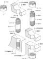
図1は、本発明によるボルト冷却用治具11の形状例と使用例を示しており、図の右側には、ボルト冷却用治具11の拡大図と断面図を描いてある。この図では、発電用の蒸気タービンのローター(図示は省略)を取り囲む複数の車室を組み上げるため、ボルト41を使用することを想定しており、ボルト41を加熱した状態でナット43の締め付けを行い、次にボルト冷却用治具11を取り付け、ボルト41の内部に空気を流して冷却を促進させる。そしてこの図の車室は、上半内部車室31と上半外部車室33と下半内部車室35と下半外部車室38の四要素で構成されており、そのうち図の左側の上半内部車室31と下半内部車室35は、蒸気タービンのローターを取り囲んでおり、また図の右側の上半外部車室33と下半外部車室38は、その外側を取り囲んでおり、このような二重構造で内部の圧力を受け止めている。なおこの図の各車室は、あくまでも模式的に描いたものであり、実物とは形状が異なる。
Figure 1 shows an example of the shape and use of the
上半内部車室31は半円状であり、これを下半内部車室35の上面に載せた後、ボルト41を用いて双方を密着させる。このボルト41は、汎用のスタッドボルトと同様、丸棒状の軸部だけで構成されており、その両端部の外周面にはオネジ47を形成してある。またボルト41を差し込むため、下半内部車室35には、その上面から伸びる締結穴36を設けてあり、その内周面にはメネジ37を形成してある。なおこの締結穴36は、途中で行き止まりとなっており、その先端が外部に露出することはない。そして、締結穴36のメネジ37とボルト41のオネジ47を螺合させることで、ボルト41は下半内部車室35と一体化するが、その際、ボルト41の上部は、下半内部車室35の上面から突出しており、そこに上半内部車室31を載せると、ボルト41は上半内部車室31の上面から突出し、そこにナット43を螺合させることになる。
The upper half inner casing 31 is semicircular, and after placing it on the upper surface of the lower half inner casing 35, the two are brought into close contact with each other using the bolt 41. This bolt 41 is composed only of a round bar-shaped shaft portion, like a general-purpose stud bolt, and has
上半外部車室33は、上半内部車室31よりも一回り大きい半円状であり、上半内部車室31を据え付けた後、下半外部車室38の上面に載せ、次にボルト41を介して上半外部車室33と下半外部車室38を密着させる。下半外部車室38の外縁部分はフランジ状に突出しているため、ボルト41は、上半外部車室33と下半外部車室38を貫くように差し込み、その後、ボルト41の両端部にナット43を螺合させ、上半外部車室33と下半外部車室38を密着させる。 The upper half external casing 33 is semicircular and slightly larger than the upper half internal casing 31. After the upper half internal casing 31 is installed, it is placed on the top surface of the lower half external casing 38, and then the upper half external casing 33 and the lower half external casing 38 are tightly attached to each other using bolts 41. Since the outer edge of the lower half external casing 38 protrudes like a flange, the bolts 41 are inserted so as to penetrate the upper half external casing 33 and the lower half external casing 38, and then nuts 43 are screwed onto both ends of the bolts 41 to tightly attach the upper half external casing 33 and the lower half external casing 38 to each other.
ボルト41の内部には、両端を貫く中心孔45を設けてあり、しかも中心孔45の端部にはメネジ48を形成してある。中心孔45は、ボルト41の加熱や冷却に使用され、またメネジ48は、ボルト41の吊り上げなどに使用される。そしてボルト41に螺合させたナット43を締め付ける際は、あらかじめボルト41の全域を加熱して全長を増大させておく。その結果、ボルト41が冷却された際は、その内部に引張荷重が作用した状態になり、上下に重なる上半内部車室31と下半内部車室35などを強固に密着させることができ、運用時の高温状態においても、この密着を維持して安全性を確保する。
Inside the bolt 41, a
ボルト冷却用治具11は、ボルト41とナット43の締め付けを終えた後、ボルト41を素早く冷却するために使用され、接続筒15と頭部13と給気口14の三要素が一体化した構成であり、六角形の頭部13の上方には給気口14が突出しており、下方には接続筒15が突出している。そして給気口14は、外部から供給される空気を取り入れるための部位であり、ここではエアホース52の端部に組み込まれたカプラー54と連結可能な構成になっており、エアホース52との連結や切り離しを極めて簡単に行うことができる。
The
接続筒15は円筒状の部位であり、ボルト41の中心孔45に差し込まれる。さらに接続筒15の外周面にはオネジ18を形成してあり、これが中心孔45に形成されたメネジ48に螺合することで、ボルト冷却用治具11がボルト41に取り付けられる。そして給気口14から取り入れられた空気は、頭部13の中を通過して接続筒15の先端面から中心孔45に到達し、以降、中心孔45に沿って流れていき、ボルト41を冷却していく。そのほか、接続筒15の側周面には排気口17を形成してあり、中心孔45に滞留した空気を外部に放出することができる。なおこの図の排気口17は、接続筒15の先端面から伸びる切り込み状になっている。
The connecting
接続筒15を中心孔45に差し込む際は、オネジ18とメネジ48を螺合させるため、ボルト冷却用治具11を回転させる必要があり、それを考慮して頭部13は六角形としてあり、その対向する二面を工具で挟み込むことで、この作業を円滑に行うことができる。またボルト冷却用治具11の持ち運びを考慮し、頭部13には持ち手19を組み込んである。持ち手19は、針金を折り曲げただけの単純な構成であり、その端部を頭部13の側面に差し込んでおり、持ち手19は一定の範囲で自在に揺動可能である。この持ち手19により、複数のボルト冷却用治具11を一度に持ち運ぶことができ、作業の時間短縮に貢献する。
When inserting the connecting
延長管21は、接続筒15の内周面に差し込み、接続筒15から離れた場所に空気を供給することができる。さらに、延長管21の一端側の外周面にはオネジ26を形成してあり、また接続筒15の内周面にはメネジ16を形成してあり、双方を螺合させることで、延長管21を接続筒15と一体化することができ、当然ながら、その後に延長管21を取り外すこともできる。そして延長管21を一体化した場合、給気口14から取り入れられた空気は、延長管21の内部に流入し、延長管21の先端面から中心孔45に流れていく。なお延長管21を接続筒15に差し込んだ後は、延長管21の外周面によって排気口17の入り口側が塞がれることになる。ただし排気口17は、接続筒15の先端面に到達しているため、延長管21の差し込み後においても、排気口17の機能が損なわれることはない。
The extension tube 21 can be inserted into the inner circumferential surface of the
上半内部車室31の据え付けに使用するボルト41の下部は、下半内部車室35の締結穴36に差し込まれるが、この締結穴36の底部は、外部に露出することのない閉じた空間である。そのためここで使用するボルト41の中心孔45は、その上端だけが外部に露出しており、ここに取り付けるボルト冷却用治具11については、あらかじめ延長管21を一体化させてあり、締結穴36の底部付近に空気を供給することができ、その空気は、中心孔45と延長管21との隙間を上昇して排気口17に到達し、外部に放出される。
The lower part of the bolt 41 used to install the upper half inner casing 31 is inserted into the fastening hole 36 of the lower half inner casing 35, but the bottom of this fastening hole 36 is a closed space that is not exposed to the outside. Therefore, only the upper end of the
対して、上半外部車室33の据え付けに用いるボルト41の下部は、下半外部車室38から外部に突出している。そのためここで使用するボルト41の中心孔45は、その上下両端が外部に露出しており、ここに取り付けるボルト冷却用治具11については、延長管21が不要であり、接続筒15を通過した空気は、中心孔45の上端付近から下端に向けて流れていき、そこから外部に放出される。このように本発明では、ボルト41の周辺構造に応じて、最適な冷却方法を選択可能である。
In contrast, the lower part of the bolt 41 used to install the upper half external casing 33 protrudes from the lower half external casing 38 to the outside. Therefore, the
図2は、図1の各車室を分離させた状態を示しており、これらはボルト41で組み上げていく。蒸気タービンのローターを取り囲む上半内部車室31と下半内部車室35をボルト41で密着させるため、上半内部車室31には、その上下を貫く締結穴32を設けてある。また下半内部車室35には、有底の締結穴36を設けてあり、その内周面にはメネジ37を形成してある。そしてボルト41の下部を締結穴36に差し込み、ボルト41のオネジ47が締結穴36のメネジ37と螺合することで、ボルト41は下半内部車室35と一体化し、その際、ボルト41の上部は下半内部車室35から突出する。
Figure 2 shows the separated state of each casing in Figure 1, which is assembled with bolts 41. To tightly connect the upper half internal casing 31 and the lower half internal casing 35 that surround the rotor of the steam turbine with the bolts 41, the upper half internal casing 31 has fastening holes 32 that penetrate from top to bottom. The lower half internal casing 35 has a bottomed fastening hole 36 with a female thread 37 formed on its inner circumferential surface. The lower part of the bolt 41 is inserted into the fastening hole 36, and the
次に、上半内部車室31を下半内部車室35に接近させ、突出しているボルト41を上半内部車室31の締結穴32に差し込み、その後、上半内部車室31を下半内部車室35に載せると、ボルト41の上部が上半内部車室31から突出するため、そこにナット43を螺合させ、これを締め付けると、上半内部車室31と下半内部車室35が密着する。なおボルト41の両端面には、六角形の突出部を設けてあり、これを使用してボルト41を回転させることができる。
Next, the upper half internal casing 31 is brought close to the lower half internal casing 35, and the protruding bolt 41 is inserted into the
また、上半外部車室33と下半外部車室38をボルト41で密着させるため、上半外部車室33には、その上下を貫く締結穴34を設けてある。下半外部車室38については、その外縁部分がフランジ状に突出しており、そこに締結穴39を設けてあり、下半外部車室38に上半外部車室33を載せた後、双方の締結穴34、39を同心に揃え、そこにボルト41を差し込むことになる。そしてボルト41の両端部にナット43を螺合させ、これらを締め付けると、上半外部車室33と下半外部車室38が密着する。なおボルト41を差し込む際は、その落下防止のため、あらかじめ上部にナット43を螺合させておく。 In addition, in order to tightly connect the upper half external casing 33 and the lower half external casing 38 with the bolts 41, the upper half external casing 33 has fastening holes 34 that penetrate from top to bottom. The outer edge of the lower half external casing 38 protrudes like a flange, and fastening holes 39 are provided there. After placing the upper half external casing 33 on the lower half external casing 38, the fastening holes 34 and 39 are aligned concentrically and the bolts 41 are inserted there. Then, when nuts 43 are screwed onto both ends of the bolts 41 and tightened, the upper half external casing 33 and the lower half external casing 38 are tightly connected. When the bolts 41 are inserted, the nuts 43 are screwed onto the top beforehand to prevent them from falling.
図3は、図2の各車室を所定の場所に配置し、さらにボルト41の差し込みを終えた段階を示しており、この後、ナット43を仮締めした状態でボルト41を加熱することになる。上半内部車室31を据え付けるボルト41は、その上部が上半内部車室31から突出しており、その中心孔45にヒーター61を差し込み、ボルト41を加熱している。また上半外部車室33を据え付けるボルト41は、その上部に螺合させたナット43により、上半外部車室33に支持されているほか、ボルト41の下部は、下半外部車室38から突出しているが、こちらもその中心孔45にヒーター61を差し込んでいる。
Figure 3 shows the stage where each of the compartments in Figure 2 has been placed in a predetermined location, and the bolts 41 have been inserted. After this, the bolts 41 are heated with the nuts 43 temporarily tightened. The upper part of the bolt 41 that installs the upper half inner compartment 31 protrudes from the upper half inner compartment 31, and a heater 61 is inserted into its
ヒーター61は丸棒状であり、中心孔45と同等の長さを有しており、ボルト41の全域を均等に加熱することができ、それによってボルト41の全長が伸びていく。そして、これ以上の加熱は不要との判断がなされると、ヒーター61を抜き取り、ボルト41とナット43が規定の位置関係に揃うまで締め付けを行う。以降、ボルト41は徐々に冷却されていくが、ナット43との螺合により、元のように収縮することはできないため、ボルト41は加熱前よりも伸びを生じることになり、これによって内部に引張荷重が作用した状態になる。なおこの図において、各ボルト41の一端側にはナット43を螺合させていないが、実際にはここにもナット43を仮締めした状態で加熱を行う。
The heater 61 is a round bar with a length equal to the
図4は、図3の後の段階を示しており、ボルト冷却用治具11を使用してボルト41を強制的に冷却している。先の図3のように、ボルト41が加熱された状態でナット43を締め付けることになるが、その後、ボルト41が冷却された状態でその伸び量を測定し、これが適正な範囲から外れている場合、締め付けをやり直すことになる。そのため冷却に要する時間を短縮することは、発電設備などの施工や検査や修理を円滑に進める上で極めて重要である。そこでナット43の締め付け後、ボルト冷却用治具11を取り付け、中心孔45に空気を供給することで強制的に冷却を行うことになる。
Figure 4 shows a stage after Figure 3, where the bolt 41 is forcibly cooled using a
ボルト冷却用治具11の接続筒15は、中心孔45に差し込まれているが、ここでは先の図1で描かれたオネジ18とメネジ48が螺合しているため、ボルト冷却用治具11がボルト41から飛び出してしまうことはない。また上半内部車室31側で使用するボルト冷却用治具11については、延長管21が一体化しているため、締結穴36の底部付近に空気を供給することができるほか、接続筒15の差し込み量を抑制してあるため、排気口17が外部に露出しており、そこから中心孔45に滞留した空気が放出される。対して、上半外部車室33側で使用するボルト冷却用治具11については、延長管21を用いていないため、中心孔45の上部から空気が流れていき、中心孔45の下端で外部に放出される。そのため接続筒15の差し込み量を増大させ、排気口17を塞いでいる。
The connecting
上半内部車室31と上半外部車室33と下半内部車室35と下半外部車室38は、いずれも蒸気タービンのローターを取り囲むような構造であり、ボルト41は各車室の外縁部に沿って狭い間隔で多数が連続的に配置されている。そのためボルト41の冷却は、複数を同時に行うことが望ましく、ここではマニホールド51を使用して複数のエアホース52に空気を供給している。個々のエアホース52の端部にはカプラー54が組み込まれており、これをボルト冷却用治具11の給気口14に連結する。なおボルト冷却用治具11の持ち手19は、自在に揺動可能であり、この図のような状態においては、エアホース52と接触しないよう、横倒しにしてある。その際、持ち手19を周辺の物に接触させることで、ボルト冷却用治具11の回り止めとして機能させることができる。
The upper half inner casing 31, the upper half outer casing 33, the lower half inner casing 35, and the lower half outer casing 38 are all structured to surround the rotor of the steam turbine, and a large number of bolts 41 are arranged continuously at close intervals along the outer edge of each casing. For this reason, it is desirable to cool multiple bolts 41 simultaneously, and here, a manifold 51 is used to supply air to
図5は、ボルト41を冷却している状態を断面で示しており、図の左側は、蒸気タービンのローターを取り囲む内部車室を描いてあり、図の右側は、内部車室を取り囲む外部車室を描いてある。図の左側のように、上半内部車室31を据え付けているボルト41は、その下部が外部に露出することなく締結穴36に差し込まれており、そこから空気を外部に放出することができない。そこでボルト冷却用治具11に延長管21を一体化してあり、締結穴36の底部付近に空気を供給しており、その空気は、中心孔45と延長管21との隙間を上昇するため、中心孔45の全域が冷却されることになり、最後には排気口17から外部に放出される。なお上半内部車室31に差し込まれるボルト41については、その全長が短いならば、延長管21を使用しないこともある。その場合、接続筒15からそのまま中心孔45に空気を供給し、これによって押し出された空気を排気口17から放出することになる。
Figure 5 shows a cross section of the bolt 41 being cooled. The left side of the figure shows the inner casing surrounding the rotor of the steam turbine, and the right side of the figure shows the outer casing surrounding the inner casing. As shown on the left side of the figure, the bolt 41 that installs the upper half inner casing 31 is inserted into the fastening hole 36 without its lower part being exposed to the outside, and air cannot be discharged from there to the outside. Therefore, the extension tube 21 is integrated into the
次に図の右側のように、上半外部車室33を据え付けているボルト41は、その下部が下半外部車室38を貫いて外部に露出しており、そこから空気を外部に放出することができる。そのため延長管21は不要であり、接続筒15から中心孔45に空気を供給しており、その空気は、中心孔45の上端付近から下端に向けて流れていき、中心孔45の全域が冷却されることになる。そしてボルト41の冷却が終了した際は、カプラー54を切り離し、さらにボルト冷却用治具11を取り外した後、ボルト41の伸び量を測定し、締め付けが適正であるか否かを判断する。なお当然ではあるが、本発明は、蒸気タービンのローターを取り囲む車室での使用に限定されるものではない。
As shown on the right side of the figure, the bolts 41 that secure the upper half outer casing 33 have their lower parts exposed to the outside through the lower half outer casing 38, from which air can be released to the outside. Therefore, the extension tube 21 is not necessary, and air is supplied to the
11 ボルト冷却用治具
13 頭部
14 給気口
15 接続筒
16 メネジ
17 排気口
18 オネジ
19 持ち手
21 延長管
26 オネジ
31 上半内部車室
32 締結穴
33 上半外部車室
34 締結穴
35 下半内部車室
36 締結穴
37 メネジ
38 下半外部車室
39 締結穴
41 ボルト
43 ナット
45 中心孔
47 オネジ
48 メネジ
51 マニホールド
52 エアホース
54 カプラー
61 ヒーター
11
Claims (3)
前記給気口(14)に供給された空気を前記接続筒(15)から前記中心孔(45)に流すことで前記ボルト(41)を冷却することができ、
前記接続筒(15)には、前記中心孔(45)内の空気を外部に放出するための排気口(17)を形成してあることを特徴とするボルト冷却用治具。 The bolt (41) has a connecting tube (15) that screws into a female thread (48) formed at the end of a central hole (45) that passes through the inside of the bolt (41), a head (13) that closes one end face of the connecting tube (15), and an air intake port (14) that protrudes from the head (13),
The bolt (41) can be cooled by flowing the air supplied to the air supply port (14) from the connecting tube (15) to the central hole (45),
The bolt cooling jig is characterized in that the connecting tube (15) is formed with an exhaust port (17) for discharging air within the central hole (45) to the outside.
Priority Applications (1)
| Application Number | Priority Date | Filing Date | Title |
|---|---|---|---|
| JP2021175079A JP7689480B2 (en) | 2021-10-26 | 2021-10-26 | Bolt cooling tool and bolt cooling method |
Applications Claiming Priority (1)
| Application Number | Priority Date | Filing Date | Title |
|---|---|---|---|
| JP2021175079A JP7689480B2 (en) | 2021-10-26 | 2021-10-26 | Bolt cooling tool and bolt cooling method |
Publications (2)
| Publication Number | Publication Date |
|---|---|
| JP2023064670A JP2023064670A (en) | 2023-05-11 |
| JP7689480B2 true JP7689480B2 (en) | 2025-06-06 |
Family
ID=86271573
Family Applications (1)
| Application Number | Title | Priority Date | Filing Date |
|---|---|---|---|
| JP2021175079A Active JP7689480B2 (en) | 2021-10-26 | 2021-10-26 | Bolt cooling tool and bolt cooling method |
Country Status (1)
| Country | Link |
|---|---|
| JP (1) | JP7689480B2 (en) |
Citations (2)
| Publication number | Priority date | Publication date | Assignee | Title |
|---|---|---|---|---|
| US20030180140A1 (en) | 2002-03-20 | 2003-09-25 | Martin Reigl | Flange bolt for turbines |
| JP2008101821A (en) | 2006-10-18 | 2008-05-01 | Mitsubishi Heavy Ind Ltd | Bolt heater and bolt heating system |
Family Cites Families (2)
| Publication number | Priority date | Publication date | Assignee | Title |
|---|---|---|---|---|
| JPS48269Y1 (en) * | 1970-05-19 | 1973-01-06 | ||
| JPH11166520A (en) * | 1997-12-05 | 1999-06-22 | Toshiba Corp | Bolt device for turbine casing and method of fixing bolt device for turbine casing |
-
2021
- 2021-10-26 JP JP2021175079A patent/JP7689480B2/en active Active
Patent Citations (2)
| Publication number | Priority date | Publication date | Assignee | Title |
|---|---|---|---|---|
| US20030180140A1 (en) | 2002-03-20 | 2003-09-25 | Martin Reigl | Flange bolt for turbines |
| JP2008101821A (en) | 2006-10-18 | 2008-05-01 | Mitsubishi Heavy Ind Ltd | Bolt heater and bolt heating system |
Also Published As
| Publication number | Publication date |
|---|---|
| JP2023064670A (en) | 2023-05-11 |
Similar Documents
| Publication | Publication Date | Title |
|---|---|---|
| CN105135101B (en) | A kind of locking device for pipe joint | |
| CN101614494B (en) | Fixed-tubesheet prestressed heat exchanger with external guide shell and treatment method thereof | |
| US10180105B2 (en) | Adjustable cable for exhaust duct liner hanger | |
| TWI445895B (en) | Method and apparatus for repairing a core spray downcomer pipe in a nuclear reactor | |
| JP7689480B2 (en) | Bolt cooling tool and bolt cooling method | |
| CN112924179B (en) | A new type of grate tooth sealing structure and tie rod sealing system | |
| KR20140001443A (en) | Tie-rod for expention joint | |
| CN111579200A (en) | Screw temperature control film clamping device | |
| KR20150142752A (en) | Jig for preventing thermal deformation | |
| US6763563B2 (en) | Apparatus and method for repairing water-cooled generator stator bar clips | |
| KR200439965Y1 (en) | Heat exchanger leak tester | |
| JPH01247989A (en) | Heat exchanger | |
| JP6248057B2 (en) | High temperature piping cooling jig, cooling device and installation method thereof, and high temperature piping and cooling device installation method thereof | |
| JP6978993B2 (en) | Flange joint fastening method | |
| CN112903275A (en) | Sectional type pull rod sealing system for thermal engine coupling fatigue test of blade | |
| JP5021041B2 (en) | Mechanical assembly to ensure structural integrity of pipe fittings | |
| CN105555977A (en) | Restoration heat-treatment method for creep-damaged heat-resistant metal member | |
| JP2820505B2 (en) | Steam turbine flange bolt cooling system | |
| KR20090011397U (en) | Hydraulic Nut | |
| RU181529U1 (en) | COVER CONNECTION WITH CAMERA HOUSING | |
| US10283226B2 (en) | Method of repairing jet pump measuring pipe and repair device therefor | |
| JPH0729407Y2 (en) | Tube heat exchanger | |
| CN222025822U (en) | Steam turbine cylinder cap bolt cooling device | |
| CN222461059U (en) | A heat exchanger heat transfer performance test platform | |
| CN215847936U (en) | Radiator drainage switch fastener |
Legal Events
| Date | Code | Title | Description |
|---|---|---|---|
| RD03 | Notification of appointment of power of attorney |
Free format text: JAPANESE INTERMEDIATE CODE: A7423 Effective date: 20231013 |
|
| A621 | Written request for application examination |
Free format text: JAPANESE INTERMEDIATE CODE: A621 Effective date: 20240814 |
|
| TRDD | Decision of grant or rejection written | ||
| A977 | Report on retrieval |
Free format text: JAPANESE INTERMEDIATE CODE: A971007 Effective date: 20250515 |
|
| A01 | Written decision to grant a patent or to grant a registration (utility model) |
Free format text: JAPANESE INTERMEDIATE CODE: A01 Effective date: 20250520 |
|
| A61 | First payment of annual fees (during grant procedure) |
Free format text: JAPANESE INTERMEDIATE CODE: A61 Effective date: 20250527 |
|
| R150 | Certificate of patent or registration of utility model |
Ref document number: 7689480 Country of ref document: JP Free format text: JAPANESE INTERMEDIATE CODE: R150 |