JP7689418B2 - Ventilation systems, buildings equipped with ventilation systems - Google Patents
Ventilation systems, buildings equipped with ventilation systems Download PDFInfo
- Publication number
- JP7689418B2 JP7689418B2 JP2020140393A JP2020140393A JP7689418B2 JP 7689418 B2 JP7689418 B2 JP 7689418B2 JP 2020140393 A JP2020140393 A JP 2020140393A JP 2020140393 A JP2020140393 A JP 2020140393A JP 7689418 B2 JP7689418 B2 JP 7689418B2
- Authority
- JP
- Japan
- Prior art keywords
- space
- air
- temperature
- unit
- gas concentration
- Prior art date
- Legal status (The legal status is an assumption and is not a legal conclusion. Google has not performed a legal analysis and makes no representation as to the accuracy of the status listed.)
- Active
Links
Images


Classifications
-
- F—MECHANICAL ENGINEERING; LIGHTING; HEATING; WEAPONS; BLASTING
- F24—HEATING; RANGES; VENTILATING
- F24F—AIR-CONDITIONING; AIR-HUMIDIFICATION; VENTILATION; USE OF AIR CURRENTS FOR SCREENING
- F24F11/00—Control or safety arrangements
- F24F11/70—Control systems characterised by their outputs; Constructional details thereof
- F24F11/72—Control systems characterised by their outputs; Constructional details thereof for controlling the supply of treated air, e.g. its pressure
- F24F11/74—Control systems characterised by their outputs; Constructional details thereof for controlling the supply of treated air, e.g. its pressure for controlling air flow rate or air velocity
-
- F—MECHANICAL ENGINEERING; LIGHTING; HEATING; WEAPONS; BLASTING
- F24—HEATING; RANGES; VENTILATING
- F24F—AIR-CONDITIONING; AIR-HUMIDIFICATION; VENTILATION; USE OF AIR CURRENTS FOR SCREENING
- F24F11/00—Control or safety arrangements
- F24F11/0001—Control or safety arrangements for ventilation
-
- F—MECHANICAL ENGINEERING; LIGHTING; HEATING; WEAPONS; BLASTING
- F24—HEATING; RANGES; VENTILATING
- F24F—AIR-CONDITIONING; AIR-HUMIDIFICATION; VENTILATION; USE OF AIR CURRENTS FOR SCREENING
- F24F11/00—Control or safety arrangements
- F24F11/62—Control or safety arrangements characterised by the type of control or by internal processing, e.g. using fuzzy logic, adaptive control or estimation of values
- F24F11/63—Electronic processing
-
- F—MECHANICAL ENGINEERING; LIGHTING; HEATING; WEAPONS; BLASTING
- F24—HEATING; RANGES; VENTILATING
- F24F—AIR-CONDITIONING; AIR-HUMIDIFICATION; VENTILATION; USE OF AIR CURRENTS FOR SCREENING
- F24F11/00—Control or safety arrangements
- F24F11/70—Control systems characterised by their outputs; Constructional details thereof
- F24F11/72—Control systems characterised by their outputs; Constructional details thereof for controlling the supply of treated air, e.g. its pressure
- F24F11/79—Control systems characterised by their outputs; Constructional details thereof for controlling the supply of treated air, e.g. its pressure for controlling the direction of the supplied air
-
- F—MECHANICAL ENGINEERING; LIGHTING; HEATING; WEAPONS; BLASTING
- F24—HEATING; RANGES; VENTILATING
- F24F—AIR-CONDITIONING; AIR-HUMIDIFICATION; VENTILATION; USE OF AIR CURRENTS FOR SCREENING
- F24F12/00—Use of energy recovery systems in air conditioning, ventilation or screening
- F24F12/001—Use of energy recovery systems in air conditioning, ventilation or screening with heat-exchange between supplied and exhausted air
-
- F—MECHANICAL ENGINEERING; LIGHTING; HEATING; WEAPONS; BLASTING
- F24—HEATING; RANGES; VENTILATING
- F24F—AIR-CONDITIONING; AIR-HUMIDIFICATION; VENTILATION; USE OF AIR CURRENTS FOR SCREENING
- F24F7/00—Ventilation
- F24F7/007—Ventilation with forced flow
-
- F—MECHANICAL ENGINEERING; LIGHTING; HEATING; WEAPONS; BLASTING
- F24—HEATING; RANGES; VENTILATING
- F24F—AIR-CONDITIONING; AIR-HUMIDIFICATION; VENTILATION; USE OF AIR CURRENTS FOR SCREENING
- F24F7/00—Ventilation
- F24F7/04—Ventilation with ducting systems, e.g. by double walls; with natural circulation
- F24F7/06—Ventilation with ducting systems, e.g. by double walls; with natural circulation with forced air circulation, e.g. by fan positioning of a ventilator in or against a conduit
- F24F7/08—Ventilation with ducting systems, e.g. by double walls; with natural circulation with forced air circulation, e.g. by fan positioning of a ventilator in or against a conduit with separate ducts for supplied and exhausted air with provisions for reversal of the input and output systems
-
- F—MECHANICAL ENGINEERING; LIGHTING; HEATING; WEAPONS; BLASTING
- F24—HEATING; RANGES; VENTILATING
- F24F—AIR-CONDITIONING; AIR-HUMIDIFICATION; VENTILATION; USE OF AIR CURRENTS FOR SCREENING
- F24F7/00—Ventilation
- F24F7/04—Ventilation with ducting systems, e.g. by double walls; with natural circulation
- F24F7/06—Ventilation with ducting systems, e.g. by double walls; with natural circulation with forced air circulation, e.g. by fan positioning of a ventilator in or against a conduit
- F24F7/10—Ventilation with ducting systems, e.g. by double walls; with natural circulation with forced air circulation, e.g. by fan positioning of a ventilator in or against a conduit with air supply, or exhaust, through perforated wall, floor or ceiling
-
- F—MECHANICAL ENGINEERING; LIGHTING; HEATING; WEAPONS; BLASTING
- F24—HEATING; RANGES; VENTILATING
- F24F—AIR-CONDITIONING; AIR-HUMIDIFICATION; VENTILATION; USE OF AIR CURRENTS FOR SCREENING
- F24F2110/00—Control inputs relating to air properties
- F24F2110/10—Temperature
-
- Y—GENERAL TAGGING OF NEW TECHNOLOGICAL DEVELOPMENTS; GENERAL TAGGING OF CROSS-SECTIONAL TECHNOLOGIES SPANNING OVER SEVERAL SECTIONS OF THE IPC; TECHNICAL SUBJECTS COVERED BY FORMER USPC CROSS-REFERENCE ART COLLECTIONS [XRACs] AND DIGESTS
- Y02—TECHNOLOGIES OR APPLICATIONS FOR MITIGATION OR ADAPTATION AGAINST CLIMATE CHANGE
- Y02B—CLIMATE CHANGE MITIGATION TECHNOLOGIES RELATED TO BUILDINGS, e.g. HOUSING, HOUSE APPLIANCES OR RELATED END-USER APPLICATIONS
- Y02B30/00—Energy efficient heating, ventilation or air conditioning [HVAC]
- Y02B30/56—Heat recovery units
-
- Y—GENERAL TAGGING OF NEW TECHNOLOGICAL DEVELOPMENTS; GENERAL TAGGING OF CROSS-SECTIONAL TECHNOLOGIES SPANNING OVER SEVERAL SECTIONS OF THE IPC; TECHNICAL SUBJECTS COVERED BY FORMER USPC CROSS-REFERENCE ART COLLECTIONS [XRACs] AND DIGESTS
- Y02—TECHNOLOGIES OR APPLICATIONS FOR MITIGATION OR ADAPTATION AGAINST CLIMATE CHANGE
- Y02B—CLIMATE CHANGE MITIGATION TECHNOLOGIES RELATED TO BUILDINGS, e.g. HOUSING, HOUSE APPLIANCES OR RELATED END-USER APPLICATIONS
- Y02B30/00—Energy efficient heating, ventilation or air conditioning [HVAC]
- Y02B30/70—Efficient control or regulation technologies, e.g. for control of refrigerant flow, motor or heating
Landscapes
- Engineering & Computer Science (AREA)
- Chemical & Material Sciences (AREA)
- Combustion & Propulsion (AREA)
- Mechanical Engineering (AREA)
- General Engineering & Computer Science (AREA)
- Signal Processing (AREA)
- Physics & Mathematics (AREA)
- Fuzzy Systems (AREA)
- Mathematical Physics (AREA)
- Fluid Mechanics (AREA)
- Ventilation (AREA)
- Air Conditioning Control Device (AREA)
Description
本開示は、換気システムおよび換気システムを備えた建物に関する。 The present disclosure relates to a ventilation system and a building equipped with a ventilation system.
特許文献1には、複数の居室内の換気と空調を同時に行う空調システムが記載されている。この空調システムは、空調機を配置した空調室を複数の居室から独立して設け、空調室と各居室を連結する給気ダクトを備える。空調された空調室内の空気は給気ダクトを介して各居室に個別的に分配給気される。各居室は、給気口と排気口とによる給排気により換気と空調が同時に行われる。 Patent Document 1 describes an air conditioning system that simultaneously ventilates and air-conditions multiple rooms. This air conditioning system has an air-conditioned room in which air conditioners are installed that is separate from the multiple rooms, and has air supply ducts that connect the air-conditioned room to each room. The conditioned air in the air-conditioned room is individually distributed and supplied to each room via the air supply duct. Each room is simultaneously ventilated and air-conditioned by air supply and exhaust through an air supply port and an exhaust port.
本発明者は、建物の複数の空間の換気システムについて以下の認識を得た。
建物の複数の空間における温度・湿度・空気質などの空調状態が不均一である場合、一方の空間から他方の空間へ移動したユーザに不快感を与える可能性がある。しかし、特許文献1の空調システムは、一方の空間と他方の空間の空調状態の不均一性の緩和について十分な対応ができていなかった。
The present inventors have come to the following realization regarding a ventilation system for multiple spaces in a building.
When the air conditioning conditions, such as temperature, humidity, and air quality, are non-uniform among multiple spaces in a building, a user who moves from one space to another may feel uncomfortable. However, the air conditioning system of Patent Document 1 does not adequately address the non-uniformity of the air conditioning conditions between one space and another space.
本開示は、上記課題を解決するためになされたものであり、ユーザの不快感を緩和可能な換気システムを提供することを目的とする。 This disclosure has been made to solve the above problems, and aims to provide a ventilation system that can alleviate the discomfort felt by users.
上記課題を解決するために、本発明のある態様の換気システムは、第1空間の換気を行う換気装置と、第1空間の天井面に設置され、第1空間から第1空間と異なる第2空間へ空気を搬送する空気搬送装置と、第1空間と第2空間とを連通し、第1空間から第2空間へ空気を搬送するための空気搬送路と、換気装置の運転と空気搬送装置の運転とを制御する制御部と、第1空間の気温を測定する第1温度測定部と、第2空間の気温を測定する第2温度測定部と、第2空間の照度を測定する照度測定部とを備える。空気搬送装置は、空気搬送路を通る空気に含まれる塵埃を捕集するための塵埃捕集部を有する。換気装置は、給気流と排気流との間で熱交換を行うための熱交換素子を有する。制御部は、第1温度測定部により測定される第1温度と、第2温度測定部により測定される第2温度とに基づき、空気搬送装置による第1空間から第2空間への空気搬送を可または不可と判定する判定部を有する。判定部は、第1温度と第2温度との間の気温差が所定温度以下であり、かつ照度測定部により測定される照度が高い状態から低い状態に変化してから一定期間維持された場合に、空気搬送装置による第1空間から第2空間への空気搬送を可と判定する。
本開示の別の態様もまた、換気システムである。この換気システムは、第1空間の換気を行う換気装置と、第1空間の天井面に設置され、第1空間から第1空間と異なる第2空間へ空気を搬送する空気搬送装置と、第1空間と第2空間とを連通し、第1空間から第2空間へ空気を搬送するための空気搬送路と、換気装置の運転と空気搬送装置の運転とを制御する制御部と、第1空間の気温を測定する第1温度測定部と、第2空間の気温を測定する第2温度測定部と、第1空間の空気に含まれる所定のガスのガス濃度を測定する第1ガス濃度測定部とを備える。空気搬送装置は、空気搬送路を通る空気に含まれる塵埃を捕集するための塵埃捕集部を有する。換気装置は、給気流と排気流との間で熱交換を行うための熱交換素子を有する。制御部は、第1温度測定部により測定される第1温度と、第2温度測定部により測定される第2温度とに基づき、空気搬送装置による第1空間から第2空間への空気搬送を可または不可と判定する判定部を有し、判定部は、第1温度と第2温度との間の気温差が所定温度以下であり、かつ第1ガス濃度測定部により測定されるガス濃度が所定濃度未満である場合に、空気搬送装置による第1空間から第2空間への空気搬送を可と判定する。
本開示のさらに別の態様もまた、換気システムである。この換気システムは、第1空間の換気を行う換気装置と、第1空間の天井面に設置され、第1空間から第1空間と異なる第2空間へ空気を搬送する空気搬送装置と、第1空間と第2空間とを連通し、第1空間から第2空間へ空気を搬送するための空気搬送路と、換気装置の運転と空気搬送装置の運転とを制御する制御部と、第1空間の気温を測定する第1温度測定部と、第2空間の気温を測定する第2温度測定部と、第2空間の空気に含まれる所定のガスのガス濃度を測定する第2ガス濃度測定部とを備える。空気搬送装置は、空気搬送路を通る空気に含まれる塵埃を捕集するための塵埃捕集部を有する。換気装置は、給気流と排気流との間で熱交換を行うための熱交換素子を有する。制御部は、第1温度測定部により測定される第1温度と、第2温度測定部により測定される第2温度とに基づき、空気搬送装置による第1空間から第2空間への空気搬送を可または不可と判定する判定部を有し、判定部は、第1温度と第2温度との間の気温差が所定温度以下であり、かつ第2ガス濃度測定部により測定されるガス濃度が所定濃度以上の場合に、空気搬送装置による第1空間から第2空間への空気搬送を可と判定する。
In order to solve the above problem, a ventilation system according to an embodiment of the present invention includes a ventilation device for ventilating a first space, an air conveying device installed on the ceiling surface of the first space and conveying air from the first space to a second space different from the first space, an air conveying path that connects the first space and the second space and conveys air from the first space to the second space, a control unit that controls the operation of the ventilation device and the operation of the air conveying device, a first temperature measuring unit that measures the air temperature of the first space, a second temperature measuring unit that measures the air temperature of the second space, and an illuminance measuring unit that measures the illuminance of the second space . The air conveying device has a dust collecting unit for collecting dust contained in the air passing through the air conveying path. The ventilation device has a heat exchange element for exchanging heat between the intake air flow and the exhaust air flow. The control unit has a determination unit that determines whether or not the air conveying device can convey air from the first space to the second space based on the first temperature measured by the first temperature measuring unit and the second temperature measured by the second temperature measuring unit. The judgment unit judges that air can be transported from the first space to the second space by the air transport device when the air temperature difference between the first temperature and the second temperature is equal to or less than a predetermined temperature and the illuminance measured by the illuminance measuring unit has changed from a high state to a low state and been maintained for a certain period of time.
Another aspect of the present disclosure is also a ventilation system. The ventilation system includes a ventilation device for ventilating a first space, an air conveying device installed on the ceiling surface of the first space and conveying air from the first space to a second space different from the first space, an air conveying path that communicates the first space with the second space and conveys air from the first space to the second space, a control unit that controls the operation of the ventilation device and the operation of the air conveying device, a first temperature measuring unit that measures the air temperature of the first space, a second temperature measuring unit that measures the air temperature of the second space, and a first gas concentration measuring unit that measures the gas concentration of a predetermined gas contained in the air of the first space. The air conveying device has a dust collecting unit for collecting dust contained in the air passing through the air conveying path. The ventilation device has a heat exchange element for exchanging heat between the supply air flow and the exhaust air flow. The control unit has a judgment unit that judges whether air can be transported from the first space to the second space by the air transport device based on a first temperature measured by the first temperature measuring unit and a second temperature measured by the second temperature measuring unit, and the judgment unit judges that air can be transported from the first space to the second space by the air transport device when the air temperature difference between the first temperature and the second temperature is equal to or less than a predetermined temperature and the gas concentration measured by the first gas concentration measuring unit is less than a predetermined concentration.
Yet another aspect of the present disclosure is also a ventilation system. The ventilation system includes a ventilation device for ventilating a first space, an air conveying device installed on the ceiling surface of the first space and conveying air from the first space to a second space different from the first space, an air conveying path that communicates the first space with the second space and conveys air from the first space to the second space, a control unit that controls the operation of the ventilation device and the operation of the air conveying device, a first temperature measuring unit that measures the air temperature of the first space, a second temperature measuring unit that measures the air temperature of the second space, and a second gas concentration measuring unit that measures the gas concentration of a predetermined gas contained in the air of the second space. The air conveying device has a dust collecting unit for collecting dust contained in the air passing through the air conveying path. The ventilation device has a heat exchange element for exchanging heat between the supply air flow and the exhaust air flow. The control unit has a judgment unit that judges whether or not air can be transported from the first space to the second space by the air transport device based on a first temperature measured by the first temperature measuring unit and a second temperature measured by the second temperature measuring unit, and the judgment unit judges that air can be transported from the first space to the second space by the air transport device when the air temperature difference between the first temperature and the second temperature is equal to or less than a predetermined temperature and the gas concentration measured by the second gas concentration measuring unit is equal to or more than a predetermined concentration.
なお、本開示の表現を方法、装置、システム、記録媒体、コンピュータプログラムなどの間で変換したものもまた、本開示の態様として有効である。 In addition, conversions of the expressions of this disclosure between methods, devices, systems, recording media, computer programs, etc. are also valid aspects of this disclosure.
本開示によれば、ユーザの不快感を緩和可能な換気システムを提供できる。 The present disclosure provides a ventilation system that can alleviate user discomfort.
以下、本開示を実施するための形態について添付図面も参照して説明する。実施例および変形例では、同一または同等の構成要素、部材には、同一の符号を付するものとし、適宜重複した説明は省略する。また、各図面における部材の寸法は、理解を容易にするために適宜拡大、縮小して示される。また、各図面において実施例を説明する上で重要ではない部材の一部は省略して表示する。 Below, the embodiments for carrying out the present disclosure will be described with reference to the attached drawings. In the embodiments and modified examples, the same or equivalent components and parts will be given the same reference numerals, and duplicated explanations will be omitted as appropriate. Furthermore, the dimensions of the parts in each drawing will be enlarged or reduced as appropriate to facilitate understanding. Furthermore, some of the parts that are not important for explaining the embodiments will be omitted in each drawing.
また、第1、第2などの序数を含む用語は多様な構成要素を説明するために用いられるが、この用語は一つの構成要素を他の構成要素から区別する目的でのみ用いられ、この用語によって構成要素が限定されるものではない。 In addition, terms including ordinal numbers such as first and second are used to describe various components, but these terms are used only for the purpose of distinguishing one component from another and do not limit the components.
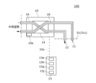
図1、図2を参照して本開示の実施例に係る換気システム100の全体構成を説明する。図1は、実施例に係る換気システム100を示す概略構成図である。図2は、換気システム100を概略的に示す機能ブロック図である。換気システム100は、住宅および、保育園、医療施設、介護施設等の住宅以外の建物に好適に利用できる。本実施形態の換気システム100は、建物の一例である住宅90に設けられる。住宅90は、居住者がプライベートな生活を営む場として提供された住居である。住宅90は、居室として居間、寝室を有してもよい。一例として第1空間51は居間(1F)であり、第2空間52は寝室(2F)である。なお、図2では、第1空間51と第2空間52とを横に並べて示している。また、図示はしないが、住宅90は、トイレ、浴室、洗面所、台所、脱衣所、階段および廊下等の空間を有してもよい。
The overall configuration of a
換気システム100は、換気装置10と、空気搬送装置20と、空気搬送路40と、制御部30とを備える。換気装置10は、第1空間51の換気を行う。空気搬送装置20は、空気搬送路40を通じて第1空間51から第2空間52へ空気を搬送する。制御部30は、換気装置10および空気搬送装置20の運転を制御する。
The
第1空間51(居間)は、床面51fと、壁面51wと、天井面51cとによって区画され、所定の気密性と断熱性とを有する空間である。壁面51wには窓(不図示)が設けられてもよい。第1空間51の天井面51cには、換気装置10の排気口11、給気口12と、空気搬送装置20の排気口21、給気口22とが設けられる。また、第1空間51はエアコンディショナなどの空調装置58により空調が施される。
The first space 51 (living room) is partitioned by a
第2空間52(寝室)は、床面52fと、壁面52wと、天井面52cとによって区画され、所定の気密性と断熱性とを有する空間である。壁面52wには窓(不図示)が設けられてもよい。第2空間52には、換気装置(不図示)や空調装置(不図示)が設けられてもよい。
The second space 52 (bedroom) is a space that is partitioned by a
(換気装置)
図3も参照して、換気装置10を説明する。図3は、換気装置10を概略的に示す概略構成図である。換気装置10は、第1空間51の天井面51cに設置される。換気装置10は、給気流16と排気流18とを生成する送風部(不図示)を有する。給気流16は、送風部により外部空気が給気口12を通じて第1空間51に供給される空気流である。排気流18は、送風部により第1空間51の内部空気が排気口11を通じて外部空間に排出される空気流である。第1空間51は、給気流16と排気流18とによって換気される。実施例の換気装置10は、空気搬送装置20が運転される場合に同時に運転される。換気装置10は、空気搬送装置20が運転停止している場合にも運転されてもよい。
(Ventilation equipment)
The
換気装置10は、給気流16と排気流18との間の熱交換とを行うための熱交換素子14を有する。また、熱交換素子14は、給気流16と排気流18との間の湿度交換を行うものであってもよい。例えば、夏の日中など、第1空間51を冷房する場合に、排気流18の温度が給気流16の温度よりも低いときには、両者の熱交換により給気流16の温度を下げることができ、換気による冷房効率の低下を抑制できる。例えば、冬の夜間など、第1空間51を暖房する場合に、排気流18の温度が給気流16の温度よりも高いときには、両者の熱交換により給気流16の温度を上げることができ、換気による暖房効率の低下を抑制できる。
The
実施例の換気装置10は、第1リモコン15によって、有線または無線の伝送路10sを介して遠隔操作可能に構成される。第1リモコン15は、第2空間52の壁面52wなどに保持される。第1リモコン15には、第2温度センサ15eと、湿度センサ15hと、第2ガスセンサ15gと、第2照度センサ15jとが設けられる。換気装置10には、第3温度センサ10eが設けられる。
The
第2温度センサ15eは、第2空間52の空気の温度(気温)を測定する第2温度測定部を例示する。第2照度センサ15jは、第2空間52の照度を測定する照度測定部を例示する。湿度センサ15hは、第2空間52の湿度を測定する。第2ガスセンサ15gは、第2空間52の空気に含まれる所定のガス(例えば二酸化炭素)のガス濃度を測定する。第2ガスセンサ15gとしては、様々な原理に基づくセンサを採用できる。実施例の第2ガスセンサ15gは、ガスの還元作用により電気抵抗が変化する酸化スズを用いた半導体式ガスセンサを採用している。第2ガスセンサ15gは、第2空間52の空気に含まれる所定のガスのガス濃度を測定する第2ガス濃度測定部を例示する。第2照度センサ15jは、第2空間52の照度を測定する。第3温度センサ10eは、外気温を測定する。これらのセンサの測定結果は、換気システム100の動作を制御するための環境情報として使用される。
The
(空気搬送装置)
図4も参照して、空気搬送装置20を説明する。図4は、空気搬送装置20を概略的に示す概略構成図である。空気搬送装置20は、第1空間51の天井面51cに設置される。空気搬送装置20は、第1空間51から第2空間52へ空気を搬送する搬送運転と、第1空間51の空気を循環させる循環運転とを行う。空気搬送装置20は、送風ユニット(不図示)と、塵埃を捕集するための塵埃捕集部29とを有する。空気搬送装置20は、搬送運転時に送風ユニットによって搬送流26を生成し、循環運転時に送風ユニットによって循環流28を生成する。空気搬送装置20は、搬送運転と、循環運転とを切り替える流路切替部24を有する。
(Air conveying device)
The
搬送流26は、送風ユニットにより第1空間51の内部空気が、塵埃捕集部29と流路切替部24と空気搬送路40とを通じて、第2空間52に搬送される空気流である。循環流28は、送風ユニットにより第1空間51の内部空気を塵埃捕集部29と流路切替部24とを通じて第1空間51に循環させる空気流である。搬送流26および循環流28において、出口側の空気は、入口側の空気よりも塵埃が低減された清浄空気である。
The
空気搬送装置20には、第1温度センサ20eと、第1ガスセンサ20gとが設けられる。第1温度センサ20eは、第1空間51から吸入した空気の温度を測定する。第1温度センサ20eは、第1空間51の空気の温度(気温)を測定する第1温度測定部を例示する。第1ガスセンサ20gは、第1空間51から吸入した空気に含まれる所定のガス(例えば二酸化炭素)のガス濃度を測定する。第1ガスセンサ20gとしては、様々の原理に基づくセンサを採用できる。実施例の第1ガスセンサ20gは、第2ガスセンサ15gと同様に、半導体式ガスセンサを採用している。第1ガスセンサ20gは、第1空間51の空気に含まれる所定のガスのガス濃度を測定する第1ガス濃度測定部を例示する。これらのセンサの測定結果は、換気システム100の動作を制御するための環境情報として使用される。
The
図4の例では、空気搬送装置20は、第1空間51側に設けられた1つの排気口21と3つの給気口22とを有する。また、空気搬送装置20は、空気搬送路40に連通された送出口23を有する。排気口21は、搬送運転時に搬送流26が通過し、循環運転時に循環流28が通過するように構成される。給気口22は、搬送運転時に閉じられ、循環運転時に循環流28が通過するように構成される。送出口23は、循環運転時に閉じられ、搬送運転時に搬送流26が通過するように構成される。
In the example of FIG. 4, the
実施例の空気搬送装置20は、第2リモコン25によって、有線または無線の伝送路20sを介して遠隔操作可能に構成される。第2リモコン25は、第1空間51の壁面51wなどに保持される。第2リモコン25には、ダストセンサ25dと、第1照度センサ25jとが設けられる。ダストセンサ25dは、第1空間51内のハウスダスト量を測定する。第1照度センサ25jは第1空間51の照度を測定する。これらのセンサの測定結果は、換気システム100の動作を制御するための環境情報として使用される。
The
(空気搬送路)
空気搬送路40を説明する。空気搬送路40は、第1空間51と第2空間52とを連通し、第1空間51から第2空間52へ空気を搬送するための通路である。空気搬送路40の構成に限定はないが、本実施例の空気搬送路40はエアダクト(風導管)により構成されている。空気搬送路40は、空気搬送装置20の送出口23に連通された入口部40jと、第2空間52の天井面52cに開口する出口部40eとを有する。空気搬送路40は、搬送運転時に送出口23から送出された搬送流26を入口部40jから出口部40eまで通過させて第2空間52に供給する。
(Air conveying path)
The
(制御部)
図5も参照して制御部30を説明する。図5は、制御部30を概略的に示すブロック図である。図5に示す各機能ブロックは、ハードウエア的には、コンピュータのCPU(Central Processing Unit)をはじめとする素子や機械装置で実現でき、ソフトウエア的にはコンピュータプログラム等によって実現されるが、ここでは、それらの連携によって実現される機能ブロックを描いている。したがって、これらの機能ブロックはハードウエア、ソフトウエアの組み合わせによっていろいろなかたちで実現できることは、本明細書に触れた当業者には理解されるところである。
(Control Unit)
The
制御部30は、図2に示すように、換気装置10または空気搬送装置20の内部に設けられてもよいが、この例ではこれらの外部に設けられている。制御部30は、有線または無線の伝送路30p、30qを介して換気装置10および空気搬送装置20と環境情報や制御情報を送受信する。
制御部30は、第1情報取得部30aと、第2情報取得部30bと、第3情報取得部30cと、第4情報取得部30dと、第5情報取得部30eと、第6情報取得部30fと、第7情報取得部30gと、第8情報取得部30hと、第9情報取得部30iと、判定部30jと、第1動作制御部30mと、第2動作制御部30nとを含む。
2, the
The
第1情報取得部30aは、第1温度センサ20eから第1空間51の第1温度T1を取得する。第2情報取得部30bは、第1ガスセンサ20gから第1空間51のガス濃度を取得する。第3情報取得部30cは、ダストセンサ25dから第1空間51のダスト情報を取得する。第4情報取得部30dは、第1照度センサ25jから第1空間51の照度を取得する。第5情報取得部30eは、第2温度センサ15eから第2空間52の第2温度T2を取得する。
The first
第6情報取得部30fは、湿度センサ15hから第2空間52の湿度を取得する。第7情報取得部30gは、第2ガスセンサ15gから第2空間52のガス濃度を取得する。第8情報取得部30hは、第2照度センサ15jから第2空間52の照度を取得する。
第9情報取得部30iは、第3温度センサ10eから外気温を取得する。
The sixth information acquiring unit 30f acquires the humidity in the
The ninth information acquisition unit 30i acquires the outside air temperature from the
判定部30jは、空気搬送装置20による第1空間51から第2空間52への空気搬送を可または不可と判定する。第1動作制御部30mは、換気装置10の運転を制御する。第2動作制御部30nは、判定部30jの判定結果に応じて空気搬送装置20の運転を制御する。
The determination unit 30j determines whether or not air can be transported from the
このように構成された換気システム100の動作の一例を説明する。以下に説明する各動作は、ユーザの所定の操作がされたタイミングまたは予め設定されたタイミングで開始される。このユーザの操作は、第1リモコン15または第2リモコン25を介して行われてもよい。
An example of the operation of the
図6を参照して、換気システム100の第1動作S110を説明する。図6は、第1動作S110を示すフローチャートである。第1動作S110は、温度差に基づいて空気搬送装置20を制御する動作である。第1動作S110では、判定部30jは、第1温度T1と第2温度T2との間の気温差が所定温度を超えた場合に、空気搬送装置20による第1空間51から第2空間52への空気搬送を可と判定する。
The first operation S110 of the
第1動作S110が開始されると、制御部30は、第1温度センサ20eから第1空間51の第1温度T1を取得する(ステップS111)。続いて制御部30は、第2温度センサ15eから第2空間52の第2温度T2を取得する(ステップS112)。
When the first operation S110 is started, the
次に、判定部30jは、第1温度T1と第2温度T2との温度差が所定温度(例えば3℃)以上か否かを判定する(ステップS113)。温度差が所定温度未満の場合(ステップS113のN)、制御部30は、第1動作S110を終了する。
Next, the determination unit 30j determines whether the temperature difference between the first temperature T1 and the second temperature T2 is equal to or greater than a predetermined temperature (e.g., 3°C) (step S113). If the temperature difference is less than the predetermined temperature (N in step S113), the
温度差が所定温度以上の場合(ステップS113のY)、制御部30は、空気搬送装置20を搬送運転させて、第1空間51の空気を第2空間52へ搬送する(ステップS114)。例えば、第3温度センサ10eで測定された外気温が24℃以上で、(第2温度T2-第1温度T1)が3℃以上の場合に、制御部30は、空気搬送装置20を搬送運転させてもよい。夏期に第2空間52の気温を下げられる。また、例えば、第3温度センサ10eで測定された外気温が16℃以下で、(第1温度T1-第2温度T2)が3℃以上の場合に、制御部30は、空気搬送装置20を搬送運転させてもよい。冬期に第2空間52の気温を上げられる。
If the temperature difference is equal to or greater than the predetermined temperature (Y in step S113), the
次に、制御部30は、第1温度センサ20eから第1空間51の第1温度T1を取得する(ステップS115)。続いて制御部30は、第2温度センサ15eから第2空間52の第2温度T2を取得する(ステップS116)。
Next, the
次に、判定部30jは、第1温度T1と第2温度T2との温度差が所定温度(例えば1℃)未満か否かを判定する(ステップS117)。温度差が所定温度以上の場合(ステップS117のN)、制御部30は、ステップS115に戻り、ステップS115~S117を繰り返す。温度差が所定温度未満の場合(ステップS117のY)、制御部30は、空気搬送装置20の搬送運転を停止する(ステップS118)。このステップで、制御部30は、空気搬送装置20を循環運転に切り替えてもよい。
Then, the judgment unit 30j judges whether the temperature difference between the first temperature T1 and the second temperature T2 is less than a predetermined temperature (e.g., 1°C) (step S117). If the temperature difference is equal to or greater than the predetermined temperature (N in step S117), the
ステップS118を実行したら第1動作S110は終了する。ステップS118は繰り返し実行されてもよい。第1動作S110における所定温度は、所望の快適性の水準に応じてシミュレーションまたは実験により設定できる。 After step S118 is performed, the first operation S110 ends. Step S118 may be performed repeatedly. The predetermined temperature in the first operation S110 can be set by simulation or experiment according to the desired level of comfort.
図7を参照して、換気システム100の第2動作S120を説明する。図7は、第2動作S120を示すフローチャートである。第2動作S120は、照度変化に基づいて空気搬送装置20を制御する動作である。第2動作S120では、判定部30jは、照度測定部(第2照度センサ15j)により測定される照度が所定の条件を満たす場合に、空気搬送装置20による第1空間51から第2空間52への空気搬送を可と判定する。
The second operation S120 of the
第2動作S120が開始されると、制御部30は、第1温度センサ20eから第1空間51の第1温度T1を取得する(ステップS121)。続いて制御部30は、第2温度センサ15eから第2空間52の第2温度T2を取得する(ステップS122)。
When the second operation S120 is started, the
次に、判定部30jは、第1温度T1と第2温度T2との温度差が所定温度(例えば7℃)以下か否かを判定する(ステップS123)。これは、第1空間51(居間)が寒いときに冷たい空気を搬送しないようにするためである。 Next, the determination unit 30j determines whether the temperature difference between the first temperature T1 and the second temperature T2 is equal to or less than a predetermined temperature (e.g., 7°C) (step S123). This is to prevent cold air from being transported when the first space 51 (living room) is cold.
温度差が所定温度を超える場合(ステップS123のN)、制御部30は、第2動作S120を終了する。温度差が所定温度以下の場合(ステップS123のY)、制御部30は、第2照度センサ15jから第2空間52の照度を取得する(ステップS124)。
If the temperature difference exceeds the predetermined temperature (N in step S123), the
次に、判定部30jは、第2空間52の照度が所定の条件を満たすか否かを判定する(ステップS125)。一例として、第2空間52の照度が高い状態から低い状態に急激に変化し、その状態が60分経過した場合に照度が所定の条件を満たすと判定してもよい。これにより、第2空間52(寝室)の明かりが消されてユーザが就寝したことを検知できる。
Next, the determination unit 30j determines whether the illuminance of the
第2空間52の照度が所定の条件を満たさない場合(ステップS125のN)、制御部30は、ステップS124に戻り、ステップS124~S125を繰り返す。
If the illuminance of the
第2空間52の照度が所定の条件を満たす場合(ステップS125のY)、制御部30は、空気搬送装置20を搬送運転させて、所定の期間(例えば180分)その状態を継続する(ステップS126)。
If the illuminance in the
所定の期間が経過したら、制御部30は、空気搬送装置20の搬送運転を停止する(ステップS127)。このステップで、制御部30は、空気搬送装置20を循環運転に切り替えてもよい。
When the predetermined period has elapsed, the
ステップS127を実行したら第2動作S120は終了する。第2動作S120は、繰り返し実行されてもよい。また、ステップS126において、第2空間52の照度が低い状態から高い状態に急激に変化した場合、制御部30は、空気搬送装置20の搬送運転を停止してもよい。第2動作S120における所定温度および照度の所定の条件は、所望の快適性の水準に応じてシミュレーションまたは実験により設定できる。
After step S127 is executed, the second operation S120 ends. The second operation S120 may be executed repeatedly. Also, in step S126, if the illuminance in the
図8を参照して、換気システム100の第3動作S130を説明する。図8は、第3動作S130を示すフローチャートである。第3動作S130は、第1空間51の二酸化炭素や臭気などに関連するガス濃度に基づいて、空気搬送装置20を制御する動作である。第3動作S130では、判定部30jは、第1ガス濃度測定部(第1ガスセンサ20g)により測定される第1空間51のガス濃度が所定濃度以下の場合に、空気搬送装置20による第1空間51から第2空間52への空気搬送を可と判定する。
The third operation S130 of the
第3動作S130が開始されると、制御部30は、第1温度センサ20eから第1空間51の第1温度T1を取得する(ステップS131)。続いて制御部30は、第2温度センサ15eから第2空間52の第2温度T2を取得する(ステップS132)。
When the third operation S130 is started, the
次に、判定部30jは、第1温度T1と第2温度T2との温度差が所定温度(例えば7℃)以下か否かを判定する(ステップS133)。これは、第1空間51(居間)が寒いときに冷たい空気を搬送しないようにするためである。 Next, the determination unit 30j determines whether the temperature difference between the first temperature T1 and the second temperature T2 is equal to or less than a predetermined temperature (e.g., 7°C) (step S133). This is to prevent cold air from being transported when the first space 51 (living room) is cold.
温度差が所定温度を超える場合(ステップS133のN)、制御部30は、第3動作S130を終了する。温度差が所定温度以下の場合(ステップS133のY)、制御部30は、第1ガスセンサ20gから第1空間51のガス濃度を取得する(ステップS134)。
If the temperature difference exceeds the predetermined temperature (N in step S133), the
次に、判定部30jは、第1空間51のガス濃度が所定濃度未満か否かを判定する(ステップS135)。第1空間51のガス濃度が所定濃度以上の場合(ステップS135のN)、制御部30は、第3動作S130を終了する。つまり、第1空間51のガス濃度が高ければ搬送運転をしない。
Next, the determination unit 30j determines whether the gas concentration in the
第1空間51のガス濃度が所定濃度未満の場合(ステップS135のY)、制御部30は、空気搬送装置20を搬送運転させる(ステップS136)。
If the gas concentration in the
次に、制御部30は、第1ガスセンサ20gから第1空間51のガス濃度を取得する(ステップS137)。次に、判定部30jは、第1空間51のガス濃度が所定濃度以上か否かを判定する(ステップS138)。第1空間51のガス濃度が所定濃度未満の場合(ステップS138のN)、制御部30は、ステップS137に戻り、ステップS137~S138を繰り返す。
Next, the
第1空間51のガス濃度が所定濃度以上の場合(ステップS138のY)、制御部30は、空気搬送装置20の搬送運転を停止する(ステップS139)。このステップで、制御部30は、空気搬送装置20を循環運転に切り替えてもよい。ステップS139を実行したら第3動作S130は終了する。第3動作S130は、繰り返し実行されてもよい。第3動作S130における所定温度およびガスの所定濃度は、所望の快適性の水準に応じてシミュレーションまたは実験により設定できる。
If the gas concentration in the
図9を参照して、換気システム100の第4動作S140を説明する。図9は、第4動作S140を示すフローチャートである。第4動作S140は、第2空間52の二酸化炭素や臭気などに関連するガス濃度に基づいて、空気搬送装置20を制御する動作である。第4動作S140では、判定部30jは、第2ガス濃度測定部(第2ガスセンサ15g)により測定される第2空間52のガス濃度が所定濃度以上の場合に、空気搬送装置20による第1空間51から第2空間52への空気搬送を可と判定する。
The fourth operation S140 of the
第4動作S140が開始されると、制御部30は、第1温度センサ20eから第1空間51の第1温度T1を取得する(ステップS141)。続いて制御部30は、第2温度センサ15eから第2空間52の第2温度T2を取得する(ステップS142)。
When the fourth operation S140 is started, the
次に、判定部30jは、第1温度T1と第2温度T2との温度差が所定温度(例えば7℃)以下か否かを判定する(ステップS143)。これは、第1空間51(居間)が寒いときに冷たい空気を搬送しないようにするためである。 Next, the determination unit 30j determines whether the temperature difference between the first temperature T1 and the second temperature T2 is equal to or less than a predetermined temperature (e.g., 7°C) (step S143). This is to prevent cold air from being transported when the first space 51 (living room) is cold.
温度差が所定温度を超える場合(ステップS143のN)、制御部30は、第4動作S140を終了する。温度差が所定温度以下の場合(ステップS143のY)、制御部30は、第2ガスセンサ15gから第2空間52のガス濃度を取得する(ステップS144)。
If the temperature difference exceeds the predetermined temperature (N in step S143), the
次に、判定部30jは、第2空間52のガス濃度が所定濃度以上か否かを判定する(ステップS145)。第2空間52のガス濃度が所定濃度未満の場合(ステップS145のN)、制御部30は、第4動作S140を終了する。つまり、第2空間52のガス濃度が低ければ搬送運転をしない。
Next, the determination unit 30j determines whether the gas concentration in the
第2空間52のガス濃度が所定濃度以上の場合(ステップS145のY)、制御部30は、空気搬送装置20を搬送運転させる(ステップS146)。
If the gas concentration in the
次に、制御部30は、第1ガスセンサ20gから第2空間52のガス濃度を取得する(ステップS147)。次に、判定部30jは、第2空間52のガス濃度が所定濃度未満か否かを判定する(ステップS148)。第2空間52のガス濃度が所定濃度以上の場合(ステップS148のN)、制御部30は、ステップS147に戻り、ステップS147~S148を繰り返す。
Next, the
第2空間52のガス濃度が所定濃度未満の場合(ステップS148のY)、制御部30は、空気搬送装置20の搬送運転を停止する(ステップS149)。このステップで、制御部30は、空気搬送装置20を循環運転に切り替えてもよい。搬送運転を停止したら、制御部30は、第4動作S140を終了する。第4動作S140は、繰り返し実行されてもよい。第4動作S140における所定温度およびガスの所定濃度は、所望の快適性の水準に応じてシミュレーションまたは実験により設定できる。
If the gas concentration in the
図10を参照して、換気システム100の第5動作S150を説明する。図10は、第5動作S150を示すフローチャートである。第5動作S150は、第1空間51のガス濃度または気温に基づいて、空気搬送装置20を制御する動作である。
The fifth operation S150 of the
第5動作S150が開始されると、制御部30は、第1温度センサ20eから第1空間51の第1温度T1を取得する(ステップS151)。
When the fifth operation S150 is started, the
次に、判定部30jは、第1温度T1が所定温度(例えば26℃)以上か否かを判定する(ステップS152)。第1温度T1が所定温度以上の場合(ステップS152のY)、制御部30は、ステップS155にジャンプして空気搬送装置20を所定期間(例えば、180分)循環運転させる(ステップS155)。つまり、空気搬送装置20は、第1温度T1が高い場合に循環運転する。
Next, the judgment unit 30j judges whether the first temperature T1 is equal to or higher than a predetermined temperature (e.g., 26°C) (step S152). If the first temperature T1 is equal to or higher than the predetermined temperature (Y in step S152), the
第1温度T1が所定温度未満の場合(ステップS152のN)、制御部30は、第1ガスセンサ20gから第1空間51のガス濃度を取得する(ステップS153)。
If the first temperature T1 is less than the predetermined temperature (N in step S152), the
次に、判定部30jは、第1空間51のガス濃度が所定濃度以上か否かを判定する(ステップS154)。第1空間51のガス濃度が所定濃度以上の場合(ステップS154のY)、制御部30は、空気搬送装置20を所定期間(例えば、180分)循環運転させる(ステップS155)。つまり、空気搬送装置20は、第1空間51のガス濃度が高い場合に循環運転する。
Next, the determination unit 30j determines whether the gas concentration in the
第1空間51のガス濃度が所定濃度未満の場合(ステップS154のN)、またはステップS155の所定期間が経過した場合、制御部30は、空気搬送装置20の運転を停止する(ステップS156)。つまり、空気搬送装置20は、第1温度T1が低いかまたは第1空間51のガス濃度が低い場合は循環運転をしない。ステップS156を実行したら制御部30は、第5動作S150を終了する。第5動作S150は、繰り返し実行されてもよい。第5動作S150における所定温度およびガスの所定濃度は、所望の快適性の水準に応じてシミュレーションまたは実験により設定できる。
If the gas concentration in the
上述の第1動作S110~第5動作S150は、あくまでも一例であって、種々の変形が可能である。第1動作S110~第5動作S150は組み合わせて実行されてもよいし、他の動作と組み合わせて実行されてもよい。 The above-described first operation S110 to fifth operation S150 are merely examples, and various modifications are possible. The first operation S110 to fifth operation S150 may be performed in combination, or may be performed in combination with other operations.
換気システム100の特徴を説明する。第1動作S110によれば、第1空間51と第2空間52との間の温度差を抑制することで、第1空間51と第2空間52との間を移動するユーザの不快感を緩和できる。また、第2動作S120によれば、第2空間52で就寝中のユーザの不快感を緩和できる。また、第3動作S130、第4動作S140によれば、第1空間51の清浄空気を第2空間52に搬送して、第2空間52の臭気等に起因するユーザの不快感を緩和できる。また、第5動作S150によれば、第1空間51の空気を清浄化して第1空間51の臭気や気温に起因するユーザの不快感を緩和できる。
The characteristics of the
本開示の一態様の概要は、次の通りである。本開示のある態様の換気システム(100)は、第1空間(51)の換気を行う換気装置(10)と、第1空間(51)の天井面(51c)に設置され、第1空間(51)から第1空間(51)と異なる第2空間(52)へ空気を搬送する空気搬送装置(20)と、第1空間(51)と第2空間(52)とを連通し、第1空間(51)から第2空間(52)へ空気を搬送するための空気搬送路(40)と、換気装置(10)の運転と空気搬送装置(20)の運転とを制御する制御部(30)と、第1空間(51)の気温を測定する第1温度測定部(20e)と、第2空間(52)の気温を測定する第2温度測定部(15e)と、を備える。空気搬送装置(20)は、空気搬送路(40)を通る空気に含まれる塵埃を捕集するための塵埃捕集部29を有する。換気装置(10)は、給気流(16)と排気流(18)との間で熱交換を行うための熱交換素子(14)を有する。制御部(30)は、第1温度測定部(20e)により測定される第1温度(T1)と、第2温度測定部(15e)により測定される第2温度(T2)とに基づき、空気搬送装置(20)による第1空間(51)から第2空間(52)への空気搬送を可または不可と判定する判定部(30j)を有する。
An overview of one aspect of the present disclosure is as follows. A ventilation system (100) according to one aspect of the present disclosure includes a ventilation device (10) that ventilates a first space (51), an air conveying device (20) that is installed on the ceiling surface (51c) of the first space (51) and conveys air from the first space (51) to a second space (52) different from the first space (51), an air conveying path (40) that communicates the first space (51) and the second space (52) and conveys air from the first space (51) to the second space (52), a control unit (30) that controls the operation of the ventilation device (10) and the operation of the air conveying device (20), a first temperature measuring unit (20e) that measures the air temperature in the first space (51), and a second temperature measuring unit (15e) that measures the air temperature in the second space (52). The air conveying device (20) has a
本実施例では、判定部(30j)は、第1温度(T1)と第2温度(T2)との間の気温差が所定温度を超えた場合に、空気搬送装置(20)による第1空間(51)から第2空間(52)への空気搬送を可と判定する。 In this embodiment, the judgment unit (30j) judges that air can be transported from the first space (51) to the second space (52) by the air transport device (20) when the air temperature difference between the first temperature (T1) and the second temperature (T2) exceeds a predetermined temperature.
本実施例は、第2空間(52)の照度を測定する照度測定部(15j)をさらに備える。判定部(30j)は、照度測定部(15j)により測定される照度が所定の条件を満たす場合に、空気搬送装置(20)による第1空間(51)から第2空間(52)への空気搬送を可と判定する。 This embodiment further includes an illuminance measuring unit (15j) that measures the illuminance of the second space (52). When the illuminance measured by the illuminance measuring unit (15j) satisfies a predetermined condition, the determining unit (30j) determines that air can be transported from the first space (51) to the second space (52) by the air transport device (20).
本実施例は、第1空間(51)の空気に含まれる所定のガスのガス濃度を測定する第1ガス濃度測定部(20g)をさらに備える。判定部(30j)は、第1ガス濃度測定部(20g)により測定されるガス濃度が所定濃度以下の場合に、空気搬送装置(20)による第1空間(51)から第2空間(52)への空気搬送を可と判定する。 This embodiment further includes a first gas concentration measuring unit (20g) that measures the gas concentration of a predetermined gas contained in the air in the first space (51). When the gas concentration measured by the first gas concentration measuring unit (20g) is equal to or lower than the predetermined concentration, the determining unit (30j) determines that air can be transported from the first space (51) to the second space (52) by the air transport device (20).
本実施例は、第2空間(52)の空気に含まれる所定のガスのガス濃度を測定する第2ガス濃度測定部(15g)をさらに備える。判定部(30j)は、第2ガス濃度測定部(15g)により測定される第2空間(52)のガス濃度が所定濃度以上の場合に、空気搬送装置(20)による第1空間(51)から第2空間(52)への空気搬送を可と判定する。 This embodiment further includes a second gas concentration measuring unit (15g) that measures the gas concentration of a predetermined gas contained in the air in the second space (52). When the gas concentration in the second space (52) measured by the second gas concentration measuring unit (15g) is equal to or greater than the predetermined concentration, the determining unit (30j) determines that air can be transported from the first space (51) to the second space (52) by the air transport device (20).
以上、本開示を実施例をもとに説明した。この実施例は例示であり、それらの各構成要素あるいは各処理プロセスの組み合わせにいろいろな変形例が可能なこと、またそうした変形例も本開示の範囲にあることは当業者に理解されるところである。前述の実施例では、このような設計変更が可能な内容に関して、「実施例の」「実施例では」等との表記を付して説明しているが、そのような表記のない内容に設計変更が許容されないわけではない。 The present disclosure has been described above based on examples. These examples are illustrative, and those skilled in the art will understand that various modifications are possible in the combination of each component or each processing process, and that such modifications are also within the scope of the present disclosure. In the above examples, content for which such design changes are possible is explained with the notation "in the example" or "in the example," but this does not mean that design changes are not permitted for content without such notation.
以下、変形例について説明する。変形例の図面および説明では、実施例と同一または同等の構成要素、部材には、同一の符号を付する。実施例と重複する説明を適宜省略し、実施例と相違する構成について重点的に説明する。 The following describes the modified examples. In the drawings and description of the modified examples, the same components and members as those in the embodiment are given the same reference numerals. Explanations that overlap with the embodiment will be omitted as appropriate, and the description will focus on the configurations that differ from the embodiment.
[変形例]
実施例の説明では、第1ガスセンサ20g、第2ガスセンサ15gが二酸化炭素の濃度を測定する例を示したが、これに限定されない。第1ガスセンサ20g、第2ガスセンサ15gは、ホルムアルデヒドなど別の種類のガスの濃度を測定するものであってもよい。
[Modification]
In the description of the embodiment, the
判定部30jは、ダストセンサ25dの測定した第1空間51内のハウスダスト量に応じて、空気搬送装置20による第1空間51から第2空間52への空気搬送を可または不可と判定してもよいし、循環運転を可または不可と判定してもよい。また、判定部30jは、湿度センサ15hの測定した第2空間52の湿度に応じて、空気搬送装置20による第1空間51から第2空間52への空気搬送を可または不可と判定してもよい。
The determination unit 30j may determine whether air transport from the
これらの変形例は、実施例と同様の作用効果を奏する。 These variations have the same effects as the embodiments.
10 換気装置、 15e 第2温度センサ、 15g 第2ガスセンサ、 15h 湿度センサ、 15j 第2照度センサ、 20 空気搬送装置、 20e 第1温度センサ、 20g 第1ガスセンサ、 14 熱交換素子、 25d ダストセンサ、 25j 第1照度センサ、 16 給気流、 18 排気流、 29 塵埃捕集部、 30 制御部、 30j 判定部、 40 空気搬送路、 51 第1空間、 51c 天井面、 52 第2空間、 100 換気システム。 10 ventilation device, 15e second temperature sensor, 15g second gas sensor, 15h humidity sensor, 15j second illuminance sensor, 20 air conveying device, 20e first temperature sensor, 20g first gas sensor, 14 heat exchange element, 25d dust sensor, 25j first illuminance sensor, 16 intake air flow, 18 exhaust air flow, 29 dust collection unit, 30 control unit, 30j determination unit, 40 air conveying path, 51 first space, 51c ceiling surface, 52 second space, 100 ventilation system.
Claims (4)
前記第1空間の天井面に設置され、前記第1空間から前記第1空間と異なる第2空間へ空気を搬送する空気搬送装置と、
前記第1空間と前記第2空間とを連通し、前記第1空間から前記第2空間へ空気を搬送するための空気搬送路と、
前記換気装置の運転と前記空気搬送装置の運転とを制御する制御部と、
前記第1空間の気温を測定する第1温度測定部と、前記第2空間の気温を測定する第2温度測定部と、
前記第2空間の照度を測定する照度測定部とを備え、
前記空気搬送装置は、前記空気搬送路を通る空気に含まれる塵埃を捕集するための塵埃捕集部を有し、
前記換気装置は、給気流と排気流との間で熱交換を行うための熱交換素子を有し、
前記制御部は、前記第1温度測定部により測定される第1温度と、前記第2温度測定部により測定される第2温度とに基づき、前記空気搬送装置による前記第1空間から前記第2空間への空気搬送を可または不可と判定する判定部を有し、
前記判定部は、前記第1温度と前記第2温度との間の気温差が所定温度以下であり、かつ前記照度測定部により測定される照度が高い状態から低い状態に変化してから一定期間維持された場合に、前記空気搬送装置による前記第1空間から前記第2空間への空気搬送を可と判定する換気システム。 A ventilation device that ventilates the first space;
an air conveying device that is installed on a ceiling surface of the first space and conveys air from the first space to a second space different from the first space;
an air transport path that communicates the first space with the second space and transports air from the first space to the second space;
A control unit that controls an operation of the ventilation device and an operation of the air conveying device;
A first temperature measuring unit that measures an air temperature in the first space, and a second temperature measuring unit that measures an air temperature in the second space;
an illuminance measuring unit that measures an illuminance in the second space ,
The air conveying device has a dust collecting unit for collecting dust contained in the air passing through the air conveying path,
The ventilation device has a heat exchange element for exchanging heat between an intake air flow and an exhaust air flow,
the control unit has a determination unit that determines whether air transport from the first space to the second space by the air transport device is possible or not based on a first temperature measured by the first temperature measurement unit and a second temperature measured by the second temperature measurement unit;
The determination unit determines that air can be transported from the first space to the second space by the air transport device when the air temperature difference between the first temperature and the second temperature is below a predetermined temperature and the illuminance measured by the illuminance measuring unit has changed from a high state to a low state and been maintained for a certain period of time .
前記第1空間の天井面に設置され、前記第1空間から前記第1空間と異なる第2空間へ空気を搬送する空気搬送装置と、
前記第1空間と前記第2空間とを連通し、前記第1空間から前記第2空間へ空気を搬送するための空気搬送路と、
前記換気装置の運転と前記空気搬送装置の運転とを制御する制御部と、
前記第1空間の気温を測定する第1温度測定部と、前記第2空間の気温を測定する第2温度測定部と、
前記第1空間の空気に含まれる所定のガスのガス濃度を測定する第1ガス濃度測定部とを備え、
前記空気搬送装置は、前記空気搬送路を通る空気に含まれる塵埃を捕集するための塵埃捕集部を有し、
前記換気装置は、給気流と排気流との間で熱交換を行うための熱交換素子を有し、
前記制御部は、前記第1温度測定部により測定される第1温度と、前記第2温度測定部により測定される第2温度とに基づき、前記空気搬送装置による前記第1空間から前記第2空間への空気搬送を可または不可と判定する判定部を有し、
前記判定部は、前記第1温度と前記第2温度との間の気温差が所定温度以下であり、かつ前記第1ガス濃度測定部により測定されるガス濃度が所定濃度未満である場合に、前記空気搬送装置による前記第1空間から前記第2空間への空気搬送を可と判定する換気システム。 A ventilation device that ventilates the first space;
an air conveying device that is installed on a ceiling surface of the first space and conveys air from the first space to a second space different from the first space;
an air transport path that communicates the first space with the second space and transports air from the first space to the second space;
A control unit that controls an operation of the ventilation device and an operation of the air conveying device;
A first temperature measuring unit that measures an air temperature in the first space, and a second temperature measuring unit that measures an air temperature in the second space;
a first gas concentration measuring unit that measures a gas concentration of a predetermined gas contained in the air in the first space ,
The air conveying device has a dust collecting unit for collecting dust contained in the air passing through the air conveying path,
The ventilation device has a heat exchange element for exchanging heat between an intake air flow and an exhaust air flow,
the control unit has a determination unit that determines whether air transport from the first space to the second space by the air transport device is possible or not based on a first temperature measured by the first temperature measurement unit and a second temperature measured by the second temperature measurement unit;
The ventilation system, wherein the judgment unit determines that air can be transported from the first space to the second space by the air transport device when the air temperature difference between the first temperature and the second temperature is below a predetermined temperature and the gas concentration measured by the first gas concentration measuring unit is less than a predetermined concentration.
前記第1空間の天井面に設置され、前記第1空間から前記第1空間と異なる第2空間へ空気を搬送する空気搬送装置と、
前記第1空間と前記第2空間とを連通し、前記第1空間から前記第2空間へ空気を搬送するための空気搬送路と、
前記換気装置の運転と前記空気搬送装置の運転とを制御する制御部と、
前記第1空間の気温を測定する第1温度測定部と、前記第2空間の気温を測定する第2温度測定部と、
前記第2空間の空気に含まれる所定のガスのガス濃度を測定する第2ガス濃度測定部とを備え、
前記空気搬送装置は、前記空気搬送路を通る空気に含まれる塵埃を捕集するための塵埃捕集部を有し、
前記換気装置は、給気流と排気流との間で熱交換を行うための熱交換素子を有し、
前記制御部は、前記第1温度測定部により測定される第1温度と、前記第2温度測定部により測定される第2温度とに基づき、前記空気搬送装置による前記第1空間から前記第2空間への空気搬送を可または不可と判定する判定部を有し、
前記判定部は、前記第1温度と前記第2温度との間の気温差が所定温度以下であり、かつ前記第2ガス濃度測定部により測定されるガス濃度が所定濃度以上の場合に、前記空気搬送装置による前記第1空間から前記第2空間への空気搬送を可と判定する換気システム。 A ventilation device that ventilates the first space;
an air conveying device that is installed on a ceiling surface of the first space and conveys air from the first space to a second space different from the first space;
an air transport path that communicates the first space with the second space and transports air from the first space to the second space;
A control unit that controls an operation of the ventilation device and an operation of the air conveying device;
A first temperature measuring unit that measures an air temperature in the first space, and a second temperature measuring unit that measures an air temperature in the second space;
a second gas concentration measuring unit that measures a gas concentration of a predetermined gas contained in the air in the second space ,
The air conveying device has a dust collecting unit for collecting dust contained in the air passing through the air conveying path,
The ventilation device has a heat exchange element for exchanging heat between an intake air flow and an exhaust air flow,
the control unit has a determination unit that determines whether air transport from the first space to the second space by the air transport device is possible or not based on a first temperature measured by the first temperature measurement unit and a second temperature measured by the second temperature measurement unit;
The ventilation system, wherein the judgment unit determines that air can be transported from the first space to the second space by the air transport device when the air temperature difference between the first temperature and the second temperature is below a predetermined temperature and the gas concentration measured by the second gas concentration measuring unit is above a predetermined concentration .
Priority Applications (5)
| Application Number | Priority Date | Filing Date | Title |
|---|---|---|---|
| JP2020140393A JP7689418B2 (en) | 2020-08-21 | 2020-08-21 | Ventilation systems, buildings equipped with ventilation systems |
| PCT/JP2021/024970 WO2022038906A1 (en) | 2020-08-21 | 2021-07-01 | Ventilation system and building equipped with ventilation system |
| US18/021,919 US20230304694A1 (en) | 2020-08-21 | 2021-07-01 | Ventilation system and building equipped with ventilation system |
| AU2021328179A AU2021328179A1 (en) | 2020-08-21 | 2021-07-01 | Ventilation system and building equipped with ventilation system |
| GB2302366.6A GB2615656B8 (en) | 2020-08-21 | 2021-07-01 | Ventilation system and building equipped with ventilation system |
Applications Claiming Priority (1)
| Application Number | Priority Date | Filing Date | Title |
|---|---|---|---|
| JP2020140393A JP7689418B2 (en) | 2020-08-21 | 2020-08-21 | Ventilation systems, buildings equipped with ventilation systems |
Publications (2)
| Publication Number | Publication Date |
|---|---|
| JP2022035825A JP2022035825A (en) | 2022-03-04 |
| JP7689418B2 true JP7689418B2 (en) | 2025-06-06 |
Family
ID=80323613
Family Applications (1)
| Application Number | Title | Priority Date | Filing Date |
|---|---|---|---|
| JP2020140393A Active JP7689418B2 (en) | 2020-08-21 | 2020-08-21 | Ventilation systems, buildings equipped with ventilation systems |
Country Status (5)
| Country | Link |
|---|---|
| US (1) | US20230304694A1 (en) |
| JP (1) | JP7689418B2 (en) |
| AU (1) | AU2021328179A1 (en) |
| GB (1) | GB2615656B8 (en) |
| WO (1) | WO2022038906A1 (en) |
Families Citing this family (1)
| Publication number | Priority date | Publication date | Assignee | Title |
|---|---|---|---|---|
| US12474677B2 (en) | 2021-08-24 | 2025-11-18 | Honeywell International Inc. | Automated setpoint generation for an asset via cloud-based supervisory control |
Citations (5)
| Publication number | Priority date | Publication date | Assignee | Title |
|---|---|---|---|---|
| JP2009127965A (en) | 2007-11-27 | 2009-06-11 | Toyota Motor Corp | building |
| JP2010032099A (en) | 2008-07-28 | 2010-02-12 | Kyoritsu Air Tech Inc | Ventilation system |
| JP2014142148A (en) | 2013-01-25 | 2014-08-07 | Misawa Homes Co Ltd | Building air conditioning structure |
| WO2015189899A1 (en) | 2014-06-09 | 2015-12-17 | 三菱電機株式会社 | Air-conditioning system |
| JP2018112352A (en) | 2017-01-12 | 2018-07-19 | パナソニック株式会社 | Control device for air-conditioning system, control method for air-conditioning system and air-conditioning system |
Family Cites Families (12)
| Publication number | Priority date | Publication date | Assignee | Title |
|---|---|---|---|---|
| JPH0894123A (en) * | 1992-02-13 | 1996-04-12 | Osaka Gas Co Ltd | Air conditioner system |
| KR100519306B1 (en) * | 2003-05-28 | 2005-10-10 | 엘지전자 주식회사 | Air-conditioner system with ventilation |
| JP5235098B2 (en) * | 2008-05-19 | 2013-07-10 | トヨタホーム株式会社 | Building air conditioning ventilation system |
| CN102588307A (en) * | 2011-01-06 | 2012-07-18 | 广东松下环境系统有限公司 | Embedded type ventilator with illuminating ceiling |
| JP5837020B2 (en) * | 2013-10-29 | 2015-12-24 | 三菱電機株式会社 | Control device |
| JP2016040504A (en) * | 2014-08-12 | 2016-03-24 | 株式会社Lixil | Ventilation device |
| CA3200732A1 (en) * | 2016-06-28 | 2018-01-04 | Ibacos, Inc. | Environmental control and air distribution system and method of using the same |
| US10788232B2 (en) * | 2016-10-21 | 2020-09-29 | Innovative Building Energy Control | Air circulation systems and methods |
| US10316141B2 (en) * | 2016-12-28 | 2019-06-11 | WLC Enterprises, Inc. | Ceiling tile with built-in air flow mechanism and UV air purifying device |
| WO2019058516A1 (en) * | 2017-09-22 | 2019-03-28 | 三菱電機株式会社 | Heat exchanging type ventilation device |
| JP7485881B2 (en) * | 2019-02-15 | 2024-05-17 | パナソニックIpマネジメント株式会社 | Air Conditioning System |
| US11300310B2 (en) * | 2019-03-04 | 2022-04-12 | Alea Labs, Inc. | HVAC system and method using smart air flow control |
-
2020
- 2020-08-21 JP JP2020140393A patent/JP7689418B2/en active Active
-
2021
- 2021-07-01 AU AU2021328179A patent/AU2021328179A1/en active Pending
- 2021-07-01 GB GB2302366.6A patent/GB2615656B8/en active Active
- 2021-07-01 US US18/021,919 patent/US20230304694A1/en active Pending
- 2021-07-01 WO PCT/JP2021/024970 patent/WO2022038906A1/en not_active Ceased
Patent Citations (5)
| Publication number | Priority date | Publication date | Assignee | Title |
|---|---|---|---|---|
| JP2009127965A (en) | 2007-11-27 | 2009-06-11 | Toyota Motor Corp | building |
| JP2010032099A (en) | 2008-07-28 | 2010-02-12 | Kyoritsu Air Tech Inc | Ventilation system |
| JP2014142148A (en) | 2013-01-25 | 2014-08-07 | Misawa Homes Co Ltd | Building air conditioning structure |
| WO2015189899A1 (en) | 2014-06-09 | 2015-12-17 | 三菱電機株式会社 | Air-conditioning system |
| JP2018112352A (en) | 2017-01-12 | 2018-07-19 | パナソニック株式会社 | Control device for air-conditioning system, control method for air-conditioning system and air-conditioning system |
Also Published As
| Publication number | Publication date |
|---|---|
| JP2022035825A (en) | 2022-03-04 |
| WO2022038906A1 (en) | 2022-02-24 |
| US20230304694A1 (en) | 2023-09-28 |
| AU2021328179A2 (en) | 2023-04-20 |
| GB202302366D0 (en) | 2023-04-05 |
| AU2021328179A1 (en) | 2023-03-23 |
| GB2615656A8 (en) | 2025-03-26 |
| GB2615656B (en) | 2024-08-14 |
| GB2615656B8 (en) | 2025-03-26 |
| GB2615656A (en) | 2023-08-16 |
Similar Documents
| Publication | Publication Date | Title |
|---|---|---|
| JP6754956B2 (en) | Air conditioning system, air conditioning system controller | |
| KR100955326B1 (en) | Air quality controller and air quality management system with temperature control | |
| JP7361247B2 (en) | Air conditioning system, air conditioned room | |
| US11976833B2 (en) | Air conditioning system controller | |
| US11940166B2 (en) | Air conditioning system for transferring air in an air-conditioned room | |
| JP2021162229A (en) | Ventilation system of building | |
| JP7485881B2 (en) | Air Conditioning System | |
| JP7689418B2 (en) | Ventilation systems, buildings equipped with ventilation systems | |
| KR102159704B1 (en) | System for air supply and the method thereof | |
| JP2012247141A (en) | Heating and cooling ventilation system for house, and mixing box thereof | |
| JP7352780B2 (en) | Air conditioning system, air conditioning system controller | |
| JPH11141954A (en) | Central air conditioning system | |
| KR102216720B1 (en) | System for air supply and the method thereof | |
| WO2020066581A1 (en) | Air-conditioning system, controller, control method, and program | |
| JP7462132B2 (en) | Air Conditioning System | |
| JP7630635B2 (en) | Ventilation Control System | |
| JP7745404B2 (en) | Air conditioning system | |
| JP2024093682A (en) | Air blowing system | |
| JP7462131B2 (en) | Air Conditioning System | |
| JP7170562B2 (en) | heat exchange ventilation system | |
| JP2025066570A (en) | Ventilation and air conditioning systems | |
| JP2026010305A (en) | Air conditioning system | |
| WO2025243433A1 (en) | Ventilation system | |
| JP2024135442A (en) | Air Conditioning System | |
| WO2026028912A1 (en) | Air conditioning system |
Legal Events
| Date | Code | Title | Description |
|---|---|---|---|
| A621 | Written request for application examination |
Free format text: JAPANESE INTERMEDIATE CODE: A621 Effective date: 20230731 |
|
| A131 | Notification of reasons for refusal |
Free format text: JAPANESE INTERMEDIATE CODE: A131 Effective date: 20240709 |
|
| A521 | Request for written amendment filed |
Free format text: JAPANESE INTERMEDIATE CODE: A523 Effective date: 20240830 |
|
| A02 | Decision of refusal |
Free format text: JAPANESE INTERMEDIATE CODE: A02 Effective date: 20241029 |
|
| A521 | Request for written amendment filed |
Free format text: JAPANESE INTERMEDIATE CODE: A523 Effective date: 20250122 |
|
| A521 | Request for written amendment filed |
Free format text: JAPANESE INTERMEDIATE CODE: A821 Effective date: 20250122 |
|
| TRDD | Decision of grant or rejection written | ||
| A01 | Written decision to grant a patent or to grant a registration (utility model) |
Free format text: JAPANESE INTERMEDIATE CODE: A01 Effective date: 20250520 |
|
| A61 | First payment of annual fees (during grant procedure) |
Free format text: JAPANESE INTERMEDIATE CODE: A61 Effective date: 20250527 |
|
| R150 | Certificate of patent or registration of utility model |
Ref document number: 7689418 Country of ref document: JP Free format text: JAPANESE INTERMEDIATE CODE: R150 |