JP7352780B2 - Air conditioning system, air conditioning system controller - Google Patents
Air conditioning system, air conditioning system controller Download PDFInfo
- Publication number
- JP7352780B2 JP7352780B2 JP2020027699A JP2020027699A JP7352780B2 JP 7352780 B2 JP7352780 B2 JP 7352780B2 JP 2020027699 A JP2020027699 A JP 2020027699A JP 2020027699 A JP2020027699 A JP 2020027699A JP 7352780 B2 JP7352780 B2 JP 7352780B2
- Authority
- JP
- Japan
- Prior art keywords
- air
- humidity
- room
- conditioned room
- living
- Prior art date
- Legal status (The legal status is an assumption and is not a legal conclusion. Google has not performed a legal analysis and makes no representation as to the accuracy of the status listed.)
- Active
Links
Images


Classifications
-
- F—MECHANICAL ENGINEERING; LIGHTING; HEATING; WEAPONS; BLASTING
- F24—HEATING; RANGES; VENTILATING
- F24F—AIR-CONDITIONING; AIR-HUMIDIFICATION; VENTILATION; USE OF AIR CURRENTS FOR SCREENING
- F24F3/00—Air-conditioning systems in which conditioned primary air is supplied from one or more central stations to distributing units in the rooms or spaces where it may receive secondary treatment; Apparatus specially designed for such systems
- F24F3/12—Air-conditioning systems in which conditioned primary air is supplied from one or more central stations to distributing units in the rooms or spaces where it may receive secondary treatment; Apparatus specially designed for such systems characterised by the treatment of the air otherwise than by heating and cooling
- F24F3/14—Air-conditioning systems in which conditioned primary air is supplied from one or more central stations to distributing units in the rooms or spaces where it may receive secondary treatment; Apparatus specially designed for such systems characterised by the treatment of the air otherwise than by heating and cooling by humidification; by dehumidification
-
- F—MECHANICAL ENGINEERING; LIGHTING; HEATING; WEAPONS; BLASTING
- F24—HEATING; RANGES; VENTILATING
- F24F—AIR-CONDITIONING; AIR-HUMIDIFICATION; VENTILATION; USE OF AIR CURRENTS FOR SCREENING
- F24F11/00—Control or safety arrangements
- F24F11/30—Control or safety arrangements for purposes related to the operation of the system, e.g. for safety or monitoring
-
- F—MECHANICAL ENGINEERING; LIGHTING; HEATING; WEAPONS; BLASTING
- F24—HEATING; RANGES; VENTILATING
- F24F—AIR-CONDITIONING; AIR-HUMIDIFICATION; VENTILATION; USE OF AIR CURRENTS FOR SCREENING
- F24F11/00—Control or safety arrangements
- F24F11/62—Control or safety arrangements characterised by the type of control or by internal processing, e.g. using fuzzy logic, adaptive control or estimation of values
- F24F11/63—Electronic processing
- F24F11/64—Electronic processing using pre-stored data
-
- F—MECHANICAL ENGINEERING; LIGHTING; HEATING; WEAPONS; BLASTING
- F24—HEATING; RANGES; VENTILATING
- F24F—AIR-CONDITIONING; AIR-HUMIDIFICATION; VENTILATION; USE OF AIR CURRENTS FOR SCREENING
- F24F11/00—Control or safety arrangements
- F24F11/70—Control systems characterised by their outputs; Constructional details thereof
- F24F11/72—Control systems characterised by their outputs; Constructional details thereof for controlling the supply of treated air, e.g. its pressure
- F24F11/74—Control systems characterised by their outputs; Constructional details thereof for controlling the supply of treated air, e.g. its pressure for controlling air flow rate or air velocity
- F24F11/77—Control systems characterised by their outputs; Constructional details thereof for controlling the supply of treated air, e.g. its pressure for controlling air flow rate or air velocity by controlling the speed of ventilators
-
- F—MECHANICAL ENGINEERING; LIGHTING; HEATING; WEAPONS; BLASTING
- F24—HEATING; RANGES; VENTILATING
- F24F—AIR-CONDITIONING; AIR-HUMIDIFICATION; VENTILATION; USE OF AIR CURRENTS FOR SCREENING
- F24F11/00—Control or safety arrangements
- F24F11/89—Arrangement or mounting of control or safety devices
-
- F—MECHANICAL ENGINEERING; LIGHTING; HEATING; WEAPONS; BLASTING
- F24—HEATING; RANGES; VENTILATING
- F24F—AIR-CONDITIONING; AIR-HUMIDIFICATION; VENTILATION; USE OF AIR CURRENTS FOR SCREENING
- F24F3/00—Air-conditioning systems in which conditioned primary air is supplied from one or more central stations to distributing units in the rooms or spaces where it may receive secondary treatment; Apparatus specially designed for such systems
- F24F3/06—Air-conditioning systems in which conditioned primary air is supplied from one or more central stations to distributing units in the rooms or spaces where it may receive secondary treatment; Apparatus specially designed for such systems characterised by the arrangements for the supply of heat-exchange fluid for the subsequent treatment of primary air in the room units
-
- F—MECHANICAL ENGINEERING; LIGHTING; HEATING; WEAPONS; BLASTING
- F24—HEATING; RANGES; VENTILATING
- F24F—AIR-CONDITIONING; AIR-HUMIDIFICATION; VENTILATION; USE OF AIR CURRENTS FOR SCREENING
- F24F11/00—Control or safety arrangements
- F24F11/50—Control or safety arrangements characterised by user interfaces or communication
- F24F11/56—Remote control
- F24F11/58—Remote control using Internet communication
-
- F—MECHANICAL ENGINEERING; LIGHTING; HEATING; WEAPONS; BLASTING
- F24—HEATING; RANGES; VENTILATING
- F24F—AIR-CONDITIONING; AIR-HUMIDIFICATION; VENTILATION; USE OF AIR CURRENTS FOR SCREENING
- F24F2110/00—Control inputs relating to air properties
- F24F2110/10—Temperature
-
- F—MECHANICAL ENGINEERING; LIGHTING; HEATING; WEAPONS; BLASTING
- F24—HEATING; RANGES; VENTILATING
- F24F—AIR-CONDITIONING; AIR-HUMIDIFICATION; VENTILATION; USE OF AIR CURRENTS FOR SCREENING
- F24F2110/00—Control inputs relating to air properties
- F24F2110/20—Humidity
-
- Y—GENERAL TAGGING OF NEW TECHNOLOGICAL DEVELOPMENTS; GENERAL TAGGING OF CROSS-SECTIONAL TECHNOLOGIES SPANNING OVER SEVERAL SECTIONS OF THE IPC; TECHNICAL SUBJECTS COVERED BY FORMER USPC CROSS-REFERENCE ART COLLECTIONS [XRACs] AND DIGESTS
- Y02—TECHNOLOGIES OR APPLICATIONS FOR MITIGATION OR ADAPTATION AGAINST CLIMATE CHANGE
- Y02B—CLIMATE CHANGE MITIGATION TECHNOLOGIES RELATED TO BUILDINGS, e.g. HOUSING, HOUSE APPLIANCES OR RELATED END-USER APPLICATIONS
- Y02B30/00—Energy efficient heating, ventilation or air conditioning [HVAC]
- Y02B30/70—Efficient control or regulation technologies, e.g. for control of refrigerant flow, motor or heating
Description
本発明は、空調システム及び空調システムコントローラに関するものである。 The present invention relates to an air conditioning system and an air conditioning system controller.
従来、住居に対して全館空調機での空調が行なわれている。また、省エネルギー住宅需要の高まりや規制強化に伴い、高断熱・高気密住宅が増加していくことが予想されており、その特徴に適した空調システムが要望されている。 Conventionally, residences have been air-conditioned using whole-house air conditioners. Additionally, with the increasing demand for energy-saving housing and stricter regulations, it is expected that highly insulated and highly airtight housing will increase, and there is a need for air conditioning systems that are suited to these characteristics.
また、空気調和機の制御として、例えば特許文献1に示されるように、空調運転開始時に周囲温度、湿度を検知し、環境に応じた快適温湿度にコントロールすると共に快適な温湿度内で、できるだけ無駄なエネルギー消費をおこさないよう目標温湿度を決定する空気調和機の制御装置が知られている。
In addition, as an air conditioner control, for example, as shown in
このような従来の空気調和機による温湿度制御、特に湿度制御においては、空調室にて空調を行い、複数の居室に対して搬送ファンにより送風を行うシステムへの適用が困難であった。つまり、従来の空気調和機においては周囲湿度を検知し、これらに対して目標湿度を設定して維持制御することで、湿度に対して快適な環境を提供している。ここで空気調和機が設けられた居室の湿度は空気調和機の制御下にあり、基本的に外部からの影響をさほど受けない。 Temperature and humidity control, particularly humidity control, using such conventional air conditioners has been difficult to apply to a system in which air conditioning is performed in an air-conditioned room and air is blown to a plurality of rooms using a conveyor fan. In other words, conventional air conditioners provide a comfortable environment with respect to humidity by detecting ambient humidity, setting a target humidity for the ambient humidity, and maintaining and controlling the humidity. Here, the humidity in the living room where the air conditioner is installed is under the control of the air conditioner and is basically not affected much by the outside.
これに対して、上記システムでは複数の居室に接続されている故に様々な湿度の空気が空調室に流入するため、空調室の湿度環境が短時間で大きく変動する。よって、このような状況下の空調室の湿度を所定の範囲に制御するには、複数の居室に対して十分に余裕を持った非常に大きな空調室を設けて湿度を制御するか、あるいは除湿能力、加湿能力を非常に高める必要があった。しかしながら、このような手段では空間的、あるいはエネルギー的に非効率であり、新たな湿度制御が求められていた。 On the other hand, in the above-mentioned system, since the system is connected to a plurality of living rooms, air with various humidities flows into the air-conditioned room, so the humidity environment of the air-conditioned room fluctuates greatly in a short period of time. Therefore, in order to control the humidity in an air-conditioned room under such conditions within a predetermined range, it is necessary to install a very large air-conditioned room with enough room for multiple living rooms to control the humidity, or to use dehumidification. It was necessary to greatly increase the capacity and humidification capacity. However, such means are inefficient in terms of space or energy, and a new humidity control method has been required.
そこで本発明は、上記従来の課題を解決するものであり、効率的な除加湿により空調室の小型化に寄与する空調システム、及び空調システムコントローラを提供することを目的とする。 SUMMARY OF THE INVENTION The present invention has been made to solve the above-mentioned conventional problems, and an object of the present invention is to provide an air conditioning system and an air conditioning system controller that contribute to downsizing of air-conditioned rooms through efficient dehumidification and humidification.
そして、この目的を達成するために、本発明は、空調室の空気を加湿する加湿器と、前記空調室の空気を前記空調室とは独立した複数の居室に搬送する、前記複数の居室毎に対応して設けられた複数の搬送ファンと、前記加湿器と前記搬送ファンを制御するシステムコントローラと、前記複数の居室それぞれの室内湿度を取得して前記システムコントローラに送信する居室湿度センサーと、前記空調室の湿度を取得して前記システムコントローラに送信する空調室湿度センサーと、を備え、前記システムコントローラは、前記加湿器を制御して前記空調室の湿度を所定の最低湿度以上で定義される所定の湿度範囲に維持する空調室湿度制御部と、前記居室湿度センサーが取得した各居室の室内湿度と、前記空調室湿度センサーが取得した前記空調室の湿度とに基づいて前記搬送ファンの送風量を決定する送風量決定部と、前記送風量決定部が決定した送風量で前記搬送ファンそれぞれの送風量を制御するファン風量制御部と、を備えた空調システム等とし、これにより所期の目的を達成するものである。 In order to achieve this object, the present invention provides a humidifier that humidifies the air in an air-conditioned room, and a humidifier that transports the air in the air-conditioned room to a plurality of living rooms independent of the air-conditioned room. a system controller that controls the humidifier and the transport fan; a room humidity sensor that acquires the indoor humidity of each of the plurality of rooms and sends it to the system controller; an air-conditioned room humidity sensor that acquires humidity in the air-conditioned room and sends it to the system controller, the system controller controlling the humidifier to keep the humidity in the air-conditioned room at or above a predetermined minimum humidity. an air-conditioned room humidity control unit that maintains the humidity within a predetermined humidity range; An air conditioning system or the like is provided with an airflow rate determination unit that determines the airflow rate, and a fan airflow rate control unit that controls the airflow rate of each of the transport fans using the airflow rate determined by the airflow rate determination unit, and thereby The goal is to achieve the following objectives.
また、本発明は、空調室の空気を加湿する加湿器と、前記空調室の空気を前記空調室とは独立した複数の居室に搬送する前記複数の居室毎に対応して設けられた複数の搬送ファンと、を制御する空調システムコントローラであって、前記加湿器を制御して前記空調室の湿度を所定の最低湿度以上で定義される所定の湿度範囲に維持する空調室湿度制御部と、
各居室の室内湿度と前記空調室の湿度とに基づいて前記搬送ファンの送風量を決定する送風量決定部と、前記送風量決定部が決定した送風量で前記搬送ファンそれぞれの送風量を制御するファン風量制御部と、を備えた空調システムコントローラ等とし、これにより所期の目的を達成するものである。
The present invention also provides a humidifier that humidifies air in an air-conditioned room, and a plurality of humidifiers provided corresponding to the plurality of living rooms that transports the air in the air-conditioned room to a plurality of living rooms independent of the air-conditioned room. an air-conditioning room humidity control unit that controls the humidifier to maintain the humidity of the air-conditioned room within a predetermined humidity range defined as a predetermined minimum humidity or higher;
an air flow rate determination unit that determines the air flow rate of the transport fan based on the indoor humidity of each room and the humidity of the air conditioned room; and a control unit that controls the air flow volume of each of the transport fans using the air flow rate determined by the air flow rate determination unit. An air conditioning system controller or the like is provided with a fan air volume control section to achieve the desired purpose.
本発明によれば、効率的な除加湿により空調室の小型化に寄与する空調システム等を提供することができる。 According to the present invention, it is possible to provide an air conditioning system and the like that contribute to downsizing of air-conditioned rooms through efficient dehumidification and humidification.
以下、本発明を実施するための形態について添付図面を参照して説明する。なお、以下に説明する実施の形態は、いずれも本発明の好ましい一具体例を示すものである。よって、以下の実施の形態で示される、数値、形状、材料、構成要素、構成要素の配置位置及び接続形態、並びに、ステップ(工程)及びステップの順序などは、一例であって本発明を限定する主旨ではない。従って、以下の実施の形態における構成要素のうち、本発明の最上位概念を示す独立請求項に記載されていない構成要素については、任意の構成要素として説明される。また、各図において、実質的に同一の構成に対しては同一の符号を付しており、重複する説明は省略又は簡略化する。 DESCRIPTION OF THE PREFERRED EMBODIMENTS Hereinafter, embodiments for carrying out the present invention will be described with reference to the accompanying drawings. It should be noted that the embodiments described below each represent a preferred specific example of the present invention. Therefore, the numerical values, shapes, materials, components, arrangement positions and connection forms of the components, steps (processes) and order of steps, etc. shown in the following embodiments are merely examples, and do not limit the present invention. That's not the point. Therefore, among the constituent elements in the following embodiments, constituent elements that are not described in the independent claims representing the most significant concept of the present invention will be explained as arbitrary constituent elements. Further, in each figure, substantially the same configurations are denoted by the same reference numerals, and overlapping explanations will be omitted or simplified.
(実施の形態1)
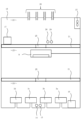
まず、図1を参照して、本発明の第1実施形態に係る空調システム20について説明する。図1は、本第1実施形態に係る空調システム20の接続概略図である。
(Embodiment 1)
First, with reference to FIG. 1, an
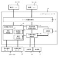
空調システム20は、外気導入ファン4と、複数の排気ファン5(排気ファン5a,5b,5c,5d)と、複数の搬送ファン3(搬送ファン3a,3b,3c,3d)と、複数の循環ファン6(6a,6b,6c,6d)と、居室温度センサー11(居室温度センサー11a,11b,11c,11d)と、居室湿度センサー12(居室湿度センサー12a,12b,12c,12d)と、空調室温度センサー14と、空調室湿度センサー15と、エアコンディショナー9と、加湿器16と、除湿器17と、入出力端末19と、システムコントローラ10(空調システムコントローラに該当)と、を備えて構成される。
The
空調システム20は、建物の一例である一般住宅1内に設置される。一般住宅1は、複数(本実施形態では4つ)の居室2(居室2a,2b,2c,2d)に加え、居室2と独立した少なくとも1つの空調室18を有している。ここで一般住宅1(住宅)とは、居住者がプライベートな生活を営む場として提供された住居であり、一般的な構成として居室2にはリビング、ダイニング、寝室、個室、子供部屋等が含まれる。また空調システム20が提供する居室にトイレ、浴室、洗面所、脱衣所等を含んでもよい。
The
空調室18では、各居室2より搬送された空気同士が混合される。また、外気導入ファン4により外気が空調室18内に取り込まれ、循環ファン6によって各居室2より搬送された空気と混合される。空調室18の空気は、空調室18内に設けられたエアコンディショナー9、加湿器16及び除湿器17によって温度及び湿度が制御され、すなわち空調されて、居室2に搬送すべき空気が生成される。空調室18にて空調された空気は、搬送ファン3により、各居室2に搬送される。ここで、空調室18は、エアコンディショナー9やその他加湿器16、除湿器17などが配置でき、各居室の空調をコントロールできる一定の広さを備えた空間を意味するが、居住空間を意図するものではなく、基本的に居住者が滞在する部屋を意味するものではない。
In the air conditioned
各居室2の空気は、循環ファン6により空調室18へ搬送される他、排気ファン5によって居室2内から一般住宅1外へ外気として排出される。空調システム20は、排気ファン5の排気風量を制御して室内から外気を排出しつつ、その排気ファン5の排気風量と連動させながら外気導入ファン4の給気風量を制御して室内に外気を取り込むことで、第1種換気方式の換気が行われる。
The air in each
外気導入ファン4は、一般住宅1の室内に外気を取り込むファンであり、給気ファンや熱交換気扇の給気機能等が該当する。上述した通り、外気導入ファン4により取り込まれた外気は、空調室18内に導入される。外気導入ファン4の給気風量は、複数段階で設定可能に構成されており、その排気風量は、後述するように、排気ファン5の排気風量に応じて設定される。
The outside air introduction fan 4 is a fan that takes outside air into the room of the
排気ファン5は、対応する居室2の空気の一部を例えば排気ダクトを介して外気として排出するファンであり、天埋換気扇、壁掛換気扇、レンジフード、熱交換気扇の排気機能等が該当する。なお、図1においては排気ファン5に接続された排気ダクトは直接一般住宅1外へ接続されているが、熱交換気扇の排気機能を利用する場合には、排気ダクトはいったん熱交換気扇に接続されてから一般住宅1外へ接続される。つまり排気ダクトを通る空気が熱交換気扇の給気風路を通る空気との間で熱交換されたのち、一般住宅1外へ排出される。排気ファン5aは居室2aに、排気ファン5bは居室2bに、排気ファン5cは居室2cに、排気ファン5dは居室2dに設けられている。
The exhaust fan 5 is a fan that exhausts a part of the air in the
各排気ファン5は、それぞれ、その排気風量が複数段階で設定可能に構成されている。通常時は、予め設定された排気風量となるように各排気ファン5は制御される。そして、ユーザによる設定や、各種センサーにより取得された値に応じて、排気ファン5a~5d毎に排気風量が制御される。
Each exhaust fan 5 is configured such that its exhaust air volume can be set in multiple stages. Normally, each exhaust fan 5 is controlled to achieve a preset exhaust air volume. Then, the exhaust air volume is controlled for each of the
搬送ファン3a~3dは、各居室2a~2dに対応して空調室18の例えば壁面に設けられている。空調室18の空気は、搬送ファン3aによって搬送ダクトを介して居室2aに搬送され、搬送ファン3bによって搬送ダクトを介して居室2bに搬送され、搬送ファン3cによって搬送ダクトを介して居室2cに搬送され、搬送ファン3dによって搬送ダクトを介して居室2dに搬送される。なお、各居室と接続される搬送ダクトはそれぞれ独立して設けられる。
The
循環ファン6aは居室2aに、循環ファン6bは居室2bに、循環ファン6cは居室2cに、循環ファン6dは居室2dに設けられている。各居室2a~2dの空気の一部は、対応する循環ファン6a~6dによって、循環ダクトを介して空調室18に搬送される。なお、空調室18と各居室とを接続する循環ダクトはそれぞれ独立して設けられてもよいが、循環ダクトの一部である複数の支流ダクトを途中より合流させて1つの循環ダクトに統合した後、空調室18に接続されてもよい。
The
エアコンディショナー9は、空調機に該当するものであり、空調室18の空調を制御する。エアコンディショナー9は、空調室18の空気の温度が設定された目標温度(空調室目標温度)となるように、空調室18の空気を冷却又は加熱する。
The
加湿器16は、空調室18の空気の湿度が設定された目標湿度(空調室目標湿度)よりも低い場合にその湿度が空調室目標湿度となるように、空調室18の空気を加湿する。なお、加湿器16がエアコンディショナー9に内蔵されている場合もあるが、複数の居室2に対応するだけの加湿能力を得るために、エアコンディショナー9とは独立した加湿器16を備えるのが望ましい。ここで空調室目標湿度は、下限を最低湿度で、上限を最高湿度で定義される所定の湿度範囲として定義される。また最低湿度、最高湿度、及び本実施例で扱われる湿度はそれぞれ相対湿度で示されるが、所定の変換処理にて絶対湿度として扱ってもよい。この場合、居室の湿度を含めて空調システムでの取り扱い全体を絶対湿度として取り扱うのが好ましい。
The
除湿器17は、空調室18の空気の湿度が設定された目標湿度(空調室目標湿度)よりも高い場合にその湿度が空調室目標湿度となるように、空調室18の空気を除湿する。なお、除湿器17がエアコンディショナー9に内蔵されている場合もあるが、複数の居室2に対応するだけの除湿能力を得るために、エアコンディショナー9とは独立した除湿器17を備えるのが望ましい。
The
居室温度センサー11aは、居室2aに設けられ、居室温度センサー11bは、居室2bに設けられ、居室温度センサー11cは、居室2cに設けられ、居室温度センサー11dは、居室2dに設けられている。居室温度センサー11a~11dは、対応する居室2a~2dそれぞれの室内温度を取得して、システムコントローラ10に送信するセンサーである。
The living room temperature sensor 11a is provided in the
居室湿度センサー12aは、居室2aに設けられ、居室湿度センサー12bは、居室2bに設けられ、居室湿度センサー12cは、居室2cに設けられ、居室湿度センサー12dは、居室2dに設けられている。居室湿度センサー12は、対応する居室2a~2dそれぞれの室内湿度(居室湿度)を取得して、システムコントローラ10に送信するセンサーである。
The living
空調室温度センサー14は、空調室18の空気の温度を取得して、システムコントローラ10に送信するセンサーである。なお、空調室温度センサー14は、エアコンディショナー9に内蔵されている場合もあるが、エアコンディショナー9に内蔵されている場合にはエアコンディショナー9周囲(例えば給気口付近)の情報しか得られない。空調室18は、上述のように外気と各居室2から搬送された空気とが混合されるため、空調室18全体としての情報が得られるように、エアコンディショナー9とは独立して備えるのが望ましい。
The air conditioned
空調室湿度センサー15は、空調室18の空気の湿度、すなわち空調室湿度を取得して、システムコントローラ10に送信するセンサーである。なお、空調室湿度センサー15も空調室温度センサー14と同様の理由で、空調室18全体としての情報が得られるように、エアコンディショナー9とは独立して備えるのが望ましい。
The air-conditioned
システムコントローラ10は、空調システム20全体を制御するコントローラである。システムコントローラ10は、外気導入ファン4、排気ファン5、搬送ファン3、循環ファン6、居室温度センサー11、居室湿度センサー12、空調室温度センサー14、空調室湿度センサー15、エアコンディショナー9、加湿器16及び除湿器17と、無線通信により通信可能に接続されている。
The
システムコントローラ10は、排気ファン5の排気風量に応じた風量となるように、外気導入ファン4の給気風量を設定する等、外気導入ファン4と排気ファン5とを連動させて制御する。これにより、一般住宅1に対して第1種換気方式による換気が行われる。
The
また、システムコントローラ10は、空調室温度センサー14及び空調室湿度センサー15により取得される空調室18の空気の温度及び湿度に基づいて、空調室18の温度及び/又は湿度が、空調室18に設定された空調室目標温度及び/又は空調室目標湿度となるように、空調機としてのエアコンディショナー9、加湿器16、除湿器17を制御する。
The
また、システムコントローラ10は、居室温度センサー11及び居室湿度センサー12により取得された各居室2それぞれの室内温度及び/又は室内湿度と、居室2a~2d毎に設定された目標温度(居室目標温度)及び/又は目標湿度(居室目標湿度)等に応じて、搬送ファン3の風量や循環ファン6の風量を設定する。
The
これにより、空調室18にて空調された空気が、各搬送ファン3に設定された風量で各居室2に搬送され、また、各居室2の空気が、各循環ファン6に設定された風量で空調室18に搬送される。よって、各居室2の室内温度及び/又は室内湿度が、居室目標温度及び/又は居室目標湿度となるように制御される。
As a result, the air conditioned in the air-conditioned
ここで、システムコントローラ10と、外気導入ファン4、排気ファン5、搬送ファン3、循環ファン6、居室温度センサー11、居室湿度センサー12、空調室温度センサー14、空調室湿度センサー15、エアコンディショナー9、加湿器16及び除湿器17とが、無線通信で接続されることにより、複雑な配線工事を不要とすることができる。ただし、これら全体を、又は、システムコントローラ10とこれらの一部を、有線通信により通信可能に構成してもよい。
Here, the
入出力端末19は、システムコントローラ10と無線通信により通信可能に接続され、空調システム20を構築するうえで必要な情報の入力を受け付けてシステムコントローラ10に記憶させたり、空調システム20の状態をシステムコントローラ10から取得して表示したりするものである。入出力端末19は、携帯電話、スマートフォン、タブレットといった携帯情報端末が例として挙げられる。
The input/
なお、入出力端末19は、必ずしも無線通信によりシステムコントローラ10と接続される必要はなく、有線通信により通信可能にシステムコントローラ10と接続されてもよい。この場合、入出力端末19は、例えば、壁掛のリモートコントローラにより実現されるものであってもよい。
Note that the input/
次いで、図2を参照して、システムコントローラ10の各機能について説明する。図2は、システムコントローラ10の概略機能ブロック図である。
Next, each function of the
システムコントローラ10は、居室目標湿度取得部54、空調室湿度制御部55、送風量決定部40、ファン風量制御部31、記憶部46を備える。
The
居室目標湿度取得部54は、入出力端末19により居室2全体に共通して設定された居室目標湿度を取得する。居室目標湿度は、下限を最低湿度で、上限を最高湿度で定義される所定の湿度範囲として設定される。本実施の形態では、居室目標湿度が空調室目標湿度と一致する。なお、本実施の形態では居室目標湿度をユーザが設定可能としているが、あらかじめ空調システムに固定値として設定されていてもよい。居室目標湿度取得部54により取得され、あるいはあらかじめ設定された最高湿度及び最低湿度は、記憶部46に記憶される。
The living room target
空調室湿度制御部55は、加湿器16及び除湿器17を利用して空調室内の湿度を居室目標湿度取得部54にて取得した空調室目標湿度に制御する。具体的には、空調室湿度センサー15にて取得した空調室の湿度が所定の湿度範囲を構成する最高湿度よりも高い場合には、除湿器17を動作させる。また、空調室湿度センサー15にて取得した空調室の湿度が最低湿度よりも低い場合には、加湿器16を動作させる。
The air conditioned room
送風量決定部40は、湿度判定部53と、湿度差比較部56と、高低判断部57とを備える。そして送風量決定部40は、居室湿度センサー12が取得した各居室の室内湿度と、空調室湿度センサー15が取得した空調室18の湿度とに基づいて搬送ファン3の送風量を決定する。なお、送風量の決定手順については後述する。
The air flow
湿度判定部53は、居室湿度センサー12が取得した各居室2の室内湿度と居室目標湿度取得部54により取得した居室目標湿度、すなわち所定の湿度範囲を示す空調室目標湿度とに基づいて、各居室2の室内湿度が所定の湿度範囲内であるか否か判定する。
The
湿度差比較部56は、居室湿度センサー12が取得した各居室の室内湿度と空調室湿度センサー15が取得した空調室18の湿度との差を算出する。具体的には、例えば居室2aの湿度が90%、空調室湿度が50%の場合、差は40となる。なお、差を算出するにあたって必ずしも%表記の湿度の差を求める必要はなく、例えば湿度から求められる水分量等により差を算出してもよく、即ち空調室湿度と居室湿度との乖離の大きさが数値化できれば良い。
The humidity
高低判断部57は、居室湿度センサー12が取得した各居室の室内湿度の、空調室湿度センサー15が取得した空調室18の湿度に対する高低を判断する。具体的には、例えば居室2aの湿度が90%であり、空調室湿度が50%である場合、居室2aの湿度は空調室湿度の50%よりも「高い」と判断する。他方、居室2cの湿度が30%であり、空調室湿度が50%である場合、居室2cの湿度は空調室湿度の50%よりも「低い」と判断する。これら判断は、すべての居室に対して行われてもよく、また、最高湿度より湿度の高い居室及び最低湿度より湿度の低い居室に対してのみ行われてもよい。
The
ファン風量制御部31は、複数の居室2a~2d毎に対応して設けられた複数の搬送ファン3a~3d個々の風量を、送風量決定部40にて決定された各搬送ファン3a~3dの送風量に制御する。また、ファン風量制御部31は、循環ファン6a~6dについても制御してよいが、ここでは詳細説明を省略する。
The fan air
記憶部46は、居室目標湿度取得部54により取得され、あるいはあらかじめ設定された所定の湿度範囲、すなわち最高湿度及び最低湿度を記憶する、いわゆるメモリである。また、その他システムコントローラ10による制御に数値などの情報の記憶が必要な場合にも記憶部46が利用される。
The
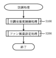
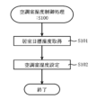
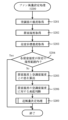
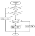
次いで、図3~図8を参照して、システムコントローラ10により実行される空調処理について説明する。図3は、空調処理を示すフローチャートである。図4は、空調室湿度制御処理を示すフローチャートである。図5は、ファン風量設定処理を示すフローチャートである。図6は、送風量決定処理を示すフローチャートである。図7は、空調室目標湿度と空調室湿度と居室湿度との関係の一例を示す図である。図8は、空調室目標湿度と空調室湿度と居室湿度との関係の他の例を示す図である。
Next, the air conditioning process executed by the
システムコントローラ10が実行する空調処理は、図3に示すように、主に空調室湿度制御処理S100、ファン風量設定処理S200により構成され、この順で実行される。
As shown in FIG. 3, the air conditioning process executed by the
ユーザが空調処理を実行すると、まず、システムコントローラ10は、図4に示す空調室湿度制御処理S100を実行する。
When the user executes the air conditioning process, the
空調室湿度制御処理S100では、システムコントローラ10は、入出力端末19にて設定された居室目標湿度を取得して記憶部46に記憶する(S101)。ここで居室目標湿度とは、ユーザが心地よいと感じる湿度であり、すべての居室に共通する湿度である。居室目標湿度は、下限を最低湿度で、上限を最高湿度で定義される所定の湿度範囲として定義される。この所定の湿度範囲は、空調室18が目標とする湿度範囲であり、即ち空調室目標湿度と同一である。ユーザは、入出力端末19に対して、例えば最高湿度を65%とし、最低湿度を45%として設定することで、システムコントローラ10は、居室目標湿度取得部54を介して入出力端末19に入力された居室目標湿度を空調室目標湿度として取得する。
In the air-conditioned room humidity control process S100, the
空調室目標湿度を取得すると、空調室湿度制御部55は、空調室湿度センサー15と加湿器16と除湿器17とを利用して、空調室18の湿度を空調室目標湿度の範囲内に維持する(S102)。
After acquiring the air-conditioned room target humidity, the air-conditioned room
具体的に空調室目標湿度の維持は、以下のように行われる。すなわち、空調室湿度センサー15にて取得した空調室湿度が最高湿度よりも高い場合には、除湿器17を動作させる。また、空調室湿度センサー15にて取得した空調室湿度が最低湿度よりも低い場合には、加湿器16を動作させる。空調室湿度制御処理後に空調室18に流入する空気による空調室湿度の変動を考慮すると、除湿時には、所定の湿度範囲であることを前提として、例えば最高湿度よりも一定の範囲で低い湿度(例えば-5%)まで除湿を行う。そして加湿時には例えば最低湿度よりも一定の範囲で高い湿度(例えば+5%)まで加湿してもよい。
Specifically, the target humidity of the air conditioned room is maintained as follows. That is, when the air conditioned room humidity acquired by the air conditioned
以上の処理により、空調室18の湿度が所定の湿度範囲内に維持される。
Through the above processing, the humidity in the air conditioned
続いて、システムコントローラ10は、図5に示すファン風量設定処理S200を実行する。
Subsequently, the
ファン風量設定処理S200では、送風量決定部40は、空調室湿度センサー15を介して空調室湿度を取得する(S201)。また、送風量決定部40は、居室湿度センサー12を介して各居室2の居室湿度を取得する(S202)。さらにシステムコントローラ10は、居室目標湿度取得部54を介して記憶部46より、所定の湿度範囲、すなわち最高湿度と最低湿度とを取得する(S203)。
In the fan air volume setting process S200, the air
次に、送風量決定部40は、湿度判定部53により各居室の居室湿度が所定の湿度範囲内であるか否か判定する(S203)。
Next, the air flow
ここで、すべての居室が所定の湿度範囲内であれば、処理を終了する(S204Yes→終了)。 Here, if all the rooms are within the predetermined humidity range, the process ends (S204 Yes -> end).
なお、少なくとも1つの居室が所定の湿度範囲内でなければ、湿度差比較部56は、該当する居室(湿度範囲内ではない居室)について、その居室の居室湿度と空調室湿度との差を算出する(S204No→S205)。さらに高低判断部57は、該当する居室について、その居室の居室湿度が空調室の湿度に対して高いか又は低いか、即ち高低を判断する(S206)。ここで、高低の判断は、空調室の湿度として、空調室湿度センサー15が取得した空調室湿度と居室湿度とを比較してもよいし、所定の湿度範囲に対する高低を判断しても結果は同じである。高低判断部57は、高低を判断し、所定の範囲内に無い居室2(居室2a~2d)を、最高湿度より高い高湿度居室と最低湿度より低い低湿度居室とに分類するとともに、湿度差比較部56が比較した温度差と関連付ける。つまり、送風量決定部40は、この処理において、高湿度居室と低湿度居室の数、及びそれぞれの空調室湿度との差とを把握することができる。
Note that if at least one living room is not within the predetermined humidity range, the humidity
上記処理が完了すると、送風量決定部40は、送風量決定処理を行う(S300)。
When the above processing is completed, the air blowing
送風量決定部40は、図6に示す送風量決定処理S300を実行する。すなわち、送風量決定処理S300においては、まず、送風量決定部40は、空調室湿度に対する低湿度居室の数と高湿度居室の数とをカウントする。
The air blowing
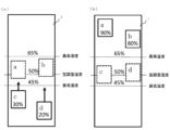
ここで、低湿度居室のみが複数存在する場合、湿度差の大きい居室の送風量を大きく決定する(S301Yes→S303)。この処理を、図7(a)を参照しながら詳しく説明する。なお、図7(a)は、低湿度居室のみが複数存在する一例である。そして図7におけるaは居室2aを、bは居室2bを、cは居室2cを、dは居室2dを示し、下部の数値は居室湿度を示す。また、最高湿度は65%、最低湿度は45%、空調室湿度は50%であるものとする。
Here, if there are a plurality of low-humidity living rooms, the amount of air blown in the living room with a large humidity difference is determined to be large (S301 Yes→S303). This process will be explained in detail with reference to FIG. 7(a). Note that FIG. 7(a) is an example in which only a plurality of low-humidity living rooms exist. In FIG. 7, a indicates the
図7(a)によると、低湿度居室のみが2室(居室2c、居室2d)存在する。そして居室2cは、空調室湿度との湿度差(絶対値)が20%、居室2dは、空調室湿度との湿度差が30%である。この場合、送風量決定部40は、湿度差が大きい居室2dに対応する搬送ファン3dの送風量を、居室2cに対応する搬送ファン3cの送風量よりも大きく設定する。ここで送風量とは、搬送ファンの送風能力、あるいは動作ノッチとすることができる。例えば搬送ファン3の送風量を送風量の小さいものから順に送風量1~送風量10の10段階の設定が可能とすると、送風量決定部40は、ここでは搬送ファン3dの送風量を最大値の送風量10に決定する。そして、送風量決定部40は、搬送ファン3cの送風量を搬送ファン3dよりも小さい例えば送風量7に決定する。
According to FIG. 7A, there are only two low-humidity living rooms (
これにより、居室2c及び居室2dには空調室の空気が流入し、各居室の居室湿度は、徐々に所定の湿度範囲内に近づいて行く。この際、送風量の差により、より不快とされる、空調室湿度との湿度差が大きい居室2dの湿度は、空調室湿度との湿度差が居室2dよりも小さい居室2cの湿度よりも改善速度が速くなる。つまり、送風量決定部40は、より湿度環境の悪い居室に対して居室の湿度改善を優先する。
As a result, air from the air-conditioned room flows into the
なおこの際、空調室湿度は、居室2c及び居室2dの乾燥した空気の流入により、50%から徐々に低下していくため、最低湿度を下回りそうな場合には必要に応じて空調室湿度制御部55が加湿器16を動作させ、空調室湿度を所定の湿度範囲に維持する。
At this time, the humidity in the air-conditioned room will gradually decrease from 50% due to the inflow of dry air from
また、送風量決定部40は、空調室湿度に対する低湿度居室の数と高湿度居室の数とをカウントし、高湿度居室のみが複数存在する場合も同様に、湿度差の大きい居室の送風量を大きく決定する(S301No→S302Yes→S303)。
Further, the air blowing
この処理を、図7(b)を参照しながら詳しく説明する。なお、図7(b)は、高湿度居室のみが複数存在する一例である。 This process will be explained in detail with reference to FIG. 7(b). Note that FIG. 7(b) is an example in which only a plurality of high-humidity living rooms exist.
図7(b)によると、高湿度居室のみが2室(居室2a、居室2b)存在する。そして居室2aは、空調室湿度との湿度差(絶対値)が40%、居室2bは、空調室湿度との湿度差が30%である。この場合、送風量決定部40は、湿度差が大きい居室2aに対応する搬送ファン3aの送風量を、居室2bに対応する搬送ファン3bの送風量よりも大きく設定する。つまり送風量決定部40は、ここでは搬送ファン3aの送風量を最大値の送風量10に決定する。そして、送風量決定部40は、搬送ファン3bの送風量を搬送ファン3bよりも小さい例えば送風量7に決定する。
According to FIG. 7(b), there are only two high-humidity living rooms (
これにより、居室2a及び居室2bには空調室の空気が流入し、各居室の居室湿度は、徐々に所定の湿度範囲内に近づいて行く。この際、送風量の差により、より不快とされる、空調室湿度との湿度差が大きい居室2aの湿度は、空調室湿度との湿度差が居室2aよりも小さい居室2bの湿度よりも改善速度が速くなる。つまり、送風量決定部40は、より湿度環境の悪い居室に対して居室の湿度改善を優先する。
As a result, air from the air-conditioned room flows into the
なおこの際、空調室湿度は、居室2a及び居室2bの湿った空気の流入により、50%から徐々に上昇していくため、最高湿度を上回りそうな場合には必要に応じて空調室湿度制御部55が除湿器17を動作させ、空調室湿度を所定の湿度範囲に維持する。
At this time, the humidity in the air-conditioned room will gradually rise from 50% due to the inflow of humid air from
また、送風量決定部40は、空調室湿度に対する低湿度居室の数と高湿度居室の数とをカウントし、高湿度居室と低湿度居室の両方が存在する場合には、湿度差が小さい居室の送風量を大きく設定する(S302No→S304Yes→S305)。
In addition, the air blowing
この処理を、図8を参照しながら詳しく説明する。なお、図8(a)は、低湿度居室のみが複数存在する一例である。なお、図8中の表現は図7と同一である。 This process will be explained in detail with reference to FIG. Note that FIG. 8(a) is an example in which only a plurality of low-humidity living rooms exist. Note that the expression in FIG. 8 is the same as in FIG. 7.
図8(a)によると、低湿度居室である居室2cと、高湿度居室である居室2aとが存在する。そして居室2cは、空調室湿度との湿度差が20%、居室2aは、空調室湿度との湿度差が40%である。この場合、送風量決定部40は、湿度差が大きい居室2aに対応する搬送ファン3aの送風量を、湿度差が小さい居室2cに対応する搬送ファン3cの送風量よりも小さく設定する。言い換えると、送風量決定部40は、湿度差が小さい居室2cに対応する搬送ファン3cの送風量を、湿度差が大きい居室2aに対応する搬送ファン3aの送風量よりも大きく設定する。具体的には、送風量決定部40は、ここでは搬送ファン3cの送風量を最大値の送風量10に決定する。そして、送風量決定部40は、搬送ファン3aの送風量を搬送ファン3cよりも小さい例えば送風量5に決定する。
According to FIG. 8(a), there are a
これにより、居室2a及び居室2cには空調室の空気が流入し、各居室の居室湿度は、徐々に所定の湿度範囲内に近づいて行く。この際、送風量の差により、図8(b)に示すように、湿度差の小さい居室2cの湿度がまず改善される。
As a result, air from the air-conditioned room flows into the
ここで、S303と異なる点は、2つの居室からの空気の流入量を制御することで、空調室湿度内の湿度の変動を最低限に抑制している点である。つまり、湿度差の大きい高湿度居室からの空調室への空気の流入量に対して、湿度差の小さい低湿度居室からの空調室への空気の流入量を多くすることで、空調室への水分の流入、流出を(理想的には)等価となるように制御する。これにより、空調室湿度の変動を抑制できるため、加湿器16や除湿器17の稼働を抑制でき、省エネルギー制御が可能となる。また、湿度の面で空調室の効率的な運用が可能となり、空調室の小型化が可能となる。
Here, the difference from S303 is that by controlling the inflow amount of air from the two rooms, fluctuations in the humidity in the air conditioned room are suppressed to the minimum. In other words, by increasing the amount of air flowing into the air-conditioned room from the low-humidity living room with a small humidity difference compared to the amount of air flowing into the air-conditioned room from the high-humidity living room with a large humidity difference, the amount of air flowing into the air-conditioned room is increased. Control the inflow and outflow of moisture so that they are (ideally) equivalent. This makes it possible to suppress fluctuations in the humidity in the air-conditioned room, thereby suppressing the operation of the
なお、送風量決定部40は、湿度差が小さい居室2cに対応する搬送ファン3cの送風量と、湿度差が大きい居室2aに対応する搬送ファン3aの送風量とを同一にしてもよい。具体的には、送風量決定部40は、搬送ファン3cの送風量と搬送ファン3aの送風量を例えば送風量10に決定する。この場合、図8(c)に示すように、まず、居室2cの湿度が改善される。この際、居室2cの湿度が改善されるまでの間は、居室2cの低湿度の空気と居室2aの高湿度の空気とが湿度を相殺するため、空調室湿度の変動を抑制することができる。なお、居室2aの湿度が高いため、空調室湿度がわずかながら上昇することが予想されるが、これに対しては必要に応じて空調室湿度制御部55が除湿器17により対応すればよい。この処理であっても、省エネルギー制御及び空調機の小型化に寄与することが可能である。
Note that the air
送風量決定部40は、空調室湿度に対する低湿度居室の数と高湿度居室の数とをカウントし、高湿度居室と低湿度居室の両方が存在しない場合、低湿度居室又は高湿度居室が1つ、存在することを意味する。この場合には、送風量決定部40は、該当する低湿度居室又は高湿度居室に所定の風量で送風することで、当該居室の湿度を所定の湿度範囲に遷移させることができる(S304No→S306)。
The air blowing
以上、空調処理について述べたが、空調処理が初回に空調処理が実行された後は、空調室湿度制御処理S100とファン風量設定処理S200とは独立して繰り返し処理される。 The air conditioning process has been described above, but after the air conditioning process is executed for the first time, the air conditioned room humidity control process S100 and the fan air volume setting process S200 are repeatedly processed independently.
以上、本発明に係る空調システム及びシステムコントローラについて説明を行ったが、上記実施の形態は、一例であり、これに限定されるものではない。 Although the air conditioning system and system controller according to the present invention have been described above, the embodiments described above are merely examples, and the present invention is not limited thereto.
例えば、循環ファン6a~6d、及び搬送ファン3a~3dは、居室と空調室とを接続するダクトによって連通されている。しかしながら循環ファン6a~6dについては必ずしもダクトで接続する必要はなく、居室間を結ぶ廊下等の空間をダクトとみなすことも可能である。この場合、居室内の空気は居室から循環ファン6a~6dによって廊下に搬送される。廊下に搬送された居室内の空気は、廊下と連通する空調室18に取り込まれる。空調室18への取り込みは、空調室18の廊下に面した壁面に新たに循環ファンを備えることで行われ、あるいは循環ファンを利用することなく空調室の負圧化により取り込んでもよい。このような構成によっても、ダクトで接続するのに対して循環効率は下がることが予想されるが、空調システムに寄与することができる。
For example, the
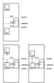
続いて、図9、図10、図11を参照して、本発明の第1実施形態に係る空調室18について説明する。図9、図10は、本第1実施形態に係る空調室18の概略図であり、図9は、空調室を3区分化した場合の空調室の概略図、図10は、空調室を2区分化した場合の空調室の概略図である。図11は、空調室を3区分化した場合のシステムコントローラの概略機能ブロック図である。なお図11では、図2で示した概略機能ブロック図に対して、さらに第一空間湿度算出部58が加えられている。
Next, the air conditioned
ところで、上述の図1では、空調室18は区分化されておらず、つまり同一空間で、エアコンディショナー9、加湿器16、及び除湿器17によって温度及び湿度が制御されている。これに対して、図9、図10では、空調室18を区分化することにより、効率的な除加湿を実現可能となる。
By the way, in the above-mentioned FIG. 1, the air-conditioned
具体的には、図9に示すように、除湿、温度制御、加湿をそれぞれ別の空間で行う。例えば、図9に示すように、空調室18は仕切り板21により第一空間22、第二空間23、第三空間24の3つの独立した空間に分離される。この場合においても、エアコンディショナー9、加湿器16及び除湿器17等は、上記同様にシステムコントローラ10で制御される。なお、上流から下流に向かって順に第一空間22、第二空間23、第三空間24が配置されており、搬送ファン3によって各空間内の空気が下流に送風される。
Specifically, as shown in FIG. 9, dehumidification, temperature control, and humidification are performed in separate spaces. For example, as shown in FIG. 9, the air-conditioned
仕切り板21は、第一空間22と第二空間23の仕切りと、第二空間23と第三空間24の仕切りの役割を持ち、木板や石膏ボード等により形成されるボードである。さらに、仕切り板21は、使用するボードに加えて、断熱ボードを貼り合わせることで、より各空間間での熱や湿度移動を防止することができる。また、仕切り板21は、板面の一部分に丸穴もしくは四角穴の空間連接開口25を備える。これにより、第一空間22と第二空間23及び第二空間23と第三空間24は、空間連接開口25を介して互いに通風可能な独立空間となる。
The
空間連接開口25は、仕切り板21が存在しない場合に第一空間22と第二空間23とが接する面の面積に対して、例えば30%以下、さらに好適には20%以下の開口面積を有する。空間連接開口25が大すぎる場合には、除湿、加湿能力の効率化への寄与度が下がり、小さすぎる場合には圧損が上昇して空間同士の通風効率に悪影響を及ぼす恐れがあるためである。また、ここでは空間連接開口25は単なる開口として設けられているが、開口内に強制的に送風を行うファン、例えばパイプ用ファン等を設置することで、上流の独立空間から下流の独立空間への送風効率を高めることができる。
The
第一空間22は、上流に屋内の空気を給気するための第一給気開口26と屋外の空気を給気するための第二給気開口27、下流に第二空間23との空間連接開口25を備える。また、第一空間22は、除湿器17、第一空間温度センサー28、第一空間湿度センサー29が配置される。この構成により、第一給気開口26からの屋内の空気と第二給気開口27からの屋外の空気を第一空間22で混合する。混合された空気は、通常、屋内の空気よりも屋外の新鮮な空気を多く含む。屋内の空気は、搬送ファン3a~3dから搬送された空気が各居室2a~2dを経由して、第一空間22に戻ってくるため、システムコントローラ10で設定された目標温度、目標湿度に近い温度、湿度である。一方、屋外の空気は、例えば、夏季や梅雨時の高温高湿環境においては、設定された目標温度、目標湿度に対して高温、高湿である。上述のように、屋外の空気が屋内の空気よりも多く第一空間22に給気されるため、第一空間22は高温、高湿の環境となる。混合された第一空間22の空気は、空調室18の空調室目標湿度よりも高い場合に、空調室目標湿度となるように、第一空間22で除湿器17により除湿されるが詳細は後述する。除湿された空気は、空間連接開口25を介して第二空間23へと送風される。
The
第一空間温度センサー28は、第一空間22の空気の温度を取得してシステムコントローラ10に送信するセンサーである。第一空間22は、上述のように外気と各居室2から搬送された空気とが混合されるため、第一空間22全体としての情報が得られるように第一空間温度センサー28を、下流すなわち空間連接開口25近傍に備えるのが望ましい。
The first
第一空間湿度センサー29は、第一空間22の空気の湿度、すなわち第一空間22の湿度を取得して、システムコントローラ10に送信するセンサーである。なお、第一空間湿度センサー29も第一空間温度センサー28と同様の理由で、第一空間22全体としての情報が得られるように、下流すなわち空間連接開口25近傍に備えるのが望ましい。
The first
第二空間23は、上流に第一空間22との空間連接開口25、下流に第三空間24との空間連接開口25を備える。また、第二空間23は、エアコンディショナー9が配置される。この構成により、第一空間22で除湿された空気は、第二空間23でエアコンディショナー9により、第二空間23の空気の温度が設定された空調室目標温度となるように冷却又は加熱される。そして、冷却又は加熱された空気は、第三空間24との空間連接開口25を介して第三空間24へと送風される。
The
第三空間24は、上流に第二空間23との空間連接開口25、下流に搬送ファン3a~3dを備える。また、第三空間24は、加湿器16が配置される。さらに、第三空間24は、下流すなわち搬送ファン3a~3d近傍に空調室温度センサー14と空調室湿度センサー15が配置される。この構成により、第二空間23で冷却又は加熱された空気は、空調室目標湿度よりも低い場合にその湿度が空調室目標湿度となるように、第三空間24で加湿器16により加湿される。そして、加湿された空気は、搬送ファン3a~3dを介して各居室2a~2dに搬送される。
The
この構成により、空調室目標温度の制御と空調室目標湿度の制御を独立した空間でそれぞれ別々に行うことができるため、効率の良い除湿・加湿を行うことができる。以下、除湿・加湿の具体的な手順と効果について説明する。 With this configuration, the air-conditioned room target temperature and the air-conditioned room target humidity can be controlled separately in independent spaces, so that efficient dehumidification and humidification can be performed. The specific procedures and effects of dehumidification and humidification will be explained below.
例えば、夏季や梅雨時の高温高湿環境の場合に、空調室18の空気を除湿や冷却を行うとする。まず、空調室湿度制御部55は、空調室目標湿度と空調室18の湿度すなわち第三空間24の湿度との差を算出する。そして、第三空間24の湿度が空調室目標湿度よりも高い場合、第一空間22に備えた除湿器17で除湿を行う。第一空間22で除湿された空気は、第二空間23に送風される。第二空間23では、設定された空調室目標温度よりも第二空間23の空気の温度が高い場合、第二空間23に備えたエアコンディショナー9で冷却を行う。ここで、第一空間22で制御された湿度は、第二空間23で冷却されることにより、相対湿度が変わってしまう。これに対して、本構成においては、第一空間22の空気は、空調室湿度制御部55により、搬送ファン3を介して空調室18外に送風される搬送空気の湿度(この場合、相対湿度)よりも低い所定の除湿湿度以下に制御される。つまり、第一空間湿度算出部58は、エアコンディショナー9による冷却を見越して、第一空間22の到達すべき湿度を算出(逆算)する。
For example, suppose that the air in the air-conditioned
具体的に、第一空間湿度算出部58は、設定された搬送空気の目標湿度(この場合、相対湿度)と、設定された搬送空気の目標温度と、第一空間22の温度に基づいて第一空間22の空気が到達すべき湿度(この場合、相対湿度)の算出を以下の手順で行う。
Specifically, the first space
まず、設定された搬送空気の目標湿度(この場合、相対湿度)と、設定された搬送空気の目標温度の条件により、搬送空気の水分量すなわち絶対湿度を算出する。夏季や梅雨時においては、空気は、上述のように第二空間23で冷却された後、第三空間24から各居室2a~2dに搬送される。つまり、第一空間22での絶対湿度を決定することで、各居室2a~2dに搬送される空気は目標の絶対湿度となる。第一空間湿度算出部58による搬送空気の絶対湿度算出後は、第一空間22の温度を検知する。これにより、到達すべき第一空間22の温度における湿度(この場合、相対湿度)が算出できる。夏季や梅雨時においては、必要に応じて第一空間22の温度に対して第二空間23の温度はエアコンディショナー9で冷却される。そのため、第一空間22の空気の湿度(この場合、相対湿度)は第二空間23の空気の湿度(この場合、相対湿度)よりも小さくなる。したがって、第一空間22の空気の湿度(この場合、相対湿度)は、搬送空気の湿度(この場合、相対湿度)よりも低い除湿湿度に制御されることとなる。
First, the moisture content of the conveying air, that is, the absolute humidity, is calculated based on the conditions of the set target humidity (in this case, relative humidity) of the conveying air and the set target temperature of the conveying air. During the summer or rainy season, the air is cooled in the
以上のように、夏季や梅雨時においては、第一空間22には高温高湿の空気が送風される。空気は、高温であればあるほど飽和水蒸気量が多くなり、より多くの水分量を含むことができる。この場合に除湿を行うとすると、除湿器17に備えられた熱交換器での空気の温度を少し低下させるだけで多くの水分を空気から取り除くことができる。つまり、効率よく空気の除湿を行うことができる。
As described above, high temperature and high humidity air is blown into the
また、梅雨時においては、エアコンディショナー9と除湿器17を空調室18の同じ空間に設けた場合、エアコンディショナー9は、屋外と空調室18の空気の温度差が小さく、サーモオフの状態となる。この場合、除湿器17のみが動作して、空気は、除湿器17の放熱により、屋外の温度よりも空調室18の温度は高くなり、その空気が各居室2a~2dに搬送されることとなる。しかし、第一空間22で先に除湿を行うことで、エアコンディショナー9には除湿器17の放熱により加熱された空気が送風されるので、エアコンディショナー9は冷房運転を行い、設定された空調室目標温度に調整することができる。また、空調室18は比較的狭い空間であることが予想される。このため、エアコンディショナー9と除湿器17を空調室18の同じ空間に設けた場合、エアコンディショナー9による空気の冷却と除湿器17からの放熱による空気の加熱が同時に行われることで、設定された目標温度への制御が困難となる。しかし、空調室18を区分化しているため、除湿器17の放熱をエアコンディショナー9のある第二空間23と分離することができるため、設定された空調室目標温度、空調室目標湿度への制御が容易となる。
Further, during the rainy season, if the
また、例えば、冬季の低温低湿環境の場合に、空調室18の空気を加熱及び加湿を行うとする。まず、空調室湿度制御部55は、第一空間22の空気の湿度を検知することで除湿の対象であるかどうかを判断するが、すでに十分に低い湿度である冬季の空気は除湿の対象とはならない。つまり、第一空間22では、第一給気開口26からの屋内の空気と第二給気開口27からの屋外の空気を混合するのみである。
Further, for example, in the case of a low-temperature, low-humidity environment in winter, the air in the air-conditioned
次に、第二空間23の空気は、設定された空調室目標温度よりも低い場合、エアコンディショナー9で設定された空調室目標温度まで加熱される。この場合、第二空間23の空気は加熱により湿度(この場合、相対湿度)が、非常に大きく低下する。第二空間23で加熱された空気は、空調室目標温度の条件を満たした状態で、第三空間24に搬送される。
Next, if the air in the
第三空間24では、空調室湿度制御部55は、設定された空調室目標湿度と第三空間24の湿度との差を算出する。そして、第三空間24の湿度が空調室目標湿度よりも低い場合、空調室湿度制御部55は、第三空間24に備えた加湿器16で加湿を行う。これにより、第三空間24の搬送ファン3a~3dから搬送される空気は、設定された空調室目標温度、空調室目標湿度となる。
In the
この構成では、第三空間24にはエアコンディショナー9で加熱された後の空気が送風される。そして、空気は温度が高ければ高いほどより多くの水分量を含むことができ、すなわち絶対湿度を大きくすることができる。これにより、第三空間24の空気は、加湿器16からの水分を効率よく吸収することができる。すなわち、第三空間24の空気は、より効率よく設定された空調室目標湿度へ加湿されて搬送ファン3a~3dから各居室2へ搬送することができる。
In this configuration, air heated by the
以上、本発明に係る空調システムの空調室18の空間を3区分に分離した構造について説明を行ったが、上記実施の形態は、一例であり、これに限定されるものではない。
Although the structure in which the space of the air-conditioned
例えば、図10に示すように、第二空間23が第三空間24を兼ねた空間とし、すなわち第二・第三空間30としてもよい。言い換えると、空気を冷却又は加熱する空間と加湿する空間を同一の空間としてもよい。
For example, as shown in FIG. 10, the
夏季や梅雨時の高温高湿環境の場合は、上記の3区分化した場合と同様に、空気は、第一空間22で除湿され、第二・第三空間30で冷却される。また、冬季の低温低湿環境の場合は、第二・第三空間30で加熱と加湿を同時に行う。本構成では、第二・第三空間30に空調室よりも温度の低い空気が第一空間22から送風されることになり、上記の3区分化した場合よりも空気を加湿する効率が悪くなる。しかし、第二・第三空間30とすることで、第三空間24よりも加湿空間の容積を大きくすることができる。すなわち、加湿された湿度の大きい空気の量は、第二・第三空間30の方が第三空間24よりも多くなり、より効率よく設定された空調室目標湿度へ加湿することができる。さらに、仕切り板21を2枚から1枚に減らすことができ、空調室18にかかる費用を低減することができる。
In the case of a high-temperature, high-humidity environment during the summer or rainy season, the air is dehumidified in the
なお、上記実施の形態では、居室として示しているが、居室は必ずしも人が居る必要は無く、一つの空間として捉えることができる。つまり、廊下やキッチンもある程度区切られているのであれば1つの空間として捉えることができ、1つの居室に該当する。 Note that in the above embodiment, the living room is shown as a living room, but the living room does not necessarily have to be occupied by a person, and can be regarded as one space. In other words, if the hallway and kitchen are separated to some extent, they can be considered as one space, and fall under one living room.
また、本発明に係る空調システムは、戸建て住宅やマンション等の複合住宅に適用可能である。ただし、空調システムを複合住宅に適用する場合には、1つのシステムが世帯単位に対応するものであり、各世帯を1つの居室とするものではない。 Furthermore, the air conditioning system according to the present invention is applicable to single-family houses and complex houses such as condominiums. However, when an air conditioning system is applied to a complex, one system corresponds to each household, and each household does not have one room.
本発明に係る空調システム及び空調システムコントローラは、効率的な除加湿により空調室の小型化に寄与する空調システム、及び空調システムコントローラとして有用である。 INDUSTRIAL APPLICABILITY The air conditioning system and air conditioning system controller according to the present invention are useful as an air conditioning system and an air conditioning system controller that contribute to downsizing of air conditioning rooms through efficient dehumidification and humidification.
1 一般住宅
2、2a、2b、2c、2d 居室
3、3a、3b、3c、3d 搬送ファン
4 外気導入ファン
5、5a、5b、5c、5d 排気ファン
6、6a、6b、6c、6d 循環ファン
9 エアコンディショナー
10 システムコントローラ
11、11a、11b、11c、11d 居室温度センサー
12、12a、12b、12c、12d 居室湿度センサー
14 空調室温度センサー
15 空調室湿度センサー
16 加湿器
17 除湿器
18 空調室
19 入出力端末
20 空調システム
21 仕切り板
22 第一空間
23 第二空間
24 第三空間
25 空間連接開口
26 第一給気開口
27 第二給気開口
28 第一空間温度センサー
29 第一空間湿度センサー
30 第二・第三空間
31 ファン風量制御部
40 送風量決定部
53 湿度判定部
54 居室目標湿度取得部
55 空調室湿度制御部
56 湿度差比較部
57 高低判断部
58 第一空間湿度算出部
1
Claims (10)
前記空調室の空気を前記空調室とは独立した複数の居室に搬送する、前記複数の居室毎に対応して設けられた複数の搬送ファンと、
前記加湿器と前記搬送ファンを制御するシステムコントローラと、
前記複数の居室それぞれの室内湿度を取得して前記システムコントローラに送信する居室湿度センサーと、
前記空調室の湿度を取得して前記システムコントローラに送信する空調室湿度センサーと、を備え、
前記システムコントローラは、
前記加湿器を制御して前記空調室の湿度を所定の最低湿度以上で定義される所定の湿度範囲に維持する空調室湿度制御部と、
前記居室湿度センサーが取得した各居室の室内湿度と、前記空調室湿度センサーが取得した前記空調室の湿度とに基づいて前記搬送ファンの送風量を決定する送風量決定部と、
前記送風量決定部が決定した送風量で前記搬送ファンそれぞれの送風量を制御するファン風量制御部と、を備え、
前記送風量決定部は、
前記居室湿度センサーが取得した各居室の室内湿度と前記所定の湿度範囲とに基づいて前記各居室の室内湿度が前記所定の湿度範囲内であるか否か判定する湿度判定部と、
前記居室湿度センサーが取得した各居室の室内湿度と前記空調室湿度センサーが取得した前記空調室の湿度との差を算出する湿度差比較部と、を備え、
前記湿度判定部の判定結果により前記各居室の室内湿度が前記所定の湿度範囲内にないと判定された場合には、前記湿度差比較部が算出した湿度差に基づいて前記搬送ファンの送風量を決定する空調システム。 A humidifier that humidifies the air in an air-conditioned room,
a plurality of transport fans provided corresponding to each of the plurality of living rooms, which transports air in the air-conditioned room to a plurality of living rooms independent of the air-conditioned room;
a system controller that controls the humidifier and the transfer fan;
a living room humidity sensor that acquires the indoor humidity of each of the plurality of living rooms and transmits it to the system controller;
an air-conditioned room humidity sensor that acquires the humidity of the air-conditioned room and sends it to the system controller,
The system controller includes:
an air conditioned room humidity control unit that controls the humidifier to maintain the humidity in the air conditioned room within a predetermined humidity range defined as a predetermined minimum humidity or higher;
an air blowing amount determination unit that determines the air blowing amount of the conveying fan based on the indoor humidity of each living room acquired by the living room humidity sensor and the humidity of the air conditioned room acquired by the air conditioned room humidity sensor;
a fan air volume control unit that controls the air volume of each of the transport fans with the air volume determined by the air volume determination unit;
The air blowing amount determining unit includes:
a humidity determination unit that determines whether the indoor humidity of each living room is within the predetermined humidity range based on the indoor humidity of each living room acquired by the living room humidity sensor and the predetermined humidity range;
a humidity difference comparison unit that calculates a difference between the indoor humidity of each living room acquired by the living room humidity sensor and the humidity of the air-conditioned room acquired by the air-conditioned room humidity sensor,
If it is determined that the indoor humidity of each living room is not within the predetermined humidity range based on the determination result of the humidity determination section, the air flow rate of the conveyance fan is determined based on the humidity difference calculated by the humidity difference comparison section. Determine the air conditioning system.
前記空調室の空気を前記空調室とは独立した複数の居室に搬送する、前記複数の居室毎に対応して設けられた複数の搬送ファンと、a plurality of transport fans provided corresponding to each of the plurality of living rooms, which transports air in the air-conditioned room to a plurality of living rooms independent of the air-conditioned room;
前記除湿器と前記搬送ファンを制御するシステムコントローラと、a system controller that controls the dehumidifier and the transfer fan;
前記複数の居室それぞれの室内湿度を取得して前記システムコントローラに送信する居室湿度センサーと、a living room humidity sensor that acquires the indoor humidity of each of the plurality of living rooms and transmits it to the system controller;
前記空調室の湿度を取得して前記システムコントローラに送信する空調室湿度センサーと、を備え、an air-conditioned room humidity sensor that acquires the humidity of the air-conditioned room and sends it to the system controller,
前記システムコントローラは、The system controller includes:
前記除湿器を制御して前記空調室の湿度を所定の最高湿度以下で定義される所定の湿度範囲に維持する空調室湿度制御部と、 an air conditioned room humidity control unit that controls the dehumidifier to maintain the humidity in the air conditioned room within a predetermined humidity range defined as a predetermined maximum humidity or less;
前記居室湿度センサーが取得した各居室の室内湿度と、前記空調室湿度センサーが取得した前記空調室の湿度とに基づいて前記搬送ファンの送風量を決定する送風量決定部と、 an air blowing amount determination unit that determines the air blowing amount of the conveying fan based on the indoor humidity of each living room acquired by the living room humidity sensor and the humidity of the air conditioned room acquired by the air conditioned room humidity sensor;
前記送風量決定部が決定した送風量で前記搬送ファンそれぞれの送風量を制御するファン風量制御部と、を備え、 a fan air volume control unit that controls the air volume of each of the transport fans with the air volume determined by the air volume determination unit;
前記送風量決定部は、The air blowing amount determining unit includes:
前記居室湿度センサーが取得した各居室の室内湿度と前記所定の湿度範囲とに基づいて前記各居室の室内湿度が前記所定の湿度範囲内であるか否か判定する湿度判定部と、 a humidity determination unit that determines whether the indoor humidity of each living room is within the predetermined humidity range based on the indoor humidity of each living room acquired by the living room humidity sensor and the predetermined humidity range;
前記居室湿度センサーが取得した各居室の室内湿度と前記空調室湿度センサーが取得した前記空調室の湿度との差を算出する湿度差比較部と、を備え、 a humidity difference comparison unit that calculates a difference between the indoor humidity of each living room acquired by the living room humidity sensor and the humidity of the air-conditioned room acquired by the air-conditioned room humidity sensor,
前記湿度判定部の判定結果により前記各居室の室内湿度が前記所定の湿度範囲内にないと判定された場合には、前記湿度差比較部が算出した湿度差に基づいて前記搬送ファンの送風量を決定する空調システム。 If it is determined that the indoor humidity of each living room is not within the predetermined humidity range based on the determination result of the humidity determination section, the air flow rate of the conveyance fan is determined based on the humidity difference calculated by the humidity difference comparison section. Determine the air conditioning system.
前記湿度差比較部が算出した湿度差が大きい居室に対し、前記湿度差が小さい居室に対するよりも前記搬送ファンの送風量を大きくする請求項1または2記載の空調システム。 The air blowing amount determining unit includes:
The air conditioning system according to claim 1 or 2, wherein the air flow rate of the transport fan is made larger for a living room where the humidity difference calculated by the humidity difference comparison unit is large than for a living room where the humidity difference is small.
前記空調室の空気を前記空調室とは独立した複数の居室に搬送する、前記複数の居室毎に対応して設けられた複数の搬送ファンと、
前記加湿器と前記搬送ファンを制御するシステムコントローラと、
前記複数の居室それぞれの室内湿度を取得して前記システムコントローラに送信する居室湿度センサーと、
前記空調室の湿度を取得して前記システムコントローラに送信する空調室湿度センサーと、を備え、
前記システムコントローラは、
前記加湿器を制御して前記空調室の湿度を所定の最低湿度以上で定義される所定の湿度範囲に維持する空調室湿度制御部と、
前記居室湿度センサーが取得した各居室の室内湿度と、前記空調室湿度センサーが取得した前記空調室の湿度とに基づいて前記搬送ファンの送風量を決定する送風量決定部と、
前記送風量決定部が決定した送風量で前記搬送ファンそれぞれの送風量を制御するファン風量制御部と、を備え、
前記送風量決定部は、
前記居室湿度センサーが取得した各居室の室内湿度と前記所定の湿度範囲とに基づいて前記各居室の室内湿度が前記所定の湿度範囲内であるか否か判定する湿度判定部と、
前記居室湿度センサーが取得した各居室の室内湿度の、前記空調室の湿度に対する高低を判断する高低判断部と、を備え、
前記湿度判定部の判定結果により前記各居室の室内湿度が前記所定の湿度範囲内にないと判定された場合には、前記高低判断部が判定した前記空調室の湿度に対する高低に基づいて前記搬送ファンの送風量を決定する空調システム。 A humidifier that humidifies the air in an air-conditioned room,
a plurality of transport fans provided corresponding to each of the plurality of living rooms, which transports air in the air-conditioned room to a plurality of living rooms independent of the air-conditioned room;
a system controller that controls the humidifier and the transfer fan;
a living room humidity sensor that acquires the indoor humidity of each of the plurality of living rooms and transmits it to the system controller;
an air-conditioned room humidity sensor that acquires the humidity of the air-conditioned room and sends it to the system controller,
The system controller includes:
an air conditioned room humidity control unit that controls the humidifier to maintain the humidity in the air conditioned room within a predetermined humidity range defined as a predetermined minimum humidity or higher;
an air blowing amount determination unit that determines the air blowing amount of the conveying fan based on the indoor humidity of each living room acquired by the living room humidity sensor and the humidity of the air conditioned room acquired by the air conditioned room humidity sensor;
a fan air volume control unit that controls the air volume of each of the transport fans with the air volume determined by the air volume determination unit;
The air blowing amount determining unit includes:
a humidity determination unit that determines whether the indoor humidity of each living room is within the predetermined humidity range based on the indoor humidity of each living room acquired by the living room humidity sensor and the predetermined humidity range;
a level determination unit that determines whether the indoor humidity of each living room acquired by the living room humidity sensor is high or low relative to the humidity of the air-conditioned room,
If it is determined that the indoor humidity of each of the living rooms is not within the predetermined humidity range based on the determination result of the humidity determination section, the conveyance is performed based on the level of humidity in the air-conditioned room determined by the level determination section. An air conditioning system that determines the airflow rate of the fan.
前記空調室の空気を前記空調室とは独立した複数の居室に搬送する、前記複数の居室毎にTransporting air from the air conditioned room to a plurality of rooms independent of the air conditioning room, for each of the plurality of rooms.
対応して設けられた複数の搬送ファンと、A plurality of correspondingly provided conveyor fans,
前記除湿器と前記搬送ファンを制御するシステムコントローラと、a system controller that controls the dehumidifier and the transfer fan;
前記複数の居室それぞれの室内湿度を取得して前記システムコントローラに送信する居室湿度センサーと、a living room humidity sensor that acquires the indoor humidity of each of the plurality of living rooms and transmits it to the system controller;
前記空調室の湿度を取得して前記システムコントローラに送信する空調室湿度センサーと、を備え、an air-conditioned room humidity sensor that acquires the humidity of the air-conditioned room and sends it to the system controller,
前記システムコントローラは、The system controller includes:
前記除湿器を制御して前記空調室の湿度を所定の最高湿度以下で定義される所定の湿度範囲に維持する空調室湿度制御部と、 an air conditioned room humidity control unit that controls the dehumidifier to maintain the humidity in the air conditioned room within a predetermined humidity range defined as a predetermined maximum humidity or less;
前記居室湿度センサーが取得した各居室の室内湿度と、前記空調室湿度センサーが取得した前記空調室の湿度とに基づいて前記搬送ファンの送風量を決定する送風量決定部と、 an air blowing amount determination unit that determines the air blowing amount of the conveying fan based on the indoor humidity of each living room acquired by the living room humidity sensor and the humidity of the air conditioned room acquired by the air conditioned room humidity sensor;
前記送風量決定部が決定した送風量で前記搬送ファンそれぞれの送風量を制御するファン風量制御部と、を備え、 a fan air volume control unit that controls the air volume of each of the transport fans with the air volume determined by the air volume determination unit;
前記送風量決定部は、The air blowing amount determining unit includes:
前記居室湿度センサーが取得した各居室の室内湿度と前記所定の湿度範囲とに基づいて前記各居室の室内湿度が前記所定の湿度範囲内であるか否か判定する湿度判定部と、 a humidity determination unit that determines whether the indoor humidity of each living room is within the predetermined humidity range based on the indoor humidity of each living room acquired by the living room humidity sensor and the predetermined humidity range;
前記居室湿度センサーが取得した各居室の室内湿度の、前記空調室の湿度に対する高低を判断する高低判断部と、を備え、 a level determination unit that determines whether the indoor humidity of each living room acquired by the living room humidity sensor is high or low with respect to the humidity of the air conditioned room,
前記湿度判定部の判定結果により前記各居室の室内湿度が前記所定の湿度範囲内にないと判定された場合には、前記高低判断部が判定した前記空調室の湿度に対する高低に基づいて前記搬送ファンの送風量を決定する空調システム。 If it is determined that the indoor humidity of each of the living rooms is not within the predetermined humidity range based on the determination result of the humidity determination section, the conveyance is performed based on the level of humidity in the air-conditioned room determined by the level determination section. An air conditioning system that determines the airflow rate of the fan.
前記空調室の空気を前記空調室とは独立した複数の居室に搬送する、前記複数の居室毎に対応して設けられた複数の搬送ファンと、
前記除湿器と前記搬送ファンを制御するシステムコントローラと、
前記複数の居室それぞれの室内湿度を取得して前記システムコントローラに送信する居室湿度センサーと、
前記空調室の湿度を取得して前記システムコントローラに送信する空調室湿度センサーと、を備え、
前記システムコントローラは、
前記除湿器を制御して前記空調室の湿度を所定の最高湿度以下で定義される所定の湿度範囲に維持する空調室湿度制御部と、
前記居室湿度センサーが取得した各居室の室内湿度と、前記空調室湿度センサーが取得した前記空調室の湿度とに基づいて前記搬送ファンの送風量を決定する送風量決定部と、
前記送風量決定部が決定した送風量で前記搬送ファンそれぞれの送風量を制御するファン風量制御部と、を備え、
前記空調室は、
給気開口を有する第一空間と、
前記第一空間の空気を除湿する前記除湿器と、
前記空調室における前記第一空間の下流に、前記第一空間と通風可能に独立して設けられた第二空間と、
前記第二空間の空気を空調するエアコンディショナーと、
前記エアコンディショナーにより空調された空気を前記空調室外に搬送する前記搬送ファンと、
前記除湿器と、前記エアコンディショナーと、を制御する前記システムコントローラと、を備えた空調システム。 A dehumidifier that dehumidifies the air in an air conditioned room,
a plurality of transport fans provided corresponding to each of the plurality of living rooms, which transports air in the air-conditioned room to a plurality of living rooms independent of the air-conditioned room;
a system controller that controls the dehumidifier and the transfer fan;
a living room humidity sensor that acquires the indoor humidity of each of the plurality of living rooms and transmits it to the system controller;
an air-conditioned room humidity sensor that acquires the humidity of the air-conditioned room and sends it to the system controller,
The system controller includes:
an air conditioned room humidity control unit that controls the dehumidifier to maintain the humidity in the air conditioned room within a predetermined humidity range defined as a predetermined maximum humidity or less;
an air blowing amount determination unit that determines the air blowing amount of the conveying fan based on the indoor humidity of each living room acquired by the living room humidity sensor and the humidity of the air conditioned room acquired by the air conditioned room humidity sensor;
a fan air volume control unit that controls the air volume of each of the transport fans with the air volume determined by the air volume determination unit;
The air conditioned room is
a first space having an air supply opening;
the dehumidifier that dehumidifies the air in the first space;
a second space provided downstream of the first space in the air-conditioned room and independently of the first space to allow ventilation;
an air conditioner that conditions the air in the second space;
the conveyance fan that conveys the air conditioned by the air conditioner to the outside of the air conditioned room;
An air conditioning system comprising: the dehumidifier; and the system controller that controls the air conditioner.
前記第三空間の空気を加湿する加湿器と、を備え、
前記システムコントローラは、
前記加湿器を制御する請求項6記載の空調システム。 a third space provided downstream of the first space and independently from the first space to allow ventilation;
a humidifier that humidifies the air in the third space,
The system controller includes:
The air conditioning system according to claim 6, wherein the air conditioning system controls the humidifier.
前記空調室の空気を前記空調室とは独立した複数の居室に搬送する、前記複数の居室毎に対応して設けられた複数の搬送ファンと、
前記加湿器と前記搬送ファンを制御するシステムコントローラと、
前記複数の居室それぞれの室内湿度を取得して前記システムコントローラに送信する居室湿度センサーと、
前記空調室の湿度を取得して前記システムコントローラに送信する空調室湿度センサーと、を備え、
前記システムコントローラは、
前記加湿器を制御して前記空調室の湿度を所定の最低湿度以上で定義される所定の湿度範囲に維持する空調室湿度制御部と、
前記居室湿度センサーが取得した各居室の室内湿度と、前記空調室湿度センサーが取得した前記空調室の湿度とに基づいて前記搬送ファンの送風量を決定する送風量決定部と、
前記送風量決定部が決定した送風量で前記搬送ファンそれぞれの送風量を制御するファン風量制御部と、を備え、
前記空調室は、
給気開口を有する第一空間と、
前記第一空間の空気を空調するエアコンディショナーと、
前記第一空間の下流に前記第一空間と通風可能に独立して設けられた第三空間と、
前記第三空間の空気を加湿する前記加湿器と、
前記エアコンディショナーにより空調された空気を前記空調室外に搬送する前記搬送ファンと、を備えた空調システム。 A humidifier that humidifies the air in an air-conditioned room,
a plurality of transport fans provided corresponding to each of the plurality of living rooms, which transports air in the air-conditioned room to a plurality of living rooms independent of the air-conditioned room;
a system controller that controls the humidifier and the transfer fan;
a living room humidity sensor that acquires the indoor humidity of each of the plurality of living rooms and transmits it to the system controller;
an air-conditioned room humidity sensor that acquires the humidity of the air-conditioned room and sends it to the system controller,
The system controller includes:
an air conditioned room humidity control unit that controls the humidifier to maintain the humidity in the air conditioned room within a predetermined humidity range defined as a predetermined minimum humidity or higher;
an air blowing amount determination unit that determines the air blowing amount of the conveying fan based on the indoor humidity of each living room acquired by the living room humidity sensor and the humidity of the air conditioned room acquired by the air conditioned room humidity sensor;
a fan air volume control unit that controls the air volume of each of the transport fans with the air volume determined by the air volume determination unit;
The air conditioned room is
a first space having an air supply opening;
an air conditioner that air-conditions the air in the first space;
a third space provided downstream of the first space and independently from the first space to allow ventilation;
the humidifier that humidifies the air in the third space;
An air conditioning system comprising: the conveyance fan that conveys air conditioned by the air conditioner to outside the air conditioned room.
Applications Claiming Priority (3)
| Application Number | Priority Date | Filing Date | Title |
|---|---|---|---|
| JP2018192204 | 2018-10-11 | ||
| JP2018192204 | 2018-10-11 | ||
| JP2019163480A JP6681557B1 (en) | 2018-10-11 | 2019-09-09 | Air conditioning system, air conditioning system controller |
Related Parent Applications (1)
| Application Number | Title | Priority Date | Filing Date |
|---|---|---|---|
| JP2019163480A Division JP6681557B1 (en) | 2018-10-11 | 2019-09-09 | Air conditioning system, air conditioning system controller |
Publications (2)
| Publication Number | Publication Date |
|---|---|
| JP2020076571A JP2020076571A (en) | 2020-05-21 |
| JP7352780B2 true JP7352780B2 (en) | 2023-09-29 |
Family
ID=88143972
Family Applications (1)
| Application Number | Title | Priority Date | Filing Date |
|---|---|---|---|
| JP2020027699A Active JP7352780B2 (en) | 2018-10-11 | 2020-02-21 | Air conditioning system, air conditioning system controller |
Country Status (1)
| Country | Link |
|---|---|
| JP (1) | JP7352780B2 (en) |
Families Citing this family (1)
| Publication number | Priority date | Publication date | Assignee | Title |
|---|---|---|---|---|
| JP7407349B2 (en) * | 2020-09-28 | 2024-01-04 | パナソニックIpマネジメント株式会社 | air conditioning system |
Citations (3)
| Publication number | Priority date | Publication date | Assignee | Title |
|---|---|---|---|---|
| JP2011127845A (en) | 2009-12-18 | 2011-06-30 | Aihome Co Ltd | Air conditioning system |
| JP2017101861A (en) | 2015-11-30 | 2017-06-08 | パナソニックIpマネジメント株式会社 | Air control system, air control method and air control device |
| JP2017101859A (en) | 2015-11-30 | 2017-06-08 | パナソニックIpマネジメント株式会社 | Air-conditioning control system, air-conditioning control method and control program |
-
2020
- 2020-02-21 JP JP2020027699A patent/JP7352780B2/en active Active
Patent Citations (3)
| Publication number | Priority date | Publication date | Assignee | Title |
|---|---|---|---|---|
| JP2011127845A (en) | 2009-12-18 | 2011-06-30 | Aihome Co Ltd | Air conditioning system |
| JP2017101861A (en) | 2015-11-30 | 2017-06-08 | パナソニックIpマネジメント株式会社 | Air control system, air control method and air control device |
| JP2017101859A (en) | 2015-11-30 | 2017-06-08 | パナソニックIpマネジメント株式会社 | Air-conditioning control system, air-conditioning control method and control program |
Also Published As
| Publication number | Publication date |
|---|---|
| JP2020076571A (en) | 2020-05-21 |
Similar Documents
| Publication | Publication Date | Title |
|---|---|---|
| JP7361247B2 (en) | Air conditioning system, air conditioned room | |
| JP6941772B2 (en) | Air conditioning system, air conditioning system controller | |
| JP7411873B2 (en) | ventilation air conditioning system | |
| JP7022906B2 (en) | Air conditioning system controller | |
| WO2020166503A1 (en) | Air-conditioning system | |
| JP7352780B2 (en) | Air conditioning system, air conditioning system controller | |
| JP7411869B2 (en) | Air conditioning system, air conditioning system controller | |
| JP2017083097A (en) | Ventilation air conditioning system | |
| US11635225B2 (en) | Air conditioning system | |
| WO2020075596A1 (en) | Air-conditioning system and air-conditioning system controller | |
| JP7029612B2 (en) | Air conditioning system | |
| WO2020066801A1 (en) | Air conditioning system |
Legal Events
| Date | Code | Title | Description |
|---|---|---|---|
| A621 | Written request for application examination |
Free format text: JAPANESE INTERMEDIATE CODE: A621 Effective date: 20220620 |
|
| RD01 | Notification of change of attorney |
Free format text: JAPANESE INTERMEDIATE CODE: A7421 Effective date: 20221020 |
|
| A977 | Report on retrieval |
Free format text: JAPANESE INTERMEDIATE CODE: A971007 Effective date: 20230322 |
|
| A131 | Notification of reasons for refusal |
Free format text: JAPANESE INTERMEDIATE CODE: A131 Effective date: 20230404 |
|
| A521 | Request for written amendment filed |
Free format text: JAPANESE INTERMEDIATE CODE: A523 Effective date: 20230419 |
|
| TRDD | Decision of grant or rejection written | ||
| A01 | Written decision to grant a patent or to grant a registration (utility model) |
Free format text: JAPANESE INTERMEDIATE CODE: A01 Effective date: 20230808 |
|
| A61 | First payment of annual fees (during grant procedure) |
Free format text: JAPANESE INTERMEDIATE CODE: A61 Effective date: 20230821 |
|
| R151 | Written notification of patent or utility model registration |
Ref document number: 7352780 Country of ref document: JP Free format text: JAPANESE INTERMEDIATE CODE: R151 |