JP7689268B2 - Identification method and ventilation system - Google Patents
Identification method and ventilation system Download PDFInfo
- Publication number
- JP7689268B2 JP7689268B2 JP2022505037A JP2022505037A JP7689268B2 JP 7689268 B2 JP7689268 B2 JP 7689268B2 JP 2022505037 A JP2022505037 A JP 2022505037A JP 2022505037 A JP2022505037 A JP 2022505037A JP 7689268 B2 JP7689268 B2 JP 7689268B2
- Authority
- JP
- Japan
- Prior art keywords
- fan motor
- unit
- air volume
- control unit
- motor unit
- Prior art date
- Legal status (The legal status is an assumption and is not a legal conclusion. Google has not performed a legal analysis and makes no representation as to the accuracy of the status listed.)
- Active
Links
Images


Classifications
-
- F—MECHANICAL ENGINEERING; LIGHTING; HEATING; WEAPONS; BLASTING
- F04—POSITIVE - DISPLACEMENT MACHINES FOR LIQUIDS; PUMPS FOR LIQUIDS OR ELASTIC FLUIDS
- F04D—NON-POSITIVE-DISPLACEMENT PUMPS
- F04D27/00—Control, e.g. regulation, of pumps, pumping installations or pumping systems specially adapted for elastic fluids
- F04D27/001—Testing thereof; Determination or simulation of flow characteristics; Stall or surge detection, e.g. condition monitoring
-
- F—MECHANICAL ENGINEERING; LIGHTING; HEATING; WEAPONS; BLASTING
- F04—POSITIVE - DISPLACEMENT MACHINES FOR LIQUIDS; PUMPS FOR LIQUIDS OR ELASTIC FLUIDS
- F04D—NON-POSITIVE-DISPLACEMENT PUMPS
- F04D25/00—Pumping installations or systems
- F04D25/02—Units comprising pumps and their driving means
- F04D25/06—Units comprising pumps and their driving means the pump being electrically driven
-
- F—MECHANICAL ENGINEERING; LIGHTING; HEATING; WEAPONS; BLASTING
- F04—POSITIVE - DISPLACEMENT MACHINES FOR LIQUIDS; PUMPS FOR LIQUIDS OR ELASTIC FLUIDS
- F04D—NON-POSITIVE-DISPLACEMENT PUMPS
- F04D27/00—Control, e.g. regulation, of pumps, pumping installations or pumping systems specially adapted for elastic fluids
- F04D27/004—Control, e.g. regulation, of pumps, pumping installations or pumping systems specially adapted for elastic fluids by varying driving speed
-
- F—MECHANICAL ENGINEERING; LIGHTING; HEATING; WEAPONS; BLASTING
- F04—POSITIVE - DISPLACEMENT MACHINES FOR LIQUIDS; PUMPS FOR LIQUIDS OR ELASTIC FLUIDS
- F04B—POSITIVE-DISPLACEMENT MACHINES FOR LIQUIDS; PUMPS
- F04B51/00—Testing machines, pumps, or pumping installations
-
- Y—GENERAL TAGGING OF NEW TECHNOLOGICAL DEVELOPMENTS; GENERAL TAGGING OF CROSS-SECTIONAL TECHNOLOGIES SPANNING OVER SEVERAL SECTIONS OF THE IPC; TECHNICAL SUBJECTS COVERED BY FORMER USPC CROSS-REFERENCE ART COLLECTIONS [XRACs] AND DIGESTS
- Y02—TECHNOLOGIES OR APPLICATIONS FOR MITIGATION OR ADAPTATION AGAINST CLIMATE CHANGE
- Y02B—CLIMATE CHANGE MITIGATION TECHNOLOGIES RELATED TO BUILDINGS, e.g. HOUSING, HOUSE APPLIANCES OR RELATED END-USER APPLICATIONS
- Y02B30/00—Energy efficient heating, ventilation or air conditioning [HVAC]
- Y02B30/70—Efficient control or regulation technologies, e.g. for control of refrigerant flow, motor or heating
Landscapes
- Engineering & Computer Science (AREA)
- Mechanical Engineering (AREA)
- General Engineering & Computer Science (AREA)
- Control Of Electric Motors In General (AREA)
- Ventilation (AREA)
- Control Of Positive-Displacement Air Blowers (AREA)
Description
本開示は、ファンモータユニットの種類を特定する特定方法、及び、ファンモータユニットを含む送風システムに関する。 The present disclosure relates to a method for identifying the type of fan motor unit, and a ventilation system including a fan motor unit.
特許文献1には、モータと、モータの回転により回転するファンと、ファンの少なくとも一部を覆うケースとを有し、外部に送風するファンモータユニットが記載されている。
従来、ファンモータユニットと、ファンモータユニットを制御する制御部とを備える送風システムが知られている。制御部が、ファンモータユニットが行う送風の風量を制御するための風量指令をファンモータユニットに出力することで、ファンモータユニットによる所望の風量の送風を実現する。 Conventionally, there is known an air blowing system that includes a fan motor unit and a control unit that controls the fan motor unit. The control unit outputs an air volume command to the fan motor unit to control the volume of air blown by the fan motor unit, thereby realizing the fan motor unit to blow a desired volume of air.
一般に、ファンモータユニットにおける、入力される風量指令と送風の風量との関係は、ファンモータユニットの種類毎に異なる。 In general, the relationship between the input air volume command and the air volume blown in a fan motor unit varies depending on the type of fan motor unit.
このため、送風システムにおいて所望の風量の送風を実現するためには、制御部は、ファンモータユニットの種類に応じた適切な風量指令を出力する必要がある。 Therefore, to achieve the desired air volume in the air blowing system, the control unit needs to output an appropriate air volume command according to the type of fan motor unit.
そこで、本開示は、制御部が、ファンモータユニットの種類を特定するための特別な信号を出力することなく、ファンモータユニットの種類を特定する特定方法及びその方法を実行可能な送風システム等を提供することを目的とする。 The present disclosure therefore aims to provide a method for identifying the type of fan motor unit without the control unit outputting a special signal for identifying the type of fan motor unit, and a ventilation system capable of executing the method.
本開示の一態様に係る特定方法は、モータと前記モータの回転により回転するファンと前記ファンの少なくとも一部を覆うケースとを有し、外部に送風するファンモータユニットと、前記ファンモータユニットを制御する制御部と、を備え、前記制御部は、前記ファンモータユニットが行う送風の風量を制御するための風量指令を前記ファンモータユニットに出力し、前記ファンモータユニットは、前記モータの回転状態を示す速度通知を前記制御部に出力する送風システムにおける前記ファンモータユニットの種類を特定する特定方法であって、前記制御部が、前記ファンモータユニットを通常動作させる制御を行う際に出力する第1の風量指令を前記ファンモータユニットに出力する第1のステップと、前記制御部が、前記第1の風量指令の出力に応じて前記ファンモータユニットから出力される第1の速度通知を取得する第2のステップと、前記制御部が、前記第1の風量指令と前記第1の速度通知とに基づいて、前記ファンモータユニットの種類を特定し、特定した種類を示す種類特定信号を出力する第3のステップと、を含む。 The method for identifying the type of the fan motor unit in an air blowing system includes a motor, a fan that rotates due to the rotation of the motor, and a case that covers at least a portion of the fan, and includes a fan motor unit that blows air to the outside, and a control unit that controls the fan motor unit, the control unit outputs an air volume command to the fan motor unit to control the volume of air blown by the fan motor unit, and the fan motor unit outputs a speed notification indicating the rotation state of the motor to the control unit. The method includes a first step in which the control unit outputs a first air volume command to the fan motor unit when controlling the fan motor unit to operate normally, a second step in which the control unit acquires a first speed notification output from the fan motor unit in response to the output of the first air volume command, and a third step in which the control unit identifies the type of the fan motor unit based on the first air volume command and the first speed notification, and outputs a type identification signal indicating the identified type.
本開示の他の一態様に係る送風システムは、モータと前記モータの回転により回転するファンと前記ファンの少なくとも一部を覆うケースとを有し、外部に送風するファンモータユニットと、前記ファンモータユニットを制御する制御部と、を備え、前記制御部は、前記ファンモータユニットが行う送風の風量を制御するための風量指令を前記ファンモータユニットに出力し、前記ファンモータユニットは、前記モータの回転状態を示す速度通知を前記制御部に出力し、前記制御部は、前記ファンモータユニットを通常動作させる制御を行う際に出力する第1の風量指令を前記ファンモータユニットに出力した場合において、前記第1の風量指令に応じて前記ファンモータユニットから第1の速度通知が出力されたときに、前記第1の風量指令と、前記第1の速度通知とに基づいて、前記ファンモータユニットの種類を特定し、特定した種類を示す種類特定信号を出力する。 An air blowing system according to another aspect of the present disclosure includes a fan motor unit that has a motor, a fan that rotates by the rotation of the motor, and a case that covers at least a portion of the fan, and that blows air to the outside; and a control unit that controls the fan motor unit, in which the control unit outputs an air volume command to the fan motor unit to control the volume of air blown by the fan motor unit, and the fan motor unit outputs a speed notification indicating the rotation state of the motor to the control unit, and when the control unit outputs a first air volume command to the fan motor unit when controlling the normal operation of the fan motor unit, and when a first speed notification is output from the fan motor unit in response to the first air volume command, the control unit identifies the type of the fan motor unit based on the first air volume command and the first speed notification, and outputs a type identification signal indicating the identified type.
制御部が、ファンモータユニットの種類を特定するための特別な信号を出力することなく、ファンモータユニットの種類を特定する特定方法及びその方法を実行可能な送風システムを提供される。 A method for identifying the type of fan motor unit without the control unit outputting a special signal for identifying the type of fan motor unit, and a ventilation system capable of executing the method are provided.
(本開示の一態様を得るに至った経緯)
ハイブリッド自動車、電気自動車等の大容量の二次電池を搭載する自動車には、二次電池を冷却するための送風システムが搭載される。この送風システムは、二次電池を格納するバッテリパック内に送風するファンモータユニットと、ファンモータユニットを制御する制御部として機能するECU(Electronic Control Unit)とから構成される。
(How one aspect of the present disclosure was achieved)
Hybrid vehicles, electric vehicles, and other vehicles equipped with large-capacity secondary batteries are equipped with airflow systems for cooling the secondary batteries. The airflow systems are composed of a fan motor unit that blows air into a battery pack that houses the secondary batteries, and an ECU (Electronic Control Unit) that functions as a control unit for controlling the fan motor unit.
ECUは、バッテリパック内に配置された温度センサにより検知されたバッテリパック内の温度に応じて、ファンモータユニットが行う送風の風量を制御するための風量指令をファンモータユニットに出力する。 The ECU outputs an air volume command to the fan motor unit to control the volume of air blown by the fan motor unit according to the temperature inside the battery pack detected by a temperature sensor disposed inside the battery pack.
一般に、ファンモータユニットにおける、入力される風量指令と送風の風量との関係は、ファンモータユニットの種類毎に異なる。 In general, the relationship between the input air volume command and the air volume blown in a fan motor unit varies depending on the type of fan motor unit.
このため、所望の風量の送風を実現するためには、ECUは、ファンモータユニットの種類に応じた適切な風量指令を出力する必要がある。 Therefore, to blow the desired amount of air, the ECU needs to output an appropriate air volume command according to the type of fan motor unit.
例えば、ファンモータユニットが、ECUからファンモータユニットの種類を特定するため特別な信号が出力されると、その信号に応じて、自ユニットの種類を特定するための識別信号をECUに出力するインターフェースを備えていれば、ECUは、その特別な信号を出力することで、そのファンモータユニットの種類を特定することができる。 For example, if a fan motor unit has an interface that outputs an identification signal to the ECU in response to a special signal output from the ECU to identify the type of fan motor unit, the ECU can identify the type of the fan motor unit by outputting the special signal.
しかしながら、一方で、送風システムで利用するファンモータユニットは、特別なインターフェースを有する特定のファンモータユニットに限定されずに、汎用的なファンモータユニットであることが望まれる。 However, on the other hand, it is desirable for the fan motor unit used in the ventilation system to be a general-purpose fan motor unit, and not limited to a specific fan motor unit with a special interface.
そこで、発明者らは、制御部(例えば、ECU)が、上記のようなファンモータユニットの種類を特定するための特別な信号を出力することなく、ファンモータユニットの種類を特定する特定方法について、鋭意検討、実験等を重ねた。その結果、発明者らは、下記特定方法及びその方法を実行可能な送風システム等に想到した。 The inventors therefore conducted extensive research and experimentation into a method for identifying the type of fan motor unit without the control unit (e.g., ECU) outputting a special signal for identifying the type of fan motor unit as described above. As a result, the inventors came up with the following identification method and a blower system capable of executing the method.
本開示の一態様に係る特定方法は、モータと前記モータの回転により回転するファンと前記ファンの少なくとも一部を覆うケースとを有し、外部に送風するファンモータユニットと、前記ファンモータユニットを制御する制御部と、を備え、前記制御部は、前記ファンモータユニットが行う送風の風量を制御するための風量指令を前記ファンモータユニットに出力し、前記ファンモータユニットは、前記モータの回転状態を示す速度通知を前記制御部に出力する送風システムにおける前記ファンモータユニットの種類を特定する特定方法であって、前記制御部が、前記ファンモータユニットを通常動作させる制御を行う際に出力する第1の風量指令を前記ファンモータユニットに出力する第1のステップと、前記制御部が、前記第1の風量指令の出力に応じて前記ファンモータユニットから出力される第1の速度通知を取得する第2のステップと、前記制御部が、前記第1の風量指令と前記第1の速度通知とに基づいて、前記ファンモータユニットの種類を特定し、特定した種類を示す種類特定信号を出力する第3のステップと、を含む。 The method for identifying the type of the fan motor unit in an air blowing system includes a motor, a fan that rotates due to the rotation of the motor, and a case that covers at least a portion of the fan, and includes a fan motor unit that blows air to the outside, and a control unit that controls the fan motor unit, the control unit outputs an air volume command to the fan motor unit to control the volume of air blown by the fan motor unit, and the fan motor unit outputs a speed notification indicating the rotation state of the motor to the control unit. The method includes a first step in which the control unit outputs a first air volume command to the fan motor unit when controlling the fan motor unit to operate normally, a second step in which the control unit acquires a first speed notification output from the fan motor unit in response to the output of the first air volume command, and a third step in which the control unit identifies the type of the fan motor unit based on the first air volume command and the first speed notification, and outputs a type identification signal indicating the identified type.
上記特定方法によると、制御部は、ファンモータユニットを通常動作させる制御を行う際に出力する第1の風量指令をファンモータユニットに出力することで、ファンモータユニットの種類を特定することができる。 According to the above identification method, the control unit can identify the type of fan motor unit by outputting a first air volume command to the fan motor unit when controlling the fan motor unit to operate normally.
このように、上記特定方法によると、ファンモータユニットの種類を特定するための特別な信号を出力することなく、ファンモータユニットの種類を特定することができる。 In this way, the above identification method makes it possible to identify the type of fan motor unit without outputting a special signal to identify the type of fan motor unit.
また、前記制御部は、更に、複数種類のファンモータユニットのそれぞれについての、前記風量指令と前記速度通知との対応関係を示す対応関係情報を保持し、前記第3のステップでは、前記制御部が、前記対応関係情報に基づいて、前記第1の風量指令と前記第1の速度通知との対応関係が、前記複数種類のファンモータユニットのうちの一の種類のファンモータユニットに該当する場合に、当該一の種類のファンモータユニットを特定するための前記種類特定信号を出力するとしてもよい。 The control unit may further hold correspondence information indicating the correspondence between the air volume command and the speed notification for each of the multiple types of fan motor units, and in the third step, when the correspondence between the first air volume command and the first speed notification corresponds to one type of fan motor unit among the multiple types of fan motor units based on the correspondence information, the control unit may output the type identification signal for identifying the one type of fan motor unit.
これにより、新たなファンモータユニットの種類を特定の対象に加える場合に、制御部が保持する対応関係情報を更新することで対応できる。 As a result, when a new type of fan motor unit is added to the list of specific targets, the correspondence information held by the control unit can be updated.
また、前記第3のステップは、更に、前記制御部が、前記対応関係情報に基づいて、前記第1の風量指令と前記第1の速度通知との対応関係が、前記複数種類のファンモータユニットのいずれにも該当しない場合に、前記ファンモータユニットに係る異常を検知した旨を示す異常検知信号を出力する第4のステップを含むとしてもよい。 The third step may further include a fourth step in which the control unit outputs an abnormality detection signal indicating that an abnormality related to the fan motor unit has been detected when the correspondence between the first air volume command and the first speed notification does not correspond to any of the multiple types of fan motor units based on the correspondence information.
これにより、ファンモータユニットに係る異常が速やかに発見される。 This allows any abnormalities in the fan motor unit to be quickly detected.
また、前記モータは、PWM(Pulse Width Modulation)制御により回転が制御され、前記風量指令は、前記モータの回転をPWM制御により制御するためのPWMデューティ信号であり、前記速度通知は、前記モータの極数をn(nは2以上の整数)とする場合において、前記モータの回転周波数のn/2倍の周波数のパルス信号であるとしてもよい。 The motor may have its rotation controlled by PWM (Pulse Width Modulation) control, the air volume command may be a PWM duty signal for controlling the rotation of the motor by PWM control, and the speed notification may be a pulse signal having a frequency n/2 times the rotation frequency of the motor when the number of poles of the motor is n (n is an integer equal to or greater than 2).
これにより、制御部が出力するPWMデューティ信号と、ファンモータユニットが出力するパルス信号との関係に基づいて、種類特定信号を出力することができる。 This allows a type-specific signal to be output based on the relationship between the PWM duty signal output by the control unit and the pulse signal output by the fan motor unit.
また、前記第1のステップでは、前記制御部が、前記PWMデューティ信号のデューティと前記パルス信号の前記周波数との関係が線形関係となる範囲における前記デューティからなる前記第1の風量指令を出力するとしてもよい。 In addition, in the first step, the control unit may output the first air volume command having a duty within a range in which the relationship between the duty of the PWM duty signal and the frequency of the pulse signal is linear.
これにより、比較的容易に、種類特定信号を出力することができる。 This makes it relatively easy to output a type-specific signal.
本開示の一態様に係る送風システムは、モータと前記モータの回転により回転するファンと前記ファンの少なくとも一部を覆うケースとを有し、外部に送風するファンモータユニットと、前記ファンモータユニットを制御する制御部と、を備え、前記制御部は、前記ファンモータユニットが行う送風の風量を制御するための風量指令を前記ファンモータユニットに出力し、前記ファンモータユニットは、前記モータの回転状態を示す速度通知を前記制御部に出力し、前記制御部は、前記ファンモータユニットを通常動作させる制御を行う際に出力する第1の風量指令を前記ファンモータユニットに出力した場合において、前記第1の風量指令に応じて前記ファンモータユニットから第1の速度通知が出力されたときに、前記第1の風量指令と、前記第1の速度通知とに基づいて、前記ファンモータユニットの種類を特定するための種類特定信号を出力する。 The air blowing system according to one aspect of the present disclosure includes a fan motor unit that has a motor, a fan that rotates by the rotation of the motor, and a case that covers at least a portion of the fan, and that blows air to the outside; and a control unit that controls the fan motor unit, in which the control unit outputs an air volume command to the fan motor unit for controlling the volume of air blown by the fan motor unit, and the fan motor unit outputs a speed notification indicating the rotation state of the motor to the control unit, and when the control unit outputs a first air volume command to the fan motor unit when controlling the normal operation of the fan motor unit, and when a first speed notification is output from the fan motor unit in response to the first air volume command, the control unit outputs a type identification signal for identifying the type of the fan motor unit based on the first air volume command and the first speed notification.
上記送風システムによると、制御部は、ファンモータユニットを通常動作させる制御を行う際に出力する第1の風量指令をファンモータユニットに出力することで、ファンモータユニットの種類を特定することができる。 According to the above-mentioned air blowing system, the control unit can identify the type of the fan motor unit by outputting a first air volume command to the fan motor unit when controlling the fan motor unit to operate normally.
このように、上記送風システムによると、ファンモータユニットの種類を特定するための特別な信号を出力することなく、ファンモータユニットの種類を特定することができる。 In this way, the above-mentioned air blowing system can identify the type of fan motor unit without outputting a special signal to identify the type of fan motor unit.
また、前記制御部は、更に、複数種類のファンモータユニットのそれぞれについての、前記風量指令と前記速度通知との対応関係を示す対応関係情報を保持し、前記対応関係情報に基づいて、前記第1の風量指令と前記第1の速度通知との対応関係が、前記複数種類のファンモータユニットのうちの一の種類のファンモータユニットに該当する場合に、前記一の種類のファンモータユニットを特定するための前記種類特定信号を出力するとしてもよい。 The control unit may further hold correspondence information indicating the correspondence between the air volume command and the speed notification for each of the multiple types of fan motor units, and when the correspondence between the first air volume command and the first speed notification corresponds to one type of fan motor unit among the multiple types of fan motor units based on the correspondence information, output the type identification signal for identifying the one type of fan motor unit.
これにより、新たなファンモータユニットの種類を特定の対象に加える場合に、制御部が保持する対応関係情報を更新することで対応できる。 As a result, when a new type of fan motor unit is added to the list of specific targets, the correspondence information held by the control unit can be updated.
また、前記制御部は、更に、前記制御部が、前記対応関係情報に基づいて、前記第1の風量指令と前記第1の速度通知との対応関係が、前記複数種類のファンモータユニットのいずれにも該当しない場合に、前記ファンモータユニットに係る異常を検知した旨を示す異常検知信号を出力するとしてもよい。 The control unit may further output an abnormality detection signal indicating that an abnormality related to the fan motor unit has been detected when the correspondence between the first air volume command and the first speed notification does not correspond to any of the multiple types of fan motor units based on the correspondence information.
これにより、ファンモータユニットに係る異常が速やかに発見される。 This allows any abnormalities in the fan motor unit to be quickly detected.
以下、本開示の一態様に係る送風システムの具体例について、図面を参照しながら説明する。ここで示す実施の形態は、いずれも本開示の一具体例を示すものである。従って、以下の実施の形態で示される数値、形状、構成要素、構成要素の配置及び接続形態、並びに、ステップ(工程)及びステップの順序等は、一例であって本開示を限定する趣旨ではない。また、各図は、模式図であり、必ずしも厳密に図示されたものではない。 Specific examples of air blowing systems according to one aspect of the present disclosure are described below with reference to the drawings. Each embodiment shown here shows one specific example of the present disclosure. Therefore, the numerical values, shapes, components, arrangement and connection of the components, steps (processes) and order of steps shown in the following embodiments are merely examples and are not intended to limit the present disclosure. In addition, each figure is a schematic diagram and is not necessarily a precise illustration.
なお、本開示の包括的又は具体的な態様は、システム、方法、集積回路、コンピュータプログラム又はコンピュータ読み取り可能なCD-ROM(Compact Disk Read Only Memory)などの記録媒体で実現されてもよく、システム、方法、集積回路、コンピュータプログラム及び記録媒体の任意な組み合わせで実現されてもよい。 The comprehensive or specific aspects of the present disclosure may be realized as a system, a method, an integrated circuit, a computer program, or a computer-readable recording medium such as a compact disk read-only memory (CD-ROM), or may be realized as any combination of a system, a method, an integrated circuit, a computer program, and a recording medium.
(実施の形態1)
<構成>
図1は、実施の形態1に係る送風システム1の構成例を示すブロック図である。
(Embodiment 1)
<Configuration>
FIG. 1 is a block diagram showing an example of the configuration of a
図1に示すように、送風システム1は、外部に送風するファンモータユニット20と、ファンモータユニット20を制御する制御部10とを備える。
As shown in FIG. 1, the
制御部10は、ファンモータユニット20が行う送風の風量を制御するための風量指令Sをファンモータユニット20に出力する。
The
ファンモータユニット20は、制御部10から出力される風量指令Sに応じた送風を行う。ファンモータユニット20は、モータ(後述するモータ21、図3を参照)を内部に有し、モータの回転状態を示す速度通知FGを制御部10に出力する。
The
図2は、送風システム1の利用例を示す模式図である。
Figure 2 is a schematic diagram showing an example of how the
図2に示すように、送風システム1は、一例として、大容量の二次電池を動力源とする電気自動車110に搭載される。送風システム1は、二次電池を格納するバッテリパック30の内部に送風することで二次電池を冷却するために利用される。この例では、制御部10は、電気自動車110を制御するECU100によって実現される。より具体的には、制御部10は、ECU100が備えるプロセッサ(図示されず)が、ECU100が備えるメモリ(図示されず)に記憶されたプログラムを実行することで実現される。
As shown in FIG. 2, the
図3は、ファンモータユニット20の構成例を示すブロック図である。
Figure 3 is a block diagram showing an example configuration of the
図3に示すように、ファンモータユニット20は、モータ21と、ファン22と、ケース23と、ホールセンサ25と、マイコン(MicroController、マイクロコントローラ)26と、駆動回路28とを有する。
As shown in FIG. 3, the
モータ21は、駆動回路28より出力される3相の交流電力(後述)により駆動されることで回転する。
The
ファン22は、モータ21の回転軸に取り付けられ、モータ21の回転により回転する。このため、ファン22は、モータ21が回転すると風を発生する。
The
ケース23は、ファン22の少なくとも一部を覆う。ケース23は、ファン22により発生された風を外部に吹き出すダクト(図示されず)を有する。これにより、ファンモータユニット20は、ファン22により発生された風を、ダクトを通して外部に送風する。
The
ホールセンサ25は、モータ21における磁界の変動を検知するセンサであって、ホール信号Hを出力する。
The
図4は、実施の形態1に係る、ホールセンサ25が出力するホール信号Hの波形の一例、及び、速度通知FG(フレームグランド)の波形の一例を示す模式図である。ここでは、ホール信号Hの波形について説明し、速度通知FGの波形についての説明は後述する。
Figure 4 is a schematic diagram showing an example of the waveform of the Hall signal H output by the
図4に示すように、ホール信号Hは、回転するモータ21における磁界の電気角が180度変化する毎に、信号レベルが“High”レベルと“Low”レベルとの間で交互に変化するパルス信号である。回転するモータ21における磁界の電気角は、モータ21の極数をn(nは2以上の整数)とする場合において、モータ21の回転子の回転角のn/2倍である。このため、ホール信号Hは、モータ21の回転子の回転周波数のn/2倍の周波数のパルス信号である。
As shown in FIG. 4, the Hall signal H is a pulse signal whose signal level alternates between a "High" level and a "Low" level every time the electrical angle of the magnetic field in the
再び図3に戻って、ファンモータユニット20の説明を続ける。
Returning to Figure 3, we will continue to explain the
マイコン26は、制御部10から出力された風量指令Sを取得し、取得した風量指令Sを、モータ21を駆動する3相PWM(Pulse Width Modulation)信号に変換して、駆動回路28に出力する。
The
図5は、マイコン26が取得する風量指令S、すなわち、実施の形態1に係る制御部10が出力する風量指令Sの波形の一例を示す模式図である。
Figure 5 is a schematic diagram showing an example of the waveform of the air volume command S acquired by the
図5に示すように、風量指令Sは、PWMデューティ信号である。ここでは、風量指令Sは、1サイクルが2msで、デューティがx(%)となるPWMデューティ信号である。 As shown in FIG. 5, the airflow command S is a PWM duty signal. Here, the airflow command S is a PWM duty signal with one cycle of 2 ms and a duty of x (%).
再び図3に戻って、ファンモータユニット20の説明を続ける。
Returning to Figure 3, we will continue to explain the
マイコン26は、さらに、ホールセンサ25から出力されたホール信号Hを取得し、取得したホール信号Hを、速度通知FGに変換して、制御部10に出力する。
The
図4に示すように、速度通知FGは、ホール信号Hの信号レベルが“High”レベルから“Low”レベルへと変化するタイミングで、信号レベルが“High”レベルから“Low”レベルへと変化し、ホール信号Hの信号レベルが“Low”レベルから“High”レベルへと変化するタイミングで、信号レベルが“Low”レベルから“High”レベルへと変化する信号である。このため、速度通知FGは、モータ21の回転子の回転周波数の2/n倍の周波数のパルス信号である。
As shown in FIG. 4, the speed notification FG is a signal whose level changes from "High" to "Low" when the signal level of the Hall signal H changes from "High" to "Low" and whose signal level changes from "Low" to "High" when the signal level of the Hall signal H changes from "Low" to "High". Therefore, the speed notification FG is a pulse signal whose frequency is 2/n times the rotational frequency of the rotor of the
なお、上記の説明で示したマイコン26は、他のハードウェア例えば、モータ駆動用集積回路いわゆるドライバIC(Integrated Circuit)や、ソフトウェアで実現することもできる。
The
上記の説明では、モータ21の回転状態を検出する手段としてホールセンサ25を用いる例を示した。モータ21の回転状態を検出する手段は、モータ21の回転状態を検出できれば他の方法でもよい。例えば、センサレス駆動のブラシレスモータのように、ホールセンサを用いることなく、誘起電圧を検出する方法又はモータに流れる電流を検出する方法などを用いてもよい。言い換えれば、モータ21の回転状態を検出するために、必ずホールセンサ25を用いる必要はない。
In the above explanation, an example has been given in which the
再び図3に戻って、ファンモータユニット20の説明を続ける。
Returning to Figure 3, we will continue to explain the
駆動回路28は、マイコン26から出力された3相PWM信号で直流電力をスイッチングすることで3相の交流電力を生成し、生成した3相の交流電力でモータ21を駆動する。
The
上記ファンモータユニット20の構成により、ファンモータユニット20は、制御部10から出力される、ファンモータユニット20が行う送風の風量を制御するための風量指令Sに応じた送風を行い、モータ21の回転状態を示す速度通知FGを制御部10に出力する。
With the above-described configuration of the
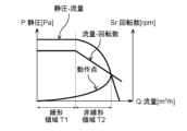
図6は、実施の形態1に係る、ファンモータユニット20の静圧P[Pa]と流量Q[m3/h]との関係、モータ21の回転数Sr[rpm]と流量Q[m3/h]との関係、及びファンモータユニット20の動作点を示す模式図である。
FIG. 6 is a schematic diagram showing the relationship between the static pressure P [Pa] and the flow rate Q [ m3 /h] of the
図6に示すように、ファンモータユニット20の動作点が、静圧Pが比較的高い領域にある場合には、モータ21の負荷が比較的低くなるため、回転数Srと流量Qとの関係は、線形関係となる。以下、回転数Srと流量Qとの関係が線形関係となるファンモータユニット20の動作領域を、「線形領域T1」とも称する。これに対して、ファンモータユニット20の動作点が、静圧Pが比較的低い領域にある場合には、モータ21の負荷が比較的高くなるため、回転数Srと流量Qとの関係は、線形関係とならない。以下、回転数Srと流量Qとの関係が線形関係とならないファンモータユニット20の動作領域を、「非線形領域T2」とも称する。実施の形態1では、ファンモータユニット20の動作点が線形領域T1に限定されている場合について例示する。
6, when the operating point of the
図7は、実施の形態1に係る制御部10の構成例を示すブロック図である。
Figure 7 is a block diagram showing an example configuration of the
図7に示すように、制御部10は、風量指令出力部11と、速度通知取得部12と、特定部13と、対応関係保持部14と、特性保持部15とを有する。制御部10は、例えば、プロセッサ(図示されず)とメモリ(図示されず)とを備え、プロセッサが、メモリに記憶されたプログラムを実行するコンピュータ装置によって実現される。
As shown in FIG. 7, the
特性保持部15は、複数のファンモータユニットの種類のそれぞれについて、ファンモータユニットに出力する風量指令Sにおけるデューティ[%]と、その風量指令Sに応じてそのファンモータユニットが行う送風の流量Q[m3/h]との関係を示す「風量指令-流量特性」を記憶する。
The
風量指令出力部11は、ファンモータユニット20が送風する風量を決定する。風量指令出力部11は、特性保持部15に記憶されている、現在制御部10に接続されているファンモータユニット20の種類についての「風量指令-流量特性」を参照して、決定した風量でファンモータユニット20に送風させるための風量指令Sを生成する。風量指令出力部11は、生成した風量指令Sをファンモータユニット20に出力する。
The air volume
風量指令出力部11は、例えば、バッテリパック30の内部に、温度を検知する温度センサが配置されている場合には、温度センサにより検知されたバッテリパック内の温度に応じて、ファンモータユニット20が送風する風量を決定してもよい。又は、風量指令出力部11は、例えば、制御部10が、送風システム1を利用するユーザによる操作を受け付ける機能を有している場合には、制御部10により受け付けられたユーザによる操作に応じて、ファンモータユニット20が送風する風量を決定してもよい。
For example, if a temperature sensor that detects temperature is disposed inside the
風量指令出力部11は、例えば、制御部10が、送風システム1を利用するユーザによる操作を受け付ける機能を有している場合には、制御部10により受け付けられたユーザによる操作に応じて、現在制御部10に接続されているファンモータユニット20の種類を特定してもよい。又は、風量指令出力部11は、特定部13から出力される種類特定信号(後述)に基づいて、現在制御部10に接続されているファンモータユニット20の種類を特定してもよい。制御部10から出力された種類特定信号は、例えば、図2に示すように、ECU内に出力される。具体的には、種類特定信号は、ECU内に設けた判定部(図示せず)等に出力される。
For example, when the
速度通知取得部12は、ファンモータユニット20から出力された速度通知FGを取得する。
The speed
対応関係保持部14は、複数種類のファンモータユニットのそれぞれについての、風量指令Sと速度通知FGとの対応関係を示す対応テーブルを保持する。対応テーブルは、予め作成される。実施の形態1では、対応テーブルが対象とする複数種類のファンモータユニットが、互いに、ファンの形状及びケースの形状の少なくとも一方が異なる一方で、互いに、モータの極数が等しい場合について例示する。すなわち、対応関係保持部14が保持する対応テーブルが対象とする複数種類のファンモータユニットは、互いに、ファンの形状及びケースの形状の少なくとも片方が異なる一方で、互いに、モータの極数が等しくなる関係となっている。
The
以下、対応関係保持部14が保持する対応テーブルの作成方法の具体例について、図面を参照しながら説明する。以下では、複数種類のファンモータユニットは、一例として、極数が10極のモータを有するファンモータユニットA(以下、「ユニットA」とも称する)と、極数が10極のモータを有するファンモータユニットB(以下、「ユニットB」とも称する)との2種類のファンモータユニットであるとして説明する。しかしながら、複数種類のファンモータユニットは、互いに、ファンの形状及びケースの形状の少なくとも片方が異なる一方で、互いに、モータの極数が等しければ、これらユニットAとユニットBとの2種類のファンモータユニットに限定される必要はない。
A specific example of a method for creating the correspondence table held by the
風量指令Sのデューティとモータの回転数Srとは、つぎの関係を有する。すなわち、最小デューティSminのとき、モータ21は制御可能な最低回転数Srminで回転する。最大デューティSmaxのとき、モータ21は制御可能な最高回転数Srmaxで回転する。
The duty of the air volume command S and the motor rotation speed Sr have the following relationship. That is, at the minimum duty Smin, the
以下、モータの制御可能な回転数の範囲、すなわち最低回転数Srmin~最高回転数Srmaxは、最小デューティが10%~最大デューティが90%の範囲で実現できるモータ21を例示して説明する。なお、最低回転数Srmin~最高回転数Srmaxを実現する最小デューティおよび最大デューティは、10%および90%に限るものではない。これらの値は、適宜、用いるモータの仕様などより導き出される。
The following description will be given using as an example a
図8は、実施の形態1に係るユニットA及びユニットBにおけるモータの回転数Sr[rpm]と流量Q[m3/h]との関係を示す模式図である。 FIG. 8 is a schematic diagram showing the relationship between the rotation speed Sr [rpm] and the flow rate Q [m 3 /h] of the motor in unit A and unit B according to the first embodiment.
前述した通り、ユニットA及びユニットBの動作点は、線形領域T1(図6を参照)である。このため、図8に示すように、ユニットA及びユニットBにおける回転数Srと流量Qとの関係は、線形関係となる。一方で、ユニットAとユニットBとは、互いに、ファンの形状及びケースの形状の少なくとも一方が異なるため、ユニットAとユニットBとで、同じ回転数Srでモータが回転しても、流量Qは互いに異なる。 As mentioned above, the operating points of unit A and unit B are in the linear region T1 (see FIG. 6). Therefore, as shown in FIG. 8, the relationship between the rotation speed Sr and the flow rate Q in unit A and unit B is linear. However, since unit A and unit B differ from each other in at least one of the shape of the fan and the shape of the case, the flow rates Q are different between unit A and unit B even if the motors rotate at the same rotation speed Sr.
まず、第1段階として、送風システム1において要求される最大流量をQmaxとした場合における、ユニットAにおいて流量Qmaxを実現するためのモータの回転数SrAと、ユニットBにおいて流量Qmaxを実現するためのモータの回転数SrBとを決定する。
First, in the first step, when the maximum flow rate required in the
次に、第2段階として、ユニットAについて、風量指令Sのデューティが90%となるときにモータの回転数SrがSrA(前述した最大回転数Srmax。以下同じ。)となるように、風量指令Sと回転数Srとの関係を決定する。ユニットBについて、風量指令Sのデューティが90%となるときに、モータの回転数SrがSrB(前述した最大回転数Srmax。以下同じ。)となるように、風量指令Sと回転数Srとの関係を決定する。 Next, in the second stage, the relationship between the airflow command S and the rotation speed Sr is determined for unit A such that the motor rotation speed Sr is Sr A (the maximum rotation speed Srmax described above; the same applies below) when the duty of the airflow command S is 90%. The relationship between the airflow command S and the rotation speed Sr is determined for unit B such that the motor rotation speed Sr is Sr B (the maximum rotation speed Srmax described above; the same applies below) when the duty of the airflow command S is 90%.
図9は、実施の形態1に係る第2段階において決定された、ユニットA及びユニットBにおける、風量指令Sのデューティ[%]とモータの回転数Sr[rpm]との関係を示す模式図である。
Figure 9 is a schematic diagram showing the relationship between the duty [%] of the airflow command S and the motor rotation speed Sr [rpm] for unit A and unit B, determined in the second stage according to
前述したように、速度通知FGの周波数、すなわち、ホール信号Hの周波数と、モータの回転周波数との関係は、速度通知FGの周波数が、モータの回転周波数×モータの極数(ここでは10)×1/2倍となる関係にある。この関係を利用して、最後に、第3段階として、第2段階において決定された、ユニットA及びユニットBにおける、風量指令Sのデューティ[%]とモータの回転数Sr[rpm]との関係に基づいて、ユニットA及びユニットBにおける、風量指令Sのデューティ[%]と速度通知FGの周波数[Hz]との関係を算出する。 As described above, the relationship between the frequency of the speed notification FG, i.e., the frequency of the hall signal H, and the motor rotation frequency is such that the frequency of the speed notification FG is the motor rotation frequency x the number of poles of the motor (here, 10) x 1/2. Finally, using this relationship, in the third step, the relationship between the duty [%] of the airflow command S and the frequency [Hz] of the speed notification FG in units A and B is calculated based on the relationship between the duty [%] of the airflow command S and the motor rotation speed Sr [rpm] in units A and B determined in the second step.
図10は、実施の形態1に係る第3段階において決定された、ユニットA及びユニットBにおける、風量指令Sのデューティ[%]と速度通知FGの周波数[Hz]との関係を示す模式図である。
Figure 10 is a schematic diagram showing the relationship between the duty [%] of the airflow command S and the frequency [Hz] of the speed notification FG in unit A and unit B, determined in the third stage in
対応関係保持部14は、第3段階において算出された、ユニットA及びユニットBにおける、風量指令Sのデューティ[%]と速度通知FGの周波数[Hz]との関係を示す対応テーブルを予め記憶する。
The
なお、図10に示すように、風量指令Sのデューティ[%]と速度通知FGの周波数[Hz]との関係は、線形関係となる。これは、前述した通り、送風システム1は、ファンモータユニット20の動作点が線形領域T1に限定されているためである。このように、風量指令出力部11は、PWMデューティ信号である風量指令Sのデューティと、パルス信号である速度通知FGの周波数との関係が線形関係となる範囲におけるデューティからなる第1の風量指令Sを出力する。
As shown in FIG. 10, the relationship between the duty [%] of the air volume command S and the frequency [Hz] of the speed notification FG is linear. This is because, as described above, in the
再び図7に戻って、制御部10の説明を続ける。
Returning to Figure 7, we will continue explaining the
特定部13は、風量指令出力部11が、ファンモータユニット20を通常動作させる制御を行う際に出力する第1の風量指令Sをファンモータユニット20に出力した場合において、第1の風量指令Sに応じてファンモータユニット20から第1の速度通知FGが出力されたときに、第1の風量指令Sと、第1の速度通知FGとに基づいて、ファンモータユニット20の種類を特定し、特定した種類を示す種類特定信号を出力する。より具体的には、特定部13は、対応関係保持部14に保持される対応テーブルに基づいて、第1の風量指令Sと第1の速度通知FGとの対応関係が、対応テーブルが対象とする複数種類のファンモータユニットのうちの一の種類のファンモータユニットに該当する場合に、その一の種類のファンモータユニットを特定し、特定した種類を示す種類特定信号を出力する。制御部10から出力された種類特定信号は、例えば、図2に示すように、ECU内に出力される。具体的には、種類特定信号は、ECU内に設けた判定部(図示せず)等に出力される。
When the air volume
ここで、ファンモータユニット20を通常動作させる制御を行う際に出力する第1の風量指令Sとは、送風システム1において規定される範囲内の風量のうちの特定の風量をファンモータユニット20に出力させるために制御部10が出力する風量指令Sのことを言う。
Here, the first air volume command S output when controlling the
図11Aは、実施の形態1に係る風量指令出力部11が、ユニットAに第1の風量指令Sを出力した場合において、第1の風量指令Sに応じてユニットAから出力される第1の速度通知FGの波形を示す模式図である。図11Bは、実施の形態1に係る風量指令出力部11が、ユニットBに第1の風量指令Sを出力した場合において、第1の風量指令Sに応じてユニットBから出力される第1の速度通知FGの波形を示す模式図である。
Figure 11A is a schematic diagram showing the waveform of the first speed notification FG output from unit A in response to the first airflow command S when the airflow
図11Aと図11Bとに示すように、ファンモータユニット20がユニットAである場合と、ファンモータユニット20がユニットBである場合とで、第1の速度通知FGの周波数が互いに異なる。
As shown in Figures 11A and 11B, the frequency of the first speed notification FG differs when the
特定部13は、対応関係保持部14に保持される対応テーブルに基づいて、第1の風量指令Sと第1の速度通知FGとの関係がユニットAに該当する場合に、ユニットAを特定するための種類特定信号を出力し、第1の風量指令Sと第1の速度通知FGとの関係がユニットBに該当する場合に、ユニットBを特定するための種類特定信号を出力する。
The
<動作>
以下、上記構成の送風システム1が行う動作について説明する。
<Operation>
The operation of the
送風システム1は、種類特定信号を出力する第1特定処理を実行する。
The
図12は、実施の形態1に係る第1特定処理のフローチャートである。
Figure 12 is a flowchart of the first identification process according to
第1特定処理は、送風システム1が起動されてから所定時間経過した時点で開始されてもよいし、ファンモータユニット20の付け替え作業が完了した時点で開始されてもよいし、所定期間毎に定期的に開始されてもよい。
The first identification process may be started when a predetermined time has elapsed since the
第1特定処理が開始されると、風量指令出力部11は、ファンモータユニット20を通常動作させる制御を行う際に出力する第1の風量指令Sをファンモータユニット20に出力する(ステップS100)。
When the first identification process is started, the air volume
第1の風量指令Sが出力されると、マイコン(MicroController、マイクロコントローラ)26は、第1の風量指令Sを取得する。マイコン(MicroController、マイクロコントローラ)26は、取得した風量指令Sを、モータ21を駆動する3相PWM信号に変換する。マイコン26は、変換した3相PWM信号を駆動回路28に出力する(ステップS110)。
When the first air volume command S is output, the
3相PWM信号が出力されると、駆動回路28は、3相PWM信号で直流電力をスイッチングすることで3相の交流電力を生成する。駆動回路28は、生成した3相の交流電力でモータ21を駆動する。すると、3相PWM信号に応じてモータ21が回転する(ステップS120)。
When the three-phase PWM signal is output, the
モータ21が回転すると、ホールセンサ25は、モータ21における磁界の変動を検知して、第1のホール信号Hを出力する。
When the
第1のホール信号Hが出力されると、マイコン26は、第1のホール信号Hを取得する。取得した第1のホール信号Hを、第1の速度通知FGに変換する。マイコン26は、変換した第1の速度通知FGを、制御部10に出力する(ステップS130)。
When the first hall signal H is output, the
第1の速度通知FGが出力されると、速度通知取得部12は、第1の速度通知FGを取得する(ステップS140)。
When the first speed notification FG is output, the speed
第1の速度通知FGが取得されると、特定部13は、第1の風量指令Sと第1の速度通知FGとに基づいて、ファンモータユニット20の種類を特定し、特定した種類を示す種類特定信号を出力する(ステップS150)。この際、特定部13は、対応関係保持部14に保持される対応テーブルに基づいて、第1の風量指令Sと第1の速度通知FGとの対応関係が、対応テーブルが対象とする複数種類のファンモータユニットのうちの一の種類のファンモータユニットに該当する場合に、その一の種類のファンモータユニットを特定するための種類特定信号を出力する。
When the first speed notification FG is acquired, the
ステップS150の処理が終了した場合に、送風システム1は、その第1特定処理を終了する。
When the processing of step S150 is completed, the
<考察>
送風システム1によると、制御部10は、ファンモータユニット20を通常動作させる制御を行う際に出力する第1の風量指令をファンモータユニットに出力することで、ファンモータユニット20の種類を特定することができる。
<Consideration>
According to the
このように、送風システム1によると、ファンモータユニット20の種類を特定するための特別な信号を出力することなく、ファンモータユニット20の種類を特定することができる。
In this way, according to the
送風システム1によると、新たなファンモータユニットの種類を特定の対象に加える場合に、対応関係保持部14が保持する対応テーブルを更新することで対応できる。
According to the
送風システム1によると、前述した通り、制御部10は、PWMデューティ信号である風量指令Sのデューティと、パルス信号である速度通知FGの周波数との関係が線形関係となる範囲におけるデューティからなる第1の風量指令Sを出力する。
As described above, in the
このため、制御部10は、比較的容易に種類特定信号を出力することができる。
This allows the
(実施の形態2)
以下、実施の形態2に係る送風システムについて説明する。ここでは、実施の形態2に係る送風システムについて、実施の形態1に係る送風システム1の構成要素と同様の構成要素については、既に説明済みであるとして、同じ符号を振ってその詳細な説明を省略する。
(Embodiment 2)
The following describes the air blowing system according to
実施の形態1に係る送風システム1は、対応テーブルが対象とする複数種類のファンモータユニットが、互いに、ファンの形状及びケースの形状の少なくともどちらかが異なる一方で、互いに、モータの極数が等しい場合について例示する構成例であった。これに対して、実施の形態2に係る送風システムは、対応テーブルが対象とする複数種類のファンモータユニットが、互いに、ファンの形状及びケースの形状が等しい一方で、互いに、モータの極数が異なる場合について例示する構成例である。
The
実施の形態2では、実施の形態1と同様に、ファンモータユニット20の動作点が線形領域T1に限定されている場合について例示する。
In the second embodiment, as in the first embodiment, an example is given in which the operating point of the
実施の形態2に係る送風システムは、実施の形態1に係る送風システムから、制御部10が実施の形態2に係る制御部10Aに変更されて構成される。
The air blowing system according to the second embodiment is configured by changing the
図13は実施の形態2に係る制御部10Aの構成例を示すブロック図である。
Figure 13 is a block diagram showing an example configuration of the
図13に示すように、制御部10Aは、実施の形態1に係る制御部10から変更されている。対応関係保持部14が対応関係保持部14Aに変更されて構成される。
As shown in FIG. 13, the
対応関係保持部14Aは、複数種類のファンモータユニットのそれぞれについての、風量指令Sと速度通知FGとの対応関係を示す対応テーブルを保持する。対応テーブルは、予め作成される。実施の形態2では、対応関係保持部14Aが保持する対応テーブルが対象とする複数種類のファンモータユニットは、ファンの形状及びケースの形状が等しい一方で、モータの極数が異なる関係となっている。
The
以下、対応関係保持部14Aが保持する対応テーブルの作成方法の具体例について、図面を参照しながら説明する。以下では、複数種類のファンモータユニットは、一例として、極数が10極のモータを有するファンモータユニットB(以下、「ユニットB」とも称する)と、極数が8極のモータを有するファンモータユニットC(以下、「ユニットC」とも称する)との2種類のファンモータユニットであるとして説明する。しかしながら、複数種類のファンモータユニットは、互いに、ファンの形状及びケースの形状が等しい一方で、互いに、モータの極数が異なれば、これらユニットBとユニットCとの2種類のファンモータユニットに限定される必要はない。
A specific example of a method for creating the correspondence table held by the
図14は、実施の形態2に係るユニットB及びユニットCにおけるモータの回転数Sr[rpm]と流量Q[m3/h]との関係を示す模式図である。 FIG. 14 is a schematic diagram showing the relationship between the rotation speed Sr [rpm] and the flow rate Q [m 3 /h] of the motor in unit B and unit C according to the second embodiment.
前述した通り、ユニットB及びユニットCの動作点は、線形領域T1(図6を参照)である。このため、図14に示すように、ユニットB及びユニットCにおける回転数Srと流量Qとの関係は、線形関係となる。一方で、ユニットBとユニットCとは、互いに、ファンの形状及びケースの形状が等しいため、ユニットBとユニットCとで、同じ回転数Srでモータが回転した場合の流量Qは等しくなる。 As mentioned above, the operating points of unit B and unit C are in the linear region T1 (see FIG. 6). Therefore, as shown in FIG. 14, the relationship between the rotation speed Sr and the flow rate Q in unit B and unit C is linear. On the other hand, since unit B and unit C have the same fan shape and case shape, the flow rate Q is the same in unit B and unit C when the motor rotates at the same rotation speed Sr.
第1段階として、実施の形態2に係る送風システムにおいて要求される最大流量をQmaxとした場合における、ユニットBにおいて流量Qmaxを実現するためのモータの回転数SrBと、ユニットCにおいて流量Qmaxを実現するためのモータの回転数SrCとを決定する。ユニットBとユニットCとは、互いに、ファンの形状及びケースの形状が等しいため、図14に示すように、SrBとSrCとは等しくなる。 In the first step, when the maximum flow rate required in the air blowing system according to the second embodiment is Qmax, the motor speed SrB for realizing the flow rate Qmax in unit B and the motor speed SrC for realizing the flow rate Qmax in unit C are determined. Unit B and unit C have the same fan shape and case shape, so SrB and SrC are equal, as shown in FIG.
第2段階として、ユニットBについて、風量指令Sのデューティが90%となるときにモータの回転数SrがSrBとなるように、風量指令Sと回転数Srとの関係を決定し、ユニットCについて、風量指令Sのデューティが90%となるときに、モータの回転数SrがSrCとなるように、風量指令Sと回転数Srとの関係を決定する。 In the second stage, for unit B, the relationship between the air volume command S and the rotation speed Sr is determined so that the motor rotation speed Sr becomes SrB when the duty of the air volume command S is 90%, and for unit C, the relationship between the air volume command S and the rotation speed Sr is determined so that the motor rotation speed Sr becomes SrC when the duty of the air volume command S is 90%.
図15は、実施の形態2に係る第2段階において決定された、ユニットB及びユニットCにおける、風量指令Sのデューティ[%]とモータの回転数Sr[rpm]との関係を示す模式図である。SrBとSrCとが等しいため、図15に示すように、ユニットB及びユニットCにおける、風量指令Sのデューティ[%]とモータの回転数Sr[rpm]との関係は等しくなる。
15 is a schematic diagram showing the relationship between the duty [%] of the airflow command S and the motor rotation speed Sr [rpm] in unit B and unit C determined in the second stage according to
前述したように、速度通知FGの周波数、すなわち、ホール信号Hの周波数と、モータの回転周波数との関係は、速度通知FGの周波数が、モータの回転周波数×モータの極数(ここでは10)×1/2倍となる関係にある。この関係を利用して、第3段階として、第2段階において決定された、ユニットB及びユニットCにおける、風量指令Sのデューティ[%]とモータの回転数Sr[rpm]との関係に基づいて、ユニットB及びユニットCにおける、風量指令Sのデューティ[%]と速度通知FGの周波数[Hz]との関係を算出する。 As described above, the relationship between the frequency of the speed notification FG, i.e., the frequency of the hall signal H, and the motor rotation frequency is such that the frequency of the speed notification FG is the motor rotation frequency x the number of poles of the motor (here, 10) x 1/2. Using this relationship, in the third stage, the relationship between the duty [%] of the airflow command S and the frequency [Hz] of the speed notification FG in units B and C is calculated based on the relationship between the duty [%] of the airflow command S and the motor rotation speed Sr [rpm] in units B and C determined in the second stage.
図16は、実施の形態2に係る第3段階において決定された、ユニットB及びユニットCにおける、風量指令Sのデューティ[%]と速度通知FGの周波数[Hz]との関係を示す模式図である。ユニットB及びユニットCにおける、風量指令Sのデューティ[%]とモータの回転数Sr[rpm]との関係は等しい。しかし、ユニットBが有するモータの極数とユニットCが有するモータの極数とが互いに異なる。このため、図16に示すように、ユニットB及びユニットCにおける、風量指令Sのデューティ[%]と速度通知FGの周波数[Hz]との関係は互いに異なることとなる。
Figure 16 is a schematic diagram showing the relationship between the duty [%] of the airflow command S and the frequency [Hz] of the speed notification FG in unit B and unit C, determined in the third stage according to
対応関係保持部14Aは、第3段階において算出された、ユニットB及びユニットCにおける、風量指令Sのデューティ[%]と速度通知FGの周波数[Hz]との関係を示す対応テーブルを予め記憶する。
The
図17Aは、実施の形態2に係る風量指令出力部11が、ユニットBに第1の風量指令Sを出力した場合において、第1の風量指令Sに応じてユニットBから出力される第1の速度通知FGの波形を示す模式図である。図17Bは、実施の形態2に係る風量指令出力部11が、ユニットCに第1の風量指令Sを出力した場合において、第1の風量指令Sに応じてユニットCから出力される第1の速度通知FGの波形を示す模式図である。
Figure 17A is a schematic diagram showing the waveform of the first speed notification FG output from unit B in response to the first airflow command S when the airflow
図17Aと図17Bとに示すように、ファンモータユニット20がユニットBである場合と、ファンモータユニット20がユニットCである場合とで、第1の速度通知FGの周波数が互いに異なる。
As shown in Figures 17A and 17B, the frequency of the first speed notification FG differs when the
このため、特定部13は、対応関係保持部14Aに保持される対応テーブルに基づいて、第1の風量指令Sと第1の速度通知FGとの関係がユニットBに該当する場合に、ユニットBを特定するための種類特定信号を出力し、第1の風量指令Sと第1の速度通知FGとの関係がユニットCに該当する場合に、ユニットCを特定するための種類特定信号を出力する。
For this reason, based on the correspondence table stored in the
なお、制御部10Aから出力された種類特定信号は、例えば、図2に示すように、ECU内に出力される。具体的には、種類特定信号は、ECU内に設けた判定部(図示せず)等に出力される。
The type identification signal output from the
<考察>
前述したように、実施の形態2に係る送風システムは、対応テーブルが対象とする複数種類のファンモータユニットが、互いに、ファンの形状及びケースの形状が等しい一方で、互いに、モータの極数が異なる場合であっても、第1の風量指令Sと第1の速度通知FGとに基づいて、ファンモータユニット20の種類を特定し、特定した種類を示す種類特定信号を出力することができる。
<Consideration>
As described above, the air blowing system of
また、実施の形態1において開示したように、送風システム1は、対応テーブルが対象とする複数種類のファンモータユニットが、ファンの形状及びケースの形状の少なくともどちらかが異なる一方で、モータの極数が等しい場合に、第1の風量指令Sと第1の速度通知FGとに基づいて、ファンモータユニット20の種類を特定するための種類特定信号を出力することができる。
As disclosed in the first embodiment, the
このため、実施の形態1において開示した技術を、実施の形態2に係る送風システムに施すことで、実施の形態2に係る送風システムは、対応テーブルが対象とする複数種類のファンモータユニットが、互いに、ファンの形状、ケースの形状、及び、モータの極数の少なくともどちらかが異なる場合であっても、第1の風量指令Sと第1の速度通知FGとに基づいて、ファンモータユニット20の種類を特定し、特定した種類を示す種類特定信号を出力することができるようになることは明らかである。
Therefore, by applying the technology disclosed in
(実施の形態3)
以下、実施の形態3に係る送風システムについて説明する。ここでは、実施の形態3に係る送風システムについて、実施の形態1に係る送風システム1の構成要素と同様の構成要素については、既に説明済みであるとして同じ符号を振ってその詳細な説明を省略する。
(Embodiment 3)
Hereinafter, a description will be given of the air blowing system according to embodiment 3. Here, in the air blowing system according to embodiment 3, components similar to those of the
実施の形態1に係る送風システム1及び実施の形態2に係る送風システムは、ファンモータユニット20の動作点が線形領域T1(図6を参照)に限定されている場合について例示する構成例であった。これに対して、実施の形態3に係る送風システムは、ファンモータユニット20の動作点が線形領域T1に限定されていない場合について例示する構成例である。
The
図18は、実施の形態3に係る、ファンモータユニット20の静圧P[Pa]と流量Q[m3/h]との関係、モータ21の回転数Sr[rpm]と流量Q[m3/h]との関係、及びファンモータユニット20の動作点を示す模式図である。
FIG. 18 is a schematic diagram showing the relationship between the static pressure P [Pa] and the flow rate Q [ m3 /h] of the
図18に示すように、実施の形態3において、ファンモータユニット20の動作点は、線形領域T1と非線形領域T2とにまたがる。
As shown in FIG. 18, in embodiment 3, the operating point of the
実施の形態3に係る送風システムは、実施の形態1に係る送風システムから、制御部10が実施の形態3に係る制御部10Bに変更されて構成される。
The air blowing system according to the third embodiment is configured by changing the
図19は実施の形態3に係る制御部10Bの構成例を示すブロック図である。
Figure 19 is a block diagram showing an example configuration of the
図19に示すように、制御部10Bは、実施の形態1に係る制御部10から変更されて構成される。対応関係保持部14が対応関係保持部14Bに変更されて構成される。
As shown in FIG. 19, the
対応関係保持部14Bは、複数種類のファンモータユニットのそれぞれについての、風量指令Sと速度通知FGとの対応関係を示す対応テーブルを保持する。対応テーブルは、予め作成される。
The
図20は、対応関係保持部14Bが記憶する対応テーブルによって示される、一の種類のファンモータユニット20についての、風量指令Sのデューティ[%]と速度通知FGの周波数[Hz]との対応関係を示す模式図である。
Figure 20 is a schematic diagram showing the correspondence relationship between the duty [%] of the air volume command S and the frequency [Hz] of the speed notification FG for one type of
図20に示すように、ファンモータユニット20の動作点が線形領域T1にある場合には、風量指令Sと速度通知FGとの関係は線形関係となる。一方で、ファンモータユニット20の動作点が非線形領域T2にある場合には、風量指令Sと速度通知FGとの関係は線形関係とならない。これは、非線形領域T2ではモータ21の負荷が比較的高いために、モータ21が、駆動回路28から供給される3相の交流電力通りの回転数で回転することができないためである。
As shown in FIG. 20, when the operating point of the
このように、ファンモータユニット20の動作点が線形領域T1に限定されていない場合には、風量指令Sと速度通知FGとの関係は、必ずしも線形関係とならない。しかしながら、風量指令Sと速度通知FGとの関係は、例えば、実機を用いたテストを行うことにより、又は、シミュレータを用いたシミュレーションにより、作成され得る。対応関係保持部14Bは、このようにして予め作成された対応テーブルを記憶する。
In this way, if the operating point of the
なお、制御部10Bから出力された種類特定信号は、例えば、図2に示すように、ECU内に出力される。具体的には、種類特定信号は、ECU内に設けた判定部(図示せず)等に出力される。
The type identification signal output from the
<考察>
前述したように、実施の形態3に係る送風システムにおいて、対応関係保持部14Bは、ファンモータユニット20の動作点が線形領域T1に限定されていない場合についての対応テーブルを保持する。このため、実施の形態3に係る送風システムによると、ファンモータユニット20の動作点が線形領域T1に限定されていない場合であっても、第1の風量指令Sと第1の速度通知FGとに基づいて、ファンモータユニット20の種類を特定し、特定した種類を示す種類特定信号を出力することができる。
<Consideration>
As described above, in the air blowing system according to the third embodiment, the
(実施の形態4)
以下、実施の形態4に係る送風システムについて説明する。ここでは、実施の形態4に係る送風システムについて、実施の形態3に係る送風システムの構成要素と同様の構成要素については、既に説明済みであるとして同じ符号を振ってその詳細な説明を省略する。
(Embodiment 4)
The following describes the air blowing system according to embodiment 4. Here, for the air blowing system according to embodiment 4, components similar to those of the air blowing system according to embodiment 3 have already been described, so they are denoted by the same reference numerals and detailed description thereof is omitted.
実施の形態4に係る送風システムは、実施の形態3に係る送風システムが有する機能と同様の機能を有する。実施の形態4に係る送風システムは、更に、第1の風量指令Sと第1の速度通知FGとの関係が所定の関係を満たす場合に、ファンモータユニット20に係る異常を検知した旨を示す異常検知信号を出力する機能を有する。
The air blowing system according to embodiment 4 has the same functions as the air blowing system according to embodiment 3. The air blowing system according to embodiment 4 further has a function of outputting an abnormality detection signal indicating that an abnormality related to the
実施の形態4に係る送風システムは、実施の形態3に係る送風システムから、制御部10Bが実施の形態4に係る制御部10Cに変更されて構成される。
The air blowing system according to the fourth embodiment is configured by changing the
図21は、実施の形態4に係る制御部10Cの構成例を示すブロック図である。
Figure 21 is a block diagram showing an example configuration of the
図21に示すように、制御部10Cは、実施の形態3に係る制御部10Bから変更されて構成される。特定部13が特定部13Cに変更されて構成される。
As shown in FIG. 21, the
特定部13Cは、実施の形態3に係る特定部13が有する機能と同様の機能を有する。特定部13Cは、更に、以下の機能を有する。
The
すなわち、特定部13Cは、対応関係保持部14Bに保持される対応テーブルに基づいて、第1の風量指令Sと第1の速度通知FGとの対応関係が、対応テーブルが対象とする複数種類のファンモータユニットのいずれにも該当しない場合に、ファンモータユニット20に係る異常を検知した旨を示す異常検知信号を出力する。
In other words, when the correspondence between the first air volume command S and the first speed notification FG does not correspond to any of the multiple types of fan motor units covered by the correspondence table stored in the
以下で例示するように、実施の形態4に係る送風システムにおいて、ファンモータユニット20に係る異常の中には、風量指令Sと速度通知FGとの関係が変動するタイプの異常がある。このため、第1の風量指令Sと第1の速度通知FGとの対応関係が、対応テーブルが対象とする複数種類のファンモータユニットのいずれにも該当しない場合には、風量指令Sと速度通知FGとの関係が変動するタイプのファンモータユニット20に係る異常が発生していると考えられる。従って、特定部13Cは、第1の風量指令Sと第1の速度通知FGとの対応関係が、対応テーブルが対象とする複数種類のファンモータユニットのいずれにも該当しない場合に、異常検知信号を出力する。
As exemplified below, in the air blowing system according to embodiment 4, among the abnormalities related to the
図22は、実施の形態4に係るファンモータユニット20に係る異常により、風量指令Sと速度通知FGとの関係が変動する様子を例示する模式図である。
Figure 22 is a schematic diagram illustrating how the relationship between the airflow command S and the speed notification FG changes due to an abnormality in the
図22に示すように、例えば、バッテリパック30内のセル電池間のセパレータが外れるという異常が発生すると、ファンモータユニット20が行う送風における風抵抗が減少する。これにより、ファンモータユニット20の動作点が非線形領域T2側に移動する。このため、風量指令Sと速度通知FGとの関係が変動する。より具体的には、風量指令Sと速度通知FGとの関係が線形関係となる範囲が狭くなるように変動する。
As shown in FIG. 22, for example, if an abnormality occurs such as a separator between cell batteries in the
例えば、ファンモータユニット20のダクトがバッテリパック30から外れるという異常が発生すると、ファンモータユニット20が行う送風における風抵抗が減少する。これにより、ファンモータユニット20の動作点が非線形領域T2側に移動する。このため、風量指令Sと速度通知FGとの関係が変動する。より具体的には、風量指令Sと速度通知FGとの関係が線形関係となる範囲が狭くなるように変動する。
For example, if an abnormality occurs in which the duct of the
例えば、バッテリパック30内のセル電池間に物が詰るという異常が発生すると、ファンモータユニット20が行う送風における風抵抗が増加する。これにより、ファンモータユニット20の動作点が線形領域T1側に移動する。このため、風量指令Sと速度通知FGとの関係が変動する。より具体的には、風量指令Sと速度通知FGとの関係が線形関係となる範囲が広くなるように変動する。
For example, if an abnormality occurs in which something is stuck between the cells in the
例えば、ファンモータユニット20のダクトに物が詰るという異常が発生すると、ファンモータユニット20が行う送風における風抵抗が増加する。これにより、ファンモータユニット20の動作点が線形領域T1側に移動する。このため、風量指令Sと速度通知FGとの関係が変動する。より具体的には、風量指令Sと速度通知FGとの関係が線形関係となる範囲が広くなるように変動する。
For example, if an abnormality occurs such as an object becoming clogged in the duct of the
以下、上記構成の実施の形態4に係る送風システムが行う動作について説明する。 The following describes the operation of the ventilation system according to the fourth embodiment of the above configuration.
実施の形態4に係る送風システムは、種類特定信号、又は、異常検知信号を出力する第2特定処理を実行する。 The air blowing system according to embodiment 4 executes a second identification process that outputs a type identification signal or an abnormality detection signal.
図23は、第2特定処理のフローチャートである。 Figure 23 is a flowchart of the second identification process.
図23において、ステップS200の処理~ステップS240の処理は、それぞれ、実施の形態1に係る第1特定処理におけるステップS100の処理~ステップS140の処理に対して、特定部13を特定部13Cに読み替えた処理と同様の処理である。このため、ここでは、ステップS200の処理~ステップS240の処理については既に説明済みであるとしてその詳細な説明を省略し、ステップS260の処理~ステップS280の処理を中心に説明する。
In FIG. 23, the processes in steps S200 to S240 are respectively the same as the processes in steps S100 to S140 in the first identification process according to
ステップS240の処理が終了すると、特定部13Cは、対応関係保持部14Bに保持される対応テーブルに基づいて、第1の風量指令Sと第1の速度通知FGとの対応関係が、対応テーブルが対象とする複数種類のファンモータユニットのいずれかに該当するか否かを判定する(ステップS260)。
When the processing of step S240 is completed, the
ステップS260の処理において、第1の風量指令Sと第1の速度通知FGとの対応関係が、対応テーブルが対象とする複数種類のファンモータユニットのいずれかに該当する場合に(ステップS260:Yes)、特定部13Cは、その該当する種類のファンモータユニットを特定するための種類特定信号を出力する(ステップS270)。
In the processing of step S260, if the correspondence between the first air volume command S and the first speed notification FG corresponds to any one of the multiple types of fan motor units covered by the correspondence table (step S260: Yes), the
ステップS260の処理において、第1の風量指令Sと第1の速度通知FGとの対応関係が、対応テーブルが対象とする複数種類のファンモータユニットのいずれにも該当しない場合に(ステップS260:No)、特定部13Cは、ファンモータユニット20に係る異常を検知した旨を示す異常検知信号を出力する(ステップS280)。
In the processing of step S260, if the correspondence between the first air volume command S and the first speed notification FG does not correspond to any of the multiple types of fan motor units covered by the correspondence table (step S260: No), the
なお、制御部10Cから出力された種類特定信号、又は、異常検知信号は、例えば、図2に示すように、ECU内に出力される。具体的には、種類特定信号、又は、異常検知信号は、ECU内に設けた判定部(図示せず)等に出力される。
The type identification signal or abnormality detection signal output from the
ステップS270の処理が終了した場合、及び、ステップS280の処理が終了した場合に、実施の形態4に係る送風システムは、その第2特定処理を終了する。 When the processing of step S270 is completed, and when the processing of step S280 is completed, the air supply system according to embodiment 4 ends its second identification process.
<考察>
前述したように、実施の形態4に係る送風システムによると、第1の風量指令Sと第1の速度通知FGとの対応関係が、対応テーブルが対象とする複数種類のファンモータユニットのいずれにも該当しない場合に、異常検知信号を出力する。これにより、ファンモータユニット20に係る異常が速やかに発見される。
<Consideration>
As described above, in the air blowing system according to the fourth embodiment, when the correspondence between the first air volume command S and the first speed notification FG does not correspond to any of the multiple types of fan motor units covered by the correspondence table, an abnormality detection signal is output. This allows an abnormality in the
(他の実施の形態)
以上のように、本出願において開示する技術の例示として、実施の形態1~実施の形態4について説明した。しかしながら、本開示による技術は、これら実施の形態に限定されるものではない。本開示の趣旨を逸脱しない限り、当業者が思いつく各種変形を本実施の形態に施したもの、又は、異なる実施の形態における構成要素を組み合わせて構築される形態も、本出願において開示する技術の範囲内に含まれてもよい。
Other Embodiments
As described above, the first to fourth embodiments have been described as examples of the technology disclosed in this application. However, the technology according to this disclosure is not limited to these embodiments. As long as it does not deviate from the spirit of this disclosure, various modifications conceived by a person skilled in the art to the present embodiments, or forms constructed by combining components in different embodiments, may also be included within the scope of the technology disclosed in this application.
(1)実施の形態1~実施の形態4において、対応関係保持部14~対応関係保持部14Bは、複数種類のファンモータユニットのそれぞれについての、風量指令Sと速度通知FGとの対応関係を示す対応テーブルを保持するとして説明した。しかしながら、対応関係保持部14~対応関係保持部14Bは、複数種類のファンモータユニットのそれぞれについての、風量指令Sと速度通知FGとの対応関係を示す対応関係情報を保持すれば、必ずしも、対応テーブルを対応関係情報として保持する構成に限定されない。例えば、対応関係保持部14は、複数種類のファンモータユニットのそれぞれについての、風量指令Sと速度通知FGとの対応関係を示す関数を対応関係情報として保持する構成であっても構わない。
(1) In the first to fourth embodiments, the
(2)本開示の一態様は、このような送風システムだけではなく、送風システムが行う特徴的な各処理をステップとする方法であってもよい。また、本開示の一態様は、方法に含まれる各ステップをコンピュータに実行させるコンピュータプログラムであってもよい。また、本開示の一態様は、そのようなコンピュータプログラムが記録された、コンピュータ読み取り可能な非一時的な記録媒体であってもよい。 (2) One aspect of the present disclosure may be not only such an air blowing system, but also a method in which each of the characteristic processes performed by the air blowing system is a step. Also, one aspect of the present disclosure may be a computer program that causes a computer to execute each of the steps included in the method. Also, one aspect of the present disclosure may be a computer-readable non-transitory recording medium on which such a computer program is recorded.
本開示は、送風する送風システムに広く利用可能である。 This disclosure can be widely used in ventilation systems.
1 送風システム
10、10A、10B、10C 制御部
11 風量指令出力部
12 速度通知取得部
13、13C 特定部
14、14A、14B 対応関係保持部
15 特性保持部
20 ファンモータユニット
21 モータ
22 ファン
23 ケース
25 ホールセンサ
26 マイコン
28 駆動回路
30 バッテリパック
100 ECU
110 電気自動車
REFERENCE SIGNS
110 Electric Vehicle
Claims (8)
前記制御部は、前記ファンモータユニットが行う送風の風量を制御するための風量指令を前記ファンモータユニットに出力し、
前記ファンモータユニットは、前記モータの回転状態を示す速度通知を前記制御部に出力する送風システムにおける前記ファンモータユニットの種類を特定する特定方法であって、
前記制御部が、前記ファンモータユニットを通常動作させる制御を行う際に出力する第1の風量指令を前記ファンモータユニットに出力する第1のステップと、
前記制御部が、前記第1の風量指令の出力に応じて前記ファンモータユニットから出力される第1の速度通知を取得する第2のステップと、
前記制御部が、前記第1の風量指令と前記第1の速度通知とに基づいて、前記ファンモータユニットの種類を特定し、特定した種類を示す種類特定信号を出力する第3のステップと、を含み、
前記風量指令のデューティと前記速度通知との関係を示す対応テーブルを予め記憶し、
前記制御部は前記対応テーブルに基づいて前記種類特定信号を出力する、
特定方法。 a fan motor unit that has a motor, a fan that rotates by rotation of the motor, and a case that covers at least a part of the fan, and that blows air to the outside; and a control unit that controls the fan motor unit,
the control unit outputs an air volume command to the fan motor unit to control the volume of air blown by the fan motor unit;
The fan motor unit outputs a speed notification indicating a rotation state of the motor to the control unit,
a first step of outputting a first air volume command to the fan motor unit by the control unit when performing control for causing the fan motor unit to operate normally;
a second step of the control unit acquiring a first speed notification output from the fan motor unit in response to the output of the first air volume command;
a third step of the control unit identifying a type of the fan motor unit based on the first air volume command and the first speed notification, and outputting a type identification signal indicating the identified type,
a correspondence table indicating a relationship between the duty of the air volume command and the speed notification is stored in advance;
the control unit outputs the type identification signal based on the correspondence table.
Specific method.
前記第3のステップでは、前記制御部が、前記対応関係情報に基づいて、前記第1の風量指令と前記第1の速度通知との対応関係が、前記複数種類のファンモータユニットのうちの一の種類のファンモータユニットに該当する場合に、前記一の種類のファンモータユニットを特定するための前記種類特定信号を出力する、請求項1に記載の特定方法。 The control unit further holds correspondence information indicating a correspondence between the air volume command and the speed notification for each of a plurality of types of fan motor units,
The method of claim 1, wherein in the third step, when the correspondence between the first air volume command and the first speed notification corresponds to one type of fan motor unit among the multiple types of fan motor units based on the correspondence information, the control unit outputs the type identification signal for identifying the one type of fan motor unit.
異常検知信号を出力する第4のステップを含む、請求項2に記載の特定方法。 The method of claim 2, wherein the third step further includes a fourth step in which the control unit outputs an abnormality detection signal indicating that an abnormality related to the fan motor unit has been detected when the correspondence between the first airflow command and the first speed notification does not apply to any of the multiple types of fan motor units based on the correspondence information.
前記風量指令は、前記モータの回転をPWM制御により制御するためのPWMデューティ信号であり、
前記速度通知は、前記モータの極数をn(nは2以上の整数)とする場合において、前記モータの回転周波数のn/2倍の周波数のパルス信号である、請求項1から請求項3のいずれか1項に記載の特定方法。 The rotation of the motor is controlled by PWM (Pulse Width Modulation) control,
the air volume command is a PWM duty signal for controlling the rotation of the motor by PWM control,
4. The method according to claim 1, wherein the speed notification is a pulse signal having a frequency n/2 times the rotational frequency of the motor, where n is an integer equal to or greater than 2, and the number of poles of the motor is n.
前記制御部は、前記ファンモータユニットが行う送風の風量を制御するための風量指令を前記ファンモータユニットに出力し、
前記ファンモータユニットは、前記モータの回転状態を示す速度通知を前記制御部に出力し、
前記制御部は、前記ファンモータユニットを通常動作させる制御を行う際に出力する第1の風量指令を前記ファンモータユニットに出力した場合において、前記第1の風量指令に応じて前記ファンモータユニットから第1の速度通知が出力されたときに、前記第1の風量指令と、前記第1の速度通知とに基づいて、前記ファンモータユニットの種類を特定し、特定した種類を示す種類特定信号を出力し、
前記風量指令のデューティと前記速度通知との関係を示す対応テーブルを予め記憶し、
前記制御部は前記対応テーブルに基づいて前記種類特定信号を出力する、
送風システム。 a fan motor unit that has a motor, a fan that rotates by rotation of the motor, and a case that covers at least a part of the fan, and that blows air to the outside; and a control unit that controls the fan motor unit,
the control unit outputs an air volume command to the fan motor unit to control the volume of air blown by the fan motor unit;
the fan motor unit outputs a speed notification indicating a rotation state of the motor to the control unit;
when the control unit outputs a first air volume command to the fan motor unit when controlling the fan motor unit to operate normally, and when a first speed notification is output from the fan motor unit in response to the first air volume command, the control unit identifies a type of the fan motor unit based on the first air volume command and the first speed notification, and outputs a type identification signal indicating the identified type;
a correspondence table indicating a relationship between the duty of the air volume command and the speed notification is stored in advance;
the control unit outputs the type identification signal based on the correspondence table.
Ventilation system.
The air blowing system of claim 7, wherein the control unit further outputs an abnormality detection signal indicating that an abnormality related to the fan motor unit has been detected when the correspondence between the first airflow command and the first speed notification based on the correspondence information does not apply to any of the multiple types of fan motor units.
Applications Claiming Priority (3)
| Application Number | Priority Date | Filing Date | Title |
|---|---|---|---|
| JP2020038246 | 2020-03-05 | ||
| JP2020038246 | 2020-03-05 | ||
| PCT/JP2021/003192 WO2021176905A1 (en) | 2020-03-05 | 2021-01-29 | Identification method and air blowing system |
Publications (3)
| Publication Number | Publication Date |
|---|---|
| JPWO2021176905A1 JPWO2021176905A1 (en) | 2021-09-10 |
| JPWO2021176905A5 JPWO2021176905A5 (en) | 2022-11-02 |
| JP7689268B2 true JP7689268B2 (en) | 2025-06-06 |
Family
ID=77614161
Family Applications (1)
| Application Number | Title | Priority Date | Filing Date |
|---|---|---|---|
| JP2022505037A Active JP7689268B2 (en) | 2020-03-05 | 2021-01-29 | Identification method and ventilation system |
Country Status (4)
| Country | Link |
|---|---|
| US (1) | US12173720B2 (en) |
| JP (1) | JP7689268B2 (en) |
| CN (1) | CN115210474B (en) |
| WO (1) | WO2021176905A1 (en) |
Families Citing this family (1)
| Publication number | Priority date | Publication date | Assignee | Title |
|---|---|---|---|---|
| CN120720259B (en) * | 2025-08-29 | 2025-11-07 | 苏州元脑智能科技有限公司 | Fan speed acquisition method and fan control components |
Citations (1)
| Publication number | Priority date | Publication date | Assignee | Title |
|---|---|---|---|---|
| US20140028292A1 (en) | 2012-07-30 | 2014-01-30 | International Business Machines Corporation | Identification system and electronic system for identifying a fan type of a fan |
Family Cites Families (11)
| Publication number | Priority date | Publication date | Assignee | Title |
|---|---|---|---|---|
| JP3562608B2 (en) * | 1996-09-04 | 2004-09-08 | 株式会社島津製作所 | Turbo molecular pump |
| US8297068B2 (en) * | 2007-03-27 | 2012-10-30 | Panasonic Corporation | Motor control device, its control method, and motor device |
| JP2010242767A (en) * | 2010-07-20 | 2010-10-28 | Fuji Industrial Co Ltd | Wind rate control method for blower |
| JP5625993B2 (en) * | 2011-02-22 | 2014-11-19 | 株式会社デンソー | Air conditioner for vehicles |
| WO2013031597A1 (en) * | 2011-08-31 | 2013-03-07 | 三洋電機株式会社 | Air-conditioning device and method for controlling air-conditioning device |
| US8788111B2 (en) * | 2011-08-31 | 2014-07-22 | Hewlett-Packard Development Company, L.P. | Identifying a fan connected to a computing device |
| JP6074607B2 (en) | 2011-11-15 | 2017-02-08 | パナソニックIpマネジメント株式会社 | Centrifugal blower |
| CN104160616B (en) * | 2012-03-02 | 2016-12-28 | 松下电器产业株式会社 | Control device of electric motor and method of motor control |
| CN205372921U (en) * | 2016-01-04 | 2016-07-06 | 武汉理工大学 | Adaptive variable blast volume air conditioner air supply fan speed controller |
| US10866006B2 (en) * | 2018-06-25 | 2020-12-15 | Dell Products L.P. | Systems and methods for fan typing and anomaly detection |
| CN111911440B (en) * | 2019-05-07 | 2023-10-13 | 联想企业解决方案(新加坡)有限公司 | Fan type identification device and method |
-
2021
- 2021-01-29 US US17/905,139 patent/US12173720B2/en active Active
- 2021-01-29 JP JP2022505037A patent/JP7689268B2/en active Active
- 2021-01-29 CN CN202180017955.6A patent/CN115210474B/en active Active
- 2021-01-29 WO PCT/JP2021/003192 patent/WO2021176905A1/en not_active Ceased
Patent Citations (1)
| Publication number | Priority date | Publication date | Assignee | Title |
|---|---|---|---|---|
| US20140028292A1 (en) | 2012-07-30 | 2014-01-30 | International Business Machines Corporation | Identification system and electronic system for identifying a fan type of a fan |
Also Published As
| Publication number | Publication date |
|---|---|
| JPWO2021176905A1 (en) | 2021-09-10 |
| US12173720B2 (en) | 2024-12-24 |
| WO2021176905A1 (en) | 2021-09-10 |
| CN115210474B (en) | 2025-11-04 |
| US20230093213A1 (en) | 2023-03-23 |
| CN115210474A (en) | 2022-10-18 |
Similar Documents
| Publication | Publication Date | Title |
|---|---|---|
| US20230223874A1 (en) | Methods and systems for automatic rotation direction determination of electronically commutated motor | |
| CN102939708B (en) | Motor drive device, brushless motor, and motor drive method | |
| US7676302B2 (en) | System and method of operating a cooling fan | |
| US20100114379A1 (en) | Fan control system | |
| US20040186629A1 (en) | Intelligent cooling fan | |
| CN104935237B (en) | Motor control assembly | |
| JP6274069B2 (en) | Motor control device | |
| US20100039055A1 (en) | Temperature control of motor | |
| CN103444071B (en) | Electric motor drive method, motor drive and brushless motor | |
| CN101233325A (en) | Air supply device and electrical equipment equipped with the same | |
| JP7689268B2 (en) | Identification method and ventilation system | |
| CN102444605A (en) | Vibration control and operating patterns for ventilation equipment | |
| JP2017158369A (en) | Motor drive apparatus | |
| JPWO2021176905A5 (en) | ||
| JP6281115B2 (en) | Motor driving method, motor driving apparatus and brushless motor | |
| JP2017131053A (en) | Motor adjustment system | |
| US11843342B2 (en) | Motor drive control device and motor drive control method | |
| JP2006291908A (en) | Electric fan control device for engine cooling system | |
| CN102882464A (en) | Motor driving circuit and motor device | |
| JP6790729B2 (en) | In-vehicle battery cooling system | |
| JP6702227B2 (en) | Vehicle cooling fan motor controller | |
| JP2003143750A (en) | Overload protective device of motor drive system | |
| CN111075738B (en) | Brushless motor-based fan starting control method and control device | |
| JP5196746B2 (en) | Fan drive control method and battery overheat protection device in battery overheat protection device | |
| JP2004278438A (en) | Blower control device |
Legal Events
| Date | Code | Title | Description |
|---|---|---|---|
| A521 | Request for written amendment filed |
Free format text: JAPANESE INTERMEDIATE CODE: A523 Effective date: 20220622 |
|
| RD01 | Notification of change of attorney |
Free format text: JAPANESE INTERMEDIATE CODE: A7421 Effective date: 20221024 |
|
| A621 | Written request for application examination |
Free format text: JAPANESE INTERMEDIATE CODE: A621 Effective date: 20231107 |
|
| A131 | Notification of reasons for refusal |
Free format text: JAPANESE INTERMEDIATE CODE: A131 Effective date: 20240716 |
|
| A521 | Request for written amendment filed |
Free format text: JAPANESE INTERMEDIATE CODE: A523 Effective date: 20240822 |
|
| RD01 | Notification of change of attorney |
Free format text: JAPANESE INTERMEDIATE CODE: A7421 Effective date: 20240918 |
|
| A131 | Notification of reasons for refusal |
Free format text: JAPANESE INTERMEDIATE CODE: A131 Effective date: 20241203 |
|
| A521 | Request for written amendment filed |
Free format text: JAPANESE INTERMEDIATE CODE: A523 Effective date: 20250108 |
|
| TRDD | Decision of grant or rejection written | ||
| A01 | Written decision to grant a patent or to grant a registration (utility model) |
Free format text: JAPANESE INTERMEDIATE CODE: A01 Effective date: 20250415 |
|
| A61 | First payment of annual fees (during grant procedure) |
Free format text: JAPANESE INTERMEDIATE CODE: A61 Effective date: 20250428 |
|
| R150 | Certificate of patent or registration of utility model |
Ref document number: 7689268 Country of ref document: JP Free format text: JAPANESE INTERMEDIATE CODE: R150 |