JP7688552B2 - Vehicle switch device and lid opening/closing device - Google Patents

Vehicle switch device and lid opening/closing device Download PDF

Info

Publication number
JP7688552B2
JP7688552B2 JP2021159320A JP2021159320A JP7688552B2 JP 7688552 B2 JP7688552 B2 JP 7688552B2 JP 2021159320 A JP2021159320 A JP 2021159320A JP 2021159320 A JP2021159320 A JP 2021159320A JP 7688552 B2 JP7688552 B2 JP 7688552B2
Authority
JP
Japan
Prior art keywords
hole
light
vehicle
switch
switch device
Prior art date
Legal status (The legal status is an assumption and is not a legal conclusion. Google has not performed a legal analysis and makes no representation as to the accuracy of the status listed.)
Active
Application number
JP2021159320A
Other languages
Japanese (ja)
Other versions
JP2023049532A (en
Inventor
玲貴 三浦
朗 名越
Current Assignee (The listed assignees may be inaccurate. Google has not performed a legal analysis and makes no representation or warranty as to the accuracy of the list.)
U-SHINLTD.
Original Assignee
U-SHINLTD.
Priority date (The priority date is an assumption and is not a legal conclusion. Google has not performed a legal analysis and makes no representation as to the accuracy of the date listed.)
Filing date
Publication date
Application filed by U-SHINLTD. filed Critical U-SHINLTD.
Priority to JP2021159320A priority Critical patent/JP7688552B2/en
Publication of JP2023049532A publication Critical patent/JP2023049532A/en
Application granted granted Critical
Publication of JP7688552B2 publication Critical patent/JP7688552B2/en
Active legal-status Critical Current
Anticipated expiration legal-status Critical

Links

Images

Landscapes

  • Switch Cases, Indication, And Locking (AREA)
  • Push-Button Switches (AREA)
  • Electric Propulsion And Braking For Vehicles (AREA)

Description

本発明は、車両用スイッチ装置、及びリッド開閉装置に関する。 The present invention relates to a vehicle switch device and a lid opening and closing device.

特許文献1に開示された車両用充電装置は、車体パネルに取り付けられるコネクタ収容部、コネクタ収容部に開閉可能に取り付けられたリッド、及びコネクタ収容部に取り付けられたスイッチ装置を備える。コネクタ収容部には、スイッチ装置のスイッチを操作するための窓孔が設けられ、この窓孔を塞ぐように車内側の面にシール部材が一体に設けられている。シール部材のうち窓孔内に位置する部分がスイッチの操作部である。 The vehicle charging device disclosed in Patent Document 1 includes a connector housing portion attached to a vehicle body panel, a lid attached to the connector housing portion so as to be able to open and close, and a switch device attached to the connector housing portion. The connector housing portion is provided with a window hole for operating a switch of the switch device, and a seal member is provided integrally with the surface on the inside of the vehicle so as to cover the window hole. The part of the seal member located within the window hole is the switch operating portion.

特開2020-68588号公報JP 2020-68588 A

特許文献1の車両用充電装置では、コネクタ収容部へのスイッチ装置の取り付けによって、これらの間にシール部材が挟み込まれるため、コネクタ収容部から車内側への浸水を防止できる。しかし、シール部材が経年劣化等によって破損した場合、コネクタ収容部を交換しなければならないため、リッドの脱着及び交換を含む大掛かりな修繕作業が必要になる。よって、特許文献1の車両用充填装置におけるスイッチ装置のシール構造には、シール部材が破損したときの修繕性について改善の余地がある。 In the vehicle charging device of Patent Document 1, a seal member is sandwiched between the switch device and the connector housing by attaching the switch device to the connector housing, preventing water from entering the inside of the vehicle through the connector housing. However, if the seal member is damaged due to aging or other reasons, the connector housing must be replaced, necessitating extensive repair work including removing and replacing the lid. Therefore, the seal structure of the switch device in the vehicle charging device of Patent Document 1 leaves room for improvement in terms of repairability when the seal member is damaged.

本発明は、シール部材が破損したときの修繕性を向上できる車両用スイッチ装置、及びリッド開閉装置を提供することを課題とする。 The objective of the present invention is to provide a vehicle switch device and a lid opening and closing device that can improve repairability when a sealing member is damaged.

本発明の一態様は、パネルの窓孔を塞ぐように配置するケースと、前記ケース内に収容されたスイッチとを備え、前記ケースは、前記窓孔を臨むように配置され、前記スイッチと対応する貫通孔が形成された閉塞壁を有するケース本体と、前記貫通孔内に配置され、前記スイッチを操作するためのノブと、前記ノブと前記貫通孔の間の隙間、及び前記閉塞壁を覆い、前記パネルに圧接される可撓性のシール部材とを備え、前記ケース本体と前記シール部材は一体である、車両用スイッチ装置を提供する。 One aspect of the present invention provides a switch device for a vehicle, comprising a case arranged to cover a window hole in a panel, and a switch housed within the case, the case being arranged to face the window hole and comprising a case body having a blocking wall with a through hole corresponding to the switch, a knob arranged within the through hole for operating the switch, and a flexible sealing member that covers the gap between the knob and the through hole and the blocking wall and is pressed against the panel, the case body and the sealing member being integral.

本発明の他の態様は、軸受部と窓孔を有し、車体パネルの開口部の内側に配置されたベースパネルと、前記開口部内に位置するように前記ベースパネルに取り付けられた受給部と、前記軸受部に軸支され、前記開口部を開放可能に閉塞するリッドと、前記開口部を開放した開位置と前記開口部を閉塞した閉位置とに前記リッドを移動させる駆動源を含む駆動機構と、前記ベースパネルの前記窓孔を塞ぐように配置されたケースと、前記ケース内に収容されたスイッチとを有するスイッチ装置とを備え、前記ケースは、前記窓孔を臨むように配置され、前記スイッチと対応する貫通孔が形成された閉塞壁を有するケース本体と、前記貫通孔内に配置され、前記スイッチを操作するためのノブと、前記ノブと前記貫通孔の間の隙間、及び前記閉塞壁を覆い、前記パネルに圧接される可撓性のシール部材とを備え、前記ケース本体と前記シール部材は一体である、リッド開閉装置を提供する。 Another aspect of the present invention provides a lid opening and closing device that includes a base panel having a bearing portion and a window hole and arranged inside an opening of a vehicle body panel, a receiving portion attached to the base panel so as to be located within the opening, a lid journaled on the bearing portion and closing the opening in an openable manner, a drive mechanism including a drive source that moves the lid between an open position that opens the opening and a closed position that closes the opening, a case arranged to close the window hole of the base panel, and a switch device having a switch housed in the case, the case being arranged to face the window hole and including a case body having a closing wall in which a through hole corresponding to the switch is formed, a knob arranged in the through hole for operating the switch, and a flexible seal member that covers the gap between the knob and the through hole and the closing wall and is pressed against the panel, the case body and the seal member being integral.

ケースは、窓孔を臨むように配置された閉塞壁を有するケース本体、スイッチを操作するためのノブ、及び閉塞壁を覆うシール部材を備え、ケース本体とシール部材が一体である。閉塞壁に形成した貫通孔がシール部材によって塞がれるため、ケース内への浸水を防止できる。また、パネルへのケースの取り付けによって、シール部材がパネルに圧接されるため、窓孔を通したパネル内への浸水も防止できる。 The case comprises a case body having a blocking wall arranged to face the window hole, a knob for operating the switch, and a sealing member covering the blocking wall, with the case body and sealing member being integrated. The through-hole formed in the blocking wall is blocked by the sealing member, preventing water from entering the case. In addition, by attaching the case to the panel, the sealing member is pressed against the panel, preventing water from entering the panel through the window hole.

ケース本体とシール部材は一体であるため、別部品からなる専用のシール部材を取り付ける必要はない。また、シール部材が経年劣化等によって損傷した場合、スイッチ装置だけ取り替えればよく、例えばリッドの脱着及び交換等の大掛かりな修繕作業は必要ない。そのため、シール部材が破損したときの修繕性を向上できる。 Because the case body and the sealing member are integrated, there is no need to attach a dedicated sealing member that is a separate part. Furthermore, if the sealing member becomes damaged due to aging or other reasons, it is only necessary to replace the switch device, and there is no need for extensive repair work such as removing and replacing the lid. This improves the ease of repair when the sealing member is damaged.

本発明では、シール部材が破損したときの修繕性を向上できる。 This invention improves repairability when the sealing member is damaged.

本発明の実施形態に係る車両用スイッチ装置を備えるリッド開閉装置の斜視図。1 is a perspective view of a lid opening and closing device including a vehicle switch device according to an embodiment of the present invention; 図1のII-II線断面図。Cross-sectional view of line II-II in Figure 1. リッドを閉じた状態の図2と同様の断面図。FIG. 3 is a cross-sectional view similar to FIG. 2 with the lid closed. 図1のIV-IV線で切断したベースパネルとスイッチ装置の断面斜視図。4 is a cross-sectional perspective view of the base panel and the switch device taken along line IV-IV in FIG. 1; ベースパネルとスイッチ装置の分解斜視図。FIG. スイッチ装置の斜視図。FIG. スイッチ装置の分解斜視図。FIG. 図6のVIII-VIII線断面図。Cross-sectional view of line VIII-VIII in Figure 6. 図6のIX-IX線断面図。Cross-sectional view taken along line IX-IX in Figure 6. 一体としたケースの分解斜視図。FIG. 図10のXI-XI線断面図。Cross-sectional view taken along line XI-XI in Figure 10. 分解したケースの下方斜視図。FIG.

以下、本発明の実施の形態を図面に従って説明する。 The following describes an embodiment of the present invention with reference to the drawings.

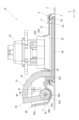
図1は、本発明の実施形態に係る車両用スイッチ装置50を備えるリッド開閉装置10を示す。 Figure 1 shows a lid opening and closing device 10 equipped with a vehicle switch device 50 according to an embodiment of the present invention.

図1を参照すると、リッド開閉装置10は、充電プラグ(図示せず)が接続される給電コネクタ15を備え、車両(電気自動車)のサイドパネル(車体パネル)1に取り付けられている。給電コネクタ15は、電気を補充するための受給部である。但し、受給部は、給電コネクタ15の代わりに、ガソリン及び軽油等の液体燃料、並びに水素及びLPガス等の気体燃料のうちのいずれかが補充される構成であってもよい。 Referring to FIG. 1, the lid opening/closing device 10 is equipped with a power supply connector 15 to which a charging plug (not shown) is connected, and is attached to a side panel (body panel) 1 of a vehicle (electric vehicle). The power supply connector 15 is a receiving section for refilling electricity. However, instead of the power supply connector 15, the receiving section may be configured to be refilled with any of liquid fuels such as gasoline and diesel, and gaseous fuels such as hydrogen and LPG.

図1及び図4を参照すると、スイッチ装置50はケース55を備え、このケース55が防水用のシール部材70を一体に備える。また、スイッチ装置50は、1個のスイッチ81、及び複数(本実施形態では2個)の光源82,83を備え、ユーザによる操作の検出だけでなく、所定の表示、及び給電コネクタ15の照明を行うことができる。 Referring to Figures 1 and 4, the switch device 50 has a case 55, which is integrally provided with a waterproof seal member 70. The switch device 50 also has one switch 81 and multiple (two in this embodiment) light sources 82 and 83, and can not only detect user operations, but also provide a predetermined display and illuminate the power supply connector 15.

以下の説明で引用する個々の図面に記載したX方向は、車両の車長方向であり、Y方向は車両の車幅方向であり、Z方向は車両の車高方向である。個々の図において、X方向の矢印が示す向きが前側であり、矢印とは逆向きが後側である。Y方向の矢印が示す向きが車内側(内側)であり、矢印とは逆向きが車外側(外側)である。Z方向の矢印が示す向きが上側であり、矢印とは逆向きが下側である。 The X direction in each of the drawings cited in the following description is the vehicle length direction, the Y direction is the vehicle width direction, and the Z direction is the vehicle height direction. In each of the drawings, the X direction arrow indicates the front side, and the direction opposite the arrow is the rear side. The Y direction arrow indicates the inside side of the vehicle (inner side), and the direction opposite the arrow is the outside side of the vehicle (outer side). The Z direction arrow indicates the upper side, and the direction opposite the arrow is the lower side.

まず、リッド開閉装置10の構成を説明する。 First, the configuration of the lid opening and closing device 10 will be described.

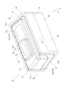
図1から図3を参照すると、サイドパネル1には、車幅方向Yの内側へ窪む凹部2が設けられている。凹部2のうち車幅方向Yの外側端が開口部3である。凹部2の底には、リッド開閉装置10を取り付ける取付口4が設けられている。車幅方向Yから見て開口部3と取付口4の形状は、本実施形態では概ね楕円形状であるが、必要に応じて変更可能である。 Referring to Figures 1 to 3, the side panel 1 has a recess 2 recessed inward in the vehicle width direction Y. The outer end of the recess 2 in the vehicle width direction Y is an opening 3. The bottom of the recess 2 has an attachment port 4 for attaching the lid opening/closing device 10. In this embodiment, the shapes of the opening 3 and the attachment port 4 are roughly elliptical when viewed from the vehicle width direction Y, but can be changed as necessary.

引き続いて図1から図3を参照すると、リッド開閉装置10は、サイドパネル1に取り付けられるベースパネル(パネル)20、開口部3を開放可能に閉塞するリッド30、及びリッド30を開閉させる駆動機構40を備える。 Continuing to refer to Figures 1 to 3, the lid opening and closing device 10 includes a base panel (panel) 20 attached to the side panel 1, a lid 30 that releasably closes the opening 3, and a drive mechanism 40 that opens and closes the lid 30.

ベースパネル20は、樹脂製(例えばポリプロピレン)で、取付口4を塞ぐベース本体21と、リッド30を軸支する軸受部26とを備える。 The base panel 20 is made of resin (e.g., polypropylene) and includes a base body 21 that covers the mounting opening 4 and a bearing portion 26 that supports the lid 30.

ベース本体21には、給電コネクタ15を取り付ける取付部22が設けられ、閉位置のリッド30とベース本体21との間をシールするシール部材23が取り付けられている。ベース本体21には更に、開口部3内に位置するように挿通孔24と窓孔25が設けられている。 The base body 21 is provided with an attachment portion 22 for attaching the power supply connector 15, and is provided with a seal member 23 for sealing between the lid 30 in the closed position and the base body 21. The base body 21 is further provided with an insertion hole 24 and a window hole 25 so as to be positioned within the opening 3.

図2及び図5を参照すると、取付部22は、車幅方向Yの内側へ窪む凹部22aを備え、この凹部22aの底に取付口22bが形成されている。取付口22bには、車幅方向Yの内側から給電コネクタ15が取り付けられている。これにより、図1に示すように、給電コネクタ15の接続部15aは、開口部3内に位置し、リッド30の解放時に開口部3を介して車外側に露出される。 2 and 5, the mounting portion 22 has a recess 22a recessed inward in the vehicle width direction Y, and a mounting opening 22b is formed at the bottom of this recess 22a. The power supply connector 15 is attached to the mounting opening 22b from the inside of the vehicle width direction Y. As a result, as shown in FIG. 1, the connection portion 15a of the power supply connector 15 is located within the opening 3, and is exposed to the outside of the vehicle through the opening 3 when the lid 30 is opened.

図2及び図3を参照すると、シール部材23は、リング状であり、ベース本体21の外周縁に沿ってベース本体21の車幅方向Yの外側に取り付けられ、凹部2の底側から開口部3に向けて突出する。シール部材23は、図3に示す閉位置のリッド30に圧接され、ベース本体21とリッド30との間を水密にシールする。シール部材23は、図2に示す開位置のリッド30には圧接されない。 2 and 3, the seal member 23 is ring-shaped and is attached to the outside of the base body 21 in the vehicle width direction Y along the outer periphery of the base body 21, protruding from the bottom side of the recess 2 toward the opening 3. The seal member 23 is pressed against the lid 30 in the closed position shown in FIG. 3, and provides a watertight seal between the base body 21 and the lid 30. The seal member 23 is not pressed against the lid 30 in the open position shown in FIG. 2.

挿通孔24は、車高方向Zの寸法が長い四角形状の孔で、取付部22の車長方向Xの前側かつ軸受部26内に位置するように設けられている。挿通孔24には、リッド30が備えるアーム31が進退可能に挿通している。 The insertion hole 24 is a rectangular hole with a longer dimension in the vehicle height direction Z, and is provided so as to be located on the front side of the mounting part 22 in the vehicle length direction X and inside the bearing part 26. An arm 31 provided on the lid 30 is inserted into the insertion hole 24 so as to be able to move forward and backward.

図1を参照すると、窓孔25は、リッド30の解放時に開口部3を介して車外側にスイッチ装置50を露出させるために設けられている。窓孔25は、開口部3内に位置するように、ベースパネル20に設けられた概ね四角形状の孔である。図4及び図5を参照すると、窓孔25は、ベース本体(第1板部)21から取付部22の凹部(第2板部)22aにかけて延びている。 Referring to FIG. 1, the window hole 25 is provided to expose the switch device 50 to the outside of the vehicle through the opening 3 when the lid 30 is opened. The window hole 25 is a roughly rectangular hole provided in the base panel 20 so as to be positioned within the opening 3. Referring to FIG. 4 and FIG. 5, the window hole 25 extends from the base body (first plate portion) 21 to the recess (second plate portion) 22a of the mounting portion 22.

詳しくは、ベース本体21は、XZ平面に沿って延びる平板状であり、凹部22aは、ベース本体21に対して交差するY方向に延びる環状の板状である。窓孔25は、ベース本体21に形成された第1孔部25aと、凹部22aに形成された第2孔部25bとを備え、取付部22の車長方向Xの後側に設けられている。第1孔部25aは車長方向Xに延び、第2孔部25bは車幅方向Yに延びている。第1孔部25aの車長方向Xの前側端と第2孔部25bの車幅方向Yの外側端とは、空間的に連なっている。 In more detail, the base body 21 is a flat plate extending along the XZ plane, and the recess 22a is an annular plate extending in the Y direction intersecting the base body 21. The window hole 25 includes a first hole portion 25a formed in the base body 21 and a second hole portion 25b formed in the recess 22a, and is provided on the rear side of the mounting portion 22 in the vehicle length direction X. The first hole portion 25a extends in the vehicle length direction X, and the second hole portion 25b extends in the vehicle width direction Y. The front end of the first hole portion 25a in the vehicle length direction X and the outer end of the second hole portion 25b in the vehicle width direction Y are spatially connected.

図1及び図2を参照すると、軸受部26は、ベース本体21と一体構造であり、取付部22の車長方向Xの前側に隣接し、ベース本体21から突出している。軸受部26は、一対の端板26aと、これらの端板26aを連結する連結板26bとを備える。一対の端板26aは、挿通孔24の上下に位置するように車高方向Zに間隔をあけて設けられ、いずれもXY平面に沿って延びている。連結板26bは、一対の端板26aそれぞれの車長方向Xの前端と車幅方向Yの外端に連なり、その他の端板26aのその他の端を開放している。 Referring to Figures 1 and 2, the bearing portion 26 is integral with the base body 21, is adjacent to the front side of the mounting portion 22 in the vehicle length direction X, and protrudes from the base body 21. The bearing portion 26 includes a pair of end plates 26a and a connecting plate 26b that connects the end plates 26a. The pair of end plates 26a are spaced apart in the vehicle height direction Z so as to be positioned above and below the insertion hole 24, and all extend along the XY plane. The connecting plate 26b is connected to the front ends of the pair of end plates 26a in the vehicle length direction X and the outer ends in the vehicle width direction Y, and leaves the other ends of the other end plates 26a open.

図1及び図3を参照すると、リッド30は、開口部3よりも小さくシール部材23よりも大きい板状である。リッド30は、アーム31を備え、このアーム31を介してベースパネル20に回転可能に取り付けられている。駆動機構40によってリッド30は、図2に示すように開口部3を開放した開位置と、図3に示すように開口部3を閉塞した閉位置とに回転される。 Referring to Figures 1 and 3, the lid 30 is a plate-like member that is smaller than the opening 3 and larger than the sealing member 23. The lid 30 has an arm 31 and is rotatably attached to the base panel 20 via the arm 31. The drive mechanism 40 rotates the lid 30 between an open position in which the opening 3 is open as shown in Figure 2, and a closed position in which the opening 3 is closed as shown in Figure 3.

図2及び図3を参照すると、アーム31は、挿通孔24を通してベースパネル20の車幅方向Yの内側から外側に跨がって配置されている。アーム31の一端側はベースパネル20に軸支され、アーム31の他端側にリッド30が取り付けられている。駆動機構40によってアーム31は、図2に示すようにサイドパネル1外へ突出した進出位置と、図3に示すようにサイドパネル1内に退避した後退位置との間を回転される。 Referring to Figures 2 and 3, the arm 31 is disposed straddling the base panel 20 from the inside to the outside in the vehicle width direction Y through the insertion hole 24. One end of the arm 31 is supported by the base panel 20, and the lid 30 is attached to the other end of the arm 31. The drive mechanism 40 rotates the arm 31 between an advanced position in which it protrudes outside the side panel 1 as shown in Figure 2, and a retracted position in which it retracts inside the side panel 1 as shown in Figure 3.

より具体的には、アーム31は、軸受部26に軸支された平板状の第1アーム部32と、リッド30に連なる円弧状の第2アーム部33とを備える。 More specifically, the arm 31 comprises a flat first arm portion 32 journaled on the bearing portion 26 and an arc-shaped second arm portion 33 connected to the lid 30.

第1アーム部32の基端(アーム31の一端側)には、軸受部26に軸支される枢着部32aが設けられている。つまり、第1アーム部32は、枢着部32aから外向きに突出している。枢着部32aは、軸受部26の一対の端板26a間に配置され、軸受部26の回転軸Aまわりに回転可能である。枢着部32aには、駆動機構40に機械的に接続するための四角形状(非円形状)の軸孔32bが設けられている。 The base end of the first arm portion 32 (one end side of the arm 31) is provided with a pivot portion 32a that is journaled on the bearing portion 26. In other words, the first arm portion 32 protrudes outward from the pivot portion 32a. The pivot portion 32a is disposed between a pair of end plates 26a of the bearing portion 26, and is rotatable around the rotation axis A of the bearing portion 26. The pivot portion 32a is provided with a square (non-circular) shaft hole 32b for mechanically connecting to the drive mechanism 40.

図1から図3を参照すると、第2アーム部33は、第1アーム部32のうち枢着部32aとは反対側の先端に機械的に接続されている。第2アーム部33は、回転軸Aを中心とする円弧状である。第2アーム部33の先端(アーム31の他端側)には、リッド30に対して機械的に接続される接続部33aが設けられている。 Referring to Figures 1 to 3, the second arm portion 33 is mechanically connected to the tip of the first arm portion 32 opposite the pivot portion 32a. The second arm portion 33 is arc-shaped with the rotation axis A as its center. The tip of the second arm portion 33 (the other end side of the arm 31) is provided with a connection portion 33a that is mechanically connected to the lid 30.

図2及び図3を参照すると、駆動機構40は、軸受部26の下側に配置されている。駆動機構40は、1個のモータ41、モータ41に取り付けられた駆動ギア42、及び枢着部32a(アーム31)を回転させる従動ギア43を備える。但し、駆動機構40は、リッド30を自動開閉できる構成であれば、必要に応じて変更が可能である。 Referring to Figures 2 and 3, the drive mechanism 40 is disposed below the bearing portion 26. The drive mechanism 40 includes one motor 41, a drive gear 42 attached to the motor 41, and a driven gear 43 that rotates the pivot portion 32a (arm 31). However, the drive mechanism 40 can be modified as necessary as long as it is configured to automatically open and close the lid 30.

モータ41は、正転及び逆転が可能な駆動源であり、アーム31を介してリッド30の開閉を行う。モータ41は、電気的に接続されたECU(Electronic Control Unit)の指令によって正転又は逆転する。正転によってモータ41は、図3に示す後退位置のアーム31を図2に示す進出位置に作動させ、閉位置のリッド30を開位置に移動させる。逆転によってモータ41は、図2に示す進出位置のアーム31を図3に示す後退位置に作動させ、開位置のリッド30を閉位置に移動させる。 The motor 41 is a drive source capable of rotating forward and reverse, and opens and closes the lid 30 via the arm 31. The motor 41 rotates forward or reverse according to commands from an electrically connected ECU (Electronic Control Unit). By rotating forward, the motor 41 operates the arm 31 from the retracted position shown in FIG. 3 to the advanced position shown in FIG. 2, and moves the lid 30 from the closed position to the open position. By rotating reverse, the motor 41 operates the arm 31 from the advanced position shown in FIG. 2 to the retracted position shown in FIG. 3, and moves the lid 30 from the open position to the closed position.

駆動ギア42は、モータ41の出力部に取り付けられるとともに、軸受部26に回転可能に取り付けられ、モータ41によって直接回転する。 The drive gear 42 is attached to the output of the motor 41 and rotatably attached to the bearing portion 26, and is rotated directly by the motor 41.

従動ギア43は、枢着部32aと同軸に配置されるとともに、駆動ギア42に噛合され、モータ41の駆動力が駆動ギア42を介して伝わることで回転する。従動ギア43は、断面四角形状の軸部43aを備える。軸部43aは、下側の端板26aを貫通して軸孔32bに挿通され、枢着部32aに対して相対的に回転不可能である。よって、従動ギア43が回転すると、軸部43aを介して枢着部32a(アーム31)が一体に回転する。 The driven gear 43 is arranged coaxially with the pivot part 32a and is meshed with the drive gear 42, and rotates when the driving force of the motor 41 is transmitted via the drive gear 42. The driven gear 43 has a shaft part 43a with a square cross section. The shaft part 43a penetrates the lower end plate 26a and is inserted into the shaft hole 32b, and cannot rotate relative to the pivot part 32a. Therefore, when the driven gear 43 rotates, the pivot part 32a (arm 31) rotates integrally via the shaft part 43a.

次に、スイッチ装置50について具体的に説明する。 Next, we will explain the switch device 50 in detail.

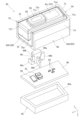
図6及び図7を参照すると、スイッチ装置50は、ケース55、回路基板80、及び蓋体85を備え、回路基板80に前述したスイッチ81、第1の光源82、及び第2の光源83が配置されている。また、スイッチ装置50は、スイッチ81を操作するための操作部56、光源82による表示部57、及び光源83による照明部58を備える。 Referring to Figures 6 and 7, the switch device 50 includes a case 55, a circuit board 80, and a cover 85, and the aforementioned switch 81, first light source 82, and second light source 83 are arranged on the circuit board 80. The switch device 50 also includes an operation unit 56 for operating the switch 81, a display unit 57 using the light source 82, and an illumination unit 58 using the light source 83.

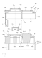
図4及び図5を参照すると、スイッチ装置50は、窓孔25を塞ぐようにベースパネル20の車幅方向Yの内側に取り付けられる。操作部56、表示部57、及び照明部58は、窓孔25内に配置され、リッド30の解放時に開口部3を介して車外側に露出される(図1参照)。このようにベースパネル20に取り付けられるスイッチ装置50は、前述のように防水用のシール部材70を一体に備える。 Referring to Figures 4 and 5, the switch device 50 is attached to the inside of the base panel 20 in the vehicle width direction Y so as to cover the window hole 25. The operation unit 56, display unit 57, and lighting unit 58 are disposed within the window hole 25, and are exposed to the outside of the vehicle through the opening 3 when the lid 30 is opened (see Figure 1). The switch device 50 attached to the base panel 20 in this manner is integrally provided with a waterproof seal member 70 as described above.

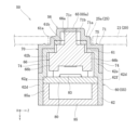
図7及び図8を参照すると、ケース55は、車幅方向Yのうちの外側端を閉鎖して内側端を開口した四角筒状である。ケース55には、前述の操作部56、表示部57、及び照明部58が設けられている。図10から図12を参照すると、ケース55は、ケース本体60、ノブ65、及びシール部材70を備える。図10から図12では、ケース本体60、ノブ65、及びシール部材70を分解した状態を示しているが、実際には、ケース本体60とシール部材70が一体に設けられ、ノブ65とシール部材70が一体に設けられている。 7 and 8, the case 55 is a rectangular tube with its outer end in the vehicle width direction Y closed and its inner end open. The case 55 is provided with the above-mentioned operation unit 56, display unit 57, and lighting unit 58. With reference to Figs. 10 to 12, the case 55 includes a case body 60, a knob 65, and a sealing member 70. Figs. 10 to 12 show the case body 60, knob 65, and sealing member 70 in disassembled form, but in reality, the case body 60 and sealing member 70 are integrally provided, and the knob 65 and sealing member 70 are integrally provided.

図8及び図10を参照すると、ケース本体60は、透光性を有する樹脂(例えばポリカーボネート)からなり、二色成形によってシール部材70と一体に設けられている。ケース本体60は、窓孔25の第1孔部25aを臨むようにベース本体21に対向配置される端壁部61と、端壁部61の外周から突出した外周壁62とを備える。外周壁62を構成する4つの壁のうちの1つは、窓孔25の第2孔部25bを臨むように凹部22aに対向配置される側壁部62aである。端壁部61と側壁部62aは、窓孔25を塞ぐ閉塞壁である。 8 and 10, the case body 60 is made of a translucent resin (e.g., polycarbonate) and is integral with the seal member 70 by two-color molding. The case body 60 includes an end wall portion 61 that is arranged opposite the base body 21 so as to face the first hole portion 25a of the window hole 25, and an outer peripheral wall 62 that protrudes from the outer periphery of the end wall portion 61. One of the four walls that make up the outer peripheral wall 62 is a side wall portion 62a that is arranged opposite the recess 22a so as to face the second hole portion 25b of the window hole 25. The end wall portion 61 and the side wall portion 62a are blocking walls that close the window hole 25.

端壁部61は、窓孔25の第1孔部25aを塞ぐことが可能な大きさの四角形状である。端壁部61には、車幅方向Yの外側へ突出する突出部61aが設けられている。図8及び図9を参照すると、突出部61aは、車幅方向Yから見て第1孔部25aよりも小さい四角形状である。 The end wall portion 61 has a rectangular shape large enough to cover the first hole portion 25a of the window hole 25. The end wall portion 61 has a protrusion portion 61a that protrudes outward in the vehicle width direction Y. With reference to Figures 8 and 9, the protrusion portion 61a has a rectangular shape that is smaller than the first hole portion 25a when viewed from the vehicle width direction Y.

図8及び図10を参照すると、突出部61aには、貫通孔61bと前方透光部(透光部)61cが形成されている。 Referring to Figures 8 and 10, the protrusion 61a is formed with a through hole 61b and a forward light-transmitting portion (light-transmitting portion) 61c.

貫通孔61bは、長方形状で、スイッチ81の車幅方向Yの外側に設けられている。貫通孔61bは、突出部61aを車幅方向Yに貫通している。 The through hole 61b is rectangular and is provided on the outside of the switch 81 in the vehicle width direction Y. The through hole 61b penetrates the protrusion 61a in the vehicle width direction Y.

前方透光部61cは、貫通孔61bの車長方向Xの後側に隣接して設けられ、前述の表示部57を構成する。前方透光部61cは、四角形状で、突出部61aから車幅方向Yの外側へ突出する第1部分61c1と、突出部61aから車幅方向Yの内側へ突出する第2部分61c2とを備える。第2部分61c2は、光源82の近傍まで突出している。 The forward light-transmitting portion 61c is provided adjacent to the rear side of the through-hole 61b in the vehicle length direction X, and constitutes the aforementioned display unit 57. The forward light-transmitting portion 61c is rectangular in shape and includes a first portion 61c1 that protrudes outward in the vehicle width direction Y from the protruding portion 61a, and a second portion 61c2 that protrudes inward in the vehicle width direction Y from the protruding portion 61a. The second portion 61c2 protrudes to the vicinity of the light source 82.

貫通孔61bと前方透光部61cの間に位置するように、突出部61aを含む端壁部61には貫通孔61dが設けられている。貫通孔61dは、車高方向Zに細長い四角形状であり、シール部材70の後述する遮光部71eが貫通している。 A through hole 61d is provided in the end wall portion 61 including the protruding portion 61a so as to be located between the through hole 61b and the forward light-transmitting portion 61c. The through hole 61d has a rectangular shape that is elongated in the vehicle height direction Z, and a light-shielding portion 71e (described later) of the seal member 70 passes through the through hole 61d.

引き続いて図8及び図10を参照すると、外周壁62の側壁部62aは、窓孔25の第2孔部25bを塞ぐことが可能な大きさで、凹部22aの壁面に沿って延びる曲面状である。 Continuing to refer to Figures 8 and 10, the side wall portion 62a of the outer peripheral wall 62 is large enough to cover the second hole portion 25b of the window hole 25, and is curved and extends along the wall surface of the recess 22a.

側壁部62aには、前述の照明部58を構成する側方透光部(透光部)62bが設けられている。図8及び図11を参照すると、側方透光部62bは、車長方向Xから見て第2孔部25bよりも小さい四角形状で、側壁部62aから車長方向Xの前側へ突出する第1部分62b1と、側壁部62aから車長方向Xの後側へ突出する第2部分62b2とを備える。第2部分62b2は、光源83の近傍まで突出している。 The side wall portion 62a is provided with a side translucent portion (translucent portion) 62b that constitutes the aforementioned illumination portion 58. With reference to FIG. 8 and FIG. 11, the side translucent portion 62b has a rectangular shape that is smaller than the second hole portion 25b when viewed from the vehicle length direction X, and includes a first portion 62b1 that protrudes from the side wall portion 62a to the front side in the vehicle length direction X, and a second portion 62b2 that protrudes from the side wall portion 62a to the rear side in the vehicle length direction X. The second portion 62b2 protrudes to the vicinity of the light source 83.

図8から図10を参照すると、外周壁62は、前述の側壁部62aの他に、側壁部62aと対向する短壁部62cと、側壁部62a及び短壁部62cにそれぞれ連なる一対の長壁部62dとを備える。短壁部62cと一対の長壁部62dはそれぞれ、端壁部61の外周に連なる第1部分62eと、第1部分62eの下端外面側に連なる第2部分62fとを備える。第1部分62の内端と、側方透光部62bのうち内側に突出した第2部分62b2の内端とによって、外周壁62の内側には、回路基板80を位置決めする位置決め部62gが形成されている。 8 to 10, in addition to the side wall portion 62a described above, the outer peripheral wall 62 includes a short wall portion 62c facing the side wall portion 62a, and a pair of long wall portions 62d connected to the side wall portion 62a and the short wall portion 62c. The short wall portion 62c and the pair of long wall portions 62d each include a first portion 62e connected to the outer periphery of the end wall portion 61, and a second portion 62f connected to the lower outer surface side of the first portion 62e. A positioning portion 62g that positions the circuit board 80 is formed on the inside of the outer peripheral wall 62 by the inner end of the first portion 62 and the inner end of the second portion 62b2 of the side translucent portion 62b that protrudes inward.

図11及び図12を参照すると、一対の長壁部62dの内面側にはそれぞれ、貫通孔61bから車幅方向Yの内側へ延びる一対の凸条が設けられ、これらの間にガイド溝62hが形成されている。また、貫通孔61dの車長方向Xの前側に位置するように、一対の長壁部62dにかけて延びる隔壁62iが設けられ、この隔壁62iにもガイド溝62jが形成されている。 Referring to Figures 11 and 12, a pair of protrusions extending inward in the vehicle width direction Y from the through hole 61b is provided on the inner surface of each of the pair of long wall portions 62d, and a guide groove 62h is formed between them. In addition, a partition wall 62i is provided extending across the pair of long wall portions 62d so as to be located in front of the through hole 61d in the vehicle length direction X, and a guide groove 62j is also formed in this partition wall 62i.

図8、図10及び図11を参照すると、ノブ65は、ケース本体60の貫通孔61b内に配置され、前述の操作部56の一部を構成する。ノブ65は、透光性を有する樹脂(例えばポリカーボネート)からなり、ケース本体60とは別体で設けられ、インサート成形によってシール部材70と一体に設けられている。 8, 10, and 11, the knob 65 is disposed in the through hole 61b of the case body 60 and constitutes a part of the aforementioned operating unit 56. The knob 65 is made of a translucent resin (e.g., polycarbonate), is provided separately from the case body 60, and is integrally provided with the seal member 70 by insert molding.

より具体的には、ノブ65は、シール部材70から露出する端板部65aと、端板部65aの車長方向Xの両端に連なる一対の側板部65bとを備える。一対の側板部65bのうち、端板部65aとは反対側の端には係止爪65cがそれぞれ設けられている。係止爪65cにはスライダ66が係止され、ノブ65はスライダ66を介してスイッチ81を操作する。 More specifically, the knob 65 includes an end plate portion 65a exposed from the seal member 70, and a pair of side plate portions 65b connected to both ends of the end plate portion 65a in the vehicle length direction X. A locking claw 65c is provided on each of the pair of side plate portions 65b at the end opposite the end plate portion 65a. A slider 66 is locked to the locking claw 65c, and the knob 65 operates the switch 81 via the slider 66.

図7から図9を参照すると、スライダ66は、ノブ65の車高方向Zの幅と同じ厚みの板体である。スライダ66は、ノブ65に係止される被係止部66aと、ケース本体60のガイド溝62h,62jに挿通されるガイド板66bとを備える。シール部材70と一体のノブ65の係止爪65cに被係止部66aが係止されることで、ケース本体60内にスライダ66がフローティング状態で配置される。 Referring to Figures 7 to 9, the slider 66 is a plate body with the same thickness as the width of the knob 65 in the vehicle height direction Z. The slider 66 has an engaged portion 66a that engages with the knob 65, and a guide plate 66b that is inserted into the guide grooves 62h, 62j of the case body 60. The engaged portion 66a engages with the engaging claw 65c of the knob 65 that is integral with the seal member 70, so that the slider 66 is positioned in a floating state within the case body 60.

スライダ66は、導光性を有する樹脂(例えばアクリル樹脂)からなり、光源83の光をノブ65に導く機能を兼ね備える。スライダ66の車長方向Xの前側には、光源83の光を側方透光部62bに導くレンズ部66cが設けられている。 The slider 66 is made of a light-conducting resin (e.g., acrylic resin) and has the function of directing the light of the light source 83 to the knob 65. A lens portion 66c is provided on the front side of the slider 66 in the vehicle length direction X to direct the light of the light source 83 to the side light-transmitting portion 62b.

図7及び図8を参照すると、シール部材70は、可撓性と遮光性を有する材料(例えばエラストマー)からなり、金型内にノブ65を配置した状態で二色成形することで、ケース本体60と一体、かつノブ65と一体に成形されている。但し、シール部材70に対してケース本体60とノブ65を一体に設ける方法は、必要に応じて変更が可能である。 Referring to Figures 7 and 8, the seal member 70 is made of a flexible and light-blocking material (e.g., elastomer), and is molded integrally with the case body 60 and the knob 65 by two-color molding with the knob 65 placed in a mold. However, the method of integrating the case body 60 and the knob 65 with the seal member 70 can be changed as necessary.

図4を参照すると、ベースパネル20へのスイッチ装置50の取り付けによって、シール部材70は、ベース本体21及び凹部22aに圧接される。シール部材70は、ケース本体60及びベースパネル20のいずれよりも材質的に柔らかい。そのため、ケース本体60とベースパネル20は、シール部材70との対比において剛体とみなすことができる。 Referring to FIG. 4, when the switch device 50 is attached to the base panel 20, the seal member 70 is pressed against the base body 21 and the recess 22a. The seal member 70 is made of a softer material than both the case body 60 and the base panel 20. Therefore, the case body 60 and the base panel 20 can be considered to be rigid bodies in comparison with the seal member 70.

図10及び図11を参照すると、シール部材70は、ケース本体60のうち、端壁部61を覆う第1シール部71、側壁部62aを覆う第2シール部72、短壁部62cの一部を覆う第3シール部73、及び一対の長壁部62dそれぞれの一部を覆う一対の第4シール部74を備える。 Referring to Figures 10 and 11, the sealing member 70 includes a first sealing portion 71 that covers the end wall portion 61 of the case body 60, a second sealing portion 72 that covers the side wall portion 62a, a third sealing portion 73 that covers a portion of the short wall portion 62c, and a pair of fourth sealing portions 74 that cover a portion of each of the pair of long wall portions 62d.

図8及び図11を参照すると、第1シール部71は、窓孔25の第1孔部25aよりも大きい四角形状で、端壁部61に沿ってXZ平面に沿って延びている。第1シール部71は、端壁部61に形成された突出部61aを覆う第1被覆部71aを備える。車幅方向Yの外側から見て、第1被覆部71aは第1孔部25aよりも小さい形状である。 Referring to Figures 8 and 11, the first seal portion 71 has a rectangular shape larger than the first hole portion 25a of the window hole 25, and extends along the XZ plane along the end wall portion 61. The first seal portion 71 has a first covering portion 71a that covers the protrusion portion 61a formed on the end wall portion 61. When viewed from the outside in the vehicle width direction Y, the first covering portion 71a has a shape smaller than the first hole portion 25a.

図8及び図9を参照すると、第1被覆部71aには、貫通孔61bの孔縁から車幅方向Yの外側へ膨出する膨出部71bが設けられている。膨出部71bには、ノブ65の端板部65aを露出させる露出孔71cが設けられている。露出孔71cの孔壁は、端板部65aの外周に密着して物理的に接着されている。これにより、貫通孔61bとノブ65の間の隙間がシール部材70によって塞がれる。また、ノブ65の端板部65aは、貫通孔61bから車幅方向Yの外側へ突出している。 8 and 9, the first covering portion 71a is provided with a bulging portion 71b that bulges outward in the vehicle width direction Y from the edge of the through hole 61b. The bulging portion 71b is provided with an exposure hole 71c that exposes the end plate portion 65a of the knob 65. The hole wall of the exposure hole 71c is physically bonded in close contact with the outer periphery of the end plate portion 65a. As a result, the gap between the through hole 61b and the knob 65 is blocked by the seal member 70. In addition, the end plate portion 65a of the knob 65 protrudes outward in the vehicle width direction Y from the through hole 61b.

このように構成された膨出部71bは、ケース本体60との間に変形を許容する空間を有し、前述の操作部56の一部を構成する。ノブ65を車幅方向Yの内側へプッシュ操作すると、膨出部71bが弾性的に撓むことで、ノブ65とスライダ66がスイッチ81側へ移動する。ノブ65のプッシュ操作を止めると、膨出部71bが弾性的に復元することで、ノブ65とスライダ66がスイッチ81から離間する。 The bulge 71b configured in this manner has a space between it and the case body 60 that allows deformation, and constitutes part of the aforementioned operating unit 56. When the knob 65 is pushed inward in the vehicle width direction Y, the bulge 71b elastically bends, causing the knob 65 and the slider 66 to move toward the switch 81. When the knob 65 is no longer pushed, the bulge 71b elastically returns to its original state, causing the knob 65 and the slider 66 to move away from the switch 81.

図8及び図11を参照すると、第1被覆部71aには更に、前方透光部61cを露出させて、光源82の光を外部へ透過させる透光孔71dが設けられている。透光孔71dの孔壁は、突出部61aから突出した前方透光部61cの外周に密着し、物理的に接着されている。 8 and 11, the first covering portion 71a further includes a light-transmitting hole 71d that exposes the forward light-transmitting portion 61c and transmits light from the light source 82 to the outside. The hole wall of the light-transmitting hole 71d is in close contact with and physically bonded to the outer periphery of the forward light-transmitting portion 61c protruding from the protruding portion 61a.

図11及び図12を参照すると、第1被覆部71aを含む第1シール部71には更に、車幅方向Yの内側へ突出し、光源82と83の光の混合を防ぐ遮光部71eが設けられている。図8を参照すると、遮光部71eは、板状であり、貫通孔61dを貫通し、隔壁62iの車長方向Xの後側に隣接している。 Referring to Figures 11 and 12, the first seal portion 71 including the first covering portion 71a is further provided with a light-shielding portion 71e that protrudes inward in the vehicle width direction Y and prevents the light from the light sources 82 and 83 from mixing. Referring to Figure 8, the light-shielding portion 71e is plate-shaped, passes through the through-hole 61d, and is adjacent to the rear side of the partition wall 62i in the vehicle length direction X.

図8及び図10を参照すると、第1シール部71には更に、側方透光部62bの端壁部61側の面を覆う第2被覆部(被覆部)71fが設けられている。第2被覆部71fは、第1被覆部71aから車長方向Xの前側へ一体に突出するとともに、側方透光部62bに密着するように車幅方向Yの内側へ突出し、側方透光部62bに密着して物理的に接着されている。車高方向Zにおける第2被覆部71fの寸法は第1被覆部71aの寸法と同じであり、第2被覆部71fは、窓孔25の第1窓部25aと第2窓部25bのいずれよりも小さい。 8 and 10, the first seal portion 71 is further provided with a second covering portion (covering portion) 71f that covers the surface of the side translucent portion 62b on the end wall portion 61 side. The second covering portion 71f protrudes integrally from the first covering portion 71a toward the front side in the vehicle length direction X, and protrudes inward in the vehicle width direction Y so as to be in close contact with the side translucent portion 62b, and is physically bonded in close contact with the side translucent portion 62b. The dimension of the second covering portion 71f in the vehicle height direction Z is the same as the dimension of the first covering portion 71a, and the second covering portion 71f is smaller than both the first window portion 25a and the second window portion 25b of the window hole 25.

引き続いて図8及び図10を参照すると、第2シール部72は、第1シール部71の車長方向Xの前側端に連なり、概ねYZ平面に沿って延びている。第2シール部72には、側方透光部62bを露出させて、光源83の光を外部へ透過させる透光孔72aが設けられている。透光孔72aの孔壁は、側方透光部62bの基部の外周に密着して物理的に接着されている。 Continuing to refer to Figures 8 and 10, the second seal portion 72 is connected to the front end of the first seal portion 71 in the vehicle length direction X and extends generally along the YZ plane. The second seal portion 72 is provided with a light-transmitting hole 72a that exposes the side light-transmitting portion 62b and transmits light from the light source 83 to the outside. The hole wall of the light-transmitting hole 72a is physically bonded in close contact with the outer periphery of the base of the side light-transmitting portion 62b.

ここで、図4、図8及び図9を参照すると、ケース本体60の突出部61aとシール部材70の第1被覆部71aとは、第1シール部71のうちベース本体21と当接する面から車幅方向Yの外側へ突出する第1突出部であり、第1孔部25a内に配置される。ケース本体60の側方透光部62bとシール部材70の第2被覆部71fとは、第2シール部72のうち凹部22aと当接する面から車長方向Xの前側へ突出する第2突出部であり、第2孔部25b内に配置される。図7を参照すると、第1突出部の車長方向Xの前端と第2突出部の車幅方向Yの外端とは連なり、これらが一体となって窓孔25内に突出している。 4, 8 and 9, the protrusion 61a of the case body 60 and the first covering portion 71a of the seal member 70 are first protrusions that protrude outward in the vehicle width direction Y from the surface of the first seal portion 71 that abuts against the base body 21, and are disposed within the first hole 25a. The side light-transmitting portion 62b of the case body 60 and the second covering portion 71f of the seal member 70 are second protrusions that protrude forward in the vehicle length direction X from the surface of the second seal portion 72 that abuts against the recess 22a, and are disposed within the second hole 25b. Referring to FIG. 7, the front end of the first protrusion in the vehicle length direction X and the outer end of the second protrusion in the vehicle width direction Y are connected, and they protrude into the window hole 25 as a unit.

図6及び図10を参照すると、第1シール部71と第2シール部72には更に、ベースパネル20に圧接される圧接部75が突設されている。圧接部75は、断面三角形状で、第1被覆部71aと透光孔72aを取り囲む環状(無端状)に形成されている。ベースパネル20へのスイッチ装置50の取り付けによって、圧接部75が弾性的に変形してベースパネル20に圧接される。 Referring to Figures 6 and 10, the first seal portion 71 and the second seal portion 72 further have a protruding pressure contact portion 75 that is pressed against the base panel 20. The pressure contact portion 75 has a triangular cross section and is formed in an annular (endless) shape that surrounds the first covering portion 71a and the light-transmitting hole 72a. When the switch device 50 is attached to the base panel 20, the pressure contact portion 75 is elastically deformed and pressed against the base panel 20.

図8及び図12を参照すると、第3シール部73は、第1シール部71の車長方向Xの後側端に連なり、YZ平面に沿って延びている。第3シール部73は、短壁部62cの第1部分62eを覆い、第2部分62fの車幅方向Yの外端まで延びている。第3シール部73の外側面は、短壁部62cの第2部分62fの外側面と面一である。 Referring to Figures 8 and 12, the third seal portion 73 is connected to the rear end of the first seal portion 71 in the vehicle length direction X and extends along the YZ plane. The third seal portion 73 covers the first portion 62e of the short wall portion 62c and extends to the outer end of the second portion 62f in the vehicle width direction Y. The outer surface of the third seal portion 73 is flush with the outer surface of the second portion 62f of the short wall portion 62c.

図9及び図12を参照すると、第4シール部74は、第1シール部71の車高方向Zの端に連なるとともに、第2シール部72及び第3シール部73それぞれの車高方向Zの端に連なり、XY平面に沿って延びている。第4シール部74は、長壁部62dの第1部分62eを覆い、第2部分62fの車幅方向Yの外端まで延びている。第4シール部74の外側面は、長壁部62dの第2部分62fの外側面と面一である。 Referring to Figures 9 and 12, the fourth seal portion 74 is connected to the end of the first seal portion 71 in the vehicle height direction Z, and is also connected to the ends of the second seal portion 72 and the third seal portion 73 in the vehicle height direction Z, and extends along the XY plane. The fourth seal portion 74 covers the first portion 62e of the long wall portion 62d and extends to the outer end of the second portion 62f in the vehicle width direction Y. The outer surface of the fourth seal portion 74 is flush with the outer surface of the second portion 62f of the long wall portion 62d.

図7及び図8を参照すると、回路基板80は、ECUに電気的に接続されており、ケース本体60内に収容されて位置決め部62gと蓋体85の間に挟み込まれている。回路基板80には、前述のように、スイッチ81、第1の光源82、及び第2の光源83が配置されている。 Referring to Figures 7 and 8, the circuit board 80 is electrically connected to the ECU, is housed in the case body 60, and is sandwiched between the positioning portion 62g and the cover 85. As described above, the switch 81, the first light source 82, and the second light source 83 are arranged on the circuit board 80.

スイッチ81は、ノブ65のプッシュ操作力がスライダ66を介して伝わることで、接点が短絡する常開のプッシュスイッチである。プッシュ操作されている間、接点が短絡し続けるため、スイッチ81は、操作されたことを示す操作信号を出力し続ける。プッシュ操作が止められ、接点の電気的な接続が遮断されると、スイッチ81は操作信号を出力しない。 The switch 81 is a normally open push switch whose contacts are shorted when the push force of the knob 65 is transmitted via the slider 66. Since the contacts remain shorted while the switch is being pushed, the switch 81 continues to output an operation signal indicating that the switch has been operated. When the push operation is stopped and the electrical connection of the contacts is cut off, the switch 81 does not output an operation signal.

光源82は、スイッチ81の車長方向Xの後側に配置された3つのLED(3色LED)からなる。光源82は、図1に示すリッド30の開状態でECUの指令によって点灯され、所定の色を発光する。光源82の光は、前方透光部61cを透過し、表面の表示部57に表出する。 The light source 82 consists of three LEDs (three-color LEDs) arranged on the rear side of the switch 81 in the vehicle length direction X. The light source 82 is turned on by a command from the ECU when the lid 30 is in the open state shown in FIG. 1, and emits light of a specified color. The light of the light source 82 passes through the forward light-transmitting portion 61c and is projected onto the display portion 57 on the surface.

光源83は、スイッチ81の車長方向Xの前側に配置されている。光源83は、例えば昼白色の光を放射可能なLEDからなり、図1に示すリッド30の開状態でECUの指令によって点灯される。光源83の光は、スライダ66と側方透光部62bを透過して給電コネクタ15(凹部22a内)を照明するとともに、スライダ66を透過してノブ65(操作部56)の表面に表出する。 The light source 83 is disposed in front of the switch 81 in the vehicle length direction X. The light source 83 is, for example, an LED capable of emitting neutral white light, and is turned on by a command from the ECU when the lid 30 is in the open state shown in FIG. 1. The light from the light source 83 passes through the slider 66 and the side translucent portion 62b to illuminate the power supply connector 15 (inside the recess 22a), and also passes through the slider 66 to appear on the surface of the knob 65 (operation portion 56).

蓋体85は、ケース本体60の開口内に嵌合され、ケース本体60との間を液密に塞ぐ。本実施形態の蓋体85は、ケース本体60の内周面に密着する四角筒状の外周壁85aを備える。 The lid 85 fits into the opening of the case body 60, sealing the gap between the case body 60 and the lid 85 in a liquid-tight manner. In this embodiment, the lid 85 has a rectangular cylindrical outer wall 85a that fits closely to the inner surface of the case body 60.

このように構成されたスイッチ装置50は、前述のように、ベースパネル20の車幅方向Yの内側において、端壁部61が窓孔25の第1孔部25aを臨み、側壁部62aが窓孔25の第2孔部25bを臨むように配置される。その後、ベース本体21に第1シール部71が圧接され、凹部22aに第2シール部72が圧接されるように、周知の取付構造によって取り付けられる。 As described above, the switch device 50 configured in this manner is positioned on the inside of the base panel 20 in the vehicle width direction Y, with the end wall portion 61 facing the first hole portion 25a of the window hole 25 and the side wall portion 62a facing the second hole portion 25b of the window hole 25. The switch device 50 is then attached using a well-known attachment structure so that the first seal portion 71 is pressed against the base body 21 and the second seal portion 72 is pressed against the recess 22a.

この車両用スイッチ装置50、及びスイッチ装置50を備えるリッド開閉装置10は、以下の特徴を有する。 This vehicle switch device 50 and the lid opening and closing device 10 equipped with the switch device 50 have the following features.

ケース55は、窓孔25を臨むように配置された閉塞壁(端壁部61と側壁部62a)を有するケース本体60、スイッチ81を操作するためのノブ65、及び閉塞壁61,62aを覆うシール部材70を備え、ケース本体60とシール部材70が一体である。閉塞壁61,62aに形成した貫通孔61bがシール部材70によって塞がれるため、ケース55内への浸水を防止できる。また、ベースパネル20へのケース55の取り付けによって、シール部材70がベースパネル20に圧接されるため、窓孔25を通したベースパネル20内への浸水も防止できる。 The case 55 comprises a case body 60 having a blocking wall (end wall portion 61 and side wall portion 62a) arranged to face the window hole 25, a knob 65 for operating the switch 81, and a seal member 70 covering the blocking walls 61, 62a, and the case body 60 and the seal member 70 are integral. The through hole 61b formed in the blocking walls 61, 62a is blocked by the seal member 70, so water can be prevented from entering the case 55. In addition, by attaching the case 55 to the base panel 20, the seal member 70 is pressed against the base panel 20, so water can also be prevented from entering the base panel 20 through the window hole 25.

ケース本体60とシール部材70は一体であるため、別部品からなる専用のシール部材を取り付ける必要はない。また、シール部材70が経年劣化等によって損傷した場合、スイッチ装置50だけ取り替えればよく、例えばリッド30の脱着及び交換等の大掛かりな修繕作業は必要ない。そのため、シール部材70が破損したときの修繕性を向上できる。 Because the case body 60 and the sealing member 70 are integrated, there is no need to attach a dedicated sealing member that is a separate part. Furthermore, if the sealing member 70 is damaged due to aging or the like, it is sufficient to replace only the switch device 50, and there is no need for extensive repair work such as removing and replacing the lid 30. This improves the ease of repair when the sealing member 70 is damaged.

ノブ65とシール部材70が一体に設けられている。これにより、ケース本体60に対するノブ65の取付作業が不要になるため、スイッチ装置10の組立性を向上できる。 The knob 65 and the seal member 70 are integrally formed. This eliminates the need to attach the knob 65 to the case body 60, improving the ease of assembly of the switch device 10.

閉塞壁は、ベース本体21と対向する端壁部61と、ベースパネル20の凹部22aと対向する側壁部62aとを有し、シール部材70は、端壁部61を覆う第1シール部71と、側壁部62aを覆う第2シール部72とを有する。そのため、ベースパネル20に形成された三次元的形状の窓孔25を1つのシール部材70でシールできる。 The blocking wall has an end wall portion 61 that faces the base body 21 and a side wall portion 62a that faces the recess 22a of the base panel 20, and the sealing member 70 has a first sealing portion 71 that covers the end wall portion 61 and a second sealing portion 72 that covers the side wall portion 62a. Therefore, the three-dimensional window hole 25 formed in the base panel 20 can be sealed with a single sealing member 70.

ケース本体60は透光性を有し、シール部材70は遮光性を有し、シール部材70にはケース本体60の透光部61c,62bを露出させて光源82,83の光を透過させる透光孔71d,72aが設けられている。よって、透光部61c,62bからのみ光を透過させ、所定の表示を行ったり、所定部位の照明を行ったりできるため、機能性を向上できる。 The case body 60 is translucent, the seal member 70 is light-blocking, and the seal member 70 is provided with translucent holes 71d, 72a that expose the translucent portions 61c, 62b of the case body 60 and transmit light from the light sources 82, 83. This allows light to pass only through the translucent portions 61c, 62b, allowing a specified display or illumination of a specified area, improving functionality.

透光部は、貫通孔61bに隣接するように端壁部61に設けられた前方透光部61cを含む。よって、スイッチ装置50をリッド開閉装置10に用いる場合、前方透光部61cは、充電状態を表示するインジケータとして機能させることができる。 The light-transmitting portion includes a front light-transmitting portion 61c provided on the end wall portion 61 so as to be adjacent to the through hole 61b. Therefore, when the switch device 50 is used in the lid opening/closing device 10, the front light-transmitting portion 61c can function as an indicator that displays the charging state.

透光部は、側壁部62aに設けられた側方透光部62bを含む。よって、スイッチ装置50をリッド開閉装置10に用いる場合、側方透光部62bは、受給部を照らす照明として機能させることができる。 The light-transmitting portion includes a lateral light-transmitting portion 62b provided on the side wall portion 62a. Therefore, when the switch device 50 is used in the lid opening/closing device 10, the lateral light-transmitting portion 62b can function as a light that illuminates the receiving portion.

側方透光部62bは側壁部62aから突出しており、第1シール部71には側方透光部62bの端壁部61側の面を覆う第2被覆部71fが設けられている。そのため、側方透光部62bの光が前側に漏れることを抑制できる。 The side translucent portion 62b protrudes from the side wall portion 62a, and the first seal portion 71 is provided with a second cover portion 71f that covers the surface of the side translucent portion 62b on the end wall portion 61 side. This makes it possible to prevent light from the side translucent portion 62b from leaking forward.

ケース55は、第1シール部71のベース本体21と当接する面から突出した第1突出部(突出部61aと第1被覆部71a)と、第2シール部72の凹部22aと当接する面から突出した第2突出部(側方透光部62bと第2被覆部71f)とを有し、第1突出部61a,71aの一端と第2突出部62b,71fの一端とは連なっている。ベースパネル20に形成された三次元的形状の窓孔25から第1突出部61a,71aと第2突出部62b,71fが一体的に露出するため、デザイン性を向上できる。また、三次元的形状の窓孔25を有するベースパネル20に対するスイッチ装置50の取付性も向上できる。 The case 55 has a first protrusion (protrusion 61a and first covering portion 71a) protruding from the surface of the first seal portion 71 that abuts against the base body 21, and a second protrusion (lateral light-transmitting portion 62b and second covering portion 71f) protruding from the surface of the second seal portion 72 that abuts against the recess 22a, and one end of the first protrusion 61a, 71a is connected to one end of the second protrusion 62b, 71f. The first protrusion 61a, 71a and the second protrusion 62b, 71f are integrally exposed from the three-dimensional window hole 25 formed in the base panel 20, improving the design. In addition, the mountability of the switch device 50 to the base panel 20 having the three-dimensional window hole 25 can also be improved.

なお、本発明は、前記実施形態の構成に限定されず、種々の変更が可能である。 The present invention is not limited to the configuration of the above embodiment, and various modifications are possible.

例えば、窓孔25は第2孔部25bを備えることなく、シール部材70(ケース55)はベース本体21のみに圧接されてもよい。 For example, the window hole 25 may not have the second hole portion 25b, and the sealing member 70 (case 55) may be pressed against only the base body 21.

スイッチ装置50は、光源82,83及び透光部61c,62bを備えることなく、スイッチ81のみを備える構成であってもよい。 The switch device 50 may be configured to include only the switch 81, without including the light sources 82, 83 and the light-transmitting portions 61c, 62b.

シール部材70にノブ65を露出させる露出孔71cを設けずに、ノブ65を含む貫通孔61b全体をシール部材70によって覆ってもよい。このようにしても、ノブ65と貫通孔61bの間の隙間がシール部材70によって覆われるため、貫通孔61bからケース55内への浸水を防止できる。 The entire through hole 61b including the knob 65 may be covered by the seal member 70 without providing an exposure hole 71c that exposes the knob 65 in the seal member 70. Even in this case, the gap between the knob 65 and the through hole 61b is covered by the seal member 70, so water can be prevented from entering the case 55 through the through hole 61b.

本発明のスイッチ装置50は、車両におけるリッド開閉装置10以外の機器にも適用でき、同様の作用及び効果を得ることができる。また、スイッチ装置50は、車体パネル(パネル)に直接取り付けられてもよい。 The switch device 50 of the present invention can be applied to devices other than the lid opening and closing device 10 in a vehicle, and can achieve the same effects and advantages. The switch device 50 may also be attached directly to a vehicle body panel.

1 サイドパネル(車体パネル、パネル)
2 凹部
3 開口部
4 取付口
10 リッド開閉装置
15 給電コネクタ(受給部)
15a 接続部
20 ベースパネル(パネル)
21 ベース本体(第1板部)
22 取付部
22a 凹部(第2板部)
22b 取付口
23 シール部材
24 挿通孔
25 窓孔
25a 第1孔部
25b 第2孔部
26 軸受部
26a 端板
26b 連結板
30 リッド
31 アーム
32 第1アーム部
32a 枢着部
32b 軸孔
33 第2アーム部
33a 接続部
40 駆動機構
41 モータ(駆動源)
42 駆動ギア
43 従動ギア
43a 軸部
50 スイッチ装置
55 ケース
56 操作部
57 表示部
58 照明部
60 ケース本体
61 端壁部(閉塞壁)
61a 突出部(第1突出部)
61b 貫通孔
61c 前方透光部
61c1 第1部分
61c2 第2部分
61d 貫通孔
62 外周壁
62a 側壁部(閉塞壁)
62b 側方透光部(第2突出部)
62b1 第1部分
62b2 第2部分
62c 短壁部
62d 長壁部
62e 第1部分
62f 第2部分
62g 位置決め部
62h ガイド溝
62i 隔壁
62j ガイド溝
65 ノブ
65a 端板部
65b 側板部
65c 係止爪
66 スライダ
66a 被係止部
66b ガイド板
66c レンズ部
70 シール部材
71 第1シール部
71a 第1被覆部(第1突出部)
71b 膨出部
71c 露出孔
71d 透光孔
71e 遮光部
71f 第2被覆部(第2突出部)
72 第2シール部
72a 透光孔
73 第3シール部
74 第4シール部
75 圧接部
80 回路基板
81 スイッチ
82 光源
83 光源
85 蓋体
85a 外周壁
1 Side panel (body panel, panel)
2 Recess 3 Opening 4 Mounting port 10 Lid opening/closing device 15 Power supply connector (receiving portion)
15a Connection portion 20 Base panel (panel)
21 Base body (first plate portion)
22 Mounting portion 22a Recess (second plate portion)
22b Mounting hole 23 Seal member 24 Insertion hole 25 Window hole 25a First hole portion 25b Second hole portion 26 Bearing portion 26a End plate 26b Connecting plate 30 Lid 31 Arm 32 First arm portion 32a Pivot portion 32b Shaft hole 33 Second arm portion 33a Connection portion 40 Drive mechanism 41 Motor (drive source)
42 Drive gear 43 Driven gear 43a Shaft portion 50 Switch device 55 Case 56 Operation portion 57 Display portion 58 Illumination portion 60 Case body 61 End wall portion (closing wall)
61a Projection (first projection)
61b Through hole 61c Front transparent portion 61c1 First portion 61c2 Second portion 61d Through hole 62 Outer peripheral wall 62a Side wall portion (closure wall)
62b Side transparent part (second protrusion)
62b1 First portion 62b2 Second portion 62c Short wall portion 62d Long wall portion 62e First portion 62f Second portion 62g Positioning portion 62h Guide groove 62i Partition wall 62j Guide groove 65 Knob 65a End plate portion 65b Side plate portion 65c Locking claw 66 Slider 66a Locked portion 66b Guide plate 66c Lens portion 70 Sealing member 71 First sealing portion 71a First covering portion (first protruding portion)
71b Swelling part 71c Exposure hole 71d Transparent hole 71e Light shielding part 71f Second covering part (second protruding part)
72 Second seal portion 72a Light transmitting hole 73 Third seal portion 74 Fourth seal portion 75 Pressure contact portion 80 Circuit board 81 Switch 82 Light source 83 Light source 85 Lid 85a Outer circumferential wall

Claims (9)

パネルの窓孔を塞ぐように配置するケースと、
前記ケース内に収容されたスイッチと
を備え、
前記ケースは、
前記窓孔を臨むように配置され、前記スイッチと対応する貫通孔が形成された閉塞壁を有するケース本体と、
前記貫通孔内に配置され、前記スイッチを操作するためのノブと、
前記ノブと前記貫通孔の間の隙間、及び前記閉塞壁を覆い、前記パネルに圧接される可撓性のシール部材と
を備え、
前記ケース本体と前記シール部材は一体である、車両用スイッチ装置。
A case that is placed to cover the window hole of the panel,
a switch housed in the case;
The case is
a case body having a blocking wall disposed to face the window hole and having a through hole corresponding to the switch;
a knob disposed in the through hole for operating the switch;
a flexible seal member that covers a gap between the knob and the through hole and the closing wall and is pressed against the panel,
The switch device for a vehicle, wherein the case body and the seal member are integral with each other.
前記ノブと前記シール部材は一体である、請求項1に記載の車両用スイッチ装置。 The vehicle switch device according to claim 1, wherein the knob and the seal member are integral. 前記閉塞壁は、前記パネルの第1板部と対向する端壁部と、前記パネルのうち前記第1板部に対して交差する方向に延びる第2板部と対向する側壁部とを有し、前記端壁部に前記貫通孔が設けられており、
前記シール部材は、前記端壁部を覆う第1シール部と、前記側壁部を覆う第2シール部とを含む、
請求項1又は2に記載の車両用スイッチ装置。
The blocking wall has an end wall portion facing a first plate portion of the panel and a side wall portion facing a second plate portion of the panel extending in a direction intersecting the first plate portion, and the through hole is provided in the end wall portion,
The seal member includes a first seal portion covering the end wall portion and a second seal portion covering the side wall portion.
The switch device for a vehicle according to claim 1 or 2.
前記ケース内には光源が収容されており、
前記ケース本体は透光性を有し、
前記シール部材は遮光性を有し、
前記シール部材には、前記ケース本体の一部である透光部を露出させて、前記光源の光を透過させる透光孔が設けられている、請求項3に記載の車両用スイッチ装置。
A light source is housed in the case,
The case body is translucent,
The sealing member has a light-shielding property,
The switch device for a vehicle according to claim 3 , wherein the seal member is provided with a light transmitting hole that exposes a light transmitting portion that is a part of the case body and transmits light from the light source.
前記透光部は、前記貫通孔に隣接するように前記端壁部に設けられた前方透光部を含む、請求項4に記載の車両用スイッチ装置。 The vehicle switch device according to claim 4, wherein the light-transmitting portion includes a front light-transmitting portion provided on the end wall portion adjacent to the through hole. 前記透光部は、前記側壁部に設けられた側方透光部を含む、請求項4又は5に記載の車両用スイッチ装置。 The vehicle switch device according to claim 4 or 5, wherein the light-transmitting portion includes a side light-transmitting portion provided on the side wall portion. 前記側方透光部は、前記側壁部から突出しており、
前記第1シール部には、前記側方透光部の前記端壁部側の面を覆う被覆部が設けられている、
請求項6に記載の車両用スイッチ装置。
The side light transmitting portion protrudes from the side wall portion,
The first seal portion is provided with a covering portion that covers a surface of the side light transmitting portion on the end wall portion side.
The switch device for a vehicle according to claim 6.
前記ケースは、
前記第1シール部のうち前記第1板部と当接する面から突出し、前記窓孔の一部を構成する第1孔部内に配置される第1突出部と、
前記第2シール部のうち前記第2板部と当接する面から突出し、前記窓孔の残りの一部を構成する第2孔部内に配置される第2突出部と
を有し、
前記第1突出部の一端と前記第2突出部の一端とは連なっている、
請求項3から6のいずれか1項に記載の車両用スイッチ装置。
The case is
a first protrusion protruding from a surface of the first seal portion that contacts the first plate portion and disposed within a first hole portion that constitutes a part of the window hole;
a second protruding portion that protrudes from a surface of the second seal portion that contacts the second plate portion and is disposed within a second hole portion that constitutes a remaining portion of the window hole;
One end of the first protrusion and one end of the second protrusion are continuous with each other.
The switch device for a vehicle according to any one of claims 3 to 6.
軸受部と窓孔を有し、車体パネルの開口部の内側に配置されたベースパネルと、
前記開口部内に位置するように前記ベースパネルに取り付けられた受給部と、
前記軸受部に軸支され、前記開口部を開放可能に閉塞するリッドと、
前記開口部を開放した開位置と前記開口部を閉塞した閉位置とに前記リッドを移動させる駆動源を含む駆動機構と、
前記ベースパネルの前記窓孔を塞ぐように配置されたケースと、前記ケース内に収容されたスイッチとを有するスイッチ装置と
を備え、
前記ケースは、
前記窓孔を臨むように配置され、前記スイッチと対応する貫通孔が形成された閉塞壁を有するケース本体と、
前記貫通孔内に配置され、前記スイッチを操作するためのノブと、
前記ノブと前記貫通孔の間の隙間、及び前記閉塞壁を覆い、前記パネルに圧接される可撓性のシール部材と
を備え、
前記ケース本体と前記シール部材は一体である、リッド開閉装置。
a base panel having a bearing portion and a window hole and disposed inside an opening of a vehicle body panel;
a receiving portion attached to the base panel so as to be positioned within the opening;
a lid that is journalled to the bearing portion and that openably closes the opening;
a drive mechanism including a drive source that moves the lid between an open position where the opening is opened and a closed position where the opening is closed;
a switch device including a case disposed so as to cover the window hole of the base panel and a switch housed in the case,
The case is
a case body having a blocking wall disposed to face the window hole and having a through hole corresponding to the switch;
a knob disposed in the through hole for operating the switch;
a flexible seal member that covers a gap between the knob and the through hole and the closing wall and is pressed against the panel,
The lid opening and closing device, wherein the case body and the seal member are integral with each other.
JP2021159320A 2021-09-29 2021-09-29 Vehicle switch device and lid opening/closing device Active JP7688552B2 (en)

Priority Applications (1)

Application Number Priority Date Filing Date Title
JP2021159320A JP7688552B2 (en) 2021-09-29 2021-09-29 Vehicle switch device and lid opening/closing device

Applications Claiming Priority (1)

Application Number Priority Date Filing Date Title
JP2021159320A JP7688552B2 (en) 2021-09-29 2021-09-29 Vehicle switch device and lid opening/closing device

Publications (2)

Publication Number Publication Date
JP2023049532A JP2023049532A (en) 2023-04-10
JP7688552B2 true JP7688552B2 (en) 2025-06-04

Family

ID=85801940

Family Applications (1)

Application Number Title Priority Date Filing Date
JP2021159320A Active JP7688552B2 (en) 2021-09-29 2021-09-29 Vehicle switch device and lid opening/closing device

Country Status (1)

Country Link
JP (1) JP7688552B2 (en)

Citations (2)

* Cited by examiner, † Cited by third party
Publication number Priority date Publication date Assignee Title
JP2012034543A (en) 2010-08-02 2012-02-16 Honda Motor Co Ltd Charging inlet lid structure of vehicle
JP2020068588A (en) 2018-10-24 2020-04-30 ダイキョーニシカワ株式会社 Vehicle charging device

Family Cites Families (4)

* Cited by examiner, † Cited by third party
Publication number Priority date Publication date Assignee Title
JPS4312335Y1 (en) * 1966-10-14 1968-05-28
JPH08129925A (en) * 1994-10-28 1996-05-21 Anritsu Corp Waterproof switch
JP3069726B2 (en) * 1995-11-28 2000-07-24 エスエムケイ株式会社 Keyboard switch
JP3323740B2 (en) * 1996-05-01 2002-09-09 株式会社クボタ Vending machine push button switch device

Patent Citations (2)

* Cited by examiner, † Cited by third party
Publication number Priority date Publication date Assignee Title
JP2012034543A (en) 2010-08-02 2012-02-16 Honda Motor Co Ltd Charging inlet lid structure of vehicle
JP2020068588A (en) 2018-10-24 2020-04-30 ダイキョーニシカワ株式会社 Vehicle charging device

Also Published As

Publication number Publication date
JP2023049532A (en) 2023-04-10

Similar Documents

Publication Publication Date Title
JP4533786B2 (en) Button waterproof structure
JP4871235B2 (en) Display device
US11878626B2 (en) Lighting module for a vehicle component and vehicle component with a lighting module
EP3179019B1 (en) Door latch actuator
WO2016009656A1 (en) Vehicle door latch device
JP5373425B2 (en) Interior lighting device
CN111717023A (en) Charging or refueling recess for insertion into a body opening of a motor vehicle
JP7688552B2 (en) Vehicle switch device and lid opening/closing device
JP3215198U (en) Service hole cap
CA2752929A1 (en) Combination light and switch assembly
CN219339146U (en) Top lamp assembly and vehicle of integrated fragrance system
US20230243203A1 (en) System for Controlling Opening of Aperture Tube Door
JP7656489B2 (en) Switch device and charging port unit equipped with switch device
JP2001036262A (en) Radio waterproof push-button switch
JP6357887B2 (en) Vehicle lamp, vehicle outside mirror device
JP2016078468A (en) Handling device
JP2020068588A (en) Vehicle charging device
JP7721899B2 (en) printing device
JP2008047421A (en) Operating device
RU2810797C2 (en) Decorative overlay and electrical switch containing such decorative overlay
JP3665685B2 (en) Light-emitting switch operation mechanism
JP2022152814A (en) Vehicle lid device
JP4133949B2 (en) Switch device and cooker
JP7785592B2 (en) Switch device and charging port unit equipped with switch device
JP7704069B2 (en) Lid device for vehicle

Legal Events

Date Code Title Description
A621 Written request for application examination

Free format text: JAPANESE INTERMEDIATE CODE: A621

Effective date: 20240718

A977 Report on retrieval

Free format text: JAPANESE INTERMEDIATE CODE: A971007

Effective date: 20250325

TRDD Decision of grant or rejection written
A01 Written decision to grant a patent or to grant a registration (utility model)

Free format text: JAPANESE INTERMEDIATE CODE: A01

Effective date: 20250430

A61 First payment of annual fees (during grant procedure)

Free format text: JAPANESE INTERMEDIATE CODE: A61

Effective date: 20250523

R150 Certificate of patent or registration of utility model

Ref document number: 7688552

Country of ref document: JP

Free format text: JAPANESE INTERMEDIATE CODE: R150