JP7686897B1 - Method and apparatus for determining maximum intensity of line laser array - Google Patents
Method and apparatus for determining maximum intensity of line laser array Download PDFInfo
- Publication number
- JP7686897B1 JP7686897B1 JP2025012411A JP2025012411A JP7686897B1 JP 7686897 B1 JP7686897 B1 JP 7686897B1 JP 2025012411 A JP2025012411 A JP 2025012411A JP 2025012411 A JP2025012411 A JP 2025012411A JP 7686897 B1 JP7686897 B1 JP 7686897B1
- Authority
- JP
- Japan
- Prior art keywords
- line laser
- laser light
- intensity
- line
- light
- Prior art date
- Legal status (The legal status is an assumption and is not a legal conclusion. Google has not performed a legal analysis and makes no representation as to the accuracy of the status listed.)
- Active
Links
Images



Landscapes
- Photometry And Measurement Of Optical Pulse Characteristics (AREA)
- Testing Of Optical Devices Or Fibers (AREA)
- Semiconductor Lasers (AREA)
Abstract
【課題】複数のラインレーザ光源で構成されるラインレーザアレイから発せられる光の最大強度を簡便に決定する技術を提供する。【解決手段】発散角が90度以下である複数の同一のラインレーザ光源(11、21、31)の発光点が等間隔となるように、各ラインレーザ光源から発せられるラインレーザ光の長手方向に一直線上に並べたラインレーザアレイ(10)から発せられる光の最大強度を決定する方法であって、隣接して配置された2つのラインレーザ光源から発せられるラインレーザ光が重なり合う範囲内で前記一直線から最も近い位置における光の強度を取得し(ステップ1)、ラインレーザ光源の発光点における光の強度と前記取得した光の強度のうち、より大きいものを前記ラインレーザアレイから発せられる光の最大強度として決定する(ステップ2)ことを特徴とする、ラインレーザアレイの最大強度の決定方法。【選択図】図7[Problem] To provide a technology for easily determining the maximum intensity of light emitted from a line laser array composed of multiple line laser light sources. [Solution] A method for determining the maximum intensity of light emitted from a line laser array (10) in which multiple identical line laser light sources (11, 21, 31) with a divergence angle of 90 degrees or less are arranged in a straight line in the longitudinal direction of line laser light emitted from each line laser light source so that the light emission points of the line laser light sources are equally spaced, the method for determining the maximum intensity of the line laser array is characterized in that the light intensity at the position closest to the straight line within the range where the line laser light emitted from two adjacently arranged line laser light sources overlap (Step 1), and the greater of the light intensity at the light emission points of the line laser light sources and the obtained light intensity is determined as the maximum intensity of light emitted from the line laser array (Step 2). [Selected Figure] Figure 7
Description
本発明は、複数のラインレーザ光源を組み合わせたラインレーザアレイから発せられる光の最大強度を決定する技術に関する。 The present invention relates to a technology for determining the maximum intensity of light emitted from a line laser array that combines multiple line laser light sources.
ラインレーザ光源は、シリンドリカルレンズなどの光学素子を用いて、半導体レーザなどのレーザ光源から発せられる光を一方向に発散することにより線状のレーザ光(ラインレーザ光)に成形して出力するものである。ラインレーザ光源は、光切断法を用いた対象物の三次元形状の測定、土木現場における墨出しなど、様々な場所において幅広い用途で用いられている。 A line laser light source uses optical elements such as a cylindrical lens to disperse the light emitted from a laser light source such as a semiconductor laser in one direction, forming it into a linear laser beam (line laser beam) and outputting it. Line laser light sources are used in a wide range of locations for a variety of purposes, such as measuring the three-dimensional shape of an object using the light cutting method and marking out at civil engineering sites.
高出力のレーザ光が人の眼などに照射されると重篤な障害を引き起こす可能性があることから、ラインレーザ光源を含む各種のレーザ製品を安全に使用するために、国際的な安全基準(IEC60825-1)に準拠したJIS規格(C6802)が定められている。このJIS規格では、レーザ製品が、その最大強度に基づいて、クラス1、クラス1M、クラス2、クラス2M、クラス3R、クラス3B、及びクラス4(目への危険性の増大順)という7つのレーザクラスに分類されており、レーザクラスごとにレーザ製品の使用条件が定められている。
Since high-power laser light can cause serious damage to the human eye when it is irradiated, the JIS standard (C6802) that complies with the international safety standard (IEC60825-1) has been established to ensure the safe use of various laser products, including line laser light sources. This JIS standard classifies laser products into seven laser classes based on their maximum intensity:
三次元形状を測定しようとする対象物が大きいものである場合や、墨出しの範囲が広い場合には、対象物に長尺のラインレーザ光を照射する必要がある。しかし、レーザ光源を対象物から遠ざけてラインレーザ光を長尺化すると、測定等に足る照度が得られない。そこで、複数の同一のラインレーザ光源を、各ラインレーザ光源から発せられるラインレーザ光の長手方向に一直線(光源線)上に等間隔に並べて配置したラインレーザアレイが用いられている(例えば特許文献1)。 When the object to be measured for three-dimensional shape is large or the range of marking is wide, it is necessary to irradiate the object with a long line laser light. However, if the line laser light is lengthened by moving the laser light source away from the object, it is not possible to obtain sufficient illuminance for measurement, etc. For this reason, a line laser array is used in which multiple identical line laser light sources are arranged at equal intervals in a straight line (light source line) in the longitudinal direction of the line laser light emitted from each line laser light source (for example, Patent Document 1).
ラインレーザアレイの取り扱いはJIS規格で明確に定義されていないものの、ラインレーザ光源を使用する場合と同様に、その最大強度を考慮し、JIS規格に準拠した安全な環境で使用する必要がある。 Although the handling of line laser arrays is not clearly defined in the JIS standard, they must be used in a safe environment that complies with the JIS standard, taking into consideration their maximum intensity, just as when using a line laser light source.
ラインレーザアレイでは、各ラインレーザ光源の発光点から遠ざかるにつれてラインレーザ光の強度が低下する一方、より多くのラインレーザ光源から発せられるラインレーザ光が重なり合って強度が増加する。ラインレーザアレイの光照射領域における光の強度分布は複雑であり、従来、ラインレーザアレイから発せられる光の最大強度を決定するには、複数のラインレーザ光源から発せられるラインレーザ光が重なり合う様々な位置で強度を測定しなければならず、その作業に手間と時間がかかるという問題があった。 In a line laser array, the intensity of the line laser light decreases as one moves away from the light emitting point of each line laser light source, while the intensity increases as the line laser light emitted from more line laser light sources overlap. The light intensity distribution in the light irradiation area of the line laser array is complex, and conventionally, in order to determine the maximum intensity of the light emitted from a line laser array, it was necessary to measure the intensity at various positions where the line laser light emitted from multiple line laser light sources overlap, which was a time-consuming and labor-intensive task.
本発明が解決しようとする課題は、複数のラインレーザ光源で構成されるラインレーザアレイから発せられる光の最大強度を簡便に決定する技術を提供することである。 The problem that this invention aims to solve is to provide a technology that can easily determine the maximum intensity of light emitted from a line laser array composed of multiple line laser light sources.
上記課題を解決するために成された本発明の一態様は、発散角が90度以下である複数の同一のラインレーザ光源を、各ラインレーザ光源の発光点が等間隔となるように、各ラインレーザ光源から発せられるラインレーザ光の長手方向に一直線上に並べて配置することにより構成されたラインレーザアレイから発せられる光の最大強度を決定する方法であって、
隣接して配置された2つのラインレーザ光源から発せられるラインレーザ光が重なり合う範囲内で前記一直線から最も近い位置における光の強度を取得し、
前記ラインレーザ光源の発光点における光の強度と前記取得した光の強度のうち、より大きいものを前記ラインレーザアレイから発せられる光の最大強度として決定する
ことを特徴とする。
One aspect of the present invention made to solve the above problem is a method for determining a maximum intensity of light emitted from a line laser array configured by arranging a plurality of identical line laser light sources, each having a divergence angle of 90 degrees or less, in a straight line in a longitudinal direction of line laser light emitted from each line laser light source such that the light emitting points of each line laser light source are equally spaced, comprising:
acquiring light intensity at a position closest to the straight line within a range where line laser light emitted from two adjacently arranged line laser light sources overlap;
The method is characterized in that the greater of the light intensity at the light emitting point of the line laser light source and the acquired light intensity is determined as the maximum intensity of the light emitted from the line laser array.
また、上記課題を解決するために成された本発明の別の一態様は、発散角が90度以下である複数の同一のラインレーザ光源を、各ラインレーザ光源の発光点が等間隔となるように、各ラインレーザ光源から発せられるラインレーザ光の長手方向に一直線上に並べて配置することにより構成されたラインレーザアレイから発せられる光の最大強度を決定する装置であって、
隣接して配置された2つのラインレーザ光源から発せられるラインレーザ光が重なり合う範囲内で前記一直線から最も近い位置における光の強度を取得する光強度取得部と、
前記ラインレーザ光源の発光点における光の強度と前記取得した光の強度のうち、より大きいものを前記ラインレーザアレイから発せられる光の最大強度として決定する最大強度決定部と
を備えることを特徴とする。
Another aspect of the present invention made to solve the above problem is a device for determining a maximum intensity of light emitted from a line laser array configured by arranging a plurality of identical line laser light sources, each having a divergence angle of 90 degrees or less, in a straight line in a longitudinal direction of line laser light emitted from each line laser light source such that light emitting points of each line laser light source are equally spaced, the device comprising:
a light intensity acquiring unit that acquires light intensity at a position closest to the straight line within a range where line laser light emitted from two adjacently arranged line laser light sources overlap;
and a maximum intensity determination unit that determines the greater of the light intensity at the light emitting point of the line laser light source and the acquired light intensity as the maximum intensity of light emitted from the line laser array.
上記のラインレーザ光の長手方向とは、ラインレーザ光源から発せられるラインレーザ光を対象物に照射したときに該対象物の表面において光が延びる方向をいう。本発明において上記位置における光の強度を取得する際には、実際にその位置における光の強度を測定してもよく、各ラインレーザ光源の発光点の間隔、及び各ラインレーザ光源から出射するラインレーザ光の強度と発散角の情報に基づいてラインレーザ光の強度を算出してもよい。 The longitudinal direction of the line laser light refers to the direction in which the light extends on the surface of an object when the line laser light emitted from the line laser light source is irradiated onto the object. In the present invention, when obtaining the light intensity at the above-mentioned position, the light intensity at the position may be actually measured, or the intensity of the line laser light may be calculated based on the distance between the light emitting points of each line laser light source and information on the intensity and divergence angle of the line laser light emitted from each line laser light source.
本発明者は、一般的に用いられている発散角が90度以下であるラインレーザ光源について、複数の同一のラインレーザ光源を、各ラインレーザ光源の発光点が等間隔となるように、各ラインレーザ光源から発せられるラインレーザ光の長手方向に一直線上に並べて配置することにより構成したラインレーザアレイから発せられる光の強度について、種々の条件で検討を行った。その結果、ラインレーザアレイから発せられる光の強度が、隣接配置された2つのラインレーザ光源から発せられるラインレーザ光が重なり合う範囲内では前記一直線から最も近い位置において最大になるという知見を得た。本発明はこの知見に基づいてなされたものであり、本発明を用いることにより、この位置における光の強度を測定し、ラインレーザ光源の発光点における光の強度と比較するのみで簡便にラインレーザアレイから発せられる光の最大強度を決定することができる。 The inventors have conducted studies under various conditions on the intensity of light emitted from a line laser array, which is constructed by arranging a plurality of identical line laser light sources, each of which has a divergence angle of 90 degrees or less, in a straight line in the longitudinal direction of the line laser light emitted from each line laser light source, so that the light emission points of each line laser light source are equally spaced. As a result, the inventors have found that the intensity of light emitted from the line laser array is maximum at the position closest to the straight line within the range where the line laser light emitted from two adjacent line laser light sources overlap. The present invention has been made based on this finding, and by using the present invention, the maximum intensity of light emitted from the line laser array can be easily determined by simply measuring the light intensity at this position and comparing it with the light intensity at the light emission points of the line laser light source.
本発明に係るラインレーザアレイの最大強度の決定方法及び装置の実施形態について、以下、図面を参照して説明する。 The following describes an embodiment of a method and device for determining the maximum intensity of a line laser array according to the present invention, with reference to the drawings.
図1に、本実施形態のラインレーザアレイの最大強度の決定装置1(以下、「ラインレーザアレイ装置1」とも呼ぶ。)の要部構成を示す。ラインレーザアレイ装置1は、大別して、ラインレーザアレイ10、制御・処理部4、及び光強度測定装置7を備えている。
Figure 1 shows the main components of the line laser array maximum intensity determination device 1 (hereinafter also referred to as the "line
ラインレーザアレイ10は、同一種類であるN本のラインレーザ光源111~11Nを有している。以下、各ラインレーザ光源111~11Nを区別せず説明する場合はラインレーザ光源11と記載する。ラインレーザ光源11は、シリンドリカルレンズなどの光学素子を用いて、半導体レーザなどのレーザ光源から発せられる光を一方向に発散することにより線状のレーザ光(ラインレーザ光)に成形して出力するものである。各ラインレーザ光源11のレーザ出力はP(AEL:被ばく放出限界)、発散角はθである。N個のラインレーザ光源111~11Nは、各ラインレーザ光源11から発せられる光の中心軸(以下、これを「ラインレーザ光源11の光軸」とも呼ぶ。)が平行になるように、各ラインレーザ光源から発せられるラインレーザ光の長手方向に間隔wずつ離れて配置されている。なお、ラインレーザ光の長手方向とは、ラインレーザ光源から発せられるラインレーザ光を対象物に照射したときに該対象物の表面において光が延びる方向をいう。
The
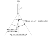
理解を容易にするために、以下の説明では、ラインレーザ光源11から発せられる光(レーザライン)が幅を有しないものとし、レーザパワーをW/mm2ではなくW/mmという単位で評価する。また、図2に示すように、ラインレーザ光源11から発せられる光の減衰は考慮せず、ラインレーザ光源11の発光点からの位置に関わらずエネルギーの総和(発光点から等距離に位置する円弧上のエネルギーの総和)は不変であるとして説明する。
For ease of understanding, in the following description, it is assumed that the light (laser line) emitted from the line
制御・処理部4は、記憶部41を備えている。記憶部41には、レーザ出力の大きさとレーザクラスの関係を対応付けた情報などが保存されている。また、制御・処理部4は、機能ブロックとして、光強度取得部51、最大強度決定部52、及びレーザクラス決定部53を備えている。制御・処理部4は、例えば一般的なパーソナルコンピュータで構成することができ、予めインストールされたラインレーザアレイ装置用プログラム5をプロセッサで実行することによりこれらの機能ブロックが具現化される。また、制御・処理部4には、使用者が適宜の情報を入力するための、キーボードやマウスなどで構成される入力部61と、適宜の情報を表示するための、液晶ディスプレイなどで構成される表示部62が接続されている。
The control/
光強度測定装置7は、ラインレーザアレイ10から発せられるレーザ光の強度を測定するものである。光強度測定装置7には、例えばレーザパワーメーターを用いることができる。
The light
ここで、ラインレーザアレイ10における光の強度分布について説明する。
Here, we explain the light intensity distribution in the
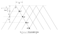
図3に示すように、ラインレーザアレイ10では、各ラインレーザ光源11の発光点から遠ざかるにつれてラインレーザ光の単位面積当たりの強度が低下する一方、より多くのラインレーザ光源11から発せられるラインレーザ光が重なり合って強度が増加する。このように、ラインレーザアレイ10の光照射領域における光の強度分布は複雑であり、従来、ラインレーザアレイ10から発せられる光の最大強度を決定するには、複数のラインレーザ光源11から発せられるラインレーザ光が重なり合う様々な位置で強度を測定しなければならず、その作業に手間と時間がかかるという問題があった。
As shown in FIG. 3, in the
そこで、本発明者は、上記実施形態のラインレーザアレイ10に関するシミュレーションを行った。1つのラインレーザ光源11から発せられた光が他のラインレーザ光源11から発せられた光と重なり合う位置の強度pn(nは着目するラインレーザ光源11以外の光源から発せられたラインレーザ光が重なる数。1≦n≦N-1)を計算した。この強度pnに対して適当なサイズの開口絞りIを乗じることで、各位置におけるレーザ出力を得ることができる。なお、本実施形態ではI=7mmとしたが、JIS C6802に基づき使用条件に応じて適宜に値を変更すればよい。
The inventor therefore performed a simulation of the
ラインレーザ光源11の光軸方向において、ラインレーザ光源11の発光点から2つのラインレーザ光の交点までの長さ(換言すると、各ラインレーザ光源11の発光点を結ぶ直線から2つのラインレーザ光の交点までの距離。以降においても同様)aは次式(1)で表される。

また、同方向における、交点p1から交点p2までの長さも同じく上式(1)で表される(p3~pN-1についても同様)。 The length from intersection point p1 to intersection point p2 in the same direction is also expressed by the above formula (1) (the same applies to p3 to pN-1).
図3に示す各点における光強度p1~p4は、係数aを用いて以下の式(2)~(5)で表される。

上式(2)~(5)を一般化すると、交点pnにおける光強度は次式(6)で表される。

ここで、式(6)に式(1)を代入すると次式(7)となる。

式(7)を整理すると次式(8)となり、更に式(8)を整理すると式(9)となる。

式(9)における変数はP, w, θであるが、このうちP, wは強度pnを定数倍する係数であり、強度pnの変化の態様に影響を及ぼす変数はθのみである。 The variables in equation (9) are P, w, and θ, but P and w are coefficients that multiply the intensity pn by a constant, and the only variable that affects the manner in which the intensity pn changes is θ.
図4~図6は、P=0.1W、w=100mmとし、θを30度、60度、及び90度としたときの各点と光強度pnの関係を表すグラフである。このグラフから分かるように、いずれの発散角の場合でも光強度p1が最大強度であることが分かる。なお、図4~図6では3つの具体的な発散角θについてのグラフを示したが、発散角θが90度以下であれば、他の発散角においても光強度p1が最大強度となることが確認された。つまり、ラインレーザアレイ10のレーザクラス分類を行う際には、ラインレーザ光の交点全ての強度を測定する必要はなく、光強度p1のみを測定し、それから求められる出力p1×Iと、レーザ光源10の出力Pのうち、より大きいものを最大強度としてレーザクラスを分類すればよい。なお、光強度pの単位はW/mmであるが、開口絞りIの単位はmmである(本実施形態ではラインレーザ光が太さを持たない線であると近似している)ため、強度pnに開口絞りIを乗じることによりレーザパワーP(単位W)を得ることができる。
Figures 4 to 6 are graphs showing the relationship between each point and the light intensity pn when P = 0.1W, w = 100mm, and θ = 30 degrees, 60 degrees, and 90 degrees. As can be seen from these graphs, the light intensity p1 is the maximum intensity for any divergence angle. Note that although graphs for three specific divergence angles θ are shown in Figures 4 to 6, it has been confirmed that the light intensity p1 is the maximum intensity for other divergence angles as long as the divergence angle θ is 90 degrees or less. In other words, when classifying the laser class of the
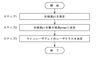
次に、本実施形態のラインレーザアレイ装置1を用いてラインレーザアレイ10のクラスを決定する手順を説明する。図7は、本実施形態のラインレーザアレイ最大強度の決定方法の手順を説明するフローチャートである。
Next, the procedure for determining the class of the
使用者がラインレーザアレイ10を構成する複数のラインレーザ光源11を所定の位置に配置し、入力部61を通じてラインレーザ光源11の位置、間隔w、及び発散角θを入力してラインレーザアレイ10のレーザクラスの決定を指示すると、光強度取得部51は、入力された情報に基づいて2つのラインレーザ光が交わる位置を特定し、その位置に光強度測定装置7を配置して光の強度を測定する。ここでは光強度測定装置7を自動的に移動させたが、使用者が、2つのラインレーザ光が交わる位置に光強度測定装置7を移動させてもよい。光強度測定装置7は移動後の位置において光強度p1を測定する(ステップ1)。
When a user places multiple line
光強度p1が測定されると、最大強度決定部52は、その光強度p1をラインレーザアレイ10の最大強度pmaxとして決定する(ステップ2)。なお、ここでは光強度p1>ラインレーザ光源11の出力Pであることを前提としている。続いて、レーザクラス決定部53は、最大強度pmaxの値を、記憶部41に保存されている、レーザ出力とレーザクラスの関係を対応付けた情報と照合し、ラインレーザアレイ10のクラスを決定する(ステップ3)。
When the light intensity p1 is measured, the maximum
このように、本実施形態のラインレーザアレイ装置1を用いることにより、また本実施形態の方法を用いることにより簡便にラインレーザアレイ10のレーザクラスを決定することができる。なお、上記の説明では光強度測定装置7を用いて光強度を測定したが、光強度取得部51が、使用者が入力したパラメータ値を用いて式(2)から光強度p1を算出するように構成してもよい。これにより、目的とするレーザクラスに属するラインレーザアレイ装置の設計を簡便に行うことができる。ただし、現在のJIS規格の下でレーザクラスを決定するためには、上記のとおり光強度測定装置7を用いて光強度を実際に測定する必要がある。
In this way, by using the line
上記の例では、ラインレーザクラスを決定する手順を説明したが、本実施形態のラインレーザアレイ装置1や方法では、ラインレーザ光源のパラメータ(レーザ出力P、発散角θ)とラインレーザ光源の間隔wのうちの少なくとも1つの値を調整し、所望のレーザクラスに属するラインレーザアレイ10を設計するために用いることもできる。
In the above example, the procedure for determining the line laser class was described, but the line
具体的には、例えば、図1に示した制御・処理部4に加えて(又は制御・処理部4に代えて)、図8に示すような構成を有する制御・処理部8を用いる。
Specifically, for example, in addition to the control/
制御・処理部8は、記憶部81を備えている。記憶部81には、レーザ出力の大きさとレーザクラスの関係を対応付けた情報などが保存されている。また、記憶部81には、ラインレーザ光源の出力P、発散角θ、及びラインレーザ光源の間隔wをパラメータとしてラインレーザアレイの光強度p1を求めるための数式が保存されている。この数式には、例えば上記したものを用いることができる。
The control/
制御・処理部8は、また、機能ブロックとして、レーザクラス入力部91、パラメータ入力部92、及び演算処理部93を備えている。制御・処理部4と同様に、制御・処理部8も、例えば一般的なパーソナルコンピュータで構成することができ、予めインストールされたラインレーザアレイ装置用プログラム9をプロセッサで実行することによりこれらの機能ブロックが具現化される。
The control/
使用者が目的とするレーザクラスに属するラインレーザアレイを設計する手順を図9のフローチャートに示す。 The procedure for a user to design a line laser array that belongs to a desired laser class is shown in the flowchart in Figure 9.
使用者が所定の入力操作によってラインレーザアレイの設計開始を指示すると、レーザクラス入力部91は、設計しようとするラインレーザアレイについて目標とするレーザクラスを入力する画面を表示部62に表示する。
When the user issues an instruction to start designing the line laser array by performing a specified input operation, the laser
使用者がレーザクラスを入力すると(ステップ11)、パラメータ入力部92は、ラインレーザ光源の出力P、発散角θ、及びラインレーザ光源の間隔wを入力する画面を表示部62に表示し、これら3つのパラメータのうちの少なくとも1つを使用者に入力させる(ステップ12)。
When the user inputs the laser class (step 11), the
ここで、使用者が2つのパラメータを入力した場合には、演算処理部93は、記憶部81から上記数式を読み出し、その数式に、使用者が入力したレーザクラスに対応するレーザパワーの最大値と、用者が入力した2つのパラメータの値を入力する。演算処理部93は、こうして残りの1つのパラメータの設定可能範囲の上限値又は下限値を算出し、その結果を表示部62に表示する(ステップ13)。使用者は、表示部62に表示された範囲内で残り1つのパラメータの値を決定することにより、目的とするレーザクラスに属するラインレーザアレイを簡便に設計することができる。
If the user inputs two parameters, the
また、使用者が1つのパラメータをのみ入力した場合にも同様に、演算処理部93は、記憶部81から上記数式を読み出し、その数式に、使用者が入力したレーザクラスに対応するレーザパワーの最大値と、使用者が入力した1つのパラメータの値を入力する。演算処理部93は、こうして残りの2つのパラメータの設定可能範囲を表す関係式を求め、その結果を表示部62に表示する(ステップ13)。使用者は、表示部62に表示された関係式を満たすように残り2つのパラメータの値を決定することにより、目的とするレーザクラスに属するラインレーザアレイを簡便に設計することができる。
Similarly, when the user inputs only one parameter, the
図10は、クラス3Rに属するラインレーザ光源11(レーザ出力P=0.1W、発散角θ=40度)を複数用いてクラス3Rに相当するラインレーザアレイ10を構成しようとする場合の、ラインレーザ光源11の間隔wとレーザ出力の関係を表すグラフである。
Figure 10 is a graph showing the relationship between the spacing w of the line
この例では、クラス3Rに属するラインレーザ光源11を間隔w=10mmで配置すると光強度p1がクラス3Rの最大出力値を超えてしまい、ラインレーザアレイ10をクラス3Bに分類する必要が生じることが分かる。一方、ラインレーザ光源11を15mm間隔あるいは20mm間隔で配置するとクラス3Rに相当するラインレーザアレイ10を設計することができる。このように、使用者が入力したパラメータ値(レーザ出力P、発散角θ、配置間隔wのうちの2つ)と、設計しようとするラインレーザアレイ10のクラスに基づいて残る1つのパラメータ(レーザ出力P、発散角θ、配置間隔wのうちの残りの1つ)が採りうる範囲を決定することができる。
In this example, it can be seen that if the line
図11は、複数のクラス3Rに属するラインレーザ光源11(レーザ出力:0.1W)を間隔w=60mmで配置したラインレーザアレイ10の光強度と、クラス3Bに属する1つのラインレーザ光源(レーザ出力:0.2W)の光強度を比較したものである。図11から分かるように、クラス3Rに属する2本以上のラインレーザ光源11を間隔w=60mmで配置したラインレーザアレイ10を構成することにより、クラス3Bのラインレーザ光源よりも最大強度を小さく抑えてクラス3R相当のラインレーザアレイとしつつ、発光点からの距離の広い範囲で、クラス3Bに属するラインレーザ光源よりも高い強度のラインレーザ光を得ることができる。また、単一のラインレーザ光源を用いるよりも長尺のラインレーザ光を得ることができる。
Figure 11 compares the light intensity of a
上記実施形態では、各ラインレーザ光源11の光軸が平行になるように複数のラインレーザ光源11を配置したラインレーザアレイ10について説明したが、本発明はそのような配置のみに限定されない。
In the above embodiment, a
例えば、隣接するラインレーザ光源の光軸が非平行である場合にも本発明を適用することができる。図12に、2つのラインレーザ光源211、212の光軸が非平行に配置されたラインレーザアレイ20を示す。ラインレーザ光源211、212から発せられるラインレーザ光の長手方向は互いに重なる(図12の紙面に沿ってラインレーザ光を照射する)ように配置されている。
For example, the present invention can also be applied when the optical axes of adjacent line laser light sources are non-parallel. Figure 12 shows a line laser array 20 in which the optical axes of two line
ラインレーザ光源211、212の光軸はそれぞれ図12における上下方向(例えば鉛直方向)からそれぞれφ、-φだけ傾いている。また、ラインレーザ光源211の光照射範囲のうち最もラインレーザ光源212に近い直線と、ラインレーザ光源212の光照射範囲のうち最もラインレーザ光源211に近い直線が角度γをなしている。ここで、γ=2φ+θ≦90度とする。これは、複数のラインレーザ光源を用いる際に想定される一般的な配置を表現したものである。
The optical axes of the line
図12における上下方向において、ラインレーザ光源211、212の発光点から2つのラインレーザ光の交点までの長さa'は次式(10)で表される。

そして、ラインレーザ光源211、212の交点における光強度p1'は次式(11)で表される。
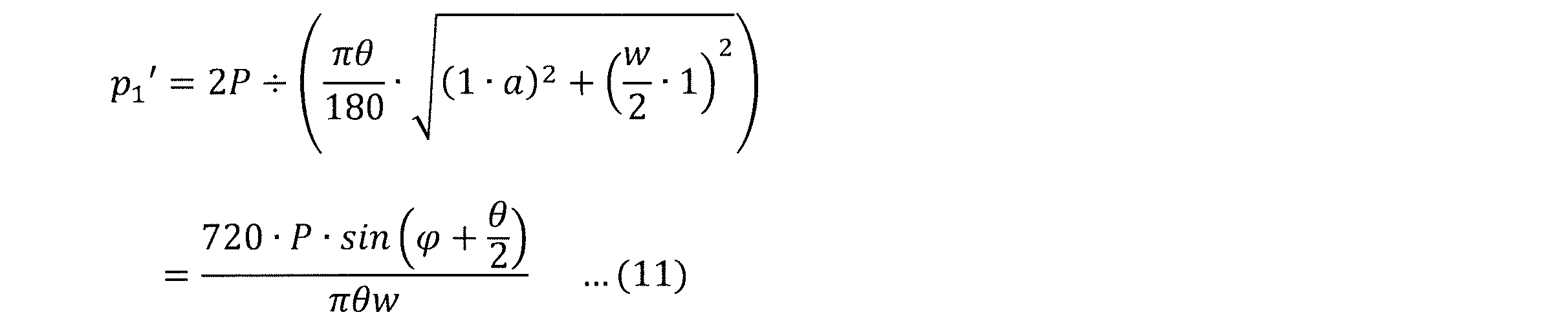
このように、2つの隣接するラインレーザ光源211、212の光軸が互いに傾いている場合でも光強度p1'を取得することによってラインレーザアレイ20のレーザクラスを簡便に決定することができる。
In this way, even if the optical axes of two adjacent line
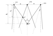
図13に、3つのラインレーザ光源311~313の光軸が非平行に配置されたラインレーザアレイ30を示す。ラインレーザ光源311~313から発せられるラインレーザ光の長手方向は互いに重なるように配置されている。
Figure 13 shows a line laser array 30 in which the optical axes of three line
ラインレーザ光源312の光軸は図13における上下方向(例えば鉛直方向)であり、ラインレーザ光源311、313の光軸はそれぞれ図13における上下方向からそれぞれφ、-φ傾いている。また、ラインレーザ光源311の光照射範囲のうち最もラインレーザ光源313に近い直線と、ラインレーザ光源313の光照射範囲のうち最もラインレーザ光源311に近い直線が角度γをなしている。ここで、γ=2φ+θ≦90度とする。
The optical axis of the line
図13における上下方向(ラインレーザ光源312の光軸方向)において、ラインレーザ光源311、312の発光点から2つのラインレーザ光の交点までの長さa1'は次式(12)で表される。

また、図13における上下方向(ラインレーザ光源312の光軸方向)において、ラインレーザ光源311~313の発光点から3つのラインレーザ光の交点までの長さa2'は次式(13)で表される。

ラインレーザ光源311、312の交点における光強度p1''と、ラインレーザ光源311~313の交点における光強度p2''は次式(14)及び(15)で表される。

上式(14)と(15)の比較を比較すると光強度p1''と光強度p2''の大小関係はp1''>p2''であるため、図13のようなラインレーザアレイ30では光強度p1''を最大出力としてレーザクラスを決定すればよいこと分かる。 Comparing the above formulas (14) and (15), the magnitude relationship between light intensity p1'' and light intensity p2'' is p1''>p2'', so for a line laser array 30 such as that shown in Figure 13, it is clear that the laser class can be determined with light intensity p1'' as the maximum output.
上記実施形態と同様の考え方は、輝度均一レーザについても適用することができる。輝度均一レーザとは、発光点を頂点とする二等辺三角形の底辺にあたる位置の単位長さ当たりの強度が均一であるラインレーザ光源である。 The same concept as in the above embodiment can also be applied to a uniform brightness laser. A uniform brightness laser is a line laser light source in which the intensity per unit length at the base of an isosceles triangle with the light emitting point as the apex is uniform.
複数の輝度均一レーザを組み合わせたラインレーザアレイでは、図3で説明した各位置における強度p1~p4が次式(16)~(19)で表される。
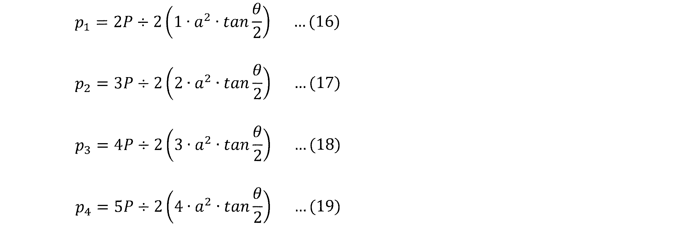
上式(16)~(19)を一般化すると、交点pnにおける光強度は次式(20)で表される。

係数aは式(1)で表されるため、上式(20)は式(21)となる。

式(21)をグラフで表した場合も、上記実施形態で説明した図4~6と同様に、nが大きくなるほど光強度pnが小さくなる。従って、複数の輝度均一レーザを組み合わせたラインレーザアレイについても光強度p1を最大強度とすればよい。 When formula (21) is expressed as a graph, the light intensity pn decreases as n increases, just as in Figures 4 to 6 described in the above embodiment. Therefore, the light intensity p1 can be set as the maximum intensity for a line laser array that combines multiple uniform brightness lasers.
上記の実施形態はいずれも一例であって、本発明の趣旨に沿って適宜に変更することができる。 The above embodiments are merely examples and can be modified as appropriate in accordance with the spirit of the present invention.
上記実施形態では、ラインレーザアレイ10、20、30の最大強度に基づいてレーザクラスを決定したが、JIS規格ではラインレーザアレイについての厳密な規定はないため、レーザクラスを決定することは必須でなく(但し、ラインレーザアレイを販売する場合にはレーザクラスを決定する必要がある)、最大強度を決定するに留めてもよい。
In the above embodiment, the laser class was determined based on the maximum intensity of the
図12及び図13に示した実施形態ではそれぞれ2つのラインレーザ光源21と3つのラインレーザ光源31を組み合わせた例を説明したが、これらの例と同様に(紙面左右方向に)対象に配置された4つ以上のラインレーザ光源を組み合わせたラインレーザアレイ装置に拡張してもよい。また、必要とするラインレーザ光の長さに応じて、図12に示した2つのラインレーザ光源21で構成されたラインレーザアレイ20や図13に示した3つのラインレーザ光源31で構成されたラインレーザアレイ30を複数組用いてラインレーザアレイ装置を構成することもできる。 In the embodiments shown in Figs. 12 and 13, examples of combining two line laser light sources 21 and three line laser light sources 31 have been described, but similar to these examples, it may be expanded to a line laser array device combining four or more line laser light sources arranged symmetrically (in the left-right direction of the paper). Also, depending on the length of the line laser light required, a line laser array device can be configured using multiple sets of a line laser array 20 composed of two line laser light sources 21 shown in Fig. 12 or a line laser array 30 composed of three line laser light sources 31 shown in Fig. 13.
[態様]
上述した例示的な実施形態が以下の態様の具体例であることは、当業者には明らかである。
[Aspects]
It will be apparent to those skilled in the art that the above-described exemplary embodiments are illustrative of the following aspects.
(第1項)
本発明の一態様は、発散角が90度以下である複数の同一のラインレーザ光源を、各ラインレーザ光源の発光点が等間隔となるように、各ラインレーザ光源から発せられるラインレーザ光の長手方向に一直線上に並べて配置することにより構成されたラインレーザアレイから発せられる光の最大強度を決定する方法であって、
隣接して配置された2つのラインレーザ光源から発せられるラインレーザ光が重なり合う範囲内で前記一直線から最も近い位置における光の強度を取得し、
前記ラインレーザ光源の発光点における光の強度と前記取得した光の強度のうち、より大きいものを前記ラインレーザアレイから発せられる光の最大強度として決定する
ことを特徴とする。
(Section 1)
One aspect of the present invention is a method for determining a maximum intensity of light emitted from a line laser array configured by arranging a plurality of identical line laser light sources, each having a divergence angle of 90 degrees or less, in a straight line in a longitudinal direction of line laser light emitted from each line laser light source such that the light emitting points of each line laser light source are equally spaced, the method comprising:
acquiring light intensity at a position closest to the straight line within a range where line laser light emitted from two adjacently arranged line laser light sources overlap;
The method is characterized in that the greater of the light intensity at the light emitting point of the line laser light source and the acquired light intensity is determined as the maximum intensity of the light emitted from the line laser array.
(第5項)
本発明の別の一態様は、発散角が90度以下である複数の同一のラインレーザ光源を、各ラインレーザ光源の発光点が等間隔となるように、各ラインレーザ光源から発せられるラインレーザ光の長手方向に一直線上に並べて配置することにより構成されたラインレーザアレイから発せられる光の最大強度を決定する装置であって、
隣接して配置された2つのラインレーザ光源から発せられるラインレーザ光が重なり合う範囲内で前記一直線から最も近い位置における光の強度を取得する光強度取得部と、
前記ラインレーザ光源の発光点における光の強度と前記取得した光の強度のうち、より大きいものを前記ラインレーザアレイから発せられる光の最大強度として決定する最大強度決定部と
を備えることを特徴とする。
(Section 5)
Another aspect of the present invention is an apparatus for determining a maximum intensity of light emitted from a line laser array configured by arranging a plurality of identical line laser light sources, each having a divergence angle of 90 degrees or less, in a straight line in a longitudinal direction of line laser light emitted from each line laser light source such that the light emitting points of each line laser light source are equally spaced, the apparatus comprising:
a light intensity acquiring unit that acquires light intensity at a position closest to the straight line within a range where line laser light emitted from two adjacently arranged line laser light sources overlap;
and a maximum intensity determination unit that determines the greater of the light intensity at the light emitting point of the line laser light source and the acquired light intensity as the maximum intensity of light emitted from the line laser array.
本発明者は、一般的に用いられている発散角が90度以下であるラインレーザ光源について、複数の同一のラインレーザ光源を、各ラインレーザ光源の発光点が等間隔となるように、各ラインレーザ光源から発せられるラインレーザ光の長手方向に一直線上に並べて配置することにより構成したラインレーザアレイから発せられる光の強度について、種々の条件で検討を行った。その結果、ラインレーザアレイから発せられる光の強度が、隣接配置された2つのラインレーザ光源から発せられるラインレーザ光が重なり合う範囲内で前記一直線から最も近い位置において最大になるという知見を得た。第1項に係るラインレーザアレイの最大強度の決定方法及び第5項に係るラインレーザアレイの最大強度の決定装置はこの知見に基づいてなされたものであり、第1項に係るラインレーザアレイの最大強度の決定方法又は第5項に係るラインレーザアレイの最大強度の決定装置を用いることにより、この位置における光の強度を測定し、ラインレーザ光源の発光点における光の強度と比較するのみで簡便にラインレーザアレイから発せられる光の最大強度を決定することができる。
The inventors have conducted studies under various conditions on the intensity of light emitted from a line laser array, which is constructed by arranging a plurality of identical line laser light sources, each having a divergence angle of 90 degrees, in a straight line in the longitudinal direction of the line laser light emitted from each line laser light source, so that the light emission points of each line laser light source are equally spaced. As a result, the inventors have found that the intensity of light emitted from the line laser array is maximum at the position closest to the straight line within the range where the line laser light emitted from two adjacent line laser light sources overlap. The method for determining the maximum intensity of the line laser array according to
(第2項)
第2項に係るラインレーザアレイの最大強度の決定方法は、第1項に係るラインレーザアレイの最大強度の決定方法において、
さらに、前記光の最大強度を、予め用意された、光の強度とレーザクラスの関係を示す情報に照らして、前記ラインレーザアレイのレーザクラスを決定する。
(Section 2)
The method for determining the maximum intensity of a line laser array according to the second aspect of the present invention is the method for determining the maximum intensity of a line laser array according to the first aspect of the present invention,
Furthermore, the laser class of the line laser array is determined by comparing the maximum light intensity with previously prepared information indicating the relationship between light intensity and laser class.
(第6項)
第6項に係るラインレーザアレイの最大強度の決定装置は、第5項に係るラインレーザアレイの最大強度の決定装置において、さらに、
光の強度とレーザクラスの関係を示す情報が保存された記憶部と、
前記光の最大強度を、前記記憶部に保存された情報に照らして、前記ラインレーザアレイのレーザクラスを決定するレーザクラス決定部と
を備える。
(Section 6)
The device for determining the maximum intensity of a line laser array according to the sixth aspect of the present invention is the device for determining the maximum intensity of a line laser array according to the fifth aspect of the present invention, further comprising:
A storage unit in which information indicating the relationship between light intensity and laser class is stored;
and a laser class determination unit that determines a laser class of the line laser array by comparing the maximum intensity of the light with information stored in the storage unit.
第2項に係るラインレーザアレイの最大強度の決定方法及び第6項に係るラインレーザアレイの最大強度の決定装置では、JIS規格等の所定の規格に定められたレーザクラスを決定することで、使用時に求められる安全性などの情報を得ることができる。
The method for determining the maximum intensity of a line laser array according to
(第3項)
第3項に係るラインレーザアレイの最大強度の決定方法は、第1項又は第2項に係るラインレーザアレイの最大強度の決定方法において、
前記複数のラインレーザ光源が、各ラインレーザ光源から発せられる光の中心軸が平行になるように配置されている。
(Section 3)
A method for determining a maximum intensity of a line laser array according to the third aspect of the present invention is a method for determining a maximum intensity of a line laser array according to the first or second aspect of the present invention, comprising the steps of:
The plurality of line laser light sources are arranged so that the central axes of the light beams emitted from each line laser light source are parallel to each other.
(第4項)
第4項に係るラインレーザアレイの最大強度の決定方法は、第1項又は第2項に係るラインレーザアレイの最大強度の決定方法において、
隣接して配置された2つのラインレーザ光源について、一方のラインレーザ光源の光の照射範囲のうち最も他方のラインレーザ光源に近い直線と、該他方のラインレーザ光源の光の照射範囲のうち最も前記一方のラインレーザ光源に近い直線のなす角が90度以下である。
(Section 4)
A method for determining a maximum intensity of a line laser array according to
For two line laser light sources arranged adjacent to each other, the angle between a straight line that is closest to the other line laser light source within the light irradiation range of one line laser light source and a straight line that is closest to the one line laser light source within the light irradiation range of the other line laser light source is 90 degrees or less.
第1項又は第2項に係るラインレーザアレイの最大強度の決定方法は、第3項に記載のように各ラインレーザ光源から発せられる光の中心軸(光軸)が平行に配置されたラインレーザアレイだけでなく、第4項に記載のように隣接するラインレーザ光源の光軸が互いに傾いて配置されたラインレーザアレイにも用いることができる。
The method for determining the maximum intensity of a line laser array according to
(第7項)
第7項に係るラインレーザアレイの最大強度の決定装置は、第6項に係るラインレーザアレイの最大強度の決定装置において、
前記記憶部に、さらに、前記ラインレーザ光源の出力及び発散角と、前記ラインレーザ光源が配置される間隔をパラメータとして前記光の強度を求める数式が保存されており、
さらに、
目的とするレーザクラスを入力させるレーザクラス入力部と、
前記ラインレーザ光源の出力及び発散角と、前記ラインレーザ光源が配置される間隔のうちの1つ又は2つの値を入力させるパラメータ入力部と、
前記レーザクラスに対応する光の強度及び前記数式を前記記憶部から読み出し、前記パラメータ入力部に入力された値を用いて未入力のパラメータの設定可能範囲を求める演算処理部と
を備える。
(Section 7)
The device for determining the maximum intensity of a line laser array according to the seventh aspect of the present invention is the device for determining the maximum intensity of a line laser array according to the sixth aspect of the present invention,
The storage unit further stores a formula for determining the intensity of the light using the output and divergence angle of the line laser light source and the interval at which the line laser light sources are arranged as parameters,
moreover,
a laser class input unit for inputting a desired laser class;
a parameter input unit for inputting one or two values of the output and divergence angle of the line laser light source and the interval at which the line laser light sources are arranged;
a calculation processing unit that reads out the light intensity and the formula corresponding to the laser class from the storage unit, and determines the settable range of a parameter that has not been input using the value input to the parameter input unit.
第7項に係るラインレーザアレイの最大強度の決定装置では、目的とするレーザクラスと、ラインレーザ光源の出力及び発散角と、前記ラインレーザ光源が配置される間隔のうちの1つ又は2つの値を入力するのみで、簡便にラインレーザアレイを設計することができる。
In the device for determining the maximum intensity of a line laser array according to
1…ラインレーザアレイの最大強度の決定装置(ラインレーザアレイ装置)
10…ラインレーザアレイ
11、111~115、11N…ラインレーザ光源
20…ラインレーザアレイ
21、211、212…ラインレーザ光源
30…ラインレーザアレイ
31、311~313…ラインレーザ光源
4、8…制御・処理部
41、81…記憶部
5、9…ラインレーザアレイ装置用プログラム
51…光強度取得部
52…最大強度決定部
53…レーザクラス決定部
61…入力部
62…表示部
7…光強度測定装置
91…レーザクラス入力部
92…パラメータ入力部
93…演算処理部
1...Device for determining maximum intensity of line laser array (line laser array device)
10...
Claims (7)
隣接して配置された2つのラインレーザ光源から発せられるラインレーザ光が重なり合う範囲内で前記一直線から最も近い位置における光の強度を取得し、
前記ラインレーザ光源の発光点における光の強度と前記取得した光の強度のうち、より大きいものを前記ラインレーザアレイから発せられる光の最大強度として決定する
ことを特徴とする、ラインレーザアレイの最大強度の決定方法。 A method for determining a maximum intensity of light emitted from a line laser array configured by arranging a plurality of identical line laser light sources, each having a divergence angle of 90 degrees or less, in a straight line in a longitudinal direction of line laser light emitted from each line laser light source such that the light emitting points of each line laser light source are equally spaced, comprising:
acquiring light intensity at a position closest to the straight line within a range where line laser light emitted from two adjacently arranged line laser light sources overlap;
A method for determining the maximum intensity of a line laser array, characterized in that the greater of the light intensity at the light emitting point of the line laser light source and the acquired light intensity is determined as the maximum intensity of light emitted from the line laser array.
ことを特徴とする、請求項1に記載のラインレーザアレイの最大強度の決定方法。 The method for determining the maximum intensity of a line laser array as described in claim 1, further comprising determining the laser class of the line laser array by comparing the maximum intensity of the light with information indicating a relationship between light intensity and laser class that has been prepared in advance.
ことを特徴とする、請求項1に記載のラインレーザアレイの最大強度の決定方法。 The method for determining the maximum intensity of a line laser array according to claim 1 , wherein the plurality of line laser light sources are arranged so that the central axes of the light emitted from each line laser light source are parallel to each other.
ことを特徴とする、請求項1に記載のラインレーザアレイの最大強度の決定方法。 2. The method for determining the maximum intensity of a line laser array as described in claim 1, characterized in that for two adjacently arranged line laser light sources, an angle between a straight line that is closest to the other line laser light source within the light irradiation range of one line laser light source and a straight line that is closest to the one line laser light source within the light irradiation range of the other line laser light source is 90 degrees or less.
隣接して配置された2つのラインレーザ光源から発せられるラインレーザ光が重なり合う範囲内で前記一直線から最も近い位置における光の強度を取得する光強度取得部と、
前記ラインレーザ光源の発光点における光の強度と前記取得した光の強度のうち、より大きいものを前記ラインレーザアレイから発せられる光の最大強度として決定する最大強度決定部と
を備えることを特徴とする、ラインレーザアレイの最大強度の決定装置。 A device for determining the maximum intensity of light emitted from a line laser array configured by arranging a plurality of identical line laser light sources, each having a divergence angle of 90 degrees or less, in a straight line in a longitudinal direction of the line laser light emitted from each line laser light source such that the light emitting points of each line laser light source are equally spaced, comprising:
a light intensity acquiring unit that acquires light intensity at a position closest to the straight line within a range where line laser light emitted from two adjacently arranged line laser light sources overlap;
a maximum intensity determination unit that determines the greater of the light intensity at the light emitting point of the line laser light source and the acquired light intensity as the maximum intensity of light emitted from the line laser array.
光の強度とレーザクラスの関係を示す情報が保存された記憶部と、
前記光の最大強度を、前記記憶部に保存された情報に照らして、前記ラインレーザアレイのレーザクラスを決定するレーザクラス決定部と
を備えることを特徴とする、請求項5に記載のラインレーザアレイの最大強度の決定装置。 moreover,
A storage unit in which information indicating the relationship between light intensity and laser class is stored;
The device for determining the maximum intensity of a line laser array as described in claim 5, further comprising: a laser class determination unit that determines a laser class of the line laser array by comparing the maximum intensity of the light with information stored in the memory unit.
さらに、
目的とするレーザクラスを入力させるレーザクラス入力部と、
前記ラインレーザ光源の出力及び発散角と、前記ラインレーザ光源が配置される間隔のうちの1つ又は2つの値を入力させるパラメータ入力部と、
前記レーザクラスに対応する光の強度及び前記数式を前記記憶部から読み出し、前記パラメータ入力部に入力された値を用いて未入力のパラメータの設定可能範囲を求める演算処理部と
を備えることを特徴とする、請求項6に記載のラインレーザアレイの最大強度の決定装置。 The storage unit further stores a formula for determining the intensity of the light using the output and divergence angle of the line laser light source and the interval at which the line laser light sources are arranged as parameters,
moreover,
a laser class input unit for inputting a desired laser class;
a parameter input unit for inputting one or two values of the output and divergence angle of the line laser light source and the interval at which the line laser light sources are arranged;
7. The device for determining the maximum intensity of a line laser array as described in claim 6, further comprising: a calculation processing unit that reads out the light intensity and the formula corresponding to the laser class from the memory unit, and uses the values input to the parameter input unit to determine the settable range of uninputted parameters.
Priority Applications (2)
| Application Number | Priority Date | Filing Date | Title |
|---|---|---|---|
| JP2025012411A JP7686897B1 (en) | 2025-01-28 | 2025-01-28 | Method and apparatus for determining maximum intensity of line laser array |
| PCT/JP2026/000663 WO2026163800A1 (en) | 2025-01-28 | 2026-01-13 | Method and device for determining maximum intensity of line laser array |
Applications Claiming Priority (1)
| Application Number | Priority Date | Filing Date | Title |
|---|---|---|---|
| JP2025012411A JP7686897B1 (en) | 2025-01-28 | 2025-01-28 | Method and apparatus for determining maximum intensity of line laser array |
Publications (2)
| Publication Number | Publication Date |
|---|---|
| JP7686897B1 true JP7686897B1 (en) | 2025-06-02 |
| JP2026128240A JP2026128240A (en) | 2026-08-07 |
Family
ID=95895087
Family Applications (1)
| Application Number | Title | Priority Date | Filing Date |
|---|---|---|---|
| JP2025012411A Active JP7686897B1 (en) | 2025-01-28 | 2025-01-28 | Method and apparatus for determining maximum intensity of line laser array |
Country Status (2)
| Country | Link |
|---|---|
| JP (1) | JP7686897B1 (en) |
| WO (1) | WO2026163800A1 (en) |
Citations (3)
| Publication number | Priority date | Publication date | Assignee | Title |
|---|---|---|---|---|
| JP2002176007A (en) * | 2000-12-08 | 2002-06-21 | Mitsubishi Electric Corp | Method and apparatus for measuring laser power of laser processing device |
| CN212658422U (en) * | 2020-08-26 | 2021-03-05 | 中国科学院西安光学精密机械研究所 | Semiconductor laser cavity surface optical catastrophe damage peak power testing device |
| CN113466960A (en) * | 2021-05-21 | 2021-10-01 | 山东威鼎航检测设备有限公司 | Method, system and equipment for detecting foreign matters on airport road |
-
2025
- 2025-01-28 JP JP2025012411A patent/JP7686897B1/en active Active
-
2026
- 2026-01-13 WO PCT/JP2026/000663 patent/WO2026163800A1/en active Pending
Patent Citations (3)
| Publication number | Priority date | Publication date | Assignee | Title |
|---|---|---|---|---|
| JP2002176007A (en) * | 2000-12-08 | 2002-06-21 | Mitsubishi Electric Corp | Method and apparatus for measuring laser power of laser processing device |
| CN212658422U (en) * | 2020-08-26 | 2021-03-05 | 中国科学院西安光学精密机械研究所 | Semiconductor laser cavity surface optical catastrophe damage peak power testing device |
| CN113466960A (en) * | 2021-05-21 | 2021-10-01 | 山东威鼎航检测设备有限公司 | Method, system and equipment for detecting foreign matters on airport road |
Also Published As
| Publication number | Publication date |
|---|---|
| JP2026128240A (en) | 2026-08-07 |
| WO2026163800A1 (en) | 2026-08-06 |
Similar Documents
| Publication | Publication Date | Title |
|---|---|---|
| US11777276B2 (en) | Semiconductor light emitting array with phase modulation regions for generating beam projection patterns | |
| US11637409B2 (en) | Semiconductor light-emitting module and control method therefor | |
| US6618123B2 (en) | Range-finder, three-dimensional measuring method and light source apparatus | |
| EP4331768A2 (en) | Laser line illumination | |
| US20200322590A1 (en) | Cross-render multiview camera, system, and method | |
| CN106932853B (en) | Light guide plate design method, light guide plate, mesh point distribution method and lighting device | |
| JP2003043266A (en) | Light guide plate for surface light emitting device | |
| CN1529830A (en) | Diffraction Shaping of Intensity Distribution of Spatial Partially Coherent Beams | |
| Chen et al. | Design a freeform microlens array module for any arbitrary-shape collimated beam shaping and color mixing | |
| RU2632254C2 (en) | Lighting device | |
| KR20220052262A (en) | Waveguide structure with segmented diffractive optical elements and near-eye display apparatus employing the same | |
| JP2009543143A (en) | Apparatus for homogenizing light and laser apparatus for generating a linear intensity distribution on the work surface | |
| JPWO2018151097A1 (en) | Diffusion element | |
| US11486790B2 (en) | Laser measuring system | |
| KR20120039747A (en) | Optical system for generating a light beam for treating a substrate | |
| JP7048897B2 (en) | Optical components, light source devices and irradiation systems | |
| JP3340296B2 (en) | Distortion inspection method and distortion inspection device | |
| CN116457706B (en) | Microarray type diffusion plate | |
| US20250180898A1 (en) | Metalens used for beam shaping, beam-shaping system and generating method thereof | |
| TW201626115A (en) | Optical component | |
| KR100493141B1 (en) | A method for automatic designing patterns of light guide plate and systems thereof | |
| CN113064231A (en) | Method, system and related equipment for designing distribution of dots on light guide plate | |
| EP4063935B1 (en) | Diffractive optical element capable of being used for projecting oblique line, projection apparatus, and design method therefor | |
| TW201827863A (en) | Free-from surface lighting system | |
| JP2017091957A (en) | Lighting environment simulation method, lighting environment simulation apparatus, and program |
Legal Events
| Date | Code | Title | Description |
|---|---|---|---|
| A621 | Written request for application examination |
Free format text: JAPANESE INTERMEDIATE CODE: A621 Effective date: 20250206 |
|
| A871 | Explanation of circumstances concerning accelerated examination |
Free format text: JAPANESE INTERMEDIATE CODE: A871 Effective date: 20250206 |
|
| TRDD | Decision of grant or rejection written | ||
| A01 | Written decision to grant a patent or to grant a registration (utility model) |
Free format text: JAPANESE INTERMEDIATE CODE: A01 Effective date: 20250430 |
|
| A61 | First payment of annual fees (during grant procedure) |
Free format text: JAPANESE INTERMEDIATE CODE: A61 Effective date: 20250521 |
|
| R150 | Certificate of patent or registration of utility model |
Ref document number: 7686897 Country of ref document: JP Free format text: JAPANESE INTERMEDIATE CODE: R150 |