JP7686868B1 - bar cutting machine - Google Patents

bar cutting machine Download PDF

Info

Publication number
JP7686868B1
JP7686868B1 JP2024188526A JP2024188526A JP7686868B1 JP 7686868 B1 JP7686868 B1 JP 7686868B1 JP 2024188526 A JP2024188526 A JP 2024188526A JP 2024188526 A JP2024188526 A JP 2024188526A JP 7686868 B1 JP7686868 B1 JP 7686868B1
Authority
JP
Japan
Prior art keywords
bar
feed
vice
supply
scrap
Prior art date
Legal status (The legal status is an assumption and is not a legal conclusion. Google has not performed a legal analysis and makes no representation as to the accuracy of the status listed.)
Active
Application number
JP2024188526A
Other languages
Japanese (ja)
Inventor
隆志 岡本
孝明 白水
Current Assignee (The listed assignees may be inaccurate. Google has not performed a legal analysis and makes no representation or warranty as to the accuracy of the list.)
Noritake Co Ltd
Original Assignee
Noritake Co Ltd
Priority date (The priority date is an assumption and is not a legal conclusion. Google has not performed a legal analysis and makes no representation as to the accuracy of the date listed.)
Filing date
Publication date
Application filed by Noritake Co Ltd filed Critical Noritake Co Ltd
Priority to JP2024188526A priority Critical patent/JP7686868B1/en
Application granted granted Critical
Publication of JP7686868B1 publication Critical patent/JP7686868B1/en
Active legal-status Critical Current
Anticipated expiration legal-status Critical

Links

Images

Landscapes

  • Sawing (AREA)

Abstract

Figure 0007686868000001

【課題】後端端材とされるような短い棒材であっても切断機に供給可能な供給装置、および、かかる供給装置を備える棒材切断機を提供する。
【解決手段】送込バイス18の開口120の開口幅W2が端材23の直径W1より小さくされた状態で、持上げ部114により端材23を送込バイス18の上方に移載されるので、開口120の上端部において端材23が支持される。その後、送込バイス18の開口120の開口幅W2が徐々に大きくされ、それにともなって端材23が徐々に下降するので、送込バイス18の開口120の開口幅W2が端材23の直径W1より大きくなった際に端材23が第2ローラ85に向かって落下するときの高さを可及的小さくすることができ、送込バイス18に与える衝撃を小さくすることができる。
【選択図】図8

Figure 0007686868000001

A supply device capable of supplying even short bar material such as rear end scrap to a cutting machine, and a bar cutting machine equipped with such a supply device are provided.
[Solution] With the opening width W2 of the opening 120 of the feed vice 18 made smaller than the diameter W1 of the scrap material 23, the lifting section 114 transfers the scrap material 23 to above the feed vice 18, so that the scrap material 23 is supported at the upper end of the opening 120. Thereafter, the opening width W2 of the opening 120 of the feed vice 18 is gradually increased, and the scrap material 23 gradually descends accordingly, so that when the opening width W2 of the opening 120 of the feed vice 18 becomes larger than the diameter W1 of the scrap material 23, the height from which the scrap material 23 falls towards the second roller 85 can be made as small as possible, and the impact on the feed vice 18 can be reduced.
[Selected figure] Figure 8

Description

本発明は、丸材、管材、異形材などの長手状の棒材を切断するために、棒材切断機構にその棒材を定寸送りする棒材切断機に関し、棒材の後端端材を短縮する技術に関する。 The present invention relates to a bar cutting machine that feeds long bar material such as round bar material, tubular bar material, and irregular shaped bar material to a bar cutting mechanism at a fixed length in order to cut the bar material, and to a technology for shortening the rear end of the bar material.

棒材を送込バイスで把持しつつその軸心方向に所定の切断長ずつ送り込む送込装置と、その送り込まれた棒材を丸鋸の両側に跨がる主バイスで把持し、その棒材を丸鋸を用いて軸心に垂直に切断する切断機とを備えた棒材切断機が知られている。かかる棒材切断機は、上記送込装置により棒材を所定の長さ寸法(切断長)だけ送り込み、次いで上記切断機に備えられた薄手の丸鋸により切断するという工程を繰り返すことにより、1本の棒材から上記切断長の複数の部品に切断加工する。1本の棒材のうちの切断残りの長さが既定値よりも短くなると、後端端材として製品とは別に振り分けられ、廃棄処分される。 There is a known bar cutting machine that includes a feed device that holds the bar in a feed vice and feeds it in along its axis at a specified cutting length, and a cutter that holds the fed bar in a main vice that straddles both sides of the circular saw and cuts the bar perpendicular to its axis using the circular saw. This bar cutting machine cuts a single bar into multiple parts of the cut length by repeating the process of feeding the bar a specified length (cutting length) using the feed device and then cutting it with a thin circular saw provided in the cutter. When the remaining cut length of a single bar becomes shorter than the specified value, it is sorted out as a rear end scrap separately from the product and disposed of.

かかる後端端材の発生に関し、特許文献1においては、主バイスのうち、入側バイスと送側バイスとを一体として動作可能とすることなどにより、発生する後端端材の大きさを可及的小さくする技術が開示されている。 Regarding the generation of such trailing edge scraps, Patent Document 1 discloses a technique for minimizing the size of the trailing edge scraps generated by, for example, making it possible for the entry and delivery vises of the main vice to operate as a single unit.

特開2016-032857号公報JP 2016-032857 A

しかしながら、特許文献1においては、主バイスや送側バイスを対応した形状にしたり、それらの動きを制御する必要があり、機構が複雑化するなどの課題があった。 However, in Patent Document 1, it was necessary to give the main vice and the feed side vice corresponding shapes and to control their movements, which led to problems such as a complicated mechanism.

また、発生する後端端材を利用する方法として、切断した鋼材の排出口側から端材を挿入して送込バイスで挟み込ませることで、端材をさらに所望の長さに切断することで、発生する端材を可及的短いものとする技術も検討されている。しかしながら、かかる技術においては、切断装置の排出口側に後端端材を挿入するための追加の機構が必要となり、装置が大型化したり、それにともない装置全体のコストが高くなるなどの課題があった。 As a method of utilizing the scraps generated, a technology has been considered in which the scraps are inserted from the outlet side of the cut steel and clamped in a feeding vice, which then cuts them to the desired length, making the scraps as short as possible. However, this technology requires an additional mechanism for inserting the scraps on the outlet side of the cutting device, which increases the size of the device and therefore the overall cost of the device.

本発明は、以上の事情を背景として為されたものであり、その目的とするところは、切断機により生じた端材を、送込装置に供給することのできる供給機構を有する棒材切断機を提供することにある。 The present invention was made against the background of the above circumstances, and its purpose is to provide a bar cutting machine having a supply mechanism that can supply scrap material generated by the cutting machine to a feed device.

上記目的を達成するための本発明の要旨とするところは、(a)棒材の長手方向に沿って往復駆動され、前記棒材を切断位置へ向かって所定の切断長ずつ送り込む送込バイスを有する送込装置と、前記棒材の軸心方向に垂直に前記棒材を切断する切断装置と、前記棒材を前記送込バイスに供給する供給装置とを備える棒材切断機であって、(b)前記供給装置は、複数の前記棒材を予め設定された供給待機位置へ向かって並列方向に整列させる供給部と、前記複数の棒材のうちの前記供給待機位置に到達した一本の棒材を前記送込バイスの上方に移動させる移載部を含み、(c)前記移載部により前記棒材を前記送込バイスの上方に移載する際には、前記送込バイスは、前記送込バイスの開口の開口幅を前記棒材の直径より小さいものとするとともに、前記棒材が前記開口に位置した後に前記開口幅を徐々に大きくすること、を特徴とする。 The gist of the present invention for achieving the above-mentioned object is (a) a bar cutting machine comprising: a feed device having a feed vice that is driven to reciprocate along the longitudinal direction of the bar and feeds the bar material toward a cutting position by a predetermined cutting length at a time; a cutting device that cuts the bar material perpendicular to the axial direction of the bar material; and a feed device that supplies the bar material to the feed vice, (b) the feed device includes a feed section that aligns a plurality of the bar materials in a parallel direction toward a preset feed standby position, and a transfer section that moves one of the plurality of bar materials that has reached the feed standby position above the feed vice, and (c) when the transfer section transfers the bar material above the feed vice, the feed vice has an opening width that is smaller than the diameter of the bar material, and gradually increases the opening width after the bar material is positioned in the opening.

本発明の棒材切断機によれば、送込バイスの開口の開口幅が前記棒材の直径より小さくされた状態で、前記移載部により前記棒材を前記送込バイスの上方に移載されるので、前記開口の上端部において前記棒材が支持される。その後、前記送込バイスの開口の開口幅が徐々に大きくされ、それにともなって前記棒材が徐々に下降するので、送込バイスの開口の開口幅が前記棒材の直径より大きくなった際に前記棒材が落下するときの高さを可及的小さくすることができ、送込バイスに与える衝撃を小さくすることができる。 According to the bar cutter of the present invention, the bar is transferred to the upper part of the feed vice by the transfer unit in a state in which the opening width of the opening of the feed vice is made smaller than the diameter of the bar, so that the bar is supported at the upper end of the opening. After that, the opening width of the feed vice is gradually increased, and the bar gradually descends accordingly, so that the height from which the bar falls when the opening width of the feed vice becomes larger than the diameter of the bar can be made as small as possible, and the impact on the feed vice can be reduced.

ここで、好適には、(d)前記移載部は前記送込バイスに隣接して設けられ、(e)前記移載部の上面は、前記送込バイス方向に向かうに従って下降する傾斜面を有する。これにより、前記棒材は前記移載部の上面である傾斜面を前記送込バイスに向かって転動することができる。 Here, preferably, (d) the transfer loading section is provided adjacent to the feed vice, and (e) the upper surface of the transfer loading section has an inclined surface that descends toward the feed vice. This allows the bar material to roll along the inclined surface that is the upper surface of the transfer loading section toward the feed vice.

また、好適には、前記供給装置は、前記移載部が移載することのできる棒材よりも長さの長い長手状の棒材を送込位置に供給する第2の移載手段を有する。前記移載部と第2の移載手段を有することにより、第2の移載手段によって供給することが困難になった、相対的に長さの短い棒材を前記供給装置により供給することができる。 Preferably, the supply device has a second transfer means for supplying, to the feed position, a longitudinal bar material that is longer than the bar material that can be transferred by the transfer unit. By having the transfer unit and the second transfer means, the supply device can supply relatively short bar material that would be difficult to supply by the second transfer means.

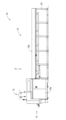
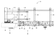
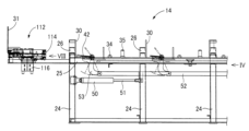
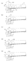
本発明の一実施例である棒材切断機の要部を示す正面図である。1 is a front view showing a main part of a bar cutter according to an embodiment of the present invention; 図1の棒材切断機における棒材供給装置の一部をカバーを取り外した状態で矢印IIで示す方向から見た平面図である。2 is a plan view of a part of the bar feeder in the bar cutter of FIG. 1 with a cover removed, as viewed in the direction indicated by the arrow II. FIG. 図1の棒材切断機における棒材供給装置の一部をカバーを取り外した状態で示す正面図である。2 is a front view showing a part of the bar feeder in the bar cutter of FIG. 1 with a cover removed. FIG. 図1の棒材切断機における棒材供給装置による棒材の供給を説明する図であり、図3のIV方向から見た図である。4 is a view for explaining supply of a bar by a bar supplying device in the bar cutting machine of FIG. 1, as viewed from the direction IV of FIG. 3. FIG. 図1の棒材切断機をそのカバーを取り外して矢印Vで示す方向から見た側面図である。FIG. 2 is a side view of the bar cutter of FIG. 1 with its cover removed, as viewed in the direction indicated by the arrow V. 図1の棒材切断機における送り込み装置の一部を送り込み方向に垂直な方向である図2のVI方向から見た図である。6 is a view showing a part of the feed device in the bar sawing machine of FIG. 1 as seen from the VI direction of FIG. 2, which is a direction perpendicular to the feed direction. 図1の棒材切断機における送込バイスを図6のVII方向から見た断面図である。7 is a cross-sectional view of the feed vice in the bar cutter of FIG. 1 as viewed from the VII direction of FIG. 6. 図1の棒材切断機における端材供給装置による端材の供給を説明する図であり、図3のVIII方向から見た図である。8 is a diagram for explaining the supply of scraps by the scrap supply device in the bar cutter of FIG. 1, as viewed from the VIII direction of FIG. 3. FIG.

以下、本発明の好適な実施例を図面に基づいて詳細に説明する。 The following describes in detail a preferred embodiment of the present invention with reference to the drawings.

図1は、本発明の一実施例である棒材切断機10を示す正面図である。図1に示すように、かかる棒材切断機10は、丸鋼、角鋼、鋼管などの金属製被切断材である棒材22(図5などを参照。)の一部を把持する送込バイス18(図7など参照。)を備え、その送込バイス18で把持されたその棒材22をその軸心方向に所定の切断長ずつ送り込む送込装置16及びその棒材22をその切断長にて切断する切断装置20を備えた本体部12と、複数本の棒材22を載置した状態で備えつつそれらの棒材22を逐一上記送込バイス18により把持され得る位置すなわち棒材22を軸心方向に所定の切断長ずつ送り込む送込装置16の送込位置Aに供給する棒材供給装置14とから構成されている。 Figure 1 is a front view of a bar cutter 10 according to an embodiment of the present invention. As shown in Figure 1, the bar cutter 10 is equipped with a feed vice 18 (see Figure 7, etc.) that holds a part of a bar 22 (see Figure 5, etc.) made of metal such as round steel, square steel, or steel pipe, and is composed of a main body 12 equipped with a feed device 16 that feeds the bar 22 held by the feed vice 18 in the axial direction at a predetermined cutting length and a cutting device 20 that cuts the bar 22 at the cutting length, and a bar feed device 14 that holds a plurality of bars 22 and feeds them one by one to a position where they can be held by the feed vice 18, that is, to a feed position A of the feed device 16 that feeds the bar 22 in the axial direction at a predetermined cutting length.

図2は、図1において矢印IIで示す方向から見た平面図であり、、また、図3は、図1の棒材切断機10のカバー10a、10bを外して、その棒材供給装置14を拡大して示す図であり、図2において矢印IIIで示す方向から見た図である。棒材供給装置14は、図2および図3に詳しく示すように、棒材供給装置14に載置された棒材22(図4における二点鎖線で示された棒材22)を供給待機位置B(図4参照)に転動させる供給レール26を複数備えている。複数の供給レール26は相互に平行であるとともに、供給待機位置Bに近づくほど鉛直方向下側になるようにそれぞれ傾斜させられている。これにより、供給レール26上に載置された棒材22は、重力によって供給待機位置Bまで転動し、後述するストッパ部材30により供給待機位置Bで停止させられる。なお、図2および図3においては、棒材供給装置14のうち切断装置20側が示されているが、省略された部分においても、同様の機構が設けられている。なお、棒材供給装置14は、本発明の第2の移載手段に相当する。 2 is a plan view seen from the direction indicated by the arrow II in FIG. 1, and FIG. 3 is an enlarged view of the bar feeder 14 of the bar cutter 10 of FIG. 1 with the covers 10a and 10b removed, seen from the direction indicated by the arrow III in FIG. 2. As shown in detail in FIGS. 2 and 3, the bar feeder 14 has a plurality of feed rails 26 that roll the bar 22 (the bar 22 shown by the two-dot chain line in FIG. 4) placed on the bar feeder 14 to the supply standby position B (see FIG. 4). The plurality of feed rails 26 are parallel to each other, and are inclined so that they are vertically downward as they approach the supply standby position B. As a result, the bar 22 placed on the feed rails 26 rolls to the supply standby position B by gravity, and is stopped at the supply standby position B by a stopper member 30 described later. In addition, in Figures 2 and 3, the cutting device 20 side of the bar material supplying device 14 is shown, but the omitted part also has a similar mechanism. The bar material supplying device 14 corresponds to the second transfer means of the present invention.

図3に示すように、棒材供給装置14は、油圧シリンダ50がもうけられている。油圧シリンダ50は基台24に固設され、図示しない油圧供給装置から供給される油圧により作動する。油圧供給装置が供給する油圧は、図示しない油圧制御装置によって制御される。油圧シリンダ50にはロッド51が連結されており、油圧シリンダ50の往復運動を伝達部材52に伝達する。伝達部材52は複数のリンク部材53に連結されており、リンク部材53はそれぞれ、伝達部材52との連結部分において回動可能とされている。リンク部材53はまた、跳ね板42に連結されている。一方、跳ね板42は基台24のうち棒材22の搬送方向(長さ方向)に設けられた一対の梁25に掛け渡された回転軸43を中心に回動可能とさせられている。これらの機構により、油圧シリンダ50の直線往復運動は、跳ね板42の回転軸43を中心とした回転方向の往復回動運動に変換される。 As shown in FIG. 3, the bar material supplying device 14 is provided with a hydraulic cylinder 50. The hydraulic cylinder 50 is fixed to the base 24 and is operated by hydraulic pressure supplied from a hydraulic supplying device (not shown). The hydraulic pressure supplied by the hydraulic supplying device is controlled by a hydraulic control device (not shown). A rod 51 is connected to the hydraulic cylinder 50, and transmits the reciprocating motion of the hydraulic cylinder 50 to a transmission member 52. The transmission member 52 is connected to a plurality of link members 53, and each of the link members 53 is rotatable at the connection portion with the transmission member 52. The link member 53 is also connected to the spring plate 42. Meanwhile, the spring plate 42 is rotatable around a rotation axis 43 that is hung across a pair of beams 25 provided on the base 24 in the transport direction (length direction) of the bar material 22. With these mechanisms, the linear reciprocating motion of the hydraulic cylinder 50 is converted into a reciprocating rotational motion in the rotation direction around the rotation axis 43 of the spring plate 42.

また、棒材供給装置14は、案内ローラー34および35が設けられている。これら案内ローラー34および35はそれぞれ、送込位置Aに位置させられた棒材22が送込バイス18により移動させられる際に棒材22の案内を行う。図2における一点鎖線は、送り込み位置Aに位置させられた棒材22が切断装置20に送り込まれた際に切断装置の丸鋸94が接触させられる位置を示している。 The bar feeder 14 is also provided with guide rollers 34 and 35. These guide rollers 34 and 35 guide the bar 22 positioned at the feed position A when the bar 22 is moved by the feed vice 18. The dashed line in FIG. 2 indicates the position where the circular saw 94 of the cutting device comes into contact with the bar 22 positioned at the feed position A when it is fed into the cutting device 20.

図4は、棒材供給装置14において棒材22が供給待機位置Bから送込位置Aまで供給される様子を説明する図である。棒材供給装置14において、供給レール26の供給待機位置B側の端部には、供給レール26に連なるようにストッパ部材30が設けられている。ストッパ部材30は凹字形状を有する板材からなっている。ストッパ部材30の供給レール26側の端面31はその下部が供給レール26と当接させられるとともに、上部は供給レール26から立ち上がるものとされている。これにより供給レール26を転動する棒材22を供給待機位置Bで停止させる。 Figure 4 is a diagram illustrating how the bar 22 is supplied from the supply standby position B to the feed position A in the bar supply device 14. In the bar supply device 14, a stopper member 30 is provided at the end of the supply rail 26 on the supply standby position B side so as to be connected to the supply rail 26. The stopper member 30 is made of a plate material having a concave shape. The lower part of the end face 31 on the supply rail 26 side of the stopper member 30 is abutted against the supply rail 26, and the upper part rises from the supply rail 26. This stops the bar 22 rolling on the supply rail 26 at the supply standby position B.

図4を用いて、棒材供給装置14における棒材22の供給待機位置Bから送込位置Aまで供給される作動を説明する。まず、供給待機位置Bにある棒材22は、前述のとおり、供給レール26の下端(図4における左端)において、ストッパ部材30の端面31によって止まっている。一方、跳ね板40は水平の状態とされている。続いて、油圧シリンダ50がロッド51を引き込む方向に作動させられると、跳ね板40が立ち上がる方向に回転軸43回りに回動する。このとき、跳ね板40は、図4における供給待機位置Bにある棒材22が供給レール26と接する位置よりも右側まで右端部42が伸びている。そのため、跳ね板40の立ち上がりにともなって、供給待機位置Bにあった棒材22は、跳ね板40により供給レール26から持ち上げられる。このとき、跳ね板40の上面41は、跳ね板40が立ち上がった状態において、前記供給レール26と同様に、送込位置Aに向かうほど下に向かう傾斜が付けられている。そのため、供給レールから持ち上げられた棒材22は、当初ストッパ部材30の端面31に支えられつつ持ち上げられる。そして、跳ね板40の立ち上がりにともなって、棒材22が端面31を超えて持ち上げられると(図4のB1位置)、跳ね板40の上面41の傾斜により送込位置A側、すなわち、図4の左側に向かって、跳ね板40の上面41を転動する(図4のB2位置)。 The operation of supplying the bar material 22 from the supply standby position B to the feed position A in the bar material supply device 14 will be described with reference to FIG. 4. First, the bar material 22 at the supply standby position B is stopped by the end face 31 of the stopper member 30 at the lower end (left end in FIG. 4) of the supply rail 26 as described above. Meanwhile, the spring plate 40 is in a horizontal state. Next, when the hydraulic cylinder 50 is operated in a direction to retract the rod 51, the spring plate 40 rotates around the rotation axis 43 in a direction in which it rises. At this time, the right end 42 of the spring plate 40 extends to the right of the position where the bar material 22 at the supply standby position B in FIG. 4 contacts the supply rail 26. Therefore, as the spring plate 40 rises, the bar material 22 at the supply standby position B is lifted from the supply rail 26 by the spring plate 40. At this time, the upper surface 41 of the spring plate 40 is inclined downward toward the feed position A, similar to the supply rail 26, when the spring plate 40 is in a raised state. Therefore, the bar 22 lifted from the supply rail is initially supported by the end surface 31 of the stopper member 30 while being lifted. Then, as the spring plate 40 rises, the bar 22 is lifted above the end surface 31 (position B1 in FIG. 4), and the inclination of the upper surface 41 of the spring plate 40 causes the bar 22 to roll on the upper surface 41 of the spring plate 40 toward the feed position A, i.e., the left side in FIG. 4 (position B2 in FIG. 4).

凹形状を有するストッパ部材30において、端面31と反対側(図の左側)の立ち上がりは、端面31側の立ち上がりよりも高くされている。そのため、跳ね板40の上面41を転動した棒材22は、端面31と反対側の立ち上がりの内側面33に当たって、転動が停止させられる。その後、シリンダ50により跳ね板40が水平状態に戻されると、棒材22は、跳ね板40の上面41とストッパ部材30の内側面33とに接しつつ、凹形状のストッパ部材30の凹部に向かって下降させられ、ローラ34上に載置されて、送り込み位置Aに位置させられる。 In the stopper member 30 having a concave shape, the rising edge on the opposite side to the end face 31 (the left side in the figure) is made higher than the rising edge on the end face 31 side. Therefore, the bar 22 that rolls on the upper surface 41 of the spring plate 40 hits the inner surface 33 of the rising edge on the opposite side to the end face 31 and stops rolling. After that, when the spring plate 40 is returned to a horizontal state by the cylinder 50, the bar 22 is lowered toward the recess of the concave stopper member 30 while contacting the upper surface 41 of the spring plate 40 and the inner surface 33 of the stopper member 30, and is placed on the roller 34 and positioned at the feed position A.

なお、立ち上がった跳ね板40によって供給待機位置Bにあった棒材22が持ち上げられると、供給レール26上において、当該供給待機位置Bにあった棒材22に隣接していた棒材22が供給レール26上を供給レール26の傾斜に従って転動するが、跳ね板40が立ち上がっている間は跳ね板40の右端部42によってそれ以上の転動が阻止される一方、跳ね板40が水平状態に戻されると、ストッパ部材30の端面31に接するまで供給レール26上をさらに転動し、供給待機位置Bに位置させられる。 When the bar 22 that was in the supply standby position B is lifted by the raised spring plate 40, the bar 22 adjacent to the bar 22 that was in the supply standby position B on the supply rail 26 rolls on the supply rail 26 in accordance with the inclination of the supply rail 26. However, while the spring plate 40 is raised, the right end 42 of the spring plate 40 prevents further rolling. On the other hand, when the spring plate 40 is returned to a horizontal state, the bar 22 rolls further on the supply rail 26 until it comes into contact with the end face 31 of the stopper member 30, and is positioned at the supply standby position B.

図5は、図1の棒材切断機10のカバー10aを取り外して矢印Vで示す方向から見た側面図である。この図に示すように、上記本体部12は、基台38と、その基台38上に設けられた送込装置16と、同じくその基台38上に設けられた切断装置20と、その切断装置20による切断に際して棒材22を把持固定するための主バイス90とから構成されている。主バイス90は油圧シリンダ98を含んで構成される。上記切断装置20は、上記基台38上に設けられた支承部92と、その支承部92の取付軸まわりに回動可能に設けられたアーム部材93と、そのアーム部材93に自転可能に設けられた薄手の丸鋸94と、その丸鋸94を回転駆動するための丸鋸用モータ95と、上記丸鋸94と丸鋸用モータ95とを連結するベルト96とを含む。また、切断装置20は丸鋸移動装置21を含んで構成される。
丸鋸移動装置21は、丸鋸94を棒材22に向かって或いは棒材22とは反対側へ移動させるために、基台38の上面に固定された回転支持部材105と、丸鋸94を支持する切断装置20のアーム部材93の上部に固定された回転支持部材106とを、相互に接近離隔するように駆動する。具体的には、丸鋸移動装置21は、回転支持部材105により回動中心C3まわりの回動可能に支持された中空円筒状の支持部材107と、その支持部材107の軸心と略同心のボールネジ状の回転出力軸を有して、支持部材107の回転支持部材106とは反対側の端部に固設された電気駆動式のサーボモータ108と、一端部が上記ボールネジ回転出力軸の外周側に螺合されつつ支持部材107の内周面により軸心方向の移動可能に且つ軸心まわりの回転不能に支持され、他端部が支持部材106により上記回動中心C3に平行な回動中心C4まわりの回動可能に支持された円筒状の軸方向移動部材109とを備えている。この丸鋸移動装置21は、サーボモータ108を作動させて、アーム部材93の上部に回転支持部材106を介して連結された軸方向移動部材109をその軸心方向すなわち図5の矢印d方向へ移動させることにより、アーム部材93を図5の支承部92回りに傾動させる。ここで、図5は、上記切断装置20が最も送込装置16側に回動した状態を示しており、その切断装置20は、棒材22を切断する際には送込装置16に接近する方向に回動させられ、一旦切断が終わるとその送込装置16から離隔する方向に復動させられる。
Fig. 5 is a side view of the bar cutter 10 of Fig. 1 with the cover 10a removed, as viewed from the direction indicated by the arrow V. As shown in this figure, the main body 12 is composed of a base 38, a feed device 16 provided on the base 38, a cutting device 20 also provided on the base 38, and a main vice 90 for gripping and fixing the bar 22 when the cutting device 20 cuts the bar 22. The main vice 90 is composed of a hydraulic cylinder 98. The cutting device 20 includes a support 92 provided on the base 38, an arm member 93 provided rotatably around the mounting axis of the support 92, a thin circular saw 94 provided rotatably on the arm member 93, a circular saw motor 95 for rotating the circular saw 94, and a belt 96 connecting the circular saw 94 and the circular saw motor 95. The cutting device 20 is also composed of a circular saw moving device 21.
The circular saw moving device 21 drives a rotating support member 105 fixed to the upper surface of the base 38 and a rotating support member 106 fixed to the upper part of the arm member 93 of the cutting device 20 that supports the circular saw 94 to move closer to and away from each other in order to move the circular saw 94 toward or away from the bar 22. Specifically, the circular saw moving device 21 comprises a hollow cylindrical support member 107 supported by a rotating support member 105 so as to be rotatable around a rotation center C3, an electrically driven servo motor 108 having a ball screw-shaped rotation output shaft that is approximately concentric with the axis of the support member 107 and fixed to the end of the support member 107 opposite the rotating support member 106, and a cylindrical axial moving member 109 having one end screwed to the outer periphery of the ball screw rotation output shaft and supported by the inner surface of the support member 107 so as to be movable in the axial direction but not rotatable around the axis, and the other end supported by the support member 106 so as to be rotatable around a rotation center C4 parallel to the rotation center C3. The circular saw moving device 21 tilts the arm member 93 about the support 92 in Fig. 5 by operating a servo motor 108 to move an axially moving member 109 connected to the upper part of the arm member 93 via a rotary support member 106 in the axial direction, i.e., in the direction of arrow d in Fig. 5. Fig. 5 shows a state in which the cutting device 20 has been rotated to the furthest position toward the feed device 16. When cutting the bar 22, the cutting device 20 is rotated in a direction approaching the feed device 16, and once cutting is completed, it is returned in a direction away from the feed device 16.

図6は、図2における矢印VIで示す方向から見た、送込装置16の側面図である。図6に示すように、送込装置16は、その軸心方向が送込装置16の送込方向と並行となるように且つその軸心まわりに回転可能に基台58に架設されたボールネジ66と、同様にその軸心方向が送込装置16の送込方向と並行となるように基台58に固設された1対の案内レール68と、互いに平行な軸心を有する1対の摺動部70及びネジ穴64を有し、その1対の摺動部70に上記1対の案内レール68が挿入されてその案内レール68の軸心方向に移動可能に設けられると共に、上記ネジ穴64において上記ボールネジ66に螺合させられた可動部材72と、その可動部材72に設けられた送込バイス18と、上記ボールネジ66を回転駆動するための送込装置用モータ60と、そのボールネジ50と送込装置用モータ60とを連結するベルト62とを備えて構成されている。また、基台58には第1ローラ84が、上記可動部材724には第2ローラ85がそれぞれの軸心まわりに回転可能に設けられており、棒材22は、それら第1ローラ84及び第2ローラ85に支持された状態で搬送される。 Figure 6 is a side view of the feeding device 16 as viewed from the direction indicated by arrow VI in Figure 2. As shown in FIG. 6, the feed device 16 is configured to include a ball screw 66 mounted on a base 58 so that its axial direction is parallel to the feed direction of the feed device 16 and rotatable around its axial center, a pair of guide rails 68 fixed to the base 58 so that their axial direction is parallel to the feed direction of the feed device 16, a pair of sliding parts 70 having parallel axes and a screw hole 64, the pair of guide rails 68 are inserted into the pair of sliding parts 70 so as to be movable in the axial direction of the guide rails 68, and a movable member 72 screwed onto the ball screw 66 in the screw hole 64, a feed vice 18 provided on the movable member 72, a feed device motor 60 for rotating the ball screw 66, and a belt 62 connecting the ball screw 50 and the feed device motor 60. In addition, a first roller 84 is provided on the base 58, and a second roller 85 is provided on the movable member 724 so as to be rotatable about their respective axes, and the bar 22 is transported while being supported by the first roller 84 and the second roller 85.

棒材切断機10には、送込装置16及び切断装置20に所定の油圧を供給するための図示しない油圧制御回路と、丸鋸用モータ95及び送込装置用モータ60の駆動を制御すること及び上記油圧制御回路における図示しない電磁弁の切換を制御することにより送込装置16及び切断装置20の駆動を制御する図示しない電子制御装置が設けられている。上記送込装置用モータ60が駆動されると、上記ベルト62を介してその駆動力が上記ボールネジ66に伝達されてそのボールネジ66が軸心まわりに回転駆動されることにより、そのボールネジ66に螺合させられた上記可動部材72が送込方向すなわち上記ボールネジ66及び1対の案内レール68に共通の軸心方向に移動させられる。ここで、送込装置用モータ60は、電子制御装置に接続されたエンコーダを備えたサーボモータである。 The bar shearing machine 10 is provided with a hydraulic control circuit (not shown) for supplying a predetermined hydraulic pressure to the feed device 16 and the cutting device 20, and an electronic control device (not shown) for controlling the driving of the circular saw motor 95 and the feed device motor 60, and for controlling the switching of an electromagnetic valve (not shown) in the hydraulic control circuit to control the driving of the feed device 16 and the cutting device 20. When the feed device motor 60 is driven, the driving force is transmitted to the ball screw 66 via the belt 62, and the ball screw 66 is rotated around its axis, so that the movable member 72 screwed to the ball screw 66 is moved in the feed direction, i.e., in the direction of the axis common to the ball screw 66 and the pair of guide rails 68. Here, the feed device motor 60 is a servo motor equipped with an encoder connected to the electronic control device.

送込バイス18の可動部材72は、送込装置用モータ60が有するエンコーダによって、その位置を検出することが可能となっており、上記可動部材72が切断装置20側の移動限界から送込装置用モータ60側の移動限界までの範囲内を移動させられるように送込装置用モータ60の駆動が制御される。 The position of the movable member 72 of the feed vice 18 can be detected by an encoder provided in the feed device motor 60, and the drive of the feed device motor 60 is controlled so that the movable member 72 can be moved within a range from the movement limit on the cutting device 20 side to the movement limit on the feed device motor 60 side.

主バイス90は、棒材22を第1挟圧部材との間で図5および図6における下向きに挟圧するための第1油圧シリンダ98と、第2挟圧部材との間で図5における左向き(図6における紙面奥行き方向)に挟圧するための第2油圧シリンダ102とから構成されている。それら第1油圧シリンダ98及び第2油圧シリンダ102の作動油圧は上記油圧制御回路を介して供給されており、その油圧に応じて棒材22の把持と解放とが切り換えられる。ここで、上記第1挟圧部材、第2油圧シリンダ102のピストン、及び第2挟圧部材における丸鋸94の経路に対応する部分には、その丸鋸94の回転を妨げないようにそれぞれ溝部が形成されている。 The main vice 90 is composed of a first hydraulic cylinder 98 for clamping the bar 22 downward in Figs. 5 and 6 between the first clamping member and a second hydraulic cylinder 102 for clamping the bar 22 leftward in Fig. 5 (in the depth direction of the paper in Fig. 6) between the first clamping member and the second clamping member. The hydraulic pressure of the first hydraulic cylinder 98 and the second hydraulic cylinder 102 is supplied via the hydraulic control circuit, and the bar 22 is gripped or released depending on the hydraulic pressure. Here, grooves are formed in the first clamping member, the piston of the second hydraulic cylinder 102, and the part of the second clamping member that corresponds to the path of the circular saw 94 so as not to interfere with the rotation of the circular saw 94.

図7は、送込装置16の可動部を図6における矢印VIIで示す方向から見た断面図である。この図に示すように、可動部材72に設けられた送込バイス18は、第3挟圧部材74と第3油圧シリンダ76との間で棒材22を挟圧する構成とされている。その第3油圧シリンダ76の作動油圧は油圧制御回路を介して供給されており、その油圧に応じて棒材22の把持と解放とが切り換えられる。その棒材22が把持された状態で送込装置用モータ60が駆動させられて可動部材72が移動させられると、把持された棒材22はその可動部材72と同じ距離だけ搬送される。 Figure 7 is a cross-sectional view of the movable part of the feed device 16, seen from the direction indicated by the arrow VII in Figure 6. As shown in this figure, the feed vice 18 provided on the movable member 72 is configured to clamp the bar 22 between a third clamping member 74 and a third hydraulic cylinder 76. The operating oil pressure of the third hydraulic cylinder 76 is supplied via a hydraulic control circuit, and the bar 22 is switched between being gripped and released depending on the oil pressure. When the feed device motor 60 is driven with the bar 22 gripped and the movable member 72 is moved, the gripped bar 22 is transported the same distance as the movable member 72.

また、図7に示すように、送込バイス18に備えられた第3油圧シリンダ76は、可動部材72に固設されたシリンダ本体77と、そのシリンダ本体77の内部を往復させられるピストン81と、そのピストン81の先端に固設された挟圧ヘッド80とから構成されている。そのように構成された第3油圧シリンダ76では、上記シリンダ本体77とピストン81との間隙である油室に作動油が供給されると、上記ピストン81及びその先端に設けられた挟圧ヘッド80が第3挟圧部材74との間で棒材22を挟圧する方向に移動させられる。その際、上記シリンダ本体77に形成された貫通穴に上記案内軸78が挿入されていることから、上記挟圧ヘッド80の挟圧面83が上記ピストン81の往復方向に対して略垂直に保たれる。 As shown in FIG. 7, the third hydraulic cylinder 76 provided in the feed vice 18 is composed of a cylinder body 77 fixed to the movable member 72, a piston 81 that reciprocates inside the cylinder body 77, and a clamping head 80 fixed to the tip of the piston 81. In the third hydraulic cylinder 76 thus configured, when hydraulic oil is supplied to the oil chamber, which is the gap between the cylinder body 77 and the piston 81, the piston 81 and the clamping head 80 provided at its tip are moved in a direction to clamp the bar 22 between the third clamping member 74. At that time, since the guide shaft 78 is inserted into the through hole formed in the cylinder body 77, the clamping surface 83 of the clamping head 80 is kept approximately perpendicular to the reciprocating direction of the piston 81.

ところで、このような構成を有する棒材切断機10においては、棒材22の送り込みと切断とを繰り返すが、一本の棒材22の切断残りの長さが規定値よりも短くなると、端材として廃棄されていた。この規定値は、主バイス90と送込バイス18とのそれぞれの棒材22の押さえ幅などに基づいて定まる。 In a bar cutting machine 10 having such a configuration, the bar 22 is repeatedly fed and cut, but when the remaining length of a bar 22 becomes shorter than a specified value, it is discarded as scrap material. This specified value is determined based on the clamping width of the bar 22 of the main vice 90 and the feed vice 18, etc.

このような端材は、切断機10に供給される棒材22に比べて長さが短いため、例えば、前述の跳ね板40の設置間隔では複数の跳ね板40でバランスよく持ち上げることが困難であったり、あるいは、送込バイス18やストッパ部材30の凹部32に落とし込む際に、落下時の衝撃により跳ねてしまうなどするため、前記棒材供給装置14などによって送込装置16に供給することが困難である。 Since such scraps are shorter than the bar material 22 supplied to the cutting machine 10, it is difficult to lift them in a balanced manner using multiple spring plates 40 at the installation intervals of the spring plates 40 described above, or they bounce due to the impact of being dropped into the feed vice 18 or the recess 32 of the stopper member 30, making it difficult to supply them to the feed device 16 using the bar material supply device 14, etc.

本実施例の棒材切断機10においては、前述の棒材供給装置14に加え、端材供給装置112を含む。図2および図3に示すように、端材供給装置112は、供給スロープ113、持ち上げ部114、および、昇降装置116を含んで構成されている。また、供給レール26のうち、最も切断装置20に近い側2本には、スロープ設置用梁118が設けられており、供給スロープ113は、例えば図2に示すように、最も切断装置20に近い供給レール26とスロープ設置用梁118とに支持されて設けられる。そのため、供給スロープ113は、前述の供給レール26が送込装置16に向かって下方に傾斜するのと略等しい勾配で傾斜している。このようにして構成される供給スロープ113によれば、2本の供給レール26の間隔に満たない端材23であっても供給待機位置Bに位置させることが可能となる。この端材供給装置112が本発明の移載部に対応し、供給スロープ113が供給部に対応する。 The bar cutting machine 10 of this embodiment includes a scrap material supplying device 112 in addition to the bar material supplying device 14 described above. As shown in Figures 2 and 3, the scrap material supplying device 112 is configured to include a supply slope 113, a lifting section 114, and a lifting device 116. In addition, a slope installation beam 118 is provided on the two supply rails 26 closest to the cutting device 20, and the supply slope 113 is supported by the supply rail 26 closest to the cutting device 20 and the slope installation beam 118, as shown in Figure 2, for example. Therefore, the supply slope 113 is inclined at a gradient approximately equal to the gradient of the supply rail 26 described above, which slopes downward toward the feed device 16. With the supply slope 113 configured in this way, even scrap material 23 that does not fill the gap between the two supply rails 26 can be positioned at the supply standby position B. This scrap material supplying device 112 corresponds to the transfer section of the present invention, and the supply slope 113 corresponds to the supply section.

供給スロープ113に載置された端材23は、供給スロープ113の傾斜により、送込装置16側に転動する。一方、供給スロープ113の送込装置16側には、供給スロープ113に連続して持ち上げ部114が設けられている。この持ち上げ部114は後述する昇降装置116により昇降可能であり、持ち上げ部114が下限位置にある場合においては、持ち上げ部114の上面114aは、供給スロープ113から連続する斜面を形成する(後述する図8(a)参照)。持ち上げ部114の上面に設けられた斜面114aが、本発明の傾斜面に相当する。さらに、持ち上げ部114の送込装置16側には、棒材22(端材23)の送り込み方向に伸びる壁部115が設けられている。これにより、供給スロープ113および持ち上げ部114の上面を転動する端材23を止めることができ、端材23が送込装置16に転がり込んだり、送込バイス18に衝突したりすることが防止できる。持ち上げ部114の端材23の軸方向長さと、持ち上げる端材23の長さとの関係は、棒材22よりも短い端材23を持ち上げた際に、端材23の長さが持ち上げ部114の端材23の軸方向長さに対して短すぎてバランスを崩して回転したり落下したりすることの無いように設定される。あるいは、端材23の長さが持ち上げ部114の端材23の軸方向長さに対して長すぎて、端材23の一部のみを持ち上げるのみで、後述するように間隙120に送り込めないことが生じないように設定される。 The scrap material 23 placed on the supply slope 113 rolls toward the feed device 16 due to the inclination of the supply slope 113. On the other hand, a lifting section 114 is provided on the feed device 16 side of the supply slope 113, continuing from the supply slope 113. This lifting section 114 can be raised and lowered by a lifting device 116 described later, and when the lifting section 114 is in the lower limit position, the upper surface 114a of the lifting section 114 forms a slope continuing from the supply slope 113 (see FIG. 8(a) described later). The slope 114a provided on the upper surface of the lifting section 114 corresponds to the inclined surface of the present invention. Furthermore, a wall section 115 extending in the feed direction of the bar material 22 (scrap material 23) is provided on the feed device 16 side of the lifting section 114. This stops the scrap 23 rolling on the top surface of the supply slope 113 and the lifting section 114, and prevents the scrap 23 from rolling into the feed device 16 or colliding with the feed vice 18. The relationship between the axial length of the scrap 23 of the lifting section 114 and the length of the scrap 23 to be lifted is set so that when a scrap 23 shorter than the bar 22 is lifted, the length of the scrap 23 is not too short relative to the axial length of the scrap 23 of the lifting section 114, causing the scrap 23 to lose balance and rotate or fall. Alternatively, the relationship is set so that the length of the scrap 23 is not too long relative to the axial length of the scrap 23 of the lifting section 114, causing only a portion of the scrap 23 to be lifted and unable to be fed into the gap 120, as described below.

壁部115は、その上面に、送込装置16側に向かって下降する傾斜面115aを有している。この傾斜面115aは、その傾斜面115aの延長線上に、送込バイス18の第3挟圧部材74と挟圧ヘッド80との間の間隙120が位置するように設けられている。なお、端材23が傾斜面115aを転動した後に間隙120に転がり込む際の挙動が安定するよう、板状の壁部115に対して、傾斜面115aは図8に示すように、送込装置16側に迫り出すように設けられてもよい。傾斜面115aも本発明の傾斜面に相当する。 The wall portion 115 has an inclined surface 115a on its upper surface that descends toward the feed device 16. This inclined surface 115a is provided so that the gap 120 between the third clamping member 74 and the clamping head 80 of the feed vice 18 is located on the extension line of the inclined surface 115a. Note that the inclined surface 115a may be provided on the plate-shaped wall portion 115 so as to protrude toward the feed device 16 as shown in FIG. 8, so that the behavior of the scrap material 23 when it rolls into the gap 120 after rolling over the inclined surface 115a is stabilized. The inclined surface 115a also corresponds to the inclined surface of the present invention.

昇降装置116は、例えば油圧シリンダであり、架台24に固定して設けられる。このとき、昇降装置116は、例えば油圧シリンダのピストンが上下方向に移動可能に設置され、ピストンが持ち上げ部114に連結されることで、持ち上げ部114の上下動がピストンの上下動により実現される。昇降装置116としての油圧シリンダに対し、電子制御装置からの指示に基づいて油圧制御回路から油圧が供給されることで、適切なタイミングで昇降装置116、ひいては持ち上げ部114が上下動させられる。 The lifting device 116 is, for example, a hydraulic cylinder, and is fixed to the stand 24. In this case, the lifting device 116 is installed such that, for example, the piston of the hydraulic cylinder can move in the vertical direction, and the piston is connected to the lifting section 114, so that the lifting section 114 moves up and down by the up and down movement of the piston. Hydraulic pressure is supplied to the hydraulic cylinder serving as the lifting device 116 from a hydraulic control circuit based on instructions from an electronic control device, so that the lifting device 116, and therefore the lifting section 114, can be moved up and down at the appropriate timing.

図8は、端材供給装置112による端材23の送込バイス18への供給作動を説明する図である。まず、図8(a)においては、持ち上げ部114はその上下動における下端に位置している。かかる下端に位置した持ち上げ部114は、供給スロープ113とともに傾斜面を形成している。供給スロープ113に載置された端材23はその傾斜に沿って、送込装置16側に転動し、壁部115によって停止させられる。また、図8(a)においては、送込バイス18における第3挟圧部材74と挟圧ヘッド80との間の間隙120の幅W2(図7参照)は、端材23の幅W1よりも狭いものとされている。 Figure 8 is a diagram illustrating the operation of the scrap material supply device 112 to supply scrap material 23 to the feed vice 18. First, in Figure 8 (a), the lifting portion 114 is located at the lower end of its vertical movement. The lifting portion 114 located at the lower end forms an inclined surface together with the supply slope 113. The scrap material 23 placed on the supply slope 113 rolls along the inclination toward the feed device 16 and is stopped by the wall portion 115. Also, in Figure 8 (a), the width W2 (see Figure 7) of the gap 120 between the third clamping member 74 and the clamping head 80 in the feed vice 18 is narrower than the width W1 of the scrap material 23.

その後、持ち上げ部114が昇降装置116により上昇させられる。このとき、持ち上げ部114の端材23の断面方向の幅は、端材23の半径以上とされているので、持ち上げ部114が上昇させられることで、端材23を上方に持ち上げることができる。端材23は、持ち上げ部114の上面の傾斜のため、送込装置16方向(図8の左下方向)へ転動しようとする一方、その転動が壁部115によって阻止されている状態であるので、持ち上げ部114を上昇させることで端材23を壁部115に沿って持ち上げることができる。 Then, the lifting section 114 is raised by the lifting device 116. At this time, the width of the lifting section 114 in the cross-sectional direction of the scrap material 23 is set to be equal to or greater than the radius of the scrap material 23, so that the scrap material 23 can be lifted upward by raising the lifting section 114. The scrap material 23 attempts to roll toward the feed device 16 (toward the lower left in FIG. 8) due to the inclination of the upper surface of the lifting section 114, but this rolling is prevented by the wall section 115. Therefore, by raising the lifting section 114, the scrap material 23 can be lifted along the wall section 115.

図8(b)は、持ち上げ部114が昇降装置116により上昇させられ、その上下動における上端に位置した状態である。このとき、図8(b)に示すように、持ち上げ部114の上面である傾斜面の下端(図8における左端)の高さと、隣接する壁部115の上面の傾斜面115aの高さとが一致する状態となるので、持ち上げ部114によって持ち上げられた端材23は壁部115を乗り越えて、壁部115の上面である傾斜面115aに移動し、転動する。図8(b)においても、送込バイス18における間隙120の幅W2は、端材23の幅W1よりも狭いものとされている。 Figure 8(b) shows the state in which the lifting section 114 has been raised by the lifting device 116 and is at the top end of its up-down movement. At this time, as shown in Figure 8(b), the height of the lower end (left end in Figure 8) of the inclined surface that is the upper surface of the lifting section 114 matches the height of the inclined surface 115a on the upper surface of the adjacent wall section 115, so the scrap material 23 lifted by the lifting section 114 climbs over the wall section 115 and moves to and rolls on the inclined surface 115a that is the upper surface of the wall section 115. In Figure 8(b) as well, the width W2 of the gap 120 in the feed vice 18 is narrower than the width W1 of the scrap material 23.

図8(c)は、傾斜面115a上を転動した端材23が、送込バイス18上に達した状態を示している。かかる状態に達する際には、端材23は傾斜面115aの端部から送込バイス18に転がり落ちることとなるが、傾斜面115aの端部の高さと、第3挟圧部材74あるいは挟圧ヘッド80上端の高さとの差を微小とすることで、送込バイス18上に着地する際の衝撃をわずかにすることができる。また、図8(c)においても、送込バイス18における間隙120の幅W2は、端材23の幅W1よりも狭いものとされている。そのため、間隙120上に達した端材23は、第3挟圧部材74および挟圧ヘッド80の上端部に支持されて留まる。 Figure 8 (c) shows the state where the scrap material 23 that has rolled on the inclined surface 115a has reached the feed vice 18. When the scrap material 23 reaches this state, it rolls down from the end of the inclined surface 115a into the feed vice 18, but by making the difference between the height of the end of the inclined surface 115a and the height of the upper end of the third clamping member 74 or the clamping head 80 small, the impact when it lands on the feed vice 18 can be made small. Also, in Figure 8 (c), the width W2 of the gap 120 in the feed vice 18 is narrower than the width W1 of the scrap material 23. Therefore, the scrap material 23 that has reached the gap 120 is supported and held by the upper ends of the third clamping member 74 and the clamping head 80.

図8(d)は、送込バイス18における間隙120の幅W2が、図8(a)~(c)よりも大きくなるよう変化させられた場合を示している。しかしながら、間隙120の幅W2は、端材23の幅W1よりも狭いものとされている。その結果、端材23の位置は図8(c)に示す場合よりもわずかに下降するが、ひきつづき、端材23は、第3挟圧部材74および挟圧ヘッド80の上端部に支持されている。また、図8(d)においては、持ち上げ部114が下端位置まで移動させられている。図8(b)~(c)で示すように持ち上げ部114が上昇している間は、次に供給待機位置Bに至る端材23は、上昇している持ち上げ部114により供給スロープ113の下端部で転動が阻止されていたが、図8(d)に示すように持ち上げ部114が下端位置に戻されると、前記端材23は壁部115に当接するまで転動し、供給待機位置Bに到達する。 Figure 8(d) shows a case where the width W2 of the gap 120 in the feed vice 18 is changed to be larger than that in Figures 8(a) to 8(c). However, the width W2 of the gap 120 is narrower than the width W1 of the scrap 23. As a result, the position of the scrap 23 is slightly lower than that shown in Figure 8(c), but the scrap 23 continues to be supported by the upper end of the third clamping member 74 and the clamping head 80. Also, in Figure 8(d), the lifting portion 114 is moved to the lower end position. While the lifting portion 114 is rising as shown in Figures 8(b) to 8(c), the scrap 23 that will next reach the supply standby position B is prevented from rolling at the lower end of the supply slope 113 by the rising lifting portion 114. However, when the lifting portion 114 is returned to the lower end position as shown in Figure 8(d), the scrap 23 rolls until it abuts against the wall portion 115 and reaches the supply standby position B.

図8(e)は、送込バイス18における間隙120の幅W2が、図8(d)よりもさらに大きくなって、間隙120の幅W2が、端材23の幅W1と等しい、もしくは僅かに大きくなった状態を示している。かかる状態においては、端材23は送り込み位置Aに達する。言い換えれば、送込バイス18の第3挟圧部材74および挟圧ヘッド80間の底部にある第2ローラ85に接することとなる。 Figure 8 (e) shows a state in which the width W2 of the gap 120 in the feed vice 18 is even larger than in Figure 8 (d), and the width W2 of the gap 120 is equal to or slightly larger than the width W1 of the scrap material 23. In this state, the scrap material 23 reaches the feed position A. In other words, it comes into contact with the second roller 85 at the bottom between the third clamping member 74 and the clamping head 80 of the feed vice 18.

ここで、本実施例の端材供給装置112によれば、端材23をバランスを崩す事無く持ち上げることができる。さらに、送込バイス18を、第3挟圧部材74および挟圧ヘッド80間の間隙120の幅W2が端材23の直径W1よりも小さい状態として、第3挟圧部材74および挟圧ヘッド80の上端部で端材23を一旦支持し、間隙120の幅W2を徐々に広げることで、端材23が送込バイス18に着地する際の高さを可及的に小さくすることができるので、送込バイス18に与える衝撃を可及的に小さくすることができる。 Here, according to the scrap material supplying device 112 of this embodiment, the scrap material 23 can be lifted without losing balance. Furthermore, by setting the feeding vice 18 in a state in which the width W2 of the gap 120 between the third clamping member 74 and the clamping head 80 is smaller than the diameter W1 of the scrap material 23, and temporarily supporting the scrap material 23 at the upper end of the third clamping member 74 and the clamping head 80, and gradually widening the width W2 of the gap 120, the height at which the scrap material 23 lands on the feeding vice 18 can be made as small as possible, and therefore the impact on the feeding vice 18 can be made as small as possible.

本実施例の端材供給装置112、あるいは、端材供給装置112を備える棒材切断機10によれば、送込バイス18の開口120の開口幅W2が端材23の直径W1より小さくされた状態で、持上げ部114により端材23を送込バイス18の上方に移載されるので、開口120の上端部において端材23が支持される。その後、送込バイス18の開口120の開口幅W2が徐々に大きくされ、それにともなって端材23が徐々に下降するので、送込バイス18の開口120の開口幅W2が端材23の直径W1より大きくなった際に端材23が第2ローラ85に向かって落下するときの高さを可及的小さくすることができ、送込バイス18に与える衝撃を小さくすることができる。 According to the scrap supplying device 112 of this embodiment, or the bar cutter 10 equipped with the scrap supplying device 112, the scrap 23 is transferred to above the feed vice 18 by the lifting section 114 in a state in which the opening width W2 of the opening 120 of the feed vice 18 is made smaller than the diameter W1 of the scrap 23, so that the scrap 23 is supported at the upper end of the opening 120. Thereafter, the opening width W2 of the opening 120 of the feed vice 18 is gradually increased, and the scrap 23 gradually descends accordingly, so that the height at which the scrap 23 falls toward the second roller 85 when the opening width W2 of the opening 120 of the feed vice 18 becomes larger than the diameter W1 of the scrap 23 can be made as small as possible, and the impact on the feed vice 18 can be reduced.

また、本実施例の端材供給装置112、あるいは、端材供給装置112を備える棒材切断機10によれば、端材供給装置112は送込バイス18に対して端材の送り込み方向に垂直な向きに隣接して設けられ、持ち上げ部114の上面114aおよび壁部115の上面115a、送込バイス18に向かうに従って下降する傾斜面を有するので、端材23はかかる傾斜面を送込バイス18に向かって転動することができる。 In addition, according to the scrap material supplying device 112 of this embodiment, or the bar cutting machine 10 equipped with the scrap material supplying device 112, the scrap material supplying device 112 is disposed adjacent to the feed vice 18 in a direction perpendicular to the feed direction of the scrap material, and the upper surface 114a of the lifting portion 114 and the upper surface 115a of the wall portion 115 have a sloping surface that descends toward the feed vice 18, so that the scrap material 23 can roll along this sloping surface toward the feed vice 18.

また、本実施例の端材供給装置112、あるいは、端材供給装置112を備える棒材切断機10によれば、棒材切断機10は、端材供給装置112に加え、端材供給装置112の持ち上げ部114が持ち上げることのできる端材23よりも長さの長い長手状の棒材22を送込位置Aに供給する棒材供給装置14を有するので、棒材供給装置14によって供給することが困難になった、相対的に長さの短い端材23を端材供給装置112により供給することができる。 In addition, according to the scrap material supplying device 112 of this embodiment, or the bar cutting machine 10 equipped with the scrap material supplying device 112, the bar cutting machine 10 has, in addition to the scrap material supplying device 112, a bar material supplying device 14 that supplies to the feed position A a longitudinal bar material 22 that is longer than the scrap material 23 that can be lifted by the lifting part 114 of the scrap material supplying device 112, so that the scrap material 23 that is relatively short in length and that would be difficult to supply by the bar material supplying device 14 can be supplied by the scrap material supplying device 112.

以上、本発明の好適な実施例を図面に基づいて詳細に説明したが、本発明はこれに限定されるものではなく、更に別の態様においても実施される。 The above describes in detail a preferred embodiment of the present invention based on the drawings, but the present invention is not limited to this and may be implemented in other forms.

例えば、前述の実施例では、切断工具として丸鋸20が用いられていたが、他の形式の切断工具、たとえば鋸歯が直線状である棒状の金鋸が用いられていてもよい。 For example, in the above embodiment, a circular saw 20 was used as the cutting tool, but other types of cutting tools, such as a rod-shaped hacksaw with straight saw teeth, may also be used.

また、前述の実施例のスロープ板113に関して、板状のものに限定されない。例えば棒材供給装置14における複数の供給レール26と同様に、複数本のレール状の部材が設けられてもよく、棒材22よりも短い端材23が安定して転動することのできるものであればよい。 The slope plate 113 in the above embodiment is not limited to a plate-shaped one. For example, multiple rail-shaped members may be provided, similar to the multiple supply rails 26 in the bar material supply device 14, as long as the end material 23, which is shorter than the bar material 22, can roll stably.

また、前述の実施例では、入側バイスを固定するために空気式のクランパが用いられていたが、油圧式、電磁式などの固定装置であっても差し支えがない。 In addition, in the above-mentioned embodiment, a pneumatic clamper was used to fix the entry vice, but a hydraulic or electromagnetic fixing device may also be used.

その他一々例示はしないが、本発明はその趣旨を逸脱しない範囲内において、種々の変更が加えられて実施されるものである。 Although we will not provide specific examples, the present invention can be implemented with various modifications without departing from the spirit of the invention.

10:棒材切断機
12:本体部
14:棒材供給装置(第2の移載手段)
16:送込装置
18:送込バイス
20:切断装置
22:棒材
23:端材
112:端材供給装置(供給装置)
113:スロープ板(供給部)
114:持ち上げ部(移載部)
114a:持ち上げ部の上面(傾斜面)
115:壁部
115a:壁部の上面(傾斜面)
116:昇降装置
118:スロープ設置梁
120:74と80との間隙(送込バイス18の開口)
W2:開口幅
10: Bar cutting machine 12: Main body 14: Bar supply device (second transfer means)
16: Feeding device 18: Feeding vice 20: Cutting device 22: Bar material 23: End material 112: End material supply device (supply device)
113: Slope plate (supply section)
114: Lifting section (transfer section)
114a: Upper surface (inclined surface) of lifting portion
115: Wall portion 115a: Upper surface (inclined surface) of the wall portion
116: Lifting device 118: Slope installation beam 120: Gap between 74 and 80 (opening of the feed vice 18)
W2: Opening width

Claims (3)

棒材の長手方向に沿って往復駆動され、前記棒材を切断位置へ向かって所定の切断長ずつ送り込む送込バイスを有する送込装置と、前記棒材の軸心方向に垂直に前記棒材を切断する切断装置と、前記棒材を前記送込バイスに供給する供給装置とを備える棒材切断機であって、
前記供給装置は、複数の前記棒材を予め設定された供給待機位置へ向かって並列方向に整列させる供給部と、前記複数の棒材のうちの前記供給待機位置に到達した一本の棒材を前記送込バイスの上方に移動させる移載部を含み、
前記移載部により前記棒材を前記送込バイスの上方に移載する際には、前記送込バイスは、前記送込バイスの開口の開口幅を前記棒材の直径より小さいものとするとともに、前記棒材が前記開口に位置した後に前記開口幅を徐々に大きくすること、
を特徴とする棒材切断機。
A bar material cutting machine comprising: a feed device having a feed vice that is driven to reciprocate along the longitudinal direction of a bar material and feeds the bar material toward a cutting position by a predetermined cutting length at a time; a cutting device that cuts the bar material perpendicular to an axial direction of the bar material; and a supply device that supplies the bar material to the feed vice,
The supply device includes a supply unit that aligns the plurality of bar materials in a parallel direction toward a preset supply standby position, and a transfer unit that moves one of the plurality of bar materials that has reached the supply standby position to above the feed vice,
When the bar material is transferred to above the feeding vice by the transfer unit , the opening width of the feeding vice is set to be smaller than the diameter of the bar material, and the opening width is gradually increased after the bar material is positioned in the opening;
A bar cutting machine characterized by:
前記移載部は前記送込バイスに隣接して設けられ、
前記移載部の上面は、前記送込バイス方向に向かうに従って下降する傾斜面を有すること、
を特徴とする請求項1に記載の棒材切断機。
The transfer unit is provided adjacent to the feeding vice,
The upper surface of the transfer portion has an inclined surface that descends toward the feed vice;
2. The bar cutter according to claim 1,
前記供給装置は、前記移載部が移載することのできる棒材よりも長さの長い長手状の棒材を送込位置に供給する第2の移載手段を有すること、
を特徴とする請求項1または2に記載の棒材切断機。
the supply device has a second transfer means for supplying a longitudinal bar material, which is longer than the bar material that can be transferred by the transfer section, to a feed position;
3. The bar cutter according to claim 1 or 2,
JP2024188526A 2024-10-25 2024-10-25 bar cutting machine Active JP7686868B1 (en)

Priority Applications (1)

Application Number Priority Date Filing Date Title
JP2024188526A JP7686868B1 (en) 2024-10-25 2024-10-25 bar cutting machine

Applications Claiming Priority (1)

Application Number Priority Date Filing Date Title
JP2024188526A JP7686868B1 (en) 2024-10-25 2024-10-25 bar cutting machine

Publications (1)

Publication Number Publication Date
JP7686868B1 true JP7686868B1 (en) 2025-06-02

Family

ID=95895094

Family Applications (1)

Application Number Title Priority Date Filing Date
JP2024188526A Active JP7686868B1 (en) 2024-10-25 2024-10-25 bar cutting machine

Country Status (1)

Country Link
JP (1) JP7686868B1 (en)

Citations (4)

* Cited by examiner, † Cited by third party
Publication number Priority date Publication date Assignee Title
JPH06182602A (en) * 1992-12-21 1994-07-05 Tsugami Corp Device for supplying different diameter rods to machine tools
JPH1029112A (en) * 1996-07-12 1998-02-03 Tsune Seiki Kk Cutting device
US20090056516A1 (en) * 2007-08-27 2009-03-05 Gramiak Michael A Chain Gripping Device
JP2010214553A (en) * 2009-03-18 2010-09-30 Noritake Co Ltd Bar material feeder of bar material cutting machine

Patent Citations (4)

* Cited by examiner, † Cited by third party
Publication number Priority date Publication date Assignee Title
JPH06182602A (en) * 1992-12-21 1994-07-05 Tsugami Corp Device for supplying different diameter rods to machine tools
JPH1029112A (en) * 1996-07-12 1998-02-03 Tsune Seiki Kk Cutting device
US20090056516A1 (en) * 2007-08-27 2009-03-05 Gramiak Michael A Chain Gripping Device
JP2010214553A (en) * 2009-03-18 2010-09-30 Noritake Co Ltd Bar material feeder of bar material cutting machine

Similar Documents

Publication Publication Date Title
JP4545731B2 (en) Bar feeder and bar processing system
JP2005219059A (en) Rebar feeder for rebar bending machine
JP3790272B2 (en) Method and machine for inserting inserts
CN112676840A (en) Integrative production line of drilling is saw cut to short material
CN112676841A (en) Automatic drilling device of short material sawing and drilling integrated machine
CN209380405U (en) Bearing shell intelligent recognition matching processing output machine
KR101508640B1 (en) Auto knurling machine with moving knurling tool rail
JP7686868B1 (en) bar cutting machine
JP4473783B2 (en) Work supply device for circular saw cutting machine and work supply method thereof
JPWO2007013172A1 (en) Long round material feeder
EP3479945B1 (en) Electrical discharge machining automated electrode changer
CN214054341U (en) Automatic drilling device of short material sawing and drilling integrated machine
JPH1029112A (en) Cutting device
CN113523340A (en) Automatic drilling device for magnetic materials
KR100714764B1 (en) Tube diameter device
US20220281130A1 (en) Apparatus for cutting caps
JP5155912B2 (en) Bar feeder for bar cutter
JP5275663B2 (en) Modified cross section bar supply device and processing device
JPH0811015A (en) Reinforcement cutting device
SU1574327A1 (en) Arrangement for feeding blanks to tube bending machine
JP7082833B2 (en) Bending equipment
CN219787581U (en) Material receiving mechanism of cutting machine
CN119604373A (en) Forming machine with shearing device and method for shearing off rod segments
CN211360905U (en) Double-head automatic chamfering machine
CN217024342U (en) Feeding control mechanism

Legal Events

Date Code Title Description
A521 Request for written amendment filed

Free format text: JAPANESE INTERMEDIATE CODE: A523

Effective date: 20241101

A621 Written request for application examination

Free format text: JAPANESE INTERMEDIATE CODE: A621

Effective date: 20241101

A871 Explanation of circumstances concerning accelerated examination

Free format text: JAPANESE INTERMEDIATE CODE: A871

Effective date: 20241105

A131 Notification of reasons for refusal

Free format text: JAPANESE INTERMEDIATE CODE: A131

Effective date: 20250128

A521 Request for written amendment filed

Free format text: JAPANESE INTERMEDIATE CODE: A523

Effective date: 20250306

TRDD Decision of grant or rejection written
A01 Written decision to grant a patent or to grant a registration (utility model)

Free format text: JAPANESE INTERMEDIATE CODE: A01

Effective date: 20250507

A61 First payment of annual fees (during grant procedure)

Free format text: JAPANESE INTERMEDIATE CODE: A61

Effective date: 20250521

R150 Certificate of patent or registration of utility model

Ref document number: 7686868

Country of ref document: JP

Free format text: JAPANESE INTERMEDIATE CODE: R150