JP7686838B2 - Image forming device - Google Patents
Image forming device Download PDFInfo
- Publication number
- JP7686838B2 JP7686838B2 JP2024073293A JP2024073293A JP7686838B2 JP 7686838 B2 JP7686838 B2 JP 7686838B2 JP 2024073293 A JP2024073293 A JP 2024073293A JP 2024073293 A JP2024073293 A JP 2024073293A JP 7686838 B2 JP7686838 B2 JP 7686838B2
- Authority
- JP
- Japan
- Prior art keywords
- toner
- discharge
- image forming
- container
- recovery
- Prior art date
- Legal status (The legal status is an assumption and is not a legal conclusion. Google has not performed a legal analysis and makes no representation as to the accuracy of the status listed.)
- Active
Links
Images


Classifications
-
- G—PHYSICS
- G03—PHOTOGRAPHY; CINEMATOGRAPHY; ANALOGOUS TECHNIQUES USING WAVES OTHER THAN OPTICAL WAVES; ELECTROGRAPHY; HOLOGRAPHY
- G03G—ELECTROGRAPHY; ELECTROPHOTOGRAPHY; MAGNETOGRAPHY
- G03G15/00—Apparatus for electrographic processes using a charge pattern
- G03G15/06—Apparatus for electrographic processes using a charge pattern for developing
- G03G15/08—Apparatus for electrographic processes using a charge pattern for developing using a solid developer, e.g. powder developer
- G03G15/0822—Arrangements for preparing, mixing, supplying or dispensing developer
- G03G15/0887—Arrangements for conveying and conditioning developer in the developing unit, e.g. agitating, removing impurities or humidity
- G03G15/0891—Arrangements for conveying and conditioning developer in the developing unit, e.g. agitating, removing impurities or humidity for conveying or circulating developer, e.g. augers
-
- G—PHYSICS
- G03—PHOTOGRAPHY; CINEMATOGRAPHY; ANALOGOUS TECHNIQUES USING WAVES OTHER THAN OPTICAL WAVES; ELECTROGRAPHY; HOLOGRAPHY
- G03G—ELECTROGRAPHY; ELECTROPHOTOGRAPHY; MAGNETOGRAPHY
- G03G21/00—Arrangements not provided for by groups G03G13/00 - G03G19/00, e.g. cleaning, elimination of residual charge
- G03G21/10—Collecting or recycling waste developer
- G03G21/105—Arrangements for conveying toner waste
-
- G—PHYSICS
- G03—PHOTOGRAPHY; CINEMATOGRAPHY; ANALOGOUS TECHNIQUES USING WAVES OTHER THAN OPTICAL WAVES; ELECTROGRAPHY; HOLOGRAPHY
- G03G—ELECTROGRAPHY; ELECTROPHOTOGRAPHY; MAGNETOGRAPHY
- G03G21/00—Arrangements not provided for by groups G03G13/00 - G03G19/00, e.g. cleaning, elimination of residual charge
- G03G21/10—Collecting or recycling waste developer
- G03G21/12—Toner waste containers
Landscapes
- Physics & Mathematics (AREA)
- General Physics & Mathematics (AREA)
- Life Sciences & Earth Sciences (AREA)
- Engineering & Computer Science (AREA)
- Environmental & Geological Engineering (AREA)
- Sustainable Development (AREA)
- Cleaning In Electrography (AREA)
- Electrophotography Configuration And Component (AREA)
- Control Or Security For Electrophotography (AREA)
Description
本発明は、電子写真方式や静電記録方式を用いた、複写機、プリンタ、ファクシミリ装置、これらのうち複数の機能を備えた複合機などの画像形成装置に関するものである。 The present invention relates to an image forming apparatus using an electrophotographic system or an electrostatic recording system, such as a copying machine, a printer, a facsimile machine, or a multifunction machine having a plurality of functions among these.
従来、例えば電子写真方式を用いた複写機などの画像形成装置では、電子写真画像形成プロセスにより像担持体としての感光体上にトナーを含む現像剤を用いて形成されたトナー像が、記録材などの被転写体に転写される。感光体から被転写体へのトナー像の転写時に感光体上に残留したトナー(転写残トナー)は、クリーニング手段によって感光体上から除去され、現像剤回収装置によって回収現像剤として回収現像剤容器へと搬送され、回収現像剤容器の内部に蓄積される。そして、回収現像剤容器は、その内部が回収現像剤で満杯になった場合などに、空の回収現像剤容器に交換される。従来、一般に、回収現像剤容器を交換する際には、現像剤回収装置による回収現像剤の搬送を停止するために、画像形成装置の画像形成動作を停止させる必要がある。そのため、例えば連続して大量の印刷を行うことが望まれる業務では、回収現像剤容器の交換のために生産性が低下しまうという課題がある。 In a conventional image forming apparatus such as a copying machine using an electrophotographic method, a toner image formed by an electrophotographic image forming process on a photoconductor as an image carrier using a developer containing a toner is transferred to a transfer target such as a recording material. The toner (transfer residual toner) remaining on the photoconductor when the toner image is transferred from the photoconductor to the transfer target is removed from the photoconductor by a cleaning means, transported to a recovered developer container as a recovered developer by a developer recovery device, and accumulated inside the recovered developer container. Then, when the recovered developer container becomes full of recovered developer, it is replaced with an empty recovered developer container. Conventionally, when replacing a recovered developer container, it is generally necessary to stop the image forming operation of the image forming apparatus in order to stop the transport of recovered developer by the developer recovery device. Therefore, for example, in a business where continuous large-volume printing is desired, there is a problem that productivity decreases due to replacement of the recovered developer container.
この課題に対し、画像形成装置の装置本体に2つの回収現像剤容器を着脱可能に設け、各回収現像剤容器にそれぞれ回収現像剤を搬出する2つの搬出部のうちいずれか1つから選択的に回収現像剤を搬出する構成が提案されている(特許文献1)。特許文献1に記載の構成では、回収現像剤が送り込まれる攪拌槽内に、回転軸に複数の翼が放射状に設けられて構成される攪拌部材が配置され、その複数の翼により回収現像剤を収容する複数の室が形成されている。そして、2つの搬出部とそれぞれ連通するように攪拌槽に設けられた2つの開口部を攪拌槽の複数の室が順次通過するように攪拌部材が回転することで、攪拌槽から回収現像剤が搬出される。左右方向に並んで配置された2つの搬出部のうち右側の搬出部から回収現像剤を搬出する場合は、攪拌部材は右回り方向に回転し、左側の搬出部から搬出する場合は左回りに回転する。この構成によれば、一方の回収現像剤容器を交換する際に他方の回収現像剤容器に回収現像剤を回収可能な状態であれば、画像形成動作を停止させることなく、一方の回収現像剤容器を交換することができる。
In response to this problem, a configuration has been proposed in which two recovered developer containers are detachably provided in the main body of an image forming apparatus, and the recovered developer is selectively discharged from one of two discharge sections that discharge the recovered developer to each recovered developer container (Patent Document 1). In the configuration described in
しかしながら、上記特許文献1に記載の構成では、攪拌槽の複数の室が攪拌槽の2つの開口部を順次通過するように攪拌部材が右回り又は左回りに回転することで、右側の搬出部又は左側の搬出部から選択的に回収現像剤を搬出する。つまり、攪拌槽の複数の室は、現在回収現像剤を搬出している搬出部と連通する開口部だけではなく、現在回収現像剤を搬出していない搬出部と連通する開口部も通過するようにして移動する。
However, in the configuration described in
そのため、例えば一方の回収現像剤容器が取り外された状態などにおいて、その回収現像剤容器に対応する攪拌槽の開口部を介した回収現像剤の漏れや飛散のリスクが高い。上記特許文献1の構成では、現在回収現像剤を搬出していない搬出部と連通する攪拌槽の開口部はシャッタ部材で閉じられるようになっているが、上述のように回収現像剤の漏れや飛散のリスクが高いことに変わりない。また、その回収現像剤の漏れや飛散を厳に防止しようとすれば、シャッタ部材の構成が複雑化したり大型化したりする原因となるため、画像形成装置の構成の複雑化、大型化につながる。
Therefore, for example, when one of the recovered developer containers is removed, there is a high risk of the recovered developer leaking or scattering through the opening of the agitation tank corresponding to that recovered developer container. In the configuration of
なお、以上では、回収現像剤は感光体から除去された転写残トナーであるものとして説明したが、画像形成装置において発生する回収現像剤はこれに限られない。例えば、回収現像剤は、第1の像担持体としての感光体から一次転写されたトナー像を記録材に二次転写するために搬送する第2の像担持体としての中間転写体から除去された転写残トナーであってもよい。また、例えば、回収現像剤は、像担持体に形成された静電像を現像する現像装置から排出された現像剤(トナーとキャリアとを含んでいてよい。)などであってもよい。 In the above, the recovered developer has been described as residual toner removed from the photoconductor, but the recovered developer generated in the image forming apparatus is not limited to this. For example, the recovered developer may be residual toner removed from an intermediate transfer body serving as a second image carrier that transports a toner image primarily transferred from a photoconductor serving as a first image carrier for secondary transfer to a recording material. Also, for example, the recovered developer may be developer (which may include toner and carrier) discharged from a developing device that develops an electrostatic image formed on an image carrier.
したがって、本発明の目的は、複数の回収現像剤容器に選択的に回収現像剤を回収する構成において、回収現像剤の漏れや飛散のリスクを低減することのできる画像形成装置を提供することである。 Therefore, an object of the present invention is to provide an image forming apparatus that can reduce the risk of leakage or scattering of recovered developer in a configuration in which recovered developer is selectively recovered into multiple recovered developer containers.
上記目的は本発明に係る画像形成装置にて達成される。要約すれば、本発明は、所定方向に配列され、トナー像を形成する複数の画像形成部と、前記複数の画像形成部の下方に配置され、前記複数の画像形成部により形成されたトナーが転写される中間転写体と、取り外し可能に設けられ、前記複数の画像形成部から排出されたトナーを回収する第1の回収容器と、取り外し可能に設けられ、前記複数の画像形成部から排出されたトナーを回収する第2の回収容器と、前記複数の画像形成部から排出されたトナーを前記第1の回収容器と前記第2の回収容器とに選択的に搬送する搬送装置と、を有し、前記搬送装置は、前記複数の画像形成部から排出されたトナーを受け入れる複数の排出トナー受入口と、トナーを排出する第1の排出口と、を備え、前記複数の排出トナー受入口から受け入れたトナーを上下方向と交差する方向に沿って前記第1の排出口に搬送する第1の搬送路と、前記第1の排出口と接続され、前記第1の排出口から排出されたトナーを上下方向に搬送する第2の搬送路と、前記第2の搬送路と接続される第3の搬送路であって、前記第1の回収容器に向けてトナーを排出する第2の排出口と、前記第2の回収容器に向けてトナーを排出する第3の排出口と、前記第2の排出口と前記第3の排出口との間に設けられ、前記第2の搬送路からトナーを受け入れる受入口と、を備え、前記受入口から受け入れられたトナーを上下方向と交差する方向に沿って前記第2の排出口もしくは前記第3の排出口に選択的に搬送可能な第3の搬送路と、前記第3の搬送路内に設けられ、前記第3の搬送路に沿う回転軸線を中心に回転可能な螺旋状の搬送部材と、前記搬送部材を正方向と逆方向とに回転駆動する駆動部と、を有し、前記搬送装置は、前記搬送部材を前記正方向に回転させることにより、前記受入口から前記第2の排出口に向かう方向にトナーを搬送することが可能であり、前記搬送部材を前記逆方向に回転させることにより、前記受入口から前記第3の排出口に向かう方向にトナーを搬送することが可能に構成され、前記複数の画像形成部は、トナー像を形成する第1の画像形成部と、トナー像を形成する第2の画像形成部と、トナー像を形成する第3の画像形成部と、トナー像を形成する第4の画像形成部と、を含み、前記複数の排出トナー受入口は、前記第1の画像形成部から排出されたトナーを受け入れる第1の排出トナー受入口と、前記第2の画像形成部から排出されたトナーを受け入れる第2の排出トナー受入口と、前記第3の画像形成部から排出されたトナーを受け入れる第3の排出トナー受入口と、前記第4の画像形成部から排出されたトナーを受け入れる第4の排出トナー受入口と、を含み、前記第1の排出口は、前記所定方向において、前記複数の排出トナー受入口のうち最も一端側に配置される前記第1の排出トナー受入口と、前記複数の排出トナー受入口のうち最も他端側に配置される前記第2の排出トナー受入口と、の間に設けられ、前記第2の排出口と前記第3の排出口は、前記所定方向において、前記第1の排出トナー受入口と前記第2の排出トナー受入口との間に配置されていることを特徴とする画像形成装置である。 The above object is achieved by the image forming apparatus according to the present invention. In summary, the present invention provides an image forming apparatus including a plurality of image forming units arranged in a predetermined direction and forming a toner image, an intermediate transfer body arranged below the plurality of image forming units and onto which the toner formed by the plurality of image forming units is transferred, a first collection container that is removably provided and collects the toner discharged from the plurality of image forming units, a second collection container that is removably provided and collects the toner discharged from the plurality of image forming units, and a transport device that selectively transports the toner discharged from the plurality of image forming units to the first collection container or the second collection container, the transport device having a plurality of discharge toner receiving ports that receive the toner discharged from the plurality of image forming units and a first discharge port that discharges the toner, and the toner discharged from the plurality of discharge toner receiving ports is transported to the intermediate transfer body. a first transport path that transports the toner discharged from the first outlet in a direction intersecting the vertical direction to the first outlet; a second transport path that is connected to the first outlet and transports the toner discharged from the first outlet in a vertical direction; a third transport path that is connected to the second transport path, the third transport path having a second outlet that discharges the toner toward the first waste container, a third outlet that discharges the toner toward the second waste container, and a receiving port that is provided between the second outlet and the third outlet and that receives the toner from the second transport path, and the third transport path is capable of selectively transporting the toner received from the receiving port to the second outlet or the third outlet in a direction intersecting the vertical direction; the conveying device has a spiral conveying member rotatable about a rotation axis, and a drive unit that drives and rotates the conveying member in a forward direction and a reverse direction, the conveying device is configured to be capable of conveying toner in a direction from the receiving port toward the second discharge port by rotating the conveying member in the forward direction, and toner in a direction from the receiving port toward the third discharge port by rotating the conveying member in the reverse direction, the multiple image forming units include a first image forming unit that forms a toner image, a second image forming unit that forms a toner image, a third image forming unit that forms a toner image, and a fourth image forming unit that forms a toner image, and the multiple discharge toner receiving units are configured to be configured to receive toner discharged from the first image forming unit, This image forming device includes a toner receiving port, a second discharge toner receiving port that receives toner discharged from the second image forming unit, a third discharge toner receiving port that receives toner discharged from the third image forming unit, and a fourth discharge toner receiving port that receives toner discharged from the fourth image forming unit, wherein the first discharge outlet is provided between the first discharge toner receiving port that is located at the furthest end of the multiple discharge toner receiving ports and the second discharge toner receiving port that is located at the furthest end of the multiple discharge toner receiving ports in the specified direction, and the second discharge outlet and the third discharge outlet are provided between the first discharge toner receiving port and the second discharge toner receiving port in the specified direction .
本発明によれば、複数の回収現像剤容器に選択的に回収現像剤を回収する構成において、回収現像剤の漏れや飛散のリスクを低減することができる。 According to the present invention, in a configuration in which recovered developer is selectively collected into multiple recovered developer containers, the risk of the recovered developer leaking or scattering can be reduced.
以下、本発明に係る画像形成装置を図面に則して更に詳しく説明する。 Hereinafter, the image forming apparatus according to the present invention will be described in more detail with reference to the drawings.
[実施例1]
1.画像形成装置
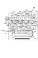
図1は、本実施例の画像形成装置100の概略断面図(後述する感光ドラム101の回転軸線方向と略直交する断面)である。本実施例の画像形成装置100は、電子写真方式を用いてフルカラー画像を形成することのできる、中間転写方式を採用したタンデム型のプリンタである。
[Example 1]
1 is a schematic cross-sectional view (a cross-section substantially perpendicular to the direction of the rotation axis of a
なお、画像形成装置100及びその要素に関して、図1の紙面手前側を「前」側、図1の紙面奥側を「後」側とする。ユーザやサービス担当者などの操作者は、通常、画像形成装置100の前側から画像形成装置100に対する操作を行うようになっている。画像形成装置100の前後方向は、後述する感光ドラム1の回転軸線方向と略平行であるものとする。また、画像形成装置100及びその要素に関して、前側から見た場合の左側、右側をそれぞれ「左」側、「右」側とする。また、画像形成装置100及びその要素に関して、上下方向は、重力方向(鉛直方向)における上下方向を言うものであるが、直上、直下のみを意味するものではなく、それぞれ注目する要素又は位置を通る水平面よりも上側、下側を含むものである。
With respect to the
画像形成装置100は、複数の画像形成手段として、それぞれイエロー(Y)、マゼンタ(M)、シアン(C)、ブラック(K)の画像を形成する第1、第2、第3、第4のステーションSY、SM、SC、SKを有する。各ステーションSY、SM、SC、SKにおける同一又は対応する機能あるいは構成を有する要素については、いずれかの色用の要素であることを表す符号の末尾のY、M、C、Kを省略して総括的に説明することがある。本実施例では、ステーションSは、後述する感光ドラム101、帯電装置102、露光装置103、現像装置104、一次転写ローラ105、ドラムクリーニング装置106などを有して構成される。本実施例では、複数(本実施例では4つ)のステーションSY、SM、SC、SKは、重力方向と交差する方向、特に本実施例では略水平方向に沿って並んで配置されている。
The
第1の像担持体としての回転可能なドラム型の感光体(電子写真感光体)である感光ドラム101は、図中矢印R1方向に回転駆動される。本実施例では、4つの感光ドラム101は、略水平方向に沿って左右に並んで配置されている。回転する感光ドラム101の表面は、帯電手段としての帯電装置102によって所定の極性(本実施例では負極性)に一様に帯電処理される。帯電処理された感光ドラム101の表面は、露光手段としての露光装置(レーザスキャナ)103によって画像情報に従って走査露光され、感光ドラム101上に静電像(静電潜像)が形成される。感光ドラム101上に形成された静電像は、現像手段としての現像装置104によってトナーが供給されて現像(可視化)され、感光ドラム101上にトナー像が形成される。本実施例では、一様に帯電処理された後に露光されることで電位の絶対値が低下した感光ドラム101上の露光部(イメージ部)に、感光ドラム101の帯電極性と同極性(本実施例では正極性)に帯電したトナーが付着する。本実施例では、現像時のトナーの帯電極性であるトナーの正規の帯電極性は負極性である。
The
4つの感光ドラム101と対向するように、第2の像担持体としての無端状のベルトで構成された中間転写体である中間転写ベルト107が配置されている。中間転写ベルト107は、複数の張架ローラ(支持ローラ)としての駆動ローラ171、テンションローラ172、二次転写対向ローラ173に掛け渡されて所定の張力で張架されている。中間転写ベルト107は、駆動ローラ171が回転駆動されることで駆動力が伝達されて、図中矢印R2方向に回転(周回移動)する。中間転写ベルト107の内周面側には、各感光ドラム101に対応して、一次転写手段としてのローラ型の一次転写部材である一次転写ローラ105が配置されている。一次転写ローラ105は、中間転写ベルト107を感光ドラム101に向けて押圧して、感光ドラム101と中間転写ベルト107とが接触する一次転写部(一次転写ニップ)N1を形成する。上述のように感光ドラム101上に形成されたトナー像は、一次転写部N1において、一次転写ローラ105の作用により、回転している中間転写ベルト107上に一次転写される。一次転写時に、一次転写ローラ105には、トナーの正規の帯電極性とは逆極性の直流電圧である一次転写電圧が印加される。例えば、フルカラー画像の形成時には、各感光ドラム101上に形成されたイエロー、マゼンタ、シアン、ブラックの各色のトナー像が、中間転写ベルト107上に重ね合わされるようにして順次一次転写される。
An
中間転写ベルト107の外周面側において、二次転写対向ローラ173に対向する位置には、二次転写手段としてのローラ型の二次転写部材である二次転写ローラ108が配置されている。二次転写ローラ108は、中間転写ベルト107を介して二次転写対向ローラ173に向けて押圧され、中間転写ベルト107と二次転写ローラ108とが接触する二次転写部(二次転写ニップ)N2を形成する。上述のように中間転写ベルト107上に形成されたトナー像は、二次転写部N2において、中間転写ベルト107と二次転写ローラ108とに挟持されて搬送されている記録用紙などの記録材(記録媒体、シート)P上に二次転写される。二次転写時に二次転写ローラ108には、トナーの正規の帯電極性とは逆極性の直流電圧である二次転写電圧が印加される。記録材Pは、記録材収容部としてのカセット111に収容されている。記録材Pは、記録材搬送装置112によってカセット111から二次転写部N2に供給される。記録材搬送装置112は、ピックアップローラ112a、給送ローラ112b、搬送ローラ112c、及びレジストローラ112dなどを有する。ピックアップローラ112aは、カセット111から記録材Pを1枚ずつ送り出す。給送ローラ112b、搬送ローラ112cは、カセット111から送り出された記録材Pを搬送する。レジストローラ112dは、給送ローラ112b、搬送ローラ112cによって搬送されてきた記録材Pを一旦停止させると共に、この記録材Pを中間転写ベルト107上のトナー像とタイミングを合わせるようにして二次転写部N2へと送り出す。
On the outer peripheral surface side of the
トナー像が転写された記録材Pは、定着手段としての定着装置113へと搬送される。定着装置113は、熱源を備えた定着ローラ113aと、定着ローラ113aに圧接する加圧ローラ113bと、を有する。定着装置113は、未定着のトナー像を担持した記録材Pを、定着ローラ113aと加圧ローラ113bとで挟持して搬送することで加熱及び加圧し、記録材P上にトナー像を定着(溶融、固着)させる。トナー像が定着された記録材Pは、排出ローラ114によって、画像形成装置100の装置本体110の外部に設けられたトレイ115上に排出(出力)される。
The recording material P onto which the toner image has been transferred is transported to a
また、一次転写時に中間転写ベルト107に転写されずに感光ドラム101上に残留したトナー(一次転写残トナー)は、感光体クリーニング手段としてのドラムクリーニング装置106によって感光ドラム101上から除去されて回収される。図2に示すように、ドラムクリーニング装置106は、クリーニング部材としての弾性体で形成されたドラムクリーニングブレード161と、トナー回収部としてのドラムクリーニング容器162と、を有する。ドラムクリーニング装置106は、感光ドラム101の表面に当接するように配置されたドラムクリーニングブレード161によって、回転する感光ドラム101の表面から一次転写残トナーを掻き取って、ドラムクリーニング容器162の内部に収容する。
Furthermore, toner remaining on the
また、中間転写ベルト107の外周面側において、テンションローラ172と対向する位置には、中間転写ベルトクリーニング手段としてのベルトクリーニング装置109が配置されている。二次転写時に記録材Pに転写されずに中間転写ベルト107上に残留したトナー(二次転写残トナー)は、ベルトクリーニング装置109によって中間転写ベルト107上から除去されて回収される。ベルトクリーニング装置109は、クリーニング部材としての弾性体で形成されたベルトクリーニングブレード191と、トナー回収部としてのベルトクリーニング容器192と、を有する。ベルトクリーニング装置109は、中間転写ベルト107の表面に当接するように配置されたベルトクリーニングブレード191により、回転する中間転写ベルト107の表面から二次転写残トナーを掻き取り、ベルトクリーニング容器192の内部に収容する。
In addition, a
ドラムクリーニング容器162に収容された一次転写残トナーは、ドラムクリーニング容器162の内部に配置された図示しない搬送手段によって搬送される。そして、この一次転写残トナーは、開口部であるドラムクリーニング容器排出口162aから排出されて、回収現像剤として後述する現像剤回収装置1に送られる。また、ベルトクリーニング容器192に収容された二次転写残トナーは、ベルトクリーニング容器192の内部に配置された図示しない搬送手段によって搬送される。そして、この二次転写残トナーは、開口部であるベルトクリーニング容器排出口192aから排出されて、回収現像剤として後述する現像剤回収装置1に送られる。
The primary transfer residual toner contained in the
本実施例では、各ステーションSにおいて、感光ドラム101と、これに作用するプロセス手段としての帯電装置102、現像装置104及びドラムクリーニング装置106とは、一体的にプロセスカートリッジ117を構成している。プロセスカートリッジ117は、画像形成装置100の前側に引き出して装置本体110に対して着脱可能なように構成されている。各色用のプロセスカートリッジ117は、現像装置104に収容されるトナーの色が異なることを除いて実質的に同一の構造とされている。
In this embodiment, at each station S, the
また、本実施例では、中間転写ベルト107、中間転写ベルト107の張架ローラ171~173、各一次転写ローラ105、及びベルトクリーニング装置109などは、一体的にユニット化されて中間転写ユニット170を構成している。中間転写ユニット170は、画像形成装置100の右側から引き出して装置本体110に対して着脱可能なように構成されている。
In addition, in this embodiment, the
また、画像形成装置100には、各現像装置104Y、104M、104C、104Kに補給する現像剤(補給現像剤)を収容する補給現像剤容器としてのトナーカートリッジ116Y、116M、116C、116Kが設けられている。トナーカートリッジ116は、画像形成装置100の前側に引き出して装置本体110に対して着脱可能なように構成されている。各色用のトナーカートリッジ116は、収容されるトナーの色が異なることを除いて実質的に同一の構造とされている。トナーカートリッジ116は、補給現像剤を収容する補給現像剤収容部116aと、補給現像剤収容部116aの内部の補給現像剤を現像装置104へと補給する補給手段としての補給部材である補給スクリュー116bと、を有する。
The
ここで、本実施例では、現像装置104は、現像剤として、トナー(非磁性トナー粒子)と、キャリア(磁性キャリア粒子)と、を含む二成分現像剤を用いる。図2に示すように、現像装置104は、現像剤担持体としての回転可能な現像スリーブ141と、現像剤を収容する現像容器142と、を有する。現像装置104は、現像スリーブ141上にトナーとキャリアとを備える現像剤を担持して、現像スリーブ141の回転によって感光ドラム101と現像スリーブ141とが対向する現像位置に現像剤を搬送する。現像装置104は、現像位置で現像剤のトナーを感光ドラム101上の静電像に供給することで、感光ドラム101上にトナー像を形成する。また、現像容器142の内部に配置された図示しない攪拌搬送手段によって、現像容器142の内部に収容された現像剤と、トナーカートリッジ116から補給された補給現像剤と、が攪拌されながら循環搬送される。本実施例では、トナーカートリッジ116から現像装置104に補給される補給現像剤は、トナーとキャリアとを含んでいる。そして、補給現像剤が補給されることで過剰になった現像容器142の内部の現像剤(トナーとキャリアとを含んでいてよい。)は、現像容器142の内部での現像剤の循環搬送に伴い、開口部である現像容器排出口142aから排出されて、回収現像剤として後述する現像剤回収装置1に送られる。
Here, in this embodiment, the developing
本実施例では、各ステーションS、中間転写ユニット170、二次転写ローラ108、及び定着装置113によって、現像剤を用いて記録材Pに画像を形成する機構部である画像形成部Gが構成される。なお、図2は、画像形成部G(各ステーションSのドラムクリーニング装置106及び現像装置104、並びにベルトクリーニング装置109)からの回収現像剤の排出態様を示す模式図である。
In this embodiment, each station S,
2.回収現像剤容器
本実施例では、画像形成装置100の装置本体110には、複数の回収現像剤容器としての第1、第2の回収現像剤容器(第1、第2の回収容器)10L、10Rの2つの容器が着脱可能とされている。本実施例では、第1、第2の回収現像剤容器10L、10Rは、装置本体110の内部において、略水平方向に沿って左右に並んで配置される。特に、本実施例では、第1、第2の回収現像剤容器10L、10Rは、実質的に同一の構造とされており、装置本体110の内部において、上下方向に関して略同一の高さに並列に配置される。そして、画像形成部Gから後述する現像剤回収装置1に送られた回収現像剤は、第1、第2の回収現像剤容器10L、10Rのうちいずれか一方の容器に選択的に搬送されて蓄積される。本実施例では、前述のように、回収現像剤は、画像形成部Gにおいて、各ステーションSのドラムクリーニング装置106及び現像装置104、並びにベルトクリーニング装置109から排出される。また、第1、第2の回収現像剤容器10L、10Rのうちいずれか一方の容器の内部が回収現像剤で満杯になった場合には、他方の容器に回収現像剤の搬送先が切り替えられると共に、該一方の容器が空の容器に交換される。
2. Recovered Developer Container In this embodiment, two containers, the first and second recovered developer containers (first and second recovered developer containers) 10L and 10R, are detachably mounted on the
なお、第1、第2の回収現像剤容器10L、10Rが略水平方向に沿って左右に並んで配置されるとは、第1、第2の回収現像剤容器10L、10R同士が上下方向に関して少なくとも一部で重なるように配置されることを含むものである。
Note that the first and second recovered
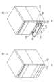
第1、第2の回収現像剤容器10L、10Rはそれぞれ、長手方向と短手方向とにそれぞれ所定の長さを有し、厚さ方向に所定の厚さ(高さ)を有する、上記長手方向と略直交する断面が略矩形の箱型の容器である。上記長手方向は、装置本体110の内部において画像形成装置100の前後方向に沿って配置される方向である。また、上記短手方向は、装置本体110の内部において画像形成装置100の左右方向に沿って配置される方向である。また、上記厚さ方向は、装置本体110の内部において上下方向に沿って配置される方向である。第1、第2の回収現像剤容器10L、10Rは、それぞれ内部に回収現像剤を収容する中空の回収現像剤収容部11L、11R(図6、図7参照)が形成されている。上述のように、本実施例では、第1、第2の回収現像剤容器10L、10Rは、実質的に同一の構造を有しており、個々の容器は、装置本体110の内部において左側に装着することも、右側に装着することもできる。本実施例では、第1の回収現像剤容器10Lが装置本体110の内部において左側に装着され、第2の回収現像剤容器10Rが装置本体110の内部において右側に装着されるものとする。
The first and second recovered
図3は、第1、第2の回収現像剤容器10L、10Rの装着態様を説明するための画像形成装置100を斜め前側から見た概略外観斜視図である。図3(a)は、後述する容器交換扉118が閉じられた状態、図3(b)はこの容器交換扉118が開放されて第1、第2の回収現像剤容器10L、10Rの着脱が可能な状態を示している。画像形成装置110の前側には、画像形成装置100の外装カバーの一部を構成すると共に、第1、第2の回収現像剤容器10L、10Rの着脱を可能とする容器交換扉118が設けられている。本実施例では、容器交換扉118は、第1、第2の回収現像剤容器10L、10Rの両方を着脱可能とする1つ(共通)の開閉部材で構成されている。本実施例では、容器交換扉118は、前側から見て左右方向に長い略矩形形状を有する。また、本実施例では、容器交換扉118は、該扉の下部で、上下方向と交差する左右方向に沿って伸びる回転軸線を中心として回動可能に構成されている。そして、容器交換扉118は、操作者の操作により、上下方向の下側において左右方向に沿って伸びる回転軸線を中心として上側を回動させることで、開閉することができるようになっている。
3 is a schematic external perspective view of the
図3(a)に示すように、容器交換扉118は、閉じられた状態で、その下側に隣接して設けられたカセット111の前パネル111aと左右方向及び上下方向の大きさが同等とされる1つのパネル状の外観を呈する。そのため、第1、第2の回収現像剤容器10L、10Rの2つの容器を設けたことにより外観が煩雑となることが抑制されている。また、1つの容器交換扉118を開閉することで、第1、第2の回収現像剤容器10L、10Rのいずれの着脱も行うことができる。そのため、複数の回収現像剤容器のそれぞれに個別に容器交換扉が設けた場合に生じ得る、操作者が誤った扉を開閉してしまうことによる操作の無駄を抑制することができる。
As shown in FIG. 3A, when the
図3(b)に示すように、容器交換扉118を開放することで、操作者は第1、第2の回収現像剤容器10L、10Rのいずれにもアクセスすることができる。装置本体110には、第1、第2の回収現像剤容器10L、10Rがそれぞれ装着される第1、第2の容器装着部119L、119Rが設けられている。第1、第2の容器装着部119L、119Rは、それぞれ第1、第2の回収現像剤容器10L、10Rの下側を支持する、前後方向に伸びる第1、第2の容器支持部120L、120Rを有する。第1、第2の容器装着部119L、119Rは、例えば第1、第2の容器支持部120L、120Rがそれぞれ第1、第2の回収現像剤容器10L、10Rと係合するレール状構造(図示せず)を有する。これにより、第1、第2の回収現像剤容器10L、10Rを、前側から後側にスライド移動させて、装置本体110の内部における所定の位置に容易に配置することができる。また、これにより、第1、第2の回収現像剤容器10L、10Rを、後側から前側にスライド移動させて、装置本体110の内部における所定の位置から引き出して装置本体110から容易に取り外すことができる。
As shown in FIG. 3B, by opening the
また、図3(b)に示すように、容器交換扉118を開放した状態で操作者が視認できるように、容器交換扉118の内側の面には、識別表示(識別表示部)121L、121Rが設けられている。識別表示121L、121Rは、左右方向に関して第1、第2の回収現像剤容器10L、10Rのそれぞれに対応する位置に設けられている。本実施例では、左側の識別表示121Lは、第1の回収現像剤容器10Lを識別するための、例えば「容器1」(あるいは「左容器」)などの文字が記載されたシールで構成されている。また、本実施例では、右側の識別表示121Rは、第2の回収現像剤容器10Rを識別するための、例えば「容器2」(あるいは「右容器」)などの文字が記載されたシールで構成されている。この識別表示121L、121Rは、後述するように画像形成装置100の操作部130(図11)などにおいていずれかの回収現像剤容器10L、10Rの交換を促す表示が行われた際に、対応する方の容器を容易に認識できるようにするためのものである。なお、本実施例では、容器交換扉118の内側の面に識別表示121L、121Rを設けたが、これに限定されるものではない。識別表示121L、121Rは、例えば、第1、第2の容器装着部119L、119Rのそれぞれに隣接するパネルの前面に、第1、第2の回収現像剤容器10L、10Rのそれぞれに対応させて設けてもよい。
3B, the inner surface of the
3.現像剤回収装置の構成
次に、本実施例における現像剤回収装置(搬送装置)1の構成について説明する。
3. Configuration of Developer Recovery Device Next, the configuration of the developer recovery device (conveying device) 1 in this embodiment will be described.
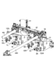
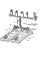
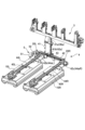
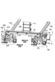
<全体構成>
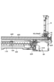
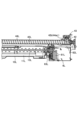
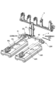
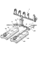
図4は、本実施例の現像剤回収装置1を前側から見た正面図である。図5は、本実施例の現像剤回収装置1を斜め前側から見た斜視図である。図4、図5では、主に現像剤回収装置1における回収現像剤搬送経路2が示されており、現像剤回収装置1に接続された第1、第2の回収現像剤容器10L、10Rも示されている。
<Overall composition>
Fig. 4 is a front view of the
本実施例では、現像剤回収装置1の回収現像剤搬送経路2は、大別して、上流搬送部3と、下流搬送部4と、を有する。上流搬送部3は、画像形成部G(各ステーションSのドラムクリーニング装置106及び現像装置104、並びにベルトクリーニング装置109)から排出された回収現像剤を受け取る。下流搬送部4は、上流搬送部3からの回収現像剤を受け取り、第1、第2の回収現像剤容器10L、10Rへと回収現像剤を搬送する。
In this embodiment, the recovered
<上流搬送部>
図4、図5を参照して、上流搬送部3は、第1~第5の排出パイプ(複数の排出トナー受入口)31~35と、メイン排出パイプ(第1の搬送路)36と、を有する。第1~第5の排出パイプ31~35及びメイン排出パイプ36は、装置本体110の内部の後側端部近傍に配置されている。
<Upstream conveying section>
4 and 5, the
本実施例では、第1~第5の排出パイプ31~35は、それぞれ略重力方向に沿って上下に伸びる中空の管状部材である。第1の排出パイプ(第1、第5の排出トナー受入口)31には、ベルトクリーニング容器排出口192a(図2)と接続される開口部である第1の排出受入口(第5の排出トナー受入口)31aと、イエロー用の現像容器排出口142a(図2)と接続される開口部である第2の排出受入口(第1の排出トナー受入口)31bと、が形成されている。第2の排出パイプ(第1、第3の排出トナー受入口)32には、イエロー用のドラムクリーニング容器排出口162a(図2)と接続される第1の排出受入口(第1の排出トナー受入口)32aと、マゼンタ用の現像容器排出口142a(図2)と接続される開口部である第2の排出受入口(第3の排出トナー受入口)32bと、が形成されている。第3の排出パイプ(第3、第4の排出トナー受入口)33には、マゼンタ用のドラムクリーニング容器排出口162a(図2)と接続される第1の排出受入口(第3の排出トナー受入口)33aと、シアン用の現像容器排出口142a(図2)と接続される開口部である第2の排出受入口(第4の排出トナー受入口)33bと、が形成されている。第4の排出パイプ(第2、第4の排出トナー受入口)34には、シアン用のドラムクリーニング容器排出口162a(図2)と接続される第1の排出受入口(第4の排出トナー受入口)34aと、ブラック用の現像容器排出口142a(図2)と接続される開口部である第2の排出受入口(第2の排出トナー受入口)34bと、が形成されている。また、第5の排出パイプ(第2の排出トナー受入口)35には、ブラック用のドラムクリーニング容器排出口162a(図2)と接続される排出受入口(第2の排出トナー受入口)35aが形成されている。そして、第1~第5の排出パイプ31~35の下側の端部は、それぞれメイン排出パイプ36に接続され、第1~第5の排出パイプ31~35の内部とメイン排出パイプ36の内部とがそれぞれ回収現像剤の受け渡しが可能なように連通している。
In this embodiment, the first to
本実施例では、メイン排出パイプ36は、略水平方向に沿って左右に伸びる中空の管状部材である。特に、本実施例では、メイン排出パイプ36は、その伸長方向(軸線方向)と略直交する断面が略円形の円管で構成されている。メイン排出パイプ36の上側の側部に第1~第5の排出パイプ31~35がそれぞれ接続され、メイン排出パイプ36の内部と第1~第5の排出パイプ31~35の内部とがそれぞれ回収現像剤の受け渡しが可能なように連通している。メイン排出パイプ36の内部(中空部)には、排出搬送部材としての排出スクリュー37が配置されている。本実施例では、排出スクリュー37は、メイン排出パイプ36の伸長方向(略水平方向)に沿って左右に伸びる回転軸線を中心として回転可能な無軸スクリューコンベア(スプリングオーガ)で構成されている。排出スクリュー37は、メイン排出パイプ36の内部の回収現像剤を攪拌しながら搬送する。また、メイン排出パイプ36の伸長方向に関する両端部の間に位置するメイン排出パイプ36の下側の側部に、メイン排出口(第1の排出口)36aが形成されている。このメイン排出口36aは、メイン排出パイプ36から回収現像剤を重力により落下させて排出して下流搬送部4に受け渡すための開口部である。なお、本実施例では、メイン排出口36aは、画像形成装置100の前後方向と略直交する断面における水平方向に関して、次のような位置に形成されている。つまり、メイン排出口36aは、該方向に関して、後述する下流搬送部4の横パイプ42に設けられた第1、第2の横パイプ排出口42b、42cの間に位置するようにメイン排出パイプ36の下側の側部に形成されている。
In this embodiment, the
第1~第5の排出パイプ31~35に送られた回収現像剤は、第1~第5の排出パイプ31~35の内部(中空部)を重力により落下してメイン排出パイプ36へと移動する。メイン排出パイプ36に落下した回収現像剤は、排出スクリュー37によってメイン排出口36aへと搬送される。本実施例では、排出スクリュー37は、その回転軸線方向に関して、メイン排出口36aに対応する位置を境に左側の第1の部分37aと右側の第2の部分37bとで巻き方向が異なる螺旋形状を有する。また、排出スクリュー37は、装置本体110に設けられた図示しない駆動源(排出スクリュー駆動部)から駆動伝達部材(単数又は複数のギアなど)125を介して回転駆動力が伝達されて所定の方向に回転駆動される。これにより、第1、第2の排出パイプ31、32からメイン排出パイプ36に送られた回収現像剤は、排出スクリュー37の第1の部分37aによって左側から右側に向かう方向に搬送されて、メイン排出口36aに送られる。一方、第3~第5の排出パイプ33~35からメイン排出パイプ36に送られた回収現像剤は、排出スクリュー37の第2の部分37bによって右側から左側に向かう方向に搬送されて、メイン排出口36aに送られる。メイン排出口36aへと搬送された回収現像剤は、メイン排出口36aから重力により落下して後述する下流搬送部4の縦パイプ41へと移動する。
The recovered developer sent to the first to
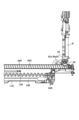
<下流搬送部>
図4、図5を参照して、下流搬送部4は、縦パイプ41と、横パイプ42と、第1、第2の回収パイプ(第4の搬送路)44L、44Rと、を有する。縦パイプ41及び横パイプ42は、装置本体110の内部の後側端部近傍に配置されている。第1、第2の回収パイプ44L、44Rは、それぞれ装置本体110の内部に配置された第1、第2の回収現像剤容器10L、10Rの上方において後側から前側へと伸びて配置されている。
<Downstream conveying section>
4 and 5, the downstream conveying
現像剤回収装置1は、画像形成部Gから排出された回収現像剤を重力方向の上方から下方に導く管状の縦搬送部(第2の搬送路)としての縦パイプ41を有している。本実施例では、縦パイプ41は、略重力方向に沿って上下に伸びる中空の管状部材である。なお、縦パイプ41は、重力方向に対して傾斜していてもよい。また、本実施例では、縦パイプ41内を回収現像剤は重力により落下して移動するが、縦パイプ41内に回収現像剤を搬送する搬送部材が設けられていてもよい。縦パイプ41の上側の端部に、上流搬送部3のメイン排出パイプ36が接続されている。そして、縦パイプ41の上側の端部には、メイン排出パイプ36のメイン排出口36aに対応する位置に、メイン排出口36aから排出された回収現像剤を縦パイプ41に受け入れるための開口部である縦パイプ受入口41aが形成されている。これにより、メイン排出口36a及び縦パイプ受入口41aを介して、メイン排出パイプ36の内部と縦パイプ41の内部とが連通している。また、縦パイプ41の下側の端部には、縦パイプ41から回収現像剤を重力により落下させて排出して横パイプ42に受け渡すための開口部である縦パイプ排出口(第2の排出口)41bが形成されている。なお、本実施例では、縦パイプ受入口41a、縦パイプ排出口41bは、それぞれ画像形成装置100の前後方向と略直交する断面における水平方向に関して、次のような位置に形成されている。つまり、縦パイプ受入口41a、縦パイプ排出口41bは、それぞれ該方向に関して、後述する横パイプ42に設けられた第1、第2の横パイプ排出口42b、42cの間に位置するように縦パイプ41に形成されている。
The
現像剤回収装置1は、縦パイプ41の内部を通って搬送された回収現像剤を重力方向と交差する方向に沿って第1の回収現像剤容器10L及び第2の回収現像剤容器10Rに向けて導くことが可能な管状の横搬送部(第3の搬送路)としての横パイプ42を有している。本実施例では、横パイプ42は、略水平方向に沿って左右に伸びる中空の管状部材である。なお、横パイプ42は、水平方向に対して傾斜していてもよい。特に、本実施例では、横パイプ42は、その伸長方向(軸線方向)と略直交する断面が略円形の円管で構成されている。横パイプ42の伸長方向に関する両端部の間の横パイプ42の上側の側部に、縦パイプ41が接続されている。そして、横パイプ42の上側の側部には、縦パイプ41の縦パイプ排出口41bに対応する位置に、縦パイプ排出口41bから排出された回収現像剤を横パイプ42に受け入れるための開口部である横パイプ受入口(受入口)42aが形成されている。これにより、縦パイプ排出口41b及び横パイプ受入口42aを介して、縦パイプ41の内部と横パイプ42の内部とが連通している。また、横パイプ42の伸長方向に関する両端部側にそれぞれ位置する横パイプ42の下側の側部に、それぞれ第1、第2の横パイプ排出口(第2、第3の排出口)42b、42cが形成されている。この第1、第2の横パイプ排出口42b、42cは、それぞれ横パイプ42から回収現像剤を重力により落下させて排出して第1、第2の回収パイプ44L、44Rに受け渡すための開口部である。第1の横パイプ排出口42bは、横パイプ42の左側の端部(第1の端部)の近傍に形成され、第2の横パイプ排出口42cは、横パイプ42の右側の端部(第2の端部)の近傍に形成されている。ここで、上記横パイプ受入口42aは、画像形成装置100の前後方向と略直交する断面における水平方向に関して、第1、第2の横パイプ排出口42b、42cの間に位置するように横パイプ42に形成されている。このように、横パイプ42は、横パイプ42の伸長方向に関する第1の端部側に設けられ第1の回収現像剤容器10Lに向けて横パイプ42から回収現像剤を排出する第1の横パイプ排出口42bを備えている。また、横パイプ42は、横パイプ42の伸長方向に関する第1の端部とは反対の第2の端部側に設けられ第2の回収現像剤容器10Rに向けて横パイプ42から回収現像剤を排出する第2の横パイプ排出口42cを備えている。また、横パイプ42は、横パイプ42の伸長方向に関する第1の横パイプ排出口42bと第2の横パイプ排出口42cとの間に設けられ縦パイプ41からの回収現像剤を横パイプ42に受け入れる横パイプ受入口42aを備えている。
The
横パイプ42の内部(中空部)には、搬送部材としての搬送スクリュー43が配置されている。本実施例では、搬送スクリュー43は、横パイプ42の伸長方向(略水平方向)に沿って左右に伸びる回転軸線を中心として回転可能な無軸スクリューコンベア(スプリングオーガ)で構成されている。本実施例では、搬送スクリュー43は、巻き方向が一方向の螺旋形状を有する。搬送スクリュー43は、横パイプ42の内部の回収現像剤を攪拌しながら搬送する。搬送スクリュー43は、駆動部5から回転駆動力が伝達されて回転駆動される。本実施例では、駆動部5は、駆動源としての駆動モータ51と、駆動モータ51からの駆動力を搬送スクリュー43に伝達する駆動列(単数又は複数のギアなど)52と、を有して構成される。本実施例では、駆動モータ51は、横パイプ42の右側の側部に配置されており、駆動列52は、搬送スクリュー43の右側の端部に接続されている。駆動部5の駆動モータ51は、正逆双方向に回転可能である。これにより、駆動部5は、搬送スクリュー43を、第1の方向と、第1の方向とは反対の第2の方向と、に回転駆動することが可能である。上述のように、搬送スクリュー43は、巻き方向が一方向の螺旋形状を有しており、第1の方向に回転することで、横パイプ42の内部の回収現像剤を右側の端部(第2の端部)側から左側の端部(第1の端部)側に向けて搬送する。また、搬送スクリュー43は、第2の方向に回転することで、横パイプ42の内部の回収現像剤を左側の端部(第1の端部)側から右側の端部(第2の端部)側に向けて搬送する。このように、現像剤回収装置1は、横パイプ42の内部の回収現像剤を搬送する搬送スクリュー43を有している。搬送スクリュー43は、次のように回収現像剤の搬送を行う巻き方向の螺旋形状部を備えている。つまり、搬送スクリュー43は、横パイプ42の伸長方向に沿う回転軸線を中心として第1の方向に回転することで回収現像剤を該回転軸線に沿って第2の端部側から第1の端部側に向かう方向に搬送する。また、この搬送スクリュー43は、該回転軸線を中心として第1の方向とは反対の第2の方向に回転することで回収現像剤を該回転軸線に沿って第1の端部側から第2の端部側に向かう方向に搬送する。また、現像剤回収装置1は、搬送スクリュー43を第1の方向及び第2の方向に回転駆動することが可能な駆動部5を有している。
A conveying
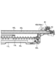
現像剤回収装置1は、第1の横パイプ排出口42bから排出された回収現像剤を第1の回収現像剤容器10Lに向けて導く管状の第1の回収搬送部としての第1の回収パイプ44Lを有している。なお、第1の回収パイプ44Lは、水平方向に対して傾斜していてもよい。本実施例では、第1の回収パイプ44Lは、略水平方向に沿って前後に伸びる中空の管状部材である。特に、本実施例では、第1の回収パイプ44Lは、その伸長方向(軸線方向)と略直交する断面が略円形の円管で構成されている。第1の回収パイプ44Lの伸長方向に関する後側の端部に位置する第1の回収パイプ44Lの上側の側部に、横パイプ42が接続されている。そして、第1の回収パイプ44Lの上側の側部には、横パイプ42の第1の横パイプ排出口42bに対応する位置に、第1の回収受入口44aLが形成されている。この第1の回収受入口44aLは、第1の横パイプ排出口42bから排出された回収現像剤を第1の回収パイプ44Lに受け入れるための開口部である。これにより、第1の横パイプ排出口42b及び第1の回収受入口44aLを介して、横パイプ42の内部と第1の回収パイプ44Lの内部とが連通している。また、第1の回収パイプ44Lの伸長方向に関する前側の端部に位置する第1の回収パイプ44Lの下側の側部に、第1の回収排出口44bLが形成されている。この第1の回収排出口44bLは、第1の回収パイプ44Lから回収現像剤を重力により落下させて排出して第1の回収現像剤容器10Lに受け渡すための開口部である。このように、第1の回収パイプ44Lは、第1の回収パイプ44Lの伸長方向に関する一方の端部側に設けられ第1の横パイプ排出口42bから排出された回収現像剤を第1の回収パイプ44Lに受け入れる第1の回収受入口44aLを備えている。また、第1の回収パイプ44Lは、第1の回収パイプ44Lの伸長方向に関する他方の端部側に設けられ第1の回収現像剤容器10Lに向けて第1の回収パイプ44Lから回収現像剤を排出する第1の回収排出口44bLを備えている。
The
第1の回収パイプ44Lの内部(中空部)には、第1の回収搬送部材としての第1の回収スクリュー45Lが配置されている。本実施例では、第1の回収スクリュー45Lは、第1の回収パイプ44Lの伸長方向(略水平方向)に沿って前後に伸びる回転軸線を中心として回転可能な無軸スクリューコンベア(スプリングオーガ)で構成されている。本実施例では、第1の回収スクリュー45Lは、巻き方向が一方向の螺旋形状を有する。第1の回収スクリュー45Lは、第1の回収パイプ44Lの内部の回収現像剤を攪拌しながら搬送する。図7に示すように、第1の回収スクリュー45Lは、第1の回収駆動部6Lから回転駆動力が伝達されて回転駆動される。本実施例では、第1の回収駆動部6Lは、駆動源としての第1の回収駆動モータ61Lと、第1の回収駆動モータ61Lからの駆動力を第1の回収スクリュー45Lに伝達する第1の回収駆動列(単数又は複数のギアなど)62Lと、を有して構成される。本実施例では、第1の回収駆動源61Lは、第1の回収パイプ44Lの後側の端部近傍の下方に配置されており、第1の回収駆動列62Lは、第1の回収スクリュー45Lの後側の端部に接続されている。第1の回収駆動部6Lの第1の回収駆動モータ61Lは、所定の方向に回転する。これにより、第1の回収駆動部6Lは、第1の回収スクリュー45Lを所定の方向に回転駆動する。上述のように、第1の回収スクリュー45Lは、巻き方向が一方向の螺旋形状を有しており、上記所定の方向に回転することで、第1の回収パイプ44Lの内部の回収現像剤を後側の端部側から前側の端部側に向けて搬送する。このように、現像剤回収装置1は、第1の回収パイプ44Lの内部の回収現像剤を搬送する第1の回収スクリュー45Lを有している。第1の回収スクリュー45Lは、次のように回収現像剤の搬送を行う巻き方向の螺旋形状部を備えている。つまり、第1の回収スクリュー45Lは、第1の回収パイプ44Lの伸長方向に沿う回転軸線を中心として所定の方向に回転することで回収現像剤を該回転軸線に沿って第1の回収パイプ44Lの一方の端部側(後側の端部側)から他方の端部側(前側の端部側)に向かう方向に搬送する。また、本実施例では、現像剤回収装置1は、第1の回収スクリュー45Lを回転駆動する第1の回収駆動部6Lを有している。
A
更に、現像剤回収装置1は、第2の横パイプ排出口42cから排出された回収現像剤を第2の回収現像剤容器10Rに向けて導く管状の第2の回収搬送部としての第2の回収パイプ44Rを有している。本実施例では、第2の回収パイプ44Rは、略水平方向に沿って前後に伸びる中空の管状部材である。なお、第2の回収パイプ44Rは、水平方向に対して傾斜していてもよい。特に、本実施例では、第2の回収パイプ44Rは、その伸長方向(軸線方向)と略直交する断面が略円形の円管で構成されている。第2の回収パイプ44Rの伸長方向に関する後側の端部に位置する第2の回収パイプ44Rの上側の側部に、横パイプ42が接続されている。そして、第2の回収パイプ44Rの上側の側部には、横パイプ42の第2の横パイプ排出口42cに対応する位置に、第2の回収受入口44aRが形成されている。この第2の回収受入口44aRは、第2の横パイプ排出口42cから排出された回収現像剤を第2の回収パイプ44Rに受け入れるための開口部である。これにより、第2の横パイプ排出口42c及び第2の回収受入口44aRを介して、横パイプ42の内部と第2の回収パイプ44Rの内部とが連通している。また、第2の回収パイプ44Rの伸長方向に関する前側の端部に位置する第2の回収パイプ44Rの下側の側部に、第2の回収排出口44bRが形成されている。この第2の回収排出口44bRは、第2の回収パイプ44Rから回収現像剤を重力により落下させて排出して第2の回収現像剤容器10Rに受け渡すための開口部である。このように、第2の回収パイプ44Rは、第2の回収パイプ44Rの伸長方向に関する一方の端部側に設けられ第2の横パイプ排出口42cから排出された回収現像剤を第2の回収パイプ44Rに受け入れる第2の回収受入口44aRを備えている。また、第2の回収パイプ44Rは、第2の回収パイプ44Rの伸長方向に関する他方の端部側に設けられ第2の回収現像剤容器10Rに向けて第2の回収パイプ44Rから回収現像剤を排出する第2の回収排出口44bRを備えている。
Furthermore, the
第2の回収パイプ44Rの内部(中空部)には、第2の回収搬送部材としての第2の回収スクリュー45Rが配置されている。本実施例では、第2の回収スクリュー45Rは、第2の回収パイプ44Rの伸長方向(略水平方向)に沿って前後に伸びる回転軸線を中心として回転可能な無軸スクリューコンベア(スプリングオーガ)で構成されている。本実施例では、第2の回収スクリュー45Rは、巻き方向が一方向の螺旋形状を有する。第2の回収スクリュー45Rは、第2の回収パイプ44Rの内部の回収現像剤を攪拌しながら搬送する。図6に示すように、第2の回収スクリュー45Rは、第2の回収駆動部6Rから回転駆動力が伝達されて回転駆動される。本実施例では、第2の回収駆動部6Rは、駆動源としての第2の回収駆動モータ61Rと、第2の回収駆動モータ61Rからの駆動力を第2の回収スクリュー45Rに伝達する第2の回収駆動列(単数又は複数のギアなど)62Rと、を有して構成される。本実施例では、第2の回収駆動源61Rは、第2の回収パイプ44Rの後側の端部近傍の下方に配置されており、第2の回収駆動列62Rは、第2の回収スクリュー45Rの後側の端部に接続されている。第2の回収駆動部6Rの第2の回収駆動モータ61Rは、所定の方向に回転する。これにより、第2の回収駆動部6Rは、第2の回収スクリュー45Rを所定の方向に回転駆動する。上述のように、第2の回収スクリュー45Rは、巻き方向が一方向の螺旋形状を有しており、上記所定の方向に回転することで、第2の回収パイプ44Rの内部の回収現像剤を後側の端部側から前側の端部側に向けて搬送する。このように、現像剤回収装置1は、第2の回収パイプ44Rの内部の回収現像剤を搬送する第2の回収スクリュー45Rを有している。第2の回収スクリュー45Rは、次のように回収現像剤の搬送を行う巻き方向の螺旋形状部を備えている。つまり、第2の回収スクリュー45Rは、第2の回収パイプ44Rの伸長方向に沿う回転軸線を中心として所定の方向に回転することで回収現像剤を該回転軸線に沿って第2の回収パイプ44Rの一方の端部側(後側の端部側)から他方の端部側(前側の端部側)に向かう方向に搬送する。また、本実施例では、現像剤回収装置1は、第2の回収スクリュー45Rを回転駆動する第2の回収駆動部6Rを有している。
A
なお、第1、第2の回収パイプ44L、44Rが設けられておらず、例えば横パイプ42から直接第1、第2の回収現像剤容器10L、10Rに回収現像剤が送られるようになっていてもよい。第1、第2の回収パイプ44L、44Rが設けられている場合、これらは横パイプ42から第1、第2の回収現像剤容器10L、10Rの間において回収現像剤を所定量保持することが可能なバッファとして機能することができる。例えば、第1、第2の回収現像剤容器10L、10Rの両方が満杯となった場合でも、ジョブの残りの画像形成枚数が所定値より少ない場合などには、このバッファとして機能する分までは画像形成を継続することができる。そして、ジョブが終了した後に第1、第2の回収現像剤容器10L、10Rの交換を促すことなどが可能となる。
It is also possible that the first and
ここで、本実施例では、第1、第2の回収現像剤容器10L、10Rは、装置本体110の内部における所定の位置に配置された状態で前側の端部に位置する上側の側部に、それぞれ第1、第2の容器受入口12L、12Rを有する。この第1、第2の容器受入口12L、12Rは、それぞれ第1、第2の回収排出口44bL、44bRから排出された回収現像剤を第1、第2の回収現像剤容器10L、10Rに受け入れるための開口部である。第1、第2の回収現像剤容器10L、10Rが装置本体110の内部における所定の位置に装着されると、第1、第2の容器受入口12L、12Rがそれぞれ第1、第2の回収排出口44bL、44bRに対応する位置に配置される。これにより、第1、第2の回収パイプ44L、44Rの内部と第1、第2の回収現像剤容器10L、10Rの内部とが連通する。なお、本実施例では、第1、第2の回収パイプ44L、44Rの前側の端部には、それぞれ第1、第2の回収排出口44bL、44bRの開閉状態を切り替える第1、第2のシャッタ部材46L、46Rが設けられている。この第1、第2のシャッタ部材46L、46Rは、それぞれ前後方向にスライド移動可能なように第1、第2の回収パイプ44L、44Rに設けられており、後側から前側に向かう方向に付勢手段としてのシャッタ押圧バネ(図示せず)によって付勢されている。そして、第1、第2の回収現像剤容器10L、10Rが装置本体110の内部における所定の位置に装着される直前に、第1、第2の回収現像剤容器10L、10Rに設けられた係合部(図示せず)が第1、第2のシャッタ部材46L、46Rに係合する。そして、第1、第2の回収現像剤容器10L、10Rが更に装置本体110の内部における所定の位置まで挿入されることで、第1、第2のシャッタ部材46L、46Rが上記シャッタ押圧バネの付勢力に抗して後側に移動させられて開放される。第1、第2の回収現像剤容器10L、10Rが装置本体110の内部における所定の位置から取り外される際には、上記の動作と逆の動作で、第1、第2のシャッタ部材46L、46Rは上記シャッタ押圧バネの付勢力により閉鎖される。なお、シャッタ部材は回収現像剤容器の移動により連動して開閉するものに限定されず、例えば適宜のアクチュエータにより開閉するものであってもよい。更に、第1、第2の回収現像剤容器10L、10Rにも、例えば上記装着動作、取り外し動作に連動して第1、第2の容器受入口12L、12Rを開閉するシャッタ部材が設けられていてよい。
Here, in this embodiment, the first and second recovered
また、本実施例では、図6、図7に示すように、第1、第2の回収現像剤容器10L、10Rの内部には、回収現像剤収容部11L、11Rに収容された回収現像剤を搬送する容器搬送部材としての第1、第2の容器スクリュー13L、13Rが設けられている。本実施例では、第1、第2の容器スクリュー13L、13Rは、第1、第2の回収現像剤容器10L、10Rが装置本体110の内部における所定の位置に配置された状態で前側から後側に向けて回収現像剤を搬送するように構成されている。本実施例では、第1、第2の容器スクリュー13L、13Rは、回転軸部と、該回転軸部の周りに螺旋状に形成されたスクリュー羽根部と、を有する。また、第1、第2の容器スクリュー13L、13Rの上記回転軸部の後側の端部に、それぞれ駆動受け部が設けられている。そして、第1、第2の回収現像剤容器10L、10Rが装置本体110の内部における所定の位置に装着されると、上記駆動受け部が、それぞれ装置本体110側に設けられた第1、第2のカップリング63L、63Rに接続される。本実施例では、この第1、第2のカップリング63L、63Rは、それぞれ前述の第1、第2の回収駆動部6L、6Rから回転駆動力が伝達されて回転する。これにより、本実施例では、第1、第2の容器スクリュー13L、13Rは、それぞれ前述の第1、第2の回収スクリュー45L、45Rと連動して回転して第1、第2の回収現像剤容器10L、10Rの内部の回収現像剤を搬送する。
In this embodiment, as shown in Figs. 6 and 7, the first and second container screws 13L and 13R are provided inside the first and second recovered
なお、第1、第2のカップリング63L、63Rは、図8に示すように、それぞれ後述する第1、第2の容器対向部122L、122Rから露出するように設けられている。
As shown in FIG. 8, the first and
<容器センサなど>
図8には、装置本体110の第1、第2の容器装着部119L、119R(図3(b))の後側の端部における、第1、第2の回収現像剤容器10L、10Rに対向する第1、第2の容器対向部122L、122Rが示されている。
<Container sensors, etc.>
Figure 8 shows first and second
本実施例では、第1、第2の容器対向部122L、122Rに、それぞれ第1、第2の回収現像剤容器10L、10Rの有無(着脱状態)を検知するための容器検知手段として第1、第2の容器センサ7L、7Rが設けられている。本実施例では、第1、第2の容器センサ7L、7Rは、押圧又は押圧の解除の状態により後述する制御部150(図11)に出力する信号が変化するメカニカルスイッチで構成されている。制御部150は、第1、第2の容器センサ7L、7Rの検知結果に基づいて、駆動部5を制御することができる。第1の容器センサ7Lは、第1の回収現像剤容器10Lが装置本体110の内部における所定の位置、すなわち、第1の回収排出口44bLと第1の容器受入口12Lとが連通する位置に配置されると、第1の回収現像剤容器10Lにより押圧される。これにより、制御部150は、第1の回収現像剤容器10Lが上記所定の位置に配置されたことを検知することができる。また、第1の容器センサ7Lは、第1の回収現像剤容器10Lが上記所定の位置から移動される(取り外される)と、第1の回収現像剤容器10Lによる押圧が解除される。これにより、制御部150は、第1の回収現像剤容器10Lが上記所定の位置から移動されたことを検知することができる。同様に、第2の容器センサ7Rの信号により、制御部150は、第2の回収現像剤容器10Rが上記所定の位置に配置されたこと、あるいは第2の回収現像剤容器10Rが上記所定の位置から移動されたことを検知することができる。なお、容器検知手段はメカニカルスイッチに限定されるものではなく、例えば光学式センサなどで構成されていてもよい。
In this embodiment, the first and
また、本実施例では、第1、第2の容器対向部122L、122Rに、それぞれ第1、第2の回収現像剤容器10L、10Rが回収現像剤で満杯になったか否かを検知するための回収現像剤検知手段として第1、第2の満杯センサ8L、8Rが設けられている。本実施例では、第1、第2の満杯センサ8L、8Rは、検知光の透過又は非透過の状態により後述する制御部150(図11)に出力する信号が変化する光学センサで構成されている。制御部150は、第1、第2の満杯センサ8L、8Rの検知結果に基づいて、駆動部5を制御することができる。本実施例では、第1、第2の満杯センサ8L、8Rは、検知光を出射する投光部と、検知光から出射された検知光を受光可能な受光部と、を有する。第1、第2の回収現像剤容器10L、10Rが装置本体110の内部における所定の位置に配置されると、これら各容器に設けられた上記検知光を透過可能な検知窓部(図示せず)が上記投光部と受光部との間に配置される。この検知窓部の内側には、第1、第2の回収現像剤容器10L、10Rの内部に予め設定された満杯状態に対応する所定の量の回収現像剤が収容された際に回収現像剤が入るようになっている。そのため、第1、第2の回収現像剤容器10L、10Rが回収現像剤で満杯になった場合に、それぞれ第1、第2の満杯センサ8L、8Rの検知光が上記検知窓の内側の回収現像剤で遮られる。これにより、制御部150は、第1、第2の回収現像剤容器10L、10Rが回収現像剤で満杯になったことを検知することができる。なお、回収現像剤検知手段は、光学センサに限定されるものではなく、例えば重量センサなどで構成されていてもよい。
In this embodiment, the first and second
さらに、本実施例では、第1、第2の容器対向部122L、122Rには、第1、第2の回収現像剤容器10L、10Rが不用意に取り外し方向に移動しないようにする抜け止め手段としての第1、第2の係止部材9L、9Rが設けられている。第1、第2の係止部材9L、9Rは、それぞれ第1、第2の回収現像剤容器10L、10Rが装置本体110の内部における所定の位置に装着された際に、これら各容器に設けられた係合部に係合する。この第1、第2の係止部材9L、9Rと第1、第2の回収現像剤容器10L、10Rとの係合は、主に前述のシャッタ押圧バネの付勢力により不用意に第1、第2の回収現像剤容器10L、10Rが移動してしまうことを防止するためのものである。したがって、この係合は、操作者が第1、第2の回収現像剤容器10L、10Rを取り外すために移動させる力で容易に解除できるようになっている。
Furthermore, in this embodiment, the first and second
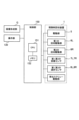
4.制御態様
図11は、本実施例の画像形成装置100の要部の制御態様を示す概略ブロック図である。本実施例では、画像形成装置100の装置本体110に制御部150が設けられている。制御部150は、演算処理を行う中心的素子である演算制御手段としてのCPU151、記憶手段としてのRAM、ROMなどのメモリ(記憶媒体)152、制御部150と各部との信号の入出力を制御する入出力回路(図示せず)などを有して構成される。書き換え可能なメモリであるRAMには、制御部150に入力された情報、検知された情報、演算結果などが格納され、ROMには制御プログラム、予め求められたデータテーブルなどが格納されている。CPU151とRAMやROMなどのメモリ152とは互いにデータの転送や読込みが可能となっている。
4. Control mode Fig. 11 is a schematic block diagram showing the control mode of the main part of the
制御部150には、画像形成部Gの各部が接続されている。また、制御部150には現像剤回収装置1の駆動部5、第1、第2の回収駆動部6L、6R、第1、第2の容器センサ7L、7R、第1、第2の満杯センサ8L、8Rなどが接続されている。また、制御部150には、画像形成装置100に設けられた操作部(操作パネル)130が接続されている。操作部130は、制御部150の制御によって情報を表示する表示手段としての液晶パネルなどの表示部、及びユーザやサービス担当者などの操作者による操作によって制御部150に情報を入力する入力手段としてのキーなどの入力部を有する。操作部130は、表示部及び入力部の機能を有するタッチパネルを有して構成されていてよい。また、制御部150には、画像形成装置100に設けられるか又は画像形成装置100に接続された画像読取装置(図示せず)や、画像形成装置100に接続されたパーソナルコンピュータなどの外部装置が接続されていてよい。
Each part of the image forming unit G is connected to the
制御部150は、画像形成装置100の操作部130や外部装置からの指示及び画像情報に基づいて画像形成部Gの各部を統括的に制御して、画像形成動作を実行させることができる。また、制御部150は、第1、第2の回収現像剤容器10L、10Rへの回収現像剤の搬送動作、各容器の交換を促す動作などを実行するように、現像剤回収装置1の各部を統括的に制御可能である。制御部150は、現像剤回収装置1の一部を構成するものとみなすこともできる。
The
5.現像剤回収装置の動作
次に、本実施例の現像剤回収装置1による第1、第2の回収現像剤容器10L、10Rへの回収現像剤の搬送動作について説明する。ここでは、第1、第2の回収現像剤容器10L、10Rのそれぞれに回収現像剤を搬送する際の現像剤回収装置1の動作について説明する。回収現像剤の搬送先の切り替えを含む現像剤回収装置1の動作シーケンスの具体例については後述する。
5. Operation of the Developer Recovery Device Next, the operation of transporting the recovered developer to the first and second recovered
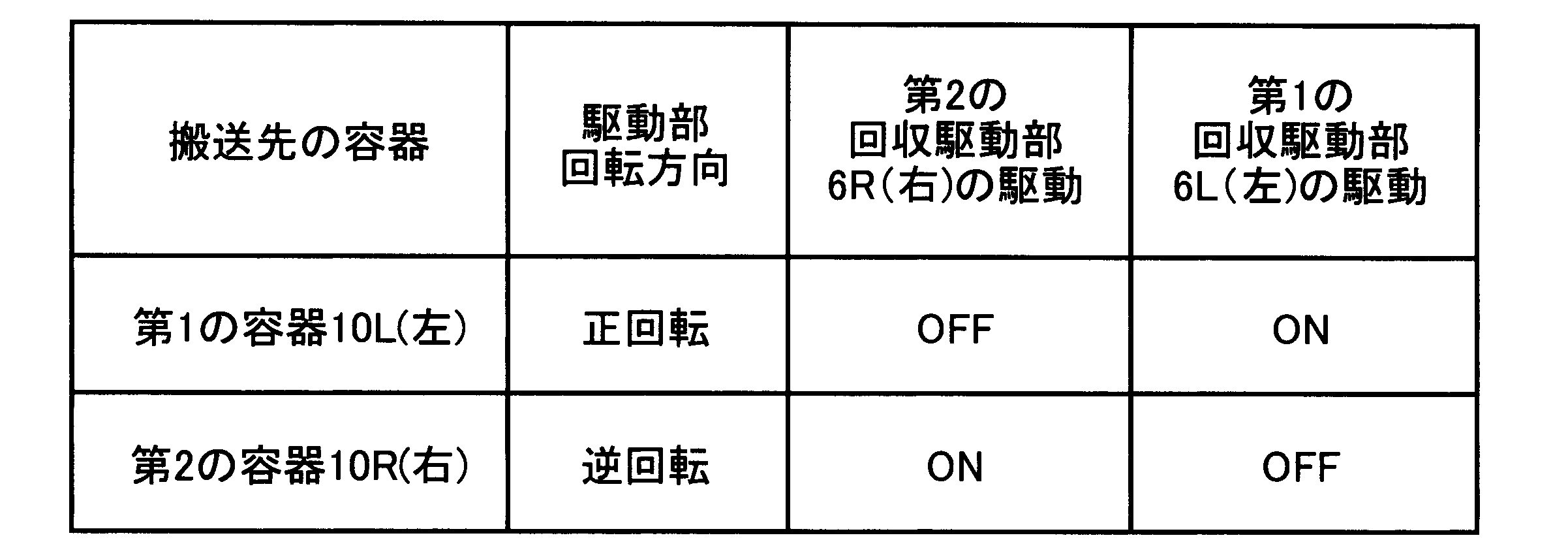
表1は、本実施例における第1、第2の回収現像剤容器10L、10Rのそれぞれへの回収現像剤の搬送動作における駆動部5、第1、第2の回収駆動部6L、6Rの動作状態をまとめたものである。この動作は、制御部150がメモリ152に格納されたプログラムに従って駆動部5、第1、第2の回収駆動部6L、6Rを制御することで実行する。
Table 1 summarizes the operating states of the
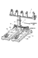
<第1の回収現像剤容器10Lへの搬送動作>
図9は、左側の第1の回収現像剤容器10Lに回収現像剤を搬送する場合の回収現像剤の流れを示している。現像剤回収装置1は、前述のようにして画像形成部Gからの回収現像剤を、上流搬送部3を介して下流搬送部4に送る。下流搬送部4に送られた回収現像剤は、縦パイプ41内を通って横パイプ42内に移動する。第1の回収現像剤容器10Lに回収現像剤を搬送する際には、駆動部5の駆動モータ51は正回転動作をし、横パイプ42内の搬送スクリュー43は駆動部5から駆動力が伝達されて第1の方向に回転する。これにより、搬送スクリュー43は、横パイプ42内の回収現像剤を右側から左側に向かう方向に搬送する。このとき、駆動部5の駆動モータ51の正回転動作に連動して、第1の回収駆動部6Lの第1の回収駆動モータ61Lが回転動作をすると共に、第2の回収駆動部6Rの第2の回収駆動モータ61Rは停止した状態になっている。
<Transportation Operation to First Collected
FIG. 9 shows the flow of the recovered developer when the recovered developer is transported to the first recovered
これにより、搬送スクリュー43によって横パイプ42内を搬送されて第1の回収パイプ44Lに送られた回収現像剤は、第1の回収スクリュー45Lによって第1の回収パイプ44L内を搬送されて第1の回収現像剤容器10Lに送られる。一方、縦パイプ41から横パイプ42に送られた回収現像剤は横パイプ42内で左側から右側に向かう方向に搬送されることはない。また、第2の回収パイプ44R内を回収現像剤が搬送されることもない。
As a result, the recovered developer transported through the
そのため、画像形成装置1の動作中に現像剤回収装置1が第1の回収現像剤容器10Lに回収現像剤を搬送している際に第2の回収現像剤容器10Rを交換するために装置本体110から取り外しても、第2の回収現像剤容器10Rの周辺から回収現像剤が装置本体110内に漏れたり飛散したりすることを抑制することができる。つまり、本実施例によれば、第1の回収現像剤容器10Lに回収現像剤を搬送している際には、画像形成部Gから送られる回収現像剤が第2の回収現像剤容器10Rに向かう搬送経路を通過することがない。そのため、第2の回収現像剤容器10Rが取り外された場合でも、第2の回収現像剤容器10Rに向かう搬送経路からの回収現像剤の漏れや飛散のリスクを低減することができる。
Therefore, even if the
なお、本実施例では第2の回収パイプ44Rには第2のシャッタ部材46Rが設けられているが、上述のような回収現像剤の漏れや飛散のリスクの低減効果によって、このシャッタ部材の省略や、その構成の簡略化を図ることも可能である。
In this embodiment, the
<第2の回収現像剤容器10Rへの搬送動作>
図10は、右側の第2の回収現像剤容器10Rに回収現像剤を搬送する場合の回収現像剤の流れを示している。現像剤回収装置1は、前述のようにして画像形成部Gからの回収現像剤を、上流搬送部3を介して下流搬送部4に送る。下流搬送部4に送られた回収現像剤は、縦パイプ41内を通って横パイプ42内に移動する。第2の回収現像剤容器10Rに回収現像剤を搬送する際には、駆動部5の駆動モータ51は逆回転動作をし、横パイプ42内の搬送スクリュー43は駆動部5から駆動力が伝達されて第2の方向に回転する。これにより、搬送スクリュー43は、横パイプ42内の回収現像剤を左側から右側に向かう方向に搬送する。このとき、駆動部5の駆動モータ51の逆回転動作に連動して、第2の回収駆動部6Rの第2の回収駆動モータ61Rが回転動作をすると共に、第1の回収駆動部6Lの第1の回収駆動モータ61Lは停止した状態になっている。
<Transportation Operation to Second Collected
FIG. 10 shows the flow of the recovered developer when the recovered developer is transported to the second recovered
これにより、搬送スクリュー43によって横パイプ42内を搬送されて第2の回収パイプ44Rに送られた回収現像剤は、第2の回収スクリュー45Rによって第2の回収パイプ44R内を搬送されて第2の回収現像剤容器10Rに送られる。一方、縦パイプ41から横パイプ42に送られた回収現像剤は横パイプ42内で右側から左側に向かう方向に搬送されることはない。また、第1の回収パイプ44L内を回収現像剤が搬送されることもない。
As a result, the recovered developer transported through the
そのため、画像形成装置1の動作中に現像剤回収装置1が第2の回収現像剤容器10Rに回収現像剤を搬送している際に第1の回収現像剤容器10Lを交換するために装置本体110から取り外しても、第1の回収現像剤容器10Lの周辺から回収現像剤が装置本体110内に漏れたり飛散したりすることを抑制することができる。つまり、本実施例によれば、第2の回収現像剤容器10Rに回収現像剤を搬送している際には、画像形成部Gから送られる回収現像剤が第1の回収現像剤容器10Lに向かう搬送経路を通過することがない。そのため、第1の回収現像剤容器10Lが取り外された場合でも、第1の回収現像剤容器10Lに向かう搬送経路からの回収現像剤の漏れや飛散のリスクを低減することができる。
Therefore, even if the first recovered
なお、本実施例では第1の回収パイプ44Lには第1のシャッタ部材46Lが設けられているが、上記第2のシャッタ部材46Rの場合と同様、このシャッタ部材の省略や、その構成の簡略化を図ることも可能である。
In this embodiment, the
このように、現像剤回収装置1は、駆動部5、第1の回収駆動部6L及び第2の回収駆動部6Rを制御する制御部150を有する。そして、制御部150は、駆動部5により搬送スクリュー43を第1の方向に回転駆動する際には、第1の回収駆動部6Lにより第1の回収スクリュー45Lを回転駆動すると共に第2の回収駆動部6Rによる第2の回収スクリュー45Rの回転駆動を停止するように制御を行う。また、制御部150は、駆動部5により搬送スクリュー43を第2の方向に回転駆動する際には、第1の回収駆動部6Lによる第1の回収スクリュー45Lの回転駆動を停止すると共に第2の回収駆動部6Rにより第2の回収スクリュー45Rを回転駆動するように制御を行う。
Thus, the
6.現像剤回収装置の動作シーケンス
次に、本実施例の現像剤回収装置1における回収現像剤の搬送先の切り替えを含む現像剤回収装置1の動作シーケンスの具体例について説明する。図12は、該動作シーケンスの手順の概略を示すフローチャート図である。ここでは、簡単のため、第1、第2の回収現像剤容器10L、10Rが装置本体110の内部における所定の位置に配置されている状態を前提として、連続画像形成のジョブの実行中に回収現像剤の搬送先を切り替える動作について説明する。なお、ジョブとは、1つの開始指示により開始される単数又は複数の記録材Pに画像を形成して出力する一連の動作である。また、以下では説明を省略しているが、制御部150は駆動部5の動作の制御と連動して前述のような第1、第2の回収駆動部6L、6Rの動作の制御も行う(表1参照)。また、以下では説明を省略しているが、上流搬送部3の排出スクリュー37は、画像形成動作中は継続して回転駆動され、画像形成動作が終了(あるいは中断)されると停止される。
6. Operation sequence of developer recovery device Next, a specific example of the operation sequence of the
制御部150は、ジョブが入力されて画像形成動作を開始すると(S101)、メモリ152に記憶されている情報に基づいて、現在の回収現像剤の搬送先が第1の回収現像剤容器10Lであるか否かを判断する(S102)。なお、制御部150は、回収現像剤の搬送先を切り替えるごとに、現在の回収現像剤の搬送先に関する情報をメモリ152に記憶させる。制御部150は、S102で現在の回収現像剤の搬送先が第1の回収現像剤容器10Lではない(「No」)と判断した場合は、S112の処理に進む。また、制御部150は、S102で現在の回収現像剤の搬送先が第1の回収現像剤容器10Lである(「Yes」)と判断した場合は、駆動部5の駆動モータ51を正回転動作させる(S103)。次に、制御部150は、第1の満杯センサ8Lからの信号に基づいて、第1の回収現像剤容器10Lが満杯か否か(第1の満杯センサ8Lの信号がONか否か)を判断する(S104)。制御部150は、S104で満杯ではない(「No」)と判断した場合は、画像形成動作を継続する(S105)。次に、制御部150は、ジョブの未出力の画像があるか否かを判断する(S106)。そして、制御部150は、S106で未出力の画像がある(「Yes」)と判断した場合はS104の処理に戻り、S106で未出力の画像がない(「No」)と判断した場合は駆動部5の駆動モータ51を停止する(S107)。また、制御部150は、画像形成動作を終了してジョブを終了する(S108)。また、制御部150は、S104で満杯である(「Yes」)と判断した場合は、第2の満杯センサ8Rからの信号に基づいて、第2の回収現像剤容器10Rが満杯か否か(第2の満杯センサ8Rの信号がONか否か)を判断する(S109)。制御部150は、S109で満杯である(「Yes」)と判断した場合は、駆動部5の駆動モータ51を停止する(S110)。また、制御部150は、画像形成動作を中断する(S111)。S111において、制御部150は、操作部130(あるいは外部装置の表示部など)(報知手段)において、第1、第2の回収現像剤容器10L、10Rの両方が満杯であることを報知するための表示などを行うことができる。
When a job is input and an image forming operation is started (S101), the
一方、制御部150は、S109で第2の回収現像剤容器10Rが満杯ではない(「No」)と判断した場合は、駆動部5の駆動モータ51の回転方向を切り替えて逆回転動作させる(S112)。これにより、回収現像剤の搬送先を第1の回収現像剤回収容器10Lから第2の回収現像剤容器10Rに切り替える。なお、制御部50は、S102で現在の回収現像剤の搬送先が第1の回収現像剤容器10Lではない(「No」)と判断した場合も、駆動部5の駆動モータ51を逆回転動作させる(S112)。次に、制御部150は、第2の満杯センサ8Rからの信号に基づいて、第2の回収現像剤容器10Lが満杯か否か(第2の満杯センサ8Rの信号がONか否か)を判断する(S113)。制御部150は、S113で満杯ではない(「No」)と判断した場合は、画像形成動作を継続する(S114)。次に、制御部150は、ジョブの未出力の画像があるか否かを判断する(S115)。そして、制御部150は、S115で未出力の画像がある(「Yes」)と判断した場合はS113の処理に戻り、S115で未出力の画像がない(「No」)と判断した場合は駆動部5の駆動モータ51を停止する(S116)。また、制御部150は、画像形成動作を終了してジョブを終了する(S117)。また、制御部150は、S113で満杯である(「Yes」)と判断した場合は、第1の満杯センサ8Lからの信号に基づいて、第1の回収現像剤容器10Lが満杯か否か(第1の満杯センサ8Lの信号がONか否か)を判断する(S118)。制御部150は、S118で満杯ではない(「No」)と判断した場合は、S103の処理に進む。つまり、制御部50は、駆動部5の駆動モータ51の回転方向を切り替えて正回転動作させ、回収現像剤の搬送先を第2の回収現像剤回収容器10Rから第1の回収現像剤容器10Lに切り替える。また、制御部150は、S118で満杯である(「Yes」)と判断した場合は、駆動部5の駆動モータ51を停止する(S119)。また、制御部150は、画像形成動作を中断する(S120)。S120において、制御部150は、操作部130(あるいは外部装置の表示部など)において、第1、第2の回収現像剤容器10L、10Rの両方が満杯であることを報知するための表示などを行うことができる。
On the other hand, if the
また、S112、S103で駆動部5の駆動モータ51の回転方向を切り替えて回収現像剤の搬送先の容器を切り替えた場合には、制御部150は、次のようにすることができる。つまり、操作部130(あるいは外部装置の表示部など)において、満杯になった方の容器の交換が必要であることを報知する表示(交換を促す表示など)を行うことができる。このとき、その報知を画像形成動作中に直ちに行うのではなく、ジョブの終了後に行ってもよい。また、ジョブの終了後に、現像剤回収装置1を満杯になった方の容器に向けて回収現像剤を搬送するように動作させて、例えば満杯になった方の容器に対応する回収パイプ44内に残っている回収現像剤をその容器に搬送するようにしてもよい。これにより、その回収パイプ44内での回収現像剤がその後放置されることで凝集(固着)などすることを抑制することができる。
In addition, when the rotation direction of the
なお、ここでは簡単のため説明を省略したが、制御部150は、第1、第2の容器センサ7L、7Rからの信号に基づいて、画像形成動作や現像剤回収装置1の動作を制御することができる。例えば、制御部150は、ジョブの開始が指示された際に、第1、第2の回収現像剤容器10L、10Rの両方が装着されていないと判断した場合には、画像形成動作を開始しないように制御することができる。また、例えば、制御部50は、第1、第2の回収現像剤容器10L、10Rのうち一方の容器の満杯が検知された際に、他方の容器が装着されていないことが検知された場合には、画像形成動作を中断するように制御することができる。これらいずれの場合も、対応する容器の装着を促す表示などを操作部130(あるいは外部装置の表示部など)で行うことができる。
Although the explanation is omitted here for simplicity, the
このように、本実施例では、第1、第2の回収現像剤容器10L、10Rのうち一方の容器が満杯になった場合に他方の容器に回収現像剤の搬送先を切り替えるようにして、第1、第2の回収現像剤容器10L、10Rを交互に用いるようにする。これにより、画像形成動作中に一方の容器が満杯となっても、画像形成動作を停止させることなくその容器を交換することができる。そして、本実施例によれば、このように画像形成動作中に一方の容器を交換する場合であっても、その容器の周辺から回収現像剤が装置本体110内に漏れたり飛散したりすることを抑制することができる。
In this way, in this embodiment, when one of the first and second recovered
以上説明したように、本実施例によれば、複数の回収現像剤容器に選択的に回収現像剤を回収する構成において、回収現像剤の漏れや飛散のリスクを低減することができる。 As described above, this embodiment reduces the risk of leakage or scattering of recovered developer in a configuration in which recovered developer is selectively collected into multiple recovered developer containers.
[実施例2]
次に、本発明の他の実施例について説明する。本実施例の現像剤回収装置1及び画像形成装置100の基本的な構成は実施例1のものと同じである。本実施例の現像剤回収装置1及び画像形成装置100において、実施例1のものと同一又は対応する機能あるいは構成を有する要素については、実施例1のものと同一の符号を付して、詳しい説明は省略する。
[Example 2]
Next, another embodiment of the present invention will be described. The basic configurations of the
1.現像剤回収装置の構成
実施例1では、現像剤回収装置1は、第1、第2の回収スクリュー45L、45Rがそれぞれ搬送スクリュー43とは別の駆動部(駆動源)によって回転駆動される構成とされていた。これに対して、本実施例では、第1、第2の回収スクリュー45L、45Rは、搬送スクリュー43に伝達された駆動力を伝達して回転駆動することができるようになっている。
1. Configuration of the Developer Recovery Device In the first embodiment, the
図13は、本実施例における現像剤回収装置1を斜め前から見た斜視図である(現像剤回収装置1に接続された第1、第2の回収現像剤容器10L、10Rも示されている。)。また、図14は、図4のX-X線と同様に切った図13に示す本実施例の現像剤回収装置1の断面図である。また、図15は、図4のY-Y線と同様に切った図13に示す本実施例の現像剤回収装置1の断面図である。また、図16は、本実施例の現像剤回収装置1の一部を斜め後から見た斜視図であり、第1、第2の回収スクリュー45L、45Rへの駆動伝達経路が示されている。
Figure 13 is a perspective view of the
図13及び図16に示すように、搬送スクリュー43は、駆動部5から回転駆動力が伝達されて回転駆動される。本実施例では、駆動部5は、駆動源としての駆動モータ51と、駆動モータ51からの駆動力を搬送スクリュー43に伝達する駆動列(単数又は複数のギアなど)52と、を有して構成される。本実施例では、駆動源51は、横パイプ42の左側の側部に配置されており、駆動列52は、搬送スクリュー43の左側の端部に接続されている。
As shown in Figures 13 and 16, the conveying
また、図13及び図16に示すように、搬送スクリュー43の回転軸線方向の左側及び右側の端部にそれぞれ形成(あるいは連結)された直線状の第1、第2の軸部43a、43bが、横パイプ42の外側に延在している。そして、この第1、第2の軸部43a、43bとそれぞれ駆動連結可能なように、第1、第2の駆動伝達部20L、20Rが設けられている。本実施例では、第1の駆動伝達部20Lは、駆動力遮断部材としての第1のワンウェイクラッチギア21Lと、第1の回収駆動列(単数又は複数のギアなど)22Lと、を有して構成される。第1のワンウェイクラッチギア21Lは、搬送スクリュー43の第1の軸部43aに駆動伝達可能に配置され、内径部にワンウェイクラッチが圧入されて構成されている。また、第1の回収駆動列22Lは、第1のワンウェイクラッチギア21Lからの回転駆動力を第1の回収スクリュー45Lに伝達するように構成されている。なお、本実施例では、第1の回収駆動列22Lは、第1のカップリング63Lにも駆動を伝達するように構成されている。同様に、本実施例では、第2の駆動伝達部20Lは、駆動力遮断部材としての第2のワンウェイクラッチギア21Rと、第2の回収駆動列(単数又は複数のギアなど)22Rと、を有して構成される。第2のワンウェイクラッチギア21Rは、搬送スクリュー43の第2の軸部43bに駆動伝達可能に配置され、内径部にワンウェイクラッチが圧入されて構成されている。また、第2の回収駆動列22Rは、第2のワンウェイクラッチギア21Rからの回転駆動力を第2の回収スクリュー45Rに伝達するように構成されている。なお、本実施例では、第2の回収駆動列22Rは、第2のカップリング63Rにも駆動を伝達するように構成されている。
As shown in Figs. 13 and 16, the first and second
第1のワンウェイクラッチギア21Lは、搬送スクリュー43が第1の方向(回収現像剤を第1の回収現像剤容器10Lに向けて搬送する方向)に回転した際に、一緒に回転し、下流に駆動力を伝えるように構成されている。また、第2のワンウェイクラッチギア21Rは、搬送スクリュー43が第2の方向(回収現像剤を第2の回収現像剤容器10Rに向けて搬送する方向)に回転した際に、一緒に回転し、下流に駆動力を伝えるように構成されている。
The first one-way
2.現像剤回収装置の動作
次に、本実施例の現像剤回収装置1による第1、第2の回収現像剤容器10L、10Rへの回収現像剤の搬送動作について説明する。ここでは、主に実施例1と異なる部分について説明する。表2は、本実施例における第1、第2の回収現像剤容器10L、10Rのそれぞれへの回収現像剤の搬送動作における駆動部5、第1、第2の回収スクリュー45L、45Rの動作状態をまとめたものである。この動作は、制御部150がメモリ152に格納されたプログラムに従って駆動部5を制御することで実行する。
2. Operation of the Developer Recovery Device Next, the operation of transporting the recovered developer to the first and second recovered
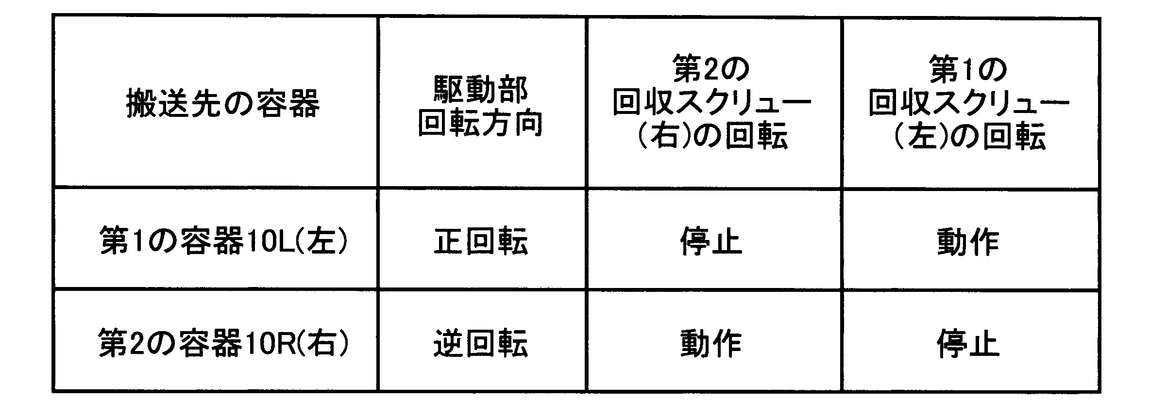
<第1の回収現像剤容器10Lへの搬送動作>
図17は、左側の第1の回収現像剤容器10Lに回収現像剤を搬送する場合の回収現像剤の流れを示している。本実施例では、第1の回収現像剤容器10Lに回収現像剤を搬送する際には、駆動部5の駆動モータ51の正回転動作による搬送スクリュー43の第1の方向への回転に同期して、第1のワンウェイクラッチギア21Lが駆動を伝達する方向に回転する。そして、第1のワンウェイクラッチギア21Lから第1の回収駆動列22Lへ駆動力が伝わり、第1の回収スクリュー45Lが回転する。一方、第2のワンウェイクラッチギア21Rは駆動を遮断し、第2の回収駆動列22Rに駆動力を伝えないため、第2の回収スクリュー45Rは停止したままである。
<Transportation Operation to First Collected
17 shows the flow of the recovered developer when the recovered developer is transported to the first recovered
これにより、搬送スクリュー43によって横パイプ42内を搬送されて第1の回収パイプ44Lに送られた回収現像剤は、第1の回収スクリュー45Lによって第1の回収パイプ44L内を搬送されて第1の回収現像剤容器10Lに送られる。一方、縦パイプ41から横パイプ42に送られた回収現像剤は横パイプ42内で左側から右側に向かう方向に搬送されることはない。また、第2の回収パイプ44R内を回収現像剤が搬送されることもない。
As a result, the recovered developer transported through the
そのため、画像形成装置1の動作中に現像剤回収装置1が第1の回収現像剤容器10Lに回収現像剤を搬送している際に第2の回収現像剤容器10Rを交換するために装置本体110から取り外しても、第2の回収現像剤容器10Rの周辺から回収現像剤が装置本体110内に漏れたり飛散したりすることを抑制することができる。
Therefore, even if the
<第2の回収現像剤容器10Rへの搬送動作>
図18は、右側の第2の回収現像剤容器10Rに回収現像剤を搬送する場合の回収現像剤の流れを示している。本実施例では、第2の回収現像剤容器10Rに回収現像剤を搬送する際には、駆動部5の駆動モータ51の逆回転動作による搬送スクリュー43の第2の方向への回転に同期して、第2のワンウェイクラッチギア21Rが駆動を伝達する方向に回転する。そして、第2のワンウェイクラッチギア21Rから第2の回収駆動列22Rへ駆動力が伝わり、第2の回収スクリュー45Rが回転する。一方、第1のワンウェイクラッチギア21Lは駆動を遮断し、第1の駆動列22Lに駆動力を伝えないため、第1の回収スクリュー45Rは停止したままである。
<Transportation Operation to Second Collected
18 shows the flow of the recovered developer when the recovered developer is transported to the second recovered
これにより、搬送スクリュー43によって横パイプ42内を搬送されて第2の回収パイプ44Rに送られた回収現像剤は、第2の回収スクリュー45Rによって第2の回収パイプ44R内を搬送されて第2の回収現像剤容器10Rに送られる。一方、縦パイプ41から横パイプ42に送られた回収現像剤は横パイプ42内で右側から左側に向かう方向に搬送されることはない。また、第1の回収パイプ44R内を回収現像剤が搬送されることもない。
As a result, the recovered developer transported through the
そのため、画像形成装置1の動作中に現像剤回収装置1が第2の回収現像剤容器10Rに回収現像剤を搬送している際に第1の回収現像剤容器10Lを交換するために装置本体110から取り外しても、第1の回収現像剤容器10Lの周辺から回収現像剤が装置本体110内に漏れたり飛散したりすることを抑制することができる。
Therefore, even if the first recovered
このように、本実施例では、現像剤回収装置1は、駆動部5から搬送スクリュー43に伝達された駆動力を第1の回収スクリュー45Lに伝達することが可能であると共に、該駆動力の伝達を遮断することが可能な第1の駆動伝達部20Lを有する。また、この現像剤回収装置1は、駆動部5から搬送スクリュー43に伝達された駆動力を第2の回収スクリュー45Rに伝達することが可能であると共に、該駆動力の伝達を遮断することが可能な第2の駆動伝達部20Rを有する。そして、駆動部5により搬送スクリュー43が第1の方向に回転駆動される際には、第1の駆動伝達部20Lは搬送スクリュー43から第1の回収スクリュー45Lに駆動力を伝達し、第2の駆動伝達部20Rは搬送スクリュー43から第2の回収スクリュー45Rへの駆動力の伝達を遮断する。また、駆動部5により搬送スクリュー43が第2の方向に回転駆動される際には、第1の駆動伝達部20Lは搬送スクリュー43から第1の回収スクリュー45Lへの駆動力の伝達を遮断し、第2の駆動伝達部20Rは搬送スクリュー43から第2の回収スクリュー45Rに駆動力を伝達する。
Thus, in this embodiment, the
なお、本実施例における現像剤回収装置1の動作シーケンスは、図12を参照して実施例1で説明したものと同様とすることができる。ただし、本実施例では、駆動部5による搬送スクリュー43の動作の制御に連動した第1、第2の回収駆動部6L、6Rの動作の制御は必要ない。
The operation sequence of the
以上説明したように、本実施例によれば、実施例1と同様の効果が得られると共に、実施例1よりも現像剤回収装置1の構成の簡易化を図ることができる。
As described above, this embodiment provides the same effects as the first embodiment, while simplifying the configuration of the
[その他]
以上、本発明を具体的な実施例に即して説明したが、本発明は上述の実施例に限定されるものではない。
[others]
Although the present invention has been described above with reference to specific embodiments, the present invention is not limited to the above-mentioned embodiments.
上述の実施例では、画像形成装置は中間転写方式を採用したタンデム型のカラー画像形成装置であったが、本発明はこれに限定されるものではない。例えば、画像形成装置は、直接転写方式を採用したタンデム型のカラー画像形成装置であってもよい。この画像形成装置は、当業者には周知のように、上述の実施例における中間転写体に代えて、記録材を担持して搬送する記録材担持体(無端状のベルトで構成された搬送ベルトなど)を有する。そして、複数のステーションの像担持体にそれぞれ形成されたトナー像が、記録材担持体に担持されて搬送される記録材に順次転写され、定着された後に、画像形成装置の外部に排出される。この画像形成装置では、画像形成部は、各ステーション、記録材担持体及び定着装置を含む。また、画像形成装置は、1つの像担持体に複数の色のトナー像を順次形成するごとに中間転写体又は記録材担持体に担持された記録材に転写する、いわゆる、1ドラム型のカラー画像形成装置であってもよい。この画像形成装置では、画像形成部は、1つの像担持体にトナー像を形成するトナー像形成部(ステーションに相当)、中間転写体(あるいは記録材担持体)及び定着装置を含む。また、画像形成装置は、モノクロ画像形成装置であってもよい。この場合、画像形成部は、1つの像担持体にトナー像を形成するトナー像形成部(ステーションに相当)及び定着装置を含む。 In the above embodiment, the image forming apparatus is a tandem type color image forming apparatus that employs an intermediate transfer method, but the present invention is not limited to this. For example, the image forming apparatus may be a tandem type color image forming apparatus that employs a direct transfer method. As is well known to those skilled in the art, this image forming apparatus has a recording material carrier (such as a conveying belt composed of an endless belt) that carries and conveys a recording material instead of the intermediate transfer body in the above embodiment. Then, the toner images formed on the image carriers of the multiple stations are sequentially transferred to the recording material carried and conveyed on the recording material carrier, and after being fixed, the image is discharged outside the image forming apparatus. In this image forming apparatus, the image forming section includes each station, the recording material carrier, and a fixing device. In addition, the image forming apparatus may be a so-called one-drum type color image forming apparatus that transfers multiple color toner images to the intermediate transfer body or the recording material carried on the recording material carrier each time they are sequentially formed on one image carrier. In this image forming device, the image forming section includes a toner image forming section (corresponding to a station) that forms a toner image on one image carrier, an intermediate transfer body (or a recording material carrier), and a fixing device. The image forming device may also be a monochrome image forming device. In this case, the image forming section includes a toner image forming section (corresponding to a station) that forms a toner image on one image carrier, and a fixing device.
1 現像剤回収装置
3 上流搬送部
4 下流搬送部
5 駆動部
6L、6R 第1、第2の回収駆動部
10L、10R 第1、第2の回収現像剤容器
41 縦パイプ
42 横パイプ
43 搬送スクリュー
44L、44R 第1、第2の回収パイプ
45L、45R 第1、第2の回収スクリュー
REFERENCE SIGNS
Claims (8)
前記複数の画像形成部の下方に配置され、前記複数の画像形成部により形成されたトナーが転写される中間転写体と、
取り外し可能に設けられ、前記複数の画像形成部から排出されたトナーを回収する第1の回収容器と、
取り外し可能に設けられ、前記複数の画像形成部から排出されたトナーを回収する第2の回収容器と、
前記複数の画像形成部から排出されたトナーを前記第1の回収容器と前記第2の回収容器とに選択的に搬送する搬送装置と、を有し、
前記搬送装置は、
前記複数の画像形成部から排出されたトナーを受け入れる複数の排出トナー受入口と、トナーを排出する第1の排出口と、を備え、前記複数の排出トナー受入口から受け入れたトナーを上下方向と交差する方向に沿って前記第1の排出口に搬送する第1の搬送路と、
前記第1の排出口と接続され、前記第1の排出口から排出されたトナーを上下方向に搬送する第2の搬送路と、
前記第2の搬送路と接続される第3の搬送路であって、前記第1の回収容器に向けてトナーを排出する第2の排出口と、前記第2の回収容器に向けてトナーを排出する第3の排出口と、前記第2の排出口と前記第3の排出口との間に設けられ、前記第2の搬送路からトナーを受け入れる受入口と、を備え、前記受入口から受け入れられたトナーを上下方向と交差する方向に沿って前記第2の排出口もしくは前記第3の排出口に選択的に搬送可能な第3の搬送路と、
前記第3の搬送路内に設けられ、前記第3の搬送路に沿う回転軸線を中心に回転可能な螺旋状の搬送部材と、
前記搬送部材を正方向と逆方向とに回転駆動する駆動部と、を有し、
前記搬送装置は、前記搬送部材を前記正方向に回転させることにより、前記受入口から前記第2の排出口に向かう方向にトナーを搬送することが可能であり、前記搬送部材を前記逆方向に回転させることにより、前記受入口から前記第3の排出口に向かう方向にトナーを搬送することが可能に構成され、
前記複数の画像形成部は、トナー像を形成する第1の画像形成部と、トナー像を形成する第2の画像形成部と、トナー像を形成する第3の画像形成部と、トナー像を形成する第4の画像形成部と、を含み、
前記複数の排出トナー受入口は、前記第1の画像形成部から排出されたトナーを受け入れる第1の排出トナー受入口と、前記第2の画像形成部から排出されたトナーを受け入れる第2の排出トナー受入口と、前記第3の画像形成部から排出されたトナーを受け入れる第3の排出トナー受入口と、前記第4の画像形成部から排出されたトナーを受け入れる第4の排出トナー受入口と、を含み、
前記第1の排出口は、前記所定方向において、前記複数の排出トナー受入口のうち最も一端側に配置される前記第1の排出トナー受入口と、前記複数の排出トナー受入口のうち最も他端側に配置される前記第2の排出トナー受入口と、の間に設けられ、
前記第2の排出口と前記第3の排出口は、前記所定方向において、前記第1の排出トナー受入口と前記第2の排出トナー受入口との間に配置されていることを特徴とする画像形成装置。 A plurality of image forming units arranged in a predetermined direction to form toner images;
an intermediate transfer body disposed below the plurality of image forming units and onto which the toner formed by the plurality of image forming units is transferred;
a first waste toner container that is detachably provided and that collects toner discharged from the plurality of image forming units;
a second collection container that is detachably provided and that collects toner discharged from the plurality of image forming units;
a conveying device that selectively conveys the toner discharged from the plurality of image forming units to the first waste toner container and the second waste toner container,
The conveying device is
a first transport path including a plurality of discharge toner receiving ports for receiving toner discharged from the plurality of image forming units and a first discharge port for discharging the toner, the first transport path transporting the toner received from the plurality of discharge toner receiving ports to the first discharge port along a direction intersecting with a vertical direction;
a second transport path connected to the first discharge port and configured to transport the toner discharged from the first discharge port in a vertical direction;
a third transport path connected to the second transport path, the third transport path including a second discharge port for discharging toner toward the first waste toner container, a third discharge port for discharging toner toward the second waste toner container, and a receiving port provided between the second discharge port and the third discharge port for receiving toner from the second transport path, the third transport path being capable of selectively transporting the toner received from the receiving port to the second discharge port or the third discharge port along a direction intersecting with a vertical direction;
a spiral conveying member provided in the third conveying path and rotatable about a rotation axis along the third conveying path;
a drive unit that rotates the conveying member in a forward direction and a reverse direction,
the transport device is configured to transport toner in a direction from the receiving opening toward the second discharge opening by rotating the transport member in the forward direction, and to transport toner in a direction from the receiving opening toward the third discharge opening by rotating the transport member in the reverse direction,
the plurality of image forming units include a first image forming unit that forms a toner image, a second image forming unit that forms a toner image, a third image forming unit that forms a toner image, and a fourth image forming unit that forms a toner image;
the plurality of discharge toner receiving ports include a first discharge toner receiving port that receives the toner discharged from the first image forming unit, a second discharge toner receiving port that receives the toner discharged from the second image forming unit, a third discharge toner receiving port that receives the toner discharged from the third image forming unit, and a fourth discharge toner receiving port that receives the toner discharged from the fourth image forming unit;
the first discharge port is provided between the first discharge toner receiving port arranged at the furthest end side of the plurality of discharge toner receiving ports and the second discharge toner receiving port arranged at the furthest end side of the plurality of discharge toner receiving ports in the predetermined direction,
an image forming apparatus, characterized in that the second discharge outlet and the third discharge outlet are disposed between the first discharge toner receiving inlet and the second discharge toner receiving inlet in the predetermined direction;
前記所定方向において、前記第1の排出トナー受入口と前記第1の排出口の間の距離を第1距離、前記第2の排出トナー受入口と前記第1の排出口の間の距離を第2距離としたとき、In the predetermined direction, a distance between the first discharge toner receiving opening and the first discharge opening is defined as a first distance, and a distance between the second discharge toner receiving opening and the first discharge opening is defined as a second distance.
前記第1距離<前記第2距離であり、the first distance is smaller than the second distance,
前記所定方向において、前記第2の排出口と前記受入口の距離を第3距離、前記第3の排出口と前記受入口の距離を第4距離としたとき、In the predetermined direction, when a distance between the second discharge port and the receiving port is a third distance and a distance between the third discharge port and the receiving port is a fourth distance,
前記第3距離<前記第4距離であることを特徴とする請求項1に記載の画像形成装置。2. The image forming apparatus according to claim 1, wherein the third distance is smaller than the fourth distance.
Priority Applications (1)
| Application Number | Priority Date | Filing Date | Title |
|---|---|---|---|
| JP2024073293A JP7686838B2 (en) | 2020-04-15 | 2024-04-29 | Image forming device |
Applications Claiming Priority (2)
| Application Number | Priority Date | Filing Date | Title |
|---|---|---|---|
| JP2020073184A JP7512069B2 (en) | 2020-04-15 | 2020-04-15 | Image forming device |
| JP2024073293A JP7686838B2 (en) | 2020-04-15 | 2024-04-29 | Image forming device |
Related Parent Applications (1)
| Application Number | Title | Priority Date | Filing Date |
|---|---|---|---|
| JP2020073184A Division JP7512069B2 (en) | 2020-04-15 | 2020-04-15 | Image forming device |
Publications (2)
| Publication Number | Publication Date |
|---|---|
| JP2024091970A JP2024091970A (en) | 2024-07-05 |
| JP7686838B2 true JP7686838B2 (en) | 2025-06-02 |
Family
ID=74884830
Family Applications (2)
| Application Number | Title | Priority Date | Filing Date |
|---|---|---|---|
| JP2020073184A Active JP7512069B2 (en) | 2020-04-15 | 2020-04-15 | Image forming device |
| JP2024073293A Active JP7686838B2 (en) | 2020-04-15 | 2024-04-29 | Image forming device |
Family Applications Before (1)
| Application Number | Title | Priority Date | Filing Date |
|---|---|---|---|
| JP2020073184A Active JP7512069B2 (en) | 2020-04-15 | 2020-04-15 | Image forming device |
Country Status (4)
| Country | Link |
|---|---|
| US (1) | US11415928B2 (en) |
| EP (1) | EP3896527A1 (en) |
| JP (2) | JP7512069B2 (en) |
| CN (1) | CN113534640B (en) |
Families Citing this family (2)
| Publication number | Priority date | Publication date | Assignee | Title |
|---|---|---|---|---|
| JP7532070B2 (en) * | 2020-04-15 | 2024-08-13 | キヤノン株式会社 | Image forming device |
| JP7822802B2 (en) | 2022-01-28 | 2026-03-03 | キヤノン株式会社 | Image forming device |
Citations (11)
| Publication number | Priority date | Publication date | Assignee | Title |
|---|---|---|---|---|
| JP2007199197A (en) | 2006-01-24 | 2007-08-09 | Fuji Xerox Co Ltd | Image forming apparatus and waste toner storage container |
| JP2009020281A (en) | 2007-07-11 | 2009-01-29 | Kyocera Mita Corp | Waste developer collecting device for image forming apparatus, and image forming apparatus |
| US20090067856A1 (en) | 2007-09-10 | 2009-03-12 | Kabushiki Kaisha Toshiba | Image Forming Apparatus |
| JP2010117675A (en) | 2008-11-14 | 2010-05-27 | Ricoh Co Ltd | Waste toner collector and image forming apparatus |
| JP2010231075A (en) | 2009-03-27 | 2010-10-14 | Fuji Xerox Co Ltd | Developer collection device and image forming apparatus |
| JP2012032621A (en) | 2010-07-30 | 2012-02-16 | Kyocera Mita Corp | Image forming apparatus |
| JP2012037812A (en) | 2010-08-10 | 2012-02-23 | Fuji Xerox Co Ltd | Developer recovery device and image forming apparatus |
| JP2015022178A (en) | 2013-07-19 | 2015-02-02 | カシオ電子工業株式会社 | Waste toner collection container |
| JP2015059946A (en) | 2013-09-17 | 2015-03-30 | 株式会社リコー | Unnecessary toner conveying device and image forming apparatus having the same |
| JP2015212799A (en) | 2014-02-07 | 2015-11-26 | 株式会社リコー | Image forming apparatus |
| JP2017015753A (en) | 2015-06-26 | 2017-01-19 | ブラザー工業株式会社 | Image forming apparatus and waste developer container |
Family Cites Families (19)
| Publication number | Priority date | Publication date | Assignee | Title |
|---|---|---|---|---|
| JPH05289584A (en) * | 1992-04-13 | 1993-11-05 | Ricoh Co Ltd | Image forming device |
| JP2001247235A (en) * | 2000-03-06 | 2001-09-11 | Ricoh Co Ltd | Image forming device |
| JP2004151238A (en) * | 2002-10-29 | 2004-05-27 | Canon Inc | Waste toner collecting apparatus and image forming apparatus having the same |
| JP4298733B2 (en) | 2006-09-25 | 2009-07-22 | シャープ株式会社 | Developer recovery apparatus and image forming apparatus including the same |
| JP4674626B2 (en) * | 2008-09-26 | 2011-04-20 | 富士ゼロックス株式会社 | Image forming apparatus |
| JP4858519B2 (en) * | 2008-09-26 | 2012-01-18 | 富士ゼロックス株式会社 | Image forming apparatus and powder conveying apparatus |
| JP4692660B2 (en) * | 2009-03-19 | 2011-06-01 | 富士ゼロックス株式会社 | Collection device and image forming apparatus |
| JP5743183B2 (en) * | 2010-03-17 | 2015-07-01 | 株式会社リコー | Image forming apparatus |
| JP5264965B2 (en) * | 2010-09-22 | 2013-08-14 | キヤノン株式会社 | Electrophotographic image forming apparatus |
| JP2012155148A (en) * | 2011-01-26 | 2012-08-16 | Fuji Xerox Co Ltd | Image forming apparatus |
| JP5772276B2 (en) * | 2011-06-21 | 2015-09-02 | 富士ゼロックス株式会社 | Image forming apparatus |
| JP5954150B2 (en) * | 2012-12-11 | 2016-07-20 | 富士ゼロックス株式会社 | Image forming apparatus |
| JP2015022095A (en) * | 2013-07-18 | 2015-02-02 | 株式会社リコー | Image forming apparatus and process cartridge |
| JP6218554B2 (en) * | 2013-10-24 | 2017-10-25 | キヤノン株式会社 | Image forming apparatus |
| JP6498030B2 (en) * | 2015-05-18 | 2019-04-10 | シャープ株式会社 | Image forming apparatus |
| JP2018092045A (en) * | 2016-12-05 | 2018-06-14 | キヤノン株式会社 | Image formation device |
| JP7413853B2 (en) * | 2020-03-12 | 2024-01-16 | 富士フイルムビジネスイノベーション株式会社 | Powder recovery equipment and image forming equipment |
| JP7532070B2 (en) * | 2020-04-15 | 2024-08-13 | キヤノン株式会社 | Image forming device |
| US12072662B2 (en) * | 2020-04-15 | 2024-08-27 | Canon Kabushiki Kaisha | Image forming apparatus |
-
2020
- 2020-04-15 JP JP2020073184A patent/JP7512069B2/en active Active
-
2021
- 2021-03-16 EP EP21162763.3A patent/EP3896527A1/en active Pending
- 2021-04-12 US US17/227,428 patent/US11415928B2/en active Active
- 2021-04-13 CN CN202110391946.5A patent/CN113534640B/en active Active
-
2024
- 2024-04-29 JP JP2024073293A patent/JP7686838B2/en active Active
Patent Citations (11)
| Publication number | Priority date | Publication date | Assignee | Title |
|---|---|---|---|---|
| JP2007199197A (en) | 2006-01-24 | 2007-08-09 | Fuji Xerox Co Ltd | Image forming apparatus and waste toner storage container |
| JP2009020281A (en) | 2007-07-11 | 2009-01-29 | Kyocera Mita Corp | Waste developer collecting device for image forming apparatus, and image forming apparatus |
| US20090067856A1 (en) | 2007-09-10 | 2009-03-12 | Kabushiki Kaisha Toshiba | Image Forming Apparatus |
| JP2010117675A (en) | 2008-11-14 | 2010-05-27 | Ricoh Co Ltd | Waste toner collector and image forming apparatus |
| JP2010231075A (en) | 2009-03-27 | 2010-10-14 | Fuji Xerox Co Ltd | Developer collection device and image forming apparatus |
| JP2012032621A (en) | 2010-07-30 | 2012-02-16 | Kyocera Mita Corp | Image forming apparatus |
| JP2012037812A (en) | 2010-08-10 | 2012-02-23 | Fuji Xerox Co Ltd | Developer recovery device and image forming apparatus |
| JP2015022178A (en) | 2013-07-19 | 2015-02-02 | カシオ電子工業株式会社 | Waste toner collection container |
| JP2015059946A (en) | 2013-09-17 | 2015-03-30 | 株式会社リコー | Unnecessary toner conveying device and image forming apparatus having the same |
| JP2015212799A (en) | 2014-02-07 | 2015-11-26 | 株式会社リコー | Image forming apparatus |
| JP2017015753A (en) | 2015-06-26 | 2017-01-19 | ブラザー工業株式会社 | Image forming apparatus and waste developer container |
Also Published As
| Publication number | Publication date |
|---|---|
| JP2024091970A (en) | 2024-07-05 |
| US20210325818A1 (en) | 2021-10-21 |
| JP2021170074A (en) | 2021-10-28 |
| JP7512069B2 (en) | 2024-07-08 |
| EP3896527A1 (en) | 2021-10-20 |
| CN113534640A (en) | 2021-10-22 |
| CN113534640B (en) | 2024-05-14 |
| US11415928B2 (en) | 2022-08-16 |
Similar Documents
| Publication | Publication Date | Title |
|---|---|---|
| JP7686838B2 (en) | Image forming device | |
| JP5716927B2 (en) | Waste toner collecting apparatus and image forming apparatus | |
| JP7793692B2 (en) | Image forming device | |
| EP3796092B1 (en) | Image forming apparatus | |
| JP6274074B2 (en) | Waste toner container and image forming apparatus | |
| JP7631052B2 (en) | Image forming device | |
| JPH08137227A (en) | Toner supply device | |
| JP7822802B2 (en) | Image forming device | |
| JP6406174B2 (en) | Waste toner container and image forming apparatus | |
| JP2023088043A (en) | image forming device | |
| JP2023117336A (en) | image forming device | |
| US20250231515A1 (en) | Image forming apparatus | |
| JP2006126570A (en) | Toner supply device | |
| JP2005024759A (en) | Image forming apparatus | |
| JP2018092044A (en) | Image forming apparatus | |
| JP5387329B2 (en) | Image forming apparatus | |
| JP2008164748A (en) | Developing unit | |
| JP2024083731A (en) | Image forming device | |
| JP2008026365A (en) | Image forming apparatus | |
| JP2020154084A (en) | Waste toner container and image forming device | |
| JP2016164649A (en) | Image forming apparatus | |
| JP2007004058A (en) | Image forming apparatus |
Legal Events
| Date | Code | Title | Description |
|---|---|---|---|
| A521 | Request for written amendment filed |
Free format text: JAPANESE INTERMEDIATE CODE: A523 Effective date: 20240529 |
|
| A621 | Written request for application examination |
Free format text: JAPANESE INTERMEDIATE CODE: A621 Effective date: 20240529 |
|
| A977 | Report on retrieval |
Free format text: JAPANESE INTERMEDIATE CODE: A971007 Effective date: 20241111 |
|
| A131 | Notification of reasons for refusal |
Free format text: JAPANESE INTERMEDIATE CODE: A131 Effective date: 20250107 |
|
| A521 | Request for written amendment filed |
Free format text: JAPANESE INTERMEDIATE CODE: A523 Effective date: 20250308 |
|
| TRDD | Decision of grant or rejection written | ||
| A01 | Written decision to grant a patent or to grant a registration (utility model) |
Free format text: JAPANESE INTERMEDIATE CODE: A01 Effective date: 20250422 |
|
| A61 | First payment of annual fees (during grant procedure) |
Free format text: JAPANESE INTERMEDIATE CODE: A61 Effective date: 20250521 |
|
| R150 | Certificate of patent or registration of utility model |
Ref document number: 7686838 Country of ref document: JP Free format text: JAPANESE INTERMEDIATE CODE: R150 |