JP7684635B2 - Method for supplying copper concentrate to a copper concentrate supply facility and copper concentrate supply facility - Google Patents
Method for supplying copper concentrate to a copper concentrate supply facility and copper concentrate supply facility Download PDFInfo
- Publication number
- JP7684635B2 JP7684635B2 JP2021136991A JP2021136991A JP7684635B2 JP 7684635 B2 JP7684635 B2 JP 7684635B2 JP 2021136991 A JP2021136991 A JP 2021136991A JP 2021136991 A JP2021136991 A JP 2021136991A JP 7684635 B2 JP7684635 B2 JP 7684635B2
- Authority
- JP
- Japan
- Prior art keywords
- copper concentrate
- particle size
- concentrate
- medium
- copper
- Prior art date
- Legal status (The legal status is an assumption and is not a legal conclusion. Google has not performed a legal analysis and makes no representation as to the accuracy of the status listed.)
- Active
Links
Images

Classifications
-
- Y—GENERAL TAGGING OF NEW TECHNOLOGICAL DEVELOPMENTS; GENERAL TAGGING OF CROSS-SECTIONAL TECHNOLOGIES SPANNING OVER SEVERAL SECTIONS OF THE IPC; TECHNICAL SUBJECTS COVERED BY FORMER USPC CROSS-REFERENCE ART COLLECTIONS [XRACs] AND DIGESTS
- Y02—TECHNOLOGIES OR APPLICATIONS FOR MITIGATION OR ADAPTATION AGAINST CLIMATE CHANGE
- Y02P—CLIMATE CHANGE MITIGATION TECHNOLOGIES IN THE PRODUCTION OR PROCESSING OF GOODS
- Y02P10/00—Technologies related to metal processing
- Y02P10/20—Recycling
Landscapes
- Manufacture And Refinement Of Metals (AREA)
Description
本発明は、銅精鉱供給設備への銅精鉱の供給方法および銅精鉱供給設備に関する。さらに詳しくは、自熔炉に装入する前に乾燥した銅精鉱を貯留する銅精鉱供給設備およびかかる銅精鉱供給設備への銅精鉱の供給方法に関する。 The present invention relates to a method for supplying copper concentrate to a copper concentrate supplying facility and to a copper concentrate supplying facility. More specifically, the present invention relates to a copper concentrate supplying facility that stores dried copper concentrate before charging into a flash smelting furnace and a method for supplying copper concentrate to such a copper concentrate supplying facility.
多くの金属精錬設備では、燃料消費率が他の製法と比べて低い自熔製錬法が採用されている。自熔製錬法は、自熔炉の反応塔内において乾燥させた粉体状の精鉱(以下、乾鉱ということもある)と空気等を吹き込むことにより、瞬間的に酸化反応を起こさせて所望の濃縮物と不要物とに分離する方法である。この自熔製錬法では、自熔炉を安定して操業することが重要であり、かかる自熔炉の安定操業には、自熔炉に供給する乾鉱の量を適切に調整することが非常に重要となる。 Many metal refining facilities use the flash smelting method, which has a lower fuel consumption rate than other methods. The flash smelting method involves blowing air into a reaction tower of a flash furnace into which dried powdered concentrate (hereinafter sometimes referred to as dry ore) is instantaneously oxidized to separate the concentrate into the desired concentrate and unwanted materials. In this flash smelting method, it is important to operate the flash furnace stably, and to operate the flash furnace stably, it is extremely important to appropriately adjust the amount of dry ore supplied to the flash furnace.
自熔炉に供給する乾鉱は、乾燥させた粉体の状態で一時的に乾鉱庫に貯留され、乾鉱庫から所定量の乾鉱が連続的に自熔炉へ搬送される。所定量の乾鉱を乾鉱庫から自熔炉に搬送する方法として、例えば、計量スクリューコンベアを使用する方法が採用されている(例えば、特許文献1、2参照)。この方法では、乾鉱庫の底部(排出口)に計量スクリューコンベアを設け、この計量スクリューコンベアの作動を制御することによって乾鉱庫から自熔炉に搬送し自熔炉に投入する乾鉱の量を調整する。
The dry ore to be supplied to the flash furnace is temporarily stored in a dry ore warehouse in a dried powder state, and a predetermined amount of dry ore is continuously transported from the dry ore warehouse to the flash furnace. As a method for transporting a predetermined amount of dry ore from the dry ore warehouse to the flash furnace, for example, a method using a weighing screw conveyor is adopted (see, for example,
しかし、計量スクリューコンベアによって乾鉱庫から自熔炉に搬送する乾鉱の量は、計量スクリューコンベアの作動状態を同じにした場合でも、乾鉱庫から切り出される乾鉱の量によって変動する。乾鉱庫から切り出される乾鉱の量は、乾鉱庫内の乾鉱の高さや乾鉱の粒度が変化すれば、計量スクリューコンベアの作動状態を同じにしても変化してしまう。したがって、計量スクリューコンベアによって所定量の乾鉱を乾鉱庫から自熔炉へ搬送するには、乾鉱庫内の乾鉱の高さや乾鉱の粒度を一定にすることが必要になる。 However, the amount of dry ore transported by the weighing screw conveyor from the dry ore warehouse to the flash smelting furnace varies depending on the amount of dry ore cut out from the dry ore warehouse, even if the operating state of the weighing screw conveyor is the same. If the height of the dry ore in the dry ore warehouse or the particle size of the dry ore changes, the amount of dry ore cut out from the dry ore warehouse will change even if the operating state of the weighing screw conveyor is the same. Therefore, in order to transport a specified amount of dry ore from the dry ore warehouse to the flash smelting furnace by the weighing screw conveyor, it is necessary to keep the height of the dry ore in the dry ore warehouse and the particle size of the dry ore constant.
乾鉱庫に貯留される乾鉱は乾燥設備で乾燥されるが、乾燥設備から乾鉱庫への乾鉱の搬送には、通常、気流搬送が用いられる。気流搬送される間に、乾鉱は、ダストチャンバー(大粒径精鉱回収部)、1次サイクロン(中粒径精鉱回収部)、2次サイクロン(小粒径精鉱回収部)によって固気分離されて回収され、各装置で回収された乾鉱が乾鉱庫に搬送される。乾鉱庫は、通常、その上部は一つの空間となっているが、その下部は複数の貯留空間に分離されており、各装置から搬送される乾鉱は、複数の貯留空間に振り分けられて貯留される。そして、乾鉱庫の各貯留空間の下端には、それぞれ計量スクリューコンベアが設けられており、各貯留空間内の乾鉱が各計量スクリューコンベアから自熔炉に供給される。 The dry ore stored in the dry ore warehouse is dried in a drying facility, and air current transport is usually used to transport the dry ore from the drying facility to the dry ore warehouse. While being transported by air current, the dry ore is separated into solid and gas and recovered by the dust chamber (large particle concentrate recovery section), the primary cyclone (medium particle concentrate recovery section), and the secondary cyclone (small particle concentrate recovery section), and the dry ore recovered by each device is transported to the dry ore warehouse. The upper part of the dry ore warehouse is usually a single space, but the lower part is separated into multiple storage spaces, and the dry ore transported from each device is sorted and stored in the multiple storage spaces. A weighing screw conveyor is provided at the bottom end of each storage space in the dry ore warehouse, and the dry ore in each storage space is supplied to the flash smelting furnace from each weighing screw conveyor.
乾燥設備から乾鉱庫への乾鉱の気流搬送では、固気分離の気体側である排ガス中に乾鉱を残さないようにするために、中粒径精鉱回収部である1次サイクロンまでに乾鉱のほとんどが回収されており、小粒径精鉱回収部である2次サイクロンで回収される乾鉱は少量となる特徴がある。そのため、乾鉱庫の複数の貯留空間のうち、2次サイクロンで回収した乾鉱が振り分けられる貯留空間では乾鉱が少ない状態となり、乾鉱庫内において貯留空間の間で乾鉱の高さにばらつきを生じる。かかる貯留空間の間で乾鉱の高さのばらつきが生じれば、貯留空間内の乾鉱の流動化の一因となる。とくに、小粒径精鉱回収部である2次サイクロンで回収された乾鉱の粒径は小さく、乾鉱庫の貯留空間において圧密されにくいという特徴もあり、乾鉱庫内において中粒径精鉱と小粒径精鉱の偏在があることも乾鉱が流動する一因となる。 In the airflow transport of dry ore from the drying equipment to the dry ore storage, most of the dry ore is collected by the first cyclone, which is the medium-particle concentrate recovery section, in order to prevent any dry ore from remaining in the exhaust gas, which is the gas side of the solid-gas separation, and only a small amount of dry ore is collected by the second cyclone, which is the small-particle concentrate recovery section. Therefore, among the multiple storage spaces in the dry ore storage, the storage space to which the dry ore collected by the second cyclone is allocated has little dry ore, and the height of the dry ore varies between the storage spaces in the dry ore storage. If the height of the dry ore varies between such storage spaces, this is one of the factors that causes the dry ore to become fluidized in the storage space. In particular, the particle size of the dry ore collected by the second cyclone, which is the small-particle concentrate recovery section, is small, and it is characterized by being difficult to consolidate in the storage space of the dry ore storage, and the uneven distribution of medium-particle concentrate and small-particle concentrate in the dry ore storage is also one of the factors that causes the dry ore to become fluidized.
このような流動化を防止する方法として、特許文献3に記載された技術がある。この技術では、大粒径精鉱回収部で回収された大粒径の銅精鉱を粒径が小さい乾鉱を多く含む貯留空間に供給することによって流動化現象を防止している。 One method for preventing such fluidization is the technology described in Patent Document 3. In this technology, the fluidization phenomenon is prevented by supplying the large-grain copper concentrate recovered in the large-grain concentrate recovery section to a storage space that contains a large amount of dry ore with a small grain size.
特許文献3に記載された技術は流動化現象を防止する技術として有効であるものの、大粒径精鉱回収部で回収される大粒径の銅精鉱の量が少ない場合には、粒径が小さい乾鉱を多く含む貯留空間に十分な量の大粒径の銅精鉱を供給できない。すると、粒径が小さい乾鉱を多く含む貯留空間における流動化を防止できず、自熔炉に供給する原料を適切に調整することが難しくなる可能性がある。 Although the technology described in Patent Document 3 is effective as a technology for preventing fluidization, if the amount of large-grained copper concentrate recovered in the large-grained concentrate recovery section is small, a sufficient amount of large-grained copper concentrate cannot be supplied to the storage space containing a large amount of small-grained dry ore. As a result, fluidization in the storage space containing a large amount of small-grained dry ore cannot be prevented, and it may become difficult to appropriately adjust the raw material supplied to the flash smelting furnace.
本発明は上記事情に鑑み、自熔炉に供給する原料を適切に調整することが可能となる銅精鉱供給設備への銅精鉱の供給方法および銅精鉱供給設備を提供することを目的とする。 In view of the above circumstances, the present invention aims to provide a method for supplying copper concentrate to a copper concentrate supplying facility and a copper concentrate supplying facility that makes it possible to appropriately adjust the raw materials supplied to a flash melting furnace.
<銅精鉱供給設備への銅精鉱の供給方法>
第1発明の銅精鉱供給設備への銅精鉱の供給方法は、自熔炉に対して銅精鉱を供給する銅精鉱供給設備に対する銅精鉱の供給を調整する方法であって、前記銅精鉱供給設備が、銅精鉱を乾燥する乾燥器と、該乾燥器から供給される銅精鉱が貯留される乾鉱庫と、前記乾燥器から前記乾鉱庫に乾燥された銅精鉱を気流搬送する気流搬送部と、を備えており、
前記乾鉱庫は、前記気流搬送部から乾燥された銅精鉱が供給される貯留空間を複数備えており、前記気流搬送部は、前記乾燥器によって乾燥された銅精鉱のうち、粒径が10μmより大きい大粒径の銅精鉱を回収する大粒径精鉱回収部と、該大粒径精鉱回収部で回収されなかった粒径が5μm以上の中粒径の銅精鉱を回収する中粒径精鉱回収部と、該中粒径精鉱回収部および前記大粒径精鉱回収部で回収されなかった粒径が5μmより小さい小粒径の銅精鉱を回収する小粒径精鉱回収部と、を備えており、前記中粒径精鉱回収部で回収された中粒径の銅精鉱の一部を、前記小粒径精鉱回収部で回収された小粒径の銅精鉱が供給される貯留空間に供給することを特徴とする。
第2発明の銅精鉱供給設備への銅精鉱の供給方法は、第1発明において、前記乾鉱庫内の各貯留空間の銅精鉱の貯留高さを測定する測定部を備えており、該測定部の測定結果に基づいて、各貯留空間に供給する前記中粒径の銅精鉱の量を調整することを特徴とする。
第3発明の銅精鉱供給設備への銅精鉱の供給方法は、第2発明において、前記乾鉱庫内の各貯留空間の銅精鉱の貯留高さを3.5m以上に維持することを特徴とする。
<銅精鉱供給設備>
第4発明の銅精鉱供給設備は、自熔炉に対して銅精鉱を供給する銅精鉱供給設備であって、前記銅精鉱供給設備が、銅精鉱を乾燥する乾燥器と、該乾燥器から供給される銅精鉱が貯留される乾鉱庫と、前記乾燥器から前記乾鉱庫に乾燥された銅精鉱を気流搬送する気流搬送部と、を備えており、前記乾鉱庫は、前記気流搬送部から乾燥された銅精鉱が供給される貯留空間を複数備えており、前記気流搬送部は、前記乾燥器によって乾燥された銅精鉱のうち、粒径が10μmより大きい大粒径の銅精鉱を回収する大粒径精鉱回収部と、該大粒径精鉱回収部で回収されなかった粒径が5μm以上の中粒径の銅精鉱を回収する中粒径精鉱回収部と、該中粒径精鉱回収部および前記大粒径精鉱回収部で回収されなかった粒径が5μmより小さい小粒径の銅精鉱を回収する小粒径精鉱回収部と、を備えており、前記中粒径精鉱回収部で回収された中粒径の銅精鉱の一部について、供給する前記乾鉱庫の貯留空間を変更する分配装置を備えていることを特徴とする。
第5発明の銅精鉱供給設備は、第4発明において、前記分配装置が、前記中粒径精鉱回収部で回収された中粒径の銅精鉱を貯留する中粒径貯留空間と前記中粒径精鉱回収部との間に設けられた、前記中粒径精鉱回収部で回収された中粒径の銅精鉱を前記中粒径貯留空間に供給する供給部と、該供給部と、前記小粒径精鉱回収部で回収された小粒径の銅精鉱を貯留する小粒径貯留空間と、の間に設けられ、該小粒径貯留空間に前記中粒径の銅精鉱を供給する連結搬送部と、を備えており、前記供給部は、前記中粒径精鉱回収部から中粒径の銅精鉱が供給される第一流路と、該第一流路の排出端と前記中粒径貯留空間とを連通する第二流路と、前記第一流路の排出端と前記連結搬送部とを連通する第三流路と、前記第一流路の排出端に設けられた、前記中粒径の銅精鉱を供給する流路を前記第二流路と前記第三流路との間で切り替える分配部と、を備えていることを特徴とする。
第6発明の銅精鉱供給設備は、第5発明において、前記分配部の作動を制御する制御部を備えており、該制御部は、前記乾鉱庫内の各貯留空間の銅精鉱の貯留高さを測定する測定部を備えており、該測定部の測定結果に基づいて、前記分配部の作動を制御する機能を有していることを特徴とする。
<Method of supplying copper concentrate to copper concentrate supply facility>
The method for supplying copper concentrate to a copper concentrate supplying facility of the first invention is a method for adjusting the supply of copper concentrate to a copper concentrate supplying facility that supplies copper concentrate to a flash smelting furnace, the copper concentrate supplying facility including a dryer for drying the copper concentrate, a dry ore storage facility for storing the copper concentrate supplied from the dryer, and an airflow conveying unit for airflow conveying the dried copper concentrate from the dryer to the dry ore storage facility,
The dry ore warehouse has a plurality of storage spaces to which dried copper concentrate is supplied from the air flow conveying section, and the air flow conveying section has a large particle size concentrate recovery section that recovers large particle size copper concentrate having a particle size of more than 10 μm from the copper concentrate dried by the dryer, a medium particle size concentrate recovery section that recovers medium particle size copper concentrate having a particle size of 5 μm or more that was not recovered in the large particle size concentrate recovery section, and a small particle size concentrate recovery section that recovers small particle size copper concentrate having a particle size of less than 5 μm that was not recovered in the medium particle size concentrate recovery section and the large particle size concentrate recovery section, and is characterized in that a portion of the medium particle size copper concentrate recovered in the medium particle size concentrate recovery section is supplied to the storage space to which the small particle size copper concentrate recovered in the small particle size concentrate recovery section is supplied.
The method of supplying copper concentrate to a copper concentrate supplying facility of the second invention is characterized in that, in the first invention, a measuring unit is provided for measuring the storage height of copper concentrate in each storage space in the dry ore warehouse, and the amount of the medium particle size copper concentrate to be supplied to each storage space is adjusted based on the measurement results of the measuring unit.
The method for supplying copper concentrate to a copper concentrate supply facility of the third invention is characterized in that in the second invention, the storage height of the copper concentrate in each storage space in the dry ore warehouse is maintained at 3.5 m or more.
<Copper concentrate supply equipment>
A copper concentrate supplying facility of a fourth invention is a copper concentrate supplying facility for supplying copper concentrate to a flash smelting furnace, the copper concentrate supplying facility comprising a dryer for drying copper concentrate, a dry ore storage for storing the copper concentrate supplied from the dryer, and an air flow conveying unit for air flow conveying the dried copper concentrate from the dryer to the dry ore storage, the dry ore storage comprising a plurality of storage spaces to which the dried copper concentrate is supplied from the air flow conveying unit, and the air flow conveying unit conveys the copper concentrate having a particle size of 10 μm or less from the copper concentrate dried by the dryer. The system is equipped with a large particle size concentrate recovery section for recovering large particle size copper concentrate, a medium particle size concentrate recovery section for recovering medium particle size copper concentrate having a particle size of 5 μm or more that has not been recovered by the large particle size concentrate recovery section, and a small particle size concentrate recovery section for recovering small particle size copper concentrate having a particle size of less than 5 μm that has not been recovered by the medium particle size concentrate recovery section and the large particle size concentrate recovery section, and is characterized in that it is equipped with a distribution device that changes the storage space of the dry ore warehouse to which a portion of the medium particle size copper concentrate recovered by the medium particle size concentrate recovery section is supplied.
The copper concentrate supplying equipment of the fifth invention is the copper concentrate supplying equipment of the fourth invention, wherein the distributor is provided between a medium particle size storage space for storing medium particle size copper concentrate recovered in the medium particle size concentrate recovery section and the medium particle size concentrate recovery section, the distributor being provided between the distributor and a small particle size storage space for storing small particle size copper concentrate recovered in the small particle size concentrate recovery section, and the distributor is provided between the distributor and a medium particle size storage space for storing medium particle size copper concentrate recovered in the medium particle size concentrate recovery section, the small particle size storage space being provided with the medium particle size copper concentrate recovered in the medium particle size concentrate recovery section. and a connecting and conveying section for supplying copper concentrate, the supplying section comprising a first flow path through which medium-sized copper concentrate is supplied from the medium-sized concentrate recovery section, a second flow path connecting a discharge end of the first flow path with the medium-sized copper concentrate storage space, a third flow path connecting a discharge end of the first flow path with the connecting and conveying section, and a distribution section provided at the discharge end of the first flow path for switching the flow path for supplying the medium-sized copper concentrate between the second flow path and the third flow path.
The copper concentrate supply equipment of the sixth invention is characterized in that, in the fifth invention, it is provided with a control unit that controls the operation of the distribution unit, and the control unit is provided with a measuring unit that measures the storage height of copper concentrate in each storage space in the dry ore warehouse, and has a function of controlling the operation of the distribution unit based on the measurement results of the measuring unit.
<銅精鉱供給設備への銅精鉱の供給方法>
第1発明によれば、回収量の多い中粒径の銅精鉱を分配するので、各貯留空間の粒度や貯留高さを均一に近づけることができる。したがって、乾鉱庫の貯留空間から切り出す銅精鉱の量を安定化することができるので、自熔炉に供給する銅精鉱の量を適切に調整することが可能になる。
第2、第3発明によれば、乾鉱庫の各貯留空間内の銅精鉱の貯留高さを適切な高さに調整できるので、自熔炉に供給する銅精鉱の量を適切に調整することが可能になる。
<銅精鉱供給設備>
第4発明によれば、分配装置によって回収量の多い中粒径の銅精鉱を分配するので、各貯留空間の粒度や貯留高さを均一に近づけることができる。したがって、乾鉱庫の貯留空間から切り出す銅精鉱の量を安定化することができるので、自熔炉に供給する銅精鉱の量を適切に調整することが可能になる。
第5発明によれば、中粒径の銅精鉱を確実に分配できる。
第6発明によれば、乾鉱庫の各貯留空間内の銅精鉱の貯留高さを適切な高さに調整できるので、自熔炉に供給する銅精鉱の量を適切に調整することが可能になる。
<Method of supplying copper concentrate to copper concentrate supply facility>
According to the first invention, since the medium-sized copper concentrate, which has a large amount of recovery, is distributed, the particle size and storage height of each storage space can be made uniform. Therefore, the amount of copper concentrate extracted from the storage space of the dry ore warehouse can be stabilized, and the amount of copper concentrate supplied to the flash smelting furnace can be appropriately adjusted.
According to the second and third aspects of the present invention, the storage height of the copper concentrate in each storage space of the dry ore warehouse can be adjusted to an appropriate height, so that the amount of copper concentrate supplied to the flash smelting furnace can be appropriately adjusted.
<Copper concentrate supply equipment>
According to the fourth invention, since the medium-sized copper concentrate, which has a large recovery amount, is distributed by the distributor, the particle size and storage height of each storage space can be made uniform. Therefore, the amount of copper concentrate extracted from the storage space of the dry ore warehouse can be stabilized, and the amount of copper concentrate supplied to the flash smelting furnace can be appropriately adjusted.
According to the fifth aspect of the present invention, the copper concentrate having a medium particle size can be reliably distributed.
According to the sixth aspect of the present invention, the storage height of the copper concentrate in each storage space of the dry ore warehouse can be adjusted to an appropriate height, so that the amount of copper concentrate supplied to the flash smelting furnace can be appropriately adjusted.
本発明の銅精鉱供給設備への銅精鉱の供給方法は、自熔炉に供給する銅精鉱を貯留する銅精鉱供給設備の乾鉱庫に対する銅精鉱の供給方法であって、乾鉱庫から銅精鉱を切り出す量を安定させることができるようにしたことに特徴を有している。 The method of supplying copper concentrate to a copper concentrate supplying facility of the present invention is a method of supplying copper concentrate to a dry ore storage facility of the copper concentrate supplying facility that stores copper concentrate to be supplied to a flash smelting furnace, and is characterized by being able to stabilize the amount of copper concentrate cut out from the dry ore storage facility.
<銅精鉱供給設備1>
まず、本発明の銅精鉱供給設備への銅精鉱の供給方法に適した銅精鉱供給設備1を説明する。
図1(A)に示すように、銅精鉱供給設備1は、乾燥器2と、乾燥器2で乾燥された銅精鉱Cを貯留する乾鉱庫10と、乾燥器2から乾鉱庫10に銅精鉱を気流搬送する気流搬送部5と、を備えている。
<Copper
First, a copper
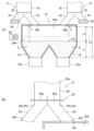
As shown in FIG. 1(A), the copper
<乾燥器2>
乾燥器2は、原料である銅精鉱Cが貯留庫から供給されて、この銅精鉱Cを水分が1%以下になるまで乾燥するものである。この乾燥器2は、銅精鉱Cを所定の水分率まで乾燥できるものであればとくに限定されないが、例えば、フラッシュドライヤーや蒸気ドライヤー等の公知の乾燥装置を乾燥器2として使用できる。
<
The
<乾鉱庫10>
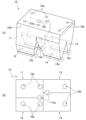
乾鉱庫10は、上述した乾燥器2で乾燥された銅精鉱Cを貯留する設備である。図3に示すように、この乾鉱庫10は、銅精鉱Cを貯留する4つの貯留空間11~14を備えた中空な箱状の構造物である。この乾鉱庫10内において、上部は貯留空間11~14と連通される一つの供給空間10Aとなっており、下部が互いに分離された貯留空間11~14となっている。各貯留空間11~14は、いずれもホッパーのような構造になっている。例えば、対向する壁面が上方から下方に向かって接近するような構造となっている。そして、各貯留空間11~14の下端には、供給口が形成されており、この供給口の下方には各貯留空間11~14内の銅精鉱Cを切り出して自熔炉Fに供給する軽量スクリューコンベアなどの搬送部15a~15dがそれぞれ設けられている。つまり、各貯留空間11~14の搬送部15a~15dを作動させれば、各貯留空間11~14内の銅精鉱Cを各搬送部15a~15dによって自熔炉Fに供給することができる。
<Dry mine 10>
The
図1(B)および図3に示すように、乾鉱庫10の上面には、乾鉱庫10内に銅精鉱Cを供給する供給口10a~10cが設けられている。各供給口10a~10cは、供給空間10Aを介して、貯留空間11~14に連通されている。具体的には、供給口10aは、貯留空間11,12の上方に形成されており、供給口10aを通して銅精鉱Cを貯留空間11,12に供給できるようになっている。また、供給口10bは、貯留空間13,14の上方に形成されており、供給口10bを通して銅精鉱Cを貯留空間13,14に供給できるようになっている。さらに、2つの供給口10cは、それぞれ、隣接する2つの貯留空間11,12の境界の上方および隣接する2つの貯留空間13,14の境界の上方にそれぞれ形成されており、一方の供給口10cを通して銅精鉱Cを貯留空間11,12に供給でき、他方の供給口10cを通して銅精鉱Cを貯留空間13,14に供給できるようになっている。
As shown in Fig. 1B and Fig. 3, the upper surface of the
なお、乾鉱庫10において、供給口10a~10cを設ける位置は、各供給口10a~10cから各貯留空間11~14に上述したように銅精鉱Cを供給できる位置であればよく、とくに限定されない。例えば、各貯留空間11~14内で十分に銅精鉱Cが広がるように、各貯留空間11~14の長手方向(図1(B)、図3(B)では左右方向)に振り分けて配置したり、各貯留空間11~14の傾斜壁から離れた位置に重点的に配置したりすることができる。
The positions of the
また、後述する気流搬送部5や分配装置20から各供給口10a~10cには配管等を介して銅精鉱Cが供給されるが、この配管等の先端は、各供給口10a~10cを通して乾鉱庫10内に挿入されていてもよい。この場合には、配管等の先端の位置は、各貯留空間11~14内に貯留された銅精鉱Cに接触しない高さ(銅精鉱Cの最大貯留高さより上方)であって、水平方向の位置が上述した各供給口10a~10cと同様に各貯留空間11~14に銅精鉱Cを供給できる位置に設けられていればよい。
Copper concentrate C is supplied to each of the
<気流搬送部5>
図1に示すように、乾燥器2と乾鉱庫10との間には、乾燥器2で乾燥された銅精鉱Cを気流搬送する気流搬送部5を備えている。この気流搬送部5には、空気とともに銅精鉱Cが流される流路5aを備えている。この流路5aには、その上流側端部に銅精鉱Cと気流が供給されており、上流側から下流側に向かって銅精鉱Cが気流搬送されるようになっている(図1(A)の矢印Xの方向)。
<Airflow conveying
As shown in Fig. 1, between the
この流路5aには、上流側から下流側に向かって、大粒径精鉱回収部6、中粒径精鉱回収部7、小粒径精鉱回収部8、がこの順番で配設されている。
In this
<大粒径精鉱回収部6>
大粒径精鉱回収部6は、大粒径の銅精鉱Cを回収(捕集)する装置である。この大粒径精鉱回収部6は、例えば10μmより大きい粒径の銅精鉱C(大粒径の銅精鉱C)を回収する機能を有するものであり、例えば、ダストチャンバーなどである。この大粒径精鉱回収部6は、回収した大粒径の銅精鉱Cを乾鉱庫10の供給口10cに供給できるようになっている。つまり、供給口10cを通して、大粒径精鉱回収部6から乾鉱庫10の貯留空間11~14に大粒径の銅精鉱Cが供給できるようになっている。例えば、大粒径精鉱回収部6から重力落下により供給口10cに大粒径の銅精鉱Cを供給してもよい。また、大粒径精鉱回収部6から公知のコンベアなどに大粒径の銅精鉱Cを供給して、公知のコンベアなどによって供給口10cに大粒径の銅精鉱Cを供給してもよい。
<Large particle size
The large particle size
<中粒径精鉱回収部7>
中粒径精鉱回収部7は、大粒径精鉱回収部6で回収(捕集)されなかった粒径の銅精鉱Cを回収する装置である。この中粒径精鉱回収部6は、大粒径精鉱回収部6で回収しきれなかった銅精鉱Cのうち、例えば5μm以上の粒径の銅精鉱C(中粒径の銅精鉱C)を回収する機能を有するものであり、例えば、サイクロンなどである。この中粒径精鉱回収部7は、分配装置20によって回収した中粒径の銅精鉱Cを乾鉱庫10の供給口10aと供給口10bの両方またはいずれか一方に供給できるようになっている。つまり、供給口10aおよび供給口10bを通して、中粒径精鉱回収部7から貯留空間11~14に中粒径の銅精鉱Cを供給できるようになっている。なお、分配装置20については後述する。また、乾鉱庫10の貯留空間11~14のうち、供給口10bの下方に位置する貯留空間13,14が特許請求の範囲にいう中粒径貯留空間に相当する。
<Medium-grained
The medium-particle size
<小粒径精鉱回収部8>
小粒径精鉱回収部8は、大粒径精鉱回収部6および中粒径精鉱回収部7で回収(捕集)できなかった粒径の銅精鉱Cを回収する装置である。この小粒径精鉱回収部8は、大粒径精鉱回収部6、中粒径精鉱回収部7で回収しきれなかった銅精鉱C(小粒径の銅精鉱C)を回収する機能を有するものであり、例えば、サイクロンなどである。この小粒径精鉱回収部8は、回収した小粒径の銅精鉱Cを供給口10aに供給できるようになっている。つまり、供給口10aを通して、小粒径精鉱回収部8から貯留空間11,12に小粒径の銅精鉱Cを供給できるようになっている。例えば、小粒径精鉱回収部8から重力落下により供給口10bに小粒径の銅精鉱Cを供給してもよい。また、小粒径精鉱回収部8から公知のコンベアなどに小粒径の銅精鉱Cを供給して、公知のコンベアなどによって供給口10aに小粒径の銅精鉱Cを供給してもよい。なお、乾鉱庫10の貯留空間11~14のうち、供給口10aの下方に位置する貯留空間11,12が特許請求の範囲にいう小粒径貯留空間に相当する。
<Small particle size
The small particle
<分配装置20>
図1(B)に示すように、分配装置20は、中粒径精鉱回収部7で回収された中粒径の銅精鉱Cを貯留空間13,14に供給する一対の供給部21,21と、中粒径の銅精鉱Cを貯留空間11,12に供給する一対の連結搬送部26,26と、を備えている。
<供給部21>
図2に示すように、供給部21は、第一流路22と、第二流路23と、第三流路24と、分配部25と、を有している。
<
As shown in Figure 1 (B), the
<
As shown in FIG. 2 , the
第一流路22は、その上流側端部に中粒径精鉱回収部7で回収された中粒径の銅精鉱Cが中粒径精鉱回収部7から供給される供給口22aを有している。この第一流路22においてこの中粒径の銅精鉱Cが排出される端部、つまり、第一流路22において供給口22aと反対側に位置する端部には、排出口22bが形成されている。この排出口22bには、第二流路23の供給口23aと第三流路24の供給口24aとが連通されている。つまり、排出口22bから排出される銅精鉱Cを、第二流路23の供給口23aと第三流路24の両方またはいずれか一方に供給できるように、排出口22bが形成されている。
The
<第二流路23>
上述したように、第一流路22の排出口22bには、第二流路23の供給口23aが連通されている。この第二流路23は、第一流路22から供給される中粒径の銅精鉱Cを排出する端部、つまり、第二流路23において供給口23aと反対側に位置する端部に、排出口23bが形成されている。この第二流路23の排出口23bは、乾鉱庫10の供給口10bに連通されている。
<
As described above, the
<第三流路24>
上述したように、第一流路22の排出口22bには、第三流路24の供給口24aが連通されている。この第三流路24も、第一流路22から供給される中粒径の銅精鉱Cを排出する端部、つまり、第三流路24において供給口24aと反対側に位置する端部に、排出口24bが形成されている。この第二流路24の排出口24bは、連結搬送部26に対して中粒径の銅精鉱Cを供給できるようになっている。
<
As described above, the
<分配部25>
分配部25は、第一流路22の排出口22bから排出される中粒径の銅精鉱Cを、第二流路23と第三流路24とに分配して供給する機能を有するものである。例えば、第一流路22の排出口22bから排出される中粒径の銅精鉱Cのすべてを第二流路23と第三流路24のいずれか一方に供給したり、大部分の中粒径の銅精鉱Cを第二流路23に供給し一部の中粒径の銅精鉱Cを第三流路24に供給したり、また、大部分の中粒径の銅精鉱Cを第三流路24に供給し一部の中粒径の銅精鉱Cを第二流路23に供給したりする機能を分配部25は有している。
<
The
図2(B)に示すように、分配部25は、第二流路23および第三流路24の開度(流路面積)を変更するダンパ25aを有している。図2(B)に示すように、2つのダンパ25aが第二流路23および第三流路24にそれぞれ設けられており、いずれも、第二流路23および第三流路24における中粒径の銅精鉱Cの流動方向と交差する方向に移動するようになっている。つまり、2つのダンパ25aを移動させると、第二流路23および第三流路24を開閉したり開度(流路面積)を調整したりできるようになっている。この分配部25は制御部30に電気的に接続されており、制御部30によって分配部25の作動(つまりダンパ25aの移動)を制御している。
As shown in FIG. 2B, the
なお、分配部25の構成は上記構成に限定されない。第一流路22の排出口22bから排出される中粒径の銅精鉱Cを、上記のように第二流路23と第三流路24とに分配して供給できる構成であればよい。
The configuration of the
<連結搬送部26>
連結搬送部26は、第二流路24の排出口24bから供給された中粒径の銅精鉱Cを乾鉱庫10の供給口10aに供給するものである。具体的には、連結搬送部26は、第二流路24の排出口24bから上流側端部に供給された中粒径の銅精鉱Cを下流側端部まで搬送し、下流側端部において配管26a等(図1(B)参照)を介して乾鉱庫10の供給口10aに供給するものである。連結搬送部26は、例えば、コンベアなどの公知の搬送装置を使用することができるが、上記機能を有するものであればとくに限定されない。
<Connected conveying
The connecting and conveying
本実施形態の銅精鉱供給設備1が以上のような構成を有しているので、乾燥器2で乾燥された銅精鉱Cを、気流搬送部5によって、その粒径に応じて乾鉱庫10の貯留空間11~14の所定の貯留空間に供給することができる。
しかも、分配装置20によって、回収量の多い中粒径の銅精鉱Cを小粒径の銅精鉱Cが貯留される貯留空間11,12にも分配するので、各貯留空間11~14内の銅精鉱Cの粒度や銅精鉱Cの貯留高さを均一に近づけることができる。
すると、乾鉱庫10の各貯留空間11~14から切り出す銅精鉱Cの量を安定化することができるので、自熔炉Fに供給する銅精鉱Cの量を適切に調整することが可能になる。
Since the copper
Furthermore, the
This makes it possible to stabilize the amount of copper concentrate C extracted from each of the
<測定部31>
上述したように、分配部25の作動を制御して、中粒径の銅精鉱Cを小粒径の銅精鉱Cが貯留される貯留空間11,12に分配するが、分配する量を乾鉱庫10の各貯留空間11~14内の銅精鉱Cの貯留高さに応じて調整するようにしてもよい。つまり、乾鉱庫10の各貯留空間11~14内の銅精鉱Cの貯留高さを測定する測定部31を設け、この測定部31の測定結果に基づいて、制御部30は分配部25の作動を制御してもよい。
<
As described above, the operation of the
なお、銅精鉱Cの貯留高さとは、各貯留空間11~14の下端、つまり、排出口が設けられている位置から銅精鉱Cの上面までの高さを意味している。なお、各貯留空間11~14内に貯留されている銅精鉱Cの上面には凹凸があるが、ここでいう銅精鉱Cの上端とは、後述する測定部31の測定器sが設けられている位置における銅精鉱Cの上端(図2(A)ではCtの位置)を意味している。
The storage height of the copper concentrate C refers to the height from the bottom of each storage space 11-14, i.e., the position where the discharge outlet is provided, to the top surface of the copper concentrate C. Note that the top surface of the copper concentrate C stored in each storage space 11-14 is uneven, but the top end of the copper concentrate C here refers to the top end of the copper concentrate C at the position where the measuring device s of the measuring
具体的には、乾鉱庫10の各貯留空間11~14内の銅精鉱Cの貯留高さを、測定部31の測定器sによって測定する。例えば、乾鉱庫10の天井、つまり、各貯留空間11~14の上方にマイクロウェーブ計などの測定器sを設け、測定器sによって銅精鉱Cの上端までの距離L3を測定する(図2(A)参照)。測定部31が測定器sから貯留空間11~14の下端までの距離L2のデータを有していれば、測定器sの測定値と距離L2とに基づいて、測定部31は銅精鉱Cの貯留高さL1(L1=L2-L3)を求めることができる。
Specifically, the storage height of the copper concentrate C in each storage space 11-14 of the
測定部31によって、各貯留空間11~14内の銅精鉱Cの貯留高さが算出されれば、その結果に基づいて、制御部30は分配部25の作動を制御して、乾鉱庫10の各貯留空間11~14内の銅精鉱Cの貯留高さを適切な高さに調整できる。すると、乾鉱庫10の各貯留空間11~14から切り出す銅精鉱Cの量を安定化しやすくなるので、乾鉱庫10の各貯留空間11~14から自熔炉Fに供給する銅精鉱Cの量を調整しやすくなる。
When the
乾鉱庫10の各貯留空間11~14内の銅精鉱Cの貯留高さは、乾鉱庫10の各貯留空間11~14から切り出す銅精鉱Cの量を安定化しやすい高さであればよく、とくに限定されない。例えば、いくらかの受け入れ余力を残しながら乾鉱庫10からいつでも銅精鉱Cを供給できるように、乾鉱庫10の内容量を6割~8割程度に保つ高さに維持することが望ましい。例えば、貯留空間11~14の下端から天井までの高さが6m程度の乾鉱庫10の場合であって、各貯留空間11~14に傾斜面が形成されている領域の高さが50cm程度であれば、銅精鉱Cの貯留高さを3.5m以上、好ましくは3.5m以上4.5m以下程度とすることが望ましい。
The storage height of the copper concentrate C in each storage space 11-14 of the
<測定部31の測定器sについて>
測定部31の測定器sは、銅精鉱Cの上面(図2(A)ではCtの位置)までの距離を測定できるものであればよく、とくに限定されない。上述したマイクロウェーブ計などの非接触で銅精鉱Cの上端までの距離を測定できる測定器sを設ければ、距離測定が各貯留空間11~14内の銅精鉱Cの状態に影響を与えないという利点がある。
<Regarding the measuring device s of the measuring
The measuring device s of the measuring
乾鉱庫10において測定部31の測定器sを設ける位置はとくに限定されない。各貯留空間11~14に対して水平方向の中央部に測定器sを設ければ、銅精鉱Cの量を精度よく把握し易くなる。水平方向の中央部に加えて、銅精鉱Cの高さが最も高くなりやすい位置や最も低くなりやすい位置に測定器sを設けてもよく、これらの位置にも測定器sを設ければ、銅精鉱Cの量をより精度よく把握できる。
The position where the measuring device s of the measuring
<分配装置20について>
上述したように、分配装置20が実質的に同じ構造の一対の供給部21,21と、実質的に同じ構造の一対の連結搬送部26,26と、を有している場合、分配装置20は、通常、各供給部21に同じ量の中粒径の銅精鉱Cを供給する。しかし、乾鉱庫10に測定部31の測定器sを設けた場合には、各貯留空間11~14内の銅精鉱Cの貯留高さに応じて、一対の供給部21,21に供給する中粒径の銅精鉱Cの量を調整する供給量調整部を分配装置20に設けてもよい。供給量調整部を有していれば、各貯留空間11~14内の銅精鉱Cの貯留高さを均一にしやすくなる。例えば、貯留空間13の銅精鉱Cの貯留高さに比べて貯留空間14の銅精鉱Cの貯留高さよりが大幅に低くなったとする。このとき、供給量調整部によって貯留高さの低い貯留空間14に中粒径の銅精鉱Cを供給する供給部21に、他方の供給部21よりも多くの中粒径の銅精鉱Cを供給するようにすれば、貯留空間13と貯留空間14の銅精鉱Cの貯留高さを均一に近づけることができる。
Regarding the
As described above, when the
なお、供給量調整部は、分配部25とは別の制御部によって制御されてもよいが、分配部25と同じ制御部30によってその作動が制御されていることが望ましい。この場合、供給量調整部と分配部25の両方で、各貯留空間11~14に供給する中粒径の銅精鉱Cの量を調整できるので、乾鉱庫10の全ての貯留空間11~14の銅精鉱Cの貯留高さを均一に近づけやすくなる。
The supply amount adjustment unit may be controlled by a control unit separate from the
本発明の銅精鉱供給設備への銅精鉱の供給方法により、乾鉱庫内の銅精鉱の貯留高さを均一に近づけることができることを確認した。 It has been confirmed that the method of supplying copper concentrate to the copper concentrate supply equipment of the present invention makes it possible to make the copper concentrate storage height in the dry ore warehouse closer to uniform.
実験では、上述した分配装置を作動させる前後における乾鉱庫内の銅精鉱の貯留高さを確認した。 In the experiment, the height of copper concentrate stored in the dry ore storage facility was confirmed before and after the above-mentioned distribution device was operated.
使用した設備は、上述した図1の設備と同様の構成を有する設備であり、4基のスクリューコンベアによって乾鉱庫から自熔炉に銅精鉱を供給する設備である。なお、乾鉱庫は図3に示す乾鉱庫と同様の構成を有するものである。乾燥器から気体搬送される銅精鉱のうち、大粒径精鉱回収部に相当するダストチャンバーで捕集された銅精鉱は図2の供給口10cに供給され、小粒径精鉱回収部に相当するサイクロンで捕集された銅精鉱は図2の供給口10aに供給され、中粒径精鉱回収部に相当するサイクロンで捕集された銅精鉱は分配装置によって、図2の供給口10a、供給口10bに供給されるようになっている設備である。
The equipment used has the same configuration as the equipment in Figure 1 described above, and is an equipment that supplies copper concentrate from the dry ore bin to the flash smelting furnace by four screw conveyors. The dry ore bin has the same configuration as the dry ore bin shown in Figure 3. Of the copper concentrates transported by gas from the dryer, the copper concentrates collected in the dust chamber corresponding to the large particle concentrate recovery section are supplied to the
乾鉱庫内には、各貯留空間の銅精鉱の上面までの距離を測定するマイクロウェーブ計をそれぞれ設けた。分配装置は、マイクロウェーブ計の測定値に基づいて算出される各貯留空間の銅精鉱の貯留高さに基づいて、各貯留空間内の高さの差が1m以内となるように制御した。なお、マイクロウェーブ計は、全ての貯留空間に設け、各貯留空間の天井の水平方向の中央部に設置した。 A microwave meter was installed in each storage space to measure the distance to the top surface of the copper concentrate. The distribution device was controlled so that the difference in height within each storage space was within 1 m, based on the storage height of the copper concentrate in each storage space calculated from the microwave meter measurements. Microwave meters were installed in all storage spaces, and were placed in the horizontal center of the ceiling of each storage space.
結果を図4に示す。
なお、縦軸に示した銅精鉱の貯留高さレベルは、各貯留空間の高さに対する銅精鉱の貯留高さ(図2のL1)の割合で示している。各貯留空間の天井は全て同じ高さであるので、各貯留空間の銅精鉱の貯留高さレベルを比較することは、実質的に各貯留空間の銅精鉱の貯留高さを比較していることになる。したがって、以下では、銅精鉱の貯留高さレベルを銅精鉱の貯留高さという場合がある。
The results are shown in Figure 4.
The copper concentrate storage height level shown on the vertical axis is shown as a ratio of the copper concentrate storage height (L1 in FIG. 2 ) to the height of each storage space. Since the ceilings of each storage space are all the same height, comparing the copper concentrate storage height levels of each storage space is essentially comparing the copper concentrate storage heights of each storage space. Therefore, hereinafter, the copper concentrate storage height level may be referred to as the copper concentrate storage height.
図4(A)に示すように、分配装置を作動しなかった場合には、小粒径貯留空間(第1、3室、図3の貯留空間11,12に相当する)の銅精鉱の貯留高さと、中粒径貯留空間(第2、4室、図3の貯留空間13,14に相当する)の銅精鉱の貯留高さは、20%以上の差があり、小粒径貯留空間の銅精鉱の貯留高さが低くなっていた。
As shown in Figure 4 (A), when the distribution device was not operated, there was a difference of 20% or more between the storage height of the copper concentrate in the small particle storage space (
一方、分配装置を作動させた場合には、図4(B)に示すように、小粒径貯留空間の貯留高さを高く、中粒径貯留空間の銅精鉱の貯留高さを低くすることができた。そして、小粒径貯留空間の銅精鉱の貯留高さと中粒径貯留空間の銅精鉱の貯留高さとの差を、最大でも10%程度にすることができた。 On the other hand, when the distribution device was operated, as shown in Figure 4 (B), the storage height of the small particle storage space could be increased and the storage height of the copper concentrate in the medium particle storage space could be decreased. Furthermore, the difference between the storage height of the copper concentrate in the small particle storage space and the storage height of the copper concentrate in the medium particle storage space could be reduced to a maximum of about 10%.
以上の結果より、本発明の銅精鉱供給設備への銅精鉱の供給方法が、乾鉱庫内の銅精鉱の貯留高さを均一に近づけること効果を発揮することが確認された。 The above results confirm that the method of supplying copper concentrate to the copper concentrate supply equipment of the present invention is effective in making the copper concentrate storage height in the dry ore warehouse closer to uniform.
本発明の銅精鉱供給設備への銅精鉱の供給方法は、銅精鉱などを原料とする非鉄金属の製錬において銅精鉱供給設備に粉体を供給する方法として適している。 The method of supplying copper concentrate to a copper concentrate supplying facility of the present invention is suitable as a method of supplying powder to a copper concentrate supplying facility in the smelting of nonferrous metals using copper concentrate as a raw material.
1 銅精鉱供給設備
2 乾燥器
5 気流搬送部
6 大粒径精鉱回収部
7 中粒径精鉱回収部
8 小粒径精鉱回収部
10 乾鉱庫
11 貯留空間
12 貯留空間
13 貯留空間
14 貯留空間
20 分配装置
21 供給部
22 第一流路
23 第二流路
24 第三流路
25 分配部
26 連結搬送部
30 制御部
31 測定部
T 銅精鉱
F 自熔炉
C 銅精鉱
REFERENCE SIGNS
Claims (6)
前記銅精鉱供給設備が、
銅精鉱を乾燥する乾燥器と、
該乾燥器から供給される銅精鉱が貯留される乾鉱庫と、
前記乾燥器から前記乾鉱庫に乾燥された銅精鉱を気流搬送する気流搬送部と、を備えており、
前記乾鉱庫は、
前記気流搬送部から乾燥された銅精鉱が供給される貯留空間を複数備えており、
前記気流搬送部は、
前記乾燥器によって乾燥された銅精鉱のうち、粒径が10μmより大きい大粒径の銅精鉱を回収する大粒径精鉱回収部と、
該大粒径精鉱回収部で回収されなかった粒径が5μm以上の中粒径の銅精鉱を回収する中粒径精鉱回収部と、
該中粒径精鉱回収部および前記大粒径精鉱回収部で回収されなかった粒径が5μmより小さい小粒径の銅精鉱を回収する小粒径精鉱回収部と、を備えており、
前記中粒径精鉱回収部で回収された中粒径の銅精鉱の一部を、前記小粒径精鉱回収部で回収された小粒径の銅精鉱が供給される貯留空間に供給する
ことを特徴とする銅精鉱供給設備への銅精鉱の供給方法。 1. A method for adjusting a supply of copper concentrate to a copper concentrate supply facility that supplies copper concentrate to a flash smelting furnace, comprising:
The copper concentrate supply facility,
a dryer for drying the copper concentrate;
a dry ore storage facility in which the copper concentrate supplied from the dryer is stored;
An airflow conveying unit that conveys the dried copper concentrate from the dryer to the dry ore storage,
The dry ore storage facility includes:
The apparatus includes a plurality of storage spaces to which the dried copper concentrate is supplied from the air flow conveying section,
The airflow conveying unit includes:
A large particle size concentrate recovery section for recovering large particle size copper concentrate having a particle size of more than 10 μm from the copper concentrate dried by the dryer;
a medium-particle size concentrate recovery section for recovering medium-particle size copper concentrate having a particle size of 5 μm or more that was not recovered in the large-particle size concentrate recovery section;
and a small particle size concentrate recovery section for recovering copper concentrate having a particle size of less than 5 μm that has not been recovered in the medium particle size concentrate recovery section and the large particle size concentrate recovery section.
A method for supplying copper concentrate to a copper concentrate supply facility, comprising: supplying a portion of the medium-particle size copper concentrate recovered in the medium-particle size concentrate recovery section to a storage space to which the small-particle size copper concentrate recovered in the small-particle size concentrate recovery section is supplied.
該測定部の測定結果に基づいて、各貯留空間に供給する前記中粒径の銅精鉱の量を調整する
ことを特徴とする請求項1記載の銅精鉱供給設備への銅精鉱の供給方法。 A measuring unit is provided for measuring the storage height of copper concentrate in each storage space in the dry ore storage,
2. The method for supplying copper concentrate to a copper concentrate supplying facility according to claim 1, further comprising the step of adjusting the amount of the medium-particle-size copper concentrate to be supplied to each storage space based on the measurement results of the measuring unit.
ことを特徴とする請求項2記載の銅精鉱供給設備への銅精鉱の供給方法。 3. The method for supplying copper concentrate to a copper concentrate supply facility according to claim 2, wherein the height of the copper concentrate stored in each storage space in said dry ore warehouse is maintained at 3.5 m or more.
前記銅精鉱供給設備が、
銅精鉱を乾燥する乾燥器と、
該乾燥器から供給される銅精鉱が貯留される乾鉱庫と、
前記乾燥器から前記乾鉱庫に乾燥された銅精鉱を気流搬送する気流搬送部と、を備えており、
前記乾鉱庫は、
前記気流搬送部から乾燥された銅精鉱が供給される貯留空間を複数備えており、
前記気流搬送部は、
前記乾燥器によって乾燥された銅精鉱のうち、粒径が10μmより大きい大粒径の銅精鉱を回収する大粒径精鉱回収部と、
該大粒径精鉱回収部で回収されなかった粒径が5μm以上の中粒径の銅精鉱を回収する中粒径精鉱回収部と、
該中粒径精鉱回収部および前記大粒径精鉱回収部で回収されなかった粒径が5μmより小さい小粒径の銅精鉱を回収する小粒径精鉱回収部と、を備えており、
前記中粒径精鉱回収部で回収された中粒径の銅精鉱の一部について、供給する前記乾鉱庫の貯留空間を変更する分配装置を備えている
ことを特徴とする銅精鉱供給設備。 A copper concentrate supply facility for supplying copper concentrate to a flash smelting furnace,
The copper concentrate supply facility,
a dryer for drying the copper concentrate;
a dry ore storage facility in which the copper concentrate supplied from the dryer is stored;
An airflow conveying unit that conveys the dried copper concentrate from the dryer to the dry ore storage,
The dry ore storage facility includes:
The apparatus includes a plurality of storage spaces to which the dried copper concentrate is supplied from the air flow conveying section,
The airflow conveying unit includes:
A large particle size concentrate recovery section for recovering large particle size copper concentrate having a particle size of more than 10 μm from the copper concentrate dried by the dryer;
a medium-particle size concentrate recovery section for recovering medium-particle size copper concentrate having a particle size of 5 μm or more that was not recovered in the large-particle size concentrate recovery section;
and a small particle size concentrate recovery section for recovering copper concentrate having a particle size of less than 5 μm that has not been recovered in the medium particle size concentrate recovery section and the large particle size concentrate recovery section.
A copper concentrate supply facility comprising a distribution device for changing the storage space of the dry ore warehouse to which a portion of the medium-grain copper concentrate recovered in the medium-grain concentrate recovery section is supplied.
前記中粒径精鉱回収部で回収された中粒径の銅精鉱を貯留する中粒径貯留空間と前記中粒径精鉱回収部との間に設けられた、前記中粒径精鉱回収部で回収された中粒径の銅精鉱を前記中粒径貯留空間に供給する供給部と、
該供給部と、前記小粒径精鉱回収部で回収された小粒径の銅精鉱を貯留する小粒径貯留空間と、の間に設けられ、該小粒径貯留空間に前記中粒径の銅精鉱を供給する連結搬送部と、を備えており、
前記供給部は、
前記中粒径精鉱回収部から中粒径の銅精鉱が供給される第一流路と、
該第一流路の排出端と前記中粒径貯留空間とを連通する第二流路と、
前記第一流路の排出端と前記連結搬送部とを連通する第三流路と、
前記第一流路の排出端に設けられた、前記中粒径の銅精鉱を供給する流路を前記第二流路と前記第三流路との間で切り替える分配部と、を備えている
ことを特徴とする請求項4記載の銅精鉱供給設備。 The dispensing device comprises:
A supply unit is provided between the medium-particle size storage space for storing the medium-particle size copper concentrate recovered in the medium-particle size concentrate recovery unit and the medium-particle size concentrate recovery unit, and supplies the medium-particle size copper concentrate recovered in the medium-particle size concentrate recovery unit to the medium-particle size storage space;
A connecting and conveying section is provided between the supply section and a small particle size storage space for storing the small particle size copper concentrate recovered in the small particle size concentrate recovery section, and supplies the medium particle size copper concentrate to the small particle size storage space,
The supply unit includes:
A first flow path to which medium-sized copper concentrate is supplied from the medium-sized concentrate recovery section;
A second flow path communicating the discharge end of the first flow path with the medium particle size storage space;
a third flow path communicating the discharge end of the first flow path with the connecting transport section;
5. The copper concentrate supply facility according to claim 4, further comprising a distributor provided at a discharge end of the first flow path for switching a flow path for supplying the medium-grain copper concentrate between the second flow path and the third flow path.
該制御部は、
前記乾鉱庫内の各貯留空間の銅精鉱の貯留高さを測定する測定部を備えており、
該測定部の測定結果に基づいて、前記分配部の作動を制御する機能を有している
ことを特徴とする請求項5記載の銅精鉱供給設備。 A control unit for controlling the operation of the distributor is provided.
The control unit
A measuring unit is provided for measuring the storage height of copper concentrate in each storage space in the dry ore storage,
6. The copper concentrate supply facility according to claim 5, further comprising a function of controlling the operation of the distributor based on the measurement results of the measuring unit.
Priority Applications (1)
| Application Number | Priority Date | Filing Date | Title |
|---|---|---|---|
| JP2021136991A JP7684635B2 (en) | 2021-08-25 | 2021-08-25 | Method for supplying copper concentrate to a copper concentrate supply facility and copper concentrate supply facility |
Applications Claiming Priority (1)
| Application Number | Priority Date | Filing Date | Title |
|---|---|---|---|
| JP2021136991A JP7684635B2 (en) | 2021-08-25 | 2021-08-25 | Method for supplying copper concentrate to a copper concentrate supply facility and copper concentrate supply facility |
Publications (2)
| Publication Number | Publication Date |
|---|---|
| JP2023031481A JP2023031481A (en) | 2023-03-09 |
| JP7684635B2 true JP7684635B2 (en) | 2025-05-28 |
Family
ID=85415677
Family Applications (1)
| Application Number | Title | Priority Date | Filing Date |
|---|---|---|---|
| JP2021136991A Active JP7684635B2 (en) | 2021-08-25 | 2021-08-25 | Method for supplying copper concentrate to a copper concentrate supply facility and copper concentrate supply facility |
Country Status (1)
| Country | Link |
|---|---|
| JP (1) | JP7684635B2 (en) |
Citations (4)
| Publication number | Priority date | Publication date | Assignee | Title |
|---|---|---|---|---|
| JP2000129369A (en) | 1998-10-29 | 2000-05-09 | Mitsui Mining & Smelting Co Ltd | Control method of reduction degree in furnace in copper smelting flash furnace |
| JP2009068062A (en) | 2007-09-12 | 2009-04-02 | Pan Pacific Copper Co Ltd | Nonferrous metal smelter operation method |
| JP2016526649A (en) | 2013-06-17 | 2016-09-05 | ハッチ リミテッドHatch Ltd. | Feed flow conditioner for particulate feed materials |
| JP2017160526A (en) | 2016-03-11 | 2017-09-14 | 住友金属鉱山株式会社 | Copper concentrate supply method to flash furnace and copper concentrate supply system |
Family Cites Families (2)
| Publication number | Priority date | Publication date | Assignee | Title |
|---|---|---|---|---|
| JPH06212298A (en) * | 1992-08-20 | 1994-08-02 | Dowa Mining Co Ltd | Method for processing fine raw materials in copper smelting |
| JPH08218128A (en) * | 1995-02-14 | 1996-08-27 | Nikko Kinzoku Kk | Method for smelting copper |
-
2021
- 2021-08-25 JP JP2021136991A patent/JP7684635B2/en active Active
Patent Citations (4)
| Publication number | Priority date | Publication date | Assignee | Title |
|---|---|---|---|---|
| JP2000129369A (en) | 1998-10-29 | 2000-05-09 | Mitsui Mining & Smelting Co Ltd | Control method of reduction degree in furnace in copper smelting flash furnace |
| JP2009068062A (en) | 2007-09-12 | 2009-04-02 | Pan Pacific Copper Co Ltd | Nonferrous metal smelter operation method |
| JP2016526649A (en) | 2013-06-17 | 2016-09-05 | ハッチ リミテッドHatch Ltd. | Feed flow conditioner for particulate feed materials |
| JP2017160526A (en) | 2016-03-11 | 2017-09-14 | 住友金属鉱山株式会社 | Copper concentrate supply method to flash furnace and copper concentrate supply system |
Also Published As
| Publication number | Publication date |
|---|---|
| JP2023031481A (en) | 2023-03-09 |
Similar Documents
| Publication | Publication Date | Title |
|---|---|---|
| KR100376560B1 (en) | Fluidized bed-carrying drying classifier | |
| US6253465B1 (en) | Multi-chamber fluidized bed-carrying classifier | |
| US4883390A (en) | Method and apparatus for effecting pneumatic conveyance of particulate solids | |
| US20070110525A1 (en) | Method and a system of distribution of fluidizable materials | |
| KR20150032518A (en) | Method and apparatus for separating particulate matter | |
| CN105492854A (en) | Feed flow conditioner for particulate feed materials | |
| JP7684635B2 (en) | Method for supplying copper concentrate to a copper concentrate supply facility and copper concentrate supply facility | |
| US6889843B1 (en) | Apparatus and methods for controlling the separation of particulate material | |
| AU2005204467B2 (en) | Supply system for suspension smelting furnace | |
| BR112018012675B1 (en) | LAYOUT OF WAREHOUSE AND BLAST FURNACE PLANT | |
| JP5058567B2 (en) | Fluidized drying method and fluidized bed drying apparatus | |
| JP2000197854A (en) | Multi-chamber fluidized bed classifier | |
| JP6747396B2 (en) | Powder feeder | |
| US4413932A (en) | Pneumatic conveyors for flow of gas-borne particulate material | |
| JP2019089584A (en) | Supply method of powder to powder supply device and powder supply device | |
| JPH077311Y2 (en) | Coal drying / classifying equipment | |
| JP6690323B2 (en) | Copper concentrate supply method and copper concentrate supply equipment to flash furnace | |
| JP2009090193A (en) | Tilted-rack fluidized-bed apparatus | |
| US20140182196A1 (en) | Apparatus for upgrading coal and method of using same | |
| JP7068642B2 (en) | Powder supply device | |
| KR20190076600A (en) | System for supplying and mixing fuel and raw material | |
| US20060182617A1 (en) | Hopper-loading method and installation | |
| JPH10109754A (en) | Hopper for powder and grain | |
| US20240198401A1 (en) | A method for processing wasted gypsum boards and a fluidized-bed calcining apparatus therefor | |
| PL189908B1 (en) | Method for producing zinc using the is process in an is shaft furnace and corresponding is shaft furnace |
Legal Events
| Date | Code | Title | Description |
|---|---|---|---|
| A621 | Written request for application examination |
Free format text: JAPANESE INTERMEDIATE CODE: A621 Effective date: 20240313 |
|
| A977 | Report on retrieval |
Free format text: JAPANESE INTERMEDIATE CODE: A971007 Effective date: 20241127 |
|
| A131 | Notification of reasons for refusal |
Free format text: JAPANESE INTERMEDIATE CODE: A131 Effective date: 20241202 |
|
| A601 | Written request for extension of time |
Free format text: JAPANESE INTERMEDIATE CODE: A601 Effective date: 20250131 |
|
| A521 | Request for written amendment filed |
Free format text: JAPANESE INTERMEDIATE CODE: A523 Effective date: 20250217 |
|
| TRDD | Decision of grant or rejection written | ||
| A01 | Written decision to grant a patent or to grant a registration (utility model) |
Free format text: JAPANESE INTERMEDIATE CODE: A01 Effective date: 20250416 |
|
| A61 | First payment of annual fees (during grant procedure) |
Free format text: JAPANESE INTERMEDIATE CODE: A61 Effective date: 20250429 |
|
| R150 | Certificate of patent or registration of utility model |
Ref document number: 7684635 Country of ref document: JP Free format text: JAPANESE INTERMEDIATE CODE: R150 |