JP7682139B2 - Method for cutting unnecessary parts of die-cast products and die-cast products - Google Patents
Method for cutting unnecessary parts of die-cast products and die-cast products Download PDFInfo
- Publication number
- JP7682139B2 JP7682139B2 JP2022157772A JP2022157772A JP7682139B2 JP 7682139 B2 JP7682139 B2 JP 7682139B2 JP 2022157772 A JP2022157772 A JP 2022157772A JP 2022157772 A JP2022157772 A JP 2022157772A JP 7682139 B2 JP7682139 B2 JP 7682139B2
- Authority
- JP
- Japan
- Prior art keywords
- piece
- laser
- cut
- protruding piece
- cutting
- Prior art date
- Legal status (The legal status is an assumption and is not a legal conclusion. Google has not performed a legal analysis and makes no representation as to the accuracy of the status listed.)
- Active
Links
Images


Landscapes
- Laser Beam Processing (AREA)
Description
本発明は、鋳造後のダイカスト品から不要部を切断する方法、及び、不要部が切断されたダイカスト品に関する。 The present invention relates to a method for cutting unnecessary parts from a die-cast product after casting, and to a die-cast product from which unnecessary parts have been cut off.
鋳造されたダイカスト品には、ランナー部等の不要部が存在する。下記特許文献1~3においては、ランナー部等の不要部は、プレス機によりトリミングされる。しかしながら、ダイカスト品の形状によっては、プレスが不可能な場合や困難な場合がある。
Cast die-cast products have unnecessary parts such as runners. In the following
本発明は、ダイカスト品から容易に不要部を切断できるようにすることを課題とする。 The objective of this invention is to make it possible to easily cut off unnecessary parts from die-cast products.
本発明に係るダイカスト品の不要部の切断方法は、鋳造されたダイカスト品の製品部から不要部を切断する方法であって、製品部は、第一片と、第一片に対して山折りに折れ曲がって第一片の第一方向の一端部から延びる第二片と、を有し、不要部は、第一片における第一方向と直交する第二方向の一端部と、第二片における第二方向の一端部のうち少なくとも一方に、第二方向に突出する突出片を有し、レーザを山折り側から照射して不要部を切断する切断工程を備え、切断工程は、レーザを第一片と第二片の接続部に近づく方向に進行させて突出片を切断する工程を含む。 The method for cutting unnecessary parts of a die-cast product according to the present invention is a method for cutting unnecessary parts from a product part of a die-cast product that has been cast, the product part having a first piece and a second piece that is bent in a mountain fold relative to the first piece and extends from one end of the first piece in a first direction, the unnecessary part having a protruding piece that protrudes in the second direction from at least one of the end of the first piece in a second direction perpendicular to the first direction and the end of the second piece in the second direction, the method includes a cutting step of irradiating a laser from the mountain fold side to cut the unnecessary part, the cutting step including a step of advancing the laser in a direction approaching the connection part between the first piece and the second piece to cut the protruding piece.
鋳造されたダイカスト品における第二片は第一片に対して折れ曲がっている。第一片あるいは第二片に不要部としての突出片が設けられている。突出片は、例えばランナー部等である。第二片が第一片に対して折れ曲がっているため、プレスによって突出片をトリミングすることは困難である。上記方法では、レーザを突出片に照射して突出片を溶融して切断する。また、レーザを谷折り側から照射するのではなく山折り側から照射することにより、レーザを突出片に容易に照射することができる。そして、レーザによって突出片を非接触で切断することができる。そのため、製品部に過度の力が作用せず、プレスのように製品部が変形したりするおそれがなく、製品部から突出片を容易に切り離して除去することができる。 The second piece in the die-cast product is bent relative to the first piece. A protruding piece is provided on the first piece or the second piece as an unnecessary part. The protruding piece is, for example, a runner part. Because the second piece is bent relative to the first piece, it is difficult to trim the protruding piece by pressing. In the above method, the protruding piece is irradiated with a laser to melt and cut off. In addition, by irradiating the laser from the mountain fold side instead of the valley fold side, the protruding piece can be easily irradiated with the laser. The protruding piece can be cut off without contact by the laser. Therefore, excessive force is not applied to the product part, there is no risk of the product part being deformed as in the case of pressing, and the protruding piece can be easily cut off and removed from the product part.
一方、レーザを突出片に照射すると、突出片の切断箇所が溶けて、レーザ照射側とは反対側に溶融金属(スパッタ)が飛び散ることになる。第一片と第二片が互いに折れ曲がっているので、溶融金属が第一片や第二片の谷折り側の面に付着するおそれがある。例えば第一片の突出片を切断する際には第二片に溶融金属が付着するおそれがあり、第二片の突出片を切断する際には第一片に溶融金属が付着するおそれがある。第一片や第二片に溶融金属が付着すると、製品不良となる場合がある。 On the other hand, when a laser is irradiated onto the protruding piece, the cut portion of the protruding piece melts, causing molten metal (spatter) to splatter on the side opposite to the laser irradiation side. Because the first piece and the second piece are bent towards each other, there is a risk that the molten metal will adhere to the fold sides of the first piece or the second piece. For example, when cutting the protruding piece of the first piece, there is a risk that the molten metal will adhere to the second piece, and when cutting the protruding piece of the second piece, there is a risk that the molten metal will adhere to the first piece. If molten metal adheres to the first piece or the second piece, it may result in a defective product.
上記方法では、レーザで突出片を切断する際、レーザを第一片と第二片の接続部から離れる方向に進行させるのではなく、レーザを接続部に近づく方向に進行させる。レーザを第一片と第二片の接続部から離れる方向に進行させると、溶融金属がレーザの進行方向の後側である接続部側に飛びやすくなる。つまり、第一片の突出片を切断する場合には第二片に向けて溶融金属が飛びやすくなり、第二片の突出片を切断する場合には第一片に向けて溶融金属が飛びやすくなる。一方、レーザを接続部に近づく方向に進行させていくと、溶融金属は接続部とは反対側に飛びやすくなり、第一片や第二片に向かいにくくなる。そのため、第一片や第二片に溶融金属が付着しにくくなる。溶融金属が飛ぶ方向は、レーザの出力や照射時間、移動速度、照射角度等の各種の条件によって種々変化するが、レーザを接続部から離れる方向に進行させる場合に比して、レーザを接続部に近づく方向に進行させることにより、溶融金属が接続部側に飛びにくくなり、第一片や第二片に溶融金属が付着することを抑制することができる。 In the above method, when cutting the protruding piece with a laser, the laser is advanced toward the connection part, rather than advancing in a direction away from the connection part between the first piece and the second piece. When the laser is advanced in a direction away from the connection part between the first piece and the second piece, the molten metal is more likely to fly toward the connection part behind the direction of laser advancement. In other words, when cutting the protruding piece of the first piece, the molten metal is more likely to fly toward the second piece, and when cutting the protruding piece of the second piece, the molten metal is more likely to fly toward the first piece. On the other hand, when the laser is advanced in a direction toward the connection part, the molten metal is more likely to fly toward the opposite side of the connection part and is less likely to be directed toward the first piece or the second piece. Therefore, the molten metal is less likely to adhere to the first piece or the second piece. The direction in which the molten metal flies varies depending on various conditions such as the laser output, irradiation time, moving speed, and irradiation angle, but compared to when the laser is advanced in a direction away from the connection part, by advancing the laser in a direction toward the connection part, the molten metal is less likely to fly toward the connection part, and the adhesion of the molten metal to the first piece or the second piece can be suppressed.
また、本発明に係るダイカスト品の不要部の切断方法は、鋳造されたダイカスト品の製品部から不要部を切断する方法であって、製品部は、第一片と、第一片に対して山折りに折れ曲がって第一片の第一方向の一端部から延びる第二片と、を有し、不要部は、第一片における第一方向と直交する第二方向の一端部と、第二片における第二方向の一端部のうち少なくとも一方に、第二方向に突出する突出片を有し、レーザを山折り側から照射して不要部を切断する切断工程を備え、切断工程は、レーザを第一片と第二片の接続部から離れる方向に進行させると共にレーザを進行方向の後側から前側に向けて斜めに照射して突出片を切断する工程を含む。 The method for cutting the unnecessary part of a die-cast product according to the present invention is a method for cutting the unnecessary part from a product part of a die-cast product that has been cast, the product part having a first piece and a second piece that is bent in a mountain fold relative to the first piece and extends from one end of the first piece in a first direction, the unnecessary part having a protruding piece that protrudes in the second direction from at least one of the end of the first piece in a second direction perpendicular to the first direction and the end of the second piece in the second direction, the cutting step includes a step of irradiating the laser from the mountain fold side to cut the unnecessary part, the cutting step includes a step of advancing the laser in a direction away from the connection part between the first piece and the second piece and irradiating the laser obliquely from the rear side to the front side in the traveling direction to cut the protruding piece.
この方法によれば、レーザで突出片を切断する際に、レーザを接続部から離れる方向に進行させる。上述のように、レーザの進行方向が接続部から離れる方向である場合には、溶融金属が接続部側に飛びやすくなる。この場合には、レーザを突出片に対して直角に照射するのではなく、レーザを傾けて照射する。即ち、レーザを突出片に対して、進行方向の後側から前側に向けて斜めに照射する。このようにレーザを傾けて照射すると、突出片の切断開始側の端部において、レーザ照射側の面(山折り側の面)よりも反レーザ照射側の面(谷折り側の面)から先に溶融させることができる。そしてその後、レーザ照射側の面へと溶融部分を拡大させることができる。そのため、レーザの照射角度が直角である場合に比して、溶融金属がレーザの進行方向の後側に飛びにくくなり、第一片や第二片に溶融金属が付着しにくくなる。 According to this method, when cutting the protruding piece with a laser, the laser is advanced in a direction away from the connection. As described above, when the laser advances in a direction away from the connection, the molten metal is more likely to fly toward the connection. In this case, the laser is not irradiated at a right angle to the protruding piece, but is irradiated at an angle. That is, the laser is irradiated at an angle from the rear side to the front side in the advancement direction to the protruding piece. By irradiating the laser at an angle in this way, the surface on the opposite side to the laser irradiation side (the surface on the valley fold side) can be melted before the surface on the laser irradiation side (the surface on the mountain fold side) at the end of the protruding piece on the cutting start side. Then, the melted portion can be expanded to the surface on the laser irradiation side. Therefore, compared to when the laser irradiation angle is at a right angle, the molten metal is less likely to fly backward in the direction of laser advancement, and the molten metal is less likely to adhere to the first piece or the second piece.
また、本発明に係るダイカスト品の不要部の切断方法は、鋳造されたダイカスト品の製品部から不要部を切断する方法であって、製品部は、第一片と、第一片に対して山折りに折れ曲がって第一片の第一方向の一端部から延びる第二片と、第一片に対して山折りに折れ曲がって第一片の第一方向の他端部から延びる第三片と、を有し、不要部は、第一片における第一方向と直交する第二方向の一端部から第二方向に突出する第一突出片を有し、レーザを山折り側から照射して不要部を切断する切断工程を備え、切断工程は、レーザを進行方向の後側から前側に向けて斜めに照射して第一突出片を切断する工程を含む。 The method for cutting unnecessary parts of a die-cast product according to the present invention is a method for cutting unnecessary parts from a product part of a die-cast product that has been cast, the product part having a first piece, a second piece that is bent in a mountain fold relative to the first piece and extends from one end of the first piece in a first direction, and a third piece that is bent in a mountain fold relative to the first piece and extends from the other end of the first piece in the first direction, the unnecessary part having a first protruding piece that protrudes in a second direction from one end of the first piece in a second direction perpendicular to the first direction, and the cutting process includes a step of irradiating the laser from the mountain fold side to cut the unnecessary part, the cutting process including a step of irradiating the laser obliquely from the rear side to the front side in the traveling direction to cut the first protruding piece.
この方法によれば、第一突出片を切断する際、レーザを第一突出片に対して進行方向の後側から前側に向けて斜めに照射する。これにより、溶融金属が第二片や第三片に向けて飛びにくくなり、溶融金属が第二片や第三片に付着しにくくなる。 According to this method, when cutting the first protruding piece, the laser is irradiated at an angle from the rear to the front of the first protruding piece in the direction of travel. This makes it difficult for the molten metal to fly toward the second or third piece, and makes it difficult for the molten metal to adhere to the second or third piece.
特に、不要部は、第二片における第二方向の一端部から第二方向に突出する第二突出片を有し、切断工程は、レーザを、第一片と第二片の接続部に近づく方向に進行させて第二突出片を切断する工程を含むことが好ましい。これにより、第二突出片を切断する際に、溶融金属が第一片に向かいにくくなって第一片に付着しにくくなる。 In particular, it is preferable that the unnecessary portion has a second protruding piece that protrudes in the second direction from one end of the second piece in the second direction, and the cutting step includes a step of cutting the second protruding piece by advancing the laser in a direction approaching the connection between the first piece and the second piece. This makes it difficult for molten metal to flow toward the first piece and adhere to the first piece when cutting the second protruding piece.
また、不要部は、第二片における第二方向の一端部から第二方向に突出する第二突出片を有し、切断工程は、レーザを第一片と第二片の接続部から離れる方向に進行させると共にレーザを進行方向の後側から前側に向けて斜めに照射して第二突出片を切断する工程を含むことが好ましい。これにより、第二突出片を切断する際に、溶融金属が第一片に向かいにくくなって第一片に付着しにくくなる。 The unnecessary portion preferably has a second protruding piece that protrudes in the second direction from one end of the second piece in the second direction, and the cutting step preferably includes a step of cutting the second protruding piece by advancing the laser in a direction away from the connection between the first piece and the second piece and irradiating the laser obliquely from the rear side to the front side in the direction of advancement. This makes it difficult for molten metal to head toward the first piece and adhere to the first piece when cutting the second protruding piece.
また本発明にかかるダイカスト品は、不要部が切断されたダイカスト品であって、第一片と、第一片に対して山折りに折れ曲がって第一片の第一方向の一端部から延びる第二片と、を備え、第一片における第一方向と直交する第二方向の一端部と、第二片における第二方向の一端部のうち少なくとも一方に、筋状のレーザ切断痕を有する切断面が設けられ、レーザ切断痕は、山折り側の面から谷折り側の面に向けて他方の片から離れる方向に傾斜した筋、又は、山折り側の面から谷折り側の面に向けて略垂直な筋である。 The die-cast product according to the present invention is a die-cast product in which unnecessary portions have been cut off, and comprises a first piece and a second piece that is bent in a mountain fold with respect to the first piece and extends from one end of the first piece in a first direction, and at least one of the end of the first piece in a second direction perpendicular to the first direction and the end of the second piece in the second direction has a cut surface with a line-like laser cut mark, and the laser cut mark is a line that is inclined in a direction away from the other piece from the mountain fold surface toward the valley fold surface, or a line that is approximately perpendicular from the mountain fold surface toward the valley fold surface.
以上のように、レーザにより不要部を非接触で溶融して切断することにより、ダイカスト品の形状に対する制約が少なくなり、製品部を変形させることなく、不要部を容易に切断することができる。そして、レーザの進行方向、あるいは、レーザの進行方向に対する傾きにより、溶融金属の製品部への付着を抑制することができ、製品不良の発生を抑制することができる。 As described above, by using a laser to melt and cut off the unnecessary parts without contact, there are fewer restrictions on the shape of the die-cast product, and the unnecessary parts can be easily cut off without deforming the product part. Furthermore, depending on the direction of the laser's travel or the inclination relative to the direction of the laser's travel, adhesion of molten metal to the product part can be suppressed, and the occurrence of product defects can be suppressed.
以下、本発明の一実施形態にかかるダイカスト品における不要部の切断方法と、不要部が切断されたダイカスト品について、図面を参酌しつつ説明する。ダイカスト品1は、製品部2と不要部3とからなり、切断方法は、不要部3を切断するものである。まず初めに、切断方法の基本原理について説明する。
Below, a method for cutting off unnecessary parts in a die-cast product according to one embodiment of the present invention and the die-cast product from which the unnecessary parts have been cut off will be explained with reference to the drawings. The die-
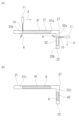
図1~図4に切断方法を概念的に示している。切断方法は、レーザ10を不要部3としての突出片4に照射して、突出片4をレーザ10により切断する。図1~図4は、突出片4をその突出方向の先端側から突出方向に見た図である。突出片4は、第一面4aと第二面4bを板面とする板状である。レーザ10は、第一面4a側から突出片4に照射する。つまり、第一面4aはレーザ照射側の面であり、第二面4bは反レーザ照射側の面である。図1等では、レーザ10を照射するためのトーチ11(ノズル)を示している。トーチ11の先端部からレーザ10が照射される。尚、トーチ11の内部にはエアが供給される。そのため、トーチ11の先端部からレーザ10と共にエアが噴射される。
The cutting method is conceptually shown in Figures 1 to 4. In the cutting method, a
図1では、突出片4の左端部4d(進行方向の一端部)にレーザ10を照射している。図1に示している矢印Aは、レーザ10の進行方向(走査方向)を示している。図1では、紙面向かって左側から右側に向けてレーザ10が進行する。レーザ10は、突出片4の第一面4a側から突出片4に照射される。トーチ11は、進行方向に対して直角である。レーザ10は、突出片4の第一面4aに向けて直角に照射される。図1(a)のように、突出片4の左端部4dにおける第一面4aにレーザ10が直角に照射されることにより、突出片4の左端部4dは、第一面4a側から溶け始める。
In FIG. 1, the
そして、図1(b)のように、突出片4の左端部4dの溶融は第一面4a側から第二面4b側へと進んでいくと共に、トーチ11を右側に向けて移動させることに伴って、突出片4の溶融部分5が右側へと拡大していく。尚、図中、溶融部分5には多数のドットを付して示している。突出片4は、第一面4a側が先に溶融し、第二面4b側が後から溶融することになる。そのため、溶融金属6(スパッタ)は、図1(b)のように、斜め左側に飛んでいくことになる。即ち、溶融金属6は、第一面4a側から第二面4b側であって且つレーザ10の進行方向に対して後側に向けて、斜めに飛んでいくことになる。尚、溶融金属6が飛んでいく角度は、レーザ10の出力や照射時間、レーザ10の移動速度等によって異なる。
As shown in FIG. 1(b), the melting of the
図1(c)に、突出片4が切断された後の切断面7を示している。切断面7には、レーザ10の照射及びその走査によって突出片4が溶融した痕跡がレーザ切断痕8として残る。レーザ切断痕8は、筋状であり、その筋の方向は、溶融金属6が向かう方向に近い。この例では、上述のように溶融金属6が斜め左側且つ下側に向かう。そのため、レーザ切断痕8の筋は、正面から見て左側且つ下側に傾斜している。即ち、レーザ切断痕8の筋は、第一面4aから第二面4bに向けて、レーザ10の進行方向の後側に傾斜している。
Figure 1 (c) shows the
図2は、図1とは逆に突出片4の右端部4cから左側に向けてトーチ11を移動させて突出片4を切断する場合を示している。この場合も同様に、まず、図2(a)のように右端部4cの第一面4a側から溶融し始め、その後、徐々に第二面4b側へと溶融部分5が拡大していく。それと共に、図2(b)のように、トーチ11が左側に進行していくことにより、第一面4a側においては第二面4b側よりも先に左側に溶融部分5が拡大する一方、第二面4b側は、後から遅れて溶融していくことになる。そのため、溶融金属6は、図2(b)のように、斜め右側に飛んでいくことになる。即ち、溶融金属6は、第一面4a側から第二面4b側であって且つレーザ10の進行方向に対して後側に向けて、斜めに飛んでいくことになる。
Figure 2 shows a case where the
図2(c)に、突出片4が切断された後の切断面7を示している。この例では、上述のように溶融金属6は斜め右側に向かう。そのため、レーザ切断痕8の筋は、正面から見て右側且つ下側に傾斜している。即ち、レーザ切断痕8の筋は、第一面4aから第二面4bに向けて、レーザ10の進行方向の後側に傾斜している。
Figure 2(c) shows the
一方、レーザ10を突出片4に対して直角ではなく傾斜した方向から照射することもできる。その場合には、レーザ10を突出片4に対して直角に照射した場合とは異なる方向に溶融金属6を飛ばすことができる。
On the other hand, the
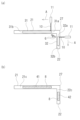
図3では、トーチ11を進行方向に対して直角の状態から進行方向の後側に倒すように傾斜させている。レーザ10の進行方向は左側から右側である。レーザ10は、進行方向の後側から前側に向けて斜めに照射される。つまり、レーザ10は左側から右側に向けて斜めに照射される。図3(a)のように、レーザ10は、最初に突出片4の左端部4d(左側面)に照射される。より詳細には、レーザ10は、最初に突出片4の左端部4dの第一面4a側ではなく第二面4b側に照射される。従って、突出片4の左端部4dのうち第二面4b側が第一面4a側よりも先に溶融し始める。そして、図3(b)のように、レーザ10が向かって右側に移動していくことで、突出片4の左端部4dのうち第二面4b側から第一面4a側へと溶融部分5が拡大していく。その結果、溶融金属6は、レーザ10を直角に照射する場合に比してレーザ10の進行方向の後側に飛びにくくなる。図3(b)においては、理解しやすい一例として、溶融金属6が第一面4a側から第二面4b側に向けて略真っ直ぐに飛んでいく状態を示しているが、溶融金属6が飛んでいく方向は、レーザ10の出力や照射時間、レーザ10の移動速度等によって異なる。
In FIG. 3, the
図3(c)に、突出片4が切断された後の切断面7を示している。この例では、理解しやすい一例として溶融金属6が第一面4a側から第二面4b側に向けて略真っ直ぐに向かう場合を示す。この場合には、レーザ切断痕8の筋は、正面から見て略垂直となる。即ち、レーザ切断痕8の筋は、第一面4aから第二面4bに向けて略垂直方向の筋となる。
Figure 3(c) shows the
図4では、図3とは逆に、トーチ11を進行方向に対して直角の状態から進行方向の前側に倒すように傾斜させている。レーザ10の進行方向は図3と同様に左側から右側である。レーザ10は、進行方向の前側から後側に向けて斜めに照射される。図4(a)のように、レーザ10は、突出片4の左端部4dの第一面4aに照射される。従って、突出片4の左端部4dのうち第一面4a側が第二面4b側よりも先に溶融し始める。そして、レーザ10が向かって右側に移動していくことで、突出片4の溶融部分5が右側へと拡大していくと共に、突出片4の左端部4dにおける溶融は、第一面4a側から第二面4b側へと進んでいく。つまり、突出片4は、第一面4a側が第二面4b側に比べて大きく先行して溶融し、第二面4b側がかなり後から遅れて溶融することになる。そのため、溶融金属6は、図4(b)のように、斜め左側に飛んでいくことになる。この斜め左側への傾斜角度は、図1の場合とレーザ10の出力等の条件が同じ場合には、図1(b)に示したときよりも更に大きくなり、図1(b)よりも更に斜め左側に大きく傾斜して飛んでいくことになる。
In FIG. 4, the
図4(c)に、突出片4が切断された後の切断面7を示している。この例では、上述のように溶融金属6が図1(b)の場合よりも更に左側に向かう。レーザ切断痕8の筋は、正面から見て、左側且つ下側に図1(c)よりも大きく傾斜している。レーザ切断痕8の筋は、第一面4aから第二面4bに向けて、レーザ10の進行方向の後側に大きく傾斜している。
Figure 4(c) shows the
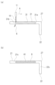
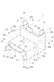
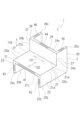
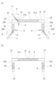
次に、ダイカスト品1の具体例を挙げて更に説明する。図5(a)に、鋳造直後のダイカスト品1の一例を模式的に示している。また、図5(b)に、ダイカスト品1から不要部3を取り除いた状態、即ち、製品部2のみを示している。尚、図5(b)において、不要部3を切断した切断面(第一切断面41、第二切断面42)には、多数のドットを付している。
Next, a specific example of the die-
鋳造直後のダイカスト品1は、製品部2の他に不要部3を有している。製品部2の形状は任意であるが、本実施形態では、製品部2は、第一片21と、第二片22を有している。第一片21及び第二片22は板状である。
Immediately after casting, the die-
第一片21の縦横二つの方向をそれぞれ第一方向101と第二方向102とする。第一方向101と第二方向102は互いに直交する。第一片21の板厚方向を第三方向103とする。第三方向103は、第一方向101及び第二方向102と直交する。以下、第一方向101を左右方向とし、図6等のように製品部2を第二方向102の第一端部側から見たときを基準にして左右の方向を定義する。従って、第一方向101の第一端部は右端部であり、第一方向101の第二端部は左端部である。また、第二方向102を前後方向とし、第二方向102の第一端部側を前側とする。従って、第二方向102の第一端部は前端部であり、第二方向102の第二端部は後端部である。更に、第三方向103を上下方向とし、第一片21から第二片22が延びる方向を下側とする。第三方向103の第一端部は上端部であり、第三方向103の第二端部は下端部である。
The two vertical and horizontal directions of the
第一片21は水平方向に延びていて、第二片22は、第一片21の右端部21aから下側に延びている。第二片22は、第一片21に対して上側から見て山折りに折れ曲がっている。本実施形態では、第二片22は第一片21に対して直角に折れ曲がっているが、その折れ曲がり角度は任意である。第一片21の右端部21aは第二片22との接続端部であり、第一片21の左端部21bは自由端部である。また、第二片22の上端部22aは第一片21との接続端部であり、第二片22の下端部22bは自由端部である。
The
不要部3の形状は任意であるが、本実施形態では、不要部3は、第一突出片31と、第二突出片32を有している。各突出片31,32は、何れも板状である。突出片は、例えばランナー部等である。
The
第一突出片31は、第一片21の前端部21cから前側に突出している。第二突出片32は、第二片22の前端部22cから前側に突出している。このように、第一突出片31と第二突出片32は、何れも製品部2から前側に突出しているが、少なくとも一方が後側に突出していてもよい。第一突出片31は、第一片21の前端部21cの全長のうちの一部に設けられ、第二突出片32は、第二片22の前端部22cの全長のうちの一部に設けられる。
The first protruding
次に、これらの第一突出片31及び第二突出片32を切断する方法について説明する。図6~図11に種々の切断方法を示している。尚、図6~図11において、第一片21及び第二片22を前側から見た状態を示している。
Next, a method for cutting the first protruding
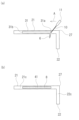
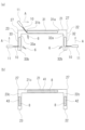
<切断方法その1>
図6(a)に、切断方法の一例を示している。第一突出片31を切断する場合には、トーチ11を第一突出片31に対して上側に設置する。また、第二突出片32を切断する場合には、トーチ11を第二突出片32に対して右側に設置する。このように、トーチ11は、第一片21及び第二片22のそれぞれの山折り側に設置されてレーザ10を山折り側から照射する。
<
6(a) shows an example of a cutting method. When cutting the first protruding
第一突出片31を切断する場合、第一突出片31をその左端部31bから右端部31aに向けて切断する。つまり、第一片21と第二片22の接続部27に向けてトーチ11を右側に移動させながら第一突出片31を切断する。トーチ11は第一突出片31に対して直角であり、進行方向に対して直角に設定されている。このようにレーザ10の進行方向(トーチ11の移動方向)を接続部27に近づく方向とすることにより、溶融金属6を斜め左側に向けて飛ばすことができる。つまり、溶融金属6を第二片22から離れる方向に飛ばすことができ、溶融金属6が第二片22に付着することを抑制することができる。尚、溶融金属6が飛ぶ角度は、レーザ10の種々の条件により異なる。
When cutting the first protruding
第二突出片32を切断する場合、第二突出片32をその下端部32bから上端部32aに向けて切断する。つまり、トーチ11を第一片21に近づくように、即ち、接続部27に近づけるように上側に移動させる。トーチ11の移動方向は、下側から上側である。トーチ11は第二突出片32に対して直角であり、進行方向に対して直角に設定されている。このようにレーザ10の進行方向を接続部27に近づけていく方向とすることにより、溶融金属6を斜め下側に向けて飛ばすことができる。つまり、溶融金属6を第一片21から離れる方向に飛ばすことができ、溶融金属6が第一片21に付着することを抑制することができる。この場合も、溶融金属6が飛ぶ角度は、レーザ10の種々の条件により異なる。尚、第一突出片31と第二突出片32の切断順序は何れが先であってもよい。
When cutting the second protruding
図6(b)に、第一突出片31と第二突出片32が切断された後のダイカスト品1を示している。第一片21の前端部21cには、第一突出片31が切断されることにより形成された第一切断面41が設けられる。第二片22の前端部22cには、第二突出片32が切断されることにより形成された第二切断面42が設けられる。第一切断面41におけるレーザ切断痕8の筋は、正面から見て左側且つ下側に傾斜している。つまり、第一切断面41におけるレーザ切断痕8の筋は、正面から見て、山折り側の面(レーザ照射側の面)から谷折り側の面(反レーザ照射側の面)に向けて、第二片22から離れる方向に傾斜している。また、第二切断面42におけるレーザ切断痕8の筋は、正面から見て左側且つ下側に傾斜している。つまり、第二切断面42におけるレーザ切断痕8の筋は、正面から見て、山折り側の面から谷折り側の面に向けて、第一片21から離れる方向に傾斜している。尚、筋の傾斜角度は、レーザ10の種々の条件により異なる。
6(b) shows the die-
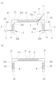
<切断方法その2>
図7(a)に、切断方法の一例を示している。第一突出片31の切断方法は図6(a)に示したものと同様である。第二突出片32の切断方法が図6(a)とは異なる。即ち、図6(a)の場合とは逆に、第二突出片32をその上端部32aから下端部32bに向けて切断する。つまり、トーチ11を第一片21から離れるように、即ち、接続部27から離れるように下側に移動させる。トーチ11の移動方向は、上側から下側である。トーチ11は第二突出片32に対して直角ではなく、進行方向の後側である上側に倒すように傾斜させる。つまり、トーチ11を上側に所定角度倒して、レーザ10を進行方向の後側である上側から、進行方向の前側である下側に向けて斜めに傾斜させて第二突出片32に照射する。これにより、溶融金属6を第二片22に対して略直角に、即ち、左側に向けて略真っ直ぐに飛ばすことができる。そのため、溶融金属6が第一片21に付着しにくくなる。尚、溶融金属6が飛ぶ方向はレーザ10の条件によって異なるが、ここでは左側に向けて略真っ直ぐに飛ぶ場合を示している。また、例えば、第一突出片31を切断した後に、続けて、第二突出片32を一筆書きのように切断することができる。
<
FIG. 7(a) shows an example of a cutting method. The cutting method of the first protruding
図7(b)に、第一突出片31と第二突出片32が切断された後のダイカスト品1を示している。第一切断面41におけるレーザ切断痕8の筋は、図6(b)と同様である。一方、第二切断面42におけるレーザ切断痕8の筋は、図6(b)とは異なり、正面から見て、第二片22に対して略垂直であって右側から左側に向けて延びている。つまり、第二切断面42におけるレーザ切断痕8の筋は、正面から見て、山折り側の面から谷折り側の面に向けて略垂直な筋である。
Figure 7(b) shows the die-
<切断方法その3>
図8(a)に、切断方法の一例を示している。第二突出片32の切断方法は図7(a)に示したものと同様である。第一突出片31の切断方法が図7(a)とは異なる。即ち、図7(a)の場合とは逆に、第一突出片31をその右端部31aから左端部31bに向けて切断する。つまり、トーチ11を第二片22から離れるように、即ち、接続部27から離れるように左側に移動させる。トーチ11の移動方向は、右側から左側である。トーチ11は第一突出片31に対して直角ではなく、進行方向の後側である右側に倒すように傾斜させる。つまり、トーチ11を右側に所定角度倒して、レーザ10を進行方向の後側である右側から、進行方向の前側である左側に向けて斜めに傾斜させて第一突出片31に照射する。これにより、溶融金属6を下側に向けて略真っ直ぐに飛ばすことができる。そのため、溶融金属6が第二片22に付着しにくくなる。尚、溶融金属6が飛ぶ方向はレーザ10の条件によって異なるが、ここでは下側に向けて略真っ直ぐに飛ぶ場合を示している。
<
FIG. 8(a) shows an example of a cutting method. The cutting method of the second protruding
図8(b)に、第一突出片31と第二突出片32が切断された後のダイカスト品1を示している。第二切断面42におけるレーザ切断痕8の筋は、図7(b)と同様である。一方、第一切断面41におけるレーザ切断痕8の筋は、図7(b)とは異なり、正面から見て、第一片21に対して略垂直であって上側から下側に向けて延びている。つまり、第一切断面41におけるレーザ切断痕8の筋は、正面から見て、山折り側の面から谷折り側の面に向けて略垂直な筋である。
Figure 8(b) shows the die-
<切断方法その4>
図9(a)に、切断方法の一例を示している。トーチ11の進行方向は、図6(a)の場合と同様であって、第一突出片31を切断する場合には右側であり、第二突出片32を切断する場合は上側である。即ち、第一突出片31と第二突出片32の何れを切断する場合においても、トーチ11の進行方向は接続部27に近づく方向である。図6(a)と異なるのは、トーチ11の角度である。トーチ11を進行方向の前側に倒すように傾斜させている。尚、レーザ10の出力や移動速度等の他の条件は、図6(a)と同じである。このように照射角度を設定すると、第一突出片31を切断する場合には、溶融金属6を図6(a)よりも更に左側に向けて飛ばすことができ、第二突出片32を切断する場合には、溶融金属6を図6(a)よりも更に下側に向けて飛ばすことができる。従って、溶融金属6が第一片21や第二片22に付着することをより一層抑制することができる。
<
FIG. 9(a) shows an example of a cutting method. The traveling direction of the
図9(b)に、第一突出片31と第二突出片32が切断された後のダイカスト品1を示している。第一切断面41におけるレーザ切断痕8の筋は、正面から見て、左側且つ下側に図6(b)の場合よりも大きく傾斜している。つまり、第一切断面41におけるレーザ切断痕8の筋は、正面から見て、山折り側の面から谷折り側の面に向けて、第二片22から離れる方向に大きく傾斜している。また、第二切断面42におけるレーザ切断痕8の筋は、正面から見て、左側且つ下側に図6(b)の場合よりも大きく傾斜している。つまり、第二切断面42におけるレーザ切断痕8の筋は、正面から見て、山折り側の面から谷折り側の面に向けて、第一片21から離れる方向に大きく傾斜している。
9(b) shows the die-
<切断方法その5>
図10(a)に、切断方法の一例を示している。トーチ11の進行方向は、図6(a)の場合と同様であって、第一突出片31を切断する場合には右側であり、第二突出片32を切断する場合は上側である。即ち、第一突出片31と第二突出片32の何れを切断する場合においても、トーチ11の進行方向は接続部27に近づく方向である。図6(a)と異なるのは、トーチ11の角度である。トーチ11を進行方向の後側に倒すように傾斜させている。レーザ10を進行方向の後側から前側に向けて照射する。尚、レーザ10の出力や移動速度等の他の条件は、図6(a)と同じである。このように照射角度を設定すると、第一突出片31を切断する場合には、溶融金属6を例えば下側に向けて飛ばすことができ、第二突出片32を切断する場合には例えば左側に向けて飛ばすことができる。この場合においても、溶融金属6が第一片21や第二片22に付着することを抑制できる。
<
FIG. 10(a) shows an example of a cutting method. The traveling direction of the
<切断方法その6>
図11(a)に、切断方法の一例を示している。第一突出片31の切断方法は図6(a)に示したものと同様である。第二突出片32の切断方法が図6(a)とは異なる。即ち、図6(a)の場合とは逆に、第二突出片32をその上端部32aから下端部32bに向けて切断する。つまり、トーチ11を接続部27から離れるように下側に移動させる。トーチ11の移動方向は、上側から下側である。トーチ11は第二突出片32に対して直角である。このように、トーチ11の角度を第二突出片32に対して直角に設定し、且つ、トーチ11を接続部27から離れるように移動させると、溶融金属6は左側且つ上側に向けて飛びやすくなる。つまり、溶融金属6は第一片21に向かいやすくなり、第一片21に溶融金属6が付着しやすくなる。
<
FIG. 11(a) shows an example of a cutting method. The cutting method of the first protruding
図11(b)に、第一突出片31と第二突出片32が切断された後のダイカスト品1を示している。第一切断面41におけるレーザ切断痕8の筋は、図6(b)と同様である。一方、第二切断面42におけるレーザ切断痕8の筋は、図6(b)とは異なり、正面から見て、左側且つ上側に傾斜している。つまり、第二切断面42におけるレーザ切断痕8の筋は、正面から見て、山折り側の面から谷折り側の面に向けて、第一片21に近づく方向に傾斜している。
Figure 11(b) shows the die-
<切断方法その7>
図12(a)に、切断方法の一例を示している。第二突出片32の切断方法は図11(a)に示したものと同様である。第一突出片31の切断方法が図11(a)とは異なる。即ち、図11(a)の場合とは逆に、第一突出片31をその右端部31aから左端部31bに向けて切断する。つまり、トーチ11を接続部27から離れるように移動させる。また、トーチ11の角度は第一突出片31に対して直角である。このように、第一突出片31を切断する場合と第二突出片32を切断する場合の何れの場合においても、トーチ11の進行方向は接続部27から離れる方向であり、また、トーチ11の角度は各突出片31、32に対して直角である。第一突出片31を切断する際には、溶融金属6は第二片22に向かいやすくなって第二片22に付着しやすくなる。第二突出片32を切断する際には、溶融金属6は第一片21に向かいやすくなって第一片21に付着しやすくなる。
<
FIG. 12(a) shows an example of a cutting method. The cutting method of the second protruding
図12(b)に、第一突出片31と第二突出片32が切断された後のダイカスト品1を示している。第二切断面42におけるレーザ切断痕8の筋は、図11(b)と同様である。一方、第一切断面41におけるレーザ切断痕8の筋は、図11(b)とは異なり、正面から見て、右側且つ下側に傾斜している。つまり、第一切断面41におけるレーザ切断痕8の筋は、正面から見て、山折り側の面から谷折り側の面に向けて、第二片22に近づく方向に傾斜している。
Figure 12(b) shows the die-
尚、上記説明では、第一片21と第二片22の双方に突出片が存在していたが、第一片21と第二片22のうちの一方のみに突出片が存在している場合においても同様である。例えば、図13や図14のように、第一片21に第一突出片31が設けられ、第二片22には突出片が設けられていない場合であっても同様である。図13(a)に示すように、トーチ11を第一突出片31に対して直角に設定すると共に接続部27に向けて移動させて第一突出片31を切断することができる。その場合、図13(b)に示すように、第一切断面41には、例えば正面から見て左側且つ下側に傾斜したレーザ切断痕8の筋が残る。
In the above description, both the
また、図14(a)に示すように、トーチ11を接続部27から離れる方向に移動させつつ進行方向の後側に倒すように傾斜させて第一突出片31を切断することができる。その場合、図14(b)に示すように、第一切断面41には、正面から見て、第一片21に対して略垂直なレーザ切断痕8の筋が残る。尚、図13や図14では、第一片21のみに突出片が設けられている場合を例示したが、逆に、第二片22のみに突出片が設けられている場合も同様である。また、第一片21の後端部21dや第二片22の後端部22dに突出片が設けられていてもよく、それらの突出片についても、上述のような切断方法で切断できる。例えば、第一片21の前端部21cに第一突出片31が設けられ、第二片22の後端部22dに第二突出片32が設けられていてもよい。
As shown in FIG. 14(a), the
次に、ダイカスト品1の他の具体例を挙げる。図15に、鋳造直後のダイカスト品1の他の例を模式的に示している。また、図16には、ダイカスト品1から不要部3を取り除いた状態を示している。図16は、製品部2のみを示しており、図16において、不要部3を切断した切断面(第一切断面41、第二切断面42、第三切断面43、第四切断面44、第五切断面45、第六切断面46)には多数のドットを付している。
Next, other specific examples of the die-
本実施形態では、製品部2は、第一片21と、第二片22と、第三片23と、第四片24と、第五片25と、第六片26とを有している。第一片21から第六片26は板状である。
In this embodiment, the
第一片21と第二片22は図5の場合と同様である。第三片23は、第一片21の左端部21bから下側に延びている。即ち、第二片22と第三片23は、第一片21から同じ側に延びている。第三片23は、第一片21に対して上側から見て山折りに折れ曲がっている。第一片21に対して、第二片22と第三片23は、何れも同じ側に折れ曲がっている。第二片22と第三片23は、互いに対向している。本実施形態において、第二片22はと第三片23は、互いに平行であるが、平行でなくてもよい。第二片22と第三片23は、第一片21に対して直交しているが、傾斜していてもよく、第一片21に対するそれぞれの折れ曲がり角度は任意である。
The
第一片21の右端部21aは第二片22との接続端部であり、第一片21の左端部21bは第三片23との接続端部である。第二片22の上端部22aは第一片21との接続端部であり、第二片22の下端部22bは自由端部である。第三片23の上端部23aは第一片21との接続端部であり、第三片23の下端部23bは自由端部である。第一片21の後端部21d、第二片22の後端部、及び、第三片23の後端部は、それぞれ第4片24、第五片25、及び、第六片26との接続端部である。
The
第四片24は、第一片21の後端部21dから上側に延びている。第四片24は、第一片21に対して、上側から見て谷折りに折れ曲がっている。本実施形態では、第四片24は第一片21に対して直角に折れ曲がっているが、その折れ曲がり角度は任意である。
The
第五片25は、第四片24の右端部24aから後側に延びている。第五片25は、第四片24に対して前側から見て山折りに折れ曲がっている。本実施形態では、第五片25は第四片24に対して直角に折れ曲がっているが、その折れ曲がり角度は任意である。第五片25は、第二片22の後側に連続していて、第二片22と第五片25は、面一である。
The
第六片26は、第四片24の左端部24bから後側に延びている。第五片25と第六片26は、第四片24から同じ側に延びている。第六片26は、第四片24に対して前側から見て山折りに折れ曲がっている。第四片24に対して、第五片25と第六片26は、何れも同じ側に折れ曲がっている。第五片25と第六片26は、互いに対向している。本実施形態において、第五片25はと第六片26は、互いに平行であるが、平行でなくてもよい。第五片25と第六片26は、第四片24に対して直交しているが、傾斜していてもよく、第四片24に対するそれぞれの折れ曲がり角度は任意である。第六片26は、第三片23の後側に連続していて、第三片23と第六片26は、面一である。
The
第四片24の右端部24aは第五片25との接続端部であり、第四片24の左端部24bは第六片26との接続端部である。第五片25の前端部は第四片24との接続端部であり、第五片25の後端部は自由端部である。第六片26の前端部は第四片24との接続端部であり、第六片26の後端部は自由端部である。
The
本実施形態では、不要部3は、第一突出片31と、第二突出片32と、第三突出片33と、第四突出片34と、第五突出片35と、第六突出片36とを有している。各突出片は、何れも板状である。突出片は、例えばランナー部等である。
In this embodiment, the
第一突出片31と第二突出片32については図5の場合と同様である。第三突出片33は、第三片23の前端部23cから前側に突出している。第一突出片31と第二突出片32と第三突出片33は、何れも前側に突出している。第一突出片31は、第一片21の前端部21cの全長のうちの一部に設けられ、第二突出片32は、第二片22の前端部22cの全長のうちの一部に設けられ、第三突出片33は、第三片23の前端部23cの全長のうちの一部に設けられる。
The first protruding
第四突出片34は、第四片24の上端部24cから上側に突出している。第五突出片35は、第五片25の上端部25cから上側に突出している。第六突出片36は、第六片26の上端部26cから上側に突出している。このように、第四突出片34と第五突出片35と第六突出片36は、何れも上側に突出している。第四突出片34は、第四片24の上端部24cの全長のうちの一部に設けられ、第五突出片35は、第五片25の上端部25cの全長のうちの一部に設けられ、第六突出片36は、第六片26の上端部26cの全長のうちの一部に設けられる。
The fourth protruding
これらの第一突出片31から第六突出片36をレーザ10により切断除去する。尚、代表的に、第一突出片31から第三突出片33を切断する場合について説明するが、第四突出片34から第六突出片36を切断する場合についても同様である。第一突出片31が切断されることにより第一切断面41が形成され、第二突出片32が切断されることにより第二切断面42が形成され、第三突出片33が切断されることにより第三切断面43が形成され、第四突出片34が切断されることにより第四切断面44が形成され、第五突出片35が切断されることにより第五切断面45が形成され、第六突出片36が切断されることにより第六切断面46が形成される。
These first protruding
図17~図21に切断方法を例示している。尚、図17~図21において、第一片21乃至第三片23を前側から見た状態を示しているが、第四片24乃至第六片26の図示は省略している。図17(a)に、切断方法の一例を示している。トーチ11は、第一突出片31を切断する場合には、第一突出片31に対して上側に設置し、第二突出片32を切断する場合には、第二突出片32に対して右側に設置し、第三突出片33を切断する場合には、第三突出片33に対して左側に設置する。つまり、トーチ11は、第一片21、第二片22、第三片23のそれぞれの山折り側に設置し、レーザ10を山折り側から各突出片に向けて照射する。
The cutting method is illustrated in Figs. 17 to 21. In Figs. 17 to 21, the
第一突出片31を切断する場合、第一突出片31をその左端部31bから右端部31aに向けて切断する。つまり、トーチ11を右側に移動させながら第一突出片31を切断する。この場合、トーチ11は第一突出片31に対して直角ではなく、進行方向の後側である左側に倒すように傾斜させる。つまり、トーチ11を左側に所定角度倒して、レーザ10を進行方向の後側である左側から、進行方向の前側である右側に向けて斜めに傾斜させて第一突出片31に照射する。このように、レーザ10を第一突出片31に進行方向の後側から前側に向けて斜めに照射することにより、溶融金属6を下側に略真っ直ぐに飛ばすことができる。つまり、第一片21に対して略直交した方向(略法線方向)に溶融金属6を飛ばすことができる。そのため、溶融金属6が第二片22や第三片23に付着することを抑制することができる。
When cutting the first protruding
第二突出片32を切断する場合、第二突出片32をその下端部32bから上端部32aに向けて切断する。つまり、トーチ11を第一片21に近づくように移動させる。トーチ11の移動方向は、下側から上側である。この場合、トーチ11は第二突出片32に対して直角であり、進行方向に対して直角に設定されている。このようにレーザ10の進行方向を第一片21と第二片22との接続部27に近づけていく方向とすることにより、溶融金属6を斜め下側に向けて飛ばすことができる。つまり、溶融金属6を第一片21から離れる方向に飛ばすことができ、溶融金属6が第一片21に付着することを抑制することができる。
When cutting the second protruding
第三突出片33を切断する場合も同様であって、第三突出片33をその下端部33bから上端部33aに向けて切断する。つまり、トーチ11を第一片21に近づくように移動させる。トーチ11の移動方向、即ち、レーザ10の進行方向は、下側から上側である。この場合も、トーチ11は第三突出片33に対して直角であり、進行方向に対して直角に設定されている。このようにレーザ10の進行方向を第一片21と第三片23との接続部27に近づけていく方向とすることにより、溶融金属6を斜め下側に向けて飛ばすことができる。つまり、溶融金属6を第一片21から離れる方向に飛ばすことができ、溶融金属6が第一片21に付着することを抑制することができる。尚、この場合には、第三突出片33を切断した後に、続けて、第一突出片31を一筆書きのように切断することができる。
The third
図17(b)に、第一突出片31と第二突出片32と第三突出片33が切断された後のダイカスト品1を示している。第一片21の前端部21cには、第一突出片31が切断されることにより第一切断面41が形成され、第二片22の前端部22cには、第二突出片32が切断されることにより第二切断面42が形成され、第三片23の前端部23cには、第三突出片33が切断されることにより第三切断面43が形成される。
Figure 17 (b) shows the die-
第一切断面41におけるレーザ切断痕8の筋は、正面から見て、第一片21に対して略垂直であって上側から下側に向けて延びている。つまり、第一切断面41におけるレーザ切断痕8の筋は、正面から見て、山折り側の面から谷折り側の面に向けて略垂直な筋である。第二切断面42におけるレーザ切断痕8の筋は、正面から見て左側且つ下側に傾斜している。つまり、第二切断面42におけるレーザ切断痕8の筋は、正面から見て、山折り側の面から谷折り側の面に向けて、第一片21から離れる方向に傾斜している。第三切断面43におけるレーザ切断痕8の筋は、正面から見て右側且つ下側に傾斜している。つまり、第三切断面43におけるレーザ切断痕8の筋は、正面から見て、山折り側の面から谷折り側の面に向けて、第一片21から離れる方向に傾斜している。
The streaks of the laser cut marks 8 on the
図18(a)のようにしてもよい。第二突出片32と第三突出片33の切断については図17(a)と同様である。第一突出片31を切断する場合の方向が図17(a)とは逆であって、第一突出片31をその右端部31aから左端部31bに向けて切断する。つまり、トーチ11の進行方向は左側である。この場合、トーチ11は第一突出片31に対して、進行方向の後側である右側に倒すように傾斜させる。つまり、トーチ11を右側に所定角度倒して、レーザ10を進行方向の後側である右側から、進行方向の前側である左側に向けて斜めに傾斜させて第一突出片31に照射する。これにより、第一突出片31の切断時において、溶融金属6を、図17(a)と同様に、下側に略真っ直ぐに飛ばすことができ、溶融金属6の第二片22や第三片23への付着を抑制することができる。尚、この場合には、第二突出片32を切断した後に、続けて、第一突出片31を一筆書きのように切断することができる。
18(a) may be used. The cutting of the second protruding
図18(b)に、第一突出片31と第二突出片32と第三突出片33が切断された後のダイカスト品1を示している。第一切断面41、第二切断面42及び第三切断面43におけるそれぞれのレーザ切断痕8の筋は、図17(b)に示したものと同様である。
Figure 18 (b) shows the die-
図19(a)のようにしてもよい。第一突出片31の切断については図17(a)の場合と同様である。図19(a)においては、第二突出片32と第三突出片33を切断する際に、トーチ11を図17(a)と同様に上側に移動させる。但し、トーチ11を、進行方向の前側である上側に倒すように傾斜させている。このようにトーチ11を進行方向の前側に倒すことで、レーザ10を第二突出片32や第三突出片33に対して、進行方向の前側から後側に向けて斜めに照射することができる。レーザ10を第二突出片32や第三突出片33に、進行方向の前側から後側に向けて斜めに照射することにより、溶融金属6を、図17に示した場合よりも更に下側に向けて斜めに飛ばすことができ、溶融金属6の第一片21への付着をより一層抑制することができる。
19(a) may be used. The cutting of the first protruding
図19(b)に、第一突出片31と第二突出片32と第三突出片33が切断された後のダイカスト品1を示している。第一切断面41におけるレーザ切断痕8の筋は、図17(b)に示したものと同様である。一方、第二切断面42及び第三切断面43における各レーザ切断痕8の筋は、図17(b)に示したものよりも更に下側に向けて大きく傾斜している。
Figure 19(b) shows the die-
図20(a)のようにしてもよい。第一突出片31の切断については図17(a)の場合と同様である。図20(a)においては、第二突出片32と第三突出片33を切断する際に、トーチ11を図17(a)とは逆に下側に移動させる。即ち、第二突出片32と第三突出片33を切断する際に、トーチ11を各接続部27から離れる方向に移動させる。そして、トーチ11を、進行方向の後側である上側に倒すように傾斜させる。このようにトーチ11を進行方向の後側に倒すことで、レーザ10を第二突出片32や第三突出片33に対して、進行方向の後側から前側に向けて斜めに照射することができる。レーザ10を第二突出片32や第三突出片33に、進行方向の後側から前側に向けて斜めに照射することにより、溶融金属6を、第一片21に近づかないように略水平に飛ばすことができる。つまり、溶融金属6を第二片22や第三片23に対して略直交した方向に飛ばすことができる。これにより、溶融金属6の第一片21への付着を抑制することができる。
20(a) may be used. The cutting of the first protruding
図20(b)に、第一突出片31と第二突出片32と第三突出片33が切断された後のダイカスト品1を示している。第一切断面41におけるレーザ切断痕8の筋は、図17(b)に示したものと同様である。一方、第二切断面42と第三切断面43におけるレーザ切断痕8の筋は、それぞれ第二片22と第三片23に対して略垂直となる。つまり、第二切断面42と第三切断面43におけるレーザ切断痕8の筋は、それぞれ正面から見て、山折り側の面から谷折り側の面に向けて略垂直に延びる筋である。このように、図20(b)の場合には、全てのレーザ切断痕8の筋が、正面から見て、山折り側の面から谷折り側の面に向けて略垂直に延びる筋となる。
20(b) shows the die-
図21(a)のようにしてもよい。第一突出片31の切断については図17(a)の場合と同様である。また、第二突出片32と第三突出片33を切断する際のトーチ11の移動方向も図17(a)の場合と同様である。図17(a)の場合と異なるのは、第二突出片32と第三突出片33を切断する際におけるトーチ11の角度である。即ち、第二突出片32と第三突出片33を切断する際において、トーチ11を進行方向の後側である下側に倒すように傾斜させる。このようにトーチ11を進行方向の後側に倒すことで、レーザ10を第二突出片32や第三突出片33に対して、進行方向の後側から前側に向けて斜めに照射することができる。レーザ10を第二突出片32や第三突出片33に、進行方向の後側から前側に向けて斜めに照射することにより、溶融金属6を、第一片21に近づかないように略水平に飛ばすことができる。つまり、溶融金属6を第二片22や第三片23に対して略直交した方向に飛ばすことができる。これにより、溶融金属6の第一片21への付着を抑制することができる。
21(a) may be used. The cutting of the first protruding
図21(b)に、第一突出片31と第二突出片32と第三突出片33が切断された後のダイカスト品1を示している。レーザ切断痕8の筋は、図20(b)に示したものと同様である。
Figure 21 (b) shows the die-
尚、図15では、第一片21、第二片22、第三片23の全てに突出片が設けられていたが、これらの三つの片のうち例えば一つの片のみに突出片が設けられたり二つの片のみに突出片が設けられたりしてもよい。第四片24、第五片25、第六片26についても同様である。また、第一片21に対して第四片24が上側から見て谷折りに折れ曲がっている形状(上側に折れ曲がっている形状)であったが、逆に第一片21に対して第四片24が上側から見て山折りに折れ曲がっている形状(下側に折れ曲がっている形状)であってもよい。また、第四片24乃至第六片26が省略された形状であってもよい。
In FIG. 15, the
1 ダイカスト品
2 製品部
3 不要部
4 突出片
4a 第一面
4b 第二面
4c 右端部
4d 左端部
5 溶融部分
6 溶融金属
7 切断面
8 レーザ切断痕
10 レーザ
11 トーチ
21 第一片
21a 右端部(第一方向の一端部)
21b 左端部(第一方向の他端部)
21c 前端部(第二方向の一端部)
21d 後端部(第二方向の他端部)
22 第二片
22a 上端部
22b 下端部
22c 前端部
23 第三片
23a 上端部
23b 下端部
23c 前端部
24 第四片
24a 右端部
24b 左端部
24c 上端部
25 第五片
25c 上端部
26 第六片
26c 上端部
27 接続部
31 第一突出片
31a 右端部
31b 左端部
32 第二突出片
32a 上端部
32b 下端部
33 第三突出片
33a 上端部
33b 下端部
34 第四突出片
35 第五突出片
36 第六突出片
41 第一切断面
42 第二切断面
43 第三切断面
44 第四切断面
45 第五切断面
46 第六切断面
101 第一方向
102 第二方向
103 第三方向
REFERENCE SIGNS
21b Left end portion (the other end portion in the first direction)
21c Front end portion (one end portion in the second direction)
21d rear end (other end in the second direction)
22
Claims (6)
製品部は、第一片と、第一片に対して山折りに折れ曲がって第一片の第一方向の一端部から延びる第二片と、を有し、
不要部は、第一片における第一方向と直交する第二方向の一端部と、第二片における第二方向の一端部のうち少なくとも一方に、第二方向に突出する突出片を有し、
レーザを山折り側から照射して不要部を切断する切断工程を備え、
切断工程は、レーザを第一片と第二片の接続部から離れる方向に進行させると共にレーザを進行方向の後側から前側に向けて斜めに照射して突出片を切断する工程を含む、ダイカスト品の不要部の切断方法。 A method for cutting off an unnecessary portion from a product portion of a cast die-cast product, comprising the steps of:
The product portion has a first piece and a second piece that is bent in a mountain fold relative to the first piece and extends from one end of the first piece in a first direction,
the unnecessary portion has a protruding piece protruding in the second direction at least at one end of the first piece in a second direction perpendicular to the first direction and at least one end of the second piece in the second direction,
A cutting step is provided in which a laser is irradiated from the mountain fold side to cut off the unnecessary portion,
The cutting process is a method for cutting unnecessary portions of a die-cast product, the method including a step of advancing a laser in a direction away from the connection between the first piece and the second piece and irradiating the laser diagonally from the rear side to the front side in the direction of advancement to cut off the protruding piece.
製品部は、第一片と、第一片に対して山折りに折れ曲がって第一片の第一方向の一端部から延びる第二片と、第一片に対して山折りに折れ曲がって第一片の第一方向の他端部から延びる第三片と、を有し、
不要部は、第一片における第一方向と直交する第二方向の一端部から第二方向に突出する第一突出片を有し、
レーザを山折り側から照射して不要部を切断する切断工程を備え、
切断工程は、レーザを進行方向の後側から前側に向けて斜めに照射して第一突出片を切断する工程を含む、ダイカスト品の不要部の切断方法。 A method for cutting off an unnecessary portion from a product portion of a cast die-cast product, comprising the steps of:
The product portion has a first piece, a second piece bent in a mountain fold relative to the first piece and extending from one end of the first piece in the first direction, and a third piece bent in a mountain fold relative to the first piece and extending from the other end of the first piece in the first direction,
the unnecessary portion has a first protruding piece protruding in the second direction from one end of the first piece in a second direction perpendicular to the first direction,
A cutting step is provided in which a laser is irradiated from the mountain fold side to cut off the unnecessary portion,
The cutting step is a method for cutting off an unnecessary portion of a die-cast product, the method including a step of irradiating a laser obliquely from the rear side to the front side in the traveling direction to cut off the first protruding piece.
切断工程は、レーザを第一片と第二片の接続部に近づく方向に進行させて第二突出片を切断する工程を含む、請求項2記載のダイカスト品の不要部の切断方法。 the unnecessary portion has a second protruding piece protruding in the second direction from one end of the second piece in the second direction,
3. The method for cutting off an unnecessary portion of a die-cast product according to claim 2 , wherein the cutting step includes a step of advancing a laser in a direction approaching the connection portion between the first piece and the second piece to cut off the second protruding piece.
切断工程は、レーザを第一片と第二片の接続部から離れる方向に進行させると共にレーザを進行方向の後側から前側に向けて斜めに照射して第二突出片を切断する工程を含む、請求項2記載のダイカスト品の不要部の切断方法。 the unnecessary portion has a second protruding piece protruding in the second direction from one end of the second piece in the second direction,
A method for cutting unnecessary portions of a die-cast product as described in claim 2, wherein the cutting process includes a step of advancing a laser in a direction away from the connection portion between the first piece and the second piece and irradiating the laser obliquely from the rear side to the front side in the direction of advancement to cut the second protruding piece.
第一片と、第一片に対して山折りに折れ曲がって第一片の第一方向の一端部から延びる第二片と、を備え、
第一片における第一方向と直交する第二方向の一端部と、第二片における第二方向の一端部の双方に、筋状のレーザ切断痕を有する切断面が設けられ、
第一片のレーザ切断痕は、山折り側の面から谷折り側の面に向けて第二片から離れる方向に傾斜した筋であり、
第二片のレーザ切断痕は、山折り側の面から谷折り側の面に向けて第一片から離れる方向に傾斜した筋である、ダイカスト品。 A die-cast product from which unnecessary parts have been cut off,
A first piece and a second piece extending from one end of the first piece in a first direction while being bent in a mountain fold relative to the first piece,
A cut surface having a streak-like laser cut mark is provided on both one end of the first piece in a second direction perpendicular to the first direction and one end of the second piece in the second direction,
The laser cut mark of the first piece is a line inclined in a direction away from the second piece from the mountain fold surface to the valley fold surface,
A die-cast product in which the laser cutting marks on the second piece are lines that are inclined in a direction away from the first piece from the mountain fold surface to the valley fold surface.
第一片と、第一片に対して山折りに折れ曲がって第一片の第一方向の一端部から延びる第二片と、を備え、
第一片における第一方向と直交する第二方向の一端部と、第二片における第二方向の一端部の双方に、筋状のレーザ切断痕を有する切断面が設けられ、
第一片のレーザ切断痕は、山折り側の面から谷折り側の面に向けて第二片から離れる方向に傾斜した筋であり、
第二片のレーザ切断痕は、山折り側の面から谷折り側の面に向けて略垂直な筋である、ダイカスト品。 A die-cast product from which unnecessary parts have been cut off,
A first piece and a second piece extending from one end of the first piece in a first direction while being bent in a mountain fold relative to the first piece,
A cut surface having a streak-like laser cut mark is provided on both one end of the first piece in a second direction perpendicular to the first direction and one end of the second piece in the second direction,
The laser cut mark of the first piece is a line inclined in a direction away from the second piece from the mountain fold surface to the valley fold surface,
A die-cast product in which the laser cutting marks on the second piece are approximately vertical lines extending from the mountain fold surface to the valley fold surface.
Priority Applications (2)
| Application Number | Priority Date | Filing Date | Title |
|---|---|---|---|
| JP2022157772A JP7682139B2 (en) | 2022-09-30 | 2022-09-30 | Method for cutting unnecessary parts of die-cast products and die-cast products |
| JP2025041231A JP2025083520A (en) | 2022-09-30 | 2025-03-14 | Method for cutting unnecessary part from die-cast product and die-cast product |
Applications Claiming Priority (1)
| Application Number | Priority Date | Filing Date | Title |
|---|---|---|---|
| JP2022157772A JP7682139B2 (en) | 2022-09-30 | 2022-09-30 | Method for cutting unnecessary parts of die-cast products and die-cast products |
Related Child Applications (1)
| Application Number | Title | Priority Date | Filing Date |
|---|---|---|---|
| JP2025041231A Division JP2025083520A (en) | 2022-09-30 | 2025-03-14 | Method for cutting unnecessary part from die-cast product and die-cast product |
Publications (2)
| Publication Number | Publication Date |
|---|---|
| JP2024051549A JP2024051549A (en) | 2024-04-11 |
| JP7682139B2 true JP7682139B2 (en) | 2025-05-23 |
Family
ID=90622528
Family Applications (2)
| Application Number | Title | Priority Date | Filing Date |
|---|---|---|---|
| JP2022157772A Active JP7682139B2 (en) | 2022-09-30 | 2022-09-30 | Method for cutting unnecessary parts of die-cast products and die-cast products |
| JP2025041231A Pending JP2025083520A (en) | 2022-09-30 | 2025-03-14 | Method for cutting unnecessary part from die-cast product and die-cast product |
Family Applications After (1)
| Application Number | Title | Priority Date | Filing Date |
|---|---|---|---|
| JP2025041231A Pending JP2025083520A (en) | 2022-09-30 | 2025-03-14 | Method for cutting unnecessary part from die-cast product and die-cast product |
Country Status (1)
| Country | Link |
|---|---|
| JP (2) | JP7682139B2 (en) |
Citations (2)
| Publication number | Priority date | Publication date | Assignee | Title |
|---|---|---|---|---|
| JP2010274327A (en) | 2009-04-27 | 2010-12-09 | Nishikimi Chuzo Kk | Metallic mold for casting of thin cast iron product, production device for thin cast iron product, and method for producing thin spheroidal graphite cast iron product |
| CN104384720A (en) | 2014-09-26 | 2015-03-04 | 东莞台一盈拓科技股份有限公司 | Method for fast removing burrs of die casting product |
Family Cites Families (4)
| Publication number | Priority date | Publication date | Assignee | Title |
|---|---|---|---|---|
| GB8829818D0 (en) * | 1988-12-21 | 1989-02-15 | Ae Turbine Components | Processing of castings |
| JPH04162971A (en) * | 1990-10-25 | 1992-06-08 | Toshiba Corp | Deburring device |
| JPH11170077A (en) * | 1997-12-10 | 1999-06-29 | Amada Co Ltd | Method and device for cutting molded work piece |
| ES2830762A1 (en) * | 2019-10-22 | 2021-06-04 | Fund Tekniker | METHOD AND APPARATUS FOR DEBURING WORKPIECES |
-
2022
- 2022-09-30 JP JP2022157772A patent/JP7682139B2/en active Active
-
2025
- 2025-03-14 JP JP2025041231A patent/JP2025083520A/en active Pending
Patent Citations (2)
| Publication number | Priority date | Publication date | Assignee | Title |
|---|---|---|---|---|
| JP2010274327A (en) | 2009-04-27 | 2010-12-09 | Nishikimi Chuzo Kk | Metallic mold for casting of thin cast iron product, production device for thin cast iron product, and method for producing thin spheroidal graphite cast iron product |
| CN104384720A (en) | 2014-09-26 | 2015-03-04 | 东莞台一盈拓科技股份有限公司 | Method for fast removing burrs of die casting product |
Non-Patent Citations (4)
| Title |
|---|
| 3D - TruLaser Cell серия 7000,YouTube[online][video],2016年06月15日,https://www.youtube.com/watch?v=l0WqVgkToHM,特に動画時間[00:33]-[00:40]等参照。[検索日2025年1月30日] |
| ENSIS RI 紹介動画,YouTube[online][video],2022年01月12日,https://www.youtube.com/watch?v=kApEOCYXu78,特に動画時間[00:00]-[00:55]等参照。[検索日2025年1月30日] |
| アマダ ENSIS 3015 RI ファイバーレーザー角パイプ切断テスト,YouTube[online][video],2019年02月23日,https://www.youtube.com/watch?v=kl98NpseUZQ,特に動画時間[00:10]-[00:33]等参照。[検索日2025年1月30日] |
| 片岡義弘、徳永剛、宮崎俊行,CO2レーザビーム切断によるアルミニウム合金の鋳ばり取りの基礎実験,鋳物,1995年,第67巻、第8号,p.557-562 |
Also Published As
| Publication number | Publication date |
|---|---|
| JP2025083520A (en) | 2025-05-30 |
| JP2024051549A (en) | 2024-04-11 |
Similar Documents
| Publication | Publication Date | Title |
|---|---|---|
| JP5360177B2 (en) | Laser processing method and laser processing head | |
| JP7123738B2 (en) | LAMINATED PRODUCT MANUFACTURING METHOD AND LAMINATED MOLDED PRODUCT | |
| JP7682139B2 (en) | Method for cutting unnecessary parts of die-cast products and die-cast products | |
| JP2009269036A (en) | Laser welding method | |
| JP3854490B2 (en) | Laser welding method for differential thickness materials | |
| JP5121420B2 (en) | Hybrid welding joint | |
| JP6416381B2 (en) | Method for building a gas turbine engine component | |
| JP6620683B2 (en) | Welding method | |
| CN1988981A (en) | Method for connecting joining parts by hard-soldering or welding, and system for carrying out said method | |
| JP7095828B1 (en) | Laser brazing joining method | |
| JP2002144061A (en) | Machining device | |
| JP3761735B2 (en) | Friction stir welding method | |
| JP2000233286A (en) | Friction stir welding method and structure | |
| JP3288678B2 (en) | Temporary joining method for friction stir welding | |
| JP5108321B2 (en) | Laser welding method | |
| JPH115179A (en) | Friction welding method | |
| JPH11138280A (en) | Laser welding method | |
| JPH07100680A (en) | Laser cutting method for metal materials such as aluminum | |
| JP2012143765A (en) | Laser welding method | |
| JP4215999B2 (en) | Method of manufacturing friction stir welding material | |
| JPH10156566A (en) | Pulsed YAG laser welding method for lap joint of Zn plated steel sheet | |
| JP2009022979A (en) | Laser welded joint and joined body using the joint | |
| JPH07100681A (en) | Laser cutting method for metal material such as aluminum and nozzle for laser cutting | |
| JP4265854B2 (en) | Laser welding method | |
| JP2646388B2 (en) | Gas shielded arc welding method |
Legal Events
| Date | Code | Title | Description |
|---|---|---|---|
| A621 | Written request for application examination |
Free format text: JAPANESE INTERMEDIATE CODE: A621 Effective date: 20230606 |
|
| A131 | Notification of reasons for refusal |
Free format text: JAPANESE INTERMEDIATE CODE: A131 Effective date: 20240830 |
|
| A521 | Request for written amendment filed |
Free format text: JAPANESE INTERMEDIATE CODE: A523 Effective date: 20241011 |
|
| A131 | Notification of reasons for refusal |
Free format text: JAPANESE INTERMEDIATE CODE: A131 Effective date: 20250207 |
|
| A521 | Request for written amendment filed |
Free format text: JAPANESE INTERMEDIATE CODE: A523 Effective date: 20250314 |
|
| TRDD | Decision of grant or rejection written | ||
| A01 | Written decision to grant a patent or to grant a registration (utility model) |
Free format text: JAPANESE INTERMEDIATE CODE: A01 Effective date: 20250502 |
|
| A61 | First payment of annual fees (during grant procedure) |
Free format text: JAPANESE INTERMEDIATE CODE: A61 Effective date: 20250513 |
|
| R150 | Certificate of patent or registration of utility model |
Ref document number: 7682139 Country of ref document: JP Free format text: JAPANESE INTERMEDIATE CODE: R150 |