JP7675813B2 - Multi-stage centrifugal compressor - Google Patents
Multi-stage centrifugal compressor Download PDFInfo
- Publication number
- JP7675813B2 JP7675813B2 JP2023524141A JP2023524141A JP7675813B2 JP 7675813 B2 JP7675813 B2 JP 7675813B2 JP 2023524141 A JP2023524141 A JP 2023524141A JP 2023524141 A JP2023524141 A JP 2023524141A JP 7675813 B2 JP7675813 B2 JP 7675813B2
- Authority
- JP
- Japan
- Prior art keywords
- ring
- centrifugal compressor
- stage centrifugal
- shaft
- slot
- Prior art date
- Legal status (The legal status is an assumption and is not a legal conclusion. Google has not performed a legal analysis and makes no representation as to the accuracy of the status listed.)
- Active
Links
Images


Classifications
-
- F—MECHANICAL ENGINEERING; LIGHTING; HEATING; WEAPONS; BLASTING
- F16—ENGINEERING ELEMENTS AND UNITS; GENERAL MEASURES FOR PRODUCING AND MAINTAINING EFFECTIVE FUNCTIONING OF MACHINES OR INSTALLATIONS; THERMAL INSULATION IN GENERAL
- F16C—SHAFTS; FLEXIBLE SHAFTS; ELEMENTS OR CRANKSHAFT MECHANISMS; ROTARY BODIES OTHER THAN GEARING ELEMENTS; BEARINGS
- F16C27/00—Elastic or yielding bearings or bearing supports, for exclusively rotary movement
- F16C27/04—Ball or roller bearings, e.g. with resilient rolling bodies
-
- F—MECHANICAL ENGINEERING; LIGHTING; HEATING; WEAPONS; BLASTING
- F04—POSITIVE - DISPLACEMENT MACHINES FOR LIQUIDS; PUMPS FOR LIQUIDS OR ELASTIC FLUIDS
- F04D—NON-POSITIVE-DISPLACEMENT PUMPS
- F04D29/00—Details, component parts, or accessories
- F04D29/05—Shafts or bearings, or assemblies thereof, specially adapted for elastic fluid pumps
- F04D29/056—Bearings
- F04D29/0563—Bearings cartridges
-
- F—MECHANICAL ENGINEERING; LIGHTING; HEATING; WEAPONS; BLASTING
- F04—POSITIVE - DISPLACEMENT MACHINES FOR LIQUIDS; PUMPS FOR LIQUIDS OR ELASTIC FLUIDS
- F04D—NON-POSITIVE-DISPLACEMENT PUMPS
- F04D17/00—Radial-flow pumps, e.g. centrifugal pumps; Helico-centrifugal pumps
- F04D17/08—Centrifugal pumps
- F04D17/10—Centrifugal pumps for compressing or evacuating
- F04D17/12—Multi-stage pumps
- F04D17/122—Multi-stage pumps the individual rotor discs being, one for each stage, on a common shaft and axially spaced, e.g. conventional centrifugal multi- stage compressors
-
- F—MECHANICAL ENGINEERING; LIGHTING; HEATING; WEAPONS; BLASTING
- F04—POSITIVE - DISPLACEMENT MACHINES FOR LIQUIDS; PUMPS FOR LIQUIDS OR ELASTIC FLUIDS
- F04D—NON-POSITIVE-DISPLACEMENT PUMPS
- F04D29/00—Details, component parts, or accessories
- F04D29/05—Shafts or bearings, or assemblies thereof, specially adapted for elastic fluid pumps
- F04D29/053—Shafts
-
- F—MECHANICAL ENGINEERING; LIGHTING; HEATING; WEAPONS; BLASTING
- F04—POSITIVE - DISPLACEMENT MACHINES FOR LIQUIDS; PUMPS FOR LIQUIDS OR ELASTIC FLUIDS
- F04D—NON-POSITIVE-DISPLACEMENT PUMPS
- F04D29/00—Details, component parts, or accessories
- F04D29/05—Shafts or bearings, or assemblies thereof, specially adapted for elastic fluid pumps
- F04D29/056—Bearings
- F04D29/059—Roller bearings
-
- F—MECHANICAL ENGINEERING; LIGHTING; HEATING; WEAPONS; BLASTING
- F04—POSITIVE - DISPLACEMENT MACHINES FOR LIQUIDS; PUMPS FOR LIQUIDS OR ELASTIC FLUIDS
- F04D—NON-POSITIVE-DISPLACEMENT PUMPS
- F04D29/00—Details, component parts, or accessories
- F04D29/66—Combating cavitation, whirls, noise, vibration or the like; Balancing
- F04D29/661—Combating cavitation, whirls, noise, vibration or the like; Balancing especially adapted for elastic fluid pumps
- F04D29/668—Combating cavitation, whirls, noise, vibration or the like; Balancing especially adapted for elastic fluid pumps damping or preventing mechanical vibrations
-
- F—MECHANICAL ENGINEERING; LIGHTING; HEATING; WEAPONS; BLASTING
- F16—ENGINEERING ELEMENTS AND UNITS; GENERAL MEASURES FOR PRODUCING AND MAINTAINING EFFECTIVE FUNCTIONING OF MACHINES OR INSTALLATIONS; THERMAL INSULATION IN GENERAL
- F16C—SHAFTS; FLEXIBLE SHAFTS; ELEMENTS OR CRANKSHAFT MECHANISMS; ROTARY BODIES OTHER THAN GEARING ELEMENTS; BEARINGS
- F16C27/00—Elastic or yielding bearings or bearing supports, for exclusively rotary movement
- F16C27/06—Elastic or yielding bearings or bearing supports, for exclusively rotary movement by means of parts of rubber or like materials
- F16C27/063—Sliding contact bearings
-
- F—MECHANICAL ENGINEERING; LIGHTING; HEATING; WEAPONS; BLASTING
- F16—ENGINEERING ELEMENTS AND UNITS; GENERAL MEASURES FOR PRODUCING AND MAINTAINING EFFECTIVE FUNCTIONING OF MACHINES OR INSTALLATIONS; THERMAL INSULATION IN GENERAL
- F16C—SHAFTS; FLEXIBLE SHAFTS; ELEMENTS OR CRANKSHAFT MECHANISMS; ROTARY BODIES OTHER THAN GEARING ELEMENTS; BEARINGS
- F16C27/00—Elastic or yielding bearings or bearing supports, for exclusively rotary movement
- F16C27/06—Elastic or yielding bearings or bearing supports, for exclusively rotary movement by means of parts of rubber or like materials
- F16C27/066—Ball or roller bearings
-
- F—MECHANICAL ENGINEERING; LIGHTING; HEATING; WEAPONS; BLASTING
- F16—ENGINEERING ELEMENTS AND UNITS; GENERAL MEASURES FOR PRODUCING AND MAINTAINING EFFECTIVE FUNCTIONING OF MACHINES OR INSTALLATIONS; THERMAL INSULATION IN GENERAL
- F16F—SPRINGS; SHOCK-ABSORBERS; MEANS FOR DAMPING VIBRATION
- F16F15/00—Suppression of vibrations in systems; Means or arrangements for avoiding or reducing out-of-balance forces, e.g. due to motion
- F16F15/02—Suppression of vibrations of non-rotating, e.g. reciprocating systems; Suppression of vibrations of rotating systems by use of members not moving with the rotating systems
- F16F15/023—Suppression of vibrations of non-rotating, e.g. reciprocating systems; Suppression of vibrations of rotating systems by use of members not moving with the rotating systems using fluid means
- F16F15/0237—Suppression of vibrations of non-rotating, e.g. reciprocating systems; Suppression of vibrations of rotating systems by use of members not moving with the rotating systems using fluid means involving squeeze-film damping
-
- F—MECHANICAL ENGINEERING; LIGHTING; HEATING; WEAPONS; BLASTING
- F16—ENGINEERING ELEMENTS AND UNITS; GENERAL MEASURES FOR PRODUCING AND MAINTAINING EFFECTIVE FUNCTIONING OF MACHINES OR INSTALLATIONS; THERMAL INSULATION IN GENERAL
- F16F—SPRINGS; SHOCK-ABSORBERS; MEANS FOR DAMPING VIBRATION
- F16F15/00—Suppression of vibrations in systems; Means or arrangements for avoiding or reducing out-of-balance forces, e.g. due to motion
- F16F15/02—Suppression of vibrations of non-rotating, e.g. reciprocating systems; Suppression of vibrations of rotating systems by use of members not moving with the rotating systems
- F16F15/04—Suppression of vibrations of non-rotating, e.g. reciprocating systems; Suppression of vibrations of rotating systems by use of members not moving with the rotating systems using elastic means
- F16F15/08—Suppression of vibrations of non-rotating, e.g. reciprocating systems; Suppression of vibrations of rotating systems by use of members not moving with the rotating systems using elastic means with rubber springs ; with springs made of rubber and metal
-
- F—MECHANICAL ENGINEERING; LIGHTING; HEATING; WEAPONS; BLASTING
- F05—INDEXING SCHEMES RELATING TO ENGINES OR PUMPS IN VARIOUS SUBCLASSES OF CLASSES F01-F04
- F05D—INDEXING SCHEME FOR ASPECTS RELATING TO NON-POSITIVE-DISPLACEMENT MACHINES OR ENGINES, GAS-TURBINES OR JET-PROPULSION PLANTS
- F05D2210/00—Working fluids
- F05D2210/10—Kind or type
- F05D2210/12—Kind or type gaseous, i.e. compressible
-
- F—MECHANICAL ENGINEERING; LIGHTING; HEATING; WEAPONS; BLASTING
- F05—INDEXING SCHEMES RELATING TO ENGINES OR PUMPS IN VARIOUS SUBCLASSES OF CLASSES F01-F04
- F05D—INDEXING SCHEME FOR ASPECTS RELATING TO NON-POSITIVE-DISPLACEMENT MACHINES OR ENGINES, GAS-TURBINES OR JET-PROPULSION PLANTS
- F05D2230/00—Manufacture
- F05D2230/70—Disassembly methods
-
- F—MECHANICAL ENGINEERING; LIGHTING; HEATING; WEAPONS; BLASTING
- F05—INDEXING SCHEMES RELATING TO ENGINES OR PUMPS IN VARIOUS SUBCLASSES OF CLASSES F01-F04
- F05D—INDEXING SCHEME FOR ASPECTS RELATING TO NON-POSITIVE-DISPLACEMENT MACHINES OR ENGINES, GAS-TURBINES OR JET-PROPULSION PLANTS
- F05D2260/00—Function
- F05D2260/96—Preventing, counteracting or reducing vibration or noise
-
- F—MECHANICAL ENGINEERING; LIGHTING; HEATING; WEAPONS; BLASTING
- F05—INDEXING SCHEMES RELATING TO ENGINES OR PUMPS IN VARIOUS SUBCLASSES OF CLASSES F01-F04
- F05D—INDEXING SCHEME FOR ASPECTS RELATING TO NON-POSITIVE-DISPLACEMENT MACHINES OR ENGINES, GAS-TURBINES OR JET-PROPULSION PLANTS
- F05D2300/00—Materials; Properties thereof
- F05D2300/40—Organic materials
- F05D2300/43—Synthetic polymers, e.g. plastics; Rubber
- F05D2300/431—Rubber
-
- F—MECHANICAL ENGINEERING; LIGHTING; HEATING; WEAPONS; BLASTING
- F05—INDEXING SCHEMES RELATING TO ENGINES OR PUMPS IN VARIOUS SUBCLASSES OF CLASSES F01-F04
- F05D—INDEXING SCHEME FOR ASPECTS RELATING TO NON-POSITIVE-DISPLACEMENT MACHINES OR ENGINES, GAS-TURBINES OR JET-PROPULSION PLANTS
- F05D2300/00—Materials; Properties thereof
- F05D2300/40—Organic materials
- F05D2300/43—Synthetic polymers, e.g. plastics; Rubber
- F05D2300/437—Silicon polymers
-
- F—MECHANICAL ENGINEERING; LIGHTING; HEATING; WEAPONS; BLASTING
- F05—INDEXING SCHEMES RELATING TO ENGINES OR PUMPS IN VARIOUS SUBCLASSES OF CLASSES F01-F04
- F05D—INDEXING SCHEME FOR ASPECTS RELATING TO NON-POSITIVE-DISPLACEMENT MACHINES OR ENGINES, GAS-TURBINES OR JET-PROPULSION PLANTS
- F05D2300/00—Materials; Properties thereof
- F05D2300/50—Intrinsic material properties or characteristics
- F05D2300/501—Elasticity
-
- F—MECHANICAL ENGINEERING; LIGHTING; HEATING; WEAPONS; BLASTING
- F16—ENGINEERING ELEMENTS AND UNITS; GENERAL MEASURES FOR PRODUCING AND MAINTAINING EFFECTIVE FUNCTIONING OF MACHINES OR INSTALLATIONS; THERMAL INSULATION IN GENERAL
- F16C—SHAFTS; FLEXIBLE SHAFTS; ELEMENTS OR CRANKSHAFT MECHANISMS; ROTARY BODIES OTHER THAN GEARING ELEMENTS; BEARINGS
- F16C2360/00—Engines or pumps
- F16C2360/44—Centrifugal pumps
-
- F—MECHANICAL ENGINEERING; LIGHTING; HEATING; WEAPONS; BLASTING
- F16—ENGINEERING ELEMENTS AND UNITS; GENERAL MEASURES FOR PRODUCING AND MAINTAINING EFFECTIVE FUNCTIONING OF MACHINES OR INSTALLATIONS; THERMAL INSULATION IN GENERAL
- F16F—SPRINGS; SHOCK-ABSORBERS; MEANS FOR DAMPING VIBRATION
- F16F2230/00—Purpose; Design features
- F16F2230/36—Holes, slots or the like
Landscapes
- Engineering & Computer Science (AREA)
- General Engineering & Computer Science (AREA)
- Mechanical Engineering (AREA)
- Physics & Mathematics (AREA)
- Acoustics & Sound (AREA)
- Aviation & Aerospace Engineering (AREA)
- Chemical & Material Sciences (AREA)
- Combustion & Propulsion (AREA)
- Structures Of Non-Positive Displacement Pumps (AREA)
- Support Of The Bearing (AREA)
- Vibration Prevention Devices (AREA)
- Rolling Contact Bearings (AREA)
Description
本発明は、多段遠心圧縮機に関する。 The present invention relates to a multi-stage centrifugal compressor.
このような圧縮機では、圧縮機の異なる段を形成する複数のブレードがシャフトに取り付けられていることが知られており、このシャフトはハウジングにおいて軸受で支えられている。 In such compressors, it is known that a number of blades forming different stages of the compressor are mounted on a shaft, the shaft being supported by bearings in the housing.
通常、これらの機械には、一般的な回転速度50Hz又は60Hzがそれほど高くないため、ころ軸受(roller bearing)が使用される。 Typically, roller bearings are used in these machines because the typical rotational speeds of 50 Hz or 60 Hz are not very high.
シャフト上のブレードの最大数、すなわち最大段数、及びブレードが回転できる最大速度は、ロータ動特性によって決まる。より具体的には、第1の臨界横速度は、回転速度の絶対的な上限である。 The maximum number of blades on a shaft, i.e. the maximum number of stages, and the maximum speed at which the blades can rotate are determined by the rotor dynamics. More specifically, the first critical lateral speed is the absolute upper limit of the rotational speed.
質量が大きすぎる場合又はシャフトが長すぎる場合には共振の問題が生じ、発生する振動が固有振動数に近づく可能性があり、これを超えることはできない。この問題は、主に転がり軸受(rolling bearing)で発生し、滑り軸受又は流体軸受ではあまり発生しない。十分な減衰がないことで臨界速度を超えることが、この制限の主な理由である。 If the mass is too large or the shaft is too long, resonance problems can occur and the resulting vibrations can approach a natural frequency that cannot be exceeded. This problem occurs mainly with rolling bearings and less with plain or hydrodynamic bearings. The main reason for this limitation is the lack of sufficient damping, which causes the critical speed to be exceeded.
従って、これらに起因する動的な問題又は共振の問題によって、速度及び可能性のあるブレード数、すなわち段数には制限がある。 Therefore, due to dynamic or resonance problems arising from these, there are limitations on the speed and possible number of blades, i.e. stages.
公知の多段遠心圧縮機の最大段数は、出力の相違(power variant)に応じて、所定の変数に制限される。 The maximum number of stages in known multi-stage centrifugal compressors is limited to certain variables depending on the power variant.
共振の問題を解決するために、薄膜ダンパ又はいわゆる「スクイズフィルムダンパ」(squeeze film dampers)が既に知られている。 To solve the resonance problem, thin film dampers or so-called "squeeze film dampers" are already known.
これは、薄い隙間にある液体(通常はオイル)の減衰効果を利用したものである。 This utilizes the damping effect of a liquid (usually oil) in a thin gap.
このような薄膜ダンパは、例えば国際公開第2019/002959号から知られている。 Such a thin film damper is known, for example, from WO 2019/002959.
このような公知のダンパには、薄膜ダンパへのオイル供給を行う必要があるという欠点がある。 Such known dampers have the disadvantage that they require oil to be supplied to the thin film damper.
つまり、このオイル供給を実現するために、オイル回路、オイルリザーバ、及びオイルポンプを設ける必要がある。 In other words, to achieve this oil supply, an oil circuit, an oil reservoir, and an oil pump must be provided.
ころ軸受の公知の多段遠心圧縮機は、ほとんどの場合、オイルポンプなどを有しておらず、結局のところ、一般的に軸受はグリース潤滑又は「スプラッシュオイル潤滑」の原理で潤滑されるので、このようなダンパの使用は、追加のコスト及び、より嵩張り、より複雑な機械を意味する。 Known multi-stage centrifugal compressors with roller bearings in most cases do not have oil pumps etc., and after all, the bearings are generally lubricated with grease lubrication or on the principle of "splash oil lubrication", so the use of such dampers means additional costs and a bulkier and more complex machine.
従って、このようなダンパは、公知の多段遠心圧縮機では使用されず、結果として、これらは、速度及び段数の点で制限されている Therefore, such dampers are not used in known multi-stage centrifugal compressors, which are consequently limited in terms of speed and number of stages.
本発明は、上記及び他の欠点の少なくとも1つに対する解決策を提供することを目的とする。 The present invention aims to provide a solution to at least one of the above and other shortcomings.
この目的のために、本発明は、複数のブレードをその上に有するシャフトを備える多段遠心圧縮機であって、シャフトは、軸受によってハウジングに取り付けられており、少なくとも1つの軸受は、シャフト又はハウジングと軸受との間に配置されたリングで構成される軸受ダンパ要素を備え、リングは、軸方向にリングの厚さを貫通し、リングの半径方向の内面及び外面から距離を置いて配置されるスロットを備え、スロットは少なくとも部分的に重なり合っており、
(A)スロットは、液体で満たされており、リングの軸方向環状面が保護キャップによって閉鎖されている、
又は、
(B)リングの両方の軸方向環状面のうちの少なくとも一方が、2つの同心ディスクの間に挟まれた粘弾性材料又はヒステリシス減衰材料を備え、ディスクはリングに取り付けられている、
又は
(C)スロットは粘弾性材料で満たされている、
ことを特徴とする、
To this end, the invention provides a multi-stage centrifugal compressor comprising a shaft having a plurality of blades thereon, the shaft being mounted in a housing by bearings, at least one of the bearings being provided with a bearing damper element consisting of a ring arranged between the shaft or the housing and the bearing, the ring being provided with a slot passing axially through the thickness of the ring and spaced apart from the radial inner and outer surfaces of the ring, the slots being at least partially overlapping,
(A) the slot is filled with liquid and the axial annular surface of the ring is closed by a protective cap;
Or,
(B) at least one of both axial annular surfaces of the ring comprises a viscoelastic or hysteretic damping material sandwiched between two concentric disks, the disks being attached to the ring;
or (C) the slot is filled with a viscoelastic material.
Characterized in that
このスロットの構成は、半径方向ばね機構を形成する。この機構のバネ定数は、臨界速度(critical speed)の領域を決定する。これは、機械の回転速度範囲のどこかで選択される。動的増幅、すなわち振動を制限した状態で臨界速度を超えるために、上記の選択肢(A)、(B)、(C)のいずれかによって、この弾性要素に減衰が加えられる。 This slot configuration forms a radial spring mechanism. The spring constant of this mechanism determines the region of the critical speed, which is selected somewhere in the rotational speed range of the machine. To exceed the critical speed while limiting dynamic amplification, i.e. vibration, damping is added to this elastic element by one of options (A), (B), or (C) above.
「重なり合う」とは、リングの中点又は中心から出発してリングを横切る線が、それぞれのスロットと交差することを意味する。 "Overlapping" means that a line originating from the midpoint or center of the ring and passing through the ring intersects each of the slots.
「スロット」とは、スロット、スリット、カットなどを意味し、これらのスロットが軸方向においてリングの厚さ全体を貫通して延びることが重要である。 By "slot" we mean slots, slits, cuts, etc., and it is important that these slots extend axially through the entire thickness of the ring.
この利点は、スロットに液体を注入する必要がなく、従って関連する液体回路、液体ポンプ又は液体リザーバを必要としない軸受ダンパ要素が作り出されることである。 The advantage of this is that it creates a bearing damper element that does not require liquid to be pumped into the slots and therefore does not require an associated liquid circuit, liquid pump or liquid reservoir.
従って、軸受ダンパ要素は、多段遠心圧縮機に容易に適用することができる。 The bearing damper element can therefore be easily applied to multi-stage centrifugal compressors.
軸受ダンパ要素を適用することにより、共振の問題を回避することができ、機械をより高速で回転させること及び/又はシャフトに追加のブレードを配置することにより追加の段を提供することができる。 By applying bearing damper elements, resonance problems can be avoided and the machine can be rotated faster and/or additional stages can be provided by placing additional blades on the shaft.
選択肢(A)では、スロットに液体が存在するが、保護キャップがスロットに液体を保持するため、この液体を継続的に補充する必要はない。 In option (A), there is liquid in the slot, but the protective cap keeps the liquid in the slot so there is no need to continually replenish this liquid.
ここで、保護キャップとリングの軸方向環状面との間に、液体で満たされた空間が存在することは排除されない。 Here, it is not excluded that a liquid-filled space exists between the protective cap and the axial annular surface of the ring.
保護キャップは、様々な方法で設計することができ、好ましくは、例えば、ゴムのようなエラストマーから作られる。 The protective cap can be designed in various ways and is preferably made from an elastomer, for example rubber.
例えば、保護キャップは、ある程度の可撓性を有する3Dプリント構造体とすること、又はハーモニカ構造を備えた薄肉の保護キャップとすることができる。 For example, the protective cap can be a 3D printed structure with some flexibility, or a thin-walled protective cap with a harmonica structure.
しかしながら、多くの異なる変形例が可能であることは明らかであろう。 However, it will be apparent that many different variations are possible.
選択肢(B)では、例えばゴムなどの粘弾性材料、又は例えば金網(metal gauze)などのヒステリシス減衰材料が、2つの同心ディスクなどによってリングと並列に配置される。 In option (B), a viscoelastic material, e.g. rubber, or a hysteretic damping material, e.g. metal gauze, is placed in juxtaposition with the ring, e.g. by two concentric discs.
また、この場合、同心ディスクは、様々な方法で具体化することができるが、最も単純な実施形態では、例えば、ネジ又はボルトによってリングに固定することができる2つの平坦な平面ディスクである。 And in this case, the concentric disks can be embodied in various ways, but in the simplest embodiment they are two flat planar disks that can be fixed to the ring, for example, by screws or bolts.
これによって、リングの片側又は両側の軸方向環状面に、粘弾性材料又はヒステリシス減衰材料を間に挟んだ同心ディスクを設けることが可能である。 This allows the ring to have concentric disks on one or both axial annular faces with a viscoelastic or hysteretic damping material sandwiched between them.
粘弾性材料は、例えば、Oリングとすることができ、ヒステリック減衰マテリアルは、例えば、金網(ワイヤメタルメッシュ)とすることができる。 The viscoelastic material may be, for example, an O-ring, and the hysteretic damping material may be, for example, a wire metal mesh.
この場合、通常、減衰が十分であれば液体は必要ないが、それでも減衰を大きくするために小さな隙間に液体を存在させることと組み合わせることができることに留意することが重要である。このように、オイル減衰がゴムシールと組み合わされる。 In this case, it is important to note that usually no liquid is needed if the damping is sufficient, but it can still be combined with the presence of liquid in small gaps to increase damping. Thus, oil damping is combined with rubber seals.
また、選択肢(C)では、液体が存在しない。スロットに設けられる粘弾性材料は、好ましくは、加硫によってスロットに取り付けられるゴムである。 Also, in option (C), no liquid is present. The viscoelastic material provided in the slot is preferably rubber that is attached to the slot by vulcanization.
好ましくは、スロットは、完全に粘弾性材料で満たされる。 Preferably, the slot is completely filled with the viscoelastic material.
本発明の特徴をよりよく説明する目的で、以下、非限定的な例として、本発明による多段遠心圧縮機のいくつかの好ましい実施形態は、添付図面を参照して説明される、 In order to better illustrate the features of the present invention, some preferred embodiments of a multi-stage centrifugal compressor according to the present invention will now be described, by way of non-limiting examples, with reference to the accompanying drawings, in which:
図1には、本発明による多段遠心圧縮機1が概略的に示されている。 Figure 1 shows a schematic diagram of a multi-stage centrifugal compressor 1 according to the present invention.
これは、基本的に、複数のブレード3をその上に有するシャフト2を備え、シャフト2は、ハウジング4内に回転可能に取り付けられている。
It basically comprises a shaft 2 having a number of
この場合、8枚のブレード3が存在するが、8枚より多い、あるいは10枚より多いブレード3が存在することも排除されない。
In this case, there are eight
周知のように、ハウジング2は、入口開口5及び出口開口6を備える。 As is well known, the housing 2 has an inlet opening 5 and an outlet opening 6.
シャフト2は、軸受7によって両側で支持される。 The shaft 2 is supported on both sides by bearings 7.
この場合、軸受7は転がり軸受7であり、詳細には複列深溝ボール軸受である。 In this case, the bearing 7 is a rolling bearing 7, specifically a double-row deep groove ball bearing.
シャフト2の一端8は、駆動端8である、すなわち、シャフト2を回転させることができるように、例えばモータの形態の駆動装置が結合されている。駆動装置は図に示されていない。 One end 8 of the shaft 2 is the drive end 8, i.e. to which a drive, for example in the form of a motor, is coupled so as to be able to rotate the shaft 2. The drive is not shown in the figures.
シャフト2の他端9は、非駆動端8である。 The other end 9 of the shaft 2 is the non-drive end 8.
本発明によれば、少なくとも1つの軸受7は、軸受ダンパ要素10を備える。
According to the present invention, at least one bearing 7 is provided with a bearing
この場合、本発明では必須ではないが、軸受7は、シャフト2の一方の端部9にのみ軸受ダンパ要素10を備えている。
In this case, although not required by the present invention, the bearing 7 is provided with a
この場合、これはシャフト2の非駆動端9に関する。 In this case, this relates to the non-drive end 9 of the shaft 2.
これは、軸受ダンパ要素10のメンテナンスがより簡単であるという利点を有する。
This has the advantage that maintenance of the
もちろん、軸受7がシャフト2の両端8、9に軸受ダンパ要素10を備えることは排除されない。
Of course, it is not excluded that the bearing 7 is provided with bearing
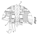
図2には、シャフトの非駆動端9の軸受ダンパ要素10を備えたそれぞれの軸受7が示されている。
Figure 2 shows each bearing 7 with a
本発明によれば、軸受ダンパ要素10は、ハウジング4とそれぞれの軸受7との間に配置されるリング11で構成される。もちろん、軸受ダンパ要素10がシャフト2と軸受7との間に配置されることも排除されない。
According to the invention, the bearing
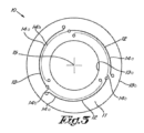
このリング11は、図3に詳細に示されている。 This ring 11 is shown in detail in Figure 3.
リング11は、軸方向X-X’にリング11の厚さを貫通し、リング11の半径方向の内面及び外面13a,13bから間隔を置いて配置される複数のスロット12を備える。
The ring 11 has a plurality of
好ましくは少なくとも3つのスロット12があり、スロット12の少なくとも半分は、最大幅が0.5ミリメートル、好ましくは最大0.2ミリメートル、より好ましくは最大1.15ミリメートルの1又は2以上の減衰部分14aを有する。
There are preferably at least three
減衰部分14aは、好ましくは、同心円状でありかつ重なり合わない。 The attenuation portions 14a are preferably concentric and non-overlapping.
これらの減衰部分14aは、好ましくはリングの中心又は中点15の80%以上、より好ましくは90%以上を囲む。
These attenuation portions 14a preferably surround at least 80% of the center or
減衰部分14aに加えて、好ましくは少なくとも1つのスロット12は、好ましくは少なくとも0.5ミリメートルの幅よりも大きい最小幅を有する1又は2以上のバネ部分14bを有する。
In addition to the damping portion 14a, preferably at least one
バネ部分14bは、好ましくは、減衰部分14aの幅の少なくとも2倍、より好ましくは少なくとも3倍の幅を有する。 The spring portion 14b preferably has a width at least twice, and more preferably at least three times, the width of the damping portion 14a.
本発明によれば、スロット12は、少なくとも部分的に重なり合っている。
According to the present invention, the
上述のように、「スロットが重なり合う」とは、リング11の中点又は中心から出発してリング11を横切る線が、各スロット8と交差することを意味する。 As stated above, "overlapping slots" means that a line originating from the midpoint or center of the ring 11 and crossing the ring 11 intersects each slot 8.
「少なくとも部分的に」とは、スロット12がその長さの少なくとも一部について重なり合うことを意味するが、必ずしもその全長について重なり合う必要はない。
"At least partially" means that the
好ましくは、スロット12のバネ部分14bは、減衰部分14aと少なくとも部分的に重なり合う。
Preferably, the spring portion 14b of the
また、好ましくは、減衰部分14aは、バネ部分14bよりもリング11の中心又は中点15から離れている。
Also, preferably, the damping portion 14a is farther from the center or
リング11の別の実施形態は、減衰部分14aのみを有するスロット12、又はバネ部分14bのみを有するスロット12を備えることもできる。減衰部分14aのみを有する実施形態は、好ましくは、以下に説明するように、上記選択肢(A)で適用され、それによって「スクイズフィルム」効果を生じさせることになる。上記選択肢(B)及び(C)の場合、減衰がスロット12に平行に実現されるので、そのような薄い減衰部分14aは、ほとんど役に立たない。この場合、好ましくは、スロット12が主に弾性効果を有するバネ部分14bのみを有する実施形態が用いられることになる。
Alternative embodiments of the ring 11 can also comprise
狭い又は薄い減衰部分14aは、好ましくは「EDM」又は「放電加工」のようなワイヤ放電プロセスを用いて作製される。 The narrow or thin attenuating portion 14a is preferably fabricated using a wire discharge process such as "EDM" or "electrical discharge machining".
より広いバネ部分14bは、ウォータージェット又はフライスプロセスを使用して作製することができる。 The wider spring portion 14b can be made using a water jet or milling process.
軸受ダンパ要素10のさらなる実施のために、本発明によるいくつかの選択肢があり、それらは図4から図6に示されている。
For further implementation of the
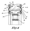
図4に示すように、本発明による第1の選択肢(A)は、スロット12が液体で満たされる実施形態に関する。この液体は粘性を有し、例えば、必須ではないが、オイルである。
As shown in FIG. 4, a first option (A) according to the invention relates to an embodiment in which the
リング11の軸方向環状面16は、保護キャップ17によって閉鎖されている。
The axial
図示の例では、保護キャップ17は、エラストマー、例えばゴムから作られている。
In the illustrated example, the
保護キャップ17は、ボルト又はネジ18によってリング11の軸方向環状面16に固定される。
The
もちろん、弾性作用、従って減衰を妨げない限り、他の固定方法も可能である。 Of course, other fastening methods are possible as long as they do not interfere with the elastic action and therefore the damping.
保護キャップ17と、液体で満たされたリングの軸方向環状面16との間には、空間19が存在する。
A space 19 exists between the
あるいは、保護キャップ17は、ある程度の可撓性を有する3Dプリント構造体とすることができる。
Alternatively, the
これは、保護キャップ17が、その構造により、可撓性である又は変形可能であることを意味する。
This means that the
3Dプリンティングによって、複雑な構造及び形状が可能であることが知られており、必要な可撓性を有する構造体を作ることができる。 3D printing is known to enable complex structures and shapes, and can create structures with the required flexibility.
例えば、保護キャップ17は、ハーモニカ構造を有する薄肉の保護キャップ17とすることができる。このようなハーモニカ構造は、周知のように、可撓性がありかつ変形可能である。
For example, the
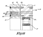
本発明による第2の選択肢(B)は、図5及び図6に示すように、リング11の2つの軸方向環状面16のうちの少なくとも1つが、2つの同心ディスク21などの間に挟まれた粘弾性材料20又はヒステリシス減衰材料20を備え、ディスク21がリング11に取り付けられる実施形態に関する。
A second option (B) according to the invention relates to an embodiment in which at least one of the two axial annular faces 16 of the ring 11 comprises a viscoelastic or hysteretic damping
ディスク21は、保護キャップ17と同様に、ボルト又はネジ18又は他の方法で固定することができる。
The
ディスク21は、多くの異なる形態で具現化することができる。
図5及び図6では、粘弾性材料20又はヒステリシス減衰材料20を収容することができるように、半径方向の内面又は外面22がわずかに輪郭形成されている。
In Figures 5 and 6, the radial inner or outer surface 22 is slightly contoured to accommodate the
選択肢(B)の場合、スロット12内に液体が存在する必要はない。
In the case of option (B), there is no need for liquid to be present in
粘弾性材料20は、図5に示すように、Oリング23とすることができるが、ヒステリシス減衰材料20は、図6に示すように、金網24(又は「ワイヤメタルメッシュ」)とすることができる。
The
図5及び図6では、粘弾性材料20又はヒステリシス減衰材料20を備えた同心ディスク21は、リング11の片側にのみ取り付けられているが、リング11の両方の軸方向環状面16に粘弾性材料20又はヒステリシス減衰材料20を備えることは排除されない。
In Figures 5 and 6, the
図示されていない第3の選択肢(C)は、スロット12が粘弾性材料で満たされる実施形態に関する。
A third option (C), not shown, relates to an embodiment in which the
この粘弾性材料は、例えば、ゴムであり、加硫によりスロット12に取り付けられる。
The viscoelastic material is, for example, rubber, and is attached to the
スロット12は、バネ部分14bのみを有する。
The
このような実施形態の利点は、保護キャップ17又は同心ディスク21をリング11に取り付ける必要がないことである。
The advantage of such an embodiment is that there is no need to attach a
多段遠心圧縮機1の動作は、非常に単純であり、以下の通りである。 The operation of the multi-stage centrifugal compressor 1 is very simple and is as follows:
遠心圧縮機1の動作中、駆動によりシャフト2が回転し、その結果、ブレード3が入口開口5を介して空気を吸い込み、空気は一連の段で圧縮され、その後、出口開口6を通って遠心圧縮機1から出る。
During operation of the centrifugal compressor 1, the shaft 2 is rotated by a drive, which causes the
動作中、振動が発生することになるが、これは共振の問題が生じないように減衰させる必要がある。 During operation, vibrations will occur which need to be damped to avoid resonance problems.
軸受ダンパ要素10は、これらの振動を減衰させることになる。
The bearing
図4の状況では、スロット12内の液体が薄膜ダンパを生じさせ、これが減衰をもたらすことになる。
In the situation shown in Figure 4, the liquid in the
保護キャップ17は、液体が流出できないようにスロット12内の液体を保持し、これはエラストマーで作られているので、振動作用の下でリング11が変形する際に一緒に動くことになる。
The
選択肢(B)の場合、図5と図6に示すように、粘弾性材料20又はヒステリシス減衰材料20が変形して振動を減衰させ、リング11は、上述のように、ある程度の可撓性を提供することになる。
In option (B), as shown in Figures 5 and 6, the viscoelastic or hysteretic damping
選択肢(C)の場合、より厚いばね部分14bは加硫され、スロット12内の粘弾性材料は、図4の実施形態のスロット12内の液体と同じ機能を有することになる。
In option (C), the thicker spring portion 14b is vulcanized and the viscoelastic material in the
軸受ダンパ要素10による振動の減衰に起因して、共振の問題は回避されることになる。これは、遠心圧縮機1は、より高速で回転すること及び/又はより多くの段数を追加することを可能にする。
Due to the damping of vibrations by the bearing
本発明は、例示的に説明されかつ図面に示された実施形態に限定されるものではなく、本発明による多段遠心圧縮機は、本発明の範囲を逸脱することなく、様々な形態及び寸法で実現することができる。 The present invention is not limited to the embodiments described by way of example and shown in the drawings, and the multi-stage centrifugal compressor according to the present invention can be realized in various forms and dimensions without departing from the scope of the present invention.
Claims (10)
少なくとも1つの前記軸受(7)は、前記シャフト(2)又は前記ハウジング(4)と前記軸受(7)の間に配置されたリング(11)で構成される軸受ダンパ要素(10)を備え、前記リング(11)は、軸方向(X-X’)に前記リング(11)の厚さを貫通し、前記リング(11)の半径方向の内面及び外面(13a、13b)から距離を置いて配置されるスロット(12)を備え、前記スロット(12)は少なくとも部分的に重なり合っており、
(A)前記リング(11)の両方の軸方向環状面(16)が、2つの同心ディスク(21)の間に挟まれたOリングを備える粘弾性材料(20)又は金網(24)を備えるヒステリシス減衰材料(20)を備え、前記2つの同心ディスク(21)は前記リング(11)に取り付けられ、
及び
(B)前記スロット(12)は粘弾性材料で満たされている、
ことを特徴とする、多段遠心圧縮機。 A multi-stage centrifugal compressor comprising a shaft (2) having a plurality of blades (3) thereon, the shaft (2) being attached to a housing (4) by bearings (7),
at least one of said bearings (7) comprises a bearing damper element (10) consisting of a ring (11) arranged between said shaft (2) or said housing (4) and said bearing (7), said ring (11) comprising a slot (12) passing through the thickness of said ring (11) in the axial direction (X-X') and spaced apart from the radial inner and outer surfaces (13a, 13b) of said ring (11), said slots (12) being at least partially overlapping;
(A) both axial annular surfaces (16) of said ring (11) are provided with a viscoelastic material (20) comprising an O-ring or a hysteretic damping material (20) comprising a wire mesh (24) sandwiched between two concentric disks (21), said two concentric disks (21) being attached to said ring (11);
and (B) the slot (12) is filled with a viscoelastic material;
A multi-stage centrifugal compressor comprising:
Applications Claiming Priority (3)
| Application Number | Priority Date | Filing Date | Title |
|---|---|---|---|
| BE20205728A BE1028709B1 (en) | 2020-10-19 | 2020-10-19 | Multistage Centrifugal Compressor |
| BE2020/5728 | 2020-10-19 | ||
| PCT/IB2021/059046 WO2022084777A1 (en) | 2020-10-19 | 2021-10-01 | Multistage centrifugal compressor |
Publications (2)
| Publication Number | Publication Date |
|---|---|
| JP2023547071A JP2023547071A (en) | 2023-11-09 |
| JP7675813B2 true JP7675813B2 (en) | 2025-05-13 |
Family
ID=73014220
Family Applications (1)
| Application Number | Title | Priority Date | Filing Date |
|---|---|---|---|
| JP2023524141A Active JP7675813B2 (en) | 2020-10-19 | 2021-10-01 | Multi-stage centrifugal compressor |
Country Status (9)
| Country | Link |
|---|---|
| US (1) | US12247584B2 (en) |
| EP (1) | EP4229309A1 (en) |
| JP (1) | JP7675813B2 (en) |
| KR (1) | KR102862144B1 (en) |
| CN (2) | CN114382720A (en) |
| BE (1) | BE1028709B1 (en) |
| BR (1) | BR112023003338A2 (en) |
| WO (1) | WO2022084777A1 (en) |
| ZA (1) | ZA202302079B (en) |
Families Citing this family (3)
| Publication number | Priority date | Publication date | Assignee | Title |
|---|---|---|---|---|
| JP7421424B2 (en) * | 2020-06-15 | 2024-01-24 | 川崎重工業株式会社 | damper |
| BE1028709B1 (en) * | 2020-10-19 | 2022-05-16 | Atlas Copco Airpower Nv | Multistage Centrifugal Compressor |
| BE1031917B1 (en) * | 2023-08-23 | 2025-03-25 | Atlas Copco Airpower Nv | Damper element, element for compressing or expanding a gas and use of such damper element |
Citations (3)
| Publication number | Priority date | Publication date | Assignee | Title |
|---|---|---|---|---|
| JP2001050267A (en) | 1999-08-10 | 2001-02-23 | Hitachi Ltd | Damping bearing and rotating machine using the same |
| US20110002571A1 (en) | 2009-01-15 | 2011-01-06 | Ab Skf | Bearing Assembly with Elastomeric Sleeve Element |
| JP2020525728A (en) | 2017-06-26 | 2020-08-27 | アトラス コプコ エアーパワー, ナームローゼ フェンノートシャップATLAS COPCO AIRPOWER, naamloze vennootschap | Bearing attenuator element, bearing and compressor element provided with such bearing attenuator element, and method of manufacturing such bearing attenuator element |
Family Cites Families (13)
| Publication number | Priority date | Publication date | Assignee | Title |
|---|---|---|---|---|
| US5603574A (en) * | 1987-05-29 | 1997-02-18 | Kmc, Inc. | Fluid dampened support having variable stiffness and damping |
| GB9526369D0 (en) * | 1995-12-22 | 1996-02-21 | Weir Pumps Ltd | Improved multistage pumps and compressors |
| JP2007056976A (en) * | 2005-08-24 | 2007-03-08 | Ishikawajima Harima Heavy Ind Co Ltd | Damper element of bearing, manufacturing method thereof, and gas turbine engine |
| JP2009281278A (en) * | 2008-05-22 | 2009-12-03 | Panasonic Corp | Centrifugal compressor and refrigeration cycle device |
| EP2187072B1 (en) * | 2008-11-07 | 2012-09-12 | General Electric Company | Compliant hybrid gas journal bearing using integral wire mesh dampers |
| JP5210893B2 (en) * | 2009-01-09 | 2013-06-12 | 三菱重工業株式会社 | Damper structure and rotating machine |
| JP5574939B2 (en) * | 2009-12-18 | 2014-08-20 | 三菱重工業株式会社 | Damper bearing device |
| US9429191B2 (en) * | 2013-10-11 | 2016-08-30 | General Electric Company | Journal bearing assemblies and methods of assembling same |
| JP6145040B2 (en) * | 2013-12-26 | 2017-06-07 | 三菱重工業株式会社 | Bearing device and rotating machine |
| DE202018001170U1 (en) * | 2018-03-06 | 2019-06-07 | Leybold Gmbh | vacuum pump |
| JP7085441B2 (en) * | 2018-09-12 | 2022-06-16 | 川崎重工業株式会社 | Damper bearings and dampers |
| CN110762127A (en) * | 2019-10-24 | 2020-02-07 | 上海裕达实业有限公司 | Bearing support vibration reduction structure suitable for molecular pump |
| BE1028709B1 (en) * | 2020-10-19 | 2022-05-16 | Atlas Copco Airpower Nv | Multistage Centrifugal Compressor |
-
2020
- 2020-10-19 BE BE20205728A patent/BE1028709B1/en active IP Right Grant
-
2021
- 2021-10-01 WO PCT/IB2021/059046 patent/WO2022084777A1/en not_active Ceased
- 2021-10-01 BR BR112023003338A patent/BR112023003338A2/en active Search and Examination
- 2021-10-01 KR KR1020237016990A patent/KR102862144B1/en active Active
- 2021-10-01 US US18/025,291 patent/US12247584B2/en active Active
- 2021-10-01 JP JP2023524141A patent/JP7675813B2/en active Active
- 2021-10-01 EP EP21783357.3A patent/EP4229309A1/en active Pending
- 2021-10-19 CN CN202111212909.XA patent/CN114382720A/en active Pending
- 2021-10-19 CN CN202122517986.8U patent/CN216518800U/en active Active
-
2023
- 2023-02-20 ZA ZA2023/02079A patent/ZA202302079B/en unknown
Patent Citations (3)
| Publication number | Priority date | Publication date | Assignee | Title |
|---|---|---|---|---|
| JP2001050267A (en) | 1999-08-10 | 2001-02-23 | Hitachi Ltd | Damping bearing and rotating machine using the same |
| US20110002571A1 (en) | 2009-01-15 | 2011-01-06 | Ab Skf | Bearing Assembly with Elastomeric Sleeve Element |
| JP2020525728A (en) | 2017-06-26 | 2020-08-27 | アトラス コプコ エアーパワー, ナームローゼ フェンノートシャップATLAS COPCO AIRPOWER, naamloze vennootschap | Bearing attenuator element, bearing and compressor element provided with such bearing attenuator element, and method of manufacturing such bearing attenuator element |
Also Published As
| Publication number | Publication date |
|---|---|
| US12247584B2 (en) | 2025-03-11 |
| WO2022084777A1 (en) | 2022-04-28 |
| CN216518800U (en) | 2022-05-13 |
| CA3189663A1 (en) | 2022-04-28 |
| BE1028709B1 (en) | 2022-05-16 |
| CN114382720A (en) | 2022-04-22 |
| BR112023003338A2 (en) | 2023-05-09 |
| EP4229309A1 (en) | 2023-08-23 |
| BE1028709A1 (en) | 2022-05-11 |
| JP2023547071A (en) | 2023-11-09 |
| KR102862144B1 (en) | 2025-09-19 |
| ZA202302079B (en) | 2024-06-26 |
| US20230323898A1 (en) | 2023-10-12 |
| KR20230085938A (en) | 2023-06-14 |
Similar Documents
| Publication | Publication Date | Title |
|---|---|---|
| JP7675813B2 (en) | Multi-stage centrifugal compressor | |
| CN101517241B (en) | vacuum pump | |
| CN109114106B (en) | Bearing damper element, bearing and compressor element equipped therewith and method of manufacture | |
| CN101189436A (en) | vacuum pump | |
| JP5276414B2 (en) | Followable hybrid gas journal bearings using an integral wire mesh damper | |
| CN111623036B (en) | Squeeze film damper bearing and rotary machine provided with same | |
| JPH08505462A (en) | Pressure damper seal | |
| FI71981B (en) | LAGER SYSTEM | |
| KR20020062077A (en) | High load capacity smart foil journal bearing with semi-active dampers | |
| KR102426608B1 (en) | Air foil bearing | |
| WO2020054133A1 (en) | Damper bearing and damper | |
| JPS60136615A (en) | Hydrodynamic bearing structure | |
| EP4632242A1 (en) | Bearing device with squeeze film damper, and centrifugal compressor | |
| CA3189663C (en) | Multistage centrifugal compressor | |
| CN111868329B (en) | Fan for lubrication and cooling of eccentric bearings in surface compactors | |
| CN109707787A (en) | A squeeze film damper | |
| JP7267772B2 (en) | Squeeze film damper bearings and rotating machinery | |
| KR20190016212A (en) | Vibration Reduced Airfoil Bearings | |
| KR20190101629A (en) | Airfoil bearing for high speed response above speed of sound | |
| Takahisa et al. | Noise and vibration of the dry pumps and their abatement |
Legal Events
| Date | Code | Title | Description |
|---|---|---|---|
| A521 | Request for written amendment filed |
Free format text: JAPANESE INTERMEDIATE CODE: A523 Effective date: 20230419 |
|
| A621 | Written request for application examination |
Free format text: JAPANESE INTERMEDIATE CODE: A621 Effective date: 20230419 |
|
| A977 | Report on retrieval |
Free format text: JAPANESE INTERMEDIATE CODE: A971007 Effective date: 20240308 |
|
| A131 | Notification of reasons for refusal |
Free format text: JAPANESE INTERMEDIATE CODE: A131 Effective date: 20240314 |
|
| A521 | Request for written amendment filed |
Free format text: JAPANESE INTERMEDIATE CODE: A523 Effective date: 20240613 |
|
| A131 | Notification of reasons for refusal |
Free format text: JAPANESE INTERMEDIATE CODE: A131 Effective date: 20240926 |
|
| A521 | Request for written amendment filed |
Free format text: JAPANESE INTERMEDIATE CODE: A523 Effective date: 20241219 |
|
| TRDD | Decision of grant or rejection written | ||
| A01 | Written decision to grant a patent or to grant a registration (utility model) |
Free format text: JAPANESE INTERMEDIATE CODE: A01 Effective date: 20250327 |
|
| A61 | First payment of annual fees (during grant procedure) |
Free format text: JAPANESE INTERMEDIATE CODE: A61 Effective date: 20250428 |
|
| R150 | Certificate of patent or registration of utility model |
Ref document number: 7675813 Country of ref document: JP Free format text: JAPANESE INTERMEDIATE CODE: R150 |